STEREO TUNER PREAMPLIFIER MX 11O CONTENTS GENERAL DESCRIPTION 1 TECHNICAL DESCRIPTION 1 FRONT PANEL FACILITIES 5 INSTALLATION 10 CONNECTING 10 AC Connections 10 AC Power Connection 10 Input Connections 11 Output Connections 12 Antenna Connections 12 OPERATING INSTRUCTIONS 13 Balancing a Stereo System 13 Adjusting Phase 14 Balancing Loudness Between Program Sources 14 Adjusting the Balance Control After the System has been Balanced 15 Adjusting for Special Effects 15 Listening to Monophonic FM Program 15 Listening to MPX Stereo 16 Listening to a Stereo Record 16 Listening to Monophonic Records 16 Listening to Tape Decks 16 Listening to Stereo Tape Machine 17 Operating Curves 18 GUARANTEE 20 OWNER'S MANUAL MX11O

Welcome message from author
This document is posted to help you gain knowledge. Please leave a comment to let me know what you think about it! Share it to your friends and learn new things together.
Transcript

STEREO TUNERPREAMPLIFIER MX 11O
CONTENTS
GENERAL DESCRIPTION 1
TECHNICAL DESCRIPTION 1
FRONT PANEL FACILITIES 5
INSTALLATION 10
CONNECTING 10AC Connections 10AC Power Connection 10Input Connections 11Output Connections 12Antenna Connections 12
OPERATING INSTRUCTIONS 13Balancing a Stereo System 13
Adjusting Phase 14
Balancing Loudness BetweenProgram Sources 14
Adjusting the Balance Control After theSystem has been Balanced 15
Adjusting for Special Effects 15
Listening to Monophonic FM Program 15
Listening to MPX Stereo 16
Listening to a Stereo Record 16
Listening to Monophonic Records 16
Listening to Tape Decks 16
Listening to Stereo Tape Machine 17
Operating Curves 18
GUARANTEE 20
OWNER'S MANUAL
MX
11
O

MX110 TUNER PREAMPLIFIER
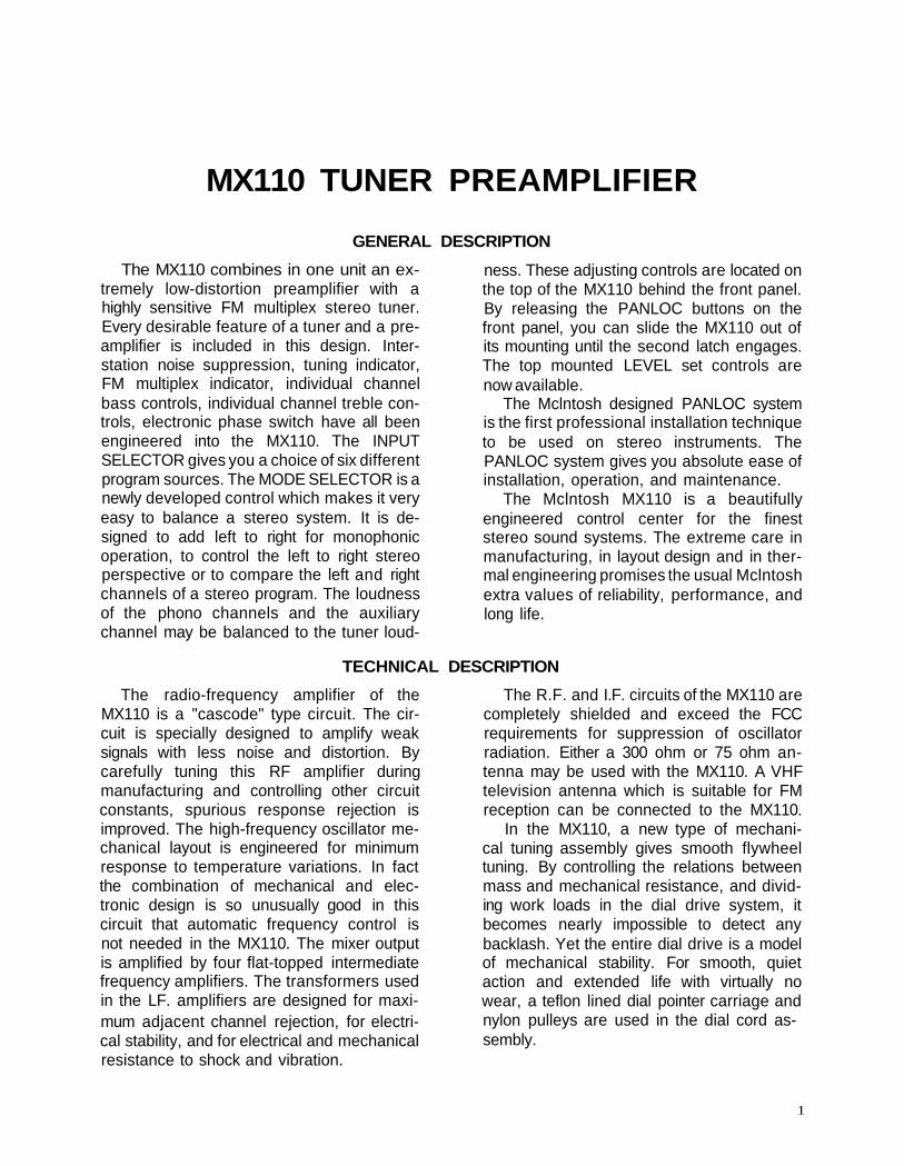
GENERAL DESCRIPTION
The MX110 combines in one unit an ex-tremely low-distortion preamplifier with ahighly sensitive FM multiplex stereo tuner.Every desirable feature of a tuner and a pre-amplifier is included in this design. Inter-station noise suppression, tuning indicator,FM multiplex indicator, individual channelbass controls, individual channel treble con-trols, electronic phase switch have all beenengineered into the MX110. The INPUTSELECTOR gives you a choice of six differentprogram sources. The MODE SELECTOR is anewly developed control which makes it veryeasy to balance a stereo system. It is de-signed to add left to right for monophonicoperation, to control the left to right stereoperspective or to compare the left and rightchannels of a stereo program. The loudnessof the phono channels and the auxiliarychannel may be balanced to the tuner loud-
ness. These adjusting controls are located onthe top of the MX110 behind the front panel.By releasing the PANLOC buttons on thefront panel, you can slide the MX110 out ofits mounting until the second latch engages.The top mounted LEVEL set controls arenow available.
The Mclntosh designed PANLOC systemis the first professional installation techniqueto be used on stereo instruments. ThePANLOC system gives you absolute ease ofinstallation, operation, and maintenance.
The Mclntosh MX110 is a beautifullyengineered control center for the fineststereo sound systems. The extreme care inmanufacturing, in layout design and in ther-mal engineering promises the usual Mclntoshextra values of reliability, performance, andlong life.
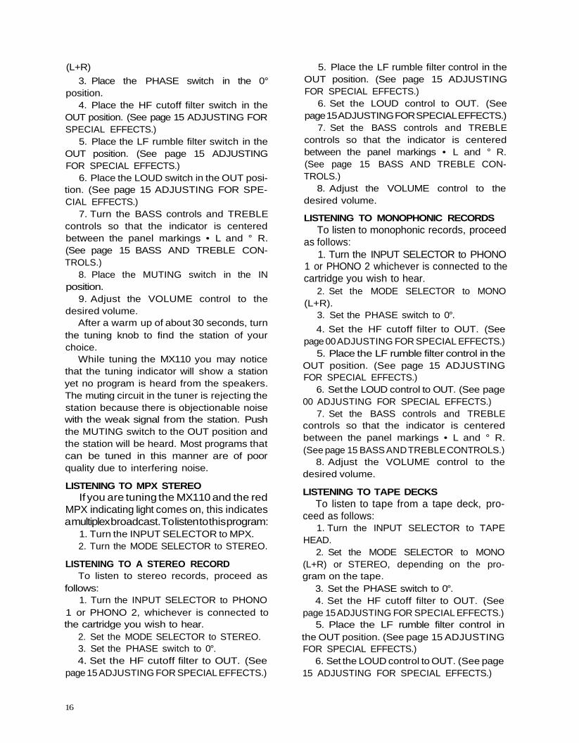
TECHNICAL DESCRIPTION
The radio-frequency amplifier of theMX110 is a "cascode" type circuit. The cir-cuit is specially designed to amplify weaksignals with less noise and distortion. Bycarefully tuning this RF amplifier duringmanufacturing and controlling other circuitconstants, spurious response rejection isimproved. The high-frequency oscillator me-chanical layout is engineered for minimumresponse to temperature variations. In factthe combination of mechanical and elec-tronic design is so unusually good in thiscircuit that automatic frequency control isnot needed in the MX110. The mixer outputis amplified by four flat-topped intermediatefrequency amplifiers. The transformers usedin the LF. amplifiers are designed for maxi-mum adjacent channel rejection, for electri-cal stability, and for electrical and mechanicalresistance to shock and vibration.
The R.F. and I.F. circuits of the MX110 arecompletely shielded and exceed the FCCrequirements for suppression of oscillatorradiation. Either a 300 ohm or 75 ohm an-tenna may be used with the MX110. A VHFtelevision antenna which is suitable for FMreception can be connected to the MX110.
In the MX110, a new type of mechani-cal tuning assembly gives smooth flywheeltuning. By controlling the relations betweenmass and mechanical resistance, and divid-ing work loads in the dial drive system, itbecomes nearly impossible to detect anybacklash. Yet the entire dial drive is a modelof mechanical stability. For smooth, quietaction and extended life with virtually nowear, a teflon lined dial pointer carriage andnylon pulleys are used in the dial cord as-sembly.
1

MULTIPLEX DECODER
The multiplex decoder uses a specialMclntosh developed detecting circuit. One ofthe advantages of this circuit is the elimina-tion of the critical adjustments necessarywith commonly used matrixing methods. Thiscircuit detects the L+R sidebands and auto-matically matrixes the recovered informa-tion with the L+R main carrier signal. Thiscircuit then yields the left and the rightprogram with maximum separation.
A temperature stabilized 19KC amplifierlocks-in a highly stable push-pull synchro-nous oscillator. Apart from other advantages,this method provides greatest noise immu-nity. Balanced detectors cancel 19KC and
38KC components in the output and insurelow distortion.
A three-section sharp cut off filter rejectsSCA interference and reduces susceptibilityto spurious signals.
The MX110 has an MPX stereo indicatorthat lights when the dial pointer crosses astation broadcasting MPX stereo. A uniquecircuit using a transistor operates the MPXstereo indicator. The transistor is controlledby a differential detecting circuit that am-plifies the 19KC pilot signal. This circuit auto-matically discriminates between the 19KCsignal and noise.
AUDIO
The MX110 audio amplifier consists ofthree negative-feedback amplifying sectionsin duplicate for the left and right stereo chan-nels and a separate L+R monophonic ampli-fier. The first section in each channel is afeedback preamplifier used to amplify andcompensate for the input signals comingfrom phonograph pickups or tape heads.Level set controls are connected into the out-put circuit of this preamplifier section whenthe INPUT SELECTOR is switched to PHONO1 or PHONO 2. These controls may be usedto maintain uniform loudness between phonoand tuner inputs. Skillful layout, grounding,and shielding for low-hum pickup, metal filmresistors, low-noise tubes and extreme carein manufacturing combine to reduce noiseand hum in the input amplifiers.
The second amplifier section in each chan-nel is a cathode follower. The sharp cut-off
(18db per octave) rumble and high-frequencyfilters are associated with this section. Input-level set controls for the auxiliary inputs areassociated with this section. All the level setcontrols are conveniently accessible
The third amplifier section is a two stagenegative feedback amplifier. The variablebass and treble controls are included in thefeedback loop to maintain the lowest possibledistortion. For example a wave meter analy-sis of the three amplifier sections of theMX110 shows less than 1/10 of 1% dis-tortion at 3 volts output. The MODE SELEC-TOR, balance controls and left and right out-puts are associated with the third amplifiersection.
The L+R monophonic amplifying sectionis a feedback summing amplifier. It suppliesmonophonic output as well as L+R output.
POWER SUPPLY
The power supply of the MX110 has re-ceived very special design attention. Threeseparate rectifier circuits are used.
First, a full-wave rectifier supplies D.C. tothe heaters of all audio stages.
A second bridge rectifier supplies D.C. tothe anodes of the audio stages.
Then a third full-wave rectifier supplies
D.C. to the tuner stages.This elaborate power supply design in-
sures the lowest possible background humlevel and also the maximum stability. Inaddition to this careful work the power trans-former uses special magnetic shielding tominimize possible hum pickup in the MX110as well as in any other equipment used with it.
2

3
MECHANICAL SPECIFICATIONS
DimensionsChassis: 16 inches wide; 57/16 inches high;
13 inches deep including connectors.Front Panel: 16 inches wide; 57/16 inches high.Knob Clearance: 1½ inches.
WeightChassis: 27½ pounds.Shipping Weight: 36 pounds.
TUNER SPECIFICATIONS
SensitivityBetter than 2.5 microvolts at 100% modula-
tion.
R.F. AmplifierCascode.
LF. AmplifiersFour.
LimitersTwo.
LF. Bandwidth200KC flat top.
LF. TransformersMechanically captive.
MutingLF. injected.
Tuning IndicatorTuning is indicated by an electron ray tube.
MULTIPLEX DECODER SPECIFICATIONS
MPX DecoderHum Level: Better than 60db below 100%
stereo modulation.Distortion: Less than 0.3% (Multiplex De-
coder only).Channel Separation: Better than 30db at
1000 cps.
AUDIO SPECIFICATIONS
InputsTotal 5 each channel:
AUX.;PHONO 1 MAG. or XTAL;PHONO 2 MAG.;TAPE HEAD;TAPE MONITOR.
OutputsMain Stereo Outputs, 1 Tape Stereo Output,
1 L+R Output.
AC AUX Outlets1 unswitched, 2 switched.
Suppression of Pilot (19KC), and Carrier(38KC): Greater than 40db below 100%modulation.
Front Panel Stereo Indicator Light: Acti-vated by 19KC pilot carrier only.
Frequency ResponseWithin ± 1db 20 to 20,000 cycles. (Including
75 microseconds deemphasis.)
HumGreater than 70db or more below 100%
mod. (Audio tubes have D.C. on the fila-ments.)
DriftLess than 25 KC.
Ant. Input Impedance300 balanced, 75 ohms unbalanced.
RadiationSubstantially below F.C.C. requirements.
DistortionLess than 0.6% distortion at 100% modula-
tion, ± 75KC deviation above 2.5 micro-volts at antenna.
FinishAnodized gold and black (front panel).
InstallationConvenient, professional PANLOC.

ControlsInput Selector: Total 6 positions: AUX,
MPX, FM, PHONO 1, PHONO 2, TAPEHEADS.
Mode Selector: Total 7 positions: L TO L&R,R TO L&R, STEREO REV., STEREO, MONO,L+R TO L, L+R TO R.
Tone: Dual treble and bass negative-feed-back controls with slip clutch for independ-ent adjustment of each channel. BassBoost: 15db at 50 cycles. Bass Cut: 18dbat 50 cycles. Treble Boost: 15db at 10,000cycles. Treble Cut: 15db at 10,000 cycles.
Balance: Turn to right to emphasize theright channel. Turn to the left to emphasizethe left channel.
Phase: 2 positions: NORMAL or REVERSED:Changing phase does not increase distor-
ELECTRICAL
Frequency Response±½db 20 to 20,000 cycles.
DistortionLess than 0.2% at rated output.
Hum and NoiseHigh-level inputs: 80db below rated output.
Low-level inputs: less than 3 microvolts atinput terminals.
Input SensitivityAUX: 0.3 volt at 200K.PHONO 1:3 millivolts at 47K.PHONO 2: 3 millivolts at 47K.
tion. H.F. Cutoff Filter: 2 positions: Flat, or5KC cutoff. (20db per octave.) L.F. CutoffFilter: 2 positions: Flat, or 50 cycles cutoff.(20db per octave.)
Loudness: Fletcher Munson compensation.Tape Monitor: 2 positions: IN and OUT. For
comparison of recorded tape with programsource after recording.
Tuning: Flywheel tuning—no backlash.Muting: 2 positions: IN or OUT for intersta-
tion noise suppression.Level Set: Three left and three right controls.
2 for AUX, 2 for PHONO 1, and 2 forPHONO 2. These controls are located backof the front panel on the top of the MX110.
AC Power—Concentric with BALANCE con-trol: ON-OFF.
SPECIFICATIONS
TAPE HEAD: 3 millivolts at 220K.TAPE MONITOR: 0.3 volt at 100K.
OutputsMAIN: 3 volts 2 in parallel each channel.L+R: 3 volts.
TAPE: From FM at 100% modulation 0.9volt from PHONO when cartridge outputis 9.0 millivolts—0.9 volt; with rated input—0.3 volt.
POWER REQUIREMENTS: 105-125 volts AC50/60 cycles; 75 watts.
FUSE: 1 amp. Slo-Blo.
TUBE COMPLEMENT
1 6DS4 R.F. -1 amplifier (nuvistor)1 12AT7 R.F.-2 mixer1 6AB4 Oscillator1 6AU6 IF-11 6AU6 IF-21 6AU6 lF-3/Limiter 11 6CS6 IF-4/Limiter21 12AT7 Muting/L+R Amplifier1 6HU6/EM87 Tuning Indicator1 6D10 FM AUDIO/Left and Right
1st Audio Amplifier1 6U8 MPX Amplifier and 19KC
Separator/Indicator control
1 12AU71 12AX71 12AX71 12AX7
1 6U81 6U82 Diodes1 Diode
1 Diode4 Diodes2 Diodes
MPX 38KC OscillatorPhono Preamplifier LeftPhono Preamplifier Right
Left and Right 2nd AudioAmplifierLeft 3rd Audio AmplifierRight 3rd Audio AmplifierDiscriminatorMuting and Tuning EyeDetectorsAGC ClampBalanced MPX DetectorsBalanced Det. for IndicatorLight
4

2 SiliconDiodes
1 MA113DC Filament SupplyTransistor-Indicator LightSwitch
4 SeleniumRectifiers High and Low Voltage Supply
FRONT PANEL INFORMATION
DIAL SCALES
The MX110 has two scales. The 88 to 108scale is marked in megacycles. The 0 to 100scale is the logging scale. The logging scalecan be used to accurately retune any station.You may find it easier to keep a record ofyour favorite stations by use of the loggingscale.
INDICATORS
The MX110 has two indicators. They arejust below each end of the logging scale. Onthe right end is the MPX STEREO indicator.On the left end is the tuning indicator.
Figure 1. MX110 Front Panel.
signal while rejecting noise pulses of equalintensity. For listening to MPX stereo, refer toOPERATING INSTRUCTIONS on page 00.
The tuning indicator off tune.
Figure 2. MPX Stereo Indicator.
The MPX STEREO indicator will light up ifthe dial pointer crosses a station broadcast-ing MPX stereo. A special circuit is used tooperate this panel indicator. This circuitautomatically detects the 19KC MPX stereo
The tuning indicator on tune.
Figure 3. Tuning Indicator.
The tuning indicator uses the movementof two electron beams inside a vacuum tubeto show when a station is precisely tuned.
The beams move toward each other as thestation comes into tune. The station is pre-cisely tuned when the beams come closesttogether. The action of this indicator is sub-stantially independent of the signal strengthof the station. Only the very weakest signalswill not close the beams.
5

VOLUME
Figure 4. VOLUME Control.
The VOLUME control is the large knoblocated to the left side of the dial face. Thevolume control adjusts the loudness of bothstereo channels and also the L+R mono-phonic channel.
INPUT SELECTOR
Figure 5. INPUT SELECTOR.
1. AUX—The AUX position of the INPUTSELECTOR connects the back panel jacksmarked AUX through the MX110. Use thesejacks to connect any high level programsource through the MX 110. Connections aremade following the instructions on page 11 inthe section titled CONNECTING. Operatingprocedure is on page 13 in the sectiontitled OPERATING INSTRUCTIONS.2. MPX—The MPX position of the INPUTSELECTOR connects the multiplex decoderto the output jacks of the MX110. Listen toMPX stereo broadcasts in this position. Toproperly connect and operate the MX110,consult the sections titled CONNECTING onpage 11 and OPERATING INSTRUCTIONSon page 13.
3. FM—The FM position of the INPUT SELEC-TOR connects FM monophonic programs to
the output jack of the MX110. To properlyoperate the MX 110, consult the sectiontitled OPERATING INSTRUCTIONS on page13,
4. PHONO 1—The PHONO 1 position of theINPUT SELECTOR connects the jacks on theback panel marked PH-1 MAG. and PH-1XTAL through the MX110. Any stereophonicor monophonic magnetic phono cartridgeplugged into the PH-1 MAG. jacks is fedthrough the MX110. Any constant ampli-tude cartridge such as a crystal or ceramicdevice plugged into the PH-1 XTAL jacks isfed through the MX110. To properly connectand operate the MX110 for use with phonocartridges, see the sections titled CON-NECTING on page 11 and OPERATINGINSTRUCTIONS on page 13.
5. PHONO 2—The PHONO 2 position of theINPUT SELECTOR connects the jacks on theback panel marked PH-2 through the MX110.Any magnetic phono cartridge plugged intothe PH-2 jacks is fed through the MX110. Toproperly connect and operate the MX110 foruse with phono cartridges, see the sectionstitled CONNECTING on page 11 and OPER-ATING INSTRUCTIONS on page 13 .
6. TAPE HD—The TAPE HD position of theINPUT SELECTOR connects the jacks on theback panel marked TAPE HEAD through theMX110. A tape deck that does not containits own playback preamplifier is connected tothe MX110 through this position. To properlyconnect and operate the MX110 for use withtape decks, consult the sections titled CON-NECTING on page 11 and OPERATING IN-STRUCTIONS on page 13.
MODE SELECTOR1. L TO L&R—The MODE SELECTOR in theL TO L&R position connects the left input toboth amplifiers and both loudspeakers.2. R TO L&R—The MODE SELECTOR in theR TO L&R position connects the right input toboth amplifiers and both loudspeakers.3. STEREO REV-The MODE SELECTOR inthe STEREO REV position connects the leftinput to the right loudspeaker and right inputto the left loudspeaker.
6

Figure 6. MODE SELECTOR.
4. STEREO—The MODE SELECTOR in theSTEREO position connects the left input tothe left loudspeaker and the right input tothe right loudspeaker. This is the normalstereo position.5. MONO—The MODE SELECTOR in theMONO position adds the left input to theright input and connects the L+R programto both amplifiers and both loudspeakers.6. L+R TO L—The MODE SELECTOR in theL+R TO L position adds the left input to theright input and connects the L+R program tothe left loudspeaker only.7. L+R TO R-The MODE SELECTOR in theL+R TO R position adds left input to the rightinput and connects the L+R program to theright loudspeaker only.
BASS
Figure 7. BASS Control.
The BASS control is a dual control. Thetwo parts of the control are concentric. Thecenter or small knob controls the bass loud-ness in the left channel. The outer ring con-trols the bass loudness in the right channel.The two knobs are friction coupled, this per-mits them to be adjusted together or inde-
pendently. Turning clockwise increases bassloudness. Turning them counterclockwisedecreases bass loudness.
TREBLE
Figures. TREBLE Control.
The TREBLE control is a dual control. Thetwo parts are concentric. The center or smallknob controls the treble loudness in the leftchannel. The outer ring controls the trebleloudness in the right channel. The two knobsare friction coupled. This permits them to beadjusted together or independently. Turningclockwise increases the treble loudness.Turning counterclockwise decreases trebleloudness.
MUTING
Figure 9. MUTING Control.
Muting suppresses the background noiseand hiss normally heard between stations.With the control in the IN position the mutingis turned on. Weak stations that may notoverride noise and interference are alsosuppressed by the muting.
In the OUT position, the muting is turnedoff. This allows conventional FM tuning withthe noise and interference present. Use thisposition to tune weak or noisy stations.
7

FILTERS
Figure 10. LF Rumble Filter Switch.
Low frequency noise below 50 cps isreduced by pushing the LF rumble filterswitch to the IN position. Low frequencyacoustically coupled feedback is also re-duced by this switch.
Figure 11. HF Filter Switch.
Surface noise above 5000 cycles is re-duced when reproducing old, badly wornrecordings by pushing the HF filter switch tothe IN position.
POWER BALANCE
Figure 12. BALANCE Control.
The POWER ON-OFF switch is the centeror small knob of this dual control. The MX 110is off when the POWER switch is turned to the
POWER OFF or left position (counterclock-wise).
On the back panel of the MX110 there arethree A.C. OUTLETS. Two of these are blackand the other is red. The power to the blackoutlets is controlled by the POWER switch.The RED outlet is used for power to a turn-table or a record changer. The turntable orrecord changer drive system is protected bythis arrangement. It is necessary to turn offthe turntable or record changer with its owncontrol switch. The two black outlets and thered outlet are not fused. Maximum rating forthese outlets is 350 watts total.
The BALANCE control balances the MX110for unequal program sources. Turning thecontrol to the left accents the left channel byreducing the right channel output. Turningthe control to the right accents the rightchannel by reducing the left channel output.
LOUD
Figure 13. LOUD Compensation Switch.
When you turn down the volume, themusic will seem to lose much of its bass andsome of its treble. This effect is due to thesensitivity characteristic of human hearing.The response of the human ear to bass andtreble pitch decreases more rapidly thanits response to notes centered in the mid-tonal range. The LOUD control automaticallyprovides the correct amount of bass andtreble boost required to compensate for thischange in response of the human ear at low-loudness levels. When the "LOUD" switch ismoved to the IN position, it converts thevolume control to a loudness compensatedcontrol. Use the LOUD IN to listen at lowvolume and still hear full-frequency range.
8

TAPE MONITOR PHASE
Figure 14 TAPE MONITOR Switch.
The TAPE MONITOR switch compares therecorded tape with the program source.When the TAPE MONITOR switch is in theOUT position, the program source is heardfrom the loudspeakers. When the TAPEMONITOR switch is in the IN position, therecorded tape is heard from the loudspeak-ers. Jacks marked TAPE MONITOR arelocated on the back panel. Plug a signal intothese jacks from a tape machine which has athird head and a preamplif ier for it. IMPOR-TANT: When the TAPE MONITOR switch isoperated in the IN position, signal from anyother source will not be heard from the loud-speakers. When not in use, make sure theswitch is in the OUT position.
Figure 15. PHASE Switch.
The PHASE switch corrects for loud-speaker or program phasing. Placing thisswitch in the 180° position reverses phase inthe left channel.
LEVEL SET CONTROLSThe MX110 LEVEL SET controls (see
figure 16 compensate for the difference inoutput level from various program sources.The output level of the FM tuner, for example,is higher than the output of a magnetic pick-up. When you switch from one programsource to another, the level will vary to anannoying degree. The level controls can beset so that the output levels of all programsources are equal. The MX110 LEVEL SETcontrols are located on top of the MX110chassis behind the front panel.
9

INSTALLATION
The MX 110 can be installed in conventionalfurniture cabinets, custom built installationsor professional relay racks. If the unit is to beplaced on a shelf or table-top, it is recom-mended that it be housed in a Mclntoshcabinet. Install the MX110 from the front ofthe cabinet, not from the rear.
To support the weight of the MX110, thewood panel used to mount it should be atleast ¼ inch thick.
The MX 110 installation should allow l3½inches behind the front panel which includes1½ inches for connectors. The desirablewidth and height of the installation are 16inches and a minimum of 5½ inches, re-spectively, so that sufficient space is allowedfor the circulation of air. These are insidedimensions. The front panel mounting spacewidth and height are 16 inches and 53/8
inches, respectively. Allow at least 1½ inchesfor knob clearance in a custom built installa-tion.
CONNECTING
AC CONNECTIONSThere are three AC outlets on the rear
panel of the MX110. (See Figure 17.1 Thesereceptacles have a maximum rating of 350watts total. The power to the two blackreceptacles is controlled by the POWERswitch on the front panel. The red receptacleis not switched. The red receptacle is usedfor powering a turntable or record changer.The receptacle is not switched so that theturntable power will not be turned off while
the turntable idler wheel engaged. Theturntable is protected by this arrangementbecause it is necessary to turn off the turn-table with its own control switch so that nodamage will result to the drive system.
AC POWERPlug the AC power cord in 105 volt to 125
volt, 50 to 60 cycle power line. The powerused by the MX110 is 75 watts.
Figure 17. AC Connections.
10

INPUT CONNECTIONSThe MX110 provides six separate pro-
gram inputs controlled by the INPUT SELEC-TOR switch. One input for tape monitor or
tape comparison is controlled by the TAPEMONITOR switch.
The input program connections should bemade in accordance with Table 1.
Figure 18. MX110 Input Connections (Back Panel).
If a cartridge requires less than 47,000ohms load impedance, a resistor can beadded across the terminals of the cartridge
Desired Impedance47,000 ohms (47K)37,000 ohms (37K)27,000 ohms (27K)15,000 ohms (15K)6,800 ohms (6.8K)
to achieve the correct termination. Thefollowing chart may be used as a guide:
Resistor Across InputNo Resistor
180,000 ohms (180K)62,000 ohms (62K)22,000ohrns (22K)
8,200 ohms (8.2K)
Table 1. Input Connections
CONNECTION
TAPE MONITOR
AUX
TAPE HEAD
PH-1 MAG& PH-2 MAG.
PH-1 XTAL
FUNCTION
Tape input operates with tape machines containing their ownplayback preamplifier.
The auxiliary input accepts any auxiliary service requiring flatfrequency response, such as a T.V. set, etc.
This jack is used with a tape deck that does not contain its ownplayback preamplifier.
These jacks are to be used with magnetic cartridges.
These jacks are to be used with a constant amplitude cartridgesuch as a crystal, ceramic, or frequency-modulated device.
INPUTSENSITIVITY
0.3 volts
0.3 volts
2.5 millivolts(25/1000 of 1 volt)
3 millivolts(3/1000 of 1 volt)
0.1 volts
INPUTIMPEDANCE
100,000 ohms(100K)
200,000 ohms(200K)
220,000 ohms(220K)
47,000 ohms(47K)
220 mmf inseries with 56K
1 1

OUTPUT CONNECTIONSThere are three sets of outputs on the left
half of the back panel. (See Figure 19.) Onepair is marked MAIN. The second pair ismarked TAPE. The third is a single jackmarked L+R OUTPUT.
The MAIN output connects to poweramplifiers (Figure 19). The TAPE outputfeeds a tape recorder.
The MAIN jacks are fed from cathodefollowers. Longer cables than are normallysupplied can be connected between theMX110 and the amplifiers. The length of thecable is limited by the capacity of the cable.The total capacity must not exceed 1000mmf. For instance: cables with a capacityof 25 mmf per foot may be 40 feet long; 13.5mmf per foot cable may be 75 feet long. Theinput impedance of the amplifiers should be100,000 ohms or greater.
The TAPE output is fed from a cathodefollower. The program material fed out of theTAPE output is not affected by these front
panel controls: VOLUME control, BASS con-trols, LF and HF filter switches, BALANCEcontrol, LOUD switch, TAPE MONITOR switch,PHASE switch, TREBLE controls, and MODESELECTOR switch.
The program material fed out of theTAPE output is affected by these frontpanel controls: INPUT SELECTOR switch,and in the FM or MPX positions of the INPUTSELECTOR, the MUTING switch and TUNINGcontrol.
The input impedance of the tape recordershould be 100,000 ohms or greater.
A jack marked L+R OUTPUT is locatedbelow the GND screw.
A monophonic signal can be distributed toother rooms by connecting another poweramplifier to the jack marked L+R. The cableconnecting this output to the amplifiershould not have a capacity of more than1000 mmf. The input impedance of thepower amplifier connecting to this outputshould not be less than 150,000ohms(150K).
Figure 19. Output Connections
ANTENNA CONNECTIONSSatisfactory MPX stereo requires about
10 times as much signal from the antenna.Monophonic installations that are satis-factory on an indoor antenna may requirethe use of an outdoor antenna for equivalentresults.
With the MX110 one of the three antennasystems can be used: (1) the indoor dipolesupplied with the MX110, (2) an outdoor
FM antenna, or 3 a VHF-TV antenna. Infringe areas best results will probably beobtained with the use of an outdoor FMantenna. In many areas the indoor dipoleantenna may be satisfactory. The use of aVHF-TV antenna is also effective in manyinstallations. Make a choice after consultingthe book on antennas titled "Themes andVariations" included with MX110.
12

OUTDOOR ANTENNAAn outdoor antenna is recommended for
optimum performance in all areas. In fringe(outlying) areas, best results will be obtainedwith a highly directional FM antenna used inconjunction with a rotator. Rotate the an-tenna until the best reception is obtained.Connect the 300 ohm antenna to the ter-minal screws marked FM ANT as in Figure 20.
INDOOR DIPOLE ANTENNAThe flexible folded dipole antenna (300
ohm) supplied with the MX110 is for indooruse in urban or high intensity signal areas.The flexibility of the thin flat wire assemblypermits it to be placed under a rug, tackedbehind the hi-fi equipment enclosure . . . or,placed in any other convenient location. Insome cases, it may be necessary to "posi-tion" the antenna for best signal reception.This should be done before it is permanentlylocated or tacked down.
To position the dipole for best results, theMX110 must be operating. The followingprocedure may be followed: Connect the twoleads from the dipole to the terminals markedFM ANT on the rear of the chassis of theMX110, see Figure 20.
IMPORTANT:BEFORE TURNING THE MX110 ON,CHECK TO SEE THAT ALL TUBES AREFIRMLY SEATED IN THEIR SOCKETS,AND THAT ALL PLUGS ARE CORRECTLYAND FIRMLY INSERTED.
Turn the POWER switch ON. Then theMODE SELECTOR to STEREO. Place theMUTING control in the OUT position. Openthe dipole to a full "T" and tune the MX110to a fairly weak station. Rotate and move thedipole about until the best reception is ob-tained. The dipole is now in the best positionfor maximum signal reception for this sta-tion. This is not a critical position; thereforeyou may permanently install the antenna in aposition which most closely conforms to it.
Keep the dipole away from metal sur-faces, metal doorways, etc., as they usuallyinterfere with its efficiency.
CONNECTING A 75 OHM COAXIALANTENNA LEAD
Figure 20. Connection for 300 ohm antenna
Figure 21. Connections for a 75 ohm antenna
An unbalanced 75 ohm antenna can beconnected to the MX110 with coaxial cable.Connect the center conductor to the left FMANT screw and the shield to the groundingscrew next to the antenna screw as in Figure21. The Mclntosh designed balun matchesthe 75 ohm input to the tuner for optimumperformance.
OPERATING INSTRUCTIONS
BALANCING A STEREO SYSTEMThe performance and enjoyment of a
stereo system is greatly increased whenthe system is properly balanced. There are
two factors that require balancing. One isunequal program loudness in each channel.The knob marked BALANCE on the MX110
13

is used to balance unequal program loud-ness. Balancing program for equal loudnessis explained under ADJUSTING BALANCECONTROL TO CORRECT PROGRAM MA-TERIAL.
The other factor that requires balancingis system balance. The balance of the stereosystem is affected by many things includingroom acoustics, furniture placement, roomshape, small differences in loudspeakers,etc. Balancing the system is done by adjust-ing the controls on the power amplifiers.
To begin balancing the system, check tosee that the controls on the amplifier areproperly set. If the amplifier is a MclntoshMC225, set the input switch to STEREO. Turnboth input level controls to the black dot atthe 12 o'clock position of the control.
If the amplifier is a Mclntosh MC240 orMC275 check to see that the cables from theMX110 are plugged into the STEREO INPUTjacks. Then set the lever switch to STEREO.Turn the BALANCE control to the 0 mark atthe 12 o'clock position of the control. Theamplifiers are now ready for the rest of thesteps to balancing the system.
1. Play a familiar recording on the recordplayer.
2. Push the two PANLOC buttons to re-lease the MX110 from the mounting shelf.Pull the MX110 toward you until the latchlocks engage. Turn all the INPUT LEVELADJUST controls full on (clockwise).
3. Turn the INPUT SELECTOR to thePHONO position into which the record playeris connected.
4. Turn the BASS controls and TREBLEcontrols so that the knob indicator is cen-tered between the panel markings L and R.
5. Turn the BALANCE control to the centeror 12 o'clock position.
6. Place the LOUD switch in the OUTposition.
7. Place the TAPE MONITOR switch in theOUT position.
8. Place the PHASE switch in the 0°position.
9. Place the LF rumble filter switch in theOUT position.
10. Place the HF cutoff filter switch in theOUT position.
11. Turn the MODE SELECTOR to the L+RTO L position.
12. While the program is playing, alternatethe MODE SELECTOR between the L+R TOR and the L+R TO L position. On amplifierssuch as the MC225, adjust the correct gaincontrol until the loudspeakers are of equalloudness. On the MC240 or the MC275, turnthe balance control until the loudspeakersare of equal loudness.
The stereo system is now balanced. It willremain balanced through all modes of opera-tion. Leave the MX110 extended on itsPANLOC stops for the next series of adjust-ments.
ADJUSTING PHASE1. Set the MODE SELECTOR to STEREO.2. Turn the BASS controls and TREBLE
controls to straight up position so that thedial indicator centers between the panelmarkings • L and ° R.
Stand approximately 10 feet in front ofand midway between the loudspeakers. Thesource of sound should appear to be directlyin front of you. Alternate the PHASE switchbetween 0° and 180°. If the sound is notdirectly in front of you in the 0° position,reverse the leads to one loudspeaker. ThePHASE control is used to correct phase in thesource material whenever necessary.
BALANCING LOUDNESS BETWEENPROGRAM SOURCES
The MX110 has set level controls in theAUXILIARY, PHONO 1 and PHONO 2 inputs.These adjustments allow you to make anyprogram material connected to the auxiliaryand phono inputs the same loudness as thetuner. To make this adjustment proceed asfollows:
1. Turn the MODE SELECTOR to MONO(L+R).
2. Turn the INPUT SELECTOR to FM.Adjust the VOLUME control to a comfortablelistening level.
3. While the record is playing, turn theMODE SELECTOR to the L+R to L position.
14

4. Now switch the INPUT SELECTOR be-tween FM and PHONO. If the record is louderthan the FM turn the INPUT LEVEL, ADJUSTCONTROL marked PHONO L down (counter-clockwise). When the loudness of FM and therecord are equal, the left channel level iscorrect.
5. Turn the MODE SELECTOR to L+R to R.6. Again switch the INPUT SELECTOR
between FM and PHONO. If the record islouder than the FM, turn the INPUT LEVELADJUST CONTROL marked PHONO R down(counterclockwise). When FM and the recordare equal, the right channel is correct.
Use these same steps to adjust the AUXinput loudness. Remember to compare theloudness to the FM only. The FM does nothave controls for loudness adjustment.
ADJUSTING BALANCE CONTROL AFTERTHE SYSTEM HAS BEEN BALANCED
When these instructions have been com-pleted, the overall system is balanced and inphase; ready to deliver maximum pleasureand enjoyment.
You may hear differences in balance fromone record to another or from one tape toanother. Some records or tapes may berecorded with slight differences betweenchannels. The differences can be correctedwith the BALANCE control on the front panel.If the difference is heard on every record,then the cartridge may have a very smalldifference in output.
ADJUSTING FOR SPECIAL EFFECTSHF Cutoff Filter. If you wish to reproduce
old, badly worn records, you can minimizethe surface noise by switching the HF cutofffilter to the IN position. (See section en-titled "Front Panel Facilities," page 5.)
LF Rumble Filter. If you are using a turn-table or changer which has low-frequencyrumble noise, you may reduce it by pushingthe LF rumble filter switch to the IN position.
Bass Controls and Treble Controls. Thetone balance which you hear when listeningto an orchestra is affected by the conductor'sinstructions to his musicians, the acousticalenvironment m which you are listening, andyour own subjective hearing interpretation.
Considering these conditions, it is easy to seewhy tone balance controls play a major role incorrecting for the following factors:
1. Each person's subjective idea of tonebalance.
2. Loudspeaker frequency response char-acteristics.
3. Loudspeaker placement in the listen-ing room.
4. The conductor's idea of tone balanceat the time the recording was made.
5. The microphone frequency responsecharacteristics.
6. The recording process influences.These factors can be considered as en-
vironmental influences. The BASS controlsand TREBLE controls are designed to providea degree of compensation for effects ofenvironment. Listen to your system witheach control set with the indicators centeredbetween the panel markings • L and ° R. Ifyou wish to reduce treble in relation to bass,turn the TREBLE controls counterclockwiseuntil the tone balance sounds correct to you.These controls will modify tone balance with-out introducing any undesirable effects. Donot be surprised if you find your preferencein tone changing from time to time.
Loudness. Due to a selective shift in sen-sitivity of human hearing, music reproducedat very low volume loses its bass and treble.
The LOUD switch on the MX110 changesthe VOLUME control to a loudness com-pensated control to correct for this effect.When you wish to listen to music at a greatlyreduced loudness level and yet hear bass andtreble, set the LOUD switch to the IN position.
Phase. If the stereo sound seems to comefrom either side of the room instead of beingdistributed between the loudspeakers, adjustthe PHASE control to 180°. This listeningeffect is due to reproducing sound that isout of phase from one channel to the other.You will find some records differ from othersin this respect and that some tapes differfrom records.
LISTENING TO A MONOPHONICFM PROGRAM
1. Turn the INPUT SELECTOR to FM.2. Turn the MODE SELECTOR to MONO
15
(L+R)
3. Place the PHASE switch in the 0°position.
4. Place the HF cutoff filter switch in theOUT position. (See page 15 ADJUSTING FORSPECIAL EFFECTS.)
5. Place the LF rumble filter switch in theOUT position. (See page 15 ADJUSTINGFOR SPECIAL EFFECTS.)
6. Place the LOUD switch in the OUT posi-tion. (See page 15 ADJUSTING FOR SPE-CIAL EFFECTS.)
7. Turn the BASS controls and TREBLEcontrols so that the indicator is centeredbetween the panel markings • L and ° R.(See page 15 BASS AND TREBLE CON-TROLS.)
8. Place the MUTING switch in the INposition.
9. Adjust the VOLUME control to thedesired volume.
After a warm up of about 30 seconds, turnthe tuning knob to find the station of yourchoice.
While tuning the MX110 you may noticethat the tuning indicator will show a stationyet no program is heard from the speakers.The muting circuit in the tuner is rejecting thestation because there is objectionable noisewith the weak signal from the station. Pushthe MUTING switch to the OUT position andthe station will be heard. Most programs thatcan be tuned in this manner are of poorquality due to interfering noise.
LISTENING TO MPX STEREOIf you are tuning the MX110 and the red
MPX indicating light comes on, this indicatesa multiplex broadcast. To listen to this program:
1. Turn the INPUT SELECTOR to MPX.2. Turn the MODE SELECTOR to STEREO.
LISTENING TO A STEREO RECORDTo listen to stereo records, proceed as
follows:1. Turn the INPUT SELECTOR to PHONO
1 or PHONO 2, whichever is connected tothe cartridge you wish to hear.
2. Set the MODE SELECTOR to STEREO.3. Set the PHASE switch to 0°.4. Set the HF cutoff filter to OUT. (See
page 15 ADJUSTING FOR SPECIAL EFFECTS.)
5. Place the LF rumble filter control in theOUT position. (See page 15 ADJUSTINGFOR SPECIAL EFFECTS.)
6. Set the LOUD control to OUT. (Seepage 15 ADJUSTING FOR SPECIAL EFFECTS.)
7. Set the BASS controls and TREBLEcontrols so that the indicator is centeredbetween the panel markings • L and ° R.(See page 15 BASS AND TREBLE CON-TROLS.)
8. Adjust the VOLUME control to thedesired volume.
LISTENING TO MONOPHONIC RECORDSTo listen to monophonic records, proceed
as follows:1. Turn the INPUT SELECTOR to PHONO
1 or PHONO 2 whichever is connected to thecartridge you wish to hear.
2. Set the MODE SELECTOR to MONO(L+R).
3. Set the PHASE switch to 0°.
4. Set the HF cutoff filter to OUT. (Seepage 00 ADJUSTING FOR SPECIAL EFFECTS.)
5. Place the LF rumble filter control in theOUT position. (See page 15 ADJUSTINGFOR SPECIAL EFFECTS.)
6. Set the LOUD control to OUT. (See page00 ADJUSTING FOR SPECIAL EFFECTS.)
7. Set the BASS controls and TREBLEcontrols so that the indicator is centeredbetween the panel markings • L and ° R.(See page 15 BASS AND TREBLE CONTROLS.)
8. Adjust the VOLUME control to thedesired volume.
LISTENING TO TAPE DECKSTo listen to tape from a tape deck, pro-
ceed as follows:1. Turn the INPUT SELECTOR to TAPE
HEAD.2. Set the MODE SELECTOR to MONO
(L+R) or STEREO, depending on the pro-gram on the tape.
3. Set the PHASE switch to 0°.4. Set the HF cutoff filter to OUT. (See
page 15 ADJUSTING FOR SPECIAL EFFECTS.)5. Place the LF rumble filter control in
the OUT position. (See page 15 ADJUSTINGFOR SPECIAL EFFECTS.)
6. Set the LOUD control to OUT. (See page15 ADJUSTING FOR SPECIAL EFFECTS.)
16

7. Set the BASS controls and TREBLEcontrols so that the dial indicator is centeredbetween the panel markings • L and ° R.
8. Adjust the VOLUME control to thedesired volume.
LISTENING TO A STEREO TAPE MACHINEA stereo tape machine with its own play-
back preamplifiers should be plugged intothe AUX input or the TAPE MONITOR input—not the TAPE HEAD input.
If the AUX input is used, proceed asfollows:
1. Turn the INPUT SELECTOR to AUX.2. Set the MODE SELECTOR to MONO
(L+R) or STEREO depending on the programon the tape.
3. Set the PHASE switch to 0°.4. Set the HF cutoff filter to OUT. (See
page 00 ADJUSTING FOR SPECIAL EFFECTS.)5. Place the LF rumble filter control in the
OUT position. (See page 15 ADJUSTING FORSPECIAL EFFECTS.)
6. Set the LOUD control to OUT. (Seepage 00 ADJUSTING FOR SPECIAL EFFECTS.)
7. Set the BASS control and TREBLE con-trols so that the dial indicator is centeredbetween the panel markings • L and ° R.
8. Adjust the VOLUME control to the de-sired volume.
If the TAPE MONITOR input is used pro-ceed as follows:
1. Push the TAPE MONITOR switch to IN.2. Set the MODE SELECTOR switch to
MONO (L+R).3. Set the PHASE switch to 0°.4. Set the HF cutoff filter to OUT. (See
page 15 ADJUSTING FOR SPECIAL EFFECTS.)5. Place the LF rumble filter control in the
OUT position. (See page 15 ADJUSTINGFOR SPECIAL EFFECTS.)
6. Set the LOUD control to OUT. (See page15 ADJUSTING FOR SPECIAL EFFECTS.)
7. Set the BASS controls and TREBLEcontrols so that the dial indicator is centeredbetween the panel markings * L and ° R.
8. Adjust the VOLUME control to thedesired volume.
17

OPERATING CURVES
EQUALIZATION CURVES
20
15
-10
-15
-20
100 1 KC
F R E Q U E N C Y
20KC
Figure 22. Equalization Curves.
BASS AND TREBLE CONTROLS
20
-20
100 1KC 10 KC 20 KC
F R E Q U E N C Y
Figure 23. Bass and Treble Controls.
18
-10
0
10
RE
SP
ON
SE
IN
D
BR
ES
PO
NS
E
IN
OB
- 5
0
5
10
20 10 KC
20

LOW AND HIGH FREQUENCY FILTERS
-20
-30
20 10KC 20 KC
LOUDNESS CONTROL
-20
10 KC 20 KC
19
FREQUENCY
Figure 25 Loudness Control.
1 KC10020
-15
-10
-5
0
5
10
20
1 5
Figure 24 LF. Filter and H.F. Filter.
FREQUENCY
I KC100
-50
-40
-10
0
RE
SP
ON
SE
IN
DB
RE
SP
ON
SE
IN
DB

Your MX110 will give you many years of pleasant and satisfac-tory performance. If you have any questions concerning the oper-ation or maintenance of this tuner-preamplifier please contact:
Customer Service
Mclntosh Laboratory Inc.
2 Chambers Street
Binghamton, New York
Our telephone number is 723-5491.The direct dial area code is 607.
GUARANTEE
Mclntosh Laboratory Incorporated guar-antees this equipment to perform as adver-tised. We also guarantee the mechanical andelectrical workmanship and components ofthis equipment to be free of defects for a
period of 90 days from date of purchase.This guarantee does not extend to compo-nents damaged by improper use nor does itextend to transportation to and from thefactory.
3-YEAR FACTORY SERVICE CONTRACT
An application for a FREE 3-YEAR FAC-TORY SERVICE CONTRACT is included inthe pocket in the back cover of this manual.The FREE 3-YEAR FACTORY SERVICE CON-TRACT will be issued by Mclntosh Laboratoryupon receipt of the completely filled outapplication form. If the application is not
mailed to Mclntosh Laboratory, only theservices offered under the standard 90-dayguarantee will apply on this equipment.TAKE ADVANTAGE OF 3 YEARS OF FREEFACTORY SERVICE BY FILLING IN THEAPPLICATION NOW.
Design subject to change without notice.
20


2 CHAMBERS STREET, BINGHAMTON, N. Y.
Made in U S A
Phone-Area Code 607-723-5491
1M 038-025
LABORATORY INC.
Related Documents