Steps for planning, layout, design, construction and operation of barrages The successful working of a barrage depends on a proper selection of the location, alignment, layout, design and operation of the structure. Hence, the following aspects have to be carefully looked in Barrage working

Welcome message from author
This document is posted to help you gain knowledge. Please leave a comment to let me know what you think about it! Share it to your friends and learn new things together.
Transcript
Steps for planning, layout, design, construction andoperation of barragesThe successful working of a barrage depends on a proper selectionof the
location, alignment, layout, design and operation of the structure. Hence, the
following aspects have to be carefully looked in Barrage working
•Site investigation and data collection ;This consists of :-1- Study of available maps and satellite imageries ,
2- Regional and site geology ,
3- Study of foundation strata ,
4- Study of available hydrological data ,
5- Assessment of water needed for diversion ,
6- Effect of the barrage on environment ,
7- Limitations on water withdrawal ,
8- Availability of construction material ,
9- Communication to the site of work ,
10- Detailed topographical survey ,
11- Hydro-meteorological data ,
12- Sediment concentration data ,
13-Pond survey ,
14- Study of navigation and fish ,
15- Study for power generation , and
16- Study for provision of a rail or a road bridge across the barrage .
•Location and alignment selection of the barrageaxis ;
The location for a barrage should be decided on considerations of suitability for the
main structure (barrage) and its appurtenant works, like silt removingdevices and
intake for canals (also called canal head regulators). An ideal location would
be that which satisfies the requirements of all these three components. Some of
the points that have to be kept in mind in selecting an appropriate location for a
barrage are as follows:
1- The canal head regulators (or head-works, as they are called) must planned to
be suitable to divert water to a canal for irrigation , by achieve a barrage of
reasonable height. The combined cost of construction of head-works and that of the canal from the barrage up to the point where the water is first used for
irrigation should be small.
2- The favorable location for fixing the site for a barrage and canal head- works
may have to be selected due to large quantities of rock excavation required.
3- The river reach at the proposed location should be straight, as far as possible,
so that velocities may be uniform and the sectional area of the river fairly
constant.
•Planning, layout of the barrage and its appurtenant structures ;The location and alignment of the barrage axis and that of the canal head works
may be decided but the other details, like the width of the barrage and regulator,
levels crests, lengths of floors, river training works, pond level , etc. have to be
finalized based on the hydraulic conditions and geologic characteristics of the river
bed and banks of the site. The major planning aspects are as follows:
1- Design flood ;
The diversion structure has to be designed in such a way that it
may be able to pass a high flood of sufficient magnitude (called the design
flood) safely. It is assumed that when the design flood passes the structure all
the gates of the structure are fully open and it acts like a weir across the river
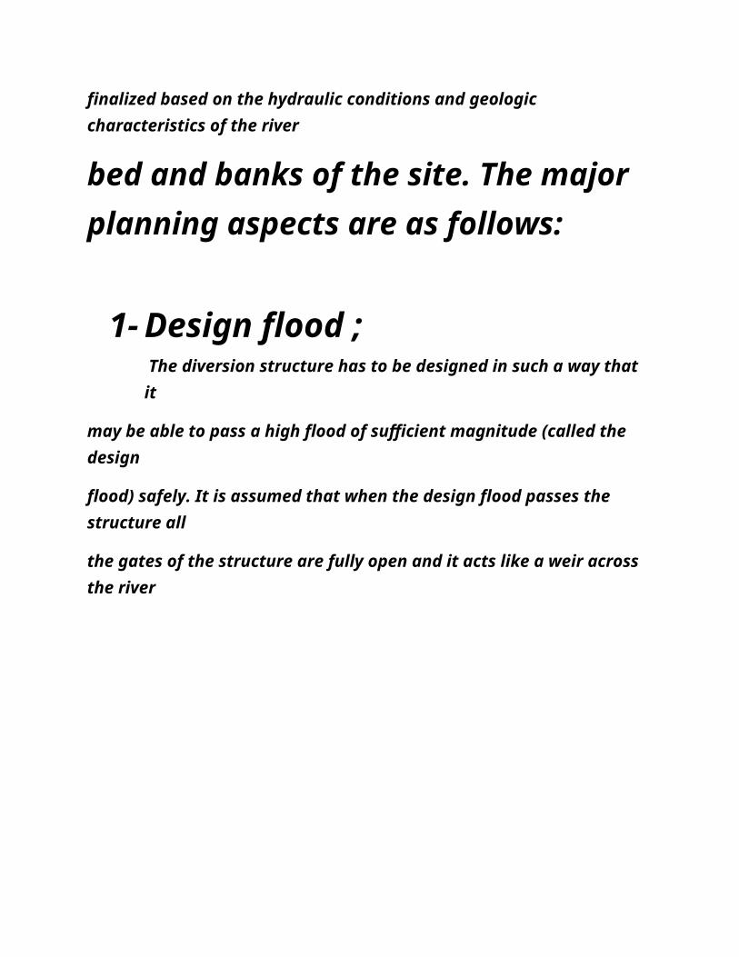
with only the obstruction of the piers between the abutments.
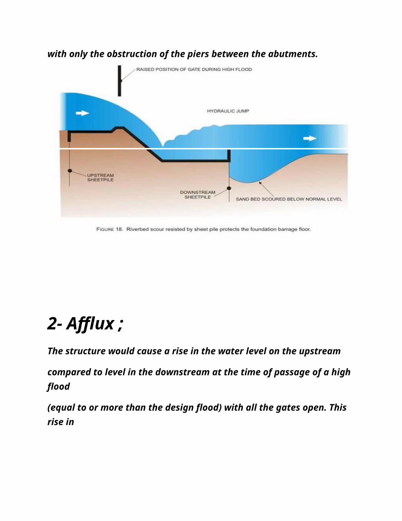
2- Afflux ;
The structure would cause a rise in the water level on the upstream
compared to level in the downstream at the time of passage of a high flood
(equal to or more than the design flood) with all the gates open. This rise in
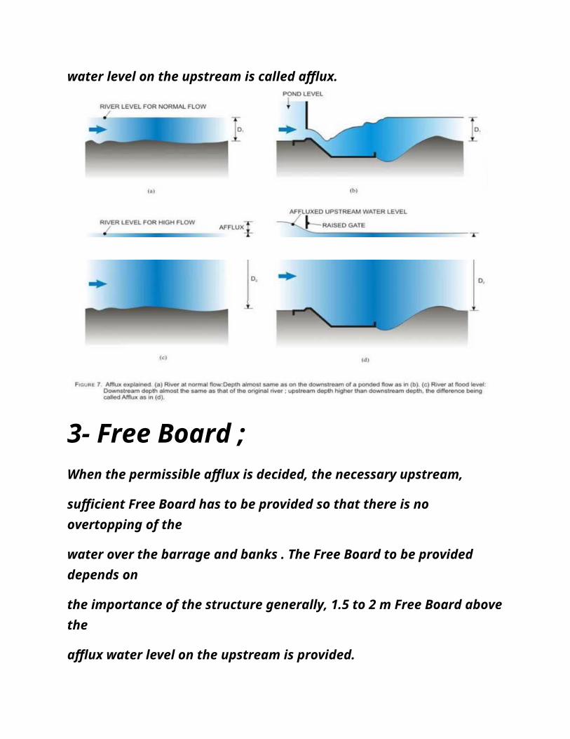
water level on the upstream is called afflux.
3- Free Board ;
When the permissible afflux is decided, the necessary upstream,
sufficient Free Board has to be provided so that there is no overtopping of the
water over the barrage and banks . The Free Board to be provided depends on
the importance of the structure generally, 1.5 to 2 m Free Board abovethe
afflux water level on the upstream is provided.
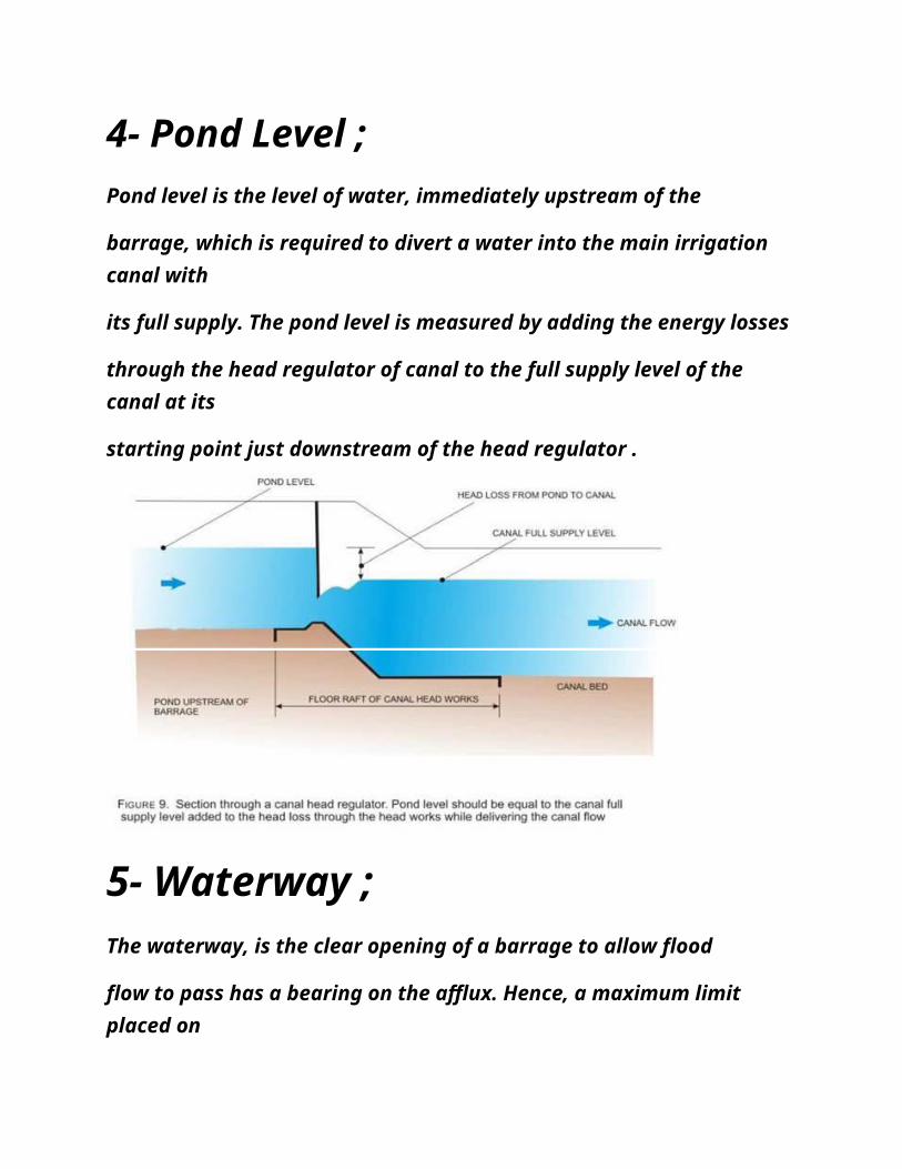
4- Pond Level ; Pond level is the level of water, immediately upstream of the
barrage, which is required to divert a water into the main irrigation canal with
its full supply. The pond level is measured by adding the energy losses
through the head regulator of canal to the full supply level of the canal at its
starting point just downstream of the head regulator .
5- Waterway ;
The waterway, is the clear opening of a barrage to allow flood
flow to pass has a bearing on the afflux. Hence, a maximum limit placed on
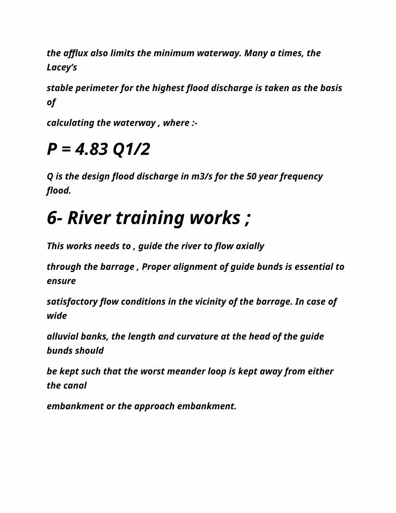
the afflux also limits the minimum waterway. Many a times, the Lacey’s
stable perimeter for the highest flood discharge is taken as the basis of
calculating the waterway , where :-
P = 4.83 Q1/2Q is the design flood discharge in m3/s for the 50 year frequency flood.
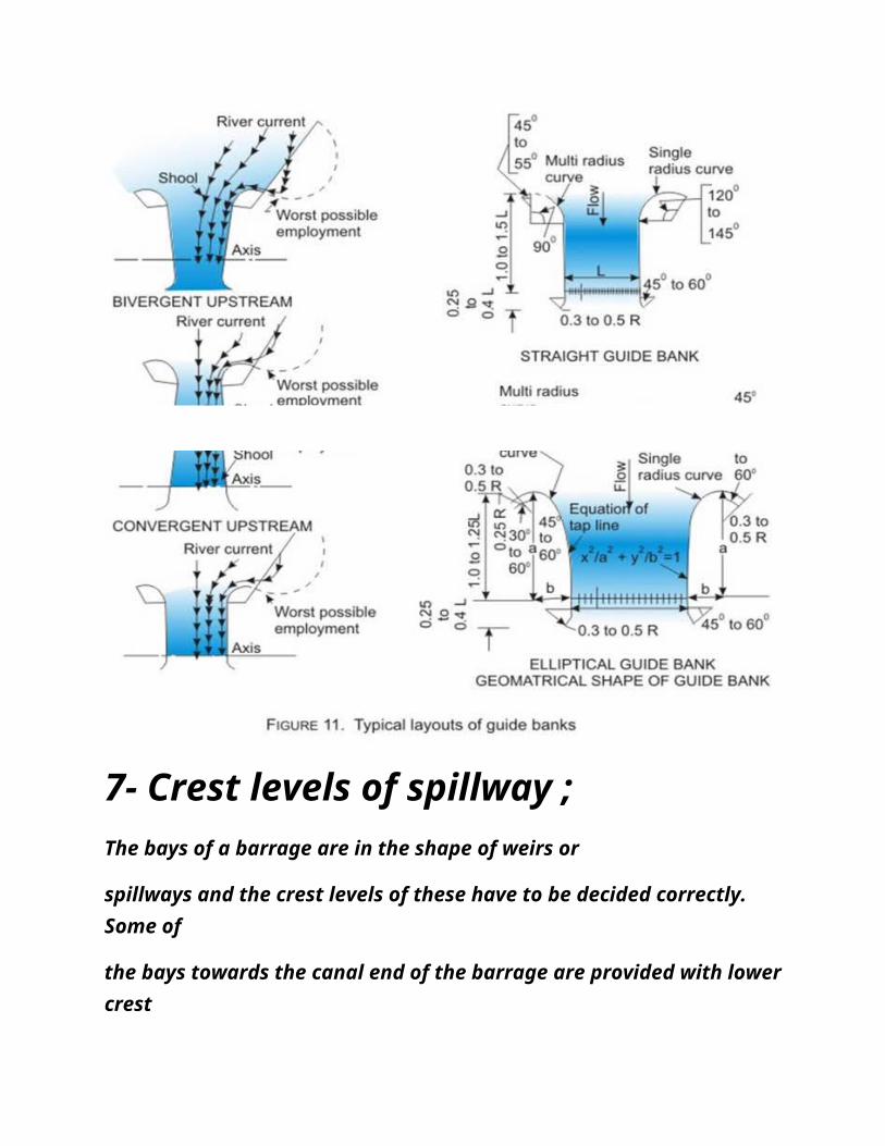
6- River training works ;
This works needs to , guide the river to flow axially
through the barrage , Proper alignment of guide bunds is essential to ensure
satisfactory flow conditions in the vicinity of the barrage. In case of wide
alluvial banks, the length and curvature at the head of the guide bunds should
be kept such that the worst meander loop is kept away from either the canal
embankment or the approach embankment.
7- Crest levels of spillway ;
The bays of a barrage are in the shape of weirs or
spillways and the crest levels of these have to be decided correctly. Some of
the bays towards the canal end of the barrage are provided with lowercrest
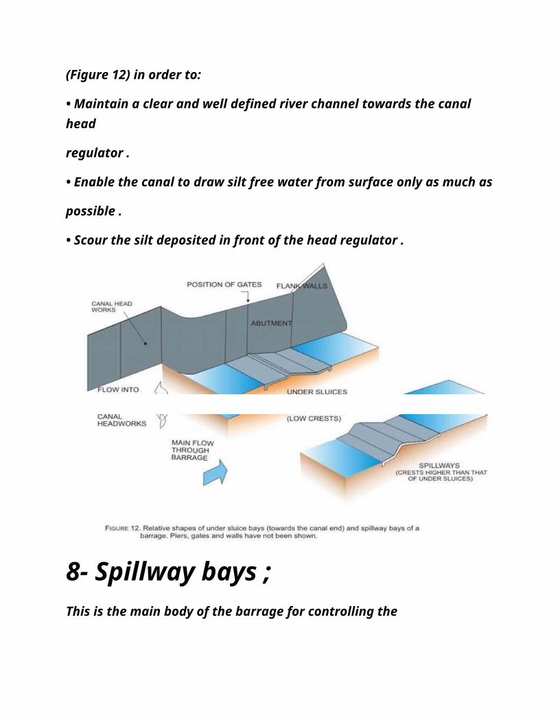
(Figure 12) in order to:
• Maintain a clear and well defined river channel towards the canal head
regulator .
• Enable the canal to draw silt free water from surface only as much as
possible .
• Scour the silt deposited in front of the head regulator .
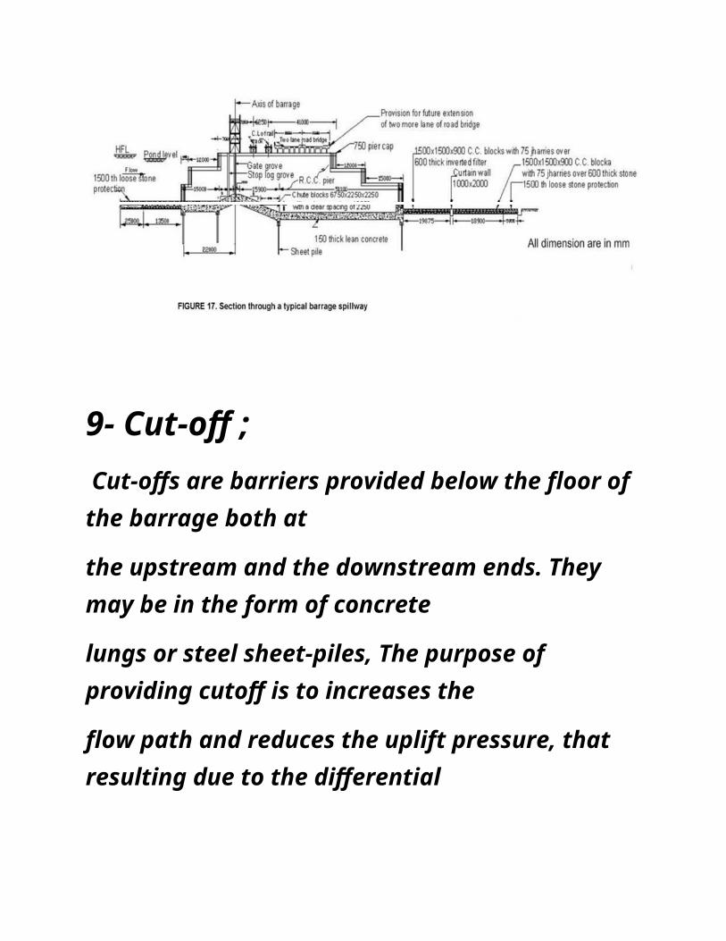
8- Spillway bays ;
This is the main body of the barrage for controlling the
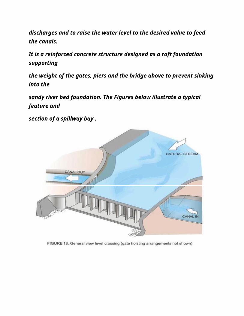
discharges and to raise the water level to the desired value to feed the canals.
It is a reinforced concrete structure designed as a raft foundation supporting
the weight of the gates, piers and the bridge above to prevent sinking into the
sandy river bed foundation. The Figures below illustrate a typical feature and
section of a spillway bay .
9- Cut-off ; Cut-offs are barriers provided below the floor of the barrage both at
the upstream and the downstream ends. They may be in the form of concrete
lungs or steel sheet-piles, The purpose of providing cutoff is to increases the
flow path and reduces the uplift pressure, that resulting due to the differential
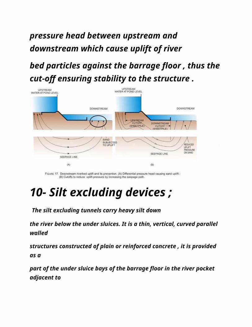
pressure head between upstream and downstream which cause uplift of river
bed particles against the barrage floor , thus the cut-off ensuring stability to the structure .
10- Silt excluding devices ; The silt excluding tunnels carry heavy silt down
the river below the under sluices. It is a thin, vertical, curved parallel walled
structures constructed of plain or reinforced concrete , it is provided as a
part of the under sluice bays of the barrage floor in the river pocket adjacent to
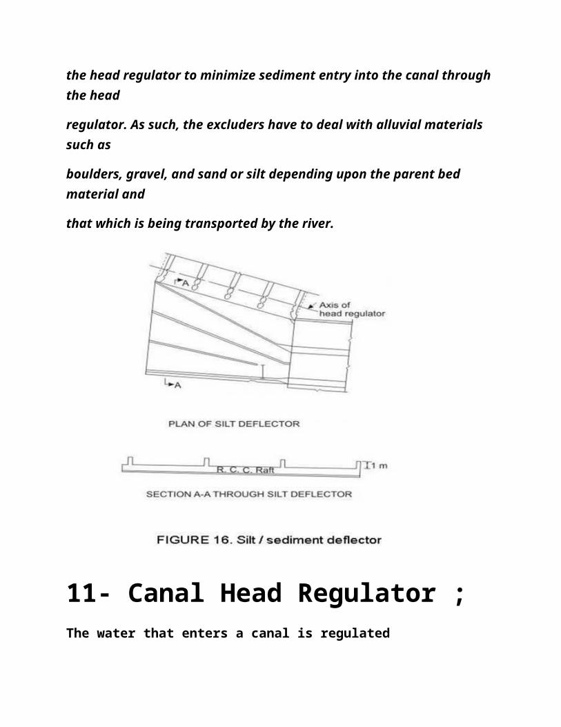
the head regulator to minimize sediment entry into the canal through the head
regulator. As such, the excluders have to deal with alluvial materials such as
boulders, gravel, and sand or silt depending upon the parent bed material and
that which is being transported by the river.
11- Canal Head Regulator ;
The water that enters a canal is regulated
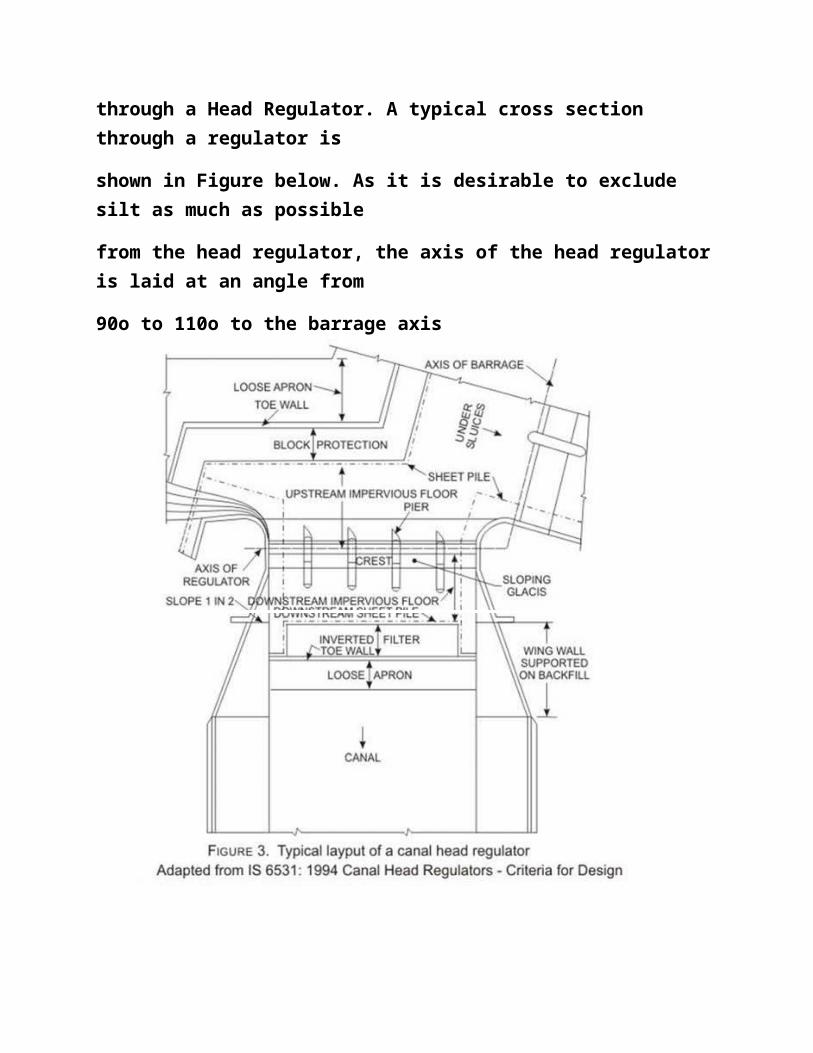
through a Head Regulator. A typical cross section through a regulator is
shown in Figure below. As it is desirable to exclude silt as much as possible
from the head regulator, the axis of the head regulatoris laid at an angle from
90o to 110o to the barrage axis
Related Documents