WHITE PAPER 7 PRIME STEPS TO CREATE MODULE LAYOUT FOR ROOFTOP PROJECTS

7 prime steps to create module layout for rooftop projects
Jul 19, 2015
Welcome message from author
This document is posted to help you gain knowledge. Please leave a comment to let me know what you think about it! Share it to your friends and learn new things together.
Transcript
WHITE PAPER
7 PRIME STEPS TO CREATE MODULE LAYOUT FOR ROOFTOP PROJECTS
BEST PRACTICES FOR CREATING A MODULE LAYOUT FOR ROOFTOP PROJECTS 2
INTRODUCTION Creating a layout is probably the first step for those who aspire to go solar and
installing photovoltaic. With increase in PV electricity growth, layout planning has evolved and improved, this paper
highlights the ways to create optimized layout for rooftop solar plant. The document lays down quantifiable steps to be followed in creating a module layout for rooftops.
Steps involved in creating a layout:
1. Type of Roof assessment
2. Orientation of the building
3. Shadow objects identification, analysis & plotting
4. Optimum Tilt & Pitch for the Roof
5. Module placement in the shadow free area
6. Yield Generation report
7. Final optimized layout
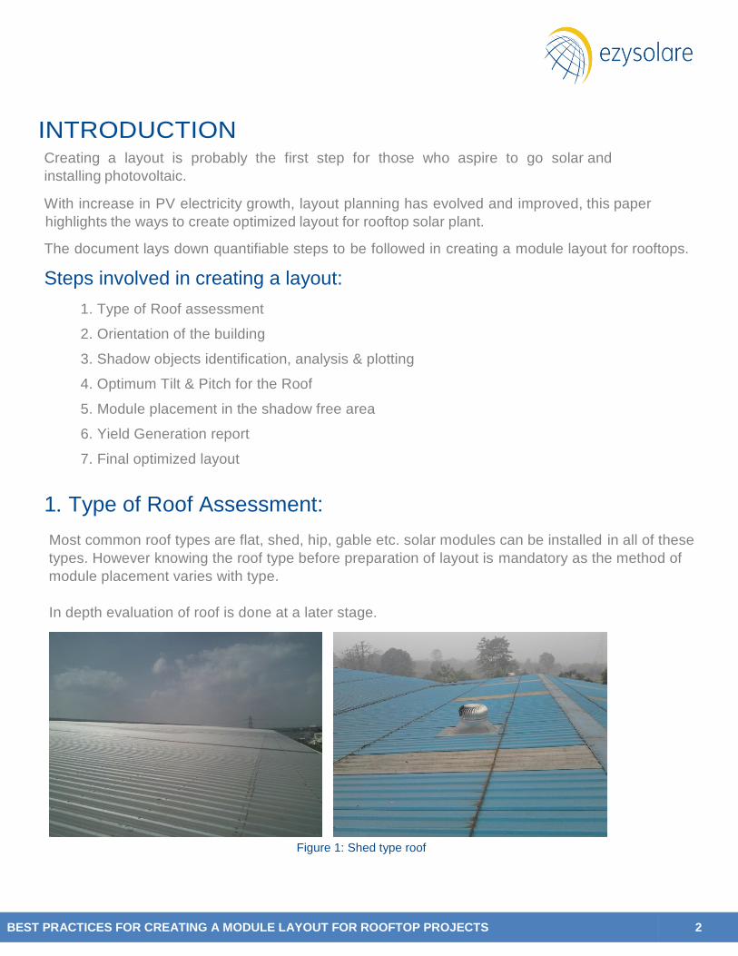
1. Type of Roof Assessment:
Most common roof types are flat, shed, hip, gable etc. solar modules can be installed in all of these
types. However knowing the roof type before preparation of layout is mandatory as the method of
module placement varies with type.
In depth evaluation of roof is done at a later stage.
Figure 1: Shed type roof

BEST PRACTICES FOR CREATING A MODULE LAYOUT FOR ROOFTOP PROJECTS 3
Figure 2: Flat type roof
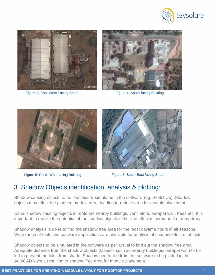
2. Orientation of the building:
Orientation of the building is to be considered in the module layout, as arrangement of module south
facing or along the direction of the building has direct impact on the generation. In northern
hemisphere orientating the modules towards south will give maximum generation.
Below table gives clear idea of generation impact with examples when module arrangement
deviates from south with respect to location of site.
Location in India South East Facing South West Facing East Facing West Facing
Southern 1% 1% 3-4% 3-4%
Western 3-4% 4-5% 13-14% 14-15%
Eastern 2-3% 3-4% 9-10% 10-11%
Northern 4-5% 5-6% 17-18% 18-19%
*Approx. percentage difference in values compared to south facing is indicated in the above table
for India.
For buildings with non-south facing orientation, if the modules are placed south then the capacity of
the system might reduce.
BEST PRACTICES FOR CREATING A MODULE LAYOUT FOR ROOFTOP PROJECTS 4
Figure 6: South-East facing Shed
Figure 3: East-West Facing Shed Figure 4: South-facing Building
Figure 5: South-West facing Building
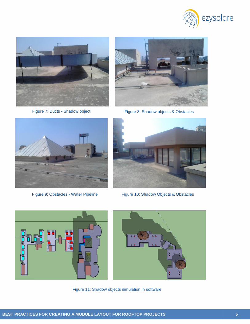
3. Shadow Objects identification, analysis & plotting:
Shadow causing objects to be identified & simulated in the software (eg. SketchUp). Shadow
objects may affect the planned module area, leading to reduce area for module placement.
Usual shadow causing objects in roofs are nearby buildings, ventilators, parapet wall, trees etc. It is
important to realize the potential of the shadow objects either the effect is permanent or temporary.
Shadow analysis is done to find the shadow free area for the most daytime hours in all seasons.
Wide range of tools and software applications are available for analysis of shadow effect of objects.
Shadow objects to be simulated in the software as per actual to find out the shadow free area.
Adequate distance from the shadow objects (Objects such as nearby buildings, parapet wall) to be
left to prevent modules from shade. Shadow generated from the software to be plotted in the
AutoCAD layout, resulting to shadow free area for module placement.
BEST PRACTICES FOR CREATING A MODULE LAYOUT FOR ROOFTOP PROJECTS 5
Figure 8: Shadow objects & Obstacles
Figure 7: Ducts - Shadow object
Figure 9: Obstacles - Water Pipeline Figure 10: Shadow Objects & Obstacles
Figure 11: Shadow objects simulation in software
BEST PRACTICES FOR CREATING A MODULE LAYOUT FOR ROOFTOP PROJECTS 6
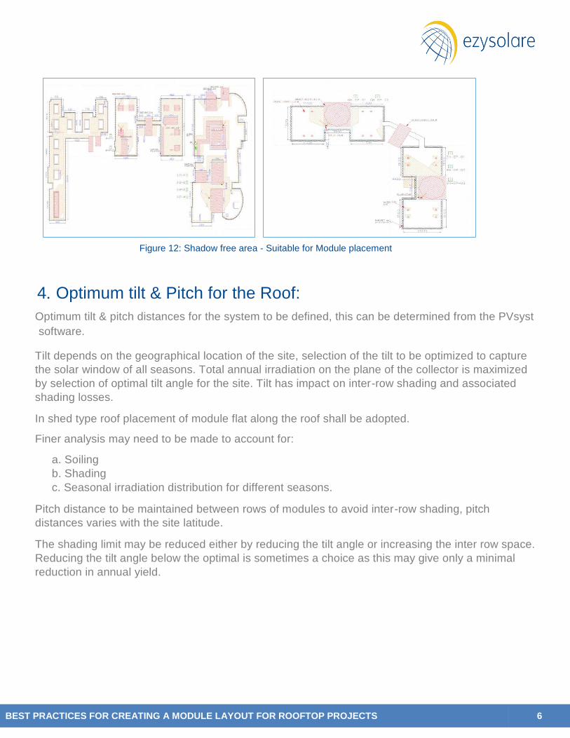
Figure 12: Shadow free area - Suitable for Module placement
4. Optimum tilt & Pitch for the Roof:
Optimum tilt & pitch distances for the system to be defined, this can be determined from the PVsyst
software.
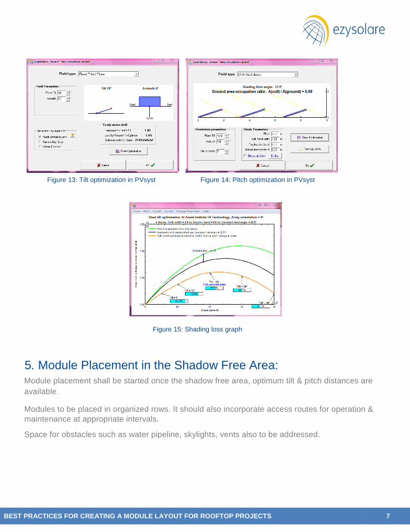
Tilt depends on the geographical location of the site, selection of the tilt to be optimized to capture
the solar window of all seasons. Total annual irradiation on the plane of the collector is maximized
by selection of optimal tilt angle for the site. Tilt has impact on inter-row shading and associated
shading losses. In shed type roof placement of module flat along the roof shall be adopted.
Finer analysis may need to be made to account for:
a. Soiling
b. Shading
c. Seasonal irradiation distribution for different seasons. Pitch distance to be maintained between rows of modules to avoid inter-row shading, pitch
distances varies with the site latitude. The shading limit may be reduced either by reducing the tilt angle or increasing the inter row space.
Reducing the tilt angle below the optimal is sometimes a choice as this may give only a minimal
reduction in annual yield.
BEST PRACTICES FOR CREATING A MODULE LAYOUT FOR ROOFTOP PROJECTS 7
Figure 13: Tilt optimization in PVsyst Figure 14: Pitch optimization in PVsyst
Figure 15: Shading loss graph
5. Module Placement in the Shadow Free Area: Module placement shall be started once the shadow free area, optimum tilt & pitch distances are
available.
Modules to be placed in organized rows. It should also incorporate access routes for operation &
maintenance at appropriate intervals. Space for obstacles such as water pipeline, skylights, vents also to be addressed.

BEST PRACTICES FOR CREATING A MODULE LAYOUT FOR ROOFTOP PROJECTS 8
Figure 16: Module placement in Shadow free area
6. Yield Generation Report:
The capacity of the site is known after the placement of module in the shadow free area.
Yield generation report to be simulated to get the annual energy generation, losses associated with
various configurations of tilt angle, orientation and row spacing and to obtain an economic
optimization.
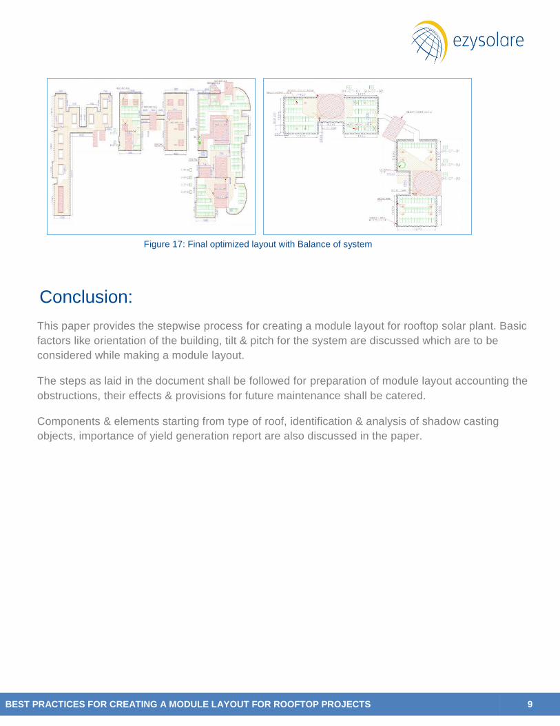
7. Final Optimized Layout:
Final optimal layout to be prepared considering the shadow free space availability, economically
optimized module arrangement with balance of systems.
Balance of system consists of Inverters, lightning protection system, weather monitoring station,
earthing connection scheme etc.
Layout to be planned with minimal cable runs and associated electrical losses, also considering
access routes and sufficient space between rows to allow movement for maintenance purposes.
BEST PRACTICES FOR CREATING A MODULE LAYOUT FOR ROOFTOP PROJECTS 9
Figure 17: Final optimized layout with Balance of system
Conclusion:
This paper provides the stepwise process for creating a module layout for rooftop solar plant. Basic
factors like orientation of the building, tilt & pitch for the system are discussed which are to be
considered while making a module layout.
The steps as laid in the document shall be followed for preparation of module layout accounting the
obstructions, their effects & provisions for future maintenance shall be catered.
Components & elements starting from type of roof, identification & analysis of shadow casting
objects, importance of yield generation report are also discussed in the paper.
Related Documents


