State Machine Design

State Machine Design Synchronous State-Machine Design The design of a synchronous state machine starts from a word description or specification and results.
Dec 14, 2015
Welcome message from author
This document is posted to help you gain knowledge. Please leave a comment to let me know what you think about it! Share it to your friends and learn new things together.
Transcript
State Machine Design
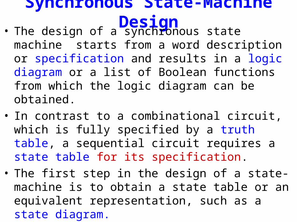
Synchronous State-Machine Design• The design of a synchronous state machine starts from a
word description or specification and results in a logic diagram or a list of Boolean functions from which the logic diagram can be obtained.
• In contrast to a combinational circuit, which is fully specified by a truth table, a sequential circuit requires a state table for its specification.
• The first step in the design of a state-machine is to obtain a state table or an equivalent representation, such as a state diagram.
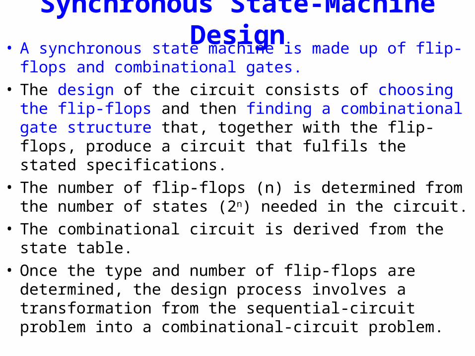
Synchronous State-Machine Design• A synchronous state machine is made up of flip-flops and
combinational gates.• The design of the circuit consists of choosing the flip-flops
and then finding a combinational gate structure that, together with the flip-flops, produce a circuit that fulfils the stated specifications.
• The number of flip-flops (n) is determined from the number of states (2n) needed in the circuit.
• The combinational circuit is derived from the state table.• Once the type and number of flip-flops are determined, the
design process involves a transformation from the sequential-circuit problem into a combinational-circuit problem.
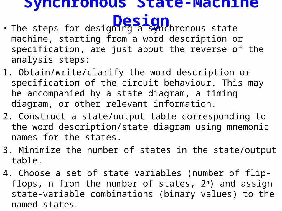
Synchronous State-Machine Design• The steps for designing a synchronous state machine,
starting from a word description or specification, are just about the reverse of the analysis steps:
1. Obtain/write/clarify the word description or specification of the circuit behaviour. This may be accompanied by a state diagram, a timing diagram, or other relevant information.
2. Construct a state/output table corresponding to the word description/state diagram using mnemonic names for the states.
3. Minimize the number of states in the state/output table.
4. Choose a set of state variables (number of flip-flops, n from the number of states, 2n) and assign state-variable combinations (binary values) to the named states.

Synchronous State-Machine Design1. Substitute the state-variable combinations (binary values)
into the state/output table to create a transition/output table.
2. Choose the type of flip-flop (e.g., D, or JK) for the state memory.
3. Derive excitation equations from the transition table that tells the desired next state for each state/input combination.
4. Derive output equations from the transition/output table that tells the desired output for each state/input combination.
4. Draw a logic diagram that shows the state-variable storage elements and realizes the required excitation and output equations.
4. Or, realize the equations directly in a programmable logic device.
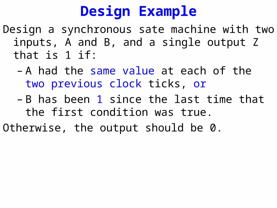
Design ExampleDesign a synchronous sate machine with two inputs, A and B,
and a single output Z that is 1 if:– A had the same value at each of the two previous clock
ticks, or – B has been 1 since the last time that the first condition
was true.
Otherwise, the output should be 0.
design specificationThe meaning of this design specification might not be clear to
you and also might be ambiguous.
As a designer, you should rewrite the specification to remove the ambiguity and provide a clear description of requirements.
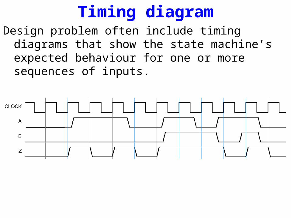
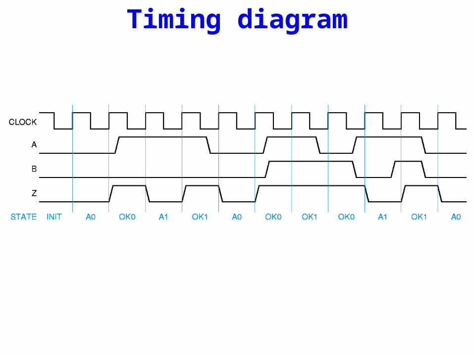
Timing diagramDesign problem often include timing diagrams that show the
state machine’s expected behaviour for one or more sequences of inputs.
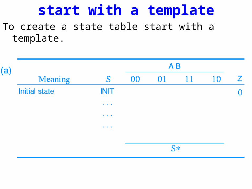
start with a templateTo create a state table start with a template.
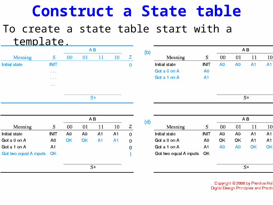
Construct a State tableTo create a state table start with a template.

Construct a State tableFrom the word description, we know that our example is a
Moore machine - its output depends only on the current state, that is, what happened in previous clock periods.
Thus in the state table template, we have added one next-state column (S*) for each possible input combination (AB) and a single column for the output (Z) values.
The order in which the input combinations are written does not affect this part of the process.
But we have written them in Karnaugh-map order (00, 01, 11, 10) to simplify the derivation of excitation equations later.

Construct a State tableWord description is not specific about what happens when this
machine is first started, so we will provide that information.
We will assume that when power is first applied to the system, the machine enters an initial state, called INIT in this example.
We write the name of the initial state (INIT) in the first row and leave room for enough rows (states) to complete the design.
The leftmost column lists the meaning of each worded state.
We can also fill in the value of Z for the INIT state; common sense says it should be 0 because there were no inputs beforehand.

Fill in the next-state entries for the INIT rowThe Z output can not be 1 until we have seen at least two inputs on A, so
we will provide two states, A0 and A1, that “remember” the value of A on the previous clock tick, as shown:
in both of these states Z is 0, since we haven’t satisfied the conditions for a 1 output yet.
The precise meaning of state A0 is “Got A=0 on the previous clock, A0 on the tick before that, and B1 at some time since the previous pair of equal A inputs.”
State A1 is defined similarly.
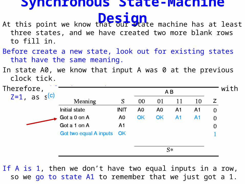
Synchronous State-Machine DesignAt this point we know that our state machine has at least three states, and
we have created two more blank rows to fill in.
Before create a new state, look out for existing states that have the same meaning.
In state A0, we know that input A was 0 at the previous clock tick.
Therefore, if A is 0 again, we go to a new state OK with Z=1, as shown:
If A is 1, then we don’t have two equal inputs in a row, so we go to state A1 to remember that we just got a 1.
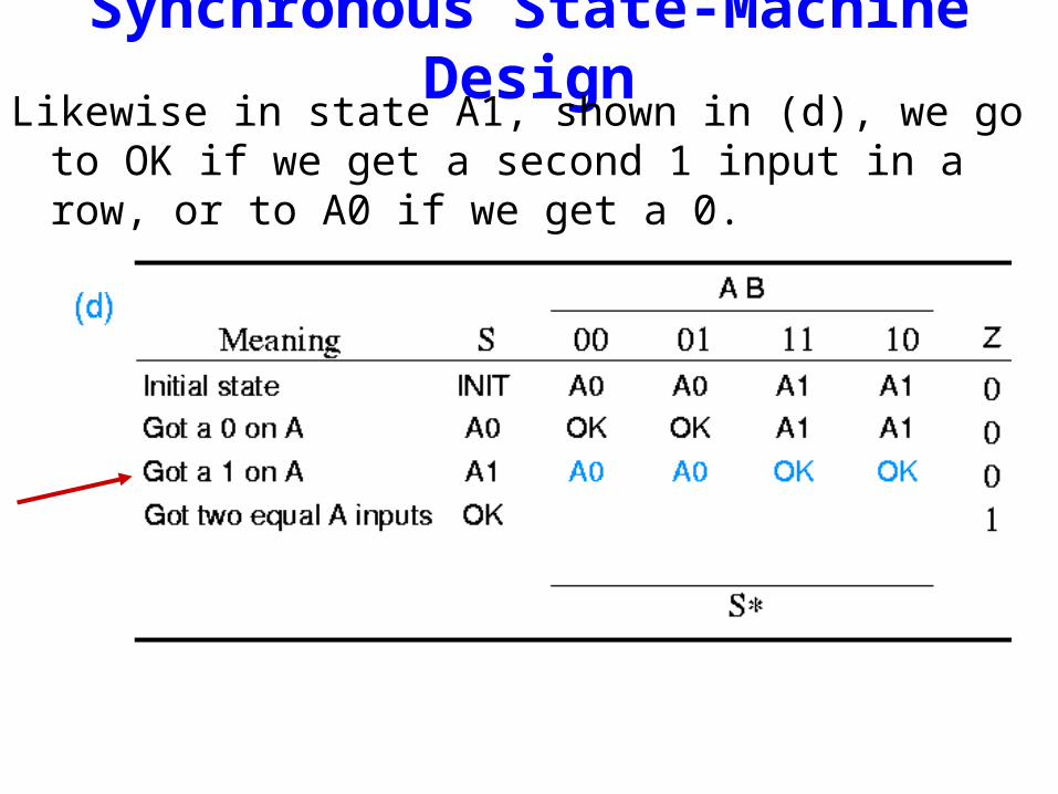
Synchronous State-Machine DesignLikewise in state A1, shown in (d), we go to OK if we get a
second 1 input in a row, or to A0 if we get a 0.
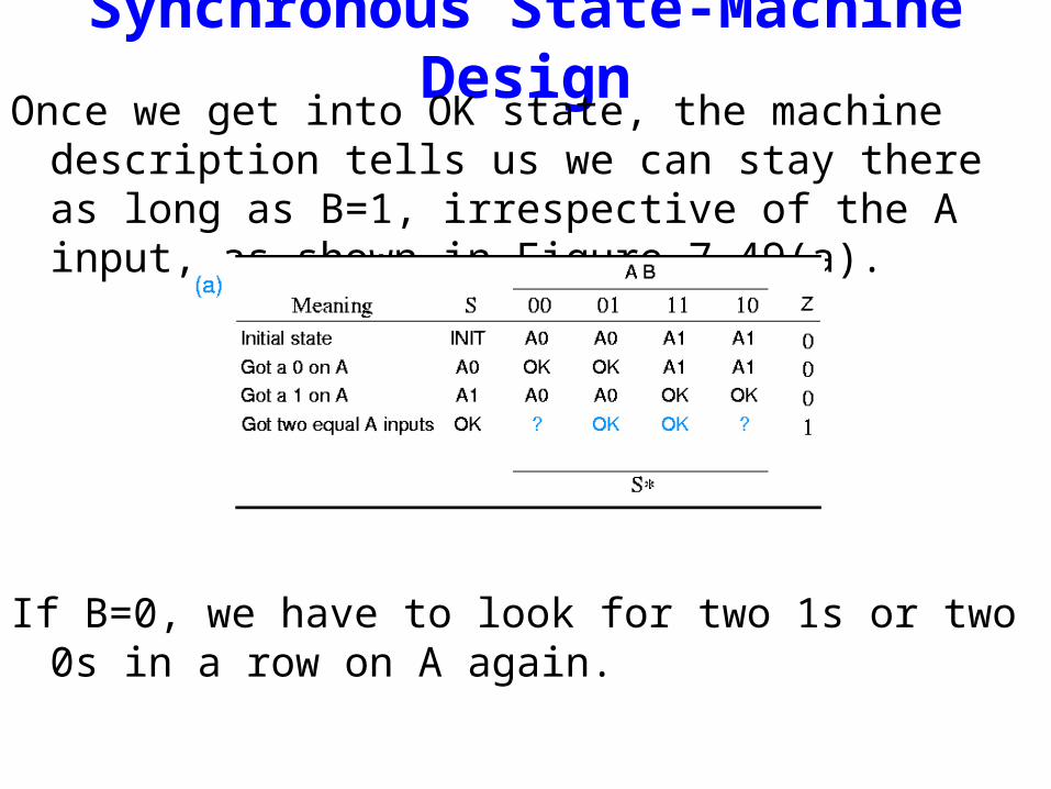
Synchronous State-Machine DesignOnce we get into OK state, the machine description tells us we
can stay there as long as B=1, irrespective of the A input, as shown in Figure 7-49(a).
If B=0, we have to look for two 1s or two 0s in a row on A again.

Synchronous State-Machine DesignHowever, we have got a little problem in this case.
The current A input may or may not be the second equal input in a row, so we may still be “OK” or we may have to go back to A0 or A1.
We defined the OK state too broadly - it does not “remember” enough to tell us which way to go.
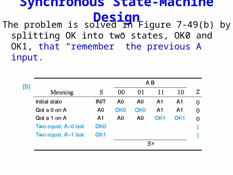
Synchronous State-Machine DesignThe problem is solved in Figure 7-49(b) by splitting OK into
two states, OK0 and OK1, that “remember” the previous A input.

Synchronous State-Machine DesignAll of the next states for OK0 and OK1 can be selected from
existing states, as shown in (c) and (d).
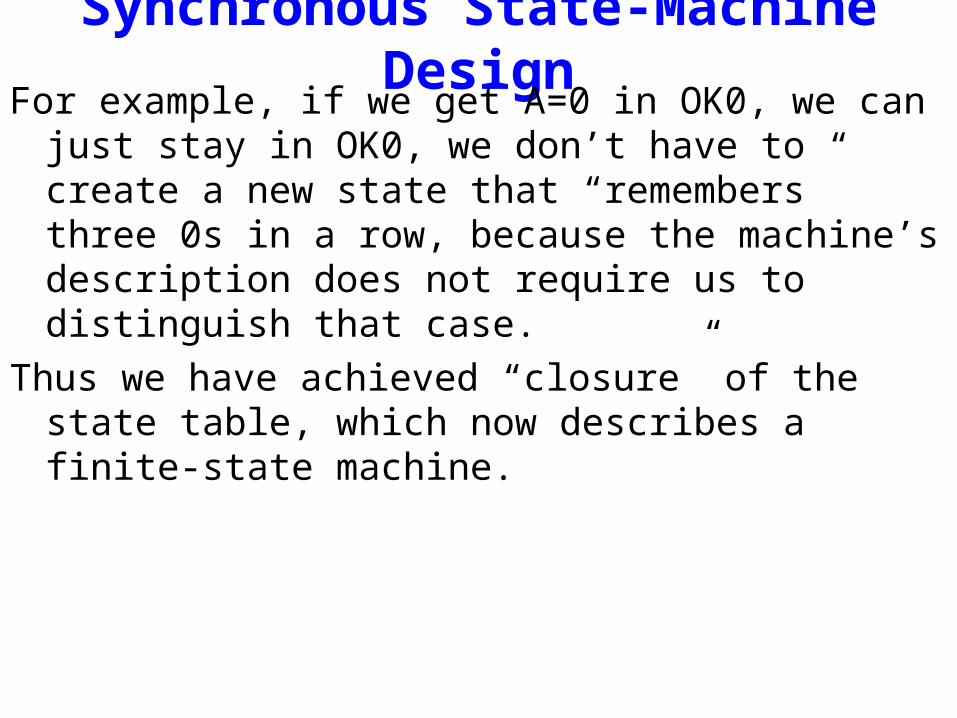
Synchronous State-Machine DesignFor example, if we get A=0 in OK0, we can just stay in OK0,
we don’t have to create a new state that “remembers” three 0s in a row, because the machine’s description does not require us to distinguish that case.
Thus we have achieved “closure” of the state table, which now describes a finite-state machine.
Timing diagram
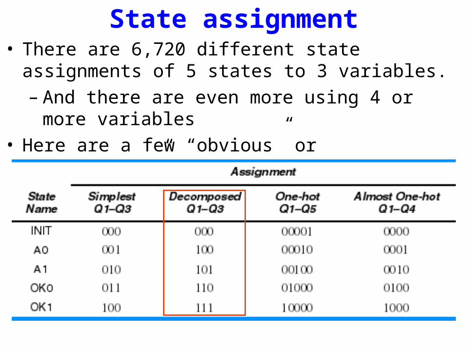
State assignment• There are 6,720 different state assignments of 5 states to 3
variables.– And there are even more using 4 or more variables
• Here are a few “obvious” or “interesting” ones:

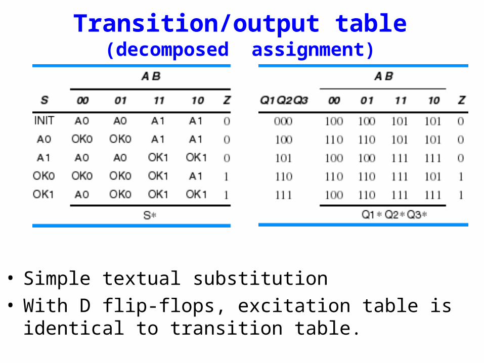
Transition/output table (decomposed assignment)
• Simple textual substitution• With D flip-flops, excitation table is identical to transition
table.
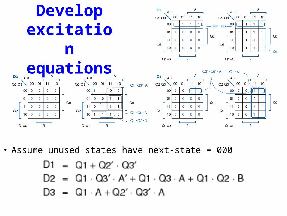
Develop excitation equations
• Assume unused states have next-state = 000

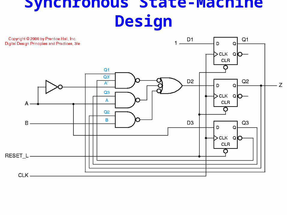
Synchronous State-Machine Design
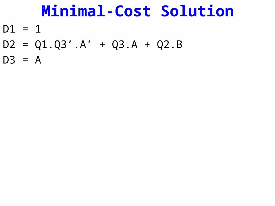
Minimal-Cost SolutionD1 = 1D2 = Q1.Q3’.A’ + Q3.A + Q2.BD3 = A
Synchronous State-Machine Design
Design a Sequence Recognizer 1101
Design a circuit that recognizes the occurrence of a particular sequence of bits, regardless of where it occurs in a longer sequence.
Design a Sequence Recognizer 1101
This sequence recognizer is to have one input X and one output Z.
The circuit is to recognize the occurrence of the sequence of bits 1101 on X by making Z equal to 1 when the previous three inputs to the circuit were 110 and current input is a 1. Otherwise, Z equals 0.
Design a Sequence Recognizer 1101
A key factor in the formulation of any state diagram is to recognize that states are used to “remember” something about the history of past inputs.
For example, for the sequence 1101, in order to be able to produce the output value 1 coincident with the final 1 in the sequence, the circuit must be in a state that “remembers” that the previous three inputs were 110.
Another exampleDigital Combionation Lock
Design a Sequence Recognizer 1101With this concept in mind, we begin to formulate the state
diagram by defining an arbitrary state - say, A - as the state in which none of the first portion of the sequence to be recognized has occurred.
If a 1 occurs on the input, since 1 is the first bit in the sequence, the event must be “remembered”, and the state after the clock pulse can not be A.
So a second state, B, is established to represent the occurrence of the first 1 in the sequence.
Further, to represent the occurrence of the first 1 in the sequence, a transition is placed from A to B labeled with a 1.
Since this is not the final 1 in the sequence 1101, its output is a 0.
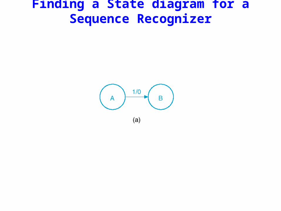
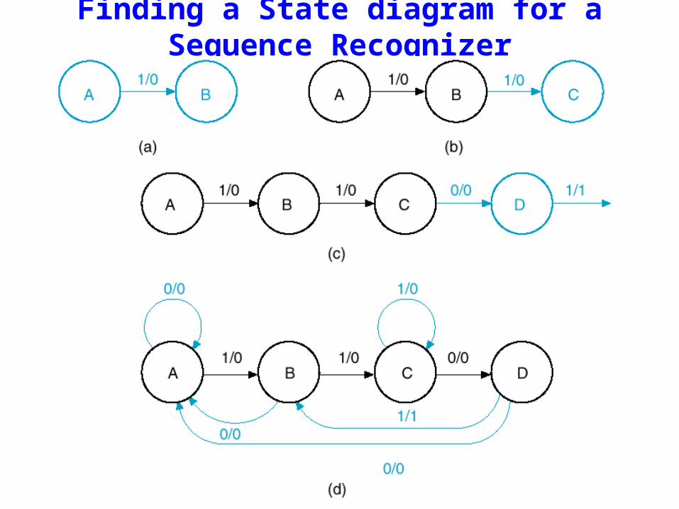
Finding a State diagram for a Sequence Recognizer
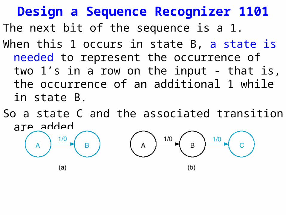
Design a Sequence Recognizer 1101The next bit of the sequence is a 1.
When this 1 occurs in state B, a state is needed to represent the occurrence of two 1’s in a row on the input - that is, the occurrence of an additional 1 while in state B.
So a state C and the associated transition are added.
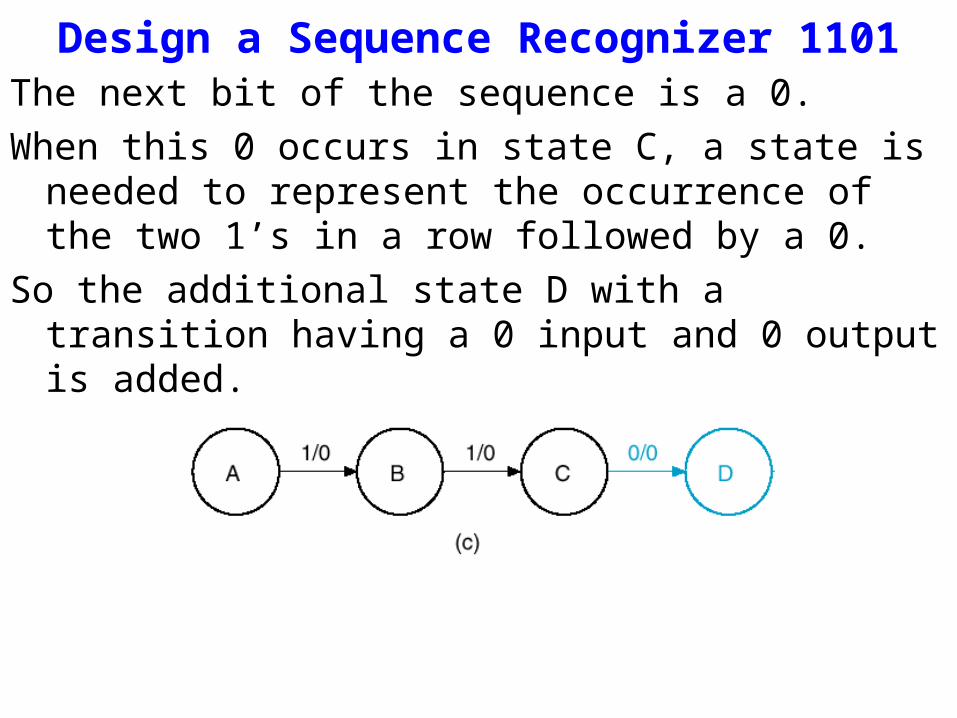
Design a Sequence Recognizer 1101The next bit of the sequence is a 0.
When this 0 occurs in state C, a state is needed to represent the occurrence of the two 1’s in a row followed by a 0.
So the additional state D with a transition having a 0 input and 0 output is added.
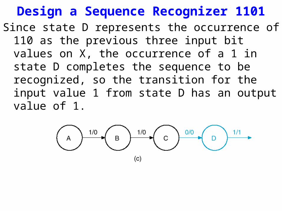
Design a Sequence Recognizer 1101Since state D represents the occurrence of 110 as the previous
three input bit values on X, the occurrence of a 1 in state D completes the sequence to be recognized, so the transition for the input value 1 from state D has an output value of 1.
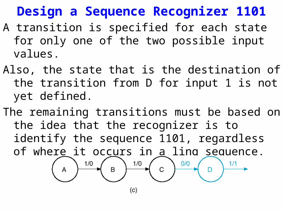
Design a Sequence Recognizer 1101A transition is specified for each state for only one of the two
possible input values.
Also, the state that is the destination of the transition from D for input 1 is not yet defined.
The remaining transitions must be based on the idea that the recognizer is to identify the sequence 1101, regardless of where it occurs in a ling sequence.
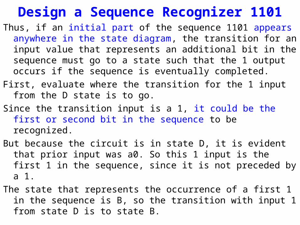
Design a Sequence Recognizer 1101Thus, if an initial part of the sequence 1101 appears anywhere in the
state diagram, the transition for an input value that represents an additional bit in the sequence must go to a state such that the 1 output occurs if the sequence is eventually completed.
First, evaluate where the transition for the 1 input from the D state is to go.
Since the transition input is a 1, it could be the first or second bit in the sequence to be recognized.
But because the circuit is in state D, it is evident that prior input was a0. So this 1 input is the first 1 in the sequence, since it is not preceded by a 1.
The state that represents the occurrence of a first 1 in the sequence is B, so the transition with input 1 from state D is to state B.
Finding a State diagram for a Sequence Recognizer
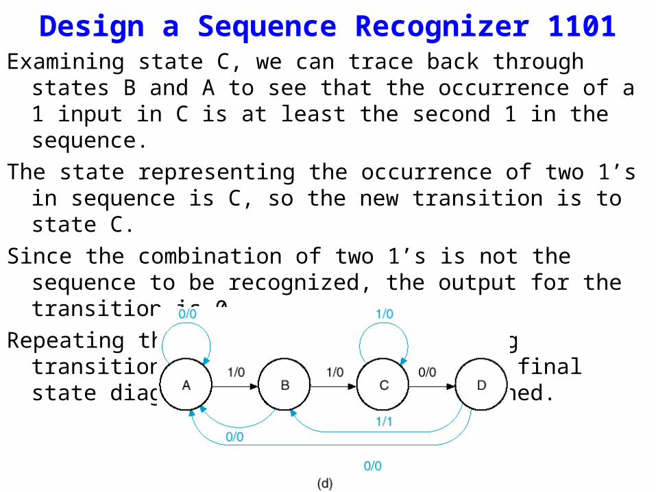
Design a Sequence Recognizer 1101Examining state C, we can trace back through states B and A to see that
the occurrence of a 1 input in C is at least the second 1 in the sequence.
The state representing the occurrence of two 1’s in sequence is C, so the new transition is to state C.
Since the combination of two 1’s is not the sequence to be recognized, the output for the transition is 0.
Repeating the same analysis for missing transitions from states B and A, the final state diagram in figure (d) is obtained.
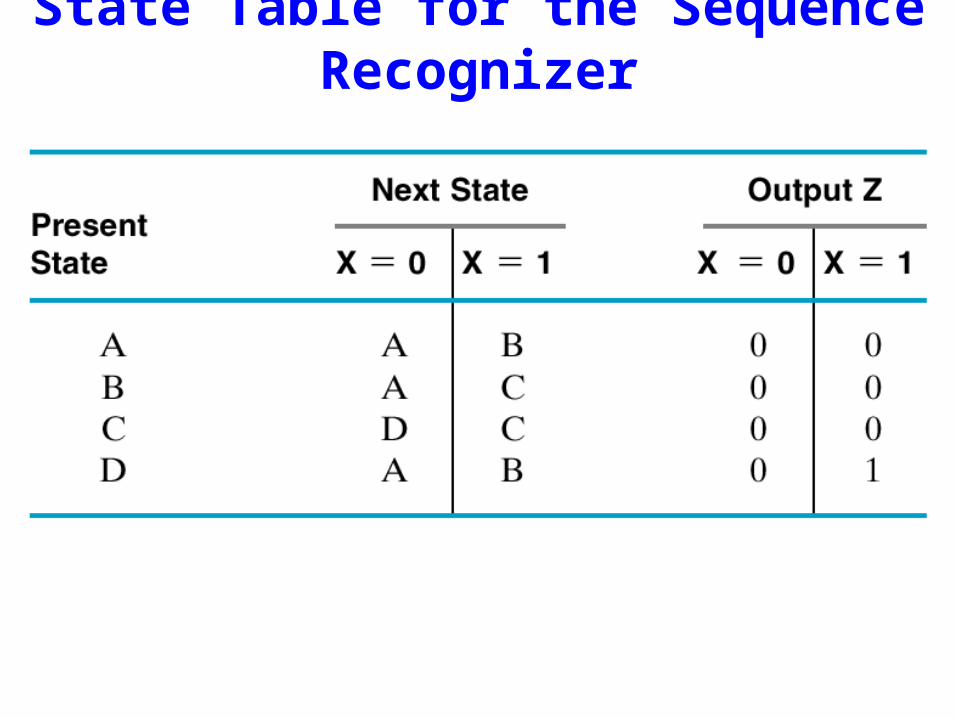
State Table for the Sequence Recognizer

Names Replaced by Binary Codes
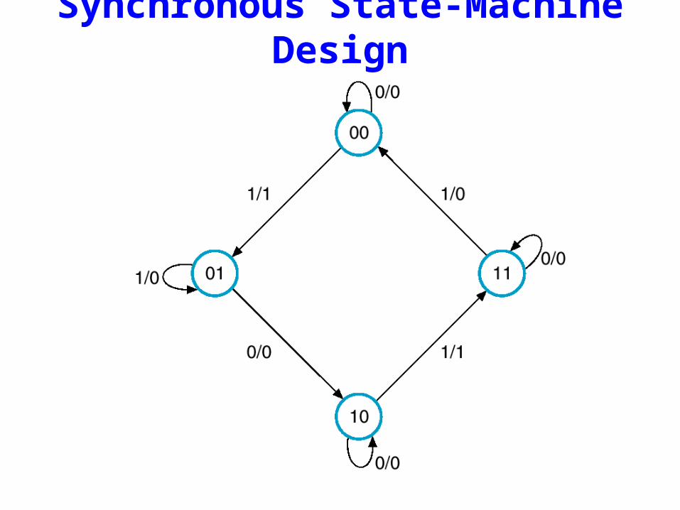
Synchronous State-Machine Design
Synchronous State-Machine Design
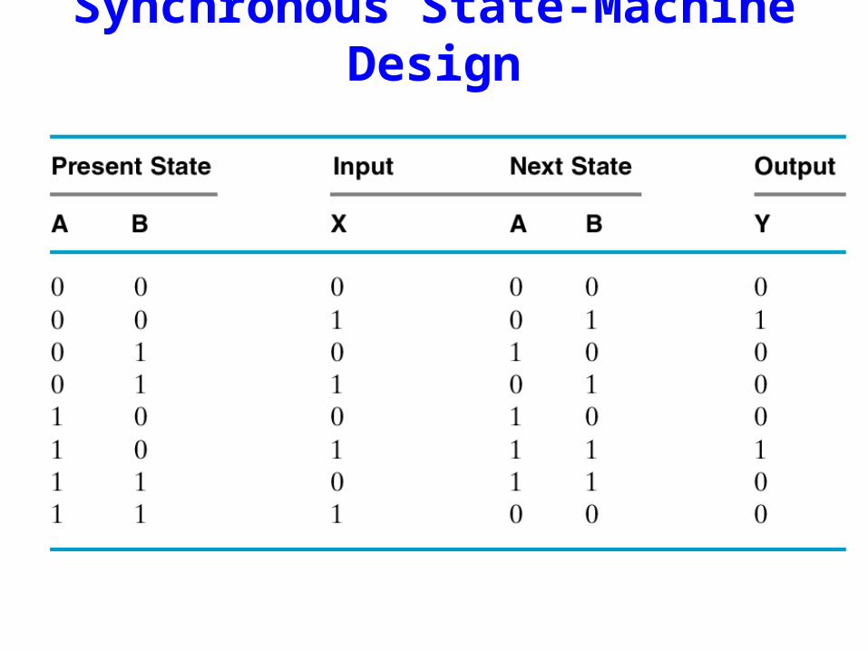
Synchronous State-Machine Design
Synchronous State-Machine Design
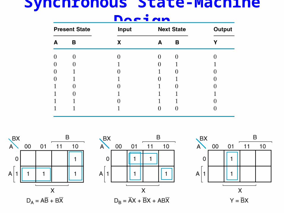
Synchronous State-Machine Design
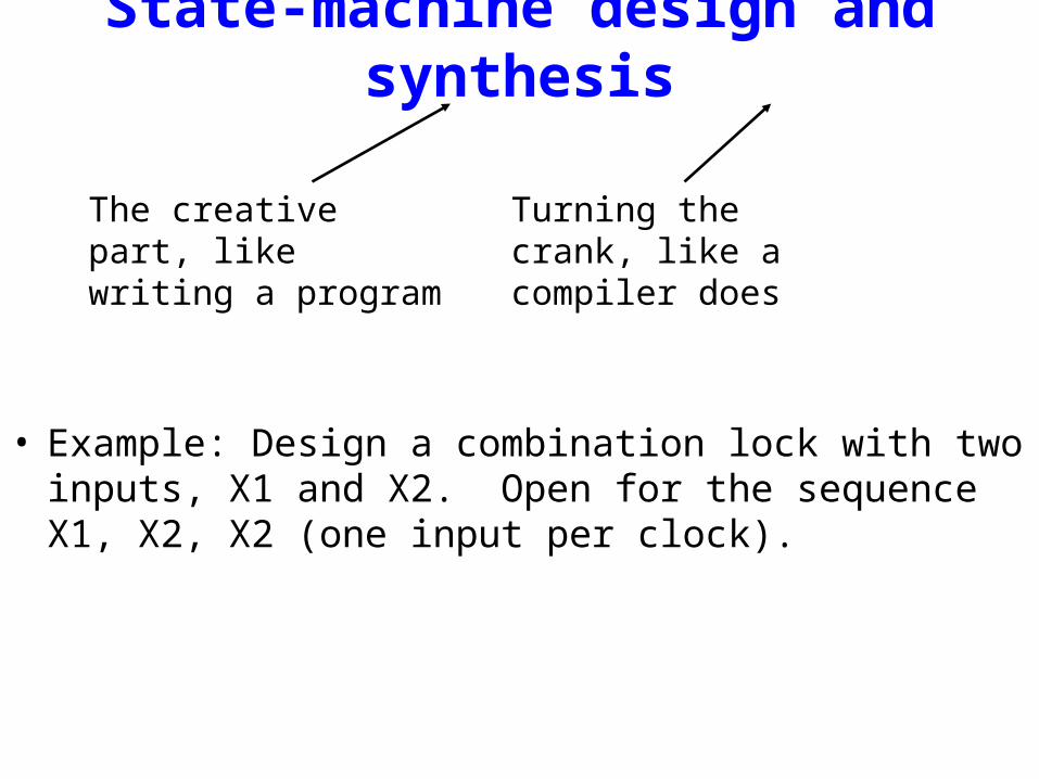
State-machine design and synthesis
• Example: Design a combination lock with two inputs, X1 and X2. Open for the sequence X1, X2, X2 (one input per clock).
The creative part, like writing a program
Turning the crank, like a compiler does

• Example: Design a combination lock with two inputs, X1 and X2. Open for the sequence X1, X2, X2 (one input per clock).
• Specification ambiguities are resolved in the state table.
State X1 X2-------------------------- -----------------------------------------------Meaning Name 00 01 10 11 UNLOCK
-------------------------- -----------------------------------------------
Start A A A B A 0
Got X1 B A C A A 0
Got X1,X2 C A D A A 0
Got X1,X2,X2 D A A B A 1(D)
(D)
(C)
(B)

State Assignment• Can minimize number of states (see text), but hardly
anyone bothers anymore.
• Need to assign state-variable combinations to states.
– Minimum number of variables for n states is log2 n
– Using more than minimum number may be advantageous in some situations, e.g., one variable per state (“one-hot”) (see text).
– Example -- 4 states, 2 state variables (Q1,Q2):
A ==> 00B ==> 01C ==> 10D ==> 11
Up to this point is “art”, the rest is just “turning the crank.”
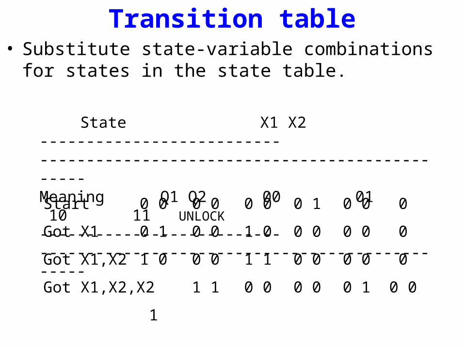
Transition table• Substitute state-variable combinations for states in the state
table.
State X1 X2-------------------------- -----------------------------------------------Meaning Q1 Q2 00 01 10 11 UNLOCK
-------------------------- -----------------------------------------------
---------------------------------------------- Q1 Q2
Start 0 0 0 0 0 0 0 1 0 0 0
Got X1 0 1 0 0 1 0 0 0 0 0 0
Got X1,X2 1 0 0 0 1 1 0 0 0 0 0
Got X1,X2,X2 1 1 0 0 0 0 0 1 0 0 1
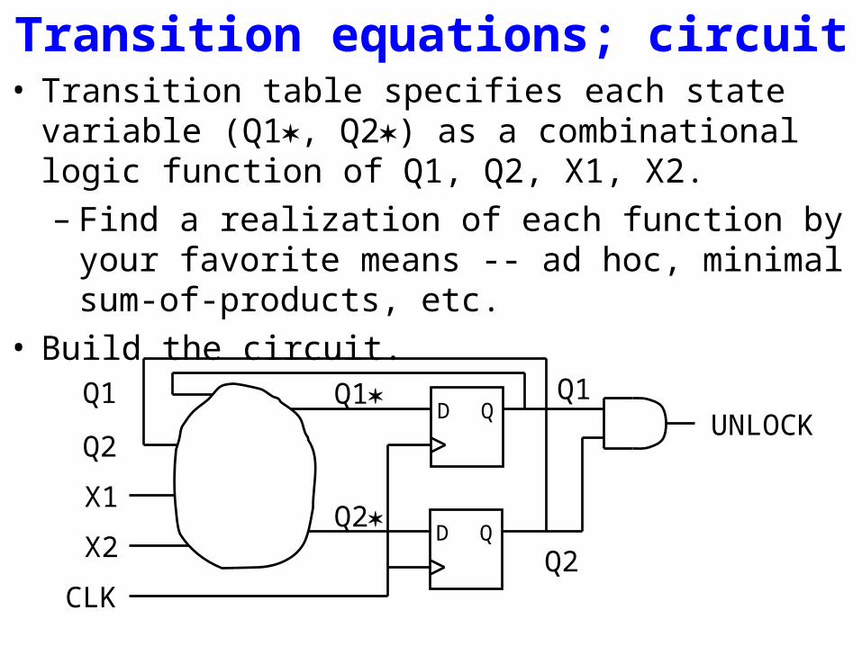
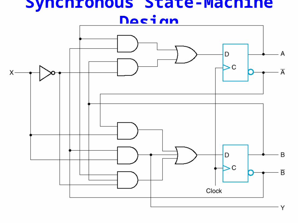
Transition equations; circuit• Transition table specifies each state variable (Q1, Q2) as
a combinational logic function of Q1, Q2, X1, X2.– Find a realization of each function by your favorite
means -- ad hoc, minimal sum-of-products, etc.• Build the circuit.
UNLOCKD Q
D Q
Q1
Q2
X1
X2
CLK
Q1
Q2
Q1
Q2
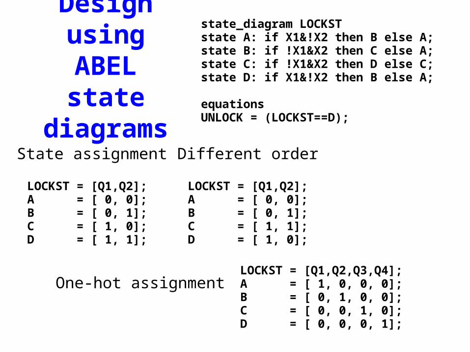
Design using ABEL state diagrams
state_diagram LOCKSTstate A: if X1&!X2 then B else A;state B: if !X1&X2 then C else A;state C: if !X1&X2 then D else C;state D: if X1&!X2 then B else A;
equationsUNLOCK = (LOCKST==D);
LOCKST = [Q1,Q2];A = [ 0, 0];B = [ 0, 1];C = [ 1, 0];D = [ 1, 1];
State assignment
LOCKST = [Q1,Q2];A = [ 0, 0];B = [ 0, 1];C = [ 1, 1];D = [ 1, 0];
Different order
LOCKST = [Q1,Q2,Q3,Q4];A = [ 1, 0, 0, 0];B = [ 0, 1, 0, 0];C = [ 0, 0, 1, 0];D = [ 0, 0, 0, 1];
One-hot assignment

Another design example (from text)• Design a machine with inputs A and B and output Z that is 1
if:– A had the same value at the two previous ticks– B has been 1 since the last time the above was true

State assignment• There are 6,720 different state assignments of 5 states to 3
variables.– And there are even more using 4 or more variables
• Here are a few “obvious” or “interesting” ones:
Transition/output table (decomposed assignment)
• Simple textual substitution• With D flip-flops, excitation table is identical to transition
table.

Develop excitation equations
• Assume unused states have next-state = 000
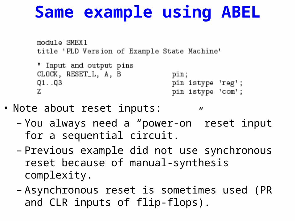
Same example using ABEL
• Note about reset inputs:– You always need a “power-on” reset input for a
sequential circuit.– Previous example did not use synchronous reset because
of manual-synthesis complexity.– Asynchronous reset is sometimes used (PR and CLR
inputs of flip-flops).

“State Diagram”
This essentially mimics the state table.
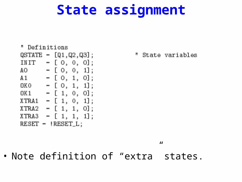
State assignment
• Note definition of “extra” states.
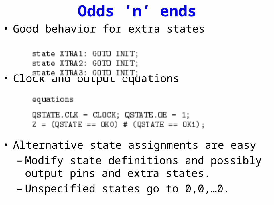
Odds ’n’ ends• Good behavior for extra states
• Clock and output equations
• Alternative state assignments are easy– Modify state definitions and possibly output pins and
extra states.– Unspecified states go to 0,0,…0.
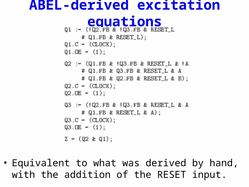
ABEL-derived excitation equations
• Equivalent to what was derived by hand, with the addition of the RESET input.
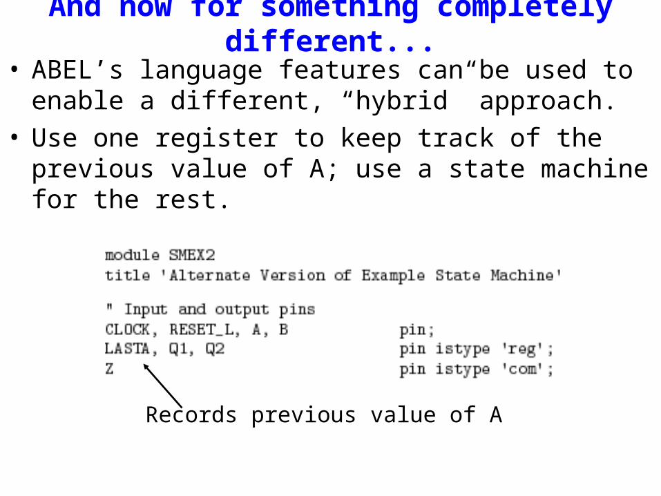
And now for something completely different...
• ABEL’s language features can be used to enable a different, “hybrid” approach.
• Use one register to keep track of the previous value of A; use a state machine for the rest.
Records previous value of A

Simpler, more natural state machine
• Really an example of “state-machine decomposition.”
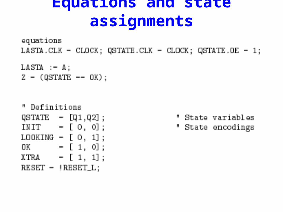
Equations and state assignments
Related Documents