Power and Electrical Engineering 2016/33 40 doi: 10.7250/pee.2016.008 ©2016 Irina Kolosok, Alexander Tikhonov, Anatolijs Mahņitko. This is an open access article licensed under the Creative Commons Attribution License (http://creativecommons.org/licenses/by/4.0). State Estimation of Electric Power Systems Including FACTS Models (SVC and STATCOM) Irina Kolosok 1 , Alexander Tikhonov 2 , Anatolijs Mahņitko 3 * 1–2 Energy System Institute SB RAS, 3 Riga Technical University Abstract – Nowadays, FACTS devices are among the most promising electrical network technologies. The typical represent- atives of parallel FACTS devices are a static synchronous compen- sator (STATCOM) and a state var compensator (SVC). The paper deals with the issues of modeling SVC and STATCOM when solv- ing the problem of power system state estimation. The algorithms developed by the authors for embedding the SVC and STATCOM models in the state estimation problem are presented. The paper considers the results of calculations using the algorithms devised for a section of the 500 kV network of the Irkutsk electric power system. A comparative analysis of the obtained results is made. Keywords – FACTS, state estimation, state var compensator, static synchronous compensator. I. INTRODUCTION Successful (reliable, quality and economical) operation of Smart Grid requires a wide range of advanced technical instru- ments and technologies that afford the opportunity to endow the network with active-adaptive qualities. In the international and national practices, there is a persis- tent trend toward adopting the power electronics controlled de- vices in the electrical networks of power systems, i.e., Flexible Alternating Current Transmission Systems (FACTS). Today, FACTS are among the most promising electrical network tech- nologies [1]–[3], which make it possible for the electrical net- work to turn from a passive facility for electricity transportation into the facility which takes an active part in control of the net- work operation. This technology provides control of interre- lated parameters, including impedances, currents, voltages, phase angles, oscillation damping at different frequencies, etc., and opens up new opportunities to control electric power sys- tems. The FACTS devices can be used to increase the transfer ca- pability, improve static and dynamic stability, and provide bet- ter power quality. Currently, there are intensive studies on the use of models of such devices in the equivalence circuits for steady state calcu- lation both in Russia [2], [4], [5] and in other countries [3], [6], [7]. To form the calculation model of the current state of the elec- tric power system, we use the state estimation methods. State estimation is the most important procedure that provides relia- ble and quality data to control electric power systems [8], [9]. The result of the state estimation is an electric power system steady state (current state) calculated on the basis of state vari- able measurements and the data on the network topology. The model of power system current state obtained from the state es- timation is used for solving the problem of operation and emer- gency control. The development of mathematical models for power system state estimation considering FACTS as well as the research into the impact of these models on the efficiency of state estimation methods is a relevant problem today. In re- cent years, such research is actively performed in other coun- tries [10]–[12]. In Russia, this research is at initial stage [13]. This paper deals with the FACTS devices, which when in- stalled at the facilities of power systems afford the possibility of controlling stability and compensating for voltage oscillations in the network, caused by frequent changes in the consumed reac- tive power. As a result, the efficiency is enhanced, the load of power plants is reduced, and the service life of the equipment is extended. These devices include static synchronous compensa- tors (STATCOM) and static var compensators (SVC). The paper presents modified state estimation algorithms for the case when STATCOMs and SVCs are included in the equivalence circuit of an electric power system. To check the efficiency of the algorithm, the comparative calculations were performed for a 500 kV network section of the Irkutsk power system with either STATOMs or SVCs installed at the nodes of the scheme. II. MODELING OF FACTS DEVICES (SVC, STATCOM) FOR STEADY STATE CALCULATION One of the FACTS devices is static var compensator (SVC). This is a multifunctional static device providing stable voltage and gradual or stage-by-stage changes in the reactive power consumed and (or) supplied by it at the buses of its connection. The static var compensator is based on the storage elements (ca- pacitances, inductances), thyristor switched capacitors (TSC), and thyristor controlled reactors (TCR). * Corresponding author. E-mail address: [email protected]

Welcome message from author
This document is posted to help you gain knowledge. Please leave a comment to let me know what you think about it! Share it to your friends and learn new things together.
Transcript

Power and Electrical Engineering 2016/33
40
doi: 10.7250/pee.2016.008
©2016 Irina Kolosok, Alexander Tikhonov, Anatolijs Mahņitko. This is an open access article licensed under the Creative Commons Attribution License (http://creativecommons.org/licenses/by/4.0).
State Estimation of Electric Power Systems Including FACTS Models (SVC and STATCOM)
Irina Kolosok1, Alexander Tikhonov2, Anatolijs Mahņitko3* 1–2 Energy System Institute SB RAS, 3 Riga Technical University
Abstract – Nowadays, FACTS devices are among the most promising electrical network technologies. The typical represent-atives of parallel FACTS devices are a static synchronous compen-sator (STATCOM) and a state var compensator (SVC). The paper deals with the issues of modeling SVC and STATCOM when solv-ing the problem of power system state estimation. The algorithms developed by the authors for embedding the SVC and STATCOM models in the state estimation problem are presented. The paper considers the results of calculations using the algorithms devised for a section of the 500 kV network of the Irkutsk electric power system. A comparative analysis of the obtained results is made.
Keywords – FACTS, state estimation, state var compensator, static synchronous compensator.
I. INTRODUCTION
Successful (reliable, quality and economical) operation of Smart Grid requires a wide range of advanced technical instru-ments and technologies that afford the opportunity to endow the network with active-adaptive qualities.
In the international and national practices, there is a persis-tent trend toward adopting the power electronics controlled de-vices in the electrical networks of power systems, i.e., Flexible Alternating Current Transmission Systems (FACTS). Today, FACTS are among the most promising electrical network tech-nologies [1]–[3], which make it possible for the electrical net-work to turn from a passive facility for electricity transportation into the facility which takes an active part in control of the net-work operation. This technology provides control of interre-lated parameters, including impedances, currents, voltages, phase angles, oscillation damping at different frequencies, etc., and opens up new opportunities to control electric power sys-tems.
The FACTS devices can be used to increase the transfer ca-pability, improve static and dynamic stability, and provide bet-ter power quality.
Currently, there are intensive studies on the use of models of such devices in the equivalence circuits for steady state calcu-lation both in Russia [2], [4], [5] and in other countries [3], [6], [7].
To form the calculation model of the current state of the elec-tric power system, we use the state estimation methods. State estimation is the most important procedure that provides relia-ble and quality data to control electric power systems [8], [9]. The result of the state estimation is an electric power system steady state (current state) calculated on the basis of state vari-able measurements and the data on the network topology. The model of power system current state obtained from the state es-timation is used for solving the problem of operation and emer-gency control. The development of mathematical models for power system state estimation considering FACTS as well as the research into the impact of these models on the efficiency of state estimation methods is a relevant problem today. In re-cent years, such research is actively performed in other coun-tries [10]–[12]. In Russia, this research is at initial stage [13].
This paper deals with the FACTS devices, which when in-stalled at the facilities of power systems afford the possibility of controlling stability and compensating for voltage oscillations in the network, caused by frequent changes in the consumed reac-tive power. As a result, the efficiency is enhanced, the load of power plants is reduced, and the service life of the equipment is extended. These devices include static synchronous compensa-tors (STATCOM) and static var compensators (SVC).
The paper presents modified state estimation algorithms for the case when STATCOMs and SVCs are included in the equivalence circuit of an electric power system. To check the efficiency of the algorithm, the comparative calculations were performed for a 500 kV network section of the Irkutsk power system with either STATOMs or SVCs installed at the nodes of the scheme.
II. MODELING OF FACTS DEVICES (SVC, STATCOM)FOR STEADY STATE CALCULATION
One of the FACTS devices is static var compensator (SVC). This is a multifunctional static device providing stable voltage and gradual or stage-by-stage changes in the reactive power consumed and (or) supplied by it at the buses of its connection. The static var compensator is based on the storage elements (ca-pacitances, inductances), thyristor switched capacitors (TSC), and thyristor controlled reactors (TCR).
* Corresponding author.E-mail address: [email protected]

Power and Electrical Engineering 2016/33
41
Fig. 1. A design of SVC: a) TSC+TCR; b) TSC; c) TCR.
In most cases, the static compensator consists of a TSC and a TCR (Fig. 1a). There can also be other combinations of the devices, for example, a separately designed TSC (Fig. 1b) or TCR (Fig. 1a). According to [3], SVC can consume or generate reactive power in order to control several specified parameters (normally voltage at some point of the network).
The working characteristic of SVC is presented in Fig. 2.
Fig. 2. Working characteristic of SVC.
Within the control range from QСmax to QLmax, the character-istic has a slope (2 % to5 %) determined by the frequency droop. Beyond the control range, the characteristic changes lin-early depending on the values of voltage U and capacitive ХСand inductive ХL reactances of SVC. Gradual control of reactive power in SVC is carried out by changing the firing angle of the thyristors in the reactor. In order to specify the admittance and maintain the specified voltage at node, it is necessary to deter-mine the angle α.
When solving the state estimation problem and calculating steady state, the reactive power of the shunt at a node i is de-termined by the equation:
H 2Hi i iQ U b (1)
and is used in the equation of nodal balance for reactive power:
HG Н ,
i
i i i ij ij
Q Q Q Q Q
(2)
where: Ui – voltage at node i; biH – the nodal shunt admittance;
QiG, QiH – reactive power generated and consumed at node i;
i
ijj
Q a sum of reactive power flows along the lines incident
to node i; ωi – a set of nodes incident to the i-th one. The authors of [3], [4], and [7] show that the SVC admit-
tance, depending on angle α, is determined by the expression:
SVC
1( ) 2 sin 2 .C
LC L
Xb X
X X
(3)
By substituting (3) to (1), we obtain an expression for the calculation of SVC reactive power:
2
SVC 2 sin 2 .i Ci L
C L
U XQ X
X X
(4)
The authors of [3] and [4] considered the SVC model, which in an explicit form includes the control angle α. In these studies, the expression for the SVC reactive power is represented as (4) (in our notations).
Linearized equations for SVC in the steady-state calculation in the k-th iteration are written as follows:
( )( ) ( )
2
0 0
.20 cos 2 1
kk k
i i
ii
L
PU
QX
(5)
The same as most of the FACTS devices, STATCOM repre-sents a thyristor-controlled reactive power source that maintains a specified voltage value by consuming or generating reactive power at the connection point without using additional external reactors or high-power capacitor banks.
STATCOMs involve either gate turnoff thyristors (GTOT) or integrated gate-commutated thyristors (IGCT), or insulated-gate bipolar transistors (IGBT).
STATCOM can include either a voltage converter or a cur-rent converter. Fig. 3 presents a simplified scheme of STAT-COM with a voltage converter.
Fig. 3. STATCOM design with a voltage converter.
TSC TCR
I s
TSC TCR
I s I s
a b c
Q
UU
UUi nst
U min
Q Lmax QCmaxAAmbmbiitt rreegguullaattiioonn
ConsumptionOutput
0
+
−
U L
CDC UDC
U
I R
bus k
E R
m a
Voltage converter
Power and Electrical Engineering 2016/33
42
The reactive power flow Q between the voltage converter and the AC electric power system is controlled by changing the value of the output voltage of the voltage converter, U. When the value U exceeds the value of voltage in line, UL, the STAT-COM operates in a capacitive mode and reactive power is gen-erated. As the value U declines below the value of voltage in line UL, STATCOM operates in an inductive mode. In this case, the reactive power is consumed. When the voltages are equal UL = U, Q = 0.
The parameters specified in STATCOM include the voltage setting Uref, voltage droop ХSТ, and ranges of change in the cur-rent Imin, Imax. Figure 4 demonstrates the STATCOM volt-am-pere characteristics.
Fig. 4. STATCOM volt-ampere characteristics.
STATCOM devices use gate-turnoff and insulated-gate bi-polar technologies with pulse-duration modulation, which makes it possible to regulate the amplitude and phase of voltage thanks to fast switchings of GTO or IGBT elements. High mod-ulation frequencies allow a considerable reduction in the level of harmonics in the output signals.
Thyristor converter of STATCOM provides an exchange of reactive power between the network phases. Thus, STATCOM can both generate and consume reactive power.
STATCOM is characterized by fast operation and small size. It can regulate both the value and the phase of voltage in the electrical network it is connected to. In the case the DC section has a storage device, STATCOM can also regulate active power.
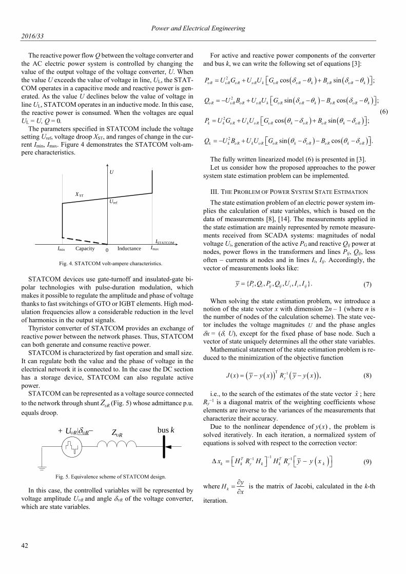
STATCOM can be represented as a voltage source connected
to the network through shunt RZ (Fig. 5) whose admittance p.u.
equals droop.
Fig. 5. Equivalence scheme of STATCOM design.
In this case, the controlled variables will be represented by voltage amplitude UR and angle R of the voltage converter, which are state variables.
For active and reactive power components of the converter and bus k, we can write the following set of equations [3]:
2 cos sin ;R R R R k R R k R R kP U G U U G B
2 sin cos ;R R R R k R R k R R kQ U B U U G B
2 cos sin ;k k R k R R k R R k RP U G U U G B
2 sin cos .k k R k R R k R R k RQ U B U U G B
(6)
The fully written linearized model (6) is presented in [3]. Let us consider how the proposed approaches to the power
system state estimation problem can be implemented.
III. THE PROBLEM OF POWER SYSTEM STATE ESTIMATION
The state estimation problem of an electric power system im-plies the calculation of state variables, which is based on the data of measurements [8], [14]. The measurements applied in the state estimation are mainly represented by remote measure-ments received from SCADA systems: magnitudes of nodal voltage Ui, generation of the active PG and reactive Qij power at nodes, power flows in the transformers and lines Pij, Qij, less often – currents at nodes and in lines Ii, Iij. Accordingly, the vector of measurements looks like:
{ , , , , , , }.i i ij ij i i ijy P Q P Q U I I (7)
When solving the state estimation problem, we introduce a notion of the state vector x with dimension 2n – 1 (where n is the number of nodes of the calculation scheme). The state vec-tor includes the voltage magnitudes U and the phase angles x = (, U), except for the fixed phase of base node. Such a vector of state uniquely determines all the other state variables.
Mathematical statement of the state estimation problem is re-duced to the minimization of the objective function
1( ) ,yJ x y y x R y y x (8)
i.e., to the search of the estimates of the state vector x̂ ; hereRy
−1 is a diagonal matrix of the weighting coefficients whose elements are inverse to the variances of the measurements that characterize their accuracy.
Due to the nonlinear dependence of )(xy , the problem is solved iteratively. In each iteration, a normalized system of equations is solved with respect to the correction vector:
11 1T Tk k y k k y kx H R H H R y y x
(9)
where k
yH
x
is the matrix of Jacobi, calculated in the k-th
iteration.
Capacity Inductance
I STATCOM
U
X ST
I min
Ur ef
Imax0
bus k Z R+ U R R −
Power and Electrical Engineering 2016/33
43
IV. MODELING OF SVC AND STATCOM IN STATE ESTIMA-
TION OF ELECTRIC POWER SYSTEM
When modeling SVC, the angle α is specified as a state vec-tor component and is determined directly in the process of solv-ing the state estimation problem.
In the calculation of corrections to the state vector x by (9), the derivative of the injection measurement Qi with respect to voltage Ui is taken equal to:
H2 .i
ijii i
ji i
QQU b
U U
When using the SVC model with the control angle α in the state estimation problem, SVC is modeled by the variable of susceptance at node i at which the SVC is installed, and α is included in the state vector x instead of Ui, which is fixed. A derivative of the injection measurement at the node with SVC with respect to αi will be equal to:
2 22( 2 2cos 2 ) (1 cos 2 ).i i L i L
i
Q U b U b
(10)
An algorithm for the calculation
1. Specify the admittance bSVC at a necessary node i,
using reference data SVCSVC 2
SVC
Qb
U .
2. Fix voltage at node i at a required value, by specify-ing it by the measurements with a zero (a very small) vari-ance. The state vector x will include αi for this node.
3. Specify the initial approximations of the vector x = x0, at which specify 0 2i for the node where the
SVC is installed; Ui0 = Uinom; for the other nodes: δi0 = 0; Ui0 = Uinom.
4. Calculate the corrections in iterations by the method of Newton, using (9). In this case, there will be one nonzero
element calculated by (9) in the column of derivatives i
i
Q
in the matrix y
x
. At node i, it is necessary to specify the
measurement of the nodal injection iQ .
STATCOM is modeled as a voltage source connected to the network through shunt RZ . The control parameters of
STATCOM (voltage RU and angle υRδ of a voltage con-
verter) represent the state vector components in state esti-mation. Therefore, such a model is easily included in the state estimation algorithm.
1. We will dwell on the calculation algorithm in more detail.
2. At node i, where voltage should be maintained con-stant, we specify a branch with a fictitious node.
3. Branch parameters: resistance R = 0 Ω, the value of reactance Х is assumed equal to a droop of the STATCOM characteristic presented in Fig. 4. In our case study, X = 0.086 Ω.
4. Fix voltage at node i at a required value by specify-ing it with the measurement with a zero (very small) vari-ance. Node i is assumed to be a transit one.
5. Fictitious node is specified by a node transit with respect to active power.
6. Make state estimation. In the process of calculation, we obtain the reactive power injection QSTATCOM at the STATCOM connection point, which is necessary to main-tain the required voltage value.
7. Check the condition: Qmin < QSTATCOM < Qmax, into which, as is shown in [5], the condition Imin < ISTATCOM < Imax can be transformed within the control range.
The condition Umin < USTATCOM < Umax is controlled when solving the problem of state estimation.
7.1. In the case condition (9) is met, we go to p. 6. 7.2. In the case condition (9) is not met, the algorithm
of considering the inequality-constraints on unmeasured variables, which is implemented in the software “Otsenka”, operates [14].
8. Exit.
V. CALCULATION RESULTS
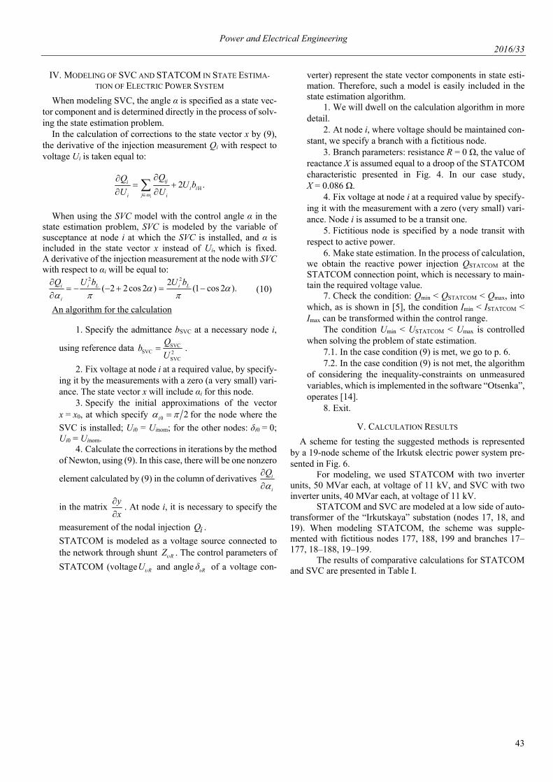
A scheme for testing the suggested methods is represented by a 19-node scheme of the Irkutsk electric power system pre-sented in Fig. 6.
For modeling, we used STATCOM with two inverter units, 50 MVar each, at voltage of 11 kV, and SVC with two inverter units, 40 MVar each, at voltage of 11 kV.
STATCOM and SVC are modeled at a low side of auto-transformer of the “Irkutskaya” substation (nodes 17, 18, and 19). When modeling STATCOM, the scheme was supple-mented with fictitious nodes 177, 188, 199 and branches 17–177, 18–188, 19–199.
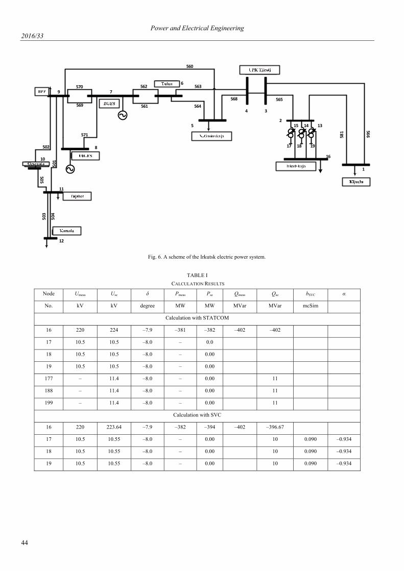
The results of comparative calculations for STATCOM and SVC are presented in Table I.
Power and Electrical Engineering 2016/33
44
БПП
БГЭС
Тулун
Н.Зиминская
УПК Тыреть
Иркутская
Ключи
УИГЭС
Озерная
Тайшет
Камала
560
581
566
565568
563
564
562
561569
570
571
502
501
505
503
504
1
2
4 3
5
7
8
6
9
10
11
12
131415
16
191817
Fig. 6. A scheme of the Irkutsk electric power system.
TABLE I
CALCULATION RESULTS
Node Umeas Use δ Pmeas Pse Qmeas Qse bSVC
α
No. kV kV degree MW MW MVar MVar mcSim
Calculation with STATCOM
16 220 224 –7.9 –381 –382 –402 –402
17 10.5 10.5 –8.0 – 0.0
18 10.5 10.5 –8.0 – 0.00
19 10.5 10.5 –8.0 – 0.00
177 – 11.4 –8.0 – 0.00 11
188 – 11.4 –8.0 – 0.00 11
199 – 11.4 –8.0 – 0.00 11
Calculation with SVC
16 220 223.64 –7.9 –382 –394 –402 –396.67
17 10.5 10.55 –8.0 – 0.00 10 0.090 –0.934
18 10.5 10.55 –8.0 – 0.00 10 0.090 –0.934
19 10.5 10.55 –8.0 – 0.00 10 0.090 –0.934

Power and Electrical Engineering 2016/33
45
The data of Table I demonstrate the calculation results for the cases of connecting two different reactive power control de-vices (SVC and STATCOM) that virtually coincide (within a specified accuracy of calculation).
The analysis of the algorithms shows that for modeling SVC, it is necessary to include additional components in the vector of state, but this makes it possible to determine the angle of control α in real time [13]. The algorithm allows us to form a mathe-matical model of an energy system with embedded SVC model, which does not require additional preparatory or subsequent calculations and can be used for off-line operation in various software packages. The main flaw of the algorithm is the fact that it is hard to implement and should be adjusted to a specific program of state estimation, considering its specific features and constraints of the applied methods.
STATCOM is modeled by an additional branch with a volt-age source at the node where STATCOM is installed. The algo-rithm is easily implemented with the minimum labor efforts and can be implemented virtually in any state estimation software (Cosmos, ANARES, Otsenka, etc.) without changes in pro-gramming code and introduction of new components in the vec-tor of state as in the case of including the SVC model in the power system state estimation problem. This algorithm does not require direct participation of an operator in the calculations and can operate in real time. The necessary condition for the imple-mentation of the STATOM model in the state estimation soft-ware is availability of a module for considering inequality-con-straints on measured and unmeasured variables. It should also be noted that compared to SVC STATCOM can be applied when voltage declines greatly. Moreover, the STATCOM re-sponse to changes in operating conditions is faster and the de-vice does not generate harmonic oscillations.
VI. CONCLUSION
The paper shows the relevance of including the models of FACTS devices in the equivalent circuit when solving the power system state estimation problem. Consideration is given to the models of SVC and STATCOM, which are used in the steady state calculation. The modified state estimation algo-rithms developed for modeling the SVC and STATCOM de-vices provide voltage stabilization and gradual or stage-by-stage change in the consumed and (or) supplied reactive power. The calculations made for a fragment of the 500 kV Irkutsk power system demonstrated high-speed operation and good convergence of the developed algorithms, which makes it pos-sible to use them for obtaining the estimates in real time.
ACKNOWLEDGMENT
The research was supported by the grant 4711.2014.8 of Leading Scientific School of the Russian Federation.
REFERENCES [1] V. E. Fortov and A. A. Makarov, A concept of Russia’s intelligent power
system with active-adaptive network, Moscow: JSC “NTC FSC EES”, 2012, p. 235.
[2] E. V. Ametistov, Fundamentals of modern energy. Modern electric power engineering, Moscow: Publishing MEI, 2010, V.2, p. 632.
[3] E. Acha, C. R. Fuerte-Esquivel, H. Ambriz-Perez, C. Angeles-Camacho, FACTS. Modeling and Simulation in Power Networks, England: JohnWil-ley&Sons, Ltd, 2004, p. 403.
[4] N. I. Voropai, O. B. Osak, “Development of equipment and control sys-tems of large-scale energy systems,” Scientific and technical report, code 2008-0-2.7-31-01-007, Irkutsk, 2009.
[5] P. M. Erokhin, V. G. Neuimin, A. S. Alexandrov and D. M. Maksimenk, “Modeling of FACTS devices in the problems of calculation and optimi-zation of energy system operation,” Bulletin of NTC EES, No. 66 (1). pp. 22–28, 2012.
[6] Y. H. Song and A. T. Johns (eds.), Flexible AC Transmission Systems (FACTS), London: Institution of Electric Engineers, 1999.
[7] N. G. Hingorani and L. Gyugyi, Understanding FACTS: concepts and technology of flexible AC transmission systems, Wiley-IEEE Press. 2000, pp. 431–432.
[8] A. Monticelly, “Electric power system state estimation,” in Proc. of the IEEE, vol. 88, issue 2, Feb. 2000. pp. 229–240. http://dx.doi.org/10.1109/5.824004
[9] A. Z. Gamm and I. N. Kolosok, “Test Equations and Their Use for State Estimation of Electrical Power System,” Power and Electrical Engineer-ing: Scientific J. of Riga Technical University. Riga: RTU Press, pp. 99–105, 2002.
[10] T. Okon and K. Wilkosz, “WLS State Estimation in Polar and Rectangular Coordinate Systems for Power System with UPFC: Significance of Types of Measurements,” in Proc. of the Int. Conf.-PowerTech, Trondheim, Norway, June 19–23, 2011.
[11] A. Zamora-Cardenas and C. R. Fuerte-Esquivel, “State estimation of power systems containing facts controllers,” Electric Power Systems Re-search, vol. 81, pp. 995–1002, 2011. http://dx.doi.org/10.1016/j.epsr.2010.12.009
[12] B. Xu and A. Abur, “State Estimation of Systems with Embedded FACTS Devices,” in Proc. of the Int. Conf., PowerTech’2013, Bologna, Italy, June 23–26, 2003. http://dx.doi.org/10.1109/PTC.2003.1304122
[13] A. V. Tikhonov, “Modeling of static var compensators in the state estima-tion problem of electric power system,” System studies in energy 2014. The papers of young scientists of ESI SB RAS, Issue 44, pp. 64–72.
[14] A. Z. Gamm and I. N. Kolosok, Bad data detection in measurements in electric power systems, Novosibirsk: Nauka, 2000, p. 152.
Related Documents