Welcome message from author
This document is posted to help you gain knowledge. Please leave a comment to let me know what you think about it! Share it to your friends and learn new things together.
Transcript


®
Rev. No. 1/06
Template No. T35-03
FULL MORFULL MORFULL MORFULL MORFULL MORTISE TISE TISE TISE TISE TEMPLATEMPLATEMPLATEMPLATEMPLATE BTE BTE BTE BTE BUTT HINGESUTT HINGESUTT HINGESUTT HINGESUTT HINGESSizes: 3½ × 3, 3½ × 3½, 3½ × 5 and 3½ × 6”
E
F
1/ 16
5/ 8 R1/ 4 R
1 .39 5
3. 500
.3 55 .3 551 .39 5
.687
.3 60
Template hinges of the hospital type conform to above screw hole location.Hospital type hinges are designated by prefix “HT” to class number.Also available “RD” radius corners (1 1/4 or 5/8)
Machine Screw Size — ½ × 10-24 F.H.Wood Screw Size — 1 × No. 10 F.H.
This template conforms with ANSI standard A156.7.
(E)
Steel Nonferrous Gauge Outside
Hinges Hinges of Metal Diameter 3½ × 3 3½ × 3½ 3½ × 5 3½ × 6
F179 F191 0.123 0.545 1 1/8 1 3/8 2 1/8 2 5/8
1900 1960 0.123 0.540 1 1/16 1 5/16 — —
1900R 1960R 0.123 0.545 1 1/8 1 3/8 — —
CB179 CB191 0.123 0.590 1 1/8 1 3/8 2 1/8 2 5/8
FBB179 FBB191 0.123 0.590 1 1/8 1 3/8 2 1/8 2 5/8
CB1900 CB1960 0.123 0.540 — 1 5/16 — —
CB1900R CB1960R 0.123 0.590 1 1/8 1 3/8 2 1/8 2 5/8
CLASS NUMBER DISTANCE FROM EDGE OF LEAF TO
SWAGE LINE (F)

®
Rev. No. 11/07
Template No. T40-01
FULL MORFULL MORFULL MORFULL MORFULL MORTISE TISE TISE TISE TISE TEMPLATEMPLATEMPLATEMPLATEMPLATE BTE BTE BTE BTE BUTT HINGESUTT HINGESUTT HINGESUTT HINGESUTT HINGESSizes: 4 × 3½*, 4 × 4, 4 × 5, 4 × 6 and 4 × 7”
Template hinges of the hospital type conform to above screw hole location.Hospital type hinges are designated by prefix “HT” to class number.Also available “RD” radius corners (1/4 or 5/8).
Machine Screw Size — ½ × 12-24 F.H.Wood Screw Size — 1¼ × No. 12 F.H.
This template conforms with ANSI standard A156.7.
*4 × 3 1/2 template can be used on doors 1 3/8 minimum thickness.
(E)
Steel Nonferrous Gauge Outside
Hinges Hinges of Metal Diameter 4 × 3½ 4 × 4 4 × 5 4 × 6 4 × 7
F179 F191 0.130 0.560 1 5/16 1 5/8 2 1/16 2 9/16 3 1/16
1900 1960 0.130 0.540 1 5/16 1 5/8 — — —
1900R 1960R 0.130 0.560 1 5/16 1 5/8 2 1/16 2 9/16 3 1/16
CB179 CB191 0.130 0.590 1 5/16 1 5/8 2 1/16 2 9/16 3 1/16
FBB179 FBB191 0.130 0.590 1 5/16 1 5/8 2 1/16 2 9/16 3 1/16
CB1900 CB1960 0.130 0.540 — 1 5/8 — — —
CB1900R CB1960R 0.130 0.590 1 5/16 1 5/8 2 1/16 2 9/16 3 1/16
CLASS NUMBERDISTANCE FROM EDGE OF LEAF TO SWAGE LINE (F)
®
Rev. No. 3/06
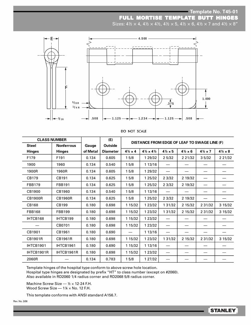
Template No. T45-01
FULL MORFULL MORFULL MORFULL MORFULL MORTISE TISE TISE TISE TISE TEMPLATEMPLATEMPLATEMPLATEMPLATE BTE BTE BTE BTE BUTT HINGESUTT HINGESUTT HINGESUTT HINGESUTT HINGESSizes: 4½ × 4, 4½ × 4½, 4½ × 5, 4½ × 6, 4½ × 7 and 4½ × 8”
Template hinges of the hospital type conform to above screw hole location.Hospital type hinges are designated by prefix “HT” to class number (except on #2060).Also available in RD2060 1/4 radius corner and RD2068 5/8 radius corner.
Machine Screw Size — ½ × 12-24 F.H.Wood Screw Size — 1¼ × No. 12 F.H.
This template conforms with ANSI standard A156.7.
E
F
1/ 16
5/ 8 R1/ 4 R
1 .125
4 .500
.508 .5081 .2 34 1 .125
1 .000
.375
(E)
Steel Nonferrous Gauge Outside
Hinges Hinges of Metal Diameter 4½ × 4 4½ × 4½ 4½ × 5 4½ × 6 4½ × 7 4½ × 8
F179 F191 0.134 0.605 1 5/8 1 29/32 2 5/32 2 21/32 3 5/32 2 21/32
1900 1960 0.134 0.540 1 5/8 1 13/16 — — — —
1900R 1960R 0.134 0.605 1 5/8 1 29/32 — — — —
CB179 CB191 0.134 0.625 1 5/8 1 25/32 2 3/32 2 19/32 — —
FBB179 FBB191 0.134 0.625 1 5/8 1 25/32 2 3/32 2 19/32 — —
CB1900 CB1960 0.134 0.540 1 5/8 1 13/16 — — — —
CB1900R CB1960R 0.134 0.625 1 5/8 1 25/32 2 3/32 2 19/32 — —
CB168 CB199 0.180 0.698 1 15/32 1 23/32 1 31/32 2 15/32 2 31/32 3 15/32
FBB168 FBB199 0.180 0.698 1 15/32 1 23/32 1 31/32 2 15/32 2 31/32 3 15/32
IHTCB168 IHTCB199 0.180 0.698 1 15/32 1 23/32 — — — —
— CB0701 0.180 0.698 1 15/32 1 23/32 — — — —
CB1901 CB1961 0.180 0.690 — 1 13/16 — — — —
CB1901R CB1961R 0.180 0.698 1 15/32 1 23/32 1 31/32 2 15/32 2 31/32 3 15/32
IHTCB1901 IHTCB1961 0.180 0.690 1 15/32 1 13/16 — — — —
IHTCB1901R IHTCB1961R 0.180 0.698 1 15/32 1 23/32 — — — —
2060R — 0.134 0.783 1 5/8 1 27/32 — — — —
DISTANCE FROM EDGE OF LEAF TO SWAGE LINE (F)CLASS NUMBER
®
Rev. No. 3/06
Template No. T45-16
FULL MORFULL MORFULL MORFULL MORFULL MORTISE TISE TISE TISE TISE TEMPLATEMPLATEMPLATEMPLATEMPLATE BTE BTE BTE BTE BUTT HINGES UTT HINGES UTT HINGES UTT HINGES UTT HINGES WITH CONCEALED WITH CONCEALED WITH CONCEALED WITH CONCEALED WITH CONCEALED WIRESWIRESWIRESWIRESWIRESSizes: 4½ × 4 and 4½ × 4½”
(E)
Steel Nonferrous Gauge Outside
Hinges Hinges of Metal Diameter 4½ × 4 4½ × 4½
CECB1900 CECB1960 0.134 0.540 1 5/8 1 13/16
CECB1900R CECB1960R 0.134 0.625 1 5/8 1 25/32
CECB1901 CECB1961 0.180 0.690 — 1 13/16
CECB1901R CECB1961R 0.180 0.698 — 1 23/32
CEIHTCB1901 CEIHTCB1961 0.180 0.690 — 1 23/32
CEIHTCB1901R CEIHTCB1961R 0.180 0.698 — 1 23/32
CLASS NUMBER DISTANCE FROM EDGE OF
LEAF TO SWAGE LINE (F)
NOTE: Prefix IHT indicates Instutional Hinge.Machine Screw Size — ½ × 12-24 F.H.Wood Screw Size — 1¼ × No. 12 F.H.
1.000
.375
.508
1.125
1.2344.500
1.125
1.125.508
3.375
E
FF
.625
1.125
3.375
.625
AA
BB
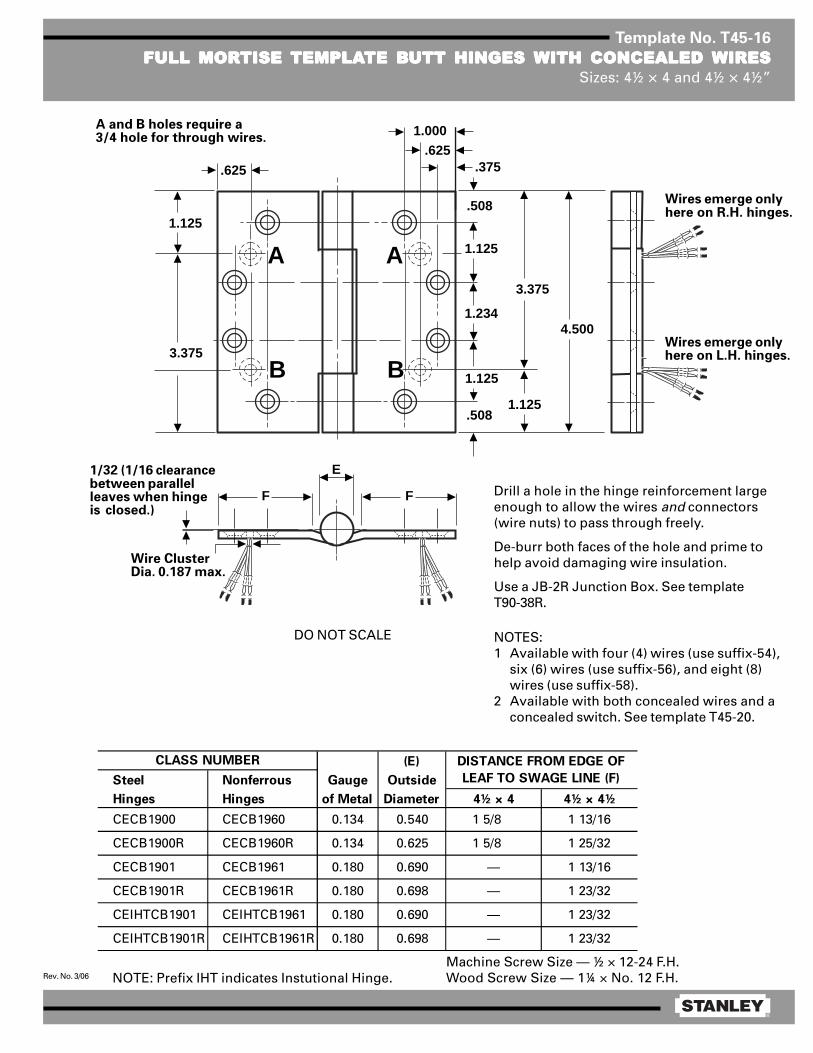
Drill a hole in the hinge reinforcement largeenough to allow the wires and connectors(wire nuts) to pass through freely.
De-burr both faces of the hole and prime tohelp avoid damaging wire insulation.
Use a JB-2R Junction Box. See templateT90-38R.
NOTES:1 Available with four (4) wires (use suffix-54),
six (6) wires (use suffix-56), and eight (8)wires (use suffix-58).
2 Available with both concealed wires and aconcealed switch. See template T45-20.
1/32 (1/16 clearancebetween parallelleaves when hingeis closed.)
Wire ClusterDia. 0.187 max.
DO NOT SCALE
Wires emerge onlyhere on R.H. hinges.
Wires emerge onlyhere on L.H. hinges.
A and B holes require a3/4 hole for through wires.
®
Rev. No. 3/06
Template No. T45-20
FULL MORFULL MORFULL MORFULL MORFULL MORTISE TISE TISE TISE TISE TEMPLATEMPLATEMPLATEMPLATEMPLATE BTE BTE BTE BTE BUTT HINGES UTT HINGES UTT HINGES UTT HINGES UTT HINGES WITH CONCEALEDWITH CONCEALEDWITH CONCEALEDWITH CONCEALEDWITH CONCEALEDWIRES WIRES WIRES WIRES WIRES AND CONCEALED SWITAND CONCEALED SWITAND CONCEALED SWITAND CONCEALED SWITAND CONCEALED SWITCHCHCHCHCH
Sizes: 4½ × 4 and 4½ × 4½”
E
FF
.500 .750 dia
DC
1.000
.375
.508
1.125
1.2344.500
1.125
1.125
.484 dia .484 dia
.508
3.375
.625
1.125
3.375
2.250
.625
AA
BB
Machine Screw Size — ½ × 12-24 F.H.Wood Screw Size — 1 ¼ × No. 12 F.H.
(E)
Steel Nonferrous Gauge Outside C D
Hinges Hinges of Metal Diameter 4½ × 4 4½ × 4½
CECSCB1900 CECSCB1960 0.134 0.540 1 5/8 1 13/16 1.234 0.875
CECSCB1900R CECSCB1960R 0.134 0.625 1 5/8 1 25/32 1.234 0.875
CECSCB1901 CECSCB1961 0.180 0.690 — 1 13/16 1.187 0.828
CECSCB1901R CECSCB1961R 0.180 0.698 — 1 23/32 1.187 0.828
CLASS NUMBER DISTANCE FROM EDGE OF
LEAF TO SWAGE LINE (F)
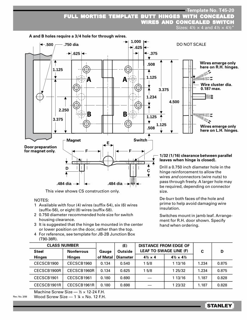
1/32 (1/16) clearance between parallelleaves when hinge is closed).
Drill a 0.750 inch diameter hole in thehinge reinforcement to allow thewires and connectors (wire nuts) topass through freely. A larger hole maybe required, depending on connectorsize.
De-burr both faces of the hole andprime to help avoid damaging wireinsulation.
Switches mount in jamb leaf. Arrange-ment for R.H. door shown. Specifyhand when ordering.
NOTES:1 Available with four (4) wires (suffix-54), six (6) wires
(suffix-56), or eight (8) wires (suffix-58).2 0.750 diameter recommended hole size for switch
housing clearance.3 It is suggested that the hinge be mounted in the center
or lower position on the door, rather than the top.4 For reference, see template for JB-2B Junction Box
(T90-38R).
This view shows CS construction only.
Magnet Switch
Door preparationfor magnet only.
Wire cluster dia.0.187 max.
Wires emerge onlyhere on R.H. hinges.
Wires emerge onlyhere on L.H. hinges.
DO NOT SCALE
A and B holes require a 3/4 hole for through wires.

®
Rev. No. 2/06
Template No. T45-17
FULL MORFULL MORFULL MORFULL MORFULL MORTISE TISE TISE TISE TISE TEMPLATEMPLATEMPLATEMPLATEMPLATE BTE BTE BTE BTE BUTT HINGES UTT HINGES UTT HINGES UTT HINGES UTT HINGES WITH CONCEALED SWITWITH CONCEALED SWITWITH CONCEALED SWITWITH CONCEALED SWITWITH CONCEALED SWITCHCHCHCHCHSizes: 4½ × 4 and 4½ × 4½”
Machine Screw Size — 12-24 × ½ F.H.Wood Screw Size — No. 12 × 1¼ F.H.
Contractor should be cautioned to preventmortar from interfering with wiring.
1/32 (1/16 clearance between parallel leaves whenhinge is closed.)
NOTES:1 Available with both a concealed switch and
concealed wires. See templates T45-19 orT45-20.
2 0.750 diameter is the recommended hole size forswitch housing clearance.
3 It is suggested that the hinge be mounted in thecenter or lower position on the door, rather thanthe top.
4 Switch mounts in jamb leaf. Arrangement forL.H. door shown. Specify hand when ordering.
5 Use JB-2R Junction Box. See Template T90-38R.
NOTE: Prefix IHT indicates Institutional Hinge.
(E)
Steel Nonferrous Gauge Outside
Hinges Hinges of Metal Diameter 4½ × 4 4½ × 4½
CSCB179 CSCB191 0.134 0.625 1 5/8 1 25/32 1.234 0.875
CSFBB179 CSFBB191 0.134 0.625 1 5/8 1 25/32 1.234 0.875
CSCB1900 CSCB1960 0.134 0.540 1 5/8 1 13/16 1.234 0.875
CSCB1900R CSCB1960R 0.134 0.625 1 5/8 1 25/32 1.234 0.875
CSCB168 CSCB199 0.180 0.698 — 1 23/32 1.187 0.828
CSFBB168 CSFBB199 0.180 0.698 — 1 23/32 1.187 0.828
CSIHTCB168 CSIHTCB199 0.180 0.698 — 1 23/32 1.187 0.828
CSCB1901 CSCB1961 0.180 0.690 — 1 13/16 1.187 0.828
CSCB1901R CSCB1961R 0.180 0.698 — 1 23/32 0.187 0.828
CSIHTCB1901 CSIHTCB1961 0.180 0.690 — 1 13/16 1.187 0.828
CSIHTCB1901R CSIHTCB1961R 0.180 0.698 — 1 23/32 0.187 0.828
B
CLASS NUMBER DISTANCE FROM EDGE OF LEAF
TO SWAGE LINE (F) A
®
Rev. No. 1/06
Template No. T45-10
RAISED BRAISED BRAISED BRAISED BRAISED BARREL ARREL ARREL ARREL ARREL TEMPLATEMPLATEMPLATEMPLATEMPLATE BTE BTE BTE BTE BUTT HINGES FOR DOORS UTT HINGES FOR DOORS UTT HINGES FOR DOORS UTT HINGES FOR DOORS UTT HINGES FOR DOORS WITHWITHWITHWITHWITHSQSQSQSQSQUUUUUARE EDGE HINGE STILESARE EDGE HINGE STILESARE EDGE HINGE STILESARE EDGE HINGE STILESARE EDGE HINGE STILES
Size: 4½ × 4½”
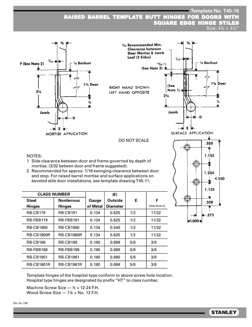
Template hinges of the hospital type conform to above screw hole location.Hospital type hinges are designated by prefix “HT” to class number.
Machine Screw Size — ½ × 12-24 F.H.Wood Screw Size — 1¼ × No. 12 F.H.
DO NOT SCALE
(E)
Steel Nonferrous Gauge Outside E F
Hinges Hinges of Metal Diameter (See Note 2)
RB-CB179 RB-CB191 0.134 0.625 1/2 11/32
RB-FBB179 RB-FBB191 0.134 0.625 1/2 11/32
RB-CB1900 RB-CB1960 0.134 0.540 1/2 11/32
RB-CB1900R RB-CB1960R 0.134 0.625 1/2 11/32
RB-CB168 RB-CB199 0.180 0.698 5/8 3/8
RB-FBB168 RB-FBB199 0.180 0.698 5/8 3/8
RB-CB1901 RB-CB1961 0.180 0.690 5/8 3/8
RB-CB1901R RB-CB1961R 0.180 0.698 5/8 3/8
CLASS NUMBER
NOTES:1 Side clearance between door and frame governed by depth of
mortise. (3/32 betwen door and frame suggested).2 Recommended for approx. 1/16 swinging clearance between door
and stop. For raised barrel mortise and surface applications onbeveled stile door installations, see template drawing T45-11.

®
Rev. No. 1/06
Template No. T45-11
RAISED BRAISED BRAISED BRAISED BRAISED BARREL ARREL ARREL ARREL ARREL TEMPLATEMPLATEMPLATEMPLATEMPLATE BTE BTE BTE BTE BUTT HINGES FOR DOORS UTT HINGES FOR DOORS UTT HINGES FOR DOORS UTT HINGES FOR DOORS UTT HINGES FOR DOORS WITHWITHWITHWITHWITHBEVELED EDGE HINGE STILESBEVELED EDGE HINGE STILESBEVELED EDGE HINGE STILESBEVELED EDGE HINGE STILESBEVELED EDGE HINGE STILES
Size: 4½ × 4½”
(E)
Steel Nonferrous Gauge Outside E F
Hinges Hinges of Metal Diameter (See Note 3)
RB-CB179 RB-CB191 0.134 0.625 1/2 11/32
RB-FBB179 RB-FBB191 0.134 0.625 1/2 11/32
RB-CB1900 RB-CB1960 0.134 0.540 1/2 11/32
RB-CB1900R RB-CB1960R 0.134 0.625 1/2 11/32
RB-CB168 RB-CB199 0.180 0.698 5/8 3/8
RB-FBB168 RB-FBB199 0.180 0.698 5/8 3/8
RB-CB1901 RB-CB1961 0.180 0.690 5/8 3/8
RB-CB1901R RB-CB1961R 0.180 0.698 5/8 3/8
CLASS NUMBER
NOTES:1 Clearance between leaves on plane of door face.2 Side clearance between door and frame goverened by depth
of mortise. (3/32 between door and frame suggested).3 Recommended for approx. 1/16 swinging clearance between
door and stop.4 For raised barrel mortise and surface applications on square
stile door installations, see template drawing T45-10.
Template hinges of the hospital type conform to above screw hole location.Hospital type hinges are designated by prefix “HT” to class number.
Machine Screw Size — ½ × 12-24 F.H.Wood Screw Size — 1¼ × No. 12 F.H.
DO NOT SCALE

®
Rev. No. 1/06
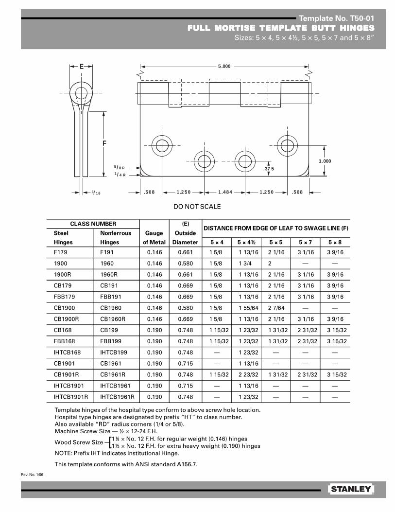
Template No. T50-01
FULL MORFULL MORFULL MORFULL MORFULL MORTISE TISE TISE TISE TISE TEMPLATEMPLATEMPLATEMPLATEMPLATE BTE BTE BTE BTE BUTT HINGESUTT HINGESUTT HINGESUTT HINGESUTT HINGESSizes: 5 × 4, 5 × 4½, 5 × 5, 5 × 7 and 5 × 8”
Template hinges of the hospital type conform to above screw hole location.Hospital type hinges are designated by prefix “HT” to class number.Also available “RD” radius corners (1/4 or 5/8).Machine Screw Size — ½ × 12-24 F.H.
Wood Screw Size —
NOTE: Prefix IHT indicates Institutional Hinge.
This template conforms with ANSI standard A156.7.
1¼ × No. 12 F.H. for regular weight (0.146) hinges1½ × No. 12 F.H. for extra heavy weight (0.190) hinges[
E
F
1/ 16
5/ 8 R1/ 4 R
1 .2 50
5 .000
.508 .5081 .484 1 .2 50
1 .000
.37 5
(E)
Steel Nonferrous Gauge Outside
Hinges Hinges of Metal Diameter 5 × 4 5 × 4½ 5 × 5 5 × 7 5 × 8
F179 F191 0.146 0.661 1 5/8 1 13/16 2 1/16 3 1/16 3 9/16
1900 1960 0.146 0.580 1 5/8 1 3/4 2 — —
1900R 1960R 0.146 0.661 1 5/8 1 13/16 2 1/16 3 1/16 3 9/16
CB179 CB191 0.146 0.669 1 5/8 1 13/16 2 1/16 3 1/16 3 9/16
FBB179 FBB191 0.146 0.669 1 5/8 1 13/16 2 1/16 3 1/16 3 9/16
CB1900 CB1960 0.146 0.580 1 5/8 1 55/64 2 7/64 — —
CB1900R CB1960R 0.146 0.669 1 5/8 1 13/16 2 1/16 3 1/16 3 9/16
CB168 CB199 0.190 0.748 1 15/32 1 23/32 1 31/32 2 31/32 3 15/32
FBB168 FBB199 0.190 0.748 1 15/32 1 23/32 1 31/32 2 31/32 3 15/32
IHTCB168 IHTCB199 0.190 0.748 — 1 23/32 — — —
CB1901 CB1961 0.190 0.715 — 1 13/16 — — —
CB1901R CB1961R 0.190 0.748 1 15/32 2 23/32 1 31/32 2 31/32 3 15/32
IHTCB1901 IHTCB1961 0.190 0.715 — 1 13/16 — — —
IHTCB1901R IHTCB1961R 0.190 0.748 — 1 23/32 — — —
CLASS NUMBERDISTANCE FROM EDGE OF LEAF TO SWAGE LINE (F)
DO NOT SCALE

®
Rev. No. 3/06
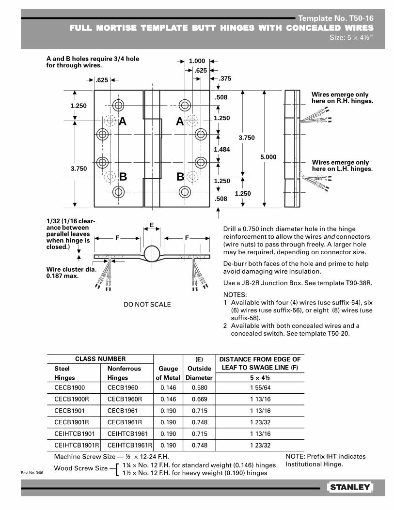
Template No. T50-16
FULL MORFULL MORFULL MORFULL MORFULL MORTISE TISE TISE TISE TISE TEMPLATEMPLATEMPLATEMPLATEMPLATE BTE BTE BTE BTE BUTT HINGES UTT HINGES UTT HINGES UTT HINGES UTT HINGES WITH CONCEALED WITH CONCEALED WITH CONCEALED WITH CONCEALED WITH CONCEALED WIRESWIRESWIRESWIRESWIRESSize: 5 × 4½”
1.000
.375
.508
1.250
1.4845.000
1.250
1.250.508
3.750
E
FF
.625
1.250
3.750
.625
AA
BB
Machine Screw Size — ½ × 12-24 F.H.
Wood Screw Size — 1¼ × No. 12 F.H. for standard weight (0.146) hinges1½ × No. 12 F.H. for heavy weight (0.190) hinges[
Drill a 0.750 inch diameter hole in the hingereinforcement to allow the wires and connectors(wire nuts) to pass through freely. A larger holemay be required, depending on connector size.
De-burr both faces of the hole and prime to helpavoid damaging wire insulation.
Use a JB-2R Junction Box. See template T90-38R.
NOTE: Prefix IHT indicatesInstitutional Hinge.
(E)
Steel Nonferrous Gauge Outside
Hinges Hinges of Metal Diameter 5 × 4½
CECB1900 CECB1960 0.146 0.580 1 55/64
CECB1900R CECB1960R 0.146 0.669 1 13/16
CECB1901 CECB1961 0.190 0.715 1 13/16
CECB1901R CECB1961R 0.190 0.748 1 23/32
CEIHTCB1901 CEIHTCB1961 0.190 0.715 1 13/16
CEIHTCB1901R CEIHTCB1961R 0.190 0.748 1 23/32
CLASS NUMBER DISTANCE FROM EDGE OF
LEAF TO SWAGE LINE (F)
NOTES:1 Available with four (4) wires (use suffix-54), six
(6) wires (use suffix-56), or eight (8) wires (usesuffix-58).
2 Available with both concealed wires and aconcealed switch. See template T50-20.
DO NOT SCALE
Wires emerge onlyhere on R.H. hinges.
Wires emerge onlyhere on L.H. hinges.
Wire cluster dia.0.187 max.
1/32 (1/16 clear-ance betweenparallel leaveswhen hinge isclosed.)
A and B holes require 3/4 holefor through wires.
®
Rev. No. 3/06
Template No. T50-20
FULL MORFULL MORFULL MORFULL MORFULL MORTISE TISE TISE TISE TISE TEMPLATEMPLATEMPLATEMPLATEMPLATE BTE BTE BTE BTE BUTT HINGES UTT HINGES UTT HINGES UTT HINGES UTT HINGES WITHWITHWITHWITHWITHCONCEALED CONCEALED CONCEALED CONCEALED CONCEALED WIRES WIRES WIRES WIRES WIRES AND CONCEALED SWITAND CONCEALED SWITAND CONCEALED SWITAND CONCEALED SWITAND CONCEALED SWITCHCHCHCHCH
Size: 5 × 4½”
E
FF
.500 .750 dia
DC
1.000
.375
.508
1.250
1.4845.000
1.250
1.250
.484 dia.484 dia
.508
3.750
.625
1.250
3.750
2.500
.625
AA
BB
Machine Screw Size — ½ × 12-24 F.H.
Wood Screw Size —
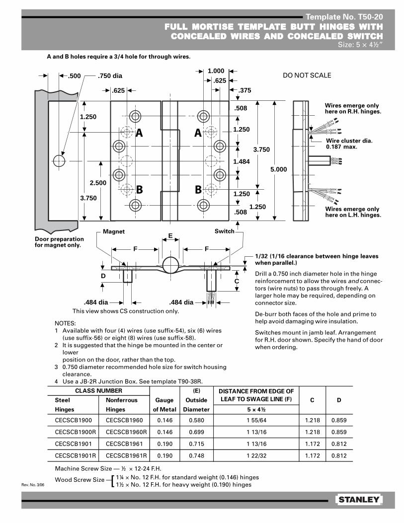
1/32 (1/16 clearance between hinge leaveswhen parallel.)
Drill a 0.750 inch diameter hole in the hingereinforcement to allow the wires and connec-tors (wire nuts) to pass through freely. Alarger hole may be required, depending onconnector size.
De-burr both faces of the hole and prime tohelp avoid damaging wire insulation.
Switches mount in jamb leaf. Arrangementfor R.H. door shown. Specify the hand of doorwhen ordering.
NOTES:1 Available with four (4) wires (use suffix-54), six (6) wires
(use suffix-56) or eight (8) wires (use suffix-58).2 It is suggested that the hinge be mounted in the center or
lowerposition on the door, rather than the top.
3 0.750 diameter recommended hole size for switch housingclearance.
4 Use a JB-2R Junction Box. See template T90-38R.
(E)
Steel Nonferrous Gauge Outside C D
Hinges Hinges of Metal Diameter 5 × 4½
CECSCB1900 CECSCB1960 0.146 0.580 1 55/64 1.218 0.859
CECSCB1900R CECSCB1960R 0.146 0.699 1 13/16 1.218 0.859
CECSCB1901 CECSCB1961 0.190 0.715 1 13/16 1.172 0.812
CECSCB1901R CECSCB1961R 0.190 0.748 1 22/32 1.172 0.812
CLASS NUMBER DISTANCE FROM EDGE OF
LEAF TO SWAGE LINE (F)
1¼ × No. 12 F.H. for standard weight (0.146) hinges1½ × No. 12 F.H. for heavy weight (0.190) hinges[
Magnet Switch
Door preparationfor magnet only.
Wire cluster dia.0.187 max.
Wires emerge onlyhere on R.H. hinges.
Wires emerge onlyhere on L.H. hinges.
DO NOT SCALE
A and B holes require a 3/4 hole for through wires.
This view shows CS construction only.

®
Rev. No. 2/06
Template No. T50-17
FULL MORFULL MORFULL MORFULL MORFULL MORTISE TISE TISE TISE TISE TEMPLATEMPLATEMPLATEMPLATEMPLATE BTE BTE BTE BTE BUTT HINGES UTT HINGES UTT HINGES UTT HINGES UTT HINGES WITH CONCEALED SWITWITH CONCEALED SWITWITH CONCEALED SWITWITH CONCEALED SWITWITH CONCEALED SWITCHCHCHCHCHSize: 5 × 4½”
Contractor should be cautioned to preventmortar from interfering with wiring.
1/32 (1/16 clearance between parallel leaves when hingeis closed.)
NOTES:1 Available with both a concealed switch and con-
cealed wires. See templates T50-19 or T50-20.2 0.750 diameter is the recommended hole size for
switch housing clearance.3 It is suggested that the hinge be mounted in the
center or lower position on the door, rather than thetop.
4 Switch mounts in jamb leaf. Arrangement for L.H.door show. Specify hand when ordering.
5 Use a JB-2R Junction Box. See Template T90-38R.
Machine Screw Size — 12-24 × ½ F.H.Wood Screw Size — No. 12 × 1¼ F.H. for standard weight (0.146) hinges
No. 12 × 1½ F.H. for heavy weight (0.190) hinges
(E)
Steel Nonferrous Gauge Outside A B
Hinges Hinges of Metal Diameter 5 × 4½
CSCB179 CSCB191 0.146 0.669 1 13/16 1.218 0.859
CSFBB179 CSFBB191 0.146 0.669 1 13/16 1.218 0.859
CSCB1900 CSCB1960 0.146 0.580 1 55/64 1.218 0.859
CSCB1900R CSCB1960R 0.146 0.669 1 13/16 1.218 0.859
CSCB168 CSCB199 0.190 0.748 1 23/32 1.172 0.812
CSFBB168 CSFBB199 0.190 0.748 1 23/32 1.172 0.812
CSIHTCB168 CSIHTCB199 0.190 0.748 1 23/32 1.172 0.812
CSCB1901 CSCB1961 0.190 0.715 1 13/16 1.172 0.812
CSCB1901R CSCB1961R 0.190 0.015 1 23/32 1.172 0.812
CSIHTCB1901 CSIHTCB1961 0.180 0.715 1 13/16 1.172 0.812
CSIHTCB1901R CSIHTCB1961R 0.190 0.748 1 23/32 1.172 0.812
CLASS NUMBER DISTANCE FROM EDGE OF LEAF TO
SWAGE LINE (F)
®
Rev. No. 1/06
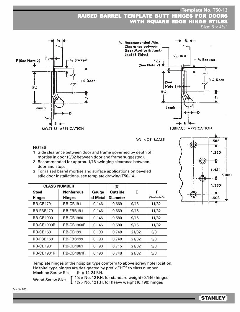
Template No. T50-13
RAISED BRAISED BRAISED BRAISED BRAISED BARREL ARREL ARREL ARREL ARREL TEMPLATEMPLATEMPLATEMPLATEMPLATE BTE BTE BTE BTE BUTT HINGES FOR DOORSUTT HINGES FOR DOORSUTT HINGES FOR DOORSUTT HINGES FOR DOORSUTT HINGES FOR DOORSWITH SQWITH SQWITH SQWITH SQWITH SQUUUUUARE EDGE HINGE STILESARE EDGE HINGE STILESARE EDGE HINGE STILESARE EDGE HINGE STILESARE EDGE HINGE STILES
Size: 5 × 4½”
Template hinges of the hospital type conform to above screw hole location.Hospital type hinges are designated by prefix “HT” to class number.Machine Screw Size — ½ × 12-24 F.H.
Wood Screw Size —
(D)
Steel Nonferrous Gauge Outside E F
Hinges Hinges of Metal Diameter (See Note 3)
RB-CB179 RB-CB191 0.146 0.669 9/16 11/32
RB-FBB179 RB-FBB191 0.146 0.669 9/16 11/32
RB-CB1900 RB-CB1960 0.146 0.580 9/16 11/32
RB-CB1900R RB-CB1960R 0.146 0.580 9/16 11/32
RB-CB168 RB-CB199 0.190 0.748 21/32 3/8
RB-FBB168 RB-FBB199 0.190 0.748 21/32 3/8
RB-CB1901 RB-CB1961 0.190 0.715 21/32 3/8
RB-CB1901R RB-CB1961R 0.190 0.748 21/32 3/8
CLASS NUMBER
NOTES:1 Side clearance between door and frame governed by depth of
mortise in door (3/32 between door and frame suggested).2 Recommended for approx. 1/16 swinging clearance between
door and stop.3 For raised barrel mortise and surface applications on beveled
stile door installations, see template drawing T50-14.
1¼ × No. 12 F.H. for standard weight (0.146) hinges1½ × No. 12 F.H. for heavy weight (0.190) hinges[

®
Rev. No. 1/06
Template No. T50-14
RAISED BRAISED BRAISED BRAISED BRAISED BARREL ARREL ARREL ARREL ARREL TEMPLATEMPLATEMPLATEMPLATEMPLATE BTE BTE BTE BTE BUTT HINGES FOR DOORSUTT HINGES FOR DOORSUTT HINGES FOR DOORSUTT HINGES FOR DOORSUTT HINGES FOR DOORSWITH BEVELED EDGE HINGE STILESWITH BEVELED EDGE HINGE STILESWITH BEVELED EDGE HINGE STILESWITH BEVELED EDGE HINGE STILESWITH BEVELED EDGE HINGE STILES
Size: 5 × 4½”
Template hinges of the hospital type conform to above screw hole location.Hospital type hinges are designated by prefix “HT” to class number.Machine Screw Size — ½ × 12-24 F.H.
Wood Screw Size —
NOTES:1 Clearance between leaves on plane of door face.2 Side clearance between door and frame governed by depth of
mortise in door (3/32 between door and frame suggested).3 Recommended for approx. 1/16 swinging clearance between
door and stop.4 For raised barrel mortise and surface applications on square
stile door installations, see template drawing T50-13.
1¼ × No. 12 F.H. for standard weight (0.146) hinges1½ × No. 12 F.H. for extra heavy weight (0.190) hinges[
(D)
Steel Nonferrous Gauge Outside E F
Hinges Hinges of Metal Diameter (See Note 3)
RB-CB179 RB-CB191 0.146 0.669 9/16 11/32
RB-FBB179 RB-FBB191 0.146 0.669 9/16 11/32
RB-CB1900 RB-CB1960 0.146 0.580 9/16 11/32
RB-CB1900R RB-CB1960R 0.146 0.669 9/16 11/32
RB-CB168 RB-CB199 0.190 0.748 21/32 3/8
RB-FBB168 RB-FBB199 0.190 0.748 21/32 3/8
RB-CB1901 RB-CB1961 0.190 0.715 21/32 3/8
RB-CB1901R RB-CB1961R 0.190 0.748 21/32 3/8
CLASS NUMBER
(3°-35’)
®
Rev. No. 4/07
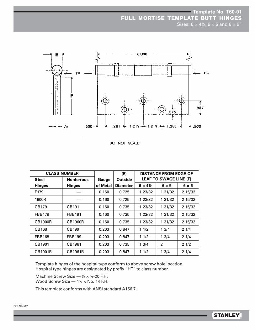
Template No. T60-01
FULL MORFULL MORFULL MORFULL MORFULL MORTISE TISE TISE TISE TISE TEMPLATEMPLATEMPLATEMPLATEMPLATE BTE BTE BTE BTE BUTT HINGESUTT HINGESUTT HINGESUTT HINGESUTT HINGESSizes: 6 × 4½, 6 × 5 and 6 × 6”
Template hinges of the hospital type conform to above screw hole location.Hospital type hinges are designated by prefix “HT” to class number.
Machine Screw Size — ½ × ¼-20 F.H.Wood Screw Size — 1½ × No. 14 F.H.
This template conforms with ANSI standard A156.7.
(E)
Steel Nonferrous Gauge Outside
Hinges Hinges of Metal Diameter 6 × 4½ 6 × 5 6 × 6
F179 — 0.160 0.725 1 23/32 1 31/32 2 15/32
1900R — 0.160 0.725 1 23/32 1 31/32 2 15/32
CB179 CB191 0.160 0.735 1 23/32 1 31/32 2 15/32
FBB179 FBB191 0.160 0.735 1 23/32 1 31/32 2 15/32
CB1900R CB1960R 0.160 0.735 1 23/32 1 31/32 2 15/32
CB168 CB199 0.203 0.847 1 1/2 1 3/4 2 1/4
FBB168 FBB199 0.203 0.847 1 1/2 1 3/4 2 1/4
CB1901 CB1961 0.203 0.735 1 3/4 2 2 1/2
CB1901R CB1961R 0.203 0.847 1 1/2 1 3/4 2 1/4
CLASS NUMBER DISTANCE FROM EDGE OF
LEAF TO SWAGE LINE (F)

®
Rev. No. 3/06
Template No. T45-01
FULL MORFULL MORFULL MORFULL MORFULL MORTISE TISE TISE TISE TISE TEMPLATEMPLATEMPLATEMPLATEMPLATE BTE BTE BTE BTE BUTT HINGESUTT HINGESUTT HINGESUTT HINGESUTT HINGESSizes: 4½ × 4, 4½ × 4½, 4½ × 5, 4½ × 6, 4½ × 7 and 4½ × 8”
Template hinges of the hospital type conform to above screw hole location.Hospital type hinges are designated by prefix “HT” to class number (except on #2060).Also available in RD2060 1/4 radius corner and RD2068 5/8 radius corner.
Machine Screw Size — ½ × 12-24 F.H.Wood Screw Size — 1¼ × No. 12 F.H.
This template conforms with ANSI standard A156.7.
E
F
1/ 16
5/ 8 R1/ 4 R
1 .125
4 .500
.508 .5081 .2 34 1 .125
1 .000
.375
(E)
Steel Nonferrous Gauge Outside
Hinges Hinges of Metal Diameter 4½ × 4 4½ × 4½ 4½ × 5 4½ × 6 4½ × 7 4½ × 8
F179 F191 0.134 0.605 1 5/8 1 29/32 2 5/32 2 21/32 3 5/32 2 21/32
1900 1960 0.134 0.540 1 5/8 1 13/16 — — — —
1900R 1960R 0.134 0.605 1 5/8 1 29/32 — — — —
CB179 CB191 0.134 0.625 1 5/8 1 25/32 2 3/32 2 19/32 — —
FBB179 FBB191 0.134 0.625 1 5/8 1 25/32 2 3/32 2 19/32 — —
CB1900 CB1960 0.134 0.540 1 5/8 1 13/16 — — — —
CB1900R CB1960R 0.134 0.625 1 5/8 1 25/32 2 3/32 2 19/32 — —
CB168 CB199 0.180 0.698 1 15/32 1 23/32 1 31/32 2 15/32 2 31/32 3 15/32
FBB168 FBB199 0.180 0.698 1 15/32 1 23/32 1 31/32 2 15/32 2 31/32 3 15/32
IHTCB168 IHTCB199 0.180 0.698 1 15/32 1 23/32 — — — —
— CB0701 0.180 0.698 1 15/32 1 23/32 — — — —
CB1901 CB1961 0.180 0.690 — 1 13/16 — — — —
CB1901R CB1961R 0.180 0.698 1 15/32 1 23/32 1 31/32 2 15/32 2 31/32 3 15/32
IHTCB1901 IHTCB1961 0.180 0.690 1 15/32 1 13/16 — — — —
IHTCB1901R IHTCB1961R 0.180 0.698 1 15/32 1 23/32 — — — —
2060R — 0.134 0.783 1 5/8 1 27/32 — — — —
DISTANCE FROM EDGE OF LEAF TO SWAGE LINE (F)CLASS NUMBER

®
Rev. No. 3/06
Template No. T45-16
FULL MORFULL MORFULL MORFULL MORFULL MORTISE TISE TISE TISE TISE TEMPLATEMPLATEMPLATEMPLATEMPLATE BTE BTE BTE BTE BUTT HINGES UTT HINGES UTT HINGES UTT HINGES UTT HINGES WITH CONCEALED WITH CONCEALED WITH CONCEALED WITH CONCEALED WITH CONCEALED WIRESWIRESWIRESWIRESWIRESSizes: 4½ × 4 and 4½ × 4½”
(E)
Steel Nonferrous Gauge Outside
Hinges Hinges of Metal Diameter 4½ × 4 4½ × 4½
CECB1900 CECB1960 0.134 0.540 1 5/8 1 13/16
CECB1900R CECB1960R 0.134 0.625 1 5/8 1 25/32
CECB1901 CECB1961 0.180 0.690 — 1 13/16
CECB1901R CECB1961R 0.180 0.698 — 1 23/32
CEIHTCB1901 CEIHTCB1961 0.180 0.690 — 1 23/32
CEIHTCB1901R CEIHTCB1961R 0.180 0.698 — 1 23/32
CLASS NUMBER DISTANCE FROM EDGE OF
LEAF TO SWAGE LINE (F)
NOTE: Prefix IHT indicates Instutional Hinge.Machine Screw Size — ½ × 12-24 F.H.Wood Screw Size — 1¼ × No. 12 F.H.
1.000
.375
.508
1.125
1.2344.500
1.125
1.125.508
3.375
E
FF
.625
1.125
3.375
.625
AA
BB
Drill a hole in the hinge reinforcement largeenough to allow the wires and connectors(wire nuts) to pass through freely.
De-burr both faces of the hole and prime tohelp avoid damaging wire insulation.
Use a JB-2R Junction Box. See templateT90-38R.
NOTES:1 Available with four (4) wires (use suffix-54),
six (6) wires (use suffix-56), and eight (8)wires (use suffix-58).
2 Available with both concealed wires and aconcealed switch. See template T45-20.
1/32 (1/16 clearancebetween parallelleaves when hingeis closed.)
Wire ClusterDia. 0.187 max.
DO NOT SCALE
Wires emerge onlyhere on R.H. hinges.
Wires emerge onlyhere on L.H. hinges.
A and B holes require a3/4 hole for through wires.

®
Rev. No. 3/06
Template No. T45-20
FULL MORFULL MORFULL MORFULL MORFULL MORTISE TISE TISE TISE TISE TEMPLATEMPLATEMPLATEMPLATEMPLATE BTE BTE BTE BTE BUTT HINGES UTT HINGES UTT HINGES UTT HINGES UTT HINGES WITH CONCEALEDWITH CONCEALEDWITH CONCEALEDWITH CONCEALEDWITH CONCEALEDWIRES WIRES WIRES WIRES WIRES AND CONCEALED SWITAND CONCEALED SWITAND CONCEALED SWITAND CONCEALED SWITAND CONCEALED SWITCHCHCHCHCH
Sizes: 4½ × 4 and 4½ × 4½”
E
FF
.500 .750 dia
DC
1.000
.375
.508
1.125
1.2344.500
1.125
1.125
.484 dia .484 dia
.508
3.375
.625
1.125
3.375
2.250
.625
AA
BB
Machine Screw Size — ½ × 12-24 F.H.Wood Screw Size — 1 ¼ × No. 12 F.H.
(E)
Steel Nonferrous Gauge Outside C D
Hinges Hinges of Metal Diameter 4½ × 4 4½ × 4½
CECSCB1900 CECSCB1960 0.134 0.540 1 5/8 1 13/16 1.234 0.875
CECSCB1900R CECSCB1960R 0.134 0.625 1 5/8 1 25/32 1.234 0.875
CECSCB1901 CECSCB1961 0.180 0.690 — 1 13/16 1.187 0.828
CECSCB1901R CECSCB1961R 0.180 0.698 — 1 23/32 1.187 0.828
CLASS NUMBER DISTANCE FROM EDGE OF
LEAF TO SWAGE LINE (F)
1/32 (1/16) clearance between parallelleaves when hinge is closed).
Drill a 0.750 inch diameter hole in thehinge reinforcement to allow thewires and connectors (wire nuts) topass through freely. A larger hole maybe required, depending on connectorsize.
De-burr both faces of the hole andprime to help avoid damaging wireinsulation.
Switches mount in jamb leaf. Arrange-ment for R.H. door shown. Specifyhand when ordering.
NOTES:1 Available with four (4) wires (suffix-54), six (6) wires
(suffix-56), or eight (8) wires (suffix-58).2 0.750 diameter recommended hole size for switch
housing clearance.3 It is suggested that the hinge be mounted in the center
or lower position on the door, rather than the top.4 For reference, see template for JB-2B Junction Box
(T90-38R).
This view shows CS construction only.
Magnet Switch
Door preparationfor magnet only.
Wire cluster dia.0.187 max.
Wires emerge onlyhere on R.H. hinges.
Wires emerge onlyhere on L.H. hinges.
DO NOT SCALE
A and B holes require a 3/4 hole for through wires.

®
Rev. No. 2/06
Template No. T45-17
FULL MORFULL MORFULL MORFULL MORFULL MORTISE TISE TISE TISE TISE TEMPLATEMPLATEMPLATEMPLATEMPLATE BTE BTE BTE BTE BUTT HINGES UTT HINGES UTT HINGES UTT HINGES UTT HINGES WITH CONCEALED SWITWITH CONCEALED SWITWITH CONCEALED SWITWITH CONCEALED SWITWITH CONCEALED SWITCHCHCHCHCHSizes: 4½ × 4 and 4½ × 4½”
Machine Screw Size — 12-24 × ½ F.H.Wood Screw Size — No. 12 × 1¼ F.H.
Contractor should be cautioned to preventmortar from interfering with wiring.
1/32 (1/16 clearance between parallel leaves whenhinge is closed.)
NOTES:1 Available with both a concealed switch and
concealed wires. See templates T45-19 orT45-20.
2 0.750 diameter is the recommended hole size forswitch housing clearance.
3 It is suggested that the hinge be mounted in thecenter or lower position on the door, rather thanthe top.
4 Switch mounts in jamb leaf. Arrangement forL.H. door shown. Specify hand when ordering.
5 Use JB-2R Junction Box. See Template T90-38R.
NOTE: Prefix IHT indicates Institutional Hinge.
(E)
Steel Nonferrous Gauge Outside
Hinges Hinges of Metal Diameter 4½ × 4 4½ × 4½
CSCB179 CSCB191 0.134 0.625 1 5/8 1 25/32 1.234 0.875
CSFBB179 CSFBB191 0.134 0.625 1 5/8 1 25/32 1.234 0.875
CSCB1900 CSCB1960 0.134 0.540 1 5/8 1 13/16 1.234 0.875
CSCB1900R CSCB1960R 0.134 0.625 1 5/8 1 25/32 1.234 0.875
CSCB168 CSCB199 0.180 0.698 — 1 23/32 1.187 0.828
CSFBB168 CSFBB199 0.180 0.698 — 1 23/32 1.187 0.828
CSIHTCB168 CSIHTCB199 0.180 0.698 — 1 23/32 1.187 0.828
CSCB1901 CSCB1961 0.180 0.690 — 1 13/16 1.187 0.828
CSCB1901R CSCB1961R 0.180 0.698 — 1 23/32 0.187 0.828
CSIHTCB1901 CSIHTCB1961 0.180 0.690 — 1 13/16 1.187 0.828
CSIHTCB1901R CSIHTCB1961R 0.180 0.698 — 1 23/32 0.187 0.828
B
CLASS NUMBER DISTANCE FROM EDGE OF LEAF
TO SWAGE LINE (F) A

®
Rev. No. 1/06
Template No. T45-10
RAISED BRAISED BRAISED BRAISED BRAISED BARREL ARREL ARREL ARREL ARREL TEMPLATEMPLATEMPLATEMPLATEMPLATE BTE BTE BTE BTE BUTT HINGES FOR DOORS UTT HINGES FOR DOORS UTT HINGES FOR DOORS UTT HINGES FOR DOORS UTT HINGES FOR DOORS WITHWITHWITHWITHWITHSQSQSQSQSQUUUUUARE EDGE HINGE STILESARE EDGE HINGE STILESARE EDGE HINGE STILESARE EDGE HINGE STILESARE EDGE HINGE STILES
Size: 4½ × 4½”
Template hinges of the hospital type conform to above screw hole location.Hospital type hinges are designated by prefix “HT” to class number.
Machine Screw Size — ½ × 12-24 F.H.Wood Screw Size — 1¼ × No. 12 F.H.
DO NOT SCALE
(E)
Steel Nonferrous Gauge Outside E F
Hinges Hinges of Metal Diameter (See Note 2)
RB-CB179 RB-CB191 0.134 0.625 1/2 11/32
RB-FBB179 RB-FBB191 0.134 0.625 1/2 11/32
RB-CB1900 RB-CB1960 0.134 0.540 1/2 11/32
RB-CB1900R RB-CB1960R 0.134 0.625 1/2 11/32
RB-CB168 RB-CB199 0.180 0.698 5/8 3/8
RB-FBB168 RB-FBB199 0.180 0.698 5/8 3/8
RB-CB1901 RB-CB1961 0.180 0.690 5/8 3/8
RB-CB1901R RB-CB1961R 0.180 0.698 5/8 3/8
CLASS NUMBER
NOTES:1 Side clearance between door and frame governed by depth of
mortise. (3/32 betwen door and frame suggested).2 Recommended for approx. 1/16 swinging clearance between door
and stop. For raised barrel mortise and surface applications onbeveled stile door installations, see template drawing T45-11.

®
Rev. No. 1/06
Template No. T45-11
RAISED BRAISED BRAISED BRAISED BRAISED BARREL ARREL ARREL ARREL ARREL TEMPLATEMPLATEMPLATEMPLATEMPLATE BTE BTE BTE BTE BUTT HINGES FOR DOORS UTT HINGES FOR DOORS UTT HINGES FOR DOORS UTT HINGES FOR DOORS UTT HINGES FOR DOORS WITHWITHWITHWITHWITHBEVELED EDGE HINGE STILESBEVELED EDGE HINGE STILESBEVELED EDGE HINGE STILESBEVELED EDGE HINGE STILESBEVELED EDGE HINGE STILES
Size: 4½ × 4½”
(E)
Steel Nonferrous Gauge Outside E F
Hinges Hinges of Metal Diameter (See Note 3)
RB-CB179 RB-CB191 0.134 0.625 1/2 11/32
RB-FBB179 RB-FBB191 0.134 0.625 1/2 11/32
RB-CB1900 RB-CB1960 0.134 0.540 1/2 11/32
RB-CB1900R RB-CB1960R 0.134 0.625 1/2 11/32
RB-CB168 RB-CB199 0.180 0.698 5/8 3/8
RB-FBB168 RB-FBB199 0.180 0.698 5/8 3/8
RB-CB1901 RB-CB1961 0.180 0.690 5/8 3/8
RB-CB1901R RB-CB1961R 0.180 0.698 5/8 3/8
CLASS NUMBER
NOTES:1 Clearance between leaves on plane of door face.2 Side clearance between door and frame goverened by depth
of mortise. (3/32 between door and frame suggested).3 Recommended for approx. 1/16 swinging clearance between
door and stop.4 For raised barrel mortise and surface applications on square
stile door installations, see template drawing T45-10.
Template hinges of the hospital type conform to above screw hole location.Hospital type hinges are designated by prefix “HT” to class number.
Machine Screw Size — ½ × 12-24 F.H.Wood Screw Size — 1¼ × No. 12 F.H.
DO NOT SCALE
®
Rev. No. 1/06
Template No. T50-01
FULL MORFULL MORFULL MORFULL MORFULL MORTISE TISE TISE TISE TISE TEMPLATEMPLATEMPLATEMPLATEMPLATE BTE BTE BTE BTE BUTT HINGESUTT HINGESUTT HINGESUTT HINGESUTT HINGESSizes: 5 × 4, 5 × 4½, 5 × 5, 5 × 7 and 5 × 8”
Template hinges of the hospital type conform to above screw hole location.Hospital type hinges are designated by prefix “HT” to class number.Also available “RD” radius corners (1/4 or 5/8).Machine Screw Size — ½ × 12-24 F.H.
Wood Screw Size —
NOTE: Prefix IHT indicates Institutional Hinge.
This template conforms with ANSI standard A156.7.
1¼ × No. 12 F.H. for regular weight (0.146) hinges1½ × No. 12 F.H. for extra heavy weight (0.190) hinges[
E
F
1/ 16
5/ 8 R1/ 4 R
1 .2 50
5 .000
.508 .5081 .484 1 .2 50
1 .000
.37 5
(E)
Steel Nonferrous Gauge Outside
Hinges Hinges of Metal Diameter 5 × 4 5 × 4½ 5 × 5 5 × 7 5 × 8
F179 F191 0.146 0.661 1 5/8 1 13/16 2 1/16 3 1/16 3 9/16
1900 1960 0.146 0.580 1 5/8 1 3/4 2 — —
1900R 1960R 0.146 0.661 1 5/8 1 13/16 2 1/16 3 1/16 3 9/16
CB179 CB191 0.146 0.669 1 5/8 1 13/16 2 1/16 3 1/16 3 9/16
FBB179 FBB191 0.146 0.669 1 5/8 1 13/16 2 1/16 3 1/16 3 9/16
CB1900 CB1960 0.146 0.580 1 5/8 1 55/64 2 7/64 — —
CB1900R CB1960R 0.146 0.669 1 5/8 1 13/16 2 1/16 3 1/16 3 9/16
CB168 CB199 0.190 0.748 1 15/32 1 23/32 1 31/32 2 31/32 3 15/32
FBB168 FBB199 0.190 0.748 1 15/32 1 23/32 1 31/32 2 31/32 3 15/32
IHTCB168 IHTCB199 0.190 0.748 — 1 23/32 — — —
CB1901 CB1961 0.190 0.715 — 1 13/16 — — —
CB1901R CB1961R 0.190 0.748 1 15/32 2 23/32 1 31/32 2 31/32 3 15/32
IHTCB1901 IHTCB1961 0.190 0.715 — 1 13/16 — — —
IHTCB1901R IHTCB1961R 0.190 0.748 — 1 23/32 — — —
CLASS NUMBERDISTANCE FROM EDGE OF LEAF TO SWAGE LINE (F)
DO NOT SCALE
®
Rev. No. 3/06
Template No. T50-16
FULL MORFULL MORFULL MORFULL MORFULL MORTISE TISE TISE TISE TISE TEMPLATEMPLATEMPLATEMPLATEMPLATE BTE BTE BTE BTE BUTT HINGES UTT HINGES UTT HINGES UTT HINGES UTT HINGES WITH CONCEALED WITH CONCEALED WITH CONCEALED WITH CONCEALED WITH CONCEALED WIRESWIRESWIRESWIRESWIRESSize: 5 × 4½”
1.000
.375
.508
1.250
1.4845.000
1.250
1.250.508
3.750
E
FF
.625
1.250
3.750
.625
AA
BB
Machine Screw Size — ½ × 12-24 F.H.
Wood Screw Size — 1¼ × No. 12 F.H. for standard weight (0.146) hinges1½ × No. 12 F.H. for heavy weight (0.190) hinges[
Drill a 0.750 inch diameter hole in the hingereinforcement to allow the wires and connectors(wire nuts) to pass through freely. A larger holemay be required, depending on connector size.
De-burr both faces of the hole and prime to helpavoid damaging wire insulation.
Use a JB-2R Junction Box. See template T90-38R.
NOTE: Prefix IHT indicatesInstitutional Hinge.
(E)
Steel Nonferrous Gauge Outside
Hinges Hinges of Metal Diameter 5 × 4½
CECB1900 CECB1960 0.146 0.580 1 55/64
CECB1900R CECB1960R 0.146 0.669 1 13/16
CECB1901 CECB1961 0.190 0.715 1 13/16
CECB1901R CECB1961R 0.190 0.748 1 23/32
CEIHTCB1901 CEIHTCB1961 0.190 0.715 1 13/16
CEIHTCB1901R CEIHTCB1961R 0.190 0.748 1 23/32
CLASS NUMBER DISTANCE FROM EDGE OF
LEAF TO SWAGE LINE (F)
NOTES:1 Available with four (4) wires (use suffix-54), six
(6) wires (use suffix-56), or eight (8) wires (usesuffix-58).
2 Available with both concealed wires and aconcealed switch. See template T50-20.
DO NOT SCALE
Wires emerge onlyhere on R.H. hinges.
Wires emerge onlyhere on L.H. hinges.
Wire cluster dia.0.187 max.
1/32 (1/16 clear-ance betweenparallel leaveswhen hinge isclosed.)
A and B holes require 3/4 holefor through wires.

®
Rev. No. 3/06
Template No. T50-20
FULL MORFULL MORFULL MORFULL MORFULL MORTISE TISE TISE TISE TISE TEMPLATEMPLATEMPLATEMPLATEMPLATE BTE BTE BTE BTE BUTT HINGES UTT HINGES UTT HINGES UTT HINGES UTT HINGES WITHWITHWITHWITHWITHCONCEALED CONCEALED CONCEALED CONCEALED CONCEALED WIRES WIRES WIRES WIRES WIRES AND CONCEALED SWITAND CONCEALED SWITAND CONCEALED SWITAND CONCEALED SWITAND CONCEALED SWITCHCHCHCHCH
Size: 5 × 4½”
E
FF
.500 .750 dia
DC
1.000
.375
.508
1.250
1.4845.000
1.250
1.250
.484 dia.484 dia
.508
3.750
.625
1.250
3.750
2.500
.625
AA
BB
Machine Screw Size — ½ × 12-24 F.H.
Wood Screw Size —
1/32 (1/16 clearance between hinge leaveswhen parallel.)
Drill a 0.750 inch diameter hole in the hingereinforcement to allow the wires and connec-tors (wire nuts) to pass through freely. Alarger hole may be required, depending onconnector size.
De-burr both faces of the hole and prime tohelp avoid damaging wire insulation.
Switches mount in jamb leaf. Arrangementfor R.H. door shown. Specify the hand of doorwhen ordering.
NOTES:1 Available with four (4) wires (use suffix-54), six (6) wires
(use suffix-56) or eight (8) wires (use suffix-58).2 It is suggested that the hinge be mounted in the center or
lowerposition on the door, rather than the top.
3 0.750 diameter recommended hole size for switch housingclearance.
4 Use a JB-2R Junction Box. See template T90-38R.
(E)
Steel Nonferrous Gauge Outside C D
Hinges Hinges of Metal Diameter 5 × 4½
CECSCB1900 CECSCB1960 0.146 0.580 1 55/64 1.218 0.859
CECSCB1900R CECSCB1960R 0.146 0.699 1 13/16 1.218 0.859
CECSCB1901 CECSCB1961 0.190 0.715 1 13/16 1.172 0.812
CECSCB1901R CECSCB1961R 0.190 0.748 1 22/32 1.172 0.812
CLASS NUMBER DISTANCE FROM EDGE OF
LEAF TO SWAGE LINE (F)
1¼ × No. 12 F.H. for standard weight (0.146) hinges1½ × No. 12 F.H. for heavy weight (0.190) hinges[
Magnet Switch
Door preparationfor magnet only.
Wire cluster dia.0.187 max.
Wires emerge onlyhere on R.H. hinges.
Wires emerge onlyhere on L.H. hinges.
DO NOT SCALE
A and B holes require a 3/4 hole for through wires.
This view shows CS construction only.

®
Rev. No. 2/06
Template No. T50-17
FULL MORFULL MORFULL MORFULL MORFULL MORTISE TISE TISE TISE TISE TEMPLATEMPLATEMPLATEMPLATEMPLATE BTE BTE BTE BTE BUTT HINGES UTT HINGES UTT HINGES UTT HINGES UTT HINGES WITH CONCEALED SWITWITH CONCEALED SWITWITH CONCEALED SWITWITH CONCEALED SWITWITH CONCEALED SWITCHCHCHCHCHSize: 5 × 4½”
Contractor should be cautioned to preventmortar from interfering with wiring.
1/32 (1/16 clearance between parallel leaves when hingeis closed.)
NOTES:1 Available with both a concealed switch and con-
cealed wires. See templates T50-19 or T50-20.2 0.750 diameter is the recommended hole size for
switch housing clearance.3 It is suggested that the hinge be mounted in the
center or lower position on the door, rather than thetop.
4 Switch mounts in jamb leaf. Arrangement for L.H.door show. Specify hand when ordering.
5 Use a JB-2R Junction Box. See Template T90-38R.
Machine Screw Size — 12-24 × ½ F.H.Wood Screw Size — No. 12 × 1¼ F.H. for standard weight (0.146) hinges
No. 12 × 1½ F.H. for heavy weight (0.190) hinges
(E)
Steel Nonferrous Gauge Outside A B
Hinges Hinges of Metal Diameter 5 × 4½
CSCB179 CSCB191 0.146 0.669 1 13/16 1.218 0.859
CSFBB179 CSFBB191 0.146 0.669 1 13/16 1.218 0.859
CSCB1900 CSCB1960 0.146 0.580 1 55/64 1.218 0.859
CSCB1900R CSCB1960R 0.146 0.669 1 13/16 1.218 0.859
CSCB168 CSCB199 0.190 0.748 1 23/32 1.172 0.812
CSFBB168 CSFBB199 0.190 0.748 1 23/32 1.172 0.812
CSIHTCB168 CSIHTCB199 0.190 0.748 1 23/32 1.172 0.812
CSCB1901 CSCB1961 0.190 0.715 1 13/16 1.172 0.812
CSCB1901R CSCB1961R 0.190 0.015 1 23/32 1.172 0.812
CSIHTCB1901 CSIHTCB1961 0.180 0.715 1 13/16 1.172 0.812
CSIHTCB1901R CSIHTCB1961R 0.190 0.748 1 23/32 1.172 0.812
CLASS NUMBER DISTANCE FROM EDGE OF LEAF TO
SWAGE LINE (F)

®
Rev. No. 1/06
Template No. T50-13
RAISED BRAISED BRAISED BRAISED BRAISED BARREL ARREL ARREL ARREL ARREL TEMPLATEMPLATEMPLATEMPLATEMPLATE BTE BTE BTE BTE BUTT HINGES FOR DOORSUTT HINGES FOR DOORSUTT HINGES FOR DOORSUTT HINGES FOR DOORSUTT HINGES FOR DOORSWITH SQWITH SQWITH SQWITH SQWITH SQUUUUUARE EDGE HINGE STILESARE EDGE HINGE STILESARE EDGE HINGE STILESARE EDGE HINGE STILESARE EDGE HINGE STILES
Size: 5 × 4½”
Template hinges of the hospital type conform to above screw hole location.Hospital type hinges are designated by prefix “HT” to class number.Machine Screw Size — ½ × 12-24 F.H.
Wood Screw Size —
(D)
Steel Nonferrous Gauge Outside E F
Hinges Hinges of Metal Diameter (See Note 3)
RB-CB179 RB-CB191 0.146 0.669 9/16 11/32
RB-FBB179 RB-FBB191 0.146 0.669 9/16 11/32
RB-CB1900 RB-CB1960 0.146 0.580 9/16 11/32
RB-CB1900R RB-CB1960R 0.146 0.580 9/16 11/32
RB-CB168 RB-CB199 0.190 0.748 21/32 3/8
RB-FBB168 RB-FBB199 0.190 0.748 21/32 3/8
RB-CB1901 RB-CB1961 0.190 0.715 21/32 3/8
RB-CB1901R RB-CB1961R 0.190 0.748 21/32 3/8
CLASS NUMBER
NOTES:1 Side clearance between door and frame governed by depth of
mortise in door (3/32 between door and frame suggested).2 Recommended for approx. 1/16 swinging clearance between
door and stop.3 For raised barrel mortise and surface applications on beveled
stile door installations, see template drawing T50-14.
1¼ × No. 12 F.H. for standard weight (0.146) hinges1½ × No. 12 F.H. for heavy weight (0.190) hinges[

®
Rev. No. 1/06
Template No. T50-14
RAISED BRAISED BRAISED BRAISED BRAISED BARREL ARREL ARREL ARREL ARREL TEMPLATEMPLATEMPLATEMPLATEMPLATE BTE BTE BTE BTE BUTT HINGES FOR DOORSUTT HINGES FOR DOORSUTT HINGES FOR DOORSUTT HINGES FOR DOORSUTT HINGES FOR DOORSWITH BEVELED EDGE HINGE STILESWITH BEVELED EDGE HINGE STILESWITH BEVELED EDGE HINGE STILESWITH BEVELED EDGE HINGE STILESWITH BEVELED EDGE HINGE STILES
Size: 5 × 4½”
Template hinges of the hospital type conform to above screw hole location.Hospital type hinges are designated by prefix “HT” to class number.Machine Screw Size — ½ × 12-24 F.H.
Wood Screw Size —
NOTES:1 Clearance between leaves on plane of door face.2 Side clearance between door and frame governed by depth of
mortise in door (3/32 between door and frame suggested).3 Recommended for approx. 1/16 swinging clearance between
door and stop.4 For raised barrel mortise and surface applications on square
stile door installations, see template drawing T50-13.
1¼ × No. 12 F.H. for standard weight (0.146) hinges1½ × No. 12 F.H. for extra heavy weight (0.190) hinges[
(D)
Steel Nonferrous Gauge Outside E F
Hinges Hinges of Metal Diameter (See Note 3)
RB-CB179 RB-CB191 0.146 0.669 9/16 11/32
RB-FBB179 RB-FBB191 0.146 0.669 9/16 11/32
RB-CB1900 RB-CB1960 0.146 0.580 9/16 11/32
RB-CB1900R RB-CB1960R 0.146 0.669 9/16 11/32
RB-CB168 RB-CB199 0.190 0.748 21/32 3/8
RB-FBB168 RB-FBB199 0.190 0.748 21/32 3/8
RB-CB1901 RB-CB1961 0.190 0.715 21/32 3/8
RB-CB1901R RB-CB1961R 0.190 0.748 21/32 3/8
CLASS NUMBER
(3°-35’)

®
Rev. No. 4/07
Template No. T60-01
FULL MORFULL MORFULL MORFULL MORFULL MORTISE TISE TISE TISE TISE TEMPLATEMPLATEMPLATEMPLATEMPLATE BTE BTE BTE BTE BUTT HINGESUTT HINGESUTT HINGESUTT HINGESUTT HINGESSizes: 6 × 4½, 6 × 5 and 6 × 6”
Template hinges of the hospital type conform to above screw hole location.Hospital type hinges are designated by prefix “HT” to class number.
Machine Screw Size — ½ × ¼-20 F.H.Wood Screw Size — 1½ × No. 14 F.H.
This template conforms with ANSI standard A156.7.
(E)
Steel Nonferrous Gauge Outside
Hinges Hinges of Metal Diameter 6 × 4½ 6 × 5 6 × 6
F179 — 0.160 0.725 1 23/32 1 31/32 2 15/32
1900R — 0.160 0.725 1 23/32 1 31/32 2 15/32
CB179 CB191 0.160 0.735 1 23/32 1 31/32 2 15/32
FBB179 FBB191 0.160 0.735 1 23/32 1 31/32 2 15/32
CB1900R CB1960R 0.160 0.735 1 23/32 1 31/32 2 15/32
CB168 CB199 0.203 0.847 1 1/2 1 3/4 2 1/4
FBB168 FBB199 0.203 0.847 1 1/2 1 3/4 2 1/4
CB1901 CB1961 0.203 0.735 1 3/4 2 2 1/2
CB1901R CB1961R 0.203 0.847 1 1/2 1 3/4 2 1/4
CLASS NUMBER DISTANCE FROM EDGE OF
LEAF TO SWAGE LINE (F)

®
Rev. No. 1/06
Template No. T45-60
FULL SURFFULL SURFFULL SURFFULL SURFFULL SURFAAAAACE CE CE CE CE TEMPLATEMPLATEMPLATEMPLATEMPLATE HINGE FOR MINERAL CORE DOORSTE HINGE FOR MINERAL CORE DOORSTE HINGE FOR MINERAL CORE DOORSTE HINGE FOR MINERAL CORE DOORSTE HINGE FOR MINERAL CORE DOORSWITH CHANNEL IRON JAMBSWITH CHANNEL IRON JAMBSWITH CHANNEL IRON JAMBSWITH CHANNEL IRON JAMBSWITH CHANNEL IRON JAMBS
Size: 4½”
Template hinges of the hospital type conform to above screw hole location.Hospital type hinges are designated by prefix “HT” to class number.
Machine Screw Size — Jamb Leaf — ½ × 12-24 O.H. Door Leaf — 2 × ¼-20 O.H.M.S. with grommet nut
This template conforms with ANSI standard A156.7.
(C) (D) (E)
Steel Nonferrous Gauge Door Leaf Jamb Leaf Outside
Hinges Hinges of Metal Offset Offset Diameter
CB171 CB110 0.134 9/16 7/16 0.625
FBB171 FBB110 0.134 9/16 7/16 0.625
CB1930 CB1990 0.134 1/2 3/8 0.540
CB1930R CB1990R 0.134 9/16 7/16 0.625
CB169 CB109 0.180 5/8 1/2 0.698
FBB169 FBB109 0.180 5/8 1/2 0.698
CB1931 CB1991 0.180 9/16 7/16 0.690
CB1931R CB1991R 0.180 5/8 1/2 0.698
CLASS NUMBER

®
Rev. No. 1/06
Template No. T50-60
FULL SURFFULL SURFFULL SURFFULL SURFFULL SURFAAAAACE CE CE CE CE TEMPLATEMPLATEMPLATEMPLATEMPLATE HINGE FOR MINERAL CORE DOORSTE HINGE FOR MINERAL CORE DOORSTE HINGE FOR MINERAL CORE DOORSTE HINGE FOR MINERAL CORE DOORSTE HINGE FOR MINERAL CORE DOORSWITH CHANNEL IRON JAMBSWITH CHANNEL IRON JAMBSWITH CHANNEL IRON JAMBSWITH CHANNEL IRON JAMBSWITH CHANNEL IRON JAMBS
Size: 5”
Template hinges of the hospital type conform to above screw hole location.Hospital type hinges are designated by prefix “HT” to class number.
Machine Screw Size — Jamb Leaf — ½ × 12-24 O.H. Door Leaf — 2 × ¼-20 O.H.M.S. with grommet nut
This template conforms with ANSI standard A156.7.
(C) (D) (E)
Steel Nonferrous Gauge Door Leaf Jamb Leaf Outside
Hinges Hinges of Metal Offset Offset Diameter
CB171 CB110 0.146 9/16 7/16 0.669
FBB171 FBB110 0.146 9/16 7/16 0.669
CB1930 CB1990 0.146 17/32 13/32 0.781
CB1930R CB1990R 0.146 9/16 7/16 0.669
CB169 CB109 0.190 5/8 1/2 0.748
FBB169 FBB109 0.190 5/8 1/2 0.748
CB1931 CB1991 0.190 19/32 15/32 0.710
CB1931R CB1991R 0.190 5/8 1/2 0.748
CLASS NUMBER

®
Rev. No. 1/06
Template No. T60-60
FULL SURFFULL SURFFULL SURFFULL SURFFULL SURFAAAAACE CE CE CE CE TEMPLATEMPLATEMPLATEMPLATEMPLATE HINGES FOR MINERAL CORE DOORSTE HINGES FOR MINERAL CORE DOORSTE HINGES FOR MINERAL CORE DOORSTE HINGES FOR MINERAL CORE DOORSTE HINGES FOR MINERAL CORE DOORSWITH CHANNEL IRON JAMBSWITH CHANNEL IRON JAMBSWITH CHANNEL IRON JAMBSWITH CHANNEL IRON JAMBSWITH CHANNEL IRON JAMBS
Size: 6”
Template hinges of the hospital type conform to above screw hole location.Hospital type hinges are designated by prefix “HT” to class number.
Machine Screw Size — Jamb Leaf — ½ × ¼-20 O.H. Door Leaf — 2 × ¼-20 O.H.M.S. with grommet nut
This template conforms with ANSI standard A156.7.
(E)
Steel Nonferrous Gauge Outside
Hinges Hinges of Metal Diameter
CB169 CB109 0.203 0.847
FBB169 FBB109 0.203 0.847
CB1931 CB1991 0.203 0.735
CB1931R CB1991R 0.203 0.847
CLASS NUMBER

®
Rev. No. 1/06
Template No. T45-40
HALF MORHALF MORHALF MORHALF MORHALF MORTISE TISE TISE TISE TISE TEMPLATEMPLATEMPLATEMPLATEMPLATE HINGESTE HINGESTE HINGESTE HINGESTE HINGESSize: 4½”
Template hinges of the hospital type conform to above screw hole location.Hospital type hinges are designated by prefix “HT” to class number.
Machine Screw Size — Jamb Leaf — ½ × 12-24 O.H. Door Leaf — ½ × 12-24 F.H.
This template conforms with ANSI standard A156.7.
(C) (D) (E)
Steel Nonferrous Gauge Door Jamb Leaf Outside
Hinges Hinges of Metal Leaf Offset Diameter
F167 — 0.134 2 1/16 7/16 0.605
1920R — 0.134 2 1/16 7/16 0.605
CB167 CB108 0.134 2 1/16 7/16 0.625
FBB167 FBB108 0.134 2 1/16 7/16 0.625
CB1920 CB1980 0.134 2 3/8 0.540
CB1920R CB1980R 0.134 2 1/16 7/16 0.625
CB138 CB98 0.180 2 1/8 1/2 0.698
FBB138 FBB98 0.180 2 1/8 1/2 0.698
CB1921 CB1981 0.180 2 1/16 7/16 0.690
CB1921R CB1981R 0.180 2 1/8 1/2 0.698
CLASS NUMBER
DO NOT SCALE
®
Rev. No. 1/06
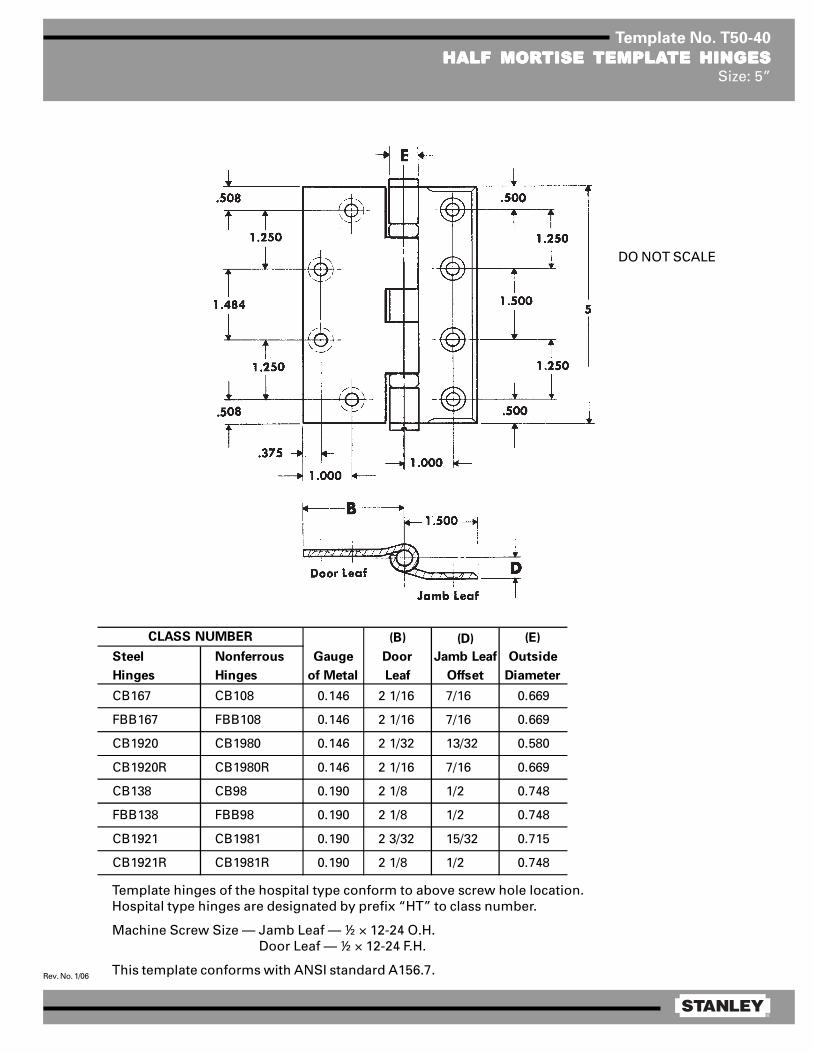
Template No. T50-40
HALF MORHALF MORHALF MORHALF MORHALF MORTISE TISE TISE TISE TISE TEMPLATEMPLATEMPLATEMPLATEMPLATE HINGESTE HINGESTE HINGESTE HINGESTE HINGESSize: 5”
Template hinges of the hospital type conform to above screw hole location.Hospital type hinges are designated by prefix “HT” to class number.
Machine Screw Size — Jamb Leaf — ½ × 12-24 O.H. Door Leaf — ½ × 12-24 F.H.
This template conforms with ANSI standard A156.7.
(B) (D) (E)
Steel Nonferrous Gauge Door Jamb Leaf Outside
Hinges Hinges of Metal Leaf Offset Diameter
CB167 CB108 0.146 2 1/16 7/16 0.669
FBB167 FBB108 0.146 2 1/16 7/16 0.669
CB1920 CB1980 0.146 2 1/32 13/32 0.580
CB1920R CB1980R 0.146 2 1/16 7/16 0.669
CB138 CB98 0.190 2 1/8 1/2 0.748
FBB138 FBB98 0.190 2 1/8 1/2 0.748
CB1921 CB1981 0.190 2 3/32 15/32 0.715
CB1921R CB1981R 0.190 2 1/8 1/2 0.748
CLASS NUMBER
DO NOT SCALE

®
Rev. No. 1/06
Template No. T45-40
HALF MORHALF MORHALF MORHALF MORHALF MORTISE TISE TISE TISE TISE TEMPLATEMPLATEMPLATEMPLATEMPLATE HINGESTE HINGESTE HINGESTE HINGESTE HINGESSize: 4½”
Template hinges of the hospital type conform to above screw hole location.Hospital type hinges are designated by prefix “HT” to class number.
Machine Screw Size — Jamb Leaf — ½ × 12-24 O.H. Door Leaf — ½ × 12-24 F.H.
This template conforms with ANSI standard A156.7.
(C) (D) (E)
Steel Nonferrous Gauge Door Jamb Leaf Outside
Hinges Hinges of Metal Leaf Offset Diameter
F167 — 0.134 2 1/16 7/16 0.605
1920R — 0.134 2 1/16 7/16 0.605
CB167 CB108 0.134 2 1/16 7/16 0.625
FBB167 FBB108 0.134 2 1/16 7/16 0.625
CB1920 CB1980 0.134 2 3/8 0.540
CB1920R CB1980R 0.134 2 1/16 7/16 0.625
CB138 CB98 0.180 2 1/8 1/2 0.698
FBB138 FBB98 0.180 2 1/8 1/2 0.698
CB1921 CB1981 0.180 2 1/16 7/16 0.690
CB1921R CB1981R 0.180 2 1/8 1/2 0.698
CLASS NUMBER
DO NOT SCALE

®
Rev. No. 1/06
Template No. T50-40
HALF MORHALF MORHALF MORHALF MORHALF MORTISE TISE TISE TISE TISE TEMPLATEMPLATEMPLATEMPLATEMPLATE HINGESTE HINGESTE HINGESTE HINGESTE HINGESSize: 5”
Template hinges of the hospital type conform to above screw hole location.Hospital type hinges are designated by prefix “HT” to class number.
Machine Screw Size — Jamb Leaf — ½ × 12-24 O.H. Door Leaf — ½ × 12-24 F.H.
This template conforms with ANSI standard A156.7.
(B) (D) (E)
Steel Nonferrous Gauge Door Jamb Leaf Outside
Hinges Hinges of Metal Leaf Offset Diameter
CB167 CB108 0.146 2 1/16 7/16 0.669
FBB167 FBB108 0.146 2 1/16 7/16 0.669
CB1920 CB1980 0.146 2 1/32 13/32 0.580
CB1920R CB1980R 0.146 2 1/16 7/16 0.669
CB138 CB98 0.190 2 1/8 1/2 0.748
FBB138 FBB98 0.190 2 1/8 1/2 0.748
CB1921 CB1981 0.190 2 3/32 15/32 0.715
CB1921R CB1981R 0.190 2 1/8 1/2 0.748
CLASS NUMBER
DO NOT SCALE

®
Rev. No. 1/06
Template No. T60-40
HALF MORHALF MORHALF MORHALF MORHALF MORTISE TISE TISE TISE TISE TEMPLATEMPLATEMPLATEMPLATEMPLATE HINGESTE HINGESTE HINGESTE HINGESTE HINGESSize: 6”
Template hinges of the hospital type conform to above screw hole location.Hospital type hinges are designated by prefix “HT” to class number.
Machine Screw Size — Jamb Leaf — ½ × ¼-20 O.H. Door Leaf — ½ × ¼-20 F.H.
This template conforms with ANSI standard A156.7.
(E)
Steel Nonferrous Gauge Outside
Hinges Hinges of Metal Diameter
CB138 CB98 0.203 0.847
FBB138 FBB98 0.203 0.847
CB1921 CB1981 0.203 0.735
CB1921R CB1981R 0.203 0.847
CLASS NUMBER
®
Rev. No. 1/06
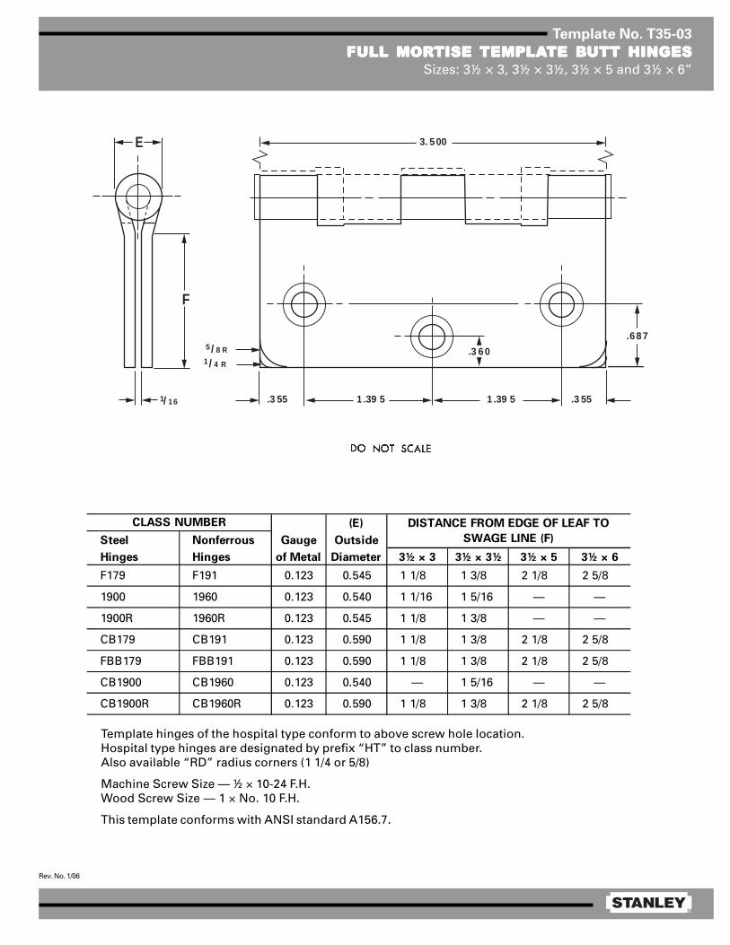
Template No. T35-03
FULL MORFULL MORFULL MORFULL MORFULL MORTISE TISE TISE TISE TISE TEMPLATEMPLATEMPLATEMPLATEMPLATE BTE BTE BTE BTE BUTT HINGESUTT HINGESUTT HINGESUTT HINGESUTT HINGESSizes: 3½ × 3, 3½ × 3½, 3½ × 5 and 3½ × 6”
E
F
1/ 16
5/ 8 R1/ 4 R
1 .39 5
3. 500
.3 55 .3 551 .39 5
.687
.3 60
Template hinges of the hospital type conform to above screw hole location.Hospital type hinges are designated by prefix “HT” to class number.Also available “RD” radius corners (1 1/4 or 5/8)
Machine Screw Size — ½ × 10-24 F.H.Wood Screw Size — 1 × No. 10 F.H.
This template conforms with ANSI standard A156.7.
(E)
Steel Nonferrous Gauge Outside
Hinges Hinges of Metal Diameter 3½ × 3 3½ × 3½ 3½ × 5 3½ × 6
F179 F191 0.123 0.545 1 1/8 1 3/8 2 1/8 2 5/8
1900 1960 0.123 0.540 1 1/16 1 5/16 — —
1900R 1960R 0.123 0.545 1 1/8 1 3/8 — —
CB179 CB191 0.123 0.590 1 1/8 1 3/8 2 1/8 2 5/8
FBB179 FBB191 0.123 0.590 1 1/8 1 3/8 2 1/8 2 5/8
CB1900 CB1960 0.123 0.540 — 1 5/16 — —
CB1900R CB1960R 0.123 0.590 1 1/8 1 3/8 2 1/8 2 5/8
CLASS NUMBER DISTANCE FROM EDGE OF LEAF TO
SWAGE LINE (F)

®
Rev. No. 2/06
Template No. T45-83
HALF SURFHALF SURFHALF SURFHALF SURFHALF SURFAAAAACE CE CE CE CE TEMPLATEMPLATEMPLATEMPLATEMPLATE HINGES TE HINGES TE HINGES TE HINGES TE HINGES WITH CONCEALED SWITWITH CONCEALED SWITWITH CONCEALED SWITWITH CONCEALED SWITWITH CONCEALED SWITCHCHCHCHCHSize: 4½”
Threaded tip permits reversing hinge to suit application.Machine Screw Size — Jamb Leaf — 12-24 × ½ F.H.
Door Leaf — ¼-20 × 2 O.H.M.S. with grommet nutDoor Plate Assembly — No. 10 × 1 FL. HD. WD. SCRS.
This template conforms with ANSI standard A156.7.
(A) (C) (E)
Class Gauge Jamb Door Leaf Outside (F)
Number Material of Metal Leaf Offset Diameter Dimension
CSCB173 Steel 0.134 2 1/16 9/16 0.625 1.234
CSFBB173 Steel 0.134 2 1/16 9/16 0.625 1.234
CSCB163 Steel 0.180 2 1/8 5/8 0.698 1.187
CSFBB163 Steel 0.180 2 1/8 5/8 0.698 1.187
CSCB1910 Steel 0.134 2 1/2 0.540 1.234
CSCB1911 Steel 0.180 2 1/16 9/16 0.690 1.187
Contractor should be cautioned to prevent mortarfrom interfering with wiring.
NOTES:1 Switch mounts in jamb leaf. Arrangement
for R.H. door shown. Specify hand whenordering.
2 0.750 diameter is the recommended holesize for switch housing clearance.
3 It is suggested that the hinge be mountedin the center or lower position on the door,rather than the top.
4 Use JB-2R Junction Box. See TemplateT90-38R.

®
Rev. No. 1/06
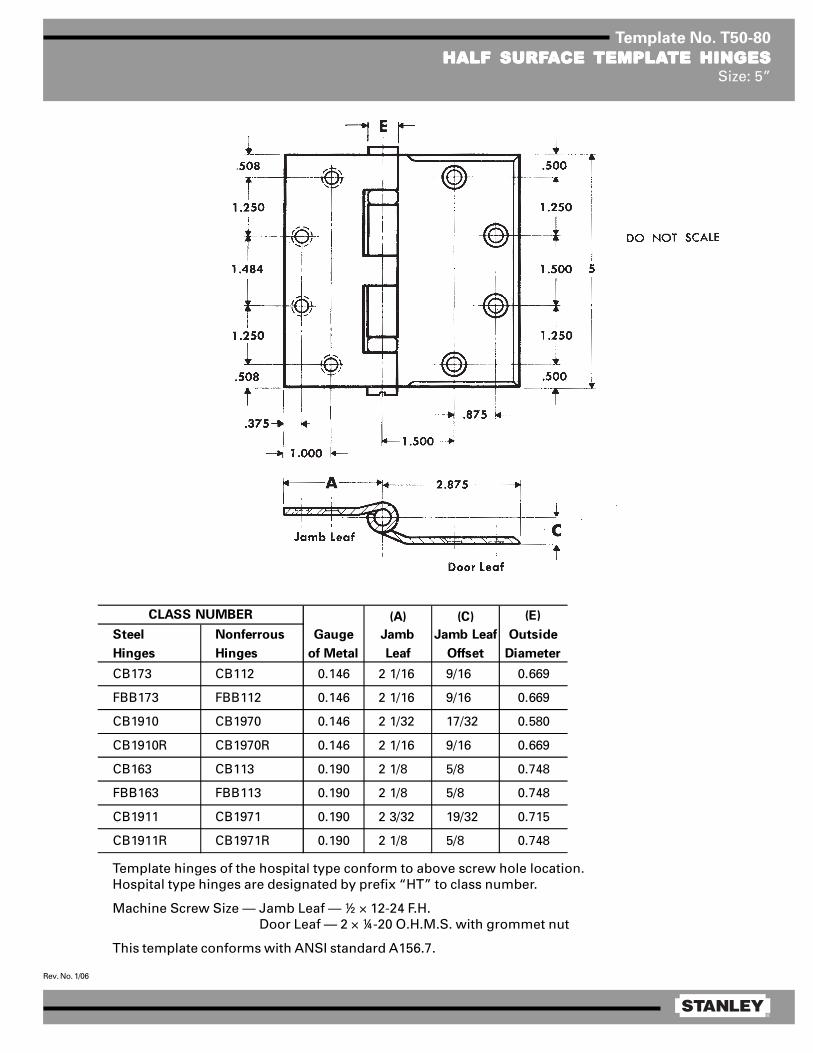
Template No. T50-80
HALF SURFHALF SURFHALF SURFHALF SURFHALF SURFAAAAACE CE CE CE CE TEMPLATEMPLATEMPLATEMPLATEMPLATE HINGESTE HINGESTE HINGESTE HINGESTE HINGESSize: 5”
Template hinges of the hospital type conform to above screw hole location.Hospital type hinges are designated by prefix “HT” to class number.
Machine Screw Size — Jamb Leaf — ½ × 12-24 F.H. Door Leaf — 2 × ¼-20 O.H.M.S. with grommet nut
This template conforms with ANSI standard A156.7.
(A) (C) (E)
Steel Nonferrous Gauge Jamb Jamb Leaf Outside
Hinges Hinges of Metal Leaf Offset Diameter
CB173 CB112 0.146 2 1/16 9/16 0.669
FBB173 FBB112 0.146 2 1/16 9/16 0.669
CB1910 CB1970 0.146 2 1/32 17/32 0.580
CB1910R CB1970R 0.146 2 1/16 9/16 0.669
CB163 CB113 0.190 2 1/8 5/8 0.748
FBB163 FBB113 0.190 2 1/8 5/8 0.748
CB1911 CB1971 0.190 2 3/32 19/32 0.715
CB1911R CB1971R 0.190 2 1/8 5/8 0.748
CLASS NUMBER

®
Rev. No. 2/06
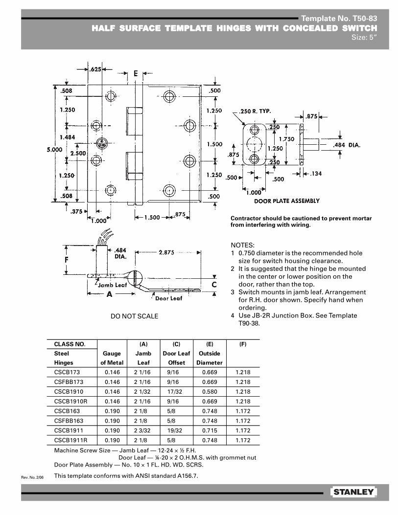
Template No. T50-83
HALF SURFHALF SURFHALF SURFHALF SURFHALF SURFAAAAACE CE CE CE CE TEMPLATEMPLATEMPLATEMPLATEMPLATE HINGES TE HINGES TE HINGES TE HINGES TE HINGES WITH CONCEALED SWITWITH CONCEALED SWITWITH CONCEALED SWITWITH CONCEALED SWITWITH CONCEALED SWITCHCHCHCHCHSize: 5”
Machine Screw Size — Jamb Leaf — 12-24 × ½ F.H. Door Leaf — ¼-20 × 2 O.H.M.S. with grommet nut
Door Plate Assembly — No. 10 × 1 FL. HD. WD. SCRS.
This template conforms with ANSI standard A156.7.
Contractor should be cautioned to prevent mortarfrom interfering with wiring.
NOTES:1 0.750 diameter is the recommended hole
size for switch housing clearance.2 It is suggested that the hinge be mounted
in the center or lower position on thedoor, rather than the top.
3 Switch mounts in jamb leaf. Arrangementfor R.H. door shown. Specify hand whenordering.
4 Use JB-2R Junction Box. See TemplateT90-38.
DO NOT SCALE
CLASS NO. (A) (C) (E) (F)
Steel Gauge Jamb Door Leaf Outside
Hinges of Metal Leaf Offset Diameter
CSCB173 0.146 2 1/16 9/16 0.669 1.218
CSFBB173 0.146 2 1/16 9/16 0.669 1.218
CSCB1910 0.146 2 1/32 17/32 0.580 1.218
CSCB1910R 0.146 2 1/16 9/16 0.669 1.218
CSCB163 0.190 2 1/8 5/8 0.748 1.172
CSFBB163 0.190 2 1/8 5/8 0.748 1.172
CSCB1911 0.190 2 3/32 19/32 0.715 1.172
CSCB1911R 0.190 2 1/8 5/8 0.748 1.172

®
Rev. No. 1/06
Template No. T45-80
HALF SURFHALF SURFHALF SURFHALF SURFHALF SURFAAAAACE CE CE CE CE TEMPLATEMPLATEMPLATEMPLATEMPLATE HINGESTE HINGESTE HINGESTE HINGESTE HINGESSize: 4½”
Machine Screw Size — Jamb Leaf — ½ × 12-24 F.H. Door Leaf — 2 × ¼-20 O.H.M.S. with grommet nut
(A) (C) (E)
Steel Nonferrous Gauge Jamb Door Leaf Outside
Hinges Hinges of Metal Leaf Offset Diameter
F173 — 0.134 2 1/16 9/16 0.605
1910 — 0.134 2 1/16 9/16 0.540
1910R — 0.134 2 1/16 9/16 0.605
CB173 CB112 0.134 2 1/16 9/16 0.625
FBB173 FBB112 0.134 2 1/16 9/16 0.625
CB1910 CB1970 0.134 2 1/16 9/16 0.540
CB1910R CB1970R 0.134 2 1/16 9/16 0.625
CB163 CB113 0.180 2 1/8 5/8 0.698
FBB163 FBB113 0.180 2 1/8 5/8 0.698
CB1911 CB1971 0.180 2 1/8 5/8 0.690
CB1911R CB1971R 0.180 2 1/8 5/8 0.698
CLASS NUMBER
Template hinges of the hospitaltype conform to above screwhole location.
Hospital type hinges are desig-nated by prefix “HT” to classnumber.
This template conforms withANSI standard A156.7.
®
Rev. No. 1/06
Template No. T50-80
HALF SURFHALF SURFHALF SURFHALF SURFHALF SURFAAAAACE CE CE CE CE TEMPLATEMPLATEMPLATEMPLATEMPLATE HINGESTE HINGESTE HINGESTE HINGESTE HINGESSize: 5”
Template hinges of the hospital type conform to above screw hole location.Hospital type hinges are designated by prefix “HT” to class number.
Machine Screw Size — Jamb Leaf — ½ × 12-24 F.H. Door Leaf — 2 × ¼-20 O.H.M.S. with grommet nut
This template conforms with ANSI standard A156.7.
(A) (C) (E)
Steel Nonferrous Gauge Jamb Jamb Leaf Outside
Hinges Hinges of Metal Leaf Offset Diameter
CB173 CB112 0.146 2 1/16 9/16 0.669
FBB173 FBB112 0.146 2 1/16 9/16 0.669
CB1910 CB1970 0.146 2 1/32 17/32 0.580
CB1910R CB1970R 0.146 2 1/16 9/16 0.669
CB163 CB113 0.190 2 1/8 5/8 0.748
FBB163 FBB113 0.190 2 1/8 5/8 0.748
CB1911 CB1971 0.190 2 3/32 19/32 0.715
CB1911R CB1971R 0.190 2 1/8 5/8 0.748
CLASS NUMBER
®
Rev. No. 2/06
Template No. T50-83
HALF SURFHALF SURFHALF SURFHALF SURFHALF SURFAAAAACE CE CE CE CE TEMPLATEMPLATEMPLATEMPLATEMPLATE HINGES TE HINGES TE HINGES TE HINGES TE HINGES WITH CONCEALED SWITWITH CONCEALED SWITWITH CONCEALED SWITWITH CONCEALED SWITWITH CONCEALED SWITCHCHCHCHCHSize: 5”
Machine Screw Size — Jamb Leaf — 12-24 × ½ F.H. Door Leaf — ¼-20 × 2 O.H.M.S. with grommet nut
Door Plate Assembly — No. 10 × 1 FL. HD. WD. SCRS.
This template conforms with ANSI standard A156.7.
Contractor should be cautioned to prevent mortarfrom interfering with wiring.
NOTES:1 0.750 diameter is the recommended hole
size for switch housing clearance.2 It is suggested that the hinge be mounted
in the center or lower position on thedoor, rather than the top.
3 Switch mounts in jamb leaf. Arrangementfor R.H. door shown. Specify hand whenordering.
4 Use JB-2R Junction Box. See TemplateT90-38.
DO NOT SCALE
CLASS NO. (A) (C) (E) (F)
Steel Gauge Jamb Door Leaf Outside
Hinges of Metal Leaf Offset Diameter
CSCB173 0.146 2 1/16 9/16 0.669 1.218
CSFBB173 0.146 2 1/16 9/16 0.669 1.218
CSCB1910 0.146 2 1/32 17/32 0.580 1.218
CSCB1910R 0.146 2 1/16 9/16 0.669 1.218
CSCB163 0.190 2 1/8 5/8 0.748 1.172
CSFBB163 0.190 2 1/8 5/8 0.748 1.172
CSCB1911 0.190 2 3/32 19/32 0.715 1.172
CSCB1911R 0.190 2 1/8 5/8 0.748 1.172
®
Rev. No. 1/06
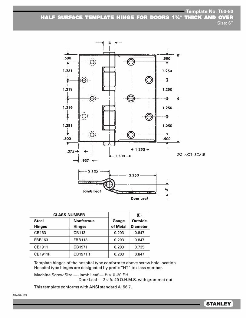
Template No. T60-80
HALF SURFHALF SURFHALF SURFHALF SURFHALF SURFAAAAACE CE CE CE CE TEMPLATEMPLATEMPLATEMPLATEMPLATE HINGE FOR DOORS 1¾TE HINGE FOR DOORS 1¾TE HINGE FOR DOORS 1¾TE HINGE FOR DOORS 1¾TE HINGE FOR DOORS 1¾” THICK THICK THICK THICK THICK AND OAND OAND OAND OAND OVERVERVERVERVERSize: 6”
Template hinges of the hospital type conform to above screw hole location.Hospital type hinges are designated by prefix “HT” to class number.
Machine Screw Size — Jamb Leaf — ½ × ¼-20 F.H. Door Leaf — 2 × ¼-20 O.H.M.S. with grommet nut
This template conforms with ANSI standard A156.7.
(E)
Steel Nonferrous Gauge Outside
Hinges Hinges of Metal Diameter
CB163 CB113 0.203 0.847
FBB163 FBB113 0.203 0.847
CB1911 CB1971 0.203 0.735
CB1911R CB1971R 0.203 0.847
CLASS NUMBER
E

®
Rev. No. 1/06
Template No. T50-07
FULL MORFULL MORFULL MORFULL MORFULL MORTISE TISE TISE TISE TISE TEMPLATEMPLATEMPLATEMPLATEMPLATE PIVTE PIVTE PIVTE PIVTE PIVOOOOOT REINFORT REINFORT REINFORT REINFORT REINFORCED HINGESCED HINGESCED HINGESCED HINGESCED HINGESSize: 5 × 4½”
Machine Screw Size — ½ × 12-24 F.H.Wood Screw Size — 1½ × No. 12 F.H.
Steel Nonferrous Gauge of Metal
CB211 CB221 0.190
FBB211 FBB221 0.190
CB1907 CB1967 0.190
CB1907R CB1967R 0.190
SET CLASS NO.
Door
Thickness
*Backset on
Door
*Backset on
Frame
1 3/4 1/4 5/16
2 1/2 9/16
2 1/4 3/4 13/16
For use with concealed door holders, closers andoperators which do not permit use of types shownon templates T50-08, T50-09, T50-10 or T50-11.
Machine Screw Size — ½ × 12-24 F.H.Wood Screw Size — 1½ × No. 12 F.H.
*CAUTION: These backsets must be usedon ALL hinges in set.
NOTE: Backsets which apply when pivot-reinforced hinge is used on door thicknessindicated and when the usual 1/16 stop clearanceis desired.

®
Rev. No. 1/06
Template No. T50-08
FULL MORFULL MORFULL MORFULL MORFULL MORTISE TISE TISE TISE TISE TEMPLATEMPLATEMPLATEMPLATEMPLATE PIVTE PIVTE PIVTE PIVTE PIVOOOOOT REINFORT REINFORT REINFORT REINFORT REINFORCED HINGES FOR DOORSCED HINGES FOR DOORSCED HINGES FOR DOORSCED HINGES FOR DOORSCED HINGES FOR DOORSWITH SQWITH SQWITH SQWITH SQWITH SQUUUUUARE EDGE HINGE STILESARE EDGE HINGE STILESARE EDGE HINGE STILESARE EDGE HINGE STILESARE EDGE HINGE STILES
Size: 5 × 4½”
Machine Screw Size — ½ × 12-24 F.H.Wood Screw Size — 1½ × No. 12 F.H.
Steel Nonferrous Gauge of Metal
CB212 CB222 0.190
FBB212 FBB222 0.190
CB1908 CB1968 0.190
CB1908R CB1968R 0.190
SET CLASS NO.
Door
Thickness
*Backset on
Door
*Backset on
Frame
1 3/4 1/4 5/16
2 1/2 9/16
2 1/4 3/4 13/16
*CAUTION: These backsets must be usedon ALL hinges in set.
NOTE: Backsets which apply when pivot-reinforced hinge is used on door thicknessindicated and when the usual 1/16 stopclearance is desired.
For use with door holders, closers and operators.See templates T50-07 and T50-10 for types whichprovide clearance for concealed devices.
Machine Screw Size — ½ × 12-24 F.H.Wood Screw Size — 1½ × No. 12 F.H.
®
Rev. No. 1/06
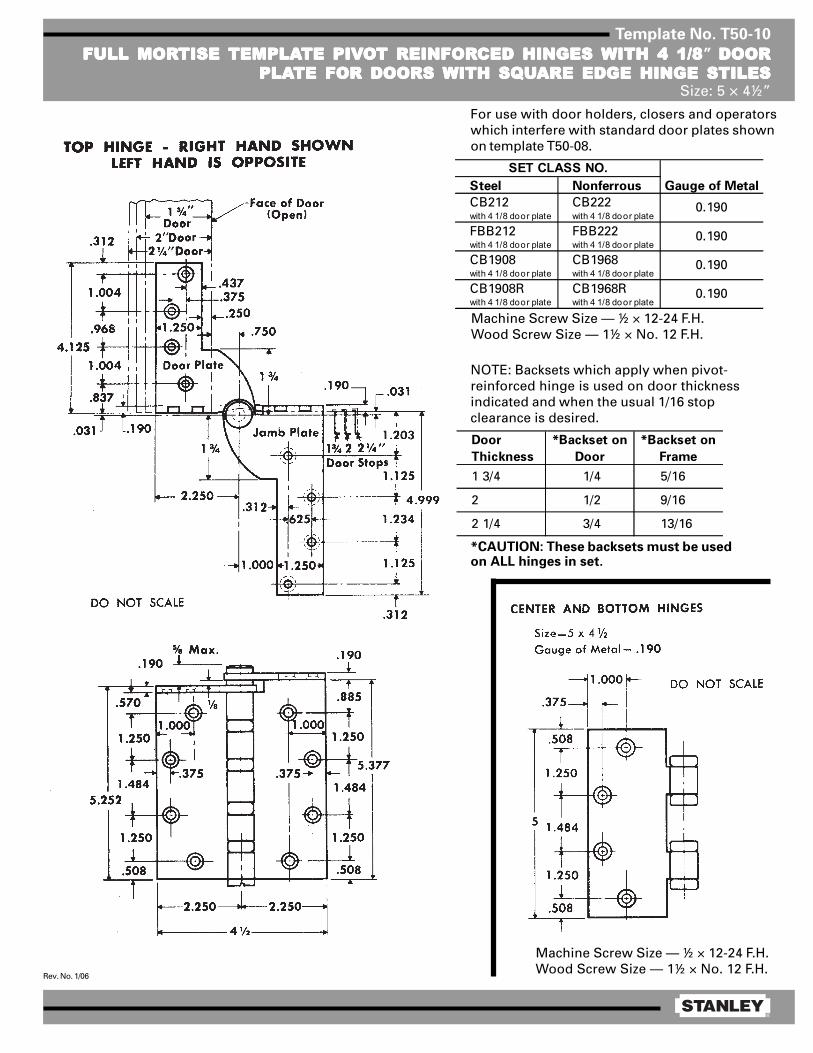
Template No. T50-10
FULL MORFULL MORFULL MORFULL MORFULL MORTISE TISE TISE TISE TISE TEMPLATEMPLATEMPLATEMPLATEMPLATE PIVTE PIVTE PIVTE PIVTE PIVOOOOOT REINFORT REINFORT REINFORT REINFORT REINFORCED HINGES CED HINGES CED HINGES CED HINGES CED HINGES WITH 4 1/8WITH 4 1/8WITH 4 1/8WITH 4 1/8WITH 4 1/8” DOORDOORDOORDOORDOORPLAPLAPLAPLAPLATE FOR DOORS TE FOR DOORS TE FOR DOORS TE FOR DOORS TE FOR DOORS WITH SQWITH SQWITH SQWITH SQWITH SQUUUUUARE EDGE HINGE STILESARE EDGE HINGE STILESARE EDGE HINGE STILESARE EDGE HINGE STILESARE EDGE HINGE STILES
Size: 5 × 4½”
Machine Screw Size — ½ × 12-24 F.H.Wood Screw Size — 1½ × No. 12 F.H.
Steel Nonferrous Gauge of Metal
CB212 CB222with 4 1 /8 door plate with 4 1 /8 door plate
FBB212 FBB222with 4 1 /8 door plate with 4 1 /8 door plate
CB1908 CB1968with 4 1 /8 door plate with 4 1 /8 door plate
CB1908R CB1968Rwith 4 1 /8 door plate with 4 1 /8 door plate
0.190
SET CLASS NO.
0.190
0.190
0.190
Door
Thickness
*Backset on
Door
*Backset on
Frame
1 3/4 1/4 5/16
2 1/2 9/16
2 1/4 3/4 13/16
Machine Screw Size — ½ × 12-24 F.H.Wood Screw Size — 1½ × No. 12 F.H.
*CAUTION: These backsets must be usedon ALL hinges in set.
NOTE: Backsets which apply when pivot-reinforced hinge is used on door thicknessindicated and when the usual 1/16 stopclearance is desired.
For use with door holders, closers and operatorswhich interfere with standard door plates shownon template T50-08.
®
Rev. No. 1/06
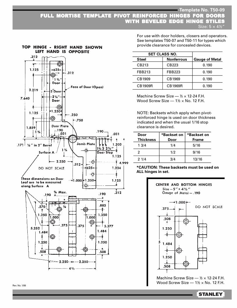
Template No. T50-09
FULL MORFULL MORFULL MORFULL MORFULL MORTISE TISE TISE TISE TISE TEMPLATEMPLATEMPLATEMPLATEMPLATE PIVTE PIVTE PIVTE PIVTE PIVOOOOOT REINFORT REINFORT REINFORT REINFORT REINFORCED HINGES FOR DOORSCED HINGES FOR DOORSCED HINGES FOR DOORSCED HINGES FOR DOORSCED HINGES FOR DOORSWITH BEVELED EDGE HINGE STILESWITH BEVELED EDGE HINGE STILESWITH BEVELED EDGE HINGE STILESWITH BEVELED EDGE HINGE STILESWITH BEVELED EDGE HINGE STILES
Size: 5 × 4½”
Machine Screw Size — ½ × 12-24 F.H.Wood Screw Size — 1½ × No. 12 F.H.
Machine Screw Size — ½ × 12-24 F.H.Wood Screw Size — 1½ × No. 12 F.H.
Steel Nonferrous Gauge of Metal
CB213 CB223 0.190
FBB213 FBB223 0.190
CB1909 CB1969 0.190
CB1909R CB1969R 0.190
SET CLASS NO.
Door
Thickness
*Backset on
Door
*Backset on
Frame
1 3/4 1/4 5/16
2 1/2 9/16
2 1/4 3/4 13/16
*CAUTION: These backsets must be used onALL hinges in set.
NOTE: Backsets which apply when pivot-reinforced hinge is used on door thicknessindicated and when the usual 1/16 stopclearance is desired.
For use with door holders, closers and operators.See templates T50-07 and T50-11 for types whichprovide clearance for concealed devices.
®
Rev. No. 1/06
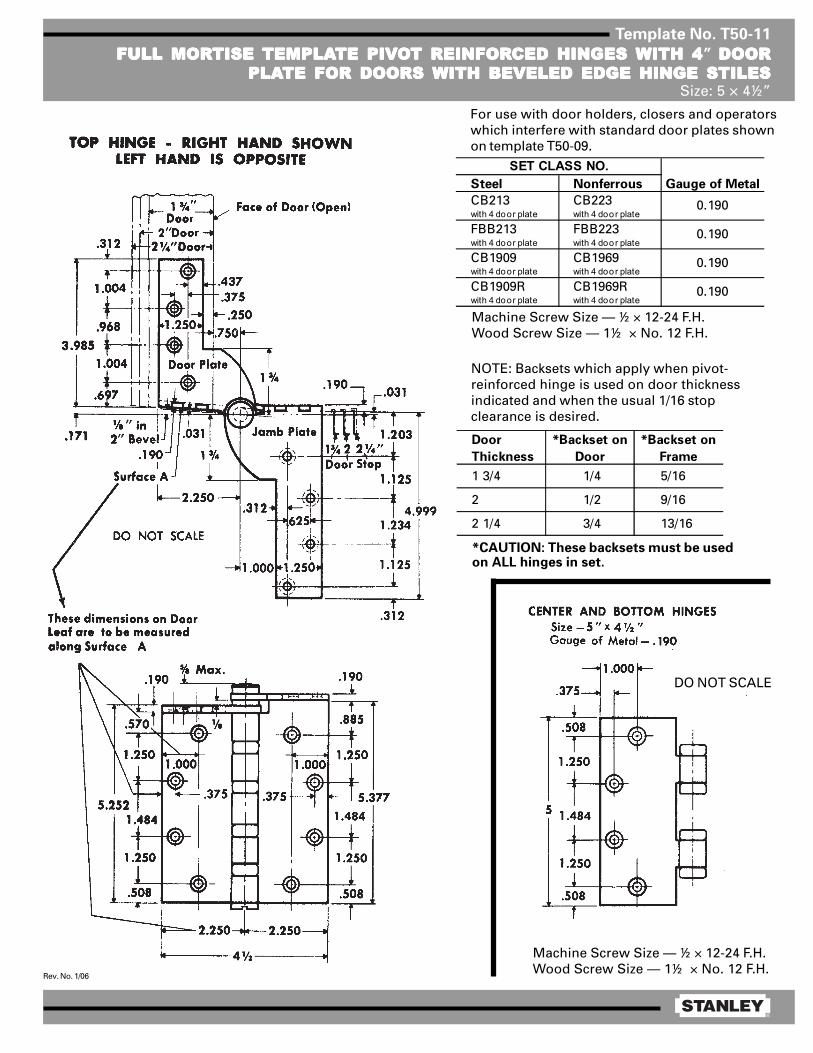
Template No. T50-11
FULL MORFULL MORFULL MORFULL MORFULL MORTISE TISE TISE TISE TISE TEMPLATEMPLATEMPLATEMPLATEMPLATE PIVTE PIVTE PIVTE PIVTE PIVOOOOOT REINFORT REINFORT REINFORT REINFORT REINFORCED HINGES CED HINGES CED HINGES CED HINGES CED HINGES WITH 4WITH 4WITH 4WITH 4WITH 4” DOORDOORDOORDOORDOORPLAPLAPLAPLAPLATE FOR DOORS TE FOR DOORS TE FOR DOORS TE FOR DOORS TE FOR DOORS WITH BEVELED EDGE HINGE STILESWITH BEVELED EDGE HINGE STILESWITH BEVELED EDGE HINGE STILESWITH BEVELED EDGE HINGE STILESWITH BEVELED EDGE HINGE STILES
Size: 5 × 4½”
Machine Screw Size — ½ × 12-24 F.H.Wood Screw Size — 1½ × No. 12 F.H.
Machine Screw Size — ½ × 12-24 F.H.Wood Screw Size — 1½ × No. 12 F.H.
*CAUTION: These backsets must be usedon ALL hinges in set.
NOTE: Backsets which apply when pivot-reinforced hinge is used on door thicknessindicated and when the usual 1/16 stopclearance is desired.
For use with door holders, closers and operatorswhich interfere with standard door plates shownon template T50-09.
DO NOT SCALE
Steel Nonferrous Gauge of Metal
CB213 CB223with 4 door plate with 4 door plate
FBB213 FBB223with 4 door plate with 4 door plate
CB1909 CB1969with 4 door plate with 4 door plate
CB1909R CB1969Rwith 4 door plate with 4 door plate
0.190
SET CLASS NO.
0.190
0.190
0.190
Door
Thickness
*Backset on
Door
*Backset on
Frame
1 3/4 1/4 5/16
2 1/2 9/16
2 1/4 3/4 13/16
®
Rev. No. 1/06
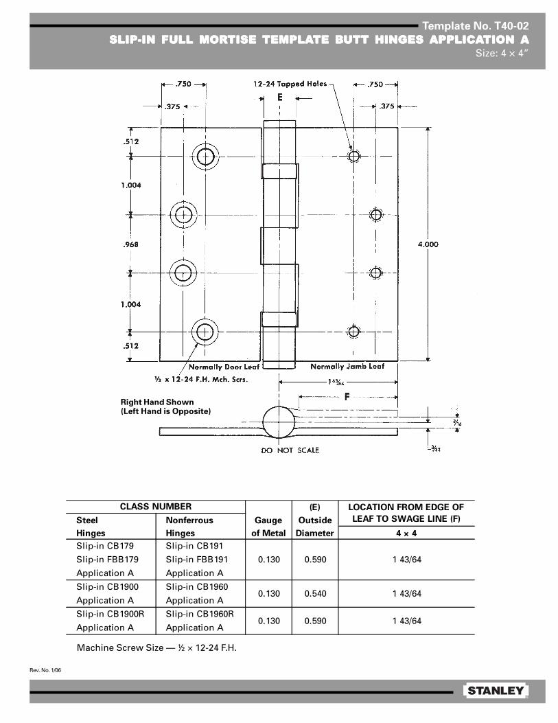
Template No. T40-02
SLIP-IN FULL MORSLIP-IN FULL MORSLIP-IN FULL MORSLIP-IN FULL MORSLIP-IN FULL MORTISE TISE TISE TISE TISE TEMPLATEMPLATEMPLATEMPLATEMPLATE BTE BTE BTE BTE BUTT HINGES UTT HINGES UTT HINGES UTT HINGES UTT HINGES APPLICAAPPLICAAPPLICAAPPLICAAPPLICATION TION TION TION TION AAAAASize: 4 × 4”
Right Hand Shown(Left Hand is Opposite)
(E)
Steel Nonferrous Gauge Outside
Hinges Hinges of Metal Diameter 4 × 4
Slip-in CB179 Slip-in CB191
Slip-in FBB179 Slip-in FBB191
Application A Application A
Slip-in CB1900 Slip-in CB1960
Application A Application A
Slip-in CB1900R Slip-in CB1960R
Application A Application A1 43/64
0.130 0.590
0.130 0.540
0.130 0.590
CLASS NUMBER LOCATION FROM EDGE OF
LEAF TO SWAGE LINE (F)
1 43/64
1 43/64
Machine Screw Size — ½ × 12-24 F.H.
®
Rev. No. 1/06
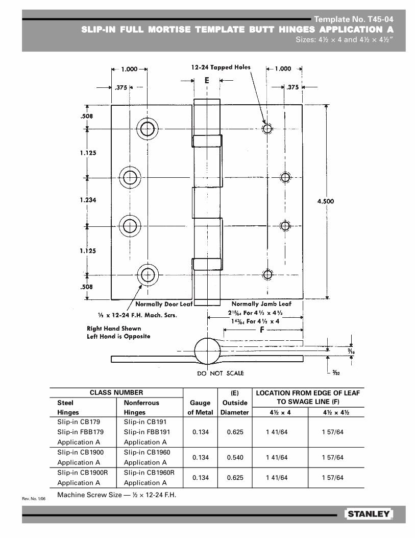
Template No. T45-04
SLIP-IN FULL MORSLIP-IN FULL MORSLIP-IN FULL MORSLIP-IN FULL MORSLIP-IN FULL MORTISE TISE TISE TISE TISE TEMPLATEMPLATEMPLATEMPLATEMPLATE BTE BTE BTE BTE BUTT HINGES UTT HINGES UTT HINGES UTT HINGES UTT HINGES APPLICAAPPLICAAPPLICAAPPLICAAPPLICATION TION TION TION TION AAAAASizes: 4½ × 4 and 4½ × 4½”
(E)
Steel Nonferrous Gauge Outside
Hinges Hinges of Metal Diameter 4½ × 4 4½ × 4½
Slip-in CB179 Slip-in CB191
Slip-in FBB179 Slip-in FBB191
Application A Application A
Slip-in CB1900 Slip-in CB1960
Application A Application A
Slip-in CB1900R Slip-in CB1960R
Application A Application A
1 57/64
0.134 0.625 1 57/64
1 41/64
1 41/64
0.134 0.540
CLASS NUMBER
0.134 0.625 1 57/64
LOCATION FROM EDGE OF LEAF
TO SWAGE LINE (F)
1 41/64
Machine Screw Size — ½ × 12-24 F.H.
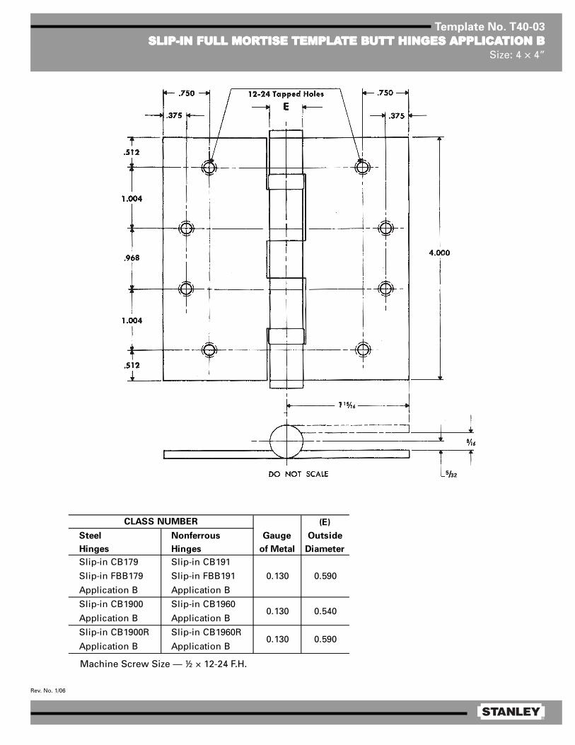
®
Rev. No. 1/06
Template No. T40-03
SLIP-IN FULL MORSLIP-IN FULL MORSLIP-IN FULL MORSLIP-IN FULL MORSLIP-IN FULL MORTISE TISE TISE TISE TISE TEMPLATEMPLATEMPLATEMPLATEMPLATE BTE BTE BTE BTE BUTT HINGES UTT HINGES UTT HINGES UTT HINGES UTT HINGES APPLICAAPPLICAAPPLICAAPPLICAAPPLICATION BTION BTION BTION BTION BSize: 4 × 4”
(E)
Steel Nonferrous Gauge Outside
Hinges Hinges of Metal Diameter
Slip-in CB179 Slip-in CB191
Slip-in FBB179 Slip-in FBB191
Application B Application B
Slip-in CB1900 Slip-in CB1960
Application B Application B
Slip-in CB1900R Slip-in CB1960R
Application B Application B
0.130 0.540
0.130 0.590
CLASS NUMBER
0.130 0.590
Machine Screw Size — ½ × 12-24 F.H.
5/32
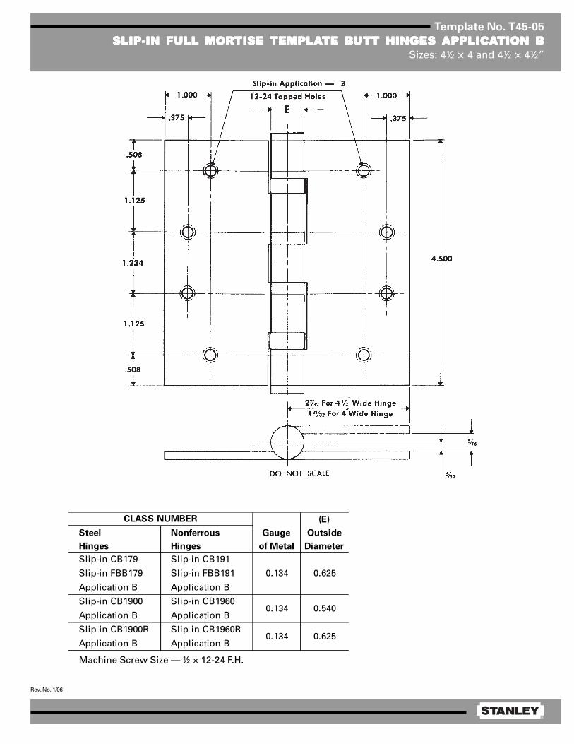
®
Rev. No. 1/06
Template No. T45-05
SLIP-IN FULL MORSLIP-IN FULL MORSLIP-IN FULL MORSLIP-IN FULL MORSLIP-IN FULL MORTISE TISE TISE TISE TISE TEMPLATEMPLATEMPLATEMPLATEMPLATE BTE BTE BTE BTE BUTT HINGES UTT HINGES UTT HINGES UTT HINGES UTT HINGES APPLICAAPPLICAAPPLICAAPPLICAAPPLICATION BTION BTION BTION BTION BSizes: 4½ × 4 and 4½ × 4½”
(E)
Steel Nonferrous Gauge Outside
Hinges Hinges of Metal Diameter
Slip-in CB179 Slip-in CB191
Slip-in FBB179 Slip-in FBB191
Application B Application B
Slip-in CB1900 Slip-in CB1960
Application B Application B
Slip-in CB1900R Slip-in CB1960R
Application B Application B
0.134 0.540
0.134 0.625
CLASS NUMBER
0.134 0.625
Machine Screw Size — ½ × 12-24 F.H.

®
Rev. No. 1/06
Template No. T45-35FULL MORFULL MORFULL MORFULL MORFULL MORTISE “SWING-CLEAR”TISE “SWING-CLEAR”TISE “SWING-CLEAR”TISE “SWING-CLEAR”TISE “SWING-CLEAR” TEMPLATEMPLATEMPLATEMPLATEMPLATE BTE BTE BTE BTE BUTT HINGESUTT HINGESUTT HINGESUTT HINGESUTT HINGES
FOR DOORS WITH BEVELED EDGE HINGE STILEFOR DOORS WITH BEVELED EDGE HINGE STILEFOR DOORS WITH BEVELED EDGE HINGE STILEFOR DOORS WITH BEVELED EDGE HINGE STILEFOR DOORS WITH BEVELED EDGE HINGE STILESize: 4½”
Template hinges of the hospital type conform to above screw hole location.Hospital type hinges are designated by prefix “HT” to class number.
Machine Screw Size — ½ × 12-24 F.H.Wood Screw Size — 1¼ × No. 12 F.H.
Class No. Material Gauge of Metal (E) Outside Diameter
CB258 Steel 0.134 0.625
FBB258 Steel 0.134 0.625
CB1946 Steel 0.134 0.531
CB1946R Steel 0.134 0.625
NOTES:1 1¾ doors will clear opening at 90°.2 This hinge alters the normal pivot point of door. For door
closers, friction or overhead door holders to be used in con-junction with this hinge, consult manufacturer of the device tobe used for application details.
CAUTION: 1/8 in 2 beveled edge hinge stile shown.For other bevels — contact Stanley Hardware.

®
Rev. No. 1/06
Template No. T45-30
FULL MORFULL MORFULL MORFULL MORFULL MORTISE “SWING-CLEAR”TISE “SWING-CLEAR”TISE “SWING-CLEAR”TISE “SWING-CLEAR”TISE “SWING-CLEAR” TEMPLATEMPLATEMPLATEMPLATEMPLATE BTE BTE BTE BTE BUTT HINGESUTT HINGESUTT HINGESUTT HINGESUTT HINGESSize: 4½”
Template hinges of the hospital type conform to above screw hole location.Hospital type hinges are designated by prefix “HT” to class number.
Machine Screw Size — ½ × 12-24 F.H.Wood Screw Size — 1¼ × No. 12 F.H.
Class No. Material Gauge of Metal (E) Outside Diameter
CB248 Steel 0.134 0.625
FBB248 Steel 0.134 0.625
CB1947 Steel 0.134 0.531
CB1947R Steel 0.134 0.625
NOTES:1 1¾ doors will clear openings at 90°.2 This hinge alters the normal pivot point of door. For door closers,
friction or overhead door holders to be used in conjunction with thishinge, consult manufacturer of the device to be used for applicationdetails.
3 For doors thicker than 1¾, backsets on doors and frames should beincreased by the amount of the additional door thickness.
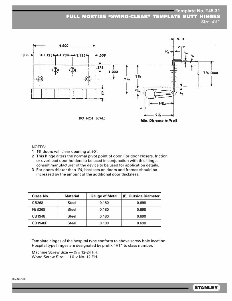
®
Rev. No. 1/06
Template No. T45-31
FULL MORFULL MORFULL MORFULL MORFULL MORTISE “SWING-CLEAR”TISE “SWING-CLEAR”TISE “SWING-CLEAR”TISE “SWING-CLEAR”TISE “SWING-CLEAR” TEMPLATEMPLATEMPLATEMPLATEMPLATE BTE BTE BTE BTE BUTT HINGESUTT HINGESUTT HINGESUTT HINGESUTT HINGESSize: 4½”
Template hinges of the hospital type conform to above screw hole location.Hospital type hinges are designated by prefix “HT” to class number.
Machine Screw Size — ½ × 12-24 F.H.Wood Screw Size — 1¼ × No. 12 F.H.
Class No. Material Gauge of Metal (E) Outside Diameter
CB268 Steel 0.180 0.698
FBB268 Steel 0.180 0.698
CB1948 Steel 0.180 0.690
CB1948R Steel 0.180 0.698
NOTES:1 1¾ doors will clear opening at 90°.2 This hinge alters the normal pivot point of door. For door closers, friction
or overhead door holders to be used in conjunction with this hinge,consult manufacturer of the device to be used for application details.
3 For doors thicker than 1¾, backsets on doors and frames should beincreased by the amount of the additional door thickness.

®
Rev. No. 1/06
Template No. T50-05
FULL MORFULL MORFULL MORFULL MORFULL MORTISE “SWING-CLEAR”TISE “SWING-CLEAR”TISE “SWING-CLEAR”TISE “SWING-CLEAR”TISE “SWING-CLEAR” TEMPLATEMPLATEMPLATEMPLATEMPLATE BTE BTE BTE BTE BUTT HINGESUTT HINGESUTT HINGESUTT HINGESUTT HINGESSize: 5”
Class No. Material Gauge of Metal
(E) Outside
Diameter F G
CB268 Steel 0.190 0.748 2 1/8 1/2
FBB268 Steel 0.190 0.748 2 1/8 1/2
CB1948 Steel 0.190 0.715 2 3/32 15/32
CB1948R Steel 0.190 0.748 2 1/8 1/2
Template hinges of the hospital type conform to above screw hole location.Hospital type hinges are designated by prefix “HT” to class number.
Machine Screw Size — ½ × 12-24 F.H.Wood Screw Size — 1½ × No. 12 F.H.
NOTES:1 For doors thicker than 1¾, backsets on doors and frames should be increased by the
amount of the additional door thickness.2 1¾ doors will clear opening at 95°.3 This hinge alters the normal pivot point of door. For door closers, friction or overhead
door holders to be used in conjunction with this hinge, consult manufacturer of thedevice to be used for application details.
Door
Thickness
Backset on
Door
Backset on
Frame
1 3/4 1/4 5/16
2 1/2 9/16
2 1/4 3/4 13/16

®
Rev. No. 1/06
Template No. T45-36
FULL MORFULL MORFULL MORFULL MORFULL MORTISE “SWING-CLEAR”TISE “SWING-CLEAR”TISE “SWING-CLEAR”TISE “SWING-CLEAR”TISE “SWING-CLEAR” TEMPLATEMPLATEMPLATEMPLATEMPLATE BTE BTE BTE BTE BUTT HINGESUTT HINGESUTT HINGESUTT HINGESUTT HINGESFOR DOORS WITH BEVELED EDGE HINGE STILEFOR DOORS WITH BEVELED EDGE HINGE STILEFOR DOORS WITH BEVELED EDGE HINGE STILEFOR DOORS WITH BEVELED EDGE HINGE STILEFOR DOORS WITH BEVELED EDGE HINGE STILE
Size: 4½”
Template hinges of the hospital type conform to above screw hole location.Hospital type hinges are designated by prefix “HT” to class number.
Machine Screw Size — ½ × 12-24 F.H.Wood Screw Size — 1¼ × No. 12 F.H.
Class No. Material Gauge of Metal (E) Outside Diameter
CB278 Steel 0.180 0.698
FBB278 Steel 0.180 0.698
CB1949 Steel 0.180 0.690
CB1949R Steel 0.180 0.698
NOTES:1 1¾ doors will clear opening at 90°.2 This hinge alters the normal pivot point of door. For
door closers, friction or overhead door hold-ers tobe used in conjunction with this hinge, consultmanufacturer of the device to be used for applicationdetails.
CAUTION: 1/8 and 2 beveled edge hinge stile shown.For other bevels — contact Stanley Hardware.
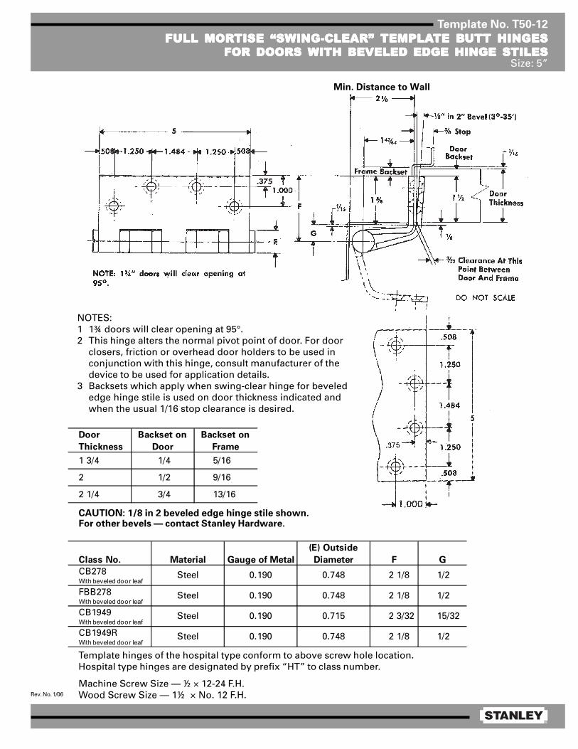
®
Rev. No. 1/06
Template No. T50-12
FULL MORFULL MORFULL MORFULL MORFULL MORTISE “SWING-CLEAR”TISE “SWING-CLEAR”TISE “SWING-CLEAR”TISE “SWING-CLEAR”TISE “SWING-CLEAR” TEMPLATEMPLATEMPLATEMPLATEMPLATE BTE BTE BTE BTE BUTT HINGESUTT HINGESUTT HINGESUTT HINGESUTT HINGESFOR DOORS WITH BEVELED EDGE HINGE STILESFOR DOORS WITH BEVELED EDGE HINGE STILESFOR DOORS WITH BEVELED EDGE HINGE STILESFOR DOORS WITH BEVELED EDGE HINGE STILESFOR DOORS WITH BEVELED EDGE HINGE STILES
Size: 5”
Template hinges of the hospital type conform to above screw hole location.Hospital type hinges are designated by prefix “HT” to class number.
Machine Screw Size — ½ × 12-24 F.H.Wood Screw Size — 1½ × No. 12 F.H.
Door
Thickness
Backset on
Door
Backset on
Frame
1 3/4 1/4 5/16
2 1/2 9/16
2 1/4 3/4 13/16
NOTES:1 1¾ doors will clear opening at 95°.2 This hinge alters the normal pivot point of door. For door
closers, friction or overhead door holders to be used inconjunction with this hinge, consult manufacturer of thedevice to be used for application details.
3 Backsets which apply when swing-clear hinge for bevelededge hinge stile is used on door thickness indicated andwhen the usual 1/16 stop clearance is desired.
CAUTION: 1/8 in 2 beveled edge hinge stile shown.For other bevels — contact Stanley Hardware.
Min. Distance to Wall
Class No. Material Gauge of Metal
(E) Outside
Diameter F G
CB278With beveled door leaf
FBB278With beveled door leaf
CB1949With beveled door leaf
CB1949RWith beveled door leaf
1/2Steel 0.190 0.748 2 1/8
1/2
15/32
1/2
Steel
Steel
Steel
2 1/8
2 3/32
2 1/8
0.190
0.190
0.190
0.748
0.715
0.748

®
Rev. No. 1/06
Template No. T50-85
HALF SURFHALF SURFHALF SURFHALF SURFHALF SURFAAAAACE “SWING-CLEAR”CE “SWING-CLEAR”CE “SWING-CLEAR”CE “SWING-CLEAR”CE “SWING-CLEAR” TEMPLATEMPLATEMPLATEMPLATEMPLATE HINGESTE HINGESTE HINGESTE HINGESTE HINGESSize: 5”
NOTES:1 1¾ doors will clear opening at 95°.2 This hinge alters the normal pivot point
of door. For door closers, friction oroverhead door holders to be used inconjunction with this hinge, consultmanufacturer of the device to be usedfor application details.
3 For doors thicker than 1¾, backsets ondoors and frames should be increasedby the amount of the additional doorthickness.
Template hinges of the hospital type conform to above screw hole location.Hospital type hinges are designated by prefix “HT”to class number.
Jamb Leaf — Machine Screw Size — ½ × 12-24 F.H.Door Leaf — Screw Size — 2 × ¼-20 O.H.M.S. with grommet nut or 1½ × No. 14 O.H. wood screw.
Class No. Material Gauge of Metal (E) Outside Diameter F G
CB269 Steel 0.190 0.748 2 1/8 1/2
FBB269 Steel 0.190 0.748 2 1/8 1/2
CB1959 Steel 0.190 0.715 2 3/32 15/32
CB1959R Steel 0.190 0.748 2 1/8 1/2
DO NOT SCALE
.508

®
Rev. No. 1/06
Template No. T50-45
HALF MORHALF MORHALF MORHALF MORHALF MORTISE “SWING-CLEAR”TISE “SWING-CLEAR”TISE “SWING-CLEAR”TISE “SWING-CLEAR”TISE “SWING-CLEAR” TEMPLATEMPLATEMPLATEMPLATEMPLATE HINGESTE HINGESTE HINGESTE HINGESTE HINGESFOR DOORS FOR DOORS FOR DOORS FOR DOORS FOR DOORS WITH SQWITH SQWITH SQWITH SQWITH SQUUUUUARE HINGE STILESARE HINGE STILESARE HINGE STILESARE HINGE STILESARE HINGE STILES
Size: 5”
Template hinges of the hospital type conform to above screw hole location.Hospital type hinges are designated by prefix “HT” to class number.Hand of hinge may be changed by inverting hinge and reversing pin and tip.
Machine Screw Size — Jamb Leaf — ½ × 12-24 F.H. Door Leaf — ½ × 12-24 F.H. or 1¼ × No. 12 F.H. WD. SCR.
Class No. Material Gauge of Metal (E) Outside Diameter
CB264 Steel 0.190 0.748
FBB264 Steel 0.190 0.748
CB1941 Steel 0.190 0.715
CB1941R Steel 0.190 0.748
NOTES:1 This hinge alters the normal pivot point of the door. For
door closers, friction or overhead door holders to be usedin conjunction with this hinge, consult manufacturer ofthe device to be used for application details.
2 1¾ doors will clear opening at 95°.3 For doors thicker than 1¾ door backsets should be
increased by the amount of the additional door thickness.

®
Rev. No. 2/06
Template No. T50-47
HALF MORHALF MORHALF MORHALF MORHALF MORTISE SWING-CLEAR TISE SWING-CLEAR TISE SWING-CLEAR TISE SWING-CLEAR TISE SWING-CLEAR TEMPLATEMPLATEMPLATEMPLATEMPLATE HINGES FOR DOORSTE HINGES FOR DOORSTE HINGES FOR DOORSTE HINGES FOR DOORSTE HINGES FOR DOORSWITH BEVELED HINGE STILESWITH BEVELED HINGE STILESWITH BEVELED HINGE STILESWITH BEVELED HINGE STILESWITH BEVELED HINGE STILES
Size: 5”
Template hinges of the hospital type conform to above screw hole location.Hospital type hinges are designated by prefix ”HT“ to class number.Machine Screw Size — Jamb Leaf — No. 12 × ½ F.H.
Door Leaf — No. 12 × ½ F.H. or No. 12 × 1¼ F.H. WD. SCR.
Door
Thickness
Backset on
Door
Backset on
Frame
1 3/4 1/4 5/16
2 1/2 9/16
2 1/4 3/4 13/16
Caution: 1/8 in 2 beveled edge hinge stile shown.For other bevels — contact Stanley Hardware.
NOTES:1 This hinge alters the normal pivot point of door.
For door closers, friction or overhead doorholders to be used in conjunction with thishinge, consult manufacturer of the device to beused for application details.
2 Backsets which apply when swing-clear hinge forbeveled edge hinge stile is used on door thick-ness indicated and when the usual 1/16 stopclearance is desired.
3 Hand of hinge may be changed by invertinghinge and reversing pin and tip.
Class No. Material Gauge of Metal (E) Outside Diameter
FBB274 Steel 0.190 0.748
CB1941 Steel 0.190 0.715
CB1941R Steel 0.190 0.748
CB274 Steel 0.190 0.748

®
Rev. No. 1/06
Template No. T50-65
FULL SURFFULL SURFFULL SURFFULL SURFFULL SURFAAAAACE “SWING-CLEAR”CE “SWING-CLEAR”CE “SWING-CLEAR”CE “SWING-CLEAR”CE “SWING-CLEAR” TEMPLATEMPLATEMPLATEMPLATEMPLATE HINGETE HINGETE HINGETE HINGETE HINGESize: 5”
NOTES:1 This hinge alters the normal pivot point of door. For door closers, friction or overhead door holders to be
used in conjunction with this hinge, consult manufacturer of the device to be used for application details.2 1¾ doors will clear opening at 95°.
Template hinges of the hospital type conform to above screw hole location.Hospital type hinges are designated by prefix “HT” to class number.Hand of hinge may be changed by inverting hinge and reversing pin and tip.
Machine Screw Size — Jamb Leaf — ½ × 12-24 F.H. Door Leaf — 2 × ¼-20 O.H.M.S. with grommet nut or
1½ × No. 14 F.H. WD. SCRS.
Class No. Material Gauge of Metal (E) Outside Diameter
CB266 Steel 0.190 0.748
FBB266 Steel 0.190 0.748
CB1951 Steel 0.190 0.715
CB1951R Steel 0.190 0.748
DO NOT SCALE

®
Rev. No. 1/06
Template No. T35-03
FULL MORFULL MORFULL MORFULL MORFULL MORTISE TISE TISE TISE TISE TEMPLATEMPLATEMPLATEMPLATEMPLATE BTE BTE BTE BTE BUTT HINGESUTT HINGESUTT HINGESUTT HINGESUTT HINGESSizes: 3½ × 3, 3½ × 3½, 3½ × 5 and 3½ × 6”
E
F
1/ 16
5/ 8 R1/ 4 R
1 .39 5
3. 500
.3 55 .3 551 .39 5
.687
.3 60
Template hinges of the hospital type conform to above screw hole location.Hospital type hinges are designated by prefix “HT” to class number.Also available “RD” radius corners (1 1/4 or 5/8)
Machine Screw Size — ½ × 10-24 F.H.Wood Screw Size — 1 × No. 10 F.H.
This template conforms with ANSI standard A156.7.
(E)
Steel Nonferrous Gauge Outside
Hinges Hinges of Metal Diameter 3½ × 3 3½ × 3½ 3½ × 5 3½ × 6
F179 F191 0.123 0.545 1 1/8 1 3/8 2 1/8 2 5/8
1900 1960 0.123 0.540 1 1/16 1 5/16 — —
1900R 1960R 0.123 0.545 1 1/8 1 3/8 — —
CB179 CB191 0.123 0.590 1 1/8 1 3/8 2 1/8 2 5/8
FBB179 FBB191 0.123 0.590 1 1/8 1 3/8 2 1/8 2 5/8
CB1900 CB1960 0.123 0.540 — 1 5/16 — —
CB1900R CB1960R 0.123 0.590 1 1/8 1 3/8 2 1/8 2 5/8
CLASS NUMBER DISTANCE FROM EDGE OF LEAF TO
SWAGE LINE (F)

®
Rev. No. 3/06
Template No. T45-01
FULL MORFULL MORFULL MORFULL MORFULL MORTISE TISE TISE TISE TISE TEMPLATEMPLATEMPLATEMPLATEMPLATE BTE BTE BTE BTE BUTT HINGESUTT HINGESUTT HINGESUTT HINGESUTT HINGESSizes: 4½ × 4, 4½ × 4½, 4½ × 5, 4½ × 6, 4½ × 7 and 4½ × 8”
Template hinges of the hospital type conform to above screw hole location.Hospital type hinges are designated by prefix “HT” to class number (except on #2060).Also available in RD2060 1/4 radius corner and RD2068 5/8 radius corner.
Machine Screw Size — ½ × 12-24 F.H.Wood Screw Size — 1¼ × No. 12 F.H.
This template conforms with ANSI standard A156.7.
E
F
1/ 16
5/ 8 R1/ 4 R
1 .125
4 .500
.508 .5081 .2 34 1 .125
1 .000
.375
(E)
Steel Nonferrous Gauge Outside
Hinges Hinges of Metal Diameter 4½ × 4 4½ × 4½ 4½ × 5 4½ × 6 4½ × 7 4½ × 8
F179 F191 0.134 0.605 1 5/8 1 29/32 2 5/32 2 21/32 3 5/32 2 21/32
1900 1960 0.134 0.540 1 5/8 1 13/16 — — — —
1900R 1960R 0.134 0.605 1 5/8 1 29/32 — — — —
CB179 CB191 0.134 0.625 1 5/8 1 25/32 2 3/32 2 19/32 — —
FBB179 FBB191 0.134 0.625 1 5/8 1 25/32 2 3/32 2 19/32 — —
CB1900 CB1960 0.134 0.540 1 5/8 1 13/16 — — — —
CB1900R CB1960R 0.134 0.625 1 5/8 1 25/32 2 3/32 2 19/32 — —
CB168 CB199 0.180 0.698 1 15/32 1 23/32 1 31/32 2 15/32 2 31/32 3 15/32
FBB168 FBB199 0.180 0.698 1 15/32 1 23/32 1 31/32 2 15/32 2 31/32 3 15/32
IHTCB168 IHTCB199 0.180 0.698 1 15/32 1 23/32 — — — —
— CB0701 0.180 0.698 1 15/32 1 23/32 — — — —
CB1901 CB1961 0.180 0.690 — 1 13/16 — — — —
CB1901R CB1961R 0.180 0.698 1 15/32 1 23/32 1 31/32 2 15/32 2 31/32 3 15/32
IHTCB1901 IHTCB1961 0.180 0.690 1 15/32 1 13/16 — — — —
IHTCB1901R IHTCB1961R 0.180 0.698 1 15/32 1 23/32 — — — —
2060R — 0.134 0.783 1 5/8 1 27/32 — — — —
DISTANCE FROM EDGE OF LEAF TO SWAGE LINE (F)CLASS NUMBER

®
Rev. No. 1/06
Template No. T50-01
FULL MORFULL MORFULL MORFULL MORFULL MORTISE TISE TISE TISE TISE TEMPLATEMPLATEMPLATEMPLATEMPLATE BTE BTE BTE BTE BUTT HINGESUTT HINGESUTT HINGESUTT HINGESUTT HINGESSizes: 5 × 4, 5 × 4½, 5 × 5, 5 × 7 and 5 × 8”
Template hinges of the hospital type conform to above screw hole location.Hospital type hinges are designated by prefix “HT” to class number.Also available “RD” radius corners (1/4 or 5/8).Machine Screw Size — ½ × 12-24 F.H.
Wood Screw Size —
NOTE: Prefix IHT indicates Institutional Hinge.
This template conforms with ANSI standard A156.7.
1¼ × No. 12 F.H. for regular weight (0.146) hinges1½ × No. 12 F.H. for extra heavy weight (0.190) hinges[
E
F
1/ 16
5/ 8 R1/ 4 R
1 .2 50
5 .000
.508 .5081 .484 1 .2 50
1 .000
.37 5
(E)
Steel Nonferrous Gauge Outside
Hinges Hinges of Metal Diameter 5 × 4 5 × 4½ 5 × 5 5 × 7 5 × 8
F179 F191 0.146 0.661 1 5/8 1 13/16 2 1/16 3 1/16 3 9/16
1900 1960 0.146 0.580 1 5/8 1 3/4 2 — —
1900R 1960R 0.146 0.661 1 5/8 1 13/16 2 1/16 3 1/16 3 9/16
CB179 CB191 0.146 0.669 1 5/8 1 13/16 2 1/16 3 1/16 3 9/16
FBB179 FBB191 0.146 0.669 1 5/8 1 13/16 2 1/16 3 1/16 3 9/16
CB1900 CB1960 0.146 0.580 1 5/8 1 55/64 2 7/64 — —
CB1900R CB1960R 0.146 0.669 1 5/8 1 13/16 2 1/16 3 1/16 3 9/16
CB168 CB199 0.190 0.748 1 15/32 1 23/32 1 31/32 2 31/32 3 15/32
FBB168 FBB199 0.190 0.748 1 15/32 1 23/32 1 31/32 2 31/32 3 15/32
IHTCB168 IHTCB199 0.190 0.748 — 1 23/32 — — —
CB1901 CB1961 0.190 0.715 — 1 13/16 — — —
CB1901R CB1961R 0.190 0.748 1 15/32 2 23/32 1 31/32 2 31/32 3 15/32
IHTCB1901 IHTCB1961 0.190 0.715 — 1 13/16 — — —
IHTCB1901R IHTCB1961R 0.190 0.748 — 1 23/32 — — —
CLASS NUMBERDISTANCE FROM EDGE OF LEAF TO SWAGE LINE (F)
DO NOT SCALE

®
Rev. No. 4/07
Template No. T60-01
FULL MORFULL MORFULL MORFULL MORFULL MORTISE TISE TISE TISE TISE TEMPLATEMPLATEMPLATEMPLATEMPLATE BTE BTE BTE BTE BUTT HINGESUTT HINGESUTT HINGESUTT HINGESUTT HINGESSizes: 6 × 4½, 6 × 5 and 6 × 6”
Template hinges of the hospital type conform to above screw hole location.Hospital type hinges are designated by prefix “HT” to class number.
Machine Screw Size — ½ × ¼-20 F.H.Wood Screw Size — 1½ × No. 14 F.H.
This template conforms with ANSI standard A156.7.
(E)
Steel Nonferrous Gauge Outside
Hinges Hinges of Metal Diameter 6 × 4½ 6 × 5 6 × 6
F179 — 0.160 0.725 1 23/32 1 31/32 2 15/32
1900R — 0.160 0.725 1 23/32 1 31/32 2 15/32
CB179 CB191 0.160 0.735 1 23/32 1 31/32 2 15/32
FBB179 FBB191 0.160 0.735 1 23/32 1 31/32 2 15/32
CB1900R CB1960R 0.160 0.735 1 23/32 1 31/32 2 15/32
CB168 CB199 0.203 0.847 1 1/2 1 3/4 2 1/4
FBB168 FBB199 0.203 0.847 1 1/2 1 3/4 2 1/4
CB1901 CB1961 0.203 0.735 1 3/4 2 2 1/2
CB1901R CB1961R 0.203 0.847 1 1/2 1 3/4 2 1/4
CLASS NUMBER DISTANCE FROM EDGE OF
LEAF TO SWAGE LINE (F)

®
Rev. No. 1/06
Template No. T35-03
FULL MORFULL MORFULL MORFULL MORFULL MORTISE TISE TISE TISE TISE TEMPLATEMPLATEMPLATEMPLATEMPLATE BTE BTE BTE BTE BUTT HINGESUTT HINGESUTT HINGESUTT HINGESUTT HINGESSizes: 3½ × 3, 3½ × 3½, 3½ × 5 and 3½ × 6”
E
F
1/ 16
5/ 8 R1/ 4 R
1 .39 5
3. 500
.3 55 .3 551 .39 5
.687
.3 60
Template hinges of the hospital type conform to above screw hole location.Hospital type hinges are designated by prefix “HT” to class number.Also available “RD” radius corners (1 1/4 or 5/8)
Machine Screw Size — ½ × 10-24 F.H.Wood Screw Size — 1 × No. 10 F.H.
This template conforms with ANSI standard A156.7.
(E)
Steel Nonferrous Gauge Outside
Hinges Hinges of Metal Diameter 3½ × 3 3½ × 3½ 3½ × 5 3½ × 6
F179 F191 0.123 0.545 1 1/8 1 3/8 2 1/8 2 5/8
1900 1960 0.123 0.540 1 1/16 1 5/16 — —
1900R 1960R 0.123 0.545 1 1/8 1 3/8 — —
CB179 CB191 0.123 0.590 1 1/8 1 3/8 2 1/8 2 5/8
FBB179 FBB191 0.123 0.590 1 1/8 1 3/8 2 1/8 2 5/8
CB1900 CB1960 0.123 0.540 — 1 5/16 — —
CB1900R CB1960R 0.123 0.590 1 1/8 1 3/8 2 1/8 2 5/8
CLASS NUMBER DISTANCE FROM EDGE OF LEAF TO
SWAGE LINE (F)

®
Rev. No. 11/07
Template No. T40-01
FULL MORFULL MORFULL MORFULL MORFULL MORTISE TISE TISE TISE TISE TEMPLATEMPLATEMPLATEMPLATEMPLATE BTE BTE BTE BTE BUTT HINGESUTT HINGESUTT HINGESUTT HINGESUTT HINGESSizes: 4 × 3½*, 4 × 4, 4 × 5, 4 × 6 and 4 × 7”
Template hinges of the hospital type conform to above screw hole location.Hospital type hinges are designated by prefix “HT” to class number.Also available “RD” radius corners (1/4 or 5/8).
Machine Screw Size — ½ × 12-24 F.H.Wood Screw Size — 1¼ × No. 12 F.H.
This template conforms with ANSI standard A156.7.
*4 × 3 1/2 template can be used on doors 1 3/8 minimum thickness.
(E)
Steel Nonferrous Gauge Outside
Hinges Hinges of Metal Diameter 4 × 3½ 4 × 4 4 × 5 4 × 6 4 × 7
F179 F191 0.130 0.560 1 5/16 1 5/8 2 1/16 2 9/16 3 1/16
1900 1960 0.130 0.540 1 5/16 1 5/8 — — —
1900R 1960R 0.130 0.560 1 5/16 1 5/8 2 1/16 2 9/16 3 1/16
CB179 CB191 0.130 0.590 1 5/16 1 5/8 2 1/16 2 9/16 3 1/16
FBB179 FBB191 0.130 0.590 1 5/16 1 5/8 2 1/16 2 9/16 3 1/16
CB1900 CB1960 0.130 0.540 — 1 5/8 — — —
CB1900R CB1960R 0.130 0.590 1 5/16 1 5/8 2 1/16 2 9/16 3 1/16
CLASS NUMBERDISTANCE FROM EDGE OF LEAF TO SWAGE LINE (F)

®
Rev. No. 3/06
Template No. T45-01
FULL MORFULL MORFULL MORFULL MORFULL MORTISE TISE TISE TISE TISE TEMPLATEMPLATEMPLATEMPLATEMPLATE BTE BTE BTE BTE BUTT HINGESUTT HINGESUTT HINGESUTT HINGESUTT HINGESSizes: 4½ × 4, 4½ × 4½, 4½ × 5, 4½ × 6, 4½ × 7 and 4½ × 8”
Template hinges of the hospital type conform to above screw hole location.Hospital type hinges are designated by prefix “HT” to class number (except on #2060).Also available in RD2060 1/4 radius corner and RD2068 5/8 radius corner.
Machine Screw Size — ½ × 12-24 F.H.Wood Screw Size — 1¼ × No. 12 F.H.
This template conforms with ANSI standard A156.7.
E
F
1/ 16
5/ 8 R1/ 4 R
1 .125
4 .500
.508 .5081 .2 34 1 .125
1 .000
.375
(E)
Steel Nonferrous Gauge Outside
Hinges Hinges of Metal Diameter 4½ × 4 4½ × 4½ 4½ × 5 4½ × 6 4½ × 7 4½ × 8
F179 F191 0.134 0.605 1 5/8 1 29/32 2 5/32 2 21/32 3 5/32 2 21/32
1900 1960 0.134 0.540 1 5/8 1 13/16 — — — —
1900R 1960R 0.134 0.605 1 5/8 1 29/32 — — — —
CB179 CB191 0.134 0.625 1 5/8 1 25/32 2 3/32 2 19/32 — —
FBB179 FBB191 0.134 0.625 1 5/8 1 25/32 2 3/32 2 19/32 — —
CB1900 CB1960 0.134 0.540 1 5/8 1 13/16 — — — —
CB1900R CB1960R 0.134 0.625 1 5/8 1 25/32 2 3/32 2 19/32 — —
CB168 CB199 0.180 0.698 1 15/32 1 23/32 1 31/32 2 15/32 2 31/32 3 15/32
FBB168 FBB199 0.180 0.698 1 15/32 1 23/32 1 31/32 2 15/32 2 31/32 3 15/32
IHTCB168 IHTCB199 0.180 0.698 1 15/32 1 23/32 — — — —
— CB0701 0.180 0.698 1 15/32 1 23/32 — — — —
CB1901 CB1961 0.180 0.690 — 1 13/16 — — — —
CB1901R CB1961R 0.180 0.698 1 15/32 1 23/32 1 31/32 2 15/32 2 31/32 3 15/32
IHTCB1901 IHTCB1961 0.180 0.690 1 15/32 1 13/16 — — — —
IHTCB1901R IHTCB1961R 0.180 0.698 1 15/32 1 23/32 — — — —
2060R — 0.134 0.783 1 5/8 1 27/32 — — — —
DISTANCE FROM EDGE OF LEAF TO SWAGE LINE (F)CLASS NUMBER
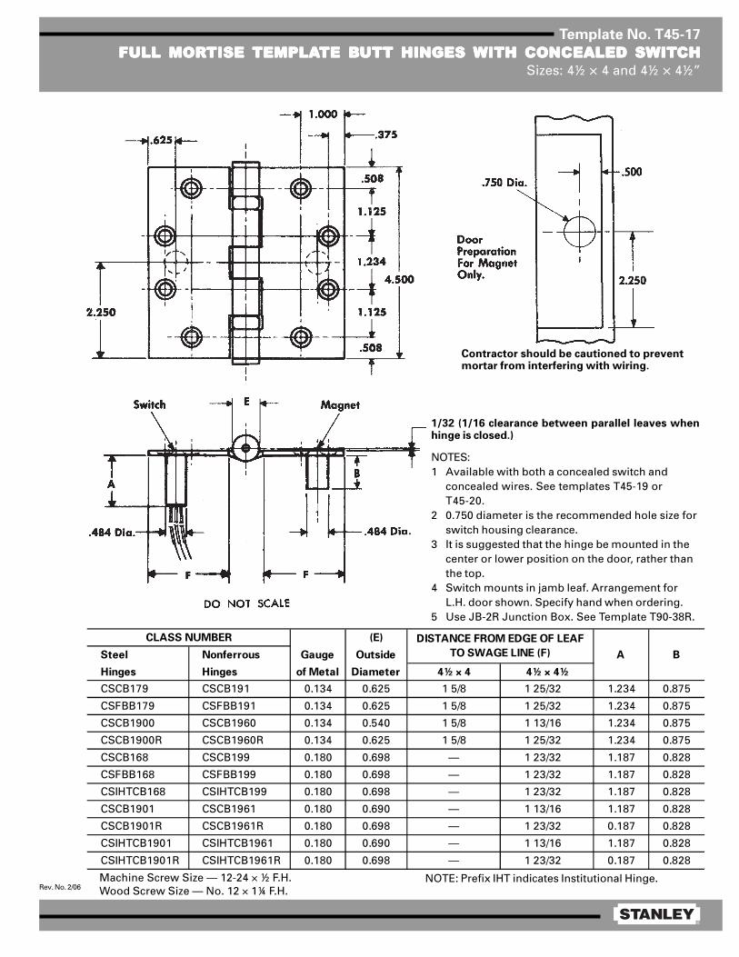
®
Rev. No. 2/06
Template No. T45-17
FULL MORFULL MORFULL MORFULL MORFULL MORTISE TISE TISE TISE TISE TEMPLATEMPLATEMPLATEMPLATEMPLATE BTE BTE BTE BTE BUTT HINGES UTT HINGES UTT HINGES UTT HINGES UTT HINGES WITH CONCEALED SWITWITH CONCEALED SWITWITH CONCEALED SWITWITH CONCEALED SWITWITH CONCEALED SWITCHCHCHCHCHSizes: 4½ × 4 and 4½ × 4½”
Machine Screw Size — 12-24 × ½ F.H.Wood Screw Size — No. 12 × 1¼ F.H.
Contractor should be cautioned to preventmortar from interfering with wiring.
1/32 (1/16 clearance between parallel leaves whenhinge is closed.)
NOTES:1 Available with both a concealed switch and
concealed wires. See templates T45-19 orT45-20.
2 0.750 diameter is the recommended hole size forswitch housing clearance.
3 It is suggested that the hinge be mounted in thecenter or lower position on the door, rather thanthe top.
4 Switch mounts in jamb leaf. Arrangement forL.H. door shown. Specify hand when ordering.
5 Use JB-2R Junction Box. See Template T90-38R.
NOTE: Prefix IHT indicates Institutional Hinge.
(E)
Steel Nonferrous Gauge Outside
Hinges Hinges of Metal Diameter 4½ × 4 4½ × 4½
CSCB179 CSCB191 0.134 0.625 1 5/8 1 25/32 1.234 0.875
CSFBB179 CSFBB191 0.134 0.625 1 5/8 1 25/32 1.234 0.875
CSCB1900 CSCB1960 0.134 0.540 1 5/8 1 13/16 1.234 0.875
CSCB1900R CSCB1960R 0.134 0.625 1 5/8 1 25/32 1.234 0.875
CSCB168 CSCB199 0.180 0.698 — 1 23/32 1.187 0.828
CSFBB168 CSFBB199 0.180 0.698 — 1 23/32 1.187 0.828
CSIHTCB168 CSIHTCB199 0.180 0.698 — 1 23/32 1.187 0.828
CSCB1901 CSCB1961 0.180 0.690 — 1 13/16 1.187 0.828
CSCB1901R CSCB1961R 0.180 0.698 — 1 23/32 0.187 0.828
CSIHTCB1901 CSIHTCB1961 0.180 0.690 — 1 13/16 1.187 0.828
CSIHTCB1901R CSIHTCB1961R 0.180 0.698 — 1 23/32 0.187 0.828
B
CLASS NUMBER DISTANCE FROM EDGE OF LEAF
TO SWAGE LINE (F) A

®
Rev. No. 3/09
Template No. T45-15
FULL MORFULL MORFULL MORFULL MORFULL MORTISE TISE TISE TISE TISE TEMPLATEMPLATEMPLATEMPLATEMPLATE BTE BTE BTE BTE BUTT HINGES UTT HINGES UTT HINGES UTT HINGES UTT HINGES WITH CONCEALED WITH CONCEALED WITH CONCEALED WITH CONCEALED WITH CONCEALED WIRESWIRESWIRESWIRESWIRESSizes: 4½ × 4 and 4½ × 4½”
Machine Screw Size — ½ × 12-24 F.H.Wood Screw Size — 1¼ × No. 12 F.H.
1/32 (1/16 clearance between hinge leaveswhen parallel).
Drill a 0.750 inch diameter hole in the hingereinforcement to allow the wires and connectors(wire nuts) to pass through freely. A larger holemay be required, depending on connector size.
De-burr both faces of the hole and prime to helpavoid damaging wire insulation.
Use a JB-2R Junction Box. See template T90-38R.
1.000.375
.508
1.125
1.2344.500
1.125
.508
2.250
E
FF
.625
DO NOT SCALE
¾ hole forthrough wires
¾ hole forthrough wires
CE hinges are available in the following configurations:
(E)
Steel Nonferrous Gauge Outside
Hinges Hinges of Metal Diameter 4½ × 4 4½ × 4½
CECB179 CECB191 0.134 0.625 1 5/8 1 25/32
CEFBB179 CEFBB191 0.134 0.625 1 5/8 1 25/32
CECB168 CECB199 0.180 0.698 1 15/32 1 23/32
CEFBB168 CEFBB199 0.180 0.698 1 15/32 1 23/32
CEIHTCB168 CEIHTCB199 0.180 0.698 1 15/32 1 23/32
CLASS NUMBER DISTANCE FROM EDGE OF LEAF
TO SWAGE LINE (F)
NOTE:Available with both concealed wires and aconcealed switch. See template No. T45-19.
Suffix Number of Wires Wire Gage
–54 4 wire 28 AWG–56 6 wire 28 AWG
2 ea 24 AWG4 ea 28 AWG2 ea 18 AWG6 ea 28 AWG
–58 8 wire 28 AWG–10 10 wire 28 AWG
Notes: FBB168 & FBB199 are not available with the –66 suffixThe –18 suffix is available only in 5 knuckle CB design
–66 6 wire
–18 8 wire

Full Mortise Butt Hinge (Size 4-½ x 4-½”) Drilling Instructions/TemplateStandard Weight - CECB 179-12C & 191-12C
Heavy Weight - CECB 168-12C & 199-12C
1/32-1/16(.79mm-1.6mm)clearance between hinge leaves when parallel.
A A
E
D
B
D
C C
B
E
4.5"114.3 mm
.508"12.9 mm
.508"12.9 mm
1.125"28.6 mm
.75"19.1 mm
1"25.4 mm.375"
9.5 mm
Ø .875"22.2 mm
Ø .218"5.6 mm
Standard Weight0.134” (3.4mm)CECB 179 & 191
Heavy Weight0.180” (4.6mm)CECB 168 & 199
2.25"57.2 mm
1.125"28.6 mm
1.234"31.3 mm
4.5" (114.3 mm)
Tools NeededHerramientas necesariasOutils nécessaires
File7/8" (22.2 mm)
Drill Bit
Wood Door
7/32" (5.6 mm)Drill Bit
Wood Door
#12-24
Metal Door
De-burr holes and prime to avoid damaging wires.
Use a JB-2R Junction Box, as required. See template T90-38R.
Drill hole C.
C
7/8"
22.2 mm 2"(50.8 mm)min. deep
Drill hole A, B, D, and E.
Machine Screw - 1/2 x 12-24 F.H.Wood Screw - 1-1/4 x #12 F.H.
A
B
D
E
A85296-C Copyright© Stanley Security 20151/2
1 2 3

.875"22.2 mm
Door Jamb
2" (50.8 mm) min. depth
De-burr holes and prime to avoid damaging wires.
A85296-C Copyright© Stanley Security 20152/2

®
Rev. No. 3/09
Template No. T45-19
FULL MORFULL MORFULL MORFULL MORFULL MORTISE TISE TISE TISE TISE TEMPLATEMPLATEMPLATEMPLATEMPLATE BTE BTE BTE BTE BUTT HINGES UTT HINGES UTT HINGES UTT HINGES UTT HINGES WITH CONCEALEDWITH CONCEALEDWITH CONCEALEDWITH CONCEALEDWITH CONCEALEDWIRES WIRES WIRES WIRES WIRES AND CONCEALED SWITAND CONCEALED SWITAND CONCEALED SWITAND CONCEALED SWITAND CONCEALED SWITCHCHCHCHCH
Sizes: 4½ × 4 and 4½ × 4½”
1/32 (1/16 clearance between hinges leaves whenparallel).
Drill a 0.750 inch diameter hole in the hingereinforcement to allow the wires and connectors(wire nuts) to pass through freely. A larger holemay be required, depending on connector size.
De-burr both faces of the hole and prime to helpavoid damaging wire insulation.
Switches mount in jamb leaf. Arrangement is forR.H. door shown. Specify the hand of door whenordering.
Use a JB-2R Junction Box. See template T90-38R.
NOTES:1 It is suggested that the hinge be mounted in
the center or lower position on the door, ratherthan the top.
2 For reference, see template for JB-2R JunctionBox (T90-38R).
Machine Screw Size — ½ × 12-24 F.H.Wood Screw Size — 1¼ × No. 12 F.H.
1.000
.375
.508
1.125
1.234
4.500
1.125
.508
2.250
E
FF
.625
1.032
1.218
.625
.500∅ .750 ∅ .750
BA
.625
This view shows CS construction only.
DO NOT SCALEDoor preparation formagnet and wireclearance only.
Frame preparation forswitch and wire clear-ance only.
Magnet Switch
(E)
Steel Nonferrous Gauge Outside A B
Hinges Hinges of Metal Diameter 4½ × 4 4½ × 4½
CECSCB179 CECSCB191 0.134 0.625 1 5/8 1 25/32 1.234 0.875
CECSFBB179 CECSFBB191 0.134 0.625 1 5/8 1 25/32 1.234 0.875
CECSCB168 CECSCB199 0.180 0.698 1 15/32 1 23/32 1.187 0.828
CECSFBB168 CECSFBB199 0.180 0.698 1 15/32 1 23/32 1.187 0.828
CLASS NUMBER DISTANCE FROM EDGE OF
LEAF TO SWAGE LINE (F)
CE hinges are available in the following configurations.
¾ hole forthrough wiresand switchhousing
Wire clusdia. 0.187
.484 dia.484 dia
Suffix Number of Wires Wire Gage
–54 4 wire 28 AWG–56 6 wire 28 AWG
2 ea 24 AWG4 ea 28 AWG2 ea 18 AWG6 ea 28 AWG
–58 8 wire 28 AWG–10 10 wire 28 AWG
Notes: FBB168 & FBB199 are not available with the –66 suffixThe –18 suffix is available only in 5 Knuckle CB design
–66 6 wire
–18 8 wire

®
Rev. No. 1/06
Template No. T50-13
RAISED BRAISED BRAISED BRAISED BRAISED BARREL ARREL ARREL ARREL ARREL TEMPLATEMPLATEMPLATEMPLATEMPLATE BTE BTE BTE BTE BUTT HINGES FOR DOORSUTT HINGES FOR DOORSUTT HINGES FOR DOORSUTT HINGES FOR DOORSUTT HINGES FOR DOORSWITH SQWITH SQWITH SQWITH SQWITH SQUUUUUARE EDGE HINGE STILESARE EDGE HINGE STILESARE EDGE HINGE STILESARE EDGE HINGE STILESARE EDGE HINGE STILES
Size: 5 × 4½”
Template hinges of the hospital type conform to above screw hole location.Hospital type hinges are designated by prefix “HT” to class number.Machine Screw Size — ½ × 12-24 F.H.
Wood Screw Size —
(D)
Steel Nonferrous Gauge Outside E F
Hinges Hinges of Metal Diameter (See Note 3)
RB-CB179 RB-CB191 0.146 0.669 9/16 11/32
RB-FBB179 RB-FBB191 0.146 0.669 9/16 11/32
RB-CB1900 RB-CB1960 0.146 0.580 9/16 11/32
RB-CB1900R RB-CB1960R 0.146 0.580 9/16 11/32
RB-CB168 RB-CB199 0.190 0.748 21/32 3/8
RB-FBB168 RB-FBB199 0.190 0.748 21/32 3/8
RB-CB1901 RB-CB1961 0.190 0.715 21/32 3/8
RB-CB1901R RB-CB1961R 0.190 0.748 21/32 3/8
CLASS NUMBER
NOTES:1 Side clearance between door and frame governed by depth of
mortise in door (3/32 between door and frame suggested).2 Recommended for approx. 1/16 swinging clearance between
door and stop.3 For raised barrel mortise and surface applications on beveled
stile door installations, see template drawing T50-14.
1¼ × No. 12 F.H. for standard weight (0.146) hinges1½ × No. 12 F.H. for heavy weight (0.190) hinges[

®
Rev. No. 1/06
Template No. T50-14
RAISED BRAISED BRAISED BRAISED BRAISED BARREL ARREL ARREL ARREL ARREL TEMPLATEMPLATEMPLATEMPLATEMPLATE BTE BTE BTE BTE BUTT HINGES FOR DOORSUTT HINGES FOR DOORSUTT HINGES FOR DOORSUTT HINGES FOR DOORSUTT HINGES FOR DOORSWITH BEVELED EDGE HINGE STILESWITH BEVELED EDGE HINGE STILESWITH BEVELED EDGE HINGE STILESWITH BEVELED EDGE HINGE STILESWITH BEVELED EDGE HINGE STILES
Size: 5 × 4½”
Template hinges of the hospital type conform to above screw hole location.Hospital type hinges are designated by prefix “HT” to class number.Machine Screw Size — ½ × 12-24 F.H.
Wood Screw Size —
NOTES:1 Clearance between leaves on plane of door face.2 Side clearance between door and frame governed by depth of
mortise in door (3/32 between door and frame suggested).3 Recommended for approx. 1/16 swinging clearance between
door and stop.4 For raised barrel mortise and surface applications on square
stile door installations, see template drawing T50-13.
1¼ × No. 12 F.H. for standard weight (0.146) hinges1½ × No. 12 F.H. for extra heavy weight (0.190) hinges[
(D)
Steel Nonferrous Gauge Outside E F
Hinges Hinges of Metal Diameter (See Note 3)
RB-CB179 RB-CB191 0.146 0.669 9/16 11/32
RB-FBB179 RB-FBB191 0.146 0.669 9/16 11/32
RB-CB1900 RB-CB1960 0.146 0.580 9/16 11/32
RB-CB1900R RB-CB1960R 0.146 0.669 9/16 11/32
RB-CB168 RB-CB199 0.190 0.748 21/32 3/8
RB-FBB168 RB-FBB199 0.190 0.748 21/32 3/8
RB-CB1901 RB-CB1961 0.190 0.715 21/32 3/8
RB-CB1901R RB-CB1961R 0.190 0.748 21/32 3/8
CLASS NUMBER
(3°-35’)

®
Rev. No. 4/07
Template No. T60-01
FULL MORFULL MORFULL MORFULL MORFULL MORTISE TISE TISE TISE TISE TEMPLATEMPLATEMPLATEMPLATEMPLATE BTE BTE BTE BTE BUTT HINGESUTT HINGESUTT HINGESUTT HINGESUTT HINGESSizes: 6 × 4½, 6 × 5 and 6 × 6”
Template hinges of the hospital type conform to above screw hole location.Hospital type hinges are designated by prefix “HT” to class number.
Machine Screw Size — ½ × ¼-20 F.H.Wood Screw Size — 1½ × No. 14 F.H.
This template conforms with ANSI standard A156.7.
(E)
Steel Nonferrous Gauge Outside
Hinges Hinges of Metal Diameter 6 × 4½ 6 × 5 6 × 6
F179 — 0.160 0.725 1 23/32 1 31/32 2 15/32
1900R — 0.160 0.725 1 23/32 1 31/32 2 15/32
CB179 CB191 0.160 0.735 1 23/32 1 31/32 2 15/32
FBB179 FBB191 0.160 0.735 1 23/32 1 31/32 2 15/32
CB1900R CB1960R 0.160 0.735 1 23/32 1 31/32 2 15/32
CB168 CB199 0.203 0.847 1 1/2 1 3/4 2 1/4
FBB168 FBB199 0.203 0.847 1 1/2 1 3/4 2 1/4
CB1901 CB1961 0.203 0.735 1 3/4 2 2 1/2
CB1901R CB1961R 0.203 0.847 1 1/2 1 3/4 2 1/4
CLASS NUMBER DISTANCE FROM EDGE OF
LEAF TO SWAGE LINE (F)

®
Rev. No. 3/09
Template No. T45-15
FULL MORFULL MORFULL MORFULL MORFULL MORTISE TISE TISE TISE TISE TEMPLATEMPLATEMPLATEMPLATEMPLATE BTE BTE BTE BTE BUTT HINGES UTT HINGES UTT HINGES UTT HINGES UTT HINGES WITH CONCEALED WITH CONCEALED WITH CONCEALED WITH CONCEALED WITH CONCEALED WIRESWIRESWIRESWIRESWIRESSizes: 4½ × 4 and 4½ × 4½”
Machine Screw Size — ½ × 12-24 F.H.Wood Screw Size — 1¼ × No. 12 F.H.
1/32 (1/16 clearance between hinge leaveswhen parallel).
Drill a 0.750 inch diameter hole in the hingereinforcement to allow the wires and connectors(wire nuts) to pass through freely. A larger holemay be required, depending on connector size.
De-burr both faces of the hole and prime to helpavoid damaging wire insulation.
Use a JB-2R Junction Box. See template T90-38R.
1.000.375
.508
1.125
1.2344.500
1.125
.508
2.250
E
FF
.625
DO NOT SCALE
¾ hole forthrough wires
¾ hole forthrough wires
CE hinges are available in the following configurations:
(E)
Steel Nonferrous Gauge Outside
Hinges Hinges of Metal Diameter 4½ × 4 4½ × 4½
CECB179 CECB191 0.134 0.625 1 5/8 1 25/32
CEFBB179 CEFBB191 0.134 0.625 1 5/8 1 25/32
CECB168 CECB199 0.180 0.698 1 15/32 1 23/32
CEFBB168 CEFBB199 0.180 0.698 1 15/32 1 23/32
CEIHTCB168 CEIHTCB199 0.180 0.698 1 15/32 1 23/32
CLASS NUMBER DISTANCE FROM EDGE OF LEAF
TO SWAGE LINE (F)
NOTE:Available with both concealed wires and aconcealed switch. See template No. T45-19.
Suffix Number of Wires Wire Gage
–54 4 wire 28 AWG–56 6 wire 28 AWG
2 ea 24 AWG4 ea 28 AWG2 ea 18 AWG6 ea 28 AWG
–58 8 wire 28 AWG–10 10 wire 28 AWG
Notes: FBB168 & FBB199 are not available with the –66 suffixThe –18 suffix is available only in 5 knuckle CB design
–66 6 wire
–18 8 wire
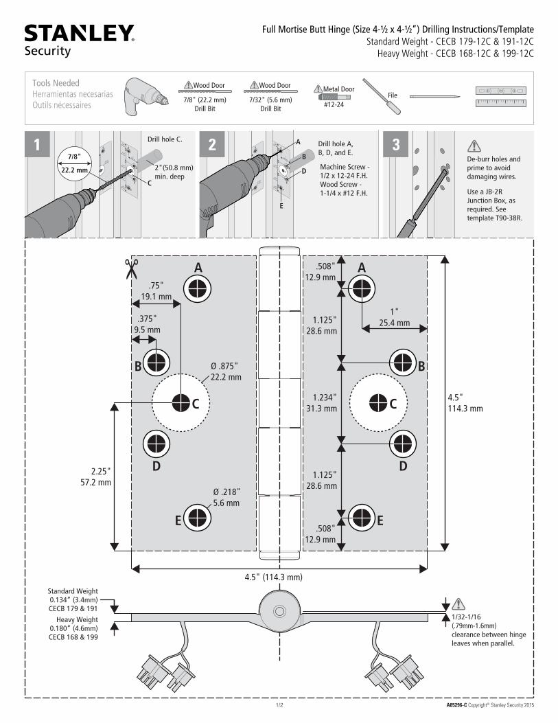
Full Mortise Butt Hinge (Size 4-½ x 4-½”) Drilling Instructions/TemplateStandard Weight - CECB 179-12C & 191-12C
Heavy Weight - CECB 168-12C & 199-12C
1/32-1/16(.79mm-1.6mm)clearance between hinge leaves when parallel.
A A
E
D
B
D
C C
B
E
4.5"114.3 mm
.508"12.9 mm
.508"12.9 mm
1.125"28.6 mm
.75"19.1 mm
1"25.4 mm.375"
9.5 mm
Ø .875"22.2 mm
Ø .218"5.6 mm
Standard Weight0.134” (3.4mm)CECB 179 & 191
Heavy Weight0.180” (4.6mm)CECB 168 & 199
2.25"57.2 mm
1.125"28.6 mm
1.234"31.3 mm
4.5" (114.3 mm)
Tools NeededHerramientas necesariasOutils nécessaires
File7/8" (22.2 mm)
Drill Bit
Wood Door
7/32" (5.6 mm)Drill Bit
Wood Door
#12-24
Metal Door
De-burr holes and prime to avoid damaging wires.
Use a JB-2R Junction Box, as required. See template T90-38R.
Drill hole C.
C
7/8"
22.2 mm 2"(50.8 mm)min. deep
Drill hole A, B, D, and E.
Machine Screw - 1/2 x 12-24 F.H.Wood Screw - 1-1/4 x #12 F.H.
A
B
D
E
A85296-C Copyright© Stanley Security 20151/2
1 2 3
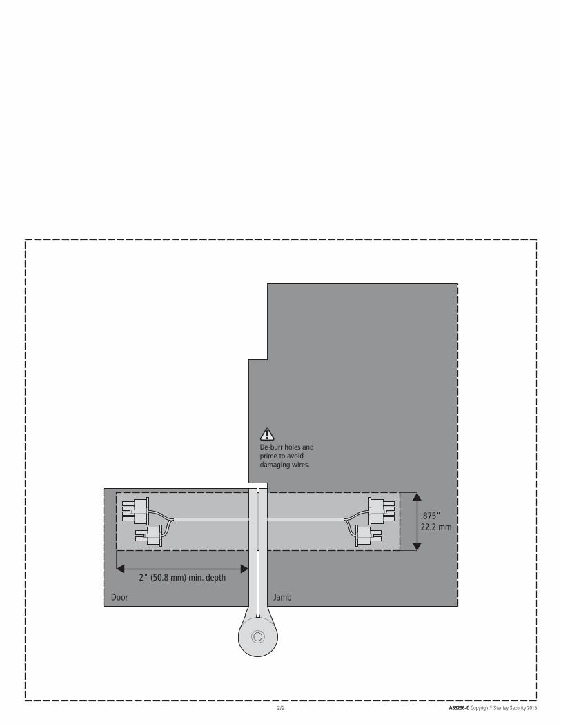
.875"22.2 mm
Door Jamb
2" (50.8 mm) min. depth
De-burr holes and prime to avoid damaging wires.
A85296-C Copyright© Stanley Security 20152/2

®
Rev. No. 3/09
Template No. T45-19
FULL MORFULL MORFULL MORFULL MORFULL MORTISE TISE TISE TISE TISE TEMPLATEMPLATEMPLATEMPLATEMPLATE BTE BTE BTE BTE BUTT HINGES UTT HINGES UTT HINGES UTT HINGES UTT HINGES WITH CONCEALEDWITH CONCEALEDWITH CONCEALEDWITH CONCEALEDWITH CONCEALEDWIRES WIRES WIRES WIRES WIRES AND CONCEALED SWITAND CONCEALED SWITAND CONCEALED SWITAND CONCEALED SWITAND CONCEALED SWITCHCHCHCHCH
Sizes: 4½ × 4 and 4½ × 4½”
1/32 (1/16 clearance between hinges leaves whenparallel).
Drill a 0.750 inch diameter hole in the hingereinforcement to allow the wires and connectors(wire nuts) to pass through freely. A larger holemay be required, depending on connector size.
De-burr both faces of the hole and prime to helpavoid damaging wire insulation.
Switches mount in jamb leaf. Arrangement is forR.H. door shown. Specify the hand of door whenordering.
Use a JB-2R Junction Box. See template T90-38R.
NOTES:1 It is suggested that the hinge be mounted in
the center or lower position on the door, ratherthan the top.
2 For reference, see template for JB-2R JunctionBox (T90-38R).
Machine Screw Size — ½ × 12-24 F.H.Wood Screw Size — 1¼ × No. 12 F.H.
1.000
.375
.508
1.125
1.234
4.500
1.125
.508
2.250
E
FF
.625
1.032
1.218
.625
.500∅ .750 ∅ .750
BA
.625
This view shows CS construction only.
DO NOT SCALEDoor preparation formagnet and wireclearance only.
Frame preparation forswitch and wire clear-ance only.
Magnet Switch
(E)
Steel Nonferrous Gauge Outside A B
Hinges Hinges of Metal Diameter 4½ × 4 4½ × 4½
CECSCB179 CECSCB191 0.134 0.625 1 5/8 1 25/32 1.234 0.875
CECSFBB179 CECSFBB191 0.134 0.625 1 5/8 1 25/32 1.234 0.875
CECSCB168 CECSCB199 0.180 0.698 1 15/32 1 23/32 1.187 0.828
CECSFBB168 CECSFBB199 0.180 0.698 1 15/32 1 23/32 1.187 0.828
CLASS NUMBER DISTANCE FROM EDGE OF
LEAF TO SWAGE LINE (F)
CE hinges are available in the following configurations.
¾ hole forthrough wiresand switchhousing
Wire clusdia. 0.187
.484 dia.484 dia
Suffix Number of Wires Wire Gage
–54 4 wire 28 AWG–56 6 wire 28 AWG
2 ea 24 AWG4 ea 28 AWG2 ea 18 AWG6 ea 28 AWG
–58 8 wire 28 AWG–10 10 wire 28 AWG
Notes: FBB168 & FBB199 are not available with the –66 suffixThe –18 suffix is available only in 5 Knuckle CB design
–66 6 wire
–18 8 wire

®
Rev. No. 2/06
Template No. T45-17
FULL MORFULL MORFULL MORFULL MORFULL MORTISE TISE TISE TISE TISE TEMPLATEMPLATEMPLATEMPLATEMPLATE BTE BTE BTE BTE BUTT HINGES UTT HINGES UTT HINGES UTT HINGES UTT HINGES WITH CONCEALED SWITWITH CONCEALED SWITWITH CONCEALED SWITWITH CONCEALED SWITWITH CONCEALED SWITCHCHCHCHCHSizes: 4½ × 4 and 4½ × 4½”
Machine Screw Size — 12-24 × ½ F.H.Wood Screw Size — No. 12 × 1¼ F.H.
Contractor should be cautioned to preventmortar from interfering with wiring.
1/32 (1/16 clearance between parallel leaves whenhinge is closed.)
NOTES:1 Available with both a concealed switch and
concealed wires. See templates T45-19 orT45-20.
2 0.750 diameter is the recommended hole size forswitch housing clearance.
3 It is suggested that the hinge be mounted in thecenter or lower position on the door, rather thanthe top.
4 Switch mounts in jamb leaf. Arrangement forL.H. door shown. Specify hand when ordering.
5 Use JB-2R Junction Box. See Template T90-38R.
NOTE: Prefix IHT indicates Institutional Hinge.
(E)
Steel Nonferrous Gauge Outside
Hinges Hinges of Metal Diameter 4½ × 4 4½ × 4½
CSCB179 CSCB191 0.134 0.625 1 5/8 1 25/32 1.234 0.875
CSFBB179 CSFBB191 0.134 0.625 1 5/8 1 25/32 1.234 0.875
CSCB1900 CSCB1960 0.134 0.540 1 5/8 1 13/16 1.234 0.875
CSCB1900R CSCB1960R 0.134 0.625 1 5/8 1 25/32 1.234 0.875
CSCB168 CSCB199 0.180 0.698 — 1 23/32 1.187 0.828
CSFBB168 CSFBB199 0.180 0.698 — 1 23/32 1.187 0.828
CSIHTCB168 CSIHTCB199 0.180 0.698 — 1 23/32 1.187 0.828
CSCB1901 CSCB1961 0.180 0.690 — 1 13/16 1.187 0.828
CSCB1901R CSCB1961R 0.180 0.698 — 1 23/32 0.187 0.828
CSIHTCB1901 CSIHTCB1961 0.180 0.690 — 1 13/16 1.187 0.828
CSIHTCB1901R CSIHTCB1961R 0.180 0.698 — 1 23/32 0.187 0.828
B
CLASS NUMBER DISTANCE FROM EDGE OF LEAF
TO SWAGE LINE (F) A

®
Rev. No. 1/06
Template No. T45-10
RAISED BRAISED BRAISED BRAISED BRAISED BARREL ARREL ARREL ARREL ARREL TEMPLATEMPLATEMPLATEMPLATEMPLATE BTE BTE BTE BTE BUTT HINGES FOR DOORS UTT HINGES FOR DOORS UTT HINGES FOR DOORS UTT HINGES FOR DOORS UTT HINGES FOR DOORS WITHWITHWITHWITHWITHSQSQSQSQSQUUUUUARE EDGE HINGE STILESARE EDGE HINGE STILESARE EDGE HINGE STILESARE EDGE HINGE STILESARE EDGE HINGE STILES
Size: 4½ × 4½”
Template hinges of the hospital type conform to above screw hole location.Hospital type hinges are designated by prefix “HT” to class number.
Machine Screw Size — ½ × 12-24 F.H.Wood Screw Size — 1¼ × No. 12 F.H.
DO NOT SCALE
(E)
Steel Nonferrous Gauge Outside E F
Hinges Hinges of Metal Diameter (See Note 2)
RB-CB179 RB-CB191 0.134 0.625 1/2 11/32
RB-FBB179 RB-FBB191 0.134 0.625 1/2 11/32
RB-CB1900 RB-CB1960 0.134 0.540 1/2 11/32
RB-CB1900R RB-CB1960R 0.134 0.625 1/2 11/32
RB-CB168 RB-CB199 0.180 0.698 5/8 3/8
RB-FBB168 RB-FBB199 0.180 0.698 5/8 3/8
RB-CB1901 RB-CB1961 0.180 0.690 5/8 3/8
RB-CB1901R RB-CB1961R 0.180 0.698 5/8 3/8
CLASS NUMBER
NOTES:1 Side clearance between door and frame governed by depth of
mortise. (3/32 betwen door and frame suggested).2 Recommended for approx. 1/16 swinging clearance between door
and stop. For raised barrel mortise and surface applications onbeveled stile door installations, see template drawing T45-11.

®
Rev. No. 1/06
Template No. T45-11
RAISED BRAISED BRAISED BRAISED BRAISED BARREL ARREL ARREL ARREL ARREL TEMPLATEMPLATEMPLATEMPLATEMPLATE BTE BTE BTE BTE BUTT HINGES FOR DOORS UTT HINGES FOR DOORS UTT HINGES FOR DOORS UTT HINGES FOR DOORS UTT HINGES FOR DOORS WITHWITHWITHWITHWITHBEVELED EDGE HINGE STILESBEVELED EDGE HINGE STILESBEVELED EDGE HINGE STILESBEVELED EDGE HINGE STILESBEVELED EDGE HINGE STILES
Size: 4½ × 4½”
(E)
Steel Nonferrous Gauge Outside E F
Hinges Hinges of Metal Diameter (See Note 3)
RB-CB179 RB-CB191 0.134 0.625 1/2 11/32
RB-FBB179 RB-FBB191 0.134 0.625 1/2 11/32
RB-CB1900 RB-CB1960 0.134 0.540 1/2 11/32
RB-CB1900R RB-CB1960R 0.134 0.625 1/2 11/32
RB-CB168 RB-CB199 0.180 0.698 5/8 3/8
RB-FBB168 RB-FBB199 0.180 0.698 5/8 3/8
RB-CB1901 RB-CB1961 0.180 0.690 5/8 3/8
RB-CB1901R RB-CB1961R 0.180 0.698 5/8 3/8
CLASS NUMBER
NOTES:1 Clearance between leaves on plane of door face.2 Side clearance between door and frame goverened by depth
of mortise. (3/32 between door and frame suggested).3 Recommended for approx. 1/16 swinging clearance between
door and stop.4 For raised barrel mortise and surface applications on square
stile door installations, see template drawing T45-10.
Template hinges of the hospital type conform to above screw hole location.Hospital type hinges are designated by prefix “HT” to class number.
Machine Screw Size — ½ × 12-24 F.H.Wood Screw Size — 1¼ × No. 12 F.H.
DO NOT SCALE

®
Rev. No. 1/06
Template No. T50-01
FULL MORFULL MORFULL MORFULL MORFULL MORTISE TISE TISE TISE TISE TEMPLATEMPLATEMPLATEMPLATEMPLATE BTE BTE BTE BTE BUTT HINGESUTT HINGESUTT HINGESUTT HINGESUTT HINGESSizes: 5 × 4, 5 × 4½, 5 × 5, 5 × 7 and 5 × 8”
Template hinges of the hospital type conform to above screw hole location.Hospital type hinges are designated by prefix “HT” to class number.Also available “RD” radius corners (1/4 or 5/8).Machine Screw Size — ½ × 12-24 F.H.
Wood Screw Size —
NOTE: Prefix IHT indicates Institutional Hinge.
This template conforms with ANSI standard A156.7.
1¼ × No. 12 F.H. for regular weight (0.146) hinges1½ × No. 12 F.H. for extra heavy weight (0.190) hinges[
E
F
1/ 16
5/ 8 R1/ 4 R
1 .2 50
5 .000
.508 .5081 .484 1 .2 50
1 .000
.37 5
(E)
Steel Nonferrous Gauge Outside
Hinges Hinges of Metal Diameter 5 × 4 5 × 4½ 5 × 5 5 × 7 5 × 8
F179 F191 0.146 0.661 1 5/8 1 13/16 2 1/16 3 1/16 3 9/16
1900 1960 0.146 0.580 1 5/8 1 3/4 2 — —
1900R 1960R 0.146 0.661 1 5/8 1 13/16 2 1/16 3 1/16 3 9/16
CB179 CB191 0.146 0.669 1 5/8 1 13/16 2 1/16 3 1/16 3 9/16
FBB179 FBB191 0.146 0.669 1 5/8 1 13/16 2 1/16 3 1/16 3 9/16
CB1900 CB1960 0.146 0.580 1 5/8 1 55/64 2 7/64 — —
CB1900R CB1960R 0.146 0.669 1 5/8 1 13/16 2 1/16 3 1/16 3 9/16
CB168 CB199 0.190 0.748 1 15/32 1 23/32 1 31/32 2 31/32 3 15/32
FBB168 FBB199 0.190 0.748 1 15/32 1 23/32 1 31/32 2 31/32 3 15/32
IHTCB168 IHTCB199 0.190 0.748 — 1 23/32 — — —
CB1901 CB1961 0.190 0.715 — 1 13/16 — — —
CB1901R CB1961R 0.190 0.748 1 15/32 2 23/32 1 31/32 2 31/32 3 15/32
IHTCB1901 IHTCB1961 0.190 0.715 — 1 13/16 — — —
IHTCB1901R IHTCB1961R 0.190 0.748 — 1 23/32 — — —
CLASS NUMBERDISTANCE FROM EDGE OF LEAF TO SWAGE LINE (F)
DO NOT SCALE
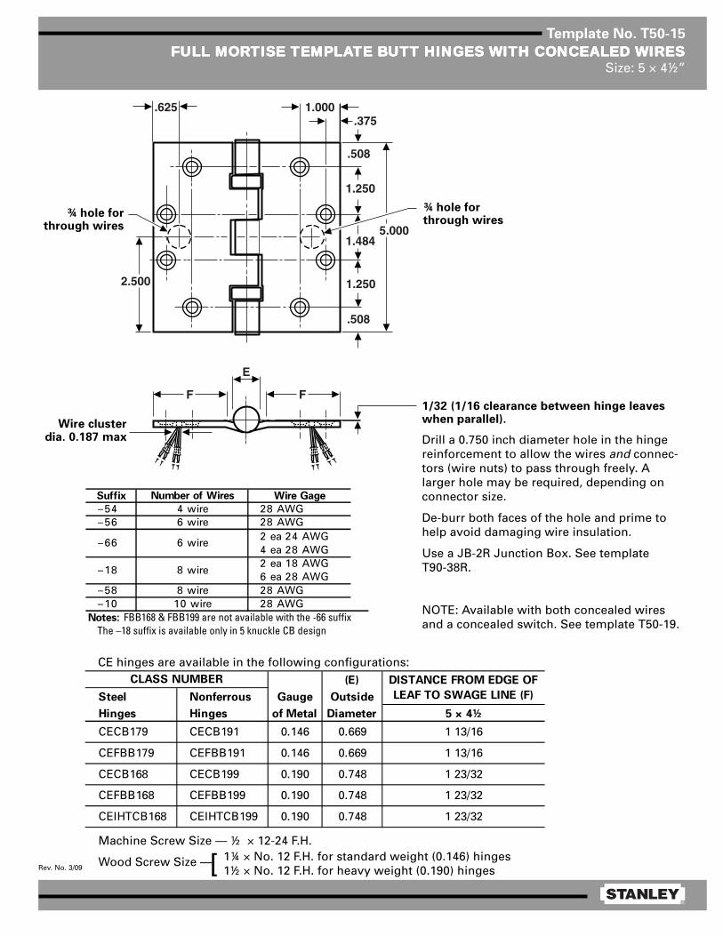
®
Rev. No. 3/09
Template No. T50-15
FULL MORFULL MORFULL MORFULL MORFULL MORTISE TISE TISE TISE TISE TEMPLATEMPLATEMPLATEMPLATEMPLATE BTE BTE BTE BTE BUTT HINGES UTT HINGES UTT HINGES UTT HINGES UTT HINGES WITH CONCEALED WITH CONCEALED WITH CONCEALED WITH CONCEALED WITH CONCEALED WIRESWIRESWIRESWIRESWIRESSize: 5 × 4½”
Machine Screw Size — ½ × 12-24 F.H.
Wood Screw Size — 1¼ × No. 12 F.H. for standard weight (0.146) hinges1½ × No. 12 F.H. for heavy weight (0.190) hinges[
1/32 (1/16 clearance between hinge leaveswhen parallel).
Drill a 0.750 inch diameter hole in the hingereinforcement to allow the wires and connec-tors (wire nuts) to pass through freely. Alarger hole may be required, depending onconnector size.
De-burr both faces of the hole and prime tohelp avoid damaging wire insulation.
Use a JB-2R Junction Box. See templateT90-38R.
NOTE: Available with both concealed wiresand a concealed switch. See template T50-19.
1.000.375
.508
1.250
1.4845.000
1.250
.508
2.500
E
FF
.625
¾ hole forthrough wires
¾ hole forthrough wires
Wire clusterdia. 0.187 max
CE hinges are available in the following configurations:(E)
Steel Nonferrous Gauge Outside
Hinges Hinges of Metal Diameter 5 × 4½
CECB179 CECB191 0.146 0.669 1 13/16
CEFBB179 CEFBB191 0.146 0.669 1 13/16
CECB168 CECB199 0.190 0.748 1 23/32
CEFBB168 CEFBB199 0.190 0.748 1 23/32
CEIHTCB168 CEIHTCB199 0.190 0.748 1 23/32
CLASS NUMBER DISTANCE FROM EDGE OF
LEAF TO SWAGE LINE (F)
Suffix Number of Wires Wire Gage
–54 4 wire 28 AWG–56 6 wire 28 AWG
2 ea 24 AWG4 ea 28 AWG2 ea 18 AWG6 ea 28 AWG
–58 8 wire 28 AWG–10 10 wire 28 AWG
Notes: FBB168 & FBB199 are not available with the -66 suffixThe –18 suffix is available only in 5 knuckle CB design
–66 6 wire
–18 8 wire

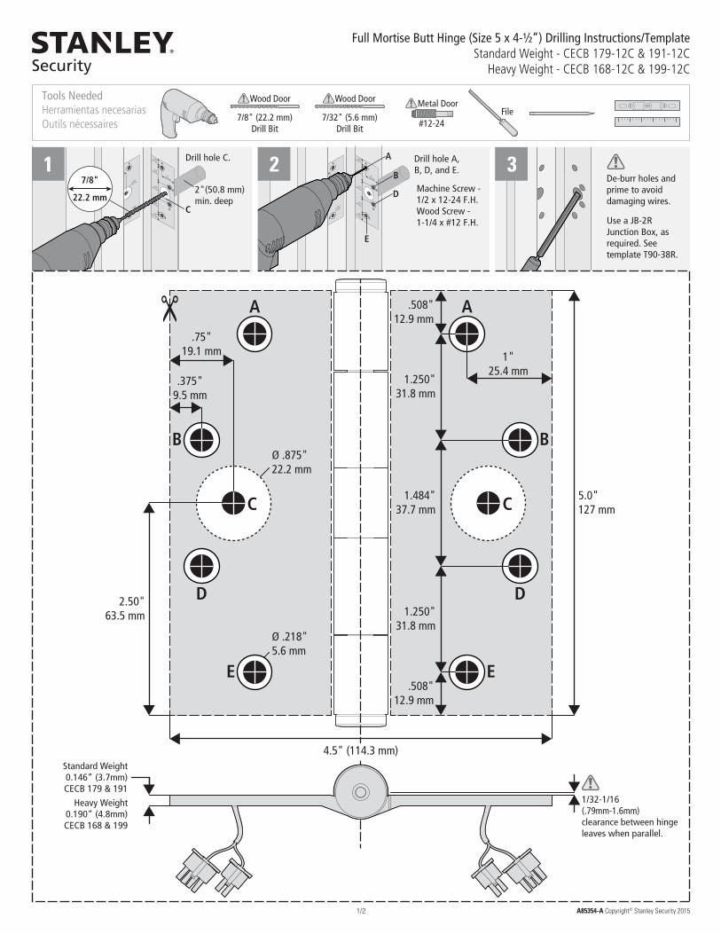
1/2
Full Mortise Butt Hinge (Size 5 x 4-½”) Drilling Instructions/TemplateStandard Weight - CECB 179-12C & 191-12C
Heavy Weight - CECB 168-12C & 199-12C
AA
BB
D
1/32-1/16(.79mm-1.6mm)clearance between hinge leaves when parallel.
5.0"127 mm
.508"12.9 mm
.508"12.9 mm
1.250"31.8 mm
1.250"31.8 mm
1.484"37.7 mm
Ø .875"22.2 mm
Ø .218"5.6 mm
Standard Weight0.146” (3.7mm)CECB 179 & 191
Heavy Weight0.190” (4.8mm)CECB 168 & 199
1"25.4 mm
.75"19.1 mm
.375"9.5 mm
2.50"63.5 mm
C C
D
EE
4.5" (114.3 mm)
Tools NeededHerramientas necesariasOutils nécessaires
File7/8" (22.2 mm)
Drill Bit
Wood Door
7/32" (5.6 mm)Drill Bit
Wood Door
#12-24
Metal Door
C
7/8"
22.2 mm2"(50.8 mm)min. deep
Drill hole C. Drill hole A, B, D, and E.
Machine Screw - 1/2 x 12-24 F.H.Wood Screw - 1-1/4 x #12 F.H.
A
B
D
E
De-burr holes and prime to avoid damaging wires.
Use a JB-2R Junction Box, as required. See template T90-38R.
A85354-A Copyright© Stanley Security 2015
1 2 3

2/2
.875"22.2 mm
Door Jamb
2" (50.8 mm) min. depth
De-burr holes and prime to avoid damaging wires.
A85354-A Copyright© Stanley Security 2015
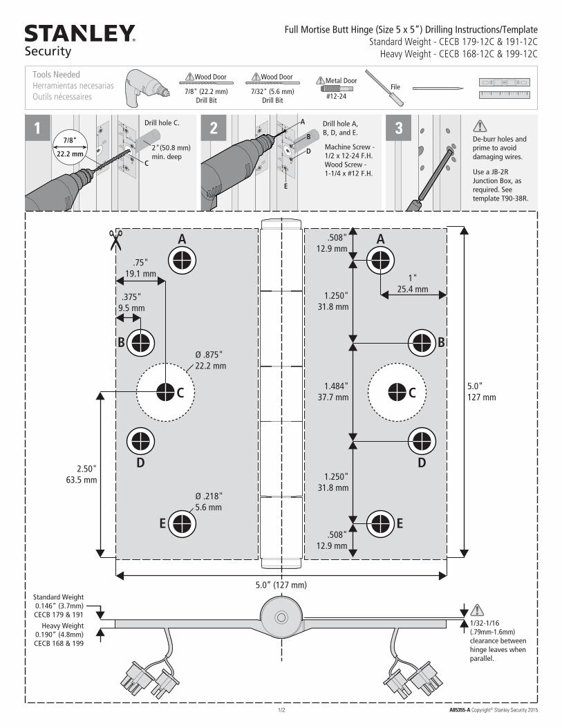
1/2
Full Mortise Butt Hinge (Size 5 x 5”) Drilling Instructions/TemplateStandard Weight - CECB 179-12C & 191-12C
Heavy Weight - CECB 168-12C & 199-12C
BB
D D
1/32-1/16(.79mm-1.6mm)clearance between hinge leaves when parallel.
5.0"127 mm
Ø .875"22.2 mm
Ø .218"5.6 mm
Standard Weight0.146” (3.7mm)CECB 179 & 191
Heavy Weight0.190” (4.8mm)CECB 168 & 199
.508"12.9 mm
.508"12.9 mm
1.250"31.8 mm
1.250"31.8 mm
1.484"37.7 mm
1"25.4 mm
.75"19.1 mm
.375"9.5 mm
2.50"63.5 mm
AA
C C
EE
5.0” (127 mm)
Tools NeededHerramientas necesariasOutils nécessaires
File7/8" (22.2 mm)
Drill Bit
Wood Door
7/32" (5.6 mm)Drill Bit
Wood Door
#12-24
Metal Door
C
7/8"
22.2 mm2"(50.8 mm)min. deep
Drill hole C. Drill hole A, B, D, and E.
Machine Screw - 1/2 x 12-24 F.H.Wood Screw - 1-1/4 x #12 F.H.
A
B
D
E
De-burr holes and prime to avoid damaging wires.
Use a JB-2R Junction Box, as required. See template T90-38R.
A85355-A Copyright© Stanley Security 2015
1 2 3

2/2
.875"22.2 mm
Door Jamb
2" (50.8 mm) min. depth
De-burr holes and prime to avoid damaging wires.
A85355-A Copyright© Stanley Security 2015

®
Rev. No. 03/09
Template No. T50-19
FULL MORFULL MORFULL MORFULL MORFULL MORTISE TISE TISE TISE TISE TEMPLATEMPLATEMPLATEMPLATEMPLATE BTE BTE BTE BTE BUTT HINGES UTT HINGES UTT HINGES UTT HINGES UTT HINGES WITH CONCEALED WITH CONCEALED WITH CONCEALED WITH CONCEALED WITH CONCEALED WIRESWIRESWIRESWIRESWIRESAND CONCEALED SWITAND CONCEALED SWITAND CONCEALED SWITAND CONCEALED SWITAND CONCEALED SWITCHCHCHCHCH
Size: 5 × 4½”
1.000
.375
.508
1.250
1.484
5.000
1.250
.508
2.500
E
FF
.625
1.094
1.406
.625
.500∅ .750
BA
∅ .750
.625
Machine Screw Size — ½ × 12-24 F.H.
Wood Screw Size — 1¼ × No. 12 F.H. for standard weight (0.146) hinges1½ × No. 12 F.H. for heavy weight (0.190) hinges[
1/32 (1/16 clearance between hinge leaveswhen parallel.)
Drill a 0.750 inch diameter hole in the hingereinforcement to allow the wires and connec-tors (wire nuts) to pass through freely. A largerhole may be required depending on connectorsize.
De-burr both faces of the hole and prime tohelp avoid damaging wire insulation.
Switches mount in jamb leaf. Arrangement forR.H. door shown. Specify the hand of doorwhen ordering.
Door preparation formagnet and wireclearance only.
Frame preparation forswitch and wire
clearance only.Magnet Switch
Wirecluster dia.0.187 max.
¾ hole forthrough wiresand switchhousing
DO NOT SCALE
CE hinges are available in the following configurations:
NOTES:1 It is suggested that the hinge be mounted in
the center or lower position on the door,rather than the top.
2 Use JB-2R Junction Box. See templateT90-38R.
This view shows CSconstruction only.
.484 dia.484 dia
(E)
Steel Nonferrous Gauge Outside A B
Hinges Hinges of Metal Diameter 5 × 4½
CECSCB179 CECSCB191 0.146 0.669 1 13/16 1.218 0.859
CECSFBB179 CECSFBB191 0.146 0.669 1 13/16 1.218 0.859
CECSCB168 CECSCB199 0.190 0.748 1 23/32 1.172 0.812
CECSFBB168 CECSFBB199 0.190 0.748 1 23/32 1.172 0.812
CLASS NUMBER DISTANCE FROM EDGE OF
LEAF TO SWAGE LINE (F)
Suffix Number of Wires Wire Gage
–54 4 wire 28 AWG–56 6 wire 28 AWG
2 ea 24 AWG4 ea 28 AWG
–58 8 wire 28 AWG–10 10 wire 28 AWG
2 ea 18 AWG6 ea 28 AWG
Notes: FBB168 & FBB199 are not available with the -66 suffix
–18 Available only in 5 Knuckle CB Design
–66 6 wire
–18 8 wire
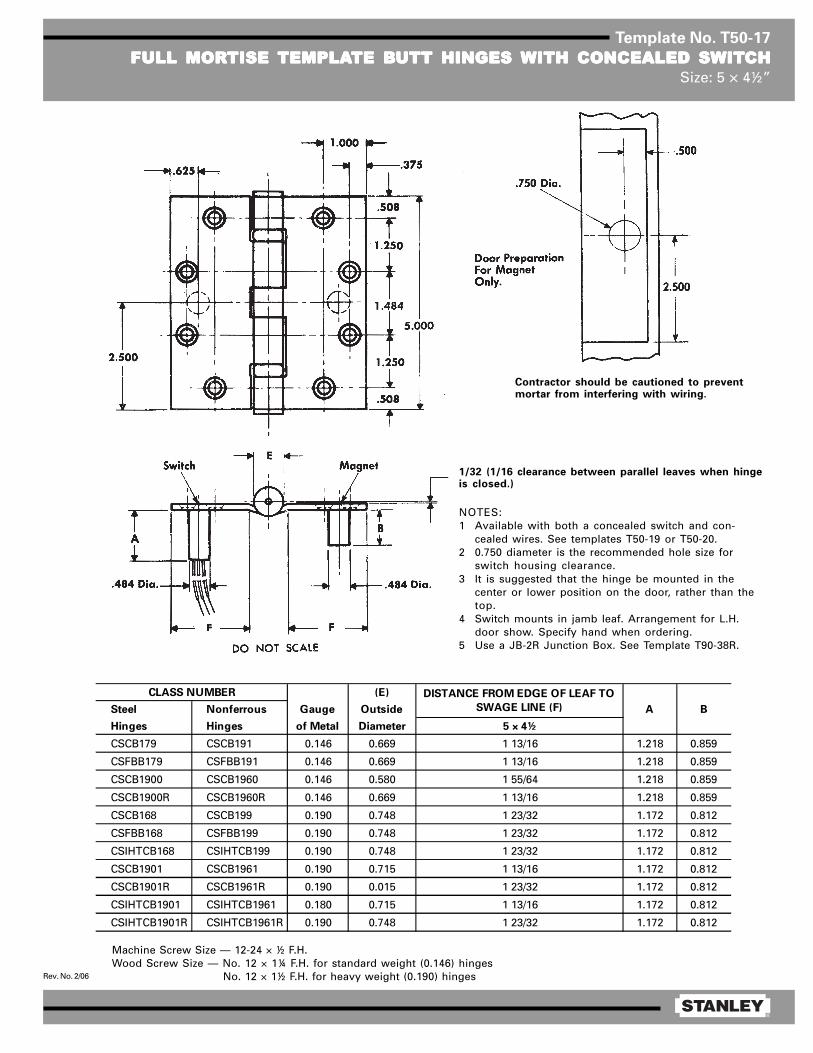
®
Rev. No. 2/06
Template No. T50-17
FULL MORFULL MORFULL MORFULL MORFULL MORTISE TISE TISE TISE TISE TEMPLATEMPLATEMPLATEMPLATEMPLATE BTE BTE BTE BTE BUTT HINGES UTT HINGES UTT HINGES UTT HINGES UTT HINGES WITH CONCEALED SWITWITH CONCEALED SWITWITH CONCEALED SWITWITH CONCEALED SWITWITH CONCEALED SWITCHCHCHCHCHSize: 5 × 4½”
Contractor should be cautioned to preventmortar from interfering with wiring.
1/32 (1/16 clearance between parallel leaves when hingeis closed.)
NOTES:1 Available with both a concealed switch and con-
cealed wires. See templates T50-19 or T50-20.2 0.750 diameter is the recommended hole size for
switch housing clearance.3 It is suggested that the hinge be mounted in the
center or lower position on the door, rather than thetop.
4 Switch mounts in jamb leaf. Arrangement for L.H.door show. Specify hand when ordering.
5 Use a JB-2R Junction Box. See Template T90-38R.
Machine Screw Size — 12-24 × ½ F.H.Wood Screw Size — No. 12 × 1¼ F.H. for standard weight (0.146) hinges
No. 12 × 1½ F.H. for heavy weight (0.190) hinges
(E)
Steel Nonferrous Gauge Outside A B
Hinges Hinges of Metal Diameter 5 × 4½
CSCB179 CSCB191 0.146 0.669 1 13/16 1.218 0.859
CSFBB179 CSFBB191 0.146 0.669 1 13/16 1.218 0.859
CSCB1900 CSCB1960 0.146 0.580 1 55/64 1.218 0.859
CSCB1900R CSCB1960R 0.146 0.669 1 13/16 1.218 0.859
CSCB168 CSCB199 0.190 0.748 1 23/32 1.172 0.812
CSFBB168 CSFBB199 0.190 0.748 1 23/32 1.172 0.812
CSIHTCB168 CSIHTCB199 0.190 0.748 1 23/32 1.172 0.812
CSCB1901 CSCB1961 0.190 0.715 1 13/16 1.172 0.812
CSCB1901R CSCB1961R 0.190 0.015 1 23/32 1.172 0.812
CSIHTCB1901 CSIHTCB1961 0.180 0.715 1 13/16 1.172 0.812
CSIHTCB1901R CSIHTCB1961R 0.190 0.748 1 23/32 1.172 0.812
CLASS NUMBER DISTANCE FROM EDGE OF LEAF TO
SWAGE LINE (F)

®
Rev. No. 1/06
Template No. T50-13
RAISED BRAISED BRAISED BRAISED BRAISED BARREL ARREL ARREL ARREL ARREL TEMPLATEMPLATEMPLATEMPLATEMPLATE BTE BTE BTE BTE BUTT HINGES FOR DOORSUTT HINGES FOR DOORSUTT HINGES FOR DOORSUTT HINGES FOR DOORSUTT HINGES FOR DOORSWITH SQWITH SQWITH SQWITH SQWITH SQUUUUUARE EDGE HINGE STILESARE EDGE HINGE STILESARE EDGE HINGE STILESARE EDGE HINGE STILESARE EDGE HINGE STILES
Size: 5 × 4½”
Template hinges of the hospital type conform to above screw hole location.Hospital type hinges are designated by prefix “HT” to class number.Machine Screw Size — ½ × 12-24 F.H.
Wood Screw Size —
(D)
Steel Nonferrous Gauge Outside E F
Hinges Hinges of Metal Diameter (See Note 3)
RB-CB179 RB-CB191 0.146 0.669 9/16 11/32
RB-FBB179 RB-FBB191 0.146 0.669 9/16 11/32
RB-CB1900 RB-CB1960 0.146 0.580 9/16 11/32
RB-CB1900R RB-CB1960R 0.146 0.580 9/16 11/32
RB-CB168 RB-CB199 0.190 0.748 21/32 3/8
RB-FBB168 RB-FBB199 0.190 0.748 21/32 3/8
RB-CB1901 RB-CB1961 0.190 0.715 21/32 3/8
RB-CB1901R RB-CB1961R 0.190 0.748 21/32 3/8
CLASS NUMBER
NOTES:1 Side clearance between door and frame governed by depth of
mortise in door (3/32 between door and frame suggested).2 Recommended for approx. 1/16 swinging clearance between
door and stop.3 For raised barrel mortise and surface applications on beveled
stile door installations, see template drawing T50-14.
1¼ × No. 12 F.H. for standard weight (0.146) hinges1½ × No. 12 F.H. for heavy weight (0.190) hinges[

®
Rev. No. 1/06
Template No. T50-14
RAISED BRAISED BRAISED BRAISED BRAISED BARREL ARREL ARREL ARREL ARREL TEMPLATEMPLATEMPLATEMPLATEMPLATE BTE BTE BTE BTE BUTT HINGES FOR DOORSUTT HINGES FOR DOORSUTT HINGES FOR DOORSUTT HINGES FOR DOORSUTT HINGES FOR DOORSWITH BEVELED EDGE HINGE STILESWITH BEVELED EDGE HINGE STILESWITH BEVELED EDGE HINGE STILESWITH BEVELED EDGE HINGE STILESWITH BEVELED EDGE HINGE STILES
Size: 5 × 4½”
Template hinges of the hospital type conform to above screw hole location.Hospital type hinges are designated by prefix “HT” to class number.Machine Screw Size — ½ × 12-24 F.H.
Wood Screw Size —
NOTES:1 Clearance between leaves on plane of door face.2 Side clearance between door and frame governed by depth of
mortise in door (3/32 between door and frame suggested).3 Recommended for approx. 1/16 swinging clearance between
door and stop.4 For raised barrel mortise and surface applications on square
stile door installations, see template drawing T50-13.
1¼ × No. 12 F.H. for standard weight (0.146) hinges1½ × No. 12 F.H. for extra heavy weight (0.190) hinges[
(D)
Steel Nonferrous Gauge Outside E F
Hinges Hinges of Metal Diameter (See Note 3)
RB-CB179 RB-CB191 0.146 0.669 9/16 11/32
RB-FBB179 RB-FBB191 0.146 0.669 9/16 11/32
RB-CB1900 RB-CB1960 0.146 0.580 9/16 11/32
RB-CB1900R RB-CB1960R 0.146 0.669 9/16 11/32
RB-CB168 RB-CB199 0.190 0.748 21/32 3/8
RB-FBB168 RB-FBB199 0.190 0.748 21/32 3/8
RB-CB1901 RB-CB1961 0.190 0.715 21/32 3/8
RB-CB1901R RB-CB1961R 0.190 0.748 21/32 3/8
CLASS NUMBER
(3°-35’)

®
Rev. No. 4/07
Template No. T60-01
FULL MORFULL MORFULL MORFULL MORFULL MORTISE TISE TISE TISE TISE TEMPLATEMPLATEMPLATEMPLATEMPLATE BTE BTE BTE BTE BUTT HINGESUTT HINGESUTT HINGESUTT HINGESUTT HINGESSizes: 6 × 4½, 6 × 5 and 6 × 6”
Template hinges of the hospital type conform to above screw hole location.Hospital type hinges are designated by prefix “HT” to class number.
Machine Screw Size — ½ × ¼-20 F.H.Wood Screw Size — 1½ × No. 14 F.H.
This template conforms with ANSI standard A156.7.
(E)
Steel Nonferrous Gauge Outside
Hinges Hinges of Metal Diameter 6 × 4½ 6 × 5 6 × 6
F179 — 0.160 0.725 1 23/32 1 31/32 2 15/32
1900R — 0.160 0.725 1 23/32 1 31/32 2 15/32
CB179 CB191 0.160 0.735 1 23/32 1 31/32 2 15/32
FBB179 FBB191 0.160 0.735 1 23/32 1 31/32 2 15/32
CB1900R CB1960R 0.160 0.735 1 23/32 1 31/32 2 15/32
CB168 CB199 0.203 0.847 1 1/2 1 3/4 2 1/4
FBB168 FBB199 0.203 0.847 1 1/2 1 3/4 2 1/4
CB1901 CB1961 0.203 0.735 1 3/4 2 2 1/2
CB1901R CB1961R 0.203 0.847 1 1/2 1 3/4 2 1/4
CLASS NUMBER DISTANCE FROM EDGE OF
LEAF TO SWAGE LINE (F)
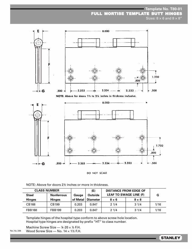
®
Rev. No. 2/06
Template No. T80-01
FULL MORFULL MORFULL MORFULL MORFULL MORTISE TISE TISE TISE TISE TEMPLATEMPLATEMPLATEMPLATEMPLATE BTE BTE BTE BTE BUTT HINGESUTT HINGESUTT HINGESUTT HINGESUTT HINGESSizes: 8 × 6 and 8 × 8”
Template hinges of the hospital type conform to above screw hole location.Hospital type hinges are designated by prefix ”HT“ to class number.
Machine Screw Size — ¼-20 × ½ F.H.Wood Screw Size — No. 14 × 1½ F.H.
NOTE: Above for doors 2½ inches or more in thickness.
(E)
Steel Nonferrous Gauge Outside G
Hinges Hinges of Metal Diameter 8 × 6 8 × 8
CB168 CB199 0.203 0.847 2 1/4 3 1/4 1/16
FBB168 FBB199 0.203 0.847 2 1/4 3 1/4 1/16
CLASS NUMBER DISTANCE FROM EDGE OF
LEAF TO SWAGE LINE (F)
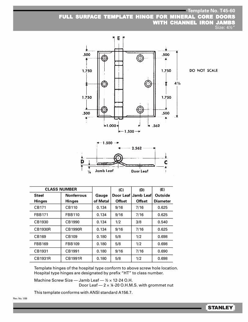
®
Rev. No. 1/06
Template No. T45-60
FULL SURFFULL SURFFULL SURFFULL SURFFULL SURFAAAAACE CE CE CE CE TEMPLATEMPLATEMPLATEMPLATEMPLATE HINGE FOR MINERAL CORE DOORSTE HINGE FOR MINERAL CORE DOORSTE HINGE FOR MINERAL CORE DOORSTE HINGE FOR MINERAL CORE DOORSTE HINGE FOR MINERAL CORE DOORSWITH CHANNEL IRON JAMBSWITH CHANNEL IRON JAMBSWITH CHANNEL IRON JAMBSWITH CHANNEL IRON JAMBSWITH CHANNEL IRON JAMBS
Size: 4½”
Template hinges of the hospital type conform to above screw hole location.Hospital type hinges are designated by prefix “HT” to class number.
Machine Screw Size — Jamb Leaf — ½ × 12-24 O.H. Door Leaf — 2 × ¼-20 O.H.M.S. with grommet nut
This template conforms with ANSI standard A156.7.
(C) (D) (E)
Steel Nonferrous Gauge Door Leaf Jamb Leaf Outside
Hinges Hinges of Metal Offset Offset Diameter
CB171 CB110 0.134 9/16 7/16 0.625
FBB171 FBB110 0.134 9/16 7/16 0.625
CB1930 CB1990 0.134 1/2 3/8 0.540
CB1930R CB1990R 0.134 9/16 7/16 0.625
CB169 CB109 0.180 5/8 1/2 0.698
FBB169 FBB109 0.180 5/8 1/2 0.698
CB1931 CB1991 0.180 9/16 7/16 0.690
CB1931R CB1991R 0.180 5/8 1/2 0.698
CLASS NUMBER

®
Rev. No. 1/06
Template No. T50-60
FULL SURFFULL SURFFULL SURFFULL SURFFULL SURFAAAAACE CE CE CE CE TEMPLATEMPLATEMPLATEMPLATEMPLATE HINGE FOR MINERAL CORE DOORSTE HINGE FOR MINERAL CORE DOORSTE HINGE FOR MINERAL CORE DOORSTE HINGE FOR MINERAL CORE DOORSTE HINGE FOR MINERAL CORE DOORSWITH CHANNEL IRON JAMBSWITH CHANNEL IRON JAMBSWITH CHANNEL IRON JAMBSWITH CHANNEL IRON JAMBSWITH CHANNEL IRON JAMBS
Size: 5”
Template hinges of the hospital type conform to above screw hole location.Hospital type hinges are designated by prefix “HT” to class number.
Machine Screw Size — Jamb Leaf — ½ × 12-24 O.H. Door Leaf — 2 × ¼-20 O.H.M.S. with grommet nut
This template conforms with ANSI standard A156.7.
(C) (D) (E)
Steel Nonferrous Gauge Door Leaf Jamb Leaf Outside
Hinges Hinges of Metal Offset Offset Diameter
CB171 CB110 0.146 9/16 7/16 0.669
FBB171 FBB110 0.146 9/16 7/16 0.669
CB1930 CB1990 0.146 17/32 13/32 0.781
CB1930R CB1990R 0.146 9/16 7/16 0.669
CB169 CB109 0.190 5/8 1/2 0.748
FBB169 FBB109 0.190 5/8 1/2 0.748
CB1931 CB1991 0.190 19/32 15/32 0.710
CB1931R CB1991R 0.190 5/8 1/2 0.748
CLASS NUMBER

®
Rev. No. 1/06
Template No. T45-60
FULL SURFFULL SURFFULL SURFFULL SURFFULL SURFAAAAACE CE CE CE CE TEMPLATEMPLATEMPLATEMPLATEMPLATE HINGE FOR MINERAL CORE DOORSTE HINGE FOR MINERAL CORE DOORSTE HINGE FOR MINERAL CORE DOORSTE HINGE FOR MINERAL CORE DOORSTE HINGE FOR MINERAL CORE DOORSWITH CHANNEL IRON JAMBSWITH CHANNEL IRON JAMBSWITH CHANNEL IRON JAMBSWITH CHANNEL IRON JAMBSWITH CHANNEL IRON JAMBS
Size: 4½”
Template hinges of the hospital type conform to above screw hole location.Hospital type hinges are designated by prefix “HT” to class number.
Machine Screw Size — Jamb Leaf — ½ × 12-24 O.H. Door Leaf — 2 × ¼-20 O.H.M.S. with grommet nut
This template conforms with ANSI standard A156.7.
(C) (D) (E)
Steel Nonferrous Gauge Door Leaf Jamb Leaf Outside
Hinges Hinges of Metal Offset Offset Diameter
CB171 CB110 0.134 9/16 7/16 0.625
FBB171 FBB110 0.134 9/16 7/16 0.625
CB1930 CB1990 0.134 1/2 3/8 0.540
CB1930R CB1990R 0.134 9/16 7/16 0.625
CB169 CB109 0.180 5/8 1/2 0.698
FBB169 FBB109 0.180 5/8 1/2 0.698
CB1931 CB1991 0.180 9/16 7/16 0.690
CB1931R CB1991R 0.180 5/8 1/2 0.698
CLASS NUMBER
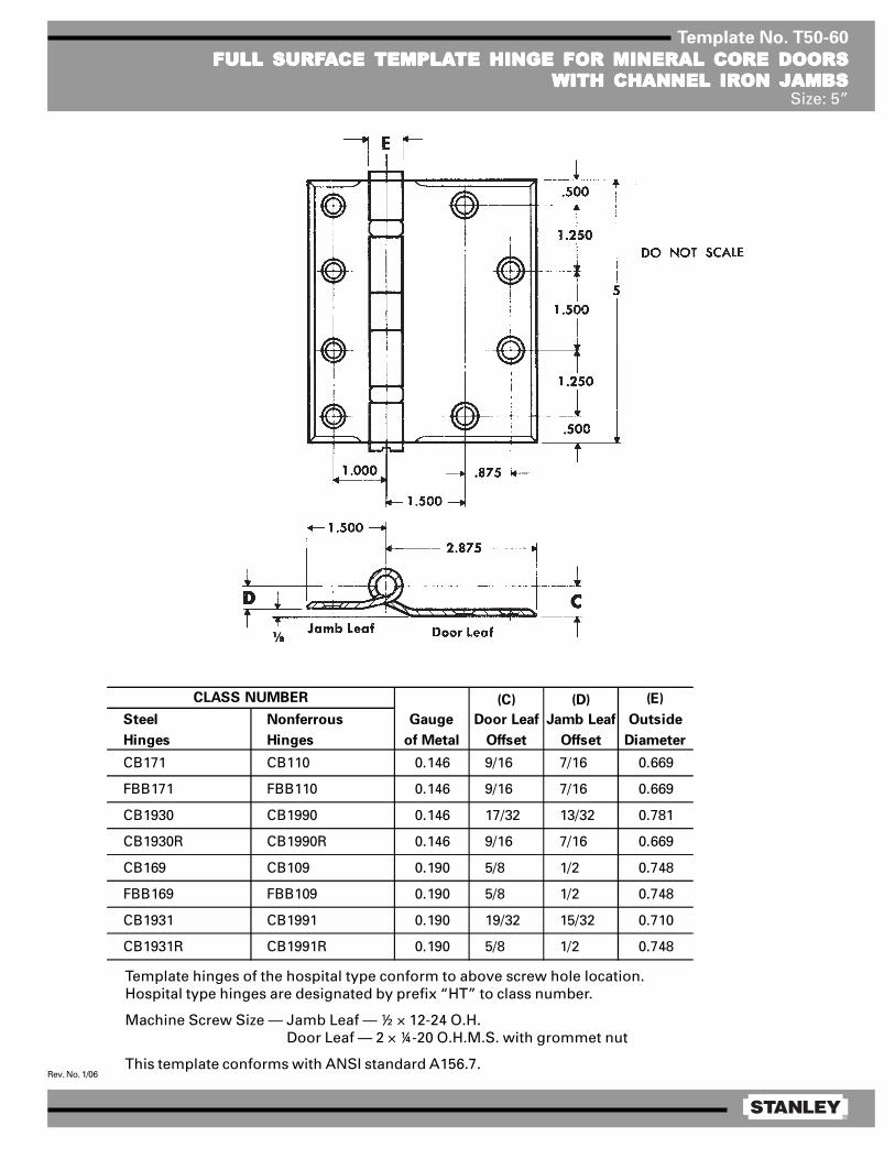
®
Rev. No. 1/06
Template No. T50-60
FULL SURFFULL SURFFULL SURFFULL SURFFULL SURFAAAAACE CE CE CE CE TEMPLATEMPLATEMPLATEMPLATEMPLATE HINGE FOR MINERAL CORE DOORSTE HINGE FOR MINERAL CORE DOORSTE HINGE FOR MINERAL CORE DOORSTE HINGE FOR MINERAL CORE DOORSTE HINGE FOR MINERAL CORE DOORSWITH CHANNEL IRON JAMBSWITH CHANNEL IRON JAMBSWITH CHANNEL IRON JAMBSWITH CHANNEL IRON JAMBSWITH CHANNEL IRON JAMBS
Size: 5”
Template hinges of the hospital type conform to above screw hole location.Hospital type hinges are designated by prefix “HT” to class number.
Machine Screw Size — Jamb Leaf — ½ × 12-24 O.H. Door Leaf — 2 × ¼-20 O.H.M.S. with grommet nut
This template conforms with ANSI standard A156.7.
(C) (D) (E)
Steel Nonferrous Gauge Door Leaf Jamb Leaf Outside
Hinges Hinges of Metal Offset Offset Diameter
CB171 CB110 0.146 9/16 7/16 0.669
FBB171 FBB110 0.146 9/16 7/16 0.669
CB1930 CB1990 0.146 17/32 13/32 0.781
CB1930R CB1990R 0.146 9/16 7/16 0.669
CB169 CB109 0.190 5/8 1/2 0.748
FBB169 FBB109 0.190 5/8 1/2 0.748
CB1931 CB1991 0.190 19/32 15/32 0.710
CB1931R CB1991R 0.190 5/8 1/2 0.748
CLASS NUMBER
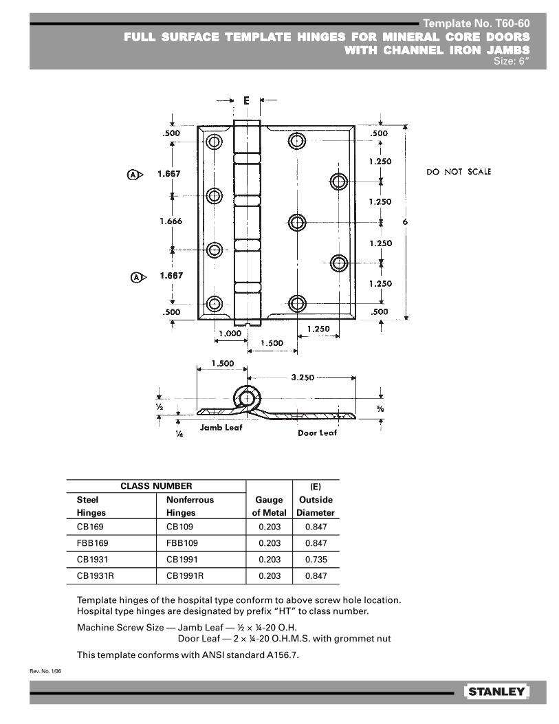
®
Rev. No. 1/06
Template No. T60-60
FULL SURFFULL SURFFULL SURFFULL SURFFULL SURFAAAAACE CE CE CE CE TEMPLATEMPLATEMPLATEMPLATEMPLATE HINGES FOR MINERAL CORE DOORSTE HINGES FOR MINERAL CORE DOORSTE HINGES FOR MINERAL CORE DOORSTE HINGES FOR MINERAL CORE DOORSTE HINGES FOR MINERAL CORE DOORSWITH CHANNEL IRON JAMBSWITH CHANNEL IRON JAMBSWITH CHANNEL IRON JAMBSWITH CHANNEL IRON JAMBSWITH CHANNEL IRON JAMBS
Size: 6”
Template hinges of the hospital type conform to above screw hole location.Hospital type hinges are designated by prefix “HT” to class number.
Machine Screw Size — Jamb Leaf — ½ × ¼-20 O.H. Door Leaf — 2 × ¼-20 O.H.M.S. with grommet nut
This template conforms with ANSI standard A156.7.
(E)
Steel Nonferrous Gauge Outside
Hinges Hinges of Metal Diameter
CB169 CB109 0.203 0.847
FBB169 FBB109 0.203 0.847
CB1931 CB1991 0.203 0.735
CB1931R CB1991R 0.203 0.847
CLASS NUMBER

®
Rev. No. 1/06
Template No. T45-40
HALF MORHALF MORHALF MORHALF MORHALF MORTISE TISE TISE TISE TISE TEMPLATEMPLATEMPLATEMPLATEMPLATE HINGESTE HINGESTE HINGESTE HINGESTE HINGESSize: 4½”
Template hinges of the hospital type conform to above screw hole location.Hospital type hinges are designated by prefix “HT” to class number.
Machine Screw Size — Jamb Leaf — ½ × 12-24 O.H. Door Leaf — ½ × 12-24 F.H.
This template conforms with ANSI standard A156.7.
(C) (D) (E)
Steel Nonferrous Gauge Door Jamb Leaf Outside
Hinges Hinges of Metal Leaf Offset Diameter
F167 — 0.134 2 1/16 7/16 0.605
1920R — 0.134 2 1/16 7/16 0.605
CB167 CB108 0.134 2 1/16 7/16 0.625
FBB167 FBB108 0.134 2 1/16 7/16 0.625
CB1920 CB1980 0.134 2 3/8 0.540
CB1920R CB1980R 0.134 2 1/16 7/16 0.625
CB138 CB98 0.180 2 1/8 1/2 0.698
FBB138 FBB98 0.180 2 1/8 1/2 0.698
CB1921 CB1981 0.180 2 1/16 7/16 0.690
CB1921R CB1981R 0.180 2 1/8 1/2 0.698
CLASS NUMBER
DO NOT SCALE

®
Rev. No. 1/06
Template No. T50-40
HALF MORHALF MORHALF MORHALF MORHALF MORTISE TISE TISE TISE TISE TEMPLATEMPLATEMPLATEMPLATEMPLATE HINGESTE HINGESTE HINGESTE HINGESTE HINGESSize: 5”
Template hinges of the hospital type conform to above screw hole location.Hospital type hinges are designated by prefix “HT” to class number.
Machine Screw Size — Jamb Leaf — ½ × 12-24 O.H. Door Leaf — ½ × 12-24 F.H.
This template conforms with ANSI standard A156.7.
(B) (D) (E)
Steel Nonferrous Gauge Door Jamb Leaf Outside
Hinges Hinges of Metal Leaf Offset Diameter
CB167 CB108 0.146 2 1/16 7/16 0.669
FBB167 FBB108 0.146 2 1/16 7/16 0.669
CB1920 CB1980 0.146 2 1/32 13/32 0.580
CB1920R CB1980R 0.146 2 1/16 7/16 0.669
CB138 CB98 0.190 2 1/8 1/2 0.748
FBB138 FBB98 0.190 2 1/8 1/2 0.748
CB1921 CB1981 0.190 2 3/32 15/32 0.715
CB1921R CB1981R 0.190 2 1/8 1/2 0.748
CLASS NUMBER
DO NOT SCALE

®
Rev. No. 1/06
Template No. T45-40
HALF MORHALF MORHALF MORHALF MORHALF MORTISE TISE TISE TISE TISE TEMPLATEMPLATEMPLATEMPLATEMPLATE HINGESTE HINGESTE HINGESTE HINGESTE HINGESSize: 4½”
Template hinges of the hospital type conform to above screw hole location.Hospital type hinges are designated by prefix “HT” to class number.
Machine Screw Size — Jamb Leaf — ½ × 12-24 O.H. Door Leaf — ½ × 12-24 F.H.
This template conforms with ANSI standard A156.7.
(C) (D) (E)
Steel Nonferrous Gauge Door Jamb Leaf Outside
Hinges Hinges of Metal Leaf Offset Diameter
F167 — 0.134 2 1/16 7/16 0.605
1920R — 0.134 2 1/16 7/16 0.605
CB167 CB108 0.134 2 1/16 7/16 0.625
FBB167 FBB108 0.134 2 1/16 7/16 0.625
CB1920 CB1980 0.134 2 3/8 0.540
CB1920R CB1980R 0.134 2 1/16 7/16 0.625
CB138 CB98 0.180 2 1/8 1/2 0.698
FBB138 FBB98 0.180 2 1/8 1/2 0.698
CB1921 CB1981 0.180 2 1/16 7/16 0.690
CB1921R CB1981R 0.180 2 1/8 1/2 0.698
CLASS NUMBER
DO NOT SCALE

®
Rev. No. 1/06
Template No. T50-40
HALF MORHALF MORHALF MORHALF MORHALF MORTISE TISE TISE TISE TISE TEMPLATEMPLATEMPLATEMPLATEMPLATE HINGESTE HINGESTE HINGESTE HINGESTE HINGESSize: 5”
Template hinges of the hospital type conform to above screw hole location.Hospital type hinges are designated by prefix “HT” to class number.
Machine Screw Size — Jamb Leaf — ½ × 12-24 O.H. Door Leaf — ½ × 12-24 F.H.
This template conforms with ANSI standard A156.7.
(B) (D) (E)
Steel Nonferrous Gauge Door Jamb Leaf Outside
Hinges Hinges of Metal Leaf Offset Diameter
CB167 CB108 0.146 2 1/16 7/16 0.669
FBB167 FBB108 0.146 2 1/16 7/16 0.669
CB1920 CB1980 0.146 2 1/32 13/32 0.580
CB1920R CB1980R 0.146 2 1/16 7/16 0.669
CB138 CB98 0.190 2 1/8 1/2 0.748
FBB138 FBB98 0.190 2 1/8 1/2 0.748
CB1921 CB1981 0.190 2 3/32 15/32 0.715
CB1921R CB1981R 0.190 2 1/8 1/2 0.748
CLASS NUMBER
DO NOT SCALE
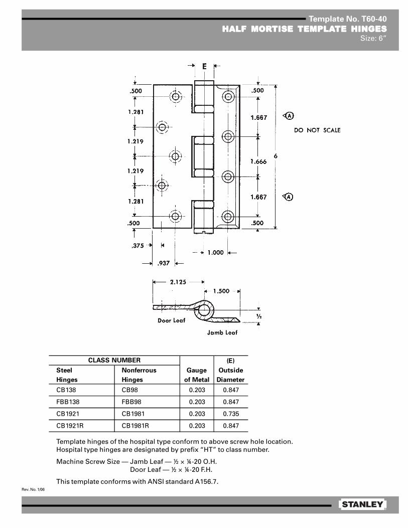
®
Rev. No. 1/06
Template No. T60-40
HALF MORHALF MORHALF MORHALF MORHALF MORTISE TISE TISE TISE TISE TEMPLATEMPLATEMPLATEMPLATEMPLATE HINGESTE HINGESTE HINGESTE HINGESTE HINGESSize: 6”
Template hinges of the hospital type conform to above screw hole location.Hospital type hinges are designated by prefix “HT” to class number.
Machine Screw Size — Jamb Leaf — ½ × ¼-20 O.H. Door Leaf — ½ × ¼-20 F.H.
This template conforms with ANSI standard A156.7.
(E)
Steel Nonferrous Gauge Outside
Hinges Hinges of Metal Diameter
CB138 CB98 0.203 0.847
FBB138 FBB98 0.203 0.847
CB1921 CB1981 0.203 0.735
CB1921R CB1981R 0.203 0.847
CLASS NUMBER
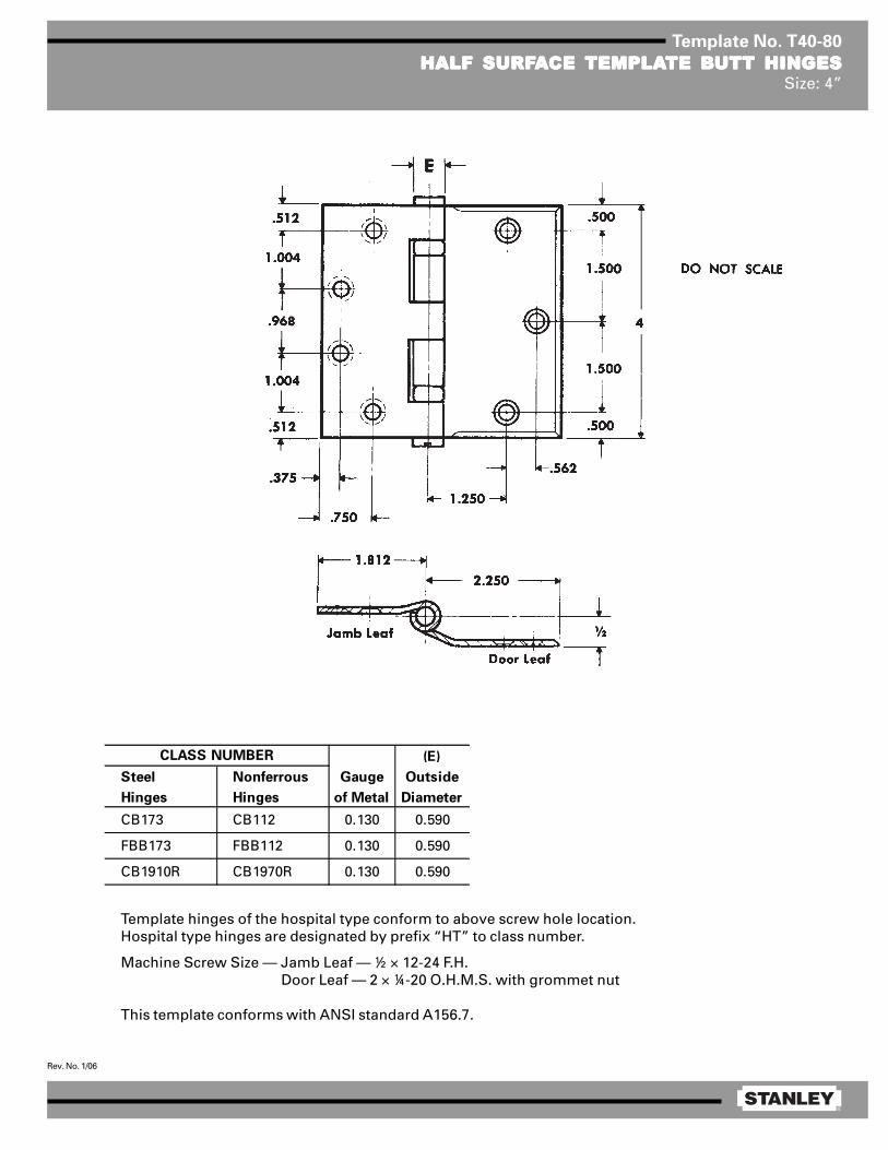
®
Rev. No. 1/06
Template No. T40-80
HALF SURFHALF SURFHALF SURFHALF SURFHALF SURFAAAAACE CE CE CE CE TEMPLATEMPLATEMPLATEMPLATEMPLATE BTE BTE BTE BTE BUTT HINGESUTT HINGESUTT HINGESUTT HINGESUTT HINGESSize: 4”
Template hinges of the hospital type conform to above screw hole location.Hospital type hinges are designated by prefix “HT” to class number.
Machine Screw Size — Jamb Leaf — ½ × 12-24 F.H. Door Leaf — 2 × ¼-20 O.H.M.S. with grommet nut
This template conforms with ANSI standard A156.7.
(E)
Steel Nonferrous Gauge Outside
Hinges Hinges of Metal Diameter
CB173 CB112 0.130 0.590
FBB173 FBB112 0.130 0.590
CB1910R CB1970R 0.130 0.590
CLASS NUMBER

®
Rev. No. 1/06
Template No. T45-80
HALF SURFHALF SURFHALF SURFHALF SURFHALF SURFAAAAACE CE CE CE CE TEMPLATEMPLATEMPLATEMPLATEMPLATE HINGESTE HINGESTE HINGESTE HINGESTE HINGESSize: 4½”
Machine Screw Size — Jamb Leaf — ½ × 12-24 F.H. Door Leaf — 2 × ¼-20 O.H.M.S. with grommet nut
(A) (C) (E)
Steel Nonferrous Gauge Jamb Door Leaf Outside
Hinges Hinges of Metal Leaf Offset Diameter
F173 — 0.134 2 1/16 9/16 0.605
1910 — 0.134 2 1/16 9/16 0.540
1910R — 0.134 2 1/16 9/16 0.605
CB173 CB112 0.134 2 1/16 9/16 0.625
FBB173 FBB112 0.134 2 1/16 9/16 0.625
CB1910 CB1970 0.134 2 1/16 9/16 0.540
CB1910R CB1970R 0.134 2 1/16 9/16 0.625
CB163 CB113 0.180 2 1/8 5/8 0.698
FBB163 FBB113 0.180 2 1/8 5/8 0.698
CB1911 CB1971 0.180 2 1/8 5/8 0.690
CB1911R CB1971R 0.180 2 1/8 5/8 0.698
CLASS NUMBER
Template hinges of the hospitaltype conform to above screwhole location.
Hospital type hinges are desig-nated by prefix “HT” to classnumber.
This template conforms withANSI standard A156.7.
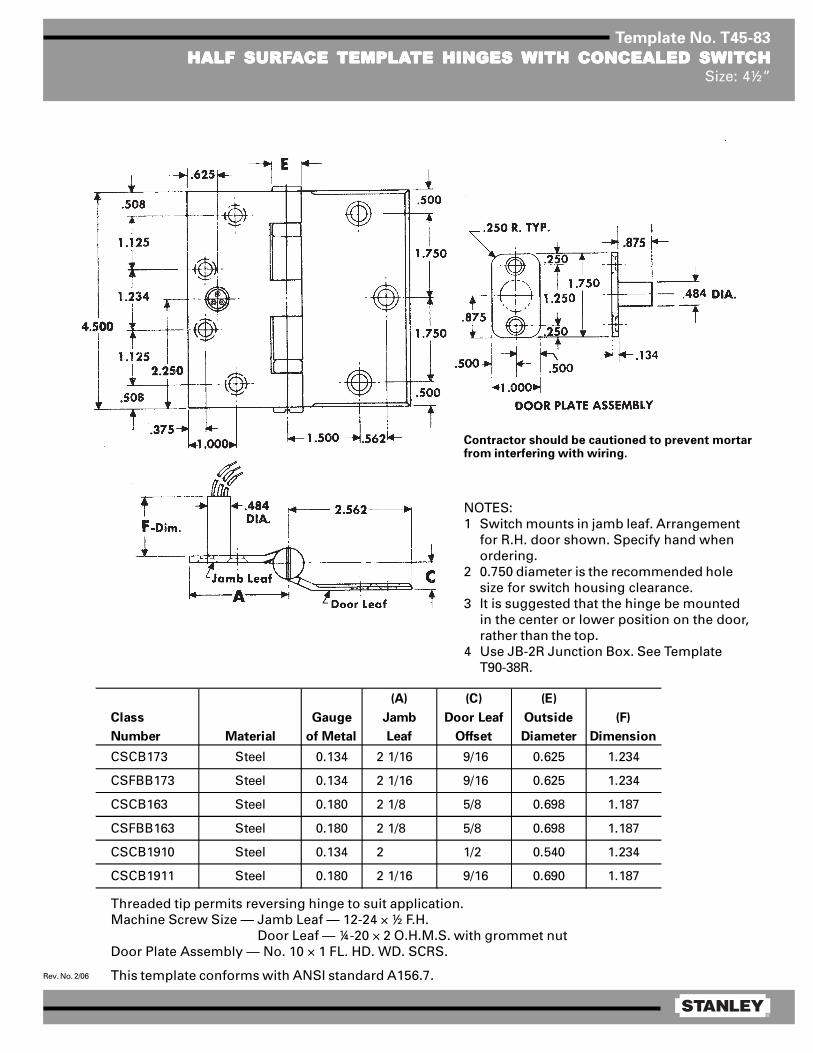
®
Rev. No. 2/06
Template No. T45-83
HALF SURFHALF SURFHALF SURFHALF SURFHALF SURFAAAAACE CE CE CE CE TEMPLATEMPLATEMPLATEMPLATEMPLATE HINGES TE HINGES TE HINGES TE HINGES TE HINGES WITH CONCEALED SWITWITH CONCEALED SWITWITH CONCEALED SWITWITH CONCEALED SWITWITH CONCEALED SWITCHCHCHCHCHSize: 4½”
Threaded tip permits reversing hinge to suit application.Machine Screw Size — Jamb Leaf — 12-24 × ½ F.H.
Door Leaf — ¼-20 × 2 O.H.M.S. with grommet nutDoor Plate Assembly — No. 10 × 1 FL. HD. WD. SCRS.
This template conforms with ANSI standard A156.7.
(A) (C) (E)
Class Gauge Jamb Door Leaf Outside (F)
Number Material of Metal Leaf Offset Diameter Dimension
CSCB173 Steel 0.134 2 1/16 9/16 0.625 1.234
CSFBB173 Steel 0.134 2 1/16 9/16 0.625 1.234
CSCB163 Steel 0.180 2 1/8 5/8 0.698 1.187
CSFBB163 Steel 0.180 2 1/8 5/8 0.698 1.187
CSCB1910 Steel 0.134 2 1/2 0.540 1.234
CSCB1911 Steel 0.180 2 1/16 9/16 0.690 1.187
Contractor should be cautioned to prevent mortarfrom interfering with wiring.
NOTES:1 Switch mounts in jamb leaf. Arrangement
for R.H. door shown. Specify hand whenordering.
2 0.750 diameter is the recommended holesize for switch housing clearance.
3 It is suggested that the hinge be mountedin the center or lower position on the door,rather than the top.
4 Use JB-2R Junction Box. See TemplateT90-38R.

®
Rev. No. 1/06
Template No. T50-80
HALF SURFHALF SURFHALF SURFHALF SURFHALF SURFAAAAACE CE CE CE CE TEMPLATEMPLATEMPLATEMPLATEMPLATE HINGESTE HINGESTE HINGESTE HINGESTE HINGESSize: 5”
Template hinges of the hospital type conform to above screw hole location.Hospital type hinges are designated by prefix “HT” to class number.
Machine Screw Size — Jamb Leaf — ½ × 12-24 F.H. Door Leaf — 2 × ¼-20 O.H.M.S. with grommet nut
This template conforms with ANSI standard A156.7.
(A) (C) (E)
Steel Nonferrous Gauge Jamb Jamb Leaf Outside
Hinges Hinges of Metal Leaf Offset Diameter
CB173 CB112 0.146 2 1/16 9/16 0.669
FBB173 FBB112 0.146 2 1/16 9/16 0.669
CB1910 CB1970 0.146 2 1/32 17/32 0.580
CB1910R CB1970R 0.146 2 1/16 9/16 0.669
CB163 CB113 0.190 2 1/8 5/8 0.748
FBB163 FBB113 0.190 2 1/8 5/8 0.748
CB1911 CB1971 0.190 2 3/32 19/32 0.715
CB1911R CB1971R 0.190 2 1/8 5/8 0.748
CLASS NUMBER

®
Rev. No. 2/06
Template No. T50-83
HALF SURFHALF SURFHALF SURFHALF SURFHALF SURFAAAAACE CE CE CE CE TEMPLATEMPLATEMPLATEMPLATEMPLATE HINGES TE HINGES TE HINGES TE HINGES TE HINGES WITH CONCEALED SWITWITH CONCEALED SWITWITH CONCEALED SWITWITH CONCEALED SWITWITH CONCEALED SWITCHCHCHCHCHSize: 5”
Machine Screw Size — Jamb Leaf — 12-24 × ½ F.H. Door Leaf — ¼-20 × 2 O.H.M.S. with grommet nut
Door Plate Assembly — No. 10 × 1 FL. HD. WD. SCRS.
This template conforms with ANSI standard A156.7.
Contractor should be cautioned to prevent mortarfrom interfering with wiring.
NOTES:1 0.750 diameter is the recommended hole
size for switch housing clearance.2 It is suggested that the hinge be mounted
in the center or lower position on thedoor, rather than the top.
3 Switch mounts in jamb leaf. Arrangementfor R.H. door shown. Specify hand whenordering.
4 Use JB-2R Junction Box. See TemplateT90-38.
DO NOT SCALE
CLASS NO. (A) (C) (E) (F)
Steel Gauge Jamb Door Leaf Outside
Hinges of Metal Leaf Offset Diameter
CSCB173 0.146 2 1/16 9/16 0.669 1.218
CSFBB173 0.146 2 1/16 9/16 0.669 1.218
CSCB1910 0.146 2 1/32 17/32 0.580 1.218
CSCB1910R 0.146 2 1/16 9/16 0.669 1.218
CSCB163 0.190 2 1/8 5/8 0.748 1.172
CSFBB163 0.190 2 1/8 5/8 0.748 1.172
CSCB1911 0.190 2 3/32 19/32 0.715 1.172
CSCB1911R 0.190 2 1/8 5/8 0.748 1.172

®
Rev. No. 1/06
Template No. T40-80
HALF SURFHALF SURFHALF SURFHALF SURFHALF SURFAAAAACE CE CE CE CE TEMPLATEMPLATEMPLATEMPLATEMPLATE BTE BTE BTE BTE BUTT HINGESUTT HINGESUTT HINGESUTT HINGESUTT HINGESSize: 4”
Template hinges of the hospital type conform to above screw hole location.Hospital type hinges are designated by prefix “HT” to class number.
Machine Screw Size — Jamb Leaf — ½ × 12-24 F.H. Door Leaf — 2 × ¼-20 O.H.M.S. with grommet nut
This template conforms with ANSI standard A156.7.
(E)
Steel Nonferrous Gauge Outside
Hinges Hinges of Metal Diameter
CB173 CB112 0.130 0.590
FBB173 FBB112 0.130 0.590
CB1910R CB1970R 0.130 0.590
CLASS NUMBER

®
Rev. No. 2/06
Template No. T45-83
HALF SURFHALF SURFHALF SURFHALF SURFHALF SURFAAAAACE CE CE CE CE TEMPLATEMPLATEMPLATEMPLATEMPLATE HINGES TE HINGES TE HINGES TE HINGES TE HINGES WITH CONCEALED SWITWITH CONCEALED SWITWITH CONCEALED SWITWITH CONCEALED SWITWITH CONCEALED SWITCHCHCHCHCHSize: 4½”
Threaded tip permits reversing hinge to suit application.Machine Screw Size — Jamb Leaf — 12-24 × ½ F.H.
Door Leaf — ¼-20 × 2 O.H.M.S. with grommet nutDoor Plate Assembly — No. 10 × 1 FL. HD. WD. SCRS.
This template conforms with ANSI standard A156.7.
(A) (C) (E)
Class Gauge Jamb Door Leaf Outside (F)
Number Material of Metal Leaf Offset Diameter Dimension
CSCB173 Steel 0.134 2 1/16 9/16 0.625 1.234
CSFBB173 Steel 0.134 2 1/16 9/16 0.625 1.234
CSCB163 Steel 0.180 2 1/8 5/8 0.698 1.187
CSFBB163 Steel 0.180 2 1/8 5/8 0.698 1.187
CSCB1910 Steel 0.134 2 1/2 0.540 1.234
CSCB1911 Steel 0.180 2 1/16 9/16 0.690 1.187
Contractor should be cautioned to prevent mortarfrom interfering with wiring.
NOTES:1 Switch mounts in jamb leaf. Arrangement
for R.H. door shown. Specify hand whenordering.
2 0.750 diameter is the recommended holesize for switch housing clearance.
3 It is suggested that the hinge be mountedin the center or lower position on the door,rather than the top.
4 Use JB-2R Junction Box. See TemplateT90-38R.
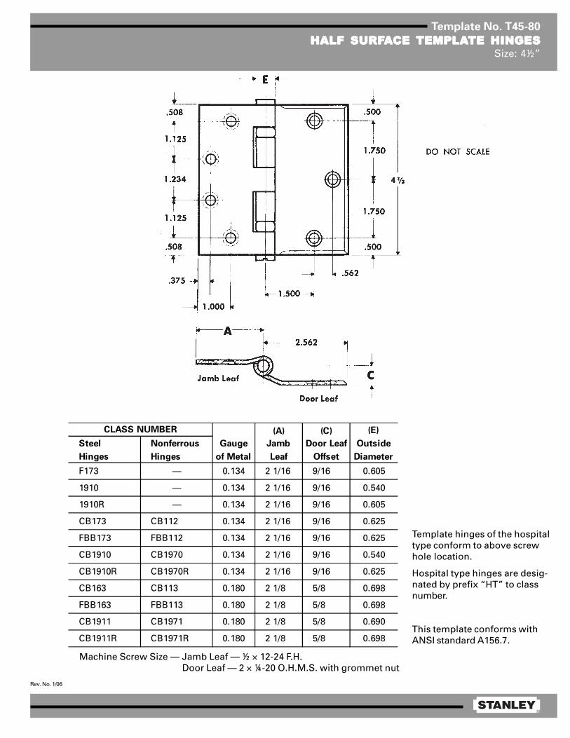
®
Rev. No. 1/06
Template No. T45-80
HALF SURFHALF SURFHALF SURFHALF SURFHALF SURFAAAAACE CE CE CE CE TEMPLATEMPLATEMPLATEMPLATEMPLATE HINGESTE HINGESTE HINGESTE HINGESTE HINGESSize: 4½”
Machine Screw Size — Jamb Leaf — ½ × 12-24 F.H. Door Leaf — 2 × ¼-20 O.H.M.S. with grommet nut
(A) (C) (E)
Steel Nonferrous Gauge Jamb Door Leaf Outside
Hinges Hinges of Metal Leaf Offset Diameter
F173 — 0.134 2 1/16 9/16 0.605
1910 — 0.134 2 1/16 9/16 0.540
1910R — 0.134 2 1/16 9/16 0.605
CB173 CB112 0.134 2 1/16 9/16 0.625
FBB173 FBB112 0.134 2 1/16 9/16 0.625
CB1910 CB1970 0.134 2 1/16 9/16 0.540
CB1910R CB1970R 0.134 2 1/16 9/16 0.625
CB163 CB113 0.180 2 1/8 5/8 0.698
FBB163 FBB113 0.180 2 1/8 5/8 0.698
CB1911 CB1971 0.180 2 1/8 5/8 0.690
CB1911R CB1971R 0.180 2 1/8 5/8 0.698
CLASS NUMBER
Template hinges of the hospitaltype conform to above screwhole location.
Hospital type hinges are desig-nated by prefix “HT” to classnumber.
This template conforms withANSI standard A156.7.

®
Rev. No. 2/06
Template No. T50-83
HALF SURFHALF SURFHALF SURFHALF SURFHALF SURFAAAAACE CE CE CE CE TEMPLATEMPLATEMPLATEMPLATEMPLATE HINGES TE HINGES TE HINGES TE HINGES TE HINGES WITH CONCEALED SWITWITH CONCEALED SWITWITH CONCEALED SWITWITH CONCEALED SWITWITH CONCEALED SWITCHCHCHCHCHSize: 5”
Machine Screw Size — Jamb Leaf — 12-24 × ½ F.H. Door Leaf — ¼-20 × 2 O.H.M.S. with grommet nut
Door Plate Assembly — No. 10 × 1 FL. HD. WD. SCRS.
This template conforms with ANSI standard A156.7.
Contractor should be cautioned to prevent mortarfrom interfering with wiring.
NOTES:1 0.750 diameter is the recommended hole
size for switch housing clearance.2 It is suggested that the hinge be mounted
in the center or lower position on thedoor, rather than the top.
3 Switch mounts in jamb leaf. Arrangementfor R.H. door shown. Specify hand whenordering.
4 Use JB-2R Junction Box. See TemplateT90-38.
DO NOT SCALE
CLASS NO. (A) (C) (E) (F)
Steel Gauge Jamb Door Leaf Outside
Hinges of Metal Leaf Offset Diameter
CSCB173 0.146 2 1/16 9/16 0.669 1.218
CSFBB173 0.146 2 1/16 9/16 0.669 1.218
CSCB1910 0.146 2 1/32 17/32 0.580 1.218
CSCB1910R 0.146 2 1/16 9/16 0.669 1.218
CSCB163 0.190 2 1/8 5/8 0.748 1.172
CSFBB163 0.190 2 1/8 5/8 0.748 1.172
CSCB1911 0.190 2 3/32 19/32 0.715 1.172
CSCB1911R 0.190 2 1/8 5/8 0.748 1.172

®
Rev. No. 1/06
Template No. T50-80
HALF SURFHALF SURFHALF SURFHALF SURFHALF SURFAAAAACE CE CE CE CE TEMPLATEMPLATEMPLATEMPLATEMPLATE HINGESTE HINGESTE HINGESTE HINGESTE HINGESSize: 5”
Template hinges of the hospital type conform to above screw hole location.Hospital type hinges are designated by prefix “HT” to class number.
Machine Screw Size — Jamb Leaf — ½ × 12-24 F.H. Door Leaf — 2 × ¼-20 O.H.M.S. with grommet nut
This template conforms with ANSI standard A156.7.
(A) (C) (E)
Steel Nonferrous Gauge Jamb Jamb Leaf Outside
Hinges Hinges of Metal Leaf Offset Diameter
CB173 CB112 0.146 2 1/16 9/16 0.669
FBB173 FBB112 0.146 2 1/16 9/16 0.669
CB1910 CB1970 0.146 2 1/32 17/32 0.580
CB1910R CB1970R 0.146 2 1/16 9/16 0.669
CB163 CB113 0.190 2 1/8 5/8 0.748
FBB163 FBB113 0.190 2 1/8 5/8 0.748
CB1911 CB1971 0.190 2 3/32 19/32 0.715
CB1911R CB1971R 0.190 2 1/8 5/8 0.748
CLASS NUMBER

®
Rev. No. 1/06
Template No. T50-07
FULL MORFULL MORFULL MORFULL MORFULL MORTISE TISE TISE TISE TISE TEMPLATEMPLATEMPLATEMPLATEMPLATE PIVTE PIVTE PIVTE PIVTE PIVOOOOOT REINFORT REINFORT REINFORT REINFORT REINFORCED HINGESCED HINGESCED HINGESCED HINGESCED HINGESSize: 5 × 4½”
Machine Screw Size — ½ × 12-24 F.H.Wood Screw Size — 1½ × No. 12 F.H.
Steel Nonferrous Gauge of Metal
CB211 CB221 0.190
FBB211 FBB221 0.190
CB1907 CB1967 0.190
CB1907R CB1967R 0.190
SET CLASS NO.
Door
Thickness
*Backset on
Door
*Backset on
Frame
1 3/4 1/4 5/16
2 1/2 9/16
2 1/4 3/4 13/16
For use with concealed door holders, closers andoperators which do not permit use of types shownon templates T50-08, T50-09, T50-10 or T50-11.
Machine Screw Size — ½ × 12-24 F.H.Wood Screw Size — 1½ × No. 12 F.H.
*CAUTION: These backsets must be usedon ALL hinges in set.
NOTE: Backsets which apply when pivot-reinforced hinge is used on door thicknessindicated and when the usual 1/16 stop clearanceis desired.

®
Rev. No. 1/06
Template No. T50-08
FULL MORFULL MORFULL MORFULL MORFULL MORTISE TISE TISE TISE TISE TEMPLATEMPLATEMPLATEMPLATEMPLATE PIVTE PIVTE PIVTE PIVTE PIVOOOOOT REINFORT REINFORT REINFORT REINFORT REINFORCED HINGES FOR DOORSCED HINGES FOR DOORSCED HINGES FOR DOORSCED HINGES FOR DOORSCED HINGES FOR DOORSWITH SQWITH SQWITH SQWITH SQWITH SQUUUUUARE EDGE HINGE STILESARE EDGE HINGE STILESARE EDGE HINGE STILESARE EDGE HINGE STILESARE EDGE HINGE STILES
Size: 5 × 4½”
Machine Screw Size — ½ × 12-24 F.H.Wood Screw Size — 1½ × No. 12 F.H.
Steel Nonferrous Gauge of Metal
CB212 CB222 0.190
FBB212 FBB222 0.190
CB1908 CB1968 0.190
CB1908R CB1968R 0.190
SET CLASS NO.
Door
Thickness
*Backset on
Door
*Backset on
Frame
1 3/4 1/4 5/16
2 1/2 9/16
2 1/4 3/4 13/16
*CAUTION: These backsets must be usedon ALL hinges in set.
NOTE: Backsets which apply when pivot-reinforced hinge is used on door thicknessindicated and when the usual 1/16 stopclearance is desired.
For use with door holders, closers and operators.See templates T50-07 and T50-10 for types whichprovide clearance for concealed devices.
Machine Screw Size — ½ × 12-24 F.H.Wood Screw Size — 1½ × No. 12 F.H.

®
Rev. No. 1/06
Template No. T50-10
FULL MORFULL MORFULL MORFULL MORFULL MORTISE TISE TISE TISE TISE TEMPLATEMPLATEMPLATEMPLATEMPLATE PIVTE PIVTE PIVTE PIVTE PIVOOOOOT REINFORT REINFORT REINFORT REINFORT REINFORCED HINGES CED HINGES CED HINGES CED HINGES CED HINGES WITH 4 1/8WITH 4 1/8WITH 4 1/8WITH 4 1/8WITH 4 1/8” DOORDOORDOORDOORDOORPLAPLAPLAPLAPLATE FOR DOORS TE FOR DOORS TE FOR DOORS TE FOR DOORS TE FOR DOORS WITH SQWITH SQWITH SQWITH SQWITH SQUUUUUARE EDGE HINGE STILESARE EDGE HINGE STILESARE EDGE HINGE STILESARE EDGE HINGE STILESARE EDGE HINGE STILES
Size: 5 × 4½”
Machine Screw Size — ½ × 12-24 F.H.Wood Screw Size — 1½ × No. 12 F.H.
Steel Nonferrous Gauge of Metal
CB212 CB222with 4 1 /8 door plate with 4 1 /8 door plate
FBB212 FBB222with 4 1 /8 door plate with 4 1 /8 door plate
CB1908 CB1968with 4 1 /8 door plate with 4 1 /8 door plate
CB1908R CB1968Rwith 4 1 /8 door plate with 4 1 /8 door plate
0.190
SET CLASS NO.
0.190
0.190
0.190
Door
Thickness
*Backset on
Door
*Backset on
Frame
1 3/4 1/4 5/16
2 1/2 9/16
2 1/4 3/4 13/16
Machine Screw Size — ½ × 12-24 F.H.Wood Screw Size — 1½ × No. 12 F.H.
*CAUTION: These backsets must be usedon ALL hinges in set.
NOTE: Backsets which apply when pivot-reinforced hinge is used on door thicknessindicated and when the usual 1/16 stopclearance is desired.
For use with door holders, closers and operatorswhich interfere with standard door plates shownon template T50-08.

®
Rev. No. 1/06
Template No. T50-09
FULL MORFULL MORFULL MORFULL MORFULL MORTISE TISE TISE TISE TISE TEMPLATEMPLATEMPLATEMPLATEMPLATE PIVTE PIVTE PIVTE PIVTE PIVOOOOOT REINFORT REINFORT REINFORT REINFORT REINFORCED HINGES FOR DOORSCED HINGES FOR DOORSCED HINGES FOR DOORSCED HINGES FOR DOORSCED HINGES FOR DOORSWITH BEVELED EDGE HINGE STILESWITH BEVELED EDGE HINGE STILESWITH BEVELED EDGE HINGE STILESWITH BEVELED EDGE HINGE STILESWITH BEVELED EDGE HINGE STILES
Size: 5 × 4½”
Machine Screw Size — ½ × 12-24 F.H.Wood Screw Size — 1½ × No. 12 F.H.
Machine Screw Size — ½ × 12-24 F.H.Wood Screw Size — 1½ × No. 12 F.H.
Steel Nonferrous Gauge of Metal
CB213 CB223 0.190
FBB213 FBB223 0.190
CB1909 CB1969 0.190
CB1909R CB1969R 0.190
SET CLASS NO.
Door
Thickness
*Backset on
Door
*Backset on
Frame
1 3/4 1/4 5/16
2 1/2 9/16
2 1/4 3/4 13/16
*CAUTION: These backsets must be used onALL hinges in set.
NOTE: Backsets which apply when pivot-reinforced hinge is used on door thicknessindicated and when the usual 1/16 stopclearance is desired.
For use with door holders, closers and operators.See templates T50-07 and T50-11 for types whichprovide clearance for concealed devices.

®
Rev. No. 1/06
Template No. T50-11
FULL MORFULL MORFULL MORFULL MORFULL MORTISE TISE TISE TISE TISE TEMPLATEMPLATEMPLATEMPLATEMPLATE PIVTE PIVTE PIVTE PIVTE PIVOOOOOT REINFORT REINFORT REINFORT REINFORT REINFORCED HINGES CED HINGES CED HINGES CED HINGES CED HINGES WITH 4WITH 4WITH 4WITH 4WITH 4” DOORDOORDOORDOORDOORPLAPLAPLAPLAPLATE FOR DOORS TE FOR DOORS TE FOR DOORS TE FOR DOORS TE FOR DOORS WITH BEVELED EDGE HINGE STILESWITH BEVELED EDGE HINGE STILESWITH BEVELED EDGE HINGE STILESWITH BEVELED EDGE HINGE STILESWITH BEVELED EDGE HINGE STILES
Size: 5 × 4½”
Machine Screw Size — ½ × 12-24 F.H.Wood Screw Size — 1½ × No. 12 F.H.
Machine Screw Size — ½ × 12-24 F.H.Wood Screw Size — 1½ × No. 12 F.H.
*CAUTION: These backsets must be usedon ALL hinges in set.
NOTE: Backsets which apply when pivot-reinforced hinge is used on door thicknessindicated and when the usual 1/16 stopclearance is desired.
For use with door holders, closers and operatorswhich interfere with standard door plates shownon template T50-09.
DO NOT SCALE
Steel Nonferrous Gauge of Metal
CB213 CB223with 4 door plate with 4 door plate
FBB213 FBB223with 4 door plate with 4 door plate
CB1909 CB1969with 4 door plate with 4 door plate
CB1909R CB1969Rwith 4 door plate with 4 door plate
0.190
SET CLASS NO.
0.190
0.190
0.190
Door
Thickness
*Backset on
Door
*Backset on
Frame
1 3/4 1/4 5/16
2 1/2 9/16
2 1/4 3/4 13/16

®
Rev. No. 1/06
Template No. T40-02
SLIP-IN FULL MORSLIP-IN FULL MORSLIP-IN FULL MORSLIP-IN FULL MORSLIP-IN FULL MORTISE TISE TISE TISE TISE TEMPLATEMPLATEMPLATEMPLATEMPLATE BTE BTE BTE BTE BUTT HINGES UTT HINGES UTT HINGES UTT HINGES UTT HINGES APPLICAAPPLICAAPPLICAAPPLICAAPPLICATION TION TION TION TION AAAAASize: 4 × 4”
Right Hand Shown(Left Hand is Opposite)
(E)
Steel Nonferrous Gauge Outside
Hinges Hinges of Metal Diameter 4 × 4
Slip-in CB179 Slip-in CB191
Slip-in FBB179 Slip-in FBB191
Application A Application A
Slip-in CB1900 Slip-in CB1960
Application A Application A
Slip-in CB1900R Slip-in CB1960R
Application A Application A1 43/64
0.130 0.590
0.130 0.540
0.130 0.590
CLASS NUMBER LOCATION FROM EDGE OF
LEAF TO SWAGE LINE (F)
1 43/64
1 43/64
Machine Screw Size — ½ × 12-24 F.H.

®
Rev. No. 1/06
Template No. T45-04
SLIP-IN FULL MORSLIP-IN FULL MORSLIP-IN FULL MORSLIP-IN FULL MORSLIP-IN FULL MORTISE TISE TISE TISE TISE TEMPLATEMPLATEMPLATEMPLATEMPLATE BTE BTE BTE BTE BUTT HINGES UTT HINGES UTT HINGES UTT HINGES UTT HINGES APPLICAAPPLICAAPPLICAAPPLICAAPPLICATION TION TION TION TION AAAAASizes: 4½ × 4 and 4½ × 4½”
(E)
Steel Nonferrous Gauge Outside
Hinges Hinges of Metal Diameter 4½ × 4 4½ × 4½
Slip-in CB179 Slip-in CB191
Slip-in FBB179 Slip-in FBB191
Application A Application A
Slip-in CB1900 Slip-in CB1960
Application A Application A
Slip-in CB1900R Slip-in CB1960R
Application A Application A
1 57/64
0.134 0.625 1 57/64
1 41/64
1 41/64
0.134 0.540
CLASS NUMBER
0.134 0.625 1 57/64
LOCATION FROM EDGE OF LEAF
TO SWAGE LINE (F)
1 41/64
Machine Screw Size — ½ × 12-24 F.H.

®
Rev. No. 1/06
Template No. T40-03
SLIP-IN FULL MORSLIP-IN FULL MORSLIP-IN FULL MORSLIP-IN FULL MORSLIP-IN FULL MORTISE TISE TISE TISE TISE TEMPLATEMPLATEMPLATEMPLATEMPLATE BTE BTE BTE BTE BUTT HINGES UTT HINGES UTT HINGES UTT HINGES UTT HINGES APPLICAAPPLICAAPPLICAAPPLICAAPPLICATION BTION BTION BTION BTION BSize: 4 × 4”
(E)
Steel Nonferrous Gauge Outside
Hinges Hinges of Metal Diameter
Slip-in CB179 Slip-in CB191
Slip-in FBB179 Slip-in FBB191
Application B Application B
Slip-in CB1900 Slip-in CB1960
Application B Application B
Slip-in CB1900R Slip-in CB1960R
Application B Application B
0.130 0.540
0.130 0.590
CLASS NUMBER
0.130 0.590
Machine Screw Size — ½ × 12-24 F.H.
5/32

®
Rev. No. 1/06
Template No. T45-05
SLIP-IN FULL MORSLIP-IN FULL MORSLIP-IN FULL MORSLIP-IN FULL MORSLIP-IN FULL MORTISE TISE TISE TISE TISE TEMPLATEMPLATEMPLATEMPLATEMPLATE BTE BTE BTE BTE BUTT HINGES UTT HINGES UTT HINGES UTT HINGES UTT HINGES APPLICAAPPLICAAPPLICAAPPLICAAPPLICATION BTION BTION BTION BTION BSizes: 4½ × 4 and 4½ × 4½”
(E)
Steel Nonferrous Gauge Outside
Hinges Hinges of Metal Diameter
Slip-in CB179 Slip-in CB191
Slip-in FBB179 Slip-in FBB191
Application B Application B
Slip-in CB1900 Slip-in CB1960
Application B Application B
Slip-in CB1900R Slip-in CB1960R
Application B Application B
0.134 0.540
0.134 0.625
CLASS NUMBER
0.134 0.625
Machine Screw Size — ½ × 12-24 F.H.

®
Rev. No. 1/06
Template No. T35-03
FULL MORFULL MORFULL MORFULL MORFULL MORTISE TISE TISE TISE TISE TEMPLATEMPLATEMPLATEMPLATEMPLATE BTE BTE BTE BTE BUTT HINGESUTT HINGESUTT HINGESUTT HINGESUTT HINGESSizes: 3½ × 3, 3½ × 3½, 3½ × 5 and 3½ × 6”
E
F
1/ 16
5/ 8 R1/ 4 R
1 .39 5
3. 500
.3 55 .3 551 .39 5
.687
.3 60
Template hinges of the hospital type conform to above screw hole location.Hospital type hinges are designated by prefix “HT” to class number.Also available “RD” radius corners (1 1/4 or 5/8)
Machine Screw Size — ½ × 10-24 F.H.Wood Screw Size — 1 × No. 10 F.H.
This template conforms with ANSI standard A156.7.
(E)
Steel Nonferrous Gauge Outside
Hinges Hinges of Metal Diameter 3½ × 3 3½ × 3½ 3½ × 5 3½ × 6
F179 F191 0.123 0.545 1 1/8 1 3/8 2 1/8 2 5/8
1900 1960 0.123 0.540 1 1/16 1 5/16 — —
1900R 1960R 0.123 0.545 1 1/8 1 3/8 — —
CB179 CB191 0.123 0.590 1 1/8 1 3/8 2 1/8 2 5/8
FBB179 FBB191 0.123 0.590 1 1/8 1 3/8 2 1/8 2 5/8
CB1900 CB1960 0.123 0.540 — 1 5/16 — —
CB1900R CB1960R 0.123 0.590 1 1/8 1 3/8 2 1/8 2 5/8
CLASS NUMBER DISTANCE FROM EDGE OF LEAF TO
SWAGE LINE (F)

®
Rev. No. 11/07
Template No. T40-01
FULL MORFULL MORFULL MORFULL MORFULL MORTISE TISE TISE TISE TISE TEMPLATEMPLATEMPLATEMPLATEMPLATE BTE BTE BTE BTE BUTT HINGESUTT HINGESUTT HINGESUTT HINGESUTT HINGESSizes: 4 × 3½*, 4 × 4, 4 × 5, 4 × 6 and 4 × 7”
Template hinges of the hospital type conform to above screw hole location.Hospital type hinges are designated by prefix “HT” to class number.Also available “RD” radius corners (1/4 or 5/8).
Machine Screw Size — ½ × 12-24 F.H.Wood Screw Size — 1¼ × No. 12 F.H.
This template conforms with ANSI standard A156.7.
*4 × 3 1/2 template can be used on doors 1 3/8 minimum thickness.
(E)
Steel Nonferrous Gauge Outside
Hinges Hinges of Metal Diameter 4 × 3½ 4 × 4 4 × 5 4 × 6 4 × 7
F179 F191 0.130 0.560 1 5/16 1 5/8 2 1/16 2 9/16 3 1/16
1900 1960 0.130 0.540 1 5/16 1 5/8 — — —
1900R 1960R 0.130 0.560 1 5/16 1 5/8 2 1/16 2 9/16 3 1/16
CB179 CB191 0.130 0.590 1 5/16 1 5/8 2 1/16 2 9/16 3 1/16
FBB179 FBB191 0.130 0.590 1 5/16 1 5/8 2 1/16 2 9/16 3 1/16
CB1900 CB1960 0.130 0.540 — 1 5/8 — — —
CB1900R CB1960R 0.130 0.590 1 5/16 1 5/8 2 1/16 2 9/16 3 1/16
CLASS NUMBERDISTANCE FROM EDGE OF LEAF TO SWAGE LINE (F)

®
Rev. No. 3/06
Template No. T45-01
FULL MORFULL MORFULL MORFULL MORFULL MORTISE TISE TISE TISE TISE TEMPLATEMPLATEMPLATEMPLATEMPLATE BTE BTE BTE BTE BUTT HINGESUTT HINGESUTT HINGESUTT HINGESUTT HINGESSizes: 4½ × 4, 4½ × 4½, 4½ × 5, 4½ × 6, 4½ × 7 and 4½ × 8”
Template hinges of the hospital type conform to above screw hole location.Hospital type hinges are designated by prefix “HT” to class number (except on #2060).Also available in RD2060 1/4 radius corner and RD2068 5/8 radius corner.
Machine Screw Size — ½ × 12-24 F.H.Wood Screw Size — 1¼ × No. 12 F.H.
This template conforms with ANSI standard A156.7.
E
F
1/ 16
5/ 8 R1/ 4 R
1 .125
4 .500
.508 .5081 .2 34 1 .125
1 .000
.375
(E)
Steel Nonferrous Gauge Outside
Hinges Hinges of Metal Diameter 4½ × 4 4½ × 4½ 4½ × 5 4½ × 6 4½ × 7 4½ × 8
F179 F191 0.134 0.605 1 5/8 1 29/32 2 5/32 2 21/32 3 5/32 2 21/32
1900 1960 0.134 0.540 1 5/8 1 13/16 — — — —
1900R 1960R 0.134 0.605 1 5/8 1 29/32 — — — —
CB179 CB191 0.134 0.625 1 5/8 1 25/32 2 3/32 2 19/32 — —
FBB179 FBB191 0.134 0.625 1 5/8 1 25/32 2 3/32 2 19/32 — —
CB1900 CB1960 0.134 0.540 1 5/8 1 13/16 — — — —
CB1900R CB1960R 0.134 0.625 1 5/8 1 25/32 2 3/32 2 19/32 — —
CB168 CB199 0.180 0.698 1 15/32 1 23/32 1 31/32 2 15/32 2 31/32 3 15/32
FBB168 FBB199 0.180 0.698 1 15/32 1 23/32 1 31/32 2 15/32 2 31/32 3 15/32
IHTCB168 IHTCB199 0.180 0.698 1 15/32 1 23/32 — — — —
— CB0701 0.180 0.698 1 15/32 1 23/32 — — — —
CB1901 CB1961 0.180 0.690 — 1 13/16 — — — —
CB1901R CB1961R 0.180 0.698 1 15/32 1 23/32 1 31/32 2 15/32 2 31/32 3 15/32
IHTCB1901 IHTCB1961 0.180 0.690 1 15/32 1 13/16 — — — —
IHTCB1901R IHTCB1961R 0.180 0.698 1 15/32 1 23/32 — — — —
2060R — 0.134 0.783 1 5/8 1 27/32 — — — —
DISTANCE FROM EDGE OF LEAF TO SWAGE LINE (F)CLASS NUMBER

®
Rev. No. 3/09
Template No. T45-15
FULL MORFULL MORFULL MORFULL MORFULL MORTISE TISE TISE TISE TISE TEMPLATEMPLATEMPLATEMPLATEMPLATE BTE BTE BTE BTE BUTT HINGES UTT HINGES UTT HINGES UTT HINGES UTT HINGES WITH CONCEALED WITH CONCEALED WITH CONCEALED WITH CONCEALED WITH CONCEALED WIRESWIRESWIRESWIRESWIRESSizes: 4½ × 4 and 4½ × 4½”
Machine Screw Size — ½ × 12-24 F.H.Wood Screw Size — 1¼ × No. 12 F.H.
1/32 (1/16 clearance between hinge leaveswhen parallel).
Drill a 0.750 inch diameter hole in the hingereinforcement to allow the wires and connectors(wire nuts) to pass through freely. A larger holemay be required, depending on connector size.
De-burr both faces of the hole and prime to helpavoid damaging wire insulation.
Use a JB-2R Junction Box. See template T90-38R.
1.000.375
.508
1.125
1.2344.500
1.125
.508
2.250
E
FF
.625
DO NOT SCALE
¾ hole forthrough wires
¾ hole forthrough wires
CE hinges are available in the following configurations:
(E)
Steel Nonferrous Gauge Outside
Hinges Hinges of Metal Diameter 4½ × 4 4½ × 4½
CECB179 CECB191 0.134 0.625 1 5/8 1 25/32
CEFBB179 CEFBB191 0.134 0.625 1 5/8 1 25/32
CECB168 CECB199 0.180 0.698 1 15/32 1 23/32
CEFBB168 CEFBB199 0.180 0.698 1 15/32 1 23/32
CEIHTCB168 CEIHTCB199 0.180 0.698 1 15/32 1 23/32
CLASS NUMBER DISTANCE FROM EDGE OF LEAF
TO SWAGE LINE (F)
NOTE:Available with both concealed wires and aconcealed switch. See template No. T45-19.
Suffix Number of Wires Wire Gage
–54 4 wire 28 AWG–56 6 wire 28 AWG
2 ea 24 AWG4 ea 28 AWG2 ea 18 AWG6 ea 28 AWG
–58 8 wire 28 AWG–10 10 wire 28 AWG
Notes: FBB168 & FBB199 are not available with the –66 suffixThe –18 suffix is available only in 5 knuckle CB design
–66 6 wire
–18 8 wire

®
Rev. No. 2/06
Template No. T45-17
FULL MORFULL MORFULL MORFULL MORFULL MORTISE TISE TISE TISE TISE TEMPLATEMPLATEMPLATEMPLATEMPLATE BTE BTE BTE BTE BUTT HINGES UTT HINGES UTT HINGES UTT HINGES UTT HINGES WITH CONCEALED SWITWITH CONCEALED SWITWITH CONCEALED SWITWITH CONCEALED SWITWITH CONCEALED SWITCHCHCHCHCHSizes: 4½ × 4 and 4½ × 4½”
Machine Screw Size — 12-24 × ½ F.H.Wood Screw Size — No. 12 × 1¼ F.H.
Contractor should be cautioned to preventmortar from interfering with wiring.
1/32 (1/16 clearance between parallel leaves whenhinge is closed.)
NOTES:1 Available with both a concealed switch and
concealed wires. See templates T45-19 orT45-20.
2 0.750 diameter is the recommended hole size forswitch housing clearance.
3 It is suggested that the hinge be mounted in thecenter or lower position on the door, rather thanthe top.
4 Switch mounts in jamb leaf. Arrangement forL.H. door shown. Specify hand when ordering.
5 Use JB-2R Junction Box. See Template T90-38R.
NOTE: Prefix IHT indicates Institutional Hinge.
(E)
Steel Nonferrous Gauge Outside
Hinges Hinges of Metal Diameter 4½ × 4 4½ × 4½
CSCB179 CSCB191 0.134 0.625 1 5/8 1 25/32 1.234 0.875
CSFBB179 CSFBB191 0.134 0.625 1 5/8 1 25/32 1.234 0.875
CSCB1900 CSCB1960 0.134 0.540 1 5/8 1 13/16 1.234 0.875
CSCB1900R CSCB1960R 0.134 0.625 1 5/8 1 25/32 1.234 0.875
CSCB168 CSCB199 0.180 0.698 — 1 23/32 1.187 0.828
CSFBB168 CSFBB199 0.180 0.698 — 1 23/32 1.187 0.828
CSIHTCB168 CSIHTCB199 0.180 0.698 — 1 23/32 1.187 0.828
CSCB1901 CSCB1961 0.180 0.690 — 1 13/16 1.187 0.828
CSCB1901R CSCB1961R 0.180 0.698 — 1 23/32 0.187 0.828
CSIHTCB1901 CSIHTCB1961 0.180 0.690 — 1 13/16 1.187 0.828
CSIHTCB1901R CSIHTCB1961R 0.180 0.698 — 1 23/32 0.187 0.828
B
CLASS NUMBER DISTANCE FROM EDGE OF LEAF
TO SWAGE LINE (F) A
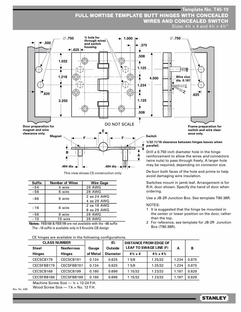
®
Rev. No. 3/09
Template No. T45-19
FULL MORFULL MORFULL MORFULL MORFULL MORTISE TISE TISE TISE TISE TEMPLATEMPLATEMPLATEMPLATEMPLATE BTE BTE BTE BTE BUTT HINGES UTT HINGES UTT HINGES UTT HINGES UTT HINGES WITH CONCEALEDWITH CONCEALEDWITH CONCEALEDWITH CONCEALEDWITH CONCEALEDWIRES WIRES WIRES WIRES WIRES AND CONCEALED SWITAND CONCEALED SWITAND CONCEALED SWITAND CONCEALED SWITAND CONCEALED SWITCHCHCHCHCH
Sizes: 4½ × 4 and 4½ × 4½”
1/32 (1/16 clearance between hinges leaves whenparallel).
Drill a 0.750 inch diameter hole in the hingereinforcement to allow the wires and connectors(wire nuts) to pass through freely. A larger holemay be required, depending on connector size.
De-burr both faces of the hole and prime to helpavoid damaging wire insulation.
Switches mount in jamb leaf. Arrangement is forR.H. door shown. Specify the hand of door whenordering.
Use a JB-2R Junction Box. See template T90-38R.
NOTES:1 It is suggested that the hinge be mounted in
the center or lower position on the door, ratherthan the top.
2 For reference, see template for JB-2R JunctionBox (T90-38R).
Machine Screw Size — ½ × 12-24 F.H.Wood Screw Size — 1¼ × No. 12 F.H.
1.000
.375
.508
1.125
1.234
4.500
1.125
.508
2.250
E
FF
.625
1.032
1.218
.625
.500∅ .750 ∅ .750
BA
.625
This view shows CS construction only.
DO NOT SCALEDoor preparation formagnet and wireclearance only.
Frame preparation forswitch and wire clear-ance only.
Magnet Switch
(E)
Steel Nonferrous Gauge Outside A B
Hinges Hinges of Metal Diameter 4½ × 4 4½ × 4½
CECSCB179 CECSCB191 0.134 0.625 1 5/8 1 25/32 1.234 0.875
CECSFBB179 CECSFBB191 0.134 0.625 1 5/8 1 25/32 1.234 0.875
CECSCB168 CECSCB199 0.180 0.698 1 15/32 1 23/32 1.187 0.828
CECSFBB168 CECSFBB199 0.180 0.698 1 15/32 1 23/32 1.187 0.828
CLASS NUMBER DISTANCE FROM EDGE OF
LEAF TO SWAGE LINE (F)
CE hinges are available in the following configurations.
¾ hole forthrough wiresand switchhousing
Wire clusdia. 0.187
.484 dia.484 dia
Suffix Number of Wires Wire Gage
–54 4 wire 28 AWG–56 6 wire 28 AWG
2 ea 24 AWG4 ea 28 AWG2 ea 18 AWG6 ea 28 AWG
–58 8 wire 28 AWG–10 10 wire 28 AWG
Notes: FBB168 & FBB199 are not available with the –66 suffixThe –18 suffix is available only in 5 Knuckle CB design
–66 6 wire
–18 8 wire

®
Rev. No. 1/06
Template No. T45-10
RAISED BRAISED BRAISED BRAISED BRAISED BARREL ARREL ARREL ARREL ARREL TEMPLATEMPLATEMPLATEMPLATEMPLATE BTE BTE BTE BTE BUTT HINGES FOR DOORS UTT HINGES FOR DOORS UTT HINGES FOR DOORS UTT HINGES FOR DOORS UTT HINGES FOR DOORS WITHWITHWITHWITHWITHSQSQSQSQSQUUUUUARE EDGE HINGE STILESARE EDGE HINGE STILESARE EDGE HINGE STILESARE EDGE HINGE STILESARE EDGE HINGE STILES
Size: 4½ × 4½”
Template hinges of the hospital type conform to above screw hole location.Hospital type hinges are designated by prefix “HT” to class number.
Machine Screw Size — ½ × 12-24 F.H.Wood Screw Size — 1¼ × No. 12 F.H.
DO NOT SCALE
(E)
Steel Nonferrous Gauge Outside E F
Hinges Hinges of Metal Diameter (See Note 2)
RB-CB179 RB-CB191 0.134 0.625 1/2 11/32
RB-FBB179 RB-FBB191 0.134 0.625 1/2 11/32
RB-CB1900 RB-CB1960 0.134 0.540 1/2 11/32
RB-CB1900R RB-CB1960R 0.134 0.625 1/2 11/32
RB-CB168 RB-CB199 0.180 0.698 5/8 3/8
RB-FBB168 RB-FBB199 0.180 0.698 5/8 3/8
RB-CB1901 RB-CB1961 0.180 0.690 5/8 3/8
RB-CB1901R RB-CB1961R 0.180 0.698 5/8 3/8
CLASS NUMBER
NOTES:1 Side clearance between door and frame governed by depth of
mortise. (3/32 betwen door and frame suggested).2 Recommended for approx. 1/16 swinging clearance between door
and stop. For raised barrel mortise and surface applications onbeveled stile door installations, see template drawing T45-11.
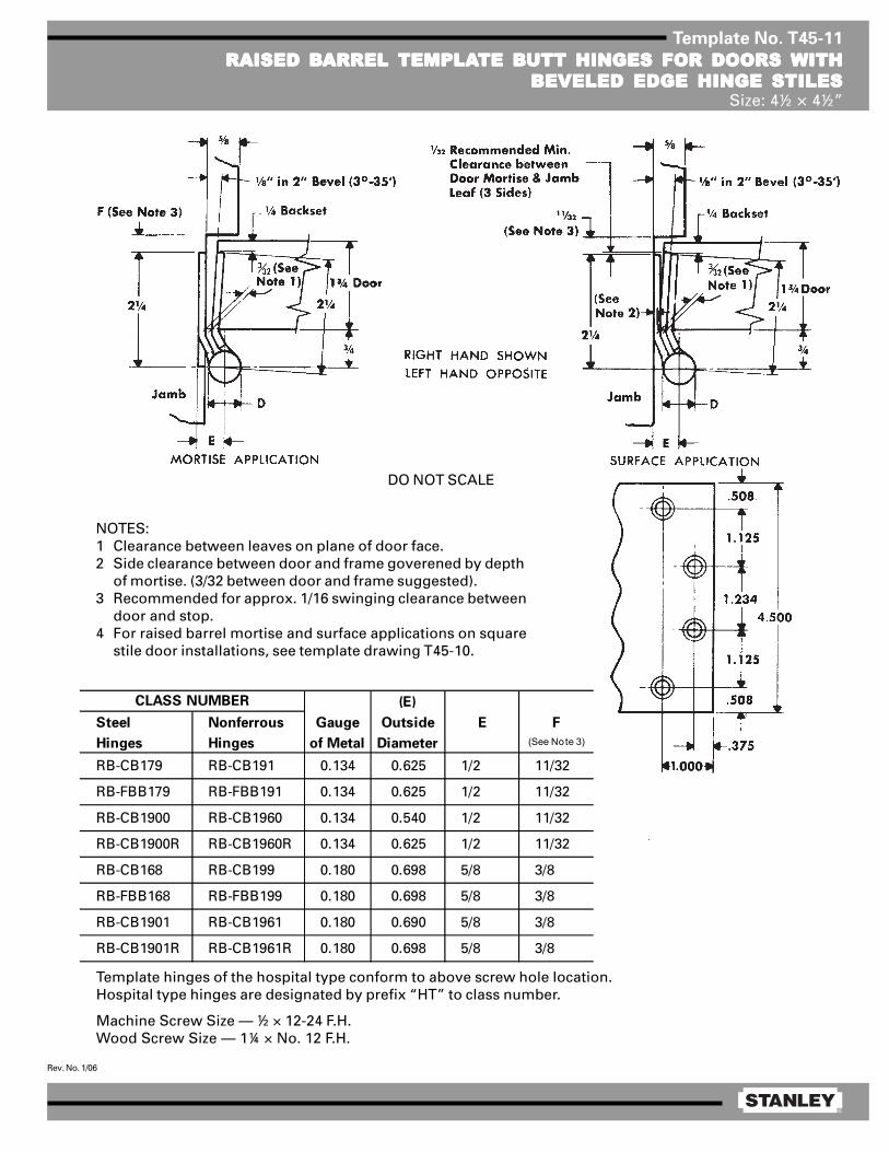
®
Rev. No. 1/06
Template No. T45-11
RAISED BRAISED BRAISED BRAISED BRAISED BARREL ARREL ARREL ARREL ARREL TEMPLATEMPLATEMPLATEMPLATEMPLATE BTE BTE BTE BTE BUTT HINGES FOR DOORS UTT HINGES FOR DOORS UTT HINGES FOR DOORS UTT HINGES FOR DOORS UTT HINGES FOR DOORS WITHWITHWITHWITHWITHBEVELED EDGE HINGE STILESBEVELED EDGE HINGE STILESBEVELED EDGE HINGE STILESBEVELED EDGE HINGE STILESBEVELED EDGE HINGE STILES
Size: 4½ × 4½”
(E)
Steel Nonferrous Gauge Outside E F
Hinges Hinges of Metal Diameter (See Note 3)
RB-CB179 RB-CB191 0.134 0.625 1/2 11/32
RB-FBB179 RB-FBB191 0.134 0.625 1/2 11/32
RB-CB1900 RB-CB1960 0.134 0.540 1/2 11/32
RB-CB1900R RB-CB1960R 0.134 0.625 1/2 11/32
RB-CB168 RB-CB199 0.180 0.698 5/8 3/8
RB-FBB168 RB-FBB199 0.180 0.698 5/8 3/8
RB-CB1901 RB-CB1961 0.180 0.690 5/8 3/8
RB-CB1901R RB-CB1961R 0.180 0.698 5/8 3/8
CLASS NUMBER
NOTES:1 Clearance between leaves on plane of door face.2 Side clearance between door and frame goverened by depth
of mortise. (3/32 between door and frame suggested).3 Recommended for approx. 1/16 swinging clearance between
door and stop.4 For raised barrel mortise and surface applications on square
stile door installations, see template drawing T45-10.
Template hinges of the hospital type conform to above screw hole location.Hospital type hinges are designated by prefix “HT” to class number.
Machine Screw Size — ½ × 12-24 F.H.Wood Screw Size — 1¼ × No. 12 F.H.
DO NOT SCALE

®
Rev. No. 1/06
Template No. T50-01
FULL MORFULL MORFULL MORFULL MORFULL MORTISE TISE TISE TISE TISE TEMPLATEMPLATEMPLATEMPLATEMPLATE BTE BTE BTE BTE BUTT HINGESUTT HINGESUTT HINGESUTT HINGESUTT HINGESSizes: 5 × 4, 5 × 4½, 5 × 5, 5 × 7 and 5 × 8”
Template hinges of the hospital type conform to above screw hole location.Hospital type hinges are designated by prefix “HT” to class number.Also available “RD” radius corners (1/4 or 5/8).Machine Screw Size — ½ × 12-24 F.H.
Wood Screw Size —
NOTE: Prefix IHT indicates Institutional Hinge.
This template conforms with ANSI standard A156.7.
1¼ × No. 12 F.H. for regular weight (0.146) hinges1½ × No. 12 F.H. for extra heavy weight (0.190) hinges[
E
F
1/ 16
5/ 8 R1/ 4 R
1 .2 50
5 .000
.508 .5081 .484 1 .2 50
1 .000
.37 5
(E)
Steel Nonferrous Gauge Outside
Hinges Hinges of Metal Diameter 5 × 4 5 × 4½ 5 × 5 5 × 7 5 × 8
F179 F191 0.146 0.661 1 5/8 1 13/16 2 1/16 3 1/16 3 9/16
1900 1960 0.146 0.580 1 5/8 1 3/4 2 — —
1900R 1960R 0.146 0.661 1 5/8 1 13/16 2 1/16 3 1/16 3 9/16
CB179 CB191 0.146 0.669 1 5/8 1 13/16 2 1/16 3 1/16 3 9/16
FBB179 FBB191 0.146 0.669 1 5/8 1 13/16 2 1/16 3 1/16 3 9/16
CB1900 CB1960 0.146 0.580 1 5/8 1 55/64 2 7/64 — —
CB1900R CB1960R 0.146 0.669 1 5/8 1 13/16 2 1/16 3 1/16 3 9/16
CB168 CB199 0.190 0.748 1 15/32 1 23/32 1 31/32 2 31/32 3 15/32
FBB168 FBB199 0.190 0.748 1 15/32 1 23/32 1 31/32 2 31/32 3 15/32
IHTCB168 IHTCB199 0.190 0.748 — 1 23/32 — — —
CB1901 CB1961 0.190 0.715 — 1 13/16 — — —
CB1901R CB1961R 0.190 0.748 1 15/32 2 23/32 1 31/32 2 31/32 3 15/32
IHTCB1901 IHTCB1961 0.190 0.715 — 1 13/16 — — —
IHTCB1901R IHTCB1961R 0.190 0.748 — 1 23/32 — — —
CLASS NUMBERDISTANCE FROM EDGE OF LEAF TO SWAGE LINE (F)
DO NOT SCALE

®
Rev. No. 3/09
Template No. T50-15
FULL MORFULL MORFULL MORFULL MORFULL MORTISE TISE TISE TISE TISE TEMPLATEMPLATEMPLATEMPLATEMPLATE BTE BTE BTE BTE BUTT HINGES UTT HINGES UTT HINGES UTT HINGES UTT HINGES WITH CONCEALED WITH CONCEALED WITH CONCEALED WITH CONCEALED WITH CONCEALED WIRESWIRESWIRESWIRESWIRESSize: 5 × 4½”
Machine Screw Size — ½ × 12-24 F.H.
Wood Screw Size — 1¼ × No. 12 F.H. for standard weight (0.146) hinges1½ × No. 12 F.H. for heavy weight (0.190) hinges[
1/32 (1/16 clearance between hinge leaveswhen parallel).
Drill a 0.750 inch diameter hole in the hingereinforcement to allow the wires and connec-tors (wire nuts) to pass through freely. Alarger hole may be required, depending onconnector size.
De-burr both faces of the hole and prime tohelp avoid damaging wire insulation.
Use a JB-2R Junction Box. See templateT90-38R.
NOTE: Available with both concealed wiresand a concealed switch. See template T50-19.
1.000.375
.508
1.250
1.4845.000
1.250
.508
2.500
E
FF
.625
¾ hole forthrough wires
¾ hole forthrough wires
Wire clusterdia. 0.187 max
CE hinges are available in the following configurations:(E)
Steel Nonferrous Gauge Outside
Hinges Hinges of Metal Diameter 5 × 4½
CECB179 CECB191 0.146 0.669 1 13/16
CEFBB179 CEFBB191 0.146 0.669 1 13/16
CECB168 CECB199 0.190 0.748 1 23/32
CEFBB168 CEFBB199 0.190 0.748 1 23/32
CEIHTCB168 CEIHTCB199 0.190 0.748 1 23/32
CLASS NUMBER DISTANCE FROM EDGE OF
LEAF TO SWAGE LINE (F)
Suffix Number of Wires Wire Gage
–54 4 wire 28 AWG–56 6 wire 28 AWG
2 ea 24 AWG4 ea 28 AWG2 ea 18 AWG6 ea 28 AWG
–58 8 wire 28 AWG–10 10 wire 28 AWG
Notes: FBB168 & FBB199 are not available with the -66 suffixThe –18 suffix is available only in 5 knuckle CB design
–66 6 wire
–18 8 wire
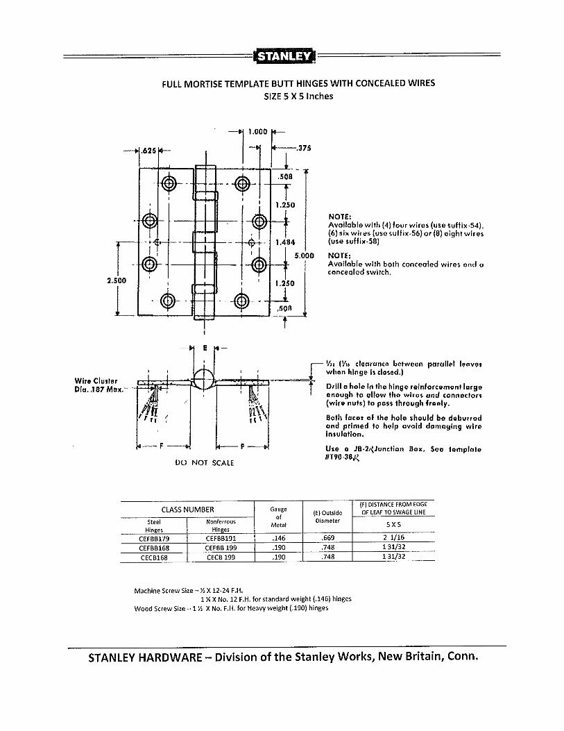

®
Rev. No. 2/06
Template No. T50-17
FULL MORFULL MORFULL MORFULL MORFULL MORTISE TISE TISE TISE TISE TEMPLATEMPLATEMPLATEMPLATEMPLATE BTE BTE BTE BTE BUTT HINGES UTT HINGES UTT HINGES UTT HINGES UTT HINGES WITH CONCEALED SWITWITH CONCEALED SWITWITH CONCEALED SWITWITH CONCEALED SWITWITH CONCEALED SWITCHCHCHCHCHSize: 5 × 4½”
Contractor should be cautioned to preventmortar from interfering with wiring.
1/32 (1/16 clearance between parallel leaves when hingeis closed.)
NOTES:1 Available with both a concealed switch and con-
cealed wires. See templates T50-19 or T50-20.2 0.750 diameter is the recommended hole size for
switch housing clearance.3 It is suggested that the hinge be mounted in the
center or lower position on the door, rather than thetop.
4 Switch mounts in jamb leaf. Arrangement for L.H.door show. Specify hand when ordering.
5 Use a JB-2R Junction Box. See Template T90-38R.
Machine Screw Size — 12-24 × ½ F.H.Wood Screw Size — No. 12 × 1¼ F.H. for standard weight (0.146) hinges
No. 12 × 1½ F.H. for heavy weight (0.190) hinges
(E)
Steel Nonferrous Gauge Outside A B
Hinges Hinges of Metal Diameter 5 × 4½
CSCB179 CSCB191 0.146 0.669 1 13/16 1.218 0.859
CSFBB179 CSFBB191 0.146 0.669 1 13/16 1.218 0.859
CSCB1900 CSCB1960 0.146 0.580 1 55/64 1.218 0.859
CSCB1900R CSCB1960R 0.146 0.669 1 13/16 1.218 0.859
CSCB168 CSCB199 0.190 0.748 1 23/32 1.172 0.812
CSFBB168 CSFBB199 0.190 0.748 1 23/32 1.172 0.812
CSIHTCB168 CSIHTCB199 0.190 0.748 1 23/32 1.172 0.812
CSCB1901 CSCB1961 0.190 0.715 1 13/16 1.172 0.812
CSCB1901R CSCB1961R 0.190 0.015 1 23/32 1.172 0.812
CSIHTCB1901 CSIHTCB1961 0.180 0.715 1 13/16 1.172 0.812
CSIHTCB1901R CSIHTCB1961R 0.190 0.748 1 23/32 1.172 0.812
CLASS NUMBER DISTANCE FROM EDGE OF LEAF TO
SWAGE LINE (F)

®
Rev. No. 03/09
Template No. T50-19
FULL MORFULL MORFULL MORFULL MORFULL MORTISE TISE TISE TISE TISE TEMPLATEMPLATEMPLATEMPLATEMPLATE BTE BTE BTE BTE BUTT HINGES UTT HINGES UTT HINGES UTT HINGES UTT HINGES WITH CONCEALED WITH CONCEALED WITH CONCEALED WITH CONCEALED WITH CONCEALED WIRESWIRESWIRESWIRESWIRESAND CONCEALED SWITAND CONCEALED SWITAND CONCEALED SWITAND CONCEALED SWITAND CONCEALED SWITCHCHCHCHCH
Size: 5 × 4½”
1.000
.375
.508
1.250
1.484
5.000
1.250
.508
2.500
E
FF
.625
1.094
1.406
.625
.500∅ .750
BA
∅ .750
.625
Machine Screw Size — ½ × 12-24 F.H.
Wood Screw Size — 1¼ × No. 12 F.H. for standard weight (0.146) hinges1½ × No. 12 F.H. for heavy weight (0.190) hinges[
1/32 (1/16 clearance between hinge leaveswhen parallel.)
Drill a 0.750 inch diameter hole in the hingereinforcement to allow the wires and connec-tors (wire nuts) to pass through freely. A largerhole may be required depending on connectorsize.
De-burr both faces of the hole and prime tohelp avoid damaging wire insulation.
Switches mount in jamb leaf. Arrangement forR.H. door shown. Specify the hand of doorwhen ordering.
Door preparation formagnet and wireclearance only.
Frame preparation forswitch and wire
clearance only.Magnet Switch
Wirecluster dia.0.187 max.
¾ hole forthrough wiresand switchhousing
DO NOT SCALE
CE hinges are available in the following configurations:
NOTES:1 It is suggested that the hinge be mounted in
the center or lower position on the door,rather than the top.
2 Use JB-2R Junction Box. See templateT90-38R.
This view shows CSconstruction only.
.484 dia.484 dia
(E)
Steel Nonferrous Gauge Outside A B
Hinges Hinges of Metal Diameter 5 × 4½
CECSCB179 CECSCB191 0.146 0.669 1 13/16 1.218 0.859
CECSFBB179 CECSFBB191 0.146 0.669 1 13/16 1.218 0.859
CECSCB168 CECSCB199 0.190 0.748 1 23/32 1.172 0.812
CECSFBB168 CECSFBB199 0.190 0.748 1 23/32 1.172 0.812
CLASS NUMBER DISTANCE FROM EDGE OF
LEAF TO SWAGE LINE (F)
Suffix Number of Wires Wire Gage
–54 4 wire 28 AWG–56 6 wire 28 AWG
2 ea 24 AWG4 ea 28 AWG
–58 8 wire 28 AWG–10 10 wire 28 AWG
2 ea 18 AWG6 ea 28 AWG
Notes: FBB168 & FBB199 are not available with the -66 suffix
–18 Available only in 5 Knuckle CB Design
–66 6 wire
–18 8 wire

®
Rev. No. 1/06
Template No. T50-13
RAISED BRAISED BRAISED BRAISED BRAISED BARREL ARREL ARREL ARREL ARREL TEMPLATEMPLATEMPLATEMPLATEMPLATE BTE BTE BTE BTE BUTT HINGES FOR DOORSUTT HINGES FOR DOORSUTT HINGES FOR DOORSUTT HINGES FOR DOORSUTT HINGES FOR DOORSWITH SQWITH SQWITH SQWITH SQWITH SQUUUUUARE EDGE HINGE STILESARE EDGE HINGE STILESARE EDGE HINGE STILESARE EDGE HINGE STILESARE EDGE HINGE STILES
Size: 5 × 4½”
Template hinges of the hospital type conform to above screw hole location.Hospital type hinges are designated by prefix “HT” to class number.Machine Screw Size — ½ × 12-24 F.H.
Wood Screw Size —
(D)
Steel Nonferrous Gauge Outside E F
Hinges Hinges of Metal Diameter (See Note 3)
RB-CB179 RB-CB191 0.146 0.669 9/16 11/32
RB-FBB179 RB-FBB191 0.146 0.669 9/16 11/32
RB-CB1900 RB-CB1960 0.146 0.580 9/16 11/32
RB-CB1900R RB-CB1960R 0.146 0.580 9/16 11/32
RB-CB168 RB-CB199 0.190 0.748 21/32 3/8
RB-FBB168 RB-FBB199 0.190 0.748 21/32 3/8
RB-CB1901 RB-CB1961 0.190 0.715 21/32 3/8
RB-CB1901R RB-CB1961R 0.190 0.748 21/32 3/8
CLASS NUMBER
NOTES:1 Side clearance between door and frame governed by depth of
mortise in door (3/32 between door and frame suggested).2 Recommended for approx. 1/16 swinging clearance between
door and stop.3 For raised barrel mortise and surface applications on beveled
stile door installations, see template drawing T50-14.
1¼ × No. 12 F.H. for standard weight (0.146) hinges1½ × No. 12 F.H. for heavy weight (0.190) hinges[

®
Rev. No. 1/06
Template No. T50-14
RAISED BRAISED BRAISED BRAISED BRAISED BARREL ARREL ARREL ARREL ARREL TEMPLATEMPLATEMPLATEMPLATEMPLATE BTE BTE BTE BTE BUTT HINGES FOR DOORSUTT HINGES FOR DOORSUTT HINGES FOR DOORSUTT HINGES FOR DOORSUTT HINGES FOR DOORSWITH BEVELED EDGE HINGE STILESWITH BEVELED EDGE HINGE STILESWITH BEVELED EDGE HINGE STILESWITH BEVELED EDGE HINGE STILESWITH BEVELED EDGE HINGE STILES
Size: 5 × 4½”
Template hinges of the hospital type conform to above screw hole location.Hospital type hinges are designated by prefix “HT” to class number.Machine Screw Size — ½ × 12-24 F.H.
Wood Screw Size —
NOTES:1 Clearance between leaves on plane of door face.2 Side clearance between door and frame governed by depth of
mortise in door (3/32 between door and frame suggested).3 Recommended for approx. 1/16 swinging clearance between
door and stop.4 For raised barrel mortise and surface applications on square
stile door installations, see template drawing T50-13.
1¼ × No. 12 F.H. for standard weight (0.146) hinges1½ × No. 12 F.H. for extra heavy weight (0.190) hinges[
(D)
Steel Nonferrous Gauge Outside E F
Hinges Hinges of Metal Diameter (See Note 3)
RB-CB179 RB-CB191 0.146 0.669 9/16 11/32
RB-FBB179 RB-FBB191 0.146 0.669 9/16 11/32
RB-CB1900 RB-CB1960 0.146 0.580 9/16 11/32
RB-CB1900R RB-CB1960R 0.146 0.669 9/16 11/32
RB-CB168 RB-CB199 0.190 0.748 21/32 3/8
RB-FBB168 RB-FBB199 0.190 0.748 21/32 3/8
RB-CB1901 RB-CB1961 0.190 0.715 21/32 3/8
RB-CB1901R RB-CB1961R 0.190 0.748 21/32 3/8
CLASS NUMBER
(3°-35’)

®
Rev. No. 4/07
Template No. T60-01
FULL MORFULL MORFULL MORFULL MORFULL MORTISE TISE TISE TISE TISE TEMPLATEMPLATEMPLATEMPLATEMPLATE BTE BTE BTE BTE BUTT HINGESUTT HINGESUTT HINGESUTT HINGESUTT HINGESSizes: 6 × 4½, 6 × 5 and 6 × 6”
Template hinges of the hospital type conform to above screw hole location.Hospital type hinges are designated by prefix “HT” to class number.
Machine Screw Size — ½ × ¼-20 F.H.Wood Screw Size — 1½ × No. 14 F.H.
This template conforms with ANSI standard A156.7.
(E)
Steel Nonferrous Gauge Outside
Hinges Hinges of Metal Diameter 6 × 4½ 6 × 5 6 × 6
F179 — 0.160 0.725 1 23/32 1 31/32 2 15/32
1900R — 0.160 0.725 1 23/32 1 31/32 2 15/32
CB179 CB191 0.160 0.735 1 23/32 1 31/32 2 15/32
FBB179 FBB191 0.160 0.735 1 23/32 1 31/32 2 15/32
CB1900R CB1960R 0.160 0.735 1 23/32 1 31/32 2 15/32
CB168 CB199 0.203 0.847 1 1/2 1 3/4 2 1/4
FBB168 FBB199 0.203 0.847 1 1/2 1 3/4 2 1/4
CB1901 CB1961 0.203 0.735 1 3/4 2 2 1/2
CB1901R CB1961R 0.203 0.847 1 1/2 1 3/4 2 1/4
CLASS NUMBER DISTANCE FROM EDGE OF
LEAF TO SWAGE LINE (F)

®
Rev. No. 3/06
Template No. T45-01
FULL MORFULL MORFULL MORFULL MORFULL MORTISE TISE TISE TISE TISE TEMPLATEMPLATEMPLATEMPLATEMPLATE BTE BTE BTE BTE BUTT HINGESUTT HINGESUTT HINGESUTT HINGESUTT HINGESSizes: 4½ × 4, 4½ × 4½, 4½ × 5, 4½ × 6, 4½ × 7 and 4½ × 8”
Template hinges of the hospital type conform to above screw hole location.Hospital type hinges are designated by prefix “HT” to class number (except on #2060).Also available in RD2060 1/4 radius corner and RD2068 5/8 radius corner.
Machine Screw Size — ½ × 12-24 F.H.Wood Screw Size — 1¼ × No. 12 F.H.
This template conforms with ANSI standard A156.7.
E
F
1/ 16
5/ 8 R1/ 4 R
1 .125
4 .500
.508 .5081 .2 34 1 .125
1 .000
.375
(E)
Steel Nonferrous Gauge Outside
Hinges Hinges of Metal Diameter 4½ × 4 4½ × 4½ 4½ × 5 4½ × 6 4½ × 7 4½ × 8
F179 F191 0.134 0.605 1 5/8 1 29/32 2 5/32 2 21/32 3 5/32 2 21/32
1900 1960 0.134 0.540 1 5/8 1 13/16 — — — —
1900R 1960R 0.134 0.605 1 5/8 1 29/32 — — — —
CB179 CB191 0.134 0.625 1 5/8 1 25/32 2 3/32 2 19/32 — —
FBB179 FBB191 0.134 0.625 1 5/8 1 25/32 2 3/32 2 19/32 — —
CB1900 CB1960 0.134 0.540 1 5/8 1 13/16 — — — —
CB1900R CB1960R 0.134 0.625 1 5/8 1 25/32 2 3/32 2 19/32 — —
CB168 CB199 0.180 0.698 1 15/32 1 23/32 1 31/32 2 15/32 2 31/32 3 15/32
FBB168 FBB199 0.180 0.698 1 15/32 1 23/32 1 31/32 2 15/32 2 31/32 3 15/32
IHTCB168 IHTCB199 0.180 0.698 1 15/32 1 23/32 — — — —
— CB0701 0.180 0.698 1 15/32 1 23/32 — — — —
CB1901 CB1961 0.180 0.690 — 1 13/16 — — — —
CB1901R CB1961R 0.180 0.698 1 15/32 1 23/32 1 31/32 2 15/32 2 31/32 3 15/32
IHTCB1901 IHTCB1961 0.180 0.690 1 15/32 1 13/16 — — — —
IHTCB1901R IHTCB1961R 0.180 0.698 1 15/32 1 23/32 — — — —
2060R — 0.134 0.783 1 5/8 1 27/32 — — — —
DISTANCE FROM EDGE OF LEAF TO SWAGE LINE (F)CLASS NUMBER

®
Rev. No. 3/09
Template No. T45-15
FULL MORFULL MORFULL MORFULL MORFULL MORTISE TISE TISE TISE TISE TEMPLATEMPLATEMPLATEMPLATEMPLATE BTE BTE BTE BTE BUTT HINGES UTT HINGES UTT HINGES UTT HINGES UTT HINGES WITH CONCEALED WITH CONCEALED WITH CONCEALED WITH CONCEALED WITH CONCEALED WIRESWIRESWIRESWIRESWIRESSizes: 4½ × 4 and 4½ × 4½”
Machine Screw Size — ½ × 12-24 F.H.Wood Screw Size — 1¼ × No. 12 F.H.
1/32 (1/16 clearance between hinge leaveswhen parallel).
Drill a 0.750 inch diameter hole in the hingereinforcement to allow the wires and connectors(wire nuts) to pass through freely. A larger holemay be required, depending on connector size.
De-burr both faces of the hole and prime to helpavoid damaging wire insulation.
Use a JB-2R Junction Box. See template T90-38R.
1.000.375
.508
1.125
1.2344.500
1.125
.508
2.250
E
FF
.625
DO NOT SCALE
¾ hole forthrough wires
¾ hole forthrough wires
CE hinges are available in the following configurations:
(E)
Steel Nonferrous Gauge Outside
Hinges Hinges of Metal Diameter 4½ × 4 4½ × 4½
CECB179 CECB191 0.134 0.625 1 5/8 1 25/32
CEFBB179 CEFBB191 0.134 0.625 1 5/8 1 25/32
CECB168 CECB199 0.180 0.698 1 15/32 1 23/32
CEFBB168 CEFBB199 0.180 0.698 1 15/32 1 23/32
CEIHTCB168 CEIHTCB199 0.180 0.698 1 15/32 1 23/32
CLASS NUMBER DISTANCE FROM EDGE OF LEAF
TO SWAGE LINE (F)
NOTE:Available with both concealed wires and aconcealed switch. See template No. T45-19.
Suffix Number of Wires Wire Gage
–54 4 wire 28 AWG–56 6 wire 28 AWG
2 ea 24 AWG4 ea 28 AWG2 ea 18 AWG6 ea 28 AWG
–58 8 wire 28 AWG–10 10 wire 28 AWG
Notes: FBB168 & FBB199 are not available with the –66 suffixThe –18 suffix is available only in 5 knuckle CB design
–66 6 wire
–18 8 wire

®
Rev. No. 2/06
Template No. T50-17
FULL MORFULL MORFULL MORFULL MORFULL MORTISE TISE TISE TISE TISE TEMPLATEMPLATEMPLATEMPLATEMPLATE BTE BTE BTE BTE BUTT HINGES UTT HINGES UTT HINGES UTT HINGES UTT HINGES WITH CONCEALED SWITWITH CONCEALED SWITWITH CONCEALED SWITWITH CONCEALED SWITWITH CONCEALED SWITCHCHCHCHCHSize: 5 × 4½”
Contractor should be cautioned to preventmortar from interfering with wiring.
1/32 (1/16 clearance between parallel leaves when hingeis closed.)
NOTES:1 Available with both a concealed switch and con-
cealed wires. See templates T50-19 or T50-20.2 0.750 diameter is the recommended hole size for
switch housing clearance.3 It is suggested that the hinge be mounted in the
center or lower position on the door, rather than thetop.
4 Switch mounts in jamb leaf. Arrangement for L.H.door show. Specify hand when ordering.
5 Use a JB-2R Junction Box. See Template T90-38R.
Machine Screw Size — 12-24 × ½ F.H.Wood Screw Size — No. 12 × 1¼ F.H. for standard weight (0.146) hinges
No. 12 × 1½ F.H. for heavy weight (0.190) hinges
(E)
Steel Nonferrous Gauge Outside A B
Hinges Hinges of Metal Diameter 5 × 4½
CSCB179 CSCB191 0.146 0.669 1 13/16 1.218 0.859
CSFBB179 CSFBB191 0.146 0.669 1 13/16 1.218 0.859
CSCB1900 CSCB1960 0.146 0.580 1 55/64 1.218 0.859
CSCB1900R CSCB1960R 0.146 0.669 1 13/16 1.218 0.859
CSCB168 CSCB199 0.190 0.748 1 23/32 1.172 0.812
CSFBB168 CSFBB199 0.190 0.748 1 23/32 1.172 0.812
CSIHTCB168 CSIHTCB199 0.190 0.748 1 23/32 1.172 0.812
CSCB1901 CSCB1961 0.190 0.715 1 13/16 1.172 0.812
CSCB1901R CSCB1961R 0.190 0.015 1 23/32 1.172 0.812
CSIHTCB1901 CSIHTCB1961 0.180 0.715 1 13/16 1.172 0.812
CSIHTCB1901R CSIHTCB1961R 0.190 0.748 1 23/32 1.172 0.812
CLASS NUMBER DISTANCE FROM EDGE OF LEAF TO
SWAGE LINE (F)

®
Rev. No. 1/06
Template No. T45-10
RAISED BRAISED BRAISED BRAISED BRAISED BARREL ARREL ARREL ARREL ARREL TEMPLATEMPLATEMPLATEMPLATEMPLATE BTE BTE BTE BTE BUTT HINGES FOR DOORS UTT HINGES FOR DOORS UTT HINGES FOR DOORS UTT HINGES FOR DOORS UTT HINGES FOR DOORS WITHWITHWITHWITHWITHSQSQSQSQSQUUUUUARE EDGE HINGE STILESARE EDGE HINGE STILESARE EDGE HINGE STILESARE EDGE HINGE STILESARE EDGE HINGE STILES
Size: 4½ × 4½”
Template hinges of the hospital type conform to above screw hole location.Hospital type hinges are designated by prefix “HT” to class number.
Machine Screw Size — ½ × 12-24 F.H.Wood Screw Size — 1¼ × No. 12 F.H.
DO NOT SCALE
(E)
Steel Nonferrous Gauge Outside E F
Hinges Hinges of Metal Diameter (See Note 2)
RB-CB179 RB-CB191 0.134 0.625 1/2 11/32
RB-FBB179 RB-FBB191 0.134 0.625 1/2 11/32
RB-CB1900 RB-CB1960 0.134 0.540 1/2 11/32
RB-CB1900R RB-CB1960R 0.134 0.625 1/2 11/32
RB-CB168 RB-CB199 0.180 0.698 5/8 3/8
RB-FBB168 RB-FBB199 0.180 0.698 5/8 3/8
RB-CB1901 RB-CB1961 0.180 0.690 5/8 3/8
RB-CB1901R RB-CB1961R 0.180 0.698 5/8 3/8
CLASS NUMBER
NOTES:1 Side clearance between door and frame governed by depth of
mortise. (3/32 betwen door and frame suggested).2 Recommended for approx. 1/16 swinging clearance between door
and stop. For raised barrel mortise and surface applications onbeveled stile door installations, see template drawing T45-11.

®
Rev. No. 1/06
Template No. T45-11
RAISED BRAISED BRAISED BRAISED BRAISED BARREL ARREL ARREL ARREL ARREL TEMPLATEMPLATEMPLATEMPLATEMPLATE BTE BTE BTE BTE BUTT HINGES FOR DOORS UTT HINGES FOR DOORS UTT HINGES FOR DOORS UTT HINGES FOR DOORS UTT HINGES FOR DOORS WITHWITHWITHWITHWITHBEVELED EDGE HINGE STILESBEVELED EDGE HINGE STILESBEVELED EDGE HINGE STILESBEVELED EDGE HINGE STILESBEVELED EDGE HINGE STILES
Size: 4½ × 4½”
(E)
Steel Nonferrous Gauge Outside E F
Hinges Hinges of Metal Diameter (See Note 3)
RB-CB179 RB-CB191 0.134 0.625 1/2 11/32
RB-FBB179 RB-FBB191 0.134 0.625 1/2 11/32
RB-CB1900 RB-CB1960 0.134 0.540 1/2 11/32
RB-CB1900R RB-CB1960R 0.134 0.625 1/2 11/32
RB-CB168 RB-CB199 0.180 0.698 5/8 3/8
RB-FBB168 RB-FBB199 0.180 0.698 5/8 3/8
RB-CB1901 RB-CB1961 0.180 0.690 5/8 3/8
RB-CB1901R RB-CB1961R 0.180 0.698 5/8 3/8
CLASS NUMBER
NOTES:1 Clearance between leaves on plane of door face.2 Side clearance between door and frame goverened by depth
of mortise. (3/32 between door and frame suggested).3 Recommended for approx. 1/16 swinging clearance between
door and stop.4 For raised barrel mortise and surface applications on square
stile door installations, see template drawing T45-10.
Template hinges of the hospital type conform to above screw hole location.Hospital type hinges are designated by prefix “HT” to class number.
Machine Screw Size — ½ × 12-24 F.H.Wood Screw Size — 1¼ × No. 12 F.H.
DO NOT SCALE

®
Rev. No. 3/06
Template No. T45-01
FULL MORFULL MORFULL MORFULL MORFULL MORTISE TISE TISE TISE TISE TEMPLATEMPLATEMPLATEMPLATEMPLATE BTE BTE BTE BTE BUTT HINGESUTT HINGESUTT HINGESUTT HINGESUTT HINGESSizes: 4½ × 4, 4½ × 4½, 4½ × 5, 4½ × 6, 4½ × 7 and 4½ × 8”
Template hinges of the hospital type conform to above screw hole location.Hospital type hinges are designated by prefix “HT” to class number (except on #2060).Also available in RD2060 1/4 radius corner and RD2068 5/8 radius corner.
Machine Screw Size — ½ × 12-24 F.H.Wood Screw Size — 1¼ × No. 12 F.H.
This template conforms with ANSI standard A156.7.
E
F
1/ 16
5/ 8 R1/ 4 R
1 .125
4 .500
.508 .5081 .2 34 1 .125
1 .000
.375
(E)
Steel Nonferrous Gauge Outside
Hinges Hinges of Metal Diameter 4½ × 4 4½ × 4½ 4½ × 5 4½ × 6 4½ × 7 4½ × 8
F179 F191 0.134 0.605 1 5/8 1 29/32 2 5/32 2 21/32 3 5/32 2 21/32
1900 1960 0.134 0.540 1 5/8 1 13/16 — — — —
1900R 1960R 0.134 0.605 1 5/8 1 29/32 — — — —
CB179 CB191 0.134 0.625 1 5/8 1 25/32 2 3/32 2 19/32 — —
FBB179 FBB191 0.134 0.625 1 5/8 1 25/32 2 3/32 2 19/32 — —
CB1900 CB1960 0.134 0.540 1 5/8 1 13/16 — — — —
CB1900R CB1960R 0.134 0.625 1 5/8 1 25/32 2 3/32 2 19/32 — —
CB168 CB199 0.180 0.698 1 15/32 1 23/32 1 31/32 2 15/32 2 31/32 3 15/32
FBB168 FBB199 0.180 0.698 1 15/32 1 23/32 1 31/32 2 15/32 2 31/32 3 15/32
IHTCB168 IHTCB199 0.180 0.698 1 15/32 1 23/32 — — — —
— CB0701 0.180 0.698 1 15/32 1 23/32 — — — —
CB1901 CB1961 0.180 0.690 — 1 13/16 — — — —
CB1901R CB1961R 0.180 0.698 1 15/32 1 23/32 1 31/32 2 15/32 2 31/32 3 15/32
IHTCB1901 IHTCB1961 0.180 0.690 1 15/32 1 13/16 — — — —
IHTCB1901R IHTCB1961R 0.180 0.698 1 15/32 1 23/32 — — — —
2060R — 0.134 0.783 1 5/8 1 27/32 — — — —
DISTANCE FROM EDGE OF LEAF TO SWAGE LINE (F)CLASS NUMBER
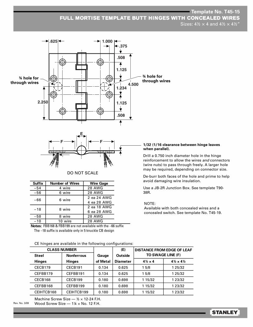
®
Rev. No. 3/09
Template No. T45-15
FULL MORFULL MORFULL MORFULL MORFULL MORTISE TISE TISE TISE TISE TEMPLATEMPLATEMPLATEMPLATEMPLATE BTE BTE BTE BTE BUTT HINGES UTT HINGES UTT HINGES UTT HINGES UTT HINGES WITH CONCEALED WITH CONCEALED WITH CONCEALED WITH CONCEALED WITH CONCEALED WIRESWIRESWIRESWIRESWIRESSizes: 4½ × 4 and 4½ × 4½”
Machine Screw Size — ½ × 12-24 F.H.Wood Screw Size — 1¼ × No. 12 F.H.
1/32 (1/16 clearance between hinge leaveswhen parallel).
Drill a 0.750 inch diameter hole in the hingereinforcement to allow the wires and connectors(wire nuts) to pass through freely. A larger holemay be required, depending on connector size.
De-burr both faces of the hole and prime to helpavoid damaging wire insulation.
Use a JB-2R Junction Box. See template T90-38R.
1.000.375
.508
1.125
1.2344.500
1.125
.508
2.250
E
FF
.625
DO NOT SCALE
¾ hole forthrough wires
¾ hole forthrough wires
CE hinges are available in the following configurations:
(E)
Steel Nonferrous Gauge Outside
Hinges Hinges of Metal Diameter 4½ × 4 4½ × 4½
CECB179 CECB191 0.134 0.625 1 5/8 1 25/32
CEFBB179 CEFBB191 0.134 0.625 1 5/8 1 25/32
CECB168 CECB199 0.180 0.698 1 15/32 1 23/32
CEFBB168 CEFBB199 0.180 0.698 1 15/32 1 23/32
CEIHTCB168 CEIHTCB199 0.180 0.698 1 15/32 1 23/32
CLASS NUMBER DISTANCE FROM EDGE OF LEAF
TO SWAGE LINE (F)
NOTE:Available with both concealed wires and aconcealed switch. See template No. T45-19.
Suffix Number of Wires Wire Gage
–54 4 wire 28 AWG–56 6 wire 28 AWG
2 ea 24 AWG4 ea 28 AWG2 ea 18 AWG6 ea 28 AWG
–58 8 wire 28 AWG–10 10 wire 28 AWG
Notes: FBB168 & FBB199 are not available with the –66 suffixThe –18 suffix is available only in 5 knuckle CB design
–66 6 wire
–18 8 wire


®
Rev. No. 2/06
Template No. T45-17
FULL MORFULL MORFULL MORFULL MORFULL MORTISE TISE TISE TISE TISE TEMPLATEMPLATEMPLATEMPLATEMPLATE BTE BTE BTE BTE BUTT HINGES UTT HINGES UTT HINGES UTT HINGES UTT HINGES WITH CONCEALED SWITWITH CONCEALED SWITWITH CONCEALED SWITWITH CONCEALED SWITWITH CONCEALED SWITCHCHCHCHCHSizes: 4½ × 4 and 4½ × 4½”
Machine Screw Size — 12-24 × ½ F.H.Wood Screw Size — No. 12 × 1¼ F.H.
Contractor should be cautioned to preventmortar from interfering with wiring.
1/32 (1/16 clearance between parallel leaves whenhinge is closed.)
NOTES:1 Available with both a concealed switch and
concealed wires. See templates T45-19 orT45-20.
2 0.750 diameter is the recommended hole size forswitch housing clearance.
3 It is suggested that the hinge be mounted in thecenter or lower position on the door, rather thanthe top.
4 Switch mounts in jamb leaf. Arrangement forL.H. door shown. Specify hand when ordering.
5 Use JB-2R Junction Box. See Template T90-38R.
NOTE: Prefix IHT indicates Institutional Hinge.
(E)
Steel Nonferrous Gauge Outside
Hinges Hinges of Metal Diameter 4½ × 4 4½ × 4½
CSCB179 CSCB191 0.134 0.625 1 5/8 1 25/32 1.234 0.875
CSFBB179 CSFBB191 0.134 0.625 1 5/8 1 25/32 1.234 0.875
CSCB1900 CSCB1960 0.134 0.540 1 5/8 1 13/16 1.234 0.875
CSCB1900R CSCB1960R 0.134 0.625 1 5/8 1 25/32 1.234 0.875
CSCB168 CSCB199 0.180 0.698 — 1 23/32 1.187 0.828
CSFBB168 CSFBB199 0.180 0.698 — 1 23/32 1.187 0.828
CSIHTCB168 CSIHTCB199 0.180 0.698 — 1 23/32 1.187 0.828
CSCB1901 CSCB1961 0.180 0.690 — 1 13/16 1.187 0.828
CSCB1901R CSCB1961R 0.180 0.698 — 1 23/32 0.187 0.828
CSIHTCB1901 CSIHTCB1961 0.180 0.690 — 1 13/16 1.187 0.828
CSIHTCB1901R CSIHTCB1961R 0.180 0.698 — 1 23/32 0.187 0.828
B
CLASS NUMBER DISTANCE FROM EDGE OF LEAF
TO SWAGE LINE (F) A
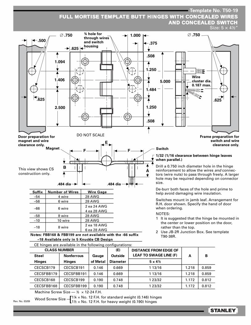
®
Rev. No. 03/09
Template No. T50-19
FULL MORFULL MORFULL MORFULL MORFULL MORTISE TISE TISE TISE TISE TEMPLATEMPLATEMPLATEMPLATEMPLATE BTE BTE BTE BTE BUTT HINGES UTT HINGES UTT HINGES UTT HINGES UTT HINGES WITH CONCEALED WITH CONCEALED WITH CONCEALED WITH CONCEALED WITH CONCEALED WIRESWIRESWIRESWIRESWIRESAND CONCEALED SWITAND CONCEALED SWITAND CONCEALED SWITAND CONCEALED SWITAND CONCEALED SWITCHCHCHCHCH
Size: 5 × 4½”
1.000
.375
.508
1.250
1.484
5.000
1.250
.508
2.500
E
FF
.625
1.094
1.406
.625
.500∅ .750
BA
∅ .750
.625
Machine Screw Size — ½ × 12-24 F.H.
Wood Screw Size — 1¼ × No. 12 F.H. for standard weight (0.146) hinges1½ × No. 12 F.H. for heavy weight (0.190) hinges[
1/32 (1/16 clearance between hinge leaveswhen parallel.)
Drill a 0.750 inch diameter hole in the hingereinforcement to allow the wires and connec-tors (wire nuts) to pass through freely. A largerhole may be required depending on connectorsize.
De-burr both faces of the hole and prime tohelp avoid damaging wire insulation.
Switches mount in jamb leaf. Arrangement forR.H. door shown. Specify the hand of doorwhen ordering.
Door preparation formagnet and wireclearance only.
Frame preparation forswitch and wire
clearance only.Magnet Switch
Wirecluster dia.0.187 max.
¾ hole forthrough wiresand switchhousing
DO NOT SCALE
CE hinges are available in the following configurations:
NOTES:1 It is suggested that the hinge be mounted in
the center or lower position on the door,rather than the top.
2 Use JB-2R Junction Box. See templateT90-38R.
This view shows CSconstruction only.
.484 dia.484 dia
(E)
Steel Nonferrous Gauge Outside A B
Hinges Hinges of Metal Diameter 5 × 4½
CECSCB179 CECSCB191 0.146 0.669 1 13/16 1.218 0.859
CECSFBB179 CECSFBB191 0.146 0.669 1 13/16 1.218 0.859
CECSCB168 CECSCB199 0.190 0.748 1 23/32 1.172 0.812
CECSFBB168 CECSFBB199 0.190 0.748 1 23/32 1.172 0.812
CLASS NUMBER DISTANCE FROM EDGE OF
LEAF TO SWAGE LINE (F)
Suffix Number of Wires Wire Gage
–54 4 wire 28 AWG–56 6 wire 28 AWG
2 ea 24 AWG4 ea 28 AWG
–58 8 wire 28 AWG–10 10 wire 28 AWG
2 ea 18 AWG6 ea 28 AWG
Notes: FBB168 & FBB199 are not available with the -66 suffix
–18 Available only in 5 Knuckle CB Design
–66 6 wire
–18 8 wire

®
Rev. No. 1/06
Template No. T50-13
RAISED BRAISED BRAISED BRAISED BRAISED BARREL ARREL ARREL ARREL ARREL TEMPLATEMPLATEMPLATEMPLATEMPLATE BTE BTE BTE BTE BUTT HINGES FOR DOORSUTT HINGES FOR DOORSUTT HINGES FOR DOORSUTT HINGES FOR DOORSUTT HINGES FOR DOORSWITH SQWITH SQWITH SQWITH SQWITH SQUUUUUARE EDGE HINGE STILESARE EDGE HINGE STILESARE EDGE HINGE STILESARE EDGE HINGE STILESARE EDGE HINGE STILES
Size: 5 × 4½”
Template hinges of the hospital type conform to above screw hole location.Hospital type hinges are designated by prefix “HT” to class number.Machine Screw Size — ½ × 12-24 F.H.
Wood Screw Size —
(D)
Steel Nonferrous Gauge Outside E F
Hinges Hinges of Metal Diameter (See Note 3)
RB-CB179 RB-CB191 0.146 0.669 9/16 11/32
RB-FBB179 RB-FBB191 0.146 0.669 9/16 11/32
RB-CB1900 RB-CB1960 0.146 0.580 9/16 11/32
RB-CB1900R RB-CB1960R 0.146 0.580 9/16 11/32
RB-CB168 RB-CB199 0.190 0.748 21/32 3/8
RB-FBB168 RB-FBB199 0.190 0.748 21/32 3/8
RB-CB1901 RB-CB1961 0.190 0.715 21/32 3/8
RB-CB1901R RB-CB1961R 0.190 0.748 21/32 3/8
CLASS NUMBER
NOTES:1 Side clearance between door and frame governed by depth of
mortise in door (3/32 between door and frame suggested).2 Recommended for approx. 1/16 swinging clearance between
door and stop.3 For raised barrel mortise and surface applications on beveled
stile door installations, see template drawing T50-14.
1¼ × No. 12 F.H. for standard weight (0.146) hinges1½ × No. 12 F.H. for heavy weight (0.190) hinges[
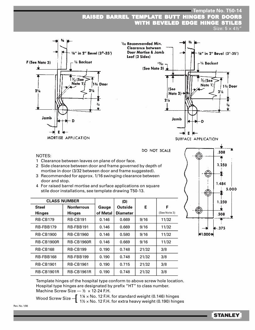
®
Rev. No. 1/06
Template No. T50-14
RAISED BRAISED BRAISED BRAISED BRAISED BARREL ARREL ARREL ARREL ARREL TEMPLATEMPLATEMPLATEMPLATEMPLATE BTE BTE BTE BTE BUTT HINGES FOR DOORSUTT HINGES FOR DOORSUTT HINGES FOR DOORSUTT HINGES FOR DOORSUTT HINGES FOR DOORSWITH BEVELED EDGE HINGE STILESWITH BEVELED EDGE HINGE STILESWITH BEVELED EDGE HINGE STILESWITH BEVELED EDGE HINGE STILESWITH BEVELED EDGE HINGE STILES
Size: 5 × 4½”
Template hinges of the hospital type conform to above screw hole location.Hospital type hinges are designated by prefix “HT” to class number.Machine Screw Size — ½ × 12-24 F.H.
Wood Screw Size —
NOTES:1 Clearance between leaves on plane of door face.2 Side clearance between door and frame governed by depth of
mortise in door (3/32 between door and frame suggested).3 Recommended for approx. 1/16 swinging clearance between
door and stop.4 For raised barrel mortise and surface applications on square
stile door installations, see template drawing T50-13.
1¼ × No. 12 F.H. for standard weight (0.146) hinges1½ × No. 12 F.H. for extra heavy weight (0.190) hinges[
(D)
Steel Nonferrous Gauge Outside E F
Hinges Hinges of Metal Diameter (See Note 3)
RB-CB179 RB-CB191 0.146 0.669 9/16 11/32
RB-FBB179 RB-FBB191 0.146 0.669 9/16 11/32
RB-CB1900 RB-CB1960 0.146 0.580 9/16 11/32
RB-CB1900R RB-CB1960R 0.146 0.669 9/16 11/32
RB-CB168 RB-CB199 0.190 0.748 21/32 3/8
RB-FBB168 RB-FBB199 0.190 0.748 21/32 3/8
RB-CB1901 RB-CB1961 0.190 0.715 21/32 3/8
RB-CB1901R RB-CB1961R 0.190 0.748 21/32 3/8
CLASS NUMBER
(3°-35’)

®
Rev. No. 4/07
Template No. T60-01
FULL MORFULL MORFULL MORFULL MORFULL MORTISE TISE TISE TISE TISE TEMPLATEMPLATEMPLATEMPLATEMPLATE BTE BTE BTE BTE BUTT HINGESUTT HINGESUTT HINGESUTT HINGESUTT HINGESSizes: 6 × 4½, 6 × 5 and 6 × 6”
Template hinges of the hospital type conform to above screw hole location.Hospital type hinges are designated by prefix “HT” to class number.
Machine Screw Size — ½ × ¼-20 F.H.Wood Screw Size — 1½ × No. 14 F.H.
This template conforms with ANSI standard A156.7.
(E)
Steel Nonferrous Gauge Outside
Hinges Hinges of Metal Diameter 6 × 4½ 6 × 5 6 × 6
F179 — 0.160 0.725 1 23/32 1 31/32 2 15/32
1900R — 0.160 0.725 1 23/32 1 31/32 2 15/32
CB179 CB191 0.160 0.735 1 23/32 1 31/32 2 15/32
FBB179 FBB191 0.160 0.735 1 23/32 1 31/32 2 15/32
CB1900R CB1960R 0.160 0.735 1 23/32 1 31/32 2 15/32
CB168 CB199 0.203 0.847 1 1/2 1 3/4 2 1/4
FBB168 FBB199 0.203 0.847 1 1/2 1 3/4 2 1/4
CB1901 CB1961 0.203 0.735 1 3/4 2 2 1/2
CB1901R CB1961R 0.203 0.847 1 1/2 1 3/4 2 1/4
CLASS NUMBER DISTANCE FROM EDGE OF
LEAF TO SWAGE LINE (F)

®
Rev. No. 2/06
Template No. T80-01
FULL MORFULL MORFULL MORFULL MORFULL MORTISE TISE TISE TISE TISE TEMPLATEMPLATEMPLATEMPLATEMPLATE BTE BTE BTE BTE BUTT HINGESUTT HINGESUTT HINGESUTT HINGESUTT HINGESSizes: 8 × 6 and 8 × 8”
Template hinges of the hospital type conform to above screw hole location.Hospital type hinges are designated by prefix ”HT“ to class number.
Machine Screw Size — ¼-20 × ½ F.H.Wood Screw Size — No. 14 × 1½ F.H.
NOTE: Above for doors 2½ inches or more in thickness.
(E)
Steel Nonferrous Gauge Outside G
Hinges Hinges of Metal Diameter 8 × 6 8 × 8
CB168 CB199 0.203 0.847 2 1/4 3 1/4 1/16
FBB168 FBB199 0.203 0.847 2 1/4 3 1/4 1/16
CLASS NUMBER DISTANCE FROM EDGE OF
LEAF TO SWAGE LINE (F)

®
Rev. No. 1/06
Template No. T45-60
FULL SURFFULL SURFFULL SURFFULL SURFFULL SURFAAAAACE CE CE CE CE TEMPLATEMPLATEMPLATEMPLATEMPLATE HINGE FOR MINERAL CORE DOORSTE HINGE FOR MINERAL CORE DOORSTE HINGE FOR MINERAL CORE DOORSTE HINGE FOR MINERAL CORE DOORSTE HINGE FOR MINERAL CORE DOORSWITH CHANNEL IRON JAMBSWITH CHANNEL IRON JAMBSWITH CHANNEL IRON JAMBSWITH CHANNEL IRON JAMBSWITH CHANNEL IRON JAMBS
Size: 4½”
Template hinges of the hospital type conform to above screw hole location.Hospital type hinges are designated by prefix “HT” to class number.
Machine Screw Size — Jamb Leaf — ½ × 12-24 O.H. Door Leaf — 2 × ¼-20 O.H.M.S. with grommet nut
This template conforms with ANSI standard A156.7.
(C) (D) (E)
Steel Nonferrous Gauge Door Leaf Jamb Leaf Outside
Hinges Hinges of Metal Offset Offset Diameter
CB171 CB110 0.134 9/16 7/16 0.625
FBB171 FBB110 0.134 9/16 7/16 0.625
CB1930 CB1990 0.134 1/2 3/8 0.540
CB1930R CB1990R 0.134 9/16 7/16 0.625
CB169 CB109 0.180 5/8 1/2 0.698
FBB169 FBB109 0.180 5/8 1/2 0.698
CB1931 CB1991 0.180 9/16 7/16 0.690
CB1931R CB1991R 0.180 5/8 1/2 0.698
CLASS NUMBER

®
Rev. No. 1/06
Template No. T50-60
FULL SURFFULL SURFFULL SURFFULL SURFFULL SURFAAAAACE CE CE CE CE TEMPLATEMPLATEMPLATEMPLATEMPLATE HINGE FOR MINERAL CORE DOORSTE HINGE FOR MINERAL CORE DOORSTE HINGE FOR MINERAL CORE DOORSTE HINGE FOR MINERAL CORE DOORSTE HINGE FOR MINERAL CORE DOORSWITH CHANNEL IRON JAMBSWITH CHANNEL IRON JAMBSWITH CHANNEL IRON JAMBSWITH CHANNEL IRON JAMBSWITH CHANNEL IRON JAMBS
Size: 5”
Template hinges of the hospital type conform to above screw hole location.Hospital type hinges are designated by prefix “HT” to class number.
Machine Screw Size — Jamb Leaf — ½ × 12-24 O.H. Door Leaf — 2 × ¼-20 O.H.M.S. with grommet nut
This template conforms with ANSI standard A156.7.
(C) (D) (E)
Steel Nonferrous Gauge Door Leaf Jamb Leaf Outside
Hinges Hinges of Metal Offset Offset Diameter
CB171 CB110 0.146 9/16 7/16 0.669
FBB171 FBB110 0.146 9/16 7/16 0.669
CB1930 CB1990 0.146 17/32 13/32 0.781
CB1930R CB1990R 0.146 9/16 7/16 0.669
CB169 CB109 0.190 5/8 1/2 0.748
FBB169 FBB109 0.190 5/8 1/2 0.748
CB1931 CB1991 0.190 19/32 15/32 0.710
CB1931R CB1991R 0.190 5/8 1/2 0.748
CLASS NUMBER

®
Rev. No. 1/06
Template No. T45-60
FULL SURFFULL SURFFULL SURFFULL SURFFULL SURFAAAAACE CE CE CE CE TEMPLATEMPLATEMPLATEMPLATEMPLATE HINGE FOR MINERAL CORE DOORSTE HINGE FOR MINERAL CORE DOORSTE HINGE FOR MINERAL CORE DOORSTE HINGE FOR MINERAL CORE DOORSTE HINGE FOR MINERAL CORE DOORSWITH CHANNEL IRON JAMBSWITH CHANNEL IRON JAMBSWITH CHANNEL IRON JAMBSWITH CHANNEL IRON JAMBSWITH CHANNEL IRON JAMBS
Size: 4½”
Template hinges of the hospital type conform to above screw hole location.Hospital type hinges are designated by prefix “HT” to class number.
Machine Screw Size — Jamb Leaf — ½ × 12-24 O.H. Door Leaf — 2 × ¼-20 O.H.M.S. with grommet nut
This template conforms with ANSI standard A156.7.
(C) (D) (E)
Steel Nonferrous Gauge Door Leaf Jamb Leaf Outside
Hinges Hinges of Metal Offset Offset Diameter
CB171 CB110 0.134 9/16 7/16 0.625
FBB171 FBB110 0.134 9/16 7/16 0.625
CB1930 CB1990 0.134 1/2 3/8 0.540
CB1930R CB1990R 0.134 9/16 7/16 0.625
CB169 CB109 0.180 5/8 1/2 0.698
FBB169 FBB109 0.180 5/8 1/2 0.698
CB1931 CB1991 0.180 9/16 7/16 0.690
CB1931R CB1991R 0.180 5/8 1/2 0.698
CLASS NUMBER

®
Rev. No. 1/06
Template No. T50-60
FULL SURFFULL SURFFULL SURFFULL SURFFULL SURFAAAAACE CE CE CE CE TEMPLATEMPLATEMPLATEMPLATEMPLATE HINGE FOR MINERAL CORE DOORSTE HINGE FOR MINERAL CORE DOORSTE HINGE FOR MINERAL CORE DOORSTE HINGE FOR MINERAL CORE DOORSTE HINGE FOR MINERAL CORE DOORSWITH CHANNEL IRON JAMBSWITH CHANNEL IRON JAMBSWITH CHANNEL IRON JAMBSWITH CHANNEL IRON JAMBSWITH CHANNEL IRON JAMBS
Size: 5”
Template hinges of the hospital type conform to above screw hole location.Hospital type hinges are designated by prefix “HT” to class number.
Machine Screw Size — Jamb Leaf — ½ × 12-24 O.H. Door Leaf — 2 × ¼-20 O.H.M.S. with grommet nut
This template conforms with ANSI standard A156.7.
(C) (D) (E)
Steel Nonferrous Gauge Door Leaf Jamb Leaf Outside
Hinges Hinges of Metal Offset Offset Diameter
CB171 CB110 0.146 9/16 7/16 0.669
FBB171 FBB110 0.146 9/16 7/16 0.669
CB1930 CB1990 0.146 17/32 13/32 0.781
CB1930R CB1990R 0.146 9/16 7/16 0.669
CB169 CB109 0.190 5/8 1/2 0.748
FBB169 FBB109 0.190 5/8 1/2 0.748
CB1931 CB1991 0.190 19/32 15/32 0.710
CB1931R CB1991R 0.190 5/8 1/2 0.748
CLASS NUMBER

®
Rev. No. 1/06
Template No. T60-60
FULL SURFFULL SURFFULL SURFFULL SURFFULL SURFAAAAACE CE CE CE CE TEMPLATEMPLATEMPLATEMPLATEMPLATE HINGES FOR MINERAL CORE DOORSTE HINGES FOR MINERAL CORE DOORSTE HINGES FOR MINERAL CORE DOORSTE HINGES FOR MINERAL CORE DOORSTE HINGES FOR MINERAL CORE DOORSWITH CHANNEL IRON JAMBSWITH CHANNEL IRON JAMBSWITH CHANNEL IRON JAMBSWITH CHANNEL IRON JAMBSWITH CHANNEL IRON JAMBS
Size: 6”
Template hinges of the hospital type conform to above screw hole location.Hospital type hinges are designated by prefix “HT” to class number.
Machine Screw Size — Jamb Leaf — ½ × ¼-20 O.H. Door Leaf — 2 × ¼-20 O.H.M.S. with grommet nut
This template conforms with ANSI standard A156.7.
(E)
Steel Nonferrous Gauge Outside
Hinges Hinges of Metal Diameter
CB169 CB109 0.203 0.847
FBB169 FBB109 0.203 0.847
CB1931 CB1991 0.203 0.735
CB1931R CB1991R 0.203 0.847
CLASS NUMBER
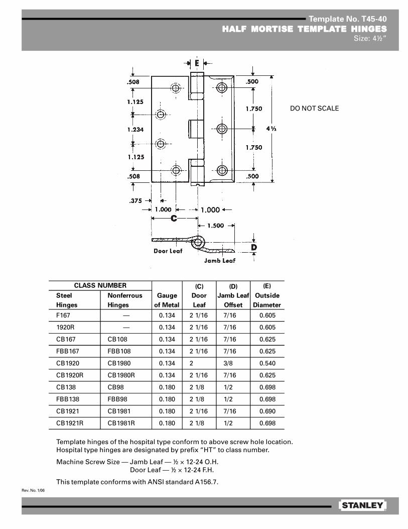
®
Rev. No. 1/06
Template No. T45-40
HALF MORHALF MORHALF MORHALF MORHALF MORTISE TISE TISE TISE TISE TEMPLATEMPLATEMPLATEMPLATEMPLATE HINGESTE HINGESTE HINGESTE HINGESTE HINGESSize: 4½”
Template hinges of the hospital type conform to above screw hole location.Hospital type hinges are designated by prefix “HT” to class number.
Machine Screw Size — Jamb Leaf — ½ × 12-24 O.H. Door Leaf — ½ × 12-24 F.H.
This template conforms with ANSI standard A156.7.
(C) (D) (E)
Steel Nonferrous Gauge Door Jamb Leaf Outside
Hinges Hinges of Metal Leaf Offset Diameter
F167 — 0.134 2 1/16 7/16 0.605
1920R — 0.134 2 1/16 7/16 0.605
CB167 CB108 0.134 2 1/16 7/16 0.625
FBB167 FBB108 0.134 2 1/16 7/16 0.625
CB1920 CB1980 0.134 2 3/8 0.540
CB1920R CB1980R 0.134 2 1/16 7/16 0.625
CB138 CB98 0.180 2 1/8 1/2 0.698
FBB138 FBB98 0.180 2 1/8 1/2 0.698
CB1921 CB1981 0.180 2 1/16 7/16 0.690
CB1921R CB1981R 0.180 2 1/8 1/2 0.698
CLASS NUMBER
DO NOT SCALE

®
Rev. No. 1/06
Template No. T50-80
HALF SURFHALF SURFHALF SURFHALF SURFHALF SURFAAAAACE CE CE CE CE TEMPLATEMPLATEMPLATEMPLATEMPLATE HINGESTE HINGESTE HINGESTE HINGESTE HINGESSize: 5”
Template hinges of the hospital type conform to above screw hole location.Hospital type hinges are designated by prefix “HT” to class number.
Machine Screw Size — Jamb Leaf — ½ × 12-24 F.H. Door Leaf — 2 × ¼-20 O.H.M.S. with grommet nut
This template conforms with ANSI standard A156.7.
(A) (C) (E)
Steel Nonferrous Gauge Jamb Jamb Leaf Outside
Hinges Hinges of Metal Leaf Offset Diameter
CB173 CB112 0.146 2 1/16 9/16 0.669
FBB173 FBB112 0.146 2 1/16 9/16 0.669
CB1910 CB1970 0.146 2 1/32 17/32 0.580
CB1910R CB1970R 0.146 2 1/16 9/16 0.669
CB163 CB113 0.190 2 1/8 5/8 0.748
FBB163 FBB113 0.190 2 1/8 5/8 0.748
CB1911 CB1971 0.190 2 3/32 19/32 0.715
CB1911R CB1971R 0.190 2 1/8 5/8 0.748
CLASS NUMBER

®
Rev. No. 1/06
Template No. T45-40
HALF MORHALF MORHALF MORHALF MORHALF MORTISE TISE TISE TISE TISE TEMPLATEMPLATEMPLATEMPLATEMPLATE HINGESTE HINGESTE HINGESTE HINGESTE HINGESSize: 4½”
Template hinges of the hospital type conform to above screw hole location.Hospital type hinges are designated by prefix “HT” to class number.
Machine Screw Size — Jamb Leaf — ½ × 12-24 O.H. Door Leaf — ½ × 12-24 F.H.
This template conforms with ANSI standard A156.7.
(C) (D) (E)
Steel Nonferrous Gauge Door Jamb Leaf Outside
Hinges Hinges of Metal Leaf Offset Diameter
F167 — 0.134 2 1/16 7/16 0.605
1920R — 0.134 2 1/16 7/16 0.605
CB167 CB108 0.134 2 1/16 7/16 0.625
FBB167 FBB108 0.134 2 1/16 7/16 0.625
CB1920 CB1980 0.134 2 3/8 0.540
CB1920R CB1980R 0.134 2 1/16 7/16 0.625
CB138 CB98 0.180 2 1/8 1/2 0.698
FBB138 FBB98 0.180 2 1/8 1/2 0.698
CB1921 CB1981 0.180 2 1/16 7/16 0.690
CB1921R CB1981R 0.180 2 1/8 1/2 0.698
CLASS NUMBER
DO NOT SCALE

®
Rev. No. 1/06
Template No. T60-40
HALF MORHALF MORHALF MORHALF MORHALF MORTISE TISE TISE TISE TISE TEMPLATEMPLATEMPLATEMPLATEMPLATE HINGESTE HINGESTE HINGESTE HINGESTE HINGESSize: 6”
Template hinges of the hospital type conform to above screw hole location.Hospital type hinges are designated by prefix “HT” to class number.
Machine Screw Size — Jamb Leaf — ½ × ¼-20 O.H. Door Leaf — ½ × ¼-20 F.H.
This template conforms with ANSI standard A156.7.
(E)
Steel Nonferrous Gauge Outside
Hinges Hinges of Metal Diameter
CB138 CB98 0.203 0.847
FBB138 FBB98 0.203 0.847
CB1921 CB1981 0.203 0.735
CB1921R CB1981R 0.203 0.847
CLASS NUMBER

®
Rev. No. 1/06
Template No. T40-80
HALF SURFHALF SURFHALF SURFHALF SURFHALF SURFAAAAACE CE CE CE CE TEMPLATEMPLATEMPLATEMPLATEMPLATE BTE BTE BTE BTE BUTT HINGESUTT HINGESUTT HINGESUTT HINGESUTT HINGESSize: 4”
Template hinges of the hospital type conform to above screw hole location.Hospital type hinges are designated by prefix “HT” to class number.
Machine Screw Size — Jamb Leaf — ½ × 12-24 F.H. Door Leaf — 2 × ¼-20 O.H.M.S. with grommet nut
This template conforms with ANSI standard A156.7.
(E)
Steel Nonferrous Gauge Outside
Hinges Hinges of Metal Diameter
CB173 CB112 0.130 0.590
FBB173 FBB112 0.130 0.590
CB1910R CB1970R 0.130 0.590
CLASS NUMBER

®
Rev. No. 1/06
Template No. T45-80
HALF SURFHALF SURFHALF SURFHALF SURFHALF SURFAAAAACE CE CE CE CE TEMPLATEMPLATEMPLATEMPLATEMPLATE HINGESTE HINGESTE HINGESTE HINGESTE HINGESSize: 4½”
Machine Screw Size — Jamb Leaf — ½ × 12-24 F.H. Door Leaf — 2 × ¼-20 O.H.M.S. with grommet nut
(A) (C) (E)
Steel Nonferrous Gauge Jamb Door Leaf Outside
Hinges Hinges of Metal Leaf Offset Diameter
F173 — 0.134 2 1/16 9/16 0.605
1910 — 0.134 2 1/16 9/16 0.540
1910R — 0.134 2 1/16 9/16 0.605
CB173 CB112 0.134 2 1/16 9/16 0.625
FBB173 FBB112 0.134 2 1/16 9/16 0.625
CB1910 CB1970 0.134 2 1/16 9/16 0.540
CB1910R CB1970R 0.134 2 1/16 9/16 0.625
CB163 CB113 0.180 2 1/8 5/8 0.698
FBB163 FBB113 0.180 2 1/8 5/8 0.698
CB1911 CB1971 0.180 2 1/8 5/8 0.690
CB1911R CB1971R 0.180 2 1/8 5/8 0.698
CLASS NUMBER
Template hinges of the hospitaltype conform to above screwhole location.
Hospital type hinges are desig-nated by prefix “HT” to classnumber.
This template conforms withANSI standard A156.7.

®
Rev. No. 2/06
Template No. T45-83
HALF SURFHALF SURFHALF SURFHALF SURFHALF SURFAAAAACE CE CE CE CE TEMPLATEMPLATEMPLATEMPLATEMPLATE HINGES TE HINGES TE HINGES TE HINGES TE HINGES WITH CONCEALED SWITWITH CONCEALED SWITWITH CONCEALED SWITWITH CONCEALED SWITWITH CONCEALED SWITCHCHCHCHCHSize: 4½”
Threaded tip permits reversing hinge to suit application.Machine Screw Size — Jamb Leaf — 12-24 × ½ F.H.
Door Leaf — ¼-20 × 2 O.H.M.S. with grommet nutDoor Plate Assembly — No. 10 × 1 FL. HD. WD. SCRS.
This template conforms with ANSI standard A156.7.
(A) (C) (E)
Class Gauge Jamb Door Leaf Outside (F)
Number Material of Metal Leaf Offset Diameter Dimension
CSCB173 Steel 0.134 2 1/16 9/16 0.625 1.234
CSFBB173 Steel 0.134 2 1/16 9/16 0.625 1.234
CSCB163 Steel 0.180 2 1/8 5/8 0.698 1.187
CSFBB163 Steel 0.180 2 1/8 5/8 0.698 1.187
CSCB1910 Steel 0.134 2 1/2 0.540 1.234
CSCB1911 Steel 0.180 2 1/16 9/16 0.690 1.187
Contractor should be cautioned to prevent mortarfrom interfering with wiring.
NOTES:1 Switch mounts in jamb leaf. Arrangement
for R.H. door shown. Specify hand whenordering.
2 0.750 diameter is the recommended holesize for switch housing clearance.
3 It is suggested that the hinge be mountedin the center or lower position on the door,rather than the top.
4 Use JB-2R Junction Box. See TemplateT90-38R.

®
Rev. No. 1/06
Template No. T50-80
HALF SURFHALF SURFHALF SURFHALF SURFHALF SURFAAAAACE CE CE CE CE TEMPLATEMPLATEMPLATEMPLATEMPLATE HINGESTE HINGESTE HINGESTE HINGESTE HINGESSize: 5”
Template hinges of the hospital type conform to above screw hole location.Hospital type hinges are designated by prefix “HT” to class number.
Machine Screw Size — Jamb Leaf — ½ × 12-24 F.H. Door Leaf — 2 × ¼-20 O.H.M.S. with grommet nut
This template conforms with ANSI standard A156.7.
(A) (C) (E)
Steel Nonferrous Gauge Jamb Jamb Leaf Outside
Hinges Hinges of Metal Leaf Offset Diameter
CB173 CB112 0.146 2 1/16 9/16 0.669
FBB173 FBB112 0.146 2 1/16 9/16 0.669
CB1910 CB1970 0.146 2 1/32 17/32 0.580
CB1910R CB1970R 0.146 2 1/16 9/16 0.669
CB163 CB113 0.190 2 1/8 5/8 0.748
FBB163 FBB113 0.190 2 1/8 5/8 0.748
CB1911 CB1971 0.190 2 3/32 19/32 0.715
CB1911R CB1971R 0.190 2 1/8 5/8 0.748
CLASS NUMBER

®
Rev. No. 2/06
Template No. T50-83
HALF SURFHALF SURFHALF SURFHALF SURFHALF SURFAAAAACE CE CE CE CE TEMPLATEMPLATEMPLATEMPLATEMPLATE HINGES TE HINGES TE HINGES TE HINGES TE HINGES WITH CONCEALED SWITWITH CONCEALED SWITWITH CONCEALED SWITWITH CONCEALED SWITWITH CONCEALED SWITCHCHCHCHCHSize: 5”
Machine Screw Size — Jamb Leaf — 12-24 × ½ F.H. Door Leaf — ¼-20 × 2 O.H.M.S. with grommet nut
Door Plate Assembly — No. 10 × 1 FL. HD. WD. SCRS.
This template conforms with ANSI standard A156.7.
Contractor should be cautioned to prevent mortarfrom interfering with wiring.
NOTES:1 0.750 diameter is the recommended hole
size for switch housing clearance.2 It is suggested that the hinge be mounted
in the center or lower position on thedoor, rather than the top.
3 Switch mounts in jamb leaf. Arrangementfor R.H. door shown. Specify hand whenordering.
4 Use JB-2R Junction Box. See TemplateT90-38.
DO NOT SCALE
CLASS NO. (A) (C) (E) (F)
Steel Gauge Jamb Door Leaf Outside
Hinges of Metal Leaf Offset Diameter
CSCB173 0.146 2 1/16 9/16 0.669 1.218
CSFBB173 0.146 2 1/16 9/16 0.669 1.218
CSCB1910 0.146 2 1/32 17/32 0.580 1.218
CSCB1910R 0.146 2 1/16 9/16 0.669 1.218
CSCB163 0.190 2 1/8 5/8 0.748 1.172
CSFBB163 0.190 2 1/8 5/8 0.748 1.172
CSCB1911 0.190 2 3/32 19/32 0.715 1.172
CSCB1911R 0.190 2 1/8 5/8 0.748 1.172

®
Rev. No. 2/06
Template No. T45-83
HALF SURFHALF SURFHALF SURFHALF SURFHALF SURFAAAAACE CE CE CE CE TEMPLATEMPLATEMPLATEMPLATEMPLATE HINGES TE HINGES TE HINGES TE HINGES TE HINGES WITH CONCEALED SWITWITH CONCEALED SWITWITH CONCEALED SWITWITH CONCEALED SWITWITH CONCEALED SWITCHCHCHCHCHSize: 4½”
Threaded tip permits reversing hinge to suit application.Machine Screw Size — Jamb Leaf — 12-24 × ½ F.H.
Door Leaf — ¼-20 × 2 O.H.M.S. with grommet nutDoor Plate Assembly — No. 10 × 1 FL. HD. WD. SCRS.
This template conforms with ANSI standard A156.7.
(A) (C) (E)
Class Gauge Jamb Door Leaf Outside (F)
Number Material of Metal Leaf Offset Diameter Dimension
CSCB173 Steel 0.134 2 1/16 9/16 0.625 1.234
CSFBB173 Steel 0.134 2 1/16 9/16 0.625 1.234
CSCB163 Steel 0.180 2 1/8 5/8 0.698 1.187
CSFBB163 Steel 0.180 2 1/8 5/8 0.698 1.187
CSCB1910 Steel 0.134 2 1/2 0.540 1.234
CSCB1911 Steel 0.180 2 1/16 9/16 0.690 1.187
Contractor should be cautioned to prevent mortarfrom interfering with wiring.
NOTES:1 Switch mounts in jamb leaf. Arrangement
for R.H. door shown. Specify hand whenordering.
2 0.750 diameter is the recommended holesize for switch housing clearance.
3 It is suggested that the hinge be mountedin the center or lower position on the door,rather than the top.
4 Use JB-2R Junction Box. See TemplateT90-38R.

®
Rev. No. 1/06
Template No. T50-80
HALF SURFHALF SURFHALF SURFHALF SURFHALF SURFAAAAACE CE CE CE CE TEMPLATEMPLATEMPLATEMPLATEMPLATE HINGESTE HINGESTE HINGESTE HINGESTE HINGESSize: 5”
Template hinges of the hospital type conform to above screw hole location.Hospital type hinges are designated by prefix “HT” to class number.
Machine Screw Size — Jamb Leaf — ½ × 12-24 F.H. Door Leaf — 2 × ¼-20 O.H.M.S. with grommet nut
This template conforms with ANSI standard A156.7.
(A) (C) (E)
Steel Nonferrous Gauge Jamb Jamb Leaf Outside
Hinges Hinges of Metal Leaf Offset Diameter
CB173 CB112 0.146 2 1/16 9/16 0.669
FBB173 FBB112 0.146 2 1/16 9/16 0.669
CB1910 CB1970 0.146 2 1/32 17/32 0.580
CB1910R CB1970R 0.146 2 1/16 9/16 0.669
CB163 CB113 0.190 2 1/8 5/8 0.748
FBB163 FBB113 0.190 2 1/8 5/8 0.748
CB1911 CB1971 0.190 2 3/32 19/32 0.715
CB1911R CB1971R 0.190 2 1/8 5/8 0.748
CLASS NUMBER

®
Rev. No. 2/06
Template No. T50-83
HALF SURFHALF SURFHALF SURFHALF SURFHALF SURFAAAAACE CE CE CE CE TEMPLATEMPLATEMPLATEMPLATEMPLATE HINGES TE HINGES TE HINGES TE HINGES TE HINGES WITH CONCEALED SWITWITH CONCEALED SWITWITH CONCEALED SWITWITH CONCEALED SWITWITH CONCEALED SWITCHCHCHCHCHSize: 5”
Machine Screw Size — Jamb Leaf — 12-24 × ½ F.H. Door Leaf — ¼-20 × 2 O.H.M.S. with grommet nut
Door Plate Assembly — No. 10 × 1 FL. HD. WD. SCRS.
This template conforms with ANSI standard A156.7.
Contractor should be cautioned to prevent mortarfrom interfering with wiring.
NOTES:1 0.750 diameter is the recommended hole
size for switch housing clearance.2 It is suggested that the hinge be mounted
in the center or lower position on thedoor, rather than the top.
3 Switch mounts in jamb leaf. Arrangementfor R.H. door shown. Specify hand whenordering.
4 Use JB-2R Junction Box. See TemplateT90-38.
DO NOT SCALE
CLASS NO. (A) (C) (E) (F)
Steel Gauge Jamb Door Leaf Outside
Hinges of Metal Leaf Offset Diameter
CSCB173 0.146 2 1/16 9/16 0.669 1.218
CSFBB173 0.146 2 1/16 9/16 0.669 1.218
CSCB1910 0.146 2 1/32 17/32 0.580 1.218
CSCB1910R 0.146 2 1/16 9/16 0.669 1.218
CSCB163 0.190 2 1/8 5/8 0.748 1.172
CSFBB163 0.190 2 1/8 5/8 0.748 1.172
CSCB1911 0.190 2 3/32 19/32 0.715 1.172
CSCB1911R 0.190 2 1/8 5/8 0.748 1.172

®
Rev. No. 1/06
Template No. T60-80
HALF SURFHALF SURFHALF SURFHALF SURFHALF SURFAAAAACE CE CE CE CE TEMPLATEMPLATEMPLATEMPLATEMPLATE HINGE FOR DOORS 1¾TE HINGE FOR DOORS 1¾TE HINGE FOR DOORS 1¾TE HINGE FOR DOORS 1¾TE HINGE FOR DOORS 1¾” THICK THICK THICK THICK THICK AND OAND OAND OAND OAND OVERVERVERVERVERSize: 6”
Template hinges of the hospital type conform to above screw hole location.Hospital type hinges are designated by prefix “HT” to class number.
Machine Screw Size — Jamb Leaf — ½ × ¼-20 F.H. Door Leaf — 2 × ¼-20 O.H.M.S. with grommet nut
This template conforms with ANSI standard A156.7.
(E)
Steel Nonferrous Gauge Outside
Hinges Hinges of Metal Diameter
CB163 CB113 0.203 0.847
FBB163 FBB113 0.203 0.847
CB1911 CB1971 0.203 0.735
CB1911R CB1971R 0.203 0.847
CLASS NUMBER
E
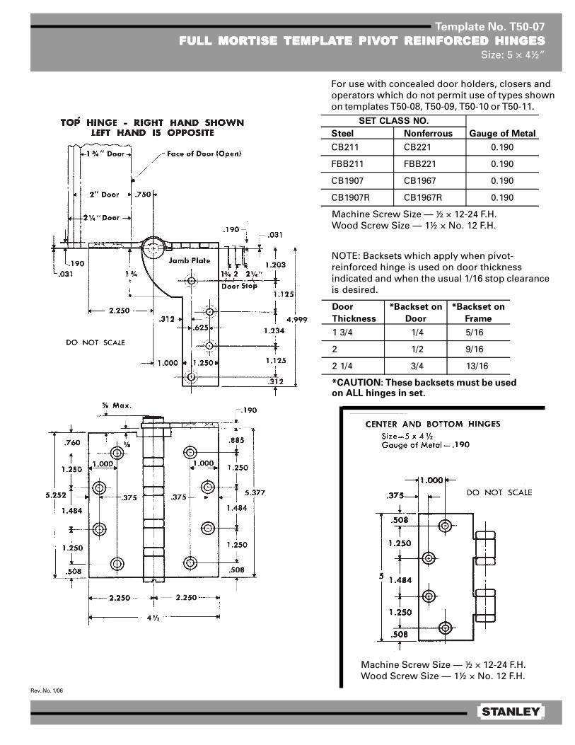
®
Rev. No. 1/06
Template No. T50-07
FULL MORFULL MORFULL MORFULL MORFULL MORTISE TISE TISE TISE TISE TEMPLATEMPLATEMPLATEMPLATEMPLATE PIVTE PIVTE PIVTE PIVTE PIVOOOOOT REINFORT REINFORT REINFORT REINFORT REINFORCED HINGESCED HINGESCED HINGESCED HINGESCED HINGESSize: 5 × 4½”
Machine Screw Size — ½ × 12-24 F.H.Wood Screw Size — 1½ × No. 12 F.H.
Steel Nonferrous Gauge of Metal
CB211 CB221 0.190
FBB211 FBB221 0.190
CB1907 CB1967 0.190
CB1907R CB1967R 0.190
SET CLASS NO.
Door
Thickness
*Backset on
Door
*Backset on
Frame
1 3/4 1/4 5/16
2 1/2 9/16
2 1/4 3/4 13/16
For use with concealed door holders, closers andoperators which do not permit use of types shownon templates T50-08, T50-09, T50-10 or T50-11.
Machine Screw Size — ½ × 12-24 F.H.Wood Screw Size — 1½ × No. 12 F.H.
*CAUTION: These backsets must be usedon ALL hinges in set.
NOTE: Backsets which apply when pivot-reinforced hinge is used on door thicknessindicated and when the usual 1/16 stop clearanceis desired.
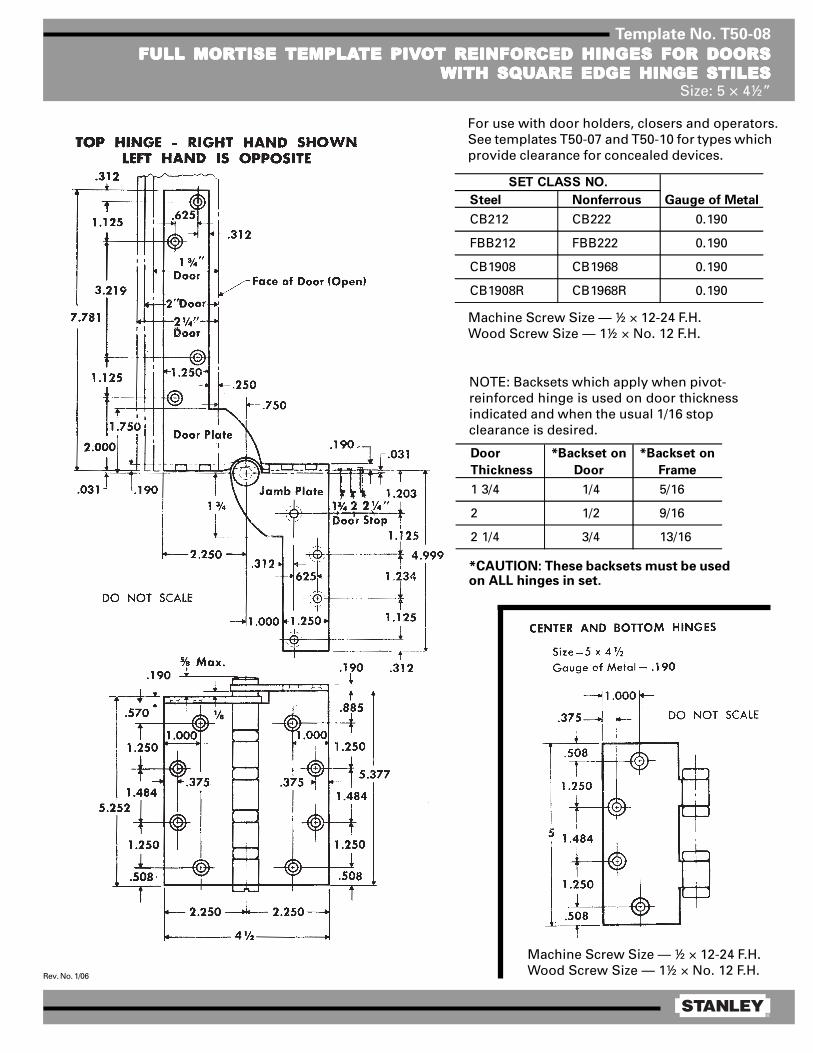
®
Rev. No. 1/06
Template No. T50-08
FULL MORFULL MORFULL MORFULL MORFULL MORTISE TISE TISE TISE TISE TEMPLATEMPLATEMPLATEMPLATEMPLATE PIVTE PIVTE PIVTE PIVTE PIVOOOOOT REINFORT REINFORT REINFORT REINFORT REINFORCED HINGES FOR DOORSCED HINGES FOR DOORSCED HINGES FOR DOORSCED HINGES FOR DOORSCED HINGES FOR DOORSWITH SQWITH SQWITH SQWITH SQWITH SQUUUUUARE EDGE HINGE STILESARE EDGE HINGE STILESARE EDGE HINGE STILESARE EDGE HINGE STILESARE EDGE HINGE STILES
Size: 5 × 4½”
Machine Screw Size — ½ × 12-24 F.H.Wood Screw Size — 1½ × No. 12 F.H.
Steel Nonferrous Gauge of Metal
CB212 CB222 0.190
FBB212 FBB222 0.190
CB1908 CB1968 0.190
CB1908R CB1968R 0.190
SET CLASS NO.
Door
Thickness
*Backset on
Door
*Backset on
Frame
1 3/4 1/4 5/16
2 1/2 9/16
2 1/4 3/4 13/16
*CAUTION: These backsets must be usedon ALL hinges in set.
NOTE: Backsets which apply when pivot-reinforced hinge is used on door thicknessindicated and when the usual 1/16 stopclearance is desired.
For use with door holders, closers and operators.See templates T50-07 and T50-10 for types whichprovide clearance for concealed devices.
Machine Screw Size — ½ × 12-24 F.H.Wood Screw Size — 1½ × No. 12 F.H.

®
Rev. No. 1/06
Template No. T50-10
FULL MORFULL MORFULL MORFULL MORFULL MORTISE TISE TISE TISE TISE TEMPLATEMPLATEMPLATEMPLATEMPLATE PIVTE PIVTE PIVTE PIVTE PIVOOOOOT REINFORT REINFORT REINFORT REINFORT REINFORCED HINGES CED HINGES CED HINGES CED HINGES CED HINGES WITH 4 1/8WITH 4 1/8WITH 4 1/8WITH 4 1/8WITH 4 1/8” DOORDOORDOORDOORDOORPLAPLAPLAPLAPLATE FOR DOORS TE FOR DOORS TE FOR DOORS TE FOR DOORS TE FOR DOORS WITH SQWITH SQWITH SQWITH SQWITH SQUUUUUARE EDGE HINGE STILESARE EDGE HINGE STILESARE EDGE HINGE STILESARE EDGE HINGE STILESARE EDGE HINGE STILES
Size: 5 × 4½”
Machine Screw Size — ½ × 12-24 F.H.Wood Screw Size — 1½ × No. 12 F.H.
Steel Nonferrous Gauge of Metal
CB212 CB222with 4 1 /8 door plate with 4 1 /8 door plate
FBB212 FBB222with 4 1 /8 door plate with 4 1 /8 door plate
CB1908 CB1968with 4 1 /8 door plate with 4 1 /8 door plate
CB1908R CB1968Rwith 4 1 /8 door plate with 4 1 /8 door plate
0.190
SET CLASS NO.
0.190
0.190
0.190
Door
Thickness
*Backset on
Door
*Backset on
Frame
1 3/4 1/4 5/16
2 1/2 9/16
2 1/4 3/4 13/16
Machine Screw Size — ½ × 12-24 F.H.Wood Screw Size — 1½ × No. 12 F.H.
*CAUTION: These backsets must be usedon ALL hinges in set.
NOTE: Backsets which apply when pivot-reinforced hinge is used on door thicknessindicated and when the usual 1/16 stopclearance is desired.
For use with door holders, closers and operatorswhich interfere with standard door plates shownon template T50-08.

®
Rev. No. 1/06
Template No. T50-09
FULL MORFULL MORFULL MORFULL MORFULL MORTISE TISE TISE TISE TISE TEMPLATEMPLATEMPLATEMPLATEMPLATE PIVTE PIVTE PIVTE PIVTE PIVOOOOOT REINFORT REINFORT REINFORT REINFORT REINFORCED HINGES FOR DOORSCED HINGES FOR DOORSCED HINGES FOR DOORSCED HINGES FOR DOORSCED HINGES FOR DOORSWITH BEVELED EDGE HINGE STILESWITH BEVELED EDGE HINGE STILESWITH BEVELED EDGE HINGE STILESWITH BEVELED EDGE HINGE STILESWITH BEVELED EDGE HINGE STILES
Size: 5 × 4½”
Machine Screw Size — ½ × 12-24 F.H.Wood Screw Size — 1½ × No. 12 F.H.
Machine Screw Size — ½ × 12-24 F.H.Wood Screw Size — 1½ × No. 12 F.H.
Steel Nonferrous Gauge of Metal
CB213 CB223 0.190
FBB213 FBB223 0.190
CB1909 CB1969 0.190
CB1909R CB1969R 0.190
SET CLASS NO.
Door
Thickness
*Backset on
Door
*Backset on
Frame
1 3/4 1/4 5/16
2 1/2 9/16
2 1/4 3/4 13/16
*CAUTION: These backsets must be used onALL hinges in set.
NOTE: Backsets which apply when pivot-reinforced hinge is used on door thicknessindicated and when the usual 1/16 stopclearance is desired.
For use with door holders, closers and operators.See templates T50-07 and T50-11 for types whichprovide clearance for concealed devices.

®
Rev. No. 1/06
Template No. T50-11
FULL MORFULL MORFULL MORFULL MORFULL MORTISE TISE TISE TISE TISE TEMPLATEMPLATEMPLATEMPLATEMPLATE PIVTE PIVTE PIVTE PIVTE PIVOOOOOT REINFORT REINFORT REINFORT REINFORT REINFORCED HINGES CED HINGES CED HINGES CED HINGES CED HINGES WITH 4WITH 4WITH 4WITH 4WITH 4” DOORDOORDOORDOORDOORPLAPLAPLAPLAPLATE FOR DOORS TE FOR DOORS TE FOR DOORS TE FOR DOORS TE FOR DOORS WITH BEVELED EDGE HINGE STILESWITH BEVELED EDGE HINGE STILESWITH BEVELED EDGE HINGE STILESWITH BEVELED EDGE HINGE STILESWITH BEVELED EDGE HINGE STILES
Size: 5 × 4½”
Machine Screw Size — ½ × 12-24 F.H.Wood Screw Size — 1½ × No. 12 F.H.
Machine Screw Size — ½ × 12-24 F.H.Wood Screw Size — 1½ × No. 12 F.H.
*CAUTION: These backsets must be usedon ALL hinges in set.
NOTE: Backsets which apply when pivot-reinforced hinge is used on door thicknessindicated and when the usual 1/16 stopclearance is desired.
For use with door holders, closers and operatorswhich interfere with standard door plates shownon template T50-09.
DO NOT SCALE
Steel Nonferrous Gauge of Metal
CB213 CB223with 4 door plate with 4 door plate
FBB213 FBB223with 4 door plate with 4 door plate
CB1909 CB1969with 4 door plate with 4 door plate
CB1909R CB1969Rwith 4 door plate with 4 door plate
0.190
SET CLASS NO.
0.190
0.190
0.190
Door
Thickness
*Backset on
Door
*Backset on
Frame
1 3/4 1/4 5/16
2 1/2 9/16
2 1/4 3/4 13/16

®
Rev. No. 1/06
Template No. T35-05
FULL MORFULL MORFULL MORFULL MORFULL MORTISE “SWING-CLEAR”TISE “SWING-CLEAR”TISE “SWING-CLEAR”TISE “SWING-CLEAR”TISE “SWING-CLEAR” TEMPLATEMPLATEMPLATEMPLATEMPLATE BTE BTE BTE BTE BUTT HINGESUTT HINGESUTT HINGESUTT HINGESUTT HINGESSize: 3½”
NOTES:1 For doors thicker than 1 3/8, backsets on doors
and frames should be increased by the amountof the additional door thickness.
2 1 3/8 doors will clear opening at 95°.
Template hinges of the hospital type conform to above screw hole location.Hospital type hinges are designated by prefix “H” to class number.
Wood Screw Size — 1 × #10 FL. HD. REC.
Class No. Material Gauge of Metal
F248 Steel 0.123
1947R Steel 0.123

®
Rev. No. 1/06
Template No. T40-05
FULL MORFULL MORFULL MORFULL MORFULL MORTISE “SWING-CLEAR”TISE “SWING-CLEAR”TISE “SWING-CLEAR”TISE “SWING-CLEAR”TISE “SWING-CLEAR” TEMPLATEMPLATEMPLATEMPLATEMPLATE BTE BTE BTE BTE BUTT HINGESUTT HINGESUTT HINGESUTT HINGESUTT HINGESSize: 4”
NOTES:1 For doors thicker than 1¾, backsets on doors
and frames should be increased by the amountof the additional door thickness.
2 1¾ doors will clear opening at 95°.
Template hinges of the hospital type conform to above screw hole location.Hospital type hinges are designated by prefix “HT” to class number.
Wood Screw Size — 1¼ × No. 12 F.H.
Class No. Material Gauge of Metal
F248 Steel 0.127
1947R Steel 0.127

®
Rev. No. 1/06
Template No. T45-30
FULL MORFULL MORFULL MORFULL MORFULL MORTISE “SWING-CLEAR”TISE “SWING-CLEAR”TISE “SWING-CLEAR”TISE “SWING-CLEAR”TISE “SWING-CLEAR” TEMPLATEMPLATEMPLATEMPLATEMPLATE BTE BTE BTE BTE BUTT HINGESUTT HINGESUTT HINGESUTT HINGESUTT HINGESSize: 4½”
Template hinges of the hospital type conform to above screw hole location.Hospital type hinges are designated by prefix “HT” to class number.
Machine Screw Size — ½ × 12-24 F.H.Wood Screw Size — 1¼ × No. 12 F.H.
Class No. Material Gauge of Metal (E) Outside Diameter
CB248 Steel 0.134 0.625
FBB248 Steel 0.134 0.625
CB1947 Steel 0.134 0.531
CB1947R Steel 0.134 0.625
NOTES:1 1¾ doors will clear openings at 90°.2 This hinge alters the normal pivot point of door. For door closers,
friction or overhead door holders to be used in conjunction with thishinge, consult manufacturer of the device to be used for applicationdetails.
3 For doors thicker than 1¾, backsets on doors and frames should beincreased by the amount of the additional door thickness.
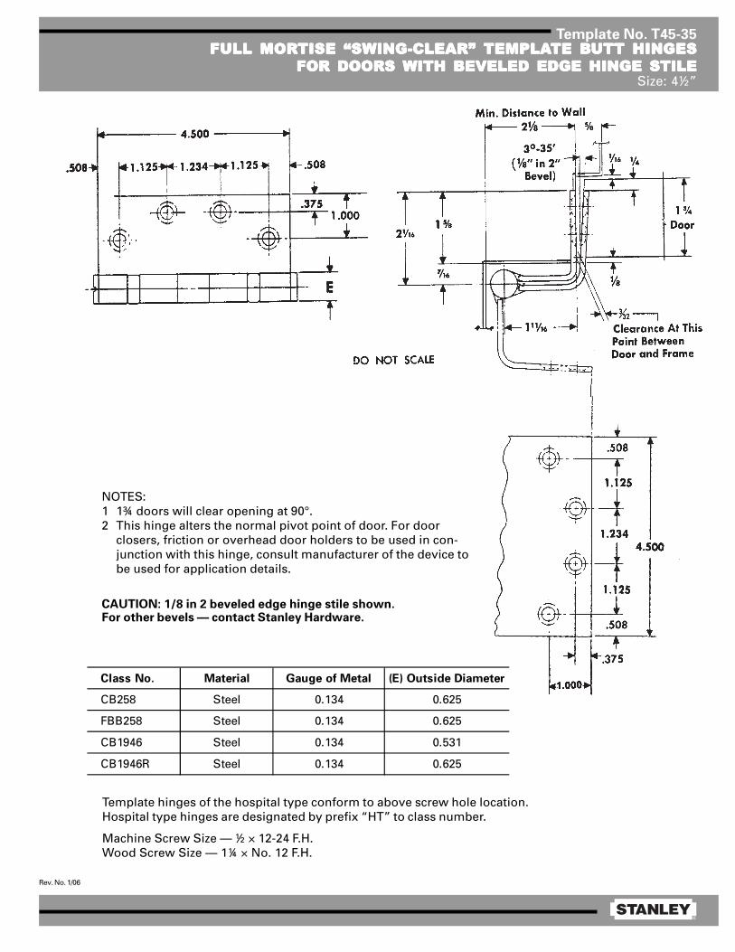
®
Rev. No. 1/06
Template No. T45-35FULL MORFULL MORFULL MORFULL MORFULL MORTISE “SWING-CLEAR”TISE “SWING-CLEAR”TISE “SWING-CLEAR”TISE “SWING-CLEAR”TISE “SWING-CLEAR” TEMPLATEMPLATEMPLATEMPLATEMPLATE BTE BTE BTE BTE BUTT HINGESUTT HINGESUTT HINGESUTT HINGESUTT HINGES
FOR DOORS WITH BEVELED EDGE HINGE STILEFOR DOORS WITH BEVELED EDGE HINGE STILEFOR DOORS WITH BEVELED EDGE HINGE STILEFOR DOORS WITH BEVELED EDGE HINGE STILEFOR DOORS WITH BEVELED EDGE HINGE STILESize: 4½”
Template hinges of the hospital type conform to above screw hole location.Hospital type hinges are designated by prefix “HT” to class number.
Machine Screw Size — ½ × 12-24 F.H.Wood Screw Size — 1¼ × No. 12 F.H.
Class No. Material Gauge of Metal (E) Outside Diameter
CB258 Steel 0.134 0.625
FBB258 Steel 0.134 0.625
CB1946 Steel 0.134 0.531
CB1946R Steel 0.134 0.625
NOTES:1 1¾ doors will clear opening at 90°.2 This hinge alters the normal pivot point of door. For door
closers, friction or overhead door holders to be used in con-junction with this hinge, consult manufacturer of the device tobe used for application details.
CAUTION: 1/8 in 2 beveled edge hinge stile shown.For other bevels — contact Stanley Hardware.

®
Rev. No. 1/06
Template No. T45-31
FULL MORFULL MORFULL MORFULL MORFULL MORTISE “SWING-CLEAR”TISE “SWING-CLEAR”TISE “SWING-CLEAR”TISE “SWING-CLEAR”TISE “SWING-CLEAR” TEMPLATEMPLATEMPLATEMPLATEMPLATE BTE BTE BTE BTE BUTT HINGESUTT HINGESUTT HINGESUTT HINGESUTT HINGESSize: 4½”
Template hinges of the hospital type conform to above screw hole location.Hospital type hinges are designated by prefix “HT” to class number.
Machine Screw Size — ½ × 12-24 F.H.Wood Screw Size — 1¼ × No. 12 F.H.
Class No. Material Gauge of Metal (E) Outside Diameter
CB268 Steel 0.180 0.698
FBB268 Steel 0.180 0.698
CB1948 Steel 0.180 0.690
CB1948R Steel 0.180 0.698
NOTES:1 1¾ doors will clear opening at 90°.2 This hinge alters the normal pivot point of door. For door closers, friction
or overhead door holders to be used in conjunction with this hinge,consult manufacturer of the device to be used for application details.
3 For doors thicker than 1¾, backsets on doors and frames should beincreased by the amount of the additional door thickness.

®
Rev. No. 1/06
Template No. T50-05
FULL MORFULL MORFULL MORFULL MORFULL MORTISE “SWING-CLEAR”TISE “SWING-CLEAR”TISE “SWING-CLEAR”TISE “SWING-CLEAR”TISE “SWING-CLEAR” TEMPLATEMPLATEMPLATEMPLATEMPLATE BTE BTE BTE BTE BUTT HINGESUTT HINGESUTT HINGESUTT HINGESUTT HINGESSize: 5”
Class No. Material Gauge of Metal
(E) Outside
Diameter F G
CB268 Steel 0.190 0.748 2 1/8 1/2
FBB268 Steel 0.190 0.748 2 1/8 1/2
CB1948 Steel 0.190 0.715 2 3/32 15/32
CB1948R Steel 0.190 0.748 2 1/8 1/2
Template hinges of the hospital type conform to above screw hole location.Hospital type hinges are designated by prefix “HT” to class number.
Machine Screw Size — ½ × 12-24 F.H.Wood Screw Size — 1½ × No. 12 F.H.
NOTES:1 For doors thicker than 1¾, backsets on doors and frames should be increased by the
amount of the additional door thickness.2 1¾ doors will clear opening at 95°.3 This hinge alters the normal pivot point of door. For door closers, friction or overhead
door holders to be used in conjunction with this hinge, consult manufacturer of thedevice to be used for application details.
Door
Thickness
Backset on
Door
Backset on
Frame
1 3/4 1/4 5/16
2 1/2 9/16
2 1/4 3/4 13/16

®
Rev. No. 1/06
Template No. T45-36
FULL MORFULL MORFULL MORFULL MORFULL MORTISE “SWING-CLEAR”TISE “SWING-CLEAR”TISE “SWING-CLEAR”TISE “SWING-CLEAR”TISE “SWING-CLEAR” TEMPLATEMPLATEMPLATEMPLATEMPLATE BTE BTE BTE BTE BUTT HINGESUTT HINGESUTT HINGESUTT HINGESUTT HINGESFOR DOORS WITH BEVELED EDGE HINGE STILEFOR DOORS WITH BEVELED EDGE HINGE STILEFOR DOORS WITH BEVELED EDGE HINGE STILEFOR DOORS WITH BEVELED EDGE HINGE STILEFOR DOORS WITH BEVELED EDGE HINGE STILE
Size: 4½”
Template hinges of the hospital type conform to above screw hole location.Hospital type hinges are designated by prefix “HT” to class number.
Machine Screw Size — ½ × 12-24 F.H.Wood Screw Size — 1¼ × No. 12 F.H.
Class No. Material Gauge of Metal (E) Outside Diameter
CB278 Steel 0.180 0.698
FBB278 Steel 0.180 0.698
CB1949 Steel 0.180 0.690
CB1949R Steel 0.180 0.698
NOTES:1 1¾ doors will clear opening at 90°.2 This hinge alters the normal pivot point of door. For
door closers, friction or overhead door hold-ers tobe used in conjunction with this hinge, consultmanufacturer of the device to be used for applicationdetails.
CAUTION: 1/8 and 2 beveled edge hinge stile shown.For other bevels — contact Stanley Hardware.

®
Rev. No. 1/06
Template No. T50-12
FULL MORFULL MORFULL MORFULL MORFULL MORTISE “SWING-CLEAR”TISE “SWING-CLEAR”TISE “SWING-CLEAR”TISE “SWING-CLEAR”TISE “SWING-CLEAR” TEMPLATEMPLATEMPLATEMPLATEMPLATE BTE BTE BTE BTE BUTT HINGESUTT HINGESUTT HINGESUTT HINGESUTT HINGESFOR DOORS WITH BEVELED EDGE HINGE STILESFOR DOORS WITH BEVELED EDGE HINGE STILESFOR DOORS WITH BEVELED EDGE HINGE STILESFOR DOORS WITH BEVELED EDGE HINGE STILESFOR DOORS WITH BEVELED EDGE HINGE STILES
Size: 5”
Template hinges of the hospital type conform to above screw hole location.Hospital type hinges are designated by prefix “HT” to class number.
Machine Screw Size — ½ × 12-24 F.H.Wood Screw Size — 1½ × No. 12 F.H.
Door
Thickness
Backset on
Door
Backset on
Frame
1 3/4 1/4 5/16
2 1/2 9/16
2 1/4 3/4 13/16
NOTES:1 1¾ doors will clear opening at 95°.2 This hinge alters the normal pivot point of door. For door
closers, friction or overhead door holders to be used inconjunction with this hinge, consult manufacturer of thedevice to be used for application details.
3 Backsets which apply when swing-clear hinge for bevelededge hinge stile is used on door thickness indicated andwhen the usual 1/16 stop clearance is desired.
CAUTION: 1/8 in 2 beveled edge hinge stile shown.For other bevels — contact Stanley Hardware.
Min. Distance to Wall
Class No. Material Gauge of Metal
(E) Outside
Diameter F G
CB278With beveled door leaf
FBB278With beveled door leaf
CB1949With beveled door leaf
CB1949RWith beveled door leaf
1/2Steel 0.190 0.748 2 1/8
1/2
15/32
1/2
Steel
Steel
Steel
2 1/8
2 3/32
2 1/8
0.190
0.190
0.190
0.748
0.715
0.748
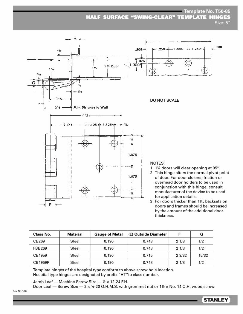
®
Rev. No. 1/06
Template No. T50-85
HALF SURFHALF SURFHALF SURFHALF SURFHALF SURFAAAAACE “SWING-CLEAR”CE “SWING-CLEAR”CE “SWING-CLEAR”CE “SWING-CLEAR”CE “SWING-CLEAR” TEMPLATEMPLATEMPLATEMPLATEMPLATE HINGESTE HINGESTE HINGESTE HINGESTE HINGESSize: 5”
NOTES:1 1¾ doors will clear opening at 95°.2 This hinge alters the normal pivot point
of door. For door closers, friction oroverhead door holders to be used inconjunction with this hinge, consultmanufacturer of the device to be usedfor application details.
3 For doors thicker than 1¾, backsets ondoors and frames should be increasedby the amount of the additional doorthickness.
Template hinges of the hospital type conform to above screw hole location.Hospital type hinges are designated by prefix “HT”to class number.
Jamb Leaf — Machine Screw Size — ½ × 12-24 F.H.Door Leaf — Screw Size — 2 × ¼-20 O.H.M.S. with grommet nut or 1½ × No. 14 O.H. wood screw.
Class No. Material Gauge of Metal (E) Outside Diameter F G
CB269 Steel 0.190 0.748 2 1/8 1/2
FBB269 Steel 0.190 0.748 2 1/8 1/2
CB1959 Steel 0.190 0.715 2 3/32 15/32
CB1959R Steel 0.190 0.748 2 1/8 1/2
DO NOT SCALE
.508
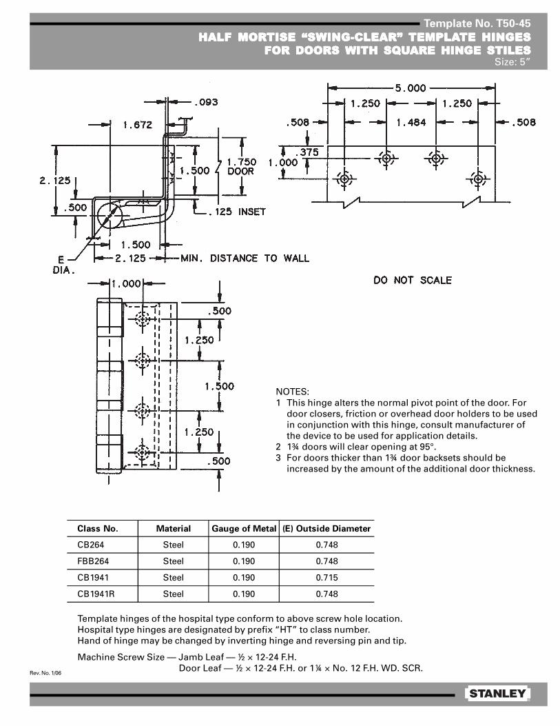
®
Rev. No. 1/06
Template No. T50-45
HALF MORHALF MORHALF MORHALF MORHALF MORTISE “SWING-CLEAR”TISE “SWING-CLEAR”TISE “SWING-CLEAR”TISE “SWING-CLEAR”TISE “SWING-CLEAR” TEMPLATEMPLATEMPLATEMPLATEMPLATE HINGESTE HINGESTE HINGESTE HINGESTE HINGESFOR DOORS FOR DOORS FOR DOORS FOR DOORS FOR DOORS WITH SQWITH SQWITH SQWITH SQWITH SQUUUUUARE HINGE STILESARE HINGE STILESARE HINGE STILESARE HINGE STILESARE HINGE STILES
Size: 5”
Template hinges of the hospital type conform to above screw hole location.Hospital type hinges are designated by prefix “HT” to class number.Hand of hinge may be changed by inverting hinge and reversing pin and tip.
Machine Screw Size — Jamb Leaf — ½ × 12-24 F.H. Door Leaf — ½ × 12-24 F.H. or 1¼ × No. 12 F.H. WD. SCR.
Class No. Material Gauge of Metal (E) Outside Diameter
CB264 Steel 0.190 0.748
FBB264 Steel 0.190 0.748
CB1941 Steel 0.190 0.715
CB1941R Steel 0.190 0.748
NOTES:1 This hinge alters the normal pivot point of the door. For
door closers, friction or overhead door holders to be usedin conjunction with this hinge, consult manufacturer ofthe device to be used for application details.
2 1¾ doors will clear opening at 95°.3 For doors thicker than 1¾ door backsets should be
increased by the amount of the additional door thickness.

®
Rev. No. 1/06
Template No. T50-12
FULL MORFULL MORFULL MORFULL MORFULL MORTISE “SWING-CLEAR”TISE “SWING-CLEAR”TISE “SWING-CLEAR”TISE “SWING-CLEAR”TISE “SWING-CLEAR” TEMPLATEMPLATEMPLATEMPLATEMPLATE BTE BTE BTE BTE BUTT HINGESUTT HINGESUTT HINGESUTT HINGESUTT HINGESFOR DOORS WITH BEVELED EDGE HINGE STILESFOR DOORS WITH BEVELED EDGE HINGE STILESFOR DOORS WITH BEVELED EDGE HINGE STILESFOR DOORS WITH BEVELED EDGE HINGE STILESFOR DOORS WITH BEVELED EDGE HINGE STILES
Size: 5”
Template hinges of the hospital type conform to above screw hole location.Hospital type hinges are designated by prefix “HT” to class number.
Machine Screw Size — ½ × 12-24 F.H.Wood Screw Size — 1½ × No. 12 F.H.
Door
Thickness
Backset on
Door
Backset on
Frame
1 3/4 1/4 5/16
2 1/2 9/16
2 1/4 3/4 13/16
NOTES:1 1¾ doors will clear opening at 95°.2 This hinge alters the normal pivot point of door. For door
closers, friction or overhead door holders to be used inconjunction with this hinge, consult manufacturer of thedevice to be used for application details.
3 Backsets which apply when swing-clear hinge for bevelededge hinge stile is used on door thickness indicated andwhen the usual 1/16 stop clearance is desired.
CAUTION: 1/8 in 2 beveled edge hinge stile shown.For other bevels — contact Stanley Hardware.
Min. Distance to Wall
Class No. Material Gauge of Metal
(E) Outside
Diameter F G
CB278With beveled door leaf
FBB278With beveled door leaf
CB1949With beveled door leaf
CB1949RWith beveled door leaf
1/2Steel 0.190 0.748 2 1/8
1/2
15/32
1/2
Steel
Steel
Steel
2 1/8
2 3/32
2 1/8
0.190
0.190
0.190
0.748
0.715
0.748

®
Rev. No. 1/06
Template No. T50-65
FULL SURFFULL SURFFULL SURFFULL SURFFULL SURFAAAAACE “SWING-CLEAR”CE “SWING-CLEAR”CE “SWING-CLEAR”CE “SWING-CLEAR”CE “SWING-CLEAR” TEMPLATEMPLATEMPLATEMPLATEMPLATE HINGETE HINGETE HINGETE HINGETE HINGESize: 5”
NOTES:1 This hinge alters the normal pivot point of door. For door closers, friction or overhead door holders to be
used in conjunction with this hinge, consult manufacturer of the device to be used for application details.2 1¾ doors will clear opening at 95°.
Template hinges of the hospital type conform to above screw hole location.Hospital type hinges are designated by prefix “HT” to class number.Hand of hinge may be changed by inverting hinge and reversing pin and tip.
Machine Screw Size — Jamb Leaf — ½ × 12-24 F.H. Door Leaf — 2 × ¼-20 O.H.M.S. with grommet nut or
1½ × No. 14 F.H. WD. SCRS.
Class No. Material Gauge of Metal (E) Outside Diameter
CB266 Steel 0.190 0.748
FBB266 Steel 0.190 0.748
CB1951 Steel 0.190 0.715
CB1951R Steel 0.190 0.748
DO NOT SCALE

®
Rev. No. 1/06
Template No. T50-65
FULL SURFFULL SURFFULL SURFFULL SURFFULL SURFAAAAACE “SWING-CLEAR”CE “SWING-CLEAR”CE “SWING-CLEAR”CE “SWING-CLEAR”CE “SWING-CLEAR” TEMPLATEMPLATEMPLATEMPLATEMPLATE HINGETE HINGETE HINGETE HINGETE HINGESize: 5”
NOTES:1 This hinge alters the normal pivot point of door. For door closers, friction or overhead door holders to be
used in conjunction with this hinge, consult manufacturer of the device to be used for application details.2 1¾ doors will clear opening at 95°.
Template hinges of the hospital type conform to above screw hole location.Hospital type hinges are designated by prefix “HT” to class number.Hand of hinge may be changed by inverting hinge and reversing pin and tip.
Machine Screw Size — Jamb Leaf — ½ × 12-24 F.H. Door Leaf — 2 × ¼-20 O.H.M.S. with grommet nut or
1½ × No. 14 F.H. WD. SCRS.
Class No. Material Gauge of Metal (E) Outside Diameter
CB266 Steel 0.190 0.748
FBB266 Steel 0.190 0.748
CB1951 Steel 0.190 0.715
CB1951R Steel 0.190 0.748
DO NOT SCALE
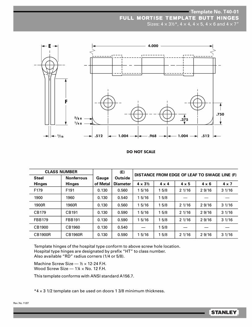
®
Rev. No. 11/07
Template No. T40-01
FULL MORFULL MORFULL MORFULL MORFULL MORTISE TISE TISE TISE TISE TEMPLATEMPLATEMPLATEMPLATEMPLATE BTE BTE BTE BTE BUTT HINGESUTT HINGESUTT HINGESUTT HINGESUTT HINGESSizes: 4 × 3½*, 4 × 4, 4 × 5, 4 × 6 and 4 × 7”
Template hinges of the hospital type conform to above screw hole location.Hospital type hinges are designated by prefix “HT” to class number.Also available “RD” radius corners (1/4 or 5/8).
Machine Screw Size — ½ × 12-24 F.H.Wood Screw Size — 1¼ × No. 12 F.H.
This template conforms with ANSI standard A156.7.
*4 × 3 1/2 template can be used on doors 1 3/8 minimum thickness.
(E)
Steel Nonferrous Gauge Outside
Hinges Hinges of Metal Diameter 4 × 3½ 4 × 4 4 × 5 4 × 6 4 × 7
F179 F191 0.130 0.560 1 5/16 1 5/8 2 1/16 2 9/16 3 1/16
1900 1960 0.130 0.540 1 5/16 1 5/8 — — —
1900R 1960R 0.130 0.560 1 5/16 1 5/8 2 1/16 2 9/16 3 1/16
CB179 CB191 0.130 0.590 1 5/16 1 5/8 2 1/16 2 9/16 3 1/16
FBB179 FBB191 0.130 0.590 1 5/16 1 5/8 2 1/16 2 9/16 3 1/16
CB1900 CB1960 0.130 0.540 — 1 5/8 — — —
CB1900R CB1960R 0.130 0.590 1 5/16 1 5/8 2 1/16 2 9/16 3 1/16
CLASS NUMBERDISTANCE FROM EDGE OF LEAF TO SWAGE LINE (F)

®
Rev. No. 3/06
Template No. T45-01
FULL MORFULL MORFULL MORFULL MORFULL MORTISE TISE TISE TISE TISE TEMPLATEMPLATEMPLATEMPLATEMPLATE BTE BTE BTE BTE BUTT HINGESUTT HINGESUTT HINGESUTT HINGESUTT HINGESSizes: 4½ × 4, 4½ × 4½, 4½ × 5, 4½ × 6, 4½ × 7 and 4½ × 8”
Template hinges of the hospital type conform to above screw hole location.Hospital type hinges are designated by prefix “HT” to class number (except on #2060).Also available in RD2060 1/4 radius corner and RD2068 5/8 radius corner.
Machine Screw Size — ½ × 12-24 F.H.Wood Screw Size — 1¼ × No. 12 F.H.
This template conforms with ANSI standard A156.7.
E
F
1/ 16
5/ 8 R1/ 4 R
1 .125
4 .500
.508 .5081 .2 34 1 .125
1 .000
.375
(E)
Steel Nonferrous Gauge Outside
Hinges Hinges of Metal Diameter 4½ × 4 4½ × 4½ 4½ × 5 4½ × 6 4½ × 7 4½ × 8
F179 F191 0.134 0.605 1 5/8 1 29/32 2 5/32 2 21/32 3 5/32 2 21/32
1900 1960 0.134 0.540 1 5/8 1 13/16 — — — —
1900R 1960R 0.134 0.605 1 5/8 1 29/32 — — — —
CB179 CB191 0.134 0.625 1 5/8 1 25/32 2 3/32 2 19/32 — —
FBB179 FBB191 0.134 0.625 1 5/8 1 25/32 2 3/32 2 19/32 — —
CB1900 CB1960 0.134 0.540 1 5/8 1 13/16 — — — —
CB1900R CB1960R 0.134 0.625 1 5/8 1 25/32 2 3/32 2 19/32 — —
CB168 CB199 0.180 0.698 1 15/32 1 23/32 1 31/32 2 15/32 2 31/32 3 15/32
FBB168 FBB199 0.180 0.698 1 15/32 1 23/32 1 31/32 2 15/32 2 31/32 3 15/32
IHTCB168 IHTCB199 0.180 0.698 1 15/32 1 23/32 — — — —
— CB0701 0.180 0.698 1 15/32 1 23/32 — — — —
CB1901 CB1961 0.180 0.690 — 1 13/16 — — — —
CB1901R CB1961R 0.180 0.698 1 15/32 1 23/32 1 31/32 2 15/32 2 31/32 3 15/32
IHTCB1901 IHTCB1961 0.180 0.690 1 15/32 1 13/16 — — — —
IHTCB1901R IHTCB1961R 0.180 0.698 1 15/32 1 23/32 — — — —
2060R — 0.134 0.783 1 5/8 1 27/32 — — — —
DISTANCE FROM EDGE OF LEAF TO SWAGE LINE (F)CLASS NUMBER

®
Rev. No. 1/06
Template No. T50-01
FULL MORFULL MORFULL MORFULL MORFULL MORTISE TISE TISE TISE TISE TEMPLATEMPLATEMPLATEMPLATEMPLATE BTE BTE BTE BTE BUTT HINGESUTT HINGESUTT HINGESUTT HINGESUTT HINGESSizes: 5 × 4, 5 × 4½, 5 × 5, 5 × 7 and 5 × 8”
Template hinges of the hospital type conform to above screw hole location.Hospital type hinges are designated by prefix “HT” to class number.Also available “RD” radius corners (1/4 or 5/8).Machine Screw Size — ½ × 12-24 F.H.
Wood Screw Size —
NOTE: Prefix IHT indicates Institutional Hinge.
This template conforms with ANSI standard A156.7.
1¼ × No. 12 F.H. for regular weight (0.146) hinges1½ × No. 12 F.H. for extra heavy weight (0.190) hinges[
E
F
1/ 16
5/ 8 R1/ 4 R
1 .2 50
5 .000
.508 .5081 .484 1 .2 50
1 .000
.37 5
(E)
Steel Nonferrous Gauge Outside
Hinges Hinges of Metal Diameter 5 × 4 5 × 4½ 5 × 5 5 × 7 5 × 8
F179 F191 0.146 0.661 1 5/8 1 13/16 2 1/16 3 1/16 3 9/16
1900 1960 0.146 0.580 1 5/8 1 3/4 2 — —
1900R 1960R 0.146 0.661 1 5/8 1 13/16 2 1/16 3 1/16 3 9/16
CB179 CB191 0.146 0.669 1 5/8 1 13/16 2 1/16 3 1/16 3 9/16
FBB179 FBB191 0.146 0.669 1 5/8 1 13/16 2 1/16 3 1/16 3 9/16
CB1900 CB1960 0.146 0.580 1 5/8 1 55/64 2 7/64 — —
CB1900R CB1960R 0.146 0.669 1 5/8 1 13/16 2 1/16 3 1/16 3 9/16
CB168 CB199 0.190 0.748 1 15/32 1 23/32 1 31/32 2 31/32 3 15/32
FBB168 FBB199 0.190 0.748 1 15/32 1 23/32 1 31/32 2 31/32 3 15/32
IHTCB168 IHTCB199 0.190 0.748 — 1 23/32 — — —
CB1901 CB1961 0.190 0.715 — 1 13/16 — — —
CB1901R CB1961R 0.190 0.748 1 15/32 2 23/32 1 31/32 2 31/32 3 15/32
IHTCB1901 IHTCB1961 0.190 0.715 — 1 13/16 — — —
IHTCB1901R IHTCB1961R 0.190 0.748 — 1 23/32 — — —
CLASS NUMBERDISTANCE FROM EDGE OF LEAF TO SWAGE LINE (F)
DO NOT SCALE

®
Rev. No. 1/06
Template No. T45-40
HALF MORHALF MORHALF MORHALF MORHALF MORTISE TISE TISE TISE TISE TEMPLATEMPLATEMPLATEMPLATEMPLATE HINGESTE HINGESTE HINGESTE HINGESTE HINGESSize: 4½”
Template hinges of the hospital type conform to above screw hole location.Hospital type hinges are designated by prefix “HT” to class number.
Machine Screw Size — Jamb Leaf — ½ × 12-24 O.H. Door Leaf — ½ × 12-24 F.H.
This template conforms with ANSI standard A156.7.
(C) (D) (E)
Steel Nonferrous Gauge Door Jamb Leaf Outside
Hinges Hinges of Metal Leaf Offset Diameter
F167 — 0.134 2 1/16 7/16 0.605
1920R — 0.134 2 1/16 7/16 0.605
CB167 CB108 0.134 2 1/16 7/16 0.625
FBB167 FBB108 0.134 2 1/16 7/16 0.625
CB1920 CB1980 0.134 2 3/8 0.540
CB1920R CB1980R 0.134 2 1/16 7/16 0.625
CB138 CB98 0.180 2 1/8 1/2 0.698
FBB138 FBB98 0.180 2 1/8 1/2 0.698
CB1921 CB1981 0.180 2 1/16 7/16 0.690
CB1921R CB1981R 0.180 2 1/8 1/2 0.698
CLASS NUMBER
DO NOT SCALE
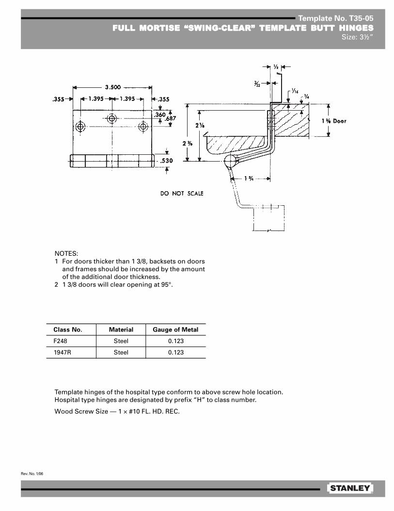
®
Rev. No. 1/06
Template No. T35-05
FULL MORFULL MORFULL MORFULL MORFULL MORTISE “SWING-CLEAR”TISE “SWING-CLEAR”TISE “SWING-CLEAR”TISE “SWING-CLEAR”TISE “SWING-CLEAR” TEMPLATEMPLATEMPLATEMPLATEMPLATE BTE BTE BTE BTE BUTT HINGESUTT HINGESUTT HINGESUTT HINGESUTT HINGESSize: 3½”
NOTES:1 For doors thicker than 1 3/8, backsets on doors
and frames should be increased by the amountof the additional door thickness.
2 1 3/8 doors will clear opening at 95°.
Template hinges of the hospital type conform to above screw hole location.Hospital type hinges are designated by prefix “H” to class number.
Wood Screw Size — 1 × #10 FL. HD. REC.
Class No. Material Gauge of Metal
F248 Steel 0.123
1947R Steel 0.123
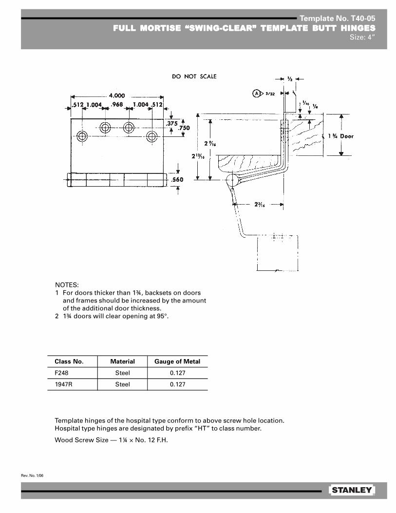
®
Rev. No. 1/06
Template No. T40-05
FULL MORFULL MORFULL MORFULL MORFULL MORTISE “SWING-CLEAR”TISE “SWING-CLEAR”TISE “SWING-CLEAR”TISE “SWING-CLEAR”TISE “SWING-CLEAR” TEMPLATEMPLATEMPLATEMPLATEMPLATE BTE BTE BTE BTE BUTT HINGESUTT HINGESUTT HINGESUTT HINGESUTT HINGESSize: 4”
NOTES:1 For doors thicker than 1¾, backsets on doors
and frames should be increased by the amountof the additional door thickness.
2 1¾ doors will clear opening at 95°.
Template hinges of the hospital type conform to above screw hole location.Hospital type hinges are designated by prefix “HT” to class number.
Wood Screw Size — 1¼ × No. 12 F.H.
Class No. Material Gauge of Metal
F248 Steel 0.127
1947R Steel 0.127

®
Rev. No. 1/06
Template No. T45-30
FULL MORFULL MORFULL MORFULL MORFULL MORTISE “SWING-CLEAR”TISE “SWING-CLEAR”TISE “SWING-CLEAR”TISE “SWING-CLEAR”TISE “SWING-CLEAR” TEMPLATEMPLATEMPLATEMPLATEMPLATE BTE BTE BTE BTE BUTT HINGESUTT HINGESUTT HINGESUTT HINGESUTT HINGESSize: 4½”
Template hinges of the hospital type conform to above screw hole location.Hospital type hinges are designated by prefix “HT” to class number.
Machine Screw Size — ½ × 12-24 F.H.Wood Screw Size — 1¼ × No. 12 F.H.
Class No. Material Gauge of Metal (E) Outside Diameter
CB248 Steel 0.134 0.625
FBB248 Steel 0.134 0.625
CB1947 Steel 0.134 0.531
CB1947R Steel 0.134 0.625
NOTES:1 1¾ doors will clear openings at 90°.2 This hinge alters the normal pivot point of door. For door closers,
friction or overhead door holders to be used in conjunction with thishinge, consult manufacturer of the device to be used for applicationdetails.
3 For doors thicker than 1¾, backsets on doors and frames should beincreased by the amount of the additional door thickness.
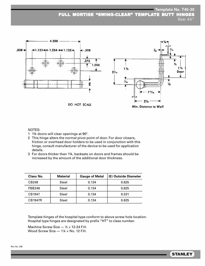
®
Rev. No. 1/06
Template No. T45-31
FULL MORFULL MORFULL MORFULL MORFULL MORTISE “SWING-CLEAR”TISE “SWING-CLEAR”TISE “SWING-CLEAR”TISE “SWING-CLEAR”TISE “SWING-CLEAR” TEMPLATEMPLATEMPLATEMPLATEMPLATE BTE BTE BTE BTE BUTT HINGESUTT HINGESUTT HINGESUTT HINGESUTT HINGESSize: 4½”
Template hinges of the hospital type conform to above screw hole location.Hospital type hinges are designated by prefix “HT” to class number.
Machine Screw Size — ½ × 12-24 F.H.Wood Screw Size — 1¼ × No. 12 F.H.
Class No. Material Gauge of Metal (E) Outside Diameter
CB268 Steel 0.180 0.698
FBB268 Steel 0.180 0.698
CB1948 Steel 0.180 0.690
CB1948R Steel 0.180 0.698
NOTES:1 1¾ doors will clear opening at 90°.2 This hinge alters the normal pivot point of door. For door closers, friction
or overhead door holders to be used in conjunction with this hinge,consult manufacturer of the device to be used for application details.
3 For doors thicker than 1¾, backsets on doors and frames should beincreased by the amount of the additional door thickness.
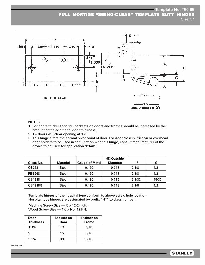
®
Rev. No. 1/06
Template No. T50-05
FULL MORFULL MORFULL MORFULL MORFULL MORTISE “SWING-CLEAR”TISE “SWING-CLEAR”TISE “SWING-CLEAR”TISE “SWING-CLEAR”TISE “SWING-CLEAR” TEMPLATEMPLATEMPLATEMPLATEMPLATE BTE BTE BTE BTE BUTT HINGESUTT HINGESUTT HINGESUTT HINGESUTT HINGESSize: 5”
Class No. Material Gauge of Metal
(E) Outside
Diameter F G
CB268 Steel 0.190 0.748 2 1/8 1/2
FBB268 Steel 0.190 0.748 2 1/8 1/2
CB1948 Steel 0.190 0.715 2 3/32 15/32
CB1948R Steel 0.190 0.748 2 1/8 1/2
Template hinges of the hospital type conform to above screw hole location.Hospital type hinges are designated by prefix “HT” to class number.
Machine Screw Size — ½ × 12-24 F.H.Wood Screw Size — 1½ × No. 12 F.H.
NOTES:1 For doors thicker than 1¾, backsets on doors and frames should be increased by the
amount of the additional door thickness.2 1¾ doors will clear opening at 95°.3 This hinge alters the normal pivot point of door. For door closers, friction or overhead
door holders to be used in conjunction with this hinge, consult manufacturer of thedevice to be used for application details.
Door
Thickness
Backset on
Door
Backset on
Frame
1 3/4 1/4 5/16
2 1/2 9/16
2 1/4 3/4 13/16
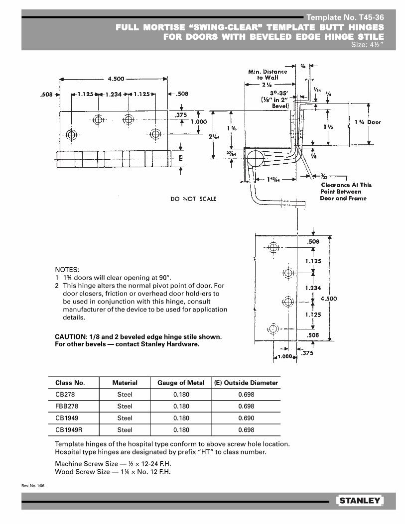
®
Rev. No. 1/06
Template No. T45-36
FULL MORFULL MORFULL MORFULL MORFULL MORTISE “SWING-CLEAR”TISE “SWING-CLEAR”TISE “SWING-CLEAR”TISE “SWING-CLEAR”TISE “SWING-CLEAR” TEMPLATEMPLATEMPLATEMPLATEMPLATE BTE BTE BTE BTE BUTT HINGESUTT HINGESUTT HINGESUTT HINGESUTT HINGESFOR DOORS WITH BEVELED EDGE HINGE STILEFOR DOORS WITH BEVELED EDGE HINGE STILEFOR DOORS WITH BEVELED EDGE HINGE STILEFOR DOORS WITH BEVELED EDGE HINGE STILEFOR DOORS WITH BEVELED EDGE HINGE STILE
Size: 4½”
Template hinges of the hospital type conform to above screw hole location.Hospital type hinges are designated by prefix “HT” to class number.
Machine Screw Size — ½ × 12-24 F.H.Wood Screw Size — 1¼ × No. 12 F.H.
Class No. Material Gauge of Metal (E) Outside Diameter
CB278 Steel 0.180 0.698
FBB278 Steel 0.180 0.698
CB1949 Steel 0.180 0.690
CB1949R Steel 0.180 0.698
NOTES:1 1¾ doors will clear opening at 90°.2 This hinge alters the normal pivot point of door. For
door closers, friction or overhead door hold-ers tobe used in conjunction with this hinge, consultmanufacturer of the device to be used for applicationdetails.
CAUTION: 1/8 and 2 beveled edge hinge stile shown.For other bevels — contact Stanley Hardware.

®
Rev. No. 1/06
Template No. T50-12
FULL MORFULL MORFULL MORFULL MORFULL MORTISE “SWING-CLEAR”TISE “SWING-CLEAR”TISE “SWING-CLEAR”TISE “SWING-CLEAR”TISE “SWING-CLEAR” TEMPLATEMPLATEMPLATEMPLATEMPLATE BTE BTE BTE BTE BUTT HINGESUTT HINGESUTT HINGESUTT HINGESUTT HINGESFOR DOORS WITH BEVELED EDGE HINGE STILESFOR DOORS WITH BEVELED EDGE HINGE STILESFOR DOORS WITH BEVELED EDGE HINGE STILESFOR DOORS WITH BEVELED EDGE HINGE STILESFOR DOORS WITH BEVELED EDGE HINGE STILES
Size: 5”
Template hinges of the hospital type conform to above screw hole location.Hospital type hinges are designated by prefix “HT” to class number.
Machine Screw Size — ½ × 12-24 F.H.Wood Screw Size — 1½ × No. 12 F.H.
Door
Thickness
Backset on
Door
Backset on
Frame
1 3/4 1/4 5/16
2 1/2 9/16
2 1/4 3/4 13/16
NOTES:1 1¾ doors will clear opening at 95°.2 This hinge alters the normal pivot point of door. For door
closers, friction or overhead door holders to be used inconjunction with this hinge, consult manufacturer of thedevice to be used for application details.
3 Backsets which apply when swing-clear hinge for bevelededge hinge stile is used on door thickness indicated andwhen the usual 1/16 stop clearance is desired.
CAUTION: 1/8 in 2 beveled edge hinge stile shown.For other bevels — contact Stanley Hardware.
Min. Distance to Wall
Class No. Material Gauge of Metal
(E) Outside
Diameter F G
CB278With beveled door leaf
FBB278With beveled door leaf
CB1949With beveled door leaf
CB1949RWith beveled door leaf
1/2Steel 0.190 0.748 2 1/8
1/2
15/32
1/2
Steel
Steel
Steel
2 1/8
2 3/32
2 1/8
0.190
0.190
0.190
0.748
0.715
0.748

®
Rev. No. 1/06
Template No. T50-85
HALF SURFHALF SURFHALF SURFHALF SURFHALF SURFAAAAACE “SWING-CLEAR”CE “SWING-CLEAR”CE “SWING-CLEAR”CE “SWING-CLEAR”CE “SWING-CLEAR” TEMPLATEMPLATEMPLATEMPLATEMPLATE HINGESTE HINGESTE HINGESTE HINGESTE HINGESSize: 5”
NOTES:1 1¾ doors will clear opening at 95°.2 This hinge alters the normal pivot point
of door. For door closers, friction oroverhead door holders to be used inconjunction with this hinge, consultmanufacturer of the device to be usedfor application details.
3 For doors thicker than 1¾, backsets ondoors and frames should be increasedby the amount of the additional doorthickness.
Template hinges of the hospital type conform to above screw hole location.Hospital type hinges are designated by prefix “HT”to class number.
Jamb Leaf — Machine Screw Size — ½ × 12-24 F.H.Door Leaf — Screw Size — 2 × ¼-20 O.H.M.S. with grommet nut or 1½ × No. 14 O.H. wood screw.
Class No. Material Gauge of Metal (E) Outside Diameter F G
CB269 Steel 0.190 0.748 2 1/8 1/2
FBB269 Steel 0.190 0.748 2 1/8 1/2
CB1959 Steel 0.190 0.715 2 3/32 15/32
CB1959R Steel 0.190 0.748 2 1/8 1/2
DO NOT SCALE
.508

®
Rev. No. 1/06
Template No. T50-45
HALF MORHALF MORHALF MORHALF MORHALF MORTISE “SWING-CLEAR”TISE “SWING-CLEAR”TISE “SWING-CLEAR”TISE “SWING-CLEAR”TISE “SWING-CLEAR” TEMPLATEMPLATEMPLATEMPLATEMPLATE HINGESTE HINGESTE HINGESTE HINGESTE HINGESFOR DOORS FOR DOORS FOR DOORS FOR DOORS FOR DOORS WITH SQWITH SQWITH SQWITH SQWITH SQUUUUUARE HINGE STILESARE HINGE STILESARE HINGE STILESARE HINGE STILESARE HINGE STILES
Size: 5”
Template hinges of the hospital type conform to above screw hole location.Hospital type hinges are designated by prefix “HT” to class number.Hand of hinge may be changed by inverting hinge and reversing pin and tip.
Machine Screw Size — Jamb Leaf — ½ × 12-24 F.H. Door Leaf — ½ × 12-24 F.H. or 1¼ × No. 12 F.H. WD. SCR.
Class No. Material Gauge of Metal (E) Outside Diameter
CB264 Steel 0.190 0.748
FBB264 Steel 0.190 0.748
CB1941 Steel 0.190 0.715
CB1941R Steel 0.190 0.748
NOTES:1 This hinge alters the normal pivot point of the door. For
door closers, friction or overhead door holders to be usedin conjunction with this hinge, consult manufacturer ofthe device to be used for application details.
2 1¾ doors will clear opening at 95°.3 For doors thicker than 1¾ door backsets should be
increased by the amount of the additional door thickness.
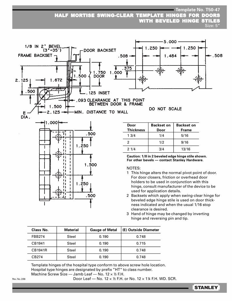
®
Rev. No. 2/06
Template No. T50-47
HALF MORHALF MORHALF MORHALF MORHALF MORTISE SWING-CLEAR TISE SWING-CLEAR TISE SWING-CLEAR TISE SWING-CLEAR TISE SWING-CLEAR TEMPLATEMPLATEMPLATEMPLATEMPLATE HINGES FOR DOORSTE HINGES FOR DOORSTE HINGES FOR DOORSTE HINGES FOR DOORSTE HINGES FOR DOORSWITH BEVELED HINGE STILESWITH BEVELED HINGE STILESWITH BEVELED HINGE STILESWITH BEVELED HINGE STILESWITH BEVELED HINGE STILES
Size: 5”
Template hinges of the hospital type conform to above screw hole location.Hospital type hinges are designated by prefix ”HT“ to class number.Machine Screw Size — Jamb Leaf — No. 12 × ½ F.H.
Door Leaf — No. 12 × ½ F.H. or No. 12 × 1¼ F.H. WD. SCR.
Door
Thickness
Backset on
Door
Backset on
Frame
1 3/4 1/4 5/16
2 1/2 9/16
2 1/4 3/4 13/16
Caution: 1/8 in 2 beveled edge hinge stile shown.For other bevels — contact Stanley Hardware.
NOTES:1 This hinge alters the normal pivot point of door.
For door closers, friction or overhead doorholders to be used in conjunction with thishinge, consult manufacturer of the device to beused for application details.
2 Backsets which apply when swing-clear hinge forbeveled edge hinge stile is used on door thick-ness indicated and when the usual 1/16 stopclearance is desired.
3 Hand of hinge may be changed by invertinghinge and reversing pin and tip.
Class No. Material Gauge of Metal (E) Outside Diameter
FBB274 Steel 0.190 0.748
CB1941 Steel 0.190 0.715
CB1941R Steel 0.190 0.748
CB274 Steel 0.190 0.748
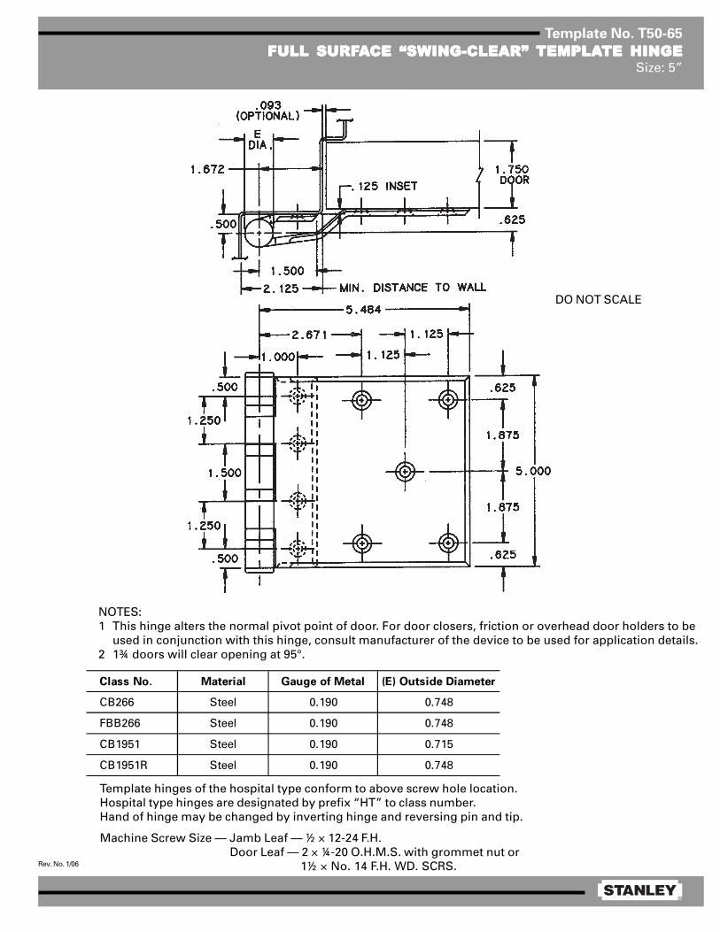
®
Rev. No. 1/06
Template No. T50-65
FULL SURFFULL SURFFULL SURFFULL SURFFULL SURFAAAAACE “SWING-CLEAR”CE “SWING-CLEAR”CE “SWING-CLEAR”CE “SWING-CLEAR”CE “SWING-CLEAR” TEMPLATEMPLATEMPLATEMPLATEMPLATE HINGETE HINGETE HINGETE HINGETE HINGESize: 5”
NOTES:1 This hinge alters the normal pivot point of door. For door closers, friction or overhead door holders to be
used in conjunction with this hinge, consult manufacturer of the device to be used for application details.2 1¾ doors will clear opening at 95°.
Template hinges of the hospital type conform to above screw hole location.Hospital type hinges are designated by prefix “HT” to class number.Hand of hinge may be changed by inverting hinge and reversing pin and tip.
Machine Screw Size — Jamb Leaf — ½ × 12-24 F.H. Door Leaf — 2 × ¼-20 O.H.M.S. with grommet nut or
1½ × No. 14 F.H. WD. SCRS.
Class No. Material Gauge of Metal (E) Outside Diameter
CB266 Steel 0.190 0.748
FBB266 Steel 0.190 0.748
CB1951 Steel 0.190 0.715
CB1951R Steel 0.190 0.748
DO NOT SCALE

®
Rev. No. 08/08
Template No. F1B
FULL MORTISE (BEVELED EDGE MOUNT)FULL MORTISE (BEVELED EDGE MOUNT)FULL MORTISE (BEVELED EDGE MOUNT)FULL MORTISE (BEVELED EDGE MOUNT)FULL MORTISE (BEVELED EDGE MOUNT)Models: 641 and 651
NOTE: Clearance for doors beveled 1/8” in 2”.
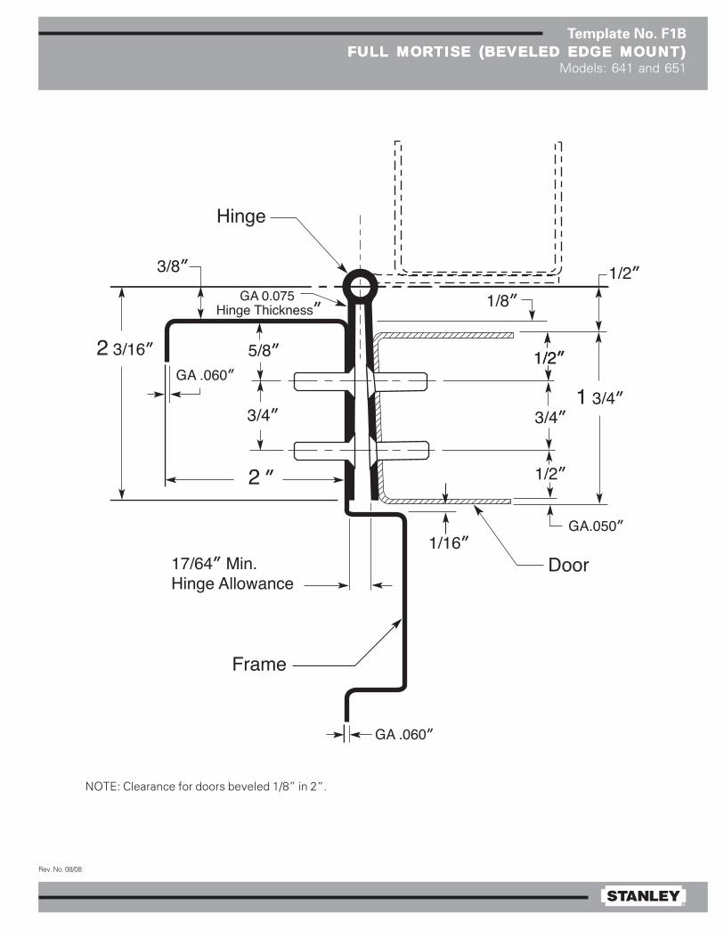
®
Rev. No. 08/08
Template No. F1B
FULL MORTISE (BEVELED EDGE MOUNT)FULL MORTISE (BEVELED EDGE MOUNT)FULL MORTISE (BEVELED EDGE MOUNT)FULL MORTISE (BEVELED EDGE MOUNT)FULL MORTISE (BEVELED EDGE MOUNT)Models: 641 and 651
NOTE: Clearance for doors beveled 1/8” in 2”.
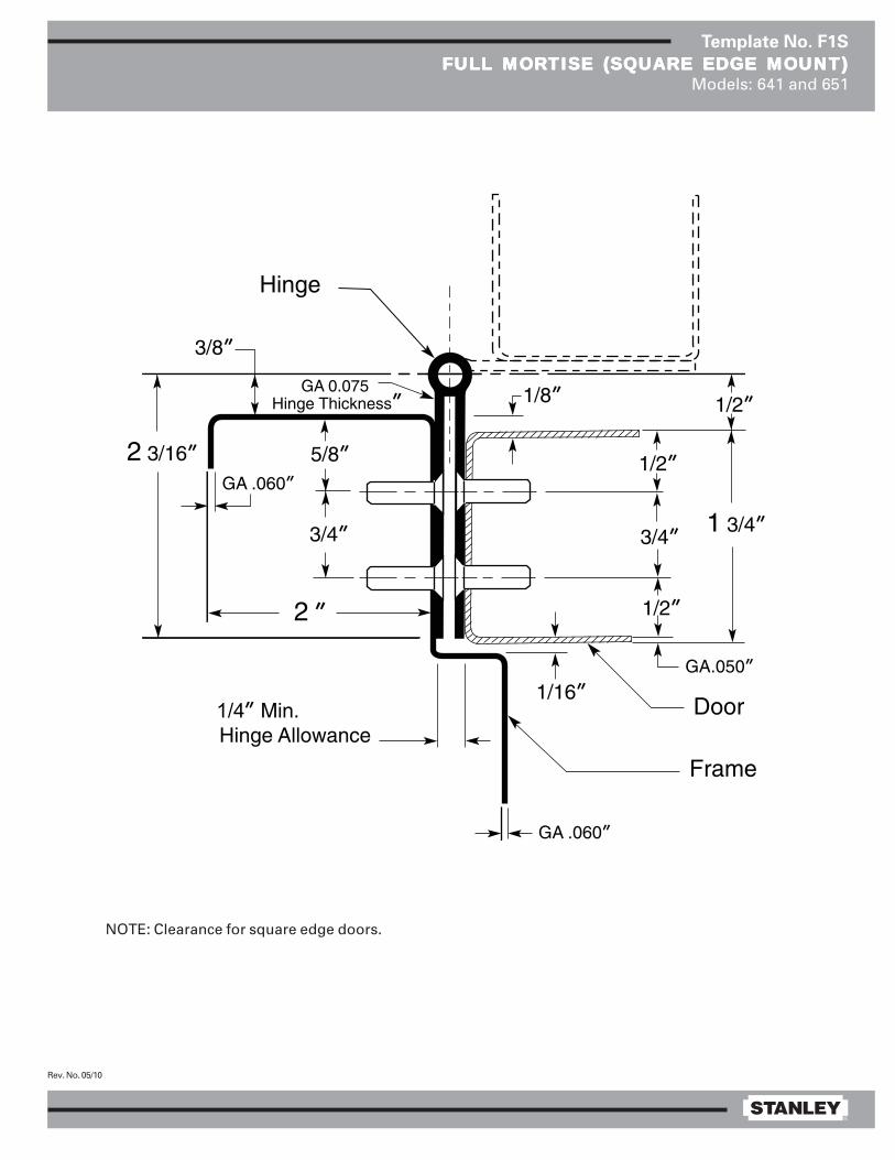
®
Rev. No. 05/10
Template No. F1S
FULL MORFULL MORFULL MORFULL MORFULL MORTISE (SQTISE (SQTISE (SQTISE (SQTISE (SQUUUUUARE EDGE MOUNT)ARE EDGE MOUNT)ARE EDGE MOUNT)ARE EDGE MOUNT)ARE EDGE MOUNT)Models: 641 and 651
NOTE: Clearance for square edge doors.
1/4

®
Rev. No. 3/11
Template No. T98-600
600 SERIES CONTINUOUS PINNED HINGE CONCEALED WIRE TRANSFER600 SERIES CONTINUOUS PINNED HINGE CONCEALED WIRE TRANSFER600 SERIES CONTINUOUS PINNED HINGE CONCEALED WIRE TRANSFER600 SERIES CONTINUOUS PINNED HINGE CONCEALED WIRE TRANSFER600 SERIES CONTINUOUS PINNED HINGE CONCEALED WIRE TRANSFER
NOTES:1 Drill a hole (1/2” maximum diameter) into the
jamb and door for the wires and connectors.2 Both faces of the hole should be deburred
and primed to help avoid damaging wireinsulation.
3 When using CE600 with 651HD, 652HD,653HD, add SHCE600 shims.
* For a non-standard hinge length, the positionof the cut-out may vary ± 1.000.
DO NOT SCALE
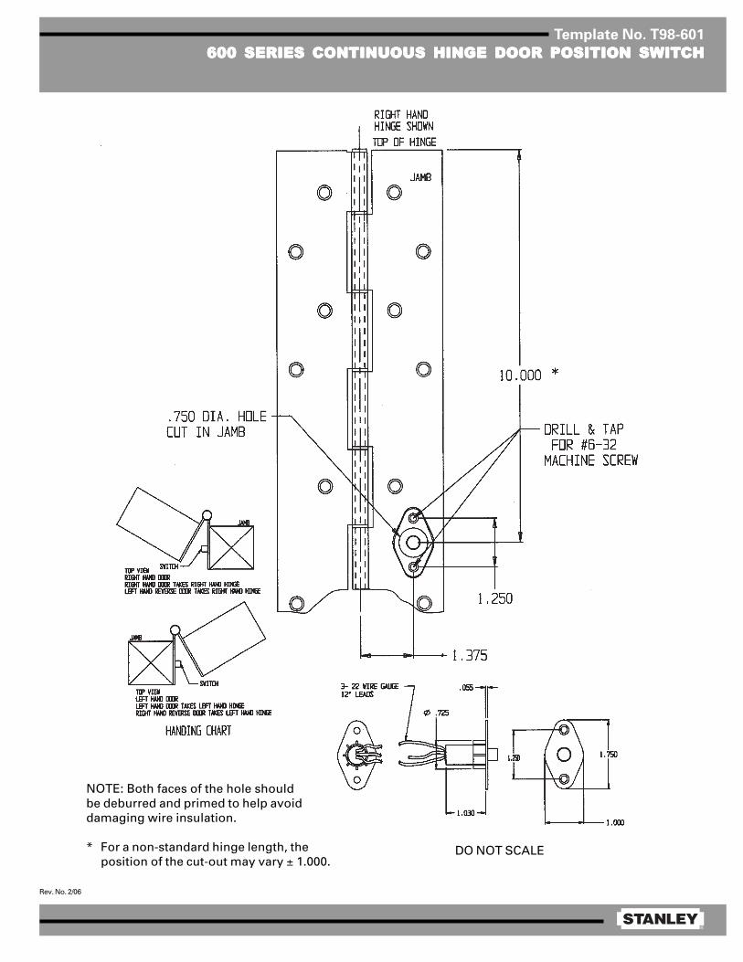
®
Rev. No. 2/06
Template No. T98-601
600 SERIES CONTINUOUS HINGE DOOR POSITION SWIT600 SERIES CONTINUOUS HINGE DOOR POSITION SWIT600 SERIES CONTINUOUS HINGE DOOR POSITION SWIT600 SERIES CONTINUOUS HINGE DOOR POSITION SWIT600 SERIES CONTINUOUS HINGE DOOR POSITION SWITCHCHCHCHCH
NOTE: Both faces of the hole shouldbe deburred and primed to help avoiddamaging wire insulation.
* For a non-standard hinge length, theposition of the cut-out may vary ± 1.000.
DO NOT SCALE

®
Rev. No. 2/06
Template No. F3
HALF HALF HALF HALF HALF WRAP EDGE GUWRAP EDGE GUWRAP EDGE GUWRAP EDGE GUWRAP EDGE GUARD (EDGE MOUNT)ARD (EDGE MOUNT)ARD (EDGE MOUNT)ARD (EDGE MOUNT)ARD (EDGE MOUNT)Models: 643 and 653
NOTE: Clearance for square edge doors.

®
Rev. No. 05/10
Template No. F10B
HALF HALF HALF HALF HALF WRAP EDGE GUWRAP EDGE GUWRAP EDGE GUWRAP EDGE GUWRAP EDGE GUARD HEAARD HEAARD HEAARD HEAARD HEAVY DUTY (BEVELED EDGE MOUNT)VY DUTY (BEVELED EDGE MOUNT)VY DUTY (BEVELED EDGE MOUNT)VY DUTY (BEVELED EDGE MOUNT)VY DUTY (BEVELED EDGE MOUNT)Model: 653HD
NOTE: Clearance for doors beveled 1/8” in 2”.
GA 0.105Ø 1/4 PIN
1/2
11/32
Ø 15/32 BARREL
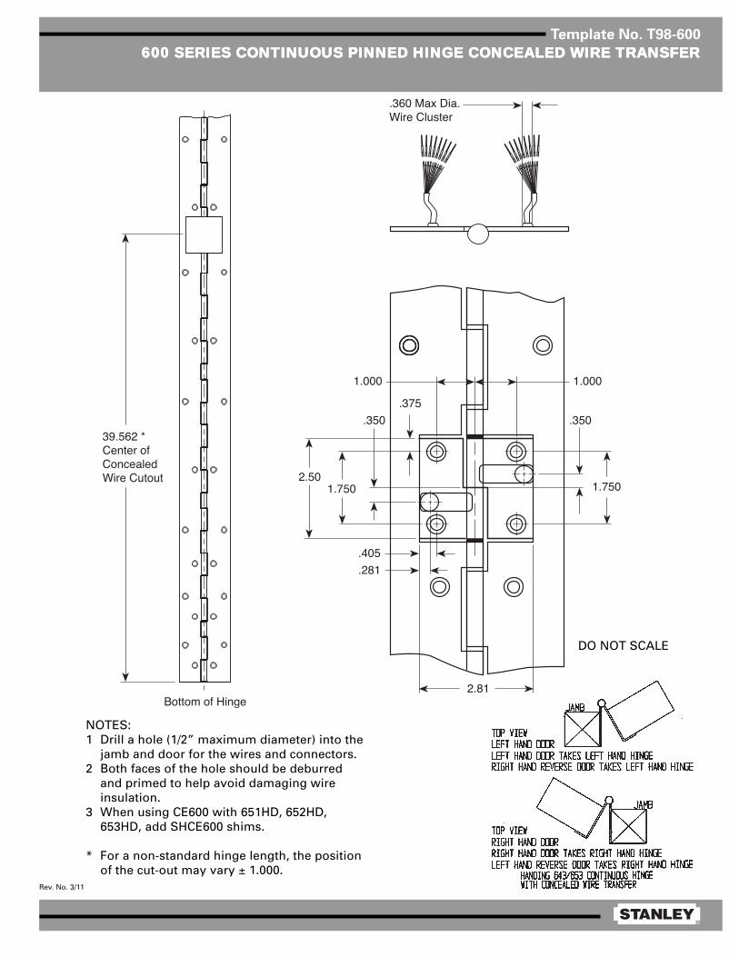
®
Rev. No. 3/11
Template No. T98-600
600 SERIES CONTINUOUS PINNED HINGE CONCEALED WIRE TRANSFER600 SERIES CONTINUOUS PINNED HINGE CONCEALED WIRE TRANSFER600 SERIES CONTINUOUS PINNED HINGE CONCEALED WIRE TRANSFER600 SERIES CONTINUOUS PINNED HINGE CONCEALED WIRE TRANSFER600 SERIES CONTINUOUS PINNED HINGE CONCEALED WIRE TRANSFER
NOTES:1 Drill a hole (1/2” maximum diameter) into the
jamb and door for the wires and connectors.2 Both faces of the hole should be deburred
and primed to help avoid damaging wireinsulation.
3 When using CE600 with 651HD, 652HD,653HD, add SHCE600 shims.
* For a non-standard hinge length, the positionof the cut-out may vary ± 1.000.
DO NOT SCALE

®
Rev. No. 2/06
Template No. T98-601
600 SERIES CONTINUOUS HINGE DOOR POSITION SWIT600 SERIES CONTINUOUS HINGE DOOR POSITION SWIT600 SERIES CONTINUOUS HINGE DOOR POSITION SWIT600 SERIES CONTINUOUS HINGE DOOR POSITION SWIT600 SERIES CONTINUOUS HINGE DOOR POSITION SWITCHCHCHCHCH
NOTE: Both faces of the hole shouldbe deburred and primed to help avoiddamaging wire insulation.
* For a non-standard hinge length, theposition of the cut-out may vary ± 1.000.
DO NOT SCALE
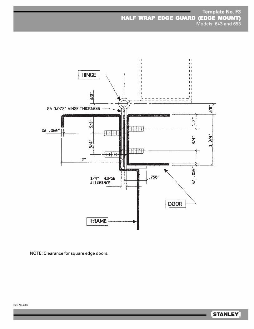
®
Rev. No. 2/06
Template No. F3
HALF HALF HALF HALF HALF WRAP EDGE GUWRAP EDGE GUWRAP EDGE GUWRAP EDGE GUWRAP EDGE GUARD (EDGE MOUNT)ARD (EDGE MOUNT)ARD (EDGE MOUNT)ARD (EDGE MOUNT)ARD (EDGE MOUNT)Models: 643 and 653
NOTE: Clearance for square edge doors.
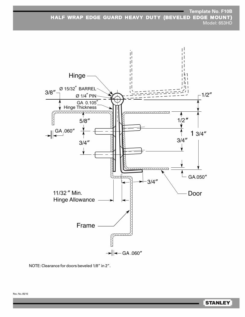
®
Rev. No. 05/10
Template No. F10B
HALF HALF HALF HALF HALF WRAP EDGE GUWRAP EDGE GUWRAP EDGE GUWRAP EDGE GUWRAP EDGE GUARD HEAARD HEAARD HEAARD HEAARD HEAVY DUTY (BEVELED EDGE MOUNT)VY DUTY (BEVELED EDGE MOUNT)VY DUTY (BEVELED EDGE MOUNT)VY DUTY (BEVELED EDGE MOUNT)VY DUTY (BEVELED EDGE MOUNT)Model: 653HD
NOTE: Clearance for doors beveled 1/8” in 2”.
GA 0.105Ø 1/4 PIN
1/2
11/32
Ø 15/32 BARREL
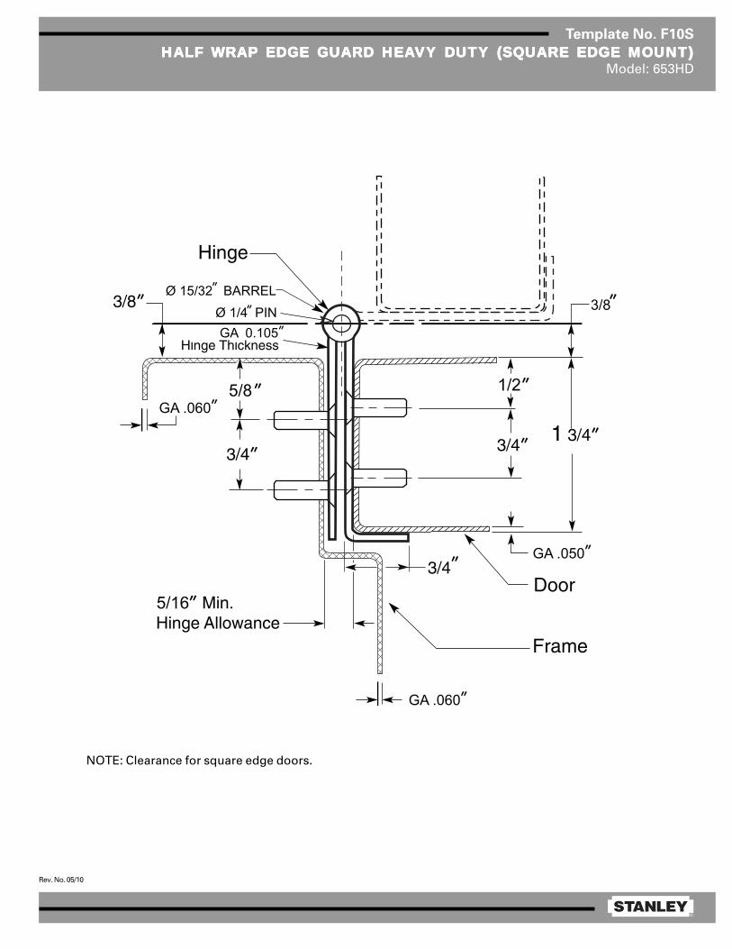
®
Rev. No. 05/10
Template No. F10S
HALF HALF HALF HALF HALF WRAP EDGE GUWRAP EDGE GUWRAP EDGE GUWRAP EDGE GUWRAP EDGE GUARD HEAARD HEAARD HEAARD HEAARD HEAVY DUTY (SQVY DUTY (SQVY DUTY (SQVY DUTY (SQVY DUTY (SQUUUUUARE EDGE MOUNT)ARE EDGE MOUNT)ARE EDGE MOUNT)ARE EDGE MOUNT)ARE EDGE MOUNT)Model: 653HD
NOTE: Clearance for square edge doors.
5/16
GA .060
GA .0601/25/8
GA 0.105Ø 1/4 PIN
Ø 15/32 BARREL
GA .050
3/8

®
Rev. No. 3/11
Template No. T98-600
600 SERIES CONTINUOUS PINNED HINGE CONCEALED WIRE TRANSFER600 SERIES CONTINUOUS PINNED HINGE CONCEALED WIRE TRANSFER600 SERIES CONTINUOUS PINNED HINGE CONCEALED WIRE TRANSFER600 SERIES CONTINUOUS PINNED HINGE CONCEALED WIRE TRANSFER600 SERIES CONTINUOUS PINNED HINGE CONCEALED WIRE TRANSFER
NOTES:1 Drill a hole (1/2” maximum diameter) into the
jamb and door for the wires and connectors.2 Both faces of the hole should be deburred
and primed to help avoid damaging wireinsulation.
3 When using CE600 with 651HD, 652HD,653HD, add SHCE600 shims.
* For a non-standard hinge length, the positionof the cut-out may vary ± 1.000.
DO NOT SCALE

®
Rev. No. 2/06
Template No. T98-601
600 SERIES CONTINUOUS HINGE DOOR POSITION SWIT600 SERIES CONTINUOUS HINGE DOOR POSITION SWIT600 SERIES CONTINUOUS HINGE DOOR POSITION SWIT600 SERIES CONTINUOUS HINGE DOOR POSITION SWIT600 SERIES CONTINUOUS HINGE DOOR POSITION SWITCHCHCHCHCH
NOTE: Both faces of the hole shouldbe deburred and primed to help avoiddamaging wire insulation.
* For a non-standard hinge length, theposition of the cut-out may vary ± 1.000.
DO NOT SCALE
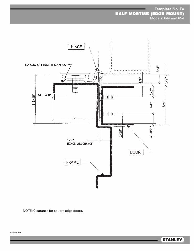
®
Rev. No. 2/06
Template No. F4
HALF MORTISE (EDGE MOUNT)HALF MORTISE (EDGE MOUNT)HALF MORTISE (EDGE MOUNT)HALF MORTISE (EDGE MOUNT)HALF MORTISE (EDGE MOUNT)Models: 644 and 654
NOTE: Clearance for square edge doors.
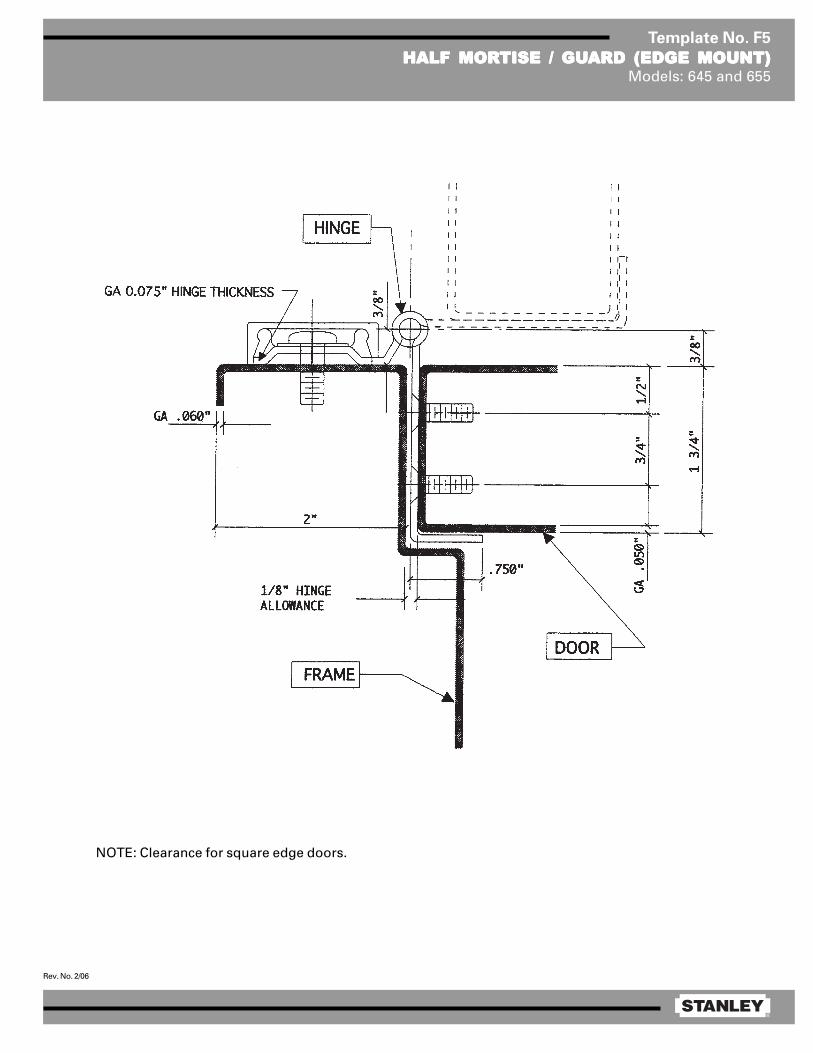
®
Rev. No. 2/06
Template No. F5
HALF MORHALF MORHALF MORHALF MORHALF MORTISE / GUTISE / GUTISE / GUTISE / GUTISE / GUARD (EDGE MOUNT)ARD (EDGE MOUNT)ARD (EDGE MOUNT)ARD (EDGE MOUNT)ARD (EDGE MOUNT)Models: 645 and 655
NOTE: Clearance for square edge doors.
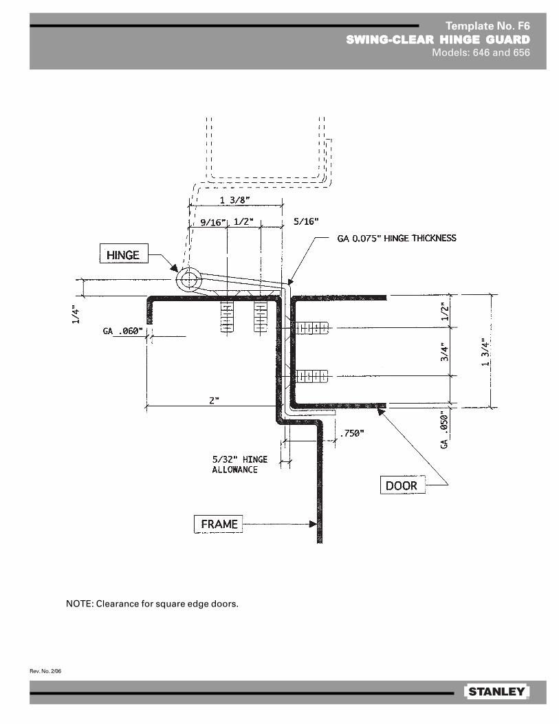
®
Rev. No. 2/06
Template No. F6
SWING-CLEAR HINGE GUSWING-CLEAR HINGE GUSWING-CLEAR HINGE GUSWING-CLEAR HINGE GUSWING-CLEAR HINGE GUARDARDARDARDARDModels: 646 and 656
NOTE: Clearance for square edge doors.
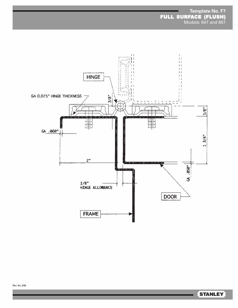
®
Rev. No. 2/06
Template No. F7
FULL SURFFULL SURFFULL SURFFULL SURFFULL SURFAAAAACE (FLCE (FLCE (FLCE (FLCE (FLUSH)USH)USH)USH)USH)Models: 647 and 657
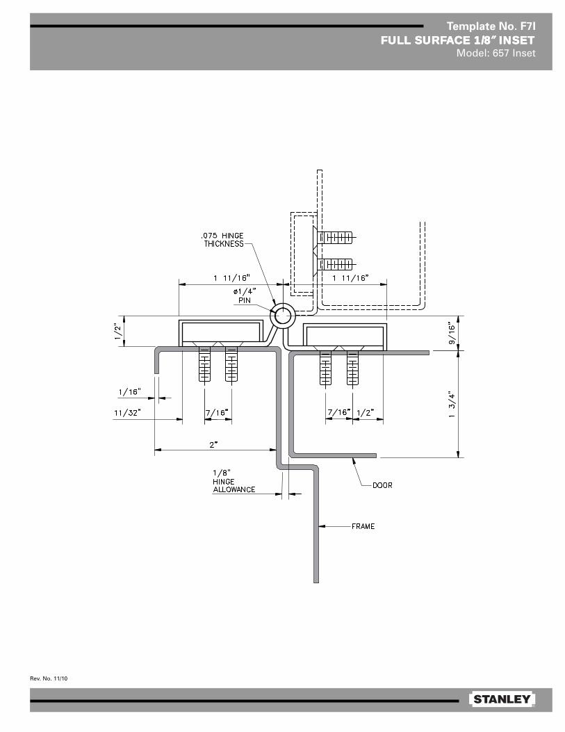
®
Rev. No. 11/10
Template No. F7I
FULL SURFFULL SURFFULL SURFFULL SURFFULL SURFAAAAACE 1/8CE 1/8CE 1/8CE 1/8CE 1/8″″″″″ INSET INSET INSET INSET INSETModel: 657 Inset
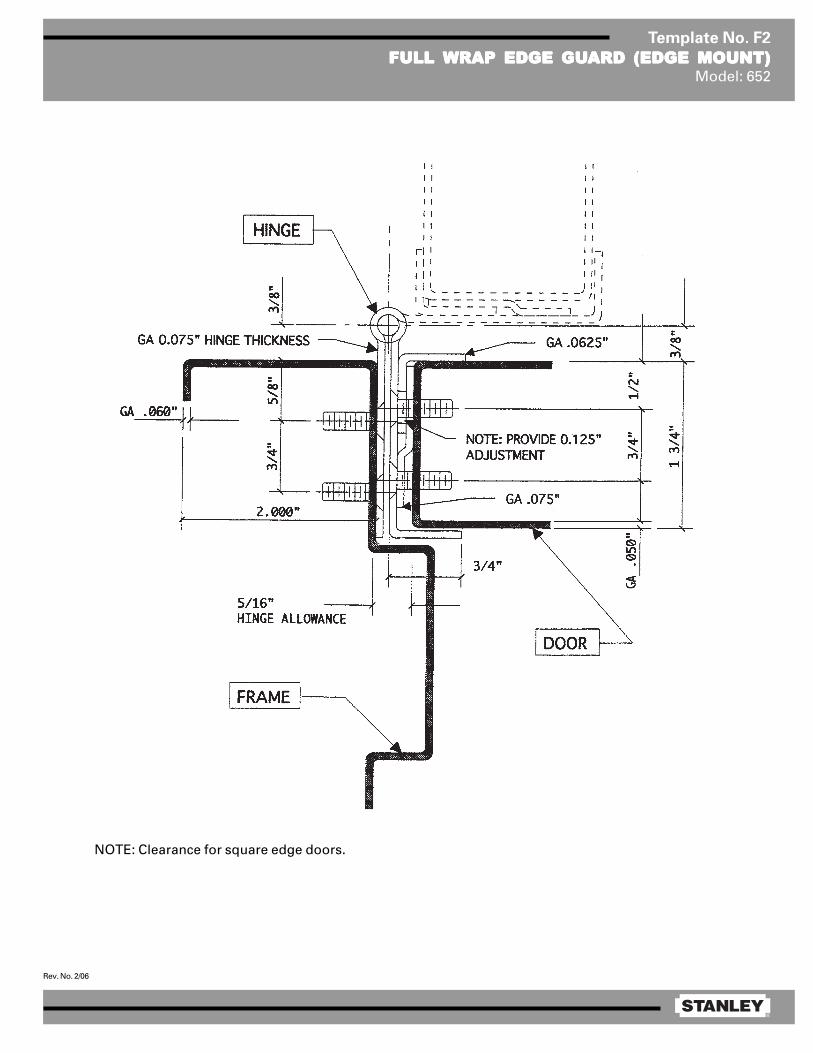
®
Rev. No. 2/06
Template No. F2
FULL FULL FULL FULL FULL WRAP EDGE GUWRAP EDGE GUWRAP EDGE GUWRAP EDGE GUWRAP EDGE GUARD (EDGE MOUNT)ARD (EDGE MOUNT)ARD (EDGE MOUNT)ARD (EDGE MOUNT)ARD (EDGE MOUNT)Model: 652
NOTE: Clearance for square edge doors.
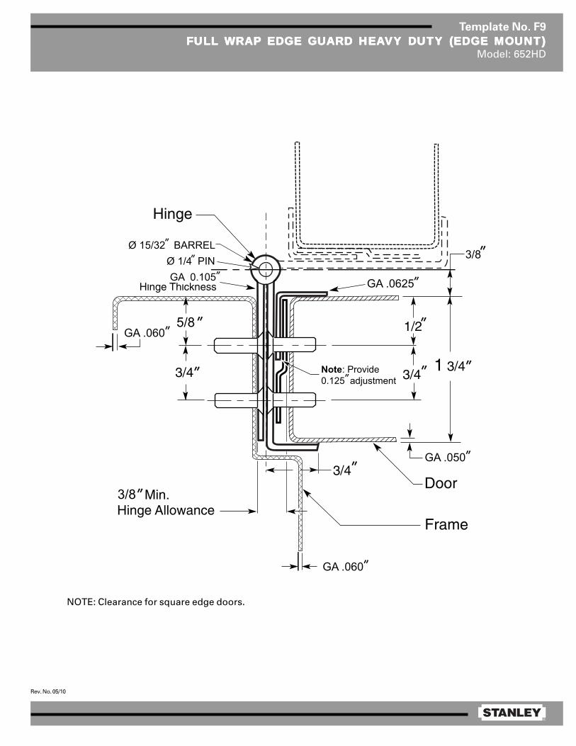
®
Rev. No. 05/10
Template No. F9
FULL FULL FULL FULL FULL WRAP EDGE GUWRAP EDGE GUWRAP EDGE GUWRAP EDGE GUWRAP EDGE GUARD HEAARD HEAARD HEAARD HEAARD HEAVY DUTY (EDGE MOUNT)VY DUTY (EDGE MOUNT)VY DUTY (EDGE MOUNT)VY DUTY (EDGE MOUNT)VY DUTY (EDGE MOUNT)Model: 652HD
NOTE: Clearance for square edge doors.
3/8
GA .060
GA .060
GA .050
GA .0625
5/8
GA 0.105
Note: Provide0.125 adjustment
Ø 1/4 PINØ 15/32 BARREL
3/8

®
Rev. No. 7/07
Template No. T01-01
7979797979”/83/83/83/83/83” 661/661 HD FULL MORTISE ALUMINUM CONTINUOUS HINGE 661/661 HD FULL MORTISE ALUMINUM CONTINUOUS HINGE 661/661 HD FULL MORTISE ALUMINUM CONTINUOUS HINGE 661/661 HD FULL MORTISE ALUMINUM CONTINUOUS HINGE 661/661 HD FULL MORTISE ALUMINUM CONTINUOUS HINGE7979797979”/83/83/83/83/83” 662/662 HD FULL MORTISE 3/32 662/662 HD FULL MORTISE 3/32 662/662 HD FULL MORTISE 3/32 662/662 HD FULL MORTISE 3/32 662/662 HD FULL MORTISE 3/32” INSET ALUMINUM CONTINUOUS HINGE INSET ALUMINUM CONTINUOUS HINGE INSET ALUMINUM CONTINUOUS HINGE INSET ALUMINUM CONTINUOUS HINGE INSET ALUMINUM CONTINUOUS HINGE
Inches mm Inches mm
79 2007 4.500 114.3
83 2108 8.500 215.9
Hinge Length Dimension ANOTE: Clearance indicated is for square edge doors.
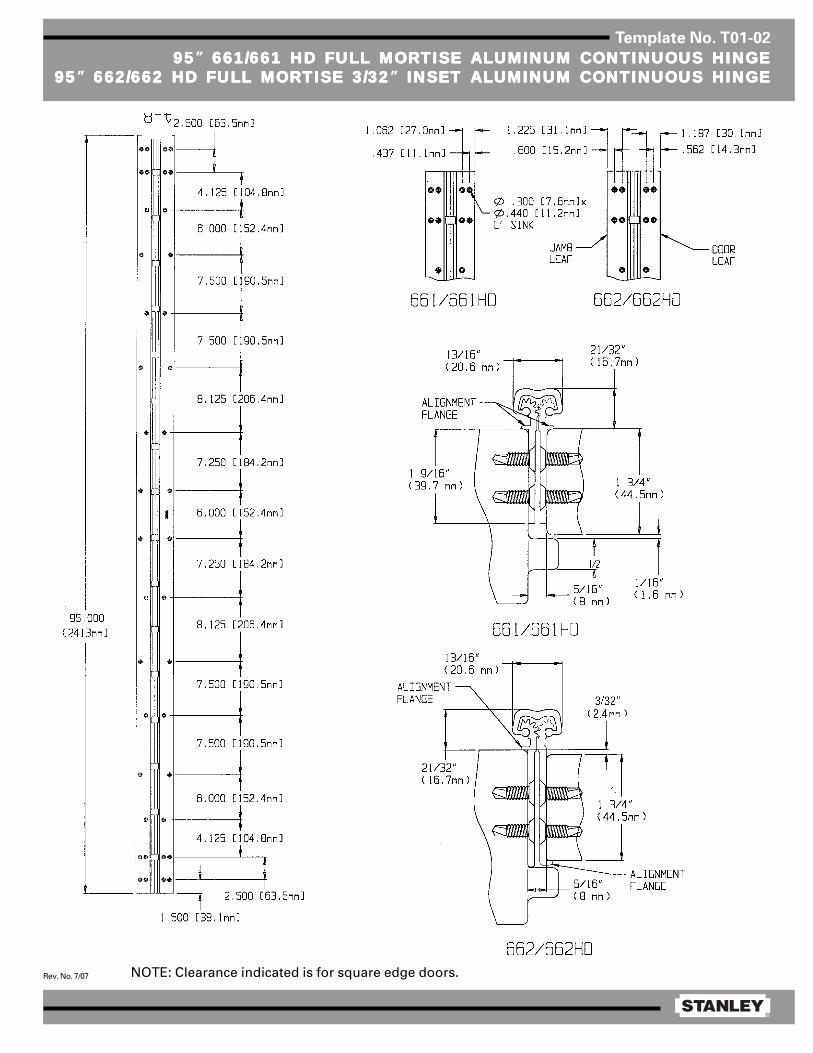
®
Rev. No. 7/07
Template No. T01-02
9595959595” 661/661 HD FULL MORTISE ALUMINUM CONTINUOUS HINGE 661/661 HD FULL MORTISE ALUMINUM CONTINUOUS HINGE 661/661 HD FULL MORTISE ALUMINUM CONTINUOUS HINGE 661/661 HD FULL MORTISE ALUMINUM CONTINUOUS HINGE 661/661 HD FULL MORTISE ALUMINUM CONTINUOUS HINGE9595959595” 662/662 HD FULL MORTISE 3/32 662/662 HD FULL MORTISE 3/32 662/662 HD FULL MORTISE 3/32 662/662 HD FULL MORTISE 3/32 662/662 HD FULL MORTISE 3/32” INSET ALUMINUM CONTINUOUS HINGE INSET ALUMINUM CONTINUOUS HINGE INSET ALUMINUM CONTINUOUS HINGE INSET ALUMINUM CONTINUOUS HINGE INSET ALUMINUM CONTINUOUS HINGE
NOTE: Clearance indicated is for square edge doors.
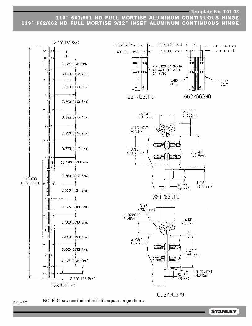
®
Rev. No. 7/07
Template No. T01-03
119119119119119” 661/661 HD FULL MORTISE ALUMINUM CONTINUOUS HINGE 661/661 HD FULL MORTISE ALUMINUM CONTINUOUS HINGE 661/661 HD FULL MORTISE ALUMINUM CONTINUOUS HINGE 661/661 HD FULL MORTISE ALUMINUM CONTINUOUS HINGE 661/661 HD FULL MORTISE ALUMINUM CONTINUOUS HINGE119119119119119” 662/662 HD FULL MORTISE 3/32 662/662 HD FULL MORTISE 3/32 662/662 HD FULL MORTISE 3/32 662/662 HD FULL MORTISE 3/32 662/662 HD FULL MORTISE 3/32” INSET ALUMINUM CONTINUOUS HINGE INSET ALUMINUM CONTINUOUS HINGE INSET ALUMINUM CONTINUOUS HINGE INSET ALUMINUM CONTINUOUS HINGE INSET ALUMINUM CONTINUOUS HINGE
NOTE: Clearance indicated is for square edge doors.
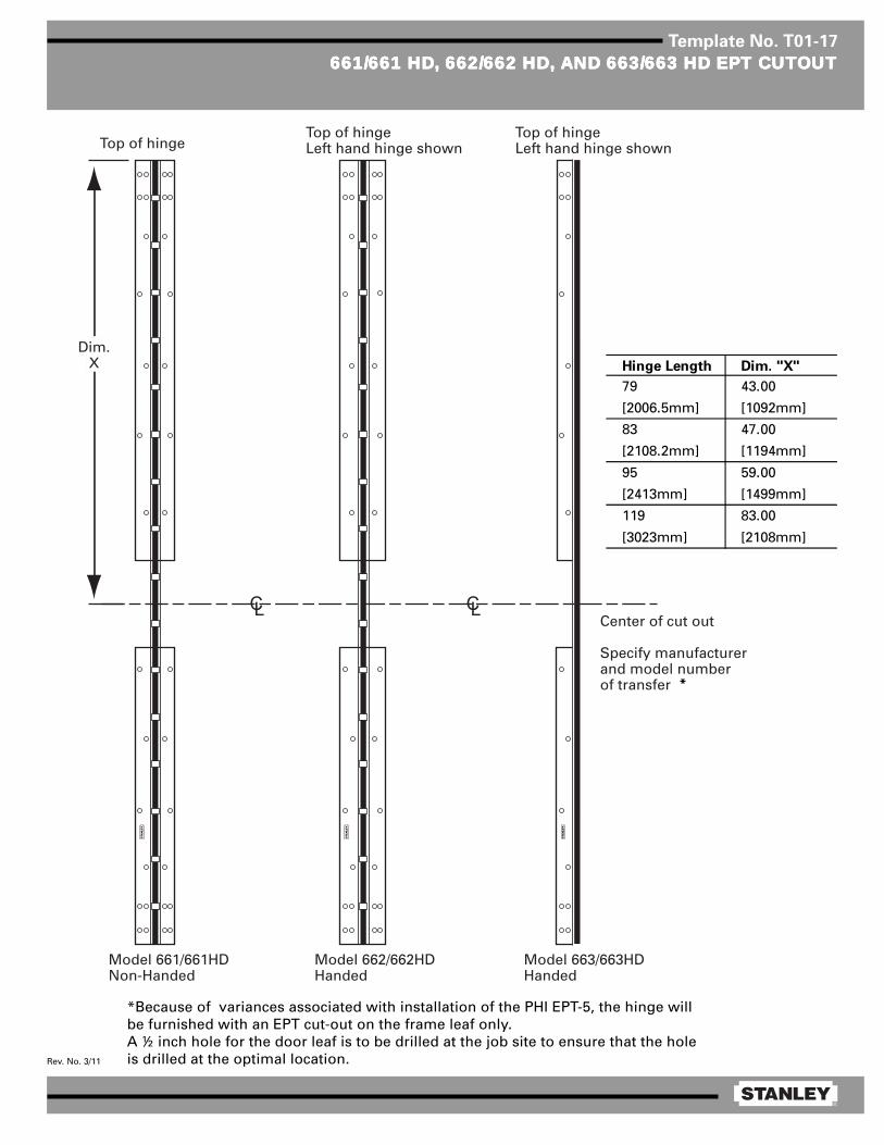
®
Rev. No. 3/11
Template No. T01-17
661/661 HD661/661 HD661/661 HD661/661 HD661/661 HD,,,,, 662/662 HD 662/662 HD 662/662 HD 662/662 HD 662/662 HD,,,,, AND 663/663 HD EPT CUTAND 663/663 HD EPT CUTAND 663/663 HD EPT CUTAND 663/663 HD EPT CUTAND 663/663 HD EPT CUTOUTOUTOUTOUTOUT
Model 662/662HDHanded
Model 661/661HDNon-Handed
Center of cut out
Specify manufacturer and model number of transfer
Model 663/663HDHanded
Top of hingeLeft hand hinge shownTop of hinge
Top of hingeLeft hand hinge shown
Dim.X Hinge Length Dim. "X"
79 43.00
[2006.5mm] [1092mm]
83 47.00
[2108.2mm] [1194mm]
95 59.00
[2413mm] [1499mm]
119 83.00
[3023mm] [2108mm]
*Because of variances associated with installation of the PHI EPT-5, the hinge willbe furnished with an EPT cut-out on the frame leaf only.A ½ inch hole for the door leaf is to be drilled at the job site to ensure that the holeis drilled at the optimal location.
*

®
Rev. No. 12/08
Template No. T01-13
FP 661/661 HD FULL MORTISE ALUMINUM CONTINUOUS HINGEFP 661/661 HD FULL MORTISE ALUMINUM CONTINUOUS HINGEFP 661/661 HD FULL MORTISE ALUMINUM CONTINUOUS HINGEFP 661/661 HD FULL MORTISE ALUMINUM CONTINUOUS HINGEFP 661/661 HD FULL MORTISE ALUMINUM CONTINUOUS HINGEFP 662/662 HD FULL MORTISE 3/32FP 662/662 HD FULL MORTISE 3/32FP 662/662 HD FULL MORTISE 3/32FP 662/662 HD FULL MORTISE 3/32FP 662/662 HD FULL MORTISE 3/32” INSET ALUMINUM CONTINUOUS HINGE INSET ALUMINUM CONTINUOUS HINGE INSET ALUMINUM CONTINUOUS HINGE INSET ALUMINUM CONTINUOUS HINGE INSET ALUMINUM CONTINUOUS HINGE
FP 663/663 HD HALF MORTISE ALUMINUM CONTINUOUS HINGEFP 663/663 HD HALF MORTISE ALUMINUM CONTINUOUS HINGEFP 663/663 HD HALF MORTISE ALUMINUM CONTINUOUS HINGEFP 663/663 HD HALF MORTISE ALUMINUM CONTINUOUS HINGEFP 663/663 HD HALF MORTISE ALUMINUM CONTINUOUS HINGE
Inches mm Inches mm Inches mm Inches mm79 2006.6 27.187 690.5 12.625 320.7 27.187 690.5
83 2108.2 27.187 690.5 16.625 422.3 27.187 690.5
95 2413 34.437 874.7 14.125 358.8 34.437 874.7
119 3023 44.187 1122.3 18.625 473.1 44.187 1122.3
Hinge Length Dimension X Dimension Y Dimension Z
6.0006.0006.0006.0006.000 [152.4mm][152.4mm][152.4mm][152.4mm][152.4mm]
6.0006.0006.0006.0006.000 [152.4mm][152.4mm][152.4mm][152.4mm][152.4mm]
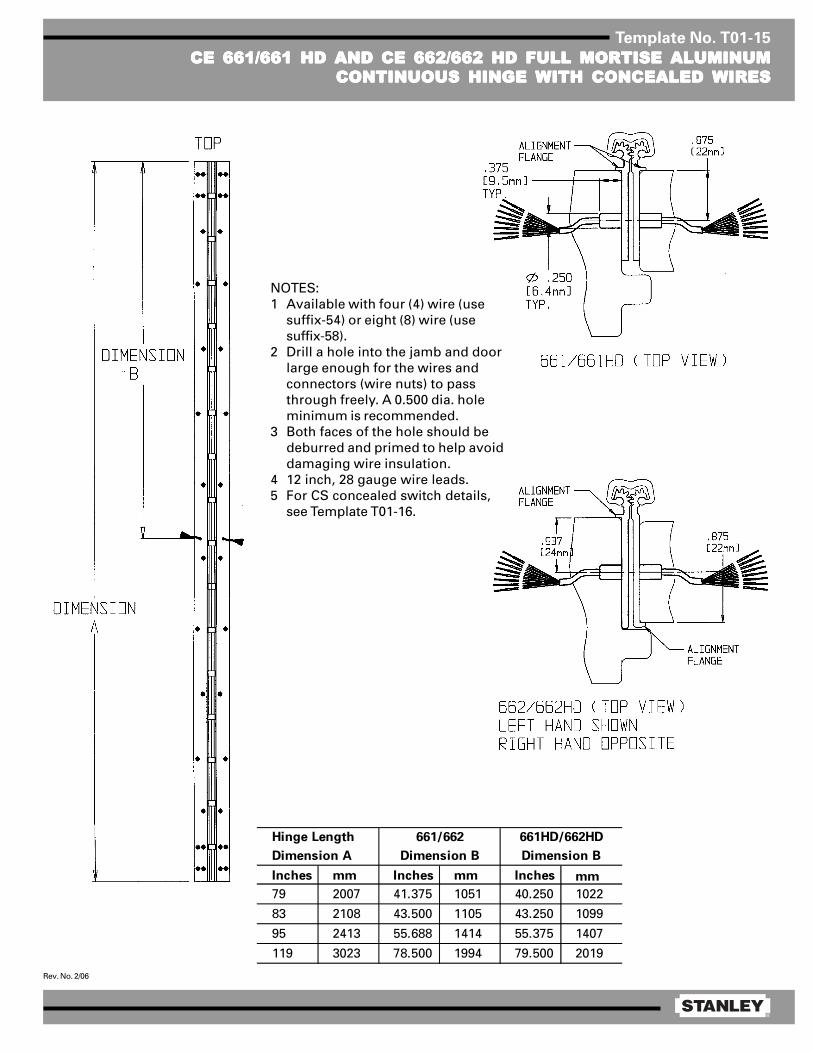
®
Rev. No. 2/06
Template No. T01-15
CE 661/661 HD AND CE 662/662 HD FULL MORTISE ALUMINUMCE 661/661 HD AND CE 662/662 HD FULL MORTISE ALUMINUMCE 661/661 HD AND CE 662/662 HD FULL MORTISE ALUMINUMCE 661/661 HD AND CE 662/662 HD FULL MORTISE ALUMINUMCE 661/661 HD AND CE 662/662 HD FULL MORTISE ALUMINUMCONTINUOUS HINGE WITH CONCEALED WIRESCONTINUOUS HINGE WITH CONCEALED WIRESCONTINUOUS HINGE WITH CONCEALED WIRESCONTINUOUS HINGE WITH CONCEALED WIRESCONTINUOUS HINGE WITH CONCEALED WIRES
NOTES:1 Available with four (4) wire (use
suffix-54) or eight (8) wire (usesuffix-58).
2 Drill a hole into the jamb and doorlarge enough for the wires andconnectors (wire nuts) to passthrough freely. A 0.500 dia. holeminimum is recommended.
3 Both faces of the hole should bedeburred and primed to help avoiddamaging wire insulation.
4 12 inch, 28 gauge wire leads.5 For CS concealed switch details,
see Template T01-16.
Inches mm Inches mm Inches mm
79 2007 41.375 1051 40.250 1022
83 2108 43.500 1105 43.250 1099
95 2413 55.688 1414 55.375 1407
119 3023 78.500 1994 79.500 2019
661HD/662HD
Dimension B
Hinge Length
Dimension A
661/662
Dimension B
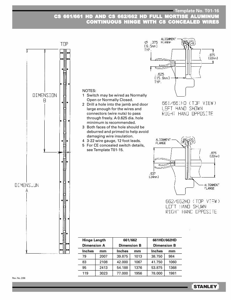
®
Rev. No. 2/06
Template No. T01-16
CS 661/661 HD AND CS 662/662 HD FULL MORTISE ALUMINUMCS 661/661 HD AND CS 662/662 HD FULL MORTISE ALUMINUMCS 661/661 HD AND CS 662/662 HD FULL MORTISE ALUMINUMCS 661/661 HD AND CS 662/662 HD FULL MORTISE ALUMINUMCS 661/661 HD AND CS 662/662 HD FULL MORTISE ALUMINUMCONTINUOUS HINGE WITH CS CONCEALED WIRESCONTINUOUS HINGE WITH CS CONCEALED WIRESCONTINUOUS HINGE WITH CS CONCEALED WIRESCONTINUOUS HINGE WITH CS CONCEALED WIRESCONTINUOUS HINGE WITH CS CONCEALED WIRES
NOTES:1 Switch may be wired as Normally
Open or Normally Closed.2 Drill a hole into the jamb and door
large enough for the wires andconnectors (wire nuts) to passthrough freely. A 0.625 dia. holeminimum is recommended.
3 Both faces of the hole should bedeburred and primed to help avoiddamaging wire insulation.
4 3-22 wire gauge, 12 foot leads.5 For CE concealed switch details,
see Template T01-15.
Inches mm Inches mm Inches mm
79 2007 39.875 1013 38.750 984
83 2108 42.000 1067 41.750 1060
95 2413 54.188 1376 53.875 1368
119 3023 77.000 1956 78.000 1981
661HD/662HD
Dimension B
Hinge Length
Dimension A
661/662
Dimension B

1/2
Fire-Rated Continuous Hinge [Locking Bolt] Installation InstructionsInstrucciones de instalación de la bisagra continua ignífuga [perno de bloqueo]
Instructions d'installation de charnière continue homologuée ignifuge [écrous bloquants]
BAluminum Continuous Geared Hinges:Bisagras con engranaje continuo de aluminio:Charnières continues en aluminiumà plusieurs crans :
Full MortiseCaja completa Mortaise complèteModels: Modelos: Modèles :661/661HD & 662/662HD
Full SurfaceSuper�cie completa Surface complèteModels: Modelos: Modèles :664/664HD & 665/665HD
Half SurfaceMedia super�cie Moitié de surfaceModels: Models: Models:663/663HD
C
Heat Activated Locking BoltPerno de bloqueo activado por calorÉcrou bloquant à activation thermique
Grommet ClipGancho con sombrereteŒillet
Snap-in Hole PlugTapón a presiónBouchon de trou encliquetable
A
B
C
Full Mortise ShownSe muestra la caja completaMortaise complète illustrée
A
A
B
C
0.505” dia.(12.8 mm)
0.630” dia.(16 mm)
Frame LeafHoja del marco
Vantail de cadre
Door LeafHoja de la puertaVantail de porte
Full Mortise Instructions:
Verify that the door and frame are prepared in accordance with the appropriate template ( T01-01 − T01-03), �re rated (T01-13).
1. Use hinge leaves to verify hole prep on both the door and frame.
2. Insert Grommet Clip ‘B’ into hole on door edge, 4 places.
3. Position door leaf hinge to door edge, making sure all holes align. Insert the Heat Activated Locking Bolt ‘A’ through the hinge and into Grommet Clip ‘B’ on door edge, 4 places.
4. Fasten door leaf hinge to door edge.
5. Position the door and hinge onto the frame. While supporting the door weight, align the holes in the frame leaf to the holes in the door frame. Fasten the frame leaf using several screws near the top and bottom of the hinge. Check door swing and function, then install the remaining screws.
6. Insert Snap-in Hole Plug ‘C’ into hole on frame leaf, 4 places.
Instrucciones para caja completa:
Veri�que que la puerta y el marco estén preparados de acuerdo con la plantilla apropiada (T01-01 − T01-03), y sean ignífugos (T01-13).
1. Use hojas de bisagra para veri�car la preparación para ori�cios en la puerta y el marco.2. Inserte el gancho con sombrerete “B” en el borde de la puerta, en 4 lugares.3. Coloque la bisagra de la hoja de la puerta en el borde de la puerta, asegurándose de que los ori�cios se alineen. Inserte el perno de bloqueo activado por calor “A” por la bisagra en el gancho con sombrerete “B” en el borde de la puerta, en 4 lugares.4. Sujete la bisagra de la hoja de la puerta al borde de la puerta.5. Coloque la puerta y la bisagra en el marco. Mientras sostiene el peso de la puerta, alinee los ori�cios en la hoja del marco con los ori�cios en el marco de la puerta. Sujete la hoja del marco usando varios tornillos cerca de la parte superior e inferior de la bisagra. Compruebe el movimiento y el funcionamiento de la puerta, e instale los tornillos restantes.6. Inserte el tapón a presión “C” en el ori�cio en la hoja del marco, en 4 lugares.
Instructions concernant la mortaise complète :
Véri�ez que les préparations de porte et de cadre sont conformes au modèle adéquat (T01-01 − T01-03) et que ces éléments sont homologués ignifuges (T01-13).
1. À l'aide des vantaux, véri�ez le bon emplacement des trous de préparation sur la porte et le cadre.2. Insérez les œillets B dans les trous situés sur la tranche de la porte aux 4 endroits prévus.3. Positionnez la charnière du vantail de la porte sur la tranche de la porte, tout en vous assurant que tous les trous sont alignés. Insérez les écrous bloquants à activation thermique A à travers la charnière et à l'intérieur des œillets B sur la tranche de la porte aux 4 endroits prévus.4. Fixez la charnière du vantail de la porte à la tranche de la porte.5. Placez la porte et la charnière sur le cadre. Tout en soutenant la porte, alignez tous les trous du vantail du cadre aux trous du cadre de la porte. Fixez le vantail du cadre à l'aide de quelques vis dans la partie supérieure et inférieure de la charnière. Véri�ez que la porte s'ouvre et se ferme correctement, puis �xez les vis restantes.6. Insérez les bouchons de trous encliquetables C dans les trous du vantail du cadre aux 4 endroits prévus.

A85390_A Copyright© Stanley Security, Inc. 20162/2
For assistance or warranty information:Call 1-855-365-2407 or visitwww.stanleydoorhinges.com
Warning: This Manufacturer advises that no lock can provide complete security by itself. This lock may be defeated by forcible or technical means, or evaded by entry elsewhere on the property. No lock can substitute for caution, awareness of your environment, and common sense. Builder’s hardware is available in multiple performance grades to suit the application. In order to enhance security and reduce risk, you should consult a quali�ed locksmith or other security professional.
Si desea ayuda o información sobre la garantia:llame al 1-855-365-2407 ou visite
www.stanleydoorhinges.com
Advertencia: Este fabricante have saber que no hay cerraduras que puedan proporcionar seguridad completa por si misma. Esta cerradura puede fallar forzandola o utilizando medios técnicos o entrando por otra parte del edi�cio. No hay cerraduras que puedan sustituir precaución, estar al tanto de su entorno y sentido común. Este fabricante también ofrece cerraduras de diferentes grados y rendimientos para ajustarse a su aplicación. Para mejorar la seguridad y reducer riesgos, usted debe consultar con un cerrajero especializado u otro profesional de seguridad.
Pour de l'aide ou des informations sur la garantie:Vauillez appeler le 1-855-365-2407 ou visiter
www.stanleydoorhinges.com
Advertissement: Le fabricant tient à vous aviser qu'aucun verrou ne peut à lui seul offrir une sécurité complète. Ce verrou peut être mis hors d'état par la force ou des moyens techniques ou etre évité par l'utilisation d'une autre entrée sur la propriété. Aucun verrou ne peut remplacer la surveillance de votre enviornnenment et le bon sens. La quincaillerie pour le constructeur est offerte selon différents grades de performance pour différentes applications. A�n d'augmenter la sécurité et de rduire le risque, vous devriez consulter un serrurier quali�é ou un autre professionel de la sécurité.
Instructions relatives à la moitié de surface :
Véri�ez que les préparations de porte et de cadre sont conformes au modèle adéquat (T01-04 − T01-06) et que ces éléments sont homologués ignifuges (T01-13).
1. Aidez-vous du vantail de cadre pour véri�er l'emplacement des trous de préparation sur le cadre.2. Insérez les œillets B dans les trous situés sur la tranche de la porte aux 4 endroits prévus.3. Insérez les écrous bloquants à activation thermique A dans les œillets B et enfoncez les œillets dans les trous de façon à ce qu'ils soient au ras de la surface aux 4 endroits prévus.4. Fixez la charnière de vantail à la porte.5. Placez la porte et la charnière sur le cadre. Tout en soutenant la porte, alignez tous les trous du vantail du cadre aux trous du cadre de la porte. Fixez le vantail du cadre à l'aide de quelques vis dans la partie supérieure et inférieure de la charnière. Véri�ez que la porte s'ouvre et se ferme correctement, puis �xez les vis restantes.6. Insérez les bouchons de trous encliquetables C dans les trous du vantail du cadre aux 4 endroits prévus.
Instrucciones para media super�cie:
Veri�que que la puerta y el marco estén preparados de acuerdo con la plantilla apropiada (T01-04 − T01-06), y sean ignífugos (T01-13).1. Use la hoja del marco para veri�car la preparación para ori�cios en el marco.2. Inserte el gancho con sombrerete “B” en el borde de la puerta, en 4 lugares.3. Inserte el perno de bloqueo activado por calor “A” en el gancho con sombrerete “B”, asiente de modo rasante con el frente del sombrerete, en 4 lugares.4. Monte la bisagra de la hoja de la puerta en la puerta.5. Coloque la puerta y la bisagra en el marco. Mientras sostiene el peso de la puerta, alinee los ori�cios en la hoja del marco con los ori�cios en el marco de la puerta. Sujete la hoja del marco usando varios tornillos cerca de la parte superior e inferior de la bisagra. Compruebe el movimiento y el funcionamiento de la puerta, e instale los tornillos restantes.6. Inserte el tapón a presión “C” en el ori�cio en la hoja del marco, en 4 lugares.
Instrucciones para super�cie completa:
Veri�que que la puerta y el marco estén preparados de acuerdo con la plantilla apropiada (T01-07 − T01-12).1. Monte la bisagra.2. Inserte el gancho con sombrerete “B” en el borde de la puerta, en 4 lugares.3. Inserte el perno de bloqueo activado por calor “A” en el gancho con sombrerete “B”, asiente de modo rasante con el frente del sombrerete, en 4 lugares.4. Inserte el tapón a presión “G” en el ori�cio en la hoja del marco, en 4 lugares.5. Compruebe el movimiento y el funcionamiento de la puerta.
Instructions relatives à la surface complète :
Véri�ez que les préparations de porte et de cadre sont conformes au modèle adéquat (T01-07 − T01-12).1. Fixez la charnière.2. Insérez les œillets B dans les trous situés sur la tranche de la porte aux 4 endroits prévus.3. Insérez les écrous bloquants à activation thermique A dans les œillets B et enfoncez les œillets dans les trous de façon à ce qu'ils soient au ras de la surface aux 4 endroits prévus.4. Insérez les bouchons de trous encliquetables G dans les trous du vantail du cadre aux 4 endroits prévus.5. Véri�ez que la porte s'ouvre et se ferme correctement.
AB
C
Frame LeafHoja del marco
Vantail de cadre
Door LeafHoja de la puertaVantail de porte
Half Surface Instructions:
Verify that the door and frame are prepared in accordance with the appropriate template ( T01-04 − T01-06), �re rated (T01-13).
1. Use frame leaf to verify hole prep on frame.
2. Insert Grommet Clip ‘B’ into hole on door edge, 4 places.
3. Insert the Heat Activated Locking Bolt ‘A’ into Grommet Clip ‘B’, seat �ush with face of grommet, 4 places. 4. Mount the door leaf hinge to the door.
5. Position the door and hinge onto the frame. While supporting the door weight, align the holes in the frame leaf to the holes in the door frame. Fasten the frame leaf using several screws near the top and bottom of the hinge. Check door swing and function, then install the remaining screws.
6. Insert Snap-in Hole Plug ‘C’ into hole on frame leaf, 4 places.
AB
C
Full Surface Instructions:
Verify that the door and frame are prepared in accordance with the appropriate template ( T01-07 − T01-12).
1. Mount the hinge.
2. Insert Grommet Clip ‘B’ into hole on door edge, 4 places.
3. Insert the Heat Activated Locking Bolt ‘A’ into Grommet Clip ‘B’, seat �ush with face of grommet, 4 places. 4. Insert Snap-in Hole Plug ‘C’ into hole on frame leaf, 4 places.
5. Check door swing and function.
Frame LeafHoja del marco
Vantail de cadre
Door LeafHoja de la puertaVantail de porte
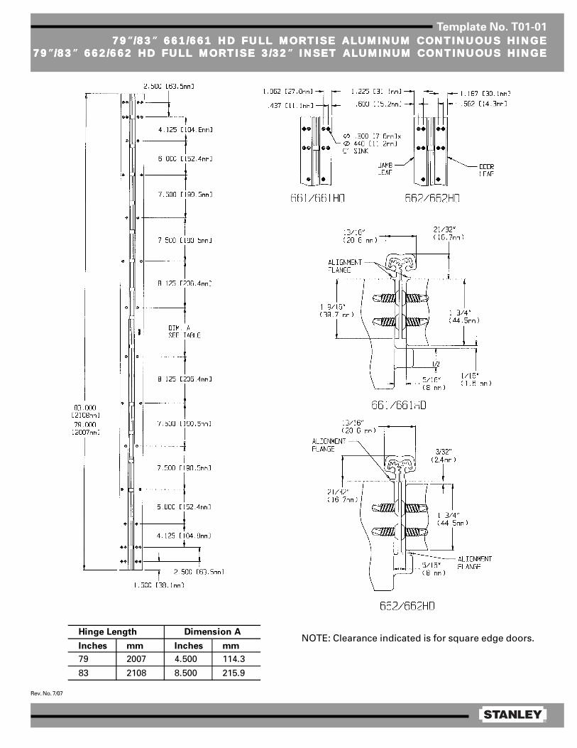
®
Rev. No. 7/07
Template No. T01-01
7979797979”/83/83/83/83/83” 661/661 HD FULL MORTISE ALUMINUM CONTINUOUS HINGE 661/661 HD FULL MORTISE ALUMINUM CONTINUOUS HINGE 661/661 HD FULL MORTISE ALUMINUM CONTINUOUS HINGE 661/661 HD FULL MORTISE ALUMINUM CONTINUOUS HINGE 661/661 HD FULL MORTISE ALUMINUM CONTINUOUS HINGE7979797979”/83/83/83/83/83” 662/662 HD FULL MORTISE 3/32 662/662 HD FULL MORTISE 3/32 662/662 HD FULL MORTISE 3/32 662/662 HD FULL MORTISE 3/32 662/662 HD FULL MORTISE 3/32” INSET ALUMINUM CONTINUOUS HINGE INSET ALUMINUM CONTINUOUS HINGE INSET ALUMINUM CONTINUOUS HINGE INSET ALUMINUM CONTINUOUS HINGE INSET ALUMINUM CONTINUOUS HINGE
Inches mm Inches mm
79 2007 4.500 114.3
83 2108 8.500 215.9
Hinge Length Dimension ANOTE: Clearance indicated is for square edge doors.

®
Rev. No. 7/07
Template No. T01-02
9595959595” 661/661 HD FULL MORTISE ALUMINUM CONTINUOUS HINGE 661/661 HD FULL MORTISE ALUMINUM CONTINUOUS HINGE 661/661 HD FULL MORTISE ALUMINUM CONTINUOUS HINGE 661/661 HD FULL MORTISE ALUMINUM CONTINUOUS HINGE 661/661 HD FULL MORTISE ALUMINUM CONTINUOUS HINGE9595959595” 662/662 HD FULL MORTISE 3/32 662/662 HD FULL MORTISE 3/32 662/662 HD FULL MORTISE 3/32 662/662 HD FULL MORTISE 3/32 662/662 HD FULL MORTISE 3/32” INSET ALUMINUM CONTINUOUS HINGE INSET ALUMINUM CONTINUOUS HINGE INSET ALUMINUM CONTINUOUS HINGE INSET ALUMINUM CONTINUOUS HINGE INSET ALUMINUM CONTINUOUS HINGE
NOTE: Clearance indicated is for square edge doors.

®
Rev. No. 7/07
Template No. T01-03
119119119119119” 661/661 HD FULL MORTISE ALUMINUM CONTINUOUS HINGE 661/661 HD FULL MORTISE ALUMINUM CONTINUOUS HINGE 661/661 HD FULL MORTISE ALUMINUM CONTINUOUS HINGE 661/661 HD FULL MORTISE ALUMINUM CONTINUOUS HINGE 661/661 HD FULL MORTISE ALUMINUM CONTINUOUS HINGE119119119119119” 662/662 HD FULL MORTISE 3/32 662/662 HD FULL MORTISE 3/32 662/662 HD FULL MORTISE 3/32 662/662 HD FULL MORTISE 3/32 662/662 HD FULL MORTISE 3/32” INSET ALUMINUM CONTINUOUS HINGE INSET ALUMINUM CONTINUOUS HINGE INSET ALUMINUM CONTINUOUS HINGE INSET ALUMINUM CONTINUOUS HINGE INSET ALUMINUM CONTINUOUS HINGE
NOTE: Clearance indicated is for square edge doors.

®
Rev. No. 3/11
Template No. T01-17
661/661 HD661/661 HD661/661 HD661/661 HD661/661 HD,,,,, 662/662 HD 662/662 HD 662/662 HD 662/662 HD 662/662 HD,,,,, AND 663/663 HD EPT CUTAND 663/663 HD EPT CUTAND 663/663 HD EPT CUTAND 663/663 HD EPT CUTAND 663/663 HD EPT CUTOUTOUTOUTOUTOUT
Model 662/662HDHanded
Model 661/661HDNon-Handed
Center of cut out
Specify manufacturer and model number of transfer
Model 663/663HDHanded
Top of hingeLeft hand hinge shownTop of hinge
Top of hingeLeft hand hinge shown
Dim.X Hinge Length Dim. "X"
79 43.00
[2006.5mm] [1092mm]
83 47.00
[2108.2mm] [1194mm]
95 59.00
[2413mm] [1499mm]
119 83.00
[3023mm] [2108mm]
*Because of variances associated with installation of the PHI EPT-5, the hinge willbe furnished with an EPT cut-out on the frame leaf only.A ½ inch hole for the door leaf is to be drilled at the job site to ensure that the holeis drilled at the optimal location.
*
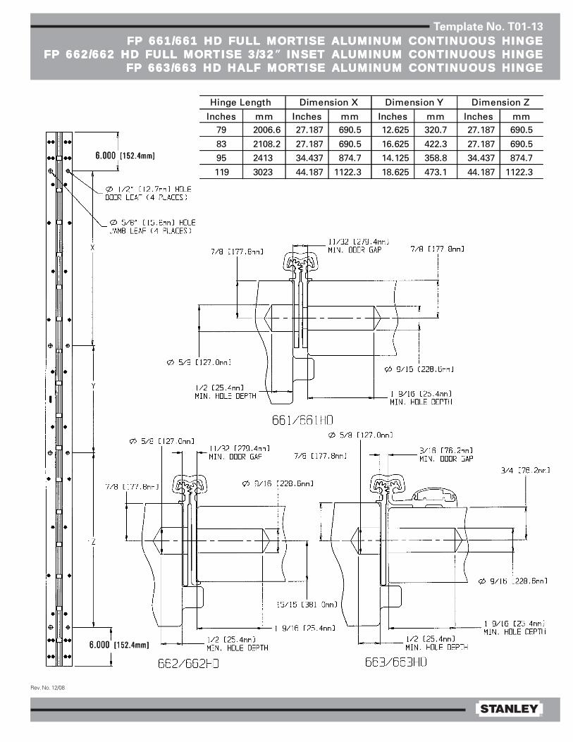
®
Rev. No. 12/08
Template No. T01-13
FP 661/661 HD FULL MORTISE ALUMINUM CONTINUOUS HINGEFP 661/661 HD FULL MORTISE ALUMINUM CONTINUOUS HINGEFP 661/661 HD FULL MORTISE ALUMINUM CONTINUOUS HINGEFP 661/661 HD FULL MORTISE ALUMINUM CONTINUOUS HINGEFP 661/661 HD FULL MORTISE ALUMINUM CONTINUOUS HINGEFP 662/662 HD FULL MORTISE 3/32FP 662/662 HD FULL MORTISE 3/32FP 662/662 HD FULL MORTISE 3/32FP 662/662 HD FULL MORTISE 3/32FP 662/662 HD FULL MORTISE 3/32” INSET ALUMINUM CONTINUOUS HINGE INSET ALUMINUM CONTINUOUS HINGE INSET ALUMINUM CONTINUOUS HINGE INSET ALUMINUM CONTINUOUS HINGE INSET ALUMINUM CONTINUOUS HINGE
FP 663/663 HD HALF MORTISE ALUMINUM CONTINUOUS HINGEFP 663/663 HD HALF MORTISE ALUMINUM CONTINUOUS HINGEFP 663/663 HD HALF MORTISE ALUMINUM CONTINUOUS HINGEFP 663/663 HD HALF MORTISE ALUMINUM CONTINUOUS HINGEFP 663/663 HD HALF MORTISE ALUMINUM CONTINUOUS HINGE
Inches mm Inches mm Inches mm Inches mm79 2006.6 27.187 690.5 12.625 320.7 27.187 690.5
83 2108.2 27.187 690.5 16.625 422.3 27.187 690.5
95 2413 34.437 874.7 14.125 358.8 34.437 874.7
119 3023 44.187 1122.3 18.625 473.1 44.187 1122.3
Hinge Length Dimension X Dimension Y Dimension Z
6.0006.0006.0006.0006.000 [152.4mm][152.4mm][152.4mm][152.4mm][152.4mm]
6.0006.0006.0006.0006.000 [152.4mm][152.4mm][152.4mm][152.4mm][152.4mm]

®
Rev. No. 2/06
Template No. T01-15
CE 661/661 HD AND CE 662/662 HD FULL MORTISE ALUMINUMCE 661/661 HD AND CE 662/662 HD FULL MORTISE ALUMINUMCE 661/661 HD AND CE 662/662 HD FULL MORTISE ALUMINUMCE 661/661 HD AND CE 662/662 HD FULL MORTISE ALUMINUMCE 661/661 HD AND CE 662/662 HD FULL MORTISE ALUMINUMCONTINUOUS HINGE WITH CONCEALED WIRESCONTINUOUS HINGE WITH CONCEALED WIRESCONTINUOUS HINGE WITH CONCEALED WIRESCONTINUOUS HINGE WITH CONCEALED WIRESCONTINUOUS HINGE WITH CONCEALED WIRES
NOTES:1 Available with four (4) wire (use
suffix-54) or eight (8) wire (usesuffix-58).
2 Drill a hole into the jamb and doorlarge enough for the wires andconnectors (wire nuts) to passthrough freely. A 0.500 dia. holeminimum is recommended.
3 Both faces of the hole should bedeburred and primed to help avoiddamaging wire insulation.
4 12 inch, 28 gauge wire leads.5 For CS concealed switch details,
see Template T01-16.
Inches mm Inches mm Inches mm
79 2007 41.375 1051 40.250 1022
83 2108 43.500 1105 43.250 1099
95 2413 55.688 1414 55.375 1407
119 3023 78.500 1994 79.500 2019
661HD/662HD
Dimension B
Hinge Length
Dimension A
661/662
Dimension B

®
Rev. No. 2/06
Template No. T01-16
CS 661/661 HD AND CS 662/662 HD FULL MORTISE ALUMINUMCS 661/661 HD AND CS 662/662 HD FULL MORTISE ALUMINUMCS 661/661 HD AND CS 662/662 HD FULL MORTISE ALUMINUMCS 661/661 HD AND CS 662/662 HD FULL MORTISE ALUMINUMCS 661/661 HD AND CS 662/662 HD FULL MORTISE ALUMINUMCONTINUOUS HINGE WITH CS CONCEALED WIRESCONTINUOUS HINGE WITH CS CONCEALED WIRESCONTINUOUS HINGE WITH CS CONCEALED WIRESCONTINUOUS HINGE WITH CS CONCEALED WIRESCONTINUOUS HINGE WITH CS CONCEALED WIRES
NOTES:1 Switch may be wired as Normally
Open or Normally Closed.2 Drill a hole into the jamb and door
large enough for the wires andconnectors (wire nuts) to passthrough freely. A 0.625 dia. holeminimum is recommended.
3 Both faces of the hole should bedeburred and primed to help avoiddamaging wire insulation.
4 3-22 wire gauge, 12 foot leads.5 For CE concealed switch details,
see Template T01-15.
Inches mm Inches mm Inches mm
79 2007 39.875 1013 38.750 984
83 2108 42.000 1067 41.750 1060
95 2413 54.188 1376 53.875 1368
119 3023 77.000 1956 78.000 1981
661HD/662HD
Dimension B
Hinge Length
Dimension A
661/662
Dimension B
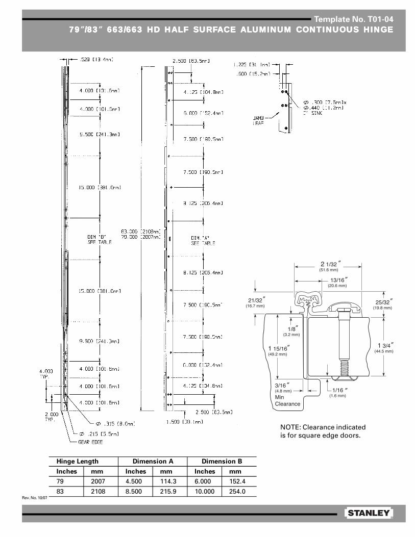
®
Rev. No. 10/07
Template No. T01-04
7979797979”/83/83/83/83/83” 663/663 HD HALF SURF 663/663 HD HALF SURF 663/663 HD HALF SURF 663/663 HD HALF SURF 663/663 HD HALF SURFAAAAACE CE CE CE CE ALALALALALUMINUM CONTINUOUS HINGEUMINUM CONTINUOUS HINGEUMINUM CONTINUOUS HINGEUMINUM CONTINUOUS HINGEUMINUM CONTINUOUS HINGE
Inches mm Inches mm Inches mm
79 2007 4.500 114.3 6.000 152.4
83 2108 8.500 215.9 10.000 254.0
Hinge Length Dimension A Dimension B
17⁄ 32″ (13.5 mm)
1⁄ 8″ (3.2 mm) LEAF THI CKNESS
NOTE: Clearance indicatedis for square edge doors.
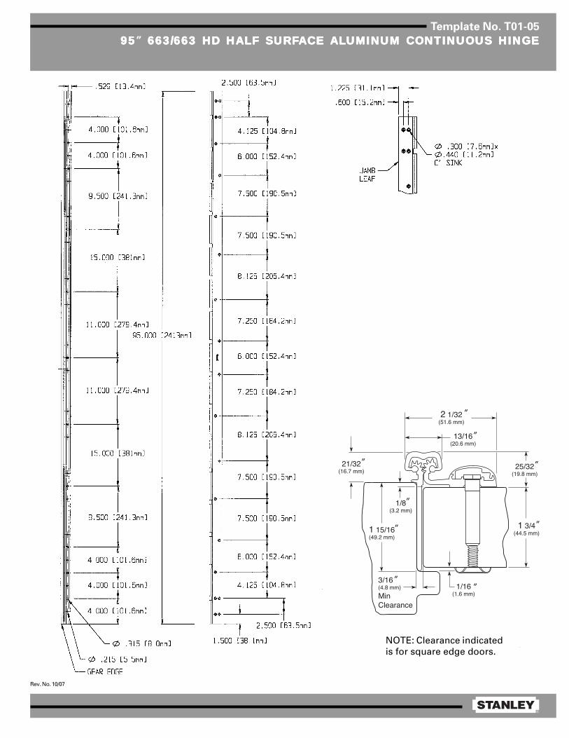
®
Rev. No. 10/07
Template No. T01-05
9595959595” 663/663 HD HALF SURF 663/663 HD HALF SURF 663/663 HD HALF SURF 663/663 HD HALF SURF 663/663 HD HALF SURFAAAAACE CE CE CE CE ALALALALALUMINUM CONTINUOUS HINGEUMINUM CONTINUOUS HINGEUMINUM CONTINUOUS HINGEUMINUM CONTINUOUS HINGEUMINUM CONTINUOUS HINGE
17⁄ 32″ (13.5 mm)
1⁄ 8″ (3.2 mm) LEAF THI CKNESS
NOTE: Clearance indicatedis for square edge doors.
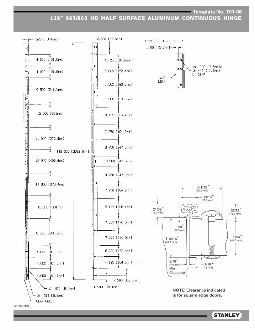
®
Rev. No. 10/07
Template No. T01-06
119119119119119” 663/663 HD HALF SURF 663/663 HD HALF SURF 663/663 HD HALF SURF 663/663 HD HALF SURF 663/663 HD HALF SURFAAAAACE CE CE CE CE ALALALALALUMINUM CONTINUOUS HINGEUMINUM CONTINUOUS HINGEUMINUM CONTINUOUS HINGEUMINUM CONTINUOUS HINGEUMINUM CONTINUOUS HINGE
17⁄ 32″ (13.5 mm)
1⁄ 8″ (3.2 mm) LEAF THI CKNESS
NOTE: Clearance indicatedis for square edge doors.

®
Rev. No. 3/11
Template No. T01-17
661/661 HD661/661 HD661/661 HD661/661 HD661/661 HD,,,,, 662/662 HD 662/662 HD 662/662 HD 662/662 HD 662/662 HD,,,,, AND 663/663 HD EPT CUTAND 663/663 HD EPT CUTAND 663/663 HD EPT CUTAND 663/663 HD EPT CUTAND 663/663 HD EPT CUTOUTOUTOUTOUTOUT
Model 662/662HDHanded
Model 661/661HDNon-Handed
Center of cut out
Specify manufacturer and model number of transfer
Model 663/663HDHanded
Top of hingeLeft hand hinge shownTop of hinge
Top of hingeLeft hand hinge shown
Dim.X Hinge Length Dim. "X"
79 43.00
[2006.5mm] [1092mm]
83 47.00
[2108.2mm] [1194mm]
95 59.00
[2413mm] [1499mm]
119 83.00
[3023mm] [2108mm]
*Because of variances associated with installation of the PHI EPT-5, the hinge willbe furnished with an EPT cut-out on the frame leaf only.A ½ inch hole for the door leaf is to be drilled at the job site to ensure that the holeis drilled at the optimal location.
*

®
Rev. No. 12/08
Template No. T01-13
FP 661/661 HD FULL MORTISE ALUMINUM CONTINUOUS HINGEFP 661/661 HD FULL MORTISE ALUMINUM CONTINUOUS HINGEFP 661/661 HD FULL MORTISE ALUMINUM CONTINUOUS HINGEFP 661/661 HD FULL MORTISE ALUMINUM CONTINUOUS HINGEFP 661/661 HD FULL MORTISE ALUMINUM CONTINUOUS HINGEFP 662/662 HD FULL MORTISE 3/32FP 662/662 HD FULL MORTISE 3/32FP 662/662 HD FULL MORTISE 3/32FP 662/662 HD FULL MORTISE 3/32FP 662/662 HD FULL MORTISE 3/32” INSET ALUMINUM CONTINUOUS HINGE INSET ALUMINUM CONTINUOUS HINGE INSET ALUMINUM CONTINUOUS HINGE INSET ALUMINUM CONTINUOUS HINGE INSET ALUMINUM CONTINUOUS HINGE
FP 663/663 HD HALF MORTISE ALUMINUM CONTINUOUS HINGEFP 663/663 HD HALF MORTISE ALUMINUM CONTINUOUS HINGEFP 663/663 HD HALF MORTISE ALUMINUM CONTINUOUS HINGEFP 663/663 HD HALF MORTISE ALUMINUM CONTINUOUS HINGEFP 663/663 HD HALF MORTISE ALUMINUM CONTINUOUS HINGE
Inches mm Inches mm Inches mm Inches mm79 2006.6 27.187 690.5 12.625 320.7 27.187 690.5
83 2108.2 27.187 690.5 16.625 422.3 27.187 690.5
95 2413 34.437 874.7 14.125 358.8 34.437 874.7
119 3023 44.187 1122.3 18.625 473.1 44.187 1122.3
Hinge Length Dimension X Dimension Y Dimension Z
6.0006.0006.0006.0006.000 [152.4mm][152.4mm][152.4mm][152.4mm][152.4mm]
6.0006.0006.0006.0006.000 [152.4mm][152.4mm][152.4mm][152.4mm][152.4mm]
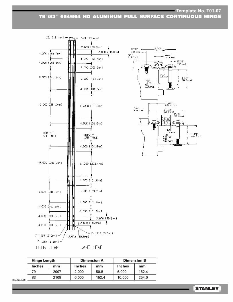
®
Rev. No. 3/06
Template No. T01-07
7979797979”/83/83/83/83/83” 664/664 HD 664/664 HD 664/664 HD 664/664 HD 664/664 HD ALALALALALUMINUM FULL SURFUMINUM FULL SURFUMINUM FULL SURFUMINUM FULL SURFUMINUM FULL SURFAAAAACE CONTINUOUS HINGECE CONTINUOUS HINGECE CONTINUOUS HINGECE CONTINUOUS HINGECE CONTINUOUS HINGE
Inches mm Inches mm Inches mm
79 2007 2.000 50.8 6.000 152.4
83 2108 6.000 152.4 10.000 254.0
Dimension A Dimension BHinge Length
17⁄ 32″ (13.5 mm)
17⁄ 32″ (13.5 mm)
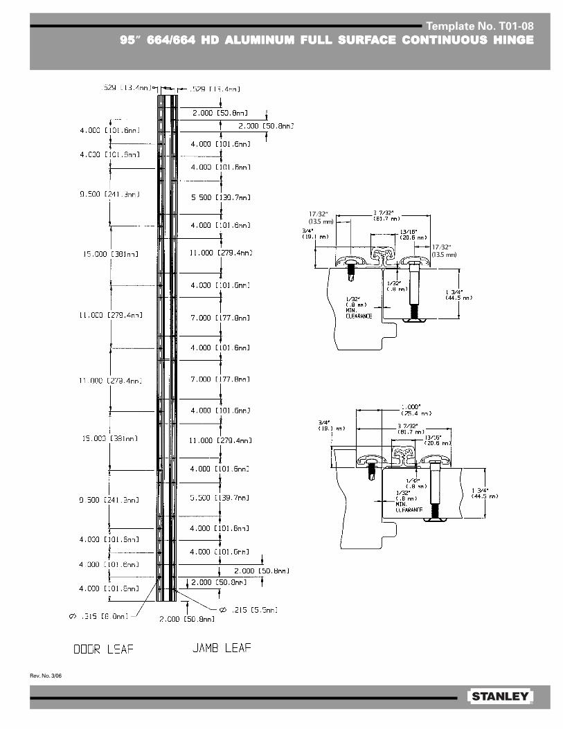
®
Rev. No. 3/06
Template No. T01-08
9595959595” 664/664 HD 664/664 HD 664/664 HD 664/664 HD 664/664 HD ALALALALALUMINUM FULL SURFUMINUM FULL SURFUMINUM FULL SURFUMINUM FULL SURFUMINUM FULL SURFAAAAACE CONTINUOUS HINGECE CONTINUOUS HINGECE CONTINUOUS HINGECE CONTINUOUS HINGECE CONTINUOUS HINGE
17⁄ 32″ (13.5 mm)
17⁄ 32″ (13.5 mm)
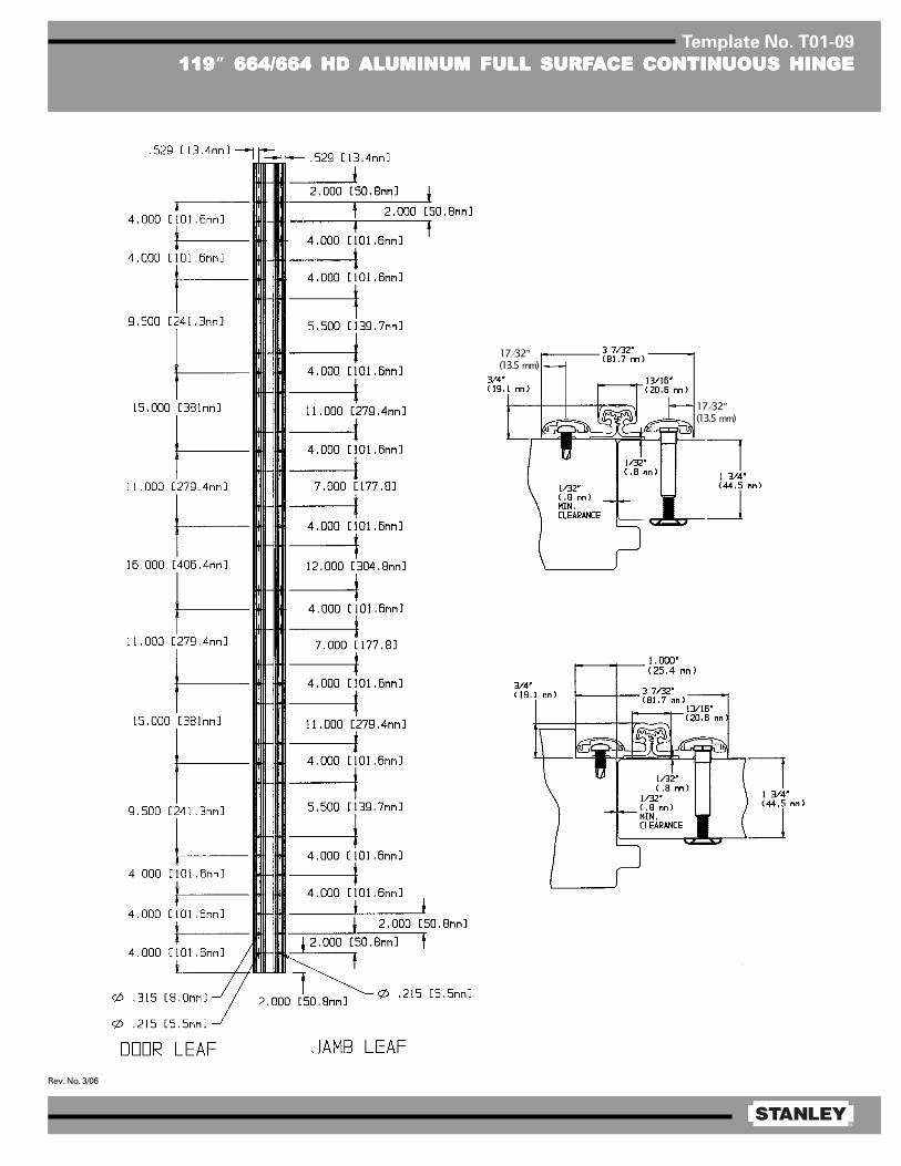
®
Rev. No. 3/06
Template No. T01-09
119119119119119” 664/664 HD 664/664 HD 664/664 HD 664/664 HD 664/664 HD ALALALALALUMINUM FULL SURFUMINUM FULL SURFUMINUM FULL SURFUMINUM FULL SURFUMINUM FULL SURFAAAAACE CONTINUOUS HINGECE CONTINUOUS HINGECE CONTINUOUS HINGECE CONTINUOUS HINGECE CONTINUOUS HINGE
17⁄ 32″ (13.5 mm)
17⁄ 32″ (13.5 mm)
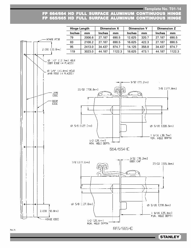
®
Rev. No. 2/06
Template No. T01-14
FP 664/664 HD FULL SURFFP 664/664 HD FULL SURFFP 664/664 HD FULL SURFFP 664/664 HD FULL SURFFP 664/664 HD FULL SURFAAAAACE CE CE CE CE ALALALALALUMINUM CONTINUOUS HINGEUMINUM CONTINUOUS HINGEUMINUM CONTINUOUS HINGEUMINUM CONTINUOUS HINGEUMINUM CONTINUOUS HINGEFP 665/665 HD FULL SURFFP 665/665 HD FULL SURFFP 665/665 HD FULL SURFFP 665/665 HD FULL SURFFP 665/665 HD FULL SURFAAAAACE CE CE CE CE ALALALALALUMINUM CONTINUOUS HINGEUMINUM CONTINUOUS HINGEUMINUM CONTINUOUS HINGEUMINUM CONTINUOUS HINGEUMINUM CONTINUOUS HINGE
Inches mm Inches mm Inches mm Inches mm
79 2006.6 27.187 690.5 12.625 320.7 27.187 690.5
83 2108.2 27.187 690.5 16.625 422.3 27.187 690.5
95 2413.0 34.437 874.7 14.125 358.8 34.437 874.7
119 3023.0 44.187 1122.3 18.625 473.1 44.187 1122.3
Hinge Length Dimension X Dimension Y Dimension Z

1/2
Fire-Rated Continuous Hinge [Locking Bolt] Installation InstructionsInstrucciones de instalación de la bisagra continua ignífuga [perno de bloqueo]
Instructions d'installation de charnière continue homologuée ignifuge [écrous bloquants]
BAluminum Continuous Geared Hinges:Bisagras con engranaje continuo de aluminio:Charnières continues en aluminiumà plusieurs crans :
Full MortiseCaja completa Mortaise complèteModels: Modelos: Modèles :661/661HD & 662/662HD
Full SurfaceSuper�cie completa Surface complèteModels: Modelos: Modèles :664/664HD & 665/665HD
Half SurfaceMedia super�cie Moitié de surfaceModels: Models: Models:663/663HD
C
Heat Activated Locking BoltPerno de bloqueo activado por calorÉcrou bloquant à activation thermique
Grommet ClipGancho con sombrereteŒillet
Snap-in Hole PlugTapón a presiónBouchon de trou encliquetable
A
B
C
Full Mortise ShownSe muestra la caja completaMortaise complète illustrée
A
A
B
C
0.505” dia.(12.8 mm)
0.630” dia.(16 mm)
Frame LeafHoja del marco
Vantail de cadre
Door LeafHoja de la puertaVantail de porte
Full Mortise Instructions:
Verify that the door and frame are prepared in accordance with the appropriate template ( T01-01 − T01-03), �re rated (T01-13).
1. Use hinge leaves to verify hole prep on both the door and frame.
2. Insert Grommet Clip ‘B’ into hole on door edge, 4 places.
3. Position door leaf hinge to door edge, making sure all holes align. Insert the Heat Activated Locking Bolt ‘A’ through the hinge and into Grommet Clip ‘B’ on door edge, 4 places.
4. Fasten door leaf hinge to door edge.
5. Position the door and hinge onto the frame. While supporting the door weight, align the holes in the frame leaf to the holes in the door frame. Fasten the frame leaf using several screws near the top and bottom of the hinge. Check door swing and function, then install the remaining screws.
6. Insert Snap-in Hole Plug ‘C’ into hole on frame leaf, 4 places.
Instrucciones para caja completa:
Veri�que que la puerta y el marco estén preparados de acuerdo con la plantilla apropiada (T01-01 − T01-03), y sean ignífugos (T01-13).
1. Use hojas de bisagra para veri�car la preparación para ori�cios en la puerta y el marco.2. Inserte el gancho con sombrerete “B” en el borde de la puerta, en 4 lugares.3. Coloque la bisagra de la hoja de la puerta en el borde de la puerta, asegurándose de que los ori�cios se alineen. Inserte el perno de bloqueo activado por calor “A” por la bisagra en el gancho con sombrerete “B” en el borde de la puerta, en 4 lugares.4. Sujete la bisagra de la hoja de la puerta al borde de la puerta.5. Coloque la puerta y la bisagra en el marco. Mientras sostiene el peso de la puerta, alinee los ori�cios en la hoja del marco con los ori�cios en el marco de la puerta. Sujete la hoja del marco usando varios tornillos cerca de la parte superior e inferior de la bisagra. Compruebe el movimiento y el funcionamiento de la puerta, e instale los tornillos restantes.6. Inserte el tapón a presión “C” en el ori�cio en la hoja del marco, en 4 lugares.
Instructions concernant la mortaise complète :
Véri�ez que les préparations de porte et de cadre sont conformes au modèle adéquat (T01-01 − T01-03) et que ces éléments sont homologués ignifuges (T01-13).
1. À l'aide des vantaux, véri�ez le bon emplacement des trous de préparation sur la porte et le cadre.2. Insérez les œillets B dans les trous situés sur la tranche de la porte aux 4 endroits prévus.3. Positionnez la charnière du vantail de la porte sur la tranche de la porte, tout en vous assurant que tous les trous sont alignés. Insérez les écrous bloquants à activation thermique A à travers la charnière et à l'intérieur des œillets B sur la tranche de la porte aux 4 endroits prévus.4. Fixez la charnière du vantail de la porte à la tranche de la porte.5. Placez la porte et la charnière sur le cadre. Tout en soutenant la porte, alignez tous les trous du vantail du cadre aux trous du cadre de la porte. Fixez le vantail du cadre à l'aide de quelques vis dans la partie supérieure et inférieure de la charnière. Véri�ez que la porte s'ouvre et se ferme correctement, puis �xez les vis restantes.6. Insérez les bouchons de trous encliquetables C dans les trous du vantail du cadre aux 4 endroits prévus.

A85390_A Copyright© Stanley Security, Inc. 20162/2
For assistance or warranty information:Call 1-855-365-2407 or visitwww.stanleydoorhinges.com
Warning: This Manufacturer advises that no lock can provide complete security by itself. This lock may be defeated by forcible or technical means, or evaded by entry elsewhere on the property. No lock can substitute for caution, awareness of your environment, and common sense. Builder’s hardware is available in multiple performance grades to suit the application. In order to enhance security and reduce risk, you should consult a quali�ed locksmith or other security professional.
Si desea ayuda o información sobre la garantia:llame al 1-855-365-2407 ou visite
www.stanleydoorhinges.com
Advertencia: Este fabricante have saber que no hay cerraduras que puedan proporcionar seguridad completa por si misma. Esta cerradura puede fallar forzandola o utilizando medios técnicos o entrando por otra parte del edi�cio. No hay cerraduras que puedan sustituir precaución, estar al tanto de su entorno y sentido común. Este fabricante también ofrece cerraduras de diferentes grados y rendimientos para ajustarse a su aplicación. Para mejorar la seguridad y reducer riesgos, usted debe consultar con un cerrajero especializado u otro profesional de seguridad.
Pour de l'aide ou des informations sur la garantie:Vauillez appeler le 1-855-365-2407 ou visiter
www.stanleydoorhinges.com
Advertissement: Le fabricant tient à vous aviser qu'aucun verrou ne peut à lui seul offrir une sécurité complète. Ce verrou peut être mis hors d'état par la force ou des moyens techniques ou etre évité par l'utilisation d'une autre entrée sur la propriété. Aucun verrou ne peut remplacer la surveillance de votre enviornnenment et le bon sens. La quincaillerie pour le constructeur est offerte selon différents grades de performance pour différentes applications. A�n d'augmenter la sécurité et de rduire le risque, vous devriez consulter un serrurier quali�é ou un autre professionel de la sécurité.
Instructions relatives à la moitié de surface :
Véri�ez que les préparations de porte et de cadre sont conformes au modèle adéquat (T01-04 − T01-06) et que ces éléments sont homologués ignifuges (T01-13).
1. Aidez-vous du vantail de cadre pour véri�er l'emplacement des trous de préparation sur le cadre.2. Insérez les œillets B dans les trous situés sur la tranche de la porte aux 4 endroits prévus.3. Insérez les écrous bloquants à activation thermique A dans les œillets B et enfoncez les œillets dans les trous de façon à ce qu'ils soient au ras de la surface aux 4 endroits prévus.4. Fixez la charnière de vantail à la porte.5. Placez la porte et la charnière sur le cadre. Tout en soutenant la porte, alignez tous les trous du vantail du cadre aux trous du cadre de la porte. Fixez le vantail du cadre à l'aide de quelques vis dans la partie supérieure et inférieure de la charnière. Véri�ez que la porte s'ouvre et se ferme correctement, puis �xez les vis restantes.6. Insérez les bouchons de trous encliquetables C dans les trous du vantail du cadre aux 4 endroits prévus.
Instrucciones para media super�cie:
Veri�que que la puerta y el marco estén preparados de acuerdo con la plantilla apropiada (T01-04 − T01-06), y sean ignífugos (T01-13).1. Use la hoja del marco para veri�car la preparación para ori�cios en el marco.2. Inserte el gancho con sombrerete “B” en el borde de la puerta, en 4 lugares.3. Inserte el perno de bloqueo activado por calor “A” en el gancho con sombrerete “B”, asiente de modo rasante con el frente del sombrerete, en 4 lugares.4. Monte la bisagra de la hoja de la puerta en la puerta.5. Coloque la puerta y la bisagra en el marco. Mientras sostiene el peso de la puerta, alinee los ori�cios en la hoja del marco con los ori�cios en el marco de la puerta. Sujete la hoja del marco usando varios tornillos cerca de la parte superior e inferior de la bisagra. Compruebe el movimiento y el funcionamiento de la puerta, e instale los tornillos restantes.6. Inserte el tapón a presión “C” en el ori�cio en la hoja del marco, en 4 lugares.
Instrucciones para super�cie completa:
Veri�que que la puerta y el marco estén preparados de acuerdo con la plantilla apropiada (T01-07 − T01-12).1. Monte la bisagra.2. Inserte el gancho con sombrerete “B” en el borde de la puerta, en 4 lugares.3. Inserte el perno de bloqueo activado por calor “A” en el gancho con sombrerete “B”, asiente de modo rasante con el frente del sombrerete, en 4 lugares.4. Inserte el tapón a presión “G” en el ori�cio en la hoja del marco, en 4 lugares.5. Compruebe el movimiento y el funcionamiento de la puerta.
Instructions relatives à la surface complète :
Véri�ez que les préparations de porte et de cadre sont conformes au modèle adéquat (T01-07 − T01-12).1. Fixez la charnière.2. Insérez les œillets B dans les trous situés sur la tranche de la porte aux 4 endroits prévus.3. Insérez les écrous bloquants à activation thermique A dans les œillets B et enfoncez les œillets dans les trous de façon à ce qu'ils soient au ras de la surface aux 4 endroits prévus.4. Insérez les bouchons de trous encliquetables G dans les trous du vantail du cadre aux 4 endroits prévus.5. Véri�ez que la porte s'ouvre et se ferme correctement.
AB
C
Frame LeafHoja del marco
Vantail de cadre
Door LeafHoja de la puertaVantail de porte
Half Surface Instructions:
Verify that the door and frame are prepared in accordance with the appropriate template ( T01-04 − T01-06), �re rated (T01-13).
1. Use frame leaf to verify hole prep on frame.
2. Insert Grommet Clip ‘B’ into hole on door edge, 4 places.
3. Insert the Heat Activated Locking Bolt ‘A’ into Grommet Clip ‘B’, seat �ush with face of grommet, 4 places. 4. Mount the door leaf hinge to the door.
5. Position the door and hinge onto the frame. While supporting the door weight, align the holes in the frame leaf to the holes in the door frame. Fasten the frame leaf using several screws near the top and bottom of the hinge. Check door swing and function, then install the remaining screws.
6. Insert Snap-in Hole Plug ‘C’ into hole on frame leaf, 4 places.
AB
C
Full Surface Instructions:
Verify that the door and frame are prepared in accordance with the appropriate template ( T01-07 − T01-12).
1. Mount the hinge.
2. Insert Grommet Clip ‘B’ into hole on door edge, 4 places.
3. Insert the Heat Activated Locking Bolt ‘A’ into Grommet Clip ‘B’, seat �ush with face of grommet, 4 places. 4. Insert Snap-in Hole Plug ‘C’ into hole on frame leaf, 4 places.
5. Check door swing and function.
Frame LeafHoja del marco
Vantail de cadre
Door LeafHoja de la puertaVantail de porte
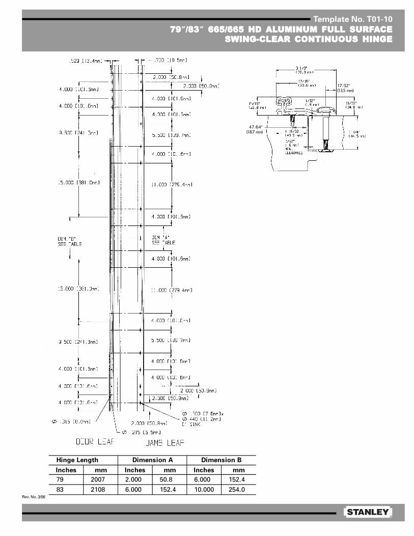
®
Rev. No. 3/06
Template No. T01-10
7979797979”/83/83/83/83/83” 665/665 HD 665/665 HD 665/665 HD 665/665 HD 665/665 HD ALALALALALUMINUM FULL SURFUMINUM FULL SURFUMINUM FULL SURFUMINUM FULL SURFUMINUM FULL SURFAAAAACECECECECESWING-CLEAR CONTINUOUS HINGESWING-CLEAR CONTINUOUS HINGESWING-CLEAR CONTINUOUS HINGESWING-CLEAR CONTINUOUS HINGESWING-CLEAR CONTINUOUS HINGE
Inches mm Inches mm Inches mm
79 2007 2.000 50.8 6.000 152.4
83 2108 6.000 152.4 10.000 254.0
Dimension A Dimension BHinge Length
17⁄ 32″ (13.5 mm)
47⁄ 64″ (18.7 mm)
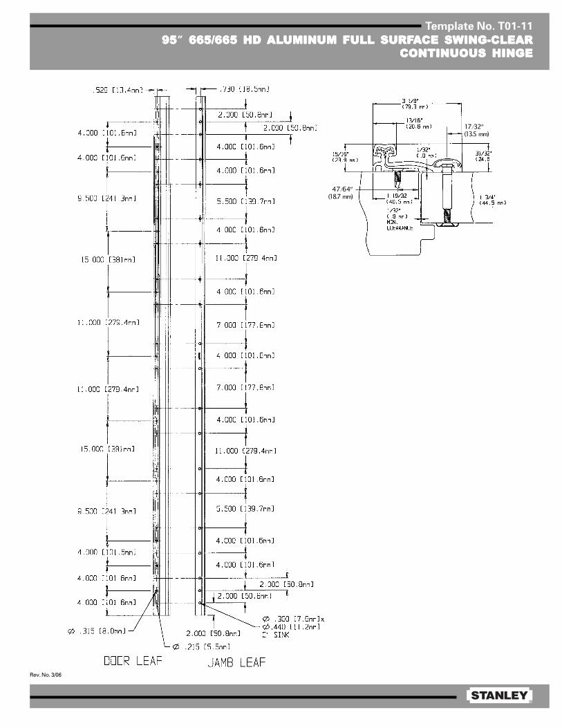
®
Rev. No. 3/06
Template No. T01-11
9595959595” 665/665 HD 665/665 HD 665/665 HD 665/665 HD 665/665 HD ALALALALALUMINUM FULL SURFUMINUM FULL SURFUMINUM FULL SURFUMINUM FULL SURFUMINUM FULL SURFAAAAACE SWING-CLEARCE SWING-CLEARCE SWING-CLEARCE SWING-CLEARCE SWING-CLEARCONTINUOUS HINGECONTINUOUS HINGECONTINUOUS HINGECONTINUOUS HINGECONTINUOUS HINGE
17⁄ 32″ (13.5 mm)
47⁄ 64″ (18.7 mm)
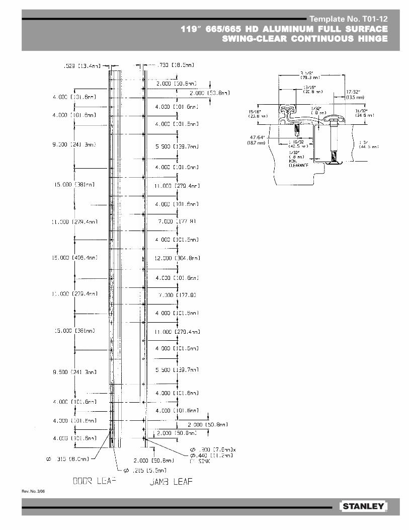
®
Rev. No. 3/06
Template No. T01-12
119119119119119” 665/665 HD 665/665 HD 665/665 HD 665/665 HD 665/665 HD ALALALALALUMINUM FULL SURFUMINUM FULL SURFUMINUM FULL SURFUMINUM FULL SURFUMINUM FULL SURFAAAAACECECECECESWING-CLEAR CONTINUOUS HINGESWING-CLEAR CONTINUOUS HINGESWING-CLEAR CONTINUOUS HINGESWING-CLEAR CONTINUOUS HINGESWING-CLEAR CONTINUOUS HINGE
17⁄ 32″ (13.5 mm)
47⁄ 64″ (18.7 mm)

®
Rev. No. 2/06
Template No. T01-14
FP 664/664 HD FULL SURFFP 664/664 HD FULL SURFFP 664/664 HD FULL SURFFP 664/664 HD FULL SURFFP 664/664 HD FULL SURFAAAAACE CE CE CE CE ALALALALALUMINUM CONTINUOUS HINGEUMINUM CONTINUOUS HINGEUMINUM CONTINUOUS HINGEUMINUM CONTINUOUS HINGEUMINUM CONTINUOUS HINGEFP 665/665 HD FULL SURFFP 665/665 HD FULL SURFFP 665/665 HD FULL SURFFP 665/665 HD FULL SURFFP 665/665 HD FULL SURFAAAAACE CE CE CE CE ALALALALALUMINUM CONTINUOUS HINGEUMINUM CONTINUOUS HINGEUMINUM CONTINUOUS HINGEUMINUM CONTINUOUS HINGEUMINUM CONTINUOUS HINGE
Inches mm Inches mm Inches mm Inches mm
79 2006.6 27.187 690.5 12.625 320.7 27.187 690.5
83 2108.2 27.187 690.5 16.625 422.3 27.187 690.5
95 2413.0 34.437 874.7 14.125 358.8 34.437 874.7
119 3023.0 44.187 1122.3 18.625 473.1 44.187 1122.3
Hinge Length Dimension X Dimension Y Dimension Z
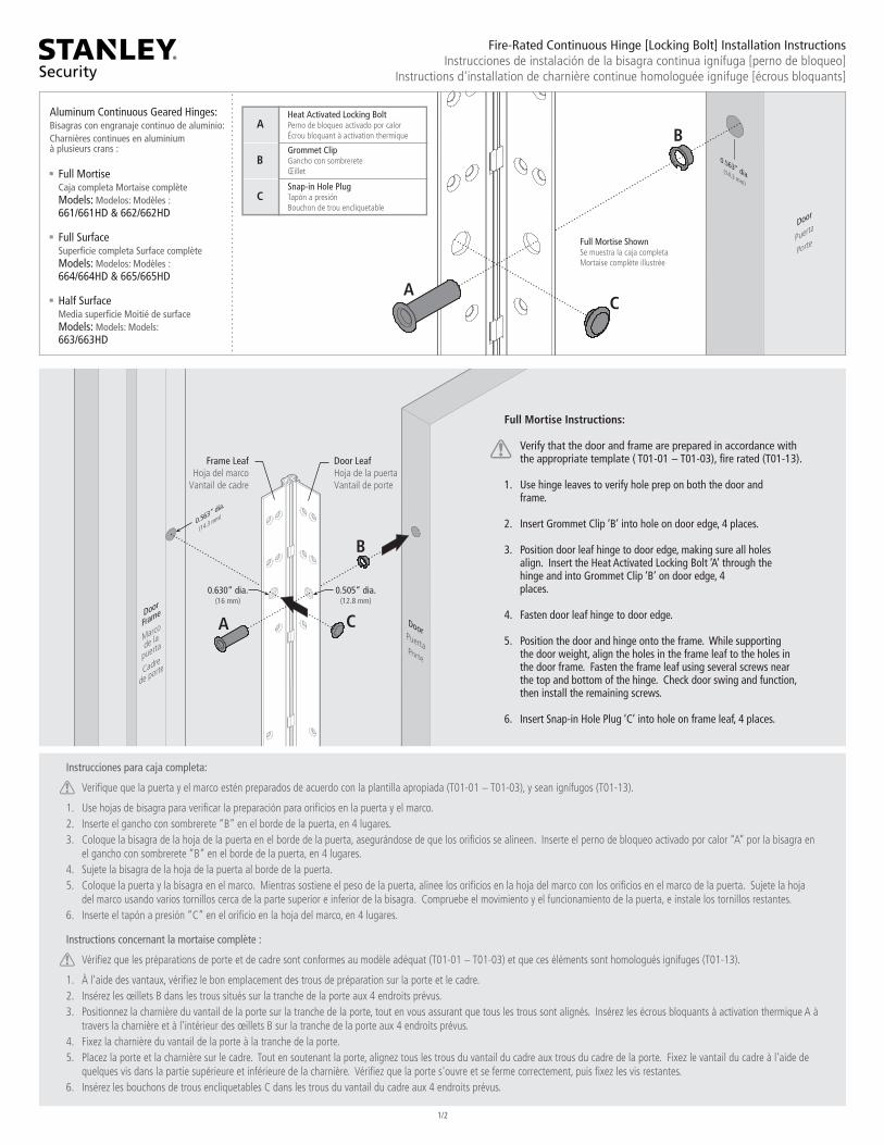
1/2
Fire-Rated Continuous Hinge [Locking Bolt] Installation InstructionsInstrucciones de instalación de la bisagra continua ignífuga [perno de bloqueo]
Instructions d'installation de charnière continue homologuée ignifuge [écrous bloquants]
BAluminum Continuous Geared Hinges:Bisagras con engranaje continuo de aluminio:Charnières continues en aluminiumà plusieurs crans :
Full MortiseCaja completa Mortaise complèteModels: Modelos: Modèles :661/661HD & 662/662HD
Full SurfaceSuper�cie completa Surface complèteModels: Modelos: Modèles :664/664HD & 665/665HD
Half SurfaceMedia super�cie Moitié de surfaceModels: Models: Models:663/663HD
C
Heat Activated Locking BoltPerno de bloqueo activado por calorÉcrou bloquant à activation thermique
Grommet ClipGancho con sombrereteŒillet
Snap-in Hole PlugTapón a presiónBouchon de trou encliquetable
A
B
C
Full Mortise ShownSe muestra la caja completaMortaise complète illustrée
A
A
B
C
0.505” dia.(12.8 mm)
0.630” dia.(16 mm)
Frame LeafHoja del marco
Vantail de cadre
Door LeafHoja de la puertaVantail de porte
Full Mortise Instructions:
Verify that the door and frame are prepared in accordance with the appropriate template ( T01-01 − T01-03), �re rated (T01-13).
1. Use hinge leaves to verify hole prep on both the door and frame.
2. Insert Grommet Clip ‘B’ into hole on door edge, 4 places.
3. Position door leaf hinge to door edge, making sure all holes align. Insert the Heat Activated Locking Bolt ‘A’ through the hinge and into Grommet Clip ‘B’ on door edge, 4 places.
4. Fasten door leaf hinge to door edge.
5. Position the door and hinge onto the frame. While supporting the door weight, align the holes in the frame leaf to the holes in the door frame. Fasten the frame leaf using several screws near the top and bottom of the hinge. Check door swing and function, then install the remaining screws.
6. Insert Snap-in Hole Plug ‘C’ into hole on frame leaf, 4 places.
Instrucciones para caja completa:
Veri�que que la puerta y el marco estén preparados de acuerdo con la plantilla apropiada (T01-01 − T01-03), y sean ignífugos (T01-13).
1. Use hojas de bisagra para veri�car la preparación para ori�cios en la puerta y el marco.2. Inserte el gancho con sombrerete “B” en el borde de la puerta, en 4 lugares.3. Coloque la bisagra de la hoja de la puerta en el borde de la puerta, asegurándose de que los ori�cios se alineen. Inserte el perno de bloqueo activado por calor “A” por la bisagra en el gancho con sombrerete “B” en el borde de la puerta, en 4 lugares.4. Sujete la bisagra de la hoja de la puerta al borde de la puerta.5. Coloque la puerta y la bisagra en el marco. Mientras sostiene el peso de la puerta, alinee los ori�cios en la hoja del marco con los ori�cios en el marco de la puerta. Sujete la hoja del marco usando varios tornillos cerca de la parte superior e inferior de la bisagra. Compruebe el movimiento y el funcionamiento de la puerta, e instale los tornillos restantes.6. Inserte el tapón a presión “C” en el ori�cio en la hoja del marco, en 4 lugares.
Instructions concernant la mortaise complète :
Véri�ez que les préparations de porte et de cadre sont conformes au modèle adéquat (T01-01 − T01-03) et que ces éléments sont homologués ignifuges (T01-13).
1. À l'aide des vantaux, véri�ez le bon emplacement des trous de préparation sur la porte et le cadre.2. Insérez les œillets B dans les trous situés sur la tranche de la porte aux 4 endroits prévus.3. Positionnez la charnière du vantail de la porte sur la tranche de la porte, tout en vous assurant que tous les trous sont alignés. Insérez les écrous bloquants à activation thermique A à travers la charnière et à l'intérieur des œillets B sur la tranche de la porte aux 4 endroits prévus.4. Fixez la charnière du vantail de la porte à la tranche de la porte.5. Placez la porte et la charnière sur le cadre. Tout en soutenant la porte, alignez tous les trous du vantail du cadre aux trous du cadre de la porte. Fixez le vantail du cadre à l'aide de quelques vis dans la partie supérieure et inférieure de la charnière. Véri�ez que la porte s'ouvre et se ferme correctement, puis �xez les vis restantes.6. Insérez les bouchons de trous encliquetables C dans les trous du vantail du cadre aux 4 endroits prévus.
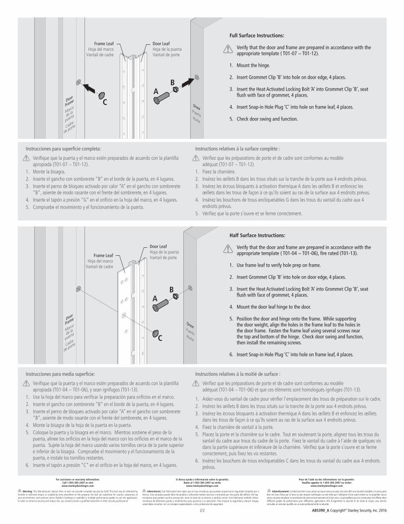
A85390_A Copyright© Stanley Security, Inc. 20162/2
For assistance or warranty information:Call 1-855-365-2407 or visitwww.stanleydoorhinges.com
Warning: This Manufacturer advises that no lock can provide complete security by itself. This lock may be defeated by forcible or technical means, or evaded by entry elsewhere on the property. No lock can substitute for caution, awareness of your environment, and common sense. Builder’s hardware is available in multiple performance grades to suit the application. In order to enhance security and reduce risk, you should consult a quali�ed locksmith or other security professional.
Si desea ayuda o información sobre la garantia:llame al 1-855-365-2407 ou visite
www.stanleydoorhinges.com
Advertencia: Este fabricante have saber que no hay cerraduras que puedan proporcionar seguridad completa por si misma. Esta cerradura puede fallar forzandola o utilizando medios técnicos o entrando por otra parte del edi�cio. No hay cerraduras que puedan sustituir precaución, estar al tanto de su entorno y sentido común. Este fabricante también ofrece cerraduras de diferentes grados y rendimientos para ajustarse a su aplicación. Para mejorar la seguridad y reducer riesgos, usted debe consultar con un cerrajero especializado u otro profesional de seguridad.
Pour de l'aide ou des informations sur la garantie:Vauillez appeler le 1-855-365-2407 ou visiter
www.stanleydoorhinges.com
Advertissement: Le fabricant tient à vous aviser qu'aucun verrou ne peut à lui seul offrir une sécurité complète. Ce verrou peut être mis hors d'état par la force ou des moyens techniques ou etre évité par l'utilisation d'une autre entrée sur la propriété. Aucun verrou ne peut remplacer la surveillance de votre enviornnenment et le bon sens. La quincaillerie pour le constructeur est offerte selon différents grades de performance pour différentes applications. A�n d'augmenter la sécurité et de rduire le risque, vous devriez consulter un serrurier quali�é ou un autre professionel de la sécurité.
Instructions relatives à la moitié de surface :
Véri�ez que les préparations de porte et de cadre sont conformes au modèle adéquat (T01-04 − T01-06) et que ces éléments sont homologués ignifuges (T01-13).
1. Aidez-vous du vantail de cadre pour véri�er l'emplacement des trous de préparation sur le cadre.2. Insérez les œillets B dans les trous situés sur la tranche de la porte aux 4 endroits prévus.3. Insérez les écrous bloquants à activation thermique A dans les œillets B et enfoncez les œillets dans les trous de façon à ce qu'ils soient au ras de la surface aux 4 endroits prévus.4. Fixez la charnière de vantail à la porte.5. Placez la porte et la charnière sur le cadre. Tout en soutenant la porte, alignez tous les trous du vantail du cadre aux trous du cadre de la porte. Fixez le vantail du cadre à l'aide de quelques vis dans la partie supérieure et inférieure de la charnière. Véri�ez que la porte s'ouvre et se ferme correctement, puis �xez les vis restantes.6. Insérez les bouchons de trous encliquetables C dans les trous du vantail du cadre aux 4 endroits prévus.
Instrucciones para media super�cie:
Veri�que que la puerta y el marco estén preparados de acuerdo con la plantilla apropiada (T01-04 − T01-06), y sean ignífugos (T01-13).1. Use la hoja del marco para veri�car la preparación para ori�cios en el marco.2. Inserte el gancho con sombrerete “B” en el borde de la puerta, en 4 lugares.3. Inserte el perno de bloqueo activado por calor “A” en el gancho con sombrerete “B”, asiente de modo rasante con el frente del sombrerete, en 4 lugares.4. Monte la bisagra de la hoja de la puerta en la puerta.5. Coloque la puerta y la bisagra en el marco. Mientras sostiene el peso de la puerta, alinee los ori�cios en la hoja del marco con los ori�cios en el marco de la puerta. Sujete la hoja del marco usando varios tornillos cerca de la parte superior e inferior de la bisagra. Compruebe el movimiento y el funcionamiento de la puerta, e instale los tornillos restantes.6. Inserte el tapón a presión “C” en el ori�cio en la hoja del marco, en 4 lugares.
Instrucciones para super�cie completa:
Veri�que que la puerta y el marco estén preparados de acuerdo con la plantilla apropiada (T01-07 − T01-12).1. Monte la bisagra.2. Inserte el gancho con sombrerete “B” en el borde de la puerta, en 4 lugares.3. Inserte el perno de bloqueo activado por calor “A” en el gancho con sombrerete “B”, asiente de modo rasante con el frente del sombrerete, en 4 lugares.4. Inserte el tapón a presión “G” en el ori�cio en la hoja del marco, en 4 lugares.5. Compruebe el movimiento y el funcionamiento de la puerta.
Instructions relatives à la surface complète :
Véri�ez que les préparations de porte et de cadre sont conformes au modèle adéquat (T01-07 − T01-12).1. Fixez la charnière.2. Insérez les œillets B dans les trous situés sur la tranche de la porte aux 4 endroits prévus.3. Insérez les écrous bloquants à activation thermique A dans les œillets B et enfoncez les œillets dans les trous de façon à ce qu'ils soient au ras de la surface aux 4 endroits prévus.4. Insérez les bouchons de trous encliquetables G dans les trous du vantail du cadre aux 4 endroits prévus.5. Véri�ez que la porte s'ouvre et se ferme correctement.
AB
C
Frame LeafHoja del marco
Vantail de cadre
Door LeafHoja de la puertaVantail de porte
Half Surface Instructions:
Verify that the door and frame are prepared in accordance with the appropriate template ( T01-04 − T01-06), �re rated (T01-13).
1. Use frame leaf to verify hole prep on frame.
2. Insert Grommet Clip ‘B’ into hole on door edge, 4 places.
3. Insert the Heat Activated Locking Bolt ‘A’ into Grommet Clip ‘B’, seat �ush with face of grommet, 4 places. 4. Mount the door leaf hinge to the door.
5. Position the door and hinge onto the frame. While supporting the door weight, align the holes in the frame leaf to the holes in the door frame. Fasten the frame leaf using several screws near the top and bottom of the hinge. Check door swing and function, then install the remaining screws.
6. Insert Snap-in Hole Plug ‘C’ into hole on frame leaf, 4 places.
AB
C
Full Surface Instructions:
Verify that the door and frame are prepared in accordance with the appropriate template ( T01-07 − T01-12).
1. Mount the hinge.
2. Insert Grommet Clip ‘B’ into hole on door edge, 4 places.
3. Insert the Heat Activated Locking Bolt ‘A’ into Grommet Clip ‘B’, seat �ush with face of grommet, 4 places. 4. Insert Snap-in Hole Plug ‘C’ into hole on frame leaf, 4 places.
5. Check door swing and function.
Frame LeafHoja del marco
Vantail de cadre
Door LeafHoja de la puertaVantail de porte
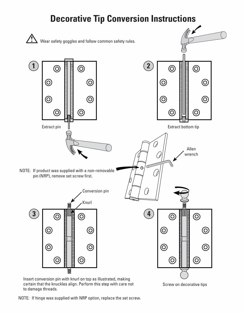

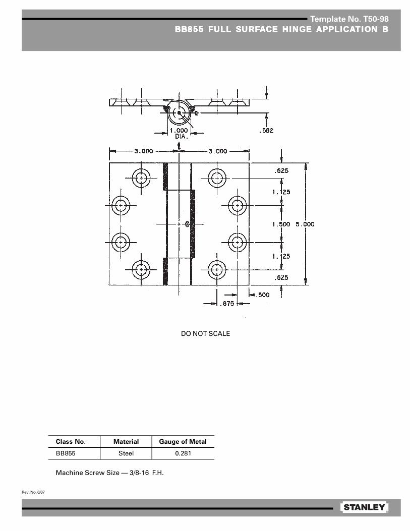
®
Rev. No. 6/07
Template No. T50-98
BB855 FULL SURFBB855 FULL SURFBB855 FULL SURFBB855 FULL SURFBB855 FULL SURFAAAAACE HINGE CE HINGE CE HINGE CE HINGE CE HINGE APPLICAAPPLICAAPPLICAAPPLICAAPPLICATION BTION BTION BTION BTION B
Machine Screw Size — 3/8-16 F.H.
DO NOT SCALE
Class No. Material Gauge of Metal
BB855 Steel 0.281
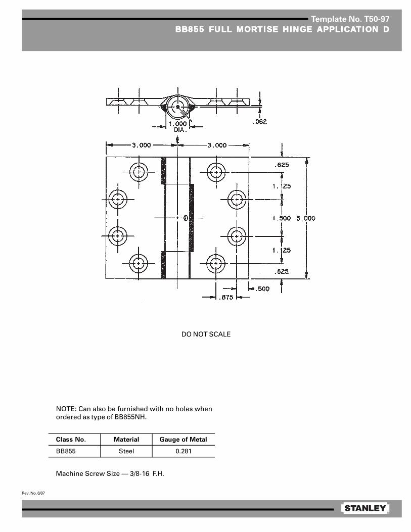
®
Rev. No. 6/07
Template No. T50-97
BB855 FULL MORBB855 FULL MORBB855 FULL MORBB855 FULL MORBB855 FULL MORTISE HINGE TISE HINGE TISE HINGE TISE HINGE TISE HINGE APPLICAAPPLICAAPPLICAAPPLICAAPPLICATION DTION DTION DTION DTION D
Machine Screw Size — 3/8-16 F.H.
DO NOT SCALE
NOTE: Can also be furnished with no holes whenordered as type of BB855NH.
Class No. Material Gauge of Metal
BB855 Steel 0.281
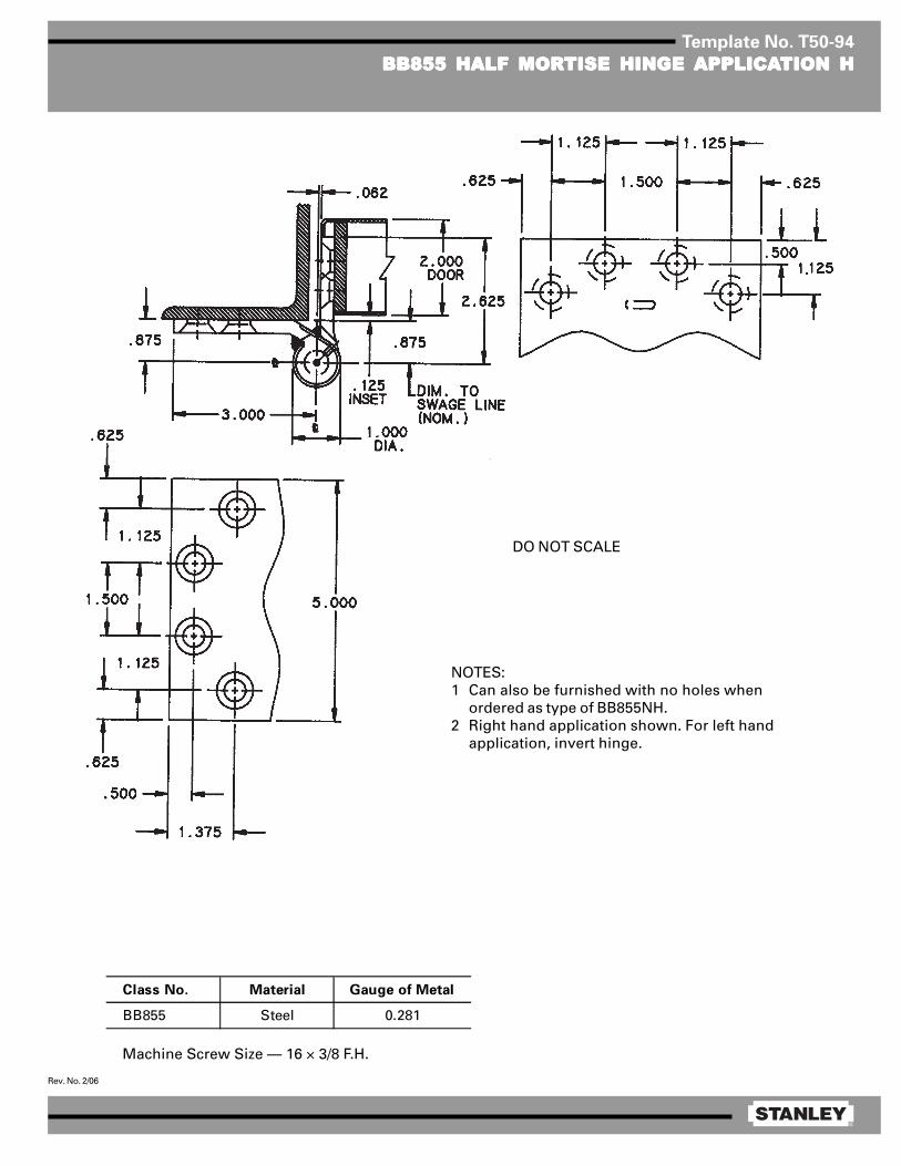
®
Rev. No. 2/06
Template No. T50-94
BB855 HALF MORBB855 HALF MORBB855 HALF MORBB855 HALF MORBB855 HALF MORTISE HINGE TISE HINGE TISE HINGE TISE HINGE TISE HINGE APPLICAAPPLICAAPPLICAAPPLICAAPPLICATION HTION HTION HTION HTION H
Machine Screw Size — 16 × 3/8 F.H.
Class No. Material Gauge of Metal
BB855 Steel 0.281
NOTES:1 Can also be furnished with no holes when
ordered as type of BB855NH.2 Right hand application shown. For left hand
application, invert hinge.
DO NOT SCALE
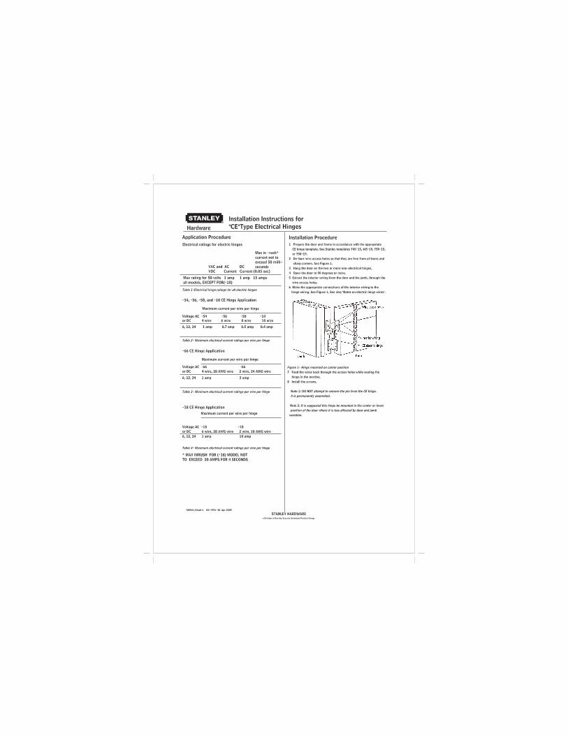
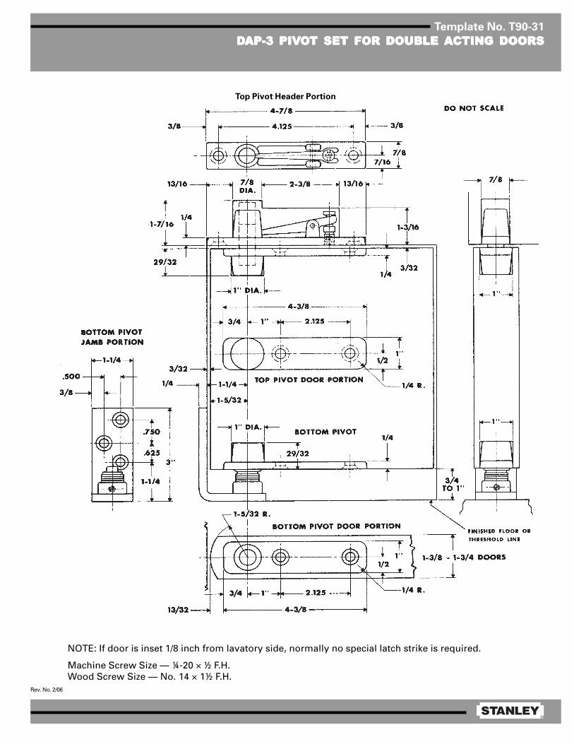
®
Rev. No. 2/06
Template No. T90-31
DDDDDAP-3 PIVAP-3 PIVAP-3 PIVAP-3 PIVAP-3 PIVOOOOOT SET FOR DOUBLE T SET FOR DOUBLE T SET FOR DOUBLE T SET FOR DOUBLE T SET FOR DOUBLE AAAAACTING DOORSCTING DOORSCTING DOORSCTING DOORSCTING DOORS
NOTE: If door is inset 1/8 inch from lavatory side, normally no special latch strike is required.
Machine Screw Size — ¼-20 × ½ F.H.Wood Screw Size — No. 14 × 1½ F.H.
Top Pivot Header Portion
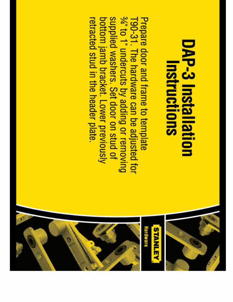
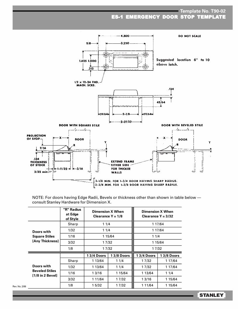
®
Rev. No. 2/06
Template No. T90-02
ES-1 EMERES-1 EMERES-1 EMERES-1 EMERES-1 EMERGENCY DOOR STGENCY DOOR STGENCY DOOR STGENCY DOOR STGENCY DOOR STOP OP OP OP OP TEMPLATEMPLATEMPLATEMPLATEMPLATETETETETE
"R" Radius
at Edge
of Style
Sharp
1/32
1/16
3/32
1/8
1 3/4 Doors 1 3/8 Doors 1 3/4 Doors 1 3/8 Doors
Sharp 1 13/64 1 1/4 1 7/32 1 17/64
1/32 1 13/64 1 1/4 1 7/32 1 17/64
1/16 1 3/16 1 15/64 1 13/64 1 1/4
3/32 1 11/64 1 7/32 1 3/16 1 15/64
1/8 1 5/32 1 7/32 1 11/64 1 15/64
1 15/64
Doors with
Beveled Stiles
[1/8 in 2 Bevel]
Doors with
Square Stiles
[Any Thickness]
1 7/32 1 7/32
Dimension X When
Clearance Y = 1/8
Dimension X When
Clearance Y = 3/32
1 1/4
1 1/4
1 15/64
1 7/32
1 17/64
1 17/64
1 1/4
NOTE: For doors having Edge Radii, Bevels or thickness other than shown in table below —consult Stanley Hardware for Dimension X.
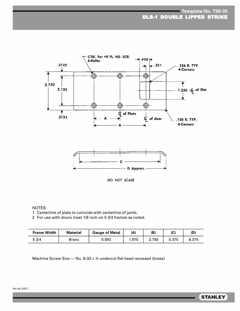
®
Rev. No. 3/2017
Template No. T90-35
DLS-1 DOUBLE LIPPED STRIKEDLS-1 DOUBLE LIPPED STRIKEDLS-1 DOUBLE LIPPED STRIKEDLS-1 DOUBLE LIPPED STRIKEDLS-1 DOUBLE LIPPED STRIKE
Machine Screw Size — No. 8-32 × ½ undercut flat head recessed (brass)
Frame Width Material Gauge of Metal (A) (B) (C) (D)
5 3/4 Brass 0.093 1.875 3.750 5.375 6.375
NOTES:1 Centerline of plate to coincide with centerline of jamb.2 For use with doors inset 1/8 inch on 5 3/4 frames as noted.
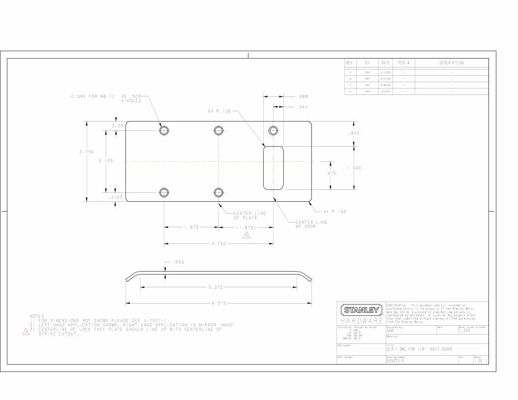
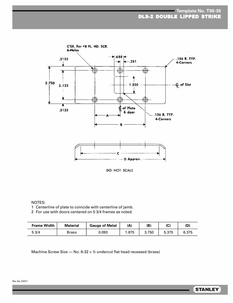
®
Rev. No. 3/2017
Template No. T90-36
DLS-2 DOUBLE LIPPED STRIKEDLS-2 DOUBLE LIPPED STRIKEDLS-2 DOUBLE LIPPED STRIKEDLS-2 DOUBLE LIPPED STRIKEDLS-2 DOUBLE LIPPED STRIKE
Machine Screw Size — No. 8-32 × ½ undercut flat head recessed (brass)
NOTES:1 Centerline of plate to coincide with centerline of jamb.2 For use with doors centered on 5 3/4 frames as noted.
Frame Width Material Gauge of Metal (A) (B) (C) (D)
5 3/4 Brass 0.093 1.875 3.750 5.375 6.375
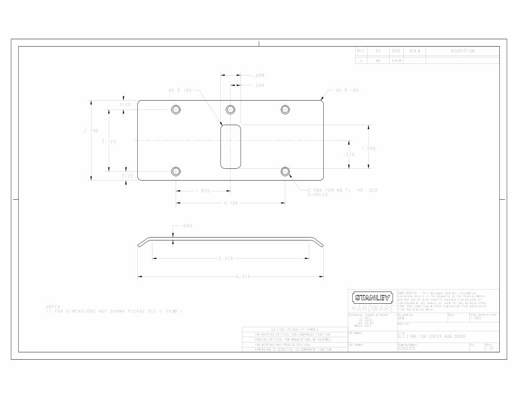
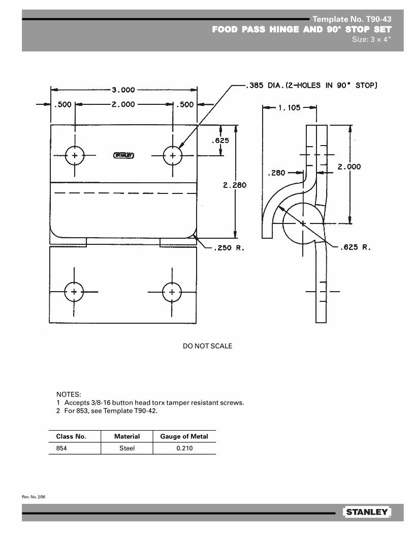
®
Rev. No. 2/06
Template No. T90-43
FOOD PFOOD PFOOD PFOOD PFOOD PASS HINGE ASS HINGE ASS HINGE ASS HINGE ASS HINGE AND 90° STAND 90° STAND 90° STAND 90° STAND 90° STOP SETOP SETOP SETOP SETOP SETSize: 3 × 4”
Class No. Material Gauge of Metal
854 Steel 0.210
DO NOT SCALE
NOTES:1 Accepts 3/8-16 button head torx tamper resistant screws.2 For 853, see Template T90-42.

®
Rev. No. 6/10
Template No. T45-95
FULL MORFULL MORFULL MORFULL MORFULL MORTISE TISE TISE TISE TISE TEMPLATEMPLATEMPLATEMPLATEMPLATE BTE BTE BTE BTE BUTT HINGES UTT HINGES UTT HINGES UTT HINGES UTT HINGES WITH SHEAR RESISTWITH SHEAR RESISTWITH SHEAR RESISTWITH SHEAR RESISTWITH SHEAR RESISTANT STUDANT STUDANT STUDANT STUDANT STUDSize: 4½ × 4½”
♦♦♦♦♦Machine Screw Size — 20 × ¼ × ½ F.H.
*Machine Screw Size — 12–24 × ½ F.H. optional: 20–¼ × ½ F.H.
NOTES:1 Recommended clearance hole for stud and radii is 0.625 dia.2 This template conforms to template ANSI A156.7 for screw hole locations only.
DO NOT SCALE
♦♦♦♦♦ ♦♦♦♦♦
Class No. Gauge of Metal (E) Outside Diameter Class No. Gauge of Metal (E) Outside Diameter
IHTCB168* 0.180 0.698 IHTCB168 x SRS* 0.180 0.698
IHTCB1901* 0.180 0.690 IHTCB1901 x SRS* 0.180 0.690
IHTCB1901R* 0.180 0.698 IHTCB1901R x SRS* 0.180 0.698
IHTCB1961* 0.180 0.690 IHTCB1961 x SRS* 0.180 0.690
IHTCB1961R* 0.180 0.698 IHTCB1961R x SRS* 0.180 0.698
IHTCB1995 0.188 0.780 IHTCB1995 x SRS 0.188 0.780
IHTCB199* 0.180 0.698 IHTCB199 x SRS* 0.180 0.698
Without Security Studs With Security Studs
E

®
Rev. No. 3/06
Template No. T45-01
FULL MORFULL MORFULL MORFULL MORFULL MORTISE TISE TISE TISE TISE TEMPLATEMPLATEMPLATEMPLATEMPLATE BTE BTE BTE BTE BUTT HINGESUTT HINGESUTT HINGESUTT HINGESUTT HINGESSizes: 4½ × 4, 4½ × 4½, 4½ × 5, 4½ × 6, 4½ × 7 and 4½ × 8”
Template hinges of the hospital type conform to above screw hole location.Hospital type hinges are designated by prefix “HT” to class number (except on #2060).Also available in RD2060 1/4 radius corner and RD2068 5/8 radius corner.
Machine Screw Size — ½ × 12-24 F.H.Wood Screw Size — 1¼ × No. 12 F.H.
This template conforms with ANSI standard A156.7.
E
F
1/ 16
5/ 8 R1/ 4 R
1 .125
4 .500
.508 .5081 .2 34 1 .125
1 .000
.375
(E)
Steel Nonferrous Gauge Outside
Hinges Hinges of Metal Diameter 4½ × 4 4½ × 4½ 4½ × 5 4½ × 6 4½ × 7 4½ × 8
F179 F191 0.134 0.605 1 5/8 1 29/32 2 5/32 2 21/32 3 5/32 2 21/32
1900 1960 0.134 0.540 1 5/8 1 13/16 — — — —
1900R 1960R 0.134 0.605 1 5/8 1 29/32 — — — —
CB179 CB191 0.134 0.625 1 5/8 1 25/32 2 3/32 2 19/32 — —
FBB179 FBB191 0.134 0.625 1 5/8 1 25/32 2 3/32 2 19/32 — —
CB1900 CB1960 0.134 0.540 1 5/8 1 13/16 — — — —
CB1900R CB1960R 0.134 0.625 1 5/8 1 25/32 2 3/32 2 19/32 — —
CB168 CB199 0.180 0.698 1 15/32 1 23/32 1 31/32 2 15/32 2 31/32 3 15/32
FBB168 FBB199 0.180 0.698 1 15/32 1 23/32 1 31/32 2 15/32 2 31/32 3 15/32
IHTCB168 IHTCB199 0.180 0.698 1 15/32 1 23/32 — — — —
— CB0701 0.180 0.698 1 15/32 1 23/32 — — — —
CB1901 CB1961 0.180 0.690 — 1 13/16 — — — —
CB1901R CB1961R 0.180 0.698 1 15/32 1 23/32 1 31/32 2 15/32 2 31/32 3 15/32
IHTCB1901 IHTCB1961 0.180 0.690 1 15/32 1 13/16 — — — —
IHTCB1901R IHTCB1961R 0.180 0.698 1 15/32 1 23/32 — — — —
2060R — 0.134 0.783 1 5/8 1 27/32 — — — —
DISTANCE FROM EDGE OF LEAF TO SWAGE LINE (F)CLASS NUMBER

®
Rev. No. 3/06
Template No. T45-01
FULL MORFULL MORFULL MORFULL MORFULL MORTISE TISE TISE TISE TISE TEMPLATEMPLATEMPLATEMPLATEMPLATE BTE BTE BTE BTE BUTT HINGESUTT HINGESUTT HINGESUTT HINGESUTT HINGESSizes: 4½ × 4, 4½ × 4½, 4½ × 5, 4½ × 6, 4½ × 7 and 4½ × 8”
Template hinges of the hospital type conform to above screw hole location.Hospital type hinges are designated by prefix “HT” to class number (except on #2060).Also available in RD2060 1/4 radius corner and RD2068 5/8 radius corner.
Machine Screw Size — ½ × 12-24 F.H.Wood Screw Size — 1¼ × No. 12 F.H.
This template conforms with ANSI standard A156.7.
E
F
1/ 16
5/ 8 R1/ 4 R
1 .125
4 .500
.508 .5081 .2 34 1 .125
1 .000
.375
(E)
Steel Nonferrous Gauge Outside
Hinges Hinges of Metal Diameter 4½ × 4 4½ × 4½ 4½ × 5 4½ × 6 4½ × 7 4½ × 8
F179 F191 0.134 0.605 1 5/8 1 29/32 2 5/32 2 21/32 3 5/32 2 21/32
1900 1960 0.134 0.540 1 5/8 1 13/16 — — — —
1900R 1960R 0.134 0.605 1 5/8 1 29/32 — — — —
CB179 CB191 0.134 0.625 1 5/8 1 25/32 2 3/32 2 19/32 — —
FBB179 FBB191 0.134 0.625 1 5/8 1 25/32 2 3/32 2 19/32 — —
CB1900 CB1960 0.134 0.540 1 5/8 1 13/16 — — — —
CB1900R CB1960R 0.134 0.625 1 5/8 1 25/32 2 3/32 2 19/32 — —
CB168 CB199 0.180 0.698 1 15/32 1 23/32 1 31/32 2 15/32 2 31/32 3 15/32
FBB168 FBB199 0.180 0.698 1 15/32 1 23/32 1 31/32 2 15/32 2 31/32 3 15/32
IHTCB168 IHTCB199 0.180 0.698 1 15/32 1 23/32 — — — —
— CB0701 0.180 0.698 1 15/32 1 23/32 — — — —
CB1901 CB1961 0.180 0.690 — 1 13/16 — — — —
CB1901R CB1961R 0.180 0.698 1 15/32 1 23/32 1 31/32 2 15/32 2 31/32 3 15/32
IHTCB1901 IHTCB1961 0.180 0.690 1 15/32 1 13/16 — — — —
IHTCB1901R IHTCB1961R 0.180 0.698 1 15/32 1 23/32 — — — —
2060R — 0.134 0.783 1 5/8 1 27/32 — — — —
DISTANCE FROM EDGE OF LEAF TO SWAGE LINE (F)CLASS NUMBER
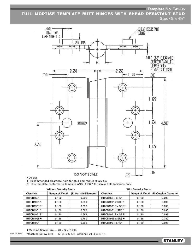
®
Rev. No. 6/10
Template No. T45-95
FULL MORFULL MORFULL MORFULL MORFULL MORTISE TISE TISE TISE TISE TEMPLATEMPLATEMPLATEMPLATEMPLATE BTE BTE BTE BTE BUTT HINGES UTT HINGES UTT HINGES UTT HINGES UTT HINGES WITH SHEAR RESISTWITH SHEAR RESISTWITH SHEAR RESISTWITH SHEAR RESISTWITH SHEAR RESISTANT STUDANT STUDANT STUDANT STUDANT STUDSize: 4½ × 4½”
♦♦♦♦♦Machine Screw Size — 20 × ¼ × ½ F.H.
*Machine Screw Size — 12–24 × ½ F.H. optional: 20–¼ × ½ F.H.
NOTES:1 Recommended clearance hole for stud and radii is 0.625 dia.2 This template conforms to template ANSI A156.7 for screw hole locations only.
DO NOT SCALE
♦♦♦♦♦ ♦♦♦♦♦
Class No. Gauge of Metal (E) Outside Diameter Class No. Gauge of Metal (E) Outside Diameter
IHTCB168* 0.180 0.698 IHTCB168 x SRS* 0.180 0.698
IHTCB1901* 0.180 0.690 IHTCB1901 x SRS* 0.180 0.690
IHTCB1901R* 0.180 0.698 IHTCB1901R x SRS* 0.180 0.698
IHTCB1961* 0.180 0.690 IHTCB1961 x SRS* 0.180 0.690
IHTCB1961R* 0.180 0.698 IHTCB1961R x SRS* 0.180 0.698
IHTCB1995 0.188 0.780 IHTCB1995 x SRS 0.188 0.780
IHTCB199* 0.180 0.698 IHTCB199 x SRS* 0.180 0.698
Without Security Studs With Security Studs
E


®
Rev. No. 3/06
Template No. T45-01
FULL MORFULL MORFULL MORFULL MORFULL MORTISE TISE TISE TISE TISE TEMPLATEMPLATEMPLATEMPLATEMPLATE BTE BTE BTE BTE BUTT HINGESUTT HINGESUTT HINGESUTT HINGESUTT HINGESSizes: 4½ × 4, 4½ × 4½, 4½ × 5, 4½ × 6, 4½ × 7 and 4½ × 8”
Template hinges of the hospital type conform to above screw hole location.Hospital type hinges are designated by prefix “HT” to class number (except on #2060).Also available in RD2060 1/4 radius corner and RD2068 5/8 radius corner.
Machine Screw Size — ½ × 12-24 F.H.Wood Screw Size — 1¼ × No. 12 F.H.
This template conforms with ANSI standard A156.7.
E
F
1/ 16
5/ 8 R1/ 4 R
1 .125
4 .500
.508 .5081 .2 34 1 .125
1 .000
.375
(E)
Steel Nonferrous Gauge Outside
Hinges Hinges of Metal Diameter 4½ × 4 4½ × 4½ 4½ × 5 4½ × 6 4½ × 7 4½ × 8
F179 F191 0.134 0.605 1 5/8 1 29/32 2 5/32 2 21/32 3 5/32 2 21/32
1900 1960 0.134 0.540 1 5/8 1 13/16 — — — —
1900R 1960R 0.134 0.605 1 5/8 1 29/32 — — — —
CB179 CB191 0.134 0.625 1 5/8 1 25/32 2 3/32 2 19/32 — —
FBB179 FBB191 0.134 0.625 1 5/8 1 25/32 2 3/32 2 19/32 — —
CB1900 CB1960 0.134 0.540 1 5/8 1 13/16 — — — —
CB1900R CB1960R 0.134 0.625 1 5/8 1 25/32 2 3/32 2 19/32 — —
CB168 CB199 0.180 0.698 1 15/32 1 23/32 1 31/32 2 15/32 2 31/32 3 15/32
FBB168 FBB199 0.180 0.698 1 15/32 1 23/32 1 31/32 2 15/32 2 31/32 3 15/32
IHTCB168 IHTCB199 0.180 0.698 1 15/32 1 23/32 — — — —
— CB0701 0.180 0.698 1 15/32 1 23/32 — — — —
CB1901 CB1961 0.180 0.690 — 1 13/16 — — — —
CB1901R CB1961R 0.180 0.698 1 15/32 1 23/32 1 31/32 2 15/32 2 31/32 3 15/32
IHTCB1901 IHTCB1961 0.180 0.690 1 15/32 1 13/16 — — — —
IHTCB1901R IHTCB1961R 0.180 0.698 1 15/32 1 23/32 — — — —
2060R — 0.134 0.783 1 5/8 1 27/32 — — — —
DISTANCE FROM EDGE OF LEAF TO SWAGE LINE (F)CLASS NUMBER
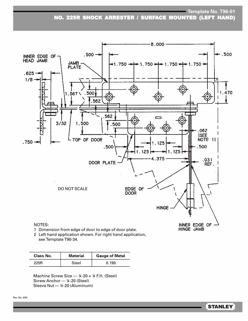
®
Rev. No. 2/06
Template No. T96-01
NONONONONO..... 225R SHOCK 225R SHOCK 225R SHOCK 225R SHOCK 225R SHOCK ARRESTER / SURFARRESTER / SURFARRESTER / SURFARRESTER / SURFARRESTER / SURFAAAAACE MOUNTED (LEFT HAND)CE MOUNTED (LEFT HAND)CE MOUNTED (LEFT HAND)CE MOUNTED (LEFT HAND)CE MOUNTED (LEFT HAND)
Machine Screw Size — ¼-20 × ¼ F.H. (Steel)Screw Anchor — ¼-20 (Steel)Sleeve Nut — ¼-20 (Aluminum)
Class No. Material Gauge of Metal
225R Steel 0.190
DO NOT SCALE
NOTES:1 Dimension from edge of door to edge of door plate.2 Left hand application shown. For right hand application,
see Template T90-34.
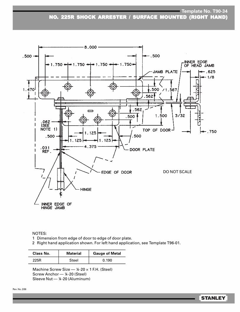
®
Rev. No. 2/06
Template No. T90-34
NONONONONO..... 225R SHOCK 225R SHOCK 225R SHOCK 225R SHOCK 225R SHOCK ARRESTER / SURFARRESTER / SURFARRESTER / SURFARRESTER / SURFARRESTER / SURFAAAAACE MOUNTED (RIGHT HAND)CE MOUNTED (RIGHT HAND)CE MOUNTED (RIGHT HAND)CE MOUNTED (RIGHT HAND)CE MOUNTED (RIGHT HAND)
Machine Screw Size — ¼-20 × 1 F.H. (Steel)Screw Anchor — ¼-20 (Steel)Sleeve Nut — ¼-20 (Aluminum)
Class No. Material Gauge of Metal
225R Steel 0.190
DO NOT SCALE
NOTES:1 Dimension from edge of door to edge of door plate.2 Right hand application shown. For left hand application, see Template T96-01.
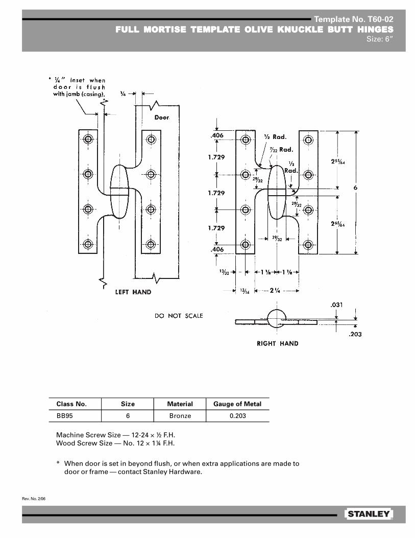
®
Rev. No. 2/06
Template No. T60-02
FULL MORFULL MORFULL MORFULL MORFULL MORTISE TISE TISE TISE TISE TEMPLATEMPLATEMPLATEMPLATEMPLATE OLIVE KNUCKLE BTE OLIVE KNUCKLE BTE OLIVE KNUCKLE BTE OLIVE KNUCKLE BTE OLIVE KNUCKLE BUTT HINGESUTT HINGESUTT HINGESUTT HINGESUTT HINGESSize: 6”
Class No. Size Material Gauge of Metal
BB95 6 Bronze 0.203
Machine Screw Size — 12-24 × ½ F.H.Wood Screw Size — No. 12 × 1¼ F.H.
* When door is set in beyond flush, or when extra applications are made todoor or frame — contact Stanley Hardware.

Quick ConnectUser Guide
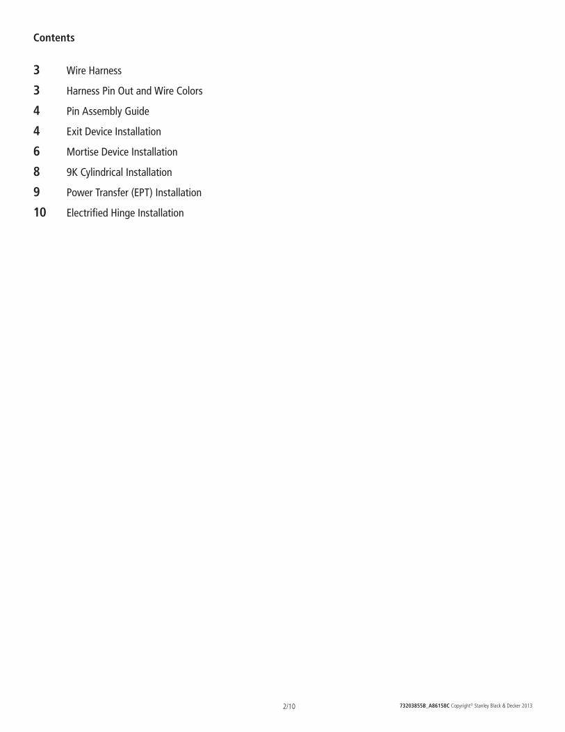
73203855B_A86158C Copyright© Stanley Black & Decker 20132/10
Contents
3 Wire Harness
3 Harness Pin Out and Wire Colors
4 Pin Assembly Guide
4 Exit Device Installation
6 Mortise Device Installation
8 9K Cylindrical Installation
9 Power Transfer (EPT) Installation
10 Electrified Hinge Installation
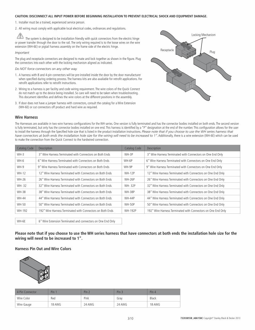
73203855B_A86158C Copyright© Stanley Black & Decker 20133/10
CAUTION: DISCONNECT ALL INPUT POWER BEFORE BEGINNING INSTALLATION TO PREVENT ELECTRICAL SHOCK AND EQUIPMENT DAMAGE.
1. Installer must be a trained, experienced service person.
2. All wiring must comply with applicable local electrical codes, ordinances and regulations.
The system is designed to be installation friendly with quick connectors from the electric hinge or power transfer through the door to the rail. The only wiring required is to the loose wires on the wire extension (WH-6E) or pigtail harness assembly on the frame side of the electric hinge.
Important
The plug and receptacle connectors are designed to mate and lock together as shown in the figure. Plug the connectors into each other with the locking mechanism aligned as indicated.
Do NOT force connectors on any other way.
1. A harness with 8 and 4-pin connectors will be pre-installed inside the door by the door manufacturer when specified during ordering process. The harness kits are also available for retrofit applications. For retrofit applications refer to retrofit instructions.
2. Wiring to a harness is per facility and code wiring requirement. The wire colors of the Quick Connect do not match up to the device being installed. So care will need to be taken when troubleshooting. This document identifies and defines the wire colors at the different positions in the assembly.
3. If door does not have a jumper harness with connectors, consult the catalog for a Wire Extension (WH-6E) or cut connectors off product and hard wire as required.
Wire HarnessThe Harnesses are available in two wire harness configurations for the WH series. One version is fully terminated and has the connector bodies installed on both ends. The second version is fully terminated, but only has the connector bodies installed on one end. This harness is identified by a “P” designation at the end of the number. This configuration allows for the user to install the harness through the Specified hole size that is listed in the product installation instructions. Please note that if you choose to use the WH series harness that have connectors at both ends the installation hole size for the wiring will need to be increased to 1”. Additionally, there is a wire extension (WH-6E) which can be used to make the connection from the Quick Connect to the hardwired connection.
Catalog Code Description Catalog Code Description
WH-3 3” Wire Harness Terminated with Connectors on Both Ends WH-3P 3” Wire Harness Terminated with Connectors on One End Only
WH-6 6” Wire Harness Terminated with Connectors on Both Ends WH-6P 6” Wire Harness Terminated with Connectors on One End Only
WH-9 9” Wire Harness Terminated with Connectors on Both Ends WH-9P 9” Wire Harness Terminated with Connectors on One End Only
WH-12 12” Wire Harness Terminated with Connectors on Both Ends WH-12P 12” Wire Harness Terminated with Connectors on One End Only
WH-26 26” Wire Harness Terminated with Connectors on Both Ends WH-26P 26” Wire Harness Terminated with Connectors on One End Only
WH- 32 32” Wire Harness Terminated with Connectors on Both Ends WH- 32P 32” Wire Harness Terminated with Connectors on One End Only
WH-38 38” Wire Harness Terminated with Connectors on Both Ends WH-38P 38” Wire Harness Terminated with Connectors on One End Only
WH-44 44” Wire Harness Terminated with Connectors on Both Ends WH-44P 44” Wire Harness Terminated with Connectors on One End Only
WH-50 50” Wire Harness Terminated with Connectors on Both Ends WH-50P 50” Wire Harness Terminated with Connectors on One End Only
WH-192 192” Wire Harness Terminated with Connectors on Both Ends WH-192P 192” Wire Harness Terminated with Connectors on One End Only
WH-6E 6” Wire Extension Terminated and connectors on One End Only
Please note that if you choose to use the WH series harness that have connectors at both ends the installation hole size for the wiring will need to be increased to 1”.
Harness Pin Out and Wire Colors
4 Pin Connector Pin 1 Pin 2 Pin 3 Pin 4
Wire Color Red Pink Gray Black
Wire Gauge 18 AWG 24 AWG 24 AWG 18 AWG
21
43
Locking Mechanism
Receptacle Plug
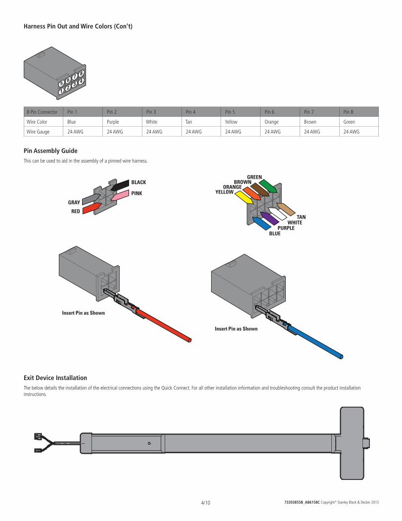
73203855B_A86158C Copyright© Stanley Black & Decker 20134/10
Harness Pin Out and Wire Colors (Con’t)
432
1
876
5
8 Pin Connector Pin 1 Pin 2 Pin 3 Pin 4 Pin 5 Pin 6 Pin 7 Pin 8
Wire Color Blue Purple White Tan Yellow Orange Brown Green
Wire Gauge 24 AWG 24 AWG 24 AWG 24 AWG 24 AWG 24 AWG 24 AWG 24 AWG
Pin Assembly GuideThis can be used to aid in the assembly of a pinned wire harness.
Insert Pin as Shown
Insert Pin as Shown
RED
GRAY
BLACK
PINK YELLOWORANGE
BROWNGREEN
BLUEPURPLE
WHITETAN
Exit Device InstallationThe below details the installation of the electrical connections using the Quick Connect. For all other installation information and troubleshooting consult the product installation instructions.
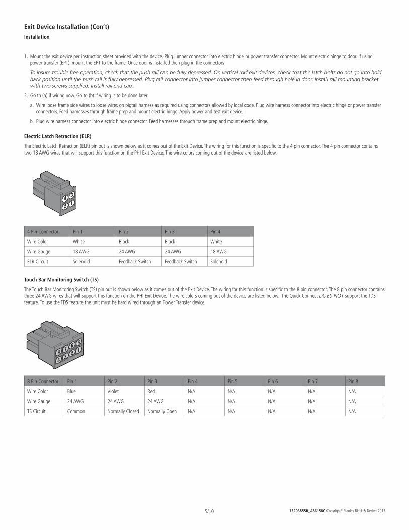
73203855B_A86158C Copyright© Stanley Black & Decker 20135/10
Exit Device Installation (Con’t)Installation
1. Mount the exit device per instruction sheet provided with the device. Plug jumper connector into electric hinge or power transfer connector. Mount electric hinge to door. If using power transfer (EPT), mount the EPT to the frame. Once door is installed then plug in the connectors
To insure trouble free operation, check that the push rail can be fully depressed. On vertical rod exit devices, check that the latch bolts do not go into hold back position until the push rail is fully depressed. Plug rail connector into jumper connector then feed through hole in door. Install rail mounting bracket with two screws supplied. Install rail end cap..
2. Go to (a) if wiring now. Go to (b) if wiring is to be done later.
a. Wire loose frame side wires to loose wires on pigtail harness as required using connectors allowed by local code. Plug wire harness connector into electric hinge or power transfer connectors. Feed harnesses through frame prep and mount electric hinge. Apply power and test exit device.
b. Plug wire harness connector into electric hinge connector. Feed harnesses through frame prep and mount electric hinge.
Electric Latch Retraction (ELR)
The Electric Latch Retraction (ELR) pin out is shown below as it comes out of the Exit Device. The wiring for this function is specific to the 4 pin connector. The 4 pin connector contains two 18 AWG wires that will support this function on the PHI Exit Device. The wire colors coming out of the device are listed below.
12
34
4 Pin Connector Pin 1 Pin 2 Pin 3 Pin 4
Wire Color White Black Black White
Wire Gauge 18 AWG 24 AWG 24 AWG 18 AWG
ELR Circuit Solenoid Feedback Switch Feedback Switch Solenoid
Touch Bar Monitoring Switch (TS)
The Touch Bar Monitoring Switch (TS) pin out is shown below as it comes out of the Exit Device. The wiring for this function is specific to the 8 pin connector. The 8 pin connector contains three 24 AWG wires that will support this function on the PHI Exit Device. The wire colors coming out of the device are listed below. The Quick Connect DOES NOT support the TDS feature. To use the TDS feature the unit must be hard wired through an Power Transfer device.
123
4
567
8
8 Pin Connector Pin 1 Pin 2 Pin 3 Pin 4 Pin 5 Pin 6 Pin 7 Pin 8
Wire Color Blue Violet Red N/A N/A N/A N/A N/A
Wire Gauge 24 AWG 24 AWG 24 AWG N/A N/A N/A N/A N/A
TS Circuit Common Normally Closed Normally Open N/A N/A N/A N/A N/A
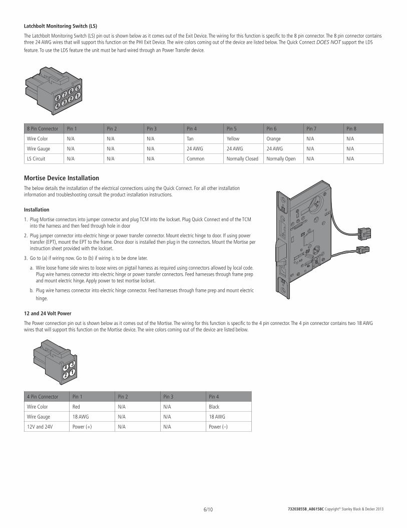
73203855B_A86158C Copyright© Stanley Black & Decker 20136/10
Latchbolt Monitoring Switch (LS)
The Latchbolt Monitoring Switch (LS) pin out is shown below as it comes out of the Exit Device. The wiring for this function is specific to the 8 pin connector. The 8 pin connector contains three 24 AWG wires that will support this function on the PHI Exit Device. The wire colors coming out of the device are listed below. The Quick Connect DOES NOT support the LDS
feature. To use the LDS feature the unit must be hard wired through an Power Transfer device.
123
4
567
8
8 Pin Connector Pin 1 Pin 2 Pin 3 Pin 4 Pin 5 Pin 6 Pin 7 Pin 8
Wire Color N/A N/A N/A Tan Yellow Orange N/A N/A
Wire Gauge N/A N/A N/A 24 AWG 24 AWG 24 AWG N/A N/A
LS Circuit N/A N/A N/A Common Normally Closed Normally Open N/A N/A
Mortise Device InstallationThe below details the installation of the electrical connections using the Quick Connect. For all other installation information and troubleshooting consult the product installation instructions.
Installation
1. Plug Mortise connectors into jumper connector and plug TCM into the lockset. Plug Quick Connect end of the TCM into the harness and then feed through hole in door
2. Plug jumper connector into electric hinge or power transfer connector. Mount electric hinge to door. If using power transfer (EPT), mount the EPT to the frame. Once door is installed then plug in the connectors. Mount the Mortise per instruction sheet provided with the lockset.
3. Go to (a) if wiring now. Go to (b) if wiring is to be done later.
a. Wire loose frame side wires to loose wires on pigtail harness as required using connectors allowed by local code. Plug wire harness connector into electric hinge or power transfer connectors. Feed harnesses through frame prep and mount electric hinge. Apply power to test mortise lockset.
b. Plug wire harness connector into electric hinge connector. Feed harnesses through frame prep and mount electric
hinge.
12 and 24 Volt Power
The Power connection pin out is shown below as it comes out of the Mortise. The wiring for this function is specific to the 4 pin connector. The 4 pin connector contains two 18 AWG wires that will support this function on the Mortise device. The wire colors coming out of the device are listed below.
12
34
4 Pin Connector Pin 1 Pin 2 Pin 3 Pin 4
Wire Color Red N/A N/A Black
Wire Gauge 18 AWG N/A N/A 18 AWG
12V and 24V Power (+) N/A N/A Power (–)
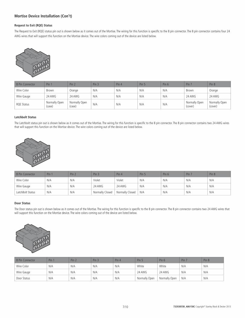
73203855B_A86158C Copyright© Stanley Black & Decker 20137/10
Mortise Device Installation (Con’t)
Request to Exit (RQE) Status
The Request to Exit (RQE) status pin out is shown below as it comes out of the Mortise. The wiring for this function is specific to the 8 pin connector. The 8 pin connector contains four 24
AWG wires that will support this function on the Mortise device. The wire colors coming out of the device are listed below.
123
4
567
8
8 Pin Connector Pin 1 Pin 2 Pin 3 Pin 4 Pin 5 Pin 6 Pin 7 Pin 8
Wire Color Brown Orange N/A N/A N/A N/A Brown Orange
Wire Gauge 24 AWG 24 AWG N/A N/A N/A N/A 24 AWG 24 AWG
RQE StatusNormally Open (case)
Normally Open (case)
N/A N/A N/A N/ANormally Open (cover)
Normally Open (cover)
Latchbolt Status
The Latchbolt status pin out is shown below as it comes out of the Mortise. The wiring for this function is specific to the 8 pin connector. The 8 pin connector contains two 24 AWG wires that will support this function on the Mortise device. The wire colors coming out of the device are listed below.
123
4
567
8
8 Pin Connector Pin 1 Pin 2 Pin 3 Pin 4 Pin 5 Pin 6 Pin 7 Pin 8
Wire Color N/A N/A Violet Violet N/A N/A N/A N/A
Wire Gauge N/A N/A 24 AWG 24 AWG N/A N/A N/A N/A
LatchBolt Status N/A N/A Normally Closed Normally Closed N/A N/A N/A N/A
Door Status
The Door status pin out is shown below as it comes out of the Mortise. The wiring for this function is specific to the 8 pin connector. The 8 pin connector contains two 24 AWG wires that will support this function on the Mortise device. The wire colors coming out of the device are listed below.
123
4
567
8
8 Pin Connector Pin 1 Pin 2 Pin 3 Pin 4 Pin 5 Pin 6 Pin 7 Pin 8
Wire Color N/A N/A N/A N/A White White N/A N/A
Wire Gauge N/A N/A N/A N/A 24 AWG 24 AWG N/A N/A
Door Status N/A N/A N/A N/A Normally Open Normally Open N/A N/A
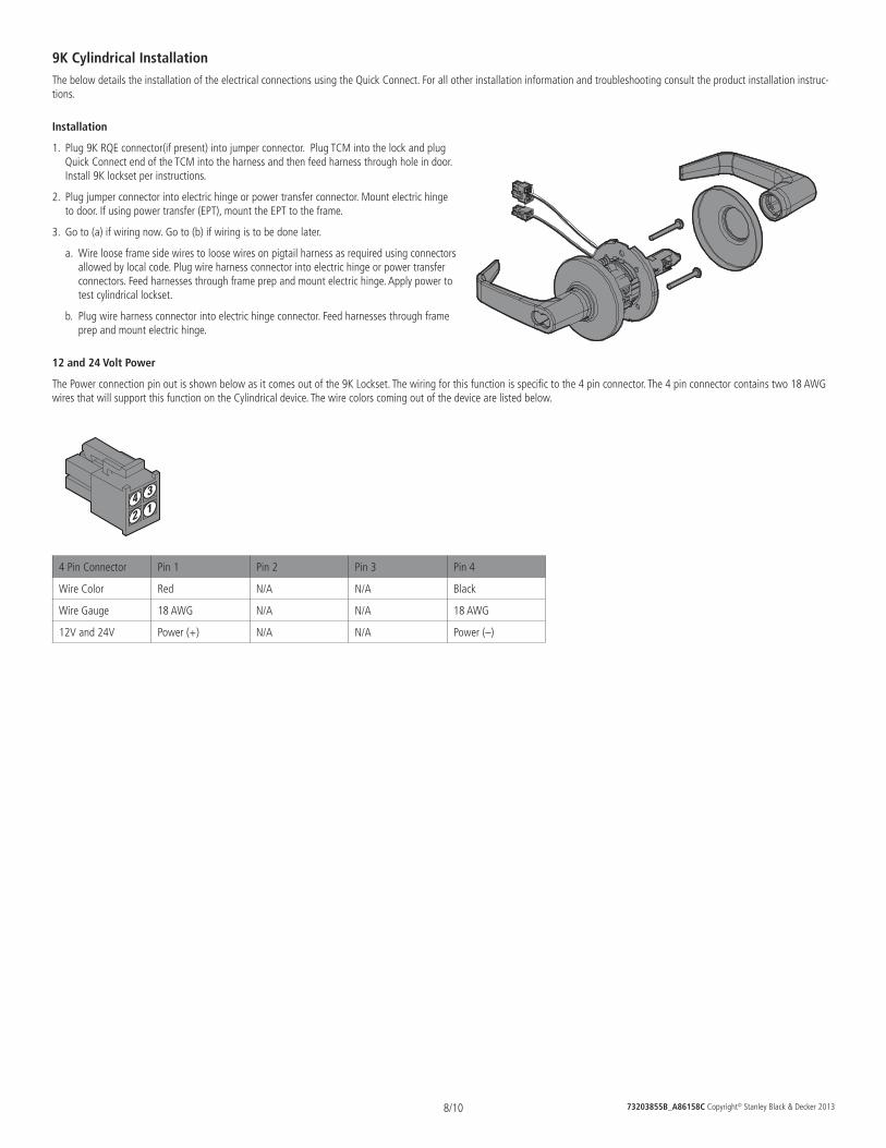
73203855B_A86158C Copyright© Stanley Black & Decker 20138/10
9K Cylindrical InstallationThe below details the installation of the electrical connections using the Quick Connect. For all other installation information and troubleshooting consult the product installation instruc-tions.
Installation
1. Plug 9K RQE connector(if present) into jumper connector. Plug TCM into the lock and plug Quick Connect end of the TCM into the harness and then feed harness through hole in door. Install 9K lockset per instructions.
2. Plug jumper connector into electric hinge or power transfer connector. Mount electric hinge to door. If using power transfer (EPT), mount the EPT to the frame.
3. Go to (a) if wiring now. Go to (b) if wiring is to be done later.
a. Wire loose frame side wires to loose wires on pigtail harness as required using connectors allowed by local code. Plug wire harness connector into electric hinge or power transfer connectors. Feed harnesses through frame prep and mount electric hinge. Apply power to test cylindrical lockset.
b. Plug wire harness connector into electric hinge connector. Feed harnesses through frame prep and mount electric hinge.
12 and 24 Volt Power
The Power connection pin out is shown below as it comes out of the 9K Lockset. The wiring for this function is specific to the 4 pin connector. The 4 pin connector contains two 18 AWG wires that will support this function on the Cylindrical device. The wire colors coming out of the device are listed below.
12
34
4 Pin Connector Pin 1 Pin 2 Pin 3 Pin 4
Wire Color Red N/A N/A Black
Wire Gauge 18 AWG N/A N/A 18 AWG
12V and 24V Power (+) N/A N/A Power (–)
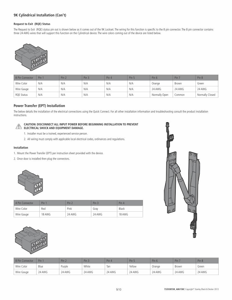
73203855B_A86158C Copyright© Stanley Black & Decker 20139/10
9K Cylindrical Installation (Con’t)
Request to Exit (RQE) Status
The Request to Exit (RQE) status pin out is shown below as it comes out of the 9K Lockset. The wiring for this function is specific to the 8 pin connector. The 8 pin connector contains three 24 AWG wires that will support this function on the Cylindrical device. The wire colors coming out of the device are listed below.
123
4
567
8
8 Pin Connector Pin 1 Pin 2 Pin 3 Pin 4 Pin 5 Pin 6 Pin 7 Pin 8
Wire Color N/A N/A N/A N/A N/A Orange Brown Green
Wire Gauge N/A N/A N/A N/A N/A 24 AWG 24 AWG 24 AWG
RQE Status N/A N/A N/A N/A N/A Normally Open Common Normally Closed
Power Transfer (EPT) InstallationThe below details the installation of the electrical connections using the Quick Connect. For all other installation information and troubleshooting consult the product installation instructions.
CAUTION: DISCONNECT ALL INPUT POWER BEFORE BEGINNING INSTALLATION TO PREVENT ELECTRICAL SHOCK AND EQUIPMENT DAMAGE.
1. Installer must be a trained, experienced service person.
2. All wiring must comply with applicable local electrical codes, ordinances and regulations.
Installation
1. Mount the Power Transfer (EPT) per instruction sheet provided with the device.
2. Once door is installed then plug the connectors.
12
34
4 Pin Connector Pin 1 Pin 2 Pin 3 Pin 4
Wire Color Red Pink Gray Black
Wire Gauge 18 AWG 24 AWG 24 AWG 18 AWG
123
4
567
8
8 Pin Connector Pin 1 Pin 2 Pin 3 Pin 4 Pin 5 Pin 6 Pin 7 Pin 8
Wire Color Blue Purple White Tan Yellow Orange Brown Green
Wire Gauge 24 AWG 24 AWG 24 AWG 24 AWG 24 AWG 24 AWG 24 AWG 24 AWG
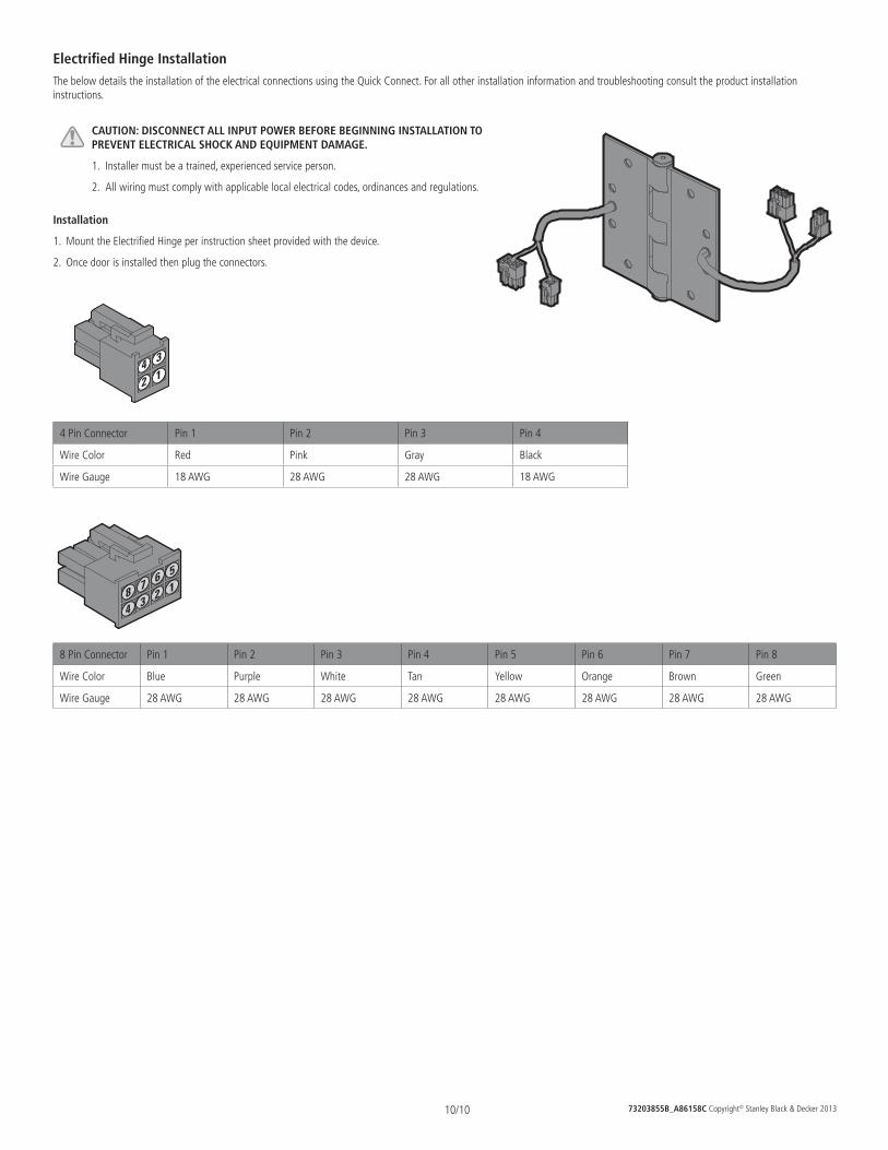
73203855B_A86158C Copyright© Stanley Black & Decker 201310/10
Electrified Hinge InstallationThe below details the installation of the electrical connections using the Quick Connect. For all other installation information and troubleshooting consult the product installation instructions.
CAUTION: DISCONNECT ALL INPUT POWER BEFORE BEGINNING INSTALLATION TO PREVENT ELECTRICAL SHOCK AND EQUIPMENT DAMAGE.
1. Installer must be a trained, experienced service person.
2. All wiring must comply with applicable local electrical codes, ordinances and regulations.
Installation
1. Mount the Electrified Hinge per instruction sheet provided with the device.
2. Once door is installed then plug the connectors.
12
34
4 Pin Connector Pin 1 Pin 2 Pin 3 Pin 4
Wire Color Red Pink Gray Black
Wire Gauge 18 AWG 28 AWG 28 AWG 18 AWG
123
4
567
8
8 Pin Connector Pin 1 Pin 2 Pin 3 Pin 4 Pin 5 Pin 6 Pin 7 Pin 8
Wire Color Blue Purple White Tan Yellow Orange Brown Green
Wire Gauge 28 AWG 28 AWG 28 AWG 28 AWG 28 AWG 28 AWG 28 AWG 28 AWG
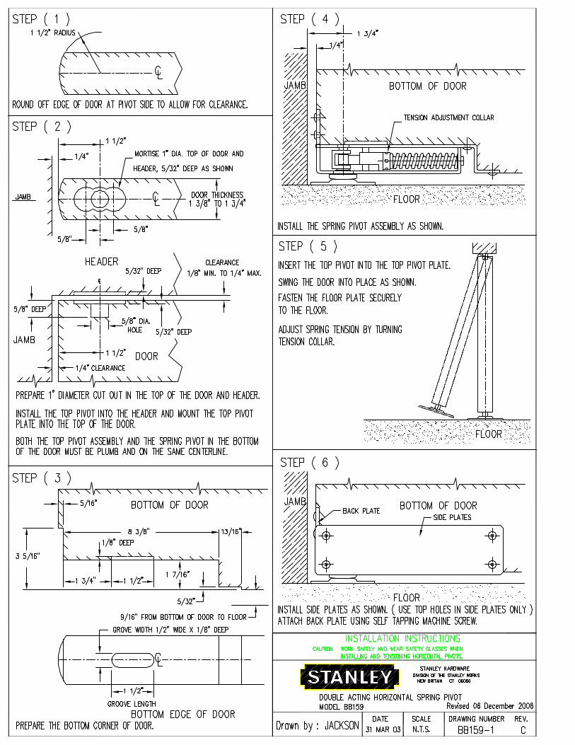
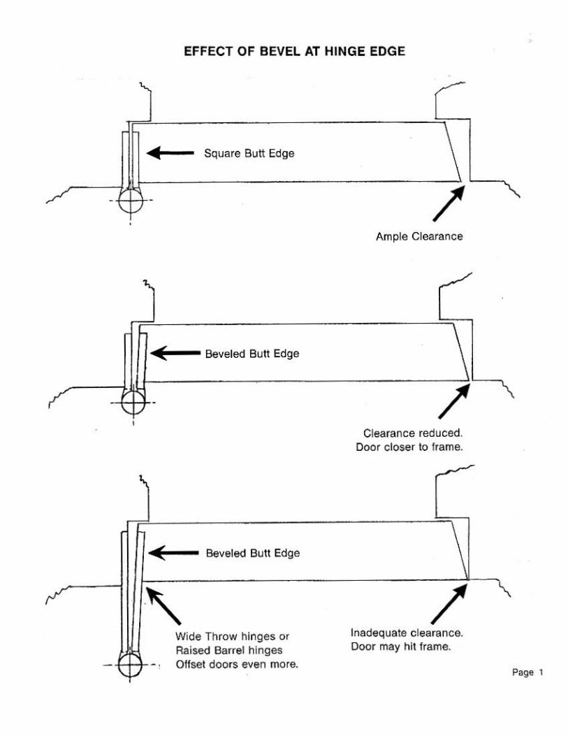
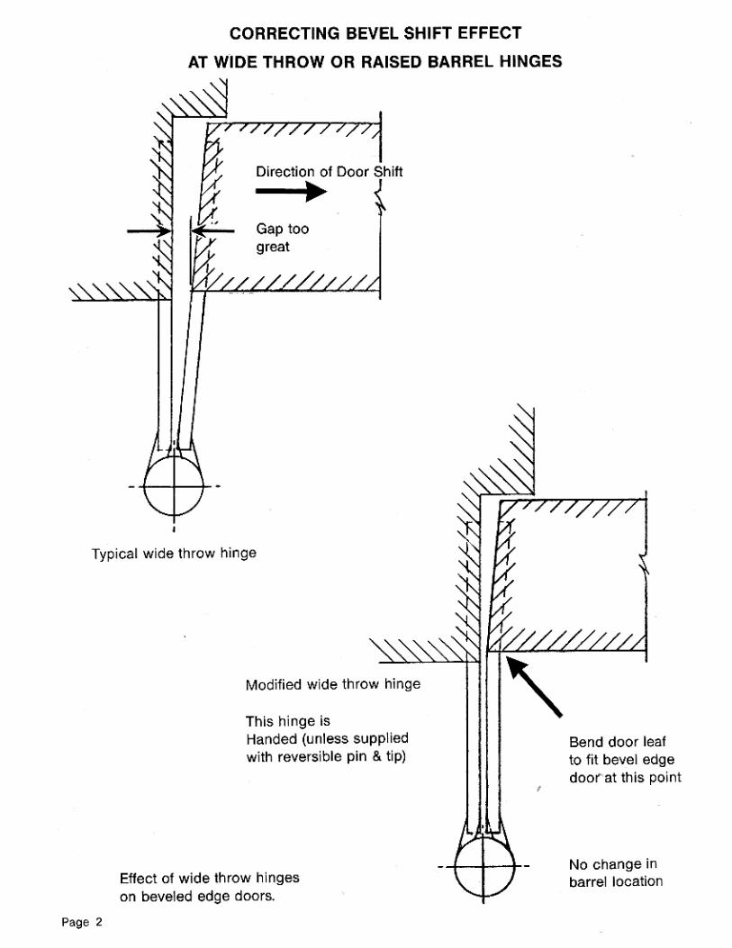
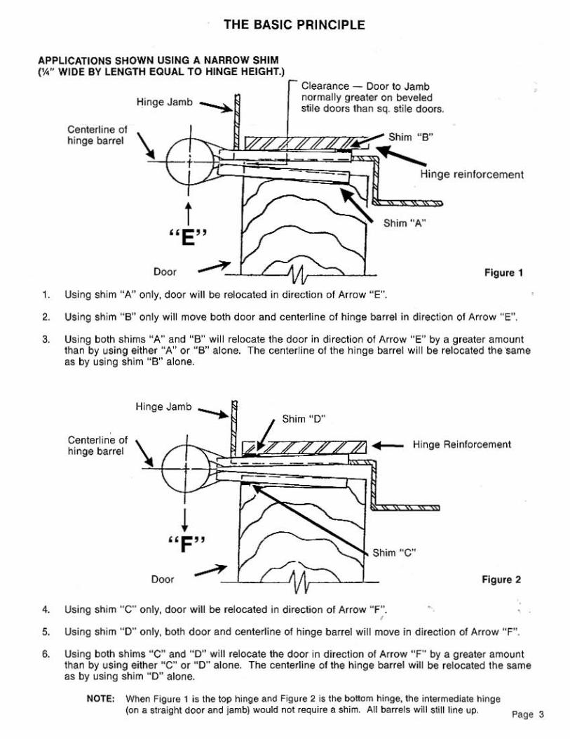
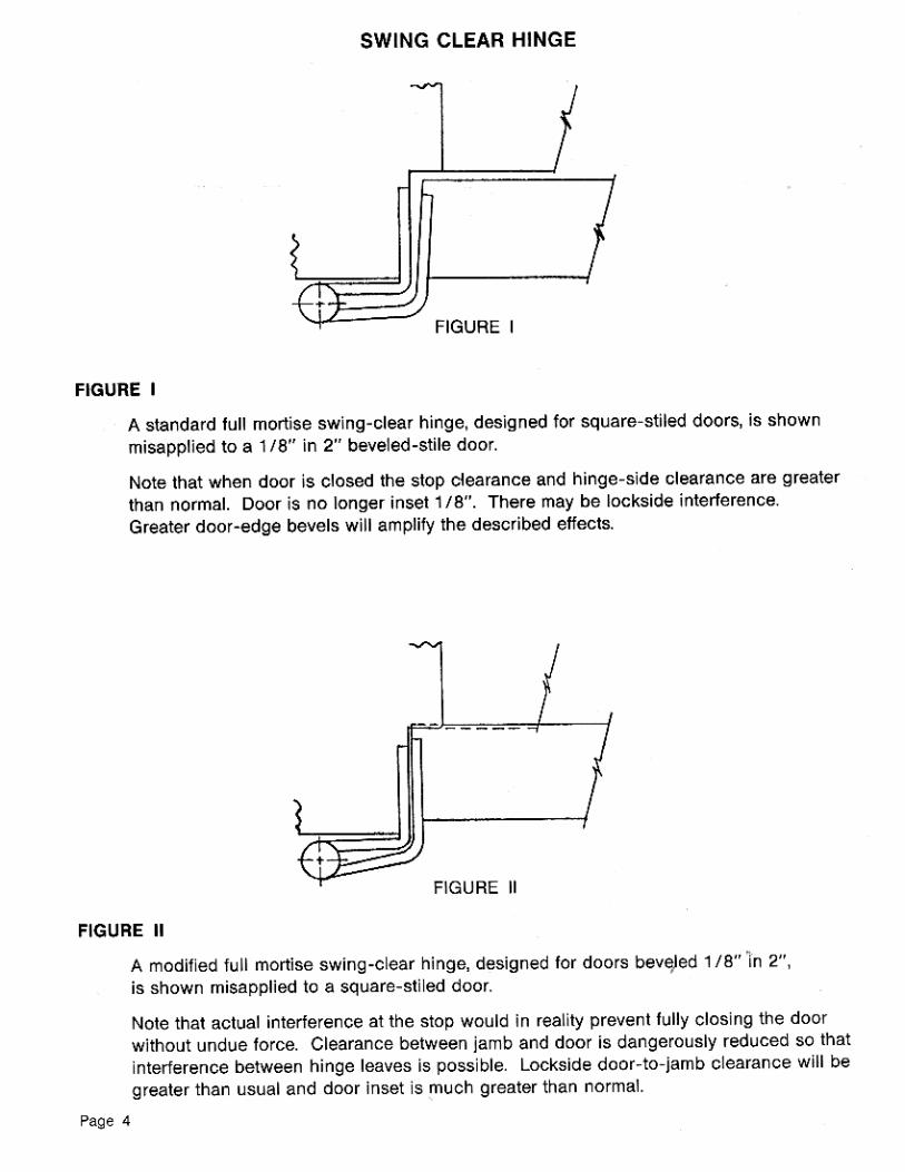
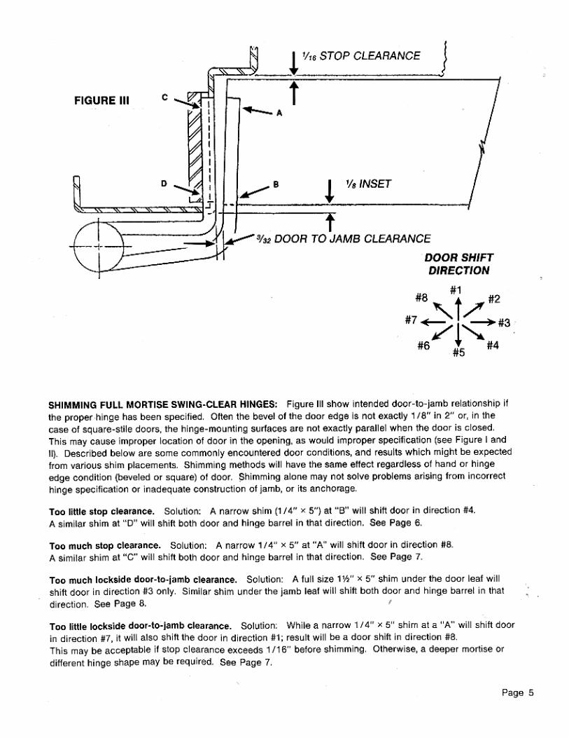
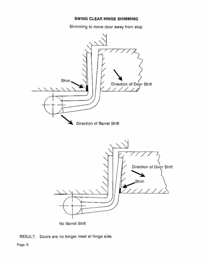
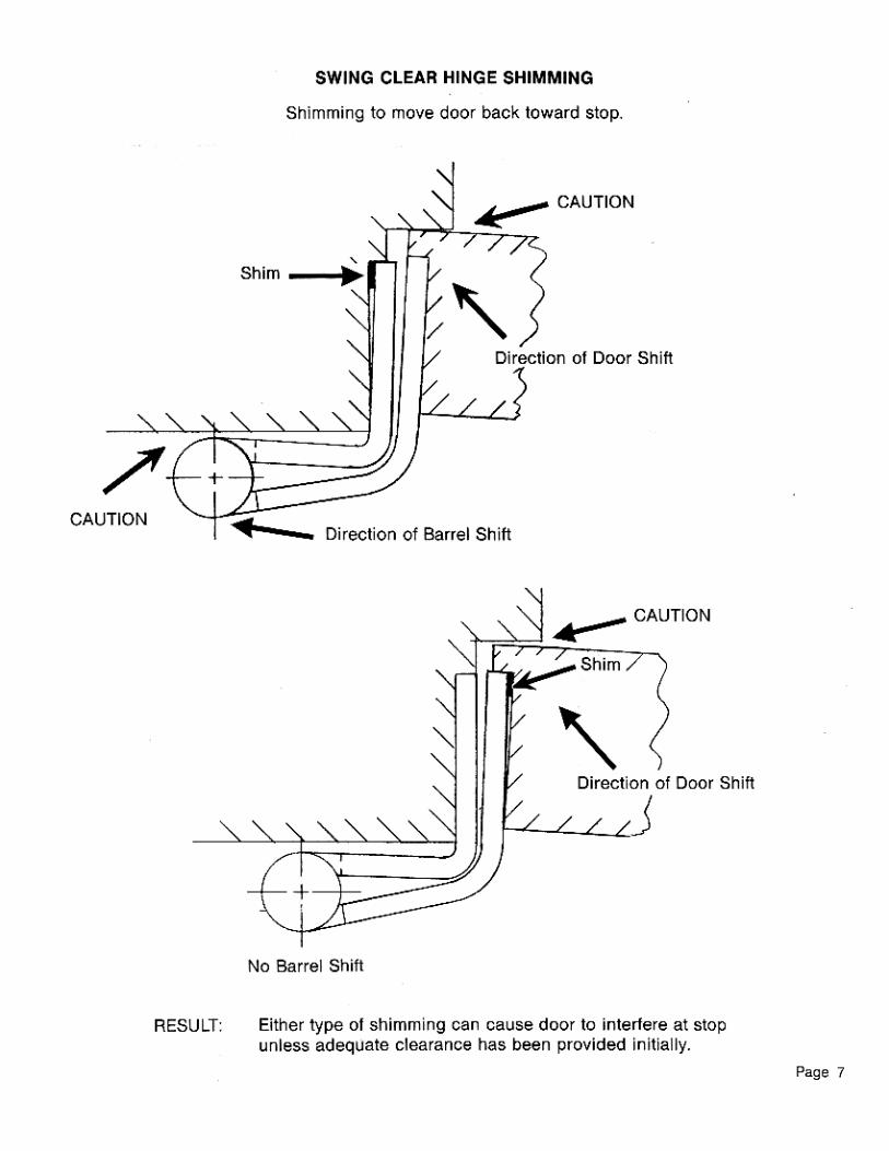
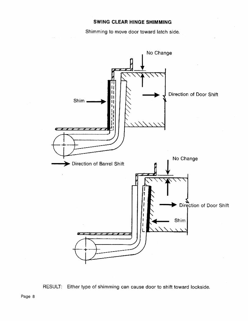
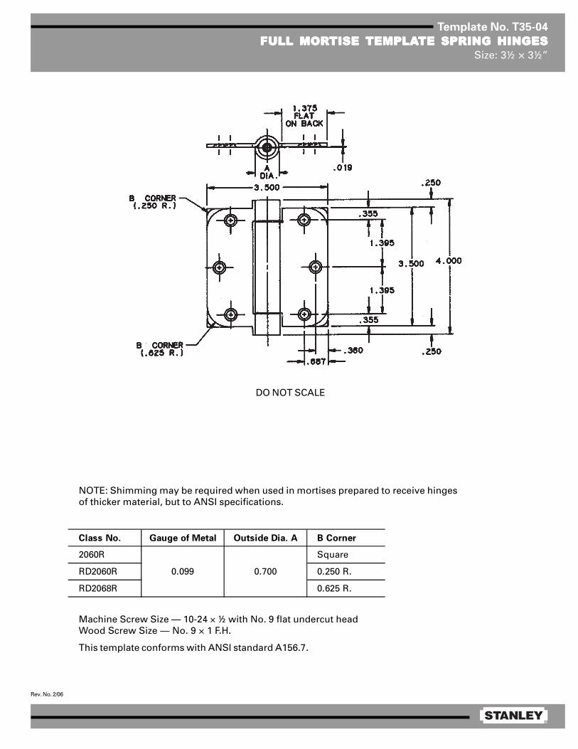
®
Rev. No. 2/06
Template No. T35-04
FULL MORFULL MORFULL MORFULL MORFULL MORTISE TISE TISE TISE TISE TEMPLATEMPLATEMPLATEMPLATEMPLATE SPRING HINGESTE SPRING HINGESTE SPRING HINGESTE SPRING HINGESTE SPRING HINGESSize: 3½ × 3½”
DO NOT SCALE
Machine Screw Size — 10-24 × ½ with No. 9 flat undercut headWood Screw Size — No. 9 × 1 F.H.
This template conforms with ANSI standard A156.7.
NOTE: Shimming may be required when used in mortises prepared to receive hingesof thicker material, but to ANSI specifications.
Class No. Gauge of Metal Outside Dia. A B Corner
2060R Square
RD2060R 0.250 R.
RD2068R 0.625 R.
0.099 0.700
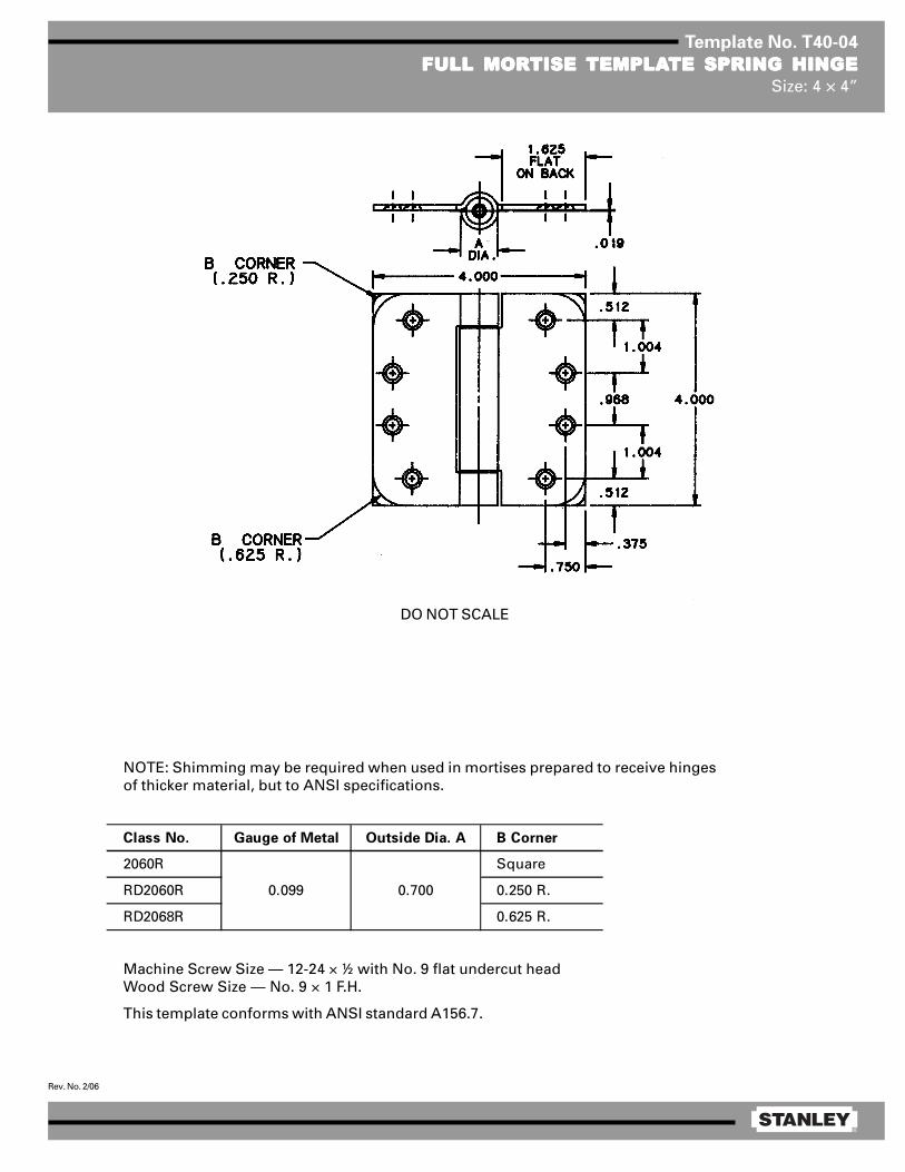
®
Rev. No. 2/06
Template No. T40-04
FULL MORFULL MORFULL MORFULL MORFULL MORTISE TISE TISE TISE TISE TEMPLATEMPLATEMPLATEMPLATEMPLATE SPRING HINGETE SPRING HINGETE SPRING HINGETE SPRING HINGETE SPRING HINGESize: 4 × 4”
Machine Screw Size — 12-24 × ½ with No. 9 flat undercut headWood Screw Size — No. 9 × 1 F.H.
This template conforms with ANSI standard A156.7.
NOTE: Shimming may be required when used in mortises prepared to receive hingesof thicker material, but to ANSI specifications.
Class No. Gauge of Metal Outside Dia. A B Corner
2060R Square
RD2060R 0.250 R.
RD2068R 0.625 R.
0.099 0.700
DO NOT SCALE

®
Rev. No. 3/06
Template No. T45-01
FULL MORFULL MORFULL MORFULL MORFULL MORTISE TISE TISE TISE TISE TEMPLATEMPLATEMPLATEMPLATEMPLATE BTE BTE BTE BTE BUTT HINGESUTT HINGESUTT HINGESUTT HINGESUTT HINGESSizes: 4½ × 4, 4½ × 4½, 4½ × 5, 4½ × 6, 4½ × 7 and 4½ × 8”
Template hinges of the hospital type conform to above screw hole location.Hospital type hinges are designated by prefix “HT” to class number (except on #2060).Also available in RD2060 1/4 radius corner and RD2068 5/8 radius corner.
Machine Screw Size — ½ × 12-24 F.H.Wood Screw Size — 1¼ × No. 12 F.H.
This template conforms with ANSI standard A156.7.
E
F
1/ 16
5/ 8 R1/ 4 R
1 .125
4 .500
.508 .5081 .2 34 1 .125
1 .000
.375
(E)
Steel Nonferrous Gauge Outside
Hinges Hinges of Metal Diameter 4½ × 4 4½ × 4½ 4½ × 5 4½ × 6 4½ × 7 4½ × 8
F179 F191 0.134 0.605 1 5/8 1 29/32 2 5/32 2 21/32 3 5/32 2 21/32
1900 1960 0.134 0.540 1 5/8 1 13/16 — — — —
1900R 1960R 0.134 0.605 1 5/8 1 29/32 — — — —
CB179 CB191 0.134 0.625 1 5/8 1 25/32 2 3/32 2 19/32 — —
FBB179 FBB191 0.134 0.625 1 5/8 1 25/32 2 3/32 2 19/32 — —
CB1900 CB1960 0.134 0.540 1 5/8 1 13/16 — — — —
CB1900R CB1960R 0.134 0.625 1 5/8 1 25/32 2 3/32 2 19/32 — —
CB168 CB199 0.180 0.698 1 15/32 1 23/32 1 31/32 2 15/32 2 31/32 3 15/32
FBB168 FBB199 0.180 0.698 1 15/32 1 23/32 1 31/32 2 15/32 2 31/32 3 15/32
IHTCB168 IHTCB199 0.180 0.698 1 15/32 1 23/32 — — — —
— CB0701 0.180 0.698 1 15/32 1 23/32 — — — —
CB1901 CB1961 0.180 0.690 — 1 13/16 — — — —
CB1901R CB1961R 0.180 0.698 1 15/32 1 23/32 1 31/32 2 15/32 2 31/32 3 15/32
IHTCB1901 IHTCB1961 0.180 0.690 1 15/32 1 13/16 — — — —
IHTCB1901R IHTCB1961R 0.180 0.698 1 15/32 1 23/32 — — — —
2060R — 0.134 0.783 1 5/8 1 27/32 — — — —
DISTANCE FROM EDGE OF LEAF TO SWAGE LINE (F)CLASS NUMBER
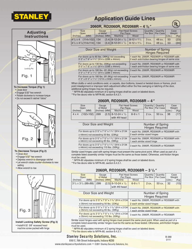
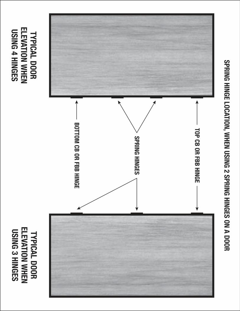
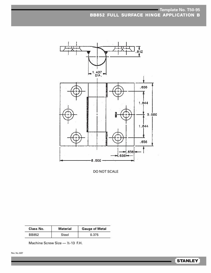
®
Rev. No. 6/07
Template No. T50-95
BB852 FULL SURFBB852 FULL SURFBB852 FULL SURFBB852 FULL SURFBB852 FULL SURFAAAAACE HINGE CE HINGE CE HINGE CE HINGE CE HINGE APPLICAAPPLICAAPPLICAAPPLICAAPPLICATION BTION BTION BTION BTION B
Machine Screw Size — ½-13 F.H.
Class No. Material Gauge of Metal
BB852 Steel 0.375
DO NOT SCALE
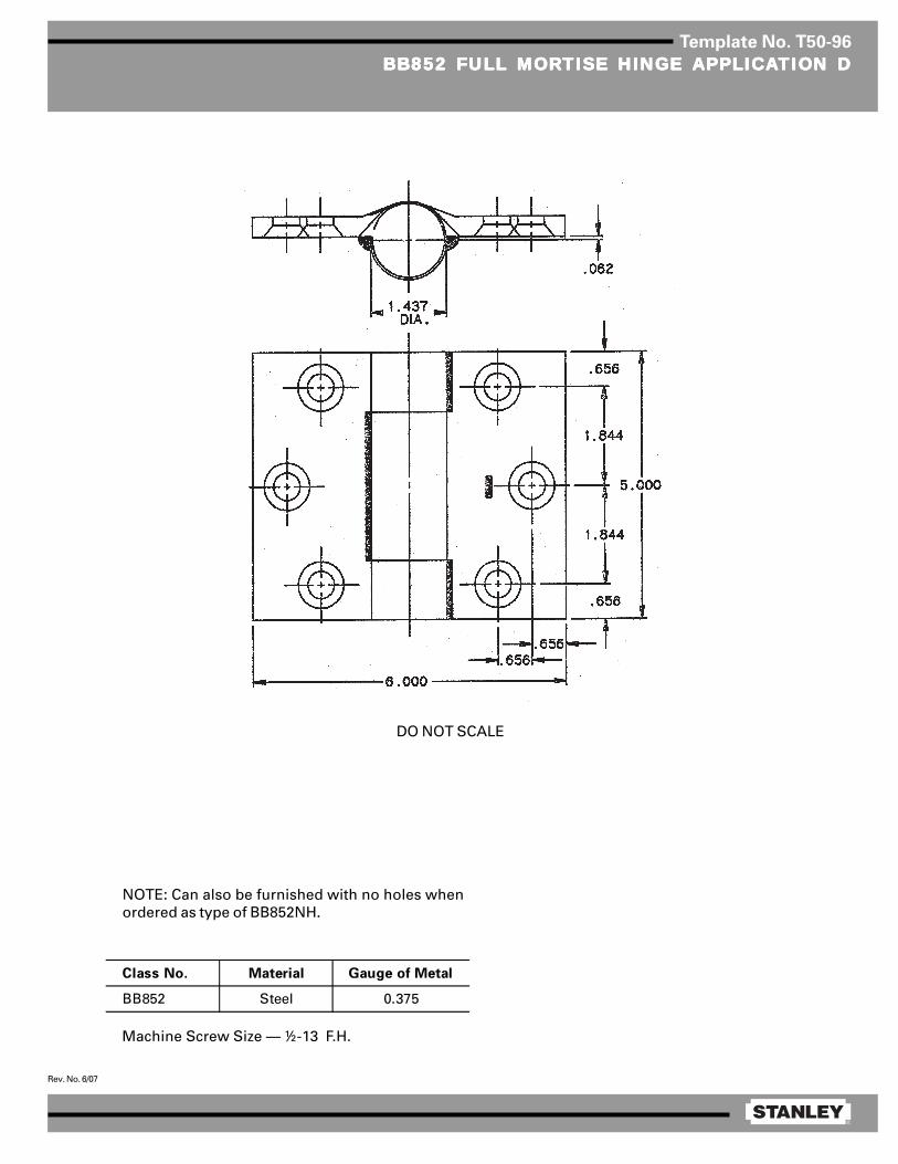
®
Rev. No. 6/07
Template No. T50-96
BB852 FULL MORBB852 FULL MORBB852 FULL MORBB852 FULL MORBB852 FULL MORTISE HINGE TISE HINGE TISE HINGE TISE HINGE TISE HINGE APPLICAAPPLICAAPPLICAAPPLICAAPPLICATION DTION DTION DTION DTION D
Machine Screw Size — ½-13 F.H.
DO NOT SCALE
NOTE: Can also be furnished with no holes whenordered as type of BB852NH.
Class No. Material Gauge of Metal
BB852 Steel 0.375
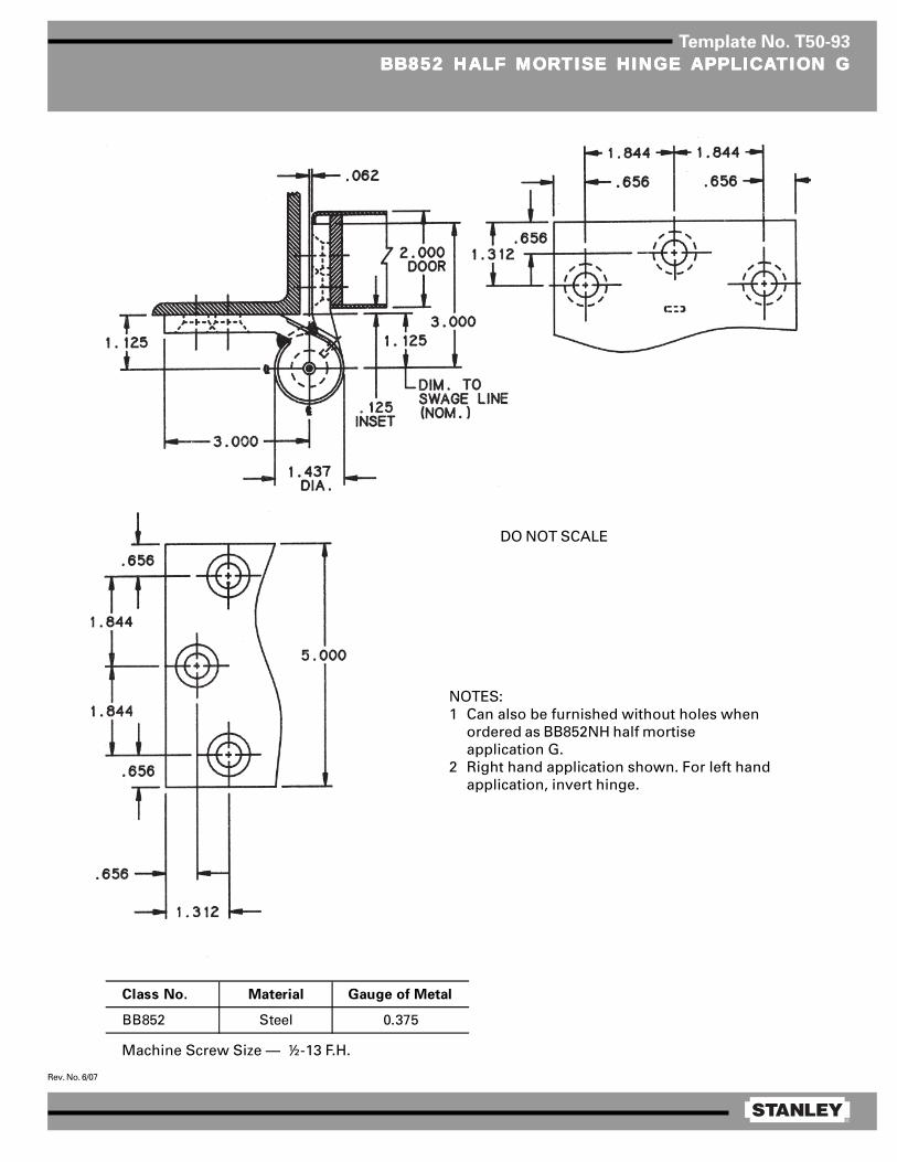
®
Rev. No. 6/07
Template No. T50-93
BB852 HALF MORBB852 HALF MORBB852 HALF MORBB852 HALF MORBB852 HALF MORTISE HINGE TISE HINGE TISE HINGE TISE HINGE TISE HINGE APPLICAAPPLICAAPPLICAAPPLICAAPPLICATION GTION GTION GTION GTION G
Machine Screw Size — ½-13 F.H.
NOTES:1 Can also be furnished without holes when
ordered as BB852NH half mortiseapplication G.
2 Right hand application shown. For left handapplication, invert hinge.
Class No. Material Gauge of Metal
BB852 Steel 0.375
DO NOT SCALE
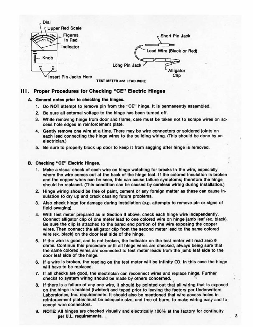
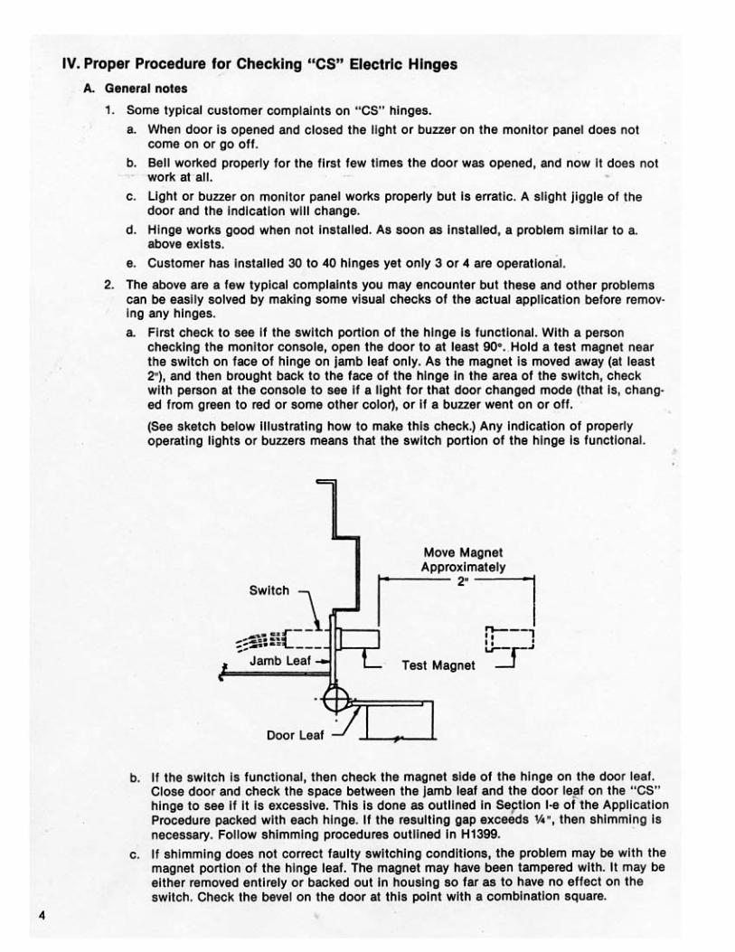
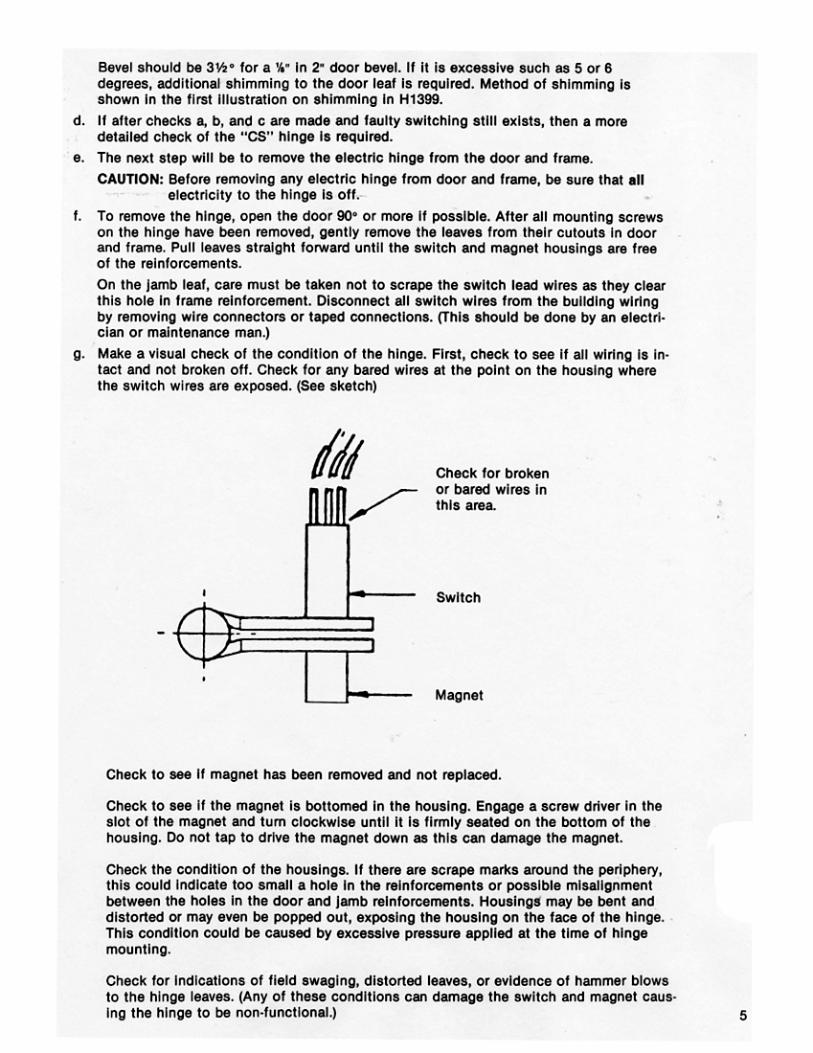
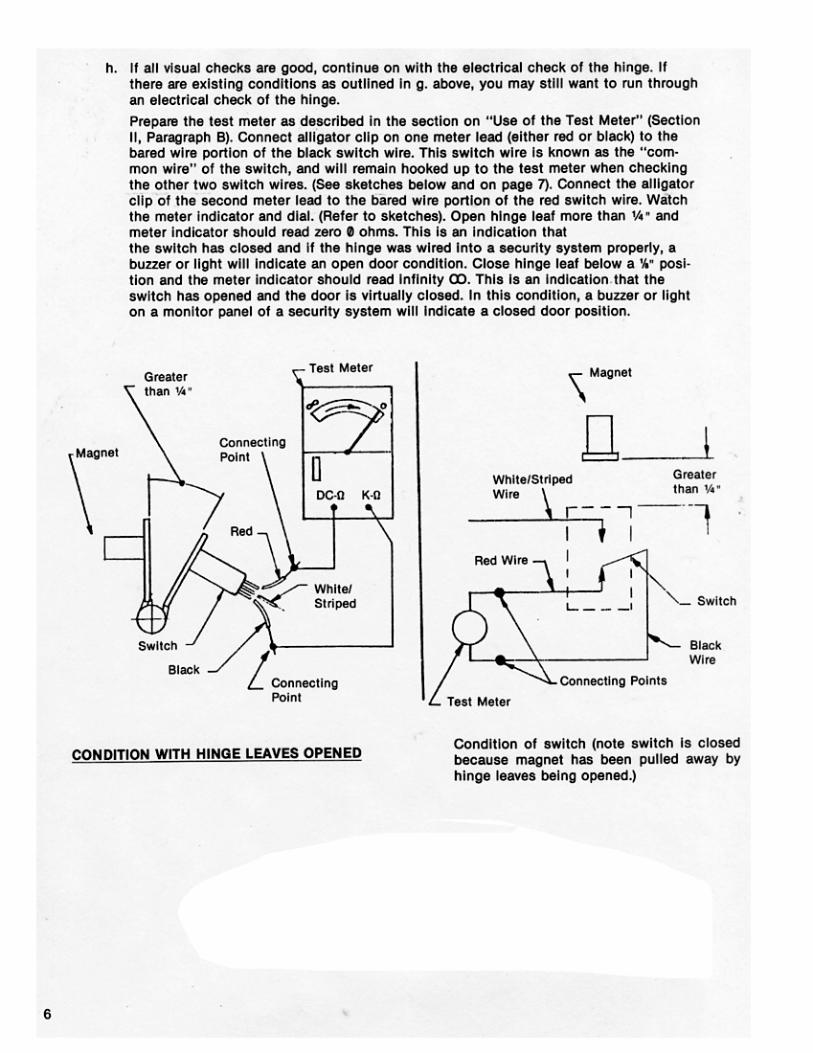
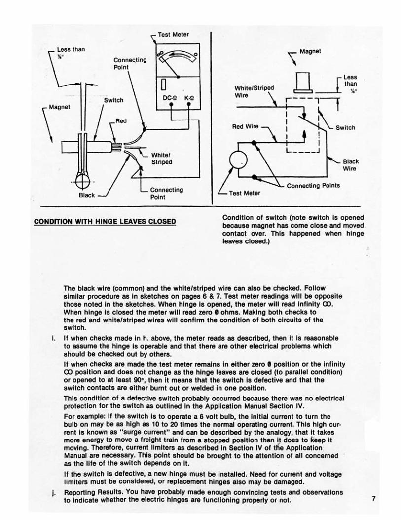
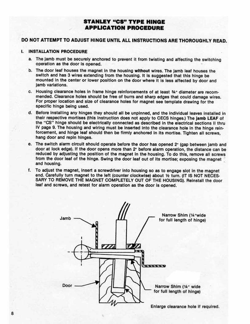
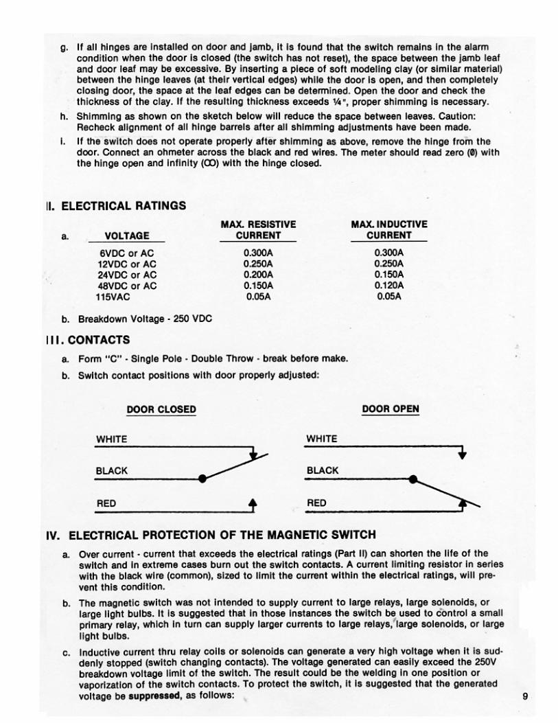
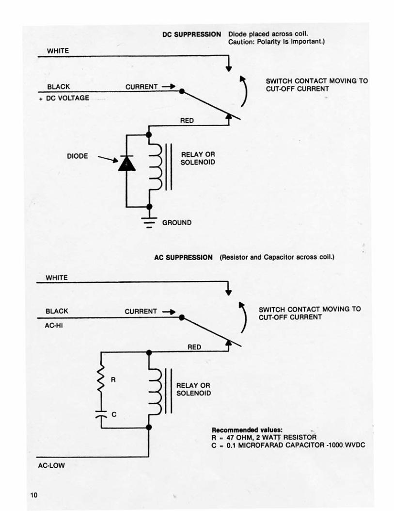
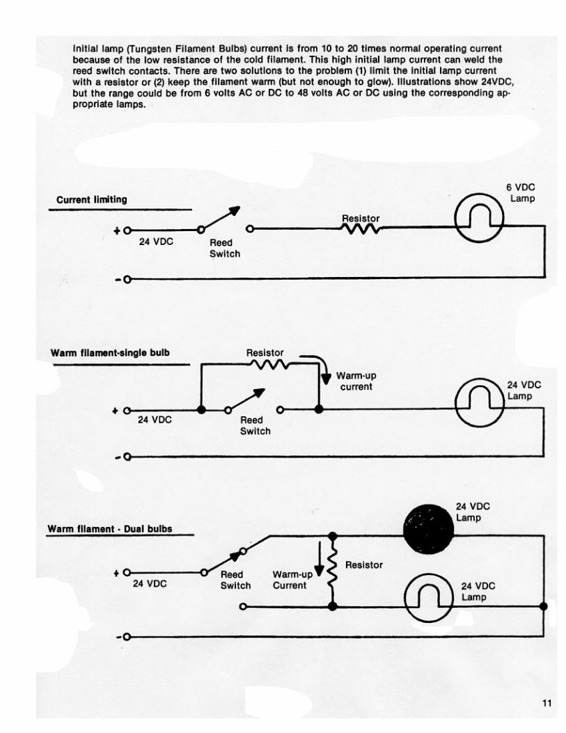
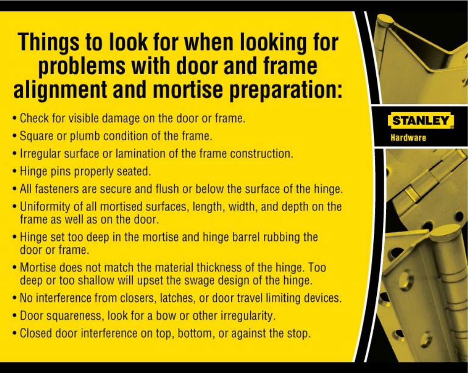
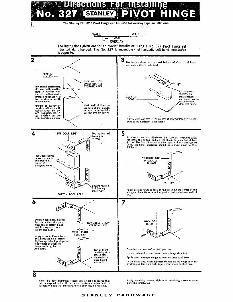
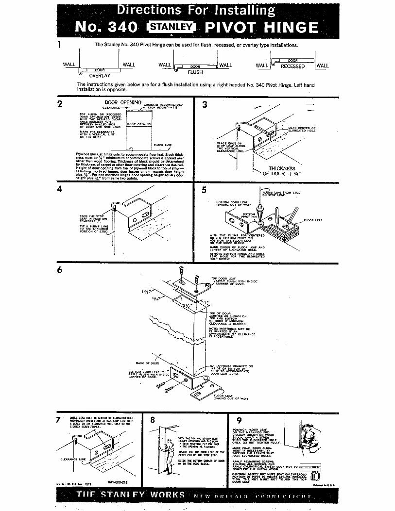
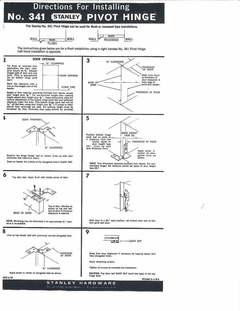
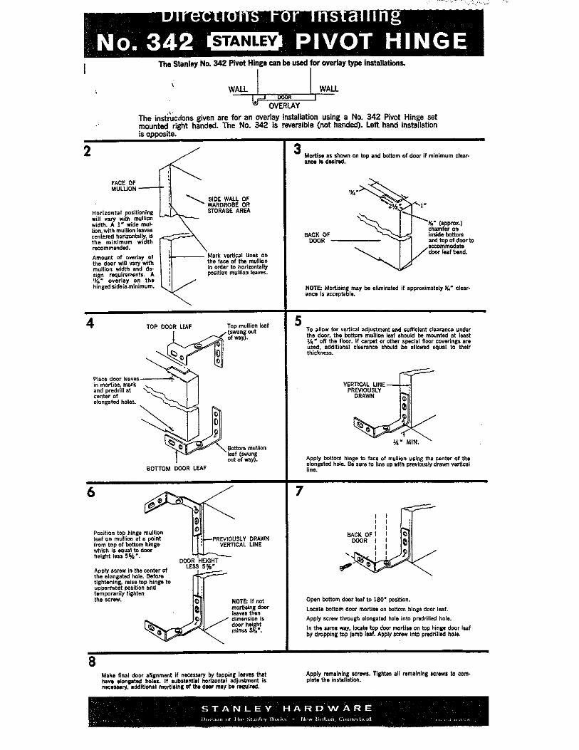
Related Documents