Standard hook Standard hook Standard hook Standard hook Standard hook-up wires -up wires -up wires -up wires -up wires and cables for Electronics and cables for Electronics and cables for Electronics and cables for Electronics and cables for Electronics Filotex Filotex Filotex Filotex Filotex ®

Welcome message from author
This document is posted to help you gain knowledge. Please leave a comment to let me know what you think about it! Share it to your friends and learn new things together.
Transcript

Standard hookStandard hookStandard hookStandard hookStandard hook-up wires-up wires-up wires-up wires-up wiresand cables for Electronicsand cables for Electronicsand cables for Electronicsand cables for Electronicsand cables for Electronics
FilotexFilotexFilotexFilotexFilotex®®®®®

.

3
Content
Guideline of wires and cables ............................................................................. 4
Part 1 - Standard coaxial cables.......................................................................... 7
KX & RG standard coaxial cables................................................................................... 9
Data bus cable M17/176-00002 ..................................................................................... 15
FLAMEX Halogen free coaxial cables ............................................................................. 17
Telecom coaxial cables ................................................................................................... 19
Low noise coaxial cables ................................................................................................ 23
Miniature coaxial cables ................................................................................................ 25
Hand formable coaxial cables ....................................................................................... 27
Part 2 - Single core and multicore cables .......................................................... 29
Operating temperature:
80°C ................................................................................................................................ 31
105°C .............................................................................................................................. 53
150°C .............................................................................................................................. 77
200°C .............................................................................................................................. 87
250°C .............................................................................................................................. 99
Part 3 - Hook-up wires for wrapping .................................................................. 105
Part 4 - Accessories ............................................................................................... 109
In addition to the standard products, you will find within this catalogue, our development and design engineers areat your disposal to provide their experience in tailoring any of our products to meet your specific requirements.

Guideline
4
Standard coaxial cables
Single core and multicore cables
Product range Description Page
COAX KX/RG KX & RG standard coaxial cables 9
M17/176-00002 Data bus cable 15
COAX FLAMEX FLAMEX halogen free coaxial cables 17
COAX TELECOMS Telecom coaxial cables 19
CAS Low noise coaxial cables 23
50/75 VMTX Miniature coaxial cables 25
Quickform® Hand formable coaxial cables 27
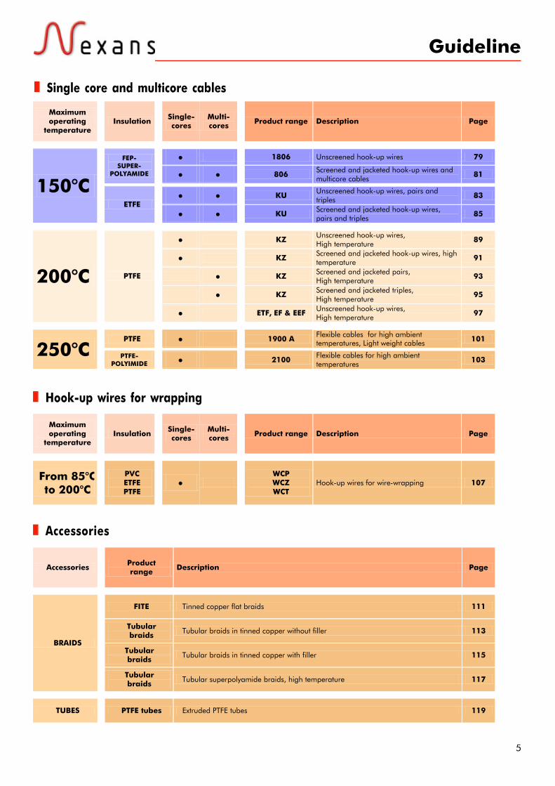
Maximum operating
temperature
Insulation
Single- cores
Multi-cores
Product range Description Page
PE/PVC • HT High voltage Hook-up wires 33
• UL 1007 UL qualified hook-up wires 35
• •
FM & FMA
Screened and jacketed hook-up wires and multicore cables for low frequency applications
37
• •
EHE & EHEA
Screened and jacketed hook-up wires and multicore cables for low frequency applications
39
•
SMA & SMBL
Unscreened and jacketed (SMA), Screened and jacketed (SMBL) multicore cables
41
•
GRTH & CCTB
Unscreened and jacketed (GRTH), Screened and jacketed (CCTB) multicore cables
43
• G250 Flexible pairs
Screened with overall braid 45
PVC
• G900 Flexible pairs
with individual and overall screens 47
•
SMA-ZH SMBL-ZH
Unscreened and jacketed (SMA-ZH), Screened and jacketed (SMBL-ZH) halogen free multicore cables
49
80°C
ZERO HAL •
G250-ZH Halogen free flexible pairs Screened with overall braid 51
• UL 1015 UL qualified hook-up wires 55
• KY/EPDX Unscreened hook-up wires 57
• KY/EPDX Screened hook-up wires, screened and jacketed hook-up wires 59
• KY/EPDX Screened pairs, screened and jacketed pairs 61
PVC
• KY/EPDX Screened triples, screened and jacketed triples 63
• 1604 Unscreened hook-up wires 65
• • 604
Screened and jacketed hook-up wires and multicore cables 67
PVC- SUPER-
POLYAMIDE • 1625 A Unscreened hook-up wires 69
• FLAMEX 20 Unscreened halogen free hook-up wires, Screened and jacketed hook-up wires 71
• FLAMEX 20 Screened and jacketed,
halogen free multicore cables 73
105°C
ZERO HAL
• KY/EPDX ZH Halogen free unscreened hook-up wires 75
5
Guideline
Single core and multicore cables
Hook-up wires for wrapping
Accessories
Maximum operating
temperature
Insulation
Single- cores
Multi-cores
Product range Description Page
• 1806 Unscreened hook-up wires 79 FEP-
SUPER-POLYAMIDE • •
806 Screened and jacketed hook-up wires and multicore cables 81
• • KU Unscreened hook-up wires, pairs and
triples 83 150°C
ETFE • •
KU Screened and jacketed hook-up wires, pairs and triples 85
• KZ Unscreened hook-up wires,
High temperature 89
• KZ Screened and jacketed hook-up wires, high temperature 91
• KZ Screened and jacketed pairs,
High temperature 93
• KZ Screened and jacketed triples,
High temperature 95
200°C PTFE
• ETF, EF & EEF Unscreened hook-up wires, High temperature 97
PTFE • 1900 A Flexible cables for high ambient temperatures, Light weight cables 101
250°C
PTFE- POLYIMIDE
• 2100 Flexible cables for high ambient temperatures 103
Maximum operating
temperature
Insulation
Single- cores
Multi-cores
Product range Description Page
From 85°C to 200°C
PVC ETFE PTFE
•
WCP WCZ WCT
Hook-up wires for wire-wrapping 107
Accessories
Product range Description Page
FITE Tinned copper flat braids 111
Tubular braids Tubular braids in tinned copper without filler 113
Tubular braids Tubular braids in tinned copper with filler 115
BRAIDS
Tubular braids Tubular superpolyamide braids, high temperature 117
TUBES PTFE tubes Extruded PTFE tubes 119

Ambient Temperature
Flexibility
Chemical attacks
Fire performances
Smoke density
Gases corrosivity
Electro Magnetic Interference
Halogen free
ROHS compliant
Symbols
6

7
Part 1Standard coaxial
cables

.

Applications
Construction
Standards
9
KX & RG COAXIAL CABLESKX/RG
Coaxial cables from 50 Ω Ω Ω Ω Ω to 95 ΩΩΩΩΩ
Coaxial cables for highfrequency connections.
1- CONDUCTORStranded or solid, in bare copper(BC), tin plated copper (TPC), silverplated copper (SPC), copper cladsteel (CCS) or silver plated copperclad steel (SPCCS)2- DIELECTRICPE or PTFE3- SCREENSingle or double braid in bare, tinplated or silver plated copper4- SHEATHPVC, FEP, PFA or glass fibre
MIL C17NF C 93-550
FlexibleSee on thefollowing pages
See on thefollowing pages
1 2 3 4
Bending radius5 x overall diameter (for most coaxial cables)
June
200
6 - C
opyr
ight
Nex
ans
10
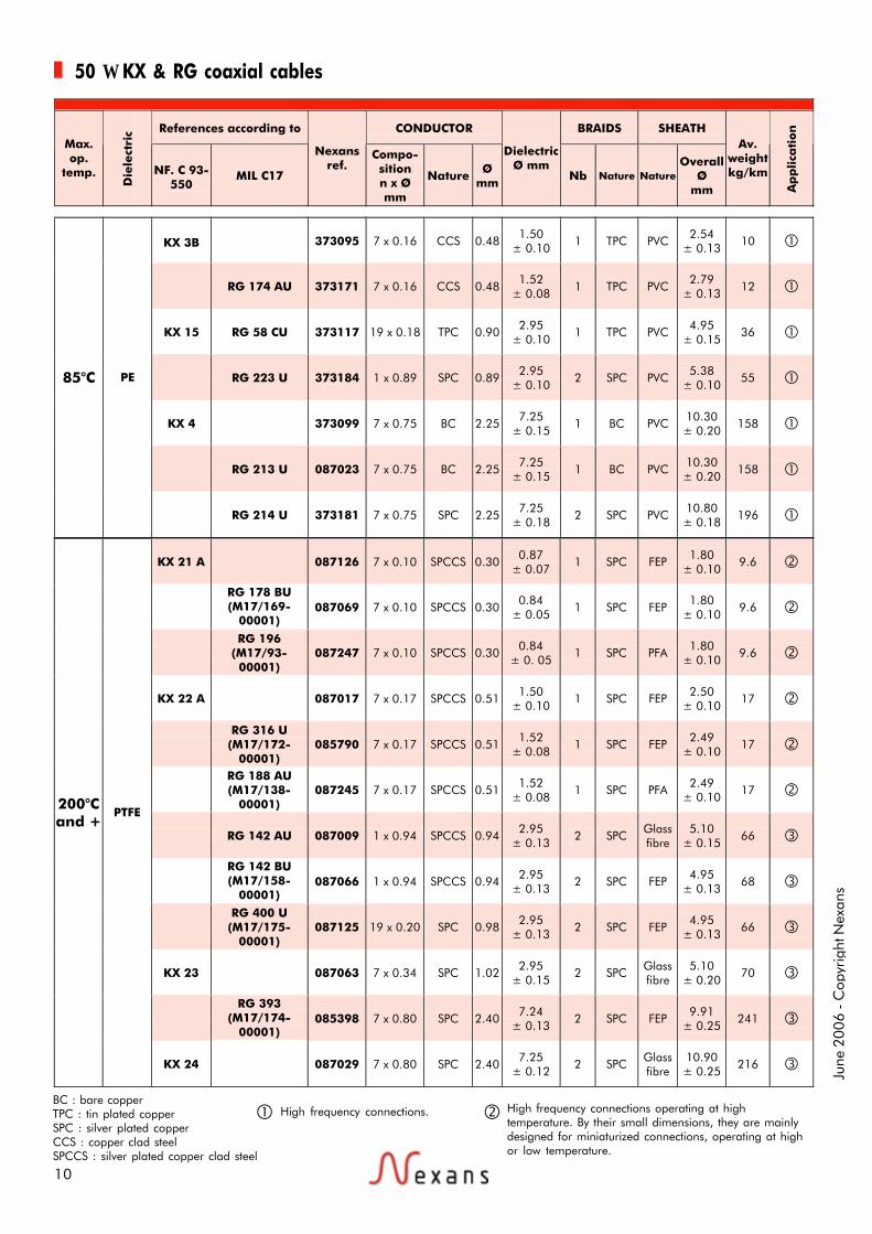
50 Ω KX & RG coaxial cables
High frequency connections. High frequency connections operating at hightemperature. By their small dimensions, they are mainlydesigned for miniaturized connections, operating at highor low temperature.
BC : bare copperTPC : tin plated copperSPC : silver plated copperCCS : copper clad steelSPCCS : silver plated copper clad steel
References according to CONDUCTOR BRAIDS SHEATH Max. op.
temp.
Die
lect
ric
NF. C 93-550
MIL C17
Nexans ref.
Compo-sition n x Ø mm
Nature Ø mm
DielectricØ mm
Nb Nature Nature Overall
Ø mm
Av. weight kg/km
Ap
plica
tion
KX 3B 373095 7 x 0.16 CCS 0.48 1.50 ± 0.10 1 TPC PVC 2.54
± 0.13 10
RG 174 AU 373171 7 x 0.16 CCS 0.48 1.52 ± 0.08 1 TPC PVC 2.79
± 0.13 12
KX 15 RG 58 CU 373117 19 x 0.18 TPC 0.90 2.95 ± 0.10 1 TPC PVC 4.95
± 0.15 36
RG 223 U 373184 1 x 0.89 SPC 0.89 2.95 ± 0.10 2 SPC PVC 5.38
± 0.10 55
KX 4 373099 7 x 0.75 BC 2.25 7.25 ± 0.15 1 BC PVC 10.30
± 0.20 158
RG 213 U 087023 7 x 0.75 BC 2.25 7.25 ± 0.15 1 BC PVC 10.30
± 0.20 158
85°C PE
RG 214 U 373181 7 x 0.75 SPC 2.25 7.25 ± 0.18 2 SPC PVC 10.80
± 0.18 196
KX 21 A 087126 7 x 0.10 SPCCS 0.30 0.87
± 0.07 1 SPC FEP 1.80 ± 0.10 9.6
RG 178 BU (M17/169-
00001)
087069 7 x 0.10 SPCCS 0.30 0.84 ± 0.05 1 SPC FEP 1.80
± 0.10 9.6
RG 196
(M17/93-00001)
087247 7 x 0.10 SPCCS 0.30 0.84 ± 0. 05 1 SPC PFA 1.80
± 0.10 9.6
KX 22 A 087017 7 x 0.17 SPCCS 0.51 1.50 ± 0.10 1 SPC FEP 2.50
± 0.10 17
RG 316 U (M17/172-
00001) 085790 7 x 0.17 SPCCS 0.51 1.52
± 0.08 1 SPC FEP 2.49 ± 0.10 17
RG 188 AU (M17/138-
00001) 087245 7 x 0.17 SPCCS 0.51 1.52
± 0.08 1 SPC PFA 2.49 ± 0.10 17
RG 142 AU 087009 1 x 0.94 SPCCS 0.94 2.95 ± 0.13 2 SPC Glass
fibre 5.10
± 0.15 66
RG 142 BU (M17/158-
00001)
087066 1 x 0.94 SPCCS 0.94 2.95 ± 0.13 2 SPC FEP 4.95
± 0.13 68
RG 400 U (M17/175-
00001) 087125 19 x 0.20 SPC 0.98 2.95
± 0.13 2 SPC FEP 4.95 ± 0.13 66
KX 23 087063 7 x 0.34 SPC 1.02 2.95 ± 0.15 2 SPC Glass
fibre 5.10
± 0.20 70
RG 393
(M17/174-00001)
085398 7 x 0.80 SPC 2.40 7.24 ± 0.13 2 SPC FEP 9.91
± 0.25 241
200°C and +
PTFE
KX 24 087029 7 x 0.80 SPC 2.40 7.25 ± 0.12 2 SPC Glass
fibre 10.90 ± 0.25 216

11
50 ΩΩΩΩΩ KX & RG coaxial cables
High frequency connections operating at hightemperature, or on equipment excepted to workunder severe conditions without failure.
-90 +200
NF C 32070/C1&C2 IEC 60332 – 1
3 95.0 65 95 300 1 0.085 0.057 0.018 69.5 750
-90 +200
NF C 32070/C1&C2 IEC 60332 – 1
3 105.0 58 80 225 2 0.085 0.057 0.018 69.5 750
-90 +230
NF C 32070/C1&C2 IEC 60332 – 1
3 105.0 58 80 225 2 0.085 0.057 0.018 69.5 750
-90 +200
NF C 32070/C1&C2 IEC 60332 – 1
3 95.0 40 55 160 2 0.17 0.11 0.032 69.5 900
-90 +200
NF C 32070/C1&C2 IEC 60332 – 1
3 105.0 40 55 160 2 0.17 0.11 0.032 69.5 900
-90 +230
NF C 32070/C1&C2 IEC 60332 – 1
3 105.0 40 55 160 2 0.17 0.11 0.032 69.5 900
-90 +250
NF C 32070/C1&C2 IEC 60332 – 1
3 95.0 19 27 79 163 5 0.66 0.45 0.15 0.08 69.5 1400
-90 +200
NF C 32070/C1&C2 IEC 60332 – 1
3 105.0 19 27 79 163 5 0.66 0.45 0.15 0.08 69.5 1400
-90 +200
NF C 32070/C1&C2 IEC 60332 – 1
3 105.0 20 29 89 185 5 0.66 0.45 0.15 0.08 69.5 1400
-90 +250
NF C 32070/C1&C2 IEC 60332 – 1
3 95.0 20 29 89 185 5 0.66 0.45 0.15 0.08 69.5 1400
-90 +200
NF C 32070/C1&C2 IEC 60332 – 1
11 105.0 9.3 14 47 109 4 2 1.3 0.43 0.22 69.5 3700
-90 +250
NF C 32070/C1&C2 IEC 60332 – 1
3 95.0 9.3 14 47 109 10 2 1.3 0.43 0.22 69.5 3700
Attenuation (db/100 m) Powers at 40°C (kw)
Op
era
tin
g
tem
pera
ture
M
in/M
ax
Fire properties
Ma
x. o
p.
freq
uen
cy
GH
z
Nominal capaci-tance pF/m
200 MHz
400 MHz
3000 MHz
10000 MHz D
iele
ctri
c st
ren
gth
kV
200 MHz
400 MHz
3000 MHz
10000 MHz
Velocity of
propa-gation
Conti-nuous
working voltage
-40 +85
NF C 32070/C2 IEC 60332 – 1&2
3 100.0 42 60 220 2 0.057 0.042 0.013 65.9 1100
-40 +85
NF C 32070/C2 IEC 60332 – 1&2
1 106.0 42 60 220 4.5 0.057 0.042 0.013 65.9 1100
-40 +85
NF C 32070/C2 IEC 60332 – 1&2
3 100.0 23 32 98 5 0.125 0.09 0.031 65.9 1400
-40 +85
NF C 32070/C2 IEC 60332 – 1&2
12.4 106.0 20 30 100 240 5 0.125 0.09 0.031 0.017 65.9 1400
-40 +85
NF C 32070/C2 IEC 60332 – 1&2
3 100.0 9.5 14.5 55 5 0.42 0.3 0.095 0.05 65.9 3700
-40 +85
NF C 32070/C2 IEC 60332 – 1&2
3 100.0 9.5 14.5 55 5 0.42 0.3 0.095 0.05 65.9 3700
-40 +85
NF C 32070/C2 IEC 60332 – 1&2
11 106.0 9 13 46 100 10 0.42 0.3 0.095 0.05 65.9 3700

12
June
200
6 - C
opyr
ight
Nex
ans
12
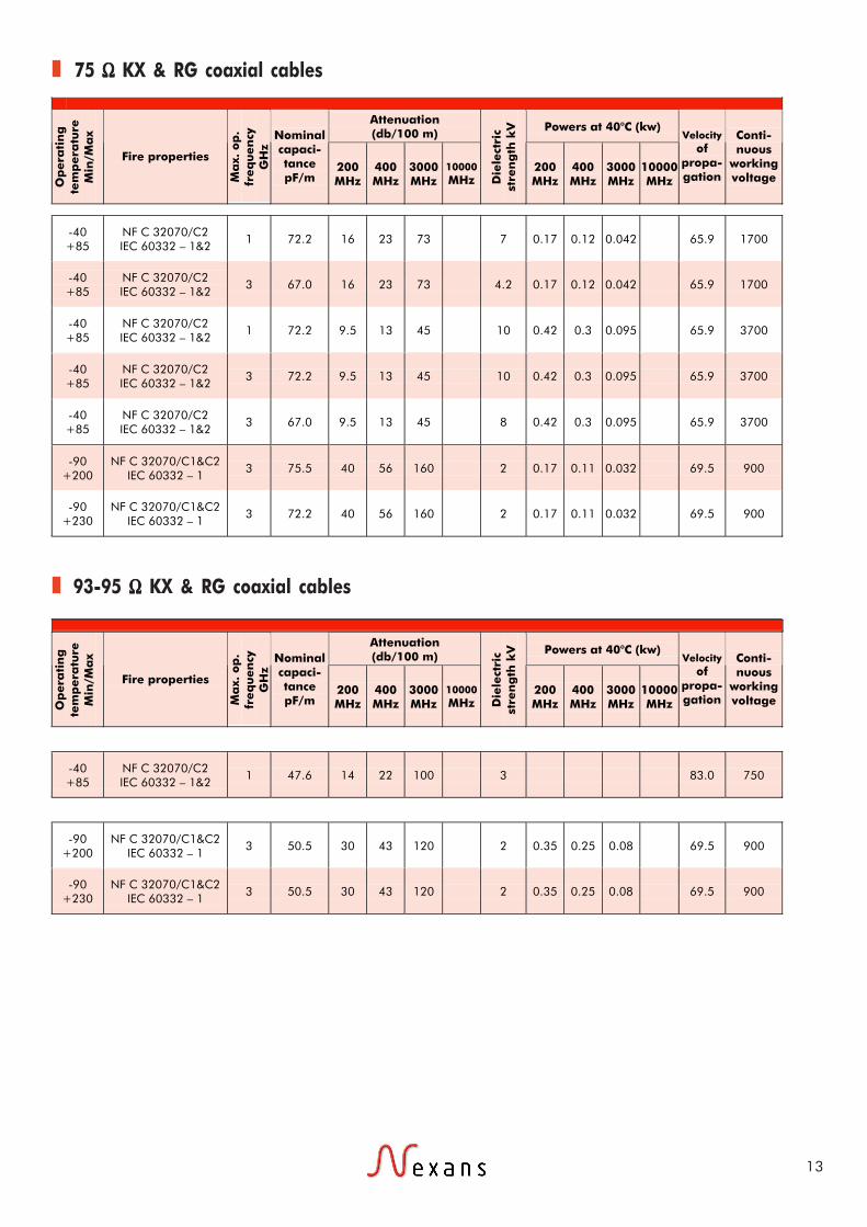
75 ΩΩΩΩΩ KX & RG coaxial cables
High frequency connections. High frequency connections operating at hightemperature. By their small dimensions, they are mainlydesigned for miniaturized connections, operating at highor low temperature.
BC : bare copperTPC : tin plated copperSPC : silver plated copperCCS : copper clad steelSPCCS : silver plated copper clad steel
93-95 ΩΩΩΩΩ KX & RG coaxial cables
References according to CONDUCTOR BRAIDS SHEATH Max. op.
temp.
Die
lect
ric
NF. C 93-550
MIL C17
Nexans ref.
Compo-sition n x Ø mm
Nature Ø mm
DielectricØ mm
Nb Nature Nature Overall
Ø mm
Av. weight kg/km
Ap
pli
cati
on
RG 59 BU 390650 1 x 0.58 CCS 0.58 3.71 ± 0.10
1 BC PVC 6.15 ± 0.10
50
KX 6A 373100 7 x 0.20 BC 0.60 3.70 ± 0.12
1 BC PVC 6.10 ± 0.15
53
RG 11 AU 373135 7 x 0.40 TPC 1.20 7.24 ± 0.18
1 BC PVC 10.30 ± 0.18
136
RG 216 U 373182 7 x 0.40 TPC 1.20 7.24 ± 0.18
2 BC PVC 10.80 ± 0.18
177
85°C PE
KX 8 373113 7 x 0.40 BC 1.20 7.25 ± 0.15
1 BC PVC 10.30 ± 0.20
135
RG 179 BU
(M17/94-RG 179)
081997 7 x 0.10 SPCCS 0.30 1.60 ± 0.08
1 SPC FEP 2.54 ± 0.13
16.9 200°C and +
PTFE
RG 187 AU (M17/136-
00001) 087244 7 x 0.10 SPCCS 0.30 1.60
± 0.08 1 SPC PFA 2.54
± 0.13 16.9
References according to CONDUCTOR BRAIDS SHEATH Max. op.
temp.
Die
lect
ric
NF. C 93-550
MIL C17
Nexans ref.
Compo-sition n x Ø mm
Nature Ø mm
DielectricØ mm
Nb Nature Nature Overall
Ø mm
Av. weight kg/km
Ap
pli
cati
on
93 Ω
85°C PE RG 62 AU 373148 1 x 0.64 CCS 0.64 3.71 ± 0.13
1 BC PVC 6.15 ± 0.18
46
95 Ω
RG 180 BU
(M17/95-RG 180)
087241 7 x 0.10 SPCCS 0.30 2.59 ± 0.08
1 SPC FEP 3.58 ± 0.10
27 200°C and +
PTFE
RG 195 AU (M17/137-
00001) 087246 7 x 0.10 SPCCS 0.30 2.59
± 0.08 1 SPC PFA 3.58
± 0.10 27
13
75 ΩΩΩΩΩ KX & RG coaxial cables
93-95 ΩΩΩΩΩ KX & RG coaxial cables
Attenuation (db/100 m) Powers at 40°C (kw)
Op
era
tin
g
tem
pera
ture
M
in/M
ax
Fire properties
Ma
x. o
p.
freq
uen
cy
GH
z
Nominal capaci-tance pF/m
200 MHz
400 MHz
3000 MHz
10000 MHz D
iele
ctri
c st
ren
gth
kV
200 MHz
400 MHz
3000 MHz
10000 MHz
Velocity of
propa-gation
Conti-nuous
working voltage
-40 +85
NF C 32070/C2 IEC 60332 – 1&2
1 72.2 16 23 73 7 0.17 0.12 0.042 65.9 1700
-40 +85
NF C 32070/C2 IEC 60332 – 1&2
3 67.0 16 23 73 4.2 0.17 0.12 0.042 65.9 1700
-40 +85
NF C 32070/C2 IEC 60332 – 1&2
1 72.2 9.5 13 45 10 0.42 0.3 0.095 65.9 3700
-40 +85
NF C 32070/C2 IEC 60332 – 1&2
3 72.2 9.5 13 45 10 0.42 0.3 0.095 65.9 3700
-40 +85
NF C 32070/C2 IEC 60332 – 1&2
3 67.0 9.5 13 45 8 0.42 0.3 0.095 65.9 3700
-90 +200
NF C 32070/C1&C2 IEC 60332 – 1
3 75.5 40 56 160 2 0.17 0.11 0.032 69.5 900
-90 +230
NF C 32070/C1&C2 IEC 60332 – 1
3 72.2 40 56 160 2 0.17 0.11 0.032 69.5 900
Attenuation (db/100 m) Powers at 40°C (kw)
Op
era
tin
g
tem
pera
ture
M
in/M
ax
Fire properties
Ma
x. o
p.
freq
uen
cy
GH
z
Nominal capaci-tance pF/m
200 MHz
400 MHz
3000 MHz
10000 MHz D
iele
ctri
c st
ren
gth
kV
200 MHz
400 MHz
3000 MHz
10000 MHz
Velocity of
propa-gation
Conti-nuous
working voltage
-40 +85
NF C 32070/C2 IEC 60332 – 1&2
1 47.6 14 22 100 3 83.0 750
-90 +200
NF C 32070/C1&C2 IEC 60332 – 1
3 50.5 30 43 120 2 0.35 0.25 0.08 69.5 900
-90 +230
NF C 32070/C1&C2 IEC 60332 – 1
3 50.5 30 43 120 2 0.35 0.25 0.08 69.5 900

June
200
6 - C
opyr
ight
Nex
ans
14
TPC : tin plated copper
Other standard cables
Application: High frequency connections. These twinaxial cables are mainly designed for digital data transmissions inelectronic systems.
References according to CONDUCTOR BRAIDS SHEATH
Imp
ed
an
ce
Max. op.
temp. D
iele
ctri
c NF. C 93-
550 MIL C17
Nexans ref.
Compo-sition n x Ø mm
Nature Ø
mm Die
lect
ric
Ø m
m
Nb Nature Nature Overall
Ø mm
Av. weight kg/km
CABLES with two CONDUCTORS
78 Ω
85°C PE RG 108 AU 087061 7 x 0.32 TPC 0.96 2.0 1 TPC PVC 6.0 ± 0.25
52
95 Ω
85°C PE RG 22 BU 087043 7 x 0.38 TPC 1.14 2.3 2 TPC PVC 10.7 ± 0.25
181
Attenuation (db/100 m)
Reference Op. temp. (min/max) Fire properties
Ma
x. o
p.
freq
uen
cy
GH
z Nominal capacitance
pF/m 1 MHz
10 MHz
200 MHz
400 MHz D
iele
ctri
c st
ren
gth
k
V
Velocity of
propa-gation
Conti-nuous
working voltage
RG 108 AU -40 +85 NF C 32070/C2 IEC 60332 – 1&2
1 64.8 10 60 95 2 65.9 750
RG 22 BU -40 +85 NF C 32070/C1 IEC 60332 – 1
53.2 5 20 29 2

Applications
Construction
Standards
15
DATA BUS CABLEM17/176-00002
77 Ω Ω Ω Ω Ω data bus cable
Bus lines for multiplexed trans-missions.The cable is constructed with 2cores and 2 fillers twistedtogether.
1- CONDUCTORStranded, high strength silver platedcopper alloy2- INSULATIONExtruded PTFE3- FILLERSExtruded PTFE4- SCREENHigh strength silver plated copperalloy5- SHEATHPFAColour : translucent blue
1blue core and 1 white core M17/176-00002
Identification
FlexibleMIL-DTL-17-65 to +200°C
1 2 4 5
3
Minimum bending radius21 mm

June
200
6 - C
opyr
ight
Nex
ans
16
M17/176-00002 data bus cable
CONDUCTOR BRAIDS SHEATH
Imp
ed
an
ce
Max. op. temp.
Die
lect
ric
Nexans reference Compo-
sition n x Ø mm
Nature Die
lect
ric
Ø m
m
Nb Nature Nature Overall
Ø mm
Av. weight kg/km
77 Ω 200°C PTFE 090612 19 x 0.13 SPC alloy 1.07 1 SPC
alloy PFA 3.27
± 0.127 26
Nexans reference Max. op. frequency GHz
Nominal capacitance pF/m
Attenuation at 1 MHz (db/m)
Continuous working voltage
090612 1 65 4.6 750
Applications
Construction
Standards
17
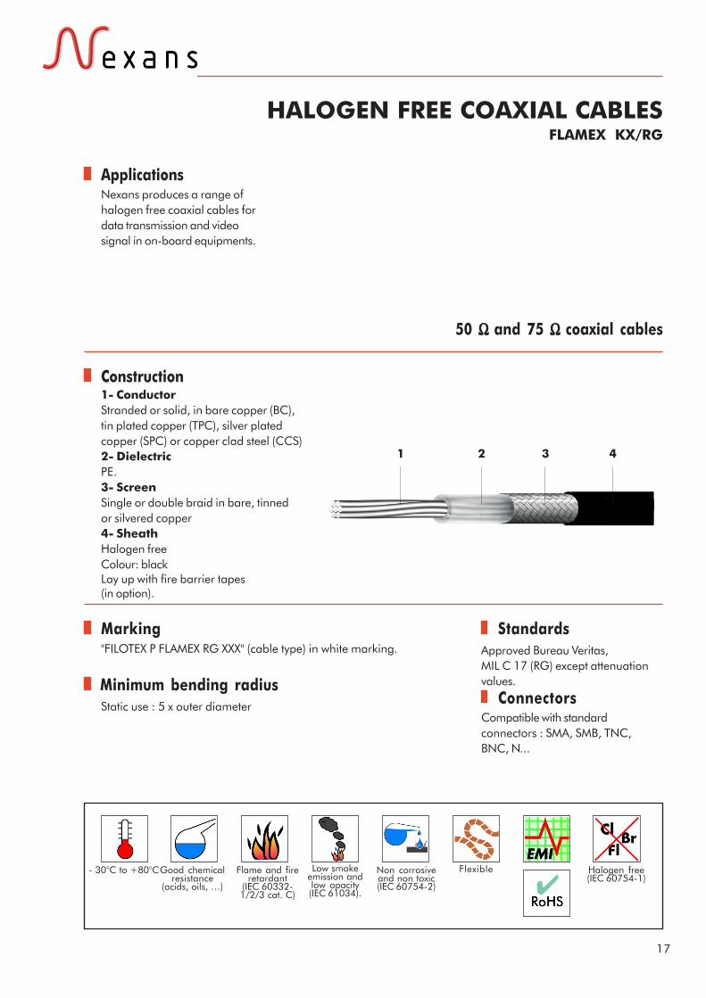
HALOGEN FREE COAXIAL CABLESFLAMEX KX/RG
50 Ω Ω Ω Ω Ω and 75 Ω Ω Ω Ω Ω coaxial cables
Nexans produces a range ofhalogen free coaxial cables fordata transmission and videosignal in on-board equipments.
1- ConductorStranded or solid, in bare copper (BC),tin plated copper (TPC), silver platedcopper (SPC) or copper clad steel (CCS)2- DielectricPE.3- ScreenSingle or double braid in bare, tinnedor silvered copper4- SheathHalogen freeColour: blackLay up with fire barrier tapes(in option).
"FILOTEX P FLAMEX RG XXX" (cable type) in white marking. Approved Bureau Veritas,MIL C 17 (RG) except attenuationvalues.
Compatible with standardconnectors : SMA, SMB, TNC,BNC, N...
Connectors
1 2 3 4
- 30°C to +80°C Low smokeemission andlow opacity(IEC 61034).
Halogen free(IEC 60754-1)
Non corrosiveand non toxic(IEC 60754-2)
FlexibleGood chemicalresistance
(acids, oils, …)
Flame and fireretardant
(IEC 60332-1/2/3 cat. C)
Marking
Minimum bending radiusStatic use : 5 x outer diameter

June
200
6 - C
opyr
ight
Nex
ans
18
FLAMEX 75 ΩΩΩΩΩ Halogen free coaxial cables
FLAMEX 50 ΩΩΩΩΩ Halogen free coaxial cables
Attenuation values
Capacitance : < 106 pF / m Velocity of propagation : 65.9%
BC: bare copper, TPC: tin plated copper, SPC : silver plated copper, CCS: copper clad steelCapacitance : < 72.2 pF / m Velocity of propagation : 65.9%
Attenuation at x MHz in db/100m (nominal values)
Designation Nexans
ref. 50 100 200 400 1000 3000 11000
FLAMEX KX 3B ET 299946 45
FLAMEX RG174 ET 299956 21.32 32.8 82.02 147.63
FLAMEX RG58 ET 299954 13.12 21.32 55.77 91.86
FLAMEX RG213 ET 299957 3.93 7.54 15.74 29.52
50 Ω
FLAMEX RG214 ET 299958 5.57 22.3 91.86 196.85
FLAMEX KX6A ET 299952 20
FLAMEX RG59 ET 299955 29.52 52.48
FLAMEX RG 11 ET 299953 17.06 30.84
FLAMEX KX8 ET 299951 12
75 Ω
FLAMEX RG 216 ET 299965 21.32 75.45
CONDUCTOR BRAIDS SHEATH
Nexans designation
Nexans reference
Compo-sition n x Ø mm
Nature Ø mm D
iele
ctri
c Ø
mm
Nb Nature Nature Overall
Ø mm
Av. weight kg/km
Ma
x. o
p.
freq
uen
cy
GH
z
Continuous working voltage
FLAMEX KX 3B ET 299946 7x0.16 CCS 0.48 1.50 ± 0.10
1 TPC FLAMEX 2.54 ± 0.13
10 3 1100
FLAMEX RG 174 ET 299956 7x0.16 CCS 0.48 1.52 ± 0.08
1 TPC FLAMEX 2.79 ± 0.13
12.5 1 1100
FLAMEX RG 58 ET 299954 19x0.18 TPC 0.90 2.95 ± 0.10
1 TPC FLAMEX 4.95 ± 0.10
41 3 1400
FLAMEX RG 213 ET 299957 7x0.75 BC 2.25 7.24 ± 0.18
1 BC FLAMEX 10.30 ± 0.18
165 3 3700
FLAMEX RG 214 ET 299958 7x0.75 SPC 2.25 7.24 ± 0.18
2 SPC FLAMEX 10.80 ± 0.18
198 11 3700
CONDUCTOR BRAIDS SHEATH
Nexans designation
Nexans reference
Compo-sition n x Ø mm
Nature Ø mm D
iele
ctri
c Ø
mm
Nb Nature Nature Overall
Ø mm
Av. weight kg/km
Ma
x. o
p.
freq
uen
cy
GH
z
Continuous working voltage
FLAMEX KX 6A ET 299952 7x0.20 BC 0.60 3.70 ± 0.12
1 BC FLAMEX 6.10 ± 0.15
57 3 1700
FLAMEX RG 59 ET 299955 1x0.57 CCS 0.57 3.71 ± 0.10
1 BC FLAMEX 6.15 ± 0.10
58 1 1700
FLAMEX RG 11 ET 299953 7x0.40 TPC 1.20 7.24 ± 0.18
1 BC FLAMEX 10.30 ± 0.18
146 1 3700
FLAMEX KX 8 ET 299951 7x0.40 BC 1.20 7.25 ± 0.15
1 BC FLAMEX 10.30 ± 0.20
145 3 3700
FLAMEX RG 216 ET 299965 7x0.40 TPC 1.20 7.24 ± 0.18
2 BC FLAMEX 10.80 ± 0.18
185 3 3700

Applications
Construction
Standards
19
TELECOM COAXIAL CABLESRG types
50 ΩΩΩΩΩ and 75 ΩΩΩΩΩ coaxial cables
These coaxial cables are mainlydesigned for high frequencyinterconnections intelecommunication equipments.If a high shielding effectivenessis required, use the doublebraided cables.
1- CONDUCTORStranded or solid, in copper cladsteel (CCS) or silver plated coppercovered steel (SPCCS)2- DIELECTRICPE, FEP, PTFE.3- SCREENSingle or double braid in barecopper or silver plated copper4- SHEATHPVC, FEP or halogen free
NEXANS specification
Compatible with all standardconnectors intended for RGcables
Connectors
Physical propertiesVery good resistance to solvents (except halogen free versions)Very good resistance to soldering operations
For halogen free versions (LSZH):- pH>4 and conductivity < 100mS/cm according to IEC 754-1- VW-1 and FT-1 according to UL and CSA standards- Low smoke emissions according to IEC 1034-2
1 2 3 4
FlexibleSee on thefollowing page
See on thefollowing page
Minimum bending radiusStatic use : 5 x outer diameter
June
200
6 - C
opyr
ight
Nex
ans
20
75 ΩΩΩΩΩ telecom coaxial cables
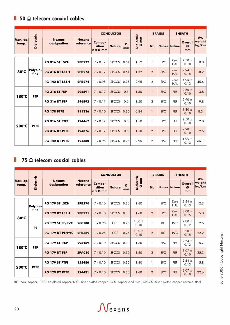
50 ΩΩΩΩΩ telecom coaxial cables
BC: bare copper, TPC: tin plated copper, SPC: silver plated copper, CCS: copper clad steel, SPCCS: silver plated copper covered steel
CONDUCTOR BRAIDS SHEATH
Max. op. temp.
Die
lect
ric
Nexans designation
Nexans reference Compo-
sition n x Ø mm
Nature Ø
mm Die
lect
ric
Ø m
m
Nb Nature Nature Overall
Ø mm
Av. weight kg/km
RG 316 ST LSZH 2PB272 7 x 0.17 SPCCS 0.51 1.52 1 SPC Zero HAL
2.50 ± 0.10 10.8
RG 316 DT LSZH 2PB273 7 x 0.17 SPCCS 0.51 1.52 2 SPC Zero HAL
2.94 ± 0.15 18.2 80°C Polyole-
fine
RG 142 DT LSZH 2PB274 1 x 0.95 SPCCS 0.95 2.95 2 SPC Zero HAL
4.95 ± 0.13 45.6
RG 316 ST FEP 296891 7 x 0.17 SPCCS 0.5 1.50 1 SPC FEP 2.50 ± 0.10 13.8
180°C FEP
RG 316 DT FEP 296892 7 x 0.17 SPCCS 0.5 1.50 2 SPC FEP 2.90 ± 0.10 19.8
RG 178 PTFE 111336 7 x 0.10 SPCCS 0.30 0.84 1 SPC FEP 1.80 ± 0.10 8.3
RG 316 ST PTFE 124467 7 x 0.17 SPCCS 0.5 1.50 1 SPC FEP 2.50 ± 0.10 12.0
RG 316 DT PTFE 124376 7 x 0.17 SPCCS 0.5 1.50 2 SPC FEP 2.90 ± 0.10 19.6
200°C PTFE
RG 142 DT PTFE 124380 1 x 0.95 SPCCS 0.95 2.95 2 SPC FEP 4.95 ± 0.13 66.1
CONDUCTOR BRAIDS SHEATH
Max. op. temp.
Die
lect
ric
Nexans designation
Nexans reference Compo-
sition n x Ø mm
Nature Ø
mm Die
lect
ric
Ø m
m
Nb Nature Nature Overall
Ø mm
Av. weight kg/km
RG 179 ST LSZH 2PB270 7 x 0.10 SPCCS 0.30 1.60 1 SPC Zero HAL
2.54 ± 0.13 12.3
Polyole-fine
RG 179 DT LSZH 2PB271 7 x 0.10 SPCCS 0.30 1.60 2 SPC Zero HAL
3.00 ± 0.15 15.8
RG 179 ST PE/PVC 288108 1 x 0.25 CCS 0.25 1.50 ± 0.10 1 BC PVC
2.80 ± 0.12 12.6
80°C
PE
RG 179 DT PE/PVC 2PB389 1 x 0.25 CCS 0.25 1.50 ± 0.10 2 BC PVC
3.20 ± 0.15 22.2
RG 179 ST FEP 296469 7 x 0.10 SPCCS 0.30 1.60 1 SPC FEP 2.54 ± 0.13 15.7
180°C FEP
RG 179 DT FEP 2PA030 7 x 0.10 SPCCS 0.30 1.60 2 SPC FEP 3.07 ± 0.10 25.3
RG 179 ST PTFE 125480 7 x 0.10 SPCCS 0.30 1.60 1 SPC FEP 2.54 ± 0.13 15.8
200°C PTFE
RG 179 DT PTFE 124431 7 x 0.10 SPCCS 0.30 1.60 2 SPC FEP 3.07 ± 0.10 22.6

21
50 ΩΩΩΩΩ telecom coaxial cables
75 ΩΩΩΩΩ telecom coaxial cables
Affaiblissement moyen (db/100 m)
Temp. De service
(min/max) Tenue au feu
Fréq
uen
ce
d’u
t. M
axi
. G
Hz Capacité
nominale pF/m 10
MHz 100 MHz
1000 MHz
900 MHz
1800MHz
3000 MHz
Vitesse de
propa-gation
Tension de service Volts
-25 +80 NF C 32070/C1 IEC 60332 – 1 3 95 86 120 160 70 900
-25 +80 NF C 32070/C1 IEC 60332 – 1 3 95 86 120 160 70 900
-25 +80 NF C 32070/C1 IEC 60332 – 1 3 95 43 62 82 70 1500
-90 +180 NF C 32070/C1&C2
IEC 60332 – 1 3 95 80 120 69.5 900
-90 +180 NF C 32070/C1&C2
IEC 60332 – 1 3 95 80 120 69.5 900
-90 +200 NF C 32070/C1&C2
IEC 60332 – 1 3 95 150 240 69.5 750
-90 +200 NF C 32070/C1&C2
IEC 60332 – 1 3 95 80 120 69.5 900
-90 +200 NF C 32070/C1&C2
IEC 60332 – 1 3 95 80 120 69.5 900
-90 +200 NF C 32070/C1&C2
IEC 60332 – 1 3 95 40 60 69.5 1400
Affaiblissement moyen (db/100 m)
Temp. de service
(min/max) Tenue au feu
Fréq
uen
ce
d’u
t. m
axi
. G
Hz Capacité
nominale pF/m 10
MHz 100 MHz
1000 MHz
900 MHz
1800MHz
3000 MHz
Vitesse de
propa-gation
Tension de service Volts
-25 +80 NF C 32070/C1 IEC 60332 – 1 3 64 100 140 185 70 900
-25 +80 NF C 32070/C1 IEC 60332 – 1 3 64 100 140 185 70 900
-20 +80 NF C 32070/C1 IEC 60332 – 1 3 67 8.5 28 89 66 900
-20 +80 NF C 32070/C1 IEC 60332 – 1 3 67 8.5 28 89 66 900
-90 +180 NF C 32070/C1&C2
IEC 60332 – 1 3 64 80 120 69.5 900
-90 +180 NF C 32070/C1&C2
IEC 60332 – 1 3 64 90 140 69.5 900
-90 +200 NF C 32070/C1&C2
IEC 60332 – 1 3 64 80 120 69.5 900
-90 +200 NF C 32070/C1&C2
IEC 60332 – 1 3 64 80 120 69.5 900

.

Applications
Construction
Standards
23
LOW NOISE COAXIAL CABLESCAS 85-22P
CAS 250-20 PCAS 250-20 SP
CAS 250-22
250/600 Volts RMS
Cables designed for lowfrequency connections submittedto displacements and vibrationsduring their operation.
1- CONDUCTORStranded or solid in silver platedcopper covered steel (SPCCS)2- DIELECTRICPE or PTFE3- ANTIMICROPHONIC NOISECOATING4- SCREENSingle braid in bare copper or silverplated copper5- SHEATHPVC or PTFE tape(s)Colour: green for standard version.Other colours on request.
NEXANS specification
1 2 3 4 5
Bending radiusStatic use : 10 x outer diameter
Up to +200°C Flexible

June
200
6 - C
opyr
ight
Nex
ans
24
Low noise coaxial cables
CONDUCTOR BRAIDS SHEATH
Die
lect
ric
Designation Nexans
reference Compo-sition n x Ø mm
Nature Ø mm
Dielectric Ø mm
Nb Nature Nature Overall Ø mm
PE CAS 85-22P 87067 1 x 0.30 SPCCS 0.30 1.10 ± 0.05 1 BC PVC 2.15 ± 0.05
PTFE CAS 250-20 P 87208 1 x 0.30 SPCCS 0.30 1.05 ± 0.05 1 SPC PTFE 1.90 ± 0.10
PTFE CAS 250-20 SP 87209 7 x 0.10 SPCCS 0.30 1.05 ± 0.05 1 SPC PTFE 1.90 ± 0.10
PTFE CAS 250-22 87068 1 x 0.30 SPCCS 0.30 0.98 ± 0.05 1 SPC PTFE 2.15 ± 0.05
Designation Nexans
reference
Average Weight kg/km
Nominal capacitance
pF/m
Velocity of propagation
Continuous working voltage
Triboelectric low noise level
CAS 85-22P 87067 8.0 95 70 600 <200 µvolts
CAS 250-20 P 87208 8.9 90 76 600 <200 µvolts
CAS 250-20 SP 87209 8.8 90 76 600 <200 µvolts
CAS 250-22 87068 11.6 90 76 250 <200 µvolts

Applications
Construction
Standards
25
MINIATURE COAXIAL CABLES50 VMTX75 VMTX
50 Ω Ω Ω Ω Ω and 75 Ω Ω Ω Ω Ω coaxial cables
Miniaturized coaxial cables forhigh frequency transmissions.
1- CONDUCTORSolid in silver plated copper coveredsteel (SPCCS)2- DIELECTRICExtruded PTFE3- SCREENSingle braid in silver plated copper4- SHEATHFEP
NEXANS specification
Physical propertiesVery good resistance to solventsVery good resistance to soldering operations
1 2 3 4
Bending radiusStatic use : 10 x outer diameter
-90 to +200°C Flexible

June
200
6 - C
opyr
ight
Nex
ans
26
Miniature coaxial cables
CONDUCTOR BRAIDS SHEATH
Imp
ed
an
ce
Die
lect
ric
Designation Nexans reference
Compo-sition n x Ø mm
Nature Ø
mm
Dielectric Ø mm
Nb Nature Nature Overall Ø mm
50 Ω PTFE 50 VMTX 87059 1 x 0.17
SPCCS 0.17 0.52 ± 0.03 1 SPC FEP 1.17 ± 0.05
75 Ω PTFE 75 VMTX 87060 1 x 0.10
SPCCS 0.10 0.57 ± 0.05 1 SPC FEP 1.22 ± 0.05
Attenuation (db/100 m)
Designation Nexans
reference
Average Weight kg/km
Max. op. frequency
GHz
Nominal capacitance
pF/m 10 MHz
100 MHz
400 MHz
1000 MHz
2000 MHz
3000MHz
Velocity of
propa-gation
Continuous working voltage
50 VMTX 87059 3 3 85 22 54 115 220 320 450 69.5 250
75 VMTX 87060 3 3 60 36 70 220 320 390 69.5 250

Applications
Construction
Standards
27
HAND FORMABLE COAXIAL CABLESQuickform® 86 and 141
50 ΩΩΩΩΩ coaxial cables
QUICKFORM® coaxial cablesare specially recommended forhigh frequency connections(mobile phone equipment, radiobeams, radar…).
Quickform® could be listedStyle UL1354 if requested.
1- CONDUCTORSilver plated copper clad steel2- DIELECTRICPTFE3- OUTER CONDUCTORTin soaked braid
NEXANS specificationIEC 61196-1IEC 61196-2
FlexibleFlame retardant(IEC 60332-1)
-65 to +150°C
PropertiesQuickform® coaxial cables have electrical performances close tothose of semi-rigid cables (very low attenuation very high screeningeffectiveness) but with easy and economical processing :- no need for drawing of the assembly,- manual shaping with or without pattern,- no previous stabilisation,- fast connection with all types of connectors intended for standardsemi-rigid cables.
The Quickform® 86 is asubstitute to M17/133-RG405.The Quickform® 141is asubstitute to M17/133-RG402.
The special outer conductorallows to change the shape ofthe assembly; nevertheless, theyare intended for static use.
Minimum bending radiusStatic use: 7 mm (Quickform® 86), 11 mm (Quickform® 141)

June
200
6 - C
opyr
ight
Nex
ans
28
Hand formable coaxial cables
CONDUCTOR OUTER CONDUCTOR
Imp
ed
an
ce
Die
lect
ric
Designation Nexans
reference Compo-sition n x Ø mm
Nature Ø mm
Dielectric Ø mm
Nature Overall Ø mm
Av. weight kg/km
PTFE QF86 Cw PTFE 296380 1 x 0.51 SPCCS 0.51 1.60 Tin soaked braid 2.11 16.5
50 Ω
PTFE QF141 Cw PTFE 296379 1 x 0.92 SPCCS 0.92 2.98 Tin soaked braid 3.50 43.8
Nominal attenuation (dB/m) at
Nexans reference
Maximum operating frequency
GHz
Capa. (pF/m)
Relative velocity
of propa-gation
(%) 0.1
GHz 0.3
GHz 1
GHz 2
GHz 3
GHz 5
GHz 10
GHz 15
GHz 20
GHz 26
GHz
296380 26 97 70 0.22 0.39 0.74 1.08 1.37 1.83 2.71 3.43 4.10 4.80
296379 26 97 70 0.12 0.21 0.42 0.64 0.82 1.12 1.70 2.22 2.61 3.13

29
Part 2Single core andmulticore cables

.
31
80°C

.
Applications
Construction
Standards
33
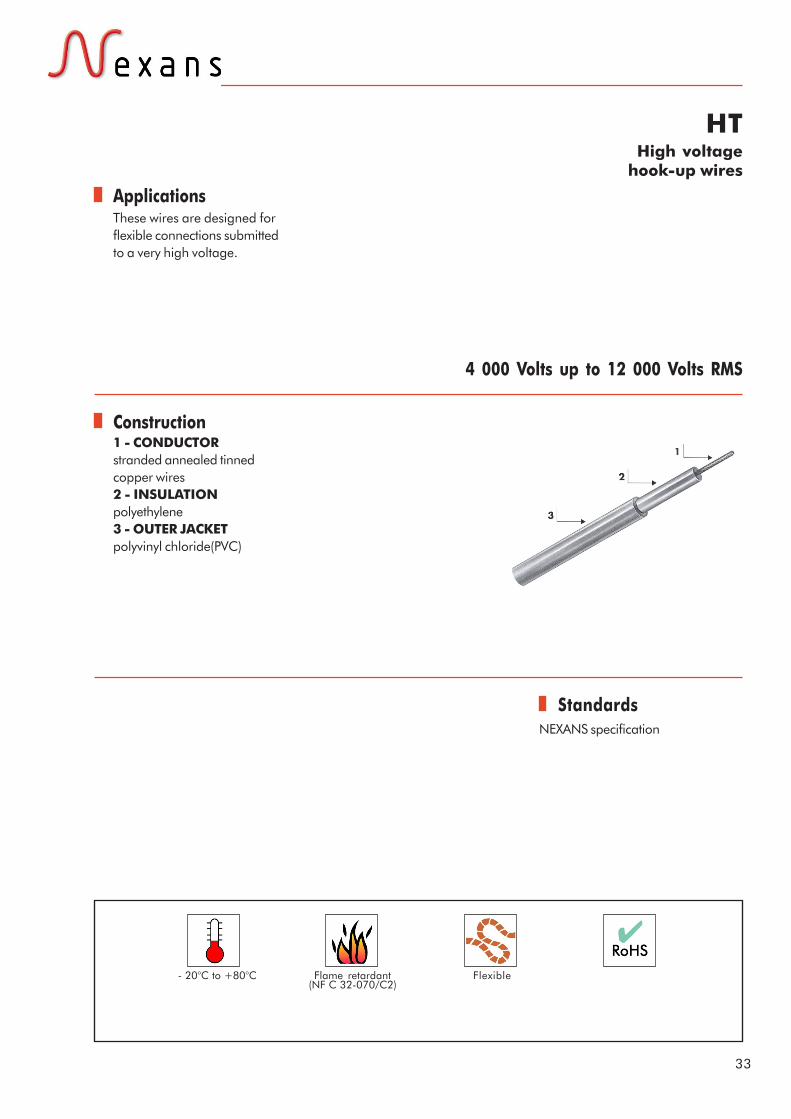
HTHigh voltage
hook-up wires
These wires are designed forflexible connections submittedto a very high voltage.
NEXANS specification
1 - CONDUCTORstranded annealed tinnedcopper wires2 - INSULATIONpolyethylene3 - OUTER JACKETpolyvinyl chloride(PVC)
4 000 Volts up to 12 000 Volts RMS
Flexible- 20°C to +80°C Flame retardant(NF C 32-070/C2)

June
200
6 - C
opyr
ight
Nex
ans
34
HT - High voltage hook-up wires
CONDUCTOR
Electrical Characteristics
Nexans Reference Cross
Gauge section Construction AWG mm2 n x Ø mm
Nom. Ø
over insulation
mm
Overall Ø
mm
Average weight Kg/km
Operating voltage V.RMS
Test voltage
V.CA
HT 306 E 20 0.60 19 X 0.20 2.3 3.1 ± 0.2 14 4000 7000 HT 406 E 20 0.60 19 X 0.20 3.0 4.2 ± 0.2 20 5000 10000 HT 610 E 16 1.34 19 X 0.30 4.5 6.2 ±0.3 44 7000 12000 HT 810 E 16 1.34 19 X 0.30 6.0 8.2 ± 0.3 72 12000 20000

Applications
Construction
Standards
35
UL 1007Hook-up wires
Those wires are mainly designed forinternal wiring in electrical andelectronic equipments.They are well suited to work understringent conditions.They are both UL and RoHsqualified. They can be used in allequipments in Europe or worldwide.
UL AWM Style 1007
1 - AMEstranded tinned copper wires2 - ISOLATIONPolyvinyl chloride (PVC-UL)
300 volts
Flexible
-40 °C to +80°C Flame retardantUL VW-1

June
200
6 - C
opyr
ight
Nex
ans
36
UL 1007 - Hook-up wires
CONDUCTOR Nexans
Reference Gauge AWG
Cross section
mm2
Construction n x Ø mm
Overall diameter mm
UL 1007 300V 80 °C 28 0.09 7 x 0.13 1.20 ± 0.05 UL 1007 300V 80 °C 26 0.14 7 x 0.16 1.30 ± 0.05 UL 1007 300V 80 °C 24 0.25 19 x 0.13 1.45 ± 0.05 UL 1007 300V 80 °C 22 0.38 19 x 0.16 1.60 ± 0.10 UL 1007 300V 80 °C 20 0.6 19 x 0.20 1.80 ± 0.10 UL 1007 300V 80 °C 18 0.93 19 x 0.25 2.20 ± 0.10 UL 1007 300V 80 °C 16 1.3 19 x 0.30 2.35 ± 0.10

Applications
Construction
Standards
37
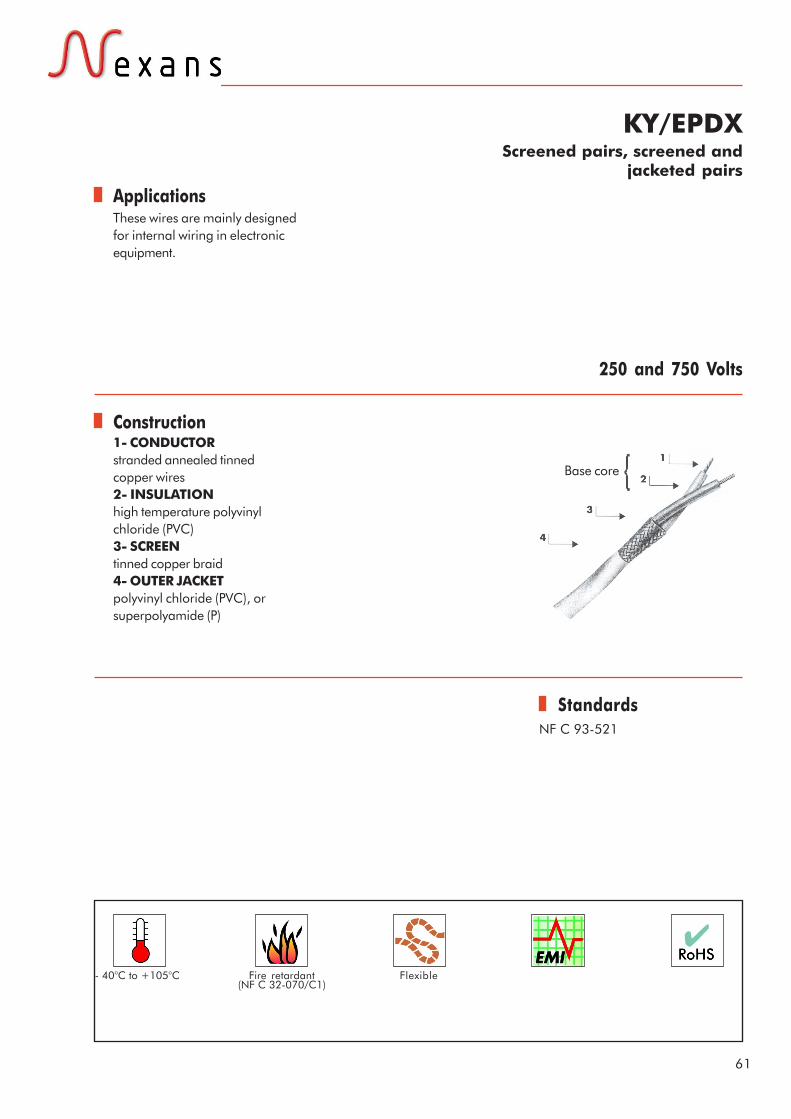
FM & FMAScreened and jacketed hook-up
wires and multicore cables for low frequency applications
These flexible cables arespecially designed for equipmentwiring requiring a good efficientscreen. For a reduced overalldiameter, use FMA range.
NEXANS specification
1 - CONDUCTORstranded tinned copper wires2 - INSULATIONpolyethylene (Pe) or polyvinylchloride (PVC) according to theproducts3- SCREENtinned copper braid4- OUTER JACKETflexible polyvinyl chloride (PVC)
Some typical applications:- outdoor and indoor audioinstallations,- microphone connections,- wiring in equipment requiringefficient shielding against lowfrequency interference andinductive coupling.
NOTA: the items with theFILOTEX reference endingby "PS" only have a PVCsheath as filler betweencores and screen.
250 volts for AWG 24 gauges750 volts for AWG 22 gauges
FlexibleFlame retardant(NF C 32-070/C2)
- 20°C to +80°C

June
200
6 - C
opyr
ight
Nex
ans
38
FM & FMA - Screened and jacketed hook-up wires and multicore cables
The cables with the letter "P" in the reference (example FMA 2P) have the polyethylene insulated cores, the othercables have the PVC insulated cores.
BASE CORE Overall diameter
CONDUCTOR mini. maxi. Nb. of cores
Nexans Reference
Gauge AWG
Cross section mm2
Construction n x Ø mm
Nom. Ø
core mm
mm
Average weight
Kg / Km Colour coding of cores
1 FM 1R 24 0.22 7 x 0.20 1.2 2.3 2.7 10 White 1 FMA 1R 24 0.22 7 x 0.20 1.1 2.1 2.5 10 White 1 FM 1M 24 0.22 7 x 0.20 1.6 3.3 3.7 18 White 1 FMA 1M 24 0.22 7 x 0.20 1.5 2.6 3.0 13 White 1 FM 1 22 0.38 12 x 0.20 2.5 4.7 5.3 35 White 1 FMA 1 22 0.34 7 x 0.25 2.0 3.2 3.6 19 White 1 FM 1P 22 0.38 12 x 0.20 2.5 4.7 5.3 34 Natural 1 FMA1P 22 0.34 7 x 0.25 2.0 3.2 3.6 18 Natural
2 FM 2 R 24 0.22 7 x 0.20 1.2 3.8 4.2 24 White, Blue 2 FMA 2 R 24 0.22 7 x 0.20 1.1 3.5 3.9 19 White, Blue 2 FM 2 M 24 0.22 7 x 0.20 1.5 4.7 5.3 34 White, Yellow 2 FMA 2 M 24 0.22 7 x 0.20 1.5 4.4 4.8 26 White, Yellow 2 FM 2 22 0.38 12 x 0.20 2.0 5.7 6.3 49 White, Blue 2 FMA2 22 0.34 7 x 0.25 2.0 5.3 5.9 39 White, Blue 2 FM 2 P 22 0.38 12 x 0.20 2.0 5.7 6.3 45 Natural, Red 2 FMA 2 P 22 0.34 7 x 0.25 2.0 5.3 5.9 34 Natural, Red 2 FM 2 PS 22 0.31 40 x 0.10 2.2 7.7 8.3 90 White, Yellow 2 FMA 2PS 22 0.34 7 x 0.25 2.0 6.8 7.4 72 White, Yellow
3 FM 3 R 24 0.22 7 x 0.20 1.2 4.0 4.4 27 White, Blue, Red 3 FMA 3 R 24 0.22 7 x 0.20 1.1 3.7 4.1 18 White, Blue, Red 3 FM 3 22 0.38 12 x 0.20 2.0 5.7 6.3 49 White, Blue, Red 3 FMA3 22 0.34 7 x 0.25 2.0 5.6 6.2 32 White, Blue, Red 3 FM 3 PS 22 0.31 40 x 0.10 2.2 7.8 8.6 90 White, Yellow, Green 3 FMA 3 PS 22 0.34 7 x 0.25 2.0 7.1 7.7 79 White, Yellow, Green
4 FM 4 R 24 0.22 7 x 0.20 1.2 5.0 5.4 40 White, Blue, Red, Yellow 4 FMA 4 R 24 0.22 7 x 0.20 1.1 4.0 4.4 19 White, Blue, Red, Yellow 4 FM 4 22 0.38 12 x 0.20 2.0 6.7 7.3 71 White, Blue, Red, Yellow 4 FMA 4 22 0.34 7 x 0.25 2.0 6.3 6.9 23 White, Blue, Red, Yellow 4 FM 4 PS 22 0.31 40 x 0.10 2.2 8.1 8.9 104 White, Yellow, Green, Blue 4 FMA 4 PS 22 0.34 7 x 0.25 2.0 7.7 8.3 91 White, Yellow, Green, Blue
5 FM 5 R 24 0.22 7 x 0.20 1.2 5.6 6.0 48 White, Blue, Red, Yellow, Green 5 FMA 5 R 24 0.22 7 x 0.20 1.1 4.4 4.8 25 White, Blue, Red, Yellow, Green 5 FM 5 22 0.38 12 x 0.20 2.0 7.7 8.3 92 White, Blue, Red, Yellow, Green 5 FMA5 22 0.34 7 x 0.25 2.0 7.1 7.7 47 White, Blue, Red, Yellow, Green
6 FM 6 R 24 0.22 7 x 0.20 1.1 5.0 5.6 42 White, Blue, Red, Yellow, Green, Black 6 FMA 6 R 24 0.22 7 x 0.20 1.1 4.7 5.1 24 White, Blue, Red, Yellow, Green, Black 6 FM 6 22 0.38 12 x 0.20 2.0 8.3 9.1 54 White, Blue, Red, Yellow, Green, Black 6 FMA 6 22 0.34 7 x 0.25 2.0 7.7 8.5 52 White, Blue, Red, Yellow, Green, Black

Applications
Construction
Standards
39
EHE & EHEAScreened and jacketed hook-up
wires and multicore cablesfor low frequency
These flexible cables are mainlydesigned for use in applicationsrequiring high efficiencyscreening at low frequencies.The screen is made up of acontinuous high conductivethermoplastic sheath andprovides a shielding efficiencyinversely proportional to thefrequency.
NEXANS specification
1 - CONDUCTORstranded tinned copper wires2 - INSULATIONpolyethylene (Pe)3- DRAIN WIRE4- SCREENhigh conductive sheath5- OUTER JACKETflexible polyvinyl chloride (PVC)
250 Volts and 750 Voltsaccording to the products
So a very high efficiency isobtained at industrialfrequencies.For a reduced overall diameter,use EHEA range.Easy stripping, as well asgrounding, because of the drainwire placed under thethermoplastic sheath.
FlexibleFlame retardant(NF C 32-070/C2)
- 20°C to +80°C

June
200
6 - C
opyr
ight
Nex
ans
40
EHE & EHEA - Screened and jacketed hook-up wires and multicore cables
BASE CORE Overall
diameter CONDUCTOR mini. maxi. Nb. of
cores. Nexans
Reference Gauge AWG
Cross section mm2
Construction n x Ø mm
Nominal Ø core
mm mm
Average weight
Kg / Km
Operating voltage
Colour coding of cores
1 EHEA1PR 24 0.22 7 x 0.20 1.1 2.4 2.8 8 250 V Natural 1 EHEA1 PM 24 0.22 7 x 0.20 1.5 3.0 3.4 11 250 V Natural 1 EHEA1P 22 0.34 7 x 0.25 2.0 3.4 3.8 14 750 V Natural
2 EHE 2 PR 24 0.22 7 x 0.20 1.2 3.8 4.2 12 250 V Natural, Blue 2 EHEA2PR 24 0.22 7 x 0.20 1.1 3.5 3.9 14 250 V Natural, Blue 2 EHEA2PM 24 0.22 7 x 0.20 1.5 4.6 5.0 17 250 V Natural, Yellow 2 EHE 2 PM 22 0.34 7 x 0.25 1.5 4.7 5.3 19 250 V Natural, Yellow 2 EHE 2 P 22 0.38 12 x 0.20 2.0 5.5 6.1 22 750 V Natural, Blue 2 EHEA2P 22 0.34 7 x 0.25 2.0 5.5 6.1 22 750 V Natural, Blue
3 EHE 3 PR 24 0.22 7 x 0.20 1.2 4.0 4.4 14 250 V Natural, Blue, Red 3 EHEA3 PR 24 0.22 7 x 0.20 1.1 3.8 4.2 13 250 V Natural, Blue, Red
3 EHEA3 PM 24 0.22 7 x 0.20 1.5 4.8 5.4 18 250 V Natural, Blue, Yellow
3 EHE 3 P 22 0.38 12 x 0.20 2.0 6.4 7.0 31 750 V Natural, Blue, Red
4 EHE 4 PR 24 0.22 7 x 0.20 1.2 4.6 5.0 16 250 V Natural, Blue, Red, Yellow
4 EHEA4 PR 24 0.22 7 x 0.20 1.1 4.2 4.6 14 250 V Natural, Blue, Red, Yellow
4 EHEA4 PM 24 0.22 7 x 0.20 1.5 5.2 5.8 20 250 V Natural, Blue, Red, Yellow
4 EHE 4 PM 22 0.34 7 x 0.25 1.5 5.5 6.1 26 250 V Natural, Blue, Red, Yellow
5 EHEA5PR 24 0.22 7 x 0.20 1.1 4.6 5.0 15 250 V Natural, Blue, Red, Yellow, Green
6 EHEA 6 PR 24 0.22 7x 0.20 1.1 4.9 5.3 16 250 V Natural, Blue, Red,
Yellow, Green, Black

Applications
Construction
Standards
41
SMA & SMBLUnscreened and jacketed (SMA),
screened and jacketed (SMBL)multicore cables
Flexible cables designed forinternal wiring in equipment,found in many markets (instru-mentation, process-control,remote control, electronicindustrial equipment,...)
NEXANS specification
1- CONDUCTORstranded tinned copper wires2- INSULATIONflexible polyvinyl chloride (PVC)3- LAY UPpolyester tape (for screenedcables only)4- SCREENtinned copper braid (forscreened cables only)5- OUTER JACKETpolyvinyl chloride (PVC)
500 Volts RMS
Colour coding of the cores by plain colours and rings.
Colour coding
FlexibleFlame retardant(NF C 32-070/C2)
- 20°C to +80°C

June
200
6 - C
opyr
ight
Nex
ans
42
SMA - Unscreened and jacketed multicore cables
SMBL - Screened and jacketed multicore cables
Description of the core
SMA/SMBL colour coding
Cross section
0.22 mm2 Cross section
0.34 mm2 Cross section
0.60 mm2 (AWG24) (AWG22) (AWG20)
∅ +/- Average weight
∅ +/- Average weight
∅ +/- Average weight
Nb. of cores
Nexans Reference
mm Kg/Km mm Kg/Km mm Kg/Km
2 SMA 02x... 3.10 0.15 11.33 3.70 0.15 16.60 4.25 0.15 28.21 3 SMA03x... 3.30 0.15 14.84 3.80 0.15 20.70 4.70 0.15 36.87 4 SMA 04x... 3.70 0.15 19.37 4.25 0.15 27.00 5.30 0.20 47.33 5 SMA05x... 3.90 0.15 22.13 4.60 0.15 32.13 5.80 0.20 56.32 7 SMA07x... 4.20 0.15 28.98 5.00 0.15 42.74 6.25 0.20 72.61
10 SMA 10x... 5.55 0.20 43.85 6.25 0.20 59.41 8.15 0.20 99.56 12 SMA12x... 5.70 0.20 49.99 6.35 0.20 67.34 8.35 0.25 114.42 19 SMA19x... 6.40 0.20 70.30 7.50 0.25 102.14 9.70 0.25 170.20 27 SMA 27x... 7.80 0.25 100.83 9.50 0.25 153.58 11.50 0.25 234.71 37 SMA37x... 8.50 0.25 129.11 10.00 0.25 188.88 13.50 0.30 330.92
Cross section
0.22 mm2 Cross section
0.34 mm2 Cross section
0.60 mm2 Cross section
0.93 mm2 Cross section
1.34 mm2
(AWG24) (AWG22) (AWG20) (AWG18) (AWG16) ∅ +/- Av.
weight ∅ +/- Av.
weight ∅ +/- Av.
weight ∅ +/- Av.
weight ∅ +/- Av.
weight
Nb. of cores
Nexans Reference
mm Kg/Km mm Kg/Km mm Kg/Km mm Kg/Km mm Kg/Km
2 SMBL 02x... 3.60 0.15 19.89 4.40 0.15 25.41 5.10 0.20 34.69 5.75 0.20 46.63 6.30 0.20 57.47 3 SMBL03x... 3.80 0.15 23.81 4.55 0.15 30.96 5.40 0.20 45.83 6.00 0.20 65.11 6.65 0.20 76.39 4 SMBL 04x... 4.10 0.15 29.24 5.00 0.15 38.59 5.90 0.20 57.01 6.80 0.20 78.38 7.40 0.25 99.80 5 SMBL05x... 4.40 0.15 32.40 5.65 0.20 49.38 6.50 0.20 68.84 7.30 0.25 93.45 8.20 0.25 121.82 7 SMBL07x... 4.90 0.15 45.29 5.80 0.20 61.40 6.90 0.20 92.43 8.00 0.25 122.12 9.00 0.25 160.78
10 SMBL 10x... 6.00 0.15 57.49 7.25 0.25 81.94 8.90 0.25 126.59 10.20 0.30 174.41 11.60 0.30 230.88 12 SMBL12x... 6.10 0.20 63.33 7.30 0.25 91.28 8.90 0.25 141.95 10.30 0.30 194.36 11.70 0.30 258.8 19 SMBL19x... 7.05 0.25 90.77 8.50 0.25 131.16 10.55 0.30 205.2 12.10 0.30 287.34 14.30 0.30 409.74 27 SMBL 27x... 8.75 0.25 129.78 9.90 0.25 175.04 12.80 0.30 294.79 14.90 0.30 418.65 17.40 0.35 576.29 37 SMBL37x... 9.45 0.25 160.87 11.10 0.30 229.01 14.30 0.30 384.18 16.40 0.35 539.74 19.50 0.40 759.42
CONDUCTOR Ø
Cross section Gauge Construction Insulation mm2 AWG n x Ø mm mm
0.22 24 7 x 0.20 1.04 0.34 22 7 x 0.25 1.24 0.60 20 19x 0.20 1.65 0.93 18 19 x 0.25 1.90 1.34 16 19 x 0.30 2.27
Core. Plain Core Plain colour/ Core. Plain Core Plain colour/
n° colour n° Ring colour n° colour n° Ring colour 1 White 11 White/Blue 21 Blue/Brown 31 Yellow/Green 2 Light Blue 12 White/Yellow 22 Blue/Black 32 Yellow/Grey 3 Yellow 13 White/Brown 23 Blue/Red 33 Yellow/Orange 4 Brown 14 White/Black 24 Blue/Green 34 Yellow/Purple 5 Black 15 White/Red 25 Blue/Grey 35 Brown/Black 6 Red 16 White/Green 26 Blue/Orange 36 Brown/Red 7 Green 17 White/Grey 27 Blue/Purple 37 Brown/Green 8 Grey 18 White/Orange 28 Yellow/Brown 9 Orange 19 White/Purple 29 Yellow/Black
10 Purple 20 White/Yellow 30 Yellow/Red
- Example of ordering : SMA 7 x 0.34 ; SMBL 19 x 0.93

Applications
Construction
Standards
43
GRTH & CCTBUnscreened and jacketed (GRTH),
screened and jacketed (CCTB)multicore cables
Flexible cables designed forinternal wiring in equipment,operating at a maximum voltageof 750 V RMS, found in manymarkets (instrumentation,process-control, remote control,electronic industrialequipment...),
NEXANS specification
1 - CONDUCTORstranded tinned copper wires2 - INSULATIONflexible polyvinyl chloride (PVC)3- LAY UPpolyester tape (for screenedcables only)4- SCREENtinned copper braid5- OUTER JACKETpolyvinyl chloride (PVC)
750 Volts RMS
Colour coding of the cores by plain colours and rings.
Colour coding
FlexibleFlame retardant(NF C 32-070/C2)
- 20°C to +80°C

June
200
6 - C
opyr
ight
Nex
ans
44
GRTH - Unscreened and jacketed multicore cables
CCTB - Screened and jacketed multicore cables
Description of the core
GRTH/CCTB colour coding
Cond. Plain n° colour 1 Black
2 Light Blue
3 Brown*
4 Grey*
5 Orange*
6 Red*
7 Purple* * From 3 cores, the last one is Yellow/Green
- Example for 3 conductors : Black – Light blue – Yellow/Green
- Example of ordering : GRTH 02 x 0.34 ; CCTB 7 x 0.93
Conductor Ø of
Cross section Gauge Construction core mm2 AWG n x Ø mm mm 0.34 22 7 x 0.25 2.15 ± 0.15 0.60 20 19x 0.20 2.35 ± 0.15 0.93 18 19 x 0.25 2.65 ± 0.15 1.34 16 19 x 0.30 2.85 ± 0.15 1.91 14 27 x 0.30 3.20 ± 0.20
Cross section 0.34 mm2
(AWG22)
Cross section 0.60 mm2
(AWG20)
Cross section 0.93 mm2
(AWG18)
Cross section 1.34 mm2
(AWG16)
Cross section 1.91 mm2
(AWG14)
Overall diameter
Overall diameter
Overall diameter
Overall diameter
Overall diameter
min. max.
Average weight
min. max.
Average weight
min. max.
Average weight
min. max.
Average weight
min. max.
Average weight
Nb. of
cores
Nexans Reference
mm Kg/Km mm Kg/Km mm Kg/Km mm Kg/Km mm Kg/Km 2 GRTH 02x... 5.0 5.4 34 5.2 5.6 41 6.7 7.1 64 7.0 7.5 75 7.2 7.7 86 3 GRTH 03x... 5.2 5.6 38 5.7 6.1 50 6.9 7.4 74 7.4 7.9 94 7.8 8.3 109 4 GRTH 04x... 5.8 6.2 47 6.3 6.7 62 7.8 8.3 95 8.3 8.8 116 8.5 9.0 135 7 GRTH 07x... 7.2 7.7 74 7.8 8.3 99 9.0 9.5 138 9.0 9.5 147 10.6 11.2 221
Cross section 0.60 mm2
(AWG20)
Cross section 0.93 mm2
(AWG18)
Cross section 1.34 mm2
(AWG16)
Cross section 1.91 mm2
(AWG14)
Overall diameter
Overall diameter
Overall diameter
Overall diameter
min. max.
Average weight
min. max.
Average weight
min. max.
Average weight
min. max.
Average weight
Nb. of
cores
Nexans Reference
mm Kg/Km mm Kg/Km mm Kg/Km mm Kg/Km 2 CCTB 02x... 6.0 6.4 57 6.9 7.4 64 7.3 7.8 90 8.0 8.5 113 3 CCTB03x... 6.4 6.8 66 7.3 7.8 87 7.8 8.3 106 8.6 9.1 134 4 CCTB 04x... 7.2 7.7 83 7.8 8.3 103 8.6 9.1 127 9.4 9.9 163 5 CCTB05x... 8.0 8.5 94 8.9 9.4 122 9.5 10.0 150 10.4 11.0 193 7 CCTB07x... 8.8 9.3 120 9.7 10.3 153 10.4 11.0 190 11.5 12.1 244

Applications
Construction
Standards
45
G250Flexible pairs
Screened with overall braid
Interconnection cables forintercoms. Flexible links for lowcurrent and electronics use orwhere screening is requiredbetween circuits, mainly for datatransmission.
NEXANS specification
1- COREstranded, 7x0.20 mm tinnedcopper2- INSULATIONPVC3- LAY UPunder polyester tape4- SCREENtinned copper braidK>55%5- OUTER JACKETVery flexible PVC with a ripcordunder the jacket.
250 Volts
Colour coding of the cores by plain colours and rings.
1
2
3
4
5
Colour coding
FlexibleFlame retardant(NF C 32-070/C2)
- 20°C to +80°C

June
200
6 - C
opyr
ight
Nex
ans
46
G250 - Flexible pairs, screened with overall braid
* PVC filler
Electrical characteristics
G250 colour coding
White/Blue = White ring Blue
CORE BRAID Overall diameter Average weight
Nb of pairs Nexans
Reference Gauge AWG
Cross section mm²
Construction n x ∅ mm
∅ strand ∅ mm ∅ mm
Tolerance mm
Kg/Km
2 G250-2/2 24 0.22 7 x 0.20 0.12 3.55 5.1 ± 0.30 36 3 G250-3/2 24 0.22 7 x 0.20 0.12 4.00 5.50 ± 0.40 44
5* G250-5/2 24 0.22 7 x 0.20 0.12 5.1 6.6 ± 0.40 64 7 G250-7/2 24 0.22 7 x 0.20 0.12 5.55 7.1 ± 0.40 82
10 G250-10/2 24 0.22 7 x 0.20 0.13 6.60 8.1 ± 0.40 106 12 G250-12/2 24 0.22 7 x 0.20 0.13 7.10 8.7 ± 0.40 123
15 G250-15/2 24 0.22 7 x 0.20 0.13 7.95 9.6 ± 0.50 147 21 G250-21/2 24 0.22 7 x 0.20 0.15 9.30 11.3 ± 0.50 208
25 G250-25/2 24 0.22 7 x 0.20 0.15 10.40 12.7 ± 0.40 242 30 G250-30/2 24 0.22 7 x 0.20 0.15 11.90 14.70 ± 0.60 300
PAIR # 1 2 3 4 5 6 7 8 9 10
WIRE 1 Blue Yellow Brown Black Green White/Blue Yellow/Blue Brown/Blue Blue/Black Green/Blue
WIRE 2 White White White White White White White White White White
PAIR # 11 12 13 14 15 16 17 18 19 20
WIRE 1 White/ Yellow
Yellow/ Brown
Yellow/ Black
Yellow/ Green
White/ Brown
Brown/ Black
Brown/ Green
White/ Black
Green/ Black
White/ Green
WIRE 2 White White White White White White White White White White
PAIR # 21 22 23 24 25 26 27 28 29 30
WIRE 1 Blue Yellow Brown Black Green White/Blue Yellow/Blue Brown/Blue Blue/Black Green/Blue
WIRE 2 White/Red White/Red White/Red White/Red White/Red White/Red White/Red White/Red White/Red White/Red
Attenuation Value Unit
Maximum loop resistance at 20°C ≤ 200 Ω/km
Insulation resistance at 20°C at 200 volts dc ≥ 500 MΩ.km

Applications
Construction
Standards
47
G900Flexible pairs
with individual and overall screens(tape+braid)
Interconnection cables forintercoms when a high protec-tion against electromagneticinterferences is required.Flexible links for low current andelectronics use or wherescreening is required betweencircuits, mainly for data trans-mission and telecom applica-tions.
NEXANS specification
1- 2 CORESStranded, 7x0.25 mm tinnedcopperFoam polyolefin insulationLay up under aluminium/polyester tape2- DRAIN WIRE7x0.25 tinned copper3- POLYESTER TAPE4- SCREENTinned copper braidK>85%5- OUTER JACKETFlexible PVC.
250 Volts
Colour coding of the cores by plain colours and rings.
1
2
3
4
5
Colour coding
FlexibleFlame retardant(NF C 32-070/C2,
IEC 60 332-1)
- 20°C to +80°C

June
200
6 - C
opyr
ight
Nex
ans
48
G900 - Flexible pairs with individual and overall screens
CORE
Nb of pairs Nexans Reference
Gauge AWG
Cross section mm²
Construction n x ∅ mm
∅ over insulation
mm
∅ over braid mm
Overall ∅ mm
Average weight Kg/Km
1 G900-1/2 22 0.34 7 x 0.25 1.80 4.25 5.15 34 2 G900-2/2 22 0.34 7 x 0.25 1.80 7.10 8.40 67
3 G900-3/2 22 0.34 7 x 0.25 1.80 7.55 8.90 81 4 G900-4/2 22 0.34 7 x 0.25 1.80 8.40 9.85 99 5 G900-5/2 22 0.34 7 x 0.25 1.80 9.35 10.95 119 7 G900-7/2 22 0.34 7 x 0.25 1.80 10.30 12.05 150
8 G900-8/2 22 0.34 7 x 0.25 1.80 11.30 13.20 173 10 G900-10/2 22 0.34 7 x 0.25 1.80 13.50 15.70 221
Attenuation Value Unit
Characteristic impedance at 1 MHz 100 ± 15 Ω
Nominal capacitance 35 nF/km
Conductor DC resistance < 57 Ω/km
Insulation resistance > 150 MΩ.km
NEXT at 1 MHz > 50 dB
Dielectric strength 1000 V dc – 1 mn,
Attenuation at 1 MHz 5 MHz 10 MHz
in dB/100 m 3 5.5 7.5
Electrical characteristics
G900 colour coding
PAIR # 1 2 3 4 5 6 7 8 9 10
WIRE 1 Blue Yellow Brown Black Green White/Blue Yellow/Blue Brown/Blue Blue/Black Green/Blue
WIRE 2 White White White White White White White White White White

Applications
Construction
Standards
49
SMA-ZH & SMBL-ZHUnscreened and jacketed (SMA-ZH),
screened and jacketed (SMBL-ZH)halogen free multicore cables
Flexible cables designed forinternal wiring in equipment,found in many markets (instru-mentation, process-control, remotecontrol, electronic industrialequipment,...)Halogen free, they are intended tobe used in places where theprotection of the people andequipment is vital.
NEXANS specificationThese cables are UL 21283qualified (80°C). They can bemanufactured with an UL markingon request.
1- CONDUCTORstranded tinned copper wires2- INSULATIONHalogen free3- LAY UPpolyester tape (for screenedcables only)4- SCREENtinned copper braid (forscreened cables only)5- OUTER JACKETHalogen free
500 Volts RMS
Colour coding of the cores by plain colours and rings.
Colour coding
We recommend to use them forcabinet wiring in public areassuch as railway or subwaystations but also in industrialareas, etc...
- 40°C to+80°C
Low smokeemission andlow opacity(IEC 61034)
Halogen free(IEC 60754-1)
Non corrosiveand non toxic(IEC 60754-2)
FlexibleFlame retardant(NF C 32-070/C2,
IEC 60332-1/2)
Screenedversions

June
200
6 - C
opyr
ight
Nex
ans
50
SMA-ZH - Unscreened and jacketed halogen free multicore cables
SMBL-ZH - Screened and jacketed halogen free multicore cables
Description of the core
SMA-ZH/SMBL-ZH colour coding
Cross section
0,22 mm2 Cross section
0,34 mm2 Cross section
0,60 mm2 Cross section
0,93 mm2 (AWG24) (AWG22) (AWG20) (AWG18)
∅ +/- Av. weight
∅ +/- Av. weight
∅ +/- Av. weight
∅ +/- Av. weight
Nb. of cores
Nexans Reference
mm Kg/Km mm Kg/Km mm Kg/Km mm Kg/Km
2 SMA-ZH 02x... 3.10 0.40 12 3.70 0.40 17 4.25 0.40 23 4.70 0.40 31 3 SMA-ZH 03x... 3.30 0.40 15 3.80 0.40 21 4.70 0.40 33 5.10 0.40 43 4 SMA-ZH 04x... 3.70 0.40 20 4.25 0.40 28 5.30 0.40 43 5.50 0.40 53 5 SMA-ZH 05x... 3.90 0.40 22 4.60 0.40 33 5.80 0.40 52 6.25 0.40 68 7 SMA-ZH 07x... 4.20 0.40 28 5.00 0.40 42 6.25 0.40 67 7.15 0.50 96
12 SMA-ZH 12x... 5.70 0.40 49 6.35 0.40 65 8.35 0.50 111 9.60 0.50 161 19 SMA-ZH 19x... 6.40 0.40 67 7.50 0.50 98 9.70 0.50 164 11.40 0.60 245 27 SMA-ZH 27x... 7.80 0.50 96 9.50 0.50 147 11.50 0.50 223 13.85 0.60 347 37 SMA-ZH 37x... 8.50 0.50 121 10.00 0.50 178 13.50 0.60 316 15.60 0.60 465
Cross section
0,22 mm2 Cross section
0,34 mm2 Cross section
0,60 mm2 Cross section
0,93 mm2 (AWG24) (AWG22) (AWG20) (AWG18)
∅ +/- Av. weight
∅ +/- Av. weight
∅ +/- Av. weight
∅ +/- Av. weight
Nb. of cores
Nexans Reference
mm Kg/Km mm Kg/Km mm Kg/Km mm Kg/Km
2 SMBL-ZH 02x... 3.60 0.40 20 4.40 0.40 27 5.10 0.40 36 5.75 0.40 49 3 SMBL-ZH 03x... 3.80 0.40 24 4.55 0.40 32 5.40 0.40 47 6.00 0.40 61 4 SMBL-ZH 04x... 4.10 0.40 28 5.00 0.40 40 5.90 0.40 58 6.80 0.40 80 5 SMBL-ZH 05x... 4.40 0.40 32 5.65 0.40 51 6.50 0.40 70 7.30 0.50 95 7 SMBL-ZH 07x... 4.90 0.40 42 5.80 0.40 59 6.90 0.40 87 8.00 0.50 122
12 SMBL-ZH 12x... 6.10 0.40 62 7.00 0.50 88 8.90 0.50 140 10.30 0.60 193 19 SMBL-ZH 19x... 6.90 0.40 90 8.50 0.50 130 10.55 0.60 200 12.10 0.60 283 27 SMBL-ZH 27x... 8.75 0.50 126 9.90 0.50 170 12.80 0.60 290 14.90 0.60 412 37 SMBL-ZH 37x... 9.25 0.50 155 11.10 0.60 222 14.30 0.60 375 16.40 0.70 530
CONDUCTOR Ø
Cross section Gauge Construction Insulation mm2 AWG n x Ø mm mm 0.22 24 7 x 0.20 1.04 0.34 22 7 x 0.25 1.24 0.60 20 19x 0.20 1.65 0.93 18 19 x 0.25 1.90
Example of ordering : SMA-ZH 7 x 0.34 ; SMBL-ZH 19 x 0.93
Core. Plain Core Plain colour/ Core. Plain Core Plain colour/
n° colour n° Ring colour n° colour n° Ring colour 1 White 11 White/Blue 21 Blue/Brown 31 Yellow/Green 2 Light Blue 12 White/Yellow 22 Blue/Black 32 Yellow/Grey 3 Yellow 13 White/Brown 23 Blue/Red 33 Yellow/Orange 4 Brown 14 White/Black 24 Blue/Green 34 Yellow/Purple 5 Black 15 White/Red 25 Blue/Grey 35 Brown/Black 6 Red 16 White/Green 26 Blue/Orange 36 Brown/Red 7 Green 17 White/Grey 27 Blue/Purple 37 Brown/Green 8 Grey 18 White/Orange 28 Yellow/Brown 9 Orange 19 White/Purple 29 Yellow/Black
10 Purple 20 White/Yellow 30 Yellow/Red

Applications
Construction
Standards
51
G250-ZHHalogen free flexible pairs
Screened with overall braid
Interconnection cables forintercoms. Flexible links for lowcurrent and electronics use orwhere screening is requiredbetween circuits, mainly for datatransmission.Halogen free, they are intendedto be used in places where theprotection of the people andequipment is vital.
NEXANS specificationThese cables are UL 21283qualified (80°C). They can bemanufactured with an UL markingon request.
1- COREstranded, 7x0.20 mm tinnedcopper2- INSULATIONHalogen free3- LAY UPunder polyester tape4- SCREENtinned copper braidK>55%5- OUTER JACKETHalogen free
250 Volts
Colour coding of the cores by plain colours and rings.
1
2
3
4
5
Colour coding
We recommend to use them forcabinet wiring in public areassuch as railway or subwaystations but also in industrialareas, etc...
- 40°C to+80°C
Low smokeemission andlow opacity(IEC 61034)
Halogen free(IEC 60754-1)
Non corrosiveand non toxic(IEC 60754-2)
FlexibleFlame retardant(NF C 32-070/C2,
IEC 60332-1/2)
Screenedversions

June
200
6 - C
opyr
ight
Nex
ans
52
G250-ZH - Halogen free flexible pairs, screened with overall braid
* PVC filler
Electrical characteristics
G250-SH colour coding
CORE BRAID Overall diameter Average weight
Nb of pairs
Nexans Reference Gauge
AWG
Cross section mm²
Construction n x ∅ mm
∅ strand ∅ mm ∅ mm
Tolerance mm
Kg/Km
2 G250-ZH-2/2 24 0.22 7 x 0.20 0.12 3.55 5.1 ± 0.30 36 3 G250-ZH-3/2 24 0.22 7 x 0.20 0.12 4.00 5.50 ± 0.40 44
5* G250-ZH-5/2 24 0.22 7 x 0.20 0.12 5.1 6.6 ± 0.40 64 7 G250-ZH-7/2 24 0.22 7 x 0.20 0.12 5.55 7.1 ± 0.40 82
10 G250-ZH-10/2 24 0.22 7 x 0.20 0.13 6.60 8.1 ± 0.40 106 12 G250-ZH-12/2 24 0.22 7 x 0.20 0.13 7.10 8.7 ± 0.40 123
15 G250-ZH-15/2 24 0.22 7 x 0.20 0.13 7.95 9.6 ± 0.50 147 21 G250-ZH-21/2 24 0.22 7 x 0.20 0.15 9.30 11.3 ± 0.50 208
25 G250-ZH-25/2 24 0.22 7 x 0.20 0.15 10.40 12.7 ± 0.40 242 30 G250-ZH-30/2 24 0.22 7 x 0.20 0.15 11.90 14.70 ± 0.60 300
White/Blue = White ring Blue
PAIR # 1 2 3 4 5 6 7 8 9 10
WIRE 1 Blue Yellow Brown Black Green White/Blue Yellow/Blue Brown/Blue Blue/Black Green/Blue
WIRE 2 White White White White White White White White White White
PAIR # 11 12 13 14 15 16 17 18 19 20
WIRE 1 White/ Yellow
Yellow/ Brown
Yellow/ Black
Yellow/ Green
White/ Brown
Brown/ Black
Brown/ Green
White/ Black
Green/ Black
White/ Green
WIRE 2 White White White White White White White White White White
PAIR # 21 22 23 24 25 26 27 28 29 30
WIRE 1 Blue Yellow Brown Black Green White/Blue Yellow/Blue Brown/Blue Blue/Black Green/Blue
WIRE 2 White/Red White/Red White/Red White/Red White/Red White/Red White/Red White/Red White/Red White/Red
Attenuation Value Unit
Maximum loop resistance at 20°C ≤ 200 Ω/km
Insulation resistance at 20°C at 200 volts dc ≥ 500 MΩ.km

53
105°C

.

Applications
Construction
Standards
55
UL 1015Hook-up wires
Those wires are mainly designed forinternal wiring in electrical andelectronic equipments.They are well suited to work understringent conditions.They are both UL and RoHsqualified. They can be used in allequipments in Europe or worldwide.
UL AWM Style 1015
1 - AMEstranded tinned copper wires2 - ISOLATIONPolyvinyl chloride (PVC-UL)
500 volts
Flexible
-20 °C to +105°C Flame retardantUL VW-1

June
200
6 - C
opyr
ight
Nex
ans
56
UL 1015 - Hook-up wires
CONDUCTOR Nexans
Reference Gauge AWG
Cross section
mm2
Construction n x Ø mm
Overall diameter mm
UL 1015 600V 105 °C 24 0.25 19 x 0.13 2.30 ± 0.10 UL 1015 600V 105 °C 22 0.38 19 x 0.16 2.45 ± 0.10 UL 1015 600V 105 °C 18 0.93 19 x 0.25 2.95 ± 0.10 UL 1015 600V 105 °C 16 1.3 19 x 0.30 3.10 ± 0.10 UL 1015 600V 105 °C 12 3.3 65 x 0.255 4.00 ± 0.12

Applications
Construction
Standards
57
KY/EPDXUnscreened hook-up wires
These wires are mainly designedfor internal wiring in electronicequipment.
NF C 93-521
1- CONDUCTORStranded annealed tinnedcopper wires2- INSULATIONHigh temperature polyvinylchloride (PVC)
250 and 750 Volts
Flexible- 40°C to +105°C Fire retardant(NF C 32-070/C1)

June
200
6 - C
opyr
ight
Nex
ans
58
KY/EPDX - Unscreened hook-up wires - 250 volts
KY/EPDX - Unscreened hook-up wires - 750 volts
CONDUCTOR Overall diameter Reference
NFC 93 521 Nexans
Reference Gauge AWG
Cross section mm²
Construction n x ∅ mm
Mini mm
Maxi mm
Average weight Kg/Km
KY 30-01 EPDX 6x0 30 0.055 7 x 0.10 0.70 0.80 1.0 KY 30-02 EPDX 5x0 28 0.079 7 x 0.12 0.76 0.86 1.3 KY 30-03 EPDX 4x0 26 0.12 7 x 0.15 0.80 1.00 1.7 KY 30-04 EPDX 000 24 0.22 7 x 0.20 1.00 1.20 2.8 KY 30-05 EPDX 00 22 0.34 7 x 0.25 1.20 1.45 4.3 KY 30-06 EPDX 26 20 0.60 19 x 0.20 1.60 1.90 7.4 KY 30-07 EPDX 27 18 0.93 19 x 0.25 1.85 2.15 11.0 KY 30-08 EPDX 28 16 1.34 19 x 0.30 2.20 2.50 15.5
- EPDX 29 14 1.91 27 x 0.30 2.55 2.85 21.5 - EPDX 100 12 3.18 45 x 0.30 3.20 3.60 35.5 - EPDX 140 10 5.16 73 x 0.30 3.90 4.30 55.5
CONDUCTOR Overall diameter Reference
NFC 93 521 Nexans
Reference Gauge AWG
Cross section mm²
Construction n x ∅ mm
Mini mm
Maxi mm
Average weight Kg/Km
KY 33 A-01 EPDX 6 24 0.22 7 x 0.20 1.60 1.80 4.6 KY 33 A-02 EPDX 7 22 0.38 12 x 0.20 2.00 2.30 7.3 KY 33 A-03 EPDX 16 20 0.60 19 x 0.20 2.20 2.50 9.8 KY 33 A-04 EPDX 17 18 1.00 32 x 0.20 2.50 2.80 14.4 KY 33 A-05 EPDX 8 16 1.34 19 x 0.30 2.70 3.00 18.0 KY 33 A-06 EPDX 9 14 1.91 27 x 0.30 3.00 3.40 24.3 KY 33 A-07 EPDX 10 12 3.18 45 x 0.30 3.80 4.20 39.7 KY 33 A-08 EPDX 14 10 5.15 73 x 0.30 4.40 4.80 59.9
- EPDX 18 9 7.40 105 x 0.30 5.00 5.40 81.8 KY 33 A-09 EPDX 15 8 10.20 144 x 0.30 5.80 6.20 112.0
KY 33 A-010 EPDX 19 4 24.70 126 x 0.50 9.60 10.20 274.0

Applications
Construction
Standards
59
KY/EPDXScreened hook-up wires, screened
and jacketed hook-up wires
These wires are mainly designedfor internal wiring in electronicequipment.
NF C 93-521
1- CONDUCTORstranded annealed tinnedcopper wires2- INSULATIONhigh temperature polyvinylchloride (PVC)3- SCREENtinned copper braid4- OUTER JACKETpolyvinyl chloride (PVC), orsuperpolyamide (P)
250 and 750 Volts
FlexibleFire retardant(NF C 32-070/C1)
- 40°C to +105°C

June
200
6 - C
opyr
ight
Nex
ans
60
KY/EPDX - Screened hook-up wires
KY/EPDX - screened and jacketed hook-up wires
Reference.. BLI: PVC outer jacket giving a good mechanical protection and electrical insulationReference.. BLP: Superpolyamide outer jacket providing only a mechanical protection
BASE CORE CONDUCTOR
Braid Overall diameter
kr mini maxi
Average weight Nb
of Cond.
Reference NFC93-521
Nexans Reference Gauge
AWG
Cross section mm2
Construction n x Ø mm
Nominal Ø core
mm Ø strands
mm % mm Kg/Km
TYPE KY - 250 VOLTS - STRANDED CONDUCTOR
1 KY 45-01 EPDX 4x0 BL 26 0.12 7 x 0.15 0.90 0.10 55 1.2 1.7 4.8 1 KY 45-02 EPDX 000 BL 24 0.22 7 x 0.20 1.10 0.10 55 1.4 1.9 6.6 1 KY 45-03 EPDX 00 BL 22 0.34 7 x 0.25 1.30 0.10 60 1.6 2.2 8.5
TYPE KY - 750 VOLTS - STRANDED CONDUCTOR
1 KY 37 A-01 EPDX 6 BL. 24 0.22 7 x 0.20 1.70 0.10 60 1.9 2.4 10.2 1 KY 37 A-02 EPDX 7 BL 22 0.38 12 x 0.20 2.15 0.12 65 2.4 3.1 16.5 1 KY 37 A-03 EPDX 16 BL 20 0.60 19 x 0.20 2.35 0.12 65 2.6 3.3 19.9 1 KY 37 A-04 EPDX 17 BL 18 1.00 32 x 0.20 2.65 0.12 65 2.9 3.6 25.5 1 KY 37 A-05 EPDX 8 B L 16 1.34 19 x 0.30 2.85 0.12 65 3.1 3.8 30.2 1 KY 37 A-06 EPDX 9 B L 14 1.91 27 x 0.30 3.20 0.12 70 3.4 4.2 39.0
BASE CORE Braid CONDUCTOR
Overall diameter Ø
strands kr
Outer jacket nature mini maxi
Average weight Nb
of Cond.
Reference NFC93-521
Nexans Reference Gauge
AWG
Cross section mm2
Construction n x Ø mm
Nominal Ø core
mm mm % mm Kg/Km
TYPE KY - 250 VOLTS - STRANDED CONDUCTOR
1 KY46-01 EPDX4x0 BL.P 26 0.12 7 x 0.15 0.90 0.10 55 P 1.4 2.1 5.2 1 KY46-02 EPDX3x0 BLP 24 0.22 7 x 0.20 1.10 0.10 55 P 1.6 2.3 7.4 1 KY46-03 EPDX 00 BLP 22 0.34 7 x 0.25 1.30 0.10 60 P 1.8 2.6 9.5
TYPE KY - 750 VOLTS - STRANDED CONDUCTOR
1 KY 41 A-01 EPDX6 BLI 24 0.22 7 x 0.20 1.7 0.10 60 PVC 3.1 3.8 18.1 1 KY 44 A-01 EPDX 6 BLP 24 0.22 7 x 0.20 1.7 0.10 60 P 2.1 2.8 11.2 1 KY 41 A-02 EPDX 7 BLI 22 0.38 12 x 0.20 2.15 0.12 65 PVC 3.6 4.5 26.2 1 KY 44 A-02 EPDX 7 BLP 22 0.38 12 x 0.20 2.15 0.12 65 P 2.6 3.5 17.7 1 KY 41 A-03 EPDX 16 BLI 20 0.60 19 x 0.20 2.35 0.12 65 PVC 3.8 4.7 30.0 1 KY 44 A-03 EPDX 16 BLP 20 0.60 19 x 0.20 2.35 0.12 65 P 2.8 3.7 21.2 1 KY 41 A-04 EPDX17BLI 18 1.0 32 x 0.20 2.65 0.12 65 PVC 4.1 5.0 36.6 1 KY 44 A-04 EPDX17BLP 18 1.0 32 x 0.20 2.65 0.12 65 P 3.1 4.0 26.9 1 KY 41 A-05 EPDX8 BLI 16 1.34 19 x 0.30 2.85 0.12 65 PVC 4.3 5.2 41.9 1 KY 44 A-05 EPDX8 BLP 16 1.34 19 x 0.30 2.85 0.12 65 P 3.3 4.2 31.7 1 KY 41 A-06 EPDX 9 BLI 14 1.91 27 x 0.30 3.20 0.12 70 PVC 4.6 5.5 51.4 1 KY 44 A-06 EPDX 9BLP 14 1.91 27 x 0.30 3.20 0.12 70 P 3.6 4.6 40.6
Applications
Construction
Standards
61
KY/EPDXScreened pairs, screened and
jacketed pairs
These wires are mainly designedfor internal wiring in electronicequipment.
NF C 93-521
1- CONDUCTORstranded annealed tinnedcopper wires2- INSULATIONhigh temperature polyvinylchloride (PVC)3- SCREENtinned copper braid4- OUTER JACKETpolyvinyl chloride (PVC), orsuperpolyamide (P)
250 and 750 Volts
Base core
FlexibleFire retardant(NF C 32-070/C1)
- 40°C to +105°C

June
200
6 - C
opyr
ight
Nex
ans
62
KY/EPDX - Screened pairs
KY/EPDX - Screened and jacketed pairs
Reference.. BLP: superpolyamide outer jacket providing only a mechanical protection.Reference.. BLBV: PVC outer jacket providing a good mechanical protection and electrical insulation.
BASE CORE Braid CONDUCTOR
Overall diameter
mini maxi Nb of
cores
Reference NFC93-521
Nexans Reference Gauge
AWG
Cross section mm2
Construction n x Ø mm
Nominal Ø core
mm
Ø Over
lay up of cores
mm
Ø strands
mm
kr %
Outer jacket nature mm
Average weight Kg/Km
TYPE KY - 250 VOLTS - STRANDED CONDUCTOR
2 KY 93-01 DX 4x0 BL 26 0.12 7 x 0.15 0.90 1.80 0.10 60 - 1.9 2.7 10.8 2 KY 93-02 DX 000BL 24 0.22 7 x 0.20 1.10 2.20 0.10 60 - 2.3 3.1 15.0 2 KY 93-03 DX 00 BL 22 0.34 7 x 0.25 1.30 2.60 0.12 65 - 2.8 3.8 18.0
TYPE KY - 750 VOLTS - STRANDED CONDUCTOR
2 KY 70 A-01 DX 7 BL 22 0.38 12 x 0.20 2.15 4.3 0.12 70 - 4.5 5.4 31.3 2 KY 70 A-02 DX 8 BL 16 1.34 19 x 0.30 2.85 5.7 0.12 75 - 5.9 6.8 60.0
BASE CORE Braid CONDUCTOR
Overall diameter
mini maxi Nb of
cores
Reference NFC93-521
Nexans Reference Gauge
AWG
Cross section mm2
Construction n x Ø mm
Nominal Ø core
mm
Ø Over
lay up of cores
mm
Ø strands
mm
kr %
Outer jacket nature mm
Average weight Kg/Km
TYPE KY - 250 VOLTS - STRANDED CONDUCTOR
2 KY 91-01 DX 4x0 BL.P 26 0.12 7 x 0.15 0.90 1.80 0.10 60 P 2.1 3.1 12.1 2 KY 91-02 DX 000 BL.P 24 0.22 7 x 0.20 1.10 2.20 0.10 60 P 2.5 3.5 16.0
2 - DKY30-04 BLBV 24 0.22 7 x 0.20 1.10 2.20 0.10 60 PVC 2.6 3.7 18.2
2 KY 91-03 DX00 BLP 22 0.34 7 x 0.25 1.30 2.60 0.12 65 P 3.0 4.2 19.4
2 - DKY30-05 BLBV 22 0.34 7 x 0.25 1.30 2.60 0.12 65 PVC 3.0 4.2 22.2
TYPE KY - 750 VOLTS - STRANDED CONDUCTOR
2 KY 83 A-01 DX 6 BLP 24 0.22 7 x 0.20 1.70 3.40 0.12 65 P 3.9 4.8 23.5 2 KY 83 A-02 DX 7 BLP 22 0.38 12 x 0.20 2.15 4.30 0.12 70 P 4.7 5.8 34.0
2 - DKY33A-02 BLBV 22 0.38 12 x 0.20 2.15 4.30 0.12 70 PVC 4.7 5.8 40.6
2 - DKY33A-03 BLBV 20 0.60 19 x 0.20 2.35 4.70 0.12 65 PVC 5.1 6.2 42.7
2 - DKY33A-04 BLBV 18 1.00 32 x 0.20 2.65 5.30 0.12 65 PVC 5.8 6.9 58.3
2 KY 83 A-03 DX 8 BL.P 16 1.34 19 x 0.30 2.85 5.70 0.12 75 P 6.1 7.2 63.6
2 - DKY33A-05 BLBV 16 1.34 19 x 0.30 2.85 5.70 0.12 75 PVC 6.1 7.2 69.9

Applications
Construction
Standards
63
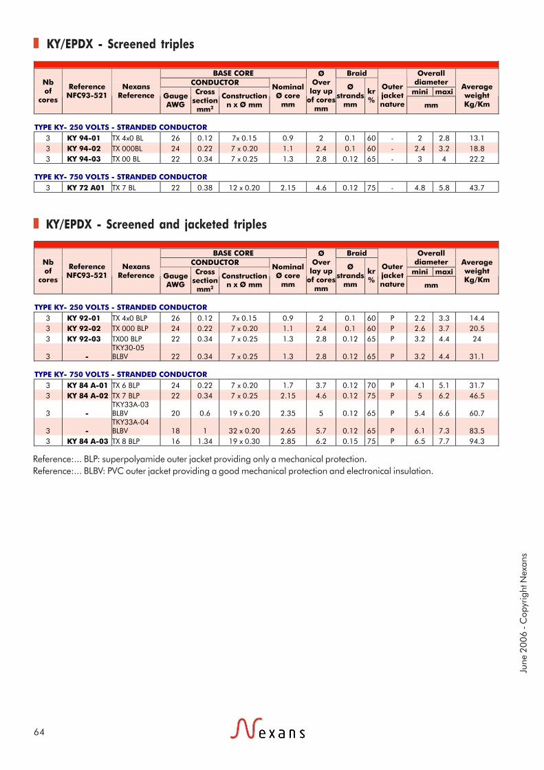
KY/EPDXScreened triples, screened and
jacketed triples
These wires are mainly designedfor internal wiring in electronicequipment.
NF C 93-521
1- CONDUCTORstranded annealed tinnedcopper wires2- INSULATIONhigh temperature polyvinylchloride (PVC)3- SCREENtinned copper braid4- OUTER JACKETpolyvinyl chloride (PVC) orsuperpolyamide (P)
250 and 750 Volts
Base core
FlexibleFire retardant(NF C 32-070/C1)
- 40°C to +105°C
June
200
6 - C
opyr
ight
Nex
ans
64
KY/EPDX - Screened triples
KY/EPDX - Screened and jacketed triples
Reference:... BLP: superpolyamide outer jacket providing only a mechanical protection.Reference:... BLBV: PVC outer jacket providing a good mechanical protection and electronical insulation.
BASE CORE Braid CONDUCTOR
Overall diameter
mini maxi Nb of
cores
Reference NFC93-521
Nexans Reference Gauge
AWG
Cross section mm2
Construction n x Ø mm
Nominal Ø core
mm
Ø Over
lay up of cores
mm
Ø strands
mm
kr %
Outer jacket nature mm
Average weight Kg/Km
TYPE KY- 250 VOLTS - STRANDED CONDUCTOR
3 KY 94-01 TX 4x0 BL 26 0.12 7x 0.15 0.9 2 0.1 60 - 2 2.8 13.1 3 KY 94-02 TX 000BL 24 0.22 7 x 0.20 1.1 2.4 0.1 60 - 2.4 3.2 18.8 3 KY 94-03 TX 00 BL 22 0.34 7 x 0.25 1.3 2.8 0.12 65 - 3 4 22.2
TYPE KY- 750 VOLTS - STRANDED CONDUCTOR
3 KY 72 A01 TX 7 BL 22 0.38 12 x 0.20 2.15 4.6 0.12 75 - 4.8 5.8 43.7
BASE CORE Braid CONDUCTOR
Overall diameter
mini maxi Nb of
cores
Reference NFC93-521
Nexans Reference Gauge
AWG
Cross section mm2
Construction n x Ø mm
Nominal Ø core
mm
Ø Over
lay up of cores
mm
Ø strands
mm
kr %
Outer jacket nature mm
Average weight Kg/Km
TYPE KY- 250 VOLTS - STRANDED CONDUCTOR
3 KY 92-01 TX 4x0 BLP 26 0.12 7x 0.15 0.9 2 0.1 60 P 2.2 3.3 14.4 3 KY 92-02 TX 000 BLP 24 0.22 7 x 0.20 1.1 2.4 0.1 60 P 2.6 3.7 20.5 3 KY 92-03 TX00 BLP 22 0.34 7 x 0.25 1.3 2.8 0.12 65 P 3.2 4.4 24
3 - TKY30-05 BLBV 22 0.34 7 x 0.25 1.3 2.8 0.12 65 P 3.2 4.4 31.1
TYPE KY- 750 VOLTS - STRANDED CONDUCTOR
3 KY 84 A-01 TX 6 BLP 24 0.22 7 x 0.20 1.7 3.7 0.12 70 P 4.1 5.1 31.7 3 KY 84 A-02 TX 7 BLP 22 0.34 7 x 0.25 2.15 4.6 0.12 75 P 5 6.2 46.5
3 - TKY33A-03 BLBV 20 0.6 19 x 0.20 2.35 5 0.12 65 P 5.4 6.6 60.7
3 - TKY33A-04 BLBV 18 1 32 x 0.20 2.65 5.7 0.12 65 P 6.1 7.3 83.5
3 KY 84 A-03 TX 8 BLP 16 1.34 19 x 0.30 2.85 6.2 0.15 75 P 6.5 7.7 94.3

Applications
Construction
Standards
65
1604Unscreened hook-up wires
Flexible cables and lightweightrange with PVC + super-polyamide insulation for use inlow temperature areas.Good abrasion resistance.They withstand most chemicalfluids except for concentratednitric acid.
To AIR 4524 and MIL.W 5086 B/7Aspecifications.These cables are approved by theAir Ministry under letters:N° 41762 STA/EQ/E2 (12-11-68)for AWG22 up to AWG 8N° 33587 STA/EQ/E2 (30-3-72)for AWG24Registered at B.N.Aé:N° 6412 411 A
1- CONDUCTORstranded tinned copper wires orstranded tinned copper alloywires for the cross section area0.21 mm²2- INSULATIONpolyvinyl chloride (PVC)3- OUTER JACKETsuperpolyamide (radialthickness: from 0.10 mm up to0.15 mm)
600 Volts RMS
Technical requirements and control conditions
Interchangeability
Air 4524 specification of September 1965 - The 105/135°C cat.NFL 52-120B - BNAé specification of December 1971 - Lightweightcables.
MIL-W-5086 B/7 U.S. specification (December 1970).AICMA N° 5102 specification (December 1962).
Colour codingTo AIR 0107A specification of October 1961.
Flexible- 40°C to +105°C Fire retardant(NF C 32-070/C1)

June
200
6 - C
opyr
ight
Nex
ans
66
1604 - Unscreened hook-up wires
The shown current rating is valid for singles wires in air.
Nexans Reference CONDUCTOR CORE
Type Cross section AWG Construction
n x Ø mm
Nominal Ø
mm
Tensile strength
daN.
Overall diameter
mm
Average weight Kg/Km
DC resist. at 20°C (maxi.) Ω / km
Current rating
A
Colour of cores
1604 0.21 24 19 x 0.12 T.P.C. All. 0.60 7 1.38 ± 0.07 3.4 105.0 4 Light Blue
1604 0.38 22 12 x 0.20 T.P.C. 0.80 8 1.50 ± 0.07 5.1 50.9 7 White
1604 0.60 20 19 x 0.20 T.P.C. 1.00 16 1.70 ± 0.07 7.5 32.2 11 Light Blue
1604 0.93 18 19 x 0.25 T.P.C.. 1.20 20 2.0 ± 0.07 11.0 20.6 16 White
1604 1.34 16 19 x 0.30 T.P.C. 1.50 20 2.30 ± 0.10 14.0 14.3 22 Light Blue
1604 1.91 14 27 x 0.30 T.P.C. 1.80 20 2.70 ± 0.10 21.6 10.1 32 White
1604 3.18 12 45 x 0.30 T.P.C. 2.30 20 3.50 ± 0.10 36.1 6.0 41 White
1604 5.15 10 73 x 0.30 T.P.C. 3.00 20 4.20 + 0.10/- 0.20
55.1 3.7 55 White
1604 8.98 8 127 x 0.30 T.P.C. 3.80 20 5.50 + 0.10/- 0.20
90.2 2.1 75 White

Applications
Construction
Standards
67
604Screened and jacketed
hook-up wires and multicore cables
Flexible cables and lightweightrange with PVC + super-polyamide insulation for use inlow temperature areasGood abrasion resistance.They withstand most chemicalfluids except for concentratednitric acid.
To AIR 4524 & MIL-W 5086B/7Aspecifications.These cables are approved by theAir Ministry under letters:N° 33587 STA/EQ/E2 (30-3-72)for AWG 24N° 41762 STA/EQ/E2 (12-11-68)for AWG 22 up to AWG 8Registered at B.N.Aé : N° 6412411 A
BASE CORE 16041- CONSTRUCTIONstranded tinned copper wires orstranded tinned copper alloywires for cross section 0.21mm2- INSULATIONpolyvinyl chloride (PVC )3- OUTER JACKETsuperpolyamide (radialthickness: from 0.10 mm up to0,15 mm)
600 Volts RMS
Technical requirements and control conditions
Colour coding
Screen: to MIL.C. 7078C (August 1971) U.S. specification
To Air 0107 A (October 1961) and note N° 348/SIB distributedunder n° 5927/STT/SIB (3 May 1961).
6044- LAY UP1 or several 1604 cores5- SCREENtinned copper braid(Kr ≥ 62%)6- OUTER JACKETsuperpolyamide (radialthickness: about 0.20mm)
FlexibleFire retardant(NF C 32-070/C1)
- 40°C to +105°C
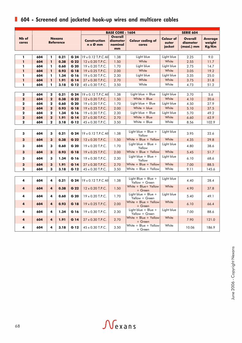
June
200
6 - C
opyr
ight
Nex
ans
68
604 - Screened and jacketed hook-up wires and multicore cables
BASE CORE : 1604 SERIE 604
Nb of cores
Nexans Reference Construction
n x Ø mm
Overall diameternominal
mm
Colour coding of cores
Colour of outer jacket
Overall diameter
(maxi.) mm
Average weight Kg/Km
1 604 1 0.21 G 24 19 x 0.12 T.P.C All 1.38 Light blue Light blue 2.25 9.0 1 604 1 0.38 G 22 12 x 0.20 T.P.C. 1.50 White White 2.55 11.7 1 604 1 0.60 G 20 19 x 0.20 T.P.C. 1.70 Light blue Light blue 2.75 14.7 1 604 1 0.93 G 18 19 x 0.25 T.P.C. 2.00 White White 3.05 19.2 1 604 1 1.34 G 16 19 x 0.30 T.P.C. 2.30 Light blue Light blue 3.35 25.0 1 604 1 1.91 G 14 27 x 0.30 T.P.C. 2.70 White White 3.75 31.8 1 604 1 3.18 G 12 45 x 0.30 T.P.C. 3.50 White White 4.73 51.2
2 604 2 0.21 G 24 19 x 0.12 T.P.C All 1.38 Light blue + Blue Light blue 3.70 5.6 2 604 2 0.38 G 22 12 x 0.20 T.P.C. 1.50 White + Blue White 4.10 20.6 2 604 2 0.60 G 20 19 x 0.20 T.P.C. 1.70 Light blue + Blue Light blue 4.50 27.9 2 604 2 0.93 G 18 19 x 0.25 T.P.C. 2.00 White + blue White 5.10 37.5 2 604 2 1.34 G 16 19 x 0.30 T.P.C. 2.30 Light blue + Blue Light blue 5.70 49.2 2 604 2 1.91 G 14 27 x 0.30 T.P.C. 2.70 White + Blue White 6.60 62.9 2 604 2 3.18 G 12 45 x 0.30 T.P.C. 3.50 White + Blue White 8.56 102.9
3 604 3 0.21 G 24 19 x 0.12 T.P.C All 1.38 Light blue + Blue + Yellow
Light blue 3.95 22.6
3 604 3 0.38 G 22 12 x 0.20 T.P.C. 1.50 White + Blue + Yellow White 4.35 29.8
3 604 3 0.60 G 20 19 x 0.20 T.P.C. 1.70 Light blue + Blue + Yellow
Light blue 4.80 38.6
3 604 3 0.93 G 18 19 x 0.25 T.P.C. 2.00 White + Blue + Yellow White 5.45 51.7
3 604 3 1.34 G 16 19 x 0.30 T.P.C. 2.30 Light blue + Blue + Yellow
Light blue 6.10 68.6
3 604 3 1.91 G 14 27 x 0.30 T.P.C. 2.70 White + Blue + Yellow White 7.00 88.5 3 604 3 3.18 G 12 45 x 0.30 T.P.C. 3.50 White + Blue + Yellow White 9.11 145.6
4 604 4 0.21 G 24 19 x 0.12 T.P.C All 1.38 Light Blue + Blue + Yellow + Green
Light blue 4.40 28.4
4 604 4 0.38 G 22 12 x 0.20 T.P.C. 1.50 White + Blue+ Yellow + Green
White 4.90 37.8
4 604 4 0.60 G 20 19 x 0.20 T.P.C. 1.70 Light blue + Blue + Yellow + Green
Light blue 5.40 49.1
4 604 4 0.93 G 18 19 x 0.25 T.P.C. 2.00 White + Blue + Yellow + Green
White 6.10 66.4
4 604 4 1.34 G 16 19 x 0.30 T.P.C. 2.30 Light blue + Blue + Yellow + Green
Light blue 7.00 88.6
4 604 4 1.91 G 14 27 x 0.30 T.P.C. 2.70 White + Blue + Yellow + Green
White 7.90 121.0
4 604 4 3.18 G 12 45 x 0.30 T.P.C. 3.50 White + Blue + Yellow + Green
White 10.06 186.9
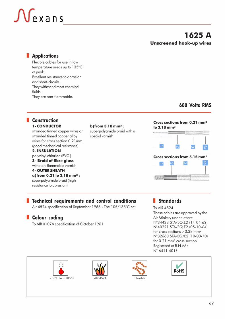
Applications
Construction
Standards
69
1625 AUnscreened hook-up wires
Flexible cables for use in lowtemperature areas up to 135°Cat peak.Excellent resistance to abrasionand short-circuits.They withstand most chemicalfluids.They are non-flammable.
To AIR 4524These cables are approved by theAir Ministry under letters:N°34438 STA/EQ.E2 (14-04-62)N°40221 STA/EQ.E2 (05-10-64)for cross sections >0.38 mm²N°32660 STA/EQ/E2 (10-03-70)for 0.21 mm² cross sectionRegistered at B.N.Aé :N° 6411 401E
1- CONDUCTORstranded tinned copper wires orstranded tinned copper alloywires for cross section 0.21mm(good mechanical resistance)2- INSULATIONpolyvinyl chloride (PVC )3- Braid of fibre glasswith non-flammable varnish4- OUTER SHEATHa)from 0.21 to 3.18 mm² :superpolyamide braid (highresistance to abrasion)
600 Volts RMS
Technical requirements and control conditionsAir 4524 specification of September 1965 - The 105/135°C cat.
b)from 3.18 mm² :superpolyamide braid with aspecial varnish
To AIR 0107A specification of October 1961.
Colour coding
Cross sections from 0.21 mm²to 3.18 mm²
Cross sections from 5.15 mm²
Flexible- 55°C to +105°C AIR 4524
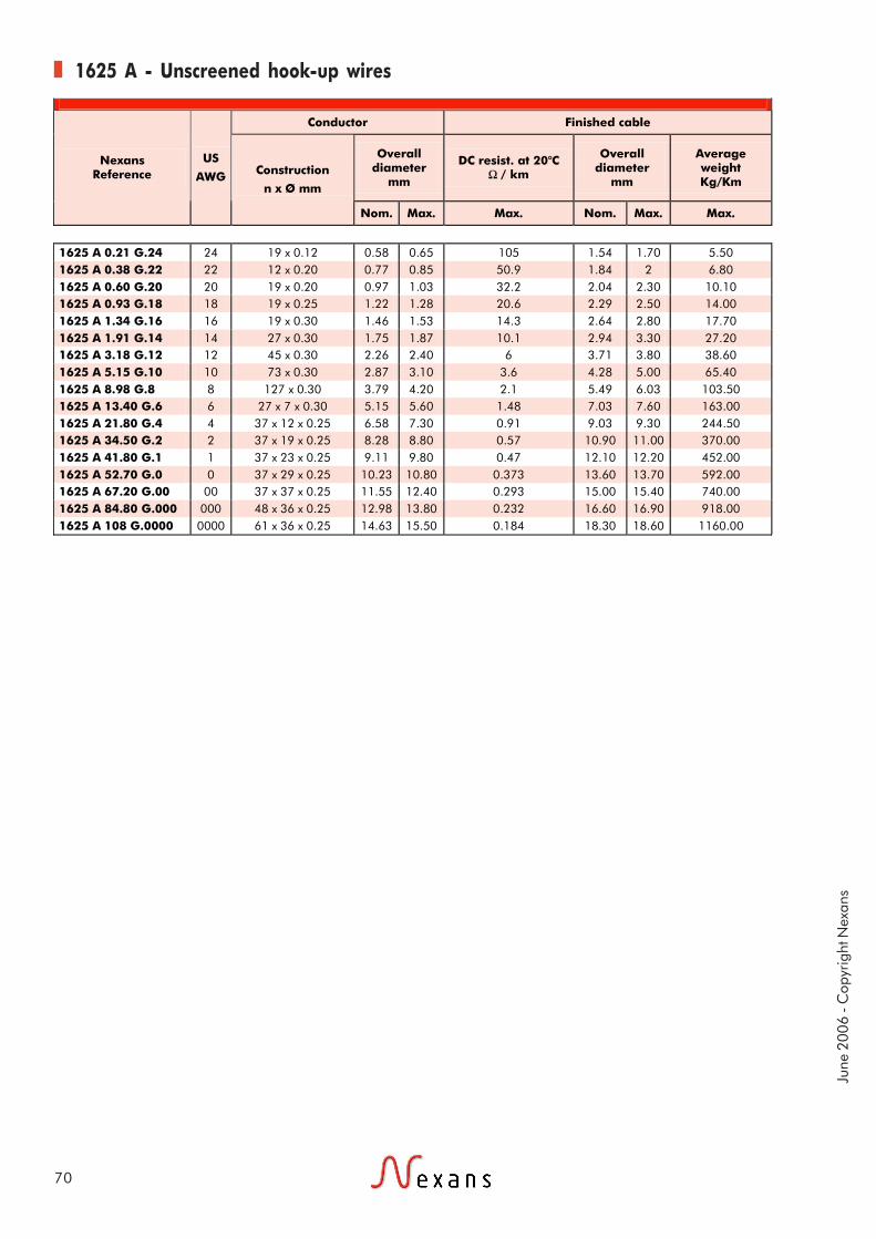
June
200
6 - C
opyr
ight
Nex
ans
70
1625 A - Unscreened hook-up wires
Conductor Finished cable
Overall diameter
mm
DC resist. at 20°C Ω / km
Overall diameter
mm
Average weight Kg/Km
Nexans Reference
US
AWG Construction
n x Ø mm
Nom. Max. Max. Nom. Max. Max.
1625 A 0.21 G.24 24 19 x 0.12 0.58 0.65 105 1.54 1.70 5.50 1625 A 0.38 G.22 22 12 x 0.20 0.77 0.85 50.9 1.84 2 6.80 1625 A 0.60 G.20 20 19 x 0.20 0.97 1.03 32.2 2.04 2.30 10.10 1625 A 0.93 G.18 18 19 x 0.25 1.22 1.28 20.6 2.29 2.50 14.00 1625 A 1.34 G.16 16 19 x 0.30 1.46 1.53 14.3 2.64 2.80 17.70 1625 A 1.91 G.14 14 27 x 0.30 1.75 1.87 10.1 2.94 3.30 27.20 1625 A 3.18 G.12 12 45 x 0.30 2.26 2.40 6 3.71 3.80 38.60 1625 A 5.15 G.10 10 73 x 0.30 2.87 3.10 3.6 4.28 5.00 65.40 1625 A 8.98 G.8 8 127 x 0.30 3.79 4.20 2.1 5.49 6.03 103.50 1625 A 13.40 G.6 6 27 x 7 x 0.30 5.15 5.60 1.48 7.03 7.60 163.00 1625 A 21.80 G.4 4 37 x 12 x 0.25 6.58 7.30 0.91 9.03 9.30 244.50 1625 A 34.50 G.2 2 37 x 19 x 0.25 8.28 8.80 0.57 10.90 11.00 370.00 1625 A 41.80 G.1 1 37 x 23 x 0.25 9.11 9.80 0.47 12.10 12.20 452.00 1625 A 52.70 G.0 0 37 x 29 x 0.25 10.23 10.80 0.373 13.60 13.70 592.00 1625 A 67.20 G.00 00 37 x 37 x 0.25 11.55 12.40 0.293 15.00 15.40 740.00 1625 A 84.80 G.000 000 48 x 36 x 0.25 12.98 13.80 0.232 16.60 16.90 918.00 1625 A 108 G.0000 0000 61 x 36 x 0.25 14.63 15.50 0.184 18.30 18.60 1160.00

Applications
Construction
Standards
71
FLAMEX SH20Unscreened halogen free
hook-up wires,screened and jacketed hook-up wires
Strictly halogen free, these wirescombine the advantages of smallsize, lightweight, high chemicalresistance, high mechanicalproperties.They are particularly recommendedfor applications where personal andmaterial safety is required in case offire.
NFF 63808, EN 50306.
1- ConductorStranded tinned copper wires2- InsulationThin wall halogen free,FLAMEX SH203- Screen(screened versions)Tinned copper braid withoptional polyester tape4- Outer sheath(screened versions)Halogen free FLAMEX
1
2
3
4
Colour codingFor NF F 63-808 cables :
For EN 50306 cables :Insulation : white, numbered 1 to nColour coded wires on requestSheath : black
Flamex SH20 - 600 Vac / 1000 Vcc
0.60
(AWG20)
0.93
(AWG18)
1.34
(AWG16)
1.82
(AWG14)
2.61
(AWG14)
4.32
(AWG12)
Yellow White Green Yellow White Green
- 40°C to+105°C
Low smokeemission andlow opacity(IEC 61034)
Halogen free(IEC 60754-1)
Non corrosiveand non toxic(IEC 60754-2
and EN 50267)
FlexibleGood chemicalresistance
(acids, oils, …)IRM 902,IRM 903
Flame and fireretardant
(NF C 32-070/C1& C2, IEC 60332-1/2/3 Cat.C and
EN 50306-1)

June
200
6 - C
opyr
ight
Nex
ans
72
Flamex SH20 - Unscreened halogen free hook-up wires
Flamex SH20 - Screened and jacketed halogen free hook-up wires
TC = Tinned copper
TC = Tinned copper
CONDUCTOR Insulation Ø Nexans
Reference Gauge AWG
Cross section mm²
Construction n x Ø mm
Maxi. Ø mm
mini. mm
maxi. mm
Average weight
Kg / Km
FLAMEX 20 0.38 22 0.38 19x0.16 TC 0.85 1.15 1.35 4.70 FLAMEX 20 0.50 20 0.50 19x0.18 TC 0.95 1.15 1.45 6.00 FLAMEX 20 0.60 20 0.60 19x0.20 TC 1.05 1.30 1.50 6.60 FLAMEX 20 0.75 20 0.75 19x0.23 TC 1.15 1.35 1.65 8.50 FLAMEX 20 0.93 18 0.93 19x0.25 TC 1.30 1.55 1.75 10.00 FLAMEX 20 1.00 18 1.00 19x0.25 TC 1.30 1.45 1.80 10.50 FLAMEX 20 1.34 16 1.34 19x0.30 TC 1.55 1.80 2.00 14.00 FLAMEX 20 1.50 16 1.50 37x0.23 TC 1.65 1.95 2.30 16.00 FLAMEX 20 1.82 14 1.82 37x0.25 TC 1.82 2.10 2.40 19.20 FLAMEX 20 2.50 14 2.50 37x0.30 TC 2.15 2.50 2.85 26.50 FLAMEX 20 2.61 14 2.61 37x0.30 TC 2.28 2.50 2.80 27.80 FLAMEX 20 4.32 12 4.32 61x0.30 TC 2.90 3.00 3.30 44.20
CONDUCTOR Insulation Ø Overall Ø Nexans
Reference Gauge AWG
Cross section mm²
Construction n x Ø mm
Maxi. Ø mm
mini. mm
maxi. mm
mini. mm
maxi. mm
Average weight
Kg / Km
FLAMEX 20 0.38 BLG 22 0.38 19x0.16 TC 0.85 1.15 1.35 2.05 2.55 11.50 FLAMEX 20 0.50 BLG 20 0.50 19x0.18 TC 0.95 1.15 1.45 2.30 2.80 14.00 FLAMEX 20 0.60 BLG 20 0.60 19x0.20 TC 1.05 1.30 1.50 2.30 2.80 15.00 FLAMEX 20 0.75 BLG 20 0.75 19x0.23 TC 1.15 1.35 1.65 2.50 3.00 17.00 FLAMEX 20 0.93 BLG 18 0.93 19x0.25 TC 1.30 1.55 1.75 2.50 3.00 19.00 FLAMEX 20 1.00 BLG 18 1.00 19x0.25 TC 1.30 1.45 1.80 2.70 3.20 20.00 FLAMEX 20 1.34 BLG 16 1.34 19x0.30 TC 1.55 1.80 2.00 2.70 3.20 24.00 FLAMEX 20 1.50 BLG 16 1.50 37x0.23 TC 1.65 1.95 2.30 3.10 3.60 28.00 FLAMEX 20 1.82 BLG 14 1.82 37x0.25 TC 1.82 2.10 2.40 3.25 3.75 32.00 FLAMEX 20 2.50 BLG 14 2.50 37x0.30 TC 2.15 2.50 2.85 3.60 4.40 43.00 FLAMEX 20 2.61 BLG 14 2.61 37x0.30 TC 2.28 2.50 2.80 3.60 4.20 43.00 FLAMEX 20 4.32 BLG 12 4.32 61x0.30 TC 2.90 3.00 3.30 4.15 4.75 63.00

Applications
Construction
Standards
73
FLAMEX SH20Screened and jacketed,
halogen free multicore cables
Strictly halogen free, these wirescombine the advantages of smallsize, lightweight, high chemicalresistance, high mechanicalproperties.They are particularly recommendedfor applications where personal andmaterial safety is required in case offire.
1- ConductorStranded tinned copper wires2- InsulationThin wall halogen free,FLAMEX SH203- ScreenTinned copper braid withoptional polyester tape4- Outer sheathHalogen free FLAMEX
12
3
4
Flamex SH20 - 600 Vac / 1000 Vcc
NFF 63808, EN 50306.
Colour codingFor NF F 63-808 cables :
For EN 50306 cables :Insulation : white, numbered 1 to nColour coded wires on requestSheath : black
0.60
(AWG20)
0.93
(AWG18)
1.34
(AWG16)
1.82
(AWG14)
2.61
(AWG14)
4.32
(AWG12)
Yellow White Green Yellow White Green
- 40°C to+105°C
Low smokeemission andlow opacity(IEC 61034)
Halogen free(IEC 60754-1)
Non corrosiveand non toxic(IEC 60754-2
and EN 50267)
FlexibleGood chemicalresistance
(acids, oils, …)IRM 902,IRM 903
Flame and fireretardant
(NF C 32-070/C1& C2, IEC 60332-1/2/3 Cat.C and
EN 50306-1)
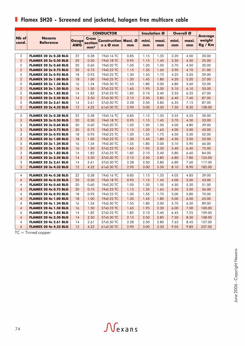
June
200
6 - C
opyr
ight
Nex
ans
74
Flamex SH20 - Screened and jacketed, halogen free multicore cable
TC = Tinned copper
CONDUCTOR Insulation Ø Overall Ø Nb of cond.
Nexans Reference Gauge
AWG
Cross section mm²
Construction n x Ø mm
Maxi. Ø mm
mini. mm
maxi. mm
mini. mm
maxi. mm
Average weight
Kg / Km
2 FLAMEX 20 2x 0.38 BLG 22 0.38 19x0.16 TC 0.85 1.15 1.35 3.20 4.00 20.00 2 FLAMEX 20 2x 0.50 BLG 20 0.50 19x0.18 TC 0.95 1.15 1.45 3.50 4.30 25.00 2 FLAMEX 20 2x 0.60 BLG 20 0.60 19x0.20 TC 1.05 1.30 1.50 3.70 4.50 30.00 2 FLAMEX 20 2x 0.75 BLG 20 0.75 19x0.23 TC 1.15 1.35 1.65 3.90 4.70 31.00 2 FLAMEX 20 2x 0.93 BLG 18 0.93 19x0.25 TC 1.30 1.55 1.75 4.25 5.05 39.00 2 FLAMEX 20 2x 1.00 BLG 18 1.00 19x0.25 TC 1.30 1.45 1.80 4.20 5.20 37.00 2 FLAMEX 20 2x 1.34 BLG 16 1.34 19x0.30 TC 1.55 1.80 2.00 4.80 5.60 52.00 2 FLAMEX 20 2x 1.50 BLG 16 1.50 37x0.23 TC 1.65 1.95 2.30 5.10 6.10 55.00 2 FLAMEX 20 2x 1.82 BLG 14 1.82 37x0.25 TC 1.82 2.10 2.40 5.55 6.35 67.00 2 FLAMEX 20 2x 2.50 BLG 14 2.50 37x0.30 TC 2.15 2.50 2.85 6.40 7.40 87.00 2 FLAMEX 20 2x 2.61 BLG 14 2.61 37x0.30 TC 2.28 2.50 2.80 6.35 7.15 87.00 2 FLAMEX 20 2x 4.32 BLG 12 4.32 61x0.30 TC 2.90 3.00 3.30 7.50 8.30 128.00
3 FLAMEX 20 3x 0.38 BLG 22 0.38 19x0.16 TC 0.85 1.15 1.35 3.55 4.35 30.00 3 FLAMEX 20 3x 0.50 BLG 20 0.50 19x0.18 TC 0.95 1.15 1.45 3.70 4.50 33.00 3 FLAMEX 20 3x 0.60 BLG 20 0.60 19x0.20 TC 1.05 1.30 1.50 4.00 4.80 39.00 3 FLAMEX 20 3x 0.75 BLG 20 0.75 19x0.23 TC 1.15 1.35 1.65 4.00 5.00 43.00 3 FLAMEX 20 3x 0.93 BLG 18 0.93 19x0.25 TC 1.30 1.55 1.75 4.50 5.30 52.00 3 FLAMEX 20 3x 1.00 BLG 18 1.00 19x0.25 TC 1.30 1.45 1.80 4.50 5.50 52.00 3 FLAMEX 20 3x 1.34 BLG 16 1.34 19x0.30 TC 1.55 1.80 2.00 5.10 5.90 66.00 3 FLAMEX 20 3x 1.50 BLG 16 1.50 37x0.23 TC 1.65 1.95 2.30 5.40 6.40 75.00 3 FLAMEX 20 3x 1.82 BLG 14 1.82 37x0.25 TC 1.82 2.10 2.40 5.80 6.60 84.00 3 FLAMEX 20 3x 2.50 BLG 14 2.50 37x0.30 TC 2.15 2.50 2.85 6.80 7.80 124.00 3 FLAMEX 20 3x 2.61 BLG 14 2.61 37x0.30 TC 2.28 2.50 2.80 6.80 7.60 117.00 3 FLAMEX 20 3x 4.32 BLG 12 4.32 61x0.30 TC 2.90 3.00 3.30 8.10 8.90 182.00
4 FLAMEX 20 4x 0.38 BLG 22 0.38 19x0.16 TC 0.85 1.15 1.35 4.05 4.85 39.00 4 FLAMEX 20 4x 0.50 BLG 20 0.50 19x0.18 TC 0.95 1.15 1.45 4.00 5.00 43.00 4 FLAMEX 20 4x 0.60 BLG 20 0.60 19x0.20 TC 1.05 1.30 1.50 4.50 5.30 51.00 4 FLAMEX 20 4x 0.75 BLG 20 0.75 19x0.23 TC 1.15 1.35 1.65 4.50 5.50 56.00 4 FLAMEX 20 4x 0.93 BLG 18 0.93 19x0.25 TC 1.30 1.55 1.75 5.00 5.80 70.00 4 FLAMEX 20 4x 1.00 BLG 18 1.00 19x0.25 TC 1.30 1.45 1.80 5.00 6.00 65.00 4 FLAMEX 20 4x 1.34 BLG 16 1.34 19x0.30 TC 1.55 1.80 2.00 5.70 6.50 89.00 4 FLAMEX 20 4x 1.50 BLG 16 1.50 37x0.23 TC 1.65 1.95 2.30 6.00 7.00 100.00 4 FLAMEX 20 4x 1.82 BLG 14 1.82 37x0.25 TC 1.82 2.10 2.40 6.45 7.25 109.00 4 FLAMEX 20 4x 2.50 BLG 14 2.50 37x0.30 TC 2.15 2.50 2.85 7.50 8.50 158.00 4 FLAMEX 20 4x 2.61 BLG 14 2.61 37x0.30 TC 2.28 2.50 2.80 7.65 8.45 157.00 4 FLAMEX 20 4x 4.32 BLG 12 4.32 61x0.30 TC 2.90 3.00 3.30 9.05 9.85 237.00

Applications
Construction
Standards
75
EPDX-ZH, KY TYPEHalogen free
unscreened hook-up wires
These wires are mainly designedfor internal wiring in electronicequipment.Halogen free, they are intendedto be used in places where theprotection of the people andequipment is vital.
NEXANS specification
1- CONDUCTORStranded annealed tinnedcopper wires2- INSULATIONHalogen free
250 and 750 Volts
We recommend to use them forcabinet wiring in public areassuch as railway or subwaystations but also in industrialareas, etc...
- 40°C to+105°C
Low smokeemission andlow opacity(IEC 61034)
Halogen free(IEC 60754-1)
Non corrosiveand non toxic(IEC 60754-2)
FlexibleFlame retardant(NF C 32-070/C2,
IEC 60332-1/2)
Screenedversions

June
200
6 - C
opyr
ight
Nex
ans
76
KY/EPDX-ZH, KY type - Halogen free unscreened hook-up wires - 250 volts
KY/EPDX-ZH, KY type- Halogen free unscreened hook-up wires - 750 volts
CONDUCTOR Nexans
Reference Gauge AWG
Cross section mm²
Construction n x ∅ mm
Overall diameter
mm
Average weight Kg/Km
EPDX-ZH 6x0 30 0.055 7 x 0.10 0.75 ± 0.05 1.05 EPDX-ZH 5x0 28 0.079 7 x 0.12 0.81 ± 0.05 1.35 EPDX-ZH 4x0 26 0.120 7 x 0.15 0.90 ± 0.10 1.75 EPDX-ZH 000 24 0.22 7 x 0.20 1.10 ± 0.10 2.90 EPDX-ZH 00 22 0.34 7 x 0.25 1.30 ± 0.10 4.35 EPDX-ZH 26 20 0.60 19 x 0.20 1.75 ± 0.15 7.60 EPDX-ZH 27 18 0.93 19 x 0.25 2.00 ± 0.15 11.05 EPDX-ZH 28 16 1.34 19 x 0.30 2.35 ± 0.15 15.85 EPDX-ZH 29 14 1.91 27 x 0.30 2.70 ± 0.15 22.00 EPDX-ZH 100 12 3.18 45 x 0.30 3.40 ± 0.20 36.00 EPDX-ZH 140 10 5.15 73 x 0.30 4.10 ± 0.20 56.50
CONDUCTOR Nexans
Reference Gauge AWG
Cross section mm²
Construction n x ∅ mm
Overall diameter
mm
Average weight Kg/Km
EPDX-ZH 6 24 0.22 7 x 0.20 1.70 ± 0.10 5.00 EPDX-ZH 7 22 0.38 12 x 0.20 2.15 ± 0.15 8.00 EPDX-ZH 16 20 0.60 19 x 0.20 2.35 ± 0.15 10.50 EPDX-ZH 17 18 1.00 32 x 0.20 2.65 ± 0.15 15.50 EPDX-ZH 8 16 1.34 19 x 0.30 2.85 ± 0.15 19.00 EPDX-ZH 9 14 1.91 27 x 0.30 3.20 ± 0.20 25.50 EPDX-ZH 10 12 3.18 45 x 0.30 4.00 ± 0.20 41.50 EPDX-ZH 14 10 5.15 73 x 0.30 4.60 ± 0.20 62.00
77
150°C

.

Applications
Construction
Standards
79
1806Unscreened hook-up wires
Flexible and lightweight range ofcables with FEP + super-polyamide insulation for use inbundles.Abrasion resistance: mediumThey withstand most chemicalfluids except for concentratednitric acid.
To AIR 4524 and MIL-W 5086B/7Aspecifications.These cables are approved by theAir Ministry under letters:N° 34722 STA/EQ/E2 (18-4-69)for AWG 24N° 41763 STA/EQ/E2 (12-11-68)for AWG 22 up to AWG 12Registered at B.N.Ae:N° 6412 420 A
1- CONDUCTORstranded tinned copper wires orstranded tinned copper alloywires for the cross section area0.21 mm²2- INSULATIONfluoropolymer (FEP)3- OUTER JACKETsuperpolyamide (radialthickness: from 0.10 mm up to0.15 mm)
600 Volts RMS
Technical requirements and control conditionsAir 4524 specification of September 1965 - the105°/135°C category,NF-L 52-120B BNAé specification of December 1971 - Lightweightcables.
Colour codingTo AIR 0107 A of October 1961 and note N° 348/SIB distributed under N°5927/STT/SIB (3.05.1961).
Flexible- 50°C to +140°C Fire retardant(NF C 32-070/C1)

June
200
6 - C
opyr
ight
Nex
ans
80
1806 - Unscreened hook-up wires
The shown current rating is valid for singles wires in air.
Nexans Reference CONDUCTOR CORE
Type Cross section AWG Construction
n x Ø mm
Nominal Ø
mm
Tensile strength daN.
Overall diameter
mm
Average weight Kg/Km
DC resist. at 20°C (maxi.) Ω / km
Current rating
A
Colour of cores
1806 0.21 24 19 x 0.12 T.P.C All. 0.60 7 1.10 + 0.05 3.10 105.0 4 Light Blue
1806 0.38 22 12 x 0.20 T.P.C. 0.80 8 1.33 + 0.05 5.10 50.9 7 White
1806 0.60 20 19 x 0.20 T.P.C. 1.00 16 1.49 + 0.05 7.10 32.2 11 Light Blue
1806 0.93 18 19 x 0.25 T.P.C. 1.20 20 1.69 + 0.05 10.4 20.6 16 White
1806 1.34 16 19 x 0.30 T.P.C. 1.50 20 1.97 + 0.05 14.6 14.3 22 Light Blue
1806 1.91 14 27 x 0.30 T.P.C. 1.80 20 2.35 + 0.05 21.0 10.1 32 White
1806 3.18 12 45 x 0.30 T.P.C. 2.30 20 2.94 + 0.05 34.0 6.0 41 White

Applications
Construction
Standards
81
806Screened and jacketed
hook-up wires and multicore cables
Flexible and lightweight range ofcables with FEP + super-polyamide insulation for use inbundles.Abrasion resistance: mediumThey withstand most chemicalfluids except for concentratednitric acid.
To AIR 4524 and MIL-W 5086B/7Aspecifications.These cables are approved by theAir Ministry under letters:N° 34722 STA/EQ/E2 (18-4-69)for AWG 24N° 41763 STA/EQ/E2 (12-11-68)for AWG 22 up to AWG 12Registered at B.N.Ae : N° 6412420 A
BASE CORE 18061- CONDUCTORstranded tinned copper wires orstranded tinned copper alloywires for the cross section area0.21 mm2- INSULATIONfluoropolymer (FEP)3- OUTER JACKETsuperpolyamide (radialthickness: from 0.10 mm up to0.15 mm)
600 Volts RMS
Technical requirements and control conditions
Colour coding
Screen: to MIL.C. 7078C (August1971) U.S. specification.
To Air 0107 A (October 1961) and note N° 348/SIB distributedunder N° 5927/STT/SIB (3-05-1961).
8064- LAY UP1 or several 1806 cores5- SCREENtinned copper braid(Kr ≥ 62%)6- OUTER JACKETsuperpolyamide (radialthickness: about 0.20 mm)
FlexibleFire retardant(NF C 32-070/C1)
- 50°C to +140°C

June
200
6 - C
opyr
ight
Nex
ans
82
806 - Screened and jacketed hook-up wires and multicore cables
BASE CORE : 1806 SERIE 806
Nb of cores Nexans Reference Construction
n x Ø mm
Overall diameternominal
mm
Colour coding of cores
Colour of outer jacket
Overall diameter
(maxi.) mm
Average weight Kg/Km
1 806 1 0.21 G 24 19 x 0.12 T.P.C All 1.10 Light blue Light blue 2 6.3 1 806 1 0.38 G 22 12 x 0.20 T.P.C. 1.33 White White 2.3 10.8 1 806 1 0.60 G 20 19 x 0.20 T.P.C. 1.49 Light blue Light blue 2.5 13.3 1 806 1 0.93 G 18 19 x 0.25 T.P.C. 1.69 White White 2.7 17.3 1 806 1 1.34 G 16 19 x 0.30 T.P.C. 1.97 Light blue Light blue 3 22.5 1 806 1 1.91 G 14 27 x 0.30 T.P.C. 2.35 White White 3.3 29.9 1 806 1 3.18 G 12 45 x 0.30 T.P.C. 2.94 White White 4.2 47.0
2 806 2 0.21 G 24 19 x 0.12 T.P.C All 1.10 Light blue + Blue Light blue 3.3 13.1 2 806 2 0.38 G 22 12 x 0.20 T.P.C. 1.33 White + Blue White 3.8 19.0 2 806 2 0.60 G 20 19 x 0.20 T.P.C. 1.49 Light blue + Blue Light blue 4.1 24.0 2 806 2 0.93 G 18 19 x 0.25 T.P.C. 1.69 White + blue White 4.5 33.7 2 806 2 1.34 G 16 19 x 0.30 T.P.C. 1.97 Light blue + Blue Light blue 5.2 44.1 2 806 2 1.91 G 14 27 x 0.30 T.P.C. 2.35 White + Blue White 5.9 59.0 2 806 2 3.18 G 12 45 x 0.30 T.P.C. 2.94 White + Blue White 7.7 94.0
3 806 3 0.21 G 24 19 x 0.12 T.P.C All 1.10 Light blue + Blue + Yellow
Light blue 3.5 17.5
3 806 3 0.38 G 22 12 x 0.20 T.P.C. 1.33 White + Blue + Yellow White 4 25.9
3 806 3 0.60 G 20 19 x 0.20 T.P.C. 1.49 Light blue + Blue + Yellow
Light blue 4.4 35.0
3 806 3 0.93 G 18 19 x 0.25 T.P.C. 1.69 White + Blue + Yellow White 4.8 46.8
3 806 3 1.34 G 16 19 x 0.30 T.P.C. 1.97 Light blue + Blue + Yellow
Light blue 5.5 61.9
3 806 3 1.91 G 14 27 x 0.30 T.P.C. 2.35 White + Blue + Yellow White 6.3 83.6 3 806 3 3.18 G 12 45 x 0.30 T.P.C. 2.94 White + Blue + Yellow White 8.2 134
4 806 4 0.21 G 24 19 x 0.12 T.P.C All 1.10 Light Blue + Blue + Yellow + Green
Light blue 3.7 21.6
4 806 4 0.38 G 22 12 x 0.20 T.P.C. 1.33 White + Blue+ Yellow + Green
White 4.4 34.4
4 806 4 0.60 G 20 19 x 0.20 T.P.C. 1.49 Light blue + Blue + Yellow + Green
Light blue 4.8 43.9
4 806 4 0.93 G 18 19 x 0.25 T.P.C. 2.69 White + Blue + Yellow + Green
White 5.3 59.3
4 806 4 1.34 G 16 19 x 0.30 T.P.C. 2.97 Light blue + Blue + Yellow + Green
Light blue 6 79.0
4 806 4 1.91 G 14 27 x 0.30 T.P.C. 2.35 White + Blue + Yellow + Green
White 6.9 107.4
4 806 4 3.18 G 12 45 x 0.30 T.P.C. 2.94 White + Blue + Yellow + Green
White 9.1 172.5

Applications
Construction
Standards
83
KUUnscreened hook up wires,
pairs and triples
Internal wiring in electronicequipment.
NF C 93-524
BASE CORE KU 011- CONDUCTORstranded annealed tinnedcopper wires2- INSULATIONethylene and tetrafluorethylenecopolymer (E.T.F.E)
KU 03 and KU 043- LAY UP2 or 3 base cores
600 volts
Flexible-55 °C to +150 °C Flame and fire retardant(NF C 32-070/C1 & C2)
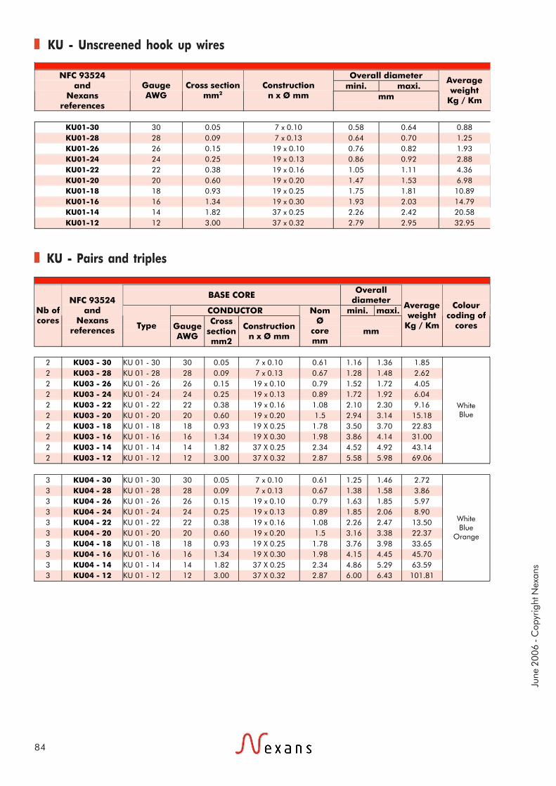
June
200
6 - C
opyr
ight
Nex
ans
84
KU - Unscreened hook up wires
KU - Pairs and triples
Overall diameter mini. maxi.
NFC 93524 and
Nexans references
Gauge AWG
Cross section
mm2 Construction
n x Ø mm mm
Average weight
Kg / Km
KU01-30 30 0.05 7 x 0.10 0.58 0.64 0.88 KU01-28 28 0.09 7 x 0.13 0.64 0.70 1.25 KU01-26 26 0.15 19 x 0.10 0.76 0.82 1.93 KU01-24 24 0.25 19 x 0.13 0.86 0.92 2.88 KU01-22 22 0.38 19 x 0.16 1.05 1.11 4.36 KU01-20 20 0.60 19 x 0.20 1.47 1.53 6.98 KU01-18 18 0.93 19 x 0.25 1.75 1.81 10.89 KU01-16 16 1.34 19 x 0.30 1.93 2.03 14.79 KU01-14 14 1.82 37 x 0.25 2.26 2.42 20.58 KU01-12 12 3.00 37 x 0.32 2.79 2.95 32.95
BASE CORE Overall
diameter CONDUCTOR mini. maxi. Nb of
cores
NFC 93524 and
Nexans references Type Gauge
AWG
Cross section mm2
Construction n x Ø mm
Nom Ø
core mm
mm
Average weight
Kg / Km
Colour coding of
cores
2 KU03 - 30 KU 01 - 30 30 0.05 7 x 0.10 0.61 1.16 1.36 1.85 2 KU03 - 28 KU 01 - 28 28 0.09 7 x 0.13 0.67 1.28 1.48 2.62 2 KU03 - 26 KU 01 - 26 26 0.15 19 x 0.10 0.79 1.52 1.72 4.05 2 KU03 - 24 KU 01 - 24 24 0.25 19 x 0.13 0.89 1.72 1.92 6.04 2 KU03 - 22 KU 01 - 22 22 0.38 19 x 0.16 1.08 2.10 2.30 9.16 2 KU03 - 20 KU 01 - 20 20 0.60 19 x 0.20 1.5 2.94 3.14 15.18 2 KU03 - 18 KU 01 - 18 18 0.93 19 X 0.25 1.78 3.50 3.70 22.83 2 KU03 - 16 KU 01 - 16 16 1.34 19 X 0.30 1.98 3.86 4.14 31.00 2 KU03 - 14 KU 01 - 14 14 1.82 37 X 0.25 2.34 4.52 4.92 43.14 2 KU03 - 12 KU 01 - 12 12 3.00 37 X 0.32 2.87 5.58 5.98 69.06
White Blue
3 KU04 - 30 KU 01 - 30 30 0.05 7 x 0.10 0.61 1.25 1.46 2.72 3 KU04 - 28 KU 01 - 28 28 0.09 7 x 0.13 0.67 1.38 1.58 3.86 3 KU04 - 26 KU 01 - 26 26 0.15 19 x 0.10 0.79 1.63 1.85 5.97 3 KU04 - 24 KU 01 - 24 24 0.25 19 x 0.13 0.89 1.85 2.06 8.90 3 KU04 - 22 KU 01 - 22 22 0.38 19 x 0.16 1.08 2.26 2.47 13.50 3 KU04 - 20 KU 01 - 20 20 0.60 19 x 0.20 1.5 3.16 3.38 22.37 3 KU04 - 18 KU 01 - 18 18 0.93 19 X 0.25 1.78 3.76 3.98 33.65 3 KU04 - 16 KU 01 - 16 16 1.34 19 X 0.30 1.98 4.15 4.45 45.70 3 KU04 - 14 KU 01 - 14 14 1.82 37 X 0.25 2.34 4.86 5.29 63.59 3 KU04 - 12 KU 01 - 12 12 3.00 37 X 0.32 2.87 6.00 6.43 101.81
White Blue
Orange

Applications
Construction
Standards
85
KUScreened and jacketed
hook-up wires, pairs and triples
Internal wiring in electronicequipment.
NF C 93-524
BASE CORE KU 011- CONDUCTORstranded annealed tinnedcopper wires2- INSULATIONethylene and tetrafluorethylenecopolymer (E.T.F.E)3- SCREENtinned copper braid4- OUTER JACKETethylene and tetrafluorethylenecopolymer (E.T.F.E.)
600 volts
FlexibleFlame and fire retardant(NF C 32-070/C1 & C2)
-55 °C to +150 °C

June
200
6 - C
opyr
ight
Nex
ans
86
KU - Screened and jacketed hook-up wires
KU - Screened and jacketed pairs and triples
BRAID: Ø STRANDS
BASE CORE Overall
diameter CONDUCTOR mini. maxi. Nb of
cores
NFC 93524 and
Nexans references Type Gauge
AWG
Cross section mm2
Construction n x Ø mm
Nom Ø
core mm
mm
Average weight
Kg / Km
1 KU 02 - 30 KU 01 - 30 30 0.05 7 x 0.10 0.61 1.35 1.43 4.10 1 KU 02 - 28 KU 01 - 28 28 0.09 7 x 0.13 0.67 1.41 1.49 4.68 1 KU 02 - 26 KU 01 - 26 26 0.15 19 x 0.10 0.79 1.51 1.59 5.70 1 KU 02 - 24 KU 01 - 24 24 0.25 19 x 0.13 0.89 1.73 1.81 7.55 1 KU 02 - 22 KU 01 - 22 22 0.38 19 x 0.16 1.08 1.96 2.06 10.02 1 KU 02 - 20 KU 01 - 20 20 0.60 19 x 0.20 1.5 2.38 2.48 14.54 1 KU 02 - 18 KU 01 - 18 18 0.93 19 X 0.25 1.78 2.76 2.88 20.72 1 KU 02 - 16 KU 01 - 16 16 1.34 19 X 0.30 1.98 2.94 3.06 25.36 1 KU 02 - 14 KU 01 - 14 14 1.82 37 X 0.25 2.34 3.26 3.40 32.48 1 KU 02 - 12 KU 01 - 12 12 3.00 37 X 0.32 2.87 3.75 3.95 47.06
BASE CORE Overall diameter
CONDUCTOR mini. maxi. Nb of cores
NFC 93524 and
Nexans references Type Gauge
AWG
Cross section mm2
Construction n x Ø mm
Nom Ø
core mm
mm
Average weight
Kg / Km
Colour coding of
cores
2 KU 05 - 30 KU 01 - 30 30 0.05 7 x 0.10 0.61 2.12 2.22 7.60 2 KU 05 - 28 KU 01 - 28 28 0.09 7 x 0.13 0.67 2.24 2.34 8.80 2 KU 05 - 26 KU 01 - 26 26 0.15 19 x 0.10 0.79 2.48 2.60 11.15 2 KU 05 - 24 KU 01 - 24 24 0.25 19 x 0.13 0.89 2.79 2.91 15.11 2 KU 05 - 22 KU 01 - 22 22 0.38 19 x 0.16 1.08 3.16 3.30 19.77 2 KU 05 - 20 KU 01 - 20 20 0.60 19 x 0.20 1.5 3.87 4.07 28.11 2 KU 05 - 18 KU 01 - 18 18 0.93 19 x 0.25 1.78 4.52 4.72 38.95 2 KU 05 - 16 KU 01 - 16 16 1.34 19 x 0.30 1.98 4.90 5.12 48.59 2 KU 05 - 14 KU 01 - 14 14 1.82 37 x 0.25 2.34 5.62 5.86 63.75 2 KU 05 - 12 KU 01 - 12 12 3.00 37 x 0.32 2.87 6.67 6.97 94.29
White Blue
3 KU 06 - 30 KU 01 - 30 30 0.05 7 x 0.10 0.61 2.32 2.42 9.60 3 KU 06 - 28 KU 01 - 28 28 0.09 7 x 0.13 0.67 2.36 2.46 10.70 3 KU 06 - 26 KU 01 - 26 26 0.15 19 x 0.10 0.79 2.70 2.82 14.89 3 KU 06 - 24 KU 01 - 24 24 0.25 19 x 0.13 0.89 2.83 2.95 18.09 3 KU 06 - 22 KU 01 - 22 22 0.38 19 x 0.16 1.08 3.23 3.37 24.36 3 KU 06 - 20 KU 01 - 20 20 0.60 19 x 0.20 1.5 4.13 4.33 37.00 3 KU 06 - 18 KU 01 - 18 18 0.93 19 x 0.25 1.78 4.72 4.94 50.70 3 KU 06 - 16 KU 01 - 16 16 1.34 19 x 0.30 1.98 5.18 5.40 64.90 3 KU 06 - 14 KU 01 - 14 14 1.82 37 x 0.25 2.34 5.96 6.22 86.37 3 KU 06 - 12 KU 01 - 12 12 3.00 37 x 0.32 2.87 7.09 7.39 129.53
White Blue
Orange
Reference AWG Ø mm KU 02 From AWG 30 to AWG 20 0.10 KU 02 From AWG 18 to AWG 12 0.12 KU 05 From AWG 30 to AWG 26 0.10 KU 05 From AWG 24 to AWG 12 0.12 KU 06 From AWG 30 to AWG 28 0.10 KU 06 From AWG 24 to AWG 12 0.12

87
200°C

.

Applications
Construction
Standards
89
KZ 04, KZ 05, KZ 06Unscreened hook-up wires
High temperature
Internal wiring in electronicequipment.Aircrafts and satellites.Excellent chemical resistance.In order to increase the operatingtemperature of the cables up to250°C, all KZ types can beproduced with a nickel platedcopper conductor on request.
NF C 93-523
1- CONDUCTORstranded silvered copper wires2- INSULATIONextruded polytetrafluorethylene(P.T.F.E.)
from 250 to 1000 Volts
Flexible-55 °C to +200 °C Fire retardant(NF C 32-070/C1)

June
200
6 - C
opyr
ight
Nex
ans
90
KZ - Unscreened hook-up wires, high temperature
Overall diameter
mini. maxi.
NFC 93523 and
Nexans references
Gauge AWG
Cross section
mm2 Construction
n x Ø mm Nom.
Ø mm
D.C. resist. at 20°C maxi.
(Ohms/Km) mm
Maximum weight
Kg / Km
Operating voltage
Volts
KZ 04 - 01 32 0.035 7 x 0.08 0.24 546 0.48 0.58 0.95 KZ 04 - 02 30 0.055 7 x 0.10 0.30 349 0.56 0.66 1.3 KZ 04 - 03 28 0.093 7 x 0.13 0.39 201 0.63 0.73 1.75 KZ 04 - 04 26 0.14 7 x 0.16 0.48 132 0.74 0.84 2.4 KZ 04 - 05 24 0.22 7 x 0.20 0.60 86 0.86 0.96 3.4 KZ 04 - 06 22 0.34 7 x 0.25 0.75 54.4 1.01 1.11 5.0 KZ 04 - 07 20 0.60 19 x 0.20 1.00 31.3 1.30 1.40 8.25
250
KZ 05 - 01 32 0.035 7 x 0.08 0.24 546 0.63 0.84 1.65 KZ 05 - 02 30 0.055 7 x 0.10 0.30 349 0.71 0.91 2.1 KZ 05 - 03 28 0.093 7 x 0.13 0.39 201 0.79 1.00 2.6 KZ 05 - 04 26 0.14 7 x 0.16 0.48 132 0.89 1.10 3.4 KZ 05 - 05 24 0.22 7 x 0.20 0.60 86 1.04 1.22 4.5 KZ 05 - 06 22 0.34 7 x 0.25 0.75 54.4 1.17 1.37 6.2 KZ 05 - 07 20 0.60 19 x 0.20 1.00 31.3 1.42 1.62 9.5 KZ 05 - 08 18 0.93 19 x 0.25 1.25 20.5 1.67 1.92 14.1 KZ 05 - 09 16 1.34 19 x 0.30 1.50 13.9 1.92 2.27 20.0 KZ 05 - 10 14 1.91 27 x 0.30 1.85 10.0 2.30 2.66 27.0 KZ 05 - 11 12 3.18 45 x 0.30 2.45 6.0 2.89 3.24 42.5
600
KZ 06 - 01 32 0.035 7 x 0.08 0.24 546 0.88 1.09 2.6 KZ 06 - 02 30 0.055 7 x 0.10 0.30 349 0.95 1.16 3.0 KZ 06 - 03 28 0.093 7 x 0.13 0.39 201 1.04 1.24 3.7 KZ 06 - 04 26 0.14 7 x 0.16 0.48 132 1.14 1.34 4.6 KZ 06 - 05 24 0.22 7 x 0.20 0.60 86 1.27 1.47 5.75 KZ 06 - 06 22 0.34 7 x 0.25 0.75 54.4 1.42 1.63 7.7 KZ 06 - 07 20 0.60 19 x 0.20 1.00 31.3 1.66 1.86 11.0 KZ 06 - 08 18 0.93 19 x 0.25 1.25 20.5 1.92 2.17 16.0 KZ 06 - 09 16 1.34 19 x 0.30 1.50 13.9 2.10 2.41 21.1 KZ 06 - 10 14 1.91 27 x 0.30 1.85 10.0 2.51 2.92 30.0 KZ 06 - 11 12 3.18 45 x 0.30 2.45 6.0 3.14 3.55 47.5
1000

Applications
Construction
Standards
91
KZ 55, KZ 57, KZ 59Screened and jacketed
hook-up wiresHigh temperature
Internal wiring in electronicequipment.Aircrafts and satellites.Excellent chemical resistance.In order to increase the operatingtemperature of the cables up to250°C, all KZ types can beproduced with a nickel platedcopper conductor on request.
NF C 93-523
1- CONDUCTORstranded silvered copper wires2- INSULATIONextruded polytetrafluorethylene(P.T.F.E.)3- SCREENSilvered copper braidKZ 55 are reinforced with apolyimide tape.4- OUTER JACKETfluoropolymer (FEP) (radialthickness: 0.30 mm nominal)
from 250 to 1000 Volts
- White core- White outer jacket
Colour coding
FlexibleFire retardant(NF C 32-070/C1)
-55 °C to +200 °C

June
200
6 - C
opyr
ight
Nex
ans
92
KZ - Screened and jacketed hook-up wires, high temperature
BASE CORE Overall
diameter CONDUCTOR mini. maxi.
NFC 93523 and
Nexans references Type Gauge
AWG
Cross section mm2
Construction n x Ø mm
Nom. Ø
mm
D.C. resist. at 20°C maxi.
(Ohms/Km)
Braid nom Ø.
of strands
mm mm
Maximum weight
Kg / Km
Operating voltage
Volts
KZ 55-04 KZ 04-04 26 0.14 7 x 0.16 0.48 132 0.10 1.85 2.05 8.11 KZ 55-05 KZ 04-05 24 0.22 7 x 0.20 0.60 86 0.10 1.97 2.17 9.66 KZ 55-06 KZ 04-06 22 0.34 7 x 0.25 0.75 54.4 0.10 2.12 2.32 11.90 KZ 55-07 KZ 04-07 20 0.60 19 x 0.20 1.00 31.3 0.10 2.40 2.60 16.50
250
KZ 57-01 KZ 05-01 32 0.035 7 x 0.08 0.24 546 0.10 1.72 1.97 6.72 KZ 57-02 KZ 05-02 30 0.055 7 x 0.10 0.30 349 0.10 1.79 2.04 7.49 KZ 57-03 KZ 05-03 28 0.093 7 x 0.13 0.39 201 0.10 1.88 2.13 8.39 KZ 57-04 KZ 05-04 26 0.14 7 x 0.16 0.48 132 0.10 1.98 2.23 9.63 KZ 57-05 KZ 05-05 24 0.22 7 x 0.20 0.60 86 0.10 2.11 2.36 11.30 KZ 57-06 KZ 05-06 22 0.34 7 x 0.25 0.75 54.4 0.10 2.25 2.50 13.60 KZ 57-07 KZ 05-07 20 0.60 19 x 0.20 1.00 31.3 0.13 2.65 2.90 20.00 KZ 57-08 KZ 05-08 18 0.93 19 x 0.25 1.25 20.5 0.13 2.93 3.18 26.10 KZ 57-09 KZ 05-09 16 1.34 19 x 0.30 1.50 13.9 0.13 3.23 3.53 33.50 KZ 57-10 KZ 05-10 14 1.91 27 x 0.30 1.85 10.0 0.13 3.61 3.91 42.60 KZ 57-11 KZ 05-11 12 3.18 45 x 0.30 2.45 6.0 0.13 4.19 4.49 61.10
600
KZ 59-01 KZ 06-01 32 0.035 7 x 0.08 0.24 546 0.10 1.97 2.22 8.79 KZ 59-02 KZ 06-02 30 0.055 7 x 0.10 0.30 349 0.10 2.03 2.28 9.45 KZ 59-03 KZ 06-03 28 0.093 7 x 0.13 0.39 201 0.10 2.12 2.37 10.6 KZ 59-04 KZ 06-04 26 0.14 7 x 0.16 0.48 132 0.10 2.22 2.47 11.9 KZ 59-05 KZ 06-05 24 0.22 7 x 0.20 0.60 86 0.10 2.35 2.60 13.6 KZ 59-06 KZ 06-06 22 0.34 7 x 0.25 0.75 54.4 0.13 2.65 2.90 18.2 KZ 59-07 KZ 06-07 20 0.60 19 x 0.20 1.00 31.3 0.13 2.89 3.14 22.7 KZ 59-08 KZ 06-08 18 0.93 19 x 0.25 1.25 20.5 0.13 3.18 3.43 29.2 KZ 59-09 KZ 06-09 16 1.34 19 x 0.30 1.50 13.9 0.13 3.38 3.68 35.4 KZ 59-10 KZ 06-10 14 1.91 27 x 0.30 1.85 10.0 0.13 3.84 4.19 46.8 KZ 59-11 KZ 06-11 12 3.18 45 x 0.30 2.45 6.0 0.13 4.65 5.00 70.4
1000

Applications
Construction
Standards
93
KZ 67, KZ 69, KZ 71Screened and jacketed pairs
High temperature
Internal wiring in electronicequipment.Aircrafts and satellites.
NF C 93-523
1- CONDUCTORstranded silvered copper wires2- INSULATIONextruded polytetrafluorethylene(P.T.F.E.)3- SCREENSilvered copper braidKZ 67 are reinforced with apolyimide tape.4- OUTER JACKETfluoropolymer (FEP) (radialthickness: 0.30 mm nominal)
from 250 to 1000 Volts
- Cores: white + light blue- Outer jacket: white
Colour coding
FlexibleFire retardant(NF C 32-070/C1)
-55 °C to +200 °C

June
200
6 - C
opyr
ight
Nex
ans
94
KZ - Screened and jacketed pairs, high temperature
BASE CORE Overall
diameter CONDUCTOR mini. maxi.
NFC 93523 and
Nexans references Type Gauge
AWG
Cross section mm2
Construction n x Ø mm
Ø Nom. mm
D.C. resist. at 20°C maxi.
(Ohms/Km)
Braid nom Ø.
of strands
mm mm
Average weight
Kg / Km
Operating voltage
Volts
KZ 67-01 KZ 04-01 32 0.035 7 x 0.08 0.24 573 0.10 2.11 2.36 8.03 KZ 67-02 KZ 04-02 30 0.055 7 x 0.10 0.30 366 0.10 2.27 2.52 9.35 KZ 67-03 KZ 04-03 28 0.093 7 x 0.13 0.39 211 0.10 2.41 2.62 10.8 KZ 67-04 KZ 04-04 26 0.14 7 x 0.16 0.48 138 0.10 2.63 2.88 13.0 KZ 67-05 KZ 04-05 24 0.22 7 x 0.20 0.60 90 0.13 3.02 3.27 17.9 KZ 67-06 KZ 04-06 22 0.34 7 x 0.25 0.75 57 0.13 3.32 3.57 22.5 KZ 67-07 KZ 04-07 20 0.60 19 x 0.20 1.00 33 0.13 3.90 4.15 31.7
250
KZ 69-01 KZ 05-01 32 0.035 7 x 0.08 0.24 573 0.10 2.46 2.71 10.6 KZ 69-02 KZ 05-02 30 0.055 7 x 0.10 0.30 366 0.10 2.60 2.85 12.0 KZ 69-03 KZ 05-03 28 0.093 7 x 0.13 0.39 211 0.10 2.78 3.03 13.7 KZ 69-04 KZ 05-04 26 0.14 7 x 0.16 0.48 138 0.13 3.13 3.38 18.1 KZ 69-05 KZ 05-05 24 0.22 7 x 0.20 0.60 90 0.13 3.39 3.64 21.5 KZ 69-06 KZ 05-06 22 0.34 7 x 0.25 0.75 57 0.13 3.67 3.92 26.2 KZ 69-07 KZ 05-07 20 0.60 19 x 0.20 1.00 33 0.13 4.17 4.42 35.1 KZ 69-08 KZ 05-08 18 0.93 19 x 0.25 1.25 21.5 0.13 4.73 5.08 46.9 KZ 69-09 KZ 05-09 16 1.34 19 x 0.30 1.50 14.6 0.13 5.51 5.86 64.4 KZ 69-10 KZ 05-10 14 1.91 27 x 0.30 1.85 10.5 0.13 6.27 6.62 82.4 KZ 69-11 KZ 05-11 12 3.18 45 x 0.30 2.45 6.3 0.13 7.43 7.78 120.0
600
KZ 71-01 KZ 06-01 32 0.035 7 x 0.08 0.24 573 0.13 3.11 3.36 16.4 KZ 71-02 KZ 06-02 30 0.055 7 x 0.10 0.30 366 0.13 3.23 3.48 17.7 KZ 71-03 KZ 06-03 28 0.093 7 x 0.13 0.39 211 0.13 3.41 3.66 19.9 KZ 71-04 KZ 06-04 26 0.14 7 x 0.16 0.48 138 0.13 3.61 3.86 22.6 KZ 71-05 KZ 06-05 24 0.22 7 x 0.20 0.60 90 0.13 3.87 4.12 26.1 KZ 71-06 KZ 06-06 22 0.34 7 x 0.25 0.75 57 0.13 4.17 4.42 31.4 KZ 71-07 KZ 06-07 20 0.60 19 x 0.20 1.00 33 0.13 4.65 4.90 40.2 KZ 71-08 KZ 06-08 18 0.93 19 x 0.25 1.25 21.5 0.13 5.39 5.64 55.6 KZ 71-09 KZ 06-09 16 1.34 19 x 0.30 1.50 14.6 0.13 5.81 6.16 68.1 KZ 71-10 KZ 06-10 14 1.91 27 x 0.30 1.85 10.5 0.13 6.73 7.08 90.7 KZ 71-11 KZ 06-11 12 3.18 45 x 0.30 2.45 6.3 0.13 7.99 8.34 133
1000

Applications
Construction
Standards
95
KZ 79, KZ 81, KZ 83Screened and jacketed triples
High temperature
Internal wiring in electronicequipment.Aircrafts and satellites.
NF C 93-523
1- CONDUCTORstranded silvered copper wires2- INSULATIONextruded polytetrafluorethylene(P.T.F.E.)3- SCREENSilvered copper braidKZ 79 are reinforced with apolyimide tape.4- OUTER JACKETfluoropolymer (FEP) (radialthickness: 0.30 mm nominal)
from 250 to 1000 Volts
- Cores: white + light blue + orange- Outer jacket: white
Colour coding
FlexibleFire retardant(NF C 32-070/C1)
-55 °C to +200 °C

June
200
6 - C
opyr
ight
Nex
ans
96
KZ - Screened and jacketed triples, high temperature
BASE CORE Overall
diameter CONDUCTOR mini. maxi.
NFC 93523 and
Nexans references
Type Gauge
AWG
Cross section mm2
Construction n x Ø mm
Ø Nom. mm
D.C. resist. at 20°C maxi.
(Ohms/Km)
Braid nom Ø.
of strands
mm mini.
mm
Average weight
Kg / Km
Operating voltage
Volts
KZ 79-01 KZ 04-01 32 0.035 7 x 0.08 0.24 573 0.10 2.19 2.44 9.85 KZ 79-02 KZ 04-02 30 0.055 7 x 0.10 0.30 366 0.10 2.36 2.61 11.7 KZ 79-03 KZ 04-03 28 0.093 7 x 0.13 0.39 211 0.10 2.51 2.76 13.7 KZ 79-04 KZ 04-04 26 0.14 7 x 0.16 0.48 138 0.13 2.90 3.15 18.7 KZ 79-05 KZ 04-05 24 0.22 7 x 0.20 0.60 90 0.13 3.15 3.40 23.1 KZ 79-06 KZ 04-06 22 0.34 7 x 0.25 0.75 57 0.13 3.48 3.73 29.6 KZ 79-07 KZ 04-07 20 0.60 19 x 0.20 1.00 33 0.13 4.10 4.35 42.7
250
KZ 81-01 KZ 05-01 32 0.035 7 x 0.08 0.24 573 0.10 2.57 2.82 13.4 KZ 81-02 KZ 05-02 30 0.055 7 x 0.10 0.30 366 0.13 2.87 3.12 17.4 KZ 81-03 KZ 05-03 28 0.093 7 x 0.13 0.39 211 0.13 3.07 3.32 19.9 KZ 81-04 KZ 05-04 26 0.14 7 x 0.16 0.48 138 0.13 3.28 3.53 23.4 KZ 81-05 KZ 05-05 24 0.22 7 x 0.20 0.60 90 0.13 3.56 3.81 28.2 KZ 81-06 KZ 05-06 22 0.34 7 x 0.25 0.75 57 0.13 3.86 4.11 34.8 KZ 81-07 KZ 05-07 20 0.60 19 x 0.20 1.00 33 0.13 4.40 4.65 47.6 KZ 81-08 KZ 05-08 18 0.93 19 x 0.25 1.25 21.5 0.13 5.18 5.53 67.5 KZ 81-09 KZ 05-09 16 1.34 19 x 0.30 1.50 14.6 0.13 5.83 6.18 89.1 KZ 81-10 KZ 05-10 14 1.91 27 x 0.30 1.85 10.5 0.13 6.64 7.00 115 KZ 81-11 KZ 05-11 12 3.18 45 x 0.30 2.45 6.3 0.13 7.89 8.24 169
600
KZ 83-01 KZ 06-01 32 0.035 7 x 0.08 0.24 573 0.13 3.26 3.51 20.9 KZ 83-02 KZ 06-02 30 0.055 7 x 0.10 0.30 366 0.13 3.39 3.64 22.7 KZ 83-03 KZ 06-03 28 0.093 7 x 0.13 0.39 211 0.13 3.58 3.83 25.8 KZ 83-04 KZ 06-04 26 0.14 7 x 0.16 0.48 138 0.13 3.80 4.05 29.6 KZ 83-05 KZ 06-05 24 0.22 7 x 0.20 0.60 90 0.13 4.08 4.33 34.5 KZ 83-06 KZ 06-06 22 0.34 7 x 0.25 0.75 57 0.13 4.40 4.65 42.1 KZ 83-07 KZ 06-07 20 0.60 19 x 0.20 1.00 33 0.13 5.09 5.34 57.6 KZ 83-08 KZ 06-08 18 0.93 19 x 0.25 1.25 21.5 0.13 5.70 6.15 76.2 KZ 83-09 KZ 06-09 16 1.34 19 x 0.30 1.50 14.6 0.13 6.15 6.60 94.8 KZ 83-10 KZ 06-10 14 1.91 27 x 0.30 1.85 10.5 0.13 7.14 7.59 127 KZ 83-11 KZ 06-11 12 3.18 45 x 0.30 2.45 6.3 0.13 8.49 8.94 188
1000

Applications
Construction
Standards
97
ETF, EF & EEFUnscreened hook-up wires
High temperature
Internal wiring in electronicequipment.Aircrafts and satellites.Excellent chemical resistance.In order to increase the operatingtemperature of the cables up to250°C, all KZ types can beproduced with a nickel platedcopper conductor on request.
To MIL W 16878/4 (EF) ,16878/5 (EEF), 16878/6 (ETF)U.S. specification
1- CONDUCTORstranded silvered copper wires2- INSULATIONextruded polytetrafluorethylene(P.T.F.E.)
from 250 to 1000 Volts
Flexible-55 °C to +200 °C Fire retardant(NF C 32-070/C1)

June
200
6 - C
opyr
ight
Nex
ans
98
ETF, EF & EEF - Unscreened hook-up wires, high temperature
Overall diameter
mini. maxi. Nexans
Reference Gauge AWG
Cross section
mm2 Construction
n x Ø mm Nom.
Ø mm
mm
Operating voltage
Volts
ETF 32-07 32 0.035 7 x 0.079 0.24 0.50 0.61 ETF 30-07 30 0.057 7 x 0.102 0.30 0.56 0.66 ETF 30-19 30 0.054 19 x 0.06 0.30 0.56 0.66 ETF 28-07 28 0.089 7 x 0.127 0.39 0.63 0.74 ETF 28-19 28 0.093 19 x 0.079 0.39 0.63 0.74 ETF 26-07 26 0.14 7 x 0.16 0.48 0.74 0.84 ETF 26-19 26 0.15 19 x 0.102 0.48 0.74 0.84 ETF 24-07 24 0.22 7 x 0.203 0.59 0.86 0.96 ETF 24-19 24 0.24 19 x 0.127 0.63 0.86 0.96 ETF 22-07 22 0.36 7 x 0.254 0.74 1.01 1.12 ETF 22-19 22 0.38 19 x 0.16 0.78 1.01 1.12 ETF 20-07 20 0.56 7 x 0.32 0.95 1.22 1.32 ETF 20-19 20 0.61 19 x 0.203 0.97 1.22 1.32
250
EF 32-07 32 0.035 7 x 0.079 0.24 0.66 0.86 EF 30-07 30 0.057 7 x 0.102 0.30 0.71 0.91 EF 30-19 30 0.054 19 x 0.06 0.34 0.71 0.91 EF 28-07 28 0.089 7 x 0.127 0.39 0.79 1.00 EF 28-19 28 0.093 19 x 0.079 0.39 0.79 1.00 EF 26-07 26 0.14 7 x 0.16 0.48 0.89 1.10 EF 26-19 26 0.15 19 x 0.102 0.48 0.89 1.10 EF 24-07 24 0.22 7 x 0.203 0.59 1.02 1.22 EF 24-19 24 0.24 19 x 0.127 0.63 1.02 1.22 EF 22-07 22 0.36 7 x 0.254 0.74 1.17 1.37 EF 22-19 22 0.38 19 x 0.16 0.78 1.17 1.37 EF 20-07 20 0.56 7 x 0.32 0.95 1.37 1.57 EF 20-19 20 0.61 19 x 0.203 0.97 1.37 1.57 EF 18-07 18 0.89 7 x 0.404 1.19 1.63 1.88 EF 18-19 18 0.96 19 x 0.254 1.21 1.63 1.88 EF 16-19 16 1.23 19 x 0.287 1.45 1.85 2.21
600
EEF 32-07 32 0.035 7 x 0.079 0.24 0.91 1.12 EEF 30-07 30 0.057 7 x 0.102 0.30 0.97 1.17 EEF 30-19 30 0.054 19 x 0.06 0.34 0.97 1.17 EEF 28-07 28 0.089 7 x 0.127 0.39 1.04 1.24 EEF 28-19 28 0.093 19 x 0.079 0.39 1.04 1.24 EEF 26-07 26 0.14 7 x 0.16 0.48 1.14 1.35 EEF 26-19 26 0.15 19 x 0.102 0.48 1.14 1.35 EEF 24-07 24 0.22 7 x 0.203 0.59 1.27 1.47 EEF 24-19 24 0.24 19 x 0.127 0.63 1.27 1.47 EEF 22-07 22 0.36 7 x 0.254 0.74 1.42 1.63 EEF 22-19 22 0.38 19 x 0.16 0.78 1.42 1.63 EEF 20-07 20 0.56 7 x 0.32 0.95 1.63 1.83 EEF 20-19 20 0.61 19 x 0.203 0.97 1.63 1.83 EEF 18-07 18 0.89 7 x 0.404 1.19 1.88 2.13 EEF 18-19 18 0.96 19 x 0.254 1.21 1.88 2.13 EEF 16-19 16 1.23 19 x 0.287 1.45 2.10 2.41
1000

99
250°C

.

Applications
Construction
Standards
101
1900 AFlexible cables
for high ambient temperaturesLight weight cables
These cables may be used athigh ambient temperatures, upto 280°C at peak.They can be used in bundles.They are non-flammable.They withstand most chemicalfluids.
To AIR 4524, B.N.AéThese cables are approved by theAir Ministry under letters:N°31951 STA/EQ/E2 (02-67) forAWG 24N°40204 STA/EQ/E2 (10-63) forAWG 20 up to AWG 12Registered at B.N.Ae: :N° 6418 430 B
1- CONDUCTORstranded nickel plated copper ornickel plated copper alloy wiresfor the cross section area 0.21mm² (high mechanicalresistance)2- INSULATIONPTFE- extruded (from 0.21 to 1.34mm²),- wrapped and fused (1.91 and3.18 mm²).
600 Volts RMS
Technical requirements and control conditionsAir 4524 specification of September 1965 - the 250°/280°Ccategory,NF-L 52-125 A BNAé specification of December 1971 - Category C- Lightweight cables.
Flexible-50 °C à +250 °C AIR 4524

June
200
6 - C
opyr
ight
Nex
ans
102
1900 A - Flexible cables for high ambient temperatures, light weight cables
CONDUCTOR CORE ELECTRICAL VALUES
Construction nominal Ø
Tensile strength
Overall diameter
mm
Average weight Kg/Km
DC resist. at 20°C
Ω / km
Current rating
Type Cross section
US
AWG
n x Ø mm mm daN Min. Max. Max. Max. A
1900 A 0.21 24 19 x 0.12 N. P. All. 0.59 7.3 1.15 1.25 4.18 112.3 4 1900 A 0.38 22 12 x 0.20 N.P.C. 0.78 8.0 1.35 1.50 6.64 54.50 7 1900 A 0.60 20 19 x 0.20 N.P.C. 0.98 16.0 1.55 1.70 9.32 34.40 11 1900 A 0.93 18 19 x 0.25 N.P.C. 1.22 > 20.0 1.80 2.00 13.53 22.00 16 1900 A 1.34 16 19 x 0.30 N.P.C. 1.47 > 20.0 2.10 2.30 18.39 15.30 22 1900 A 1.91 14 27 x 0.30 N.P.C. 1.74 > 20.0 - 2.60 24.37 10.80 32 1900 A 3.18 12 45 x 0.30 N.P.C. 2.25 > 20.0 - 3.30 38.14 6.40 41
N.P.All. = nickel plated annealed copper alloy – N.P.C. = nickel plated annealed electrolytic copperThe currents shown are valid for single wires in air.

Applications
Construction
Standards
103
2100Flexible cables for
high ambient temperature
These cables are designed foruse at high ambienttemperatures up to 289°C atpeak.Excellent flame resistance, non-flammable, they withstand mostsolvents.
To AIR 4524, B.N.Aé, MIL-W-22759 D & B.M.S. 13-58These cables are approved by theAir Ministry under letters :N°42707 STA/EQ/E2 (03-12-68)Registered at the B.N.Aé :N° 6418 401
1- CONDUCTORStranded nickel plated copper‚Thin wrapped PTFE layer2- INSULATIONPolyimide3- OUTER JACKETa)from 0.38 to 1.34 mm²:extruded PTFE sheath (highabrasion resistance)b)from 1.91 mm² :composite glass fibre + PTFE +wrapped and sintered PTFEsheath.
600 volts RMS
Technical requirements and control conditions
Interchangeability
Air4524 Specification of September 1965 - Category 250/280°C,NF.L 52-125A French Draft Specification - Category C, of July 1978- Standard cables.
MIL-W-22759 D Specification - Index 8 A of June 1973.
According to AIR0107 (10/1961).
Colour coding
Cross sections from 0.38 to 1.34 mm²
Cross sections from 1.91 mm²
Flexible-50 °C to +250 °C AIR 4524

June
200
6 - C
opyr
ight
Nex
ans
104
2100 - Flexible cables for high ambient temperature
The currents shown are valid for single wires in air.
CONDUCTOR CORE ELECTRICAL VALUES Nexans
Reference Gauge Construction Nominal diameter
Overall diameter Weight D.C. Resistance
at 20°C (maxi.) Current rating
Type Cross section AWG n x Ø mm mm mm nomi.
g/m maxi. g/m Ω / km A
2100 0.38 22 12 x 0.20 0.85 1.90 ± 0.10 8.6 9.3 54.50 7
2100 0.60 20 19 x 0.20 1.00 2.20 ± 0.10 12.1 12.4 34.40 11
2100 0.98 18 19 x 0.25 1.25 2.40 ± 0.10 15.8 17 22.00 16
2100 1.34 16 19 x 0.30 1.50 2.70 ± 0.10 19.6 20 15.30 22
2100 1.91 14 27 x 0.30 1.85 2.95 ± 0.10 26.1 27 10.80 32
2100 3.18 12 45 x 0.30 2.40 3.60 ± 0.15 40.8 16.5 6.50 41
2100 5.15 10 73 x 0.30 3.10 4.20 ± 0.20 60.4 65 3.40 55
2100 8.98 8 127 x 0.30 4.00 5.30 ± 0.20 102 108 2.30 75
2100 13.40 6 27 x 7 x 0.30 5.10 7.00 ± 0.30 158 160 1.60 100
2100 21.80 4 37 x 12 x 0.25 6.60 9.00 ± 0.30 237 245 0.97 135
2100 34.50 2 37 x 19 x 0.25 8.10 10.60 ± 0.30 391 396 0.61 181
2100 41.80 1 37 x 23 x 0.25 9.80 11.80 ± 0.30 460 470 0.50 211
2100 52.70 0 37 x 29 x 0.25 10.80 13.10 ± 0.30 580 600 0.40 245
2100 67.20 00 37 x 37 x 0.25 12.40 14.20 ± 0.30 736 750 0.31 283
105
Part 3
Hook-up wiresfor wrapping

.
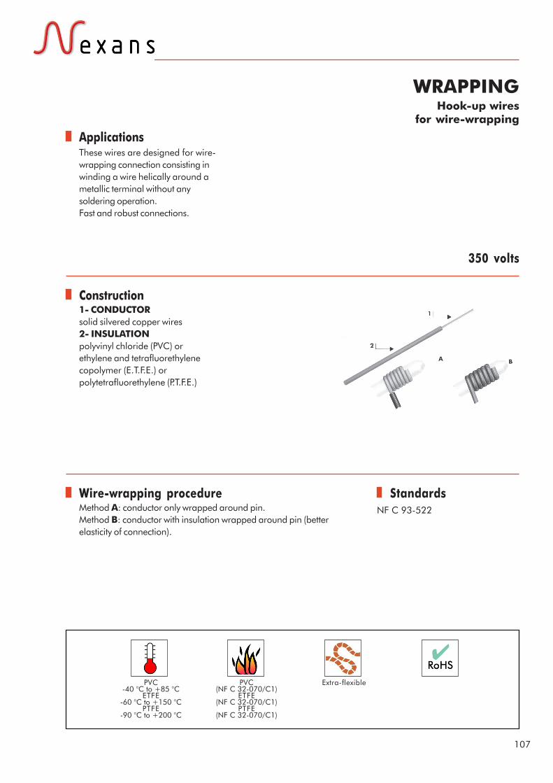
Applications
Construction
Standards
107
WRAPPINGHook-up wires
for wire-wrapping
These wires are designed for wire-wrapping connection consisting inwinding a wire helically around ametallic terminal without anysoldering operation.Fast and robust connections.
NF C 93-522
1- CONDUCTORsolid silvered copper wires2- INSULATIONpolyvinyl chloride (PVC) orethylene and tetrafluorethylenecopolymer (E.T.F.E.) orpolytetrafluorethylene (P.T.F.E.)
350 volts
Wire-wrapping procedureMethod A: conductor only wrapped around pin.Method B: conductor with insulation wrapped around pin (betterelasticity of connection).
Extra-flexiblePVC-40 °C to +85 °C
ETFE-60 °C to +150 °C
PTFE-90 °C to +200 °C
PVC(NF C 32-070/C1)
ETFE(NF C 32-070/C1)
PTFE(NF C 32-070/C1)

June
200
6 - C
opyr
ight
Nex
ans
108
Hook-up wires for wire-wrapping
For connections on automatic machines, we manufacture these wires with smaller dimensional tolerances.Please, consult us.
CONDUCTOR Overall
diameter mini. maxi.
Reference NFC 93 522
Nexans Reference Gauge
AWG
Cross section mm²
Construction n x Ø mm
Insulation nature
mm
Average weight Kg/km
KW 01-30C1 WCP 30 30 0.05 1 x 0.254 PVC 0.48 0.58 0.73 KW 01-28C1 WCP 28 28 0.08 1 x 0.32 PVC 0.57 0.67 1.05 KW 01-26C1 WCP 26 26 0.12 1 x 0.40 PVC 0.69 0.79 1.65 KW 01-24C1 WCP 24 24 0.20 1 x 0.51 PVC 1.00 1.10 2.80
KW 02-30B1 WCZ 30 30 0.05 1 x 0.254 ETFE 0.48 0.58 0.79 KW 02-28B1 WCZ 28 28 0.08 1 x 0.32 ETFE 0.57 0.67 1.12 KW 02-26B1 WCZ 26 26 0.12 1 x 0.40 ETFE 0.69 0.79 1.85 KW 02-24B1 WCZ 24 24 0.20 1 x 0.51 ETFE 1.00 1.10 2.90
KW 03-30A2 WCT 30 30 0.05 1 x 0.254 PTFE 0.48 0.58 0.88 KW 03-28A2 WCT 28 28 0.08 1 x 0.32 PTFE 0.57 0.67 1.25 KW 03-26A2 WCT 26 26 0.12 1 x 0.40 PTFE 0.69 0.79 1.90 KW 03-24A2 WCT 24 24 0.20 1 x 0.51 PTFE 1.00 1.10 3.30
109
Part 4Accessories

.

Applications
Construction
Standards
111
FITETinned copper flat braids
Applications: mainly for connectionsof mobile contacts, shunts andearthing of mobile equipment(doors, chassis, etc...).The very thin strands used tomanufacture these braids makethem extremely flexible and givethem an excellent flex life.
NEXANS specification
Braids made up of tinned copperwires.These braids are ribbon-likestructures (only one ribbon)up toFITE 10.They are flattened (crushedcylinder) for greater sizes.
Flat braids
Extra-flexible

June
200
6 - C
opyr
ight
Nex
ans
112
FITE - Tinned copper flat braids
Nexans Reference
Construction n x Ø mm
Cross section area mm²
Approximate dimensions
mm
Average weight Kg/km
Current rating
A
FITE 01 26 x 0.12 0.29 2.0 x 0.3 3 3 FITE 02 26 x 0.15 0.46 3.0 x 0.4 4 6 FITE 03 26 x 0.20 0.81 4.0 x 0.6 8 9 FITE 04 39 x 0.20 1.22 4.5 x 0.6 12 12 FITE 05 78 x 0.20 2.45 7.0 x 0.7 25 25 FITE 06 104 x 0.20 3.26 8.0 x 1.0 32 32 FITE 07 130 x 0.15 2.30 6.5 x 0.7 22 21 FITE 08 195 x 0.15 3.44 8.0 x 1.0 35 32 FITE 09 260 x 0.15 4.60 9.0 x 1.0 45 38 FITE 10 390 x 0.15 6.90 11.0 x 1.5 70 50 FITE 11 736 x 0.15 13.00 16.0 x 2.0 130 80 FITE 12 352 x 0.20 11.10 15.0 x 2.0 113 70 FITE 13 384 x 0.25 18.80 21.0 x 2.5 198 116 FITE 14 480 x 0.25 23.50 22.0 x 2.5 235 144 FITE 15 960 x 0.20 30.20 25.0 x 3.0 300 160 FITE 16 800 x 0.20 25.10 20.0 x 2.5 250 150

Applications
Construction
Standards
113
TUBULAR BRAIDSin tinned copper
without filler
Physical and electrical protection forcable bundles.The diameter of these braids mayvary thanks to their very highflexibility, thus facilitating the bundleintroduction.
NEXANS specification
Tubular braid made up of tinnedcopper wires.
Tubular braids
Extra-flexible

June
200
6 - C
opyr
ight
Nex
ans
114
Tubular braids in tinned copper without filler
Internal Ø nominal mm
Construction n x Ø mm
Cross section area mm²
Increases overall
diameter
Average weight Kg/km
4 112 x 0.20 3.5 0.8 35 6 144 x 0.20 4.5 0.8 45 8 192 x 0.20 6.0 0.8 60
10 192 x 0.25 9.4 1.0 94 12 224 x 0.25 11 1.0 110 15 256 x 0.25 12.6 1.0 135 19 320 x 0.25 15.7 1.0 165

Applications
Construction
Standards
115
TUBULAR BRAIDSin tinned copper
with filler
Physical and electrical protection forcable bundles.The central filler prevents anydeformation of the braid and iswithdrawn when introducing thebundles.
NEXANS specification
Tubular braid made up of tinnedcopper wires around a centralfiller.
Nota : The cover factor is about75 % (Kr = 0,75) or 80 %(Kr = 0,80) according toNF C 93521§ 1.7.5. Frenchspecification.
Tubular braids
Extra-flexible

June
200
6 - C
opyr
ight
Nex
ans
116
Tubular braids in tinned copper with filler
Nexans Reference
Internal Ø
mm
Overall Ø mm
Covering coefficient Kr
Average weight Kg/km
Nominal cross section
mm²
52104 4 4.5 0.75 14.0 1.37 55304/1 0.80 15.0 52 106 6 6.5 0.75 21.4 2.00 55 306/1 0.80 22.0 52108 8 8.5 0.75 28.2 2.60 55308/1 0.80 29.0 52110 10 10.5 0.75 35.1 3.40 55 310/1 0.80 36.0 52112 12 12.5 0.75 42.0 4.00 55312/1 0.80 44.0 52115 15 15.5 0.75 52.3 5.00 55 315/1 0.80 54.0 55955/1 18 18.5 0.80 79.0 7.20 52120 20 20.8 0.75 105.0 9.60 55320/1 0.80 108.0 59956/1 22 22.8 0.80 120.0 11.30 59957/1 25 26.0 0.80 182.0 17.60 59958/1 30 31.0 0.80 218.0 20.00

Applications
Construction
Standards
117
TUBULARSUPERPOLYAMIDE BRAIDS
Mechanical protection of cableswithout any faradization screen.Very high toughness.Very significant breaking load.Very good abrasion resistance.Lightweight in comparison withcorresponding copper braid or steelbraid.
NEXANS specification
Tubular braid made up ofsuperpolyamide strands.
Tubular braids
High temperature
+135 °C max Extra-flexible
June
200
6 - C
opyr
ight
Nex
ans
118
Tubular superpolyamide braids, high temperature
Internal Ø nominal
mm
Construction n x Ø mm
Increases overall diameter mm
Average weight Kg/km
3 32 x 0.29 1.2 4.7 4 72 x 0.29 1.2 6.7 6 96 x 0.29 1.2 9.0 8 128 x 0.29 1.2 13.0
10 160 x 0.29 1.2 18.0 12 192 x 0.29 1.2 21.0 15 200 x 0.29 1.2 25.0 18 240 x 0.29 1.2 28.0 20 288x 0.29 1.2 35.0 25 336 x 0.29 1.2 41.0 30 224 x 0.40 1.6 64.0 35 280 x 0.40 1.6 70 40 335 x 0.40 1.6 80.0

Applications
Construction
Standards
119
TUBESExtruded PTFE
These flexible tubes are used forinsulation and mechanicalprotection of cores.They are recommend for use athigh ambient temperatures up to300°C at peak.
NEXANS specification
Tube in extrudedpolytetrafluorethylene (P.T.F.E.)
Tubes
Very good resistance to fluids(oil, skydrol, petrol, isopropylalcohol, kerosene) and mostsolvents.Mould and Fungus Resistant.They are waterproof and fireretardant.
Ultra-flexible- 90°C to +250°C Fire retardant(NF C 32-070/C1)

June
200
6 - C
opyr
ight
Nex
ans
120
PTFE tubes
Internal Ø Gauge AWG minimum
(mm) nominal
(mm) maximum
(mm)
Radial thickness
(mm)
Tolerance +/-
(mm)
Nominal external Ø
(mm)
Average weight
(Kg/km)
30 0.25 0.30 0.38 0.23 0.05 0.76 0.9 28 0.33 0.38 0.48 0.23 0.05 0.84 1.0 26 0.41 0.46 0.56 0.23 0.05 0.91 1.1 24 0.51 0.56 0.69 0.25 0.08 1.07 1.5 22 0.64 0.77 0.81 0.25 0.08 1.28 1.7 21 0.74 0.81 0.91 0.25 0.08 1.32 1.9 20 0.81 0.86 1.01 0.31 0.08 1.47 2.5 19 0.91 0.97 1.11 0.31 0.08 1.58 2.7 18 1.02 1.07 1.24 0.31 0.08 1.68 2.9 17 1.14 1.19 1.37 0.31 0.08 1.80 3.1 16 1.30 1.35 1.55 0.31 0.08 1.96 3.5 15 1.45 1.50 1.70 0.31 0.08 2.11 3.8 14 1.63 1.68 1.88 0.31 0.08 2.29 4.2 13 1.83 1.93 2.08 0.31 0.08 2.54 4.8 12 2.06 2.16 2.31 0.31 0.08 2.77 5.2 11 2.31 2.41 2.56 0.31 0.08 3.02 5.7 10 2.59 2.70 2.84 0.31 0.08 3.31 6.4 9 2.90 3.00 3.15 0.38 0.08 3.76 8.9 8 3.28 3.38 3.58 0.38 0.08 4.14 9.7 7 3.66 3.76 4.01 0.38 0.08 4.52 11.0 6 4.11 4.21 4.52 0.38 0.08 4.97 12.1 5 4.62 4.72 5.03 0.38 0.08 5.48 13.4

121
Equivalence table of U.S. wire gaugesfor diameters and cross section areas
*Nominal diameter of solid bare copper wire
GAUGES
DIAMETERS*
CROSS SECTION AREAS
D.C. RESISTANCES AT 20°C
AWG
Mils mm
Circ. mils sq. mm (mm2)
Ohm / kFt Ohm / Km
44 2,0 0,050 4,00 0,0020 2590,0 8498,00 43 2,2 0,055 4,84 0,0025 2140,0 7021,00 42 2,5 0,063 6,25 0,0032 1660,0 5446,00 41 2,8 0,071 7,84 0,0039 1320,0 4330,00 40 3,1 0,079 9,61 0,0049 1080,0 3540,00 39 3,5 0,089 12,30 0,0062 847,0 2780,00 38 4,0 0,102 16,00 0,0081 648,0 2130,00 37 4,5 0,114 20,30 0,0103 512,0 1680,00 36 5,0 0,127 25,00 0,0127 415,0 1360,00 35 5,6 0,142 31,40 0,0159 331,0 1080,00 34 6,3 0,160 39,70 0,0201 261,0 587,00 33 7,1 0,180 50,40 0,0255 206,0 675,00 32 8,0 0,203 64,00 0,0324 162,0 532,00 31 8,9 0,226 79,20 0,0401 131,0 430,00 30 10,0 0,254 100,00 0,0507 104,0 340,00 29 11,3 0,287 128,00 0,0649 81,20 266,00 28 12,6 0,320 159,00 0,0806 65,30 214,00 27 14,2 0,361 202,00 0,1020 51,40 169,00 26 15,9 0,404 253,00 0,1280 41,00 135,00 25 17,9 0,455 320,00 0,1620 32,40 106,00 24 20,1 0,511 404,00 0,2050 25,70 84,20 23 22,6 0,574 511,00 0,2590 20,30 66,60 22 25,3 0,643 640,00 0,3240 16,20 53,20 21 28,5 0,724 812,00 0,4110 12,80 41,90 20 32,0 0,813 1.020 0,5190 10,10 33,20 19 35,9 0,912 1.290 0,6530 8,05 26,40 18 40,3 1,020 1.620 0,8230 6,39 21,00 17 45,3 1,150 2.050 1,0400 5,05 16,60 16 50,8 1,290 2.580 1,3100 4,02 13,20 15 57,1 1,450 3.260 1,6500 3,18 10,40 14 64,1 1,630 4.110 2,0800 2,52 8,28 13 72,0 1,830 5.180 2,6300 2,00 6,56 12 80,8 2,050 6.530 3,3100 1,59 5,21 11 90,7 2,300 8.230 4,1700 1,26 4,14 10 101,9 2,588 10.380 5,2600 0,9988 3,277 9 114,4 2,906 13.090 6,6300 0,7925 2,600 8 128,5 3,264 16.510 8,3700 0,6281 2,061 7 144,3 3,655 28.820 10,5500 0,4981 1,634 6 162,0 4,115 26.240 13,3000 0,3952 1,296 5 181,9 4,620 33.090 16,7700 0,3134 1,028 4 204,3 5,189 41.740 21,1500 0,2485 0,8152 3 229,4 5,827 52.620 26,6700 0,1971 0,6466 2 257,6 6,543 66.360 33,6200 0,1563 0,5128 1 289,3 7,348 83.690 42,4100 0,1239 0,4065
1/0 324,9 8,252 105.600 53,4900 0,09825 0,3223 2/0 364,8 9,266 133.100 67,4300 0,07793 0,2557 3/0 409,6 10,400 167.800 85,0100 0,06182 0,2028 4/0 460,0 11,680 211.600 107,2200 0,04901 0,1608

This catalogue shows a general description of products whose characteristics are not contractual in any waywhatsoever. Nexans reserves the right to change specifications without prior notice.Passing on or copying of the document, use or communicate of its content is not permitted without prior writtenauthorization.
June
200
6 - C
opyr
ight
Nex
ans
122

.

Global expert in cables and cabling systems
Nexans is the worldwide leader in the cable industry. TheGroup brings an extensive range of advanced copper andoptical fiber cable solutions to the infrastructure, industryand building markets. Nexans cables and cabling systemscan be found in every area of people's lives, fromtelecommunications and energy networks, to aeronautics,aerospace, automobile, railways, building, petrochemical,medical applications, etc. With an industrial presence in 29countries and commercial activities in 65 countries, Nexansemploys 20,000 people and had sales in 2005 of euros5.4 billion. Nexans is listed on the Paris stock exchange.
140, rue Eugène Delacroix - BP1 - 91211 Draveil Cedex FranceTel : + 33 (0)1 69 83 78 00 - Fax : +33 (0)1 69 42 05 70
[email protected] - www.nexans.com
Related Documents


