St. Johns River Power Park Demolition Project Document Title: Document No. Date Rev: St. Johns River Power Park Demolition Specification – Addendum #4 17 OCT 2017 0 1 | Page Addendum #4 1. REPLACE: Issuing new Attachment B – Includes Site Zone Demolition drawings Sheets 1-22 and civil drawings Sheets 1-18. Submittal includes .pdf and .dwg formats for all drawings. 2. REPLACE: Replace Section 15.0 in the Demolition Specification with the following: 15.0 GRADING AND GRASSING OF THE SJRPP SITE, CONVEYOR ALIGNMENT, AND COAL TERMINAL 15.1 SJRPP SITE 15.1.1 Final Grading Contractor is responsible for the final site grading as noted on the Site Grading Plan in Attachment B after demolition activities are completed. Contractor shall backfill all holes from foundation removal in accordance with Section 11 of this specification, and contour the surfaces of adjoining areas to match adjacent elevations. In general, the site will be graded, with appropriate compaction to allow for percolation to minimize runoff from the site, limit ponding of water and create a dust-free condition. Sediment controls should be implemented as shown on the grading plan. Stabilization practices must follow the requirements specified in the general permit and Contractor developed Construction SWPPP. For any area which crushed concrete is re-purposed as backfill material, the Contractor shall final grade the upper two feet using native material from the site or imported fill as defined in Section 11. Contractor shall remove BMPs from the site upon establishment of permanent surface cover (grassing or hardscape). 15.1.2 Grassing and Sodding Contractor shall provide all materials, water, equipment, transportation, tools, and labor, to establish grass plus all items called for or that can be reasonably inferred from the drawings, including seed and mulch, sodding, grading, fertilizing, watering, mowing, replacing and maintaining the area to complete the project. Bring all areas to be grassed to finished grades, remove rock debris and any other material protruding from the surface (to the best of equipment availability), and smooth grade the area. Apply seed and mulch or hydroseed as recommended by the supplier to all soil areas. Do not seed and/or mulch when wind is greater than 5 MPH. Provide supplemental water when the rainfall is not adequate to maintain soil moisture necessary for germination and growth of the grass. It is Contractor's responsibility to determine the quantities of water required and when to irrigate. Place sod on all slopes 3:1 or greater. Sod shall be Argentine Bahia with well matted roots. Seed shall be Argentine Bahia mixed with rye grass. Maintain all grassed areas for a period of 90 days after the date of substantial completion and guarantee against all defects and faults of material and workmanship. 15.1.3 Post-Demolition/Pre-Backfill Survey After structures are removed, concrete rubble backfill has been placed, and area is rough graded, Contractor shall conduct a pre-backfill survey using a Florida registered professional surveyor

Welcome message from author
This document is posted to help you gain knowledge. Please leave a comment to let me know what you think about it! Share it to your friends and learn new things together.
Transcript

St. Johns River Power Park Demolition Project
Document Title: Document No. Date Rev: St. Johns River Power Park Demolition Specification – Addendum #4 17 OCT 2017 0
1 | P a g e
Addendum #4 1. REPLACE: Issuing new Attachment B – Includes Site Zone Demolition drawings
Sheets 1-22 and civil drawings Sheets 1-18. Submittal includes .pdf and .dwg formats for all drawings.
2. REPLACE: Replace Section 15.0 in the Demolition Specification with the following: 15.0 GRADING AND GRASSING OF THE SJRPP SITE, CONVEYOR ALIGNMENT, AND COAL
TERMINAL
15.1 SJRPP SITE
15.1.1 Final Grading
Contractor is responsible for the final site grading as noted on the Site Grading Plan in Attachment B after demolition activities are completed.
Contractor shall backfill all holes from foundation removal in accordance with Section 11 of this specification, and contour the surfaces of adjoining areas to match adjacent elevations. In general, the site will be graded, with appropriate compaction to allow for percolation to minimize runoff from the site, limit ponding of water and create a dust-free condition. Sediment controls should be implemented as shown on the grading plan. Stabilization practices must follow the requirements specified in the general permit and Contractor developed Construction SWPPP.
For any area which crushed concrete is re-purposed as backfill material, the Contractor shall final grade the upper two feet using native material from the site or imported fill as defined in Section 11.
Contractor shall remove BMPs from the site upon establishment of permanent surface cover (grassing or hardscape).
15.1.2 Grassing and Sodding
Contractor shall provide all materials, water, equipment, transportation, tools, and labor, to establish grass plus all items called for or that can be reasonably inferred from the drawings, including seed and mulch, sodding, grading, fertilizing, watering, mowing, replacing and maintaining the area to complete the project. Bring all areas to be grassed to finished grades, remove rock debris and any other material protruding from the surface (to the best of equipment availability), and smooth grade the area.
Apply seed and mulch or hydroseed as recommended by the supplier to all soil areas. Do not seed and/or mulch when wind is greater than 5 MPH. Provide supplemental water when the rainfall is not adequate to maintain soil moisture necessary for germination and growth of the grass. It is Contractor's responsibility to determine the quantities of water required and when to irrigate.
Place sod on all slopes 3:1 or greater. Sod shall be Argentine Bahia with well matted roots.
Seed shall be Argentine Bahia mixed with rye grass.
Maintain all grassed areas for a period of 90 days after the date of substantial completion and guarantee against all defects and faults of material and workmanship.
15.1.3 Post-Demolition/Pre-Backfill Survey
After structures are removed, concrete rubble backfill has been placed, and area is rough graded, Contractor shall conduct a pre-backfill survey using a Florida registered professional surveyor

St. Johns River Power Park Demolition Project
Document Title: Document No. Date Rev: St. Johns River Power Park Demolition Specification – Addendum #4 17 OCT 2017 0
2 | P a g e
and mapper. This pre-backfill survey shall serve as the basis for the initial conditions for measurement and payment of backfill to be imported to the site.
15.1.4 Final Site Grading and Stormwater Configuration
Contractor shall complete the final site grading, including installation of drainage appurtenances, pipes, control structures, or other features as noted on the Grading Plan in the Contract Drawings. The final installation shall be surveyed by a registered Florida surveyor and mapper and certified by a registered Florida professional engineer in accordance with the permit requirements from the FDEP.
15.2 CONVEYOR ALIGNMENT AND COAL TERMINAL
15.2.1 Final Grading, Backfill, and Restoration
Contractor shall grade, backfill, and restore all conveyor and coal terminal excavations, laydown areas, and work areas to match the pre-existing grades and conditions. The backfill quantity shown in Attachment B is not inclusive of the backfill required for this section.
Contractor shall backfill all holes from foundation removal in accordance with Section 11 of this specification, and contour the surfaces of adjoining areas to match adjacent elevations. In general, the site will be graded, with appropriate compaction to allow for percolation to minimize runoff from the site, limit ponding of water and create a dust-free condition. Sediment controls and stabilization practices shall be implemented with the requirements specified in the general permit and Contractor developed Construction SWPPP.
Contractor shall remove BMPs from the site upon establishment of permanent surface cover (grassing or hardscape).
15.2.2 Grassing and Sodding
Contractor shall provide all materials, water, equipment, transportation, tools, and labor, to establish grass plus all items called for or that can be reasonably inferred from the drawings, including seed and mulch, sodding, grading, fertilizing, watering, mowing, replacing and maintaining the area to complete the project. Bring all areas to be grassed to finished grades, remove rock debris and any other material protruding from the surface (to the best of equipment availability), and smooth grade the area.
Apply seed and mulch or hydroseed as recommended by the supplier to all soil areas. Do not seed and/or mulch when wind is greater than 5 MPH. Provide supplemental water when the rainfall is not adequate to maintain soil moisture necessary for germination and growth of the grass. It is Contractor's responsibility to determine the quantities of water required and when to irrigate.
Place sod on all slopes 3:1 or greater. Sod shall be Argentine Bahia with well matted roots.
Seed shall be Argentine Bahia mixed with rye grass.
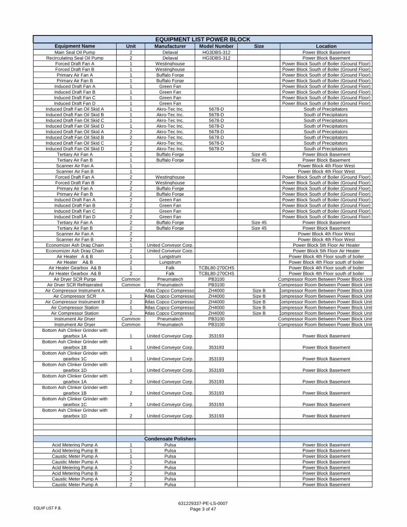
3. ADD: Document 631229337-PE-LS-0007-0 – SJRPP Equipment List is provided as a reference document. The file includes a current incomplete list of operating equipment, transformers and motors on the Site.
4. Clarification: In Attachment D of document 631229337-PE-SP-0001-0; areas which are presumed to have asbestos containing materials (ACM), including the boiler refractory and inner chimney bricks are excluded from the Contractors bid for asbestos removal.

St. Johns River Power Park Demolition Project
Document Title: Document No. Date Rev: St. Johns River Power Park Demolition Specification – Addendum #4 17 OCT 2017 0
3 | P a g e
5. ADD: Include drawing M-001625-01 – General Arrangement – Intake Structure to the reference drawings and include these two images as reference information:


St. Johns River Power Park Demolition Project
Document Title: Document No. Date Rev: St. Johns River Power Park Demolition Specification – Addendum #4 17 OCT 2017 0
4 | P a g e
6. REPLACE: Replace Section 8.2 in the Demolition Specification with the following: 8.2 Groundwater Recovery and Discharge
1. Recovered groundwater discharge to surface waters shall comply with the requirements of the CGP and the FDEP Rule 62-302 Surface Water Quality Standards.
2. Groundwater recovered on SJRPP during excavation activities shall be directed to the on-site wastewater treatment plant (WWTP) via an existing sedimentation pond that discharges to the WWTP or via temporary hoses or piping to the headworks of the on-site WWTP. Dewatering effluent to the WWTP shall not exceed 75 mg/l of Total Suspended Solids (TSS). The contractor shall demonstrate the water being sent to the WWTP influent meets this parameter. If at any time it is determined the turbidity exceeds this parameter the operation shall cease until corrective measures are implemented and the contractor demonstrates the turbidity meets the specification. The contractor may elect to use a field turbidity measurement based on Nephelometric Turbidity Units (NTUs). If NTU field measurements are to be used, the Contractor shall collect and analyze sufficient corresponding TSS laboratory samples to determine a maximum equivalent NTU value
3. Groundwater recovery and discharge during excavation activities in other areas of the project (off-site conveyor, coal terminal) shall be governed by the CGP conditions for temporary dewatering.
7. CLARIFICATION: SJRPP Equipment Cleaning Owner will wash-down and remove ash and coal fines from the equipment in a manner consistent with the conditions normally established at the beginning of a typical unit scheduled maintenance outage. This will include de-slagging the boilers, washing the boiler back passes and air heaters with water hoses, hosing down the plates and durotrodes in the precipitators and washing down the scrubber interiors with high pressure water hoses. Owner will hose down ash and gypsum equipment and storage vessel once after all material is removed from precipitators. Coal conveyors and transfer points will be washed down with water hoses.
All other cleaning or universal waste removal has been detailed in the Demolition Specification. . 8. ADD: Attachment D, item D7 SJRPP Survey Drawings. This includes document D-
13517 Sheet 1 & 2 – SJRPP Survey Drawings prepared by R.E. Holland provided as reference information. These drawings provide reference information including causeway partial cross-sections between the SJRPP site and Heckscher Drive.

Professional Surveyors & Mappers
R. E. Holland

Professional Surveyors & Mappers
R. E. Holland

EQUIP LIST P.B.631229337-PE-LS-0007
Page 1 of 47
Equipment Name Unit Manufacturer Model Number Size LocationMain Turbine 1 General Electric 270T Turbine Deck (3)Main Turbine 2 General Electric 270T Turbine Deck (3)
Generator 1 General Electric 280T Turbine Deck (3)Generator 2 General Electric 280T Turbine Deck (3)
A Coal Pulverizer 1 Foster Wheeler MBF-22.5 22.5 Power Block BasementB Coal Pulverizer 1 Foster Wheeler MBF-22.5 22.5 Power Block BasementC Coal Pulverizer 1 Foster Wheeler MBF-22.5 22.5 Power Block BasementD Coal Pulverizer 1 Foster Wheeler MBF-22.5 22.5 Power Block BasementE Coal Pulverizer 1 Foster Wheeler MBF-22.5 22.5 Power Block BasementF Coal Pulverizer 1 Foster Wheeler MBF-22.5 22.5 Power Block BasementG Coal Pulverizer 1 Foster Wheeler MBF-22.5 22.5 Power Block BasementA Coal Pulverizer 2 Foster Wheeler MBF-22.5 22.5 Power Block BasementB Coal Pulverizer 2 Foster Wheeler MBF-22.5 22.5 Power Block BasementC Coal Pulverizer 2 Foster Wheeler MBF-22.5 22.5 Power Block BasementD Coal Pulverizer 2 Foster Wheeler MBF-22.5 22.5 Power Block BasementE Coal Pulverizer 2 Foster Wheeler MBF-22.5 22.5 Power Block BasementF Coal Pulverizer 2 Foster Wheeler MBF-22.5 22.5 Power Block BasementG Coal Pulverizer 2 Foster Wheeler MBF-22.5 22.5 Power Block Basement
A Coal Pulverizer Gearbox 1 IHI (Japan) STU160H-11 138"L X78"BX55"H Power Block BasementB Coal Pulverizer Gearbox 1 IHI (Japan) STU160H-11 138"L X78"BX55"H Power Block BasementC Coal Pulverizer Gearbox 1 IHI (Japan) STU160H-11 138"L X78"BX55"H Power Block BasementD Coal Pulverizer Gearbox 1 IHI (Japan) STU160H-11 138"L X78"BX55"H Power Block BasementE Coal Pulverizer Gearbox 1 IHI (Japan) STU160H-11 138"L X78"BX55"H Power Block BasementF Coal Pulverizer Gearbox 1 IHI (Japan) STU160H-11 138"L X78"BX55"H Power Block BasementG Coal Pulverizer Gearbox 1 IHI (Japan) STU160H-11 138"L X78"BX55"H Power Block BasementA Coal Pulverizer Gearbox 2 IHI (Japan) STU160H-11 138"L X78"BX55"H Power Block BasementB Coal Pulverizer Gearbox 2 IHI (Japan) STU160H-11 138"L X78"BX55"H Power Block BasementC Coal Pulverizer Gearbox 2 IHI (Japan) STU160H-11 138"L X78"BX55"H Power Block BasementD Coal Pulverizer Gearbox 2 IHI (Japan) STU160H-11 138"L X78"BX55"H Power Block BasementE Coal Pulverizer Gearbox 2 IHI (Japan) STU160H-11 138"L X78"BX55"H Power Block BasementF Coal Pulverizer Gearbox 2 IHI (Japan) STU160H-11 138"L X78"BX55"H Power Block BasementG Coal Pulverizer Gearbox 2 IHI (Japan) STU160H-11 138"L X78"BX55"H Power Block Basement
Coal Pulverizer Gravimetric Feeder 1A 1 Stock 5916-1F Power Block Boiler Area 3rd Floor
Coal Pulverizer Gravimetric Feeder 1B 1 Stock 5916-1F Power Block Boiler Area 3rd Floor
Coal Pulverizer Gravimetric Feeder 1C 1 Stock 5916-1F Power Block Boiler Area 3rd Floor
Coal Pulverizer Gravimetric Feeder 1D 1 Stock 5916-1F Power Block Boiler Area 3rd Floor
Coal Pulverizer Gravimetric Feeder 1E 1 Stock 5916-1F Power Block Boiler Area 3rd Floor
Coal Pulverizer Gravimetric Feeder 1F 1 Stock 5916-1F Power Block Boiler Area 3rd Floor
Coal Pulverizer Gravimetric Feeder 1G 1 Stock 5916-1F Power Block Boiler Area 3rd Floor
Coal Pulverizer Gravimetric Feeder 1A 2 Stock 5916-1F Power Block Boiler Area 3rd Floor
Coal Pulverizer Gravimetric Feeder 1B 2 Stock 5916-1F Power Block Boiler Area 3rd Floor
Coal Pulverizer Gravimetric Feeder 1C 2 Stock 5916-1F Power Block Boiler Area 3rd Floor
Coal Pulverizer Gravimetric Feeder 1D 2 Stock 5916-1F Power Block Boiler Area 3rd Floor
Coal Pulverizer Gravimetric Feeder 1E 2 Stock 5916-1F Power Block Boiler Area 3rd Floor
Coal Pulverizer Gravimetric Feeder 1F 2 Stock 5916-1F Power Block Boiler Area 3rd Floor
Coal Pulverizer Gravimetric Feeder 1G 2 Stock 5916-1F Power Block Boiler Area 3rd FloorA Boiler Feed Pump 1 Pacific RMHBK-BFI 14" Turbine Deck (3)B Boiler Feed Pump 1 Pacific RMHBK-BFI 14" Turbine Deck (3)A Boiler Feed Pump 2 Pacific RMHBK-BFI 14" Turbine Deck (3)B Boiler Feed Pump 2 Pacific RMHBK-BFI 14" Turbine Deck (3)
A Boiler Feed Booster Pump 1 Pacific DSK 10" X 23" Turbine Deck (3)B Boiler Feed Booster Pump 1 Pacific DSK 10" X 23" Turbine Deck (3)A Boiler Feed Booster Pump 2 Pacific DSK 10" X 23" Turbine Deck (3)B Boiler Feed Booster Pump 2 Pacific DSK 10" X 23" Turbine Deck (3)Boiler Feed Pump Gearbox A 1 Foot Jones Dresser HLHS 1201 Turbine Deck (3)Boiler Feed Pump Gearbox B 1 Foot Jones Dresser HLHS 1201 Turbine Deck (3)Boiler Feed Pump Gearbox A 2 Foot Jones Dresser HLHS 1201 Turbine Deck (3)Boiler Feed Pump Gearbox B 2 Foot Jones Dresser HLHS 1201 Turbine Deck (3)Boiler Feed Pump Turbine A 1 General Electric Turbine Deck (3)Boiler Feed Pump Turbine B 1 General Electric Turbine Deck (3)Boiler Feed Pump Turbine A 2 General Electric Turbine Deck (3)Boiler Feed Pump Turbine B 2 General Electric Turbine Deck (3)
EQUIPMENT LIST POWER BLOCK

EQUIP LIST P.B.631229337-PE-LS-0007
Page 2 of 47
Equipment Name Unit Manufacturer Model Number Size LocationEQUIPMENT LIST POWER BLOCK
Boiler Feed Pump Turbine Lube Oil Pump 1AA 1 Carver WKLV50-4-DD 2 X 3 Turbine Deck (3)
Boiler Feed Pump Turbine Lube Oil Pump 1AB 1 Carver WKLV50-4-DD 2 X 3 Turbine Deck (3)
Boiler Feed Pump Turbine Lube Oil Pump 1BA 1 Carver WKLV50-4-DD 2 X 3 Turbine Deck (3)
Boiler Feed Pump Turbine Lube Oil Pump 1BB 1 Carver WKLV50-4-DD 2 X 3 Turbine Deck (3)
Boiler Feed Pump Turbine Lube Oil Pump 2AA 1 Carver WKLV50-4-DD 2 X 3 Turbine Deck (3)
Boiler Feed Pump Turbine Lube Oil Pump 2AB 1 Carver WKLV50-4-DD 2 X 3 Turbine Deck (3)
Boiler Feed Pump Turbine Lube Oil Pump 2BA 1 Carver WKLV50-4-DD 2 X 3 Turbine Deck (3)
Boiler Feed Pump Turbine Lube Oil Pump 2BB 1 Carver WKLV50-4-DD 2 X 3 Turbine Deck (3)
Heater Drain Pump 1 Pacific BC-9 10" X 20" Turbine Mezz (2)Heater Drain Pump 2 Pacific WYRDS 12" X 19" Turbine Mezz (2)
Condensate Pump A 1 Pacific WYRDS 12" X 19" Condensate Pit (Basement)Condensate Pump B 1 Pacific WYRDS 12" X 19" Condensate Pit (Basement)Condensate Pump C 1 Pacific WYRDS 12" X 19" Condensate Pit (Basement)Condensate Pump A 2 Pacific WYRDS 12" X 19" Condensate Pit (Basement)Condensate Pump B 2 Pacific WYRDS 12" X 19" Condensate Pit (Basement)Condensate Pump C 2 Pacific WYRDS 12" X 19" Condensate Pit (Basement)
Stator Cooling Water Pump A 1 Ingersoll Rand 3X10ATS 3" X 10" Power Block BasementStator Cooling Water Pump B 1 Ingersoll Rand 3X10ATS 3" X 10" Power Block BasementStator Cooling Water Pump A 2 Ingersoll Rand 3X10ATS 3" X 10" Power Block BasementStator Cooling Water Pump B 2 Ingersoll Rand 3X10ATS 3" X 10" Power Block Basement
Circulating Water Pump A 1 Ingersoll Rand 47APM 47" Power Block BasementCirculating Water Pump B 1 Ingersoll Rand 47APM 47" Power Block BasementCirculating Water Pump A 2 Ingersoll Rand 47APM 47" Power Block BasementCirculating Water Pump B 2 Ingersoll Rand 47APM 47" Power Block Basement
Cooling Tower Make-up Pump Common Ingersoll Rand APHJ 29" Water front at NGSCooling Tower Make-up Pump Common Ingersoll Rand APHJ 29" Water front at NGSCooling Tower Make-up Pump Common Ingersoll Rand APHJ 29" Water front at NGS
Cooling Tower Blowdown A 1 Ingersoll Rand APS 18" West of U#1 Cooling TowerCooling Tower Blowdown B 1 Ingersoll Rand APS 18" West of U#1 Cooling TowerCooling Tower Blowdown A 2 Ingersoll Rand APS 18" West of U#2 Cooling TowerCooling Tower Blowdown B 2 Ingersoll Rand APS 18" West of U#2 Cooling TowerPulverizer Seal Air Fan A 1 Robinson RB1212 32 1/2 X 2 1/8 Power Block BasementPulverizer Seal Air Fan B 1 Robinson RB1212 32 1/2 X 2 1/8 Power Block BasementPulverizer Seal Air Fan C 1 Robinson RB1212 32 1/2 X 2 1/8 Power Block BasementPulverizer Seal Air Fan A 2 Robinson RB1212 32 1/2 X 2 1/8 Power Block BasementPulverizer Seal Air Fan B 2 Robinson RB1212 32 1/2 X 2 1/8 Power Block BasementPulverizer Seal Air Fan C 2 Robinson RB1212 32 1/2 X 2 1/8 Power Block Basement
Bottom Ash Slurry Pump A 1 Warman EM 84 10 X 8 Power Block BasementBottom Ash Slurry Pump B 1 Warman EM 84 10 X 8 Power Block BasementBottom Ash Slurry Pump A 2 Warman EM 84 10 X 8 Power Block BasementBottom Ash Slurry Pump B 2 Warman EM 84 10 X 8 Power Block Basement
EHC Pump A 1 Rex Roth WF 1 Power Block BasementEHC Pump B 1 Rex Roth WF 1 Power Block BasementEHC Pump A 2 Rex Roth WF 1 Power Block BasementEHC Pump B 2 Rex Roth WF 1 Power Block BasementCCW Pump A 1 Goulds Power Block BasementCCW Pump B 1 Goulds Power Block BasementCCW Pump A 2 Goulds Power Block BasementCCW Pump B 2 Goulds Power Block Basement
Circulating Water Booster Pump A 1 Morris Power Block BasementCirculating Water Booster Pump B 1 Morris Power Block BasementCirculating Water Booster Pump A 2 Morris Power Block BasementCirculating Water Booster Pump B 2 Morris Power Block Basement
Vacuum Pump A 1 Graham EXP 69944 Power Block MezzVacuum Pump B 1 Graham EXP 69944 Power Block MezzVacuum Pump C 1 Graham EXP 69944 Power Block MezzVacuum Pump A 2 Nash Power Block MezzVacuum Pump B 2 Nash Power Block MezzVacuum Pump C 2 Graham EXP 69944 Power Block Mezz
Motor suction Oil Pump 1 Buffalo Forge VCRE 9014.5 Power Block MezzTurning Gear Oil Pump 1 Buffalo Forge VCRE 8013 Power Block Mezz
Emergency bearing Oil Pump 1 Buffalo Forge BCEE 6018 Power Block MezzEmergency Seal Oil Pump 1 Delaval EG3DBS-250 Power Block Basement
Main Seal Oil Pump 1 Delaval HG3DBS-312 Power Block BasementRecirculating Seal Oil Pump 1 Delaval HG3DBS-312 Power Block Basement
Motor suction Oil Pump 2 Buffalo Forge VCRE 9014.5 Power Block MezzTurning Gear Oil Pump 2 Buffalo Forge VCRE 8013 Power Block Mezz
Emergency bearing Oil Pump 2 Buffalo Forge BCEE 6018 Power Block MezzEmergency Seal Oil Pump 2 Delaval EG3DBS-250 Power Block Basement
EQUIP LIST P.B.631229337-PE-LS-0007
Page 3 of 47
Equipment Name Unit Manufacturer Model Number Size LocationEQUIPMENT LIST POWER BLOCK
Main Seal Oil Pump 2 Delaval HG3DBS-312 Power Block BasementRecirculating Seal Oil Pump 2 Delaval HG3DBS-312 Power Block Basement
Forced Draft Fan A 1 Westinghouse Power Block South of Boiler (Ground Floor)Forced Draft Fan B 1 Westinghouse Power Block South of Boiler (Ground Floor)Primary Air Fan A 1 Buffalo Forge Power Block South of Boiler (Ground Floor)Primary Air Fan B 1 Buffalo Forge Power Block South of Boiler (Ground Floor)
Induced Draft Fan A 1 Green Fan Power Block South of Boiler (Ground Floor)Induced Draft Fan B 1 Green Fan Power Block South of Boiler (Ground Floor)Induced Draft Fan C 1 Green Fan Power Block South of Boiler (Ground Floor)Induced Draft Fan D 1 Green Fan Power Block South of Boiler (Ground Floor)
Induced Draft Fan Oil Skid A 1 Akro-Tec Inc. 5678-D South of Precipitators Induced Draft Fan Oil Skid B 1 Akro-Tec Inc. 5678-D South of Precipitators Induced Draft Fan Oil Skid C 1 Akro-Tec Inc. 5678-D South of Precipitators Induced Draft Fan Oil Skid D 1 Akro-Tec Inc. 5678-D South of Precipitators Induced Draft Fan Oil Skid A 2 Akro-Tec Inc. 5678-D South of Precipitators Induced Draft Fan Oil Skid B 2 Akro-Tec Inc. 5678-D South of Precipitators Induced Draft Fan Oil Skid C 2 Akro-Tec Inc. 5678-D South of Precipitators Induced Draft Fan Oil Skid D 2 Akro-Tec Inc. 5678-D South of Precipitators
Tertiary Air Fan A 1 Buffalo Forge Size 45 Power Block BasementTertiary Air Fan B 1 Buffalo Forge Size 45 Power Block BasementScanner Air Fan A 1 Power Block 4th Floor WestScanner Air Fan B 1 Power Block 4th Floor WestForced Draft Fan A 2 Westinghouse Power Block South of Boiler (Ground Floor)Forced Draft Fan B 2 Westinghouse Power Block South of Boiler (Ground Floor)Primary Air Fan A 2 Buffalo Forge Power Block South of Boiler (Ground Floor)Primary Air Fan B 2 Buffalo Forge Power Block South of Boiler (Ground Floor)
Induced Draft Fan A 2 Green Fan Power Block South of Boiler (Ground Floor)Induced Draft Fan B 2 Green Fan Power Block South of Boiler (Ground Floor)Induced Draft Fan C 2 Green Fan Power Block South of Boiler (Ground Floor)Induced Draft Fan D 2 Green Fan Power Block South of Boiler (Ground Floor)
Tertiary Air Fan A 2 Buffalo Forge Size 45 Power Block BasementTertiary Air Fan B 2 Buffalo Forge Size 45 Power Block BasementScanner Air Fan A 2 Power Block 4th Floor WestScanner Air Fan B 2 Power Block 4th Floor West
Economizer Ash Drag Chain 1 United Conveyor Corp. Power Block 5th Floor Air HeaterEconomizer Ash Drag Chain 2 United Conveyor Corp. Power Block 5th Floor Air Heater
Air Heater A & B 1 Lungstrum Power Block 4th Floor south of boilerAir Heater A& B 2 Lungstrum Power Block 4th Floor south of boiler
Air Heater Gearbox A& B 1 Falk TCBL80-270CHS Power Block 4th Floor south of boilerAir Heater Gearbox A& B 2 Falk TCBL80-270CHS Power Block 4th Floor south of boiler
Air Dryer SCR Purge Common Pneumatech PB3100 Compressor Room Between Power Block UnitsAir Dryer SCR Refrigerated Common Pneumatech PB3100 Compressor Room Between Power Block Units
Air Compressor Instrument A Atlas Copco Compressor ZH4000 Size B Compressor Room Between Power Block UnitsAir Compressor SCR 1 Atlas Copco Compressor ZH4000 Size B Compressor Room Between Power Block Units
Air Compressor Instrument B 2 Atlas Copco Compressor ZH4000 Size B Compressor Room Between Power Block UnitsAir Compressor Station 1 Atlas Copco Compressor ZH4000 Size B Compressor Room Between Power Block UnitsAir Compressor Station 2 Atlas Copco Compressor ZH4000 Size B Compressor Room Between Power Block Units
Instrument Air Dryer Common Pneumatech PB3100 Compressor Room Between Power Block UnitsInstrument Air Dryer Common Pneumatech PB3100 Compressor Room Between Power Block Units
Bottom Ash Clinker Grinder with gearbox 1A 1 United Conveyor Corp. 353193 Power Block Basement
Bottom Ash Clinker Grinder with gearbox 1B 1 United Conveyor Corp. 353193 Power Block Basement
Bottom Ash Clinker Grinder with gearbox 1C 1 United Conveyor Corp. 353193 Power Block Basement
Bottom Ash Clinker Grinder with gearbox 1D 1 United Conveyor Corp. 353193 Power Block Basement
Bottom Ash Clinker Grinder with gearbox 1A 2 United Conveyor Corp. 353193 Power Block Basement
Bottom Ash Clinker Grinder with gearbox 1B 2 United Conveyor Corp. 353193 Power Block Basement
Bottom Ash Clinker Grinder with gearbox 1C 2 United Conveyor Corp. 353193 Power Block Basement
Bottom Ash Clinker Grinder with gearbox 1D 2 United Conveyor Corp. 353193 Power Block Basement
Condensate PolishersAcid Metering Pump A 1 Pulsa Power Block BasementAcid Metering Pump B 1 Pulsa Power Block BasementCaustic Meter Pump A 1 Pulsa Power Block BasementCaustic Meter Pump A 1 Pulsa Power Block BasementAcid Metering Pump A 2 Pulsa Power Block BasementAcid Metering Pump B 2 Pulsa Power Block BasementCaustic Meter Pump A 2 Pulsa Power Block BasementCaustic Meter Pump A 2 Pulsa Power Block Basement

EQUIP LIST P.B.631229337-PE-LS-0007
Page 4 of 47
Equipment Name Unit Manufacturer Model Number Size LocationEQUIPMENT LIST POWER BLOCK
Acid Transfer Pump A Common 20gpm Outside, Unit 2 Polisher Area Acid Transfer Pump B Common 20gpm Outside, Unit 2 Polisher Area
Caustic Transfer Pump A Common 20gpm Outside, Unit 2 Polisher Area Caustic Transfer Pump B Common 20gpm Outside, Unit 2 Polisher Area
Rinse Recycle Pump 1 Goulds 1100gpm Power Block BasementRinse Recycle Pump 2 Goulds 1100gpm Power Block Basement
Sulfuric Acid Storage Tank Common 6000gal Outside, Unit 2 Polisher Area Sodium Hydroxide Storage Tank Common 10000gal Outside, Unit 2 Polisher Area Condensate Polisher Vessel A 1 8' x 6' 6" (2400gal) Power Block BasementCondensate Polisher Vessel B 1 8' x 6' 6" (2400gal) Power Block BasementCondensate Polisher Vessel C 1 8' x 6' 6" (2400gal) Power Block BasementCondensate Polisher Vessel D 1 8' x 6' 6" (2400gal) Power Block BasementCondensate Polisher Vessel A 2 8' x 6' 6" (2400gal) Power Block BasementCondensate Polisher Vessel B 2 8' x 6' 6" (2400gal) Power Block BasementCondensate Polisher Vessel C 2 8' x 6' 6" (2400gal) Power Block BasementCondensate Polisher Vessel D 2 8' x 6' 6" (2400gal) Power Block Basement
Separation Tank 1 4' 6" x 27' 2" Power Block BasementSeparation Tank 2 4' 6" x 27' 2" Power Block Basement
Cation Regeneration Tank 1 4' 6" x 10' Power Block BasementCation Regeneration Tank 2 4' 6" x 10' Power Block BasementAnion Regeneration Tank 1 4' 6" x 15' Power Block BasementAnion Regeneration Tank 2 4' 6" x 15' Power Block Basement
Resin Storage Tank 1 6' 6" x 9' 6" Power Block BasementResin Storage Tank 2 6' 6" x 9' 6" Power Block BasementResin Interface Tank 1 3' x 8' Power Block BasementResin Interface Tank 2 3' x 8' Power Block BasementResin Retention Tank 1 48"x72"x108" Power Block BasementResin Retention Tank 2 48"x72"x108" Power Block Basement
Acid Day Tank 1 2' 6" x 5' Power Block BasementAcid Day Tank 2 2' 6" x 5' Power Block Basement
Caustic Day Tank 1 3' x 5' Power Block BasementCaustic Day Tank 2 3' x 5' Power Block BasementHot Water Tank 1 8' x 8' Power Block BasementHot Water Tank 2 8' x 8' Power Block Basement
Sodium Analyzers (4) 1 Orion 2111xp Power Block Basement Sodium Analyzers (4) 2 Orion 2111xp Power Block Basement
Conductivity/Resistivity Meters (13) 1 Yokogawa Power Block BasementConductivity/Resistivity Meters (13) 2 Yokogawa Power Block Basement
A-3 Regeneration Waste Sump Pump A Common Power Block Basement (unit 1 polisher side)
A-3 Regeneration Waste Sump Pump B Common Power Block Basement (unit 1 polisher side)
A-8 Regeneration Waste Sump Pump A 2 Outside, Unit 2 Polisher Area
A-8 Regeneration Waste Sump Pump B 2 Outside, Unit 2 Polisher Area A-9 Acid Storage Containment Sump
Pump Common Sandpiper Outside, Unit 2 Polisher Area A-10 Caustic Storage Containment
Sump Pump Common Sandpiper Outside, Unit 2 Polisher Area

Equipment List SCR631229337-PE-LS-0007
Page 5 of 47
Equipment Name Unit Manufacturer Model Number Size LocationSCR Ash Drag Chain AA 1 United Conveyer CorpSCR Ash Drag Chain AB 1 United Conveyer CorpSCR Ash Drag Chain BA 1 United Conveyer CorpSCR Ash Drag Chain BB 1 United Conveyer CorpSCR Ash Drag Chain AA 2 United Conveyer CorpSCR Ash Drag Chain AB 2 United Conveyer CorpSCR Ash Drag Chain BA 2 United Conveyer CorpSCR Ash Drag Chain BB 2 United Conveyer Corp
SCR Ash Drag Chain Gear Reducer 1 Nord Gear Corp 73/22 VL 180TC2-182SCR Ash Drag Chain Gear Reducer 1 Nord Gear Corp 73/22 VL 180TC2-182SCR Ash Drag Chain Gear Reducer 1 Nord Gear Corp 73/22 VL 180TC2-182SCR Ash Drag Chain Gear Reducer 2 Nord Gear Corp 73/22 VL 180TC2-182SCR Ash Drag Chain Gear Reducer 2 Nord Gear Corp 73/22 VL 180TC2-182SCR Ash Drag Chain Gear Reducer 2 Nord Gear Corp 73/22 VL 180TC2-182
Seal Air Fan A 1 Twin City Fan & Blower BCN-SWSeal Air Fan B 1 Twin City Fan & Blower BCN-SWSeal Air Fan C 1 Twin City Fan & Blower BCN-SWSeal Air Fan A 2 Twin City Fan & Blower BCN-SWSeal Air Fan B 2 Twin City Fan & Blower BCN-SWSeal Air Fan C 2 Twin City Fan & Blower BCN-SW
Nox Sample Fan 1Nox Sample Fan 1Nox Sample Fan 2Nox Sample Fan 2
Dilution Air Fan A 1 Chcago Blower Corp M 4Dilution Air Fan B 1 Chcago Blower Corp M 4Dilution Air Fan C 1 Chcago Blower Corp M 4Dilution Air Fan A 2 Chcago Blower Corp M 4Dilution Air Fan B 2 Chcago Blower Corp M 4Dilution Air Fan C 2 Chcago Blower Corp M 4
EQUIPMENT LIST SCR

EQUIP LIST AQCS631229337-PE-LS-0007
Page 6 of 47
Equipment Name Unit Manufacturer Model Number Size LocationA1 Absorber Feed Pump 1 ASH GH-9-5 21X20X41 AQCS AlleyA2 Absorber Feed Pump 1 ASH GH-9-5 21X20X41 AQCS AlleyA3 Absorber Feed Pump 1 ASH GH-9-5 21X20X41 AQCS AlleyA4 Absorber Feed Pump 1 ASH GH-9-5 21X20X41 AQCS AlleyB1 Absorber Feed Pump 1 ASH GH-9-5 21X20X41 AQCS AlleyB2 Absorber Feed Pump 1 ASH GH-9-5 21X20X41 AQCS AlleyB3 Absorber Feed Pump 1 ASH GH-9-5 21X20X41 AQCS AlleyB4 Absorber Feed Pump 1 ASH GH-9-5 21X20X41 AQCS AlleyC1 Absorber Feed Pump 1 ASH GH-9-5 21X20X41 AQCS AlleyC2 Absorber Feed Pump 1 ASH GH-9-5 21X20X41 AQCS AlleyC3 Absorber Feed Pump 1 ASH GH-9-5 21X20X41 AQCS AlleyC4 Absorber Feed Pump 1 ASH GH-9-5 21X20X41 AQCS AlleyA1 Absorber Feed Pump 2 ASH GH-9-5 21X20X41 AQCS AlleyA2 Absorber Feed Pump 2 ASH GH-9-5 21X20X41 AQCS AlleyA3 Absorber Feed Pump 2 ASH GH-9-5 21X20X41 AQCS AlleyA4 Absorber Feed Pump 2 ASH GH-9-5 21X20X41 AQCS AlleyB1 Absorber Feed Pump 2 ASH GH-9-5 21X20X41 AQCS AlleyB2 Absorber Feed Pump 2 ASH GH-9-5 21X20X41 AQCS AlleyB3 Absorber Feed Pump 2 ASH GH-9-5 21X20X41 AQCS AlleyB4 Absorber Feed Pump 2 ASH GH-9-5 21X20X41 AQCS AlleyC1 Absorber Feed Pump 2 ASH GH-9-5 21X20X41 AQCS AlleyC2 Absorber Feed Pump 2 ASH GH-9-5 21X20X41 AQCS AlleyC3 Absorber Feed Pump 2 ASH GH-9-5 21X20X41 AQCS AlleyC4 Absorber Feed Pump 2 ASH GH-9-5 21X20X41 AQCS Alley
1A1 Quencher Spray Pump 1 ASH GH-9-5 21X20X41 AQCS Alley1A2 Quencher Spray Pump 1 ASH GH-9-5 21X20X41 AQCS Alley1B1 Quencher Spray Pump 1 ASH GH-9-5 21X20X41 AQCS Alley1B2 Quencher Spray Pump 1 ASH GH-9-5 21X20X41 AQCS Alley1C1 Quencher Spray Pump 1 ASH GH-9-5 21X20X41 AQCS Alley1C2 Quencher Spray Pump 1 ASH GH-9-5 21X20X41 AQCS Alley2A1 Quencher Spray Pump 2 ASH GH-9-5 21X20X41 AQCS Alley2A2 Quencher Spray Pump 2 ASH GH-9-5 21X20X41 AQCS Alley2B1 Quencher Spray Pump 2 ASH GH-9-5 21X20X41 AQCS Alley2B2 Quencher Spray Pump 2 ASH GH-9-5 21X20X41 AQCS Alley2C1 Quencher Spray Pump 2 ASH GH-9-5 21X20X41 AQCS Alley2C2 Quencher Spray Pump 2 ASH GH-9-5 21X20X41 AQCS Alley1A1 Hydroclone Feed Pump 1 ASH C-6-6 10X8X21 AQCS Tower1A2 Hydroclone Feed Pump 1 ASH C-6-6 10X8X21 AQCS Tower1B1 Hydroclone Feed Pump 1 ASH C-6-6 10X8X21 AQCS Tower1B2 Hydroclone Feed Pump 1 ASH C-6-6 10X8X21 AQCS Tower1C1 Hydroclone Feed Pump 1 ASH C-6-6 10X8X21 AQCS Tower1C2 Hydroclone Feed Pump 1 ASH C-6-6 10X8X21 AQCS Tower2A1 Hydroclone Feed Pump 2 ASH C-6-6 10X8X21 AQCS Tower2A2 Hydroclone Feed Pump 2 ASH C-6-6 10X8X21 AQCS Tower2B1 Hydroclone Feed Pump 2 ASH C-6-6 10X8X21 AQCS Tower2B2 Hydroclone Feed Pump 2 ASH C-6-6 10X8X21 AQCS Tower2C1 Hydroclone Feed Pump 2 ASH C-6-6 10X8X21 AQCS Tower2C2 Hydroclone Feed Pump 2 ASH C-6-6 10X8X21 AQCS Tower
1A1 Waste Tranfer Pump 1 ASH B-6-6 6X6X17 AQCS Tower1A2 Waste Tranfer Pump 1 ASH B-6-6 6X6X17 AQCS Tower1B1 Waste Tranfer Pump 1 ASH B-6-6 6X6X17 AQCS Tower1B2 Waste Tranfer Pump 1 ASH B-6-6 6X6X17 AQCS Tower1C1 Waste Tranfer Pump 1 ASH B-6-6 6X6X17 AQCS Tower1C2 Waste Tranfer Pump 1 ASH B-6-6 6X6X17 AQCS Tower2A1 Waste Tranfer Pump 2 ASH B-6-6 6X6X17 AQCS Tower2A2 Waste Tranfer Pump 2 ASH B-6-6 6X6X17 AQCS Tower2B1 Waste Tranfer Pump 2 ASH B-6-6 6X6X17 AQCS Tower2B2 Waste Tranfer Pump 2 ASH B-6-6 6X6X17 AQCS Tower2C1 Waste Tranfer Pump 2 ASH B-6-6 6X6X17 AQCS Tower2C2 Waste Tranfer Pump 2 ASH B-6-6 6X6X17 AQCS Tower
1A Waste Tranfer Tank Agitator 1 Lightin 71Q1.5 20.8 to 1 AQCS Tower1B Waste Tranfer Tank Agitator 1 Lightin 71Q1.5 20.8 to 1 AQCS Tower1C Waste Tranfer Tank Agitator 1 Lightin 71Q1.5 20.8 to 1 AQCS Tower2A Waste Tranfer Tank Agitato 2 Lightin 71Q1.5 20.8 to 1 AQCS Tower2B Waste Tranfer Tank Agitator 2 Lightin 71Q1.5 20.8 to 1 AQCS Tower2C Waste Tranfer Tank Agitator 2 Lightin 71Q1.5 20.8 to 1 AQCS Tower
A Waste Slurry Tank Agitator 1 Lightin 782Q30 780 AQCS B Waste Slurry Tank Agitator 1 Lightin 782Q30 780 AQCS
EQUIPMENT LIST AQCS

EQUIP LIST AQCS631229337-PE-LS-0007
Page 7 of 47
Equipment Name Unit Manufacturer Model Number Size LocationEQUIPMENT LIST AQCS
A Waste Slurry Tank Agitator 2 Lightin 782Q30 780 AQCS B Waste Slurry Tank Agitator 2 Lightin 782Q30 780 AQCS
A Dewatering Feed Pump 1 ASH B-6-6 6X6X17 AQCS B Dewatering Feed pump 1 ASH B-6-6 6X6X17 AQCS A Dewatering Feed Pump 2 ASH B-6-6 6X6X17 AQCS B Dewatering Feed pump 2 ASH B-6-6 6X6X17 AQCS A FGD Area Sump Pump 1 Townly MSPP8-A/75 8" AQCS B FGD Area Sump Pump 1 Townly MSPP8-A/75 8" AQCS A FGD Area Sump Pump 2 Townly MSPP8-A/75 8" AQCS B FGD Area Sump Pump 2 Townly MSPP8-A/75 8" AQCS
A Slurry Reclaim Sump Pump 1 Townly MSPP6-A/50 6" AQCS B Slurry Reclaim Sump Pump 1 Townly MSPP6-A/50 6" AQCS A Slurry Reclaim Sump Pump 2 Townly MSPP6-A/50 6" AQCS B Slurry Reclaim Sump Pump 2 Townly MSPP6-A/50 6" AQCS
1A Seal Air Fan (Inlet ) 1 PHELPS FAN=Y W-226/43=Y 1-15/16" AQCS Tower1B Seal Air Fan (Inlet ) 1 PHELPS FAN=Y W-226/43=Y 1-15/16" AQCS Tower1C Seal Air Fan (Inlet ) 1 PHELPS FAN=Y W-226/43=Y 1-15/16" AQCS Tower
1A Seal Air Fan (Outlet ) 1 CINCINNATI FAN=Y HDBI-160=Y 1-15/16" AQCS Tower1B Seal Air Fan (Outlet ) 1 CINCINNATI FAN=Y HDBI-160=Y 1-15/16" AQCS Tower1C Seal Air Fan (Outlet ) 1 CINCINNATI FAN=Y HDBI-160=Y 1-15/16" AQCS Tower2A Seal Air Fan (Inlet ) 2 PHELPS FAN=Y W-226/43=Y 1-15/16" AQCS Tower2B Seal Air Fan (Inlet ) 2 PHELPS FAN=Y W-226/43=Y 1-15/16" AQCS Tower2C Seal Air Fan (Inlet ) 2 PHELPS FAN=Y W-226/43=Y 1-15/16" AQCS Tower2A Seal Air Fan (Outlet) 2 CINCINNATI FAN=Y HDBI-160=Y 1-15/16" AQCS Tower2B Seal Air Fan (Outlet) 2 CINCINNATI FAN=Y HDBI-160=Y 1-15/16" AQCS Tower2C Seal Air Fan (Outlet ) 2 CINCINNATI FAN=Y HDBI-160=Y 1-15/16" AQCS Tower
1A Absorber Feed Tank Agitator 1 Lightin 782Q125 782 AQCS ,AFT Tank1B Absorber Feed Tank Agitator 1 Lightin 782Q125 782 AQCS ,AFT Tank1C Absorber Feed Tank Agitator 1 Lightin 782Q125 782 AQCS ,AFT Tank2A Absorber Feed Tank Agitator 2 Lightin 782Q125 782 AQCS ,AFT Tank2B Absorber Feed Tank Agitator 2 Lightin 782Q125 782 AQCS ,AFT Tank2C Absorber Feed Tank Agitator 2 Lightin 782Q125 782 AQCS ,AFT Tank1A Deluges Well Water Pump 1 Dresser D-1011 10x8X15 AQCS Alley1B Deluges Well Water Pump 1 Dresser D-1011 10x8x15 AQCS Alley1C Deluges Well Water Pump 1 Dresser D-1011 10x8x15 AQCS Alley2A Deluges Well Water Pump 2 Dresser D-1011 10x8x15 AQCS Alley2B Deluges Well Water Pump 2 Dresser D-1011 10x8x15 AQCS Alley2C Deluges Well Water Pump 2 Dresser D-1011 10x8x15 AQCS Alley1A Oxidation Air Compressor 1 Allis-Chalmers Singel Stage D20JSR AQCS Alley1B Oxidation Air Compressor 1 Allis-Chalmers Singel Stage D20JSR AQCS Alley9C Oxidation Air Compressor Common Allis-Chalmers Singel Stage D20JSR AQCS Alley2AOxidation Air Compressor 2 Allis-Chalmers Singel Stage D20JSR AQCS Alley2B Oxidation Air Compressor 2 Allis-Chalmers Singel Stage D20JSR AQCS Alley
Air Dryer 1 Kemp 300ps-4x AQCS Air Dryer 2 Kemp 300ps-4x AQCS
Slurry Reclaim Pump 1 ASH B-6-6 5x4x17 AQCS Slurry Reclaim Pump 2 ASH B-6-6 5x4x17 AQCS
slurry Reclaim Tank Agitator Common Lightnin 73Q5 782 AQCS Unit 1 Stack Fan 1Unit 2 stack Fan 2
1K Fluidizing Blower 1 Gardner-Denver 3CDL8F Precips1L Fluidizing Blower 1 Gardner-Denver 3CDL8F Precips2K Fluidizing Blower 2 Gardner-Denver 3CDL8F Precips2L Fluidizing Blower 2 Gardner-Denver 3CDL8F Precips
1A Conveying Blower 1 Roots Whispair RCS-JV 8x21 Precips1B Conveying Blower 1 Roots Whispair RCS-JV 8x21 Precips1C Conveying Blower 1 Roots Whispair RCS-JV 8x21 Precips2A Conveying Blower 2 Roots Whispair RCS-JV 8x21 Precips2B Conveying Blower 2 Roots Whispair RCS-JV 8x21 Precips2C Conveying Blower 2 Roots Whispair RCS-JV 8x21 Precips
Unit 1A P-10 Sump Pump 1 Gorman-Rupp 3 PrecipsUnit 1B P-10 Sump Pump 1 Gorman-Rupp 3 PrecipsUnit 2A P-11 Sump Pump 2 Eliminator Submersible 3 PrecipsUnit 2B P-11 Sump Pump 2 Eliminator Submersible 3 Precips
Unit 1A Precips Seal Air Fan 1 PrecipsUnit 1B Precips Seal Air Fan 1 Precips
Precips

EQUIP LIST AQCS631229337-PE-LS-0007
Page 8 of 47
Equipment Name Unit Manufacturer Model Number Size LocationEQUIPMENT LIST AQCS
Unit 2A Precips Seal Air Fan 2 PrecipsUnit 2B Precips Seal Air Fan 2 Precips
Ball Mill Gear Reducer 1 Falk 2130Y1-LS 55gal AQCS Ball MillBall Mill Gear Reducer 2 Falk 2130Y1-LS 55gal AQCS Ball Mill
Mill Slurry pump 1 Ash B-6-6 5x4x12 AQCS Ball MillMill Slurry pump 1 Ash B-6-6 5x4x12 AQCS Ball MillMill Slurry pump 2 Ash B-6-6 5x4x12 AQCS Ball MillMill Slurry pump 2 Ash B-6-6 5x4x12 AQCS Ball Mill
Mill Slurry Tank Mixer 1 Lightnin 71Q3 14.5 to1 AQCS Ball MillMill Slurry Tank Mixer 2 Lightnin 71Q3 14.5 to1 AQCS Ball MillBall Mill Lube Oil tank 1 Mine and Smelter 2-BT-1700 110gal AQCS Ball MillBall Mill Lube Oil tank 2 Mine and Smelter 2-BT-1700 110gal AQCS Ball Mill
A Reagent Feed Tank Agitator 1 Lightnin 780Q30 780 AQCS Ball MillB Reagent Feed Tank Agitator 1 Lightnin 780Q30 780 AQCS Ball MillA Reagent Feed Tank Agitator 2 Lightnin 780Q30 780 AQCS Ball MillB Reagent Feed Tank Agitator 2 Lightnin 780Q30 780 AQCS Ball Mill
A Reagent Feed Pump 1 Ash B-6-6 6x6x17 AQCS Ball MillB Reagent Feed Pump 1 Ash B-6-6 6x6x17 AQCS Ball MillA Reagent Feed Pump 1 Ash B-6-6 6x6x17 AQCS Ball MillB Reagent Feed Pump 1 Ash B-6-6 6x6x17 AQCS Ball Mill
Ball Mill

EQUIP LIST ASH631229337-PE-LS-0007
Page 9 of 47
Equipment Name Unit Manufacturer Model Number Size Location1-A Fluidizing Blower 1 Gardner Denver 3CDL5L7 3" 1A Silo1-B Fluidizing Blower 1 Gardner Denver 3CDL5L7 3" 1A Silo1-C Fluidizing Blower 1 Gardner Denver 3CDL5L7 3" 1B Silo1-E Fluidizing Blower 1 Gardner Denver 3CDL8L 3" 1 NONsale1-F Fluidizing Blower 1 Gardner Denver 3CDL8L 3" 1 NONsale2-A Fluidizing Blower 2 Gardner Denver 3CDL5L7 3" 2A Silo2-B Fluidizing Blower 2 Gardner Denver 3CDL5L7 3" 2A Silo2-C Fluidizing Blower 2 Gardner Denver 3CDL5L7 3" 2B Silo2-D Fluidizing Blower 2 Gardner Denver 3CDL5L7 3" 2B Silo2-E Fluidizing Blower 2 Gardner Denver 3CDL8L 3" 2 NONsale2-F Fluidizing Blower 2 Gardner Denver 3CDL8L 3" 2 NONsale1-F Conveying Blower 1 Roots 616RAM J 6" Blower Building (28)1-G Conveying Blower 1 Roots 616RAM J 6" Blower Building (28)1-H Conveying Blower 1 Roots 616RAM J 6" Blower Building (28)2-F Conveying Blower 2 Roots 616RAM J 6" Blower Building (28)2-G Conveying Blower 2 Roots 616RAM J 6" Blower Building (28)2-H Conveying Blower 2 Roots 616RAM J 6" Blower Building (28)
1-A-IHP Pump 1 Goulds 5500B4, 4X6-29 6" Pump Alley1-B-IHP Pump 1 Goulds 5500B4, 4X6-29 6" Pump Alley2-A IHP Pump 2 Goulds 5500B4, 4X6-29 6" Pump Alley2-B IHP Pump 2 Goulds 5500B4, 4X6-29 6" Pump Alley1-A ILP Pump 1 Goulds JC.4J 6X6-14 4" Pump Alley1-B ILP Pump 1 Goulds JC.4J 6X6-14 4" Pump Alley2-A ILP Pump 2 Goulds JC.4J 6X6-14 4" Pump Alley2-B ILP Pump 2 Goulds JC.4J 6X6-14 4" Pump Alley1-A CLP Pump 1 Goulds JC.4J 6X6-14 4" Pump Alley1-B CLP Pump 1 Goulds JC.4J 6X6-14 4" Pump Alley2-A CLP Pump 2 Goulds JC.4J 6X6-14 4" Pump Alley2-B CLP Pump 2 Goulds JC.4J 6X6-14 4" Pump Alley
P-9 Pump A N/A Gorman Rupp TGA61-BF 6" Between Gypsum Building & PondP-9 Pump B N/A Gorman Rupp TGA61-BF 6" Between Gypsum Building & Pond
P-26 Pump North N/A All Prime S-6 6" LandfillP-26 Pump South N/A Prime-S S-6 6" Landfill
OW-5 N/A Gorman Rupp TGA61-BF 6" Behind Building 29Unit 1 Bottom Ash Belt 1 Falk 152-1060FZ2AA 31 TO 1 2nd Floor East of Ash SilosUnit 2 Bottom Ash Belt 2 Falk 152-1060FZ2AA 32 TO 1 2nd Floor East of Ash Silos
Unit 1 Unloader 1 No Name Plate 2nd Floor East of Ash SilosUnit 2 Unloader 2 No Name Plate 2nd Floor East of Ash Silos
EQUIPMENT LIST ASH LANDFILL

EQUIP LIST DE-WATERING631229337-PE-LS-0007
Page 10 of 47
Equipment Name Unit Manufacturer Model Number Size LocationFiltrate Pump 1 Labour 25DPL DewateringFiltrate Pump 1 Labour 25DPL DewateringFiltrate Pump 1 Labour 25DPL DewateringFiltrate Pump 1 Labour 25DPL DewateringFiltrate Pump 1 Labour 25DPL DewateringFiltrate Pump 1 Labour 25DPL DewateringFiltrate Pump 1 Labour 25DPL DewateringFiltrate Pump 1 Labour 25DPL Dewatering
Filtrate feed sump agitator 1 Lightnin 73Q5 6" Dewatering
Fiter Feed Sump Pump 1 Galiger Ash4VRVA 200x60
520 6" DewateringFiltrate Pump 2 Labour 25DPL DewateringFiltrate Pump 2 Labour 25DPL DewateringFiltrate Pump 2 Labour 25DPL DewateringFiltrate Pump 2 Labour 25DPL DewateringFiltrate Pump 2 Labour 25DPL DewateringFiltrate Pump 2 Labour 25DPL DewateringFiltrate Pump 2 Labour 25DPL Dewatering
Filtrate feed sump agitator 2 Lightnin 73Q5 73 Dewatering
Fiter Feed Sump Pump 2 Galiger Ash4VRVA 200x60
520 6" Dewatering
Dewatering area Sump Pump A Galiger Ash4VRVA 200x60
520 6" Dewatering
Dewatering area Sump Pump B Galiger Ash4VRVA 200x60
520 6" DewateringReturn Water Pump 1 Ash B-6-6 6x6x17 DewateringReturn Water Pump 1 Ash B-6-6 6x6x17 DewateringReturn Water Pump 2 ASH B-6-6 6x6x17 DewateringReturn Water Pump 2 ASH B-6-6 6x6x17 Dewatering
Vacum Pump 1 ASH CL-200 DewateringVacum Pump 1 Nash CL-200 DewateringVacum Pump 1 Nash CL-200 DewateringVacum Pump 2 Nash CL-200 DewateringVacum Pump 2 Nash CL-200 DewateringVacum Pump 2 Nash CL-200 Dewatering
Vacum Pump speed Reducer 1 FALK 2050Y1-LS DewateringVacum Pump speed Reducer 1 FALK 2050Y1-LS DewateringVacum Pump speed Reducer 1 FALK 2050Y1-LS DewateringVacum Pump speed Reducer 1 FALK 2050Y1-LS DewateringVacum Pump speed Reducer 2 FALK 2050Y1-LS DewateringVacum Pump speed Reducer 2 FALK 2050Y1-LS DewateringVacum Pump speed Reducer 2 FALK 2050Y1-LS DewateringVacum Pump speed Reducer 2 FALK 2050Y1-LS Dewatering
Vac Fltr Drum Prime Drive 1 Reliance 890092569 DewateringVac Fltr Drum Prime Drive 1 Reliance 890092569 DewateringVac Fltr Drum Prime Drive 1 Reliance 890092569 DewateringVac Fltr Drum Prime Drive 2 Reliance 890092569 DewateringVac Fltr Drum Prime Drive 2 Reliance 890092569 DewateringVac Fltr Drum Prime Drive 2 Reliance 890092569 DewateringVac Fltr Drum Worm Drive 1 Komline- Sanderson ? DewateringVac Fltr Drum Worm Drive 1 Komline- Sanderson ? DewateringVac Fltr Drum Worm Drive 1 Komline- Sanderson ? DewateringVac Fltr Drum Worm Drive 1 Komline- Sanderson ? DewateringVac Fltr Drum Worm Drive 2 Komline- Sanderson ? DewateringVac Fltr Drum Worm Drive 2 Komline- Sanderson ? DewateringVac Fltr Drum Worm Drive 2 Komline- Sanderson ? DewateringVac Fltr Drum Worm Drive 2 Komline- Sanderson ? Dewatering
Vac Fltr Agitator Drive 1 EXCELLO-CONE DRIVE BMV60 DewateringVac Fltr Agitator Drive 1 EXCELLO-CONE DRIVE BMV60 DewateringVac Fltr Agitator Drive 1 EXCELLO-CONE DRIVE BMV60 DewateringVac Fltr Agitator Drive 1 EXCELLO-CONE DRIVE BMV60 DewateringVac Fltr Agitator Drive 2 EXCELLO-CONE DRIVE BMV60 DewateringVac Fltr Agitator Drive 2 EXCELLO-CONE DRIVE BMV60 DewateringVac Fltr Agitator Drive 2 EXCELLO-CONE DRIVE BMV60 DewateringVac Fltr Agitator Drive 2 EXCELLO-CONE DRIVE BMV60 Dewatering
Gysum Conveyor Speed Reducer 1 FALK 1050FC3AS DewateringGysum Conveyor Speed Reducer 1 FALK 1050FC3AS DewateringGysum Conveyor Speed Reducer 2 FALK 1050FC3AS DewateringGysum Conveyor Speed Reducer 2 FALK 1050FC3AS Dewatering
P-24 A Sump Pump AQCS Pond Galigher 65RA1100x72 520 Presedmentation pondP-24 B Sump Pump AQCS Pond Galigher 65RA1100x72 520 Presedmentation pondP-24 C Sump Pump AQCS Pond Galigher 65RA1100x72 520 Presedmentation pond
P-24 A Sump Agitator AQCS Pond Lightnin 73Q5 Presedmentation pondP-24 B Sump Agitator AQCS Pond Lightnin 73Q5 Presedmentation pond
EQUIPMENT LIST DE-WATERING

EQUIP LIST WASTE WATER631229337-PE-LS-0007
Page 11 of 47
Equipment Name Unit Manufacturer Model Number Size LocationA Clarifier Gear Reducer Top of tank Winsmith 11CTD2 Waste WaterB Clarifier Gear Reducer Top of tank Winsmith 11CTD2 Waste Water
A Clarifier Mixer Drive Top of tank Eurodrive RM147 Waste WaterB Clarifier Mixer Drive Top of tank Eurodrive RM147 Waste Water
A Lime Slurry Pump Lime Silo Warman BAA-RRRG 2X1.5 Waste WaterB Lime Slurry Pump Lime Silo Warman BAA-RRRG 2X1.5 Waste Water
Lime Slaker Silo WW ZMI/Portec Waste WaterA Lime Silo Screw Feeder Inside Silo Acrison 105Z Waste WaterB Lime Silo Screw Feeder Inside Silo Acrison 105Z Waste Water
A Lime Silo Feeder WW Acrison 207-1431 Waste WaterB Lime Silo Feeder WW Acrison 207-1431 Waste Water
A Gavity FIlter blower WW Sutorbilt 8WF Waste WaterB Gravity Fiter blower WW Sutorbilt 8WF Waste Water
A Clarifier Scaper Drive Top of tank Reeves 342 Waste WaterB Clarifier Scaper Drive Top of tank Reeves 342 Waste WaterA Reaction Tank Mixer Top of tank SEW RM147 Waste WaterB Reaction Tank Mixer Top of tank SEW RM147 Waste WaterA Polymer Feed Pump Inside Miltonroy EDMR1-48-72R Waste WaterB Poylymer Feed Pump Inside Miltonroy EDMR1-48-72R Waste Water
P-4 Pump Station Pond Clow Yeoman L80131 6" Waste WaterP-4 Pump Station Pond Clow Yeoman L80131 6" Waste WaterP-4 Pump Station Pond Clow Yeoman L80131 6" Waste WaterP-5 Pump Station Pond Vertiflo 824 3" Waste WaterP-5 Pump Station Pond Vertiflo 824 3" Waste WaterP-5 Pump Station Pond Vertiflo 824 3" Waste WaterP-6 Pump Station Pond Clow Yeoman B-40100 Waste WaterP-6 Pump Station Pond Clow Yeoman B-40100 Waste WaterP-9 Pump Station Pond Clow Yeoman Waste Water
PH Adjustment Mixer drive WW Eurodrive RF100LP Waste WaterA Sulfuric Acid Pump Inside Miltonroy EDMR1-48-72R 1" Waste WaterB Sulfuric Acid Pump Inside Miltonroy EDMR1-48-72R 1" Waste Water
Continuation Tank mixer Inside Waste WaterA Final Effluent Pump WW Goulds 3171 10" Waste WaterB Final Effluent Pump WW Goulds 3171 10" Waste WaterC Final Effluent Pump WW Goulds 3171 10" Waste Water
A Backwash pumP WW Goulds 5150 4" Waste WaterB Backwash PumP WW Goulds 5150 4" Waste WaterC Backwash Pump WW Schurco V-MR 4" Waste Water
A Metal Cleaning Overflow Pump WW Goulds 5150 6" Waste WaterB Metal Cleaning Overflow Pump WW Goulds 5150 6" Waste WaterA Clarifier Overflow Sump pump WW Goulds 3171 8" Waste WaterB Clarifier Overflow Sump Pump WW Goulds 3171 8" Waste WaterC Clarifier Overflow Sump Pump WW Goulds 3171 8" Waste Water
A Clarifier Underflow Sump Pump WW Goulds 5150 6" Waste WaterB Clarifier Underflow Sump Pump WW Goulds 5150 6" Waste WaterC Clarifier Underflow Sump Pump WW Goulds 5150 6" Waste Water
Oily Waste OW-6 Sump pumps Pond Goulds 4SDX12G4KC PondsOily Waste OW-7 sump Pumps Pond Goulds 4SDX12G4KC Ponds
EQUIPMENT LIST WASTE WATER

EQUIP LIST COAL YARD631229337-PE-LS-0007
Page 12 of 47
Equipment Name Unit Manufacturer Model Number Size LocationFeeder A Gearbox Falk 1100FCB4A Coal Handling BuildingFeeder B Gearbox Falk 1100FCB4A Coal Handling Building
C-4 Gearbox Falk 2150Y2-LB Coal Handling BuildingC-3 Gearbox Falk 2155Y2-LB Coal Handling BuildingC-2 Gearbox Falk 2155Y2-LB Coal Handling BuildingC-9 Gearbox Falk 2090Y82-L Tripper Deck
C-10 Gearbox Falk 2090Y82-L Tripper DeckC-7 Gearbox Falk 2130Y2-LB 13th Floor PBC-8 Gearbox Falk 2130Y2-LB 13th Floor PBC-0 Gearbox Dumper BuildingC-1 Gearbox Dumper Building
Dumper Feed 1 Gearbox Dumper BuildingDumper Feed 2 Gearbox Dumper BuildingDumper Feed 3 Gearbox Dumper BuildingDumper Feed 4 Gearbox Dumper Building
C-3 Feeder 1 Gearbox Tail of C-3C-3 Feeder 2 Gearbox Tail of C-3
Boom Conveyor Gearbox CT Stacker Horseburgh & Scott 120-DB Head CT BoomTrail Conveyor Gearbox CT Stacker Horseburgh & Scott 120-DB Head Trail Conveyor
Stacker Gearbox Travel Drive X6 Base CT StackerReclaimer (Tail) Gearbox Falk 2080Y2-LS Tail CT Reclaimer Gear Box Motor
Reclaimer (Motor) Falk Tail CT Reclaimer Gear Box Motor
Reclaimer (Head) Gearbox Buckets Falk Tail CT Reclaimer Gear Box Motor
Reclaimer (Head) Gearbox Buckets Falk Tail CT Reclaimer Gear Box MotorBucket Wheel Gearbox Foote-Jones Dresser 2504-BHG Stacker Reclaimer
Boom Belt Gearbox Horseburgh-Scott 120-TB SPL Stacker Reclaimer
Trailing Conveyor Gearbox Horseburgh-Scott 30-TB Stacker ReclaimerTravel Drive Gearbox Couldn't find tags Stacker ReclaimerSlew Drive Gearbox Couldn't read tags X 4 Stacker Reclaimer
EQUIPMENT LIST COAL YARD

EQUIP LIST COAL TERMINAL631229337-PE-LS-0007
Page 13 of 47
Equipment Name Unit Manufacturer Model Number Size Location
CT-1 Gearbox Foote-Jones Serial# C00417 1002-HLE Island
CT-2 Gearbox Foote-JonesSerial#
9C30047 1802-HLEX Island
CT-3 Gearbox Foote-Jones Serial# C00415 1602-HLE TS-3
CT-4 Gearbox Foote-JonesSerial#
9C30045 1802-HLE TS-7
CT-5 Gearbox Foote-JonesSerial#
8CP0645 1402-HLE TS-79GC04 Gearbox Falk 2070Y3-L N/A Dewatering (Top)9GC05 Gearbox Falk 1080FC 3A N/A Gypsum Building (Top)
L-3 Gearbox Falk 21000Y2-L N/A Ball Mill (Top)Boom Belt Gearbox Couldn't read tag CT Stacker
Training Conveyor Gearbox Couldn't read tag CT StackerTravel Drive Gearbox Couldn't read tag CT Stacker
Bucket Wheel Gearbox Couldn't read tag CT ReclaimerSlew Drive North Gearbox Couldn't read tag CT ReclaimerSlew Drive South Gearbox Couldn't read tag CT Reclaimer
Travel Drive Gearbox Couldn't read tag CT ReclaimerTravel Drives Gearbox 16 Faulk 2080YBV-3-5 Ship Unloader
Boom Gear Box Gearbox 1 Faulk 2170Y3K289-S Ship UnloaderClose Bucket Gearbox 1 Faulk 2195YN3-K-S Ship Unloader
Bucket Gearbox 1 Faulk 2195YN3-K-S Ship UnloaderFeeder Gearbox 1 Faulk Couldn't Read Ship Unloader
Fire Gate Gearbox 1 Faulk Ship UnloaderSpillage Conveyor Gearbox 2 Faulk 9.75 X 3.725 Ship Unloader
EQUIPMENT LIST COAL TERMINAL

EQUIP LIST DEMIN631229337-PE-LS-0007
Page 14 of 47
Equipment Name Unit Manufacturer Model Number Size LocationA1 Sump Pump "A" Pump Common Goulds Demin BuildingA1 Sump Pump "B" Pump Common Goulds Demin Building
Degas Forwarding Pump 1A 1 Goulds 3196 2X3-10 Demin BuildingDegas Forwarding Pump 1B 1 Goulds 3196 2X3-10 Demin BuildingDegas Forwarding Pump 2A 2 Goulds 3196 2X3-10 Demin BuildingDegas Forwarding Pump 2B 2 Goulds 3196 2X3-10 Demin BuildingCaustic Dilution Pump "A" Common Goulds 3196 1X2-10 Outside Demin Building West SideCaustic Dilution Pump "B" Common Goulds 3196 1X2-10 Outside Demin Building West Side
Condensate Transfer Pump "A" Common Goulds 3196 4X6-13 Outside Demin Building West SideCondensate Transfer Pump "B' Common Goulds 3196 4X6-13 Outside Demin Building West Side
Service Water Pump "A" Common Goulds 3415 8X10-22 Outside Demin Building West SideService Water Pump "B" Common Goulds 3415 8X10-22 Outside Demin Building West SideService Water Pump "C" Common Goulds 3415 8X10-22 Outside Demin Building West SideService Water Pump "D" Common Goulds 3415 8X10-22 Outside Demin Building West SideService Water Pump "E" Common Goulds 3415 8X10-22 Outside Demin Building West Side
Demineralized Water Transfer Pmp "A" Common Goulds 3196 2X3-13 West of "B" Condensate Tank
Demineralized Water Transfer Pmp "B" Common Goulds 3196 2X3-13 West of "B" Condensate Tank
Waste Neutralization Pump "A" Common Goulds 3196 South of Demin Building Waste Neutralization Pump "B" Common Goulds 3196 South of Demin Building
Diesel Fire Pump (pump) Common Peerless 8AEG North of Demin BuildingDiesel Fire Pump (engine) Cummings QSL9 North of Demin Building
Electric Fire Pump Common Peerless North of Demin BuildingJockey Fire Pump Common Peerless TMUB19 North of Demin Building
Potable Water Booster Pump "A" Common Peerless North of Demin BuildingPotable Water Booster Pump "B" Common Peerless North of Demin Building
EQUIPMENT LIST DEMINERALIZER

Medium Voltage Breakers631229337-PE-LS-0007
Page 15 of 47
Cubicle Equipment Voltage Rating Amperage Rating Type Cubicle Equipment Voltage Rating Amperage Rating Type1A Main / Aux. 15 KV 3000 Amp. VB 13.8-1000-3 1A Main / Aux. 15 KV 3000 Amp. VB 13.8-1000-32A 1A Condensate Pump 8.25 KV 1200 Amp. VB 7.2-500-3 2A 1C Condensate Pump 8.25 KV 1200 Amp. VB 7.2-500-33A LP Heater Drain Pump 8.25 KV 1200 Amp. VB 7.2-500-3 3A 1B Condensate Pump 8.25 KV 1200 Amp. VB 7.2-500-34A 1A CCW 8.25 KV 1200 Amp. VB 7.2-500-3 4A 1B CCW 8.25 KV 1200 Amp. VB 7.2-500-35A 1A1 SST 8.25 KV 1200 Amp. VB 7.2-500-3 5A 1B1 SST 8.25 KV 1200 Amp. VB 7.2-500-36A 1A Circulating Water Pump 8.25 KV 1200 Amp. VB 7.2-500-3 6A 1B Circulating Water Pump 8.25 KV 1200 Amp. VB 7.2-500-37A 1A2 SST 8.25 KV 1200 Amp. VB 7.2-500-3 7A 1B2 SST 8.25 KV 1200 Amp. VB 7.2-500-38A 1A3 SST 8.25 KV 1200 Amp. VB 7.2-500-3 8A 1E ID Fan Stand-By Drive 8.25 KV 1200 Amp. VB 7.2-500-39A 1A4 SST 8.25 KV 1200 Amp. VB 7.2-500-3 9A Spare10A 1D Pulverizer 8.25 KV 1200 Amp. VB 7.2-500-3 10A 1B3 SST 8.25 KV 1200 Amp. VB 7.2-500-311A 1E Pulverizer 8.25 KV 1200 Amp. VB 7.2-500-3 11A 1A Pulverizer 8.25 KV 1200 Amp. VB 7.2-500-312A 1F Pulverizer 8.25 KV 1200 Amp. VB 7.2-500-3 12A 1B Pulverizer 8.25 KV 1200 Amp. VB 7.2-500-313A 1G Pulverizer 8.25 KV 1200 Amp. VB 7.2-500-3 13A 1C Pulverizer 8.25 KV 1200 Amp. VB 7.2-500-3
14A 1A5 SST 8.25 KV 1200 Amp. VB 7.2-500-3 14A U1 Instrument Air Compressor 8.25 KV 1200 Amp. VB 7.2-500-315A 1A7 SCR SST 8.25 KV 1200 Amp. VB 7.2-500-3 15A 1B5 SST 8.25 KV 1200 Amp. VB 7.2-500-316A 1A FD Fan 8.25 KV 1200 Amp. VB 7.2-500-3 16A 1B FD Fan 8.25 KV 1200 Amp. VB 7.2-500-317A 1A6 SST 8.25 KV 1200 Amp. VB 7.2-500-3 17A 1B Start-Up / Stand-By 15 KV 3000 Amp. VB 13.8-1000-318A 1A Start-Up / Stand-By 15 KV 3000 Amp. VB 13.8-1000-3 18A 1B6 SST 8.25 KV 1200 Amp. VB 7.2-500-3
19A A Cooling Tower Make-Up Pump 8.25 KV 1200 Amp. VB 7.2-500-3 19AB Cooling Tower Make-Up
Pump 8.25 KV 1200 Amp. VB 7.2-500-320A 1A PA Fan 8.25 KV 1200 Amp. VB 7.2-500-3 20A 1B PA Fan 8.25 KV 1200 Amp. VB 7.2-500-321A U1 Station Air Compressor 8.25 KV 1200 Amp. VB 7.2-500-3 21A SCR Air Compressor 8.25 KV 1200 Amp. VB 7.2-500-3
22A FD Fan Stand-By Drive 8.25 KV 1200 Amp. VB 7.2-500-3
Cubicle Equipment Voltage Rating Amperage Rating Type Cubicle Equipment Voltage Rating Amperage Rating Type1A Main / Aux. 15 KV 3000 Amp. VB 13.8-1000-3 1A Main / Aux. 15 KV 3000 Amp. VB 13.8-1000-32A 2A Condensate Pump 8.25 KV 1200 Amp. VB 7.2-500-3 2A 2C Condensate Pump 8.25 KV 1200 Amp. VB 7.2-500-33A LP Heater Drain Pump 8.25 KV 1200 Amp. VB 7.2-500-3 3A 2B Condensate Pump 8.25 KV 1200 Amp. VB 7.2-500-34A 2A CCW 8.25 KV 1200 Amp. VB 7.2-500-3 4A 2B CCW 8.25 KV 1200 Amp. VB 7.2-500-35A 2A1 SST 8.25 KV 1200 Amp. VB 7.2-500-3 5A 2B1 SST 8.25 KV 1200 Amp. VB 7.2-500-36A 2A Circulating Water Pump 8.25 KV 1200 Amp. VB 7.2-500-3 6A 2B Circulating Water Pump 8.25 KV 1200 Amp. VB 7.2-500-37A 2A2 SST 8.25 KV 1200 Amp. VB 7.2-500-3 7A 2B2 SST 8.25 KV 1200 Amp. VB 7.2-500-38A 2A3 SST 8.25 KV 1200 Amp. VB 7.2-500-3 8A 2B3 SST 8.25 KV 1200 Amp. VB 7.2-500-3
9A 2A4 SST 8.25 KV 1200 Amp. VB 7.2-500-3 9AC Cooling Tower Make-Up
Pump 8.25 KV 1200 Amp. VB 7.2-500-310A 2G Pulverizer 8.25 KV 1200 Amp. VB 7.2-500-3 10A Spare11A 2F Pulverizer 8.25 KV 1200 Amp. VB 7.2-500-3 11A 2C Pulverizer 8.25 KV 1200 Amp. VB 7.2-500-312A 2E Pulverizer 8.25 KV 1200 Amp. VB 7.2-500-3 12A 2B Pulverizer 8.25 KV 1200 Amp. VB 7.2-500-313A 1D Pulverizer 8.25 KV 1200 Amp. VB 7.2-500-3 13A 2A Pulverizer 8.25 KV 1200 Amp. VB 7.2-500-314A 2A5 SST 8.25 KV 1200 Amp. VB 7.2-500-3 14A 2B5 SST 8.25 KV 1200 Amp. VB 7.2-500-3
15A Spare 15A U2 Instrument Air Compressor 8.25 KV 1200 Amp. VB 7.2-500-316A 1A7 SST 8.25 KV 1200 Amp. VB 7.2-500-3 16A 2E ID Fan Stand-By Drive 8.25 KV 1200 Amp. VB 7.2-500-317A 1A6 SST 8.25 KV 1200 Amp. VB 7.2-500-3 17A 2B Start-Up / Stand-By 15 KV 3000 Amp. VB 13.8-1000-318A 1A Start-Up / Stand-By 15 KV 3000 Amp. VB 13.8-1000-3 18A 2B6 SST 8.25 KV 1200 Amp. VB 7.2-500-319A 2A FD Fan 8.25 KV 1200 Amp. VB 7.2-500-3 19A 2B FD Fan 8.25 KV 1200 Amp. VB 7.2-500-320A 2A PA Fan 8.25 KV 1200 Amp. VB 7.2-500-3 20A 2B PA Fan 8.25 KV 1200 Amp. VB 7.2-500-321A U2 Station Air Compressor 8.25 KV 1200 Amp. VB 7.2-500-3 21A Spare
22A FD Fan Stand-By Drive 8.25 KV 1200 Amp. VB 7.2-500-3
480 Volt Breakers
Amperage Rating Type Total Voltage Rating Amperage Rating Brand Total1200 Amp. VB 7.2-500-3 12 480 Volt 800 Amp Square-D 1923000 Amp. VB 7.2-500-3 1 480 Volt 1600 Amp Square-D 25
480 Volt 3200 Amp Square-D 75
8.25 KV15 KV
2A Bus 2B Bus
Spares
Voltage Rating
Unit 1 Power Block GE P 1A Bus 1B Bus
Unit 2 Power GE Powe

Medium Voltage Breakers631229337-PE-LS-0007
Page 16 of 47
Cubicle Equipment Voltage Rating Amperage Rating Type Cubicle Equipment Voltage Rating Amperage Rating Type1A Main / Aux. 15 KV 3000 Amp. VB 13.8-1000-3 1A Main / Aux. 15 KV 3000 Amp. VB 13.8-1000-32A 1A ID FAN 8.25 KV 1200 Amp. VB 7.2-500-3 2A 1C ID FAN 8.25 KV 1200 Amp. VB 7.2-500-33A 1C1 SST 8.25 KV 1200 Amp. VB 7.2-500-3 3A 1D1 SST 8.25 KV 1200 Amp. VB 7.2-500-34A 1B ID FAN 8.25 KV 1200 Amp. VB 7.2-500-3 4A 1D ID FAN 8.25 KV 1200 Amp. VB 7.2-500-35A 1C2 SST 8.25 KV 1200 Amp. VB 7.2-500-3 5A 1D2 SST 8.25 KV 1200 Amp. VB 7.2-500-36A 1F Bus Main 8.25 KV 2000 Amp. VB 7.2-500-3 6A 1G Bus Main 8.25 KV 2000 Amp. VB 7.2-500-37A 1C Start-Up / Stand-By 15 KV 3000 Amp. VB 13.8-1000-3 7A 1D3 SST 8.25 KV 1200 Amp. VB 7.2-500-38A Spare 8A 1D Start-Up / Stand-By 15 KV 3000 Amp. VB 13.8-1000-39A Spare 9A 1D91 SST 8.25 KV 1200 Amp. VB 7.2-500-310A 1C3 SCR SST 8.25 KV 1200 Amp. VB 7.2-500-3 10A 1D4 SST 8.25 KV 1200 Amp. VB 7.2-500-3
11A Spare
Cubicle Equipment Voltage Rating Amperage Rating Type Cubicle Equipment Voltage Rating Amperage Rating Type1A Main / Aux. 15 KV 3000 Amp. VB 13.8-1000-3 1A Main / Aux. 15 KV 3000 Amp. VB 13.8-1000-32A 2A ID FAN 8.25 KV 1200 Amp. VB 7.2-500-3 2A 2C ID FAN 8.25 KV 1200 Amp. VB 7.2-500-33A 2C1 SST 8.25 KV 1200 Amp. VB 7.2-500-3 3A 2D1 SST 8.25 KV 1200 Amp. VB 7.2-500-34A 2B ID FAN 8.25 KV 1200 Amp. VB 7.2-500-3 4A 2D ID FAN 8.25 KV 1200 Amp. VB 7.2-500-35A 2C2 SST 8.25 KV 1200 Amp. VB 7.2-500-3 5A 2D2 SST 8.25 KV 1200 Amp. VB 7.2-500-36A 2F Bus Main 8.25 KV 2000 Amp. VB 7.2-500-3 6A 2G Bus Main 8.25 KV 2000 Amp. VB 7.2-500-37A 2C Start-Up / Stand-By 15 KV 3000 Amp. VB 13.8-1000-3 7A 2D3 SST 8.25 KV 1200 Amp. VB 7.2-500-38A 2C3 SCR SST 8.25 KV 1200 Amp. VB 7.2-500-3 8A 2D Start-Up / Stand-By 15 KV 3000 Amp. 3000 Amp.
9A 2D91 SST 8.25 KV 1200 Amp. VB 7.2-500-310A 2D4 SST 8.25 KV 1200 Amp. VB 7.2-500-3
2C Bus 2D Bus
ower Vac Circuit Breakers1C Bus 1D Bus
er Vac Circuit Breakers

Transformers631229337-PE-LS-0007
Page 17 of 47
R. Kennon
No. PRUC # Xfmr I.D. Xfmr Pwr Feed Location Description Manufacturer Cat # Type Gal. of Oil VA
Phases
Primary Secondary Configuration Weight Condition/Date Inservicel Date
1 316-193-0759 FZP-1D412 MCC 1D41 Cooling Twr Elect Bldg, Outside GS Hevi-Duty Electric T2HF45 Dry N/A 45kva 3 480 208/120 Delta/Wye Poor3/1/10 1986
2 315-582-7043 1D4 6.9kv Swgr 1D Cooling Twr Elect Bldg, Outside ABB FQBE01750C Oil 613 1000kva 3 6.9kv 480 Delta/Wye 10,444 New3/22/10 20103 315-582-7043 2D4 6.9kv Swgr 2D Cooling Twr Elect Bldg, Outside ABB FQBE01750C Oil 613 1000kva 3 6.9kv 480 Delta/Wye 10,444 New3/22/10 2010
4 RP-1D411 MCC 1D41 Cooling Twr Elect Bldg, Inside GS Hevi-Duty Electric None Dry N/A 30kva 3 480 208/120 Delta/Wye 370 Good3/3/10 1986
5 316-193-0759 FZP-2D41 MCC 2D41 Cooling Twr Elect Bldg, Inside ***Removed*** 19866 TG1A (Main) Turbine Generator Unit 1, North side of TB GE GEK-81293 Oil 22,000 350MVA 3 24kv 230kv Delta/Wye 798,600 Good3/4/10 19867 TG1B Main Xfmr Turbine Generator Unit 1, North side of TB GE GEK-81293 Oil 22,000 350MVA 3 24kv 230kv Delta/Wye 798,600 Good3/4/10 19868 Spare Main Unit 1, North side of TB GE 30-223 Oil 19,940 600MVA 3 24kv 230kv Delta/Wye 525,500 Good3/4/10 20079 TG2A (Main) Turbine Generator Unit 2, North side of TB Pauwels None Oil 15,278 600MVA 3 24kv 230kv Delta/Wye 592,439 Good3/4/10 199110 TG2B (Main) Turbine Generator Unit 2, North side of TB GE GEK-81293 Oil 22,000 350MVA 3 24kv 230kv Delta/Wye 798,600 Good3/4/10 200511 315-288-1748 SUAB (Startup) Switchyard North side of TB GE GEK-81313 Oil 9850 54MVA 3 230kv 6.9kv Wye/Wye 221,700 Good3/4/10 198612 315-288-1748 SUCD (Startup) Switchyard North side of TB GE GEK-81313 Oil 9850 54MVA 3 230kv 6.9kv Wye/Wye 221,700 Godd3/4/10 198613 315-287-1730 1CDAUX Turbine Generator Unit 1, North side of TB GE M-102069 Oil 7460 54MVA 3 24kv 6.9kv Delta/Wye 207100 Good3/4/10 198614 315-287-1730 1ABAUX Turbine Generator Unit 1, North side of TB GE M-102070 Oil 7460 54MVA 3 24kv 6.9kv Delta/Wye 207100 Good3/4/10 198615 315-287-1730 2ABAUX Turbine Generator Unit 2, North side of TB GE M-102216 Oil 7460 54MVA 3 24kv 6.9kv Delta/Wye 207100 Good3/4/10 198716 315-287-1730 2CDAUX Turbine Generator Unit 2, North side of TB GE M-102217 Oil 7460 54MVA 3 24kv 6.9kv Delta/Wye 207100 Good3/4/10 1987
17 315-586-7150 1XFMR-028-01A Unit 1 6.9kv Bus 1C Unit 1 Westside of ID/FD Control Bldg Virginina Trans. Corp. 436500A001-B034A Oil 1948 6.5MVA 3 6.9kv 2kv Delta/Delta-Wye 50,000 Good3/8/10 2009
18 315-586-7150 1XFMR-028-01B Unit 1 6.9kv Bus 1C Unit 1 Westside of ID/FD Control Bldg Virginina Trans. Corp. 436500A001-B034B Oil 1948 6.5MVA 3 6.9kv 2kv Delta/Delta-Wye 50,000 Good3/8/10 2009
19 315-586-7150 1XFMR-028-01C Unit 1 6.9kv Bus 1D Unit 1 Westside of ID/FD Control Bldg Virginina Trans. Corp. 436500A001-B034C Oil 1948 6.5MVA 3 6.9kv 2kv Delta/Delta-Wye 50,000 Good3/8/10 2009
20 315-586-7150 1XFMR-028-01D Unit 1 6.9kv Bus 1D Unit 1 Westside of ID/FD Control Bldg Virginina Trans. Corp. 436500A001-B033E Oil 1948 6.5MVA 3 6.9kv 2kv Delta/Delta-Wye 50,000 Good3/8/10 2009
21 315-586-7150 1XFMR-028-01E Unit 1 6.9kv Bus 1b Unit 1 Westside of ID/FD Control Bldg Virginina Trans. Corp. 436500A001-B033E Oil 1948 6.5MVA 3 6.9kv 2kv Delta/Delta-Wye 50,000 Good3/8/10 2009
22 315-586-7150 FD Fan XFMR 1A Unit 1 6.9kv Bus 1A Unit 1 Westside of ID/FD Control Bldg GE GEK-8782 Oil 490 2.516MVA 3 6.9kv 2.150kv Delta/Wye 20,350 RUSTY4/30/10 1986
23 315-586-7150 FD Fan XFMR 1B Unit 1 6.9kv Bus 1B Unit 1 Westside of ID/FD Control Bldg GE GEK-87083 Oil 490 2.516MVA 3 6.9kv 2.150kv Delta/Wye 20,350 Good3/8/10 1986
24 315-586-7150 FD Fan XFMR 1AB Unit 1 6.9kv Bus 1B Unit 1 Westside of ID/FD Control Bldg GE GEK-87084 Oil 490 2.516MVA 3 6.9kv 2.150kv Delta/Wye 20,350 Good3/8/10 1986
25 315-582-7043 SST 1A6 Unit 1 6.9kv Bus 1A U1 ID/FD Bldg 19 BBC 24-29629 Dry N/A 750kva 3 6.9kv 480/277 Delta/Wye ? Good3/8/10 198626 315-582-7043 SST 1B6 Unit 1 6.9kv Bus 1B U1 ID/FD Bldg 19 BBC 24-29830 Dry N/A 750kva 3 6.9kv 480/277 Delta/Wye ? Good3/8/10 1986
27 315-586-7150 2XFMR-028-02A Unit 2 6.9kvBus 2C Unit 2, East of ID/FD Control Bldg Virginina Trans. Corp. 436500A001-B033A Oil 1948 6.5MVA 3 6.9kv 2kv Delta/Delta-Wye 50,000 Good3/8/10 2008
28 315-586-7150 2XFMR-028-02B Unit 2 6.9kvBus 2C Unit 2, East of ID/FD Control Bldg Virginina Trans. Corp. 436500A001-B033B Oil 1948 6.5MVA 3 6.9kv 2kv Delta/Delta-Wye 50,000 Good3/8/10 2008
29 315-586-7150 2XFMR-028-02C Unit 2 6.9kvBus 2D Unit 2, East of ID/FD Control Bldg Virginina Trans. Corp. 436500A001-B033C Oil 1948 6.5MVA 3 6.9kv 2kv Delta/Delta-Wye 50,000 Good3/8/10 2008
30 315-586-7150 2XFMR-028-02D Unit 2 6.9kv Bus 2D Unit 2, East of ID/FD Control Bldg Virginina Trans. Corp. 436500A001-B033E Oil 1948 6.5MVA 3 6.9kv 2kv Delta/Delta-Wye 50,000 Good3/8/10 2008
31 315-586-7150 2XFMR-028-02E Unit 2 6.9kv Bus 2b Unit 2, East of ID/FD Control Bldg Virginina Trans. Corp. 436500A001-B033D Oil 1948 6.5MVA 3 6.9kv 2kv Delta/Delta-Wye 50,000 Good3/8/10 2008
32 315-586-7150 FD Fan XFMR 2B Unit 2 6.9kv Bus 2B Unit 2, East of ID/FD Control Bldg GE GEK-87084 Oil 490 2.516MVA 3 6.9kv 2.150kv Delta/Delta 20,350 Good3/8/10 198733 315-586-7150FD FAN XFMR 2ABUnit 2 6.9kv Bus 2B Unit 2, East of ID/FD Control Bldg GE GEK-87083 Oil 520 2.516MVA 3 6.9kv 2.150kv Delta/Wye 20,300 Good3/8/10 198734 315-586-7150 FD Fan XFMR 2A Unit 2 6.9kv Bus 2A Unit 2, East of ID/FD Control Bldg GE GEK-87083 Oil 520 2.516MVA 3 6.9kv 2.150kv Delta/Wye 20,300 Good3/8/10 198735 315-582-7043 SST 2A6 Unit 2 6.9kv Bus 2A Unit 2 Swgr Room, 2nd Floor BBC 48-55115-P Dry N/A 750kva 3 6.9kv 480/277 Delta/Wye 5500 Good3/8/10 198736 315-582-7043 SST 2B6 Unit 2 6.9kv Bus 2B Unit 2 Swgr Room, 2nd Floor BBC 48-55115-Q Dry N/A 750kva 3 6.9kv 480/277 Delta/Wye 5500 Good3/8/10 198737 315-582-7043 SST 2A4 Unit 2 6.9kv Bus 2A Unit 2 Swgr Room, 2nd Floor BBC 48-55115-M1 Dry N/A 1500kva 3 6.9kv 480/277 Delta/Wye 9000 Good3/8/10 198738 315-582-7043 SST 2A3 Unit 2 6.9kv Bus 2A Unit 2 Swgr Room, 2nd Floor BBC 48-55115-M3 Dry N/A 1500kva 3 6.9kv 480/277 Delta/Wye 9000 Good3/8/10 198739 315-582-7043 SST 2A2 Unit 2 6.9kv Bus 2A Unit 2 Swgr Room, 2nd Floor BBC 48-55115-M2 Dry N/A 1500kva 3 6.9kv 480/277 Delta/Wye 9000 Good3/8/10 198740 315-582-7043 SST 2A1 Unit 2 6.9kv Bus 2A Unit 2 Swgr Room, 2nd Floor BBC 48-55115-A4 Dry N/A 1500kva 3 6.9kv 480/277 Delta/Wye 9000 Good3/8/10 198741 315-582-7043 SST 1A1 Unit 1 6.9kv Bus 1A Unit 1, Swgr Room, 2nd Floor BBC 48-55115-A1 Dry N/A 1500kva 3 6.9kv 480/277 Delta/Wye 9000 Good3/8/10 198642 315-582-7043 SST 1B1 Unit 1 6.9kv Bus 1B Unit 1, Swgr Room, 2nd Floor BBC 48-55115-B1 Dry N/A 1500kva 3 6.9kv 480/277 Delta/Wye 9000 Good3/8/10 198643 315-582-7043 SST 1A2 Unit 1 6.9kv Bus 1A Unit 1, Swgr Room, 2nd Floor BBC 48-55115-A2 Dry N/A 1500kva 3 6.9kv 480/277 Delta/Wye 9000 Good3/8/10 198644 315-582-7043 SST 1B2 Unit 1 6.9kv Bus 1B Unit 1, Swgr Room, 2nd Floor BBC 48-55115-B2 Dry N/A 1500kva 3 6.9kv 480/277 Delta/Wye 9000 Good3/8/10 198645 315-582-7043 SST 1A3 Unit 1 6.9kv Bus 1A Unit 1, Swgr Room, 2nd Floor BBC 48-55115-A3 Dry N/A 1500kva 3 6.9kv 480/277 Delta/Wye 9000 Good3/8/10 198646 315-582-7043 SST 1B3 Unit 1 6.9kv Bus 1B Unit 1, Swgr Room, 2nd Floor BBC 48-55115-B3 Dry N/A 1500kva 3 6.9kv 480/277 Delta/Wye 9000 Good3/8/10 198647 315-582-7043 SST 1A4 Unit 1 6.9kv Bus 1A Unit 1, Swgr Room, 2nd Floor BBC 48-55115-A4 Dry N/A 1500kva 3 6.9kv 480/277 Delta/Wye 9000 Good3/8/10 198648 315-582-7043 SST ? Unit 1, Swgr Room, 2nd Floor BBC 48-55115-C Dry N/A 750kva 3 6.9kv 480/277 Delta/Wye 4900 Good3/8/10 1986
SJRPP Transformer Survey 2010

Transformers631229337-PE-LS-0007
Page 18 of 47
R. Kennon
No. PRUC # Xfmr I.D. Xfmr Pwr Feed Location Description Manufacturer Cat # Type Gal. of Oil VA
Phases
Primary Secondary Configuration Weight Condition/Date Inservicel Date
SJRPP Transformer Survey 2010
49 315-581-7016 PP2B3311 XFMR MCC 2A61 U2 ID/FD Bldg 20 Cutler-Hammer V48M28T30CUEE Dry N/A 30kva 3 480 208/120 Delta/Wye 350 Good3/8/10 198750 RP2A611 XFMR MCC 2A61 U2 ID/FD Bldg 20 Magnetics L-15531 Dry N/A 30kva 3 480 208/120 Delta/Wye 384 Good3/8/10 198751 LP2B3311 XFMR MCC 2B331 U2 ID/FD Bldg 20 Magnetics L-15867 Dry N/A 15kva 3 480 480/277 Delta/Wye 355 Good3/8/10 198752 LP2A611 XFMR MCC 2A61 U2 ID/FD Bldg 20 Magnetics L-15869 Dry N/A 45kva 3 480 480/277 Delta/Wye 510 Good3/8/10 198753 PP2B611 MCC2B61 U2 ID/FD Bldg 20 Magnetics L-15870 Dry N/A 25kva 3 480 120/240 Delta/Wye 380 Good3/8/10 198754 315-581-7016 PP2A612 XFMR MCC 1B61 U1 ID/FD Bldg Acme T1-53019-15 Dry N/A 37.5kva 3 480 120/240 Delta/Wye 350 Good3/8/10 198655 315-581-7016 PP1A613 XFMR MCC 1A61 U1 ID/FD Bldg 19 Cutler-Hammer V48M28T30CUEE Dry N/A 30kva 3 480 208/120 Delta/Wye 315 Good3/8/10 198656 315-581-7016 PP1A612 XFMR MCC 1A61 U1 ID/FD Bldg 19 Acme T1-53019-15 Dry N/A 37.5kva 3 480 120/240 Delta/Wye 350 Good3/8/10 1986
57 316-193-0759 FZR1B611 XFMR MCC 1B61 U1 ID/FD Bldg 19 GS Hevi-Duty Electric T2-HF15 Dry N/A 15kva 3 480 208/120 Delta/Wye 330 Good3/8/10 1986
58 LP1A611 "MJ" MCC 1A61 U1 ID/FD Bldg 19 Acme T-1A-3500075-3S Dry N/A 75kva 3 480 480/277 Delta/Wye 553 Good3/8/10 198659 RP1A611 "ML" MCC 1A61 U1 ID/FD Bldg 19 Acme ME-1-53312-31 Dry N/A 30kva 3 480 208/120 Delta/Wye 350 Good3/8/10 198660 LP1B3311 "MK" MCC 1B331 U1 ID/FD Bldg 19 Acme T-1A-3500030-3S Dry N/A 30kva 3 480 480/277 Delta/Wye 315 Good3/8/10 198661 315-581-7016 PP1B3311 XFMR MCC 1B331 U1 ID/FD Bldg 19 Acme T-1A-3500037-3S Dry N/A 37.5kva 3 480 208/120 Delta/Wye 345 Good3/8/10 1986
62 315-584-7096 TRANS 1E Swgr 6.9kv Bus 1G Coal Handling Waubesha Electric WT00425 Oil 2490 10.5MVA 3 6.9kv 2.4kv Delta/Wye 61,400 Good3/29/11 2010
63 315-584-7096 TRANS 2E Swgr 6.9kv Bus 2G Coal Handling Waubesha Electric A6336T Oil 2490 10.5MVA 3 6.9kv 2.4kv Delta/Wye 61400 Good3/8/10 2008/2009
64 311-329-2632 LP1B331 MCC 1B33 U 1 Turbine Bldg, Ground Floor Acme T-1A-3500030-3S Dry N/A 30kva 3 480 480/277 Delta/Wye 315 Good3/22/10 198665 311-329-2632 RP1A311 MCC1A31 U 1 Turbine Bldg, Ground Floor Westinghouse T6E360 Dry N/A 15kva 1 480 120/240 1986
66 311-329-2632 LP1B332 MCC 1B33 U 1 Turbine Bldg, Ground Floor GS Hevi-Duty Electric Ser D Dry N/A 30kva 3 480 480/277 Delta/Wye 408 Good3/22/10 1986
67 311-329-2632 LP1A111 MCC 1A111 U 1 Turbine Bldg, Ground Floor Acme T-1A-3500075-3S Dry N/A 75kva 3 480 480/277 Delta/Wye 525 Good3/22/10 198668 311-329-2632 No I.D. U 1 Turbine Bldg, Ground Floor Acme T-1-53019-1S Dry N/A 37.5kva 1 480 120/240 Delta/Delta 350 Good3/10/10 198669 311-329-2632 Receptacle Pnl ? U 1 Turbine Bldg, Ground Floor GE 9T23B3844 Dry N/A 75kva 3 480 120/240 Split Phase Delta 465 Good3/10/10 198670 311-329-2632 RP1B111 MCC 1B11 U 1 Turbine Bldg, Ground Floor Acme T-1A-3500075-3S Dry N/A 45kva 3 480 208/120 Delta/Wye 380 Poor3/22/10 198671 315-581-7016 PP1A112 MCC 1A11 U 1 Turbine Bldg, Ground Floor Acme MKE1-53312-31 Dry N/A 30kva 3 480 208/120 Delta/Wye 350 Fair3/22/10 1986
72 315-581-7016 PP1A312 MCC 1A31 U 1 Turbine Bldg, Ground Floor GS Hevi-Duty Electric Ser D Dry N/A 45kva 3 480 208/120 Delta/Wye 370 Fair3/22/10 1986
73 311-329-2632 RP1B221 XFMR MCC 1B22 U1 Swgr Room, Elev. 38 GS Hevi-Duty Electric TG-122 Dry N/A 30kva 3 480 208/120 Delta/Wye 405 Good3/10/10 1986
74 311-329-2632 LP!B336 XFMR MCC 1B33 U1 Swgr Room, Elev. 38 GS Hevi-Duty Electric TG-31 Dry N/A 30kva 3 480 480/277 Delta/Wye 405 Good3/10/10 1986
75 311-329-2632 LP1B221 MCC 1B22 U1 Swgr Room, Elev. 38 GS Hevi-Duty Electric TG-31 Dry N/A 30kva 3 480 480/277 Delta/Wye 405 Good3/10/10 1986
76 315-581-7016 PP No I.D. ? U1 Swgr Room, Elev. 38 Acme ME-1-53313-1S Dry N/A 45kva 3 480 208/120 Delta/Wye 425 Good3/10/10 1986
77 316-193-0759 FZP2B111 MCC 2B11 U2 Turbine Bldg, Ground Floor GS Hevi-Duty Electric T2M45 Dry N/A 45kva 3 480 208/120 Delta/Wye 410 Good3/22/10 1986
78 311-329-2632 LP2A111 MCC 2A11 U2 Turbine Bldg, Ground Floor GE 9T23B3852 Dry N/A 30kva 3 480 480/277 Delta/Wye 290 Good3/22/10 198779 311-329-2632 LP2B332 MCC 2B331 U2 Turbine Bldg, Ground Floor GE 9T23B3852 Dry N/A 15kva 3 480 480/277 Delta/Wye 225 Good3/22/10 198780 315-581-7016 PP2A112 MCC 2A11 U2 Turbine Bldg, Ground Floor Magnetics L-15531 Dry N/A 30kva 3 480 208/120 Delta/Wye 384 Fair3/22/10 1987
81 315-581-7016 PP2A312 MCC 2A31 U2 Turbine Bldg, Ground Floor GS Hevi-Duty Electric Ser D Dry N/A 45kva 3 480 208/120 Delta/Wye 370 Fair3/22/10 1987
82 311-329-2632 No I.D. U2 Turbine Bldg, Ground Floor Magnetics L-15741 Dry N/A 15kva 1 480 120/240 Split Phase Delta 295 Good3/10/10 198783 311-329-2632 No I.D. U2 Swgr Room, Elev 38 Magnetics L-15536 Dry N/A 45kva 3 480 208/120 Delta/Wye 470 Good3/10/10 198784 311-329-2632 LP2B331 XFMR MCC 2B331 U2 Swgr Room, Elev 38 Acme T-1A-3500075-3S Dry N/A 45kva 3 480 480/277 Delta/Wye 380 Good3/10/10 1987
85 311-329-2632 RP2B312 XFMR MCC 2B31 U2 Swgr Room, Elev 38 GS Hevi-Duty Electric GM-388497 Dry N/A 15kva 3 480 208/120 Delta/Wye 325 Good3/10/10 1987
86 315-581-7016 PP2B212 XFMR MCC 2B21 U2 38' Elev Turbine Bldg GE 9T23B3872 Dry N/A 30kva 3 480 208/120 Delta/Wye 300 Good3/10/10 198787 311-329-2632 LP2B333 XFMR MCC 2B331 U2 38' Elev Turbine Bldg GE 9T23B3851 Dry N/A 15kva 3 480 480/277 Delta/Wye 125 Good3/10/10 198788 311-329-2632 LP2A221 XFMR MCC 2A22 U2 38' Elev Turbine Bldg GE 9T23B3852 Dry N/A 30kva 3 480 480/277 Delta/Wye 290 Good3/10/10 198789 311-329-2632 RP2A221 XFMR MCC 2A22 U2 38' Elev Turbine Bldg GE 9T2303572G62 Dry N/A 30kva 3 480 208/120 Delta/Wye 360 Good3/10/10 198790 311-329-2632 RP2A212 XFMR MCC 2A21 U2 38' Elev Turbine Bldg GE 9T23B3871G62 Dry N/A 15kva 3 480 208/120 Delta/Wye 125 Good3/10/10 198791 315-581-7016 PP2A212 XFMR MCC 2A21 U2 38' Elev Turbine Bldg Magnetics L-15531 Dry N/A 30kva 3 480 208/120 Delta/Wye 384 Good3/10/10 198792 311-329-2632 RP2A211 XFMR MCC 2A21 U2 38' Elev Turbine Bldg GE 9T23B3871G62 Dry N/A 15kva 3 480 208/120 Delta/Wye 125 Good3/10/10 198793 311-329-2632 LP1B333 XFMR MCC 1B33 U1 38' Elev Turbine Bldg Acme T-1A-3500030-3S Dry N/A 30kva 3 480 480/277 Delta/Wye 315 Good3/10/10 198694 311-329-2632 LP1A221 XFMR MCC 1A22 U1 38' Elev Turbine Bldg Acme T-1A-3500075-3S Dry N/A 75kva 3 480 480/277 Delta/Wye 553 Good3/10/10 198695 315-581-7016 PP1A212 XFMR MCC 1A21 U1 38' Elev Turbine Bldg GE 9T23B3872 Dry N/A 30kva 3 480 208/120 Delta/Wye 300 Good3/10/10 198696 315-581-7016 PP1B212 XFMR MCC 1B21 U1 38' Elev Turbine Bldg GE 9T23B3872 Dry N/A 30kva 3 480 208/120 Delta/Wye 300 Good3/10/10 1986
97 311-329-2632 RP1A21A XFMR MCC 1A21 U1 38' Elev Turbine Bldg GS Hevi-Duty Electric Ser D Dry N/A 30kva 3 480 208/120 Delta/Wye 405 Good3/10/10 1986
98 311-329-2632 RP1A211 XFMR MCC 1A21 U1 38' Elev Turbine Bldg GS Hevi-Duty Electric Ser D Dry N/A 30kva 3 480 208/120 Delta/Wye 405 Good3/10/10 1986

Transformers631229337-PE-LS-0007
Page 19 of 47
R. Kennon
No. PRUC # Xfmr I.D. Xfmr Pwr Feed Location Description Manufacturer Cat # Type Gal. of Oil VA
Phases
Primary Secondary Configuration Weight Condition/Date Inservicel Date
SJRPP Transformer Survey 2010
99 SST 2E92 2.4 kv Swgr 2E Coal Car Dumper Bldg GE GEK-5697 Dry N/A 1500kva 3 2.4kv 480/277 Delta/Wye 10,000 Good 3/15/10 1986100 C17716/F-CC-2 MCC 1E92 Coal Car Dumper Bldg Westinghouse GE 4785 Dry N/A 27kva 3 480 480/277 Delta/Wye 250 Good3/15/10 1986101 C17716/F-CC-1 MCC 1E92 Coal Car Dumper Bldg Westinghouse GE 4785 Dry N/A 27kva 3 480 480/277 Delta/Wye 250 Good3/15/10 1986102 C17716/F-CC-? MCC 1E92 Coal Car Dumper Bldg Westinghouse GE 4785 Dry N/A 27kva 3 480 480/277 Delta/Wye 250 Good3/15/10 1986103 SST 2E93 2.4 kv Swgr 2E Coal Car Dumper Bldg GE GEK-5697 Dry N/A 1000kva 3 2.4kv 480/277 Delta/Wye 7150 Good3/15/10 1986104 C-17703/F-CD-1 MCC 2E92 Coal Car Dumper Bldg Westinghouse 6E-410-9 Dry N/A 20kva 3 480 480/277 Delta/Wye 250 Good3/15/10 1986105 C-17703/F-CD-2 MCC 2E92 Coal Car Dumper Bldg Westinghouse 6E-410-9 Dry N/A 20kva 3 480 480/277 Delta/Wye 250 Good3/15/10 1986106 C-17703/F-CD-3 MCC 2E92 Coal Car Dumper Bldg Westinghouse 6E-410-9 Dry N/A 20kva 3 480 480/277 Delta/Wye 250 Good3/15/10 1986107 C-17703/F-CD-4 MCC 2E92 Coal Car Dumper Bldg Westinghouse 6E-410-9 Dry N/A 20kva 3 480 480/277 Delta/Wye 250 Good3/15/10 1986
108 316-193-0759 FZP-WWTF MCC1G51 Wastewater Treatment Bldg-Bldg 27 GS Hevi-Duty Electric T2HF15 Dry N/A 15kva 3 480 208/120 Delta/Wye 250 est. Poor3/15/10 1986
109 SST 1G5 Unit 1 6.9kv Bus 1G Wastewater Treatment Bldg-Bldg 27 BBC Form 1009 Dry N/A 750kva 3 6.9kv 480/277 Delta/Wye 5500 Good3/15/10 1986
110 SST 2G5 Unit 1 6.9kv Bus 2G Wastewater Treatment Bldg-Bldg 27 BBC Form 1009 Dry N/A 750kva 3 6.9kv 480/277 Delta/Wye 5500 Good3/15/10 1986
111 LP1G511 MCC 1G51 Wastewater Treatment Bldg-Bldg 27 GS Hevi-Duty Electric Ser D Dry N/A 30kva 3 480 480/277 Delta/Wye 430 Good3/15/10 1986
112 RP2G51 MCC 2G51 Wastewater Treatment Bldg-Bldg 27 GS Hevi-Duty Electric Ser D Dry N/A 30kva 3 480 208/120 Delta/Wye 405 Good3/15/10 1987
113 RP1G511 MCC1 G51 Wastewater Treatment Bldg-Bldg 27 GS Hevi-Duty Electric Ser D Dry N/A 30kva 3 480 208/120 Delta/Wye 405 Good3/15/10 1986
114 315-581-7016 PP2G513-2 MCC 2G51 Coal/Limestone Service Bldg 26 GE 9T30B3873 Dry N/A 30kva 3 480 208/120 Delta/Wye 300 Good3/15/10 1987115 LP8-XFMR-X08 MCC 2G51 Coal/Limestone Service Bldg 26 Acme T-1A-1500045-35 Dry N/A 45kva 3 480 480/277 Delta/Wye 300 Good3/15/10 1987116 LP9-XFMR-X09 MCC 2G51 Coal/Limestone Service Bldg 26 Acme T2 Dry N/A 15kva 3 480 480/277 Delta/Wye 205 Good3/15/10 1987
117 RP2F12-2 MCC 2F12 AQCS Mech. Maintenance Bldg 12 GE 9T23B3872 Dry N/A 30kva 3 480 208/120 Delta/Wye 300 Fair3/22/10 1986
118 312-723-8181 RP1G41-2 MCC 1G41 Dewatering Area Bldg 21 GS Hevi-Duty Electric Ser D Dry N/A 15kva 3 480 208/120 Delta/Wye 320 Good3/22/10 1986
119 312-723-8181 LP1G41-5 MCC 1G41 Dewatering Area Bldg 21 GS Hevi-Duty Electric Ser D Dry N/A 15kva 3 480 208/120 Delta/Wye 320 Good3/22/10 1986
120 315-581-7016 PP1E11-5 MCC 1E11 Dewatering Area Bldg 21 GS Hevi-Duty Electric Ser D Dry N/A 15kva 3 480 208/120 Delta/Wye 320 Good3/22/10 1986
121 315-581-7016 PP1F41-2 MCC 1F41 Dewatering Area Bldg 21 GS Hevi-Duty Electric Ser D Dry N/A 15kva 3 480 208/120 Delta/Wye 320 Good3/22/10 1986
122 316-193-0759 FRZ1F41-3 MCC 1F41 Dewatering Area Bldg 21 GS Hevi-Duty Electric Ser D Dry N/A 15kva 3 480 208/120 Delta/Wye 320 Good3/22/10 1986
123 316-193-0759 FRZ1G41-6 MCC 1G41 Dewatering Area Bldg 21 GS Hevi-Duty Electric Ser D Dry N/A 15kva 3 480 208/120 Delta/Wye 320 Fair3/22/10 1986
124 316-193-0759 FRZ2F41-3 MCC 2F41 Dewatering Area Bldg 21 GS Hevi-Duty Electric Ser D Dry N/A 15kva 3 480 208/120 Delta/Wye 320 Fair3/22/10 1986
125 316-193-0759 FRZ1G41-6 MCC 1G41 Dewatering Area Bldg 21 GS Hevi-Duty Electric Ser D Dry N/A 15kva 3 480 208/120 Delta/Wye 320 Fair3/22/10 1986
126 316-193-0759 FRZ2G41-4 MCC 2G41 Dewatering Area Bldg 21 GS Hevi-Duty Electric Ser D Dry N/A 15kva 3 480 208/120 Delta/Wye 320 Poor3/22/10 1986
127 316-193-0759 FRZ1G41-4 MCC 1G41 Dewatering Area Bldg 21 GS Hevi-Duty Electric Ser D Dry N/A 15kva 3 480 208/120 Delta/Wye 320 Poor3/22/10 1986
128 No I.D. Bldg 24 Coal Crusher Bldg Westinghouse DT-3 Dry N/A 30kva 3 480 208/120 Delta/Wye 500 Good3/22/10 1986129 C-17711/F-RH-2 ? Bldg 24 Coal Crusher Bldg Westinghouse DT-3 Dry N/A 30kva 3 480 208/120 Delta/Wye 500 Good3/22/10 1986130 C-17708/F-CR-A ? Bldg 24 Coal Crusher Bldg Westinghouse DT-3 Dry N/A 30kva 3 480 208/120 Delta/Wye 500 Good3/22/10 1986131 No I.D. Bldg 24 Coal Crusher Bldg Westinghouse DT-3 Dry N/A 30kva 3 480 208/120 Delta/Wye 500 Good3/22/10 1986132 Limestone Ltg MCC 2E93 Bldg 24 Coal Crusher Bldg GE 9T83B3852 Dry N/A 30kva 3 480 480/277 Delta/Wye 360 Good3/22/10 1987133 No I.D. MCC 1E91 Bldg 24 Coal Crusher Bldg GE 923B3856 Dry N/A 150kva 3 480 480/277 Delta/Wye 775 Good3/22/10 1986134 315-582-7043 SST 1E91 Swgr 6.9kv Bus 1E Bldg 24 Coal Crusher Bldg GE GEK 5697 Dry N/A 750kva 3 6.9kv 480/277 Delta/Wye 5650 Good3/22/10 1986135 315-582-7043 SST 2E93 Swgr 6.9kv Bus 2E Bldg 24 Coal Crusher Bldg GE GEK 5697 Dry N/A 750kva 3 6.9kv 480/277 Delta/Wye 5650 Good3/22/10 1987136 None Bldg 23 Coal Handling Bldg Single Ph 205 Poor3/22/10 1986137 SST7 Swgr 4160 Coal Conveyor Swgr/EE4 GE GEK 97510 Oil 188 840kva 3 4160 480/277 Delta/Wye 4990 Fair3/22/10 1986138 T-4 JEA Pole 10827 Coal Conveyor Swgr/EE4 GE GEK 97510 Oil 188 840kva 3 26kv 4160 Delta/Wye 4990 Fair3/22/10 1986139 Ltg XFMR MCC 4 Coal Conveyor Swgr/EE4 GE 9T23Q3853G80 Dry N/A 30kva 3 480 480/277 Delta/Wye 325 Good3/22/10 1986140 315-581-7016 PP XFMR MCC 4 Coal Conveyor Swgr/EE4 GE 9T23Q3072 Dry N/A 30kva 3 480 208/120 Delta/Wye 365 Good3/22/10 1986141 XFMR1B621 MCC 1B6 Chlorine Bldg #37 GE 9T23B3872 Dry N/A 30kva 3 480 208/120 Delta/Wye 300 Good3/22/10 1986
142 No I.D. AQCS Bldg- Control Rm Mech. Rm Square D 30T3H Dry N/A 30kva 3 480 208/120 Delta/Wye 295 Good3/22/10 1986

Transformers631229337-PE-LS-0007
Page 20 of 47
R. Kennon
No. PRUC # Xfmr I.D. Xfmr Pwr Feed Location Description Manufacturer Cat # Type Gal. of Oil VA
Phases
Primary Secondary Configuration Weight Condition/Date Inservicel Date
SJRPP Transformer Survey 2010
143 No I.D. AQCS Bldg- Control Rm Mech. Rm Square D 30T3H Dry N/A 30kva 3 480 208/120 Delta/Wye 295 Good3/22/10 1986
144 315-582-7043 SST 1F3 Unit 1 Swgr 6.9kv 1F AQCS Bldg- Unit1 Swgr Room-2nd Flr BBC Form 1009 Dry N/A 1500kva 3 6.9kv 480/277 Delta/Wye 9200 Good3/22/10 1986
145 315-582-7043 SST 1G3 Unit 1 Swgr 6.9kv 1G AQCS Bldg- Unit1 Swgr Room-2nd Flr BBC Form 1009 Dry N/A 1500kva 3 6.9kv 480/277 Delta/Wye 9200 Good3/22/10 1986
146 315-582-7043 SST 1G2 Unit 1 Swgr 6.9kv 1G AQCS Bldg- Unit1 Swgr Room-2nd Flr BBC Form 1009 Dry N/A 1500kva 3 6.9kv 480/277 Delta/Wye 9200 Good3/22/10 1986
147 315-582-7043 SST 1F2 Unit 1 Swgr 6.9kv 1F AQCS Bldg- Unit1 Swgr Room-2nd Flr BBC Form 1009 Dry N/A 1500kva 3 6.9kv 480/277 Delta/Wye 9200 Good3/22/10 1986
148 LP1F21-8 MCC 1F21 AQCS Bldg- Unit1 Swgr Room-2nd Flr Square D None Dry N/A 30kva 3 480 480/277 Delta/Wye 300 Good3/22/10 1986
149 315-581-7016 PP1G31-6 MCC1G31 AQCS Bldg- Unit1 Swgr Room-2nd Flr GS Hevi-Duty Electric Ser D Dry N/A 45kva 3 480 208/120 Delta/Wye 425 Good3/22/10 1986
150 ELP XFMR PP1E11-6 AQCS Bldg- Unit1 Swgr Room-2nd Flr Square D 30T3H Dry N/A 30kva 3 480 480/277 Delta/Wye 295 Good3/22/10 1986
151 315-582-7043 SST 2G1 Unit 2 Swgr 6.9kv 2G AQCS Bldg- Unit2 Swgr Room-2nd Flr BBC 4855519-B Dry N/A 1500kva 3 6.9kv 480/277 Delta/Wye 9200 Good3/22/10 1987
152 315-582-7043 SST 2F1 Unit 2 Swgr 6.9kv 2G AQCS Bldg- Unit2 Swgr Room-2nd Flr BBC 4855519-B Dry N/A 1500kva 3 6.9kv 480/277 Delta/Wye 9200 Good3/22/10 1987
153 315-582-7043 SST 2F1 Unit 2 Swgr 6.9kv 2F AQCS Bldg- Unit2 Swgr Room-2nd Flr BBC 4855519-B Dry N/A 1500kva 3 6.9kv 480/277 Delta/Wye 9200 Good3/22/10 1987
154 315-582-7043 SST 2G2 Unit 2 Swgr 6.9kv 2G AQCS Bldg- Unit2 Swgr Room-2nd Flr BBC 4855519-B Dry N/A 1500kva 3 6.9kv 480/277 Delta/Wye 9200 Good3/22/10 1987
155 315-582-7043 SST 2F2 Unit 2 Swgr 6.9kv 2F AQCS Bldg- Unit2 Swgr Room-2nd Flr BBC 4855519-B Dry N/A 1500kva 3 6.9kv 480/277 Delta/Wye 9200 Good3/22/10 1987
156 315-582-7043 SST 2F3 Unit 2 Swgr 6.9kv 2F AQCS Bldg- Unit2 Swgr Room-2nd Flr BBC 4855519-B Dry N/A 1500kva 3 6.9kv 480/277 Delta/Wye 9200 Good3/22/10 1987
157 315-582-7043 SST 2G3 Unit 2 Swgr 6.9kv 2G AQCS Bldg- Unit2 Swgr Room-2nd Flr BBC 4855519-B Dry N/A 1500kva 3 6.9kv 480/277 Delta/Wye 9200 Good3/22/10 1987
158 No I.D. AQCS Bldg- Unit2 Swgr Room-2nd Flr GS Hevi-Duty Electric Ser D Dry N/A 30kva 3 480 208/120 Delta/Wye 405 Good3/22/10 1986
159 315-581-7016 No I.D. MCC? AQCS Bldg- Unit2 Swgr Room-2nd Flr GS Hevi-Duty Electric Ser D Dry N/A 30kva 3 480 208/120 Delta/Wye 405 Good3/22/10 1986
160 315-581-7016 PP1D21-2 MCC1D21 Unit 1 Precipitator Control Room GS Hevi-Duty Electric Ser D Dry N/A 15kva 3 480 208/120 Delta/Wye 330 Good3/30/10 1986
161 315-581-7016 PP1C11-4 MCC1C11 Unit 1 Precipitator Control Room GS Hevi-Duty Electric Ser D Dry N/A 15kva 3 480 208/120 Delta/Wye 330 Good3/30/10 1986
162 LP1D21-2 MCC1D21 Unit 1 Precipitator Rapor Area GS Hevi-Duty Electric Ser D Dry N/A 15kva 3 480 480/277 Delta/Wye 335 Good3/30/10 1986
163 LP1B335-1 MCC1B33 Unit 1 Precipitator Rapor Area GS Hevi-Duty Electric Ser D Dry N/A 15kva 3 480 480/277 Delta/Wye 335 Good3/30/10 1986
164 LP1C11-3 MCC1C11 Unit 1 Precipitator Rapor Area GS Hevi-Duty Electric DT-3 Dry N/A 15kva 3 480 480/277 Delta/Wye 335 Good3/30/10 1986
165 LP1C11-2 MCC1C11 Unit 1 Precipitator Rapor Area GS Hevi-Duty Electric DT-3 Dry N/A 15kva 3 480 480/277 Delta/Wye 335 Good3/30/10 1986
166 315-582-7043 SST1C1 Unit1 6.9kv Swgr 1C Unit 1 Precipitator Swgr Room BBC 48-55366-A04 Dry N/A 1500kva 3 6.9kv 480/277 Delta/Wye 9075 Good3/30/10 1986167 315-582-7043 SST1C2 Unit1 6.9kv Swgr 1C Unit 1 Precipitator Swgr Room BBC 48-55366-A04 Dry N/A 1500kva 3 6.9kv 480/277 Delta/Wye 9075 Good3/30/10 1986168 315-582-7043 SST1D1 Unit1 6.9kv Swgr 1D Unit 1 Precipitator Swgr Room BBC 48-55366-A04 Dry N/A 1500kva 3 6.9kv 480/277 Delta/Wye 9075 Good3/30/10 1986169 315-582-7043 SST1D2 Unit1 6.9kv Swgr 1D Unit 1 Precipitator Swgr Room BBC 48-55366-A04 Dry N/A 1500kva 3 6.9kv 480/277 Delta/Wye 9075 Good3/30/10 1986
170 315-581-7016 PP1B335,335-1 MCC1B33 Unit 1 Precipitator Swgr Room GS Hevi-Duty Electric Ser D Dry N/A 45kva 3 480 208/120 Delta/Wye 370 Good3/30/10 1986
171 AHI-1C31-1 ? SCR Common Area- Elev. 84' Square D EE45T3HCUSS Dry N/A 45kva 3 480 208/120 Delta/Wye 418 Good3/30/10 2009172 AHI-1A71-1 ? SCR Common Area- Elev. 84' Square D EE45T3HCUSS Dry N/A 45kva 3 480 208/120 Delta/Wye 418 Good3/30/10 2009
173 315-581-7016 PP2B335,335-1 MCC2B33 Unit 2 Precipitator Control Room GS Hevi-Duty Electric Ser D Dry N/A 45kva 3 480 208/120 Delta/Wye 525 Good3/30/10 1987
174 315-581-7016 PP2C11-4 MCC2C11 Unit 2 Precipitator Control Room GS Hevi-Duty Electric Ser D Dry N/A 15kva 3 480 208/120 Delta/Wye 320 Good3/30/10 1987
175 315-581-7016 PP2D2102 MCC2D21 Unit 2 Precipitator Control Room GS Hevi-Duty Electric Ser D Dry N/A 15kva 3 480 208/120 Delta/Wye 320 Good3/30/10 1987
176 LP2D21-2 MCC2D21 Unit 2 Precipitator Rapor Area GS Hevi-Duty Electric Ser D Dry N/A 15kva 3 480 480/277 Delta/Wye 320 Good3/30/10 1987

Transformers631229337-PE-LS-0007
Page 21 of 47
R. Kennon
No. PRUC # Xfmr I.D. Xfmr Pwr Feed Location Description Manufacturer Cat # Type Gal. of Oil VA
Phases
Primary Secondary Configuration Weight Condition/Date Inservicel Date
SJRPP Transformer Survey 2010
177 LP2C11-3 MCC2C11 Unit 2 Precipitator Rapor Area GS Hevi-Duty Electric Ser D Dry N/A 15kva 3 480 480/277 Delta/Wye 320 Good3/30/10 1987
178 LP2C11-3 MCC2C11 Unit 2 Precipitator Rapor Area GS Hevi-Duty Electric Ser D Dry N/A 15kva 3 480 480/277 Delta/Wye 320 Good3/30/10 1987
179 LP2C11-2 MCC2C11 Unit 2 Precipitator Rapor Area GS Hevi-Duty Electric Ser D Dry N/A 15kva 3 480 480/277 Delta/Wye 320 Good3/30/10 1987
180 LP2B335-1 MCC2B33 Unit 2 Precipitator Rapor Area GS Hevi-Duty Electric Ser D Dry N/A 15kva 3 480 480/277 Delta/Wye 320 Good3/30/10 1987
181 315-582-7043 SST2C1 Unit 2 6.9kv Swgr 2C Unit 2 Precipitator Swgr Room BBC 48-55366-A04 Dry N/A 1500kva 3 6.9kv 480/277 Delta/Wye 9075 Good3/30/10 2008182 315-582-7043 SST2C2 Unit 2 6.9kv Swgr 2C Unit 2 Precipitator Swgr Room BBC 48-55366-A04 Dry N/A 1500kva 3 6.9kv 480/277 Delta/Wye 9075 Good3/30/10 1987183 315-582-7043 SST2D1 Unit 2 6.9kv Swgr 2D Unit 2 Precipitator Swgr Room BBC 48-55366-A04 Dry N/A 1500kva 3 6.9kv 480/277 Delta/Wye 9075 Good3/30/10 1987184 315-582-7043 SST2D2 Unit 2 6.9kv Swgr 2D Unit 2 Precipitator Swgr Room BBC 48-55366-A04 Dry N/A 1500kva 3 6.9kv 480/277 Delta/Wye 9075 Good3/30/10 1987
185 316-193-0759 Heat Trace Cab. Outside Bldg 18, Plant Water Services Bldg Square D EE30T3HCUss Dry N/A 30kva 3 480 208/120 Delta/Wye 340 Good3/30/10 1986
186 315-582-7043 SST1D3 Unit 1 6.9kv Swgr 1D Bldg 18 Plant Water Serv. Swgr Rm BBC 48-55366-A04 Dry N/A 1500kva 3 6.9kv 480/277 Delta/Wye 9075 Good3/30/10 1986
187 315-582-7043 SST2D3 Unit 2 Swgr 2D Bldg 18 Plant Water Serv. Swgr Rm BBC 48-55366-A04 Dry N/A 1500kva 3 6.9kv 480/277 Delta/Wye 9075 Good3/30/10 1987
188 LP2D311-MA MCC2D31 Bldg 18 Plant Water Serv. Bldg Acme T-1A-1500045-35 Dry N/A 45kva 3 480 480/277 Delta/Wye 355 Good3/30/10 1987189 RP2D311 MCC2D31 Bldg 18 Plant Water Serv. Bldg Acme T253311-1 Dry N/A 15kva 3 480 208/120 Delta/Wye 285 Good3/30/10 1987
190 316-193-0759 FZP1D311 MCC1D31 Bldg 18 Plant Water Serv. Bldg GS Hevi-Duty Electric Ser D Dry N/A 15kva 3 480 208/120 Delta/Wye 320 Good3/30/10 1987
191 LP1B335-MC Bldg 18 Plant Water Serv. Bldg Acme T-1A-3500030-3S Dry N/A 30kva 3 480 480/277 Delta/Wye 315 Poor3/30/10 1987
192 316-193-0759 FZP2D311 MCC2D31 Bldg 18 Plant Water Serv. Bldg GS Hevi-Duty Electric Ser D Dry N/A 45kva 3 480 208/120 Delta/Wye 370 Good3/30/10 1987
193 CP2D31-2 MCC2D31 Anhydrous Ammonia Area Cutler-Hammer V48M47T15CUEE Dry N/A 15kva 3 480 480/277 Delta/Wye 251 Good3/30/10 1987194 316-193-0759 FZP1B531 MCC1B53 Dewatering Facility, Bldg 21 Area GE 9T83B3873 Dry N/A 45kva 3 480 208/120 Delta/Wye 430 Poor3/30/10 1987
195 316-193-0759 FRZ "no I.D." Limestone Trans. Tower-E. of Bldg 21 GS Hevi-Duty Electric Ser D Dry N/A 15kva 3 480 208/120 Delta/Wye 320 Poor3/30/10 1986
196 316-193-0759 FRZ "no I.D." Limestone Trans. Tower-E. of Bldg 21 GS Hevi-Duty Electric Ser D Dry N/A 15kva 3 480 208/120 Delta/Wye 320 Poor3/30/10 1986
197 TR-7 EER7 Coal Conveyor TS 7 OIL ? 3 Poor3/30/10 1986198 IP7 MCC 7 EER7 Coal Conveyor TS 7 GE 9T91L1204 Dry N/A 5kva 1 480 120/240 Split Phase Delta 100 Fair3/30/10 1986199 LP7 MCC 7 EER7 Coal Conveyor TS 7 GE 9T23Q3853G80 Dry N/A 30kva 3 480 480/277 Delta/Wye 325 Fair3/30/10 1986200 LRP7 Mcc 7 EER7 Coal Conveyor TS 7 GE 9T23C3072 Dry N/A 30kva 3 480 208/120 Delta/Wye 365 Fair3/30/10 1986
201 Equip. Rm Xfmr Unit 1 Boiler Area-Elevator Equip Rm Montgomery LR-88251 Dry N/A 54kva 480 120/240 Split Phase Delta 350 good4/5/10 1986
202 RP1A233 "BAD" MCC1A23 Unit 1 Boiler Area- Elev. 241 @J13 col.
GS Hevi-Duty Electric CM388497 Dry N/A 15kva 3 480 120/240 Delta/Wye 320 Poor4/5/10 1986
203 LP1A233 "BAE" MCC1A23 Unit 1 Boiler Area- Elev. 241 @J13 col. Acme TZA-3500030-3S Dry N/A 30kva 3 480 480/277 Delta/Wye 315 Poor3/30/10 1986
204 LP1B3313 "BAF" MCC1B33 Unit 1 Boiler Area- Elev. 241 @J13 col. Acme TZA-3500030-3S Dry N/A 30kva 3 480 480/277 Delta/Wye 315 Poor3/30/10 1986
205 316-193-0759 FZP1A231 MCC1A21 Unit 1 Boiler Area- Elev. 241 @J13 col. GE 9T83133873 Dry N/A 45kva 3 480 208/120 Delta/Wye 470 Fair3/30/10 1986
206 No I.D. Unit 1 Boiler Area- Elev. 241 @J13 col. no name plate Dry N/A 10kva 1986
207 316-193-0759 FRZ1B232 MCC1B32 Unit 1 Boiler Area- Elev. 230' @K6z col.
GS Hevi-Duty Electric T2HF15 Dry N/A 15kva 3 480 208/120 Delta/Wye 330 Good3/30/10 1986
208 315-581-7016 PP1B232 MCC1B23 Unit 1 Boiler Area-Elev. 150' Acme no name plate Dry N/A 45kva 3 480 208/120 Delta/Wye 355 Fair3/30/10 1986
209 316-193-0759 FRZ1A232 MCC1A23 Unit 1 Boiler Area-Elev. 150' GS Hevi-Duty Electric T2HF45 Dry N/A 45kva 3 480 208/120 Delta/Wye 570 Fair3/30/10 1986
210 RP1B231-BP MCC1B23 Unit 1 Boiler Area-Elev. 150' Acme no name plate Dry N/A 15kva 3 480 208/120 Delta/Wye ? Fair3/30/10 1986211 LP1B231-BP MCC1B23 Unit 1 Boiler Area-Elev. 150' Acme T-1A-3500030-3S Dry N/A 30kva 3 480 480/277 Delta/Wye 315 Poor3/30/10 1986212 LP1B3316-BQ MCC1B33 Unit 1 Boiler Area-Elev. 150' Acme T-1A-3500030-3S Dry N/A 30kva 3 480 480/277 Delta/Wye 315 Poor3/30/10 1986213 RP1A131-BR MCC1A13 Unit 1 Boiler Area-Elev. 150'-East Acme T253311-1 Dry N/A 15kva 3 480 208/120 Delta/Wye 285 Good3/30/10 1986214 LP1A231-BS MCC1A23 Unit 1 Boiler Area-Elev. 150'-East Acme T-1A-3500030-3S Dry N/A 30kva 3 480 480/277 Delta/Wye 315 Fair3/30/10 1986215 LP1B3319-BT MCC1B33 Unit 1 Boiler Area-Elev. 150'-East Acme T-1A-3500030-3S Dry N/A 30kva 3 480 480/277 Delta/Wye 315 Fair3/30/10 1986216 315-581-7016 PP1A232 MCC1A23 Unit 1 Boiler Area-Elev. 150'-East Acme T-1A-3500030-3S Dry N/A 30kva 3 480 208/120 Delta/Wye 315 Good3/30/10 1986
217 316-193-0759 FZP1B231 MCC1B23 Unit 1 Boiler-Elev. 124' @K8z col. GS Hevi-Duty Electric T2HF15 Dry N/A 15kva 3 480 208/120 Delta/Wye 330 Good3/30/10 1986
218 316-193-0759 FZP1B234 MCC1B23 Unit 1 Boiler-Elev. 124' @K8z col. GS Hevi-Duty Electric T2HF15 Dry N/A 15kva 3 480 208/120 Delta/Wye 330 Good3/30/10 1986

Transformers631229337-PE-LS-0007
Page 22 of 47
R. Kennon
No. PRUC # Xfmr I.D. Xfmr Pwr Feed Location Description Manufacturer Cat # Type Gal. of Oil VA
Phases
Primary Secondary Configuration Weight Condition/Date Inservicel Date
SJRPP Transformer Survey 2010
219 LP1B3315-BJ MCC1B33 Unit 1 Boiler-Elev. 93' East Acme T-1A-3500030-3S Dry N/A 30kva 3 480 480/277 Delta/Wye 315 Fair3/30/10 1986220 LP1B122-BG MCC1B12 Unit 1 Boiler-Elev. 93' East Acme T-1A-3500030-3S Dry N/A 30kva 3 480 480/277 Delta/Wye 315 Fair3/30/10 1986
221 RP1B122-BH MCC1B12 Unit 1 Boiler-Elev. 93' East GS Hevi-Duty Electric T253311-1 Dry N/A 15kva 3 480 208/120 Delta/Wye 245 Fair3/30/10 1986
222 LP1A122-BL MCC1A12 Unit 1 Boiler-Elev 93' East Acme T-1A-3500030-3S Dry N/A 30kva 3 480 480/277 Delta/Wye 315 Poor3/30/10 1986223 LP1B3310-BM MCC1B33 Unit 1 Boiler-Elev 93' East Acme T-1A-3500030-3S Dry N/A 30kva 3 480 480/277 Delta/Wye 315 Fair3/30/10 1986224 RP1A122-BK MCC1A12 Unit 1 Boiler-Elev 93' East Acme T253311-1 Dry N/A 15kva 3 480 208/120 Delta/Wye 285 Good3/30/10 1986225 LP1B3314-BB MCC1B33 Unit 1 Boiler-38' West Acme T-1A-3500030-3S Dry N/A 30kva 3 480 480/277 Delta/Wye 315 Fair3/30/10 1986226 LP1B121-BA MCC1B12 Unit 1 Boiler-38' West Acme T-1A-3500030-3S Dry N/A 30kva 3 480 480/277 Delta/Wye 315 Fair3/30/10 1986227 RP1B121 MCC1B12 Unit 1 Boiler-38' West Acme T253311-1 Dry N/A 15kva 3 480 208/120 Delta/Wye 285 Good3/30/10 1986228 315-581-7016 PP1A122 Unit 1 Boiler-Elev 18' @N-11 col. Magnetics L15870 Dry N/A 25kva 3 480 208/120 Delta/Wye 380 Good3/30/10 1986229 315-581-7016 PP1B122 MCC1B12 Unit 1 Boiler-Elev 18' Magnetics L15870 Dry N/A 25kva 3 480 208/120 Delta/Wye 380 Good3/30/10 1986
230 316-193-0759 FRZ1A122 MCC1A12 Unit 1 Boiler-Elev 18' GS Hevi-Duty Electric T2HF15 Dry N/A 15kva 3 480 208/120 Delta/Wye 330 Good3/30/10 1986
231 LP1B338 MCC1B33 Unit 1 Boiler-18' Acme T-1A-3500030-3S Dry N/A 30kva 3 480 480/277 Delta/Wye 315 Fair3/30/10 1986232 LP1A121 MCC1A12 Unit 1 Boiler-18' Acme T-1A-3500030-3S Dry N/A 30kva 3 480 480/277 Delta/Wye 315 Fair3/30/10 1986233 RP1A121 MCC1A12 Unit 1 Boiler-18' Acme T253311-1 Dry N/A 15kva 3 480 208/120 Delta/Wye 285 Good3/30/10 1986234 311-329-2632 LP2B334 MCC2B33 Unit 2 Turbine Deck @ Stairwell GE 9T23B3851 Dry N/A 15kva 3 480 480/277 Delta/Wye 125 Good3/10/10 1987235 311-329-2632 LP2B131 MCC2B13 Unit 2 Turbine Deck @ Stairwell GE 9T2303572G62 Dry N/A 30kva 3 480 208/120 Delta/Wye 360 Good3/10/10 1987236 315-581-7016 PP2B132 MCC2B13 Unit 2 Deaerator Area Elect. Room Magnetics L15331 Dry N/A 30kva 3 480 208/120 Delta/Wye 334 Good3/10/10 1987237 311-329-2632 LP2B132 MCC2B13 Unit 2 Deaerator Area Elect. Room Magnetics None Dry N/A 30kva 3 480 480/277 Delta/Wye 334 Good3/10/10 1987238 311-329-2632 RP2B131 MCC2B13 Unit 2 Deaerator Area Elect. Room Magnetics None Dry N/A 15kva 3 480 208/120 Delta/Wye 355 Good3/10/10 1987
239 316-193-0759 FRZ1B131 MCC1B13 Unit 1 Below Deaerator GS Hevi-Duty Electric T2HF45 Dry N/A 45kva 3 480 208/120 Delta/Wye 570 Poor3/10/10 1986
240 311-329-2632 RP1B131 MCC1B13 Unit 1 Deaerator Deck-HVAC Room Acme T253311-1 Dry N/A 15kva 3 480 208/120 Delta/Wye 285 Good3/30/10 1986
241 311-329-2632 LP1B132 MCC1B13 Unit 1 Deaerator Deck-HVAC Room GS Hevi-Duty Electric TG-31 Dry N/A 30kva 3 480 480/277 Delta/Wye 405 Fair3/30/10 1986
242 315-581-7016 PP1B132 MCC1B13 Unit 1 Deaerator Deck-HVAC Room Acme M153312-31 Dry N/A 30kva 3 480 208/120 Delta/Wye 360 Poor3/10/10 1986
243 311-329-2632 RP2B231 MCC2B23 Unit 2 Boiler-Elev. 150' @J24z Magnetics Dry N/A 15kva 3 480 208/120 Delta/Wye 255 Poor3/10/10 1987244 311-346-9467 LP2B231 MCC2B23 Unit 2 Boiler-Elev. 150' @J24z Magnetics Dry N/A 15kva 3 480 480/277 Delta/Wye 355 Poor3/10/10 1987245 311-346-9467 LP3316 MCC2B23 Unit 2 Boiler-Elev. 150' @J24z Magnetics Dry N/A 15kva 3 480 480/277 Delta/Wye 355 Poor3/10/10 1987246 315-581-7016 PP2B232 MCC2B23 Unit 2 Boiler-Elev. 150' @J24z Magnetics Dry N/A 30kva 3 480 480/277 Delta/Wye 334 Poor3/10/10 1987247 311-346-9467 RP2A231 MCC2A23 Unit 2 Boiler @ J29 Magnetics Dry N/A 15kva 3 480 208/120 Delta/Wye 355 Fair3/30/10 1987248 311-346-9467 LP2A231 MCC2A23 Unit 2 Boiler @ J29 Magnetics Dry N/A 15kva 3 480 480/277 Delta/Wye 355 Fair3/30/10 1987249 311-346-9467 LP2B3319 MCC2B33 Unit 2 Boiler @ J29 Magnetics Dry N/A 15kva 3 480 480/277 Delta/Wye 355 Fair3/30/10 1987250 315-581-7016 PP2A232 MCC2A23 Unit 2 Boiler @ J29 Magnetics Dry N/A 15kva 3 480 208/120 Delta/Wye 355 Fair3/30/10 1987251 311-346-9467 LP2B3317 MCC2B33 Unit 2 Boiler-Elev.196' Magnetics Dry N/A 15kva 3 480 480/277 Delta/Wye 355 Fair3/30/10 1987252 311-346-9467 LP2B232 MCC2B32 Unit 2 Boiler-Elev.196' Magnetics Dry N/A 15kva 3 480 480/277 Delta/Wye 355 Fair3/30/10 1987253 311-346-9467 RP2B232 MCC2B32 Unit 2 Boiler-Elev.196' Magnetics Dry N/A 15kva 3 480 208/120 Delta/Wye 355 Fair3/30/10 1987254 311-346-9467 LP2B3312 MCC2B33 Unit 2 Boiler - Elev. 206' Magnetics Dry N/A 15kva 3 480 480/277 Delta/Wye 355 Poor3/30/10 1987255 311-346-9467 LP2A232 MCC2A23 Unit 2 Boiler - Elev. 206' Magnetics Dry N/A 15kva 3 480 480/277 Delta/Wye 355 Poor3/30/10 1987256 311-346-9467 RP2A232 MCC2A32 Unit 2 Boiler - Elev. 206' Magnetics Dry N/A 15kva 3 480 208/120 Delta/Wye 355 Poor3/30/10 1987257 311-346-9467 RP2A233 MCC2A23 Unit 2 Boiler - Elev. 241'' Magnetics Dry N/A 15kva 3 480 208/120 Delta/Wye 355 Poor3/30/10 1987258 311-346-9467 LP2A233 MCC2A23 Unit 2 Boiler - Elev. 241'' Magnetics Dry N/A 15kva 3 480 480/277 Delta/Wye 355 Poor3/30/10 1987259 311-346-9467 LP2B3313 MCC2B33 Unit 2 Boiler - Elev. 241'' Magnetics Dry N/A 15kva 3 480 480/277 Delta/Wye 355 Poor3/30/10 1987260 311-346-9467 LP2B3318 MCC2B33 Unit 2 Boiler - Elev. 241'' Magnetics Dry N/A 15kva 3 480 480/277 Delta/Wye 355 Poor3/30/10 1987261 311-346-9467 LP2B233 MCC2B33 Unit 2 Boiler - Elev. 241'' Magnetics Dry N/A 15kva 3 480 480/277 Delta/Wye 355 Poor3/30/10 1987262 311-346-9467 RP2B33 MCC2B33 Unit 2 Boiler - Elev. 241'' Magnetics Dry N/A 15kva 3 480 208/120 Delta/Wye 355 Poor3/30/10 1987263 316-193-0759 FRZ2B233 MCC2B33 Unit 2 Boiler - Elev. 241'' ? Dry N/A 15kva 3 480 208/120 Delta/Wye 355 Fair3/30/10 1987264 311-346-9467 LP2B3310 MCC2B33 Unit 2 Boiler - Elev. 103' Magnetics Dry N/A 15kva 3 480 480/277 Delta/Wye 355 Fair3/30/10 1987265 311-346-9467 LP2A122 MCC2A12 Unit 2 Boiler - Elev. 103' Magnetics Dry N/A 15kva 3 480 480/277 Delta/Wye 355 Fair3/30/10 1987266 311-346-9467 RP2A122 MCC2A12 Unit 2 Boiler - Elev. 103' Magnetics Dry N/A 15kva 3 480 208/120 Delta/Wye 355 Fair3/30/10 1987267 311-346-9467 LP2B3315 MCC2B33 Unit 2 Boiler - Elev. 83' Magnetics Dry N/A 15kva 3 480 480/277 Delta/Wye 355 Fair3/30/10 1987268 311-346-9467 LP2B122 MCC2B12 Unit 2 Boiler - Elev. 83' Magnetics Dry N/A 15kva 3 480 Delta/Wye 355 Fair3/30/10 1987269 311-346-9467 RP2B122-BH MCC2B12 Unit 2 Boiler - Elev. 83' Magnetics Dry N/A 15kva 3 480 Delta/Wye 355 Fair3/30/10 1987270 311-342-9899 LP2B311 MCC2B31 Unit 2 Electronics Room Magnetics L15867 Dry N/A 15kva 3 480 480/277 Delta/Wye 355 Good3/30/10 1987271 315-581-7016 PP2B132 "UPS" Unit 2 Electronics Room 1987272 315-581-7016 PP2A12 "UPS" Unit 2 Electronics Room 1987273 315-581-7016 PP2B313 MCC2B31 Unit 2 Electronics Room Magnetics L15531 Dry N/A 30kva 3 480 208/120 Delta/Wye 384 Good3/30/10 1987274 315-581-7016 PP2B337 MCC2B33 Unit 2 Electronics Room Magnetics L15531 Dry N/A 30kva 3 480 208/120 Delta/Wye 384 Good3/30/10 1987275 311-342-9899 RP2B311 MCC2B31 Unit 2 Electronics Room Magnetics L15879 Dry N/A 15kva 3 480 208/120 Delta/Wye 367 Good3/30/10 1987

Transformers631229337-PE-LS-0007
Page 23 of 47
R. Kennon
No. PRUC # Xfmr I.D. Xfmr Pwr Feed Location Description Manufacturer Cat # Type Gal. of Oil VA
Phases
Primary Secondary Configuration Weight Condition/Date Inservicel Date
SJRPP Transformer Survey 2010
276 311-342-9899 LP2B337 MCC2B33 Unit 2 Electronics Room Magnetics L15867 Dry N/A 15kva 3 480 480/277 Delta/Wye 355 Good3/30/10 1987277 315-581-7016 PP2B331 MCC2B33 Unit 2 Electronics Room Magnetics L15531 Dry N/A 30kva 3 480 208/120 Delta/Wye 384 Good3/30/10 1987278 315-581-7016 PP2B312 MCC2B31 Unit 2 Electronics Room Magnetics L15531 Dry N/A 30kva 3 480 208/120 Delta/Wye 384 Good3/30/10 1987279 311-342-9899 LP1B311 "CB" MCC1B31 Unit 1 Electronics Room Acme TA1-3500075-3S Dry N/A 75kva 3 480 480/277 Delta/Wye 525 Good3/30/10 1986280 315-581-7016 PP1B312 MCC1B31 Unit 1 Electronics Room Acme ME-1-53312-31 Dry N/A 30kva 3 480 208/120 Delta/Wye 350 Good3/30/10 1986281 315-581-7016 PP1B331 MCC1B33 Unit 1 Electronics Room Acme ME-1-53312-31 Dry N/A 30kva 3 480 208/120 Delta/Wye 350 Good3/30/10 1986282 311-342-9899 LP1B337 "CH" MCC1B33 Unit 1 Electronics Room Acme TA1-3500045-3S Dry N/A 45kva 3 480 480/277 Delta/Wye 350 Good3/30/10 1986283 311-342-9899 RP1B311 "CI" MCC1B31 Unit 1 Electronics Room Acme Dry N/A 30kva 3 480 208/120 Delta/Wye 350 Good3/30/10 1986284 315-581-7016 PP1B337 MCC1B33 Unit 1 Electronics Room Acme ME-1-53312-31 Dry N/A 30kva 3 480 208/120 Delta/Wye 350 Good3/30/10 1986285 315-581-7016 PP1B313 MCC1B31 Unit 1 Electronics Room Acme ME-1-53312-31 Dry N/A 30kva 3 480 208/120 Delta/Wye 350 Good3/30/10 1986286 315-581-7016 PP1B3310 MCC1B33 Unit 1 Electronics Room Acme ME-1-53312-31 Dry N/A 30kva 3 480 208/120 Delta/Wye 350 Good3/30/10 1986287 311-346-9467 RP2A121 MCC2A12 Unit 2 Boiler Ground- Elev. 18' Magnetics L15879 Dry N/A 15kva 3 480 208/120 Delta/Wye 355 Fair4/14/10 1987288 311-346-9467 LP2A121 MCC2A12 Unit 2 Boiler Ground- Elev. 18' Magnetics L15867 Dry N/A 15kva 3 480 480/277 Delta/Wye 350 Fair4/14/10 1987289 311-346-9467 LP2B338 MCC2B33 Unit 2 Boiler Ground- Elev. 18' Magnetics L15867 Dry N/A 15kva 3 480 480/277 Delta/Wye 350 Fair4/14/10 1987290 315-581-7016 PP2A122 MCC2A12 Unit 2 Boiler Ground- Elev. 18' Magnetics L15870 Dry N/A 25kva 3 480 208/120 Delta/Wye 380 Good4/14/10 1987291 315-581-7016 PP2B122 MCC2B12 Unit 2 Boiler Ground- Elev. 18' Magnetics L15870 Dry N/A 25kva 3 480 208/120 Delta/Wye 380 Good4/14/10 1987292 311-346-9467 LP2B3314 MCC2B33 Unit 2 Boiler Ground- Elev. 18' Magnetics L15867 Dry N/A 15kva 3 480 480/277 Delta/Wye 350 Fair4/14/10 1987293 311-346-9467 LP2B121 MCC2B12 Unit 2 Boiler Ground- Elev. 18' Magnetics L15867 Dry N/A 15kva 3 480 480/277 Delta/Wye 350 Fair4/14/10 1987294 311-346-9467 RP2B121 MCC2B12 Unit 2 Boiler Ground- Elev. 18' Magnetics L15879 Dry N/A 15kva 3 480 480/277 Delta/Wye 350 Fair4/14/10 1987295 315-581-7016 AHT-1C31-1 SCR Area - Elev. 84' Square D EE45T3HCUSS Dry N/A 45kva 3 480 208/120 Delta/Wye 418 Good4/14/10 2009296 315-581-7016 AHT-24T1-1 SCR Area - Elev. 84' Square D EE45T3HCUSS Dry N/A 45kva 3 480 208/120 Delta/Wye 418 Good4/14/10 2009
297 315-581-7016 No I.D. SCR Area - Elev. 84'-Electronics Room Square D EE30T3HCUss Dry N/A 30kva 3 480 208/120 Delta/Wye Good4/14/10 2008
298 LP2C312 Unit 2 SCR Area - Elev. 199' VTI UDSMB30CU-3480 Dry N/A 30kva 3 480 208/120 Delta/Wye Good4/14/10 2008299 315-581-7016 PP2C31-3 Unit 2 SCR Area - Elev. 199' VTI UDSMB15CU-3480 Dry N/A 15kva 3 480 208/120 Delta/Wye Good4/14/10 2008300 315-581-7016 PP1A713 Unit 1 SCR Area -Elev. 199' VTI UDSMB15CU-3480 Dry N/A 15kva 3 480 208/120 Delta/Wye Good4/14/10 2009301 LP1A71-2 Unit 1 SCR Area -Elev. 199' VTI UDSMB30CU-3480 Dry N/A 30kva 3 480 480/277 Delta/Wye 2009302 RP/LP1F21/2F31 PP2F31 Unit 1 & 2 FGDS Area GE 9T23B3872 Dry N/A 30kva 3 480 480/277 Delta/Wye Poor4/14/10 1986303 315-581-7016 PP1F21/2F31 PP2F31 Unit 1 & 2 FGDS Area GE 9T23B3872 Dry N/A 30kva 3 480 208/120 Delta/Wye Poor4/14/10 1986
304 Monitor Pwr Pnl Unit 1 & 2 FGDS Area - Elev. 53' @ FJ-20 GE 9T21B106 Dry N/A 25kva 3 480 120/240 Delta/Wye Poor4/14/10 1986
305 Bldg Pwr Pnl Unit 1 & 2 FGDS Area - Elev. 53' @ FJ-21 GE 9T23B2672 Dry N/A 37.5kva 3 480 120/240 Delta/Wye 270 Poor4/14/10 1986
306 315-581-7016 PP2F31-7 MCC2F31 Unit 2 FGDS Area - Elev. 18' GS Hevi-Duty Electric Ser D Dry N/A 30kva 3 480 208/120 Delta/Wye 405 Fair4/14/10 1987
307 315-581-7016 PP2G11-3 MCC2G11 Unit 2 FGDS Area - Elev. 18' GS Hevi-Duty Electric Ser D Dry N/A 30kva 3 480 208/120 Delta/Wye 405 Fair4/14/10 1987
308 315-581-7016 PP2E11-3 MCC2E11 Unit 2 FGDS Area - Elev. 18' GS Hevi-Duty Electric Ser D Dry N/A 30kva 3 480 208/120 Delta/Wye 405 Poor4/14/10 1987
309 316-193-0759 FRZ2G21-4 MCC2G21 Unit 2 FGDS Area - Elev. 18' GS Hevi-Duty Electric Ser D Dry N/A 15kva 3 480 208/120 Delta/Wye 330 Poor4/14/10 1987
310 316-193-0759 FRZ2F21-3 MCC2F21 Unit 2 FGDS Area - Elev. 18' GS Hevi-Duty Electric Ser D Dry N/A 15kva 3 480 208/120 Delta/Wye 330 Poor4/14/10 1987
311 RP2F11-2 MCC2F11 Unit 2 FGDS Area - Elev. 18' GS Hevi-Duty Electric Ser D Dry N/A 15kva 3 480 208/120 Delta/Wye 330 Fair4/14/10 1987
312 LP2F31-2 MCC2F31 Unit 2 FGDS Area - Elev. 18' GS Hevi-Duty Electric Ser D Dry N/A 15kva 3 480 480/277 Delta/Wye 330 Fair4/14/10 1987
313 316-193-0759 FRZ2F11-3 MCC2F11 Unit 2 FGDS Area - Elev. 18' GS Hevi-Duty Electric Ser D Dry N/A 15kva 3 480 208/120 Delta/Wye 330 Fair4/14/10 1987
314 RP1F11-2 MCC1F11 Unit 1 FGDS GS Hevi-Duty Electric Ser D Dry N/A 15kva 3 480 208/120 Delta/Wye 330 Fair4/14/10 1986
315 LP1F31-2 MCC1F31 Unit 1 FGDS GS Hevi-Duty Electric Ser D Dry N/A 15kva 3 480 480/277 Delta/Wye 330 Fair4/14/10 1986
316 316-193-0759 FRZ1F11-3 MCC1B11 Unit 1 FGDS GS Hevi-Duty Electric Ser D Dry N/A 15kva 3 480 208/120 Delta/Wye 330 Fair4/14/10 1986
317 316-193-0759 FRZ1G21-3 MCC1G21 Unit 1 FGDS GS Hevi-Duty Electric Ser D Dry N/A 15kva 3 480 208/120 Delta/Wye 330 Fair4/14/10 1986
318 315-581-7016 PP1G11-3 MCC1DG11 Unit 1 FGDS GS Hevi-Duty Electric Ser D Dry N/A 30kva 3 480 208/120 Delta/Wye 405 Good4/14/10 1986
319 315-581-7016 PP1E11-3 MCC1E11 Unit 1 FGDS GS Hevi-Duty Electric Ser D Dry N/A 30kva 3 480 208/120 Delta/Wye 405 Good4/14/10 1986
320 315-581-7016 PP1F31-7 MCC1F31 Unit 1 FGDS GS Hevi-Duty Electric Ser D Dry N/A 30kva 3 480 208/120 Delta/Wye 405 Good4/14/10 1986

Transformers631229337-PE-LS-0007
Page 24 of 47
R. Kennon
No. PRUC # Xfmr I.D. Xfmr Pwr Feed Location Description Manufacturer Cat # Type Gal. of Oil VA
Phases
Primary Secondary Configuration Weight Condition/Date Inservicel Date
SJRPP Transformer Survey 2010
321 316-193-0759 FRZ1G21-4 MCC1G21 Unit 1 FGDS GS Hevi-Duty Electric Ser D Dry N/A 15kva 3 480 208/120 Delta/Wye 330 Good4/14/10 1986
322 316-193-0759 FRZ1F21-3 MCC1F21 Unit 1 FGDS GS Hevi-Duty Electric Ser D Dry N/A 15kva 3 480 208/120 Delta/Wye 330 Good4/14/10 1986
323 315-581-7016 No I.D. MCC No I.D. Ship Unloader Square D Dry N/A 15kva 3 480 208/120 Delta/Wye 300 Poor4/14/10 1988324 312-507-0125 Control Xfmr Ship Unloader No I.D. Dry N/A 5kva 3 480 Fair4/14/10 1988325 312-507-0131 No I.D. Ship Unloader Square D 15T3H Dry N/A 15kva 3 480 208/120 Delta/Wye 300 Good4/14/10 1988326 312-507-0131 Ltg Panel Ship Unloader GE 9T23B3851 Dry N/A 45kva 3 480 480/277 Delta/Wye Fair4/14/10 1988327 SST Ship Unloader Magnetics TVRBB100AM03 Dry N/A 600kva 3 4160 480/277 Delta/Wye Good4/14/10 1988328 RP Panel Coal Terminal Operations Bldg GE 9T21B1006G2 Dry N/A 10kva 3 480 240/120 Single Phase Good4/14/10 1986329 No I.D. Coal Terminal Guard Shack Cutler-Hammer V48M28T30K Dry N/A 30kva 3 480 208/120 Delta/Wye 229 Good4/14/10 1986330 EER2 JEA Feed Coal Terminal Area- EER2 GE M154851A OIL 552 3000kva 3 26.4kv 480/277 Delta/Wye 7050 Good4/14/10 1986331 EER2 EE2 Main Xfmr Coal Temrnial Area -EER2 GE GEK97608 OIL 207 1000kva 3 4160 480/277 Delta/Wye 5785 Good4/14/10 1986332 No I.D. EER2 MCC EER2 Swgr Bldg Square D 15T3H Dry N/A 15kva 3 480 208/120 Delta/Wye 210 Good4/14/10 1986333 EER3 High Volt JEA Feed EER3 Coal Converyor GE GEK97507 OIL 257 1000kva 3 26.4kv 480/277 Delta/Wye 6315 Good4/14/10 1986334 EER3 Med. Volt EER3 Main Xfmr EER3 Coal Converyor GE M154854A OIL 134 225kva 3 4160 480/277 Delta/Wye 2940 Good4/14/10 1986335 IP-3 Panel MCC 3 EER3 Swgr Bldg GE 9T91L120A Dry N/A 5kva 1 480 240/120 Split Phase Good4/14/10 1986336 LP-3 MCC 3 EER3 Swgr Bldg GE 9T23Q3853G80 Dry N/A 30kva 3 480 480/277 Delta/Wye 325 Good4/14/10 1986337 LRP-3 MCC 3 EER3 Swgr Bldg GE 9T23Q3072 Dry N/A 30kva 3 480 480/277 Delta/Wye 365 Good4/14/10 1986338 LPF422 MCC2E91 Coal Reclaimer-West Square D 30T76H Dry N/A 30kva 3 480 480/277 Delta/Wye 295 Good4/14/10 1986339 315-581-7016 LVPF423 MCC2E91 Coal Reclaimer-West Square D 30T3HXV Dry N/A 30kva 3 480 208/120 Delta/Wye 480 Good4/14/10 1986340 PNL F418 MCC2E91 Coal Reclaimer-West Olsun 8818AD Dry N/A 57kva 3 480 240/139 Delta/Wye 549 Good4/14/10 1986341 SST2E91 Xfmr 2E Coal Reclaimer-West GE 9T26G2135 Dry N/A 500kva 3 2.4kv 480/277 Delta/Wye 6320 Good4/14/10 1986342 SST2E91 Xfmr 2E Stacker Swgr Room GE M154634 Dry N/A 500kva 3 4160 480/277 Delta/Wye 3300 Good4/14/10 1986
343 No I.D. MCC 5 Stacker Swgr Room GS Hevi-Duty Electric DT841H75 Dry N/A 75kva 3 480 460/266 Delta/Wye 580 Good4/14/10 1986
344 LTR-5 MCC 5 Stacker Swgr Room No I.D. Dry N/A 30kva 3 480 480/277 Delta/Wye Good4/14/10 1986345 315-581-7016 LVPF423 MCC in Room Reclaimer -East Square D 330T3H Dry N/A 30kva 3 480 208/120 Delta/Wye 295 Good4/14/10 1986346 LDP MCC in Room Reclaimer -East Square D 15776H Dry N/A 15kva 3 480 480/277 Delta/Wye 230 Good4/14/10 1986347 315-581-7016 Slew Drive Xfmr 1 MCC in Room Reclaimer -East Square D 15T3H Dry N/A 15kva 3 480 208/120 Delta/Wye 210 Good4/14/10 1986348 315-581-7016 Slew Drive Xfmr 2 MCC in Room Reclaimer -East Magnetics name plate inaccess Dry N/A 15kva 3 480 208/120 Delta/Wye Good4/14/10 1986349 SST2E91 Xfmr 2E Reclaimer -East GE GEK45270 Dry N/A 500kva 3 4160 480/277 Delta/Wye 4200 Good4/14/10 1986350 315-581-7016 Main Guard Bldg Main Guard Shack Westinghouse V48M28T45C Dry N/A 45kva 3 480 208/120 Delta/Wye 500 Good4/14/10 1990351 LP10-1A42 MCC 1A4 COMP # Bldg 5 Rm 5-41-1 Balteau Standard ME-1-53312-38 Dry N/A 30kva 3 480 208/120 Delta/Wye 370 Good3/1/10 1986
352 315-581-7016 Rear Guard Bldg Rear Guard Shack GS Hevi-Duty Electric T2HF30 Dry N/A 30kva 3 480 208/120 Delta/Wye 410 Good4/14/10 1986
353 315-582-7043 SST Sold Waste Area GE SN87-0-1 OIL 463 3000kva 3 ? 480/277 Delta/Wye 14,560 Good4/14/10 1986354 LP/RP 5 Bldg 29 Solid W. Hdlg Admin Bldg Acme TA1-3500030-3S Dry N/A 30kva 3 480 480/277 Delta/Wye 350 Good4/14/10 1986355 315-581-7016 PP1A-1&2 Bldg 29 Solid W. Hdlg Admin Bldg Acme T-1A-3500075-3S Dry N/A 75kva 3 480 208/120 Delta/Wye 553 Good4/14/10 1986
356 315-582-7043 SST 1B5 Unit 1 6.9kv Swgr 1B Bldg 30 Solid Waste Area - Elect. Bldg BBC 48-551150AG Dry N/A 1500kva 3 6.9kv 480/277 Delta/Wye 9000 Good4/16/10 1986
357 315-582-7043 SST 1A5 Unit 1 6.9kv Swgr 1A Bldg 30 Solid Waste Area - Elect. Bldg BBC 48-551150AG Dry N/A 1500kva 3 6.9kv 480/277 Delta/Wye 9000 Good4/16/10 1986
358 312-723-8181 LP1A521 MCC1A52 Bldg 30 Solid Waste Area - Elect. Bldg Acme T-1A-3500030-3S Dry N/A 30kva 3 480 480/277 Delta/Wye 315 Good4/16/10 1986
359 312-723-8181 RP1A521 MCC1A52 Bldg 30 Solid Waste Area - Elect. Bldg Acme T2-53311-1 Dry N/A 15kva 3 480 208/120 Delta/Wye 245 Good4/16/10 1986
360 315-581-7016 PP1B336 MCC 1B33 Bldg 30 Solid Waste Area - Elect. Bldg Dry N/A 1986
361 312-723-8181 LP1B3361 Bldg 30 Solid Waste Area - Elect. Bldg Acme T-1A-3500030-3S Dry N/A 30kva 3 480 480/277 Delta/Wye 315 Good4/16/10 1986
362 315-581-7016 PP1B521 MCC1B52 Bldg 30 Solid Waste Area - Elect. Bldg Dry N/A 30kva 3 480 208/120 Delta/Wye 315 1986
363 316-193-0759 FRZ1B512 MCC1B51 Bldg 30 Solid Waste Area - Elect. Bldg
GS Hevi-Duty Electric T2HF45 Dry N/A 45kva 3 480 208/120 Delta/Wye 570 Poor4/16/10 1986
364 316-193-0759 FRZ1B511 MCC1B51 Bldg 30 Solid Waste Area - Elect. Bldg
GS Hevi-Duty Electric T2HF45 Dry N/A 45kva 3 480 208/120 Delta/Wye 570 Poor4/16/10 1986
365 316-193-0759 FRZ1A511 MCC1A51 Bldg 30 Solid Waste Area - Elect. Bldg
GS Hevi-Duty Electric T2HF45 Dry N/A 45kva 3 480 208/120 Delta/Wye 570 Poor4/16/10 1986
366 312-723-8181 LP1B3364 MCC1A51 Bldg 30 Solid Waste Area - Elect. Bldg Acme T-1A-3500030-3S Dry N/A 30kva 3 480 480/277 Delta/Wye 315 Poor4/16/10 1986
367 312-723-8181 RP1B512 MCC1B51 Bldg 30 Solid Waste Area - Elect. Bldg Acme T2-53311-1 Dry N/A 15kva 3 480 208/120 Delta/Wye 245 Poor4/16/10 1986

Transformers631229337-PE-LS-0007
Page 25 of 47
R. Kennon
No. PRUC # Xfmr I.D. Xfmr Pwr Feed Location Description Manufacturer Cat # Type Gal. of Oil VA
Phases
Primary Secondary Configuration Weight Condition/Date Inservicel Date
SJRPP Transformer Survey 2010
368 312-723-8181 LP1B512 MCC1B51 Bldg 30 Solid Waste Area - Elect. Bldg Acme T-1A-3500015-3S Dry N/A 30kva 3 480 480/277 Delta/Wye 315 Poor4/16/10 1986
369 315-581-7016 PP1A512 MCC1A51 Unit 1 - Bldg 28 Flyash Blowr Bldg Acme ME1-53312-1S Dry N/A 30kva 3 480 208/120 Delta/Wye 345 Good4/16/10 1986370 315-581-7016 PP1B512 MCC1B51 Unit 1 - Bldg 28 Flyash Blowr Bldg Acme ME1-53312-1S Dry N/A 30kva 3 480 208/120 Delta/Wye 345 Good4/16/10 1986
371 312-723-8181 LP1A511 MCC1A51 Unit 1 - Bldg 28 Flyash Blowr Bldg GS Hevi-Duty Electric Ser D Dry N/A 30kva 3 480 480/277 Delta/Wye 405 Good4/16/10 1986
372 312-723-8181 RP1A511 MCC1A51 Unit 1 - Bldg 28 Flyash Blowr Bldg Acme T2-5331-1S Dry N/A 15kva 3 480 208/120 Delta/Wye 245 Good4/16/10 1986373 312-723-8181 LP1B3365 Unit 1 - Bldg 28 Flyash Blowr Bldg Acme T1A-3500030-3S Dry N/A 30kva 3 480 480/277 Delta/Wye 315 Good4/16/10 1986374 312-723-8181 LP1 MCC "B" Unit 1 - Bldg 28 Flyash Blowr Bldg Square D 45T3H Dry N/A 45kva 3 480 208/120 Delta/Wye 330 Good4/16/10 1986375 312-723-8181 No I.D. Unit 1 - Bldg 28 Flyash Blowr Bldg Square D 15T6H Dry N/A 15kva 3 480 120/240 Delta/Delta 215 Good4/16/10 1986376 312-723-8181 No I.D. Unit 1 - Bldg 28 Flyash Blowr Bldg Square D 15T6H Dry N/A 15kva 3 480 120/240 Delta/Delta 215 Good4/16/10 1986377 312-723-8181 RP2A511 MCC2A51 Unit 2 - Bldg 28 Flyash Blowr Bldg Magnetics L-15879 Dry N/A 15kva 3 480 208/120 Delta/Wye 357 Good4/16/10 1987378 312-723-8181 LP2A511 MCC2A51 Unit 2 - Bldg 28 Flyash Blowr Bldg Magnetics L-15867 Dry N/A 15kva 3 480 480/277 Delta/Wye 355 Good4/16/10 1987379 315-581-7016 PP2B512 MCC2B51 Unit 2 - Bldg 28 Flyash Blowr Bldg Magnetics L-15531 Dry N/A 30kva 3 480 208/120 Delta/Wye 384 Good4/16/10 1987380 315-581-7016 PP2A512 MCC2A51 Unit 2 - Bldg 28 Flyash Blowr Bldg Magnetics L-15531 Dry N/A 30kva 3 480 208/120 Delta/Wye 384 Good4/16/10 1987
381 312-723-8181 LP1B3363 Unit 1 - Ash Loadout Structure Area-Ground Acme T1A-3500030-3S Dry N/A 30kva 3 480 480/277 Delta/Wye 315 Poor4/16/10 1986
382 312-723-8181 LP1B511 MCC1B51 Unit 1 - Ash Loadout Structure Area-Ground Acme T1A-3500045-3S Dry N/A 45kva 3 480 480/277 Delta/Wye 330 Poor4/16/10 1986
383 312-723-8181 RP1B511 MCC1B51 Unit 1 - Ash Loadout Structure Area-Ground Acme T2-5331-1S Dry N/A 15kva 3 480 208/120 Delta/Wye 245 Poor4/16/10 1986
384 312-723-8181 No I.D. Unit 1 - Ash Loadout Structure Area-Upper GE Dry N/A 30kva 3 480 480/277 Delta/Wye Poor4/16/10 1986
385 312-723-8181 No I.D. Unit 1 - Ash Loadout Structure Area-Upper GE Dry N/A 30kva 3 480 480/277 Delta/Wye Poor4/16/10 1986
386 312-723-8181 LP2B3363 Unit 2 - Ash Loadout Structure Area-Upper Magnetics L-15867 Dry N/A 15kva 3 480 480/277 Delta/Wye 355 Fair4/16/10 1987
387 312-723-8181 LP2B511 MCC2B51 Unit 2 - Ash Loadout Structure Area-Upper Magnetics L-15868 Dry N/A 30kva 3 480 480/277 Delta/Wye 360 Fair4/16/10 1987
388 312-723-8181 RP2B511 MCC2B11 Unit 2 - Ash Loadout Area-Upper Magnetics L-15879 Dry N/A 15kva 3 480 208/120 Delta/Wye 367 Fair4/16/10 1987389 Bldg 1 Xfmr SST 2A43 Bldg 1/ Outside South Wall Balteau Standard PUL-1031 Oil 150 500 3 480 480/277 Delta/Wye 4000 Poor3/2/10 1990390 315-581-7016 No I.D. Bldg 1, Hallway GE 9T23B3873 Dry N/A 45kva 3 480 208/120 Delta/Wye 360 Good3/2/10 1985391 315-581-7016 No I.D. Bldg 1, Hallway GE 9T23B3872 Dry N/A 30kva 3 480 208/120 Delta/Wye 290 Good3/2/10 1985
392 315-581-7016 No I.D. Bldg 2 Warehouse GS Hevi-Duty Electric T2H30 Dry N/A 30kva 3 480 208/120 Delta/Wye 405 Good4/20/10 1985
393 LTG Panel Bldg 2 Warehouse GE 9T21B3106 Dry N/A 15kva 3 480 480/277 Delta/Wye 305 Good4/20/10 1985
394 315-581-7016 No I.D. Bldg 3 Warehouse GS Hevi-Duty Electric T2H30 Dry N/A 30kva 3 480 208/120 Delta/Wye 405 Good4/20/10 1985
395 Ltg Panel Bldg 3 Warehouse GE 9T21B3106 Dry N/A 15kva 3 480 480/277 Delta/Wye 305 Good4/20/10 1985396 Bldg Xfrmr Bldg 4 Warehouse, Outside Balteau Standard PUL-1032 OIL 150 500kva 3 6.9kv 480/277 Delta/Wye 4000 Poor4/29/10 1990
397 RP/LP-1 Panel Bldg 4 Warehouse GS Hevi-Duty Electric T2H75 Dry N/A 75kva 3 480 208/120 Delta/Wye 580 Good4/20/10 1985
398 RP2A142 Bldg 4 "Shop Area" 1985
399 RP3A Bldg 4 Warehouse GS Hevi-Duty Electric T2H45 Dry N/A 45kva 3 480 208/120 Delta/Wye 410 Good4/20/10 1985
400 RP2A144 Bldg 4 Warehouse GE 9T23B4005G23 Dry N/A 51kva 3 480 230/133 Delta/Wye 325 Good4/20/10 1985401 315-581-7016 PP2A1421 Bldg 4 Warehouse GE 9T23B3873 Dry N/A 45kva 3 480 208/120 Delta/Wye 365 Good4/20/10 1985402 315-581-7016 No I.D. Bldg 4 Warehouse-2nd Flr Square D 45T3H Dry N/A 45kva 3 480 208/120 Delta/Wye 330 Good4/20/10 1985403 311-304-2112 LP/PDP1A42 MCC1A4 Bldg 5 Tool Room Acme T-1A3500112-3S Dry N/A 112.5kva 3 480 480/277 Delta/Wye 715 Good4/27/10 1985404 311-304-2112 LP12-1A42 MCC1A4 Bldg 5 Tool Room Acme ME1-53312-3S Dry N/A 30kva 3 480 208/120 Delta/Wye 370 Good4/27/10 1985405 311-304-2112 LP2-1A42 MCC1A4 Bldg 5 Tool Room Acme T1-153079-3S Dry N/A 37.5kva 3 480 120/240 Delta/Delta 330 Good4/27/10 1985406 315-581-7016 PP1B339 MCC1B3 Bldg 5 Tool Room Acme ME1-53312-38 Dry N/A 30kva 3 480 208/120 Delta/Wye 370 Good4/27/10 1985407 311-304-2112 LP1B339 MCC1B3 Bldg 5 Tool Room Acme T-1A350030-3S Dry N/A 30kva 3 480 480/277 Delta/Wye 315 Good4/27/10 1985408 311-304-2112 LP2B334 MCC2B3 Bldg 5 Tool Room Magnetics L15868 Dry N/A 30kva 3 480 480/277 Delta/Wye 360 Good4/27/10 1985409 311-329-2632 LP10-1A42 MCC 1A4 COMP # Bldg 5 Rm 5-41-1 Balteau Standard ME-1-53312-38 Dry N/A 30kva 3 480 480/277 Delta/Wye 380 Good3/10/10 1985410 315-581-7016 No I.D. Cooling Twr MCC Bldg 6 Warehouse GE 9T23B3872 Dry N/A 30kva 3 480 208/120 Delta/Wye 290 Good4/21/10 1986411 315-581-7016 No I.D. Bldg 10 Square D 33768 Dry N/A 45kva 3 480 208/120 Delta/Wye 350 Good4/21/10 1986412 315-581-7016 No I.D. Bldg 11 GE 9T23B3872 Dry N/A 30kva 3 480 208/120 Delta/Wye 300 Good4/21/10 1986
Stack- access?

Transformers631229337-PE-LS-0007
Page 26 of 47
R. Kennon
No. PRUC # Xfmr I.D. Xfmr Pwr Feed Location Description Manufacturer Cat # Type Gal. of Oil VA
Phases
Primary Secondary Configuration Weight Condition/Date Inservicel Date
SJRPP Transformer Survey 2010
Note: The RP and LP panel transformers without PRUC #'s have no retirement unit system
description for lighting or receptacle panels.

Motors631229337-PE-LS-0007
Page 27 of 47
6/21/2017
UNIT EQUIPMENT_NAME HP VOLTS1 PHASE FRAME RPM HZ FLA MANUFACTURER ENCLOSURE SF NOMINALEFFICIENCY
INSULATIONCLASS
ROTORBARS
STATORSLOTS
PWRFEED
SP_HTR_VOLTS
SP_HTR_WATTS
SP_HTR_AMPS
SP_PWR_FEED NAMEPLATE_INFO RECORD_ AREA DATE1 TYPE SERIAL_No
0 AEREATOR A BLOWER A 0 0 31 DI 15-Sep-080 AEREATOR A BLOWER B 0 0 32 DI 15-Sep-080 AEREATOR B BLOWER A 0 0 33 DI 15-Sep-080 AEREATOR B BLOWER B 0 0 34 DI 15-Sep-08
1 AIRHEATER 1A GUIDE BEARING LUBE OIL COOLER 0 0 MCC 1A12-
7FJ 35 PB 15-Sep-08
1 AIRHEATER 1A SUPPORT BEARING LUBE OIL PUMP 0 0 MCC 1A12-
7FA 38 PB 15-Sep-08
1 AIRHEATER 1B GUIDE BEARING LUBE OIL COOLER 0 0 MCC 1A12-
7FJ 986 PB 15-Sep-08
1 AIRHEATER 1B SUPPORT BEARING LUBE OIL PUMP 0 0 MCC 1B12-
7FA 40 PB 15-Sep-08
2 AIRHEATER 2A GUIDE BEARING LUBE OIL COOLER 0 0 MCC 2A12-
7FJ 41 PB 15-Sep-08
2 AIRHEATER 2A SUPPORT BEARING LUBE OIL PUMP 0 0 MCC 2A12-
7FA 42 PB 15-Sep-08
2 AIRHEATER 2B GUIDE BEARING LUBE OIL COOLER 0 0 MCC 2B12-
7FJ 43 PB 15-Sep-08
2 AIRHEATER 2B SUPPORT BEARING LUBE OIL PUMP 0 0 MCC 2B12-
7FA 44 PB 15-Sep-08
1 BOILER FEED PUMP 1A EMERGENCY LUBE OIL PUMP 3 3500 GENERAL ELECTRIC TENV F 0 0 Wound: Shunt. Field Ohms @ 25C: 575 57 PB 15-Sep-08 CDL186ATC
1 BOILER FEED PUMP 1B EMERGENCY LUBE OIL PUMP 3 3500 GENERAL ELECTRIC TENV F 0 0 Wound: Shunt. Field Ohms @ 25C: 575 62 PB 15-Sep-08 CDL186ATC
2 BOILER FEED PUMP 2A EMERGENCY LUBE OIL PUMP 3 3500 GENERAL ELECTRIC TENV F 0 0 Wound: Shunt. Field Ohms @ 25C: 575 67 PB 15-Sep-08 CDL186ATC CYB-350-CY
2 BOILER FEED PUMP 2B EMERGENCY LUBE OIL PUMP 3 3500 GENERAL ELECTRIC TENV F 0 0 Wound: Shunt. Field Ohms @ 25C: 575 72 PB 15-Sep-08 CDL186ATC CYB-416-CY
1 BOILER FEED PUMP TURBINE LUBE OIL CONDITIONER PUMP 1 0 0 77 PB 15-Sep-08
2 BOILER FEED PUMP TURBINE LUBE OIL CONDITIONER PUMP 2 0 0 78 PB 15-Sep-08
1 BOTTOM ASH DEWATERING BINS CONVEYOR 1 0 0 MCC 1B51-
4RJ 81 SW 15-Sep-08
2 BOTTOM ASH DEWATERING BINS CONVEYOR 2 0 0 MCC 2A51-
4RJ 82 SW 15-Sep-08
1 BOTTOM ASH PLANT LOW PRESSURE SEAL WATER PUMP 1A 0 0 83 SW 15-Sep-08
1 BOTTOM ASH PLANT LOW PRESSURE SEAL WATER PUMP 1B 0 0 84 SW 15-Sep-08
2 BOTTOM ASH PLANT LOW PRESSURE SEAL WATER PUMP 2A 0 0 85 SW 15-Sep-08
2 BOTTOM ASH PLANT LOW PRESSURE SEAL WATER PUMP 2B 0 0 86 SW 15-Sep-08
0 C/T RECLAIMER SLEW DRIVE 10/19 900/1950 GENERAL ELECTRIC TENV 0 0 MAX SAFE SPEED 3600 RPM; SHUNT WOUND FIELD 102 CT 15-Sep-08 MD-802C-
AE ZB-1-282-ZB
0 C/T STACKER DRIVE #1 7.5 1150 DC RELIANCE 1.0 F 0 0 MAX SAFE SPEED 45OO;MAX FLD AMPS AT 25C 1.72; 108 CY 15-Sep-08 1KA866771-VN
0 C/T STACKER DRIVE #2 7.5 1150 DC RELIANCE 1.0 F 0 0 MAX SAFE SPEED 45OO;MAX FLD AMPS AT 25C 1.72; 109 CY 15-Sep-08 1KA866771-VN
0 COAL CONVEYOR C4 TAKEUP 0 0 158 CY 15-Sep-08
0 COAL CONVEYOR C5 (STACKER/RECLAIMER) 0 0 159 CY 15-Sep-08
0 COAL CONVEYOR C7 0 0 161 CY 15-Sep-080 COAL CONVEYOR C7 SLIDE GATE 0 0 162 CY 15-Sep-080 COAL CONVEYOR C8 0 0 163 CY 15-Sep-080 COAL CONVEYOR C8 SLIDE GATE 0 0 164 CY 15-Sep-080 COAL CONVEYOR C9 TRIPPER (A) 0 0 166 CY 15-Sep-080 COAL CRUSHER A LUBE OIL PUMP 0 0 177 CY 15-Sep-080 COAL CRUSHER B LUBE OIL PUMP 0 0 179 CY 15-Sep-080 COAL CRUSHER FEEDER FCR-A 0 0 180 CY 15-Sep-080 COAL CRUSHER FEEDER FCR-B 0 0 181 CY 15-Sep-08
0 COAL DUMPER BELT FEEDER FCD-1 0 0 182 CY 15-Sep-08
0 COAL DUMPER COUPLER ARM 0 0 183 CY 15-Sep-080 COAL DUMPER HAULAGE DRIVE 0 0 185 CY 15-Sep-08
0 COAL DUMPER HAULAGE MOTOR BLOWER 0 0 186 CY 15-Sep-08
0 COAL DUMPER RAILCAR CLAMP HYDRAULIC PUMP 1 0 0 187 CY 15-Sep-08
0 COAL DUMPER RAILCAR CLAMP HYDRAULIC PUMP 2 0 0 188 CY 15-Sep-08
0 COAL DUMPER RAILCAR CLAMP HYDRAULIC PUMP 3 0 0 189 CY 15-Sep-08
0 COAL DUMPER RAILCAR CLAMP HYDRAULIC PUMP 4 0 0 190 CY 15-Sep-08
1 COAL FEEDER 1G CLEANOUT CONVEYOR 0 0 199 PB 15-Sep-08
2 COAL FEEDER 2A CLEANOUT CONVEYOR 0 0 200 PB 15-Sep-08
2 COAL FEEDER 2B CLEANOUT CONVEYOR 0 0 201 PB 15-Sep-08
2 COAL FEEDER 2C CLEANOUT CONVEYOR 0 0 202 PB 15-Sep-08
2 COAL FEEDER 2D CLEANOUT CONVEYOR 0 0 203 PB 15-Sep-08
2 COAL FEEDER 2E CLEANOUT CONVEYOR 0 0 204 PB 15-Sep-08
2 COAL FEEDER 2F CLEANOUT CONVEYOR 0 0 205 PB 15-Sep-08
0 COAL HANDLING DUST COLLECTOR DC1-1 EXHAUST FAN 0 0 220 CY 15-Sep-08
0 COAL HANDLING DUST COLLECTOR DC1-1 FILTER INDEX 0 0 221 CY 15-Sep-08
0 COAL HANDLING DUST COLLECTOR DC1-1 REVERSE AIR BLWR 0 0 222 CY 15-Sep-08
0 COAL HANDLING DUST COLLECTOR DC1-1 ROTARY AIRLOCK 0 0 223 CY 15-Sep-08
0 COAL HANDLING DUST COLLECTOR DC2-1 EXHAUST FAN 0 0 224 CY 15-Sep-08
SJRPP MOTOR DATA Does not include Plant Inventory Spare Motors

Motors631229337-PE-LS-0007
Page 28 of 47
6/21/2017
UNIT EQUIPMENT_NAME HP VOLTS1 PHASE FRAME RPM HZ FLA MANUFACTURER ENCLOSURE SF NOMINALEFFICIENCY
INSULATIONCLASS
ROTORBARS
STATORSLOTS
PWRFEED
SP_HTR_VOLTS
SP_HTR_WATTS
SP_HTR_AMPS
SP_PWR_FEED NAMEPLATE_INFO RECORD_ AREA DATE1 TYPE SERIAL_No
SJRPP MOTOR DATA Does not include Plant Inventory Spare Motors
0 COAL HANDLING DUST COLLECTOR DC2-1 FILTER INDEX 0 0 225 CY 15-Sep-08
0 COAL HANDLING DUST COLLECTOR DC2-1 REVERSE AIR BLWR 0 0 226 CY 15-Sep-08
0 COAL HANDLING DUST COLLECTOR DC2-1 ROTARY AIRLOCK 0 0 227 CY 15-Sep-08
0 COAL HANDLING DUST COLLECTOR PB1 PRESSURE BLOWER 0 0 228 CY 15-Sep-08
0 COAL HANDLING DUST COLLECTOR PB2 PRESSURE BLOWER 0 0 229 CY 15-Sep-08
0 COAL RECLAIM HOPPER FEEDER FRH-1 0 0 230 CY 15-Sep-08
0 COAL RECLAIM HOPPER FEEDER FRH-2 0 0 231 CY 15-Sep-08
0 COAL SAMPLE SYSTEM COLLECTOR BELT FEEDER 0 0 232 CY 15-Sep-08
0 COAL SAMPLE SYSTEM CONVEYOR C2 PRIMARY BELT FEEDER 0 0 233 CY 15-Sep-08
0 COAL SAMPLE SYSTEM CONVEYOR C3 PRIMARY BELT FEEDER 0 0 234 CY 15-Sep-08
0 COAL SAMPLE SYSTEM CONVEYOR C4 PRIMARY BELT FEEDER 0 0 235 CY 15-Sep-08
0 COAL SAMPLE SYSTEM CONVEYOR C4 TRANSFER BELT FEEDER 0 0 236 CY 15-Sep-08
0 COAL SAMPLE SYSTEM CRUSHER 0 0 237 CY 15-Sep-08
0 COAL SAMPLE SYSTEM REJECT BUCKET ELVATOR 0 0 238 CY 15-Sep-08
0 COAL SAMPLE SYSTEM SECONDARY BELT FEEDER 0 0 239 CY 15-Sep-08
1 BOTTOM ASH YARD LOW PRESSURE SEAL WATER PUMP 1A 0 0 92 SW 15-Sep-08
1 BOTTOM ASH YARD LOW PRESSURE SEAL WATER PUMP 1B 0 0 93 SW 15-Sep-08
2 BOTTOM ASH YARD LOW PRESSURE SEAL WATER PUMP 2A 0 0 94 SW 15-Sep-08
2 BOTTOM ASH YARD LOW PRESSURE SEAL WATER PUMP 2B 0 0 95 SW 15-Sep-08
0 C/T RECLAIMER BOOM LUFF HYDRAULIC PUMP 0 0 97 CY 15-Sep-08
0 C/T RECLAIMER BUCKETWHEEL DRIVE 125 460 RELIANCE 1.15 F 0 0 DUTY CONT;MOTOR HAS 3 OVER TEMP
DEVICES. 98 CY 15-Sep-08 P 1MAF32068-G1-WN
0 C/T STACKER DRIVE #3 7.5 1150 DC RELIANCE 1.0 F 0 0 MAX SAFE SPEED 45OO;MAX FLD AMPS AT 25C 1.72; 110 CY 15-Sep-08 1KA866771-VN
0 C/T STACKER DRIVE #4 7.5 1150 DC RELIANCE 1.0 F 0 0 MAX SAFE SPEED 45OO;MAX FLD AMPS AT 25C 1.72; 111 CY 15-Sep-08 1KA866771-VN
0 C/T STACKER DRIVE #5 7.5 1150 DC RELIANCE 1.0 F 0 0 MAX SAFE SPEED 45OO;MAX FLD AMPS AT 25C 1.72; 112 CY 15-Sep-08 1KA866771-VN
0 C/T STACKER DRIVE #6 7.5 1150 DC RELIANCE 1.0 F 0 0 MAX SAFE SPEED 45OO;MAX FLD AMPS AT 25C 1.72; 113 CY 15-Sep-08 1KA866771-VN
0 C/T STACKER DRIVE #7 7.5 1150 DC RELIANCE 1.0 F 0 0 MAX SAFE SPEED 45OO;MAX FLD AMPS AT 25C 1.72; 114 CY 15-Sep-08 1KA866771-VN
0 C/T STACKER DRIVE #8 7.5 1150 DC RELIANCE 1.0 F 0 0 MAX SAFE SPEED 45OO;MAX FLD AMPS AT 25C 1.72; 115 CY 15-Sep-08 1KA866771-VN
0 COAL CONVEYOR C0 0 0 148 CY 15-Sep-080 COAL CONVEYOR C1-A 0 0 149 CY 15-Sep-080 COAL CONVEYOR C1-B 0 0 150 CY 15-Sep-08
0 COAL CONVEYOR C1 SPLITTER GATE 0 0 151 CY 15-Sep-08
0 COAL CONVEYOR C10 TRIPPER (B) 0 0 153 CY 15-Sep-080 COAL CONVEYOR C2 0 0 154 CY 15-Sep-080 COAL CONVEYOR C2 SLIDE GATE 0 0 155 CY 15-Sep-08
0 COAL CONVEYOR CT3 SAMPLE PRIMARY FEEDER 0 0 171 CT 15-Sep-08
0 COAL CONVEYOR CT3 SAMPLE SPLITTER GATE 0 0 172 CT 15-Sep-08
0 COAL DUMPER WHEEL CLAMP HYDRAULIC PUMP 0 0 191 CY 15-Sep-08
1 COAL FEEDER 1A CLEANOUT CONVEYOR 0 0 193 PB 15-Sep-08
1 COAL FEEDER 1B CLEANOUT CONVEYOR 0 0 194 PB 15-Sep-08
1 COAL FEEDER 1C CLEANOUT CONVEYOR 0 0 195 PB 15-Sep-08
1 COAL FEEDER 1D CLEANOUT CONVEYOR 0 0 196 PB 15-Sep-08
1 COAL FEEDER 1E CLEANOUT CONVEYOR 0 0 197 PB 15-Sep-08
1 COAL FEEDER 1F CLEANOUT CONVEYOR 0 0 198 PB 15-Sep-08
2 COAL FEEDER 2G CLEANOUT CONVEYOR 0 0 206 PB 15-Sep-08
0 COAL HANDLING DUST COLLECTOR DC-1 FILTER INDEX 0 0 208 CY 15-Sep-08
0 COAL HANDLING DUST COLLECTOR DC-1 REVERSE AIR BLWR 0 0 209 CY 15-Sep-08
0 COAL HANDLING DUST COLLECTOR DC-1 ROTARY AIRLOCK 0 0 210 CY 15-Sep-08
0 COAL HANDLING DUST COLLECTOR DC-1 SCREW CONVEYOR 0 0 211 CY 15-Sep-08
0 COAL HANDLING DUST COLLECTOR DC-2 FILTER INDEX 0 0 213 CY 15-Sep-08
0 COAL HANDLING DUST COLLECTOR DC-2 REVERSE AIR BLWR 0 0 214 CY 15-Sep-08
0 COAL HANDLING DUST COLLECTOR DC-2 ROTARY AIRLOCK 0 0 215 CY 15-Sep-08
0 COAL HANDLING DUST COLLECTOR DC-3 EXHAUST FAN 0 0 216 CY 15-Sep-08
0 COAL HANDLING DUST COLLECTOR DC-3 FILTER INDEX 0 0 217 CY 15-Sep-08
0 COAL HANDLING DUST COLLECTOR DC-3 REVERSE AIR BLWR 0 0 218 CY 15-Sep-08
0 COAL HANDLING DUST COLLECTOR DC-3 ROTARY AIRLOCK 0 0 219 CY 15-Sep-08

Motors631229337-PE-LS-0007
Page 29 of 47
6/21/2017
UNIT EQUIPMENT_NAME HP VOLTS1 PHASE FRAME RPM HZ FLA MANUFACTURER ENCLOSURE SF NOMINALEFFICIENCY
INSULATIONCLASS
ROTORBARS
STATORSLOTS
PWRFEED
SP_HTR_VOLTS
SP_HTR_WATTS
SP_HTR_AMPS
SP_PWR_FEED NAMEPLATE_INFO RECORD_ AREA DATE1 TYPE SERIAL_No
SJRPP MOTOR DATA Does not include Plant Inventory Spare Motors
1 CONDENSER TUBE CLEANING COLLECTOR 1A 0 0 252 PB 15-Sep-08
1 CONDENSER TUBE CLEANING COLLECTOR 1B 0 0 253 PB 15-Sep-08
2 CONDENSER TUBE CLEANING COLLECTOR 2A 0 0 254 PB 15-Sep-08
1 CONDENSER TUBE CLEANING COLLECTOR 2B 0 0 255 PB 15-Sep-08
1 CONDENSER TUBE CLEANING RECIRCULATING PUMP 1A 0 0 256 PB 15-Sep-08
1 CONDENSER TUBE CLEANING RECIRCULATING PUMP 1B 0 0 257 PB 15-Sep-08
2 CONDENSER TUBE CLEANING RECIRCULATING PUMP 2A 0 0 258 PB 15-Sep-08
2 CONDENSER TUBE CLEANING RECIRCULATING PUMP 2B 0 0 259 PB 15-Sep-08
1 CONDENSER TUBE CLEANING REINJECTION PUMP 1A 0 0 260 PB 15-Sep-08
1 CONDENSER TUBE CLEANING REINJECTION PUMP 1B 0 0 261 PB 15-Sep-08
2 CONDENSER TUBE CLEANING REINJECTION PUMP 2A 0 0 262 PB 15-Sep-08
2 CONDENSER TUBE CLEANING REINJECTION PUMP 2B 0 0 263 PB 15-Sep-08
1 ID FAN 1B LUBE OIL PUMP A 0 0 388 PB 15-Sep-081 ID FAN 1B LUBE OIL PUMP B 0 0 389 PB 15-Sep-081 ID FAN 1C LUBE OIL PUMP A 0 0 391 PB 15-Sep-081 ID FAN 1C LUBE OIL PUMP B 0 0 392 PB 15-Sep-081 ID FAN 1D LUBE OIL PUMP A 0 0 394 PB 15-Sep-081 ID FAN 1D LUBE OIL PUMP B 395 PB 15-Sep-081 ID FAN 2A LUBE OIL PUMP A 0 0 397 PB 15-Sep-081 ID FAN 2A LUBE OIL PUMP B 0 0 398 PB 15-Sep-08
1 CONDENSER VAC PUMP 1A SEAL WATER RECIRCULATING PP 0 0 MCC 1A21-
5FJ 269 PB 15-Sep-08
1 CONDENSER VAC PUMP 1B SEAL WATER RECIRCULATION PUMP 0 0 MCC 1A21-
5FG 271 PB 15-Sep-08
2 CONDENSER VAC PUMP 2A SEAL WATER RECIRCULATION PUMP 0 0 MCC 2A21-
5FJ 274 PB 15-Sep-08
2 CONDENSER VAC PUMP 2B SEAL WATER RECIRCULATION PUMP 0 0 MCC 2A21-
5FG 276 PB 15-Sep-08
0 COOLING TOWER MAKEUP WATER STRAINER A 0 0 288 PB 15-Sep-08
0 COOLING TOWER MAKEUP WATER STRAINER B 0 0 289 PB 15-Sep-08
1 EHC FLUID PUMP 1A 0 0 296 PB 15-Sep-081 EHC FLUID PUMP 1B 0 0 297 PB 15-Sep-082 EHC FLUID PUMP 2A 0 0 298 PB 15-Sep-082 EHC FLUID PUMP 2B 0 0 299 PB 15-Sep-08
2 EMERG OIL MTR 2A 3 3500 DC GENERAL ELECTRIC 1.15 0 0POWER SUPPLY CODE D
ENCLOSURE TENV 300 15-Sep-08 CLD186ATC CY8-350-CY
2 EMERG OIL MTR 2B 3 3500 DC GENERAL ELECTRIC 1.15 0 0POWER SUPPLY CODE D
ENCLOSURE TENV 301 15-Sep-08 CLD186ATC CY8-416-CY
1 EMERGENCY BEARING OIL PUMP 1 30 240 3 1750 GENERAL ELECTRIC 1.14 F 0 0 250V DC PANEL 1A1 CONTINUOUS DUTY 302 PB 15-Sep-08 CD368ATD BX-1-135-BX
2 EMERGENCY BEARING OIL PUMP 2 30 240 3 1750 GENERAL ELECTRIC 1.14 F 0 0 250V DC PANEL 2A1 CONTINUOUS DUTY 303 PB 15-Sep-08 CD368ATD EX-1-319-EX
1 EMERGENCY SEAL OIL PUMP 1 0 0 304 PB 15-Sep-082 EMERGENCY SEAL OIL PUMP 2 0 0 305 PB 15-Sep-08
1 FLYASH SILO 1B DISCHARGE CHUTE VIBRATOR 1.5 230/460 3 1725 60 4/2 VIBCO 993 SW 15-Sep-08 75D 60119
2 FLYASH SILO 2B DISCHARGE CHUTE VIBRATOR 1.5 230/460 3 1725 60 4/2 VIBCO 994 SW 15-Sep-08
1 ID FAN 1A LUBE OIL PUMP A 0 0 385 PB 15-Sep-081 ID FAN 1A LUBE OIL PUMP B 0 0 386 PB 15-Sep-081 ID FAN 2B LUBE OIL PUMP A 0 0 400 PB 15-Sep-081 ID FAN 2B LUBE OIL PUMP B 0 0 401 PB 15-Sep-081 ID FAN 2C LUBE OIL PUMP A 0 0 403 PB 15-Sep-081 ID FAN 2C LUBE OIL PUMP B 0 0 404 PB 15-Sep-081 ID FAN 2D LUBE OIL PUMP A 0 0 405 PB 15-Sep-081 ID FAN 2D LUBE OIL PUMP B 0 0 406 PB 15-Sep-080 LIME SILO MIXER 0 0 422 W. 15-Sep-080 LIMESTONE BELT FEEDER 9FLD-01 0 0 426 CY 15-Sep-080 LIMESTONE BELT FEEDER 9FLD-02 0 0 427 CY 15-Sep-080 LIMESTONE BELT FEEDER 9FLD-03 0 0 428 CY 15-Sep-080 LIMESTONE BELT FEEDER 9FLD-03 0 0 429 CY 15-Sep-080 LIMESTONE CAR POSITIONER 0 0 430 CY 15-Sep-08
0 LIMESTONE CONV 9LC-01 MAGNETIC SEPERATOR 0 0 431 CY 15-Sep-08
0 LIMESTONE CONVEYOR 9LC-00 0 0 432 CY 15-Sep-080 LIMESTONE CONVEYOR 9LC-01 0 0 433 CY 15-Sep-08
0 LIMESTONE DUST COLLECTOR LDC1 EXHAUST FAN 0 0 434 CY 15-Sep-08
0 LIMESTONE DUST COLLECTOR LDC1 FILTER INDEX DRIVE 0 0 435 CY 15-Sep-08
1 LIMESTONE SILO DUST COLLECTOR 1DC-01 CLEANING BLOWER 0 0 454 AQ 15-Sep-08
1 LIMESTONE SILO DUST COLLECTOR 1DC-01 FILTER MANIFOLD 0 0 455 AQ 15-Sep-08
1 LIMESTONE SILO DUST COLLECTOR 1DC-01 SYSTEM FAN 0 0 456 AQ 15-Sep-08
2 LIMESTONE SILO DUST COLLECTOR 2DC-01 CLEANING BLOWER 0 0 457 AQ 15-Sep-08
2 LIMESTONE SILO DUST COLLECTOR 2DC-01 FILTER MANIFOLD 0 0 458 AQ 15-Sep-08

Motors631229337-PE-LS-0007
Page 30 of 47
6/21/2017
UNIT EQUIPMENT_NAME HP VOLTS1 PHASE FRAME RPM HZ FLA MANUFACTURER ENCLOSURE SF NOMINALEFFICIENCY
INSULATIONCLASS
ROTORBARS
STATORSLOTS
PWRFEED
SP_HTR_VOLTS
SP_HTR_WATTS
SP_HTR_AMPS
SP_PWR_FEED NAMEPLATE_INFO RECORD_ AREA DATE1 TYPE SERIAL_No
SJRPP MOTOR DATA Does not include Plant Inventory Spare Motors
2 LIMESTONE SILO DUST COLLECTOR 2DC-01 SYSTEM FAN 0 0 459 AQ 15-Sep-08
1 LIMESTONE WEIGH FEEDER 1LC-01 1 1750 DC GENERAL ELECTRIC F 0 0 460 AQ 15-Sep-08 MT8-958-MT
2 LIMESTONE WEIGH FEEDER 2LC-01 0 0 462 AQ 15-Sep-082 LIMESTONE WEIGH FEEDER 2LC-01 0 0 461 AQ 15-Sep-081 LOADOUT SILO 1A CHUTE HOIST 0 0 463 SW 15-Sep-081 LOADOUT SILO 1A VENT FAN 0 0 466 SW 15-Sep-081 LOADOUT SILO 1B CHUTE HOIST 0 0 467 SW 15-Sep-081 LOADOUT SILO 1B VENT FAN 0 0 469 SW 15-Sep-082 LOADOUT SILO 2A CHUTE HOIST 0 0 470 SW 15-Sep-082 MAIN SEAL OIL PUMP 2 0 0 491 PB 15-Sep-080 METAL CLEANING WASTE CELL 15 230/460 3 875 RELIANCE 0 0 492 WW 15-Sep-08
0 METAL CLEANING WASTE CELL B AGITATOR 15 230/460 3 875 RELIANCE 0 0 495 W. 15-Sep-08 1MAF17663-G3-NL
0 METAL CLEANING WASTE CELL B AGITATOR 15 230/460 3 875 RELIANCE 0 0 496 W. 15-Sep-08 1MAF17663-G2-NL
0 METAL CLNG WASTE CELL A AGTR 480 3 NOT INSTALLED 0 0 493 WW 15-Sep-080 OILY WASTE Pp STATION O.W.-0 NOT INSTALLED 0 0 518 W. 15-Sep-080 OILY WASTE Pp STATION O.W.-0 0 0 517 15-Sep-080 OILY WASTE Pp STATION O.W.-0 0 0 520 15-Sep-080 OILY WASTE Pp STATION O.W.-1 0 0 521 15-Sep-08
0 OXIDATION AIR COMPRESSOR 1C-01 0 0 524 F. 15-Sep-08
0 OXIDATION AIR COMPRESSOR 1C-01 0 0 523 F. 15-Sep-08
1 PRECIPITATOR 1B SEAL AIR FAN 0 0 540 AQ 15-Sep-081 PRECIPITATOR 2A SEAL AIR FAN 0 0 541 AQ 15-Sep-081 PRECIPITATOR 2B SEAL AIR FAN 0 0 542 AQ 15-Sep-08
1 PRECIPITATOR FLYASH FLUIDIZING BLOWER 1K 0 0 549 PB 15-Sep-08
1 PRECIPITATOR FLYASH FLUIDIZING BLOWER 1L 0 0 550 PB 15-Sep-08
2 PRECIPITATOR FLYASH FLUIDIZING BLOWER 2K 0 0 551 PB 15-Sep-08
2 PRECIPITATOR FLYASH FLUIDIZING BLOWER 2L 0 0 552 PB 15-Sep-08
1 PULVERIZER 1A LUBE OIL PUMP 2.2 KW 460 3 1130 60 4.2 TOSHIBA E 0 0 SPEC.J1S C4004;CONTINUOUS DUTY;6 POLES;FORM FBK; 563 PB 15-Sep-08 IK 13250921
2 PULVERIZER 2A LUBE OIL PUMP 2.2K 460 3 1130 60 4.2 TOSHIBA E 0 0 SPEC.J1S C4004;CONTINUOUS DUTY;6 POLES;FORM FBK; 577 PB 15-Sep-08 IK 40514423
2 PULVERIZER 2B LUBE OIL PUMP 2.2K 460 3 1130 60 4.2 TOSHIBA E 0 0 SPEC.J1S C4004;CONTINUOUS DUTY;6 POLES;FORM FBK; 579 PB 15-Sep-08 IK 40557826
2 PULVERIZER 2C LUBE OIL PUMP 2.2K 460 3 1130 60 4.2 TOSHIBA E 0 0 SPEC.J1S C4004;CONTINUOUS DUTY;6 POLES;FORM FBK; 581 PB 15-Sep-08 IK 40557824
2 PULVERIZER 2D LUBE OIL PUMP 2.2K 460 3 1130 60 4.2 TOSHIBA E 0 0 SPEC.J1S C4004;CONTINUOUS DUTY;6 POLES;FORM FBK; 583 PB 15-Sep-08 IK 40557820
2 PULVERIZER 2E LUBE OIL PUMP 2.2K 460 3 1130 60 4.2 TOSHIBA E 0 0 SPEC.J1S C4004;CONTINUOUS DUTY;6 POLES;FORM FBK; 585 PB 15-Sep-08 IK 40557821
2 PULVERIZER 2F LUBE OIL PUMP 2.2K 460 3 1130 60 4.2 TOSHIBA E 0 0 SPEC.J1S C4004;CONTINUOUS DUTY;6 POLES;FORM FBK; 587 PB 15-Sep-08 IK 43235412
2 PULVERIZER 2G LUBE OIL PUMP 2.2K 460 3 1130 60 4.2 TOSHIBA E 0 0 SPEC.J1S C4004;CONTINUOUS DUTY;6 POLES;FORM FBK; 589 PB 15-Sep-08 IK 40514419
0 LIGHT OIL UNLOADING PUMP A 0 0 MCC 1A52-6D 412 PB 15-Sep-08
0 LIGHT OIL UNLOADING PUMP B 0 0 MCC 2A52- 413 PB 15-Sep-08
0 LIGHT OIL UNLOADING PUMP C 0 0 MCC 1B52-6D 414 PB 15-Sep-08
0 LIME SILO AIR COMP 3 0 0 415 W. 15-Sep-080 LIME SILO DUST FILTER EXHST 0 0 416 W. 15-Sep-080 LIME SILO EXHST FAN 115 1 0 0 417 W. 15-Sep-08
0 LIMESTONE DUST COLLECTOR LDC1 REVERSE AIR BLOWER 0 0 436 CY 15-Sep-08
0 LIMESTONE DUST COLLECTOR LDC1 ROTARY AIR LOCK 0 0 437 CY 15-Sep-08
0 LIMESTONE DUST COLLECTOR LDC1 SCREW CONVEYOR 1 0 0 438 CY 15-Sep-08
0 LIMESTONE DUST COLLECTOR LDC1 SCREW CONVEYOR 2 0 0 439 CY 15-Sep-08
0 LIMESTONE DUST COLLECTOR LDC2 EXHAUST FAN 0 0 440 CY 15-Sep-08
0 LIMESTONE DUST COLLECTOR LDC2 FILTER INDEX DRIVE 0 0 441 CY 15-Sep-08
0 LIMESTONE DUST COLLECTOR LDC2 REVERSE AIR BLOWER 0 0 442 CY 15-Sep-08
0 LIMESTONE DUST COLLECTOR LDC2 ROTARY AIRLOCK 0 0 443 CY 15-Sep-08
0 LIMESTONE DUST COLLECTOR LDC2 ROTARY AIRLOCK 0 0 444 CY 15-Sep-08
0 LIMESTONE DUST COLLECTOR LDC2 SCREW CONVEYOR 0 0 445 CY 15-Sep-08
0 LIMESTONE RECLAIM TUNNEL DUST COLLECTOR 9DC-01 CLEANING BLWR 460 3 0 0 448 CY 15-Sep-08
0 LIMESTONE RECLAIM TUNNEL DUST COLLECTOR 9DC-01 FLTR 460 3 0 0 449 CY 15-Sep-08
0 LIMESTONE RECLAIM TUNNEL DUST COLLECTOR 9DC-01 SYSTEM FAN 0 0 450 CY 15-Sep-08
2 LOADOUT SILO 2A VENT FAN 0 0 472 SW 15-Sep-082 LOADOUT SILO 2B CHUTE HOIST 0 0 473 SW 15-Sep-082 LOADOUT SILO 2B VENT FAN 0 0 475 SW 15-Sep-08
1 LOADOUT SILO CONVEYING BLOWER 1F 0 0 476 SW 15-Sep-08
1 LOADOUT SILO CONVEYING BLOWER 1G 0 0 477 SW 15-Sep-08
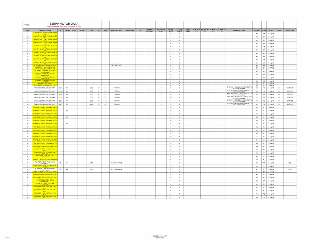
Motors631229337-PE-LS-0007
Page 31 of 47
6/21/2017
UNIT EQUIPMENT_NAME HP VOLTS1 PHASE FRAME RPM HZ FLA MANUFACTURER ENCLOSURE SF NOMINALEFFICIENCY
INSULATIONCLASS
ROTORBARS
STATORSLOTS
PWRFEED
SP_HTR_VOLTS
SP_HTR_WATTS
SP_HTR_AMPS
SP_PWR_FEED NAMEPLATE_INFO RECORD_ AREA DATE1 TYPE SERIAL_No
SJRPP MOTOR DATA Does not include Plant Inventory Spare Motors
1 LOADOUT SILO CONVEYING BLOWER 1H 0 0 478 SW 15-Sep-08
2 LOADOUT SILO CONVEYING BLOWER 2F 0 0 479 SW 15-Sep-08
2 LOADOUT SILO CONVEYING BLOWER 2G 0 0 480 SW 15-Sep-08
2 LOADOUT SILO CONVEYING BLOWER 2H 0 0 481 SW 15-Sep-08
1 LOADOUT SILO FLUIDIZING BLOWER 1G 0 0 482 SW 15-Sep-08
1 LOADOUT SILO FLUIDIZING BLOWER 1H 0 0 483 SW 15-Sep-08
1 LOADOUT SILO FLUIDIZING BLOWER 1J 0 0 484 SW 15-Sep-08
2 LOADOUT SILO FLUIDIZING BLOWER 2G 0 0 485 SW 15-Sep-08
2 LOADOUT SILO FLUIDIZING BLOWER 2H 0 0 486 SW 15-Sep-08
2 LOADOUT SILO FLUIDIZING BLOWER 2J 0 0 487 SW 15-Sep-08
0 METAL CLNG WASTE CELL A AGTR NOT INSTALLED 0 0 494 WW 15-Sep-080 MILL SLURRY TNK AGIT 1MX-06 0 0 503 F. 15-Sep-080 MILL SLURRY TNK AGIT 2MX-06 0 0 504 F. 15-Sep-08
1 NONSALE FLYASH FLUIDIZING BLOWER 1M 0 0 509 PB 15-Sep-08
1 NONSALE FLYASH FLUIDIZING BLOWER 1N 0 0 510 PB 15-Sep-08
2 NONSALE FLYASH FLUIDIZING BLOWER 2M 0 0 511 PB 15-Sep-08
2 NONSALE FLYASH FLUIDIZING BLOWER 2N 0 0 512 PB 15-Sep-08
0 PRECIP FLDZG BLWR 0 0 538 FL 15-Sep-081 PRECIPITATOR 1A SEAL AIR FAN 0 0 539 AQ 15-Sep-08
1 PULVERIZER 1B LUBE OIL PUMP 2.2K 460 3 1130 60 4.2 TOSHIBA E 0 0 SPEC.J1S C4004;CONTINUOUS DUTY;6 POLES;FORM FBK; 565 PB 15-Sep-08 IK 13250926
1 PULVERIZER 1C LUBE OIL PUMP 2.2KW 460 3 1130 60 4.2 TOSHIBA E 0 0 SPEC.J1S C4004;CONTINUOUS DUTY;6 POLES;FORM FBK; 567 PB 15-Sep-08 IK 132509??
1 PULVERIZER 1D LUBE OIL PUMP 2.2K 460 3 1130 60 4.2 TOSHIBA E 0 0 SPEC.J1S C4004;CONTINUOUS DUTY;6 POLES;FORM FBK; 569 PB 15-Sep-08 IK 13250925
1 PULVERIZER 1E LUBE OIL PUMP 2.2K 460 3 1130 60 4.2 TOSHIBA E 0 0 SPEC.J1S C4004;CONTINUOUS DUTY;6 POLES;FORM FBK; 571 PB 15-Sep-08 IK 13250924
1 PULVERIZER 1F LUBE OIL PUMP 2.2K 460 3 1130 60 4.2 TOSHIBA E 0 0 SPEC.J1S C4004;CONTINUOUS DUTY;6 POLES;FORM FBK; 573 PB 15-Sep-08 IK 13250922
1 PULVERIZER 1G LUBE OIL PUMP 2.2K 460 3 1130 60 4.2 TOSHIBA E 0 0 SPEC.J1S C4004;CONTINUOUS DUTY;6 POLES;FORM FBK; 575 PB 15-Sep-08 IK 13250916
0 PUMP ENCLOSURE VENT FAN 1VF-01 0 0 595 F. 15-Sep-08
0 PUMP ENCLOSURE VENT FAN 1VF-01 460 3 0 0 593 F. 15-Sep-08
0 PUMP ENCLOSURE VENT FAN 1VF-01 0 0 592 F. 15-Sep-08
0 PUMP ENCLOSURE VENT FAN 1VF-01 460 3 0 0 590 F. 15-Sep-08
0 PUMP ENCLOSURE VENT FAN 1VF-01 0 0 594 F. 15-Sep-08
0 PUMP ENCLOSURE VENT FAN 1VF-01 460 3 0 0 591 F. 15-Sep-08
0 PUMP ENCLOSURE VENT FAN 2VF-01 0 0 601 F. 15-Sep-08
0 PUMP ENCLOSURE VENT FAN 2VF-01 0 0 599 F. 15-Sep-08
0 PUMP ENCLOSURE VENT FAN 2VF-01 0 0 598 F. 15-Sep-08
0 PUMP ENCLOSURE VENT FAN 2VF-01 0 0 597 F. 15-Sep-08
0 PUMP ENCLOSURE VENT FAN 2VF-01 0 0 596 F. 15-Sep-08
0 PUMP ENCLOSURE VENT FAN 2VF-01 0 0 600 F. 15-Sep-08
0 PUMP STATION P-11 (UNIT 2 PRECIP) 0 0 606 WT 15-Sep-08
0 PUMP STATION P-13 (UNIT 2 FGD AREA) 0 0 607 WT 15-Sep-08
0 PUMP STATION P-14 (LIMESTONE HANDLING) 0 0 608 WT 15-Sep-08
0 PUMP STATION P-15 (COAL UNLOADING) 0 0 609 WT 15-Sep-08
0 PUMP STATION P-16 (COAL RECLAIM) 0 0 610 WT 15-Sep-08
0 PUMP STATION P-17 (GYPSUM STORAGE) 5 460 3 1760 WESTINGHOUSE 0 0 611 WT 15-Sep-08 8505
0 PUMP STATION P-18 (GYPSUM NON-SALE) 0 0 612 WT 15-Sep-08
0 PUMP STATION P-19 (GYPSUM DEWATERING) 5 460 3 1760 WESTINGHOUSE 0 0 613 WT 15-Sep-08 8505
0 PUMP STATION P-20 (FLYASH WET) 0 0 614 WT 15-Sep-08
0 PUMP STATION P-23 (SOLID WASTE) 0 0 616 WT 15-Sep-08
0 PUMP STATION S-20 (SOLID WASTE) 0 0 618 WT 15-Sep-08
1 PYRITES DEWATERING BIN CONVEYOR 1 0 0 619 SW 15-Sep-08
2 PYRITES DEWATERING BIN CONVEYOR 2 0 0 620 SW 15-Sep-08
1 QUENCHER SUMP AGITATOR 1MX-01B1 0 0 641 AQ 15-Sep-08
1 QUENCHER SUMP AGITATOR 1MX-01B2 0 0 642 AQ 15-Sep-08
1 QUENCHER SUMP AGITATOR 1MX-01C2 0 0 647 AQ 15-Sep-08
1 QUENCHER SUMP AGITATOR 1MX-01C3 0 0 648 AQ 15-Sep-08

Motors631229337-PE-LS-0007
Page 32 of 47
6/21/2017
UNIT EQUIPMENT_NAME HP VOLTS1 PHASE FRAME RPM HZ FLA MANUFACTURER ENCLOSURE SF NOMINALEFFICIENCY
INSULATIONCLASS
ROTORBARS
STATORSLOTS
PWRFEED
SP_HTR_VOLTS
SP_HTR_WATTS
SP_HTR_AMPS
SP_PWR_FEED NAMEPLATE_INFO RECORD_ AREA DATE1 TYPE SERIAL_No
SJRPP MOTOR DATA Does not include Plant Inventory Spare Motors
1 QUENCHER SUMP AGITATOR 1MX-01C4 0 0 649 AQ 15-Sep-08
1 QUENCHER SUMP AGITATOR 1MX-01C5 0 0 650 AQ 15-Sep-08
2 QUENCHER SUMP AGITATOR 2MX-01A1 0 0 651 AQ 15-Sep-08
2 QUENCHER SUMP AGITATOR 2MX-01A2 0 0 652 AQ 15-Sep-08
2 QUENCHER SUMP AGITATOR 2MX-01A3 0 0 653 AQ 15-Sep-08
2 QUENCHER SUMP AGITATOR 2MX-01A4 0 0 654 AQ 15-Sep-08
2 QUENCHER SUMP AGITATOR 2MX-01A5 0 0 655 AQ 15-Sep-08
2 QUENCHER SUMP AGITATOR 2MX-01B1 0 0 656 AQ 15-Sep-08
2 QUENCHER SUMP AGITATOR 2MX-01B2 0 0 657 AQ 15-Sep-08
2 QUENCHER SUMP AGITATOR 2MX-01B3 0 0 658 AQ 15-Sep-08
2 QUENCHER SUMP AGITATOR 2MX-01B4 0 0 659 AQ 15-Sep-08
2 QUENCHER SUMP AGITATOR 2MX-01B5 0 0 660 AQ 15-Sep-08
2 REAGENT FEED TANK AGITATOR 2MX-07A 0 0 675 AQ 15-Sep-08
2 REAGENT FEED TANK AGITATOR 2MX-07B 0 0 676 AQ 15-Sep-08
0 REAGENT PREP AREA SUMP 1A 0 0 677 F. 15-Sep-080 REAGENT PREP AREA SUMP AGIT 0 0 679 F. 15-Sep-080 REAGENT PREP ENCL VENT FAN 0 0 680 F. 15-Sep-081 RECIRCULATING SEAL OIL PUMP 1 0 0 681 PB 15-Sep-082 RECIRCULATING SEAL OIL PUMP 2 0 0 682 PB 15-Sep-08
1 REHEAT FAN 1FN-01A LUBE OIL PUMP A 1 1/ 460 3 0 0 685 AQ 15-Sep-08
1 QUENCHER SUMP AGITATOR 1MX-01A5 0 0 640 AQ 15-Sep-08
2 QUENCHER SUMP AGITATOR 2MX-01C1 0 0 661 AQ 15-Sep-08
2 QUENCHER SUMP AGITATOR 2MX-01C2 0 0 662 AQ 15-Sep-08
2 QUENCHER SUMP AGITATOR 2MX-01C3 0 0 663 AQ 15-Sep-08
2 QUENCHER SUMP AGITATOR 2MX-01C4 0 0 664 AQ 15-Sep-08
2 QUENCHER SUMP AGITATOR 2MX-01C5 0 0 665 AQ 15-Sep-08
1 REAGENT FEED TANK AGITATOR 1MX-07A 0 0 673 AQ 15-Sep-08
1 REHEAT FAN 1FN-01A LUBE OIL PUMP B 1 1/ 460 3 0 0 686 AQ 15-Sep-08
1 REHEAT FAN 1FN-01B LUBE OIL PUMP B 460 0 0 689 AQ 15-Sep-08
2 REHEAT FAN 2FN-01A 0 0 690 AQ 15-Sep-08
2 REHEAT FAN 2FN-01A LUBE OIL PUMP A 0 0 691 AQ 15-Sep-08
2 REHEAT FAN 2FN-01B 0 0 693 AQ 15-Sep-08
2 REHEAT FAN 2FN-01B LUBE OIL PUMP A 0 0 694 AQ 15-Sep-08
2 REHEAT FAN 2FN-01B LUBE OIL PUMP B 0 0 695 AQ 15-Sep-08
1 SETTLING TANK SLUDGE PUMP 1C 0 0 747 SW 15-Sep-081 SETTLING TANK SLUDGE PUMP 1D 0 0 748 SW 15-Sep-082 SETTLING TANK SLUDGE PUMP 2C 0 0 749 SW 15-Sep-082 SETTLING TANK SLUDGE PUMP 2D 0 0 750 SW 15-Sep-08
0 SEWAGE LIFT STATION SL-03 (SEWAGE TRTMT) 0 0 751 WT 15-Sep-08
0 SEWAGE LIFT STATION SL-04 (SEWAGE TRTMT) 0 0 752 WT 15-Sep-08
0 SEWAGE LIFT STATION SL-05 (SOLID WASTE) 0 0 753 WT 15-Sep-08
0 SEWAGE LIFT STATION SL-06 (EAST OF AQCS) 0 0 754 WT 15-Sep-08
0 SHIP UNLOADER BOOM HOIST 0 0 761 CT 15-Sep-08
0 SHIP UNLOADER BUCKET CLOSE/OPEN DRIVE 500 650/1000 GENERAL ELECTRIC TE - MOTOR
COOLED F 0 0 DC 120 1000
FLD OHMS;13.1 @ 25C;RPM ; BRUSHES: 36A164453AA021; SHUNT WOUND
THERMOSTATS: TWO NC, AC RATING: 600V MAX- .5A, 2.5V-1.5A, OR 125V-3A;
DC RATING: 30V MAX-1.5A.
762 CT 15-Sep-08 CD4570 NC-2-36NC
0 SHIP UNLOADER BUCKET SLEW 0 0 764 CT 15-Sep-080 SHIP UNLOADER CAB TRAVEL 0 0 765 CT 15-Sep-08
0 STACKER/RECLAIMER BUCKET WHEEL DRIVE 0 0 789 CY 15-Sep-08
0 STACKER/RECLAIMER LUFFING PUMP 1 0 0 790 CY 15-Sep-08
0 STACKER/RECLAIMER LUFFING PUMP 2 0 0 791 CY 15-Sep-08
0 STACKER/RECLAIMER SLEW DRIVE 0 0 792 CY 15-Sep-081 SURGE TANK SLUDGE PUMP 1A 0 0 808 SW 15-Sep-081 SURGE TANK SLUDGE PUMP 1B 0 0 809 SW 15-Sep-082 SURGE TANK SLUDGE PUMP 2A 0 0 810 SW 15-Sep-082 SURGE TANK SLUDGE PUMP 2B 0 0 811 SW 15-Sep-08
0 TURBINE LUBE OIL TRANSFER PUMP 0 0 MCC 2D31-7FE 833 PB 15-Sep-08
0 VENT FAN DWTRG ENCLSR 3 0 0 842 GY 15-Sep-080 VENT FAN DWTRG ENCLSR 3 0 0 843 GY 15-Sep-080 VENT FAN DWTRG ENCLSR 3 0 0 846 GY 15-Sep-080 VENT FAN DWTRG ENCLSR 3 0 0 845 GY 15-Sep-080 WASTE TRANSFER PUMP 1P-03B1 0 0 866 F. 15-Sep-080 WASTE TRANSFER PUMP 1P-03C1 0 0 868 F. 15-Sep-080 WASTE TRANSFER PUMP 1P-03C2 0 0 869 F. 15-Sep-080 WASTE TRANSFER PUMP 2P-03A1 0 0 870 F. 15-Sep-08

Motors631229337-PE-LS-0007
Page 33 of 47
6/21/2017
UNIT EQUIPMENT_NAME HP VOLTS1 PHASE FRAME RPM HZ FLA MANUFACTURER ENCLOSURE SF NOMINALEFFICIENCY
INSULATIONCLASS
ROTORBARS
STATORSLOTS
PWRFEED
SP_HTR_VOLTS
SP_HTR_WATTS
SP_HTR_AMPS
SP_PWR_FEED NAMEPLATE_INFO RECORD_ AREA DATE1 TYPE SERIAL_No
SJRPP MOTOR DATA Does not include Plant Inventory Spare Motors
0 WASTE TRANSFER PUMP 2P-03A2 0 0 871 F. 15-Sep-080 WASTE TRANSFER PUMP 2P-03B1 0 0 872 F. 15-Sep-080 WASTE TRANSFER PUMP 2P-03B2 0 0 873 F. 15-Sep-080 WASTE TRANSFER PUMP 2P-03C1 0 0 874 F. 15-Sep-080 WASTE TRANSFER PUMP 2P-03C2 0 0 875 F. 15-Sep-08
0 SHIP UNLOADER DUST COLLECTOR FILTER INDEX DRIVE 0 0 767 CT 15-Sep-08
0 SHIP UNLOADER DUST COLLECTOR REVERSE AIR BLOWER 0 0 768 CT 15-Sep-08
0 SHIP UNLOADER DUST COLLECTOR ROTARY AIRLOCK 0 0 769 CT 15-Sep-08
0 SHIP UNLOADER DUST COLLECTOR SCREW CONVEYOR A 0 0 770 CT 15-Sep-08
0 SHIP UNLOADER HOPPER GATE 0 0 772 CT 15-Sep-08
0 SHIP UNLOADER HOPPER VIBRATOR A 0 0 773 CT 15-Sep-08
0 SHIP UNLOADER HOPPER VIBRATOR B 0 0 774 CT 15-Sep-08
0 SHIP UNLOADER JIB LINE WINCH A 0 0 775 CT 15-Sep-080 SHIP UNLOADER JIB LINE WINCH B 0 0 776 CT 15-Sep-080 SHIP UNLOADER SPILL PLATE 0 0 777 CT 15-Sep-08
0 SHIP UNLOADER SPILL PLATE CONVEYOR A 0 0 778 CT 15-Sep-08
0 SHIP UNLOADER SPILL PLATE CONVEYOR B 0 0 779 CT 15-Sep-08
0 SHIP UNLOADER SPILL PLATE VIBRATOR A 0 0 780 CT 15-Sep-08
0 SHIP UNLOADER SPILL PLATE VIBRATOR B 0 0 781 CT 15-Sep-08
0 SHIP UNLOADER SPILLAGE CONVEYOR 0 0 782 CT 15-Sep-08
0 SHIP UNLOADER TROLLEY ROPE TENSIONER 0 0 784 CT 15-Sep-08
0 SHIP UNLOADER TROLLEY TRAVEL DRIVE 200 850 GENERAL ELECTRIC TE F 0 0 120 180
WOUND SHUNT; NEMA PWR SUPPLY CODE: C; THERMOSTAT NORMALLY CLOSED, AC RATING 600V MAX .5A,
250V 1.5A OR 125V- 3.0A,DC RATING 30V MAX - 1.5A CON
785 CT 15-Sep-08 TEUC
0 SHIP UNLOADER TROLLEY WINCH 200 DC GENERAL ELECTRIC F 0 0 DC ENCL TEVC;WOUND SHUNT;FLD OHMS @ 25C=34.8 786 CT 15-Sep-08 CD508ATY NC-1-24ONC
0 SHIP UNLOADER WIND SCREEN PLATE A 0 0 787 CT 15-Sep-08
0 SHIP UNLOADER WIND SCREEN PLATE B 0 0 788 CT 15-Sep-08
0 STACKER/RECLAIMER TRIPPER PUMP 1 0 0 793 CY 15-Sep-08
0 STACKER/RECLAIMER TRIPPER PUMP 2 0 0 794 CY 15-Sep-08
0 TROLLEY & HOIST 1HO-02 460 3 900 HARNISCHFEGER 0 0 825 GY 15-Sep-080 TROLLEY & HOIST 9-HO-01A 460 3 900 HARNISCHFEGER 0 0 826 GY 15-Sep-080 TROLLEY & HOIST 9-HO-02B 3 0 0 828 GY 15-Sep-08
1 TURBINE GENERATOR 1 MAIN TURNING GEAR GENERAL ELECTRIC 0 0 836 PB 15-Sep-08
2 TURBINE GENERATOR 2 MAIN TURNING GEAR 0 0 838 PB 15-Sep-08
1 TURBINE LUBE OIL RESERVOIR VAPOR EXTRACTOR 1 0 0 MCC 1B11-
7FB 831 PB 15-Sep-08
2 TURBINE LUBE OIL RESERVOIR VAPOR EXTRACTOR 2 0 0 MCC 2B11-
7FB 832 PB 15-Sep-08
0 VENT FAN DWTRG ENCLSR 3 0 0 847 GY 15-Sep-080 VENT FAN DWTRG ENCLSR 3 0 0 844 GY 15-Sep-080 VENT FAN SWTCHGR & MCC RM 3 0 0 848 GY 15-Sep-080 VENT FAN SWTCHGR & MCC RM 3 0 0 850 GY 15-Sep-080 VENT FAN SWTCHGR & MCC RM 3 0 0 849 GY 15-Sep-080 WASTE SLURRY TNK AGIT 2MX 0 0 857 F. 15-Sep-080 WASTE SLURRY TNK AGIT 2MX 0 0 856 F. 15-Sep-080 WASTE TNSFR TNK AGIT 1MX-03A 0 0 858 F. 15-Sep-080 WASTE TNSFR TNK AGIT 1MX-03C 0 0 860 F. 15-Sep-080 WASTE TNSFR TNK AGIT 2MX-03A 0 0 861 F. 15-Sep-080 WASTE TNSFR TNK AGIT 2MX-03B 0 0 862 F. 15-Sep-080 WASTE TNSFR TNK AGIT 2MX-03C 0 0 863 F. 15-Sep-081 YARD AREA OVERFLOW PUMP 1A 0 0 882 SW 15-Sep-081 YARD AREA OVERFLOW PUMP 1B 0 0 883 SW 15-Sep-082 YARD AREA OVERFLOW PUMP 2A 0 0 884 SW 15-Sep-082 YARD AREA OVERFLOW PUMP 2B 0 0 885 SW 15-Sep-08
1 YARD HIGH PRESSURE SEAL WATER PUMP 1A 0 0 886 SW 15-Sep-08
1 YARD HIGH PRESSURE SEAL WATER PUMP 1B 0 0 887 SW 15-Sep-08
2 YARD HIGH PRESSURE SEAL WATER PUMP 2A 0 0 888 SW 15-Sep-08
2 YARD HIGH PRESSURE SEAL WATER PUMP 2B 0 0 889 SW 15-Sep-08
0 FIRST STAGE VACUUM FILTER AGITATOR 1VF-01B 7.5 230/460 3 1213TD7 1760 RELIANCE 0 0 1073 SW 15-Sep-08 TEFC 1YAB32467A1 WK
0 FIRST STAGE VACUUM FILTER AGITATOR 2VF-01A 7.5 230/460 3 1213TD7 1760 RELIANCE 0 0 1075 SW 15-Sep-08 TEFC 1YAB32467A1 WK
0 FIRST STAGE VACUUM FILTER AGITATOR 2VF-01B 7.5 230/460 3 1213TD7 1760 RELIANCE 0 0 1074 SW 15-Sep-08 TEFC 1YAB32467A1 WK
0 FIRST STG VAC FLTR AGIT 7.5 230/460 3 1213TD7 1760 RELIANCE 0 0 336 GY 15-Sep-08 P-TEFC 1YAB32466A4 WK

Motors631229337-PE-LS-0007
Page 34 of 47
6/21/2017
UNIT EQUIPMENT_NAME HP VOLTS1 PHASE FRAME RPM HZ FLA MANUFACTURER ENCLOSURE SF NOMINALEFFICIENCY
INSULATIONCLASS
ROTORBARS
STATORSLOTS
PWRFEED
SP_HTR_VOLTS
SP_HTR_WATTS
SP_HTR_AMPS
SP_PWR_FEED NAMEPLATE_INFO RECORD_ AREA DATE1 TYPE SERIAL_No
SJRPP MOTOR DATA Does not include Plant Inventory Spare Motors
0 FIRST STAGE VACUUM FILTER AGITATOR 1VF-01A 7.5 230/460 3 1213TD7 1760 RELIANCE 0 0 335 SW 15-Sep-08 TEFC 1YAB32467A1 WK
0 SECOND STG VAC FLTR AGIT 7.5 230/460 3 1213TD7 1760 RELIANCE 0 0 729 GY 15-Sep-08 P-TBFC0 SECOND STG VAC FLTR AGIT 7.5 230/460 3 1213TD7 1760 RELIANCE 0 0 727 GY 15-Sep-08 P-TEFC 1YAB32467A2 WK0 SECOND STG VAC FLTR AGIT 7.5 230/460 3 1213TD7 1760 RELIANCE 0 0 728 GY 15-Sep-08 P-TEFC0 OILY WASTE Pp STATION O.W.-0 2 230/460 3 140T4 1735 RELIANCE 0 0 519 W. 15-Sep-08 P N/A0 OILY WASTE PUMP STATION O.W.-0 2 230/460 3 140T4 1735 RELIANCE 0 0 522 W. 15-Sep-08 P N/A
AIR HEATER SECTOR PLATE DRIVE .5 230/460 3 143T 855 60 2.9/1.45 MARATHON TEFC 1.15 F MILL AND CHEMICAL DUTY 995 PB 15-Sep-08AIR HEATER SECTOR PLATE DRIVE .5 230/460 3 143T 855 60 2.9/1.45 WESTINGHOUSE TEFC MILL AND CHEMICAL DUTY 943 PB 15-Sep-08
1 BOILER FEED PUMP 1A LUBE OIL VAPOR EXTRACTOR 1 230/460 3 143T 1755 60 3.8/1.9 US ELECTRIC
MOTORS TEFC 1.15 81.5 F 0 0 60 PB 15-Sep-08 CT TE
1 BOILER FEED PUMP 1B LUBE OIL VAPOR EXTRACTOR 1 230/460 3 143T 1755 60 3.8/1.9 US ELECTRIC
MOTORS TEFC 1.15 81.5 F 0 0 65 PB 15-Sep-08 CT TE
2 BOILER FEED PUMP 2A LUBE OIL VAPOR EXTRACTOR 1 230/460 3 143T 1755 60 3.8/1.9 US ELECTRIC
MOTORS TEFC 1.15 81.5 F 0 0 70 PB 15-Sep-08 CT TE
2 BOILER FEED PUMP 2B LUBE OIL VAPOR EXTRACTOR 1 230/460 3 143T 1755 60 3.8/1.9 US ELECTRIC
MOTORS TEFC 1.15 81.5 F 0 0 75 PB 15-Sep-08 CT TE
0 LIME SILO GRIT SCREEN 1 230/460 3 143T 1740 US MOTOR 0 0 420 W. 15-Sep-08 TCTE FA-244-01-891-K009-R
2 VAPOR EXTRCTN MTR 2B 3/4 230/460 3 143T 1725 60 3/1. GENERAL ELECTRIC B 0 0 DUTY CONT; 841 15-Sep-08 EXL-1
1 AIRHEATER 1A GUIDE BEARING LUBE OIL PUMP A 1 230/460 3 145T 1200 60 3.4/1.7 TOSHIBA TEFC F 0 0 MCC 1A12-
7FD 36 PB 15-Sep-08 IKH
1 AIRHEATER 1A GUIDE BEARING LUBE OIL PUMP B 1 230/460 3 145T 1200 60 3.4/1.7 TOSHIBA TEFC F 0 0 MCC 1A12-
7FD 36 PB 15-Sep-08 IKH
1 AIRHEATER 1B GUIDE BEARING LUBE OIL PUMP A 1 230/460 3 145T 1200 60 3.4/1.7 TOSHIBA TEFC F 0 0 MCC 1A12-
7FD 36 PB 15-Sep-08 IKH
1 AIRHEATER 1B GUIDE BEARING LUBE OIL PUMP B 1 230/460 3 145T 1200 60 3.4/1.7 TOSHIBA TEFC F 0 0 MCC 1A12-
7FD 36 PB 15-Sep-08 IKH
1 AIRHEATER 2A GUIDE BEARING LUBE OIL PUMP A 1 230/460 3 145T 1200 60 3.4/1.7 TOSHIBA TEFC F 0 0 MCC 1A12-
7FD 36 PB 15-Sep-08 IKH
1 AIRHEATER 2A GUIDE BEARING LUBE OIL PUMP B 1 230/460 3 145T 1200 60 3.4/1.7 TOSHIBA TEFC F 0 0 MCC 1A12-
7FD 36 PB 15-Sep-08 IKH
1 AIRHEATER 2B GUIDE BEARING LUBE OIL PUMP A 1 230/460 3 145T 1200 60 3.4/1.7 TOSHIBA TEFC F 0 0 MCC 1A12-
7FD 36 PB 15-Sep-08 IKH
1 AIRHEATER 2B GUIDE BEARING LUBE OIL PUMP B 1 230/460 3 145T 1200 60 3.4/1.7 TOSHIBA TEFC F 0 0 MCC 1A12-
7FD 36 PB 15-Sep-08 IKH
0 LIME SILO SLAKER DRV 2 230/460 3 145T 1730 U.S.MOTORS 0 0 423 W. 15-Sep-08 TCTE F-A250-01-891-K002R0
0 LIMESTONE RECLAIM TUNNEL SUMP 1 1/ 230/460 3 145T 1740 RELIANCE 0 0 451 F. 15-Sep-08 P-TENV 05BAH03897A4 WK
1 WASTE TRANSFER TANK AGITATOR 1MX-03A 1.5 230/460 3 145T 1740 60 4.2 RELIANCE 1.15 F 0 0 480V 876 AQ 15-Sep-08 P
1 WASTE TRANSFER TANK AGITATOR 1MX-03B 1.5 230/460 3 145T 1740 60 4.2 RELIANCE 1.15 F 0 0 480V 877 AQ 15-Sep-08 P
0 WASTE TRANSFER TANK AGITATOR 1MX-03B 1.5 230/460 3 145T 1740 RELIANCE 0 0 859 AQ 15-Sep-08 P 05BAK03897A3
1 CONDENSER TUBE SHEET PRESSURIZATION PUMP 1A 2 208-
230/460 3 145TC 3450 60 5.7-4/2.7 BALDOR TEFC 1.15 78.5 B 0 0 264 PB 15-Sep-08
1 CONDENSER TUBE SHEET PRESSURIZATION PUMP 1B 2 208-
230/460 3 145TC 3450 60 5.7-4/2.7 BALDOR TEFC 1.15 78.5 B 0 0 265 PB 15-Sep-08
2 CONDENSER TUBE SHEET PRESSURIZATION PUMP 2A 2 208-
230/460 3 145TC 3450 60 5.7-4/2.7 BALDOR TEFC 1.15 78.5 B 0 0 266 PB 15-Sep-08
2 CONDENSER TUBE SHEET PRESSURIZATION PUMP 2B 2 208-
230/460 3 145TC 3450 60 5.7-4/2.7 BALDOR TEFC 1.15 78.5 B 0 0 267 PB 15-Sep-08
0 INCLINED CONV A 2 230/460 3 145TC 1730 U.S. ELECTRIC 0 0 408 W. 15-Sep-08 UTFTE N/A
1 SEAL OIL VACUUM PUMP 1 2 208-230/460 3 145TC 1730 60 6.1-6.0/3.0 US ELECTRIC
MOTORS TEFC 1.25 84 F 0 0 716 PB 15-Sep-08 FUT
2 SEAL OIL VACUUM PUMP 2 2 208-230/460 3 145TC 1730 60 6.1-6.0/3.0 US ELECTRIC
MOTORS TEFC 1.25 84 F 0 0 717 PB 15-Sep-08 FUT
1 COAL FEEDER 1G 3 230/460 3 182 TDV 1745 60 9.2/4.6 US ELECTRIC MOTORS 1.15 82.5 F 2.2KW J2870074 895 PB 15-Sep-08 TVC TE
1 COAL FEEDER 2A 3 230/460 3 182 TDV 1745 60 9.2/4.6 US ELECTRIC MOTORS 1.15 82.5 F 2.2KW J2870074 896 PB 15-Sep-08 TVC TE
1 COAL FEEDER 2B 3 230/460 3 182 TDV 1745 60 9.2/4.6 US ELECTRIC MOTORS 1.15 82.5 F 2.2KW J2870074 897 PB 15-Sep-08 TVC TE
1 COAL FEEDER 2C 3 230/460 3 182 TDV 1745 60 9.2/4.6 US ELECTRIC MOTORS 1.15 82.5 F 2.2KW J2870074 898 PB 15-Sep-08 TVC TE
1 COAL FEEDER 2D 3 230/460 3 182 TDV 1745 60 9.2/4.6 US ELECTRIC MOTORS 1.15 82.5 F 2.2KW J2870074 899 PB 15-Sep-08 TVC TE
1 COAL FEEDER 2E 3 230/460 3 182 TDV 1745 60 9.2/4.6 US ELECTRIC MOTORS 1.15 82.5 F 2.2KW J2870074 900 PB 15-Sep-08 TVC TE
1 COAL FEEDER 2F 3 230/460 3 182 TDV 1745 60 9.2/4.6 US ELECTRIC MOTORS 1.15 82.5 F 2.2KW J2870074 901 PB 15-Sep-08 TVC TE
1 COAL FEEDER EDDY CURRENT CLUTCH DRIVE 3 230/460 3 182 TDV 1745 60 9.2/4.6 US ELECTRIC
MOTORS TEFC 1.15 82.5 F 2.2KW J2870074; 192 PB 15-Sep-08 TVC TE
1 COAL FEEDER 1B 3 230/460 3 182 TDV 1745 60 9.2/4.6 US ELECTRIC MOTORS 1.15 82.5 F 2.2KW J2870074 890 PB 15-Sep-08 TVC TE
1 COAL FEEDER 1C 3 230/460 3 182 TDV 1745 60 9.2/4.6 US ELECTRIC MOTORS 1.15 82.5 F 2.2KW J2870074 891 PB 15-Sep-08 TVC TE
1 COAL FEEDER 1D 3 230/460 3 182 TDV 1745 60 9.2/4.6 US ELECTRIC MOTORS 1.15 82.5 F 2.2KW J2870074 892 PB 15-Sep-08 TVC TE
1 COAL FEEDER 1E 3 230/460 3 182 TDV 1745 60 9.2/4.6 US ELECTRIC MOTORS 1.15 82.5 F 2.2KW J2870074 893 PB 15-Sep-08 TVC TE
1 COAL FEEDER 1F 3 230/460 3 182 TDV 1745 60 9.2/4.6 US ELECTRIC MOTORS 1.15 82.5 F 2.2KW J2870074 894 PB 15-Sep-08 TVC TE
1 COAL FEEDER 2G 3 230/460 3 182 TDV 1745 60 9.2/4.6 US ELECTRIC MOTORS 1.15 82.5 F 2.2KW J2870074 902 PB 15-Sep-08 TVC TE
0 GRAVITY THICKENER A SCRAPER 3 460 3 1821-20 1725 U.S. ELECTRIC 0 0 374 W. 15-Sep-08 TFC-6W 6403688-8710 GRAVITY THICKENER B SCRAPER 3 460 3 1821-20 1725 U.S. ELECTRIC 0 0 375 W. 15-Sep-08 TFC-6WTE 6403688-871
1 BOILER FEED PUMP 1A TURNING GEAR 3 230/460 3 182T 1745 60 9/4. GENERAL ELECTRIC 1.15 F 0 0 GREASE CHEV SRI-2;DUTY CONT;NEMA
DESIGN B; 61 PB 15-Sep-08 K 5K182BL6206A
1 BOILER FEED PUMP 1B TURNING GEAR 3 230/460 3 182T 1745 60 9/4. GENERAL ELECTRIC 1.15 F 0 0 GREASE CHEV SRI-2;DUTY CONT;NEMA
DESIGN B; 66 PB 15-Sep-08 K 5K182BL6206A
2 BOILER FEED PUMP 2A TURNING GEAR 3 230/460 3 182T 1745 60 9/4. GENERAL ELECTRIC 1.15 F 0 0 GREASE CHEV SRI-2;DUTY CONT;NEMA
DESIGN B; 71 PB 15-Sep-08 K 5K182BL6206A
2 BOILER FEED PUMP 2B TURNING GEAR 3 230/460 3 182T 1740 60 7.8/3.9 SIEMENS TEFC 1.15 87.5 F 0 0 3 YEAR WARRANTY 76 PB 15-Sep-08 RGZESD A02 T008 6 CE 4
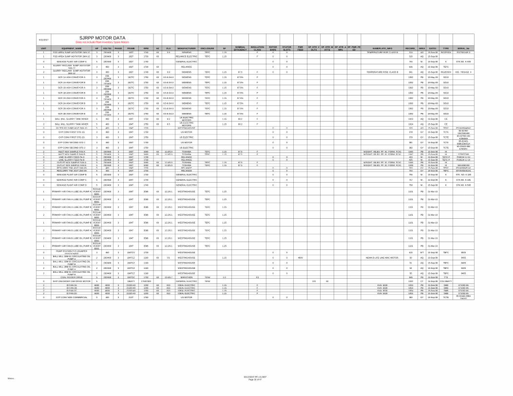
Motors631229337-PE-LS-0007
Page 35 of 47
6/21/2017
UNIT EQUIPMENT_NAME HP VOLTS1 PHASE FRAME RPM HZ FLA MANUFACTURER ENCLOSURE SF NOMINALEFFICIENCY
INSULATIONCLASS
ROTORBARS
STATORSLOTS
PWRFEED
SP_HTR_VOLTS
SP_HTR_WATTS
SP_HTR_AMPS
SP_PWR_FEED NAMEPLATE_INFO RECORD_ AREA DATE1 TYPE SERIAL_No
SJRPP MOTOR DATA Does not include Plant Inventory Spare Motors
1 FGD AREA SUMP AGITATOR 1MX-1C 3 230/460 3 182T 1740 60 3.9 SIEMENS TEFC 1.15 F 0 0 TEMPERATURE RISE CLASS B 314 AQ 15-Sep-08 RGZESDX F01T0014IE-3
1 FGD AREA SUMP AGITATOR 2MX-1C 3 230/460 3 182T 1730 60 RELIANCE ELECTRIC TEFC 1.15 F 0 0 315 AQ 15-Sep-08
0 SEWAGE PLANT AIR COMP A 5 230/460 3 182T 1750 GENERAL ELECTRIC 0 0 755 W. 15-Sep-08 K STK.NO. K-593
1 SLURRY RECLAIM SUMP AGITATOR 1MX-12 3 460 3 182T 1730 60 RELIANCE 0 0 636 AQ 15-Sep-08 TEFC
2 SLURRY RECLAIM SUMP AGITATOR 2MX-12 3 460 3 182T 1740 60 3.9 SIEMENS TEFC 1.15 87.5 F 0 0 TEMPERATURE RISE: CLASS B 941 AQ 15-Sep-08 RGZESDX K01 T00141E 4
1 SCR 1A ASH CONVEYOR A 3 208-230/460 3 182TC 1750 60 8.5-8.0/4.0 SIEMENS TEFC 1.15 87.5% F 1092 PB 18-May-09 SD10
1 SCR 1A ASH CONVEYOR B 3 208-230/460 3 182TC 1750 60 8.5-8.0/4.0 SIEMENS TEFC 1.15 87.5% F 1092 PB 18-May-09 SD10
1 SCR 1B ASH CONVEYOR A 3 208-230/460 3 182TC 1750 60 8.5-8.0/4.0 SIEMENS TEFC 1.15 87.5% F 1092 PB 18-May-09 SD10
1 SCR 1B ASH CONVEYOR B 3 208-230/460 3 182TC 1750 60 8.5-8.0/4.0 SIEMENS TEFC 1.15 87.5% F 1092 PB 18-May-09 SD10
1 SCR 2A ASH CONVEYOR A 3 208-230/460 3 182TC 1750 60 8.5-8.0/4.0 SIEMENS TEFC 1.15 87.5% F 1092 PB 18-May-09 SD10
1 SCR 2A ASH CONVEYOR B 3 208-230/460 3 182TC 1750 60 8.5-8.0/4.0 SIEMENS TEFC 1.15 87.5% F 1092 PB 18-May-09 SD10
1 SCR 2B ASH CONVEYOR A 3 208-230/460 3 182TC 1750 60 8.5-8.0/4.0 SIEMENS TEFC 1.15 87.5% F 1092 PB 18-May-09 SD10
1 SCR 2B ASH CONVEYOR B 3 208-230/460 3 182TC 1750 60 8.5-8.0/4.0 SIEMENS TEFC 1.15 87.5% F 1092 PB 18-May-09 SD10
1 BALL MILL SLURRY TANK MIXER 5 460 3 184T 1750 60 6.5 US ELECTRIC MOTORS 1.15 90.2 F 1023 AQ 15-Sep-08 CE
2 BALL MILL SLURRY TANK MIXER 5 460 3 184T 1750 60 6.5 US ELECTRIC MOTORS 1.15 90.2 F 1024 AQ 15-Sep-08 CE
0 FILTER FD SUMP AGIT 2MX-10 5 460 3 184T 1730 WESTINGHOUSE 0 0 320 AQ 15-Sep-08 TEFC 05YAH06449A1
0 GYP CONV FIRST STG 1G 3 460 3 184T 1750 US MOTOR 0 0 378 GY 15-Sep-08 TCTE 65-02780-16K2960498
0 GYP CONV FIRST STG 2G 3 460 3 184T 1750 US ELECTRIC 0 0 379 GY 15-Sep-08 TCTE 65-02780-106 K296049
0 GYP CONV SECOND STG 1 3 460 3 184T 1750 US MOTOR 0 0 381 GY 15-Sep-08 TCTE 65-02443-088K2960514
0 GYP CONV SECOND STG 2 3 460 3 184T 1750 US ELECTRIC 0 0 382 GY 15-Sep-08 TCTE 65-02443-088 K296051
2 INLET NOX SAMPLE FAN A 5 230/460 3 184T 3490 60 11.8/5.9 TOSHIBA TEFC 1.15 87.5 F WEIGHT: 95LBS; PF: 91; FORM: FCK1 1045 PB 15-Sep-08 IK2 INLET NOX SAMPLE FAN B 5 230/460 3 184T 3490 60 11.8/5.9 TOSHIBA TEFC 1.15 87.5 F WEIGHT: 95LBS; PF: 91; FORM: FCK1 1047 PB 15-Sep-08 IK S750573890 LIME SLURRY FEED Pp A 5 230/460 3 184T 1730 RELIANCE 0 0 424 W. 15-Sep-08 TEFC-P P18G34 1J XJ0 LIME SLURRY FEED Pp B 5 230/460 3 184T 1730 RELIANCE 0 0 425 W. 15-Sep-08 TEFC-P P18G34 1J 1X2 OUTLET NOX SAMPLE FAN A 5 230/460 3 184T 3490 60 11.8/5.9 TOSHIBA TEFC 1.15 87.5 F WEIGHT: 95LBS; PF: 91; FORM: FCK1 1046 PB 15-Sep-08 IK2 OUTLET NOX SAMPLE FAN B 5 230/460 3 184T 3490 60 11.8/5.9 TOSHIBA TEFC 1.15 87.5 F WEIGHT: 95LBS; PF: 91; FORM: FCK1 1048 PB 15-Sep-08 IK S6518901900 RESLURRY TNK AGIT 1MX-09 5 460 3 184T 1730 RELIANCE 0 0 703 GY 15-Sep-08 TEFC 05YAH06451A10 RESLURRY TNK AGIT 2MX-09 5 460 3 184T 1730 RELIANCE 0 0 704 GY 15-Sep-08 TEFC 05YAH06451A1
0 SEWAGE PLANT AIR COMP B 5 230/460 3 184T 1740 GENERAL ELECTRIC 0 0 756 W. 15-Sep-08 K STK. NO. K-185
0 SEWAGE PLANT AIR COMP C 5 230/460 3 184T 1740 GENERAL ELECTRIC 0 0 757 W. 15-Sep-08 K STK.NO. K-185
0 SEWAGE PLANT AIR COMP D 5 230/460 3 184T 1740 GENERAL ELECTRIC 0 0 758 W. 15-Sep-08 K STK.NO. K-595
1 PRIMARY AIR FAN A LUBE OIL PUMP A5CD144VC0007
B001230/460 3 184T 3586 60 12.2/6.1 WESTINGHOUSE TEFC 1.25 1101 PB 31-Mar-10
1 PRIMARY AIR FAN A LUBE OIL PUMP B5CD144VC0007
B001230/460 3 184T 3586 60 12.2/6.1 WESTINGHOUSE TEFC 1.25 1101 PB 31-Mar-10
2 PRIMARY AIR FAN A LUBE OIL PUMP B5CD144VC0007
B001230/460 3 184T 3586 60 12.2/6.1 WESTINGHOUSE TEFC 1.25 1101 PB 31-Mar-10
2 PRIMARY AIR FAN A LUBE OIL PUMP A5CD144VC0007
B001230/460 3 184T 3586 60 12.2/6.1 WESTINGHOUSE TEFC 1.25 1101 PB 31-Mar-10
1 PRIMARY AIR FAN B LUBE OIL PUMP B5CD144VC0007
B001230/460 3 184T 3586 60 12.2/6.1 WESTINGHOUSE TEFC 1.25 1101 PB 31-Mar-10
2 PRIMARY AIR FAN B LUBE OIL PUMP A5CD144VC0007
B001230/460 3 184T 3586 60 12.2/6.1 WESTINGHOUSE TEFC 1.25 1101 PB 31-Mar-10
2 PRIMARY AIR FAN B LUBE OIL PUMP B5CD144VC0007
B001230/460 3 184T 3586 60 12.2/6.1 WESTINGHOUSE TEFC 1.25 1101 PB 31-Mar-10
1 PRIMARY AIR FAN B LUBE OIL PUMP A5CD144VC0007
B001230/460 3 184T 3586 60 12.2/6.1 WESTINGHOUSE TEFC 1.25 1101 PB 31-Mar-10
0 PUMP STATION P-21 (DUMPER POSITIONER) 3 460 3 184TCV 1730 WESTINGHOUSE 0 0 615 WT 15-Sep-08 TBFC 8505
1 BALL MILL 1BM-01 CIRCULATING OIL PUMP A 2 230/460 3 184TCZ 1160 60 7/3. WESTINGHOUSE 1.15 0 0 480V NEMA B LIFE LINE MAC MOTOR. 50 AQ 15-Sep-08 8405
1 BALL MILL 1BM-01 CIRCULATING OIL PUMP B 2 230/460 3 184TCZ 1160 WESTINGHOUSE 0 0 51 AQ 15-Sep-08 TBFC 8405
2 BALL MILL 2BM-01 CIRCULATING OIL PUMP A 2 230/460 3 184TCZ 1160 WESTINGHOUSE 0 0 54 AQ 15-Sep-08 TBFC 8405
2 BALL MILL 2BM-01 CIRCULATING OIL PUMP B 2 230/460 3 184TCZ 1160 WESTINGHOUSE 0 0 55 AQ 15-Sep-08 TBFC 8405
COAL FEEDER DRIVE 5 230/460 3 184TDZ 1750 60 13.4/6.7 MARATHON TENV 1.0 F3 946 PB 15-Sep-08 TTS
0 SHIP UNLOADER CAB DRIVE MOTOR 5 186ATY 1750/2300 GENERAL ELECTRIC TENV 120 30 1032 CT 15-Sep-08 CDL186ATY
2 ID FAN 2A 6600 4000 3 21320-40 1200 60 813 IDEAL ELECTRIC 1.15 F KVA: 5630 1034 PB 15-Sep-08 SMB 071002-062 ID FAN 2B 6600 4000 3 21320-40 1200 60 813 IDEAL ELECTRIC 1.15 F KVA: 5630 1053 PB 15-Sep-08 SMB 071002-062 ID FAN 2C 6600 4000 3 21320-40 1200 60 813 IDEAL ELECTRIC 1.15 F KVA: 5630 1054 PB 15-Sep-08 SMB 071002-062 ID FAN 2D 6600 4000 3 21320-40 1200 60 813 IDEAL ELECTRIC 1.15 F KVA: 5630 1055 PB 15-Sep-08 SMB 071002-06
0 GYP CONV NON COMMERCIAL 5 460 3 213T 1760 US MOTOR 0 0 380 GY 15-Sep-08 TCTE 65-02444-088A 296052

Motors631229337-PE-LS-0007
Page 36 of 47
6/21/2017
UNIT EQUIPMENT_NAME HP VOLTS1 PHASE FRAME RPM HZ FLA MANUFACTURER ENCLOSURE SF NOMINALEFFICIENCY
INSULATIONCLASS
ROTORBARS
STATORSLOTS
PWRFEED
SP_HTR_VOLTS
SP_HTR_WATTS
SP_HTR_AMPS
SP_PWR_FEED NAMEPLATE_INFO RECORD_ AREA DATE1 TYPE SERIAL_No
SJRPP MOTOR DATA Does not include Plant Inventory Spare Motors
1 LUB FAN A2 7.5 480 3 213T 3510 60 19.2/9.6 US ELECTRIC MOTORS TEFC 1.25 86.5 F UNIMOUNT125;
SERVICE FACTOR AMPS: 24.0/12.0 905 PB 15-Sep-08 UT/TE A912/PO7P114R053
1 BALL MILL 1BM-01 JACKING OIL PUMP 3 460 3 213TC 1150 WESTINGHOUSE 0 0 52 AQ 15-Sep-08 TBFC 8404
2 BALL MILL 2BM-01 JACKING OIL PUMP 3 460 3 213TC 1150 WESTINGHOUSE 0 0 56 AQ 15-Sep-08 TBFC 8404
0 FIRE PROTECTION SYSTEM JOCKEY PUMP 7.5 230/460 3 213TC 3510 60 18.4/9.2 GENERAL ELECTRIC 1018 PB 15-Sep-08 K
0 FIRST STG VAC FLTR DRUM 7.5 460 3 213TC 1740 RELIANCE 0 0 346 GY 15-Sep-08 30342416S-TK0 FIRST STG VAC FLTR DRUM 7.5 230/460 3 213TC 1740 RELIANCE 0 0 343 GY 15-Sep-08 P 30342417 STK0 FIRST STG VAC FLTR DRUM 7.5 460 3 213TC 1740 RELIANCE 0 0 344 GY 15-Sep-08 30342417S-TK0 FIRST STG VAC FLTR DRUM 7.5 230/460 3 213TC 1740 RELIANCE 0 0 345 GY 15-Sep-08 P 303424165-TK0 SECOND STG VAC FLTR DRUM 7.5 230/460 3 213TC 1740 RELIANCE 0 0 736 GY 15-Sep-08 P 30342417 STK0 SECOND STG VAC FLTR DRUM 7.5 230/460 3 213TC 1740 RELIANCE 0 0 735 GY 15-Sep-08 P0 SECOND STG VAC FLTR DRUM 7.5 230/460 3 213TC 1740 RELIANCE 0 0 737 GY 15-Sep-08 P 30342416S-TK0 SECOND STG VAC FLTR DRUM 7.5 230/460 3 213TC 1740 RELIANCE 0 0 734 GY 15-Sep-08 P
0 PUMP STATION P-10 (UNIT 1 PRECIP) 7.5 460 3 213TCV 1740 60 10 WESTINGHOUSE TE 1 F 0 0 605 WT 15-Sep-08 8505
1 TURBINE GENERATOR 1 TURNING GEAR PIGGYBACK 8FT/ 460 3 213TDZ 450 60 GENERAL ELECTRIC TEFC 0 0 NEMA DESIGN TE;TIME RATING 10 MIN; 837 PB 15-Sep-08 KR
2 TURBINE GENERATOR 2 TURNING GEAR PIGGYBACK 8FT/ 460 3 213TDZ 450 60 GENERAL ELECTRIC TEFC 1.0 F 0 0 NEMA DESIGN TE;TIME RATING 10 MIN; 839 PB 15-Sep-08 KR
0 AMMONIA FORWARDING PUMP 9A 5 460 3 215T 1170 60 6.24 WESTINGHOUSE/TECO TEFC 1.5 91 F WEIGHT: 174 LBS. 1039 PB 15-Sep-08 AEHH8B LP44B3140004
0 AMMONIA FORWARDING PUMP 9B 5 460 3 215T 1170 60 6.24 WESTINGHOUSE/TECO TEFC 1.5 91 F WEIGHT: 174 LBS. 1040 PB 15-Sep-08 AEHH8B LP44B3140007
0 AMMONIA UNLOADING COMPRESSOR 9A (RAIL CAR) 5 460 3 215T 1765 60 17.3 WESTINGHOUSE/TE
CO TEFC 1.15 91 F 1041 PB 15-Sep-08 AEHH8B LR606B1010004
0 AMMONIA UNLOADING COMPRESSOR 9B (TRUCK) 5 460 3 215T 1765 60 17.3 WESTINGHOUSE/TE
CO TEFC 1.15 91 F 1042 PB 15-Sep-08 AEHH8B LR606B1010001
0 POSITIONER CABLE TAKE UP SHEAVE 5 460 3 215T 1155 60 7.6 GENERAL ELECTRIC TENV 1.15 F F2 CONDUIT BOX MOUNTING; EXPLOSION PROOF CL I (D), CL II (F& G) 1017 CY 15-Sep-08 KG
0 OXIDATION AIR COMPRESSOR 1C-01 5 230/460 3 215TC 1160 RELIANCE 0 0 527 F. 15-Sep-08 P P1-1015C
1 VACUUM FILTER 1VF-01A 10 460 3 215TCV 1800 60 SIEMENS TEFC 0 0 840 AQ 15-Sep-081 VACUUM FILTER 1VF-01B 10 460 3 215TCV 1800 60 SIEMENS 0 0 999 AQ 15-Sep-081 VACUUM FILTER 1VF-02A 10 460 3 215TCV 1800 60 SIEMENS 0 0 1000 AQ 15-Sep-081 VACUUM FILTER 1VF-02B 10 460 3 215TCV 1800 60 SIEMENS 0 0 1001 AQ 15-Sep-082 VACUUM FILTER 2VF-01A 10 460 3 215TCV 1800 60 SIEMENS 0 0 1002 AQ 15-Sep-082 VACUUM FILTER 2VF-01B 10 460 3 215TCV 1800 60 SIEMENS 0 0 1003 AQ 15-Sep-082 VACUUM FILTER 2VF-02A 10 460 3 215TCV 1800 60 SIEMENS 0 0 1004 AQ 15-Sep-082 VACUUM FILTER 2VF-02B 10 460 3 215TCV 1800 60 SIEMENS 0 0 1005 AQ 15-Sep-080 FINAL EFFLUENT RE-USE Pp A 15 460 3 250HP 3515 WESTINGHOUSE 0 0 324 W. 15-Sep-08 TBFC 84030 FINAL EFFLUENT RE-USE Pp B 15 460 3 250HP 3515 WESTINGHOUSE 0 0 325 W. 15-Sep-08 TBFC 840302
0 METAL CLEANING WASTE OVERFLOW PUMP A 7.5 460 3 250HP 1150 60 WESTINGHOUSE 0 0 497 WW 15-Sep-08 TBFC 8403-01-001
0 METAL CLEANING WASTE OVERFLOW PUMP B 7.5 460 3 250HP 1150 60 WESTINGHOUSE 0 0 498 WW 15-Sep-08 TBFC 8403-01-002
0 THICKENER UNDERFLOW Pp A 5 460 3 250HP 875 WESTINGHOUSE 0 0 822 W. 15-Sep-08 TE TBFC 84070 THICKENER UNDERFLOW Pp B 5 460 3 250HP 875 WESTINGHOUSE 0 0 823 W. 15-Sep-08 TBFC-TE 84070 THICKENER UNDERFLOW Pp C 5 460 3 250HP 875 WESTINGHOUSE 0 0 824 W. 15-Sep-08 TBFC-TE 8407
0 SHIP UNLOADER TRAVEL DRIVE N1 12 2512AT 1750 GENERAL ELECTRIC TENV - WP F 0 0 DC 120 75
BRUSH 36A171014AA011, WOUND SHUNT :;INSTRUCTION MANUAL:
GEX5304; CONNECTION DIAG: 36A171028BA; THRUSTER BRAKE: MFR:
GE; IC: 9516463K011AA161; LBS/FT TORQUE: 125 MAX/ CONT MIN
783 CT 15-Sep-08 CD2512AT YB-8-786-YB
0 SHIP UNLOADER TRAVEL DRIVE N2 12 2512AT 1750 35 GENERAL ELECTRIC TENV - WP F 0 0 DC 120 75
BRUSH 36A171014AA011, WOUND SHUNT :;INSTRUCTION MANUAL:
GEX5304; CONNECTION DIAG: 36A171028BA; THRUSTER BRAKE: MFR:
GE; IC: 9516463K011AA161; LBS/FT TORQUE: 125 MAX/ CONT MIN
907 CT 15-Sep-08 CD2512AT YB-8-786-YB
0 SHIP UNLOADER TRAVEL DRIVE N3 12 2512AT 1750 35 GENERAL ELECTRIC TENV - WP F 0 0 DC 120 75
BRUSH 36A171014AA011, WOUND SHUNT :;INSTRUCTION MANUAL:
GEX5304; CONNECTION DIAG: 36A171028BA; THRUSTER BRAKE: MFR:
GE; IC: 9516463K011AA161; LBS/FT TORQUE: 125 MAX/ CONT MIN
908 CT 15-Sep-08 CD2512AT YB-8-786-YB
0 SHIP UNLOADER TRAVEL DRIVE N7 12 2512AT 1750 35 GENERAL ELECTRIC TENV - WP F 0 0 DC 120 75
BRUSH 36A171014AA011, WOUND SHUNT :;INSTRUCTION MANUAL:
GEX5304; CONNECTION DIAG: 36A171028BA; THRUSTER BRAKE: MFR:
GE; IC: 9516463K011AA161; LBS/FT TORQUE: 125 MAX/ CONT MIN
912 CT 15-Sep-08 CD2512AT YB-8-786-YB
0 SHIP UNLOADER TRAVEL DRIVE N8 12 2512AT 1750 35 GENERAL ELECTRIC TENV - WP F 0 0 DC 120 75
BRUSH 36A171014AA011, WOUND SHUNT :;INSTRUCTION MANUAL:
GEX5304; CONNECTION DIAG: 36A171028BA; THRUSTER BRAKE: MFR:
GE; IC: 9516463K011AA161; LBS/FT TORQUE: 125 MAX/ CONT MIN
913 CT 15-Sep-08 CD2512AT YB-8-786-YB
0 SHIP UNLOADER TRAVEL DRIVE S1 12 2512AT 1750 35 GENERAL ELECTRIC TENV - WP F 0 0 DC 120 75
BRUSH 36A171014AA011, WOUND SHUNT :;INSTRUCTION MANUAL:
GEX5304; CONNECTION DIAG: 36A171028BA; THRUSTER BRAKE: MFR:
GE; IC: 9516463K011AA161; LBS/FT TORQUE: 125 MAX/ CONT MIN
914 CT 15-Sep-08 CD2512AT YB-8-786-YB

Motors631229337-PE-LS-0007
Page 37 of 47
6/21/2017
UNIT EQUIPMENT_NAME HP VOLTS1 PHASE FRAME RPM HZ FLA MANUFACTURER ENCLOSURE SF NOMINALEFFICIENCY
INSULATIONCLASS
ROTORBARS
STATORSLOTS
PWRFEED
SP_HTR_VOLTS
SP_HTR_WATTS
SP_HTR_AMPS
SP_PWR_FEED NAMEPLATE_INFO RECORD_ AREA DATE1 TYPE SERIAL_No
SJRPP MOTOR DATA Does not include Plant Inventory Spare Motors
0 SHIP UNLOADER TRAVEL DRIVE S5 12 2512AT 1750 35 GENERAL ELECTRIC TENV - WP F 0 0 DC 120 75
BRUSH 36A171014AA011, WOUND SHUNT :;INSTRUCTION MANUAL:
GEX5304; CONNECTION DIAG: 36A171028BA; THRUSTER BRAKE: MFR:
GE; IC: 9516463K011AA161; LBS/FT TORQUE: 125 MAX/ CONT MIN
918 CT 15-Sep-08 CD2512AT YB-8-786-YB
0 SHIP UNLOADER TRAVEL DRIVE S6 12 2512AT 1750 35 GENERAL ELECTRIC TENV - WP F 0 0 DC 120 75
BRUSH 36A171014AA011, WOUND SHUNT :;INSTRUCTION MANUAL:
GEX5304; CONNECTION DIAG: 36A171028BA; THRUSTER BRAKE: MFR:
GE; IC: 9516463K011AA161; LBS/FT TORQUE: 125 MAX/ CONT MIN
919 CT 15-Sep-08 CD2512AT YB-8-786-YB
0 SHIP UNLOADER TRAVEL DRIVE S7 12 2512AT 1750 35 GENERAL ELECTRIC TENV - WP F 0 0 DC 120 75
BRUSH 36A171014AA011, WOUND SHUNT :;INSTRUCTION MANUAL:
GEX5304; CONNECTION DIAG: 36A171028BA; THRUSTER BRAKE: MFR:
GE; IC: 9516463K011AA161; LBS/FT TORQUE: 125 MAX/ CONT MIN
920 CT 15-Sep-08 CD2512AT YB-8-786-YB
0 SHIP UNLOADER TRAVEL DRIVE N4 12 2512AT 1750 35 GENERAL ELECTRIC TENV - WP F 0 0 DC 120 75
BRUSH 36A171014AA011, WOUND SHUNT :;INSTRUCTION MANUAL:
GEX5304; CONNECTION DIAG: 36A171028BA; THRUSTER BRAKE: MFR:
GE; IC: 9516463K011AA161; LBS/FT TORQUE: 125 MAX/ CONT MIN
909 CT 15-Sep-08 CD2512AT YB-8-786-YB
0 SHIP UNLOADER TRAVEL DRIVE N5 12 2512AT 1750 35 GENERAL ELECTRIC TENV - WP F 0 0 DC 120 75
BRUSH 36A171014AA011, WOUND SHUNT :;INSTRUCTION MANUAL:
GEX5304; CONNECTION DIAG: 36A171028BA; THRUSTER BRAKE: MFR:
GE; IC: 9516463K011AA161; LBS/FT TORQUE: 125 MAX/ CONT MIN
910 CT 15-Sep-08 CD2512AT YB-8-786-YB
0 SHIP UNLOADER TRAVEL DRIVE N6 12 2512AT 1750 35 GENERAL ELECTRIC TENV - WP F 0 0 DC 120 75
BRUSH 36A171014AA011, WOUND SHUNT :;INSTRUCTION MANUAL:
GEX5304; CONNECTION DIAG: 36A171028BA; THRUSTER BRAKE: MFR:
GE; IC: 9516463K011AA161; LBS/FT TORQUE: 125 MAX/ CONT MIN
911 CT 15-Sep-08 CD2512AT YB-8-786-YB
0 SHIP UNLOADER TRAVEL DRIVE S2 12 2512AT 1750 35 GENERAL ELECTRIC TENV - WP F 0 0 DC 120 75
BRUSH 36A171014AA011, WOUND SHUNT :;INSTRUCTION MANUAL:
GEX5304; CONNECTION DIAG: 36A171028BA; THRUSTER BRAKE: MFR:
GE; IC: 9516463K011AA161; LBS/FT TORQUE: 125 MAX/ CONT MIN
915 CT 15-Sep-08 CD2512AT YB-8-786-YB
0 SHIP UNLOADER TRAVEL DRIVE S3 12 2512AT 1750 35 GENERAL ELECTRIC TENV - WP F 0 0 DC 120 75
BRUSH 36A171014AA011, WOUND SHUNT :;INSTRUCTION MANUAL:
GEX5304; CONNECTION DIAG: 36A171028BA; THRUSTER BRAKE: MFR:
GE; IC: 9516463K011AA161; LBS/FT TORQUE: 125 MAX/ CONT MIN
916 CT 15-Sep-08 CD2512AT YB-8-786-YB
0 SHIP UNLOADER TRAVEL DRIVE S4 12 2512AT 1750 35 GENERAL ELECTRIC TENV - WP F 0 0 DC 120 75
BRUSH 36A171014AA011, WOUND SHUNT :;INSTRUCTION MANUAL:
GEX5304; CONNECTION DIAG: 36A171028BA; THRUSTER BRAKE: MFR:
GE; IC: 9516463K011AA161; LBS/FT TORQUE: 125 MAX/ CONT MIN
917 CT 15-Sep-08 CD2512AT YB-8-786-YB
0 SHIP UNLOADER TRAVEL DRIVE S8 12 2512AT 1750 GENERAL ELECTRIC TENV - WP F 0 0 DC 120 75
BRUSH 36A171014AA011, WOUND SHUNT :;INSTRUCTION MANUAL:
GEX5304; CONNECTION DIAG: 36A171028BA; THRUSTER BRAKE: MFR:
GE; IC: 9516463K011AA161; LBS/FT TORQUE: 125 MAX/ CONT MIN
921 CT 15-Sep-08 CD2512AT YB-8-786-YB
0 C/T RECLAIMER NORTH SE TRAVEL DRIVE 10 460 3 254T 1660 60 14 RELIANCE 1.15 F 0 0 2 OVER TEMP DEVICES; 100 CT 15-Sep-08 P 4MAF32068-C2-WN
0 C/T RECLAIMER NW TRAVEL DRIVE 10 460 3 254T 1660 60 14 RELIANCE 1.15 F 0 0 2 OVER TEMP DEVICES; 101 CY 15-Sep-08 P 4MAF32068-C6-WN
0 C/T RECLAIMER SOUTH NE TRAVEL DRIVE 10 460 3 254T 1660 60 14 RELIANCE 1.15 F 0 0 2 OVER TEMP DEVICES; 103 CY 15-Sep-08 P 4MAF32068-C3-WN
0 C/T RECLAIMER SOUTH SE TRAVEL DRIVE 10 460 3 254T 1660 60 14 RELIANCE 1.15 F 0 0 2 OVER TEMP DEVICES; 104 CT 15-Sep-08 P 4MAF32068-C1-WN
0 C/T RECLAIMER SW TRAVEL DRIVE 10 460 3 254T 1660 60 14 RELIANCE 1.15 F 0 0 2 OVER TEMP DEVICES; 105 CY 15-Sep-08 P 4MAF32068-C5-WN
1 CLINKER GRINDER 1A 15 460 3 254T 1760 60 19 RELIANCE ELECTRIC TEFC F 0 0 143 PB 15-Sep-08 P
1 CLINKER GRINDER 1B 15 460 3 254T 1760 60 19 RELIANCE ELECTRIC TEFC F 0 0 976 PB 15-Sep-08 P
1 CLINKER GRINDER 1C 15 460 3 254T 1760 60 19 RELIANCE ELECTRIC TEFC F 0 0 977 PB 15-Sep-08 P
1 CLINKER GRINDER 1D 15 460 3 254T 1760 60 19 RELIANCE ELECTRIC TEFC F 0 0 978 PB 15-Sep-08 P
1 CLINKER GRINDER 2A 15 460 3 254T 1760 60 19 RELIANCE ELECTRIC TEFC F 0 0 979 PB 15-Sep-08 P
1 CLINKER GRINDER 2B 15 460 3 254T 1760 60 19 RELIANCE ELECTRIC TEFC F 0 0 980 PB 15-Sep-08 P
1 CLINKER GRINDER 2C 15 460 3 254T 1760 60 19 RELIANCE ELECTRIC TEFC F 0 0 981 PB 15-Sep-08 P
1 CLINKER GRINDER 2D 15 460 3 254T 1760 60 19 RELIANCE ELECTRIC TEFC F 0 0 982 PB 15-Sep-08 P
0 C/T RECLAIMER NORTH NE TRAVEL DRIVE 10 460 3 254T 1660 60 14 RELIANCE 1.15 F 0 0 2 OVER TEMP DEVICES; 99 CY 15-Sep-08 P 4MAF32068-C4-WN
0 LIMESTONE RECLAIM TUNNEL SUMP 10 460 3 254T 1760 WESTINGHOUSE 0 0 452 F. 15-Sep-08 TBFC 8410-01-0010 LIMESTONE RECLAIM TUNNEL SUMP 10 460 3 254T 1760 WESTINGHOUSE 0 0 453 F. 15-Sep-08 TBFC 8410-01-002
0 REACTION TANK A MIXER 15 230/460 3 254TC 1760 60 40/20 RELIANCE 1.15 F 0 0 666 WT 15-Sep-08 P F288343-A1&A2-V1
0 REACTION TANK B MIXER 15 230/460 3 254TC 1760 RELIANCE 0 0 667 W. 15-Sep-08 P F288343-A1&A2-VL
0 PUMP STATION P-05 PUMP A (COAL PILE RUNOFF) 15 460 3 254TCV 1760 BALDOR 0 0 602 WW 15-Sep-08 TBFC 8506
0 PUMP STATION P-05 PUMP B (COAL PILE RUNOFF) 15 460 3 254TCV 1760 BALDOR 0 0 1071 WW 15-Sep-08 TBFC 8506
0 PUMP STATION P-05 PUMP C (COAL PILE RUNOFF) 15 460 3 254TCV 1760 BALDOR 0 0 1072 WW 15-Sep-08 TBFC 8506
1 STEAM PACKING EXHAUSTER 1A 15 460 3 254TZ 3545 60 GENERAL ELECTRIC 1.15 0 0 801 PB 15-Sep-08 TEFC

Motors631229337-PE-LS-0007
Page 38 of 47
6/21/2017
UNIT EQUIPMENT_NAME HP VOLTS1 PHASE FRAME RPM HZ FLA MANUFACTURER ENCLOSURE SF NOMINALEFFICIENCY
INSULATIONCLASS
ROTORBARS
STATORSLOTS
PWRFEED
SP_HTR_VOLTS
SP_HTR_WATTS
SP_HTR_AMPS
SP_PWR_FEED NAMEPLATE_INFO RECORD_ AREA DATE1 TYPE SERIAL_No
SJRPP MOTOR DATA Does not include Plant Inventory Spare Motors
1 STEAM PACKING EXHAUSTER 1B 15 460 3 254TZ 3545 60 GENERAL ELECTRIC 1.15 0 0 802 PB 15-Sep-08 TEFC
2 STEAM PACKING EXHAUSTER 2A 15 460 3 254TZ 3545 60 GENERAL ELECTRIC 1.15 0 0 803 PB 15-Sep-08 TEFC
2 STEAM PACKING EXHAUSTER 2B 15 460 3 254TZ 3545 60 GENERAL ELECTRIC 1.15 0 0 804 PB 15-Sep-08 TEFC
0 SCR AIR COMPRESSOR CHILLER PUMP A 20 208-
230/460 3 256JM 3500 60 50.1-46 / 23 TEFC 1.15 88.5 F SPEC: 07H389W372; PF:92 1043 PB 15-Sep-08 ENCL/TEFC F0607246294
0 SCR AIR COMPRESSOR CHILLER PUMP B 20 208-
230/460 3 256JM 3500 60 50.1-46 / 23 TEFC 1.15 88.5 F SPEC: 07H389W372; PF:92 1044 PB 15-Sep-08 ENCL/TEFC F0701026059
0 CHLORINE INJECTION PUMP 1 20 230/460 3 256T 3530 60 44/22 1.15 F 1012 PB 15-Sep-080 CHLORINE INJECTION PUMP 2 20 230/460 3 256T 3530 60 44/22 1.15 F 1013 PB 15-Sep-080 CAUSTIC DILUTION WATER PUMP A 460 3 256T 3525 60 1025 PB 15-Sep-081 CONDENSATE PUMP 1P-02A 15 460 3 256T 3520 WESTINGHOUSE 0 0 243 AQ 15-Sep-08 TBFC 8410-01-0011 CONDENSATE PUMP 1P-02B 15 460 3 256T 3520 WESTINGHOUSE 0 0 244 AQ 15-Sep-08 TBFC 8410-01-0022 CONDENSATE PUMP 2P-02A 15 460 3 256T 3520 WESTINGHOUSE 0 0 248 AQ 15-Sep-08 TBFC2 CONDENSATE PUMP 2P-02B 15 460 3 256T 3520 WESTINGHOUSE 0 0 249 AQ 15-Sep-08 TBFC0 FIRST STG FLTRT Pp 1P-1 15 460 3 256T 1760 WESTINGHOUSE 0 0 330 GY 15-Sep-08 TE-TBFC 84110 FIRST STG FLTRT Pp 1P-1 15 460 3 256T 1760 WESTINGHOUSE 0 0 328 GY 15-Sep-08 TE-TBFC 8410-01-0010 FIRST STG FLTRT Pp 1P-1 15 460 3 256T 1760 WESTINGHOUSE 0 0 329 GY 15-Sep-08 TE-TBFC 8410-01-0030 FIRST STG FLTRT Pp 1P-1 15 460 3 256T 1760 WESTINGHOUSE 0 0 327 GY 15-Sep-08 TE-TBFC 84110 FIRST STG FLTRT Pp 2P-1 15 460 3 256T 1760 WESTINGHOUSE 0 0 334 GY 15-Sep-08 TBFC 84110 FIRST STG FLTRT Pp 2P-1 15 460 3 256T 1760 WESTINGHOUSE 0 0 332 GY 15-Sep-08 TBFC 84110 FIRST STG FLTRT Pp 2P-1 15 460 3 256T 1760 WESTINGHOUSE 0 0 333 GY 15-Sep-08 TBFC 8410-01-0040 FIRST STG FLTRT Pp 2P-1 15 460 3 256T 1760 WESTINGHOUSE 0 0 331 GY 15-Sep-08 TBFC 8410-01-0020 GYP CONV 9GC-04 15 460 3 256T 1780 WESTINGHOUSE 0 0 376 GY 15-Sep-08 TC
0 OXIDATION AIR COMPRESSOR 1C-01 10 230/460 3 256T 1170 SIEMENS-ALLIS 0 0 526 F. 15-Sep-08 RGZCH 1-3106-LR53579-01
0 OXIDATION AIR COMPRESSOR 1C-01 10 230/460 3 256T 1170 SIEMENS/ALLIS 0 0 525 F. 15-Sep-08 RG2CH 1-3106-LR53579-01
0 RESLURRY Pp 1P-15B 15 460 3 256T 1760 WESTINGHOUSE 0 0 700 GY 15-Sep-08 TE-TBFC 8410-01-0020 RESLURRY Pp 2P-15A 15 460 3 256T 1760 WESTINGHOUSE 0 0 701 GY 15-Sep-08 TBFC 8602-01-0010 RESLURRY Pp 2P-15B 15 460 3 256T 1760 WESTINGHOUSE 0 0 702 GY 15-Sep-08 TBFC 8602-01-0020 SECOND STG FLTRT Pp 1P- 15 460 3 256T 1760 WESTINGHOUSE 0 0 719 GY 15-Sep-08 TE-TBFC 8410-01-0060 SECOND STG FLTRT Pp 1P- 15 460 3 256T 1760 WESTINGHOUSE 0 0 720 GY 15-Sep-08 TE 84110 SECOND STG FLTRT Pp 1P- 15 460 3 256T 1760 WESTINGHOUSE 0 0 718 GY 15-Sep-08 TE-TBFC 8410-01-0050 SECOND STG FLTRT Pp 2P- 15 460 3 256T 1760 WESTINGHOUSE 0 0 724 GY 15-Sep-08 TE-TBFC0 SECOND STG FLTRT Pp 2P- 15 460 3 256T 1760 WESTINGHOUSE 0 0 722 GY 15-Sep-08 TE-TBFC0 SECOND STG FLTRT Pp 2P- 15 460 3 256T 1760 WESTINGHOUSE 0 0 721 GY 15-Sep-08 TE-TBFC0 SECOND STG FLTRT Pp 2P- 15 460 3 256T 1760 WESTINGHOUSE 0 0 723 GY 15-Sep-08 TE-TBFC0 RESLURRY Pp 1P-15A 15 460 3 256T 1760 WESTINGHOUSE 0 0 699 GY 15-Sep-08 TE-TBFC 8410-01-0010 SECOND STG FLTRT Pp 1P- 15 460 3 256T 1760 WESTINGHOUSE 0 0 725 GY 15-Sep-08 TE-TBFC 8411
0 C/T STACKER BOOM LUFF HYDRAULIC PUMP 20 230/460 3 256TC 1760 60 50/2 BALDOR 1.15 f 0 0 107 CY 15-Sep-08
0 PUMP STATION P-06 (A & B) (METAL CLEANING WASTE) 7.5 460 3 256TCV 1200 60 11 US ELECTRIC
MOTORS TE 1.0 84 F 0 0 603 WW 15-Sep-08 TEFC 8506
0 GYP CONV 9GC-05 15 460 3 256T-TE 1780 WESTINGHOUSE 0 0 377 GY 15-Sep-08 TC
0 LIMESTONE RECLAIM HOPPER ACTIVATOR 9LA-01 3 460 3 256YZ 690 60 5.9 L0UIS - ALLIS TENV 0 0 447 CY 15-Sep-08 CJ15B
0 BACKWASH WASTE PUMP A 10 460 3 280HP 880 60 14.7 WESTINGHOUSE TEFC 1 87.5 F 0 0 46 WW 15-Sep-08 TBFC 01/84070 BACKWASH WASTE PUMP B 10 460 3 280HP 880 WESTINGHOUSE 0 0 47 WT 15-Sep-08 TBFC 02/84070 BACKWASH WASTE PUMP C 10 460 3 280HP 880 WESTINGHOUSE 0 0 48 WT 15-Sep-08 N/A 03/8407
0 GRAVITY FILTER BLWR A 25 230/460 3 284T 1765 RELIANCE 0 0 372 WW 15-Sep-08 TEFC-P P28GO367HG01-NK/MH 1
0 GRAVITY FILTER BLWR B 25 230/460 3 284T 1765 RELIANCE 0 0 373 WW 15-Sep-08 TEFC P28GO367H-G02-NK/MN
0 FILTER FEED PUMP 1P-16A 20 460 3 284T 1770 WESTINGHOUSE 0 0 928 AQ 15-Sep-08 TE-TBFC 8410-01-0020 FILTER FEED PUMP 1P-16B 20 460 3 284T 1770 WESTINGHOUSE 0 0 316 AQ 15-Sep-08 TE-TBFC 8410-01-0020 FILTER FEED PUMP 2P-16A 20 460 3 284T 1780 RELIANCE 0 0 317 AQ 15-Sep-08 TEFC-P 1MAF 28677-G1-NN0 FILTER FEED PUMP 2P-16B 20 460 3 284T 1780 RELIANCE 0 0 318 AQ 15-Sep-08 TEFC-P 1MAF 28677-G2-NN
1 MAIN SEAL OIL PUMP 1 15 460 3 284T 1180 60 19.2 RELIANCE ELECTRIC TEFC 1.15 92.4 F 0 0 490 PB 15-Sep-08 30GP280466 G1 VW
1 NONSALE STORAGE SILO FLUIDIZING BLOWER 1F 25 460 3 284T 1760 60 RELIANCE ELECTRIC 0 0 514 SW 15-Sep-08
2 NONSALE STORAGE SILO FLUIDIZING BLOWER 2E 25 460 3 284T 1760 60 RELIANCE ELECTRIC 0 0 515 SW 15-Sep-08
2 NONSALE STORAGE SILO FLUIDIZING BLOWER 2F 25 460 3 284T 1760 60 RELIANCE ELECTRIC 0 0 516 SW 15-Sep-08
1 NONSALE STORAGE SILO FLUIDIZING BLOWER 1E 25 460 3 284T 1760 60 RELIANCE ELECTRIC 0 0 513 SW 15-Sep-08
0 PUMP STATION P-24 B 25 460 3 284T 1770 60 BALDOR 1015 WW 15-Sep-080 PUMP STATION P-24 C 25 460 3 284T 1770 60 BALDOR 1016 WW 15-Sep-080 REAGENT PREP AREA SUMP 9P-09B 20 460 3 284T 1770 60 24.5 WESTINGHOUSE TEFC 1.15 F 0 0 678 AQ 15-Sep-08 8410-C1-0021 PRECIPITATOR 1A VENT FAN 10 460 3 284TZ 1170 60 13 WESTINGHOUSE TE 1.15 F 1026 AQ 15-Sep-08 MAC 8411
1 FLYASH LOADOUT SILO 1A EXHAUST FAN 30 460 3 286T 1770 60 RELIANCE ELECTRIC TEFC 0 0 120 465 SW 15-Sep-08 P 18MAF-22875-G1-
RM
1 FLYASH LOADOUT SILO 1B EXHAUST FAN 30 460 3 286T 1770 60 RELIANCE ELECTRIC TEFC 0 0 120 1068 SW 15-Sep-08 P 18MAF-22875-G1-
RM
2 FLYASH LOADOUT SILO 2A EXHAUST FAN 30 460 3 286T 1770 60 RELIANCE ELECTRIC TEFC 0 0 120 1069 SW 15-Sep-08 P 18MAF-22875-G1-
RM
2 FLYASH LOADOUT SILO 2B EXHAUST FAN 30 460 3 286T 1770 60 RELIANCE ELECTRIC TEFC 0 0 120 1070 SW 15-Sep-08 P 18MAF-22875-G1-
RM0 RETURN WTR FD Pp 1P-18A 25 460 3 286T 1770 WESTINGHOUSE 0 0 705 GY 15-Sep-08 TE-TBFC 8410-01-0020 RETURN WTR FD Pp 1P-18B 25 460 3 286T 1770 WESTINGHOUSE 0 0 706 GY 15-Sep-08 TE-TBFC 8410-01-0010 RETURN WTR FD Pp 2P-18A 25 460 3 286T 1770 WESTINGHOUSE 0 0 707 GY 15-Sep-08 TBFC 8602-01-0010 RETURN WTR FD Pp 2P-18B 25 460 3 286T 1770 WESTINGHOUSE 0 0 708 GY 15-Sep-08 TBFC 8602-01-002
0 PUMP STATION P-09A (SOLID WASTE) 30 460 3 286T 1170 60 TECO 0 0 604 SW 15-Sep-08
0 PUMP STATION P-09B (SOLID WASTE) 20 460 3 286T 1170 60 WESTINGHOUSE/TECO 0 0 1031 SW 15-Sep-08
0 WASTE TRANSFER PUMP 1P-03A2 25 460 3 286T 1770 WESTINGHOUSE 0 0 865 F. 15-Sep-08 TBFC 8410-01-002

Motors631229337-PE-LS-0007
Page 39 of 47
6/21/2017
UNIT EQUIPMENT_NAME HP VOLTS1 PHASE FRAME RPM HZ FLA MANUFACTURER ENCLOSURE SF NOMINALEFFICIENCY
INSULATIONCLASS
ROTORBARS
STATORSLOTS
PWRFEED
SP_HTR_VOLTS
SP_HTR_WATTS
SP_HTR_AMPS
SP_PWR_FEED NAMEPLATE_INFO RECORD_ AREA DATE1 TYPE SERIAL_No
SJRPP MOTOR DATA Does not include Plant Inventory Spare Motors
0 WASTE TRANSFER PUMP 1P-03B2 25 460 3 286T 1770 WESTINGHOUSE 0 0 867 F. 15-Sep-08 TBFC 8410-01-0010 WASTE TRANSFER PUMP 1P-03A1 25 460 3 286T 1770 WESTINGHOUSE 0 0 864 F. 15-Sep-08 TBFC 8410-01-004
1 BOILER FEED PUMP 1A LUBE OIL PUMP B 30 230/460 3 286TC 3540 60 73.6/36.8 RELIANCE ELECTRIC 1.15 91.0 F 0 0 59 PB 15-Sep-08 P 01UBZ86181
1 BOILER FEED PUMP 1A LUBE OIL PUMP A 30 460 3 286TCV 3550 60 34.5 GENERAL ELECTRIC 1.15 B 0 0 NEMA DESIGN B-TE;40C MAX AMBIENT; 58 PB 15-Sep-08 K
1 BOILER FEED PUMP 1B LUBE OIL PUMP A 30 460 3 286TCV 3550 60 34.5 GENERAL ELECTRIC 1.15 B 0 0 NEMA DESIGN B-TE;40C MAX AMBIENT; 63 PB 15-Sep-08 K
1 BOILER FEED PUMP 1B LUBE OIL PUMP B 30 460 3 286TCV 3550 60 34.5 GENERAL ELECTRIC 1.15 B 0 0 NEMA DESIGN B-TE;40C MAX AMBIENT; 64 PB 15-Sep-08 K
2 BOILER FEED PUMP 2A LUBE OIL PUMP A 30 460 3 286TCV 3550 60 34.5 GENERAL ELECTRIC 1.15 B 0 0 NEMA DESIGN B-TE;40C MAX AMBIENT; 68 PB 15-Sep-08 K
2 BOILER FEED PUMP 2A LUBE OIL PUMP B 30 460 3 286TCV 3550 60 34.5 GENERAL ELECTRIC 1.15 B 0 0 NEMA DESIGN B-TE;40C MAX AMBIENT; 69 PB 15-Sep-08 K
2 BOILER FEED PUMP 2B LUBE OIL PUMP A 30 460 3 286TCV 3550 60 34.5 GENERAL ELECTRIC 1.15 B 0 0 NEMA DESIGN B-TE;40C MAX AMBIENT; 73 PB 15-Sep-08 K
2 BOILER FEED PUMP 2B LUBE OIL PUMP B 30 460 3 286TCV 3550 60 34.5 GENERAL ELECTRIC 1.15 B 0 0 NEMA DESIGN B-TE;40C MAX AMBIENT; 74 PB 15-Sep-08 K
1 SCANNER AIR FAN 1A 30 480 3 286TS 3600 60 GENERAL ELECTRIC 0 0 MCC 1A12-4FH 712 PB 15-Sep-08
1 SCANNER AIR FAN 1B 30 286TS 3600 RELIANCE ELECTRIC 0 0 MCC 1B12-4FH 713 PB 15-Sep-08
2 SCANNER AIR FAN 2A 30 286TS 3600 RELIANCE ELECTRIC 0 0 MCC 2A12-4FH 714 PB 15-Sep-08
2 SCANNER AIR FAN 2B 30 480 3 286TS 3525 60 34 SIEMENS TEFC 1.155 91.7 F 0 0 MCC 2B12-4FH KW: 22.38 715 PB 15-Sep-08 RGZESD
0 CLARIFIER UNDERFLOW Pp A 20 460 3 320 HP 885 WESTINGHOUSE 0 0 141 W. 15-Sep-08 TBFC 84070 CLARIFIER UNDERFLOW Pp B 20 460 3 320HP 885 WESTINGHOUSE 0 0 142 W. 15-Sep-08 TBFC 84070 CLARIFIER OVERFLOW Pump A 25 460 3 320HP 1180 WESTINGHOUSE 0 0 131 W. 15-Sep-08 TBFC 8403-01-002
0 CLARIFIER OVERFLOW Pump B 25 460 3 320HP 1180 60 29.5 WESTINGHOUSE TBFC 1.0 90.2 F 0 0 132 WW 15-Sep-08 TBFC 8403-01-003
0 CLARIFIER OVERFLOW Pump C 25 460 3 320HP 1180 WESTINGHOUSE 0 0 133 W. 15-Sep-08 TBFC 8403-01-001
0 FINAL EFFLUENT DISCHARGE PUMP A 40 460 3 320HP 1770 WESTINGHOUSE 0 0 321 WW 15-Sep-08 TBFC 8509-01-001
0 FINAL EFFLUENT DISCHARGE PUMP B 40 460 3 320HP 1770 WESTINGHOUSE 0 0 322 WW 15-Sep-08 N/A 8509-01-003
0 FINAL EFFLUENT DISCHARGE PUMP C 40 460 3 320HP 1770 47 WESTINGHOUSE 1.15 0 0 323 WW 15-Sep-08 TBFC 8509-01-002
1 AIR HANDLER 1-4 AIR WASHER PUMP #2 40 230/460 3 324JMV TE 1770 60 97/48.5 US ELECTRIC
MOTORS TEFC w/ TOPHAT 1.15 89.5 F 120 90 948 PB 15-Sep-08 TV 9503678-206
0 COAL CONVEYOR CT3 SAMPLE CRUSHER 40 230/460 3 324T 1770 3 75/4 SIEMANS-ALLIS 1.15 F 0 0 DUTY CONT; 170 CT 15-Sep-08 RGZ50 51-502-014
1 CONTINUOUS LOW PRESSURE PUMP 1A 40 460 3 324T 1775 60 49.1 RELIANCE ELECTRIC TEFC 1.15 F 0 0 278 SW 15-Sep-08 P 7MAF22875-G1-S
1 CONTINUOUS LOW PRESSURE PUMP 1B 40 460 3 324T 1770 60 44.7 WESTINGHOUSE/TE
CO TEFC 1.15 93.6 F 0 0 IEEE 841 Class; Weight 638 lbs. 279 SW 15-Sep-08 7086017 0008
2 CONTINUOUS LOW PRESSURE PUMP 2A 40 460 3 324T 1765 60 45.2 WESTINGHOUSE/TE
CO TEFC 1.15 93.0 % F 0 0 280 SW 15-Sep-08 AEEANE012 P706C027005
2 CONTINUOUS LOW PRESSURE PUMP 2B 40 460 3 324T 1775 60 49.1 RELIANCE ELECTRIC TEFC 1.15 F 0 0 281 SW 15-Sep-08 P 7MAF22875-G1-S
1 LOADOUT SILO 1A ROTARY UNLOADER 40 460 3 324T 1790 60 46.1 GENERAL ELECTRIC TEFC 1.15 0 0 464 SW 15-Sep-08 K
1 LOADOUT SILO 1B ROTARY UNLOADER 40 460 3 324T 1790 60 46.1 TEFC 1.15 0 0 468 SW 15-Sep-08 K
1 PRECIPITATOR STORAGE SILO FLUIDIZING BLOWER 1A 40 460 3 324T 1775 60 49.1 RELIANCE ELECTRIC TEFC 1.15 0 0 120 553 SW 15-Sep-08 XT
1 PRECIPITATOR STORAGE SILO FLUIDIZING BLOWER 1B 40 460 3 324T 1775 60 49.1 RELIANCE ELECTRIC TEFC 1.15 0 0 120 554 SW 15-Sep-08 XT
1 PRECIPITATOR STORAGE SILO FLUIDIZING BLOWER 1C 40 460 3 324T 1775 60 49.1 RELIANCE ELECTRIC TEFC 1.15 0 0 120 555 SW 15-Sep-08 XT
1 PRECIPITATOR STORAGE SILO FLUIDIZING BLOWER 1D 40 460+ 3 324T 1775 60 49.1 RELIANCE ELECTRIC TEFC 1.15 0 0 120 556 SW 15-Sep-08 XT
2 PRECIPITATOR STORAGE SILO FLUIDIZING BLOWER 2A 40 460 3 324T 1775 60 49.1 RELIANCE ELECTRIC TEFC 1.15 0 0 120 557 SW 15-Sep-08 XT
2 PRECIPITATOR STORAGE SILO FLUIDIZING BLOWER 2B 40 460 3 324T 1775 60 49.1 RELIANCE ELECTRIC TEFC 1.15 0 0 120 558 SW 15-Sep-08 XT
2 LOADOUT SILO 2A ROTARY UNLOADER 40 460 3 324T 1790 60 46.1 TEFC 1.15 0 0 471 SW 15-Sep-08 K
2 LOADOUT SILO 2B ROTARY UNLOADER 40 460 3 324T 1790 60 46.1 TEFC 1.15 0 0 474 SW 15-Sep-08 K
2 PRECIPITATOR STORAGE SILO FLUIDIZING BLOWER 2C 40 460 3 324T 1775 60 49.1 RELIANCE ELECTRIC TEFC 1.15 0 0 120 559 SW 15-Sep-08 XT
2 PRECIPITATOR STORAGE SILO FLUIDIZING BLOWER 2D 40 460 3 324T 1775 60 49.1 RELIANCE ELECTRIC TEFC 1.15 0 0 120 560 SW 15-Sep-08 XT
2 SO3 BLOWER 40 230/460 3 324T 3545 60 89.2/44.6 GENERAL ELECTRIC TEFC 1.5 F 1077 PB 22-Oct-08 KE RNFFKS03
1 TERTIARY AIR FAN 1A 40 460 3 324T 1775 60 51.0 GENERAL ELECTRIC 1.15 F 0 0 MCC 1A22-5FB 812 PB 15-Sep-08
1 TERTIARY AIR FAN 1B 40 460 3 324T 1775 60 51.0 GENERAL ELECTRIC 1.15 F 0 0 MCC 1B22-5FB 813 PB 15-Sep-08
2 TERTIARY AIR FAN 2A 40 460 3 324T 1780 60 46.1 GENERAL ELECTRIC TEFC 1.15 F 0 0 MCC 2A22-5FB 814 PB 15-Sep-08
2 TERTIARY AIR FAN 2B 40 460 3 324T 1780 60 45.5 GENERAL ELECTRIC TEFC 1.15 F 0 0 MCC 2B22-5FB 815 PB 22-Oct-09
2 ABSORBER TOWER INLET DAMPER SEAL AIR FAN A 40 460 3 324TS 3540 60 971 AQ 15-Sep-08
1 ABSORBER TOWER INLET DAMPER SEAL AIR FAN A 40 460 3 324TS 3540 60 970 AQ 15-Sep-08
1 ABSORBER TOWER INLET DAMPER SEAL AIR FAN B 40 460 3 324TS 3540 60 973 AQ 15-Sep-08
2 ABSORBER TOWER INLET DAMPER SEAL AIR FAN B 40 460 3 324TS 3540 60 972 AQ 15-Sep-08
2 ABSORBER TOWER INLET DAMPER SEAL AIR FAN C 40 460 3 324TS 3540 60 975 AQ 15-Sep-08
1 ABSORBER TOWER INLET DAMPER SEAL AIR FAN C 40 460 3 324TS 3540 60 974 AQ 15-Sep-08
0 SO3 BLOWER 40 3 324TS 3600 60 TOSHIBA TEFC 1.5 F 1078 PB 22-Oct-08

Motors631229337-PE-LS-0007
Page 40 of 47
6/21/2017
UNIT EQUIPMENT_NAME HP VOLTS1 PHASE FRAME RPM HZ FLA MANUFACTURER ENCLOSURE SF NOMINALEFFICIENCY
INSULATIONCLASS
ROTORBARS
STATORSLOTS
PWRFEED
SP_HTR_VOLTS
SP_HTR_WATTS
SP_HTR_AMPS
SP_PWR_FEED NAMEPLATE_INFO RECORD_ AREA DATE1 TYPE SERIAL_No
SJRPP MOTOR DATA Does not include Plant Inventory Spare Motors
1 SO3 BLOWER 40 230/460 3 324TS 3545 60 89.2/44.6 GENERAL ELECTRIC TEFC 1.5 F 1076 PB 22-Oct-08 KE RNFFKS03
2 MAINTENANCE DAMPERS SEAL AIR FAN 24A 50 460 3 326T 1770 60 56.9 WESTINGHOUSE/TE
CO 1.15 94.5 F 1051 PB 15-Sep-08
2 MAINTENANCE DAMPERS SEAL AIR FAN 24B 50 460 3 326T 1770 60 56.9 WESTINGHOUSE/TE
CO 1.15 94.5 F 1052 PB 15-Sep-08
0 SAMPLE SYSTEM CRUSHER 40 460 3 326T 1770 WESTINGHOUSE 0 0 711 CO 15-Sep-08 TBEP 8412
0 SHIP UNLOADER DUST SUPRESSION PUMP 50 460 3 326T 3545 60 60 SIEMENS 1.15 F 0 0 NEMA DESIGN B;DUTY CONT; 771 CT 15-Sep-08 RGZSD
0 CONDENSATE TRANSFER PUMP A 40 460 3 326TS TE 1780 60 47.6 US MOTORS 1.15 F 0 0 250 DI 15-Sep-08 TC0 CONDENSATE TRANSFER PUMP B 40 460 3 326TS TE 1780 60 47.6 US MOTORS 1.15 F 0 0 251 DI 15-Sep-08 J0770127
1 AIRHEATER 1A ROTOR DRIVE 50 230/460 3 364T 1785 60 144.2/72.1 GENERAL ELECTRIC TEFC 1.15 F 0 0 MCC 1A12-5FH 115 100 37 PB 15-Sep-08 JW363015
1 AIRHEATER 1B ROTOR DRIVE 50 230/460 3 364T 1785 60 144.2/72.1 GENERAL ELECTRIC TEFC 1.15 F 0 0 115 100 944 PB 15-Sep-08 XD441017
1 AIRHEATER 2A ROTOR DRIVE 50 230/460 3 364T 1785 60 144.2/72.1 GENERAL ELECTRIC TEFC 1.15 F 0 0 115 100 945 PB 15-Sep-08 XD441018
2 AIRHEATER 2B ROTOR DRIVE 50 230/460 3 364T 1785 60 144.2/72.1 GENERAL ELECTRIC TEFC 1.15 F 0 0 MCC 1A12-5FH 115 100 947 PB 15-Sep-08 XF6405237
1 MILL SLURRY PUMP 1P-11A 50 460 3 364T 1780 MARATHON 0 0 499 AQ 15-Sep-081 MILL SLURRY PUMP 1P-11B 50 460 3 364T 1780 MARATHON 0 0 500 AQ 15-Sep-082 MILL SLURRY PUMP 2P-11A 50 460 3 364T 1780 WESTINGHOUSE 0 0 501 AQ 15-Sep-08 TBFC 8411-01-0022 MILL SLURRY PUMP 2P-11B 50 460 3 364T 1780 WESTINGHOUSE 0 0 502 AQ 15-Sep-08 TBFC 8411-01-001
1 QUENCHER SUMP AGITATOR 1MX-01B3 50 460 3 364T 1780 WESTINGHOUSE 0 0 643 AQ 15-Sep-08 TBFC 8410-02-002
1 QUENCHER SUMP AGITATOR 1MX-01B4 50 460 3 364T 1780 WESTINGHOUSE 0 0 644 AQ 15-Sep-08 TBFC 8410-01-008
1 QUENCHER SUMP AGITATOR 1MX-01B5 50 460 3 364T 1780 WESTINGHOUSE 0 0 645 AQ 15-Sep-08 TBFC 8410-02-002
1 QUENCHER SUMP AGITATOR 1MX-01C1 50 460 3 364T 1780 WESTINGHOUSE 0 0 646 AQ 15-Sep-08 TBFC 8410-02-004
1 REAGENT FEED TANK AGITATOR 1MX-O7B 30 460 3 364T 1180 WESTINGHOUSE 0 0 674 AQ 15-Sep-08 TBFC 8410-01-002
0 RECLAIM SLURRY RECIRCULATING PUMP 9P-20A 60 230/460 3 364T 1780 60 144/72 US ELECTRIC
MOTORS TEFC 1059 AQ 15-Sep-08 CT
0 RECLAIM SLURRY RECIRCULATING PUMP 9P-20B 75 460 3 364T 1760 60 WESTINGHOUSE/TE
CO TEFC 1014 AQ 15-Sep-08 CT
1 REHEAT FAN 1A 50 230/460 3 364T 1785 60 144/ GENERAL ELECTRIC 1.15 F 0 0 CONTINUOUS DUTY;NEMA DESIGN A.TE;115VOLT-100WATT MTR HTR. 683 15-Sep-08 K JW363015
1 REHEAT FAN 1B 50 230/460 3 364T 1785 60 144/ GENERAL ELECTRIC 1.15 F 0 0 CONTINUOUS DUTY;NEMA DESIGN A.TE;115VOLT-100WATT MTR HTR. 696 15-Sep-08 K JW363014
0 QUENCHER SUMP AGITATOR 1MX-01A2 50 460 3 364T 1780 WESTINGHOUSE 0 0 637 AQ 15-Sep-08 TBFC 8410-01-007
1 QUENCHER SUMP AGITATOR 1MX-01A3 50 460 3 364T 1780 WESTINGHOUSE 0 0 638 AQ 15-Sep-08 TBFC 8410-02-001
1 QUENCHER SUMP AGITATOR 1MX-01A4 50 460 3 364T 1780 WESTINGHOUSE 0 0 639 AQ 15-Sep-08 N/A 8410-01-005
2 REHEAT FAN 2A 50 230/460 3 364T 1785 60 144/ GENERAL ELECTRIC 1.15 F 0 0 CONTINUOUS DUTY;NEMA DESIGN A.TE;115VOLT-100WATT MTR HTR. 697 15-Sep-08 K EY215020
2 REHEAT FAN 2B 50 230/460 3 364T 1785 60 144/ GENERAL ELECTRIC 1.15 F 0 0 CONTINUOUS DUTY;NEMA DESIGN A.TE;115VOLT-100WATT MTR HTR. 698 15-Sep-08 K EY215019
0 WASTE SLURRY TANK AGITATOR 1MX- 30 460 3 364T 1180 WESTINGHOUSE 0 0 854 F. 15-Sep-08 N/A 8410-01-001
1 WASTE SLURRY TANK AGITATOR 1MX- 30 460 3 364T 1180 60 35 WESTINGHOUSE 1.15 F 0 0 NEMA B;CONT DUTY;ENCLOSURE TE: 855 AQ 15-Sep-08 8410-01-001
0 WASTE SLURRY TANK AGITATOR 1MX- 30 460 3 364T 1180 WESTINGHOUSE 0 0 853 F. 15-Sep-08 N/A 8410-01-002
0 PUMP STATION P-04A 30 460 3 364TCV 1180 35 WESTINGHOUSE TEFC 1.0 F 0 0 561 WW 15-Sep-08 TBFC 85060 PUMP STATION P-04B 30 460 3 364TCV 1180 35 WESTINGHOUSE TEFC 1.0 F 0 0 933 WW 15-Sep-08 TBFC 85060 PUMP STATION P-04C 30 460 3 364TCV 1180 35 WESTINGHOUSE TEFC 1.0 F 0 0 934 WW 15-Sep-08 TBFC 8506
1 DEGASIFIER FORWARDING PUMP 1A 60 460 3 364TS 3545 60 76 RELIANCE ELECTRIC TEFC 1.15 88.5 F 1019 PB 15-Sep-08 P P36G388D-C2-OK
1 DEGASIFIER FORWARDING PUMP 1B 60 460 3 364TS 3545 60 76 RELIANCE ELECTRIC TEFC 1.15 88.5 F 1020 PB 15-Sep-08 P P36G371D-C6-PJ
2 DEGASIFIER FORWARDING PUMP 2A 60 460 3 364TS 3545 60 76 RELIANCE ELECTRIC TEFC 1.15 88.5 F 1021 PB 15-Sep-08 P P36G0388D-G2-YJ/MN 189
2 DEGASIFIER FORWARDING PUMP 2B 60 460 3 364TS 3545 60 76 RELIANCE ELECTRIC TEFC 1.15 88.5 F 1022 PB 15-Sep-08 P P36G388D-C1-CK
1 FLYASH WETTING PUMP 1A 60 230/406 3 364TS 1775 60 144/72.4 RELIANCE ELECTRIC TEFC 1.15 90.2 F 0 0 364 SW 15-Sep-08 P
1 FLYASH WETTING PUMP 1B 60 230/406 3 364TS 1775 60 144/72.4 RELIANCE ELECTRIC TEFC 1.15 90.2 F 0 0 365 SW 15-Sep-08 P
1 FLYASH WETTING PUMP 1C 60 230/406 3 364TS 1775 60 144/72.4 RELIANCE ELECTRIC TEFC 1.15 90.2 F 0 0 366 SW 15-Sep-08 P
1 FLYASH WETTING PUMP 1D 60 230/406 364TS 1775 60 144/72.4 RELIANCE ELECTRIC TEFC 1.15 90.2 F 0 0 367 SW 15-Sep-08 P
2 FLYASH WETTING PUMP 2A 60 230/406 3 364TS 1775 60 144/72.4 RELIANCE ELECTRIC TEFC 1.15 90.2 F 0 0 368 SW 15-Sep-08 P
2 FLYASH WETTING PUMP 2B 60 230/406 3 364TS 1775 60 144/72.4 RELIANCE ELECTRIC TEFC 1.15 90.2 F 0 0 369 SW 15-Sep-08 P
2 FLYASH WETTING PUMP 2C 60 230/406 3 364TS 1775 60 144/72.4 RELIANCE ELECTRIC TEFC 1.15 90.2 F 0 0 370 SW 15-Sep-08 P
2 FLYASH WETTING PUMP 2D 60 230/406 3 364TS 1775 60 144/72.4 RELIANCE ELECTRIC TEFC 1.15 90.2 F 0 0 371 SW 15-Sep-08 P
0 IGNITER OIL PUMP (SPARE) 50 460 3 364TS 3600 60 60.5 MARATHON TEFC 1.15 F 120 126 906 PB 15-Sep-08
0 IGNITER OIL PUMP A 50 460 3 364TS 3555 60 60.5 US ELECTRIC MOTORS TEFC 1.15 F MCC 1A52-
4C 120 120 407 PB 15-Sep-08 9400512-828
0 IGNITER OIL PUMP B 50 460 3 364TS 3555 60 60.5 US ELECTRIC MOTORS TEFC 1.15 MCC 1A52-
4C 120 120 903 PB 15-Sep-08 9400512-828
0 IGNITER OIL PUMP C 50 460 3 364TS 3555 60 60.5 US ELECTRIC MOTORS TEFC 1.15 MCC 1A52-
4C 120 120 904 PB 15-Sep-08 9400512-828
1 STATOR COOLING WATER PUMP 1A 60 460 3 364TS 3545 60 76 RELIANCE 1.15 F 0 0 CONTINUOUS DUTY 797 PB 15-Sep-08 P P36G0371-G2-WN/MN698
1 STATOR COOLING WATER PUMP 1B 50 460 3 364TS 3565 60 60 GENERAL ELECTRIC 1.15 F 0 0 CONTINUOUS DUTY 798 PB 15-Sep-08 K BV06 3005
2 STATOR COOLING WATER PUMP 2A 50 460 3 364TS 3570 60 59.4 GENERAL ELECTRIC 1.15 F 0 0 CONTINUOUS DUTY 799 PB 15-Sep-08 K BV06 3004 OR VB3310
2 STATOR COOLING WATER PUMP 2B 50 460 3 364TS 3565 60 60 GENERAL ELECTRIC 1.15 F 0 0 CONTINUOUS DUTY 800 PB 15-Sep-08 K BV06 3004
1 2ND STAGE DEWATERING FEED PUMP 1P-01A 60 460 3 365T 1775 WESTINGHOUSE 0 0 1027 AQ 15-Sep-08 TBFC
1 2ND STAGE DEWATERING FEED PUMP 1P-01B 60 460 3 365T 1775 WESTINGHOUSE 0 0 295 AQ 15-Sep-08 TBFC 8501

Motors631229337-PE-LS-0007
Page 41 of 47
6/21/2017
UNIT EQUIPMENT_NAME HP VOLTS1 PHASE FRAME RPM HZ FLA MANUFACTURER ENCLOSURE SF NOMINALEFFICIENCY
INSULATIONCLASS
ROTORBARS
STATORSLOTS
PWRFEED
SP_HTR_VOLTS
SP_HTR_WATTS
SP_HTR_AMPS
SP_PWR_FEED NAMEPLATE_INFO RECORD_ AREA DATE1 TYPE SERIAL_No
SJRPP MOTOR DATA Does not include Plant Inventory Spare Motors
1 2ND STAGE DEWATERING FEED PUMP 2P-01A 60 460 3 365T 1775 WESTINGHOUSE 0 0 1028 AQ 15-Sep-08 TBFC
2 2ND STAGE DEWATERING FEED PUMP 2P-01B 60 460 3 365T 1775 WESTINGHOUSE 0 0 1029 AQ 15-Sep-08 TBFC
1 BOTTOM ASH SUMP PUMP (SPARE) 75 460 3 365T 1780 60 RELIANCE ELECTRIC TEFC 1.15 F 0 0 956 PB 15-Sep-08 TEFC
1 BOTTOM ASH SUMP PUMP 1A 75 460 3 365T 1780 60 RELIANCE ELECTRIC TEFC 1.15 F 0 0 91 PB 15-Sep-08 TEFC
1 BOTTOM ASH SUMP PUMP 1C 75 460 3 365T 1780 60 RELIANCE ELECTRIC TEFC 1.15 F 0 0 957 PB 15-Sep-08 TEFC
1 BOTTOM ASH SUMP PUMP 2A 75 460 3 365T 1780 60 RELIANCE ELECTRIC TEFC 1.15 F 0 0 960 PB 15-Sep-08 TEFC
1 BOTTOM ASH SUMP PUMP 2B 75 460 3 365T 1780 60 RELIANCE ELECTRIC TEFC 1.15 F 0 0 959 PB 15-Sep-08 TEFC
1 BOTTOM ASH SUMP PUMP 2C 75 460 3 365T 1780 60 RELIANCE ELECTRIC TEFC 1.15 F 0 0 958 PB 15-Sep-08 TEFC
1 FGD AREA SUMP 1P-04A 60 460 3 365T 1775 60 WESTINGHOUSE 0 0 310 AQ 15-Sep-081 FGD AREA SUMP 1P-04B 60 460 3 365T 1775 60 WESTINGHOUSE 0 0 311 AQ 15-Sep-082 FGD AREA SUMP 2P-04A 60 460 3 365T 1775 60 WESTINGHOUSE 0 0 312 AQ 15-Sep-082 FGD AREA SUMP 2P-04B 60 460 3 365T 1775 60 WESTINGHOUSE 0 0 313 AQ 15-Sep-08
0 LIMESTONE RECLAIM CONVEYOR 9LC-02 60 460 3 365T 1780 60 72 US ELECTRIC
MOTORS TEFC 1.15 F 0 0 120 446 CY 15-Sep-08 TC
1 REAGENT FEED PUMP 1P-10A 60 460 3 365T 1775 60 WESTINGHOUSE TEFC 0 0 672 AQ 15-Sep-081 REAGENT FEED PUMP 1P-10B 60 460 3 365T 1775 60 WESTINGHOUSE TEFC 0 0 1060 AQ 15-Sep-081 REAGENT FEED PUMP 2P-10A 60 460 3 365T 1775 60 WESTINGHOUSE TEFC 0 0 1062 AQ 15-Sep-081 REAGENT FEED PUMP 2P-10B 60 460 3 365T 1775 60 WESTINGHOUSE TEFC 0 0 1061 AQ 15-Sep-08
0 IRRIGATION PUMP 75 3 365TP 1775 60 86.5 US ELECTRIC MOTORS 1.15 F OIL CAPACITY: 3.25 QTS 1007 CY 15-Sep-08 RU T04T1020184CT
1 SCR DILUTION AIR FAN A 75 460 3 365TS 3540 60 81 WESTINGHOUSE/TECO 1.15 93 F 1050 PB 15-Sep-08 AEEANE-
012 P706C033001
2 SCR DILUTION AIR FAN A 75 460 3 365TS 3540 60 81 WESTINGHOUSE/TECO 1.15 93 F 1049 PB 15-Sep-08 AEEANE-
012 P706C033002
2 SCR DILUTION AIR FAN B 75 460 3 365TS 3540 60 81 WESTINGHOUSE/TECO 1.15 93 F 1050 PB 15-Sep-08 AEEANE-
012 P706C033001
1 SCR DILUTION AIR FAN B 75 460 3 365TS 3540 60 81 WESTINGHOUSE/TECO 1.15 93 F 1050 PB 15-Sep-08 AEEANE-
012 P706C033001
0 SHIP UNLOADER BOOM DRIVE MOTOR 75 366ATY 1750/2300 GENERAL ELECTRIC TENV 120 180 1033 CT 15-Sep-08 CD366ATY
0 TROLLEY & HOIST 9-HO-01B 460 3 3M8-416 HARNISCHFEGER 0 0 827 GY 15-Sep-08 614326
0 STACK PRESSURIZATION FAN #1 60 460 3 404T 1185 60 74 SIEMENS TEFC 1.15 94.1 F 0 0 MILL & CHEMICAL DUTY, KW :44.76, SF AMPS: 85.0, TEMPERATURE CLASS B 120 AQ 15-Sep-08 RGZESD DO1T 0635 TE 1
0 STACK PRESSURIZATION FAN #2 60 460 3 404T 1175 60 70 WESTINGHOUSE TEFC 1.15 91.7 F 0 0 MILL & CHEMICAL DUTY 121 AQ 15-Sep-08 LIFE LINE T 8310
1 PRV 2-10 60 460 3 404TCZ 1185 60 75.7 GENERAL ELECTRIC TEAO 1.15 H 1063 PB 15-Sep-08 UA283015
1 PRV 2-11 60 460 3 404TCZ 1185 60 75.7 GENERAL ELECTRIC TEAO 1.15 F 942 PB 15-Sep-08 K UA283016
1 PRV 2-7 60 460 3 404TCZ 1185 60 75.7 GENERAL ELECTRIC TEAO 1.15 F 1064 PB 15-Sep-08 K UA283014
1 PRV 2-8 60 460 3 404TCZ 1185 60 75.7 GENERAL ELECTRIC TEAO 1.15 F 929 PB 15-Sep-08 K UA283017
1 PRV 2-9 60 460 3 404TCZ 1185 60 75.7 GENERAL ELECTRIC TEAO 1.15 F 1065 PB 15-Sep-08 K UA283018
1 PRV 1-10 60 460 3 404TCZ 1185 60 75.7 GENERAL ELECTRIC TEAO 1.15 H 927 PB 15-Sep-08
1 PRV 1-11 60 460 3 404TCZ 1185 60 75.7 GENERAL ELECTRIC TEAO 1.15 H 925 PB 15-Sep-08
1 PRV 1-12 60 460 3 404TCZ 1185 60 75.7 GENERAL ELECTRIC TEAO 1.15 H 924 PB 15-Sep-08 KY413021
1 PRV 1-9 60 460 3 404TCZ 1185 60 75.7 GENERAL ELECTRIC TEAO 1.15 H 926 PB 15-Sep-08
2 AIR HANDLER AH2-7 30 460 364T 404TS 705 60 41.6 GENERAL ELECTRIC TE 1.15 89.5 F 115 100 1080 PB 03-Dec-08 K 80224006
0 C/T STACKER BOOM CONVEYOR S2 DRIVE 100 460 3 405T 1785 60 111 RELIANCE TEFC 1.15 F 0 0 106 CY 15-Sep-08 TEFC
0 C/T RECLAIMER BOOM CONVEYOR 100 460 3 405T 1775 60 120 RELIANCE 1.15 F 0 0 3 OVER TEMP DEVICES;NEMA NOM EFF 90.2; 96 CY 15-Sep-08 P 2MA32068-G1-WN
0 C/T STACKER TRAILING CONVEYOR S1 DRIVE 100 460 3 405T 1785 60 111 RELIANCE TEFC 1.15 F 0 0 116 CY 15-Sep-08 TEFC
2 INTERMITTENT LOW PRESSURE PUMP 2A 100 460 3 405T 1775 60 112 WESTINGHOUSE/TE
CO 1.15 F 0 0 CONTINUOUS DUTY, TEFC, DESIGN B, CODE G, 991 SW 08-Dec-08 MAX E-2
2 INTERMITTENT LOW PRESSURE PUMP 2B 100 460 3 405T 1775 60 112 WESTINGHOUSE/TE
CO 1.15 F 0 0 CONTINUOUS DUTY, TEFC, DESIGN B, CODE G, 991 SW 08-Dec-08 MAX E-2
0 COAL CONVEYOR C9 75 460 3 405TS 1775 60 89 RELIANCE ELECTRIC TEXP 1.15 B 0 0 120 UL CERTIFIED 165 CY 15-Sep-08 P
0 COAL CONVEYOR CT1 100 460 3 405TS 1785 60 130 WESTINGHOUSE 1.15 F 0 0
BEARINGS MUST BE LUBRICATED WHILE MOTOR IS RUNNING,DO NOT MIX
GREASES.THIS MOTOR MUST BE WIRED WYE FOR PROPER FLUID DRIVE
OPERATION
167 CT 15-Sep-08 HSA 1MAF3989S-G1-VP
0 COAL CONVEYOR CT1 (SPARE) 100 460 3 405TS 1780 60 130 RELIANCE ELECTRIC 1.15 F 0 0
BEARINGS MUST BE LUBRICATED WHILE MOTOR IS RUNNING,DO NOT MIX
GREASES.THIS MOTOR MUST BE WIRED WYE FOR PROPER FLUID DRIVE
OPERATION
167 CT 15-Sep-08 HSA 12MAF22875-G2-SM
0 COAL CONVEYOR C10 75 460 3 405TS 1775 60 89 RELIANCE ELECTRIC TEXP 1.15 B 0 0 120 UL CERTIFIED CLASS I GROUP DYY, CLASS II GROUP FGX 1079 CY 15-Sep-08 P
1 INTERMITTENT LOW PRESSURE PUMP 1A 100 460 3 405TS 1760 60 116 RELIANCE 1.15 F 0 0 CONTINUOUS DUTY, TEFC, DESIGN B,
CODE G, 411 SW 15-Sep-08 P
1 INTERMITTENT LOW PRESSURE PUMP 1B 100 460 3 405TS 1760 60 116 RELIANCE 1.15 F 0 0 CONTINUOUS DUTY, TEFC, DESIGN B,
CODE G, 990 SW 15-Sep-08 P
2 INTERMITTENT LOW PRESSURE PUMP 2B 100 460 3 405TS 1760 60 116 RELIANCE 1.15 F 0 0 CONTINUOUS DUTY, TEFC, DESIGN B,
CODE G, 992 SW 15-Sep-08 P
0 SHIP UNLOADER BELT FEEDER DRIVE 50 409AT 1150 DC GENERAL ELECTRIC TEFC-WP F 0 0 DC 120 180 FLD OHMS 25C;ENCL TEFC-WP; 760 CT 15-Sep-08 CD409AT 2B-1-400ZB
0 COAL HANDLING DUST COLLECTOR DC-1 EXHAUST FAN 60 460 3 444T 885 60 76 WESTINGHOUSE TEFC 1.15 F 0 0 120 207 CY 15-Sep-08 TRI-MAC 8412

Motors631229337-PE-LS-0007
Page 42 of 47
6/21/2017
UNIT EQUIPMENT_NAME HP VOLTS1 PHASE FRAME RPM HZ FLA MANUFACTURER ENCLOSURE SF NOMINALEFFICIENCY
INSULATIONCLASS
ROTORBARS
STATORSLOTS
PWRFEED
SP_HTR_VOLTS
SP_HTR_WATTS
SP_HTR_AMPS
SP_PWR_FEED NAMEPLATE_INFO RECORD_ AREA DATE1 TYPE SERIAL_No
SJRPP MOTOR DATA Does not include Plant Inventory Spare Motors
0 COAL HANDLING DUST COLLECTOR DC-2 EXHAUST FAN 60 460 3 444T 885 60 76 WESTINGHOUSE TEFC 1.15 F 0 0 120 212 CY 15-Sep-08 TRI-MAC 8412
0 DEEP WELL PUMP A 100 460 3 444TPA 1185 60 115 US MOTOR 1.15 F 0 0
MOTOR LOCATED WEST OF D.I. PLA
93.6% EFFICEINCY;DESIGN G;CODE B; 290 DI 15-Sep-08 CJ1590130-832455-748
0 COAL DUMPER ROTARY DRIVE 125 460 3 444TZ 1780 60 141 MARATHON EPFC 1.15 F1 0 0 120 157 F1 Mounting 184 CY 15-Sep-08 TGS WAA00357B
1 COOLING TOWER BLOWDOWN PUMP 1A 125 460 3 445LP 1185 60 143 RELIANCE 1.15 F 0 0 NORTH MOTOR ON PAD. 282 PB 15-Sep-08 P 2YWB29759A1-VM
2 COOLING TOWER BLOWDOWN PUMP 1B 125 460 3 445LP 1185 60 143 RELIANCE 1.15 F 0 0 SOUTH MOTOR ON PAD. 285 PB 15-Sep-08 P 1YWB29759A2-RK
2 COOLING TOWER BLOWDOWN PUMP 2A 125 460 3 445LP 1185 60 143 RELIANCE 1.15 F 0 0 NORTH MOTOR ON PAD. 284 PB 15-Sep-08 P 1YWB29759A1-RK
1 COOLING TOWER BLOWDOWN PUMP 2B 125 460 3 445LP 1185 60 143 RELIANCE 1.15 F 0 0 SOUTH MOTOR ON PAD. 283 PB 15-Sep-08 P 2YWB29759A2-VM
2 ABSORBER FEED TANK AGITATOR (SPARE) 150 460 3 445T 1785 60 170 SIEMENS 1.15 95.8 F 0 0 SPACE HEATER: 120VAC, 1067 AQ 15-Sep-08 TBFC L03T0625TE 2
1 ABSORBER FEED TANK AGITATOR 1MX-02A 125 460 3 445T 1775 140 WESTINGHOUSE 0 0 25 AQ 15-Sep-08 TBFC 8410-01-001
1 ABSORBER FEED TANK AGITATOR 1MX-02B 125 460 3 445T 1775 140 WESTINGHOUSE 0 0 26 AQ 15-Sep-08 TBFC
1 ABSORBER FEED TANK AGITATOR 1MX-02C 125 460 3 445T 1775 140 WESTINGHOUSE 0 0 27 AQ 15-Sep-08 TBFC
2 ABSORBER FEED TANK AGITATOR 2MX-02A 125 460 3 445T 1775 140 WESTINGHOUSE 0 0 28 AQ 15-Sep-08 TBFC 8602
2 ABSORBER FEED TANK AGITATOR 2MX-02B 125 460 3 445T 1775 WESTINGHOUSE 0 0 29 AQ 15-Sep-08 TBFC 8602
2 ABSORBER FEED TANK AGITATOR 2MX-02C 125 460 3 445T 1775 60 140 WESTINGHOUSE 1.15 F 0 0 SPACE HEATER: 120VAC, 1.84A; 30 AQ 15-Sep-08 TBFC 8410-01-001
1 NONSALE FLYASH CONVEYING BLOWER 1D 150 460 3 445T 1785 60 170 SIEMENS TEFC 1.15 95.8 120 505 PB 15-Sep-08 RGZESD D03T0625TE3
1 NONSALE FLYASH CONVEYING BLOWER 1E 150 460 3 445T 1785 60 RELIANCE ELECTRIC 57 72 120 506 PB 15-Sep-08
2 NONSALE FLYASH CONVEYING BLOWER 2D 150 460 3 445T 1785 60 RELIANCE ELECTRIC 57 72 120 507 PB 15-Sep-08
2 NONSALE FLYASH CONVEYING BLOWER 2E 150 460 3 445T 1785 60 RELIANCE ELECTRIC 57 72 120 508 PB 15-Sep-08
1 QUENCHER HYDROCLONE FEED PUMP 1P-05A1 125 460 3 445T 1775 WESTINGHOUSE 0 0 621 AQ 15-Sep-08 TBFC 8411-01-005
2 QUENCHER HYDROCLONE FEED PUMP 2P-05C1 125 460 3 445T 1775 WESTINGHOUSE 0 0 968 AQ 15-Sep-08 TBFC 8411-01-003
2 QUENCHER HYDROCLONE FEED PUMP 2P-05C2 125 460 3 445T 1775 WESTINGHOUSE 0 0 969 AQ 15-Sep-08 TBFC 8411-01-003
1 QUENCHER HYDROCLONE FEED PUMP 1P-05A2 125 460 3 445T 1775 WESTINGHOUSE 0 0 622 AQ 15-Sep-08 TBFC 8411-01-002
1 QUENCHER HYDROCLONE FEED PUMP 1P-05B1 125 460 3 445T 1775 WESTINGHOUSE 0 0 623 AQ 15-Sep-08 TBFC 90CRISE-SF
1 QUENCHER HYDROCLONE FEED PUMP 1P-05B2 125 460 3 445T 1775 WESTINGHOUSE 0 0 963 AQ 15-Sep-08 TBFC 8411-01-003
1 QUENCHER HYDROCLONE FEED PUMP 1P-05C1 125 460 3 445T 1775 WESTINGHOUSE 0 0 964 AQ 15-Sep-08 TBFC 8411-01-003
1 QUENCHER HYDROCLONE FEED PUMP 1P-05C2 125 460 3 445T 1775 WESTINGHOUSE 0 0 965 AQ 15-Sep-08 TBFC 8411-01-003
2 QUENCHER HYDROCLONE FEED PUMP 2P-05A1 125 460 3 445T 1775 WESTINGHOUSE 0 0 966 AQ 15-Sep-08 TBFC 8411-01-003
2 QUENCHER HYDROCLONE FEED PUMP 2P-05A2 125 460 3 445T 1775 WESTINGHOUSE 0 0 967 AQ 15-Sep-08 TBFC 8411-01-003
2 QUENCHER HYDROCLONE FEED PUMP 2P-05B1 125 460 3 445T 1775 WESTINGHOUSE 0 0 968 AQ 15-Sep-08 TBFC 8411-01-003
2 QUENCHER HYDROCLONE FEED PUMP 2P-05B2 125 460 3 445T 1775 WESTINGHOUSE 0 0 969 AQ 15-Sep-08 TBFC 8411-01-003
1 EXHAUST FAN E1-16 150 460 3 445TCZ 1190 60 176 GENERAL ELECTRIC TEAO F 949 PB 15-Sep-08
1 EXHAUST FAN E2-16 150 460 3 445TCZ 1190 60 176 GENERAL ELECTRIC TEAO F 1006 PB 15-Sep-08 UA283032
1 EXHAUST FAN E2-17 150 460 3 445TCZ 1190 60 176 GENERAL ELECTRIC TEAO F 1066 PB 15-Sep-08 UA283032
0 FIRST STG VAC Pp 1VP-01 125 460 3 445TS 1770 WESTINGHOUSE 0 0 351 GY 15-Sep-08 TE-TCFC 8411-01-0020 FIRST STG VAC Pp 2VP-01 125 460 3 445TS 1770 WESTINGHOUSE 0 0 353 GY 15-Sep-08 TCFC 8411-01-0010 FIRST STAGE VAC Pp 2VP-01 125 460 3 445TS 1770 WESTINGHOUSE 0 0 326 GY 15-Sep-08 TE-TCFC 8411-01-0020 FIRST STG VAC Pp 1VP-01 125 460 3 445TS 1770 WESTINGHOUSE 0 0 352 GY 15-Sep-08 TE-TCFC 8411-01-0010 SECOND STG VAC Pp 1VP-0 125 460 3 445TS 1770 WESTINGHOUSE 0 0 742 GY 15-Sep-08 TE-TCFC 8411-01-0040 SECOND STG VAC Pp 1VP-0 125 460 3 445TS 1770 WESTINGHOUSE 0 0 743 GY 15-Sep-08 TE-TBFC 8411-01-0040 SECOND STG VAC Pp 2VP-0 125 460 3 445TS 1770 WESTINGHOUSE 0 0 744 GY 15-Sep-08 TE-TCFC 8411-01-0020 SECOND STG VAC Pp 2VP-0 125 460 3 445TS 1770 WESTINGHOUSE 0 0 745 GY 15-Sep-08 TE-TBFC 8411-01-004
0 COAL CONVEYOR C6 (STACKER/RECLAIMER) 125 460 3 445TZ 1785 60 138 GENERAL ELECTRIC 1.15 0 0 115 145 160 CY 15-Sep-08
0 DEEP WELL PUMP B 125 460 3 447TPA 1188 60 152 US MOTOR 1.15 94.1% F 0 0 #1 FAN DR BLD
90 SUS TO 100F;145-175 SUS @100F; HIGH THRUST VERTICAL. STORES ITEM
MOT-MA-026291 AQ 15-Sep-08 TU E CJ1590127-832458-
748
1 INTERMITTENT HIGH PRESSURE PUMP 1A 200 460 3 447TS 1785 60 223 RELIANCE ELECTRIC TEFC 1.15 0 0 120 410 SW 15-Sep-08 P
1 INTERMITTENT HIGH PRESSURE PUMP 1B 200 460 3 447TS 1785 60 223 RELIANCE ELECTRIC TEFC 1.15 0 0 120 987 SW 15-Sep-08 P
1 BOTTOM ASH SLURRY PUMP 1A 250 460 3 449T 1785 60 281 SIEMENS TEFC 1.15 95.8 F 0 0 TEMPERATURE RISE CLASS: B 87 PB 15-Sep-08 RGZESDX
1 BOTTOM ASH SLURRY PUMP 1B 250 460 3 449T 1785 60 273 RELIANCE ELECTRIC TEFC 1.0 96.2 F 0 0 88 PB 15-Sep-08 P
2 BOTTOM ASH SLURRY PUMP 2A 250 460 3 449T 1785 60 273 RELIANCE ELECTRIC TEFC 1.0 96.2 F 0 0 89 PB 15-Sep-08 P
2 BOTTOM ASH SLURRY PUMP 2B 250 460 3 449T 1785 60 273 RELIANCE ELECTRIC TEFC 1.0 96.2 F 0 0 90 PB 15-Sep-08 P
1 FLYASH CONVEYING BLOWER 1A 250 460 3 449T 1785 60 276 RELIANCE ELECTRIC TEFC 1.15 F 0 72 543 PB 15-Sep-08 P
1 FLYASH CONVEYING BLOWER 1B 250 460 3 449T 1785 60 276 RELIANCE ELECTRIC TEFC 1.15 F 0 72 544 PB 15-Sep-08 P
1 FLYASH CONVEYING BLOWER 1C 250 460 3 449T 1785 60 276 RELIANCE ELECTRIC TEFC 1.15 F 0 72 545 PB 15-Sep-08 P
2 FLYASH CONVEYING BLOWER 2A 250 460 3 449T 1785 60 276 RELIANCE ELECTRIC TEFC 1.15 F 0 72 546 PB 15-Sep-08 P 16MAF22875-G1-OM

Motors631229337-PE-LS-0007
Page 43 of 47
6/21/2017
UNIT EQUIPMENT_NAME HP VOLTS1 PHASE FRAME RPM HZ FLA MANUFACTURER ENCLOSURE SF NOMINALEFFICIENCY
INSULATIONCLASS
ROTORBARS
STATORSLOTS
PWRFEED
SP_HTR_VOLTS
SP_HTR_WATTS
SP_HTR_AMPS
SP_PWR_FEED NAMEPLATE_INFO RECORD_ AREA DATE1 TYPE SERIAL_No
SJRPP MOTOR DATA Does not include Plant Inventory Spare Motors
2 FLYASH CONVEYING BLOWER 2B 250 460 3 449T 1785 60 276 RELIANCE ELECTRIC TEFC 1.15 F 0 72 547 PB 15-Sep-08 P
2 FLYASH CONVEYING BLOWER 2C 250 460 3 449T 1785 60 276 RELIANCE TEFC 1.15 F 0 72 548 PB 15-Sep-08 P
2 INTERMITTENT HIGH PRESSURE PUMP 2A 200 460 3 449T 1188 60 298 WESTINGHOUSE/TE
CO TEFC 1.15 0 0 120 988 SW 15-Sep-08 MAX E-2
2 INTERMITTENT HIGH PRESSURE PUMP 2B 200 460 3 449T 1188 60 298 WESTINGHOUSE/TE
CO TEFC 1.15 0 0 120 988 SW 15-Sep-08 MAX E-2
1 PULVERIZER SEAL AIR FAN A 250 460 3 449TS 3570 60 267 SIEMENS TEFC 1.15 F 115 145 935 PB 15-Sep-08 RGZESD L03T0615TE
2 PULVERIZER SEAL AIR FAN A 150 460 3 449TS 3575 60 165 GENERAL ELECTRIC TEFC 1.15 115 145 940 PB 15-Sep-08 KS
1 PULVERIZER SEAL AIR FAN B 150 460 3 449TS 3575 60 165 GENERAL ELECTRIC TEFC 1.15 115 145 936 PB 15-Sep-08 KS
2 PULVERIZER SEAL AIR FAN B 150 460 3 449TS 3575 60 165 GENERAL ELECTRIC TEFC 1.15 115 145 939 PB 15-Sep-08 KS
2 PULVERIZER SEAL AIR FAN C 150 460 3 449TS 3575 60 165 GENERAL ELECTRIC TEFC 1.15 115 145 938 PB 15-Sep-08 KS
1 PULVERIZER SEAL AIR FAN C 150 460 3 449TS 3575 60 165 GENERAL ELECTRIC TEFC 1.15 115 145 937 PB 15-Sep-08 KS
1 WELL WATER PUMP 1P-07A 250 460 3 449TS 1790 60 WESTINGHOUSE 0 0 878 AQ 15-Sep-08 TAFC 8501-01-0031 WELL WATER PUMP 1P-07B 250 460 3 449TS 1790 60 WESTINGHOUSE 0 0 879 AQ 15-Sep-08 TAFC 8501-01-0010 WELL WATER PUMP 1P-07C 250 460 3 449TS 1790 60 WESTINGHOUSE 0 0 880 F. 15-Sep-08 TAFC 8501-01-0022 WELL WATER PUMP 2P-07A 250 460 3 449TS 1790 268 WESTINGHOUSE TEFC 0 0 997 AQ 15-Sep-08 TAFC 8501-01-0022 WELL WATER PUMP 2P-07B 250 460 3 449TS 1790 60 WESTINGHOUSE 0 0 998 AQ 15-Sep-08 TAFC 8501-01-0022 WELL WATER PUMP 2P-07C 250 460 3 449TS 1790 60 WESTINGHOUSE 0 0 996 AQ 15-Sep-08 TAFC 8501-01-0020 CLARIFIER POLYMER DRY FEEDER 1/8 .0-1 DC 48 1800 HAMPTON ELECT. 0 0 134 W. 15-Sep-08 TENV N/A
0 THICKENED SLUDGE POLYMER DRY F 1/8 .0-1 DC 48 1800 HAMPTON ELECT. 0 0 819 W. 15-Sep-08 TENV N/A
0 WWTF BUILDING VENT FAN (MCC ROOM) 1/3 115 1 48 1725 GENERAL ELECTRIC 0 0 881 WT 15-Sep-08 N/A N/A
0 DEEP WELL PUMP C 200 460 3 5006PA 1185 60 231 US MOTOR 1.15 F 0 0 292 PB 15-Sep-08 HU CJ1590126-832561-762
1 BOILER FILL PUMP 1 300 460 3 5007S 3570 60 338 US MOTOR 1.15 F 0 0 CONTINUOUS DUTY 79 PB 15-Sep-08 840898-8472 BOILER FILL PUMP 2 300 460 3 5007S 3570 60 338 US MOTOR 1.15 F 0 0 CONTINUOUS DUTY 80 PB 15-Sep-08 852111-210
1 CIRCULATING WATER BOOSTER PUMP 1A 125 460 3 5007S 590 60 183 US MOTOR 1.15 F 0 0 122 PB 15-Sep-08 H 840033-771
1 CIRCULATING WATER BOOSTER PUMP 1B 125 460 3 5007S 590 60 183 US MOTOR 1.15 F 0 0 CONTINUOUS DUTY 123 PB 15-Sep-08 H 840032-771
2 CIRCULATING WATER BOOSTER PUMP 2A 125 460 3 5007S 590 60 183 US MOTOR 1.15 F 0 0 CONTINUOUS DUTY 124 PB 15-Sep-08 H 851742-181
2 CIRCULATING WATER BOOSTER PUMP 2B 125 460 3 5007S 590 60 183 US MOTOR 1.15 F 0 0 CONTINUOUS DUTY 125 PB 15-Sep-08 H 851742-194
0 SERVICE WATER PUMP (SPARE) 300 460 3 5007S 1770 60 334 US ELECTRIC MOTORS 1.15 0 0 90 CEG C RISE BY RESISTANCE @ 1.15
SF 955 DI 15-Sep-08 H 840570-810
0 SERVICE WATER PUMP A 300 460 3 5007S 1770 60 334 US ELECTRIC MOTORS 1.15 0 0 90 DEG C RISE BY RESISTANCE @ 1.15
SF 746 DI 15-Sep-08 H 840570-810
0 SERVICE WATER PUMP B 300 460 3 5007S 1770 60 334 US ELECTRIC MOTORS 1.15 0 0 90 CEG C RISE BY RESISTANCE @ 1.15
SF 951 DI 15-Sep-08 H 840570-810
0 SERVICE WATER PUMP C 300 460 3 5007S 1770 60 334 US ELECTRIC MOTORS 1.15 0 0 90 CEG C RISE BY RESISTANCE @ 1.15
SF 952 DI 15-Sep-08 H 840570-810
0 SERVICE WATER PUMP D 300 460 3 5007S 1770 60 334 US ELECTRIC MOTORS 1.15 0 0 90 CEG C RISE BY RESISTANCE @ 1.15
SF 953 DI 15-Sep-08 H 840570-810
0 SERVICE WATER PUMP E 300 460 3 5007S 1770 60 334 US ELECTRIC MOTORS 1.15 0 0 90 CEG C RISE BY RESISTANCE @ 1.15
SF 954 DI 15-Sep-08 H 840570-810
2 CONDENSER VACUUM PUMP 2C 125 460 3 5008-L 707 60 158 WESTINGHOUSE 1.5 F 0 0POWER CENTER
2A3TIME CONTINUOUS 277 PB 15-Sep-08 LAC
INDUCTION 4036AA-02
1 CONDENSER VACUUM PUMP 1A 125 460 3 5008-L 707 60 158 WESTINGHOUSE 1.5 F 0 0POWER CENTER
1A2TIME CONTINUOUS 268 PB 15-Sep-08 LCA 1S-84-04
1 CONDENSER VACUUM PUMP 1B 125 460 3 5008-L 707 60 158 WESTINGHOUSE 1.5 F 0 0POWER CENTER
1B2TIME CONTINUOUS 270 PB 15-Sep-08
LCA INDUCTION
M3S-84-04
1 CONDENSER VACUUM PUMP 1C 125 460 3 5008-L 707 60 158 WESTINGHOUSE 1.5 F 0 0POWER CENTER
1A3TIME CONTINUOUS 272 PB 15-Sep-08
LCA INDUCTION
M2S-84-04
2 CONDENSER VACUUM PUMP 2A 125 460 3 5008-L 707 60 158 WESTINGHOUSE 1.5 F 0 0POWER CENTER
2A2TIME CONTINUOUS 273 PB 15-Sep-08 LCA
INDUCTION 4036AA-03
2 CONDENSER VACUUM PUMP 2B 125 460 3 5008-L 707 60 158 WESTINGHOUSE 1.5 F 0 0POWER CENTER
2B2TIME CONTINUOUS 275 PB 15-Sep-08
LCA INDUCTION
M4036AA-01
0 DIESEL GENERATOR 277/480 500KW 1800 RELIANCE 0 0 293 AQ 15-Sep-08 23475 91968 CAT# 4P42500
1 800 6600 3 5010S 3567 60 59.4 WP 1 1.15 F 0 0 120 525 409 PB CG E15759-01-12 #2 INSTRUMENT AIR COMPRESSOR 800 6900 3 5010S 3567 60 59.4 SIEMENS WP 1 1.15 F 0 0 120 525 1036 PB 15-Sep-08 CG E15759-01-11 #1 STATION AIR COMPRESSOR 800 6900 3 5010S 3567 60 59.4 SIEMENS TEFC 1.15 F 0 0 796 PB 15-Sep-08 CG E15073-01-21 #2 STATION AIR COMPRESSOR 800 6900 3 5010S 3567 60 59.4 SIEMENS TEFC 1.15 F 0 0 1037 PB 15-Sep-08 CG E15073-01-2
0 COAL CONVEYOR CT6 200 4000 3 509E 1781 60 25.2 WESTINGHOUSE 1.15 F 0 0
BEARINGS MUST BE LUBRICATED WHILE MOTOR IS RUNNING,DO NOT MIX
GREASES. THIS MOTOR MUST BE WOUND WYE FOR PROPER FLIUD
DRIVE OPERATION
175 CT 15-Sep-08 HSA 1-17S7769
0 COAL CONVEYOR CT5 250 4000 3 509E 1781 60 31.5 WESTINGHOUSE 1.15 F 0 0BEARINGS MUST BE LUBRICATED
WHILE MOTOR IS RUNNING, DO NOT MIX GREASES.
174 CY 15-Sep-08 HSA 1-17S7768
0 SHIP UNLOADER DUST COLLECTOR FAN 250 4160 3 509US 1190 60 32 SIEMANS ALLIS 1.15 F 0 0 NEMA DESIGN B;DUTY CONT; 766 CT 15-Sep-08 RGZ 7-5113-53520-1-1
0 STANDBY LUBE OIL PUMP .5 230/460 56 1140 BALDOR 0 0 795 DI 15-Sep-08 F281
0 W.W.T.F. BLDG VENT FAN (4 1/2 230/460 3 56 1725 GENERAL ELECTRIC 0 0 852 W. 15-Sep-08 N/A BYD
0 LIME SILO GRIT SCREW 1/3 230/460 3 56C 1750 US MOTOR 0 0 421 W. 15-Sep-08 UTF-TE FA 674-00-846-J312-R
0 FLOCPRESS A FOLLOWER DRV 3/4 90 A DC 56C5328D 1750 WOODS 0 0 355 W. 15-Sep-08 N/A 1181MO750 FLOCPRESS B FOLLOWER DRV 3/4 90 A DC 56C5328D 1750 WOODS 0 0 360 W. 15-Sep-08 N/A 1181MO75
1 PRIMARY AIR FAN 1B 3600 6600 3 580 - 1600 1180 60 282 TOSHIBA WP II F 6.9KV -1B 115 218 WEIGHT: 19580 LBS. IN SERVICE: 01/13/04 533 PB 15-Sep-08 TIKE - OCW
2 PRIMARY AIR FAN 2B 3600 6600 3 580 - 1600 1180 60 282 TOSHIBA WP II 1.15 F 75 90 6.9KV-2B-20 535 PB 15-Sep-08 TIKE - OCW

Motors631229337-PE-LS-0007
Page 44 of 47
6/21/2017
UNIT EQUIPMENT_NAME HP VOLTS1 PHASE FRAME RPM HZ FLA MANUFACTURER ENCLOSURE SF NOMINALEFFICIENCY
INSULATIONCLASS
ROTORBARS
STATORSLOTS
PWRFEED
SP_HTR_VOLTS
SP_HTR_WATTS
SP_HTR_AMPS
SP_PWR_FEED NAMEPLATE_INFO RECORD_ AREA DATE1 TYPE SERIAL_No
SJRPP MOTOR DATA Does not include Plant Inventory Spare Motors
1 QUENCHER SPRAY PUMP 1P-06B1 400 6600 3 5810B 1180 60 31 WESTINGHOUSE HSW2 1.0 F 0 0 110 200 626 AQ 15-Sep-08 LLD 2S-07-85
1 QUENCHER SPRAY PUMP 1P-06C1 400 6600 3 5810B 1180 60 31 WESTINGHOUSE HSW2 1.0 F 0 0 110 200 628 AQ 15-Sep-08 N/A 3S-07-85
2 QUENCHER SPRAY PUMP 2P-06A1 400 6600 3 5810B 1180 60 31 WESTINGHOUSE HSW2 1.0 F 0 0 110 200 630 AQ 15-Sep-08 LAC INDUCTION 4S-7-85
2 QUENCHER SPRAY PUMP 2P-06A2 400 6600 3 5810B 1180 60 31 WESTINGHOUSE HSW2 1.0 F 0 0 110 200 631 AQ 15-Sep-08 LAC INDUCTION 1S-7-85
2 QUENCHER SPRAY PUMP 2P-06B1 400 6600 3 5810B 1180 60 31 WESTINGHOUSE HSW2 1.0 F 0 0 110 200 632 AQ 15-Sep-08 LAC INDUCTION 5S-7-85
2 QUENCHER SPRAY PUMP 2P-06B2 400 6600 3 5810B 1180 60 31 WESTINGHOUSE HSW2 1.0 F 0 0 110 200 633 AQ 15-Sep-08 LAC INDUCTION 2S-7-85
2 QUENCHER SPRAY PUMP 2P-06C1 400 6600 3 5810B 1180 60 31 WESTINGHOUSE HSW2 1.0 F 0 0 110 200 634 AQ 15-Sep-08 LAC INDUCTION 6S-7-85
2 QUENCHER SPRAY PUMP 2P-06C2 400 6600 3 5810B 1180 31 WESTINGHOUSE HSW2 1.0 F 0 0 110 200 635 AQ 15-Sep-08 LAC INDUCTION 3S-7-85
1 QUENCHER SPRAY PUMP 1P-06A1 400 6600 3 5810-B 1180 60 31 WESTINGHOUSE HSW2 1.0 F 0 0 6.9KV 1F-111B 110 200 624 AQ 15-Sep-08 LLD 1S-07-85
1 QUENCHER SPRAY PUMP 1P-06A2 400 6600 3 5810-B 1180 60 31 WESTINGHOUSE HSW 2 1.0 F 0 0 6.9KV 1F-107B 110 200 625 AQ 15-Sep-08 LLD 1S-84-10
1 QUENCHER SPRAY PUMP 1P-06B2 400 6600 3 5810-B 1180 60 31 WESTINGHOUSE HSW2 1.0 F 0 0 110 200 627 AQ 15-Sep-08 N/A 2S-84-10
1 QUENCHER SPRAY PUMP 1P-06C2 400 6600 3 5810-B 1180 60 31 WESTINGHOUSE HSW2 1.0 F 0 0 110 200 629 AQ 15-Sep-08 N/A 3S-84-10
1 CLOSED COOLING WATER PUMP 1A 400 6600 3 5810-L 1189 60 31 WESTINGHOUSE 1.0 F 0 0THERMALCOUPLES ON BOTH
BEARINGS; RTD FOR STATOR TEMP. 6 POLES\LRA=187
144 PB 15-Sep-08 LAC INDUCTION 1S-84-09
1 CLOSED COOLING WATER PUMP 1B 400 6600 3 5810-L 1189 60 31 WESTINGHOUSE 1.0 F 0 0THERMALCOUPLES ON BOTH
BEARINGS, RTD'S FOR STATOR TEMP. 6 POLES\LRA=187
145 PB 15-Sep-08 LAC INDUCTION 2S-84-09
2 CLOSED COOLING WATER PUMP 2A 400 6600 3 5810-L 1189 60 31 WESTINGHOUSE 1.0 F 0 0THERMALCOUPLES ON BOTH
BEARINGS, RTD'S FOR STATOR TEMP. 6 POLES\LRA=187
146 PB 15-Sep-08 LAC INDUCTION 2S-7-85
2 CLOSED COOLING WATER PUMP 2B 400 6600 3 5810-L 1189 60 31 WESTINGHOUSE 1.0 F 0 0THERMALCOUPLES ON BOTH
BEARINGS, RTD'S FOR STATOR TEMP. 6 POLES\LRA=187
147 PB 15-Sep-08 LAC INDUCTION 1S-7-85
2 LP HEATER DRAIN PUMP 2 400 6600 3 5810P36 1188 60 31 WESTINGHOUSE VSWF 1.0 F 0 0 MAINT INST BOOK IL-3030-D1 6-POLES 489 PB 15-Sep-08 LLD 1S-84-09
1 LP HEATER DRAIN PUMP 1 400 6600 3 5810P36 1188 60 31 WESTINGHOUSE VSWF 1.0 F 0 0 MAINT INST BOOK IL-3030-D1; 6-POLES 488 PB 15-Sep-08 LLD 1S-8-85
0 COAL CONVEYOR C4 400 2300 3 5810S 1776 60 WESTINGHOUSE TEXP 1.15 B 0 0 157 CY 15-Sep-08 HS 1-17S58040 SECOND STG VAC FLTR AGIT 7.5 460 3 6213TDZ 1760 RELIANCE 1.15 F 0 0 726 GY 15-Sep-08 TEFC 1YAB32466A3 WK1 BALL MILL 1BM-01 700 6600 3 6808-L 1190 60 54 WESTINGHOUSE HSW2 1.0 F 0 0 NSULATION: THERMALASTIC EPOXY 49 AQ 15-Sep-08 LLD 1S-84-092 BALL MILL 2BM-01 700 6600 3 6808-L 1190 54 WESTINGHOUSE HSW2 1.0 F 0 0 INSULATION: THERMALASTIC EPOXY 53 AQ 15-Sep-08 LLD
ABSORBER FEED PUMP S/N 4901001 800 6600 3 6808Z 1190 60 61 IEM 1.15 F 120 200 CLASS B TEMPERATURE RISE @ 1.0 SERVICE FACTOR 932 AQ 15-Sep-08 HSW 2 4901001
1 ABSORBER FEED PUMP 1P-08A1 800 6600 3 6808-Z 1190 60 61 WESTINGHOUSE HSW2 1.0 F 107 91 6.9KV 1F- 110B
GREASE LUBRICATED; SHOP ORDER No. 83F 12538; SQUIRREL CAGE
INDUCTION1 AQ 15-Sep-08 LLD 4S-7-85 (#017)
1 ABSORBER FEED PUMP 1P-08A2 800 6600 3 6808-Z 1190 60 61 WESTINGHOUSE 1.0 F 107 91
GREASE LUBRICATED; NEMA DESIGN B; CONTINUOUS DUTY; ENCLOSURE
HSW2; SHOP ORDER No. 83F 12538; SQIRREL CAGE INDUCTION; 6 POLES
2 AQ 15-Sep-08 LLD 1S-6-85 (001)
1 ABSORBER FEED PUMP 1P-08A3 800 6600 3 6808-Z 1190 60 61 WESTINGHOUSE 1.0F
THERMOLASTIC EPOXY
107 91
GREASE LUBRICATED;NEMA DESIGN B;CONTINUOUS DUTY;ENCLOSURE HSW2; SHOPORDER No. 83F 12538;
SQUIRREL CAGE INDUCTION; 6 POLES
3 AQ 15-Sep-08 LLD 1S09-84 (003)
1 ABSORBER FEED PUMP 1P-08A4 800 6600 3 6808-Z 1190 60 61 WESTINGHOUSE HSW2 1.0F
THERMOLASTIC EPOXY
107 91SWGR 1F, CUBICLE
110B
GREASE LUBRICATED; SHOPORDER No. 83F 12538; SQUIRREL CAGE
INDUCTION; 6 POLES4 AQ 15-Sep-08 LLD 8S-10-84 (#011)
1 ABSORBER FEED PUMP 1P-08B1 800 6600 3 6808-Z 1190 60 61 WESTINGHOUSE 1.0F
THERMOLASTIC EPOXY
0 0SWGR 1F, CUBICLE
111A
GREASE LUBRICATED;NEMA DESIGN B;CONTINUOUS DUTY;ENCLOSURE
HSW2;5 AQ 15-Sep-08 LLD 2S-06-85 (#005)
1 ABSORBER FEED PUMP 1P-08B2 800 6600 3 6808-Z 1190 60 61 WESTINGHOUSE 1.0F
THERMOLASTIC EPOXY
0 0GREASE LUBRICATED;NEMA DESIGN B;CONTINUOUS DUTY;ENCLOSURE
HSW2;6 AQ 15-Sep-08 LLD (#006)
1 ABSORBER FEED PUMP 1P-08B3 800 6600 3 6808-Z 1190 60 61 WESTINGHOUSE 1.0F
THERMOLASTIC EPOXY
0 0SWGR 1G CUBICLE
207A
GREASE LUBRICATED;NEMA DESIGN B;CONTINUOUS DUTY;ENCLOSURE
HSW2;7 AQ 15-Sep-08 LLD 5S-10-84 (#023)
1 ABSORBER FEED PUMP 1P-08B4 800 6600 3 6808-Z 1190 60 61 WESTINGHOUSE 1.0F
THERMOLASTIC EPOXY
0 0SWGR 1G, CUBICLE
208A
GREASE LUBRICATED;NEMA DESIGN B;CONTINUOUS DUTY;ENCLOSURE
HSW2;8 AQ 15-Sep-08 LLD 2S-10-84 (#007)
1 ABSORBER FEED PUMP 1P-08C1 800 6600 3 6808-Z 1190 60 61 WESTINGHOUSE 1.0F
THERMOLASTIC EPOXY
0 0SWGR 1G CUBICLE
211A
GREASE LUBRICATED;NEMA DESIGN B;CONTINUOUS DUTY;ENCLOSURE
HSW2;9 AQ 15-Sep-08 LLD 7S-07-85 (#004)
1 ABSORBER FEED PUMP 1P-08C2 800 6600 3 6808-Z 1190 60 61 WESTINGHOUSE 1.0F
THERMOLASTIC EPOXY
0 0SWGR 1G CUBICLE
206B
GREASE LUBRICATED;NEMA DESIGN B;CONTINUOUS DUTY;ENCLOSURE
HSW2;10 AQ 15-Sep-08 LLD 3S-06-85 (#022)
1 ABSORBER FEED PUMP 1P-08C3 800 6600 3 6808-Z 1190 60 61 WESTINGHOUSE 1.0F
THERMOLASTIC EPOXY
0 0SWGR 1G, CUBICLE
205A
GREASE LUBRICATED;NEMA DESIGN B;CONTINUOUS DUTY;ENCLOSURE
HSW2;11 AQ 15-Sep-08 LLD 7S-07-85 (#009)
1 ABSORBER FEED PUMP 1P-08C4 800 6600 3 6808-Z 1190 60 61 WESTINGHOUSE 1.0F
THERMOLASTIC EPOXY
0 0SWGR 1G, CUBICLE
206A
GREASE LUBRICATED;NEMA DESIGN B;CONTINUOUS DUTY;ENCLOSURE
HSW2;12 AQ 15-Sep-08 LLD 9S-10-84
2 ABSORBER FEED PUMP 2P-08A1 800 6600 3 6808-Z 1190 60 61 WESTINGHOUSE 1.0F
THERMOLASTIC EPOXY
0 0SWGR 2F CUBICLE
110B
GREASE LUBRICATED;NEMA DESIGN B;CONTINUOUS DUTY;ENCLOSURE
HSW2;13 AQ 15-Sep-08 LLD 1S-7-85
2 ABSORBER FEED PUMP 2P-08A2 800 6600 3 6808-Z 1190 60 61 WESTINGHOUSE 1.0F
THERMOLASTIC EPOXY
0 0SWGR 2F, CUBICLE
106A
GREASE LUBRICATED;NEMA DESIGN B;CONTINUOUS DUTY;ENCLOSURE
HSW2;14 AQ 15-Sep-08 LLD 2S-7-85
2 ABSORBER FEED PUMP 2P-08A3 800 6600 3 6808-Z 1190 60 61 WESTINGHOUSE 1.0F
THERMOLASTIC EPOXY
0 0SWGR 2F, CUBICLE
107A
GREASE LUBRICATED;NEMA DESIGN B;CONTINUOUS DUTY;ENCLOSURE
HSW2;15 AQ 15-Sep-08 LLD 3S-7-85
2 ABSORBER FEED PUMP 2P-08A4 800 6600 3 6808-Z 1190 60 61 WESTINGHOUSE 1.0F
THERMALASTIC EPOXY
0 0SWGR 2F, CUBICLE
105A
GREASE LUBRICATED;NEMA DESIGN B;CONTINUOUS DUTY;ENCLOSURE
HSW2;16 AQ 15-Sep-08 LLD 4S-7-85
2 ABSORBER FEED PUMP 2P-08B1 800 6600 3 6808-Z 1190 60 61 WESTINGHOUSE 1.0F
THERMALASTIC EPOXY
0 0SWGR 2F CUBICLE
111A
GREASE LUBRICATED;NEMA DESIGN B;CONTINUOUS DUTY;ENCLOSURE
HSW2;17 AQ 15-Sep-08 LLD 4S-7-85
2 ABSORBER FEED PUMP 2P-08B2 800 6600 3 6808-Z 1190 60 61 WESTINGHOUSE 1.0F
THERMALASTIC EPOXY
0 0SWGR 2F, CUBICLE
105B
GREASE LUBRICATED;NEMA DESIGN B;CONTINUOUS DUTY;ENCLOSURE
HSW2;18 AQ 15-Sep-08 LLD 5S-7-85

Motors631229337-PE-LS-0007
Page 45 of 47
6/21/2017
UNIT EQUIPMENT_NAME HP VOLTS1 PHASE FRAME RPM HZ FLA MANUFACTURER ENCLOSURE SF NOMINALEFFICIENCY
INSULATIONCLASS
ROTORBARS
STATORSLOTS
PWRFEED
SP_HTR_VOLTS
SP_HTR_WATTS
SP_HTR_AMPS
SP_PWR_FEED NAMEPLATE_INFO RECORD_ AREA DATE1 TYPE SERIAL_No
SJRPP MOTOR DATA Does not include Plant Inventory Spare Motors
2 ABSORBER FEED PUMP 2P-08B3 800 6600 3 6808-Z 1190 60 61 WESTINGHOUSE 1.0F
THERMALASTIC EPOXY
0 0SWGR 2G, CUBICLE
207A
GREASE LUBRICATED;NEMA DESIGN B;CONTINUOUS DUTY;ENCLOSURE
HSW2;19 AQ 15-Sep-08 LLD 6S-7-85
2 ABSORBER FEED PUMP 2P-08B4 800 6600 3 6808-Z 1190 60 61 WESTINGHOUSE 1.0F
THERMALASTIC EPOXY
0 0SWGR 2G CUBICLE
207A
GREASE LUBRICATED;NEMA DESIGN B;CONTINUOUS DUTY;ENCLOSURE
HSW2;20 AQ 15-Sep-08 LLD
2 ABSORBER FEED PUMP 2P-08C1 800 6600 3 6808-Z 1190 60 61 WESTINGHOUSE 1.0F
THERMALASTIC EPOXY
0 0SWGR 2G CUBICLE
211A
GREASE LUBRICATED;NEMA DESIGN B;CONTINUOUS DUTY;ENCLOSURE
HSW2;21 AQ 15-Sep-08 LLD 3S-6-85
2 ABSORBER FEED PUMP 2P-08C2 800 6600 3 6808-Z 1190 60 61 WESTINGHOUSE 1.0F
THERMALASTIC EPOXY
0 0SWGR 2G, CUBICLE
206B
GREASE LUBRICATED;NEMA DESIGN B;CONTINUOUS DUTY;ENCLOSURE
HSW2;22 AQ 15-Sep-08 LLD 6S-7-85
2 ABSORBER FEED PUMP 2P-08C3 800 6600 3 6808-Z 1190 60 61 WESTINGHOUSE 1.0F
THERMALASTIC EPOXY
0 0 2G COMP:205A
GREASE LUBRICATED;NEMA DESIGN B;CONTINUOUS DUTY;ENCLOSURE
HSW2;23 AQ 15-Sep-08 LLD 9S-7-85
2 ABSORBER FEED PUMP 2P-08C4 800 6600 3 6808-Z 1190 60 61 WESTINGHOUSE 1.0F
THERMALASTIC EPOXY
0 0SWGR 2G, CUBICLE
206A
GREASE LUBRICATED;NEMA DESIGN B;CONTINUOUS DUTY;ENCLOSURE
HSW2;24 AQ 15-Sep-08 LLD 6S-7-85
1 CONDENSATE PUMP 1A 1250 6600 3 6809-P42 1788 60 66 WESTINGHOUSE 1.0 F 0 0 6.9KV 1A 240 PB 15-Sep-08 LAC 1S-84-09
1 CONDENSATE PUMP 1B 1250 6600 3 6809-P42 1788 60 66 WESTINGHOUSE 1.0 F 0 01A 6.9KV
SWITCHGEAR
241 PB 15-Sep-08 LAC 2S-84-09
1 CONDENSATE PUMP 1C 1250 6600 3 6809-P42 1788 60 66 WESTINGHOUSE 1.0 F 0 01B 6.9KV
SWITCHGEAR
1B 242 PB 15-Sep-08 LAC 3S-84-09
2 CONDENSATE PUMP 2A 1250 6600 3 6809-P42 1788 60 66 WESTINGHOUSE 1.0 F 0 02A 6.9KV
SWITCHGEAR
245 PB 15-Sep-08 LAC 1S-8-85
2 CONDENSATE PUMP 2B 1250 6600 3 6809-P42 1788 60 66 WESTINGHOUSE 1.0 F 0 0 246 PB 15-Sep-08 LAC 2S-9-85
2 CONDENSATE PUMP 2C 1250 6600 3 6809-P42 1788 60 66 WESTINGHOUSE 1.0 F 0 0 247 PB 15-Sep-08 LAC 3S-10-85
0 COAL CONVEYOR C3 450 2300 3 6809S 1775 60 96.7 WESTINGHOUSE 0 0 156 CY 15-Sep-08
1 REHEAT FAN 1FN-01A 350 6600 3 6810G 446 60 40 WESTINGHOUSE 1.0 F 0 0 110 200 1.8 684 AQ 15-Sep-08 LAC INDUCTION S10-84
1 REHEAT FAN 1FN-01B 350 6600 3 6810G 446 60 40 WESTINGHOUSE 1.0 F 0 0 110 200 1.8 687 AQ 15-Sep-08 LAC INDUCTION S10-84
1 REHEAT FAN 2FN-01A 350 6600 3 6810G 446 60 40 WESTINGHOUSE 1.0 F 0 0 110 200 1.8 930 AQ 15-Sep-08 LAC INDUCTION S10-84
1 REHEAT FAN 2FN-01B 350 6600 3 6810G 446 60 40 WESTINGHOUSE 1.0 F 0 0 110 200 1.8 931 AQ 15-Sep-08 LAC INDUCTION S10-84
1 PULVERIZER 2906001 600 6600 3 6810-G 890 60 52 IEM WP II 1.15 923 PB 15-Sep-08 HSW2 2906001
0 COAL CRUSHER A 500 2300 3 6810L 720 60 123 WESTINGHOUSE TEFCEP 1.15 F 0 0 APPROXIMATE WEIGHT 11400# 176 CY 15-Sep-08 HS
0 COAL CRUSHER B 500 2300 3 6810L 720 60 123 WESTINGHOUSE TEFCEP 1.15 F 0 0 APPROXIMATE WEIGHT 11400# 178 CY 15-Sep-08 HS
0 COOLING TOWER MAKEUP PUMP B 600 6600 3 6810P30 893 60 48 IEM WPII 1.0 F 0 0 120 240
STAR CONNECTED, 8 POLES, WINDING RTD'S: 10 OHMS COPPER @ 25C, TYPE
E THERMOCOUPLES, LURICATION: TURBINE 1000 SUS @ 100F
287 PB 15-Sep-08 VSS-WII 2907001
1 OXIDATION AIR COMPRESSOR 1C-01A 1750 6600 3 6810-S 1790 60 130 WESTINGHOUSE HSW2 1.0 F 0 0 OIL LUBRICATED W/MOBIL DTE HEAVY MEDIUM 528 AQ 15-Sep-08 LLD 3S-84-09
1 OXIDATION AIR COMPRESSOR 1C-01B 1750 6600 3 6810-S 1790 60 130 WESTINGHOUSE HSW2 1.0 F 0 0 OIL LUBRICATED W/MOBIL DTE HEAVY MEDIUM 529 AQ 15-Sep-08 LLD 1S-84-09
2 OXIDATION AIR COMPRESSOR 2C-01A 1750 6600 3 6810-S 1790 60 130 WESTINGHOUSE HSW2 1.0 F 0 0 NEMA DESIGN B;ENCLOSURE HSW2;OIL LUBRICATED,HARMONY 46. 950 AQ 15-Sep-08 LLD 1S-7-85
2 OXIDATION AIR COMPRESSOR 2C-01B 1750 6600 3 6810-S 1790 60 130 WESTINGHOUSE HSW2 1.0 F 0 0 NEMA DESIGN B;ENCLOSURE HSW2;OIL LUBRICATED,HARMONY 46. 530 AQ 15-Sep-08 LLD 2S-7-85
0 OXIDATION AIR COMPRESSOR 9C-01 1750 6600 3 6810-S 1790 130 WESTINGHOUSE HSW2 1.0 F 0 0 531 AQ 15-Sep-08 LLD 2S-84-09
2 PULVERIZER 1-17S0063 500 6600 3 6811-L 893 60 42 WESTINGHOUSE 1.15 F 0 0 120 150 DATE CODE 8606;; CLASS II GROUP F; 8 POLES. 580 PB 15-Sep-08 HS 1-17S0063
2 PULVERIZER 1-17S0064 600 6600 3 6811-L 893 60 49.6 WESTINGHOUSE TEXP 1.15 0 0 120 150 DATE CODE 8606; CLASS II GROUP F; 8 POLES. 578 PB 15-Sep-08 HS 1-17S0064
2 PULVERIZER 1-17S0128 600 6600 3 6811-L 893 60 49.6 WESTINGHOUSE TEXP 1.15 F 0 0 120 150 ;DATE CODE 8606; CLASS II GROUP F; ENCLOSURE TEXP; 8 POLES. 588 PB 15-Sep-08 HS 1-17S0128
1 PULVERIZER 2S-84-07 500 6600 3 6811-L 893 60 42 WESTINGHOUSE TEXP 1.15 F 0 0 120 150 DATE CODE 8606; CLASS II GROUP F; 8 POLES. 562 PB 15-Sep-08 HS 2S-84-07
1 PULVERIZER 3-17S0063 500 6600 3 6811-L 893 60 42 WESTINGHOUSE TEXP 1.15 F 0 0 120 150 DATE CODE 8606; CLASS II GROUP F; 8 POLES. 572 PB 15-Sep-08 HS 3-17S0063
2 PULVERIZER 3-17S0064 500 6600 3 6811-L 893 60 42 WESTINGHOUSE 1.15B/BUILT WITH
CLASS F INSULATION
0 0CONTINUOUS DUTY;DATE CODE
8606;WEIGHT 12350;CLASS II GROUP F; ENCLOSURE TEXP;8 POLES.
584 PB 15-Sep-08 HS 3-17S0064
1 PULVERIZER 1S-84-07 500 6600 3 6811-L 893 60 42 WESTINGHOUSE TEXP 1.15 F 0 0 DATE CODE 8606; CLASS II GROUP F; 8 POLES. 564 PB 15-Sep-08 HS 1S-84-07
1 PULVERIZER 2-17S0063 500 6600 3 6811-L 893 60 42 WESTINGHOUSE TEXP 1.15 F 0 0 120 150 DATE CODE 8606; CLASS II GROUP F; 8 POLES. 570 PB 15-Sep-08 HS 2-17S0063
2 PULVERIZER 2-17S0064 500 6600 3 6811-L 893 60 42 WESTINGHOUSE TEXP 1.15B/BUILT WITH
CLASS F INSULATION
0 0 120 150 DATE CODE 8606; CLASS II GROUP F; 8 POLES. 586 PB 15-Sep-08 HS 2-17S0064
1 PULVERIZER 3S-84-07 600 6600 3 6811-L 893 60 49.6 WESTINGHOUSE TEXP 1.15 F 0 0 120 150 DATE CODE 8606; CLASS II GROUP F; 8 POLES. 566 PB 15-Sep-08 HS 3S-84-07
1 PULVERIZER 4-17S0063 600 6600 3 6811-L 893 60 42 WESTINGHOUSE TEXP 1.15 F 0 0 120 150 DATE CODE 8606; CLASS II GROUP F; 8 POLES. 574 PB 15-Sep-08 HS 4-17S0063
2 PULVERIZER 4S-84-07 500 6600 3 6811-L 893 60 42 WESTINGHOUSE TEXP 1.15 F 0 0 120 150CONTINUOUS DUTY;DATE CODE
8606;WEIGHT 12350;CLASS II GROUP F; ENCLOSURE TEXP;8 POLES.
582 PB 15-Sep-08 HS 4S-84-07
2 PULVERIZER 5S-84-07 600 6600 3 6811-L 893 60 42 WESTINGHOUSE TEXP 1.15 F 0 0 120 150 DATE CODE 8606; CLASS II GROUP F; 8 POLES. 576 PB 15-Sep-08 HS 5S-84-07
1 PULVERIZER 6S-84-08 600 6600 3 6811-L 893 60 49.6 WESTINGHOUSE TEXP 1.15 F 0 0 120 150 DATE CODE 8606; CLASS II GROUP F; 8 POLES. 568 PB 15-Sep-08 HS 6S-84-08

Motors631229337-PE-LS-0007
Page 46 of 47
6/21/2017
UNIT EQUIPMENT_NAME HP VOLTS1 PHASE FRAME RPM HZ FLA MANUFACTURER ENCLOSURE SF NOMINALEFFICIENCY
INSULATIONCLASS
ROTORBARS
STATORSLOTS
PWRFEED
SP_HTR_VOLTS
SP_HTR_WATTS
SP_HTR_AMPS
SP_PWR_FEED NAMEPLATE_INFO RECORD_ AREA DATE1 TYPE SERIAL_No
SJRPP MOTOR DATA Does not include Plant Inventory Spare Motors
0 COAL CONVEYOR CT2 500 4000 3 688S 1787 60 61.8 WESTINGHOUSE TEFC 1.15 F 0 0
*TEMP RISE: 70 DEG C@ SF 1.0. MOTOR SUITABLE FOR 8 STARTS/HR W/LOAD
TORQUE & INERTIA ISOLATED BY FLUID COUPLING. MOTOR EQUIPPED
W/WINDING TEMP DETECTORS.
168 CT 15-Sep-08 HSA 1-17S0124
1 FD FAN 1B 2150 2000 3 8610 578 57 F GENERAL ELECTRIC F 0 06.9KV
SWITCHGEAR 1B-16
307 PB 15-Sep-08 TS HX8431010
2 FD FAN 2A 2150 2000 3 8610 578 57 F GENERAL ELECTRIC F 0 06.9KV
SWITCHGEAR 2A-16
308 PB 15-Sep-08 TS HX8431009
2 FD FAN 2B 2150 2000 3 8610 578 57 F GENERAL ELECTRIC F 0 06.9KV
SWITCHGEAR 2B-16
309 PB 15-Sep-08 TS HX8431011
1 FD FAN 1A 2150 2000 3 8610 578 57 535. GENERAL ELECTRIC F 0 0SYNCHRONOUS; EXCITATION
VOLTS:460; AMPS: ; 3 PHASE; 60 CYCLE
306 PB 15-Sep-08 TS HX8431008
1 ID FAN 1C 3800 2000 3 8611 900 60 466 GENERAL ELECTRIC F 80 96
CONNECTED DUAL -WYE-;CONTINUOUS DUTY;PF .90;INSULATION CLASS F; EXCITATION-VOLTS 460-AMPS 65-3
PHASE-60 CYCLE;
390 PB 15-Sep-08 TS
1 ID FAN 1D 3800 2000 3 8611 900 60 466 GENERAL ELECTRIC F 80 96
CONNECTED DUAL -WYE-;CONTINUOUS DUTY;PF .90;INSULATION CLASS F; EXCITATION-VOLTS 460-AMPS 65-3
PHASE-60 CYCLE;
393 PB 15-Sep-08 TS
2 ID FAN 2A 3800 2000 3 8611 900 60 466 GENERAL ELECTRIC F 80 96
CONNECTED DUAL -WYE-;CONTINUOUS DUTY;PF .90;INSULATION CLASS F; EXCITATION-VOLTS 460-AMPS 65-3
PHASE-60 CYCLE;
396 PB 15-Sep-08 TS
1 ID FAN 1A 3800 2000 3 8611 900 60 466 GENERAL ELECTRIC F 80 96CONNECTED DUAL-WYE; PF: .90;
EXCITATION-VOLTS: 460; AMPS: 65; 3 PHASE;60 CYCLE
384 PB 15-Sep-08 TS
1 ID FAN 1B 3800 2000 3 8611 900 60 466 GENERAL ELECTRIC F 80 96
CONNECTED DUAL -WYE-;CONTINUOUS DUTY;PF .90;INSULATION CLASS F; EXCITATION-VOLTS 460-AMPS 65-3
PHASE-60 CYCLE;
387 PB 15-Sep-08 TS
2 ID FAN 2B 3800 2000 3 8611 900 60 466 GENERAL ELECTRIC F 80 96
CONNECTED DUAL -WYE-;CONTINUOUS DUTY;PF .90;INSULATION CLASS F; EXCITATION-VOLTS 460-AMPS 65-3
PHASE-60 CYCLE;
399 PB 15-Sep-08 TS
2 ID FAN 2C 3800 2000 3 8611 900 60 466 GENERAL ELECTRIC F 80 96
CONNECTED DUAL -WYE-;CONTINUOUS DUTY;PF .90;INSULATION CLASS F; EXCITATION-VOLTS 460-AMPS 65-3
PHASE-60 CYCLE;
402 PB 15-Sep-08 TS
1 PRIMARY AIR FAN 1A 3600 6600 3 B16316 1194 60 302 WESTINGHOUSE WP II 1.15 F 75 90 6.9KV 1A-20 120 2000 532 PB 15-Sep-08 INDUCTION 1689AA-01
2 PRIMARY AIR FAN 2A 3600 6600 3 B16316 1194 60 302 WESTINGHOUSE WP II 1.15 F 75 90 6.9KV - 2A-20 120 2000 534 PB 15-Sep-08 INDUCTION 1689AA-02
2 ID FAN 2A EXCITER 125 BE-14-3 136 IDEAL ELECTRIC F 1035 PB 15-Sep-08 BWE2 ID FAN 2B EXCITER 125 BE-14-3 136 IDEAL ELECTRIC F 1056 PB 15-Sep-08 BWE2 ID FAN 2C EXCITER 125 BE-14-3 136 IDEAL ELECTRIC F 1057 PB 15-Sep-08 BWE2 ID FAN 2D EXCITER 125 BE-14-3 136 IDEAL ELECTRIC F 1058 PB 15-Sep-08 BWE
1 TURBINE TURNING GEAR OIL PUMP 1 40 460 3 C326HP16 1765 60 49.8 GENERAL ELECTRIC 1.15 F 0 0 MCC 1B33-2FH CONTINUOUS DUTY 834 PB 15-Sep-08 K JWJ907252
2 TURBINE TURNING GEAR OIL PUMP 2 40 460 3 C326HP16 1765 60 49.8 GENERAL ELECTRIC 1.15 F 0 0 MCC 2B33-2FH CONTINUOUS DUTY 835 PB 15-Sep-08 K JWJ523266
1 TURBINE LUBE OIL MOTOR SUCTION PUMP 1 40 460 3 C326HP16 1765 60 49.8 GENERAL ELECTRIC 1.15 F 0 0 MCC 1A22-
6FH CONTINUOUS DUTY 829 PB 15-Sep-08 K JWJ907253
2 TURBINE LUBE OIL MOTOR SUCTION PUMP 2 40 460 3 C326HP16 1765 60 49.8 GENERAL ELECTRIC 1.15 F 0 0 MCC 2A22-
6FH CONTINUOUS DUTY 830 PB 15-Sep-08 K JWJ914289
0 STACKER/ RECLAIMER TRAVEL DRIVE NE 10 CD288AT 1750 GENERAL ELECTRIC 1.15 F 75 1008 CY 15-Sep-08 5BY455A109
0 STACKER/ RECLAIMER TRAVEL DRIVE NW 10 CD288AT 1750 GENERAL ELECTRIC 1009 CY 15-Sep-08 5BY455A109
0 STACKER/ RECLAIMER TRAVEL DRIVE SE 10 CD288AT 1750 GENERAL ELECTRIC 1011 CY 15-Sep-08 5BY455A109
0 STACKER/ RECLAIMER TRAVEL DRIVE SW 10 CD288AT 1750 GENERAL ELECTRIC 1010 CY 15-Sep-08 5BY455A109
0 HORIZONTAL CONV MTR 2 230/460 3 D145T 1720 GENERAL ELECTRIC 0 0 383 W. 15-Sep-08 TEFV XC21369105D
0 SEWAGE PLANT COMMUTATOR 1/2 220/ 3 D56C 1725 DOERR 0 0 759 W. 15-Sep-08 PF MTR. REF. 603500AJ82
0 FLOCPRESS A MAIN DRV 3 180 DC DB 1750 RELIANCE/SHUNT 0 0 356 W. 15-Sep-08 TENV-TR T18R1102F-ZF0 FLOCPRESS B MAIN DRV 3 180- DC DB 1750 RELIANCE/SHUNT 0 0 361 W. 15-Sep-08 TENV-TR T18R1102F-ZF0 SULFURIC ACID TANK MIXER .3 115/230 1 EB56 1725 RELIANCE 0 0 807 WT 15-Sep-08 TS N/A0 FLOCPRESS A FLOCCULATOR DRV 1/2 90 A DC EC56C 1725 RELIANCE 0 0 354 W. 15-Sep-08 TPR T56H1021M-VG0 FLOCPRESS A WTR DRUM DRV # 1/2 90 A DC EC56C 1725 RELIANCE 0 0 358 W. 15-Sep-08 TPR T56H1021M-PG0 FLOCPRESS A WTR DRUM DRV # 1/2 90 A DC EC56C 1725 RELIANCE 0 0 357 W. 15-Sep-08 TPR T56H1021M-VG0 FLOCPRESS B FLOCCULATOR DRV 1/2 90 A DC EC56C 1725 RELIANCE 0 0 359 W. 15-Sep-08 TPR T56H1021M-VG0 FLOCPRESS B WTR DRUM DRV # 1/2 90 A DC EC56C 1725 RELIANCE 0 0 363 W. 15-Sep-08 TPR T56H1021M-PG0 FLOCPRESS B WTR DRUM DRV # 1/2 90 A DC EC56C 1725 RELIANCE 0 0 362 W. 15-Sep-08 TPR T56H1021M-VG
0 DWTG DRUM DRV "A" FLOC .50 90VD DC EF56C 1725 5.2 RELIANCE 1.30 F 0 0 THIS IS A NEW MOTOR,OLD ONE SMOKED. 294 15-Sep-08 TPR T56H1021R-QQ
0 CAUSTIC FEED Pp A 1/2 115/230 1 FB56K 1725 RELIANCE 0 0 117 W. 15-Sep-08 CS N/A0 CAUSTIC FEED Pp B 1/2 115/230 1 FB56K 1725 RELIANCE 0 0 118 W. 15-Sep-08 CS N/A0 SULFURIC ACID FEED PUMP A 1/2 115/230 1 FB56K 1725 RELIANCE 0 0 805 WT 15-Sep-08 CS N/A0 SULFURIC ACID FEED PUMP B 1/2 115/230 1 FB56K 1725 RELIANCE 0 0 806 WT 15-Sep-08 CS N/A0 SAMPLE Pp MTR A 1 1/ 230/460 3 FC145T 1730 RELIANCE 0 0 709 W. 15-Sep-08 P P14H3238MTK0 SAMPLE Pp MTR B 1 1/ 230/460 3 FC145T 1730 RELIANCE 0 0 710 W. 15-Sep-08 P P14H3238MTK
1 REHEAT FAN 1FN-01B LUBE OIL PUMP A 1/3 115/230 1 FC56H 1725 RELIANCE 0 0 688 AQ 15-Sep-08 C56H3689M-WK
2 REHEAT FAN 2FN-01A LUBE OIL PUMP B 1/3 115/230 1 FC56H 1725 RELIANCE 0 0 692 AQ 15-Sep-08
0 CAUSTIC TNK MIXER .43 115/230 1 FD56CZ 1725 RELIANCE 0 0 119 W. 15-Sep-08 CH N/A0 CLARIFIER POLYMER LWR TNK MXR .43 115/230 1 FD56CZ 1725 RELIANCE 0 0 139 W. 15-Sep-08 CH N/A0 CLARIFIER POLYMER UPR TNK MXR .43 115/230 1 FD56CZ 1725 RELIANCE 0 0 140 W. 15-Sep-08 CH N/A
0 THICKENED POLYMER LWR TNK MXR .43 115/230 1 FD56CZ 1725 RELIANCE 0 0 817 W. 15-Sep-08 CH N/A
0 THICKENED POLYMER UPR TNK MXR .43 115/230 1 FD56CZ 1725 RELIANCE 0 0 818 W. 15-Sep-08 CH N/A

Motors631229337-PE-LS-0007
Page 47 of 47
6/21/2017
UNIT EQUIPMENT_NAME HP VOLTS1 PHASE FRAME RPM HZ FLA MANUFACTURER ENCLOSURE SF NOMINALEFFICIENCY
INSULATIONCLASS
ROTORBARS
STATORSLOTS
PWRFEED
SP_HTR_VOLTS
SP_HTR_WATTS
SP_HTR_AMPS
SP_PWR_FEED NAMEPLATE_INFO RECORD_ AREA DATE1 TYPE SERIAL_No
SJRPP MOTOR DATA Does not include Plant Inventory Spare Motors
0 REACTOR CLARIFIER A SCRAPER 7.5 460 3 FJ56CZ 1725 RELIANCE 0 0 669 W. 15-Sep-08 TEFC B77C5425M0 REACTOR CLARIFIER B SCRAPER 7.5 460 3 FJ56CZ 1725 RELIANCE 0 0 671 W. 15-Sep-08 TEFC B77C5425M0 CLARIFIER POLYMER FEED PUMP A 3/4 115 1 FK56C 1725 RELIANCE 0 0 135 WW 15-Sep-08 N/A E77R6405M-UK0 CLARIFIER POLYMER FEED PUMP B 3/4 115 1 FK56C 1725 RELIANCE 0 0 136 WW 15-Sep-08 N/A E77R6405M-UK0 CLARIFIER POLYMER FEED PUMP C 3/4 115 1 FK56C 1725 RELIANCE 0 0 137 WW 15-Sep-08 N/A E77R6405M-UK0 CLARIFIER POLYMER LQUD Pp 1/2 115/230 1 FK56C 1725 RELIANCE 0 0 138 W. 15-Sep-08 CS C56H3676MYJ0 THICKENED POLYMER LIQUID Pp 1/2 115/230 1 FK56C 1725 RELIANCE 0 0 816 W. 15-Sep-08 CS C56H3676MYJ0 THICKENED SLUDGE POLYMER FD 3/4 115 1 FK56C 1725 RELIANCE 0 0 820 W. 15-Sep-08 T N/A0 THICKENED SLUDGE POLYMER FD 3/4 115 1 FK56C 1725 RELIANCE 0 0 821 W. 15-Sep-08 T N/A0 SECOND STG VAC FLTR WIR 3/4 ARMV 3 FZ568CZ 1725 RELIANCE 0 0 741 GY 15-Sep-08 TPR V77B6360M VK0 FIRST STG VAC FLTR WIRE .75 ARM= DC FZ56HCZ 1725 RELIANCE 0 0 348 GY 15-Sep-08 TPR VY77B63OM VK0 FIRST STG VAC FLTR WIRE 3/4 ARM= DC FZ56HCZ 1725 RELIANCE 0 0 350 GY 15-Sep-08 TPR VT736360M VK0 FIRST STG VAC FLTR WIRE 3/4 ARM= DC FZ56HCZ 1725 RELIANCE 0 0 347 GY 15-Sep-08 TPR VT736360M VK0 FIRST STG VAC FLTR WIRE .75 ARM= DC FZ56HCZ 1725 RELIANCE 0 0 349 GY 15-Sep-08 TPR VY77B630M VK0 SECOND STG VAC FLTR WIR 3/4 ARM= 3 FZ56HCZ 1725 RELIANCE 0 0 739 GY 15-Sep-08 TPR V77B6360M VK0 SECOND STG VAC FLTR WIR 3/4 90V= DC FZ56HZ 1725 RELIANCE 0 0 738 GY 15-Sep-08 TPR V77B6360M VK0 SECOND STG VAC FLTR WIR 3/4 90= DC FZ56HZ 1725 RELIANCE 0 0 740 GY 15-Sep-08 TPR V77B6360MVK
0 DEEP WELL PUMP D 125 460 3 H445TP 1190 60 144 US MOTOR WP I 1.15 95% F 0 0 115 192 PC 1D3 1038 AQ 15-Sep-08 RUI L1220078700-10OR-01
0 COAL CONVEYOR CT3 400 4160 3 H509E 1788 60 50 WESTINGHOUSE 1.15 F 0 0 120 300
BEARINGS MUST BE LUBRICATED WHILE MOTOR IS RUNNING, DO NOT
MIX GREASES. THIS MOTOR MUST BE WIRED DELTA FOR PROPER FLUID
DRIVE OPERATION. Est. Weight = 5000 lbs.
169 CT 15-Sep-08 HSA 1-17S7767
0 COAL CONVEYOR CT4 400 4160 3 H509E 1788 60 50 WESTINGHOUSE 1.15 F 0 0
BEARINGS MUST BE LUBRICATED WHILE MOTOR IS RUNNING,DO NOT MIX
GREASES.THIS MOTOR MUST BE WIRED WYE FOR PROPER FLUID DRIVE
OPERATION.
173 CT 15-Sep-08 HSA 2-17S7767
0 COAL CONVEYOR CT 3 (SPARE) 400 4000 3 H509E 1788 60 49.7 ELETTRA TECHNOLOGIES 1.15 F 0 0 120 300
BEARINGS MUST BE LUBRICATED WHILE MOTOR IS RUNNING, DO NOT
MIX GREASES. THIS MOTOR MUST BE WIRED DELTA FOR PROPER FLUID
DRIVE OPERATION. Est. Weight = 5000 lbs.
169 CT 27-Oct-09 HS 1-ET50140
0 PH ADJUSTMENT TNK MXR 5 460 3 L1841C 1750 RELIANCE 0 0 536 W. 15-Sep-08 TEFC-P P18C1124CXJ0 FILTER FD SUMP AGIT 1MX-10 5 230/460 3 L184T 1750 RELIANCE 0 0 319 AQ 15-Sep-08 B 05YAH03777A1VK0 FIRST STG VAC FLTR BLWR 5 460 3 L184T 1750 RELIANCE 0 0 340 GY 15-Sep-08 1YAB322468A7VK0 FIRST STG VAC FLTR BLWR 5 460 3 L184T 1750 RELIANCE 0 0 341 GY 15-Sep-08 1YAB322468A50 FIRST STG VAC FLTR BLWR 5 230/460 3 L184T 1750 RELIANCE 0 0 342 GY 15-Sep-08 TEFC 1YAB32468A3 VK0 FIRST STG VAC FLTR BLWR 5 230/460 3 L184T 1750 RELIANCE 0 0 339 GY 15-Sep-08 TEFC 1YAB32468A1 VK0 SECOND STG VAC FLTR BLWR 5 230/460 3 L184T 1750 RELIANCE 0 0 733 GY 15-Sep-08 TEFC 1YAB32468A4 VK0 SECOND STG VAC FLTR BLWR 15 460 3 L184T 1750 RELIANCE 0 0 732 GY 15-Sep-08 TEFC0 SECOND STG VAC FLTR BLWR 5 230/460 3 L184T 1750 RELIANCE 0 0 730 GY 15-Sep-08 TEFC0 SECOND STG VAC FLTR BLWR 5 230/460 3 L184T 1750 RELIANCE 0 0 731 GY 15-Sep-08 TEFC 1YAB32468A2 VK0 CLARIFIER 1A MIXER DRIVE 5 480 3 L184TC 1750 60 6.1 RELIANCE 1.15 0 0 130 AQ 15-Sep-08 P P1891124CXJ0 PH ATTENUATION TNK MXR 5 230/460 3 L184TC 1750 RELIANCE 0 0 537 W. 15-Sep-08 TEFC-P P18G1124C XJ0 REACTOR CLARIFIER A ROTOR 5 230/460 3 L184TC 1750 RELIANCE 0 0 668 W. 15-Sep-08 TEFC-P P18C1124CXJ0 REACTOR CLARIFIER B ROTOR 5 230/460 3 L184TC 1750 RELIANCE 0 0 670 W. 15-Sep-08 TEFC-P P18C1124CXJ0 FIRST STG VAC FLTR AGIT 7.5 460 3 L213TD2 1760 WESTINGHOUSE 0 0 338 GY 15-Sep-08 P 1YAB32466A10 FIRST STG VAC FLTR AGIT 7.5 460 3 L213TDZ 1760 RELIANCE 0 0 337 GY 15-Sep-08 P 1YAB32467A4
2 PUMP STATION P-01A 60 460 3 L364TP16 1780 60 75 GENERAL ELECTRIC TEFC 1.15 F 0 0 561 PB 15-Sep-08 UD292017
2 PUMP STATION P-01B 60 460 3 L364TP16 1780 60 75 GENERAL ELECTRIC TEFC 1.15 F 0 0 561 PB 15-Sep-08 UD292017
2 PUMP STATION P-02A 60 460 3 L364TP16 1780 60 75 GENERAL ELECTRIC TEFC 1.15 F 0 0 561 PB 15-Sep-08 UD292017
2 PUMP STATION P-02B 60 460 3 L364TP16 1780 60 75 GENERAL ELECTRIC TEFC 1.15 F 0 0 561 PB 15-Sep-08 UD292017
0 COOLING TOWER MAKEUP PUMP (SPARE) 600 6600 3 L6810P30 893 60 48 WESTINGHOUSE VSW2 1.0 F 0 0 120 240
BEARING OIL CAPACITY: UPPER - APPROXIMATELY 12 QT; LOWER -
APPROXIMATELY 3 QT962 PB 15-Sep-08 LLD 1S-9-85
0 COOLING TOWER MAKEUP PUMP A 600 6600 3 L6810P30 893 60 48 WESTINGHOUSE VSW2 1.0 F 0 0 120 240BEARING OIL CAPACITY: UPPER - APPROXIMATELY 12 QT; LOWER -
APPROXIMATELY 3 QT286 PB 15-Sep-08 LLD 2S-5-85
0 COOLING TOWER MAKEUP PUMP C 600 6600 3 L6810P30 893 60 48 WESTINGHOUSE VSW2 1.0 F 0 0 120 240BEARING OIL CAPACITY: UPPER - APPROXIMATELY 12 QT; LOWER -
APPROXIMATELY 3 QT961 PB 15-Sep-08 LLD 1S-3-85
0 COOLING TOWER MAKEUP PUMP C 600 6600 3 L6810P30 893 60 48 WESTINGHOUSE VSW2 1.0 F 0 0 120 240BEARING OIL CAPACITY: UPPER - APPROXIMATELY 12 QT; LOWER -
APPROXIMATELY 3 QT1030 PB 15-Sep-08 LLD 2S-5-85
0 LIME SILO FDR 1 90 A DC N/A 1725 GENERAL ELECTRIC 0 0 418 W. 15-Sep-08 N/A VOLTS FLD.=100
0 LIME SILO FDR A 1 90 A DC N/A 1725 GENERAL ELECTRIC 0 0 419 W. 15-Sep-08 N/A VOLTS FLD.=100
0 PUMP STATION S-19 (WWTF HYDROPNEUMATIC) 1/2 460 3 N/A N/A WELL PUMP CO. 0 0 617 WT 15-Sep-08 N/A N/A
0 W W CONTROL BRD EXHST 1/30 110 1 N/A 3000 KOOLTRONIC 0 0 851 W. 15-Sep-08 N/A 9UA27623R
0 SHIP UNLOADER BUCKET HOIST 500 TE 650/1000 GENERAL ELECTRIC TE - MOTOR COOLED F 0 0 DC
FLD OHMS;13.1 @ 25C;RPM ; BRUSHES: 36A164453AA021; SHUNT WOUND
THERMOSTATS: TWO NC, AC RATING: 600V MAX- .5A, 2.5V-1.5A, OR 125V-3A;
DC RATING: 30V MAX-1.5A.
763 CT 15-Sep-08 CD4570 NC-2-25NC
CIRCULATING WATER PUMP (HITACHI) 3000 6600 3 V6200DFF 508 60 254 HITACHI 1.15 F 0 0 120 1080 922 PB 15-Sep-08 VEFOAN - KK 3376656-1
2 CIRCULATING WATER PUMP 01 3000 6600 3 V6200DFF 511 60 241 WESTINGHOUSE 1.0 95.7% F 0 0 84% POWER FACTOR;LRA 1398 amps @580%. 129 PB 15-Sep-08 1689DA-01
2 CIRCULATING WATER PUMP 02 3000 6600 3 V6200DFF 511 60 241 WESTINGHOUSE 1.0 F 0 095.7% EFFICEINCY;84% POWER
FACTOR;LRA 1398amps @580%. NORTH MOTOR ON PAD.
128 PB 15-Sep-08 1689DA-02
1 CIRCULATING WATER PUMP 03 3000 6600 3 V6200DFF 511 60 241 WESTINGHOUSE 1.0 F 0 095.7% EFFICEINCY;84% POWER FACTOR;LRA 1398amps @580%.
WEIGHT 31000 LBS.127 PB 15-Sep-08 1689DA-03
1 CIRCULATING WATER PUMP 04 3000 6600 3 V6200DFF 511 60 241 WESTINGHOUSE 1.0 F 0 095.7% EFFICIENCY;84% POWER
FACTOR;LRA 1398amps @580%. NORTH MOTOR ON PAD.
126 PB 15-Sep-08 1689DA-04
Related Documents