Installation and Setup Guide 020-102024-02 Spyder X80

Welcome message from author
This document is posted to help you gain knowledge. Please leave a comment to let me know what you think about it! Share it to your friends and learn new things together.
Transcript
Installation and Setup Guide020-102024-02
Spyder X80
NOTICESCOPYRIGHT AND TRADEMARKS
Copyright © 2018 Christie Digital Systems USA Inc. All rights reserved.
All brand names and product names are trademarks, registered trademarks or trade names of their respective holders.
GENERAL
Every effort has been made to ensure accuracy, however in some cases changes in the products or availability could occur which may not be reflected in thisdocument. Christie reserves the right to make changes to specifications at any time without notice. Performance specifications are typical, but may varydepending on conditions beyond Christie's control such as maintenance of the product in proper working conditions. Performance specifications are based oninformation available at the time of printing. Christie makes no warranty of any kind with regard to this material, including, but not limited to, impliedwarranties of fitness for a particular purpose. Christie will not be liable for errors contained herein or for incidental or consequential damages in connectionwith the performance or use of this material. Canadian manufacturing facility is ISO 9001 and 14001 certified.
WARRANTY
Products are warranted under Christie’s standard limited warranty, the complete details of which are available by contacting your Christie dealer or Christie. Inaddition to the other limitations that may be specified in Christie’s standard limited warranty and, to the extent relevant or applicable to your product, thewarranty does not cover:
a. Problems or damage occurring during shipment, in either direction.
b. Problems or damage caused by combination of a product with non-Christie equipment, such as distribution systems, cameras, DVD players, etc., or useof a product with any non-Christie interface device.
c. Problems or damage caused by misuse, improper power source, accident, fire, flood, lightning, earthquake, or other natural disaster.
d. Problems or damage caused by improper installation/alignment, or by equipment modification, if by other than Christie service personnel or a Christieauthorized repair service provider.
e. Problems or damage caused by use of a product on a motion platform or other movable device where such product has not been designed, modified orapproved by Christie for such use.
f. Except where the product is designed for outdoor use, problems or damage caused by use of the product outdoors unless such product is protected fromprecipitation or other adverse weather or environmental conditions and the ambient temperature is within the recommended ambient temperature setforth in the specifications for such product.
g. Defects caused by normal wear and tear or otherwise due to normal aging of a product.
The warranty does not apply to any product where the serial number has been removed or obliterated. The warranty also does not apply to any product soldby a reseller to an end user outside of the country where the reseller is located unless (i) Christie has an office in the country where the end user is located or(ii) the required international warranty fee has been paid.
The warranty does not obligate Christie to provide any on site warranty service at the product site location.
PREVENTATIVE MAINTENANCE
Preventative maintenance is an important part of the continued and proper operation of your product. Failure to perform maintenance as required, and inaccordance with the maintenance schedule specified by Christie, will void the warranty.
REGULATORY
The product has been tested and found to comply with the limits for a Class A digital device, pursuant to Part 15 of the FCC Rules. These limits are designedto provide reasonable protection against harmful interference when the product is operated in a commercial environment. The product generates, uses, andcan radiate radio frequency energy and, if not installed and used in accordance with the instruction manual, may cause harmful interference to radiocommunications. Operation of the product in a residential area is likely to cause harmful interference in which case the user will be required to correct theinterference at the user’s own expense.
CAN ICES-3 (A) / NMB-3 (A)
이 기기는 업무용(A급)으로 전자파적합등록을 한 기기이오니 판매자 또는 사용자는 이점을 주의하시기 바라며, 가정 외의 지역에서 사용하는 것을 목적으로 합니다.
ENVIRONMENTAL
The product is designed and manufactured with high-quality materials and components that can be recycled and reused. This symbol means that electrical
and electronic equipment, at their end-of-life, should be disposed of separately from regular waste. Please dispose of the product appropriately and accordingto local regulations. In the European Union, there are separate collection systems for used electrical and electronic products. Please help us to conserve theenvironment we live in!
ContentProduct overview. . . . . . . . . . . . . . . . . . . . . . . . . . . . . . . . . . . . . . . . . . . . . . . . . . 5
Important safeguards. . . . . . . . . . . . . . . . . . . . . . . . . . . . . . . . . . . . . . . . . . . . . . . . .5
General safety precautions. . . . . . . . . . . . . . . . . . . . . . . . . . . . . . . . . . . . . . . . . . . 5
Power precautions. . . . . . . . . . . . . . . . . . . . . . . . . . . . . . . . . . . . . . . . . . . . . . . . . 6
Required tools. . . . . . . . . . . . . . . . . . . . . . . . . . . . . . . . . . . . . . . . . . . . . . . . . . . . . 6
Product documentation. . . . . . . . . . . . . . . . . . . . . . . . . . . . . . . . . . . . . . . . . . . . . . . .6
Related documentation. . . . . . . . . . . . . . . . . . . . . . . . . . . . . . . . . . . . . . . . . . . . . . 7
Spyder X80 interface and ports. . . . . . . . . . . . . . . . . . . . . . . . . . . . . . . . . . . . . . . . . . .7
Front panel components. . . . . . . . . . . . . . . . . . . . . . . . . . . . . . . . . . . . . . . . . . . . . 7
Rear ports. . . . . . . . . . . . . . . . . . . . . . . . . . . . . . . . . . . . . . . . . . . . . . . . . . . . . . 8
Installing the Spyder X80. . . . . . . . . . . . . . . . . . . . . . . . . . . . . . . . . . . . . . . . . . . 10Mounting the Spyder X80 in a rack. . . . . . . . . . . . . . . . . . . . . . . . . . . . . . . . . . . . . . . .10
Connecting the power. . . . . . . . . . . . . . . . . . . . . . . . . . . . . . . . . . . . . . . . . . . . . . . .10
Connecting video sources and displays. . . . . . . . . . . . . . . . . . . . . . . . . . . . . . . . . . . . . 10
Connecting the Spyder X80 to the network. . . . . . . . . . . . . . . . . . . . . . . . . . . . . . . . . . .11
Changing the IP address of the Spyder X80. . . . . . . . . . . . . . . . . . . . . . . . . . . . . . . . 11
Configuring Spyder Studio. . . . . . . . . . . . . . . . . . . . . . . . . . . . . . . . . . . . . . . . . . 12Installing the Spyder Studio software. . . . . . . . . . . . . . . . . . . . . . . . . . . . . . . . . . . . . . 12
Configuring the network connection. . . . . . . . . . . . . . . . . . . . . . . . . . . . . . . . . . . . . . . 12
Connecting Spyder Studio to the Spyder hardware. . . . . . . . . . . . . . . . . . . . . . . . . . . . . . 13
Adding a router. . . . . . . . . . . . . . . . . . . . . . . . . . . . . . . . . . . . . . . . . . . . . . . . . . . .13
Configuring a router. . . . . . . . . . . . . . . . . . . . . . . . . . . . . . . . . . . . . . . . . . . . . . . . . 14
Creating a new Spyder configuration. . . . . . . . . . . . . . . . . . . . . . . . . . . . . . . . . . . . . . 14
Saving a project file to the computer. . . . . . . . . . . . . . . . . . . . . . . . . . . . . . . . . . . . . . 15
Specifications. . . . . . . . . . . . . . . . . . . . . . . . . . . . . . . . . . . . . . . . . . . . . . . . . . . . 16Physical specifications. . . . . . . . . . . . . . . . . . . . . . . . . . . . . . . . . . . . . . . . . . . . . . . .16
Power requirements. . . . . . . . . . . . . . . . . . . . . . . . . . . . . . . . . . . . . . . . . . . . . . . . . 16
Environment requirements. . . . . . . . . . . . . . . . . . . . . . . . . . . . . . . . . . . . . . . . . . . . .16
Regulatory. . . . . . . . . . . . . . . . . . . . . . . . . . . . . . . . . . . . . . . . . . . . . . . . . . . . . . .17
Safety. . . . . . . . . . . . . . . . . . . . . . . . . . . . . . . . . . . . . . . . . . . . . . . . . . . . . . . 17
Electro-magnetic compatibility. . . . . . . . . . . . . . . . . . . . . . . . . . . . . . . . . . . . . . . . 17
Environmental. . . . . . . . . . . . . . . . . . . . . . . . . . . . . . . . . . . . . . . . . . . . . . . . . . 18
Spyder X80 Installation and Setup Guide 3020-102024-02 Rev. 1 (04-2018)Copyright © 2018 Christie Digital Systems USA, Inc. All rights reserved.

Glossary. . . . . . . . . . . . . . . . . . . . . . . . . . . . . . . . . . . . . . . . . . . . . . . . . . . . . . . . 19
Content
Spyder X80 Installation and Setup Guide 4020-102024-02 Rev. 1 (04-2018)Copyright © 2018 Christie Digital Systems USA, Inc. All rights reserved.

Product overviewSpyder is a versatile video processing system that blends, windows, and scales a wide array of videosignals.The Spyder architecture allows multiple displays to be combined to generate a resolution exceedingwhat a single display can handle. Use Spyder to drive multiple displays to achieve greater brightness,image quality, and resolution than previously possible.Spyder systems are generally composed of the following base components:
• Spyder—The hardware-based video processor core of the system. Adding additional Spyderboxes expands the system and allows more video inputs and windows to be managed.
• Spyder Studio—Used to configure the Spyder system and provides online and offline editingcapabilities for creating configurations.Spyder Studio hosts a virtual version of the Spyder server allowing users to work within thesoftware as though connected to the system. It provides synchronization options for the userto take a copy of the system data offline, or to push their offline work to the server hardware.
• External control systems—Use external control protocols to develop customized controlsystems and user interfaces. These control systems are generally found in installations whereSpyder is only one of several disparate systems combined to form a larger system. Typicalapplications include systems such as Montage II, AMX, or Crestron.
Important safeguardsTo prevent personal injury and to protect the device from damage, read and follow these safetyprecautions.
General safety precautionsTo prevent personal injury and to protect the device from damage, read and follow these safetyprecautions.
Warning! If not avoided, the following could result in death or serious injury.
• SHOCK HAZARD! Disconnect the product from AC before installing, moving, servicing, cleaning,removing components, or opening any enclosure.
• A minimum of two people or appropriately rated lift equipment is required to safely lift, install,or move the product.
• Motors and fans may start without warning.
Spyder X80 Installation and Setup Guide 5020-102024-02 Rev. 1 (04-2018)Copyright © 2018 Christie Digital Systems USA, Inc. All rights reserved.
Power precautionsEnsure all power precautions are understood before installing the product.
Warning! If not avoided, the following could result in death or serious injury.
• FIRE AND SHOCK HAZARD! Do not operate the system unless certified power connections,providing the recommended voltage, are used.
• FIRE AND SHOCK HAZARD! Do not attempt operation unless the power cord, power socket, andpower plug meet the appropriate local rating standards.
Caution! If not avoided, the following could result in minor or moderate injury.
• SHOCK HAZARD! Only use the AC power cord provided with the product or recommended byChristie.
• TRIP OR FIRE HAZARD! Position all cables where they cannot contact hot surfaces, be pulled, betripped over, or damaged by persons walking on or objects rolling over the cables.
• FIRE HAZARD! Do not use a power cord, harness, or cable that appears damaged.
• FIRE OR SHOCK HAZARD! Do not overload power outlets and extension cords.
• SHOCK HAZARD! The AC power cord must be inserted into an outlet with grounding.
• SHOCK HAZARD! Do not attempt operation if the AC supply is not within the specified voltageand current, as specified on the license label.
Required toolsMake sure the following tools are available during the installation.
• Torque driver
• M6 screwdriver
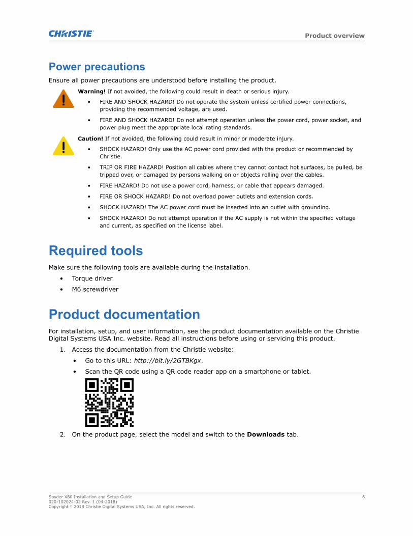
Product documentationFor installation, setup, and user information, see the product documentation available on the ChristieDigital Systems USA Inc. website. Read all instructions before using or servicing this product.
1. Access the documentation from the Christie website:
• Go to this URL: http://bit.ly/2GTBKgx.
• Scan the QR code using a QR code reader app on a smartphone or tablet.
2. On the product page, select the model and switch to the Downloads tab.
Product overview
Spyder X80 Installation and Setup Guide 6020-102024-02 Rev. 1 (04-2018)Copyright © 2018 Christie Digital Systems USA, Inc. All rights reserved.
Related documentationAdditional information on Spyder is available in the following documents:
• Christie Spyder Studio User Guide (P/N: 020-102205-XX)
• Christie Spyder Serial Commands Technical Reference (P/N: 020-102207-XX)
Spyder X80 interface and portsLearn about the interface and physical ports on the Spyder.
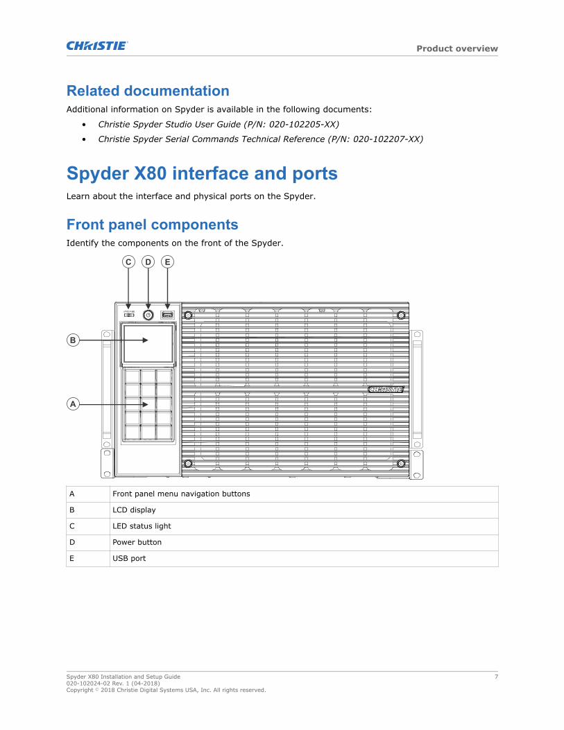
Front panel componentsIdentify the components on the front of the Spyder.
A Front panel menu navigation buttons
B LCD display
C LED status light
D Power button
E USB port
Product overview
Spyder X80 Installation and Setup Guide 7020-102024-02 Rev. 1 (04-2018)Copyright © 2018 Christie Digital Systems USA, Inc. All rights reserved.
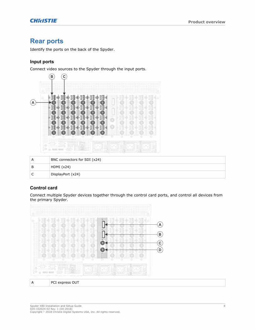
Rear portsIdentify the ports on the back of the Spyder.
Input portsConnect video sources to the Spyder through the input ports.
A BNC connectors for SDI (x24)
B HDMI (x24)
C DisplayPort (x24)
Control cardConnect multiple Spyder devices together through the control card ports, and control all devices fromthe primary Spyder.
A PCI express OUT
Product overview
Spyder X80 Installation and Setup Guide 8020-102024-02 Rev. 1 (04-2018)Copyright © 2018 Christie Digital Systems USA, Inc. All rights reserved.
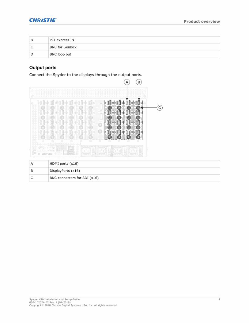
B PCI express IN
C BNC for Genlock
D BNC loop out
Output portsConnect the Spyder to the displays through the output ports.
A HDMI ports (x16)
B DisplayPorts (x16)
C BNC connectors for SDI (x16)
Product overview
Spyder X80 Installation and Setup Guide 9020-102024-02 Rev. 1 (04-2018)Copyright © 2018 Christie Digital Systems USA, Inc. All rights reserved.
Installing the SpyderX80Use the following instructions to install and configure the Spyder X80.
Mounting the Spyder X80 in a rackThe Spyder X80 must be mounted in a clean and dry environment. Provide space at the front and rearof the system for ventilation.
1. Attach the L brackets onto the rack using the screws supplied with the rack.
2. Set the Spyder X80 onto the brackets, and slide the device back into the rack.
3. Secure the Spyder X80 to the rack using the screws supplied with the rack.
Connecting the powerSupply power to the Spyder in the rack.
If the Spyder is not being installed in a rack, plug one end of the power cord into the AC receptacle onthe device and plug the other end of the power cord into a grounded AC outlet.
1. For each of the four power receptacles on the Spyder, attach a power cable.Two of the power receptacles are used to provide power to the Spyder, and the other tworeceptacles provide redundancy.
2. Plug the other end of the power cords into grounded AC outlets.
Connecting video sources and displaysAll source connections are made to the input panel, located at the back of the Spyder. Each projectoror display is connected through the output panel.
1. Connect your video sources to the Input ports.
2. Connect the projectors or displays to the Output ports.
Related information
Spyder X80 interface and ports (on page 7)
Spyder X80 Installation and Setup Guide 10020-102024-02 Rev. 1 (04-2018)Copyright © 2018 Christie Digital Systems USA, Inc. All rights reserved.
Connecting the Spyder X80 to the networkUse a CAT5 Ethernet cable to connect the Spyder X80 to the network.
1. Connect a standard CAT5 Ethernet cable between the controller (or Ethernet hub) and theSpyder X80.
2. Review the front panel display, and verify an IP address is displayed.If the IP address 0.0.0.0 is displayed, a DHCP server cannot be found and an IP address mustbe manually set for the Spyder X80.
Related information
Changing the IP address of the Spyder X80 (on page 11)
Changing the IP address of the Spyder X80If there is no DHCP server available on the network, manually assign an IP address to the Spyder X80.
1. On the front panel of the Spyder X80, press Network.
2. With the Type row selected, press Enter to change the type to Static.
3. Using the arrows, select IP address and press Enter.
4. Using the keypad, clear any IP address that may be displayed in the field and type the IPaddress of the Spyder X80.
5. Press OK.
6. Change the Subnet and Gateway settings as necessary.
Installing the Spyder X80
Spyder X80 Installation and Setup Guide 11020-102024-02 Rev. 1 (04-2018)Copyright © 2018 Christie Digital Systems USA, Inc. All rights reserved.
Configuring SpyderStudioUse the Spyder Studio software to connect to a Spyder, configure the canvas size and pixelspace, anddesign the configuration.
Installing the Spyder Studio softwareInstall the Spyder Studio software on a computer with a resolution of 1920 x 1080 or greater.
Supported operating systems:
• Windows 7 SP1 or newer
Do not use MAC or PC emulators such as VMWare and Microsoft Virtual PC to run Spyder Studio.Hardware requirements:
• 1 GHz or faster 32-bit (x86) or 64-bit (x64) processor
• 1 GB RAM (32-bit) or 2 GB RAM (64-bit)
• 16 GB available hard disk space (32-bit) or 20 GB (64-bit)
Christie recommends closing all programs before installing the Spyder Studio software.
1. Download Spyder Studio from the Christie website (www.christiedigital.com).
2. Double-click Spyder Studio <version> Setup.exe.
3. Install any prerequisite programs and follow the Spyder Studio installation wizard.Although the application does not require that it be installed on any particular disk drive, thedata path for the application has been hard coded to C:\SPYDER. All users must have fullcontrol (read and write access) to the installation directory and to C:\SPYDER.
Configuring the network connectionTo ensure network performance and consistent communication between Spyder and Spyder Studioclients, configure the network connection with these recommendations.
• Spyder communicates to its clients over broadcast traffic. This traffic can be intensive to analready active network. Christie recommends that Spyder and all Spyder Studio clients beinstalled on a closed network. Place any unnecessary devices that also generate large amountsof network traffic on a separate network.
• Christie does not recommend using complex routers and managed switching equipment in thenetwork as it may cause communication interruptions if they are not configured properly,resulting in loss of communication with Spyder. If the connection between Spyder and itsclient(s) are interrupted, the communication socket can to break. This causes a temporary lossof communication until the socket is restored with restarting the client application.
Spyder X80 Installation and Setup Guide 12020-102024-02 Rev. 1 (04-2018)Copyright © 2018 Christie Digital Systems USA, Inc. All rights reserved.
• On computers running Spyder Studio, avoid configuring a network card with multiple IPaddresses and enabling secondary wired/wireless Ethernet connections.
Network cards on client computers must be configured with an IP address in a specific range.
1. Change the Internet Protocol (TCP/IP) properties to have the computer running Spyder Studioon the same subnet as the Spyder hardware.
2. If Spyder Studio is open, for the settings to be applied, restart the software.
Connecting Spyder Studio to the SpyderhardwareThe computer running Spyder Studio must be connected to the Spyder before a configuration can bedisplayed and live changes can be made.
1. Open Spyder Studio.
2. Select Server > Connection Manager.The server connection manager displays all individual Spyder frames or primary framesavailable on the network. Spyder frames configured as expansion frames do not appear in theServer Connection dialog.
3. In the Current Connection area, select the Spyder from the list, and click Connect.The Spyder Studio version on the client computer must have the same the firmware version ofthe Spyder frame before a connection is allowed. If the software versions do not match, theConnect button text changes to Update Now and the firmware must be updated.
Adding a routerTo have access to more sources than can connect directly to Spyder, add a router to the configuration.
1. Select Tools > Routers > Add New Router.Alternatively, select a source and in the Router area of the properties, click Add.
2. Type a name for the router.
3. Select the number of inputs and outputs available on the router.
4. Select the type of router.If the router is not listed, contact Christie Technical Support.
5. For Spyder X20 frames, in the Patch To list select the router protocol.
6. Select the type of connection between the router and Spyder.Analog is only valid for Spyder X20 frames.
7. Click OK.
Configuring Spyder Studio
Spyder X80 Installation and Setup Guide 13020-102024-02 Rev. 1 (04-2018)Copyright © 2018 Christie Digital Systems USA, Inc. All rights reserved.
Configuring a routerFor increased redundancy, configure multiple Spyder systems to share the same physical routingswitcher.
The router patch definition on each Spyder system distinguishes the physical router outputs thatcorrelate to the Spyder frame inputs.
1. Select Tools > Routers and select the router.
2. Type a name for the router.
3. Select the type of router.If the router is not listed, contact Christie Technical Support.
4. Select the number of inputs and outputs available on the router.
5. Select the type of connection between the router and Spyder.
6. If the router is an IP router, type the IP address of the router.
7. If the router is a serial router, select the serial port controlling the router.
8. To test the connection to the router, click Query Now.
Creating a new Spyder configurationCreate a new project file for each show.
For additional configuration options, refer to Christie Spyder Studio User Guide (P/N: 020-102205-XX).
1. Select File > New.
2. In the Welcome Screen, select the type of configuration to start with.
• Start with new empty configuration—Build a new configuration.
• Load current configuration—Create a new configuration file using the settings from thelast project loaded into Spyder Studio.
3. Add the Spyder frames to be used in the configuration.Select the model of each Spyder frame and the IP address of the frame in the order it willappear in the expansion chain.
4. Select the frame rate and mode for the Spyder system.To create a 3D configuration, select Stereoscopic mode.
5. Select the pixel depth model.
6. To include a Preview area in the configuration, click Preview Disabled.The button changes to Preview Enabled.
7. Click Next.
8. Define the canvas for each frame in the configuration.a) Set the width and height of the canvas space.
b) Identify the starting position of the canvas.
9. Click Next.
10. Add pixelspaces to the canvas.a) To add a pixelspace, right-click within the grid and select Add Pixelspace.
Configuring Spyder Studio
Spyder X80 Installation and Setup Guide 14020-102024-02 Rev. 1 (04-2018)Copyright © 2018 Christie Digital Systems USA, Inc. All rights reserved.
b) Select the new pixelspace and adjust the size with the pixelspace boundary handles or byspecifying the width and height in pixels in the top toolbar.
c) Click and drag the pixelspace to the correct position on the grid.The location can also be specified by entering the X and Y position of the pixelspace in thetop toolbar.
d) To rename the pixelspace, in the pixelspace properties pane type a new name and pressTab.
e) To remove a pixelspace, right-click the pixelspace and select Remove.
11. Click Next.
12. Select an output and drag it onto the pixelspace.
13. To configure the output, select it on the canvas and in the Properties pane adjust the outputsettings.
14. Click Next.
15. Select which data types within the configuration to keep and remove from the newconfiguration.
16. Add a router to the configuration.Routers can also be added after the configuration has been created.
17. Click Next.
18. Apply the configuration.
• If the computer is connected to Spyder, select Apply to Spyder hardware now.
• If the computer is not connected to Spyder, select Apply to local PC now (VirtualMode).
19. In the confirmation dialog, click OK and Close.Updates to Spyder the may cause devices in the expansion chain to restart.
Saving a project file to the computerWhen creating or updating a project while disconnected from Spyder, save the project file on thecomputer.
1. Select File > Backup.
2. Navigate to the location where the file will be saved.
3. Type a name for the project file.
4. Click Save.Spyder Studio projects are saved with a .vap extension.
5. Select whether the still images in the configuration should be included.Including still images in the backup may significantly increase the size of the file.
Configuring Spyder Studio
Spyder X80 Installation and Setup Guide 15020-102024-02 Rev. 1 (04-2018)Copyright © 2018 Christie Digital Systems USA, Inc. All rights reserved.
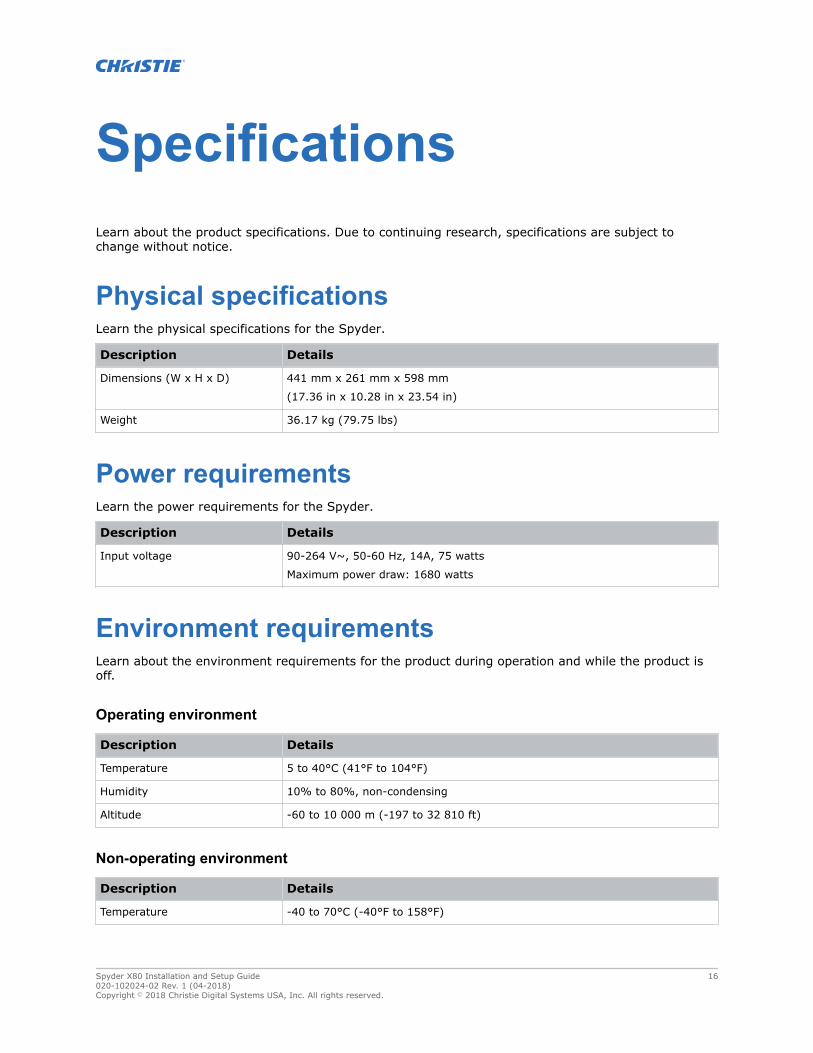
SpecificationsLearn about the product specifications. Due to continuing research, specifications are subject tochange without notice.
Physical specificationsLearn the physical specifications for the Spyder.
Description Details
Dimensions (W x H x D) 441 mm x 261 mm x 598 mm
(17.36 in x 10.28 in x 23.54 in)
Weight 36.17 kg (79.75 lbs)
Power requirementsLearn the power requirements for the Spyder.
Description Details
Input voltage 90-264 V~, 50-60 Hz, 14A, 75 watts
Maximum power draw: 1680 watts
Environment requirementsLearn about the environment requirements for the product during operation and while the product isoff.
Operating environment
Description Details
Temperature 5 to 40°C (41°F to 104°F)
Humidity 10% to 80%, non-condensing
Altitude -60 to 10 000 m (-197 to 32 810 ft)
Non-operating environment
Description Details
Temperature -40 to 70°C (-40°F to 158°F)
Spyder X80 Installation and Setup Guide 16020-102024-02 Rev. 1 (04-2018)Copyright © 2018 Christie Digital Systems USA, Inc. All rights reserved.

Description Details
Humidity
RegulatoryThis product conforms to the latest regulations and standards related to product safety, environmentalrequirements and electromagnetic compatibility (EMC).
Safety• CAN/CSA C22.2 No. 60950-1
• ANSI/UL 60950-1 - Information Technology Equipment – Safety – Part 1: GeneralRequirements
• IEC 60950-1 IEC/EN 60950-1 - Information Technology Equipment – Safety – Part 1: GeneralRequirements
• EN 60950-1
• IEC 62471-1 - Photobiological safety of lamps and lamp systems
Electro-magnetic compatibilityEmissions
• FCC CFR47, Part 15, Subpart B, Class A - Unintentional Radiators
• CAN ICES-003 (A)/NMB-003 (A) - Information Technology Equipment (Including DigitalApparatus) - Limits and Methods of Measurement
• CISPR 32/EN 55032, Class A
• IEC 61000-3-2/EN61000-3-2: Limits for Harmonic Current Emissions
Immunity• IEC 61000-3-3/EN61000-3-3
• IEC/EN61000
• IEC 61000-4-2/EN61000-4-2
• IEC 61000-4-3/EN61000-4-3
• IEC 61000-4-4/EN61000-4-4
• IEC 61000-4-5/EN61000-4-5
• IEC 61000-4-6/EN61000-4-6
• IEC 61000-4-8/EN61000-4-8
• IEC 61000-4-11/EN61000-4-11
Specifications
Spyder X80 Installation and Setup Guide 17020-102024-02 Rev. 1 (04-2018)Copyright © 2018 Christie Digital Systems USA, Inc. All rights reserved.

EnvironmentalEU Directive (2011/65/EU) on the restriction of the uses of certain hazardous substances (RoHS) inelectrical and electronic equipment and the applicable official amendment(s).EU Regulation (EC) No. 1907/2006 on the registration, evaluation, authorization and restriction ofchemicals (REACH) and the applicable official amendment(s).EU Directive (2012/19/EU) on waste and electrical and electronic equipment (WEEE) and theapplicable official amendment(s).China Ministry of Information Industry (along with 7 other Government Agencies) Order No.32(01/2016) on the control of pollution caused by electronic information products, hazardous substancesconcentration limits (GB/T 26572 - 2011), and the applicable product marking requirement (SJ/T11364 - 2014).
Specifications
Spyder X80 Installation and Setup Guide 18020-102024-02 Rev. 1 (04-2018)Copyright © 2018 Christie Digital Systems USA, Inc. All rights reserved.
Glossary
1080p1080p is the Advanced Television SystemsCommittee (ATSC) high definition 1920 x 1080progressive scan video format in which acomplete frame of video is delivered at either 60or 24 frames per second.
4KA display specification that is capable ofdisplaying 4096 x 2160 resolution, orapproximately 8.85 million pixels.
Active stereoscopic displayPowered glasses that present the image intendedfor the left eye while blocking the view of theright eye, then presenting the right eye imagewhile blocking the left eye. This cycle is repeatedrapidly, so that the two images combine into asingle 3D image.
Aspect ratioThe ratio of the width of an image to its height,such as the 4:3 aspect ratio common in videooutput. Can also be expressed as a decimalnumber, such as 1.77, 1.85 or 2.39. The largerthe ratio or decimal, the wider and less squarethe image.
Brightness (perceived)The human eye responds to low light levels byenlarging the pupil, allowing more light to enterthe eye. This response results in a differencebetween measured and perceived light levels. Thebrightness of a projection system can be preciselymeasured with a light meter; however, thehuman eye has a logarithmic response to light. Alamp that is dimmed to 10% of its maximummeasured light output is perceived as beingdimmed to only 32%. Likewise, a lamp dimmedto 1% is perceived to be at 10%.
Color temperatureThe coloration (reddish, white, bluish, greenish,and so on.) of white in an image, measured usingthe Kelvin (on page 20) (degrees K)temperature scale.
Contrast (ratio)The degree of difference between the lightest anddarkest areas of the image.
DisplayPortA digital display interface primarily used toconnect a video source to a display device suchas a computer monitor, though it can also beused to transmit audio, USB, and other forms ofdata. DisplayPort can be used to transmit audioand video simultaneously.
DVIDigital visual interface. A standard that definesthe interface between digital devices such asprojectors, flat screens and personal computers.For devices that support DVI, a digital-to-digitalconnection can be made to eliminate theconversion to analog and deliver an image.DVI can also carry an analog signal and comes asDVI-I (integrated—analog and digital), DVI-D(digital only) and DVI-A (analog only).
E-EDIDEnhanced extended display identificationstandard. Enables properties (such as resolution)of a display device to be detected by the displaycard in a controlling device such as a PC. The PC,in turn, can then output in a matching format tofill the display.
Spyder X80 Installation and Setup Guide 19020-102024-02 Rev. 1 (04-2018)Copyright © 2018 Christie Digital Systems USA, Inc. All rights reserved.
GammaThe relationship between input video voltage andoutput brightness, which determines how mid-tones appear.
HDCPHigh-bandwidth digital content protection.Prevents copying of digital audio and videocontent as it travels across connections.
InputA physical connection route for a source signal.
Input signalSignal sent from a source device to the projectoror display.
KelvinA temperature measurement scale where 0°Kelvin (0°K) is equal to absolute zero, thetemperature at which all molecular movementceases. One degree of Kelvin is equal to onedegree of Celsius. The color temperature of largeimage devices is measured in Kelvin.
KeyframeVisual attributes applied to a layer such as size,position, borders, shadows, or clone modes.
Passive stereoscopic displayTwo images are projected superimposed onto thesame screen through polarizing filters orpresented on a display with polarized filters. Theviewer wears glasses which also contain a pair ofopposite polarizing filters. As each filter onlypasses light which is similarly polarized andblocks the opposite polarized light, each eye onlysees one of the images.
PixelThe smallest discernible element of data from acomputer-generated image.
PixelspaceA clipping rectangle defining an area of thescreen.
PresetA set of layers and treatments to be displayedwithin a pixelspace.
OutputA physical connection route for sending a signalto a projector or display.
LayerA single input, displaying either a live video inputor a still image.
ResolutionThe maximum number of pixels that can bedisplayed horizontally and vertically.
SourceThe device, such as a computer or DVD player,connected to the Spyder for display.
StereoscopicThe creation of a 3D or stereoscopic display isbased on the principle that a person’s eyes seetwo different viewpoints. These two distinctviewpoints are then projected onto a screen sothat each eye sees the proper perspective; theleft eye sees only the left-eye viewpoint, and theright eye sees only the right-eye viewpoint. Thebrain then reads both viewpoints simultaneouslyto produce a single image with the depthnecessary to make it appear three dimensional.There are two ways to present 3D content, activestereoscopic (on page 19) or passive stereoscopic(on page 20) displays.
Glossary
Spyder X80 Installation and Setup Guide 20020-102024-02 Rev. 1 (04-2018)Copyright © 2018 Christie Digital Systems USA, Inc. All rights reserved.
For the most current technical documentation, visit www.christiedigital.com.
Christie Digital Systems Canada Inc.Kitchenerph: 519 744 8005
Christie Digital Systems USA, Inc.Cypressph: 714 236 8610
Corporate offi ces
United Kingdomph: +44 (0) 118 977 8000
United Arab Emiratesph: +971 4 3206688
Spainph: +34 91 633 9990
Singaporeph: +65 6877 8737
Republic of South Africaph: +27 (0)11 510 0094
Korea (Seoul)ph: +82 2 702 1601
Japan (Tokyo)ph: 81 3 3599 7481
Indiaph: +91 (080) 6708 9999
Germanyph: +49 2161 664540
Franceph: +33 (0) 1 41 21 44 04
Russian Federationand Eastern Europeph: +36 (0) 1 47 48 100
China (Shanghai)ph: +86 21 6278 7708
China (Beijing)ph: +86 10 6561 0240
Brazilph: +55 (11) 2548 4753
Australiaph: +61 (0) 7 3624 4888
Worldwide offi ces
Italyph: +39 (0) 2 9902 1161
Independant sales consultant offi ces
Mexicoph: +52 55 4744 1790
United States (New York)ph: 646 779 2014
United States (Arizona)ph: 602 943 5700

Related Documents