SPHERA: Spherical Plasma for HElicity Relaxation Assessment F. Alladio, G. Angelone, P. Buratti, A. Cardinali, A. Cecchini, R. Cesario, C. Gourlan, L. Lovisetto, A. Mancuso, P. Micozzi, S. Mantovani, S. Migliori, L. Pieroni, L. Semeraro, A.A. Tuccillo, F. Valente, V. Zanza Frascati, March 1997

Welcome message from author
This document is posted to help you gain knowledge. Please leave a comment to let me know what you think about it! Share it to your friends and learn new things together.
Transcript
SPHERA: Spherical Plasma for HElicity Relaxation
Assessment
F. Alladio, G. Angelone, P. Buratti, A. Cardinali, A. Cecchini, R. Cesario, C. Gourlan, L. Lovisetto, A. Mancuso, P. Micozzi,
S. Mantovani, S. Migliori, L. Pieroni, L. Semeraro, A.A. Tuccillo, F. Valente, V. Zanza
Frascati, March 1997
2
INDEX EXECUTIVE SUMMARY ... ... … … … … … 4 General motivations for Spherical Tori … … … … 4 Parameters of the proposal … … … … … … 5 Experimental Phases of SPHERA … … … … … 5 Scenarios of the proposal … … … … … … 6 Scientific motivations of SPHERA-PINCH … … … … 8 Scientific motivations of SPHERA with a central conductor … 8 Technological requirements … … … … … … 9 Other proposed Spherical Tokamaks … … … … … 9 The role of SPHERA in the European Fusion Program … … 10 Reactor extrapolation … … … … … … … 11 1. INTRODUCTION … … … … … … … 13 1.1 Characteristics of Spherical Tori … … … … 13 1.1.1 Advantages of Spherical Tori … … … … 14 1.1.2 Problems of Spherical Tori … … … … 16 1.1.3 Limits to Aspect Ratio in Spherical Tori … … 17 1.1.4 Helicity Injection in Spherical Tori … … … 17 1.1.5 The "Flux Core" Experiment of TS-3 … … 20 1.2 LART, ULART and SPHERA … … … … 24 2. EQUILIBRIUM AND STABILITY OF SPHERA … … … 27 2.1 The SPHERA-PINCH equilibrium with Ip = 2.7 MA … 27 2.2 The SPHERA equilibrium in presence of a central conductor 34 2.3 Current and aspect ratio limits for SPHERA due to the tilt mode 38 3. THE ASSUMPTIONS FOR THE SPHERICAL TORUS … … 40 3.1 Density limit … … … … … … … 40 3.2 Energy confinement time … … … … … 40 3.3 Fixed power scenarios … … … … … 40 3.4 H-mode power threshold … … … … … 41 4. PLASMA FORMATION AND COMPRESSION … … … 42 4.1 Formation and compression in presence of the central Screw Pinch … … … … … … … 42 4.1.1 Screw Pinch breakdown … … … … 43 4.1.2 ULART breakdown … … … … … 43 4.1.3 ULART compression … … … … … 44 4.1.4 Power supply for SPHERA-PINCH … … … 49 4.2 Formation and compression in presence of a central conductor 50 4.2.1 Power supply for SPHERA with a central conductor 52 5. THE SCENARIOS OF SPHERA … … … … … 53 5.1 SPHERA-RF … … … … … … … 53 5.1.1 Propagation, absorption and CD efficiency of the LH on SPHERA … … … … … … … 56 5.1.2 The NBI system for SPHERA … … … … 61
3
5.1.3 The ECRH system for SPHERA … … … 64 5.1.4 SPHERA with central conductor at high β … … 64 5.2 SPHERA-HI … … … … … … … 65 5.3 SPHERA-PINCH … … … … … … 68 5.3.1 O-X-B heating for SPHERA-PINCH and SPHERA-HI 69 6. RELAXED STATES AND SPHERA-PINCH … … … 70 7. CHARACTERISATION OF THE ELECTRODES AND OF THE SCREW PINCH … … … … … … 73 7.1 Past experiments with Deuterium arc discharges … … 73 7.2 Electrodes for SPHERA … … … … … 74 7.3 The resistivity of the central Screw Pinch … … … 75 7.4 Screw Pinch power balance … … … … … 76 7.5 SOL plasma characteristics of SPHERA … … … 78 8. THE LOAD ASSEMBLY … … … … … … 80 8.1 General scheme of the load assembly … … … … 80 8.2 Poloidal field coils … … … … … … 83 8.3 Toroidal field coils … … … … … … 84 8.4 The stresses on the central conductor in case of a tilt disruption 86 8.5 The toroidal field ripple … … … … … 87 9. CRITICAL POINTS OF THE PROPOSAL … … … … 88 9.1 Critical points of SPHERA-RF … … … … 88 9.2 Critical points of SPHERA-HI … … … … 89 9.3 Critical points of SPHERA-PINCH … … … … 90 APPENDIX: HELICITY AND MAGNETIC RELAXATION … … 91 A1 Definition of the magnetic Helicity … … … … 91 A2 General meaning of the magnetic Helicity … … … 92 A3 Magnetic Relaxation and Gravitational analogue … … 94 A4 Helicity and Magnetic Reconnection … … … … 96 A5 Relative Magnetic Helicity … … … … … 98 A6 Helicity Injection … … … … … … 100 A7 DC Helicity Injection in a Spherical Torus … … … 102 A8 DC Helicity Injection in a Torus with central conductor … 103 A9 DC Helicity Injection in Spheromaks … … … … 104 A10 Taylor's theory of DC Helicity Injection in relaxed states … 105 A11 Boozer's theory of DC Helicity Injection in quasi-relaxed states 108 A12 Efficiency of DC Helicity Injection Current Drive … … 109 REFERENCES … … … … … … … … 111
4
EXECUTIVE SUMMARY GENERAL MOTIVATIONS FOR SPHERICAL TORI Low Aspect Ratio Tokamak (LART, A < 2) are fusion relevant configurations, as they allow [1-3]: • High plasma current at low toroidal field; • Very simple poloidal and toroidal field windings; • Natural elongation up to κ=3 and intrinsic vertical stability; • Very high values of total β (β up to 4% in ohmic discharges and up to 12% in additionally heated discharges have been obtained in the START experiment [2]); values of β up to 40% are expected in the next generation of Spherical Tokamaks; • Robust stability at high βN; • Increased stability for kink and tearing modes; • Possible absence of disruptions; • High confinement due to high plasma density, high current density and strong shaping; • Minimal geodesic curvature of the lines of force; • Natural divertor and easy plasma rotation, which should mean easy access to advanced Tokamak regimes; • Moderate requirements for Current Drive, due to the low R, to the high toroidal component of the diamagnetic current and to the large bootstrap current at high β. • Easy Direct Current Helicity Injection (low Helicity and low inductance). • Extrapolation to a compact volumetric neutron source [4] and to small size reactors [5]. There are, however, further reasons which push toward the Ultra Low Aspect Ratio Tokamak (ULART, A ≤ 1.3 ) [6]. One of the main problems of a LART reactor is that, since the central conductor of the toroidal magnet cannot be shielded against the neutron flux, it is then bombarded by neutrons, and therefore cannot be built by super conducting materials [7]. Thus the central rod of the toroidal magnet may involve an energy dissipation too large with respect to the generated fusion power. In order to avoid excessive losses in the central conductor the only way is to go toward an ULART, with A < 1.3. The reason being the particularly low ratio between the current in the central conductor Itf and the toroidal plasma current Ip, which, for aspect ratios A < 2, is well described by [8, 9]:
5
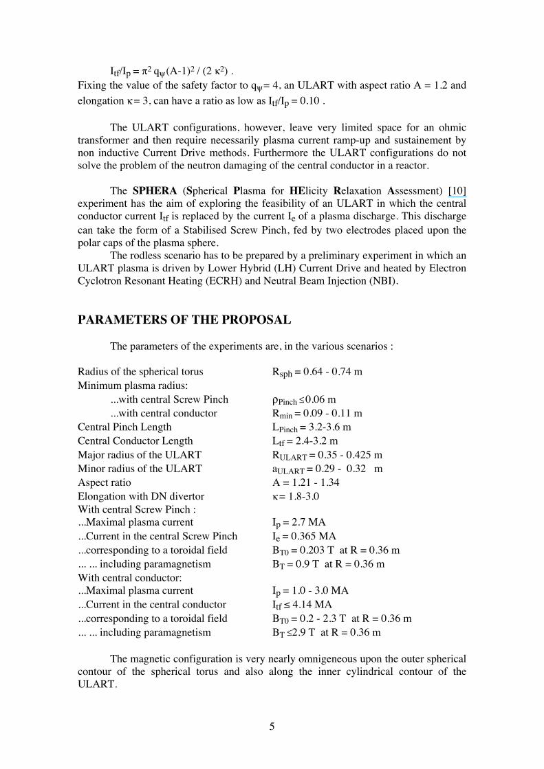
Itf/Ip = π2 qψ (A-1)2 / (2 κ2) . Fixing the value of the safety factor to qψ = 4, an ULART with aspect ratio A = 1.2 and elongation κ = 3, can have a ratio as low as Itf/Ip = 0.10 . The ULART configurations, however, leave very limited space for an ohmic transformer and then require necessarily plasma current ramp-up and sustainement by non inductive Current Drive methods. Furthermore the ULART configurations do not solve the problem of the neutron damaging of the central conductor in a reactor. The SPHERA (Spherical Plasma for HElicity Relaxation Assessment) [10] experiment has the aim of exploring the feasibility of an ULART in which the central conductor current Itf is replaced by the current Ie of a plasma discharge. This discharge can take the form of a Stabilised Screw Pinch, fed by two electrodes placed upon the polar caps of the plasma sphere. The rodless scenario has to be prepared by a preliminary experiment in which an ULART plasma is driven by Lower Hybrid (LH) Current Drive and heated by Electron Cyclotron Resonant Heating (ECRH) and Neutral Beam Injection (NBI). PARAMETERS OF THE PROPOSAL The parameters of the experiments are, in the various scenarios : Radius of the spherical torus Rsph = 0.64 - 0.74 m Minimum plasma radius: ...with central Screw Pinch ρPinch ≤ 0.06 m ...with central conductor Rmin = 0.09 - 0.11 m Central Pinch Length LPinch = 3.2-3.6 m Central Conductor Length Ltf = 2.4-3.2 m Major radius of the ULART RULART = 0.35 - 0.425 m Minor radius of the ULART aULART = 0.29 - 0.32 m Aspect ratio A = 1.21 - 1.34 Elongation with DN divertor κ = 1.8-3.0 With central Screw Pinch : ...Maximal plasma current Ip = 2.7 MA ...Current in the central Screw Pinch Ie = 0.365 MA ...corresponding to a toroidal field BT0 = 0.203 T at R = 0.36 m ... ... including paramagnetism BT = 0.9 T at R = 0.36 m With central conductor: ...Maximal plasma current Ip = 1.0 - 3.0 MA ...Current in the central conductor Itf ≤ 4.14 MA ...corresponding to a toroidal field BT0 = 0.2 - 2.3 T at R = 0.36 m ... ... including paramagnetism BT ≤2.9 T at R = 0.36 m The magnetic configuration is very nearly omnigeneous upon the outer spherical contour of the spherical torus and also along the inner cylindrical contour of the ULART.
6
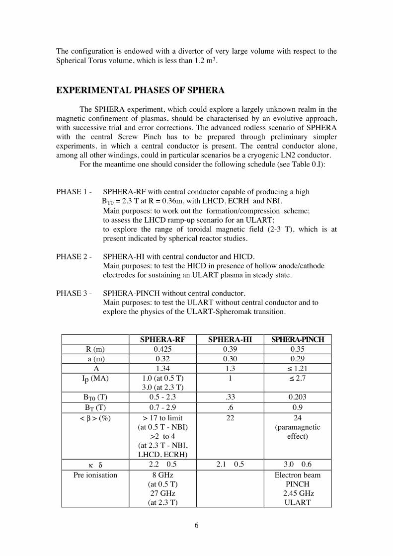
The configuration is endowed with a divertor of very large volume with respect to the Spherical Torus volume, which is less than 1.2 m3. EXPERIMENTAL PHASES OF SPHERA The SPHERA experiment, which could explore a largely unknown realm in the magnetic confinement of plasmas, should be characterised by an evolutive approach, with successive trial and error corrections. The advanced rodless scenario of SPHERA with the central Screw Pinch has to be prepared through preliminary simpler experiments, in which a central conductor is present. The central conductor alone, among all other windings, could in particular scenarios be a cryogenic LN2 conductor. For the meantime one should consider the following schedule (see Table 0.I): PHASE 1 - SPHERA-RF with central conductor capable of producing a high BT0 = 2.3 T at R = 0.36m, with LHCD, ECRH and NBI. Main purposes: to work out the formation/compression scheme; to assess the LHCD ramp-up scenario for an ULART; to explore the range of toroidal magnetic field (2-3 T), which is at present indicated by spherical reactor studies. PHASE 2 - SPHERA-HI with central conductor and HICD. Main purposes: to test the HICD in presence of hollow anode/cathode electrodes for sustaining an ULART plasma in steady state. PHASE 3 - SPHERA-PINCH without central conductor. Main purposes: to test the ULART without central conductor and to explore the physics of the ULART-Spheromak transition.
SPHERA-RF SPHERA-HI SPHERA-PINCH R (m) 0.425 0.39 0.35 a (m) 0.32 0.30 0.29
A 1.34 1.3 ≤ 1.21 Ip (MA) 1.0 (at 0.5 T)
3.0 (at 2.3 T) 1 ≤ 2.7
BT0 (T) 0.5 - 2.3 .33 0.203 BT (T) 0.7 - 2.9 .6 0.9
< β > (%) > 17 to limit (at 0.5 T - NBI)
>2 to 4 (at 2.3 T - NBI, LHCD, ECRH)
22 24 (paramagnetic
effect)
κ δ 2.2 0.5 2.1 0.5 3.0 0.6 Pre ionisation 8 GHz
(at 0.5 T) 27 GHz
(at 2.3 T)
Electron beam PINCH
2.45 GHz ULART
7
Start up Compression + NBI or LHCD
Compression + HICD
Compression + HICD
Auxiliary Heating
NBI (4 MW) ECRH 140 GHz
(1.5 MW) LH 2.45, 8 GHz
(3 MW)
HICD (>2 MW)
HICD (>4 MW)
Pulse length (s) 1.5
a few ? a few ?
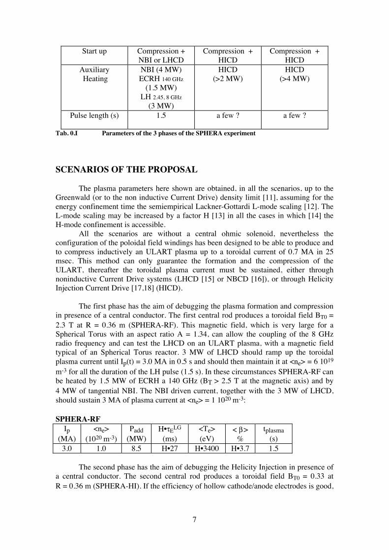
Tab. 0.I Parameters of the 3 phases of the SPHERA experiment SCENARIOS OF THE PROPOSAL The plasma parameters here shown are obtained, in all the scenarios, up to the Greenwald (or to the non inductive Current Drive) density limit [11], assuming for the energy confinement time the semiempirical Lackner-Gottardi L-mode scaling [12]. The L-mode scaling may be increased by a factor H [13] in all the cases in which [14] the H-mode confinement is accessible. All the scenarios are without a central ohmic solenoid, nevertheless the configuration of the poloidal field windings has been designed to be able to produce and to compress inductively an ULART plasma up to a toroidal current of 0.7 MA in 25 msec. This method can only guarantee the formation and the compression of the ULART, thereafter the toroidal plasma current must be sustained, either through noninductive Current Drive systems (LHCD [15] or NBCD [16]), or through Helicity Injection Current Drive [17,18] (HICD). The first phase has the aim of debugging the plasma formation and compression in presence of a central conductor. The first central rod produces a toroidal field BT0 = 2.3 T at R = 0.36 m (SPHERA-RF). This magnetic field, which is very large for a Spherical Torus with an aspect ratio A = 1.34, can allow the coupling of the 8 GHz radio frequency and can test the LHCD on an ULART plasma, with a magnetic field typical of an Spherical Torus reactor. 3 MW of LHCD should ramp up the toroidal plasma current until Ip(t) = 3.0 MA in 0.5 s and should then maintain it at <ne> = 6 1019
m-3 for all the duration of the LH pulse (1.5 s). In these circumstances SPHERA-RF can be heated by 1.5 MW of ECRH a 140 GHz (BT > 2.5 T at the magnetic axis) and by 4 MW of tangential NBI. The NBI driven current, together with the 3 MW of LHCD, should sustain 3 MA of plasma current at <ne> = 1 1020 m-3: SPHERA-RF
Ip (MA)
<ne> (1020 m-3)
Padd (MW)
H•τELG
(ms) <Te> (eV)
< β > %
tplasma (s)
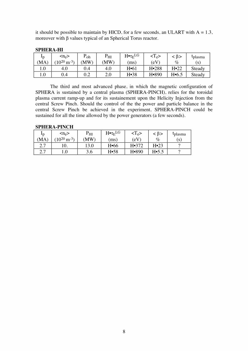
3.0 1.0 8.5 H•27 H•3400 H•3.7 1.5 The second phase has the aim of debugging the Helicity Injection in presence of a central conductor. The second central rod produces a toroidal field BT0 = 0.33 at R = 0.36 m (SPHERA-HI). If the efficiency of hollow cathode/anode electrodes is good,
8
it should be possible to maintain by HICD, for a few seconds, an ULART with A = 1.3, moreover with β values typical of an Spherical Torus reactor. SPHERA-HI
Ip (MA)
<ne> (1020 m-3)
Poh (MW)
PHI (MW)
H•τELG
(ms) <Te> (eV)
< β > %
tplasma (s)
1.0 4.0 0.4 4.0 H•61 H•288 H•22 Steady 1.0 0.4 0.2 2.0 H•38 H•890 H•6.5 Steady
The third and most advanced phase, in which the magnetic configuration of SPHERA is sustained by a central plasma (SPHERA-PINCH), relies for the toroidal plasma current ramp-up and for its sustainement upon the Helicity Injection from the central Screw Pinch. Should the control of the the power and particle balance in the central Screw Pinch be achieved in the experiment, SPHERA-PINCH could be sustained for all the time allowed by the power generators (a few seconds). SPHERA-PINCH
Ip (MA)
<ne> (1020 m-3)
PHI (MW)
H•τELG
(ms) <Te> (eV)
< β > %
tplasma (s)
2.7 10. 13.0 H•66 H•372 H•23 ? 2.7 1.0 3.6 H•58 H•890 H•5.5 ?
9
SCIENTIFIC MOTIVATIONS OF SPHERA-PINCH In its most advanced scenario SPHERA-PINCH tries to: • avoid the damaging of the central conductor in an ULART; • sustain the ULART configuration, in absence of inductive current drive, through DC Helicity Injection, obtained by driving plasma current along the lines of force of the central Screw Pinch. The formation and compression scheme which needs a double breakdown in the same vacuum vessel is one of the main challenges, but also one of the main points of scientific interest for SPHERA-PINCH. The ULART of SPHERA-PINCH could show a tendency toward a relaxed quasi force-free state [19], i.e. with µ0µ = j•B/B2 almost constant all over the ULART plasma. The main idea of the experiment is to drive the spherical plasma of radius Rsph, through appropriate initial conditions (formation and compression of the ULART), toward a stable state with µ0µRsph < 4.49 (first Spheromak eigenvalue [17]), by increasing the value of µ, but maintaining in the ULART safety factor values typical of a Tokamak (q0≈1, qedge≈3-4), with the aim of controlling the Helicity flow toward the toroidal magnetic axis and to avoid the complete relaxation of the system. At the end of the formation and compression of the plasma, the control of the Screw Pinch parameters should allow to maintain the configuration at the largest possible value of µ0µRsph without transforming the plasma into a Spheromak. On the other hand the control of the ULART parameters should allow to influence the Helicity and Power transfer from the Screw Pinch to the ULART. These objectives, i.e. the Helicity Injection and the control of the magnetic relaxation, along with the study of the resulting confinement and β limits, are the key points of the physics addressed by the SPHERA-PINCH experiment. SCIENTIFIC MOTIVATIONS OF SPHERA WITH A CENTRAL CONDUCTOR The most advanced scenario of SPHERA with the central Screw Pinch must be prepared through preliminary simpler scenarios, which are ULART experiments with a central conductor. The first scenario has a central conductor capable of producing BT0 ≤ 2.3 T at R = 0.36 m (SPHERA-RF). This scenario leads to the only experiment in which the toroidal plasma current in an ULART can be increased up to 3 MA and is then maintained by LHCD, eventually in conjunction with NBCD and ECRH. This experiment could show the relevance of LHCD for the plasma current ramp-up for future reactor-grade Spherical Tori. It would also give unique data upon the effect of small normalised Larmor radius in the performances of Spherical Tori. However at high toroidal field the beta value is predicted to be quite small (2-4%) even at full heating power.
10
The reduction of the toroidal field to BT0 = 0.5 T at R = 0.36 m could allow to obtain high beta values (>17%), although in this case the only available CD system would be the 4 MW tangential NBI. The second scenario has a reduced central conductor capable of producing BT0 = 0.33 (SPHERA-HI). Such an experiment can take advantage of the extended divertor region in both the internal as well as in the external divertor branch, in order to study the Helicity Injection Current Drive (HICD) using hollow cathode/anode electrodes. This scenario has the aim of obtaining a steady state plasma, moreover with β values typical of an ULART reactor. This experiment is unique among other Helicity Injection experiments and proposals, as it uses the Helicity Injection not only for the plasma start-up but also for the plasma sustainement, and moreover it would be the first attempt of DC Helicity Injection in absence of a conducting shell surrounding the plasma. TECHNOLOGICAL REQUIREMENTS The main technological objective of SPHERA-PINCH is that of finding a working regime for the electrodes at a power level which can lead to a reactor extrapolation. The most critical point in the SPHERA-PINCH experiment is the requirement of containing the power Pe injected through the electrodes in order to minimise damages and impurity influx. In the scenarios with a central conductor the large divertor region allows to study the Helicity Injection, even in circumstances where powers of a few tens MW should be required on the electrodes. A constructive solution that allows an easy maintenance and substitution of the central conductor is proposed. Insulation problems are very critical for the Helicity Injection in both the central conductor as well as in the rodless scenarios. OTHER PROPOSED SPHERICAL TOKAMAKS There are quite a few devices in the field of low aspect ratio Tokamak being built and proposed in many laboratories around the world. In order to assess the place of the SPHERA proposal within the contest of the ongoing activity, we will consider only the two largest Spherical Tokamaks under construction, i.e. the ones that aim at similar range of parameters. MAST (Mega Amp Spherical Tokamak), being built by the Culham Laboratory [20, 21], is a scaled up version of START [22, 23] and should produce its first plasma within 1998. MAST is endowed with a central solenoid, which can sustain an ohmic Spherical Tokamak. Its main aim is to extend the experimental results of START to the 1-2 MA range of plasma current. Two broad objectives are: 1) to make a significant contribution to the understanding of Tokamak Physics (confinement scaling, plasma exhaust, MHD stability etc.) also in view of ITER; 2) to test the spherical Tokamak
11
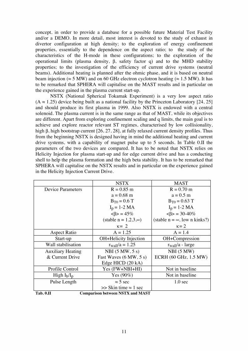
concept, in order to provide a database for a possible future Material Test Facility and/or a DEMO. In more detail, most interest is devoted to the study of exhaust in divertor configuration at high density; to the exploration of energy confinement properties, essentially to the dependence on the aspect ratio; to the study of the characteristics of the H-mode in these configurations; to the exploration of the operational limits (plasma density, β, safety factor q) and to the MHD stability properties; to the investigation of the efficiency of current drive systems (neutral beams). Additional heating is planned after the ohmic phase, and it is based on neutral beam injection (≈ 5 MW) and on 60 GHz electron cyclotron heating (≈ 1.5 MW). It has to be remarked that SPHERA will capitalise on the MAST results and in particular on the experience gained in the plasma current start-up. NSTX (National Spherical Tokamak Experiment) is a very low aspect ratio (A ≈ 1.25) device being built as a national facility by the Princeton Laboratory [24, 25] and should produce its first plasma in 1999. Also NSTX is endowed with a central solenoid. The plasma current is in the same range as that of MAST, while its objectives are different. Apart from exploring confinement scaling and q limits, the main goal is to achieve and explore reactor relevant ST regimes, characterised by low collisionality, high β, high bootstrap current [26, 27, 28], at fully relaxed current density profiles. Thus from the beginning NSTX is designed having in mind the additional heating and current drive systems, with a capability of magnet pulse up to 5 seconds. In Table 0.II the parameters of the two devices are compared. It has to be noted that NSTX relies on Helicity Injection for plasma start-up and for edge current drive and has a conducting shell to help the plasma formation and the high beta stability. It has to be remarked that SPHERA will capitalise on the NSTX results and in particular on the experience gained in the Helicity Injection Current Drive.
NSTX MAST Device Parameters R = 0.85 m
a = 0.68 m BT0 = 0.6 T Ip = 1-2 MA <β> = 45%
(stable n = 1,2,3,∞) κ = 2
R = 0.70 m a = 0.5 m
BT0 = 0.63 T Ip = 1-2 MA
<β> = 30-40% (stable n = ∞, low n kinks?)
κ = 2 Aspect Ratio A = 1.25 A = 1.4
Start-up OH+Helicity Injection OH+Compression Wall stabilisation rwall/a = 1.25 rwall/a - large Auxiliary Heating & Current Drive
NBI (5 MW, 5 s) Fast Waves (6 MW, 5 s)
Edge HICD (20 kA)
NBI (5 MW) ECRH (60 GHz, 1.5 MW)
Profile Control Yes (FW+NBI+HI) Not in baseline High Ib/Ip Yes (90%) Not in baseline
Pulse Length ≈ 5 sec >> Skin time ≈ 1 sec
1.0 sec
Tab. 0.II Comparison between NSTX and MAST
12
THE ROLE OF SPHERA IN THE EUROPEAN FUSION PROGRAM The scientific program of SPHERA will be compared with that of MAST, both since MAST is being built and because it is within the European Fusion program. SPHERA is proposed to test a configuration of an Ultra-Low Aspect Ratio Tokamak, where the central conductor is substituted by a current carrying plasma, typically a Screw Pinch. The feasibility of such a solution is very difficult to treat theoretically and a dedicated experiment could have a great importance for proving this solution. In this aim SPHERA is complementary to MAST. With this final goal in mind, the scientific program of SPHERA is articulated in three main phases. While SPHERA-PINCH is the most innovative and original phase of the proposed experiment, the previous phases with a central conductor will capitalise from the MAST experimental results and will try to provide data complementary to the ones collected by MAST: • In particular SPHERA-RF will explore the application of RF waves (LH and ECRH) on a spherical plasma, both for heating and current drive. This will occur in conjunction with tangential NBI. • The ρ* (Larmor radius normalised to the plasma minor radius) values explored by SPHERA-RF will be quite smaller than the ρ* values obtained in MAST. This will give indications about the effects of finite ρ* on stability and confinement of Spherical Tori. • It is to be noted that qψ ≈ 20 at BT0 = 2.3 T and Ip ≈ 1 MA. Current density profile control could allow to enter regimes of strong shear reversal with qo»1, and to obtain enhanced performances. SPHERA-HI is devoted mainly to investigate the efficiency of Helicity Injection for current drive. This experiment is not yet planned for MAST, whose load assembly does not include, at the moment, the required vacuum vessel insulation. If this phase is successful, regimes with total relaxation of the current density profiles, even at high plasma temperature (with additional heating) and high β, could be studied. In conclusion, SPHERA will extend the range of plasma parameters obtained in Spherical Tori, and will tackle some physical problem that MAST does not plan to investigate such as RFCD and HICD scenarios. It should be stressed that a tangential neutral beam system (with a total power of ≈ 4 MW) would be very useful both for heating and diagnostics. It is true that in Frascati there is no experience in neutral beam injection, but the technology, for positive ion sources, is quite mature and these system could be acquired from other laboratories, who have applied this technique to their magnetic confinement experiments. We believe that SPHERA would have a complementary and supporting role for MAST in the European Fusion program, and as such could be well accepted by the European and by the International Fusion Community. REACTOR EXTRAPOLATION Should the SPHERA Experiment show that the total power which has to be injected into the central Screw Pinch can be contained within reasonable terms, and that
13
the plasma energy confinement and β values are adequate, the road toward small, compact, low field and simple maintenance fusion reactor could be possible. Here we only show that scaling by a factor of 3 in linear dimensions the SPHERA experiment, and leaving unchanged the current density both in the plasma as well as in the coils, one could approach a D-T burning plasma (SPHERA-DT). The main parameters of SPHERA-DT are: Radius of the spherical torus Rsph = 1.95 m Minimum radius of central Pinch ρPinch = ≤ 0.18 m Pinch Length LPinch = 10.8 m Major Radius R = 1.05 m Minor Radius a = 0.87 m Aspect Ratio A = 1.21 Elongation with DN divertor κ = 3.0 Maximal plasma current with q95 = 2-3 Ip = 24.3 MA Current in central Screw Pinch Ie ≤ 3.28 MA ...corresponding to toroidal field BT0 = 0.6 T at R = 1.08 m ... ... including paramagnetism BT = 2.7 T at R = 1.08 m Spherical Torus volume Vp = 32.4 m3 Poloidal surface of spherical torus Sp = 5.8 m2
Poloidal perimeter of spherical torus lp = 10.9 m
Greenwald density limit <ne> = 1021 m-3
Total Beta < β > = 32% Poloidal Beta βpol = 0.29 Beta normalised through Ip / a BT0 βN0 = 0.69
Beta normalised through Ip / a BT βN = 3.6 As the D-T fusion power, in the selected temperature range, can be expressed as: PfusD-T = (Efus/4) 1.2 10-24 <ne>2 <Te>2 Vp (W, J, m-3, keV, m3), looking for a solution with <ne> = 4 1020 m-3 and <Te> = 10 keV. one obtains Pfus = 440 MW , Pα = 88 MW. Then the confinement of SPHERA-DT is evaluated, with Pα = 88 MW, using the Lackner-Gottardi scaling law with a H factor H = 2, and τE = 0.94 s is obtained, corresponding to <Te> = 12.7 keV, which should guarantee the burning. Under these conditions the power to be released for the HICD, in order to sustain 24.3 MA of toroidal plasma current, is really low and can be evaluated (see 4.4 and 6.1) as PHI = 10•POH = 2.7 MW. However the power dissipated in the central Screw Pinch , assuming TPinch = 200 eV, is too large PPinch = 55 Zeff,Pinch MW. The central Pinch should be restricted to ρPinch = 0.09 m (which means A = 1.1 and Ie = 0.82 MA), then the power dissipated in the Pinch would be reduced to PPinch = 14 Zeff,Pinch MW.
14
Should the power due to Helicity Injection from the central Pinch be not sufficient for reaching the ignition (PHI = 16-24 MW in absence of α-heating), an additional power of roughly 20 MW of NBI would be required, before the α-heating takes over. So, apart from the confinement and the beta limit, the extrapolability of SPHERA to a reactor depends critically upon the amount of power dissipated inside the central Pinch, which in turn depends mainly on the compression limit (see Section 2.3). The limit to the compression of the Pinch can be influenced by the elongation of the ULART, which can be limited by the vertical or by the tilt stability (see Section 2.1). The SPHERA experiment should be able to provide data about all these points.
15
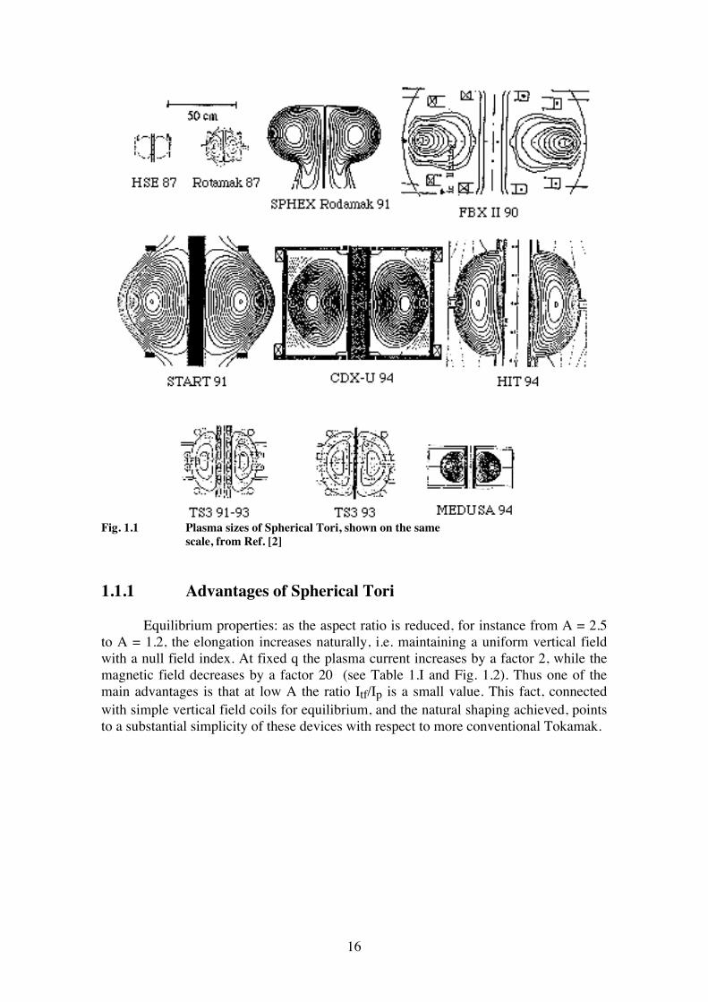
1. INTRODUCTION 1.1 Characteristics of Spherical Tori An excellent review on the progress of Spherical Tori has been given by A. Sykes at the EPS Conference in Montpellier [2]. A large part of this section is derived from this work. The research on low aspect ratio or Spherical Torus belongs to the goal of finding a class of advanced magnetic configurations in order to attain economic power from a fusion plant. The ITER route, which is based on conventional Tokamak design, has the main aim to supply experience of ignited plasmas. The low aspect ratio Torus (A = R/a < 2) has been first proposed by M. Peng and his colleagues at ORNL. They pointed out certain advantages connected with low A, concerning for examples the high value of β that can be achieved. The physical properties expected from these configurations were described [1] in 1986. No dedicated experiment along this line was built until the early '90. The first explorations of low aspect ratio configuration were made by modifying Spheromak experiments with the addition of a central rod to produce a longitudinal magnetic field. The objective was to control the tilting instability of the Spheromak. The main results of this work was that a Tokamak configuration could exist down to A = 1.1. HSE (Heidelberg Spheromak experiment) [29], Rotamak in Australia [30], Sphex in UK [31], FBX II in Japan [32], were devoted to these experiments between 1987 and 1991. The drawbacks of the plasmas produced in these devices were the low temperature obtained (Te < 50 eV) and the short pulse duration (tpulse < 2 ms), which prevented a strong assessment on the feasibility and advantages of these configurations. START at Culham [22, 23] began operation in 1991. Plasma current up to 250 kA, obtained by inducing a current at large radius and compressing the plasma down to A ≈ 1.25, with a pulse length of ≈ 40 ms, (extended by the addition of a compact central solenoid), allowed the attainment of hot (Te ≈ 500 eV) and dense (ne > 1020 m-3) plasmas. Thus some characteristics of spherical Tori could be, for the first time, compared with theoretical expectations with some confidence. CDX-U at Princeton [8, 33] and HIT at Seattle [34] complete the series of present experiments that produce low A plasma of sufficient duration to enable plasma properties to be evaluated. HIT is particularly relevant for SPHERA (see 1.1.4), since it is devoted to the study of Helicity Injection to drive the plasma current. Indeed up to 200 kA has been driven by this mechanism for ≈ 10 ms, with a good power efficiency of the Helicity Injection. Fig. 1.1 shows the magnetic equilibria achieved in all the experiments cited above. The first results of additional heating in a Spherical Torus have been recently obtained in START [35], where ≈ 450 kW of NBI at an energy of 30 kV have been co injected tangentially into the plasma. The results are very encouraging as a record total beta value <β> = 12% and a central beta β0 = 50% have been achieved without any deterioration of the energy confinement time. The encouraging experimental results have promoted the proposals of larger and more significant devices in the MA range of plasma current. We point out briefly the advantages and disadvantages of Spherical Tori.
16
Fig. 1.1 Plasma sizes of Spherical Tori, shown on the same scale, from Ref. [2] 1.1.1 Advantages of Spherical Tori Equilibrium properties: as the aspect ratio is reduced, for instance from A = 2.5 to A = 1.2, the elongation increases naturally, i.e. maintaining a uniform vertical field with a null field index. At fixed q the plasma current increases by a factor 2, while the magnetic field decreases by a factor 20 (see Table 1.I and Fig. 1.2). Thus one of the main advantages is that at low A the ratio Itf/Ip is a small value. This fact, connected with simple vertical field coils for equilibrium, and the natural shaping achieved, points to a substantial simplicity of these devices with respect to more conventional Tokamak.
17
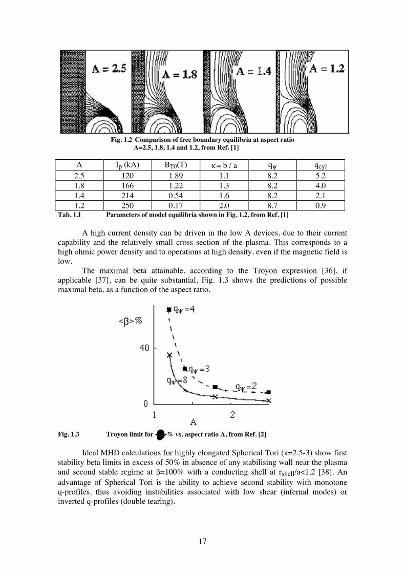
Fig. 1.2 Comparison of free boundary equilibria at aspect ratio A=2.5, 1.8, 1.4 and 1.2, from Ref. [1]
A Ip (kA) BT0(T) κ = b / a qψ qcyl 2.5 120 1.89 1.1 8.2 5.2 1.8 166 1.22 1.3 8.2 4.0 1.4 214 0.54 1.6 8.2 2.1 1.2 250 0.17 2.0 8.7 0.9
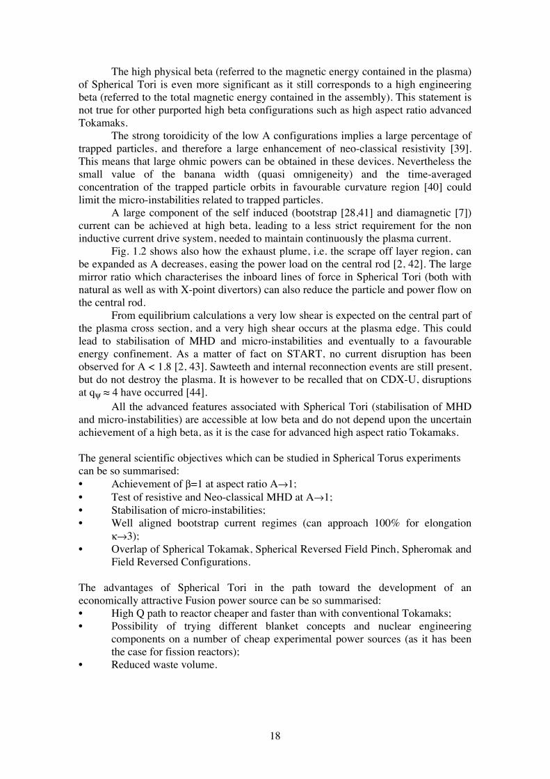
Tab. 1.I Parameters of model equilibria shown in Fig. 1.2, from Ref. [1] A high current density can be driven in the low A devices, due to their current capability and the relatively small cross section of the plasma. This corresponds to a high ohmic power density and to operations at high density, even if the magnetic field is low. The maximal beta attainable, according to the Troyon expression [36], if applicable [37], can be quite substantial. Fig. 1.3 shows the predictions of possible maximal beta, as a function of the aspect ratio.
Fig. 1.3 Troyon limit for <β>% vs. aspect ratio A, from Ref. [2] Ideal MHD calculations for highly elongated Spherical Tori (κ=2.5-3) show first stability beta limits in excess of 50% in absence of any stabilising wall near the plasma and second stable regime at β=100% with a conducting shell at rshell/a<1.2 [38]. An advantage of Spherical Tori is the ability to achieve second stability with monotone q-profiles, thus avoiding instabilities associated with low shear (infernal modes) or inverted q-profiles (double tearing).
18
The high physical beta (referred to the magnetic energy contained in the plasma) of Spherical Tori is even more significant as it still corresponds to a high engineering beta (referred to the total magnetic energy contained in the assembly). This statement is not true for other purported high beta configurations such as high aspect ratio advanced Tokamaks. The strong toroidicity of the low A configurations implies a large percentage of trapped particles, and therefore a large enhancement of neo-classical resistivity [39]. This means that large ohmic powers can be obtained in these devices. Nevertheless the small value of the banana width (quasi omnigeneity) and the time-averaged concentration of the trapped particle orbits in favourable curvature region [40] could limit the micro-instabilities related to trapped particles. A large component of the self induced (bootstrap [28,41] and diamagnetic [7]) current can be achieved at high beta, leading to a less strict requirement for the non inductive current drive system, needed to maintain continuously the plasma current. Fig. 1.2 shows also how the exhaust plume, i.e. the scrape off layer region, can be expanded as A decreases, easing the power load on the central rod [2, 42]. The large mirror ratio which characterises the inboard lines of force in Spherical Tori (both with natural as well as with X-point divertors) can also reduce the particle and power flow on the central rod. From equilibrium calculations a very low shear is expected on the central part of the plasma cross section, and a very high shear occurs at the plasma edge. This could lead to stabilisation of MHD and micro-instabilities and eventually to a favourable energy confinement. As a matter of fact on START, no current disruption has been observed for A < 1.8 [2, 43]. Sawteeth and internal reconnection events are still present, but do not destroy the plasma. It is however to be recalled that on CDX-U, disruptions at qψ ≈ 4 have occurred [44]. All the advanced features associated with Spherical Tori (stabilisation of MHD and micro-instabilities) are accessible at low beta and do not depend upon the uncertain achievement of a high beta, as it is the case for advanced high aspect ratio Tokamaks. The general scientific objectives which can be studied in Spherical Torus experiments can be so summarised: • Achievement of β=1 at aspect ratio A→1; • Test of resistive and Neo-classical MHD at A→1; • Stabilisation of micro-instabilities; • Well aligned bootstrap current regimes (can approach 100% for elongation κ→3); • Overlap of Spherical Tokamak, Spherical Reversed Field Pinch, Spheromak and Field Reversed Configurations. The advantages of Spherical Tori in the path toward the development of an economically attractive Fusion power source can be so summarised: • High Q path to reactor cheaper and faster than with conventional Tokamaks; • Possibility of trying different blanket concepts and nuclear engineering components on a number of cheap experimental power sources (as it has been the case for fission reactors); • Reduced waste volume.
19
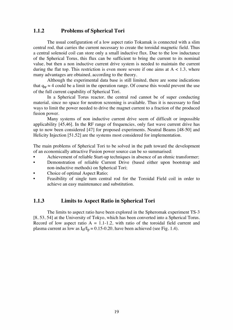
1.1.2 Problems of Spherical Tori The usual configuration of a low aspect ratio Tokamak is connected with a slim central rod, that carries the current necessary to create the toroidal magnetic field. Thus a central solenoid coil can store only a small inductive flux. Due to the low inductance of the Spherical Torus, this flux can be sufficient to bring the current to its nominal value, but then a non inductive current drive system is needed to maintain the current during the flat top. This restriction is even more severe if one aims at A < 1.3, where many advantages are obtained, according to the theory. Although the experimental data base is still limited, there are some indications that qψ ≈ 4 could be a limit in the operation range. Of course this would prevent the use of the full current capability of Spherical Tori. In a Spherical Torus reactor, the central rod cannot be of super conducting material, since no space for neutron screening is available. Thus it is necessary to find ways to limit the power needed to drive the magnet current to a fraction of the produced fusion power. Many systems of non inductive current drive seem of difficult or impossible applicability [45,46]. In the RF range of frequencies, only fast wave current drive has up to now been considered [47] for proposed experiments. Neutral Beams [48-50] and Helicity Injection [51,52] are the systems most considered for implementation. The main problems of Spherical Tori to be solved in the path toward the development of an economically attractive Fusion power source can be so summarised: • Achievement of reliable Start-up techniques in absence of an ohmic transformer; • Demonstration of reliable Current Drive (based either upon bootstrap and non-inductive methods) on Spherical Tori; • Choice of optimal Aspect Ratio; • Feasibility of single turn central rod for the Toroidal Field coil in order to achieve an easy maintenance and substitution. 1.1.3 Limits to Aspect Ratio in Spherical Tori The limits to aspect ratio have been explored in the Spheromak experiment TS-3 [8, 53, 54] at the University of Tokyo, which has been converted into a Spherical Torus. Record of low aspect ratio A = 1.1-1.2, with ratio of the toroidal field current and plasma current as low as Itf/Ip = 0.15-0.20, have been achieved (see Fig. 1.4).
20
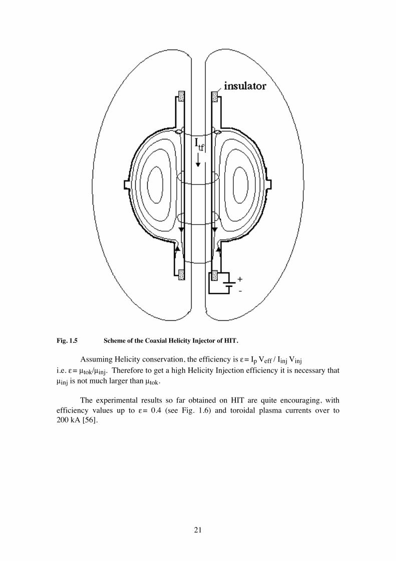
Fig. 1.4 Limit to Itf/Ip at low aspect ratio in TS-3, from Ref. [53] 1.1.4 Helicity Injection in Spherical Tori The most clear demonstration of DC Helicity Injection has been obtained on the HIT Spherical Torus, at the Washington University (Seattle) [34,55,56]. In HIT the path of the current along the toroidal plasma has been lengthened at most by using a SN (Single Null) configuration in which the Injectors coincide with the divertor plates (Coaxial Helicity Injector, contained within the toroidal field coils, see Fig. 1.5). To inject Helicity through electrodes into a toroidal configuration it is necessary (see Appendix) that the relaxation parameter of the Injector is larger than the relaxation parameter of the Tokamak: µinj > µtok. The Helicity dissipation inside the torus, which contains a toroidal flux ψT, can be described through an equivalent loop voltage Veff = Vloop, by balancing the dissipated Helicity within the torus with the Helicity provided by the Injector, which is characterised by a current Iinj, a voltage Vinj and a poloidal flux ψinj: 2 Vinj ψinj = 2 Veff ψT . So the Injector is able to provide an equivalent Vloop Veff = Vinj ψinj / ψT.
21
Fig. 1.5 Scheme of the Coaxial Helicity Injector of HIT. Assuming Helicity conservation, the efficiency is ε = Ip Veff / Iinj Vinj i.e. ε = µtok/µinj. Therefore to get a high Helicity Injection efficiency it is necessary that µinj is not much larger than µtok. The experimental results so far obtained on HIT are quite encouraging, with efficiency values up to ε = 0.4 (see Fig. 1.6) and toroidal plasma currents over to 200 kA [56].
22
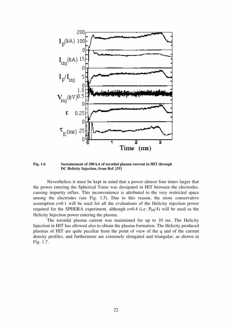
Fig. 1.6 Sustainement of 200 kA of toroidal plasma current in HIT through DC Helicity Injection, from Ref. [55]
Nevertheless it must be kept in mind that a power almost four times larger that the power entering the Spherical Torus was dissipated in HIT between the electrodes, causing impurity influx. This inconvenience is attributed to the very restricted space among the electrodes (see Fig. 1.5). Due to this reason, the more conservative assumption ε=0.1 will be used for all the evaluations of the Helicity injection power required for the SPHERA experiment, although ε=0.4 (i.e. PHI/4) will be used as the Helicity Injection power entering the plasma. The toroidal plasma current was maintained for up to 10 ms. The Helicity Injection in HIT has allowed also to obtain the plasma formation. The Helicity produced plasmas of HIT are quite peculiar from the point of view of the q and of the current density profiles, and furthermore are extremely elongated and triangular, as shown in Fig. 1.7.
23
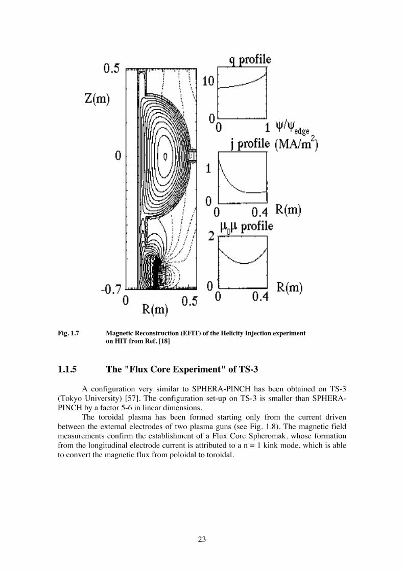
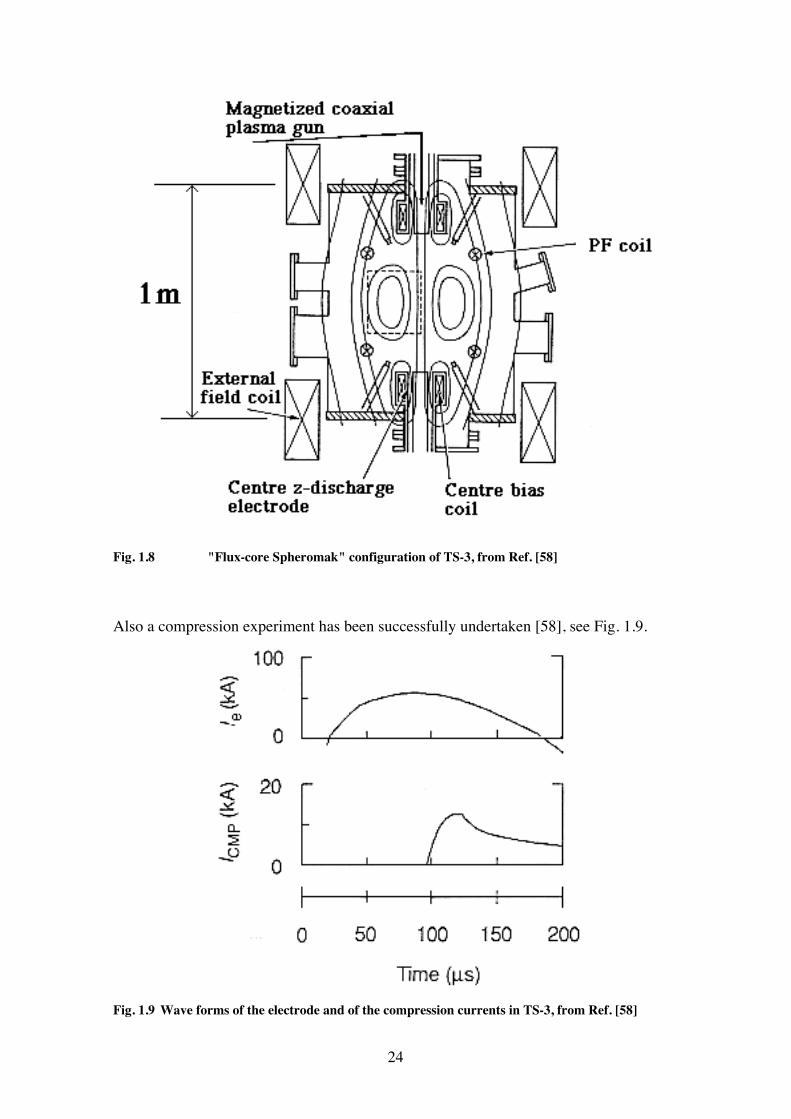
Fig. 1.7 Magnetic Reconstruction (EFIT) of the Helicity Injection experiment on HIT from Ref. [18] 1.1.5 The "Flux Core Experiment" of TS-3 A configuration very similar to SPHERA-PINCH has been obtained on TS-3 (Tokyo University) [57]. The configuration set-up on TS-3 is smaller than SPHERA-PINCH by a factor 5-6 in linear dimensions. The toroidal plasma has been formed starting only from the current driven between the external electrodes of two plasma guns (see Fig. 1.8). The magnetic field measurements confirm the establishment of a Flux Core Spheromak, whose formation from the longitudinal electrode current is attributed to a n = 1 kink mode, which is able to convert the magnetic flux from poloidal to toroidal.
24
Fig. 1.8 "Flux-core Spheromak" configuration of TS-3, from Ref. [58] Also a compression experiment has been successfully undertaken [58], see Fig. 1.9.
Fig. 1.9 Wave forms of the electrode and of the compression currents in TS-3, from Ref. [58]
25
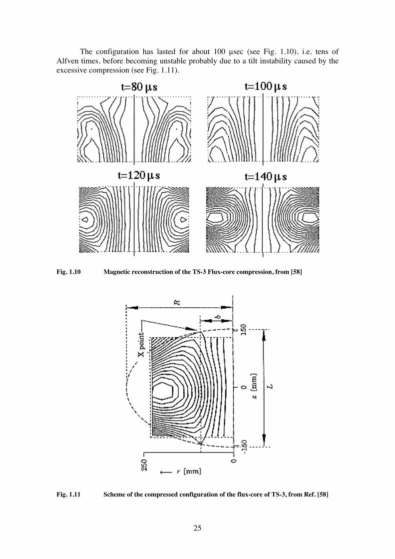
The configuration has lasted for about 100 µsec (see Fig. 1.10), i.e. tens of Alfven times, before becoming unstable probably due to a tilt instability caused by the excessive compression (see Fig. 1.11).
Fig. 1.10 Magnetic reconstruction of the TS-3 Flux-core compression, from [58]
Fig. 1.11 Scheme of the compressed configuration of the flux-core of TS-3, from Ref. [58]
26
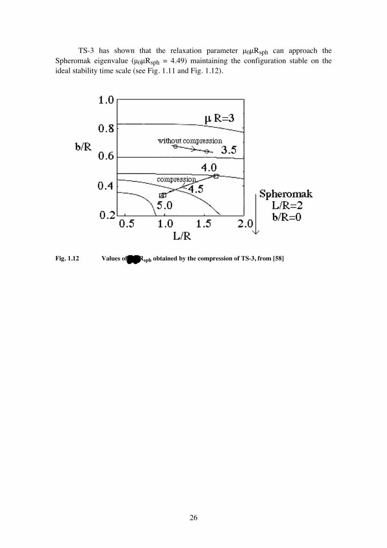
TS-3 has shown that the relaxation parameter µ0µRsph can approach the Spheromak eigenvalue (µ0µRsph = 4.49) maintaining the configuration stable on the ideal stability time scale (see Fig. 1.11 and Fig. 1.12).
Fig. 1.12 Values of µ 0µRsph obtained by the compression of TS-3, from [58]
27
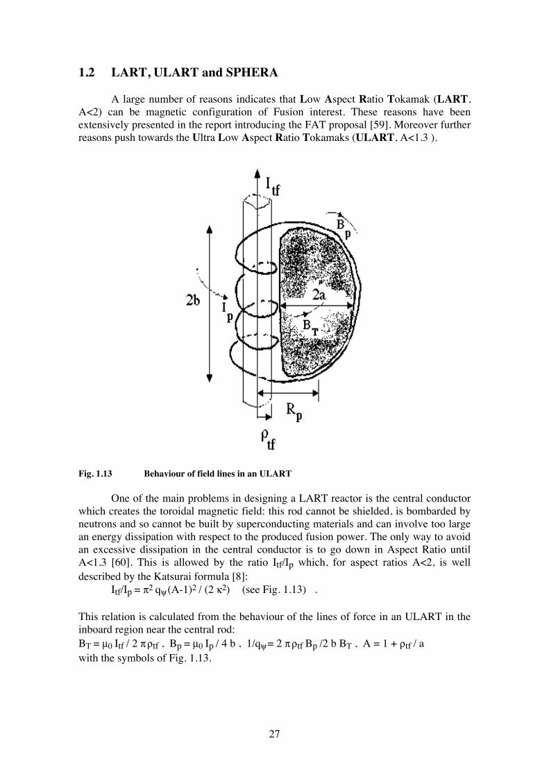
1.2 LART, ULART and SPHERA A large number of reasons indicates that Low Aspect Ratio Tokamak (LART, A<2) can be magnetic configuration of Fusion interest. These reasons have been extensively presented in the report introducing the FAT proposal [59]. Moreover further reasons push towards the Ultra Low Aspect Ratio Tokamaks (ULART, A<1.3 ).
Fig. 1.13 Behaviour of field lines in an ULART One of the main problems in designing a LART reactor is the central conductor which creates the toroidal magnetic field: this rod cannot be shielded, is bombarded by neutrons and so cannot be built by superconducting materials and can involve too large an energy dissipation with respect to the produced fusion power. The only way to avoid an excessive dissipation in the central conductor is to go down in Aspect Ratio until A<1.3 [60]. This is allowed by the ratio Itf/Ip which, for aspect ratios A<2, is well described by the Katsurai formula [8]: Itf/Ip = π2 qψ (A-1)2 / (2 κ2) (see Fig. 1.13) . This relation is calculated from the behaviour of the lines of force in an ULART in the inboard region near the central rod: BT = µ0 Itf / 2 π ρtf , Bp = µ0 Ip / 4 b , 1/qψ = 2 π ρtf Bp /2 b BT , A = 1 + ρtf / a with the symbols of Fig. 1.13.
28
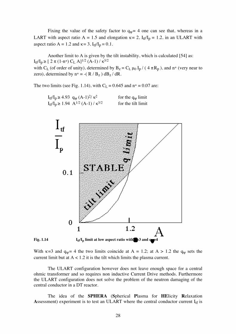
Fixing the value of the safety factor to qψ = 4 one can see that, whereas in a LART with aspect ratio A = 1.5 and elongation κ = 2, Itf/Ip = 1.2, in an ULART with aspect ratio A = 1.2 and κ = 3, Itf/Ip = 0.1. Another limit to A is given by the tilt instability, which is calculated [54] as: Itf/Ip ≥ [ 2 π (1-n*) CL A]1/2 (A-1) / κ3/2
with CL (of order of unity), determined by Bz = CL µ0 Ip / ( 4 π Rp ), and n* (very near to zero), determined by n* = -( R / Bz ) dBz / dR. The two limits (see Fig. 1.14), with CL = 0.645 and n* = 0.07 are: Itf/Ip ≥ 4.93 qψ (A-1)2/ κ2
for the qψ limit
Itf/Ip ≥ 1.94 A1/2 (A-1) / κ3/2
for the tilt limit
Fig. 1.14 Itf/Ip limit at low aspect ratio with κ=3 and qψ=4 With κ =3 and qψ = 4 the two limits coincide at A = 1.2; at A > 1.2 the qψ sets the current limit but at A < 1.2 it is the tilt which limits the plasma current. The ULART configuration however does not leave enough space for a central ohmic transformer and so requires non inductive Current Drive methods. Furthermore the ULART configuration does not solve the problem of the neutron damaging of the central conductor in a DT reactor. The idea of the SPHERA (Spherical Plasma for HElicity Relaxation Assessment) experiment is to test an ULART where the central conductor current Itf is
29
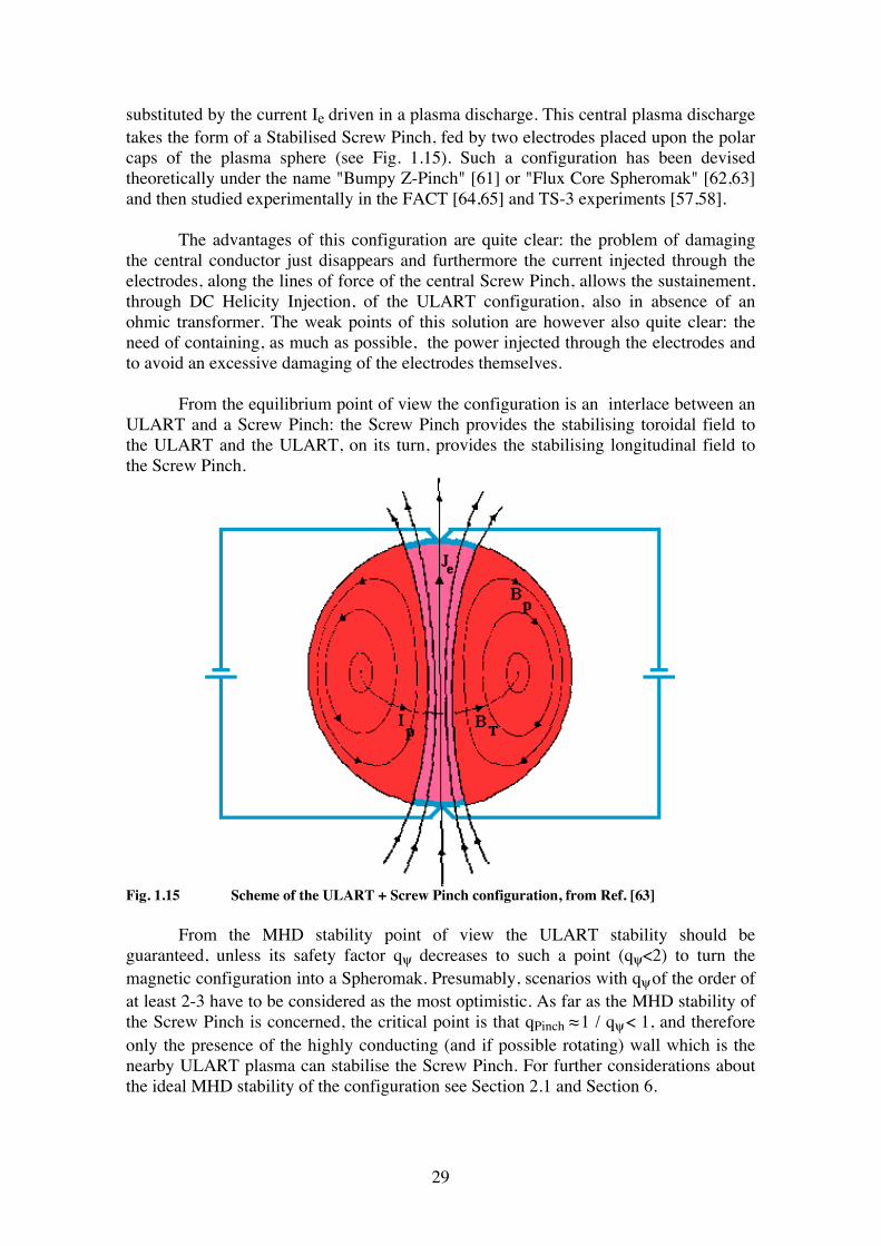
substituted by the current Ie driven in a plasma discharge. This central plasma discharge takes the form of a Stabilised Screw Pinch, fed by two electrodes placed upon the polar caps of the plasma sphere (see Fig. 1.15). Such a configuration has been devised theoretically under the name "Bumpy Z-Pinch" [61] or "Flux Core Spheromak" [62,63] and then studied experimentally in the FACT [64,65] and TS-3 experiments [57,58]. The advantages of this configuration are quite clear: the problem of damaging the central conductor just disappears and furthermore the current injected through the electrodes, along the lines of force of the central Screw Pinch, allows the sustainement, through DC Helicity Injection, of the ULART configuration, also in absence of an ohmic transformer. The weak points of this solution are however also quite clear: the need of containing, as much as possible, the power injected through the electrodes and to avoid an excessive damaging of the electrodes themselves. From the equilibrium point of view the configuration is an interlace between an ULART and a Screw Pinch: the Screw Pinch provides the stabilising toroidal field to the ULART and the ULART, on its turn, provides the stabilising longitudinal field to the Screw Pinch.
Fig. 1.15 Scheme of the ULART + Screw Pinch configuration, from Ref. [63] From the MHD stability point of view the ULART stability should be guaranteed, unless its safety factor qψ decreases to such a point (qψ<2) to turn the magnetic configuration into a Spheromak. Presumably, scenarios with qψ of the order of at least 2-3 have to be considered as the most optimistic. As far as the MHD stability of the Screw Pinch is concerned, the critical point is that qPinch ≈ 1 / qψ < 1, and therefore only the presence of the highly conducting (and if possible rotating) wall which is the nearby ULART plasma can stabilise the Screw Pinch. For further considerations about the ideal MHD stability of the configuration see Section 2.1 and Section 6.
30
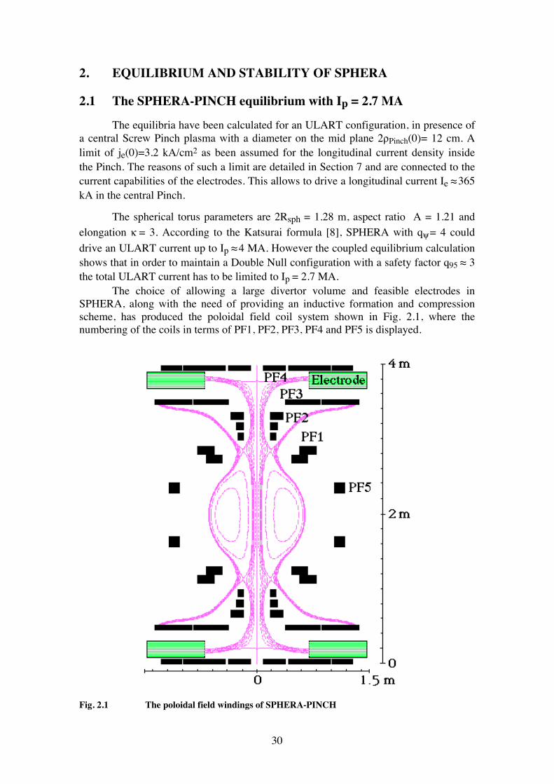
2. EQUILIBRIUM AND STABILITY OF SPHERA 2.1 The SPHERA-PINCH equilibrium with Ip = 2.7 MA The equilibria have been calculated for an ULART configuration, in presence of a central Screw Pinch plasma with a diameter on the mid plane 2ρPinch(0)= 12 cm. A limit of je(0)=3.2 kA/cm2 as been assumed for the longitudinal current density inside the Pinch. The reasons of such a limit are detailed in Section 7 and are connected to the current capabilities of the electrodes. This allows to drive a longitudinal current Ie ≈ 365 kA in the central Pinch. The spherical torus parameters are 2Rsph = 1.28 m, aspect ratio A = 1.21 and elongation κ = 3. According to the Katsurai formula [8], SPHERA with qψ = 4 could drive an ULART current up to Ip ≈ 4 MA. However the coupled equilibrium calculation shows that in order to maintain a Double Null configuration with a safety factor q95 ≈ 3 the total ULART current has to be limited to Ip = 2.7 MA. The choice of allowing a large divertor volume and feasible electrodes in SPHERA, along with the need of providing an inductive formation and compression scheme, has produced the poloidal field coil system shown in Fig. 2.1, where the numbering of the coils in terms of PF1, PF2, PF3, PF4 and PF5 is displayed.
Fig. 2.1 The poloidal field windings of SPHERA-PINCH
31
The poloidal field coils have been kept to the minimum number, in particular: • the PF1 coil is devoted to the Aspect Ratio control of the ULART by determining the radial position of the X point; • the PF2 coil is the divertor coil and determines the ULART elongation; • the PF3 coil, which is in series with the PF2 coil, has the function of shaping the internal and external divertor regions; • the PF4 coil is composed by three independent parts and is devoted to making straight and horizontal lines of force near the entrance of the electrodes (see Section 7); • the PF5 coil provides the equilibrium vertical field. The equilibrium scenario has been calculated by a code based on spherical geometry [66]. The code solves the Grad-Shafranov equation for the combined equilibrium of an ULART and of a Force-Free Screw Pinch under the assumption that the pressure p(ψ) and the diamagnetic current f(ψ) are continuous at the ULART-Screw Pinch interface, which is defined by the separatrix. The poloidal flux function ψ = 2πRAφ is zero on the symmetry axis and takes the value ψx at the separatrix. The toroidal current density jφ is limited within the magnetic separatrix for the ULART and within the innermost electrode radius for the Pinch; it may have a jump at the ULART-Screw Pinch interface. Whereas the total toroidal current Ip inside the ULART is an input of the code, the total toroidal current IφPinch inside the Screw Pinch is an output of the calculation. The following parameters were chosen: • Ie = 365 kA, that means BT0 = 0.203 T at R = 0.36 m ; • p(ψ) = pe = constant and f2(ψ) = Ie2(ψ2/ψx2) inside the Pinch; • Ip = 2.7 MA (Ie/Ip = 0.135) ; • p(ψ) = pe + Cp(ψ−ψx)1.1 and f2(ψ) = Ie2+ Cf(ψ−ψx)1.1 inside the ULART; • βp, defined as βp = 2 <p> ( ∫ dl )2 / (µ0 Ip2), has been chosen to have the value βp = 0.10; the two inputs Ip and βp determine during the iterative solution the values of Cp and Cf; • The Screw Pinch extends up to the inner electrode radius R = 0.7 m. The sum of the absolute values of the currents in the poloidal field windings is Ipf = 1.85 MA (Ipf/Ip = 0.68). The currents in the poloidal field coils (in kA) are shown in Table 2.I
PF1 PF2 PF3 PF4a PF4b PF4c PF5 -430 576 212 -200 -60 5 -365
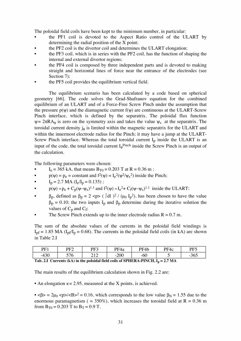
Tab. 2.I Currents (kA) in the poloidal field coils of SPHERA-PINCH, Ip = 2.7 MA The main results of the equilibrium calculation shown in Fig. 2.2 are: • An elongation κ = 2.95, measured at the X points, is achieved. • <β> = 2µ0 <p>/<B>2 = 0.16, which corresponds to the low value βN = 1.55 due to the enormous paramagnetism ( ≈ 350%), which increases the toroidal field at R = 0.36 m from BT0 = 0.203 T to BT = 0.9 T.
32
• The central Screw Pinch, fed by a longitudinal current Ie=0.365 MA, extends until ρPinch(0) = 0.06 m on the equatorial plane and drives a large current in the toroidal direction IφPinch = 1.95 MA, due to its force-free nature.
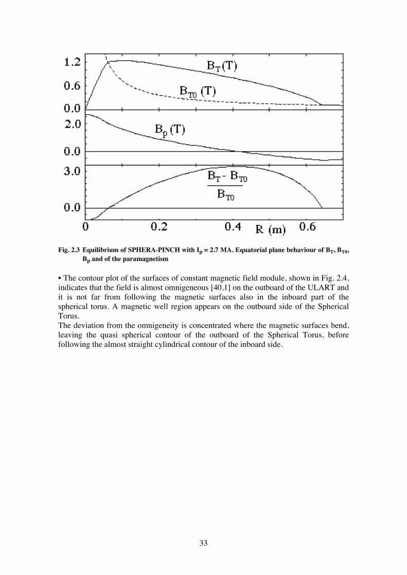
Fig. 2.2 Equilibrium of SPHERA-PINCH with Ip= 2.7 MA, Ie = 0.365 MA, βp = 0.1 Fig. 2.3 shows the behaviour of the fields BT and Bp and of the paramagnetism (BT-BT0)/BT0 at the equator of the configuration.
33
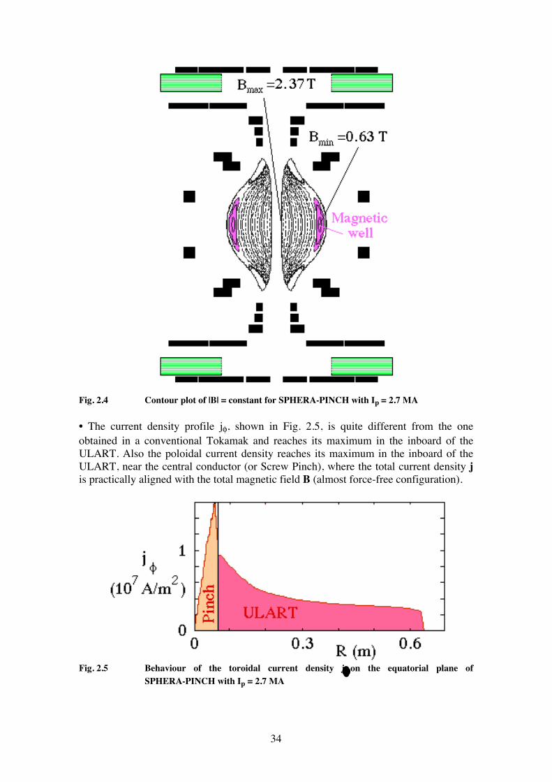
Fig. 2.3 Equilibrium of SPHERA-PINCH with Ip = 2.7 MA. Equatorial plane behaviour of BT, BT0, Bp and of the paramagnetism • The contour plot of the surfaces of constant magnetic field module, shown in Fig. 2.4, indicates that the field is almost omnigeneous [40,1] on the outboard of the ULART and it is not far from following the magnetic surfaces also in the inboard part of the spherical torus. A magnetic well region appears on the outboard side of the Spherical Torus. The deviation from the omnigeneity is concentrated where the magnetic surfaces bend, leaving the quasi spherical contour of the outboard of the Spherical Torus, before following the almost straight cylindrical contour of the inboard side.
34
Fig. 2.4 Contour plot of |B| = constant for SPHERA-PINCH with Ip = 2.7 MA • The current density profile jφ, shown in Fig. 2.5, is quite different from the one obtained in a conventional Tokamak and reaches its maximum in the inboard of the ULART. Also the poloidal current density reaches its maximum in the inboard of the ULART, near the central conductor (or Screw Pinch), where the total current density j is practically aligned with the total magnetic field B (almost force-free configuration).
Fig. 2.5 Behaviour of the toroidal current density jφ on the equatorial plane of SPHERA-PINCH with Ip = 2.7 MA
35
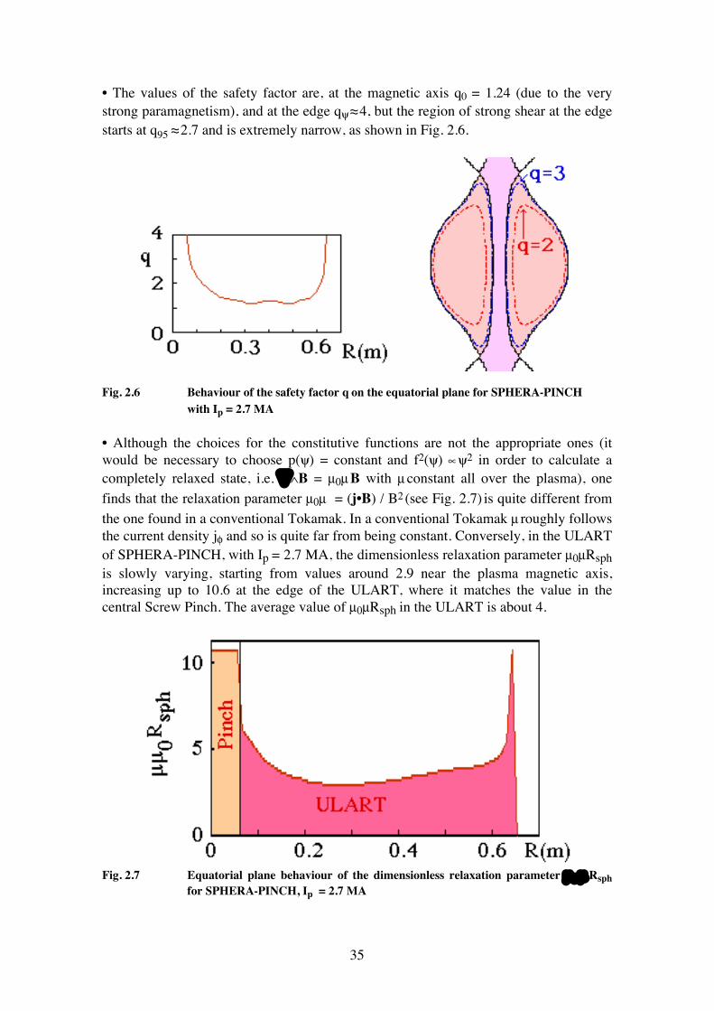
• The values of the safety factor are, at the magnetic axis q0 = 1.24 (due to the very strong paramagnetism), and at the edge qψ ≈ 4, but the region of strong shear at the edge starts at q95 ≈ 2.7 and is extremely narrow, as shown in Fig. 2.6.
Fig. 2.6 Behaviour of the safety factor q on the equatorial plane for SPHERA-PINCH with Ip = 2.7 MA • Although the choices for the constitutive functions are not the appropriate ones (it would be necessary to choose p(ψ) = constant and f2(ψ) ∝ ψ2 in order to calculate a completely relaxed state, i.e. ∇∧B = µ0µ B with µ constant all over the plasma), one finds that the relaxation parameter µ0µ = (j•B) / B2 (see Fig. 2.7) is quite different from the one found in a conventional Tokamak. In a conventional Tokamak µ roughly follows the current density jφ and so is quite far from being constant. Conversely, in the ULART of SPHERA-PINCH, with Ip = 2.7 MA, the dimensionless relaxation parameter µ0µRsph is slowly varying, starting from values around 2.9 near the plasma magnetic axis, increasing up to 10.6 at the edge of the ULART, where it matches the value in the central Screw Pinch. The average value of µ0µRsph in the ULART is about 4.
Fig. 2.7 Equatorial plane behaviour of the dimensionless relaxation parameter µ 0 µ Rsph for SPHERA-PINCH, Ip = 2.7 MA
36
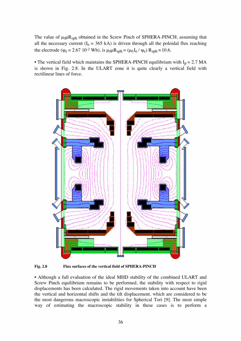
The value of µ0µRsph obtained in the Screw Pinch of SPHERA-PINCH, assuming that all the necessary current (Ie = 365 kA) is driven through all the poloidal flux reaching the electrode (ψe = 2.67 10-2 Wb), is µ0µRsph = (µ0 Ie / ψe) Rsph ≈ 10.6. • The vertical field which maintains the SPHERA-PINCH equilibrium with Ip = 2.7 MA is shown in Fig. 2.8. In the ULART zone it is quite clearly a vertical field with rectilinear lines of force.
Fig. 2.8 Flux surfaces of the vertical field of SPHERA-PINCH • Although a full evaluation of the ideal MHD stability of the combined ULART and Screw Pinch equilibrium remains to be performed, the stability with respect to rigid displacements has been calculated. The rigid movements taken into account have been the vertical and horizontal shifts and the tilt displacement, which are considered to be the most dangerous macroscopic instabilities for Spherical Tori [9]. The most simple way of estimating the macroscopic stability in these cases is to perform a
37
vertical/horizontal shift and a rigid tilt of the poloidal field coils and to calculate the reaction forces and the torque acting on the plasma (
F =
j ∫ ∧ δ B dV ,
T = r ∧ (
j ∫ ∧ δ B ) dV , where δ
B is the change in the magnetic field
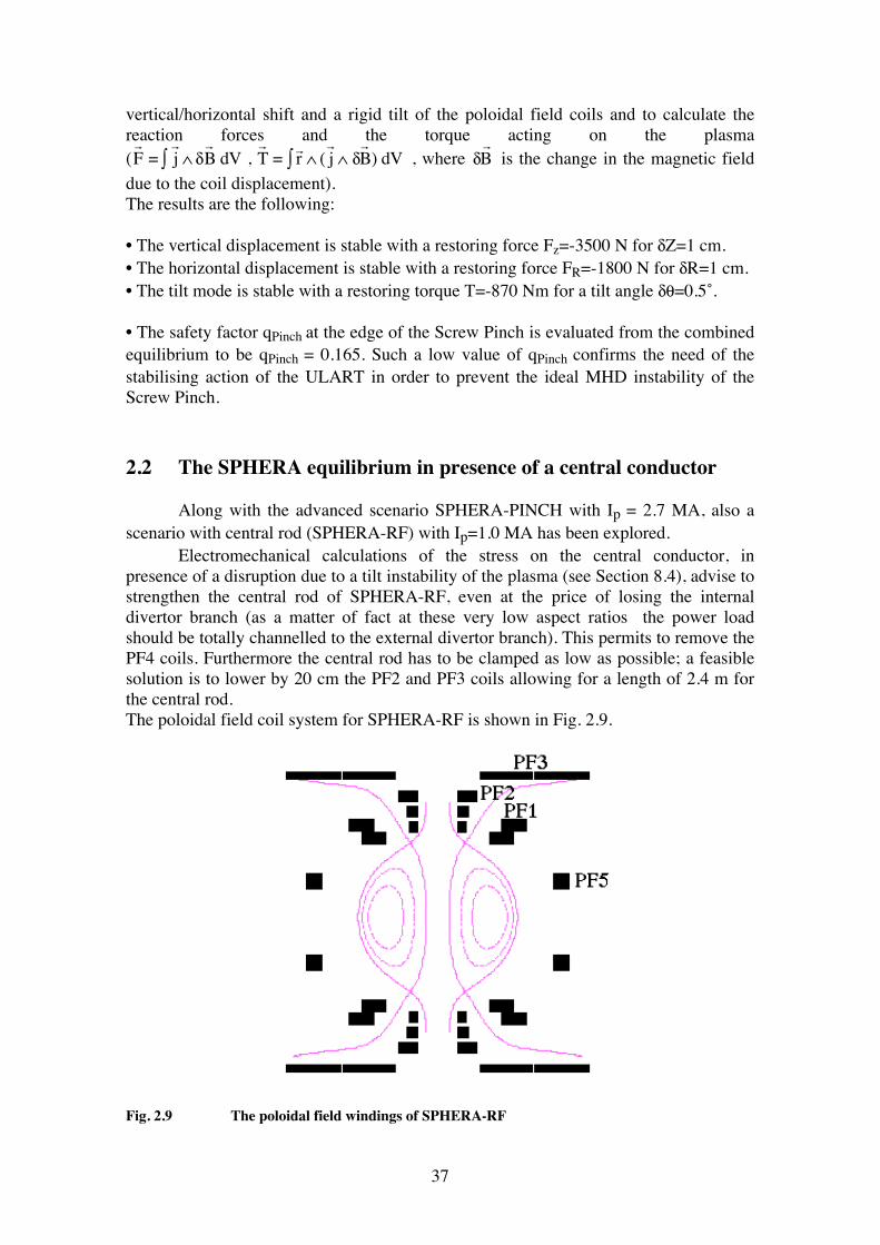
due to the coil displacement). The results are the following: • The vertical displacement is stable with a restoring force Fz=-3500 N for δZ=1 cm. • The horizontal displacement is stable with a restoring force FR=-1800 N for δR=1 cm. • The tilt mode is stable with a restoring torque T=-870 Nm for a tilt angle δθ=0.5˚. • The safety factor qPinch at the edge of the Screw Pinch is evaluated from the combined equilibrium to be qPinch = 0.165. Such a low value of qPinch confirms the need of the stabilising action of the ULART in order to prevent the ideal MHD instability of the Screw Pinch. 2.2 The SPHERA equilibrium in presence of a central conductor Along with the advanced scenario SPHERA-PINCH with Ip = 2.7 MA, also a scenario with central rod (SPHERA-RF) with Ip=1.0 MA has been explored. Electromechanical calculations of the stress on the central conductor, in presence of a disruption due to a tilt instability of the plasma (see Section 8.4), advise to strengthen the central rod of SPHERA-RF, even at the price of losing the internal divertor branch (as a matter of fact at these very low aspect ratios the power load should be totally channelled to the external divertor branch). This permits to remove the PF4 coils. Furthermore the central rod has to be clamped as low as possible; a feasible solution is to lower by 20 cm the PF2 and PF3 coils allowing for a length of 2.4 m for the central rod. The poloidal field coil system for SPHERA-RF is shown in Fig. 2.9.
Fig. 2.9 The poloidal field windings of SPHERA-RF
38
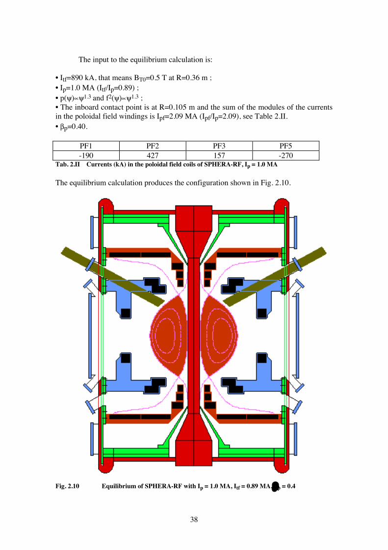
The input to the equilibrium calculation is: • Itf=890 kA, that means BT0=0.5 T at R=0.36 m ; • Ip=1.0 MA (Itf/Ip=0.89) ; • p(ψ)∝ψ1.3 and f2(ψ)∝ψ1.3 ; • The inboard contact point is at R=0.105 m and the sum of the modules of the currents in the poloidal field windings is Ipf=2.09 MA (Ipf/Ip=2.09), see Table 2.II. • βp=0.40.
PF1 PF2 PF3 PF5 -190 427 157 -270
Tab. 2.II Currents (kA) in the poloidal field coils of SPHERA-RF, Ip = 1.0 MA The equilibrium calculation produces the configuration shown in Fig. 2.10.
Fig. 2.10 Equilibrium of SPHERA-RF with Ip = 1.0 MA, Itf = 0.89 MA, βp = 0.4
39
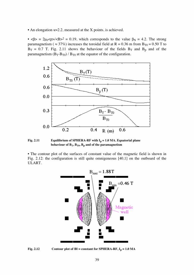
• An elongation κ=2.2, measured at the X points, is achieved. • <β> = 2µ0<p>/<B>2 = 0.19, which corresponds to the value βN = 4.2. The strong paramagnetism ( ≈ 37%) increases the toroidal field at R = 0.36 m from BT0 = 0.50 T to BT = 0.7 T. Fig. 2.11 shows the behaviour of the fields BT and Bp and of the paramagnetism (BT-BT0) / BT0 at the equator of the configuration.
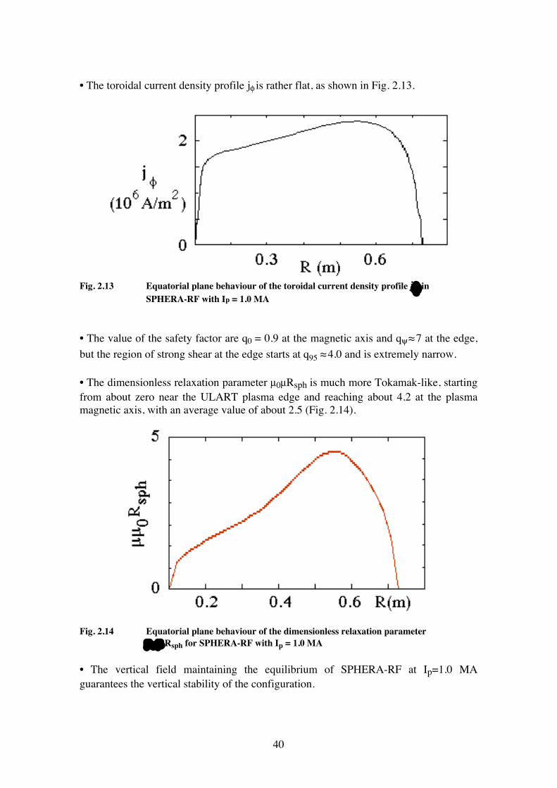
Fig. 2.11 Equilibrium of SPHERA-RF with Ip = 1.0 MA. Equatorial plane behaviour of BT, BT0, Bp and of the paramagnetism • The contour plot of the surfaces of constant value of the magnetic field is shown in Fig. 2.12: the configuration is still quite omnigeneous [40,1] on the outboard of the ULART.
Fig. 2.12 Contour plot of |B| = constant for SPHERA-RF, Ip = 1.0 MA
40
• The toroidal current density profile jφ is rather flat, as shown in Fig. 2.13.
Fig. 2.13 Equatorial plane behaviour of the toroidal current density profile jφ in SPHERA-RF with Ip = 1.0 MA • The value of the safety factor are q0 = 0.9 at the magnetic axis and qψ ≈ 7 at the edge, but the region of strong shear at the edge starts at q95 ≈ 4.0 and is extremely narrow. • The dimensionless relaxation parameter µ0µRsph is much more Tokamak-like, starting from about zero near the ULART plasma edge and reaching about 4.2 at the plasma magnetic axis, with an average value of about 2.5 (Fig. 2.14).
Fig. 2.14 Equatorial plane behaviour of the dimensionless relaxation parameter µ 0 µ Rsph for SPHERA-RF with Ip = 1.0 MA • The vertical field maintaining the equilibrium of SPHERA-RF at Ip=1.0 MA guarantees the vertical stability of the configuration.
41
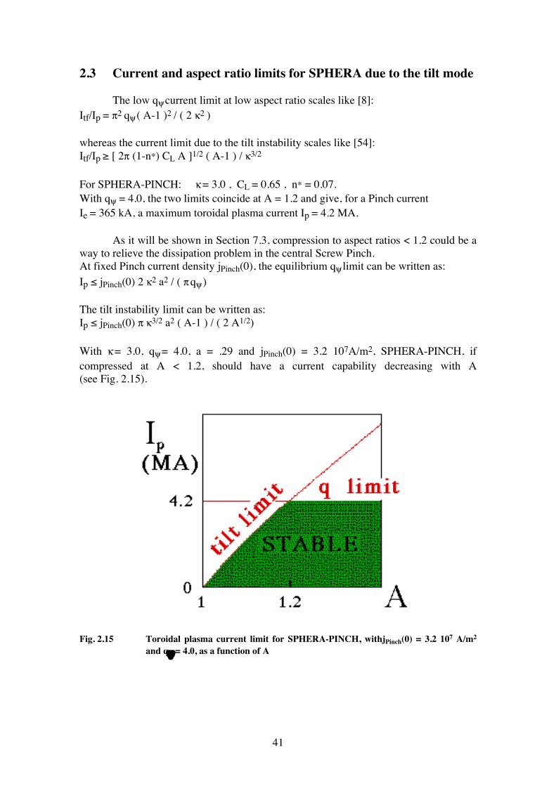
2.3 Current and aspect ratio limits for SPHERA due to the tilt mode The low qψ current limit at low aspect ratio scales like [8]: Itf/Ip = π2 qψ ( A-1 )2 / ( 2 κ2 ) whereas the current limit due to the tilt instability scales like [54]: Itf/Ip ≥ [ 2π (1-n*) CL A ]1/2 ( A-1 ) / κ3/2 For SPHERA-PINCH: κ = 3.0 , CL = 0.65 , n* = 0.07. With qψ = 4.0, the two limits coincide at A = 1.2 and give, for a Pinch current Ie = 365 kA, a maximum toroidal plasma current Ip = 4.2 MA. As it will be shown in Section 7.3, compression to aspect ratios < 1.2 could be a way to relieve the dissipation problem in the central Screw Pinch. At fixed Pinch current density jPinch(0), the equilibrium qψ limit can be written as: Ip ≤ jPinch(0) 2 κ2
a2
/ ( π qψ )
The tilt instability limit can be written as: Ip ≤ jPinch(0) π κ3/2
a2
( A-1 ) / ( 2 A1/2)
With κ = 3.0, qψ = 4.0, a = .29 and jPinch(0) = 3.2 107A/m2, SPHERA-PINCH, if compressed at A < 1.2, should have a current capability decreasing with A (see Fig. 2.15).
Fig. 2.15 Toroidal plasma current limit for SPHERA-PINCH, withjPinch(0) = 3.2 107 A/m2 and qψ = 4.0, as a function of A
42
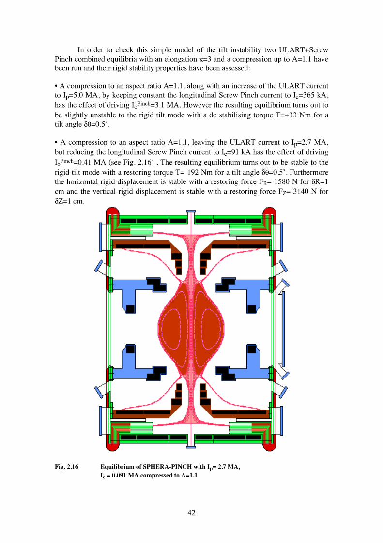
In order to check this simple model of the tilt instability two ULART+Screw Pinch combined equilibria with an elongation κ=3 and a compression up to A=1.1 have been run and their rigid stability properties have been assessed: • A compression to an aspect ratio A=1.1, along with an increase of the ULART current to Ip=5.0 MA, by keeping constant the longitudinal Screw Pinch current to Ie=365 kA, has the effect of driving IφPinch=3.1 MA. However the resulting equilibrium turns out to be slightly unstable to the rigid tilt mode with a de stabilising torque T=+33 Nm for a tilt angle δθ=0.5˚. • A compression to an aspect ratio A=1.1, leaving the ULART current to Ip=2.7 MA, but reducing the longitudinal Screw Pinch current to Ie=91 kA has the effect of driving IφPinch=0.41 MA (see Fig. 2.16) . The resulting equilibrium turns out to be stable to the rigid tilt mode with a restoring torque T=-192 Nm for a tilt angle δθ=0.5˚. Furthermore the horizontal rigid displacement is stable with a restoring force FR=-1580 N for δR=1 cm and the vertical rigid displacement is stable with a restoring force FZ=-3140 N for δZ=1 cm.
Fig. 2.16 Equilibrium of SPHERA-PINCH with Ip= 2.7 MA, Ie = 0.091 MA compressed to A=1.1
43
The q profile of this compressed configuration is still Tokamak-like with a value at the magnetic axis q0 = 1.17 (due to the extreme paramagnetism), and at the edge qψ ≈ 2.7. As far as the scenario with central rod at high field (SPHERA-RF) is concerned, the current limit due to qψ and to the tilt instability is by a factor 4-5 larger than the maximum expected total plasma current.
44
3. THE ASSUMPTIONS FOR THE SPHERICAL TORUS 3.1 Density limit A simple evaluation for the density limit of SPHERA can be obtained by using the Greenwald density limit [11], which seems to fit the START data [43]: <nemax> = κ <jφ>, where nemax is in units of 1020 m-3, <jφ> in MA/m2, the averages are on the plasma poloidal surface and κ is the elongation. For κ = 3.0 and Ip = 2.7 MA, <jφ> = ( 2.7 / 0.638 ) MA/m2, whereas, for κ = 2.3 and Ip = 1.0 MA, <jφ> = ( 1.0 / 0.446 ) MA/m2. Therefore the density limit for SPHERA is: <nemax> = 1.2 1021 m-3 for κ = 3 and Ip = 2.7 MA <nemax> = 5.0 1020 m-3 for κ = 2.2 and Ip = 1.0 MA, however, due to the density limit of the NBCD and LHCD in SPHERA-RF (see Section 5.1) a reasonable guess is that Ip = 1.0 MA can be driven at <nemax> = 2 1020 m-3 3.2 Energy confinement time A few L-mode scaling laws for the energy confinement time have been used. The scaling laws are expressed in terms of the units: ms, MA, T, 1020 m-3, m, MW. Lackner-Gottardi [12]: τELG = 120 Ip0.8 R1.8 a0.4 <ne>0.4 qψ0.4 M0.5 P-0.6 κ/( 1+κ )0.8 ITER-89P [67]: τEITER-P = 48 Ip0.85 R1.2 a0.3 κ 0.5 <ne>0.1 BΤ0.2 M0.5 P-0.5 3.3 Fixed power scenarios A first estimate has been performed with the parameters: Ip = 2.7 MA, R = 0.35 m, a = 0.29 m, <ne> = 1.2 1021 m-3, qψ = 3, M = 2, BΤ = 0.9 T, κ = 3.0, P = 5.0 MW. The results are: τELG = 55 ms , τEITER-P = 30 ms. With the moderate assumptions: Ip = 1.0 MA, R = 0.39 m, a = 0.31 m, <ne> = 2.0 1020 m-3, qψ = 4, M = 2, BΤ = 0.7 T, κ = 2.3, P = 5.0 MW. The results are:
45
τELG = 15 ms , τEITER-P = 10 ms. The Lackner-Gottardi scaling law, which is in good agreement with the results of START [68] will be employed in the following. 3.4 H-mode power threshold Using the ASDEX H-mode power threshold [14]: PthreshASDEX = 0.05 <ne> BT ST
where the power is in MW, <ne> BT is in 1020 m-3T and ST (m2) is the total toroidal surface of the ULART. It turns out that, at the density limit <ne> = 1.2 1021 m-3 , SPHERA-PINCH with Ip = 2.7 MA, ST = 6.4 m2 and BT = 0.9 T requires Pthresh
ASDEX = 3.5 MW , whereas SPHERA-RF at the density <ne> = 2 1020 m-3, with Ip = 1.0 MA, ST =7.0 m2 and BT = 0.7 T, requires Pthresh
ASDEX = 0.5 MW. As, decreasing the plasma density, the heating power is fixed or goes down more slowly than <ne>, SPHERA should reach the H-mode in both the scenarios, maybe marginally at the density limit, but more easily for lower densities. Using the DIII-D H-mode power threshold for Double Null plasmas [69], PthreshDIIID = 0.06 ST
the threshold power for SPHERA is just PthreshDIIID = 0.42 MW.
Therefore SPHERA should reach the H-mode quite easily in almost all the cases. As a conclusion the ULART of SPHERA should reach the H-mode (if it exists in Spherical Torus) in most conditions and should be able to investigate the beneficial effect on the improved confinement of the shaping factor S = qψ Ip / a BT0, which can go up to 140. It must be pointed out that in conventional Tokamaks the largest value of the shaping parameter has been achieved in DIII-D [70] and is limited to S=10.
46
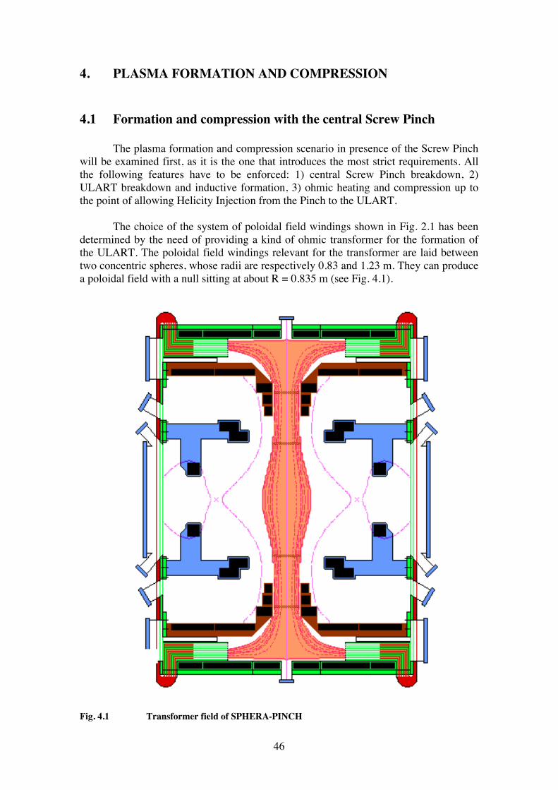
4. PLASMA FORMATION AND COMPRESSION 4.1 Formation and compression with the central Screw Pinch The plasma formation and compression scenario in presence of the Screw Pinch will be examined first, as it is the one that introduces the most strict requirements. All the following features have to be enforced: 1) central Screw Pinch breakdown, 2) ULART breakdown and inductive formation, 3) ohmic heating and compression up to the point of allowing Helicity Injection from the Pinch to the ULART. The choice of the system of poloidal field windings shown in Fig. 2.1 has been determined by the need of providing a kind of ohmic transformer for the formation of the ULART. The poloidal field windings relevant for the transformer are laid between two concentric spheres, whose radii are respectively 0.83 and 1.23 m. They can produce a poloidal field with a null sitting at about R = 0.835 m (see Fig. 4.1).
Fig. 4.1 Transformer field of SPHERA-PINCH
47
4.1.1 Screw-Pinch breakdown The required currents in the poloidal field coils, at the Screw Pinch breakdown are:
PF1 PF2 PF3 PF4a PF4b PF4c PF5 3000 1152 424 -100 -400 -200 -380
Tab. 4.I Currents (kA) in the poloidal field coils of SPHERA-PINCH, at the breakdown of the Screw Pinch The currents in the PF2, PF3 coils have just twice the values as in presence of the final plasma equilibrium (see Table 2.I); they reach these values during 300 msec before the Pinch breakdown. The PF2 and PF3 coils are enclosed within a 0.5 cm thick copper shell contained within a secondary vacuum vessel; the time constant of copper shell being about 20-30 ms. Consequently the PF2 and PF3 currents are kept constant during all the 33 ms required for the ULART formation and compression; thereafter they are reduced toward their final value on a time scale greater than 30 ms. The PF5 current is determined by the requirement of obtaining a null of poloidal field at R = 0.835 m. The PF4 currents are determined by the requirement of obtaining straight and horizontal lines of force near the entrance of the electrodes (see Section 7.2). An electron beam injected vertically along the symmetry axis of the machine acts as a pre-ionisation. Once formed, the Pinch has a radius ρPinch(0) = 0.295 m on the equatorial plane; it is limited by the secondary vacuum vessel near the PF2 coils and extends up to the electrode inner radius R=0.7 m. Its current is raised to Ie = 365 kA, thereafter it is maintained constant during all the formation and sustainement of the ULART. The equilibrium of the Screw Pinch is calculated with the assumption that it is force-free and so it drives a current in the toroidal direction IφPinch = 177 kA. The safety factor qPinch at the edge of the Screw Pinch, before the ULART breakdown, can be evaluated from the Pinch equilibrium as qPinch = 2.01. With such a q value the Pinch should be stable until the ULART breakdown takes place. During the ULART breakdown and compression the qPinch will decrease towards its steady state value qPinch = 0.165, but the secondary vacuum vessels and the ULART will act as stabilisers. During the ULART formation the Screw Pinch will try, through inductive effects, to maintain its q at the edge constant at qPinch = 2, at least for times of the order of the Pinch skin time, which for temperature TPinch = 50-70 eV, is evaluated to be about 15-20 msec. 4.1.2 ULART breakdown Once the steady state current in the Screw Pinch is achieved, the ULART breakdown can be obtained, by a fast decrease of the currents in the PF1 and PF5 coils. The ULART breakdown could be the more difficult to control for a number of reasons: • The quality of the poloidal field null at R = 0.835 m is rather poor: dBp / dR = 113 Gauss/cm with BT0 = 875 Gauss.
48
• The breakdown must be obtained in presence of the pre-existing Screw Pinch plasma, which will absorb part of the flux released by the discharging PF1 and PF5 coils. • The flux stored in the poloidal field coils before the ULART breakdown cannot be exploited gradually during the fast decrease of the currents in the coils, as the field configuration is compatible with an ULART equilibrium only near the end of the decrease. However: • The plasma will be already present in the breakdown region, due to the diffusion from the Screw Pinch plasma. • The poloidal field null can be maintained (with decreasing dBp / dR and therefore with a better and better quality of the poloidal field null) during the whole transformer discharging, by tailoring a different discharging of the currents in the PF5 coil with respect to the PF1 current. The PF4 currents are varied in order to maintain straight and horizontal lines of force near the entrance of the electrodes. • The flux stored at the beginning of the breakdown is 1.0 Wb and it can provide, if the transformer discharging is fast enough, loop voltages of the order of hundred Volts. • As the toroidal field at R = 0.36 m is BT0 = 0.203 T, the ULART breakdown can be assisted by radio frequency pre-ionisation, in fact the 2.45 GHz frequency [71] will be resonant at the first ECRH harmonic on the poloidal field null at R = 0.835 m. 4.1.3 ULART compression As soon as the toroidal plasma is formed, the more and more negative values taken by the currents in the PF1 and PF5 poloidal field coils produces a compression and an ohmic induction in the ULART. This gives the possibility of increasing the toroidal current by compressing the plasma. A quantitative evaluation of such an effect has been made by balancing the flux required from the forming plasma, which can be written as: ψPlasma = Ltot Ip + ∫ dt Vr + ∫ dt (dW/dt) / Ip where Ltot is the total inductance, Vr the resistive loop voltage, and W is the thermal energy content of the plasma. The resistive loop voltage and the thermal energy content of the ULART plasma are calculated under the following assumptions: • τΕ following the Lackner-Gottardi scaling law [12], • σ following the Spitzer conductivity [72], • <ne> at the Greenwald density limit [11] until <ne> = 1 1020 m-3. The released flux ψv is calculated from the equilibrium code, assuming βpol = 0.1. The resulting balance, along with the need of formation and compression times fast enough to allow for a qPinch staying around 2, at least for times of the order of the Screw Pinch skin time, leads to the formation and compression scheme shown in Fig. 4.2. The formation and compression scheme of SPHERA can also be seen in terms of Helicity conservation. Before the ULART breakdown the Helicity is due to the interlacing between the flux tubes produced by the Pinch (or the central conductor) and
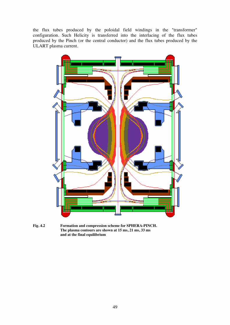
49
the flux tubes produced by the poloidal field windings in the "transformer" configuration. Such Helicity is transferred into the interlacing of the flux tubes produced by the Pinch (or the central conductor) and the flux tubes produced by the ULART plasma current.
Fig. 4.2 Formation and compression scheme for SPHERA-PINCH. The plasma contours are shown at 15 ms, 21 ms, 33 ms and at the final equilibrium
50
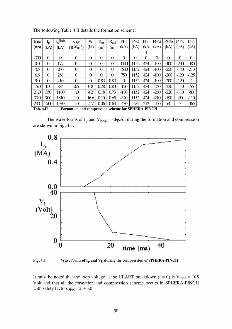
The following Table 4.II details the formation scheme: time (ms)
Ip (kA)
IφPinch
(kA) <ne>
(1020m-3) W (kJ)
Rint (m)
Rext (m)
PF1 (kA)
PF2 (kA)
PF3 (kA
)
PF4a (kA)
PF4b (kA)
PF4c (kA)
PF5 (kA)
-300 0 0 0 0 0 0 0 0 0 0 0 0 0 0.0 0 177 0 0 0 0 3000 1152 424 -100 -400 -200 -380 4.5 0 206 0 0 0 0 1500 1152 424 -100 -250 -140 -213 6.8 0 268 0 0 0 0 750 1152 424 -100 -200 -120 -125 9.0 0 410 0 0 0.83 0.83 0 1152 424 -100 -200 -120 -1 15.0 150 884 0.6 0.8 0.28 0.83 -120 1152 424 -260 -220 -110 -55 21.0 350 1160 1.0 4.2 0.18 0.73 -180 1152 424 -260 -220 -110 -80 33.0 700 1810 1.0 16.6 0.10 0.65 -320 1152 424 -210 -190 -90 -110 200. 2700 1930 1.0 247 0.06 0.64 -430 576 212 -200 -60 5 -365 Tab. 4.II Formation and compression scheme for SPHERA-PINCH The wave forms of Ip and Vloop = -dψv/dt during the formation and compression are shown in Fig. 4.3.
Fig. 4.3 Wave forms of Ip and VL during the compression of SPHERA-PINCH It must be noted that the loop voltage at the ULART breakdown (t = 0) is Vloop = 105 Volt and that all the formation and compression scheme occurs in SPHERA-PINCH with safety factors q95 = 2.3-3.0.
51
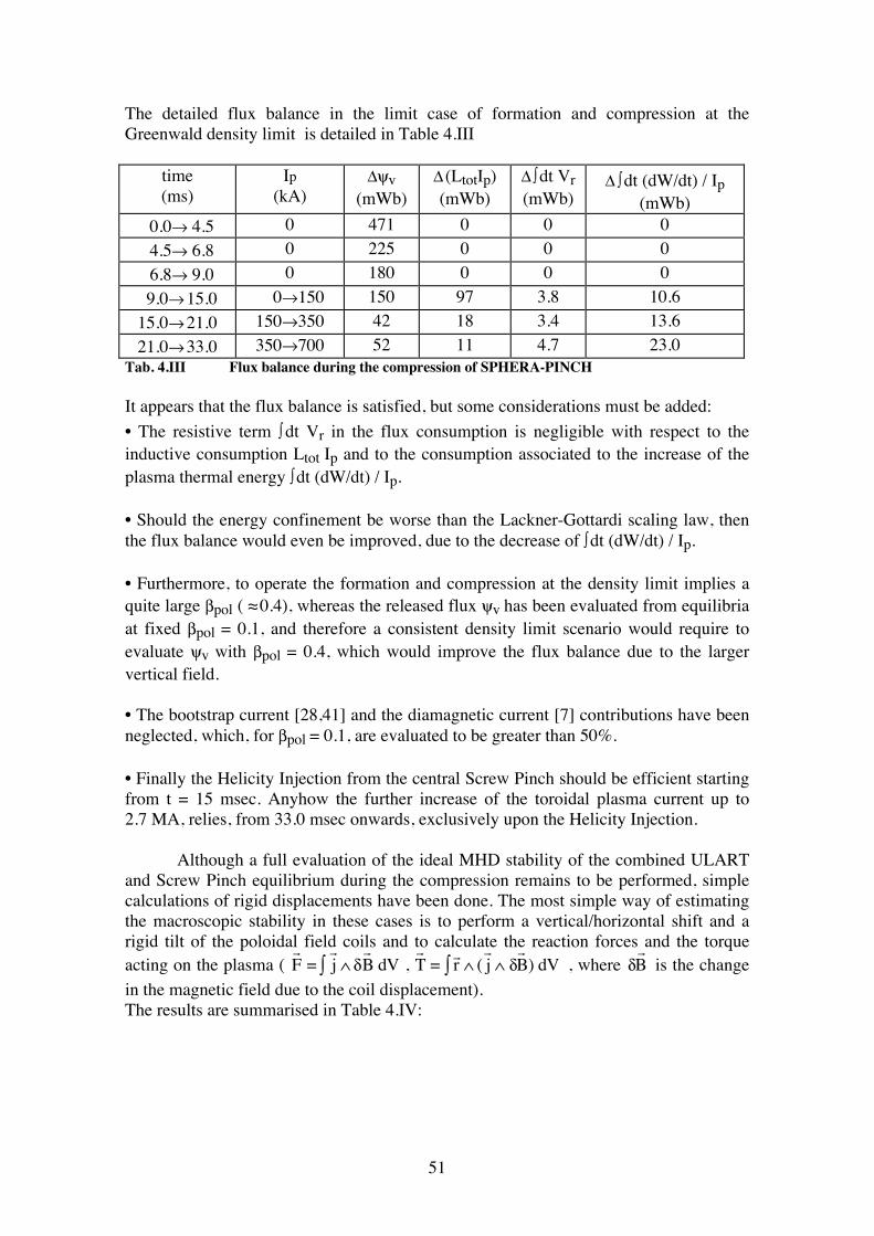
The detailed flux balance in the limit case of formation and compression at the Greenwald density limit is detailed in Table 4.III
time (ms)
Ip (kA)
Δψv (mWb)
Δ (LtotIp) (mWb)
Δ ∫ dt Vr (mWb)
Δ ∫ dt (dW/dt) / Ip (mWb)
0.0→ 4.5 0 471 0 0 0 4.5→ 6.8 0 225 0 0 0 6.8→ 9.0 0 180 0 0 0 9.0→ 15.0 0→150 150 97 3.8 10.6 15.0→ 21.0 150→350 42 18 3.4 13.6 21.0→ 33.0 350→700 52 11 4.7 23.0
Tab. 4.III Flux balance during the compression of SPHERA-PINCH It appears that the flux balance is satisfied, but some considerations must be added: • The resistive term ∫ dt Vr in the flux consumption is negligible with respect to the inductive consumption Ltot Ip and to the consumption associated to the increase of the plasma thermal energy ∫ dt (dW/dt) / Ip. • Should the energy confinement be worse than the Lackner-Gottardi scaling law, then the flux balance would even be improved, due to the decrease of ∫ dt (dW/dt) / Ip. • Furthermore, to operate the formation and compression at the density limit implies a quite large βpol ( ≈ 0.4), whereas the released flux ψv has been evaluated from equilibria at fixed βpol = 0.1, and therefore a consistent density limit scenario would require to evaluate ψv with βpol = 0.4, which would improve the flux balance due to the larger vertical field. • The bootstrap current [28,41] and the diamagnetic current [7] contributions have been neglected, which, for βpol = 0.1, are evaluated to be greater than 50%. • Finally the Helicity Injection from the central Screw Pinch should be efficient starting from t = 15 msec. Anyhow the further increase of the toroidal plasma current up to 2.7 MA, relies, from 33.0 msec onwards, exclusively upon the Helicity Injection. Although a full evaluation of the ideal MHD stability of the combined ULART and Screw Pinch equilibrium during the compression remains to be performed, simple calculations of rigid displacements have been done. The most simple way of estimating the macroscopic stability in these cases is to perform a vertical/horizontal shift and a rigid tilt of the poloidal field coils and to calculate the reaction forces and the torque acting on the plasma (
F =
j ∫ ∧ δ B dV ,
T = r ∧ (
j ∫ ∧ δ B ) dV , where δ
B is the change
in the magnetic field due to the coil displacement). The results are summarised in Table 4.IV:
52
time (ms)
Ip (kA)
Vertical Force δ Z = 1cm FZ (N)
Horizontal Force δR =1cm FR (N)
Tilt Torque δ θ = 0.5̊ T (Nm)
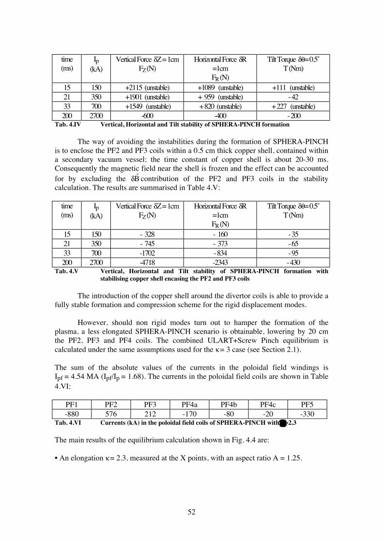
15 150 +2115 (unstable) +1089 (unstable) +111 (unstable) 21 350 +1901 (unstable) + 959 (unstable) - 42 33 700 +1549 (unstable) + 820 (unstable) + 227 (unstable) 200 2700 -600 -400 - 200
Tab. 4.IV Vertical, Horizontal and Tilt stability of SPHERA-PINCH formation The way of avoiding the instabilities during the formation of SPHERA-PINCH is to enclose the PF2 and PF3 coils within a 0.5 cm thick copper shell, contained within a secondary vacuum vessel; the time constant of copper shell is about 20-30 ms. Consequently the magnetic field near the shell is frozen and the effect can be accounted for by excluding the δ
B contribution of the PF2 and PF3 coils in the stability
calculation. The results are summarised in Table 4.V:
time (ms)
Ip (kA)
Vertical Force δ Z = 1cm FZ (N)
Horizontal Force δR =1cm FR (N)
Tilt Torque δ θ = 0.5̊ T (Nm)
15 150 - 328 - 160 - 35 21 350 - 745 - 373 - 65 33 700 -1702 - 834 - 95 200 2700 -4718 -2343 - 430
Tab. 4.V Vertical, Horizontal and Tilt stability of SPHERA-PINCH formation with stabilising copper shell encasing the PF2 and PF3 coils
The introduction of the copper shell around the divertor coils is able to provide a fully stable formation and compression scheme for the rigid displacement modes. However, should non rigid modes turn out to hamper the formation of the plasma, a less elongated SPHERA-PINCH scenario is obtainable, lowering by 20 cm the PF2, PF3 and PF4 coils. The combined ULART+Screw Pinch equilibrium is calculated under the same assumptions used for the κ = 3 case (see Section 2.1). The sum of the absolute values of the currents in the poloidal field windings is Ipf = 4.54 MA (Ipf/Ip = 1.68). The currents in the poloidal field coils are shown in Table 4.VI:
PF1 PF2 PF3 PF4a PF4b PF4c PF5 -880 576 212 -170 -80 -20 -330
Tab. 4.VI Currents (kA) in the poloidal field coils of SPHERA-PINCH with κ=2.3 The main results of the equilibrium calculation shown in Fig. 4.4 are: • An elongation κ = 2.3, measured at the X points, with an aspect ratio A = 1.25.
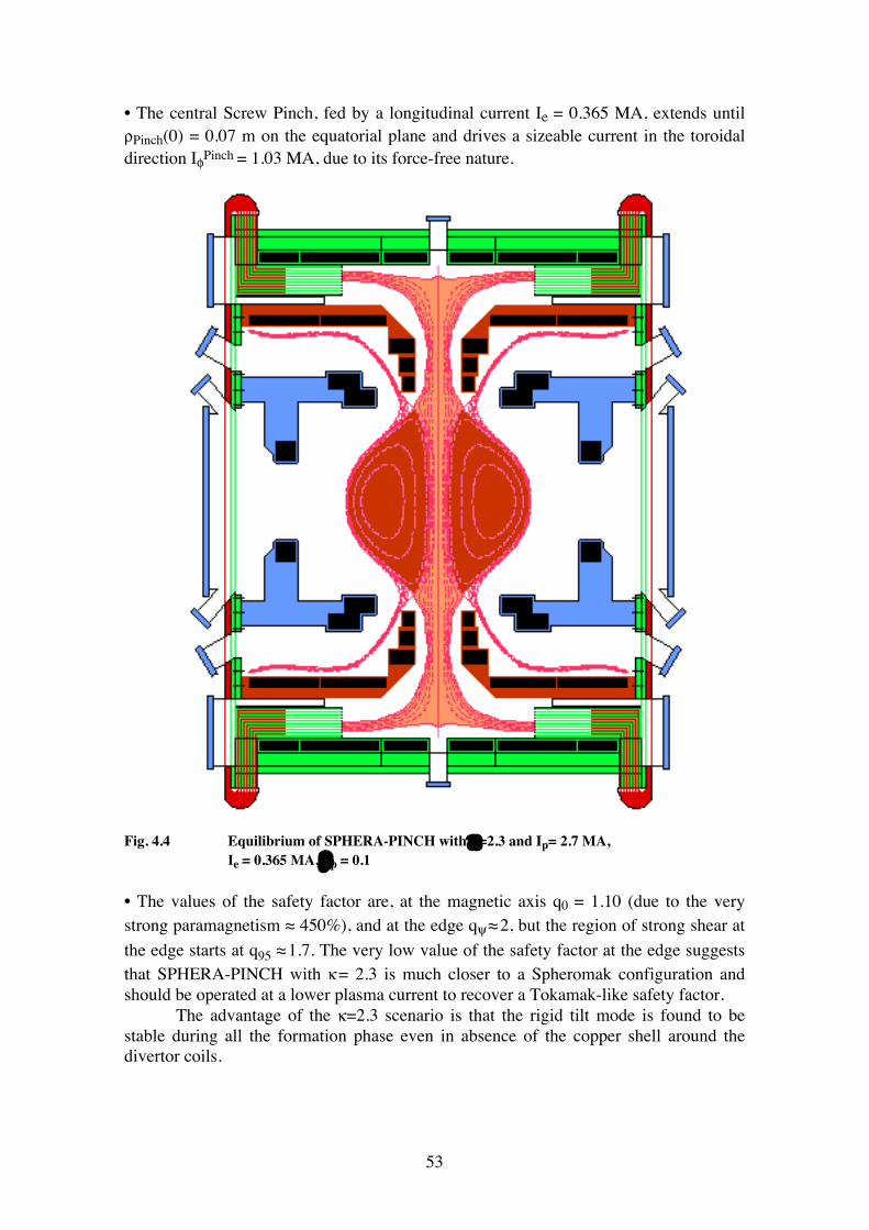
53
• The central Screw Pinch, fed by a longitudinal current Ie = 0.365 MA, extends until ρPinch(0) = 0.07 m on the equatorial plane and drives a sizeable current in the toroidal direction IφPinch = 1.03 MA, due to its force-free nature.
Fig. 4.4 Equilibrium of SPHERA-PINCH with κ=2.3 and Ip= 2.7 MA, Ie = 0.365 MA, βp = 0.1 • The values of the safety factor are, at the magnetic axis q0 = 1.10 (due to the very strong paramagnetism ≈ 450%), and at the edge qψ ≈ 2, but the region of strong shear at the edge starts at q95 ≈ 1.7. The very low value of the safety factor at the edge suggests that SPHERA-PINCH with κ = 2.3 is much closer to a Spheromak configuration and should be operated at a lower plasma current to recover a Tokamak-like safety factor. The advantage of the κ=2.3 scenario is that the rigid tilt mode is found to be stable during all the formation phase even in absence of the copper shell around the divertor coils.
54
4.1.4 Power supply for SPHERA-PINCH The current wave forms for the formation and compression scheme of SPHERA-PINCH (Table 4.II) are quite fast and cannot be much lengthened, even if the loop voltage required for the ULART break-down should turn out to be much smaller, as the upper time limit is set by the Screw Pinch resistive diffusion time (see 4.1.1). In particular the PF1 coil discharges to zero in 9 msec very large positive currents. This implies extremely high peak powers during the ULART breakdown: the peak power for PF1 in the first 9 msec is 3.0 GW, whereas the overall power required by the poloidal field coils in the first 9 msec reaches 3.3 GW and corresponds to an energy dissipation of 45 MJ in 9 msec. A preliminary assessment of this scheme leads to the possibility of using the existing MFG3 generator for feeding all the poloidal field coils of SPHERA-PINCH. In particular the existing T feeder, by adding a more powerful (factor of 4) commutation circuitry, could feed the PF1; the existing V feeder could feed the PF2 and PF3 coils. Concerning the PF4a, PF4b and PF4c coils (which make the line of force straight and horizontal in the electrode region), they could be fed by fast feeders, different from the ones actually existing at Frascati, based upon GTO power transistors, so avoiding to build the dedicated commutation systems. The existing F feeder could be used for the PF5 coil. The feeding system can be so summarised: The poloidal field circuitry of SPHERA-PINCH would require 6 feeders. All of them will be dependent upon the MFG3 rotating machine. PF1 ⇒ Existing T feeder with commutation circuitry (upgraded by factor of 4) PF2 and PF3 ⇒ Existing V feeder PF4a,b,c ⇒ 3 GTO feeders (5, 40 and 30 MW respectively) PF5 ⇒ Existing F feeder As far as the power supply of the Screw Pinch is concerned the only feasible solution seems the one of using the 40 MW presently available on the power grid, building a dedicated rectifying system able to provide 400 kA at a voltage up to 100 V. Moreover a condenser bank able to provide 5 kV for the Screw Pinch breakdown must be built. In this power supply scenario for SPHERA-PINCH the existing MFG1 and MFG2 rotating machines remain available for feeding the NBI or other additional systems of heating and current drive.
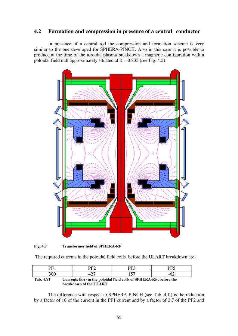
55
4.2 Formation and compression in presence of a central conductor In presence of a central rod the compression and formation scheme is very similar to the one developed for SPHERA-PINCH. Also in this case it is possible to produce at the time of the toroidal plasma breakdown a magnetic configuration with a poloidal field null approximately situated at R = 0.835 (see Fig. 4.5).
Fig. 4.5 Transformer field of SPHERA-RF The required currents in the poloidal field coils, before the ULART breakdown are:
PF1 PF2 PF3 PF5 300 427 157 -62
Tab. 4.VI Currents (kA) in the poloidal field coils of SPHERA-RF, before the breakdown of the ULART The difference with respect to SPHERA-PINCH (see Tab. 4.II) is the reduction by a factor of 10 of the current in the PF1 current and by a factor of 2.7 of the PF2 and
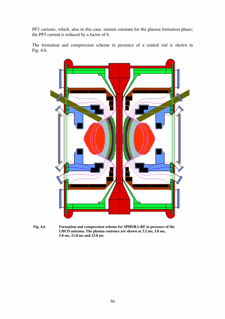
56
PF3 currents, which, also in this case, remain constant for the plasma formation phase; the PF5 current is reduced by a factor of 6. The formation and compression scheme in presence of a central rod is shown in Fig. 4.6.
Fig. 4.6 Formation and compression scheme for SPHERA-RF in presence of the LHCD antenna. The plasma contours are shown at 3.2 ms, 3.8 ms,
5.8 ms, 11.8 ms and 23.8 ms
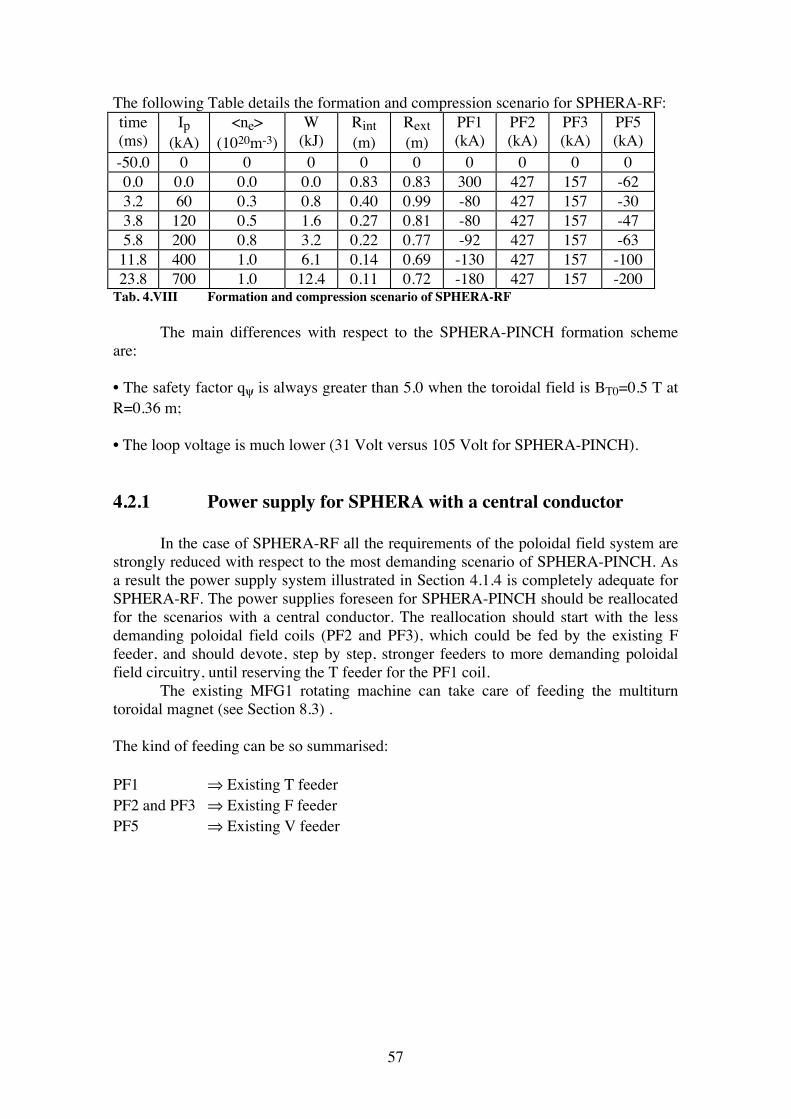
57
The following Table details the formation and compression scenario for SPHERA-RF: time (ms)
Ip (kA)
<ne> (1020m-3)
W (kJ)
Rint (m)
Rext (m)
PF1 (kA)
PF2 (kA)
PF3 (kA)
PF5 (kA)
-50.0 0 0 0 0 0 0 0 0 0 0.0 0.0 0.0 0.0 0.83 0.83 300 427 157 -62 3.2 60 0.3 0.8 0.40 0.99 -80 427 157 -30 3.8 120 0.5 1.6 0.27 0.81 -80 427 157 -47 5.8 200 0.8 3.2 0.22 0.77 -92 427 157 -63 11.8 400 1.0 6.1 0.14 0.69 -130 427 157 -100 23.8 700 1.0 12.4 0.11 0.72 -180 427 157 -200
Tab. 4.VIII Formation and compression scenario of SPHERA-RF The main differences with respect to the SPHERA-PINCH formation scheme are: • The safety factor qψ is always greater than 5.0 when the toroidal field is BT0=0.5 T at R=0.36 m; • The loop voltage is much lower (31 Volt versus 105 Volt for SPHERA-PINCH). 4.2.1 Power supply for SPHERA with a central conductor In the case of SPHERA-RF all the requirements of the poloidal field system are strongly reduced with respect to the most demanding scenario of SPHERA-PINCH. As a result the power supply system illustrated in Section 4.1.4 is completely adequate for SPHERA-RF. The power supplies foreseen for SPHERA-PINCH should be reallocated for the scenarios with a central conductor. The reallocation should start with the less demanding poloidal field coils (PF2 and PF3), which could be fed by the existing F feeder, and should devote, step by step, stronger feeders to more demanding poloidal field circuitry, until reserving the T feeder for the PF1 coil. The existing MFG1 rotating machine can take care of feeding the multiturn toroidal magnet (see Section 8.3) . The kind of feeding can be so summarised: PF1 ⇒ Existing T feeder PF2 and PF3 ⇒ Existing F feeder PF5 ⇒ Existing V feeder
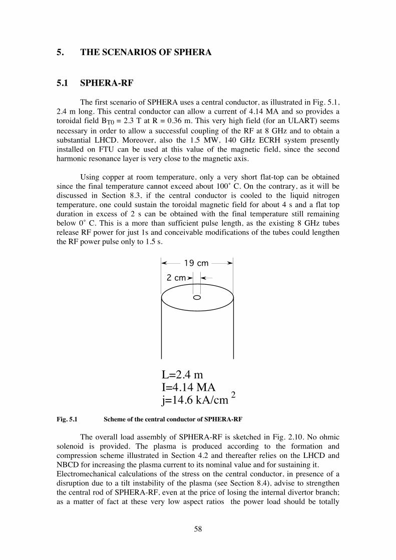
58
5. THE SCENARIOS OF SPHERA 5.1 SPHERA-RF The first scenario of SPHERA uses a central conductor, as illustrated in Fig. 5.1, 2.4 m long. This central conductor can allow a current of 4.14 MA and so provides a toroidal field BT0 = 2.3 T at R = 0.36 m. This very high field (for an ULART) seems necessary in order to allow a successful coupling of the RF at 8 GHz and to obtain a substantial LHCD. Moreover, also the 1.5 MW, 140 GHz ECRH system presently installed on FTU can be used at this value of the magnetic field, since the second harmonic resonance layer is very close to the magnetic axis. Using copper at room temperature, only a very short flat-top can be obtained since the final temperature cannot exceed about 100˚ C. On the contrary, as it will be discussed in Section 8.3, if the central conductor is cooled to the liquid nitrogen temperature, one could sustain the toroidal magnetic field for about 4 s and a flat top duration in excess of 2 s can be obtained with the final temperature still remaining below 0˚ C. This is a more than sufficient pulse length, as the existing 8 GHz tubes release RF power for just 1s and conceivable modifications of the tubes could lengthen the RF power pulse only to 1.5 s.
19 cm2 cm
L=2.4 mI=4.14 MAj=14.6 kA/cm 2
Fig. 5.1 Scheme of the central conductor of SPHERA-RF The overall load assembly of SPHERA-RF is sketched in Fig. 2.10. No ohmic solenoid is provided. The plasma is produced according to the formation and compression scheme illustrated in Section 4.2 and thereafter relies on the LHCD and NBCD for increasing the plasma current to its nominal value and for sustaining it. Electromechanical calculations of the stress on the central conductor, in presence of a disruption due to a tilt instability of the plasma (see Section 8.4), advise to strengthen the central rod of SPHERA-RF, even at the price of losing the internal divertor branch; as a matter of fact at these very low aspect ratios the power load should be totally
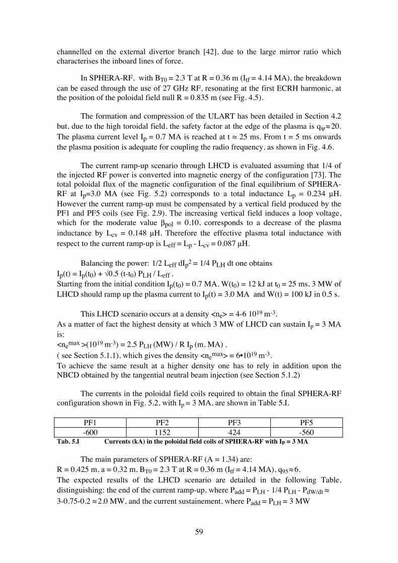
59
channelled on the external divertor branch [42], due to the large mirror ratio which characterises the inboard lines of force. In SPHERA-RF, with BT0 = 2.3 T at R = 0.36 m (Itf = 4.14 MA), the breakdown can be eased through the use of 27 GHz RF, resonating at the first ECRH harmonic, at the position of the poloidal field null R = 0.835 m (see Fig. 4.5). The formation and compression of the ULART has been detailed in Section 4.2 but, due to the high toroidal field, the safety factor at the edge of the plasma is qψ ≈ 20. The plasma current level Ip = 0.7 MA is reached at t ≈ 25 ms. From t = 5 ms onwards the plasma position is adequate for coupling the radio frequency, as shown in Fig. 4.6. The current ramp-up scenario through LHCD is evaluated assuming that 1/4 of the injected RF power is converted into magnetic energy of the configuration [73]. The total poloidal flux of the magnetic configuration of the final equilibrium of SPHERA-RF at Ip=3.0 MA (see Fig. 5.2) corresponds to a total inductance Lp = 0.234 µH. However the current ramp-up must be compensated by a vertical field produced by the PF1 and PF5 coils (see Fig. 2.9). The increasing vertical field induces a loop voltage, which for the moderate value βpol = 0.10, corresponds to a decrease of the plasma inductance by Lcv = 0.148 µH. Therefore the effective plasma total inductance with respect to the current ramp-up is Leff = Lp - Lcv = 0.087 µH. Balancing the power: 1/2 Leff dIp2 = 1/4 PLH dt one obtains Ip(t) = Ip(t0) + √0.5 (t-t0) PLH / Leff . Starting from the initial condition Ip(t0) = 0.7 MA, W(t0) = 12 kJ at t0 = 25 ms, 3 MW of LHCD should ramp up the plasma current to Ip(t) = 3.0 MA and W(t) = 100 kJ in 0.5 s. This LHCD scenario occurs at a density <ne> = 4-6 1019 m-3. As a matter of fact the highest density at which 3 MW of LHCD can sustain Ip = 3 MA is: <nemax >(1019 m-3) = 2.5 PLH (MW) / R Ip (m, MA) , ( see Section 5.1.1), which gives the density <nemax> = 6•1019 m-3. To achieve the same result at a higher density one has to rely in addition upon the NBCD obtained by the tangential neutral beam injection (see Section 5.1.2) The currents in the poloidal field coils required to obtain the final SPHERA-RF configuration shown in Fig. 5.2, with Ip = 3 MA, are shown in Table 5.I.
PF1 PF2 PF3 PF5 -600 1152 424 -560
Tab. 5.I Currents (kA) in the poloidal field coils of SPHERA-RF with Ip = 3 MA The main parameters of SPHERA-RF (A = 1.34) are: R = 0.425 m, a = 0.32 m, BT0 = 2.3 T at R = 0.36 m (Itf = 4.14 MA), q95 ≈ 6. The expected results of the LHCD scenario are detailed in the following Table, distinguishing: the end of the current ramp-up, where Padd = PLH - 1/4 PLH - PdW/dt ≈ 3-0.75-0.2 ≈ 2.0 MW, and the current sustainement, where Padd = PLH = 3 MW
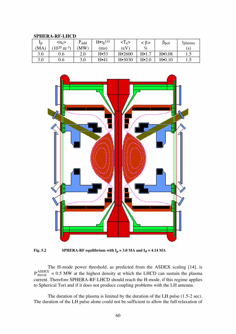
60
SPHERA-RF-LHCD
Ip (MA)
<ne> (1020 m-3)
Padd (MW)
H•τELG
(ms) <Te> (eV)
< β > %
βpol tplasma (s)
3.0 0.6 2.0 H•53 H•2600 H•1.7 H•0.08 1.5 3.0 0.6 3.0 H•41 H•3030 H•2.0 H•0.10 1.5
Fig. 5.2 SPHERA-RF equilibrium with Ip = 3.0 MA and Itf = 4.14 MA The H-mode power threshold, as predicted from the ASDEX scaling [14], is PthreshASDEX = 0.5 MW at the highest density at which the LHCD can sustain the plasma
current. Therefore SPHERA-RF-LHCD should reach the H-mode, if this regime applies to Spherical Tori and if it does not produce coupling problems with the LH antenna. The duration of the plasma is limited by the duration of the LH pulse (1.5-2 sec). The duration of the LH pulse alone could not be sufficient to allow the full relaxation of
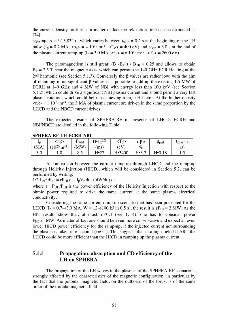
61
the current density profile: as a matter of fact the relaxation time can be estimated as [74]: tskin =µ0 σ a2 / ( 3.832 ), which varies between tskin = 0.2 s at the beginning of the LH pulse (Ip = 0.7 MA, <ne> = 4 1019 m-3, <Te> = 400 eV) and tskin = 3.0 s at the end of the plasma current ramp-up (Ip = 3.0 MA, <ne> = 6 1019 m-3, <Te> = 2600 eV). The paramagnetism is still great: (BT-BT0) / BT0 = 0.25 and allows to obtain BT = 2.5 T near the magnetic axis, which can permit the 140 GHz ECR Heating at the 2nd harmonic (see Section 5.1.3). Conversely the β values are rather low; with the aim of obtaining more significant β values it is possible to add up the existing 1.5 MW of ECRH at 140 GHz and 4 MW of NBI with energy less than 100 keV (see Section 5.1.2), which could drive a significant NBI plasma current and should permit a very fast plasma rotation, which could help in achieving a large H factor. At the higher density <ne> = 1 1020 m-3, the 3 MA of plasma current are driven in the same proportion by the LHCD and the NBCD current drives. The expected results of SPHERA-RF in presence of LHCD, ECRH and NBI/NBCD are detailed in the following Table: SPHERA-RF-LH-ECRH-NBI
Ip (MA)
<ne> (1020 m-3)
Padd (MW)
H•τELG
(ms) <Te> (eV)
< β > %
βpol tplasma (s)
3.0 1.0 8.5 H•27 H•3400 H•3.7 H•0.18 1.5 A comparison between the current ramp-up through LHCD and the ramp-up through Helicity Injection (HICD), which will be considered in Section 5.2, can be performed by writing: 1/2 Leff dIp2 = εPHI dt - IpVr dt - ( dW/dt ) dt where ε = POH/PHI is the power efficiency of the Helicity Injection with respect to the ohmic power required to drive the same current at the same plasma electrical conductivity. Considering the same current ramp-up scenario that has been presented for the LHCD (Ip = 0.7→3.0 MA, W = 12→100 kJ in 0.5 s), the result is εPHI = 2 MW. As the HIT results show that, at most, ε ≤ 0.4 (see 1.1.4), one has to consider power PHI ≥ 5 MW. As matter of fact one should be even more conservative and expect an even lower HICD power efficiency for the ramp-up, if the injected current not surrounding the plasma is taken into account (ε=0.1). This suggests that in a high field ULART the LHCD could be more efficient than the HICD in ramping up the plasma current. 5.1.1 Propagation, absorption and CD efficiency of the LH on SPHERA The propagation of the LH waves in the plasmas of the SPHERA-RF scenario is strongly affected by the characteristics of the magnetic configuration; in particular by the fact that the poloidal magnetic field, on the outboard of the torus, is of the same order of the toroidal magnetic field.
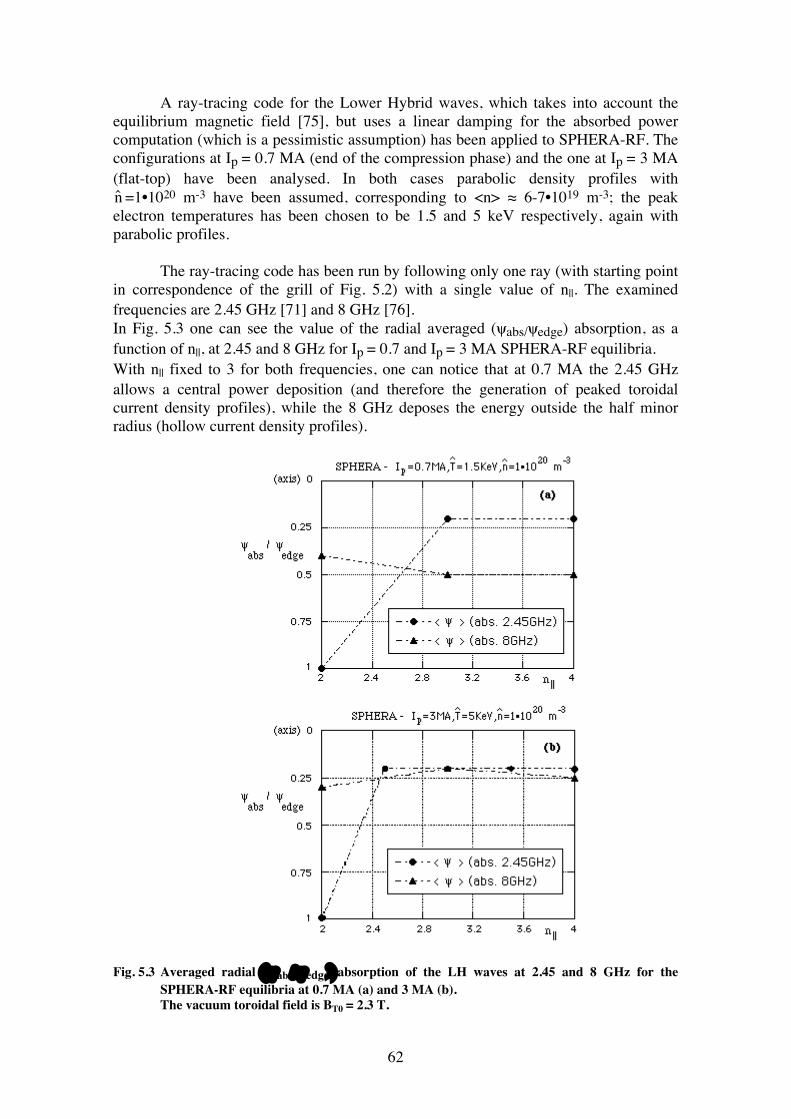
62
A ray-tracing code for the Lower Hybrid waves, which takes into account the equilibrium magnetic field [75], but uses a linear damping for the absorbed power computation (which is a pessimistic assumption) has been applied to SPHERA-RF. The configurations at Ip = 0.7 MA (end of the compression phase) and the one at Ip = 3 MA (flat-top) have been analysed. In both cases parabolic density profiles with ˆ n =1•1020 m-3 have been assumed, corresponding to <n> ≈ 6-7•1019 m-3; the peak electron temperatures has been chosen to be 1.5 and 5 keV respectively, again with parabolic profiles. The ray-tracing code has been run by following only one ray (with starting point in correspondence of the grill of Fig. 5.2) with a single value of n||. The examined frequencies are 2.45 GHz [71] and 8 GHz [76]. In Fig. 5.3 one can see the value of the radial averaged (ψabs/ψedge) absorption, as a function of n||, at 2.45 and 8 GHz for Ip = 0.7 and Ip = 3 MA SPHERA-RF equilibria. With n|| fixed to 3 for both frequencies, one can notice that at 0.7 MA the 2.45 GHz allows a central power deposition (and therefore the generation of peaked toroidal current density profiles), while the 8 GHz deposes the energy outside the half minor radius (hollow current density profiles).
Fig. 5.3 Averaged radial (ψabs/ψedge) absorption of the LH waves at 2.45 and 8 GHz for the SPHERA-RF equilibria at 0.7 MA (a) and 3 MA (b). The vacuum toroidal field is BT0 = 2.3 T.
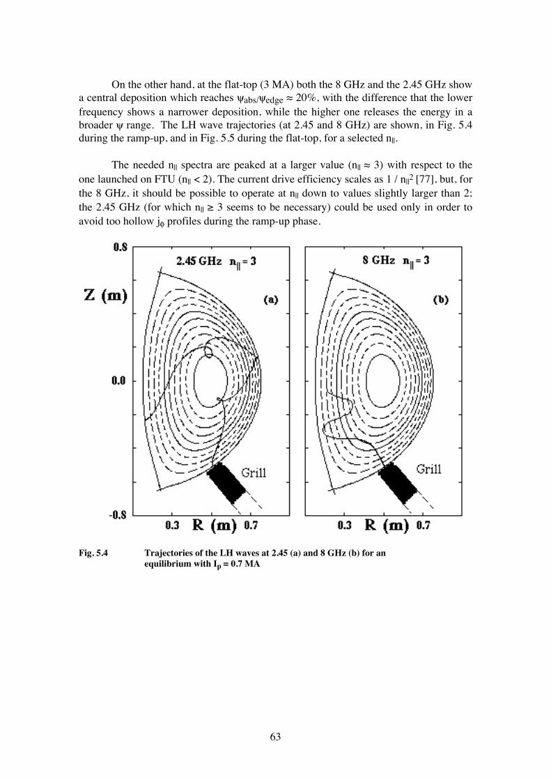
63
On the other hand, at the flat-top (3 MA) both the 8 GHz and the 2.45 GHz show a central deposition which reaches ψabs/ψedge ≈ 20%, with the difference that the lower frequency shows a narrower deposition, while the higher one releases the energy in a broader ψ range. The LH wave trajectories (at 2.45 and 8 GHz) are shown, in Fig. 5.4 during the ramp-up, and in Fig. 5.5 during the flat-top, for a selected n||. The needed n|| spectra are peaked at a larger value (n|| ≈ 3) with respect to the one launched on FTU (n|| < 2). The current drive efficiency scales as 1 / n||2 [77], but, for the 8 GHz, it should be possible to operate at n|| down to values slightly larger than 2; the 2.45 GHz (for which n|| ≥ 3 seems to be necessary) could be used only in order to avoid too hollow jφ profiles during the ramp-up phase.
Fig. 5.4 Trajectories of the LH waves at 2.45 (a) and 8 GHz (b) for an equilibrium with Ip = 0.7 MA
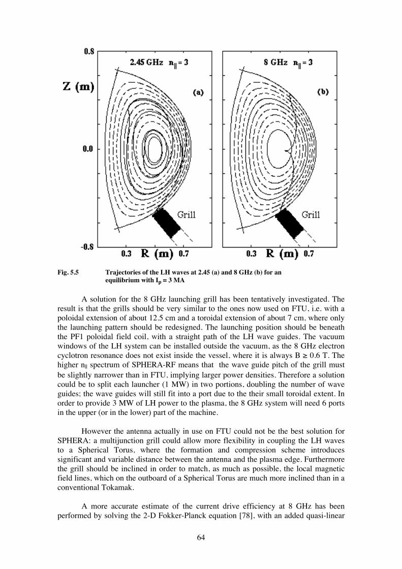
64
Fig. 5.5 Trajectories of the LH waves at 2.45 (a) and 8 GHz (b) for an equilibrium with Ip = 3 MA A solution for the 8 GHz launching grill has been tentatively investigated. The result is that the grills should be very similar to the ones now used on FTU, i.e. with a poloidal extension of about 12.5 cm and a toroidal extension of about 7 cm, where only the launching pattern should be redesigned. The launching position should be beneath the PF1 poloidal field coil, with a straight path of the LH wave guides. The vacuum windows of the LH system can be installed outside the vacuum, as the 8 GHz electron cyclotron resonance does not exist inside the vessel, where it is always B ≥ 0.6 T. The higher n|| spectrum of SPHERA-RF means that the wave guide pitch of the grill must be slightly narrower than in FTU, implying larger power densities. Therefore a solution could be to split each launcher (1 MW) in two portions, doubling the number of wave guides; the wave guides will still fit into a port due to the their small toroidal extent. In order to provide 3 MW of LH power to the plasma, the 8 GHz system will need 6 ports in the upper (or in the lower) part of the machine. However the antenna actually in use on FTU could not be the best solution for SPHERA: a multijunction grill could allow more flexibility in coupling the LH waves to a Spherical Torus, where the formation and compression scheme introduces significant and variable distance between the antenna and the plasma edge. Furthermore the grill should be inclined in order to match, as much as possible, the local magnetic field lines, which on the outboard of a Spherical Torus are much more inclined than in a conventional Tokamak. A more accurate estimate of the current drive efficiency at 8 GHz has been performed by solving the 2-D Fokker-Planck equation [78], with an added quasi-linear
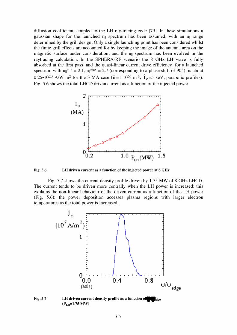
65
diffusion coefficient, coupled to the LH ray-tracing code [79]. In these simulations a gaussian shape for the launched n|| spectrum has been assumed, with an n|| range determined by the grill design. Only a single launching point has been considered whilst the finite grill effects are accounted for by keeping the image of the antenna area on the magnetic surface under consideration, and the n|| spectrum has been evolved in the raytracing calculation. In the SPHERA-RF scenario the 8 GHz LH wave is fully absorbed at the first pass, and the quasi-linear current drive efficiency, for a launched spectrum with n||min = 2.1, n||max = 2.7 (corresponding to a phase shift of 90 ̊), is about 0.25•1020 A/W m2 for the 3 MA case ( ˆ n =1 1020 m-3, ˆ T e =5 keV, parabolic profiles). Fig. 5.6 shows the total LHCD driven current as a function of the injected power.
Fig. 5.6 LH driven current as a function of the injected power at 8 GHz Fig. 5.7 shows the current density profile driven by 1.75 MW of 8 GHz LHCD. The current tends to be driven more centrally when the LH power is increased; this explains the non-linear behaviour of the driven current as a function of the LH power (Fig. 5.6): the power deposition accesses plasma regions with larger electron temperatures as the total power is increased.
Fig. 5.7 LH driven current density profile as a function of ψ /ψedge
(PLH=1.75 MW)
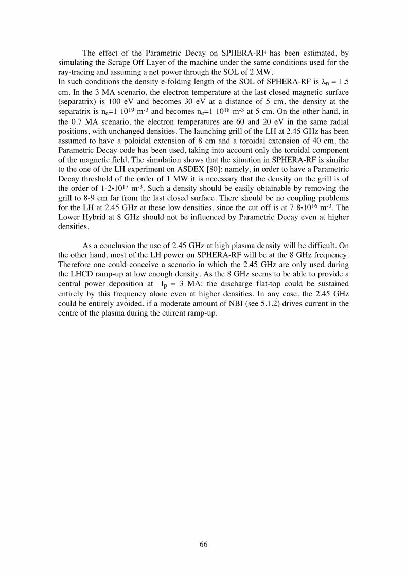
66
The effect of the Parametric Decay on SPHERA-RF has been estimated, by simulating the Scrape Off Layer of the machine under the same conditions used for the ray-tracing and assuming a net power through the SOL of 2 MW. In such conditions the density e-folding length of the SOL of SPHERA-RF is λn = 1.5 cm. In the 3 MA scenario, the electron temperature at the last closed magnetic surface (separatrix) is 100 eV and becomes 30 eV at a distance of 5 cm, the density at the separatrix is ne=1 1019 m-3 and becomes ne=1 1018 m-3 at 5 cm. On the other hand, in the 0.7 MA scenario, the electron temperatures are 60 and 20 eV in the same radial positions, with unchanged densities. The launching grill of the LH at 2.45 GHz has been assumed to have a poloidal extension of 8 cm and a toroidal extension of 40 cm, the Parametric Decay code has been used, taking into account only the toroidal component of the magnetic field. The simulation shows that the situation in SPHERA-RF is similar to the one of the LH experiment on ASDEX [80]: namely, in order to have a Parametric Decay threshold of the order of 1 MW it is necessary that the density on the grill is of the order of 1-2•1017 m-3. Such a density should be easily obtainable by removing the grill to 8-9 cm far from the last closed surface. There should be no coupling problems for the LH at 2.45 GHz at these low densities, since the cut-off is at 7-8•1016 m-3. The Lower Hybrid at 8 GHz should not be influenced by Parametric Decay even at higher densities. As a conclusion the use of 2.45 GHz at high plasma density will be difficult. On the other hand, most of the LH power on SPHERA-RF will be at the 8 GHz frequency. Therefore one could conceive a scenario in which the 2.45 GHz are only used during the LHCD ramp-up at low enough density. As the 8 GHz seems to be able to provide a central power deposition at Ip = 3 MA: the discharge flat-top could be sustained entirely by this frequency alone even at higher densities. In any case, the 2.45 GHz could be entirely avoided, if a moderate amount of NBI (see 5.1.2) drives current in the centre of the plasma during the current ramp-up.
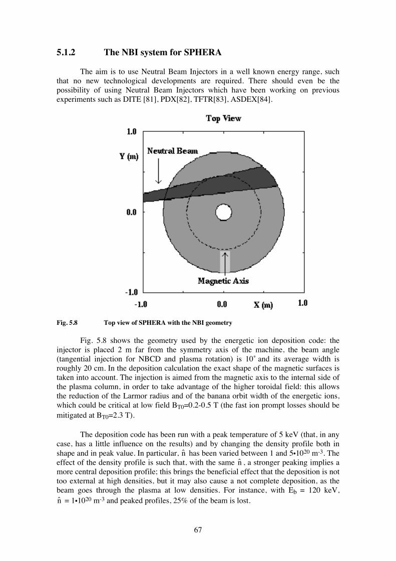
67
5.1.2 The NBI system for SPHERA The aim is to use Neutral Beam Injectors in a well known energy range, such that no new technological developments are required. There should even be the possibility of using Neutral Beam Injectors which have been working on previous experiments such as DITE [81], PDX[82], TFTR[83], ASDEX[84].
Fig. 5.8 Top view of SPHERA with the NBI geometry Fig. 5.8 shows the geometry used by the energetic ion deposition code: the injector is placed 2 m far from the symmetry axis of the machine, the beam angle (tangential injection for NBCD and plasma rotation) is 10 ̊and its average width is roughly 20 cm. In the deposition calculation the exact shape of the magnetic surfaces is taken into account. The injection is aimed from the magnetic axis to the internal side of the plasma column, in order to take advantage of the higher toroidal field: this allows the reduction of the Larmor radius and of the banana orbit width of the energetic ions, which could be critical at low field BT0=0.2-0.5 T (the fast ion prompt losses should be mitigated at BT0=2.3 T). The deposition code has been run with a peak temperature of 5 keV (that, in any case, has a little influence on the results) and by changing the density profile both in shape and in peak value. In particular, ˆ n has been varied between 1 and 5•1020 m-3. The effect of the density profile is such that, with the same ˆ n , a stronger peaking implies a more central deposition profile; this brings the beneficial effect that the deposition is not too external at high densities, but it may also cause a not complete deposition, as the beam goes through the plasma at low densities. For instance, with Eb = 120 keV, ˆ n = 1•1020 m-3 and peaked profiles, 25% of the beam is lost.
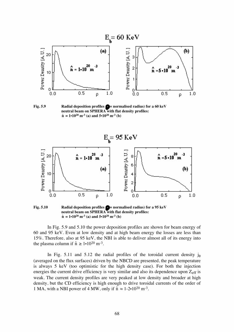
68
Fig. 5.9 Radial deposition profiles (ρ = normalised radius) for a 60 keV neutral beam on SPHERA with flat density profiles: ˆ n = 1•1020 m-3 (a) and 5•1020 m-3 (b)
Fig. 5.10 Radial deposition profiles (ρ = normalised radius) for a 95 keV neutral beam on SPHERA with flat density profiles: ˆ n = 1•1020 m-3 (a) and 5•1020 m-3 (b) In Fig. 5.9 and 5.10 the power deposition profiles are shown for beam energy of 60 and 95 keV. Even at low density and at high beam energy the losses are less than 15%. Therefore, also at 95 keV, the NBI is able to deliver almost all of its energy into the plasma column if ˆ n ≥ 1•1020 m-3. In Fig. 5.11 and 5.12 the radial profiles of the toroidal current density jφ (averaged on the flux surfaces) driven by the NBCD are presented, the peak temperature is always 5 keV (too optimistic for the high density case). For both the injection energies the current drive efficiency is very similar and also its dependence upon Zeff is weak. The current density profiles are very peaked at low density and broader at high density, but the CD efficiency is high enough to drive toroidal currents of the order of 1 MA, with a NBI power of 4 MW, only if ˆ n ≈ 1-2•1020 m-3.
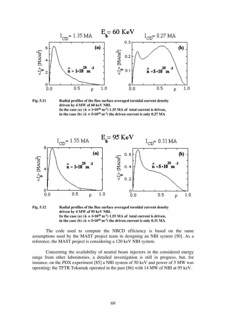
69
Fig. 5.11 Radial profiles of the flux surface averaged toroidal current density driven by 4 MW of 60 keV NBI. In the case (a) ( ˆ n = 1•1020 m-3) 1.35 MA of total current is driven, in the case (b) ( ˆ n = 5•1020 m-3) the driven current is only 0.27 MA
Fig. 5.12 Radial profiles of the flux surface averaged toroidal current density driven by 4 MW of 95 keV NBI. In the case (a) ( ˆ n = 1•1020 m-3) 1.55 MA of total current is driven, in the case (b) ( ˆ n = 5•1020 m-3) the driven current is only 0.31 MA The code used to compute the NBCD efficiency is based on the same assumptions used by the MAST project team in designing an NBI system [50]. As a reference, the MAST project is considering a 120 keV NBI system. Concerning the availability of neutral beam injectors in the considered energy range from other laboratories, a detailed investigation is still in progress, but, for instance, on the PDX experiment [85] a NBI system of 50 keV and power of 5 MW was operating; the TFTR Tokamak operated in the past [86] with 14 MW of NBI at 95 keV.
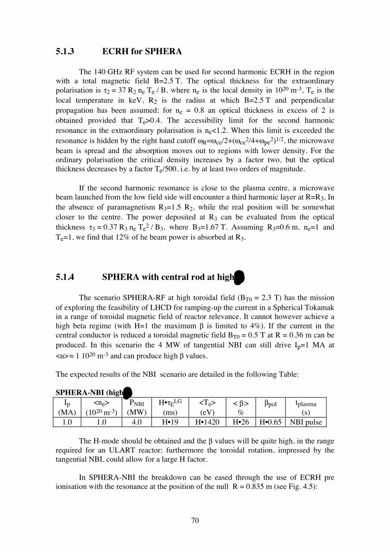
70
5.1.3 ECRH for SPHERA The 140 GHz RF system can be used for second harmonic ECRH in the region with a total magnetic field B=2.5 T. The optical thickness for the extraordinary polarisation is τ2 = 37 R2 ne Te / B, where ne is the local density in 1020 m-3, Te is the local temperature in keV, R2 is the radius at which B=2.5 T and perpendicular propagation has been assumed; for ne = 0.8 an optical thickness in excess of 2 is obtained provided that Te>0.4. The accessibility limit for the second harmonic resonance in the extraordinary polarisation is ne<1.2. When this limit is exceeded the resonance is hidden by the right hand cutoff ωR=ωce/2+(ωce2/4+ωpe2)1/2, the microwave beam is spread and the absorption moves out to regions with lower density. For the ordinary polarisation the critical density increases by a factor two, but the optical thickness decreases by a factor Te/500, i.e. by at least two orders of magnitude. If the second harmonic resonance is close to the plasma centre, a microwave beam launched from the low field side will encounter a third harmonic layer at R=R3. In the absence of paramagnetism R3=1.5 R2, while the real position will be somewhat closer to the centre. The power deposited at R3 can be evaluated from the optical thickness τ3 = 0.37 R3 ne Te2 / B3, where B3=1.67 T. Assuming R3=0.6 m, ne=1 and Te=1, we find that 12% of he beam power is absorbed at R3. 5.1.4 SPHERA with central rod at high β The scenario SPHERA-RF at high toroidal field (BT0 = 2.3 T) has the mission of exploring the feasibility of LHCD for ramping-up the current in a Spherical Tokamak in a range of toroidal magnetic field of reactor relevance. It cannot however achieve a high beta regime (with H=1 the maximum β is limited to 4%). If the current in the central conductor is reduced a toroidal magnetic field BT0 = 0.5 T at R = 0.36 m can be produced. In this scenario the 4 MW of tangential NBI can still drive Ip=1 MA at <n> ≈ 1 1020 m-3 and can produce high β values. The expected results of the NBI scenario are detailed in the following Table: SPHERA-NBI (high β)
Ip (MA)
<ne> (1020 m-3)
PNBI (MW)
H•τELG
(ms) <Te> (eV)
< β > %
βpol tplasma (s)
1.0 1.0 4.0 H•19 H•1420 H•26 H•0.65 NBI pulse The H-mode should be obtained and the β values will be quite high, in the range required for an ULART reactor; furthermore the toroidal rotation, impressed by the tangential NBI, could allow for a large H factor. In SPHERA-NBI the breakdown can be eased through the use of ECRH pre ionisation with the resonance at the position of the null R = 0.835 m (see Fig. 4.5):
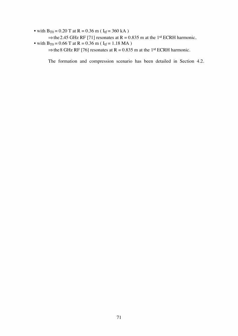
71
• with BT0 = 0.20 T at R = 0.36 m ( Itf = 360 kA ) ⇒ the 2.45 GHz RF [71] resonates at R = 0.835 m at the 1st ECRH harmonic, • with BT0 = 0.66 T at R = 0.36 m ( Itf = 1.18 MA ) ⇒ the 8 GHz RF [76] resonates at R = 0.835 m at the 1st ECRH harmonic. The formation and compression scenario has been detailed in Section 4.2.
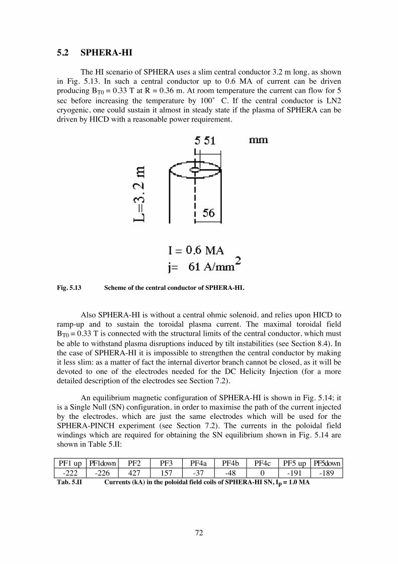
72
5.2 SPHERA-HI The HI scenario of SPHERA uses a slim central conductor 3.2 m long, as shown in Fig. 5.13. In such a central conductor up to 0.6 MA of current can be driven producing BT0 = 0.33 T at R = 0.36 m. At room temperature the current can flow for 5 sec before increasing the temperature by 100 ̊ C. If the central conductor is LN2 cryogenic, one could sustain it almost in steady state if the plasma of SPHERA can be driven by HICD with a reasonable power requirement.
Fig. 5.13 Scheme of the central conductor of SPHERA-HI. Also SPHERA-HI is without a central ohmic solenoid, and relies upon HICD to ramp-up and to sustain the toroidal plasma current. The maximal toroidal field BT0 = 0.33 T is connected with the structural limits of the central conductor, which must be able to withstand plasma disruptions induced by tilt instabilities (see Section 8.4). In the case of SPHERA-HI it is impossible to strengthen the central conductor by making it less slim: as a matter of fact the internal divertor branch cannot be closed, as it will be devoted to one of the electrodes needed for the DC Helicity Injection (for a more detailed description of the electrodes see Section 7.2). An equilibrium magnetic configuration of SPHERA-HI is shown in Fig. 5.14; it is a Single Null (SN) configuration, in order to maximise the path of the current injected by the electrodes, which are just the same electrodes which will be used for the SPHERA-PINCH experiment (see Section 7.2). The currents in the poloidal field windings which are required for obtaining the SN equilibrium shown in Fig. 5.14 are shown in Table 5.II: PF1 up PF1down PF2 PF3 PF4a PF4b PF4c PF5 up PF5down
-222 -226 427 157 -37 -48 0 -191 -189 Tab. 5.II Currents (kA) in the poloidal field coils of SPHERA-HI SN, Ip = 1.0 MA
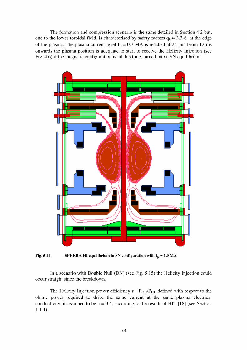
73
The formation and compression scenario is the same detailed in Section 4.2 but, due to the lower toroidal field, is characterised by safety factors qψ ≈ 3.3-6 at the edge of the plasma. The plasma current level Ip = 0.7 MA is reached at 25 ms. From 12 ms onwards the plasma position is adequate to start to receive the Helicity Injection (see Fig. 4.6) if the magnetic configuration is, at this time, turned into a SN equilibrium.
Fig. 5.14 SPHERA-HI equilibrium in SN configuration with Ip = 1.0 MA In a scenario with Double Null (DN) (see Fig. 5.15) the Helicity Injection could occur straight since the breakdown. The Helicity Injection power efficiency ε = POH/PHI, defined with respect to the ohmic power required to drive the same current at the same plasma electrical conductivity, is assumed to be ε = 0.4, according to the results of HIT [18] (see Section 1.1.4).
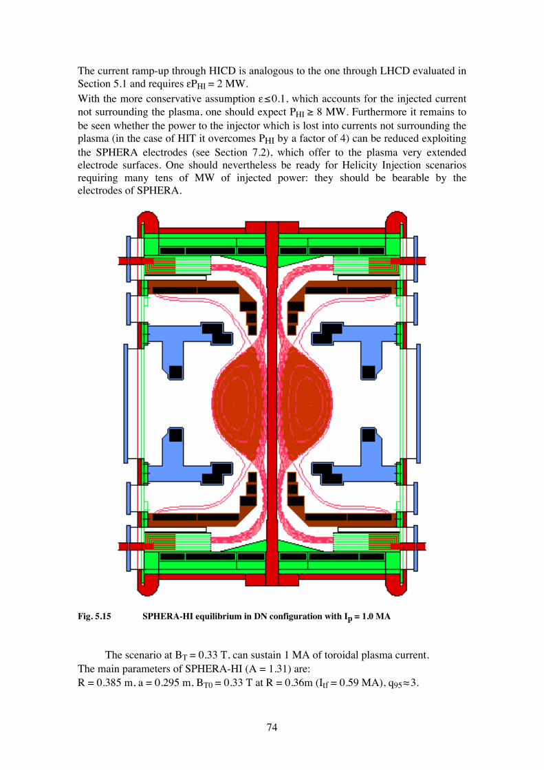
74
The current ramp-up through HICD is analogous to the one through LHCD evaluated in Section 5.1 and requires εPHI = 2 MW. With the more conservative assumption ε ≤ 0.1, which accounts for the injected current not surrounding the plasma, one should expect PHI ≥ 8 MW. Furthermore it remains to be seen whether the power to the injector which is lost into currents not surrounding the plasma (in the case of HIT it overcomes PHI by a factor of 4) can be reduced exploiting the SPHERA electrodes (see Section 7.2), which offer to the plasma very extended electrode surfaces. One should nevertheless be ready for Helicity Injection scenarios requiring many tens of MW of injected power: they should be bearable by the electrodes of SPHERA.
Fig. 5.15 SPHERA-HI equilibrium in DN configuration with Ip = 1.0 MA The scenario at BT = 0.33 T, can sustain 1 MA of toroidal plasma current. The main parameters of SPHERA-HI (A = 1.31) are: R = 0.385 m, a = 0.295 m, BT0 = 0.33 T at R = 0.36m (Itf = 0.59 MA), q95 ≈ 3.
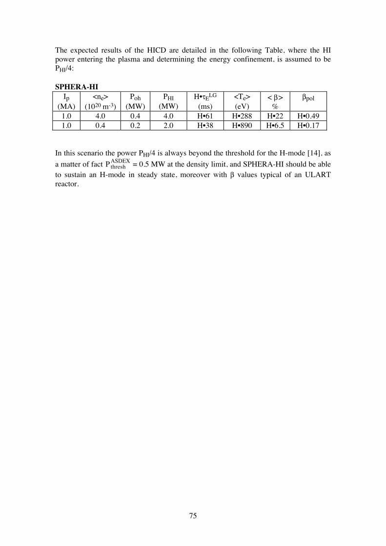
75
The expected results of the HICD are detailed in the following Table, where the HI power entering the plasma and determining the energy confinement, is assumed to be PHI/4: SPHERA-HI
Ip (MA)
<ne> (1020 m-3)
Poh (MW)
PHI (MW)
H•τELG
(ms) <Te> (eV)
< β > %
βpol
1.0 4.0 0.4 4.0 H•61 H•288 H•22 H•0.49 1.0 0.4 0.2 2.0 H•38 H•890 H•6.5 H•0.17
In this scenario the power PHI/4 is always beyond the threshold for the H-mode [14], as a matter of fact Pthresh
ASDEX = 0.5 MW at the density limit, and SPHERA-HI should be able to sustain an H-mode in steady state, moreover with β values typical of an ULART reactor.
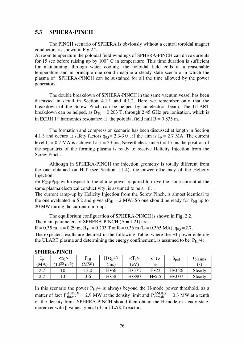
76
5.3 SPHERA-PINCH The PINCH scenario of SPHERA is obviously without a central toroidal magnet conductor, as shown in Fig 2.2. At room temperature the poloidal field windings of SPHERA-PINCH can drive currents for 15 sec before raising up by 100 ̊ C in temperature. This time duration is sufficient for maintaining, through water cooling, the poloidal field coils at a reasonable temperature and in principle one could imagine a steady state scenario in which the plasma of SPHERA-PINCH can be sustained for all the time allowed by the power generators. The double breakdown of SPHERA-PINCH in the same vacuum vessel has been discussed in detail in Section 4.1.1 and 4.1.2. Here we remember only that the breakdown of the Screw Pinch can be helped by an electron beam. The ULART breakdown can be helped, as BT0 = 0.203 T, through 2.45 GHz pre ionisation, which is in ECRH 1st harmonics resonance at the poloidal field null R = 0.835 m. The formation and compression scenario has been discussed at length in Section 4.1.3 and occurs at safety factors q95 = 2.3-3.0 , if the aim is Ip = 2.7 MA. The current level Ip = 0.7 MA is achieved at t = 33 ms. Nevertheless since t = 15 ms the position of the separatrix of the forming plasma is ready to receive Helicity Injection from the Screw Pinch. Although in SPHERA-PINCH the injection geometry is totally different from the one obtained on HIT (see Section 1.1.4), the power efficiency of the Helicity Injection ε = POH/PHI, with respect to the ohmic power required to drive the same current at the same plasma electrical conductivity, is assumed to be ε = 0.1. The current ramp-up by Helicity Injection from the Screw Pinch, is almost identical to the one evaluated in 5.2 and gives εPHI = 2 MW. So one should be ready for PHI up to 20 MW during the current ramp-up. The equilibrium configuration of SPHERA-PINCH is shown in Fig. 2.2. The main parameters of SPHERA-PINCH (A = 1.21) are: R = 0.35 m, a = 0.29 m, BT0 = 0.203 T at R = 0.36 m (Ie = 0.365 MA), q95 ≈ 2.7. The expected results are detailed in the following Table, where the HI power entering the ULART plasma and determining the energy confinement, is assumed to be PHI/4: SPHERA-PINCH
Ip (MA)
<ne> (1020 m-3)
PHI (MW)
H•τELG
(ms) <Te> (eV)
< β > %
βpol tplasma (s)
2.7 10. 13.0 H•66 H•372 H•23 H•0.26 Steady 2.7 1.0 3.6 H•58 H•890 H•5.5 H•0.07 Steady
In this scenario the power PHI/4 is always beyond the H-mode power threshold, as a matter of fact Pthresh
ASDEX = 2.9 MW at the density limit and PthreshASDEX = 0.3 MW at a tenth
of the density limit. SPHERA-PINCH should then obtain the H-mode in steady state, moreover with β values typical of an ULART reactor.
77
If 4 MW of tangential NBI are added, the following scenario can be expected, where PHI/4 is the HI power entering the ULART plasma: SPHERA-PINCH-NBI
Ip (MA)
<ne> (1020 m-3)
Padd (MW)
PHI (MW)
H•τELG
(ms) <Te> (eV)
< β > %
βpol
2.7 10. 6.4 9.6 H•45 H•550 H•30 H•0.34 2.7 1.0 4.4 1.6 H•22 H•1840 H•10 H•0.11
5.3.1 O-X-B heating for SPHERA-PINCH and SPHERA-HI Electron cyclotron resonance heating encounters a density limit when the optically thick cyclotron resonances are hidden by cutoff layers. There is a possibility to overcome this limitation by exploiting mode conversion processes, which produce electron Bernstein electrostatic modes that can propagate in overdense plasmas, and are strongly absorbed at cyclotron resonance layers. The mode conversion scheme is based on the fact that the evanescence region behind the cutoff layer disappears for ordinary polarised waves having a propagation index in the direction parallel to the magnetic field: N||,opt=(1+ω/ωce)-1/2. Waves launched from the low field side with propagation index close to N||,opt tunnel through the cutoff layer with negligible reflection loss and are converted to backwards propagating extraordinary waves. This is the O-X part of the scheme. The X wave encounters the upper hybrid resonance along its propagation towards the low field side, and there it is converted to an electron Bernstein wave (X-B conversion); the B wave propagates towards the high field side and can reach the plasma centre. The critical point of this scheme is the efficiency of tunnelling through the O-mode cutoff [87], which depends on the spatial spectrum (i.e. on the N|| distribution) of the incident beam, on the density gradient scale length and on the roughness of the cutoff surface, i.e. on amplitude and wavelength of density fluctuations. Efficient O-X-B heating has been demonstrated for the first time on the W7-AS stellarator [87]. The magnetic field at the ULART magnetic axis in the 2.7 MA SPHERA-PINCH reference scenario is 0.78 T; the minimum value on the low field side is 0.63 T and the value at the edge is 0.65 T. This shallow variation on the low field side (which is due to the large contribution from the poloidal field) avoids harmonic overlap problems, for example a wave in third harmonic resonance at the magnetic axis has no fourth harmonic resonance within the plasma, so that central heating in the first three harmonics (namely 21.8, 43.7 and 65.5 GHz) is possible. In the 1 MA scenario the relevant magnetic field values are: 0.49, 0.46 and 0.48 T (on axis, minimum and at the outer edge respectively). The first three on-axis resonances occur at 13.7, 27.4 and 41.2 GHz. A frequency that could be used for O-X-B heating in both scenarios is 44 GHz, which corresponds to a critical density of 2.4·1019 m-3. (for strongly overdense plasmas both conversion processes take place just inside the critical density layer). For the 2.7 MA scenario (second harmonic heating) N||,opt=0.58, while at 1 MA (third harmonic) N||,opt=0.5. The possibility to employ the 28 GHz Gyrotrons that have been widely used for fusion experiment in the past can also be considered. In this case the critical density is 0.97·1019 m-3. Second harmonic heating (N||,opt=0.58) at 28 GHz could be performed
78
on the 1 MA scenario as it is, or on the 2.7 MA scenario with all the fields reduced by a factor 1.6. Third harmonic heating (N||,opt=0.5) would require reduction factors of 1.5 and 2.4 for the 1 and 2.7 MA scenarios respectively. The use of the 8 GHz system has also been considered. In this case, the field on axis should be reduced to 0.28 T (including paramagnetism) for first harmonic heating (N||,opt=0.7), and the critical density would be 8•1017 m-3.
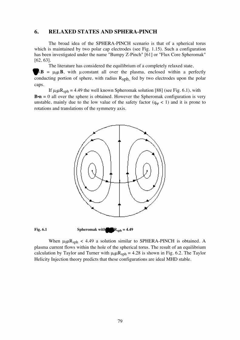
79
6. RELAXED STATES AND SPHERA-PINCH The broad idea of the SPHERA-PINCH scenario is that of a spherical torus which is maintained by two polar cap electrodes (see Fig. 1.15). Such a configuration has been investigated under the name "Bumpy Z-Pinch" [61] or "Flux Core Spheromak" [62, 63]. The literature has considered the equilibrium of a completely relaxed state, ∇∧B = µ0µ B, with µ constant all over the plasma, enclosed within a perfectly conducting portion of sphere, with radius Rsph, fed by two electrodes upon the polar caps. If µ0µRsph = 4.49 the well known Spheromak solution [88] (see Fig. 6.1), with B•n = 0 all over the sphere is obtained. However the Spheromak configuration is very unstable, mainly due to the low value of the safety factor (qψ < 1) and it is prone to rotations and translations of the symmetry axis.
Fig. 6.1 Spheromak with µ 0 µ Rsph = 4.49 When µ0µRsph < 4.49 a solution similar to SPHERA-PINCH is obtained. A plasma current flows within the hole of the spherical torus. The result of an equilibrium calculation by Taylor and Turner with µ0µRsph = 4.28 is shown in Fig. 6.2. The Taylor Helicity Injection theory predicts that these configurations are ideal MHD stable.
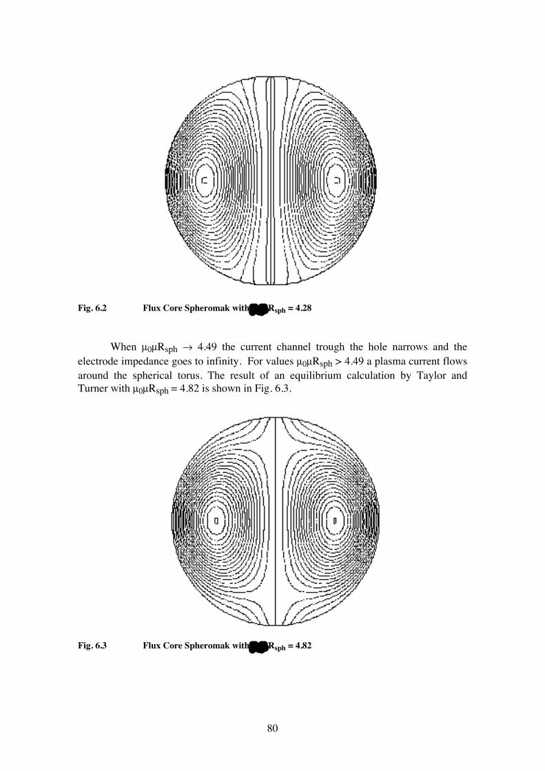
80
Fig. 6.2 Flux Core Spheromak with µ 0 µ Rsph = 4.28 When µ0µRsph → 4.49 the current channel trough the hole narrows and the electrode impedance goes to infinity. For values µ0µRsph > 4.49 a plasma current flows around the spherical torus. The result of an equilibrium calculation by Taylor and Turner with µ0µRsph = 4.82 is shown in Fig. 6.3.
Fig. 6.3 Flux Core Spheromak with µ 0 µ Rsph = 4.82
81
The Taylor Helicity Injection theory predicts that these configurations are ideal MHD unstable. The ULART of SPHERA-PINCH could show a tendency toward a force-free quasi relaxed state, i.e. with µ0µ = j•B/B2 almost constant upon the plasma. The idea of the SPHERA-PINCH experiment is to drive the plasma, through a particular formation and compression scheme, toward a stable state with µ0µRsph < 4.49, by increasing the value of µ, but maintaining in the ULART safety factor values (q0≈1, qedge≈3-4) typical of a Tokamak, with the aim of controlling the Helicity flow toward the toroidal magnetic axis and to avoid the complete relaxation of the system. At the end of the plasma formation and compression, the control of the Screw Pinch, obtained by the current injected through the electrodes, by the gas injected into the Pinch and by the field shaping through the poloidal field coils, should allow to maintain the SPHERA configuration at the highest possible level of µ0µRsph, without making the transition into a Spheromak configuration. On the other hand the control of the ULART, obtained by pellet injection into the spherical torus, by the poloidal field coils, and by additional heating and current drive (NBI), should influence the Helicity and power transfer between the Screw Pinch and the ULART. The objectives of controlling the Helicity Injection and the Magnetic Relaxation and then of exploring the resulting confinement and β limits, are the key-points of the physics investigated by the SPHERA-PINCH experiment. The MHD stability of the SPHERA-PINCH experiment remains to be evaluated, but the encouraging results obtained on TS-3 [57,58] (see 1.1.5), show that a configuration like SPHERA-PINCH can be ideal MHD stable while approaching a relaxed state: this is in agreement with the Taylor calculations of flux-core Spherical Tori. However a number of issues are present in SPHERA-PINCH which are at variance with both the TS-3 experiment as well as with the idealised Taylor calculations: • The absence in SPHERA-PINCH of a conducting shell near the plasma. • The formation scheme, which is totally different from the TS-3 formation. • The attempt of building the electrodes removed and shielded from the main plasma.
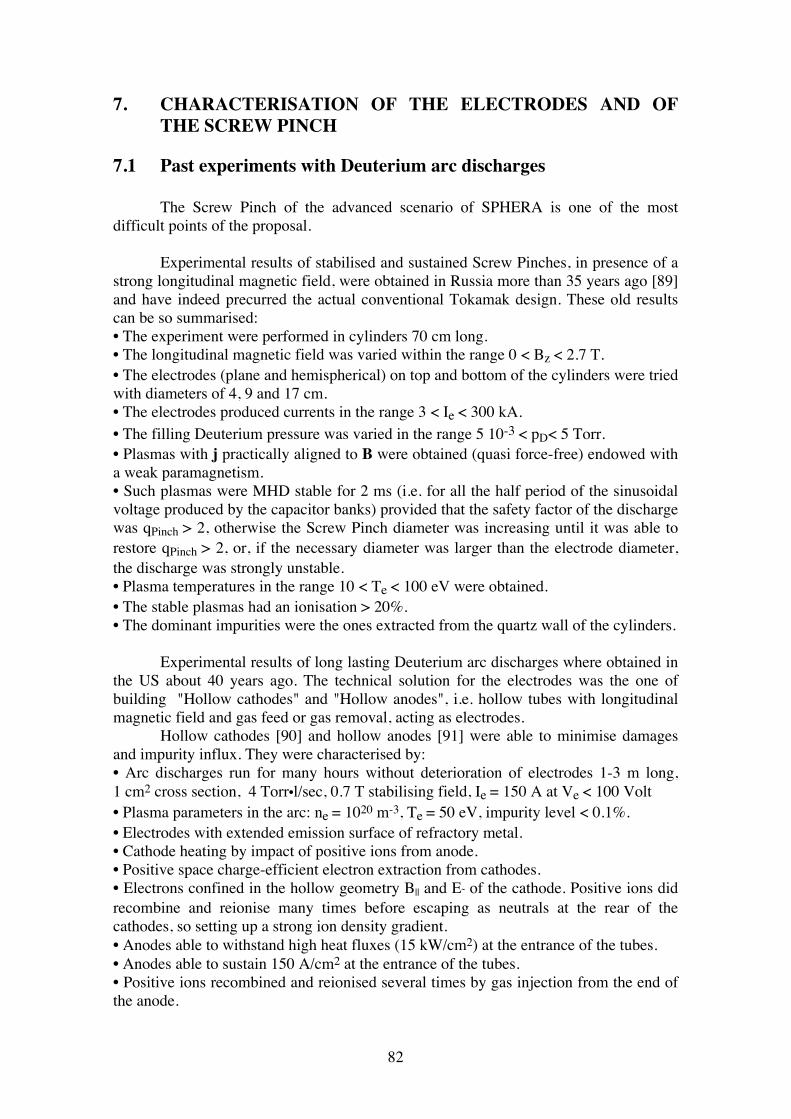
82
7. CHARACTERISATION OF THE ELECTRODES AND OF THE SCREW PINCH 7.1 Past experiments with Deuterium arc discharges The Screw Pinch of the advanced scenario of SPHERA is one of the most difficult points of the proposal. Experimental results of stabilised and sustained Screw Pinches, in presence of a strong longitudinal magnetic field, were obtained in Russia more than 35 years ago [89] and have indeed precurred the actual conventional Tokamak design. These old results can be so summarised: • The experiment were performed in cylinders 70 cm long. • The longitudinal magnetic field was varied within the range 0 < Bz < 2.7 T. • The electrodes (plane and hemispherical) on top and bottom of the cylinders were tried with diameters of 4, 9 and 17 cm. • The electrodes produced currents in the range 3 < Ie < 300 kA. • The filling Deuterium pressure was varied in the range 5 10-3 < pD< 5 Torr. • Plasmas with j practically aligned to B were obtained (quasi force-free) endowed with a weak paramagnetism. • Such plasmas were MHD stable for 2 ms (i.e. for all the half period of the sinusoidal voltage produced by the capacitor banks) provided that the safety factor of the discharge was qPinch > 2, otherwise the Screw Pinch diameter was increasing until it was able to restore qPinch > 2, or, if the necessary diameter was larger than the electrode diameter, the discharge was strongly unstable. • Plasma temperatures in the range 10 < Te < 100 eV were obtained. • The stable plasmas had an ionisation > 20%. • The dominant impurities were the ones extracted from the quartz wall of the cylinders. Experimental results of long lasting Deuterium arc discharges where obtained in the US about 40 years ago. The technical solution for the electrodes was the one of building "Hollow cathodes" and "Hollow anodes", i.e. hollow tubes with longitudinal magnetic field and gas feed or gas removal, acting as electrodes. Hollow cathodes [90] and hollow anodes [91] were able to minimise damages and impurity influx. They were characterised by: • Arc discharges run for many hours without deterioration of electrodes 1-3 m long, 1 cm2 cross section, 4 Torr•l/sec, 0.7 T stabilising field, Ie = 150 A at Ve < 100 Volt • Plasma parameters in the arc: ne = 1020 m-3, Te = 50 eV, impurity level < 0.1%. • Electrodes with extended emission surface of refractory metal. • Cathode heating by impact of positive ions from anode. • Positive space charge-efficient electron extraction from cathodes. • Electrons confined in the hollow geometry B|| and E˜ of the cathode. Positive ions did recombine and reionise many times before escaping as neutrals at the rear of the cathodes, so setting up a strong ion density gradient. • Anodes able to withstand high heat fluxes (15 kW/cm2) at the entrance of the tubes. • Anodes able to sustain 150 A/cm2 at the entrance of the tubes. • Positive ions recombined and reionised several times by gas injection from the end of the anode.
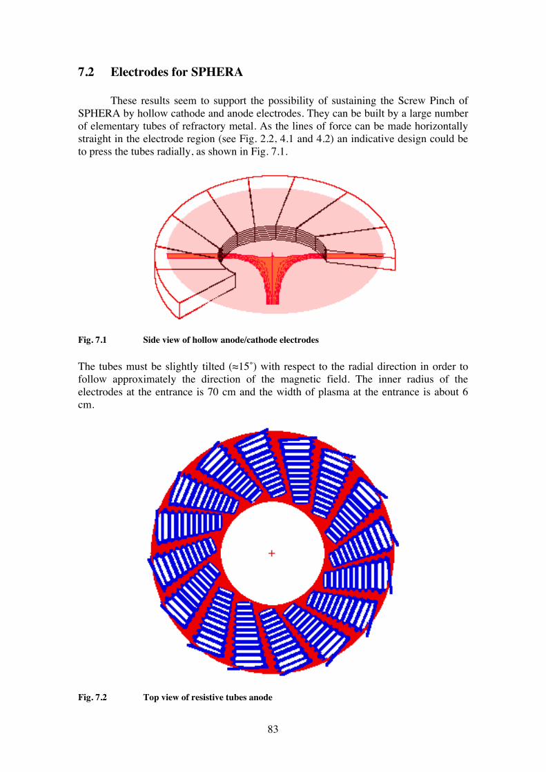
83
7.2 Electrodes for SPHERA These results seem to support the possibility of sustaining the Screw Pinch of SPHERA by hollow cathode and anode electrodes. They can be built by a large number of elementary tubes of refractory metal. As the lines of force can be made horizontally straight in the electrode region (see Fig. 2.2, 4.1 and 4.2) an indicative design could be to press the tubes radially, as shown in Fig. 7.1.
Fig. 7.1 Side view of hollow anode/cathode electrodes The tubes must be slightly tilted (≈15˚) with respect to the radial direction in order to follow approximately the direction of the magnetic field. The inner radius of the electrodes at the entrance is 70 cm and the width of plasma at the entrance is about 6 cm.
Fig. 7.2 Top view of resistive tubes anode
84
Using the figures quoted in Ref. [91] these electrodes should be able to handle a maximum Pinch current Ie
= 400 kA (with 150 A/cm2 at the entrance of the tubes) and a maximum power Pe
= 40 MW ( with 15 kW/cm2 at the entrance of the tubes). Both these figures are in good agreement with the required Screw Pinch current and available power supply for the central Screw Pinch. In order to dissipate most of the energy in volume Joule heating of the anodes refractory metal could be tightly wound in coils inside the tubes (see Fig. 7.2), allowing for collector depressing. As a large amount of gas will be injected from the anodes, the gas removal from the rear of the cathode requires a high pumping speed. A small experiment consisting of a stabilised Screw Pinch fed by hollow electrodes will have to be built before the SPHERA-HI and SPHERA-PINCH phases, with the aim of collecting experience and data for a detailed design of the final electrodes. 7.3 The resistivity of the central Screw Pinch From the Katsurai formula [8] (see Section 1.2) the current in the ULART is proportional to the current density in the central Screw Pinch (Ie = π ρ2Pinch(0) jPinch(0)): Ip = jPinch(0) 2 κ2 a2 / ( π qψ ) Then reducing ρPinch(0), keeping jPinch(0) unchanged, one can maintain the same plasma current, unless a tilt mode is destabilised. The advantage of reducing ρPinch(0) is clear, since it reduces the Joule dissipation in the central Screw Pinch: PPinch = ∫ dV j2 / σ = π j2Pinch(0) ρ4Pinch(0) ∫-L/2
L/2 dz / (σ ρ2Pinch(z)) ;
under the assumption of constant electrical conductivity in the Screw Pinch σ = constant, as jPinch(z) ρ2Pinch(z) = jPinch(0) ρ2Pinch(0) and taking from the equilibrium calculation the estimate < 1 / ρ2Pinch(z) > = 1 / ( 2.5 ρ2Pinch(0) ), one obtains: PPinch = π j2Pinch(0) ρ2Pinch(0) LPinch / 2.5 σ . Inserting LPinch = 3.6 m, jPinch(0) = 3.2 107 A/m2, σ = 2 103 Te3/2 / Zeff ( i.e. lnΛ = 10) one finds that, PPinch = 2.3 1012 ρ2Pinch(0) Zeff / Te3/2 , which reduces, for Te = 50 eV, to: PPinch = 6.5 109 ρ2Pinch(0) Zeff Watt, which means a Joule dissipation which scales with the aspect ratio as: for ρPinch(0) = 0.0600 m, i.e. A =1.2, PPinch = 23.4 Zeff MW; for ρPinch(0) = 0.0300 m, i.e. A =1.1, PPinch = 5.8 Zeff MW; for ρPinch(0) = 0.0150 m, i.e. A =1.05, PPinch = 1.5 Zeff MW;
85
Then the power dissipated by Joule effect in the central Screw Pinch goes down like ρ2Pinch(0), and reaches acceptable limits only at very low aspect ratios. Considering now the power injected into the central Screw Pinch in order to sustain the Helicity of the ULART, assuming Helicity balance and neglecting any Helicity dissipation: VHelicity ψe = Voh ψT ; now, as the ULART toroidal flux is ψT = 0.51 Wb and does almost not scale with ρPinch(0), whereas the electrode poloidal flux scales like ψe = 0.027 ( ρPinch(0) / 0.06 )2 Wb. As Voh = 0.5 Volt for SPHERA at 2.7 MA and at the density limit, whereas Voh=0.13 Volt at one tenth of the density limit, one derives: VHelicity = 3.4 10-2 / ρ2Pinch(0), so that the minimum power required for injecting the Helicity at the density limit is: PHelicity = Ie • VHelicity = 1.0 108 ρ2Pinch(0) • 3.4 10-2 / ρ2Pinch(0) = 3.4 MW ; at one tenth of the density limit the minimum power for injecting the Helicity is reduced to PHelicity = 0.9 MW. Note that the minimum Helicity Injection power is fixed and independent of ρPinch(0) and that the electrode impedance for the Helicity Injection at the density limit is ZHelicity = VHelicity / Ie= 3.4 10-10 / ρ4Pinch(0) , diverging like 1 / ρ4Pinch(0). The minimum requirement for the Helicity Injection power ranges from 0.9 MW to 3.4 MW. This has to be compared with a total requirement, derived assuming a Helicity Injection power efficiency ε=0.1, which ranges from 3.6 to 13.0 MW (see Section 5.3) and with an ohmic power dissipation of 23.4 Zeff MW in the central plasma under the assumption of Te = 50 eV for the Pinch temperature. All these estimates show that a power supply able to provide 40 MW to the central Screw Pinch should be sufficient for the experiment. 7.4 Screw Pinch power balance In order to derive the plasma parameters of the Screw Pinch, which substitutes the central conductor in SPHERA, a power balance is made modelling the Pinch and the electrodes as a flux tube similar to the scrape off layer of a limiter Tokamak [92], with the main difference of the large current density carried through this plasma. The Pinch is modelled as a straight cylinder of radius ρ and length L (≈ 3.60 m). Since the magnetic field lines are helices, for simplicity the connection length (i.e. the length of a field line from one electrode to the other) is taken as 2L.
86
• Thus, similarly to the power losses through the sheath of a limiter, the power incident on the electrodes due to the particle flux can be written as: Pel = γ n ks TL3/2 π ρ2 1.6 10-19 Watts, where γ is the energy transmission factor through the sheath (γ ≈ 8) and ks the numerical coefficient for the sound velocity expressed in m/s (ks = 9.78 103 / A1/2, A being the mass number of the incident ion). • The power lost by diffusion though the Pinch surface is: PDiff = kB ( n T2 / B ) 2 π ρ L 1.6 10-19 Watts, where a thermal conductivity of the Bohm type (∝ T / B; kB = .06 when T in eV and B in T) is assumed. • The power lost by radiation is expressed by: Prad = fimp n2 R(T) π ρ2 L, where fimp is the impurity fraction and R(T) the cooling rate. • The maximum power loss is that connected with the convected flux due to the current at the anode, i.e.: Pan = 5/2 j T π ρ2 • The input power is given (see Section 7.3) by: PPinch = π j2Pinch(0) ρ2Pinch(0) LPinch / 2.5 σ , corresponding to the constraint that the longitudinal plasma current density in the Pinch is a constant. The weight of the various loss terms is evaluated. The Pinch radius at which the radial power losses dominate with respect to the power lost at the electrodes, can be derived by the condition: 2 γ n ks T3/2 π ρ2 / [kB (n T2 / B) 2 π ρ L ] ≤ 1 , which gives ρ ≤ [ kB L / ( γ ks B)]1/2 T1/4 . Here and in the following the plasma temperature is assumed to be constant along the field line. At the end condition in which this assumption is satisfied will be verified. By substituting numerical values, it is easy to verify that only when ρ < a few mm (even taking into account a reasonable enhancement over Bohm diffusion), the radial loss term is significant. The radial loss term is therefore neglected in the power balance. Also the radiation term is neglected for the moment. Thus: 5/2 j T π ρ2 = ( π ρ2 j2 L Zeff ) / ( 2.5 kσ T3/2 ) j being the average current density in the Pinch, and kσ the numerical coefficient for the Spitzer resistivity. By substituting numerical coefficients, the Pinch temperature is obtained: T≈ 40 eV Assuming the density of the order of a few 1019 m-3 , it is easy to check that all the other power losses indicated are negligible with respect to those due to the Pinch current. The power to the anode is Pel = 23.4 Zeff MW when ρ = 6 cm. The power lost through impurity radiation is calculated assuming a 1% impurity concentration and a cooling rate R(T) ≈ 10-31 Wm3, which correspond to the maximal cooling rate of
87
Oxygen. The result is Prad ≈ 1.1 MW, which indeed can be neglected with respect to the total power, taking also into account that this evaluation is somewhat overestimated. The condition for avoiding strong longitudinal temperature gradient is [93]: n L ≤ 1017 T2 / Zeff (m-2) This condition is strictly verified for the Pinch if T ≈ 30-40 eV. At lower temperatures, the plasma temperature at the electrodes should be lower than that at the Pinch core, if (like in the SOL) the pressure is constant. In this case a more refined model would be necessary. Finally it is possible to derive also the particle flux (electron-ion pairs) to the electrodes: Γel = n ks T1/2 π ρ2 ≈ 1.3 1023 p/s. The particle losses through the cylindrical surface of the Pinch are two order of magnitude lower. These evaluations are to be considered very preliminary. 7.5 SOL plasma characteristics of SPHERA A simple 0-D model, based on the work by Dnestrovskii et al. [94], has been used to derive the parameters of the SOL plasma in SPHERA, for the various scenarios . The model is based on the integral conservation equations for particles, momentum and energy in the SOL. Neutral fluxes and neutral ionisation are also taken into account, therefore determining self-consistently the recycling coefficient at the divertor plates (i.e. the ion flux amplification factor due to the neutral being ionised in proximity of the plates). Energy transport along the field lines is assumed classical (Spitzer conductivity coefficient). Heat transport across the magnetic field is assumed anomalous and equal to Bohm's expression. Inputs to the model are the net power conducted/convected across the last closed magnetic surface (i.e. the total input power minus the power lost by radiation in the plasma bulk) and the density at the mid plane edge. Numerical solutions of the coupled equations gives the main parameters of the plasma in the SOL, such as the temperature (Te = Ti is assumed) at the edge and in front of the target plates, the density at the plates, the ion fluxes and the e-folding length for the density. The connection length, which is a most important parameter, is derived from each equilibrium configuration, following a field line ≈ 1 cm into the SOL, from the mid plane to the target plate. It is to be noted that SPHERA is characterised by relatively short connection lengths between the X point and the target plates, due to the strength of the poloidal magnetic field with respect to the toroidal one, as it is to be expected in a ULART configuration. It is also assumed that the power radiated from the bulk plasma is about 50% of the total input power. This value depends on the intrinsic impurity species in the plasma, or in other words on the material chosen for the divertor plates. If this material is a metal (such as Ni or Mo), the experience from FTU justify the previous assumption [95].
88
The plasma characteristics of the SPHERA SOL are presented in Tables 7.I, 7.II and 7.III. The symbols are: ns the density at the last closed magnetic surface, nd the density at the divertor plates, Γs the ion flux across the LCMS, Γd the ion flux at the targets, Ts the plasma temperature at the mid plane, Td the temperature at the plates, λn the e-folding length for the density and R the recycling coefficient. It is to be noted that the values presented in Tables 7.I, 7.II and 7.III has to be taken only as indicative values, due to the simplicity of the model used. No impurity radiation losses in the SOL have been considered: only losses due to ionisation and emission from deuterium are taken into account. As a general consideration, by operating at sufficiently high edge density, which is allowed by the high density limit of SPHERA, it is possible to obtain the so called high recycling divertor regime, with a high density and low temperature plasma in front of the plates. Thus impurity generation by sputtering processes can be limited, assuring a low impurity content in the plasma core. From this point of view, the most critical situation occurs with the SPHERA-RF scenario, where an edge density of the order of 1020 m-3 is needed to have low enough temperature in front of the divertor plates. With regard to the power load on the divertor plates, this seems to present no problem, at least for the pulse duration envisaged in the experiment. Indeed, due to the large volume available in the divertor region, a small angle between the plate surface and the poloidal direction can be achieved, thus increasing the plasma wetted area. Taking into account the flux expansion in this region, we assume very pessimistically that the heat load can be deposited over a width of ≈ 20 cm on the target plates in the worst cases. The smallest total area for heat deposition amounts then to about 2.5 m2, thus limiting in all cases the specific average heat load to 1-2 MW/m2, which could be sustainable for a discharge lasting a few seconds, without the need of an active cooling.
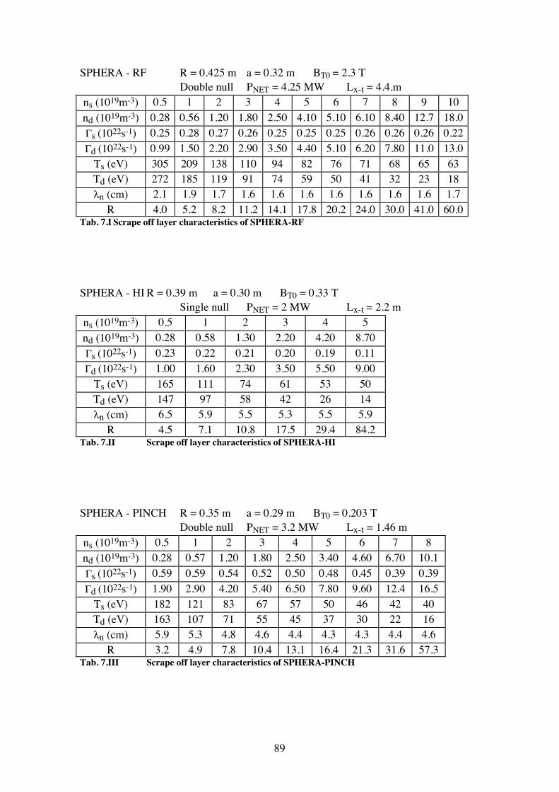
89
SPHERA - RF R = 0.425 m a = 0.32 m BT0 = 2.3 T Double null PNET = 4.25 MW Lx-t = 4.4.m ns (1019m-3) 0.5 1 2 3 4 5 6 7 8 9 10 nd (1019m-3) 0.28 0.56 1.20 1.80 2.50 4.10 5.10 6.10 8.40 12.7 18.0 Γs (1022s-1) 0.25 0.28 0.27 0.26 0.25 0.25 0.25 0.26 0.26 0.26 0.22 Γd (1022s-1) 0.99 1.50 2.20 2.90 3.50 4.40 5.10 6.20 7.80 11.0 13.0
Ts (eV) 305 209 138 110 94 82 76 71 68 65 63 Td (eV) 272 185 119 91 74 59 50 41 32 23 18 λn (cm) 2.1 1.9 1.7 1.6 1.6 1.6 1.6 1.6 1.6 1.6 1.7
R 4.0 5.2 8.2 11.2 14.1 17.8 20.2 24.0 30.0 41.0 60.0 Tab. 7.I Scrape off layer characteristics of SPHERA-RF
SPHERA - HI R = 0.39 m a = 0.30 m BT0 = 0.33 T Single null PNET = 2 MW Lx-t = 2.2 m ns (1019m-3) 0.5 1 2 3 4 5 nd (1019m-3) 0.28 0.58 1.30 2.20 4.20 8.70 Γs (1022s-1) 0.23 0.22 0.21 0.20 0.19 0.11 Γd (1022s-1) 1.00 1.60 2.30 3.50 5.50 9.00
Ts (eV) 165 111 74 61 53 50 Td (eV) 147 97 58 42 26 14 λn (cm) 6.5 5.9 5.5 5.3 5.5 5.9
R 4.5 7.1 10.8 17.5 29.4 84.2 Tab. 7.II Scrape off layer characteristics of SPHERA-HI SPHERA - PINCH R = 0.35 m a = 0.29 m BT0 = 0.203 T Double null PNET = 3.2 MW Lx-t = 1.46 m ns (1019m-3) 0.5 1 2 3 4 5 6 7 8 nd (1019m-3) 0.28 0.57 1.20 1.80 2.50 3.40 4.60 6.70 10.1 Γs (1022s-1) 0.59 0.59 0.54 0.52 0.50 0.48 0.45 0.39 0.39 Γd (1022s-1) 1.90 2.90 4.20 5.40 6.50 7.80 9.60 12.4 16.5
Ts (eV) 182 121 83 67 57 50 46 42 40 Td (eV) 163 107 71 55 45 37 30 22 16 λn (cm) 5.9 5.3 4.8 4.6 4.4 4.3 4.3 4.4 4.6
R 3.2 4.9 7.8 10.4 13.1 16.4 21.3 31.6 57.3 Tab. 7.III Scrape off layer characteristics of SPHERA-PINCH
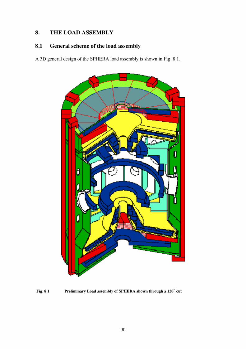
90
8. THE LOAD ASSEMBLY 8.1 General scheme of the load assembly A 3D general design of the SPHERA load assembly is shown in Fig. 8.1.
Fig. 8.1 Preliminary Load assembly of SPHERA shown through a 120 ̊ cut
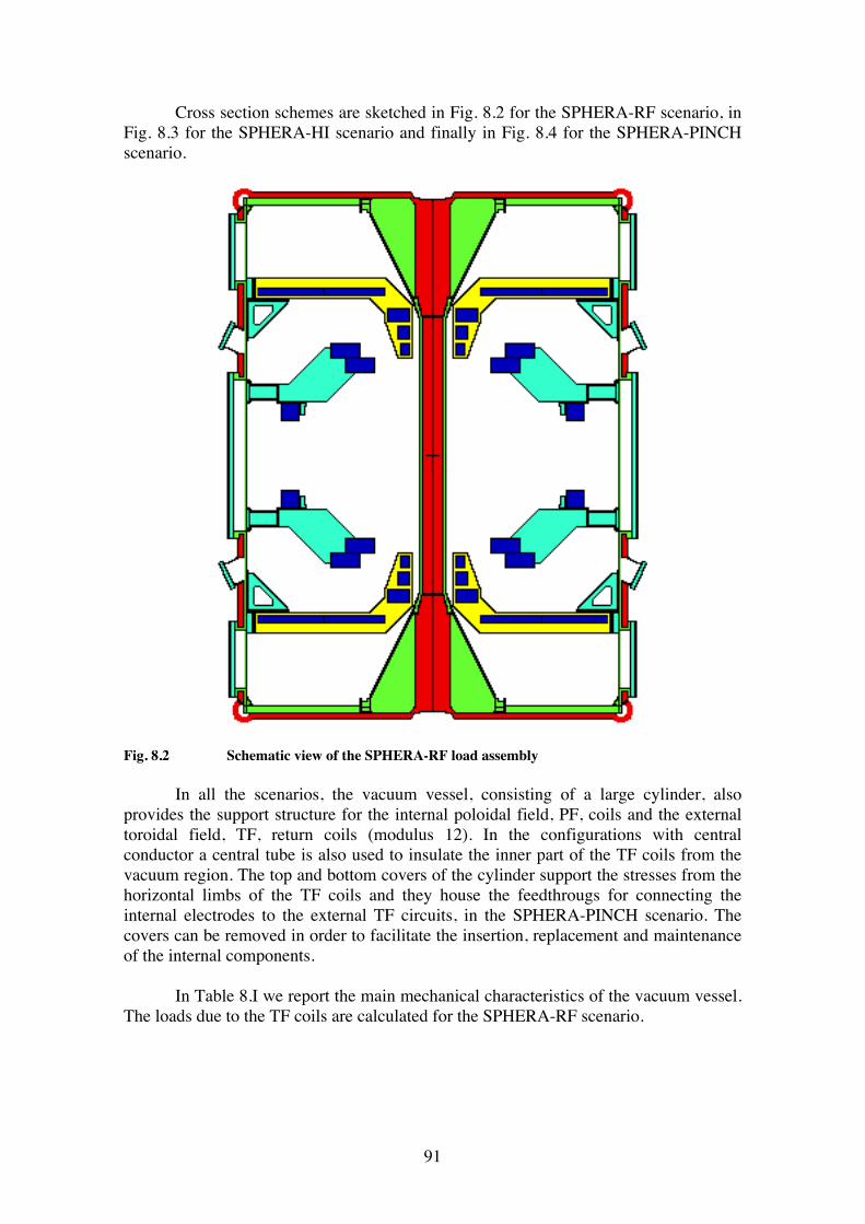
91
Cross section schemes are sketched in Fig. 8.2 for the SPHERA-RF scenario, in Fig. 8.3 for the SPHERA-HI scenario and finally in Fig. 8.4 for the SPHERA-PINCH scenario.
Fig. 8.2 Schematic view of the SPHERA-RF load assembly In all the scenarios, the vacuum vessel, consisting of a large cylinder, also provides the support structure for the internal poloidal field, PF, coils and the external toroidal field, TF, return coils (modulus 12). In the configurations with central conductor a central tube is also used to insulate the inner part of the TF coils from the vacuum region. The top and bottom covers of the cylinder support the stresses from the horizontal limbs of the TF coils and they house the feedthrougs for connecting the internal electrodes to the external TF circuits, in the SPHERA-PINCH scenario. The covers can be removed in order to facilitate the insertion, replacement and maintenance of the internal components. In Table 8.I we report the main mechanical characteristics of the vacuum vessel. The loads due to the TF coils are calculated for the SPHERA-RF scenario.
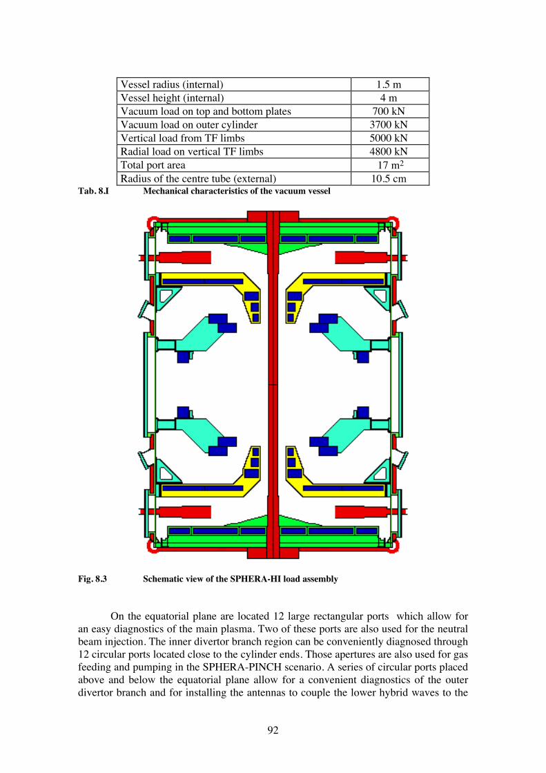
92
Vessel radius (internal) 1.5 m Vessel height (internal) 4 m Vacuum load on top and bottom plates 700 kN Vacuum load on outer cylinder 3700 kN Vertical load from TF limbs 5000 kN Radial load on vertical TF limbs 4800 kN Total port area 17 m2 Radius of the centre tube (external) 10.5 cm
Tab. 8.I Mechanical characteristics of the vacuum vessel
Fig. 8.3 Schematic view of the SPHERA-HI load assembly On the equatorial plane are located 12 large rectangular ports which allow for an easy diagnostics of the main plasma. Two of these ports are also used for the neutral beam injection. The inner divertor branch region can be conveniently diagnosed through 12 circular ports located close to the cylinder ends. Those apertures are also used for gas feeding and pumping in the SPHERA-PINCH scenario. A series of circular ports placed above and below the equatorial plane allow for a convenient diagnostics of the outer divertor branch and for installing the antennas to couple the lower hybrid waves to the
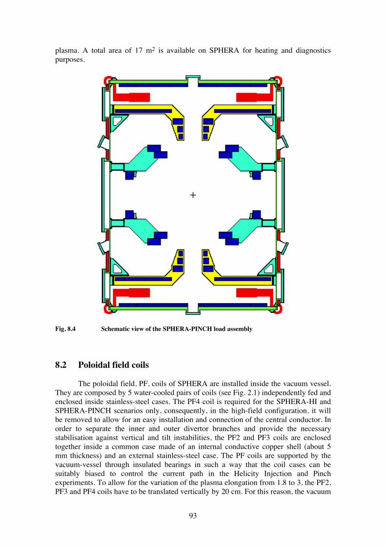
93
plasma. A total area of 17 m2 is available on SPHERA for heating and diagnostics purposes.
Fig. 8.4 Schematic view of the SPHERA-PINCH load assembly 8.2 Poloidal field coils The poloidal field, PF, coils of SPHERA are installed inside the vacuum vessel. They are composed by 5 water-cooled pairs of coils (see Fig. 2.1) independently fed and enclosed inside stainless-steel cases. The PF4 coil is required for the SPHERA-HI and SPHERA-PINCH scenarios only, consequently, in the high-field configuration, it will be removed to allow for an easy installation and connection of the central conductor. In order to separate the inner and outer divertor branches and provide the necessary stabilisation against vertical and tilt instabilities, the PF2 and PF3 coils are enclosed together inside a common case made of an internal conductive copper shell (about 5 mm thickness) and an external stainless-steel case. The PF coils are supported by the vacuum-vessel through insulated bearings in such a way that the coil cases can be suitably biased to control the current path in the Helicity Injection and Pinch experiments. To allow for the variation of the plasma elongation from 1.8 to 3, the PF2, PF3 and PF4 coils have to be translated vertically by 20 cm. For this reason, the vacuum
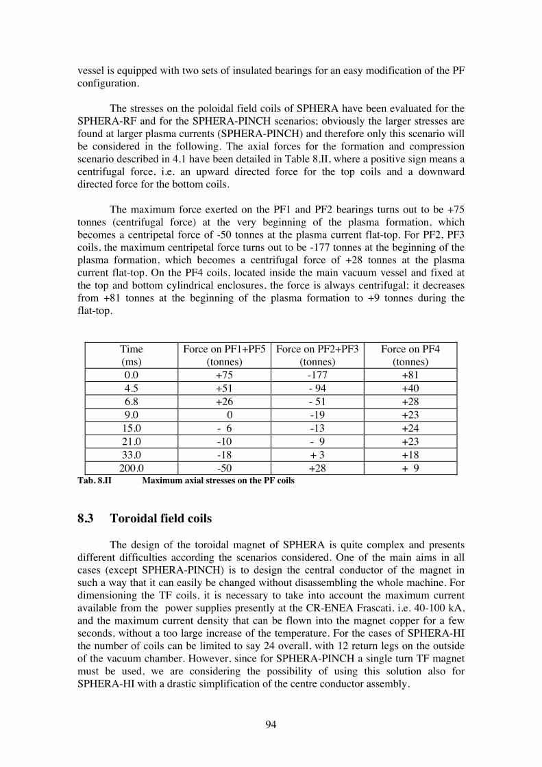
94
vessel is equipped with two sets of insulated bearings for an easy modification of the PF configuration. The stresses on the poloidal field coils of SPHERA have been evaluated for the SPHERA-RF and for the SPHERA-PINCH scenarios; obviously the larger stresses are found at larger plasma currents (SPHERA-PINCH) and therefore only this scenario will be considered in the following. The axial forces for the formation and compression scenario described in 4.1 have been detailed in Table 8.II, where a positive sign means a centrifugal force, i.e. an upward directed force for the top coils and a downward directed force for the bottom coils. The maximum force exerted on the PF1 and PF2 bearings turns out to be +75 tonnes (centrifugal force) at the very beginning of the plasma formation, which becomes a centripetal force of -50 tonnes at the plasma current flat-top. For PF2, PF3 coils, the maximum centripetal force turns out to be -177 tonnes at the beginning of the plasma formation, which becomes a centrifugal force of +28 tonnes at the plasma current flat-top. On the PF4 coils, located inside the main vacuum vessel and fixed at the top and bottom cylindrical enclosures, the force is always centrifugal; it decreases from +81 tonnes at the beginning of the plasma formation to +9 tonnes during the flat-top.
Time (ms)
Force on PF1+PF5 (tonnes)
Force on PF2+PF3 (tonnes)
Force on PF4 (tonnes)
0.0 +75 -177 +81 4.5 +51 - 94 +40 6.8 +26 - 51 +28 9.0 0 -19 +23 15.0 - 6 -13 +24 21.0 -10 - 9 +23 33.0 -18 + 3 +18 200.0 -50 +28 + 9
Tab. 8.II Maximum axial stresses on the PF coils 8.3 Toroidal field coils The design of the toroidal magnet of SPHERA is quite complex and presents different difficulties according the scenarios considered. One of the main aims in all cases (except SPHERA-PINCH) is to design the central conductor of the magnet in such a way that it can easily be changed without disassembling the whole machine. For dimensioning the TF coils, it is necessary to take into account the maximum current available from the power supplies presently at the CR-ENEA Frascati, i.e. 40-100 kA, and the maximum current density that can be flown into the magnet copper for a few seconds, without a too large increase of the temperature. For the cases of SPHERA-HI the number of coils can be limited to say 24 overall, with 12 return legs on the outside of the vacuum chamber. However, since for SPHERA-PINCH a single turn TF magnet must be used, we are considering the possibility of using this solution also for SPHERA-HI with a drastic simplification of the centre conductor assembly.
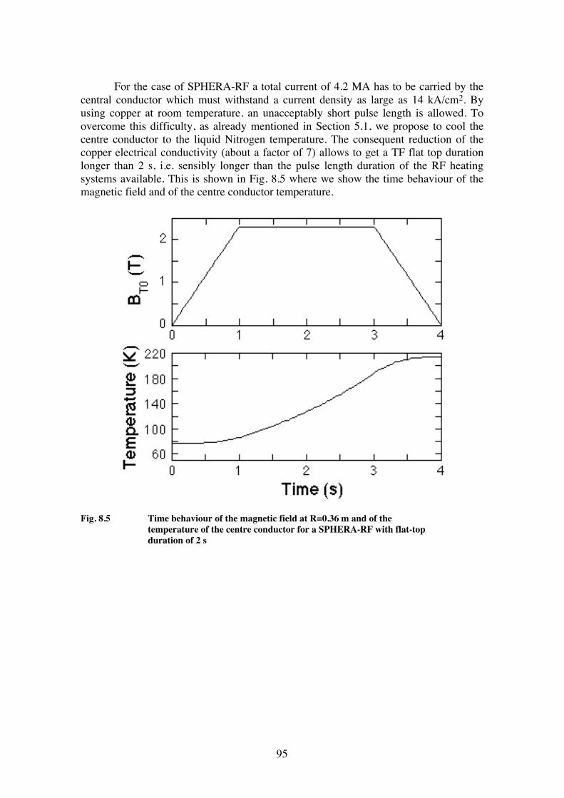
95
For the case of SPHERA-RF a total current of 4.2 MA has to be carried by the central conductor which must withstand a current density as large as 14 kA/cm2. By using copper at room temperature, an unacceptably short pulse length is allowed. To overcome this difficulty, as already mentioned in Section 5.1, we propose to cool the centre conductor to the liquid Nitrogen temperature. The consequent reduction of the copper electrical conductivity (about a factor of 7) allows to get a TF flat top duration longer than 2 s, i.e. sensibly longer than the pulse length duration of the RF heating systems available. This is shown in Fig. 8.5 where we show the time behaviour of the magnetic field and of the centre conductor temperature.
Fig. 8.5 Time behaviour of the magnetic field at R=0.36 m and of the temperature of the centre conductor for a SPHERA-RF with flat-top duration of 2 s
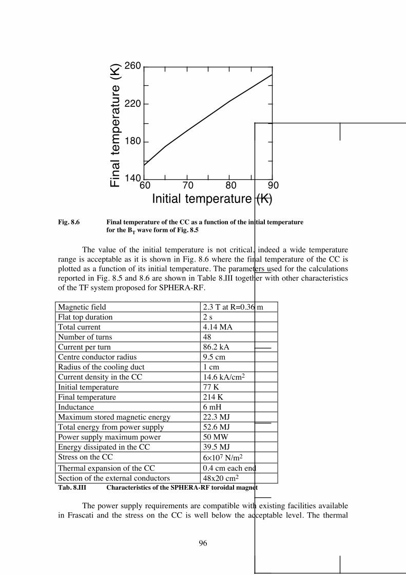
96
140
180
220
260
60 70 80 90Fina
l tem
pera
ture
(K)
Initial temperature (K)
Fig. 8.6 Final temperature of the CC as a function of the initial temperature for the BT wave form of Fig. 8.5 The value of the initial temperature is not critical, indeed a wide temperature range is acceptable as it is shown in Fig. 8.6 where the final temperature of the CC is plotted as a function of its initial temperature. The parameters used for the calculations reported in Fig. 8.5 and 8.6 are shown in Table 8.III together with other characteristics of the TF system proposed for SPHERA-RF. Magnetic field 2.3 T at R=0.36 m Flat top duration 2 s Total current 4.14 MA Number of turns 48 Current per turn 86.2 kA Centre conductor radius 9.5 cm Radius of the cooling duct 1 cm Current density in the CC 14.6 kA/cm2 Initial temperature 77 K Final temperature 214 K Inductance 6 mH Maximum stored magnetic energy 22.3 MJ Total energy from power supply 52.6 MJ Power supply maximum power 50 MW Energy dissipated in the CC 39.5 MJ Stress on the CC 6×10⁷ N/m2 Thermal expansion of the CC 0.4 cm each end Section of the external conductors 48x20 cm2 Tab. 8.III Characteristics of the SPHERA-RF toroidal magnet The power supply requirements are compatible with existing facilities available in Frascati and the stress on the CC is well below the acceptable level. The thermal
97
expansion of the centre conductor during a shot (0.4 cm each end) suggests using, to connect the CC to the external circuits, sliding joints similar to those used on MAST [96,97]. The contact area and the current through each joint are very similar in the two cases. The 48 external conductors of the TF coils are arranged in 12 groups of 4 conductors each. The vertical legs are water cooled while a thermal gradient is allowed to develop in the horizontal limbs as a consequence of the temperature difference between the CC and the vertical limbs. The energy lost between two shots is limited to the acceptable value of 2 MJ which does not require the cooling of the whole TF circuit, with a considerable simplification of the external TF assembly. In addition, this solution permits the use of the same external TF circuit for all the scenarios of SPHERA with a simple modification of the connection scheme. 8.4 The stresses on the central conductor in case of a tilt disruption The stresses that the central conductor has to withstand in case of a non-axisymmetric plasma movement (tilt/displacement disruption) have been evaluated in the two scenarios SPHERA-RF and SPHERA-HI. In particular two kinds of disruptive events have been considered: a rigid side displacement and a rigid tilt of the plasma. The latter mechanism (see Section 2.3) is typical of low aspect ratio, low qψ toroidal plasmas. To calculate the j∧B force due to the interaction of the current flowing in the central toroidal field coil with the non-axisymmetric poloidal field associated with the disruption, the most simple method is the one of displacing or tilting the central conductor in the field of the fixed axisymmetric plasma and poloidal field coils. Simple symmetry considerations show that the plasma rigid displacement induces a net torque upon the central conductor (but no net force), whereas the plasma rigid tilt does not produce a net torque but only a net force perpendicular to the central conductor. The geometrical limits to the rigid displacement ΔR and to the rigid tilting by an angle θ, assumed in the various scenarios, are the following: SPHERA-RF ( Ip = 3 MA, BT0 = 2.3 T ⇒ Itf = 4.140 MA ): ΔRmax = 0.042m, θmax = 3° SPHERA-HI (Ip = 1 MA, BT0 = 0.33 T ⇒ Itf = 0.600 MA ): ΔRmax = 0.09 m , θmax=6°30' The calculations have been performed by considering an only copper central conductor, even if a steel casing will obviously be required and will increase its stiffness. The limit to the copper stress is about Scopper = 220÷230 MPa. The stresses on the central conductor due to the plasma displacement turn out to be lower, by an order of magnitude, than the ones due to the plasma tilt. Therefore only the more severe tilt case will be illustrated. The first evaluation has been done with central conductors 3.4 m long, clamped at the ends; the results are the following (Δmax is the deformation on the equatorial plane): SPHERA-RF: Smax = 474 MPa, Δmax = 19.6 mm
98
SPHERA-HI: Smax = 340 MPa, Δmax = 20 mm So, with a 3.4 m long central conductor SPHERA-RF cannot hold and SPHERA-HI is critical. In the SPHERA-HI scenario, as the internal divertor branch is required for the Helicity Injection, only a limited reduction of the central conductor length to 3.2 m is feasible (see Fig. 8.3). Taking into account this reduction in length, the stiffening due to the steel casing and the fact that the expected plasma is calculated to be stable to a rigid tilt mode (see Section 2.1) with a restoring torque T=-100 Nm for a tilt angle δθ=0.5˚, the central conductor for SPHERA-HI should not be critical. On the other hand a more conservative design has been chosen for the SPHERA-RF scenario, lowering substantially the clamping of the central conductor (until Z = ± 1.2 m) (see Fig. 8.2). As a matter of fact a new evaluation of the stresses with a central conductor 2.4 m long gives the following result: SPHERA-RF: Smax = 208 MPa, Δmax = 7.5 mm, which is within the copper limit. 8.5 The toroidal field ripple The toroidal field ripple has been computed by simulating the toroidal magnet with a discrete number of rectangular wires. Each module of the toroidal magnet has been assumed to have an internal radius of 10 cm; the return leg is located at R=1.5 m and its height is 4.0 m. This corresponds to the magnet of SPHERA-RF (see Fig. 8.2), but one also the other scenarios are satisfactory represented by this geometry. The ripple of the toroidal magnetic field is defined as (Bmin − Bmax ) / (Bmin + Bmax ) . With a toroidal magnet modulus 12 , one obtains a ripple which is about 0.1% at R=0.83 m (the position of the poloidal field null at the time of the ULART breakdown, Fig. 4.1) and a ripple ≤ 10-4 in all the plasma region during the flat-top. At R =1.5 m (the position of the vacuum windows of the LH system), the ripple is of the order of 25%; this value avoids that the 8 GHz electron cyclotron resonance falls inside the vacuum vessel. On the other hand, with a toroidal magnet modulus 8, the ripple is ≈1% at R = 0.835 m and becomes ≤ 0.1% in all the plasma region during the flat-top. A problem could arise at R = 1.5 m, where ripple is of the order of 50%. As a conclusion, with the exception of the LH requirements, even a toroidal magnet modulus 8 could be a viable solution for the SPHERA machine.
99
9. CRITICAL POINTS OF THE PROPOSAL 9.1 Critical points of SPHERA-RF The main objectives of the SPHERA-RF experiment are: 1) to try and optimise the plasma formation and compression scheme; 2) to establish an LHCD scenario for the start-up of an ULART; 3) to explore the high field (2-3 T), which is indicated by the ULART reactor studies [98]. 4) to try a large additional heating on an ULART. It must be stressed that the scenario SPHERA-RF alone would justify the proposal, which occupies a space that in existing or proposed experiments is actually empty. As a matter of fact the General Atomics Company is studying the possibility of building after DIII-D [99] (and after the first NSTX results) a very large ULART (size of DIII-D) without OH transformer and endowed with various RFCD methods: SPHERA-RF could provide useful and unique information for such a large ULART. The physics critical points could be: 1) The passive currents could influence the plasma formation/compression scheme. ⇒ An alternative formation scheme similar to the one used in START (and proposed for MAST [21]) could be a back-up solution. In this formation scheme the plasma is formed from two distinct axisymmetric plasma rings induced around two up-down symmetrical poloidal field coils, thereafter the two plasmas are merged into is single torus which is compressed in major radius. A simple scaling of this not completely understood formation scheme relates the final compressed plasma current Ip at the radius Rp to the currents flowing in each poloidal field coil Ipf at the radius Rpf [21]: Ip = 2 Rpf Ipf / Rp . If the PF1 coils were used in this way, by precharging it to the same current Ipf1 = 300 kA, as in the SPHERA-RF formation scenario (see Table 4.VIII), then the final plasma could carry Ip ≈ 800 kA. This value very similar to the one provided by the main formation scheme, with the disadvantage of the formation around a material object and the advantage of a much simpler magnetic configuration during the formation. 2) Unhappy surprises with the LHCD on an ULART. ⇒ Alternative methods of RFCD have to be considered as a back-up. 3) The inner divertor branch is closed by the central conductor. ⇒ The results of START with NBI will help in telling whether this is a real problem.
100
9.2 Critical points of SPHERA-HI The main objectives of the SPHERA-HI experiment are: 1) to assess the Helicity Injection as the main current drive method for an ULART endowed with a large divertor volume and with hollow cathodes/anodes electrodes; 2) to test the electrodes for the final rodless scenario. It must be stressed that the scenario SPHERA-HI alone would justify the proposal, which occupies a space that in existing or proposed experiments is actually empty. As a matter of fact MAST does not plan for Helicity Injection and NSTX plans to use it just for the plasma formation and peripheral Current Drive, with a reduced space for the electrodes and in presence of a conducting shell close to the plasma. The physics critical points could be: 1) Too much power introduced by the Helicity Injection inside the plasma in order to sustain the required toroidal current. ⇒ Co-NBCD should help in maintaining the required plasma current with less power, although not in steady state. 2) Excessive contamination of the main plasma from impurities released from the Helicity Injection electrodes. ⇒ The available tools to counteract this problem are to change the electrode composition and to vary the edge plasma density. 3) Inefficient Helicity Injection in absence of a conducting shell near the plasma. ⇒ If this were assessed by the SPHERA-HI experiment, then major modifications in the load assembly would be required. The engineering critical points could be: 1) The central conductor must be built slim in order to leave space for the internal divertor branch. All the stress problems of the slim central rod must be analysed carefully. 2) The electrical insulation of the central conductor could be particularly critical in DN Helicity Injection experiments when the electrodes are placed in the top and bottom internal divertor branches.
101
9.3 Critical points of SPHERA-PINCH The main objectives of the SPHERA-PINCH experiment are: 1) to test an ULART without central conductor; 2) to explore the physics of the ULART-SPHEROMAK transition. It must be stressed that the scenario SPHERA-PINCH alone would justify the proposal, which occupies a space which is actually empty, at least at scale the of SPHERA. As a matter of fact a few very small experiments have explored the ULART-SPHEROMAK transition [57,58,64,65], but always starting from a Spheromak configuration. The physics critical points could be: 1) Production of the Stabilised Screw Pinch before the ULART breakdown. ⇒ The production a stable Screw Pinch with a size many times greater than the early Russian and American attempts in the 60's [89,90,91] is in itself a challenging task. A preliminary small experiment will assess the main properties of the Stabilised Screw Pinch. 2) Instabilities during the ULART formation/compression scheme in presence of the central Screw Pinch. ⇒ If all possible controls of the timing between the Pinch and the ULART currents, and of the shape of the Pinch and of the ULART should not be able to produce a stable formation/compression scheme, then the electrodes could be placed more near to the spherical plasma [57,58]. Should this move be not yet effective, then one could switch to the TS-3 Spheromak formation scheme, however with major modifications of the load assembly (introduction of a conducting shell surrounding the plasma). 3) Inefficient Helicity Injection from the Screw Pinch to the ULART. ⇒ Co-NBCD should help in maintaining the required plasma current, although not in steady state. 4) Excessive relaxation of the configuration, i.e. too efficient Helicity Injection from the Screw Pinch to the ULART, which becomes too easily a Spheromak. ⇒ Counter-NBCD should help in reducing the relaxation of the configuration, although not in steady state. 5) Excessive contamination of the main plasma from impurities released from the Helicity Injection electrodes. ⇒ The available tools to counteract this problem are to change the electrode composition and to vary the edge plasma density.
102
6) Excessive power injected into the central Screw Pinch ⇒ If this conclusion were eventually assessed by the SPHERA-PINCH experiment, then the ULART configuration without a central conductor would not lead to a reactor design.
103
APPENDIX: HELICITY AND MAGNETIC RELAXATION The purpose of this appendix is to give a short reference guide to literature dealing with the Helicity Injection. A1: Definition of the magnetic Helicity The origin of the idea of applying the Helicity Injection to magnetic configurations of fusion interest can be traced back to J.B. Taylor [17, 100] In a perfectly conducting plasma: ∂A/∂t = v∧B + ∇χ , where χ is an arbitrary gauge. The parallel component of A satisfies the magnetic differential equation: B•∇χ = B•∂A/∂t To make χ single valued it is necessary that [101]
∫οdl
Β[ B •
A
t∂∂ ]
and ∫ο [ B •
A
t∂∂ ]dS
|∇ψ| are zero upon any closed field line and upon any magnetic surface, respectively. So, for every flux tube labelled by constant values of the two variables (α,β),
K(α,β) = ∫ A•B dV is an invariant Minimising the magnetic energy
W = 1/2µ0 ∫ (∇∧A)2 dV with the constraint that K=constant the
Euler's equation of motion is obtained [19] ∇∧B = µ0µ(α,β) B ; B•∇µ = 0 which describes a force-free magnetic field.
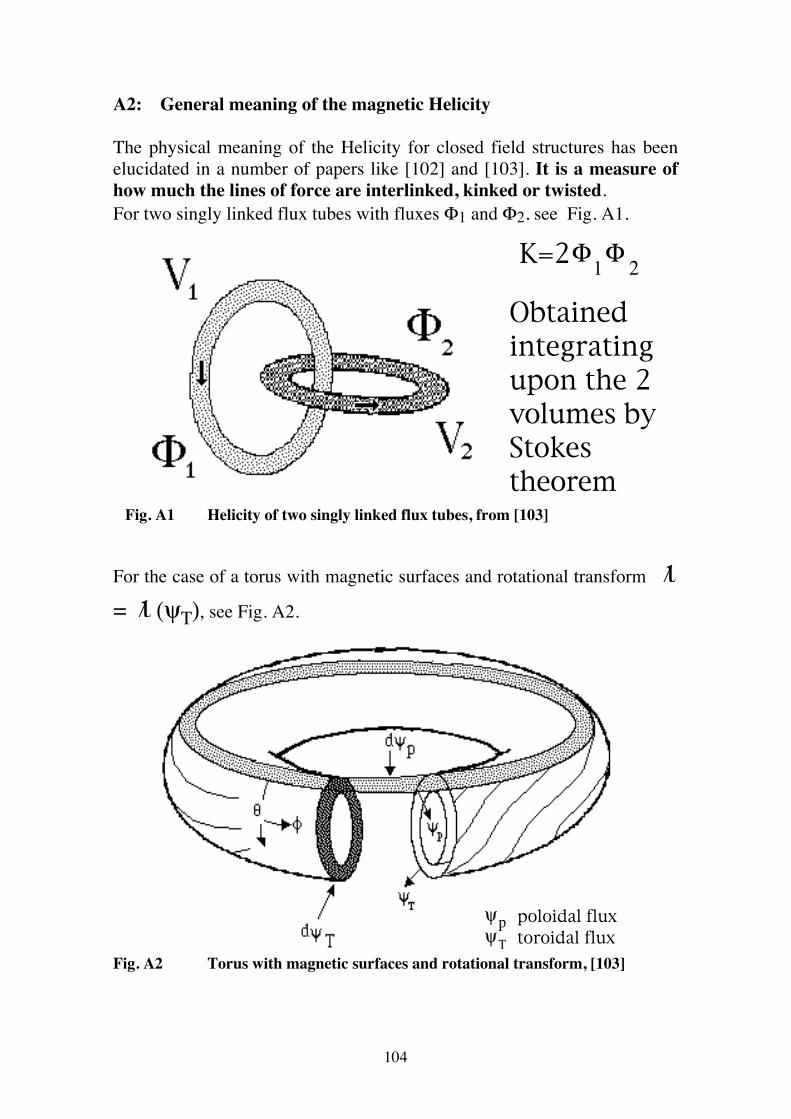
104
A2: General meaning of the magnetic Helicity The physical meaning of the Helicity for closed field structures has been elucidated in a number of papers like [102] and [103]. It is a measure of how much the lines of force are interlinked, kinked or twisted. For two singly linked flux tubes with fluxes Φ1 and Φ2, see Fig. A1.
K=2Φ1 2Φ
Obtainedintegratingupon the 2volumes by Stokestheorem
Fig. A1 Helicity of two singly linked flux tubes, from [103] For the case of a torus with magnetic surfaces and rotational transform ι/ = ι/ (ψΤ), see Fig. A2.
poloidal fluxtoroidal flux
ψψpT
Fig. A2 Torus with magnetic surfaces and rotational transform, [103]
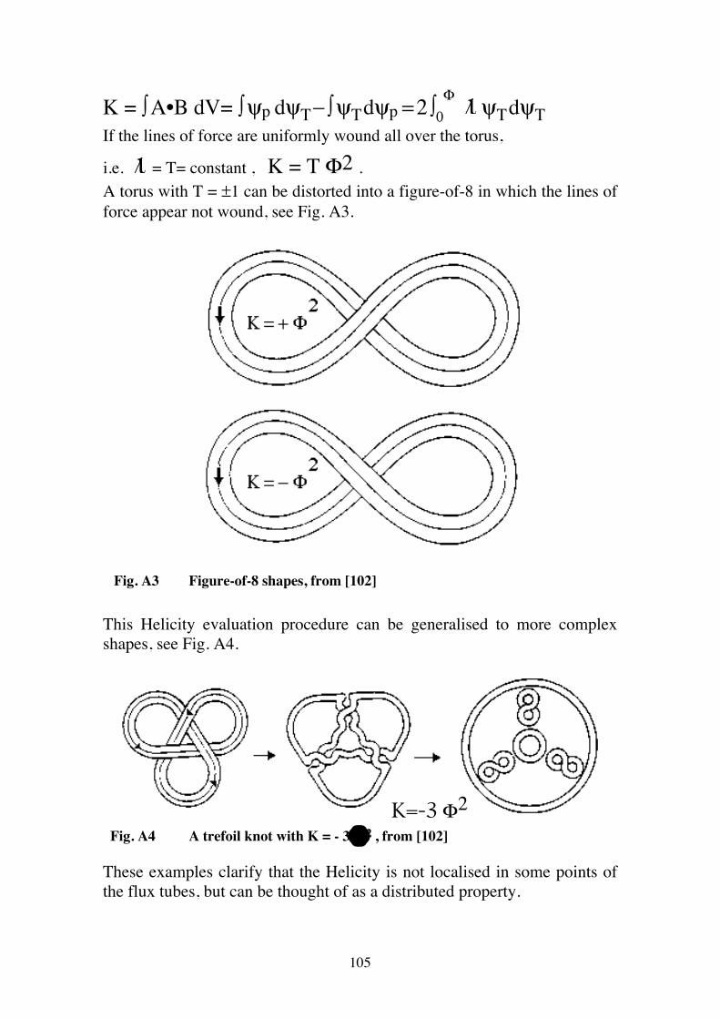
105
K = ∫ A•B dV= ∫ ψp dψΤ − ∫ ψΤ dψp = 2 ∫0Φ ι/ ψΤ dψΤ
If the lines of force are uniformly wound all over the torus,
i.e. ι/ = T= constant , K = T Φ2 . A torus with T = ±1 can be distorted into a figure-of-8 in which the lines of force appear not wound, see Fig. A3.
Fig. A3 Figure-of-8 shapes, from [102] This Helicity evaluation procedure can be generalised to more complex shapes, see Fig. A4.
K=-3Φ2
Fig. A4 A trefoil knot with K = - 3 Φ2 , from [102]
These examples clarify that the Helicity is not localised in some points of the flux tubes, but can be thought of as a distributed property.
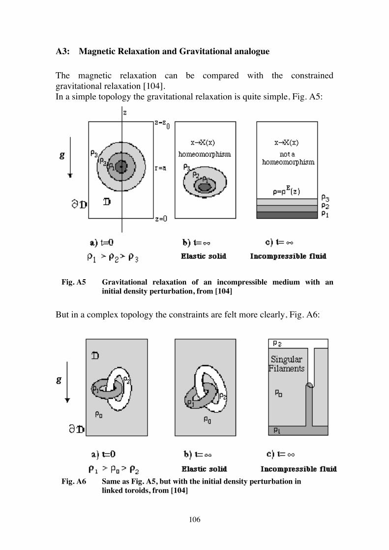
106
A3: Magnetic Relaxation and Gravitational analogue The magnetic relaxation can be compared with the constrained gravitational relaxation [104]. In a simple topology the gravitational relaxation is quite simple, Fig. A5:
Fig. A5 Gravitational relaxation of an incompressible medium with an initial density perturbation, from [104] But in a complex topology the constraints are felt more clearly, Fig. A6:
Fig. A6 Same as Fig. A5, but with the initial density perturbation in linked toroids, from [104]
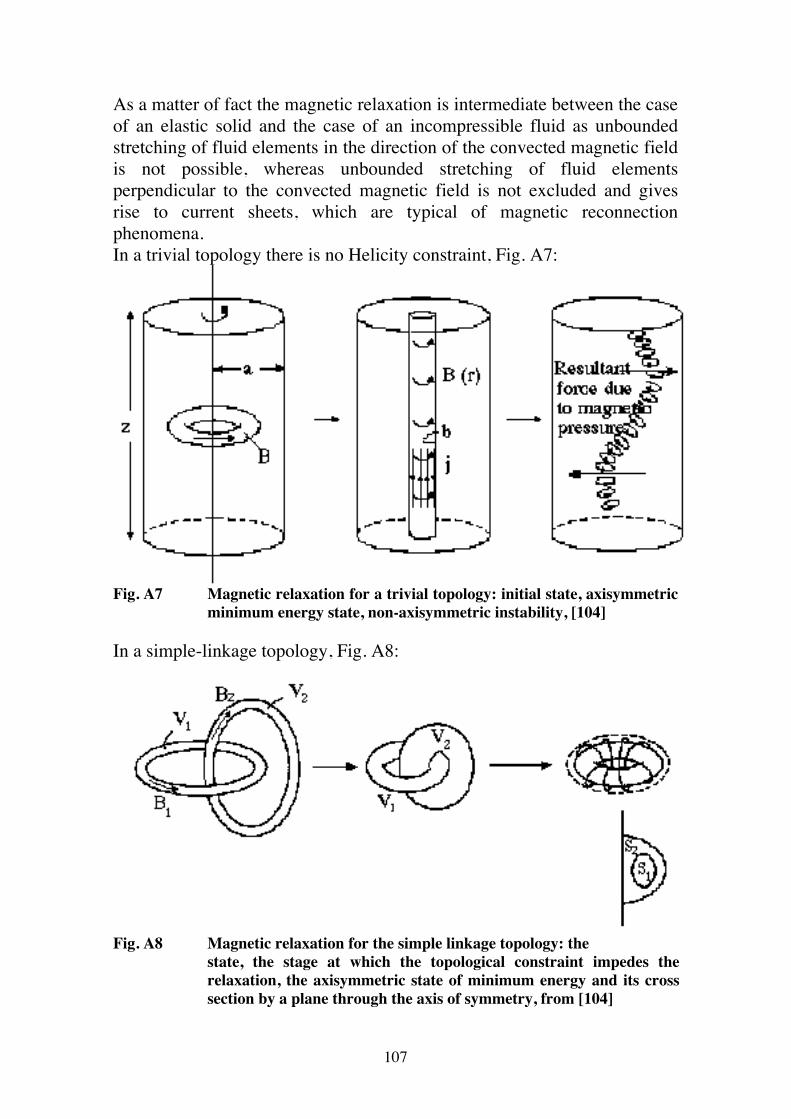
107
As a matter of fact the magnetic relaxation is intermediate between the case of an elastic solid and the case of an incompressible fluid as unbounded stretching of fluid elements in the direction of the convected magnetic field is not possible, whereas unbounded stretching of fluid elements perpendicular to the convected magnetic field is not excluded and gives rise to current sheets, which are typical of magnetic reconnection phenomena. In a trivial topology there is no Helicity constraint, Fig. A7:
Fig. A7 Magnetic relaxation for a trivial topology: initial state, axisymmetric
minimum energy state, non-axisymmetric instability, [104] In a simple-linkage topology, Fig. A8:
Fig. A8 Magnetic relaxation for the simple linkage topology: the state, the stage at which the topological constraint impedes the relaxation, the axisymmetric state of minimum energy and its cross section by a plane through the axis of symmetry, from [104]
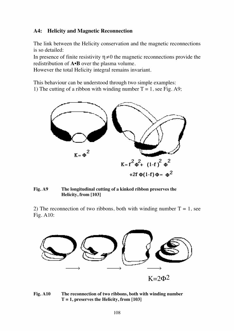
108
A4: Helicity and Magnetic Reconnection The link between the Helicity conservation and the magnetic reconnections is so detailed: In presence of finite resistivity η ≠ 0 the magnetic reconnections provide the redistribution of A•B over the plasma volume. However the total Helicity integral remains invariant. This behaviour can be understood through two simple examples: 1) The cutting of a ribbon with winding number T = 1, see Fig. A9;
Fig. A9 The longitudinal cutting of a kinked ribbon preserves the Helicity, from [103] 2) The reconnection of two ribbons, both with winding number T = 1, see Fig. A10:
K=2Φ2 Fig. A10 The reconnection of two ribbons, both with winding number T = 1, preserves the Helicity, from [103]
109
As a matter of fact it has been shown in [105] that a number of integral quantities should be preserved by the magnetic reconnections; they can be expressed by: Kα = ∫ χα (A•B) dV ,
where χ = qs ψΤ - ψp is the helicoidal flux associated with the resonant surface upon which the magnetic reconnection occurs. However the Taylor invariant
K0 = ∫ (A•B) dV is the only invariant common to all winding numbers
and so to all resonant surfaces. It provides the Euler's equation: ∇∧B = µ0µ B , with µ = constant all over the plasma.
The solutions to this equation are called Relaxed States. The reason why the Helicity is a robust invariant can be seen by comparing the decay time of the magnetic energy and the decay time of the Taylor Helicity:
dW/dt = - η ∫ j2 dV
dK0/dt = - 2 η ∫ j•B dV , where η is the plasma resistivity. On the space scale of the tearing mode wavelength k ∝ η-1/2 the following ordering applies:
dW/dt = O(1) dK0/dt = O(η1/2) . The Helicity dissipation is then η1/2 less strong than the magnetic energy dissipation in the limit of low plasma resistivity.
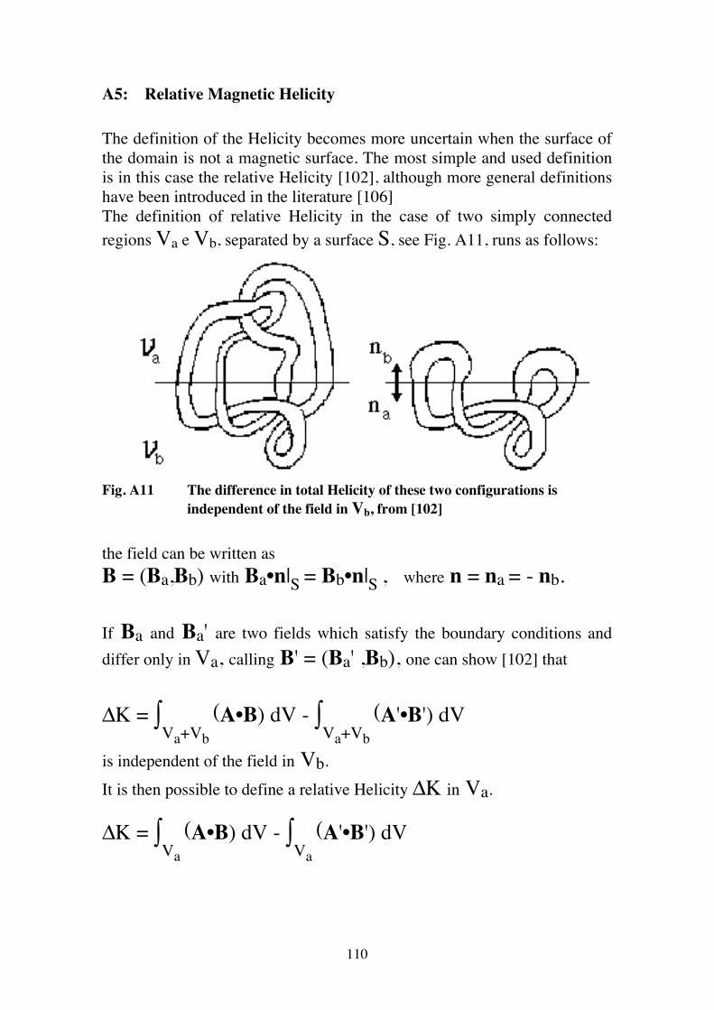
110
A5: Relative Magnetic Helicity The definition of the Helicity becomes more uncertain when the surface of the domain is not a magnetic surface. The most simple and used definition is in this case the relative Helicity [102], although more general definitions have been introduced in the literature [106] The definition of relative Helicity in the case of two simply connected regions Va e Vb, separated by a surface S, see Fig. A11, runs as follows:
Fig. A11 The difference in total Helicity of these two configurations is independent of the field in Vb, from [102]
the field can be written as B = (Ba,Bb) with Ba•n|S = Bb•n|S , where n = na = - nb. If Ba and Ba' are two fields which satisfy the boundary conditions and differ only in Va, calling B' = (Ba' ,Bb), one can show [102] that ΔK = ∫
Va+Vb
(A•B) dV - ∫Va+Vb
(A'•B') dV
is independent of the field in Vb. It is then possible to define a relative Helicity ΔK in Va.
ΔK = ∫Va
(A•B) dV - ∫Va
(A'•B') dV
111
A particularly simple choice for defining the relative Helicity [107] is the vacuum potential field in Va , B' = Bv . The relative Helicity then becomes: ΔK = K0 - Kv In the case of a toroidal domain, not necessarily axisymmetric, the definition becomes: ΔK = K1 = ∫ (A•B) dV - ( ∫οA•dxθ) ( ∫οA•dxφ ) dxθ and dxφ being the length elements in the poloidal and toroidal
directions, defined by the poloidal angle θ and the toroidal angle φ. This is equivalent to the Boozer's definition [108] K1 = 2 ∫ ( ψpb - ψp ) dψΤ ( dθ / 2π ) ( dφ / 2π ) with ψp being the poloidal flux ( ψpb its values at the boundary of the
domain) and ψΤ the toroidal flux,. The Boozer expression permits to derive the most general time evolution for the Helicity in a toroidal domain (here n points towards the outside of the boundary): dK1/dt = 2 V Ψ - 2 ∫ (E•B) dV - 2 ∫ ΦE B•n dS , where Ψ = ∫ψΤ dφ / 2π is the averaged toroidal flux,
V = ∫ο ( dθ / 2π ) ∫ο ( dφ / 2π ) dψpb / dt is the loop voltage, and
ΦE is the electrostatic potential.
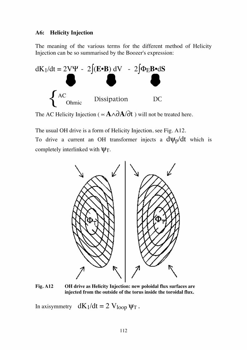
112
A6: Helicity Injection The meaning of the various terms for the different method of Helicity Injection can be so summarised by the Boozer's expression:
dK1/dt = 2VΨ - 2∫(E•B) dV - 2∫ΦEB•dS ⇓ ⇓ ⇓
{ACOhmic Dissipation DC
The AC Helicity Injection ( ∝ A∧∂A/∂t ) will not be treated here. The usual OH drive is a form of Helicity Injection, see Fig. A12. To drive a current an OH transformer injects a dψp/dt which is
completely interlinked with ψΤ.
Fig. A12 OH drive as Helicity Injection: new poloidal flux surfaces are injected from the outside of the torus inside the toroidal flux.
In axisymmetry dK1/dt = 2 Vloop ψΤ .
113
The DC Helicity Injection can be accomplished within a domain by driving current along the lines of force which cross the boundary of the domain. This is performed through electrodes placed where B•n ≠ 0; these electrodes must be electrically insulated from the rest of the boundary, upon which B•n = 0. [63, 107]. If an MHD equilibrium with beta much less than one is obtained, then the current density j is approximately parallel to the magnetic field B. Therefore, current enters and leaves the electrodes at the locations where the magnetic field enters and leaves the electrodes. The Injection rate is |dK/dt| = 2VΦe, where Φe = 0.5 ∫ |B•n| dS is
the magnetic flux which enters and exits both the electrodes. To inject dK/dt > 0: the electrostatic potential must be < 0, where B•n dS > 0; the electrostatic potential must be > 0, where B•n dS < 0. The total current Ie which flows trough the electrodes is , in the case of a
relaxed state with µ0µ = j•B / B2 = constant, Ie = µ Φe . The physical meaning of the DC Helicity Injection is quite simple: • as the beta is much less than one the current density is approximately parallel to the magnetic field; • due to the 'rotational transform' of the open field lines, the current from the electrodes winds up also in the toroidal direction around the closed flux surfaces; • the magnetic reconnections due to the resistive instabilities allow these currents to penetrate within the closed magnetic surfaces, where other instabilities can take care that the injected current reaches the magnetic axis [109]. The time evolution of the Helicity can be expressed through a 'Poynting theorem':
dK1/dt + ∫ Q•n dS = - 2 ∫ η j•B dV , with as 'Poynting vector'
Q = 2ΦeB + A∧∂A/∂t , as 'Poynting vector', which can also be written as: Q = ΦeB + E∧A .
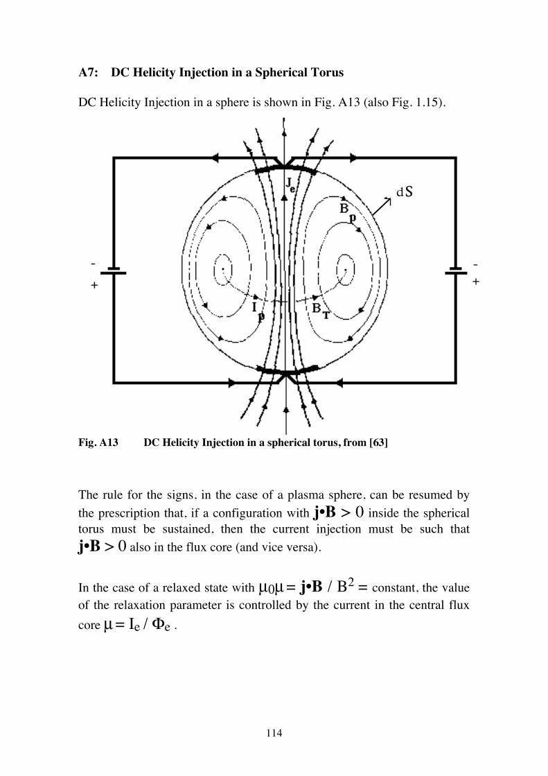
114
A7: DC Helicity Injection in a Spherical Torus DC Helicity Injection in a sphere is shown in Fig. A13 (also Fig. 1.15).
dS
Fig. A13 DC Helicity Injection in a spherical torus, from [63] The rule for the signs, in the case of a plasma sphere, can be resumed by the prescription that, if a configuration with j•B > 0 inside the spherical torus must be sustained, then the current injection must be such that j•B > 0 also in the flux core (and vice versa). In the case of a relaxed state with µ0µ = j•B / B2 = constant, the value of the relaxation parameter is controlled by the current in the central flux core µ = Ie / Φe .
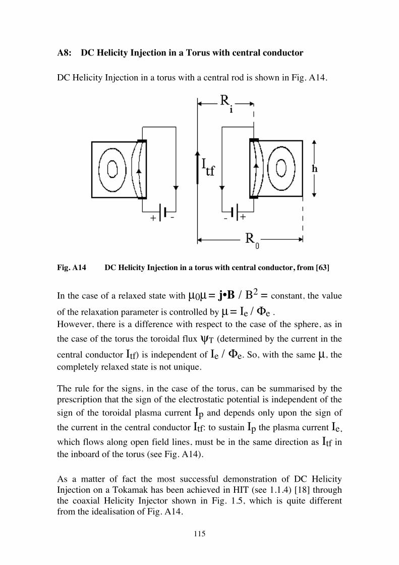
115
A8: DC Helicity Injection in a Torus with central conductor DC Helicity Injection in a torus with a central rod is shown in Fig. A14.
Fig. A14 DC Helicity Injection in a torus with central conductor, from [63] In the case of a relaxed state with µ0µ = j•B / B2 = constant, the value
of the relaxation parameter is controlled by µ = Ie / Φe . However, there is a difference with respect to the case of the sphere, as in the case of the torus the toroidal flux ψΤ (determined by the current in the
central conductor Itf) is independent of Ie / Φe. So, with the same µ, the completely relaxed state is not unique. The rule for the signs, in the case of the torus, can be summarised by the prescription that the sign of the electrostatic potential is independent of the sign of the toroidal plasma current Ip and depends only upon the sign of the current in the central conductor Itf: to sustain Ip the plasma current Ie, which flows along open field lines, must be in the same direction as Itf in the inboard of the torus (see Fig. A14). As a matter of fact the most successful demonstration of DC Helicity Injection on a Tokamak has been achieved in HIT (see 1.1.4) [18] through the coaxial Helicity Injector shown in Fig. 1.5, which is quite different from the idealisation of Fig. A14.
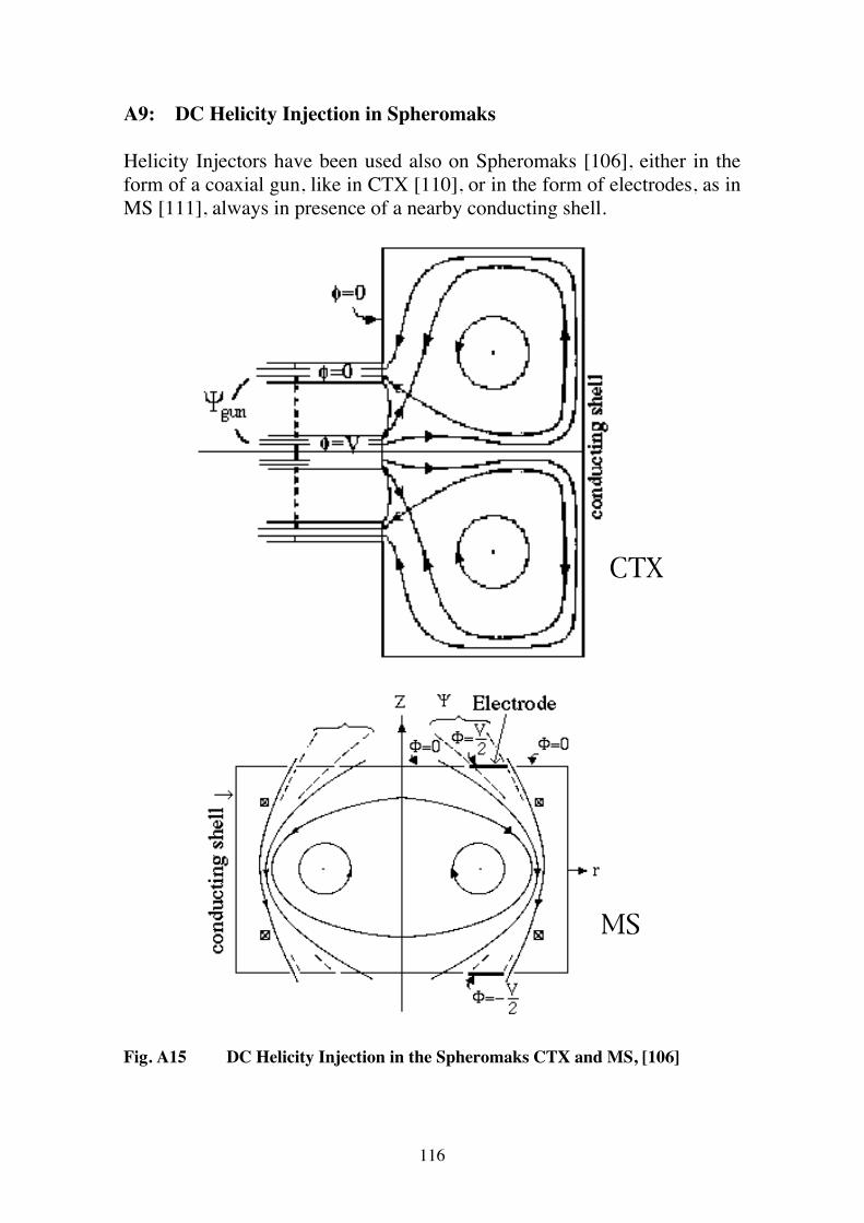
116
A9: DC Helicity Injection in Spheromaks Helicity Injectors have been used also on Spheromaks [106], either in the form of a coaxial gun, like in CTX [110], or in the form of electrodes, as in MS [111], always in presence of a nearby conducting shell.
CTX
MS
Fig. A15 DC Helicity Injection in the Spheromaks CTX and MS, [106]
117
A10: Taylor's theory of DC Helicity Injection in relaxed states The theory describing the DC Helicity Injection on fully relaxed states is quite well established. The magnetic vector potential A of a relaxed state (∇∧B =µ0µ B with
µ = constant all over the plasma) can be written as:
A = A0 + Σi αi ai , where A0 is the vacuum potential field satisfying the boundary conditions ∇∧∇∧A0 = 0 ; whereas ai are the eigenvectors (with eigenvalues λi) of the equation ∇∧∇∧ai = λi ∇∧ai , with boundary conditions ai = 0. The normalisation is:
∫ ai•∇∧aj dV = λi / |λi| δij and
∫ ai•∇∧A0 dV = Ii .
So:
A = A0 + Σi Ii ai λi µ0µ / ( |λi|(λi-µ0µ) )
for µ0µ ≠ λi
A = A0 + Σi≠jIi ai λi λj / ( |λi| (λi-λj)) + β aj
for µ0µ = λj with Ij ≠ 0 The relative Helicity ΔK = K0 - Kv, with Kv = ∫ A0•∇∧A0 dV, is
used after normalising to the square of the toroidal flux ψΤ2. In the first case ( µ0µ ≠ λi ) :
118
ΔK / ψΤ2 = Σi (λi / |λi|) (Ii / ψΤ)2 [ λi2 / (λi-µ0µ)2- 1 ]
It is noteworthy that ΔK / ψΤ2 diverges when µ0µ → λi and in
particular when µ0µ → λi- or when µ0µ → λi+, which are respectively the maximum of the negative eigenvalues and the minimum of the positive eigenvalues. Therefore µ is determined by ΔK /ψΤ
2 and one can always find a value
in the range λ1- < µ0µ < λ1+. As, fixing the value of ΔK / ψΤ2, one
can show that the minimum energy fully relaxed state is the one with the minimum |µ|, it is clear that the accessible range of relaxation parameters
is: 0 < µ < λ0 = min( |λ1-|,|λ1+| ). In the second case ( µ0µ = λj ) , one gets
ΔK / ψΤ2 = Σi≠j
(λi / |λi|) (Ii / ψΤ)2 [ (2λi-λj) / (λi-λj)2 ] + (β / ψΤ
2) λj / |λj| Therefore µ is determined by µ0µ = λ0 whereas ΔK / ψΤ
2 determines
the component β of the eigenvector a0 (corresponding to the eigenvalue
λ0), which will be present in the relaxed state. In general the eigenvector a0 can be non-axisymmetric. As far as the stability of the relaxed state is concerned, one can show [107] that in ideal MHD a generic relaxed state is stable, whatever its αi spectrum along the eigenvectors ai, provided that λ1- < µ0µ < λ1+. Examples for the 'unitary' sphere are given in Section 6. Examples for the unitary torus with µ0µ < λ0 = 4.48 are in Fig. A16.
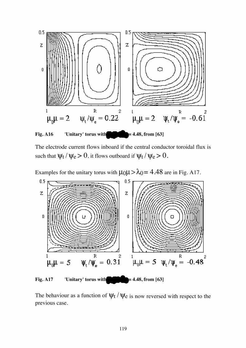
119
Fig. A16 'Unitary' torus with µ 0 µ < λ0 = 4.48, from [63] The electrode current flows inboard if the central conductor toroidal flux is such that ψt / ψe > 0, it flows outboard if ψt / ψe > 0. Examples for the unitary torus with µ0µ > λ0 = 4.48 are in Fig. A17.
Fig. A17 'Unitary' torus with µ 0 µ > λ0 = 4.48, from [63] The behaviour as a function of ψt / ψe is now reversed with respect to the previous case.
120
A11: Boozer's theory of DC Helicity Injection in quasi-relaxed states The theory describing the DC Helicity Injection on quasi-relaxed states (i.e. states with the relaxation parameter µ slowly varying across the plasma) is much less well established. The quasi-relaxed states are the ones relevant for fusion applications, so dedicated experiments are required to investigate these configurations. A question which has been addressed by the theory of quasi-relaxed states is the following one: how does the Helicity Injected from the boundary diffuse toward the centre of the plasma? A guess can be found comparing the expressions for the magnetic energy and the relative Helicity in fully relaxed states:
ΔW = Σi |λi| Ii2 (µ0µ)2 / (λi-µ0µ)2
ΔK = Σi (λi/|λi|) Ii2 [λi2 / (λi-µ0µ)2 - 1]
This gives d(ΔW) / d(ΔK) = µ0µ / 2 . This equation shows clearly that the Helicity flows from higher to lower µ values: as a matter of fact a Helicity transfer from a flux tube with larger
µ to a flux tube with smaller µ lowers the overall magnetic energy of the two flux tubes. Boozer [112] has proposed an additional term in the fluctuation-averaged Ohm's law, which accounts for the Helicity diffusion: E + v∧B = η j - (B / B2) ∇ •( λη ∇jˆ / B) where λη is a 'viscous' coefficient, which prevents the current to change
over scales shorter than δ2 = λη / ( η B2). With this Ohm's law there is an additional Helicity flux: Qλ = - λη ∇ ( j•B / B2) = - λη µ0 ∇µ Therefore the 'Poynting's theorem' for the Helicity becomes
dK1/dt + ∫ [- λη ∇(j•B / B2) + ( 2ΦeB + A∧∂A/∂t)]•n dS
= - 2 ∫ η j•B dV .
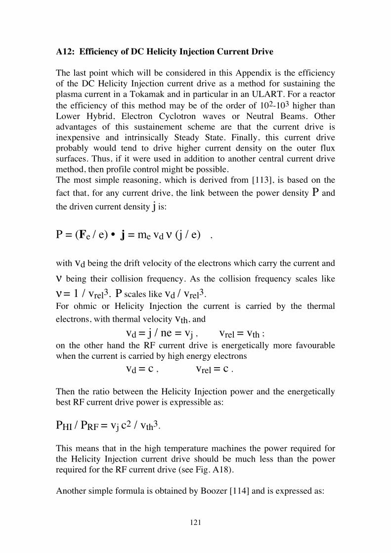
121
A12: Efficiency of DC Helicity Injection Current Drive The last point which will be considered in this Appendix is the efficiency of the DC Helicity Injection current drive as a method for sustaining the plasma current in a Tokamak and in particular in an ULART. For a reactor the efficiency of this method may be of the order of 102-103 higher than Lower Hybrid, Electron Cyclotron waves or Neutral Beams. Other advantages of this sustainement scheme are that the current drive is inexpensive and intrinsically Steady State. Finally, this current drive probably would tend to drive higher current density on the outer flux surfaces. Thus, if it were used in addition to another central current drive method, then profile control might be possible. The most simple reasoning, which is derived from [113], is based on the fact that, for any current drive, the link between the power density P and the driven current density j is: P = (Fe / e) • j = me vd ν (j / e) , with vd being the drift velocity of the electrons which carry the current and
ν being their collision frequency. As the collision frequency scales like
ν = 1 / vrel3, P scales like vd / vrel3. For ohmic or Helicity Injection the current is carried by the thermal electrons, with thermal velocity vth, and vd = j / ne = vj , vrel = vth ; on the other hand the RF current drive is energetically more favourable when the current is carried by high energy electrons vd = c , vrel = c . Then the ratio between the Helicity Injection power and the energetically best RF current drive power is expressible as: PHI / PRF = vj c2 / vth3. This means that in the high temperature machines the power required for the Helicity Injection current drive should be much less than the power required for the RF current drive (see Fig. A18). Another simple formula is obtained by Boozer [114] and is expressed as:
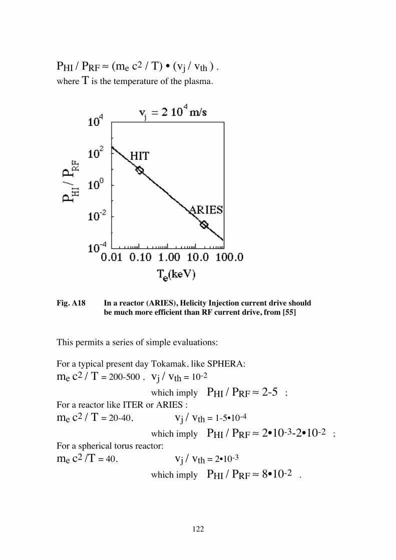
122
PHI / PRF ≈ (me c2 / T) • (vj / vth ) , where T is the temperature of the plasma.
Fig. A18 In a reactor (ARIES), Helicity Injection current drive should be much more efficient than RF current drive, from [55] This permits a series of simple evaluations: For a typical present day Tokamak, like SPHERA: me c2 / T = 200-500 , vj / vth = 10-2
which imply PHI / PRF ≈ 2-5 ; For a reactor like ITER or ARIES : me c2 / T = 20-40, vj / vth = 1-5•10-4
which imply PHI / PRF ≈ 2•10-3-2•10-2 ; For a spherical torus reactor: me c2 /T = 40, vj / vth = 2•10-3
which imply PHI / PRF ≈ 8•10-2 .
123
All this reasoning is based upon the high power efficiency measured on HIT for the Helicity Injection [18], which gives a modest increase (of a factor less than 1 / ε = 1 / 0.4 = 2.5) of the power required with respect to the ohmic power. A further assumption is that, by proper choices of the plasma and of the injector geometry, the problem of the power dissipated by currents not flowing around the plasma can be eliminated.
124
References
[1] Peng,Y-K.M. and Strickler,D.J., Nucl. Fus. 26 (1986) 1139 [2] Sykes,A., Plasma Phys. Contr. Fus. 36 (1994) B93 [3] Robinson,D.C., in Tokamak Concept Improvements, International School of Plasma Physics Piero Caldirola, Varenna 1994, Societa' Italiana di Fisica, Editrice Compositori Bologna, p. 127 [4] Abdou,M.A., Peng,Y-K.M. et al., Plasma Physics and Controlled Fusion Research, Proc. 15h IAEA Conference, 1994, Seville, Vol. 2 p. 733 [5] Buttery,R., Counsell,G. et al., Plasma Physics and Controlled Fusion Research, Proc. 15h IAEA Conference, 1994, Seville, Vol. 2 p. 633 [6] Peng,Y-K.M. and Hicks, J.B., Fus. Techn. 2 (1990) 1287 [7] Hender,T.C. et al., Proc. 14th IAEA Conference, 1992, Würzburg, Vol 3, p. 339 [8] Hwang,Y.S., Yamada,M., et al., Plasma Physics and Controlled Fusion Research, Proc. 15h IAEA Conference, 1994, Seville, Vol. 1 p. 737 [9] Yamada, M., Pomphrey, N., Morita, A., Ono, Y., Katsurai, M., Nucl. Fus. 36 (1996) 1210 [10] Alladio,F., Cardinali,A., Micozzi,P., Pieroni,L., SPHERA: Spherical Plasma for HElicity Relaxation Assessment, in U.S.-Japan Workshop for Low Aspect Ratio Tokamak and International Workshop on Spherical Torus, Princeton, 1995, Vol. II [11] Greenwald,M., Nucl. Fus. 28 (1988) 12 [12] Lackner, K., Gottardi,N.A.O., Nucl. Fus. 30 (1990) 767 [13] Wagner, F. et al., Phys. Rev. Lett., 49 (1982) 1408 [14] Zohm,H., Ryter,R. and Wagner,F., The H-mode: Current Understanding and Extrapolability, in Tokamak Concept Improvement, International School of Plasma Physics 'Piero Caldirola', Societa' Italiana di Fisica, Editrice Compositori, Bologna (1994), p. 149 [15] Fisch,N.J., Rev. Mod. Phys. 59 (1987) 175 [16] Ohkawa,T., Nucl. Fus. 10 (1970) 185 [17] Taylor,J.B., Rev. Mod. Phys. 58 (1986) 741 [18] Nelson,B.A., Jarboe,T.R. et al, Phys. Rev. Lett. 72 (1994) 3666 [19] Woltjer,L., Proc. Nat. Acad. Sci 44 (1958) 489 [20] MAST The Mega Amp Spherical Tokamak, UKAEA/EURATOM Fusion Association, Cuhlam Laboratory, Application for Preferential Support - Phase I, EUR FU(94) CCFP 62/6.2 [21] Morris,A.W. and the MAST Team, The Physics Capability of MAST, in U.S.- Japan Workshop for Low Aspect Ratio Tokamak and International Workshop on Spherical Torus, Princeton, 1995, Vol. II [22] Sykes,A. et al., Nucl. Fus. 32 (1992) 694 [23] Sykes,A., Bevir,M., et al., Plasma Physics and Controlled Fusion Research,
Proc. 15h IAEA Conference, 1994, Seville, Vol. 1 p. 719 [24] Robinson,J., Ono,M., et al., Bull. Am. Phys. Soc. 39 (1994) 1573 [25] Kaye, M.S. for the NSTX Group, Physics Issues for a 1 MA Spherical Tokamak - NSTX, in U.S.- Japan Workshop for Low Aspect Ratio Tokamak and International Workshop on Spherical Torus, Princeton, 1995, Vol. II [26] Kicuchi,M., Nucl. Fus. 30 (1990) 265 [27] Kicuchi,M., Bootstrap Current - Theory and Experiment, in Tokamak Concept Improvement, International School of Plasma Physics 'Piero Caldirola', Societa' Italiana di Fisica, Editrice Compositori, Bologna (1994), p. 247
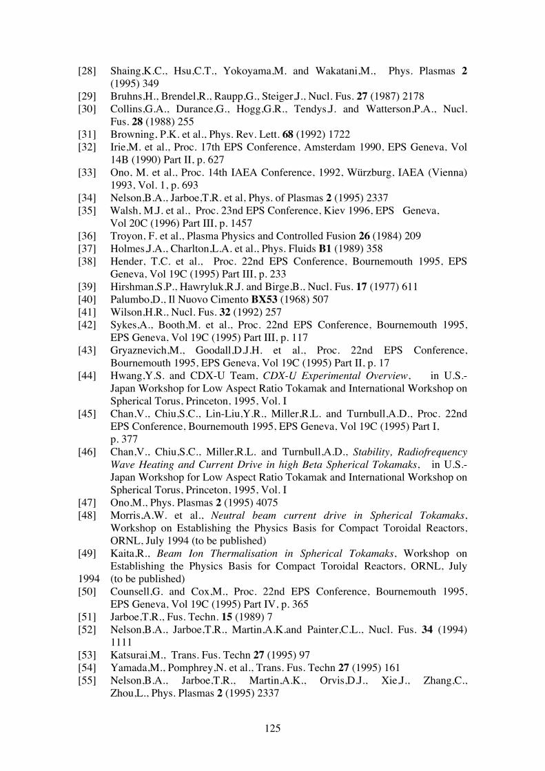
125
[28] Shaing,K.C., Hsu,C.T., Yokoyama,M. and Wakatani,M., Phys. Plasmas 2 (1995) 349 [29] Bruhns,H., Brendel,R., Raupp,G., Steiger,J., Nucl. Fus. 27 (1987) 2178 [30] Collins,G.A., Durance,G., Hogg,G.R., Tendys,J. and Watterson,P.A., Nucl. Fus. 28 (1988) 255 [31] Browning, P.K. et al., Phys. Rev. Lett. 68 (1992) 1722 [32] Irie,M. et al., Proc. 17th EPS Conference, Amsterdam 1990, EPS Geneva, Vol 14B (1990) Part II, p. 627 [33] Ono, M. et al., Proc. 14th IAEA Conference, 1992, Würzburg, IAEA (Vienna) 1993, Vol. 1, p. 693 [34] Nelson,B.A., Jarboe,T.R. et al, Phys. of Plasmas 2 (1995) 2337 [35] Walsh, M.J. et al., Proc. 23nd EPS Conference, Kiev 1996, EPS Geneva,
Vol 20C (1996) Part III, p. 1457 [36] Troyon, F. et al., Plasma Physics and Controlled Fusion 26 (1984) 209 [37] Holmes,J.A., Charlton,L.A. et al., Phys. Fluids B1 (1989) 358 [38] Hender, T.C. et al., Proc. 22nd EPS Conference, Bournemouth 1995, EPS Geneva, Vol 19C (1995) Part III, p. 233 [39] Hirshman,S.P., Hawryluk,R.J. and Birge,B., Nucl. Fus. 17 (1977) 611 [40] Palumbo,D., Il Nuovo Cimento BX53 (1968) 507 [41] Wilson,H.R., Nucl. Fus. 32 (1992) 257 [42] Sykes,A., Booth,M. et al., Proc. 22nd EPS Conference, Bournemouth 1995, EPS Geneva, Vol 19C (1995) Part III, p. 117 [43] Gryaznevich,M., Goodall,D.J.H. et al., Proc. 22nd EPS Conference, Bournemouth 1995, EPS Geneva, Vol 19C (1995) Part II, p. 17 [44] Hwang,Y.S. and CDX-U Team, CDX-U Experimental Overview, in U.S.- Japan Workshop for Low Aspect Ratio Tokamak and International Workshop on Spherical Torus, Princeton, 1995, Vol. I [45] Chan,V., Chiu,S.C., Lin-Liu,Y.R., Miller,R.L. and Turnbull,A.D., Proc. 22nd EPS Conference, Bournemouth 1995, EPS Geneva, Vol 19C (1995) Part I,
p. 377 [46] Chan,V., Chiu,S.C., Miller,R.L. and Turnbull,A.D., Stability, Radiofrequency Wave Heating and Current Drive in high Beta Spherical Tokamaks, in U.S.- Japan Workshop for Low Aspect Ratio Tokamak and International Workshop on Spherical Torus, Princeton, 1995, Vol. I [47] Ono,M., Phys. Plasmas 2 (1995) 4075 [48] Morris,A.W. et al., Neutral beam current drive in Spherical Tokamaks, Workshop on Establishing the Physics Basis for Compact Toroidal Reactors, ORNL, July 1994 (to be published) [49] Kaita,R., Beam Ion Thermalisation in Spherical Tokamaks, Workshop on Establishing the Physics Basis for Compact Toroidal Reactors, ORNL, July 1994 (to be published) [50] Counsell,G. and Cox,M., Proc. 22nd EPS Conference, Bournemouth 1995, EPS Geneva, Vol 19C (1995) Part IV, p. 365 [51] Jarboe,T.R., Fus. Techn. 15 (1989) 7 [52] Nelson,B.A., Jarboe,T.R., Martin,A.K.and Painter,C.L., Nucl. Fus. 34 (1994) 1111 [53] Katsurai,M., Trans. Fus. Techn 27 (1995) 97 [54] Yamada,M., Pomphrey,N. et al., Trans. Fus. Techn 27 (1995) 161 [55] Nelson,B.A., Jarboe,T.R., Martin,A.K., Orvis,D.J., Xie,J., Zhang,C., Zhou,L., Phys. Plasmas 2 (1995) 2337
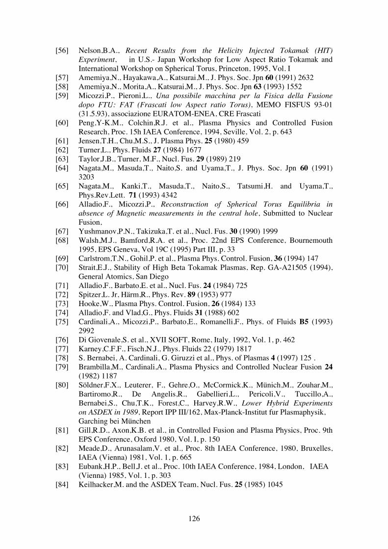
126
[56] Nelson,B.A., Recent Results from the Helicity Injected Tokamak (HIT) Experiment, in U.S.- Japan Workshop for Low Aspect Ratio Tokamak and International Workshop on Spherical Torus, Princeton, 1995, Vol. I [57] Amemiya,N., Hayakawa,A., Katsurai,M., J. Phys. Soc. Jpn 60 (1991) 2632 [58] Amemiya,N., Morita,A., Katsurai,M., J. Phys. Soc. Jpn 63 (1993) 1552 [59] Micozzi,P., Pieroni,L., Una possibile macchina per la Fisica della Fusione dopo FTU: FAT (Frascati low Aspect ratio Torus), MEMO FISFUS 93-01 (31.5.93), associazione EURATOM-ENEA, CRE Frascati [60] Peng,Y-K.M., Colchin,R.J. et al., Plasma Physics and Controlled Fusion Research, Proc. 15h IAEA Conference, 1994, Seville, Vol. 2, p. 643 [61] Jensen,T.H., Chu,M.S., J. Plasma Phys. 25 (1980) 459 [62] Turner,L., Phys. Fluids 27 (1984) 1677 [63] Taylor,J.B., Turner, M.F., Nucl. Fus. 29 (1989) 219 [64] Nagata,M., Masuda,T., Naito,S. and Uyama,T., J. Phys. Soc. Jpn 60 (1991) 3203 [65] Nagata,M., Kanki,T., Masuda,T., Naito,S., Tatsumi,H. and Uyama,T., Phys.Rev.Lett. 71 (1993) 4342 [66] Alladio,F., Micozzi,P., Reconstruction of Spherical Torus Equilibria in absence of Magnetic measurements in the central hole, Submitted to Nuclear Fusion, [67] Yushmanov,P.N., Takizuka,T. et al., Nucl. Fus. 30 (1990) 1999 [68] Walsh,M.J., Bamford,R.A. et al., Proc. 22nd EPS Conference, Bournemouth 1995, EPS Geneva, Vol 19C (1995) Part III, p. 33 [69] Carlstrom,T.N., Gohil,P. et al., Plasma Phys. Control. Fusion, 36 (1994) 147 [70] Strait,E.J., Stability of High Beta Tokamak Plasmas, Rep. GA-A21505 (1994), General Atomics, San Diego [71] Alladio,F., Barbato,E. et al., Nucl. Fus. 24 (1984) 725 [72] Spitzer,L. Jr, Härm,R., Phys. Rev. 89 (1953) 977 [73] Hooke,W., Plasma Phys. Control. Fusion, 26 (1984) 133 [74] Alladio,F. and Vlad,G., Phys. Fluids 31 (1988) 602 [75] Cardinali,A., Micozzi,P., Barbato,E., Romanelli,F., Phys. of Fluids B5 (1993) 2992 [76] Di Giovenale,S. et al., XVII SOFT, Rome, Italy, 1992, Vol. 1, p. 462 [77] Karney,C.F.F., Fisch,N.J., Phys. Fluids 22 (1979) 1817 [78] S. Bernabei, A. Cardinali, G. Giruzzi et al., Phys. of Plasmas 4 (1997) 125 . [79] Brambilla,M., Cardinali,A., Plasma Physics and Controlled Nuclear Fusion 24 (1982) 1187 [80] Söldner,F.X., Leuterer, F., Gehre,O., McCormick,K., Münich,M., Zouhar,M., Bartiromo,R., De Angelis,R., Gabellieri,L., Pericoli,V., Tuccillo,A., Bernabei,S., Chu,T.K., Forest,C., Harvey,R.W., Lower Hybrid Experiments on ASDEX in 1989, Report IPP III/162, Max-Planck-Institut fur Plasmaphysik, Garching bei München [81] Gill,R.D., Axon,K.B. et al., in Controlled Fusion and Plasma Physics, Proc. 9th EPS Conference, Oxford 1980, Vol. I, p. 150 [82] Meade,D., Arunasalam,V. et al., Proc. 8th IAEA Conference, 1980, Bruxelles, IAEA (Vienna) 1981, Vol. 1, p. 665 [83] Eubank,H.P., Bell,J. et al., Proc. 10th IAEA Conference, 1984, London, IAEA (Vienna) 1985, Vol. 1, p. 303 [84] Keilhacker,M. and the ASDEX Team, Nucl. Fus. 25 (1985) 1045
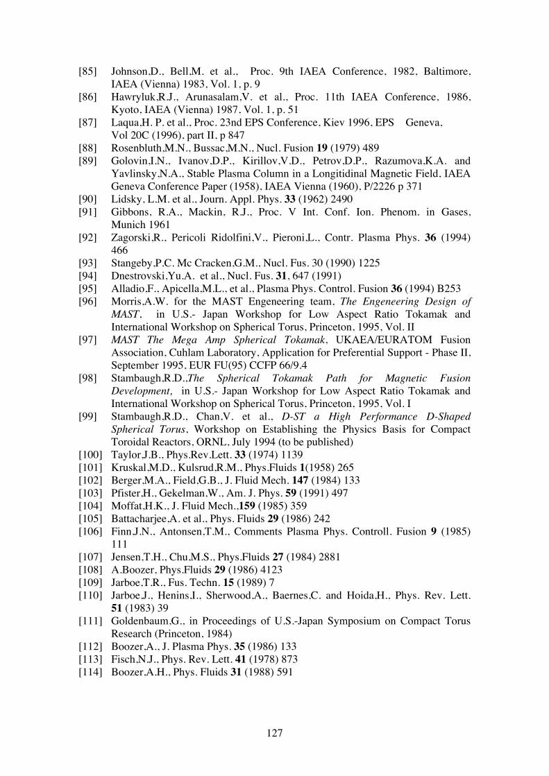
127
[85] Johnson,D., Bell,M. et al., Proc. 9th IAEA Conference, 1982, Baltimore, IAEA (Vienna) 1983, Vol. 1, p. 9 [86] Hawryluk,R.J., Arunasalam,V. et al., Proc. 11th IAEA Conference, 1986, Kyoto, IAEA (Vienna) 1987, Vol. 1, p. 51 [87] Laqua,H. P. et al., Proc. 23nd EPS Conference, Kiev 1996, EPS Geneva,
Vol 20C (1996), part II, p 847 [88] Rosenbluth,M.N., Bussac,M.N., Nucl. Fusion 19 (1979) 489 [89] Golovin,I.N., Ivanov,D.P., Kirillov,V.D., Petrov,D.P., Razumova,K.A. and Yavlinsky,N.A., Stable Plasma Column in a Longitidinal Magnetic Field, IAEA Geneva Conference Paper (1958), IAEA Vienna (1960), P/2226 p 371 [90] Lidsky, L.M. et al., Journ. Appl. Phys. 33 (1962) 2490 [91] Gibbons, R.A., Mackin, R.J., Proc. V Int. Conf. Ion. Phenom. in Gases, Munich 1961 [92] Zagorski,R., Pericoli Ridolfini,V., Pieroni,L., Contr. Plasma Phys. 36 (1994) 466 [93] Stangeby,P.C. Mc Cracken,G.M., Nucl. Fus. 30 (1990) 1225 [94] Dnestrovski,Yu.A. et al., Nucl. Fus. 31, 647 (1991) [95] Alladio,F., Apicella,M.L., et al., Plasma Phys. Control. Fusion 36 (1994) B253 [96] Morris,A.W. for the MAST Engeneering team, The Engeneering Design of MAST, in U.S.- Japan Workshop for Low Aspect Ratio Tokamak and International Workshop on Spherical Torus, Princeton, 1995, Vol. II [97] MAST The Mega Amp Spherical Tokamak, UKAEA/EURATOM Fusion Association, Cuhlam Laboratory, Application for Preferential Support - Phase II, September 1995, EUR FU(95) CCFP 66/9.4 [98] Stambaugh,R.D.,The Spherical Tokamak Path for Magnetic Fusion Development, in U.S.- Japan Workshop for Low Aspect Ratio Tokamak and International Workshop on Spherical Torus, Princeton, 1995, Vol. I [99] Stambaugh,R.D., Chan,V. et al., D-ST a High Performance D-Shaped Spherical Torus, Workshop on Establishing the Physics Basis for Compact Toroidal Reactors, ORNL, July 1994 (to be published) [100] Taylor,J.B., Phys.Rev.Lett. 33 (1974) 1139 [101] Kruskal,M.D., Kulsrud,R.M., Phys.Fluids 1(1958) 265 [102] Berger,M.A., Field,G.B., J. Fluid Mech. 147 (1984) 133 [103] Pfister,H., Gekelman,W., Am. J. Phys. 59 (1991) 497 [104] Moffat,H.K., J. Fluid Mech.,159 (1985) 359 [105] Battacharjee,A. et al., Phys. Fluids 29 (1986) 242 [106] Finn,J.N., Antonsen,T.M., Comments Plasma Phys. Controll. Fusion 9 (1985) 111 [107] Jensen,T.H., Chu,M.S., Phys.Fluids 27 (1984) 2881 [108] A.Boozer, Phys.Fluids 29 (1986) 4123 [109] Jarboe,T.R., Fus. Techn. 15 (1989) 7 [110] Jarboe,J., Henins,I., Sherwood,A., Baernes,C. and Hoida,H., Phys. Rev. Lett. 51 (1983) 39 [111] Goldenbaum,G., in Proceedings of U.S.-Japan Symposium on Compact Torus Research (Princeton, 1984) [112] Boozer,A., J. Plasma Phys. 35 (1986) 133 [113] Fisch,N.J., Phys. Rev. Lett. 41 (1978) 873 [114] Boozer,A.H., Phys. Fluids 31 (1988) 591
Related Documents


![GUIA SPHERA [Venezuela Apertura 2012]](https://static.cupdf.com/doc/110x72/568bd4f31a28ab203496aa6d/guia-sphera-venezuela-apertura-2012.jpg)