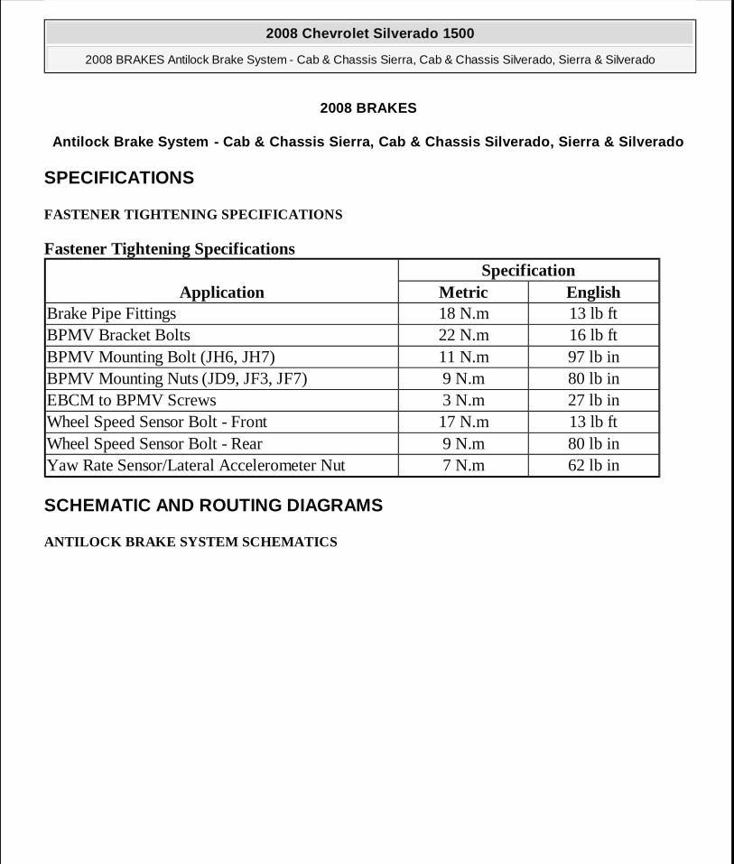
2008 BRAKES Antilock Brake System - Cab & Chassis Sierra, Cab & Chassis Silverado, Sierra & Silverado SPECIFICATIONS FASTENER TIGHTENING SPECIFICATIONS Fastener Tightening Specifications SCHEMATIC AND ROUTING DIAGRAMS ANTILOCK BRAKE SYSTEM SCHEMATICS Application Specification Metric English Brake Pipe Fittings 18 N.m 13 lb ft BPMV Bracket Bolts 22 N.m 16 lb ft BPMV Mounting Bolt (JH6, JH7) 11 N.m 97 lb in BPMV Mounting Nuts (JD9, JF3, JF7) 9 N.m 80 lb in EBCM to BPMV Screws 3 N.m 27 lb in Wheel Speed Sensor Bolt - Front 17 N.m 13 lb ft Wheel Speed Sensor Bolt - Rear 9 N.m 80 lb in Yaw Rate Sensor/Lateral Accelerometer Nut 7 N.m 62 lb in 2008 Chevrolet Silverado 1500 2008 BRAKES Antilock Brake System - Cab & Chassis Sierra, Cab & Chassis Silverado, Sierra & Silverado 2008 Chevrolet Silverado 1500 2008 BRAKES Antilock Brake System - Cab & Chassis Sierra, Cab & Chassis Silverado, Sierra & Silverado

Welcome message from author
This document is posted to help you gain knowledge. Please leave a comment to let me know what you think about it! Share it to your friends and learn new things together.
Transcript
2008 BRAKES
Antilock Brake System - Cab & Chassis Sierra, Cab & Chassis Silverado, Sierra & Silverado
SPECIFICATIONS
FASTENER TIGHTENING SPECIFICATIONS
Fastener Tightening Specifications
SCHEMATIC AND ROUTING DIAGRAMS
ANTILOCK BRAKE SYSTEM SCHEMATICS
ApplicationSpecification
Metric EnglishBrake Pipe Fittings 18 N.m 13 lb ftBPMV Bracket Bolts 22 N.m 16 lb ftBPMV Mounting Bolt (JH6, JH7) 11 N.m 97 lb inBPMV Mounting Nuts (JD9, JF3, JF7) 9 N.m 80 lb inEBCM to BPMV Screws 3 N.m 27 lb inWheel Speed Sensor Bolt - Front 17 N.m 13 lb ftWheel Speed Sensor Bolt - Rear 9 N.m 80 lb inYaw Rate Sensor/Lateral Accelerometer Nut 7 N.m 62 lb in
2008 Chevrolet Silverado 1500
2008 BRAKES Antilock Brake System - Cab & Chassis Sierra, Cab & Chassis Silverado, Sierra & Silverado
2008 Chevrolet Silverado 1500
2008 BRAKES Antilock Brake System - Cab & Chassis Sierra, Cab & Chassis Silverado, Sierra & Silverado
MY
Wednesday, April 08, 2009 12:33:41 PM Page 1 © 2005 Mitchell Repair Information Company, LLC.
MY
Wednesday, April 08, 2009 12:33:58 PM Page 1 © 2005 Mitchell Repair Information Company, LLC.
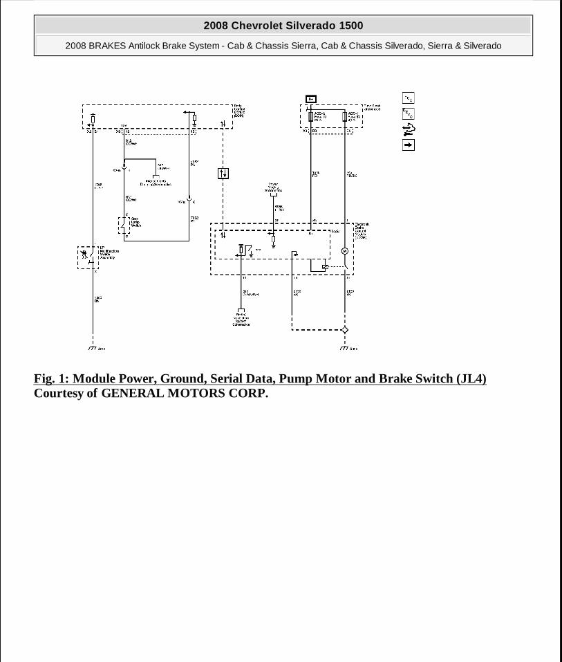
Fig. 1: Module Power, Ground, Serial Data, Pump Motor and Brake Switch (JL4) Courtesy of GENERAL MOTORS CORP.
2008 Chevrolet Silverado 1500
2008 BRAKES Antilock Brake System - Cab & Chassis Sierra, Cab & Chassis Silverado, Sierra & Silverado
MY
Wednesday, April 08, 2009 12:33:41 PM Page 2 © 2005 Mitchell Repair Information Company, LLC.
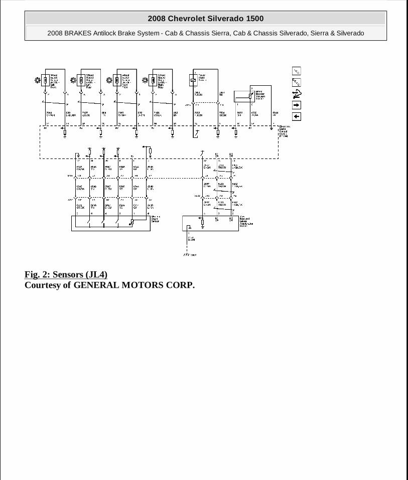
Fig. 2: Sensors (JL4) Courtesy of GENERAL MOTORS CORP.
2008 Chevrolet Silverado 1500
2008 BRAKES Antilock Brake System - Cab & Chassis Sierra, Cab & Chassis Silverado, Sierra & Silverado
MY
Wednesday, April 08, 2009 12:33:41 PM Page 3 © 2005 Mitchell Repair Information Company, LLC.
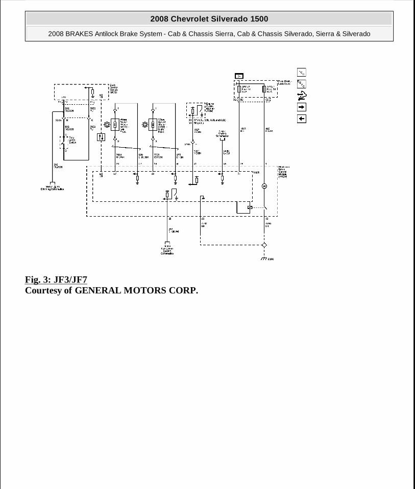
Fig. 3: JF3/JF7 Courtesy of GENERAL MOTORS CORP.
2008 Chevrolet Silverado 1500
2008 BRAKES Antilock Brake System - Cab & Chassis Sierra, Cab & Chassis Silverado, Sierra & Silverado
MY
Wednesday, April 08, 2009 12:33:41 PM Page 4 © 2005 Mitchell Repair Information Company, LLC.
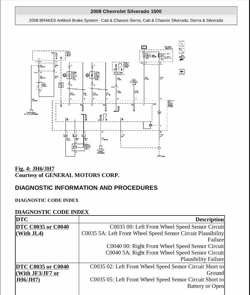
Fig. 4: JH6/JH7 Courtesy of GENERAL MOTORS CORP.
DIAGNOSTIC INFORMATION AND PROCEDURES
DIAGNOSTIC CODE INDEX
DIAGNOSTIC CODE INDEX DTC DescriptionDTC C0035 or C0040 (With JL4)
C0035 00: Left Front Wheel Speed Sensor Circuit C0035 5A: Left Front Wheel Speed Sensor Circuit Plausibility
Failure C0040 00: Right Front Wheel Speed Sensor Circuit C0040 5A: Right Front Wheel Speed Sensor Circuit
Plausibility FailureDTC C0035 or C0040 (With JF3/JF7 or JH6/JH7)
C0035 02: Left Front Wheel Speed Sensor Circuit Short to Ground
C0035 05: Left Front Wheel Speed Sensor Circuit Short to Battery or Open
2008 Chevrolet Silverado 1500
2008 BRAKES Antilock Brake System - Cab & Chassis Sierra, Cab & Chassis Silverado, Sierra & Silverado
MY
Wednesday, April 08, 2009 12:33:41 PM Page 5 © 2005 Mitchell Repair Information Company, LLC.
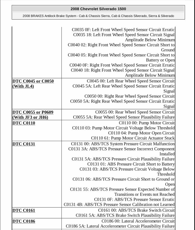
C0035 0F: Left Front Wheel Speed Sensor Circuit Erratic C0035 18: Left Front Wheel Speed Sensor Circuit Signal
Amplitude Below Minimum C0040 02: Right Front Wheel Speed Sensor Circuit Short to
Ground C0040 05: Right Front Wheel Speed Sensor Circuit Short to
Battery or Open C0040 0F: Right Front Wheel Speed Sensor Circuit Erratic C0040 18: Right Front Wheel Speed Sensor Circuit Signal
Amplitude Below MinimumDTC C0045 or C0050 (With JL4)
C0045 00: Left Rear Wheel Speed Sensor Circuit C0045 5A: Left Rear Wheel Speed Sensor Circuit Erratic
Signal C0050 00: Right Rear Wheel Speed Sensor Circuit
C0050 5A: Right Rear Wheel Speed Sensor Circuit Erratic Signal
DTC C0055 or P0609 (With JF3 or JH6)
C0055 00: Rear Wheel Speed Sensor Circuit C0055 5A: Rear Wheel Speed Sensor Plausibility Failure
DTC C0110 C0110 00: Pump Motor Circuit C0110 03: Pump Motor Circuit Voltage Below Threshold
C0110 04: Pump Motor Open Circuit C0110 61: Pump Motor Circuit Actuator Stuck
DTC C0131 C0131 00: ABS/TCS System Pressure Circuit Malfunction C0131 3A: ABS/TCS Pressure Sensor Incorrect Component
Installed C0131 5A: ABS/TCS Pressure Circuit Plausibility Failure
C0131 01: ABS Pressure Circuit Short to Battery C0131 03: ABS/TCS Pressure Circuit Voltage Below
Threshold C0131 06: ABS/TCS Pressure Circuit Short to Ground or
Open C0131 55: ABS/TCS Pressure Sensor Expected Number of
Transitions or Events not Reached C0131 0F: ABS/TCS Pressure Sensor Erratic
C0131 4B: ABS/TCS Pressure Sensor Calibration not LearnedDTC C0161 C0161 00: ABS/TCS Brake Switch Circuit
C0161 5A: ABS/TCS Brake Switch Plausibility FailureDTC C0186 C0186 00: Lateral Accelerometer Circuit
C0186 5A: Lateral Accelerometer Circuit Plausibility Failure
2008 Chevrolet Silverado 1500
2008 BRAKES Antilock Brake System - Cab & Chassis Sierra, Cab & Chassis Silverado, Sierra & Silverado
MY
Wednesday, April 08, 2009 12:33:41 PM Page 6 © 2005 Mitchell Repair Information Company, LLC.

DIAGNOSTIC STARTING POINT - ANTILOCK BRAKE SYSTEM
DTC C0196 C0196 00: Yaw Rate Circuit C0196 5A: Yaw Rate Circuit Plausibility Failure
DTC C0201 C0201 00: Antilock Brake System (ABS) Enable Relay Contact Circuit
C0201 04: Antilock Brake System (ABS) Enable Relay Contact Circuit Open
C0201 0E: Antilock Brake System (ABS) Enable Relay Contact Circuit Resistance Below Threshold
DTC C0242 C0242 00: Engine Control Module (ECM) Indicated TCS Malfunction
P0856: Engine Control Module (ECM) Indicated TCS Malfunction
DTC C0245 C0245 00: Wheel Speed Sensor Frequency Error C0245 5A: Wheel Speed Sensor Plausibility Failure
DTC C0252 C0252 00: VSES Sensor UncorrelatedDTC C0253 C0253 00: Centering ErrorDTC C0299 C0299 00: Brake Booster Sensor Performance
C0299 5A: Brake Booster Sensor Plausibility Failure C0299 31: Brake Booster General Checksum Failure
DTC C0455 C0455 00: Front Steering Position Sensor CircuitDTC C0550 C0550 00: Electronic Control Unit (ECU) Performance
C0550 01: Electronic Control Unit (ECU) Performance C0550 02: Electronic Control Unit (ECU) Performance C0550 03: Electronic Control Unit (ECU) Performance C0550 04: Electronic Control Unit (ECU) Performance
DTC C0561 C0561 71: System Disabled Information Stored Invalid Serial Data Received
C0561 72: System Disabled Information Stored Alive Counter Incorrect or not Updated
C0561 74: System Disabled Information Stored Value of Signal Protection Calculation Incorrect
DTC C0569 C0569 00: System Configuration ErrorDTC C0710 C0710 00: Steering Position Signal
C0710 5A: Steering Position Signal Plausibility FailureDTC C0774 C0774 00: Low Tire Pressure System PerformanceDTC C1100 or C1101 C1100 00: Brake Booster Vacuum Sensor Performance
2008 Chevrolet Silverado 1500
2008 BRAKES Antilock Brake System - Cab & Chassis Sierra, Cab & Chassis Silverado, Sierra & Silverado
MY
Wednesday, April 08, 2009 12:33:41 PM Page 7 © 2005 Mitchell Repair Information Company, LLC.
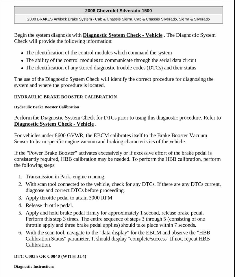
Begin the system diagnosis with Diagnostic System Check - Vehicle . The Diagnostic System Check will provide the following information:
� The identification of the control modules which command the system � The ability of the control modules to communicate through the serial data circuit � The identification of any stored diagnostic trouble codes (DTCs) and their status
The use of the Diagnostic System Check will identify the correct procedure for diagnosing the system and where the procedure is located.
HYDRAULIC BRAKE BOOSTER CALIBRATION
Hydraulic Brake Booster Calibration
Perform the Diagnostic System Check for DTCs prior to using this diagnostic procedure. Refer to Diagnostic System Check - Vehicle .
For vehicles under 8600 GVWR, the EBCM calibrates itself to the Brake Booster Vacuum Sensor to learn specific engine vacuum and braking characteristics of the vehicle.
If the "Power Brake Booster" activates excessively or if excessive effort of the brake pedal is consistently required, HBB calibration may be needed. To perform the HBB calibration, perform the following steps:
1. Transmission in Park, engine running. 2. With scan tool connected to the vehicle, check for any DTCs. If there are any DTCs current,
diagnose and correct DTCs before proceeding. 3. Apply throttle pedal to attain 3000 RPM 4. Release throttle pedal. 5. Apply and hold brake pedal firmly for approximately 1 second, release brake pedal.
Perform this step 3 times. The entire sequence of steps 3 through 5 (consisting of one throttle apply and three brake pedal applies) should take place within 7 seconds.
6. With the scan tool, navigate to the "data display" for the EBCM and observe the "HBB Calibration Status" parameter. It should display "complete/success" If not, repeat HBB Calibration.
DTC C0035 OR C0040 (WITH JL4)
Diagnostic Instructions
2008 Chevrolet Silverado 1500
2008 BRAKES Antilock Brake System - Cab & Chassis Sierra, Cab & Chassis Silverado, Sierra & Silverado
MY
Wednesday, April 08, 2009 12:33:41 PM Page 8 © 2005 Mitchell Repair Information Company, LLC.
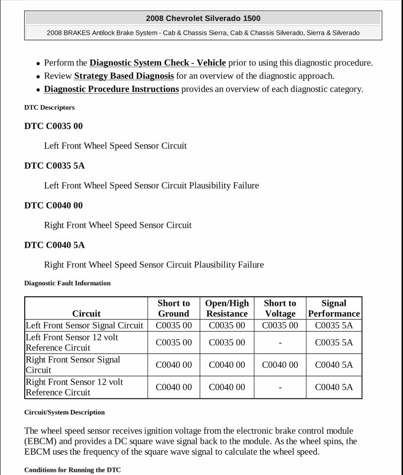
� Perform the Diagnostic System Check - Vehicle prior to using this diagnostic procedure.
� Review Strategy Based Diagnosis for an overview of the diagnostic approach.
� Diagnostic Procedure Instructions provides an overview of each diagnostic category.
DTC Descriptors
DTC C0035 00
Left Front Wheel Speed Sensor Circuit
DTC C0035 5A
Left Front Wheel Speed Sensor Circuit Plausibility Failure
DTC C0040 00
Right Front Wheel Speed Sensor Circuit
DTC C0040 5A
Right Front Wheel Speed Sensor Circuit Plausibility Failure
Diagnostic Fault Information
Circuit/System Description
The wheel speed sensor receives ignition voltage from the electronic brake control module (EBCM) and provides a DC square wave signal back to the module. As the wheel spins, the EBCM uses the frequency of the square wave signal to calculate the wheel speed.
Conditions for Running the DTC
CircuitShort to Ground
Open/High Resistance
Short to Voltage
Signal Performance
Left Front Sensor Signal Circuit C0035 00 C0035 00 C0035 00 C0035 5ALeft Front Sensor 12 volt Reference Circuit
C0035 00 C0035 00 - C0035 5A
Right Front Sensor Signal Circuit
C0040 00 C0040 00 C0040 00 C0040 5A
Right Front Sensor 12 volt Reference Circuit
C0040 00 C0040 00 - C0040 5A
2008 Chevrolet Silverado 1500
2008 BRAKES Antilock Brake System - Cab & Chassis Sierra, Cab & Chassis Silverado, Sierra & Silverado
MY
Wednesday, April 08, 2009 12:33:41 PM Page 9 © 2005 Mitchell Repair Information Company, LLC.
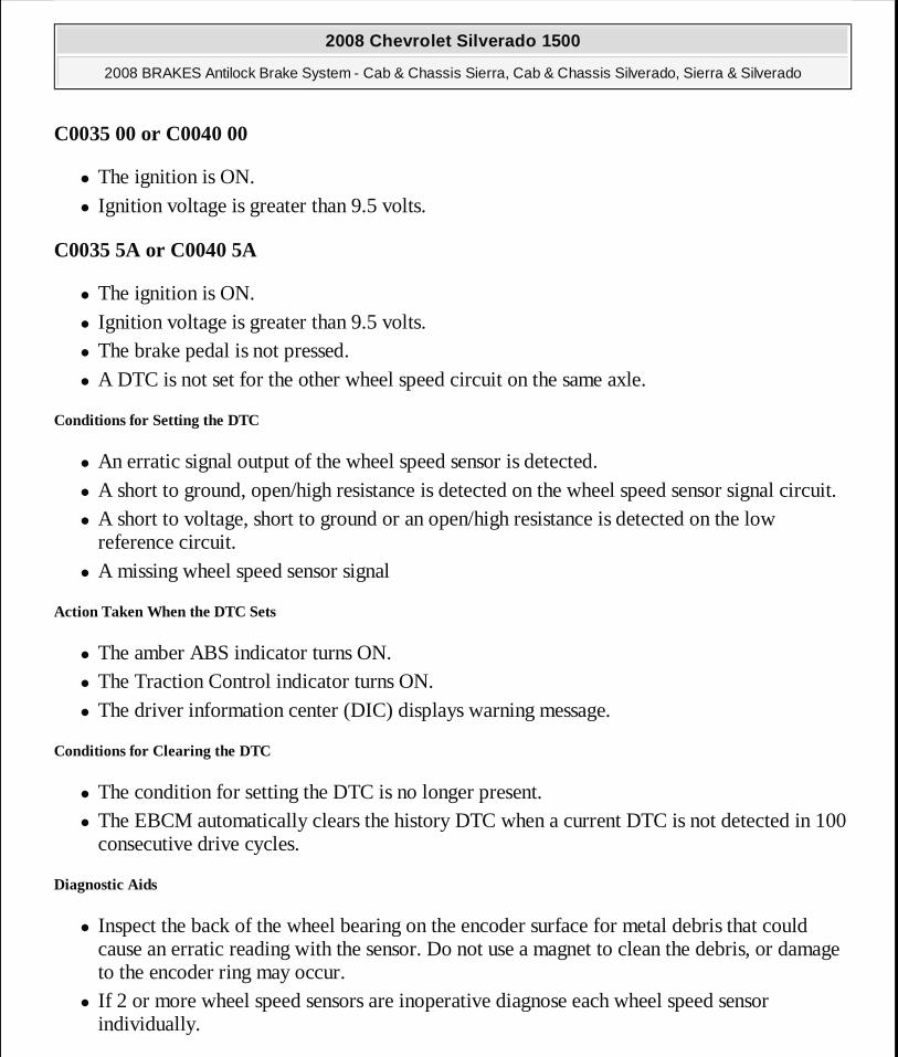
C0035 00 or C0040 00
� The ignition is ON. � Ignition voltage is greater than 9.5 volts.
C0035 5A or C0040 5A
� The ignition is ON. � Ignition voltage is greater than 9.5 volts. � The brake pedal is not pressed. � A DTC is not set for the other wheel speed circuit on the same axle.
Conditions for Setting the DTC
� An erratic signal output of the wheel speed sensor is detected. � A short to ground, open/high resistance is detected on the wheel speed sensor signal circuit. � A short to voltage, short to ground or an open/high resistance is detected on the low
reference circuit. � A missing wheel speed sensor signal
Action Taken When the DTC Sets
� The amber ABS indicator turns ON. � The Traction Control indicator turns ON. � The driver information center (DIC) displays warning message.
Conditions for Clearing the DTC
� The condition for setting the DTC is no longer present. � The EBCM automatically clears the history DTC when a current DTC is not detected in 100
consecutive drive cycles.
Diagnostic Aids
� Inspect the back of the wheel bearing on the encoder surface for metal debris that could cause an erratic reading with the sensor. Do not use a magnet to clean the debris, or damage to the encoder ring may occur.
� If 2 or more wheel speed sensors are inoperative diagnose each wheel speed sensor individually.
2008 Chevrolet Silverado 1500
2008 BRAKES Antilock Brake System - Cab & Chassis Sierra, Cab & Chassis Silverado, Sierra & Silverado
MY
Wednesday, April 08, 2009 12:33:41 PM Page 10 © 2005 Mitchell Repair Information Company, LLC.

� An ECE 13 response may be required, after repairs are made, and DTCs are cleared, operate the vehicle at speeds greater than 15 km/h (10 mph) to complete the self test, and the EBCM will turn off the ABS indicator.
If the customer comments that the ABS indicator is ON only during moist environmental conditions: rain, snow, vehicle wash, etc., inspect the wheel speed sensor wiring for signs of water intrusion. If the DTC is not current, clear all DTCs and simulate the effects of water intrusion by using the following procedure:
1. Spray the suspected area with a 5 percent saltwater solution. To create a 5 percent saltwater solution, add 2 teaspoons of salt to 8 fl oz of water (10 g of salt to 200 ml of water).
2. Test drive the vehicle over various road surfaces: bumps, turns, etc., above 40 km/h (25 mph) for at least 30 seconds.
3. Rinse the area thoroughly when completed.
Reference Information
Schematic Reference
Antilock Brake System Schematics
Connector End View Reference
Component Connector End Views
Description and Operation
ABS Description and Operation (With JL4) or ABS Description and Operation (Without JL4)
Electrical Information Reference
� Circuit Testing
� Connector Repairs � Testing for Intermittent Conditions and Poor Connections � Wiring Repairs
Scan Tool Reference
Control Module References for Scan Tool Information
2008 Chevrolet Silverado 1500
2008 BRAKES Antilock Brake System - Cab & Chassis Sierra, Cab & Chassis Silverado, Sierra & Silverado
MY
Wednesday, April 08, 2009 12:33:41 PM Page 11 © 2005 Mitchell Repair Information Company, LLC.
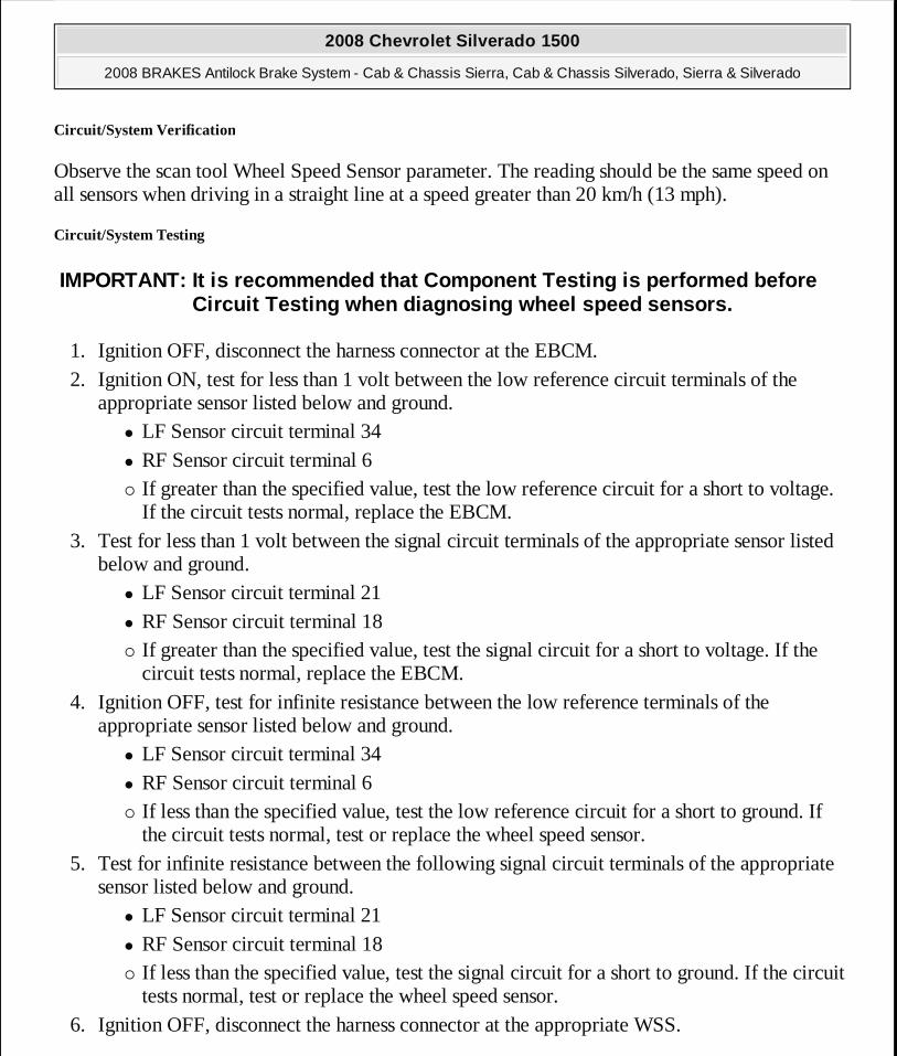
Circuit/System Verification
Observe the scan tool Wheel Speed Sensor parameter. The reading should be the same speed on all sensors when driving in a straight line at a speed greater than 20 km/h (13 mph).
Circuit/System Testing
1. Ignition OFF, disconnect the harness connector at the EBCM. 2. Ignition ON, test for less than 1 volt between the low reference circuit terminals of the
appropriate sensor listed below and ground. � LF Sensor circuit terminal 34 � RF Sensor circuit terminal 6 � If greater than the specified value, test the low reference circuit for a short to voltage.
If the circuit tests normal, replace the EBCM. 3. Test for less than 1 volt between the signal circuit terminals of the appropriate sensor listed
below and ground. � LF Sensor circuit terminal 21 � RF Sensor circuit terminal 18 � If greater than the specified value, test the signal circuit for a short to voltage. If the
circuit tests normal, replace the EBCM. 4. Ignition OFF, test for infinite resistance between the low reference terminals of the
appropriate sensor listed below and ground. � LF Sensor circuit terminal 34 � RF Sensor circuit terminal 6 � If less than the specified value, test the low reference circuit for a short to ground. If
the circuit tests normal, test or replace the wheel speed sensor. 5. Test for infinite resistance between the following signal circuit terminals of the appropriate
sensor listed below and ground. � LF Sensor circuit terminal 21 � RF Sensor circuit terminal 18 � If less than the specified value, test the signal circuit for a short to ground. If the circuit
tests normal, test or replace the wheel speed sensor. 6. Ignition OFF, disconnect the harness connector at the appropriate WSS.
IMPORTANT: It is recommended that Component Testing is performed before Circuit Testing when diagnosing wheel speed sensors .
2008 Chevrolet Silverado 1500
2008 BRAKES Antilock Brake System - Cab & Chassis Sierra, Cab & Chassis Silverado, Sierra & Silverado
MY
Wednesday, April 08, 2009 12:33:41 PM Page 12 © 2005 Mitchell Repair Information Company, LLC.

7. Test for less than 2 ohms between the appropriate low reference circuit terminals listed below.
� LF Sensor circuit terminals 34 at the EBCM harness connector, and terminal 1 at the WSS harness connector
� RF Sensor circuit terminals 6 at the EBCM harness connector, and terminal 1 at the WSS harness connector
� If greater than the specified value, test the low reference circuit for an open or high resistance. If the circuit tests normal, test or replace the wheel speed sensor.
8. Test for less than 2 ohms between the appropriate signal circuit terminals listed below. � LF Sensor circuit terminals 21 at the EBCM harness connector, and terminal 2 at the
WSS harness connector � RF Sensor circuit terminals 18 at the EBCM harness connector, and terminal 2 at the
WSS harness connector � If greater than the specified value, test the signal circuit for an open or high resistance.
If the circuit tests normal, test or replace the wheel speed sensor. 9. If all circuits test normal, replace the EBCM.
Component Testing
1. Ignition OFF, disconnect the harness connector at the suspect wheel speed sensor. 2. Ignition On, test at the harness connector for 10-12 volts between the signal circuit terminal,
and low reference circuit terminal. � If not within the specified range, perform the Circuit/System Testing procedure.
3. Connect a jumper wire between the signal circuit terminal on the harness side, and to the wheel speed sensor signal circuit terminal on the WSS.
4. Connect a DMM between the low reference terminal at the WSS, and to the low reference terminal on the harness connector. Set up the DMM to measure mA using the DC scale.
5. Spin the wheel very slowly. Using the DMM MIN/MAX feature, test for 4-8 mA on the MIN capture, and 12-16 mA on the MAX capture. The sensor mA readings should toggle from high to low with in the specified range.
� If not within the specified range, replace the wheel speed sensor. 6. If all sensor circuits test normal, perform the Circuit/System Testing procedure.
Repair Procedures
Perform the Diagnostic Repair Verification after completing the diagnostic procedure.
2008 Chevrolet Silverado 1500
2008 BRAKES Antilock Brake System - Cab & Chassis Sierra, Cab & Chassis Silverado, Sierra & Silverado
MY
Wednesday, April 08, 2009 12:33:41 PM Page 13 © 2005 Mitchell Repair Information Company, LLC.
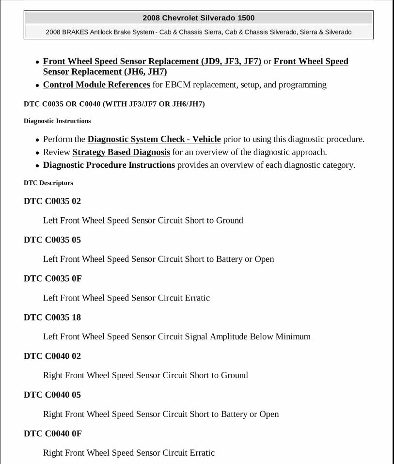
� Front Wheel Speed Sensor Replacement (JD9, JF3, JF7) or Front Wheel Speed Sensor Replacement (JH6, JH7)
� Control Module References for EBCM replacement, setup, and programming
DTC C0035 OR C0040 (WITH JF3/JF7 OR JH6/JH7)
Diagnostic Instructions
� Perform the Diagnostic System Check - Vehicle prior to using this diagnostic procedure.
� Review Strategy Based Diagnosis for an overview of the diagnostic approach.
� Diagnostic Procedure Instructions provides an overview of each diagnostic category.
DTC Descriptors
DTC C0035 02
Left Front Wheel Speed Sensor Circuit Short to Ground
DTC C0035 05
Left Front Wheel Speed Sensor Circuit Short to Battery or Open
DTC C0035 0F
Left Front Wheel Speed Sensor Circuit Erratic
DTC C0035 18
Left Front Wheel Speed Sensor Circuit Signal Amplitude Below Minimum
DTC C0040 02
Right Front Wheel Speed Sensor Circuit Short to Ground
DTC C0040 05
Right Front Wheel Speed Sensor Circuit Short to Battery or Open
DTC C0040 0F
Right Front Wheel Speed Sensor Circuit Erratic
2008 Chevrolet Silverado 1500
2008 BRAKES Antilock Brake System - Cab & Chassis Sierra, Cab & Chassis Silverado, Sierra & Silverado
MY
Wednesday, April 08, 2009 12:33:41 PM Page 14 © 2005 Mitchell Repair Information Company, LLC.
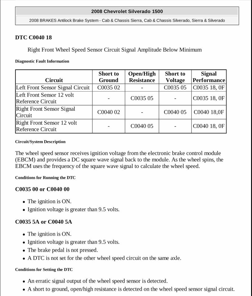
DTC C0040 18
Right Front Wheel Speed Sensor Circuit Signal Amplitude Below Minimum
Diagnostic Fault Information
Circuit/System Description
The wheel speed sensor receives ignition voltage from the electronic brake control module (EBCM) and provides a DC square wave signal back to the module. As the wheel spins, the EBCM uses the frequency of the square wave signal to calculate the wheel speed.
Conditions for Running the DTC
C0035 00 or C0040 00
� The ignition is ON. � Ignition voltage is greater than 9.5 volts.
C0035 5A or C0040 5A
� The ignition is ON. � Ignition voltage is greater than 9.5 volts. � The brake pedal is not pressed. � A DTC is not set for the other wheel speed circuit on the same axle.
Conditions for Setting the DTC
� An erratic signal output of the wheel speed sensor is detected. � A short to ground, open/high resistance is detected on the wheel speed sensor signal circuit.
CircuitShort to Ground
Open/High Resistance
Short to Voltage
Signal Performance
Left Front Sensor Signal Circuit C0035 02 - C0035 05 C0035 18, 0FLeft Front Sensor 12 volt Reference Circuit
- C0035 05 - C0035 18, 0F
Right Front Sensor Signal Circuit
C0040 02 - C0040 05 C0040 18,0F
Right Front Sensor 12 volt Reference Circuit
- C0040 05 - C0040 18, 0F
2008 Chevrolet Silverado 1500
2008 BRAKES Antilock Brake System - Cab & Chassis Sierra, Cab & Chassis Silverado, Sierra & Silverado
MY
Wednesday, April 08, 2009 12:33:41 PM Page 15 © 2005 Mitchell Repair Information Company, LLC.
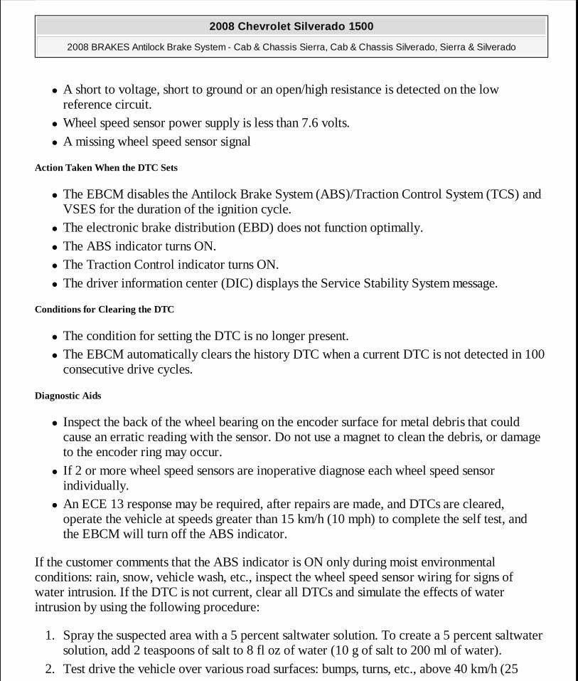
� A short to voltage, short to ground or an open/high resistance is detected on the low reference circuit.
� Wheel speed sensor power supply is less than 7.6 volts. � A missing wheel speed sensor signal
Action Taken When the DTC Sets
� The EBCM disables the Antilock Brake System (ABS)/Traction Control System (TCS) and VSES for the duration of the ignition cycle.
� The electronic brake distribution (EBD) does not function optimally. � The ABS indicator turns ON. � The Traction Control indicator turns ON. � The driver information center (DIC) displays the Service Stability System message.
Conditions for Clearing the DTC
� The condition for setting the DTC is no longer present. � The EBCM automatically clears the history DTC when a current DTC is not detected in 100
consecutive drive cycles.
Diagnostic Aids
� Inspect the back of the wheel bearing on the encoder surface for metal debris that could cause an erratic reading with the sensor. Do not use a magnet to clean the debris, or damage to the encoder ring may occur.
� If 2 or more wheel speed sensors are inoperative diagnose each wheel speed sensor individually.
� An ECE 13 response may be required, after repairs are made, and DTCs are cleared, operate the vehicle at speeds greater than 15 km/h (10 mph) to complete the self test, and the EBCM will turn off the ABS indicator.
If the customer comments that the ABS indicator is ON only during moist environmental conditions: rain, snow, vehicle wash, etc., inspect the wheel speed sensor wiring for signs of water intrusion. If the DTC is not current, clear all DTCs and simulate the effects of water intrusion by using the following procedure:
1. Spray the suspected area with a 5 percent saltwater solution. To create a 5 percent saltwater solution, add 2 teaspoons of salt to 8 fl oz of water (10 g of salt to 200 ml of water).
2. Test drive the vehicle over various road surfaces: bumps, turns, etc., above 40 km/h (25
2008 Chevrolet Silverado 1500
2008 BRAKES Antilock Brake System - Cab & Chassis Sierra, Cab & Chassis Silverado, Sierra & Silverado
MY
Wednesday, April 08, 2009 12:33:41 PM Page 16 © 2005 Mitchell Repair Information Company, LLC.

mph) for at least 30 seconds. 3. Rinse the area thoroughly when completed.
Reference Information
Schematic Reference
Antilock Brake System Schematics
Connector End View Reference
Component Connector End Views
Description and Operation
ABS Description and Operation (With JL4) or ABS Description and Operation (Without JL4)
Electrical Information Reference
� Circuit Testing
� Connector Repairs � Testing for Intermittent Conditions and Poor Connections � Wiring Repairs
Scan Tool Reference
Control Module References for Scan Tool Information
Circuit/System Verification
Observe the scan tool Wheel Speed Sensor parameter. The reading should be the same speed on all sensors when driving in a straight line at a speed greater than 20 km/h (13 mph).
Circuit/System Testing
With JF3/JF7
It is recommended that Component Testing is performed before Circuit Testing when diagnosing wheel speed sensors.
2008 Chevrolet Silverado 1500
2008 BRAKES Antilock Brake System - Cab & Chassis Sierra, Cab & Chassis Silverado, Sierra & Silverado
MY
Wednesday, April 08, 2009 12:33:41 PM Page 17 © 2005 Mitchell Repair Information Company, LLC.
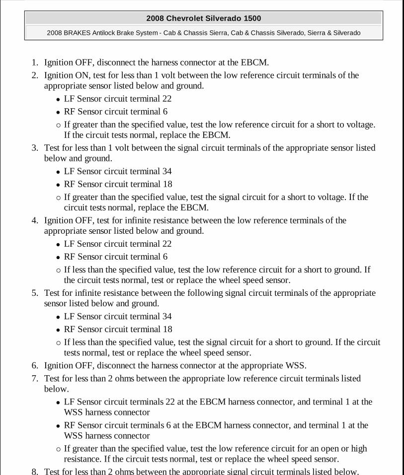
1. Ignition OFF, disconnect the harness connector at the EBCM. 2. Ignition ON, test for less than 1 volt between the low reference circuit terminals of the
appropriate sensor listed below and ground. � LF Sensor circuit terminal 22 � RF Sensor circuit terminal 6 � If greater than the specified value, test the low reference circuit for a short to voltage.
If the circuit tests normal, replace the EBCM. 3. Test for less than 1 volt between the signal circuit terminals of the appropriate sensor listed
below and ground. � LF Sensor circuit terminal 34 � RF Sensor circuit terminal 18 � If greater than the specified value, test the signal circuit for a short to voltage. If the
circuit tests normal, replace the EBCM. 4. Ignition OFF, test for infinite resistance between the low reference terminals of the
appropriate sensor listed below and ground. � LF Sensor circuit terminal 22 � RF Sensor circuit terminal 6 � If less than the specified value, test the low reference circuit for a short to ground. If
the circuit tests normal, test or replace the wheel speed sensor. 5. Test for infinite resistance between the following signal circuit terminals of the appropriate
sensor listed below and ground. � LF Sensor circuit terminal 34 � RF Sensor circuit terminal 18 � If less than the specified value, test the signal circuit for a short to ground. If the circuit
tests normal, test or replace the wheel speed sensor. 6. Ignition OFF, disconnect the harness connector at the appropriate WSS. 7. Test for less than 2 ohms between the appropriate low reference circuit terminals listed
below. � LF Sensor circuit terminals 22 at the EBCM harness connector, and terminal 1 at the
WSS harness connector � RF Sensor circuit terminals 6 at the EBCM harness connector, and terminal 1 at the
WSS harness connector � If greater than the specified value, test the low reference circuit for an open or high
resistance. If the circuit tests normal, test or replace the wheel speed sensor. 8. Test for less than 2 ohms between the appropriate signal circuit terminals listed below.
2008 Chevrolet Silverado 1500
2008 BRAKES Antilock Brake System - Cab & Chassis Sierra, Cab & Chassis Silverado, Sierra & Silverado
MY
Wednesday, April 08, 2009 12:33:41 PM Page 18 © 2005 Mitchell Repair Information Company, LLC.
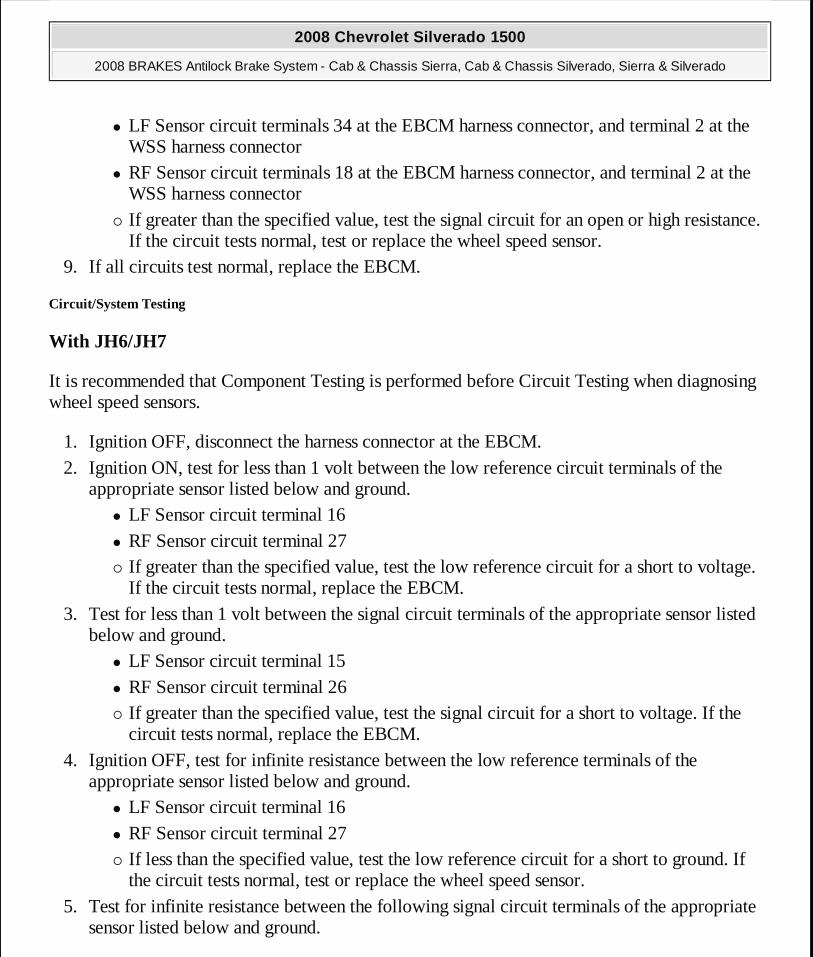
� LF Sensor circuit terminals 34 at the EBCM harness connector, and terminal 2 at the WSS harness connector
� RF Sensor circuit terminals 18 at the EBCM harness connector, and terminal 2 at the WSS harness connector
� If greater than the specified value, test the signal circuit for an open or high resistance. If the circuit tests normal, test or replace the wheel speed sensor.
9. If all circuits test normal, replace the EBCM.
Circuit/System Testing
With JH6/JH7
It is recommended that Component Testing is performed before Circuit Testing when diagnosing wheel speed sensors.
1. Ignition OFF, disconnect the harness connector at the EBCM. 2. Ignition ON, test for less than 1 volt between the low reference circuit terminals of the
appropriate sensor listed below and ground. � LF Sensor circuit terminal 16 � RF Sensor circuit terminal 27 � If greater than the specified value, test the low reference circuit for a short to voltage.
If the circuit tests normal, replace the EBCM. 3. Test for less than 1 volt between the signal circuit terminals of the appropriate sensor listed
below and ground. � LF Sensor circuit terminal 15 � RF Sensor circuit terminal 26 � If greater than the specified value, test the signal circuit for a short to voltage. If the
circuit tests normal, replace the EBCM. 4. Ignition OFF, test for infinite resistance between the low reference terminals of the
appropriate sensor listed below and ground. � LF Sensor circuit terminal 16 � RF Sensor circuit terminal 27 � If less than the specified value, test the low reference circuit for a short to ground. If
the circuit tests normal, test or replace the wheel speed sensor. 5. Test for infinite resistance between the following signal circuit terminals of the appropriate
sensor listed below and ground.
2008 Chevrolet Silverado 1500
2008 BRAKES Antilock Brake System - Cab & Chassis Sierra, Cab & Chassis Silverado, Sierra & Silverado
MY
Wednesday, April 08, 2009 12:33:41 PM Page 19 © 2005 Mitchell Repair Information Company, LLC.

� LF Sensor circuit terminal 15 � RF Sensor circuit terminal 26 � If less than the specified value, test the signal circuit for a short to ground. If the circuit
tests normal, test or replace the wheel speed sensor. 6. Test for less than 2 ohms between the appropriate low reference circuit terminals listed
below. � LF Sensor circuit terminals 16 at the EBCM harness connector, and terminal A at the
WSS harness connector � RF Sensor circuit terminals 27 at the EBCM harness connector, and terminal A at the
WSS harness connector � If greater than the specified value, test the low reference circuit for an open or high
resistance. If the circuit tests normal, test or replace the wheel speed sensor. 7. Test for less than 2 ohms between the appropriate signal circuit terminals listed below.
� LF Sensor circuit terminals 15 at the EBCM harness connector, and terminal B at the WSS harness connector
� RF Sensor circuit terminals 26 at the EBCM harness connector, and terminal B at the WSS harness connector
� If greater than the specified value, test the signal circuit for an open or high resistance. If the circuit tests normal, test or replace the wheel speed sensor.
8. If all circuits test normal, replace the EBCM.
Component Testing
1. Ignition OFF, disconnect the harness connector at the suspect wheel speed sensor. 2. Ignition On, test at the harness connector for 10-12 volts between the signal circuit terminal,
and low reference circuit terminal. � If not within the specified range, perform the Circuit/System Testing procedure.
3. Connect a jumper wire between the signal circuit terminal on the harness side, and to the wheel speed sensor signal circuit terminal on the WSS.
4. Connect a DMM between the low reference terminal at the WSS, and to the low reference terminal on the harness connector. Set up the DMM to measure mA using the DC scale.
5. Spin the wheel very slowly. Using the DMM MIN/MAX feature, test for 4-8 mA on the MIN capture, and 12-16 mA on the MAX capture. The sensor mA readings should toggle from high to low with in the specified range.
� If not within the specified range, replace the wheel speed sensor. 6. If all sensor circuits test normal, perform the Circuit/System Testing procedure.
2008 Chevrolet Silverado 1500
2008 BRAKES Antilock Brake System - Cab & Chassis Sierra, Cab & Chassis Silverado, Sierra & Silverado
MY
Wednesday, April 08, 2009 12:33:41 PM Page 20 © 2005 Mitchell Repair Information Company, LLC.
Repair Procedures
Perform the Diagnostic Repair Verification after completing the diagnostic procedure.
� Front Wheel Speed Sensor Replacement (JD9, JF3, JF7) or Front Wheel Speed Sensor Replacement (JH6, JH7)
� Control Module References for EBCM replacement, setup, and programming
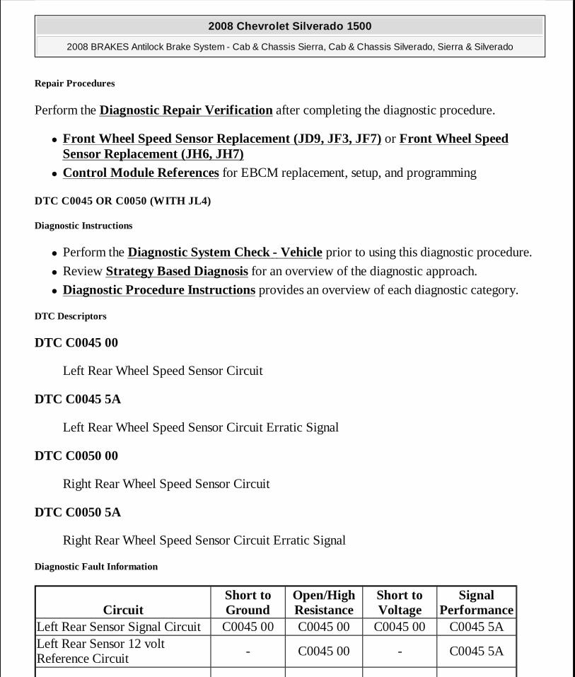
DTC C0045 OR C0050 (WITH JL4)
Diagnostic Instructions
� Perform the Diagnostic System Check - Vehicle prior to using this diagnostic procedure.
� Review Strategy Based Diagnosis for an overview of the diagnostic approach.
� Diagnostic Procedure Instructions provides an overview of each diagnostic category.
DTC Descriptors
DTC C0045 00
Left Rear Wheel Speed Sensor Circuit
DTC C0045 5A
Left Rear Wheel Speed Sensor Circuit Erratic Signal
DTC C0050 00
Right Rear Wheel Speed Sensor Circuit
DTC C0050 5A
Right Rear Wheel Speed Sensor Circuit Erratic Signal
Diagnostic Fault Information
CircuitShort to Ground
Open/High Resistance
Short to Voltage
Signal Performance
Left Rear Sensor Signal Circuit C0045 00 C0045 00 C0045 00 C0045 5ALeft Rear Sensor 12 volt Reference Circuit
- C0045 00 - C0045 5A
2008 Chevrolet Silverado 1500
2008 BRAKES Antilock Brake System - Cab & Chassis Sierra, Cab & Chassis Silverado, Sierra & Silverado
MY
Wednesday, April 08, 2009 12:33:41 PM Page 21 © 2005 Mitchell Repair Information Company, LLC.

Circuit/System Description
The wheel speed sensor receives ignition voltage from the electronic brake control module (EBCM) and provides a DC square wave signal back to the module. As the wheel spins, the EBCM uses the frequency of the square wave signal to calculate the wheel speed.
Conditions for Running the DTC
C0045 00 or C0050 00
� The ignition is ON. � Ignition voltage is greater than 9.5 volts.
C0045 5A or C0050 5A
� The ignition is ON. � Ignition voltage is greater than 9 volts. � The brake pedal is not pressed. � A DTC is not set for the other wheel speed circuit on the same axle.
Conditions for Setting the DTC
� An erratic signal output of the wheel speed sensor is detected. � A short to voltage, open or ground is detected on the wheel speed sensor signal circuit. � A open or short to ground in the wheel speed sensor circuit supply voltage. � A missing wheel speed sensor signal
Action Taken When the DTC Sets
� The amber ABS indicator turns ON. � The Traction Control indicator turns ON. � The driver information center (DIC) displays the warning message.
Conditions for Clearing the DTC
� The condition for setting the DTC is no longer present.
Right Rear Sensor Signal CircuitC0050 00 C0050 00 C0050 00 C0050 5ARight Rear Sensor 12 volt Reference Circuit
- C0050 00 - C0050 5A
2008 Chevrolet Silverado 1500
2008 BRAKES Antilock Brake System - Cab & Chassis Sierra, Cab & Chassis Silverado, Sierra & Silverado
MY
Wednesday, April 08, 2009 12:33:41 PM Page 22 © 2005 Mitchell Repair Information Company, LLC.
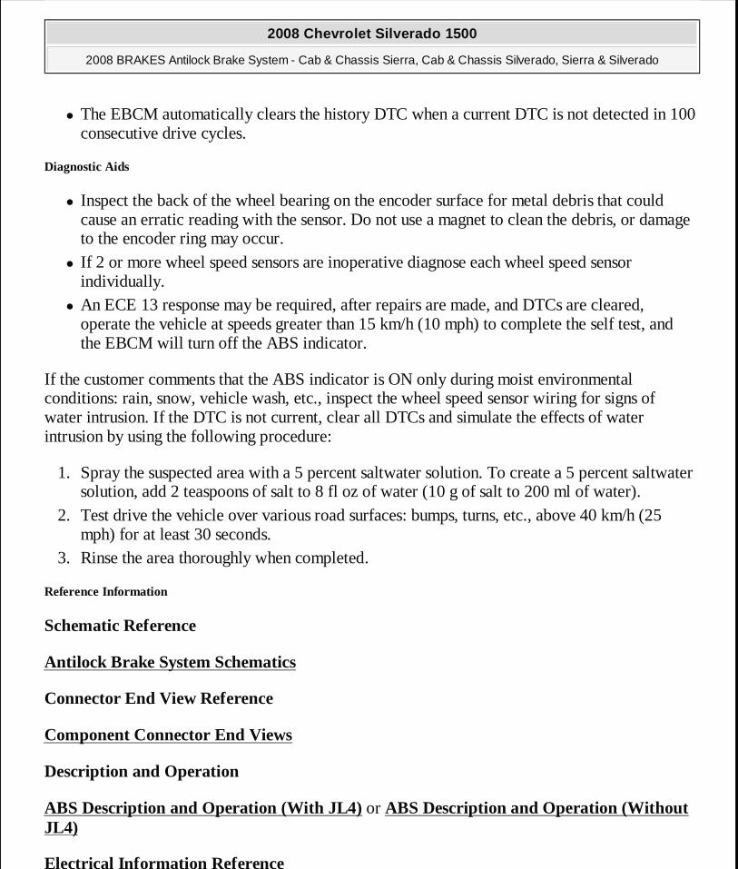
� The EBCM automatically clears the history DTC when a current DTC is not detected in 100 consecutive drive cycles.
Diagnostic Aids
� Inspect the back of the wheel bearing on the encoder surface for metal debris that could cause an erratic reading with the sensor. Do not use a magnet to clean the debris, or damage to the encoder ring may occur.
� If 2 or more wheel speed sensors are inoperative diagnose each wheel speed sensor individually.
� An ECE 13 response may be required, after repairs are made, and DTCs are cleared, operate the vehicle at speeds greater than 15 km/h (10 mph) to complete the self test, and the EBCM will turn off the ABS indicator.
If the customer comments that the ABS indicator is ON only during moist environmental conditions: rain, snow, vehicle wash, etc., inspect the wheel speed sensor wiring for signs of water intrusion. If the DTC is not current, clear all DTCs and simulate the effects of water intrusion by using the following procedure:
1. Spray the suspected area with a 5 percent saltwater solution. To create a 5 percent saltwater solution, add 2 teaspoons of salt to 8 fl oz of water (10 g of salt to 200 ml of water).
2. Test drive the vehicle over various road surfaces: bumps, turns, etc., above 40 km/h (25 mph) for at least 30 seconds.
3. Rinse the area thoroughly when completed.
Reference Information
Schematic Reference
Antilock Brake System Schematics
Connector End View Reference
Component Connector End Views
Description and Operation
ABS Description and Operation (With JL4) or ABS Description and Operation (Without JL4)
Electrical Information Reference
2008 Chevrolet Silverado 1500
2008 BRAKES Antilock Brake System - Cab & Chassis Sierra, Cab & Chassis Silverado, Sierra & Silverado
MY
Wednesday, April 08, 2009 12:33:41 PM Page 23 © 2005 Mitchell Repair Information Company, LLC.
� Circuit Testing
� Connector Repairs � Testing for Intermittent Conditions and Poor Connections � Wiring Repairs
Scan Tool Reference
Control Module References for Scan Tool Information
Circuit/System Verification
Observe the scan tool Wheel Speed Sensor parameter. The reading should be the same speed on all sensors when driving in a straight line at a speed greater than 20 km/h (13 mph).
Circuit/System Testing
It is recommended that Component Testing is performed before Circuit Testing when diagnosing wheel speed sensors.
1. Ignition OFF, disconnect the harness connector at the EBCM. 2. Ignition ON, test for less than 1 volt between the low reference circuit terminals of the
appropriate sensor listed below and ground. � LR Sensor circuit terminal 20 � RR Sensor circuit terminal 31 � If greater than the specified value, test the low reference circuit for a short to voltage.
If the circuit tests normal, replace the wheel speed sensor. 3. Test for less than 1 volt between the signal circuit terminals of the appropriate sensor listed
below and ground. � LR Sensor circuit terminal 33 � RR Sensor circuit terminal 19 � If greater than the specified value, test the signal circuit for a short to voltage. If the
circuit tests normal, replace the wheel speed sensor. 4. Ignition OFF, test for infinite resistance between the low reference terminals of the
appropriate sensor listed below and ground. � LR Sensor circuit terminal 20 � RR Sensor circuit terminal 31 � If less than the specified value, test the low reference circuit for a short to ground. If
2008 Chevrolet Silverado 1500
2008 BRAKES Antilock Brake System - Cab & Chassis Sierra, Cab & Chassis Silverado, Sierra & Silverado
MY
Wednesday, April 08, 2009 12:33:41 PM Page 24 © 2005 Mitchell Repair Information Company, LLC.
the circuit tests normal, test or replace the wheel speed sensor. 5. Test for infinite resistance between the following signal circuit terminals of the appropriate
sensor listed below and ground. � LR Sensor circuit terminal 33 � RR Sensor circuit terminal 19 � If less than the specified value, test the signal circuit for a short to ground. If the circuit
tests normal, test or replace the wheel speed sensor. 6. Ignition OFF, disconnect the harness connector at the appropriate WSS. 7. Test for less than 2 ohms between the appropriate low reference circuit terminals listed
below. � LR Sensor circuit terminals 20 at the EBCM harness connector, and terminal A at the
WSS harness connector � RR Sensor circuit terminals 31 at the EBCM harness connector, and terminal A at the
WSS harness connector � If greater than the specified value, test the low reference circuit for an open or high
resistance. If the circuit tests normal, test or replace the wheel speed sensor. 8. Test for less than 2 ohms between the appropriate signal circuit terminals listed below.
� LR Sensor circuit terminals 33 at the EBCM harness connector, and terminal B at the WSS harness connector
� RR Sensor circuit terminals 19 at the EBCM harness connector, and terminal B at the WSS harness connector
� If greater than the specified value, test the signal circuit for an open or high resistance. If the circuit tests normal, test or replace the wheel speed sensor.
9. If all circuits test normal, replace the EBCM.
Component Testing
1. Ignition OFF, disconnect the harness connector at the suspect wheel speed sensor. 2. Ignition On, test at the harness connector for 10-12 volts between the signal circuit terminal,
and low reference circuit terminal. � If not within the specified range, perform the Circuit/System Testing procedure.
3. Connect a jumper wire between the signal circuit terminal on the harness side, and to the wheel speed sensor signal circuit terminal on the WSS.
4. Connect a DMM between the low reference terminal at the WSS, and to the low reference terminal on the harness connector. Set up the DMM to measure mA using the DC scale.
5. Spin the wheel very slowly. Using the DMM MIN/MAX feature, test for 4-8 mA on the
2008 Chevrolet Silverado 1500
2008 BRAKES Antilock Brake System - Cab & Chassis Sierra, Cab & Chassis Silverado, Sierra & Silverado
MY
Wednesday, April 08, 2009 12:33:41 PM Page 25 © 2005 Mitchell Repair Information Company, LLC.

MIN capture, and 12-16 mA on the MAX capture. The sensor mA readings should toggle from high to low with in the specified range.
� If not within the specified range, replace the wheel speed sensor. 6. If all sensor circuits test normal, perform the Circuit/System Testing procedure.
Repair Procedures
Perform the Diagnostic Repair Verification after completing the diagnostic procedure.
� Rear Wheel Speed Sensor Replacement � Control Module References for EBCM replacement, setup, and programming
DTC C0055 OR P0609 (WITH JF3 OR JH6)
Diagnostic Instructions
� Perform the Diagnostic System Check - Vehicle prior to using this diagnostic procedure.
� Review Strategy Based Diagnosis for an overview of the diagnostic approach.
� Diagnostic Procedure Instructions provides an overview of each diagnostic category.
DTC Descriptors
DTC C0055 00
Rear Wheel Speed Sensor Circuit
DTC C0055 5A
Rear Wheel Speed Sensor Plausibility Failure
Diagnostic Fault Information
Circuit/System Description
The electronic control module (ECM) converts the data from the vehicle speed sensor to a 128K pulses/mile signal. The electronic brake control module (EBCM) uses the vehicle speed signal from the ECM in order to calculate the rear wheel speed.
CircuitShort to Ground
Open/High Resistance
Short to Voltage
Signal Performance
Rear Wheel Speed Sensor SignalC0055 00 C0055 00 C0055 00 C0055 5A
2008 Chevrolet Silverado 1500
2008 BRAKES Antilock Brake System - Cab & Chassis Sierra, Cab & Chassis Silverado, Sierra & Silverado
MY
Wednesday, April 08, 2009 12:33:41 PM Page 26 © 2005 Mitchell Repair Information Company, LLC.
Conditions for Running the DTC
C0055 00
� The ignition is ON. � Ignition voltage is greater than 9.5 volts.
C0055 5A
� The ignition is ON. � Ignition voltage is greater than 9.5 volts. � The brake pedal is not pressed. � A DTC is not set for the other wheel speed circuit on the same axle.
Conditions for Setting the DTC
C0055 00
� An open is detected on the rear wheel speed sensor signal circuit. � A short to ground is detected on the rear wheel speed sensor signal circuit. � A short to voltage is detected on the rear wheel speed sensor signal circuit.
C0055 5A
The EBCM detects an erratic rear wheel speed signal.
Action Taken When the DTC Sets
� The EBCM disables the Antilock Brake System (ABS)/Traction Control System (TCS) for the duration of the ignition cycle.
� The electronic brake distribution (EBD) does not function optimally. � The ABS indicator turns ON.
Conditions for Clearing the DTC
� The condition for setting the DTC is no longer present. � The EBCM automatically clears the history DTC when a current DTC is not detected in 100
consecutive drive cycles.
Diagnostic Aids
2008 Chevrolet Silverado 1500
2008 BRAKES Antilock Brake System - Cab & Chassis Sierra, Cab & Chassis Silverado, Sierra & Silverado
MY
Wednesday, April 08, 2009 12:33:41 PM Page 27 © 2005 Mitchell Repair Information Company, LLC.

If 2 or more wheel speed sensors are inoperative diagnose each wheel speed sensor individually.
An ECE 13 response may be required, after repairs are made, and DTCs are cleared, operate the vehicle at speeds greater than 13 km/h (8 mph) to complete the self test, and the EBCM will turn off the ABS indicator.
C0055 5A, 00
If the customer comments that the ABS indicator is ON only during moist environmental conditions: rain, snow, vehicle wash, etc., inspect the wheel speed sensor wiring for signs of water intrusion. Also, a condition may result in a stored history DTC C0055, this DTC can set if a customer turns the ignition key from the RUN position to the ACCESSORY and leaves it for more than 1 second. The DTC may be stored in history due to a software condition in the EBCM, and no repairs are necessary. If the ABS indicator illuminates intermittently, clear all DTCs and simulate the effects of water intrusion by using the following procedure:
1. Spray the suspected area with a 5 percent saltwater solution. To create a 5 percent saltwater solution, add 2 teaspoons of salt to 8 fl oz of water (10 g of salt to 200 ml of water).
2. Test drive the vehicle over various road surfaces: bumps, turns, etc., above 40 km/h (25 mph) for at least 30 seconds.
3. Rinse the area thoroughly when completed.
Reference Information
Schematic Reference
Antilock Brake System Schematics
Electrical Information Reference
� Circuit Testing
� Connector Repairs � Testing for Intermittent Conditions and Poor Connections � Wiring Repairs
Circuit/System Testing
1. Use a scan tool in order to clear the DTCs. Cycle the ignition to OFF and then start the engine. A current failure will set a DTC.
� If the DTC does not reset, go to Diagnostic Aids.
2008 Chevrolet Silverado 1500
2008 BRAKES Antilock Brake System - Cab & Chassis Sierra, Cab & Chassis Silverado, Sierra & Silverado
MY
Wednesday, April 08, 2009 12:33:42 PM Page 28 © 2005 Mitchell Repair Information Company, LLC.

2. Turn OFF the ignition and disconnect the EBCM harness connector. At the EBCM harness connector terminal 31 W/JF3 or terminal 20 W/JH6, test for 10 volts on the vehicle speed signal circuit.
� If the voltage is below 10 volts, test for an open or short to ground on the vehicle speed signal circuit. If all circuits test normal, replace the EBCM.
3. Ignition ON, verify that a test lamp does not illuminates between the vehicle speed signal circuit terminal 31 W/JF3 or terminal 20 W/JH6 and ground.
� If the test lamp illuminate, test the vehicle speed signal circuit for a short to B+. If the circuit tests normal, replace the EBCM.
4. If all circuits test normal, replace the PCM.
Repair Procedures
Perform the Diagnostic Repair Verification after completing the diagnostic procedure.
Control Module References for EBCM/BPMV or PCM replacement, setup, and programming
DTC C0110
Diagnostic Instructions
� Perform the Diagnostic System Check - Vehicle prior to using this diagnostic procedure.
� Review Strategy Based Diagnosis for an overview of the diagnostic approach.
� Diagnostic Procedure Instructions provides an overview of each diagnostic category.
DTC Descriptor
DTC C0110 00
Pump Motor Circuit
DTC C0110 03
Pump Motor Circuit Voltage Below Threshold
DTC C0110 04
Pump Motor Open Circuit
DTC C0110 61
2008 Chevrolet Silverado 1500
2008 BRAKES Antilock Brake System - Cab & Chassis Sierra, Cab & Chassis Silverado, Sierra & Silverado
MY
Wednesday, April 08, 2009 12:33:42 PM Page 29 © 2005 Mitchell Repair Information Company, LLC.
Pump Motor Circuit Actuator Stuck
Circuit/System Description
The pump motor is an integral part of the brake pressure modulator valve (BPMV), while the pump motor relay is integral to the electronic brake control module (EBCM). The pump motor relay is not engaged during normal system operation. When antilock brake system (ABS) or traction control system (TCS) operation is required the EBCM activates the pump motor relay and ground circuit is provided to the pump motor.
Conditions for Running the DTC
� The ignition switch is in the ON position. � Initialization is complete.
Conditions for Setting the DTC
� The EBCM motor drive circuit detects a short to battery positive, or open ground circuit, and a continuously on or off motor.
� The pump motor continues to rotate briefly after activation creating a feedback voltage. The EBCM sets the code if the measured feedback voltage indicates a binding or stalled pump motor.
Action Taken When the DTC Sets
� The EBCM disables the ABS/TCS/VSES for the duration of the ignition cycle. � The ABS indicator turns ON. � The Traction Control and VSES indicators turn ON. � The Traction Control and StabiliTrak displayed on the DIC.
Conditions for Clearing the DTC
� The condition for the DTC is no longer present. � The EBCM automatically clears the history DTC when a current DTC is not detected in 100
consecutive drive cycles.
Reference Information
Schematic Reference
Antilock Brake System Schematics
2008 Chevrolet Silverado 1500
2008 BRAKES Antilock Brake System - Cab & Chassis Sierra, Cab & Chassis Silverado, Sierra & Silverado
MY
Wednesday, April 08, 2009 12:33:42 PM Page 30 © 2005 Mitchell Repair Information Company, LLC.
Connector End View Reference
Component Connector End Views
Description and Operation
ABS Description and Operation (With JL4) or ABS Description and Operation (Without JL4)
Electrical Information Reference
� Circuit Testing
� Connector Repairs � Testing for Intermittent Conditions and Poor Connections � Wiring Repairs
Scan Tool Reference
Control Module References for Scan Tool Information
Circuit/System Testing
1. Ignition OFF, disconnect the EBCM harness connector and connect a test lamp between the battery positive voltage circuit terminal going to the ABS pump motor, and to ground.
2. Ignition ON, verify that the test lamp illuminates. � If the test lamp does not illuminate, repair the open or high resistance in the battery
positive voltage circuit. 3. Connect a test lamp between the battery positive voltage circuit and pump motor ground
circuit at the EBCM connector, verify that the test lamp illuminates. � If the test lamp does not illuminate, repair the open or high resistance in the pump
motor ground circuit. 4. Ignition OFF, remove the EBCM from the BPMV. 5. Inspect the EBCM to BPMV connector for conditions such as damage, corrosion, or
presence of brake fluid. � If connector corrosion or damage is evident, replace BPMV and/or EBCM as
necessary. � If brake fluid is present, replace both BPMV and EBCM.
6. Connect the EBCM harness to the EBCM with the BPMV still separated.
2008 Chevrolet Silverado 1500
2008 BRAKES Antilock Brake System - Cab & Chassis Sierra, Cab & Chassis Silverado, Sierra & Silverado
MY
Wednesday, April 08, 2009 12:33:42 PM Page 31 © 2005 Mitchell Repair Information Company, LLC.
7. Connect a test lamp between the pump motor circuits, internal EBCM side. 8. Ignition ON, use the scan tool to perform the Pump Motor Test.
� If test lamp illuminates replace the BPMV. � If test lamp does not illuminate replace the EBCM.
Repair Procedures
Perform the Diagnostic Repair Verification after completing the diagnostic procedure.
� Brake Pressure Modulator Valve Replacement (JD9, JF3, JF7) or Brake Pressure Modulator Valve Replacement (JH6, JH7)
� Control Module References for EBCM replacement, setup, and programming
DTC C0131
Diagnostic Instructions
� Perform the Diagnostic System Check - Vehicle prior to using this diagnostic procedure.
� Review Strategy Based Diagnosis for an overview of the diagnostic approach.
� Diagnostic Procedure Instructions provides an overview of each diagnostic category.
DTC Descriptors
DTC C0131 00
ABS/TCS System Pressure Circuit Malfunction
DTC C0131 3A
ABS/TCS Pressure Sensor Incorrect Component Installed
DTC C0131 5A
ABS/TCS Pressure Circuit Plausibility Failure
DTC C0131 01
ABS Pressure Circuit Short to Battery
DTC C0131 03
2008 Chevrolet Silverado 1500
2008 BRAKES Antilock Brake System - Cab & Chassis Sierra, Cab & Chassis Silverado, Sierra & Silverado
MY
Wednesday, April 08, 2009 12:33:42 PM Page 32 © 2005 Mitchell Repair Information Company, LLC.
ABS/TCS Pressure Circuit Voltage Below Threshold
DTC C0131 06
ABS/TCS Pressure Circuit Short to Ground or Open
DTC C0131 55
ABS/TCS Pressure Sensor Expected Number of Transitions or Events not Reached
DTC C0131 0F
ABS/TCS Pressure Sensor Erratic
DTC C0131 4B
ABS/TCS Pressure Sensor Calibration not Learned
Diagnostic Fault Information
Circuit/System Description
The electronic brake control module (EBCM) uses input from the brake pressure sensor for more accurate control during a vehicle stability enhancement system (VSES) event.
Conditions for Running the DTC
� The ignition switch is in the ON position. � Ignition voltage is greater than 9.5 volts.
Conditions for Setting the DTC
� Internal pressure sensor line fault. � Pressure signal does not correlate to estimated Pressure over time. � Brake Signal does not correlate to Pressure Signal. � Signal is erratic and changes faster than physically allowed.
CircuitShort to Ground
Open/High Resistance
Short to Voltage
Signal Performance
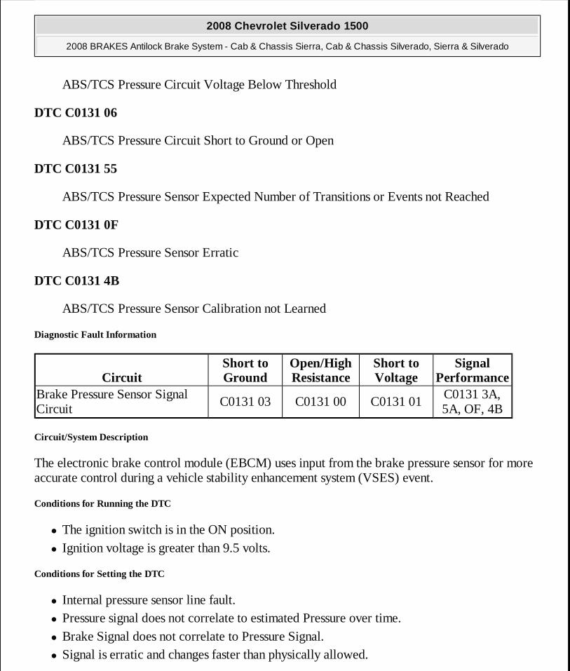
Brake Pressure Sensor Signal Circuit
C0131 03 C0131 00 C0131 01C0131 3A, 5A, OF, 4B
2008 Chevrolet Silverado 1500
2008 BRAKES Antilock Brake System - Cab & Chassis Sierra, Cab & Chassis Silverado, Sierra & Silverado
MY
Wednesday, April 08, 2009 12:33:42 PM Page 33 © 2005 Mitchell Repair Information Company, LLC.

Action Taken When the DTC Sets
� The EBCM disables the antilock brake system (ABS)/traction control system/(TCS) and vehicle stability enhancement system/(VSES) for the duration of the ignition cycle.
� The ABS/TCS and stabilitrak indicator turns ON. � The Service Traction Control, and stabilitrak displayed on the DIC.
Conditions for Clearing the DTC
� The condition for the DTC is no longer present. � The EBCM automatically clears the history DTC when a current DTC is not detected in 100
consecutive drive cycles.
Diagnostic Aids
The brake fluid pressure sensor is integral to the BPMV/EBCM. The brake fluid pressure sensor is not serviceable. After replacing a BPMV and the DTC resets as a current code, it may be necessary to perform a brake pressure sensor calibration with the Tech 2 in ABS, special function.
Reference Information
Schematic Reference
Antilock Brake System Schematics
Connector End View Reference
Component Connector End Views
Description and Operation
ABS Description and Operation (With JL4) or ABS Description and Operation (Without JL4)
Electrical Information Reference
� Circuit Testing
� Connector Repairs � Testing for Intermittent Conditions and Poor Connections � Wiring Repairs
2008 Chevrolet Silverado 1500
2008 BRAKES Antilock Brake System - Cab & Chassis Sierra, Cab & Chassis Silverado, Sierra & Silverado
MY
Wednesday, April 08, 2009 12:33:42 PM Page 34 © 2005 Mitchell Repair Information Company, LLC.

Scan Tool Reference
Control Module References for Scan Tool Information
Circuit/System Testing
1. Apply and release brake pedal. Verify brake lamps operate properly.
� If brake lamps do not operate properly, refer to Symptoms - Lighting 2. Replace EBCM/brake pressure modulator valve (BPMV) assembly.
Repair Procedures
Perform the Diagnostic Repair Verification after completing the diagnostic procedure.
� Brake Pressure Modulator Valve Replacement (JD9, JF3, JF7) or Brake Pressure Modulator Valve Replacement (JH6, JH7)
� Electronic Brake Control Module Replacement (JH6, JH7) or Electronic Brake Control Module Replacement (JD9, JF3, JF7)
� Control Module References for EBCM replacement, setup, and programming
DTC C0161
Diagnostic Instructions
� Perform the Diagnostic System Check - Vehicle prior to using this diagnostic procedure.
� Review Strategy Based Diagnosis for an overview of the diagnostic approach.
� Diagnostic Procedure Instructions provides an overview of each diagnostic category.
DTC Descriptor
DTC C0161 00
ABS/TCS Brake Switch Circuit
DTC C0161 5A
ABS/TCS Brake Switch Plausibility Failure
Circuit/System Description
The EBCM receives a serial data message from BCM that the brake pedal is applied and to
2008 Chevrolet Silverado 1500
2008 BRAKES Antilock Brake System - Cab & Chassis Sierra, Cab & Chassis Silverado, Sierra & Silverado
MY
Wednesday, April 08, 2009 12:33:42 PM Page 35 © 2005 Mitchell Repair Information Company, LLC.
ensure that the states of their feedback circuits agree.
Conditions for Running the DTC
� The ignition is ON. � The vehicle speed is greater than 16 km/h (10 mph). � The ignition voltage is greater than 9.5 volts.
Conditions for Setting the DTC
� The brake pedal is sensed as applied for 6 minutes. � The vehicle speed is greater than 21 km/h (13 mph).
Action Taken When the DTC Sets
The ABS/TCS/VSES if equipped, remains functional.
Conditions for Clearing the DTC
� The condition for the DTC is no longer present. � The EBCM automatically clears the history DTC when a current DTC is not detected in 100
consecutive drive cycles.
Diagnostic Aids
The DTC C0161 00 can be set if the brake switch is applied while accelerating.
Reference Information
Schematic Reference
Antilock Brake System Schematics
Connector End View Reference
Component Connector End Views
Description and Operation
ABS Description and Operation (With JL4) or ABS Description and Operation (Without JL4)
2008 Chevrolet Silverado 1500
2008 BRAKES Antilock Brake System - Cab & Chassis Sierra, Cab & Chassis Silverado, Sierra & Silverado
MY
Wednesday, April 08, 2009 12:33:42 PM Page 36 © 2005 Mitchell Repair Information Company, LLC.

Electrical Information Reference
� Circuit Testing
� Connector Repairs � Testing for Intermittent Conditions and Poor Connections � Wiring Repairs
Scan Tool Reference
Control Module References for Scan Tool Information
Circuit/System Verification
With the ignition ON, use a scan tool to display DTCs for the body control module (BCM).
� If DTC C0277 is present, refer to Diagnostic Trouble Code (DTC) List - Vehicle .
� If no DTCs are present, go to Diagnostic Aids.
Repair Verification
Perform the Diagnostic Repair Verification after completing the diagnostic procedure.
DTC C0186
Diagnostic Instructions
� Perform the Diagnostic System Check - Vehicle prior to using this diagnostic procedure.
� Review Strategy Based Diagnosis for an overview of the diagnostic approach.
� Diagnostic Procedure Instructions provides an overview of each diagnostic category.
DTC Descriptors
DTC C0186 00
Lateral Accelerometer Circuit
DTC C0186 5A
Lateral Accelerometer Circuit Plausibility Failure
Diagnostic Fault Information
2008 Chevrolet Silverado 1500
2008 BRAKES Antilock Brake System - Cab & Chassis Sierra, Cab & Chassis Silverado, Sierra & Silverado
MY
Wednesday, April 08, 2009 12:33:42 PM Page 37 © 2005 Mitchell Repair Information Company, LLC.
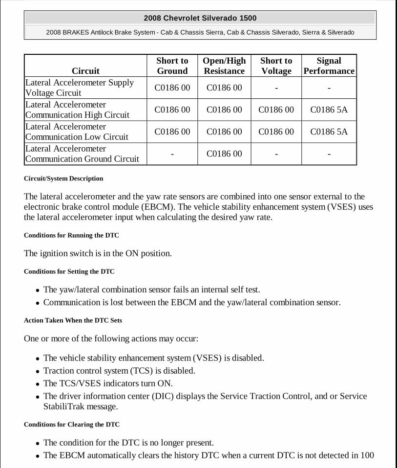
Circuit/System Description
The lateral accelerometer and the yaw rate sensors are combined into one sensor external to the electronic brake control module (EBCM). The vehicle stability enhancement system (VSES) uses the lateral accelerometer input when calculating the desired yaw rate.
Conditions for Running the DTC
The ignition switch is in the ON position.
Conditions for Setting the DTC
� The yaw/lateral combination sensor fails an internal self test. � Communication is lost between the EBCM and the yaw/lateral combination sensor.
Action Taken When the DTC Sets
One or more of the following actions may occur:
� The vehicle stability enhancement system (VSES) is disabled. � Traction control system (TCS) is disabled. � The TCS/VSES indicators turn ON. � The driver information center (DIC) displays the Service Traction Control, and or Service
StabiliTrak message.
Conditions for Clearing the DTC
� The condition for the DTC is no longer present. � The EBCM automatically clears the history DTC when a current DTC is not detected in 100
CircuitShort to Ground
Open/High Resistance
Short to Voltage
Signal Performance
Lateral Accelerometer Supply Voltage Circuit
C0186 00 C0186 00 - -
Lateral Accelerometer Communication High Circuit
C0186 00 C0186 00 C0186 00 C0186 5A
Lateral Accelerometer Communication Low Circuit
C0186 00 C0186 00 C0186 00 C0186 5A
Lateral Accelerometer Communication Ground Circuit
- C0186 00 - -
2008 Chevrolet Silverado 1500
2008 BRAKES Antilock Brake System - Cab & Chassis Sierra, Cab & Chassis Silverado, Sierra & Silverado
MY
Wednesday, April 08, 2009 12:33:42 PM Page 38 © 2005 Mitchell Repair Information Company, LLC.
consecutive drive cycles.
Reference Information
Schematic Reference
Antilock Brake System Schematics
Connector End View Reference
Component Connector End Views
Description and Operation
ABS Description and Operation (With JL4) or ABS Description and Operation (Without JL4)
Electrical Information Reference
� Circuit Testing
� Connector Repairs � Testing for Intermittent Conditions and Poor Connections � Wiring Repairs
Scan Tool Reference
Control Module References for Scan Tool Information
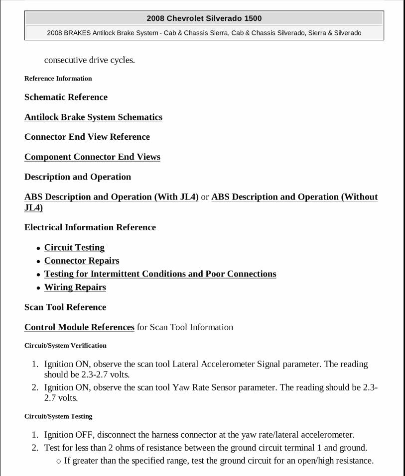
Circuit/System Verification
1. Ignition ON, observe the scan tool Lateral Accelerometer Signal parameter. The reading should be 2.3-2.7 volts.
2. Ignition ON, observe the scan tool Yaw Rate Sensor parameter. The reading should be 2.3-2.7 volts.
Circuit/System Testing
1. Ignition OFF, disconnect the harness connector at the yaw rate/lateral accelerometer. 2. Test for less than 2 ohms of resistance between the ground circuit terminal 1 and ground.
� If greater than the specified range, test the ground circuit for an open/high resistance.
2008 Chevrolet Silverado 1500
2008 BRAKES Antilock Brake System - Cab & Chassis Sierra, Cab & Chassis Silverado, Sierra & Silverado
MY
Wednesday, April 08, 2009 12:33:42 PM Page 39 © 2005 Mitchell Repair Information Company, LLC.
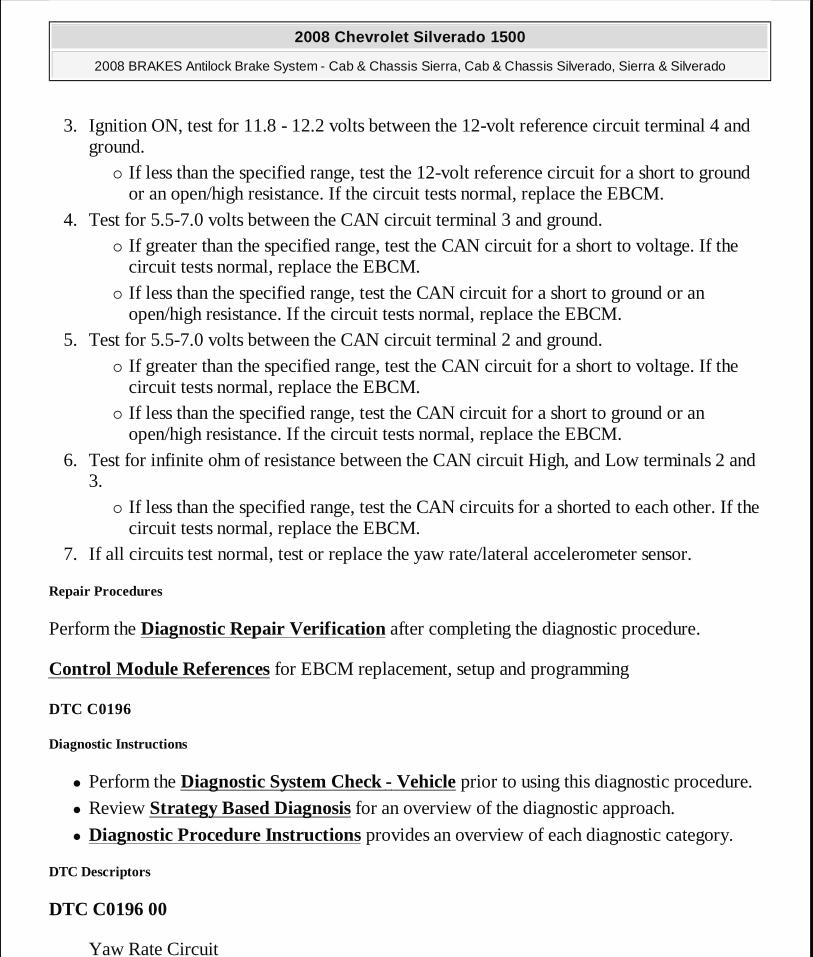
3. Ignition ON, test for 11.8 - 12.2 volts between the 12-volt reference circuit terminal 4 and ground.
� If less than the specified range, test the 12-volt reference circuit for a short to ground or an open/high resistance. If the circuit tests normal, replace the EBCM.
4. Test for 5.5-7.0 volts between the CAN circuit terminal 3 and ground. � If greater than the specified range, test the CAN circuit for a short to voltage. If the
circuit tests normal, replace the EBCM. � If less than the specified range, test the CAN circuit for a short to ground or an
open/high resistance. If the circuit tests normal, replace the EBCM. 5. Test for 5.5-7.0 volts between the CAN circuit terminal 2 and ground.
� If greater than the specified range, test the CAN circuit for a short to voltage. If the circuit tests normal, replace the EBCM.
� If less than the specified range, test the CAN circuit for a short to ground or an open/high resistance. If the circuit tests normal, replace the EBCM.
6. Test for infinite ohm of resistance between the CAN circuit High, and Low terminals 2 and 3.
� If less than the specified range, test the CAN circuits for a shorted to each other. If the circuit tests normal, replace the EBCM.
7. If all circuits test normal, test or replace the yaw rate/lateral accelerometer sensor.
Repair Procedures
Perform the Diagnostic Repair Verification after completing the diagnostic procedure.
Control Module References for EBCM replacement, setup and programming
DTC C0196
Diagnostic Instructions
� Perform the Diagnostic System Check - Vehicle prior to using this diagnostic procedure.
� Review Strategy Based Diagnosis for an overview of the diagnostic approach.
� Diagnostic Procedure Instructions provides an overview of each diagnostic category.
DTC Descriptors
DTC C0196 00
Yaw Rate Circuit
2008 Chevrolet Silverado 1500
2008 BRAKES Antilock Brake System - Cab & Chassis Sierra, Cab & Chassis Silverado, Sierra & Silverado
MY
Wednesday, April 08, 2009 12:33:42 PM Page 40 © 2005 Mitchell Repair Information Company, LLC.
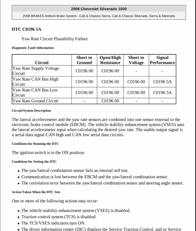
DTC C0196 5A
Yaw Rate Circuit Plausibility Failure
Diagnostic Fault Information
Circuit/System Description
The lateral accelerometer and the yaw rate sensors are combined into one sensor external to the electronic brake control module (EBCM). The vehicle stability enhancement system (VSES) uses the lateral accelerometer input when calculating the desired yaw rate. The usable output signal is a serial data signal CAN high and CAN low serial data circuits.
Conditions for Running the DTC
The ignition switch is in the ON position.
Conditions for Setting the DTC
� The yaw/lateral combination sensor fails an internal self test. � Communication is lost between the EBCM and the yaw/lateral combination sensor. � The correlation error between the yaw/lateral combination sensor and steering angle sensor.
Action Taken When the DTC Sets
One or more of the following actions may occur:
� The vehicle stability enhancement system (VSES) is disabled. � Traction control system (TCS) is disabled. � The TCS/VSES indicators turn ON. � The driver information center (DIC) displays the Service Traction Control, and or Service
CircuitShort to Ground
Open/High Resistance
Short to Voltage
Signal Performance
Yaw Rate Supply Voltage Circuit
C0196 00 C0196 00 - -
Yaw Rate CAN Bus High Circuit
C0196 00 C0196 00 C0196 00 C0196 5A
Yaw Rate CAN Bus Low Circuit
C0196 00 C0196 00 C0196 00 C0196 5A
Yaw Rate Ground Circuit - C0196 00 - -
2008 Chevrolet Silverado 1500
2008 BRAKES Antilock Brake System - Cab & Chassis Sierra, Cab & Chassis Silverado, Sierra & Silverado
MY
Wednesday, April 08, 2009 12:33:42 PM Page 41 © 2005 Mitchell Repair Information Company, LLC.

StabiliTrak message.
Conditions for Clearing the DTC
� The condition for the DTC is no longer present. � The EBCM automatically clears the history DTC when a current DTC is not detected in 100
consecutive drive cycles.
Diagnostic Aids
Possible causes of this DTC are as follows:
� CAN HI and CAN LO circuits shorted together � CAN HI or CAN LO circuit shorted to ground � CAN HI or CAN LO circuit shorted to voltage
Reference Information
Schematic Reference
Antilock Brake System Schematics
Connector End View Reference
Component Connector End Views
Description and Operation
ABS Description and Operation (With JL4) or ABS Description and Operation (Without JL4)
Electrical Information Reference
� Circuit Testing
� Connector Repairs � Testing for Intermittent Conditions and Poor Connections � Wiring Repairs
Scan Tool Reference
Control Module References for Scan Tool Information
2008 Chevrolet Silverado 1500
2008 BRAKES Antilock Brake System - Cab & Chassis Sierra, Cab & Chassis Silverado, Sierra & Silverado
MY
Wednesday, April 08, 2009 12:33:42 PM Page 42 © 2005 Mitchell Repair Information Company, LLC.

Circuit/System Verification
1. Ignition ON, observe the scan tool Lateral Accelerometer Signal parameter. The reading should be 2.3-2.7 volts.
2. Ignition ON, observe the scan tool Yaw Rate Sensor parameter. The reading should be 2.3-2.7 volts.
Circuit/System Testing
1. Ignition OFF, disconnect the harness connector at the yaw rate/lateral accelerometer. 2. Test for less than 2 ohms of resistance between the ground circuit terminal 1 and ground.
� If greater than the specified range, test the ground circuit for an open/high resistance. 3. Ignition ON, test for 11.8 - 12.2 volts between the 12-volt reference circuit terminal 4 and
ground. � If less than the specified range, test the 12-volt reference circuit for a short to ground
or an open/high resistance. If the circuit tests normal, replace the EBCM. 4. Test for 5.5-7.0 volts between the CAN circuit terminal 3 and ground.
� If greater than the specified range, test the CAN circuit for a short to voltage. If the circuit tests normal, replace the EBCM.
� If less than the specified range, test the CAN circuit for a short to ground or an open/high resistance. If the circuit tests normal, replace the EBCM.
5. Test for 5.5-7.0 volts between the CAN circuit terminal 2 and ground. � If greater than the specified range, test the CAN circuit for a short to voltage. If the
circuit tests normal, replace the EBCM. � If less than the specified range, test the CAN circuit for a short to ground or an
open/high resistance. If the circuit tests normal, replace the EBCM. 6. Test for infinite ohm of resistance between the CAN circuit High, and Low terminals 2 and
3. � If less than the specified range, test the CAN circuits for a shorted to each other. If the
circuit tests normal, replace the EBCM. 7. If all circuits test normal, test or replace the yaw rate/lateral accelerometer sensor.
Repair Procedures
Perform the Diagnostic Repair Verification after completing the diagnostic procedure.
Control Module References for EBCM replacement, setup and programming
2008 Chevrolet Silverado 1500
2008 BRAKES Antilock Brake System - Cab & Chassis Sierra, Cab & Chassis Silverado, Sierra & Silverado
MY
Wednesday, April 08, 2009 12:33:42 PM Page 43 © 2005 Mitchell Repair Information Company, LLC.
DTC C0201
Diagnostic Instructions
� Perform the Diagnostic System Check - Vehicle prior to using this diagnostic procedure.
� Review Strategy Based Diagnosis for an overview of the diagnostic approach.
� Diagnostic Procedure Instructions provides an overview of each diagnostic category.
DTC Descriptor
DTC C0201 00
Antilock Brake System (ABS) Enable Relay Contact Circuit
DTC C0201 04
Antilock Brake System (ABS) Enable Relay Contact Circuit Open
DTC C0201 0E
Antilock Brake System (ABS) Enable Relay Contact Circuit Resistance Below Threshold
Circuit/System Description
The solenoid relay, located within the electronic brake control module (EBCM), supplies battery voltage to all of the valve solenoids.
Conditions for Running the DTC
� Ignition voltage is greater than 9.5 volts. � The solenoid relay is commanded ON.
Conditions for Setting the DTC
One or more of the following conditions exists:
� The EBCM detects an open in the battery positive voltage circuit to the solenoid valve relay.
� The EBCM detects a stuck open solenoid valve relay or an open circuit between the solenoid valve relay and solenoid valves.
Action Taken When the DTC Sets
2008 Chevrolet Silverado 1500
2008 BRAKES Antilock Brake System - Cab & Chassis Sierra, Cab & Chassis Silverado, Sierra & Silverado
MY
Wednesday, April 08, 2009 12:33:42 PM Page 44 © 2005 Mitchell Repair Information Company, LLC.

� The EBCM disables the antilock brake system (ABS)/traction control system (TCS)/dynamic rear proportion (DRP) for the duration of the ignition cycle.
� The ABS indicator turns ON. � The Traction Control indicator turns ON. � The red brake warning indicator turns ON. � The driver information center (DIC) displays the SERVICE BRAKE
SYSTEM/TRACTION SYSTEM message.
Conditions for Clearing the DTC
� The condition for setting the DTC is no longer present. � The EBCM automatically clears the history DTC when a current DTC is not detected in 100
consecutive drive cycles.
Reference Information
Schematic Reference
Antilock Brake System Schematics
Connector End View Reference
Component Connector End Views
Description and Operation
ABS Description and Operation (With JL4) or ABS Description and Operation (Without JL4)
Electrical Information Reference
� Circuit Testing
� Connector Repairs � Testing for Intermittent Conditions and Poor Connections � Wiring Repairs
Scan Tool Reference
Control Module References for Scan Tool Information
2008 Chevrolet Silverado 1500
2008 BRAKES Antilock Brake System - Cab & Chassis Sierra, Cab & Chassis Silverado, Sierra & Silverado
MY
Wednesday, April 08, 2009 12:33:42 PM Page 45 © 2005 Mitchell Repair Information Company, LLC.
Circuit/System Verification
Ignition ON, observe the scan tool EBCM Battery Voltage Signal parameter. The reading should be battery voltage.
Circuit/System Testing
1. Ignition OFF, disconnect the harness connector at the EBCM. 2. Test for less than 2 ohm of resistance between the ground terminals 38 and 12 to ground.
� If greater than the specified range, test the ground circuits for an open/high resistance. 3. Verify that a test lamp illuminates between the B+ terminals 25 and 13 and ground.
� If the test lamp does not illuminate, test the B+ circuits for a short to ground or an open/high resistance.
4. If all circuits test normal, replace the EBCM.
Repair Procedures
Perform the Diagnostic Repair Verification after completing the diagnostic procedure.
Control Module References for EBCM replacement, setup, and programming
DTC C0242
Diagnostic Instructions
� Perform the Diagnostic System Check - Vehicle prior to using this diagnostic procedure.
� Review Strategy Based Diagnosis for an overview of the diagnostic approach.
� Diagnostic Procedure Instructions provides an overview of each diagnostic category.
DTC Descriptor
DTC C0242 00
Engine Control Module (ECM) Indicated TCS Malfunction
DTC P0856
Engine Control Module (ECM) Indicated TCS Malfunction
Circuit/System Description
The electronic brake control module (EBCM) and the engine control module (ECM)
2008 Chevrolet Silverado 1500
2008 BRAKES Antilock Brake System - Cab & Chassis Sierra, Cab & Chassis Silverado, Sierra & Silverado
MY
Wednesday, April 08, 2009 12:33:42 PM Page 46 © 2005 Mitchell Repair Information Company, LLC.

simultaneously control the traction control. The EBCM sends a serial data message to the ECM requesting torque reduction. When certain ECM DTCs are set, the ECM will not be able to perform the torque reduction for traction control. A serial data message is sent to the EBCM indicating that traction control is not allowed.
Conditions for Running the DTC
� The ignition is ON. � Ignition voltage is greater than 8 volts.
Conditions for Setting the DTC
The ECM diagnoses a condition preventing the engine control portion of the traction control function and sends a serial data message to the EBCM indicating that torque reduction is not allowed. The ECM will typically set a DTC and the EBCM will set this DTC.
Action Taken When the DTC Sets
� The EBCM disables the TCS for the duration of the ignition cycle. � The Traction Off indicator turns ON. � The DIC displays the Service Traction Control message. � The ABS remains functional.
Conditions for Clearing the DTC
� The condition for the DTC is no longer present and the DTC is cleared with a scan tool. � The electronic brake control module (EBCM) automatically clears the history DTC when a
current DTC is not detected in 100 consecutive drive cycles.
Reference Information
Schematic Reference
Antilock Brake System Schematics
Connector End View Reference
Component Connector End Views
Description and Operation
ABS Description and Operation (With JL4) or ABS Description and Operation (Without
2008 Chevrolet Silverado 1500
2008 BRAKES Antilock Brake System - Cab & Chassis Sierra, Cab & Chassis Silverado, Sierra & Silverado
MY
Wednesday, April 08, 2009 12:33:42 PM Page 47 © 2005 Mitchell Repair Information Company, LLC.

JL4)
Electrical Information Reference
� Circuit Testing
� Connector Repairs � Testing for Intermittent Conditions and Poor Connections � Wiring Repairs
Scan Tool Reference
Control Module References for Scan Tool Information
Circuit/System Verification
Verify that no DTCs are set in the ECM.
� If DTCs are set, refer to Symptoms - Engine Controls .
Repair Procedures
Perform the Diagnostic Repair Verification after completing the diagnostic procedure.
Control Module References
DTC C0245
Diagnostic Instructions
� Perform the Diagnostic System Check - Vehicle prior to using this diagnostic procedure.
� Review Strategy Based Diagnosis for an overview of the diagnostic approach.
� Diagnostic Procedure Instructions provides an overview of each diagnostic category.
DTC Descriptor
DTC C0245 00
Wheel Speed Sensor Frequency Error
DTC C0245 5A
Wheel Speed Sensor Plausibility Failure
2008 Chevrolet Silverado 1500
2008 BRAKES Antilock Brake System - Cab & Chassis Sierra, Cab & Chassis Silverado, Sierra & Silverado
MY
Wednesday, April 08, 2009 12:33:42 PM Page 48 © 2005 Mitchell Repair Information Company, LLC.
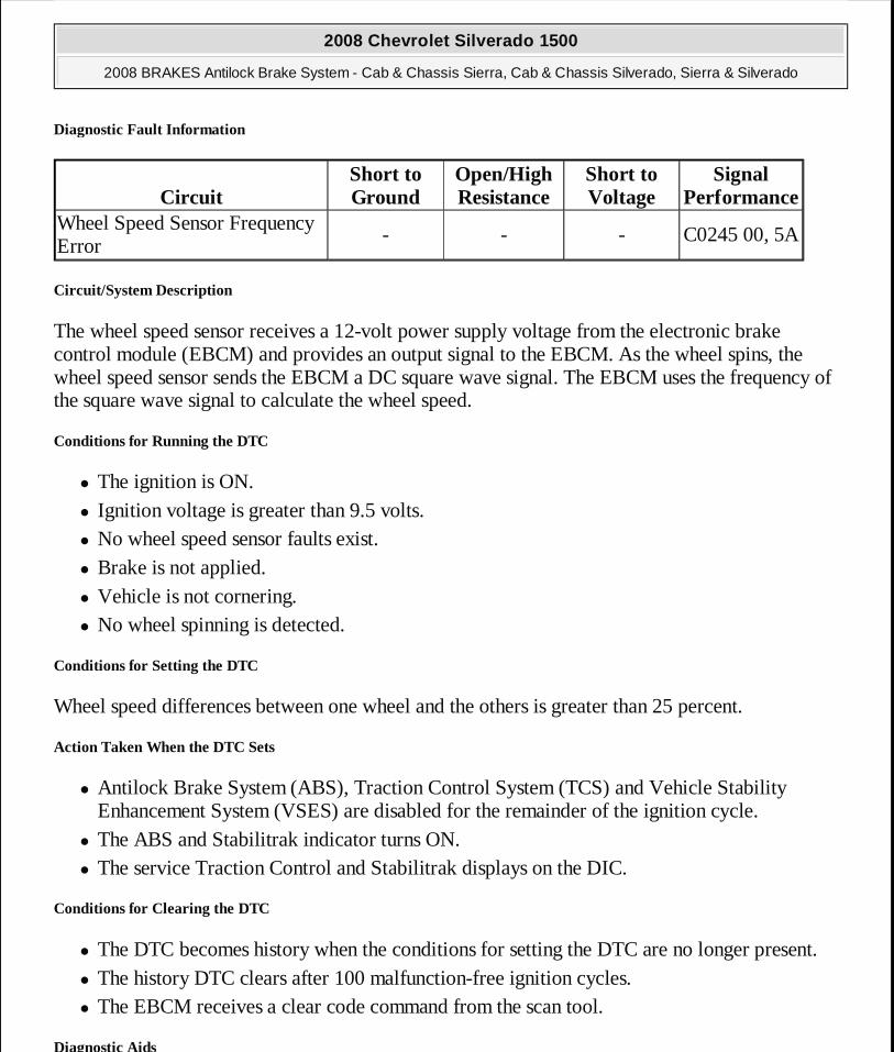
Diagnostic Fault Information
Circuit/System Description
The wheel speed sensor receives a 12-volt power supply voltage from the electronic brake control module (EBCM) and provides an output signal to the EBCM. As the wheel spins, the wheel speed sensor sends the EBCM a DC square wave signal. The EBCM uses the frequency of the square wave signal to calculate the wheel speed.
Conditions for Running the DTC
� The ignition is ON. � Ignition voltage is greater than 9.5 volts. � No wheel speed sensor faults exist. � Brake is not applied. � Vehicle is not cornering. � No wheel spinning is detected.
Conditions for Setting the DTC
Wheel speed differences between one wheel and the others is greater than 25 percent.
Action Taken When the DTC Sets
� Antilock Brake System (ABS), Traction Control System (TCS) and Vehicle Stability Enhancement System (VSES) are disabled for the remainder of the ignition cycle.
� The ABS and Stabilitrak indicator turns ON. � The service Traction Control and Stabilitrak displays on the DIC.
Conditions for Clearing the DTC
� The DTC becomes history when the conditions for setting the DTC are no longer present. � The history DTC clears after 100 malfunction-free ignition cycles. � The EBCM receives a clear code command from the scan tool.
Diagnostic Aids
CircuitShort to Ground
Open/High Resistance
Short to Voltage
Signal Performance
Wheel Speed Sensor Frequency Error
- - - C0245 00, 5A
2008 Chevrolet Silverado 1500
2008 BRAKES Antilock Brake System - Cab & Chassis Sierra, Cab & Chassis Silverado, Sierra & Silverado
MY
Wednesday, April 08, 2009 12:33:42 PM Page 49 © 2005 Mitchell Repair Information Company, LLC.
� Faulty wheel speed sensor will not set this DTC. � A vehicle using a space saver spare will not set this code.
Reference Information
Schematic Reference
Antilock Brake System Schematics
Connector End View Reference
Component Connector End Views
Description and Operation
ABS Description and Operation (With JL4) or ABS Description and Operation (Without JL4)
Electrical Information Reference
� Circuit Testing
� Connector Repairs � Testing for Intermittent Conditions and Poor Connections � Wiring Repairs
Scan Tool Reference
Control Module References for Scan Tool Information
Circuit/System Verification
Inspect for one tire that has improper air pressure or improper size.
Repair Procedures
Perform the Diagnostic Repair Verification after completing the diagnostic procedure.
DTC C0252
Diagnostic Instructions
� Perform the Diagnostic System Check - Vehicle prior to using this diagnostic procedure.
2008 Chevrolet Silverado 1500
2008 BRAKES Antilock Brake System - Cab & Chassis Sierra, Cab & Chassis Silverado, Sierra & Silverado
MY
Wednesday, April 08, 2009 12:33:42 PM Page 50 © 2005 Mitchell Repair Information Company, LLC.
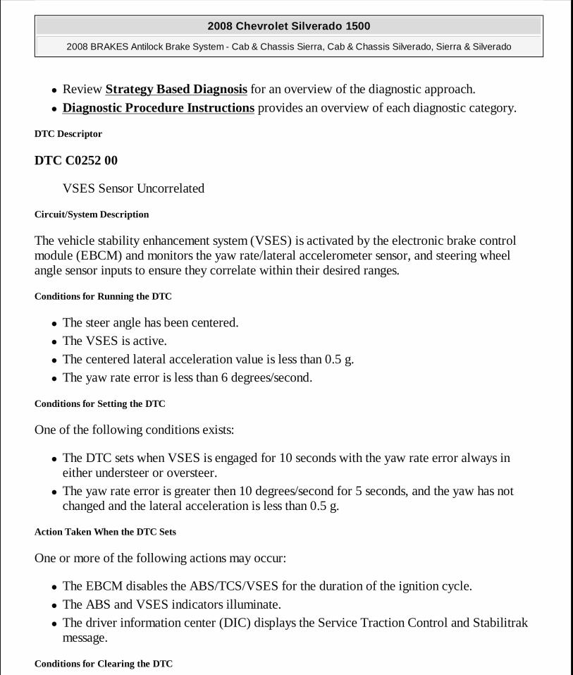
� Review Strategy Based Diagnosis for an overview of the diagnostic approach.
� Diagnostic Procedure Instructions provides an overview of each diagnostic category.
DTC Descriptor
DTC C0252 00
VSES Sensor Uncorrelated
Circuit/System Description
The vehicle stability enhancement system (VSES) is activated by the electronic brake control module (EBCM) and monitors the yaw rate/lateral accelerometer sensor, and steering wheel angle sensor inputs to ensure they correlate within their desired ranges.
Conditions for Running the DTC
� The steer angle has been centered. � The VSES is active. � The centered lateral acceleration value is less than 0.5 g. � The yaw rate error is less than 6 degrees/second.
Conditions for Setting the DTC
One of the following conditions exists:
� The DTC sets when VSES is engaged for 10 seconds with the yaw rate error always in either understeer or oversteer.
� The yaw rate error is greater then 10 degrees/second for 5 seconds, and the yaw has not changed and the lateral acceleration is less than 0.5 g.
Action Taken When the DTC Sets
One or more of the following actions may occur:
� The EBCM disables the ABS/TCS/VSES for the duration of the ignition cycle. � The ABS and VSES indicators illuminate. � The driver information center (DIC) displays the Service Traction Control and Stabilitrak
message.
Conditions for Clearing the DTC
2008 Chevrolet Silverado 1500
2008 BRAKES Antilock Brake System - Cab & Chassis Sierra, Cab & Chassis Silverado, Sierra & Silverado
MY
Wednesday, April 08, 2009 12:33:42 PM Page 51 © 2005 Mitchell Repair Information Company, LLC.
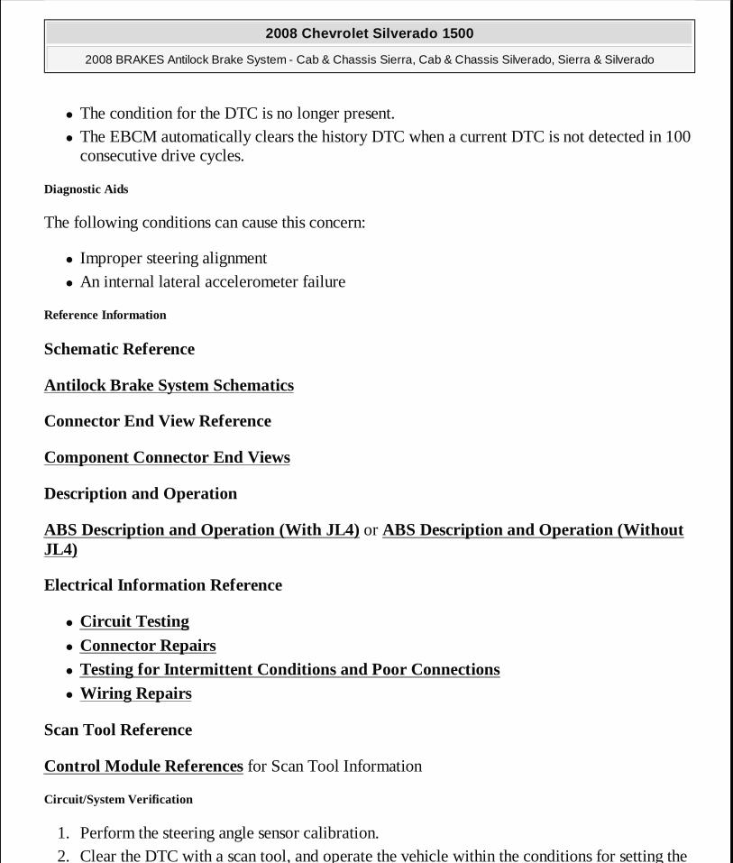
� The condition for the DTC is no longer present. � The EBCM automatically clears the history DTC when a current DTC is not detected in 100
consecutive drive cycles.
Diagnostic Aids
The following conditions can cause this concern:
� Improper steering alignment � An internal lateral accelerometer failure
Reference Information
Schematic Reference
Antilock Brake System Schematics
Connector End View Reference
Component Connector End Views
Description and Operation
ABS Description and Operation (With JL4) or ABS Description and Operation (Without JL4)
Electrical Information Reference
� Circuit Testing
� Connector Repairs � Testing for Intermittent Conditions and Poor Connections � Wiring Repairs
Scan Tool Reference
Control Module References for Scan Tool Information
Circuit/System Verification
1. Perform the steering angle sensor calibration. 2. Clear the DTC with a scan tool, and operate the vehicle within the conditions for setting the
2008 Chevrolet Silverado 1500
2008 BRAKES Antilock Brake System - Cab & Chassis Sierra, Cab & Chassis Silverado, Sierra & Silverado
MY
Wednesday, April 08, 2009 12:33:42 PM Page 52 © 2005 Mitchell Repair Information Company, LLC.
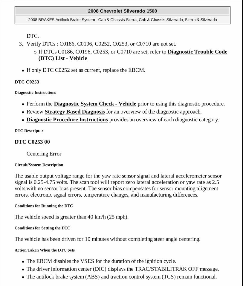
DTC. 3. Verify DTCs : C0186, C0196, C0252, C0253, or C0710 are not set.
� If DTCs C0186, C0196, C0253, or C0710 are set, refer to Diagnostic Trouble Code (DTC) List - Vehicle
� If only DTC C0252 set as current, replace the EBCM.
DTC C0253
Diagnostic Instructions
� Perform the Diagnostic System Check - Vehicle prior to using this diagnostic procedure.
� Review Strategy Based Diagnosis for an overview of the diagnostic approach.
� Diagnostic Procedure Instructions provides an overview of each diagnostic category.
DTC Descriptor
DTC C0253 00
Centering Error
Circuit/System Description
The usable output voltage range for the yaw rate sensor signal and lateral accelerometer sensor signal is 0.25-4.75 volts. The scan tool will report zero lateral acceleration or yaw rate as 2.5 volts with no sensor bias present. The sensor bias compensates for sensor mounting alignment errors, electronic signal errors, temperature changes, and manufacturing differences.
Conditions for Running the DTC
The vehicle speed is greater than 40 km/h (25 mph).
Conditions for Setting the DTC
The vehicle has been driven for 10 minutes without completing steer angle centering.
Action Taken When the DTC Sets
� The EBCM disables the VSES for the duration of the ignition cycle. � The driver information center (DIC) displays the TRAC/STABILITRAK OFF message. � The antilock brake system (ABS) and traction control system (TCS) remain functional.
2008 Chevrolet Silverado 1500
2008 BRAKES Antilock Brake System - Cab & Chassis Sierra, Cab & Chassis Silverado, Sierra & Silverado
MY
Wednesday, April 08, 2009 12:33:42 PM Page 53 © 2005 Mitchell Repair Information Company, LLC.

Conditions for Clearing the DTC
� The condition for the DTC is no longer present. � The EBCM automatically clears the history DTC when a current DTC is not detected in 100
consecutive drive cycles.
Diagnostic Aids
The following conditions can cause this concern:
� Improper steering alignment. � Internal yaw and lateral acceleration sensor failure. � EBCM internal failure.
Reference Information
Schematic Reference
Antilock Brake System Schematics
Connector End View Reference
Component Connector End Views
Description and Operation
ABS Description and Operation (With JL4) or ABS Description and Operation (Without JL4)
Electrical Information Reference
� Circuit Testing
� Connector Repairs � Testing for Intermittent Conditions and Poor Connections � Wiring Repairs
Scan Tool Reference
Control Module References for Scan Tool Information
Circuit/System Verification
2008 Chevrolet Silverado 1500
2008 BRAKES Antilock Brake System - Cab & Chassis Sierra, Cab & Chassis Silverado, Sierra & Silverado
MY
Wednesday, April 08, 2009 12:33:42 PM Page 54 © 2005 Mitchell Repair Information Company, LLC.

1. With the scan tool perform the Steering Angle Sensor Calibration. 2. Operate the vehicle within the conditions for setting the DTC. Verify DTC C0186, C0196,
C0253, or C0710 are not set.
� If DTC C0186, C0196, or C0710 are set, refer to Diagnostic Trouble Code (DTC) List - Vehicle .
� If only DTC C0253 set, replace the yaw and lateral acceleration sensor. If DTC C0253 sets again, replace the EBCM.
Repair Procedures
Perform the Diagnostic Repair Verification after completing the diagnostic procedure.
� Vehicle Yaw Sensor with Vehicle Lateral Accelerometer Replacement � Control Module References for EBCM replacement, setup, and programming
DTC C0299
Diagnostic Instructions
� Perform the Diagnostic System Check - Vehicle prior to using this diagnostic procedure.
� Review Strategy Based Diagnosis for an overview of the diagnostic approach.
� Diagnostic Procedure Instructions provides an overview of each diagnostic category.
DTC Descriptor
DTC C0299 00
Brake Booster Sensor Performance
DTC C0299 5A
Brake Booster Sensor Plausibility Failure
DTC C0299 31
Brake Booster General Checksum Failure
Diagnostic Fault Information
Short to Open/High Short to Signal
2008 Chevrolet Silverado 1500
2008 BRAKES Antilock Brake System - Cab & Chassis Sierra, Cab & Chassis Silverado, Sierra & Silverado
MY
Wednesday, April 08, 2009 12:33:42 PM Page 55 © 2005 Mitchell Repair Information Company, LLC.
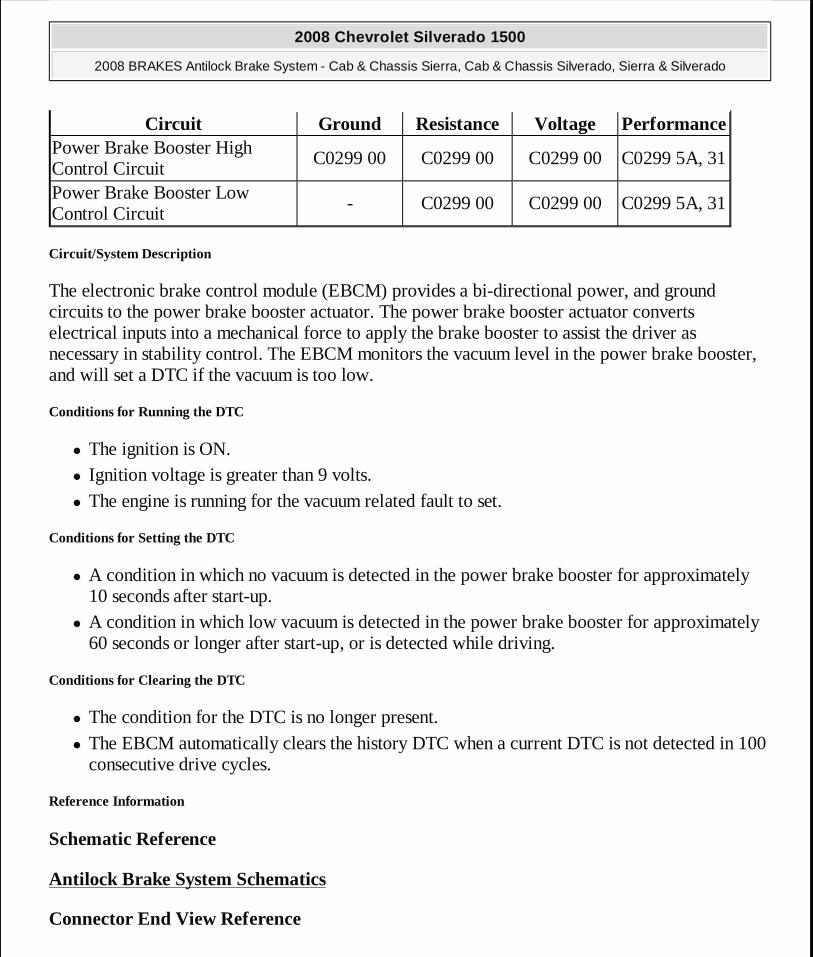
Circuit/System Description
The electronic brake control module (EBCM) provides a bi-directional power, and ground circuits to the power brake booster actuator. The power brake booster actuator converts electrical inputs into a mechanical force to apply the brake booster to assist the driver as necessary in stability control. The EBCM monitors the vacuum level in the power brake booster, and will set a DTC if the vacuum is too low.
Conditions for Running the DTC
� The ignition is ON. � Ignition voltage is greater than 9 volts. � The engine is running for the vacuum related fault to set.
Conditions for Setting the DTC
� A condition in which no vacuum is detected in the power brake booster for approximately 10 seconds after start-up.
� A condition in which low vacuum is detected in the power brake booster for approximately 60 seconds or longer after start-up, or is detected while driving.
Conditions for Clearing the DTC
� The condition for the DTC is no longer present. � The EBCM automatically clears the history DTC when a current DTC is not detected in 100
consecutive drive cycles.
Reference Information
Schematic Reference
Antilock Brake System Schematics
Connector End View Reference
Circuit Ground Resistance Voltage PerformancePower Brake Booster High Control Circuit
C0299 00 C0299 00 C0299 00 C0299 5A, 31
Power Brake Booster Low Control Circuit
- C0299 00 C0299 00 C0299 5A, 31
2008 Chevrolet Silverado 1500
2008 BRAKES Antilock Brake System - Cab & Chassis Sierra, Cab & Chassis Silverado, Sierra & Silverado
MY
Wednesday, April 08, 2009 12:33:42 PM Page 56 © 2005 Mitchell Repair Information Company, LLC.

Component Connector End Views
Description and Operation
ABS Description and Operation (With JL4) or ABS Description and Operation (Without JL4)
Electrical Information Reference
� Circuit Testing
� Connector Repairs � Testing for Intermittent Conditions and Poor Connections � Wiring Repairs
Scan Tool Reference
Control Module References for Scan Tool Information
Circuit/System Verification
1. DTC C0299 will set as result of power brake booster actuator or circuit failure, test for power, and ground circuits to the EBCM. These electrical failures will typically be set immediately after key-up.
� Test and repair the EBCM power or ground circuits if necessary. 2. DTC C0299 will set as result of the power brake booster vacuum is too low. These will be
set approximately 10 seconds or more after start-up, and may be intermittent.
� Locate and repair the source of the vacuum leak. Refer to Brake System Vacuum Source Test .
Circuit/System Testing
1. Ignition OFF, disconnect the harness connector from the power brake booster actuator. 2. Test for less than 25.0 ohm of resistance between the harness connector terminal 5 and
ground. � If greater than 25.0 ohm, test the ground circuit for an open/high resistance.
IMPORTANT: It is recommend that Component Testing is performed before Circuit Testing when diagnosing the power brake boo ster actuator.
2008 Chevrolet Silverado 1500
2008 BRAKES Antilock Brake System - Cab & Chassis Sierra, Cab & Chassis Silverado, Sierra & Silverado
MY
Wednesday, April 08, 2009 12:33:42 PM Page 57 © 2005 Mitchell Repair Information Company, LLC.
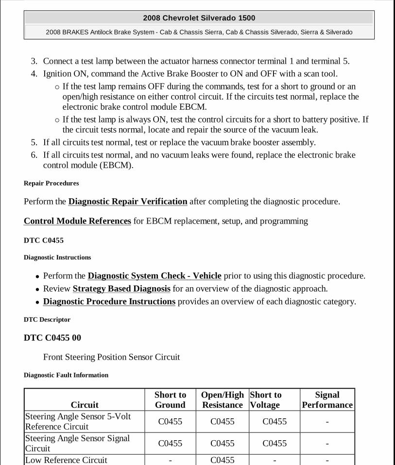
3. Connect a test lamp between the actuator harness connector terminal 1 and terminal 5. 4. Ignition ON, command the Active Brake Booster to ON and OFF with a scan tool.
� If the test lamp remains OFF during the commands, test for a short to ground or an open/high resistance on either control circuit. If the circuits test normal, replace the electronic brake control module EBCM.
� If the test lamp is always ON, test the control circuits for a short to battery positive. If the circuit tests normal, locate and repair the source of the vacuum leak.
5. If all circuits test normal, test or replace the vacuum brake booster assembly. 6. If all circuits test normal, and no vacuum leaks were found, replace the electronic brake
control module (EBCM).
Repair Procedures
Perform the Diagnostic Repair Verification after completing the diagnostic procedure.
Control Module References for EBCM replacement, setup, and programming
DTC C0455
Diagnostic Instructions
� Perform the Diagnostic System Check - Vehicle prior to using this diagnostic procedure.
� Review Strategy Based Diagnosis for an overview of the diagnostic approach.
� Diagnostic Procedure Instructions provides an overview of each diagnostic category.
DTC Descriptor
DTC C0455 00
Front Steering Position Sensor Circuit
Diagnostic Fault Information
CircuitShort to Ground
Open/High Resistance
Short to Voltage
Signal Performance
Steering Angle Sensor 5-Volt Reference Circuit
C0455 C0455 C0455 -
Steering Angle Sensor Signal Circuit
C0455 C0455 C0455 -
Low Reference Circuit - C0455 - -
2008 Chevrolet Silverado 1500
2008 BRAKES Antilock Brake System - Cab & Chassis Sierra, Cab & Chassis Silverado, Sierra & Silverado
MY
Wednesday, April 08, 2009 12:33:42 PM Page 58 © 2005 Mitchell Repair Information Company, LLC.
Circuit/System Description
The steering angle sensor supplies input circuits to the electronic brake control module (EBCM) from the Phase A and Phase B, the Index Pulse Phase C circuits, and 1 Analog signal circuit for steering wheel angle. The analog signal is used along with the index pulse to calibrate the steering angle sensor (SAS). The SAS position is then determined by Phase A and Phase B signals. The 2 input signals Phase A and Phase B are approximately 90 degrees out of phase. Once calibrated, the EBCM dynamically interprets the relationship between the Phase A and Phase B inputs, and determines the position of the steering wheel and the direction of the steering wheel rotation.
Conditions for Running the DTC
� The ignition is ON. � Ignition voltage is greater than 9.5 volts.
Conditions for Setting the DTC
� Opens, short to ground, or voltage on the analog signal circuits. � The calculated steering angle from the steering angle sensor does not correlate with the
steering angle calculated from the yaw rate.
Action Taken When the DTC Sets
� The EBCM disables the Vehicle Stability Enhancement System (VSES) for the duration of the ignition cycle.
� The driver information center (DIC) displays the Service Stability System message. � The Antilock Brake System (ABS) remains functional. � The VSES Caution indicator turns ON.
Conditions for Clearing the DTC
� The condition for the DTC is no longer present. � The EBCM automatically clears the history DTC when a current DTC is not detected in 100
consecutive drive cycles.
Diagnostic Aids
� During diagnosis, park the vehicle on a level surface. � Inspect the vehicle for proper alignment. The vehicle should not pull in either direction
while driving straight on a level surface. � Find out from the customer the conditions under which the DTC was set. This information
2008 Chevrolet Silverado 1500
2008 BRAKES Antilock Brake System - Cab & Chassis Sierra, Cab & Chassis Silverado, Sierra & Silverado
MY
Wednesday, April 08, 2009 12:33:42 PM Page 59 © 2005 Mitchell Repair Information Company, LLC.
will help to duplicate the failure. � The snapshot function on the scan tool can help find an intermittent DTC.
Reference Information
Schematic Reference
Antilock Brake System Schematics
Connector End View Reference
Component Connector End Views
Description and Operation
ABS Description and Operation (With JL4) or ABS Description and Operation (Without JL4)
Electrical Information Reference
� Circuit Testing
� Connector Repairs � Testing for Intermittent Conditions and Poor Connections � Wiring Repairs
Scan Tool Reference
Control Module References for scan tool information.
Circuit/System Verification
With scan tool installed, clear the DTCs. Turn the steering wheel through its full range and back to straight ahead to center SAS. Using a scan tool, observe the Steering Wheel position parameter changes smoothly while turning steering wheel through the entire range. Correlate zero reading with wheels in the straight ahead position. Drive the vehicle through a variety of maneuvers turning to the left, and to the right and straight at a speed greater than 20 km/h (13 mph).
� If the DTC did not set as a current DTC see diagnostic aids.
Circuit/System Testing
2008 Chevrolet Silverado 1500
2008 BRAKES Antilock Brake System - Cab & Chassis Sierra, Cab & Chassis Silverado, Sierra & Silverado
MY
Wednesday, April 08, 2009 12:33:42 PM Page 60 © 2005 Mitchell Repair Information Company, LLC.
1. Ignition OFF, disconnect the harness connector at the SAS. 2. Test for less than 2.0 ohm of resistance between the low reference circuit terminal 2 and
ground. � If greater than the specified range, test the low reference circuit for an open/high
resistance. If the circuit tests normal, replace the EBCM. 3. Ignition ON, test for 4.8-5.2 volts between the 5-volt reference circuit terminal 1 and
ground. � If less than the specified range, test the 5-volt reference circuit for a short to ground or
an open/high resistance. If the circuit tests normal, replace the EBCM. 4. Test for 4.8-5.2 volts between the 5-volt reference circuit terminal 1 and the signal circuit
terminal 6. � If less than the specified range, test the signal circuit for an open/high resistance. If the
circuit tests normal, replace the EBCM. 5. Ignition OFF, reconnect the SAS. 6. Disconnect the EBCM harness connector. 7. Test for infinite resistance between the signal circuit pin 6 and ground.
� If less than the specified range, test the signal circuit for a short to ground. 8. Disconnect the SAS. 9. Reconnect the EBCM harness connector.
10. Ignition ON, test voltage of phase A phase B, and phase C. verify that the reading is battery positive voltage for each of the three phases.
� If not the specified value, test the phase A phase B, and phase C circuits for a short to ground or an open/high resistance. If the circuit tests normal, replace the EBCM.
11. Ignition OFF, reconnect the SAS. Turn the ignition ON. Using the scan tool, rotate the steering wheel and observe the SAS. Verify the sensor sweeps through the entire range while monitoring the steering wheel as it rotates in degrees from the input signals between circuit phase A and the signal circuit phase B. The rotation in degrees should vary between phase A and phase B without any spikes or dropouts.
� If not within the specified range or is erratic, replace the steering angle sensor. 12. If the sensor test normal, replace the EBCM.
Repair Procedures
Perform the Diagnostic Repair Verification after completing the diagnostic procedure.
� Electronic Brake Control Module Replacement (JH6, JH7) or Electronic Brake
2008 Chevrolet Silverado 1500
2008 BRAKES Antilock Brake System - Cab & Chassis Sierra, Cab & Chassis Silverado, Sierra & Silverado
MY
Wednesday, April 08, 2009 12:33:42 PM Page 61 © 2005 Mitchell Repair Information Company, LLC.
Control Module Replacement (JD9, JF3, JF7) � Control Module References for EBCM replacement, setup, and programming
DTC C0550
Diagnostic Instructions
� Perform the Diagnostic System Check - Vehicle prior to using this diagnostic procedure.
� Review Strategy Based Diagnosis for an overview of the diagnostic approach.
� Diagnostic Procedure Instructions provides an overview of each diagnostic category.
DTC Descriptor
DTC C0550 00
Electronic Control Unit (ECU) Performance
DTC C0550 01
Electronic Control Unit (ECU) Performance
DTC C0550 02
Electronic Control Unit (ECU) Performance
DTC C0550 03
Electronic Control Unit (ECU) Performance
DTC C0550 04
Electronic Control Unit (ECU) Performance
Circuit/System Description
The electronic brake control module (EBCM) detects an internal malfunction.
Conditions for Running the DTC
The ignition switch is in the ON position.
Conditions for Setting the DTC
2008 Chevrolet Silverado 1500
2008 BRAKES Antilock Brake System - Cab & Chassis Sierra, Cab & Chassis Silverado, Sierra & Silverado
MY
Wednesday, April 08, 2009 12:33:42 PM Page 62 © 2005 Mitchell Repair Information Company, LLC.
An internal EBCM malfunction exists.
Action Taken When the DTC Sets
One or more of the following actions may occur:
� The antilock brake system (ABS) and vehicle stability enhancement system (VSES) are disabled.
� TCS is degraded. � The ABS/TCS indicators turn ON. � The red BRAKE Warning indicator turns ON.
Conditions for Clearing the DTC
� The condition for the DTC is no longer present. � The EBCM automatically clears the history DTC when a current DTC is not detected in 100
consecutive drive cycles.
Reference Information
Schematic Reference
Antilock Brake System Schematics
Connector End View Reference
Component Connector End Views
Description and Operation
ABS Description and Operation (With JL4) or ABS Description and Operation (Without JL4)
Electrical Information Reference
� Circuit Testing
� Connector Repairs � Testing for Intermittent Conditions and Poor Connections � Wiring Repairs
Scan Tool Reference
2008 Chevrolet Silverado 1500
2008 BRAKES Antilock Brake System - Cab & Chassis Sierra, Cab & Chassis Silverado, Sierra & Silverado
MY
Wednesday, April 08, 2009 12:33:42 PM Page 63 © 2005 Mitchell Repair Information Company, LLC.
Control Module References for Scan Tool Information
Circuit/System Verification
1. Verify that DTC C0550 is not set. � If the DTC is set, clear the DTC with a scan tool, and operate the vehicle within the
conditions for setting the DTC. If the DTC reset, replace the EBCM.
Repair Procedures
Perform the Diagnostic Repair Verification after completing the diagnostic procedure.
Control Module References for EBCM replacement, setup, and programming
DTC C0561
Diagnostic Instructions
� Perform the Diagnostic System Check - Vehicle prior to using this diagnostic procedure.
� Review Strategy Based Diagnosis for an overview of the diagnostic approach.
� Diagnostic Procedure Instructions provides an overview of each diagnostic category.
DTC Descriptor
DTC C0561 71
System Disabled Information Stored Invalid Serial Data Received
DTC C0561 72
System Disabled Information Stored Alive Counter Incorrect or not Updated
DTC C0561 74
System Disabled Information Stored Value of Signal Protection Calculation Incorrect
Circuit/System Description
The electronic brake control module (EBCM) receives messages from other modules over GMLAN which are needed to perform antilock brake system (ABS), vehicle stability enhancement system (VSES), or traction control system (TCS) functions.
Conditions for Running the DTC
2008 Chevrolet Silverado 1500
2008 BRAKES Antilock Brake System - Cab & Chassis Sierra, Cab & Chassis Silverado, Sierra & Silverado
MY
Wednesday, April 08, 2009 12:33:43 PM Page 64 © 2005 Mitchell Repair Information Company, LLC.
� The ignition switch is in the ON position. � Ignition voltage is greater than 9.5 volts.
Conditions for Setting the DTC
The EBCM receives an invalid message from another module over GMLAN which causes EBCM to deactivate ABS, VSES, TCS, etc.
Action Taken When the DTC Sets
One or more of the following actions may occur:
� The EBCM disables the ABS/TCS/VSES for the duration of the ignition cycle. � The dynamic rear proportioning (DRP) may be disabled and the Brake Warning indicator
may turn ON. � The Stability Caution indicator turns ON. � The driver information center (DIC) displays the SERVICE STAB SYS message. � The DIC displays the TRACTION FAILED message.
Conditions for Clearing the DTC
� The condition for the DTC is no longer present. � The EBCM automatically clears the history DTC when a current DTC is not detected in 100
consecutive drive cycles.
Reference Information
Schematic Reference
Antilock Brake System Schematics
Connector End View Reference
Component Connector End Views
Description and Operation
ABS Description and Operation (With JL4) or ABS Description and Operation (Without JL4)
Electrical Information Reference
2008 Chevrolet Silverado 1500
2008 BRAKES Antilock Brake System - Cab & Chassis Sierra, Cab & Chassis Silverado, Sierra & Silverado
MY
Wednesday, April 08, 2009 12:33:43 PM Page 65 © 2005 Mitchell Repair Information Company, LLC.

� Circuit Testing
� Connector Repairs � Testing for Intermittent Conditions and Poor Connections � Wiring Repairs
Scan Tool Reference
Control Module References for Scan Tool Information
Circuit/System Verification
1. Perform the Diagnostic System Check Vehicle. Diagnose any other DTCs before attempting to diagnosis of C0561.
2. With a Tech 2, view the Invalid Signal Data Display. 3. If no invalid signal are present, view Signal Fault Data in the Enhanced DTC Data. 4. Refer to appropriate module for diagnosing the invalid message data. 5. Do not replace the EBCM due to this DTC fault.
Repair Verification
Perform the Diagnostic Repair Verification after completing the diagnostic procedure.
DTC C0569
Diagnostic Instructions
� Perform the Diagnostic System Check - Vehicle prior to using this diagnostic procedure.
� Review Strategy Based Diagnosis for an overview of the diagnostic approach.
� Diagnostic Procedure Instructions provides an overview of each diagnostic category.
DTC Descriptor
DTC C0569 00
System Configuration Error
Circuit/System Description
The electronic brake module (EBCM) receives a GMLAN message from each of the network modules. Each module contains its own unique identification (ID) code that must be learned into
2008 Chevrolet Silverado 1500
2008 BRAKES Antilock Brake System - Cab & Chassis Sierra, Cab & Chassis Silverado, Sierra & Silverado
MY
Wednesday, April 08, 2009 12:33:43 PM Page 66 © 2005 Mitchell Repair Information Company, LLC.

the EBCM memory. Once all the IDs have been learned and vehicle speed is 25 mph, or greater, the EBCM continuously compares IDs in the GMLAN message to its learned IDs to determine if all the network modules are present.
Conditions for Running the DTC
The ignition is ON.
Conditions for Setting the DTC
The EBCM has not undergone the programming procedure.
Action Taken When the DTC Sets
The driver information center (DIC) displays the SERVICE ABS warning message.
Conditions for Clearing the DTC
A current DTC will clear when the EBCM has undergone the setup procedure.
Diagnostic Aids
A newly replaced EBCM will set DTC C0569 on its initial ignition ON cycle.
Reference Information
Scan Tool Reference
Control Module References for Scan Tool Information
Circuit/System Verification
1. Verify that C0569 is not set as current.
� If the DTC is set, perform the EBCM setup procedure. Refer to Electronic Brake Control Module Programming and Setup If the DTC resets, replace the EBCM.
Repair Procedures
Perform the Diagnostic Repair Verification after completing the diagnostic procedure.
Control Module References for EBCM replacement, setup, and programming
DTC C0710
2008 Chevrolet Silverado 1500
2008 BRAKES Antilock Brake System - Cab & Chassis Sierra, Cab & Chassis Silverado, Sierra & Silverado
MY
Wednesday, April 08, 2009 12:33:43 PM Page 67 © 2005 Mitchell Repair Information Company, LLC.

Diagnostic Instructions
� Perform the Diagnostic System Check - Vehicle prior to using this diagnostic procedure.
� Review Strategy Based Diagnosis for an overview of the diagnostic approach.
� Diagnostic Procedure Instructions provides an overview of each diagnostic category.
DTC Descriptor
DTC C0710 00
Steering Position Signal
DTC C0710 5A
Steering Position Signal Plausibility Failure
Diagnostic Fault Information
Circuit/System Description
The steering angle sensor supplies input circuits to the electronic brake control module (EBCM) from the Phase A and Phase B, the Index Pulse Phase C circuits, and 1 Analog signal circuit for steering wheel angle. The analog signal is used along with the index pulse to calibrate the steering angle sensor (SAS). The SAS position is then determined by Phase A and Phase B signals. The 2 input signals Phase A and Phase B are approximately 90 degrees out of phase. Once calibrated, the EBCM dynamically interprets the relationship between the Phase A and Phase B inputs, and determines the position of the steering wheel and the direction of the steering wheel rotation.
Conditions for Running the DTC
� The ignition is ON. � Ignition voltage is greater than 9 volts.
Conditions for Setting the DTC
� Opens, short to ground, or short to voltage � The calculated steering angle from the steering angle sensor does not correlate with the
steering angle calculated from the yaw rate.
CircuitShort to Ground
Open/High Resistance
Short to Voltage
Signal Performance
Steering Position Signal Circuit C0710 00 C0710 00 C0710 00 C0710 5A
2008 Chevrolet Silverado 1500
2008 BRAKES Antilock Brake System - Cab & Chassis Sierra, Cab & Chassis Silverado, Sierra & Silverado
MY
Wednesday, April 08, 2009 12:33:43 PM Page 68 © 2005 Mitchell Repair Information Company, LLC.
Action Taken When the DTC Sets
� The EBCM disables the vehicle stability enhancement system (VSES) for the duration of the ignition cycle.
� The driver information center (DIC) displays the Service Stability System message. � The antilock brake system (ABS) remains functional. � The VSES Caution indicator turns ON.
Conditions for Clearing the DTC
� The condition for the DTC is no longer present. � The EBCM automatically clears the history DTC when a current DTC is not detected in 100
consecutive drive cycles.
Diagnostic Aids
� During diagnosis, park the vehicle on a level surface. � Inspect the vehicle for proper alignment. The car should not pull in either direction while
driving straight on a level surface. � Find out from the customer the conditions under which the DTC was set. This information
will help to duplicate the failure. � The snapshot function on the scan tool can help find an intermittent DTC.
Reference Information
Schematic Reference
Antilock Brake System Schematics
Connector End View Reference
Component Connector End Views
Description and Operation
ABS Description and Operation (With JL4) or ABS Description and Operation (Without JL4)
Electrical Information Reference
� Circuit Testing
2008 Chevrolet Silverado 1500
2008 BRAKES Antilock Brake System - Cab & Chassis Sierra, Cab & Chassis Silverado, Sierra & Silverado
MY
Wednesday, April 08, 2009 12:33:43 PM Page 69 © 2005 Mitchell Repair Information Company, LLC.
� Connector Repairs � Testing for Intermittent Conditions and Poor Connections � Wiring Repairs
Scan Tool Reference
Control Module References for Scan Tool Information
Circuit/System Verification
With scan tool installed, clear the DTCs. Turn the steering wheel through its full range and back to straight ahead to center SAS. Using a scan tool, observe the Steering Wheel Position parameter changes smoothly while turning steering wheel through the entire range. Correlate zero reading with wheels in the straight ahead position. Drive the vehicle through a variety of maneuvers turning to the left, and to the right and straight line at a speed greater than 20 km/h (13 mph).
� If the DTC did not set as a current DTC see diagnostic aids.
Circuit/System Testing
1. Ignition OFF, disconnect the harness connector at the SAS. 2. Test for less than 2 ohm of resistance between the low reference circuit terminal 2 and
ground. � If greater than the specified range, test the low reference circuit for an open/high
resistance. If the circuit tests normal, replace the EBCM. 3. Ignition ON, test for 4.8-5.2 volts between the 5-volt reference circuit terminal 1 and
ground. � If less than the specified range, test the 5-volt reference circuit for a short to ground or
an open/high resistance. If the circuit tests normal, replace the EBCM. 4. Test for 4.8-5.2 volts between the 5-volt reference circuit terminal 1 and the signal circuit
terminal 6. � If less than the specified range, test the signal circuit for an open/high resistance. If the
circuit tests normal, replace the EBCM. 5. Ignition OFF, reconnect the SAS. 6. Disconnect the EBCM harness connector. 7. Test for infinite resistance between the signal circuit pin 6 and ground.
� If less than the specified range, test the signal circuit for a short to ground. 8. Disconnect the SAS.
2008 Chevrolet Silverado 1500
2008 BRAKES Antilock Brake System - Cab & Chassis Sierra, Cab & Chassis Silverado, Sierra & Silverado
MY
Wednesday, April 08, 2009 12:33:43 PM Page 70 © 2005 Mitchell Repair Information Company, LLC.
9. Reconnect the EBCM harness connector. 10. Ignition ON, test voltage of phase A phase B, and phase C. verify that the reading is battery
positive voltage for each of the three phases. � If not the specified value, test the phase A phase B, and phase C circuits for a short to
ground or an open/high resistance. If the circuit tests normal, replace the EBCM. 11. Ignition OFF, reconnect the SAS. Turn the ignition ON. Using the scan tool, rotate the
steering wheel and observe the SAS. Verify the sensor sweeps through the entire range while monitoring the steering wheel as it rotates in degrees from the input signals between circuit phase A and the signal circuit phase B. The rotation in degrees should vary between phase A and phase B without any spikes or dropouts.
� If not within the specified range or is erratic, replace the steering angle sensor. 12. If the sensor test normal, replace the EBCM.
Repair Procedures
Perform the Diagnostic Repair Verification after completing the diagnostic procedure.
� Vehicle Yaw Sensor with Vehicle Lateral Accelerometer Replacement � Control Module References for EBCM replacement, setup, and programing
DTC C0774
Diagnostic Instructions
� Perform the Diagnostic System Check - Vehicle prior to using this diagnostic procedure.
� Review Strategy Based Diagnosis for an overview of the diagnostic approach.
� Diagnostic Procedure Instructions provides an overview of each diagnostic category.
DTC Descriptor
DTC C0774 00
Low Tire Pressure System Performance
Circuit Description
The tire pressure monitor (TPM) system has 4 radio frequency (RF) transmitting pressure sensors inside each wheel/tire assembly. If a sensor detects a low tire pressure, the DIC will display the CHECK TIRE PRESSURE, and the Electronic Brake Control Module (EBCM) will receive a serial data message that a DTC C0774 has set. The Vehicle Stability Enhancement System
2008 Chevrolet Silverado 1500
2008 BRAKES Antilock Brake System - Cab & Chassis Sierra, Cab & Chassis Silverado, Sierra & Silverado
MY
Wednesday, April 08, 2009 12:33:43 PM Page 71 © 2005 Mitchell Repair Information Company, LLC.

(VSES) will compensate for the low tire pressure with a calibration change to low tire present. Review the TPM for diagnostics for C0774.
Conditions for Running the DTC
Vehicle speed is 32 km/h (20 mph), or greater for 1 minute.
Conditions for Setting the DTC
� The TPM detects a tire pressure difference in 1 tire of 8.2 kPa (1.2 psi) higher or lower than the other 3.
� The EBCM will receive a serial data message that a DTC C0774 has set.
Actions Taken When the DTC Sets
� A DTC C0774 is stored in memory. � The VSES system compensates for low tire pressure.
Conditions for Clearing the DTC
� A current DTC will clear when the TPM system is reset. � A history DTC will clear after 100 consecutive malfunction-free ignition cycles from when
the TPM system has been reset.
Diagnostic Aids
A possible cause of this DTC could be a low tire pressure in one of the four tires.
Scan Tool Reference
Control Module References for Scan Tool Information
Repair Procedures
Perform the Diagnostic Repair Verification after completing the diagnostic procedure.
DTC C1100 OR C1101
Diagnostic Instructions
� Perform the Diagnostic System Check - Vehicle prior to using this diagnostic procedure.
� Review Strategy Based Diagnosis for an overview of the diagnostic approach.
� Diagnostic Procedure Instructions provides an overview of each diagnostic category.
2008 Chevrolet Silverado 1500
2008 BRAKES Antilock Brake System - Cab & Chassis Sierra, Cab & Chassis Silverado, Sierra & Silverado
MY
Wednesday, April 08, 2009 12:33:43 PM Page 72 © 2005 Mitchell Repair Information Company, LLC.
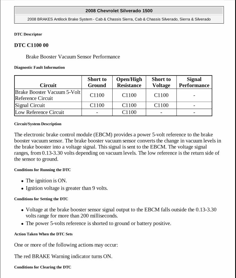
DTC Descriptor
DTC C1100 00
Brake Booster Vacuum Sensor Performance
Diagnostic Fault Information
Circuit/System Description
The electronic brake control module (EBCM) provides a power 5-volt reference to the brake booster vacuum sensor. The brake booster vacuum sensor converts the change in vacuum levels in the brake booster into a voltage signal. This signal is sent to the EBCM. The voltage signal ranges, from 0.13-3.30 volts depending on vacuum levels. The low reference is the return side of the sensor to ground.
Conditions for Running the DTC
� The ignition is ON. � Ignition voltage is greater than 9 volts.
Conditions for Setting the DTC
� Voltage at the brake booster sensor signal output to the EBCM falls outside the 0.13-3.30 volts range for more than 200 milliseconds.
� The power 5-volts reference is shorted to ground or battery positive.
Action Taken When the DTC Sets
One or more of the following actions may occur:
The red BRAKE Warning indicator turns ON.
Conditions for Clearing the DTC
CircuitShort to Ground
Open/High Resistance
Short to Voltage
Signal Performance
Brake Booster Vacuum 5-Volt Reference Circuit
C1100 C1100 C1100 -
Signal Circuit C1100 C1100 C1100 -Low Reference Circuit - C1100 - -
2008 Chevrolet Silverado 1500
2008 BRAKES Antilock Brake System - Cab & Chassis Sierra, Cab & Chassis Silverado, Sierra & Silverado
MY
Wednesday, April 08, 2009 12:33:43 PM Page 73 © 2005 Mitchell Repair Information Company, LLC.
� The condition for the DTC is no longer present. � The EBCM automatically clears the history DTC when a current DTC is not detected in 100
consecutive drive cycles.
Reference Information
Schematic Reference
Antilock Brake System Schematics
Connector End View Reference
Component Connector End Views
Description and Operation
ABS Description and Operation (With JL4) or ABS Description and Operation (Without JL4)
Electrical Information Reference
� Circuit Testing
� Connector Repairs � Testing for Intermittent Conditions and Poor Connections � Wiring Repairs
Scan Tool Reference
Control Module References for Scan Tool Information
Circuit/System Testing
1. Ignition OFF, disconnect the harness connector at the brake booster vacuum sensor. 2. Test for less than 3.0 ohm of resistance between the low reference circuit terminal A and
ground. � If greater than 3.0 ohm, test the low reference circuit for an open/high resistance. If the
circuit tests normal, replace the EBCM. 3. Ignition ON, test for 4.8-5.2 volts between the 5-volt reference circuit terminal B and
ground. � If less than 4.8 volts, test the 5-volt reference circuit for a short to ground or an
2008 Chevrolet Silverado 1500
2008 BRAKES Antilock Brake System - Cab & Chassis Sierra, Cab & Chassis Silverado, Sierra & Silverado
MY
Wednesday, April 08, 2009 12:33:43 PM Page 74 © 2005 Mitchell Repair Information Company, LLC.
open/high resistance. If the circuit tests normal, replace the EBCM. � If greater than 5.2 volts, test the 5-volt reference circuit for a short to voltage. If the
circuit tests normal, replace the EBCM. 4. Test for 4.5-5.3 volts between the 5-volt reference circuit terminal B and the signal circuit
terminal C. � If less than the specified range, test the signal circuit for an open/high resistance. If the
circuit tests normal, replace the EBCM. � If greater specified range, test the signal circuit for a short to voltage. If the circuit
tests normal, replace the EBCM. 5. Install a 3A fused jumper wire at the signal circuit terminal C. Toggle the jumper wire
between the low reference circuit terminal and the 5-volt reference circuit terminal B. Verify the scan tool Brake Pressure Sensor Input parameter toggles between 0.2-3.2 volts.
� If the specified parameter, does not toggle between the minimum and maximum values test the signal circuit for a short to voltage, short to ground or an open/high resistance. If the circuit tests normal, replace the EBCM.
6. If all circuits test normal, test or replace the brake booster vacuum sensor.
Repair Procedures
Perform the Diagnostic Repair Verification after completing the diagnostic procedure.
Control Module References for EBCM replacement, setup, and programming
SYMPTOMS - ANTILOCK BRAKE SYSTEM
IMPORTANT: The following steps must be completed before using the symptom tables.
1. Perform the ABS Diagnostic System Check before us ing the symptom tables in order to verify that all of the f ollowing are true:
� There are no DTCs set. � The control modules can communicate via the serial
data link. 2. Review the system description and operation in or der to
familiarize yourself with the system functions. Ref er to ABS Description and Operation (With JL4) or ABS Description and Operation (Without JL4) .
2008 Chevrolet Silverado 1500
2008 BRAKES Antilock Brake System - Cab & Chassis Sierra, Cab & Chassis Silverado, Sierra & Silverado
MY
Wednesday, April 08, 2009 12:33:43 PM Page 75 © 2005 Mitchell Repair Information Company, LLC.

Visual/Physical Inspection
� Inspect for aftermarket devices which could affect the operation of the ABS. Refer to Checking Aftermarket Accessories .
� Inspect the easily accessible or visible system components, for obvious damage or conditions, which could cause the symptom.
Intermittent
Faulty electrical connections or wiring may be the cause of intermittent conditions. Refer Testing for Intermittent Conditions and Poor Connections .
Symptom List
Refer to a symptom diagnostic procedure from the following list in order to diagnose the symptom:
ABS INDICATOR MALFUNCTION
Diagnostic Instructions
� Perform the Diagnostic System Check - Vehicle prior to using this diagnostic procedure.
� Review Strategy Based Diagnosis for an overview of the diagnostic approach.
� Diagnostic Procedure Instructions provides an overview of each diagnostic category.
Circuit/System Description
The instrument panel cluster (IPC) illuminates the Antilock Brake System (ABS) indicator by supplying ground to the lamp. The electronic brake control module (EBCM) sends a serial data messages to the IPC, in order to command the indicator ON or OFF.
Reference Information
Schematic Reference
Antilock Brake System Schematics
Connector End View Reference
Component Connector End Views
Description and Operation
2008 Chevrolet Silverado 1500
2008 BRAKES Antilock Brake System - Cab & Chassis Sierra, Cab & Chassis Silverado, Sierra & Silverado
MY
Wednesday, April 08, 2009 12:33:43 PM Page 76 © 2005 Mitchell Repair Information Company, LLC.
ABS Description and Operation (With JL4) or ABS Description and Operation (Without JL4)
Electrical Information Reference
� Circuit Testing
� Connector Repairs � Testing for Intermittent Conditions and Poor Connections � Wiring Repairs
Scan Tool Reference
Control Module References for Scan Tool Information
Circuit Verification
Ignition ON, observe the ABS indicator to turn ON then OFF during the IPC bulb test.
Circuit/System Testing
1. Ignition On, with a scan tool command the Scan Tool IPC display test ON and OFF. The ABS indicator should turn ON and OFF.
� If the ABS warning lamp does not turn ON and OFF, replace the IPC.
Repair Procedures
Perform the Diagnostic Repair Verification after completing the diagnostic procedure.
Control Module References for EBCM or IPC replacement, setup, and programming
STABILITRAK INDICATOR MALFUNCTION
Diagnostic Instructions
� Perform the Diagnostic System Check - Vehicle prior to using this diagnostic procedure.
� Review Strategy Based Diagnosis for an overview of the diagnostic approach.
� Diagnostic Procedure Instructions provides an overview of each diagnostic category.
Circuit Description
The instrument panel cluster (IPC) illuminates the stabilitrak indicator during the IPC bulb check
2008 Chevrolet Silverado 1500
2008 BRAKES Antilock Brake System - Cab & Chassis Sierra, Cab & Chassis Silverado, Sierra & Silverado
MY
Wednesday, April 08, 2009 12:33:43 PM Page 77 © 2005 Mitchell Repair Information Company, LLC.
or when the electronic brake control module (EBCM) sends a serial data message to the IPC commanding the indicator ON.
Reference Information
Schematic Reference
Antilock Brake System Schematics
Connector End View Reference
Component Connector End Views
Description and Operation
ABS Description and Operation (With JL4) or ABS Description and Operation (Without JL4)
Electrical Information Reference
� Circuit Testing
� Connector Repairs � Testing for Intermittent Conditions and Poor Connections � Wiring Repairs
Scan Tool Reference
Control Module References for Scan Tool Information
Circuit Verification
Ignition ON, observe the Stabilitrak indicator to turn ON then OFF during the IPC bulb test.
Circuit/System Testing
1. Ignition On, with a scan tool command the Scan Tool IPC display test ON and OFF. The Stabilitrak indicator should turn ON and OFF.
� If the Stabilitrak indicator does not turn ON and OFF, replace the IPC.
Repair Procedures
Perform the Diagnostic Repair Verification after completing the diagnostic procedure.
2008 Chevrolet Silverado 1500
2008 BRAKES Antilock Brake System - Cab & Chassis Sierra, Cab & Chassis Silverado, Sierra & Silverado
MY
Wednesday, April 08, 2009 12:33:43 PM Page 78 © 2005 Mitchell Repair Information Company, LLC.
Control Module References for EBCM or IPC replacement, setup, and programming
TRACTION OFF INDICATOR MALFUNCTION
Diagnostic Instructions
� Perform the Diagnostic System Check - Vehicle prior to using this diagnostic procedure.
� Review Strategy Based Diagnosis for an overview of the diagnostic approach.
� Diagnostic Procedure Instructions provides an overview of each diagnostic category.
Circuit/System Description
The Low Traction indicator is controlled by the instrument cluster via serial data messages from the electronic brake control module (EBCM). When the traction control system (TCS) is active for 0.5 seconds, the EBCM commands the instrument cluster to flash the Low Traction indicator.
The electronic brake control module (EBCM) sends a serial data message to the instrument panel cluster (IPC) to illuminate the Traction Control indicator when the EBCM has disabled the traction control system (TCS) due to a DTC. The Traction Control indicator will also turn ON during the instrument cluster bulb check. When the ignition switch is turned to ON, the Traction Control indicator will turn ON for approximately 3 seconds and then turn OFF.
Reference Information
Schematic Reference
Antilock Brake System Schematics
Connector End View Reference
Component Connector End Views
Description and Operation
ABS Description and Operation (With JL4) or ABS Description and Operation (Without JL4)
Electrical Information Reference
� Circuit Testing
� Connector Repairs
2008 Chevrolet Silverado 1500
2008 BRAKES Antilock Brake System - Cab & Chassis Sierra, Cab & Chassis Silverado, Sierra & Silverado
MY
Wednesday, April 08, 2009 12:33:43 PM Page 79 © 2005 Mitchell Repair Information Company, LLC.

� Testing for Intermittent Conditions and Poor Connections � Wiring Repairs
Scan Tool Reference
Control Module References for EBCM and IPC
Circuit/System Verification
1. Turn OFF the ignition for 5 seconds. 2. Turn ON the ignition, with a scan tool, select instrument panel special functions Display
Test. Command the instrument panel lamps ON. Verify the traction control off lamp illuminates for at least 2 seconds and then turns off.
Circuit/System Testing
1. Ignition OFF for 5 seconds, Igniton ON, observe that the traction off indicator functions by illuminating for 2 seconds then turns OFF.
� If the traction OFF indicator does not illuminate, with the scan tool, select instrument panel special functions Display Test. Command the instrument panel lamps ON and OFF. Verify the TC lamp turns ON and OFF.
� If the TC warning lamp does not turn OFF, replace the IPC.
� If the TC warning lamp does turn OFF, replace the EBCM.
Repair Procedures
Perform the Diagnostic Repair Verification after completing the diagnostic procedure.
Control Module References for EBCM or IPC replacement, setup, and programming
Repair Validation
Ignition OFF for 5 seconds, Igniton ON, observe that the traction control off indicator functions by illuminating for 2 seconds then turns OFF.This is the bulb self test that operates upon every ignition key start cycle.
IMPORTANT: Diagnose all vehicle DTCs before using th is diagnostic. The malfunction must be present during diagnosis in order to prevent unnecessary parts replacement.
2008 Chevrolet Silverado 1500
2008 BRAKES Antilock Brake System - Cab & Chassis Sierra, Cab & Chassis Silverado, Sierra & Silverado
MY
Wednesday, April 08, 2009 12:33:43 PM Page 80 © 2005 Mitchell Repair Information Company, LLC.
REPAIR INSTRUCTIONS
ANTILOCK BRAKE SYSTEM AUTOMATED BLEED PROCEDURE (WITH JL4)
1. Install a scan tool to the vehicle. 2. Start the engine and allow the engine to idle. 3. Using the scan tool, begin the automated bleed procedure. 4. Follow the instructions on the scan tool to complete the automated bleed procedure. Apply
the brake pedal when instructed by the scan tool. 5. Turn the ignition OFF. 6. Remove the scan tool from the vehicle. 7. Fill the brake master cylinder reservoir to the maximum-fill level with Delco Supreme 11®,
GM P/N 12377967 (Canadian P/N 992667), or equivalent DOT-3 brake fluid from a clean, sealed brake fluid container.
8. Bleed the hydraulic brake system. Refer to Hydraulic Brake System Bleeding (Pressure) or Hydraulic Brake System Bleeding (Manual) .
9. With the ignition OFF, apply the brakes 3-5 times, or until the brake pedal becomes firm, in order to deplete the brake booster power reserve.
10. Slowly depress and release the brake pedal. Observe the feel of the brake pedal. 11. If the brake pedal feels spongy, repeat the automated bleeding procedure. If the brake pedal
NOTE: When adding fluid to the brake master cylinder reservoir, use only Delco Supreme 11®, GM P/N 12377967 (Canadian P/N 99 2667), or equivalent DOT-3 brake fluid from a clean, sealed b rake fluid container. The use of any type of fluid other than the recommended type of brake fluid, may cause contamination which could result in damage to the internal rubber seals and/or rubber l inings of hydraulic brake system components.
NOTE: Refer to BRAKE FLUID EFFECTS ON PAINT AND ELEC TRICAL COMPONENTS NOTICE .
IMPORTANT: The base hydraulic brake system must be b led before performing this automated bleeding procedure. If you have not yet performed the base hydraulic brake system bleeding procedure, refer to Hydraulic Brake System Bleeding (Pressure) or Hydraulic Brake System Bleeding (Manual) before proceeding.
2008 Chevrolet Silverado 1500
2008 BRAKES Antilock Brake System - Cab & Chassis Sierra, Cab & Chassis Silverado, Sierra & Silverado
MY
Wednesday, April 08, 2009 12:33:43 PM Page 81 © 2005 Mitchell Repair Information Company, LLC.
still feels spongy after repeating the automated bleeding procedure inspect the brake system for external leaks. Refer to Brake System External Leak Inspection .
12. Turn the ignition key ON, with the engine OFF; check to see if the brake system warning lamp remains illuminated.
13. If the brake system warning lamp remains illuminated, DO NOT allow the vehicle to be driven until it is diagnosed and repaired. Refer to Symptoms - Hydraulic Brakes .
14. Drive the vehicle to exceed 13 km/h (8 mph) to allow ABS initialization to occur. Observe brake pedal feel.
15. If the brake pedal feels spongy, repeat the automated bleeding procedure until a firm brake pedal is obtained.
ANTILOCK BRAKE SYSTEM AUTOMATED BLEED PROCEDURE (WITHOUT JL4)
1. Install a scan tool to the vehicle. 2. Start the engine and allow the engine to idle. 3. Depress the brake pedal firmly and maintain steady pressure on the pedal.
NOTE: When adding fluid to the brake master cylinder reservoir, use only Delco Supreme 11®, GM P/N 12377967 (Canadian P/N 99 2667), or equivalent DOT-3 brake fluid from a clean, sealed b rake fluid container. The use of any type of fluid other than the recommended type of brake fluid, may cause contamination which could result in damage to the internal rubber seals and/or rubber l inings of hydraulic brake system components.
NOTE: Refer to BRAKE FLUID EFFECTS ON PAINT AND ELEC TRICAL COMPONENTS NOTICE .
IMPORTANT: This procedure may be performed on all ve hicles EXCEPT those equipped with option code JL4, Vehicle Stability En hancement System (VSES).
IMPORTANT: The base hydraulic brake system must be b led before performing this automated bleeding procedure. If you have not yet performed the base hydraulic brake system bleeding procedure, refer to Hydraulic Brake System Bleeding (Pressure) or Hydraulic Brake System Bleeding (Manual) before proceeding.
2008 Chevrolet Silverado 1500
2008 BRAKES Antilock Brake System - Cab & Chassis Sierra, Cab & Chassis Silverado, Sierra & Silverado
MY
Wednesday, April 08, 2009 12:33:43 PM Page 82 © 2005 Mitchell Repair Information Company, LLC.
4. Using the scan tool, begin the automated bleed procedure. 5. Follow the instructions on the scan tool to complete the automated bleed procedure. Release
the brake pedal between each test sequence. 6. Turn the ignition OFF. 7. Remove the scan tool from the vehicle. 8. Fill the brake master cylinder reservoir to the maximum-fill level with Delco Supreme 11®,
GM P/N 12377967 (Canadian P/N 992667), or equivalent DOT-3 brake fluid from a clean, sealed brake fluid container.
9. Bleed the hydraulic brake system. Refer to Hydraulic Brake System Bleeding (Pressure) or Hydraulic Brake System Bleeding (Manual) .
10. With the ignition OFF, apply the brakes 3-5 times, or until the brake pedal becomes firm, in order to deplete the brake booster power reserve.
11. Slowly depress and release the brake pedal. Observe the feel of the brake pedal. 12. If the brake pedal feels spongy, repeat the automated bleeding procedure. If the brake pedal
still feels spongy after repeating the automated bleeding procedure inspect the brake system for external leaks. Refer to Brake System External Leak Inspection .
13. Turn the ignition key ON, with the engine OFF; check to see if the brake system warning lamp remains illuminated.
14. If the brake system warning lamp remains illuminated, DO NOT allow the vehicle to be driven until it is diagnosed and repaired. Refer to Symptoms - Hydraulic Brakes .
15. Drive the vehicle to exceed 13 km/h (8 mph) to allow ABS initialization to occur. Observe brake pedal feel.
16. If the brake pedal feels spongy, repeat the automated bleeding procedure until a firm brake pedal is obtained.
ELECTRONIC BRAKE CONTROL MODULE REPLACEMENT (JH6, JH7)
2008 Chevrolet Silverado 1500
2008 BRAKES Antilock Brake System - Cab & Chassis Sierra, Cab & Chassis Silverado, Sierra & Silverado
MY
Wednesday, April 08, 2009 12:33:43 PM Page 83 © 2005 Mitchell Repair Information Company, LLC.
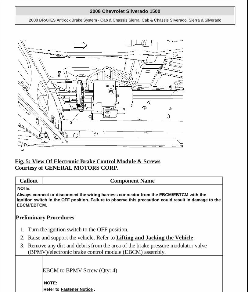
Fig. 5: View Of Electronic Brake Control Module & Screws Courtesy of GENERAL MOTORS CORP.
Callout Component Name
Preliminary Procedures
1. Turn the ignition switch to the OFF position.
2. Raise and support the vehicle. Refer to Lifting and Jacking the Vehicle . 3. Remove any dirt and debris from the area of the brake pressure modulator valve
(BPMV)/electronic brake control module (EBCM) assembly.
NOTE:Always connect or disconnect the wiring harness con nector from the EBCM/EBTCM with the ignition switch in the OFF position. Failure to obs erve this precaution could result in damage to the EBCM/EBTCM.
EBCM to BPMV Screw (Qty: 4)
NOTE:Refer to Fastener Notice .
2008 Chevrolet Silverado 1500
2008 BRAKES Antilock Brake System - Cab & Chassis Sierra, Cab & Chassis Silverado, Sierra & Silverado
MY
Wednesday, April 08, 2009 12:33:43 PM Page 84 © 2005 Mitchell Repair Information Company, LLC.
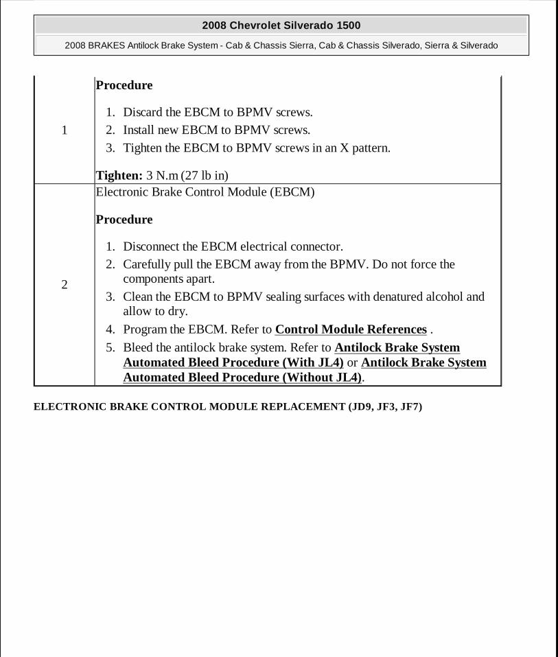
ELECTRONIC BRAKE CONTROL MODULE REPLACEMENT (JD9, JF3, JF7)
1
Procedure
1. Discard the EBCM to BPMV screws. 2. Install new EBCM to BPMV screws. 3. Tighten the EBCM to BPMV screws in an X pattern.
Tighten: 3 N.m (27 lb in)
2
Electronic Brake Control Module (EBCM)
Procedure
1. Disconnect the EBCM electrical connector. 2. Carefully pull the EBCM away from the BPMV. Do not force the
components apart. 3. Clean the EBCM to BPMV sealing surfaces with denatured alcohol and
allow to dry.
4. Program the EBCM. Refer to Control Module References . 5. Bleed the antilock brake system. Refer to Antilock Brake System
Automated Bleed Procedure (With JL4) or Antilock Brake System Automated Bleed Procedure (Without JL4).
2008 Chevrolet Silverado 1500
2008 BRAKES Antilock Brake System - Cab & Chassis Sierra, Cab & Chassis Silverado, Sierra & Silverado
MY
Wednesday, April 08, 2009 12:33:43 PM Page 85 © 2005 Mitchell Repair Information Company, LLC.
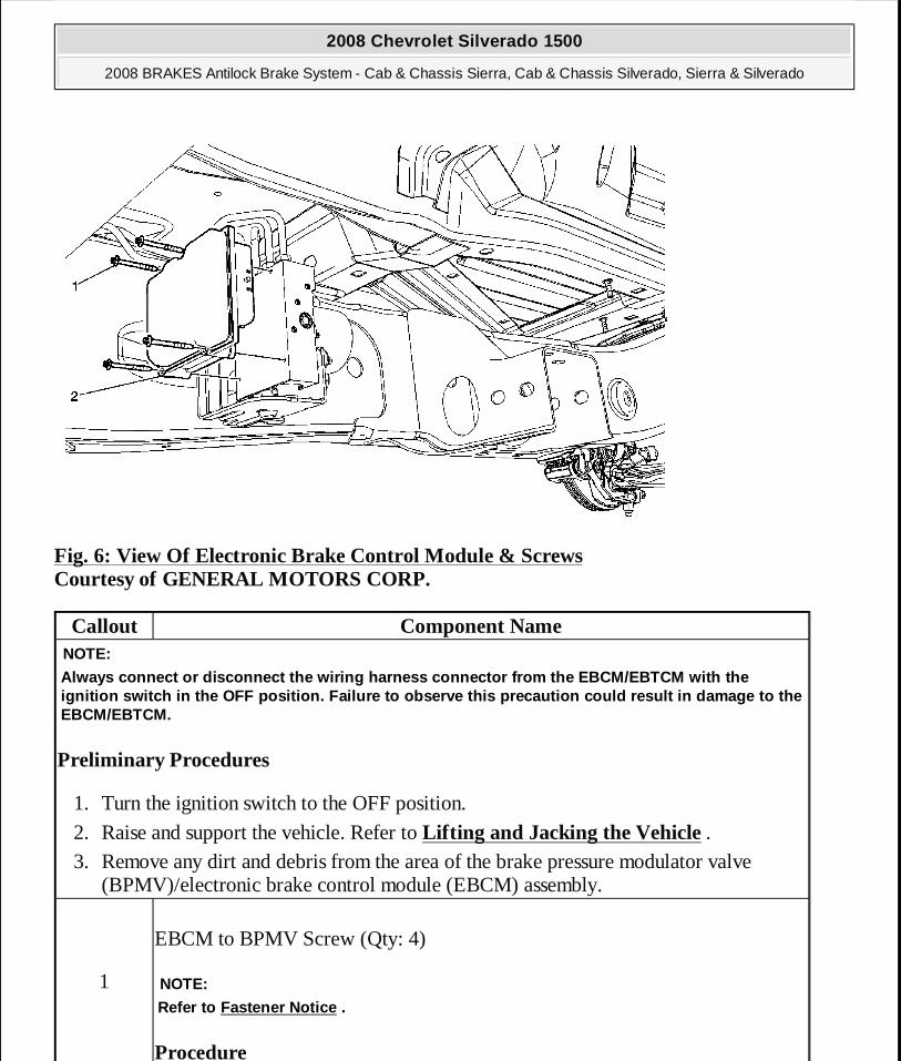
Fig. 6: View Of Electronic Brake Control Module & Screws Courtesy of GENERAL MOTORS CORP.
Callout Component Name
Preliminary Procedures
1. Turn the ignition switch to the OFF position.
2. Raise and support the vehicle. Refer to Lifting and Jacking the Vehicle . 3. Remove any dirt and debris from the area of the brake pressure modulator valve
(BPMV)/electronic brake control module (EBCM) assembly.
NOTE:
Always connect or disconnect the wiring harness con nector from the EBCM/EBTCM with the ignition switch in the OFF position. Failure to obs erve this precaution could result in damage to the EBCM/EBTCM.
1
EBCM to BPMV Screw (Qty: 4)
Procedure
NOTE:
Refer to Fastener Notice .
2008 Chevrolet Silverado 1500
2008 BRAKES Antilock Brake System - Cab & Chassis Sierra, Cab & Chassis Silverado, Sierra & Silverado
MY
Wednesday, April 08, 2009 12:33:43 PM Page 86 © 2005 Mitchell Repair Information Company, LLC.
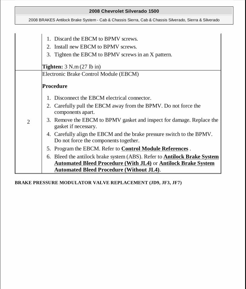
BRAKE PRESSURE MODULATOR VALVE REPLACEMENT (JD9, JF3, JF7)
1. Discard the EBCM to BPMV screws. 2. Install new EBCM to BPMV screws. 3. Tighten the EBCM to BPMV screws in an X pattern.
Tighten: 3 N.m (27 lb in)
2
Electronic Brake Control Module (EBCM)
Procedure
1. Disconnect the EBCM electrical connector. 2. Carefully pull the EBCM away from the BPMV. Do not force the
components apart. 3. Remove the EBCM to BPMV gasket and inspect for damage. Replace the
gasket if necessary. 4. Carefully align the EBCM and the brake pressure switch to the BPMV.
Do not force the components together.
5. Program the EBCM. Refer to Control Module References . 6. Bleed the antilock brake system (ABS). Refer to Antilock Brake System
Automated Bleed Procedure (With JL4) or Antilock Brake System Automated Bleed Procedure (Without JL4).
2008 Chevrolet Silverado 1500
2008 BRAKES Antilock Brake System - Cab & Chassis Sierra, Cab & Chassis Silverado, Sierra & Silverado
MY
Wednesday, April 08, 2009 12:33:43 PM Page 87 © 2005 Mitchell Repair Information Company, LLC.
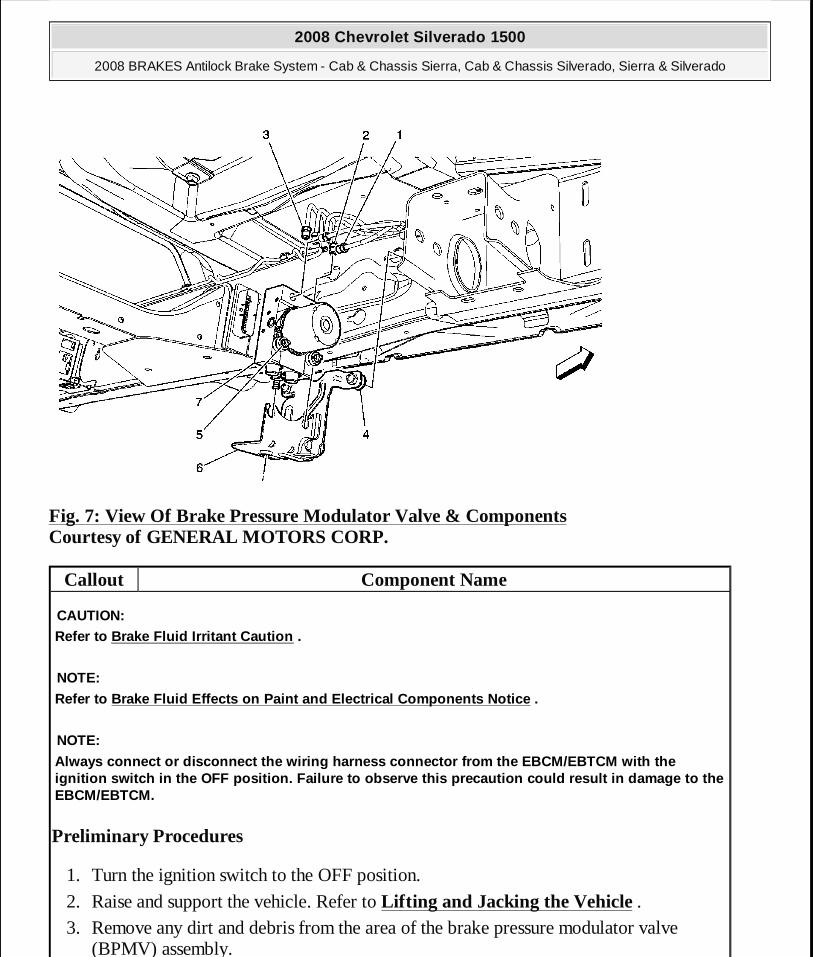
Fig. 7: View Of Brake Pressure Modulator Valve & Components Courtesy of GENERAL MOTORS CORP.
Callout Component Name
Preliminary Procedures
1. Turn the ignition switch to the OFF position.
2. Raise and support the vehicle. Refer to Lifting and Jacking the Vehicle . 3. Remove any dirt and debris from the area of the brake pressure modulator valve
(BPMV) assembly.
CAUTION:Refer to Brake Fluid Irritant Caution .
NOTE:
Refer to Brake Fluid Effects on Paint and Electrica l Components Notice .
NOTE:
Always connect or disconnect the wiring harness con nector from the EBCM/EBTCM with the ignition switch in the OFF position. Failure to obs erve this precaution could result in damage to the EBCM/EBTCM.
2008 Chevrolet Silverado 1500
2008 BRAKES Antilock Brake System - Cab & Chassis Sierra, Cab & Chassis Silverado, Sierra & Silverado
MY
Wednesday, April 08, 2009 12:33:43 PM Page 88 © 2005 Mitchell Repair Information Company, LLC.
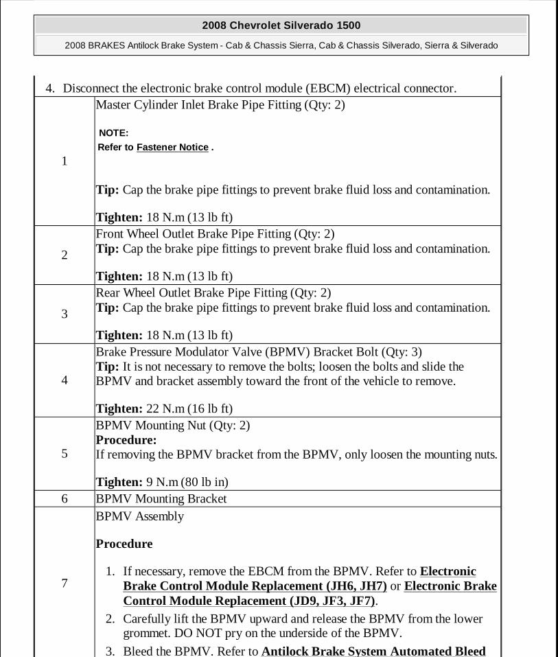
4. Disconnect the electronic brake control module (EBCM) electrical connector.
1
Master Cylinder Inlet Brake Pipe Fitting (Qty: 2)
Tip: Cap the brake pipe fittings to prevent brake fluid loss and contamination.
Tighten: 18 N.m (13 lb ft)
NOTE:Refer to Fastener Notice .
2
Front Wheel Outlet Brake Pipe Fitting (Qty: 2) Tip: Cap the brake pipe fittings to prevent brake fluid loss and contamination.
Tighten: 18 N.m (13 lb ft)
3
Rear Wheel Outlet Brake Pipe Fitting (Qty: 2) Tip: Cap the brake pipe fittings to prevent brake fluid loss and contamination.
Tighten: 18 N.m (13 lb ft)
4
Brake Pressure Modulator Valve (BPMV) Bracket Bolt (Qty: 3) Tip: It is not necessary to remove the bolts; loosen the bolts and slide the BPMV and bracket assembly toward the front of the vehicle to remove.
Tighten: 22 N.m (16 lb ft)
5
BPMV Mounting Nut (Qty: 2) Procedure: If removing the BPMV bracket from the BPMV, only loosen the mounting nuts.
Tighten: 9 N.m (80 lb in) 6 BPMV Mounting Bracket
7
BPMV Assembly
Procedure
1. If necessary, remove the EBCM from the BPMV. Refer to Electronic Brake Control Module Replacement (JH6, JH7) or Electronic Brake Control Module Replacement (JD9, JF3, JF7).
2. Carefully lift the BPMV upward and release the BPMV from the lower grommet. DO NOT pry on the underside of the BPMV.
3. Bleed the BPMV. Refer to Antilock Brake System Automated Bleed
2008 Chevrolet Silverado 1500
2008 BRAKES Antilock Brake System - Cab & Chassis Sierra, Cab & Chassis Silverado, Sierra & Silverado
MY
Wednesday, April 08, 2009 12:33:43 PM Page 89 © 2005 Mitchell Repair Information Company, LLC.
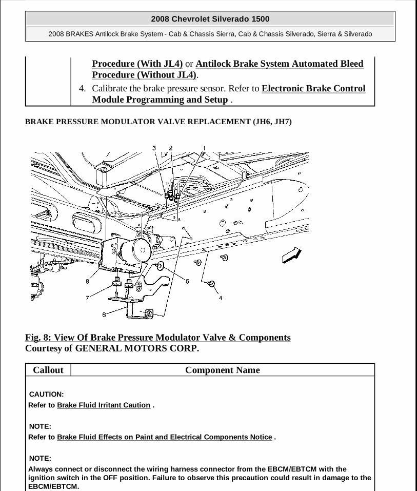
BRAKE PRESSURE MODULATOR VALVE REPLACEMENT (JH6, JH7)
Fig. 8: View Of Brake Pressure Modulator Valve & Components Courtesy of GENERAL MOTORS CORP.
Procedure (With JL4) or Antilock Brake System Automated Bleed Procedure (Without JL4).
4. Calibrate the brake pressure sensor. Refer to Electronic Brake Control Module Programming and Setup .
Callout Component Name
CAUTION:
Refer to Brake Fluid Irritant Caution .
NOTE:Refer to Brake Fluid Effects on Paint and Electrica l Components Notice .
NOTE:
Always connect or disconnect the wiring harness con nector from the EBCM/EBTCM with the ignition switch in the OFF position. Failure to obs erve this precaution could result in damage to the EBCM/EBTCM.
2008 Chevrolet Silverado 1500
2008 BRAKES Antilock Brake System - Cab & Chassis Sierra, Cab & Chassis Silverado, Sierra & Silverado
MY
Wednesday, April 08, 2009 12:33:43 PM Page 90 © 2005 Mitchell Repair Information Company, LLC.
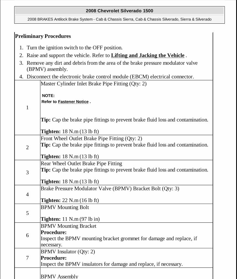
Preliminary Procedures
1. Turn the ignition switch to the OFF position.
2. Raise and support the vehicle. Refer to Lifting and Jacking the Vehicle . 3. Remove any dirt and debris from the area of the brake pressure modulator valve
(BPMV) assembly. 4. Disconnect the electronic brake control module (EBCM) electrical connector.
1
Master Cylinder Inlet Brake Pipe Fitting (Qty: 2)
Tip: Cap the brake pipe fittings to prevent brake fluid loss and contamination.
Tighten: 18 N.m (13 lb ft)
NOTE:Refer to Fastener Notice .
2
Front Wheel Outlet Brake Pipe Fitting (Qty: 2) Tip: Cap the brake pipe fittings to prevent brake fluid loss and contamination.
Tighten: 18 N.m (13 lb ft)
3
Rear Wheel Outlet Brake Pipe Fitting Tip: Cap the brake pipe fittings to prevent brake fluid loss and contamination.
Tighten: 18 N.m (13 lb ft)
4Brake Pressure Modulator Valve (BPMV) Bracket Bolt (Qty: 3)
Tighten: 22 N.m (16 lb ft)
5BPMV Mounting Bolt
Tighten: 11 N.m (97 lb in)
6
BPMV Mounting Bracket Procedure: Inspect the BPMV mounting bracket grommet for damage and replace, if necessary.
7BPMV Insulator (Qty: 2) Procedure: Inspect the BPMV insulators for damage and replace, if necessary.
BPMV Assembly
2008 Chevrolet Silverado 1500
2008 BRAKES Antilock Brake System - Cab & Chassis Sierra, Cab & Chassis Silverado, Sierra & Silverado
MY
Wednesday, April 08, 2009 12:33:43 PM Page 91 © 2005 Mitchell Repair Information Company, LLC.
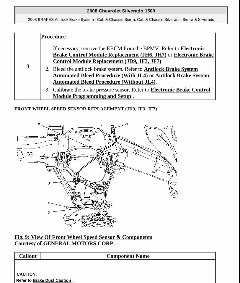
FRONT WHEEL SPEED SENSOR REPLACEMENT (JD9, JF3, JF7)
Fig. 9: View Of Front Wheel Speed Sensor & Components Courtesy of GENERAL MOTORS CORP.
8
Procedure
1. If necessary, remove the EBCM from the BPMV. Refer to Electronic Brake Control Module Replacement (JH6, JH7) or Electronic Brake Control Module Replacement (JD9, JF3, JF7).
2. Bleed the antilock brake system. Refer to Antilock Brake System Automated Bleed Procedure (With JL4) or Antilock Brake System Automated Bleed Procedure (Without JL4).
3. Calibrate the brake pressure sensor. Refer to Electronic Brake Control Module Programming and Setup .
Callout Component Name
CAUTION:Refer to Brake Dust Caution .
2008 Chevrolet Silverado 1500
2008 BRAKES Antilock Brake System - Cab & Chassis Sierra, Cab & Chassis Silverado, Sierra & Silverado
MY
Wednesday, April 08, 2009 12:33:43 PM Page 92 © 2005 Mitchell Repair Information Company, LLC.

FRONT WHEEL SPEED SENSOR REPLACEMENT (JH6, JH7)
Preliminary Procedures
1. Raise and support the vehicle. Refer to Lifting and Jacking the Vehicle .
2. Remove the tire and wheel assembly. Refer to Tire and Wheel Removal and Installation .
3. Remove the brake rotor. Refer to Front Brake Rotor Replacement (JH6, JH7) or Front Brake Rotor Replacement (JD9, JF3, JF7) .
1
Wheel Speed Sensor Electrical Connector Clip
Procedure
1. Disconnect the electrical connector. 2. Release the wheel speed sensor electrical connector clip from the brake
hose bracket.
2Wheel Speed Sensor Harness Clip Procedure: Release the wheel speed sensor harness clip from the brake hose bracket.
3Wheel Speed Sensor Harness Clip Procedure: Release the wheel speed sensor harness clip from the steering knuckle bracket.
4
Wheel Speed Sensor Bolt
Tighten: 17 N.m (13 lb ft)
NOTE:Refer to Fastener Notice .
5Wheel Speed Sensor Procedure: Perform the Diagnostic System Check - Vehicle .
2008 Chevrolet Silverado 1500
2008 BRAKES Antilock Brake System - Cab & Chassis Sierra, Cab & Chassis Silverado, Sierra & Silverado
MY
Wednesday, April 08, 2009 12:33:43 PM Page 93 © 2005 Mitchell Repair Information Company, LLC.
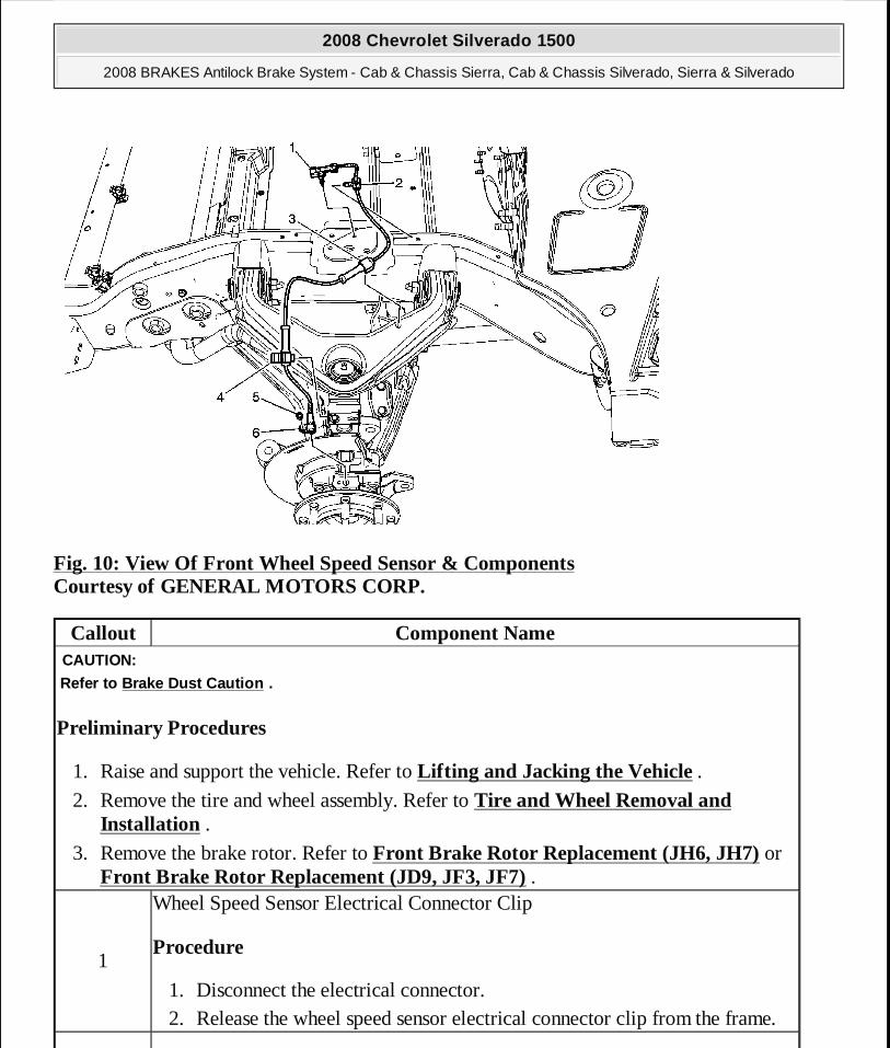
Fig. 10: View Of Front Wheel Speed Sensor & Components Courtesy of GENERAL MOTORS CORP.
Callout Component Name
Preliminary Procedures
1. Raise and support the vehicle. Refer to Lifting and Jacking the Vehicle .
2. Remove the tire and wheel assembly. Refer to Tire and Wheel Removal and Installation .
3. Remove the brake rotor. Refer to Front Brake Rotor Replacement (JH6, JH7) or Front Brake Rotor Replacement (JD9, JF3, JF7) .
CAUTION:
Refer to Brake Dust Caution .
1
Wheel Speed Sensor Electrical Connector Clip
Procedure
1. Disconnect the electrical connector. 2. Release the wheel speed sensor electrical connector clip from the frame.
2008 Chevrolet Silverado 1500
2008 BRAKES Antilock Brake System - Cab & Chassis Sierra, Cab & Chassis Silverado, Sierra & Silverado
MY
Wednesday, April 08, 2009 12:33:43 PM Page 94 © 2005 Mitchell Repair Information Company, LLC.
REAR WHEEL SPEED SENSOR REPLACEMENT
2Wheel Speed Sensor Harness Clip Procedure: Release the wheel speed sensor harness clip from the frame.
3Wheel Speed Sensor Harness Clip Procedure: Release the wheel speed sensor harness clip from the upper control arm.
4Wheel Speed Sensor Harness Clip Procedure: Release the wheel speed sensor harness clip from the brake hose bracket.
5
Wheel Speed Sensor Bolt
Tighten: 17 N.m (13 lb ft)
NOTE:Refer to Fastener Notice .
6Wheel Speed Sensor Procedure: Perform the Diagnostic System Check - Vehicle .
2008 Chevrolet Silverado 1500
2008 BRAKES Antilock Brake System - Cab & Chassis Sierra, Cab & Chassis Silverado, Sierra & Silverado
MY
Wednesday, April 08, 2009 12:33:43 PM Page 95 © 2005 Mitchell Repair Information Company, LLC.
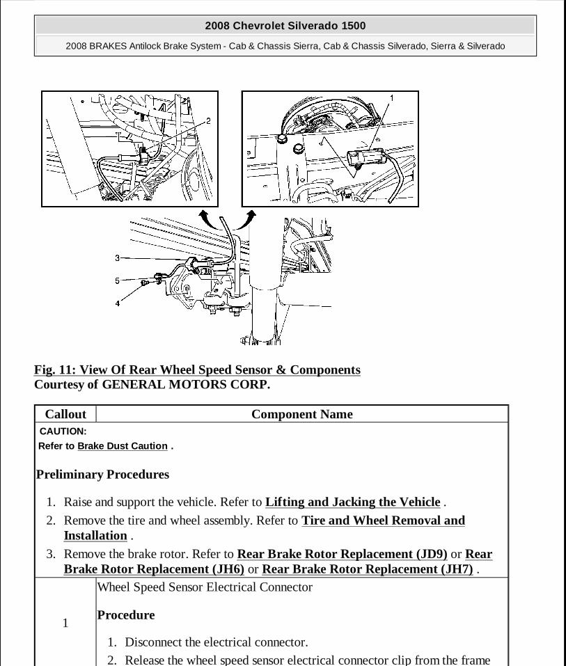
Fig. 11: View Of Rear Wheel Speed Sensor & Components Courtesy of GENERAL MOTORS CORP.
Callout Component Name
Preliminary Procedures
1. Raise and support the vehicle. Refer to Lifting and Jacking the Vehicle .
2. Remove the tire and wheel assembly. Refer to Tire and Wheel Removal and Installation .
3. Remove the brake rotor. Refer to Rear Brake Rotor Replacement (JD9) or Rear Brake Rotor Replacement (JH6) or Rear Brake Rotor Replacement (JH7) .
CAUTION:
Refer to Brake Dust Caution .
1
Wheel Speed Sensor Electrical Connector
Procedure
1. Disconnect the electrical connector. 2. Release the wheel speed sensor electrical connector clip from the frame
2008 Chevrolet Silverado 1500
2008 BRAKES Antilock Brake System - Cab & Chassis Sierra, Cab & Chassis Silverado, Sierra & Silverado
MY
Wednesday, April 08, 2009 12:33:43 PM Page 96 © 2005 Mitchell Repair Information Company, LLC.
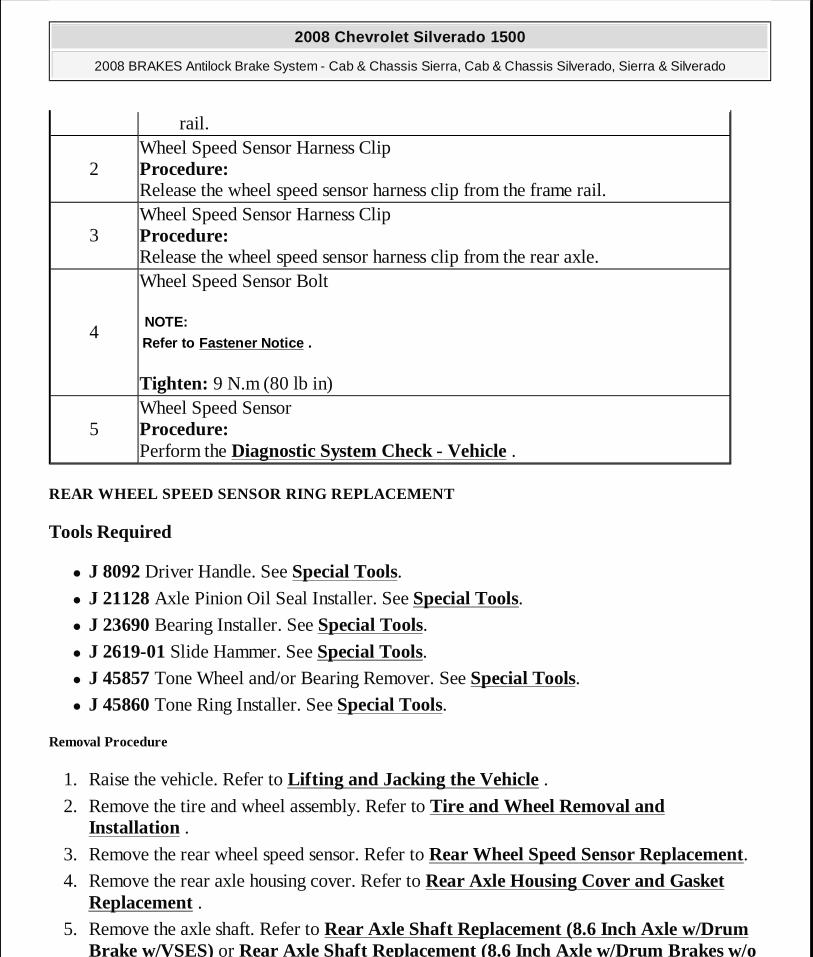
REAR WHEEL SPEED SENSOR RING REPLACEMENT
Tools Required
� J 8092 Driver Handle. See Special Tools. � J 21128 Axle Pinion Oil Seal Installer. See Special Tools. � J 23690 Bearing Installer. See Special Tools. � J 2619-01 Slide Hammer. See Special Tools. � J 45857 Tone Wheel and/or Bearing Remover. See Special Tools. � J 45860 Tone Ring Installer. See Special Tools.
Removal Procedure
1. Raise the vehicle. Refer to Lifting and Jacking the Vehicle .
2. Remove the tire and wheel assembly. Refer to Tire and Wheel Removal and Installation .
3. Remove the rear wheel speed sensor. Refer to Rear Wheel Speed Sensor Replacement. 4. Remove the rear axle housing cover. Refer to Rear Axle Housing Cover and Gasket
Replacement . 5. Remove the axle shaft. Refer to Rear Axle Shaft Replacement (8.6 Inch Axle w/Drum
Brake w/VSES) or Rear Axle Shaft Replacement (8.6 Inch Axle w/Drum Brakes w/o
rail.
2Wheel Speed Sensor Harness Clip Procedure: Release the wheel speed sensor harness clip from the frame rail.
3Wheel Speed Sensor Harness Clip Procedure: Release the wheel speed sensor harness clip from the rear axle.
4
Wheel Speed Sensor Bolt
Tighten: 9 N.m (80 lb in)
NOTE:
Refer to Fastener Notice .
5Wheel Speed Sensor Procedure: Perform the Diagnostic System Check - Vehicle .
2008 Chevrolet Silverado 1500
2008 BRAKES Antilock Brake System - Cab & Chassis Sierra, Cab & Chassis Silverado, Sierra & Silverado
MY
Wednesday, April 08, 2009 12:33:44 PM Page 97 © 2005 Mitchell Repair Information Company, LLC.
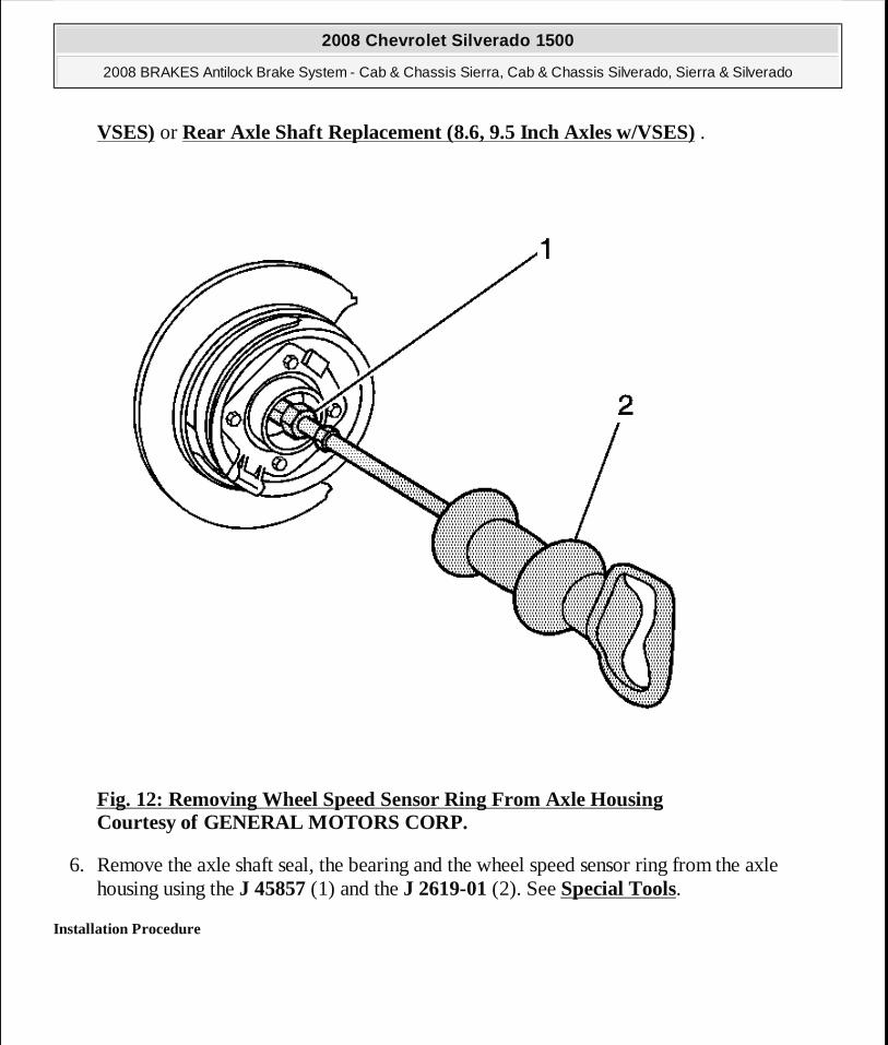
VSES) or Rear Axle Shaft Replacement (8.6, 9.5 Inch Axles w/VSES) .
Fig. 12: Removing Wheel Speed Sensor Ring From Axle Housing Courtesy of GENERAL MOTORS CORP.
6. Remove the axle shaft seal, the bearing and the wheel speed sensor ring from the axle housing using the J 45857 (1) and the J 2619-01 (2). See Special Tools.
Installation Procedure
2008 Chevrolet Silverado 1500
2008 BRAKES Antilock Brake System - Cab & Chassis Sierra, Cab & Chassis Silverado, Sierra & Silverado
MY
Wednesday, April 08, 2009 12:33:44 PM Page 98 © 2005 Mitchell Repair Information Company, LLC.
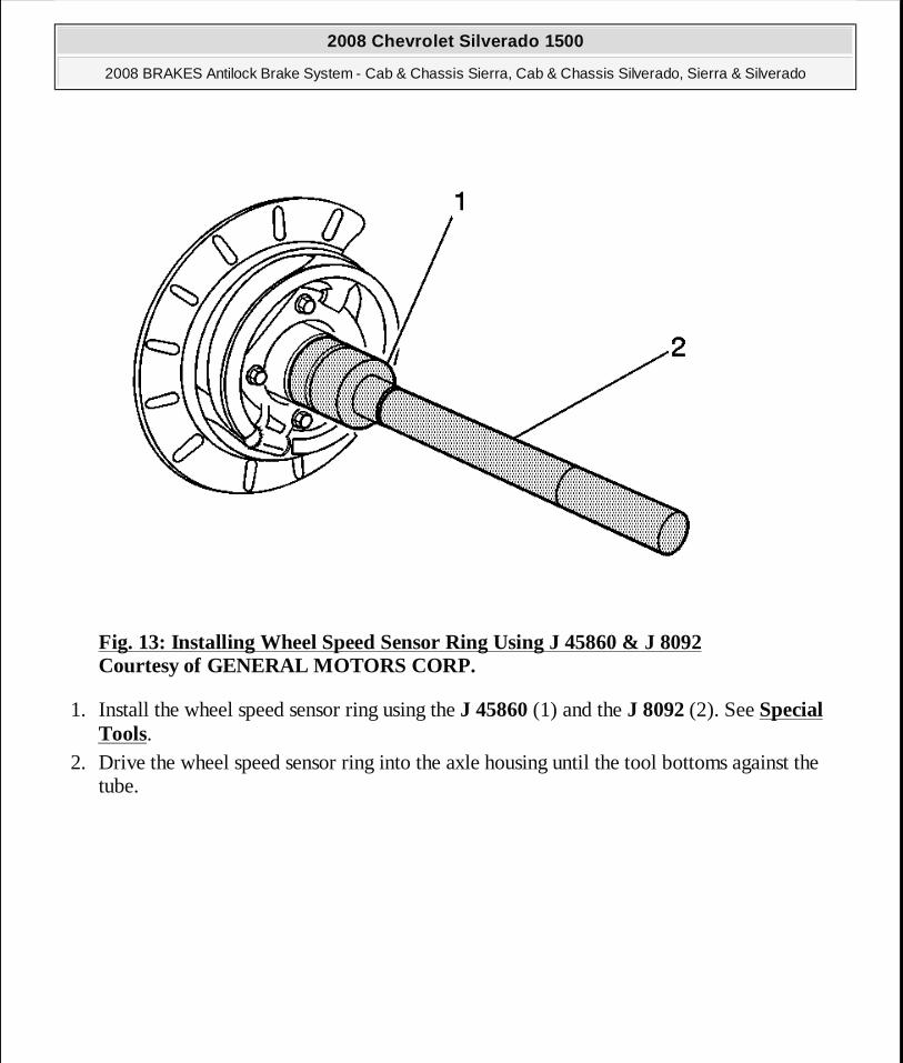
Fig. 13: Installing Wheel Speed Sensor Ring Using J 45860 & J 8092 Courtesy of GENERAL MOTORS CORP.
1. Install the wheel speed sensor ring using the J 45860 (1) and the J 8092 (2). See Special Tools.
2. Drive the wheel speed sensor ring into the axle housing until the tool bottoms against the tube.
2008 Chevrolet Silverado 1500
2008 BRAKES Antilock Brake System - Cab & Chassis Sierra, Cab & Chassis Silverado, Sierra & Silverado
MY
Wednesday, April 08, 2009 12:33:44 PM Page 99 © 2005 Mitchell Repair Information Company, LLC.

Fig. 14: Installing Axle Shaft Bearing Using J 23690 Or J 29709 & J 8092 Courtesy of GENERAL MOTORS CORP.
3. Install the axle shaft bearing using the J 23690 (1) and the J 8092 (2). See Special Tools. 4. Drive the axle shaft bearing into the axle housing until the tool bottoms against the tube.
2008 Chevrolet Silverado 1500
2008 BRAKES Antilock Brake System - Cab & Chassis Sierra, Cab & Chassis Silverado, Sierra & Silverado
MY
Wednesday, April 08, 2009 12:33:44 PM Page 100 © 2005 Mitchell Repair Information Company, LLC.
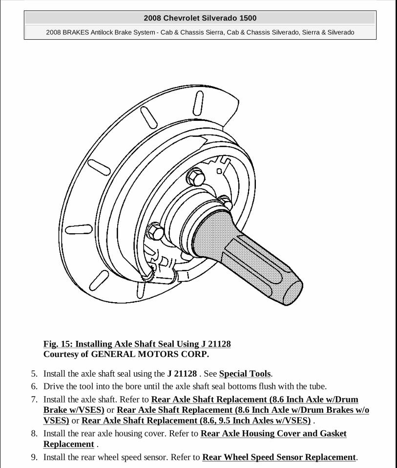
Fig. 15: Installing Axle Shaft Seal Using J 21128 Courtesy of GENERAL MOTORS CORP.
5. Install the axle shaft seal using the J 21128 . See Special Tools. 6. Drive the tool into the bore until the axle shaft seal bottoms flush with the tube.
7. Install the axle shaft. Refer to Rear Axle Shaft Replacement (8.6 Inch Axle w/Drum Brake w/VSES) or Rear Axle Shaft Replacement (8.6 Inch Axle w/Drum Brakes w/o VSES) or Rear Axle Shaft Replacement (8.6, 9.5 Inch Axles w/VSES) .
8. Install the rear axle housing cover. Refer to Rear Axle Housing Cover and Gasket Replacement .
9. Install the rear wheel speed sensor. Refer to Rear Wheel Speed Sensor Replacement.
2008 Chevrolet Silverado 1500
2008 BRAKES Antilock Brake System - Cab & Chassis Sierra, Cab & Chassis Silverado, Sierra & Silverado
MY
Wednesday, April 08, 2009 12:33:44 PM Page 101 © 2005 Mitchell Repair Information Company, LLC.
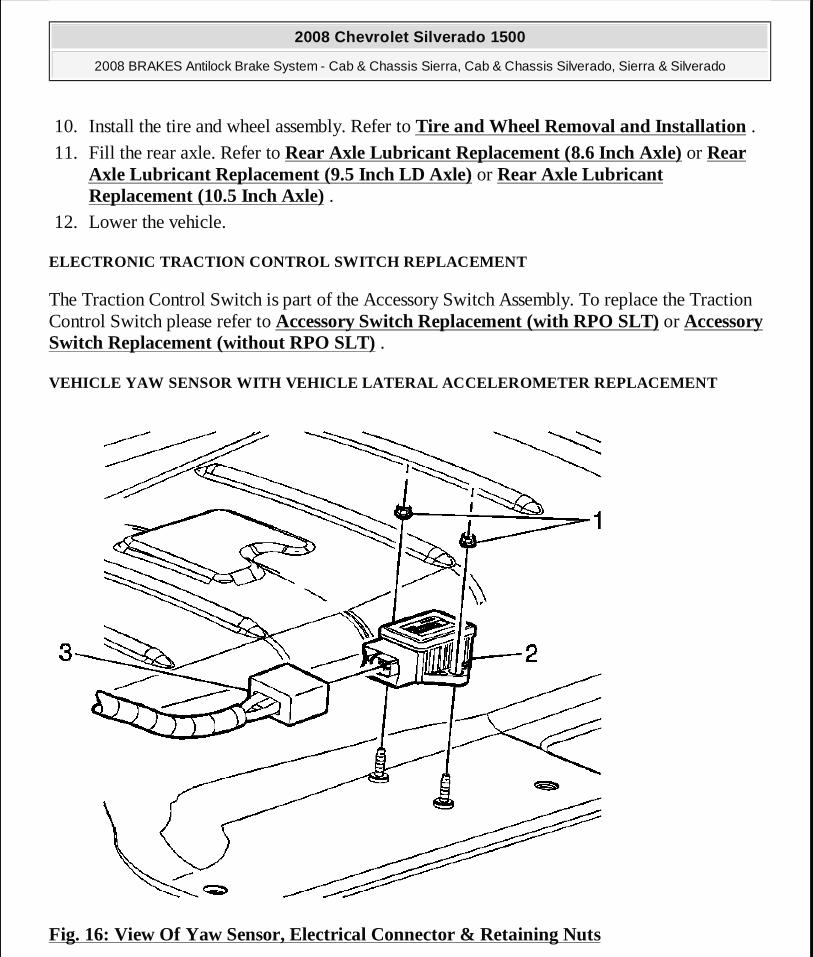
10. Install the tire and wheel assembly. Refer to Tire and Wheel Removal and Installation .
11. Fill the rear axle. Refer to Rear Axle Lubricant Replacement (8.6 Inch Axle) or Rear Axle Lubricant Replacement (9.5 Inch LD Axle) or Rear Axle Lubricant Replacement (10.5 Inch Axle) .
12. Lower the vehicle.
ELECTRONIC TRACTION CONTROL SWITCH REPLACEMENT
The Traction Control Switch is part of the Accessory Switch Assembly. To replace the Traction Control Switch please refer to Accessory Switch Replacement (with RPO SLT) or Accessory Switch Replacement (without RPO SLT) .
VEHICLE YAW SENSOR WITH VEHICLE LATERAL ACCELEROMETER REPLACEMENT
Fig. 16: View Of Yaw Sensor, Electrical Connector & Retaining Nuts
2008 Chevrolet Silverado 1500
2008 BRAKES Antilock Brake System - Cab & Chassis Sierra, Cab & Chassis Silverado, Sierra & Silverado
MY
Wednesday, April 08, 2009 12:33:44 PM Page 102 © 2005 Mitchell Repair Information Company, LLC.
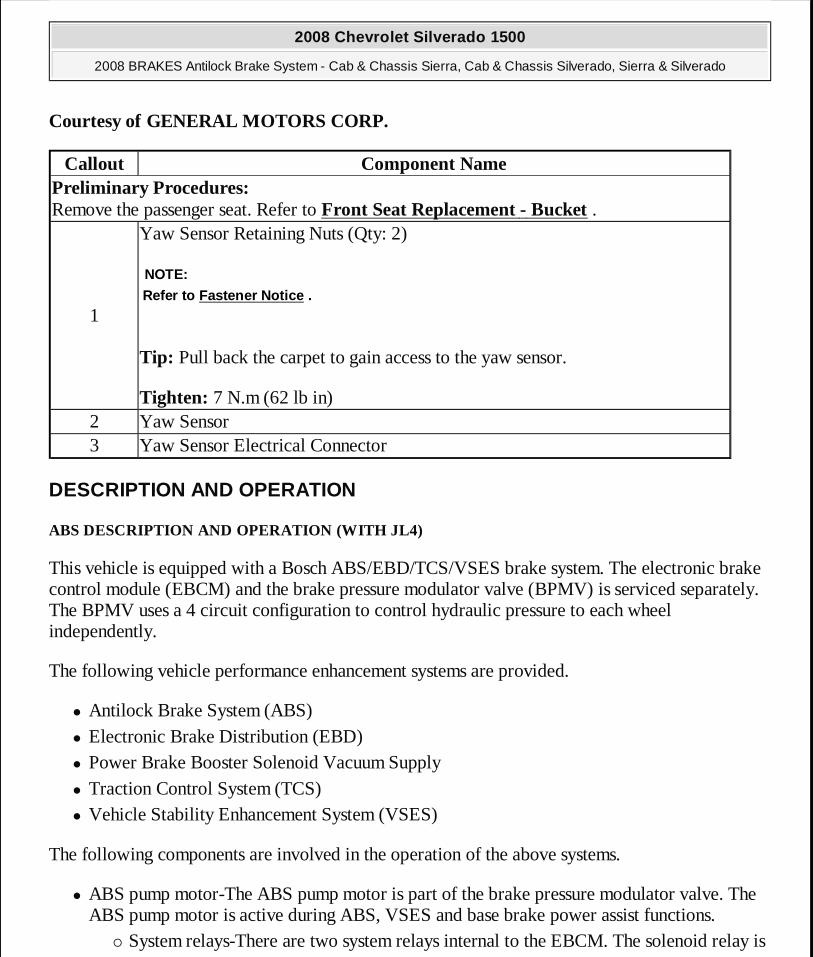
Courtesy of GENERAL MOTORS CORP.
DESCRIPTION AND OPERATION
ABS DESCRIPTION AND OPERATION (WITH JL4)
This vehicle is equipped with a Bosch ABS/EBD/TCS/VSES brake system. The electronic brake control module (EBCM) and the brake pressure modulator valve (BPMV) is serviced separately. The BPMV uses a 4 circuit configuration to control hydraulic pressure to each wheel independently.
The following vehicle performance enhancement systems are provided.
� Antilock Brake System (ABS) � Electronic Brake Distribution (EBD) � Power Brake Booster Solenoid Vacuum Supply � Traction Control System (TCS) � Vehicle Stability Enhancement System (VSES)
The following components are involved in the operation of the above systems.
� ABS pump motor-The ABS pump motor is part of the brake pressure modulator valve. The ABS pump motor is active during ABS, VSES and base brake power assist functions.
� System relays-There are two system relays internal to the EBCM. The solenoid relay is
Callout Component NamePreliminary Procedures: Remove the passenger seat. Refer to Front Seat Replacement - Bucket .
1
Yaw Sensor Retaining Nuts (Qty: 2)
Tip: Pull back the carpet to gain access to the yaw sensor.
Tighten: 7 N.m (62 lb in)
NOTE:
Refer to Fastener Notice .
2 Yaw Sensor3 Yaw Sensor Electrical Connector
2008 Chevrolet Silverado 1500
2008 BRAKES Antilock Brake System - Cab & Chassis Sierra, Cab & Chassis Silverado, Sierra & Silverado
MY
Wednesday, April 08, 2009 12:33:44 PM Page 103 © 2005 Mitchell Repair Information Company, LLC.
energized when the ignition is ON. The ABS pump motor relay supplies a ground path to the ABS pump motor when the EBCM commands the ABS pump motor on. The system relays are non serviceable.
� Solenoids-The solenoids are commanded ON and OFF by the EBCM to operate the appropriate valves in the brake pressure modulator valve (BPMV).
� Brake booster solenoid-The Power Brake Booster is solenoid operated, and applies a mechanical force to brake master cylinder push rod to aid in brake pedal effort.
� Brake booster vacuum sensor-The Brake Booster Vacuum Sensor is a input to EBCM, and operates the ABS pump motor to precharge the brake system.
� Brake pressure modulator valve (BPMV)-The BPMV uses a 4-circuit configuration to control hydraulic pressure to each wheel independently.
The BPMV contains the following components:
� ABS pump motor and pump � Four inlet valves � Four outlet valves � Two TC isolation valves � Two TC supply valves � A master cylinder pressure sensor � A front low-pressure accumulator � A rear low-pressure accumulator
� Lateral accelerometer-The EBCM uses the lateral accelerometer to determine the sideways acceleration of the vehicle. The lateral accelerometer is packaged with the yaw rate sensor as a single component.
� Master cylinder pressure sensor-The master cylinder pressure sensor is located within the BPMV. The master cylinder pressure sensor uses a 5-volt reference and generates an output signal proportionate to the hydraulic fluid pressure which is present in the front brake circuit at the master cylinder.
� Power brake booster solenoid-Assist unit creates vacuum for the brake booster in case of a vacuum loss or low vacuum to the brake booster. The power brake booster Solenoid is active during increased brake booster assist, and base brake power assist functions.
� Steering wheel position sensor-The EBCM receives several inputs from the steering wheel position sensor. Three digital square wave signal inputs and one analog signal input are wired directly to the EBCM harness connector. The EBCM uses the signals signals A and B for determining position movement and uses the analog and index signals to determine absolute center. All signals are monitored for plausibility to each other. The sensor is
2008 Chevrolet Silverado 1500
2008 BRAKES Antilock Brake System - Cab & Chassis Sierra, Cab & Chassis Silverado, Sierra & Silverado
MY
Wednesday, April 08, 2009 12:33:44 PM Page 104 © 2005 Mitchell Repair Information Company, LLC.

provided ground and 5-volt power directly from the EBCM. � Traction control switch-VSES and the engine torque reduction function of TCS are
manually disabled or enabled by pressing the traction control switch. � Wheel speed sensors (WSS)-EBCM sends a 12-volt reference voltage signal to each wheel
speed sensor. As the wheel spins, the wheel speed sensor produces a square wave DC signal voltage. The wheel speed sensor increases the signal frequency as the wheel speed increases, but does not increase the signal amplitude.
� Yaw rate sensor-The EBCM uses the yaw rate sensor to determine the rate of rotation along the vehicle's vertical axis. The yaw rate sensor is packaged with the lateral accelerometer as a single component.
Antilock Brake System (ABS)
When wheel slip is detected during a brake application, an ABS event occurs. During antilock braking, hydraulic pressure in the individual wheel circuits is controlled to prevent any wheel from slipping. A separate hydraulic line and specific solenoid valves are provided for each wheel. The ABS can decrease, hold, or increase hydraulic pressure to each wheel. The ABS does not, however, increase hydraulic pressure above the amount which is transmitted by the master cylinder during braking.
During antilock braking, a series of rapid pulsations is felt in the brake pedal. These pulsations are caused by the rapid changes in position of the individual solenoid valves as the electronic brake control module (EBCM) responds to wheel speed sensor inputs and attempts to prevent wheel slip. These pedal pulsations are present only during antilock braking and stop when normal braking is resumed or when the vehicle comes to a stop. A ticking or popping noise may also be heard as the solenoid valves cycle rapidly. During antilock braking on dry pavement, intermittent chirping noises may be heard as the tires approach slipping. These noises and pedal pulsations are considered normal during antilock operation.
Vehicles equipped with ABS may be stopped by applying normal force to the brake pedal. Brake pedal operation during normal braking is no different than that of previous non-ABS systems. Maintaining a constant force on the brake pedal provides the shortest stopping distance while maintaining vehicle stability. The typical ABS activation sequence is as follows.
Pressure Hold
The EBCM closes the isolation valve and keeps the dump valve closed in order to isolate the slipping wheel when wheel slip occurs. This holds the pressure steady on the brake so that the hydraulic pressure does not increase or decrease.
Pressure Decrease
2008 Chevrolet Silverado 1500
2008 BRAKES Antilock Brake System - Cab & Chassis Sierra, Cab & Chassis Silverado, Sierra & Silverado
MY
Wednesday, April 08, 2009 12:33:44 PM Page 105 © 2005 Mitchell Repair Information Company, LLC.
If a pressure hold does not correct the wheel slip condition, a pressure decrease occurs. The EBCM decreases the pressure to individual wheels during deceleration when wheel slip occurs. The isolation valve is closed and the dump valve is opened. The excess fluid is stored in the accumulator until the pump can return the fluid to the master cylinder or fluid reservoir.
Pressure Increase
After the wheel slip is corrected, a pressure increase occurs. The EBCM increases the pressure to individual wheels during deceleration in order to reduce the speed of the wheel. The isolation valve is opened and the dump valve is closed. The increased pressure is delivered from the master cylinder.
Electronic Brake Distribution (EBD)
The electronic brake distribution (EBD) is a control system that enhances the hydraulic proportioning function of the mechanical proportioning valve in the base brake system. The EBD control system is part of the operation software in the electronic brake control module (EBCM). The EBD uses active control with existing ABS in order to regulate the vehicle's rear brake pressure.
Brake Pressure Application
The EBCM uses brake pressure application to control traction by transferring torque through the driveline to wheels which are not slipping. The ABS pump motor, and appropriate valve solenoids are commanded ON and OFF to apply brake pressure to the slipping wheels. Brake pressure application is used in an attempt to maintain equal wheel speed sensor (WSS) signals at the driven wheels.
The EBCM does not allow excessive brake pressure application due to the fact that the solenoid coils or the brakes may become overheated, damaging the EBCM or reducing the drivers ability to stop the vehicle. Estimated coil and brake temperatures are determined by a calculation in the EBCM software. Overheated solenoid coils cause all brake pressure application to become disabled and the stability system disabled message to be displayed. Overheated brakes cause brake pressure application during TCS events to disable, yet the VSES remains functional and as long as the engine torque reduction is enabled, there is no indication to the driver when this occurs and no DTC sets.
Vehicle Stability Enhancement System (VSES)
Vehicle stability enhancement system (VSES) provides added stability during aggressive maneuvers. Yaw rate is the rate of rotation about the vehicle's vertical axis. The VSES is activated when the electronic brake control module (EBCM) determines that the desired yaw rate
2008 Chevrolet Silverado 1500
2008 BRAKES Antilock Brake System - Cab & Chassis Sierra, Cab & Chassis Silverado, Sierra & Silverado
MY
Wednesday, April 08, 2009 12:33:44 PM Page 106 © 2005 Mitchell Repair Information Company, LLC.
does not match the actual yaw rate as measured by the yaw rate sensor.
The desired yaw rate is calculated by the EBCM using, primarily, the following inputs.
� The position of the steering wheel � The speed of the vehicle � The lateral, or sideways acceleration of the vehicle
The difference between the desired yaw rate and the actual yaw rate is the yaw rate error, which is a measurement of oversteer or understeer. When a yaw rate error is detected, the EBCM attempts to correct the vehicle's yaw motion by applying brake pressure to one or more of the wheels. The amount of brake pressure which is applied varies, depending on the correction required. The engine torque may be reduced also, if it is necessary to slow the vehicle while maintaining stability.
VSES activations generally occur in turns during aggressive driving. When braking during VSES activation, the pedal may pulsate. The brake pedal pulsates at a higher frequency during VSES activation than during ABS activation.
Power-Up Self-Test
The electronic brake control module (EBCM) is able to detect many malfunctions whenever the ignition is ON. However, certain failures cannot be detected unless active diagnostic tests are performed on the components. Shorted solenoid coil or motor windings, for example, cannot be detected until the components are commanded ON by the EBCM. Therefore, a power-up self-test is required at the beginning of each ignition cycle to verify correct operation of components before the various control systems can be enabled. The EBCM performs the first phase of the power-up self-test when the ignition is first turned ON. The system relay, solenoids and the ABS pump motor are commanded ON and OFF to verify proper operation and the EBCM verifies the ability to return the system to base braking in the event of a failure. The master cylinder pressure sensor performs a self-test by sending a series of specific voltage signals to the EBCM, each for a predetermined amount of time. This phase of the power-up self-test may be heard by the driver, depending on how soon the engine is cranked and started after turning ON the ignition. The second phase of the power-up self-test begins when the vehicle is driven at a speed greater than 12 km/h (7.5 mph) and the EBCM has not detected any traction control module (TCS)/vehicle stability enhancement system (VSES) related malfunctions thus far. When the brake switch indicates that the brake is not applied and the master cylinder pressure is detected as being low, the EBCM proceeds with the test. The EBCM isolates all of the wheels by closing the 4 isolation valves. Due to the fact that all of the wheels are isolated during the second phase of the test, the test must be aborted if the brake is applied while the test is being performed. Occasionally, the
2008 Chevrolet Silverado 1500
2008 BRAKES Antilock Brake System - Cab & Chassis Sierra, Cab & Chassis Silverado, Sierra & Silverado
MY
Wednesday, April 08, 2009 12:33:44 PM Page 107 © 2005 Mitchell Repair Information Company, LLC.

driver may detect this by experiencing a momentary hard pedal.
VSES Sensors Initialization
The vehicle stability enhancement system (VSES) sensors values may vary slightly due to differences in temperature, sensor mounting, connector resistances, manufacturing, etc. Since VSES is a very sensitive and precise control system, it is imperative that the electronic brake control module (EBCM) be able to accurately equate a given sensor voltage with an actual unit of measurement. For example, the yaw rate signal of one vehicle may be 2.64 volts at +18.0 deg/sec yaw rate while the yaw rate signal of another vehicle may be 2.64 volts at +17.5 deg/sec yaw rate. Therefore, at the beginning of each ignition cycle, the EBCM must perform an initialization procedure to observe how the VSES sensors are correlated with each other and also to determine what each sensor value is when the applicable unit of measurement equals 0. This voltage is referred to as the sensor bias voltage. Although some activation of the VSES system may occur if required to prior to full initialization, the system does not give optimum performance until the sensors are fully initialized.
The following VSES sensors require initialization:
� The yaw rate sensor � The lateral accelerometer � The master cylinder pressure sensor � The steering wheel position sensor
When the vehicle speed is greater than 25 km/h (15 mph), full sensor initialization must occur during 3 km (1.8 mi) of driving or 1 km (0.6 mi) of straight and stable driving, whichever occurs first. Although an attempt at initialization may fail due to driving conditions, such as driving on a very winding road, failed initialization is usually caused by a sensor bias voltage which is not within an acceptable range. Often, a DTC sets soon after a failed initialization attempt. The message center displays the stability system disabled message when sensor initialization fails.
ECE 13 Response
The electronic brake control module (EBCM) illuminates the ABS indicator when a malfunction which disables ABS is detected. Usually, the ABS indicator is turned OFF during the following ignition cycle unless the fault is detected during that ignition cycle. However, the setting of a wheel speed sensor related DTC causes the ABS indicator to remain illuminated during the following ignition cycle until the vehicle is operated at a speed greater than 13 km/h (8 mph). This allows the EBCM to verify that no malfunction exists, before turning OFF the ABS indicator. This reaction occurs even if the ABS indicator turns OFF when the scan tool is used to clear the DTCs. When repairing these vehicles, it is important to ensure that the ECE 13 response
2008 Chevrolet Silverado 1500
2008 BRAKES Antilock Brake System - Cab & Chassis Sierra, Cab & Chassis Silverado, Sierra & Silverado
MY
Wednesday, April 08, 2009 12:33:44 PM Page 108 © 2005 Mitchell Repair Information Company, LLC.
has occurred and that the ABS indicator does not illuminate after returning the vehicle to the customer. It is also important to verify that ECE 13 is not the cause of an ABS indicator which is illuminated when no DTCs are set, before attempting to diagnose other possible causes.
Active Vacuum Booster
The power brake booster assist unit creates mechanical force for the brake booster in case of a vacuum loss or low vacuum to the brake booster. The power brake booster system consists of:
� The sensor circuits and pressure sensor � The check valve manifold � The vacuum solenoid valve
The Power Brake Booster is solenoid operated, and applies a mechanical force to brake master cylinder push rod to aid in brake pedal effort.
The Brake Booster Vacuum Sensor is a input to EBCM, and operates the ABS pump motor to precharge the brake system.
Driver Information Indicators and Messages
The following indicators are used to inform the driver of several different factors.
Brake Warning Indicator
The instrument panel cluster (IPC) illuminates the brake warning indicator when the following occurs.
� The body control module (BCM) detects that the park brake is engaged. The IPC receives a serial data message from the BCM requesting illumination. The brake warning indicator flashes at a rate of approximately twice per second when the park brake is engaged.
� The electronic brake control module (EBCM) detects a low brake fluid condition or a base brake pressure differential and sends a serial data message to the IPC requesting illumination.
� The IPC performs the bulb check. � The EBCM detects an ABS-disabling malfunction which also disables electronic brake
distribution (EBD) and sends a serial data message to the IPC requesting illumination.
ABS Indicator
The IPC illuminates the ABS indicator when the following occurs.
2008 Chevrolet Silverado 1500
2008 BRAKES Antilock Brake System - Cab & Chassis Sierra, Cab & Chassis Silverado, Sierra & Silverado
MY
Wednesday, April 08, 2009 12:33:44 PM Page 109 © 2005 Mitchell Repair Information Company, LLC.
� The EBCM detects an ABS-disabling malfunction and sends a serial data message to the IPC requesting illumination.
� The IPC performs the bulb check. � The IPC detects a loss of serial data communication with the EBCM. � A DTC is set during the previous ignition cycle which requires an ECE 13 response at the
beginning of the current ignition cycle. The EBCM sends a serial data message to the IPC requesting illumination.
Traction Control Off Indicator
The IPC illuminates the traction off indicator when the following occurs.
� The EBCM disables engine torque reduction due to a malfunction and sends a serial data message to the IPC requesting illumination.
� The driver manually disables VSES and engine torque reduction by pressing the traction control switch. The EBCM sends a serial data message to the IPC requesting illumination.
Service Brake Booster Message
The service brake system message is displayed whenever the red brake warning indicator is illuminated.
Stabilitrak Off Message
The message center displays the stabilitrak off message when one or more of the following conditions exists.
� The transfer case is shifted into 4 LO. The EBCM sends a serial data message to the IPC requesting illumination.
� The driver manually disables the VSES and engine torque reduction by pressing the traction control switch. The EBCM sends a serial data message to the IPC requesting illumination.
� The estimated temperature of any solenoid coil exceeds an acceptable limit. The EBCM sends a serial data message to the IPC requesting this display.
� The EBCM detects a failed brake switch. The EBCM sends a serial data message to the IPC requesting this display. A DTC sets when this condition exists.
� VSES sensor initialization time is excessive. The EBCM sends a serial data message to the IPC requesting this display.
� Serial data communication between the EBCM and any of several other control modules is interrupted. The EBCM sends a serial data message to the IPC requesting this display or the
2008 Chevrolet Silverado 1500
2008 BRAKES Antilock Brake System - Cab & Chassis Sierra, Cab & Chassis Silverado, Sierra & Silverado
MY
Wednesday, April 08, 2009 12:33:44 PM Page 110 © 2005 Mitchell Repair Information Company, LLC.
IPC displays the message when communication with the EBCM is interrupted. � The PCM is not able to perform engine torque reduction. The EBCM sends a GMLAN
message to the IPC requesting this display. DTCs set when this condition exists. � The EBCM detects an excessively low or excessively high ignition voltage. The EBCM
sends a GMLAN message to the IPC requesting this display.
Service Stabilitrak Message
The message center displays the service stability system message when any one of many VSES-disabling DTCs is set. The EBCM sends a serial data message to the IPC requesting this display.
Service Traction Control Message
The message center displays the service traction control system message when any one of many traction control - disabling DTCs is set. The EBCM sends a serial data message to the IPC requesting this display.
ABS DESCRIPTION AND OPERATION (WITHOUT JL4)
This vehicle is equipped with an EBC 345 ABS/EBD module.
This module provides the following vehicle performance enhancement systems.
� Antilock Brake System (ABS) � Electronic Brake Distribution (EBD)
The following components are involved in the operation of the above systems.
� Electronic brake control module (EBCM) - The EBCM controls the system functions and detects failures.
The EBCM contains the following components.
� System relay - The system relay is internal to the EBCM. The system relay is energized when the ignition is ON. The system relay supplies battery positive voltage to the valve solenoids and to the ABS pump motor. This voltage is referred to as system voltage.
� Solenoids - The solenoids are commanded ON and OFF by the EBCM to operate the appropriate valves in the brake pressure modulator valve (BPMV).
� Brake pressure modulator valve (BPMV) - The BPMV uses a 3-circuit configuration to control hydraulic pressure to each front wheel independently, and to the rear wheels as a pair.
2008 Chevrolet Silverado 1500
2008 BRAKES Antilock Brake System - Cab & Chassis Sierra, Cab & Chassis Silverado, Sierra & Silverado
MY
Wednesday, April 08, 2009 12:33:44 PM Page 111 © 2005 Mitchell Repair Information Company, LLC.
The BPMV contains the following components.
� ABS pump motor and pump � Three isolation valves � Three dump valves � A front low-pressure accumulator � A rear low-pressure accumulator
� Wheel speed sensors (WSS)-EBCM sends a 12-volt reference voltage signal to each front wheel speed sensor. As the wheel spins, the wheel speed sensor produces a square wave DC signal voltage. The wheel speed sensor increases the signal frequency as the wheel speed increases, but does not increase the signal amplitude.
Antilock Brake System (ABS) Operation
When wheel slip is detected during a brake application, an antilock brake system (ABS) event occurs. During antilock braking, hydraulic pressure in the individual wheel circuits is controlled to prevent any wheel from slipping. A separate hydraulic line and specific solenoid valves are provided for each wheel. The ABS can decrease, hold, or increase hydraulic pressure to each wheel. The ABS does not, however, increase hydraulic pressure above the amount which is transmitted by the master cylinder during braking.
During antilock braking, a series of rapid pulsations is felt in the brake pedal. These pulsations are caused by the rapid changes in position of the individual solenoid valves as the electronic brake control module (EBCM) responds to wheel speed sensor inputs and attempts to prevent wheel slip. These pedal pulsations are present only during antilock braking and stop when normal braking is resumed or when the vehicle comes to a stop. A ticking or popping noise may also be heard as the solenoid valves cycle rapidly. During antilock braking on dry pavement, intermittent chirping noises may be heard as the tires approach slipping. These noises and pedal pulsations are considered normal during antilock operation.
Vehicles equipped with ABS may be stopped by applying normal force to the brake pedal. Brake pedal operation during normal braking is no different than that of previous non-ABS systems. Maintaining a constant force on the brake pedal provides the shortest stopping distance while maintaining vehicle stability. The typical ABS activation sequence is as follows.
Pressure Hold
The EBCM closes the isolation valve and keeps the dump valve closed in order to isolate the slipping wheel when wheel slip occurs. This holds the pressure steady on the brake so that the hydraulic pressure does not increase or decrease.
2008 Chevrolet Silverado 1500
2008 BRAKES Antilock Brake System - Cab & Chassis Sierra, Cab & Chassis Silverado, Sierra & Silverado
MY
Wednesday, April 08, 2009 12:33:44 PM Page 112 © 2005 Mitchell Repair Information Company, LLC.
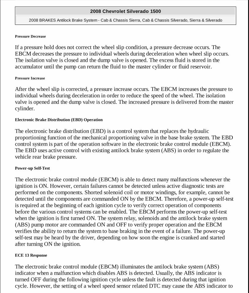
Pressure Decrease
If a pressure hold does not correct the wheel slip condition, a pressure decrease occurs. The EBCM decreases the pressure to individual wheels during deceleration when wheel slip occurs. The isolation valve is closed and the dump valve is opened. The excess fluid is stored in the accumulator until the pump can return the fluid to the master cylinder or fluid reservoir.
Pressure Increase
After the wheel slip is corrected, a pressure increase occurs. The EBCM increases the pressure to individual wheels during deceleration in order to reduce the speed of the wheel. The isolation valve is opened and the dump valve is closed. The increased pressure is delivered from the master cylinder.
Electronic Brake Distribution (EBD) Operation
The electronic brake distribution (EBD) is a control system that replaces the hydraulic proportioning function of the mechanical proportioning valve in the base brake system. The EBD control system is part of the operation software in the electronic brake control module (EBCM). The EBD uses active control with existing antilock brake system (ABS) in order to regulate the vehicle rear brake pressure.
Power-up Self-Test
The electronic brake control module (EBCM) is able to detect many malfunctions whenever the ignition is ON. However, certain failures cannot be detected unless active diagnostic tests are performed on the components. Shorted solenoid coil or motor windings, for example, cannot be detected until the components are commanded ON by the EBCM. Therefore, a power-up self-test is required at the beginning of each ignition cycle to verify correct operation of components before the various control systems can be enabled. The EBCM performs the power-up self-test when the ignition is first turned ON. The system relay, solenoids and the antilock brake system (ABS) pump motor are commanded ON and OFF to verify proper operation and the EBCM verifies the ability to return the system to base braking in the event of a failure. The power-up self-test may be heard by the driver, depending on how soon the engine is cranked and started after turning ON the ignition.
ECE 13 Response
The electronic brake control module (EBCM) illuminates the antilock brake system (ABS) indicator when a malfunction which disables ABS is detected. Usually, the ABS indicator is turned OFF during the following ignition cycle unless the fault is detected during that ignition cycle. However, the setting of a wheel speed sensor related DTC may cause the ABS indicator to
2008 Chevrolet Silverado 1500
2008 BRAKES Antilock Brake System - Cab & Chassis Sierra, Cab & Chassis Silverado, Sierra & Silverado
MY
Wednesday, April 08, 2009 12:33:44 PM Page 113 © 2005 Mitchell Repair Information Company, LLC.
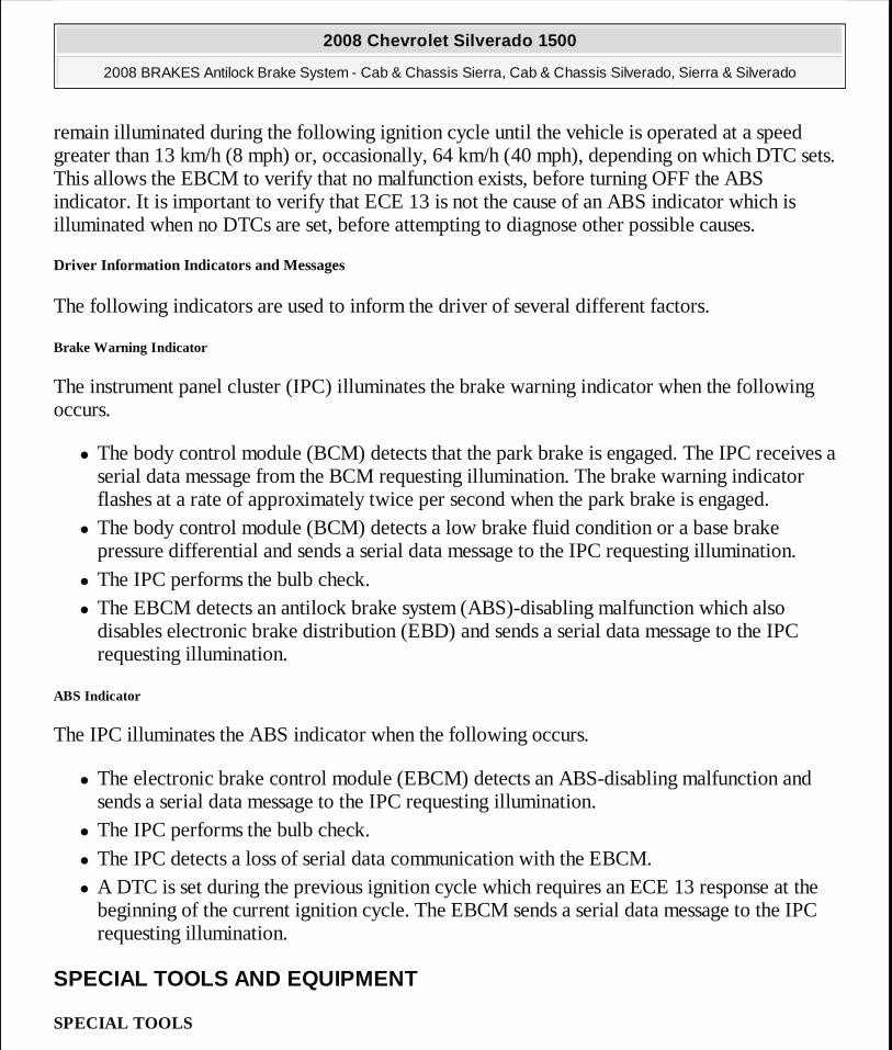
remain illuminated during the following ignition cycle until the vehicle is operated at a speed greater than 13 km/h (8 mph) or, occasionally, 64 km/h (40 mph), depending on which DTC sets. This allows the EBCM to verify that no malfunction exists, before turning OFF the ABS indicator. It is important to verify that ECE 13 is not the cause of an ABS indicator which is illuminated when no DTCs are set, before attempting to diagnose other possible causes.
Driver Information Indicators and Messages
The following indicators are used to inform the driver of several different factors.
Brake Warning Indicator
The instrument panel cluster (IPC) illuminates the brake warning indicator when the following occurs.
� The body control module (BCM) detects that the park brake is engaged. The IPC receives a serial data message from the BCM requesting illumination. The brake warning indicator flashes at a rate of approximately twice per second when the park brake is engaged.
� The body control module (BCM) detects a low brake fluid condition or a base brake pressure differential and sends a serial data message to the IPC requesting illumination.
� The IPC performs the bulb check. � The EBCM detects an antilock brake system (ABS)-disabling malfunction which also
disables electronic brake distribution (EBD) and sends a serial data message to the IPC requesting illumination.
ABS Indicator
The IPC illuminates the ABS indicator when the following occurs.
� The electronic brake control module (EBCM) detects an ABS-disabling malfunction and sends a serial data message to the IPC requesting illumination.
� The IPC performs the bulb check. � The IPC detects a loss of serial data communication with the EBCM. � A DTC is set during the previous ignition cycle which requires an ECE 13 response at the
beginning of the current ignition cycle. The EBCM sends a serial data message to the IPC requesting illumination.
SPECIAL TOOLS AND EQUIPMENT
SPECIAL TOOLS
2008 Chevrolet Silverado 1500
2008 BRAKES Antilock Brake System - Cab & Chassis Sierra, Cab & Chassis Silverado, Sierra & Silverado
MY
Wednesday, April 08, 2009 12:33:44 PM Page 114 © 2005 Mitchell Repair Information Company, LLC.

Illustration Tool Number/ Description
J 8092 Driver Handle
J 21128 Axle Pinion Oil Seal Installer
J 23690 Bearing Installer
J 2619-01 Slide Hammer
J 39700 100-Pin Breakout Box
2008 Chevrolet Silverado 1500
2008 BRAKES Antilock Brake System - Cab & Chassis Sierra, Cab & Chassis Silverado, Sierra & Silverado
MY
Wednesday, April 08, 2009 12:33:44 PM Page 115 © 2005 Mitchell Repair Information Company, LLC.
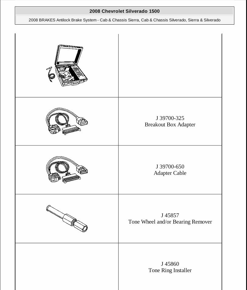
J 39700-325 Breakout Box Adapter
J 39700-650 Adapter Cable
J 45857 Tone Wheel and/or Bearing Remover
J 45860 Tone Ring Installer
2008 Chevrolet Silverado 1500
2008 BRAKES Antilock Brake System - Cab & Chassis Sierra, Cab & Chassis Silverado, Sierra & Silverado
MY
Wednesday, April 08, 2009 12:33:44 PM Page 116 © 2005 Mitchell Repair Information Company, LLC.
J 46079 Tire Pressure Monitor Diagnostic Tool
2008 Chevrolet Silverado 1500
2008 BRAKES Antilock Brake System - Cab & Chassis Sierra, Cab & Chassis Silverado, Sierra & Silverado
MY
Wednesday, April 08, 2009 12:33:44 PM Page 117 © 2005 Mitchell Repair Information Company, LLC.
Related Documents