1 6 Specifications click No. CP-PC-2119E HPA Series Self-contained Photoelectric Sensors with High Functions FEATURES Strobe Light Emission, High Margin Regulation, Front Incoming Light Display, and Output Inhibit Functions Allow Sensing Range to be Reliably Adjusted at High Speed. • Strobe light emission permits you to easily confirm the sensing range. (high performance thru scan and polarized retroreflective) • The high margin regulation function permits you to adjust sensing range at a margin three times greater than usual. (high performance thru scan and polarized retroreflective) • The front incoming light display facilitates adjustment of the sensing range. (thru scan) • The Output Inhibit function permits secure adjustment of the sensing range while debugging the PLC. (high performance thru scan and polarized retrore-flective) • An automatic pulse-phase shift system enhances mutual interference pre-vention. (pola- rized retroreflective type and diffuse scan) • The binary latching self-diagnostic function permits online checking of incoming light for instability/shielded status. • A high sealing monoblock housing. (IP67) • Universal Features (PNP, DIN mounting) • A polarized retroreflective model for transparent object detection is available. • Diffuse scan small-spot detection is realized by a narrow-view lens attachment. (2mm dia. spot diameter) ORDER GUIDE • Pre-leaded type (2m lead) Model Detection method Scanning diatance Light ON/ dark ON selectable Sensitivity adjustment Self-diagnostic indication Self-diagnostic output Triple alignment (initial setting) function (Note 1) Front light incoming indication Supply voltage Output mode Catalog listing Horizontal Thru scan General use High function 10m (Note 2) ~ ~ 10 to 30V dc NPN open collector HPA-T11 ~ ~ PNP open collector HPA-T12 NPN open collector HPA-T13 PNP open collector HPA-T14 Polarized retroreflective General use High function 4m ~ ~ ~ NPN open collector HPA-P11 ~ ~ PNP open collector HPA-P12 NPN open collector HPA-P13 PNP open collector HPA-P14 Transparent object detection polarized retroreflective 0.3 to 1m ~ ~ NPN open collector HPA-F11 Diffuse scan 20cm ~ ~ ~ NPN open collector HPA-D11 PNP open collector HPA-D12 80cm NPN open collector HPA-A11 PNP open collector HPA-A12 Vertical Thru scan General use High function 10m (Note 2) ~ ~ NPN open collector HPA-T21 ~ ~ PNP open collector HPA-T22 NPN open collector HPA-T23 PNP open collector HPA-T24 Polarized retroreflective General use High function 4m ~ ~ ~ NPN open collector HPA-P21 ~ ~ PNP open collector HPA-P22 NPN open collector HPA-P23 PNP open collector HPA-P24 Transparent object detection polarized retroreflective 0.3 to 1m ~ ~ NPN open collector HPA-F21 Diffuse scan 20cm ~ ~ ~ NPN open collector HPA-D21 PNP open collector HPA-D22 80cm NPN open collector HPA-A21 PNP open collector HPA-A22 Note 1: Triple alignment function: Stroboscopic light emitting function, high margin adjustment function, output inhibit function Note 2: Sensitivity adjustment VR is provided on the emitter of high function models.

Welcome message from author
This document is posted to help you gain knowledge. Please leave a comment to let me know what you think about it! Share it to your friends and learn new things together.
Transcript
1
6
Specifications
click
No. CP-PC-2119E
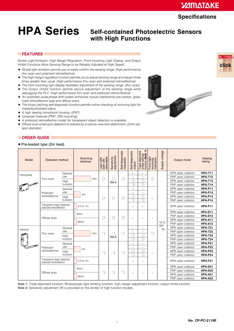
HPA Series Self-contained Photoelectric Sensorswith High Functions
FEATURES
Strobe Light Emission, High Margin Regulation, Front Incoming Light Display, and Output
Inhibit Functions Allow Sensing Range to be Reliably Adjusted at High Speed.
• Strobe light emission permits you to easily confirm the sensing range. (high performance
thru scan and polarized retroreflective)
• The high margin regulation function permits you to adjust sensing range at a margin three
times greater than usual. (high performance thru scan and polarized retroreflective)
• The front incoming light display facilitates adjustment of the sensing range. (thru scan)
• The Output Inhibit function permits secure adjustment of the sensing range while
debugging the PLC. (high performance thru scan and polarized retrore-flective)
• An automatic pulse-phase shift system enhances mutual interference pre-vention. (pola-
rized retroreflective type and diffuse scan)
• The binary latching self-diagnostic function permits online checking of incoming light for
instability/shielded status.
• A high sealing monoblock housing. (IP67)
• Universal Features (PNP, DIN mounting)
• A polarized retroreflective model for transparent object detection is available.
• Diffuse scan small-spot detection is realized by a narrow-view lens attachment. (2mm dia.
spot diameter)
ORDER GUIDE
•Pre-leaded type (2m lead)
Model Detection methodScanningdiatance
Lig
htO
N/
dark
ON
sele
cta
ble
Sensitiv
ity
adju
stm
ent
Self-d
iagnostic
indic
ation
Self-d
iagnostic
outp
ut
Triple
alig
nm
ent
(initia
lse
ttin
g)
funct
ion
(Not
e1)
Fro
ntlight
incom
ing
indic
ation
Supply
voltage
Output modeCataloglisting
Horizontal
Thru scan
Generaluse
Highfunction
10m
(Note 2)
~ ~
10 to
30V
dc
NPN open collector HPA-T11~ ~ PNP open collector HPA-T12
NPN open collector HPA-T13PNP open collector HPA-T14
Polarizedretroreflective
Generaluse
Highfunction
4m
~ ~
~
NPN open collector HPA-P11~ ~ PNP open collector HPA-P12
NPN open collector HPA-P13PNP open collector HPA-P14
Transparent object detectionpolarized retroreflective
0.3 to 1m ~ ~ NPN open collector HPA-F11
Diffuse scan
20cm
~ ~ ~
NPN open collector HPA-D11PNP open collector HPA-D12
80cmNPN open collector HPA-A11PNP open collector HPA-A12
Vertical
Thru scan
Generaluse
Highfunction
10m
(Note 2)
~ ~ NPN open collector HPA-T21~ ~ PNP open collector HPA-T22
NPN open collector HPA-T23PNP open collector HPA-T24
Polarizedretroreflective
Generaluse
Highfunction
4m
~ ~
~
NPN open collector HPA-P21~ ~ PNP open collector HPA-P22
NPN open collector HPA-P23PNP open collector HPA-P24
Transparent object detectionpolarized retroreflective
0.3 to 1m ~ ~ NPN open collector HPA-F21
Diffuse scan
20cm
~ ~ ~
NPN open collector HPA-D21PNP open collector HPA-D22
80cmNPN open collector HPA-A21PNP open collector HPA-A22
Note 1: Triple alignment function: Stroboscopic light emitting function, high margin adjustment function, output inhibit function
Note 2: Sensitivity adjustment VR is provided on the emitter of high function models.

2
•Connector type
Model Detection methodScanningdiatance
Lig
htO
N/
dark
ON
sele
cta
ble
Sensitiv
ity
adju
stm
ent
Self-d
iagnostic
indic
ation
Self-d
iagnostic
outp
ut
Triple
alig
nm
ent
(initia
lse
ttin
g)
funct
ion
(Not
e1)
Fro
ntlight
incom
ing
indic
ation
Supply
voltage
Output modeCataloglisting
Horizontal
Thru scan
Generaluse
Highfunction
10m
(Note 2)
~ ~
10 to
30V
dc
NPN open collector HPA-T31~ ~ PNP open collector HPA-T32
NPN open collector HPA-T33PNP open collector HPA-T34
Polarizedretroreflective
Generaluse
Highfunction
4m
~ ~
~
NPN open collector HPA-P31~ ~ PNP open collector HPA-P32
NPN open collector HPA-P33PNP open collector HPA-P34
Diffuse scan
20cm
~ ~ ~
NPN open collector HPA-D31PNP open collector HPA-D32
80cmNPN open collector HPA-A31PNP open collector HPA-A32
Vertical
Thru scan
Generaluse
Highfunction
10m
(Note 2)
~ ~ NPN open collector HPA-T41~ ~ PNP open collector HPA-T42
NPN open collector HPA-T43PNP open collector HPA-T44
Polarizedretroreflective
Generaluse
Highfunction
4m
~ ~
~
NPN open collector HPA-P41~ ~ PNP open collector HPA-P42
NPN open collector HPA-P43PNP open collector HPA-P44
Diffuse scan
20cm
~ ~ ~
NPN open collector HPA-D41PNP open collector HPA-D42
80cmNPN open collector HPA-A41PNP open collector HPA-A42
Note 1: Triple alignment function: Stroboscopic light emitting function, high margin adjustment function, output inhibit function
Note 2: Sensitivity adjustment VR is provided on the emitter of high function models.
•Pre-leaded connector type (30cm lead)
Model Detection methodScanningdiatance
Lig
htO
N/
dark
ON
sele
cta
ble
Sensitiv
ity
adju
stm
ent
Self-d
iagnostic
indic
ation
Self-d
iagnostic
outp
ut
Triple
alig
nm
ent
(initia
lse
ttin
g)
funct
ion
(Not
e1)
Fro
ntlight
incom
ing
indic
ation
Supply
voltage
Output modeCataloglisting
Horizontal
Thru scan
Generaluse
Highfunction
10m
(Note 2)
~ ~
10 to
30V
dc
NPN open collector HPA-T51~ ~ PNP open collector HPA-T52
NPN open collector HPA-T53PNP open collector HPA-T54
Polarizedretroreflective
Generaluse
Highfunction
4m
~ ~
~
NPN open collector HPA-P51~ ~ PNP open collector HPA-P52
NPN open collector HPA-P53PNP open collector HPA-P54
Diffuse scan
20cm
~ ~ ~
NPN open collector HPA-D51PNP open collector HPA-D52
80cmNPN open collector HPA-A51PNP open collector HPA-A52
Vertical
Thru scan
Generaluse
Highfunction
10m
(Note 2)
~ ~ NPN open collector HPA-T61~ ~ PNP open collector HPA-T62
NPN open collector HPA-T63PNP open collector HPA-T64
Polarizedretroreflective
Generaluse
Highfunction
4m
~ ~
~
NPN open collector HPA-P61~ ~ PNP open collector HPA-P62
NPN open collector HPA-P63PNP open collector HPA-P64
Diffuse scan
20cm
~ ~ ~
NPN open collector HPA-D61PNP open collector HPA-D62
80cmNPN open collector HPA-A61PNP open collector HPA-A62
Note 1: Triple alignment function: Stroboscopic light emitting function, high margin adjustment function, output inhibit function
Note 2: Sensitivity adjustment VR is provided on the emitter of high function models.

3
SPECIFICATIONS
Detection method Thru scan Polarized retroreflective Diffuse scan
Model GeneralHighfunction
GeneralHighfunction
Transparentobjectdetection
Shortdistance
Longdistance
Catalog listingHPA-T 1HPA-T 2
HPA-T 3HPA-T 4
HPA-P 1HPA-P 2
HPA-P 3HPA-P 4
HPA-F11HPA-F21
HPA-D 1HPA-D 2
HPA-A 1HPA-A 2
Supply voltage 10 to 30Vdc (ripple not over 10%)
Current consumption50mA max. (Note 1)Emitter 20mA max.Receiver 30mA max.
40mA max. (Note 1)
Scanning distance 10m 4m (when used with FE-RR8 reflector) 0.3 to 1m 20cm 80cm
Target object Opaque object, 8mm dia. min.Opaque object 80mm dia. min.(when used with FE-RR8 reflector)
~
Standard target object ~ ~10 10cm whitepaper (Note 2)
30 30cm whitepaper (Note 2)
Directional angle 2 to 20˚ Sensor body 1 to 5˚, reflector 40˚ ~
Differential travel ~ 20%
Operation mode Light-operated/dark-operated changeable by switch
Output mode NPN or PNP transistor open collector
Control outputSwitching current: 100mA max. (resistive load) Output dielectric strength: 30V max.Residual voltage: 1V max. (at 100mA switching current), with output short-circuit protection circuit
Self-diagnostic output
None Provided None Provided None None None
Switching current: 50mA max. (resistive load) Output dielectric strength: 30V max.Residual voltage: 1V max. (at 50mA switching current), with output short-circuit protection circuit
Response time0.5ms max. for bothoperation and reset
1ms max. for bothoperation and reset
0.5ms max. for bothoperation and reset
5ms max. for bothoperation and reset
Sensitivity adjustment 2-turn potentiometer with an indicator
Light emitter Red LED Infrared LED
IndicatorOther than thru emitter; Light-operated (LO) indicator: Red (ON during LO),Stability indication: Green [ON during stable LO or DO (dark-operated), flashing during self-diagnostics]Thru emitter; Power indicator: Red (ON while power is supplied), HPA-E13 with SET mode indication: Green light ON
Operating ambient light Incandescent lamp: Max. 5,000lx, Sun light: Max. 20,000lx
Operating ambient temperature ~25 to +60˚C (Note3)
Storage temperature ~40 to +70˚C
Humidity range 35 to 85%RH (Non-condensing)
Insulation resistance 20M min. (by 500Vdc megger)
Dielectric strength 1,000Vac, 50/60Hz for 1min. between case and electrically live metals
Vibration 10 to 55Hz, 1.5mm peak-to-peak amplitude, 2 hours each in X, Y, and Z directions
Shock 490m/s2 repeated 10 times in X, Y, and Z directions
Protection IP67 (IEC standard)
Wiring method Pre-leaded, pre-leaded quick connect, quick connect
Weight About 55g (body only), with 2m cable
Others Equipped with a power ON/OFF malfunction prevention circuit (about 100ms) and reverse connection protection circuit
• Installation Instructions No.: CP-UM-3098E
Note 1: About 30mA consumption current increases at triple alignment operation.
Note 2: CODAK 90% white paper is used.
Note 3: The triple alignment function should be used within the range of 5 to 30˚C.
CATALOG LISTING
HPA- I II III I detection method: T: Thru scan (E for emitter, R for receiver)
P: Polarized retroreflective
D: Short distance diffuse scan
A: Long distance diffuse scan
F: Polarized retroreflective
II Shape / wiring method: 1: Horizontal, pre-leaded
2: Vertical, pre-leaded
3: Horizontal, connector
4: Vertical, connector
5: Horizontal, pre-leaded connector
6: Vertical, pre-leaded connector
III Output mode / function: 1: General purpose NPN transistor output
2: General purpose PNP transistor output
3: High function NPN transistor output
(with self-diagnostic and triple alignment functions)
4: High function PNP transistor output
(with self-diagnostic and triple alignment functions)

4
ATTACHMENT (sold separately)
Name Shape Contents Catalog listing Application model
Slit for thru scan model One set of 2mm, 1mm, 0.5mm, 2mm dia.,
1mm dia., and 0.5mm dia. (for emitter
and receiver)
HPA-U01 All thru scan models
HPA-T
Mutual interference
preven-tion filter for thru
scan model
2 sets of filters (for emitter and receiver) HPA-U02 All thru scan models
HPA-T
Narrow view lens attach-
ment
Narrow view spot light is realized when
lens is attached to the HPA-D. 2mm dia.
at scanning distance 30mm.
HPA-U03 All short distance
diffuse scan models
HPA-D
Small reflector for pola-
rized retroreflective model
A small reflector used when the mounting
space of the reflector is not sufficient. To
be ordered separately from HPA-Por HPA-F .
FE-RR15 All polarized retro-
reflective models
HPA-P ,
HPA-F
Reflector for polarized
retro-reflective model
To be ordered separately from HPA-P or HPA-F .
FE-RR8
Mounting bracket vertical
model
~ HPA-B02 All vertical models
Mounting bracket for verti-
cal model
~ HPA-B03 All modeles (cannot be
used for a connector
model)
EXCESS GAIN (light receving level margin) (typical examples)
•Pre-leaded modelsThru scan model
HPA-T
Thru scan model
HPA-T+Mutual interference prevention filter HPA-U02
Polarized retroreflective model
HPA-P+Reflector FE-RR8/RR15 (horizontal reflector)
Polarized retroreflective model
HPA-P+Reflector FE-RR8/RR15 (vertical reflector)
Short distance diffuse scan model
HPA-D
Long distance diffuse scan model
HPA-A

5
•PARALLEL MOTION CHARACTERISTICS (typical examples)
Thru scan model
HPA-T
Thru scan model HPA-T +
Mutual interference prevention filter HPA-U02 (receiver side)
Polarized retroreflective model
HPA-P+Reflector FE-RR8/RR15 (vertical direction)
Polarized retroreflective model
HPA-P+Reflector FE-RR8/RR15 (horizontal direction)
Transparent object detection, polarized retroreflective model
HPA-F+Reflector FE-RR8/RR15 (vertical direction)
Transparent object detection, polarized retroreflective model
HPA-F+Small reflector FE-RR15 (horizontal direction)
DETECTION AREA CHARACTERISTICS (typical examples)
Short distance diffuse scan model
HPA-D
Short distance diffuse scan model HPA-D
+Narrow view lens attachment HPA-U03
Long distance diffuse scan model
HPA-A
DETECTION OBJECT WIDTH VS SCANNING DISTANCE (typical examples)
Short distance diffuse scan model
HPA-D
Short distance diffuse scan model HPA-D
+Narrow view lens attachment HPA-U03
Long distance diffuse scan model
HPA-A
ANGULAR CHARACTERISTICS (typical examples)
Thru scan model
HPA-T
Polarized retroreflective model
HPA-P+Reflector FE-RR8/RR15 (vertical direction)
Polarized retroreflective model
HPA-P+Reflector FE-RR8/RR15 (receiver side)

6
SCANNING DISTANCE VS. SPOT DIAMETER CHARACTERISTICS
HPA-D
+Narrow view lens attachment HPA-U03
TYPICAL VALUES OF SCANNING DISTANCE CHARACTERISTICS WITH USE OF SLIT (ratio to the value without use of slit)
SlitSlit used toemitter only
Slit used toreceiver only
Slit used toemitter/receiver
2mm 46% 46% 18%
1mm 30% 32% 11%
0.5mm 16% 21% 3.6%
2mm dia. 15% 25% 3.6%
1mm dia. 4.8% 12% 0.6%
EXTERNAL DIMENSIONS
(unit: mm)•General use thru scan model •High function thru scan model• Horizontal type (pre-leaded, pre-leaded connector)
HPA-T11, T12, T51, T52
• Horizontal type (pre-leaded, pre-leaded connector)
HPA-T13, T14, T53, T54Emitter Receiver Common to emitter and receiver
• Polyvinyl chloride insulated cord (oil resistant type: 0.2mm2) 4.2dia.Standard cord length 2m (pre-leaded)Lead colors ..... Receiver: Gray
Emitter: Black (pre-leaded)Gray (pre-leaded connector)
• Polyvinyl chloride insulated cord (oil resistanttype:0.2mm2) 4.2dia.Standard cord length 2m (pre-leaded)Lead colors ..... Receiver: Gray
Emitter: Black (pre-leaded)Gray (pre-leaded con-nector)

7
(unit: mm)•General use thru scan model •High function thru scan model• Vertical type (pre-leaded, pre-leaded connector)
HPA-T21, T22, T61, T62
• Vertical type (pre-leaded, pre-leaded connector)
HPA-T23, T24, T63, T64Emitter Receiver Common to emitter and receiver
• Polyvinyl chloride insulated cord (oil resistant type: 0.2mm2) 4.2dia.Standard cord length 2m (pre-leaded)Lead colors ..... Receiver: Gray
Emitter: Black (pre-leaded)Gray (pre-leaded connector)
• Polyvinyl chloride insulated cord (oil resistant type:0.2mm2) 4.2dia.Standard cord length 2m (pre-leaded)Lead colors ..... Receiver: Gray
Emitter: Black (pre-leaded)Gray (pre-leaded con-nector)
•Polarized retroreflective model• Horizontal type (pre-leaded, pre-leaded connector)
HPA-P11, P12, P13, P14, P51, P52, P53, P54, F11
•Polarized retroreflective model• Vertical type (pre-leaded, pre-leaded connector)
HPA-P21, P22, P23, P24, P61, P62, P63, P64, F21
• Polyvinyl chloride insulated cord (oil resistant type: 0.2mm2) 4.2dia.Standard cord length 2m (pre-leaded)Lead colors ..... Gray
• Polyvinyl chloride insulated cord (oil resistant type: 0.2mm2) 4.2dia.Standard cord length 2m (pre-leaded)Lead colors ..... Gray
•Diffuse scan model •Diffuse scan model• Horizontal type (pre-leaded, pre-leaded connector)
HPA-D11, D12, A11, A12
• Vertical type (pre-leaded, pre-leaded connector)
HPA-D21, D22, A21, A22
• Polyvinyl chloride insulated cord (oil resistant type: 0.2mm2) 4.2dia.Standard cord length 2m (pre-leaded)Lead colors ..... Gray
• Polyvinyl chloride insulated cord (oil resistant type: 0.2mm2) 4.2dia.Standard cord length 2m (pre-leaded)Lead colors ..... Gray
8
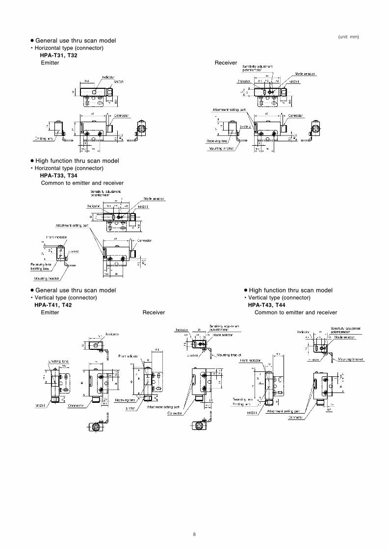
(unit: mm)•General use thru scan model• Horizontal type (connector)
HPA-T31, T32Emitter Receiver
•High function thru scan model• Horizontal type (connector)
HPA-T33, T34Common to emitter and receiver
•General use thru scan model• Vertical type (connector)
HPA-T41, T42
•High function thru scan model• Vertical type (connector)
HPA-T43, T44Emitter Receiver Common to emitter and receiver

9
(unit: mm)•Polarized retroreflective model• Horizontal type (connector)
HPA-P31, P32, P33, P34
•Polarized retroreflective model• Vertical type (connector)
HPA-P41, P42, P43, P44
•Diffuse scan model• Horizontal type (connector)
HPA-D31, D32, A31, A32
•Diffuse scan model• Vertical type (connector)
HPA-D41, D42, A41, A42
•Pre-leaded connector type connector (external dimensions of connector)
HPA- 5 , 6
• Cord length 30cm
•Bracket• Mounting bracket HPA-B01 (attached as standard)
(When mounted on horizontal model) (When mounted on vertical model)
10
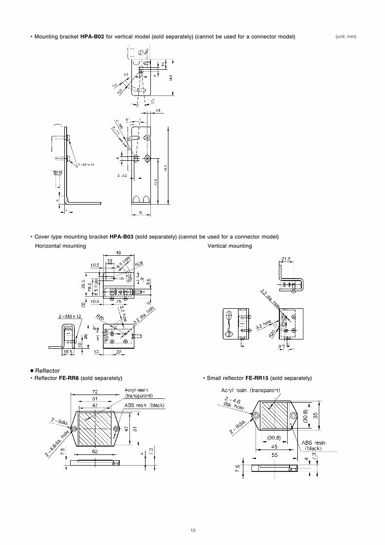
(unit: mm)• Mounting bracket HPA-B02 for vertical model (sold separately) (cannot be used for a connector model)
• Cover type mounting bracket HPA-B03 (sold separately) (cannot be used for a connector model)
Horizontal mounting Vertical mounting
•Reflector• Reflector FE-RR8 (sold separately) • Small reflector FE-RR15 (sold separately)
11
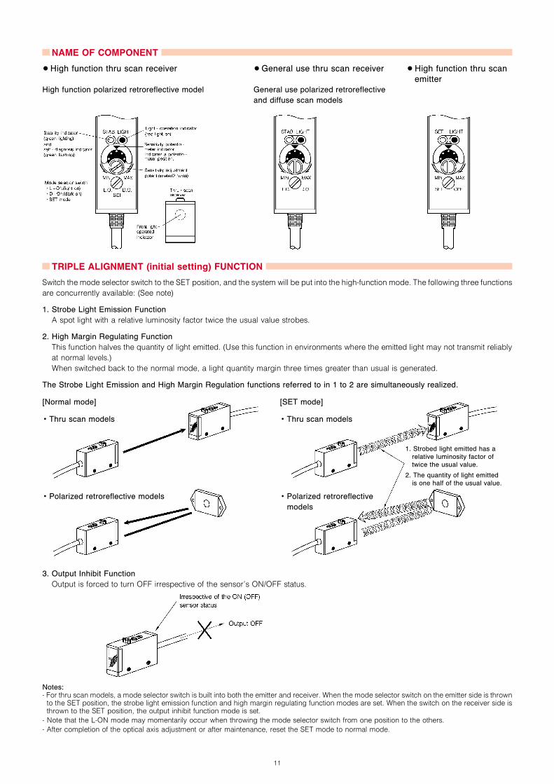
NAME OF COMPONENT
•High function thru scan receiver •General use thru scan receiver •High function thru scan
emitter
High function polarized retroreflective model General use polarized retroreflective
and diffuse scan models
TRIPLE ALIGNMENT (initial setting) FUNCTION
Switch the mode selector switch to the SET position, and the system will be put into the high-function mode. The following three functions
are concurrently available: (See note)
1. Strobe Light Emission Function
A spot light with a relative luminosity factor twice the usual value strobes.
2. High Margin Regulating Function
This function halves the quantity of light emitted. (Use this function in environments where the emitted light may not transmit reliably
at normal levels.)
When switched back to the normal mode, a light quantity margin three times greater than usual is generated.
The Strobe Light Emission and High Margin Regulation functions referred to in 1 to 2 are simultaneously realized.
[Normal mode] [SET mode]
• Thru scan models • Thru scan models
1. Strobed light emitted has arelative luminosity factor oftwice the usual value.
2. The quantity of light emittedis one half of the usual value.
• Polarized retroreflective models • Polarized retroreflective
models
3. Output Inhibit Function
Output is forced to turn OFF irrespective of the sensor’s ON/OFF status.
Notes:- For thru scan models, a mode selector switch is built into both the emitter and receiver. When the mode selector switch on the emitter side is thrownto the SET position, the strobe light emission function and high margin regulating function modes are set. When the switch on the receiver side isthrown to the SET position, the output inhibit function mode is set.
- Note that the L-ON mode may momentarily occur when throwing the mode selector switch from one position to the others.
- After completion of the optical axis adjustment or after maintenance, reset the SET mode to normal mode.
12
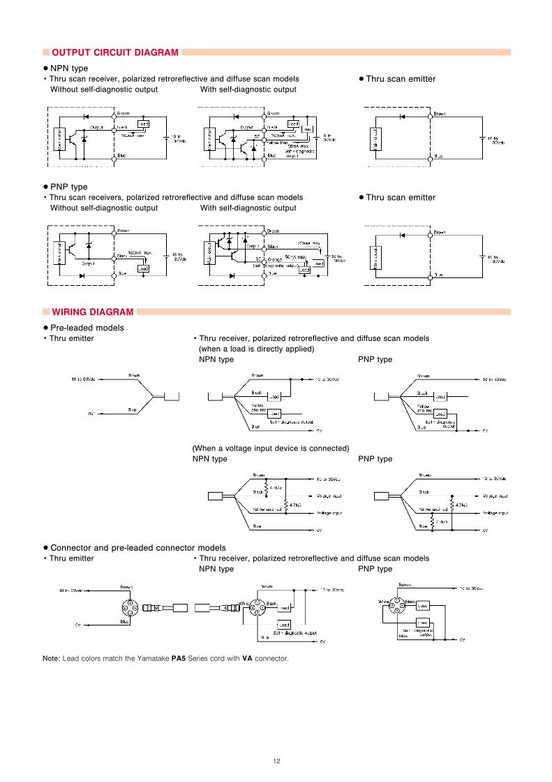
OUTPUT CIRCUIT DIAGRAM
•NPN type• Thru scan receiver, polarized retroreflective and diffuse scan models •Thru scan emitter
Without self-diagnostic output With self-diagnostic output
•PNP type• Thru scan receivers, polarized retroreflective and diffuse scan models •Thru scan emitter
Without self-diagnostic output With self-diagnostic output
WIRING DIAGRAM
•Pre-leaded models• Thru emitter • Thru receiver, polarized retroreflective and diffuse scan models
(when a load is directly applied)
NPN type PNP type
(When a voltage input device is connected)
NPN type PNP type
•Connector and pre-leaded connector models• Thru emitter • Thru receiver, polarized retroreflective and diffuse scan models
NPN type PNP type
Note: Lead colors match the Yamatake PA5 Series cord with VA connector.

13
OPERATIONAL TIMING CHARTS OF OUTPUT AND INDICATORS
The HPA’s self-diagnostic output and indicators latch when there is:
insufficient incoming light (due to a decrease in the quantity of light caused by dirt, etc.)
an incompletely blocked light (due to irregular position of a workpiece, etc.).
Latches in the dark on (DO) mode or in the LIGHT ON (LO) mode.
•Diagnosis of incoming light
Explanation of timing charts:1. If the photoelectric sensor returns to the stable DO level without reaching the stable
LO state after the photoelectric sensor operates, the self-diagnostic output will goON and latch high when the stability indicator starts blinking.
2. The self-diagnostic output will go OFF and latch low when the quantity of lightreceived reaches the stable LO level 2 and the stability indicator finishes blinking.
•Diagnosis of blocked light
Explanation of timing charts:1. If the photoelectric sensor returns to the stable LO level without reaching the stable
DO state after the photoelectric sensor operates, the self-diagnostic output will goON and latch high when the stability indicator starts blinking.
2. The self-diagnostic output will go OFF and latch low when the quantity of lightreceived reaches the stable DO level (as shown at 2 above) and the stability indi-cator finishes blinking (self-diagnostic indication).
Caution: Status that may not be diagnosed: The control output willbe inverted in an unstable LO and DO state.When a workpiece with a slight difference in the quantity reflected oflight is scanned, such as in scanning a transparent body, the quantityof light received will neither fall to the stable DO level nor rise to thestable LO level. In this case, neither the self-diagnostic output nor theindicating lamps go ON. An incoming light signal is neither outputnor indicated until the quantity of light received falls to the stable DOlevel. An blocked light signal is neither output nor indicated until thequan-tity of light received rises to the stable LO level.
14
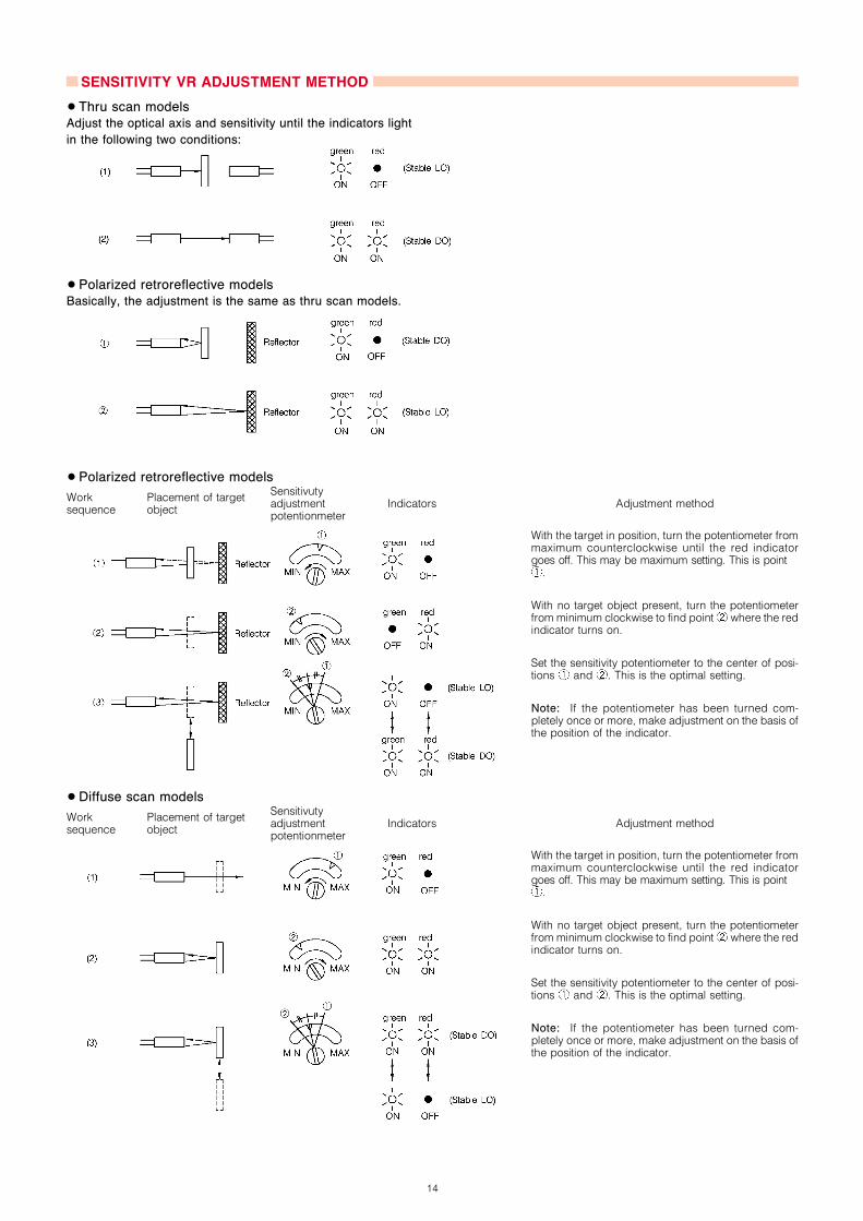
SENSITIVITY VR ADJUSTMENT METHOD
•Thru scan models
Adjust the optical axis and sensitivity until the indicators light
in the following two conditions:
•Polarized retroreflective models
Basically, the adjustment is the same as thru scan models.
•Polarized retroreflective models
Worksequence
Placement of targetobject
Sensitivutyadjustmentpotentionmeter
Indicators Adjustment method
With the target in position, turn the potentiometer frommaximum counterclockwise until the red indicatorgoes off. This may be maximum setting. This is point
.
With no target object present, turn the potentiometerfrom minimum clockwise to find point where the redindicator turns on.
Set the sensitivity potentiometer to the center of posi-tions and . This is the optimal setting.
Note: If the potentiometer has been turned com-pletely once or more, make adjustment on the basis ofthe position of the indicator.
•Diffuse scan models
Worksequence
Placement of targetobject
Sensitivutyadjustmentpotentionmeter
Indicators Adjustment method
With the target in position, turn the potentiometer frommaximum counterclockwise until the red indicatorgoes off. This may be maximum setting. This is point
.
With no target object present, turn the potentiometerfrom minimum clockwise to find point where the redindicator turns on.
Set the sensitivity potentiometer to the center of posi-tions and . This is the optimal setting.
Note: If the potentiometer has been turned com-pletely once or more, make adjustment on the basis ofthe position of the indicator.

15
CONNECTOR SPECIFICATIONS Note 1
Item Specifications
Operating voltage / current 5Vac/dc, 5mA min., 125Vac/dc, 3A max.
Insulation resistance 100M min. (by 500Vdc megger)
Dielectric strength 1500Vac, for 1min (between contacts, between contact and connector housing)
Initial contact resistance 40m max., (when 3A current is fed to a male/female contact, except for the resistances of cords)
Connector pulling-out force 0.4 to 4.0N (per contact)
Number of times of connector pul-ling-out 50 times
Contact fastening strength 0.8Nm min (See note 2)
Cord tensile strength 100N min
Vibration 10 to 55Hz, peak-to-peak amplitude 1.5mm, 2hr each direction of X, Y and Z
Shock 300m/s2 (about 30G), three times in each direction of X, Y and Z
Protection IP67 (IP65 with panel-mount connector)
Operating ambient temperature ~10 to +70˚C
Storage temperature ~20 to +80˚C
Humidity range 95%RH max.
Material
Contacts: Gold-plated brass Contact holder: Glass-lined polyester resin
Housing: Polyester elastomer (panel-mount contactor housing: A1)
Coupling: Ni-plated brass
O-ring: NBR
Notes: 1. Specifications assume Yamatake male/female connectors.
2. The recommended torque is 0.4 to 0.6N-m.If fastened poorly, the IP67 protection is lost, or looseness occurs.Fasten the connector securely by hand.
CONNECTION CORD WITH CONNECTOR
Be sure to use PA5 Series cord with VA connector when connecting a pre-leaded connector or connector type sensors.
• PA5 Series cord with VA connector
Shape Power supply Cord length Catalog listing Lead color
dc
2m PA5-4ISX2HK
1-brown, 2-white, 3-blue, 4-black5m PA5-4ISX5HK
2m PA5-4ILX2HK
5m PA5-4ILX5HK
PA5 Series cordwith VA connector
Pre-leaded connector model
Female
Male
Connector model
Male
•Fastening the connector
Align the grooves of the connectors and turn the fastening screw
of the VA connector of the PA5 cord by hand until it fits tightly
with the screw on the sensor side.

16
BASIC PRECAUTIONS
•Wiring• Be sure to connect a photoelectric sensor to the power supply
and load correctly.
• If a high-voltage or power cable exists near a photoelectric
sensor cord, lay the photoelectric sensor’s cord independently
or lay in another conduit to prevent surge and noise influence.
• Connect the lead end securely using crimp terminals.
• Use a cord of at least 0.3mm2 in cross-sectional area for ex-
tensions. The lead length should not be over 100m. Consider
the influence of noise due to lead extension.
• If a controlling power unit is used, ground its frame.
• If capacitive load is used, connect a current limiting resistor so
as to limit the inrush current to max. 100mA.
•Handling• Do not swing a photoelectric sensor by its lead.
• Do not pull the cord of a photoelectric sensor with excessive
force. The tensile strength of the lead is 49N max.
• Do not impact or damage the sensing head.
• Do not use a photoelectric sensor outdoors, in environments
where chemicals (organic solvent, acid, alkali) are present, or
where there is water or oil may splash onto the sensor.
• Fasten the connectors securely by hand.
• Set the bending radius R of the cord to 30mm min.
•Polarized retroreflective model
The polarized retroreflective model uses a light-polarizing filter,
and employs a detection method intended to prevent reflection
from mirror surfaces or shiny detection objects. For this reason,
malfunction may occur when the characteristics of the detection
body are such that the body itself polarizes light. Check this
before use.
Example
: Detection objects covered in transparent film
: Mirror surfaces with slight surface unevenness or shiny
detection objects
RESTRICIONS ON USEThis product has been designed, developed and manufactured for general-purpose application in machinery and equipment.Accordingly, when used in applications outlined below, special care should be taken to implement a fail-safe and/or redundantdesign concept as well as a periodic maintenance program.
- Safety devices for plant worker protection- Start/stop control devices for transportation and material handling machines- Aeronautical/aerospace machines- Control devices for nuclear reactors
Never use this product in applications where human safety may be put at risk.
(01)Printed in Japan (SP)
1st Edition: lssued in Apr., 2002
2nd Edition: Issued in Oct., 2003
Related Documents