Specification for Subsea Wellhead and Tree Equipment API SPECIFICATION 17D THIRD EDITION, XXXX 2021

Welcome message from author
This document is posted to help you gain knowledge. Please leave a comment to let me know what you think about it! Share it to your friends and learn new things together.
Transcript

Specification for Subsea Wellhead and Tree Equipment
API SPECIFICATION 17D THIRD EDITION, XXXX 2021

Special Notes API publications necessarily address problems of a general nature. With respect to particular circumstances, local, state, and federal laws and regulations should be reviewed.
Neither API nor any of API's employees, subcontractors, consultants, committees, or other assignees make any warranty or representation, either express or implied, with respect to the accuracy, completeness, or usefulness of the information contained herein, or assume any liability or responsibility for any use, or the results of such use, of any information or process disclosed in this publication. Neither API nor any of API's employees, subcontractors, consultants, or other assignees represent that use of this publication would not infringe upon privately owned rights.
API publications may be used by anyone desiring to do so. Every effort has been made by the Institute to assure the accuracy and reliability of the data contained in them; however, the Institute makes no representation, warranty, or guarantee in connection with this publication and hereby expressly disclaims any liability or responsibility for loss or damage resulting from its use or for the violation of any authorities having jurisdiction with which this publication may conflict.
API publications are published to facilitate the broad availability of proven, sound engineering and operating practices. These publications are not intended to obviate the need for applying sound engineering judgment regarding when and where these publications should be used. The formulation and publication of API publications is not intended in any way to inhibit anyone from using any other practices.
Any manufacturer marking equipment or materials in conformance with the marking requirements of an API standard is solely responsible for complying with all the applicable requirements of that standard. API does not represent, warrant, or guarantee that such products do in fact conform to the applicable API standard.
All rights reserved. No part of this work may be reproduced, translated, stored in a retrieval system, or transmitted by any means, electronic, mechanical, photocopying, recording, or otherwise, without prior written permission from the
publisher. Contact the Publisher, API Publishing Services, 200 Massachusetts Ave, Washington, DC 20001.
copyright © 2020 American Petroleum Institute
Foreword Nothing contained in any API publication is to be construed as granting any right, by implication or otherwise, for the manufacture, sale, or use of any method, apparatus, or product covered by letters patent. Neither should anything contained in the publication be construed as insuring anyone against liability for infringement of letters patent.
The verbal forms used to express the provisions in this document are as follows.
Shall: As used in a standard, “shall” denotes a minimum requirement in order to conform to the standard.
Should: As used in a standard, “should” denotes a recommendation or that which is advised but not required in order to conform to the standard.
May: As used in a standard, “may” denotes a course of action permissible within the limits of a standard.
Can: As used in a standard, “can” denotes a statement of possibility or capability.
This document was produced under API standardization procedures that ensure appropriate notification and participation in the developmental process and is designated as an API standard. Questions concerning the interpretation of the content of this publication or comments and questions concerning the procedures under which this publication was developed should be directed in writing to the Director of Standards, American Petroleum Institute, 1220 L Street, NW, Washington, DC 20005. Requests for permission to reproduce or translate all or any part of the material published herein should also be addressed to the director.
Generally, API standards are reviewed and revised, reaffirmed, or withdrawn at least every five years. A one-time extension of up to two years may be added to this review cycle. Status of the publication can be ascertained from the API Standards Department, telephone (202) 682-8000. A catalog of API publications and materials is published annually by API, 1220 L Street, NW, Washington, DC 20005.
Suggested revisions are invited and should be submitted to the Standards Department, API, 200 Massachusetts Ave, Washington, DC 20001, [email protected].

Contents Page
1 Scope ................................................................................................................................................. 4 2 Normative References ...................................................................................................................... 5 3 Terms, Definitions, Abbreviated Terms, and Symbols .................................................................. 6
3.1 Terms and Definitions ......................................................................................................................... 6
3.2 Abbreviated Terms and Symbols ...................................................................................................... 13 4 Application, Service Conditions, and Production Specification Levels .................................... 15
4.1 Application ........................................................................................................................................ 15
4.2 Service Conditions ............................................................................................................................ 18
4.3 Product Specification Levels ............................................................................................................ 18 5 Common System Requirements ................................................................................................... 19
5.1 Design and Performance Requirements ........................................................................................... 19
5.2 Materials ........................................................................................................................................... 30
5.3 Welding ............................................................................................................................................. 31
5.4 Quality Control .................................................................................................................................. 31
5.5 Equipment Marking ........................................................................................................................... 35
5.6 Storing and Shipping ......................................................................................................................... 36 6 General Design Requirements for Subsea Tree Systems .......................................................... 37
6.1 General ............................................................................................................................................. 37
6.2 Tubing Head and Tree Valving ......................................................................................................... 38
6.3 Thermally Induced Pressure Changes ............................................................................................. 46
6.4 Testing of Subsea Tree Assemblies ................................................................................................. 46
6.5 Marking ............................................................................................................................................. 47
6.6 Storing and Shipping ......................................................................................................................... 47 7 Specific Requirements—Subsea Tree-Related Equipment and Subassemblies ..................... 51
7.1 Flanged End and Outlet Connections ............................................................................................... 51
7.2 API Clamp Hub-type Connections..................................................................................................... 74
7.3 Threaded Connections ...................................................................................................................... 74
7.4 Other End Connectors ...................................................................................................................... 74
7.5 Studs, Nuts and Bolting ..................................................................................................................... 74
7.6 Crosses, Tees, and Elbows ............................................................................................................... 75
7.7 Completion Guidebase...................................................................................................................... 75
7.8 Tree and Tubing Head Connectors ................................................................................................... 76
7.9 Tree stab/seal Subs for Vertical Tree ................................................................................................ 79
7.10 Valves, Valve Blocks and Actuators/Operators ............................................................................ 80
7.11 Re-entry Interface ........................................................................................................................ 92
7.12 Subsea Tree Cap ......................................................................................................................... 93
7.13 Tree Cap Running Tool ............................................................................................................... 96
7.14 Tree and Tubing Head Guide Frames ......................................................................................... 98

7.15 Tree Running Tool ..................................................................................................................... 101
7.16 Tree, Tubing Head, and Completion Guide Base Piping .......................................................... 104
7.17 Flowline Connections ................................................................................................................. 105
7.18 Ancillary Equipment Running Tools ........................................................................................... 108
7.19 Tree-mounted Hydraulic/electric/optical Control Interfaces ........................................................ 109
7.20 Subsea Chokes and Actuators/operators .................................................................................. 113
7.21 Miscellaneous Equipment .......................................................................................................... 124 8 Specific Requirements—Subsea Wellhead ................................................................................ 125
8.1 General ........................................................................................................................................... 125
8.2 Temporary Guidebase .................................................................................................................... 126
8.3 Permanent Guidebase .................................................................................................................... 127
8.4 Conductor (low pressure) Housing ................................................................................................. 132
8.5 Wellhead (high-pressure) Housing ................................................................................................. 134
8.6 Casing Hangers .............................................................................................................................. 137
8.7 Annulus Seal Assemblies ................................................................................................................ 140
8.8 Casing Hanger Lockdown Bushing ................................................................................................. 141
8.9 Bore Protectors and Wear Bushings ............................................................................................... 142
8.10 Corrosion Cap ............................................................................................................................ 143
8.11 Running, Retrieving and Testing Tools ...................................................................................... 143
8.12 Over-Trawlable Protection Structure ......................................................................................... 143
8.13 Wellhead Inclination and Orientation.......................................................................................... 143
8.14 Submudline Casing Hanger and Submudline Annulus Seal Assemblies ...................................... 143 9 Specific Requirements—Subsea Tubing Hanger System ......................................................... 144
9.1 Design ............................................................................................................................................. 144
9.2 Materials ......................................................................................................................................... 147
9.3 Testing ............................................................................................................................................ 147 10 Specific Requirements—Mudline Suspension Equipment ....................................................... 148
10.1 General ...................................................................................................................................... 148
10.2 Mudline Suspension-landing/elevation Ring .............................................................................. 151
10.3 Casing Hangers ......................................................................................................................... 152
10.4 Casing Hanger Running Tools and Tieback Adapters ............................................................... 153
10.5 Abandonment Caps ................................................................................................................... 153
10.6 Mudline Conversion Equipment for Subsea Completions .......................................................... 154
10.7 Tubing Hanger System—Mudline Conversion Equipment for Subsea Completions ................. 154 11 Specific Requirements—Drill-through Mudline Suspension Equipment ................................ 155
11.1 General ...................................................................................................................................... 155
11.2 External Drill-through Casing Hangers (Outside of the drill-through Casing Hanger Housing) .. 155
11.3 Drill-through Casing Hanger Housing ......................................................................................... 155
11.4 Internal Drill-through Mudline Casing Hangers .......................................................................... 157

11.5 Internal Drill-through Annulus Seal Assemblies ......................................................................... 158
11.6 Internal Drill-through Bore Protectors and Wear Bushings ........................................................ 158
11.7 Tubing Hanger System—Drill-through Mudline Equipment for Subsea Completions ................ 159 ...................................................................................................................................................... 160 ...................................................................................................................................................... 162
B.1 General .......................................................................................................................................... 162
B.2 Typical Wellhead and Tree Configurations .................................................................................... 162
B.3 Product Specification Levels .......................................................................................................... 162
B.4 Material Class ................................................................................................................................ 163
B.5 Data Sheets ................................................................................................................................... 164 ...................................................................................................................................................... 181
C.1 Scope ............................................................................................................................................. 181
C.2 Selection of Steel Forging Classes (SFC) .................................................................................... 181 ...................................................................................................................................................... 183
D.1 Scope ............................................................................................................................................. 183
D.2 Functional Specifications ............................................................................................................... 184
D.3 Load Descriptions .......................................................................................................................... 185
D.4 Risk Analysis ................................................................................................................................. 185
D.5 Design Verification ......................................................................................................................... 185
D.6 Materials Selection, Characterization, and Qualification ............................................................... 186
D.7 Design Validation ........................................................................................................................... 188
D.8 Quality Assurance and Product Specification Level ...................................................................... 189 ....................................................................................................................................................... 191
E.1 General .......................................................................................................................................... 191
E.2 Calculation of Pressure Ratings for Mudline Suspension Equipment ............................................ 191 ....................................................................................................................................................... 198
F.1 Scope ............................................................................................................................................. 198
F.2 Guidelines for Assembly ................................................................................................................ 202 ...................................................................................................................................................... 207
G.1 General .......................................................................................................................................... 207
G.2 Design ............................................................................................................................................ 208
G.3 Design Calculations and Loading Criteria ..................................................................................... 213
G.4 Factory Testing of Equipment Lift Points and Primary Load Path Members ................................. 218
G.5 Maintenance .................................................................................................................................. 219
G.6 Marking Requirements ................................................................................................................... 219 ...................................................................................................................................................... 220
H.1 General .......................................................................................................................................... 220
H.2 Design ............................................................................................................................................ 220
H.3 Materials ........................................................................................................................................ 221
H.4 Testing ........................................................................................................................................... 221 ........................................................................................................................................................ 222
I.1 General ........................................................................................................................................... 222
I.2 Purpose........................................................................................................................................... 222
I.3 Surface Preparation ........................................................................................................................ 222
I.4 Priming ............................................................................................................................................ 223
I.5 Coating Systems ............................................................................................................................. 223
I.6 Touch-up of Coating System ........................................................................................................... 223
I.7 Inspection ....................................................................................................................................... 224 ....................................................................................................................................................... 225
J.1 Scope .............................................................................................................................................. 225
J.2 General Requirements .................................................................................................................... 225
J.3 Validation of Actuated Valves ......................................................................................................... 225
J.4 Validation of Hydraulic Actuators .................................................................................................... 226
J.5 Validation of Valves with Manual Operator (ROV/Diver Operated) ................................................ 227
J.6 Other Valves ................................................................................................................................... 228
J.7 Documentation ................................................................................................................................ 228 ...................................................................................................................................................... 229
K.1 General .......................................................................................................................................... 229
K.2 Level 1 Screening Tests ................................................................................................................ 229
K.3 Level 2 Screening Tests ................................................................................................................ 231
K.4 Level 3 Screening Tests ................................................................................................................ 232 ....................................................................................................................................................... 234 ...................................................................................................................................................... 238 ...................................................................................................................................................... 240 ...................................................................................................................................................... 242 ....................................................................................................................................................... 245
Specification for Subsea Wellhead and Tree Equipment
1 Scope
This document provides specifications for subsea wellheads, mudline wellheads, drill-through mudline wellheads and both vertical and horizontal subsea trees. It specifies the associated tooling necessary to

handle, test and install the equipment. It also specifies the areas of design, material, welding, quality control (including factory acceptance testing), marking, storing and shipping for individual equipment, sub-assemblies, and subsea tree assemblies.
The user/purchaser is responsible for ensuring subsea equipment meets any additional requirements of governmental regulations for the country in which it is installed. This is outside the scope of this specification.
This specification is not applicable to the rework and repair of used equipment.
In-situ testing is beyond the scope of this specification.
SIT is beyond the scope of this specification.
2 Normative References
The following referenced documents are indispensable for the application of this document. For dated references, only the edition cited applies. For undated references, the latest edition of the referenced document (including any amendments) applies, except that new editions may be used on issue and shall become mandatory upon the effective date specified by the publisher or 6 months from the date of the revision (where no effective date is specified).
API Specification 5B, Specification for Threading, Gauging, and Thread Inspection of Casing, Tubing, and Line Pipe Threads (US Customary Units)
API Specification 5DP, Drill Pipe
API Specification 6A, Specification for Wellhead and Tree Equipment, 21st Edition
API Specification 6AV1, Specification for Validation of Wellhead Surface Safety Valves and Underwater Safety Valves for Offshore Service
API Specification 16A, Specification for Drill-Through Equipment
API Recommended Practice 17A, Design and Operation of Subsea Production Systems—General Requirements and Recommendations
API Standard 17F, Standard for Subsea Production Control Systems
API Standard 17G, Recommended Practice for Completion/Workover Riser
API Recommended Practice 17H, Remotely Operated Tools and Interfaces on Subsea Production Systems
API Recommended Practice 17R, Recommended Practice for Flowline Connectors and Jumpers
API TR 17TR7, Verification and Validation of Subsea Connectors
API TR 17TR8, High-pressure High-temperature Design Guidelines
API Specification 20E, Alloy and Carbon Steel Bolting for use in the Petroleum and Natural Gas Industries
API Specification 20F, Corrosion-resistant Bolting for use in the Petroleum and Natural Gas Industries
ASME B16.11 1, Forged Fittings, Socket-Welding and Threaded
1 American Society of Mechanical Engineers, Two Park Avenue, New York, New York 10016, www.asme.org.

ASME B31.3, Process Piping
ASME Boiler and Pressure Vessel Code (BPVC), Section VIII: Pressure Vessels; Division 2: Alternative Rules
ASME Boiler and Pressure Vessel Code (BPVC), Section VIII: Pressure Vessels; Division 3: Alternative Rules for Construction of High Pressure Vessels
ASTM 2 D1414, Standard Test Methods for Rubber O-Rings
DNVGL-RP-B4013, Cathodic Protection Design
DNVGL-RP-0034, Steel Forgings for Subsea Applications
ISO 4 8501-1, Preparation of steel substrates before application of paints and related products — Visual assessment of surface cleanliness — Part 1: Rust grades and preparation grades of uncoated steel substrates and of steel substrates after overall removal of previous coatings
NACE MR 0175/ISO 15156 5 (all parts), Petroleum and natural gas industries — Materials for use in H2S-containing environments in oil and gas production
NACE No. 2/SSPC-SP 10, Joint Surface Preparation Standard: Near-White Metal Blast Cleaning
NACE SP0176, Corrosion Control of Submerged Areas of Permanently Installed Steel Offshore Structures Associated with Petroleum Production
SAE/AS 4059 6, Aerospace Fluid Power — Cleanliness Classification for Hydraulic Fluids
SAE J517, Hydraulic Hose
SAE J343, Test and Test Procedures for SAE 100R Series Hydraulic Hose and Hose Assemblies
3 Terms, Definitions, Abbreviated Terms, and Symbols
3.1 Terms and Definitions
For the purposes of this document, the following terms and definitions shall apply.
3.1.1 actuator Mechanism for the remote operation of a valve or choke.
3.1.2 annulus seal assembly Mechanism that provides pressure isolation between each casing hanger and the wellhead (high-pressure) housing.
2 ASTM International, 100 Barr Harbor Drive, West Conshohocken, Pennsylvania 19428, www.astm.org.
3 DNV GL, 1560 Wilson Boulevard, Arlington, Virginia, 22209, www.dnvgl.com.
4 International Organization for Standardization, BIBC II, Chemin de Blandonnet 8, CP 401, 1214 Vernier, Geneva, Switzerland, www.iso.org.
5 NACE International, 15835 Park Ten Place, Houston, Texas 77084, www.nace.org.
6 SAE International, 400 Commonwealth Drive, Warrendale, Pennsylvania 15096, www.sae.org.

3.1.3 backdriving Unplanned movement.
3.1.4 bore protector Device that protects internal bore surfaces during drilling or workover operations.
3.1.5 check valve Device designed to prevent flow in one direction.
3.1.6 choke Equipment used to restrict and control the flow of fluids and gas.
3.1.7 closure bolting Threaded fasteners used to assemble well-bore pressure containing parts or join end or outlet connections.
EXAMPLES Flange bolting, bonnet bolting, end connection bolting, and clamp bolting.
3.1.8 conductor (low pressure) housing Top of the first casing string, which forms the basic foundation of the subsea wellhead and provides attachments for guidance structures.
3.1.9 corrosion cap Cap placed over the wellhead to protect it from contamination by debris, marine growth or corrosion during temporary abandonment of the well.
3.1.10 corrosion-resistant alloy CRA Nonferrous-based alloy in which any one or the sum of the specified amount of the element titanium, nickel, cobalt, chromium, and molybdenum exceeds 50% mass fraction.
NOTE This definition is different from that in NACE MR0175/ISO 15156
3.1.11 corrosion-resistant material CRM Ferrous or non-ferrous alloy that is more corrosion resistant than low-alloy steels.
NOTE This term includes CRAs, duplex, and stainless steels.
3.1.12 critical bolting Threaded fasteners in the vertical load path from the subsea wellhead to the top connection of the subsea tree that are subjected to additional environmental loading resulting from the coupling of well control and well intervention equipment whose failure will result in the release of wellbore fluid to the environment.
3.1.13 crossover valve optional valve that, when opened, allows communication between the annulus and production tree paths, which are normally isolated.

3.1.14 depth rating Maximum water depth at which equipment is designed to function.
3.1.15 downstream Direction of movement away from the reservoir.
3.1.16 event, extreme Occurrence that produces operating conditions that exceed normal operating conditions and include the unavoidable but predictable load conditions due to environmental and operating scenarios; rated working pressure or temperature is not exceeded during the event.
NOTE Loading conditions for an extreme event can be specified by the user/purchaser in accordance with API 17G and API 17 TR7.
3.1.17 event, normal Occurrence that produces operating conditions that include all loads, individual and combined, as defined by operational criteria up to extreme conditions; rated working pressure or temperature is not exceeded during the event.
3.1.18 event, survival Occurrence that produces operating conditions that exceed extreme conditions and include the unplanned unavoidable, and unpredictable load conditions due to the environmental, operating, or any other scenarios; rated working pressure or temperature is not exceeded during the event.
NOTE Loading conditions for a survival event can be specified by the user/purchaser in accordance with API 17G and API 17 TR7.
3.1.19 extension sub Sealing tubular member that provides tree-bore continuity between adjacent tree components.
3.1.20 fail-closed valve Actuated valve designed to revert to the closed position when the actuator is de-energized.
3.1.21 fail-in-place valve Actuated valve designed to remain in its current position when the actuator is de-energized.
3.1.22 fail-open valve Actuated valve designed to revert to the open position when the actuator is de-energized.
3.1.23 flowline Any pipeline connecting to the subsea tree assembly outboard of the flowline connector or hub.
3.1.24 flowline connector support frame Structural frame which receives and supports the flowline connector and transfers flowline loads back into the wellhead or seabed anchored structure.
3.1.25 flowline connector system Equipment used to attach subsea pipelines and/or control umbilicals to a subsea tree.

EXAMPLE Tree-mounted connection systems used to connect a subsea flowline directly to a subsea tree, connect a flowline end termination to the subsea tree through a jumper, connect a subsea tree to a manifold through a jumper, etc.
3.1.26 flow loop Piping that connects the outlet(s) of the subsea tree to the subsea flowline connection and/or to other tree piping connections (crossover piping, etc.).
3.1.27 guide funnel Tapered enlargement at the end of a guidance member to provide primary guidance over another guidance member.
3.1.28 guideline Taut line from the seafloor to the surface for the purpose of guiding equipment to the seafloor structure.
3.1.29 high-pressure riser Tubular member which extends the wellbore from the mudline wellhead or tubing head to a surface BOP.
3.1.30 horizontal tree Tree that does not have a production master valve in the vertical bore but in the horizontal outlet(s) to the side.
3.1.31 hyperbaric pressure External pressure of ambient ocean environment.
3.1.32 inboard tree piping Subsea tree piping upstream, relative to the wellhead, of the second actuated production valve.
3.1.33 intervention fixture Device or feature permanently fitted to subsea well equipment to facilitate subsea intervention tasks.
NOTE: Examples include but are not limited to:
— grasping intervention fixtures;
— docking intervention fixtures;
— landing intervention fixtures;
— linear actuator intervention fixtures;
— rotary actuator intervention fixtures;
— fluid coupling intervention fixtures. 3.1.34 intervention system Extension of the production and/or annulus bore(s) of a subsea well to a surface vessel using a riser.
NOTE 1: Intervention systems include but are not limited to:
— open water intervention riser system (OWIRS)
— through bore intervention riser system (TBIRS)

NOTE 2: See API 17G
3.1.35 lifting bolting Bolting in the direct lifting load path that is loaded in tension that is not integral to the equipment being lifted, excluding commercial type lifting accessories and/or devices (e.g. eyebolts, shackles, etc.).
3.1.36 lifting pad eye Pad eye, intended for lifting and suspending a designed load or packaged assembly
3.1.37 loose connector loose flange Connector, as manufactured, that is not intended to be made integral with equipment conforming to this specification.
EXAMPLES Blind, threaded, weld-neck, flanged, studded, or other end connectors.
3.1.38 lower workover riser package LWRP Unitized assembly that interfaces with the tree upper connection and allows sealing of the tree vertical bore(s).
3.1.39 manual manual valve (or choke) manual operation manual operator Valve (choke, or a functional) operation without an actuator, operated by a Remote Operated Vehicle (ROV), diver, or retrievable tool (ROT) intervention system.
3.1.40 mudline suspension system Drilling system consisting of a series of housings used to support casing strings at the mudline, installed from a bottom-supported rig using a surface BOP.
3.1.41 outboard tree piping Subsea tree piping that is downstream, relative to the wellhead, of the second, actuated production valve and upstream of the flowline connection.
3.1.42 Performance Requirement (level) Designation determined by the extent of testing successfully performed in accordance with minimum performance criteria identified by the specification.
3.1.43 permanent guidebase Structure that sets alignment and orientation relative to the wellhead system and provides entry guidance for running equipment on or into the wellhead assembly.
3.1.44 pressure-containing part Part whose failure to function as intended results in a release of retained fluid to the environment.
EXAMPLES Bodies, bonnets, one-piece stem, and the segment of multi-piece stems that passes through the pressure boundary.

3.1.45 pressure-controlling bolting Bolting (other than critical bolting or closure bolting) whose failure would result in the loss of wellbore pressure-controlling functionality.
EXAMPLE Hydraulic system bolting.
3.1.46 primary member Bodies or structural members that support a load-bearing force or are in direct load path of lifting loads.
3.1.47 pressure-controlling part Part intended to control or regulate the movement of pressurized wellbore fluids.
EXAMPLES Valve-bore sealing mechanisms, choke trim and hangers.
3.1.48 rated working pressure RWP Maximum internal pressure that the equipment is designed to contain and/or control.
3.1.49 re-entry hub Tree upper connection profile, which allows remote connection of a tree running tool, intervention system or tree cap.
3.1.50 reverse differential pressure Condition during which differential pressure is applied to a choke valve in a direction opposite to the specified operating direction.
NOTE This can be in the operating or closed-choke position.
3.1.51 retained fluid Fluid produced by or injected into a well.
3.1.52 running tool Tool used to run, retrieve, position or connect subsea equipment remotely from the surface.
EXAMPLES Tree running tools, tree cap running tools, flowline connector running tools, etc.
3.1.53 service condition Classifications for pressure, temperature and the various wellbore constituents and operating conditions for which the equipment is designed.
3.1.54 subsea BOP Blowout preventer designed for use on subsea wellheads, tubing heads or trees.
3.1.55 subsea casing hanger Device that supports a casing string in the wellhead at the mudline.
3.1.56 subsea completion equipment Specialized tree and wellhead equipment used to complete a well below the surface of a body of water.

3.1.57 subsea wellhead (high-pressure) housing Pressure-containing housing that provides a means for suspending and sealing the well casing strings.
3.1.58 subsea wireline/coiled tubing BOP Subsea BOP that attaches to the top of a subsea tree to facilitate wireline or coiled tubing intervention.
3.1.59 Substantive Change Change identified by the manufacturer that affects the performance of the product in the intended service
3.1.60 surface BOP Blowout preventer designed for use on a surface facility such as a fixed platform, jackup or floating drilling vessel.
3.1.61 swivel flange Flange assembly consisting of a central hub and a separate flange rim that is free to rotate about the hub.
NOTE Type 17SV swivel flanges can mate with standard API type 17SS and 6BX flanges of the same size and pressure rating.
3.1.62 tieback adapter Device used to provide the interface between mudline suspension equipment and subsea completion equipment.
3.1.63 tree cap Pressure-containing environmental barrier installed above production swab valve in a vertical tree or tubing hanger in a horizontal tree.
3.1.64 tree connector Mechanism to join and seal a subsea tree to a subsea wellhead or tubing head.
3.1.65 tree guide frame Structural framework that may be used for guidance, orientation and protection of the subsea tree on the subsea wellhead/tubing head, and that also provides support for tree flowlines and connection equipment, control pods, anodes and counterbalance weights.
3.1.66 tree-side outlet Point where a bore exits at the side of the tree block.
3.1.67 umbilical Hose, tubing, piping, and/or electrical conductor that directs fluids and/or electrical current or signals to or from subsea trees.
3.1.68 upstream Direction of movement towards the reservoir.
3.1.69 utility bolting Threaded fasteners used to mount equipment and accessories to the production equipment.

EXAMPLES Bolting on nameplates, clamps for tubing, guards, position indicator bolting, structural bolting, and miscellaneous attachment bolting.
3.1.70 valve block Integral block containing two or more valves.
3.1.71 visible leakage Leakage of test media seen either through direct observation or with the use of video equipment.
3.1.72 vertical tree Tree with the master valve in the vertical bore of the tree below the side outlet.
3.1.73 wear bushing Bore protector that also protects the casing hanger below it.
3.1.74 wellbore Cavity that contains retained fluid.
3.1.75 wellhead (high-pressure) housing pressure boundary Wellhead (high-pressure) housing from the top of the wellhead to where the lowermost of either the annulus seal assembly or the test tool seals.
3.2 Abbreviated Terms and Symbols
For the purposes of this document, the following abbreviations and symbols shall apply.
AAV annulus access valve (or WOV)
AIV annulus isolation valve
AMV annulus master valve
ANSI American National Standards Institute
API American Petroleum Institute
ASME American Society of Mechanical Engineers
ASV annulus swab valve
AWS American Welding Society
AWV annulus wing valve
BOP blowout preventer
BSL bolting specification level
CGB completion guidebase
CID chemical injection—downhole
CIT chemical injection—tree

CP cathodic protection
CRA corrosion-resistant alloy
CRM corrosion-resistant material
CV flow coefficient (U.S. customary units)
EDP emergency disconnect package (see API 17G)
EF enhancement factor
FAT factory acceptance test
FEA finite element analysis
GRA guidelineless re-entry assembly
HXT horizontal subsea tree
ID inside diameter
KV flow coefficient (SI units)
LWRP lower workover riser package (WCP ��EDP) (see API 17G)
MGW maximum gross weight
NA not applicable
NACE National Association of Corrosion Engineers
NDE non-destructive examination
OD outside diameter
OEC other end connectors
OWIRS open water intervention riser system
PCV production choke valve
PGB permanent guidebase
P&ID piping and instrumentation diagram
PMR per manufacturer’s rating
PMV production master valve
POV production orifice valve
PR performance requirement
PSL product specification level
PSV production swab valve
PWV production wing valve

QA/QC quality assurance/quality control
QTC qualification test coupon
RMS root mean square
ROT remotely operated tool
ROV remotely operated vehicle
RWP rated working pressure
Sb bending stress
Sm membrane stress
SY yield strength
SCSSV surface-controlled subsurface safety valve
SFC steel forging class
SIT system integration test
SWL safe working load
TBIRS through bore intervention riser system
TGB temporary guidebase
USV underwater safety valve
VXT vertical subsea tree
WCP well control package (see API 17G)
WOV workover valve (or AAV)
XOV cross-over valve
XT subsea tree
4 Application, Service Conditions, and Production Specification Levels
4.1 Application
Equipment within the scope of this specification is listed as follows, including eligible PSL’s (see section 4.3) for components:
NOTE: Refer to annex B for additional guidance on selection of PSL
Components without PSL listed shall be per manufacturer requirements.
a) subsea trees:
— tree and tubing head connectors (PSL 2, 3)
— valves, (multiple) valve block assemblies (PSL 2, 3, 3G)

— chokes (PSL 2, 3, 3G)
— actuators/operators for valves and chokes (PSL 2, 3)
— under water safety valves (USV) (PSL2, 3, 3G)
— actuators for under water safety valves (PSL 2, 3)
— tree cap (PSL 2, 3, 3G)
— crown plugs (PSL 2, 3)
— tree piping (inboard)
— tree frames, and completion guidebases
— tree running tools (PSL 2, 3)
— tree cap running tools
— tubing heads (PSL 2, 3, 3G)
b) subsea wellheads:
— conductor (low-pressure) housings
— wellhead (high-pressure) housings (PSL 2, 3)
— casing hangers (PSL 2, 3)
— submudline casing hangers (PSL 2, 3)
— annulus seal assemblies
— submudline annulus seal assemblies
— casing hanger lockdown bushings (PSL 2, 3)
— guidebases
— bore protectors and wear bushings
— corrosion caps
c) mudline suspension systems:
— wellheads (PSL 2, 3)
— running tools
— casing hangers (PSL 2, 3)
— casing hanger running tools
— casing hanger tieback tools (PSL 2, 3)
— subsea completion adaptors and tubing heads for mudline wellheads (PSL 2, 3)
— corrosion caps

d) drill-through mudline suspension systems:
— external casing hangers (PSL 2, 3)
— external casing hanger (wellhead) housings (PSL 2, 3)
— internal casing hangers (PSL 2, 3)
— internal annulus seal assemblies
— bore protectors and wear bushings
e) tubing hanger systems:
— tubing hangers (PSL 2, 3, 3G)
— running tools (PSL 2, 3)
f) miscellaneous equipment:
— flanged end and studded outlet connections, including tees, crosses, and elbows (PSL 2, 3)
— clamp hub-type connections (PSL 2, 3)
— threaded end and studded outlet connections, including tees, crosses, and elbows (PSL 2, 3)
— other end connections (PSL 2, 3)
— ring joint gaskets
This specification includes equipment definitions, an explanation of equipment use and function, an explanation of service conditions and product specification levels, and a description of critical components, i.e. those parts having requirements specified in this specification.
The following is outside the scope of API 17D:
— subsea well control packages (WCPs) and subsea test trees
— production risers
— intervention riser systems (TBIR, OWIR, and mudline suspension)
— control systems and subsea control modules (control pods)
— platform (well) tiebacks
— protective structures
— subsea process equipment
— subsea manifolds and jumpers and jumper connectors
— subsea wellhead tools
— multiple well template structures and interfaces
— subsea manifold piping

4.2 Service Conditions
Pressure
For this specification, pressure measurements shall be gauge pressure.
Temperature Classifications
Temperature classifications shall be used to indicate temperature ranges, from minimum (ambient or flowing) to maximum flowing fluid temperatures. Unless otherwise indicated, temperature classifications shall conform to API 6A.
Sour Service Designation and Marking
The user/purchaser shall specify materials of construction for pressure-containing and pressure-controlling equipment. Material classes AA-HH as defined in Table 1 shall be used to indicate the material of those equipment components. Guidelines for choosing material class based on the retained fluid constituents and operating conditions are given in API 6A, and in Annex B of this specification.
When a H2S partial pressure limit is specified by NACE MR0175/ISO 15156, a suffix value shall be marked after the material class designation in units consistent with the rated working pressure (RWP) marking. Where no H2S limit is defined by NACE MR0175/ISO 15156 for the partial pressure, no partial pressure shall be marked. Use of materials in fluid conditions exceeding the limits defined in NACE MR0175/ISO 15156, or the use of materials not addressed in NACE MR0175/ISO 15156 should be described and marked as material class ZZ. For class ZZ, the manufacturer shall satisfy material specifications supplied or approved by the user/purchaser and shall maintain traceable records to document the materials of construction, regardless of PSL.
EXAMPLE “FF-10” on equipment with the RWP marked in psi indicates material class FF rated with a 10 psi-pp H2S maximum allowable limit; when used within the environmental limits specified in NACE MR0175/ISO 15156.
For material classes DD, EE, FF and HH, the manufacturer shall meet the requirements of NACE MR0175/ISO 15156 for material processing and material properties (e.g. hardness).
4.3 Product Specification Levels
NOTE 1 Guidelines for selecting an appropriate product specification level (PSL) are provided in Annex B.
The PSL of an assembled system of wellhead or tree equipment shall be determined by the lowest PSL of any pressure-containing or pressure-controlling component in the assembly.
Structural components and other non-pressure-containing or non-pressure-controlling parts of equipment manufactured to this specification shall be defined by the manufacturer’s specifications.
All pressure-containing components of equipment manufactured to this specification shall conform to the requirements of PSL 2, PSL 3, or PSL 3G, as a minimum, as established in API 6A. Pressure-controlling components shall conform to the requirements of PSL 2, PSL 3, or PSL 3G as specified in 5.4 and API 6A, except where additions, modifications, or exceptions are noted within this specification.
NOTE 2 PSL designations define different levels of technical quality requirements as established in API 6A. PSL 4S defines the designation for an optional level of quality and testing requirements specifically intended for products used in high-pressure/high-temperature (HPHT) applications.
Products manufactured to the requirements of this specification shall satisfy the material, welding, quality, and testing requirements for a PSL (PSL 2 or PSL 3), when applicable.
NOTE 3 PSL does not apply to all products of this specification.
A supplemental designation of PSL 3G shall apply to PSL 3 products that have satisfied the PSL 3 requirements in addition to the requirements of gas testing.
NOTE 4 Alternative validation and quality process requirements above PSL 3, for carbon steel and low-alloy steels, are listed in Annex C.
NOTE 5 PSL 4S as defined in this specification exceeds PSL 3 and 3G requirements. See Section 5.4.2 and Annex D.
5 Common System Requirements
5.1 Design and Performance Requirements
General
5.1.1.1 Product Capability
Product capability shall be defined by the manufacturer based on analysis and testing, more specifically:
— validation (see 5.1.7), which is to demonstrate performance of generic product families, by representative testing of defined product variants;
— performance requirements, which define the operating capability of the specific “as-shipped” items (as specified in 5.1.1 and 5.1.2), which is demonstrated by reference to both factory acceptance testing and relevant validation data.
NOTE Performance requirements are only applicable to newly-manufactured products, and do not apply to products after they have been put into service.
All products shall be designed and tested for their application in accordance with 5.1, 6.1, and Section 7 through Section 11.
5.1.1.2 Pressure Integrity
Product designs shall be capable of withstanding rated working pressure at rated temperature without exceeding stress criteria, and without experiencing deformation that prevents meeting any other performance requirement, in accordance with 5.1.3.
5.1.1.3 Thermal Integrity
Product designs shall be capable of functioning throughout the temperature range for which the product is rated. Components shall be designed for the maximum and minimum rated operating temperatures. Rated range of a component shall include all temperatures the component can experience in service.
NOTE 1 Thermal analysis can be used to establish component temperature-operating requirements.
NOTE 2 API 6A provides information for design and de-rating of equipment for use at elevated temperatures. Annex D provides additional information on material characterization and de-rating at higher temperatures.
Transitional low-temperature effects associated with Joule-Thomson (J-T) cooling and well start-up conditions may be addressed by one or more of the following methods:
a) component validation to the required minimum temperature as specified in 5.1.7;
b) component validation to the standard operating temperature range combined with material Charpy V-notch validation at or below the minimum transitional operating temperature in accordance with 4.2.2;
c) component validation to the standard operating temperature range combined with additional material documentation supporting suitability for operation at the transitional temperature range
5.1.1.4 Materials
Product shall be designed with material class selected from Table 1 and shall conform to the requirements of API 6A.

Table 1—Material Requirements
Materials Class
Body, Bonnet, End and Outlet Connectors
Mandrel Hangers, Valve Bore Sealing Mechanisms, Metal Seals,
and Stems
AA—General service Carbon or low alloy steel, or stainless steel or CRAd
Carbon or low alloy steel, or stainless steel or CRAd
BB—General service Carbon or low alloy steel, or stainless steel or CRAd Stainless steel or CRAd
CC—General service Stainless steel or CRAd Stainless steel or CRAd
DD—Sour servicea Carbon or low alloy steel or CRAb,d Carbon or low alloy steel, or stainless
steel or CRAb,d
EE—Sour servicea Carbon or low alloy steel or CRAb,d Stainless steel or CRAb,d
FF—Sour servicea Stainless steel or CRAb,d Stainless steel or CRAb,d
HH—Sour servicea CRAb,c,d CRAb,c,d
ZZe - -
FOOTNOTES a As defined by NACE MR0175/ISO 15156. b In accordance with NACE MR0175/ISO 15156 c CRA required on retained fluid wetted surfaces only; CRA cladding of low-alloy or stainless steel is permitted (see 5.3.3). d CRA as defined in 3.1.16. NACE MR0175/ISO 15156 definition of CRA does not apply. e Refer to API 6A for information on material class ZZ
Equipment shall be constructed with materials (metallics and non-metallics) suitable for its respective material classification in accordance with Table 1. Table 1 does not define all factors within the wellhead environment but provides material classes for various levels of service conditions and relative corrosivity.
Material requirements shall conform to Table 1. All wellbore wetted pressure-containing components shall be treated as “bodies” for determining material trim requirements from Table 1. However, in this specification, other wellbore-pressure boundary-penetration equipment, such as grease and bleeder fittings, shall be treated as “stems” as set forth in Table 1. Metal seals shall be treated as pressure-controlling parts with regards to Table 1.
All pressure-containing components exposed to well-bore fluids shall be in accordance with NACE MR0175/ISO 15156 (all parts) and Table 1 material classes AA-HH.
5.1.1.5 Load Capability
Product designs shall be capable of sustaining rated loads without exceeding stress criteria and without experiencing deformation to such an extent that prevents meeting any other performance requirement. Product designs that support tubulars shall be capable of supporting the rated load without collapsing the tubulars below the drift diameter.
NOTE 1 Design requirements and criteria found in this specification are based on rated working pressure and external loads relevant for installation, testing and normal events. For extreme and survival events refer to API 17TR7, API 17TR8 or API 17G.
Design requirements due to drilling-riser or workover-riser imparted loads shall be determined by the manufacturer, and overall operating limits documented.
NOTE 2 See API 17G for design requirements for intervention riser loads and API 16Q for drilling riser loads.

5.1.1.6 Cycles
Product designs shall be capable of performing and operating in service as intended for the number of operating cycles as specified by the manufacturer. Products should be designed to operate for the required pressure/temperature cycles, cyclic external loads and multiple make/break (latch/unlatch).
5.1.1.7 Operating Force or Torque
Products shall be designed to operate within the manufacturer’s force or torque specification.
Service Conditions
5.1.2.1 Pressure Ratings
Equipment, except actuators, shall be designed to operate at only the standard rating pressure identified in Table 2. The standard pressure rating shall be used as the rated working pressure (RWP) for all testing.
Table 2—Equipment Standard Pressure Rating
Pressure Rating
Equipment 5000 psi (34.5 MPa)
10,000 psi (69.0 MPa)
15,000 psi (103.5 MPa)
Valves, Chokes X X X
Pressure-containing Equipment a X X X
Pressure-controlling Equipment a X X X
Tree and Tubing Head Connectors X X X
Tubing Hangers b, X X X
Tree and Tubing Hanger downhole conduits b, c PMR
Wellhead (high-pressure) housing X X X
Casing hangers / internal wellhead components f, g PMR
Mudline suspension equipment d Per section 10
Drill through Mudline equipment d Per section 11
Hydraulic Components PMR
Other e PMR PMR = Per Manufacturer Requirements a Only standard pressures apply unless specifically noted elsewhere in this table. b May contain flow passages that shall not exceed 1.0 times the RWP of the tubing hanger assembly plus 2,500 psi (17.2 MPa). Production and annulus tubing connections may have a pressure rating lower than the tubing hanger RWP. c Intermediate pressure rating permitted if component requires a design greater than working pressure. d Rated for working pressure in accordance with the methods given in Section 10 and Annex E. e Not listed in this table, such as such as running, retrieval and test tools. f Threaded connections may have a pressure rating lower than the assembly RWP, to be defined PMR g Tools and internal components, such as casing hangers, may have other pressure ratings, depending on size, connection thread and operating requirements
Where small diameter lines (e.g. SCSSV control lines, chemical injection lines) pass through a cavity such as the tree/tubing hanger cavity, the equipment bounding that cavity shall be designed for the maximum pressure in any of those lines unless a means is provided to monitor and relieve cavity pressure; see 7.9.1 and 9.1.7 for additional information.
Intermediate pressure ratings [e.g. 7,500 psi (51.7 MPa)] shall not be applied except where noted in the footnotes of Table 2.

NOTE Pressure ratings that do not conform to Table 2 are outside the normative scope of this specification. See Annex D for pressure ratings above 15,000 psi
5.1.2.2 Threaded Equipment Limitations
Equipment designed for a mechanical connection with small-bore connections [up to 1.00 in. (25.4 mm) bore], test ports and gauge connections shall be internally threaded, shall conform to the limits on use specified in 7.3 and shall conform to the size and RWP limitations in Table 3.
OECs, with internal threads and meeting the requirements of 7.3 that are designed specifically for small-bore, test-port or gauge-connection applications may also be used.
Table 3 shall not apply to tubing and casing hangers.
Table 3—Pressure Ratings for Internal Thread End or Outlet Connectors
Type of Thread Nominal Size in. (mm)
Rated Working Pressure psi (MPa)
API Line Pipe (Sizes) ½ (12.7) 10,000 (69.0)
High-Pressure Connections Test and Gauge Connector Ports per API 6A >=15,000 (103.5)
5.1.2.3 Temperature Ratings
5.1.2.3.1 Standard Operating Temperature Rating
Equipment covered by this specification shall be rated to operate throughout a temperature range defined by the manufacturer and as a system in accordance with API 6A. Valve and choke actuators/operators shall be rated to a minimum temperature of no more than 35 °F (2 °C) and a maximum temperature of no less than 150 °F (66 °C). The minimum classification for the subsea system in accordance with this specification shall be temperature classification V [35 °F (2 °C) to 250 °F (121 °C)]. When impact toughness is required of materials (PSL 3 and PSL 3G), the minimum classification for pressure-containing and pressure-controlling materials should be temperature classification U [��°F (��18 °C) to 250 °F (121 °C)].
NOTE 1 For non-standard temperature ranges that can be described by letter designations, the first letter denotes the minimum temperature rating and the second letter the maximum temperature rating; e.g. VX or V-X. Alternatively, for non-standard temperature ranges that cannot be described by letter designations the actual temperature rating can be marked; e.g. -25°F to 125°F.
NOTE 2 Pre-deployment testing at the surface may be conducted at environmental temperatures lower than the system rating as specified by the manufacturer. It is not necessary that the product validation be performed at the pre- deployment testing temperature.
NOTE 3 Transitional low-temperature effects are outside the designated temperature rating.
5.1.2.3.2 Standard Operating Temperature Rating Adjusted for Seawater Cooling
If analysis or testing demonstrates that component does not exceed a lower designated temperature rating, then that equipment shall, at the manufacturer’s option, be designated and rated to operate at that lower temperature.
Subsea components and equipment that are thermally shielded from seawater by insulating materials shall be demonstrated by calculation or thermal analysis that they can work within temperature range of the designated temperature classification.
5.1.2.3.3 Site Testing Environment
Site testing environmental requirements (along with any specific requirements) shall be provided by manufacturer. If subsea equipment will be stored or tested on the surface at temperatures outside of its
temperature rating, then the manufacturer should be contacted to determine if special storage or surface-testing procedures are recommended.
Design Methods and Criteria
5.1.3.1 General
All pressure-containing parts and all pressure-controlling parts shall be designed to satisfy the manufacturer’s documented performance characteristics and the service conditions in Section 4. The manufacturer shall document engineering practices and acceptance criteria on which the design is based.
NOTE1 Specific loading conditions are identified per product in this specification.
NOTE 2 It is user/purchaser responsibility to confirm that anticipated operating loads are within the operating limits of the equipment being used for the specific application.
5.1.3.2 Standard API Flanges, Hubs and Threaded Equipment
Flange and hub designs for subsea use shall conform to 7.1, 7.2 and/or 7.3.
5.1.3.3 Pressure-controlling Components
Unless otherwise noted in th is speci f icat ion, pressure-controlling components, shall be designed in accordance with API 6A.
5.1.3.4 Pressure-containing Components
Pressure-containing component designs shall conform to API 6A.
5.1.3.5 Bolting
5.1.3.5.1 General
The manufacturer shall specify the bolting preload for rated working pressure and normal operating loads.
Critical bolting, closure bolting, and pressure-controlling bolting used on subsea completion equipment shall conform to API 6A and any additional requirements defined in this document.
NOTE For bolting that has been in service, refer to API 6AR
5.1.3.5.2 Requirements
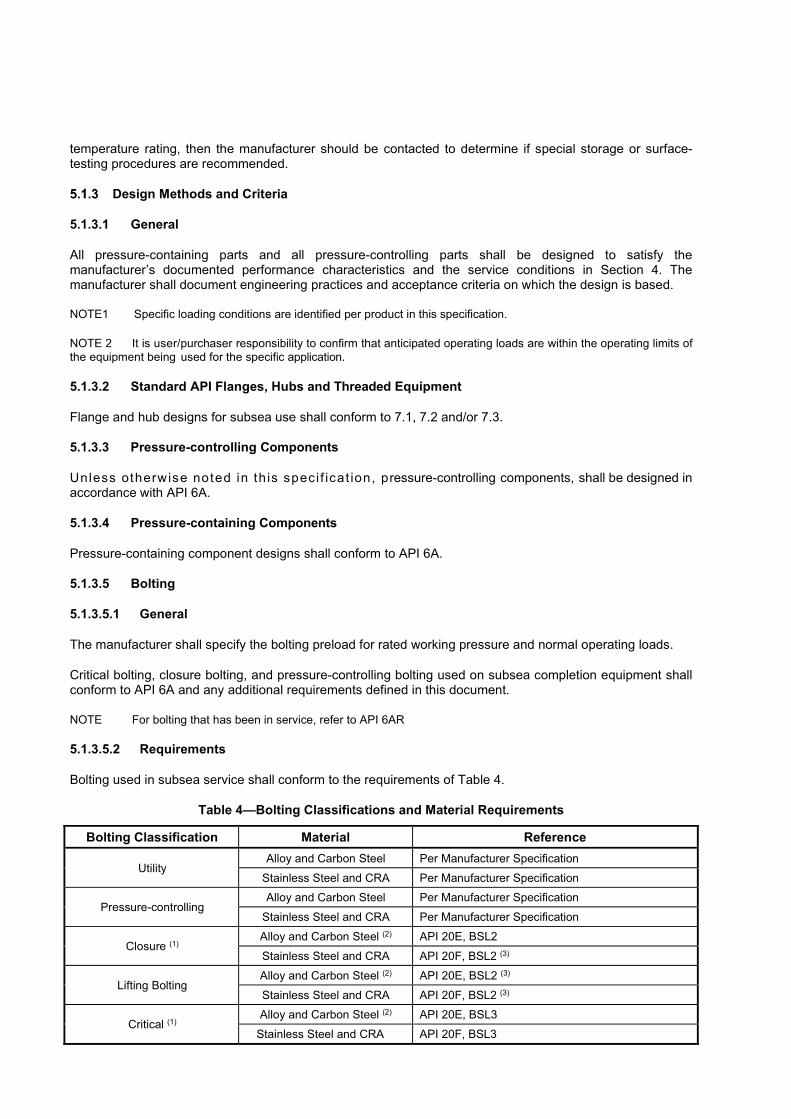
Bolting used in subsea service shall conform to the requirements of Table 4.
Table 4—Bolting Classifications and Material Requirements
Bolting Classification Material Reference
Utility Alloy and Carbon Steel Per Manufacturer Specification
Stainless Steel and CRA Per Manufacturer Specification
Pressure-controlling Alloy and Carbon Steel Per Manufacturer Specification
Stainless Steel and CRA Per Manufacturer Specification
Closure (1) Alloy and Carbon Steel (2) API 20E, BSL2
Stainless Steel and CRA API 20F, BSL2 (3)
Lifting Bolting Alloy and Carbon Steel (2) API 20E, BSL2 (3)
Stainless Steel and CRA API 20F, BSL2 (3)
Critical (1) Alloy and Carbon Steel (2) API 20E, BSL3
Stainless Steel and CRA API 20F, BSL3

(1) See API 6A for guidance on bolting material selection. (2) For 105ksi (725MPa) 0.2% Offset Yield Strength studs, Bolts, or Cap ���������� ��������������������������������
ASTM A320/A320M L43. (3) The use of an unlisted bolting material shall be as agreed between the Manufacturer and User/Purchaser and shall
be in accordance with specific requirements in API 20F for BSL-2, excluding any specific grade/alloy requirements
For material classes DD, EE, FF, and HH, bolting that is covered by insulation shall be treated as exposed bolting in accordance with NACE MR0175 (all parts).
5.1.3.5.3 Utility Bolting
Utility bolting manufactured from carbon or alloy steel, when used in submerged service, shall be limited to 35 HRC (327 HBW) to facilitate the use of standard ASTM specifications.
5.1.3.5.4 Pressure-controlling Bolting
Pressure-controlling bolting manufactured from carbon or alloy steel, when used in submerged service, shall be limited to 34 HRC (319 HBW).
5.1.3.5.5 Closure Bolting
Manufacturers shall document the design make-up tension (or torque) for closure bolting and critical bolting using tables, similar to the one in Annex F. The torque table(s) shall be supported by documented validation results.
Calibrated torque or bolt-tensioning equipment shall be used to ensure accurate make-up tension for closure bolting and critical bolting.
Where closure bolting is also classifiable as critical bolting, 5.1.3.5.7 shall apply.
5.1.3.5.6 Lifting Bolting
Lifting bolting used within the scope of this specification shall be assembled using torque (or other validated bolt preload method) that achieves a tensile make-up stress sufficient to keep the membrane stresses based on the tensile stress area below yield under test conditions and under worst-case load conditions. NOTE Consult local regulations for bolting requirements used in direct lifting load path.
5.1.3.5.7 Critical Bolting
Manufacturers shall document the design make-up tension (or torque) for closure bolting and critical bolting using tables, like the one in Annex F. The torque table(s) shall be supported by documented validation results.
Calibrated torque or bolt-tensioning equipment shall be used to ensure accurate make-up tension for closure bolting and critical bolting.
5.1.3.6 Structural Components
If specific design requirements in Section 6 through Section 11 differ from the general requirements in Section 5, then the equipment’s specific design requirements shall take precedence.
Design requirements for structural components (not pressure-controlling or pressure-containing) not otherwise identified in this specification shall be in accordance with one or more of the following:
— accepted industry practices using a design factor of 1.5 or more based on specified minimum yield strength.
— FEA used to demonstrate that applied loads do not result in deformation to such an extent that prevents meeting any other performance requirement

5.1.3.7 Design of Equipment for Lifting
5.1.3.7.1 General
NOTE See Annex G for design, testing, and maintenance guidelines for lifting equipment.
Equipment used exclusively for running in, on or out of the wellbore should be designed as given in 5.1.3.6 or 5.1.3.7 and Annex G or Annex H, as applicable.
5.1.3.7.2 Pad Eyes
Pad eyes should be designed as given in Annex G. Load capacities of pad eyes shall be marked as specified in 5.5.2.
5.1.3.7.3 Primary Members
If the primary member is either pressure-containing or pressure-controlling, and is designed to be pressurized during lifting operations, then the load capacity shall include the additional stresses induced by internal rated working pressure.
Miscellaneous Design Information
5.1.4.1 Tolerances
Unless otherwise specified in tables or figures of API 17D, the following tolerances shall apply.
a) The tolerance for dimensions with format X. X is �� 0.1 in. (X is ��2.5 mm).
b) The tolerance for dimensions with format X. XX is ��0.02 in. (X. X is ��0.5 mm).
c) The tolerance for dimensions with format X. XXX is ��0.005 in. (X. XX is ��0.13 mm)
d) Dimensions listed as XXXX / YYYY are considered the maximum dimension (XXXX) and the minimum dimension (YYYY), overriding the nominal tolerances to accommodate certain geometries.
5.1.4.2 End and Outlet Bolting
5.1.4.2.1 Hole Alignment
End and outlet bolt holes for API flanges shall be equally spaced and shall straddle the common center line; see Table 9.
5.1.4.2.2 Stud-thread Engagement
Stud-thread engagement length into the body of API studded flanges shall be a minimum of one times the OD of the stud.
5.1.4.3 Other Bolting
The stud-thread anchoring means shall be designed to sustain a tensile load equivalent to the load that can be transferred to the stud through a fully engaged nut.
5.1.4.4 Test, Vent, Injection and Gauge Connections
5.1.4.4.1 Sealing
All test, vent, injection and gauge connections shall provide a leak-tight seal at the test pressure of the equipment in which they are installed.

A means shall be provided such that any pressure behind a test, vent, injection or gauge connector can be safely vented prior to removal of the component.
5.1.4.4.2 Test and Gauge Connection Ports
Test and gauge connection ports shall conform to the requirements of 5.1.2.2 and 7.3.
5.1.4.5 Coatings (External)
5.1.4.5.1 Methods
The coating system and procedure used shall conform to the written specification of the equipment manufacturer or the coating manufacturer as agreed between the user/purchaser and manufacturer.
The manufacturer shall maintain, and have available for review, documentation specifying the coating systems and procedures used.
NOTE See Annex I.
5.1.4.5.2 Color Selection
Color selection for underwater visibility shall be in accordance with API 17H.
5.1.4.6 Cathodic Protection
The cathodic protection (CP) system design shall conform to the manufacturer’s written specification and in accordance with either of the following design codes:
— NACE SP0176
— DNVGL RP B401
This documentation shall contain the following information as a minimum:
— location and size of wetted surface area for specific materials, coated and uncoated
— areas where welding is allowed or prohibited
— materials of construction and coating systems applied to external wetted surfaces
— control line interface locations
— flowline interfaces
NOTE Some materials have demonstrated a susceptibility to hydrogen embrittlement when exposed to cathodic protection in seawater. Materials that have shown this susceptibility include martensitic stainless steels and the more highly alloyed steels having yield strengths over 900 MPa (131,000 psi). Other materials subject to this phenomenon are hardened, low-alloy steels, particularly with hardness levels greater than Rockwell “C” 35 [with yield strength exceeding 900 MPa (131,000 psi)], precipitation-hardened nickel-copper alloys and some high-strength titanium alloys.
5.1.4.7 Monitoring
Designs shall facilitate monitoring of CP potentials of subsea equipment. CP monitoring location shall be identified which provides a representative potential.
Design Documentation
Documentation of designs shall include methods, assumptions, calculations, validation reports and design- validation requirements. Design documentation requirements shall include, but not be limited to, those criteria for size, test and operating pressures, material, environmental requirements and other pertinent

requirements on which the design is being based. Design documentation media shall be clear, legible, reproducible and retrievable. Design documentation retention shall be for a minimum of five years after the last unit of that model, size and rated working pressure is manufactured. All design requirements shall be recorded in a manufacturer’s specification, which shall reflect the requirements of this specification.
Design Review
Design documentation shall be reviewed and verified by any qualified individual other than the individual who created the original design.
Validation
5.1.7.1 Introduction
The minimum validation procedures that shall be used to validate product designs in accordance with Table 5 are defined in 5.1.7. The manufacturer shall define additional validation that are applicable and demonstrate that this validation can be correlated with the intended service life and/or operating conditions in accordance with the user/purchaser requirements.
5.1.7.2 General
Prototype equipment (or first article) and fixtures used to validate designs shall be representative of production models in terms of design, production dimensions/tolerances, intended manufacturing processes, deflections and materials. If a product design undergoes a substantive change, the manufacturer shall document the impact of such changes on the performance of the product. Documentation shall contain an explanation of the change if revalidation is not required.
For items with primary and secondary independent seal mechanisms, the seal mechanisms shall be independently validated unless the primary and secondary seal mechanisms are identical. Equipment should be validated with the minimal lubricants required for assembly unless the lubricants can be replenished when the equipment is in service or is provided for service in a sealed chamber.
The actual dimensions of equipment subjected to validation shall be within the allowable range for dimensions specified for normal production equipment.
NOTE Annex J provides information on a consistent method of conducting validation on valves conforming to this specification, by prescribing the types of cycles and the order in which the cycles are to be performed.
5.1.7.3 Test Media
Liquid shall be used as the test medium for pressure-hold periods for hydrostatic body (1.5 times RWP) tests. Gas is the preferred test medium in all other cases for pressure-hold periods of pressure-containing and pressure-controlling equipment for which the purpose of the test includes validating one or more seals for validation or FAT. However, gas test shall be required for PSL3G or 4S equipment. Pressure-hold periods conducted for pressure-containing and pressure-controlling equipment for the purpose of validating external pressure capacities may use liquid as the test medium. Test procedures and acceptance criteria shall meet the requirements in 5.4.
For validation of FAT pressure tests of PSL 2 or 3 equipment that do not require gas, manufacturers may substitute liquid for gas as the test medium throughout testing.
5.1.7.4 Pressure-cycling Tests
Table 5 list equipment that shall be subjected to repetitive pressure cycling tests simulating well start-up and shutdown pressure cycling that occurs in long-term field service. For these tests, the equipment shall be alternately pressurized to the full rated working pressure and then depressurized to 1% or less of the test pressure until the specified number of pressure cycles have been completed.
NOTE No holding period is required for each pressure cycle.

If applicable, equipment shall be tested per 5.4.5.1 prior to pressure cycling testing. Pressure test cycles that are conducted during the temperature cycling test can satisfy both pressure and temperature cycling requirements. After pressure cycle testing, pressure testing shall be performed per 5.4.5 or 5.4.6, as applicable.
5.1.7.5 Load Testing
The manufacturer’s rated load capacities for equipment in accordance with this specification shall be verified by both validation testing and engineering analysis. The equipment shall be loaded to the rated capacity to the number of cycles in accordance with Table 5 during the test without deformation to such an extent that any other performance requirement is affected (unless otherwise specified). Engineering analysis shall be conducted using techniques and programs that conform to documented industry practice.
Table 5—Minimum Validation Requirements
Equipment Pressure/load Cycling Test
Temperature Cycling Testa
Endurance Cycling Test (Total
Cumulative Cycles)
Metal seal exposed to retained fluids g 200 3 PMR
Metal seal not exposed to retained fluids g 3 3 PMR
Non-metallic seal exposed to retained fluids 200 3 PMR
Non-metallic seal not exposed to retained fluids 3 3 PMR
OEC 200 3 PMR
Wellhead/tree/tubing head connectors e 3 NA PMR
Tubing heads 3 NA NA
Valves operated with actuators b 200 3 600
Manual Valves 200 3 400 f
Valve actuators/operators (alone but under load) 200 3 600
Tree cap connectors 3 NA PMR
Manual Subsea chokes 200 3 500 d, f
Subsea chokes operated with actuators 200 3 1,000 d
Subsea wellhead casing hangers and submudline casing hangers 3 NA NA
Subsea wellhead annulus seal assemblies (including backup seal assemblies) and submudline annulus seal assemblies
3 3 NA
Subsea tubing hangers, HXT internal tree caps and crown plugs 3 NA NA
Poppets, sliding sleeves, and check valves 200 3 PMR
Mudline tubing heads 3 NA NA
Mudline wellhead, casing hangers, tubing hangers 3 NA NA
Running tools (including tree running tool connectors) c 3 NA PMR
NOTE Pressure cycles, temperature cycles and endurance cycles are run as specified above in a cumulative test with one product without changing seals or components.

a Temperature cycles shall be in accordance with API 6A. b Before and after the pressure cycle test a low-pressure, 300 psi +/- 30 psi (2 MPa +/- 0.2 MPa), leak-tightness test
shall be performed. c Subsea wellhead running tools are not included. d A choke-actuator/operator cycle is defined as total choke stroke from full-open to full-close or full-close to full-open. e For PR1 per PMR. For PR2 refer to API 17TR7 (see 7.8.3.3) f Manual valves or manual chokes operated by an actuator shall be qualified as an actuated valve or actuated choke g API ring joint gaskets are excluded from this requirement
5.1.7.6 Temperature Cycling Tests
Validation shall be performed at or beyond the rated operating temperature range, or component temperature operating requirements as defined in 5.1.1.3, while at RWP or load condition.
Table 5 lists equipment that shall be subjected to repetitive temperature cycling tests simulating start-up and shutdown temperature cycling that occur in long-term field service. For these temperature cycling tests, the equipment shall be alternately heated and cooled to the upper and lower temperature extremes of its rated operating temperature classification as defined in 5.1.2.3. During temperature cycling, rated working pressure shall be applied to the equipment at the temperature extremes with API 6A.
NOTE Pressure test cycles that are conducted during the Temperature cycling test can satisfy both pressure and temperature cycling requirements.
As an alternative to testing, objective evidence shall be provided to ensure that the equipment will meet performance requirements at both temperature extremes.
5.1.7.7 Life Cycle/endurance Testing
Table 5 lists equipment that shall be subjected to extended lifecycle/endurance testing to simulate long-term field service. For these lifecycle/endurance tests, the equipment shall be subjected to operational cycles in accordance with the manufacturer’s performance specifications (i.e. make-up to full torque/break-out, open/close under full rated working pressure). Connectors, including stabs, shall be subjected to a full disconnect/lift as part of the cycle.
NOTE 1 Additional requirements for life cycle/endurance testing can be found in the equipment-specific sections covering these items (Section 6 to Section 11).
Secondary functions, such as connector secondary unlock, shall be included in life cycle/endurance testing.
Where it can be demonstrated that pressure and/or temperature testing similarly loads the component or assembly to that condition specified for endurance-cycle testing, those cycles may be accumulated toward the total number of cycles specified for endurance-cycle testing. For example, the 200/3 pressure/temperature cycles used to test a valve may cumulatively qualify as 203 cycles toward the 600 total cycles required for endurance cycling.
5.1.7.8 Product Family Validation
A product of one size may be used to verify other sizes in a product family, providing the following requirements are met:
a) A product family is a group of products for which the design principles, physical configuration, and functional operation are the same, but which differ in size.
b) The product geometries are parametrically modelled such that the design stress levels and deflections in relation to material mechanical properties are based on the same criteria for all members of the product family in order to verify designs via this method.
c) Scaling may be used to verify the members of a product family in accordance with API 6A..
5.1.7.9 Documentation
Validation procedures and test results shall be documented. The documentation requirements for validation testing shall be the same as the documentation requirements for design documentation in 5.1.5 with the addition that the documentation shall identify the person(s) conducting and witnessing the tests and the time and place of the testing.
5.2 Materials
General
5.2.1.1 Manufacturing Requirements
All materials shall be manufactured in accordance with API 6A with the following modifications and exceptions listed below.
For purposes of this reference, subsea wellheads, tubing head inner bodies, valve bodies, and composite valve block valve bodies, tubing hanger bodies, and re-entry hubs shall be considered pressure-containing parts. "High-load-bearing" describes a load condition acting on a component such that the resulting loaded equivalent stress exceeds 50% of the base-material's minimum yield strength.
Valve actuators are not pressure-containing or pressure-controlling parts of equipment. Where the valve stem and/or valve bonnet are integral to the actuator, these components shall be classified as pressure-containing and/or pressure-controlling as appropriate.
NOTE Other accepted manufacturing/process practices associated with material characterization and performance include API 20B, API 20C, API 20H, API 6HT and API 17TR8.
5.2.1.2 Heat Treatment and Qualification Test Coupons (QTC)
Heat treatment practices and QTCs for this specification shall conform to API 6A.
Corrosion
5.2.2.1 Corrosion from Retained Fluids
Material selection based upon wellbore fluids shall be made in accordance with 5.1.1.4.
5.2.2.2 Corrosion from Marine Environment
Corrosion protection through material selection based on a marine environment shall, as a minimum, include impacts from the following:
— external fluids
— internal fluids
— weldability
— crevice corrosion
— dissimilar-metals effects
— cathodic-protection effects
— coatings

5.3 Welding
Pressure-containing/controlling Components
All welding on pressure-containing/controlling components shall conform to the requirements of API 6A for PSL 2 or PSL 3, as specified.
Structural Components
Structural welds shall be treated as non-pressure-containing welds. Structural welds shall meet one of the following industry standards:
— a documented structural welding code, such as AWS D1.1
— weld design classifications that conform to API 17P
Weld locations where the loaded stress exceeds 50% of the weld or base-material yield strength, and welded pad eyes for lifting shall be identified as "critical welds" and shall be treated as in 5.3.1, PSL 3.
Hardfacing and Overlays
5.3.3.1 Corrosion-resistant Overlays
Corrosion-resistant overlays shall conform to API 6A for the following:
— Overlay of wetted surfaces of pressure-containing and pressure-controlling parts to meet material class
— Overlay of ring grooves
— Overlay of stems
— Overlay of valve bore sealing mechanisms
— Overlay of sealing surfaces with metal seals
— Overlay of choke trim
NOTE These requirements apply for weld overlay for corrosion-resistance and/or hardfacing and other material properties with respect to retained fluids, the base metal, and sealing materials (surface hardness galling resistance, and dissimilar metals corrosion).
5.3.3.2 Overlay for other than Corrosion-resistance
Hardfacing or other weld-metal overlays for applications other than corrosion-resistance shall conform to API 6A and manufacturers written specification.
5.4 Quality Control
General
Equipment manufactured to this specification shall conform to the quality control and record requirements of API 6A. For those components not covered in API 6A, equipment-specific quality-control requirements shall conform to the manufacturer’s written specifications. The user/purchaser and manufacturer should agree on any additional requirements.
The manufacturer shall have a quality management system that conforms to an internationally recognized quality management standard.
All outsourced manufacturing processes shall meet the requirements of the manufacturer’s quality management system.
Processes eligible to be outsourced shall include, but not be limited to, heat treatment, welding, machining, nondestructive testing, and coating. The manufacturer shall maintain documentation of the manufacturing process controls used for outsourced processes.
Product Specification Level
Quality control and testing for pressure-containing and pressure-controlling components covered by this part of API 17D shall conform to requirements for PSL 2 or PSL 3 as established in API 6A. Pressure testing shall meet the requirements of API 6A except for valves and chokes, which shall conform to 5.4.5 or 5.4.6 dependent upon PSL. Requirements for other components shall be in accordance with the manufacturer’s written specification.
NOTE "PSL 4S" as defined in this specification is a designation for an optional level of quality and testing requirements specifically intended for products used in high-pressure/high-temperature (HPHT) applications (see Annex D).
Structural Components
Quality control and testing of welding for structural components shall be specified as non-pressure-containing welds and conform to API 6A or a documented structural welding code, such as AWS D.1.1. “Critical welds” shall be treated as pressure-controlling welds and conform to API 6A, PSL 3, excluding volumetric NDE examination.
Lifting Devices
NOTE Guidelines for sizing and calculating stresses of lifting pad eyes are defined in Annex G.
Additionally, welds on pad eyes and other lifting devices attached by welding shall be in accordance with the weld requirements as specified in 5.3.2 and 5.4.3. All pad eye and lifting device welds shall be designated as “critical welds”. Lifting pad eyes shall also be individually proof load tested to at least two and one-half (2.5) times the documented maximum gross weight (MGW) for the individual pad eye (MGW/number of pad eyes). Pad eyes shall undergo NDE with magnetic particle examination (MPE) and/or dye (liquid) penetrant following proof testing. Proof-load testing shall be repeated following significant repairs or modifications prior to being put into use. The base metal and welds of pad eyes and other lifting devices shall meet PSL 3 requirements. Sea-fastening points and pad eyes not used for lifting do not require proof test.
Testing for PSL 2, PSL 3 and PSL 3G Equipment
5.4.5.1 Hydrostatic Pressure Testing
Procedures for hydrostatic pressure testing of equipment specified in Sections 6 through 11 shall conform to the requirements for PSL 2, PSL 3 or 3G in accordance with API 6A, with the exception that parts may be painted prior to testing.
For all pressure ratings, the hydrostatic body test pressure shall be a minimum of 1.5 times the rated working pressure and the hydrostatic seat test pressure shall be a minimum of 1.0 times the rated working pressure. The acceptance criterion for hydrostatic pressure tests shall be no visible leakage during the hold period. The final settling pressure shall not fall below the test pressure at the end of the test hold period. Initial test pressure shall not be greater than 5 % above the specified test. Hydrostatic pressure testing shall be conducted at ambient temperature.
Loose flanges shall not require a hydrostatic body test prior to final acceptance.
Momentary pressure drops during the hold period due to sensitivity/noise in electronic data acquisition systems are permitted so long as the final pressure recorded is above the specified minimum test pressure and measurement devices have remained isolated from the pressure source throughout the entire hold period. If a pressure-monitoring gauge and/or chart recorder is used for documentation purposes, the chart record may have a pressure settling rate not exceeding 3 % of the test pressure, or 300 psi (2 MPa) per hour, whichever is less.

Hydrostatic pressure test referenced to in API 17D is considered equivalent to the API 6A reference for a shell test or hydrostatic shell test.
5.4.5.2 Drift Test
Vertical runs, with direct access that require the passage of wellbore tools shall be physically drifted with the API 6A-specified drift mandrel.
When direct access is not possible, an alternate method of meeting drift requirements shall be used such as the use of a borescope and/or visual inspection provided the procedure has been validated with a calibrated (go/no-go) physical drift test for the given bore size.
Additional Testing for PSL 3G Equipment
5.4.6.1 Pressure Testing
Procedures for body testing of equipment specified in Sections 6 through 11 shall conform to the requirements for PSL 3G in accordance with API 6A, with the exception that parts may be painted prior to testing.
5.4.6.2 Hydrostatic Body and Seat Test
A hydrostatic body test and hydrostatic valve seat tests (PSL 3) shall be performed per 5.4.5.1 prior to any gas testing.
5.4.6.3 Gas Body Test for Assembled Equipment
The test shall be conducted under the following conditions.
a) The test shall be conducted at ambient temperature.
b) The test medium shall be nitrogen.
c) The test shall be conducted with the equipment completely submerged in a water bath, unless an alternative leak detection means is agreed to between the user/purchaser and the manufacturer.
d) The valves and chokes shall be in the partially open position during testing.
e) The gas body test for assembled equipment shall consist of a single holding period of not less than 15 min, the timing of which shall not start until the test pressure has been reached and the equipment and pressure- monitoring gauge have been isolated from the pressure source.
f) The test pressure shall equal the rated working pressure of the equipment.
Gas body testing shall be 1.0 times the rated working pressure. The acceptance criterion for gas tests shall be no visible leakage during the hold period. The final settling pressure shall not fall below the test pressure at the end of the test hold period. Initial test pressure shall not be greater than 5 % above the specified test pressure.
Momentary pressure drops during the hold period due to sensitivity/noise in electronic data acquisition systems are permitted so long as the final pressure recorded is above the specified minimum test pressure and measurement devices have remained isolated from the pressure source throughout the entire hold period. If a pressure-monitoring gauge and/or chart recorder is used for documentation purposes, the chart record may have a pressure settling rate not exceeding 3 % of the test pressure, or 300 psi (2 MPa) per 15 minutes, whichever is less.
5.4.6.4 Gas Seat Test—Valves
The gas seat test may be conducted in addition to, or in place of, the hydrostatic seat test.
The test shall be conducted under the following conditions.

a) The gas pressure shall be applied to each side of gate or plug of bi-directional valves with the other side open to the atmosphere. Unidirectional valves shall be tested in the direction indicated on the body, except for check valves, which shall be tested from the downstream side.
b) The test shall be conducted at ambient temperatures.
c) The test medium shall be nitrogen.
d) The test shall be conducted with the equipment completely submerged in a bath of water unless an alternative leak detection means is agreed to between the user/purchaser and the manufacturer.
e) Testing shall consist of two, monitored holding periods.
f) The primary test pressure shall equal rated working pressure.
g) The primary test monitored hold period shall be 15 minutes.
h) The pressure shall be reduced to zero between the primary and secondary hold points, but not by opening the valve.
i) The secondary test pressure shall be 300 psi ��30 psi (2 MPa ��0.2 MPa).
j) The secondary test monitored hold period shall be 15 minutes; the upstream pressure is then vented to zero, but not by opening the valve.
k) The valves shall be fully opened and fully closed between tests.
l) Bi-directional valves shall be tested on the other side of the gate or plug using the same procedure.
Gas seat test pressure test shall be 1.0 times the rated working pressure. The acceptance criterion for gas tests shall be no visible leakage during the hold period. The final settling pressure shall not fall below the test pressure at the end of the test hold period. Initial test pressure shall not be greater than 5 % above the specified test pressure.
Momentary pressure drops during the hold period due to sensitivity/noise in electronic data acquisition systems are permitted so long as the final pressure recorded is above the specified minimum test pressure and measurement devices have remained isolated from the pressure source throughout the entire hold period. If a pressure-monitoring gauge and/or chart recorder is used for documentation purposes, the chart record may have a pressure settling rate not exceeding 3 % of the test pressure, or 300 psi (2 MPa) per 15 minutes, whichever is less.
For the secondary low-pressure seat test, the test pressure shall be 300 psi ��30 psi (2 MPa ��0.2 MPa) over the hold period.
5.4.6.5 Requirements for HPHT
When required by the manufacturer or user/purchaser, HPHT equipment shall be pressure tested in accordance with Annex D of this specification.
Hydraulic System Pressure Testing
Components that contain a hydraulic control fluid shall be tested to a hydrostatic body test at 1.5 times the hydraulic RWP of their respective hydraulic systems with primary and secondary hold times in accordance with 5.4, PSL 3. All operating subsystems (actuators, connectors, etc.) that are operated by the hydraulic system shall function at 0.9 times the hydraulic RWP or less of their respective system.
Where the hydraulic system does not communicate with the wellbore, the hydraulic system RWP shall be limited to the lowest rated hydraulic system pressure-containing element, as specified by the manufacturer. The hydrostatic test pressure of the hydraulic system shall be 1.5 times the hydraulic RWP with primary and

secondary hold times in accordance with 5.4, PSL 3. The test medium is the hydraulic system fluid. Acceptance criterion shall be no visible leakage.
NOTE Chart recording is not required.
Cathodic Protection
Electric continuity tests shall be performed to prove the effectiveness of the cathodic protection system. If the electrical continuity is not obtained, earth cabling shall be incorporated in the ineffective areas where the ����������������������������������
Interface Testing
Where tooling can be affected by coating or insulation proximity, an interface check shall be performed after coating/insulation is applied to confirm that there is no loss or impairment to functionality of mating components or tooling, per manufacturer’s written specification.
5.5 Equipment Marking
General
Equipment that meets the requirements of this Specification shall be marked “API 17D” in accordance with API 6A, marking "API 17D" in place of "API 6A".
All equipment marked “API 17D” shall, also, be marked with the following minimum information: part number, manufacturer name or trademark.
NOTE See API 6A for metallic marking locations.
Equipment shall be marked in either metric units or imperial units where size information is applicable and useful. The units shall be marked together with the numbers.
All marking done directly on pressure-containing components, excluding peripheral marking on API flanges, shall be done using low-stress marking methods.
Pad Eyes and Lift Points
Pad eyes intended for lifting shall be painted red and marked for lifting to alert personnel that safe handling can be made from this point. In addition, the documented MGW, sling lift angles from vertical, and the number of pad eyes used in the lift shall be marked adjacent to each lifting pad eye and the overall MGW of the equipment assembly shall be marked on the equipment or framework. There shall only be one common unit of measure in the marking for MGW and individual lift pad eye load capacity.
EXAMPLE A subsea assembly that has a MGW of 10,000 lbs. (4 536 kg) with 4 pad eyes and designed for a 4-part sling lift at an angle of 30° (from vertical) is marked as:
4 x 2500 lbs, 0-30°, adjacent to each lift pad eye,
and
MGW = 10,000 lbs, in a visible position when it is in the operating position.
WARNING - Pad eyes on frames not painted red and/or properly labeled should be considered only as aids for handling lines (tag lines) or tie-down (e.g. transportation, sea fastening). Any pad eye or lift point not properly marked with lift marking should not be used for lifting. Lifting from unmarked pad eyes can lead to serious damage or injury.
WARNING—Special attention should be paid to payload weights and their markings to ensure the unit of measure for maximum gross weight (MGW) match rigging requirements.
All packages exceeding 22,500 lbs (100 kN) shall have pad eyes or other handling/tiedown provisions for handling and sea fastening. If pad eyes are used, they shall not be painted red and should be considered only as aids for handling lines (tag lines) or tie-down (transportation, sea fastening, etc.). All other equipment not suitable for shipping in baskets or containers shall be furnished with facilities for sea fastening.
Reusable Lifting Devices
Reusable lifting devices, such as tools, as determined in 5.1.3.7, or lift frames (such as lift subs, spreader bars, or strong-back beams), used for lifting shall be designed in accordance with 5.1.3.6, DNVGL ST-E273, or regional lifting standard(s). Lift pad eyes shall be painted red and properly marked for lifting per 5.5.2 for its MGW and its designed lifting capacity of other equipment.
All lift points and lift frames should be periodically inspected by competent/qualified personnel (inspector). Inspection intervals shall be specified by the manufacturer, if not dictated by the lifting standard(s).
Accommodation should be made in the design of the lift points and load paths to allow regular inspection, NDE, and/or load testing, if required. All repairs that include welding of the lift point or lifting load path shall require load testing and NDE after repair. The inspector shall decide if load testing/NDE following non-welded repairs is required.
5.6 Storing and Shipping
Draining After Testing
All equipment shall be drained and lubricated in accordance with the manufacturer’s written specification after testing and prior to storage or shipment.
Rust Prevention
Prior to shipment, parts and equipment shall have exposed metallic surfaces (except those otherwise designated such as anodes or nameplates) protected in accordance with API 6A.
Equipment already coated, but showing damage after testing, should undergo coating repair prior to storage or shipment as specified in 5.1.4.6.
Sealing Surface Protection
Exposed seals and seal surfaces, threads, and operating parts shall be protected from mechanical damage during shipping. Equipment or containers shall be designed such that equipment does not rest on any seal or seal surface during shipment or storage.
Loose Seals and Ring Gaskets
Loose seals, stab subs and ring gaskets shall be individually boxed or wrapped for shipping and storage.
Elastomer Age Control
The manufacturer shall document instructions concerning the proper storage environment, age control procedures and protection of elastomer materials. Loose or spare materials which are past their expiration date shall not be used on equipment. Hoses on equipment should be pressure tested to their RWP after extended storage periods, per the manufacturer's written specification
Hydraulic Systems
Prior to shipment, the equipment including hydraulic lines shall be flushed and filled in accordance with the manufacturer’s written specification. Exposed hydraulic end fittings shall be capped or covered. All pressure shall be bled from equipment, unless otherwise agreed between the manufacturer and user/purchaser.

Electrical/electronic Systems
The manufacturer shall document instructions concerning proper storage and shipping of all electrical cables, connectors and electronic packages (pods).
Shipments
For shipment of units and assemblies the manufacturer shall maintain a documented procedure for securing and shipping equipment.
Assembly, Installation and Maintenance Instructions
The manufacturer shall document instructions concerning field assembly, installation and maintenance of equipment. These shall address safe operating procedures and practices.
Storage and Preservation
Storage and preservation requirements for equipment after delivery to the user/purchaser is beyond the scope of this specification. The manufacturer shall provide recommendations for storage to the user/purchaser upon request.
6 General Design Requirements for Subsea Tree Systems
6.1 General
Introduction
NOTE Section 6 provides specific requirements for the equipment covered in Section 7 and Section 9. Subsea tree assembly configurations vary depending on wellhead type, service, well shut-in pressure, water depth, reservoir parameters, environmental factors and operational requirements. As such, the subsea tree configuration requirements, including the location and quantity of USVs are not specified in Section 6.
The number of potential leak paths should be minimized during system design.
Equipment that is used in the assembly of the subsea tree, but which is not covered in Section 6, Section 7, and Section 9, shall conform to the manufacturer’s written specifications. The user/purchaser and manufacturer should agree on any additional requirements.
Handling and Installation
Structural analysis should be performed by the user/purchaser to ensure that structural failure does not occur at a point below the tree re-entry hub and that the tree can be left in a safe condition in the event of a drive-off before the tree running tool/EDP can be disconnected.
The design of the subsea tree assembly shall address handling and installation including balance within 1.0° (in air) in the as-run condition.
Orientation and Alignment
A tolerance and stack-up analysis shall be conducted to ensure that trees engage tubing hangers, wellheads and guidebases; that tree running tools engage re-entry hubs; that caps engage re-entry hubs. These studies shall include external influences, such as flowline forces, temperature, currents, riser offsets, etc. System tolerances should be defined to enable initial orientation and alignment while simultaneously avoiding seal and seal surface damage during landing, entering, mating or disengagement of equipment packages. Where feasible during factory acceptance testing, orientation and alignment should be confirmed by testing of interfaces that will be engaged remotely.
Rating
The PSL designation, pressure rating, temperature rating and material class assigned to the subsea tree assembly shall be determined by the minimum rating of any single component used in the assembly of the subsea tree that is normally exposed to wellbore fluid.
Interchangeability
Components and sub-assemblies for different arrangements of subsea tree configurations should be interchangeable if functional requirements permit.
EXAMPLES Change-out of tree connectors to suit different wellhead profiles, change-out of wing valve arrangements for different services, such as production, injection, etc., and the interchangeability of spares.
It is recommended that items that are engaged subsea have their interfaces confirmed using a mating item or fixture, especially when multiple units are being delivered separately. Manufacturers should define which parts are designed to be interchangeable.
6.2 Tubing Head and Tree Valving
Master Valves, Vertical Tree
Any valve in the vertical bore of the tree between the wellhead and the tree side outlet shall be defined as a master valve. A vertical subsea tree shall have one or more master valves in the vertical production (injection) bore and annulus access bore (when applicable). At least one valve in each bore shall be an actuated, fail-closed valve.
Master Valves, Horizontal Tree
The inboard valve branching horizontally off the tree between the tree body and tubing hanger and the production (injection) flow path (bore) shall be defined as the production master valve. The inboard valve on the bore into the annulus below the tubing hanger shall be defined as the annulus master valve. A horizontal subsea tree shall have one or more master valves on each of the above bores. At least one valve in each of the above bores shall be an actuated, fail-closed valve.
Wing Valves, Vertical Tree
The side outlet for production (injection) shall have at least one wing valve. The annulus flow path of the subsea tree shall have at least one wing valve when a second annulus master valve is not present.
Wing Valves, Horizontal Tree
The horizontal subsea tree shall have a wing valve downstream (upstream – injection) of the master valve in both the production (injection) flow path and the annulus flow path.
Crossover Valves
NOTE A crossover valve is an optional valve that, when opened allows communication between the annulus and production tree paths, which are normally isolated. Can also be used for circulating completion fluids for an intervention system (see API 17G). For examples of valve placement refer to Figures 1, 2 and 3.
Swab Closures, Vertical and Horizontal Tree
Any bore that passes through the subsea tree that can be used in workover operations shall be equipped with at least two barriers when the production outlet is below the entry to the bore and sealed when production is taken through the bore. In preparation for a workover and connection of the workover system, the bore shall be sealed by at least two barriers. Barriers may be caps, stabs, crown plugs or valves. The removal or opening of the barriers shall not result in any diametrical restriction through the production bore of the tree or tubing hanger.

Any valve performing the task of a Swab valve, may be either manual or actuated and shall be operable only via a workover control system (IWOCS – as described in API 17G5) when actuated. During intervention operations, operable barriers may be either manual or actuated and when actuated shall only be operable by a workover control system.
Annulus access (AAV) or workover (WOV) valves may be considered forms of swab closures.
NOTE Tree cap requirements are found in section 7.12.
Horizonal Tree System Additional Access Requirements
An access port to the cavity between crown plugs shall be provided. Access to the TH gallery seal shall be provided
Production (Injection) and Annulus Flow Paths
Valving in the production (injection) and annulus flow paths shall include one actuated, fail-closed master valve in the production (injection) bore and one actuated, fail-closed master valve in the annulus bore.
Other valves as described in 6.2 may be added when required by legislation or project requirements with respect to operational/process and/or well-intervention requirements.
The annulus flow path shall be designed to allow for the management of casing pressure in the production annulus with the ability to circulate during workover and well-control situations.
NOTE A schematic for a typical vertical dual-bore subsea tree is illustrated in Figure 1. Figure 2 illustrates vertical trees with tubing heads. Figure 3 illustrates horizontal subsea trees.
Key

1 Tree cap (swab closure) 9 optional crossover piping routing 2 ASV (manual or failed closed or optional plug) 10 AMV 3 PSV (manual or failed closed or optional plug) 11 PMV 4 AWV 12 optional lower master (manual or fail closed 5 PWV 13 tubing hanger 6 Annulus (to umbilical line or service line) 14 subsea wellhead 7 production 15 SCSSV 8 XOV
NOTE The dotted inclusions are optional. A non-pressure-containing tree cap can be considered when two swab closures are included.
Figure 1—Example of a Dual-Bore Tree on a Subsea Wellhead
Key
1 Tree cap (swab closure) 11 PMV 2 ASV (manual or fail close or optional plug) 12 optional lower master (manual or fail close) 3 PSV (manual or fail close or optional plug) 13 tubing hanger 4 AWV 14 tubing head

5 PWV 15 subsea wellhead 6 Annulus (to umbilical line or service line) 16 AIV 7 Production 17 optional ASV (WOV or AAV) (manual or fail close) 8 XOV 18 optional XOV 9 Optional crossover piping routing 19 annulus valves (manual and fail close or both fail close) 10 AMV
NOTE The dotted inclusions are optional. A non-pressure-containing tree cap can be considered when two swab closures are included.
Figure 2—Example of Vertical Trees on Tubing Heads
Key
1 ASV (WOV or AAV) (manual or fail closed) 7 AMV 2 XOV 8 PMV3 tree cap 9 PWV 4 AWV 10 tree body5 tubing hanger 11 subsea wellhead 6 optional AWV 12 SCSSV

Figure 3—Examples of Horizontal Trees
a) Production Bore Penetrations

b) Annulus Bore Penetrations
Figure 4—Examples of Bore Penetrations
Production and Annulus Bore Penetrations
There shall be at least two fail-closed pressure closures, one of which shall be an actuated, fail-closed valve, for any penetration leading into the production path of the tree or tubing head.
The master valve may be used as one of the barriers for conduit penetrations downstream of the master valve.
There shall be at least one testable pressure closure between the wellhead and any penetration leading into the annulus path of the tree or tubing head.
Sealed sensor devices contained within a pressure containing body may be directly attached to the penetration without additional barrier. Sealed sensor devices shall have the same or higher rated working pressure as the tree or tubing head body to which it is connected.
All wellbore penetrations inboard of the wing valve shall have isolation means within the block and/or bolted to the block.
Flanges, clamp hubs or other end connection, as applicable, meeting the requirements of Section 7 shall be used to provide connections for the penetrations to the tree or tubing head.
NOTE Figure 4 illustrates the minimum configurations that meet the requirements of this section.
SCSSV Control Line Penetrations
At least one pressure-controlling closure shall be used at all SCSSV control-line penetrations that pass through either the tree or tubing head.
NOTE 1 Manual valves (diver/ROV-operated) are acceptable closure devices.
Any remotely operated closure device, including control-line couplers that are designed to prevent the ingress of seawater, used in the SCSSV control line circuit shall be designed such that it does not interfere with the closure of the SCSSV. Connections threaded directly into a tree body or wing-valve block for SCSSV control line penetrations are prohibited.
Check valves shall not be used anywhere in the SCSSV circuit if their closure can prevent venting down of the control pressure.
NOTE 2 Figure 5 illustrates typical subsea tree valving for SCSSV circuits that meet the requirements of this section.

Key
1 CID options 2 PSV 3 PWV 4 PMV 5 SCSSV isolation 6 SCSSV
NOTE The SCSSV line is designed to prevent hydraulic lock-open of SCSSV when it is disconnected.
Figure 5—Examples of Tree Valving for Downhole Chemical Injection and SCSSV
Downhole Chemical-injection Line Penetrations
Two fail-closed barriers (e.g. check valves or actuated valves) shall be included for all chemical-injection lines that pass through the tubing hanger. At least one of the valves shall be an actuated, fail-closed valve.
Flow-closed check valves may be used as one of the fail-closed valves, for lines with a diameter of 1.00 in. (25.4 mm) or smaller.
The left side of Figure 5 illustrates typical subsea tree valving for the above. The check valve may be inboard or outboard of the fail-closed valve.
Flanges, clamp hubs or OECs, as applicable, meeting the requirements of Section 7 shall be used to provide connections for the penetrations to the tree.
Threaded connections going directly into a tree body or wing-valve block for chemical injection penetrations shall not be used when inboard of the two closure devices.
Pressure Monitoring/test Lines and Internal Control Lines
At least one pressure-controlling closure shall be used on all pressure-monitoring/test internal control lines and passages (that pass into or through either the tree or tubing head).

The rated working pressure of any hydraulic control line that has the potential for wellbore communication shall be equal to or greater than the rated working pressure of the tree.
Threaded connections going directly into a tree body or wing valve block for pressure monitoring/test line penetrations shall not be used when inboard of the two closure devices.
Compensating Barrier
Where a compensating barrier is used to exclude seawater from the actuator and to balance external pressure, it shall be sized to accommodate a minimum of 120 % of the swept volume. A means, such as check valves, should be included in the circuit to prevent hydraulic lock. A relief device shall be included in this circuit to eliminate the chance that the failure of an actuator seal can affect the performance of the remaining valves. The manufacturer shall document the compensation fill procedure.
Downhole Hydraulic Control Line Penetrations for Intelligent Well Completions
At least one pressure-controlling closure shall be used in all hydraulic control lines that penetrate through the tree and tubing head and that are used to operate downhole, intelligent, well-completion systems.
Closure devices shall be manual or fail-closed isolation valves for an intelligent well’s control system that is operated remotely through the production control umbilical.
Closure devices should always be maintained in the closed position except while the intelligent well-control system is being operated. When a control pod is used to operate the intelligent well-control system, the intelligent well-control functions shall be vented through a hydraulic circuit other than the one(s) used to vent fluid/pressure from other control functions on the tree, including the SCSSV.
Flanges, clamp hubs or OECs, as applicable, meeting the requirements of Section 7 shall be used to provide connections for the intelligent well-control penetrations to the tree. Threaded connections going directly into a tree body or wing-valve block for intelligent well-control line penetrations are prohibited.
Thermal expansion of the hydraulic fluid in the intelligent well control lines should be addressed in the design and operation of the intelligent well control system.
6.3 Thermally Induced Pressure Changes
Pressure integrity shall not be compromised due to thermally induced pressure changes in trapped volumes. All trapped volume analysis shall account for the various fluid properties contained.
6.4 Testing of Subsea Tree Assemblies
Validation
NOTE There are no validation requirements at the assembly level for subsea trees. Validation of various tree components are covered in Section 5.1.7.
Factory Acceptance Testing
The subsea tree assembly shall be factory acceptance tested in accordance with the manufacturer’s written specification using the actual mating equipment or an appropriate test fixture that simulates the applicable interfaces (CGB, PGB, GRA, tree frame, etc.), wellhead and tubing hanger interfaces.
The subsea tree assembly shall be pressure tested to 1.0X RWP. Refer to section 7.16.2.6 for pressure test requirements for inboard and outboard piping.
NOTE 1 See Section 5 for testing requirements.
NOTE 2 Because of the different subsea tree configurations, components can be directly exposed to wellbore fluid in some instances or serve as a second barrier in others. Table 6 is provided as a pictorial representation to clarify where the components are located and what hydrostatic test pressures are required with respect to body, interface, and

lockdown retention testing. Detailed test requirements for each element/location are described in the applicable sections within this specification.
6.5 Marking
The subsea tree assembly shall be tagged with a nameplate labelled as “Subsea Tree Assembly” in a visible location and contain the following information as a minimum:
— name of assembler/date
— PSL designation of assembly
— rated working pressure of assembly
— temperature rating of assembly
— material class of assembly (including maximum H2S partial pressure if applicable)
— unique identifier (serial number, PSL 3 and above)
— API 17D.
6.6 Storing and Shipping
Any disassembly, removal or replacement of parts or equipment after FAT shall be as agreed with the user/purchaser.

Table 6—Pressure Test Pictorial Representations
a) Vertical Subsea Tree
Position Description RWP Hydrostatic Body Test Pressure
Lockdown Retention Test
Pressure
A Subsea wellhead 1.0 ��RWP 1.5 ��RWP NA
B Tubing head connector, Tubing head and tree connector
1.0 ��RWP 1.5 ��RWP NA
C Valves, valve block 1.0 ��RWP 1.5 ��RWP NA
D
Downhole flow passages and seal subs (SCSSV, other hydraulic, injection) (pressure-containing)
1.0 ���RWP + up to 2500 psi (17.2 MPa)]
1.5 ��RWP
NA
Downhole flow passages and seal subs (SCSSV, other hydraulic, injection) (pressure-controlling)
1.0 ���RWP + up to 2500 psi (17.2 MPa)]
1.0 ���RWP + up to 2500 psi (17.2 MPa)] NA
E Tree cap (flow passages below tree cap and lock mechanism)
1.0 ��RWP 1.5 ��RWP NA
F Tubing hanger 1.0 ��RWP 1.5 ��RWP NA
L1 Below installed tubing hanger NA NA 1.1 ��RWP
L2 (not shown)
Above tubing hanger plug NA NA 1.0 ��RWP
Below tubing hanger plug NA NA 1.1 ��RWP
L3 Gallery 1.0 ���RWP + up to 2500 psi (17.2 MPa)] NA NA

b) Horizontal Subsea Tree with Separate Internal Tree Cap
Position Description RWP Hydrostatic Body Test Pressure
Lockdown Retention Test
Pressure
A Subsea wellhead 1.0 ��RWP 1.5 ��RWP NA
B Tree connector 1.0 ��RWP 1.5 ��RWP NA
C Valves, valve block 1.0 ��RWP 1.5 ��RWP NA
D
SCSSV flow passages and seal subs (SCSSV, other hydraulic, injection) (pressure-containing)
1.0 ���RWP + up to 2500 psi (17.2 MPa)]
1.5 ��RWP
NA
SCSSV flow passages and seal subs (SCSSV, other hydraulic, injection) (pressure-controlling)
1.0 ���RWP + up to 2500 psi (17.2 MPa)]
1.0 ���RWP + up to 2500 psi (17.2 MPa)]
NA
E Debris cap PMR PMR NA
F Crown plugs 1.0 ��RWP 1.5 ��RWP NA
G Internal tree cap 1.0 ��RWP 1.5 ��RWP NA
H Tubing hanger 1.0 ��RWP 1.5 ��RWP NA
L1 Below installed tubing hanger NA NA 1.5 ��RWP
L2 Below internal tree cap NA NA 1.5 ��RWP
L3 Above lower crown plug NA NA 1.0 ��RWP
Below lower crown plug NA NA 1.5 ��RWP
L4 Above upper crown plug NA NA 1.0 ��RWP
Below upper crown pluga NA NA 1.5 ��RWP
L5 Gallery 1.0 ���RWP + up to 2500 psi (17.2 MPa)] NA NA
a If a lower crown plug is in place during the upper-crown-plug test from below, then the lower crown plug shall be pressure- equalized from above and below the lower crown plug during the test.

c) Horizontal Subsea Tree Without Separate Internal Tree Cap
Position Description RWP Hydrostatic Body Test Pressure
Lockdown Retention Test
Pressure
A Subsea wellhead 1.0 ��RWP 1.5 ��RWP NA
B Tree connector 1.0 ��RWP 1.5 ��RWP NA
C Valves, valve block 1.0 ��RWP 1.5 ��RWP NA
D
SCSSV flow passages and seal subs (SCSSV, other hydraulic, injection) (pressure-containing)
1.0 ���RWP + up to 2500 psi (17.2 MPa)]
1.5 ��RWP
NA
SCSSV flow passages and seal subs (SCSSV, other hydraulic, injection) (pressure-controlling)
1.0 ���RWP + up to 2500 psi (17.2 MPa)]
1.0 ���RWP + up to 2500 psi (17.2 MPa)] NA
E Debris cap PMR PMR NA
F Crown plugs 1.0 ��RWP 1.5 ��RWP NA
G ROV tree cap PMR PMR NA
H Tubing hanger 1.0 ��RWP 1.5 ��RWP NA
L1 Below installed tubing hanger NA NA 1.5 ��RWP
L2Above lower crown plug NA NA 1.0 ��RWP
Below lower crown plug NA NA 1.5 ��RWP
L3 Above upper crown plug NA NA 1.0 ��RWP
Below upper crown pluga NA NA 1.5 ��RWP
L4 Gallery 1.0 ���RWP + up to 2500 psi (17.2 MPa)] NA NA
a If a lower crown plug is in place during the upper-crown-plug test from below, then the lower crown plug shall be pressure- equalized from above and below the lower crown plug during the test.

7 Specific Requirements—Subsea Tree-Related Equipment and Subassemblies
7.1 Flanged End and Outlet Connections
General—Flange Types
NOTE 1 Section 7 specifies the API type end and outlet flanges used on subsea completion equipment. Table 7 lists the types and sizes of flanges covered by this specification.
Table 7—Rated Working Pressures and Size Ranges of API Flanges
Rated Working Pressure
Flange Size Range
Type 17SS Type 17SV Type 6BX
Psi (MPa) in. (mm) in. (mm) in. (mm)
5000 (34.5) 21/16 to 135/8 (52 to 346) 21/16 to 135/8 (52 to 346) 135/8 to 21¼ (346 to 540)
10,000 (69.0) — — 113/16 to 13 5/8 (46 to 346) 113/16 to 21¼ (46 to 540)
15,000 (103.5) — — — — 113/16 to 18¾ (46 to 496)
Standard flanges for subsea completion equipment with working pressures of 5,000 psi (34.5 MPa) in sizes of 21/16 in. (52 mm) through 135/8 in. (346 mm) shall be type 17SS flanges as defined in 7.1.2.2. Type 17SS flanges shall conform to Table 7, Table 9, Table 10 and Table 11.
Standard flanges for 5000 psi (34.5 MPa) in sizes of 135/8 in. (346 mm) through 21¼ in. (540 mm) shall be type 6BX flanges as defined in API 6A.
Standard flanges for subsea completions with maximum working pressures of 10,000 psi (69 MPa) or 15,000 psi (103.5 MPa) shall be type 6BX flanges as defined in API 6A. API-type flanges for subsea completions may be either integral, blind or welding neck flanges. Threaded flanges, as defined in API 6A, shall not be used on subsea completion equipment handling produced fluids, except as specified in 7.3.
Segmented flanges shall not be used.
NOTE 2 Swivel flanges are often used to facilitate subsea flowline connections that are made up underwater. Type 17SV flanges, as defined herein, have been developed as the standard swivel-flange design for subsea completions in the sizes and working pressures given in Table 7. Type 17SV swivel flanges are designed to mate with standard API-type 17SS and type 6BX flanges of the same size and pressure rating.
Design
7.1.2.1 General
All flanges used on subsea completion equipment shall be of the ring-joint type designed for face-to-face make-up. The connection make-up force and external loads shall react primarily on the raised face of the flange. Therefore, at least one of the flanges in a connection shall have a raised face.
All flanged connections that are made up underwater in accordance with the manufacturer’s written specification shall be equipped with a means to vent any trapped fluids. Type SBX ring gaskets, as shown in Table 8, are an acceptable means for venting type 6BX, 17SS, or 17SV flanges. Type SBX or API 6A-type BX ring gaskets, are acceptable for 6BX, 17SS or 17SV flanges made up in air.
Other proprietary flange and seal designs that eliminate the trapped fluid problem have been developed and these are, therefore, well suited for underwater make-up. These proprietary flange and seal designs shall conform to Section 7.4.

Trapped fluid may interfere with the proper make-up of padstuds or bolts installed in blind holes underwater. If installed underwater, a means should be provided to confirm that bolting has been fully engaged in the blind hole or a means to vent trapped fluid from behind the installed bolting.
7.1.2.2 Ring Gaskets
Types 6BX, 17SS and 17SV flanges in subsea completion equipment shall use t y p e s BX or SBX gaskets. If these flanges are made up underwater, they shall be made up with SBX gaskets, in accordance with 7.1.2.1.
Connections that are not made up underwater may use non-vented type BX gaskets.
Gasket material shall be of a CRA or corrosion-resistant material to provide corrosion resistance to seawater under the specified operating conditions (dissimilar metal corrosion with the ring groove). Gasket materials shall conform to the requirements of API 6A.
The thickness of coatings and platings used on BX and SBX ring gaskets to aid seal engagement while minimizing galling shall not exceed 0.0005 in. (0.013 mm). The use of coatings that can be harmful to the environment or galvanically active should be avoided. Local legislation should be checked for coatings deemed hazardous.
Proprietary gaskets shall conform to the manufacturer’s written specification.
Grease shall not be applied around the complete perimeter to hold ring gaskets in position during make-up, since grease can interfere with proper make-up of the gasket. Tack welding rods to the OD of seal rings (to simplify positioning of the ring during make-up) shall not be used on gaskets for subsea service.
Except for testing purposes, BX and SBX ring gaskets shall not be reused.

Tabl
e 8—
API
type
SB
X Pr
essu
re-E
nerg
ized
Rin
g G
aske
ts
NO
TE 1
R
adiu
s R
shal
l be
8 %
to 1
2 %
of t
he g
aske
t hei
ght,
H
NO
TE 2
Tw
o pr
essu
re p
assa
ge h
oles
in t
he S
BX r
ing
cros
s-se
ctio
n pr
even
t pr
essu
re lo
ck w
hen
conn
ectio
ns a
re m
ade
up u
nder
wat
er.
Two
optio
ns a
re
prov
ided
for
drilli
ng th
e pr
essu
re p
assa
ge h
oles
.
Key
To
lera
nces
, ex
pres
sed
in
inch
es (m
illim
eter
s)
1
OD
, out
er d
iam
eter
of r
ing
2
OD
T, o
utsi
de d
iam
eter
T
±0.
002
(±0.
05)
3
C w
idth
of f
lat
4
R 1
radi
us in
ring
S
ee N
ote
1
5
Ha
hei
ght o
f rin
g
6
Aa w
idth
of r
ing
7
E d
epth
of g
roov
e +0
.02,
-0 (+
0.5,
-0)
8
G
outs
ide
diam
eter
of g
roov
e +0
.004
, -0
(+0.
1, -0
)
9
N w
idth
of g
roov
e +0
.004
, -0
(+0.
1, -0
)
10 R
2 rad
ius
in g
roov
e m
ax.
11 B
reak
sha
rp c
orne
r
12 D
ho
le d
iam
eter
S
ee T
able
8
Max
. 1/
16 (1
.5) x
45°
Max
. 1/
16 (1
.5) x
45°
1/32
(0.8
)

Tabl
e 8—
API
type
SB
X Pr
essu
re-E
nerg
ized
Rin
g G
aske
ts (c
ontin
ued)
Rin
g N
umbe
r Si
ze
Out
side
D
iam
eter
of
Rin
g
Hei
ght o
f R
inga
Wid
th o
f R
inga
Dia
met
er o
f Fla
t W
idth
of F
lat
Hol
e Si
ze
Dep
th o
f Gro
ove
Out
side
Dia
met
er
of G
roov
e W
idth
of G
roov
e
OD
H
A
OD
T C
D
E G
N
In.
(mm
) In
. (m
m)
In.
(mm
) In
. (m
m)
In.
(mm
) In
. (m
m)
In.
(m
m)
In.
(mm
) In
. (m
m)
In.
(m
m)
SB
X 14
9 ¾
(1
9)
1.
679
(4
2.64
7)
0.
379
(9
.627
)
0.29
6
(7.5
18)
1.
627
(4
1.32
6)
0.
241
(6
.121
)
0.06
(1.5
) 0.
23
0.21
5.8
42�
5.3
34�
1.74
1
1.73
5
44.
221�
44.
069�
0.38
1
0.37
7
9.6
77�
9.5
76�
SBX
150
0.06
(1
.5)
SBX
151
0.06
(1
.5)
SBX
152
0.06
(1
.5)
SBX
153
0.06
(1
.5)
SBX
154
0.06
(1
.5)
SBX
155
0.06
(1
.5)
SBX
156
0.12
(3
.0)
SBX
157
0.12
(3
.0)
SBX
158
0.12
(3
.0)
SBX
159
0.12
(3
.0)
SBX
160
0.12
(3
.0)
SBX
161
0.12
(3
.0)
SBX
162
0.06
(1
.5)
SBX
163
0.12
(3
.0)
SBX
164
0.12
(3
.0)
SBX
165
0.12
(3
.0)
SBX
166
0.12
(3
.0)
SBX
169
0.06
(1
.5)
a A
plu
s to
lera
nce
of 0
.008
in. (
0.2
mm
) for
wid
th, A
, and
hei
ght,
H, i
s pe
rmitt
ed, p
rovi
ded
the
varia
tion
in w
idth
or h
eigh
t of a
ny ri
ng d
oes
not e
xcee
d 0.
004
in. (
0.1
mm
) thr
ough
out i
ts e
ntire
circ
umfe
renc
e.
NO
TE:
Unl
iste
d di
men
sion
al in
form
atio
n fo
r SB
X150
thro
ugh
SB
X169
ring
gas
kets
are
ava
ilabl
e in
AP
I 6A
.

7.1.2.3 Corrosion Resistant Ring Grooves
All end and outlet flanges, and flanged connections used on subsea completion equipment shall be manufactured from a CRA, or their ring grooves overlaid with a CRM/CRA material, per section 5.3.3, to provide corrosion resistance to seawater under the specified operating conditions.
Prior to application of the overlay, preparation of the BX ring grooves shall conform to the dimensions in Table 12 or API 6A. The overlay material shall be compatible in accordance with the manufacturer’s written specification with to retained fluids, and with both the base metal of the flange and the gasket material (surface hardness, galling, and dissimilar metals corrosion).
7.1.2.4 Standard Subsea Flanges—Type 6BX with Working Pressures of 10,000 psi (69 MPa) or 15,000 psi (103.5 MPa)
Standard flanges for subsea completion equipment with a working pressure of 10,000 psi (69 MPa) or 15,000 psi (103.5 MPa) shall conform to the requirements for type 6BX flanges, as defined in API 6A. These flanges are ring-joint-type flanges, designed for face-to-face make-up. The connection make-up force and external loads shall react primarily on the raised face of the flange.
Corrosion resistant, inlaid ring grooves for type 6BX flanges shall conform to the requirements of API 6A.
7.1.2.5 Special Purpose Subsea Flanges—Type 17SS with Working Pressures of 15,000 psi (103.5 MPa) or 17,500 psi (120.7 MPa)
Special purpose 1 in. (25 mm) flanges for use with a working pressure of 15,000 psi (103.5 MPa) or 0.75 in. (19 mm) flanges for use with a working pressure of 17,500 psi (120.7 MPa) for subsea completion equipment shall conform to the requirements for type 6BX flanges, as defined in Table 10.
7.1.2.6 Standard Subsea Flanges—Type 17SS with Working Pressures of 5,000 psi (34.5 MPa)
7.1.2.6.1 General
21/16 in. (52 mm) through 11 in. (279 mm) type 17SS flange designs are based on type 6B flange designs as defined in API 6A, but they have been modified to incorporate type BX ring gaskets (the established practice for subsea completions) rather than type R or RX gaskets. In addition, type 17SS flanges shall be designed with raised faces for rigid face-to-face make-up.
5,000 psi (34.5 MPa) type 17SS flanges shall be used for all 21/16 in. (52 mm) through 11 in. (279 mm) subsea- completion API-type flange applications at or below 5,000 psi (34.5 MPa) working pressure.
135/8 in. (346 mm) through 21¼ in. (540 mm) standard subsea flanges for working pressures of 5,000 psi (34.5 MPa) and below shall be type 6BX flanges as defined in API 6A.
7.1.2.6.2 Dimensions
7.1.2.6.2.1 Standard Dimensions
Dimensions for type 17SS flanges shall conform to Figure 6 and Table 9, Table 10 and Table 11. Dimensions for ring grooves shall conform to Table 8 through Table 12 or API 6A.
Type 17SS flanges used as end connections on subsea completion equipment may have entrance bevels, counterbores or recesses to receive running/test tools, plugs, etc. The dimensions of counterbores and recesses are not covered by this specification but shall not exceed the B dimension given in Table 9 and Table 10.
7.1.2.6.2.2 Integral Flange Exceptions
The manufacturer shall ensure that the modified integral flange designs shall meet the requirements of Section 5.

7.1.2.6.2.3 Welding Neck Flanges—Line Pipe
The following conditions shall apply.
a) Bore and wall thickness: The bore diameter, JL, shall not exceed the values given in Table 11. The specified bore shall not result in a weld-end wall thickness less than 87.5 % of the wall thickness of the pipe to which the flange is being attached.
b) Weld end preparation: Dimensions for weld end preparation shall conform to Figure 8.
c) Taper: When the thickness at the welding end is at least 0.09 in. (2.3 mm) greater than that of the pipe, and the additional thickness decreases the ID, the flange shall be taper-bored from the weld end at a slope not exceeding 3 to 1.
NOTE It is not intended in this specification that Type 17SS welding neck flanges be welded to wellheads or tree bodies. Their purpose is to provide a welding transition between a flange and a pipe.

Table 9—Basic Flange and Bolt Dimensions for Type 17SS Flanges for 5000 psi (34.5 MPa) Rated Working Pressure
Key
a 0.12 in. (3 mm) minimum R. b Break sharp corners. c Q = 0.18 in. (4.6 mm) ± 0.06 in. (1.5 mm). d ring groove shall be concentric with bore within 0.010 in. (0.3 mm) total indicator runout. e Bolt hold centerline located within 0.03 in. (0.8 mm) of theoretical B.C. and bolt holes with equal spacing.
f .

Tabl
e 9—
Bas
ic F
lang
e an
d B
olt D
imen
sion
s fo
r Typ
e 17
SS F
lang
es fo
r 500
0 ps
i (34
.5 M
Pa) R
ated
Wor
king
Pre
ssur
e (c
ontin
ued)
Bas
ic F
lang
e D
imen
sion
s B
olt D
imen
sion
s
Nom
inal
Si
ze a
nd
Bor
e of
Fl
ange
Max
imum
B
ore
Out
side
D
iam
eter
of
Fla
nge
Tole
ranc
e on
OD
Max
imum
C
ham
fer
Dia
met
er o
f R
aise
d Fa
ce
Tota
l Th
ickn
ess
of F
lang
e
Dia
met
er o
f H
ub
Dia
met
er o
f B
olt C
ircle
N
o.
of
Bol
ts D
iam
eter
of
Bol
ts
Dia
met
er o
f B
olt h
oles
B
olt H
ole
Tole
ranc
ea
Leng
th
of S
tud
Bol
ts
BX
Rin
g N
o.
B O
D
C K
T X
BC
in.
(mm
) in
. (m
m)
in.
(mm
) in
. (m
m)
in.
(mm
) in
. (m
m)
in.
(mm
) in
. (m
m)
in.
(mm
)
in.
(mm
) in
. (m
m)
in.
(mm
) in
. (m
m)
21 / 16
(52)
2.
09 (
53.1
) 8.
50
(215
) �0
.06
(�2)
0.
12
(3)
5.03
(1
28)
1.81
(4
6.0)
4.
12
(104
.7)
6.50
(1
65.1
) 8
7/8
(22)
1.
00
(26)
+0
.06
(2)
6.00
(1
55)
152
29 / 16
(65)
2.
59 (
65.8
) 9.
62
(245
) �0
.06
(�2)
0.
12
(3)
5.78
(1
47)
1.94
(4
9.3)
4.
88
(124
.0)
7.50
(1
90.5
) 8
1 (2
5)
1.12
(2
9)
+0.0
6 (2
) 6.
50
(165
) 15
3
31 / 8
(78)
3.
09 (
78.5
) 10
.50
(265
) �0
.06
(�2)
0.
12
(3)
6.31
(1
60)
2.19
(5
5.7)
5.
25
(133
.4)
8.00
(2
03.2
) 8
1 1/
18
(29)
1.
25
(32)
+0
.06
(2)
7.25
(1
85)
154
41 / 16
(103
) 4.
09 (
103.
9)
12.2
5 (3
10)
�0.0
6 (�
2)
0.12
(3
) 7.
63
(194
) 2.
44
(62.
0)
6.38
(1
62.1
) 9.
50
(241
.3)
8 1
1/4
(32)
1.
38
(36)
+0
.06
(2)
8.00
(2
05)
155
51 / 8
(130
) 5.
16 (
131.
1)
14.7
5 (3
75)
�0.0
6 (�
2)
0.12
(3
) 9.
38
(238
) 3.
19
(81.
1)
7.75
(1
96.9
) 11
.50
(292
.1)
8 1
1/2
(38)
1.
62
(42)
+0
.06
(2)
10.0
0 (2
55)
169
71 / 16
(179
) 7.
09 (
180.
1)
15.5
0 (3
95)
�0.1
2 (�
3)
0.25
(6
) 10
.70
(272
) 3.
62
(92.
0)
9.00
(2
28.6
) 12
.50
(317
.5)
12
1 3/
8 (3
5)
1.50
(3
9)
+0.0
6 (2
) 10
.75
(275
) 15
6
9 (2
28)
9.03
(22
9.4)
19
.00
(485
) �0
.12
(�3)
0.
25
(6)
13.2
5 (3
37)
4.06
(10
3.2)
11
.50
(292
.1)
15.5
0 (3
93.7
) 12
1
5/8
(42)
1.
75
(45)
+0
.09
(+2.
5)
12.0
0 (3
05)
157
11
(279
) 11
.03
(280
.2)
23.0
0 (5
85)
�0.1
2 (�
3)
0.25
(6
) 16
.25
(418
) 4.
69 (
119.
2)
14.5
0 (3
68.3
) 19
.00
(482
.6)
12
1 7/
8 (4
8)
2.00
(5
1)
+0.0
9 (+
2.5)
13
.75
(350
) 15
8
135 / 8
(3
46) 1
3.66
(347
.0)
26.5
0 (6
73)
�0.1
2 (�
3)
0.25
(6
) 18
.00
(457
) 4.
44 (
112.
8)
14.5
0 (3
68.3
) 23
.25
(590
.6)
16
1 5/
8 (4
2)
1.75
(4
5)
+0.0
9 (+
2.5)
12
.75
(324
) 16
0
a M
inim
um b
olt h
ole
tole
ranc
e is
��0
.02
in. (
0.5
mm
).

a O
ptio
nal;
optio
nal p
ortin
g sh
all h
ave
a de
sign
ratin
g eq
ual t
o or
hig
her t
han
the
RW
P of
the
flang
e.
NO
TE
Rai
sed
hub,
XR
EF,
rais
ed fa
ce, Q
, and
cou
nter
bore
, B, a
re o
ptio
nal.
See
Tab
le 7
or T
able
8 fo
r dim
ensi
ons
B, X
, Q,
and
Tan
d fo
r tho
se n
ot s
how
n.
Figu
re 6
—Ty
pe 1
7SS
Inte
gral
or B
lind
Flan
ge
Tabl
e 10
—B
asic
Fla
nge
and
Bol
t Dim
ensi
ons
for ¾
in. (
19 m
m) a
nd 1
in. (
25 m
m) T
ype
17SS
Fla
nges
Bas
ic F
lang
e D
imen
sion
s

Pres
sure
R
atin
g of
Fl
ange
Max
imum
Bor
e O
utsi
de D
iam
eter
of
Fla
nge
Max
imum
C
ham
fer
Dia
met
er o
f R
aise
d Fa
ce
Tota
l Thi
ckne
ss
of F
lang
e D
iam
eter
of
Hub
B
OD
C
K
T
X
psi
(MP
a)
in.
(mm
) in
. (m
m)
in.
(mm
) in
. (m
m)
in.
(mm
) in
. (m
m)
tole
ranc
e>
(max
) (m
ax)
±0.0
6 (±
2)
(max
) (m
ax)
±0.0
2 (±
0.5)
±0
.02
(±0.
5)
±0.0
2 (±
0.5)
17,5
00
(120
.7)
0.75
(1
9)
6.25
(1
58.8
) 0.
12
(3)
2.25
(5
7.2)
1.
62
(41.
1)
2.31
(5
8.7)
15,0
00
(103
.5)
1.02
(2
6)
6.75
(1
71.5
) 0.
12
(3)
3.35
(8
5.1)
1.
62
(41.
1)
2.31
(5
8.7)
Bol
ting
Dim
ensi
ons
Pres
sure
R
atin
g of
Fl
ange
Dia
met
er o
f Bol
t C
ircle
Num
ber
of B
olts
Dia
met
er
of B
olts
D
iam
eter
of B
olt
Hol
es
Leng
th o
f Stu
d B
olts
, Fla
nge
X Fl
ange
Leng
th o
f Stu
d B
olts
, St
udde
d X
Fl
ange
B
X R
ing
Num
ber
BC
psi
(MP
a)
in.
(mm
) in
. in
. (m
m)
in.
(mm
) in
. (m
m)
tole
ranc
e>
See
NO
TE (b
)
See
NO
TE (a
) ±0
.06
(±2)
±0
.06
(±2)
17,5
00
(120
.7)
4.52
(1
14.8
) 4
1.00
0-8
1.06
(2
6.9)
5.
88
(149
) 4.
00
(102
) 14
9
15,0
00
(103
.5)
4.62
(1
17.3
) 4
1.00
0-8
1.06
(2
6.9)
5.
88
(149
) 4.
00
(102
) 15
0
NO
TES:
(a
) Tol
eran
ce o
n bo
lt ho
le d
iam
eter
is +
0.06
/-0.0
2 in
. (+2
/-0.5
mm
) (b
) Bol
t hol
e ce
nter
line
shal
l be
loca
ted
with
in 0
.03
in. (
0.8
mm
) of t
heor
etic
al b
olt c
ircle
(BC
) and
equ
al s
paci
ng.

Table 11—Hub and Bore Dimensions for Type 17SS Line Pipe Welding Neck Flanges for 5,000 psi (34.5 Mpa) Rated Working Pressure
NOTE See Table 7 for dimensions B, Q, and T and for those not shown.
Nominal Size and Bore of Flange
Neck Diameter of Welding Neck
Flange Tolerance for HL Maximum Bore
of Welding Neck Flange
HL JL ��0.03 (0.76)
in. (mm) in. (mm) in. (mm) in. (mm)
21/16 (52) 2.38 (60.5) �� 0.09 ��0.03
� +2�0.7� 1.69 (43.0)
29/16 (65) 2.88 (73.2) �� 0.09 ��0.03 � +2
�0.7� 2.13 (54.1)
31/8 (98) 3.50 (88.9) �� 0.09 ��0.03
� +2�0.7� 2.62 (66.5)
41/16 (103) 4.50 (114.3) �� 0.09 ��0.03
� +2�0.7� 3.44 (87.4)
51/8 (130) 5.56 (141.2) �� 0.09 ��0.03
� +2�0.7� 4.31 (109.5)
71/16 (179) 6.63 (168.4) �� 0.16 ��0.03
� +4�0.7� 5.19 (131.0)
9 (228) 8.63 (219.2) �� 0.16 ��0.03
� +4�0.7� 6.81 (173.0)
11 (279) 10.75 (273.1) �� 0.16 ��0.03
� +4�0.7� 8.50 (215.9)
135/8 (346) 16.69 (424.0) �� 0.16 ��0.03
� +4�0.7� 13.61 (347.0)

Table 12—Rough Machining Detail for Corrosion-Resistant API Ring Groove
Dimensions in inches (millimeters) unless otherwise noted
a 0.13 (3.3) allowed for finish machining.
Ring number
Outside diameter of
groove
A
Inside diameter of groove
B
Depth of groove
C
Ring number
Outside diameter of
groove
A
Inside diameter of groove
B
Depth of groove
C
in. (mm) in. (mm) in. (mm) in. (mm) in. (mm) in. (mm)
BX-149 2.100 (53.34) 1.140 (28.96) 0.350 (8.89) BX-159 17.466 (443.64) 14.124 (358.75) 0.895 (22.73)
BX-150 3.326 (84.48) 1.644 (41.76) 0.485 (12.32) BX-160 16.496 (419.00) 14.134 (359.00) 0.825 (20.96)
BX-151 3.496 (88.80) 1.774 (45.06) 0.485 (12.32) BX-162 19.266 (489.36) 17.064 (433.43) 0.595 (15.11)
BX-152 3.826 (97.18) 2.044 (51.92) 0.505 (12.83) BX-163 22.616 (574.45) 19.814 (503.28) 0.985 (25.02)
BX-153 4.486 (113.94) 2.604 (66.14) 0.535 (13.59) BX-164 23.186 (588.92) 19.804 (503.02) 0.985 (25.02)
BX-154 5.116 (129.95) 3.114 (79.10) 0.565 (14.35) BX-165 25.336 (643.53) 22.394 (568.81) 1.015 (25.78)
BX-155 6.366 (161.70) 4.184 (106.27) 0.595 (15.11) BX-166 25.946 (659.03) 22.404 (596.06) 1.015 (25.78)
BX-156 9.956 (252.88) 7.314 (185.78) 0.705 (17.91) BX-167 30.686 (779.42) 28.084 (713.33) 1.105 (28.07)
BX-157 12.206 (310.03) 9.324 (236.83) 0.765 (19.43) BX-168 30.916 (785.27) 28.094 (713.59) 1.105 (28.07)
BX-158 14.496 (14.496) 11.414 (289.92) 0.825 (20.96) BX-169 7.396 (187.86) 5.274 (133.96) 0.645 (16.38)
Dimensions in inches (millimeters)
0.25 in. (6 mm)

a Face off for final machine
NOTE For the BX-149 and BX-150 ring-groove profiles, the flange’s raised face profile can come very close to the heat-affected zone (HAZ) created at the outermost diameter of the CRA weld overlay during the finish machining process of the flange, which can cause inspection problems. The alternate rough/finish machine profile illustrated above may be used to avoid HAZ interface problems
Figure 7—Alternate Rough and Finish Machining Detail for Corrosion-Resistant BX-149 and BX-150 Ring Grooves
This alternate weld preparation may be employed only where the strength of the overlay alloy equals or exceeds the strength of the base material and volumetric NDE is performed on the weld metal and fusion zone with the same acceptance criteria as is used for the base metal.
Dimensions in inches (millimeters) unless otherwise indicated
a) For Neck Thickness � 7/8 (22) b) For Neck Thickness ��7/8 (22)
Figure 8—Weld End Preparation for Types 17SS and 17SV Welding Neck Flanges
7.1.2.7 Swivel Flanges—Type 17SV for Working Pressures 5000 psi (34.5 Mpa) or 10,000 psi (69 Mpa)
����7 / 8
(22)
max
. 1 / 1
6 ± 1 / 3
2 (1.
6 ±
0.8)
¼ (6.4) minimum
t > 7 / 8
(22)
max
.
1 / 16 ±
1 / 32 (
1.6
± 0.
8)
¼ (6.4) minimum
3/4
R 1/8 (3) minimum

7.1.2.7.1 General
Type 17SV flanges are multiple-piece assemblies in which the flange rim is free to rotate relative to the flange hub. A retainer groove is provided on the neck of the hub to allow installation of a snap wire of sufficient diameter to hold the ring on the hub during storage, handling and installation. Type 17SV flanges may be used on subsea completion equipment where it is difficult or impossible to rotate either of the flange hubs to align the mating bolt holes. Type 17SV flanges mate with standard types 6BX and 17SS flanges of the same size and pressure rating.
NOTE Type 17SV swivel flanges are of the ring-joint type and are designed for face-to-face make-up, see Figure 9.
The connection make-up force and external loads shall react primarily on the raised face of the flange.
7.1.2.7.2 Dimensions
Dimensions for type 17SV flanges shall conform to Table 13 through Table 16.
Dimensions for welding neck preparations shall conform to Figure 8 and Table 13.
Dimensions for ring grooves shall conform to Table 8 and Table 12.
7.1.2.7.3 Flange Face
Flange faces shall be fully machined. The nut bearing surface shall be parallel to the flange gasket face within 1°.
The back face may be fully machined or spot faced at the bolt holes.
The thickness of type 17SS flanges and type 17SV hubs and swivel rings after facing shall meet the dimensions of Table 9, Table 10, and Table 13 through Table 16, as applicable. The thickness of type 6BX flanges shall meet the requirements of API 6A.
7.1.2.7.4 Flange Materials
The swivel flange materials shall conform to the requirements in Section 5 materials with a minimum yield strength of 75,000 psi (517 Mpa) shall be used for type 17SV flanges for 10,000 psi (69 Mpa) rated working pressure. The clamp hub portion of a 17SV flange shall conform to section 7.2.

Figure 9 – Assembled Type 17 SV Flange
Key
1 Hub (ref. Tables 13 and 15) 6 SBX or BX ring gasket 2 Ring (ref. Tables 14 and 16) 7 Closure bolting 3 Retainer ring 8 Mating API 6BX flange 4 Butt weld (ref. Figure 8) 9 Mating API 6BX studded connector 5 Component welded to hub

Table 13—Hub Dimensions for Type 17SV Flanges—USC Units

������������ �������������� ������������������������������!"�#�"���
Dimensions in inches
Nominal size (in.)
Maximum Bore
Outside Diameter
Total Thickness
Large Diameter of Neck
Length of Neck
Groove Location
Retainer Groove Radius Ring
Groove B OD T J L M GR
Tolerance: maximum ± 0.03 + 0.03/ -0 + 0.03/ -0 minimum +0.030/-0 +0.005/-0
21/16 2.09 5.03 1.17 3.66 3.28 2.907 0.125 BX-152
29/16 2.59 5.78 1.17 4.41 3.28 2.907 0.125 BX-153
31/8 3.09 6.31 1.17 4.94 3.43 3.067 0.125 BX-154
41/16 4.09 7.62 1.20 6.25 3.76 3.382 0.125 BX-155
51/8 5.16 9.38 1.41 7.75 4.73 4.357 0.125 BX-169
71/16 7.09 10.70 1.62 9.07 5.54 4.979 0.188 BX-156
9 9.03 13.25 1.62 11.62 6.11 5.551 0.188 BX-157
11 11.03 16.25 1.65 14.62 6.93 6.370 0.188 BX-158
135/8 13.66 20.62 1.87 19.00 7.15 6.614 0.188 BX-160
������������ �������������� �����$��������������������������!"�#�"���
Dimensions in inches
Nominal size (in.)
Maximum Bore
Outside Diameter
Total Thickness
Large Diameter of Neck
Length of Neck
Groove Location
Retainer Groove Radius Ring
Groove B OD T J L M GR
Tolerance: maximum ± 0.03 + 0.031/-0 + 0.03/-0 minimum + 0.03/-0 +0.005/ -0
113/16 1.84 4.50 1.166 3.250 3.282 2.907 0.125 BX-151
21/16 2.09 5.00 1.166 3.750 3.282 2.907 0.125 BX-152
29/16 2.59 5.80 1.166 4.550 3.302 2.927 0.125 BX-153
31/16 3.09 6.93 1.197 5.680 3.666 3.291 0.125 BX-154
41/16 4.09 8.44 1.310 6.812 4.277 3.902 0.125 BX-155
51/8 5.16 9.96 1.500 8.335 4.732 4.357 0.125 BX-169
71/16 7.09 13.66 1.653 12.035 6.204 5.641 0.188 BX-156
9 9.03 16.25 1.653 14.625 7.270 6.707 0.188 BX-157
11 11.03 18.87 2.035 17.245 8.153 7.591 0.188 BX-158
135/8 13.66 22.25 2.309 20.625 9.531 8.969 0.188 BX-159

Table 14—Ring Dimensions for Type 17SV Flanges–USC Units
NOTE: Dimensions are in inches

Ring Dimensions for Type 17SV Flanges for 5000 psi Rated Working Pressure!"�#�"��s
Dimensions in inches
Nominal size (in.)
Outside Diameter of Ring
Depth of
Large ID
Large ID of Ring
Small ID of Ring
Length of Ring Chamfer Bolt
Circle
Bolt HoleQty.
Diameter of Bolt Holes
ROD RT RJ1 RJ2 RL C BC Y X
Tolerance: +0.06/ -0 +0.06/ -0 +0.03/-0 +0.03/-0 +0.12/-0 MAX See Figure See below
21/16 8.50 0.96 5.09 3.72 2.45 0.12 6.50 8 1.00 +.06/-.02
29/16 9.62 0.96 5.84 4.47 2.45 0.12 7.50 8 1.12 +.06/-.02
31/8 10.50 0.96 6.38 5.00 2.60 0.12 8.00 8 1.25 +.06/-.02
41/16 12.25 1.00 7.69 6.31 2.93 0.12 9.50 8 1.38 +.06/-.02
51/8 14.75 1.21 9.44 7.82 3.90 0.12 11.50 8 1.62 +.06/-.02
71/16 15.50 1.42 10.76 9.16 4.46 0.19 12.50 12 1.50 +.06/-.02
9 19.00 1.42 13.31 11.69 5.03 0.19 15.50 12 1.75 +.09/-.02
11 23.00 1.45 16.31 14.69 5.85 0.19 19.00 12 2.00 +.09/-.02
135/8 26.50 1.67 20.69 19.06 6.06 0.19 23.25 16 1.75 +.09/-.02
������������ ���%&������������� �����$��������������������������!"�#�"���
Dimensions in inches
Nominal size (in.)
Outside Diameter of Ring
Depth of
Large ID
Large ID of Ring
Small ID of Ring
Length of Ring Chamfer Bolt
Circle
Bolt HoleQty.
Diameter of Bolt Holes
ROD RT RJ1 RJ2 RL C BC Y X
Tolerance: +0.06/ -0 +0.06/ -0 +0.03/ -0 +0.03/ -0 +0.12/ -0 MAX See Figure See below
113/16 7.38 0.96 4.562 3.31 2.45 0.12 5.75 8 0.88 +.06/-.02
21/16 7.88 0.96 5.062 3.81 2.45 0.12 6.25 8 0.88 +.06/-.02
29/16 9.12 0.96 5.862 4.61 2.47 0.12 7.25 8 1.00 +.06/-.02
31/16 10.62 1.00 6.992 5.74 2.83 0.12 8.50 8 1.12 +.06/-.02
41/16 12.44 1.11 8.500 6.88 3.44 0.12 10.19 8 1.25 +.06/-.02
51/8 14.06 1.30 10.022 8.40 3.90 0.12 11.81 12 1.25 +.06/-.02
71/16 18.88 1.45 13.722 12.10 5.12 0.19 15.88 12 1.62 +.09/-.02
9 21.75 1.45 16.312 14.69 6.19 0.19 18.75 16 1.62 +.09/-.02
11 25.75 1.83 18.932 17.31 7.07 0.19 22.25 16 1.88 +.09/-.02
135/8 30.25 2.11 22.312 20.69 8.45 0.19 26.50 20 2.00 +.09/-.02

Table 15—Hub Dimensions for Type 17 SV Flanges—SI Units
NOTE: Dimensions are in millimeters.

Hub Dimensions for 17SV Flanges for 34.5 MPa ������������������!�'�"���
Dimensions in millimeters
Nominal Size (in.)
Maximum Bore
Outside Diameter
Total Thickness
Large Diameter of Neck
Length of Neck
Groove Location
Retainer Groove Radius
Ring Groove
B OD T J L M GR
Tolerance: maximum ± 0.8 + 0.8/ -0 + 0.8/ -0 minimum + 0.8/ -0
21/16 53.1 128 29.6 93 84 73.8 3 BX-152
29/16 65.8 147 29.6 112 84 73.8 3 BX-153
31/16 78.5 160 29.6 126 88 77.9 3 BX-154
41/16 103.9 194 30.5 159 96 85.9 3 BX-155
51/8 131.1 238 35.8 197 120 110.7 3 BX-169
71/16 180.1 272 41.2 231 141 126.5 5 BX-156
9 229.4 337 41.2 295 156 141.0 5 BX-157
11 280.2 413 42.0 371 176 161.8 5 BX-158
135/8 347.0 524 47.5 483 182 168.0 5 BX-160
Hub Dimensions for 17SV Flanges for 69.0 MPa Rated Working Pressure—SI Units
Dimensions in millimeters
Nominal Size (in.)
Maximum Bore
Outside Diameter
Total Thickness
Large Diameter of Neck
Length of Neck
Groove Location
Retainer Groove Radius
Ring Groove
B OD T J L M GR
Tolerance: maximum ± 0.8 + 0.8/ -0 + 0.8/ -0 minimum + 0.8/ -0 +0.1/ -0
113/16 46.7 114 29.6 82.6 84 74 3 BX-151
21/16 53.1 127 29.6 95.3 84 74 3 BX-152
29/16 65.8 147 29.6 115.6 84 75 3 BX-153
31/16 78.5 176 30.5 144.3 93 84 3 BX-154
41/16 103.9 214 35.8 173.0 109 99 3 BX-155
51/8 131.1 253 41.2 211.7 121 111 3 BX-169
71/16 180.1 347 41.2 305.7 158 143 5 BX-156
9 229.4 413 41.2 371.5 185 170 5 BX-157
11 280.2 479 51.7 438.0 207 193 5 BX-158
135/8 347.0 565 58.6 523.9 242 228 5 BX-159

Table 16—Ring Dimensions for Type 17 SV Flanges—SI Units
NOTE: Dimensions are in millimeters
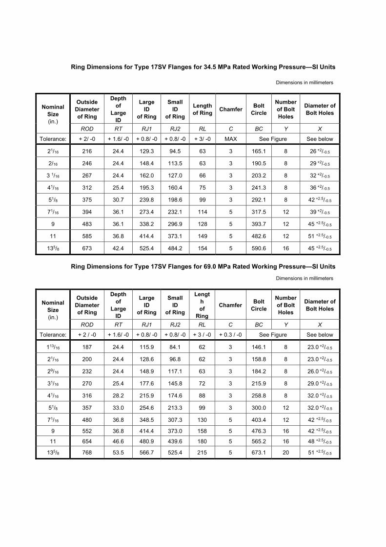
Ring Dimensions for Type 17SV Flanges for 34.5 MPa Rated Working Pressure—SI Units
Dimensions in millimeters
Nominal Size (in.)
Outside Diameter of Ring
Depth of
Large ID
Large ID
of Ring
Small ID
of Ring
Length of Ring Chamfer Bolt
Circle
Number of Bolt Holes
Diameter of Bolt Holes
ROD RT RJ1 RJ2 RL C BC Y X
Tolerance: + 2/ -0 + 1.6/ -0 + 0.8/ -0 + 0.8/ -0 + 3/ -0 MAX See Figure See below
21/16 216 24.4 129.3 94.5 63 3 165.1 8 26 +2/-0.5
2/16 246 24.4 148.4 113.5 63 3 190.5 8 29 +2/-0.5
3 1/16 267 24.4 162.0 127.0 66 3 203.2 8 32 +2/-0.5
41/16 312 25.4 195.3 160.4 75 3 241.3 8 36 +2/-0.5
51/8 375 30.7 239.8 198.6 99 3 292.1 8 42 +2.5/-0.5
71/16 394 36.1 273.4 232.1 114 5 317.5 12 39 +2/-0.5
9 483 36.1 338.2 296.9 128 5 393.7 12 45 +2.5/-0.5
11 585 36.8 414.4 373.1 149 5 482.6 12 51 +2.5/-0.5
135/8 673 42.4 525.4 484.2 154 5 590.6 16 45 +2.5/-0.5
Ring Dimensions for Type 17SV Flanges for 69.0 MPa Rated Working Pressure—SI Units
Dimensions in millimeters
Nominal Size (in.)
Outside Diameter of Ring
Depth of
Large ID
Large ID
of Ring
Small ID
of Ring
Length of
Ring
Chamfer Bolt Circle
Number of Bolt Holes
Diameter of Bolt Holes
ROD RT RJ1 RJ2 RL C BC Y X
Tolerance: + 2 / -0 + 1.6/ -0 + 0.8/ -0 + 0.8/ -0 + 3 / -0 + 0.3 / -0 See Figure See below
113/16 187 24.4 115.9 84.1 62 3 146.1 8 23.0 +2/-0.5
21/16 200 24.4 128.6 96.8 62 3 158.8 8 23.0 +2/-0.5
29/16 232 24.4 148.9 117.1 63 3 184.2 8 26.0 +2/-0.5
31/16 270 25.4 177.6 145.8 72 3 215.9 8 29.0 +2/-0.5
41/16 316 28.2 215.9 174.6 88 3 258.8 8 32.0 +2/-0.5
51/8 357 33.0 254.6 213.3 99 3 300.0 12 32.0 +2/-0.5
71/16 480 36.8 348.5 307.3 130 5 403.4 12 42 +2.5/-0.5
9 552 36.8 414.4 373.0 158 5 476.3 16 42 +2.5/-0.5
11 654 46.6 480.9 439.6 180 5 565.2 16 48 +2.5/-0.5
135/8 768 53.5 566.7 525.4 215 5 673.1 20 51 +2.5/-0.5

7.2 API Clamp Hub-type Connections
API clamp-hub-type connections for use on subsea completion equipment shall conform to the dimensional requirements of API 16A. All end and outlet clamp hubs used on subsea completion equipment shall have their ring grooves either manufactured from, or inlaid with, corrosion resistant materials.
Corrosion-resistant inlaid ring grooves for clamp hubs shall conform to API 16A. When BX or SBX gaskets are used, corrosion-resistant inlaid ring grooves shall conform to Figure 7 and Table 8. Overlays shall not be required if the base material is compatible with well fluids, seawater, etc.
7.3 Threaded Connections
Loose-threaded flanges and other threaded end and outlet connections shall not be used on subsea completion equipment where the connection is in direct contact with retained fluid with the following exceptions:
a. When threaded connections, such as instrument connections, test ports, and injection/monitor connections, are located downstream of the first wing valve, they shall not be greater than 1.00in (25,4 mm). They shall conform to the rated working pressure of the tree defined in Table 3 and API 6A.
b. When threaded connections are used upstream of the first wing valve, there shall be an isolation valve and either a
bolted flange, clamp hub or welded connection as defined in 7.20.2.6 on the tree side of the threaded connection. The threaded connection shall not be greater than 1.00in (25.4 mm). They shall conform to the rated working pressure of the tree defined in Table 3 and API 6A.
c. Tubing hangers
When threaded connections are used for non-production bore penetration connections, there shall be an isolation valve and either a bolted flange or a clamp hub connection on the tree side of the threaded connection. Sealing areas for threaded connection penetrations shall be made of corrosion-resistant materials. Threaded connections used on subsea equipment covered by this specification shall comply with the requirements of 5.1.2.2.
When threaded fittings are used in chemical injection circuits, mechanical means shall be employed to prevent back-off.
When threaded bleeder/grease/injection fittings are used, these fittings shall be allowed upstream of the first wing valve without the isolation valve and flange/clamp hub if at least two pressure barriers between the produced fluid and the external environment are provided.
7.4 Other End Connectors
The use of other non-standard end connectors, such as misalignment connectors, non-API flanges, ball joints, articulated jumper assemblies or instrument/monitor flanges may be used in subsea completion equipment when these connectors have been designed, documented and tested in accordance with the requirements established in Section 5.
Materials for OECs shall conform to 5.2 and 5.3. Seal surfaces on OECs with metal-to-metal seals used on subsea completion equipment shall be CRA or inlaid with a CRM/CRA that is compatible with well fluids, seawater, etc. If the connector’s primary seals are not metal-to-metal, redundant seals shall be provided.
7.5 Studs, Nuts and Bolting
Selection of stud, nut and bolting materials and coatings/platings should address the following:
— seawater-induced chloride stress corrosion cracking
— corrosion fatigue
— hydrogen embrittlement induced by cathodic protection systems, and

— effect of coatings on the cathodic protection systems.
Some high-strength bolting materials may not be suitable for service in a seawater environment (see 5.1.3.5).
NOTE API TR 21TR1 provides a reference for materials and coatings/platings for subsea applications.
7.6 Crosses, Tees, and Elbows
Nominal sizes, pressure ratings, temperature class, dimensions (including flange clearance and studded outlet connection requirements), material class of flanged or studded connection crosses, tees, and elbows shall conform to API 6A and sections 5, and 7.1 through 7.5 of this specification. Hybrid combinations of flanged or studded connection outlets, and nominal sizes are permitted under this specification. Overall pressure rating shall be to the lowest pressure rating of all the body’s outlets.
7.7 Completion Guidebase
General
NOTE The completion guidebase (CGB) is similar in function to a permanent guidebase used on a subsea wellhead. The CGBattaches to either the conductor (low pressure) housing (after the PGB is removed) or is attached to the tubing head connector (in the same way a tree guide frame is attached to the subsea tree connector). It provides the same guidance for the drilling and s u b s e a completion equipment, and provides landing and structural support for ancillary equipment, such as remote OEC flowline connections. The CGB provides guidance of the BOP and subsea tree onto the subsea wellhead or tubing head using guideline or guidelineless methods.
The CGB shall not interfere with BOP stack installation, ROV access or cuttings disposal.
Guidance and orientation with other subsea equipment shall conform to 7.14.2.1.
Guidance on design and associated load testing shall conform to the requirements in 5.1.3.6.
Design
7.7.2.1 Loads
Design shall meet the requirements of 5.1.3.1.
The following loads may apply:
— guideline tension
— flowline pull-in, connection, installation, and operational loads (see 7.17.2.3)
— annulus access connection loads
— environmental
— installation loads (including conductor hang off on spider beams)
— snagging loads
— BOP and tree loads
— ROV impact loads
7.7.2.2 Dimensions
The dimensions of the CGB shall conform to the dimensions listed in 7.14.2.1 and 8.3.2.2 and shown in Figure 10a, unless the orientation system requires tighter tolerances.

7.8 Tree and Tubing Head Connectors
General
7.8.1.1 Tree and Tubing Head Connectors
Two validation levels, PR1 or PR2, shall apply for tree and tubing head connectors.
NOTE See 7.8.2.2 for load/capacity and 7.8.3.3 for validation requirements.
All connectors shall be designated by size, pressure rating and the profile type of the subsea wellhead to which they are attached (see Table 17).
Table 17—Wellhead Systems—Standard Sizes and Types
System Designation High-Pressure Housing Working Pressure Minimum Vertical Bore
in.; psi (mm - MPa) Psi (MPa) in. (mm)
135/8; 10,000 (346 - 69) 10,000 (69.0) 12.31 (313)
135/8; 15,000 (346 - 103) 15,000 (103.5) 12.31 (313)
16¾; 5,000 (425 - 35) 5,000 (34.5) 15.12 (384)
16¾; 10,000 (425 - 69) 10,000 (69.0) 15.12 (384)
18¾ ; 10,000 (476 - 69) 10,000 (69.0) 17.56 (446)
18¾; 15,000 (476 - 103) 15,000 (103.5) 17.56 (446)
20¾; 21¼; 2,000 (527 - 540 - 14) 2,000 (13.8) 18.59 (472)
21¼; 5,000 (540 - 35) 5,000 (34.5) 18.59 (472)
Tree/tubing head connectors shall conform to maximum standard pressure ratings of 5,000 psi (34.5 MPa), 10,000 psi (69 MPa) or 15,000 psi (103.5 MPa), as applicable. Body proof testing shall be conducted at 1.5 times the rated working pressure. The design and installed preload shall address the potential for higher pressure from an SCSSV seal sub leakage in the gallery inside the tree connector.
7.8.1.2 Tubing Heads
7.8.1.2.1 Applications
NOTE Tubing heads are commonly used as follows:
— provide a crossover between wellheads and subsea trees made by different equipment manufacturers
— provide a crossover between different sizes and/or pressure ratings of subsea wellheads and trees
— provide a surface for landing and sealing a tubing hanger if the wellhead is damaged or is not designed to receive the hanger
— provide a means for attaching any guidance equipment to the subsea wellhead
7.8.1.2.2 Types, Sizes, and Pressure Rating
The tubing head shall be designated by size, pressure rating, and the profile types of its top and bottom connections. Top connections are commonly either hub- or mandrel-type connections that shall match the tree connector. The bottom connection shall match the wellhead.

Tubing heads shall conform to standard rated working pressures of 5000 psi (34.5 MPa), 10,000 psi (69 MPa) or 15,000 psi (103.5 MPa), as applicable. Body proof testing shall be conducted at 1.5 times the pressure rating. When the tubing head and connector are manufactured as an integral unit, then the pressure rating shall apply to the entire unit.
Design
7.8.2.1 Loads/Conditions
Design shall meet the requirements of 5.1.3.1.
The following loads may apply:
— internal and external pressure
— pressure separation loads, which shall be based on worst-case sealing conditions (leakage to the largest redundant seal diameter shall be assumed)
— mechanical preloads
— riser bending and tension loads (completion and/or drilling riser)
— environmental loads
— snagging loads
— fatigue assessment
— vibration
— mechanical installation (impact) loads
— hydraulic coupler/flowline stab connector thrust and/or preloads
— thermal expansion (trapped fluids, dissimilar metals)
— BOP loads
— tree loads
— flowline loads
— installation/workover
— overpull
— corrosion
7.8.2.2 Load/Capacity
For PR1 requirements, the manufacturer shall specify the loads/conditions for which tree and tubing head connectors, are designed.
For PR2 requirements, a capacity chart shall be provided (such as those outlined in API 16A or API 17TR7). The capacity chart shall include rated capacities with design factors of 1.5 (.67 x SY) for normal capacity, 1.25 (.8 x SY) for extreme capacity, and 1.0 (1.0 x SY) for survival capacity.
7.8.2.3 Actuating Pressures
The manufacturer shall address the following when designing the connector:

— The primary and secondary unlock forces shall be 1.25 times the force required to lock the connector
NOTE: The additional unlock force may be provided by additional hydraulic rated working pressure, additional ‘unlock piston’ area, or additional force supplied by another/additional mechanism.
— Connector shall include a secondary release function. Failure of the primary unlock system shall not compromise the secondary unlock function (7.8.2.4).
— Document the normal operating pressure (the pressure to generate preload) and hydraulic RWP (or mechanical force) for the connector’s lock function.
— Document the hydraulic RWP (or mechanical force) for the connector’s unlock and secondary release functions.
7.8.2.4 Secondary Release
Hydraulically actuated tree and tubing head connectors shall be designed with a secondary release method, which may be hydraulic or mechanical. Hydraulic unlock and lock line piping shall provide either an isolation valve with hot stab, or be positioned with a cut-away loop (for cutting the lines by diver/ROV) to vent pressure and allow the secondary release to function.
Additionally, the following shall apply:
— The secondary unlock function shall be designed such that the connector will not unlock upon exposure of the unlock line to ambient pressure
— Secondary unlock force capacity shall be the same as or greater than the primary unlock force.
7.8.2.5 Position Indication
Remotely operated tree connector and/or tubing head connectors shall be equipped with an external position indicator suitable for observation by diver/ROV to confirm connector lock and unlock.
7.8.2.6 Self-locking Requirement
Hydraulic tree and tubing-head connectors shall be designed to prevent release due to loss of hydraulic locking pressure.
Preventing release due to loss of hydraulic locking pressure may be achieved by the connector self-locking mechanism (such as a flat-to-flat locking segment design) or backed up using a mechanical locking device or other demonstrated means.
The design of mechanical locking devices shall include a means for secondary release in the event of malfunction. The connector and mechanical locking device design shall ensure that locking is effective with worst-case dimensional tolerances of the locking mechanism.
7.8.2.7 Overlay of Seal Surfaces
Seal surfaces for tree and tubing-head connectors that engage metal-to-metal seals shall be inlaid with corrosion- resistant material that is compatible with well fluids, seawater, etc. Overlays shall not be required if the base metal is compatible with well fluids, seawater, etc., e.g. if the material is a CRA. Design shall be in accordance with the manufacturer’s specifications.
7.8.2.8 Seal Testing
Means shall be provided for pressure testing all subsea mated primary seals in the connector to the rated working pressure of the tree/tubing head connector or tubing hanger, whichever is lower.
7.8.2.9 Seal Replacement
The design shall allow for the offshore/field replacement of the tree/tubing head connector’s subsea mated primary seal, isolation sleeve seals, and/or stab sub seals.

7.8.2.10 Hydraulic Lock
The design shall ensure that trapped fluid does not interfere with the installation of the connector.
7.8.2.11 Materials
Materials shall conform to 5.2.
Testing
7.8.3.1 General
The test procedure in 7.8.3.2 shall apply to both mechanical and hydraulic connectors.
7.8.3.2 Factory Acceptance Testing
After final assembly, the connector shall be tested for proper operation and interface in accordance with the manufacturer’s written specification using actual mating equipment or an appropriate test fixture. Testing shall be conducted in accordance with the manufacturer’s written specification to confirm the proper function of the primary and secondary operating and release mechanisms, override mechanisms and locking mechanisms. Testing shall confirm that the actual operating forces/pressures fall within the manufacturer’s documented specifications.
Connectors that are hydraulically operated shall have its internal hydraulic circuit, pistons, and cylinder cavities subjected to a hydrostatic test to demonstrate structural integrity. The test pressure shall be a minimum of 1.5 times the hydraulic RWP of the connector. No visible leakage shall be allowed. Minimum hold period for the connector’s hydraulic actuator hydrostatic test shall be 3 minutes.
7.8.3.3 Validation
PR1 validation of tree and tubing head connectors shall be in accordance with manufacturer’s written specification. PR2 validation of tree and tubing head connectors shall be in accordance with API 17TR7 for PR2 Hydraulic Connector Operational Characteristics.
7.9 Tree stab/seal Subs for Vertical Tree
General
NOTE Stab subs and seal subs provide pressure-controlling conduits between two remotely mated subsea components within the tree/tubing head envelope (valve block to tubing hanger, for example). Stab/seal subs are used on the production (injection) bore, annulus bore, hydraulic couplers, SCSSV control lines and downhole chemical-injection lines.
The housing for electrical penetrator(s) shall be treated as a stab sub with respect to the design requirements in 7.9. Stab/seal subs shall be considered pressure-containing if their failure to seal as intended results in a release of wellbore fluid to the environment. Stab/seal subs shall be considered pressure-controlling if at least one additional seal barrier exists between the stab/seal sub and the environment.
Stab subs and seal subs in the production and annulus bore should conform to standard maximum pressure ratings of 5,000 psi (34.5 MPa), 10,000 psi (69 MPa) or 15,000 psi (103.5 MPa) as covered by this specification. The effects of pressure acting externally on stabs and seal subs shall be addressed up to the tree pressure rating, pressure rating of any seal sub in the annulus envelope outside the seal stab, or the hyperbaric pressure rating, whichever is greatest. Stab subs or seal subs used to conduct SCSSV control fluid, other hydraulic fluids, or injected chemicals shall be rated to a working pressure equal to or greater than the SCSSV control pressure or injection pressure, respectively, whichever is the higher, and be limited to 2,500 psi (17.2 MPa) plus the RWP of the tree.
Proof testing shall be at 1.0 times the stab/seal sub pressure rating if the stab/seal sub is pressure-controlling, and 1.5 times the stab/seal sub pressure rating if the stab/seal sub is pressure-containing. Working-pressure tests shall be at the pressure rating of the seal sub and its fluid passage. Galleries outboard of the stab/seal sub shall be tested to the highest pressure rated stab/seal sub in that gallery, unless a means to vent the gallery is provided, in which case the gallery test shall be at the rated working pressure rating of the interface.

Design
7.9.2.1 Loads/conditions
Design shall meet the requirements of 5.1.3.1.
NOTE The following loads may apply:
— internal and external pressure
— separation loads
— bending loads during installation
— thermal expansion
— corrosion
— galling
7.9.2.2 Seal Design
The seal mechanism may be either a metal-to-metal or a redundant non-metallic seal.
Corrosion-resistant material shall be used for the metal-to-metal seal-sub designs and is recommended for redundant non-metallic seal designs.
7.10 Valves, Valve Blocks and Actuators/Operators
Overview
7.10.1.1 Flanged End Valves
Valves having API-type flanged end connections shall use integral, studded, or welding neck, flanges as specified in 7.1.
For units having end and outlet connections with different pressure ratings, the rating of the lowest-rated pressure-containing part shall be the rating of the unit.
7.10.1.2 Other End Connector Valves
Clamp-type connections shall conform to API 16A. OECs shall conform to 7.4.
Design
7.10.2.1 Valves and Valve Blocks
7.10.2.1.1 General
Valves and valve blocks used in the subsea tree bores and tree piping shall conform to the applicable bore dimensional requirements of API 6A. Other valve and valve block dimensions shall conform to 7.1 through 7.6.
If the lower end connection of the tree that mates to the tree connector encapsulates SCSSV control lines that have a higher pressure rating than the tree-pressure rating, the design shall address leaking control lines or seal subs unless relief is provided as specified in 5.1.2.1. Proof testing of the end connections and body shall be at 1.5 times RWP of the valve block.
Consideration should be given to the inclusion of diver/ROV valve overrides, particularly in the vertical run, to facilitate well intervention in the event of hydraulic control failure.
Penetrations shall not be permitted for the purpose of greasing, back seat testing or for testing secondary stem seals.

Where pressure may become trapped between seals, the function of the valve shall not be adversely affected.
7.10.2.1.2 Valves
The following shall apply to all valve types.
— Valves shall have their service classification in conformance with Section 5, with respect to pressure rating, temperature and material class. Additionally, underwater safety valves (USVs) shall be rated for sandy service (PR2 class II), as defined by API 6A.
— Valves designated as underwater safety valves (USV) shall meet the requirements in 7.10.6.
— Valves for subsea service shall address the impact of external pressure and the environment as well as internal fluid conditions.
— Manufacturers of subsea valves shall document design and operating parameters of the valves as listed in Table 18.
— Measures shall be taken to ensure that there are no burrs or upsets at the gate and seat bores that can damage the gate and seat surfaces or interfere with the passage of wireline tools.
7.10.2.1.3 Valve Blocks
Valve blocks shall meet the design requirements given in 6.1 and in API 6A.
Dual bore valve blocks shall meet the applicable design requirements of API 6A. Table 19 specifies the center distances for dual parallel bore valve blocks designed to this specification. There are no specific end-to-end dimension or outlet requirements for these valve blocks.
Other multiple bore valve block configurations shall meet the applicable design requirements of API 6A.
Table 18—Operating Parameters of Valves and Actuators/Operators
A Valve
1 Nominal bore size 2 Rated Working pressure 3 Class of service 4 Temperature classifications 5 Type and size connections a 6 Valve stroke 7 Overall external dimensions and mass a 8 Materials class rating
9 Reset position (open, closed, in place)
10 Unidirectional or bi-directional (flow through valve bore – for unidirectional, mark external of valve body with flow direction arrow)
11 Position indicator type (visual, electrical, etc.)
B Actuator (Hydraulic, Electric, or Hybrid)
1 Minimum hydraulic operating pressure or electric power
2 Maximum allowed hydraulic operating pressure or electric power (volts, amps), at continuous stall
3 Temperature classifications
4 (Hydraulic) Actuator volume displacement a
5 Number of turns to open/close valve b
6 Override force or torque required b
7 Maximum override force or torque b
8 Maximum override speed b

9 Overall external dimensions and mass
10 Override type and class (in accordance with API 17H) b
11 Make and model number of valves the actuator is designed for
C Valve/actuator Assembly
1 Maximum water depth rating At maximum rated depth of assembly and maximum rated bore pressure, the actuator hydraulic pressure in psi (MPa) or electric power in Watts at the following valve positions:
2 Start to open from previously closed position
3 Fully open
4 Start to close from previously open position
5 Fully closed At maximum rated depth of assembly and 0 psi (MPa), bore pressure, the actuator hydraulic pressure, expressed in psi (MPa) or electric power in Watts in at the following valve positions:
6 Start to open from previously closed position
7 Fully open
8 Start to close from previously open position
9 Fully closed a Where applicable. b When equipped with manual or ROV override.
Table 19—Center Distances of Conduit Bores for Dual Parallel Bore Valve Blocks
Valve size in. (mm)
Valve-bore Center to Valve-bore Center
in. (mm)
Large Valve-bore Center to Block-body Center
in. (mm)
5000 psi (34.5 MPa)
21/16 ��21/16 (52 ��52) 3.547 (90.09) 1.774 (45.06)
29/16 ��21/16 (65 ��52) 3.547 (90.09) 1.650 (41.91)
31/8 ��21/16 (79 ��52) 4.578 (116.28) 2.008 (51.00)
41/16 ��21/16 (103 ��52) 4.563 (115.90) 1.750 (44.45)
51/8 ��21/16 (130 ��52) 4.500 (114.30) 0.0
10,000 psi (69.0 MPa)
21/16 ��21/16 (52 ��52) 3.550 (90.17) 1.774 (45.05)
29/16 ��21/16 (65 ��52) 4.000 (101.60) 1.875 (47.63)
31/16 ��21/16 (78 ��52) 5.050 (128.27) 2.524 (64.10)
41/16 ��21/16 (103 ��52) 5.000 (127.00) 1.625 (41.28)
51/8 ��21/16 (130 ��52) 5.750 (146.05) 0.0
15,000 psi (103.5 MPa)
21/16 ��21/16 (52 ��52) 3.550 (90.17) 1.774 (45.05)
29/16 ��21/16 (65 ��52) 4.000 (101.60) 1.875 (47.63)
31/16 ��21/16 (78 ��52) 5.050 (128.27) 2.524 (64.10)
41/16 ��21/16 (103 ��52) 5.500 (139.70) 1.125 (28.58)
51/8 � 21/16 (130 � 52) 6.750 (171.45) 0.0

Bore-position seal-preparation centers shall be within 0.005 in. (0.13 mm) of their true position with respect to the block-body center or block-body end connection seal. Bores shall be true within 0.010 in. (0.25 mm) total indicator reading with respect to the centers of the bore seal preparation.
7.10.2.2 Actuators/Operators
7.10.2.2.1 General
The following shall apply to the design of subsea valve actuators/operators.
— Actuators/operators should be designed to prevent functional impairment by marine growth, fouling, calcareous deposit, hydrate formation at seawater boundaries, or corrosion/deterioration caused by the environment, hydraulic operating or compensation fluids and, if exposed, the well stream fluid.
— Designs shall be capable of operating a valve or group of valves. An actuator/operator paired to work together with a valve shall meet or exceed the functional performance requirements set for operating the valve, including the requirements in this section.
— Designs shall be capable of operating the valve without damage to the valve or actuator/operator (to such an extent that prevents meeting any other performance requirement), when the actuation force (within its rated working force / torque, hydraulic operating pressure, or electric power rating) is either applied or removed under any valve bore pressure conditions or stoppage of the valve bore sealing mechanism at any intermediate position.
— Designs shall account for the effect of external hydrostatic pressure at the manufacturer’s maximum rated water depth and the RWP of the valve.
— Manual overrides, if provided, shall be in accordance with the following requirements for fail-close valves:
a) A rotation-type override shall open the valve with a counter-clockwise rotation looking at the end of the stem.
b) A linear-type override for fail-closed valve shall open the valve with a push on the override.
For fail-open, fail-in-place, or position-indexed (stepping) actuated valves, the manufacturers shall document the method for override.
The manufacturer shall document the method, procedures and operating limits for override.
— If a design feature to separate an actuator from a valve is provided, the design should demonstrate that the valve stem does not move during actuator removal / replacement to satisfy the actuator removal requirement. Before removal of the actuator, the hydraulic or electric power conduits leading to the actuator should be isolated and/or sealed off prior to removal / connection of the actuator and done under a vented or powered down state.
— Position indicators, if provided, shall show a valve’s position from full open to full closed. Where the actuator incorporates a manual override, the position indicator shall be visible from the diver/ROV’s working position with override tool installed.
— Water depth rating—Manufacturer shall specify the maximum water depth rating of the actuator/operator assembly. Water depth rating shall be based on the design’s external pressure as a function of water depth using seawater specific gravity of 1.03. If pressure compensation is required, the design of the actuator/operator should pressure compensate all fluid filled chambers accounting for the maximum rated water depth and the thermal expansion coefficient of the fluids.
Other subsea actuator/operator performance criteria can be specified, such as wire/coiled tubing shearing design criteria, but these shall be addressed separately from the above fundamental set of criteria.
Hybrid actuator designs, such as electro-hydraulic actuators shall meet the appropriate requirements of these sections for their respective subassemblies and components within.
7.10.2.2.2 Manual Operator
The following requirements shall apply to manual operator.
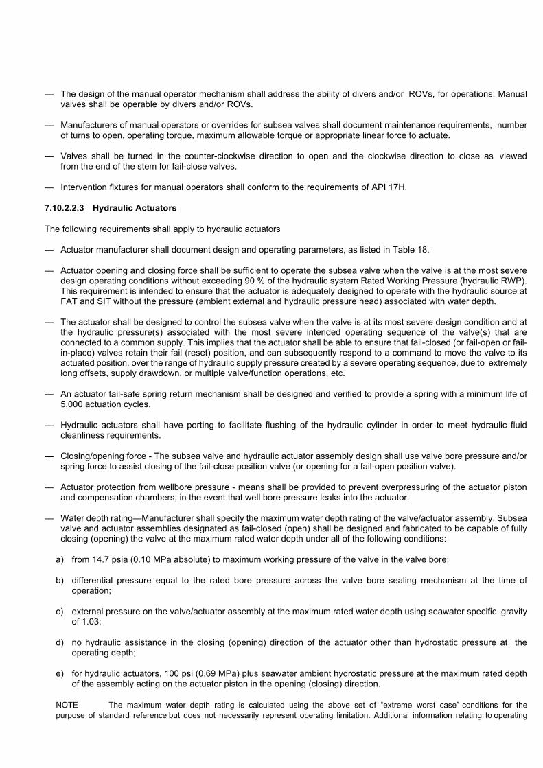
— The design of the manual operator mechanism shall address the ability of divers and/or ROVs, for operations. Manual valves shall be operable by divers and/or ROVs.
— Manufacturers of manual operators or overrides for subsea valves shall document maintenance requirements, number of turns to open, operating torque, maximum allowable torque or appropriate linear force to actuate.
— Valves shall be turned in the counter-clockwise direction to open and the clockwise direction to close as viewed from the end of the stem for fail-close valves.
— Intervention fixtures for manual operators shall conform to the requirements of API 17H.
7.10.2.2.3 Hydraulic Actuators
The following requirements shall apply to hydraulic actuators
— Actuator manufacturer shall document design and operating parameters, as listed in Table 18.
— Actuator opening and closing force shall be sufficient to operate the subsea valve when the valve is at the most severe design operating conditions without exceeding 90 % of the hydraulic system Rated Working Pressure (hydraulic RWP). This requirement is intended to ensure that the actuator is adequately designed to operate with the hydraulic source at FAT and SIT without the pressure (ambient external and hydraulic pressure head) associated with water depth.
— The actuator shall be designed to control the subsea valve when the valve is at its most severe design condition and at the hydraulic pressure(s) associated with the most severe intended operating sequence of the valve(s) that are connected to a common supply. This implies that the actuator shall be able to ensure that fail-closed (or fail-open or fail-in-place) valves retain their fail (reset) position, and can subsequently respond to a command to move the valve to its actuated position, over the range of hydraulic supply pressure created by a severe operating sequence, due to extremely long offsets, supply drawdown, or multiple valve/function operations, etc.
— An actuator fail-safe spring return mechanism shall be designed and verified to provide a spring with a minimum life of 5,000 actuation cycles.
— Hydraulic actuators shall have porting to facilitate flushing of the hydraulic cylinder in order to meet hydraulic fluid cleanliness requirements.
— Closing/opening force - The subsea valve and hydraulic actuator assembly design shall use valve bore pressure and/or spring force to assist closing of the fail-close position valve (or opening for a fail-open position valve).
— Actuator protection from wellbore pressure - means shall be provided to prevent overpressuring of the actuator piston and compensation chambers, in the event that well bore pressure leaks into the actuator.
— Water depth rating—Manufacturer shall specify the maximum water depth rating of the valve/actuator assembly. Subsea valve and actuator assemblies designated as fail-closed (open) shall be designed and fabricated to be capable of fully closing (opening) the valve at the maximum rated water depth under all of the following conditions:
a) from 14.7 psia (0.10 MPa absolute) to maximum working pressure of the valve in the valve bore;
b) differential pressure equal to the rated bore pressure across the valve bore sealing mechanism at the time of operation;
c) external pressure on the valve/actuator assembly at the maximum rated water depth using seawater specific gravity of 1.03;
d) no hydraulic assistance in the closing (opening) direction of the actuator other than hydrostatic pressure at the operating depth;
e) for hydraulic actuators, 100 psi (0.69 MPa) plus seawater ambient hydrostatic pressure at the maximum rated depth of the assembly acting on the actuator piston in the opening (closing) direction.
NOTE The maximum water depth rating is calculated using the above set of “extreme worst case” conditions for thepurpose of standard reference but does not necessarily represent operating limitation. Additional information relating to operating

water depth for specific applications can be provided and agreed between manufacturer and user/purchaser as being more representative of likely field conditions.
7.10.2.2.4 Electric Actuators
The following requirements apply to electric actuators.
— Actuator manufacturer shall document design and operating parameters, as listed in Table 18.
— Actuator shall be designed to require no more than 90% of its rated torque/force capability to operate the valve in the most severe design operating condition.
— The actuator shall be designed to control the subsea valve when the valve is at its most severe design condition and have sufficient stored energy for the most severe intended operating sequence of the valve(s).
— Actuator with a permanently installed energy storage device for fail close or fail open functions shall be designed to provide an energy storage device with a minimum life of 5,000 full actuation cycles (open to close and close to open – reference Annex J.4.1).
— Retrievable energy storage devices should have a minimum capacity of 150% of the storage device manufacturer’s rated life.
— Use of electric actuator on a manual operator valve shall be acceptable only if the valve/manual operator has been qualified to 600 endurance cycles.
— Actuator protection from wellbore pressure and temperature - means shall be provided to prevent over-pressuring of the actuator electrical housing and compensation chambers, if well bore pressure leaks into the actuator. Thermal protection for the motor and electrical components shall be provided.
— Electrical subassemblies and components, such as winding stators/rotors energy storage units and controllers shall be in accordance with the requirements of API 17F or the applicable standards (such as IEC/CENELEC). Electrical control latching (hold-open) power shall be in accordance with manufacturer's written specification. This should include end of valve or choke service life.
— Closing/opening force—The subsea valve and electric actuator assembly design shall use valve bore pressure and/or a stored energy source (such as a spring, permanent magnet, or battery) to assist closing of the fail-close position valve (or opening for a fail-open position valve).
Materials
Materials for valves, valve blocks and actuators shall conform to 5.2. Seal surfaces that engage metal-to-metal seals shall be inlaid with a corrosion-resistant material that is compatible with well fluids, seawater, etc.
NOTE Overlays are not required if the base material is compatible with well fluids, seawater, etc.
Testing
7.10.4.1 Validation
7.10.4.1.1 General
Testing shall validate specific valve and valve actuator/operator designs manufactured under this specification (see 5.1.7).
NOTE Annex J provides information on a consistent method of conducting validation on valves and actuators conforming to this specification, by prescribing the types of cycles and the order in which the cycles are to be performed.
7.10.4.1.2 Valve and Hydraulic Actuator Assembly Testing
Subsea valve and actuator assemblies shall be tested to demonstrate the performance limits of the assembly. Unidirectional valves shall be tested with pressure applied in the intended direction. Bi-directional valves shall be tested with pressure applied in both directions in separate tests.

For a fail-closed (fail-open) valve, with the assembly subjected to external pressure (actual or simulated) of the maximum rated water depth and full rated bore pressure, applied as a differential across the gate, the valve shall open (close) fully from a previously closed (open) position with a maximum of 90 % of the hydraulic system RWP above actual or simulated external pressure.
For a hydraulic fail-closed (fail-open) valve, with the assembly subjected to the external pressure, (actual or simulated) of the maximum rated water depth and atmospheric pressure in the body cavity, the valve shall be shown to move from a previously fully open (closed) position to a fully closed (open) position as the hydraulic pressure in the actuator is lowered to a minimum of 100 psi (0.69 MPa) above external pressure.
Validation of a fail-closed (or fail-open) valve/actuator assembly may be used to validate an equivalent fail-open (fail-close) valve/actuator design, provided that the fail-open (fail-closed) valve/actuator is subjected to a functional stroking tested with external pressure applied; one cycle with the valve bore at RWP, and the second with the bore at atmospheric pressure.
For a fail-in-place valve, with the assembly subjected to the external pressure (actual or simulated) of the maximum rated water depth, the valve shall close or open fully from a previously open or closed position with a maximum of 90 % of the operating hydraulic system RWP above actual or simulated external pressure. A fail-in-place hydraulically actuated valve shall remain in position as the hydraulic control pressure in the actuator is lowered to a minimum of 100 psi (0.69 MPa) above external pressure.
7.10.4.1.3 Valve and Electric Actuator Assembly Testing
This section covers the performance requirements for a fully assembled, valve/actuator set.
For a fail-closed (fail-open) valve, with the assembly subjected to external hydrostatic pressure (actual or simulated) of the maximum rated water depth and full rated bore pressure, applied as a differential across the gate, it shall be shown that the valve opens (closes) fully from a previously closed (open) position with a maximum of 90% of the minimum electric power, applied to the actuator, PMR.
For a fail-closed (fail-open) valve, with the assembly subjected to the external hydrostatic pressure, (actual or simulated) of the maximum rated water depth and atmospheric pressure in the body cavity, the valve shall be shown to move from a previously fully open (closed) position to a fully closed (open) position in the event of loss of power or loss of communication.
For a fail-in-place valve, with the assembly subjected to the external hydrostatic pressure (actual or simulated) of the maximum rated water depth, the valve shall be shown to closed or open fully from a previously open or closed position with a maximum of 90% of the minimum electric power, applied to the actuator, PMR. A fail-in-place electric valve shall remain in position in the event of loss of power or loss of communication.
7.10.4.2 Factory Acceptance Testing
7.10.4.2.1 General
Each subsea valve and valve actuator/operator shall be subjected to a hydrostatic and operational test to demonstrate the structural integrity and proper assembly and operation of each completed valve and/or actuator/operator.
NOTE Tables 20 and 21 offer examples of test documentation.
Table 20a—Example of PSL 2 Valve Factory Acceptance Test Documentation
VALVE BODY PRESSURE TEST HYDROSTATIC TEST GAS TEST
PSI Start Time End Time PSI Start Time End Time
1. Primary Body Test (TP) 3 minute hold NA NA NA 2. Secondary Body Test (TP) 3 minute hold NA NA NA
VALVE SEAT PRESSURE TEST
HYDROSTATIC TEST GAS TEST
PSI Start Time End Time PSI Start Time End Time 3. Seat Test (RWP) 3 minute hold NA NA NA

4. First hydrostatic break open seat NA NA NA NA NA 5. Seat Test (RWP) 3 minute hold (PSL 2) NA NA NA 6. Second hydrostatic break open seat NA NA NA NA NA 7. Seat Test (RWP) 3 minute hold (PSL 2) NA NA NA
8.a Opposite Seat Test (RWP) 3 minute hold NA NA NA
9.a First hydrostatic break open opposite seat NA NA NA NA NA 10.a Opposite Seat Test (RWP) 3 minute hold NA NA NA 11.a Second hydrostatic break open opposite seat NA NA NA NA NA 12.a Opposite Seat Test (RWP) 3 minute hold NA NA NA 13. Drift Test Successfully Completed Yes/No (As applicable) a Bi-directional sealing valves only. TP = test pressure = 1.5 x Rated working pressure (RWP)

Table 20b—Example of PSL 3 Valve Factory Acceptance Test Documentation
VALVE BODY PRESSURE TEST
HYDROSTATIC TEST GAS TEST PSI Start Time End Time PSI Start Time End Time
1. Primary Body Test (TP) 3 minute hold NA NA NA 2. Second. Body Test (TP) 15 minute hold (PSL 3) NA NA NA
VALVE SEAT PRESSURE TEST HYDROSTATIC TEST GAS TEST
PSI Start Time End Time PSI Start Time End Time 3. Seat Test (RWP) 3 minute hold NA NA NA 4. First hydrostatic break open seat NA NA NA NA NA 5. Seat Test (RWP) 15 minute hold (PSL 3) NA NA NA 6. Second hydrostatic break open seat NA NA NA NA NA 7. Seat Test (RWP) 15 minute hold NA NA NA 8.a Opposite Seat Test (RWP) 3 minute hold NA NA NA 9.a First hydrostatic break open opposite seat NA NA NA NA NA 10.a Opposite Seat Test (RWP) 15 minute hold NA NA NA 11.a Second hydrostatic break open opposite seat NA NA NA NA NA 12. a Opposite Seat Test (RWP) 15 minute hold NA NA NA 13. Drift Test Successfully Completed Yes/No (As applicable) a Bi-directional sealing valves only. TP = test pressure = 1.5 x Rated working pressure (RWP)
Table 20c—Example of PSL 3G Valve Factory Acceptance Test Documentation
VALVE BODY PRESSURE TEST HYDROSTATIC TEST GAS TEST
PSI Start Time End Time PSI Start Time End Time 1. Primary Body Test (TP) 3 minute hold NA NA NA 2. Second. Body Test (TP) 15 minute hold (PSL 3G) NA NA NA 3. Third Body Test (RWP) 15 minute hold (PSL 3G) NA NA NA
VALVE SEAT PRESSURE TEST HYDROSTATIC TEST GAS TEST
PSI Start Time End Time PSI Start Time End Time 4. Seat Test (RWP) 3 minute hold NA NA NA 5. First hydrostatic break open seat (RWP) NA NA NA NA NA 6. Seat test (RWP) 15 minute hold NA NA NA 7. Second hydrostatic break open seat (RWP) NA NA NA NA NA 8. a Opposite seat Test (RWP) 3 minute hold NA NA NA 9.a First hydrostatic break open opposite seat (RWP) NA NA NA NA NA 10.a Opposite Seat Test (RWP) 15 minute hold NA NA NA 11.a Second hydrostatic break open opposite (RWP) NA NA NA NA NA 12. Seat gas test (RWP) 15 minute hold NA NA NA 13. Seat gas test (LP) 15 minute hold NA NA NA
14. a Opposite Seat Gas Test (RWP) 15 minute hold NA NA NA 15.a Opposite Seat Gas Test (LP) 15 minute hold NA NA NA 16. Drift Test Successfully Completed Yes/No (As applicable) a Bi-directional sealing valves only TP = test pressure = 1.5 x Rated working pressure (RWP), LP = low pressure = 300 psi ± 30 psi

Table 21—Example Documentation of the Factory Acceptance Testing for a Hydraulic Actuator
Factory Acceptance Test Form for Hydraulic Actuator Test Sequence
(3 minute minimum hold period) Hydrostatic Test
Pressure Start time End time 1 Control port hydrostatic test (1.5
times hydraulic RWP)
2 Control port hydrostatic test (1.5 times hydraulic RWP)
3 Control port seal test (0.2 times hydraulic RWP)
4 Control port seal test (1.0 times hydraulic RWP)
5 Compensation port hydrostatic test (1.5 times compensation working pressure)
6 Spring chamber hydrostatic test (1.5 times compensation working pressure)
7 Actuator function test: Complete three cycles
8 Manual operation test: Complete three cycles (rotary design) onecycle (linear design)
Stroke, expressed as inches (millimeters) per number of turns to operate
Force per torque, expressed as pounds (Newtons) per foot-pounds·(Newton-meters) with no pressure
Force per torque, expressed as pounds (Newtons) per foot-pounds·(Newton-meters) with differential pressure
7.10.4.2.2 Subsea Valve
Each subsea valve shall be factory acceptance tested in accordance with PSL 2 or PSL 3 or PSL 3G as specified in 5.4.5 or 5.4.6.
7.10.4.2.3 Subsea Valve Actuator
7.10.4.2.3.1 Hydraulic Actuator Hydrostatic Body Test
Each hydraulic actuator cylinder and piston shall be subjected to a hydrostatic body test to demonstrate structural integrity. The test pressure shall be a minimum of 1.5 times the hydraulic RWP of the actuator. No visible leakage shall be allowed.
There shall be a minimum of two hold periods at no less than 3 minutes each.
7.10.4.2.3.2 Actuator Operational Test
The actuator shall be tested for proper operation by stroking the actuator from the fully closed position to the fully open position, a minimum of three times, per the manufacturers written specification. The actuator should operate smoothly (no evidence of stick-slip movement, sometimes referred to as chatter) in both directions in accordance with the manufacturer’s written specification. Test media for hydraulic actuators shall be specified by the manufacturer.
NOTE Cycling prior to further testing followed by low pressure testing in the next step confirms that the seals were not damaged by the high-pressure test.
7.10.4.2.3.3 Hydraulic Actuator Seal Test
The actuator seals shall be pressure-tested in two steps by applying pressures of 0.2 times the hydraulic RWP and a minimum of 1.0 times the hydraulic RWP of the actuator. No seal leakage shall be allowed. The test media shall be specified by the manufacturer. The minimum test duration for each test pressure shall be 3 minutes. The test period shall not begin until the test pressure has been reached and has stabilized. The test gauge pressure reading and time at the beginning and at the end of each pressure holding period shall be recorded.
The low-pressure test shall not apply to hydraulic piston flow-by-type actuators.

7.10.4.2.3.4 Hydraulic Actuator Compensation Circuit Test
The actuator compensation chamber and circuit shall be tested per the manufacturer’s written specification.
NOTE Compensating barriers are found in section 6.2.12.
7.10.4.2.3.5 Fully Assembled Electric Actuator
The electric actuator shall be tested for proper operation by stroking the actuator from the fully closed position to the fully open position a minimum of three times, per the manufacturers written specification. The actuator should operate smoothly (no evidence of stick-slip movement, sometimes referred to as chatter) in both directions. If applicable, the actuator compensation chamber shall be tested per the manufacturer's written specification.
7.10.4.2.4 Testing of Valve/actuator Assembly
After final assembly, each valve/actuator assembly (including override if fitted) shall be subjected to a functional and pressure test to demonstrate proper assembly and operation in accordance with the manufacturer’s written specification. Equipment assembled entirely with previously hydrostatically tested equipment need only be tested to rated working pressure. The functional test shall be performed by a qualified subsea valve/actuator manufacturer. All test data shall be recorded on a data sheet and shall be maintained by the subsea valve/actuator manufacturer for at least five years after date of manufacture. The test data sheet shall be signed and dated by the person(s) performing the functional test(s).
The subsea valve and actuator assembly shall meet the testing requirement of 7.10.4.2.2 and 7.10.4.2.3.
Marking
7.10.5.1 Subsea Valve Marking
Subsea valve assemblies shall be tagged with a nameplate, located on the valve body or nearest accessible location, and contain the same information as Section 6.5.
7.10.5.2 Subsea Valve Actuator/Operator Marking
The subsea valve actuator shall be marked as shown in Table 22.
Table 22—Marking for Subsea Valve Actuator/Operator
Marking Application
1 Manufacturer’s name or trademark Nameplate
2 API 17D Nameplate
3 Hydraulic cylinder maximum working pressure – Hydraulic actuator Electric Power rating (Watts) – Electric actuator
Nameplate and hydraulic actuator cylinder or
Nameplate and power unit housing
4 Manufacturer’s part number Nameplate
5 Serial or identification number Nameplate and actuator cylinder or power unit housing
7.10.5.3 Subsea Valve and Actuator/operator Assembly Marking
The subsea valve and actuator/operator assembly shall be marked as shown in Table 23.
Table 23—Marking for Subsea Valve and Actuator/Operator Assembly
Marking Application
1 Manufacturer’s name or trademark Nameplate
2 API 17D Nameplate

3 Assembly serial or identification number Nameplate
4 Maximum water depth rating Nameplate
7.10.5.4 Nameplates
Nameplates shall be attached after final coating of the equipment. Nameplates should be designed to remain legible for the design life of the product.
7.10.5.5 Flow Direction
All subsea valves that are designed to have unidirectional flow should have the flow direction prominently and permanently marked.
Underwater Safety Valves and Actuators
7.10.6.1 Underwater Safety Valves
7.10.6.1.1 General
USVs shall conform to the PSL requirements of API 17D in addition to specific USV quality requirements for actuated valves, in accordance with API 6A. Record requirements and the accompanying data packages for manufactured USVs shall be in accordance with USV record requirements of API 6A. 7.10.6.1.2 USV Design
USVs shall be designed for and constructed of materials conforming to Section 7.10. Design criteria for USVs shall include maximum water depth. The USV shall be of a fail-close design. The USV shall be designed to operate, without damage to the safety valve or safety valve actuator, when the valve is actuated open or closed, pressurized or depressurized, under any internal valve body pressure within its pressure rating, and under external pressure up to the maximum depth rating. USVs may use end connectors as specified in Section 7. USVs may be of nonstandard bores and/or face-to-face lengths. End connectors shall meet all other requirements of this specification. A USV valve may be a single loose valve or one valve in a multiple- or block-valve assembled body. 7.10.6.1.3 USV Validation
USVs shall satisfy the performance requirements specified in Sections 5 and shall be validated as specified by API 6AV1 for the sandy service class (I, II or III) designated by the manufacturer. The USV shall be operated by a USV actuator during validation. Validation of a single-unit USV shall validate a multiple- or block-type valve for performance without additional validation testing, if it is of the same internal design as a USV within the manufacturer’s product line that has passed the required validation testing, and if all other scaling requirements are satisfied. Scaling provision of Section 5 and API 6AV1 shall apply. An independent test agency, as defined by API 6A and API 6AV1, shall conduct the API 6AV1 portion of USV validation and prepare the test report. The manufacturer shall submit a USV of the same basic design and materials of construction for the API 6AV1 validation tests. An independent test agency is not required for other USV validation per Section 5. NOTE It is not required that a single valve be consecutively tested to Section 5 and API 6AV1. The tests are not cumulative.

7.10.6.2 USV Actuators
USV actuators shall be designed for and constructed of materials conforming to Section 7.10 and shall perform satisfactorily in the tests required of Sections 5 and 7.10.4. The safety valve actuator’s closing force shall be sufficient to close the USV when it is at the most severe design-closing condition specified by the manufacturer. Permanently attached lock-open features shall not be permitted on USV actuators. NOTE The term “USV actuator” refers to a subsea actuator designated for use with an underwater safety valve (USV). 7.10.6.3 USV Acceptance Testing
All assembled USVs with USV actuators shall pass all applicable tests per API 17D as required in Section 7.10.4. All test data records shall be provided in accordance with USV record requirements of API 6A. Low pressure testing shall conform to API 17D in lieu of API 6A low pressure testing. 7.10.6.4 USV Marking
In addition to the requirements of Section 6.5, valves and actuators used for USVs shall have separate nameplates affixed.
USVs shall be tagged with a nameplate in a visible location on the valve body or near the USV bonnet on a multiple- or block-type valve arrangement per Table 23, and contain the following information as a minimum:
— manufacturer’s name or trademark
— date
— PSL designation of the USV
— rated working pressure of the USV
— temperature rating of the USV
— material class of the USV (including maximum H2S partial pressure if applicable)
— sandy service class (per API 6AV1 validation)
— unique identifier (serial number, PSL 3 and above)
— API 17D - USV
USV actuators shall be tagged with a nameplate in a visible location on the actuator body with the information listed in Table 22 with the designation “API 17D-USV” 7.11 Re-entry Interface
General
NOTE A re-entry interface is used to provide an attachment interface on the tree or tubing head assembly for connection of
— a running tool used for installation and workover purposes
— a tree cap, or other pressure cap
— internal crown plugs, if applicable

— interface to other intervention hardware
Design
7.11.2.1 Pressure Rating
The re-entry interface shall be rated to the tree working pressure as defined by 5.1.2.1.
7.11.2.2 Re-entry Interface Upper Connection/profile
The connection shall also provide for passage of wireline tools and shall not limit the drift diameter of the tree bore.
Design Loads/conditions
Design shall meet the requirements of 5.1.3.1.
The following loads may apply:
— internal and external pressure
— pressure separation loads, which shall be based on worst-case sealing conditions (leakage to the largest redundant seal diameter shall be assumed)
— mechanical preloads
— riser bending and tension loads
— external environmental loads
— fatigue assessment
— vibration
— mechanical installation (impact) loads
— hydraulic coupler thrust and/or preloads
— corrosion
7.12 Subsea Tree Cap
General
7.12.1.1 Introduction
Vertical and horizontal trees use internally and externally attached tree caps. When internal caps are used, an external debris cap or cover may be installed to protect sealing surfaces and hydraulic couplers. Hydraulic couplers may be incorporated in the tree cap. These may be integral with the cap or externally attached.
7.12.1.2 Non-pressure-containing Tree Cap
NOTE Non-pressure-containing tree caps protect the tree re-entry interface, hydraulic couplers and vertical wellbores from possible environmental damage or undesired effects resulting from corrosion, marine growth or potential mechanical loads.
Design of non-pressure-containing tree caps shall conform to Section 5 and is not addressed further in this specification.
If a parking spot for the debris cap is included in the tree it shall provide a method of securing the cap. Load cases should include transportation, handling, installation and accidental conditions e.g. tree lowered too fast or dropped.

7.12.1.3 Pressure-containing Tree Cap
When the tree cap is used as a barrier, the system shall be designed to remove or isolate any trapped pressure from below or allow for the installation of a well control device before the tree cap can be removed.
Design
7.12.2.1 General
The provisions in 7.12.2 shall apply to pressure-containing tree caps. The design of this equipment shall conform to 5.1. The requirements given in 7.12.2.2 to 7.12.2.4 shall apply to both internally and externally attached tree caps.
7.12.2.2 Pressure Rating
The tree cap shall be rated to the tree working pressure as defined by 5.1.2.1.
7.12.2.3 Tree Cap Locking Mechanism
The tree cap locking mechanism shall be designed to contain the rated tree working pressure acting over the corresponding seal areas that interface with the upper tree connection. The tree cap locking mechanism shall include a secondary release feature or separate fishing profile.
NOTE Three types of tree cap are commonly used:
— hydraulic, remote operated
— mechanical, remote operated
— mechanical diver/ROV operated
7.12.2.4 Design Loads/Conditions
Design shall meet the requirements of 5.1.3.1.
The following loads may apply:
— internal and external pressure
— pressure separation loads, which shall be based on worst-case sealing conditions (leakage to the largest redundant seal diameter shall be assumed) unless relief is provided as described in 5.1.2.1
— mechanical preloads
— installation string bending and tension loads
— temperature variations
— external environmental loads
— fatigue assessment
— vibration
— trapped volumes and thermal expansion
— mechanical installation (impact) loads
— hydraulic coupler thrust and/or preloads
— corrosion

— dropped objects and snag loads
Design and Functional Requirements
7.12.3.1 Installation Pressure Test
A means shall be provided to test the upper tree connection and tree cap seal(s) after installation.
7.12.3.2 Pressure Venting
A means shall be provided such that any pressure underneath the tree cap can be vented prior to removal.
7.12.3.3 Hydraulic Lock
A means shall be provided for the prevention of hydraulic lock during installation or removal of the tree cap.
7.12.3.4 Operating Pressure
Hydraulically actuated tree caps shall be capable of containing hydraulic release pressures of at least 25 % above normal operating release pressures if normal operating release pressure is inadequate to effect release of the connector. The manufacturer shall document both normal and maximum operating release pressures. The unlocking force shall be greater than the locking force. The values shall be documented by the manufacturer.
7.12.3.5 Secondary Release
Tree caps shall be designed with a secondary release method, which may be hydraulic or mechanical. Diver/ROV/remote tooling shall conform to API 17H. Hydraulic open and close control-line piping shall be positioned to allow cutting by diver/ROV or contain a means to vent hydraulic lock pressure if necessary for the secondary release to function.
7.12.3.6 External Position Indication
External tree caps shall be equipped with an external position indicator to show when the tree cap is fully locked.
7.12.3.7 Self-locking Requirement
Hydraulic tree caps shall be designed for the following:
— prevent unintentional release due to loss of hydraulic locking pressure; and
— intentional release in the event of malfunction of the hydraulic locking pressure.
Materials
Materials shall conform to 5.2. Seal surfaces that engage metal-to-metal seals shall be inlaid with a corrosion- resistant material that is compatible with well fluids, seawater, etc.
NOTE Overlays are not required if the base material is compatible with well fluids, seawater, etc.
Testing
7.12.5.1 General
The following test procedure shall apply to tree caps having either mechanical or hydraulic connectors.
Crown plugs associated with HXT tubing hangers or internal tree caps shall follow the same testing requirements as internal tree caps.
7.12.5.2 Validation
Validation of the tree cap shall conform to 5.1.7. In addition, the lockdown mechanism of an external tree cap shall be tested to a minimum of 1.5 times the RWP from below. The lockdown mechanism for an internal tree cap, shall be tested to to 1.0

times the RWP from above. Where access devices (e.g. poppet, shuttle, sliding sleeve, etc.) and chemical carriers are incorporated into the design, these shall meet the design performance qualification requirements as shown in Table 5.
7.12.5.3 Factory Acceptance Testing
Testing shall be conducted in accordance with the manufacturer’s written specification to confirm the proper function of the primary and secondary operating and release mechanisms, override mechanisms and locking mechanisms. Testing shall confirm that the actual operating forces/pressures fall within the manufacturer’s documented specifications.
Pressure-containing tree caps shall be tested in accordance with 7.8.3.2 and Table 6, as applicable.
7.13 Tree Cap Running Tool
General
Tools for running tree caps may have some of the following functions:
— actuation of the tree cap connector
— pressure tests of the tree cap seals
— relieve pressure beneath the tree cap
— injection of corrosion inhibitor fluid
Design
7.13.2.1 Operating Criteria
The manufacturer shall specify the operating criteria for which the tree cap running/retrieval tool is designed.
Tree cap running/retrieval tools should be designed such that they function in the conditions/circumstances expected to exist during tree cap running/retrieving operations and well re-entry/workover operations. Specific operating criteria (design loads and angle limits, etc.) shall address the impact of vessel motions, resulting running string tensions and angles that can occur.
7.13.2.2 Loads
Design shall meet the requirements of 5.1.3.1.
The following loads may apply:
— internal and external pressure
— pressure separation loads, which shall be based on worst-case sealing conditions (leakage to the largest redundant seal diameter shall be assumed)
— mechanical preloads
— installation string bending and tension loads
— environmental loads
— fatigue assessment
— vibration
— mechanical installation (impact) loads
— hydraulic coupler thrust and/or preloads

— thermal expansion (trapped fluids, dissimilar metals)
— installation/workover overpull
— corrosion
The manufacturer shall specify the loads/conditions for which the equipment is designed.
7.13.2.3 Tree Cap to Running Tool Interfaces
7.13.2.3.1 General
The interface between the tree cap and running tool shall be designed for release at a running string departure angle as documented by the manufacturer to meet the operational requirements. This release shall not cause any damage to the tree cap such that prevents meeting any other performance requirement nor present a risk of snagging or loosening the tree cap when removed at that angle.
The tree cap interface may consist of the following:
— locking profile and connector
— re-entry seal
— extension subs or seals
— controls and instrumentation
— diver/ROV interfaces (for operation and pressure testing functions)
Control system and data gathering instrumentation conduits may pass through the tree running tool body.
7.13.2.3.2 Locking Profile and Connector
The tree cap running tool shall land and lock onto the locking profile of the tree cap and shall withstand the separating forces resulting from applied mechanical loads and when applicable the rated working pressure of the tree as specified by the manufacturer. The tree cap running-tool connector shall meet functional requirements set forth in 7.13.2.2.
Means shall be provided to prevent trapped fluid from interfering with the make-up of the hydraulic or mechanical running-tool connector.
7.13.2.4 Tree-guide Frame Interface
Guidance and orientation with other subsea equipment should conform to or be an extension of the geometries specified in 7.14.2.1, when applicable to the design.
7.13.2.5 Secondary Release
Hydraulically actuated tree cap running tools shall be designed with a secondary release method that may be hydraulic or mechanical. Hydraulic open and close piping shall be positioned to allow cutting by diver/ROV or contain a means to vent hydraulic lock pressure if needed for the secondary release to function.
7.13.2.6 Position Indication
Remotely operated tree cap running tools shall be equipped with an external position indicator suitable for observation by diver/ROV.
7.13.2.7 Factory Acceptance Testing
Testing shall be conducted in accordance with the manufacturer’s written specification to confirm the proper function of the primary and secondary operating and release mechanisms, override mechanisms and locking mechanisms. Testing shall confirm that the actual operating forces/pressures fall within the manufacturer’s documented specifications.

Pressure-containing tree cap running tools shall be tested in accordance with 7.8.3.2, as applicable.
Factory acceptance testing shall apply to both mechanical and hydraulic tree cap running-tool connectors.
7.14 Tree and Tubing Head Guide Frames
General
The tree or tubing head guide frame may interface with either a CGB or PGB (or GRA) to guide the equipment onto the subsea wellhead or tubing head. The frame may also provide a structural mounting for piping, flowline connection, control interfaces, work platforms, anodes, handling points, ROV docking/override panels and structural protection both on surface and subsea for tree components. The tree-guide frame provides an envelope and structural mounting for the control pod, when used.
The envelope shall allow for control-pod installation, retrieval and access. The provisions in this subsection shall apply if a retrievable choke module is located on the subsea tree.
Design and associated load testing shall conform to the requirements in 5.1.3.6. and the manufacturer’s written specification.
The guide frame may address structural protection of pressure containing components as agreed to between manufacturer and user/purchaser.
The tree-guide frame should have a guidance structure that interfaces with the CGB or posts from the PGB (GRA), to provide initial orientation and alignment. It shall be designed to provide alignment to protect seals, control line stabs and seal surfaces from damage in accordance with the manufacturer’s written specification.
Design
7.14.2.1 Guidance and Orientation
For guideline configurations, interfacing shall conform to the dimensions shown in Figure 10a, unless the orientation system requires tighter tolerances. Guide-post funnels are typically fabricated from 10¾ in. OD ��0.5 in. wall (273 mm OD ��12.5 mm wall) pipe or tubulars. Spatial orientation (heading (yaw) and vertical tilt (pitch- sway) and fixed X-Y-Z position) tolerance is typically ��0.5° when mated with the guideposts . The manufacturer shall address methods to achieve more precise orientation or alignment when required
For guidelineless configurations, the outermost diameter of the re-entry funnel should be no less than 1.5 times the diameter of the component it is capturing. The re-entry funnel’s angle should be no shallower than 40° with respect to horizontal.
Once captured, the funnel and inner cylinder should be designed to allow for equipment re-entry at tilt angles up to 3° (relative misalignment between mating equipment) in any orientation, and subsequently assist in righting the captured component to vertical.
Portions of the re-entry cone may be scalloped to accommodate rough alignment and/or guidelineless re-entry of adjacent equipment whose capture funnel can intersect with the main funnels because of space constraints. This is acceptable, although it takes away from the re-entry properties of the funnel in the scalloped-out area. Its practice should be carried out with sound engineering judgement comparing operational limits lost versus size and mass (weight) gained. Ideally, scalloped funnels should be minimized or covered wherever practical.
Since funnel-up re-entry designs are typically cylindrical and conical in nature, horizontal resting pads or a beam structure should be incorporated in the frame’s design to provide a sound, flat surface that can firmly sit on spider beams to support or suspend the equipment.
When spatial orientation is required, funnel-up funnels and capture equipment may also feature Y-slots and orienting pins. The upper portion of the Y-slot should be wide enough to capture mating pins within ��7.5° of true orientation. The Y-slot should then taper down to a width commensurate with the pin to provide orientation to within ��0.5° (like the angular orientation provided by guideposts and funnels). Typically, there are two or four orienting pins, each with a minimum diameter of 4.0 in. (101.6 mm) in diameter (see Figure 10b).
Other orientation methods, such as orienting helixes or indexing devices (ratchets, etc.) shall be acceptable. All designs shall allow for the 3° tilt re-entry requirement.

Tree or tubing head assembly connector shall be able to retain a wellhead ring gasket during installation or retrieval, or re-entry design with a wellhead ring gasket pre-placed on the wellhead or tubing head. This includes avoiding contact with isolation sleeves or stab mandrel.
Funnel-down orientation methods may include helixes, indexing devices or circumferential alignment pins/posts.
Orientation should initially allow a wide enough capture within ��7.5° of true orientation, then refine the alignment down to an orientation to within ��0.5°. Whatever the orienting method, it is necessary that the design allow for the 3° tilt re-entry requirement.
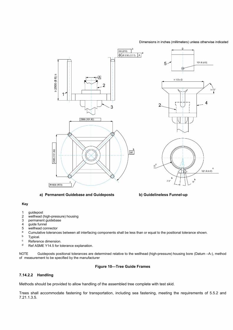
a) Permanent Guidebase and Guideposts b) Guidelineless Funnel-up
Key
1 guidepost 2 wellhead (high-pressure) housing 3 permanent guidebase 4 guide funnel 5 wellhead connector a Cumulative tolerances between all interfacing components shall be less than or equal to the positional tolerance shown. b Typical. c Reference dimension. d Ref ASME Y14.5 for tolerance explanation.
NOTE Guideposts positional tolerances are determined relative to the wellhead (high-pressure) housing bore (Datum –A-), method of measurement to be specified by the manufacturer
Figure 10—Tree Guide Frames
7.14.2.2 Handling
Methods should be provided to allow handling of the assembled tree complete with test skid.
Trees shall accommodate fastening for transportation, including sea fastening, meeting the requirements of 5.5.2 and 7.21.1.3.5.
7.14.2.3 Loads
The guide funnels should be capable of supporting the full weight of the stacked tree, running tool and EDP, or alternatively landing pads may be provided.
Depending on the environment in which the tree is being used, the structure may be required to extend from the bottom of the tree to the top of the tree to provide protection from installation loads and snag loads.
Design shall meet the requirements of 5.1.3.1.
The following loads may apply:
— guideline tension
— flowline reaction loads
— snag loads
— dropped object loads (see API 17A)
— impact loads/fishing-gear loads (see API 17A)
— installation loads and intervention loads
— piping and connection loads (due to frame deflection)
— handling and shipping loads
7.14.2.4 Intervention Interfaces
Provision for ROV access to relevant ROV functions shall be provided.
Subsea intervention fixtures attached to the tree-guide frame shall be in accordance with API 17H.
The frame design shall not impede access or observation, as appropriate, by divers/ROV of tree functions and position indicators.
Validation
Interface testing of guide frame guidance provisions in 7.14.2.1 shall be conducted to verify four-post or guidelineless alignment. A wellhead connector and mandrel or other centralizing means shall be used during the test. Test results shall be in accordance with the manufacturer’s written specifications.
7.15 Tree Running Tool
General
NOTE The function of a hydraulic or mechanical tree running tool is to suspend the tree during installation and retrieval operationsfrom the subsea wellhead and to connect to the tree during workover operations. It may also be used to connect the completion riser to the subsea tree during installation, test or workover operations. A subsea wireline/coil tubing BOP or other tool packages may be run between the completion riser and tree running tool.
The requirement for soft landing systems should be evaluated.
Operating Criteria
The user/purchaser shall specify the operating criteria necessary for the tree installation. The manufacturer shall document the operating limits for which the tree running/retrieval tool is designed.
The tree running tool may provide a pressure barrier to allow for pressure testing an internal tree cap, crown plug, or swab valve from above.

Tree running/retrieval tools should be designed to be operable in the conditions/circumstances expected to exist during tree running/retrieving operations and well re-entry/workover operations. Specific operating criteria (design loads and angle limits etc.) should include the maximum surface vessel motions and resulting maximum running string tensions and angles that can occur.
Loads
Design shall meet the requirements of 5.1.3.1.
The following loads may apply:
— internal and external pressure
— pressure separation loads, which shall be based on worst-case sealing conditions (leakage to the largest redundant seal diameter shall be assumed, unless relief is provided as described in 5.1.2.1)
— mechanical preloads
— external bending and tension loads from intervention equipment (API 17G)
— environmental loads
— fatigue assessment
— ROV impact loads
— mechanical installation (impact) loads
— hydraulic coupler thrust and/or preloads
— IWOCS equipment loading (trapped fluids, dissimilar metals)
— installation/workover overpull
The manufacturer shall state whether the basis of load ratings is stress limits or seal separation limits.
Tree Interface
7.15.4.1 General
The interface between the tree running tool and tree shall be designed for emergency release at a running string departure angle as specified by the manufacturer or user/purchaser. This release shall not cause any damage to the subsea tree such that prevents meeting any other performance requirement.
The tree interface shall consist of four main component areas:
— locking profile and connector
— re-entry seal, where applicable
— extension subs or seals, where applicable
— controls and instrumentation, where applicable
NOTE For use with dynamically positioned rigs, it is particularly important that the connector have a high-angle release capability and that the connector can be quickly unlocked. In some systems, the EDP connector design can meet these requirements.
The manufacturer and/or user/purchaser shall specify the angle and unlocking time.
7.15.4.2 Locking Profile and Connector
The tree running tool shall land and lock onto the locking profile of the tree re-entry hub and shall withstand the separating forces resulting from applied mechanical loads and any pressure loads from a re-entry seal, if present as specified by the manufacturer. The tree running tool connector shall meet functional requirements specified in 7.8.3.
Means shall be provided to prevent trapped fluid from interfering with make-up of the hydraulic or mechanical connector.
7.15.4.3 Re-entry Seal
The pressure-containing capability of this seal shall be at least equal to the tree-rated working pressure or the maximum anticipated control pressure of the downhole safety valve, whichever is greater, if the SCSSV control circuit(s) is encapsulated by this seal, unless relief is provided as described in 5.1.2.1.
7.15.4.4 Extension Subs or Seals
Extension subs or seals (if used) shall engage the mating surfaces in the upper tree connection for the purpose of isolating each bore. The seal mechanism shall have a primary and back-up seal.
In multi-bore applications that use a re-entry seal as specified in 7.15.4.3, each extension sub or seal shall be designed to withstand an external pressure as specified by the manufacturer.
7.15.4.5 Controls and Instrumentation
Control system and data gathering instrumentation conduits may pass through the tree running tool body. Specific designs and selection of component materials are the responsibility of the manufacturer.
7.15.4.6 Intervention Interface
The tree running tool shall interface with one or more of the following:
— drilling riser system
— OWIRS or TBIRS interfaces (API 17G)
— wire rope deployment system
7.15.4.7 Guidance and Orientation
Guidance and orientation with other subsea equipment shall conform to or be an extension of the geometries specified in 7.14.2.1.
7.15.4.8 Control System Interface
If the tree running tool incorporates the intervention interface, the protocol should be transferred to the workover control system (see API 17G5).
7.15.4.9 Secondary Release
Hydraulically actuated tree running tool connectors shall be designed with a secondary release method. Hydraulic open and close control line piping shall be positioned to allow cutting by diver/ROV or contain a means to vent hydraulic lock pressure if required for the secondary release to function.
7.15.4.10 Position Indication
Remotely operated tree running tool connectors shall be equipped with an external position indicator suitable for observation by diver/ROV.
Materials
Tree running tool portions that can be exposed to wellbore fluids shall be made of materials conforming to 5.2.

Factory Acceptance Testing
Testing shall be conducted in accordance with the manufacturer’s written specification to confirm the proper function of the primary and secondary operating and release mechanisms, override mechanisms and locking mechanisms. Testing shall confirm that the actual operating forces/pressures fall within the manufacturer’s documented specifications.
Pressure containing tree running tools shall be tested per 7.8.3.2, as applicable.
7.16 Tree, Tubing Head, and Completion Guide Base Piping
General
The term piping is used to encompass the requirements for all pipe, fittings or pressure conduits, excluding valves and chokes, from the bores of the tree to the flowline connection(s) leaving the subsea tree. The piping may be used for production, pigging, monitoring, water, gas or chemical injection, service or test of the subsea tree.
Design
7.16.2.1 Allowable Stresses
Outboard tree piping shall conform to the requirements of an existing, documented piping code and as a minimum, the design rated working pressure of the outboard piping shall be equal to the rated working pressure of the tree. Inboard piping designs shall conform to 5.1.
In all cases the following loads may apply:
— allowable stress at working pressure
— allowable stress at test pressure
— external loading
— tolerances
— corrosion/erosion allowance
— temperature
— wall thinning due to bending
— vibration
7.16.2.2 Operating Parameters
Operating parameters for tree piping shall be based on the service, temperature, material and external loading on each line. Tree piping may be designed to flex to enable connectors to stroke or to compensate for manufacturing tolerances.
NOTE Attention is to be given to piping downstream of chokes, due to possible high fluid velocities and low temperatures (see Section 5).
7.16.2.3 Tree Piping Flowloops
Tree piping flowloops may be fabricated using forged fittings, pre-bent sections, or may be formed in a continuous piece.
Bends that are being used in H2S service shall conform to the requirements of NACE MR 0175 (all parts). Induction-bent piping shall be manufactured in accordance with qualified procedures and suppliers.

7.16.2.4 Pigging
The manufacturer shall document the ability to pig tree piping where such piping is intended to be piggable. Demonstration of the piggability of the intended piping shall be agreed to by the user/purchaser and manufacturer.
7.16.2.5 Flowline Connector Interface
The tree piping and flowline connector, when required by the system, shall be designed to allow flexibility for connection in accordance with the manufacturer’s written specification. Alternatively, the flexibility may be built into the interface piping system. In the connected position, the combination of induced pipe tension, permanent bend stress, thermal expansion, wellhead deflection and the specified operating pressure shall not exceed the allowable stress as defined in 7.16.2.1. Stresses induced during make-up may exceed the level in 7.16.2.1 but shall not exceed material minimum yield strength.
Pressure/temperature transducers and chemical-injection penetrations located on inboard piping shall be equipped with flanged or studded outlets that conform to 7.1 or 7.4.
Penetrations located on outboard piping may be either flanged, threaded or weld-on bosses. Threaded connections shall conform to 7.3, flanged connections shall conform to 7.1 or 7.4, and weld-on bosses shall conform to ASME B16.11.
Safeguarding of penetrator connections may be provided by either locating ports in protected areas or by fabricating protective covers as agreed to between the manufacturer and the user/purchaser.
7.16.2.6 Specification Break
The location of the specification break between the requirements of this specification (on the tree or CGB) and that of the flowline/pipeline is specifically defined below.
The following shall apply for tree and tubing head/CGB specification breaks.
— Design code: All piping shall be designed in accordance with 7.16.2.1. End connections/fittings for both inboard and outboard piping shall be designed in accordance with 7.1 through 7.4, regardless of piping code used.
— Testing: All testing for inboard piping shall conform to the requirements in accordance with 5.4. All testing for outboard piping shall be in accordance with the specified piping code.
— Materials: Materials for inboard piping shall conform to 5.2. Material for outboard piping and pipe fittings shall conform to the requirements of the specified piping code. For example, wall thickness calculated using ASME B31.3 requires the use of ASME B31.3 allowable material stresses.
— Welding: Welding of inboard piping shall be in accordance with 5.3. Welding of outboard piping shall conform to the specified piping code or 5.3, whichever is appropriate.
7.17 Flowline Connections
Flowline Connection Support Frame
7.17.1.1 General
The flowline connection shall be supported by an appropriately designed support frame that shall be attached to the subsea tree and/or subsea wellhead. The support frame shall be attached to the subsea wellhead (high-pressure) housing, the PGB, GRA or CGB, the tree and/or tree frame or other structural member suitable for accommodating all expected loading conditions.
7.17.1.2 Design
7.17.1.2.1 Loads
Design shall meet the requirements of 5.1.3.1.
The following loads may apply:

— flowline pull-in, catenary and/or drag forces during installation
— flowline alignment loads (rotational, lateral, and axial) during installation
— flowline reaction loads due to residual stresses, flowline weight, thermal expansion/contraction and operational/environmental effects
— reactions from environmental loads on flowline connector running/retrieval and maintenance tools
— flowline reaction/alignment loads when the tree is pulled for service
— flowline/umbilical overloads
— wellhead deflection
— internal and external pressures (operational and hydrostatic/gas tests).
7.17.1.2.2 Functional Requirements
The flowline connector support frame shall transmit all loads imparted by the flowline and umbilical into a structural member to ensure that the:
— tree valves and/or tree piping are protected from flowline/umbilical loads which could damage these components
— alignment of critical mating components is provided and maintained during installation
— tree can be removed and replaced without damage to critical mating components
The flowline connector support frame shall be designed to avoid interfering with the BOP stack.
Flowline Connectors
7.17.2.1 General
NOTE The flowline connector and its associated running tools provide the means for joining the subsea flowline(s) and/or umbilical(s) to the subsea tree. In some cases, the flowline connector also provides means for disconnecting and removing the tree without retrieving the subsea flowline/umbilical to the surface.
Flowline connectors shall fall into one of the following categories:
a) manual connectors operated by divers or ROVs
b) hydraulic connectors with integral hydraulics (see API 17R)
c) mechanical connectors with the actuators contained in a separate running tool (see API 17R)
7.17.2.2 Design
Flowline connectors shall have an RWP equal to the RWP of the tree. The design of the flowline connector shall be in accordance with API 17R and the stress allowables for the selected outboard piping code with respect to movement and alignment conditions. Integral hydraulics shall be in accordance with API 17R and 5.4.7.
7.17.2.3 Loads
Design shall meet the requirements of 5.1.3.1.
The following loads may apply:
— flowline pull-in, catenary and/or drag forces during installation
— flowline alignment loads (rotational, lateral, and axial) during installation

— flowline reaction loads due to residual stresses, flowline weight, thermal expansion/contraction and operational/environmental effects
— reactions from environmental loads on flowline connector running/retrieval and maintenance tools
— flowline reaction/alignment loads when the tree is pulled for service
— flowline/umbilical overloads
— wellhead deflection
— internal and external pressures (operational and hydrostatic/gas tests)
— load created by a loss of station-keeping
— Cyclic loads from vortex induced vibration
The flowline connector shall ensure sealing under all pressure and external loading conditions specified.
When actuated to the locked position, hydraulic flowline connectors shall remain self-locked without requiring that the hydraulic pressure be maintained. Connectors shall be designed to prevent loosening due to cyclic installation and/or operational loading. This shall be achieved by a mechanical locking system or backup system or other demonstrated means. Mechanical locking devices shall incorporate a release mechanism in the event of malfunction.
7.17.2.4 Dimensions
The dimensions of the flowline connector’s flow passages should be compatible with the drift diameters of the flowlines.
If pigging capability is specified, the flowline connector flow passages should be configured to provide transitions and internal geometry compatible with the type(s) of pig specified by the manufacturer.
The end connections used on the flowline connector (flanges, clamp hubs, or other types of connections) shall conform to 7.1 through 7.6. Preparations for welded end connections may be done in accordance with 7.1.2.6 or API 6A.
The termination interface between the flowline connector and the flowline shall conform to the requirements of 7.1 through 7.4 at the flowline connector side, and to the requirements of the specified piping code on the flowline side.
7.17.2.5 Functional Requirements
The flowline connector and/or its associated running tool(s) should provide positioning and alignment of mating components such that connection can be accomplished without damage to sealing components or structural connection devices. Seals and sealing surfaces shall be designed such that they can be protected during installations operations.
Primary seals on flowline connectors shall be metal-to-metal. Glands for the metal seals shall be inlaid with corrosion-resistant material unless the base material is corrosion-resistant.
Where multiple bore seals are enclosed within an outer environmental or secondary seal, bi-directional bore seals shall be provided to prevent cross-communication between individual bores.
The flowline connection system shall provide means for pressure testing the flowline and/or umbilical connections following installation and hook-up.
The flowline connector shall have as a minimum the same rated working pressure as the subsea tree. Means shall be provided for pressure-testing the tree and all its associated valves and chokes without exceeding the test pressure rating of the flowline connector.
The flowline connector should have a visual means for external position verification.
Flowline connector components located downstream of the choke may require a lower temperature rating than the tree system due to J-T cooling effects.

Testing
7.17.3.1 General
NOTE This section covers the testing of the flowline connection system, which includes the flowline-connection support frame, the flowline connector, the flow loops and associated running/retrieval and maintenance tools.
7.17.3.2 Validation
Tests shall be conducted to verify the structural and pressure integrity of the flowline connection system under the rated loads specified by the manufacturer in accordance with API 17R. Additionally, testing shall include:
— simulated operation of all running/retrieval tools under loads typical of those expected during actual field installations
— simulated pull-in or catenary flowline loads (as applicable) during flowline installation and connection
— removal and replacement of primary seals for flowline connectors for remotely replaceable seals
— functional tests of required running/retrieval and maintenance tools
— maximum specified misalignment
— connection qualification test including torsion, bending, pressure and temperature (see API 17R).
The manufacturer shall document successful completion of the above tests.
7.17.3.3 Factory Acceptance Testing
Factory acceptance testing shall be as specified as follows:
a) Structural Components:
All mating structural components shall be tested in accordance with the manufacturer’s written specification for fit and function using actual mating equipment or test fixtures.
b) Pressure-containing Components:
Testing shall be conducted in accordance with the manufacturer’s written specification to confirm the proper function of the primary and secondary operating and release mechanisms, override mechanisms and locking mechanisms. Testing shall verify that the actual operating forces/pressures fall within the manufacturer’s documented specifications. Flowline connectors shall be hydrostatically tested in accordance with the specified piping code using the subsea tree’s RWP as the piping code’s design pressure. In addition, the flowline connector shall be tested in accordance with 7.8.3.2, as applicable.
c) Running Tools:
Testing shall be conducted in accordance with the manufacturer’s written specification to confirm the proper function of the primary and secondary operating and release mechanisms, override mechanisms and locking mechanisms. Testing shall verify that the actual operating forces/pressures fall within the manufacturer’s documented specifications.
7.18 Ancillary Equipment Running Tools
Operating Criteria
The manufacturer shall document the operating criteria, clearance and access criteria for ancillary equipment and their running/retrieval tools as it pertains to the mounting on the subsea tree. Ancillary equipment may include control pods, retrievable chokes and flowline connection equipment.
Running/retrieval and testing tools should be designed such that they are operable in the conditions/circumstances expected to exist during running/retrieving operations and workover operations. Specific operating criteria (design loads and angle

limits, etc.) should include the maximum surface-vessel motions and resulting maximum running-string tensions and angles that can occur.
Loads and Component Strength
Design shall meet the requirements of 5.1.3.1.
The following loads may apply:
— internal and external pressure
— pressure separation loads, which shall be based on worst-case sealing conditions (leakage to the largest redundant seal diameter shall be assumed)
— mechanical preloads
— running string bending and tension loads
— environmental loads
— fatigue assessment
— vibration
— mechanical installation (impact) loads
— hydraulic coupler thrust and/or preloads
— installation/workover overpull
The manufacturer shall specify the loads/conditions for which the equipment is designed. The manufacturer shall document the load/capacity for their running tool.
Running Tool Interfaces
The running tool shall be capable of connection, functioning and disconnection at the maximum combined loads, as specified in 7.18.2
Control and/or test connections that pass through the interface shall retain their pressure integrity at the maximum combined load rating.
Guidance and Orientation
If the subsea tree structure is used for alignment and orientation, running-tool guidance structures shall conform to or be an extension of the geometries specified in 7.14.2.1. Independent guidance and orientation shall be designed in accordance with the manufacturer’s written specification.
7.19 Tree-mounted Hydraulic/electric/optical Control Interfaces
General
Tree-mounted hydraulic/electric/optical control interfaces covered by this specification shall include all pipes, hoses, electric or optical cables, fittings or connectors mounted on the subsea tree, flowline base or associated running/retrieving tools for the purpose of transmitting hydraulic, electric or optical signals or hydraulic or electric power between controls, valve actuators and monitoring devices on the tree, flowline base or running tools and the control umbilical(s) or riser paths.

Design
7.19.2.1 Pipe/tubing/hose
Allowable stresses in pipe/tubing shall be in accordance with ASME B31.3. Hose design shall conform to SAE J517 and shall include validation to SAE J343. Design shall account for the
— allowable stresses at working pressure
— allowable stresses at test pressure
— external loading
— collapse
— manufacturing tolerances
— fluid compatibility
— flow rate
— corrosion/erosion
— temperature range
— vibration
7.19.2.2 Size and Pressure
All pipe/tubing/hose shall be minimum of 3/16 in. inner diameter. Sizes and pressure ratings of individual tubing runs shall be determined to suit the functions being operated. Injection lines, downhole hydraulic, connector/gasket seals test lines, pressure monitor lines or any line that by design is exposed to wellbore fluids shall be rated at the working pressure of the tree. SCSSV lines shall be rated at the specified SCSSV operating pressure (see 5.1.2.1 and 9.1.7 for additional information).
7.19.2.3 Optical Cables and Cable Penetrations
Optical terminations shall include penetrations validated to prevent fluid leakage from these conduits. Optical penetrations into pressure-containing cavities or piping systems shall be qualified for the full differential pressure across the penetration. Optical fibers run in fluid-filled hoses shall include sufficient internal fiber slack length to prevent fiber tensioning under the expected load conditions.
7.19.2.4 Envelope
All pipe/tubing/hose/electric or optical cable shall be within the envelope defined by the guide frames of the tree, running/retrieving tool or the flowline base.
7.19.2.5 Routing
Small-bore [less than 1.0 in. (25.4 mm) ID] tubing runs should be planned to use the minimum number of fittings or welded joints. In line threaded couplings and unions to extend line length shall not be allowed.
The bend radius of cold-bent tubing shall not exceed the requirements of NACE MR 0175 (all parts) for cold-working. Cold bends shall be in accordance with ASME B31.3. Tubing that runs to hydraulic tree connectors, running tool connectors and flowline connectors shall be accessible to divers/ROV/remote tooling, such that it can be disconnected, vented or cut, in order to release locked-in fluid and allow mechanical override.
Electrical cables should be routed such that any water entering the compensated hoses moves away from the end terminations by gravity. Electrical signal cables shall be screened/shielded to avoid cross talk and other interferences.

7.19.2.6 Small Bore Tubing and Connections
General Requirements for small bore [less than 1.0 in. (25.4mm) ID] tubing and connections:
- Quality requirements for small-bore tubing and connections shall be to the manufacturer’s written specification.
- Hydraulic couplers, end fittings and couplers shall meet or exceed requirements of the existing piping code used for the piping/tubing/hose design in 7.19.2.1.Tubing shall be seamless.
- Threaded connections shall be in accordance with section 7.3.
For a line that penetrates the wellbore (for example, chemical injection or SCSSV):
- If located inboard of two isolation valves, of which one is remotely operated; connections shall be full-penetration butt welds as specified in 5.3.1.
- If located outboard of two isolation valves, of which one is remotely operated; connections may be full-penetration butt welds, fittings or socket welds.
For a line that does not penetrate the wellbore connection may be a fitting or socket weld.
7.19.2.7 Electrical Connectors
Electrical connection interfaces made up subsea shall prevent the ingress of water or external contaminants. The retrievable half of conductive-type electrical connectors should contain seals, primary compensation chambers, penetrators, springs, etc. The design of the non-retrievable half shall address the effects of corrosion, calcareous growth, cathodic protection, etc.
7.19.2.8 Optical Connectors
Optical-connection interfaces made up subsea shall feature pressure-compensated chambers in which the final optical-fiber connections are engaged. The configuration shall prevent the ingress of water or external contaminants that can potentially interfere with the optical fiber engagement. Optical connectors should ideally include an automatic mechanism to wipe the face of the fibers prior to final engagement of the mating fibers.
7.19.2.9 Control Line Stabs/Couplers
As a minimum, control line stabs for the SCSSV, production master valve(s), production wing valve, and annulus master valve shall be designed so as not to trap pressure when the control stabs are separated except where allowed in 9.1.9.
Both vented and non-vented control stabs should be designed to minimize seawater ingress when connected/disconnected. They shall be capable of disconnection at the rated internal working pressure, without detrimental effects to the seal interface. The half containing the seals shall be in the retrievable assemblies. In addition to the internal working pressure, the control stabs shall be designed to withstand external pressure at manufacturer’s rated water depth. Stabs shall be capable of sealing at all pressures within their rating, in both the mated and un-mated (non-vented type) condition, except as noted herein.
NOTE 1 Venting control stab connections are primarily intended as a well control feature of a subsea tree when the tree is controlled by direct or a piloted hydraulic control system. Subsea tree interface designs with individual hydraulic control lines often feature poppet connections to protect the line from debris and seawater ingress. If the control stab connection were separated during a severe damage or emergency disconnect event before hydraulic line pressure can be bled down, the individual stab’s poppet can trap hydraulic control line pressure behind the poppet, preventing the above mentioned fail-closed safety devices from closing. The venting control stab requirement is intended to circumvent the trapped pressure possibility.
NOTE 2 The venting control stab requirement is not intended for other control system configurations or their internal interface connections providing a vent feature is included to allow fail-closed safety devices to close. API 17F provides guidance on properavoidance of trapped hydraulic pressure situations for these control systems.
7.19.2.10 Coupling Stab and Receiver Plate Assembly
Multi-port hydraulic receiver plates, as used at the control pod, tree cap, tree running tool, etc., shall have an alignment system to ensure correct alignment of hydraulic couplers prior to engagement of their seals. The stab’s couplers shall be

mounted in a manner to accommodate any misalignment during make-up. The alignment shall also not allow miscommunication between umbilical lines and tree plumbing, i.e. shall align in one orientation only.
The coupling stab and receiver plate assembly shall be designed to withstand the rated working pressure applied simultaneously in every control path without deforming to the extent that any other performance requirement is affected in accordance with the manufacturer’s written specification. In addition, when non-pressure balanced-control couplers are used, the manufacturer shall determine and document the rated water depth at which coupler plate/junction plate can decouple the control couplers without deformation damage to the plate assemblies with zero pressure inside the couplers. The manufacturer shall determine and document the force required for decoupling at the rated water depth with zero pressure inside the couplers.
Proprietary coupler stab and receiver-plate designs shall meet the test requirements in 7.19.5.
7.19.2.11 Secondary Release
Where horizontal hydraulic/electric/fiber optic penetrations are required between HXT and TH, a secondary release method shall permit disengagement of the penetrator in the event of a malfunction which prevents normal (linear) retraction of the stem.
Assembly Practice
7.19.3.1 Cleanliness During Assembly
Practices should be adopted during assembly to maintain tubing/piping/fittings cleanliness.
7.19.3.2 Flushing
After assembly, all tubing-runs and hydraulically actuated equipment shall be flushed to meet the cleanliness requirements of SAE/AS 4059. The class of cleanliness shall be as agreed between the manufacturer and user/purchaser. Final flushing operations shall use a hydraulic fluid compatible with the fluid being used in the field operations. Equipment shall be supplied filled with hydraulic fluid. Fittings, hydraulic couplings, etc., shall be blanked off after completion of flushing/testing to prevent particle contamination during storage and retrieval.
Materials
7.19.4.1 Corrosion
Pipe/tubing and end fittings, connectors and connector plates shall be made of materials that can withstand atmospheric and seawater corrosion.
Pipe/tubing/hoses in contact with wellbore fluids or injected chemical shall be made from materials compatible with those fluids.
NOTE Recommended test procedures can be found in Annex K.
7.19.4.2 Seal Materials
Seal materials shall be suitable for the type of hydraulic control fluid being used in the system. Seals in contact with wellbore fluids or injected chemicals shall be made of materials compatible with those fluids.
Testing
7.19.5.1 Small Bore Tubing, Hoses, and Connections
Testing of assembled pipe/tubing/hose and end fittings, connectors and connector plates exposed to production pressure shall conform to 5.4, except that the test pressure shall not exceed the test pressure of the lowest pressure-rated component in the system in accordance with 5.4.7. Testing of assembled pipe/tubing/hose and end fittings, connectors and connector plates carrying control fluid shall be in accordance with ASME B31.3 as specified in 5.4.7.
Hydraulic couplers, end fittings, couplings, tubing and hose fittings shall be tested to verify that they are electrically connected to the cathodic protection system.

7.19.5.2 Stab/receiver Plate Assembly
The stab/receiver plate assembly shall be tested to rated working pressure applied simultaneously in every control path in accordance with the manufacturer’s written specification.
Connector Plate Marking
Each connector plate shall be permanently marked with the following minimum information:
a) its part number;
b) path designation numbers or letters identifying each path/connector.
All part numbers, path designations, operating pressures of each path and other pertinent information should be included in the design documentation.
7.20 Subsea Chokes and Actuators/operators
General
In 7.20 are covered subsea chokes, actuators and their assemblies used in subsea applications. It provides requirements for the choke and actuator/operators assembly performance standards, sizing, design, materials, testing, marking, storage and shipping. Subsea choke applications are production, gas lift and injection.
The design of the tree system may include requirements for replacement of high-wear items of the subsea choke, including isolation prior to retrieval and testing following re-installation.
Subsea Chokes
7.20.2.1 Choke Configuration
Examples of orifice configurations are shown in Figure 11.

a) Rotating Discs d) Sliding Sleeve and Cage
b) Needle and Seat e) Multi-stage/cascade
c) Plug and Cage f) Cage and External Sleeve
Figure 11—Choke Common Orifice Configurations
7.20.2.2 Design
7.20.2.2.1 General
Subsea chokes shall be designed in accordance with the general design requirements of 5.1. Choke capacity should be in accordance with the requirements of ISA 75.01.01 and ISA 75.02.01 for anticipated or actual production flow rate and fluid conditions (pressures and temperature and flow media).
NOTE The information shown in Annex B illustrate purchasing guidelines to the choke manufacturer for the sizing of the choke.
Testing shall validate specific choke and choke actuator/operator designs manufactured under this specification (see 5.1.7).
7.20.2.2.2 Design and Operating Parameters
Manufacturers shall document the following design and operating parameters of the subsea choke:
— maximum pressure rating
— maximum reverse differential pressure rating
— maximum Cv (Kv)
— temperature rating
— maximum
— minimum
— PSL
— material class
— type of choke (retrieval style)
— non-retrievable
— diver assist retrievable
— tool retrievable
— functional style of choke
— adjustable choke prep. for manual operator
— adjustable choke prep. for hydraulic actuator
— end connections
— size and pressure rating
— ring gasket size (if applicable)
— type of operation
— ROV
— diver assist
— ROT or end effector configuration
— water depth rating
7.20.2.2.3 Pressure Rating
For chokes having end connections with different pressure ratings, the rating of lowest-rated pressure-containing part shall be the rating of the subsea choke. The rated working pressure of the subsea choke shall be equal to or greater than the rated working pressure of the subsea tree.
7.20.2.2.4 Temperature Rating
All pressure-containing components of subsea chokes shall be designed for the temperature ratings specified in 5.1.2.3. For subsea chokes, the maximum temperature rating is based on the highest temperature of the fluid that can flow through
the choke. Subsea chokes shall have a maximum temperature rating equal to or greater than the tree. The minimum temperature rating of subsea chokes shall be in accordance with the manufacturer’s written specifications but equal to or less than the tree rating.
7.20.2.2.5 End Connections
End connections for chokes shall be as specified in 7.1 to 7.6.
7.20.2.2.6 Vent Requirements
Subsea chokes shall be designed to prevent internal cavities from trapping pressure. The system shall have the means to facilitate pressure being vented prior to releasing and during landing of the body-to-bonnet connector.
7.20.2.2.7 External Pressure Requirements
Subsea chokes shall be designed to withstand external pressure at the maximum rated water depth. The design shall prevent the ingress of water from external pressure.
7.20.2.3 Factory Acceptance Test
Hydrostatic testing of subsea chokes shall be in accordance with 5.4. If functional testing is performed, reference Tables 21, 24 and 25 for example data sheets.
Subsea Choke Actuators/operators
7.20.3.1 General
Subsea choke actuators/operators shall be a fail-in-place design in accordance with requirements in 7.10.2.2 and the following:
a) Actuator manufacturer shall document design and operating parameters, as listed in Table 24.
b) Motion type (ratchet, stepping, linear, rotary, etc.) of actuator/operator shall be described and documented, including the number of turns, steps, or partial movement graduation between full-closed and full-open positions.
c) Rotary-operated subsea choke actuators/operators shall be turned in the counter-clockwise direction to open and clockwise to close the choke as viewed from the end of the stem.
d) The actuator/operator mechanism shall be designed to prevent backdriving by the choke under all operating conditions, including loss of power or communication to the actuator/operator.
e) Since chokes are fail-in-place devices, the closing/opening force requirement from 7.10.2.2.4 does not apply.

Table 24—Example Documentation of the Factory Acceptance Testing for the Operational Test of a Subsea Choke with Actuator/Operator
Factory Acceptance Test Form for the Operational Test of a Subsea Choke with Actuator/Operator
Test no.
Cycle no.
Choke pressure
Hydraulic pressure or
electric power required to
Verification that the choke operates without backdriving Reversing
hydraulic pressurea or electric
power
During opening During closing
Close choke
Open choke time time Open Close
1
1 Atmospheric
2 Atmospheric
3 Atmospheric
2
1 Working pressure
2 Working pressure
3 Working pressure
4 Working pressure
5 Working pressure
a Pressure to reverse operating direction subsequent to overstepping shall be less than 90 % of hydraulic pressure used to overstep or over travel on linear actuators.
Table 25—Example Documentation of the Factory Acceptance Testing for a Subsea Choke with Actuator/Operator - Mechanical Override Operational Test
Factory acceptance test form for a subsea choke with an actuator/operator with mechanical override operational test (choke with manual operator, and choke hydraulic operator with manual override)
Test No.
Cycle No. Choke pressure
Verification that the choke operates without backdriving
During opening During closing
time
Starting torque
Running torque
time
Starting torque
Running torque
1 1 Atmospheric pressure
2 Atmospheric pressure
3 Atmospheric pressure
2 1 Working pressure
2 Working pressure
3 Working pressure
4 Working pressure

5 Working pressure
7.20.3.2 Design and Operating Parameters of Manual Operator for Subsea Chokes
The following parameters shall be documented:
— operating torque input
— maximum rated torque capacity
— type and size of interface (ROV) for manual operation
— material class
— temperature rating
— number of turns, steps, or partial movement graduation between full-closed and full-open positions
7.20.3.3 Design and Operating Parameters of Actuators for Subsea Chokes
The following parameters shall be documented:
— design type (ratchet, stepping, rotary, linear actuators)
— maximum output torque capacity
— material class
— temperature rating
— full stroke definition
— hydraulic fluid compatibility for hydraulic actuators
— hydraulic cylinder(s) (if provided)
— number of cylinders
— volume
— pressure rating: maximum hydraulic operating pressure and minimum hydraulic operating pressure
— maximum actuator operation speed
— type of local position indicator (if any)
— manual override (if supplied)
— ROV assist or diver assist
— maximum input torque capacity
— operation
— maximum
— type and size of interface (ROV) for manual operation hex,
— number of turns to open or close the choke

— water depth rating
— type of volume compensation device (if any
— bladder,
— piston.
7.20.3.4 Documentation
The actuator manufacturer shall provide installation and service manuals.
7.20.3.5 Actuator/Operator Testing
The following requirements apply to actuator testing.
Subsea choke actuators/operators shall conform to the testing requirement of 7.10.4.2.2 and 7.10.4.2.3. All test data shall be recorded on a data sheet such as listed in Table 24, Table 25, and/or Table 26.
When subsea choke actuators are shipped separately, the actuators shall be assembled with a test fixture that meets the specified choke operating parameters and tested as specified in 7.20.4.2.
Table 26—Example Data Sheet for the Factory Acceptance Testing of a Hydraulic Actuator
A: Actuator Data
Manufacturer
Model No.
Serial No.
Part No.
Size
PSL
Hydraulic Pressure Rating
Temperature Rating
Actuator separate or with choke
B: Actuator cylinder seal test (hydrostatic test)
Test Pressure
Cylinder 1
Holding period Beginning
Completion
Total test time
Cylinder 2
Holding period Beginning

Completion
Total test time
Performed by
Date
C: Performance test for actuators shipped separately
See Table 24
Choke and Actuator/operator Assembly Factory Acceptance Test
Subsea choke and actuator/operator assembly shall be tested together to demonstrate proper assembly and operation. This shall be accomplished by actuating the subsea choke from the fully closed position to the fully open position a minimum of three times with the choke body at atmospheric pressure and a minimum of five times with the choke body at rated working pressure. All test data shall be recorded on a data sheet, including:
— pressure inside choke body
— actuator pressure or power required to close choke
— actuator pressure or power required to open choke
— verification that the choke operates without backdriving within the manufacturer’s specified for or torque limit
NOTE Table 27 offers an example of test documentation
Table 27—Example Data Sheet for the Factory Acceptance Testing of a Subsea Choke
A: Choke Data
Manufacturer
Model No.
Part No.
Serial No.
Orifice Size
Working Pressure
Test Pressure
Temperature rating
PSL
B: Hydrostatic test
Test Pressure

First Holding period Beginning
Completion
Total test time
Second holding period Beginning
Completion
Total test time
Performed by
Date
C: Operational Test of subsea choke with manual operator
Test 1 Pressure in choke
1
2
3
Test 2 Pressure in choke
1
2
3
4
5
Performed by
Date
Insert Retrievable Choke
7.20.5.1 General
Insert retrievable chokes shall have a visual marking system indicating full makeup and full release position of the insert to body connector system.
7.20.5.2 Connector
Connector system shall be designed to be self-locking in the locked clamped position to prevent backdriving in service under all operational loads.

Connection mechanism of an insert retrievable choke actuator/operator shall have a secondary release feature or diver/ROV access for cutting/removal of the mechanism. Placement and connection mechanism of an insert retrievable choke locking mechanism (to the rest of the choke assembly) should allow for adequate access for diver/ROV operations.
A rotary connector drive shall be turned in the counterclockwise direction to open the connector and the clockwise direction to close as viewed from the end of the stem.
7.20.5.3 Seal System
It shall be possible to test the insert to the body seal to validate seal function.
A blanking trim may be used when performing this test.
7.20.5.4 Design and Operating Parameters of Connectors for Subsea Chokes
The following parameters shall be specified:
— clamp makeup torque or linear thrust rating
— clamp maximum input torque or maximum linear thrust rating
— type and size of interface (ROV)
— number of turns to open or close, or linear travel, to operate the clamp
Materials
Both subsea chokes and subsea actuators/operators shall be made of materials that meet the applicable requirements of 5.2 and the requirements of API 6A.
Welding
Welding of pressure-containing components shall be performed in accordance with the requirements given in 5.3. Welding of pressure-controlling (“trim”) components shall conform to the manufacturer’s written specifications.
Marking
Marking of subsea chokes, actuators/operators, and choke/actuator assemblies shall be marked as given in Table 28, Table 29, Table 30 and Table 31.
Table 28—Marking for Subsea Chokes
Marking Application
1 Manufacturer’s name or trademark Nameplate
2 API 17D Nameplate
3 Manufacturer’s part number Nameplate
4 PSL designation Nameplate
5 Rated working pressure Nameplate
6 Temperature rating Nameplate
7 Material class (including maximum H2S partial pressure if applicable) Nameplate
8 Unique identifier (serial number, PSL 3 and above) Nameplate
9 Maximum applied torque – ft-lbs (Nm) Nameplate
10 Number of turns from close to full open Nameplate
11 Manual operator direction to open – CW or CCW Nameplate
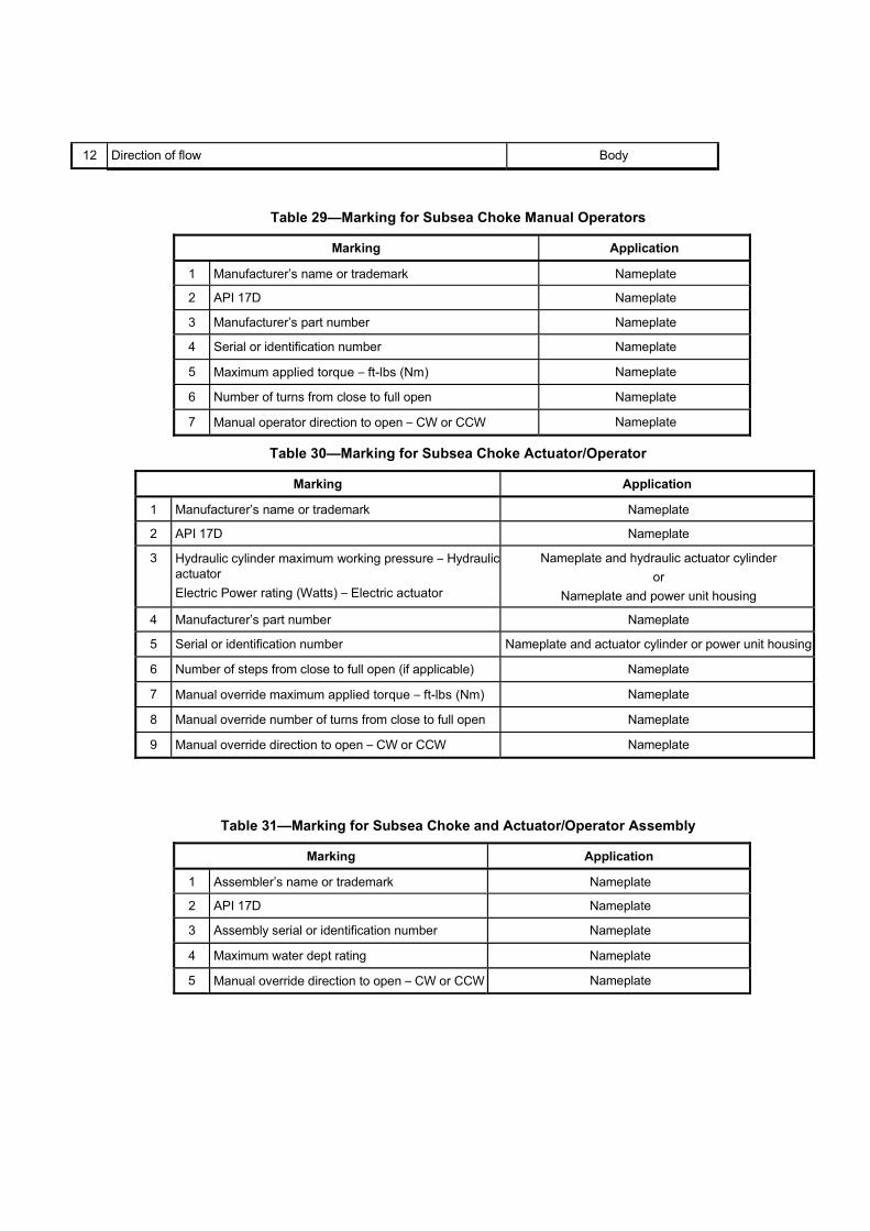
12 Direction of flow Body
Table 29—Marking for Subsea Choke Manual Operators
Marking Application
1 Manufacturer’s name or trademark Nameplate
2 API 17D Nameplate
3 Manufacturer’s part number Nameplate
4 Serial or identification number Nameplate
5 Maximum applied torque – ft-lbs (Nm) Nameplate
6 Number of turns from close to full open Nameplate
7 Manual operator direction to open – CW or CCW Nameplate
Table 30—Marking for Subsea Choke Actuator/Operator
Marking Application
1 Manufacturer’s name or trademark Nameplate
2 API 17D Nameplate
3 Hydraulic cylinder maximum working pressure – Hydraulic actuator Electric Power rating (Watts) – Electric actuator
Nameplate and hydraulic actuator cylinder or
Nameplate and power unit housing
4 Manufacturer’s part number Nameplate
5 Serial or identification number Nameplate and actuator cylinder or power unit housing
6 Number of steps from close to full open (if applicable) Nameplate
7 Manual override maximum applied torque – ft-lbs (Nm) Nameplate
8 Manual override number of turns from close to full open Nameplate
9 Manual override direction to open – CW or CCW Nameplate
Table 31—Marking for Subsea Choke and Actuator/Operator Assembly
Marking Application
1 Assembler’s name or trademark Nameplate
2 API 17D Nameplate
3 Assembly serial or identification number Nameplate
4 Maximum water dept rating Nameplate
5 Manual override direction to open – CW or CCW Nameplate

7.21 Miscellaneous Equipment
Design
7.21.1.1 General Design Requirements
7.21.1.1.1 Loads
As a minimum, the following loads shall, where applicable, be included when designing miscellaneous equipment: � suspended weight
� control pressure
� well pressure
� hydrostatic pressure
� handling loads
� impact
7.21.1.1.2 Operating Pressure
Tools operated by hydraulic pressure shall be rated in accordance with the pressure ratings specified by the manufacturer.
7.21.1.2 Remote Guideline Establishment and Re-establishment Tools
NOTE Guideline establishment/re-establishment tools are used to attach cables to guideposts of subsea completion structures.
Any guideline establishment/re-establishment tool that uses the relative guidepost positions shall be designed based on the spacing described in 8.3.2.2.
7.21.1.3 Test Stands and Fixtures
7.21.1.3.1 General
Miscellaneous equipment shall be designed and manufactured in accordance with the structural requirements, stress limitations and documentation requirements of 5.1.
NOTE Test stands and fixtures (including jigs) are used at the point of assembly or installation to validate the interface and functional operation, load and pressure capacity, and interchangeability of the equipment being installed. They can also serve as the shipping skids for transporting equipment offshore. Test stands and fixtures used only at the manufacturer’s facilities are outside the scope of this specification.
7.21.1.3.2 Accuracy of Test Equipment
Where test equipment is used to simulate a mating component for testing the assembly of interest, it shall be made to the same dimensions, tolerances and surface finish at all interfaces as the simulated component.
7.21.1.3.3 Loads During Testing/handling and Assembly
Design of test stands and fixtures shall include assembly and handling loads as well as test loads.
7.21.1.3.4 Test Stumps
Test stumps simulate the profiles of the wellhead, tree re-entry interface, etc., to facilitate pressure testing of the tree, tree running tool, tree cap, etc., and to position orienting joints relative to the BOP stack. They may also contain hydraulic
couplers to facilitate testing of the control functions. Stab pockets may be machined directly in the stump or, for tree testing, may be contained in a dummy tubing hanger.
When specified, the tree test stump shall accept a real tubing hanger. Test ports shall communicate with the individual bores of the test stumps to facilitate pressure testing. Guidance provided by the test stumps shall simulate the requirements of the actual equipment being tested.
7.21.1.3.5 Equipment Used for Shipping
Test skids, etc. used for shipping equipment offshore shall provide protection to the equipment during handling and transportation.
Sea fastenings shall be designed for all static and accelerated loading conditions due to roll, pitch and heave of the vessel in the locality where it will be transported and should be suitable for securing the assembly to the rig and rig skids (see 5.5.2).
Materials
Materials shall conform to 5.1 and 5.2 for all pressure-containing and high load-bearing parts.if subjected to well-fluid contact. Selection of other materials shall include the effects of encountered fluids and galvanic compatibility, as well as mechanical properties. Seal surfaces that engage metal- to-metal seals shall be inlaid with a corrosion-resistant material that is compatible with the well fluids, seawater, etc. Overlays are not required if the base material is compatible with well fluids, seawater, etc.
Testing
All components subject to pressure shall be tested to one and one-half times their RWP unless a different test pressure is required elsewhere in this specification. The test procedure shall conform to 5.4. Testing shall be performed in accordance with the manufacturer's written specification to confirm fit and function for any tool that has an interface with equipment that is being installed subsea.
Marking
Tools shall be permanently marked following the methods and requirements of 5.5. In addition, all tools that are not a permanent part of a subsea assembly shall be marked with the date of manufacture, applicable load ratings and part number.
8 Specific Requirements—Subsea Wellhead
8.1 General
NOTE 1 Section 8 describes subsea wellhead systems that are normally run from floating drilling rigs. It establishes standards and specifications for this equipment. The subsea wellhead system supports and seals casing strings. It also supports the BOPstack during drilling, and the subsea tree and possibly the tubing hanger after completion. The subsea wellhead system is installed at or near the mudline.
All pressure-containing and pressure-controlling parts included as part of the subsea wellhead equipment shall be designed to meet all the requirements of NACE MR 0175 (all parts). These parts shall include
— wellhead (high-pressure) housing
— production casing hanger body
— annulus seal and seal bodies
— sealing casing hanger lockdown bushing body
The requirements of NACE MR 0175 (all parts) shall not be mandatory for the following components:
— casing hanger bodies for other than production casing

— the conductor (low pressure) housing body
— lock rings
— load rings
— load shoulders
— submudline equipment
— bore protectors and wear bushings
— Non-sealing lockdown bushing body
Additionally, life-of-well parameters shall be included in the design, including contributions from the drilling, testing, completion and production phases of well operations.
Further evaluation shall be required for the following issues, that affect long-term reliability:
— cyclic external loads
— internal pressure cycle loads and displacements
— thermal loads and gradients
— general corrosion
— stress corrosion cracking (due to hydrogen, H2S or chlorides)
NOTE 2 While the codes governing the structural capacity of the wellhead system ensure reliability in the short-term, this is insufficient to ensure integrity for long-term production applications.
These issues may require assessment by fatigue analysis, fracture mechanics evaluation, structural evaluation due to thermal loading, or structural evaluation with reduced capacity due to corrosion allowance. While cathodic protection systems are often used for production wells to reduce corrosion, this can increase the possibility for stress corrosion cracking due to the release of free hydrogen.
8.2 Temporary Guidebase
General
The TGB when used provides a guide template for drilling the conductor hole and stabbing the conductor pipe. It compensates for misalignment from irregular ocean-bottom conditions and may provide a support base for the PGB. If used together with a PGB, a cone-and-gimbal arrangement compensates for angular misalignment between the TGB and the PGB due to the seabed topography and the verticality of the well. For guideline systems, it also establishes the initial anchor point for the guidelines. It may also include a provision for suspending a foundation sleeve to support unconsolidated surface soils. The TGB might not always be used, as in the case of template completions or satellite structure (foundation and/or protective structure) completions.
A TGB may also serve as a mudmat if the drilling of the conductor hole is performed by jetting operations. In this instance, it serves a physical stop to assure that the wellhead stays a fixed distance above the sea floor and subsequently serves as a temporary foundation, enhancing the bearing load capacity in unconsolidated or under- consolidated surface soils. The increased bearing capacity is used to support the weight of the conductor (preventing it from sinking) until the next section of hole is drilled and the surface pipe is sufficiently landed and cemented in place.
Provisions for the design shall conform to the requirements in 5.1.3.6.

Design
8.2.2.1 Loads
Design shall meet the requirements of 5.1.3.1.
The following loads may apply:
— ballast
— guideline tension
— weight of conductor pipe
— weight of PGB assembly
— hanging or suspension loads
— soil reaction
The TGB shall be capable of supporting, as a minimum, a static load of 175,000 lbf (780 kN) on the interface with the PGB while the TGB is supported at four locations, equally spaced 90°��2° apart and a minimum of 62 in. (1 575 mm) from the center (radial measure).
NOTE Recommendations for lifting pad eyes are outlined in Annex G.
8.2.2.2 Dimensions
The requirements for dimensions shall be as follows.
a) The TGB minimum bearing area shall be 75 ft2 (7 m2). This area may be augmented with weld-on or bolt-on extensions to compensate for soil strengths and anticipated loads.
b) TGB should pass through a 16.4 ft (5 m) square opening or as specified by the manufacturer.
c) TGB shall provide four guideline anchor points in position to match the guideposts on the PGB.
d) Together with the PGB, the TGB shall allow a minimum angular misalignment of 5° between the conductor pipe and the temporary guidebase.
e) TGB shall provide a minimum storage volume of 70.6 ft3 (2 m3) for ballast material.
8.3 Permanent Guidebase
General
The PGB attaches to the conductor (low pressure) housing and provides guidance for the subsea drilling and completion equipment (surface casing, BOP, production tree, running tools). The PGB provides entry into the well prior to installation of the wellhead (high-pressure) housing and BOP. After the wellhead (high-pressure) housing installation, the PGB provides guidance of the BOP, subsea tree or tubing head onto the wellhead (high-pressure) housing using guideline or guidelineless methods. It may establish structural support and final alignment for the wellhead system and provides a seat and lock down for the conductor (low pressure) housing. PGBs can be built as a single piece or split into two pieces to ease handling and installation. Optionally, they may include provisions for conductor-pipe hang-off, retrieval and to transfer flowline loads. The PGB may be retrieved after drilling is complete and replaced by a PGB carrying flowline connection/manifold equipment. Alternatively, the PGB installed for drilling may carry flowline connection/manifold equipment.
The PGB shall not interfere with the BOP stack installation. ROV access and cuttings disposal shall be included in the design.

A PGB using a re-entry funnel for guidelineless equipment guidance is often referred to as a guidelineless re-entry assembly or GRA. The re-entry funnel may be on the GRA housing looking upward (funnel-up) or may be configured in concert with matching funnel equipment on the subsea equipment subsequently landed in the GRA (funnel down). Funnel geometry usually involves one (or more) cone(s) and a center cylinder frame to provide alignment between mating components/structures.
The outermost diameter of the cone should be no less than 1.5 times the diameter of the component it is capturing. The cone’s angle should be no shallower than 40° with respect to horizontal. Typically, the cone angle is 45°. Once captured, the GRA’s cone(s) and inner cylinder should be designed to allow for equipment re-entry at tilt angles up to 3° from vertical in any orientation, and subsequently assist in righting the captured component to vertical.
Portions of the re-entry cone may be scalloped out to accommodate the guidelineless re-entry of adjacent equipment whose capture funnel can intersect with the main funnel(s) because of space constraints. This is acceptable, although it takes away from the re-entry properties of the funnel in the scalloped-out area.
Its practice should be carried out with sound engineering judgement comparing operational limits lost versus size and weight gained. Ideally, scalloped funnels should be minimized or covered wherever practical.
GRAs also may include provisions for conductor-pipe hang-off.
If so, since GRAs are typically cylindrical and conical in nature, horizontal resting pads or a beam structure should be incorporated in the frame’s design to provide a sound flat surface that can firmly sit on spider beams.
When spatial orientation is required, the funnel-up funnels and capture equipment may also feature Y-slots and orienting pins.
The upper portion of the Y-slot should be wide enough to capture mating pins within ��7.5° of true orientation. The Y-slot should then taper down to a width commensurate with the pin to provide orientation to within ��0.5° (similar to the angular orientation provided by guideposts and funnels).
Typically, there are two or four orienting pins, each with a minimum diameter of 4.00 in. (101.6 mm) in diameter. Other orientation methods, such as orienting helixes or indexing devices (ratchets, etc.) may be used. Whatever the orienting method, it is necessary that the design allow for the 3° tilt re-entry requirement with enough play to accommodate this gimballing effect.
Funnel-down funnels do not easily accommodate Y-slots and orienting pins. Alternate orientation methods such as orientation helixes or indexing devices may be required.
PGB/GRAs should not impede the flowby required for cementing, jetting operations, etc.
Provisions for design shall conform to the requirements in 5.1.3.6.
Design
8.3.2.1 Loads
Design shall meet the requirements of 5.1.3.1.
The following loads may apply (see Figure 12 and Figure 13):
— conductor pipe weight
— conductor (low pressure) housing weight
— hanging loads
— jetting-string weight when supported on the spider beams
— guideline tension
— flowline pull-in, connection or installation loads

— annulus access connection loads
— environmental
— reaction for TGB
— installation loads (including conductor hang-off on spider beams)
— snagging loads
— BOP loads
— sea fastening (when supported on spider beams)
The PGB or GRA shall be capable of supporting, as a minimum, a static load of 175000 lbf (780 kN) on the interface with the conductor (low pressure) housing while the PGB is supported at four locations equally spaced 90° ��2° apart and a minimum of 60 in. (1 525 mm) from the center (radial measure).
8.3.2.2 PGB Dimensions
The PGB dimensional requirements shall be as follows.
— The dimensions of the PGB shall conform to the dimensions shown in Figure 10a).
— The guideposts shall be fabricated of 85/8 in. (219 mm) OD pipe or tubulars. Guidepost funnels are typically fabricated from 10¾ in. OD ��0.5 in. wall (273 mm OD ��13 mm wall) pipe or tubulars.
— The length of the guidepost [item 1 in Figure 10a)] shall be 8 ft (2 440 mm) minimum for drilling purposes. The guideposts may be extended to provide guidance for the subsea tree, LWRP and/or tree cap.
Key
1 riser tension 5 environmental (current, wave, action, etc.) 2 applied moments 6 soil reaction 3 guideline tension 7 thermal 4 flow line connection

Figure 12—External Loads on a Subsea Tree and Wellhead

Key
F force from guideline
M1 torsional bending moment
M2 bending moment
T tension
���� angle at which guideline force acts
Figure 13—Permanent Guidebase (PGB) Loads
8.3.2.3 GRA Dimensions
NOTE The re-entry funnel may be on the GRA housing looking upward (funnel-up) or may be configured in concert with matchingfunnel equipment on the subsea equipment subsequently landed in the GRA (funnel down). Funnel geometry usually involves one (or more) cone(s) and a center cylinder frame to provide alignment between mating components/structures.
The outermost diameter of the cone should be no less than 1.5 times the diameter of the component it is capturing. The cone’s angle should be no shallower than 40° with respect to horizontal. Typically, the cone angle is 45°. Once captured, the GRAs cone(s) and inner cylinder should be designed to allow for equipment re-entry at tilt angles up to 3° from vertical in any orientation, and subsequently assist in righting the captured component to vertical.
When spatial orientation is required, 7.14.2.1 shall apply
8.3.2.4 Functional Requirements
The functional requirements shall be as follows.
a) When used with the TGB, the PGB (GRA) shall allow a minimum angular misalignment of 5° between a 30 in. (762 mm) conductor pipe and the TGB. For other conductor pipe sizes, the manufacturer shall document the misalignment capability.
b) Guideposts shall be field-replaceable without welding, using either diver, ROV or remote tooling. The locking mechanism should not inadvertently release due to snagging wires, cables, etc.
c) Guideposts can be either slotted or non-slotted. Slotted guideposts are required when used with a TGB, if the guidelines are not disconnected from the TGB. For slotted guideposts, provisions shall be made to insert guidelines of at least ¾ in. (19 mm) OD into the post with retainers at the top and at or near the bottom of the post.
d) Provisions shall be made to attach guidelines to the top of the guideposts. The guidelines shall be capable of being released and re-established.
NOTE 1 This may occur using diver, ROV or remote tooling.
e) The PGB (GRA) should contain a feature that facilitates the orientation between the PGB (GRA) and the conductor (low pressure) housing.
NOTE 2 The orientation device may allow the installation of the guidebase in multiple-orientation positions to suit rig heading or installed equipment orientation. The orientation device may also provide an anti-rotation feature to resist the loads defined in 8.3.2.1.
f) When specified, the PGB (GRA) shall contain grouting funnels for cement top-up.
g) When specified, the PGB (GRA) shall contain seals and a structure to deflect seabed and cement-port gases (which can form hydrates) from entering the BOP, subsea tree or tubing head connector.
h) Guidelineless equipment shall not reduce the release angle of the BOP, tree or tubing head connector. The guidelineless equipment shall allow installation and retrieval of equipment up to a 3° angle without damaging the wellhead seal surfaces or contacting installed wellhead gaskets.
i) A positive lock or load shoulder should be used to hang off the conductor in the PGB (GRA).
j) Dedicated lift points shall be provided.
k) PGB (GRA) should not impede flowby.
l) PGB (GRA) shall be designed to be run with a conductor (low pressure) housing or independently on a running tool.
8.4 Conductor (low pressure) Housing
General
NOTE 1 The conductor (low pressure) housing attaches to the top of the conductor pipe to form the foundation of a subsea well. The housing typically has a means of attaching to the PGB (GRA), which can also provide a means for anti- rotation between the PGB (GRA) and the conductor (low pressure) housing.
NOTE 2 A typical conductor (low pressure) housing profile is shown in Figure 14. The internal profile of the conductor (low pressure) housing includes a landing shoulder suitable for supporting the wellhead (high-pressure) housing and the loads imposed during the drilling, completion and workover operations.
Running tool preparations should also be a part of the internal housing profile. The external profile of the conductor (low pressure) housing shall be compatible with supporting the conductor pipe in the rotary table and/or at the spider beams in the moonpool. Cement return passageways may be incorporated in the conductor (low pressure) housing/PGB (GRA) assembly to allow directing cement and mud returns either below the PGB (GRA) or through ports in the PGB (GRA).
NOTE 3 Provision for seals against hydrates, etc., may also be incorporated in the conductor (low pressure) housing when required.
NOTE 4 Other enhancements to the conductor (low pressure) housing, such as cuttings disposal, cement top-off, rigid lockdown, etc., may be included. An intermediate casing string may also be hung off inside the conductor (low pressure) housing prior to the wellhead casing string. Facilities for landing the intermediate casing string can be required for the wellhead casing string. Methods of annular shut-off may be used on flowby holes to avoid hydrate migration from the annulus between the conductor pipe and the wellhead casing string.
Design
8.4.2.1 Loads
Design shall meet the requirements of 5.1.3.1.
The following loads may apply (see 8.2.2.1):
— wellhead loads
— hanging/hangoff loads while suspended in the moonpool
— riser forces

— PGB loads (see Figures 11 and 12)
— environmental loads
— snag loads
— pressure loads
— thermal loads
— Fatigue assessment
The interface between the conductor (low pressure) housing and the PGB shall be designed for a minimum rated load of 175,000 lbf (780 kN).
Key
1 wellhead lock down 6 permanent guidebase 2 landing shoulder for wellhead 7 landing shoulder 3 permanent guidebase attachment 8 centerline 4 running tool and tieback connector preparation 9 conductor casing 5 cement port (optional)

Figure 14—Typical Conductor (low pressure) Housing
8.4.2.2 Bottom Connection
The bottom connection shall conform to the purchasing requirement for connection type and casing loads.
The manufacturer shall address the design and use of weldments, extensions, reducers, swages, etc. to the manufacturer’s written specification to meet the casing ends and load requirements.
Weld end connections shall be prepared for a full-penetration butt-weld.
The manufacturer shall document the alignment between the machined part and welded joint.
The manufacturer and user/purchaser should agree on bottom connection requirements with respect to fatigue criteria.
8.4.2.3 Pup Joint
NOTE The bottom end connection may feature a pup joint of casing that is factory installed to ease field installation. In addition, handling and support lugs may be added for hang-off during f ield installation or for handling during shipping.
The maximum rotary table hang-off height for joint make-up should be specified by the user/purchaser.
Sufficient length for tongs on the body and pup joint should be provided for threaded torque make-up.
The user/purchaser and manufacturer shall agree on the pup joint’s design specification and length, with end connection(s) conforming to 8.4.2.3. Support lug design shall be in accordance with 5.1.3.6, 5.1.3.7, 5.4.4 and 5.5.2.
Testing
8.4.3.1 Validation
Conductor (low pressure) housings shall conform to manufacturers written specification.
8.4.3.2 Factory Acceptance Testing
A dimensional check or drift test shall be performed on the conductor (low pressure) housing to confirm the manufacturers written specification.
8.5 Wellhead (high-pressure) Housing
General
NOTE 1 The wellhead (high-pressure) housing lands inside the conductor (low pressure) housing. It provides pressure integrity for the well, suspends the surface and subsequent casing strings and tubing hanger and resists against external loads. The BOP stack or subsea tree attaches and seals to the top of the wellhead (high-pressure) housing using a compatible wellhead connector and gasket.
The wellhead (high-pressure) housing shall accept tubing hangers or tubing hanger adapter.
Body penetrations within the housing pressure boundary shall not be permitted.
NOTE 2 The standard system sizes are given in Table 17. Figure 15 shows profiles of two typical wellhead (high-pressure) housings.
Design
8.5.2.1 Loads
Design shall meet the requirements of 5.1.3.1.
The following loads may apply:
— riser forces (drilling, production and workover)
— BOP loads
— subsea tree loads
— pressure (internal and external)
— radial loads
— thermal loads
— environmental loads
— flowline loads
— suspended-casing loads
— conductor-housing reactions
— tubing-hanger reactions
— hydraulic connector loads
— fatigue assessment

Mandrel type * Hub type *
Key
1 connector profile 7 hanger lock-down profile 2 housing lock-down 8 hanger landing shoulder 3 landing shoulder 9 minimum bore 4 gasket profile 10 centerline 5 running tool preparation 11 wellhead (high-pressure) housing pressure boundary 6 annulus seal assembly area 12 position of lowermost annulus seal assembly or test tool seal
Figure 15—Typical Wellhead (High-pressure) Housings
8.5.2.2 Connections
8.5.2.2.1 Top Connection
The top connection should be of a hub or mandrel type (see Figure 15) as specified by the user/purchaser. The gasket profiles shall be manufactured from or inlaid with corrosion-resistant material as specified in 5.3.3. The gasket profile shall provide a primary and a secondary gasket seal area.
8.5.2.2.2 Bottom Connection
The bottom connection shall conform to the purchasing requirements for connection type and casing loads.
The manufacturer shall address the design and use of weldments, extensions, reducers, swages, etc. to the manufacturer’s written specification to meet the casing ends and load requirements.
Weld end connections shall be prepared for a full-penetration butt-weld.

The manufacturer shall document the alignment between the machined part and welded joint
The manufacturer and user/purchaser should agree on bottom connection requirements with respect to fatigue criteria.
8.5.2.2.3 Pup Joint
NOTE The bottom end connection may feature a pup joint of casing that is factory installed to ease field installation.
The maximum rotary table hang-off height for joint make-up should be specified by the user/purchaser.
Enough length for tongs on the body and pup joint should be provided for threaded torque make-up.
The user/purchaser and manufacture shall agree on the pup joint’s design specification and length, with end connections conforming to this section.
Dimensions
The dimensional requirements shall be as follows.
a) The minimum vertical bore of the wellhead (high-pressure) housing shall be as given in Table 17.
b) Dimensions of the wellhead pressure boundary (see Figure 15) shall be in accordance with the manufacturer’s written specification.
Rated Working Pressure
The RWP for the wellhead (high-pressure) housing pressure boundary (see Figure 15) shall be 5000 psi (34.5 MPa), 10,000 psi (69 MPa) or 15,000 psi (103.5 MPa).
Factory Acceptance Testing
All wellhead (high-pressure) housings shall be hydrostatically tested prior to shipment from the manufacturer’s facility. The hydrostatic test is performed to confirm the pressure integrity of the housing pressure boundary. All wellhead (high-pressure) housings shall be tested to the requirements of PSL 3.
The hydrostatic body test pressure shall be determined from the housing rated working pressure (see Table 32). The hydrostatic body test pressure shall not be less than the values given in Table 32.
Wellhead (high-pressure) housings shall show no visible leakage during each pressure holding period. Any permanent deformation of the housing, after hydrostatic testing is complete, shall not adversely affect the function of the casing hangers, packoffs, gaskets, connectors or other subsea equipment.
Table 32—Test Pressure
Rated Working Pressure Hydrostatic Body Test Pressure
psi (MPa) psi (MPa)
5000 (34.5) 7500 (51.8)
10,000 (69.0) 15,000 (103.5)
15,000 (103.5) 22,500 (155.2)
8.6 Casing Hangers
General
8.6.1.1 Pressure
Subsea casing hangers shall be treated as pressure-controlling equipment.

Submudline casing hangers suspended from submudline landing rings shall meet the requirements of 8.14.
NOTE 1 The subsea casing hanger is installed on top of each casing string and supports the string when landed in the wellhead (high-pressure) housing. It is configured to run through the drilling riser and subsea BOP stack, land in the subsea wellhead, and support the required casing load.
Casing hangers shall have provisions for an annulus seal assembly and support loads generated by BOP test pressures above the hanger and loads due to subsequent casing strings. Means shall be provided to transfer casing load and test pressure load to the wellhead (high-pressure) housing or to the previous casing hanger. If required a lockdown mechanism shall be used to limit or restrict movement of the casing hanger.
NOTE 2 The lockdown mechanism can be integral to the annulus seal assembly or run as part of an independent assembly.
8.6.1.2 Bottom Connection
A pup joint of casing should be installed on the hanger. This reduces the risk of damage during handling and later make-up in the field. API threaded connections should follow API 5CT for make-up requirements when connecting the pup joint to the hanger.
Proprietary thread connection should be made up in accordance with the manufacturer’s written specification.
Design
8.6.2.1 Loads
Design shall meet the requirements of 5.1.3.1.
The following loads may apply (including lockdown mechanisms, if used):
— casing loads
— overpull
— pressure, internal and external
— thermal
— torsional
— radial
— impact
8.6.2.2 Threaded Connections
The type of casing threads on the hanger shall be specified by the user/purchaser. Identification markings shall conform to API 6A.

Table 33—Recommended Minimum Vertical Bore Sizes for Casing Hangers, Bore Protectors, and Wear Bushings
Nominal Casing OD Minimum Vertical Bore
in. in. (mm)
7 6.03 (153)
75/8 6.78 (172)
85/8 7.66 (195)
95/8 8.53 (217)
97/8 8.53 (217)
103/4 9.53 (242)
113/4 10.66 (271)
133/8 12.28 (312)
135/8 12.28 (312)
14 12.28 (312)
16 14.81 (376)
18 16.55 (420)
20 17.58 (447)
Casing threads should be coated to prevent galling when required by the thread type or material and should be specified by the manufacturer.
8.6.2.3 Minimum Vertical Bore for Full-opening Casing Hangers
The minimum vertical bores for full-opening or full-bore casing hangers should be as given in Table 33.
Equipment conforming to this requirement shall be referred to as having full-opening bores. Reduced vertical bores may also be supplied.
8.6.2.4 Casing Hanger Ratings
NOTE The load and pressure ratings for casing hangers can be a function of the tubular grade of material and wall section as well as the wellhead equipment in which it is installed.
The user/purchaser shall be responsible for selecting the weight, grade and thread of casing.
The manufacturer shall address the following load/pressure ratings for casing hangers, as defined below, based on the user/purchaser’s requirements:
a) Hanging Capacity: The manufacturer’s stated hanging capacity rating for a casing hanger includes the casing thread (normally a female thread) cut into the hanger body.
b) Pressure Rating: The manufacturer’s stated pressure rating for a casing hanger includes the hanger body and the casing thread (normally a female thread) cut into the lower end of the hanger.
c) BOP Test Pressure: The BOP test pressure rating for a casing hanger is the maximum pressure that may be applied to the upper portion of the hanger body and to the annulus seal assembly. This rating specifically excludes the casing connection at the lower end of the casing hanger.
d) Support Capacity: The manufacturer’s stated support capacity is the rated weight that the casing hanger(s) are capable of transferring to the wellhead (high-pressure) housing or previous casing hanger(s). The effects of full rated internal working pressure shall be included.

8.6.2.5 Flowby Area
An external flowby area allows for returns to flow past the hanger during cementing operations and is designed to minimize pressure drop while passing as large a particle size as possible. Casing hanger minimum flowby areas and maximum particle size shall be documented by the manufacturer and maintained for each casing hanger assembly.
Testing
8.6.3.1 Validation
Subsea wellhead casing hangers shall conform to 5.1.7 and be compliant with API 6A mandrel hanger group definitions. Testing for internal pressure shall be performed to validate the structural integrity of the hanger and shall be independent of the casing grade and thread.
8.6.3.2 Factory Acceptance Testing
A dimensional check or drift test shall be performed on the hanger to confirm the minimum vertical bore (see Table 33) conforms to the manufacturer’s specification.
Factory acceptance testing of subsea wellhead casing hangers does not require pressure testing.
8.7 Annulus Seal Assemblies
General
Subsea annulus seal assemblies shall be treated as pressure-controlling equipment.
Design
8.7.2.1 General
Design shall meet the requirements of 5.1.3.1.
The following loads may apply:
— setting loads
— thermal loads
— pressure loads
— releasing and/or retrieval loads
8.7.2.2 Rated Working Pressure
The rated working pressure from above for the annulus seal assembly shall be equal to or greater than the rated working pressure of the casing hanger (see 8.6.2.5.b). The manufacturer shall specify the rated working pressure from below if it is different than the rated working pressure from above.
8.7.2.3 Lockdown
The annulus seal assembly shall be locked to the casing hanger and/or wellhead (high-pressure) housing.
The user/purchaser shall define the expected pressure and thermal end loads from casing (expansion) movement and specify whether a locking mechanism to the wellhead (high-pressure) housing is required.
The manufacturer shall document the operating limits for which the lockdown mechanism is designed
The requirement for an additional lockdown device or limiting device during production shall be addressed by the manufacturer based on expected loads (see 8.7.2.1 and 8.8) and annulus seal design.

Contingency Annulus Seal Assemblies
Contingency annulus seal assemblies that position the seal in a different area or use a different seal mechanism shall be designed. The design shall meet all requirements given in 8.7.2.
Testing
8.7.4.1 Validation
Validation of annulus seal assembly and contingency annulus seal assembly shall conform to 5.1.7 and API 6A (group 3 or 4 mandrel hangers).
8.7.4.2 Factory Acceptance Testing
Factory acceptance testing for either the annulus seal assembly or contingency annulus seal assembly shall not apply.
8.8 Casing Hanger Lockdown Bushing
General
Lockdown bushings shall be treated as pressure-controlling equipment.
A casing hanger lockdown bushing may be installed on top of the uppermost casing hanger in the subsea wellhead (high-pressure) housing to provide one or more of the following functions:
— Prevent vertical movement of the casing hanger and annulus seal assembly, thereby improving the long-term sealing integrity of the annulus seal assembly
— resist greater upward loads than the lockdown device on the annulus seal assembly is capable of resisting, such as thermal expansion loads of the production casing string
— isolate the uppermost annulus seal assembly from the annulus between the production tubing and the production casing hanger
— provide a sealing interface to a subsea tree, tubing hanger or tubing head
— provide a lockdown profile for the tubing hanger.
The lockdown bushing shall be designed such that it is retrievable through the drilling/completion riser and subsea BOP.
The lockdown bushing’s sealing surface and seals along with its installation tool may be used as a subsea BOP test tool in some instances.
Design
8.8.2.1 Loads
Design shall meet the requirements of 5.1.3.1.
The following loads may apply:
— setting loads
— overpull
— pressure, internal and external (including casing-expansion loads)
— thermal (including casing-expansion loads and trapped fluids)
— torsional

— impact
— releasing and/or retrieval loads
— tubing hanger pressure end loads
— tubing string suspension loads
— BOP test loads
8.8.2.2 Pressure Rating
The manufacturer shall determine and document the internal and external pressure rating of a sealing lockdown bushing.
NOTE Some lockdown bushings do not seal.
Testing
8.8.3.1 Validation
Validation of casing hanger lockdown bushing shall conform to 5.1.7. Validation for internal and external pressure shall be done in accordance with Table 5 with the same criteria as metal seals not exposed to retained fluids. The minimum validation criteria shall be in alignment with API 6A (group 4 mandrel hangers). The upward and downward load capacity shall be performed to verify the structural integrity of the lockdown bushing with three cycles at Rated Working Load.
Validation may be done in combination (axial load vs. pressure) or done individually (axial load and pressure).
8.8.3.2 Factory Acceptance Testing
A dimensional check or drift test shall be performed on the lockdown bushing to confirm the minimum vertical bore is in accordance with the manufacturer’s specification.
Factory acceptance testing of casing hanger lockdown bushings does not require pressure testing.
8.9 Bore Protectors and Wear Bushings
General
A bore protector protects annulus seal assembly sealing surfaces inside the wellhead (high-pressure) housing before casing hangers are installed. After a casing hanger is run, a correspondingly sized wear bushing is installed to protect the remaining annular sealing surfaces and the previously installed annular seal assemblies and casing hangers. They are not pressure-containing or pressure-controlling components. However, wear bushings may be designed to support BOP stack pressure test loading.
Design
8.9.2.1 Loads
Design shall meet the requirements of 5.1.5.
The following loads may apply:
— BOP test pressure loading
— radial loads
— drill pipe hang-off loads
— lockdown loads

— retrieval loads
— anti-rotation loads
8.9.2.2 Minimum Vertical Bores for Full Opening Bore Protectors and Wear Bushings
The minimum vertical bores for full-opening or full-bore bore protectors and wear bushings should be as given in Table 33. Equipment conforming to this requirement shall be referred to as having full-opening bores. Reduced vertical bores may also be supplied.
8.9.2.3 Profile
Wear bushings and bore protectors shall have lead-in tapers top and bottom to avoid causing the bit or tool passing through them to hang up.
Anti-rotation may be added as an optional feature.
8.9.2.4 Rated Working Pressure
NOTE Bore protectors and wear bushings are not normally designed to retain pressure.
Materials
The materials used in bore protectors and wear bushings shall conform to the manufacturer’s written specifications.
Testing
A dimensional or drift test shall be performed on the bore protector or wear bushing to confirm the minimum vertical bore is in accordance with the manufacturer’s specification.
NOTE Bore protectors do not require pressure testing.
8.10 Corrosion Cap
When required by the user/purchaser a means for injecting corrosion inhibitor fluids, and venting trapped pressure may be provided.
The manufacturer shall document the service life of the corrosion cap and its cathodic protection.
8.11 Running, Retrieving and Testing Tools
NOTE See Annex H for tools for running, retrieving and for testing all subsea wellhead components.
8.12 Over-Trawlable Protection Structure
An over-trawlable protection structure shall be provided when requested by the user/purchaser to provide external protection from foreign objects dropped/dragged or snagged.
8.13 Wellhead Inclination and Orientation
NOTE An inclination of 0.5° or less helps to ensure that future completion scenarios are possible. An inclination of between 0.5° and 1.0° can restrict options for tiebacks, well completion and re-entry, but can be drilled by making some adjustments to rig position. Readings of more than 1° can lead to damage due to drill-pipe key seating between the casing hanger and flex joint. An inclination greater than 1.25° can severely restrict future operations.
8.14 Submudline Casing Hanger and Submudline Annulus Seal Assemblies
General
Load limits and pressure ratings for the landing ring, the submudline casing hanger and submudline annulus seal assembly shall be defined by the manufacturer.
The manufacturer shall document the submudline landing ring and casing hanger materials and interfaces when associated with casing or pipe.
NOTE Submudline casing hangers provide a suspension point for additional intermediate casing strings that cannot be accommodated by a standard conductor (low-pressure) housing or wellhead (high-pressure) housings. Submudline annulus seal assemblies provide pressure isolation between the submudline landing ring and submudline casing hanger. Submudline landing rings are integrally incorporated into the casing string below a wellhead (high-pressure) housing or conductor (low-pressure) housing.Submudline casing hangers suspend the next casing string, landing on and transferring their loads to the landing ring.
Design
NOTE Submudline landing rings and casing hangers are integral parts of casing strings.
Design requirements and pressure rating methods assigned to like components in Section 8 shall not apply to submudline landing rings and submudline casing hangers. Design requirements shall conform to 10.1.2.
Equipment ratings should remain the same regardless of their location in the casing string. Submudline landing rings and casing hangers should not be subjected to the rated working pressure nor test pressure associated with the low-pressure or high-pressure wellhead (high-pressure) housing when a landing ring is placed directly below these housings.
Submudline annulus seals, submudline annulus seal assemblies and backup submudline annulus seal assemblies shall be treated as pressure-controlling equipment.
Submudline annulus seal assemblies shall be excluded from the pressure-rating methods assigned to like components in Section 8 and given a pressure rating corresponding to the submudline landing ring and casing hanger.
Validation
Submudline hangers shall conform to 5.1.7 and API 6A (group 3 or group 4 mandrel hangers). Testing for internal pressure shall validate the structural integrity of the hanger and shall be independent of the casing grade and thread.
Submudline annulus seal assemblies shall conform to Table 5 for subsea wellhead annulus seal assemblies.
9 Specific Requirements—Subsea Tubing Hanger System
9.1 Design
General
The OD of the tubing hanger system shall be compatible with the ID of the BOP stack and marine riser system being used. The design should keep diameters to the minimum and minimize the length of large diameters in order to ease running and retrieving of the tubing hanger system through the ball/flex joint. The operating procedures should advise the limiting ball/flex joint angle for running and retrieving of the tubing hanger system. The design of tubing hanger systems shall conform to 5.1. The seals shall not engage in the sealing bore until the orientation is complete.
Additional requirements for subsea tubing hangers apply as follows:
a) the tubing hanger lock down mechanism shall remain engaged under all documented tubing hanger loads; if a self-locking taper type of mechanism is used to lock the tubing hanger into an HXT, a secondary locking arrangement shall be incorporated.
b) installation load capacity of the orientation pin/key onto the helix/slot shall be documented;
c) tubing hanger shall allow for a minimum of one full thread recut in the body or ability to reestablish the thread, or tubing hanger shall be provided with saver sub functionality;
d) a method of protecting hydraulic lines and electrical penetrations at the bottom of the tubing hanger should be provided. For tubing hangers landing in a wellhead, provision for protection may not be possible due to casing hanger interface.
Annulus access may be through an outlet below the tubing hanger in the tubing head or horizontal tree body.

Where annulus access is through the hanger and into the tree connector cavity area, provision shall be made for sealing off the annulus bore.
Hydraulically actuated running tools shall be of a fail-as-is design, so loss of primary control pressure shall not release the tubing hanger from its running tool. There shall be positive indication that the running tool is correctly attached to the tubing hanger before supporting the weight of the tubing string. The hydraulic running tool shall be capable of release from the tubing hanger in the event of power or communication loss through activation of a secondary means to release tubing hanger running tool. The top of the running tool/orientation joint shall interface with the completion riser, tubing strings or drill pipe as specified by the manufacturer. The top of the running tool/extension joint shall interface with the TBIR, as defined in API 17G.
NOTE See Annex L for additional information on tubing hangers.
Loads
Design shall meet the requirements of 5.1.3.1.
The following loads may apply:
— suspended weight
— overpull
— pressure, internal and external
— tubing hanger/running tool separation loads due to pressure
— thermal loads
— torsional loads
— radial loads
— oriented loads
— tree-reacting loads
Threaded Connections
9.1.3.1 Tubing Hanger
The type of tubing threads on the hanger shall be specified by the user/purchaser. Identification markings shall conform to API 6A. Tubing threads should be coated to prevent galling when required by the thread type or material.
9.1.3.2 Running Tool
Tubing threads shall conform to API 5B or the manufacturer’s written specification. The length of tool joint shall allow for use of tongs.
The load capacity of the tool shall not be inferred from the choice of end connections on the tools.
Running Tool Seals
All stab subs and other sealing elements shall have a minimum of one elastomer seal. If additional seals are used, hydraulic lock shall be avoided.
Vertical Bores
The minimum vertical bore with and without profiles shall conform to the manufacturer’s written specification. The effect of wall thickness reduction due to plug profiles in the tubing hanger shall be included in the design analysis and documented as required in 5.1.

The tubing hanger bores shall be drifted in accordance with manufacturer’s written specifications. When specified by the manufacturer, the annulus bore shall include a plug catcher device, which may be integral or threaded to the hanger. When specified by the user/purchaser, the plug profiles shall be in nipples threaded into the bottom of the hanger.
For horizontal trees, an isolation sleeve shall be required to close off the tubing hanger side outlet during tubing hanger installation or retrieval. Refer to section 9.1.10.2 for requirements.
Tubing Hanger/Crown Plugs
NOTE Tubing hanger plugs used in vertical trees are used as a temporary closure device and, are not covered under the provisions of 9.1.6. Tubing hanger plugs used with horizontal trees are called crown plugs and are used as permanent pressure barriers.
Crown plugs shall meet the general design criteria, material and testing requirements of an internal tree cap as specified in 7.12 and Table 5.
Rated Working Pressure
The tubing hanger shall have a rated working pressure of either 5,000 psi (34.5 MPa), 10,000 psi (69 MPa), or 15,000 psi (103.5 MPa) (see to 5.1.2.1). This rating shall be exclusive of the tubing connection at the bottom of the hanger. Any downhole flow (SCSSV control or injection) passages through the tubing hanger body shall conform to the additional pressure requirements defined in Table 6.
The rated working pressure of the tubing hanger shall be equal to the tree pressure rating of either 5,000 psi (34.5 MPa), 10,000 psi (69 MPa), or 15,000 psi (103.5 MPa). The tubing hanger lockdown mechanism and annulus seal assembly shall have a design capability to retain a pressure load of 1.1 times RWP for a vertical tree completion system. The tubing hanger lockdown mechanism and annulus seal assembly shall have a design capability to retain a pressure load of 1.5 times the RWP for a horizontal tree completion system.
Seal Barriers
There shall be a minimum of two seal barriers between the production and annulus bores of the tubing hanger and the environment.
Stab Design for SCSSV, Other Hydraulic, and Chemical injection Control Lines
There shall be a minimum of two seal barriers between the SCSSV, other hydraulic, and chemical injection control line stabs of the tubing hanger and the environment in operation mode when the tree is installed.
On vertical tree applications, SCSSV control line stabs in the tubing hanger shall be designed so as to vent control pressure when the tree is removed. Where a spring loaded relief valve is used on the SCSSV line, the pressure required to open it shall be documented. The SCSSV, other hydraulic, and chemical injection control stabs shall be designed to minimize the ingress of debris and seawater when the tree is removed. The pressure rating of the control line stabs shall be the same as or greater than the its control or injection pressure and shall be selected from 9.1.7
On horizontal tree applications, the horizontal control line stab may contain an integral coupler with poppet check valve or other valve type for the purpose of isolating the wellbore completion fluid from the control line internal control fluid. However, the check valve shall not interfere with the intended function.
Miscellaneous Tools
9.1.10.1 General
Miscellaneous tools, such as storage and test stands, emergency recovery tools, inspection stands, lead impression tools, wireline installed internal isolation sleeves (horizontal tree), shall be supplied as needed.
9.1.10.2 HXT TH Isolation Sleeve
TH isolation sleeve shall provide isolation of the production outlet, to allow circulation of the production string during running/retrieval.
The following design requirements shall apply.

— TH isolation sleeve shall be locked in place.
— TH isolation sleeve rated working pressure shall be the same as the tree system rated working pressure.
9.1.10.3 HXT TH Protection Sleeve
During down hole operations, adequate protection of the TH internals, such as seal areas and landing/locking profiles, shall be provided by means of a deployable and retrievable protection sleeve.
The deployable and retrievable protection sleeve shall be configured for tool strings to pass in to and out of the bore. The protection sleeve shall be suspended and locked in place.
9.2 Materials
Materials shall conform to 5.2. Seal surfaces that engage metal-to-metal seals shall be inlaid with or be made from a corrosion resistant material that is compatible with well fluids, seawater, etc.
9.3 Testing
Validation
Validation of the tubing hanger shall conform to section 5.1.7. In addition, the tubing-hanger lockdown shall be tested to a minimum of 1.1 times RWP for VXT or 1.5 times RWP for HXT from below and from above to 1.0 times RWP for both. Where annulus access devices (e.g. poppet, shuttle, sliding sleeve, etc.) and chemical injection stab barriers are incorporated into the tubing hanger design, these shall meet the requirements in Table 5.
Factory Acceptance Testing
9.3.2.1 Tubing Hanger
All tubing hangers shall be hydrostatically tested prior to shipment from the manufacturer’s facility. The hydrostatic body test pressure of production and annulus bores shall be equal to or greater than 1.5 times RWP in accordance with the requirements in 5.4.5 and Table 6. All operating control or injection passages through the tubing hanger body shall be hydrostatically tested to 1.5 times their respective RWPs in accordance with 5.4.5 and Table 6.
A pup joint of tubing shall be installed on the hanger and the connection hydrostatic tested to manufacturer’s written specifications.
Tubing hanger internal profiles shall be drifted, and pressure tested with a mating plug or fixture to the manufacturer’s written specifications. The pressure test for this profile and tubing plugs or crown plugs shall conform to Table 6.
Testing shall be conducted in accordance with the manufacturer’s written specification to confirm the functionality of the primary and secondary operating and release mechanisms, override mechanisms, locking mechanisms, instrumentation and control lines. Testing shall confirm that the actual operating forces/pressures fall within the manufacturer’s documented specifications.
9.3.2.2 Tubing Hanger Running Tool
All wellbore pressure containing or pressure controlling components shall conform to the hydrostatic test requirements of 5.4.5 with the addition that the through-bores of the running tools shall be tested to a test pressure equal to at least 1.5 times RWP.
Components having multiple bores or ports shall have each bore or port tested individually if there is possibility of intercommunication.
Components that contain hydraulic control fluid shall be subjected to a hydrostatic body test in accordance with the requirements given in 5.4.7. After assembly and hydraulic testing, the equipment shall be flushed to meet the cleanliness requirements of SAE/AS 4059. The class of cleanliness shall be as agreed between the manufacturer and user/purchaser.
Testing shall be conducted in accordance with the manufacturer’s written specification to confirm the functionality of the primary and secondary operating and release mechanisms, override mechanisms, locking mechanisms,

instrumentation and control lines. Testing shall confirm that the actual operating forces/pressures fall within the manufacturer’s documented specifications.
10 Specific Requirements—Mudline Suspension Equipment
10.1 General
Introduction
Mudline suspension equipment shall conform to 8.14 except for sub mudline annulus seals.
NOTE 1 Mudline casing hangers, casing hanger running tools (landing subs), casing hanger landing rings, and tieback tools (tieback subs) are an integral part of the casing strings.
Design requirements and pressure rating methods assigned to similar components in Section 8 shall not apply to mudline suspension equipment.
Mudline suspension equipment used during drilling and/or run as part of the casing string includes the following; see Figure E.1:
— landing rings
— casing hangers
— casing hanger running tools (landing subs)
— tieback adapters (tieback subs)
— abandonment caps
These components shall be treated as “casing and tubing hanger mandrels” as set forth in API 6A.
NOTE 2 Mudline conversion equipment for subsea completions includes tubing head assemblies; see Figure E.2:
Tubing head assemblies shall be designated as pressure-containing.
NOTE 3 See Annex E for additional information on mudline suspension equipment.
Design
10.1.2.1 General
The general design requirements for mudline equipment shall conform to 5.1. If specific requirements for mudline equipment in Section 10 differ from the general requirements stated in 5.1, these specific requirements shall take precedence.
10.1.2.2 Rated Working Pressure
For each piece of mudline equipment, a rated working pressure shall be determined in accordance with Table 34 and Annex E, or by proof testing as specified in API 6A.

Table 34 — Maximum Allowable Stress Due to Pressure a,b
(for mudline equipment only)
Allowable Stress
At Rated Working Pressure At Test Pressure
Suspension equipment Conversion equipment Suspension & conversion equipment
Membrane Membrane stress = Sm (where Sm + Sb � 1 × Syld)
0.8 × Syld 0.67 × Syld 0.9 × Syld
Membrane + Bending
Membrane + bending = Sm + Sb (where Sm � 0,67 × Syld) 1.2 × Syld 1.0 × Syld 1.35 × Syld
Membrane + bending = Sm + Sb (where 0.67 × Syld � Sm � 0.9 × Syld)2.004 × Syld – 1.2 × Sm N/A 2.15 × Syld – 1.2 × Sm
Key: Sm is the calculated membrane stress. Sb is the calculated bending stress. Syld is the minimum specified yield stress.
a Stresses given in this table shall be determined in accordance with the definitions and methods presented in Annex E. b Bending stresses in this method are limited to values lower than are permitted by the ASME method for secondary stresses, sincethis table provides a limit-based method with inherently higher design factor safety margins. An alternative method is included inAnnex E to permit higher secondary stresses while controlling membrane stresses to the traditional, more conservative limits.
The rated working pressure shall be inclusive of the pressure capacity of the end connections.
10.1.2.3 Hanging/running Capacity Rating
10.1.2.3.1 Rating Running Capacity
A rated running capacity shall be determined for each piece of mudline suspension equipment in the load path between the top connection of the running tool and the lower connection of the hanger that is run as part of the casing string. The rated running capacity is defined as the maximum weight that can be run below the mudline component. Rated running capacity is not the same as joint strength, ultimate tensile strength or proof test load.
Primary membrane stresses in the body at the rated running capacity shall not exceed 80 % of the minimum specified yield strength and shall be exclusive of internally applied pressure and externally applied global bending loads.
10.1.2.3.2 Rated Hanging Capacity
The rated hanging capacities shall be determined for each piece of mudline suspension equipment that hangs casing weight. The rated hanging capacity is defined as the maximum weight that can be suspended from the component at the rated location.
Compressive stresses at load shoulders shall be permitted to exceed material yield strength at the rated hanging capacity provided that all other performance requirements are satisfied.
Rated hanging capacities shall include the effects of full rated working pressure. Both internal and external pressure shall be included. Primary membrane stresses in the body at the rated hanging capacities shall not exceed 80 % of minimum specified yield strength.
Rated hanging capacities shall be documented by the manufacturer for a given set of nested equipment in an assembly or for each component individually.
10.1.2.4 Outside and Inside Diameters
The manufacturer shall document minimum ID and maximum OD dimensions for mudline equipment. These values shall be based on machining dimensions and shall be stated in decimal form to the nearest 0.001 in. (0.02 mm). This requirement shall apply only to IDs which must pass (admit) other mudline components and to ODs that must pass through other mudline components. Outside dimensions shall exclude the expanded condition of expanding latches.

10.1.2.5 Flow-by Areas
Manufacturers shall document the minimum flow-by area and maximum particle size provided for each design, including:
— flow-by area while running through a specified weight of casing
— flow-by area when landed in a specified mudline component
— critical velocity for running-tool wash ports
10.1.2.6 Temperature Ratings
Each component shall have a temperature rating as specified in 5.1.2.3.
10.1.2.7 Misalignment
The manufacturer shall document allowable inclination from vertical for drilling and production tieback.
Materials
10.1.3.1 Material Classes
Subsea mudline completion equipment shall follow appropriate material classes AA to HH listed in Table 1.
10.1.3.2 NACE Requirements
For material classes DD through HH (sour service), NACE MR 0175 (all parts) requirements shall be limited to the internal pressure-containing and pressure-controlling components exposed to wellbore fluids. For example, sour-service mudline hangers may include non-NACE external latch mechanisms and load rings.
NOTE For the purposes of this provision, NACE MR0175 is equivalent to ISO 15156 (all parts).
Testing
10.1.4.1 Validation
Manufacturers shall perform validation and document results in conformance with 5.1.7.
10.1.4.2 Factory Acceptance Testing
10.1.4.2.1 Hydrostatic Testing
Hydrostatic testing of mudline suspension equipment shall not be required.
When included in the manufacturer’s written specification, the test pressures shall not exceed the requirements of E.2.5.
Hydrostatic testing of mudline conversion equipment shall be tested in conformance with 5.4.5.
10.1.4.2.2 Drift Testing
Drift testing shall not be required.
If drift testing is included in the manufacturer’s written specification, then the requirements in API 5CT shall apply. The drift test may specify either individual component drift testing or assembly drift testing (i.e. hanger, running tool and casing pups assembled together).
10.1.4.2.3 Stack-up and Fit Test
A stack-up and fit test shall not be required.

If stack-up and fit testing is part of the manufacturer’s written specification, then the manufacturer shall document the requirements for measuring and/or recording axial and drift dimensions that shall be taken to confirm proper stack-up.
Marking and Documentation
All mudline equipment shall be stamped with at least the following information:
— manufacturer’s name or trademark
— size
— assembly serial number, if applicable
— part number and revision
— material class.
The following information shall be either stamped on the equipment or provided in the system documentation as applicable:
— rated working pressure
— rated running capacity
— rated hanging capacity
— minimum flowby area
— maximum particle size
— drift diameter
— maximum allowable test pressure
— maximum make up and breakout torque
— maximum wash port flow rate.
— In addition, mudline conversion equipment shall be stamped in accordance with 5.5.
10.2 Mudline Suspension-landing/elevation Ring
Description
The following may apply in the design of landing elevation ring:
— shoulder load-bearing strength
— completion elevation above mudline
— centralization of casing hangers
— mud and cement return flowby area
Design
The following may apply when designing the landing/elevation ring:
— structural loads, including casing-hanging loads and reduced area due to flowby profiles

— dimensional compatibility with other hangers
— dimensional compatibility with specified bit program
— welding requirements
— mud flowby requirements
The minimum ID of each ring shall be selected to allow both the landing of subsequent casing hangers and the passage of bit sizes to be used.
Documentation
The manufacturer shall document any critical alignment and/or welding requirements for attachment of the landing/elevation ring to the conductor pipe.
10.3 Casing Hangers
General
10.3.1.1 End Connections
The assembly of casing extensions, running tool and casing hanger shall be done prior to shipment to the rig. This allows the handling and running of the casing-hanger assembly as just another piece of casing.
10.3.1.2 Internal Profiles
The internal profiles of mudline casing hangers serve these functions:
— lock and seal running tool (landing sub) and tieback adapters
— seat subsequent casing hangers
— seat tubing hanger (optional)
The lock and seal mechanism for the running tool and tieback adapters is usually the upper internal profile of the mudline casing hanger. The locking profile may be a thread or an internal locking groove for a cam-actuated locking mechanism. The running tool is usually designed to release with right-hand rotation.
Wash ports may be incorporated as necessary into each landing sub or casing hanger to provide a flow rate, without cutting out the port area. After the casing hanger has been landed and cemented, the wash ports are opened. After flushing out the casing riser annulus, the wash ports are closed. The purpose of washing out the casing riser area is to ensure that excessive cement has been removed from the casing hanger/running tool connection area.
Design
10.3.2.1 Loads
The following loads may apply:
— casing loads
— pressure
— operating torque
10.3.2.2 Flowby Area
Casing-hanger minimum flowby areas shall be documented by the manufacturer for each casing-hanger design configuration.

10.3.2.3 Particle Size
The maximum particle size shall be documented for each casing hanger-design configuration.
10.3.2.4 End Connections
Standard API or other end connections provided on the casing hanger and running tool (landing sub) shall conform to the requirements of 7.1 through 7.6.
Adequate surface areas for tongs should be provided for installing the casing into the casing hanger and running tool (landing sub).
10.4 Casing Hanger Running Tools and Tieback Adapters
Description
Casing hanger running tools shall be designed to provide a reversible connection between the mudline casing hanger and the casing hanger running tool. Tieback adapters shall be designed to provide a remote make up connection between the mudline casing hanger and tieback adapter.
Casing hanger running tools may be either threaded (including an optional weight set) or cam-actuated as supplied by each individual manufacturer. Threaded running tools engage directly into the casing hanger. Cam-actuated tools engage in an internal locking groove inside of the casing hanger. Wash ports may be provided in the casing hanger or landing sub to allow for cleaning of cement from around the previously run hanger/landing sub connection.
NOTE Tieback adapters (tieback subs) are used to connect casing pipe joints to mudline suspension wellhead equipment for either surface wellhead completions or subsea completion purposes.
Mudline casing hangers running tools and tieback adaptors shall be treated as pressure-controlling.
Design
10.4.2.1 Loads
The following loads may apply:
— suspended weight
— pressure loads
— torque
— overpull
— environmental loads
10.4.2.2 Threaded Running and Tieback Adapters
Threaded running tools shall be right-hand release. Threaded tieback adapters and tieback profiles shall be right-hand make-up.
The manufacturer shall document maximum flow rate through washout ports.
10.5 Abandonment Caps
Abandonment caps shall be designed to be pressure containing, and provide a means for detecting and relieving pressure prior to releasing the cap.

10.6 Mudline Conversion Equipment for Subsea Completions
Description
Mudline conversion equipment for subsea completions shall provide the interface between mudline suspension equipment and subsea completion equipment; see Figure E.2.
Mudline conversion equipment shall be treated as pressure-controlling.
Design
The lower end of mudline conversion equipment shall provide a load shoulder (or threaded) and sealing interface for at least two tieback adapters and casing strings. The conversion may also provide a centralizing and load- bearing feature to provide structural integrity to transfer applied loads to the surface casing or conductor pipe. The mudline conversion hardware also shall feature the necessary adjustment capability to accommodate the spacing between the mudline wellhead casing hangers, the surface pipe end and the subsea completion hardware.
The upper end of mudline conversion equipment shall feature a tubing-head assembly to interface with a high- pressure completion riser, the subsea tubing hanger and subsea tree.
Care shall be exercised when specifying in situ testing of mudline conversion equipment such that the suspension equipment does not see higher pressures than pressure rating for the well’s casing, the tieback adapter, or the casing strings installed above and below the casing hanger.
NOTE The casing riser string that attaches to the tubing head is often the defining requirement for pressure rating and equipment size for a mudline conversion system. Usually, this riser string has a thicker wall and/or is made from the higher-strength materials required to withstand both internal pressure and external environmental loads.
The user/purchaser shall define the loads, including but not limited to, pressure rating and tension requirements for a mudline conversion system.
Bodies of mudline conversion tubing-head assemblies shall be treated as pressure-containing.
Rated Working Pressure
The RWP for the tubing-head assembly pressure boundary shall be based on the RWP of the casing riser used to complete the well and install tubing strings. Selection of the rated working pressure shall conform to Table 2.
Factory Acceptance Testing
All tubing-head assemblies shall be hydrostatically tested prior to shipment from the manufacturer’s facility. They shall be tested to the requirements of this specification with the addition that the tests (including PSL 2) shall have a secondary holding period of not less than 15 minutes. The hydrostatic test is performed to confirm the pressure integrity of the housing pressure boundary.
The overall hydrostatic body test pressure shall be determined by the lesser of either the rated working pressure of the tubing head’s body or the high-pressure casing-string riser’s pressure rating; as defined in Annex E. Typical pressure ratings for the tubing head assembly are listed in Table 35.
10.7 Tubing Hanger System—Mudline Conversion Equipment for Subsea Completions
All design, materials and testing of the tubing hanger system shall conform to Section 9.
11 Specific Requirements—Drill-through Mudline Suspension Equipment
11.1 General
All pressure-containing and pressure-controlling parts included as part of the drill-through mudline suspension equipment shall be designed to meet all the requirements of the specified material class and NACE MR 0175 (all parts) for the casing-hanger housing, and all of the components installed inside it.
Mudline suspension hardware external to the drill-through housing may be non-NACE depending on the surface-casing design. The innermost casing riser string that attaches to the drill-through casing hanger housing is often the defining requirement for pressure rating and equipment size for a drill-through system. Usually, this riser string has a thicker wall and/or is made from the higher-strength materials required to achieve a higher-than-average pressure rating.
Drift diameter, NACE or non-NACE service, connector size and strength and material availability shall be determined in accordance with the well’s requirements.
NOTE See Annex M for typical drill-through mudline equipment.
11.2 External Drill-through Casing Hangers (Outside of the drill-through Casing Hanger Housing)
All drill-through mudline casing hangers external to the drill-through casing hanger housing shall be designed and manufactured in accordance with 10.1 through 10.4.
External drill-through mudline casing hanger bodies shall be treated as pressure-controlling.
11.3 Drill-through Casing Hanger Housing
General
The drill-through casing hanger housing lands inside the last mudline suspension casing hanger landing ring. It provides pressure integrity for the well, suspends the intermediate and subsequent casing strings, the tubing hanger when installed and transfers external loads back into the surface casing hanger. Internally, it has a landing shoulder for the subsequent hangers and an internal profile for a running/tie-back tool. The subsea tree attaches and seals to the upper connection after the drilling phase is complete.
Drill-through casing hanger housings shall be treated as pressure-containing.
Design
11.3.2.1 Loads
The following loads may apply:
— riser forces (drilling, production and workover, including tension)
— fatigue assessment
— subsea tree loads
— pressure
— radial loads
— thermal loads
— environmental loads
— flowline loads
— suspended casing loads

— surface casing hanger/conductor (low pressure) housing reactions
— tubing-hanger reactions
— riser and tree connector loads
11.3.2.2 Connections
11.3.2.2.1 Top Connection
The top connection should be of a hub or mandrel type (see Figure 15) as specified by the manufacturer. The gasket profiles shall be manufactured from or inlaid with corrosion-resistant material as specified in 5.3.3.
11.3.2.2.2 Bottom Connection
The high-pressure housing attaches to the top of the intermediate casing to form the basic foundation of a subsea well. If the bottom connection is being welded, it shall be prepared for a full penetration butt-weld. If threaded, the type of casing thread on the housing shall be as specified in API 6A.
11.3.2.2.3 Pup Joint
The wellhead (high-pressure) housing may have a pup joint that is factory-welded on to ease field installation or threaded into the housing.
Dimensions
The dimensional requirements are as follows.
a) The minimum bore of the housing shall not be less than the drift diameter of the intermediate casing. The manufacturer shall document the through-bore size.
b) Dimensions of the drill-through casing hanger housing pressure boundary (see Figure 15) shall be in accordance with the manufacturer’s written specification.
c) The drill-through casing hanger housing minimum flow-by area shall be documented by the manufacturer.
Rated Working Pressure
The RWP for the drill-through casing hanger housing pressure boundary shall be based on the RWP of the casing riser used to drill and complete the well. Selection of the rated working pressure shall conform to Table 35.
Table 35—Drill-through Casing Hanger Housing—Pressure Rating and Test Pressure
Rated working pressure Hydrostatic body test pressure
Psi (MPa) psi (MPa)
5000 (34.5) 7500 (51.8)
7500 (51.8) 11,250 (77.57)
10,000 (69.0) 15,000 (103.5)
Factory Acceptance Testing
All drill-through casing hanger housings shall be hydrostatically tested prior to shipment from the manufacturer’s facility. They shall be tested to the requirements of this specification, with the addition that the tests (including PSL 2) shall have a secondary holding period of not less than 15 minutes.
The overall hydrostatic body-test pressure shall be determined by the lesser of either the rated working pressure of the housing’s body or the high-pressure casing-string riser’s pressure rating, or the pressure rating of innermost drill-through mudline casing-hanger that will be attached to the production casing string, as defined in Annex E.
NOTE Pressure ratings for the drill-through casing hanger housing body are listed in Table 35.
Hydrostatic factory acceptance testing of drill-through casing hanger housings is mandatory and shall be performed in accordance with 5.4.5. A dimensional check or drift test shall be performed on the housing to confirm the minimum vertical bore.
11.4 Internal Drill-through Mudline Casing Hangers
General
Internal drill-through mudline casing hangers shall have provisions for an annulus seal assembly and support loads generated by BOP test pressures above the hanger and loads due to subsequent casing strings. Means shall be provided to transfer casing load and test-pressure load to the drill-through casing-hanger housing or to the previous casing hanger.
Bodies of internal drill-through mudline casing hangers shall be treated as pressure-controlling.
Design
11.4.2.1 Loads
The following loads may apply:
— suspended weight
— overpull
— pressure, internal and external
— thermal
— torsional
— radial
— impact
11.4.2.2 Threaded Connections
The type of casing threads on the hanger shall be as specified in API 6A.
11.4.2.3 Vertical Bore
Internal drill-through casing hangers with a minimum vertical bore conforming to table 33 shall be designated as full-opening. Internal drill-through casing hangers with reduced bores are allowed but shall be designated as reduced-bore. The manufacturer shall document their designation, along with the reduced-bore value, when applicable.
11.4.2.4 Casing Hanger Ratings
Internal drill-through casing hanger load and pressure ratings shall conform to 8.6.2.5.
11.4.2.5 Flowby Area
Internal drill-through casing hanger flowby areas shall conform to 8.6.2.6.
Testing
11.4.3.1 Validation
Validation of drill-through mudline casing hangers shall conform to 5.1.7. Testing for internal pressure shall be performed to validate the structural integrity of the hanger and shall be independent of the casing grade and thread.
11.4.3.2 Factory acceptance testing
A dimensional check or drift test shall be performed on the internal drill-through casing hanger to confirm the minimum vertical bore.
NOTE Hydrostatic testing is not required as part of the factory acceptance testing of internal drill-through casing hangers.
11.5 Internal Drill-through Annulus Seal Assemblies
General
Internal drill-through mudline annulus seal assemblies, including backup annulus seal assemblies, shall be treated as pressure-controlling.
Design
11.5.2.1 Loads
The following loads may apply:
— setting loads
— thermal loads
— pressure loads
— releasing and/or retrieval loads
11.5.2.2 Rated Working Pressure
Internal drill-through annulus seal assembly shall contain pressure from above equal to the rated working pressure of the casing hanger (see 11.4.2.5).
The manufacturer shall specify the rated working pressure from below if it is different than the rated working pressure from above.
11.5.2.3 Lockdown
The Internal drill-through annulus seal assembly shall be locked to the casing hanger and/or wellhead (high-pressure) housing using a lock mechanism that allows retrieval without damage to the seal surfaces, in the event of seal failure.
Factory Acceptance Testing
Factory acceptance testing for either the annulus seal assembly or backup annulus seal assembly shall not apply.
11.6 Internal Drill-through Bore Protectors and Wear Bushings
Design
11.6.1.1 Loads
The following loads may apply:
— BOP test pressure loading
— radial loads
— drill pipe hang-off loads
— lockdown loads

— retrieval loads
— anti-rotation loads
It is not required for bore protectors or wear bushings to meet the requirements of Section 5.
11.6.1.2 Vertical Bores
Bore protectors and wear bushings conforming to Table 33 shall be designated as full-opening. Bore protectors and wear bushings with reduced bores are allowed but shall be designated as reduced-bore. The manufacturer shall document their designation, along with the reduced-bore value, when applicable.
11.6.1.3 Rated Working Pressure
NOTE Bore protectors and wear bushings are not required to retain pressure.
11.6.1.4 Lockdown/anti-rotation
Means shall be provided to restrain or lock the wear bushings or bore protector within the housing.
Materials
The materials used in bore protectors and wear bushings shall conform to the manufacturer’s written specifications.
Testing
A dimensional or drift test shall be performed on the bore protector or wear bushing to confirm the minimum vertical bore is in accordance with the manufacturer’s specification.
NOTE Bore protectors do not require pressure testing.
11.7 Tubing Hanger System—Drill-through Mudline Equipment for Subsea Completions
All design, materials and testing of the tubing hanger system shall be in accordance with Section 9.

(informative)
Subsea Wellhead
The subsea wellhead is normally run from a floating drilling rig and is located at the mudline. It supports the casing strings and seals off the annuli between them. It is used in conjunction with a subsea BOP stack that locks and seals to the high-pressure wellhead (high-pressure) housing. The subsea tree locks and seals to the high-pressure housing after drilling is complete. Figure A.1 illustrates the items of equipment used in a subsea wellhead.
Subsea wellhead systems can be run with a TGB/PGB (guideline) TGB/GRA (guidelineless) or without (guidelineless), and can incorporate alternative means of orientation, if required.
Subsea wellheads may be used for subsea completions or tied back to a surface completion. Major items of equipment used with subsea wellhead are:
— TGB
— PGB or GRA
— conductor (low-pressure) housing
— wellhead (high-pressure) housing
— casing hangers (intermediate and production)
— seal assemblies (packoffs, contingency packoffs, lockdown bushings)
— bore protectors and wear bushings
— corrosion caps
— running tools

Key
1 Temporary guidebase running tool 12 Wear bushing
2 Conductor (low-pressure) housing running tool 13 Annulus seal assembly
3 Wellhead (high-pressure) housing running tool 14 Intermediate casing hanger
4 Casing hanger running tool (drill pipe or fullbore) 15 Housing bore protector
5 Test tool 16 Wellhead (high-pressure) housing
6 Wear bushing 17 Surface casing
7 Annulus seal assembly 18 Conductor (low-pressure) housing
8 Production casing hanger 19 Permanent guidebase
9 Wear bushing 20 Temporary guidebase
10 Annulus seal assembly 21 Conductor casing
11 Intermediate casing hanger 22 Seafloor
23 Guidelines
Figure A;�!���������<��

(informative)
Purchasing Guidelines
B.1 General
Annex B provides recommended guidelines for inquiry and purchase of equipment covered by this specification.
B.2 Typical Wellhead and Tree Configurations
Examples of typical wellhead and tree configurations are shown in Annexes A, E, M, O, and P
B.3 Product Specification Levels
PSLs are defined in 5.2 and 5.3, and in API 6A. PSLs apply to pressure-containing and pressure-controlling parts and assembled equipment as defined in this specification. Determination of the PSL is the responsibility of the user/purchaser. Selection of PSL can depend on whether equipment is primary or secondary equipment, as defined in API 6A. For this specification primary equipment shall include, as a minimum, the tubing head/high-pressure housing, the first two actuated (master and/or wing) valves downstream of the tubing hanger, the lower tree connector, and any other flowline or isolation valve in direct communication with the well bore upstream of the second actuated valve.
The following are recommendations for selection, summarized by the decision tree in Figure B.1.
— PSL 2: recommended for general (non-sour) service at working pressure 5,000 psi (34.5 MPa); recommended for secondary equipment for working pressure of 10,000 psi (69 MPa) or below;
— PSL 3: recommended for primary equipment in sour service, all working pressures, and general service above pressures of 5,000 psi (34.5 MPa); recommended for primary and secondary equipment, sour or general service, for pressures above 10,000 psi (69 MPa) or for maximum temperature ratings above 250 °F (121 °C).
— Other considerations that can lead the user/purchaser to consider PSL 3 over PSL 2 include water depth, composition of retained or injected fluids, field infrastructure, difficulty of intervention, acceptance of risk, sensitivity of environment, and useful field life.
— PSL 3G: same recommendations as for PSL 3, with additional considerations for wells that are gas producers, have a high gas/oil ratio or are used for gas injection.
— PSL 4S: reserved for HPHT equipment (see Annex D).

Figure B.1—PSL Decision Tree for Subsea Equipment
B.4 Material Class
Material-class manufacturing requirements are given in API 6A and in Table 1. Material class shall be determined by the user/purchaser.
The following may apply:
a) pressure
b) temperature
c) composition of produced or injected fluid, particularly H2S, CO2, and chlorides
d) pH of water phase or brine
e) exposure to salt water during installation or operation
f) use of inhibitors for scale, paraffin, corrosion or other reasons

g) possibility of acidizing and concentration of acidizing solutions
h) anticipated production rates
i) sand production and other potential for erosion
j) anticipated service life
k) future operations that can affect pressure, temperature or fluid content
l) risk analysis
NOTE Corrosion, stress-corrosion cracking (SCC), erosion-corrosion, and sulfide stress cracking (SSC) are all influenced by the interaction of the environmental factors and the production variables. Other factors not listed can also influence fluid corrosivity.
B.5 Data Sheets
General
This section provides suggested data sheets that can be used for enquiry and purchase of subsea wellhead and tree equipment.
The data sheets are designed to perform three functions:
— assist the user/purchaser in determining requirements
— assist the user/purchaser in communicating needs and requirements, as well as information on the well environment, to the manufacturer in designing and producing equipment
— facilitate the communication regarding user/purchaser requirements, relative to the supplier’s options and/or capabilities such that a common understanding is agreed
A copy of the data sheets should be completed as accurately as possible. The typical configurations should be referred to, as required, to select the required equipment. The decision tree in Figure B.1, together with its instructions, provides the recommended practice as to which PSL each piece of equipment should be manufactured. A copy of the data sheet should then be attached to the purchase order or request for proposal.
Data sheets from API 6A may also be useful in selecting specific wellhead equipment components.
Well Data Sheet
User/purchaser to provide a P&ID or sketch of the well design (see API RP 96), along with the following:

a) Location and water depth
Description Comments
Number of wells
Well (or block) identifier
Well location(s) � Block:
� Mercator Location X:
� Mercator Location Y:
� Latitude:
� Longitude:
Water depth feet (meters)
Seabed temperature °F (°C)
b) Reservoir flow rates and pressures
Comments
FWHP (at wellhead) psi (MPa)
FWHT °F ( °C)
SIWP psi (MPa)
c) Metocean data
Description Comments
Current profile vs. Water depth Water depth velocity ft (m) ft/s (m/s)
Current direction � Aligned to waves
� Other specify:
Significant and Maximum wave height
Hs : ft (m)
Hmax: ft (m)
Wave period Tp : sec
Wave spectrum � JONSWAP
� Pierson – Moskowitz
� Other specify:

d) Drilling plan
Type of drilling vessel Plan for well
� Jackup rig
� Moored semi
� DP semi
� Moored drillship
� DP drillship
� Completion vessel (only)
� Drill and abandon � Drill and complete
� Drill, temporary abandon, then complete
� Other specify:
e) Wellhead interface
Baseline Options
Wellhead type � mudline suspension
� subsea
� Other specify:
Wellhead size � 18-3/4” � 16-3/4”
� Other specify:
Wellhead rated working pressure � 10,000 psi (69.05 MPa)
� 15,000 psi (103.5 MPa)
� Other specify:
Wellhead top external profile Specify:
Shallow water flow system? � No � Yes
Specify size (OD/wall):
Rigid lock/Preloaded high-pressure housing (for bending/fatigue)
� No � Yes
Guidance � Guideline (GL) � Guidelineless (GLL)
� Funnel up � Funnel down
� Orientation required
Specify:
Surface pipe installation � Drilled (requires TGB)
� Jetted
Specify size (OD/wall):
� Drill-ahead
� Other specify:
On template? � No � Yes specify:
Casing program � 20”x13-3/8”x9-5/8” � 20”x13-3/8”x10-3/4” � Provide well diagram:
� Other specify: Indicate production casing size

Casing thread profile (type) � Buttress � Other specify:
Number and size of submudline hangers suspended in wellhead
� Provide well diagram:
� Other specify:
Number and size of liner hangers to be suspended downhole
� Provide well diagram:
� Other specify:
Casing hanger lockdown bushing? � Yes � No
Anticipated tubing hanger completion � In the wellhead � In the lockdown bushing � In a separate tubing head
� HXT � Other specify:
Well deviation angle (from vertical) � Provide well diagram: � Other specify:
Distance from mudline to top of surface pipe or high pressure wellhead (high-pressure) housing
� TGB stack up height � 10 – 15 ft (3 – 4.6 m)
� Other specify:
Seabed hydrates anticipated � Yes � No
Outlet extension on conductor (low pressure) housing
� Yes � No
� With shut-off valve � Other specify:
Marine drilling riser loads (i.e. normal, extreme, accidental, and fatigue) and load combinations (see API 17A)
� Vessel RAO:
Subsea Completion and Tree Data Sheet
User/purchaser to provide a P&ID or sketch of the tree and flowline system (see Figure B.2 for examples), along with the following:
a) Reservoir general information
Comments
Flow rates/zone
Gas SCFD (m3/d)
Oil or condensate BPD (m3/d)
Water BPD (m3/d)
FWHP (at wellhead) psi (MPa)
FWHT °F (°C)
SIWP psi (MPa)
Commingling zones? � Yes � No
Completion type Specify (open hole, cased well, gravel pack, horizontal, staged, etc.):
Producing life Years

Annulus gas lift location(s) � Not required � Required, provide well diagram: � Required, other, specify:
b) Reservoir fluid properties
Description Comments
Reservoir pressure psi (MPa)
Reservoir temperature °F ( °C)
Reservoir properties
Fluid type � oil � gas � Hydrocarbon chain (Cx) % list
Gas-oil ratio scf/bbl (m3/m3)
API gravity °API
Gas (specific) gravity
Condensate yield (GOR) bbl/scf (m3/m3)
H2S � psi pp (MPa pp)
� mol %
CO2 � psi pp (MPa pp)
� mol %
Paraffin mass %
Deposition rate:
Cloud point (°F ( °C)):
Asphaltenes mass %
Precipitation pressure (psi (MPa)):
Formation water salinity or dissolved NaCl concentration
� mass % � parts per thousand (ppt); ‰ � ppm
Formation water pH
Sand production Sand rate:
lb/bbl (g/m3) of produced fluid
Particle size (micron):
Particle type (smooth, angular):

c) Downhole interface
Description
Tubing size
OD, weight: Coupling OD/Upset OD: Drift diameter: Material type/grade: Thread connection (type): Insulated? � Yes � No
Annular pressure compensation/thermal cap Required? � Yes � No
Subsurface safety valve (SCSSV) Number of SCSSVs:
Model:
Size (OD, bore):
RWP:
� Hydraulic RWP
Number of lines:
� Electric power:
Number of lines:
Comments:
Other downhole hydraulic/chemical injection
lines
Number of lines: RWP: OD, weight: Material type/grade: Thread connection (type):
Downhole electric/fibre optic lines Number of lines: OD: Signal or power: Type (coax, shielded, quad, etc.): Material type/grade: Connection (type/RWP):
Wireline plug model, type (plug profile), size,
and pressure rating for tubing hanger
production bore
� Upper crown plug (HXT) specify: � Lower crown plug (HXT) specify: � Tubing hanger plug (VXT) � Saver sub tubing plug (VXT)
Bottom tubing hanger saver sub/blast joint
for production bore (OD, bore, length, thread
type/ size)
Specify:

Wireline plug model, type (plug profile), size,
and pressure rating for tubing hanger
annulus bore, for multi-bore tubing hangers,
if applicable
� Tubing hanger plug (VXT) � Isolation check valve (VXT, optional)
Bottom tubing hanger tail sub/plug catcher
for annulus bore (OD, bore, length, thread
type/size), for multi-bore tubing hangers, if
applicable
Specify:
Minimum dia. of production bore Specify:
Bottom connection for SCSSV line(s) Specify:
Bottom connection for downhole chemical
line(s), if applicable
Specify:
Bottom connection for other downhole
hydraulic line(s), if applicable
Specify:
Bottom connection for electrical line(s), if
applicable
Specify:
Bottom connection for optic line(s), if
applicable
Specify:
d) Anticipated well tieback (see API 17A)
Type of tieback to Host Comments (including offset distance)
� Fixed platform tieback
� Floating (compliant) production tieback
� To another subsea
completion � Subsea to beach
� Multi well cluster to manifold application
� On template wells
� Single satellite well � Daisy chained (connected along a common flowline)
� Flowline pair (round trip pigging)
e) Host field and topsides information
Description Comments
Host location Block:
Mercator Location X:
Mercator Location Y:
Latitude:
Longitude:
Water depth ft (m)

Offset distance miles (km)
Separator pressure psi (MPa)
Process capacity Oil (BPD (m3/d)):
Gas (SCFD (m3/d)):
Water (BPD (m3/d)):
Slug catcher size, if any bbl (m3)
J-Tubes: No. and size
I-Tubes: No. and size
Surface air temperature Minimum: °F ( °C)
Maximum: °F ( °C)
Surface water temperature Minimum: °F ( °C)
Maximum: °F ( °C)
Seabed temperature °F ( °C)
f) Service life requirements
Subsea service life Reusability
Baseline Options Baseline Options
� 10 year service life � 20 year service life
� Other specify:
� Do not reuse � Refurbishment & reuse
� Other specify:
g) Completion plan
Type of drilling vessel Plan for well completion
� Jackup rig
� Moored semi
� DP semi
� Moored drillship
� DP drillship
� Completion vessel (only)
� Rigless vessel:
� Construction/crane vessel
� Lightwell intervention vessel
� Other specify:
� Drill and complete
� Complete on previously drilled well
� Well flow back/clean up:
� To rig
� To host
� Completed then shut-in (dormant)
� Other specify:

� Marine drilling riser loads (i.e.
normal, extreme, accidental,
and fatigue) and load
combinations (see API 17A)
� TBIRS or OWIRS loads (i.e.
normal, extreme, accidental,
and fatigue) and load
combinations (see API 17G)
� Vessel RAO

h) Intervention plan (see API 17G)
Type of intervention Plan for well intervention
� Jackup rig
� Moored semi
� DP semi
� Moored drillship
� DP drillship
� Completion vessel (only)
� Rigless vessel:
� Construction/crane vessel
� Lightwell intervention vessel
� BOP/TBIRS on well
� BOP/TBIRS on tree
� OWIRS on tree
� Riserless lightwell intervention
� Other specify:
� Wireline intervention
� Coiled tubing intervention
� Fluid circulation/bull head intervention
� Tree pull/refurbish/replace
� Downhole hardware/tubing pull/replace
� Pull/reinstall tubing hanger
� Zone recompletion
� Side-track and recompletion
� Wellhead (size, RWP, top profile, bore) specify:
� Tree re-entry hub (size, RWP, top profile, bore) specify:
� Other specify:
� Marine drilling riser loads (i.e.
normal, extreme, accidental,
and fatigue) and load
combinations (see API 17A)
� TBIRS or OWIRS loads (i.e.
normal, extreme, accidental,
and fatigue) and load
combinations
� Vessel RAO
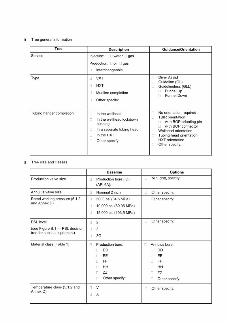
i) Tree general information
Tree Description Guidance/Orientation
Service Injection: � water � gas
Production: � oil � gas
� Interchangeable
Type � VXT
� HXT
� Mudline completion
� Other specify:
� Diver Assist � Guideline (GL) � Guidelineless (GLL)
� Funnel Up � Funnel Down
Tubing hanger completion � In the wellhead � In the wellhead lockdown
bushing � In a separate tubing head � In the HXT � Other specify:
� No orientation required � TBIR orientation
� with BOP orienting pin � with BOP connector
� Wellhead orientation � Tubing head orientation � HXT orientation � Other specify:
j) Tree size and classes
Baseline Options
Production valve size � Production bore (ID) (API 6A):
� Min. drift, specify:
Annulus valve size � Nominal 2 inch � Other specify:
Rated working pressure (5.1.2 and Annex D)
� 5000 psi (34.5 MPa)
� 10,000 psi (69.05 MPa)
� 15,000 psi (103.5 MPa)
� Other specify:
PSL level
(see Figure B.1 — PSL decision tree for subsea equipment)
� 2
� 3
� 3G
� Other specify:
Material class (Table 1) � Production bore: � DD � EE � FF � HH � ZZ � Other specify:
� Annulus bore: � DD � EE � FF � HH � ZZ � Other specify:
Temperature class (5.1.2 and Annex D)
� V
� X � Other specify:

k) Valves on trees (see Figures 1-4)
Valve Type Quantity Options Override /
Position indicator
PMV � Fail-closed � USV
� 1 � 2 � Override � Position Indicator
PWV � Fail-closed � USV
� Override � Position Indicator
PSV (for VXT)
� Fail-closed � Manual
� Override � Position Indicator
XOV � Upstream of PWV/AWV - Fail-closed
� Downstream of PMV/AWV – Fail-open
� Override � Position Indicator
AMV � Fail-closed � Manual
� 1 (VXT/HXT) � 2 (Mudline)
� Override � Position Indicator
AWV � Fail-closed � 1 (VXT/HXT) � 0 (Mudline)
� Override � Position Indicator
ASV (for VXT)
� Fail-closed � Manual
� Override � Position Indicator
AAV or WOV
(for HXT)
� Fail-closed � Manual
� Override � Position Indicator
AIV (for Tubing
Head)
� Fail-closed � Manual
� Override � Position Indicator
TST � Manual
THST (for Tubing
Head)
� Manual
CIT � Fail-closed � Manual � Check valve
� P&ID � Number
specify:
� 1 valve � 1 valve +
check valve � 2 valves
� Override � Metering valve
CID � Fail-closed � Manual � Check valve
� P&ID � Number
specify:
� 1 valve + check valve
� 2 valves
� Override � Metering valve
SV � Manual � P&ID � Number
specify:

HYD � Manual � P&ID � Number
specify:
� 1 valve + check valve
� 2 valves
Tubing Hanger Gallery
(for HXT)
� Manual � P&ID � Number
specify:
l) Tree mounted chokes
Type Description Options
� Production choke (PCV)
� Injection choke (ICV)
� Flow coefficient:
� Graph:
� Fixed orifice size:
� Specify Cv (Kv):
� Temperature:
� High:
� Low:
� Body:
� RWP:
� Full bore size:
� Material Class:
Check all options required:
� Hydraulic actuator � Electric
� Manual/operator � Override
� Insert retrievable
� Adjustable, specify steps:
� Fixed
� Visual position indicator
� Electronic position indicator (LVDT)
� Other specify:
� Gas Lift choke (to annulus bore) (GLCV)
� Flow coefficient:
� Graph:
� Fixed orifice size:
� Specify Cv (Kv):
� Temperature:
� High:
� Low:
� Body:
� RWP:
� Full bore size:
� Material Class:
Check all options required:
� Hydraulic actuator � Electric
� Manual/operator � Override
� Insert retrievable
� Fixed
� Adjustable, specify steps:
� Visual position indicator
� Electronic position indicator (LVDT)
� Other specify:

� Production orifice valve (POV)
� Specify Cv (Kv)
� Low temperature,
specify:
� High temperature,
specify:
� Valve size, specify:
� RWP:
� Full bore size:
� Fixed orifice size:
� Material Class:
Check all options required:
� Hydraulic Fail-open (full bore) � Electric
� Manual/operator � Override
� Visual position indicator
� Other specify:
m) Sensors
Baseline Options
Flow Meter (API 17S) � Yes: � Single phase � Multi-phase
� No
� Remote sampling
Production bore pressure/ temperature sensor
� Yes, specify: � No
� P&ID
� Between PMV & PWV
� Downstream of PCV
Annulus bore pressure/ temperature sensor
� Yes, specify: � No
� P&ID
� Upstream of AMV
� Between AMV and AWV
� Downstream of AWV
Leak detection � Yes, specify: � No
Erosion monitoring � Yes, specify: � No
Sand detection � Yes, specify: � No
Pig detector � Yes, specify: � No

n) Flowline connections
Baseline Options
Flowline connection location
� Subsea tree � Tubing head � CGB
� Other, specify:
Flowline type � Rigid pipe, specify: � Size, RWP � Design Code
� Spool Piece � Jumper � Pull-in
� Flexible pipe, specify: � Size, RWP � Design Code (see API 17B, 17J, 17K)
Flowline connection type
� 17SV flange � Vertical hub � Horizontal hub
(fixed) � Horizontal hub
(extend) � Single bore � Size, RWP, specify:
� Prod. bore
� 17SS flange
� Horizontal connector (fixed)
� Horizontal connector (extend)
� Multi-bore � Size, RWP, specify:
� Production bore � Annulus bore � Hydraulic, specify: � Electric, specify: � Other, specify:
Snag load protection � Not required � Required, specify:
� At flowline connection
� Outboard
� Snag load design basis
Dropped object protection � Not required � Required, specify:
� Dropped object design basis
Flowline load design basis (API 17R)
Specify: � Hydrate remediation in connector

o) flow assurance
Baseline Options
Downhole chemical injection
� Not required � Required, specify:
� Purpose (corrosion, scale, hydrate, paraffin) � chemical � injection pressure � injection flow rate (scfd (m3/d)) � mix with other chemicals before injection � line size (bore)
Tree chemical injection
� Not required � Required, specify:
� Purpose (corrosion, scale, hydrate, paraffin) � chemical � injection pressure � injection flow rate (scfd (m3/d)) � mix with other chemicals before injection � line size (bore)
Gas lift � Not required � Required, specify:
� Injection pressure
� Injection flow rate (scfd (m3/d))
� Gas lift isolation valve: � Yes � No
� Line size (bore)
� Nominal 2 inch
� Other, specify:
Pigging � Not required � Required, specify: � Round trip pigging
� Through tree piping � Outboard of tree
� Subsea pig launching � Other specify:
Insulation � Not required � Insulation covering � Fluid circulation � Electric heating
� Check all that apply:
� Tree connector
� Tree body
� Tree flowloops/piping
� Choke body
� Flow meter
� Other, specify:
Insulation latent
heat retention
� Insulation Design Basis (API 17U)
� Cool down from °F (°C) to °F (°C)
Minimum “no touch time” at least hours

Figure B.2—Examples of Subsea Tree P&ID

(Informative)
Alternate Requirements for Carbon and Low Alloy Steel Subsea Forgings
C.1 Scope
When required by the manufacturer or user/purchaser, the requirements of DNVGL-RP-0034 shall supersede all raw material requirements of API 17D.
This Annex contains guidance for additional levels of raw material performance, SFC 1, SFC 2, or SFC 3, above what is prescribed for PSL 3 subsea pressure-containing or pressure-controlling forged components in this specification. SFCs are not applicable to forgings that weigh less than 500 pounds when heat-treated, regardless of equivalent round (ER).This Annex shall be used in conjunction with DNVGL RP-0034 for carbon steel (CS) and low-alloy steels (LAS) grades up to 95 ksi (655 MPa) specified minimum yield strength.
CS or LAS grades over 95 ksi (655 MPa) specified minimum yield strength may be produced in accordance with DNVGL RP-0034, but the Charpy impact requirements should be agreed between the manufacturer and the user/purchaser.
C.2 Selection of Steel Forging Classes (SFC)
Subsea components listed in Table C.1 should be Steel Forging Class (SFC) 2. SFCs shall be assigned using the following guidance:
— Forgings for pressure-controlling components over 1000 pounds or over 5-inch ER, excluding gates and seats, shall be assigned SFC 1. Forgings weighing 1000 pounds or less and having a 5 inch or less ER shall as a minimum be manufactured according to API 17D/API6A requirements.
— Forgings for pressure-containing components over 1000 pounds or over 5-inch ER shall be assigned SFC 2. Forgings weighing 1000 pounds or less and having a 5 inch or less ER shall as a minimum be manufactured according to API 17D/6A requirements.
— Any pressure-containing or pressure-controlling component, regardless of size, identified as fatigue sensitive shall be assigned SFC 3 (see also Annex D).
NOTE 1 ER method pertains to the method described in API 6A, Section 6.4.
NOTE 2 DNVGL-RP-0034 SFC 3 is intended as a best practice to provide high quality steel for applications involving cyclic loading conditions. SFC 3 may not provide all necessary design parameters for some design verification analyses. For complete material characterization test protocol, see Annex D.

Table C.1— SFC 2 Subsea Components
Tubing Head Assembly—body
Tubing Head Wing Block(s)—body
Valve Bonnets (> 1000 lbs or > 5 in ER)
Master Valve Block—body
Tubing Head Assembly—connector body
Tree Connector—body
Production Wing Block(s)—body
Annulus Wing Block(s)—body
Production Choke—body
Flowline Connector—body
Tubing Hanger—body
Tree Cap Connector—body
Tree Running Tool—connector body
Subsea Wellhead—conductor (low-pressure) housing
Subsea Wellhead—subsea wellhead (high pressure) housing
Transition Joint (between subsea wellhead (high pressure) housing and surface pipe)
Casing Hangers—all bodies

(informative)
High-pressure High-temperature
D.1 Scope
General
This annex specifies requirements for load identification, design verification, materials, design validation and quality of subsea wellhead and production equipment that meet the definition of high-pressure high-temperature (HPHT), defined here as any environment above 15,000 psi (103.5 MPa) working pressure and/or operating above 350 oF (177 oC). This annex shall be used in conjunction with API 17TR8, whose guidance is limited to pressure-containing components, seals, and fastener components that come into contact with or are immediately adjacent to wellbore fluids operating in HPHT conditions. These requirements may be applied to pressure-controlling components if the design methodology can appropriately assess the applicable failure modes.
This annex provides additional requirements for HPHT equipment in the following areas of the verification and validation process:
— load descriptions
— functional specifications
— risk analysis
— design verification
— material selection, characterization, and qualification
— design validation
— QA/QC and product specification levels (PSL)
Equipment repair, other than bolt hole repair, and remanufacturing is not in the scope of this annex.
Standard Pressure Ratings
Equipment, except actuators, should be designed to operate at only the standard rated working pressures identified in Table D.1. The rated working pressure (RWP) shall be the basis for all testing.
Temperature Ratings
Equipment covered by this specification shall be designed and rated to operate throughout a temperature range defined by the manufacturer and as a system. For HPHT service conditions, the temperature class range shall be marked with the standard temperature class designation per 5.1.2.3.1, plus the numerical value of the maximum rated operating temperature, plus the letter ‘F’ for Fahrenheit or ‘C’ for Celsius.
EXAMPLE VX400F represents 35 to 400 °F temperature range. X450F represents 0 to 450 °F. X210C represents -18 to 210 °C.

Table D;�!���%�>?��������������������������
Equipment
Pressure Rating
20,000 psi (138.0 MPa)
in 5,000 psi (34.5 MPa) increments
Valves, Chokes X
Pressure-containing Equipment X
Pressure-controlling Equipment X
Flanges, Connectors (Tubing Head, Tree, Tree Running Tool (TRT)), OECs X
Tubing Hangers a,c X
Tubing Hanger Conduits, Tree Penetrations and Connections a,b X
Wellhead (high-pressure) housing and Annulus Seal Assembly X
Conductor (low-pressure) housing, Mudline, and Submudline Housings, Casing Hangers Submudline Annulus Seal assemblies c NA
Hydraulic Components PMR
Other d PMR
a May contain other (non-wellbore) flow passages that shall not exceed 1.0 times the RWP of the tubing hanger assembly plus 2500 psi (17.2 MPa).
b Intermediate pressure rating permitted if component has a higher-than-working-pressure design requirement. c Rated for working pressure in accordance with the design methods given in this Annex; or end connection thread, bulkhead fitting
requirements d Not listed in this table, such as such as running, retrieval and test tools, lockdown bushings, piping.
D.2 Functional Specifications
The manufacturer and user/purchaser shall agree on the equipment functional specifications based on the full lifecycle approach.
Functional specifications shall define applicable environmental conditions (including well fluid properties or compositions), operational loads, and cyclic/lifecycle load.
Operational cyclic/lifecycle loads shall include, as applicable, the following:
— Combined Cyclic Loads (bending, tension, shear, etc.)
— Test loads that each specific piece will be subjected to during its lifecycle
— Extreme and Survival Events
— Operational pressure/temperature cycles
— Flow induced loads
NOTE Further guidance on loading conditions for HPHT applications can be found in API 17TR8.
Where functional requirements are not available, the manufacturer may provide a design technical specification for the equipment based on experience or documented capabilities of existing equipment for review and acceptance by the user/purchaser.

D.3 Load Descriptions
Load descriptions shall be per API 17TR8, which correlate loads typically experienced on oil and gas equipment to loads identified in ASME BPVC Section VIII Division 2 and Division 3.
The loading conditions may be a generalized set of load capacities (capacity chart) defined by the manufacturer based on material strength(s) and various combinations of loads. Alternatively, specific loading conditions may be defined by the user/purchaser to correspond with a certain set of environment and operating conditions.
The loading conditions as defined shall be categorized as Normal, Extreme, and Survival, as per API 17TR8.
The RWP shall not be increased above the nominal rated working pressure of the equipment for Normal, Extreme and Survival load cases.
D.4 Risk Analysis
A risk assessment (e.g. FMEA, FMECA, HAZID/HAZOPs, etc.) shall be performed on 17D HPHT equipment to identify potential failure modes when this equipment is subjected to the loads identified in the functional specifications. The risk assessment serves as an integral part of defining the verification, material selection/qualification, validation, and quality requirements for mitigating the identified risks.
The risk assessment shall define the equipment performance (validation) requirements (PR), which are mentioned in section H.7. Further guidance on the FMECA process can be found in API 17TR8.
D.5 Design Verification
General
Design verification shall be performed to verify conformance to:
— HPHT equipment functional specification
— serviceability criteria, i.e. API 17TR8
— acceptance criteria for failure modes typically identified for HPHT equipment:
— global plastic collapse
— local strain limit damage (local failure due to excessive strain)
— ratcheting effects
— plastic collapse under the hydrostatic test condition
— fatigue assessment (lifecycle estimation)
Other failure modes may be derived from the risk assessment
The requirements of section D.5 do not apply to seal design.
Design Analysis Methodology
D.5.2.1 General
Design analysis shall be performed according to D.5.2.2 or D.5.2.3. See API 17TR8 for suggested application of design analysis path. When selecting a verification route per API 17TR8 for a component the code selected should remain constant for all verification assessments.
The applicable equivalent stress: von Mises equivalent stress (VME) or stress intensity (SINT), should be in accordance with API 6X.
A system may be made up of components that are verified using different design codes.
D.5.2.2 Linear-Elastic Analysis
Linear-elastic analysis shall be used in accordance with ASME BPVC Section VIII Division 2 or API 6X to verify adequate protection against failure modes identified in D.5.1.
The allowable stress criteria shall be: S = 2/3 x SYST, SPL = SYST, and SPS = 2 SYST, where SYST = specified minimum yield strength adjusted for elevated temperature.
NOTE 1 See API 17TR8 for linear-elastic analysis of identified failure modes (e.g. global plastic collapse, local strain limit, ratcheting effects, plastic collapse under hydrostatic test condition)
NOTE 2 See API 17TR8 for additional information on linear-elastic analysis
D.5.2.3 Elastic-Plastic Analysis
Elastic-plastic analysis shall be used in accordance with ASME BPVC Section VIII Division 2 or Division 3 to verify adequate protection against failure modes identified in D.5.1.
Material characterization for elastic-plastic analysis shall follow D.6.2.1.
NOTE 1 See API 17TR8 for elastic-plastic analysis of identified failure modes (e.g. global plastic collapse, local strain limit, ratcheting effects, plastic collapse under hydrostatic test condition).
NOTE 2 Elastic-Perfectly Plastic or Limit-Load design analysis are acceptable methods provided their results meet the acceptance criteria of the selected method.
Fatigue Assessment
D.5.3.1 General
HPHT equipment shall be assessed for fatigue, unless found exempt through fatigue screening.
NOTE See API 17TR8 for fatigue screening information
D.5.3.2 Fatigue Design
When fatigue assessment identifies components susceptible to fatigue damage, a fatigue design analysis shall be performed by the S-N method (stress or strain based) or fracture mechanics method (FM) addressing the environmental effects on the material of construction. Fatigue assessment method shall be determined by API 17TR8.
D.5.3.3 Fatigue Design Acceptance Criteria
The fatigue lifecycle assessment shall meet the following.
— S-N Design—Fatigue life design margin shall conform to API 17TR8.
— Fracture Mechanics Design—Fatigue life design margin shall conform to API 17TR8.
The minimum detectable initial flaw size capability from the manufacturer’s NDE procedures (See D.8.5) should be referenced in the design verification calculations.
D.6 Materials Selection, Characterization, and Qualification
Materials Selection
D.6.1.1 General
Materials intended for pressure containing, pressure controlling or load bearing API 17D components subjected to HPHT conditions shall follow one of the following:

� API 6ACRA
� DNVGL-RP-0034 for carbon steel (CS) and low alloy steel (LAS) up to 95ksi yield strength
� API 6A along with API TR6MET and API 17TR8 for other grades
NOTE A common list of environmental conditions for HPHT equipment can be found in API 17TR8.
D.6.1.2 Bolting and Seals
All closure bolting for HPHT applications shall be manufactured to API 20E or 20F, BSL 3. For all other bolting Table 4 applies.
NOTE See API 17TR8 for additional requirements for HPHT bolting and seals.
Materials Characterization
D.6.2.1 Properties for Design Verification
Material properties for linear-elastic analysis shall be per API 17TR8. Material properties for elastic-plastic analysis shall be per API 17TR8.
D.6.2.2 Properties for Fatigue Assessment
Before a full-scale fatigue testing program is established, material susceptibility to environmental assisted cracking (EAC) for the intended service condition environment(s) shall be validated using the test protocols found in API 17TR8.
D.6.2.3 Ceramic Material Characterization
HPHT equipment utilizing ceramics in conjunction with pressure containing/pressure controlling applications shall require proof testing to validate the design RWP as follows:
— Six proof tests of three prototypes (2 per prototype)
— For proof tests performed at ambient temperature, the RWP shall be defined as:
RWP = 0.4W
— For proof tests performed at minimum or maximum rated temperatures, the RWP shall be defined as:
RWP = 0.67W
W is the maximum test pressure successfully achieved during proof test where the material maintained structural integrity.
NOTE The design guidelines in API 17TR8 are based on the premise that ductile materials with good fracture toughness are used in the construction of HPHT equipment.
Ceramic materials may be needed in certain applications, such as bulkhead penetrations. Ceramics exhibit very low ductility and it may be difficult to model or analyze structural integrity and functional performance because of this.
Materials Qualification
The manufacturer shall prepare and conduct a one-time material process qualification to validate a material’s mechanical performance properties. Guidance for test protocols are found in API 17TR8. During material qualification, validation samples shall be taken from the same prolongation or sacrificial forging qualification test coupon (QTC). The material process qualification shall identify all necessary mechanical performance characterization tests and QA/QC validation along with their acceptance criteria. The material process qualification’s validation may involve testing at elevated temperatures and/or various environmental conditions, as specified by the manufacturer, while validation is conducted per the test standard’s requirements. Both set of test results (taken from the same QTC) shall establish a documented cross-reference between material performance properties and QA/QC acceptance criteria. Subsequently, the manufacturer shall prepare a material process specification containing the QA/QC acceptance criteria for validation to be performed on production run QTCs. Meeting the acceptance criteria of the material process specification shall infer the material’s specified mechanical performance properties have been met.
Additional mechanical performance characteristics (for different temperatures, environments, etc.) may be added later to an existing qualified material, provided there is a material process qualification prepared for the new set of test protocols along with the same set of QA/QC validation meeting the same acceptance criteria to be taken from the new (single/same) validation QTC.
Other materials with similar mechanical properties but different chemistry/wrought process criteria may not use or infer the cross-reference.
D.7 Design Validation
General
Design validation shall be performed to ensure equipment demonstrates the mechanical integrity and functionality/operability for the loads identified in the functional specifications. The validation program shall be based on API 17D, plus any additional performance validation identified from the risk assessment, and may include the following types of elements to address the identified risks:
— Validation or qualification of an assembly/component under development.
— Validation of design method.
— Validation of materials for use in design verification.
Validation Pressure Tests
Hydrostatic body pressure tests shall be performed at ambient temperature using a liquid as the test medium before the start of any validation pressure test program. Functional pressure test programs should follow test procedures and hold times of API 17D using gas as the test medium at the test temperature(s), per the manufacturer’s procedures. Functional pressure tests should not exceed the specified RWP by more than 5%.
Performance Requirement, Level 3 (PR3)
Equipment subject to PR3 validation shall be validated per API 17D section 5.1.7 requirements plus the additional performance validation as identified by the manufacturer’s risk assessment.
An exclusion or reduction in the additional performance validation process is acceptable with technical justification, where:
— Performance characteristics have been determined by analysis and validated by similar or scaled testing, with supporting evidence/experience which shall include similar internal or externally published data; or
— Quantitative failure assessments may be performed to justify a reduction in the scope of qualification activities, where the failure probability is determined to be below a certain acceptance level agreed with the user/purchaser and/or specified in a recognized code or standard.
Performance Requirement, Level 4 (PR4)
If fatigue assessment/design is indicated for a component, that component shall require a minimum performance rating of PR4, which includes defining cyclic loading requirements. Validation for fatigue sensitive components shall be per one of the following methods:
— strain-gauging program of a representative test specimen or component, and subsequent comparison analysis of the strain-gauging measurements to the numerical (FEA) results (See API 17TR8). Acceptance criteria used for this comparison shall be documented.
— component fatigue testing to demonstrate the component’s fatigue life meets or exceeds required service life. Appropriate adjustment (reduced life) for environmental effects (e.g. “knock down” factors or methods) should be applied to correlate the test environment to the service environment.
PR4 testing may be performed on a separate test article than which was used for API 17D or PR3 validation.
D.8 Quality Assurance and Product Specification Level
General
Product Specification Level (PSL) 4S for HPHT equipment within the scope of API 17D shall be compliant with API 6A PSL 4 product standards with the following additions, modifications, or exceptions as outlined in sections D8.2 through D8.6.
Pressure Testing
D.8.2.1 General
Hydrostatic body pressure tests of HPHT components during FAT shall follow API 17D PSL 3 for hydrostatic pressure test procedures and hold times. Functional pressure tests of HPHT components during FAT that contain or incorporate pressure-controlling parts (requiring low or rated working (differential) pressure tests) shall follow API 17D PSL 3G for pressure test procedures and hold times.
Painting may be performed prior to FAT provided it does not adversely affect the selected NDE method.
Body pressure testing at hydrostatic test pressures using gas as a test medium is not permitted. Only liquid test mediums are permitted at hydrostatic test pressures at ambient temperature.
D.8.2.2 Hydrostatic Body Test Pressure
For rated working pressure (RWP) < 20,000 psi (<138.0 MPa), the hydrostatic body test pressure during FAT shall be a minimum of 1.5 times the equipment RWP as marked on the component. Hydrostatic body pressure tests during FAT shall be performed at ambient temperature.
������!��������#���$�38.0 MPa), the hydrostatic body test pressure during FAT shall be a minimum of 1.25 times the equipment RWP. If linear elastic design methods are used in design verification, then the hydrostatic body test pressure during FAT shall be a minimum of 1.5 times RWP.
Acoustic emission (AE), if used, should be performed in accordance with procedures specified in ASTM E569 to identify potential flaws and the acceptance criteria should be agreed upon by the equipment manufacturer and user/purchaser. The acoustic emission examination should be conducted throughout the duration of the hydrostatic body test.
Painting may be performed prior to hydrostatic pressure test provided it does not adversely affect the selected NDE method.
D.8.2.3 Test Pressure for Pressure-Controlling Components
Functional pressure tests for HPHT equipment should follow PSL 3G procedures and hold times of API 17D, using gas as the test medium that will remain in the gas phase at functional test pressure. Functional pressure tests during FAT shall be performed at ambient temperature. Chart recording of pressure tests is required. Functional pressure tests during FAT should not exceed the specified RWP by more than 5%.
Backseat testing of valve and choke stems (with or without actuators/operators) is not required.
Impact Testing
Charpy impact (CVN), in accordance with API 17TR8. Material mechanical properties shall meet or exceed established acceptance criteria values at the assigned coupon testing temperature. Acceptable impact energy values shall also infer that the material’s fracture toughness performance at elevated temperatures.
One set of three Charpy impact (CVN) specimens shall be in accordance with API 17TR8. Material mechanical properties should meet or exceed established acceptance criteria values at the assigned coupon testing temperature. Acceptable impact energy values shall also infer that the material’s fracture toughness performance at elevated temperatures are met.
The CVN test temperature should correspond to one of the temperature classes specified in API 17D, e.g. X (0°F/-18°C) or V(35°F/2°C).
Minimum recommended CVN absorbed energy requirements are listed in Table D.2.

Table D.2— Minimum CVN Absorbed Energy in Longitudinal and Transverse Direction
Specified minimum yield strength (SMYS) Average Single Up to 75 ksi (517 MPa) 37 ft-lb (50 J) 1 28 ft-lb (38 J) 1 Over 75 ksi (517 MPa) Up to 85 ksi (586 MPa)
44 ft-lb (60 J) 33 ft-lb (45 J)
Over 85 ksi (586 MPa) 52 ft-lb (70 J) 39 ft-lb (53 J) 1 For compliance with requirements in API 17G, the minimum absorbed energy in longitudinal direction shall be 44 ft-lb (60 J) average and 33 ft-lb (45 J) single.
Alternate Material Selection
The user/purchaser may elect to specify alternative material performance, processing or compositional requirements for carbon steel and low alloy steel forgings per Annex C; which may exceed requirements in this Annex.
NDE
The manufacturer shall define and qualify the NDE methods, probability of detection (PoD), size of flaws, its geometry orientation and location. This may require multiple NDE methods to complete the evaluation and set the acceptance criteria. Each of these parameters shall be defined by the equipment designer as a part of the technical specification required for cyclic fatigue crack growth evaluation.
The manufacturer shall document the capability of their NDE methods to detect the minimum initial flaw size used in design verification fatigue assessments. Guidance for initial flaw size characterization is found in API 17TR8. NDE methods defined in ASME BPVC Section VIII Division 2 or Division 3, should be used, according to the selected design methodology and defined by the manufacturer’s initial flaw size.
Magnetic particle (MT) and ultrasonic testing (UT) NDE processes, methods, and procedures shall cover the entire volume.
Bolt Hole Repair
Weld repair of bolt holes, tapped holes and machined blind holes used for pressure containing or lifting bolting shall not be permitted. The use of threaded inserts with matching base material requirements to repair bolt holes, tapped holes, and machined blind holes is permitted. The manufacturer shall be responsible for design verification and validation of the thread insert repair.

(normative)
Mudline Suspension and Conversion Systems
E.1 General
Mudline suspension equipment is used to suspend casing weight at or near to the mudline, to provide pressure control and to provide annulus access to the surface wellhead. Mudline equipment is used when drilling with a bottom-supported rig or platform and provides for drilling, abandonment, platform tieback completion and subsea completion. During drilling/workover operations, the BOP is located at the surface. The casing annuli are not sealed at the mudline suspension; therefore, it is necessary to install mudline conversion equipment prior to installing a tubing completion and subsea tree.
Tieback adapters, mudline conversion equipment and tubing heads are used to provide a preparation to accept the tubing hanger and a profile to which a subsea tree can be locked and sealed.
Major items of equipment used with mudline equipment are:
— landing and elevation ring
— casing hangers
— casing hanger running tools and tieback adapters
— abandonment caps
— mudline conversion equipment
— mudline conversion tubing head
Figure E.1 illustrates the items of equipment used in mudline suspension and conversion equipment.
E.2 Calculation of Pressure Ratings for Mudline Suspension Equipment
Introduction
The purpose of this annex is to define methods for calculating rated working pressure and test pressure for mudline equipment that are consistent with accepted engineering practice. Mudline equipment design is a unique combination of tubular goods and hanger equipment and, therefore, it is not intended that these methods and allowable stresses be applied to any other type of equipment. Fatigue analysis, thermal expansion effects and allowable values for localized bearing stress are beyond the scope of these rated working pressure calculations.
As an alternative to the method presented in this annex, the designer may use the rules in ASME BPVC Section VIII Division 2 modified in accordance with API 6X in which bending stresses in wall-section discontinuities can be treated as secondary stresses.
When using the alternative method, the calculation for the rated working pressure shall be made in combination with loads applied by the rated running capacity (if applicable) and the rated hanging capacity as well as thermal loads. The designer shall ensure that strains resulting from these higher allowable stresses do not impair the function of the component, particularly in seal areas.
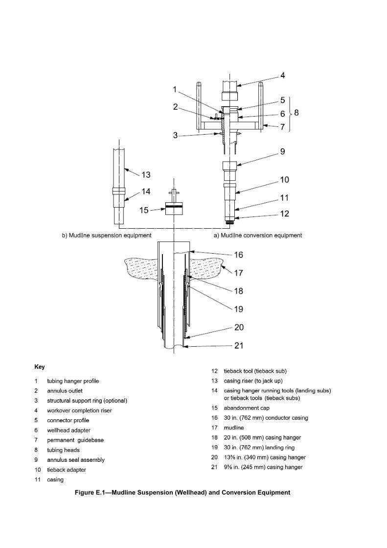
Figure E.1—Mudline Suspension (Wellhead) and Conversion Equipment
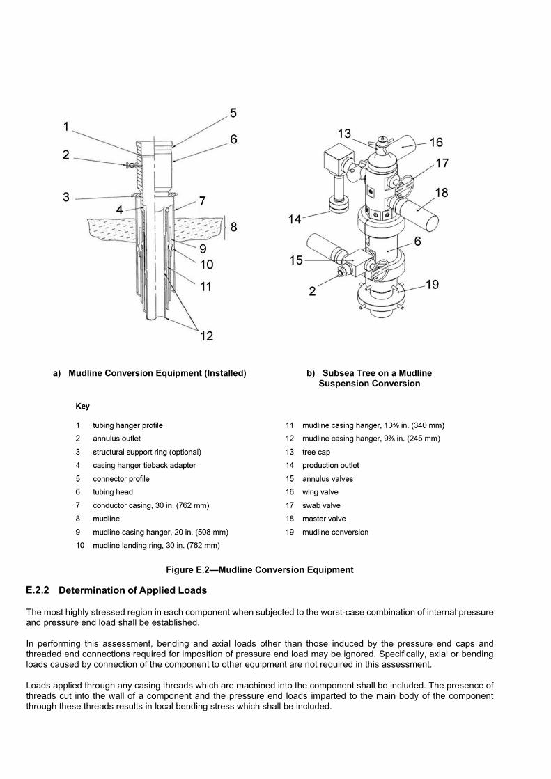
a) Mudline Conversion Equipment (Installed) b) Subsea Tree on a Mudline Suspension Conversion
Figure E.2—Mudline Conversion Equipment
Determination of Applied Loads
The most highly stressed region in each component when subjected to the worst-case combination of internal pressure and pressure end load shall be established.
In performing this assessment, bending and axial loads other than those induced by the pressure end caps and threaded end connections required for imposition of pressure end load may be ignored. Specifically, axial or bending loads caused by connection of the component to other equipment are not required in this assessment.
Loads applied through any casing threads which are machined into the component shall be included. The presence of threads cut into the wall of a component and the pressure end loads imparted to the main body of the component through these threads results in local bending stress which shall be included.

NOTE The general shape of the main body of the component can result in section bending stress, especially when pressure end load is added.
Determination of Stresses
After the location of the highest stress for any given component and loading condition have been determined, the stress distribution across the critical section shall be linearized to establish the membrane stress, Sm, the local bending stress, Sb, and peak stress, F, in the section; see Figure E.3 (see API 16Q). The linearization operation shall be performed on each component of stress. The individual linearized components shall then be used to calculate a von Mises equivalent stress through the cross-section. The von Mises equivalent stress or distortion energy stress, Se, shall be calculated as given in Equation (E.1):
1
2 2 2 2 2 2 23e x y z x y x z y z xy xz yzS S S S S S S S S S S �� � � � � � � � �� �� � (E.1)�
where
Sx, Sy, Sz are the component normal stresses at a point;
Sxy, Sxz, Syz are the component shear stresses at a point;
subscripts x, y and z refer to the global coordinate system
The linearization operation can be done by hand calculation, but it is more often done using a computer program. If a computer program or FEA post-processing program is used, caution shall be used to verify that the program is calculating the linearization stresses correctly. A check on computer output is highly recommended. One such simple check for FEA post-processing programs is to construct an FEA model of a simple beam in four-point bending. This model should be analyzed for plane strain conditions and should have a beam depth made up of at least five elements. The linearized von Mises stress through the center section of such a beam should produce no von Mises membrane stress.
The von Mises stress values of interest in the cross section of the component being studied are the linearized membrane (net section) stress, and the linearized local bending stress as shown in Figure E.3. These values consider the multiaxial stress condition at a point since they are von Mises equivalent stresses.
Allowable Stress Levels for Working and Test Conditions
NOTE 1 The allowable stress levels for test and working conditions are based on percentages of membrane-plus-bending and membrane-only stress required to yield the material. For the case of the stresses used in this, the local membrane and bending stress calculated in E.2.3 are primary stresses since they are the stresses required to provide static equilibrium of the section with the applied pressure and end loads.
To establish allowable levels for this case, the limiting situation of full section yielding shall be defined.
NOTE 2 Assuming the simple case of a rectangular beam and an elastic/perfectly plastic material, a plot of limiting membrane-plus-bending versus membrane-only stress can be made (see ASME BPVC Section II and ASME BPVC Section VIII). Figure E.4 shows the limiting values of various combinations of membrane-plus-bending and membrane-only stresses normalized using the minimum specified material yield strength, SY. The limit stress ratio for membrane only is 1.0 and for bending only the limit is 1.5. If a membrane stress less than 2/3 SY is added to a large bending stress, the membrane-plus-bending stress ratio may exceed 1.5. This is due to the stiffening effect of the membrane stress and shifting of the beam’s neutral axis. This increase in bending capacity when axial load is applied is generally ignored.
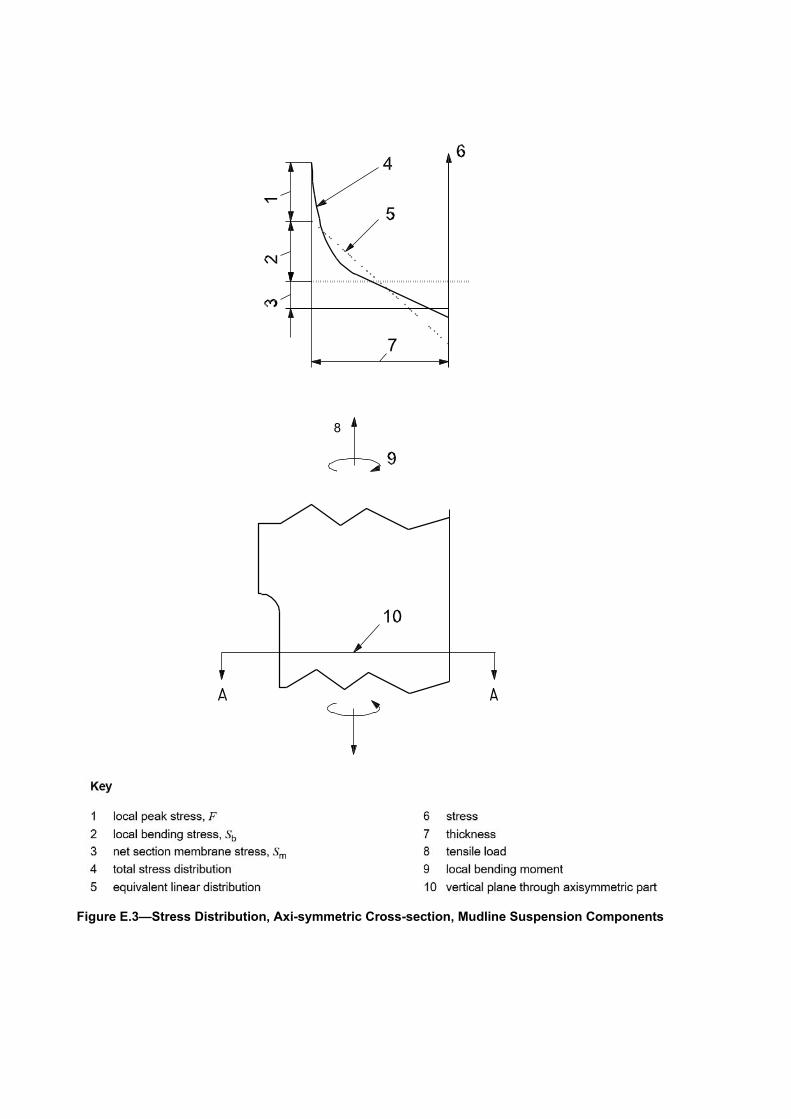
8
Figure E.3—Stress Distribution, Axi-symmetric Cross-section, Mudline Suspension Components

Figure E.4—Limiting Stress Values, Mudline Suspension Components
Test Pressure
For the purposes of this specification, the allowable von Mises stresses for hydrostatic test conditions on both suspension and conversion equipment are as follows: the membrane stress, Sm, as given in Inequality (E.2) and the membrane-plus-bending stress, Sm ��Sb, as given in inequality (E.3) for S m ��0.67S Y and as given in inequality (E.4), 1.2 Sm for 0.67S Y ��S m ��0.90S Y : and as given in
S m ��0.90S Y (E.2)

S m + S b ��1.35S Y (E.3)
S m + S b ��1.35S Y (E.4)
The test pressure shall be that required to cause any of the allowable stresses to occur in the critical cross section of the component when pressure and end loads due to test end caps or plugs are included.
Rated Working Pressure
E.2.6.1 Mudline Suspension Equipment
For the purposes of this specification, the allowable von Mises stresses for working conditions for mudline suspension equipment are as follows: the membrane stress, Sm, as given in Inequality (E.5) and the membrane-plus-bending stress, Sm ��Sb, as given in Inequality (E.6) for S m ��0.67S Y a and as given in Inequality (E.7), 1.2 Sm for 0.67S
Y ��S m ��0.80S Y :
S m ��0.80S Y (E.5)
S m ��S b ��S Y (E.6)
S m ��S b ��2.004S Y (E.7)
The rated working pressure shall be that required to cause these stresses to occur in the critical cross-section of the component.
E.2.6.2 Mudline Conversion Equipment
For the purposes of this specification, the allowable von Mises stresses for working conditions for mudline conversion equipment are as follows: the membrane stress, Sm, as given in Inequality (E.8) and the membrane- plus-bending stress, Sm ��Sb, as given in Inequality (E.9):
S m ��0.67S Y (E.8)
S m ��S b ��S Y (E.9)
The rated working pressure shall be that required to cause these stresses to occur in the critical cross-section of the component.

(informative)
Assembly Guidelines of API Bolted Flanged Connections
F.1 Scope
General
Successful use of API bolted flanged connections require knowledge of their capabilities and careful assembly. This annex provides the provisions for assembly and bolt make-up for type 6BX integral, welding neck and blind flanges as defined in API 6A and type 17SS integral, welding neck and blind flanges as defined in this part of API 17D.
Introduction
An assembly procedure for bolted flanged connections is defined. Its purpose is to ensure structural integrity and control of leak-tightness for the API bolted flanged connections.
Recommended Bolting Make-up Tension/torque
NOTE 1 API flanges are designed and analyzed based on bolt tension in equation F.1 generated by using two bolting material yield strengths: 80 ksi or 105 ksi. These two values represent the minimum and maximum bounds for yield strengths used in calculating bolt tensions for API flange applications.
Flange applications using bolt tensions generated from minimum material yield strengths outside of these bounds should be analyzed as other end connectors per Section 7.4. Bolting with minimum yield strengths greater than the maximum specified for an API flange applications (such as Alloy 718 at 120 ksi) may be allowed provided the required bolt tension used in equation F.1 is calculated based on 105 ksi material yield strength (not 120 ksi) to maintain API flange design integrity and avoid possible flange overload.
Low-strength connection bolting for flanges as defined in F.1.1, such as ASTM A193/A193M grade B7M and ASTM A320/320M grade L7M, shall be made up using a validated bolt preload method that achieves a tensile make-up stress sufficient to ensure flange face circumferential contact at rated working pressure and normal operating loads, while not exceeding yield under test conditions and under worst-case load conditions. Low-strength bolting is defined as having a material yield strength of 80000 psi (550 MPa).
NOTE 2 Bolt load scatter can affect joint performance. Use of alternative make up methods or bolt designs to limit scatter for critical bolting is advised and to be agreed with user/purchaser.
Table F.1 provides example torque values for ASTM A193/A193M grades B7 and B16, and ASTM A320/320M grades L7 and L43, and for ASTM A193/A193M grade B7M, and ASTM A320/320M grade 7M bolting material. This table provides calculated torque values based on the material yield strengths listed in paragraphs 1 and 2 of this subsection and a 0.07 friction coefficient.
Some factors that affect the relationship between nut torque and bolt tension stress are the
— thread pitch, pitch diameter and thread form,
— surface finish of thread faces and nut bearing surface area
— degree of parallelism of nut-bearing area with flange face,
— type of lubrication or coating of the threads (the friction factor associated with lubricants or coatings can vary up to 20 %)
— nut-bearing surface area
It should be recognized that torque applied to a nut is only one of several ways to approximate tension and stress in a fastener. The main requirement is to reach the applied tension stress range listed in this subsection and to achieve

gasket seating and hub face circumferential contact. The example torque values listed in Table F.1 is provided only as an informative guide, and manufacturer’s torque tables(s) shall be supported by documented validation results.
Flange bolting torques are calculated as given in a) through c).
a) Hexagon size (heavy hex nuts) equals 1.5D + 0.125 in. (1.5D + 3.175 mm), where D is the bolt diameter, expressed in inches (millimeters).
b) The flange bolt torque, T, expressed in SI units of Newton-meters, is given by Equation (F.1)
3 3
( )[(1 / ) ( )( )(sec 30 )] ( 3.175)( )( )
2 10 [ ( ) ( )(1 / )(sec 30 )] 4 10
F P N f P h D F fT
x P f N x
�
�
� � � �� �
� � (F.1)
where
D is the bolt thread major diameter, expressed in millimeters As is the effective stress area, expressed in square millimeters, equal to:
20.9743
0.7854 Dn
�� �� �� �
for UTS < 689.5 MPa (F.1.a)
20.16238
3.1416min2
S
n
E�� �
� �� �
for UTS >= 689.5 MPa (F.1.b)
F is the bolt tension, expressed in newtons, equal to As times the bolt stress N, n is the number of threads per millimeter
P is the pitch diameter, expressed in millimeters
f is the friction factor (dimensionless)
h is the hexagon size, expressed in millimeters
ESmin is the minimum pitch diameter of the external thread in millimeters
c) The flange bolt torque, T, expressed in imperial units of foot-pounds, is given by Equation (F.2)
( )[(1 / ) ( )( )(sec30 )] ( 0.125)( )( )2(12)[ ( ) ( )(1 / )(sec30 )] 4(12)F P N f P h D F f
TP f N
��
� � � �� �
� � (F.2)
where
D is the bolt thread major diameter, expressed in inches
As is the effective stress area, expressed in square inches, equal to:
20.9743
0.7854 Dn
�� �� �� �
for UTS < 100 ksi (F.2.a)
20.16238
3.1416min2
S
n
E�� �
� �� �
for UTS >= 100 ksi (F.2.b)
F is the bolt tension, expressed in pounds, equal to As times the bolt stress
N, n is the number of threads per inch
P is the pitch diameter, expressed in inches

f is the friction factor (dimensionless)
h is the hexagon size, expressed in inches
ESmin is the minimum pitch diameter of the external thread in inches

Tabl
e F.
1 —
Exa
mpl
e Fl
ange
Bol
t Tor
ques
(0.0
7 Fr
ictio
n Fa
ctor
) For
67%
Yie
ld S
tren
gth
Tens
ion
(NO
TE
*���
���
����
����
�����
��\�
���^
*��
�100
ksi
(Eq.
��
��_�`
^*�
��{
|}��
~!
��$E
q. F
.1.b
)]
Bol
t Siz
e
L7, L
43, B
16, B
7, o
r gr6
60 M
ater
ial
L7M
or B
7M M
ater
ial
Bol
t Ten
sion
M
ake
Up
Torq
ue
Bol
t Ten
sion
M
ake
Up
Torq
ue
in.,
TPI
mm
lb
f kN
ft*
lbs
N
m
lbf
kN
ft lb
s N
m
1 /2, 1
3 U
NC
12
.70
9 67
8 43
.05
46
62.3
7 7
374
32.8
0 35
47
.45
5 /8, 1
1 U
NC
15
.88
15 4
78
68.8
5 89
12
0.67
11
793
52
.46
68
92.2
0
3 /4, 1
0 U
NC
19
.05
22 9
74
102.
19
155
210.
15
17 5
04
77.8
6 11
8 15
9.99
7 /8, 9
UN
C
22.2
3 31
789
14
1.40
24
6 33
3.53
24
221
10
7.74
18
8 25
4.89
1, 8
UN
25
.40
41 7
73
185.
82
367
497.
59
31 8
27
141.
57
279
378.
27
11 /8, 8
UN
28
.58
54 6
14
242.
94
527
714.
52
41 6
11
185.
09
402
545.
04
11 /4, 8
UN
31
.75
69 1
9830
7.81
729
988.
3952
723
234.
5255
575
2.48
13 /8, 8
UN
34
.93
85 4
79
380.
23
975
1 32
1.92
65
127
28
9.70
74
3 1
007.
37
11 2, 8
UN
38
.10
103
508
460.
43
1 27
2 1
724.
60
78 8
63
350.
80
969
1 31
3.79
15 /8, 8
UN
41
.28
123
261
548.
29
1 62
2 2
199.
14
93 9
13
417.
75
1 23
6 1
675.
79
13 /4, 8
UN
44
.45
144
720
643.
75
2 03
1 2
753.
67
110
263
490.
47
1 54
8 2
098.
81
17 /8, 8
UN
47
.63
167
900
746.
86
2 50
4 3
394.
97
127
924
569.
03
1 90
8 2
586.
90
2, 8
UN
50
.80
192
822
857.
71
3 04
5 4
128.
47
146
912
653.
50
2 32
0 3
145.
50
21/4,
8 U
N
57.1
5 24
7 81
4 1
102.
33
4 34
7 5
893.
74
188
811
839.
87
3 31
2 4
490.
47
21 /2, 8
UN
63
.50
309
722
1 37
7.71
5
977
8 10
3.72
23
5 97
9 1
049.
69
4 55
4 6
174.
39
25 /8, 8
UN
a 66
.68
309
024
1 37
4.61
6
234
8 45
2.17
26
1 53
3 1
163.
36
5 27
6 7
153.
30
23 /4, 8
UN
a 69
.85
340
770
1 51
5.82
7
173
9 72
5.28
28
8 40
1 1
282.
87
6 07
1 8
231.
17
a C
alcu
late
d ba
sed
on re
duce
d yi
eld
stre
ngth
of 9
5000
psi
(655
MPa
). S
ome
mat
eria
ls, s
uch
as L
43 a
nd G
r 660
, can
use
a h
ighe
r stre
ngth
for t
hese
bo
lt si
zes
in a
ccor
danc
e w
ith F
.1.3
.

F.2 Guidelines for Assembly
Introduction
Leak-free bolted flanged connections are the result of many selections/activities having been made/performed within a relatively narrow band of acceptable limits. One of these activities essential to leak-free performance is the connection assembly process. The provisions outlined in Annex F cover the assembly elements essential for consistent leak-tight performance of API flanged connections. Written procedures, incorporating the features of these provisions shall be developed for use by the qualified connection assemblers.
NOTE 1 There are many ways to assemble an API bolted flanged connection and Annex F is intended to provide provisions to those responsible for preparing bolted flanged connection assembly (make-up) procedures or for qualifying bolted flange connection assembler.
NOTE 2 The types of bolt-up tools and load control techniques covered by Annex F are not intended to exclude or limit other tools and techniques that are certified to produce an equivalent or better bolt preload scatter value.
Examination of “Working” Surfaces
All flange working surfaces should be cleaned and examined before assembly. A non-abrasive cloth may be used to clean all working surfaces to remove grease, preservation coatings and dirt. Working surfaces are intended to have metal-to-metal contact during make-up, hence any painting on a flange’s working surfaces should be removed. Adherent coatings, such a PTFE or plating, are acceptable on the flange working surfaces. Light oils may be used if galling or fretting is a concern.
Examine the ring groove surfaces of both connection flanges for appropriate surface finish and for damage to surface finish, such as scratches, nicks, gouges and burrs. Indications running radially in the outer ring groove (leak path) are of particular concern. Unacceptable scratches and dents in the groove and flange face require re-machining. Correct any radial defect in the groove that exceeds the depth of serrations. The defects may be removed by lightly polishing with a fine abrasive wet or dry paper around the gasket seat circumference. Ensure that the rework area blends in uniformly and avoid local polishing of the defect. Report any questionable imperfections for appropriate disposition.
A new gasket shall be used whenever a flange is opened and re-made. Check the gasket contact surfaces of both surfaces for any mechanical damage and for surface roughness. Reject damaged or questionable gaskets. Gaskets may be reused for testing purpose. A new gasket shall always be used for final assembly. If required, light oil can be used to lubricate the gasket during seating. Take care that no solid particles are present in the lubricant. Report any questionable results.
Examine stud and nut threads for deformation and damage, such as rust, corrosion, cracks and burrs. Previously used bolts should be thoroughly cleaned (such as wire brushing) before being reused. Inspect studs that have been subjected to high-cycle external loading with an appropriate NDE technique. Replace questionable parts.
Examine nut-bearing surfaces of flanged for scores, burrs, galling marks etc. Remove protrusions.
Alignment of Mating Surfaces
Flanges should be aligned both axially and rotationally to the design plane within specified tolerances. Any pipe or other connection that affects the alignment should be properly supported. The use of bolt load to achieve flange alignment is not permitted. There should be just sufficient gap to insert the gasket in case of horizontal assembly. The flange faces should be aligned within 0.02 in. per each 7.875 in. (0.5 mm per each 200 mm) measure across any diameter (0.15°), and flange bolt holes should be aligned with 0.12 in. (3 mm) offset; see Figure F.1. Report any questionable misalignment or use of excessive loads to align the flanges.

Dimensions in US customary units
Figure F.1—Flange-to-flange Alignment Tolerances
Installation of BX Gaskets
Check that the BX/SBX gasket complies with specified ring number and material specification.
Position the gasket such that it is concentric with the groove, taking suitable measures to ensure that it is adequately supported during the positioning process.
Ensure that the gasket remains in place during the assembly process. A dab or two of grease may be used to retain the gasket in place when assembling.
NOTE More than two dabs may be required to retain the gasket in place (especially for larger gaskets), but it is important that the majority of the gasket groove is free from grease except for the dabbed locations, and that the majority of the gasket is also free from grease (except for dabbed locations). Grease around the full circumference of the gasket or gasket groove, or the use of an excessive number of grease dab locations and grease dab size, can result in a hydraulic lock condition occurring when making up the joint, which can prevent the gasket from fully seating in the gasket groove, otherwise cause the joint to leak, or cause damage to the gasket and/or the gasket groove.
Installation of Bolts
Verify compliance with bolt and nut specifications for the following: material grades, coating, diameter, length of bolts and nut thickness equal to the bolt diameter (heavy hex series nut).
The nut thread and nut-bearing surface should be lubricated in accordance to the qualified procedure when torque tools are used. Ensure that the lubricant is chemically compatible with the bolt/nut materials and the exposed environment. Particular care should be taken to avoid lubricant chemistry that can result in stress corrosion cracking.
The nuts shall engage the threads for the full depth of the nut. Corrosion of excess thread can hinder joint disassembly. A practice that facilitates connection disassembly is to fully engage the nut on one end (with no part of the bolt projecting beyond the nut) so that all excess length is located on the opposite end. The excess threads should not project more than 0.5 in (13 mm) beyond the nut, unless required for use of hydraulic tensioners. Hydraulic bolt tensioners require excess thread length of about one bolt diameter for engagement of a pull adapter.

Tightening of the Bolts
Calibrated tools shall be used. Use the selected tightening method, tighten the connection using load -increment rounds of 30 %, 60 %, then 100 % of the specified make-up torque value, in addition to using the crisscross tightening-sequence pattern as shown in Figure F.2. Do not tighten the connection while it is subject to pressure or mechanical loads.
Check that the flange-face gap at the raised face is closed all around the circumference of the connection.
Bolt tension (or torque) should be rechecked after a flange (or bolted clamp) has been subjected to the initial hydrostatic pressure tests (body test or rated working pressure test). In some instances, the bolting can undergo some minor yielding during the test. Retighten the bolts, as necessary, to 100 % of the make-up tension (torque).
Figure F.2—Cross-bolt Torque Tightening Sequence for One Tool, Two Tools and Four Tools
Connection Disassembly
Always check, never take for granted, that the connection has been de-pressurized. Ensure that there are no built-in loads in the connection due to restraints. Loosen bolts in the order of a crisscross pattern (see Figure F.2) as follows.
a) Start with loosening the nuts to 60 % of the target torque in a cross pattern.
b) Check the gap around the circumference and loosen nuts in the order required to accomplish a reasonably uniform gap.
c) Loosen the nuts to 30 % of the target torque.
d) If the gap around the circumference is reasonably uniform, proceed with nut removal on a rotational basis. If the gap around the circumference is not reasonably uniform, make the appropriate adjustments by selective loosening before proceeding with nut removal on a rotational basis.
e) If flange bolting or nuts are fully loosened they shall be cleaned, and all accessible surfaces shall be visually examined for damage. If gaskets are reused for testing purpose, marks should be places on the gaskets to ensure that new gaskets are used for the final assembly.
NOTE 1 When loosening bolting, the elastic recovery of the clamped parts can result in excessive loads on the unloosened bolts and flange.
Loosening and re-tightening of flange bolting may result in a different torque to tension relationship, and consequently may require an alternative validated torque table.
NOTE 2 Refer to API 6AR for flange bolting that has been in service.

Records
Manufacturers shall document recommended make-up tension (or torque) as a part of the end connection assembly record for each assembled connection. A typical record is provided in Table F.2.
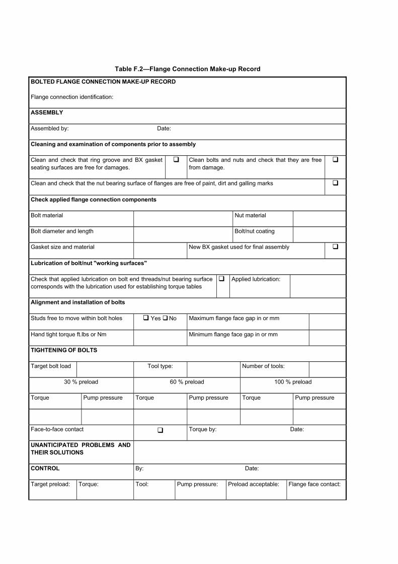
Table F.2—Flange Connection Make-up Record
BOLTED FLANGE CONNECTION MAKE-UP RECORD Flange connection identification:
ASSEMBLY
Assembled by: Date:
Cleaning and examination of components prior to assembly
Clean and check that ring groove and BX gasket seating surfaces are free for damages.
�� Clean bolts and nuts and check that they are free from damage.
��
Clean and check that the nut bearing surface of flanges are free of paint, dirt and galling marks ��
Check applied flange connection components
Bolt material Nut material
Bolt diameter and length Bolt/nut coating
Gasket size and material New BX gasket used for final assembly ��
Lubrication of bolt/nut "working surfaces"
Check that applied lubrication on bolt end threads/nut bearing surface corresponds with the lubrication used for establishing torque tables
��Applied lubrication:
Alignment and installation of bolts
Studs free to move within bolt holes � Yes ��No Maximum flange face gap in or mm
Hand tight torque ft.lbs or Nm Minimum flange face gap in or mm
TIGHTENING OF BOLTS
Target bolt load Tool type: Number of tools:
30 % preload 60 % preload 100 % preload
Torque Pump pressure Torque Pump pressure Torque Pump pressure
Face-to-face contact �� Torque by: Date:
UNANTICIPATED PROBLEMS AND THEIR SOLUTIONS
CONTROL By: Date:
Target preload: Torque: Tool: Pump pressure: Preload acceptable: Flange face contact:

(informative)
Design and Testing of Pad Eyes for Lifting
G.1 General
The purpose of this annex is to provide a recommended practice for the design, and verification of lifting pad eyes (including pad eye lift subs) used as lifting and handling points for equipment covered in this Specification. This annex has been written to provide a single unified set of design calculations intended to meet or exceed pad eye designs proffered by different regional lift codes. However, it is still the responsibility of the designer to compare and verify that pad eye designs from this annex indeed meet or exceed local code requirements.
Assemblies and equipment that are handled between supply boat and rig exceeding 22,500 pounds maximum gross weight should feature additional pad eyes for handling (tag lines) or tie-down (transportation, sea fastening, etc.). These unmarked (non-red) pad eyes are outside the scope of this annex.
To reduce the likelihood of compounding design margins or load amplification factors, Table G.1 lists enhancement factors (EF) for different load ratings. These factors are designed to be simple to use and conservative, incorporating the effects of skew lifting angles, submerged lift hydrodynamic forces, vessel heave, and the “n-1” rule to account for the loss of a sling leg during a lift. EFs are higher at smaller loads, as they are more unstable and susceptible to dynamic load variations (larger when compared to the static load). Allowable stresses and design margin acceptance criteria in this annex are based on 85 % of material yield strength unless stated otherwise.
Table G.1—Enhancement Factors for Pad Eyes on Subsea Equipment
Weight (MGW) Enhancement Factors (EF)1,2
Kg Lbs 1- Pad eye 2- Pad eyes 3- Pad eyes 4-Pad eyes
����� �����} 7.50 4.00 3.50 2.50
2500 5512 7.00 4.00 3.00 2.00
3000 6614 6.50 4.00 3.00 2.00
3500 7716 6.00 4.00 3.00 2.00
4000 8818 6.00 4.00 3.00 2.00
4500 9921 5.75 3.50 3.00 2.00
5000 11,023 5.50 3.50 3.00 2.00
5500 12,125 5.50 3.50 3.00 2.00
6000 13,228 5.25 3.50 3.00 2.00
7000-20,000 15,432-44,092 5.00 3.00 2.00 1.50
21,000-25,000 46,297-55,116 5.00 3.00 1.50 1.25
> 25,000 > 55,116 3.00 2.00 1.50 1.25
NOTE 1 For intermediate MGW values, the EF may be interpolated. Recommended minimum values for EF take into account design factors for the effects of hydrodynamic drag and added mass for submerged lifts. Consult DNVGL ST-E273 or DNV VMO for different EF values for lifts in air.
NOTE 2 EF values may be reduced to 5.00, 3.00, 3.00, 2.00 respectively for all MGW payloads < 14,330 lbs.
(< 6500 Kg), if vessel heave kept below 10 ft. (3 m) during a lift.
This annex does not cover pad eyes used for functions other than lifting. In addition, this annex does not cover the maintenance of reusable lifting devices to which the (subsea hardware) lifting pad eye is attached. Guidelines for reusable lifting devices (lifting frames and appliances) can be found in 5.5.3.
This annex assumes that shackles are used to interface with the lifting (point) pad eyes, and sling lift angle (see Figure G.3) is 30 degrees from vertical or less, but not to exceed 45 degrees.

Structural framing design which incorporate lifting pad eyes into the overall structure of offshore and subsea structures (such as offshore jackets, offshore decks and platforms, subsea manifolds and templates, subsea mud mats, subsea PLETs and sleds) should be designed to withstand the same design loads as the pad eyes and take into account structural loads from subsea equipment installation (such as buckling due to compressive loads created by slings) and subsequent operation; as discussed in 5.1.3.6.
G.2 Design
Pad Eye Materials
Pad eye plate should be constructed from special or primary steel meeting API 2H minimum or equivalent. Pad eye lift subs should be constructed from bar stock or round forgings meeting API 6A minimum or equivalent.
NOTE �!����#����������������#��������������y of 42,000 psi (289 MPa) or 47,000–50,000 psi (324 - 345 MPa); API 6A forged �����������#��������������y of 60,000 psi (414 MPa) or 75,000 psi (517 MPa)
If the lifting load is transferred through the plate thickness (z-axis) plates with specified (documented) through thickness properties shall be used.
G.2.1.1 Design Lift Temperature
The design lift temperature should not be greater than the (statistically) lowest daily air temperature for the area where the lift takes place. In the absence of a design temperature designation, the design temperature should be -4°F (-20° C).
NOTE Lifts performed in temperatures colder than -4°F (-20°C) are considered outside the scope of this annex.
G.2.1.2 Ductility
Primary members and lift points (pad eyes) of lifting equipment should be manufactured with materials that have sufficient ductility while supporting the load at the temperatures at which the equipment is being lifted. Impact material properties for pad eyes should follow API 2H, 6A, or DNVGL ST-E273 requirements for a given planned design lift temperature.
G.2.1.3 Corrosion
If lifting is required after prolonged exposure in aggressive environments or after possible damage to cathodic protection systems a risk assessment should be performed
G.2.1.4 Certification and Inspection
All lifting equipment primary members in the load path and lift points (pad eyes) should require material certification and NDE in accordance with 5.4.4.
Manufacturing Dimensions
G.2.2.1 General
The basic dimensions of pad eyes are calculated in accordance with design rules below (see Figure G.1) and the overall shape of a lifting shackle. A summary of the design loads and calculated design stresses based on these dimensions is found in G.3.
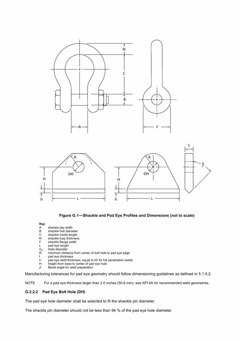
Figure G.1—Shackle and Pad Eye Profiles and Dimensions (not to scale)
Key A shackle jaw width B shackle bolt diameter C shackle inside length N shackle loop thickness F shackle flange width L pad eye length D� Hole diameter R minimum distance from center of bolt hole to pad eye edge t pad eye thickness h pad eye weld thickness, equal to t/2 for full penetration welds H height from base to center of pad eye hole � Bevel angle for weld preparation
Manufacturing tolerances for pad eye geometry should follow dimensioning guidelines as defined in 5.1.4.2.
NOTE For a pad eye thickness larger than 2.0 inches (50.8 mm), see API 6A for recommended weld geometries.
G.2.2.2 Pad Eye Bolt Hole (DH)
The pad eye hole diameter shall be selected to fit the shackle pin diameter.
The shackle pin diameter should not be less than 94 % of the pad eye hole diameter.

Pad eye bolt holes should be drilled or machined. Holes flame-cut by hand are not acceptable.
G.2.2.3 Pad Eye Thickness (t)
The pad eye thickness, t, should not be less than 75 % of the shackle jaw width, A, as given by Equation G.1:
����������� (G.1)
EXAMPLE �������{��}{����$������_�����������������{��}{��������$���������������|����_��
To avoid excessive clearance between the shackle jaws and the pad eye, increasing the pad eye thickness or adding cheek plates are acceptable. Cheek plate thickness should not be used in bearing or tear out stress calculations. If added strength desired, reduce cheek plate thickness and increase pad eye thickness (t). However, the pad eye thickness should not exceed 90 % of the shackle jaw width, A, to provide adequate clearance for fitting the shackle over the pad eye, as given in Equation (G.2):
t � 0.90 × A (G.2)
EXAMPLE �������{��}{����$������_�������������}����{��}{������|{�����$��}������������{���_��
See G.3.3 for stress calculations with respect to t.
G.2.2.4 Pad Eye Radius (R)
The pad eye design should allow free movement of the shackle and sling termination without fouling the pad eye. In general, the radius, R, of the pad eye is taken as 1.75 to 2 times the pad eye bolt hole diameter,D�. See G.3.3.1 for ����������������������������#��������������������\����������$���������H) may be used to improve the calculated value of the tear-out stress, provided this does not cause a clearance issue for the wire rope with the thimble inside the shackle eye. See G.3.3.2 for tear-out stress calculation.
For lifting-sub pad eyes that are machined from bar stock, pad eye length (L) is approximately equal to the shoulder OD of the lifting sub’s thread profile.
G.2.2.5 Distance from Base to Center Line of Pad Eye Bolt Hole (H) and Weld Height (h)
The minimum distance from the base of the pad eye to the centerline of the pad eye bolt hole (H) should be sufficient to ensure that the shackle jaw does not interfere with the weld height (h).
This is done by adding clearance as shown in Equation (G.3).
2F
H h C� � �� �� �� �
(G.3)
where
C (clearance) 12.7 mm (0.5 in.) for shackles with FP � 13,000 lb (57,827 N);
C (clearance) 25.4 mm (1.0 in.) for shackles with FP > 13000 lb (57,827 N):
F the shackle pin flange width as defined in Figure G.1;
FP the pad eye design load as defined in G.3.2.
The calculated value of H may be increased for extra shackle or rigging clearance.
See G.3.4 for stress calculations with respect to weld height (h).
For lifting subs that are machined from bar stock (see Figure G.2), H is calculated as given in Equation (G.4):
2F
H C� �� �� �� �
(G.4)
where
C (clearance) 12.7 mm (0.5 in.) for shackles with FP � 13,000 lb (57,827 N);

C (clearance) 25.4 mm (1.0 in.) for shackles with FP > 13000 lb (57,827 N):

Key L pad eye length R minimum distance from center of bolt hole to pad eye edge t pad eye thickness H height from base to center of pad eye hole r fillet radius (typical both sides) a region of material machined away
Figure G.2—Pad Eye Lift Sub Dimensions (Not to Scale)
G.2.2.6 Pad Eye Length (L)
Recommended minimum value of a pad eye length L, given by equation G.5 is:
L = 2 x R (G.5)
Actual pad eye length may depend on geometric constraints. For example: a pad eye with 60 degree tapered sides has a length � = �
�� �� + (� � �) tan 30��
NOTE See G.3.3 for weld throat stress calculations.
G.2.3 Other Design Requirements
Other design requirements are as follows.
— Pad eyes should not protrude outside the boundaries of the host structure and should, as far as possible, be designed to avoid damage from other equipment
— Lifting points should be positioned to preclude, as far as possible, the risk of slings fouling against the host structure or its cargo during normal use
— To prevent lateral bending moments, the pad eyes should be aligned with the sling to the center of lift. In other words, the sling load should be in the plane of the pad eye’s plate
— In some instances, the sling arrangement and its resultant positioning of the pad eye can locate the pad eye along a “weaker” moment-of-inertia plane of the structural member to which the pad eye is affixed. (Structural I-beams and H-beams are especially susceptible.) It is necessary to pay special attention to locate these weaker orientations and reinforce the structural beam with stiffener webs, plates, doubler saddles, etc., as appropriate.
— In some instances, fillet-welded cheek plates are used to fill up the space between the pad eye and the shackle-jaw width. The thickness associated with these cheek plates should not be taken into account when calculating the pad eye bearing or tear-out stress.
r
a
t
H
L

— To avoid deformation during welding of the structural member to which the pad eye is being affixed (in cases where the pad eye thickness is more than 0.25 inches (6.35 mm) greater than the structural member cross-sectional thickness), reinforcement such as stiffeners, plates, doubler saddles, etc. may be used, as appropriate.
— Pad eyes should be located such that sufficient access is maintained for NDE of the pad eye welds and load testing; see G.4.
— Pad eyes welded onto the primary structure, and/or with cheek plates welded on are subjected to heat affected zones that could locally reduce the yield strength of those materials.
G.3 Design Calculations and Loading Criteria
General
G.3.1.1 Assumptions
The following may apply:
— Load is lifted by single crane
— Spreader bars are not used for lifting; though in controlled environments they can be used
— Equipment are not pressurized during transportation
— Cheek plate thickness shall not be used for calculating stress
— For subsea submerged applications, installation/lift will ensure no slack slings
G.3.1.2 Sling Angle
The sling angle, �, is defined as depicted in Figure G.3.
Figure G.3—Pictorial Representation of Lifting Set Showing the Angle of Sling Leg From Vertical
The sling angle from vertical, �� should not exceed 45 degrees.
Pad Eye Design
To prevent equipment lifts from overturning (tipping) on a moving deck, pad eyes should be located to withstand the following tilt angles in any direction without overturning as follows:
— for vessel heave of 10 feet (3 meters): 15 degrees,
— for vessel heave of 20 feet (6 meters): 30 degrees
Design stresses for lift points should not exceed 85 % of the specified yield strength of the pad eye material at the design load, ��.

Multi-point lif��#���������������������������������������������������������$�����_������������������������������������#�������Multi-point lift points should address the effect of the sling leg angle from vertical in accordance with Figure G.3.
For single pad eyes, the total vertical design load (��) is given in Equation (G.6):
�� = EF x MGW (G.6)
where
MGW for permanently installed equipment is the maximum gross weight of the permanently installed equipment. Calculations should also account for any increase from anticipated amount of seawater which could be entrained within the subsea hardware from a subsea lift into the air.
MGW for reusable lifting devices needs to account for the added weight from: lift frames (such as spreader bars and strong-back beams), cargo (such as lifting permanently installed equipment), rigging, plus any additional seawater entrainment from lift frames.
EF is the Enhancement Factor (Table G��_�����������~���������#������������$�����_��������������������#��������where n is the number of lift points, including submerged hydrodynamic effects (drag and added mass), and motion effects associated with vessel heave [assumed up to 20 feet (6 meters)].
For multiple pad eyes, the design load, ��, for each pad eye should be calculated as given in Equation (G.7):
cosP
EF MGWF
v�
� (G.7)
where
sling angle (v) from vertical is used for design (Figure G.3).
The angle from vertical �, shall not exceed 45�.
For a sling angle (v) of 45°, the design load Fp, as given by Equation (G.8), is expressed as:
s 45coP
EF MGWF
��
� (G.8)
Calculation Methodology
G.3.3.1 Calculated Stress Basis for Pad Eye Dimensions of Plate Thickness (t)
The criteria specified in G.3.3 ensure that the “hot spot” stresses at the bolt hole are below the minimum specified yield strength.
G.3.3.2 Contact Stress Between the Shackle Bolt and Pad Eye Hole
For larger shackle pin diameters (B ���}����DH), the contact stress is calculated as follows, per equation G.9:
0.045 pc
H
F x E
D x t� � (G.9)
where
FP is the resulting sling load on the pad eyes;
E is the elastic modulus of the material:
DH is the pad eye hole diameter:
t is the Thickness of pad eye at hole/material thickness:

For smaller pin diameters (B < 0.94 × DH) the following equation G.10 is used:
0.18
1 1p
c
pin H
F x E
t
xD D
� �
� ��� �� �
� � (G.10)
where
allowable stress is 0.85c y� �� �
G.3.3.3 Tear Out Stress at Pad Eye Hole
The tear out stress is calculated by equation G.11:
3*
2P
tH
FR D t
� �� � �
(G.11)
where
allowable stress is 0.85t y� �� �
NOTE 1 Do not include the thickness of cheek spacers when calculating the tear out stress.
NOTE 2 The “3” in Equation (G.15) is a stress-concentration factor for the shackle bolt hole and is applicable for both single-point and multi-point lift.
A greater value of R (R ������DH) may be used to improve the calculated value of the tear-out stress, provided this does not cause a clearance issue for the wire rope with the thimble inside the shackle eye.
If fillet-welded doubler saddles plates are used, the saddle plate dimensions should be the pad eye length, L, for the minimum length and width, and the pad eye weld height, h, for the minimum saddle plate thickness.
All lift pad eyes and related primary member welds shall be full penetration welds and considered “critical welds” per Section 5. If the pad eye is to be secured to a flat structural surface by fillet welding, section 5 requires that the pad eye be fabricated with the appropriate bevels (see the example in Figure G.1). See API 6A for weld geometry practices.
If the pad eye is a forged or an integral part of the structure and the load is transferred directly into the structure, then pad eye design calculations should be commensurate with the integral design.
G.3.3.4 Weld Calculations for Full Penetration Fillet Weld
Shear stress due to the horizontal component of the force at the throat of the weld are found in equations (G.12) to (G.23). They are based on classical equations for model 45o fillet welds to ensure that the weld is sufficient to withstand shear and bending stresses.
FS
W
SS
A� (G.12)
where
SF is the shear force acting on pad eye weld = FP;
FP is the pad eye design load:

v is the sling angle, as shown in Figure G.3; or for a single pad eye lift, the maximum skew angle of the sling just before the load is lifted off the ground:
Aw is the total throat area = 2 x (0.707 x h x (L + t)):
h is the weld size (full penetration) = 0.5 x t:
t is the thickness of the pad eye:
L is the length of the pad eye.
The calculation for the shear stress, ��, can then also be as given in Equation (G.13):
sinPS
w
F vS
A� (G.13)
The permissible stress for butt or fillet welds in shear is determined using a design margin for the weld in shear of 0.577/0.40, or 1.44 (based on the distortion-energy theory as the criterion of failure) as given in Inequality (G.14):
2.5 y
SS
�� (G.14)
Where
y� is the specified yield strength of the pad eye base and weld material.
Tensile stress due to the vertical component of the force at the throat of the weld, tensile stress, S�, is calculated as given in Equation (G.15):
Pt
W
TS
A� (G.15)
where
�� is the tensile force acting on pad eye weld = �� x cos �
Tensile stress as given by Equation (G.16),
cosPt
W
FS
Av
� (G.16)
������������������������������������������������{��������������\��������$G.17):
/ 1.67y tS� � (G.17)
Bending stress at throat due to the horizontal component of the force:
Bending stress, ��, is calculated as given in Equation (G.18):
yb
W
MS
I�

�� = ���!
(G.18)
where
M is the bending moment = FP x sin v x H
y is the dimension from neutral axis to end of weld = (L + 2h)/2:
IW is the moment of inertia of weld = 0.707 h x Iu:
Iu is the unit moment of inertia of weld = 2 3
6
L t L�
h is the weld size (full penetration) = 0.5 x t
Design margin as given by equation G.19:
/ 1.52y bS� � (G.19)
where
"# is the specified yield strength of the pad eye base and weld material.
G.3.3.5 Maximum Shear Stress Theory at Throat
Total direct vertical stress, �$, is the superposition of the tensile stress, �%, and bending stress, �&, as given in Equation (G.20):
d b tS S S� � (G.20)
The maximum shear stress, '*,-, at the weld is as given in Equation (G.21):
22
max 2d
S
SS � �� �
� �� �
(G.21)
where
�� is the shear stress on the pad eye weld
�& is the bending stress on the pad eye weld
�% is the tensile stress on the pad eye weld
The allowable stress for butt or fillet welds in shear is determined using a design margin for the weld in shear of 0.577/0.40, or 1.44 (based on the distortion-energy theory as the criterion of failure) as given in Inequality (G.22):
max
2.5 y�
� (G.22)
where
"# is the specified yield strength of the pad eye base and weld material.

G.4 Factory Testing of Equipment Lift Points and Primary Load Path Members
General
Permanently installed equipment (as defined in 5.1.3.6) is lifted during manufacture, transportation, and subsequently installed subsea. This equipment is seldom lifted during its operational life.
Reusable lifting devices (such as tools as defined in 5.1.3.7, lift frames, baskets, or transportation handling equipment) is lifted repeatedly during its operational lifetime.
Welds on lift pad eyes and primary members in the lifting load path shall follow weld requirements as specified in 5.3.2 and 5.4.3. All lift point and primary member welds in the load path shall be designated as “critical welds”.
Testing and Inspection
Each lift pad eye and its adjacent mounting area shall be individually (vertical) proof-load tested to at least two and one-half (2.5) times the individual lift pad eye’s MGW. An example of an individual vertical proof-load test is shown in Figure G.4.
Key
1 hydraulic or mechanical ram 2 I-beam or structure with pad eye support a Area around lift pad eye should be designed to provide clearance and structural support for the vertical proof-load test.
Figure G.4—Localized Testing of Fabricated Pad Eyes
The individual pad eye test load of a of multi-point lift pad eye should not exceed 2.5 times the individual pad eye’s marked load lift capacity. For example: a subsea assembly that has a MGW of 10000 lbs (4536 kg) and designed for a 4-part sling lift is marked by each of the four lift pad eyes as: 4 x 2500 lbs Therefore, the pad eye’s lift load capacity is 2500 lbs, and the vertical proof-load should not exceed 2.5 times 2500 lbs, or 6250 lbs (2835 kg).
Where practical, the entire equipment assembly should also be load tested (load test by overhead lift through all lift points) to 1 times the MGW to demonstrate sling angle, alignment, and load stability with respect to the equipment’s center of gravity. Load testing beyond the equipment’s MGW is not required. The MGW is defined in Equation (G.7).
Visual examination and magnetic particle examination (MPE), or dye (liquid) penetrant, LP shall be performed on the lift pad eye’s tear-out region and adjacent welds in the load path after load testing as shown shaded in gray in Figure G.5. This is in addition to any examination of welds at the time of fabrication.
Figure G.5—NDE Regions on Fabricated Pad Eyes
G.5 Maintenance
Pad eyes and framework on permanently installed equipment may not be practical or accessible subsea for inspection or testing.
G.6 Marking Requirements
Pad eyes intended for lifting are painted red and properly marked per 5.5.2.

(informative)
Design and Testing of Subsea Wellhead Running, Retrieving and Testing Tools
H.1 General
Annex H addresses the design and testing of tools for running, retrieving and testing all subsea wellhead components, including guidance equipment, housings, casing suspension equipment, annulus sealing equipment and protective devices.
H.2 Design
Loads
The following loads may apply:
— suspended weight
— external bending and tension loads
— internal and external pressure
— torsional loads
— pressure separation loads, which shall be based on worst-case sealing conditions (leakage to the largest redundant seal diameter shall be assumed, unless relief is provided as described in 5.1.2.1)
— installation/workover overpull
— environmental loads
— mechanical installation (impact) loads
— hydraulic coupler thrust and/or preloads
End Connections
Tool joints shall be in accordance with API 5DP. Casing threads shall be in accordance with API 5B or with manufacturers written specification. The tool shall have an adequate dimension for tonging. The load capacity of the tool shall not be inferred from the choice of end connections for the tool.
Torque-operated tools shall preferably use left-hand torque for make-up and right-hand torque for release, to prevent backoff of casing/tubing/drill pipe threads during operation/disconnection.
Vertical Bore
Tools with through-bore shall have a sufficient ID and internal transitions to allow the passage of tools required for subsequent operations in accordance with the manufacturer’s written specification.
Outside Profile
The length, outside profile and fluid-bypass area should be designed to minimize surge/swab pressure and for ease of running while tripping and circulating.

Load Capacity
Tool load ratings shall be in accordance with the manufacturer’s written specification.
Vent
The conductor-housing running tool shall be provided with a vent or system of vents. This system of vents is used either to fill the conductor with fluid during running or to allow the passage of cuttings during a jetting operation.
Pressure Rating
The pressure and depth rating of the tool shall be in accordance with the manufacturer’s written specification.
H.3 Materials
Selection
The materials used in these tools shall be chosen for strength and it is not necessary that they be resistant to corrosive environments. They shall conform to the manufacturer’s written specification.
NOTE If exposure to severe stress cracking environments is expected, special practices beyond the scope of this specification can be required.
Coatings
Coatings shall conform to 5.1.4.6.
H.4 Testing
Validation
Validation shall conform to 5.1.7.
Factory Acceptance Testing
All tools shall be tested and dimensionally inspected to confirm their correct operation prior to shipment from the manufacturer’s facility. Tools with hydraulic operating systems shall have the hydraulic system tested in accordance with the manufacturer’s written specification. This hydrostatic test shall consist of three parts:
— primary pressure-holding period
— reduction of the pressure to zero (atmospheric)
— secondary pressure-holding period
Each holding period shall not be less than 3 min, the timing of which shall not start until the external surfaces of the body members have been thoroughly dried, the test pressure has been reached, and the equipment and the pressure monitoring gauge have been isolated from the pressure source.
Hydrotesting to rated working pressure is sufficient for running tools that are assembled entirely with previously hydrotested equipment.

(informative)
Procedure for the Application of a Coating System
I.1 General
Annex I covers a system for the application of a standard protective paint coating to subsea equipment.
I.2 Purpose
The purpose of this protective coating procedure is to ensure the proper preparation of the material and proper application of the coating. There is a number of paint companies that manufacture high-quality two-part epoxy- polyamide or polyamine paints suitable for coating subsea equipment. This annex describes how to apply this type of paint to the subsea equipment. This annex describes only one of the many acceptable coating systems and should be regarded as typical of how coating systems should be applied.
I.3 Surface Preparation
Required Finish
All surfaces to be coated shall be grit blasted to near-white metal finish in accordance with one of the following standards:
— NACE NO. 2
— SSPC-SP 10
— ISO 8501-1
Required Cleanliness
Any oil and/or grease shall be removed with an appropriate solvent before priming. Atmospheric Conditions
Blast cleaning shall not be carried out on wet surfaces, nor shall blast cleaning be carried out when surfaces are less than 5 °F (3 °C) above dew point.
Air Supply
The compressed-air supply used for blasting shall be supplied at a minimum pressure of 70 psi (0.5 MPa) and shall be free from water and oil.
Use of Chemicals
No acid washes or other cleaning solutions, including inhibited washes intended to prevent rusting, shall be used on metal surfaces after they have been blasted.
Surface Laminations
Surface laminations shall be ground out and weld splatter shall be removed. Other surface irregularities, including rough capping, undercut and slag, together with sharp or rough edges, fins and burrs, shall be power wire brushed, ground, chipped or blasted as necessary to render the substrate suitable for coating.
Masking
Areas that are not being painted and that require protection shall be adequately masked.

Rust Removal
If any rust forms after initial blasting, the rusted surfaces shall be re-blasted and cleaned prior to priming.
I.4 Priming
Cleaning
All sand and dust shall be blown from the surfaces being primed with dry, oil-free compressed air or nitrogen gas.
Application
The primer shall be applied with spray, preferably airless spray equipment.
Timing
Blast-cleaned surfaces shall be coated with the specified primer within 4 h after grit blasting.
Humidity
The primer shall be applied within the relative humidity specified by the paint manufacturer.
I.5 Coating Systems
Typical Coating Materials
The following are typical coating materials:
a) primer: polyamide or polyamine or epoxy primer, 2.5/4.0 mils dry-film thickness;
b) finish coat: polyamine glass flake epoxy, 12/20 mils dry-film thickness.
Alternative coatings may be used providing that none of the products contains heavy metals such as lead, chrome, etc.
Drying Times
Drying times between coats shall be strictly in accordance with the paint manufacturer’s instructions.
Instructions Preparation/application
All coatings shall be mixed, thinned and applied in accordance with the manufacturer’s instructions.
Legislative Requirements
All products used shall meet any applicable legislation in the country of manufacture and country where used with regard to volatile organic compounds.
Finish Coat Color
Finish-coat color for subsea equipment shall meet the requirements of API 17H.
I.6 Touch-up of Coating System
General
All touch-up coatings shall be the same manufacturer’s materials as the original coatings. Where sandblasting is impractical, power wire brushing to remove all oxidation is acceptable. The area within 6 in. (150 mm) of the damaged area may also be wire brushed or lightly sanded by hand to roughen the epoxy to promote adhesion.

Repair of Coating Damage Down to Metal
Clean area with solvent to remove all oil and grease; wire brush if shiny. If the manufacturer supplies a solvent to assist during repairs, apply the solvent to the coated areas adjacent to the damaged area. When the adjacent coating becomes tacky, apply the coating system described in I.5.1.
Repair of Epoxy Coating Damage Not Extending to Metal
Sand and feather out the area being repaired. Clean off with dry, oil-free compressed air or nitrogen gas. Apply the high-solid epoxy coatings as necessary to achieve the original finish.
I.7 Inspection
Coating Thickness
A calibrated paint-film thickness device shall be used to measure thickness of the dry film at each stage of the painting process.
Correcting Coating Thickness
When dry-film thicknesses are less than those specified, additional coatings shall be applied as necessary to achieve specified thickness.
Coating Defects
All coatings shall be free of pin holes, voids, bubbles and other holidays.

(informative)
Validation of Valves and Actuators/operators
J.1 Scope
Annex J provides a method of conducting validation on valves conforming to this specification, by prescribing the types of cycles and the order in which the cycles are to be performed.
J.2 General Requirements
A cycle is completed when the valve moves through the positions listed in Table J.1. Pressure, if required in the cycle, would be applied against the closed valve sealing mechanism and then the valve opened against full differential pressure. Unless otherwise noted, all testing specified in this annex shall be performed on the same (single) valve or actuator/operator, without the valve or actuator/operator being disassembled, without maintenance on the valve or actuator/operator, without the addition of lubricant or sealant to the valve or actuator/operator, and without replacing seals or components within the valve or actuator/operator.
%����[;�!���\�#&]���������
Valve Style Starting Position Intermediate Position Final Position
Fail Close Closed Open Closed
Fail Open Open Closed Open
Fail-in-place Closed Open Closed
Manual Closed Open Closed
In the event of failure during validation, subsequent testing shall start from the beginning of the validation per this annex. However, troubleshooting such as stroking of the valve and re-starting a seal test is permitted.
Hyperbaric cycles may be performed in a suitable test fixture simulating hyperbaric pressure.
During the hyperbaric functional cycles, valve internal pressure and chamber pressure shall be monitored to prevent overpressure of the chamber due to valve leakage.
Testing of valves shall be performed in one flow direction only, unless otherwise specified.
Endurance cycles and hyperbaric cycles may be performed in either order, but both shall be performed after the PR2 sequence per API 6A, F.2.2.
Hydrostatic Testing shall conform to API 6A, F.1.7, and gas testing shall conform to API 6A, F.1.8 unless specified otherwise
J.3 Validation of Actuated Valves
General
The following tests shall be conducted on an actuated valve assembly. The valve shall be tested in one of two configurations:
a) With an actuator conforming to this specification.
NOTE In this configuration, the valve can be validated if all requirements of J.3 are satisfied, and the fluid powered actuator can be concurrently validated if all requirements of J.4 are satisfied. Refer to section J.5 for manual valves.
b) With a test actuator or fixture that provides the functionality and output forces/torques required of a production-style actuator.

Initial Function Test of Valve
Before performing all testing described below, the valve shall undergo FAT per section 7.10.4.2.2. The valve is not required to be submerged.
Endurance Cycling Test
NOTE The full execution of J.3.3 completes the 600 endurance cycles required by Table 5.
The initial test sequence shall be performed as per API 6A, F.2.2 for PR2 valves.
NOTE This satisfies 200 of the 600 endurance cycles and the 3 temperature cycles required by Table 5.
A total of 200 hyperbaric cycles shall be performed in accordance with Annex N (of this specification), except that testing shall be conducted at a temperature not to exceed 120 °F (49 °C). After closure of the valve bleed the downstream pressure to 1% or less of the test pressure.
NOTE This satisfies the 200 pressure/load cycles and 200 of the 600 endurance cycles required by Table 5.
Additional cycles shall be performed in accordance with API 6A, F.2.2.2.2. except the number of cycles shall be 200.
NOTE This will satisfy 200 of the 600 endurance cycles required by Table 5.
Final Testing
After all testing described above is completed, the valve shall be subjected to a gas body and seat test in accordance with sections 5.4.6.3 and 5.4.6.4, except that the low-pressure test shall be performed at 500 psi ± 30 psi (3.5 MPa ± 0.2 MPa). Low pressure tests conducted below 500 psi are acceptable if agreed by the manufacturer and user/purchaser. The leakage acceptance criteria shall be in conformance with API 6A Table F.1, except that no external leakage (e.g., from a stem seal or bonnet gasket) is allowed.
The tested valve shall be disassembled and inspected. All relevant items should be photographed. Documentation of the examination shall include a written statement that the valve did not sustain damage or wear to an extent that the performance requirements were not satisfied.
J.4 Validation of Hydraulic Actuators
General
The following test shall be conducted on an actuator assembly. The actuator shall be tested in one of two configurations:
a) With a valve conforming to this specification.
NOTE In this configuration, the valve can be validated if all requirements of J.3 are satisfied, and the fluid powered actuator can be concurrently validated if all requirements of J.4 are satisfied. Refer to J.5 for manual valves.
b) With a test valve or fixture that provides the functionality and output forces/torques required of a production-style valve.
A cycle is defined as moving the operating portion of the actuator from the normal position to its full opposite position and back to normal. If the bonnet assembly is part of the actuator, validation of the stem seal and bonnet design shall be performed to validate these design elements to the requirements for valves.
Initial Function Test of an Actuator
Actuators shall be subjected to a functional test per 7.10.4.2.3.1, 7.10.4.2.3.1.2, and 7.10.4.2.3.1.3. Section 7.10.4.2.3.4 shall be performed as well if a compensation system is required by the manufacturer for validation.
Endurance Cycle Testing
NOTE 1 The full execution of J.4.3 completes the 600 endurance cycles required by Table 5.

The initial test sequence shall be performed as per API 6A, F.2.3 for PR2 actuators.
NOTE 2 This satisfies 200 of the 600 endurance cycles and the three temperature cycles required by Table 5.
A total of 200 hyperbaric cycles shall be performed in accordance with Annex N (of this specification), except that testing shall be conducted at a temperature not to exceed 120 °F (49 °C).
NOTE 3 This satisfies the 200 pressure/load cycles and 200 of the 600 endurance cycles required by Table 5.
Testing shall also be performed to satisfy the requirements of 7.10.4.1.3 and may be performed at any time during the hyperbaric testing.
Additional cycles shall be performed in accordance with API 6A, F.2.3.2.2 except the number of cycles shall be 200.
NOTE 4 This satisfies 200 of the 600 endurance cycles required by Table 5.
Final Testing
After the testing listed above is completed, the actuators shall be subjected to a functional test per 7.10.4.2.3.3. The testing specified in Section 7.10.4.2.3.4 shall also be performed if a compensation system is required by the manufacturer for validation.
The tested actuator shall be disassembled and inspected. All relevant items should be photographed. Documentation of the examination shall include a written statement that the actuator did not sustain damage or wear to an extent that the performance requirements were not satisfied.
J.5 Validation of Valves with Manual Operator (ROV/Diver Operated)
General
The following tests shall be conducted on a Valve with manual operator (ROV/Diver Operated).
Initial Function Test of Valve
Initial Function Testing shall be performed as specified in J.3.2.
Pressure/Temperature Testing
Pressure/temperature testing shall be performed in conformance with API 6A, F.2.2. Unless the requirements of 5.1.7.2 apply, validated designs modified for subsea use shall not require revalidation; only the additional validation is required.
Hyperbaric Pressure Testing
The hyperbaric pressure testing cycles may be completed on a different valve than that which was tested to satisfy J.5.3. For example, if a manual valve has been validated per API 6A and the subsea version is the same design that did not undergo substantive change (see 5.1.7.2) for the addition of ambient pressure seals (e.g., a sealed bearing cap), then the hyperbaric pressure cycles alone may be performed on the subsea version.
Testing shall be performed to verify operability of the manual valve in installed conditions (water-depth) per the manufacturer’s written specification. The actuator should operate smoothly (no evidence of stick-slip movement, sometimes referred to as chatter) in either direction. The hyperbaric test pressure shall be based on the maximum rated seawater depth specified by the manufacturer. The valve shall operate smoothly throughout its cycle (from fully closed to fully open, and back to fully closed). 200 cycles shall be performed at RWP and maximum hyperbaric pressure.
Before the opening of the valve, the pressure downstream of the gate shall be reduced to less than 1% of the RWP.

If the design of the pressure-containing seals (e.g., body-to-bonnet seals and stem seals), and the stem motion (linear or rotary) is identical to that of an actuated valve, validation of the actuated (or manual) valve shall be acceptable as validation of the manual (or actuated) valve.
Final Testing
Final testing shall be performed as specified in J.3.4.
J.6 Other Valves
Check Valves
Check valves shall be validated per the requirements in Annex J and Table J.1 for Fail Close valve to complete a total of 400 endurance cycles, 3 temperature cycles and 200 pressure/load cycles.
J.6.1.1 Initial Function Test of Valve
Testing shall be performed as specified in J.3.2.
J.6.1.2 Endurance Cycling Test
NOTE 1 The full execution of J.6.1.2 completes the 400 endurance cycles required by J.6.1.
The initial test sequence shall be performed as per API 6A, F.2.2 for PR2 valves.
NOTE 2 This satisfies 200 of the 400 endurance cycles and the 3 temperature cycles required by J.6.1.
A total of 200 hyperbaric cycles shall be performed in accordance with Annex N (of this specification), except that testing shall be conducted at a temperature not to exceed 120 °F (49 °C) and that testing does not required to open the valve with a differential pressure of RWP applied on valve bore sealing mechanism. After closure of the valve bleed the downstream pressure to 1% or less of the test pressure.
For check valves without any penetrations running through the body wall, 200 endurance cycles in accordance with API 6A, F.2.2.2.2 may be performed in lieu of the 200 hyperbaric cycles.
NOTE 3 This satisfies the 200 pressure/load cycles and 200 of the 400 endurance cycles required by J.6.1.
J.6.1.3 Final Testing
Final testing shall be performed as specified in J.3.4.
Needle Valves
Needle valves shall be validated per the requirements in Annex J for Actuated or Manual valves as applicable.
J.7 Documentation
Documentation shall be per API 6A, F.1.15. In addition, the following shall be contained or referenced:
a) Names and affiliations of designated witnesses and of test facility personnel supervising the testing.
b) Assembly and component traceability as specified by the manufacturer (assembly number, part numbers, revisions, serial numbers, material, weld nondestructive examinations, etc.)
c) Critical dimensions

(informative)
Screening Tests for Material Compatibility
K.1 General
As reservoirs and environment become more complex and subject to acute temperature changes, injection of chemical additives into remote subsea completions is done to refine the fluid-flow properties of wellbore fluids and inhibit the formation of precipitates and crystalline structures that can block fluid flow. These additives are often proprietary mixtures formulated specifically to deal with specific wellbore fluid properties. This annex is presented as a means to provide a standardized set of procedures to validate the additive’s compatibility with materials associated with the subsea completion hardware to screen for adverse results that can
— degrade or erode the metallic and non-metallic materials used for pressure containment and sealing mechanisms;
— degrade the overall design life of the subsea hardware.
Listed in this annex are three levels of screening. Level 1 identifies possible chemical and or physical changes in selected materials. Level 1 is intended to provide general information that can be published by either chemical suppliers and/or manufacturers. Level 2 looks for chemical and/or physical changes in non-metallic materials, such as swelling, when the material resides in a confined space. Level 2 testing also uses more specific concentrations and operating conditions defined by the user/purchaser for a particular application. Level 2 results are likely to be proprietary and project-specific and might not necessarily be directly comparable to other published level 2 data. Level 3 is an in-depth test to determine the useful operating life of non-metallic materials in the presence of the additive using accelerated-life-estimation testing procedures based on the Arrhenius principle.
K.2 Level 1 Screening Tests
Unconfined Testing—Placement
Place test specimen in a container with no significant deflection of test specimen.
Elastomers
K.2.2.1 Test Parameters
The following test parameters apply:
a) specimen: O-ring number 214, 0.984 in. (25.0 mm) ID, 0.139 in. (3.53 mm) width
b) container: covered but not airtight, with a volume that shall be no less than 6.1 in3 (100 cm3)
c) concentration: neat (full strength; no dilution), and in solution at a concentration typically recommended for the application; solution shall be added during the testing to maintain a 25:1 to 27:1 ratio of fluid volume to seal volume
d) temperature: 140 °F (60 °C); if the boiling point or flash point is close to 140 °F (60 °C), the chemical supplier shall determine the appropriate steps to obtain acceptable results with user/purchaser approval
e) pressure: ambient
f) duration: 32 days with measurements taken at the start and after 1 day, 2 days, 4 days, 8 days, 16 days and 32 days; all test samples shall be taken from the same material batch
g) measurements: For the following measurements, remove the test sample from the oven, towel dry immediately, and cool to [68 °F ��2 °F (20 °C ��1 °C)] prior to taking measurements. Record the weight change, hardness change and percent volume change within 3 h after removal from of the oven:

— day 0: Perform tensile test in accordance with ASTM D1414.
— day 1: Towel dry; determine changes in weight, hardness, percent volume and appearance.
— day 2: Towel dry; determine changes in weight, hardness, percent volume and appearance.
— day 4: Towel dry; determine changes in weight, hardness, percent volume and appearance.
— day 8: Towel dry; determine changes in weight, hardness, percent volume and appearance.
— day 16: Towel dry; determine changes in weight, hardness, percent volume and appearance.
— day 32: Towel dry; determine changes in weight, hardness, percent volume and appearance.
— day 32: Place a sample in an evacuated desiccator at a maximum pressure of 1.5 psi (0.01 MPa) and ambient temperature; allow to dry for 1 week, then perform tensile test in accordance with ASTM D1414.
h) test vessel: The vessel shall be rated for use with the test chemicals, materials, temperatures, and pressures. The fluid capacity shall be such that the ratio of fluid volume to seal volume is in the range 25:1 to 27:1.
K.2.2.2 Acceptance Criteria for Compatibility
The following acceptance criteria shall apply:
a) percent weight change: ��10 %
b) hardness change:
— For < 90 Durometer (Shore A), +10 /-20 points,
— For 90 Durometer (Shore A) +5 /-20 points,
— For > 90 Durometer (Shore A) +5 /-20 points
c) Percent volume change +25% / -5%
d) appearance: no blistering, cracking, disintegration or change in the appearance of the chemical (color, precipitates, etc.) with no magnification.
Metals
K.2.3.1 Test Parameters
The following test parameters apply:
a) specimen: recommended sample size is 1.0 in. ��3.0 in. ��0.25 in. (25.4 mm ��76.2 mm ��6.35 mm). Specimen may be coated, clad or plated to test coating/plating material compatibility. An uncoated control specimen of the base metal and size shall be tested in a separate test vessel.
b) Minimum ratio of volume to surface area shall be 1:6; surface finish shall be 125 μin. (3.2 μm) RMS or better.
c) container: covered but not airtight, with a volume that shall be no less than 6.1 in3 (100 cm3);
d) concentration: neat (full strength; no dilution), and in solution at a concentration typically recommended for the application; solution shall be added during the testing to maintain a 25:1 to 27:1 ratio of fluid volume to seal volume
e) temperature: 140 °F (60 °C); if the boiling point or flash point is close to 140 °F (60 °C), the chemical supplier shall determine the appropriate steps to obtain acceptable results with user/purchaser approval
f) pressure: ambient

g) duration: 4 weeks with measurements taken at the start, after 1 week, after 2 weeks, and after 4 weeks
h) test vessel: the vessel shall be rated for use at the test chemicals, materials, temperatures and
i) pressures. The fluid capacity shall be such that the ratio of fluid volume to seal volume is in the range of 25:1 to 27:1.
j) Photographs shall be taken to document the initial surface finish and final surface finish.
K.2.3.2 Acceptance Criteria for Compatibility
The following acceptance criteria shall apply:
a) appearance: No change in the color or in the observable finish at 10��magnification, or in the appearance (color, precipitates, etc.) of the chemical
b) corrosion rate: Report mils per year. Using 100 % survey on a minimum of the two largest sides, define pitting and depth using 10��magnification.
c) surface finish: (125 μin. (3.2 μm) RMS or better (no change).
K.3 Level 2 Screening Tests
Confined Testing—Non-metallic Materials (Elastomers and Plastics)
The following test parameters apply:
d) specimen: O-ring number 214, 0.984 in. (25.0 mm) ID, 0.139 in. (3.53 mm) width
e) test container: with recommended O-ring gland dimensions for number 214 O-ring, static application
f) concentration: neat (full strength; no dilution), and also in solution at a concentration typically recommended for the application; solution shall be added during the testing to maintain a 25:1 to 27:1 ratio of fluid volume to seal volume;
g) temperature: 140 °F (60 °C); if the boiling point or flash point is close to 140 °F (60 °C), the chemical supplier shall determine the appropriate steps to obtain acceptable results with user/purchaser approval
h) pressure: ambient
i) duration: 32 days with measurements taken at the start, after 1 day, after 2 days, after 4 days, after 8 days, after 16 days, after 32 days; all test samples shall be taken from the same material batch.
j) measurements: For the following measurements, remove the test sample from the oven, towel dry immediately, and cool to [68 °F ��2 °F (20 °C ��1 °C)] prior to taking measurements. Record the weight change, hardness change and percent volume change within 3 h after removal from of the oven:
— day 0: Perform tensile test in accordance with ASTM D1414.
— day 1: Towel dry; determine changes in weight, hardness, percent volume and appearance.
— day 2: Towel dry; determine changes in weight, hardness, percent volume and appearance.
— day 4: Towel dry; determine changes in weight, hardness, percent volume and appearance.
— day 8: Towel dry; determine changes in weight, hardness, percent volume and appearance.
— day 16: Towel dry; determine changes in weight, hardness, percent volume and appearance.
— day 32: Towel dry; determine changes in weight, hardness, percent volume and appearance.
— day 32: Place a sample in an evacuated desiccator at a maximum pressure of 1.5 psi (0.01 MPa) and ambient temperature; allow to dry for 1 week, then perform tensile test in accordance with ASTM D1414.
k) test vessel: The vessel shall be rated for use with the test chemicals, materials, temperatures, and pressures. The fluid capacity shall be such that the ratio of fluid volume to seal volume is in the range 25:1 to 27:1.
Acceptance Criteria for Compatibility
The following acceptance criteria shall apply.
a) percent weight change: ��10 %
b) hardness change:
— For < 90 Durometer (Shore A), +10 / -20 points,
— For 90 Durometer (Shore A) +5 / -20 points,
— For > 90 Durometer (Shore A) +5 / -20 points
c) percent volume change: +25% / -5%
d) percent tensile strength change: ��50 %
e) percent change in the % elongation: ��50 %
f) percent change in the 50% modulus: ��50 %
g) appearance: no blistering, cracking, disintegration or change in the appearance of the chemical (color, precipitates, etc.) with no magnification.
K.4 Level 3 Screening Tests
Life Estimation and Aging
To approximate the life of a non-metallic material for use in a severe service environment, tests should be conducted in the specific environment under accelerated temperature and/or pressure conditions. Without some type of accelerated testing, it can be difficult to quantify the service life of an elastomeric component. Elevated temperature and/or pressure testing can provide a useful method for estimating non-metallic material capabilities under realistic conditions.
Life estimation testing may be considered as the best estimate of long-term service life to evaluate the long-term performance of a non-metallic material in a severe service environment. The basic technique involves collecting time-to-failure data at elevated temperatures (higher than the maximum anticipated service temperature) and plotting the results on semi-log graph paper. The vertical scale is the log of the time to failure and the horizontal scale is the reciprocal of the absolute temperature (see API 6J1, Figure 1, for a typical life estimation plot). Alternately, the time to failure at the service temperature also can be calculated from the appropriate mathematical equations.
Certain precautions should be exercised when performing accelerated temperature and/or pressure tests. It should be verified experimentally that the failure mechanism (and activation energy) does not change with elevated temperatures or pressures. In addition, it shall be recognized that gas diffusion can occur through an elastomer seal at an accelerated rate and this shall be properly accounted for if this is used as failure criteria. It also may be helpful to test a non-metallic material with known field performance as a reference for comparison; see level 2 tests. Stagnant fluids and gases can give better or worse life estimation than if the fluids are periodically refreshed.
Examples of accepted industrial procedures that use Arrhenius aging techniques include:
— API 6J1
— ASTM D3045

— ASTM D2990
— ISO 23936 (all parts)
— UL 746B.
Aging tests and life estimation of elastomeric materials should be as given in API 6J1, Section 5 and Figure 2, or in ISO 23936, Reporting should be as given in ISO 23936. Specimen size should be similar to an O-ring number 325, with an ID of 1.475 in. (37.47 mm) and a width of 0.210 in. (5.33 mm).
Aging tests and life estimation of thermoplastic materials should be as given in ISO 23936. Reporting should be as given in ISO 23936, Specimen size should be similar to an O-ring number 325, with an ID of 1.475 in. (37.47 mm) and a width of 0.210 in. (5.33 mm).
Rapid Gas Decompression Testing
Rapid gas decompression tests should be as given in in ISO 23936. Reporting should be as given in in ISO 23936. Specimen size should be similar to an O-ring number 325, with an ID of 1.475 in. (37.47 mm) and a width of 0.210 in. (5.33 mm).

(informative)
Subsea Tubing Hanger
Subsea tubing hangers are located in the wellhead, tubing head (wellhead conversion assembly) or horizontal tree.
They suspend the tubing, seal off the production and provide sealing pockets for the production and control stabs as a minimum. Horizontal trees also have annular seals for the horizontal side outlets.
Tubing hangers having multiple bores require orientating relative to the PGB to ensure that the tree engages with the tubing hanger when installed. It is normal to orientate tubing hangers with horizontal production outlets to give a smooth flow passage between the tubing hanger and horizontal tree. Concentric tubing hangers do not necessarily require orientation, unless required because of providing downhole instrumentation.
After installation, the tubing hanger is locked into the mating wellhead, tubing head, etc., to resist the force due to pressure in the production casing and to resist thermal expansion. Lock mechanisms may be mechanically or hydraulically actuated depending on water depth and specific project requirements.
Major elements of the tubing hanger system are
— tubing hanger
— concentric; see Figure L.1
— multiple bores; see Figure L.2
— horizontal tree; see Figure L.3
— horizontal tree, extended; see Figure L.4
— tubing hanger running tool
— orientation device
— miscellaneous tools

Figure L.1—Concentric Tubing Hanger Figure L.2—Tubing Hanger with Multiple Bores

Common names for individual components are included in the numbered key.
Key
1 running tool latching groove 2 wireline plug profile or closure device 3 seal 4 lockdown 5 production outlet
Figure L.3—Tubing Hanger for Horizontal Tree
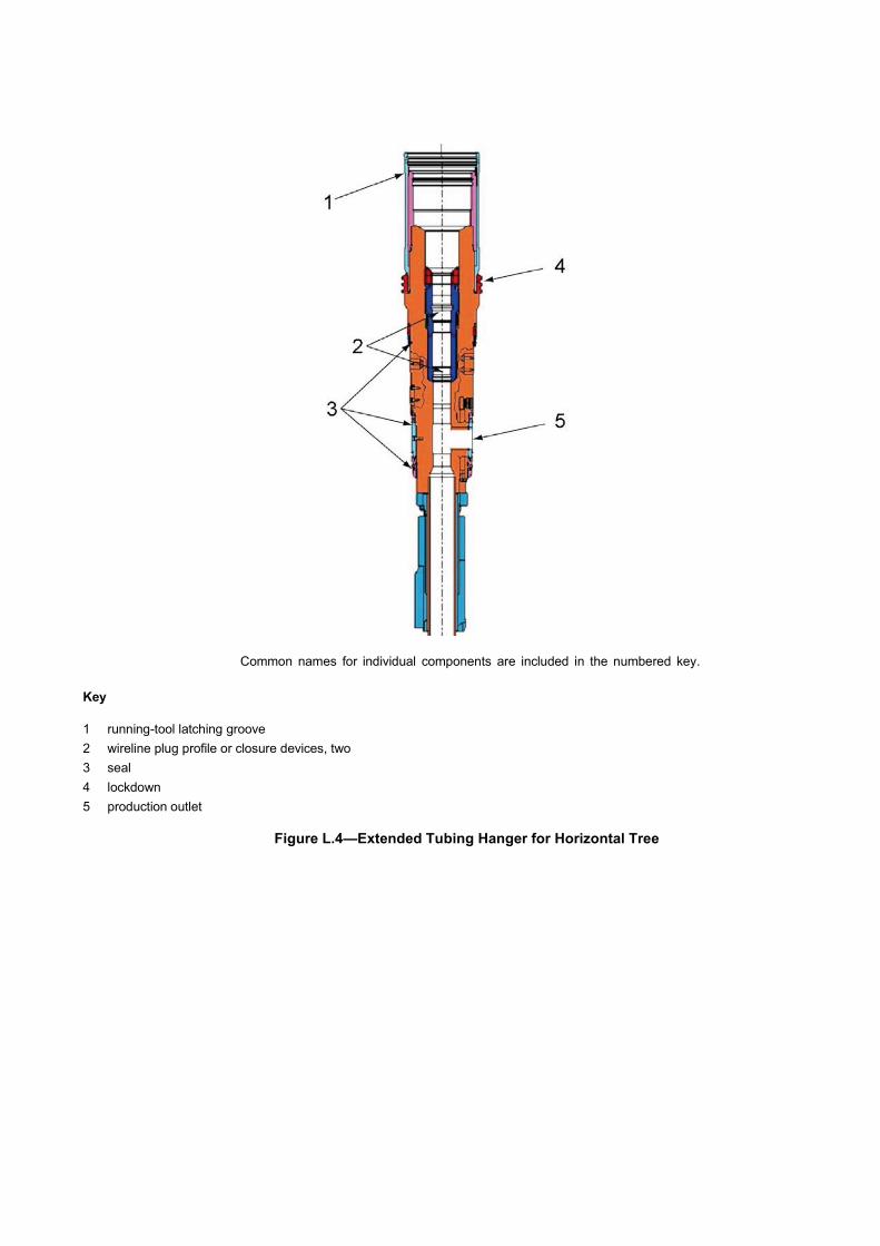
Common names for individual components are included in the numbered key.
Key
1 running-tool latching groove 2 wireline plug profile or closure devices, two 3 seal 4 lockdown 5 production outlet
Figure L.4—Extended Tubing Hanger for Horizontal Tree

(informative)
Drill-through Mudline Suspension Systems
Drill-through mudline suspension equipment is used to suspend casing weight at or near to the mudline and to provide pressure control. Drill-through mudline suspension equipment is used when drilling with a bottom- supported rig when it is anticipated that the well can be completed subsea. During drilling, workover and completion operations, the BOP is located at the surface. The system differs from mudline suspension in that the surface casing is suspended from a wellhead (high-pressure) housing and subsequent casing strings use wellhead-like hangers and annulus seal assemblies. The hangers have positive landing shoulders; therefore, their OD is normally too large to allow running them through casing tiebacks. It is usual to use risers having a pressure rating and bore equivalent to the surface BOP for the installation of casing hangers, seal assemblies, internal abandonment caps and tubing hangers. The wellhead (high-pressure) housing contains the necessary profile for locking down the tubing hanger and has an external profile to which the subsea tree can be locked; therefore drill-through mudline requires no conversion equipment.
Major items of equipment used with drill-through mudline suspension are the:
— conductor (low pressure) housing
— surface casing hanger
— wellhead (high-pressure) housing
— casing hangers
— annulus seal assemblies
— bore protectors and wear bushings
— abandonment caps
— running, retrieving and test tools
Figure M.1 illustrates the items of equipment used in drill-through mudline suspension systems.

Figure M.1—Drill-through Mudline Suspension System

(informative)
Hyperbaric Testing Guidelines
Table N.1 lists subsea equipment that should be subjected to hyperbaric (external) pressure testing to validate performance under installed (water-depth) conditions. The hyperbaric test pressure should be based on the maximum rated water depth (1.0x water depth pressure) specified by the manufacturer for the equipment. If agreed between the user/purchaser and manufacturer, the hyperbaric test medium should be maintained at 40 °F ± 10 °F (4 °C ± 5 °C) throughout the test.
For static components the functional cycles specified in Table N.1 should be internal pressure cycles from rated working pressure to fully depressurized (atmospheric pressure), while continuously subjected to external hyperbaric pressure.
For equipment with moving parts, the functional cycles specified in Table N.1 should be dynamic operation cycles (see 5.1.7.7), such that full operating motion of the equipment is achieved. E.g., for valves and chokes, a cycle should consist of starting from the fully closed position, applying a differential bore pressure of RWP, then actuating open under differential pressure and stroking to the full open position with bore pressure vented to atmospheric. The specified number of cycles should be completed with the equipment continuously subjected to external hyperbaric pressure.
During the hyperbaric functional cycles, leakage should not exceed that specified in API 6A, Annex F, for PR2F. A single internal hydrostatic test (see 5.4) should be performed for acceptance after all hyperbaric functional cycles have been completed and hyperbaric conditions depressurized to atmospheric pressure. Hold time should be 15 minutes minimum. Leakage should not exceed the acceptance criteria for hold periods specified in API 6A, Annex F, for PR2F.
If agreed between the manufacturer and user/purchaser, the hyperbaric functional test cycles can be considered as contributing to the 600 life cycle/endurance cycles required by Table 5. For example, a valve and actuator/operator assembly may be subjected to a total of 400 functional cycles, of which 200 are hyperbaric as described in this annex, and 200 are as described in API 6A, Annex F, PR2F, including 20 cycles at maximum rated temperature and at minimum rated temperature.

Table N.1—Hyperbaric Testing Guidelines
Component Operational Cycles while under Hyperbaric Pressure
Metal seal exposed to retained fluids 200b
Metal seal not exposed to retained fluids 3b
Non-metallic seal exposed to retained fluids 200b
Non-metallic seal not exposed to retained fluids 3b
OEC NA
Wellhead/tree/tubing head connectors NA
Tubing heads NA
Manual Valves 200 Valve operated with actuators 200
Tree cap connectors NA
Manual Subsea chokes 200
Subsea chokes operated with actuators 200
Subsea wellhead casing hangers NA
Subsea wellhead annulus seal assemblies (including backup annulus seal assemblies) NA
Subsea tubing hangers, HXT internal tree caps and crown plugs NA
Poppets, sliding sleeves, and check valves 200
Mudline tubing heads NA
Mudline wellhead, casing hangers, tubing hangers NA
Running tools (including tree running tool connectors)a NA
a Subsea wellhead running tools are not included. b Applicable if seal is directly exposed to hyperbaric conditions in service.

(informative)
Vertical Subsea Trees
Vertical subsea trees are installed either on the wellhead or on a tubing head, after the subsea tubing-hanger has been installed through the drilling BOP stack and landed and locked into the wellhead or tubing head. The production flow path is through the valves mounted in the vertical bore(s) and either out of the top of the tree during workover and testing [in special applications production (injection) may be via the top of the tree] and during production (injection) via the production outlet that branches off the vertical bore.
The subsea tree may have a concentric bore or may have multiple bores. Annulus access may be through one of the tree bores or it may be through a side outlet in the tubing head, below the tubing hanger.
The production outlet may be at 90° to the production bore or may be angled to best suit flow requirements.
Figure O.1 and Figure O.2 illustrate the major items of equipment in vertical subsea trees. The arrangements shown are typical and should not be construed as requirements.
Major items of equipment in a subsea tree are
— completion guidebases and tubing head
— tree wellhead connector
— tree stabs and seal subs
— valves, valve blocks and valve actuators/operators
— tree re-entry interface
— tree cap
— tree cap running tool
— tree piping
— tree guide frame
— tree running tool
— flowline connectors
— flowline-connector support frame
— subsea chokes and actuators/operators
— tree-mounted control interfaces
— control pod interface

Key
1 production wing valve 6 crossover valve 2 tree cap 7 tree connector 3 production swab valve 8 tree guide frame 4 master valve block 9 annulus wing valve 5 flow loop 10 flow line connection
Figure O.1—Guideline Style Vertical Tree

Key 1 swab valves 5 tubing hanger 9 GRA, CGB, or tubing head 2 annulus wing valve 6 crossover valve 3 annulus master valve 7 production outlet 4 master valve 8 wing valve
Figure O.2—Guidelineless Style Vertical Tree

(informative)
Horizontal Subsea Trees
Several options are available for horizontal tree arrangements. These offer different benefits for installation, retrieval and maintenance. These are addressed for information only. No attempt is made within this specification to evaluate or recommend an option.
Horizontal subsea trees may be installed after drilling and installation of the complete wellhead system and prior to installation of the tubing completion and tubing hanger. For this mode of operation, the BOP is installed on top of the horizontal subsea tree and the tubing hanger and tubing completion is run through the BOP and landed off on a landing shoulder in the bore of the horizontal subsea tree. The production flow path exits horizontally through a branch bore in the tubing hanger between seals and connects to the aligned production outlet. A typical tree of this type is illustrated in Figure P.1. The arrangement shown in Figure P.1 requires that the tubing completion be retrieved prior to retrieving the tree. The arrangement also includes a pressure-containing internal tree cap above the tubing hanger to provide a second barrier.
In an alternative arrangement, the tubing hanger and internal tree cap are combined into a single extended tubing hanger system suspended in the horizontal tree. It doubles up on the number of isolation plugs and annular seals for barrier protection and features a debris cap that can also serve as a back-up locking mechanism for the tubing hanger.
A guidelineless version of the horizontal tree, which is typically a funnel down arrangement, is shown in Figure P.2. The extended neck on top of the tree is required for clearance for the BOP’s re-entry funnel and “swallow” of its connector.
A third configuration, generally referred to as the “drill-through” horizontal tree, allows the installation of the horizontal tree immediately after the wellhead (high-pressure) housing is landed. This system allows carryout out the drilling and installation of casing strings through the horizontal tree, minimizing the number of times it is necessary to run and retrieve the BOP stack. In this configuration, the diameter of the tree bore protector and tubing hanger orientation system should drift the casing hanger and annulus seal assembly.
Horizontal trees may also be used with mudline suspension equipment and drill-through mudline suspension equipment and may, additionally, be configured for artificial lift completions, such as electric submersible pumps or hydraulic submersible pumps.
Horizontal subsea trees use many of the same items of equipment as vertical trees. However, equipment that differs significantly includes the:
— tree body
— tubing hanger
— isolation plugs (left in place)
— tree cap

Common names for individual components are included in the numbered key. The two items not identified are the
casing hangers (blue) and tree (yellow).
Key
1 crown plugs 6 extended tubing hanger 11 master valve
2 debris cap 7 re-entry interface 12 wing valve
3 internal tree cap 8 annulus swab valve 13 crossover valve
4 tubing hanger 9 annulus wing valve 14 crossover flowloop
5 locking cap 10 annulus master valve 15 production outlet
Figure P.1—Guideline Style Horizontal Tree

Key
1 re-entry interface 5 master valve 2 annulus swab valve 6 wing valve 3 annulus wing valve 7 production outlet 4 annulus master valve 8 guidelineless re-entry funnel (funnel down)
Figure P.2—Guidelineless Style Horizontal Tree

Bibliography
[1] ISO 2859-1, Sampling procedures for inspection by attributes — Part 1: Sampling schemes indexed by acceptance quality limit (AQL) for lot-by-lot inspection
[2] ISO 3183, Petroleum and natural gas industries — Steel pipe for pipeline transportation systems
[3] ISO 11961, Petroleum and natural gas industries — Steel drill pipe
[4] ANSI/ASME B1.1, Unified Inch Screw Threads, UN and UNR Thread Form
[5] ANSI/ASME B1.2, Gages and Gaging for Unified Inch Screw Threads
[ 6 ] ANSI/ASME B18.2.2, Square and Hex Nuts (Inch Series)
[ 7 ] ANSI/ISA 75.02, Control Valve Capacity Test Procedure
[8] ANSI Y14.5M, Dimensioning and Tolerancing
[9] ASME Boiler and Pressure Vessel Code, Section II: Materials
[10] ASME Boiler and Pressure Vessel Code, Section V: Nondestructive Examination; Article 5: Ultrasonic examination methods for materials
[11] ASME Boiler and Pressure Vessel Code, Section VIII: Pressure Vessels; Division 1
[12] ASME Boiler and Pressure Vessel Code, Section IX: Welding and Brazing Qualifications
[13] ASTM A193/A193M, Standard Specification for Alloy-Steel and Stainless Steel Bolting Materials for High Temperature or High Pressure Service and Other Special Purpose Applications
[14] ASTM A194/194M, Standard Specification for Carbon and Alloy Steel Nuts for Bolts for High Pressure or High Temperature Service, or Both
[15] ASTM A307, Standard Specification for Carbon Steel Bolts and Studs, 60 000 PSI Tensile Strength
[16] ASTM A320/320M, Standard Specification for Alloy-Steel and Stainless Steel Bolting for Low-Temperature Service
[17] ASTM A370, Standard Test Methods and Definitions for Mechanical Testing of Steel Products
[18] ASTM A388, Standard Practice for Ultrasonic Examination of Steel Forgings
[19] ASTM A453/453, Standard Specification for High-Temperature Bolting, with Expansion Coefficients Comparable to Austenitic Stainless Steels
[20] ASTM D2990, Standard Test Methods for Tensile, Compressive, and Flexural Creep and Creep-Rupture of Plastics
[21] ASTM D3045, Standard Practice for Heat Aging of Plastics Without Load
[22] ASTM E10, Standard Test Method for Brinell Hardness of Metallic Materials

[23] ASTM E18, Standard Test Methods for Rockwell Hardness of Metallic Materials
[24] ASTM E92, Standard Test Method for Vickers Hardness of Metallic Materials
[25] ASTM E94, Standard Guide for Radiographic Examination
[26] ASTM E140, Standard Hardness Conversion Tables for Metals Relationship Among Brinell Hardness, Vickers Hardness, Rockwell Hardness, Superficial Hardness, Knoop Hardness, and Scleroscope Hardness
[27] ASTM E165, Standard Practice for Liquid Penetrant Examination for General Industry
[28] ASTM E428, Standard Practice for Fabrication and Control of Metal, Other than Aluminum, Reference Blocks Used in Ultrasonic Testing
[29] ASTM E709, Standard Guide for Magnetic Particle Testing
[30] ASTM E747, Standard Practice for Design, Manufacture and Material Grouping Classification of Wire Image Quality Indicators (IQI) Used for Radiology
[31] API TR 6J1, Elastomer Life Estimation Testing Procedures, 2000
[32] ISA Handbook of Control Valves
[33] MSS SP-55, Quality Standard for Steel Castings for Valves, Flanges and Fittings and Other Piping Components — Visual Method for Evaluation of Surface Irregularities
[34] MIL-STD 120, Gage Inspection
[35] API Std 598, Valve Inspection and Testing
[36] ISO 23936 (all parts)7), Petroleum, petrochemical and natural gas industries — Non-metallic materials in contact with media related to oil and gas production. (formerly: NORSOK M710), Qualification of Non-Metallic Sealing Materials and Manufacturers), 2011
[37] ASNT SNT-TC-1A, Recommended Practice No. SNT-TC-1A — Non-Destructive Testing
[38] UL 746B, Polymeric Materials — Long Term Property Evaluations
[39] SAE/AS 568, Aerospace Size Standard for O-rings
[40] API TR 17TR3, Evaluation of the Risks and Benefits of Penetrations in Subsea Wellheads Below the BOP Stack
[41] API RP 90, Recommended Practice for Annular Casing Pressure Management for Offshore Wells
[42] ANSI/NACE MR0175/ISO 15156, Petroleum and Natural Gas Industries — Materials for Use in H2S-containing Environments in Oil and Gas Production — Part 1, Part 2, and Part 3
[43] ANSI/AWS D1.1, Structural Welding Code — Steel
7 Parts 1 and 2, Thermoplastics, and Elastomers have been published; parts 3 to 5 are under development.

[44] API RP 6HT, Heat Treatment and Testing of Large Cross Section and Critical Section Components
[45] ISO 10426 (all parts), Petroleum and natural gas industries — Cements and materials for well cementing
[46] API TR 17TR12, Consideration of External Pressure in the Design and Pressure Rating of Subsea Equipment
[47] API RP 17G5, Subsea Intervention Workover Control Systems
[48] ASME B31.4, Pipeline Transportation Systems for Liquid Hydrocarbons and Other Liquids
[49] ASME B31.8, Gas Transmission and Distribution Piping Systems
[50] API Specification 5DP, Specification for Drill Pipe
[51] ISA 75.01.01, Industrial-Process Control Valves – Part 2-1: Flow Capacity - Sizing Equations for fluid flow under installed conditions
[52] ISA 75.02.01, Control Valve Capacity Test Procedures
[53] DNVGL ST-E273 2.7-3, Portable offshore units
[54] API STD 6AR, Repair and Remanufacture of Wellhead and Tree Equipment, 2nd edition
[55] API TR 21TR1, Technical Report on Materials Selection for Bolting, 1st Edition
Related Documents