NIPPON THOMPSON CO., LTD. (JAPAN) Head Office : 19-13 Takanawa 2-chome Minato-ku Tokyo 108-8586, Japan Phone : +81 (0)3-3448-5850 Fax : +81 (0)3-3447-7637 E-mail : [email protected] URL : http://www.ikont.co.jp/eg/ Plant : Gifu, Kamakura IKO THOMPSON ASIA CO., LTD. (THAILAND) 1-7 Zuellig House, 3rd Floor Silom Road, Silom, Bangrak Bangkok 10500, Thailand Phone : +66 (0)2-637-5115 FAX : +66 (0)2-637-5116 E-mail : [email protected] NIPPON THOMPSON EUROPE B.V. (EUROPE) The Netherlands (Sales Head Office) Sheffieldstraat 35-39 3047 AN Rotterdam The Netherlands Phone : +31 (0)10-462 68 68 Fax : +31 (0)10-462 60 99 E-mail : [email protected] Germany Branch Mündelheimer Weg 54 40472 Düsseldorf Germany Phone : +49 (0)211-41 40 61 Fax : +49 (0)211-42 76 93 E-mail : [email protected] Regensburg Sales Office Im Gewerbepark D 30 93059 Regensburg Germany Phone : +49 (0)941-20 60 70 Fax : +49 (0)941-20 60 719 E-mail : [email protected] Neunkirchen Sales Office Gruben Str. 95c 66540 Neunkirchen Germany Phone : +49 (0)6821-99 98 60 Fax : +49 (0)6821-99 98 626 E-mail : [email protected] U.K. Branch 2 Vincent Avenue, Crownhill Milton Keynes, Bucks, MK8 0AB United Kingdom Phone : +44 (0)1908-566144 Fax : +44 (0)1908-565458 E-mail : [email protected] Spain Branch Autovia Madrid-Barcelona, Km. 43,700 Polig. Ind. AIDA - Nove A-8, Ofic. 2-1 a 19200 Azuqueca de Henares (Guadalajara) Spain Phone : +34 949-26 33 90 Fax : +34 949-26 31 13 E-mail : [email protected] France Branch Roissypole Le Dôme 2 rue de La Haye BP 15950 Tremblay en France 95733 Roissy C. D. G. Cedex France Phone : +33 (0)1-48 16 57 39 Fax : +33 (0)1-48 16 57 46 E-mail : [email protected] IKO INTERNATIONAL, INC. (U.S.A.) East Coast Operations (Sales Head Office) 91 Walsh Drive Parsippany, NJ 07054 U.S.A. Phone : +1 973-402-0254 Toll Free : 1-800-922-0337 Fax : +1 973-402-0441 E-mail : [email protected] Midwest Operations 101 Mark Street Unit G, Wood Dale, IL 60191 U.S.A. Phone : +1 630-766-6464 Toll Free : 1-800-323-6694 Fax : +1 630-766-6869 E-mail : [email protected] Minnesota Sales Office 1500 McAndrews Road West, Suite 210 Burnsville, MN 55337 U.S.A. Phone : +1 952-892-8415 Toll Free : 1-800-323-6694 Fax : +1 952-892-1722 E-mail : [email protected] West Coast Operations 9830 Norwalk Boulevard, Suite 198 Santa Fe Springs, CA 90670 U.S.A. Phone : +1 562-941-1019 Toll Free : 1-800-252-3665 Fax : +1 562-941-4027 E-mail : [email protected] Silicon Valley Sales Office 1500 Wyatt Drive, Suite 10 Santa Clara, CA 95054 U.S.A. Phone : +1 408-492-0240 Toll Free : 1-800-252-3665 Fax : +1 408-492-0245 E-mail : [email protected] Southeast Operations 2150 Boggs Road, Suite 100 Duluth, GA 30096 U.S.A. Phone : +1 770-418-1904 Toll Free : 1-800-874-6445 Fax : +1 770-418-9403 E-mail : [email protected] Southwest Operations 8105 N. Beltline Road, Suite 130 lrving, TX 75063 U.S.A. Phone : +1 972-929-1515 Toll Free : 1-800-295-7886 Fax : +1 972-915-0060 E-mail : [email protected] IKO THOMPSON BRAZIL SERVICE CO.,LTD. (BRAZIL) Av.Paulista, 854 10th floor, Top Center, 01310-100, Sao Paulo, SP, Brazil Phone : +55 (0)11-2186-0221 Fax : +55 (0)11-2186-0299 E-mail : [email protected] IKO THOMPSON KOREA CO.,LTD. (KOREA) 2F, 111, Yeouigongwon-ro, Yeongdeungpo-gu, Seoul, Korea Phone : +82 (0)2-6337-5851 Fax : +82 (0)2-6337-5852 E-mail : [email protected] IKO THOMPSON BEARINGS CANADA, INC.(CANADA) 731-2425 Matheson Boulevard East 7th floor Mississauga, Ontario L4W 5K4, Canada Phone : +1 905-361-2872 Fax : +1 905-361-6401 E-mail : [email protected] IKO-THOMPSON (SHANGHAI) LTD. (CHINA) Shanghai (Sales Head Office) 1608-10 MetroPlaza No.555 LouShanGuan Road ChangNing District Shanghai People's Republic of China 200051 Phone : +86 (0)21-3250-5525 Fax : +86 (0)21-3250-5526 E-mail : [email protected] Beijing Branch Room1506, Jingtai Tower, NO.24, Jianguomenwai Avenue, Chaoyang District, Beijing People's Republic of China 100022 Phone : +86 (0)10-6515-7681 Fax : +86 (0)10-6515-7681*106 E-mail : [email protected] Guangzhou Branch Room 834, Garden Tower, Garden Hotel 368 Huanshi East Road, Yuexiu District, Guangzhou, Guangdong People's Republic of China 510064 Phone : +86 (0)20-8384-0797 Fax : +86 (0)20-8381-2863 E-mail : [email protected] Wuhan Branch Room 2300, Truroll Plaza No.72 Wusheng Road, Qiao kou District, Wuhan, Hubei People's Republic of China 430033 Phone : +86 (0)27-8556-1610 Fax : +86 (0)27-8556-1630 E-mail : [email protected] Shenzhen Office Room 420, Oriental Plaza, 1072 Jianshe Road, Luohu District, Shenzhen, Guangdong People's Republic of China 518001 Phone : +86 (0)755-2265-0553 Fax : +86 (0)755-2298-0665 E-mail : [email protected] Ningbo Office Room 3406, Zhongnongxin Building, No.181 Zhongshan East Road, Haishu Ward, Ningbo, Zhejiang People's Republic of China 315000 Phone : +86 (0)574-8718-9535 Fax : +86 (0)574-8718-9533 E-mail : [email protected] Qingdao Office 2107 Block A, World Trade Center Building, No.230 Changjiang Middle Road, Development Zone Qingdao People's Republic of China 266555 Phone : +86 (0)532-8670-2246 FAX : +86 (0)532-8670-2242 E-mail : [email protected] Shenyang Office 2-1203 Tower I.City Plaza Shenyang, No.206 Nanjing North Street Heping District, Shenyang People's Republic of China 110001 Phone : +86 (0)24-2334-2662 FAX : +86 (0)24-2334-2442 E-mail : [email protected] Recognizing that conservation of the global environment is the top-priority challenge for the world’s population, Nippon Thompson will conduct its activities with consideration of the environment as a corporate social responsibility, reduce its negative impact on the environment, and help foster a rich global environment. ISO 9001 & 14001 Quality system registration certificate • The specifications and dimensions of products in this catalog are subject to change without prior notice. • When these products are exported, the exporter should confirm a forwarding country and a use, and, in case of falling under the customer's requirements, take necessary procedures such as export permission application. • Although all data in this catalog has been carefully compiled to make the information as complete as possible, NIPPON THOMPSON CO., LTD. shall not be liable for any damages whatsoever, direct or indirect, based upon any information in this catalog. NIPPON THOMPSON CO., LTD. makes no warranty, either express or impiled, including the impiled warranty of merchantability or fitness for a particular purpose. • Reproduction and conversion without permission are prohibited. Printed in Korea © November 2016 (AK) CAT-1569E CAT-1569E Special Selection

Welcome message from author
This document is posted to help you gain knowledge. Please leave a comment to let me know what you think about it! Share it to your friends and learn new things together.
Transcript
NIPPON THOMPSON CO., LTD. (JAPAN) Head Of�ce : 19-13 Takanawa 2-chome Minato-ku Tokyo 108-8586, Japan Phone : +81 (0)3-3448-5850 Fax : +81 (0)3-3447-7637 E-mail : [email protected] URL : http://www.ikont.co.jp/eg/ Plant : Gifu, Kamakura
IKO THOMPSON ASIA CO., LTD. (THAILAND) 1-7 Zuellig House, 3rd Floor Silom Road, Silom, Bangrak Bangkok 10500, Thailand Phone : +66 (0)2-637-5115 FAX : +66 (0)2-637-5116 E-mail : [email protected]
NIPPON THOMPSON EUROPE B.V. (EUROPE)The Netherlands (Sales Head Office) Shef�eldstraat 35-39 3047 AN Rotterdam The Netherlands Phone : +31 (0)10-462 68 68 Fax : +31 (0)10-462 60 99 E-mail : [email protected] Branch Mündelheimer Weg 54 40472 Düsseldorf Germany Phone : +49 (0)211-41 40 61 Fax : +49 (0)211-42 76 93 E-mail : [email protected]
Regensburg Sales Office Im Gewerbepark D 30 93059 Regensburg Germany Phone : +49 (0)941-20 60 70 Fax : +49 (0)941-20 60 719 E-mail : [email protected]
Neunkirchen Sales Office Gruben Str. 95c 66540 Neunkirchen Germany Phone : +49 (0)6821-99 98 60 Fax : +49 (0)6821-99 98 626 E-mail : [email protected]. Branch 2 Vincent Avenue, Crownhill Milton Keynes, Bucks, MK8 0AB United Kingdom Phone : +44 (0)1908-566144 Fax : +44 (0)1908-565458 E-mail : [email protected] Branch Autovia Madrid-Barcelona, Km. 43,700 Polig. Ind. AIDA - Nove A-8, O�c. 2-1a
19200 Azuqueca de Henares (Guadalajara) Spain Phone : +34 949-26 33 90 Fax : +34 949-26 31 13 E-mail : [email protected] Branch Roissypole Le Dôme 2 rue de La Haye BP 15950 Tremblay en France 95733 Roissy C. D. G. Cedex France Phone : +33 (0)1-48 16 57 39 Fax : +33 (0)1-48 16 57 46 E-mail : [email protected]
IKO INTERNATIONAL, INC. (U.S.A.)East Coast Operations (Sales Head Office) 91 Walsh Drive Parsippany, NJ 07054 U.S.A. Phone : +1 973-402-0254 Toll Free : 1-800-922-0337 Fax : +1 973-402-0441 E-mail : [email protected] Operations 101 Mark Street Unit G, Wood Dale, IL 60191 U.S.A. Phone : +1 630-766-6464 Toll Free : 1-800-323-6694 Fax : +1 630-766-6869 E-mail : [email protected]
Minnesota Sales Office 1500 McAndrews Road West, Suite 210 Burnsville, MN 55337 U.S.A. Phone : +1 952-892-8415 Toll Free : 1-800-323-6694 Fax : +1 952-892-1722 E-mail : [email protected] Coast Operations 9830 Norwalk Boulevard, Suite 198 Santa Fe Springs, CA 90670 U.S.A. Phone : +1 562-941-1019 Toll Free : 1-800-252-3665 Fax : +1 562-941-4027 E-mail : [email protected]
Silicon Valley Sales Office 1500 Wyatt Drive, Suite 10 Santa Clara, CA 95054 U.S.A. Phone : +1 408-492-0240 Toll Free : 1-800-252-3665 Fax : +1 408-492-0245 E-mail : [email protected] Operations 2150 Boggs Road, Suite 100 Duluth, GA 30096 U.S.A. Phone : +1 770-418-1904 Toll Free : 1-800-874-6445 Fax : +1 770-418-9403 E-mail : [email protected] Operations 8105 N. Beltline Road, Suite 130 lrving, TX 75063 U.S.A. Phone : +1 972-929-1515 Toll Free : 1-800-295-7886 Fax : +1 972-915-0060 E-mail : [email protected]
IKO THOMPSON BRAZIL SERVICE CO.,LTD. (BRAZIL) Av.Paulista, 854 10th �oor, Top Center, 01310-100, Sao Paulo, SP, Brazil Phone : +55 (0)11-2186-0221 Fax : +55 (0)11-2186-0299 E-mail : [email protected]
IKO THOMPSON KOREA CO.,LTD. (KOREA) 2F, 111, Yeouigongwon-ro, Yeongdeungpo-gu, Seoul, Korea Phone : +82 (0)2-6337-5851 Fax : +82 (0)2-6337-5852 E-mail : [email protected]
IKO THOMPSON BEARINGS CANADA, INC.(CANADA) 731-2425 Matheson Boulevard East 7th �oor Mississauga, Ontario L4W 5K4, Canada Phone : +1 905-361-2872 Fax : +1 905-361-6401 E-mail : [email protected]
IKO-THOMPSON (SHANGHAI) LTD. (CHINA)Shanghai (Sales Head Office) 1608-10 MetroPlaza No.555 LouShanGuan Road ChangNing District Shanghai People's Republic of China 200051 Phone : +86 (0)21-3250-5525 Fax : +86 (0)21-3250-5526 E-mail : [email protected] Branch Room1506, Jingtai Tower, NO.24, Jianguomenwai Avenue, Chaoyang District, Beijing People's Republic of China 100022 Phone : +86 (0)10-6515-7681 Fax : +86 (0)10-6515-7681*106 E-mail : [email protected] Branch Room 834, Garden Tower, Garden Hotel 368 Huanshi East Road, Yuexiu District, Guangzhou, Guangdong People's Republic of China 510064 Phone : +86 (0)20-8384-0797 Fax : +86 (0)20-8381-2863 E-mail : [email protected] Branch Room 2300, Truroll Plaza No.72 Wusheng Road, Qiao kou District, Wuhan, Hubei People's Republic of China 430033 Phone : +86 (0)27-8556-1610 Fax : +86 (0)27-8556-1630 E-mail : [email protected]
Shenzhen Office Room 420, Oriental Plaza, 1072 Jianshe Road, Luohu District, Shenzhen, Guangdong People's Republic of China 518001 Phone : +86 (0)755-2265-0553 Fax : +86 (0)755-2298-0665 E-mail : [email protected] Ningbo Office Room 3406, Zhongnongxin Building, No.181 Zhongshan East Road, Haishu Ward, Ningbo, Zhejiang People's Republic of China 315000 Phone : +86 (0)574-8718-9535 Fax : +86 (0)574-8718-9533 E-mail : [email protected] Qingdao Office 2107 Block A, World Trade Center Building, No.230 Changjiang Middle Road, Development Zone Qingdao People's Republic of China 266555 Phone : +86 (0)532-8670-2246 FAX : +86 (0)532-8670-2242 E-mail : [email protected] Shenyang Office 2-1203 Tower I.City Plaza Shenyang, No.206 Nanjing North Street Heping District, Shenyang People's Republic of China 110001 Phone : +86 (0)24-2334-2662 FAX : +86 (0)24-2334-2442 E-mail : [email protected]
Recognizing that conservation of the global environment is the top-priority challenge for the world’s population, Nippon Thompson will conduct its activities with consideration of the environment as a corporate social responsibility, reduce its negative impact on the environment, and help foster a rich global environment.
ISO 9001 & 14001 Quality system registration certificate
• The specifications and dimensions of products in this catalog are subject to change without prior notice.
• When these products are exported, the exporter should confirm a forwarding country and a use, and, in case of falling under the customer's requirements, take necessary procedures such as export permission application.
• Although all data in this catalog has been carefully compiled to make the information as complete as possible, NIPPON THOMPSON CO., LTD. shall not be liable for any damages whatsoever, direct or indirect, based upon any information in this catalog. NIPPON THOMPSON CO., LTD. makes no warranty, either express or impiled, including the impiled warranty of merchantability or fitness for a particular purpose.
• Reproduction and conversion without permission are prohibited.
Printed in Korea © November 2016 (AK) CAT-1569ECAT-1569E
Special Selection
Cam
Fo
llow
ers & R
oller F
ollo
wers
Cam Followers and Roller Followers are comprised of needle rollers surrounded by a thick outer ring.
These bearings are designed for rotation of the outer ring, with a low coefficient of friction and excellent rotation
performance.
These bearings are designed with a small radial clearance so as to effectively expand the loading zone.
This ensures stable and long life by lessening the shock load as the outer ring rolls over the mating cam surface.
A wide variety of models are available in both Cam Followers with studs and Roller Followers with inner rings.
Thus, an appropriate bearing can be selected for various operating conditions.
They are often used for cam mechanisms or linear motion on conveying equipment.
Experts in Needle Roller Bearings. Cam Followers & Roller FollowersCam Followers & Roller Followers
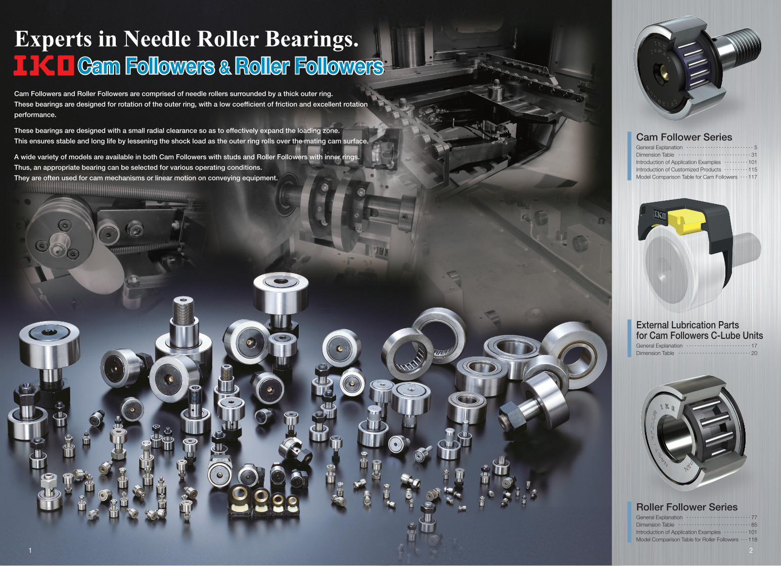
Cam Follower SeriesGeneral Explanation・・・・・・・・・・・・・・・・・・・・・・・・・・5Dimension Table・・・・・・・・・・・・・・・・・・・・・・・・・・・・31Introduction of Application Examples・・・・・・・・・・101Introduction of Customized Products・・・・・・・・・・115Model Comparison Table for Cam Followers・・・・117
Roller Follower SeriesGeneral Explanation・・・・・・・・・・・・・・・・・・・・・・・・・77Dimension Table・・・・・・・・・・・・・・・・・・・・・・・・・・・・85Introduction of Application Examples・・・・・・・・・・101Model Comparison Table for Roller Followers・・・・118
External Lubrication Parts for Cam Followers C-Lube UnitsGeneral Explanation・・・・・・・・・・・・・・・・・・・・・・・・・17Dimension Table・・・・・・・・・・・・・・・・・・・・・・・・・・・・20
21
CONTENTSCAM FOLLOWER SeriesCam Follower Series
ROLLER FOLLOWER SeriesRoller Follower SeriesCam Follower Series
Explanation Dimension Table
Option Parts
Features ……………………………………………………………… 5C-Lube Unit for Cam Followers ……………………19Identi�cation Number ………………………………………21Load Rating and Life ………………………………………22Maximum Allowable Static Load …………………22Accuracy ……………………………………………………………23Radial Internal Clearance ………………………………24Fit …………………………………………………………………………24Track Capacity …………………………………………………25Allowable Rotational Speed ……………………………25Lubrication …………………………………………………………25Oil Hole ………………………………………………………………26Accessories ………………………………………………………27Special Speci�cation ………………………………………28Operating Temperature Range ………………………29Mounting ……………………………………………………………29Precautions for Use …………………………………………30
Explanation
Features ……………………………………………………………… 5C-Lube Unit for Cam Followers ………………… 19Identification Number …………………………………… 21Load Rating and Life …………………………………… 22Maximum Allowable Static Load ……………… 22Accuracy ………………………………………………………… 23Radial Internal Clearance …………………………… 24Fit ……………………………………………………………………… 24Track Capacity ……………………………………………… 25
Allowable Rotational Speed ……………………… 25Lubrication ……………………………………………………… 25Oil Hole …………………………………………………………… 26Accessories …………………………………………………… 27Special Specification …………………………………… 28Operating Temperature Range ………………… 29Mounting ………………………………………………………… 29Precautions for Use ……………………………………… 30
Explanation
Features …………………………………………………………… 77Identification Number …………………………………… 79Load Rating and Life …………………………………… 80Maximum Allowable Static Load ……………… 80Accuracy ………………………………………………………… 81Radial Internal Clearance …………………………… 82Fit ……………………………………………………………………… 83
Track Capacity ……………………………………………… 83Allowable Rotational Speed ……………………… 83Lubrication ……………………………………………………… 83Oil Hole …………………………………………………………… 83Operating Temperature Range ………………… 83Mounting ………………………………………………………… 84
Introduction of Application Examples …… 101Introduction of Customized Products …… 115Model Comparison Table for Cam Followers … 117
Model Comparison Table for Roller Followers … 118Miscellaneous Tables ………………………………… 119
Dimension Table
Miniature Type Cam Followers …………………………………… CFS …………………………………………………………………… 31Thrust Disk Type Miniature Cam Followers ……………… CFS…W …………………………………………………………… 33Standard Type Cam Followers …………………………………… CF…B ……………………………………………………………… 35Double Hex Hole Cam Followers ………………………………… CFKR ………………………………………………………………… 39Cam Follower G ……………………………………………………………… CF…G ……………………………………………………………… 43Thrust Disk Type Cam Followers ………………………………… CF…WB …………………………………………………………… 45C-Lube Cam Followers…………………………………………………… CF…WB…/SG ………………………………………………… 47Solid Eccentric Stud Type Cam Followers ……………… CFES…B ………………………………………………………… 49Eccentric Type Cam Followers …………………………………… CFE…B …………………………………………………………… 51Centralized Lubrication Type Cam Followers ………… CF-RU1, CF-FU1 ………………………………………… 55Easy Mounting Type Cam Followers ………………………… CF-SFU…B ……………………………………………………… 57Cylindrical Roller Cam Followers ………………………………… NUCF…B ………………………………………………………… 59Inch Series Cam Followers CR …………………………………… CR…B, CR ……………………………………………………… 61Inch Series Cam Followers CRH ………………………………… CRH…V, CRH…VB ……………………………………… 69
Option Parts
Way for Cam Follower ………………………………… 73
Dimension Table
Separable Roller Followers …………………………………………… RNAST, NAST ………………………………………………… 85Non-separable Roller Followers ………………………………… NART ………………………………………………………………… 89C-Lube Roller Followers ………………………………………………… NART…/SG …………………………………………………… 93Cylindrical Roller Followers …………………………………………… NURT ………………………………………………………………… 95Inch Series Non-separable Roller Followers …………… CRY …………………………………………………………………… 97
Introduction of Technical Service Site 127
Introduction of Products 129
Application Examples / Customized Products / Model Comparison Table / Miscellaneous Tables
Miniature Type Cam Followers ………………………31Thrust Disk Type Miniature Cam Followers ……33Standard Type Cam Followers ………………………35Double Hex Hole Cam Followers …………………39Cam Follower G ………………………………………………43Thrust Disk Type Cam Followers …………………45C-Lube Cam Followers ……………………………………47Solid Eccentric Stud Type Cam Followers ……49Eccentric Type Cam Followers ………………………51Centralized Lubrication Type
Cam Followers ……………………………………55Easy Mounting Type Cam Followers ……………57Cylindrical Roller Cam Followers …………………59Inch Series Cam Followers CR ……………………61Inch Series Cam Followers CRH …………………69
Way for Cam Follower ……………………………………73
3 4
CAM FOLLOWERSC
am Fo
llow
ers

Cam Followers are bearings incorporating needle rollers with a stud enclosed in a
thick outer ring. These Bearings are designed for outer ring rotation with superior
rotational performance, a low coefficient of friction and high load capacity. Cam Followers
have a high rigidity and accuracy making them well suited for various applications such as
cam mechanisms and guide rollers for linear motion. They have a wide range of uses such
as machine tools, industrial robots, electronic parts and office automation equipment.
The hexagon socket on the stud head allows for secure tightening with a hexagon wrench
as means for mounting. In addition, ’s original lubrication structure enables the
Cam Follower to be lubricated from multiple locations including the stud head allowing for
more freedom when designing equipment.
CF Variety & OriginalityVariety & OriginalityVariety & Originality
Reliable and Proven Cam Follower Series!Reliable and Proven Cam Follower Series!Reliable and Proven Cam Follower Series!
Introducing the features of Cam Follower excellence!
Standard Type Cam FollowersStandard Type Cam Followers
Miniature Type Cam FollowersMiniature Type Cam Followers
European RoHS Compliant Products
CageWell suited for high speed due to its excellent rotational properties.
SealTotally sealed to prevent foreign substances entering the bearing.
Needle RollerCrowned roller helps resist shock loads.
Hexagon SocketHexagon wrench can be used to secure.
Grease NippleEnables lubrication via grease gun as well as functions as a plug.
Outer RingThick structure helps resist shock loads.
StudMachined threads make for easy mounting.
Side plateQuench-hardened for increased wear resistance.
Cam Followers
page7
❶ Substantial Product LineupOur substantial product lineup offers types such as extremely-small-sized miniature, built-in thrust disk good for mounting errors, maintenance free with pre-packed solid lubricant as well as other types.
page13
❷ Wide Selection of Product Specifications to match your needs
Options such as material type, roller guide method, seal structure and shape of the outer ring surface are available to meet the needs of your application.
page15
❸ Hexagon Socket for Easy MountingThe hexagon socket on the stud head allows for easy means of mounting with hexagon wrench.
page16
❹ Original Lubricating Structure which allows for lubrication from the stud head
The hexagon socket’s unique design allows for grease to be administered from the stud head end.
page17
❺ New Innovation of C-Lube Unit for Cam FollowersThe C-Lube unit supplies lubrication oil to the outside surface of the Cam Follower’s outer ring and the track surface. Thus reducing friction and wear as well as eliminating the need to routinely grease these surfaces.
5 6
CAM FOLLOWERSC
am Fo
llow
ers

Selectable product speci�cations
Roller guide method
Type of material
Shape of outer ring
outside surface
Seal structure
With cage
Full complement
High carbon steelStainless steel
Cylindrical outer ringCrowned outer ring
Shield type
Sealed type
No symbol
V
No symbol
F
No symbol
R
No symbol
UUStud
Side plate
Needle roller
Outer ring
Miniature Type Cam Followers2 to 6
mmStud diameter
CFS
CFS CFS…V
Ultra�ne needle roller is incorporated to the outer ring of bearing so the compact design is realized with outer ring outside diameter which is small relative to the stud diameter. They are used in electronic devices, OA equipment, small index devices, etc.
Thrust Disk Type Miniature Cam Followers mmStud diameter
CFS…WMiniature Type Cam Followers incorporated with special synthetic resin thrust washers excellent in wear and heat resistance. It receives axial load of outer ring generated due to installation errors to prevent friction and wear on the sliding surface.
Standard Type Cam Followers3 to 30
mmStud diameter
CF…BThese are the basic bearing models in the Cam Follower series. Size variations from 3 to 30 mm in stud diameter are available.
Double Hex Hole Cam Followers10 to 30
mmStud diameter
CFKRCFKR have a structure with hexagon sockets at each end of the stud and can be mounted using a hexagon wrench as baf�e from either end, leaving the mounting location unrestricted.
World's smallest size!A Cam Follower with stud diameter of just 1.4 mm!!
Ultra-compact CFS1.4WV with a stud diameter of 1.4 mm and outer ring diameter of just 4 mm. The built-in thrust disk receives the axial load of the outer ring generated due to mounting errors.
5 Features of CFS1.4WVStud diameterJust φ1.4 mm
Outside dia. of outer ringJust φ4 mm
Hexagon socket for easy mounting
Full complement type for large load capacity
Includes thrust disks to resist mounting errors
Stud diameterJust φ1.4 mm
Outside dia. of outer ringJust φ4 mm
Hexagon socket for easy mounting
Full complement type for large load capacity
Includes thrust disks to resist mounting errors
1 2 3 4 5
Selectable product speci�cations
Roller guide method
Type of material
Shape of outer ring
outside surface
Seal structure
With cage
Full complement
High carbon steelStainless steel
Cylindrical outer ringCrowned outer ring
Shield type
Sealed type
No symbol
V
No symbol
F
No symbol
R
No symbol
UU
Selectable product speci�cations
Roller guide method
Type of material
Shape of outer ring
outside surface
Seal structure
With cage
Full complement
High carbon steelStainless steel
Cylindrical outer ringCrowned outer ring
Shield type
Sealed type
No symbol
V
No symbol
F
No symbol
R
No symbol
UU
Cam Followers with pre-packed grease at reasonable price.
Cam Follower G
CF…G
Selectable product speci�cations
Roller guide method
Type of material
Shape of outer ring
outside surface
Seal structure
With cage
Full complement
High carbon steelStainless steel
Cylindrical outer ringCrowned outer ring
Shield type
Sealed type
No symbol
V
No symbol
F
No symbol
R
No symbol
UU
Selectable product speci�cations
Roller guide method
Type of material
Shape of outer ring
outside surface
Seal structure
With cage
Full complement
High carbon steelStainless steel
Cylindrical outer ringCrowned outer ring
Shield type
Sealed type
No symbol
V
No symbol
F
No symbol
R
No symbol
UU
Pre-packed greaseCan be used as-is when opened
Outer ring
Needle roller
Stud
Side plate
CageSeal
CageStud
Hexagon socket
When the stud thread is interfering When the stud head is interfering
Side plate
Needle roller
Outer ring
1.4 to 6
❶ Substantial product lineup 1
page31
page35
page33
page39
7 8
CAM FOLLOWERSC
am Fo
llow
ers
1N=0.102kgf=0.2248lbs.1mm=0.03937inch

C-Lube Cam Followers5 to 20
mmStud diameter
CF…WB…/SG Selectable product speci�cations
Maintenance free product with thermoset solid lubricant C-Lube pre-packed in the bearing space. C-Lube is heat-treated and solidi�ed lubricant composed of an amount of lubrication oil and particulate ultra-high molecular polyethylene resin. As the bearing rotates, the lubricant oozes out of C-Lube onto the raceway in proper quantities, maintaining the lubrication performance for a long period of time.
Solid Eccentric Stud Type Cam Followers6 to 18
mmStud diameter
CFES…BRotation of eccentric stud can align height of outer ring outside diameter when multiple rings are used. Eccentricity is from 0.25 to 0.6 mm and it can be mounted to the same mounting hole as the Standard Type Cam Followers.
Eccentric Type Cam Followers6 to 30
mmStud diameter
CFE…BIn these bearings, an eccentric collar is assembled with the Cam Follower stud, enabling the outer ring to be positioned easily in the radial direction against the mating cam guide surface. Eccentricity is from 0.4 to 1.5 mm.
Roller guide method
Type of material
Shape of outer ring
outside surface
Seal structure
With cage
Full complement
High carbon steelStainless steel
Cylindrical outer ringCrowned outer ring
Shield type
Sealed type
No symbol
V
No symbol
F
No symbol
R
No symbol
UU
Selectable product speci�cations
Roller guide method
Type of material
Shape of outer ring
outside surface
Seal structure
With cage
Full complement
High carbon steelStainless steel
Cylindrical outer ringCrowned outer ring
Shield type
Sealed type
No symbol
V
No symbol
F
No symbol
R
No symbol
UU
Thrust Disk
C-Lube<Durability Test>
100
75
50
25
0
Operating time min
Lub
ricat
ion
oil r
esid
ue %
0 1 000 2 000 5 0004 0003 000
C-Lube Cam Followers
Test portionLubrication conditionsRotational speed
Ambient temperature
CF10WBUUR/SGC-Lube only, no pre-packed grease1000 min-1
Room temperature
Ecc
entr
icity
ε(0
.25
to 0
.6 m
m)
Selectable product speci�cations
Roller guide method
Type of material
Shape of outer ring
outside surface
Seal structure
With cage
Full complement
High carbon steelStainless steel
Cylindrical outer ringCrowned outer ring
Shield type
Sealed type
No symbol
V
No symbol
F
No symbol
R
No symbol
UU
(0.4
to
1.5
mm
)E
ccen
tric
ity ε
Eccentric stud
Eccentric collar
Test conditions
Test Result
Ideal for combination with C-Lube Units for Cam Followers!!The combination with C-Lube Unit for Cam Follower realizes maintenance-free of Cam Follower inside and cam guide surface.
Thrust Disk Type Cam Followers3 to 20
mmStud diameter
CF…WBAs it is incorporated with special synthetic resin thrust washers excellent in wear and heat resistance, it receives axial load of outer ring generated due to mounting errors to prevent friction and wear on the sliding surface.
Selectable product speci�cations
Roller guide method
Type of material
Shape of outer ring
outside surface
Seal structure
With cage
Full complement
High carbon steelStainless steel
Cylindrical outer ringCrowned outer ring
Shield type
Sealed type
No symbol
V
No symbol
F
No symbol
R
No symbol
UU
Thrust DiskThrust Disk
❶ Substantial product lineup 2
page45
page49
page47
page17
page51
9 10
CAM FOLLOWERSC
am Fo
llow
ers
1N=0.102kgf=0.2248lbs.1mm=0.03937inch
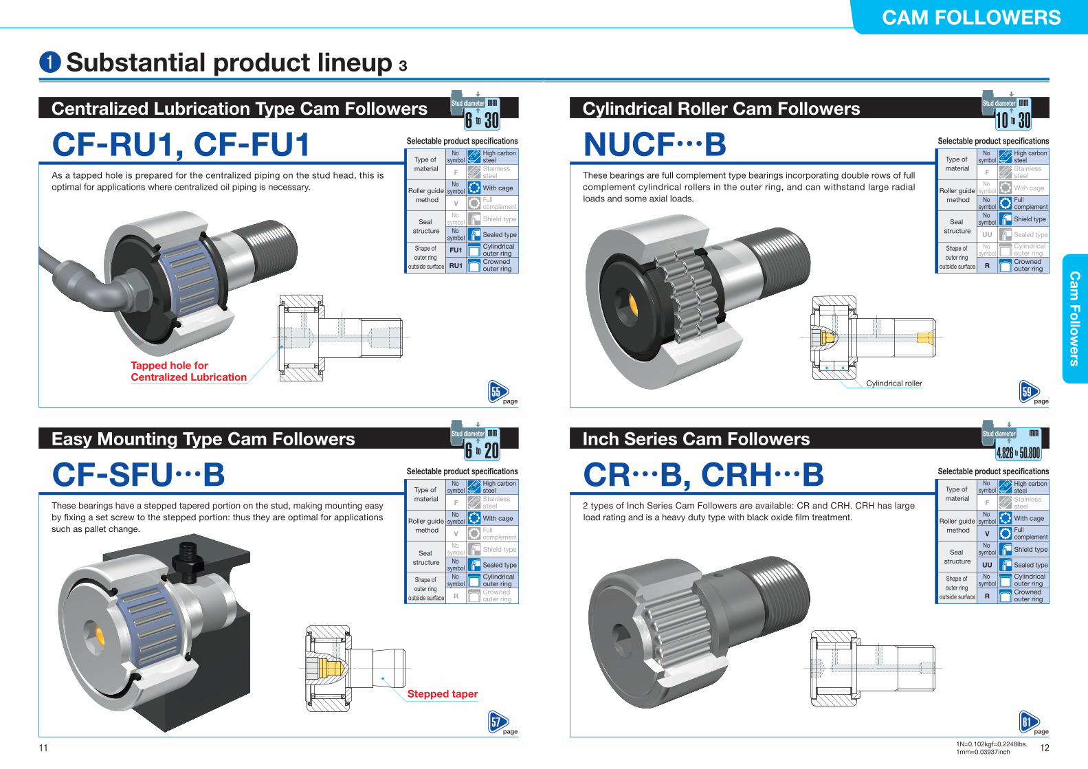
Cylindrical Roller Cam Followers10 to 30
mmStud diameter
NUCF…BThese bearings are full complement type bearings incorporating double rows of full complement cylindrical rollers in the outer ring, and can withstand large radial loads and some axial loads.
Inch Series Cam Followers4.826 to 50.800
mmStud diameter
CR…B, CRH…B2 types of Inch Series Cam Followers are available: CR and CRH. CRH has large load rating and is a heavy duty type with black oxide �lm treatment.
Selectable product speci�cations
Type of material
Shape of outer ring
outside surface
Seal structure
Full complement
High carbon steelStainless steel
Cylindrical outer ringCrowned outer ring
Shield type
Sealed type
No symbol
No symbol
F
No symbol
R
No symbol
UU
Selectable product speci�cations
Roller guide method
Type of material
Shape of outer ring
outside surface
Seal structure
With cage
Full complement
High carbon steelStainless steel
Cylindrical outer ringCrowned outer ring
Shield type
Sealed type
No symbol
V
No symbol
F
No symbol
R
No symbol
UU
Centralized Lubrication Type Cam Followers6 to 30
mmStud diameter
CF-RU1, CF-FU1As a tapped hole is prepared for the centralized piping on the stud head, this is optimal for applications where centralized oil piping is necessary.
Easy Mounting Type Cam Followers6 to 20
mmStud diameter
CF-SFU…BThese bearings have a stepped tapered portion on the stud, making mounting easy by �xing a set screw to the stepped portion: thus they are optimal for applications such as pallet change.
Selectable product speci�cations
Roller guide method
Type of material
Shape of outer ring
outside surface
With cage
Full complement
High carbon steelStainless steel
Cylindrical outer ringCrowned outer ring
Sealed type
No symbol
V
No symbol
F
FU1
RU1
No symbol
Selectable product speci�cations
Roller guide method
Type of material
Seal structure
Shape of outer ring
outside surface
Seal structure
With cage
Full complement
High carbon steelStainless steel
Cylindrical outer ring
Sealed type
No symbol
V
No symbol
F
No symbol
No symbol
Cylindrical roller
Tapped hole for Centralized Lubrication
Stepped taper
Roller guide method
Crowned outer ringR
Shield typeNo symbol
Shield typeNo symbol
With cageNo
symbol
❶ Substantial product lineup 3
page55
page59
page57
page61
11 12
CAM FOLLOWERSC
am Fo
llow
ers
1N=0.102kgf=0.2248lbs.1mm=0.03937inch
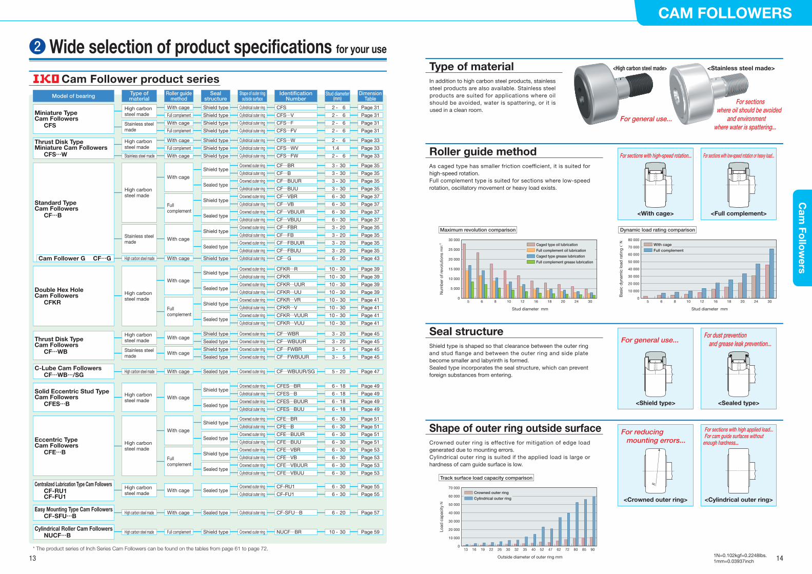
Cam Follower product series In addition to high carbon steel products, stainless steel products are also available. Stainless steel products are suited for applications where oil should be avoided, water is spattering, or it is used in a clean room.
Type of material
Roller guide method
Shield type is shaped so that clearance between the outer ring and stud �ange and between the outer ring and side plate become smaller and labyrinth is formed.Sealed type incorporates the seal structure, which can prevent foreign substances from entering.
As caged type has smaller friction coef�cient, it is suited for high-speed rotation.Full complement type is suited for sections where low-speed rotation, oscillatory movement or heavy load exists.
Shape of outer ring outside surfaceCrowned outer ring is effective for mitigation of edge load generated due to mounting errors.Cylindrical outer ring is suited if the applied load is large or hardness of cam guide surface is low.
Dynamic load rating comparison
5 6 8 10 12 16 18 20 24 30
Stud diameter mm
0
10 000
20 000
30 000
40 000
50 000
60 000
70 000
80 000
Bas
ic d
ynam
ic lo
ad r
atin
g C
N With cage
Full complement
Track surface load capacity comparison
13 16 19 22 26 30 32 35 40 52 47 62 72 80 85 90
Outside diameter of outer ring mm
0
10 000
20 000
30 000
40 000
50 000
60 000
70 000
Load
cap
acity
N
Maximum revolution comparison
5 6 8 10 12 16 18 20 24 30
Stud diameter mm
0
5 000
10 000
15 000
20 000
25 000
30 000
Num
ber
of r
evol
utio
ns m
in-1 Caged type oil lubrication
Full complement oil lubrication
Caged type grease lubrication
Full complement grease lubrication
<With cage> <Full complement>
For sections with high-speed rotation... For sections with low-speed rotation or heavy load...
Seal structure
<Crowned outer ring> <Cylindrical outer ring>
For reducing mounting errors...
For sections with high applied load...For cam guide surfaces without
enough hardness...
Crowned outer ring
Cylindrical outer ring
<Shield type> <Sealed type>
For general use...For dust prevention
and grease leak prevention...
<High carbon steel made> <Stainless steel made>
For general use...
For sections where oil should be avoided
and environment where water is spattering...
R
❷ Wide selection of product specifications for your use
Model of bearing
Miniature Type Cam Followers CFS
High carbon steel made
With cage
Full complement
Shield type
Shield type
Cylindrical outer ring
Cylindrical outer ring
Page 31
Page 31
CFS
CFS…V
2 - 6
2 - 6
Stainless steel made
With cage
Full complement
Shield type
Shield type
Cylindrical outer ring
Cylindrical outer ring
Page 31
Page 31
CFS…FCFS…FV
2 - 6
2 - 6
Centralized Lubrication Type Cam Followers CF-RU1 CF-FU1
High carbon steel made With cage Sealed type
Crowned outer ring
Cylindrical outer ring
Page 55
Page 55
CF-RU1
CF-FU1
6 - 30
6 - 30
Thrust Disk Type Cam Followers CF…WB
High carbon steel made With cage
Shield type
Sealed type
Crowned outer ring
Crowned outer ring
Page 45
Page 45
CF…WBR
CF…WBUUR
3 - 20
3 - 20
Stainless steel made With cage
Shield type
Sealed type
Crowned outer ring
Crowned outer ring
Page 45
Page 45
CF…FWBR
CF…FWBUUR
3 - 5
3 - 5
Double Hex Hole Cam Followers CFKR
High carbon steel made
With cage
Shield typeCrowned outer ring Page 39CFKR…R 10 - 30
Cylindrical outer ring Page 39CFKR 10 - 30
Sealed typeCrowned outer ring Page 39CFKR…UUR 10 - 30
Cylindrical outer ring Page 39CFKR…UU 10 - 30
Full complement
Shield typeCrowned outer ring Page 41CFKR…VR 10 - 30
Cylindrical outer ring Page 41CFKR…V 10 - 30
Sealed typeCrowned outer ring Page 41CFKR…VUUR 10 - 30
Cylindrical outer ring Page 41CFKR…VUU 10 - 30
Thrust Disk Type Miniature Cam Followers CFS…W
High carbon steel made
With cage
Full complement
Shield type
Shield type
Cylindrical outer ring
Cylindrical outer ring
Page 33
Page 33
CFS…W
CFS…WV
2 - 6
1.4
Stainless steel made With cage Shield type Cylindrical outer ring Page 33CFS…FW 2 - 6
With cage
Shield typeCrowned outer ring Page 35CF…BR 3 - 30
Cylindrical outer ring Page 35CF…B 3 - 30
Sealed typeCrowned outer ring Page 35CF…BUUR 3 - 30
Cylindrical outer ring Page 35CF…BUU 3 - 30
Standard Type Cam Followers CF…B
Cam Follower G CF…G
High carbon steel made
Stainless steel made
Full complement
Shield typeCrowned outer ring Page 37CF…VBR 6 - 30
Cylindrical outer ring Page 37CF…VB 6 - 30
Sealed typeCrowned outer ring Page 37CF…VBUUR 6 - 30
Cylindrical outer ring Page 37CF…VBUU 6 - 30
With cage
Shield typeCrowned outer ring Page 35CF…FBR 3 - 20
Cylindrical outer ring Page 35CF…FB 3 - 20
Sealed typeCrowned outer ring Page 35CF…FBUUR 3 - 20
Cylindrical outer ring Page 35CF…FBUU 3 - 20
High carbon steel made With cage Shield type Cylindrical outer ring Page 43CF…G 6 - 20
Type of material
Roller guide method
Seal structure
Shape of outer ring outside surface
Identification Number
Dimension Table
Stud diameter(mm)
C-Lube Cam Followers CF…WB…/SG
High carbon steel made With cage Sealed type Crowned outer ring Page 47CF…WBUUR/SG 5 - 20
Easy Mounting Type Cam Followers CF-SFU…B
High carbon steel made With cage Sealed type Cylindrical outer ring Page 57CF-SFU…B 6 - 20
Cylindrical Roller Cam Followers NUCF…B
High carbon steel made Full complement Shield type Crowned outer ring Page 59NUCF…BR 10 - 30
Solid Eccentric Stud Type Cam Followers CFES…B
High carbon steel made With cage
Shield typeCrowned outer ring Page 49CFES…BR 6 - 18
Cylindrical outer ring Page 49CFES…B 6 - 18
Sealed typeCrowned outer ring Page 49CFES…BUUR 6 - 18
Cylindrical outer ring Page 49CFES…BUU 6 - 18
Eccentric Type Cam Followers CFE…B
High carbon steel made
With cage
Shield typeCrowned outer ring Page 51CFE…BR 6 - 30
Cylindrical outer ring Page 51CFE…B 6 - 30
Sealed typeCrowned outer ring Page 51CFE…BUUR 6 - 30
Cylindrical outer ring Page 51CFE…BUU 6 - 30
Full complement
Shield typeCrowned outer ring Page 53CFE…VBR 6 - 30
Cylindrical outer ring Page 53CFE…VB 6 - 30
Sealed typeCrowned outer ring Page 53CFE…VBUUR 6 - 30
Cylindrical outer ring Page 53CFE…VBUU 6 - 30
* The product series of Inch Series Cam Followers can be found on the tables from page 61 to page 72.
13 14
CAM FOLLOWERSC
am Fo
llow
ers
1N=0.102kgf=0.2248lbs.1mm=0.03937inch
Hexagon wrench
Hex Head Cam FollowersHex Head Cam Followers
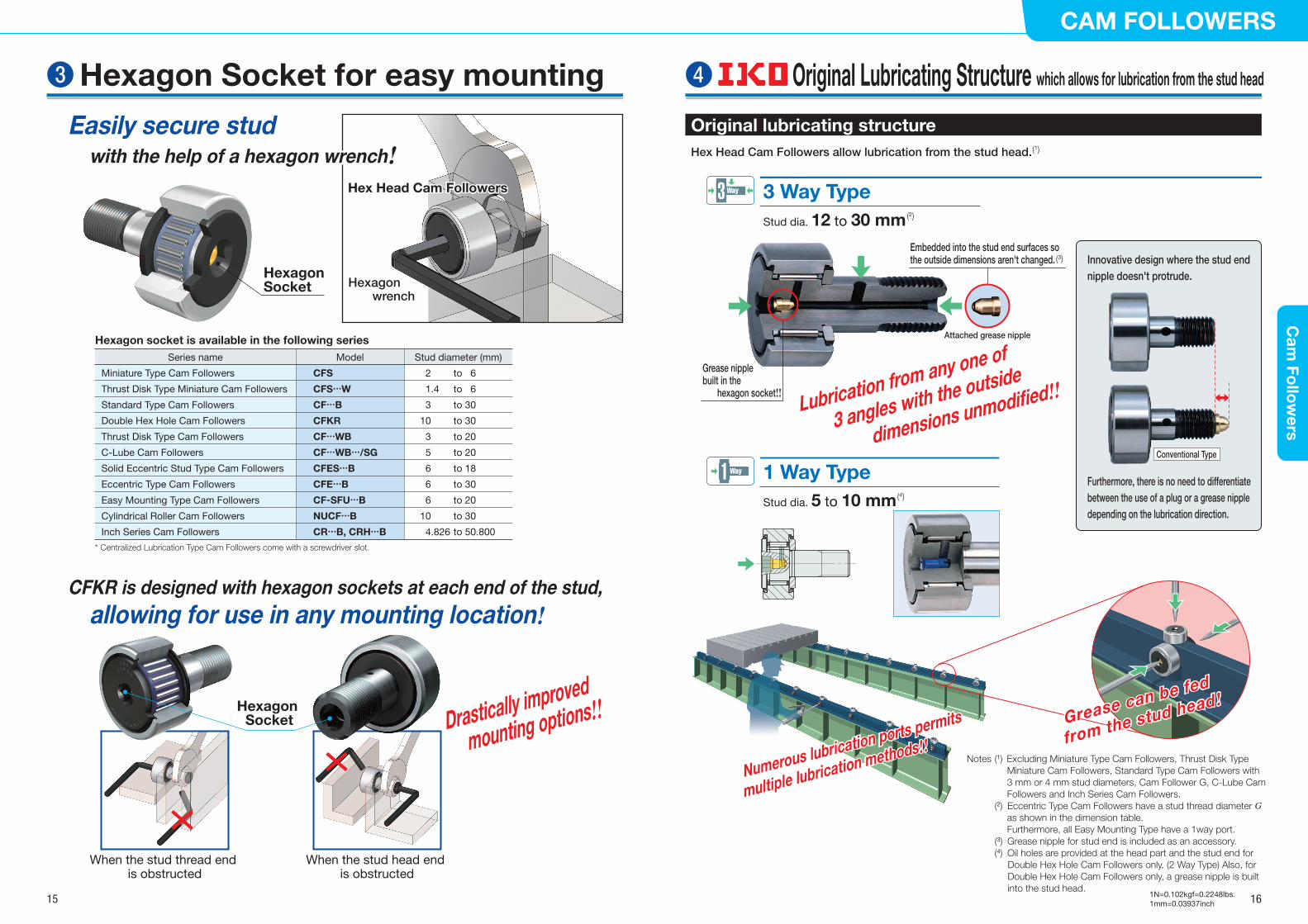
Original lubricating structureHex Head Cam Followers allow lubrication from the stud head.
3 Way TypeStud dia. 12 to 30 mm
1 Way TypeStud dia. 5 to 10 mm
3 Way
Numerous lubrication ports permits
multiple lubrication methods!!Numerous lubrication ports permits
multiple lubrication methods!!
Embedded into the stud end surfaces so the outside dimensions aren't changed.
Notes (1) Excluding Miniature Type Cam Followers, Thrust Disk Type Miniature Cam Followers, Standard Type Cam Followers with 3 mm or 4 mm stud diameters, Cam Follower G, C-Lube Cam Followers and Inch Series Cam Followers.
(2) Eccentric Type Cam Followers have a stud thread diameter G as shown in the dimension table. Furthermore, all Easy Mounting Type have a 1way port.
(3) Grease nipple for stud end is included as an accessory. (4) Oil holes are provided at the head part and the stud end for
Double Hex Hole Cam Followers only. (2 Way Type) Also, for Double Hex Hole Cam Followers only, a grease nipple is built into the stud head.
Grease can be fed
from the stud head!Grease can be fed
from the stud head!
Attached grease nipple
1 Way
(2)
(4)
(3)
(1)
Innovative design where the stud end nipple doesn't protrude.
Furthermore, there is no need to differentiate between the use of a plug or a grease nipple depending on the lubrication direction.
Conventional Type
Easily secure stud with the help of a hexagon wrench!
Easily secure stud with the help of a hexagon wrench!
CFKR is designed with hexagon sockets at each end of the stud, allowing for use in any mounting location!
Hexagon Socket
* Centralized Lubrication Type Cam Followers come with a screwdriver slot.
CFS
CFS…W
CF…B
CFKR
CF…WB
CF…WB…/SG
CFES…B
CFE…B
CF-SFU…B
NUCF…B
CR…B, CRH…B
2 to 6
1.4 to 6
3 to 30
10 to 30
3 to 20
5 to 20
6 to 18
6 to 30
6 to 20
10 to 30
4.826 to 50.800
Miniature Type Cam Followers
Thrust Disk Type Miniature Cam Followers
Standard Type Cam Followers
Double Hex Hole Cam Followers
Thrust Disk Type Cam Followers
C-Lube Cam Followers
Solid Eccentric Stud Type Cam Followers
Eccentric Type Cam Followers
Easy Mounting Type Cam Followers
Cylindrical Roller Cam Followers
Inch Series Cam Followers
Model Stud diameter (mm)Series name
Hexagon socket is available in the following series
Drastically improved
mounting options!!Hexagon Socket
When the stud thread end is obstructed
When the stud head end is obstructed
Lubrication from any one of
3 angles with the outside
dimensions unmodified!!Grease nipple built in the
hexagon socket!!
❸ Hexagon Socket for easy mounting ❹ Original Lubricating Structure which allows for lubrication from the stud head
15 16
CAM FOLLOWERSC
am Fo
llow
ers
1N=0.102kgf=0.2248lbs.1mm=0.03937inch
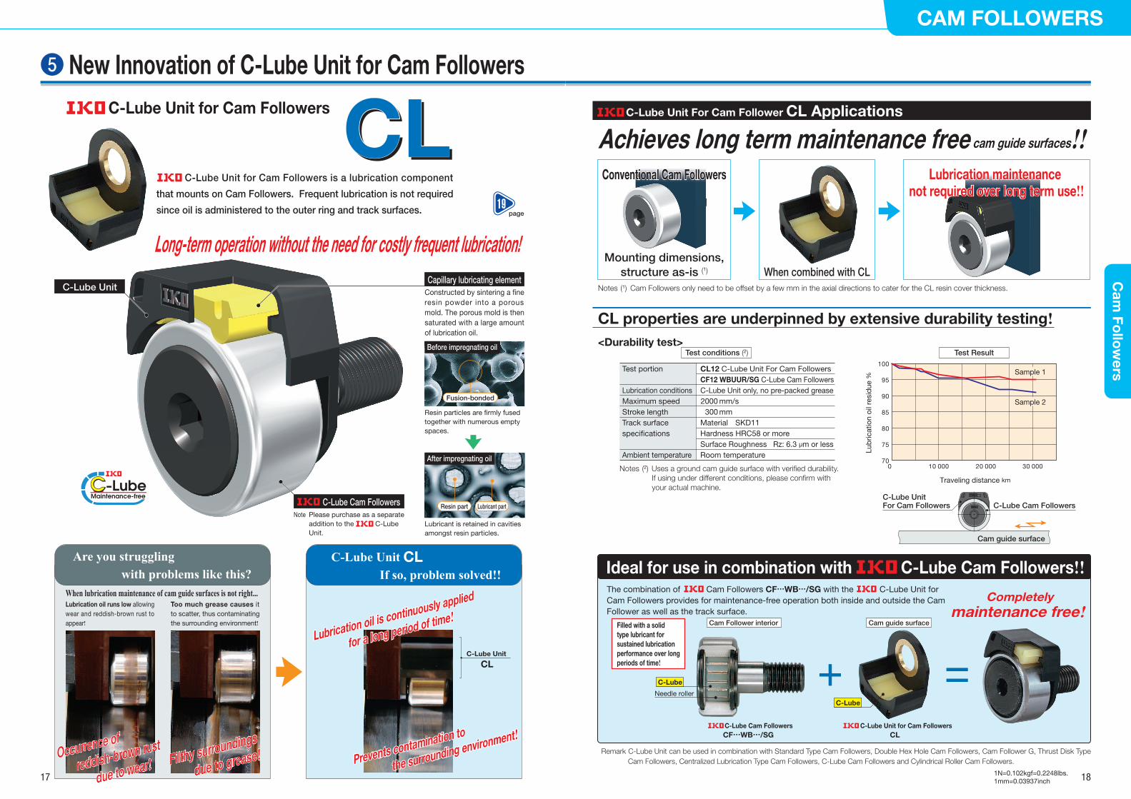
CLCLCLC-Lube Unit for Cam Followers is a lubrication component
that mounts on Cam Followers. Frequent lubrication is not required
since oil is administered to the outer ring and track surfaces.
C-Lube Cam Followers
Constructed by sintering a �ne resin powder into a porous mold. The porous mold is then saturated with a large amount of lubrication oil.
Capillary lubricating elementC-Lube Unit
Fusion-bonded
Lubricant partResin part
Resin particles are �rmly fused together with numerous empty spaces.
Lubricant is retained in cavities amongst resin particles.
Before impregnating oil
After impregnating oil
Are you struggling with problems like this?
C-Lube Unit CL If so, problem solved!!
Long-term operation without the need for costly frequent lubrication!Long-term operation without the need for costly frequent lubrication!
Achieves long term maintenance free cam guide surfaces!!
Please purchase as a separate addition to the C-Lube Unit.
Note
When lubrication maintenance of cam guide surfaces is not right... Lubrication oil runs low allowing wear and reddish-brown rust to appear!
Too much grease causes it to scatter, thus contaminating the surrounding environment!
Occurrence of
reddish-brown rust
due to wear!Occurrence of
reddish-brown rust
due to wear! Filthy surroundings
due to grease!Filthy surroundings
due to grease!
Lubrication oil is continuously applied
for a long period of time!
Prevents contamination to
the surrounding environment!
Lubrication oil is continuously applied
for a long period of time!
Prevents contamination to
the surrounding environment!
C-Lube Unit
CL
Ideal for use in combination with C-Lube Cam Followers!!
When combined with CL
C-Lube Unit For Cam Follower CL Applications
Lubrication maintenance not required over long term use!!
Lubrication maintenance not required over long term use!!
Notes (2) Uses a ground cam guide surface with veri�ed durability.If using under different conditions, please con�rm with your actual machine.
Test portion
Lubrication conditionsMaximum speedStroke lengthTrack surface speci�cations
Ambient temperature
CL12 C-Lube Unit For Cam FollowersCF12 WBUUR/SG C-Lube Cam FollowersC-Lube Unit only, no pre-packed grease 2000 mm/s
300 mmMaterial SKD11Hardness HRC58 or moreSurface Roughness Rz: 6.3 μm or lessRoom temperature
<Durability test>Test conditions (2)
Mounting dimensions,structure as-is (1)
Conventional Cam FollowersConventional Cam Followers
Notes (1) Cam Followers only need to be offset by a few mm in the axial directions to cater for the CL resin cover thickness.
C-Lube Cam FollowersC-Lube Unit For Cam Followers
CL properties are underpinned by extensive durability testing!
The combination of Cam Followers CF…WB…/SG with the C-Lube Unit for Cam Followers provides for maintenance-free operation both inside and outside the Cam Follower as well as the track surface.
Needle roller
C-Lube
C-Lube Cam FollowersCF…WB…/SG
C-Lube Unit for Cam FollowersCL
Completely maintenance free!
C-Lube
Filled with a solid type lubricant for sustained lubrication performance over long periods of time!
Cam guide surfaceCam Follower interior
Cam guide surface
70
75
80
85
90
95
100
0 10 000 20 000 30 000
Sample 2
Sample 1
Test Result
Lub
ricat
ion
oil r
esid
ue %
Traveling distance km
Remark C-Lube Unit can be used in combination with Standard Type Cam Followers, Double Hex Hole Cam Followers, Cam Follower G, Thrust Disk Type Cam Followers, Centralized Lubrication Type Cam Followers, C-Lube Cam Followers and Cylindrical Roller Cam Followers.
❺ New Innovation of C-Lube Unit for Cam FollowersC-Lube Unit for Cam Followers
page19
17 18
CAM FOLLOWERSC
am Fo
llow
ers
1N=0.102kgf=0.2248lbs.1mm=0.03937inch
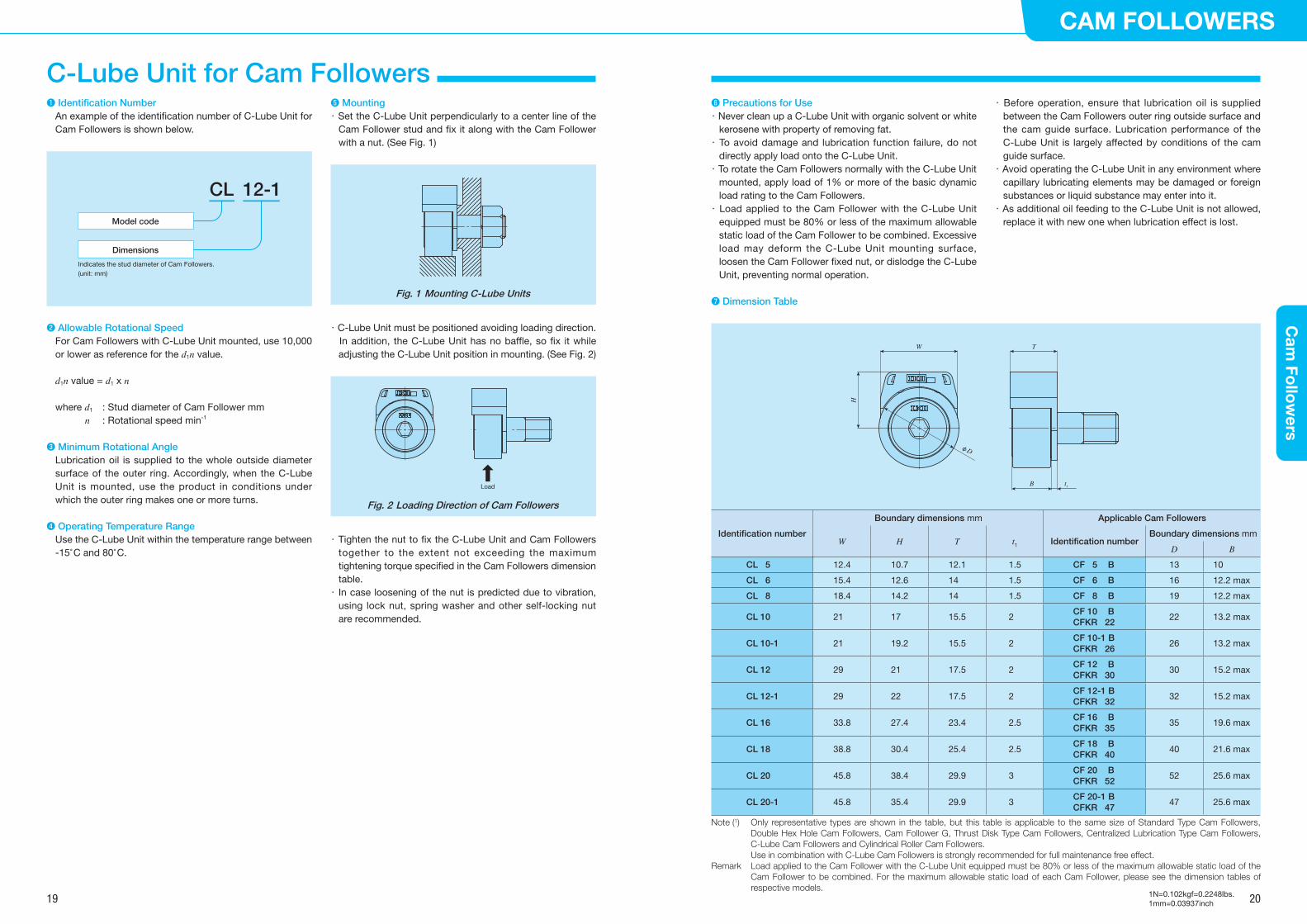
❶ Identification NumberAn example of the identification number of C-Lube Unit for Cam Followers is shown below.
Model code
Dimensions
Indicates the stud diameter of Cam Followers.(unit: mm)
CL 12-1
❷ Allowable Rotational SpeedFor Cam Followers with C-Lube Unit mounted, use 10,000 or lower as reference for the d1n value.
d1n value = d1 x n
where d1 : Stud diameter of Cam Follower mm n : Rotational speed min-1
❸ Minimum Rotational AngleLubrication oil is supplied to the whole outside diameter surface of the outer ring. Accordingly, when the C-Lube Unit is mounted, use the product in conditions under which the outer ring makes one or more turns.
❹ Operating Temperature RangeUse the C-Lube Unit within the temperature range between -15°C and 80°C.
❺ Mounting・ Set the C-Lube Unit perpendicularly to a center line of the
Cam Follower stud and fix it along with the Cam Follower with a nut. (See Fig. 1)
Fig. 1 Mounting C-Lube Units
・ C-Lube Unit must be positioned avoiding loading direction. In addition, the C-Lube Unit has no baffle, so fix it while
adjusting the C-Lube Unit position in mounting. (See Fig. 2)
Load
Fig. 2 Loading Direction of Cam Followers
・ Tighten the nut to fix the C-Lube Unit and Cam Followers together to the extent not exceeding the maximum tightening torque specified in the Cam Followers dimension table.・ In case loosening of the nut is predicted due to vibration,
using lock nut, spring washer and other self-locking nut are recommended.
❻ Precautions for Use・ Never clean up a C-Lube Unit with organic solvent or white
kerosene with property of removing fat.・ To avoid damage and lubrication function failure, do not
directly apply load onto the C-Lube Unit.・ To rotate the Cam Followers normally with the C-Lube Unit
mounted, apply load of 1% or more of the basic dynamic load rating to the Cam Followers.・ Load applied to the Cam Follower with the C-Lube Unit
equipped must be 80% or less of the maximum allowable static load of the Cam Follower to be combined. Excessive load may deform the C-Lube Unit mounting surface, loosen the Cam Follower fixed nut, or dislodge the C-Lube Unit, preventing normal operation.
・ Before operation, ensure that lubrication oil is supplied between the Cam Followers outer ring outside surface and the cam guide surface. Lubrication performance of the C-Lube Unit is largely affected by conditions of the cam guide surface.・ Avoid operating the C-Lube Unit in any environment where
capillary lubricating elements may be damaged or foreign substances or liquid substance may enter into it.・ As additional oil feeding to the C-Lube Unit is not allowed,
replace it with new one when lubrication effect is lost.
❼ Dimension Table
Identification number
Boundary dimensions mm Applicable Cam Followers
W H T t1 Identification numberBoundary dimensions mm
D B
CL 5 12.4 10.7 12.1 1.5 CF 5 B 13 10
CL 6 15.4 12.6 14 1.5 CF 6 B 16 12.2 max
CL 8 18.4 14.2 14 1.5 CF 8 B 19 12.2 max
CL 10 21 17 15.5 2CF 10 BCFKR 22
22 13.2 max
CL 10-1 21 19.2 15.5 2CF 10-1 BCFKR 26
26 13.2 max
CL 12 29 21 17.5 2CF 12 BCFKR 30
30 15.2 max
CL 12-1 29 22 17.5 2CF 12-1 BCFKR 32
32 15.2 max
CL 16 33.8 27.4 23.4 2.5CF 16 BCFKR 35
35 19.6 max
CL 18 38.8 30.4 25.4 2.5CF 18 BCFKR 40
40 21.6 max
CL 20 45.8 38.4 29.9 3CF 20 BCFKR 52
52 25.6 max
CL 20-1 45.8 35.4 29.9 3CF 20-1 BCFKR 47
47 25.6 max
Note (1) Only representative types are shown in the table, but this table is applicable to the same size of Standard Type Cam Followers, Double Hex Hole Cam Followers, Cam Follower G, Thrust Disk Type Cam Followers, Centralized Lubrication Type Cam Followers, C-Lube Cam Followers and Cylindrical Roller Cam Followers.
Use in combination with C-Lube Cam Followers is strongly recommended for full maintenance free effect.Remark Load applied to the Cam Follower with the C-Lube Unit equipped must be 80% or less of the maximum allowable static load of the
Cam Follower to be combined. For the maximum allowable static load of each Cam Follower, please see the dimension tables of respective models.
H
t1B
TW
φD
19 20
CAM FOLLOWERSC
am Fo
llow
ers
1N=0.102kgf=0.2248lbs.1mm=0.03937inch
C-Lube Unit for Cam Followers
Miniature Type Cam FollowersThrust Disk Type Miniature Cam FollowersStandard Type Cam FollowersDouble Hex Hole Cam FollowersCam Follower GThrust Disk Type Cam FollowersC-Lube Cam FollowersSolid Eccentric Stud Type Cam FollowersEccentric Type Cam FollowersCentralized Lubrication Type Cam Follower (Crowned Outer Ring)Centralized Lubrication Type Cam Follower (Cylindrical Outer Ring)Easy Mounting Type Cam FollowersCylindrical Roller Cam FollowersInch Series Cam Followers (With Hexagon Socket)Inch Series Cam Followers (With Screwdriver Slot)Inch Series Cam Followers (With Hexagon Socket)Inch Series Cam Followers (With Screwdriver Slot)
Basic dynamic load rating C
Basic dynamic load rating refers to a static radial load with a certain direction and size with which 90% of a group of the same Cam Followers can run one million rotations without material damages due to rolling contact fatigue when they are operated in the same conditions.
Basic static load rating C0
Basic static load rating refers to a static radial load with a certain direction and size with a certain contact stress at the center of contact parts of the rolling elements and a raceway under maximum load.
Life
The basic rating life calculation formulas are shown below.
L10 = (CPr)10/3 (1)
Where, L10 : Basic rating life 106 rev. C : Basic dynamic load rating N Pr : Dynamic equivalent radial load N
Therefore, life time can be calculated by applying the rotational speed to the formula below.
Lh = 106L10 60n (2)
Where, Lh : Basic rating life represented by service hours h
n : Rotational speed min-1
Static Safety Factor
Static safety factor can be obtained by the following equation and typical values are shown in Table 1.
fs =C0
P0r (3)
Where, fs : Static safety factor C0 : Basic static load rating N P0r : Static equivalent radial load (maximum
load) N
Table 1 Static safety factorOperating conditions of the bearing fs
When high rotational accuracy is required ≥3
For ordinary operation conditions ≥1.5
For normal operating conditions not requiring very smooth rotationWhen it is rarely rotated
≥1
Load factor
Load actually applied on the Cam Followers becomes larger than load theoretically calculated from vibration and shock. Therefore, multiply the load by the load factor shown in Table 2.
Table 2 Load factorOperating conditions fw
Smooth operation free from shock 1 to 1.2
Normal operation 1.2 to 1.5
Operation with shock load 1.5 to 3
The applicable load on Cam Followers is, in some cases, limited by the bending strength and shear strength of the stud and the strength of the outer ring instead of the load rating of the needle roller bearing. Therefore, the maximum allowable static load that is limited by these strengths is specified.
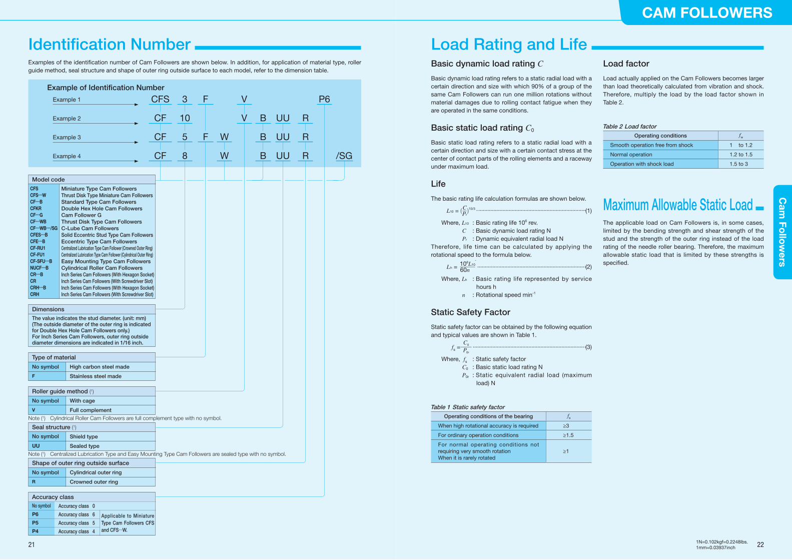
Examples of the identification number of Cam Followers are shown below. In addition, for application of material type, roller guide method, seal structure and shape of outer ring outside surface to each model, refer to the dimension table.
Example of Identification Number
Example 1
Example 2
Example 3
Example 4
CFS
CF
CF
CF
3
10
5
8
F
F
B
B
B
UU
UU
UU
R
R
R
P6
W
W /SG
V
V
No symbol
P6
P5
P4
Type of material
No symbol
F
High carbon steel made
Stainless steel made
Model code
CFSCFS…WCF…BCFKRCF…GCF…WBCF…WB…/SGCFES…BCFE…BCF-RU1CF-FU1CF-SFU…BNUCF…BCR…BCRCRH…BCRH
Roller guide method (1)
No symbol
V
With cage
Full complement
Seal structure (1)
No symbol
UU
Shield type
Sealed type
Shape of outer ring outside surface
No symbol
R
Cylindrical outer ring
Crowned outer ring
Dimensions
The value indicates the stud diameter. (unit: mm)(The outside diameter of the outer ring is indicated for Double Hex Hole Cam Followers only.)For Inch Series Cam Followers, outer ring outside diameter dimensions are indicated in 1/16 inch.
Accuracy class
Accuracy class 0
Accuracy class 6
Accuracy class 5
Accuracy class 4
Applicable to Miniature Type Cam Followers CFS and CFS…W.
Note (1) Cylindrical Roller Cam Followers are full complement type with no symbol.
Note (1) Centralized Lubrication Type and Easy Mounting Type Cam Followers are sealed type with no symbol.
Maximum Allowable Static Load
21 22
CAM FOLLOWERSC
am Fo
llow
ers
1N=0.102kgf=0.2248lbs.1mm=0.03937inch
Identification Number Load Rating and Life

The accuracy of Cam Followers is shown in Table 3, Table 4.1, Table 4.2, and Table 4.3. We also provide special accuracy class products. For details, please contact .
Radial internal clearance of Cam Followers is shown in Table 5.
Recommended fit of the Cam Followers stud and mounting hole is shown in Table 6 and dimensional tolerances of mounting hole are shown in Table 7, respectively. Since the Cam Follower is supported in a cantilever position, the mounting hole diameter should be prepared without play between the stud and the hole especially when heavy shock loads are applied.
Fit
Table 3 Tolerances unit: μm
SeriesItem
Miniature Type Cam FollowersCFS, CFS…W
Standard Type Cam Followers (1) Inch Series Cam Followers
Crowned outer ring Cylindrical outer ring Crowned outer ring Cylindrical outer ring
Outside dia. of outer ring D See Table 4.1 0-50
See Table 4.2 0-50
See Table 4.3
Stud diameter d1 h6 h7+ 25 0
Width of outer ring C 0-120
0-120
0-130
Note (1) Applicable for Cam Followers other than Miniature Type Cam Followers and Inch Series Cam Followers.
Table 4.1 Tolerance and allowance of outer ring (Miniature Type Cam Followers CFS and CFS…W) unit: μm
ΔDmpDeviation of mean outside diameter in a single plane
Kea
Radial runout of outer ring of assembled bearing(Maximum)
Class 0 Class 6 Class 5 Class 4 Class 0 Class 6 Class 5 Class 4
High Low High Low High Low High Low
0 -8 0 -7 0 -5 0 -4 15 8 5 4
Table 4.2 Tolerance and allowance of outer ring (Standard Type Cam Followers, Cylindrical outer ring) unit: μm
DNominal outside diameter of
outer ring
ΔDmpDeviation of mean outside diameter in a single plane
VDsp
Variation of outside diameter in a single plane
VDmp
Variation of mean outside diameter
Kea
Radial runout of outer ring of assembled bearing
mm (Maximum) (Maximum) (Maximum)
Over Incl. High Low
6 18 0 - 8 10 6 15
18 30 0 - 9 12 7 15
30 50 0 -11 14 8 20
50 80 0 -13 16 10 25
80 120 0 -15 19 11 35
Table 4.3 Tolerance and allowance of outer ring (Inch series Cam Followers, Cylindrical outer ring) unit: μm
DNominal outside diameter of
outer ring
ΔDmpDeviation of mean outside diameter in a single plane
VDsp
Variation of outside diameter in a single plane
VDmp
Variation of mean outside diameter
Kea
Radial runout of outer ring of assembled bearing
mm (Maximum) (Maximum) (Maximum)
Over Incl. High Low
6 18
0 -25
10 6 15
18 30 12 7 15
30 50 14 8 20
50 80 16 10 25
80 120 19 11 35
Table 5 Radial internal clearance unit: μm
Identification number Radial internal clearance
Miniature Type Cam FollowersCFS, CFS…W
Standard Type Cam Followers (1)
Cylindrical Roller Cam Followers
Inch Series Cam Followers Min. Max.
CFS1.4 to CFS5 CF 3B to CF 5 B - CR 8, CR 8-1, CRH 8-1, CRH 9 3 17
CFS6 CF 6B - CR10, CR10-1, CRH10-1, CRH11 5 20
- CF 8 to CF 12-1CFKR30 to CFKR32
- CR12 to CR22, CRH12 to CRH22 5 25
- CF 16 to CF 20-1CFKR22 to CFKR52
- CR24 to CR36, CRH24 to CRH36 10 30
- CF 24 to CF 30-2CFKR62 to CFKR90
- CR48, CRH40 to CRH56 10 40
- - - CRH64 15 50
- - NUCF10 B to NUCF24 B - 20 45
- - NUCF24-1B to NUCF30-2B - 25 50
Note (1) Applicable for all Cam Followers other than Miniature Type Cam Followers, Cylindrical Roller Cam Followers and Inch Series Cam Followers.
Table 6 Recommended fitModel of bearing Tolerance class of mounting hole for stud
Miniature Type Cam Followers CFS, CFS…W H6
Standard Type Cam Followers (1) H7
Inch Series Cam Followers F7
Note (1) Applicable for Cam Followers other than Miniature Type Cam Followers and Inch Series Cam Followers.
Table 7 Dimensional tolerances of mounting hole unit: μm
Classification of diameter F7 H6 H7
mm
Over Incl. High Low High Low High Low
- 3 +16 + 6 + 6 0 +10 0
3 6 +22 +10 + 8 0 +12 0
6 10 +28 +13 + 9 0 +15 0
10 18 +34 +16 +11 0 +18 0
18 30 +41 +20 +13 0 +21 0
3040
4050
+50 +25 +16 0 +25 0
23 24
CAM FOLLOWERSC
am Fo
llow
ers
1N=0.102kgf=0.2248lbs.1mm=0.03937inch
Radial Internal Clearance Accuracy

Track capacity is defined as the load which can be continuously applied on a Cam Follower placed on a steel cam guide surface without causing deformation or indentation on the cam guide surface when the outer ring of the Roller Follower makes contact with the mating cam guide surface (plane). Track capacities shown in the dimension table are values on the assumption that hardness of the mating member material is 40HRC (tensile strength: 1250 N/mm2) and if hardness is not 40HRC, these values must be multiplied by track capacity factors shown in Table 8.If lubrication between the outer ring and the mating cam guide surface is insufficient, seizure and/or wear may occur depending on the operating conditions. Therefore, attention must be paid to lubrication and surface roughness of the mating cam guide especially for high-speed rotations such as cam mechanisms.
The allowable rotational speed of Cam Followers is affected by mounting and operating conditions. For d1n value with only pure radial load applied, use values in Table 9 or lower as references. Under actual use conditions, it is recommended to use d1n, one tenth of indicated values, taking into account the effect of axial load.C-Lube Cam Followers and Cam Followers with C-Lube Unit mounted, use 10,000 or lower as reference for the d1n value.
d1n = d1 x n
where d1 : Stud diameter of Cam Follower mm n : Rotational speed min-1
Bearings with pre-packed grease are shown in Table 10. ALVANIA GREASE S2 (SHOWA SHELL SEKIYU K.K.) is pre-packed as lubrication grease.For bearings without pre-packed grease, grease should be packed through the oil hole in the stud for use. Operating without lubrication will increase the wear on the rolling contact surfaces and lead to short bearing life.
Table 10 Bearings with pre-packed grease 〇: With grease ×: Without grease
TypeModel of bearingStud dia. d1(1) mm
With cageFull
complementShield type
Sealed type
Miniature Type Cam Followers CFS
Thrust Disk Type Miniature Cam Followers CFS…W
〇 - 〇
Standard Type Cam Followers CF…B
Double Hex Hole Cam Followers CFKR
Thrust Disk Type Cam Followers CF…WB
Solid Eccentric Stud Type Cam Followers CFES…B
Eccentric Type Cam Followers CFE…B
d1≤ 5
〇
〇
-
6≤d1≤10
〇
12≤d1 ×
Cam Follower G CF…G 〇 - -
C-Lube Cam Followers CF…WB…/SG (2) - × -
Centralized Lubrication Type Cam Followers CF-RU1
CF-FU1- 〇 -
Easy Mounting Type Cam Followers CF-SFU…B - 〇 -
Cylindrical Roller Cam Followers NUCF…B - - 〇
Inch Series Cam Followers CR…B (With hexagon socket)
CR (With screwdriver slot)〇 〇 〇
Inch Series Cam Followers CRH…B (With hexagon socket)
CRH (With screwdriver slot)- - 〇
Note (1) For Eccentric Type Cam Followers (CFE), thread diameter G as shown in the dimension table is applicable.
(2) C-Lube, a thermosetting solid-type lubricant, �lls the inner space of the bearing.
The position of oil hole is shown in Table 11.Perform greasing quietly by fitting a lubrication nozzle shown in Table 12 to a straight type grease gun in JIS B 9808 and pressing the nozzle against the grease nipple or re-greasing fitting.When the NPT type grease nipple of the special specifications shown in Table 19 and NPB type grease nipple shown in Table 15 are mounted, you may also fill grease by pressing the grease gun without using a supply nozzle specified in Table 12.In addition, oil cannot be fed for those without oil hole described in Table 11.
Lubrication
Table 9 d1n values of Cam Followers
LubricationModel of bearing
Grease lubrication
Oil lubrication
With cage 84 000 140 000
Full complement 42 000 70 000
Cylindrical Roller Cam Followers 66 000 110 000
Table 8 Track capacity factor
HardnessHRC
Tensile strengthN/mm2
Track capacity factor
Crowned outer ring
Cylindrical outer ring
20 760 0.22 0.37
25 840 0.31 0.46
30 950 0.45 0.58
35 1 080 0.65 0.75
38 1 180 0.85 0.89
40 1 250 1.00 1.00
42 1 340 1.23 1.15
44 1 435 1.52 1.32
46 1 530 1.85 1.51
48 1 635 2.27 1.73
50 1 760 2.80 1.99
52 1 880 3.46 2.29
54 2 015 4.21 2.61
56 2 150 5.13 2.97
58 2 290 6.26 3.39
Table 11 Location of oil hole
〇: With oil hole
Oil hole positionModel of bearingStud dia. d1(1) mm
①Head
②Stud outer diameter section
③Studend
Miniature Type Cam Followers CFS
Thrust Disk Type Miniature Cam Followers CFS…W
- - -
Standard Type Cam Followers CF…B
Double Hex Hole Cam Followers CFKR
Thrust Disk Type Cam Followers CF…WB
Solid Eccentric Stud Type Cam Followers CFES…B
Eccentric Type Cam Followers CFE…B
Cylindrical Roller Cam Followers NUCF…B
d1≤ 4 - - -
5≤d1≤10 〇 (2) - - (6)
10<d1 〇 (3) 〇 〇
Cam Follower G CF…G - - -
C-Lube Cam Followers CF…WB…/SG - - -
Centralized Lubrication Type Cam Followers (4)CF-RU1, CF-FU1
d1≤12 〇 - -
12<d1 〇 〇 〇
Easy Mounting Type Cam FollowersCF-SFU…B
d1≤10 〇 (2) - -
10<d1 〇 (5) - -
Inch Series Cam FollowersCR…B (With hexagon socket)
d1≤6.35 - - -
6.35 <d1 - 〇 〇
Inch Series Cam FollowersCR (With screwdriver slot)
d1≤6.35 〇 - -
6.35 <d1 〇 〇 〇
Inch Series Cam FollowersCRH…B (With hexagon socket)
d1≤7.938 - - -
7.938<d1 - 〇 〇
Inch Series Cam FollowersCRH (With screwdriver slot)
d1≤7.938 〇 - -
7.938<d1 〇 〇 〇
Note (1) For Eccentric Type Cam Followers (CFE), thread diameter G as shown in the dimension table is applicable. However, oil hole on the stud outside surface cannot be used.
(2) Grease can be fed from the re-greasing fitting located inside the hexagon socket on the head.
(3) A grease nipple is incorporated in the hexagon socket at the head. Re-greasing can be done from the stud head and the stud end by press �tting a supplied grease nipple into the oil hole on the stud end.
(4) Head and stud end have a tapped hole for piping. (5) Grease can be fed from the grease nipple located inside
the hexagon socket on the head. (6) Lubrication from the head part and the stud end is possible
for Double Hex Hole Cam Followers (CFKR) only.
③
②
①
Table 12 Models and dimensions of supply nozzle
Model DimensionApplicable grease
nipple and re-greasing fitting
A-5126T
NPF3 (1)NPF4-1 (1)NPF6-1 (1)Re-greasing fitting (1)
A-5120R
NPF4-1 (1)NPF6-1 (1)
B-5120R
A-5120V
NPT4-1NPT6-1NPB2NPB3NPB3-1NPB4
A-5240V
B-5120V
B-5240V
Note (1) HSP-3 of YAMADA CORPORATION can also be used.Remark The supply nozzles shown in the table can be mounted on
the main body of a common grease gun available on the market shown below.
If needed, specify the supply nozzle model and contact .
17°
φ1.
5
φ5
126Width across �ats 12
Width across �ats 12
29
PT1/8
φ5
120Width across �ats 12
Width across �ats 12
29
PT1/8
R2.5
φ5
120
Width across �ats 12
Width across �ats 12
29
PT1/8
R2.5
φ5
φ5
120
Width across �ats 12
Width across �ats 12
29
PT1/8
240
φ5
Width across �ats 12
Width across �ats 12
29
PT1/8
φ5
120
Width across �ats 12
Width across �ats 12
29
PT1/8
φ5
φ5
240
Width across �ats 12
Width across �ats 12
29
PT1/8
φ5
Body of grease gun
Supply nozzle
25 26
CAM FOLLOWERSC
am Fo
llow
ers
1N=0.102kgf=0.2248lbs.1mm=0.03937inch
Allowable Rotational Speed
Track Capacity Oil Hole
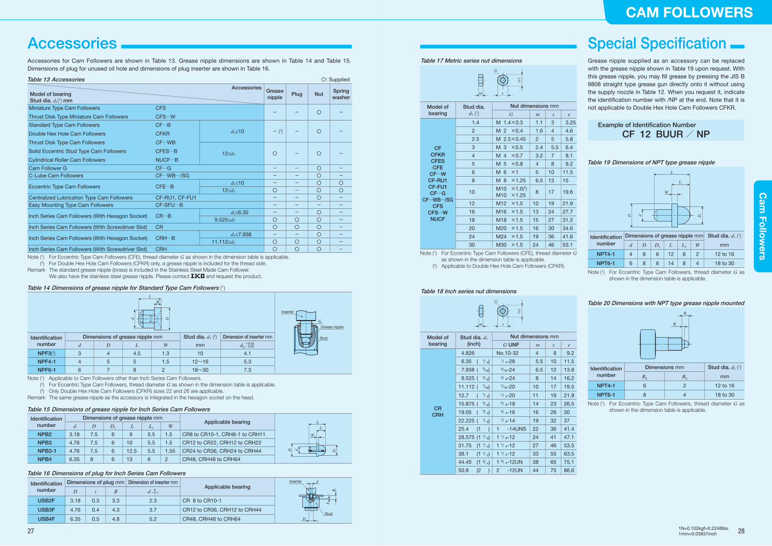
Accessories for Cam Followers are shown in Table 13. Grease nipple dimensions are shown in Table 14 and Table 15. Dimensions of plug for unused oil hole and dimensions of plug inserter are shown in Table 16.
Grease nipple supplied as an accessory can be replaced with the grease nipple shown in Table 19 upon request. With this grease nipple, you may fill grease by pressing the JIS B 9808 straight type grease gun directly onto it without using the supply nozzle in Table 12. When you request it, indicate the identification number with /NP at the end. Note that it is not applicable to Double Hex Hole Cam Followers CFKR.
Example of Identification Number
CF 12 BUUR / NP
Table 19 Dimensions of NPT type grease nipple
Identification number
Dimensions of grease nipple mm Stud dia. d1 (1)
d D D1 L L1 W mm
NPT4-1 4 8 6 12 6 2 12 to 16
NPT6-1 6 8 6 14 8 4 18 to 30
Note (1) For Eccentric Type Cam Followers, thread diameter G as shown in the dimension table is applicable.
Table 20 Dimensions with NPT type grease nipple mounted
Identification number
Dimensions mm Stud dia. d1 (1)
B4 B5 mm
NPT4-1 6 2 12 to 16
NPT6-1 8 4 18 to 30
Note (1) For Eccentric Type Cam Followers, thread diameter G as shown in the dimension table is applicable.
L1
L
W
D1
D d
B4
B5
Special Specification Table 17 Metric series nut dimensions
G
s
(e)
m
Model of bearing
Stud dia. d1 (1)
Nut dimensions mm
G m s e
CF CFKR CFES CFE
CF…W CF-RU1 CF-FU1 CF…G
CF…WB…/SG CFS
CFS…W NUCF
1.4 M 1.4×0.3 1.1 3 3.25
2 M 2 ×0.4 1.6 4 4.6
2.5 M 2.5×0.45 2 5 5.8
3 M 3 ×0.5 2.4 5.5 6.4
4 M 4 ×0.7 3.2 7 8.1
5 M 5 ×0.8 4 8 9.2
6 M 6 ×1 5 10 11.5
8 M 8 ×1.25 6.5 13 15
10M10 ×1.0(2)M10 ×1.25
8 17 19.6
12 M12 ×1.5 10 19 21.9
16 M16 ×1.5 13 24 27.7
18 M18 ×1.5 15 27 31.2
20 M20 ×1.5 16 30 34.6
24 M24 ×1.5 19 36 41.6
30 M30 ×1.5 24 46 53.1
Note (1) For Eccentric Type Cam Followers (CFE), thread diameter G as shown in the dimension table is applicable.
(2) Applicable to Double Hex Hole Cam Followers (CFKR).
Table 18 Inch series nut dimensions
(e)
s
G
m
Model of bearing
Stud dia. d1 (inch)
Nut dimensions mm
G UNF m s e
CR CRH
4.826 No.10-32 4 8 9.2
6.35 ( /1 4) 1/ 4-28 5.5 10 11.5
7.938 ( /516) 5/16-24 6.5 12 13.8
9.525 ( /3 8) 3/ 8-24 8 14 16.2
11.112 ( /716) 7/16-20 10 17 19.5
12.7 ( /1 2) 1/ 2-20 11 19 21.9
15.875 ( /5 8) 5/ 8-18 14 23 26.5
19.05 ( /3 4) 3/ 4-16 16 26 30
22.225 ( /7 8) 7/ 8-14 19 32 37
25.4 (1 ) 1 -14UNS 22 36 41.4
28.575 (1 /1 8) 1 1/ 8-12 24 41 47.1
31.75 (1 /1 4) 1 1/ 4-12 27 46 53.5
38.1 (1 /1 2) 1 1/ 2-12 33 55 63.5
44.45 (1 /3 4) 1 3/ 4-12UN 38 65 75.1
50.8 (2 ) 2 -12UN 44 75 86.6
Table 13 Accessories 〇: Supplied
AccessoriesModel of bearingStud dia. d1(1) mm
Grease nipple
Plug NutSpring washer
Miniature Type Cam Followers CFS
Thrust Disk Type Miniature Cam Followers CFS…W- - 〇 -
Standard Type Cam Followers CF…B
Double Hex Hole Cam Followers CFKR
Thrust Disk Type Cam Followers CF…WB
Solid Eccentric Stud Type Cam Followers CFES…B
Cylindrical Roller Cam Followers NUCF…B
d1≤10 - (2) - 〇 -
12≤d1 〇 - 〇 -
Cam Follower G CF…G - - 〇 -C-Lube Cam Followers CF…WB…/SG - - 〇 -
Eccentric Type Cam Followers CFE…Bd1≤10 - - 〇 〇
12≤d1 〇 - 〇 〇Centralized Lubrication Type Cam Followers CF-RU1, CF-FU1 - - 〇 -Easy Mounting Type Cam Followers CF-SFU…B - - - -
Inch Series Cam Followers (With Hexagon Socket) CR…Bd1≤6.35 - - 〇 -
9.525≤d1 〇 〇 〇 -Inch Series Cam Followers (With Screwdriver Slot) CR 〇 〇 〇 -
Inch Series Cam Followers (With Hexagon Socket) CRH…Bd1≤7.938 - - 〇 -
11.112≤d1 〇 〇 〇 -Inch Series Cam Followers (With Screwdriver Slot) CRH 〇 〇 〇 -Note (1) For Eccentric Type Cam Followers (CFE), thread diameter G as shown in the dimension table is applicable.
(2) For Double Hex Hole Cam Followers (CFKR) only, a grease nipple is included for the thread side.Remark The standard grease nipple (brass) is included in the Stainless Steel Made Cam Follower. We also have the stainless steel grease nipple. Please contact and request the product.
Table 15 Dimensions of grease nipple for Inch Series Cam Followers
Identification number
Dimensions of grease nipple mmApplicable bearing
d D D1 L L1 W
NPB2 3.18 7.5 6 9 5.5 1.5 CR8 to CR10-1, CRH8-1 to CRH11
NPB3 4.76 7.5 6 10 5.5 1.5 CR12 to CR22, CRH12 to CRH22
NPB3-1 4.76 7.5 6 12.5 5.5 1.55 CR24 to CR36, CRH24 to CRH44
NPB4 6.35 8 6 13 6 2 CR48, CRH48 to CRH64
L1
D1D d
L
W
Table 16 Dimensions of plug for Inch Series Cam Followers
Identification number
Dimensions of plug mm Dimension of inserter mmApplicable bearing
D t B d 0-0.1
USB2F 3.18 0.3 3.3 2.3 CR 8 to CR10-1
USB3F 4.76 0.4 4.3 3.7 CR12 to CR36, CRH12 to CRH44
USB4F 6.35 0.5 4.8 5.2 CR48, CRH48 to CRH64 D
dInserter
Stud
t
B
t
Table 14 Dimensions of grease nipple for Standard Type Cam Followers (1)
Identification number
Dimensions of grease nipple mm Stud dia. d1 (2) Dimension of inserter mm
d D L W mm d0 +0.05-0.05
NPF3(3) 3 4 4.5 1.3 10 4.1
NPF4-1 4 5 5 1.5 12~16 5.3
NPF6-1 6 7 8 2 18~30 7.3
Note (1) Applicable to Cam Followers other than Inch Series Cam Followers.(2) For Eccentric Type Cam Followers, thread diameter G as shown in the dimension table is applicable.(3) Only Double Hex Hole Cam Followers (CFKR) sizes 22 and 26 are applicable.
Remark The same grease nipple as the accessory is integrated in the hexagon socket on the head.
LW
Dd
d0
Inserter
Stud
Grease nipple
27 28
CAM FOLLOWERSC
am Fo
llow
ers
1N=0.102kgf=0.2248lbs.1mm=0.03937inch
Accessories
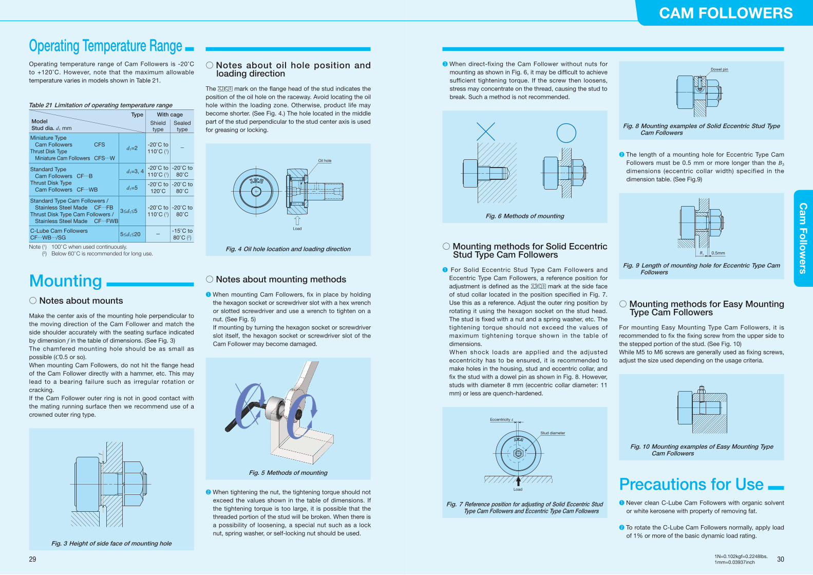
○ Notes about mounts
Make the center axis of the mounting hole perpendicular to the moving direction of the Cam Follower and match the side shoulder accurately with the seating surface indicated by dimension f in the table of dimensions. (See Fig. 3)The chamfered mounting hole should be as small as possible (C0.5 or so).When mounting Cam Followers, do not hit the flange head of the Cam Follower directly with a hammer, etc. This may lead to a bearing failure such as irregular rotation or cracking.If the Cam Follower outer ring is not in good contact with the mating running surface then we recommend use of a crowned outer ring type.
Fig. 3 Height of side face of mounting hole
f
○ Notes about oil hole position and loading direction
The mark on the flange head of the stud indicates the position of the oil hole on the raceway. Avoid locating the oil hole within the loading zone. Otherwise, product life may become shorter. (See Fig. 4.) The hole located in the middle part of the stud perpendicular to the stud center axis is used for greasing or locking.
Fig. 4 Oil hole location and loading direction
○ Notes about mounting methods
❶ When mounting Cam Followers, fix in place by holding the hexagon socket or screwdriver slot with a hex wrench or slotted screwdriver and use a wrench to tighten on a nut. (See Fig. 5)If mounting by turning the hexagon socket or screwdriver slot itself, the hexagon socket or screwdriver slot of the Cam Follower may become damaged.
Fig. 5 Methods of mounting
❷ When tightening the nut, the tightening torque should not exceed the values shown in the table of dimensions. If the tightening torque is too large, it is possible that the threaded portion of the stud will be broken. When there is a possibility of loosening, a special nut such as a lock nut, spring washer, or self-locking nut should be used.
Oil hole
Load
❸ When direct-fixing the Cam Follower without nuts for mounting as shown in Fig. 6, it may be difficult to achieve sufficient tightening torque. If the screw then loosens, stress may concentrate on the thread, causing the stud to break. Such a method is not recommended.
Fig. 6 Methods of mounting
○ Mounting methods for Solid Eccentric Stud Type Cam Followers
❶ For Solid Eccentric Stud Type Cam Followers and Eccentric Type Cam Followers, a reference position for adjustment is defined as the mark at the side face of stud collar located in the position specified in Fig. 7. Use this as a reference. Adjust the outer ring position by rotating it using the hexagon socket on the stud head. The stud is fixed with a nut and a spring washer, etc. The tightening torque should not exceed the values of maximum tightening torque shown in the table of dimensions.
When shock loads are applied and the adjusted eccentricity has to be ensured, it is recommended to make holes in the housing, stud and eccentric collar, and fix the stud with a dowel pin as shown in Fig. 8. However, studs with diameter 8 mm (eccentric collar diameter: 11 mm) or less are quench-hardened.
Stud diameter
Load
Eccentricity ε
Fig. 7 Reference position for adjusting of Solid Eccentric Stud Type Cam Followers and Eccentric Type Cam Followers
❷ The length of a mounting hole for Eccentric Type Cam Followers must be 0.5 mm or more longer than the B3 dimensions (eccentric collar width) specified in the dimension table. (See Fig.9)
0.5mmB3
Fig. 9 Length of mounting hole for Eccentric Type Cam Followers
○ Mounting methods for Easy Mounting Type Cam Followers
For mounting Easy Mounting Type Cam Followers, it is recommended to fix the fixing screw from the upper side to the stepped portion of the stud. (See Fig. 10)While M5 to M6 screws are generally used as fixing screws, adjust the size used depending on the usage criteria.
Fig. 10 Mounting examples of Easy Mounting Type Cam Followers
Dowel pin
Fig. 8 Mounting examples of Solid Eccentric Stud Type Cam Followers
❶ Never clean C-Lube Cam Followers with organic solvent or white kerosene with property of removing fat.
❷ To rotate the C-Lube Cam Followers normally, apply load of 1% or more of the basic dynamic load rating.
Precautions for Use
Operating temperature range of Cam Followers is -20°C to +120°C. However, note that the maximum allowable temperature varies in models shown in Table 21.
Table 21 Limitation of operating temperature rangeType
ModelStud dia. d1 mm
With cage
Shield type
Sealed type
Miniature Type Cam Followers CFS
Thrust Disk Type Miniature Cam Followers CFS…W
d1=2-20°C to 110°C (1)
-
Standard Type Cam Followers CF…B
Thrust Disk Type Cam Followers CF…WB
d1=3, 4-20°C to 110°C (1)
-20°C to 80°C
d1=5-20°C to 120°C
-20°C to 80°C
Standard Type Cam Followers / Stainless Steel Made CF…FB
Thrust Disk Type Cam Followers / Stainless Steel Made CF…FWB
3≤d1≤5-20°C to 110°C (1)
-20°C to 80°C
C-Lube Cam FollowersCF…WB…/SG
5≤d1≤20 - -15°C to 80°C (2)
Note (1) 100°C when used continuously. (2) Below 60°C is recommended for long use.
Operating Temperature Range
29 30
CAM FOLLOWERSC
am Fo
llow
ers
1N=0.102kgf=0.2248lbs.1mm=0.03937inch
Mounting

31 32
CAM FOLLOWERSC
am Fo
llow
ers
1N=0.102kgf=0.2248lbs.1mm=0.03937inch
Miniature Type Cam Followers
Stud diameter
Identification number Mass Boundary dimensions mm Mounting dimensions
f
Maximum tightening
torque
Basic dynamic load rating
C
Basic static load rating
C0
Maximum allowable static load
Track capacity(Ref.)
With cage Full complement
D C d1 G G1 B B1 B2 C1 H Min.mm g mm N・cm N N N N
2
CFS 2 ―
―CFS 2 V
0.6 4.5 2.5 2 M2 ×0.4 2 4 8 4 0.7 0.9 4.3 9.1
288 768
202 734
202 229
220CFS 2 F
――
CFS 2 FV 230 614
161 587
161 229
2.5
CFS 2.5 ―
―CFS 2.5 V
1 5 3 2.5 M2.5×0.45 2.5 4.5 9.5 5 0.7 0.9 4.8 18.7
4281 000
3511 080
351 360
298CFS 2.5 F
――
CFS 2.5 FV 342 800
281 862
281 360
3
CFS 3―
―CFS 3 V
2 6 4 3 M3 ×0.5 3 5.5 11.5 6 0.7 1.3 5.8 33.5
6291 420
6111 790
484 484
485CFS 3 F
――
CFS 3 FV 5041 140
4881 430
484 484
4
CFS 4―
―CFS 4 V
4 8 5 4 M4 ×0.7 4 7 15 8 1.0 1.5 7.7 77.7
1 1202 370
1 1203 000
919 919
799CFS 4 F
――
CFS 4 FV 8971 900
8942 400
894 919
5
CFS 5―
―CFS 5 V
7 10 6 5 M5 ×0.8 5 8 18 10 1.0 2 9.6 158
1 5703 180
1 8504 700
1 5701 570
1 210CFS 5 F
――
CFS 5 FV1 2502 540
1 4803 760
1 4801 570
6
CFS 6 ―
―CFS 6 V
13 12 7 6 M6 ×1 6 9.5 21.5 12 1.2 2.5 11.6 268
2 0904 610
2 2006 250
2 1502 150
1 680CFS 6 F
――
CFS 6 FV1 6703 690
1 7605 000
1 7602 150
Remarks 1. No oil hole is provided.2. Provided with pre-packed grease.
CFSCFS…F
B
H
C
B2
B1
G1
C1
D G
d 1
B
H
C
G1
C1
B1
B2
D G
f
d 1
CFS…VCFS…FV
Selectable product specifications
Type of
material
Roller guide
method
Seal
structure
Shape of
outer ring
outside surface
No symbol
High carbon steel
F Stainless steel
No symbol With cage
V Full complement
No symbol Shield type
UU Sealed type
No symbol
Cylindrical outer ring
R Crowned outer ring
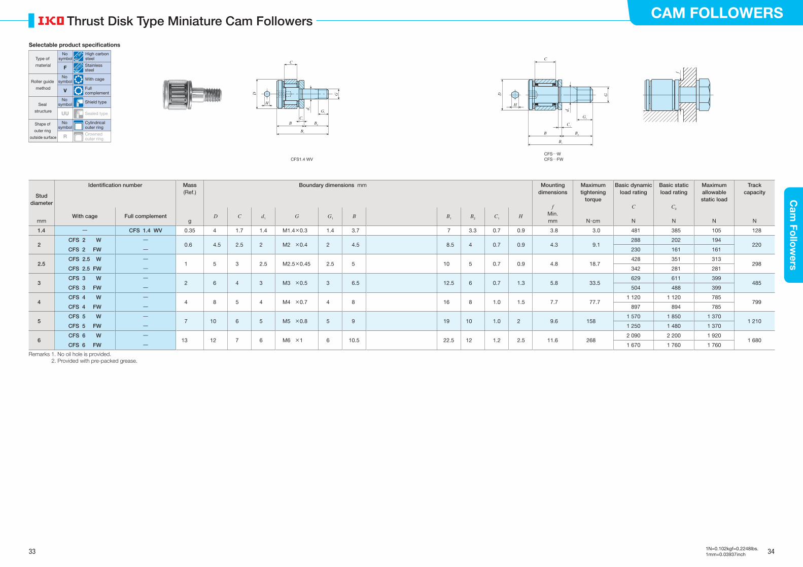
33 34
CAM FOLLOWERSC
am Fo
llow
ers
1N=0.102kgf=0.2248lbs.1mm=0.03937inch
Thrust Disk Type Miniature Cam Followers
Stud diameter
Identification number Mass Boundary dimensions mm Mounting dimensions
f
Maximum tightening
torque
Basic dynamic load rating
C
Basic static load rating
C0
Maximum allowable static load
Track capacity(Ref.)
With cage Full complement
D C d1 G G1 B B1 B2 C1 H Min.mm g mm N・cm N N N N
1.4 ― CFS 1.4 WV 0.35 4 1.7 1.4 M1.4×0.3 1.4 3.7 7 3.3 0.7 0.9 3.8 3.0 481 385 105 128
2CFS 2 W ―
0.6 4.5 2.5 2 M2 ×0.4 2 4.5 8.5 4 0.7 0.9 4.3 9.1 288 202 194
220CFS 2 FW ― 230 161 161
2.5CFS 2.5 W ―
1 5 3 2.5 M2.5×0.45 2.5 5 10 5 0.7 0.9 4.8 18.7 428 351 313
298CFS 2.5 FW ― 342 281 281
3CFS 3 W ―
2 6 4 3 M3 ×0.5 3 6.5 12.5 6 0.7 1.3 5.8 33.5 629 611 399
485CFS 3 FW ― 504 488 399
4CFS 4 W ―
4 8 5 4 M4 ×0.7 4 8 16 8 1.0 1.5 7.7 77.71 120 1 120 785
799CFS 4 FW ― 897 894 785
5CFS 5 W ―
7 10 6 5 M5 ×0.8 5 9 19 10 1.0 2 9.6 1581 570 1 850 1 370
1 210CFS 5 FW ― 1 250 1 480 1 370
6CFS 6 W ―
13 12 7 6 M6 ×1 6 10.5 22.5 12 1.2 2.5 11.6 2682 090 2 200 1 920
1 680CFS 6 FW ― 1 670 1 760 1 760
Remarks 1. No oil hole is provided.2. Provided with pre-packed grease.
CFS1.4 WV
B
H
C
B2
B1
G1
C1
D G
d 1
B
H
C
G1
C1
B1
B2
D G
d 1
CFS…WCFS…FW
f
Selectable product specifications
Type of
material
Roller guide
method
Seal
structure
Shape of
outer ring
outside surface
No symbol
High carbon steel
F Stainless steel
No symbol With cage
V Full complement
No symbol Shield type
UU Sealed type
No symbol
Cylindrical outer ring
R Crowned outer ring
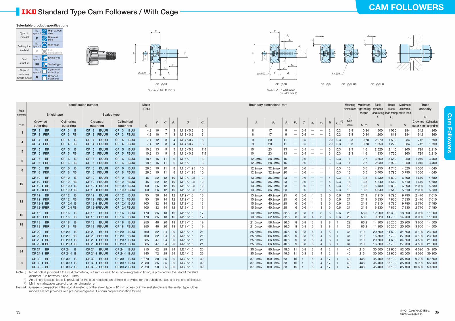
35 36
CAM FOLLOWERSC
am Fo
llow
ers
1N=0.102kgf=0.2248lbs.1mm=0.03937inch
Standard Type Cam Followers / With Cage
Stud diameter
Identification number Mass Boundary dimensions mm Mounting dimensions
f
Maximum tightening
torque
Basic dynamic
load ratingC
Basic static
load ratingC0
Maximum allowable static load
Track capacity
N
(Ref.)
Shield type Sealed type
D C d1 G G1 B B1 B2 B3 C1 g1 g2 H (3)rs minCrowned outer ring
Cylindrical outer ring
Crowned outer ring
Cylindrical outer ring
Min. Crowned outer ring
Cylindrical outer ringmm g mm N・m N N N
3CF 3 BR CF 3 FBR
CF 3 BCF 3 FB
CF 3 BUURCF 3 FBUUR
CF 3 BUUCF 3 FBUU
4.34.3
1010
7 7
3 3
M 3×0.5M 3×0.5
55
8 8
17 17
9 9
――
0.50.5
――
――
22
0.20.2
6.86.8
0.340.34
1 500 1 200
1 020 813
384 384
542542
1 3601 360
4CF 4 BRCF 4 FBR
CF 4 BCF 4 FB
CF 4 BUURCF 4 FBUUR
CF 4 BUUCF 4 FBUU
7.47.4
1212
8 8
4 4
M 4×0.7M 4×0.7
66
9 9
20 20
1111
――
0.50.5
――
――
2.52.5
0.30.3
8.38.3
0.780.78
2 070 1 650
1 590 1 270
834 834
712712
1 7901 790
5CF 5 BRCF 5 FBR
CF 5 BCF 5 FB
CF 5 BUURCF 5 FBUUR
CF 5 BUUCF 5 FBUU
10.310.3
1313
9 9
5 5
M 5×0.8M 5×0.8
7.57.5
1010
23 23
1313
――
0.50.5
――
――
33
0.30.3
9.39.3
1.61.6
2 520 1 930
2 140 1 730
1 260 1 260
794794
2 2102 210
6CF 6 BRCF 6 FBR
CF 6 BCF 6 FB
CF 6 BUURCF 6 FBUUR
CF 6 BUUCF 6 FBUU
18.518.5
1616
1111
6 6
M 6×1M 6×1
88
12.2max12.2max
28.2max 28.2max
1616
――
0.60.6
――
――
33
0.30.3
1111
2.72.7
3 660 2 930
3 650 2 920
1 950 1 950
1 0401 040
3 4003 400
8CF 8 BRCF 8 FBR
CF 8 BCF 8 FB
CF 8 BUURCF 8 FBUUR
CF 8 BUUCF 8 FBUU
28.528.5
1919
1111
8 8
M 8×1.25M 8×1.25
1010
12.2max12.2max
32.2max 32.2max
2020
――
0.60.6
――
――
44
0.30.3
1313
6.56.5
4 250 3 400
4 740 3 790
4 620 3 790
1 3301 330
4 0404 040
10
CF 10 BRCF 10 FBRCF 10-1 BRCF 10-1FBR
CF 10 BCF 10 FBCF 10-1 BCF 10-1FB
CF 10 BUURCF 10 FBUURCF 10-1 BUURCF 10-1FBUUR
CF 10 BUUCF 10 FBUUCF 10-1 BUUCF 10-1FBUU
45456060
22222626
12121212
10101010
M10×1.25M10×1.25M10×1.25M10×1.25
12121212
13.2max13.2max13.2max13.2max
36.2max 36.2max 36.2max 36.2max
23232323
――――
0.60.60.60.6
――――
――――
4545
0.30.30.30.3
16161616
13.813.813.813.8
5 430 4 340 5 430 4 340
6 890 5 510 6 890 5 510
6 890 5 510 6 890 5 510
1 6101 6102 0302 030
4 6804 6805 5305 530
12
CF 12 BRCF 12 FBRCF 12-1 BRCF 12-1FBR
CF 12 BCF 12 FBCF 12-1 BCF 12-1FB
CF 12 BUURCF 12 FBUURCF 12-1 BUURCF 12-1FBUUR
CF 12 BUUCF 12 FBUUCF 12-1 BUUCF 12-1FBUU
9595
105105
30303232
14141414
12121212
M12×1.5M12×1.5M12×1.5M12×1.5
13131313
15.2max15.2max15.2max15.2max
40.2max 40.2max 40.2max 40.2max
25252525
6 6 6 6
0.60.60.60.6
4444
3333
6666
0.60.60.60.6
21212121
21.921.921.921.9
7 910 6 330 7 910 6 330
9 790 7 830 9 790 7 830
9 790 7 830 9 790 7 830
2 4702 4702 7102 710
7 0107 0107 4807 480
16CF 16 BRCF 16 FBR
CF 16 BCF 16 FB
CF 16 BUURCF 16 FBUUR
CF 16 BUUCF 16 FBUU
170170
3535
1818
1616
M16×1.5M16×1.5
1717
19.6max19.6max
52.1max 52.1max
32.532.5
8 8
0.80.8
44
33
66
0.60.6
2626
58.558.5
12 000 9 620
18 30014 700
18 30014 700
3 0603 060
11 20011 200
18CF 18 BRCF 18 FBR
CF 18 BCF 18 FB
CF 18 BUURCF 18 FBUUR
CF 18 BUUCF 18 FBUU
250250
4040
2020
1818
M18×1.5M18×1.5
1919
21.6max21.6max
58.1max 58.1max
36.536.5
8 8
0.80.8
66
33
88
11
2929
86.286.2
14 80011 800
25 20020 200
25 20020 200
3 6603 660
14 50014 500
20
CF 20 BRCF 20 FBRCF 20-1 BRCF 20-1FBR
CF 20 BCF 20 FBCF 20-1 BCF 20-1FB
CF 20 BUURCF 20 FBUURCF 20-1 BUURCF 20-1FBUUR
CF 20 BUUCF 20 FBUUCF 20-1 BUUCF 20-1FBUU
460460385385
52524747
24242424
20202020
M20×1.5M20×1.5M20×1.5M20×1.5
21212121
25.6max25.6max25.6max25.6max
66.1max 66.1max 66.1max 66.1max
40.540.540.540.5
9 9 9 9
0.80.80.80.8
6666
4444
8888
1111
34343434
119119119119
20 70016 50020 70016 500
34 60027 70034 60027 700
34 60027 70034 60027 700
5 1905 1904 5304 530
23 20023 20021 00021 000
24CF 24 BRCF 24-1 BR
CF 24 BCF 24-1 B
CF 24 BUURCF 24-1 BUUR
CF 24 BUUCF 24-1 BUU
8151 140
6272
2929
2424
M24×1.5M24×1.5
2525
30.6max30.6max
80.1max 80.1max
49.549.5
1111
0.80.8
66
44
1212
11
4040
215215
30 50030 500
52 60052 600
52 00052 000
6 5808 020
34 30039 800
30CF 30 BRCF 30-1 BRCF 30-2 BR
CF 30 BCF 30-1 BCF 30-2 B
CF 30 BUURCF 30-1 BUURCF 30-2 BUUR
CF 30 BUUCF 30-1 BUUCF 30-2 BUU
1 8702 0302 220
808590
353535
303030
M30×1.5M30×1.5M30×1.5
323232
37 max37 max37 max
100 max100 max100 max
636363
151515
111
666
444
171717
111
494949
438438438
45 40045 40045 400
85 10085 10085 100
85 10085 10085 100
9 2209 990
10 800
52 70056 00059 300
Note (1) No oil hole is provided if the stud diameter d1 is 4 mm or less. An oil hole (re-greasing �tting) is provided for the head if the stud diameter d1 is between 5 and 10 mm.
(2) An oil hole (grease nipple) is provided for the stud head and an oil hole is provided for the outside surface and the end of the stud. (3) Minimum allowable value of chamfer dimension r.Remark Grease is pre-packed if the stud diameter d1 of the shield type is 10 mm or less or if the seal structure is the sealed type. Other
models are not provided with pre-packed grease. Perform proper lubrication for use.
BR = 500
H
C
B2
B1
G1
C1
D G
d 1
Stud dia. d1 12 to 30 mm (2)(12 to 20 mm) (2)
CF…(F)BR CF…(F)B CF…(F)BUUR CF…(F)BUUCF…(F)BR
Stud dia. d1 3 to 10 mm (1)
f
R = 500R = 500
r
r
r
r
B
H
C
G1
C1
B1
B2
D G
d 1
g 1
B3
g2
Selectable product specifications
Type of
material
Roller guide
method
Seal
structure
Shape of
outer ring
outside surface
No symbol
High carbon steel
F Stainless steel
No symbol With cage
V Full complement
No symbol Shield type
UU Sealed type
No symbol
Cylindrical outer ring
R Crowned outer ring
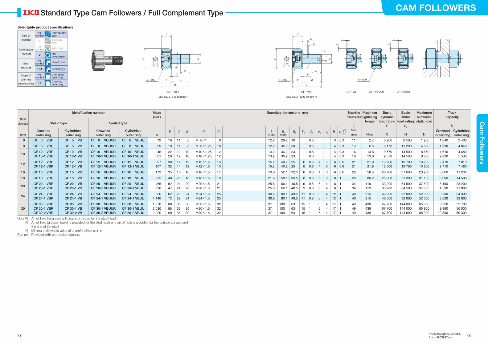
37 38
CAM FOLLOWERSC
am Fo
llow
ers
1N=0.102kgf=0.2248lbs.1mm=0.03937inch
Standard Type Cam Followers / Full Complement Type
Stud diameter
Identification number Mass Boundary dimensions mm Mounting dimensions
f
Maximum tightening
torque
Basic dynamic
load ratingC
Basic static
load ratingC0
Maximum allowable static load
Track capacity
N
(Ref.)
Shield type Sealed type
D C d1 G G1 Bmax
B1max
B2 B3 C1 g1 g2 H (3)rs minCrowned outer ring
Cylindrical outer ring
Crowned outer ring
Cylindrical outer ring
Min. Crowned outer ring
Cylindrical outer ringmm g mm N・m N N N
6 CF 6 VBR CF 6 VB CF 6 VBUUR CF 6 VBUU 19 16 11 6 M 6×1 8 12.2 28.2 16 ― 0.6 ― ― 3 0.3 11 2.7 6 980 8 500 1 950 1 040 3 400
8 CF 8 VBR CF 8 VB CF 8 VBUUR CF 8 VBUU 29 19 11 8 M 8×1.25 10 12.2 32.2 20 ― 0.6 ― ― 4 0.3 13 6.5 8 170 11 200 4 620 1 330 4 040
10CF 10 VBRCF 10-1 VBR
CF 10 VBCF 10-1 VB
CF 10 VBUURCF 10-1 VBUUR
CF 10 VBUUCF 10-1 VBUU
46 61
2226
1212
1010
M10×1.25M10×1.25
1212
13.213.2
36.236.2
2323
――
0.60.6
――
――
4 4
0.30.3
1616
13.813.8
9 570 9 570
14 500 14 500
8 650 8 650
1 6102 030
4 6805 530
12CF 12 VBRCF 12-1 VBR
CF 12 VBCF 12-1 VB
CF 12 VBUURCF 12-1 VBUUR
CF 12 VBUUCF 12-1 VBUU
97 107
3032
1414
1212
M12×1.5M12×1.5
1313
15.215.2
40.240.2
2525
6 6
0.60.6
44
33
6 6
0.60.6
2121
21.921.9
13 50013 500
19 700 19 700
13 20013 200
2 4702 710
7 0107 480
16 CF 16 VBR CF 16 VB CF 16 VBUUR CF 16 VBUU 173 35 18 16 M16×1.5 17 19.6 52.1 32.5 8 0.8 4 3 6 0.6 26 58.5 20 700 37 600 23 200 3 060 11 200
18 CF 18 VBR CF 18 VB CF 18 VBUUR CF 18 VBUU 255 40 20 18 M18×1.5 19 21.6 58.1 36.5 8 0.8 6 3 8 1 29 86.2 25 300 51 300 31 100 3 660 14 500
20CF 20 VBRCF 20-1 VBR
CF 20 VBCF 20-1 VB
CF 20 VBUURCF 20-1 VBUUR
CF 20 VBUUCF 20-1 VBUU
465 390
5247
2424
2020
M20×1.5M20×1.5
2121
25.625.6
66.166.1
40.540.5
9 9
0.80.8
66
44
8 8
11
3434
119119
33 20033 200
64 500 64 500
37 50037 500
5 1904 530
23 20021 000
24CF 24 VBRCF 24-1 VBR
CF 24 VBCF 24-1 VB
CF 24 VBUURCF 24-1 VBUUR
CF 24 VBUUCF 24-1 VBUU
8201 140
6272
2929
2424
M24×1.5M24×1.5
2525
30.630.6
80.180.1
49.549.5
1111
0.80.8
66
44
1212
11
4040
215215
46 60046 600
92 000 92 000
52 00052 000
6 5808 020
34 30039 800
30CF 30 VBRCF 30-1 VBRCF 30-2 VBR
CF 30 VBCF 30-1 VBCF 30-2 VB
CF 30 VBUURCF 30-1 VBUURCF 30-2 VBUUR
CF 30 VBUUCF 30-1 VBUUCF 30-2 VBUU
1 8702 0302 220
808590
353535
303030
M30×1.5M30×1.5M30×1.5
323232
373737
100100100
636363
151515
111
666
444
171717
111
494949
438438438
67 70067 70067 700
144 000144 000144 000
85 90085 90085 900
9 2209 990
10 800
52 70056 00059 300
Note (1) An oil hole (re-greasing �tting) is provided for the stud head. (2) An oil hole (grease nipple) is provided for the stud head and an oil hole is provided for the outside surface and
the end of the stud. (3) Minimum allowable value of chamfer dimension r.Remark Provided with pre-packed grease.
Stud dia. d1 12 to 30 mm (2)
CF…VBR CF…VB CF…VBUUR CF…VBUUCF…VBR
Stud dia. d1 6 to 10 mm (1)
BR = 500
H
C
B2
B1
G1
C1
D G
d 1
f
R = 500R = 500
r
r
r
r
B
H
C
G1
C1
B1
B2
D G
d 1
g 1
B3
g2
Selectable product specifications
Type of
material
Roller guide
method
Seal
structure
Shape of
outer ring
outside surface
No symbol
High carbon steel
F Stainless steel
No symbol With cage
V Full complement
No symbol Shield type
UU Sealed type
No symbol
Cylindrical outer ring
R Crowned outer ring
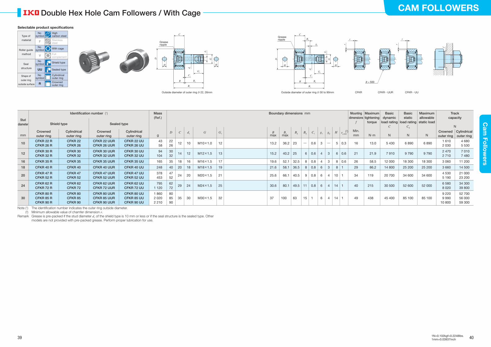
39 40
CAM FOLLOWERSC
am Fo
llow
ers
1N=0.102kgf=0.2248lbs.1mm=0.03937inch
Double Hex Hole Cam Followers / With Cage
Stud diameter
Identification number (1) Mass Boundary dimensions mm Mounting dimensions
f
Maximum tightening
torque
Basic dynamic
load ratingC
Basic static
load ratingC0
Maximum allowable static load
Track capacity
N
(Ref.)
Shield type Sealed type
D C d1 G G1 Bmax
B1max
B2 B3 C1 g1 g2 H (2)rs minCrowned outer ring
Cylindrical outer ring
Crowned outer ring
Cylindrical outer ring
Min. Crowned outer ring
Cylindrical outer ringmm g mm N・m N N N
10CFKR 22 RCFKR 26 R
CFKR 22CFKR 26
CFKR 22 UURCFKR 26 UUR
CFKR 22 UUCFKR 26 UU
4358
2226
12 10 M10×1.0 12 13.2 36.2 23 ― 0.6 3 ― 5 0.3 16 13.0 5 430 6 890 6 8901 6102 030
4 6805 530
12CFKR 30 RCFKR 32 R
CFKR 30CFKR 32
CFKR 30 UURCFKR 32 UUR
CFKR 30 UUCFKR 32 UU
94104
3032
14 12 M12×1.5 13 15.2 40.2 25 6 0.6 4 3 6 0.6 21 21.9 7 910 9 790 9 7902 4702 710
7 0107 480
16 CFKR 35 R CFKR 35 CFKR 35 UUR CFKR 35 UU 165 35 18 16 M16×1.5 17 19.6 52.1 32.5 8 0.8 4 3 8 0.6 26 58.5 12 000 18 300 18 300 3 060 11 200
18 CFKR 40 R CFKR 40 CFKR 40 UUR CFKR 40 UU 248 40 20 18 M18×1.5 19 21.6 58.1 36.5 8 0.8 6 3 8 1 29 86.2 14 800 25 200 25 200 3 660 14 500
20CFKR 47 RCFKR 52 R
CFKR 47CFKR 52
CFKR 47 UURCFKR 52 UUR
CFKR 47 UUCFKR 52 UU
378453
4752
24 20 M20×1.5 21 25.6 66.1 40.5 9 0.8 6 4 10 1 34 119 20 700 34 600 34 6004 5305 190
21 00023 200
24CFKR 62 RCFKR 72 R
CFKR 62CFKR 72
CFKR 62 UURCFKR 72 UUR
CFKR 62 UUCFKR 72 UU
7951 120
6272
29 24 M24×1.5 25 30.6 80.1 49.5 11 0.8 6 4 14 1 40 215 30 500 52 600 52 0006 5808 020
34 30039 800
30CFKR 80 RCFKR 85 RCFKR 90 R
CFKR 80CFKR 85CFKR 90
CFKR 80 UURCFKR 85 UURCFKR 90 UUR
CFKR 80 UUCFKR 85 UUCFKR 90 UU
1 8602 0202 210
808590
35 30 M30×1.5 32 37 100 63 15 1 6 4 14 1 49 438 45 400 85 100 85 1009 2209 990
10 800
52 70056 00059 300
Note (1) The identification number indicates the outer ring outside diameter. (2) Minimum allowable value of chamfer dimension r.Remark Grease is pre-packed if the stud diameter d1 of the shield type is 10 mm or less or if the seal structure is the sealed type. Other
models are not provided with pre-packed grease. Perform proper lubrication for use.
CFKR CFKR…UUR CFKR…UU
r
r
r
r
R = 500
f
Outside diameter of outer ring D 22, 26mm Outside diameter of outer ring D 30 to 90mm
H
B1
G1
D
d 1
g 1
H
Grease nipple
B B2
C1
G
CGrease nipple
B B2
C1
G
C
g2
B3
H
B1
G1
D
d 1
H
g 1
Selectable product specifications
Type of
material
Roller guide
method
Seal
structure
Shape of
outer ring
outside surface
No symbol
High carbon steel
F Stainless steel
No symbol With cage
V Full complement
No symbol Shield type
UU Sealed type
No symbol
Cylindrical outer ring
R Crowned outer ring
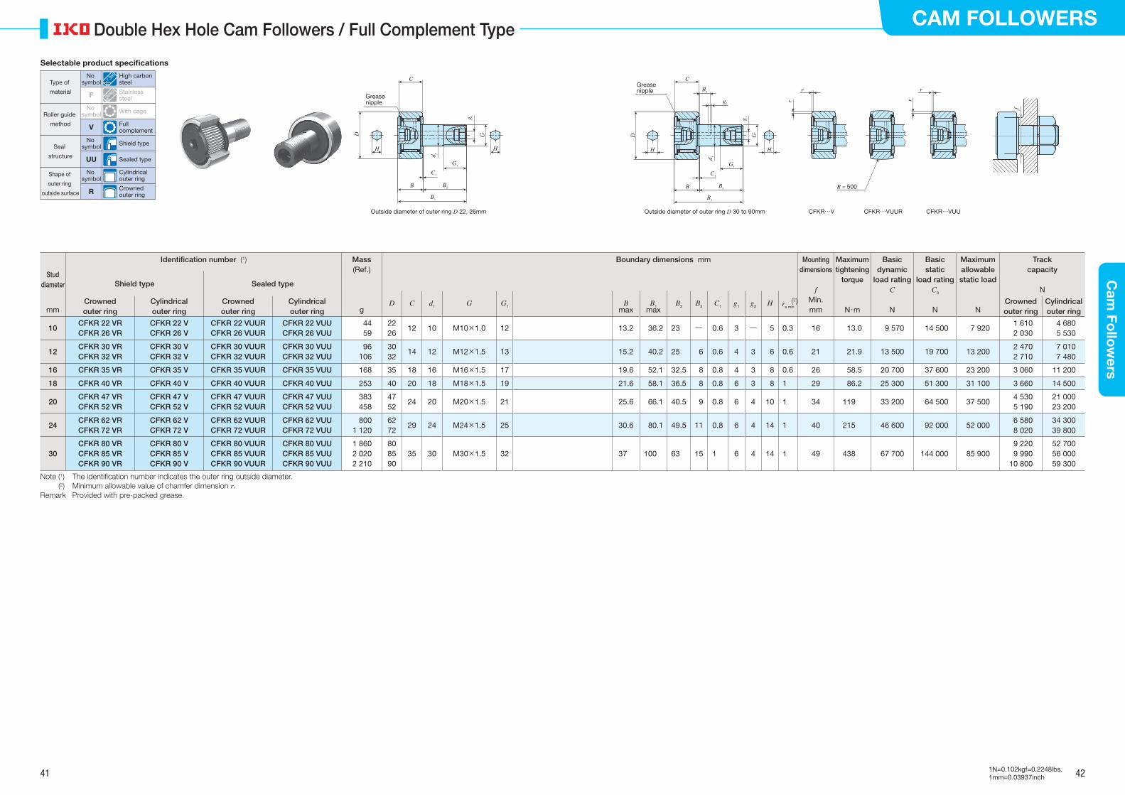
41 42
CAM FOLLOWERSC
am Fo
llow
ers
1N=0.102kgf=0.2248lbs.1mm=0.03937inch
Double Hex Hole Cam Followers / Full Complement Type
Stud diameter
Identification number (1) Mass Boundary dimensions mm Mounting dimensions
f
Maximum tightening
torque
Basic dynamic
load ratingC
Basic static
load ratingC0
Maximum allowable static load
Track capacity
N
(Ref.)
Shield type Sealed type
D C d1 G G1 Bmax
B1max
B2 B3 C1 g1 g2 H (2)rs minCrowned outer ring
Cylindrical outer ring
Crowned outer ring
Cylindrical outer ring
Min. Crowned outer ring
Cylindrical outer ringmm g mm N・m N N N
10CFKR 22 VRCFKR 26 VR
CFKR 22 VCFKR 26 V
CFKR 22 VUURCFKR 26 VUUR
CFKR 22 VUUCFKR 26 VUU
4459
2226
12 10 M10×1.0 12 13.2 36.2 23 ― 0.6 3 ― 5 0.3 16 13.0 9 570 14 500 7 9201 6102 030
4 6805 530
12CFKR 30 VR CFKR 32 VR
CFKR 30 V CFKR 32 V
CFKR 30 VUUR CFKR 32 VUUR
CFKR 30 VUU CFKR 32 VUU
96106
30 32
14 12 M12×1.5 13 15.2 40.2 25 6 0.6 4 3 6 0.6 21 21.9 13 500 19 700 13 2002 4702 710
7 0107 480
16 CFKR 35 VR CFKR 35 V CFKR 35 VUUR CFKR 35 VUU 168 35 18 16 M16×1.5 17 19.6 52.1 32.5 8 0.8 4 3 8 0.6 26 58.5 20 700 37 600 23 200 3 060 11 200
18 CFKR 40 VR CFKR 40 V CFKR 40 VUUR CFKR 40 VUU 253 40 20 18 M18×1.5 19 21.6 58.1 36.5 8 0.8 6 3 8 1 29 86.2 25 300 51 300 31 100 3 660 14 500
20CFKR 47 VR CFKR 52 VR
CFKR 47 V CFKR 52 V
CFKR 47 VUUR CFKR 52 VUUR
CFKR 47 VUU CFKR 52 VUU
383458
47 52
24 20 M20×1.5 21 25.6 66.1 40.5 9 0.8 6 4 10 1 34 119 33 200 64 500 37 5004 5305 190
21 00023 200
24CFKR 62 VR CFKR 72 VR
CFKR 62 V CFKR 72 V
CFKR 62 VUUR CFKR 72 VUUR
CFKR 62 VUU CFKR 72 VUU
8001 120
62 72
29 24 M24×1.5 25 30.6 80.1 49.5 11 0.8 6 4 14 1 40 215 46 600 92 000 52 0006 5808 020
34 30039 800
30CFKR 80 VR CFKR 85 VR CFKR 90 VR
CFKR 80 V CFKR 85 V CFKR 90 V
CFKR 80 VUUR CFKR 85 VUUR CFKR 90 VUUR
CFKR 80 VUU CFKR 85 VUU CFKR 90 VUU
1 8602 0202 210
80 85 90
35 30 M30×1.5 32 37 100 63 15 1 6 4 14 1 49 438 67 700 144 000 85 9009 2209 990
10 800
52 70056 00059 300
Note (1) The identi�cation number indicates the outer ring outside diameter. (2) Minimum allowable value of chamfer dimension r.Remark Provided with pre-packed grease.
CFKR…V CFKR…VUUR CFKR…VUU
r
r
r
r
R = 500
f
H
B1
G1
D
d 1
g 1
H
B B2
C1
G
C
B B2
C1
G
C
g2
B3
H
B1
G1
D
d 1
H
g 1
Grease nipple
Grease nipple
Outside diameter of outer ring D 22, 26mm Outside diameter of outer ring D 30 to 90mm
Selectable product specifications
Type of
material
Roller guide
method
Seal
structure
Shape of
outer ring
outside surface
No symbol
High carbon steel
F Stainless steel
No symbol With cage
V Full complement
No symbol Shield type
UU Sealed type
No symbol
Cylindrical outer ring
R Crowned outer ring

43 44
CAM FOLLOWERSC
am Fo
llow
ers
1N=0.102kgf=0.2248lbs.1mm=0.03937inch
Cam Follower G
Stud diameter
Identification number Mass Boundary dimensions mm Mounting dimensions
f
Maximum tightening
torque
Basic dynamic load rating
C
Basic static load rating
C0
Maximum allowable static load
Track capacity(Ref.)
With cage
D C d1 G G1 Bmax
B1max
B2 C1 H (1)rs min
Min.mm g mm N・m N N N N
6 CF 6 G 19.5 16 11 6 M 6 ×1 8 12.2 28.2 16 0.6 3 0.3 11 2.7 3 660 3 650 1 950 3 400
8 CF 8 G 29.5 19 11 8 M 8 ×1.25 10 12.2 32.2 20 0.6 4 0.3 13 6.5 4 250 4 740 4 620 4 040
10CF 10 GCF 10-1 G
47.561.5
2226
1212
1010
M10 ×1.25M10 ×1.25
1212
13.213.2
36.236.2
2323
0.60.6
44
0.30.3
1616
13.813.8
5 430 5 430
6 890 6 890
6 890 6 890
4 6805 530
12CF 12 GCF 12-1 G
95.0105
3032
1414
1212
M12 ×1.5M12 ×1.5
1313
15.215.2
40.240.2
2525
0.60.6
66
0.60.6
2121
23.923.9
7 910 7 910
9 790 9 790
9 790 9 790
7 0107 480
16 CF 16 G 175 35 18 16 M16 ×1.5 17 19.6 52.1 32.5 0.8 6 0.6 26 61.1 12 000 18 300 18 300 11 200
18 CF 18 G 255 40 20 18 M18 ×1.5 19 21.6 58.1 36.5 0.8 8 1 29 89.2 14 800 25 200 25 200 14 500
20CF 20 GCF 20-1 G
470400
5247
2424
2020
M20 ×1.5M20 ×1.5
2121
25.625.6
66.166.1
40.540.5
0.80.8
88
11
3434
125125
20 70020 700
34 60034 600
34 60034 600
23 20021 000
Note (1) Minimum allowable value of chamfer dimension r.Remarks 1. This bearing cannot be re-lubricated due to its structure. If re-lubrication is necessary, please use Standard Type Cam
Followers. 2. Provided with pre-packed grease.
CF…G
B
H
C
r
B2
B1
G1
C1
D
r
G
d 1
f
Selectable product specifications
Type of
material
Roller guide
method
Seal
structure
Shape of
outer ring
outside surface
No symbol
High carbon steel
F Stainless steel
No symbol With cage
V Full complement
No symbol Shield type
UU Sealed type
No symbol
Cylindrical outer ring
R Crowned outer ring

45 46
CAM FOLLOWERSC
am Fo
llow
ers
1N=0.102kgf=0.2248lbs.1mm=0.03937inch
Thrust Disk Type Cam Followers
Stud diameter
Identification number Mass Boundary dimensions mm Mounting dimensions
f
Maximum tightening
torque
Basic dynamic
load ratingC
Basic static
load ratingC0
Maximum allowable static load
Track capacity(Ref.)
Shield type Sealed type
D C d1 G G1 B B1 B2 B3 C1 g1 g2 H Min.mm g mm N・m N N N N
3CF 3 WBRCF 3 FWBR
CF 3 WBUURCF 3 FWBUUR
4.34.3
1010
7 7
3 3
M 3×0.5M 3×0.5
55
8 8
1717
99
――
0.50.5
――
――
22
6.86.8
0.340.34
1 500 1 200
1 020 813
384 384
542542
4CF 4 WBRCF 4 FWBR
CF 3 WBUURCF 3 FWBUUR
7.47.4
1212
8 8
4 4
M 4×0.7M 4×0.7
66
9 9
2020
1111
――
0.50.5
――
――
2.52.5
8.38.3
0.780.78
2 070 1 650
1 590 1 270
834 834
712712
5CF 5 WBRCF 5 FWBR
CF 5 WBUURCF 5 FWBUUR
10.310.3
1313
9 9
5 5
M 5×0.8M 5×0.8
7.57.5
1010
2323
1313
――
0.50.5
――
――
33
9.39.3
1.61.6
2 520 1 930
2 140 1 730
1 260 1 260
794794
6 CF 6 WBR CF 6 WBUUR 18.5 16 11 6 M 6×1 8 12.2max 28.2max 16 ― 0.6 ― ― 3 11 2.7 3 660 3 650 1 950 1 040
8 CF 8 WBR CF 8 WBUUR 28.5 19 11 8 M 8×1.25 10 12.2max 32.2max 20 ― 0.6 ― ― 4 13 6.5 4 250 4 740 4 620 1 330
10CF 10 WBRCF 10-1 WBR
CF 10 WBUURCF 10-1 WBUUR
4560
2226
1212
1010
M10×1.25M10×1.25
1212
13.2max13.2max
36.2max36.2max
2323
――
0.60.6
――
――
44
1616
13.813.8
5 430 5 430
6 890 6 890
6 890 6 890
1 6102 030
12CF 12 WBRCF 12-1 WBR
CF 12 WBUURCF 12-1 WBUUR
95105
3032
1414
1212
M12×1.5M12×1.5
1313
15.2max15.2max
40.2max40.2max
2525
66
0.60.6
44
33
66
2121
21.921.9
7 910 7 910
9 790 9 790
9 790 9 790
2 4702 710
16 CF 16 WBR CF 16 WBUUR 170 35 18 16 M16×1.5 17 19.6max 52.1max 32.5 8 0.8 4 3 6 26 58.5 12 000 18 300 18 300 3 060
18 CF 18 WBR CF 18 WBUUR 250 40 20 18 M18×1.5 19 21.6max 58.1max 36.5 8 0.8 6 3 8 29 86.2 14 800 25 200 25 200 3 660
20CF 20 WBRCF 20-1 WBR
CF 20 WBUURCF 20-1 WBUUR
460385
5247
2424
2020
M20×1.5M20×1.5
2121
25.6max25.6max
66.1max66.1max
40.540.5
99
0.80.8
66
44
88
3434
119119
20 70020 700
34 60034 600
34 60034 600
5 1904 530
Note (1) No oil hole is provided if the stud diameter d1 is 4 mm or less. An oil hole (re-greasing �tting) is provided for the head if the stud diameter d1 is between 5 and 10 mm.
(2) An oil hole (grease nipple) is provided for the stud head and an oil hole is provided for the outside surface and the end of the stud.Remark Grease is pre-packed if the stud diameter d1 of the shield type is 10 mm or less or if the seal structure is the sealed type. Other
models are not provided with pre-packed grease. Perform proper lubrication for use.
BR = 500
H
C
B2
B1
G1
C1
D G
d 1
Stud dia. d1 12 to 20 mm (2)
CF…WBR CF…(F)WBUURCF…(F)WBR
Stud dia. d1 3 to 10 mm (1)(3 to 5 mm) (1)
f
R = 500R = 500 B
H
C
G1
C1
B1
B2
D G
d 1
g 1
B3
g2
Selectable product specifications
Type of
material
Roller guide
method
Seal
structure
Shape of
outer ring
outside surface
No symbol
High carbon steel
F Stainless steel
No symbol With cage
V Full complement
No symbol Shield type
UU Sealed type
No symbol
Cylindrical outer ring
R Crowned outer ring
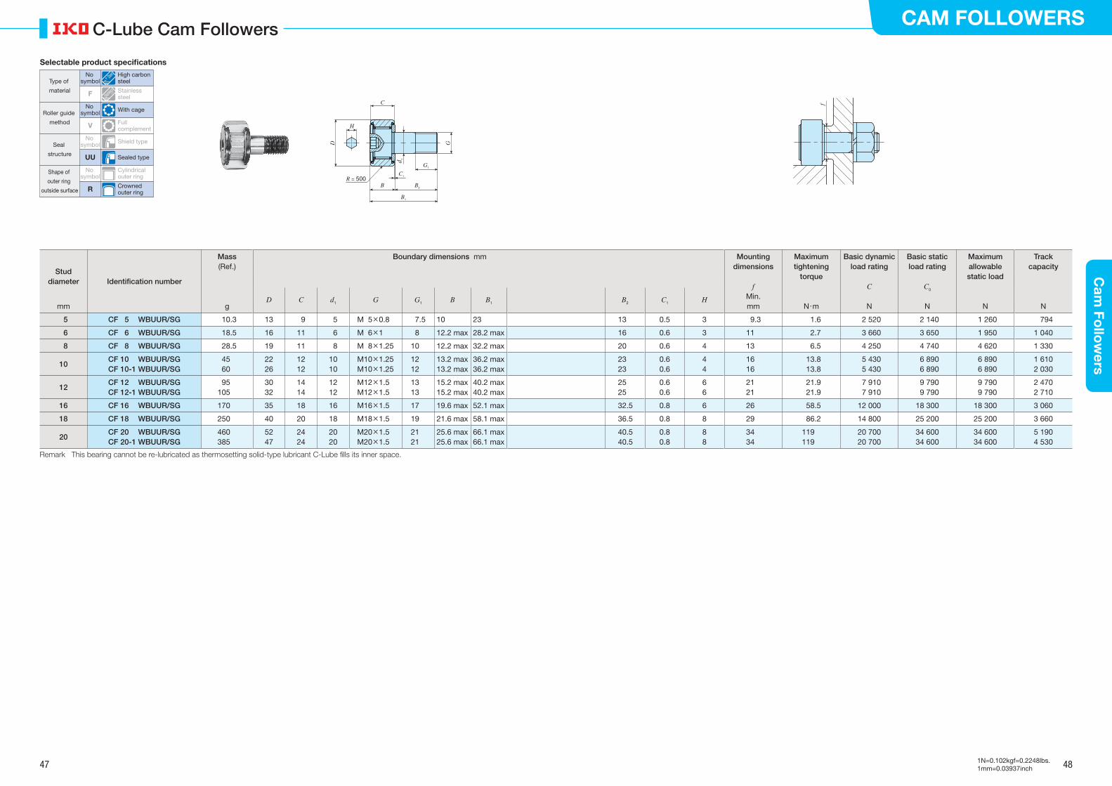
47 48
CAM FOLLOWERSC
am Fo
llow
ers
1N=0.102kgf=0.2248lbs.1mm=0.03937inch
C-Lube Cam Followers
Stud diameter Identification number
Mass Boundary dimensions mm Mounting dimensions
f
Maximum tightening
torque
Basic dynamic load rating
C
Basic static load rating
C0
Maximum allowable static load
Track capacity(Ref.)
D C d1 G G1 B B1 B2 C1 H Min.mm g mm N・m N N N N
5 CF 5 WBUUR/SG 10.3 13 9 5 M 5×0.8 7.5 10 23 13 0.5 3 9.3 1.6 2 520 2 140 1 260 794
6 CF 6 WBUUR/SG 18.5 16 11 6 M 6×1 8 12.2 max 28.2 max 16 0.6 3 11 2.7 3 660 3 650 1 950 1 040
8 CF 8 WBUUR/SG 28.5 19 11 8 M 8×1.25 10 12.2 max 32.2 max 20 0.6 4 13 6.5 4 250 4 740 4 620 1 330
10CF 10 WBUUR/SGCF 10-1 WBUUR/SG
4560
2226
1212
1010
M10×1.25M10×1.25
1212
13.2 max13.2 max
36.2 max36.2 max
2323
0.60.6
44
1616
13.813.8
5 430 5 430
6 890 6 890
6 890 6 890
1 6102 030
12CF 12 WBUUR/SGCF 12-1 WBUUR/SG
95105
3032
1414
1212
M12×1.5M12×1.5
1313
15.2 max15.2 max
40.2 max40.2 max
2525
0.60.6
66
2121
21.921.9
7 910 7 910
9 790 9 790
9 790 9 790
2 4702 710
16 CF 16 WBUUR/SG 170 35 18 16 M16×1.5 17 19.6 max 52.1 max 32.5 0.8 6 26 58.5 12 000 18 300 18 300 3 060
18 CF 18 WBUUR/SG 250 40 20 18 M18×1.5 19 21.6 max 58.1 max 36.5 0.8 8 29 86.2 14 800 25 200 25 200 3 660
20CF 20 WBUUR/SGCF 20-1 WBUUR/SG
460385
5247
2424
2020
M20×1.5M20×1.5
2121
25.6 max25.6 max
66.1 max66.1 max
40.540.5
0.80.8
88
3434
119119
20 70020 700
34 60034 600
34 60034 600
5 1904 530
Remark This bearing cannot be re-lubricated as thermosetting solid-type lubricant C-Lube �lls its inner space.
B
H
C
B2
B1
G1
C1
D G
d 1
f
R = 500
Selectable product specifications
Type of
material
Roller guide
method
Seal
structure
Shape of
outer ring
outside surface
No symbol
High carbon steel
F Stainless steel
No symbol With cage
V Full complement
No symbol Shield type
UU Sealed type
No symbol
Cylindrical outer ring
R Crowned outer ring

49 50
CAM FOLLOWERSC
am Fo
llow
ers
1N=0.102kgf=0.2248lbs.1mm=0.03937inch
Solid Eccentric Stud Type Cam Followers
Stud diameter
Identification number Mass Boundary dimensions mm Mounting dimensions
f
Maximum tightening
torque
Basic dynamic
load ratingC
Basic static
load ratingC0
Maximum allowable static load
Track capacity
N
(Ref.) Eccentricity
Shield type Sealed type
D C d1 G G1 Bmax
B1max
B2 B3 C1 g1 g2 H (3)rs minCrowned outer ring
Cylindrical outer ring
Crowned outer ring
Cylindrical outer ring
ε Min. Crowned outer ring
Cylindrical outer ringmm g mm N・m N N N
6 CFES 6 BR CFES 6 B CFES 6 BUUR CFES 6 BUU 18.5 16 11 6 M 6×1 8 12.2 28.2 16 ― 0.6 ― ― 3 0.3 0.25 11 2.7 3 660 3 650 1 980 1 040 3 400
8 CFES 8 BR CFES 8 B CFES 8 BUUR CFES 8 BUU 28.5 19 11 8 M 8×1.25 10 12.2 32.2 20 ― 0.6 ― ― 4 0.3 0.25 13 6.5 4 250 4 740 4 670 1 330 4 040
10CFES 10 BRCFES 10-1 BR
CFES 10 BCFES 10-1 B
CFES 10 BUURCFES 10-1 BUUR
CFES 10 BUUCFES 10-1 BUU
4560
2226
1212
1010
M10×1.25M10×1.25
1212
13.213.2
36.236.2
2323
――
0.60.6
――
――
44
0.30.3
0.30.3
1616
13.813.8
5 430 5 430
6 890 6 890
6 890 6 890
1 6102 030
4 6805 530
12CFES 12 BRCFES 12-1 BR
CFES 12 BCFES 12-1 B
CFES 12 BUURCFES 12-1 BUUR
CFES 12 BUUCFES 12-1 BUU
95105
3032
1414
1212
M12×1.5M12×1.5
1313
15.215.2
40.240.2
2525
66
0.60.6
44
33
66
0.60.6
0.40.4
2121
21.921.9
7 910 7 910
9 790 9 790
9 790 9 790
2 4702 710
7 0107 480
16 CFES 16 BR CFES 16 B CFES 16 BUUR CFES 16 BUU 170 35 18 16 M16×1.5 17 19.6 52.1 32.5 8 0.8 4 3 6 0.6 0.5 26 58.5 12 000 18 300 18 300 3 060 11 200
18 CFES 18 BR CFES 18 B CFES 18 BUUR CFES 18 BUU 250 40 20 18 M18×1.5 19 21.6 58.1 36.5 8 0.8 6 3 8 1 0.6 29 86.2 14 800 25 200 25 200 3 660 14 500
Note (1) An oil hole (re-greasing �tting) is provided for the stud head. (2) An oil hole (grease nipple) is provided for the stud head and an oil hole is provided for the outside surface and the end of the stud. (3) Minimum allowable value of chamfer dimension r.Remark Grease is pre-packed if the stud diameter d1 of the shield type is 10 mm or less or if the seal structure is the sealed type. Other
models are not provided with pre-packed grease. Perform proper lubrication for use.
Stud dia. d1 12 to 18 mm (2)
CFES…BR CFES…B CFES…BUUR CFES…BUUCFES…BR
ε (
Ecc
entr
icity
)
ε (
Ecc
entr
icity
)
Stud dia. d1 6 to 10 mm (1)
B
R = 500
H
C
B2
B1
G1
C1
D G
d 1
f
R = 500R = 500
r
r
r
r
B
H
C
G1C1
B1
B2
D G
d 1
g 1
B3
g2
Selectable product specifications
Type of
material
Roller guide
method
Seal
structure
Shape of
outer ring
outside surface
No symbol
High carbon steel
F Stainless steel
No symbol With cage
V Full complement
No symbol Shield type
UU Sealed type
No symbol
Cylindrical outer ring
R Crowned outer ring

51 52
CAM FOLLOWERSC
am Fo
llow
ers
1N=0.102kgf=0.2248lbs.1mm=0.03937inch
Eccentric Type Cam Followers / With Cage
Outside diameter
of eccentric
collar
Identification number Mass Boundary dimensions mm Mounting dimensions
f
Maximum tightening
torque
Basic dynamic
load ratingC
Basic static
load ratingC0
Maximum allowable static load
Track capacity
N
(Ref.) Eccentricity
Shield type Sealed type
D C de G B3 Bmax
B1max
B2 C1 g1 G1 H (3)rs minCrowned outer ring
Cylindrical outer ring
Crowned outer ring
Cylindrical outer ring
ε Min. Crowned outer ring
Cylindrical outer ringmm g mm N・m N N N
9 CFE 6 BR CFE 6 B CFE 6 BUUR CFE 6 BUU 20.5 16 11 9 M 6×1 7.5 12.2 28.2 16 0.6 ― 8.5 3 0.3 0.4 11 2.7 3 660 3 650 1 950 1 040 3 400
11 CFE 8 BR CFE 8 B CFE 8 BUUR CFE 8 BUU 32 19 11 11 M 8×1.25 9.5 12.2 32.2 20 0.6 ― 10.5 4 0.3 0.4 13 6.5 4 250 4 740 4 620 1 330 4 040
13CFE 10 BRCFE 10-1 BR
CFE 10 BCFE 10-1 B
CFE 10 BUURCFE 10-1 BUUR
CFE 10 BUUCFE 10-1 BUU
49.565
2226
1212
1313
M10×1.25M10×1.25
10.510.5
13.213.2
36.236.2
2323
0.60.6
――
12.512.5
4 4
0.30.3
0.40.4
1616
13.813.8
5 430 5 430
6 890 6 890
6 890 6 890
1 6102 030
4 6805 530
16CFE 12 BRCFE 12-1 BR
CFE 12 BCFE 12-1 B
CFE 12 BUURCFE 12-1 BUUR
CFE 12 BUUCFE 12-1 BUU
105115
3032
1414
1616
M12×1.5M12×1.5
11.511.5
15.215.2
40.240.2
2525
0.60.6
44
13.513.5
6 6
0.60.6
0.80.8
2121
21.921.9
7 910 7 910
9 790 9 790
9 790 9 790
2 4702 710
7 0107 480
22 CFE 16 BR CFE 16 B CFE 16 BUUR CFE 16 BUU 190 35 18 22 M16×1.5 15.5 19.6 52.1 32.5 0.8 4 17 6 0.6 0.8 26 58.5 12 000 18 300 18 300 3 060 11 200
24 CFE 18 BR CFE 18 B CFE 18 BUUR CFE 18 BUU 280 40 20 24 M18×1.5 17.5 21.6 58.1 36.5 0.8 6 19 8 1 0.8 29 86.2 14 800 25 200 25 200 3 660 14 500
27CFE 20 BRCFE 20-1 BR
CFE 20 BCFE 20-1 B
CFE 20 BUURCFE 20-1 BUUR
CFE 20 BUUCFE 20-1 BUU
500425
5247
2424
2727
M20×1.5M20×1.5
19.519.5
25.625.6
66.166.1
40.540.5
0.80.8
66
2121
8 8
11
0.80.8
3434
119119
20 70020 700
34 60034 600
34 60034 600
5 1904 530
23 20021 000
33CFE 24 BRCFE 24-1 BR
CFE 24 BCFE 24-1 B
CFE 24 BUURCFE 24-1 BUUR
CFE 24 BUUCFE 24-1 BUU
8951 220
6272
2929
3333
M24×1.5M24×1.5
25.525.5
30.630.6
80.180.1
49.549.5
0.80.8
66
2424
1212
11
0.80.8
4040
215215
30 50030 500
52 60052 600
52 00052 000
6 5808 020
34 30039 800
41CFE 30 BRCFE 30-1 BRCFE 30-2 BR
CFE 30 BCFE 30-1 BCFE 30-2 B
CFE 30 BUURCFE 30-1 BUURCFE 30-2 BUUR
CFE 30 BUUCFE 30-1 BUUCFE 30-2 BUU
2 0302 1902 380
808590
353535
414141
M30×1.5M30×1.5M30×1.5
32.532.532.5
373737
100100100
636363
111
666
30.530.530.5
171717
111
1.51.51.5
494949
438438438
45 40045 40045 400
85 10085 10085 100
85 10085 10085 100
9 2209 990
10 800
52 70056 00059 300
Note (1) An oil hole (re-greasing �tting) is provided for the stud head. (2) An oil hole (grease nipple) is provided for the stud head and an oil hole is provided for the outside surface and the end of the stud. (3) Minimum allowable value of chamfer dimension r.Remark Grease is pre-packed if the stud thread diameter G of the shield type is 10 mm or less or if the seal structure is the sealed type. Other
models are not provided with pre-packed grease. Perform proper lubrication for use.
Outside diameter of eccentric collar de 16 to 41 mm (2)
CFE…BR CFE…B CFE…BUUR CFE…BUUCFE…BR
Outside diameter of eccentric collar de 9 to 13 mm (1)
R = 500
ε (
Ecc
entr
icity
)
B
R = 500
H
C
B2
B1
G1
C1
D G d e
B3
ε (
Ecc
entr
icity
)
f
R = 500
r
r
r
r
B
H
C
G1
C1
B1
B2
D G d e
g 1
B3
Selectable product specifications
Type of
material
Roller guide
method
Seal
structure
Shape of
outer ring
outside surface
No symbol
High carbon steel
F Stainless steel
No symbol With cage
V Full complement
No symbol Shield type
UU Sealed type
No symbol
Cylindrical outer ring
R Crowned outer ring

53 54
CAM FOLLOWERSC
am Fo
llow
ers
1N=0.102kgf=0.2248lbs.1mm=0.03937inch
Eccentric Type Cam Followers / Full Complement Type
Outside diameter
of eccentric
collar
Identification number Mass Boundary dimensions mm Mounting dimensions
f
Maximum tightening
torque
Basic dynamic
load ratingC
Basic static
load ratingC0
Maximum allowable static load
Track capacity
N
(Ref.) Eccentricity
Shield type Sealed type
D C de G B3 Bmax
B1max
B2 C1 g1 G1 H (3)rs minCrowned outer ring
Cylindrical outer ring
Crowned outer ring
Cylindrical outer ring
ε Min. Crowned outer ring
Cylindrical outer ringmm g mm N・m N N N
9 CFE 6 VBR CFE 6 VB CFE 6 VBUUR CFE 6 VBUU 21 16 11 9 M 6×1 7.5 12.2 28.2 16 0.6 ― 8.5 3 0.3 0.4 11 2.7 6 980 8 500 1 950 1 040 3 400
11 CFE 8 VBR CFE 8 VB CFE 8 VBUUR CFE 8 VBUU 32.5 19 11 11 M 8×1.25 9.5 12.2 32.2 20 0.6 ― 10.5 4 0.3 0.4 13 6.5 8 170 11 200 4 620 1 330 4 040
13CFE 10 VBRCFE 10-1 VBR
CFE 10 VBCFE 10-1 VB
CFE 10 VBUURCFE 10-1 VBUUR
CFE 10 VBUUCFE 10-1 VBUU
50.566
2226
1212
1313
M10×1.25M10×1.25
10.510.5
13.213.2
36.236.2
2323
0.60.6
――
12.512.5
4 4
0.30.3
0.40.4
1616
13.813.8
9 570 9 570
14 500 14 500
8 650 8 650
1 6102 030
4 6805 530
16CFE 12 VBRCFE 12-1 VBR
CFE 12 VBCFE 12-1 VB
CFE 12 VBUURCFE 12-1 VBUUR
CFE 12 VBUUCFE 12-1 VBUU
107117
3032
1414
1616
M12×1.5M12×1.5
11.511.5
15.215.2
40.240.2
2525
0.60.6
44
13.513.5
6 6
0.60.6
0.40.4
2121
21.921.9
13 50013 500
19 700 19 700
13 20013 200
2 4702 710
7 0107 480
22 CFE 16 VBR CFE 16 VB CFE 16 VBUUR CFE 16 VBUU 193 35 18 22 M16×1.5 15.5 19.6 52.1 32.5 0.8 4 17 6 0.6 0.8 26 58.5 20 700 37 600 23 200 3 060 11 200
24 CFE 18 VBR CFE 18 VB CFE 18 VBUUR CFE 18 VBUU 285 40 20 24 M18×1.5 17.5 21.6 58.1 36.5 0.8 6 19 8 1 0.8 29 86.2 25 300 51 300 31 100 3 660 14 500
27CFE 20 VBRCFE 20-1 VBR
CFE 20 VBCFE 20-1 VB
CFE 20 VBUURCFE 20-1 VBUUR
CFE 20 VBUUCFE 20-1 VBUU
505430
5247
2424
2727
M20×1.5M20×1.5
19.519.5
25.625.6
66.166.1
40.540.5
0.80.8
66
2121
8 8
11
0.80.8
3434
119119
33 20033 200
64 500 64 500
37 50037 500
5 1904 530
23 20021 000
33CFE 24 VBRCFE 24-1 VBR
CFE 24 VBCFE 24-1 VB
CFE 24 VBUURCFE 24-1 VBUUR
CFE 24 VBUUCFE 24-1 VBUU
9001 220
6272
2929
3333
M24×1.5M24×1.5
25.525.5
30.630.6
80.180.1
49.549.5
0.80.8
66
2424
1212
11
0.80.8
4040
215215
46 60046 600
92 000 92 000
52 00052 000
6 5808 020
34 30039 800
41CFE 30 VBRCFE 30-1 VBRCFE 30-2 VBR
CFE 30 VBCFE 30-1 VBCFE 30-2 VB
CFE 30 VBUURCFE 30-1 VBUURCFE 30-2 VBUUR
CFE 30 VBUUCFE 30-1 VBUUCFE 30-2 VBUU
2 0302 1902 380
808590
353535
414141
M30×1.5M30×1.5M30×1.5
32.532.532.5
373737
100100100
636363
111
666
30.530.530.5
171717
111
1.51.51.5
494949
438438438
67 70067 70067 700
144 000144 000144 000
85 90085 90085 900
9 2209 990
10 800
52 70056 00059 300
Note (1) An oil hole (re-greasing �tting) is provided for the stud head. (2) An oil hole (grease nipple) is provided for the stud head and an oil hole is provided for the outside surface and the end of the stud. (3) Minimum allowable value of chamfer dimension r.Remark Provided with pre-packed grease.
Outside diameter of eccentric collar de 16 to 41 mm (2)
CFE…VBR CFE…VB CFE…VBUUR CFE…VBUU
Outside diameter of eccentric collar de 9 to 13 mm (1)
R = 500
ε (
Ecc
entr
icity
)
B
R = 500
H
C
B2
B1
G1
C1
D G d e
B3
ε (
Ecc
entr
icity
)
f
R = 500
r
r
r
r
B
H
C
G1
C1
B1
B2
D G d e
g 1
B3
CFE…VBR
Selectable product specifications
Type of
material
Roller guide
method
Seal
structure
Shape of
outer ring
outside surface
No symbol
High carbon steel
F Stainless steel
No symbol With cage
V Full complement
No symbol Shield type
UU Sealed type
No symbol
Cylindrical outer ring
R Crowned outer ring
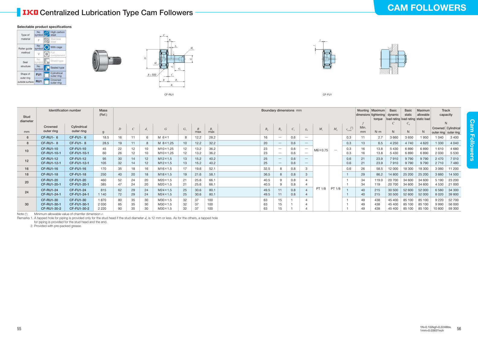
55 56
CAM FOLLOWERSC
am Fo
llow
ers
1N=0.102kgf=0.2248lbs.1mm=0.03937inch
Centralized Lubrication Type Cam Followers
Stud diameter
Identification number Mass Boundary dimensions mm Mounting dimensions
f
Maximum tightening
torque
Basic dynamic
load ratingC
Basic static
load ratingC0
Maximum allowable static load
Track capacity
N
(Ref.)
Crowned outer ring
Cylindrical outer ring
D C d1 G G1 Bmax
B1max
B2 B3 C1 g2 M1 M2(1)rs min
Min. Crowned outer ring
Cylindrical outer ringmm g mm N・m N N N
6 CF-RU1- 6 CF-FU1- 6 18.5 16 11 6 M 6×1 8 12.2 28.2 16 ― 0.6 ―
M6×0.75 ―
0.3 11 2.7 3 660 3 650 1 950 1 040 3 400
8 CF-RU1- 8 CF-FU1- 8 28.5 19 11 8 M 8×1.25 10 12.2 32.2 20 ― 0.6 ― 0.3 13 6.5 4 250 4 740 4 620 1 330 4 040
10CF-RU1-10CF-RU1-10-1
CF-FU1-10CF-FU1-10-1
4560
2226
1212
1010
M10×1.25M10×1.25
1212
13.213.2
36.236.2
2323
――
0.60.6
――
0.30.3
1616
13.813.8
5 430 5 430
6 890 6 890
6 890 6 890
1 6102 030
4 6805 530
12CF-RU1-12CF-RU1-12-1
CF-FU1-12CF-FU1-12-1
95105
3032
1414
1212
M12×1.5M12×1.5
1313
15.215.2
40.240.2
2525
――
0.60.6
――
0.60.6
2121
23.923.9
7 910 7 910
9 790 9 790
9 790 9 790
2 4702 710
7 0107 480
16 CF-RU1-16 CF-FU1-16 170 35 18 16 M16×1.5 17 19.6 52.1 32.5 8 0.8 3
PT 1/8 PT 1/8
0.6 26 58.5 12 000 18 300 18 300 3 060 11 200
18 CF-RU1-18 CF-FU1-18 250 40 20 18 M18×1.5 19 21.6 58.1 36.5 8 0.8 3 1 29 86.2 14 800 25 200 25 200 3 660 14 500
20CF-RU1-20CF-RU1-20-1
CF-FU1-20CF-FU1-20-1
460385
5247
2424
2020
M20×1.5M20×1.5
2121
25.625.6
66.166.1
40.540.5
9 9
0.80.8
44
11
3434
119.0119
20 70020 700
34 60034 600
34 60034 600
5 1904 530
23 20021 000
24CF-RU1-24CF-RU1-24-1
CF-FU1-24CF-FU1-24-1
8151 140
6272
2929
2424
M24×1.5M24×1.5
2525
30.630.6
80.180.1
49.549.5
1111
0.80.8
44
11
4040
215215
30 50030 500
52 60052 600
52 00052 000
6 5808 020
34 30039 800
30CF-RU1-30CF-RU1-30-1CF-RU1-30-2
CF-FU1-30CF-FU1-30-1CF-FU1-30-2
1 8702 0302 220
808590
353535
303030
M30×1.5M30×1.5M30×1.5
323232
373737
100100100
636363
151515
111
444
111
494949
438438438
45 40045 40045 400
85 10085 10085 100
85 10085 10085 100
9 2209 990
10 800
52 70056 00059 300
Note (1) Minimum allowable value of chamfer dimension r.Remarks 1. A tapped hole for piping is provided only for the stud head if the stud diameter d1 is 12 mm or less. As for the others, a tapped hole
for piping is provided for the stud head and the end. 2. Provided with pre-packed grease.
B
R = 500
C
B2
B1
G1
C1
D G
B3
g2
M2
f
r
r
CF-RU1 CF-FU1
M1
d 1
Selectable product specifications
Type of
material
Roller guide
method
Seal
structure
Shape of
outer ring
outside surface
No symbol
High carbon steel
F Stainless steel
No symbol With cage
No symbol Shield type
V Full complement
No symbol Sealed type
FU1 Cylindrical outer ring
RU1 Crowned outer ring
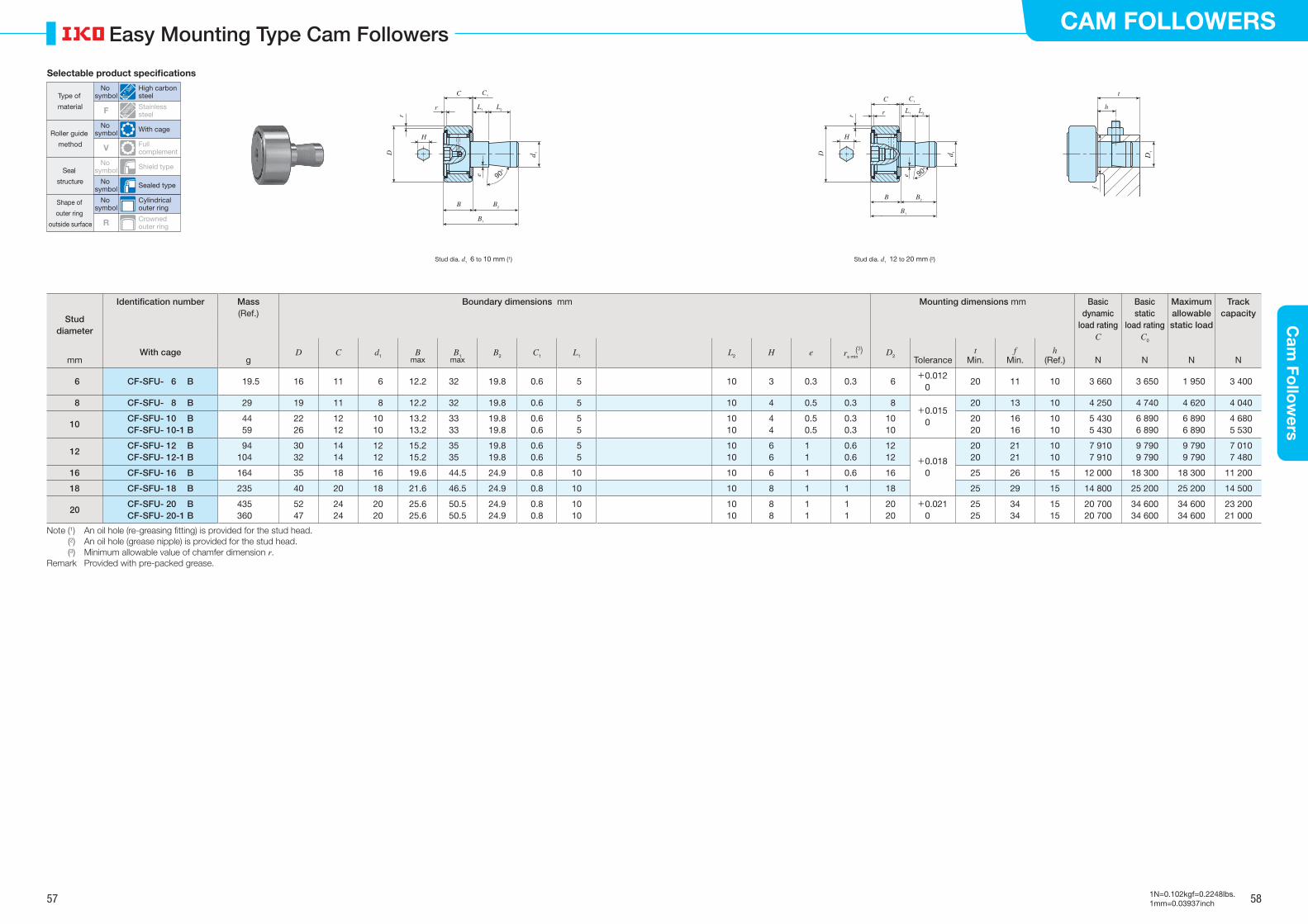
57 58
CAM FOLLOWERSC
am Fo
llow
ers
1N=0.102kgf=0.2248lbs.1mm=0.03937inch
Easy Mounting Type Cam Followers
Stud diameter
Identification number Mass Boundary dimensions mm Mounting dimensions mm Basic dynamic
load ratingC
Basic static
load ratingC0
Maximum allowable static load
Track capacity(Ref.)
With cage
D C d1 Bmax
B1max
B2 C1 L1 L2 H e (3)rs minD2
Tolerancet
Min.f
Min.h
(Ref.)mm g N N N N
6 CF-SFU- 6 B 19.5 16 11 6 12.2 32 19.8 0.6 5 10 3 0.3 0.3 6+0.012
020 11 10 3 660 3 650 1 950 3 400
8 CF-SFU- 8 B 29 19 11 8 12.2 32 19.8 0.6 5 10 4 0.5 0.3 8+0.015
0
20 13 10 4 250 4 740 4 620 4 040
10CF-SFU- 10 BCF-SFU- 10-1 B
44 59
2226
1212
1010
13.213.2
3333
19.819.8
0.60.6
5 5
1010
44
0.50.5
0.30.3
1010
2020
1616
1010
5 430 5 430
6 890 6 890
6 890 6 890
4 6805 530
12CF-SFU- 12 BCF-SFU- 12-1 B
94104
3032
1414
1212
15.215.2
3535
19.819.8
0.60.6
5 5
1010
66
11
0.60.6
1212 +0.018
0
2020
2121
1010
7 910 7 910
9 790 9 790
9 790 9 790
7 0107 480
16 CF-SFU- 16 B 164 35 18 16 19.6 44.5 24.9 0.8 10 10 6 1 0.6 16 25 26 15 12 000 18 300 18 300 11 200
18 CF-SFU- 18 B 235 40 20 18 21.6 46.5 24.9 0.8 10 10 8 1 1 18 25 29 15 14 800 25 200 25 200 14 500
20CF-SFU- 20 BCF-SFU- 20-1 B
435360
5247
2424
2020
25.625.6
50.550.5
24.924.9
0.80.8
1010
1010
88
11
11
2020
+0.0210
2525
3434
1515
20 70020 700
34 60034 600
34 60034 600
23 20021 000
Note (1) An oil hole (re-greasing �tting) is provided for the stud head. (2) An oil hole (grease nipple) is provided for the stud head. (3) Minimum allowable value of chamfer dimension r.Remark Provided with pre-packed grease.
B
90°
H
C
B2
B1
L2L1
C1
D
r
e
d 1
Stud dia. d1 12 to 20 mm (2)Stud dia. d1 6 to 10 mm (1)
t
h
f
r
B
90°
H
C
B2
B1
L2L1
C1
D
r
e
d 1
D1
r
Selectable product specifications
Type of
material
Roller guide
method
Seal
structure
Shape of
outer ring
outside surface
No symbol
High carbon steel
F Stainless steel
No symbol
No symbol
With cage
V Full complement
No symbol Sealed type
Cylindrical outer ring
No symbol Shield type
R Crowned outer ring
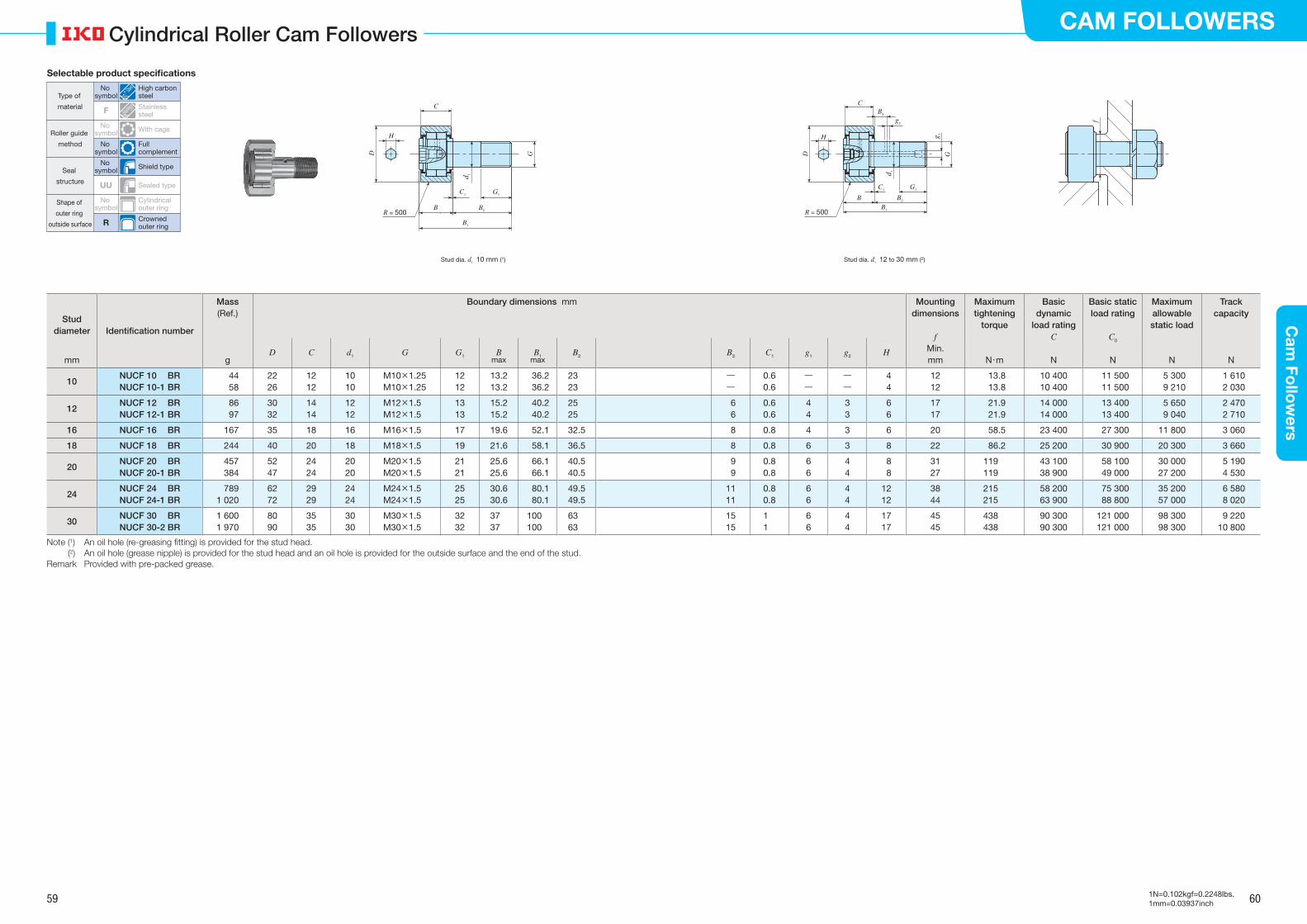
59 60
CAM FOLLOWERSC
am Fo
llow
ers
1N=0.102kgf=0.2248lbs.1mm=0.03937inch
Cylindrical Roller Cam Followers
Stud diameter Identification number
Mass Boundary dimensions mm Mounting dimensions
f
Maximum tightening
torque
Basic dynamic
load ratingC
Basic static load rating
C0
Maximum allowable static load
Track capacity(Ref.)
D C d1 G G1 Bmax
B1max
B2 B3 C1 g1 g2 H Min.mm g mm N・m N N N N
10NUCF 10 BRNUCF 10-1 BR
44 58
2226
1212
1010
M10×1.25M10×1.25
1212
13.213.2
36.236.2
2323
――
0.60.6
――
――
4 4
1212
13.813.8
10 40010 400
11 500 11 500
5 300 9 210
1 6102 030
12NUCF 12 BRNUCF 12-1 BR
86 97
3032
1414
1212
M12×1.5M12×1.5
1313
15.215.2
40.240.2
2525
6 6
0.60.6
44
33
6 6
1717
21.921.9
14 00014 000
13 400 13 400
5 650 9 040
2 4702 710
16 NUCF 16 BR 167 35 18 16 M16×1.5 17 19.6 52.1 32.5 8 0.8 4 3 6 20 58.5 23 400 27 300 11 800 3 060
18 NUCF 18 BR 244 40 20 18 M18×1.5 19 21.6 58.1 36.5 8 0.8 6 3 8 22 86.2 25 200 30 900 20 300 3 660
20NUCF 20 BRNUCF 20-1 BR
457 384
5247
2424
2020
M20×1.5M20×1.5
2121
25.625.6
66.166.1
40.540.5
9 9
0.80.8
66
44
8 8
3127
119119
43 10038 900
58 100 49 000
30 00027 200
5 1904 530
24NUCF 24 BRNUCF 24-1 BR
7891 020
6272
2929
2424
M24×1.5M24×1.5
2525
30.630.6
80.180.1
49.549.5
1111
0.80.8
66
44
1212
3844
215215
58 20063 900
75 300 88 800
35 20057 000
6 5808 020
30NUCF 30 BRNUCF 30-2 BR
1 6001 970
8090
3535
3030
M30×1.5M30×1.5
3232
3737
100100
6363
1515
11
66
44
1717
4545
438438
90 30090 300
121 000121 000
98 30098 300
9 22010 800
Note (1) An oil hole (re-greasing �tting) is provided for the stud head. (2) An oil hole (grease nipple) is provided for the stud head and an oil hole is provided for the outside surface and the end of the stud.Remark Provided with pre-packed grease.
Stud dia. d1 12 to 30 mm (2)Stud dia. d1 10 mm (1)
f
R = 500B
H
C
G1C1
B1
B2
D G
d 1
R = 500
B
H
C
G1C1
B1
B2
D G
d 1
g 1
B3
g2
Selectable product specifications
Type of
material
Roller guide
method
Seal
structure
Shape of
outer ring
outside surface
No symbol
High carbon steel
F Stainless steel
No symbol
Full complement
No symbol Shield type
UU Sealed type
No symbol
Cylindrical outer ring
R Crowned outer ring
No symbol With cage
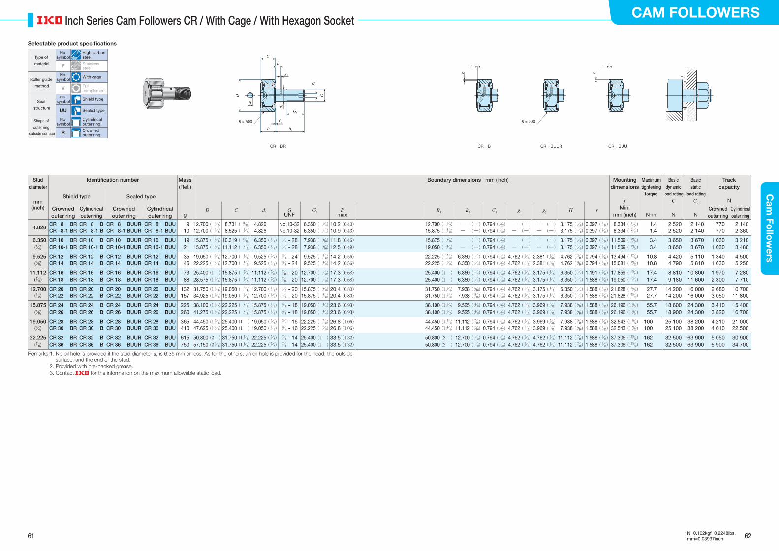
61 62
CAM FOLLOWERSC
am Fo
llow
ers
1N=0.102kgf=0.2248lbs.1mm=0.03937inch
Inch Series Cam Followers CR / With Cage / With Hexagon Socket
Stud diameter
Identification number Mass Boundary dimensions mm (inch) Mounting dimensions
f
Maximum tightening
torque
Basic dynamic
load ratingC
Basic static
load ratingC0
Track capacity
N
(Ref.)
Shield type Sealed typemm
(inch)
D C d1 GUNF
G1 Bmax
B2 B3 C1 g1 g2 H rCrowned outer ring
Cylindrical outer ring
Crowned outer ring
Cylindrical outer ring
Min. Crowned outer ring
Cylindrical outer ringg mm (inch) N・m N N
4.826CR 8 BRCR 8-1 BR
CR 8 BCR 8-1 B
CR 8 BUURCR 8-1 BUUR
CR 8 BUUCR 8-1 BUU
9 10
12.700 ( / 1 2)
12.700 ( / 1 2)
8.731 ( / 11 32)
8.525 ( / 3 8)
4.826 4.826
No.10-32No.10-32
6.350 ( / 1 4)
6.350 ( / 1 4)
10.2 (0.40)10.9 (0.43)
12.700 ( / 1 2)
15.875 ( / 5 8)
― (―) ― (―)
0.794 (/ 1 32)
0.794 (/ 1 32)
― (―) ― (―)
― (―) ― (―)
3.175 (/ 1 8)
3.175 (/ 1 8)
0.397 (/ 1 64)
0.397 (/ 1 64)
8.334 ( / 21 64)
8.334 ( / 21 64)
1.41.4
2 520 2 520
2 140 2 140
770770
2 1402 360
6.350(/ 1 4 )
CR 10 BRCR 10-1 BR
CR 10 BCR 10-1 B
CR 10 BUURCR 10-1 BUUR
CR 10 BUUCR 10-1 BUU
19 21
15.875 ( / 5 8)
15.875 ( / 5 8)
10.319 ( / 13 32)
11.112 ( / 7 16)
6.350 (/ 1 4)
6.350 (/ 1 4)
/ 1 4 - 28/ 1 4 - 28
7.938 ( / 5 16)
7.938 ( / 5 16)
11.8 (0.46)12.5 (0.49)
15.875 ( / 5 8)
19.050 ( / 3 4)
― (―) ― (―)
0.794 (/ 1 32)
0.794 (/ 1 32)
― (―) ― (―)
― (―) ― (―)
3.175 (/ 1 8)
3.175 (/ 1 8)
0.397 (/ 1 64)
0.397 (/ 1 64)
11.509 ( / 29 64)
11.509 ( / 29 64)
3.43.4
3 650 3 650
3 670 3 670
1 0301 030
3 2103 480
9.525(/ 3 8 )
CR 12 BRCR 14 BR
CR 12 BCR 14 B
CR 12 BUURCR 14 BUUR
CR 12 BUUCR 14 BUU
35 46
19.050 ( / 3 4)
22.225 ( / 7 8)
12.700 ( / 1 2)
12.700 ( / 1 2)
9.525 (/ 3 8)
9.525 (/ 3 8)
/ 3 8 - 24/ 3 8 - 24
9.525 ( / 3 8)
9.525 ( / 3 8)
14.2 (0.56)14.2 (0.56)
22.225 ( / 7 8)
22.225 ( / 7 8)
6.350 (/ 1 4)
6.350 (/ 1 4)
0.794 (/ 1 32)
0.794 (/ 1 32)
4.762 (/ 3 16)
4.762 (/ 3 16)
2.381 (/ 3 32)
2.381 (/ 3 32)
4.762 (/ 3 16)
4.762 (/ 3 16)
0.794 (/ 1 32)
0.794 (/ 1 32)
13.494 ( / 17 32)
15.081 ( / 19 32)
10.810.8
4 420 4 790
5 110 5 810
1 3401 630
4 5005 250
11.112(/ 7 16)
CR 16 BRCR 18 BR
CR 16 BCR 18 B
CR 16 BUURCR 18 BUUR
CR 16 BUUCR 18 BUU
73 88
25.400 (1 )28.575 (1/ 1
8)15.875 ( / 5
8)15.875 ( / 5
8)11.112 (/ 7
16)11.112 (/ 7
16)/ 7 16 - 20/ 7 16 - 20
12.700 ( / 1 2)
12.700 ( / 1 2)
17.3 (0.68)17.3 (0.68)
25.400 (1 )25.400 (1 )
6.350 (/ 1 4)
6.350 (/ 1 4)
0.794 (/ 1 32)
0.794 (/ 1 32)
4.762 (/ 3 16)
4.762 (/ 3 16)
3.175 (/ 1 8)
3.175 (/ 1 8)
6.350 (/ 1 4)
6.350 (/ 1 4)
1.191 (/ 3 64)
1.588 (/ 1 16)
17.859 ( / 45 64)
19.050 ( / 3 4)
17.417.4
8 810 9 180
10 80011 600
1 9702 300
7 2807 710
12.700(/ 1 2 )
CR 20 BRCR 22 BR
CR 20 BCR 22 B
CR 20 BUURCR 22 BUUR
CR 20 BUUCR 22 BUU
132157
31.750 (1/ 1 4)
34.925 (1/ 3 8)
19.050 ( / 3 4)
19.050 ( / 3 4)
12.700 (/ 1 2)
12.700 (/ 1 2)
/ 1 2 - 20/ 1 2 - 20
15.875 ( / 5 8)
15.875 ( / 5 8)
20.4 (0.80)20.4 (0.80)
31.750 (1/ 1 4)
31.750 (1/ 1 4)
7.938 (/ 5 16)
7.938 (/ 5 16)
0.794 (/ 1 32)
0.794 (/ 1 32)
4.762 (/ 3 16)
4.762 (/ 3 16)
3.175 (/ 1 8)
3.175 (/ 1 8)
6.350 (/ 1 4)
6.350 (/ 1 4)
1.588 (/ 1 16)
1.588 (/ 1 16)
21.828 ( / 55 64)
21.828 ( / 55 64)
27.727.7
14 20014 200
16 00016 000
2 6803 050
10 70011 800
15.875(/ 5 8 )
CR 24 BRCR 26 BR
CR 24 BCR 26 B
CR 24 BUURCR 26 BUUR
CR 24 BUUCR 26 BUU
225260
38.100 (1/ 1 2)
41.275 (1/ 5 8)
22.225 ( / 7 8)
22.225 ( / 7 8)
15.875 (/ 5 8)
15.875 (/ 5 8)
/ 5 8 - 18/ 5 8 - 18
19.050 ( / 3 4)
19.050 ( / 3 4)
23.6 (0.93)23.6 (0.93)
38.100 (1/ 1 2)
38.100 (1/ 1 2)
9.525 (/ 3 8)
9.525 (/ 3 8)
0.794 (/ 1 32)
0.794 (/ 1 32)
4.762 (/ 3 16)
4.762 (/ 3 16)
3.969 (/ 5 32)
3.969 (/ 5 32)
7.938 (/ 5 16)
7.938 (/ 5 16)
1.588 (/ 1 16)
1.588 (/ 1 16)
26.196 (1/ 3 64)
26.196 (1/ 3 64)
55.755.7
18 60018 900
24 30024 300
3 4103 820
15 40016 700
19.050(/ 3 4 )
CR 28 BRCR 30 BR
CR 28 BCR 30 B
CR 28 BUURCR 30 BUUR
CR 28 BUUCR 30 BUU
365410
44.450 (1/ 3 4)
47.625 (1/ 7 8)
25.400 (1 )25.400 (1 )
19.050 (/ 3 4)
19.050 (/ 3 4)
/ 3 4 - 16/ 3 4 - 16
22.225 ( / 7 8)
22.225 ( / 7 8)
26.8 (1.06)26.8 (1.06)
44.450 (1/ 3 4)
44.450 (1/ 3 4)
11.112 (/ 7 16)
11.112 (/ 7 16)
0.794 (/ 1 32)
0.794 (/ 1 32)
4.762 (/ 3 16)
4.762 (/ 3 16)
3.969 (/ 5 32)
3.969 (/ 5 32)
7.938 (/ 5 16)
7.938 (/ 5 16)
1.588 (/ 1 16)
1.588 (/ 1 16)
32.543 (1/ 9 32)
32.543 (1/ 9 32)
100100
25 10025 100
38 20038 200
4 2104 610
21 00022 500
22.225(/ 7 8 )
CR 32 BRCR 36 BR
CR 32 BCR 36 B
CR 32 BUURCR 36 BUUR
CR 32 BUUCR 36 BUU
615750
50.800 (2 )57.150 (2/ 1
4)31.750 (1/ 1
4)31.750 (1/ 1
4)22.225 (/ 7
8)22.225 (/ 7
8)/ 7 8 - 14/ 7 8 - 14
25.400 (1 )25.400 (1 )
33.5 (1.32)33.5 (1.32)
50.800 (2 )50.800 (2 )
12.700 (/ 1 2)
12.700 (/ 1 2)
0.794 (/ 1 32)
0.794 (/ 1 32)
4.762 (/ 3 16)
4.762 (/ 3 16)
4.762 (/ 3 16)
4.762 (/ 3 16)
11.112 (/ 7 16)
11.112 (/ 7 16)
1.588 (/ 1 16)
1.588 (/ 1 16)
37.306 (1/ 15 32)
37.306 (1/ 15 32)
162162
32 50032 500
63 90063 900
5 0505 900
30 90034 700
Remarks 1. No oil hole is provided if the stud diameter d1 is 6.35 mm or less. As for the others, an oil hole is provided for the head, the outside surface, and the end of the stud.
2. Provided with pre-packed grease. 3. Contact for the information on the maximum allowable static load.
CR…B CR…BUUR CR…BUUCR…BR
R = 500R = 500
B
H
C
G1
C1
B2
D G
d 1
g 1
B3
g2 f
r
r
r
r
Selectable product specifications
Type of
material
Roller guide
method
Seal
structure
Shape of
outer ring
outside surface
No symbol
High carbon steel
F Stainless steel
No symbol With cage
V Full complement
No symbol Shield type
UU Sealed type
No symbol
Cylindrical outer ring
R Crowned outer ring
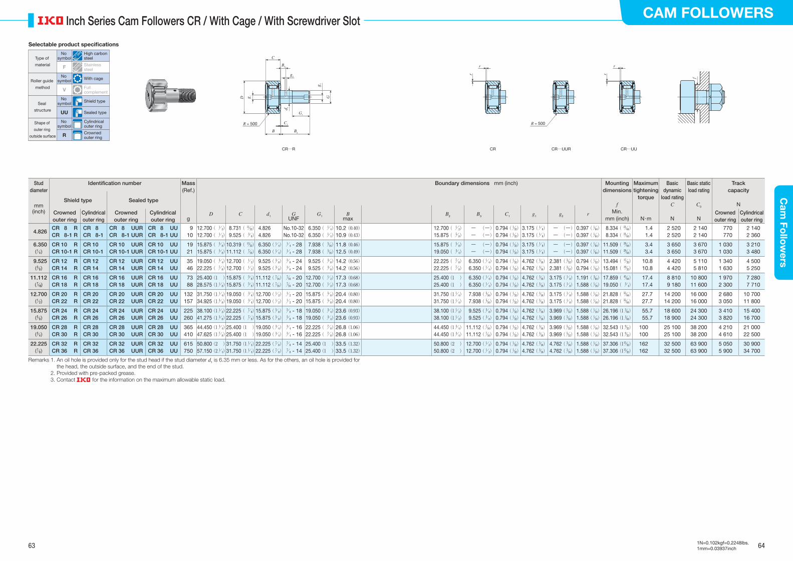
63 64
CAM FOLLOWERSC
am Fo
llow
ers
1N=0.102kgf=0.2248lbs.1mm=0.03937inch
Inch Series Cam Followers CR / With Cage / With Screwdriver Slot
Stud diameter
Identification number Mass Boundary dimensions mm (inch) Mounting dimensions
f
Maximum tightening
torque
Basic dynamic
load ratingC
Basic static load rating
C0
Track capacity
N
(Ref.)
Shield type Sealed typemm
(inch)
D C d1 GUNF
G1 Bmax
B2 B3 C1 g1 g2 rCrowned outer ring
Cylindrical outer ring
Crowned outer ring
Cylindrical outer ring
Min. Crowned outer ring
Cylindrical outer ringg mm (inch) N・m N N
4.826CR 8 RCR 8-1 R
CR 8 CR 8-1
CR 8 UURCR 8-1 UUR
CR 8 UUCR 8-1 UU
9 10
12.700 ( / 1 2)
12.700 ( / 1 2)
8.731 ( / 11 32)
9.525 ( / 3 8)
4.826 4.826
No.10-32No.10-32
6.350 ( / 1 4)
6.350 ( / 1 4)
10.2 (0.40)10.9 (0.43)
12.700 ( / 1 2)
15.875 ( / 5 8)
― (―) ― (―)
0.794 (/ 1 32)
0.794 (/ 1 32)
3.175 (/ 1 8)
3.175 (/ 1 8)
― (―) ― (―)
0.397 (/ 1 64)
0.397 (/ 1 64)
8.334 ( / 21 64)
8.334 ( / 21 64)
1.41.4
2 520 2 520
2 140 2 140
770770
2 1402 360
6.350(/ 1 4 )
CR 10 RCR 10-1 R
CR 10 CR 10-1
CR 10 UURCR 10-1 UUR
CR 10 UUCR 10-1 UU
19 21
15.875 ( / 5 8)
15.875 ( / 5 8)
10.319 ( / 13 32)
11.112 ( / 7 16)
6.350 (/ 1 4)
6.350 (/ 1 4)
/ 1 4 - 28/ 1 4 - 28
7.938 ( / 5 16)
7.938 ( / 5 16)
11.8 (0.46)12.5 (0.49)
15.875 ( / 5 8)
19.050 ( / 3 4)
― (―) ― (―)
0.794 (/ 1 32)
0.794 (/ 1 32)
3.175 (/ 1 8)
3.175 (/ 1 8)
― (―) ― (―)
0.397 (/ 1 64)
0.397 (/ 1 64)
11.509 ( / 29 64)
11.509 ( / 29 64)
3.43.4
3 650 3 650
3 670 3 670
1 0301 030
3 2103 480
9.525(/ 3 8 )
CR 12 RCR 14 R
CR 12 CR 14
CR 12 UURCR 14 UUR
CR 12 UUCR 14 UU
35 46
19.050 ( / 3 4)
22.225 ( / 7 8)
12.700 ( / 1 2)
12.700 ( / 1 2)
9.525 (/ 3 8)
9.525 (/ 3 8)
/ 3 8 - 24/ 3 8 - 24
9.525 ( / 3 8)
9.525 ( / 3 8)
14.2 (0.56)14.2 (0.56)
22.225 ( / 7 8)
22.225 ( / 7 8)
6.350 (/ 1 4)
6.350 (/ 1 4)
0.794 (/ 1 32)
0.794 (/ 1 32)
4.762 (/ 3 16)
4.762 (/ 3 16)
2.381 (/ 3 32)
2.381 (/ 3 32)
0.794 (/ 1 32)
0.794 (/ 1 32)
13.494 ( / 17 32)
15.081 ( / 19 32)
10.810.8
4 420 4 420
5 110 5 810
1 3401 630
4 5005 250
11.112(/ 7 16)
CR 16 RCR 18 R
CR 16 CR 18
CR 16 UURCR 18 UUR
CR 16 UUCR 18 UU
73 88
25.400 (1 )28.575 (1/ 1
8)15.875 ( / 5
8)15.875 ( / 5
8)11.112 (/ 7
16)11.112 (/ 7
16)/ 7 16 - 20/ 7 16 - 20
12.700 ( / 1 2)
12.700 ( / 1 2)
17.3 (0.68)17.3 (0.68)
25.400 (1 )25.400 (1 )
6.350 (/ 1 4)
6.350 (/ 1 4)
0.794 (/ 1 32)
0.794 (/ 1 32)
4.762 (/ 3 16)
4.762 (/ 3 16)
3.175 (/ 1 8)
3.175 (/ 1 8)
1.191 (/ 3 64)
1.588 (/ 1 16)
17.859 ( / 45 64)
19.050 ( / 3 4)
17.417.4
8 810 9 180
10 80011 600
1 9702 300
7 2807 710
12.700(/ 1 2 )
CR 20 RCR 22 R
CR 20 CR 22
CR 20 UURCR 22 UUR
CR 20 UUCR 22 UU
132157
31.750 (1/ 1 4)
34.925 (1/ 3 8)
19.050 ( / 3 4)
19.050 ( / 3 4)
12.700 (/ 1 2)
12.700 (/ 1 2)
/ 1 2 - 20/ 1 2 - 20
15.875 ( / 5 8)
15.875 ( / 5 8)
20.4 (0.80)20.4 (0.80)
31.750 (1/ 1 4)
31.750 (1/ 1 4)
7.938 (/ 5 16)
7.938 (/ 5 16)
0.794 (/ 1 32)
0.794 (/ 1 32)
4.762 (/ 3 16)
4.762 (/ 3 16)
3.175 (/ 1 8)
3.175 (/ 1 8)
1.588 (/ 1 16)
1.588 (/ 1 16)
21.828 ( / 55 64)
21.828 ( / 55 64)
27.727.7
14 20014 200
16 00016 000
2 6803 050
10 70011 800
15.875(/ 5 8 )
CR 24 RCR 26 R
CR 24 CR 26
CR 24 UURCR 26 UUR
CR 24 UUCR 26 UU
225260
38.100 (1/ 1 2)
41.275 (1/ 5 8)
22.225 ( / 7 8)
22.225 ( / 7 8)
15.875 (/ 5 8)
15.875 (/ 5 8)
/ 5 8 - 18/ 5 8 - 18
19.050 ( / 3 4)
19.050 ( / 3 4)
23.6 (0.93)23.6 (0.93)
38.100 (1/ 1 2)
38.100 (1/ 1 2)
9.525 (/ 3 8)
9.525 (/ 3 8)
0.794 (/ 1 32)
0.794 (/ 1 32)
4.762 (/ 3 16)
4.762 (/ 3 16)
3.969 (/ 5 32)
3.969 (/ 5 32)
1.588 (/ 1 16)
1.588 (/ 1 16)
26.196 (1/ 3 64)
26.196 (1/ 3 64)
55.755.7
18 60018 900
24 30024 300
3 4103 820
15 40016 700
19.050(/ 3 4 )
CR 28 RCR 30 R
CR 28 CR 30
CR 28 UURCR 30 UUR
CR 28 UUCR 30 UU
365410
44.450 (1/ 3 4)
47.625 (1/ 7 8)
25.400 (1 )25.400 (1 )
19.050 (/ 3 4)
19.050 (/ 3 4)
/ 3 4 - 16/ 3 4 - 16
22.225 ( / 7 8)
22.225 ( / 7 8)
26.8 (1.06)26.8 (1.06)
44.450 (1/ 3 4)
44.450 (1/ 3 4)
11.112 (/ 7 16)
11.112 (/ 7 16)
0.794 (/ 1 32)
0.794 (/ 1 32)
4.762 (/ 3 16)
4.762 (/ 3 16)
3.969 (/ 5 32)
3.969 (/ 5 32)
1.588 (/ 1 16)
1.588 (/ 1 16)
32.543 (1/ 9 32)
32.543 (1/ 9 32)
100100
25 10025 100
38 20038 200
4 2104 610
21 00022 500
22.225(/ 7 8 )
CR 32 RCR 36 R
CR 32 CR 36
CR 32 UURCR 36 UUR
CR 32 UUCR 36 UU
615750
50.800 (2 )57.150 (2/ 1
4)31.750 (1/ 1
4)31.750 (1/ 1
4)22.225 (/ 7
8)22.225 (/ 7
8)/ 7 8 - 14/ 7 8 - 14
25.400 (1 )25.400 (1 )
33.5 (1.32)33.5 (1.32)
50.800 (2 )50.800 (2 )
12.700 (/ 1 2)
12.700 (/ 1 2)
0.794 (/ 1 32)
0.794 (/ 1 32)
4.762 (/ 3 16)
4.762 (/ 3 16)
4.762 (/ 3 16)
4.762 (/ 3 16)
1.588 (/ 1 16)
1.588 (/ 1 16)
37.306 (1/ 15 32)
37.306 (1/ 15 32)
162162
32 50032 500
63 90063 900
5 0505 900
30 90034 700
Remarks 1. An oil hole is provided only for the stud head if the stud diameter d1 is 6.35 mm or less. As for the others, an oil hole is provided for the head, the outside surface, and the end of the stud.
2. Provided with pre-packed grease. 3. Contact for the information on the maximum allowable static load.
CR CR…UUR CR…UU
R = 500R = 500
B
C
G1
C1
B2
D G
d 1
g 1
g 1
B3
g2 f
r
r
r
r
CR…R
Selectable product specifications
Type of
material
Roller guide
method
Seal
structure
Shape of
outer ring
outside surface
No symbol
High carbon steel
F Stainless steel
No symbol With cage
V Full complement
No symbol Shield type
UU Sealed type
No symbol
Cylindrical outer ring
R Crowned outer ring

65 66
CAM FOLLOWERSC
am Fo
llow
ers
1N=0.102kgf=0.2248lbs.1mm=0.03937inch
Inch Series Cam Followers CR / Full Complement Type / With Hexagon Socket
Stud diameter
Identification number Mass Boundary dimensions mm (inch) Mounting dimensions
f
Maximum tightening
torque
Basic dynamic
load ratingC
Basic static
load ratingC0
Track capacity
N
(Ref.)
Shield type Sealed typemm
(inch)
D C d1 GUNF
G1 Bmax
B2 B3 C1 g1 g2 H rCrowned outer ring
Cylindrical outer ring
Crowned outer ring
Cylindrical outer ring
Min. Crowned outer ring
Cylindrical outer ringg mm (inch) N・m N N
4.826CR 8 VBRCR 8-1 VBR
CR 8 VBCR 8-1 VB
CR 8 VBUURCR 8-1 VBUUR
CR 8 VBUUCR 8-1 VBUU
9 10
12.700 ( / 1 2)
12.700 ( / 1 2)
8.731 ( / 11 32)
8.525 ( / 3 8)
4.826 4.826
No.10-32No.10-32
6.350 ( / 1 4)
6.350 ( / 1 4)
10.2 (0.40)10.9 (0.43)
12.700 ( / 1 2)
15.875 ( / 5 8)
― (―) ― (―)
0.794 (/ 1 32)
0.794 (/ 1 32)
― (―) ― (―)
― (―) ― (―)
3.175 (/ 1 8)
3.175 (/ 1 8)
0.397 (/ 1 64)
0.397 (/ 1 64)
8.334 ( / 21 64)
8.334 ( / 21 64)
1.41.4
4 260 4 710
4 750 5 410
770770
2 1402 360
6.350(/ 1 4 )
CR 10 VBRCR 10-1 VBR
CR 10 VBCR 10-1 VB
CR 10 VBUURCR 10-1 VBUUR
CR 10 VBUUCR 10-1 VBUU
19 21
15.875 ( / 5 8)
15.875 ( / 5 8)
10.319 ( / 13 32)
11.112 ( / 7 16)
6.350 (/ 1 4)
6.350 (/ 1 4)
/ 1 4 - 28/ 1 4 - 28
7.938 ( / 5 16)
7.938 ( / 5 16)
11.8 (0.46)12.5 (0.49)
15.875 ( / 5 8)
19.050 ( / 3 4)
― (―) ― (―)
0.794 (/ 1 32)
0.794 (/ 1 32)
― (―) ― (―)
― (―) ― (―)
3.175 (/ 1 8)
3.175 (/ 1 8)
0.397 (/ 1 64)
0.397 (/ 1 64)
11.509 ( / 29 64)
11.509 ( / 29 64)
3.43.4
5 830 6 340
7 660 8 530
1 0301 030
3 2103 480
9.525(/ 3 8 )
CR 12 VBRCR 14 VBR
CR 12 VBCR 14 VB
CR 12 VBUURCR 14 VBUUR
CR 12 VBUUCR 14 VBUU
36 47
19.050 ( / 3 4)
22.225 ( / 7 8)
12.700 ( / 1 2)
12.700 ( / 1 2)
9.525 (/ 3 8)
9.525 (/ 3 8)
/ 3 8 - 24/ 3 8 - 24
9.525 ( / 3 8)
9.525 ( / 3 8)
14.2 (0.56)14.2 (0.56)
22.225 ( / 7 8)
22.225 ( / 7 8)
6.350 (/ 1 4)
6.350 (/ 1 4)
0.794 (/ 1 32)
0.794 (/ 1 32)
4.762 (/ 3 16)
4.762 (/ 3 16)
2.381 (/ 3 32)
2.381 (/ 3 32)
4.762 (/ 3 16)
4.762 (/ 3 16)
0.794 (/ 1 32)
0.794 (/ 1 32)
13.494 ( / 17 32)
15.081 ( / 19 32)
10.810.8
8 710 8 710
12 30012 300
1 3401 630
4 5005 250
11.112(/ 7 16)
CR 16 VBRCR 18 VBR
CR 16 VBCR 18 VB
CR 16 VBUURCR 18 VBUUR
CR 16 VBUUCR 18 VBUU
74 85
25.400 (1 )28.575 (1/ 1
8)15.875 ( / 5
8)15.875 ( / 5
8)11.112 (/ 7
16)11.112 (/ 7
16)/ 7 16 - 20/ 7 16 - 20
12.700 ( / 1 2)
12.700 ( / 1 2)
17.3 (0.68)17.3 (0.68)
25.400 (1 )25.400 (1 )
6.350 (/ 1 4)
6.350 (/ 1 4)
0.794 (/ 1 32)
0.794 (/ 1 32)
4.762 (/ 3 16)
4.762 (/ 3 16)
3.175 (/ 1 8)
3.175 (/ 1 8)
6.350 (/ 1 4)
6.350 (/ 1 4)
1.191 (/ 3 64)
1.588 (/ 1 16)
17.859 ( / 45 64)
19.050 ( / 3 4)
17.417.4
13 10013 100
22 70022 700
1 9702 300
7 2807 710
12.700(/ 1 2 )
CR 20 VBRCR 22 VBR
CR 20 VBCR 22 VB
CR 20 VBUURCR 22 VBUUR
CR 20 VBUUCR 22 VBUU
137160
31.750 (1/ 1 4)
34.925 (1/ 3 8)
19.050 ( / 3 4)
19.050 ( / 3 4)
12.700 (/ 1 2)
12.700 (/ 1 2)
/ 1 2 - 20/ 1 2 - 20
15.875 ( / 5 8)
15.875 ( / 5 8)
20.4 (0.80)20.4 (0.80)
31.750 (1/ 1 4)
31.750 (1/ 1 4)
7.938 (/ 5 16)
7.938 (/ 5 16)
0.794 (/ 1 32)
0.794 (/ 1 32)
4.762 (/ 3 16)
4.762 (/ 3 16)
3.175 (/ 1 8)
3.175 (/ 1 8)
6.350 (/ 1 4)
6.350 (/ 1 4)
1.588 (/ 1 16)
1.588 (/ 1 16)
21.828 ( / 55 64)
21.828 ( / 55 64)
27.727.7
23 60023 600
31 70031 700
2 6803 050
10 70011 800
15.875(/ 5 8 )
CR 24 VBRCR 26 VBR
CR 24 VBCR 26 VB
CR 24 VBUURCR 26 VBUUR
CR 24 VBUUCR 26 VBUU
230265
38.100 (1/ 1 2)
41.275 (1/ 5 8)
22.225 ( / 7 8)
22.225 ( / 7 8)
15.875 (/ 5 8)
15.875 (/ 5 8)
/ 5 8 - 18/ 5 8 - 18
19.050 ( / 3 4)
19.050 ( / 3 4)
23.6 (0.93)23.6 (0.93)
38.100 (1/ 1 2)
38.100 (1/ 1 2)
9.525 (/ 3 8)
9.525 (/ 3 8)
0.794 (/ 1 32)
0.794 (/ 1 32)
4.762 (/ 3 16)
4.762 (/ 3 16)
3.969 (/ 5 32)
3.969 (/ 5 32)
7.938 (/ 5 16)
7.938 (/ 5 16)
1.588 (/ 1 16)
1.588 (/ 1 16)
26.196 (1/ 3 64)
26.196 (1/ 3 64)
55.755.7
28 20028 200
40 10040 100
3 4103 820
15 40016 700
19.050(/ 3 4 )
CR 28 VBRCR 30 VBR
CR 28 VBCR 30 VB
CR 28 VBUURCR 30 VBUUR
CR 28 VBUUCR 30 VBUU
372418
44.450 (1/ 3 4)
47.625 (1/ 7 8)
25.400 (1 )25.400 (1 )
19.050 (/ 3 4)
19.050 (/ 3 4)
/ 3 4 - 16/ 3 4 - 16
22.225 ( / 7 8)
22.225 ( / 7 8)
26.8 (1.06)26.8 (1.06)
44.450 (1/ 3 4)
44.450 (1/ 3 4)
11.112 (/ 7 16)
11.112 (/ 7 16)
0.794 (/ 1 32)
0.794 (/ 1 32)
4.762 (/ 3 16)
4.762 (/ 3 16)
3.969 (/ 5 32)
3.969 (/ 5 32)
7.938 (/ 5 16)
7.938 (/ 5 16)
1.588 (/ 1 16)
1.588 (/ 1 16)
32.543 (1/ 9 32)
32.543 (1/ 9 32)
100100
35 30035 300
55 60055 600
4 2104 610
21 00022 500
22.225(/ 7 8 )
CR 32 VBRCR 36 VBR
CR 32 VBCR 36 VB
CR 32 VBUURCR 36 VBUUR
CR 32 VBUUCR 36 VBUU
627759
50.800 (2 )57.150 (2/ 1
4)31.750 (1/ 1
4)31.750 (1/ 1
4)22.225 (/ 7
8)22.225 (/ 7
8)/ 7 8 - 14/ 7 8 - 14
25.400 (1 )25.400 (1 )
33.5 (1.32)33.5 (1.32)
50.800 (2 )50.800 (2 )
12.700 (/ 1 2)
12.700 (/ 1 2)
0.794 (/ 1 32)
0.794 (/ 1 32)
4.762 (/ 3 16)
4.762 (/ 3 16)
4.762 (/ 3 16)
4.762 (/ 3 16)
11.112 (/ 7 16)
11.112 (/ 7 16)
1.588 (/ 1 16)
1.588 (/ 1 16)
37.306 (1/ 15 32)
37.306 (1/ 15 32)
162162
45 70045 700
80 60080 600
5 0505 900
30 90034 700
Remarks 1. No oil hole is provided if the stud diameter d1 is 6.35 mm or less. As for the others, an oil hole is provided for the head, the outside surface, and the end of the stud.
2. Provided with pre-packed grease. 3. Contact for the information on the maximum allowable static load.
R = 500
f
r
r
r
r
CR…VBR CR…VB CR…VBUUR CR…VBUU
R = 500
B
H
C
G1
C1
B2
D G
d 1
g 1
B3
g2
Selectable product specifications
Type of
material
Roller guide
method
Seal
structure
Shape of
outer ring
outside surface
No symbol
High carbon steel
F Stainless steel
No symbol With cage
V Full complement
No symbol Shield type
UU Sealed type
No symbol
Cylindrical outer ring
R Crowned outer ring
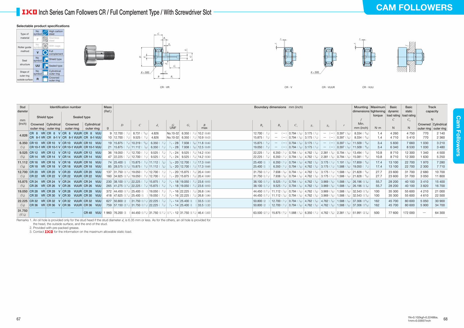
67 68
CAM FOLLOWERSC
am Fo
llow
ers
1N=0.102kgf=0.2248lbs.1mm=0.03937inch
Inch Series Cam Followers CR / Full Complement Type / With Screwdriver Slot
Stud diameter
Identification number Mass Boundary dimensions mm (inch) Mounting dimensions
f
Maximum tightening
torque
Basic dynamic
load ratingC
Basic static
load ratingC0
Track capacity
N
(Ref.)
Shield type Sealed typemm
(inch)
D C d1 GUNF
G1 Bmax
B2 B3 C1 g1 g2 rCrowned outer ring
Cylindrical outer ring
Crowned outer ring
Cylindrical outer ring
Min. Crowned outer ring
Cylindrical outer ringg mm (inch) N・m N N
4.826CR 8 VRCR 8-1 VR
CR 8 VCR 8-1 V
CR 8 VUURCR 8-1 VUUR
CR 8 VUUCR 8-1 VUU
910
12.700 ( / 1 2)
12.700 ( / 1 2)
8.731 ( / 11 32)
9.525 ( / 3 8)
4.826 4.826
No.10-32No.10-32
6.350 ( / 1 4)
6.350 ( / 1 4)
10.2 (0.40)10.9 (0.43)
12.700 ( / 1 2)
15.875 ( / 5 8)
― (―) ― (―)
0.794 (/ 1 32)
0.794 (/ 1 32)
3.175 (/ 1 8)
3.175 (/ 1 8)
― (―) ― (―)
0.397 (/ 1 64)
0.397 (/ 1 64)
8.334 ( / 21 64)
8.334 ( / 21 64)
1.41.4
4 260 4 710
4 750 5 410
770770
2 1402 360
6.350(/ 1 4 )
CR 10 VRCR 10-1 VR
CR 10 VCR 10-1 V
CR 10 VUURCR 10-1 VUUR
CR 10 VUUCR 10-1 VUU
1921
15.875 ( / 5 8)
15.875 ( / 5 8)
10.319 ( / 13 32)
11.112 ( / 7 16)
6.350 ( / 1 4)
6.350 ( / 1 4)
/ 1 4 - 28 / 1
4 - 28 7.938 ( / 5
16) 7.938 ( / 5
16)11.8 (0.46)12.5 (0.49)
15.875 ( / 5 8)
19.050 ( / 3 4)
― (―) ― (―)
0.794 (/ 1 32)
0.794 (/ 1 32)
3.175 (/ 1 8)
3.175 (/ 1 8)
― (―) ― (―)
0.397 (/ 1 64)
0.397 (/ 1 64)
11.509 ( / 29 64)
11.509 ( / 29 64)
3.43.4
5 830 6 340
7 660 8 530
1 0301 030
3 2103 480
9.525(/ 3 8 )
CR 12 VRCR 14 VR
CR 12 VCR 14 V
CR 12 VUURCR 14 VUUR
CR 12 VUUCR 14 VUU
3647
19.050 ( / 3 4)
22.225 ( / 7 8)
12.700 ( / 1 2)
12.700 ( / 1 2)
9.525 ( / 3 8)
9.525 ( / 3 8)
/ 3 8 - 24 / 3
8 - 24 9.525 ( / 3
8) 9.525 ( / 3
8)14.2 (0.56)14.2 (0.56)
22.225 ( / 7 8)
22.225 ( / 7 8)
6.350 (/ 1 4)
6.350 (/ 1 4)
0.794 (/ 1 32)
0.794 (/ 1 32)
4.762 (/ 3 16)
4.762 (/ 3 16)
2.381 (/ 3 32)
2.381 (/ 3 32)
0.794 (/ 1 32)
0.794 (/ 1 32)
13.494 ( / 17 32)
15.081 ( / 19 32)
10.810.8
8 710 8 710
12 300 12 300
1 3401 630
4 5005 250
11.112(/ 7 16)
CR 16 VRCR 18 VR
CR 16 VCR 18 V
CR 16 VUURCR 18 VUUR
CR 16 VUUCR 18 VUU
7485
25.400 (1 )28.575 (1/ 1
8)15.875 ( / 5
8)15.875 ( / 5
8)11.112 ( / 7
16)11.112 ( / 7
16) / 7
16 - 20 / 7
16 - 2012.700 ( / 1
2)12.700 ( / 1
2)17.3 (0.68)17.3 (0.68)
25.400 (1 )25.400 (1 )
6.350 (/ 1 4)
6.350 (/ 1 4)
0.794 (/ 1 32)
0.794 (/ 1 32)
4.762 (/ 3 16)
4.762 (/ 3 16)
3.175 (/ 1 8)
3.175 (/ 1 8)
1.191 (/ 3 64)
1.588 (/ 1 16)
17.859 ( / 45 64)
19.050 ( / 3 4)
17.417.4
13 10013 100
22 700 22 700
1 9702 300
7 2807 710
12.700(/ 1 2 )
CR 20 VRCR 22 VR
CR 20 VCR 22 V
CR 20 VUURCR 22 VUUR
CR 20 VUUCR 22 VUU
137160
31.750 (1/ 1 4)
34.925 (1/ 3 8)
19.050 ( / 3 4)
19.050 ( / 3 4)
12.700 ( / 1 2)
12.700 ( / 1 2)
/ 1 2 - 20 / 1
2 - 2015.875 ( / 5
8)15.875 ( / 5
8)20.4 (0.80)20.4 (0.80)
31.750 (1/ 1 4)
31.750 (1/ 1 4)
7.938 (/ 5 16)
7.938 (/ 5 16)
0.794 (/ 1 32)
0.794 (/ 1 32)
4.762 (/ 3 16)
4.762 (/ 3 16)
3.175 (/ 1 8)
3.175 (/ 1 8)
1.588 (/ 1 16)
1.588 (/ 1 16)
21.828 ( / 55 64)
21.828 ( / 55 64)
27.727.7
23 60023 600
31 700 31 700
2 6803 050
10 70011 800
15.875(/ 5 8 )
CR 24 VRCR 26 VR
CR 24 VCR 26 V
CR 24 VUURCR 26 VUUR
CR 24 VUUCR 26 VUU
230265
38.100 (1/ 1 2)
41.275 (1/ 5 8)
22.225 ( / 7 8)
22.225 ( / 7 8)
15.875 ( / 5 8)
15.875 ( / 5 8)
/ 5 8 - 18 / 5
8 - 1819.050 ( / 3
4)19.050 ( / 3
4)23.6 (0.93)23.6 (0.93)
38.100 (1/ 1 2)
38.100 (1/ 1 2)
9.525 (/ 3 8)
9.525 (/ 3 8)
0.794 (/ 1 32)
0.794 (/ 1 32)
4.762 (/ 3 16)
4.762 (/ 3 16)
3.969 (/ 5 32)
3.969 (/ 5 32)
1.588 (/ 1 16)
1.588 (/ 1 16)
26.196 (1/ 3 64)
26.196 (1/ 3 64)
55.755.7
28 20028 200
40 100 40 100
3 4103 820
15 40016 700
19.050(/ 3 4 )
CR 28 VRCR 30 VR
CR 28 VCR 30 V
CR 28 VUURCR 30 VUUR
CR 28 VUUCR 30 VUU
372418
44.450 (1/ 3 4)
47.625 (1/ 7 8)
25.400 (1 )25.400 (1 )
19.050 ( / 3 4)
19.050 ( / 3 4)
/ 3 4 - 16 / 3
4 - 1622.225 ( / 7
8)22.225 ( / 7
8)26.8 (1.06)26.8 (1.06)
44.450 (1/ 3 4)
44.450 (1/ 3 4)
11.112 (/ 7 16)
11.112 (/ 7 16)
0.794 (/ 1 32)
0.794 (/ 1 32)
4.762 (/ 3 16)
4.762 (/ 3 16)
3.969 (/ 5 32)
3.969 (/ 5 32)
1.588 (/ 1 16)
1.588 (/ 1 16)
32.543 (1/ 9 32)
32.543 (1/ 9 32)
100100
35 30035 300
55 600 55 600
4 2104 610
21 00022 500
22.225(/ 7 8 )
CR 32 VRCR 36 VR
CR 32 VCR 36 V
CR 32 VUURCR 36 VUUR
CR 32 VUUCR 36 VUU
627759
50.800 (2 )57.150 (2/ 1
4)31.750 (1/ 1
4)31.750 (1/ 1
4)22.225 ( / 7
8)22.225 ( / 7
8) / 7
8 - 14 / 7
8 - 1425.400 (1 )25.400 (1 )
33.5 (1.32)33.5 (1.32)
50.800 (2 )50.800 (2 )
12.700 (/ 1 2)
12.700 (/ 1 2)
0.794 (/ 1 32)
0.794 (/ 1 32)
4.762 (/ 3 16)
4.762 (/ 3 16)
4.762 (/ 3 16)
4.762 (/ 3 16)
1.588 (/ 1 16)
1.588 (/ 1 16)
37.306 (1/ 15 32)
37.306 (1/ 15 32)
162162
45 70045 700
80 600 80 600
5 0505 900
30 90034 700
31.750(1/ 1
4 )― ― ― CR 48 VUU 1 960 76.200 (3 ) 44.450 (1/ 3
4) 31.750 (1/ 1 4) 1/ 3
4 - 12 31.750 (1/ 1 4) 46.4 (1.83) 63.500 (2/ 1
2) 15.875 (/ 5 8) 1.588 (/ 1
16) 6.350 (/ 1 4) 4.762 (/ 3
16) 2.381 (/ 3 32) 51.991 (2/ 3
64) 500 77 600 172 000 ― 64 300
Remarks 1. An oil hole is provided only for the stud head if the stud diameter d1 is 6.35 mm or less. As for the others, an oil hole is provided for the head, the outside surface, and the end of the stud.
2. Provided with pre-packed grease. 3. Contact for the information on the maximum allowable static load.
CR…V CR…VUUR CR…VUU
R = 500R = 500
B
C
G1
C1
B2
D G
d 1
g 1
g 1
B3
g2 f
r
r
r
r
CR…VR
Selectable product specifications
Type of
material
Roller guide
method
Seal
structure
Shape of
outer ring
outside surface
No symbol
High carbon steel
F Stainless steel
No symbol With cage
V Full complement
No symbol Shield type
UU Sealed type
No symbol
Cylindrical outer ring
R Crowned outer ring
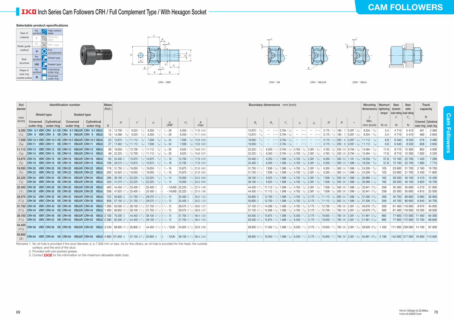
69 70
CAM FOLLOWERSC
am Fo
llow
ers
1N=0.102kgf=0.2248lbs.1mm=0.03937inch
Inch Series Cam Followers CRH / Full Complement Type / With Hexagon Socket
Stud diameter
Identification number Mass Boundary dimensions mm (inch) Mounting dimensions
f
Maximum tightening
torque
Basic dynamic
load ratingC
Basic static
load ratingC0
Track capacity
N
(Ref.)
Shield type Sealed typemm
(inch)
D C d1 GUNF
G1 Bmax
B2 B3 C1 g1 g2 H R rCrowned outer ring
Cylindrical outer ring
Crowned outer ring
Cylindrical outer ring
Min. Crowned outer ring
Cylindrical outer ringg mm (inch) N・m N N
6.350(/ 1 4 )
CRH 8-1 VBRCRH 9 VBR
CRH 8-1 VBCRH 9 VB
CRH 8-1 VBUURCRH 9 VBUUR
CRH 8-1 VBUUCRH 9 VBUU
1215
12.700 ( / 1 2)
14.288 ( / 9 16)
9.525 ( / 3 8)
9.525 ( / 3 8)
6.350 ( / 1 4)
6.350 ( / 1 4)
/ 1 4 - 28 / 1
4 - 28 6.350 ( / 1
4) 6.350 ( / 1
4)11.0 (0.44)11.1 (0.44)
15.875 ( / 5 8)
15.875 ( / 5 8)
― (―) ― (―)
0.794 (/ 1 32)
0.794 (/ 1 32)
― (―) ― (―)
― (―) ― (―)
3.175 (/ 1 8)
3.175 (/ 1 8)
180 ( 7)180 ( 7)
0.397 (/ 1 64)
0.397 (/ 1 64)
8.334 ( / 21 64)
8.334 ( / 21 64)
3.43.4
4 710 4 710
5 410 5 410
401469
2 3602 650
7.938(/ 5 16)
CRH 10-1 VBRCRH 11 VBR
CRH 10-1 VBCRH 11 VB
CRH 10-1 VBUURCRH 11 VBUUR
CRH 10-1 VBUUCRH 11 VBUU
2327
15.875 ( / 5 8)
17.462 ( / 11 16)
11.112 ( / 7 16)
11.112 ( / 7 16)
7.938 ( / 5 16)
7.938 ( / 5 16)
/ 5 16 - 24 / 5
16 - 24 7.938 ( / 5
16) 7.938 ( / 5
16)12.8 (0.50)12.8 (0.50)
19.050 ( / 3 4)
19.050 ( / 3 4)
― (―) ― (―)
0.794 (/ 1 32)
0.794 (/ 1 32)
― (―) ― (―)
― (―) ― (―)
3.175 (/ 1 8)
3.175 (/ 1 8)
200 ( 8)200 ( 8)
0.397 (/ 1 64)
0.397 (/ 1 64)
11.112 ( / 7 16)
11.112 ( / 7 16)
6.86.8
6 340 6 340
8 530 8 530
579658
3 4803 830
11.112(/ 7 16)
CRH 12 VBRCRH 14 VBR
CRH 12 VBCRH 14 VB
CRH 12 VBUURCRH 14 VBUUR
CRH 12 VBUUCRH 14 VBUU
3949
19.050 ( / 3 4)
22.225 ( / 7 8)
12.700 ( / 1 2)
12.700 ( / 1 2)
11.112 ( / 7 16)
11.112 ( / 7 16)
/ 7 16 - 20 / 7
16 - 20 9.525 ( / 3
8) 9.525 ( / 3
8)14.6 (0.57)14.6 (0.57)
22.225 ( / 7 8)
22.225 ( / 7 8)
6.350 (/ 1 4)
6.350 (/ 1 4)
0.794 (/ 1 32)
0.794 (/ 1 32)
4.762 (/ 3 16)
4.762 (/ 3 16)
2.381 (/ 3 32)
2.381 (/ 3 32)
4.762 (/ 3 16)
4.762 (/ 3 16)
250 (10)250 (10)
0.794 (/ 1 32)
0.794 (/ 1 32)
13.494 ( / 17 32)
13.494 ( / 17 32)
17.617.6
8 710 8 710
12 300 12 300
8531 050
4 5005 250
15.875(/ 5 8 )
CRH 16 VBRCRH 18 VBR
CRH 16 VBCRH 18 VB
CRH 16 VBUURCRH 18 VBUUR
CRH 16 VBUUCRH 18 VBUU
93109
25.400 (1 ) 28.575 (1/ 1
8)15.875 ( / 5
8)15.875 ( / 5
8)15.875 ( / 5
8)15.875 ( / 5
8) / 5
8 - 18 / 5
8 - 1812.700 ( / 1
2)12.700 ( / 1
2)17.9 (0.70)17.9 (0.70)
25.400 (1 )25.400 (1 )
6.350 (/ 1 4)
6.350 (/ 1 4)
1.588 (/ 1 16)
1.588 (/ 1 16)
4.762 (/ 3 16)
4.762 (/ 3 16)
2.381 (/ 3 32)
2.381 (/ 3 32)
6.350 (/ 1 4)
6.350 (/ 1 4)
300 (12)300 (12)
1.191 (/ 3 64)
1.588 (/ 1 16)
18.256 ( / 23 32)
18.256 ( / 23 32)
57.857.8
13 100 13 100
22 700 22 700
1 4201 660
7 2807 710
19.050(/ 3 4 )
CRH 20 VBRCRH 22 VBR
CRH 20 VBCRH 22 VB
CRH 20 VBUURCRH 22 VBUUR
CRH 20 VBUUCRH 22 VBUU
176200
31.750 (1/ 1 4)
34.925 (1/ 3 8)
19.050 ( / 3 4)
19.050 ( / 3 4)
19.050 ( / 3 4)
19.050 ( / 3 4)
/ 3 4 - 16 / 3
4 - 1615.875 ( / 5
8)15.875 ( / 5
8)21.0 (0.83)21.0 (0.83)
31.750 (1/ 1 4)
31.750 (1/ 1 4)
7.938 (/ 5 16)
7.938 (/ 5 16)
1.588 (/ 1 16)
1.588 (/ 1 16)
4.762 (/ 3 16)
4.762 (/ 3 16)
2.381 (/ 3 32)
2.381 (/ 3 32)
6.350 (/ 1 4)
6.350 (/ 1 4)
360 (14)360 (14)
1.588 (/ 1 16)
1.588 (/ 1 16)
24.209 ( / 61 64)
24.209 ( / 61 64)
103103
23 600 23 600
31 700 31 700
2 1602 450
10 70011 800
22.225(/ 7 8 )
CRH 24 VBRCRH 26 VBR
CRH 24 VBCRH 26 VB
CRH 24 VBUURCRH 26 VBUUR
CRH 24 VBUUCRH 26 VBUU
296329
38.100 (1/ 1 2)
41.275 (1/ 5 8)
22.225 ( / 7 8)
22.225 ( / 7 8)
22.225 ( / 7 8)
22.225 ( / 7 8)
/ 7 8 - 14 / 7
8 - 1419.050 ( / 3
4)19.050 ( / 3
4)24.3 (0.96)24.3 (0.96)
38.100 (1/ 1 2)
38.100 (1/ 1 2)
9.525 (/ 3 8)
9.525 (/ 3 8)
1.588 (/ 1 16)
1.588 (/ 1 16)
4.762 (/ 3 16)
4.762 (/ 3 16)
2.381 (/ 3 32)
2.381 (/ 3 32)
7.938 (/ 5 16)
7.938 (/ 5 16)
500 (20)500 (20)
1.588 (/ 1 16)
1.588 (/ 1 16)
26.988 (1/ 1 16)
26.988 (1/ 1 16)
162162
28 200 28 200
40 100 40 100
3 4103 820
15 40016 700
25.400( 1 )
CRH 28 VBRCRH 30 VBR
CRH 28 VBCRH 30 VB
CRH 28 VBUURCRH 30 VBUUR
CRH 28 VBUUCRH 30 VBUU
463508
44.450 (1/ 3 4)
47.625 (1/ 7 8)
25.400 (1 )25.400 (1 )
25.400 (1 )25.400 (1 )
1 - 14UNS1 - 14UNS
22.225 ( / 7 8)
22.225 ( / 7 8)
27.4 (1.08)27.4 (1.08)
44.450 (1/ 3 4)
44.450 (1/ 3 4)
11.112 (/ 7 16)
11.112 (/ 7 16)
1.588 (/ 1 16)
1.588 (/ 1 16)
4.762 (/ 3 16)
4.762 (/ 3 16)
2.381 (/ 3 32)
2.381 (/ 3 32)
7.938 (/ 5 16)
7.938 (/ 5 16)
500 (20)500 (20)
1.588 (/ 1 16)
1.588 (/ 1 16)
32.941 (1/ 19 64)
32.941 (1/ 19 64)
258258
35 300 35 300
55 600 55 600
4 2104 610
21 00022 500
28.575(1/ 1 8 )
CRH 32 VBRCRH 36 VBR
CRH 32 VBCRH 36 VB
CRH 32 VBUURCRH 36 VBUUR
CRH 32 VBUUCRH 36 VBUU
722858
50.800 (2 ) 57.150 (2/ 1
4)31.750 (1/ 1
4)31.750 (1/ 1
4)28.575 (1/ 1
8)28.575 (1/ 1
8)1/ 1
8 - 121/ 1
8 - 1225.400 (1 )25.400 (1 )
34.2 (1.35)34.2 (1.35)
50.800 (2 )50.800 (2 )
12.700 (/ 1 2)
12.700 (/ 1 2)
1.588 (/ 1 16)
1.588 (/ 1 16)
4.762 (/ 3 16)
4.762 (/ 3 16)
3.175 (/ 1 8)
3.175 (/ 1 8)
11.112 (/ 7 16)
11.112 (/ 7 16)
600 (24)600 (24)
1.588 (/ 1 16)
1.588 (/ 1 16)
37.306 (1/ 15 32)
37.306 (1/ 15 32)
356356
45 700 45 700
80 600 80 600
5 6906 640
30 90034 700
31.750(1/ 1 4 )
CRH 40 VBRCRH 44 VBR
CRH 40 VBCRH 44 VB
CRH 40 VBUURCRH 44 VBUUR
CRH 40 VBUUCRH 44 VBUU
1 2601 460
63.500 (2/ 1 2)
69.850 (2/ 3 4)
38.100 (1/ 1 2)
38.100 (1/ 1 2)
31.750 (1/ 1 4)
31.750 (1/ 1 4)
1/ 1 4 - 121/ 1
4 - 1228.575 (1/ 1
8)28.575 (1/ 1
8)40.0 (1.57)40.0 (1.57)
57.150 (2/ 1 4)
57.150 (2/ 1 4)
14.288 (/ 9 16)
14.288 (/ 9 16)
1.588 (/ 1 16)
1.588 (/ 1 16)
4.762 (/ 3 16)
4.762 (/ 3 16)
3.175 (/ 1 8)
3.175 (/ 1 8)
12.700 (/ 1 2)
12.700 (/ 1 2)
760 (30)760 (30)
2.381 (/ 3 32)
2.381 (/ 3 32)
40.878 (1/ 39 64)
40.878 (1/ 39 64)
500500
61 400 61 400
116 000116 000
8 97010 200
45 00049 500
38.100(1/ 1 2 )
CRH 48 VBRCRH 52 VBR
CRH 48 VBCRH 52 VB
CRH 48 VBUURCRH 52 VBUUR
CRH 48 VBUUCRH 52 VBUU
2 1002 380
76.200 (3 ) 82.500 (3/ 1
4)44.450 (1/ 3
4)44.450 (1/ 3
4)38.100 (1/ 1
2)38.100 (1/ 1
2)1/ 1
2 - 121/ 1
2 - 1231.750 (1/ 1
4)31.750 (1/ 1
4)46.4 (1.83)46.4 (1.83)
63.500 (2/ 1 2)
63.500 (2/ 1 2)
15.875 (/ 5 8)
15.875 (/ 5 8)
1.588 (/ 1 16)
1.588 (/ 1 16)
6.350 (/ 1 4)
6.350 (/ 1 4)
3.175 (/ 1 8)
3.175 (/ 1 8)
19.050 (/ 3 4)
19.050 (/ 3 4)
760 (30)760 (30)
2.381 (/ 3 32)
2.381 (/ 3 32)
51.991 (2/ 3 64)
51.991 (2/ 3 64)
892892
77 600 77 600
172 000172 000
11 40012 700
64 30069 600
44.450(1/ 3 4 )
CRH 56 VBR CRH 56 VB CRH 56 VBUUR CRH 56 VBUU 3 240 88.900 (3/ 1 2) 50.800 (2 ) 44.450 (1/ 3
4) 1/ 3 4 - 12UN 34.925 (1/ 3
8) 52.8 (2.08) 69.850 (2/ 3 4) 17.462 (/ 11
16) 1.588 (/ 1 16) 6.350 (/ 1
4) 3.175 (/ 1 8) 19.050 (/ 3
4) 760 (30) 2.381 (/ 3 32) 59.928 (2/ 23
64) 1 450 111 000 239 000 14 100 87 000
50.800( 2 )
CRH 64 VBR CRH 64 VB CRH 64 VBUUR CRH 64 VBUU 4 960 101.600 (4 ) 57.150 (2/ 1 4) 50.800 (2 ) 2 - 12UN 38.100 (1/ 1
2) 59.4 (2.34) 88.900 (3/ 1 2) 19.050 (/ 3
4) 1.588 (/ 1 16) 6.350 (/ 1
4) 3.175 (/ 1 8) 19.050 (/ 3
4) 760 (30) 2.381 (/ 3 32) 64.691 (2/ 35
64) 2 190 142 000 317 000 16 800 113 000
Remarks 1. No oil hole is provided if the stud diameter d1 is 7.938 mm or less. As for the others, an oil hole is provided for the head, the outside surface, and the end of the stud.
2. Provided with pre-packed grease. 3. Contact for the information on the maximum allowable static load.
R
f
r
r
r
r
CRH…VBR CRH…VB CRH…VBUUR CRH…VBUU
R
B
H
C
G1
C1
B2
D G
d 1
g 1
B3
g2
Selectable product specifications
Type of
material
Roller guide
method
Seal
structure
Shape of
outer ring
outside surface
No symbol
High carbon steel
F Stainless steel
No symbol With cage
V Full complement
No symbol Shield type
UU Sealed type
No symbol
Cylindrical outer ring
R Crowned outer ring
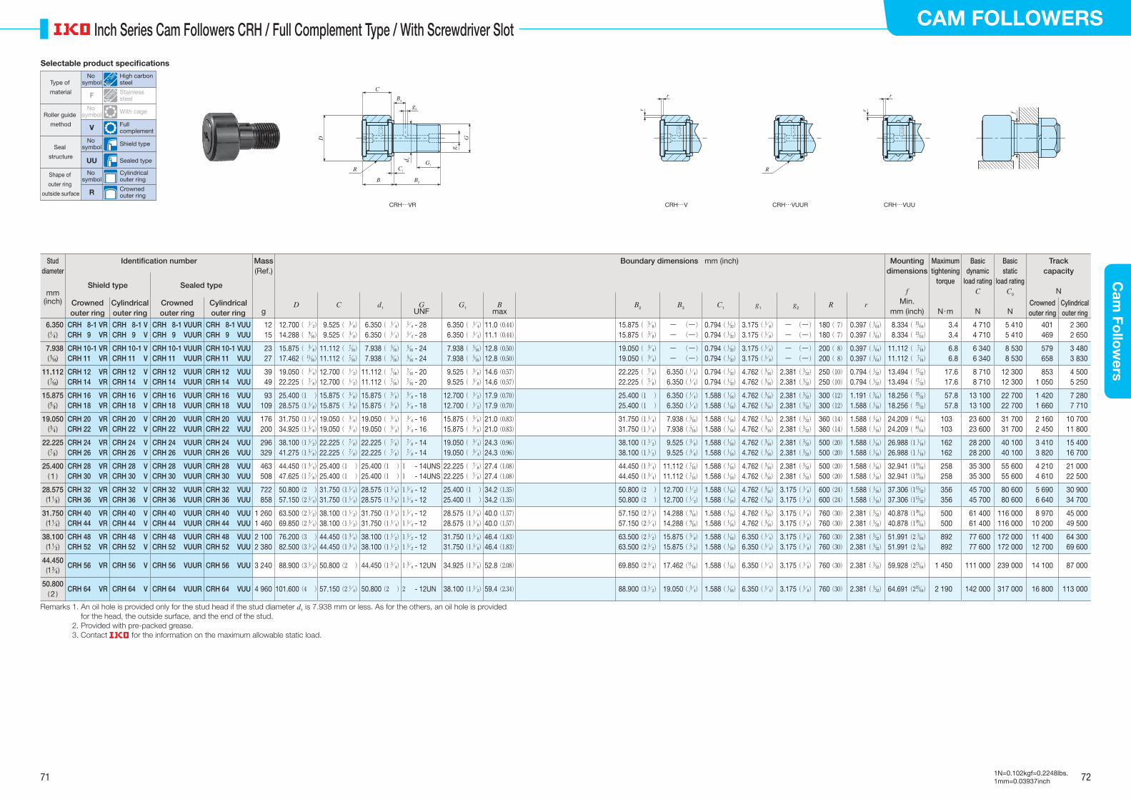
71 72
CAM FOLLOWERSC
am Fo
llow
ers
1N=0.102kgf=0.2248lbs.1mm=0.03937inch
Inch Series Cam Followers CRH / Full Complement Type / With Screwdriver Slot
Stud diameter
Identification number Mass Boundary dimensions mm (inch) Mounting dimensions
f
Maximum tightening
torque
Basic dynamic
load ratingC
Basic static
load ratingC0
Track capacity
N
(Ref.)
Shield type Sealed typemm
(inch)
D C d1 GUNF
G1 Bmax
B2 B3 C1 g1 g2 R rCrowned outer ring
Cylindrical outer ring
Crowned outer ring
Cylindrical outer ring
Min. Crowned outer ring
Cylindrical outer ringg mm (inch) N・m N N
6.350(/ 1 4 )
CRH 8-1 VRCRH 9 VR
CRH 8-1 VCRH 9 V
CRH 8-1 VUURCRH 9 VUUR
CRH 8-1 VUUCRH 9 VUU
1215
12.700 ( / 1 2)
14.288 ( / 9 16)
9.525 ( / 3 8)
9.525 ( / 3 8)
6.350 ( / 1 4)
6.350 ( / 1 4)
/ 1 4 - 28 / 1
4 - 28 6.350 ( / 1
4) 6.350 ( / 1
4)11.0 (0.44)11.1 (0.44)
15.875 ( / 5 8)
15.875 ( / 5 8)
― (―) ― (―)
0.794 (/ 1 32)
0.794 (/ 1 32)
3.175 (/ 1 8)
3.175 (/ 1 8)
― (―) ― (―)
180 ( 7)180 ( 7)
0.397 (/ 1 64)
0.397 (/ 1 64)
8.334 ( / 21 64)
8.334 ( / 21 64)
3.43.4
4 710 4 710
5 410 5 410
401469
2 3602 650
7.938(/ 5 16)
CRH 10-1 VRCRH 11 VR
CRH 10-1 VCRH 11 V
CRH 10-1 VUURCRH 11 VUUR
CRH 10-1 VUUCRH 11 VUU
2327
15.875 ( / 5 8)
17.462 ( / 11 16)
11.112 ( / 7 16)
11.112 ( / 7 16)
7.938 ( / 5 16)
7.938 ( / 5 16)
/ 5 16 - 24 / 5
16 - 24 7.938 ( / 5
16) 7.938 ( / 5
16)12.8 (0.50)12.8 (0.50)
19.050 ( / 3 4)
19.050 ( / 3 4)
― (―) ― (―)
0.794 (/ 1 32)
0.794 (/ 1 32)
3.175 (/ 1 8)
3.175 (/ 1 8)
― (―) ― (―)
200 ( 8)200 ( 8)
0.397 (/ 1 64)
0.397 (/ 1 64)
11.112 ( / 7 16)
11.112 ( / 7 16)
6.86.8
6 340 6 340
8 530 8 530
579658
3 4803 830
11.112(/ 7 16)
CRH 12 VRCRH 14 VR
CRH 12 VCRH 14 V
CRH 12 VUURCRH 14 VUUR
CRH 12 VUUCRH 14 VUU
3949
19.050 ( / 3 4)
22.225 ( / 7 8)
12.700 ( / 1 2)
12.700 ( / 1 2)
11.112 ( / 7 16)
11.112 ( / 7 16)
/ 7 16 - 20 / 7
16 - 20 9.525 ( / 3
8) 9.525 ( / 3
8)14.6 (0.57)14.6 (0.57)
22.225 ( / 7 8)
22.225 ( / 7 8)
6.350 (/ 1 4)
6.350 (/ 1 4)
0.794 (/ 1 32)
0.794 (/ 1 32)
4.762 (/ 3 16)
4.762 (/ 3 16)
2.381 (/ 3 32)
2.381 (/ 3 32)
250 (10)250 (10)
0.794 (/ 1 32)
0.794 (/ 1 32)
13.494 ( / 17 32)
13.494 ( / 17 32)
17.617.6
8 710 8 710
12 300 12 300
8531 050
4 5005 250
15.875(/ 5 8 )
CRH 16 VRCRH 18 VR
CRH 16 VCRH 18 V
CRH 16 VUURCRH 18 VUUR
CRH 16 VUUCRH 18 VUU
93109
25.400 (1 ) 28.575 (1/ 1
8)15.875 ( / 5
8)15.875 ( / 5
8)15.875 ( / 5
8)15.875 ( / 5
8) / 5
8 - 18 / 5
8 - 1812.700 ( / 1
2)12.700 ( / 1
2)17.9 (0.70)17.9 (0.70)
25.400 (1 )25.400 (1 )
6.350 (/ 1 4)
6.350 (/ 1 4)
1.588 (/ 1 16)
1.588 (/ 1 16)
4.762 (/ 3 16)
4.762 (/ 3 16)
2.381 (/ 3 32)
2.381 (/ 3 32)
300 (12)300 (12)
1.191 (/ 3 64)
1.588 (/ 1 16)
18.256 ( / 23 32)
18.256 ( / 23 32)
57.857.8
13 100 13 100
22 700 22 700
1 4201 660
7 2807 710
19.050(/ 3 4 )
CRH 20 VRCRH 22 VR
CRH 20 VCRH 22 V
CRH 20 VUURCRH 22 VUUR
CRH 20 VUUCRH 22 VUU
176200
31.750 (1/ 1 4)
34.925 (1/ 3 8)
19.050 ( / 3 4)
19.050 ( / 3 4)
19.050 ( / 3 4)
19.050 ( / 3 4)
/ 3 4 - 16 / 3
4 - 1615.875 ( / 5
8)15.875 ( / 5
8)21.0 (0.83)21.0 (0.83)
31.750 (1/ 1 4)
31.750 (1/ 1 4)
7.938 (/ 5 16)
7.938 (/ 5 16)
1.588 (/ 1 16)
1.588 (/ 1 16)
4.762 (/ 3 16)
4.762 (/ 3 16)
2.381 (/ 3 32)
2.381 (/ 3 32)
360 (14)360 (14)
1.588 (/ 1 16)
1.588 (/ 1 16)
24.209 ( / 61 64)
24.209 ( / 61 64)
103103
23 600 23 600
31 700 31 700
2 1602 450
10 70011 800
22.225(/ 7 8 )
CRH 24 VRCRH 26 VR
CRH 24 VCRH 26 V
CRH 24 VUURCRH 26 VUUR
CRH 24 VUUCRH 26 VUU
296329
38.100 (1/ 1 2)
41.275 (1/ 5 8)
22.225 ( / 7 8)
22.225 ( / 7 8)
22.225 ( / 7 8)
22.225 ( / 7 8)
/ 7 8 - 14 / 7
8 - 1419.050 ( / 3
4)19.050 ( / 3
4)24.3 (0.96)24.3 (0.96)
38.100 (1/ 1 2)
38.100 (1/ 1 2)
9.525 (/ 3 8)
9.525 (/ 3 8)
1.588 (/ 1 16)
1.588 (/ 1 16)
4.762 (/ 3 16)
4.762 (/ 3 16)
2.381 (/ 3 32)
2.381 (/ 3 32)
500 (20)500 (20)
1.588 (/ 1 16)
1.588 (/ 1 16)
26.988 (1/ 1 16)
26.988 (1/ 1 16)
162162
28 200 28 200
40 100 40 100
3 4103 820
15 40016 700
25.400( 1 )
CRH 28 VRCRH 30 VR
CRH 28 VCRH 30 V
CRH 28 VUURCRH 30 VUUR
CRH 28 VUUCRH 30 VUU
463508
44.450 (1/ 3 4)
47.625 (1/ 7 8)
25.400 (1 )25.400 (1 )
25.400 (1 )25.400 (1 )
1 - 14UNS1 - 14UNS
22.225 ( / 7 8)
22.225 ( / 7 8)
27.4 (1.08)27.4 (1.08)
44.450 (1/ 3 4)
44.450 (1/ 3 4)
11.112 (/ 7 16)
11.112 (/ 7 16)
1.588 (/ 1 16)
1.588 (/ 1 16)
4.762 (/ 3 16)
4.762 (/ 3 16)
2.381 (/ 3 32)
2.381 (/ 3 32)
500 (20)500 (20)
1.588 (/ 1 16)
1.588 (/ 1 16)
32.941 (1/ 19 64)
32.941 (1/ 19 64)
258258
35 300 35 300
55 600 55 600
4 2104 610
21 00022 500
28.575(1/ 1 8 )
CRH 32 VRCRH 36 VR
CRH 32 VCRH 36 V
CRH 32 VUURCRH 36 VUUR
CRH 32 VUUCRH 36 VUU
722858
50.800 (2 ) 57.150 (2/ 1
4)31.750 (1/ 1
4)31.750 (1/ 1
4)28.575 (1/ 1
8)28.575 (1/ 1
8)1/ 1
8 - 121/ 1
8 - 1225.400 (1 )25.400 (1 )
34.2 (1.35)34.2 (1.35)
50.800 (2 )50.800 (2 )
12.700 (/ 1 2)
12.700 (/ 1 2)
1.588 (/ 1 16)
1.588 (/ 1 16)
4.762 (/ 3 16)
4.762 (/ 3 16)
3.175 (/ 1 8)
3.175 (/ 1 8)
600 (24)600 (24)
1.588 (/ 1 16)
1.588 (/ 1 16)
37.306 (1/ 15 32)
37.306 (1/ 15 32)
356356
45 700 45 700
80 600 80 600
5 6906 640
30 90034 700
31.750(1/ 1 4 )
CRH 40 VRCRH 44 VR
CRH 40 VCRH 44 V
CRH 40 VUURCRH 44 VUUR
CRH 40 VUUCRH 44 VUU
1 2601 460
63.500 (2/ 1 2)
69.850 (2/ 3 4)
38.100 (1/ 1 2)
38.100 (1/ 1 2)
31.750 (1/ 1 4)
31.750 (1/ 1 4)
1/ 1 4 - 121/ 1
4 - 1228.575 (1/ 1
8)28.575 (1/ 1
8)40.0 (1.57)40.0 (1.57)
57.150 (2/ 1 4)
57.150 (2/ 1 4)
14.288 (/ 9 16)
14.288 (/ 9 16)
1.588 (/ 1 16)
1.588 (/ 1 16)
4.762 (/ 3 16)
4.762 (/ 3 16)
3.175 (/ 1 8)
3.175 (/ 1 8)
760 (30)760 (30)
2.381 (/ 3 32)
2.381 (/ 3 32)
40.878 (1/ 39 64)
40.878 (1/ 39 64)
500500
61 400 61 400
116 000116 000
8 97010 200
45 00049 500
38.100(1/ 1 2 )
CRH 48 VRCRH 52 VR
CRH 48 VCRH 52 V
CRH 48 VUURCRH 52 VUUR
CRH 48 VUUCRH 52 VUU
2 1002 380
76.200 (3 ) 82.500 (3/ 1
4)44.450 (1/ 3
4)44.450 (1/ 3
4)38.100 (1/ 1
2)38.100 (1/ 1
2)1/ 1
2 - 121/ 1
2 - 1231.750 (1/ 1
8)31.750 (1/ 1
8)46.4 (1.83)46.4 (1.83)
63.500 (2/ 1 2)
63.500 (2/ 1 2)
15.875 (/ 5 8)
15.875 (/ 5 8)
1.588 (/ 1 16)
1.588 (/ 1 16)
6.350 (/ 1 4)
6.350 (/ 1 4)
3.175 (/ 1 8)
3.175 (/ 1 8)
760 (30)760 (30)
2.381 (/ 3 32)
2.381 (/ 3 32)
51.991 (2/ 3 64)
51.991 (2/ 3 64)
892892
77 600 77 600
172 000172 000
11 40012 700
64 30069 600
44.450(1/ 3 4 )
CRH 56 VR CRH 56 V CRH 56 VUUR CRH 56 VUU 3 240 88.900 (3/ 1 2) 50.800 (2 ) 44.450 (1/ 3
4) 1/ 3 4 - 12UN 34.925 (1/ 3
8) 52.8 (2.08) 69.850 (2/ 3 4) 17.462 (/ 11
16) 1.588 (/ 1 16) 6.350 (/ 1
4) 3.175 (/ 1 8) 760 (30) 2.381 (/ 3
32) 59.928 (2/ 23 64) 1 450 111 000 239 000 14 100 87 000
50.800( 2 )
CRH 64 VR CRH 64 V CRH 64 VUUR CRH 64 VUU 4 960 101.600 (4 ) 57.150 (2/ 1 4) 50.800 (2 ) 2 - 12UN 38.100 (1/ 1
2) 59.4 (2.34) 88.900 (3/ 1 2) 19.050 (/ 3
4) 1.588 (/ 1 16) 6.350 (/ 1
4) 3.175 (/ 1 8) 760 (30) 2.381 (/ 3
32) 64.691 (2/ 35 64) 2 190 142 000 317 000 16 800 113 000
Remarks 1. An oil hole is provided only for the stud head if the stud diameter d1 is 7.938 mm or less. As for the others, an oil hole is provided for the head, the outside surface, and the end of the stud.
2. Provided with pre-packed grease. 3. Contact for the information on the maximum allowable static load.
R
f
r
r
r
r
CRH…VR CRH…V CRH…VUUR CRH…VUU
R
B
C
G1
C1
B2
D G
d 1
g 1
B3
g2
Selectable product specifications
Type of
material
Roller guide
method
Seal
structure
Shape of
outer ring
outside surface
No symbol
High carbon steel
F Stainless steel
No symbol With cage
V Full complement
No symbol Shield type
UU Sealed type
No symbol
Cylindrical outer ring
R Crowned outer ring

Applicable Cam Followers
TRLB- 600-34-22
TRLB- 800-34-22
TRLB-1000-34-22
TRLB- 600-50-40
TRLB- 800-50-40
TRLB-1000-50-40
Identification number
Boundary dimensions mm
L
N
W
H
hn (Pieces)
100 100
4-C0.5
4-C0.5
200
d 2 d 1
Material: SKS3 equivalentSurface hardness: HRC40 or more
Boundary dimensions mm
Applicable Cam Followers
TRLA - 800 - 49 - 22
❶ Identification Number Example of the identification number of Way for Cam Follower is shown below.
❷ Dimension Table
<Way A Type> <Way B Type>
<Way A Type>
Identification number
L (n) W H N d1 d2 h
TRLA- 600-40-22
TRLA- 800-40-22
TRLA-1000-40-22
TRLA- 600-49-22
TRLA- 800-49-22
TRLA-1000-49-22
TRLA- 600-64-22
TRLA- 800-64-22
TRLA-1000-64-22
600 (3)
800 (4)
1000 (5)
600 (3)
800 (4)
1000 (5)
600 (3)
800 (4)
1000 (5)
40
49
64
22 12 9 14 11
Stud dia. 3 to 8 mm
Stud dia. 10 to 18 mm
Stud dia. 20 to 30 mm
Remark For other dimensions, please contact .
L
N
W
H
hn (Pieces)
100 100
4-C0.5
4-C0.5
200
d 2 d 1
<Way B Type>
L (n) W H N d1 d2 h
600 (3)
800 (4)
1000 (5)
600 (3)
800 (4)
1000 (5)
34
50
22
40
17
25
9
11
14
17
11
13
Stud dia. 3 to 12 mm
Stud dia. 16 to 30 mm
Remark For other dimensions, please contact .
Material: SKS3 equivalentSurface hardness: HRC40 or more
The accuracy of the mating cam guide that comes in contact with the outer ring of Cam Followers has a large influence on the guide performance of Cam Followers and machinery.A specially designed high-precision Way for Cam Follower should be used in order to achieve sufficient performance from the Cam Followers. Fixed with bolts for simple assembly and available in 2 models - A type or B type - depending on the mounting direction.
Model codeTRLA (Way A Type)
TRLB (Way B Type)
Overall length
mm
Width
mm
Height
mm
73 74
CAM FOLLOWERSC
am Fo
llow
ers
1N=0.102kgf=0.2248lbs.1mm=0.03937inch
Way for Cam Follower

CF
CF
Way
Way
CF
CF
Way
Way
Introducing special support examples of Way for Cam Follower.A variety of shapes are supported. For details, please contact .
Roller Follower SeriesExplanation Dimension Table
Features ………………………………………………………………77Identi�cation number ………………………………………79Load Rating and Life ………………………………………80Maximum Allowable Static Load …………………80Accuracy ……………………………………………………………81Radial Internal Clearance ………………………………82Fit …………………………………………………………………………83Track Capacity …………………………………………………83Allowable Rotational Speed ……………………………83Lubrication …………………………………………………………83Oil Hole ………………………………………………………………83Operating Temperature Range ………………………83Mounting ……………………………………………………………84
Separable Roller Followers ……………………………85Non-separable Roller Followers ……………………89C-Lube Roller Followers …………………………………93Cylindrical Roller Followers ……………………………95Inch Series Non-separable
Roller Followers ……………………………………97
76
ROLLER FOLLOWERSR
oller Fo
llow
ers
75
Introduction of Special Support Examples
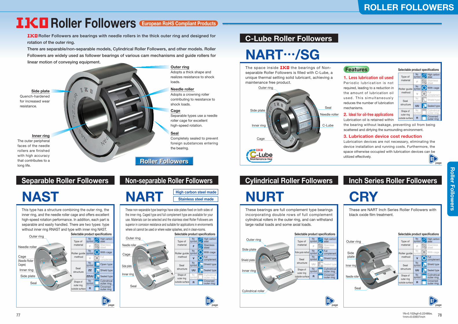
Roller Followers are bearings with needle rollers in the thick outer ring and designed for
rotation of the outer ring.
There are separable/non-separable models, Cylindrical Roller Followers, and other models. Roller
Followers are widely used as follower bearings of various cam mechanisms and guide rollers for
linear motion of conveying equipment.
Roller FollowersRoller Followers
Separable Roller Followers
NASTThis type has a structure combining the outer ring, the inner ring, and the needle roller cage and offers excellent high-speed rotation performance. In addition, each part is separable and easily handled. There are two types: type without inner ring RNAST and type with inner ring NAST.
Selectable product speci�cations
Roller guide method
Shape of outer ring
outside surface
Seal structure
With cage
Full complement
Cylindrical outer ringCrowned outer ring
Open type
Shield type
No symbol
V
No symbol
R
No symbol
ZZ
Sealed typeZZUU
Non-separable Roller Followers
NARTThese non-separable type bearings have side plates �xed on both sides of the inner ring. Caged type and full complement type are available for your use. Materials can be selected and the stainless steel Roller Followers are superior in corrosion resistance and suitable for applications in environments where oil cannot be used or where water splashes, and in clean-rooms.
Selectable product speci�cations
Roller guide method
Shape of outer ring
outside surface
Seal structure
With cage
Full complement
Cylindrical outer ringCrowned outer ring
Shield type
No symbol
V
No symbol
R
No symbol
Sealed typeUU
Cylindrical Roller Followers
NURTThese bearings are full complement type bearings incorporating double rows of full complement cylindrical rollers in the outer ring, and can withstand large radial loads and some axial loads.
Inch Series Roller Followers
CRYThese are NART Inch Series Roller Followers with black oxide �lm treatment.
Selectable product speci�cations
Roller guide method
Shape of outer ring
outside surface
Seal structure
With cage
Full complement
Cylindrical outer ringCrowned outer ring
Shield type
No symbol
V
No symbol
R
No symbol
Sealed typeUU
Selectable product speci�cations
Roller guide method
Seal structure
Full complement
Cylindrical outer ringCrowned outer ring
Shield type
No symbol
No symbol
R
No symbol
Sealed typeUU
Type of material
High carbon steel
No symbol
Stainless steelF
C-Lube Roller Followers
NART…/SGThe space inside the bearings of Non-separable Roller Followers is �lled with C-Lube, a unique thermal setting solid lubricant, achieving a maintenance free product.
Cage
C-Lube
Needle roller
Seal
Outer ring
Inner ring
Side plate
European RoHS Compliant Products
Type of material
High carbon steel
No symbol
Stainless steelF
Type of material
High carbon steel
No symbol
Stainless steelF
Outer ring
Needle roller
Cage
Side plate
Inner ringSeal
Features
Seal
Needle roller
Outer ring
Inner ring
Side plate
Cylindrical roller
Shield plate
Side plate
Outer ring
Inner ring
Outer ring
Side plate
Inner ring
Cage (Needle Roller Cages)
Cage
Seal
Needle roller
Outer ring
Inner ring
Side plate
Seal
Needle roller
High carbon steel made
Stainless steel made
Type of material
High carbon steel
No symbol
Stainless steelF
Selectable product speci�cations
Roller guide method
Shape of outer ring
outside surface
Seal structure
With cage
Full complement
Cylindrical outer ringCrowned outer ring
Shield type
No symbol
V
No symbol
R
No symbol
Sealed typeUU
Type of material
High carbon steel
No symbol
Stainless steelF
1. Less lubrication oil usedP e r i o d i c l u b r i c a t i o n i s n o t required, leading to a reduction in the amount of lubrication oi l u s e d . T h i s s i m u l t a n e o u s l y reduces the number of lubrication mechanisms.
2. Ideal for oil-free applicationsLubrication oil is retained within the bearing without leakage, preventing oil from being scattered and dirtying the surrounding environment.
3. Lubrication device cost reductionLubrication devices are not necessary, eliminating the device installation and running costs. Furthermore, the space otherwise occupied with lubrication devices can be utilized effectively.
Shape of outer ring
outside surface
Quench-hardened for increased wear resistance.
The outer peripheral faces of the needle rollers are �nished with high accuracy that contributes to a long life.
Adopts a thick shape and realizes resistance to shock loads.
Adopts a crowning roller contributing to resistance to shock loads.
Separable types use a needle roller cage for excellent high-speed rotation.
Completely sealed to prevent foreign substances entering the bearing.
Roller Followers
77 78
ROLLER FOLLOWERSR
oller Fo
llow
ers
page89
page97
page93
page85
page95
1N=0.102kgf=0.2248lbs.1mm=0.03937inch
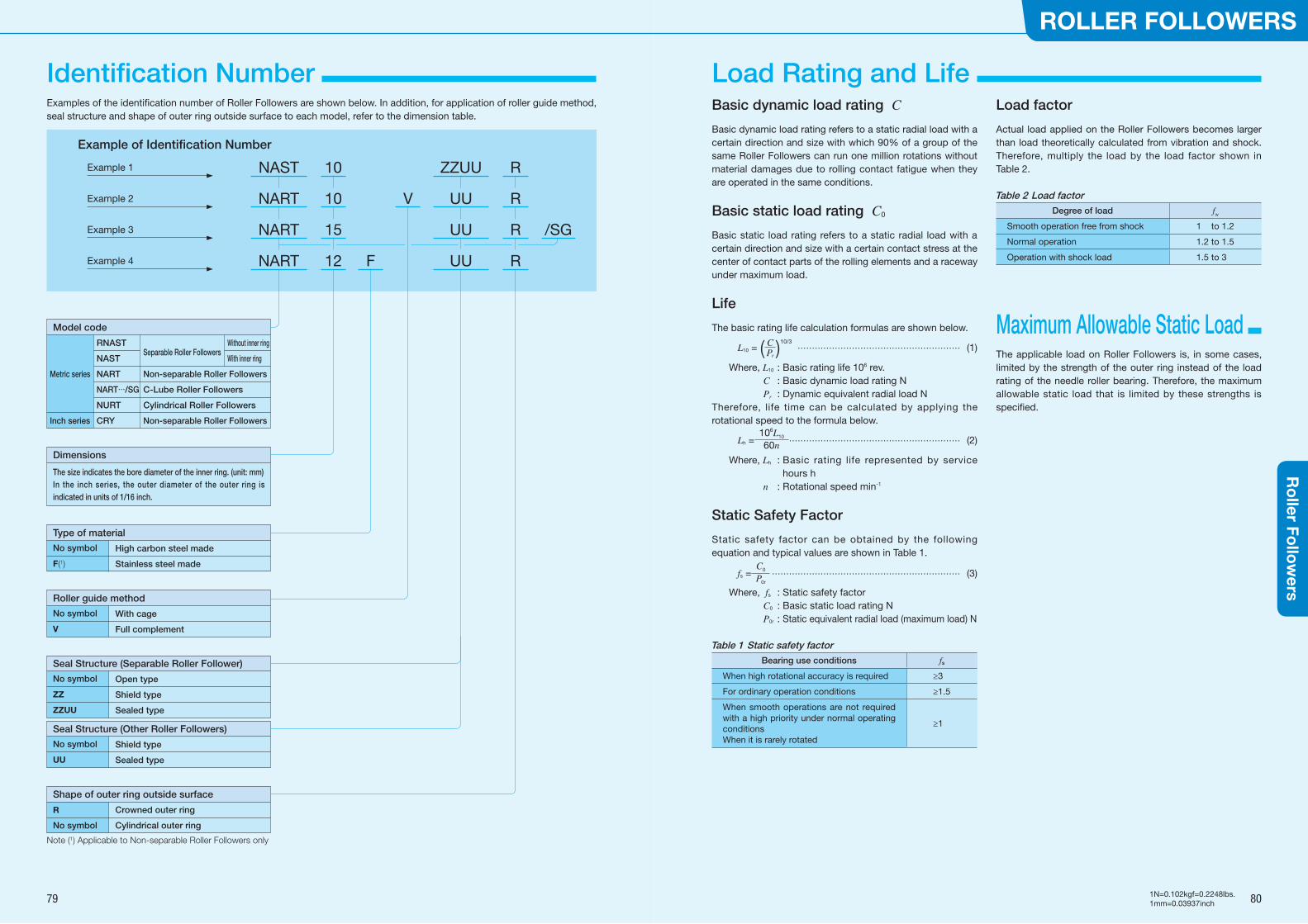
Note (1) Applicable to Non-separable Roller Followers only
Examples of the identification number of Roller Followers are shown below. In addition, for application of roller guide method, seal structure and shape of outer ring outside surface to each model, refer to the dimension table.
Example of Identification Number
NAST
NART
NART
NART
10
10
15
12
ZZUU
UU
UU
UU
R
R
R
R
/SG
F
V
Model code
Metric series
Inch series
RNAST
NAST
NART
NART…/SG
NURT
CRY
Separable Roller Followers
Non-separable Roller Followers
C-Lube Roller Followers
Cylindrical Roller Followers
Non-separable Roller Followers
Roller guide method
Type of material
No symbol
V
No symbol
F(1)
With cage
Full complement
High carbon steel made
Stainless steel made
Seal Structure (Separable Roller Follower)
No symbol
ZZ
ZZUU
Open type
Shield type
Sealed type
Seal Structure (Other Roller Followers)
No symbol
UU
Shield type
Sealed type
Shape of outer ring outside surface
R
No symbol
Crowned outer ring
Cylindrical outer ring
Dimensions
The size indicates the bore diameter of the inner ring. (unit: mm)In the inch series, the outer diameter of the outer ring is indicated in units of 1/16 inch.
Without inner ring
With inner ring
Example 1
Example 2
Example 3
Example 4
Basic dynamic load rating C
Basic dynamic load rating refers to a static radial load with a certain direction and size with which 90% of a group of the same Roller Followers can run one million rotations without material damages due to rolling contact fatigue when they are operated in the same conditions.
Basic static load rating C0
Basic static load rating refers to a static radial load with a certain direction and size with a certain contact stress at the center of contact parts of the rolling elements and a raceway under maximum load.
Life
The basic rating life calculation formulas are shown below.
L10 = ( C Pr )
10/3 ………………………………………………… (1)
Where, L10 : Basic rating life 106 rev. C : Basic dynamic load rating N Pr : Dynamic equivalent radial load N
Therefore, life time can be calculated by applying the rotational speed to the formula below.
Lh =106L10
60n …………………………………………………… (2)
Where, Lh : Basic rating life represented by service hours h
n : Rotational speed min-1
Static Safety Factor
Static safety factor can be obtained by the following equation and typical values are shown in Table 1.
fs =C0
P0r ………………………………………………………… (3)
Where, fs : Static safety factor C0 : Basic static load rating N P0r : Static equivalent radial load (maximum load) N
Table 1 Static safety factorBearing use conditions fs
When high rotational accuracy is required ≥3
For ordinary operation conditions ≥1.5
When smooth operations are not required with a high priority under normal operating conditionsWhen it is rarely rotated
≥1
Load factor
Actual load applied on the Roller Followers becomes larger than load theoretically calculated from vibration and shock. Therefore, multiply the load by the load factor shown in Table 2.
Table 2 Load factorDegree of load fw
Smooth operation free from shock 1 to 1.2
Normal operation 1.2 to 1.5
Operation with shock load 1.5 to 3
Maximum Allowable Static Load The applicable load on Roller Followers is, in some cases, limited by the strength of the outer ring instead of the load rating of the needle roller bearing. Therefore, the maximum allowable static load that is limited by these strengths is specified.
79 80
ROLLER FOLLOWERSR
oller Fo
llow
ers
1N=0.102kgf=0.2248lbs.1mm=0.03937inch
Load Rating and Life Identification Number
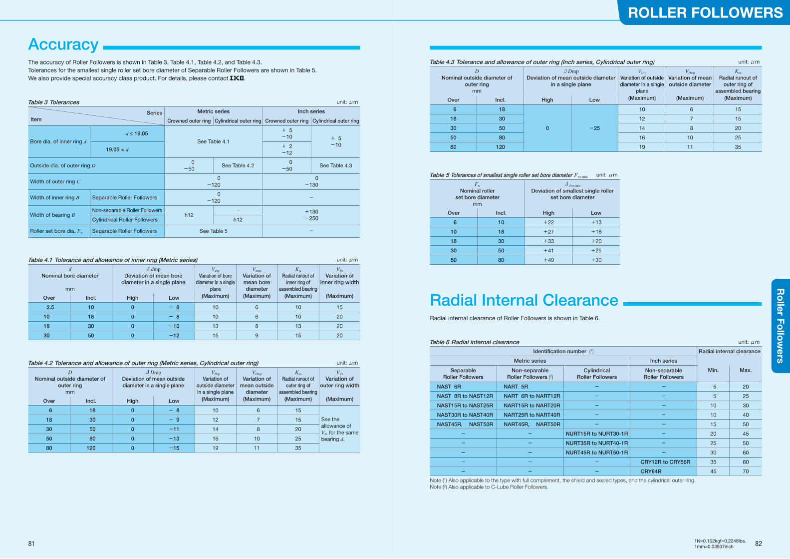
The accuracy of Roller Followers is shown in Table 3, Table 4.1, Table 4.2, and Table 4.3. Tolerances for the smallest single roller set bore diameter of Separable Roller Followers are shown in Table 5. We also provide special accuracy class product. For details, please contact .
Table 3 Tolerances unit: μm
SeriesItem
Metric series Inch series
Crowned outer ring Cylindrical outer ring Crowned outer ring Cylindrical outer ring
Bore dia. of inner ring d
d ≤ 19.05
See Table 4.1
+ 5-10 + 5
-1019.05 < d
+ 2-12
Outside dia. of outer ring D 0-50
See Table 4.2 0-50
See Table 4.3
Width of outer ring C 0-120
0-130
Width of inner ring B Separable Roller Followers 0-120
-
Width of bearing BNon-separable Roller Followers
h12- +130
-250Cylindrical Roller Followers h12
Roller set bore dia. Fw Separable Roller Followers See Table 5 -
Table 4.1 Tolerance and allowance of inner ring (Metric series) unit: μm
dNominal bore diameter
mm
ΔdmpDeviation of mean bore
diameter in a single plane
Vdsp
Variation of bore diameter in a single
plane
Vdmp
Variation of mean bore diameter
Kia
Radial runout of inner ring of
assembled bearing
VBs
Variation of inner ring width
Over Incl. High Low (Maximum) (Maximum) (Maximum) (Maximum)
2.5 10 0 - 8 10 6 10 15
10 18 0 - 8 10 6 10 20
18 30 0 -10 13 8 13 20
30 50 0 -12 15 9 15 20
Table 4.2 Tolerance and allowance of outer ring (Metric series, Cylindrical outer ring) unit: μm
DNominal outside diameter of
outer ringmm
ΔDmpDeviation of mean outside diameter in a single plane
VDsp
Variation of outside diameter in a single plane
VDmp
Variation of mean outside
diameter
Kea
Radial runout of outer ring of
assembled bearing
VCs
Variation of outer ring width
Over Incl. High Low (Maximum) (Maximum) (Maximum) (Maximum)
6 18 0 - 8 10 6 15
See the allowance of VBs for the same bearing d.
18 30 0 - 9 12 7 15
30 50 0 -11 14 8 20
50 80 0 -13 16 10 25
80 120 0 -15 19 11 35
Table 4.3 Tolerance and allowance of outer ring (Inch series, Cylindrical outer ring) unit: μm
DNominal outside diameter of
outer ringmm
ΔDmpDeviation of mean outside diameter
in a single plane
VDsp
Variation of outside diameter in a single
plane
VDmp
Variation of mean outside diameter
Kea
Radial runout of outer ring of
assembled bearing
Over Incl. High Low (Maximum) (Maximum) (Maximum)
6 18 10 6 15
18 30 12 7 15
30 50 0 -25 14 8 20
50 80 16 10 25
80 120 19 11 35
Table 5 Tolerances of smallest single roller set bore diameter Fws min unit: μm
Fw
Nominal roller set bore diameter
mm
Δ Fws min
Deviation of smallest single roller set bore diameter
Over Incl. High Low
6 10 +22 +13
10 18 +27 +16
18 30 +33 +20
30 50 +41 +25
50 80 +49 +30
Radial Internal Clearance Radial internal clearance of Roller Followers is shown in Table 6.
Table 6 Radial internal clearance unit: μm
Identification number (1) Radial internal clearance
Metric series Inch series
Separable Roller Followers
Non-separable Roller Followers (2)
Cylindrical Roller Followers
Non-separable Roller Followers
Min. Max.
NAST 6R NART 5R - - 5 20
NAST 8R to NAST12R NART 6R to NART12R - - 5 25
NAST15R to NAST25R NART15R to NART20R - - 10 30
NAST30R to NAST40R NART25R to NART40R - - 10 40
NAST45R, NAST50R NART45R, NART50R - - 15 50
- - NURT15R to NURT30-1R - 20 45
- - NURT35R to NURT40-1R - 25 50
- - NURT45R to NURT50-1R - 30 60
- - - CRY12R to CRY56R 35 60
- - - CRY64R 45 70
Note (1) Also applicable to the type with full complement, the shield and sealed types, and the cylindrical outer ring.Note (2) Also applicable to C-Lube Roller Followers.
81 82
ROLLER FOLLOWERSR
oller Fo
llow
ers
1N=0.102kgf=0.2248lbs.1mm=0.03937inch
Accuracy
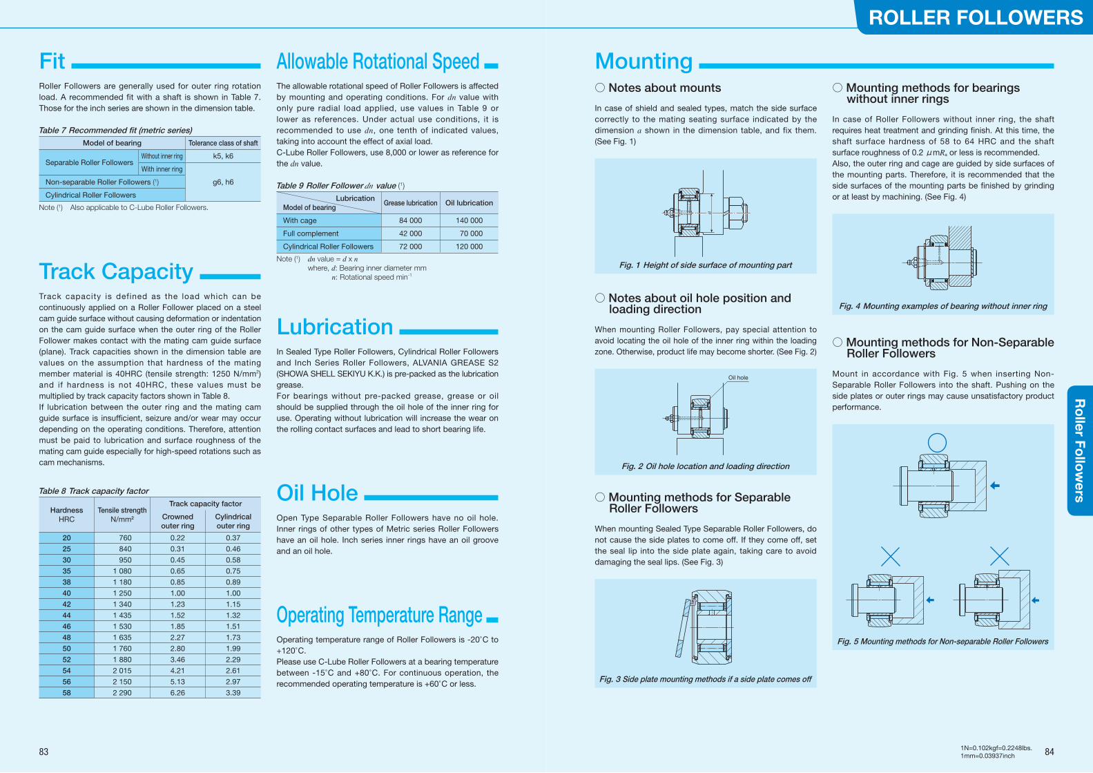
Fit Roller Followers are generally used for outer ring rotation load. A recommended fit with a shaft is shown in Table 7. Those for the inch series are shown in the dimension table.
Table 7 Recommended fit (metric series)Model of bearing Tolerance class of shaft
Separable Roller FollowersWithout inner ring k5, k6
With inner ring
Non-separable Roller Followers (1) g6, h6
Cylindrical Roller Followers
Note (1) Also applicable to C-Lube Roller Followers.
Track capacity is defined as the load which can be continuously applied on a Roller Follower placed on a steel cam guide surface without causing deformation or indentation on the cam guide surface when the outer ring of the Roller Follower makes contact with the mating cam guide surface (plane). Track capacities shown in the dimension table are values on the assumption that hardness of the mating member material is 40HRC (tensile strength: 1250 N/mm2) and if hardness is not 40HRC, these values must be multiplied by track capacity factors shown in Table 8.If lubrication between the outer ring and the mating cam guide surface is insufficient, seizure and/or wear may occur depending on the operating conditions. Therefore, attention must be paid to lubrication and surface roughness of the mating cam guide especially for high-speed rotations such as cam mechanisms.
Table 8 Track capacity factor
HardnessHRC
Tensile strengthN/mm2
Track capacity factor
Crowned outer ring
Cylindrical outer ring
20 760 0.22 0.37
25 840 0.31 0.46
30 950 0.45 0.58
35 1 080 0.65 0.75
38 1 180 0.85 0.89
40 1 250 1.00 1.00
42 1 340 1.23 1.15
44 1 435 1.52 1.32
46 1 530 1.85 1.51
48 1 635 2.27 1.73
50 1 760 2.80 1.99
52 1 880 3.46 2.29
54 2 015 4.21 2.61
56 2 150 5.13 2.97
58 2 290 6.26 3.39
Allowable Rotational Speed Mounting The allowable rotational speed of Roller Followers is affected by mounting and operating conditions. For dn value with only pure radial load applied, use values in Table 9 or lower as references. Under actual use conditions, it is recommended to use dn, one tenth of indicated values, taking into account the effect of axial load. C-Lube Roller Followers, use 8,000 or lower as reference for the dn value.
Table 9 Roller Follower dn value (1)
LubricationModel of bearing
Grease lubrication Oil lubrication
With cage 84 000 140 000
Full complement 42 000 70 000
Cylindrical Roller Followers 72 000 120 000
Note (1) dn value = d x n where, d: Bearing inner diameter mm n: Rotational speed min-1
Lubrication In Sealed Type Roller Followers, Cylindrical Roller Followers and Inch Series Roller Followers, ALVANIA GREASE S2 (SHOWA SHELL SEKIYU K.K.) is pre-packed as the lubrication grease.For bearings without pre-packed grease, grease or oil should be supplied through the oil hole of the inner ring for use. Operating without lubrication will increase the wear on the rolling contact surfaces and lead to short bearing life.
Open Type Separable Roller Followers have no oil hole. Inner rings of other types of Metric series Roller Followers have an oil hole. Inch series inner rings have an oil groove and an oil hole.
Oil Hole
Operating temperature range of Roller Followers is -20°C to +120°C.Please use C-Lube Roller Followers at a bearing temperature between -15°C and +80°C. For continuous operation, the recommended operating temperature is +60°C or less.
Operating Temperature Range
○ Notes about mounts
In case of shield and sealed types, match the side surface correctly to the mating seating surface indicated by the dimension a shown in the dimension table, and fix them. (See Fig. 1)
a
Fig. 1 Height of side surface of mounting part
○ Notes about oil hole position and loading direction
When mounting Roller Followers, pay special attention to avoid locating the oil hole of the inner ring within the loading zone. Otherwise, product life may become shorter. (See Fig. 2)
Oil hole
Fig. 2 Oil hole location and loading direction
○ Mounting methods for Separable Roller Followers
When mounting Sealed Type Separable Roller Followers, do not cause the side plates to come off. If they come off, set the seal lip into the side plate again, taking care to avoid damaging the seal lips. (See Fig. 3)
Fig. 3 Side plate mounting methods if a side plate comes off
○ Mounting methods for bearings without inner rings
In case of Roller Followers without inner ring, the shaft requires heat treatment and grinding finish. At this time, the shaft surface hardness of 58 to 64 HRC and the shaft surface roughness of 0.2 μmRa or less is recommended.Also, the outer ring and cage are guided by side surfaces of the mounting parts. Therefore, it is recommended that the side surfaces of the mounting parts be finished by grinding or at least by machining. (See Fig. 4)
Fig. 4 Mounting examples of bearing without inner ring
○ Mounting methods for Non-Separable Roller Followers
Mount in accordance with Fig. 5 when inserting Non-Separable Roller Followers into the shaft. Pushing on the side plates or outer rings may cause unsatisfactory product performance.
Fig. 5 Mounting methods for Non-separable Roller Followers
83 84
ROLLER FOLLOWERSR
oller Fo
llow
ers
1N=0.102kgf=0.2248lbs.1mm=0.03937inch
Track Capacity
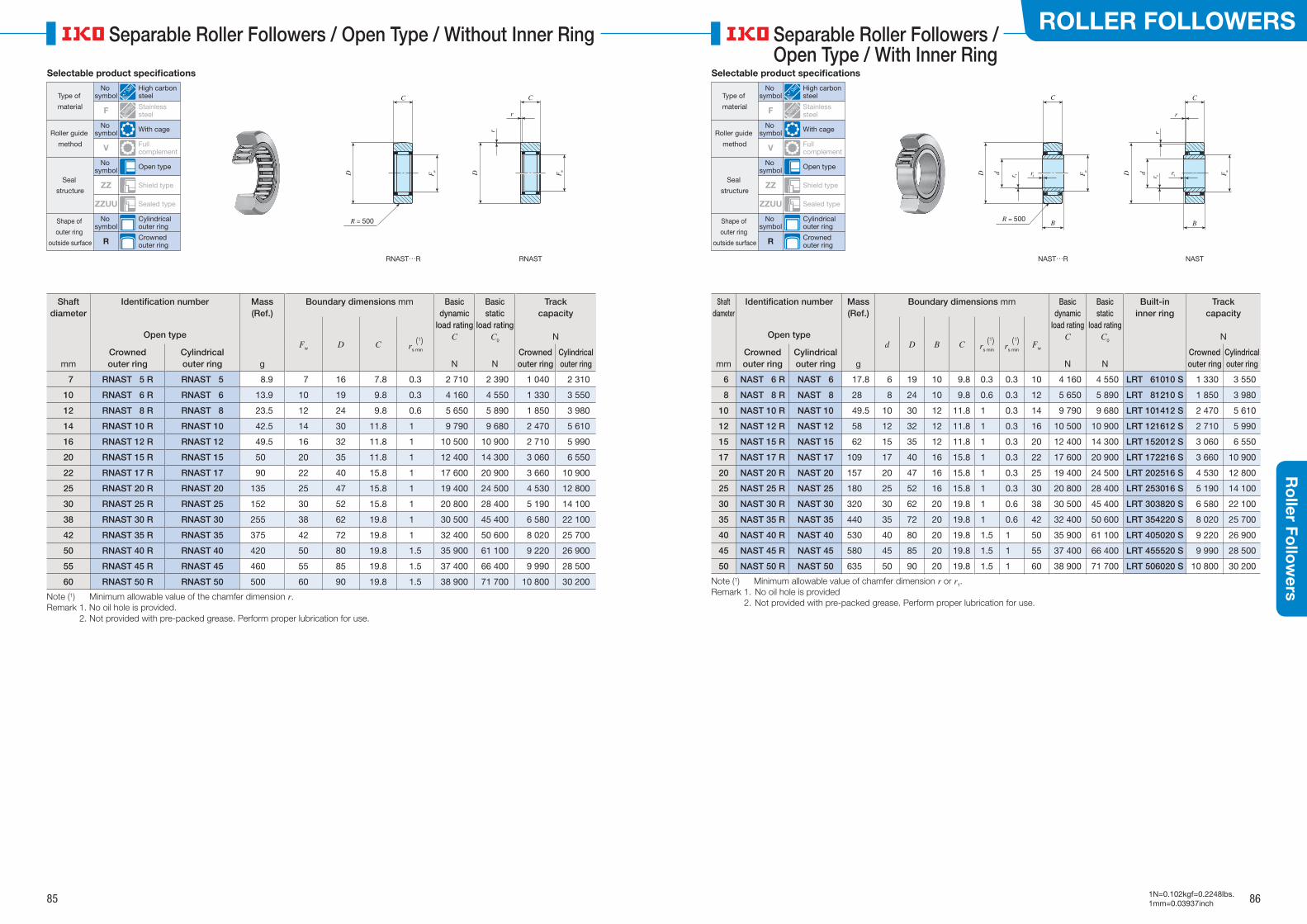
Shaft diameter
Identification number Mass(Ref.)
Boundary dimensions mm Basic dynamic
load ratingC
Basic static
load ratingC0
Track capacity
NFw D C (1)
rs min
Open type
mmCrowned outer ring
Cylindrical outer ring g N N
Crowned outer ring
Cylindrical outer ring
7 RNAST 5 R RNAST 5 8.9 7 16 7.8 0.3 2 710 2 390 1 040 2 310
10 RNAST 6 R RNAST 6 13.9 10 19 9.8 0.3 4 160 4 550 1 330 3 550
12 RNAST 8 R RNAST 8 23.5 12 24 9.8 0.6 5 650 5 890 1 850 3 980
14 RNAST 10 R RNAST 10 42.5 14 30 11.8 1 9 790 9 680 2 470 5 610
16 RNAST 12 R RNAST 12 49.5 16 32 11.8 1 10 500 10 900 2 710 5 990
20 RNAST 15 R RNAST 15 50 20 35 11.8 1 12 400 14 300 3 060 6 550
22 RNAST 17 R RNAST 17 90 22 40 15.8 1 17 600 20 900 3 660 10 900
25 RNAST 20 R RNAST 20 135 25 47 15.8 1 19 400 24 500 4 530 12 800
30 RNAST 25 R RNAST 25 152 30 52 15.8 1 20 800 28 400 5 190 14 100
38 RNAST 30 R RNAST 30 255 38 62 19.8 1 30 500 45 400 6 580 22 100
42 RNAST 35 R RNAST 35 375 42 72 19.8 1 32 400 50 600 8 020 25 700
50 RNAST 40 R RNAST 40 420 50 80 19.8 1.5 35 900 61 100 9 220 26 900
55 RNAST 45 R RNAST 45 460 55 85 19.8 1.5 37 400 66 400 9 990 28 500
60 RNAST 50 R RNAST 50 500 60 90 19.8 1.5 38 900 71 700 10 800 30 200
Note (1) Minimum allowable value of the chamfer dimension r.Remark 1. No oil hole is provided. 2. Not provided with pre-packed grease. Perform proper lubrication for use.
Shaft diameter
Identification number Mass(Ref.)
Boundary dimensions mm Basic dynamic
load ratingC
Basic static
load ratingC0
Built-in inner ring
Track capacity
Nd D B C (1)
rs min
(1)rs min
Fw
Open type
mmCrowned outer ring
Cylindrical outer ring g N N
Crowned outer ring
Cylindrical outer ring
6 NAST 6 R NAST 6 17.8 6 19 10 9.8 0.3 0.3 10 4 160 4 550 LRT 61010 S 1 330 3 550
8 NAST 8 R NAST 8 28 8 24 10 9.8 0.6 0.3 12 5 650 5 890 LRT 81210 S 1 850 3 980
10 NAST 10 R NAST 10 49.5 10 30 12 11.8 1 0.3 14 9 790 9 680 LRT 101412 S 2 470 5 610
12 NAST 12 R NAST 12 58 12 32 12 11.8 1 0.3 16 10 500 10 900 LRT 121612 S 2 710 5 990
15 NAST 15 R NAST 15 62 15 35 12 11.8 1 0.3 20 12 400 14 300 LRT 152012 S 3 060 6 550
17 NAST 17 R NAST 17 109 17 40 16 15.8 1 0.3 22 17 600 20 900 LRT 172216 S 3 660 10 900
20 NAST 20 R NAST 20 157 20 47 16 15.8 1 0.3 25 19 400 24 500 LRT 202516 S 4 530 12 800
25 NAST 25 R NAST 25 180 25 52 16 15.8 1 0.3 30 20 800 28 400 LRT 253016 S 5 190 14 100
30 NAST 30 R NAST 30 320 30 62 20 19.8 1 0.6 38 30 500 45 400 LRT 303820 S 6 580 22 100
35 NAST 35 R NAST 35 440 35 72 20 19.8 1 0.6 42 32 400 50 600 LRT 354220 S 8 020 25 700
40 NAST 40 R NAST 40 530 40 80 20 19.8 1.5 1 50 35 900 61 100 LRT 405020 S 9 220 26 900
45 NAST 45 R NAST 45 580 45 85 20 19.8 1.5 1 55 37 400 66 400 LRT 455520 S 9 990 28 500
50 NAST 50 R NAST 50 635 50 90 20 19.8 1.5 1 60 38 900 71 700 LRT 506020 S 10 800 30 200
Note (1) Minimum allowable value of chamfer dimension r or r1.Remark 1. No oil hole is provided 2. Not provided with pre-packed grease. Perform proper lubrication for use.
Selectable product specifications
Roller guide
method
Type of
material
Seal
structure
Shape of
outer ring
outside surface
No symbol With cage
No symbol
High carbon steel
F Stainless steel
V Full complement
No symbol Open type
ZZ Shield type
No symbol
Cylindrical outer ring
R Crowned outer ring
ZZUU Sealed type
RNAST…R RNAST NAST…R NAST
F wD
R = 500
C C
r
r
D F w
C
B
F wr1r 1
R = 500
D d F w
r 1
r1
C
B
r
r
D d
85 86
ROLLER FOLLOWERSR
oller Fo
llow
ers
1N=0.102kgf=0.2248lbs.1mm=0.03937inch
Separable Roller Followers / Open Type / Without Inner Ring Separable Roller Followers / Open Type / With Inner Ring
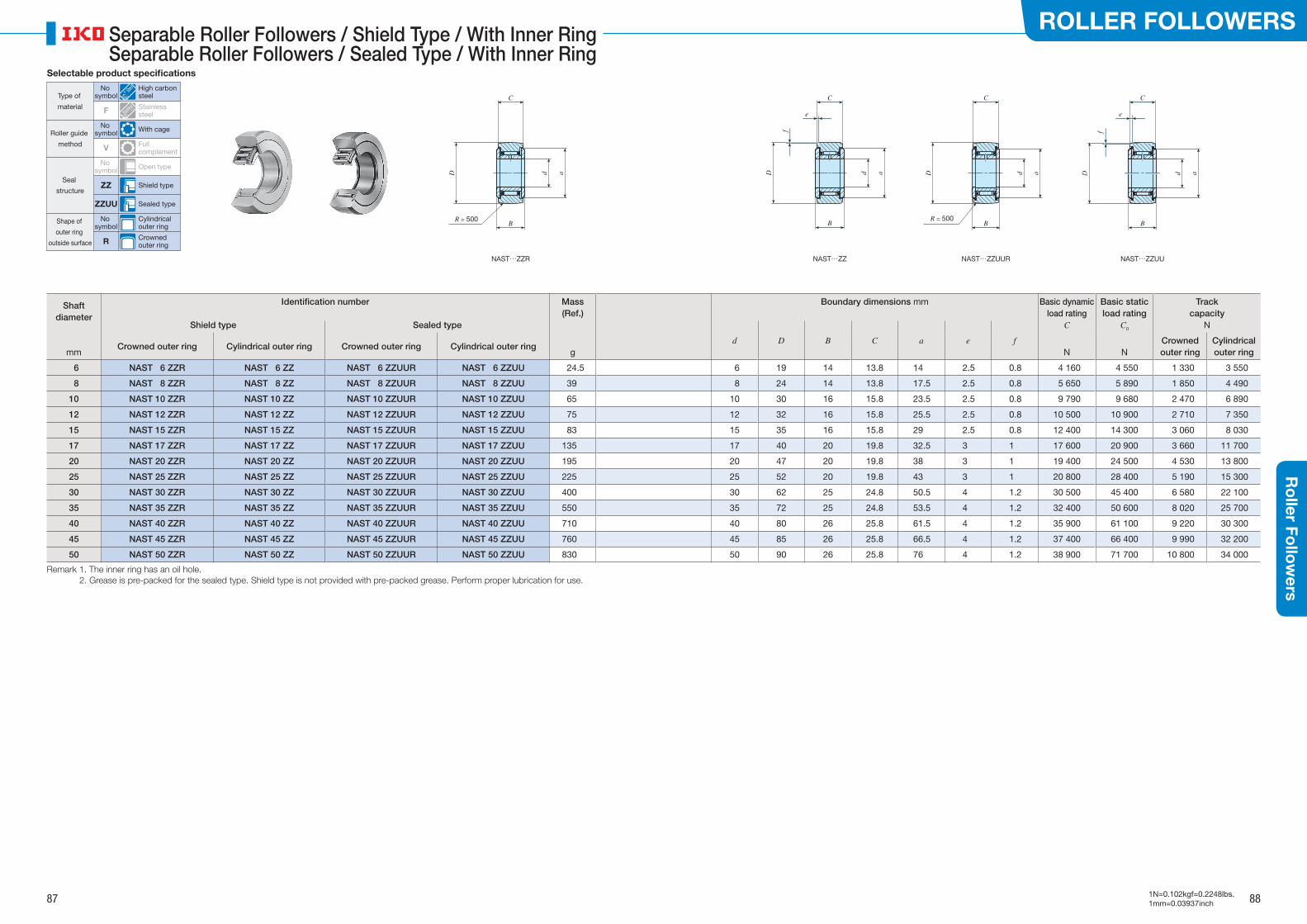
Shaft diameter
Identification number Mass(Ref.)
Boundary dimensions mm Basic dynamic load rating
C
Basic static load rating
C0
Track capacity
NShield type Sealed type
gd D B C a e f
mmCrowned outer ring Cylindrical outer ring Crowned outer ring Cylindrical outer ring
N NCrowned outer ring
Cylindrical outer ring
6 NAST 6 ZZR NAST 6 ZZ NAST 6 ZZUUR NAST 6 ZZUU 24.5 6 19 14 13.8 14 2.5 0.8 4 160 4 550 1 330 3 550
8 NAST 8 ZZR NAST 8 ZZ NAST 8 ZZUUR NAST 8 ZZUU 39 8 24 14 13.8 17.5 2.5 0.8 5 650 5 890 1 850 4 490
10 NAST 10 ZZR NAST 10 ZZ NAST 10 ZZUUR NAST 10 ZZUU 65 10 30 16 15.8 23.5 2.5 0.8 9 790 9 680 2 470 6 890
12 NAST 12 ZZR NAST 12 ZZ NAST 12 ZZUUR NAST 12 ZZUU 75 12 32 16 15.8 25.5 2.5 0.8 10 500 10 900 2 710 7 350
15 NAST 15 ZZR NAST 15 ZZ NAST 15 ZZUUR NAST 15 ZZUU 83 15 35 16 15.8 29 2.5 0.8 12 400 14 300 3 060 8 030
17 NAST 17 ZZR NAST 17 ZZ NAST 17 ZZUUR NAST 17 ZZUU 135 17 40 20 19.8 32.5 3 1 17 600 20 900 3 660 11 700
20 NAST 20 ZZR NAST 20 ZZ NAST 20 ZZUUR NAST 20 ZZUU 195 20 47 20 19.8 38 3 1 19 400 24 500 4 530 13 800
25 NAST 25 ZZR NAST 25 ZZ NAST 25 ZZUUR NAST 25 ZZUU 225 25 52 20 19.8 43 3 1 20 800 28 400 5 190 15 300
30 NAST 30 ZZR NAST 30 ZZ NAST 30 ZZUUR NAST 30 ZZUU 400 30 62 25 24.8 50.5 4 1.2 30 500 45 400 6 580 22 100
35 NAST 35 ZZR NAST 35 ZZ NAST 35 ZZUUR NAST 35 ZZUU 550 35 72 25 24.8 53.5 4 1.2 32 400 50 600 8 020 25 700
40 NAST 40 ZZR NAST 40 ZZ NAST 40 ZZUUR NAST 40 ZZUU 710 40 80 26 25.8 61.5 4 1.2 35 900 61 100 9 220 30 300
45 NAST 45 ZZR NAST 45 ZZ NAST 45 ZZUUR NAST 45 ZZUU 760 45 85 26 25.8 66.5 4 1.2 37 400 66 400 9 990 32 200
50 NAST 50 ZZR NAST 50 ZZ NAST 50 ZZUUR NAST 50 ZZUU 830 50 90 26 25.8 76 4 1.2 38 900 71 700 10 800 34 000
Remark 1. The inner ring has an oil hole. 2. Grease is pre-packed for the sealed type. Shield type is not provided with pre-packed grease. Perform proper lubrication for use.
Selectable product specifications
Roller guide
method
Type of
material
Seal
structure
Shape of
outer ring
outside surface
No symbol With cage
No symbol
High carbon steel
F Stainless steel
V Full complement
No symbol Open type
ZZ Shield type
No symbol
Cylindrical outer ring
R Crowned outer ring
ZZUU Sealed type
NAST…ZZR NAST…ZZUUNAST…ZZUURNAST…ZZ
D
R = 500
C C C
e
B B BBR = 500
D D
f
C
e
f
d a d a d ad a
87 88
ROLLER FOLLOWERSR
oller Fo
llow
ers
1N=0.102kgf=0.2248lbs.1mm=0.03937inch
Separable Roller Followers / Shield Type / With Inner RingSeparable Roller Followers / Sealed Type / With Inner Ring
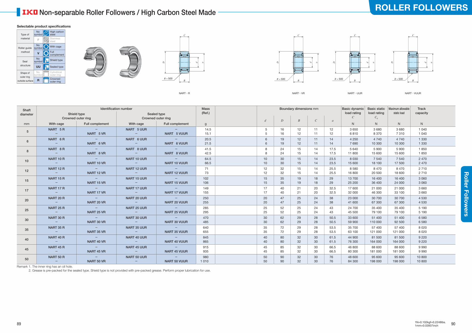
Shaft diameter
Identification number Mass(Ref.)
Boundary dimensions mm Basic dynamic load rating
C
Basic static load rating
C0
Maximum allowable static load
Track capacityShield type
Crowned outer ringSealed type
Crowned outer ring
gd D B C a
N N N Nmm With cage Full complement With cage Full complement
5NART 5 R
--
NART 5 VRNART 5 UUR
--
NART 5 VUUR14.515.1
5 5
1616
1212
1111
1212
3 650 6 810
3 6808 370
3 6807 310
1 0401 040
6NART 6 R
--
NART 6 VRNART 6 UUR
--
NART 6 VUUR20.521.5
6 6
1919
1212
1111
1414
4 250 7 690
4 74010 300
4 74010 300
1 3301 330
8NART 8 R
--
NART 8 VRNART 8 UUR
--
NART 8 VUUR41.542.5
8 8
2424
1515
1414
17.517.5
5 64011 800
5 90015 600
5 90015 600
1 8501 850
10NART 10 R
--
NART 10 VRNART 10 UUR
--
NART 10 VUUR64.566.5
1010
3030
1515
1414
23.523.5
8 03015 600
7 54018 100
7 54017 500
2 4702 470
12NART 12 R
--
NART 12 VRNART 12 UUR
--
NART 12 VUUR7173
1212
3232
1515
1414
25.525.5
8 58016 800
8 47020 500
8 47018 600
2 7102 710
15NART 15 R
--
NART 15 VRNART 15 UUR
--
NART 15 VUUR102106
1515
3535
1919
1818
2929
13 70025 200
16 40036 400
16 40024 000
3 0603 060
17NART 17 R
--
NART 17 VRNART 17 UUR
--
NART 17 VUUR149155
1717
4040
2121
2020
32.532.5
17 60032 000
21 00046 300
21 00033 100
3 6603 660
20NART 20 R
--
NART 20 VRNART 20 UUR
--
NART 20 VUUR250255
2020
4747
2525
2424
3838
23 00041 600
30 70067 300
30 70067 300
4 5304 530
25NART 25 R
--
NART 25 VRNART 25 UUR
--
NART 25 VUUR285295
2525
5252
2525
2424
4343
24 70045 500
35 40079 100
35 40079 100
5 1905 190
30NART 30 R
--
NART 30 VRNART 30 UUR
--
NART 30 VUUR470485
3030
6262
2929
2828
50.550.5
33 60059 900
51 400110 000
51 40092 500
6 5806 580
35NART 35 R
--
NART 35 VRNART 35 UUR
--
NART 35 VUUR640655
3535
7272
2929
2828
53.553.5
35 70063 100
57 400121 000
57 400121 000
8 0208 020
40NART 40 R
--
NART 40 VRNART 40 UUR
--
NART 40 VUUR845865
4040
8080
3232
3030
61.561.5
44 90076 300
81 500164 000
81 500164 000
9 2209 220
45NART 45 R
--
NART 45 VRNART 45 UUR
--
NART 45 VUUR915935
4545
8585
3232
3030
66.566.5
46 80080 300
88 600181 000
88 600181 000
9 9909 990
50NART 50 R
--
NART 50 VRNART 50 UUR
--
NART 50 VUUR980
1 0105050
9090
3232
3030
7676
48 60084 300
95 600198 000
95 600198 000
10 80010 800
Remark 1. The inner ring has an oil hole. 2. Grease is pre-packed for the sealed type. Shield type is not provided with pre-packed grease. Perform proper lubrication for use.
Selectable product specifications
Roller guide
method
Seal
structure
Shape of
outer ring
outside surface
Type of
material
No symbol With cage
V Full complement
No symbol Shield type
No symbol
Cylindrical outer ring
R Crowned outer ring
UU Sealed type
No symbol
High carbon steel
F Stainless steel
NART…R NART…VUURNART…UURNART…VR
D
R = 500
C C
BBR = 500
D d a
C
BR = 500
D d a
C
BR = 500
D d aad
89 90
ROLLER FOLLOWERSR
oller Fo
llow
ers
1N=0.102kgf=0.2248lbs.1mm=0.03937inch
Non-separable Roller Followers / High Carbon Steel Made

Shaft diameter
Identification number Mass(Ref.)
Boundary dimensions mm Basic dynamic load rating
C
Basic static load rating
C0
Maximum allowable static load
Track capacity
Shield type Sealed type d D B C amm g N N N N
5 NART 5 FR NART 5 FUUR 13 5 16 12 11 12 2 930 2 920 2 920 1 040
6 NART 6 FR NART 6 FUUR 19 6 19 12 11 14 3 400 3 790 3 790 1 330
8 NART 8 FR NART 8 FUUR 39 8 24 15 14 17.5 4 340 5 510 5 510 1 850
10 NART 10 FR NART 10 FUUR 61 10 30 15 14 22.5 6 330 7 830 7 830 2 470
12 NART 12 FR NART 12 FUUR 67 12 32 15 14 25.5 6 510 8 400 8 400 2 710
15 NART 15 FR NART 15 FUUR 99 15 35 19 18 27.5 9 620 14 700 14 700 3 060
17 NART 17 FR NART 17 FUUR 146 17 40 21 20 31 11 800 20 200 20 200 3 660
20 NART 20 FR NART 20 FUUR 241 20 47 25 24 36.5 16 500 27 700 27 700 4 530
25 NART 25 FR NART 25 FUUR 269 25 52 25 24 43 19 800 28 300 28 300 5 190
30 NART 30 FR NART 30 FUUR 447 30 62 29 28 50 26 900 41 200 41 200 6 580
Remark 1. The inner ring has an oil hole. 2. Grease is pre-packed for the sealed type. Shield type is not provided with pre-packed grease. Perform proper lubrication for use.
Selectable product specifications
Roller guide
method
Seal
structure
Shape of
outer ring
outside surface
Type of
material
No symbol With cage
V Full complement
No symbol Shield type
No symbol
Cylindrical outer ring
R Crowned outer ring
UU Sealed type
No symbol
High carbon steel
F Stainless steel
NART…FR NART…FUUR
R = 500
D d
C
a D d
C
a
B BR = 500
91 92
ROLLER FOLLOWERSR
oller Fo
llow
ers
1N=0.102kgf=0.2248lbs.1mm=0.03937inch
Non-separable Roller Followers / Stainless Steel Made / With Cage / With Inner Ring

Shaft diameter
Identification number Mass(Ref.)
Boundary dimensions mm Basic dynamic load rating
C
Basic static load rating
C0
Maximum allowable static load
Track capacity
Sealed type d D B C amm g N N N N
5 NART 5 UUR / SG 14.5 5 16 12 11 12 3 650 3 680 3 680 1 040
6 NART 6 UUR / SG 20.5 6 19 12 11 14 4 250 4 740 4 740 1 330
8 NART 8 UUR / SG 41.5 8 24 15 14 17.5 5 640 5 900 5 900 1 850
10 NART 10 UUR / SG 64.5 10 30 15 14 23.5 8 030 7 540 7 540 2 470
12 NART 12 UUR / SG 71 12 32 15 14 25.5 8 580 8 470 8 470 2 710
15 NART 15 UUR / SG 102 15 35 19 18 29 13 700 16 400 16 400 3 060
17 NART 17 UUR / SG 149 17 40 21 20 32.5 17 600 21 000 21 000 3 660
20 NART 20 UUR / SG 250 20 47 25 24 38 23 000 30 700 30 700 4 530
Remark This bearing cannot be re-lubricated as thermosetting solid-type lubricant C-Lube �lls its inner space.
Selectable product specifications
Roller guide
method
Seal
structure
Shape of
outer ring
outside surface
Type of
material
No symbol With cage
V Full complement
No symbol Shield type
No symbol
Cylindrical outer ring
R Crowned outer ring
UU Sealed type
No symbol
High carbon steel
F Stainless steel
NART…UUR/SG
C
B
dD a
R = 500
93 94
ROLLER FOLLOWERSR
oller Fo
llow
ers
1N=0.102kgf=0.2248lbs.1mm=0.03937inch
C-Lube Roller Followers / With Cage / With Inner Ring
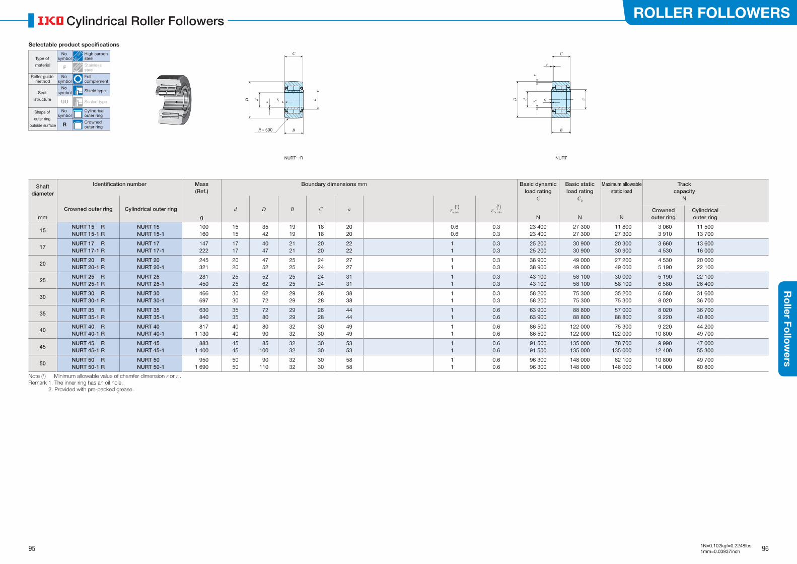
Shaft diameter
Identification number Mass(Ref.)
Boundary dimensions mm Basic dynamic load rating
C
Basic static load rating
C0
Maximum allowable static load
Track capacity
N
Crowned outer ring Cylindrical outer ring d D B C a (1)rs min
(1)r1s min
mm g N N NCrowned outer ring
Cylindrical outer ring
15NURT 15 RNURT 15-1 R
NURT 15NURT 15-1
100160
1515
35 42
1919
1818
2020
0.60.6
0.30.3
23 40023 400
27 300 27 300
11 800 27 300
3 0603 910
11 50013 700
17NURT 17 RNURT 17-1 R
NURT 17NURT 17-1
147222
1717
40 47
2121
2020
2222
11
0.30.3
25 20025 200
30 900 30 900
20 300 30 900
3 6604 530
13 60016 000
20NURT 20 RNURT 20-1 R
NURT 20NURT 20-1
245321
2020
47 52
2525
2424
2727
11
0.30.3
38 90038 900
49 000 49 000
27 200 49 000
4 5305 190
20 00022 100
25NURT 25 RNURT 25-1 R
NURT 25NURT 25-1
281450
2525
52 62
2525
2424
3131
11
0.30.3
43 10043 100
58 100 58 100
30 000 58 100
5 1906 580
22 10026 400
30NURT 30 RNURT 30-1 R
NURT 30NURT 30-1
466697
3030
62 72
2929
2828
3838
11
0.30.3
58 20058 200
75 300 75 300
35 200 75 300
6 5808 020
31 60036 700
35NURT 35 RNURT 35-1 R
NURT 35NURT 35-1
630840
3535
72 80
2929
2828
4444
11
0.60.6
63 90063 900
88 800 88 800
57 000 88 800
8 0209 220
36 70040 800
40NURT 40 RNURT 40-1 R
NURT 40NURT 40-1
8171 130
4040
80 90
3232
3030
4949
11
0.60.6
86 50086 500
122 000122 000
75 300122 000
9 22010 800
44 20049 700
45NURT 45 RNURT 45-1 R
NURT 45NURT 45-1
8831 400
4545
85100
3232
3030
5353
11
0.60.6
91 50091 500
135 000135 000
78 700135 000
9 99012 400
47 00055 300
50NURT 50 RNURT 50-1 R
NURT 50NURT 50-1
9501 690
5050
90110
3232
3030
5858
11
0.60.6
96 30096 300
148 000148 000
82 100148 000
10 80014 000
49 70060 800
Note (1) Minimum allowable value of chamfer dimension r or r1.Remark 1. The inner ring has an oil hole. 2. Provided with pre-packed grease.
Type of
material
Selectable product specifications
Roller guide method
Seal
structure
Shape of
outer ring
outside surface
No symbol
High carbon steel
F Stainless steel
No symbol
Full complement
No symbol Shield type
No symbol
Cylindrical outer ring
R Crowned outer ring
UU Sealed type
NURT…R NURT
r 1
r1D d a
R = 500
C
B
a
B
C
r
r 1r
r1D d
95 96
ROLLER FOLLOWERSR
oller Fo
llow
ers
1N=0.102kgf=0.2248lbs.1mm=0.03937inch
Cylindrical Roller Followers
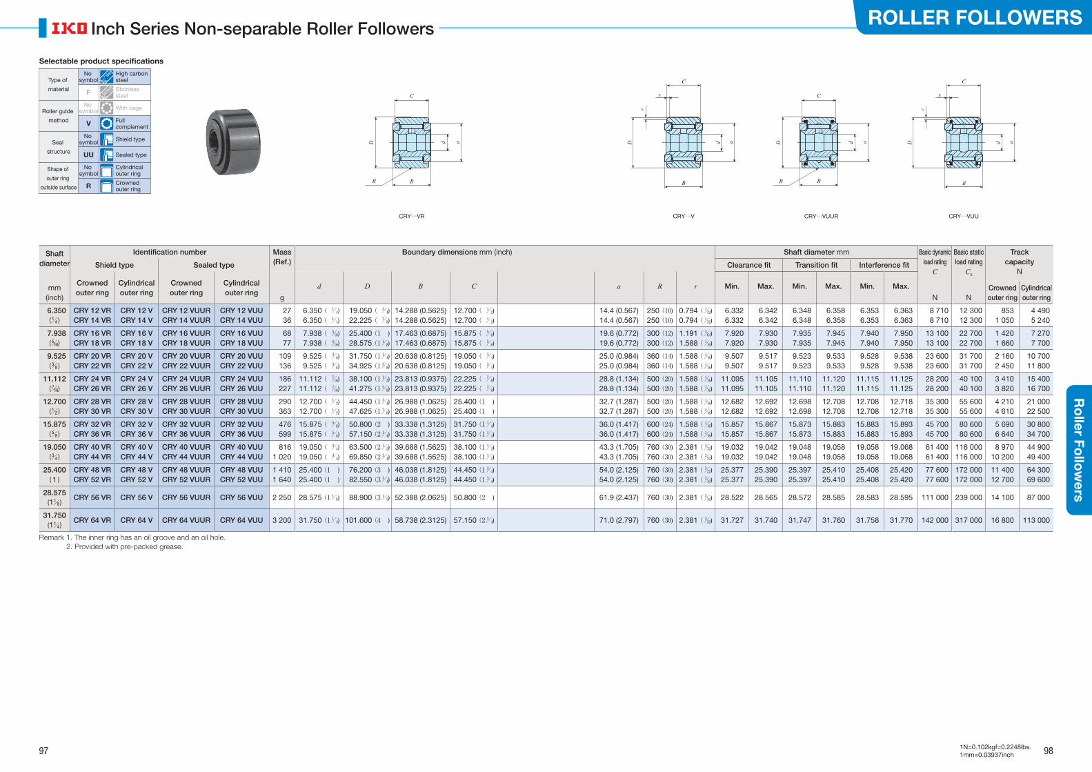
Shaft diameter
Identification number Mass(Ref.)
Boundary dimensions mm (inch) Shaft diameter mm Basic dynamic load rating
C
Basic static load rating
C0
Track capacity
NShield type Sealed type Clearance fit Transition fit Interference fit
mm(inch)
Crowned outer ring
Cylindrical outer ring
Crowned outer ring
Cylindrical outer ring
d D B C a R r Min. Max. Min. Max. Min. Max.
g N NCrowned outer ring
Cylindrical outer ring
6.350(/ 1 4 )
CRY 12 VRCRY 14 VR
CRY 12 VCRY 14 V
CRY 12 VUURCRY 14 VUUR
CRY 12 VUUCRY 14 VUU
2736
6.350 ( / 1 4)
6.350 ( / 1 4)
19.050 ( / 3 4)
22.225 ( / 7 8)
14.288 (0.5625)14.288 (0.5625)
12.700 ( / 1 2)
12.700 ( / 1 2)
14.4 (0.567)14.4 (0.567)
250 (10)250 (10)
0.794 (/ 1 32)
0.794 (/ 1 32)
6.3326.332
6.3426.342
6.3486.348
6.3586.358
6.3536.353
6.3636.363
8 710 8 710
12 300 12 300
8531 050
4 4905 240
7.938(/ 5 16)
CRY 16 VRCRY 18 VR
CRY 16 VCRY 18 V
CRY 16 VUURCRY 18 VUUR
CRY 16 VUUCRY 18 VUU
6877
7.938 ( / 5 16)
7.938 ( / 5 16)
25.400 (1 ) 28.575 (1/ 1
8)17.463 (0.6875)17.463 (0.6875)
15.875 ( / 5 8)
15.875 ( / 5 8)
19.6 (0.772)19.6 (0.772)
300 (12)300 (12)
1.191 (/ 3 64)
1.588 (/ 1 16)
7.9207.920
7.9307.930
7.9357.935
7.9457.945
7.9407.940
7.9507.950
13 100 13 100
22 700 22 700
1 4201 660
7 2707 700
9.525(/ 3 8 )
CRY 20 VRCRY 22 VR
CRY 20 VCRY 22 V
CRY 20 VUURCRY 22 VUUR
CRY 20 VUUCRY 22 VUU
109136
9.525 ( / 3 8)
9.525 ( / 3 8)
31.750 (1/ 1 4)
34.925 (1/ 3 8)
20.638 (0.8125)20.638 (0.8125)
19.050 ( / 3 4)
19.050 ( / 3 4)
25.0 (0.984)25.0 (0.984)
360 (14)360 (14)
1.588 (/ 1 16)
1.588 (/ 1 16)
9.5079.507
9.5179.517
9.5239.523
9.5339.533
9.5289.528
9.5389.538
23 600 23 600
31 700 31 700
2 1602 450
10 70011 800
11.112(/ 7 16)
CRY 24 VRCRY 26 VR
CRY 24 VCRY 26 V
CRY 24 VUURCRY 26 VUUR
CRY 24 VUUCRY 26 VUU
186227
11.112 ( / 7 16)
11.112 ( / 7 16)
38.100 (1/ 1 2)
41.275 (1/ 5 8)
23.813 (0.9375)23.813 (0.9375)
22.225 ( / 7 8)
22.225 ( / 7 8)
28.8 (1.134)28.8 (1.134)
500 (20)500 (20)
1.588 (/ 1 16)
1.588 (/ 1 16)
11.09511.095
11.10511.105
11.11011.110
11.12011.120
11.11511.115
11.12511.125
28 200 28 200
40 100 40 100
3 4103 820
15 40016 700
12.700(/ 1 2 )
CRY 28 VRCRY 30 VR
CRY 28 VCRY 30 V
CRY 28 VUURCRY 30 VUUR
CRY 28 VUUCRY 30 VUU
290363
12.700 ( / 1 2)
12.700 ( / 1 2)
44.450 (1/ 3 4)
47.625 (1/ 7 8)
26.988 (1.0625)26.988 (1.0625)
25.400 (1 )25.400 (1 )
32.7 (1.287)32.7 (1.287)
500 (20)500 (20)
1.588 (/ 1 16)
1.588 (/ 1 16)
12.68212.682
12.69212.692
12.69812.698
12.70812.708
12.70812.708
12.71812.718
35 300 35 300
55 600 55 600
4 2104 610
21 00022 500
15.875(/ 5 8 )
CRY 32 VRCRY 36 VR
CRY 32 VCRY 36 V
CRY 32 VUURCRY 36 VUUR
CRY 32 VUUCRY 36 VUU
476599
15.875 ( / 5 8)
15.875 ( / 5 8)
50.800 (2 ) 57.150 (2/ 1
4)33.338 (1.3125)33.338 (1.3125)
31.750 (1/ 1 4)
31.750 (1/ 1 4)
36.0 (1.417)36.0 (1.417)
600 (24)600 (24)
1.588 (/ 1 16)
1.588 (/ 1 16)
15.85715.857
15.86715.867
15.87315.873
15.88315.883
15.88315.883
15.89315.893
45 700 45 700
80 600 80 600
5 6906 640
30 80034 700
19.050(/ 3 4 )
CRY 40 VRCRY 44 VR
CRY 40 VCRY 44 V
CRY 40 VUURCRY 44 VUUR
CRY 40 VUUCRY 44 VUU
8161 020
19.050 ( / 3 4)
19.050 ( / 3 4)
63.500 (2/ 1 2)
69.850 (2/ 3 4)
39.688 (1.5625)39.688 (1.5625)
38.100 (1/ 1 2)
38.100 (1/ 1 2)
43.3 (1.705)43.3 (1.705)
760 (30)760 (30)
2.381 (/ 3 32)
2.381 (/ 3 32)
19.03219.032
19.04219.042
19.04819.048
19.05819.058
19.05819.058
19.06819.068
61 400 61 400
116 000116 000
8 97010 200
44 90049 400
25.400( 1 )
CRY 48 VRCRY 52 VR
CRY 48 VCRY 52 V
CRY 48 VUURCRY 52 VUUR
CRY 48 VUUCRY 52 VUU
1 4101 640
25.400 (1 )25.400 (1 )
76.200 (3 ) 82.550 (3/ 1
4)46.038 (1.8125)46.038 (1.8125)
44.450 (1/ 3 4)
44.450 (1/ 3 4)
54.0 (2.125)54.0 (2.125)
760 (30)760 (30)
2.381 (/ 3 32)
2.381 (/ 3 32)
25.37725.377
25.39025.390
25.39725.397
25.41025.410
25.40825.408
25.42025.420
77 600 77 600
172 000172 000
11 40012 700
64 30069 600
28.575(1/ 1
8 )CRY 56 VR CRY 56 V CRY 56 VUUR CRY 56 VUU 2 250 28.575 (1/ 1
8) 88.900 (3/ 1 2) 52.388 (2.0625) 50.800 (2 ) 61.9 (2.437) 760 (30) 2.381 (/ 3
32) 28.522 28.565 28.572 28.585 28.583 28.595 111 000 239 000 14 100 87 000
31.750(1/ 1
4 )CRY 64 VR CRY 64 V CRY 64 VUUR CRY 64 VUU 3 200 31.750 (1/ 1
4) 101.600 (4 ) 58.738 (2.3125) 57.150 (2/ 1 4) 71.0 (2.797) 760 (30) 2.381 (/ 3
32) 31.727 31.740 31.747 31.760 31.758 31.770 142 000 317 000 16 800 113 000
Remark 1. The inner ring has an oil groove and an oil hole. 2. Provided with pre-packed grease.
Selectable product specifications
Roller guide
method
Seal
structure
Shape of
outer ring
outside surface
Type of
material
No symbol With cage
V Full complement
No symbol
UU
Shield type
No symbol
Cylindrical outer ring
R Crowned outer ring
Sealed type
No symbol
High carbon steel
F Stainless steel
CRY…VR CRY…VUUCRY…VUURCRY…V
C
r
r
B
D d a
C
r
r
D d a
C
BR
D d aD
R
C
B
ad
97 98
ROLLER FOLLOWERSR
oller Fo
llow
ers
1N=0.102kgf=0.2248lbs.1mm=0.03937inch
Inch Series Non-separable Roller Followers

Application Examples Customized Products Model Comparison Table Miscellaneous Tables
Application Examples Customized Products Model Comparison Table Miscellaneous Tables
Application Examples Customized Products Model Comparison Table Miscellaneous Tables
Introduction of Application Examples ..................................... 101
Introduction of Customized Products ..................................... 115
Model Comparison Table for Cam Followers ........ 117
Model Comparison Table for Roller Followers ..... 118
Miscellaneous Tables ...................................................................................................... 119
Introduction of Technical Service Site ............. 127
Introduction of Products ................................................................... 129
99 100

Chip mounter shaft mover
NURT
Automatic packager position adjuster
Entire device
CF…WBUUR
Device interior
101 102
Application Examples
Introduction of Application Examples
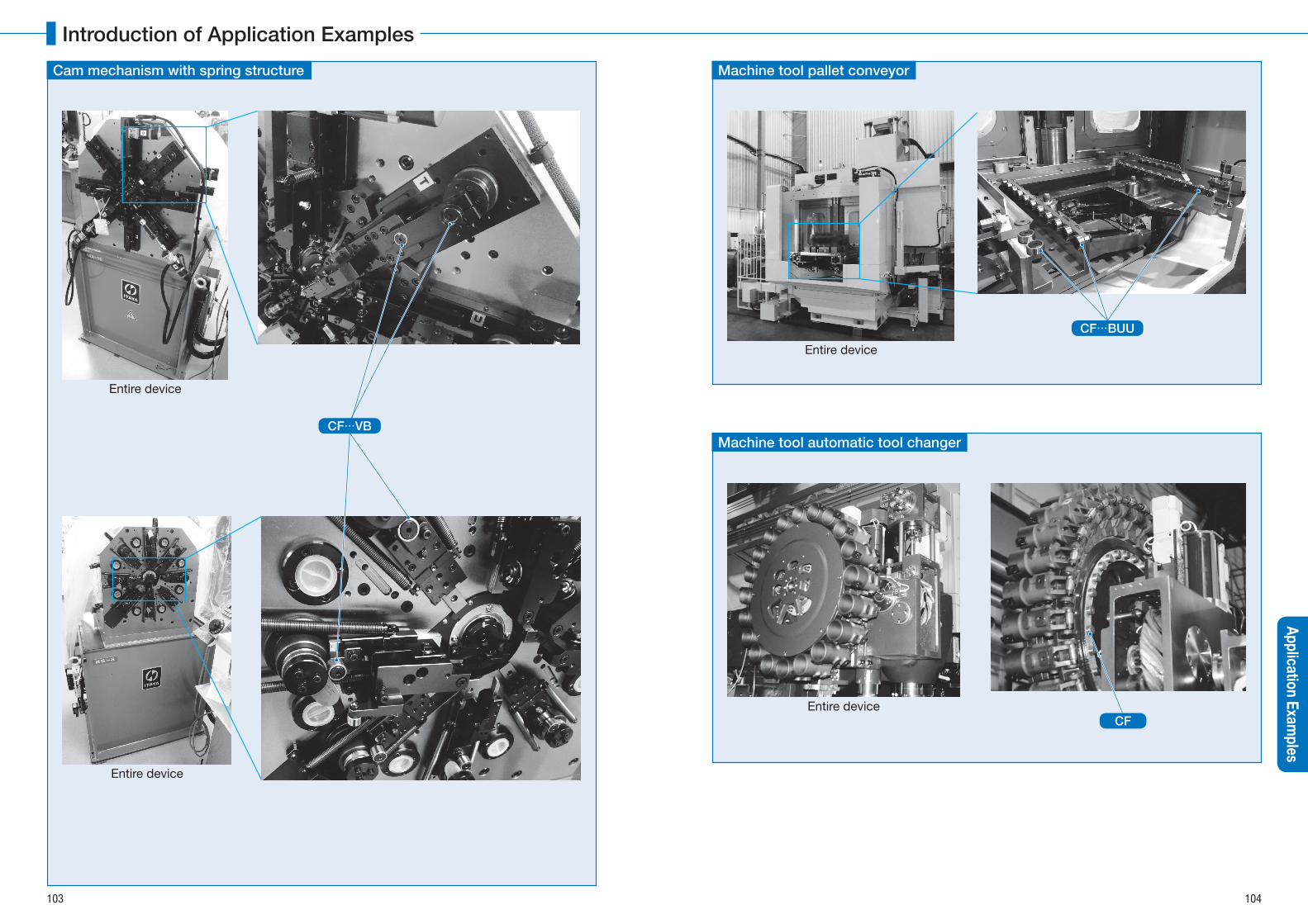
Entire device
Machine tool pallet conveyor
CF…BUU
Cam mechanism with spring structure
Entire device
Entire device
CF…VB
Entire device
Machine tool automatic tool changer
CF
103 104
Introduction of Application ExamplesApplication Exam
ples
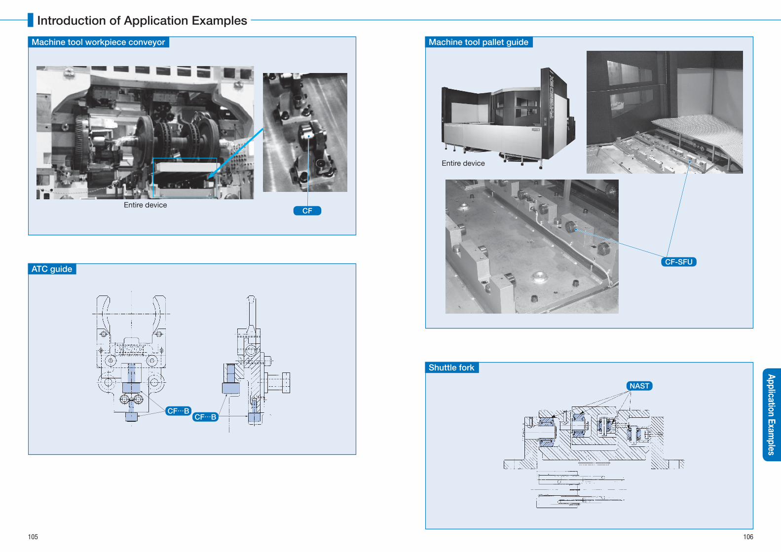
Shuttle fork
NAST
Entire device
Machine tool workpiece conveyor
CF
Machine tool pallet guide
Entire device
CF-SFUATC guide
CF…BCF…B
105 106
Introduction of Application ExamplesApplication Exam
ples
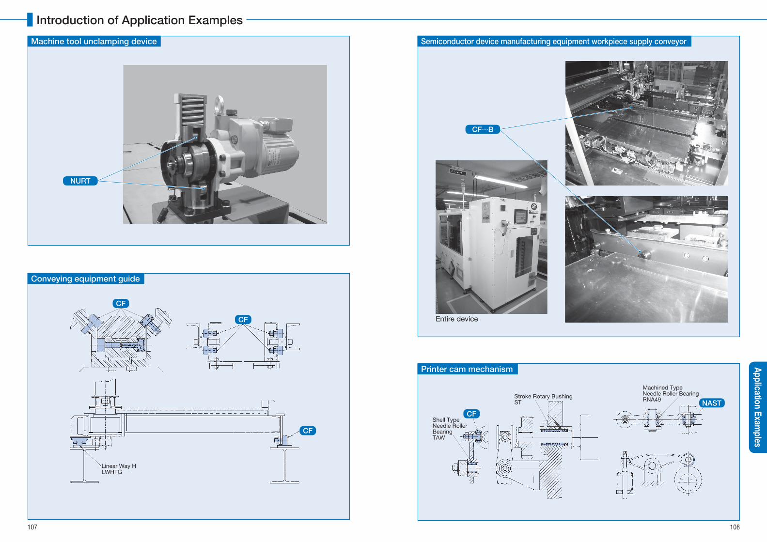
Printer cam mechanism
Machined Type Needle Roller BearingRNA49Stroke Rotary Bushing
ST
Shell TypeNeedle RollerBearingTAW
CF
NAST
Machine tool unclamping device
Conveying equipment guide
Linear Way HLWHTG
CF
CF
CF
Semiconductor device manufacturing equipment workpiece supply conveyor
Entire device
CF…B
NURT
107 108
Introduction of Application ExamplesApplication Exam
ples
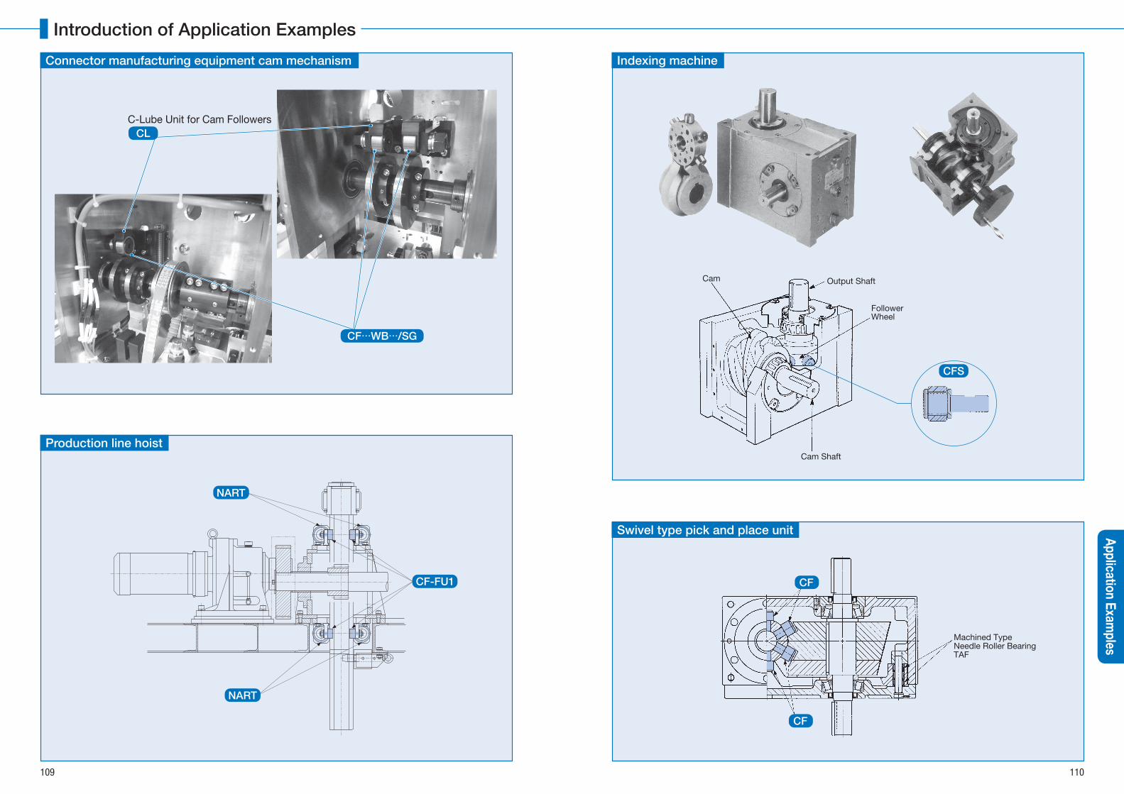
Swivel type pick and place unit
Machined Type Needle Roller BearingTAF
CF
CF
Connector manufacturing equipment cam mechanism
C-Lube Unit for Cam FollowersCL
CF…WB…/SG
Production line hoist
NART
NART
CF-FU1
Indexing machine
Cam
FollowerWheel
Cam Shaft
Output Shaft
CFS
109 110
Introduction of Application ExamplesApplication Exam
ples

Bottling system (capper)
CF…B
Diesel engine
Cam Shaft Valve Lifter Cam Roller
NAST
RNAST
Thread fastener shaft guide
Entire device
Rodless cylinder
CF…W
CF…B
111 112
Introduction of Application ExamplesApplication Exam
ples
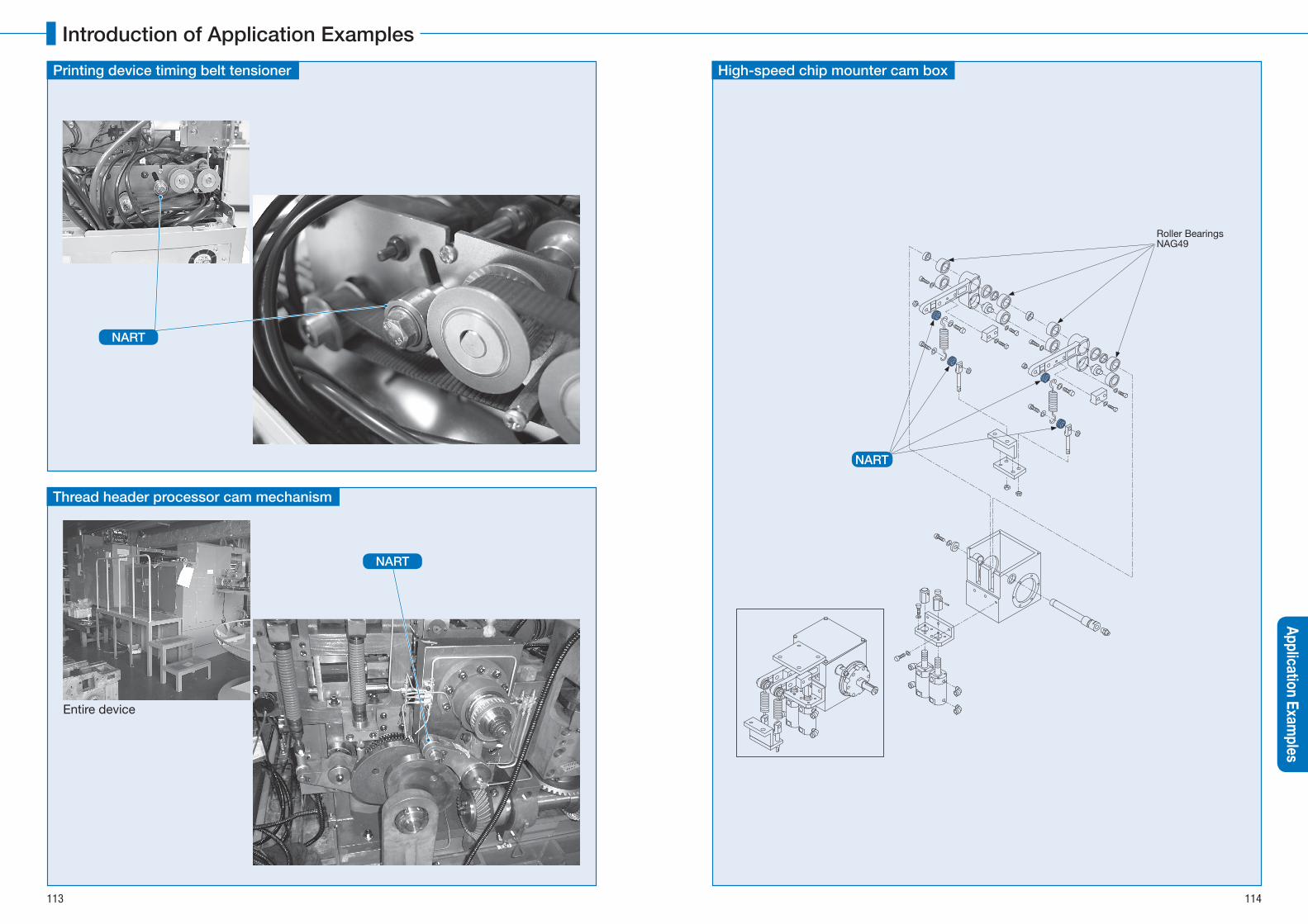
High-speed chip mounter cam box
Roller BearingsNAG49
NART
Printing device timing belt tensioner
NART
Thread header processor cam mechanism
Entire device
NART
113 114
Introduction of Application ExamplesApplication Exam
ples
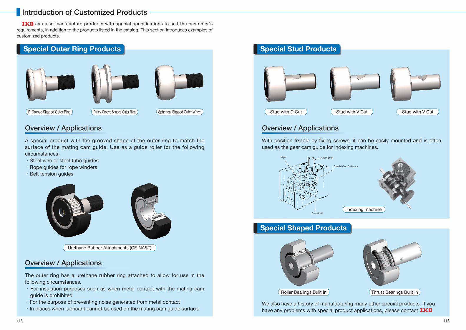
With position fixable by fixing screws, it can be easily mounted and is often used as the gear cam guide for indexing machines.
Stud with D Cut
Roller Bearings Built In Thrust Bearings Built In
Stud with V Cut Stud with V Cut
Special Stud Products
Overview / Applications
can also manufacture products with special specifications to suit the customer's requirements, in addition to the products listed in the catalog. This section introduces examples of customized products.
A special product with the grooved shape of the outer ring to match the surface of the mating cam guide. Use as a guide roller for the following circumstances.・ Steel wire or steel tube guides・ Rope guides for rope winders・ Belt tension guides
The outer ring has a urethane rubber ring attached to allow for use in the following circumstances.・ For insulation purposes such as when metal contact with the mating cam
guide is prohibited・ For the purpose of preventing noise generated from metal contact・ In places when lubricant cannot be used on the mating cam guide surface
R-Groove Shaped Outer Ring
Urethane Rubber Attachments (CF, NAST)
Pulley-Groove Shaped Outer Ring Spherical Shaped Outer Wheel
Special Outer Ring Products
Special Shaped Products
Cam
Special Cam Followers
Cam Shaft
Output Shaft
Overview / Applications
Overview / Applications
We also have a history of manufacturing many other special products. If you have any problems with special product applications, please contact .
Indexing machine
115 116
Introduction of Customized Products

Model of bearingDimen-sions Page
JNS / THK INA / SKF Mc.GILLKOYO
TORRINGTONSMITH
Miniature Type Cam Followers
CFS 31 CFS…A
CFS…V 31 CFS…VA
CFS…F 31 CFS…MA
CFS…FV 31 CFS…VMA
Thrust Disk Type Miniature Cam Followers
CFS…W 33
CFS…WV 33
CFS…FW 33
Standard Type Cam Followers
CF…BR 35 CF…RA KR…SK MFCR…B KM…RHM MCR…B
CF…B 35 CF…A KR…XSK MFCR…BX KM…HMM MCR…CB
CF…BUUR 35 CF…UURA KR…PPSK MFCR…SB KM…UURHM MCR…SB
CF…BUU 35 CF…UUA KR…PPXSK MFCR…SBX KM…UUHM MCR…SCB
Standard Type Cam Followers (Full Complement Type)
CF…VBR 37 CF…VUURA KRV…SK MCF…BA CM…RHM MCRV…B
CF…VB 37 CF…VA KRV…XSK MCF…BXA CM…HM MCRV…CB
CF…VBUUR 37 CF…VUURA KRV…PPSK MCF…SB CM…UURHM MCRV…SB
CF…VBUU 37 CF…VUUA KRV…PPXSK MCF…SBX CM…UUHM MCRV…SCB
Cam Follower G CF…G 43
Standard Type Cam Followers (Stainless Steel Made)
CF…FBR 35 CF…MRA
CF…FB 35 CF…MA
CF…FBUUR 35 CF…MUURA
CF…FBUU 35 CF…MUUA
Double Hex Hole Cam Followers
CFKR 39 CF…AB KR…X
CFKR…R 39 CF…RAB KR
CFKR…UU 39 CF…UUAB KR…PPX
CFKR…UUR 39 CF…UURAB KR…PP
Double Hex Hole Cam Followers (Full Complement Type)
CFKR…V 41 CF…VAB KRV…X
CFKR…VR 41 CF…VRAB KRV
CFKR…VUU 41 CF…VUUAB KRV…PPX
CFKR…VUUR 41 CF…VUURAB KRV…PP
Thrust Disk Type Cam Followers
CF…WBR 45
CF…WBUUR 45
CF…FWBR 45
CF…FWBUUR 45
C-Lube Cam Followers CF…WBUUR/SG 47
Solid Eccentric Stud Type Cam Followers
CFES…BR 49 CFH…RA
CFES…B 49 CFH…A
CFES…BUUR 49 CFH…UURA
CFES…BUU 49 CFH…UUA
Eccentric Type Cam Followers
CFE…BR 51 KRE…SK MCFRE…B MCR…BE
CFE…B 51 KRE…XSK MCFRE…BX MCR…CBE
CFE…BUUR 51 KRE…PPSK MCFRE…SB MCR…SBE
CFE…BUU 51 KRE…PPXSK MCFRE…SBX MCR…SCBE
Eccentric Type Cam Followers (Full Complement Type)
CFE…VBR 53 KRVE…SK MCFE…B MCRV…BE
CFE…VB 53 KRVE…XSK MCFE…BX MCRV…CBE
CFE…VBUUR 53 KRVE…PPSK MCFE…SB MCRV…SBE
CFE…VBUU 53 KRVE…PPXSK MCFE…SBX MCRV…SCBE
Centralized Lubrication Type Cam Followers (With Screwdriver Slot)
CF-RU1 55 CFT…UUR
CF-FU1 55 CFT…UU
Easy Mounting Type Cam Followers CF-SFU…B 57 CF-SFU…
Cylindrical Roller Cam Followers NUCF…BR 59 NUCF…AB NUKR MCFD NUKR…B
Remark Cam Followers have a hexagon socket for easy mounting and an original lubrication mechanism that allows lubrication from the stud head.
Model of bearingDimen-sions Page
JNS / THK INA / SKF Mc.GILLKOYO
TORRINGTONSMITH RBC
Inch Series Cam Followers (With Cage / With Hexagon Socket)
CR…BR 61 CFC…YSK
CR…B 61 CFC…SK
CR…BUUR 61 CFC…PPYSK
CR…BUU 61 CFC…PPSK
Inch Series Cam Followers (With Cage / With Screwdriver Slot)
CR…R 63 CR…R CFC…Y
CR 63 CR… CFC
CR…UUR 63 CR…UUR CFC…PPPY
CR…UU 63 CR…UU CFC…PP
Inch Series Cam Followers (Full Complement Type / With Hexagon Socket)
CR…VBR 65 CF…YSK CCF…B CRBC CR…BC CS…W
CR…VB 65 CF…SK CF…B CRB CR…B S…W
CR…VBUUR 65 CF…PPYSK CCF…SB CRSBC CR…XBC CS…LW
CR…VBUU 65 CF…PPSK CF…SB CRSB CR…XB S…LW
Inch Series Cam Followers (Full Complement Type / With Screwdriver Slot)
CR…VR 67 CF…Y CCF CRC CS
CR…V 67 CF CF CR S
CR…VUUR 67 CF…PPY CCF…S CRSC CS…L
CR…VUU 67 CF…PP CF…S CRS S…L
Inch Series Cam Followers (Full Complement Type / With Hexagon Socket)
CRH…VBR 69 CCFH…B HR…BC CH…W
CRH…VB 69 CFH…B HR…B H…W
CRH…VBUUR 69 CCFH…SB HR…XBC CH…LW
CRH…VBUU 69 CFH…SB HR…XB H…LW
Inch Series Cam Followers (Full Complement Type / With Screwdriver Slot)
CRH…VR 71 CCFH…B HR…BC CH
CRH…V 71 CFH…B HR…B H
CRH…VUUR 71 CCFH…SB HR…XBC CH…L
CRH…VUU 71 CFH…SB HR…XB H…L
Model of bearingDimen-sions Page
JNS / THK INA / SKF Mc.GILLKOYO
TORRINGTONSMITH
Separable Roller Followers (Open Type / Without Inner Ring)
RNAST…R 85 RNAST…R RSTO RSTO…RNAST 85 RNAST RSTO…X RSTO…DZ
Separable Roller Followers (Open Type / With Inner Ring)
NAST…R 86 NAST…R STO STO…NAST 86 NAST STO…X STO…DZ
Separable Roller Followers (Shield Type / With Inner Ring)
NAST…ZZR 87 NAST…ZZR NAST…2Z (SKF) STO…ZZ
NAST…ZZ 87 NAST…ZZ NAST…P2Z (SKF) STO…ZZDZ
Separable Roller Followers (Sealed Type / With Inner Ring)
NAST…ZZUUR 87 NAST…ZZUUR
NAST…ZZUU 87 NAST…ZZUU
Non-separable Roller Followers
NART…R 89 NART…R NATR MCYRR CXM…RM
NART…VR 89 NART…VR NATV MCYR CYM…RM
NART…UUR 89 NART…UUR NATR…PP MCYRR…S CXM…UURM
NART…VUUR 89 NART…UUVR NATV…PP MCYR…S CYM…UURM
Non-separable Roller Followers(Stainless Steel)
NART…FR 91 NART…MR
NART…FUUR 91 NART…MUUR
C-Lube Roller Followers NART…UUR/SG 93
Cylindrical Roller Followers
NURT…R 95 NURT…R NUTR MYCRD
NURT 95 NURT…X MYCRD…X
Inch Series Non-separable Roller Followers
CRY…VR 97 RF…Y CCYR
CRY…V 97 RF CYR
CRY…VUUR 97 RF…PPY CCYR…S
CRY…VUU 97 RF…PP CYR…S
117 1181N=0.102kgf=0.2248lbs.1mm=0.03937inch
Model Comparison Table for Cam Followers Model Comparison Table for Inch Series Cam Followers
Model Comparison Table for Roller Followers

Comparison table between S! units, CGS units and gravitational system of unitsItem
System of unitsLength Mass Time Acceleration Force Stress and
pressure Energy Power Temperature Viscosity Kinematic viscosity
Magnetic flux
Magnetic flux density
Magnetic field intensity
S! units m kg s m/s2 N Pa J W K Pa・s m2/s Wb T A/m
CGS units cm g s Gal dyn dyn/cm2 erg erg/s ℃ P St Mx Gs Oe
Gravity units m kgf・s2/m s m/s2 kgf kgf/m2 kgf・m kgf・m/s ℃ kgf・s/m2 m2/s ― ― ―
Item Unit name Symbol S! conversion rate S! unit name Symbol
AngleDegree ° π/180
Radian radMinute ' π/10 800Second " π/648 000
Length
Meter m 1
Meter mMicron μ 10-6
Angstrom Å 10-10
X ray unit ≈1.002 08 x 10-13
Nautical mile n mile 1852
AreaSquare meter m2 1
Square meter m2Are a 102
Hectare ha 104
VolumeCubic meter m3 1
Cubic meter m3
Liter l, L 10-3
MassKilogram kg 1
Kilogram kgTon t 103
Atomic mass unit u ≈1.660 57 x 10-27
Time
Second s 1
Second sMinute min 60Hour h 3 600Day d 86 400
VelocityMeter per second m/s 1
Meter per second m/sKnot kn 1 852/3 600
Frequency and vibration Cycle s-1 1 Hertz Hz
Rotation speed Rotation per minute rpm 1/60 Per second s-1
Angular velocity Radian per second rad/s 1 Radian per second rad/s
AccelerationMeter per second squared m/s2 1 Meter per second
squaredm/s2
G G 9.806 65
ForceKilogram force kgf 9.806 65
Newton NTon force tf 9 806.65Dyne dyn 10-5
Moment of force Kilogram force-meter kgf・m 9.806 65 Newton-meter N・m
Stress and pressure
Kilogram force per square meter kgf/m2 9.806 65Pascal PaKilogram force per square centimeter kgf/cm2 9.806 65×104
Kilogram force per square millimeter kgf/mm2 9.806 65×106
Item Unit name Symbol S! conversion rate S! unit name Symbol
Pressure
Hydro-column meter mH2O 9 806.65
Pascal PaMercury column millimeter mmHg 101 325/760Torr Torr 101 325/760Atmosphere atm 101 325Bar bar 105
Energy
Erg erg 10-7
Joule J
!T calorie cal!T 4.186 8Kilogram force-meter kgf・m 9.806 65Kilowatt hour kW・h 3.600×10⁶
Horse power hour (French) PS・h ≈2.647 79 x 106
Electron volt eV ≈1.602 19 x 10-19
Power and motivity
Watt W 1Watt WHorse power (French) PS ≈735.5
Kilogram force-meter per second kgf・m/s 9.806 65
ViscosityPoise P 10-1
Pascal-second Pa・sCentipoise cP 10-3
Kilogram force-second per square meter kgf・s/m2 9.806 65
Kinematic viscosity
Stokes St 10-4Square meter per second m2/s
Centistokes cSt 10-6
Temperature degree ℃ +273.15 Kelvin K
Radioactivity Curie Ci 3.7×10¹⁰ Becquerel BqExposure dose Roentgen R 2.58×10⁻⁴ Coulomb per kilogram C/kgAbsorbed dose Rad rad 10-2 Gray GyDose equivalent Rem rem 10-2 Sievert Sv
Magnetic flux Maxwell Mx 10-8 Weber Wb
Magnetic flux density
Gamma γ 10-9
Tesla TGauss Gs 10-4
Magnetic field intensity Oersted Oe 103/4π Ampere per meter A/m
Electric quantity Coulomb C 1 Coulomb CElectric potential difference Volt V 1 Volt VElectrostatic capacity Farad F 1 Farad F(Electric) resistance Ohm Ω 1 Ohm Ω(Electric) conductance Siemens S 1 Siemens S
Inductance Henry H 1 Henry HCurrent Ampere A 1 Ampere A
Conversion into S! units
● Unit Conversion Rate Table
119 1201N=0.102kgf=0.2248lbs.1mm=0.03937inch
Miscellaneous Tables
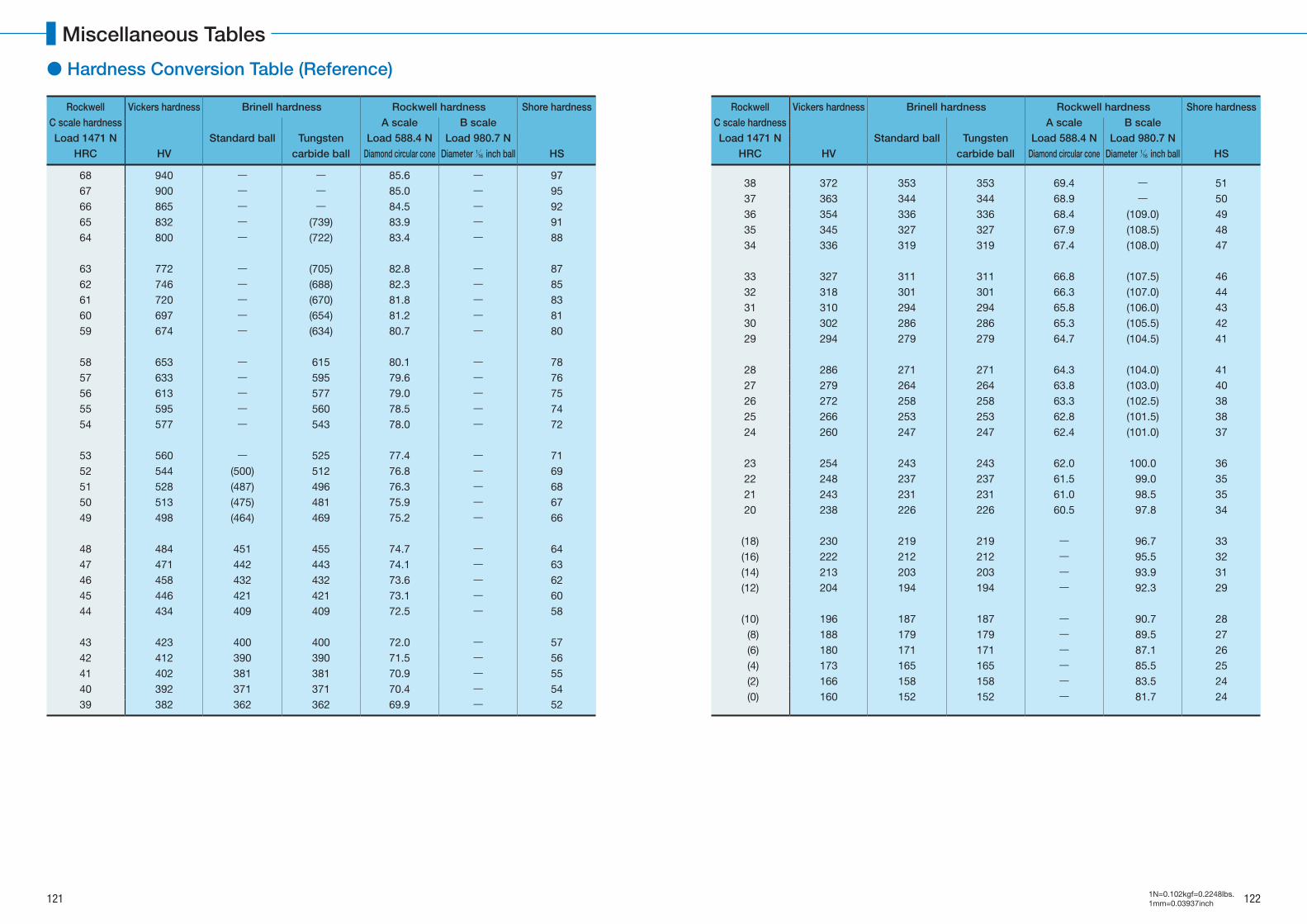
Rockwell Vickers hardness Brinell hardness Rockwell hardness Shore hardnessC scale hardness
Standard ball Tungsten carbide ball
A scale B scaleLoad 1471 N Load 588.4 N Load 980.7 N
HRC HV Diamond circular cone Diameter 1/16 inch ball HS
68 940 ― ― 85.6 ― 9767 900 ― ― 85.0 ― 9566 865 ― ― 84.5 ― 9265 832 ― (739) 83.9 ― 9164 800 ― (722) 83.4 ― 88
63 772 ― (705) 82.8 ― 8762 746 ― (688) 82.3 ― 8561 720 ― (670) 81.8 ― 8360 697 ― (654) 81.2 ― 8159 674 ― (634) 80.7 ― 80
58 653 ― 615 80.1 ― 7857 633 ― 595 79.6 ― 7656 613 ― 577 79.0 ― 7555 595 ― 560 78.5 ― 7454 577 ― 543 78.0 ― 72
53 560 ― 525 77.4 ― 7152 544 (500) 512 76.8 ― 6951 528 (487) 496 76.3 ― 6850 513 (475) 481 75.9 ― 6749 498 (464) 469 75.2 ― 66
48 484 451 455 74.7 ― 6447 471 442 443 74.1 ― 6346 458 432 432 73.6 ― 6245 446 421 421 73.1 ― 6044 434 409 409 72.5 ― 58
43 423 400 400 72.0 ― 5742 412 390 390 71.5 ― 5641 402 381 381 70.9 ― 5540 392 371 371 70.4 ― 5439 382 362 362 69.9 ― 52
Rockwell Vickers hardness Brinell hardness Rockwell hardness Shore hardnessC scale hardness
Standard ball Tungsten carbide ball
A scale B scaleLoad 1471 N Load 588.4 N Load 980.7 N
HRC HV Diamond circular cone Diameter 1/16 inch ball HS
38 372 353 353 69.4 ― 5137 363 344 344 68.9 ― 5036 354 336 336 68.4 (109.0) 4935 345 327 327 67.9 (108.5) 4834 336 319 319 67.4 (108.0) 47
33 327 311 311 66.8 (107.5) 4632 318 301 301 66.3 (107.0) 4431 310 294 294 65.8 (106.0) 4330 302 286 286 65.3 (105.5) 4229 294 279 279 64.7 (104.5) 41
28 286 271 271 64.3 (104.0) 4127 279 264 264 63.8 (103.0) 4026 272 258 258 63.3 (102.5) 3825 266 253 253 62.8 (101.5) 3824 260 247 247 62.4 (101.0) 37
23 254 243 243 62.0 100.0 3622 248 237 237 61.5 99.0 3521 243 231 231 61.0 98.5 3520 238 226 226 60.5 97.8 34
(18) 230 219 219 ― 96.7 33(16) 222 212 212 ― 95.5 32(14) 213 203 203 ― 93.9 31(12) 204 194 194 ― 92.3 29
(10) 196 187 187 ― 90.7 28 (8) 188 179 179 ― 89.5 27 (6) 180 171 171 ― 87.1 26 (4) 173 165 165 ― 85.5 25 (2) 166 158 158 ― 83.5 24 (0) 160 152 152 ― 81.7 24
● Hardness Conversion Table (Reference)
121 122
Miscellaneous Tables
1N=0.102kgf=0.2248lbs.1mm=0.03937inch
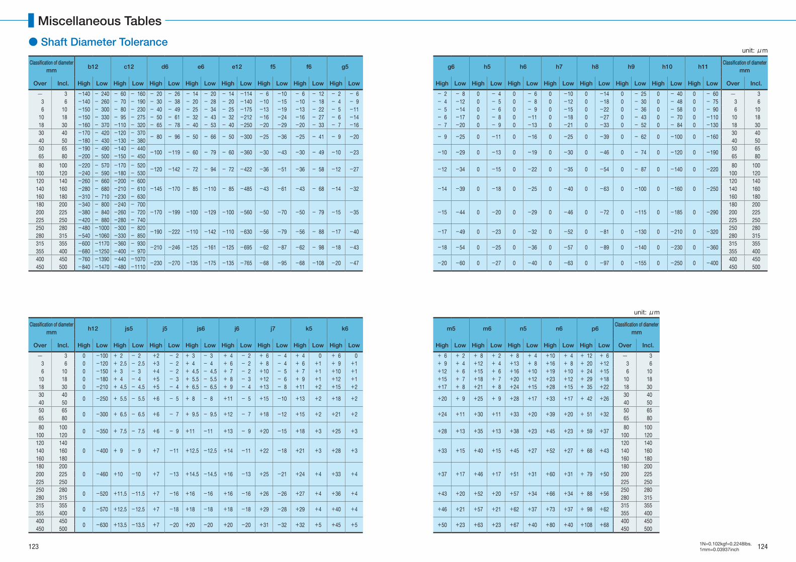
unit: μm
Classification of diameterb12 c12 d6 e6 e12 f5 f6 g5 g6 h5 h6 h7 h8 h9 h10 h11
Classification of diametermm mm
Over Incl. High Low High Low High Low High Low High Low High Low High Low High Low High Low High Low High Low High Low High Low High Low High Low High Low Over Incl.
3 -140 - 240 - 60 - 160 - 20 - 26 - 14 - 20 - 14 -114 - 6 -10 - 6 - 12 - 2 - 6 - 2 - 8 0 - 4 0 - 6 0 -10 0 -14 0 - 25 0 - 40 0 - 60 3 3 6 -140 - 260 - 70 - 190 - 30 - 38 - 20 - 28 - 20 -140 -10 -15 -10 - 18 - 4 - 9 - 4 -12 0 - 5 0 - 8 0 -12 0 -18 0 - 30 0 - 48 0 - 75 3 6 6 10 -150 - 300 - 80 - 230 - 40 - 49 - 25 - 34 - 25 -175 -13 -19 -13 - 22 - 5 -11 - 5 -14 0 - 6 0 - 9 0 -15 0 -22 0 - 36 0 - 58 0 - 90 6 10 10 18 -150 - 330 - 95 - 275 - 50 - 61 - 32 - 43 - 32 -212 -16 -24 -16 - 27 - 6 -14 - 6 -17 0 - 8 0 -11 0 -18 0 -27 0 - 43 0 - 70 0 -110 10 18 18 30 -160 - 370 -110 - 320 - 65 - 78 - 40 - 53 - 40 -250 -20 -29 -20 - 33 - 7 -16 - 7 -20 0 - 9 0 -13 0 -21 0 -33 0 - 52 0 - 84 0 -130 18 30 30 40 -170 - 420 -120 - 370 - 80 - 96 - 50 - 66 - 50 -300 -25 -36 -25 - 41 - 9 -20 - 9 -25 0 -11 0 -16 0 -25 0 -39 0 - 62 0 -100 0 -160
30 40 40 50 -180 - 430 -130 - 380 40 50 50 65 -190 - 490 -140 - 440 -100 -119 - 60 - 79 - 60 -360 -30 -43 -30 - 49 -10 -23 -10 -29 0 -13 0 -19 0 -30 0 -46 0 - 74 0 -120 0 -190
50 65 65 80 -200 - 500 -150 - 450 65 80
80 100 -220 - 570 -170 - 520 -120 -142 - 72 - 94 - 72 -422 -36 -51 -36 - 58 -12 -27 -12 -34 0 -15 0 -22 0 -35 0 -54 0 - 87 0 -140 0 -220 80 100
100 120 -240 - 590 -180 - 530 100 120120 140 -260 - 660 -200 - 600
-145 -170 - 85 -110 - 85 -485 -43 -61 -43 - 68 -14 -32 -14 -39 0 -18 0 -25 0 -40 0 -63 0 -100 0 -160 0 -250120 140
140 160 -280 - 680 -210 - 610 140 160160 180 -310 - 710 -230 - 630 160 180180 200 -340 - 800 -240 - 700
-170 -199 -100 -129 -100 -560 -50 -70 -50 - 79 -15 -35 -15 -44 0 -20 0 -29 0 -46 0 -72 0 -115 0 -185 0 -290180 200
200 225 -380 - 840 -260 - 720 200 225225 250 -420 - 880 -280 - 740 225 250250 280 -480 -1000 -300 - 820 -190 -222 -110 -142 -110 -630 -56 -79 -56 - 88 -17 -40 -17 -49 0 -23 0 -32 0 -52 0 -81 0 -130 0 -210 0 -320
250 280280 315 -540 -1060 -330 - 850 280 315315 355 -600 -1170 -360 - 930 -210 -246 -125 -161 -125 -695 -62 -87 -62 - 98 -18 -43 -18 -54 0 -25 0 -36 0 -57 0 -89 0 -140 0 -230 0 -360
315 355355 400 -680 -1250 -400 - 970 355 400400 450 -760 -1390 -440 -1070 -230 -270 -135 -175 -135 -765 -68 -95 -68 -108 -20 -47 -20 -60 0 -27 0 -40 0 -63 0 -97 0 -155 0 -250 0 -400
400 450450 500 -840 -1470 -480 -1110 450 500
unit: μm
Classification of diameterh12 js5 j5 js6 j6 j7 k5 k6 m5 m6 n5 n6 p6
Classification of diametermm mm
Over Incl. High Low High Low High Low High Low High Low High Low High Low High Low High Low High Low High Low High Low High Low Over Incl.
3 0 -100 + 2 - 2 +2 - 2 + 3 - 3 + 4 - 2 + 6 - 4 + 4 0 + 6 0 + 6 + 2 + 8 + 2 + 8 + 4 +10 + 4 + 12 + 6 3 3 6 0 -120 + 2.5 - 2.5 +3 - 2 + 4 - 4 + 6 - 2 + 8 - 4 + 6 +1 + 9 +1 + 9 + 4 +12 + 4 +13 + 8 +16 + 8 + 20 +12 3 6 6 10 0 -150 + 3 - 3 +4 - 2 + 4.5 - 4.5 + 7 - 2 +10 - 5 + 7 +1 +10 +1 +12 + 6 +15 + 6 +16 +10 +19 +10 + 24 +15 6 10 10 18 0 -180 + 4 - 4 +5 - 3 + 5.5 - 5.5 + 8 - 3 +12 - 6 + 9 +1 +12 +1 +15 + 7 +18 + 7 +20 +12 +23 +12 + 29 +18 10 18 18 30 0 -210 + 4.5 - 4.5 +5 - 4 + 6.5 - 6.5 + 9 - 4 +13 - 8 +11 +2 +15 +2 +17 + 8 +21 + 8 +24 +15 +28 +15 + 35 +22 18 30 30 40
0 -250 + 5.5 - 5.5 +6 - 5 + 8 - 8 +11 - 5 +15 -10 +13 +2 +18 +2 +20 + 9 +25 + 9 +28 +17 +33 +17 + 42 +26 30 40
40 50 40 50 50 65
0 -300 + 6.5 - 6.5 +6 - 7 + 9.5 - 9.5 +12 - 7 +18 -12 +15 +2 +21 +2 +24 +11 +30 +11 +33 +20 +39 +20 + 51 +32 50 65
65 80 65 80
80 1000 -350 + 7.5 - 7.5 +6 - 9 +11 -11 +13 - 9 +20 -15 +18 +3 +25 +3 +28 +13 +35 +13 +38 +23 +45 +23 + 59 +37
80 100100 120 100 120120 140
0 -400 + 9 - 9 +7 -11 +12.5 -12.5 +14 -11 +22 -18 +21 +3 +28 +3 +33 +15 +40 +15 +45 +27 +52 +27 + 68 +43120 140
140 160 140 160160 180 160 180180 200
0 -460 +10 -10 +7 -13 +14.5 -14.5 +16 -13 +25 -21 +24 +4 +33 +4 +37 +17 +46 +17 +51 +31 +60 +31 + 79 +50180 200
200 225 200 225225 250 225 250250 280
0 -520 +11.5 -11.5 +7 -16 +16 -16 +16 -16 +26 -26 +27 +4 +36 +4 +43 +20 +52 +20 +57 +34 +66 +34 + 88 +56250 280
280 315 280 315315 355
0 -570 +12.5 -12.5 +7 -18 +18 -18 +18 -18 +29 -28 +29 +4 +40 +4 +46 +21 +57 +21 +62 +37 +73 +37 + 98 +62315 355
355 400 355 400400 450
0 -630 +13.5 -13.5 +7 -20 +20 -20 +20 -20 +31 -32 +32 +5 +45 +5 +50 +23 +63 +23 +67 +40 +80 +40 +108 +68400 450
450 500 450 500
● Shaft Diameter Tolerance
123 124
Miscellaneous Tables
1N=0.102kgf=0.2248lbs.1mm=0.03937inch
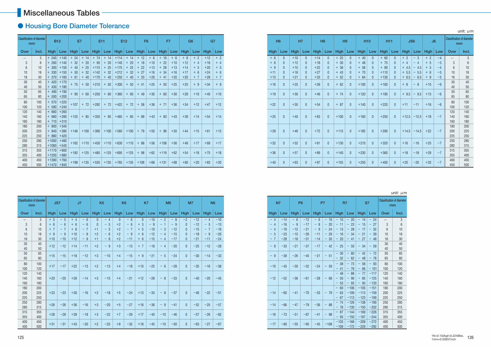
unit: μm
Classification of diameterB12 E7 E11 E12 F6 F7 G6 G7 H6 H7 H8 H9 H10 H11 JS6 J6
Classification of diametermm mm
Over Incl. High Low High Low High Low High Low High Low High Low High Low High Low High Low High Low High Low High Low High Low High Low High Low High Low Over Incl.
3 + 240 +140 + 24 + 14 + 74 + 14 +114 + 14 + 12 + 6 + 16 + 6 + 8 + 2 +12 + 2 + 6 0 +10 0 +14 0 + 25 0 + 40 0 + 60 0 + 3 - 3 + 2 -4 3 3 6 + 260 +140 + 32 + 20 + 95 + 20 +140 + 20 + 18 +10 + 22 +10 +12 + 4 +16 + 4 + 8 0 +12 0 +18 0 + 30 0 + 48 0 + 75 0 + 4 - 4 + 5 -3 3 6 6 10 + 300 +150 + 40 + 25 +115 + 25 +175 + 25 + 22 +13 + 28 +13 +14 + 5 +20 + 5 + 9 0 +15 0 +22 0 + 36 0 + 58 0 + 90 0 + 4.5 - 4.5 + 5 -4 6 10 10 18 + 330 +150 + 50 + 32 +142 + 32 +212 + 32 + 27 +16 + 34 +16 +17 + 6 +24 + 6 +11 0 +18 0 +27 0 + 43 0 + 70 0 +110 0 + 5.5 - 5.5 + 6 -5 10 18 18 30 + 370 +160 + 61 + 40 +170 + 40 +250 + 40 + 33 +20 + 41 +20 +20 + 7 +28 + 7 +13 0 +21 0 +33 0 + 52 0 + 84 0 +130 0 + 6.5 - 6.5 + 8 -5 18 30 30 40 + 420 +170 + 75 + 50 +210 + 50 +300 + 50 + 41 +25 + 50 +25 +25 + 9 +34 + 9 +16 0 +25 0 +39 0 + 62 0 +100 0 +160 0 + 8 - 8 +10 -6
30 40 40 50 + 430 +180 40 50 50 65 + 490 +190 + 90 + 60 +250 + 60 +360 + 60 + 49 +30 + 60 +30 +29 +10 +40 +10 +19 0 +30 0 +46 0 + 74 0 +120 0 +190 0 + 9.5 - 9.5 +13 -6
50 65 65 80 + 500 +200 65 80
80 100 + 570 +220 +107 + 72 +292 + 72 +422 + 72 + 58 +36 + 71 +36 +34 +12 +47 +12 +22 0 +35 0 +54 0 + 87 0 +140 0 +220 0 +11 -11 +16 -6 80 100
100 120 + 590 +240 100 120120 140 + 660 +260
+125 + 85 +335 + 85 +485 + 85 + 68 +43 + 83 +43 +39 +14 +54 +14 +25 0 +40 0 +63 0 +100 0 +160 0 +250 0 +12.5 -12.5 +18 -7120 140
140 160 + 680 +280 140 160160 180 + 710 +310 160 180180 200 + 800 +340
+146 +100 +390 +100 +560 +100 + 79 +50 + 96 +50 +44 +15 +61 +15 +29 0 +46 0 +72 0 +115 0 +185 0 +290 0 +14.5 -14.5 +22 -7180 200
200 225 + 840 +380 200 225225 250 + 880 +420 225 250250 280 +1000 +480 +162 +110 +430 +110 +630 +110 + 88 +56 +108 +56 +49 +17 +69 +17 +32 0 +52 0 +81 0 +130 0 +210 0 +320 0 +16 -16 +25 -7
250 280280 315 +1060 +540 280 315315 355 +1170 +600 +182 +125 +485 +125 +695 +125 + 98 +62 +119 +62 +54 +18 +75 +18 +36 0 +57 0 +89 0 +140 0 +230 0 +360 0 +18 -18 +29 -7
315 355355 400 +1250 +680 355 400400 450 +1390 +760 +198 +135 +535 +135 +765 +135 +108 +68 +131 +68 +60 +20 +83 +20 +40 0 +63 0 +97 0 +155 0 +250 0 +400 0 +20 -20 +33 -7
400 450450 500 +1470 +840 450 500
unit: μm
Classification of diameterJS7 J7 K5 K6 K7 M6 M7 N6 N7 P6 P7 R7 S7
Classification of diametermm mm
Over Incl. High Low High Low High Low High Low High Low High Low High Low High Low High Low High Low High Low High Low High Low Over Incl.
3 + 5 - 5 + 4 - 6 0 - 4 0 - 6 0 -10 - 2 - 8 -2 -12 - 4 -10 - 4 -14 - 6 -12 - 6 - 16 - 10 - 20 - 14 - 24 3 3 6 + 6 - 6 + 6 - 6 0 - 5 +2 - 6 + 3 - 9 - 1 - 9 0 -12 - 5 -13 - 4 -16 - 9 -17 - 8 - 20 - 11 - 23 - 15 - 27 3 6 6 10 + 7 - 7 + 8 - 7 +1 - 5 +2 - 7 + 5 -10 - 3 -12 0 -15 - 7 -16 - 4 -19 -12 -21 - 9 - 24 - 13 - 28 - 17 - 32 6 10 10 18 + 9 - 9 +10 - 8 +2 - 6 +2 - 9 + 6 -12 - 4 -15 0 -18 - 9 -20 - 5 -23 -15 -26 -11 - 29 - 16 - 34 - 21 - 39 10 18 18 30 +10 -10 +12 - 9 +1 - 8 +2 -11 + 6 -15 - 4 -17 0 -21 -11 -24 - 7 -28 -18 -31 -14 - 35 - 20 - 41 - 27 - 48 18 30 30 40 +12 -12 +14 -11 +2 - 9 +3 -13 + 7 -18 - 4 -20 0 -25 -12 -28 - 8 -33 -21 -37 -17 - 42 - 25 - 50 - 34 - 59
30 40 40 50 40 50 50 65 +15 -15 +18 -12 +3 -10 +4 -15 + 9 -21 - 5 -24 0 -30 -14 -33 - 9 -39 -26 -45 -21 - 51
- 30 - 60 - 42 - 72 50 65 65 80 - 32 - 62 - 48 - 78 65 80
80 100 +17 -17 +22 -13 +2 -13 +4 -18 +10 -25 - 6 -28 0 -35 -16 -38 -10 -45 -30 -52 -24 - 59- 38 - 73 - 58 - 93 80 100
100 120 - 41 - 76 - 66 - 101 100 120120 140
+20 -20 +26 -14 +3 -15 +4 -21 +12 -28 - 8 -33 0 -40 -20 -45 -12 -52 -36 -61 -28 - 68- 48 - 88 - 77 -117 120 140
140 160 - 50 - 90 - 85 -125 140 160160 180 - 53 - 93 - 93 -133 160 180180 200
+23 -23 +30 -16 +2 -18 +5 -24 +13 -33 - 8 -37 0 -46 -22 -51 -14 -60 -41 -70 -33 - 79- 60 -106 -105 -151 180 200
200 225 - 63 -109 -113 -159 200 225225 250 - 67 -113 -123 -169 225 250250 280 +26 -26 +36 -16 +3 -20 +5 -27 +16 -36 - 9 -41 0 -52 -25 -57 -14 -66 -47 -79 -36 - 88
- 74 -126 -138 -190 250 280280 315 - 78 -130 -150 -202 280 315315 355 +28 -28 +39 -18 +3 -22 +7 -29 +17 -40 -10 -46 0 -57 -26 -62 -16 -73 -51 -87 -41 - 98
- 87 -144 -169 -226 315 355355 400 - 93 -150 -187 -244 355 400400 450 +31 -31 +43 -20 +2 -25 +8 -32 +18 -45 -10 -50 0 -63 -27 -67 -17 -80 -55 -95 -45 -108
-103 -166 -209 -272 400 450450 500 -109 -172 -229 -292 450 500
● Housing Bore Diameter Tolerance
125 126
Miscellaneous Tables
1N=0.102kgf=0.2248lbs.1mm=0.03937inch
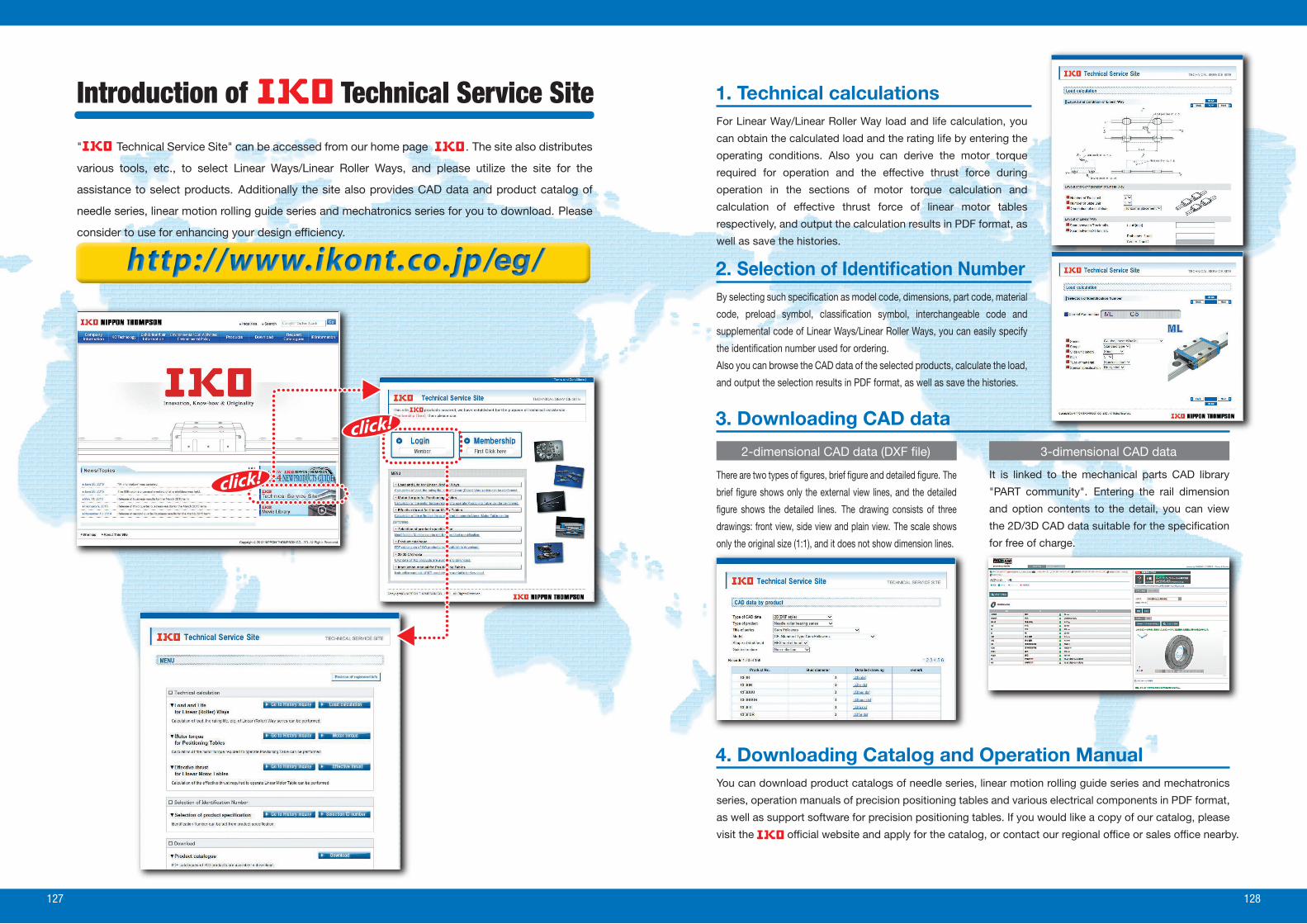
Introduction of Technical Service Site
" Technical Service Site" can be accessed from our home page . The site also distributes
various tools, etc., to select Linear Ways/Linear Roller Ways, and please utilize the site for the
assistance to select products. Additionally the site also provides CAD data and product catalog of
needle series, linear motion rolling guide series and mechatronics series for you to download. Please
consider to use for enhancing your design ef�ciency.
1. Technical calculationsFor Linear Way/Linear Roller Way load and life calculation, you
can obtain the calculated load and the rating life by entering the
operating conditions. Also you can derive the motor torque
required for operation and the effective thrust force during
operation in the sections of motor torque calculation and
calculation of effective thrust force of linear motor tables
respectively, and output the calculation results in PDF format, as
well as save the histories.
2. Selection of Identi�cation NumberBy selecting such speci�cation as model code, dimensions, part code, material
code, preload symbol, classi�cation symbol, interchangeable code and
supplemental code of Linear Ways/Linear Roller Ways, you can easily specify
the identi�cation number used for ordering.
Also you can browse the CAD data of the selected products, calculate the load,
and output the selection results in PDF format, as well as save the histories.
4. Downloading Catalog and Operation Manual
3. Downloading CAD data
There are two types of �gures, brief �gure and detailed �gure. The
brief �gure shows only the external view lines, and the detailed
�gure shows the detailed lines. The drawing consists of three
drawings: front view, side view and plain view. The scale shows
only the original size (1:1), and it does not show dimension lines.
2-dimensional CAD data (DXF �le)
It is linked to the mechanical parts CAD library
"PART community". Entering the rail dimension
and option contents to the detail, you can view
the 2D/3D CAD data suitable for the speci�cation
for free of charge.
3-dimensional CAD data
You can download product catalogs of needle series, linear motion rolling guide series and mechatronics
series, operation manuals of precision positioning tables and various electrical components in PDF format,
as well as support software for precision positioning tables. If you would like a copy of our catalog, please
visit the of�cial website and apply for the catalog, or contact our regional of�ce or sales of�ce nearby.
127 128

Linear Motion Rolling Guides are manufactured through a control
system that alleviates their impact on the global environment to meet the
quality requirements of ISO 14001 in compliance with the quality require-
ments level of ISO 9001 for quality improvement.
The standard products listed in this catalog comply with the specifications of
the six hazardous materials mentioned cited in the European RoHS Directive.
●
●
Gentle to The EarthNippon Thompson Co., Ltd. is working to develop global environment-friendly products.
It is committed to developing products that make its customers’ machinery and
equipment more reliable, thereby contributing to preserving the global environment.
This development stance manifests well in the keyword “Oil Minimum.”
Our pursuit of Oil Minimum has led to the creation of
’s proprietary family of lubricating parts as “C-Lube.”
Products Underpin SustainTechnology LeapsNippon Thompson Co., Ltd. was the �rst Japanese manufacturer to develop needle bearings on its own and has since expanded into the arena of linear motion rolling guides (Linear Motion Series and Mechatro Series) on the support of its advanced expertise. The company now offers a vast assortment of ingenious products, including the world’s �rst C-Lube maintenance-free series, to address increasingly diversi�ed customer needs and thus sustain technology leaps.
C-Lube Maintenance-Free Series Products Evolving from the “Oil Minimum” ConceptWe have developed lubricating parts impregnated with a large amount of lubricant as C-Lube Series to save the customer’s oiling management workload and built them into bearings and linear motion rolling guides.The C-Lube Series not only keeps products maintenance-free for long by giving them an optimal and minimal amount of a lubricant for an extended period of time but also contributes greatly to preserving the global environment.
Needle BearingsMachine elements essential to any industry
Linear Motion Rolling Guides/Linear Motion SeriesAvailable in broad sizes, from minimum to extra-large
Linear Motion Rolling Guides/Mechatro SeriesA merger of precision machining expertise and electronics
129 130
Related Documents