SPC4xxx/5xxx/6xxx Installation & Configuration Manual Document ID: A6V10276959-d Edition date: 11.2018

Welcome message from author
This document is posted to help you gain knowledge. Please leave a comment to let me know what you think about it! Share it to your friends and learn new things together.
Transcript

SPC4xxx/5xxx/6xxxInstallation & Configuration Manual
Document ID: A6V10276959-d
Edition date: 11.2018

Data and design subject to change without notice. / Supply subject to availability.
© 2018 Copyright byVanderbilt International Ltd.
We reserve all rights in this document and in the subject thereof. Byacceptance of the document the recipient acknowledges these rights andundertakesnot to publish the document nor the subject thereof in full or in part, nor to make them available to any third partywithout our priorexpresswritten authorization, nor to use it for anypurpose other than for which it wasdelivered to him.
Table of ContentsTable of Contents 3
1 Meaning of symbols 10
2 Security 11
2.1 Target group 11
2.2 General safety instructions 11
2.2.1 General information 11
2.2.2 Transport 11
2.2.3 Setup 12
2.2.4 Operation 12
2.2.5 Service andmaintenance 12
2.3Meaning of written warning notices and hazard symbols 12
2.3.1Warning notices 12
2.3.2 Hazard symbols 13
3 Directives and standards 14
3.1 EU directives 14
3.2 Overview of Conformity to EN50131 Standard 14
3.2.1 Compliance with EN50131 Approvals 20
3.3 Compliance with EN 50136-1:2012 and EN 50136-2:2014 22
3.4 Compliance with INCERT Approvals 22
3.5 PD 6662:2010 ConformanceGuidelines 23
3.5.1 Product scope 23
3.5.2 Standards overview 24
3.5.3Methods for the completion of setting and unsetting 24
3.5.4 Configuration requirements for PD 6662:2010 conformance 26
3.5.5 Additional commissioning requirements for PD 6662:2010 conformance 27
3.5.6 Additional information 27
3.6 Compliance with VdS approvals 28
3.7 Compliance with NF and A2P approvals including CYBER requirements 29
3.7.1 Compliance with NF and A2P approvals including CYBER requirements 29
3.7.2 Compliance with NF and A2P approvals including CYBER requirements - SPC Products 30
4 Technical Data 31
4.1 SPC4000 31
4.2 SPC5000 33
4.3 SPC6000 37
4.4 SPCP355.300 40
5 Introduction 42
6 Mounting system equipment 43
©Vanderbilt 2018 3 A6V10276959-d11.2018
6.1Mounting aG2 housing 43
6.2Mounting aG3 housing 44
6.2.1Mounting a Back Tamper Kit 46
6.2.2 Battery installation for EN50131 compliance 50
6.3Mounting aG5 housing 51
6.3.1 Tamper protection 52
6.3.2Mounting the housing with tamper protection 53
6.3.3 Installing the batteries 55
6.4Mounting a keypad 56
6.5Mounting an expander 56
7 Smart PSU 57
7.1 SPCP355.300 Smart PSU 57
7.1.1 Supervised Outputs 59
7.1.2 Batteries 60
7.1.3Wiring the X-BUS Interface 62
7.1.4 Compliance with NF and A2P approvals including CYBER requirements 65
7.1.5 PSU LED Status 66
7.1.6 System Recovery 66
8 Controller hardware 68
8.1 Controller Hardware 42xx/43xx/53xx/63xx 68
8.2 Controller Hardware SPC5350 and 6350 71
9 Door Expander 74
10 Wiring the system 75
10.1Wiring the X-BUS interface 75
10.1.1 Loop configuration 76
10.1.2 Spur configuration 77
10.1.3 Star andmulti-drop configuration 78
10.1.4 Shielding 83
10.1.5 CableMap 83
10.2Wiring of branch expander 83
10.3Wiring the system ground 84
10.4Wiring the relay output 84
10.5Wiring the zone inputs 85
10.6Wiring an external SAB bell 88
10.7Wiring an internal sounder 89
10.8Wiring Glassbreak 89
10.9 Installing plug-in modules 90
11 Powering up the SPC controller 92
11.1 Powering from battery only 92
SPC4xxx/5xxx/6xxx– Installation &ConfigurationManual Table of Contents
© Vanderbilt 2018 4 A6V10276959-d11.2018
12 Keypad user interface 93
12.1 SPCK420/421 93
12.1.1 About the LCD keypad 93
12.1.2 Using the LCD keypad interface 95
12.1.3 Data entry on the LCD keypad 98
12.2 SPCK620/623 99
12.2.1 About the Comfort keypad 99
12.2.2 LED description 103
12.2.3 Viewingmode description 103
12.2.4 Function keys in idle state 104
13 Software support tools 105
14 Starting the system 106
14.1 Engineer modes 106
14.1.1 Engineer PINs 106
14.2 Programming with the keypad 106
14.3 Configuring start-up settings 107
14.4 Creating system users 108
14.5 Programming the portable ACE 109
14.6 Configuring wireless fob devices 110
14.6.1 Clearing alerts using the fob 110
15 Soft Engineer programming via the keypad 111
16 Engineer programming via the keypad 112
16.1 System Status 112
16.2 Options 113
16.3 Timers 117
16.4 Areas 121
16.5 AreaGroups 123
16.6 X-BUS 123
16.6.1 X-BUS Addressing 123
16.6.2 XBUS Refresh 124
16.6.3 Reconfigure 124
16.6.4 Keypads/Expanders/Door Controllers 125
16.6.5 AddressingMode 133
16.6.6 XBUS Type 134
16.6.7 Bus Retries 134
16.6.8 Comms Timer 135
16.7 Users 135
16.7.1 Add 135
16.7.2 Edit 135
SPC4xxx/5xxx/6xxx– Installation &ConfigurationManual Table of Contents
© Vanderbilt 2018 5 A6V10276959-d11.2018
16.7.3 Delete 138
16.8 User Profiles 138
16.8.1 Add 138
16.8.2 Edit 138
16.8.3 Delete 139
16.9Wireless 139
16.9.1 Select a wireless programming option 140
16.9.2 One-way wireless 141
16.9.3 Two-way wireless 145
16.10 Zones 148
16.11 Doors 148
16.12Outputs 152
16.12.1 Outputs types and output ports 153
16.13 Communication 157
16.13.1 Serial Ports 157
16.13.2 Ethernet Ports 158
16.13.3Modems 158
16.13.4 Central Station 160
16.13.5 SPC Connect PRO 162
16.14 Test 162
16.14.1 Bell Test 162
16.14.2Walk Test 162
16.14.3 ZoneMonitor 163
16.14.4 Output Test 164
16.14.5 Soak Test 164
16.14.6 Audible Options 164
16.14.7 Visual Indicators 165
16.14.8 Seismic Test 165
16.15 Utilities 165
16.16 Isolate 166
16.17 Event Log 166
16.18 Access Log 166
16.19 Alarm Log 166
16.20 Change Engineer Pin 167
16.21 SMS 167
16.21.1 Add 168
16.21.2 Edit 168
16.21.3 Delete 169
16.22 X-10 169
SPC4xxx/5xxx/6xxx– Installation &ConfigurationManual Table of Contents
© Vanderbilt 2018 6 A6V10276959-d11.2018
16.23 Set Date/Time 169
16.24 Installer Text 170
16.25 Door Control 170
16.26 SPC Connect 171
17 Engineer programming via the browser 172
17.1 System Information 172
17.2 Ethernet interface 172
17.3 Connecting to the panel via USB 174
17.4 Logging into the browser 176
17.5 SPC Home 177
17.5.1 System Summary 177
17.5.2 Alarms Overview 178
17.5.3 Viewing Video 178
17.6 Panel status 179
17.6.1 Status 179
17.6.2 X-Bus Status 180
17.6.3Wireless 187
17.6.4 Zones 189
17.6.5 Doors 191
17.6.6 FlexC Status 192
17.6.7 System alerts 194
17.7 Logs 194
17.7.1 System Log 194
17.7.2 Access Log 195
17.7.3 ALARM LOG 195
17.8 Users 196
17.8.1 Adding/Editing a User 196
17.8.2 Adding/Editing User Profiles 199
17.8.3 Configuring SMS 203
17.8.4 SMS Commands 204
17.8.5 DeletingWeb Passwords 207
17.8.6 Configuring Engineer Settings 207
17.9Wireless 209
17.9.1 One-way wireless 210
17.9.2 Two-way wireless 220
17.10 Configuration 228
17.10.1 Configuring controller inputs and outputs 229
17.10.2 X-BUS 238
17.10.3 Changing system settings 252
SPC4xxx/5xxx/6xxx– Installation &ConfigurationManual Table of Contents
© Vanderbilt 2018 7 A6V10276959-d11.2018
17.10.4 Configuring zones, doors and areas 269
17.10.5 Calendars 284
17.10.6 Change own PIN 287
17.10.7 Configuring advanced settings 287
17.11 Configuring Communications 295
17.11.1 Communications Settings 295
17.11.2 FlexC® 304
17.11.3 Reporting 323
17.11.4 PC Tools 335
17.12 File Operations 337
17.12.1 File UpgradeOperations 337
17.12.2 File Manager Operations 341
18 Accessing web server remotely 343
18.1 PSTN connection 343
18.2 GSM connection 345
19 Intruder alarm functionality 348
19.1 Financial mode operation 348
19.2 Commercial mode operation 348
19.3 Domestic mode operation 349
19.4 Full and local alarms 349
20 System examples and scenarios 351
20.1When to use a common area 351
21 Seismic Sensors 353
21.1 Seismic Sensor Testing 354
21.1.1Manual and Automatic Test Process 354
21.1.2 Automatically Testing Sensors 354
21.1.3Manually Testing Sensors 355
22 Blocking Lock Operation 357
22.1 Blocking Lock 357
22.2 Authorized Setting of the Blocking Lock 358
22.3 Locking Element 359
23 Appendix 361
23.1 Network cable connections 361
23.2 Controller status LEDs 362
23.3 Powering expanders from the auxiliary power terminals 363
23.4 Calculating the battery power requirements 364
23.5 Domestic, Commercial and Financial mode default settings 366
23.6Wiring of the X10 interface 367
23.7 SIA Codes 368
SPC4xxx/5xxx/6xxx– Installation &ConfigurationManual Table of Contents
© Vanderbilt 2018 8 A6V10276959-d11.2018
23.8 CID Codes 373
23.9 Overview of keypad types 375
23.10 User PIN combinations 376
23.11 Duress PINs 376
23.12 Automatic inhibits 376
23.12.1 Zones 376
23.12.2 Access PINs 377
23.12.3 Engineer Access 377
23.12.4 Keypad User Logoff 377
23.13Wiring of mains cable to the controller 377
23.14Maintenance controller 377
23.15Maintenance Smart PSU 378
23.16 Zone types 379
23.17 Zone attributes 384
23.18 Applicable attributes to zone types 387
23.19 ATS levels and attenuation specifications 388
23.20 Supported card readers and card formats 388
23.21 SPC Support for E-Bus Devices 390
23.21.1 Configuring and Addressing E-Bus Devices 391
23.22 FlexC Glossary 393
23.23 FlexC Commands 394
23.24 ATS Category Timings 397
23.25 ATP Category Timings 398
24 Notes 400
SPC4xxx/5xxx/6xxx– Installation &ConfigurationManual Table of Contents
© Vanderbilt 2018 9 A6V10276959-d11.2018
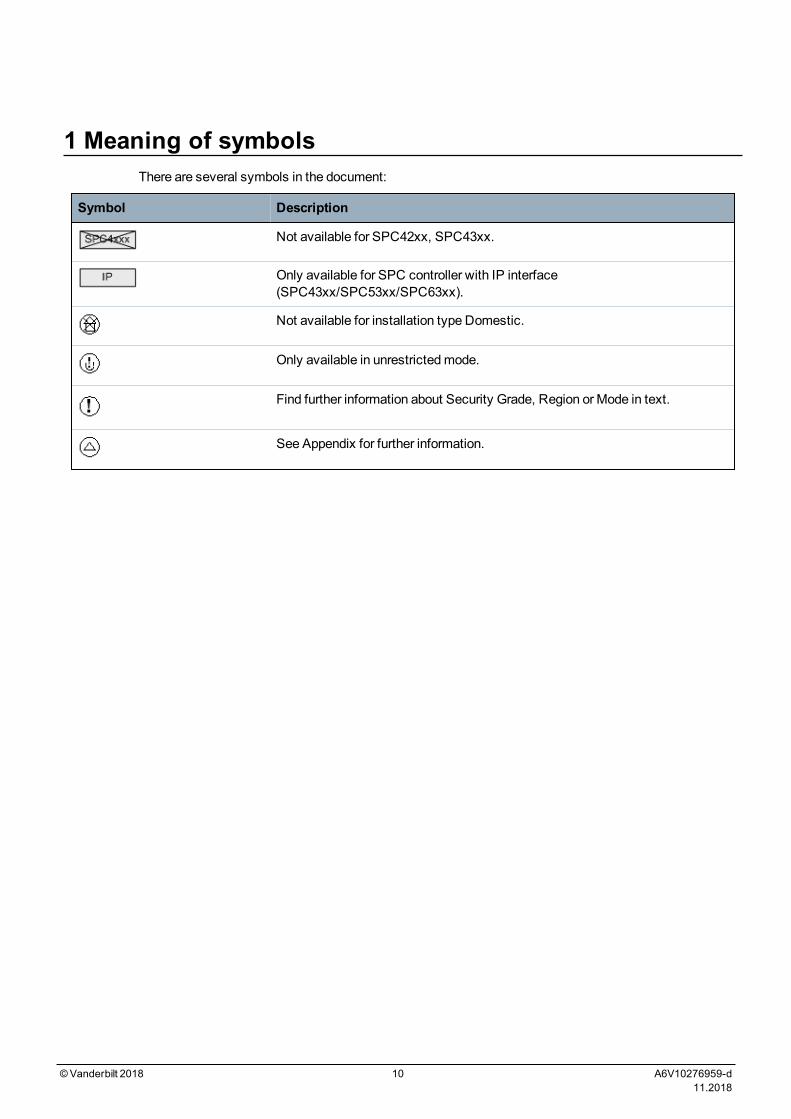
1 Meaning of symbolsThere are several symbols in the document:
Symbol Description
Not available for SPC42xx, SPC43xx.
Only available for SPC controller with IP interface(SPC43xx/SPC53xx/SPC63xx).
Not available for installation type Domestic.
Only available in unrestrictedmode.
Find further information about Security Grade, Region or Mode in text.
See Appendix for further information.
©Vanderbilt 2018 10 A6V10276959-d11.2018
2 SecurityThis chapter covers:
2.1 Target group 11
2.2 General safety instructions 11
2.3 Meaning of written warning notices and hazard symbols 12
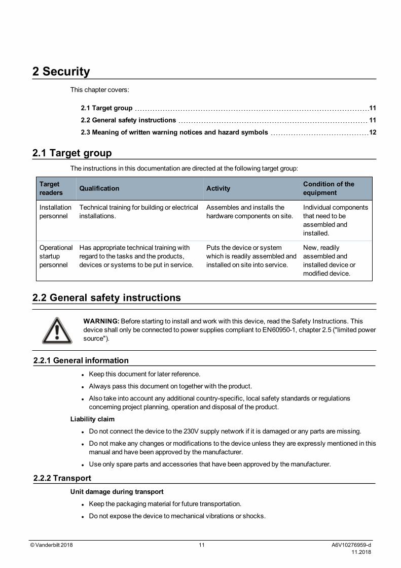
2.1 Target groupThe instructions in this documentation are directed at the following target group:
Targetreaders Qualification Activity Condition of the
equipment
Installationpersonnel
Technical training for building or electricalinstallations.
Assembles and installs thehardware components on site.
Individual componentsthat need to beassembled andinstalled.
Operationalstartuppersonnel
Has appropriate technical training withregard to the tasks and the products,devices or systems to be put in service.
Puts the device or systemwhich is readily assembled andinstalled on site into service.
New, readilyassembled andinstalled device ormodified device.
2.2 General safety instructions
WARNING:Before starting to install and work with this device, read the Safety Instructions. Thisdevice shall only be connected to power supplies compliant to EN60950-1, chapter 2.5 ("limited powersource").
2.2.1 General informationl Keep this document for later reference.
l Always pass this document on together with the product.
l Also take into account any additional country-specific, local safety standards or regulationsconcerning project planning, operation and disposal of the product.
Liability claim
l Do not connect the device to the 230V supply network if it is damaged or any parts aremissing.
l Do not make any changes or modifications to the device unless they are expressly mentioned in thismanual and have been approved by themanufacturer.
l Use only spare parts and accessories that have been approved by themanufacturer.
2.2.2 TransportUnit damage during transport
l Keep the packagingmaterial for future transportation.
l Do not expose the device tomechanical vibrations or shocks.
©Vanderbilt 2018 11 A6V10276959-d11.2018
2.2.3 SetupRadio interference with other devices in the environment/EMS
l When handlingmodules that are susceptible to electrostatic discharge, observe the ESDguidelines.
Damage due to unsuitable mounting location
l The environmental conditions recommended by themanufacturer must be observed.See Technical Data on page 31.
l Do not operate the device close to sources of powerful electromagnetic radiation.
Danger of electrical shock due to incorrect connection
l Connect the device only to power sources with the specified voltage. Voltage supply requirementscan be found on the rating label of the device.
l Ensure that the device is permanently connected to the electricity supply; a readily accessibledisconnect devicemust be provided.
l Ensure that the circuit that the device is connected to is protected with a 16A (max.) fuse. Do notconnect any devices from other systems to this fuse.
l This device is designed to work with TN power systems. Do not connect the device to any otherpower systems.
l Electrical groundingmust meet the customary local safety standards and regulations.
l Primary supply cables and secondary cables should be routed such that they do not run in parallel orcross over or touch one anther inside the housing.
l Telephone cables should be fed into the unit separately from other cables.
Risk of cable damage due to stress
l Ensure that all outgoing cables and wires are sufficiently strain-relieved.
2.2.4 OperationDangerous situation due to false alarm
l Make sure to notify all relevant parties and authorities providing assistance before testing thesystem.
l To avoid panic, always inform all those present before testing any alarm devices.
2.2.5 Service and maintenanceDanger of electrical shock during maintenance
l Maintenance work must only be carried out by trained specialists.
l Always disconnect the power cable and other cables from themain power supply before performingmaintenance.
Danger of electrical shock while cleaning the device
l Do not use liquid cleaners or sprays that contain alcohol, spirit or ammonia.
2.3 Meaning of written warning notices and hazard symbols2.3.1 Warning notices
Signal Word Type of Risk
DANGER Danger of death or severe bodily harm.
SPC4xxx/5xxx/6xxx– Installation &ConfigurationManual Security
© Vanderbilt 2018 12 A6V10276959-d11.2018
Signal Word Type of Risk
WARNING Possible danger of death or severe bodily harm.
CAUTION Danger of minor bodily injury or property damage
IMPORTANT Danger of malfunctions
2.3.2 Hazard symbols
WARNING: Warning of hazard area
WARNING: Warning of dangerous electrical voltage
SPC4xxx/5xxx/6xxx– Installation &ConfigurationManual Security
© Vanderbilt 2018 13 A6V10276959-d11.2018

3 Directives and standardsThis chapter covers:
3.1 EU directives 14
3.2 Overview of Conformity to EN50131 Standard 14
3.3 Compliance with EN 50136-1:2012 and EN 50136-2:2014 22
3.4 Compliance with INCERT Approvals 22
3.5 PD 6662:2010 Conformance Guidelines 23
3.6 Compliance with VdS approvals 28
3.7 Compliance with NF and A2P approvals including CYBER requirements 29
3.1 EU directivesThis product complies with the requirements of the European Directives 2004/108/EC “Directive ofElectromagnetic Compatibility”, 2006/95/EC “Low Voltage Directive”, and1999/5/EC on Radio andTelecommunications Terminal Equipment (R&TTE). The EU declaration of conformity is available to theresponsible agencies at http://pcd.vanderbiltindustries.com/doc/SPC
European Directive 2004/108/EC “Electromagnetic Compatibility”
Compliance with the European Directive 2004/108/EC has been proven by testing according to thefollowing standards:
emc emission EN 55022 Class B
emc immunity EN 50130-4
European Directive 2006/95/EC “Low-Voltage Directive”
Compliance with the European Directive 2006/95/EC has been proven by testing according to thefollowing standard:
Safety EN 60950-1
3.2 Overview of Conformity to EN50131 StandardThis section gives an overview of the SPC compliance to the EN50131 standard.
Address of Certifying Body
VdS (VdS A/C/EN/SES Approval)AG Köln HRB 28788Sitz der Gesellschaft:Amsterdamer Str. 174, 50735 KölnGeschäftsführer:Robert ReinermannJörgWilms-Vahrenhorst (Stv.)
©Vanderbilt 2018 14 A6V10276959-d11.2018
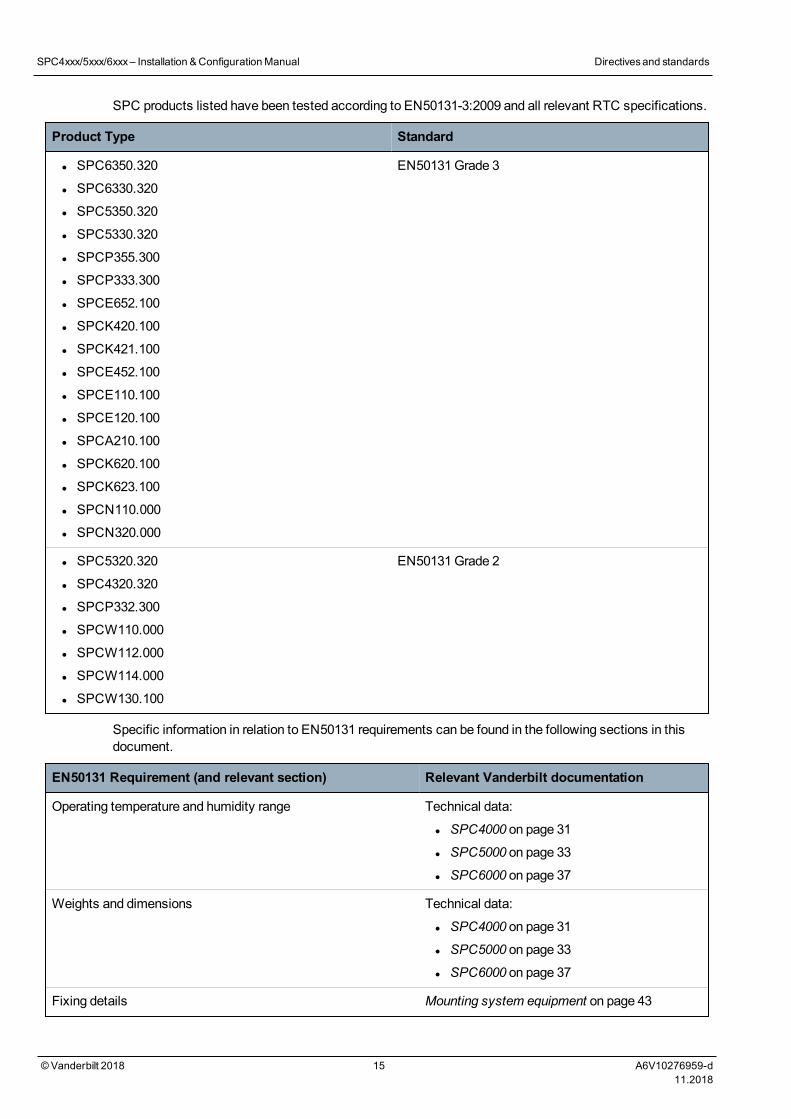
SPC products listed have been tested according to EN50131-3:2009 and all relevant RTC specifications.
Product Type Standard
l SPC6350.320
l SPC6330.320
l SPC5350.320
l SPC5330.320
l SPCP355.300
l SPCP333.300
l SPCE652.100
l SPCK420.100
l SPCK421.100
l SPCE452.100
l SPCE110.100
l SPCE120.100
l SPCA210.100
l SPCK620.100
l SPCK623.100
l SPCN110.000
l SPCN320.000
EN50131Grade 3
l SPC5320.320
l SPC4320.320
l SPCP332.300
l SPCW110.000
l SPCW112.000
l SPCW114.000
l SPCW130.100
EN50131Grade 2
Specific information in relation to EN50131 requirements can be found in the following sections in thisdocument.
EN50131 Requirement (and relevant section) Relevant Vanderbilt documentation
Operating temperature and humidity range Technical data:
l SPC4000 on page 31
l SPC5000 on page 33
l SPC6000 on page 37
Weights and dimensions Technical data:
l SPC4000 on page 31
l SPC5000 on page 33
l SPC6000 on page 37
Fixing details Mounting system equipment on page 43
SPC4xxx/5xxx/6xxx– Installation &ConfigurationManual Directivesand standards
© Vanderbilt 2018 15 A6V10276959-d11.2018
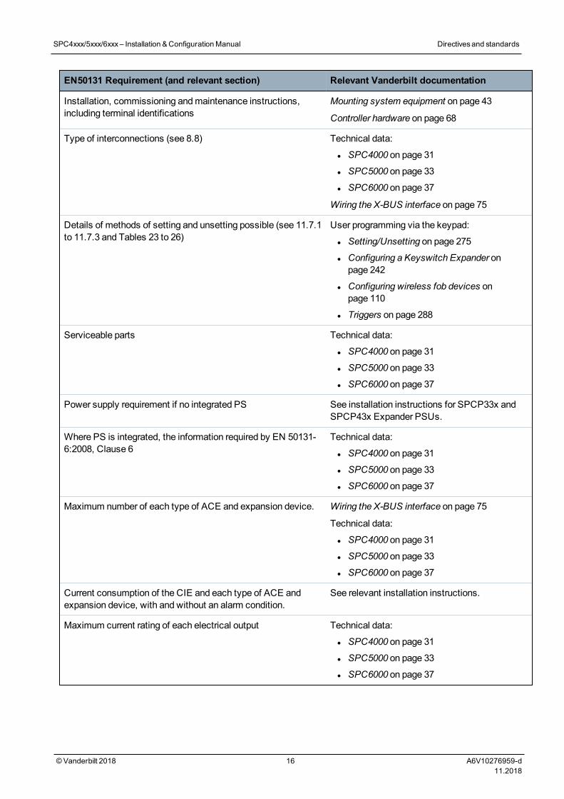
EN50131 Requirement (and relevant section) Relevant Vanderbilt documentation
Installation, commissioning andmaintenance instructions,including terminal identifications
Mounting system equipment on page 43
Controller hardware on page 68
Type of interconnections (see 8.8) Technical data:
l SPC4000 on page 31
l SPC5000 on page 33
l SPC6000 on page 37
Wiring the X-BUS interface on page 75
Details of methods of setting and unsetting possible (see 11.7.1to 11.7.3 and Tables 23 to 26)
User programming via the keypad:
l Setting/Unsetting on page 275
l Configuring a Keyswitch Expander onpage 242
l Configuring wireless fob devices onpage 110
l Triggers on page 288
Serviceable parts Technical data:
l SPC4000 on page 31
l SPC5000 on page 33
l SPC6000 on page 37
Power supply requirement if no integrated PS See installation instructions for SPCP33x andSPCP43x Expander PSUs.
Where PS is integrated, the information required by EN 50131-6:2008, Clause 6
Technical data:
l SPC4000 on page 31
l SPC5000 on page 33
l SPC6000 on page 37
Maximum number of each type of ACE and expansion device. Wiring the X-BUS interface on page 75
Technical data:
l SPC4000 on page 31
l SPC5000 on page 33
l SPC6000 on page 37
Current consumption of the CIE and each type of ACE andexpansion device, with and without an alarm condition.
See relevant installation instructions.
Maximum current rating of each electrical output Technical data:
l SPC4000 on page 31
l SPC5000 on page 33
l SPC6000 on page 37
SPC4xxx/5xxx/6xxx– Installation &ConfigurationManual Directivesand standards
© Vanderbilt 2018 16 A6V10276959-d11.2018
EN50131 Requirement (and relevant section) Relevant Vanderbilt documentation
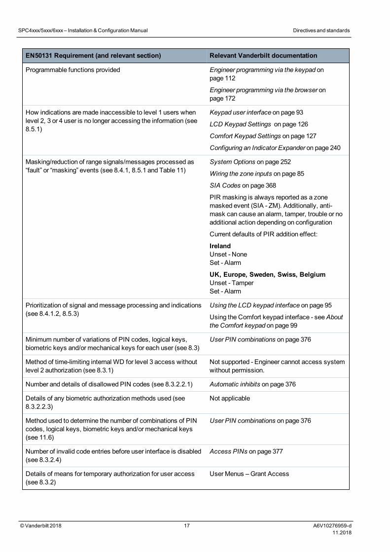
Programmable functions provided Engineer programming via the keypad onpage 112
Engineer programming via the browser onpage 172
How indications aremade inaccessible to level 1 users whenlevel 2, 3 or 4 user is no longer accessing the information (see8.5.1)
Keypad user interface on page 93
LCD Keypad Settings on page 126
Comfort Keypad Settings on page 127
Configuring an Indicator Expander on page 240
Masking/reduction of range signals/messages processed as“fault” or “masking” events (see 8.4.1, 8.5.1 and Table 11)
System Options on page 252
Wiring the zone inputs on page 85
SIA Codes on page 368
PIR masking is always reported as a zonemasked event (SIA - ZM). Additionally, anti-mask can cause an alarm, tamper, trouble or noadditional action depending on configuration
Current defaults of PIR addition effect:
IrelandUnset - NoneSet - Alarm
UK, Europe, Sweden, Swiss, BelgiumUnset - TamperSet - Alarm
Prioritization of signal andmessage processing and indications(see 8.4.1.2, 8.5.3)
Using the LCD keypad interface on page 95
Using the Comfort keypad interface - seeAboutthe Comfort keypad on page 99
Minimum number of variations of PIN codes, logical keys,biometric keys and/or mechanical keys for each user (see 8.3)
User PIN combinations on page 376
Method of time-limiting internal WD for level 3 access withoutlevel 2 authorization (see 8.3.1)
Not supported - Engineer cannot access systemwithout permission.
Number and details of disallowed PIN codes (see 8.3.2.2.1) Automatic inhibits on page 376
Details of any biometric authorizationmethods used (see8.3.2.2.3)
Not applicable
Method used to determine the number of combinations of PINcodes, logical keys, biometric keys and/or mechanical keys(see 11.6)
User PIN combinations on page 376
Number of invalid code entries before user interface is disabled(see 8.3.2.4)
Access PINs on page 377
Details of means for temporary authorization for user access(see 8.3.2)
User Menus –Grant Access
SPC4xxx/5xxx/6xxx– Installation &ConfigurationManual Directivesand standards
© Vanderbilt 2018 17 A6V10276959-d11.2018
EN50131 Requirement (and relevant section) Relevant Vanderbilt documentation
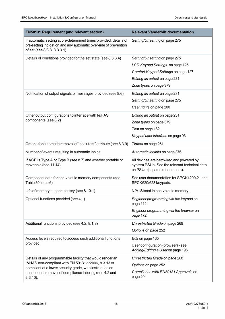
If automatic setting at pre-determined times provided, details ofpre-setting indication and any automatic over-ride of preventionof set (see 8.3.3, 8.3.3.1)
Setting/Unsetting on page 275
Details of conditions provided for the set state (see 8.3.3.4) Setting/Unsetting on page 275
LCD Keypad Settings on page 126
Comfort Keypad Settings on page 127
Editing an output on page 231
Zone types on page 379
Notification of output signals or messages provided (see 8.6) Editing an output on page 231
Setting/Unsetting on page 275
User rights on page 200
Other output configurations to interface with I&HAScomponents (see 8.2)
Editing an output on page 231
Zone types on page 379
Test on page 162
Keypad user interface on page 93
Criteria for automatic removal of “soak test” attribute (see 8.3.9) Timers on page 261
Number of events resulting in automatic inhibit Automatic inhibits on page 376
If ACE is Type A or Type B (see 8.7) and whether portable ormoveable (see 11.14)
All devices are hardwired and powered bysystem PSUs. See the relevant technical dataon PSUs (separate documents).
Component data for non-volatile memory components (seeTable 30, step 6)
See user documentation for SPCK420/421 andSPCK620/623 keypads.
Life of memory support battery (see 8.10.1) N/A. Stored in non-volatile memory.
Optional functions provided (see 4.1) Engineer programming via the keypad onpage 112
Engineer programming via the browser onpage 172
Additional functions provided (see 4.2, 8.1.8) Unrestricted Grade on page 268
Options on page 252
Access levels required to access such additional functionsprovided
Edit on page 135
User configuration (browser) - seeAdding/Editing a User on page 196
Details of any programmable facility that would render anI&HAS non-compliant with EN 50131-1:2006, 8.3.13 orcompliant at a lower security grade, with instruction onconsequent removal of compliance labeling (see 4.2 and8.3.10).
Unrestricted Grade on page 268
Options on page 252
Compliance with EN50131 Approvals onpage 20
SPC4xxx/5xxx/6xxx– Installation &ConfigurationManual Directivesand standards
© Vanderbilt 2018 18 A6V10276959-d11.2018
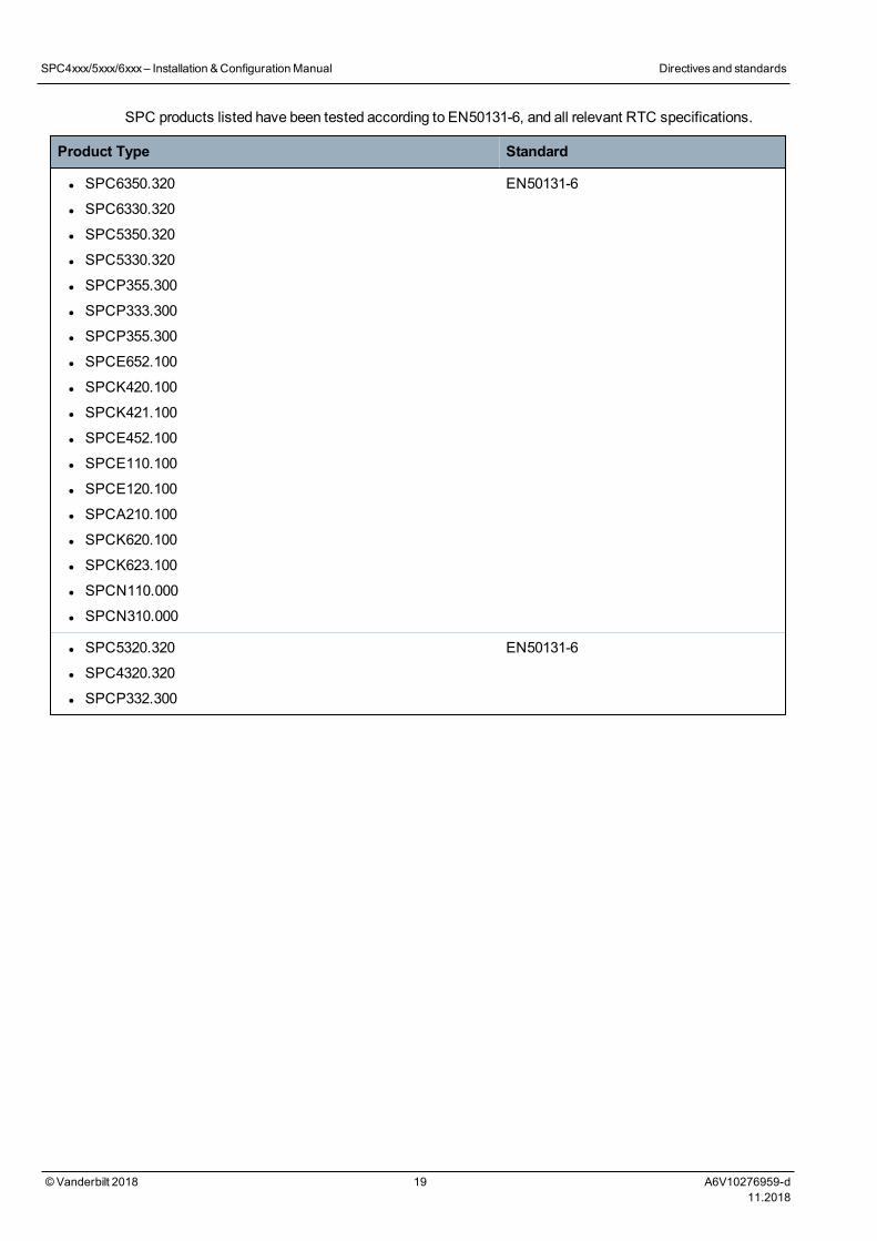
SPC products listed have been tested according to EN50131-6, and all relevant RTC specifications.
Product Type Standard
l SPC6350.320
l SPC6330.320
l SPC5350.320
l SPC5330.320
l SPCP355.300
l SPCP333.300
l SPCP355.300
l SPCE652.100
l SPCK420.100
l SPCK421.100
l SPCE452.100
l SPCE110.100
l SPCE120.100
l SPCA210.100
l SPCK620.100
l SPCK623.100
l SPCN110.000
l SPCN310.000
EN50131-6
l SPC5320.320
l SPC4320.320
l SPCP332.300
EN50131-6
SPC4xxx/5xxx/6xxx– Installation &ConfigurationManual Directivesand standards
© Vanderbilt 2018 19 A6V10276959-d11.2018
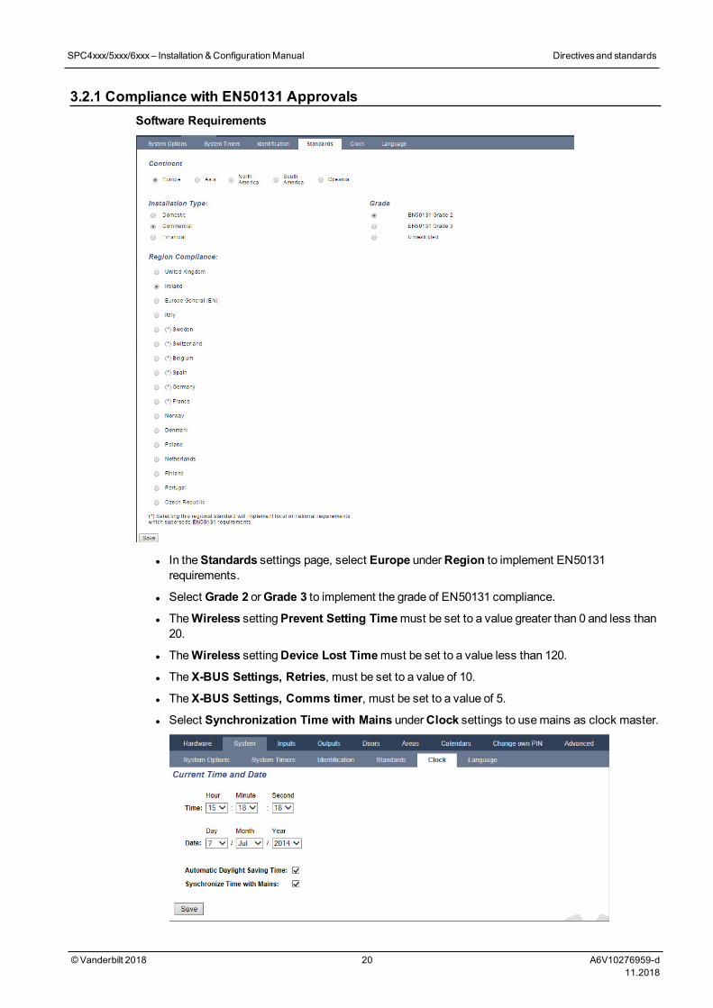
3.2.1 Compliance with EN50131 ApprovalsSoftware Requirements
l In theStandards settings page, select Europe underRegion to implement EN50131requirements.
l Select Grade 2 orGrade 3 to implement the grade of EN50131 compliance.
l TheWireless settingPrevent Setting Timemust be set to a value greater than 0 and less than20.
l TheWireless settingDevice Lost Timemust be set to a value less than 120.
l TheX-BUS Settings, Retries, must be set to a value of 10.
l TheX-BUS Settings, Comms timer, must be set to a value of 5.
l Select Synchronization Time with Mains underClock settings to usemains as clock master.
SPC4xxx/5xxx/6xxx– Installation &ConfigurationManual Directivesand standards
© Vanderbilt 2018 20 A6V10276959-d11.2018
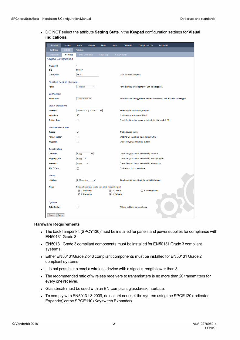
l DONOT select the attributeSetting State in theKeypad configuration settings forVisualindications.
Hardware Requirements
l The back tamper kit (SPCY130) must be installed for panels and power supplies for compliance withEN50131Grade 3.
l EN50131Grade 3 compliant components must be installed for EN50131Grade 3 compliantsystems.
l Either EN50131Grade 2 or 3 compliant components must be installed for EN50131Grade 2compliant systems.
l It is not possible to enrol a wireless device with a signal strength lower than 3.
l The recommended ratio of wireless receivers to transmistters is nomore than 20 transmitters forevery one receiver.
l Glassbreak must be used with an EN-compliant glassbreak interface.
l To comply with EN50131-3:2009, do not set or unset the system using the SPCE120 (IndicatorExpander) or the SPCE110 (Keyswitch Expander).
SPC4xxx/5xxx/6xxx– Installation &ConfigurationManual Directivesand standards
© Vanderbilt 2018 21 A6V10276959-d11.2018
The SPCN110 PSTN module and SPCN320GSM/GPRS module are tested with EN50131approvedGrade 2 andGrade 3 panels and can be used with these approved panels.
3.3 Compliance with EN 50136-1:2012 and EN 50136-2:2014SPC products listed have been tested according to EN 50136-1:2012 and EN 50136-2:2014.
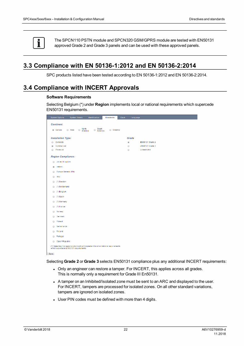
3.4 Compliance with INCERT ApprovalsSoftware Requirements
Selecting Belgium (*) underRegion implements local or national requirements which supercedeEN50131 requirements.
SelectingGrade 2 orGrade 3 selects EN50131 compliance plus any additional INCERT requirements:
l Only an engineer can restore a tamper. For INCERT, this applies across all grades.This is normally only a requirement for Grade III En50131.
l A tamper on an Inhibited/Isolated zonemust be sent to an ARC and displayed to the user.For INCERT, tampers are processed for isolated zones. On all other standard variations,tampers are ignored on isolated zones.
l User PIN codes must be defined with more than 4 digits.
SPC4xxx/5xxx/6xxx– Installation &ConfigurationManual Directivesand standards
© Vanderbilt 2018 22 A6V10276959-d11.2018
Hardware Requirements
l Theminimum battery capacity for SPC42xx/43xx/52xx/53xx/63xx is 10Ah/12V. If a 10Ah battery isused, then the battery is biased to the left of the housing and the bottom flap is bent to meet thebattery.
l Fit jumper (J12) on the battery selector for 17/10Ah battery use and remove for 7Ah battery.
l The amount of current from Aux output using a 10Ah battery for SPC42xx/SPC52xx is:
COMMSNONE (mA) PSTN (mA) GSM (mA) PSTN+GSM (mA)
Standby time
12 h 568 543 438 413
24h 214 189 84 59
30 h 143 118 13 N/A
60h 2 N/A N/A N/A
l The amount of current from Aux output using a 10Ah battery for SPC43xx/SPC53xx/ SPC63xx is:
COMMSNONE (mA) PSTN (mA) GSM (mA) PSTN+GSM (mA)
Standby time
12 h 538 513 408 383
24 h 184 159 54 29
30 h 113 88 N/A N/A
60 h N/A N/A N/A N/A
3.5 PD 6662:2010 Conformance GuidelinesThis document contains all the criteria for the installation, and commissioning andmaintenance of the SPCSystem to enable it to conform to the PD 6662:2010 Standard.
3.5.1 Product scopeThe scope of this document is aimed at the following components of the SPC system:
SPC4320.320-L1Grade 2 Controller
SPC5320.320-L1Grade 2 Controller
SPC5330.320-L1Grade 3 Controller
SPC5350.320-L1Grade 3 Controller
SPC6330.320-L1Grade 3 Controller
SPC6350.320-L1Grade 3 Controller
SPCK420/421.100 LCD Keypad
SPCE452.100 Expander, 8 Relay Outputs
SPCE652.100 Expander, 8 Inputs/2 Outputs
SPCP332.300 Smart PSU with I/O Expander
SPCP355.300 Smart PSU with 8 Inputs/2 Outputs Expander
SPCP333.300 Smart PSU with I/O Expander
SPCN110.000 PSTN Module
SPCN320.000GSMModule
SPC4xxx/5xxx/6xxx– Installation &ConfigurationManual Directivesand standards
© Vanderbilt 2018 23 A6V10276959-d11.2018
3.5.2 Standards overviewGuidelines are provided for the implementation of PD 6662:2010 conformance for an SPC system tothe following relevant standards:
PD 6662:2010
BS 4737-3.1:1977
BS 8243:2010
BS 8473:2006+A1:2008
BS EN 50131-1:2006+A1:2009
BS EN 50136-1-1:1998+A2:2008
BS EN 50136-1-2:1998
BS EN 50136-1-3:1998
BS EN 50136-1-5:2008
BS EN 50136-2-1:1998 +A1:1998
BS EN 50136-2-2:1998
BS EN 50136-2-3:1998
BS EN 50131-3:2009
BS EN 50131-6:2008
DD 263:2010
DD CLC/TS 50131-7:2008
3.5.3 Methods for the completion of setting and unsetting3.5.3.1 Methods of completion of setting (BS 8243:2010 - Clause 6.3)
Completion/Termination of the full setting procedure is achieved by any of the followingmethods:
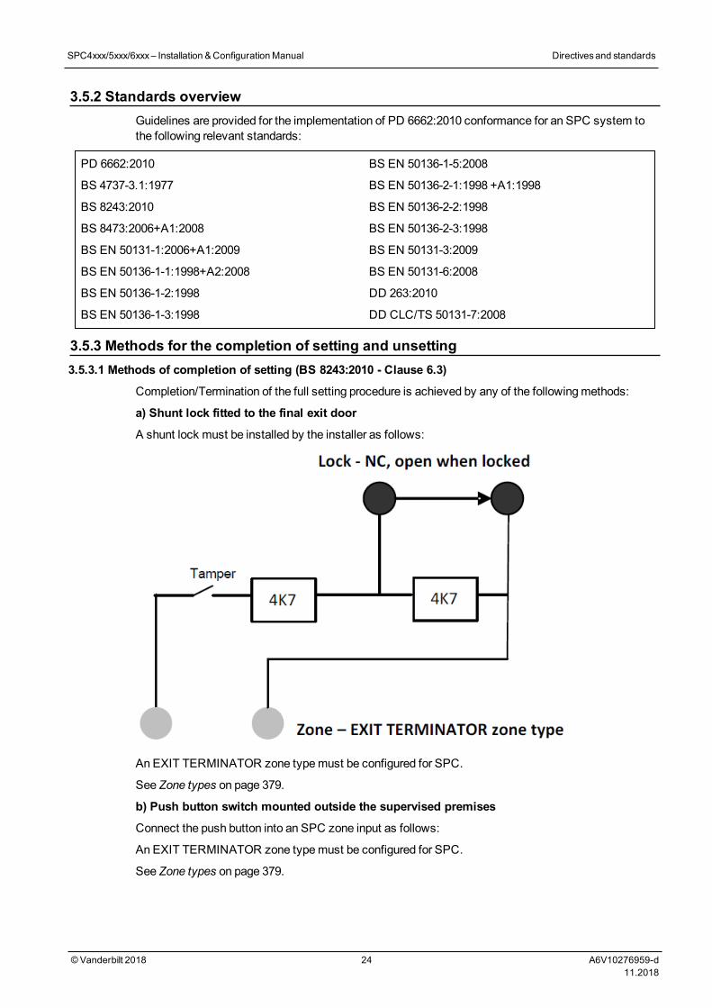
a) Shunt lock fitted to the final exit door
A shunt lock must be installed by the installer as follows:
An EXIT TERMINATOR zone typemust be configured for SPC.
See Zone types on page 379.
b) Push button switch mounted outside the supervised premises
Connect the push button into an SPC zone input as follows:
An EXIT TERMINATOR zone typemust be configured for SPC.
See Zone types on page 379.
SPC4xxx/5xxx/6xxx– Installation &ConfigurationManual Directivesand standards
© Vanderbilt 2018 24 A6V10276959-d11.2018

c) Protective switch (that is, door contact) fitted to the final exit door of the alarmed premises orarea
Connect the switch to the SPC System as follows:
The contact is fitted to the final exit door and is connected to an ENTRY/EXIT zone with a ‘Final Exit‘ attribute.
See Zone types on page 379 and Zone attributes on page 384.
A misoperation signal is possible using the alarm abort feature. This is enabled by default.
SeeOptions on page 113 (Keypad) andOptions on page 252 (Browser).
d) Digital key
Not supported by SPC.
e) In conjunction with an ARC
This method of setting is supported by using SPC COMXT or other third party ARC software using EDPcommands.
3.5.3.2 Methods of completion of unsetting (BS 8243:2010 - Clause 6.4)
Unsettingmethods are complied with as follows:
6.4.1 For all the unsettingmethods in the SPC system there is an audible indication to the user that thesystem has been unset successfully. This is in the form of a beep sequence from the CIE.
6.4.2 Prevention of entry to the supervised premises before the intruder alarm system (IAS) isunset:
a)Unlocking the initial entry door causes the IAS to be unset;
Compliance by SPC if KEYARM zone type is used with the UNSET attribute only. This zone typemustnot be used for setting.
b)Unsetting the IAS by the user before entering the supervised premises causes or permits the initial entrydoor to be unlocked.
Compliance by SPC by unsetting using an access card reader on an entry reader with the UNSET option,or an input from a third party access system to a KEYARM zone with an UNSET attribute.
6.4.3 Prevention of entry to the supervised premises before all means of intruder alarmconfirmation have been disabled:
a)Unlocking the initial entry door causes all means of confirmation to be disabled
Operation not permitted by SPC.
b)Disabling all means of confirmation by the user before entering the supervised premises causes orpermits the initial entry door to be unlocked
Operation not permitted by SPC.
6.4.4 Opening the initial entry door disables all means of intruder alarm confirmation
Operation not permitted by SPC.
6.4.5 Completion of unsetting using a digital key
a)Operation of a digital key before entering the supervised premises (for example, via radio)
SPC satisfies this clause when the installer installs a PACE reader (for example, SPCK421) outside thepremises.
b)Operation of a digital key after entering the supervised premises from a location as near as practicableto the initial entry door.
This functionality is provided by use of a PACE reader (for example, SPCK421) near the entry door of apremises.
SPC4xxx/5xxx/6xxx– Installation &ConfigurationManual Directivesand standards
© Vanderbilt 2018 25 A6V10276959-d11.2018
See Zone types on page 379 and Zone attributes on page 384.
WARNING: Your attention is drawn to the fact that by allowing this method of unsetting, if anintruder succeeds in forcing the initial entry door, the police will not be called, regardless of theintruder’s further progress through the premises.
This method of unsetting the intruder alarm systemmight be unacceptable to your insurers.
6.4.6 Unsetting in conjunction with an alarm receiving centre (ARC)
Compliance by SPC using third party ARC software. Indication external to the buildingmust beprovided by means of a timed buzzer/strobe, etc., that will operate on a system unset for a timedperiod, for example, 30 seconds.
See Timers on page 117.
3.5.4 Configuration requirements for PD 6662:2010 conformanceRecommendations for the recording of remotely notified alarm conditions (BS 8243:2010 -Annex G.1 and G.2)
Alarm conditions can be categorised for analysis in accordance with Annex G if the SPC system isconfigured so that the entry timer is less than 30 seconds, and the dialer delay is set to 30 seconds.
See the following sections:
l Areas on page 121
l Adding/Editing an area on page 270
l Timers on page 117
Requirements for systems using dedicated alarm paths (BS EN 50136-1-2, 1998)
The SPC system should be configured to do an automated test call to the ARC.
The SPC system should be configured with a 'Fail to Communicate‘ output.
See the following section:
l Adding/Editing an ARC using SIA or CID on page 324
Requirements for equipment used in systems with digital communicators using PSTN (BS EN50136-2-2, 1998)
Fault Output
The SPC system should be configured with a 'Fail to Communicate‘ output.
See the following sections:
l Outputs on page 152 (Keypad)
l Configuring controller inputs and outputs on page 229 (Browser)
l Adding/Editing an ARC using SIA or CID on page 324
Retransmission Attempts
Retransmission attempts (Dial Attempts) are configured in this manual:
l Adding/Editing an ARC using SIA or CID on page 324
l Editing EDP settings on page 333
A minimum of 1 and amaximum of 12 retransmissions are allowed.
Intrusion and hold-up - System design (DD CLC TS 50131-7, 2008)
Setting and unsetting
SPC system is configurable in such a way that the setting is completed by 'Final Exit'.
It is possible to configure the SPC so that aWD (Warning Device) is activatedmomentarily on setting.
SPC4xxx/5xxx/6xxx– Installation &ConfigurationManual Directivesand standards
© Vanderbilt 2018 26 A6V10276959-d11.2018
See the following sections:
l Timers on page 117
l Zone attributes on page 384
l Outputs on page 152 (Keypad)
l Editing an output on page 231 (Browser)
Intrusion and confirmed hold-up alarm (BS8243:2010 Designation of hold-up alarm (HUA) signalsfor sequential confirmation)
SPC system is configurable in such a way that the following scenarios, when triggeredmore than twominutes apart from any hold-up zone or hold-up device (HD), will report a confirmed hold-up alarm event(HV for SIA and 129 for CID) to the CIE:
l two hold-up zone activations
l a hold-up zone and a panic zone activation
If a hold-up zone and a tamper zone or a panic zone and a tamper zone activation occurs within the twominute period, this will also send a confirmed hold-up alarm event.
A confirmed hold-up will not require an engineer restore even if engineer restore is enabled. A confirmedhold-up event is logged in the system log.
3.5.5 Additional commissioning requirements for PD 6662:2010 conformanceInformation to be included in the system design proposal and as-fitted document (BS 8243:2010 -Annex F)
l During the installation, configuration and commissioning of an SPC system, the installer mustadhere to the following guidelines as required in the above annex:
l It is recommended that dual paths are used for signalling which are supported in the SPC systemusing GSM, PSTN and Ethernet options.
l The SPC systemmust be installed and configured to provide an effective confirmation facility. Anyexceptions to this should be outlined in the ‘As Fitted’ document.
l Combinations and sequences which contribute to a confirmed alarm should be clearly notified to theend user.
l The intrusion confirmation time should be clearly notified to the end user.
l Methods of completion of setting and unsettingmethods should be clearly described to the end useras detailed in this document.
l Ensure written arrangements are supplied to the end user in the event of a lock failure.
It is recommended that the enclosed PD 6662:2010 label is affixed in an appropriate position on theinside of the SPC housing beside the product type label.
3.5.6 Additional informationTransmission Network Requirements – Performance, Availability and Security Levels (BS EN50136-1-2, 1998 and BS EN 50136-1-5, 2008)
The SPC System has been tested and approved to EN50136-1-1.
SPC levels are classified as follows:
Transmission time D2 as max.
SPC4xxx/5xxx/6xxx– Installation &ConfigurationManual Directivesand standards
© Vanderbilt 2018 27 A6V10276959-d11.2018
Transmission time, max. values M0 –M4
Reporting time T3 as max.
Availability SeeATS levels and attenuation specifications on page 388.
Signalling security level Tested to EN50136-1-1 and classified as ‘S0’.
3.6 Compliance with VdS approvalsThis installation document encompasses the required product installation information for VdSapprovals.
Vanderbilt
SPC42xx/43xx/53xx/63xx : VdS Approval Nr. G 112104, G112124, andG112128. VdS EN CertificatesEN-ST000142, EN-ST000143, EN-ST000055, EN-ST000056, EN-ST000057, EN-ST000058, EN-ST000061, EN-ST000062.
Siemens
SPC42xx/43xx/53xx/: VdS Approval Nr. G116035. VdS EN Certificates EN-ST000225, EN-ST000226, EN-ST000227, EN-ST000228, EN-ST000229, EN-ST000230, EN-ST000231, EN-ST000232.
This section describes the compliance of this system with VdS approvals.
Configuring software for VdS compliance
To set the system for VdS compliance, do the following:
1. Log on to the panel with the browser.
2. Click Full Engineer.
3. Click Configuration > System > Standards.
4. Select Europe in theContinent section of the page.
5. Select Germany in theRegion Compliance section of the page.
6. Select the VDS grade required by your installation type.
Hardware Fault reporting— inConfiguration > System > System Options, youmust select theEnabled + Reporting (10s) option from theWatchdog Output Mode drop-down list.
Hardware faults are not reported if the Engineer is logged in to the system.
Hardware
VdS compliance requires the following:
l A G5 housing with Front tamper implemented as aminimum requirement.
l Keypads do not show status information if the system is armed.
l The number of supported zones is as follows:
– 512 zones in ring configuration
– 128 zones per X-Bus inmulti-drop (spur) configuration
l The following end of line resistance combinations do not comply with VdS standards:
– 1k, 470 ohm
– 1k, 1k, 6k6 ohm
SPC4xxx/5xxx/6xxx– Installation &ConfigurationManual Directivesand standards
© Vanderbilt 2018 28 A6V10276959-d11.2018
3.7 Compliance with NF and A2P approvals including CYBER require-mentsAddress of Certifying Body
CNPP Cert
Pôle Européen de Sécurité - Vernon
Route de la Chapelle Réanville
CD 64 - CS 22265
F-27950 SAINT MARCEL
www.cnpp.com
AFNOR Certification
11 rue François de Pressensé
93571 Saint Denis La Plaine Cedex
www.marque-nf.com
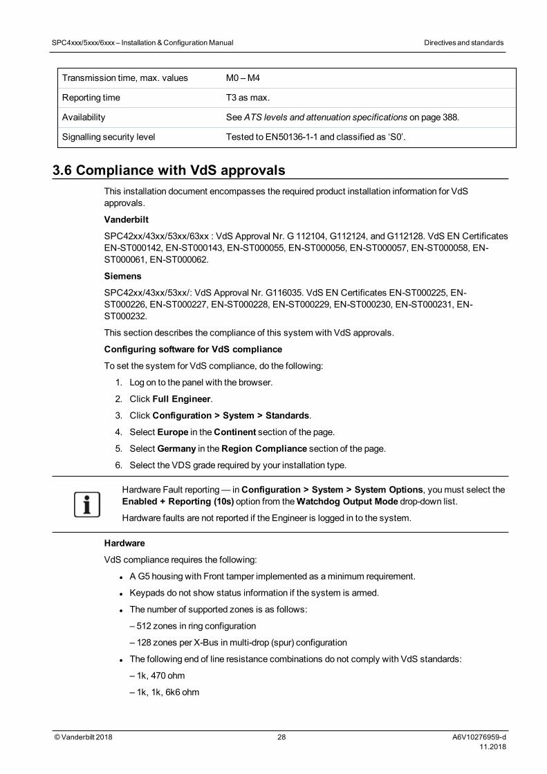
To comply with NF and A2P installation regulations, this housingmust be sealed by affixing theaccompanying Tamper Label after installation.
3.7.1 Compliance with NF and A2P approvals including CYBER requirements
To comply with the NF & A2P and CYBER requirements, the HTTPWeb server must be disabledaccording to the following instructions.
The system configuration can only be done with the SPC Connect Pro tool via the USB socket of the SPCcontrol panel.
To disable the SPC panel web interface:
1. Enter programmingmode and select theCommunications option.
2. On theServices tab, uncheck theHTTP enabled box.
This will disable the SPC panel web interface.
SPC4xxx/5xxx/6xxx– Installation &ConfigurationManual Directivesand standards
© Vanderbilt 2018 29 A6V10276959-d11.2018
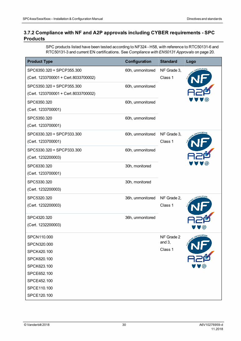
3.7.2 Compliance with NF and A2P approvals including CYBER requirements - SPCProducts
SPC products listed have been tested according to NF324 - H58, with reference to RTC50131-6 andRTC50131-3 and current EN certifications. SeeCompliance with EN50131 Approvals on page 20.
Product Type Configuration Standard Logo
SPC6350.320 + SPCP355.300
(Cert. 1233700001 + Cert.8033700002)
60h, unmonitored NF Grade 3,
Class 1
SPC5350.320 + SPCP355.300
(Cert. 1233700001 + Cert.8033700002)
60h, unmonitored
SPC6350.320
(Cert. 1233700001)
60h, unmonitored
SPC5350.320
(Cert. 1233700001)
60h, unmonitored
SPC6330.320 + SPCP333.300
(Cert. 1233700001)
60h, unmonitored NF Grade 3,
Class 1
SPC5330.320 + SPCP333.300
(Cert. 1232200003)
60h, unmonitored
SPC6330.320
(Cert. 1233700001)
30h, monitored
SPC5330.320
(Cert. 1232200003)
30h, monitored
SPC5320.320
(Cert. 1232200003)
36h, unmonitored NF Grade 2,
Class 1
SPC4320.320
(Cert. 1232200003)
36h, unmonitored
SPCN110.000
SPCN320.000
SPCK420.100
SPCK620.100
SPCK623.100
SPCE652.100
SPCE452.100
SPCE110.100
SPCE120.100
NF Grade 2and 3,
Class 1
SPC4xxx/5xxx/6xxx– Installation &ConfigurationManual Directivesand standards
© Vanderbilt 2018 30 A6V10276959-d11.2018
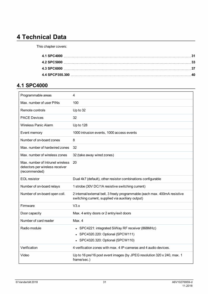
4 Technical DataThis chapter covers:
4.1 SPC4000 31
4.2 SPC5000 33
4.3 SPC6000 37
4.4 SPCP355.300 40
4.1 SPC4000Programmable areas 4
Max. number of user PINs 100
Remote controls Up to 32
PACE Devices 32
Wireless Panic Alarm Up to 128
Event memory 1000 intrusion events, 1000 access events
Number of on-board zones 8
Max. number of hardwired zones 32
Max. number of wireless zones 32 (take away wired zones)
Max. number of Intrunet wirelessdetectors per wireless receiver(recommended)
20
EOL resistor Dual 4k7 (default), other resistor combinations configurable
Number of on-board relays 1 strobe (30V DC/1A resistive switching current)
Number of on-board open coll. 2 internal/external bell, 3 freely programmable (eachmax. 400mA resistiveswitching current, supplied via auxiliary output)
Firmware V3.x
Door capacity Max. 4 entry doors or 2 entry/exit doors
Number of card reader Max. 4
Radiomodule l SPC4221: integrated SiWay RF receiver (868MHz)
l SPC4320.220: Optional (SPCW111)
l SPC4320.320: Optional (SPCW110)
Verification 4 verification zones with max. 4 IP-cameras and 4 audio devices.
Video Up to 16 pre/16 post event images (by JPEG resolution 320 x 240, max. 1frame/sec.)
©Vanderbilt 2018 31 A6V10276959-d11.2018
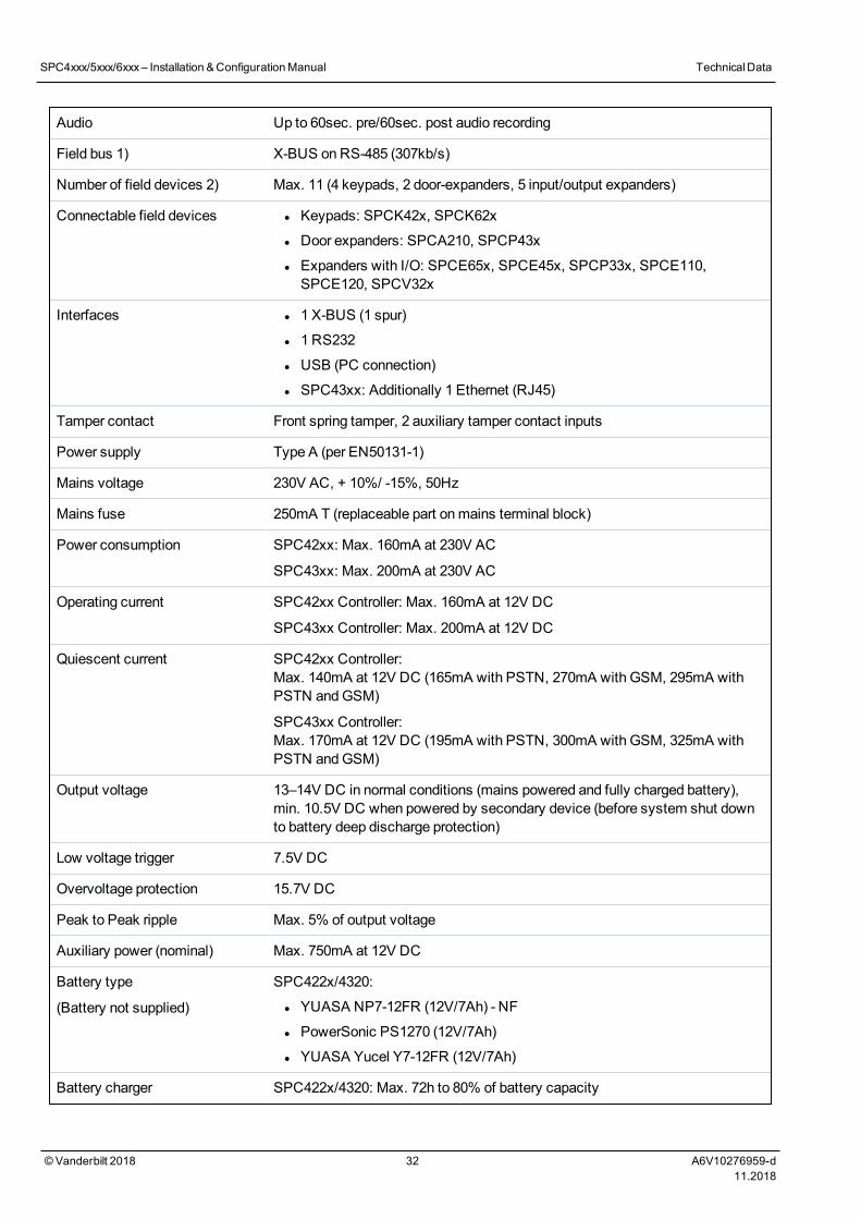
Audio Up to 60sec. pre/60sec. post audio recording
Field bus 1) X-BUS onRS-485 (307kb/s)
Number of field devices 2) Max. 11 (4 keypads, 2 door-expanders, 5 input/output expanders)
Connectable field devices l Keypads: SPCK42x, SPCK62x
l Door expanders: SPCA210, SPCP43x
l Expanders with I/O: SPCE65x, SPCE45x, SPCP33x, SPCE110,SPCE120, SPCV32x
Interfaces l 1 X-BUS (1 spur)
l 1 RS232
l USB (PC connection)
l SPC43xx: Additionally 1 Ethernet (RJ45)
Tamper contact Front spring tamper, 2 auxiliary tamper contact inputs
Power supply Type A (per EN50131-1)
Mains voltage 230V AC, + 10%/ -15%, 50Hz
Mains fuse 250mA T (replaceable part onmains terminal block)
Power consumption SPC42xx: Max. 160mA at 230V AC
SPC43xx: Max. 200mA at 230V AC
Operating current SPC42xx Controller: Max. 160mA at 12V DC
SPC43xx Controller: Max. 200mA at 12V DC
Quiescent current SPC42xx Controller:Max. 140mA at 12V DC (165mA with PSTN, 270mA with GSM, 295mA withPSTN andGSM)
SPC43xx Controller:Max. 170mA at 12V DC (195mA with PSTN, 300mA with GSM, 325mA withPSTN andGSM)
Output voltage 13–14V DC in normal conditions (mains powered and fully charged battery),min. 10.5V DC when powered by secondary device (before system shut downto battery deep discharge protection)
Low voltage trigger 7.5V DC
Overvoltage protection 15.7V DC
Peak to Peak ripple Max. 5% of output voltage
Auxiliary power (nominal) Max. 750mA at 12V DC
Battery type
(Battery not supplied)
SPC422x/4320:
l YUASA NP7-12FR (12V/7Ah) - NF
l PowerSonic PS1270 (12V/7Ah)
l YUASA Yucel Y7-12FR (12V/7Ah)
Battery charger SPC422x/4320: Max. 72h to 80% of battery capacity
SPC4xxx/5xxx/6xxx– Installation &ConfigurationManual TechnicalData
© Vanderbilt 2018 32 A6V10276959-d11.2018
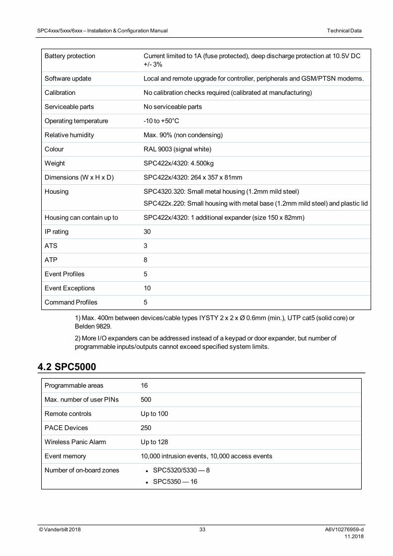
Battery protection Current limited to 1A (fuse protected), deep discharge protection at 10.5V DC+/- 3%
Software update Local and remote upgrade for controller, peripherals andGSM/PTSN modems.
Calibration No calibration checks required (calibrated at manufacturing)
Serviceable parts No serviceable parts
Operating temperature -10 to +50°C
Relative humidity Max. 90% (non condensing)
Colour RAL 9003 (signal white)
Weight SPC422x/4320: 4.500kg
Dimensions (W x H x D) SPC422x/4320: 264 x 357 x 81mm
Housing SPC4320.320: Small metal housing (1.2mmmild steel)
SPC422x.220: Small housing with metal base (1.2mmmild steel) and plastic lid
Housing can contain up to SPC422x/4320: 1 additional expander (size 150 x 82mm)
IP rating 30
ATS 3
ATP 8
Event Profiles 5
Event Exceptions 10
Command Profiles 5
1) Max. 400m between devices/cable types IYSTY 2 x 2 x Ø 0.6mm (min.), UTP cat5 (solid core) orBelden 9829.
2) More I/O expanders can be addressed instead of a keypad or door expander, but number ofprogrammable inputs/outputs cannot exceed specified system limits.
4.2 SPC5000Programmable areas 16
Max. number of user PINs 500
Remote controls Up to 100
PACE Devices 250
Wireless Panic Alarm Up to 128
Event memory 10,000 intrusion events, 10,000 access events
Number of on-board zones l SPC5320/5330— 8
l SPC5350—16
SPC4xxx/5xxx/6xxx– Installation &ConfigurationManual TechnicalData
© Vanderbilt 2018 33 A6V10276959-d11.2018
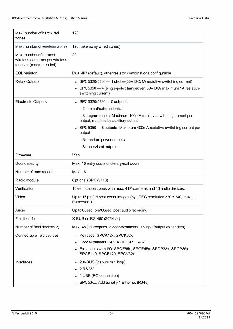
Max. number of hardwiredzones
128
Max. number of wireless zones 120 (take away wired zones)
Max. number of Intrunetwireless detectors per wirelessreceiver (recommended)
20
EOL resistor Dual 4k7 (default), other resistor combinations configurable
Relay Outputs l SPC5320/5330— 1 strobe (30V DC/1A resistive switching current)
l SPC5350—4 (single-pole changeover, 30V DC/ maximum 1A resistiveswitching current)
Electronic Outputs l SPC5320/5330— 5 outputs:
– 2 internal/external bells
– 3 programmable. Maximum 400mA resistive switching current peroutput, supplied by auxiliary output.
l SPC5350—8 outputs. Maximum 400mA resistive switching current peroutput
– 5 standard power outputs
– 3 supervised outputs
Firmware V3.x
Door capacity Max. 16 entry doors or 8 entry/exit doors
Number of card reader Max. 16
Radiomodule Optional (SPCW110)
Verification 16 verification zones with max. 4 IP-cameras and 16 audio devices.
Video Up to 16 pre/16 post event images (by JPEG resolution 320 x 240, max. 1frame/sec.)
Audio Up to 60sec. pre/60sec. post audio recording
Field bus 1) X-BUS onRS-485 (307kb/s)
Number of field devices 2) Max. 48 (16 keypads, 8 door-expanders, 16 input/output expanders)
Connectable field devices l Keypads: SPCK42x, SPCK62x
l Door expanders: SPCA210, SPCP43x
l Expanders with I/O: SPCE65x, SPCE45x, SPCP33x, SPCP35x,SPCE110, SPCE120, SPCV32x
Interfaces l 2 X-BUS (2 spurs or 1 loop)
l 2 RS232
l 1 USB (PC connection)
l SPC53xx: Additionally 1 Ethernet (RJ45)
SPC4xxx/5xxx/6xxx– Installation &ConfigurationManual TechnicalData
© Vanderbilt 2018 34 A6V10276959-d11.2018
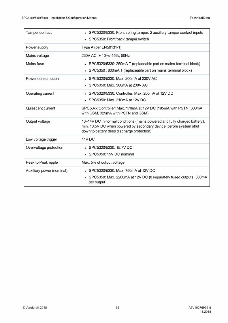
Tamper contact l SPC5320/5330: Front spring tamper, 2 auxiliary tamper contact inputs
l SPC5350: Front/back tamper switch
Power supply Type A (per EN50131-1)
Mains voltage 230V AC, + 10%/-15%, 50Hz
Mains fuse l SPC5320/5330: 250mA T (replaceable part onmains terminal block)
l SPC5350 : 800mA T (replaceable part onmains terminal block)
Power consumption l SPC5320/5330: Max. 200mA at 230V AC
l SPC5350: Max. 500mA at 230V AC
Operating current l SPC5320/5330: Controller: Max. 200mA at 12V DC
l SPC5350: Max. 210mA at 12V DC
Quiescent current SPC53xx Controller: Max. 170mA at 12V DC (195mA with PSTN, 300mAwith GSM, 325mA with PSTN andGSM)
Output voltage 13–14V DC in normal conditions (mains powered and fully charged battery),min. 10.5V DC when powered by secondary device (before system shutdown to battery deep discharge protection)
Low voltage trigger 11V DC
Overvoltage protection l SPC5320/5330: 15.7V DC
l SPC5350: 15V DC nominal
Peak to Peak ripple Max. 5% of output voltage
Auxiliary power (nominal) l SPC5320/5330: Max. 750mA at 12V DC
l SPC5350: Max. 2200mA at 12V DC (8 separately fused outputs, 300mAper output)
SPC4xxx/5xxx/6xxx– Installation &ConfigurationManual TechnicalData
© Vanderbilt 2018 35 A6V10276959-d11.2018
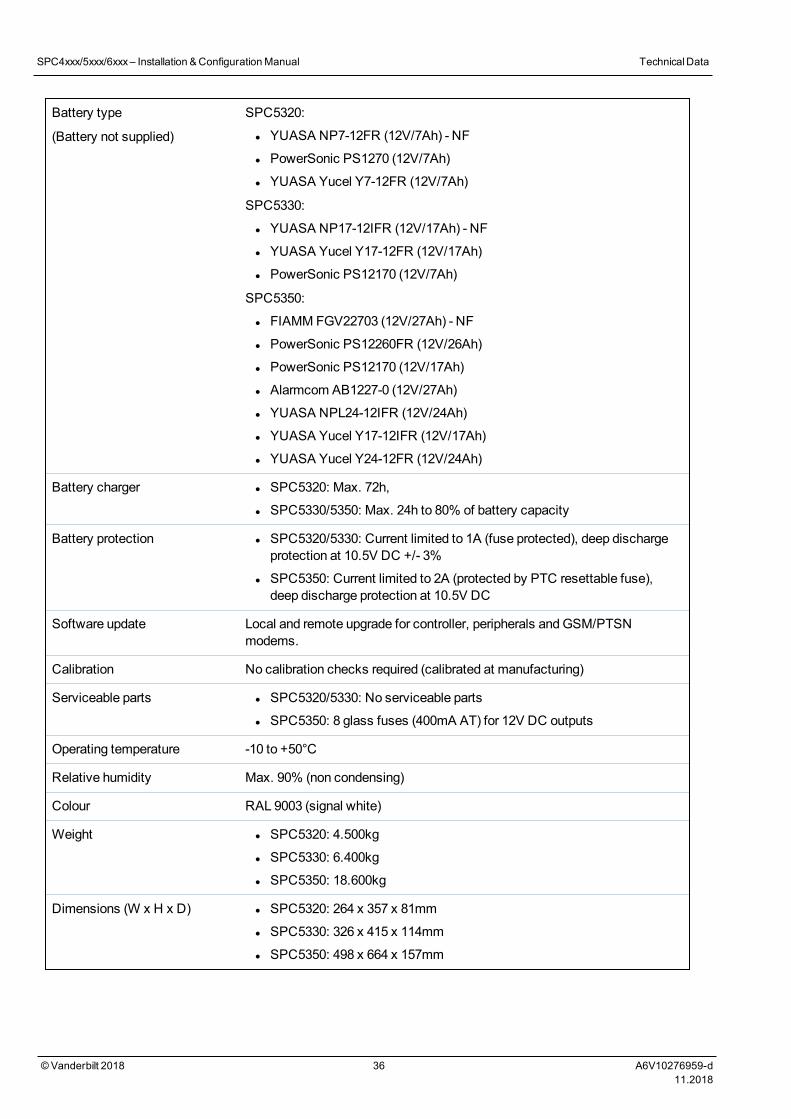
Battery type
(Battery not supplied)
SPC5320:
l YUASA NP7-12FR (12V/7Ah) - NF
l PowerSonic PS1270 (12V/7Ah)
l YUASA Yucel Y7-12FR (12V/7Ah)
SPC5330:
l YUASA NP17-12IFR (12V/17Ah) - NF
l YUASA Yucel Y17-12FR (12V/17Ah)
l PowerSonic PS12170 (12V/7Ah)
SPC5350:
l FIAMM FGV22703 (12V/27Ah) - NF
l PowerSonic PS12260FR (12V/26Ah)
l PowerSonic PS12170 (12V/17Ah)
l Alarmcom AB1227-0 (12V/27Ah)
l YUASA NPL24-12IFR (12V/24Ah)
l YUASA Yucel Y17-12IFR (12V/17Ah)
l YUASA Yucel Y24-12FR (12V/24Ah)
Battery charger l SPC5320: Max. 72h,
l SPC5330/5350: Max. 24h to 80% of battery capacity
Battery protection l SPC5320/5330: Current limited to 1A (fuse protected), deep dischargeprotection at 10.5V DC +/- 3%
l SPC5350: Current limited to 2A (protected by PTC resettable fuse),deep discharge protection at 10.5V DC
Software update Local and remote upgrade for controller, peripherals andGSM/PTSNmodems.
Calibration No calibration checks required (calibrated at manufacturing)
Serviceable parts l SPC5320/5330: No serviceable parts
l SPC5350: 8 glass fuses (400mA AT) for 12V DC outputs
Operating temperature -10 to +50°C
Relative humidity Max. 90% (non condensing)
Colour RAL 9003 (signal white)
Weight l SPC5320: 4.500kg
l SPC5330: 6.400kg
l SPC5350: 18.600kg
Dimensions (W x H x D) l SPC5320: 264 x 357 x 81mm
l SPC5330: 326 x 415 x 114mm
l SPC5350: 498 x 664 x 157mm
SPC4xxx/5xxx/6xxx– Installation &ConfigurationManual TechnicalData
© Vanderbilt 2018 36 A6V10276959-d11.2018
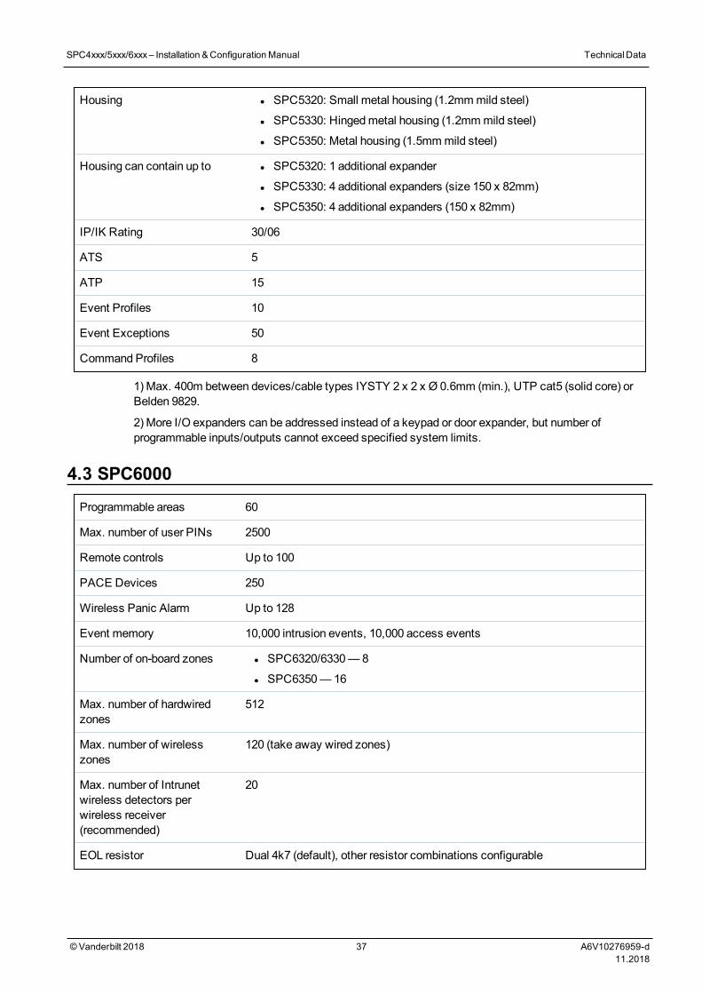
Housing l SPC5320: Small metal housing (1.2mmmild steel)
l SPC5330: Hingedmetal housing (1.2mmmild steel)
l SPC5350: Metal housing (1.5mmmild steel)
Housing can contain up to l SPC5320: 1 additional expander
l SPC5330: 4 additional expanders (size 150 x 82mm)
l SPC5350: 4 additional expanders (150 x 82mm)
IP/IK Rating 30/06
ATS 5
ATP 15
Event Profiles 10
Event Exceptions 50
Command Profiles 8
1) Max. 400m between devices/cable types IYSTY 2 x 2 x Ø 0.6mm (min.), UTP cat5 (solid core) orBelden 9829.
2) More I/O expanders can be addressed instead of a keypad or door expander, but number ofprogrammable inputs/outputs cannot exceed specified system limits.
4.3 SPC6000Programmable areas 60
Max. number of user PINs 2500
Remote controls Up to 100
PACE Devices 250
Wireless Panic Alarm Up to 128
Event memory 10,000 intrusion events, 10,000 access events
Number of on-board zones l SPC6320/6330— 8
l SPC6350—16
Max. number of hardwiredzones
512
Max. number of wirelesszones
120 (take away wired zones)
Max. number of Intrunetwireless detectors perwireless receiver(recommended)
20
EOL resistor Dual 4k7 (default), other resistor combinations configurable
SPC4xxx/5xxx/6xxx– Installation &ConfigurationManual TechnicalData
© Vanderbilt 2018 37 A6V10276959-d11.2018
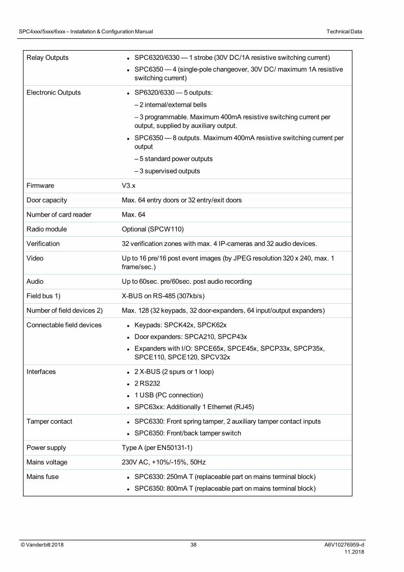
Relay Outputs l SPC6320/6330— 1 strobe (30V DC/1A resistive switching current)
l SPC6350—4 (single-pole changeover, 30V DC/ maximum 1A resistiveswitching current)
Electronic Outputs l SP6320/6330— 5 outputs:
– 2 internal/external bells
– 3 programmable. Maximum 400mA resistive switching current peroutput, supplied by auxiliary output.
l SPC6350—8 outputs. Maximum 400mA resistive switching current peroutput
– 5 standard power outputs
– 3 supervised outputs
Firmware V3.x
Door capacity Max. 64 entry doors or 32 entry/exit doors
Number of card reader Max. 64
Radiomodule Optional (SPCW110)
Verification 32 verification zones with max. 4 IP-cameras and 32 audio devices.
Video Up to 16 pre/16 post event images (by JPEG resolution 320 x 240, max. 1frame/sec.)
Audio Up to 60sec. pre/60sec. post audio recording
Field bus 1) X-BUS onRS-485 (307kb/s)
Number of field devices 2) Max. 128 (32 keypads, 32 door-expanders, 64 input/output expanders)
Connectable field devices l Keypads: SPCK42x, SPCK62x
l Door expanders: SPCA210, SPCP43x
l Expanders with I/O: SPCE65x, SPCE45x, SPCP33x, SPCP35x,SPCE110, SPCE120, SPCV32x
Interfaces l 2 X-BUS (2 spurs or 1 loop)
l 2 RS232
l 1 USB (PC connection)
l SPC63xx: Additionally 1 Ethernet (RJ45)
Tamper contact l SPC6330: Front spring tamper, 2 auxiliary tamper contact inputs
l SPC6350: Front/back tamper switch
Power supply Type A (per EN50131-1)
Mains voltage 230V AC, +10%/-15%, 50Hz
Mains fuse l SPC6330: 250mA T (replaceable part onmains terminal block)
l SPC6350: 800mA T (replaceable part onmains terminal block)
SPC4xxx/5xxx/6xxx– Installation &ConfigurationManual TechnicalData
© Vanderbilt 2018 38 A6V10276959-d11.2018
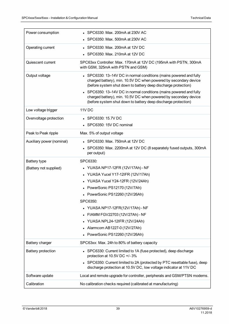
Power consumption l SPC6330: Max. 200mA at 230V AC
l SPC6350: Max. 500mA at 230V AC
Operating current l SPC6330: Max. 200mA at 12V DC
l SPC6350: Max. 210mA at 12V DC
Quiescent current SPC63xx Controller: Max. 170mA at 12V DC (195mA with PSTN, 300mAwith GSM, 325mA with PSTN andGSM)
Output voltage l SPC6330: 13–14V DC in normal conditions (mains powered and fullycharged battery), min. 10.5V DC when powered by secondary device(before system shut down to battery deep discharge protection)
l SPC6350: 13–14V DC in normal conditions (mains powered and fullycharged battery), min. 10.5V DC when powered by secondary device(before system shut down to battery deep discharge protection)
Low voltage trigger 11V DC
Overvoltage protection l SPC6330: 15.7V DC
l SPC6350: 15V DC nominal
Peak to Peak ripple Max. 5% of output voltage
Auxiliary power (nominal) l SPC6330: Max. 750mA at 12V DC
l SPC6350: Max. 2200mA at 12V DC (8 separately fused outputs, 300mAper output)
Battery type
(Battery not supplied)
SPC6330:
l YUASA NP17-12FR (12V/17Ah) - NF
l YUASA Yucel Y17-12IFR (12V/17Ah)
l YUASA Yucel Y24-12FR (12V/24Ah)
l PowerSonic PS12170 (12V/7Ah)
l PowerSonic PS12260 (12V/26Ah)
SPC6350:
l YUASA NP17-12FR(12V/17Ah) - NF
l FIAMM FGV22703 (12V/27Ah) - NF
l YUASA NPL24-12IFR (12V/24Ah)
l Alarmcom AB1227-0 (12V/27Ah)
l PowerSonic PS12260 (12V/26Ah)
Battery charger SPC63xx: Max. 24h to 80% of battery capacity
Battery protection l SPC6330: Current limited to 1A (fuse protected), deep dischargeprotection at 10.5V DC +/- 3%
l SPC6350: Current limited to 2A (protected by PTC resettable fuse), deepdischarge protection at 10.5V DC, low voltage indicator at 11V DC
Software update Local and remote upgrade for controller, peripherals andGSM/PTSN modems.
Calibration No calibration checks required (calibrated at manufacturing)
SPC4xxx/5xxx/6xxx– Installation &ConfigurationManual TechnicalData
© Vanderbilt 2018 39 A6V10276959-d11.2018
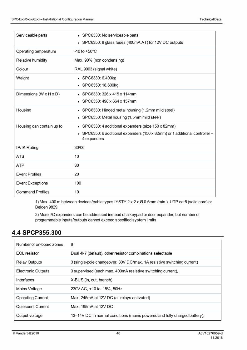
Serviceable parts l SPC6330: No serviceable parts
l SPC6350: 8 glass fuses (400mA AT) for 12V DC outputs
Operating temperature -10 to +50°C
Relative humidity Max. 90% (non condensing)
Colour RAL 9003 (signal white)
Weight l SPC6330: 6.400kg
l SPC6350: 18.600kg
Dimensions (W x H x D) l SPC6330: 326 x 415 x 114mm
l SPC6350: 498 x 664 x 157mm
Housing l SPC6330: Hingedmetal housing (1.2mmmild steel)
l SPC6350: Metal housing (1.5mmmild steel)
Housing can contain up to l SPC6330: 4 additional expanders (size 150 x 82mm)
l SPC6350: 6 additional expanders (150 x 82mm) or 1 additional controller +4 expanders
IP/IK Rating 30/06
ATS 10
ATP 30
Event Profiles 20
Event Exceptions 100
Command Profiles 10
1) Max. 400m between devices/cable types IYSTY 2 x 2 x Ø 0.6mm (min.), UTP cat5 (solid core) orBelden 9829.
2) More I/O expanders can be addressed instead of a keypad or door expander, but number ofprogrammable inputs/outputs cannot exceed specified system limits.
4.4 SPCP355.300Number of on-board zones 8
EOL resistor Dual 4k7 (default), other resistor combinations selectable
Relay Outputs 3 (single-pole changeover, 30V DC/max. 1A resistive switching current)
Electronic Outputs 3 supervised (eachmax. 400mA resistive switching current),
Interfaces X-BUS (in, out, branch)
Mains Voltage 230V AC, +10 to -15%, 50Hz
Operating Current Max. 245mA at 12V DC (all relays activated)
Quiescent Current Max. 195mA at 12V DC
Output voltage 13–14V DC in normal conditions (mains powered and fully charged battery),
SPC4xxx/5xxx/6xxx– Installation &ConfigurationManual TechnicalData
© Vanderbilt 2018 40 A6V10276959-d11.2018
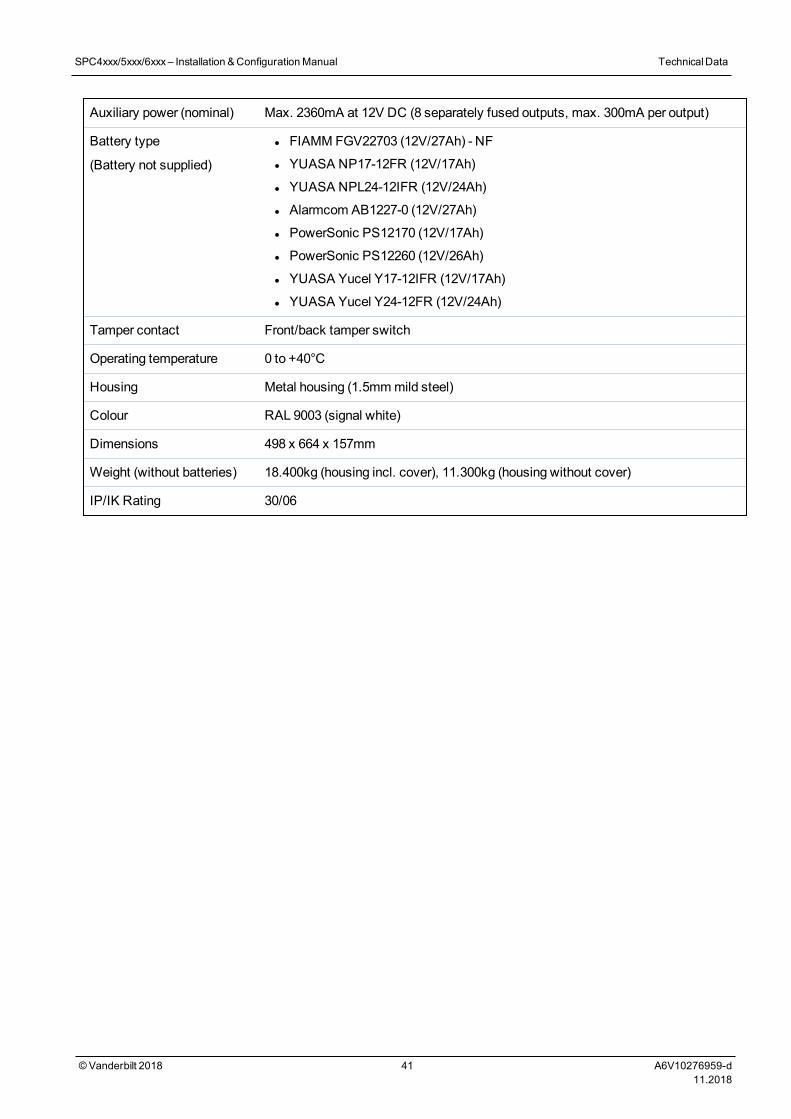
Auxiliary power (nominal) Max. 2360mA at 12V DC (8 separately fused outputs, max. 300mA per output)
Battery type
(Battery not supplied)
l FIAMM FGV22703 (12V/27Ah) - NF
l YUASA NP17-12FR (12V/17Ah)
l YUASA NPL24-12IFR (12V/24Ah)
l Alarmcom AB1227-0 (12V/27Ah)
l PowerSonic PS12170 (12V/17Ah)
l PowerSonic PS12260 (12V/26Ah)
l YUASA Yucel Y17-12IFR (12V/17Ah)
l YUASA Yucel Y24-12FR (12V/24Ah)
Tamper contact Front/back tamper switch
Operating temperature 0 to +40°C
Housing Metal housing (1.5mmmild steel)
Colour RAL 9003 (signal white)
Dimensions 498 x 664 x 157mm
Weight (without batteries) 18.400kg (housing incl. cover), 11.300kg (housing without cover)
IP/IK Rating 30/06
SPC4xxx/5xxx/6xxx– Installation &ConfigurationManual TechnicalData
© Vanderbilt 2018 41 A6V10276959-d11.2018
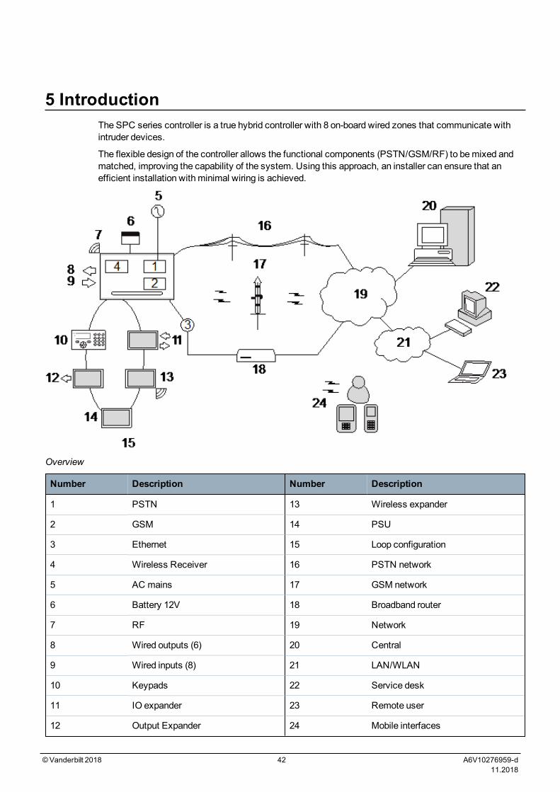
5 IntroductionThe SPC series controller is a true hybrid controller with 8 on-board wired zones that communicate withintruder devices.
The flexible design of the controller allows the functional components (PSTN/GSM/RF) to bemixed andmatched, improving the capability of the system. Using this approach, an installer can ensure that anefficient installation with minimal wiring is achieved.
Overview
Number Description Number Description
1 PSTN 13 Wireless expander
2 GSM 14 PSU
3 Ethernet 15 Loop configuration
4 Wireless Receiver 16 PSTN network
5 AC mains 17 GSM network
6 Battery 12V 18 Broadband router
7 RF 19 Network
8 Wired outputs (6) 20 Central
9 Wired inputs (8) 21 LAN/WLAN
10 Keypads 22 Service desk
11 IO expander 23 Remote user
12 Output Expander 24 Mobile interfaces
©Vanderbilt 2018 42 A6V10276959-d11.2018

6 Mounting system equipmentThis chapter covers:
6.1 Mounting a G2 housing 43
6.2 Mounting a G3 housing 44
6.3 Mounting a G5 housing 51
6.4 Mounting a keypad 56
6.5 Mounting an expander 56
6.1 Mounting a G2 housingThe SPC G2 housing is supplied with ametallic or plastic cover. The cover is attached to the base of thehousing by 2 securing screws located on the top and bottom of the front cover.
To open the housing, remove both screws with the appropriate screwdriver and lift the cover directly fromthe base.
TheG2 housing contains the controller PCB (Printed Circuit Board) mounted on 4 support pillars. Anoptional input/output module can bemounted directly beneath the controller PCB. A battery with capacityof 7Ahmax. can be accommodated below the controller.
An optional external antennamust be fitted to housings with metallic lid if the wireless functionality isrequired. If an antenna is fitted to the unit, it must be enabled in the firmware.
The SPC G2 housing provides 3 screw holes for wall mounting the unit.
To wall mount the housing, remove the cover and locate the initial fixing screw hole at the top of thehousing. Mark the position of this screw hole on the desired location on the wall and drill the initial screwhole. Screw the unit to the wall andmark the position of the bottom 2 screw hole positions with the unitvertically aligned.
Screws with a 4–5mm shank, aminimum head diameter of 8mm and aminimum length of 40mm arerecommended for mounting the housing. Additional expansion plugs or fixings may be required dependingon the construction of the wall.
©Vanderbilt 2018 43 A6V10276959-d11.2018
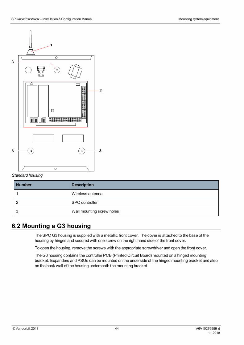
Standard housing
Number Description
1 Wireless antenna
2 SPC controller
3 Wall mounting screw holes
6.2 Mounting a G3 housingThe SPC G3 housing is supplied with ametallic front cover. The cover is attached to the base of thehousing by hinges and secured with one screw on the right hand side of the front cover.
To open the housing, remove the screws with the appropriate screwdriver and open the front cover.
TheG3 housing contains the controller PCB (Printed Circuit Board) mounted on a hingedmountingbracket. Expanders and PSUs can bemounted on the underside of the hingedmounting bracket and alsoon the back wall of the housing underneath themounting bracket.
SPC4xxx/5xxx/6xxx– Installation &ConfigurationManual Mounting system equipment
© Vanderbilt 2018 44 A6V10276959-d11.2018
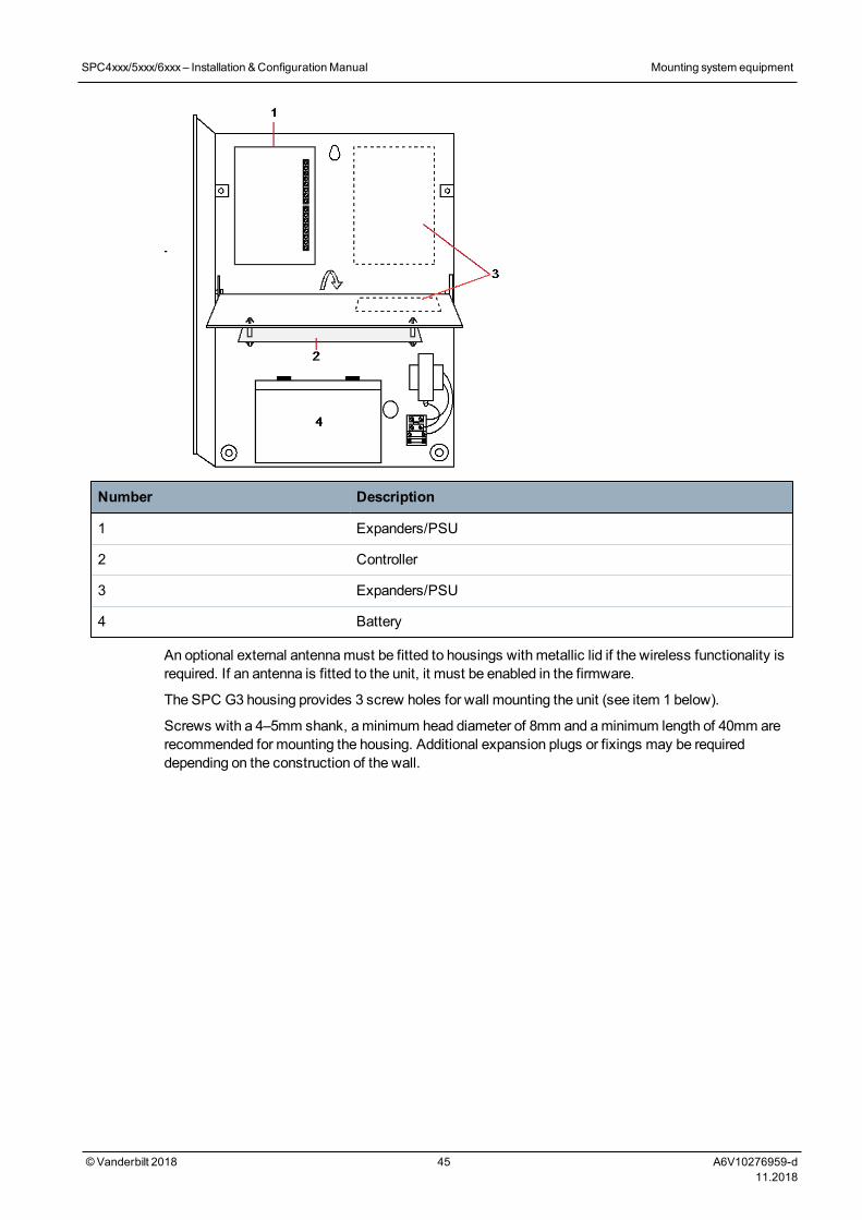
Number Description
1 Expanders/PSU
2 Controller
3 Expanders/PSU
4 Battery
An optional external antennamust be fitted to housings with metallic lid if the wireless functionality isrequired. If an antenna is fitted to the unit, it must be enabled in the firmware.
The SPC G3 housing provides 3 screw holes for wall mounting the unit (see item 1 below).
Screws with a 4–5mm shank, aminimum head diameter of 8mm and aminimum length of 40mm arerecommended for mounting the housing. Additional expansion plugs or fixings may be requireddepending on the construction of the wall.
SPC4xxx/5xxx/6xxx– Installation &ConfigurationManual Mounting system equipment
© Vanderbilt 2018 45 A6V10276959-d11.2018
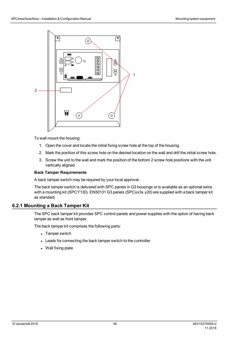
Towall mount the housing:
1. Open the cover and locate the initial fixing screw hole at the top of the housing.
2. Mark the position of this screw hole on the desired location on the wall and drill the initial screw hole.
3. Screw the unit to the wall andmark the position of the bottom 2 screw hole positions with the unitvertically aligned.
Back Tamper Requirements
A back tamper switchmay be required by your local approval.
The back tamper switch is delivered with SPC panels in G3 housings or is available as an optional extrawith amounting kit (SPCY130). EN50131G3 panels (SPCxx3x.x20) are supplied with a back tamper kitas standard.
6.2.1 Mounting a Back Tamper KitThe SPC back tamper kit provides SPC control panels and power supplies with the option of having backtamper as well as front tamper.
The back tamper kit comprises the following parts:
l Tamper switch
l Leads for connecting the back tamper switch to the controller
l Wall fixing plate
SPC4xxx/5xxx/6xxx– Installation &ConfigurationManual Mounting system equipment
© Vanderbilt 2018 46 A6V10276959-d11.2018
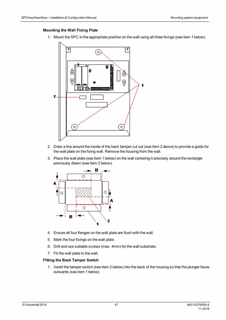
Mounting the Wall Fixing Plate
1. Mount the SPC in the appropriate position on the wall using all three fixings (see item 1 below).
2. Draw a line around the inside of the back tamper cut out (see item 2 above) to provide a guide forthe wall plate on the fixing wall. Remove the housing from the wall.
3. Place the wall plate (see item 1 below) on the wall centering it precisely around the rectanglepreviously drawn (see item 2 below).
4. Ensure all four flanges on the wall plate are flush with the wall.
5. Mark the four fixings on the wall plate.
6. Drill and use suitable screws (max. 4mm) for the wall substrate.
7. Fit the wall plate to the wall.
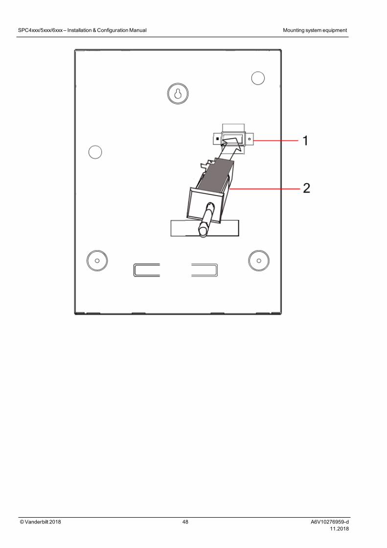
Fitting the Back Tamper Switch
1. Insert the tamper switch (see item 2 below) into the back of the housing so that the plunger facesoutwards (see item 1 below).
SPC4xxx/5xxx/6xxx– Installation &ConfigurationManual Mounting system equipment
© Vanderbilt 2018 47 A6V10276959-d11.2018
SPC4xxx/5xxx/6xxx– Installation &ConfigurationManual Mounting system equipment
© Vanderbilt 2018 48 A6V10276959-d11.2018
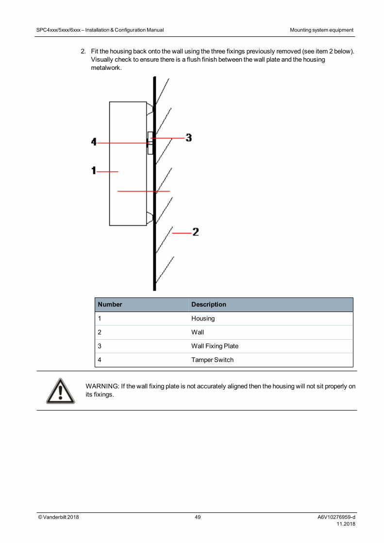
2. Fit the housing back onto the wall using the three fixings previously removed (see item 2 below).Visually check to ensure there is a flush finish between the wall plate and the housingmetalwork.
Number Description
1 Housing
2 Wall
3 Wall Fixing Plate
4 Tamper Switch
WARNING: If the wall fixing plate is not accurately aligned then the housing will not sit properly onits fixings.
SPC4xxx/5xxx/6xxx– Installation &ConfigurationManual Mounting system equipment
© Vanderbilt 2018 49 A6V10276959-d11.2018
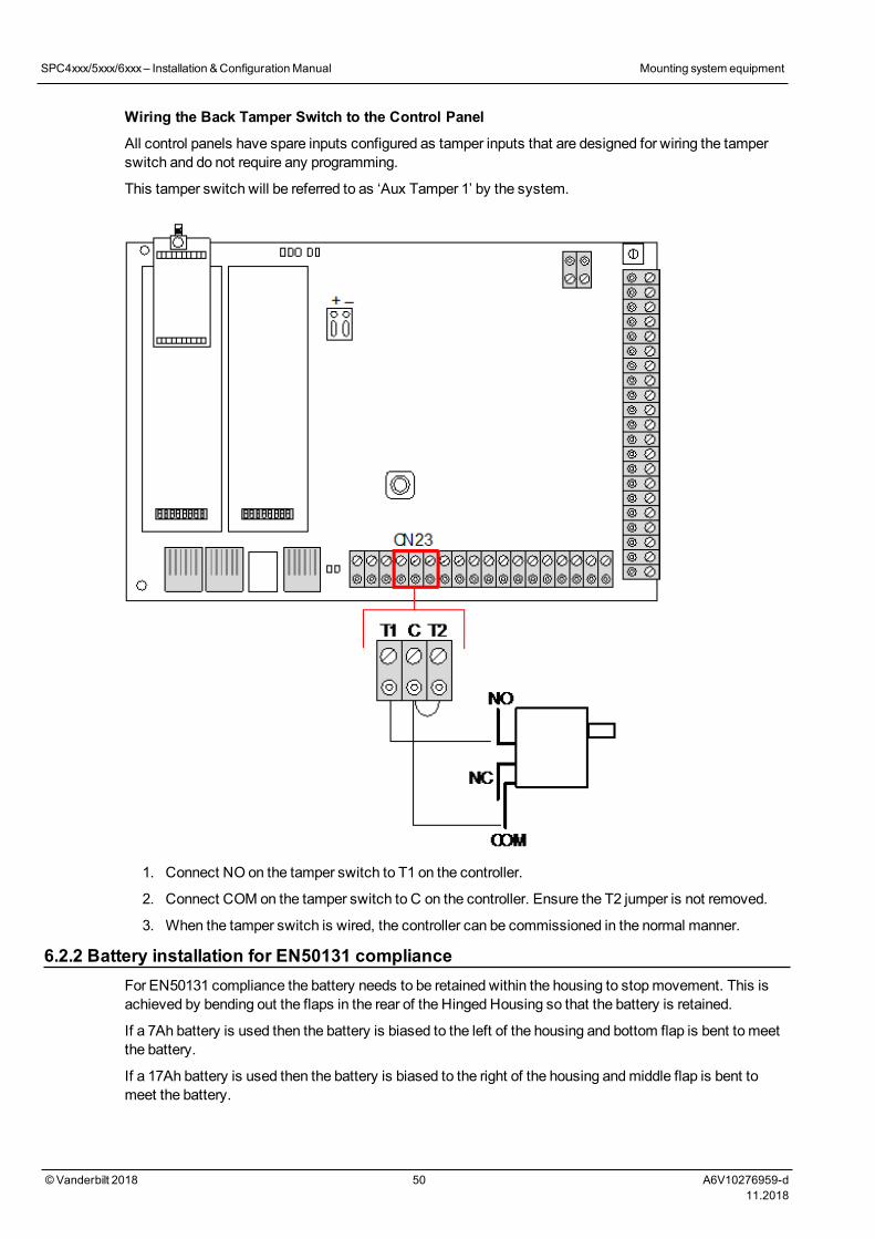
Wiring the Back Tamper Switch to the Control Panel
All control panels have spare inputs configured as tamper inputs that are designed for wiring the tamperswitch and do not require any programming.
This tamper switch will be referred to as ‘Aux Tamper 1’ by the system.
1. Connect NO on the tamper switch to T1 on the controller.
2. Connect COM on the tamper switch to C on the controller. Ensure the T2 jumper is not removed.
3. When the tamper switch is wired, the controller can be commissioned in the normal manner.
6.2.2 Battery installation for EN50131 complianceFor EN50131 compliance the battery needs to be retained within the housing to stopmovement. This isachieved by bending out the flaps in the rear of the Hinged Housing so that the battery is retained.
If a 7Ah battery is used then the battery is biased to the left of the housing and bottom flap is bent to meetthe battery.
If a 17Ah battery is used then the battery is biased to the right of the housing andmiddle flap is bent tomeet the battery.
SPC4xxx/5xxx/6xxx– Installation &ConfigurationManual Mounting system equipment
© Vanderbilt 2018 50 A6V10276959-d11.2018
The battery flaps should be bent carefully as not to damage the battery. If any signs of a damagedbattery exist or any leakage of the electrolyte then the battery should be discarded as per thecurrent regulations and a new battery fitted.
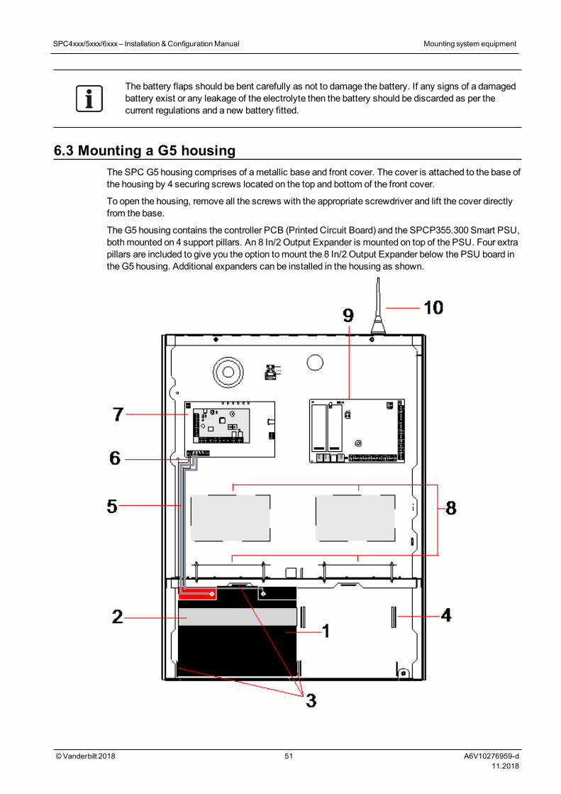
6.3 Mounting a G5 housingThe SPC G5 housing comprises of ametallic base and front cover. The cover is attached to the base ofthe housing by 4 securing screws located on the top and bottom of the front cover.
To open the housing, remove all the screws with the appropriate screwdriver and lift the cover directlyfrom the base.
TheG5 housing contains the controller PCB (Printed Circuit Board) and the SPCP355.300 Smart PSU,bothmounted on 4 support pillars. An 8 In/2 Output Expander is mounted on top of the PSU. Four extrapillars are included to give you the option tomount the 8 In/2 Output Expander below the PSU board inthe G5 housing. Additional expanders can be installed in the housing as shown.
SPC4xxx/5xxx/6xxx– Installation &ConfigurationManual Mounting system equipment
© Vanderbilt 2018 51 A6V10276959-d11.2018
Number Description Number Description
1 Battery 6 Battery temperature leads
2 Battery strap 7 PSU
3 Fixing tabs 8 Optional expander positions
4 Strap holes 9 Controller
5 Battery leads 10 Antenna
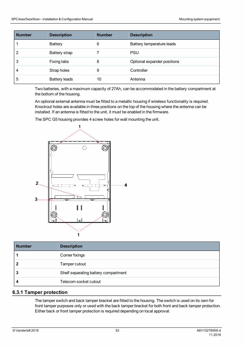
Two batteries, with amaximum capacity of 27Ah, can be accommodated in the battery compartment atthe bottom of the housing.
An optional external antennamust be fitted to ametallic housing if wireless functionality is required.Knockout holes are available in three positions on the top of the housing where the antenna can beinstalled. If an antenna is fitted to the unit, it must be enabled in the firmware.
The SPC G5 housing provides 4 screw holes for wall mounting the unit.
Number Description
1 Corner fixings
2 Tamper cutout
3 Shelf separating battery compartment
4 Telecom socket cutout
6.3.1 Tamper protectionThe tamper switch and back tamper bracket are fitted to the housing. The switch is used on its own forfront tamper purposes only or used with the back tamper bracket for both front and back tamper protection.Either back or front tamper protection is required depending on local approval.
SPC4xxx/5xxx/6xxx– Installation &ConfigurationManual Mounting system equipment
© Vanderbilt 2018 52 A6V10276959-d11.2018
The tamper bracket is held firmly in place with a securing screw. Remember to remove this screw ifcommissioning the system for back tamper protection. Do not remove this screw if using front tamperonly.
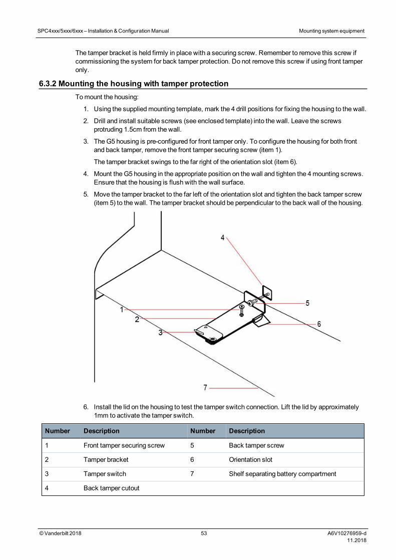
6.3.2 Mounting the housing with tamper protectionTomount the housing:
1. Using the suppliedmounting template, mark the 4 drill positions for fixing the housing to the wall.
2. Drill and install suitable screws (see enclosed template) into the wall. Leave the screwsprotruding 1.5cm from the wall.
3. TheG5 housing is pre-configured for front tamper only. To configure the housing for both frontand back tamper, remove the front tamper securing screw (item 1).
The tamper bracket swings to the far right of the orientation slot (item 6).
4. Mount the G5 housing in the appropriate position on the wall and tighten the 4mounting screws.Ensure that the housing is flush with the wall surface.
5. Move the tamper bracket to the far left of the orientation slot and tighten the back tamper screw(item 5) to the wall. The tamper bracket should be perpendicular to the back wall of the housing.
6. Install the lid on the housing to test the tamper switch connection. Lift the lid by approximately1mm to activate the tamper switch.
Number Description Number Description
1 Front tamper securing screw 5 Back tamper screw
2 Tamper bracket 6 Orientation slot
3 Tamper switch 7 Shelf separating battery compartment
4 Back tamper cutout
SPC4xxx/5xxx/6xxx– Installation &ConfigurationManual Mounting system equipment
© Vanderbilt 2018 53 A6V10276959-d11.2018
WARNING: If the back tamper screw is not secure against the wall, then tamper protection iscompromised. If the housing is removed from the wall or displaced, the back tamper contact needs tobe tested again for proper functionality and re-adjusted if required.
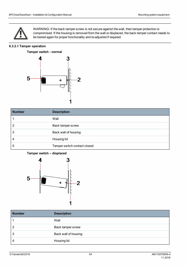
6.3.2.1 Tamper operation
Tamper switch - normal
Number Description
1 Wall
2 Back tamper screw
3 Back wall of housing
4 Housing lid
5 Tamper switch contact closed
Tamper switch – displaced
Number Description
1 Wall
2 Back tamper screw
3 Back wall of housing
4 Housing lid
SPC4xxx/5xxx/6xxx– Installation &ConfigurationManual Mounting system equipment
© Vanderbilt 2018 54 A6V10276959-d11.2018
Number Description
5 Tamper switch contact open
If the housing is removed from the wall or displaced, the tamper bracket screw is no longer secureagainst the wall, causing the bracket to pivot. This in turn causes the tamper switch to swivel awayfrom the lid and opens the switch contact.
WARNING: If the tamper bracket screw is not secure against the wall, then tamper protection iscompromised.
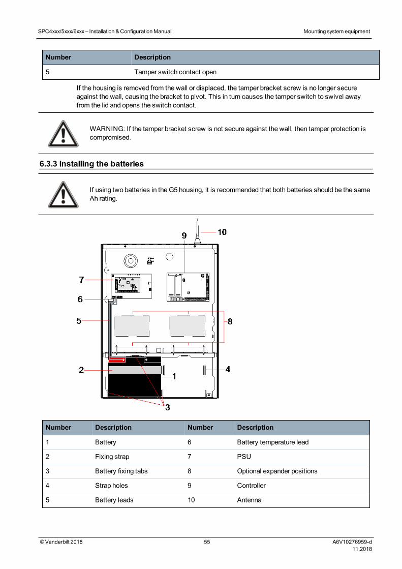
6.3.3 Installing the batteries
If using two batteries in the G5 housing, it is recommended that both batteries should be the sameAh rating.
Number Description Number Description
1 Battery 6 Battery temperature lead
2 Fixing strap 7 PSU
3 Battery fixing tabs 8 Optional expander positions
4 Strap holes 9 Controller
5 Battery leads 10 Antenna
SPC4xxx/5xxx/6xxx– Installation &ConfigurationManual Mounting system equipment
© Vanderbilt 2018 55 A6V10276959-d11.2018

To install the batteries:
1. Place the batteries into the battery compartment.
2. Press themetal tabs at the top and either side of the batteries in towards the batteries.
3. Secure each battery to the housing using a battery strap. Ensure that the strap is thread through thebattery strap holes at the back of the battery compartment and around the battery, with the two endsof the strap at the front of the battery.
4. Fasten the two ends of the strap firmly using the Velcro strip. Ensure that the strap is tight aroundthe battery.
5. Connect one end of the battery leads to the battery + and - terminals and the other ends to thecorresponding + and - inputs of the PSU.
CAUTION: When installing the battery, always connect the positive (+) lead tothe battery first before connecting the negative (-) lead. When removing thebattery, always remove the negative (-) lead first before removing the positive (+).
6. Connect the loose ends of the attached temperaturemonitoring leads to the battery temperaturemonitoring inputs on the PSU.
6.4 Mounting a keypadSee the corresponding installation instruction.
Installation guides are available at http://www.spcsupportinfo.com/connectspcdata/userdata.
6.5 Mounting an expanderSee the corresponding installation instruction.
Installation guides are available at http://www.spcsupportinfo.com/connectspcdata/userdata.
SPC4xxx/5xxx/6xxx– Installation &ConfigurationManual Mounting system equipment
© Vanderbilt 2018 56 A6V10276959-d11.2018
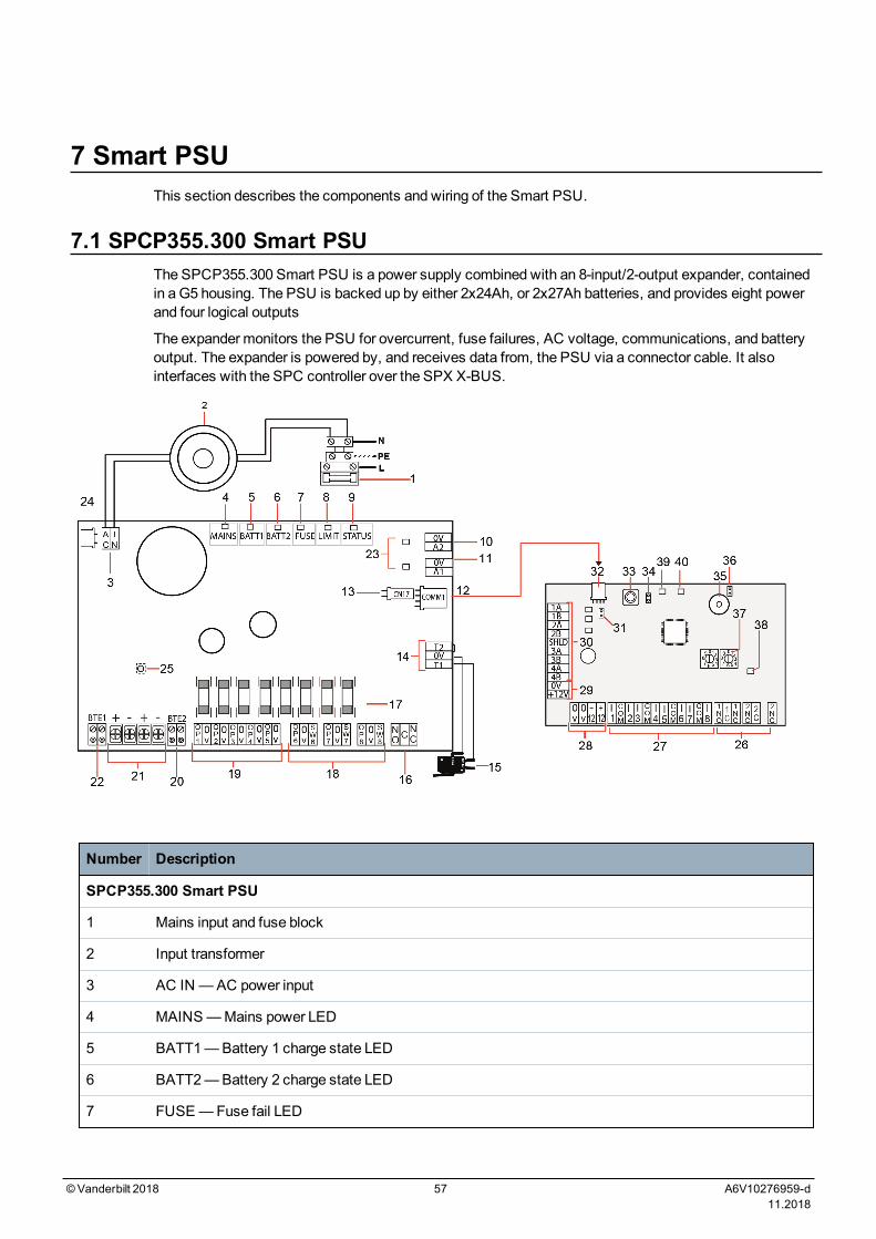
7 Smart PSUThis section describes the components and wiring of the Smart PSU.
7.1 SPCP355.300 Smart PSUThe SPCP355.300 Smart PSU is a power supply combined with an 8-input/2-output expander, containedin a G5 housing. The PSU is backed up by either 2x24Ah, or 2x27Ah batteries, and provides eight powerand four logical outputs
The expander monitors the PSU for overcurrent, fuse failures, AC voltage, communications, and batteryoutput. The expander is powered by, and receives data from, the PSU via a connector cable. It alsointerfaces with the SPC controller over the SPX X-BUS.
Number Description
SPCP355.300 Smart PSU
1 Mains input and fuse block
2 Input transformer
3 AC IN —AC power input
4 MAINS—Mains power LED
5 BATT1—Battery 1 charge state LED
6 BATT2—Battery 2 charge state LED
7 FUSE—Fuse fail LED
©Vanderbilt 2018 57 A6V10276959-d11.2018
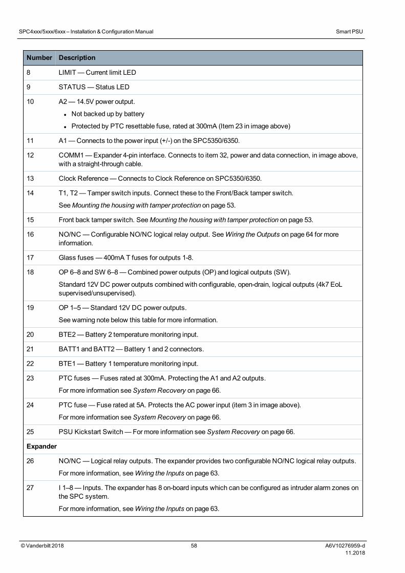
Number Description
8 LIMIT—Current limit LED
9 STATUS—Status LED
10 A2—14.5V power output.
l Not backed up by battery
l Protected by PTC resettable fuse, rated at 300mA (Item 23 in image above)
11 A1—Connects to the power input (+/-) on the SPC5350/6350.
12 COMM1—Expander 4-pin interface. Connects to item 32, power and data connection, in image above,with a straight-through cable.
13 Clock Reference—Connects to Clock Reference on SPC5350/6350.
14 T1, T2—Tamper switch inputs. Connect these to the Front/Back tamper switch.
SeeMounting the housing with tamper protection on page 53.
15 Front back tamper switch. SeeMounting the housing with tamper protection on page 53.
16 NO/NC —Configurable NO/NC logical relay output. SeeWiring the Outputs on page 64 for moreinformation.
17 Glass fuses — 400mA T fuses for outputs 1-8.
18 OP 6–8 and SW 6–8—Combined power outputs (OP) and logical outputs (SW).
Standard 12V DC power outputs combined with configurable, open-drain, logical outputs (4k7 EoLsupervised/unsupervised).
19 OP 1–5—Standard 12V DC power outputs.
See warning note below this table for more information.
20 BTE2—Battery 2 temperaturemonitoring input.
21 BATT1 and BATT2—Battery 1 and 2 connectors.
22 BTE1—Battery 1 temperaturemonitoring input.
23 PTC fuses —Fuses rated at 300mA. Protecting the A1 and A2 outputs.
For more information seeSystem Recovery on page 66.
24 PTC fuse—Fuse rated at 5A. Protects the AC power input (item 3 in image above).
For more information seeSystem Recovery on page 66.
25 PSU Kickstart Switch—Formore information seeSystem Recovery on page 66.
Expander
26 NO/NC —Logical relay outputs. The expander provides two configurable NO/NC logical relay outputs.
For more information, seeWiring the Inputs on page 63.
27 I 1–8— Inputs. The expander has 8 on-board inputs which can be configured as intruder alarm zones onthe SPC system.
For more information, seeWiring the Inputs on page 63.
SPC4xxx/5xxx/6xxx– Installation &ConfigurationManual Smart PSU
©Vanderbilt 2018 58 A6V10276959-d11.2018
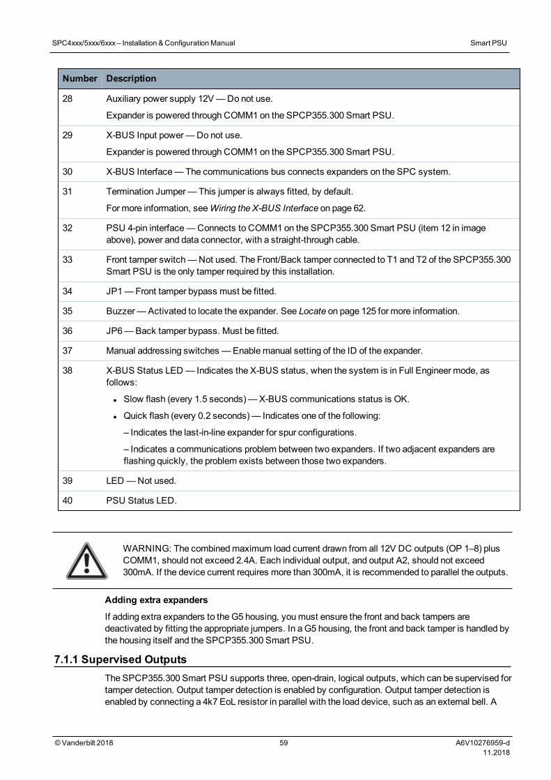
Number Description
28 Auxiliary power supply 12V—Do not use.
Expander is powered through COMM1 on the SPCP355.300 Smart PSU.
29 X-BUS Input power—Do not use.
Expander is powered through COMM1 on the SPCP355.300 Smart PSU.
30 X-BUS Interface—The communications bus connects expanders on the SPC system.
31 Termination Jumper—This jumper is always fitted, by default.
For more information, seeWiring the X-BUS Interface on page 62.
32 PSU 4-pin interface—Connects to COMM1 on the SPCP355.300 Smart PSU (item 12 in imageabove), power and data connector, with a straight-through cable.
33 Front tamper switch—Not used. The Front/Back tamper connected to T1 and T2 of the SPCP355.300Smart PSU is the only tamper required by this installation.
34 JP1—Front tamper bypass must be fitted.
35 Buzzer—Activated to locate the expander. See Locate on page 125 for more information.
36 JP6—Back tamper bypass. Must be fitted.
37 Manual addressing switches —Enablemanual setting of the ID of the expander.
38 X-BUS Status LED — Indicates the X-BUS status, when the system is in Full Engineer mode, asfollows:
l Slow flash (every 1.5 seconds)—X-BUS communications status is OK.
l Quick flash (every 0.2 seconds)— Indicates one of the following:
– Indicates the last-in-line expander for spur configurations.
– Indicates a communications problem between two expanders. If two adjacent expanders areflashing quickly, the problem exists between those two expanders.
39 LED —Not used.
40 PSU Status LED.
WARNING: The combinedmaximum load current drawn from all 12V DC outputs (OP 1–8) plusCOMM1, should not exceed 2.4A. Each individual output, and output A2, should not exceed300mA. If the device current requires more than 300mA, it is recommended to parallel the outputs.
Adding extra expanders
If adding extra expanders to the G5 housing, youmust ensure the front and back tampers aredeactivated by fitting the appropriate jumpers. In a G5 housing, the front and back tamper is handled bythe housing itself and the SPCP355.300 Smart PSU.
7.1.1 Supervised OutputsThe SPCP355.300 Smart PSU supports three, open-drain, logical outputs, which can be supervised fortamper detection. Output tamper detection is enabled by configuration. Output tamper detection isenabled by connecting a 4k7 EoL resistor in parallel with the load device, such as an external bell. A
SPC4xxx/5xxx/6xxx– Installation &ConfigurationManual Smart PSU
©Vanderbilt 2018 59 A6V10276959-d11.2018
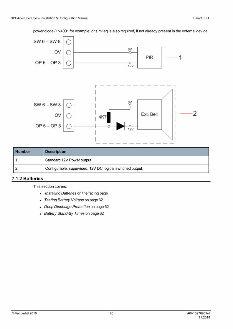
power diode (1N4001 for example, or similar) is also required, if not already present in the external device.
Number Description
1 Standard 12V Power output
2 Configurable, supervised, 12V DC logical switched output.
7.1.2 BatteriesThis section covers:
l Installing Batteries on the facing page
l Testing Battery Voltage on page 62
l DeepDischarge Protection on page 62
l Battery Stand-By Times on page 62
SPC4xxx/5xxx/6xxx– Installation &ConfigurationManual Smart PSU
©Vanderbilt 2018 60 A6V10276959-d11.2018
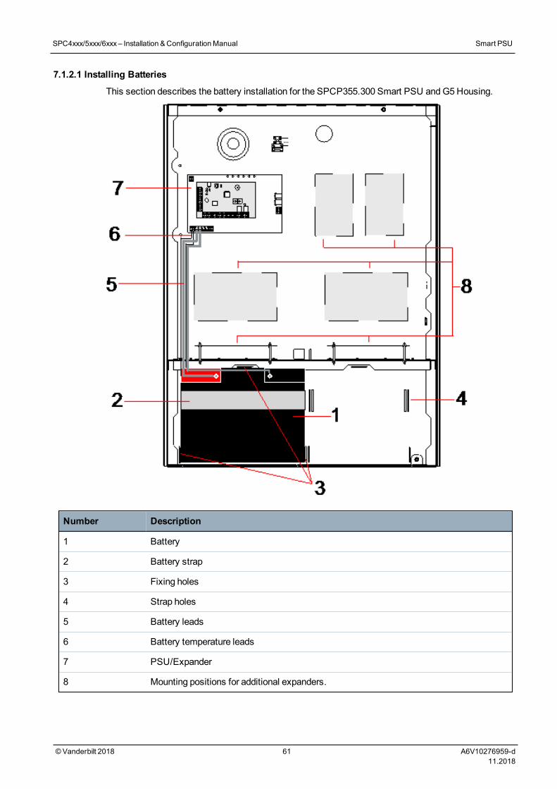
7.1.2.1 Installing Batteries
This section describes the battery installation for the SPCP355.300 Smart PSU andG5Housing.
Number Description
1 Battery
2 Battery strap
3 Fixing holes
4 Strap holes
5 Battery leads
6 Battery temperature leads
7 PSU/Expander
8 Mounting positions for additional expanders.
SPC4xxx/5xxx/6xxx– Installation &ConfigurationManual Smart PSU
©Vanderbilt 2018 61 A6V10276959-d11.2018
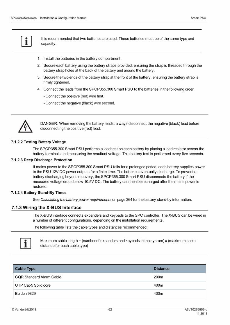
It is recommended that two batteries are used. These batteries must be of the same type andcapacity.
1. Install the batteries in the battery compartment.
2. Secure each battery using the battery straps provided, ensuring the strap is threaded through thebattery strap holes at the back of the battery and around the battery.
3. Secure the two ends of the battery strap at the front of the battery, ensuring the battery strap isfirmly tightened.
4. Connect the leads from the SPCP355.300 Smart PSU to the batteries in the following order:
- Connect the positive (red) wire first.
- Connect the negative (black) wire second.
DANGER: When removing the battery leads, always disconnect the negative (black) lead beforedisconnecting the positive (red) lead.
7.1.2.2 Testing Battery Voltage
The SPCP355.300 Smart PSU performs a load test on each battery by placing a load resistor across thebattery terminals andmeasuring the resultant voltage. This battery test is performed every five seconds.
7.1.2.3 Deep Discharge Protection
If mains power to the SPCP355.300 Smart PSU fails for a prolonged period, each battery supplies powerto the PSU 12V DC power outputs for a finite time. The batteries eventually discharge. To prevent abattery discharging beyond recovery, the SPCP355.300 Smart PSU disconnects the battery if themeasured voltage drops below 10.5V DC. The battery can then be recharged after themains power isrestored.
7.1.2.4 Battery Stand-By Times
SeeCalculating the battery power requirements on page 364 for the battery stand-by information.
7.1.3 Wiring the X-BUS InterfaceThe X-BUS interface connects expanders and keypads to the SPC controller. The X-BUS can be wired ina number of different configurations, depending on the installation requirements.
The following table lists the cable types and distances recommended:
Maximum cable length = (number of expanders and keypads in the system) x (maximum cabledistance for each cable type)
Cable Type Distance
CQR Standard Alarm Cable 200m
UTP Cat-5 Solid core 400m
Belden 9829 400m
SPC4xxx/5xxx/6xxx– Installation &ConfigurationManual Smart PSU
©Vanderbilt 2018 62 A6V10276959-d11.2018
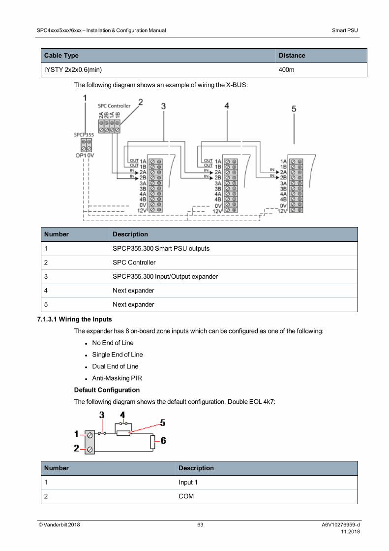
Cable Type Distance
IYSTY 2x2x0.6(min) 400m
The following diagram shows an example of wiring the X-BUS:
Number Description
1 SPCP355.300 Smart PSU outputs
2 SPC Controller
3 SPCP355.300 Input/Output expander
4 Next expander
5 Next expander
7.1.3.1 Wiring the Inputs
The expander has 8 on-board zone inputs which can be configured as one of the following:
l NoEnd of Line
l Single End of Line
l Dual End of Line
l Anti-Masking PIR
Default Configuration
The following diagram shows the default configuration, Double EOL 4k7:
Number Description
1 Input 1
2 COM
SPC4xxx/5xxx/6xxx– Installation &ConfigurationManual Smart PSU
©Vanderbilt 2018 63 A6V10276959-d11.2018
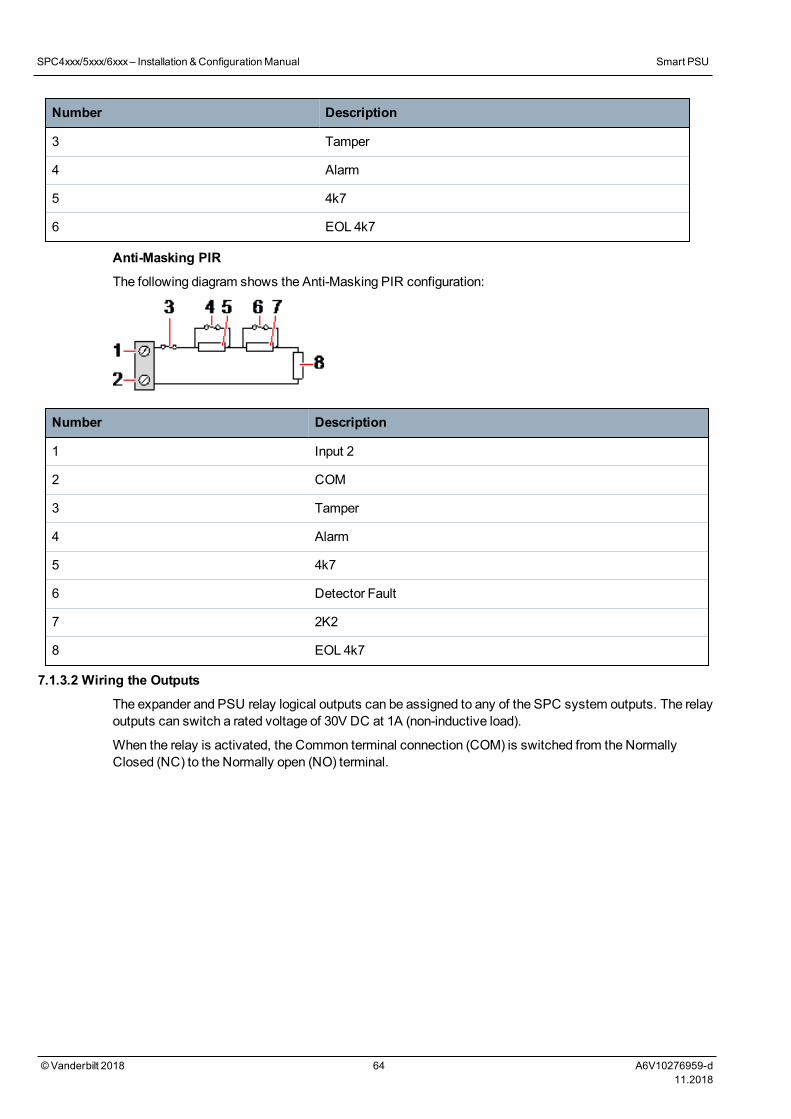
Number Description
3 Tamper
4 Alarm
5 4k7
6 EOL 4k7
Anti-Masking PIR
The following diagram shows the Anti-Masking PIR configuration:
Number Description
1 Input 2
2 COM
3 Tamper
4 Alarm
5 4k7
6 Detector Fault
7 2K2
8 EOL 4k7
7.1.3.2 Wiring the Outputs
The expander and PSU relay logical outputs can be assigned to any of the SPC system outputs. The relayoutputs can switch a rated voltage of 30V DC at 1A (non-inductive load).
When the relay is activated, the Common terminal connection (COM) is switched from the NormallyClosed (NC) to the Normally open (NO) terminal.
SPC4xxx/5xxx/6xxx– Installation &ConfigurationManual Smart PSU
©Vanderbilt 2018 64 A6V10276959-d11.2018
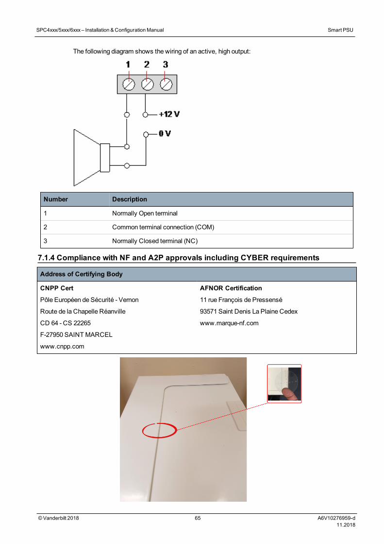
The following diagram shows the wiring of an active, high output:
Number Description
1 Normally Open terminal
2 Common terminal connection (COM)
3 Normally Closed terminal (NC)
7.1.4 Compliance with NF and A2P approvals including CYBER requirements
Address of Certifying Body
CNPP Cert
Pôle Européen de Sécurité - Vernon
Route de la Chapelle Réanville
CD 64 - CS 22265
F-27950 SAINT MARCEL
www.cnpp.com
AFNOR Certification
11 rue François de Pressensé
93571 Saint Denis La Plaine Cedex
www.marque-nf.com
SPC4xxx/5xxx/6xxx– Installation &ConfigurationManual Smart PSU
©Vanderbilt 2018 65 A6V10276959-d11.2018
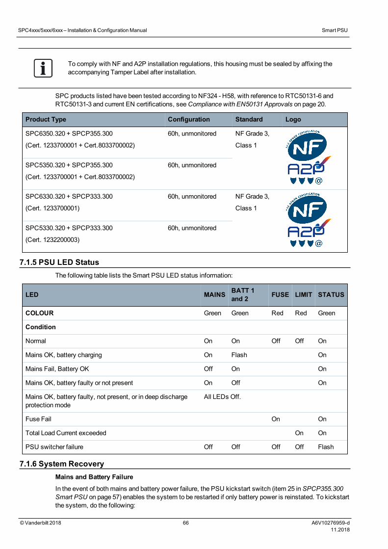
To comply with NF and A2P installation regulations, this housingmust be sealed by affixing theaccompanying Tamper Label after installation.
SPC products listed have been tested according to NF324 - H58, with reference to RTC50131-6 andRTC50131-3 and current EN certifications, seeCompliance with EN50131 Approvals on page 20.
Product Type Configuration Standard Logo
SPC6350.320 + SPCP355.300
(Cert. 1233700001 + Cert.8033700002)
60h, unmonitored NF Grade 3,
Class 1
SPC5350.320 + SPCP355.300
(Cert. 1233700001 + Cert.8033700002)
60h, unmonitored
SPC6330.320 + SPCP333.300
(Cert. 1233700001)
60h, unmonitored NF Grade 3,
Class 1
SPC5330.320 + SPCP333.300
(Cert. 1232200003)
60h, unmonitored
7.1.5 PSU LED StatusThe following table lists the Smart PSU LED status information:
LED MAINS BATT 1and 2 FUSE LIMIT STATUS
COLOUR Green Green Red Red Green
Condition
Normal On On Off Off On
Mains OK, battery charging On Flash On
Mains Fail, Battery OK Off On On
Mains OK, battery faulty or not present On Off On
Mains OK, battery faulty, not present, or in deep dischargeprotectionmode
All LEDs Off.
Fuse Fail On On
Total Load Current exceeded On On
PSU switcher failure Off Off Off Off Flash
7.1.6 System RecoveryMains and Battery Failure
In the event of bothmains and battery power failure, the PSU kickstart switch (item 25 inSPCP355.300Smart PSU on page 57) enables the system to be restarted if only battery power is reinstated. To kickstartthe system, do the following:
SPC4xxx/5xxx/6xxx– Installation &ConfigurationManual Smart PSU
©Vanderbilt 2018 66 A6V10276959-d11.2018

Prerequisiteso Mains power has failedo Battery power has failedo New batteries are available
1. Attach the battery leads.
2. Press and hold the PSU Kickstart button.
All LEDs flash.
3. Hold the PSU Kickstart button until the LEDs stop flashing.
4. Release the PSU Kickstart button.
PTC Fuse Reset
In the event of one of the PTC fuses resetting, youmust manually disconnect then reconnect themainsand battery connections.
SPC4xxx/5xxx/6xxx– Installation &ConfigurationManual Smart PSU
©Vanderbilt 2018 67 A6V10276959-d11.2018
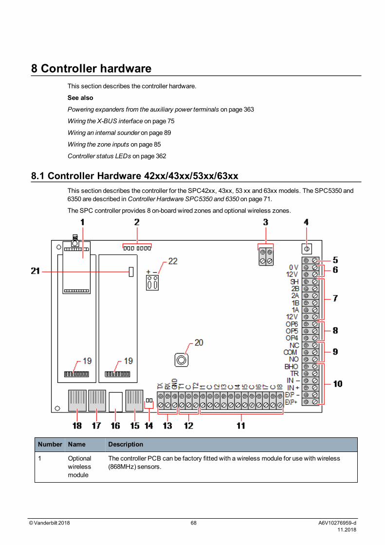
8 Controller hardwareThis section describes the controller hardware.
See also
Powering expanders from the auxiliary power terminals on page 363
Wiring the X-BUS interface on page 75
Wiring an internal sounder on page 89
Wiring the zone inputs on page 85
Controller status LEDs on page 362
8.1 Controller Hardware 42xx/43xx/53xx/63xxThis section describes the controller for the SPC42xx, 43xx, 53 xx and 63xx models. The SPC5350 and6350 are described inController Hardware SPC5350 and 6350 on page 71.
The SPC controller provides 8 on-board wired zones and optional wireless zones.
Number Name Description
1 Optionalwirelessmodule
The controller PCB can be factory fitted with a wireless module for use with wireless(868MHz) sensors.
©Vanderbilt 2018 68 A6V10276959-d11.2018
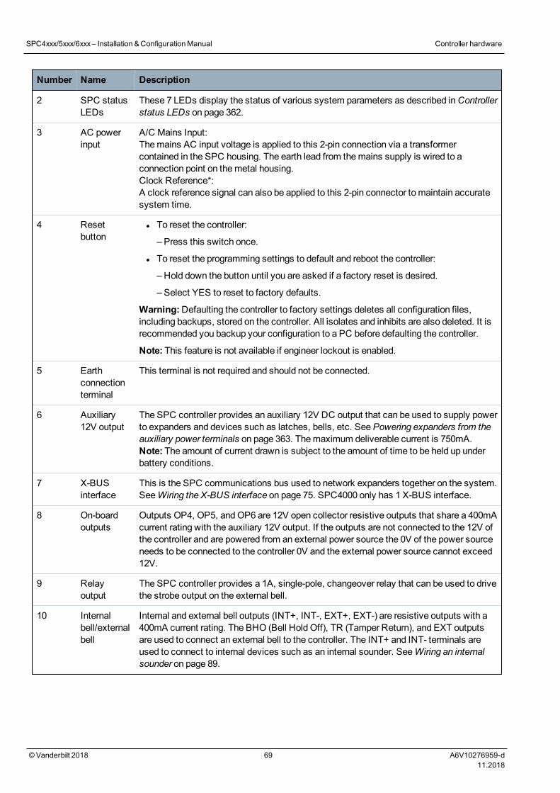
Number Name Description
2 SPC statusLEDs
These 7 LEDs display the status of various system parameters as described inControllerstatus LEDs on page 362.
3 AC powerinput
A/C Mains Input:Themains AC input voltage is applied to this 2-pin connection via a transformercontained in the SPC housing. The earth lead from themains supply is wired to aconnection point on themetal housing.Clock Reference*:A clock reference signal can also be applied to this 2-pin connector to maintain accuratesystem time.
4 Resetbutton
l To reset the controller:
– Press this switch once.
l To reset the programming settings to default and reboot the controller:
– Hold down the button until you are asked if a factory reset is desired.
– Select YES to reset to factory defaults.
Warning:Defaulting the controller to factory settings deletes all configuration files,including backups, stored on the controller. All isolates and inhibits are also deleted. It isrecommended you backup your configuration to a PC before defaulting the controller.
Note: This feature is not available if engineer lockout is enabled.
5 Earthconnectionterminal
This terminal is not required and should not be connected.
6 Auxiliary12V output
The SPC controller provides an auxiliary 12V DC output that can be used to supply powerto expanders and devices such as latches, bells, etc. SeePowering expanders from theauxiliary power terminals on page 363. Themaximum deliverable current is 750mA.Note: The amount of current drawn is subject to the amount of time to be held up underbattery conditions.
7 X-BUSinterface
This is the SPC communications bus used to network expanders together on the system.SeeWiring the X-BUS interface on page 75. SPC4000 only has 1 X-BUS interface.
8 On-boardoutputs
Outputs OP4, OP5, andOP6 are 12V open collector resistive outputs that share a 400mAcurrent rating with the auxiliary 12V output. If the outputs are not connected to the 12V ofthe controller and are powered from an external power source the 0V of the power sourceneeds to be connected to the controller 0V and the external power source cannot exceed12V.
9 Relayoutput
The SPC controller provides a 1A, single-pole, changeover relay that can be used to drivethe strobe output on the external bell.
10 Internalbell/externalbell
Internal and external bell outputs (INT+, INT-, EXT+, EXT-) are resistive outputs with a400mA current rating. The BHO (Bell Hold Off), TR (Tamper Return), and EXT outputsare used to connect an external bell to the controller. The INT+ and INT- terminals areused to connect to internal devices such as an internal sounder. SeeWiring an internalsounder on page 89.
SPC4xxx/5xxx/6xxx– Installation &ConfigurationManual Controller hardware
© Vanderbilt 2018 69 A6V10276959-d11.2018
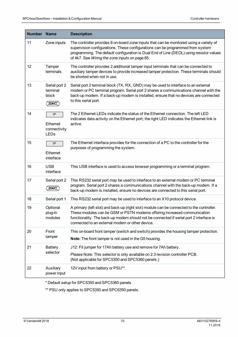
Number Name Description
11 Zone inputs The controller provides 8 on-board zone inputs that can bemonitored using a variety ofsupervision configurations. These configurations can be programmed from systemprogramming. The default configuration is Dual End of Line (DEOL) using resistor valuesof 4k7. SeeWiring the zone inputs on page 85.
12 Tamperterminals
The controller provides 2 additional tamper input terminals that can be connected toauxiliary tamper devices to provide increased tamper protection. These terminals shouldbe shorted when not in use.
13 Serial port 2terminalblock
Serial port 2 terminal block (TX, RX, GND)may be used to interface to an externalmodem or PC terminal program. Serial port 2 shares a communications channel with theback-upmodem. If a back-upmodem is installed, ensure that no devices are connectedto this serial port.
14
EthernetconnectivityLEDs
The 2 Ethernet LEDs indicate the status of the Ethernet connection. The left LEDindicates data activity on the Ethernet port; the right LED indicates the Ethernet link isactive.
15
Ethernetinterface
The Ethernet interface provides for the connection of a PC to the controller for thepurposes of programming the system.
16 USBinterface
This USB interface is used to access browser programming or a terminal program.
17 Serial port 2 This RS232 serial port may be used to interface to an external modem or PC terminalprogram. Serial port 2 shares a communications channel with the back-upmodem. If aback-upmodem is installed, ensure no devices are connected to this serial port.
18 Serial port 1 This RS232 serial port may be used to interface to an X10 protocol device.
19 Optionalplug-inmodules
A primary (left slot) and back-up (right slot) module can be connected to the controller.Thesemodules can beGSM or PSTN modems offering increased communicationfunctionality. The back-upmodem should not be connected if serial port 2 interface isconnected to an external modem or other device.
20 Fronttamper
This on-board front tamper (switch and switch) provides the housing tamper protection.
Note: The front tamper is not used in the G5 housing.
21 Batteryselector
J12: Fit jumper for 17Ah battery use and remove for 7Ah battery.
Please Note: This selector is only available on 2.3 revision controller PCB.(Not applicable for SPC5350 and SPC5360 panels.)
22 Auxiliarypower input
12V input from battery or PSU**.
* Default setup for SPC5350 and SPC5360 panels
** PSU only applies to SPC5350 and SPC6350 panels.
SPC4xxx/5xxx/6xxx– Installation &ConfigurationManual Controller hardware
© Vanderbilt 2018 70 A6V10276959-d11.2018
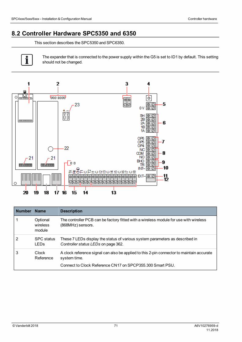
8.2 Controller Hardware SPC5350 and 6350This section describes the SPC5350 and SPC6350.
The expander that is connected to the power supply within the G5 is set to ID1 by default. This settingshould not be changed.
Number Name Description
1 Optionalwirelessmodule
The controller PCB can be factory fitted with a wireless module for use with wireless(868MHz) sensors.
2 SPC statusLEDs
These 7 LEDs display the status of various system parameters as described inController status LEDs on page 362.
3 ClockReference
A clock reference signal can also be applied to this 2-pin connector to maintain accuratesystem time.
Connect to Clock Reference CN17 on SPCP355.300 Smart PSU.
SPC4xxx/5xxx/6xxx– Installation &ConfigurationManual Controller hardware
© Vanderbilt 2018 71 A6V10276959-d11.2018
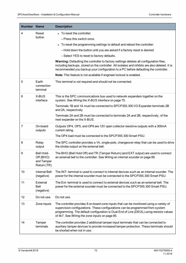
Number Name Description
4 Resetbutton
l To reset the controller:
– Press this switch once.
l To reset the programming settings to default and reboot the controller:
– Hold down the button until you are asked if a factory reset is desired.
– Select YES to reset to factory defaults.
Warning:Defaulting the controller to factory settings deletes all configuration files,including backups, stored on the controller. All isolates and inhibits are also deleted. It isrecommended you backup your configuration to a PC before defaulting the controller.
Note: This feature is not available if engineer lockout is enabled.
5 Earthconnectionterminal
This terminal is not required and should not be connected.
6 X-BUSinterface
This is the SPC communications bus used to network expanders together on thesystem. SeeWiring the X-BUS interface on page 75.
Terminals 1B and 1A must be connected to SPCP355.300 I/O Expander terminals 2Band 2A, respectively
Terminals 2A and 2B must be connected to terminals 2A and 2B, respectively, of thenext expander on the X-BUS.
7 On-boardoutputs
Outputs OP4, OP5, andOP6 are 12V open collector resistive outputs with a 300mAcurrent rating.
TheOP4 loadmust be connected to the SPCP355.300 Smart PSU.
8 Relayoutput
The SPC controller provides a 1A, single-pole, changeover relay that can be used to drivethe strobe output on the external bell.
9 Bell Hold-Off (BHO)and TamperReturn (TR)
The BHO (Bell Hold Off) and TR (Tamper Return) (and EXT output) are used to connectan external bell to the controller. SeeWiring an internal sounder on page 89.
10 Internal Bell(negative)
The INT- terminal is used to connect to internal devices such as an internal sounder. Thepower for the internal sounder must be connected to the SPCP355.300 Smart PSU.
11 ExternalBell(negative)
The Ext- terminal is used to connect to external devices such as an external bell. Thepower for the external sounder must be connected to the SPCP355.300 Smart PSU.
12 Do not use. Do not use.
13 Zone inputs The controller provides 8 on-board zone inputs that can bemonitored using a variety ofsupervision configurations. These configurations can be programmed from systemprogramming. The default configuration is Dual End of Line (DEOL) using resistor valuesof 4k7. SeeWiring the zone inputs on page 85.
14 Tamperterminals
The controller provides 2 additional tamper input terminals that can be connected toauxiliary tamper devices to provide increased tamper protection. These terminals shouldbe shorted when not in use.
SPC4xxx/5xxx/6xxx– Installation &ConfigurationManual Controller hardware
© Vanderbilt 2018 72 A6V10276959-d11.2018
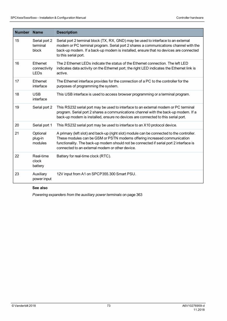
Number Name Description
15 Serial port 2terminalblock
Serial port 2 terminal block (TX, RX, GND)may be used to interface to an externalmodem or PC terminal program. Serial port 2 shares a communications channel with theback-upmodem. If a back-upmodem is installed, ensure that no devices are connectedto this serial port.
16 EthernetconnectivityLEDs
The 2 Ethernet LEDs indicate the status of the Ethernet connection. The left LEDindicates data activity on the Ethernet port; the right LED indicates the Ethernet link isactive.
17 Ethernetinterface
The Ethernet interface provides for the connection of a PC to the controller for thepurposes of programming the system.
18 USBinterface
This USB interface is used to access browser programming or a terminal program.
19 Serial port 2 This RS232 serial port may be used to interface to an external modem or PC terminalprogram. Serial port 2 shares a communications channel with the back-upmodem. If aback-upmodem is installed, ensure no devices are connected to this serial port.
20 Serial port 1 This RS232 serial port may be used to interface to an X10 protocol device.
21 Optionalplug-inmodules
A primary (left slot) and back-up (right slot) module can be connected to the controller.Thesemodules can beGSM or PSTN modems offering increased communicationfunctionality. The back-upmodem should not be connected if serial port 2 interface isconnected to an external modem or other device.
22 Real-timeclockbattery
Battery for real-time clock (RTC).
23 Auxiliarypower input
12V input from A1 on SPCP355.300 Smart PSU.
See also
Powering expanders from the auxiliary power terminals on page 363
SPC4xxx/5xxx/6xxx– Installation &ConfigurationManual Controller hardware
© Vanderbilt 2018 73 A6V10276959-d11.2018
9 Door ExpanderThe two door expander can handle up to two doors and two card readers. Configuration of the operationmode is done via the two door I/Os. Each of the two door I/Os is responsible for the functionality of twoinputs and one output of the door controller. A specific door number can be assigned to a door I/O, whichgives the inputs and output predefined functionality. If no door number is assigned to neither of the doorI/Os (option “Zones” is selected), the inputs and outputs of the door controller can be used like inputs andoutputs on the control panel. Thus, no access functionality is available on this two door controller.
If a door number is assigned only to the first door I/O of the two door controller, the first reader is used asentry reader for this door. If a second reader is available, it is used as exit reader for the configured door.Two inputs and one output have predefined functionality and two inputs and one output can be configuredby the user. Additionally, the door position sensor input of the first door can be used as intrusion zone butonly with limited functionality.
If a door number is assigned to each of the two door I/Os, the two doors are handled independently. Thefirst card reader is used as entry reader for the first door and the second card reader is used as entry readerfor the second door. All inputs and outputs have predefined functionality. The door position sensor inputs ofthe two doors can additionally be used as intrusion zones but only with limited functionality.
SeeSupported card readers and card formats on page 388 for details of currently supported card readersand card formats.
Each free zone number can be assigned to the zones. But the assignment is not fixed. If number 9was assigned to a zone, the zone and an input expander with the address 1 is connected to the X-Bus(which is using the zone numbers 9–16).The assigned zone from the two door controller will bemovedto the next free zone number. Configuration will be adapted accordingly.
©Vanderbilt 2018 74 A6V10276959-d11.2018
10 Wiring the systemThis chapter covers:
10.1 Wiring the X-BUS interface 75
10.2 Wiring of branch expander 83
10.3 Wiring the system ground 84
10.4 Wiring the relay output 84
10.5 Wiring the zone inputs 85
10.6 Wiring an external SAB bell 88
10.7 Wiring an internal sounder 89
10.8 Wiring Glassbreak 89
10.9 Installing plug-in modules 90
10.1 Wiring the X-BUS interfaceThe X-BUS interface provides for the connection of expanders to the controller. The X-BUS can be wired ina number of different configurations depending on the installation requirements. The X-BUS interface baudrate is 307kb.
NOTICE: The X-BUS is an RS-485 bus with a baud rate of 307kb. The full performance is onlysupported in loop (see Loop configuration on the next page) and spur (seeSpur configuration onpage 77) wiring configuration (best signal quality due to daisy chain of isolated sections with 1transmitter/1 receiver and balanced terminating resistors on each end).
The performance in star or multi-drop configuration wiring (seeStar andmulti-drop configuration onpage 78) is limited due to non-optimal conditions of the RS-485 bus specification (reduced signalquality due tomultiple receivers/transmitters in parallel with unbalanced terminating resistors).
NOTICE: It is strongly recommended to use loop (see Loop configuration on the next page) or spur(seeSpur configuration on page 77) configuration.
The table below shows themaximum distances between controller/expander or expander/expander for allcable types in loop and spur configuration.
Cable Type Distance
CQR standard alarm cable 200m
UTP Category: 5 (solid core) 400m
Belden 9829 400m
IYSTY 2 x 2 x 0.6 (min) 400m
Each device has 4 terminals (1A, 1B, 2A, 2B) for connection to expanders via the X-BUS cable. Thecontroller initiates a detection procedure on power up to determine the number of expanders connected onthe system and the topology in which they are connected.
©Vanderbilt 2018 75 A6V10276959-d11.2018
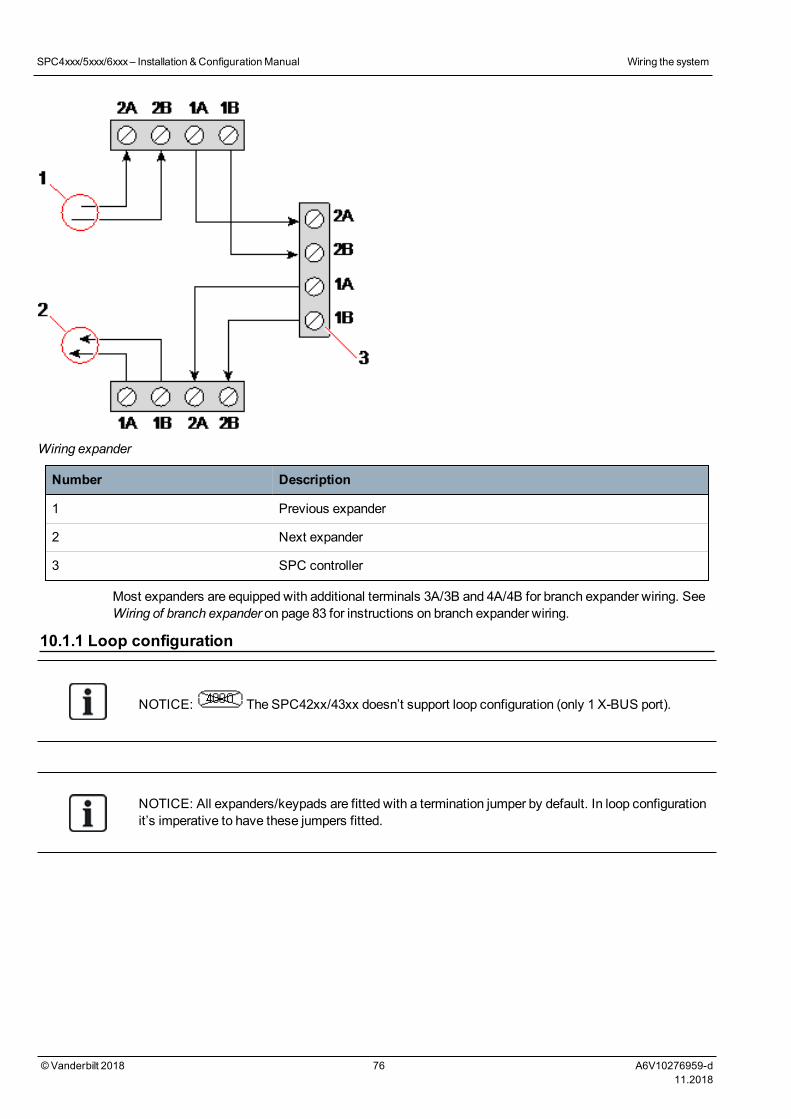
Wiring expander
Number Description
1 Previous expander
2 Next expander
3 SPC controller
Most expanders are equipped with additional terminals 3A/3B and 4A/4B for branch expander wiring. SeeWiring of branch expander on page 83 for instructions on branch expander wiring.
10.1.1 Loop configuration
NOTICE: The SPC42xx/43xx doesn’t support loop configuration (only 1 X-BUS port).
NOTICE: All expanders/keypads are fitted with a termination jumper by default. In loop configurationit’s imperative to have these jumpers fitted.
SPC4xxx/5xxx/6xxx– Installation &ConfigurationManual Wiring the system
©Vanderbilt 2018 76 A6V10276959-d11.2018
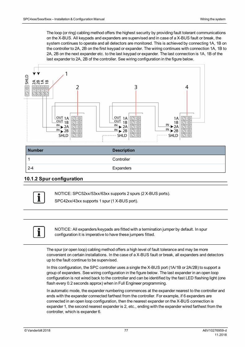
The loop (or ring) cablingmethod offers the highest security by providing fault tolerant communicationson the X-BUS. All keypads and expanders are supervised and in case of a X-BUS fault or break, thesystem continues to operate and all detectors aremonitored. This is achieved by connecting 1A, 1B onthe controller to 2A, 2B on the first keypad or expander. The wiring continues with connection 1A, 1B to2A, 2B on the next expander etc. to the last keypad or expander. The last connection is 1A, 1B of thelast expander to 2A, 2B of the controller. See wiring configuration in the figure below.
Number Description
1 Controller
2-4 Expanders
10.1.2 Spur configuration
NOTICE: SPC52xx/53xx/63xx supports 2 spurs (2 X-BUS ports).
SPC42xx/43xx supports 1 spur (1 X-BUS port).
NOTICE: All expanders/keypads are fitted with a termination jumper by default. In spurconfiguration it is imperative to have these jumpers fitted.
The spur (or open loop) cablingmethod offers a high level of fault tolerance andmay bemoreconvenient on certain installations. In the case of a X-BUS fault or break, all expanders and detectorsup to the fault continue to be supervised.
In this configuration, the SPC controller uses a single the X-BUS port (1A/1B or 2A/2B) to support agroup of expanders. See wiring configuration in the figure below. The last expander in an open loopconfiguration is not wired back to the controller and can be identified by the fast LED flashing light (oneflash every 0.2 seconds approx) when in Full Engineer programming.
In automatic mode, the expander numbering commences at the expander nearest to the controller andends with the expander connected farthest from the controller. For example, if 6 expanders areconnected in an open loop configuration, then the nearest expander on the X-BUS connection isexpander 1, the second nearest expander is 2, etc., ending with the expander wired farthest from thecontroller, which is expander 6.
SPC4xxx/5xxx/6xxx– Installation &ConfigurationManual Wiring the system
©Vanderbilt 2018 77 A6V10276959-d11.2018
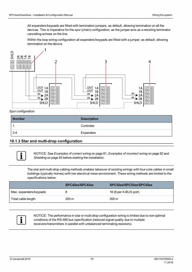
All expanders/keypads are fitted with termination jumpers, as default, allowing termination on all thedevices. This is imperative for the spur (chain) configuration, as the jumper acts as a resisting terminatorcancelling echoes on the line.
Within the loop wiring configuration all expanders/keypads are fitted with a jumper, as default, allowingtermination on the device.
Spur configuration
Number Description
1 Controller
2-4 Expanders
10.1.3 Star and multi-drop configuration
NOTICE: SeeExamples of correct wiring on page 81, Examples of incorrect wiring on page 82 andShielding on page 83 before starting the installation.
The star andmulti-drop cablingmethods enables takeover of existing wirings with four-core cables in smallbuildings (typically homes) with low electrical noise environment. These wiringmethods are limited to thespecifications below:
SPC42xx/SPC43xx SPC52xx/SPC53xx/SPC63xx
Max. expanders/keypads 8 16 (8 per X-BUS port)
Total cable length 200m 200m
NOTICE: The performance in star or multi-drop configuration wiring is limited due to non-optimalconditions of the RS-485 bus specification (reduced signal quality due tomultiplereceivers/transmitters in parallel with unbalanced terminating resistors).
SPC4xxx/5xxx/6xxx– Installation &ConfigurationManual Wiring the system
©Vanderbilt 2018 78 A6V10276959-d11.2018
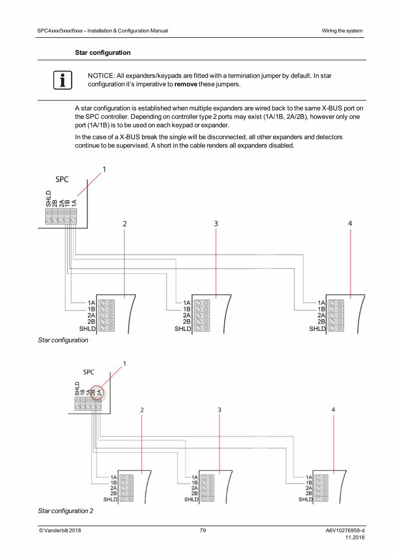
Star configuration
NOTICE: All expanders/keypads are fitted with a termination jumper by default. In starconfiguration it’s imperative to remove these jumpers.
A star configuration is established whenmultiple expanders are wired back to the same X-BUS port onthe SPC controller. Depending on controller type 2 ports may exist (1A/1B, 2A/2B), however only oneport (1A/1B) is to be used on each keypad or expander.
In the case of a X-BUS break the single will be disconnected, all other expanders and detectorscontinue to be supervised. A short in the cable renders all expanders disabled.
Star configuration
Star configuration 2
SPC4xxx/5xxx/6xxx– Installation &ConfigurationManual Wiring the system
©Vanderbilt 2018 79 A6V10276959-d11.2018
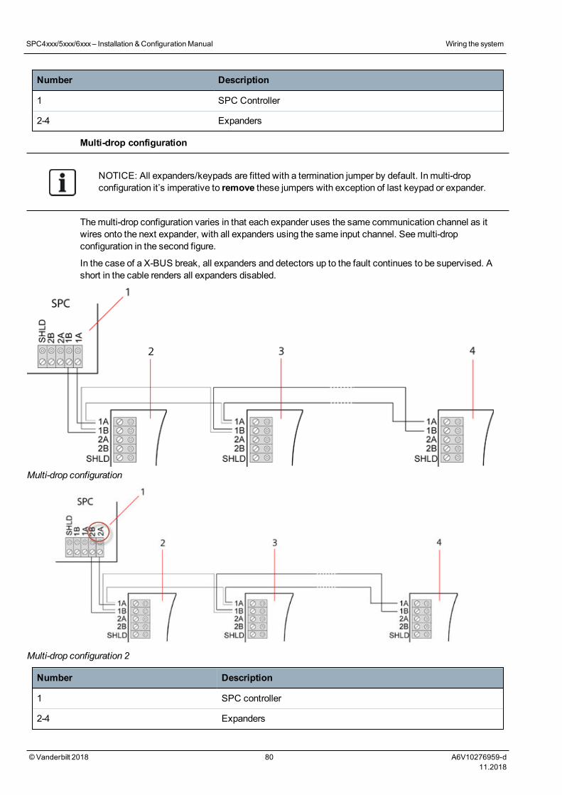
Number Description
1 SPC Controller
2-4 Expanders
Multi-drop configuration
NOTICE: All expanders/keypads are fitted with a termination jumper by default. In multi-dropconfiguration it’s imperative to remove these jumpers with exception of last keypad or expander.
Themulti-drop configuration varies in that each expander uses the same communication channel as itwires onto the next expander, with all expanders using the same input channel. Seemulti-dropconfiguration in the second figure.
In the case of a X-BUS break, all expanders and detectors up to the fault continues to be supervised. Ashort in the cable renders all expanders disabled.
Multi-drop configuration
Multi-drop configuration 2
Number Description
1 SPC controller
2-4 Expanders
SPC4xxx/5xxx/6xxx– Installation &ConfigurationManual Wiring the system
©Vanderbilt 2018 80 A6V10276959-d11.2018
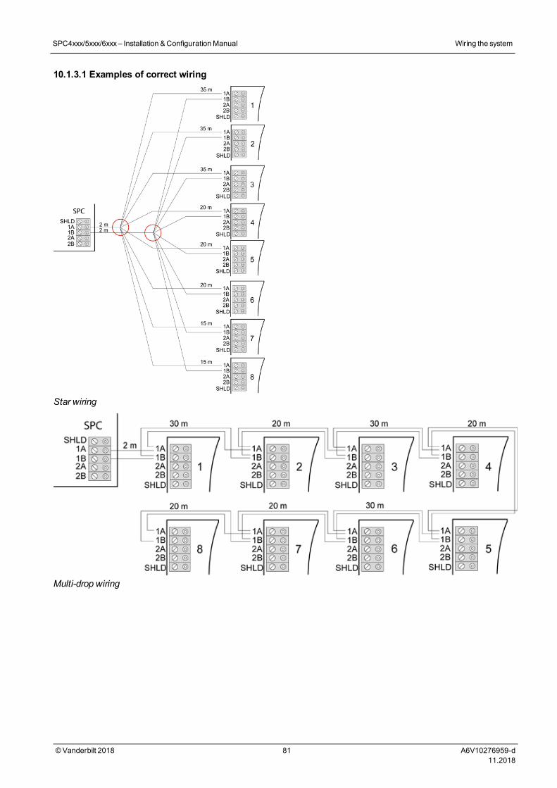
10.1.3.1 Examples of correct wiring
Star wiring
Multi-drop wiring
SPC4xxx/5xxx/6xxx– Installation &ConfigurationManual Wiring the system
©Vanderbilt 2018 81 A6V10276959-d11.2018
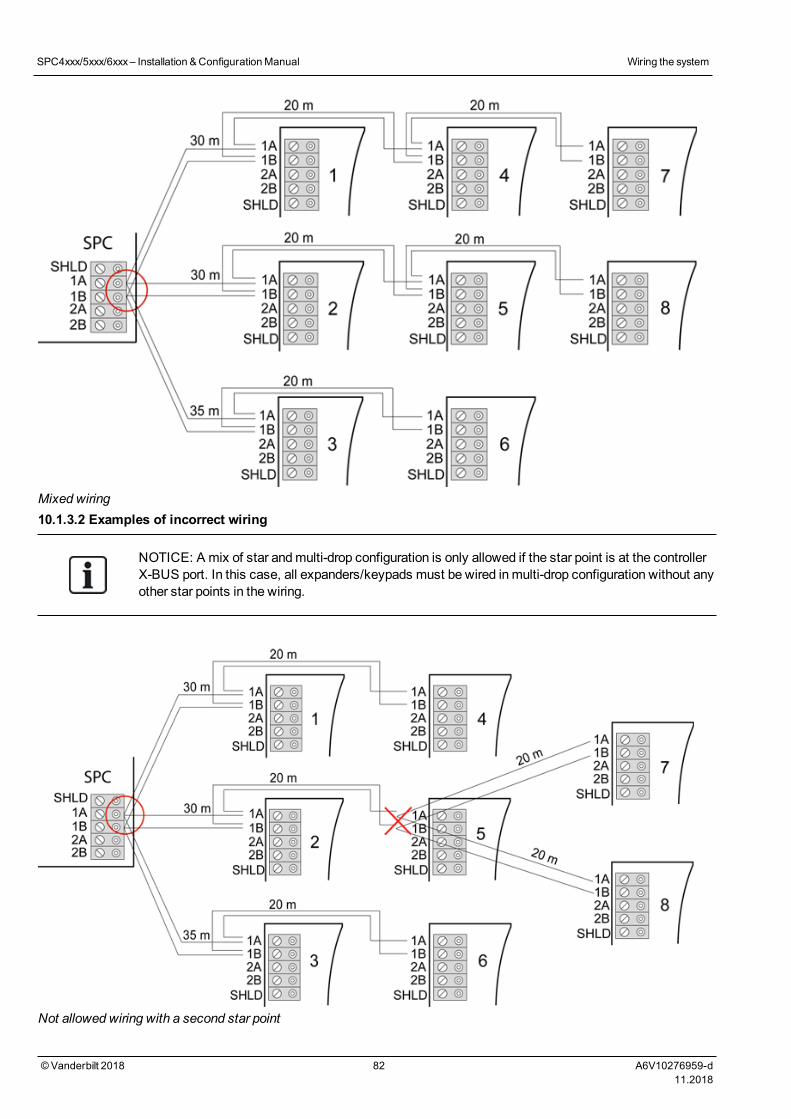
Mixed wiring10.1.3.2 Examples of incorrect wiring
NOTICE: A mix of star andmulti-drop configuration is only allowed if the star point is at the controllerX-BUS port. In this case, all expanders/keypads must be wired in multi-drop configuration without anyother star points in the wiring.
Not allowed wiring with a second star point
SPC4xxx/5xxx/6xxx– Installation &ConfigurationManual Wiring the system
©Vanderbilt 2018 82 A6V10276959-d11.2018
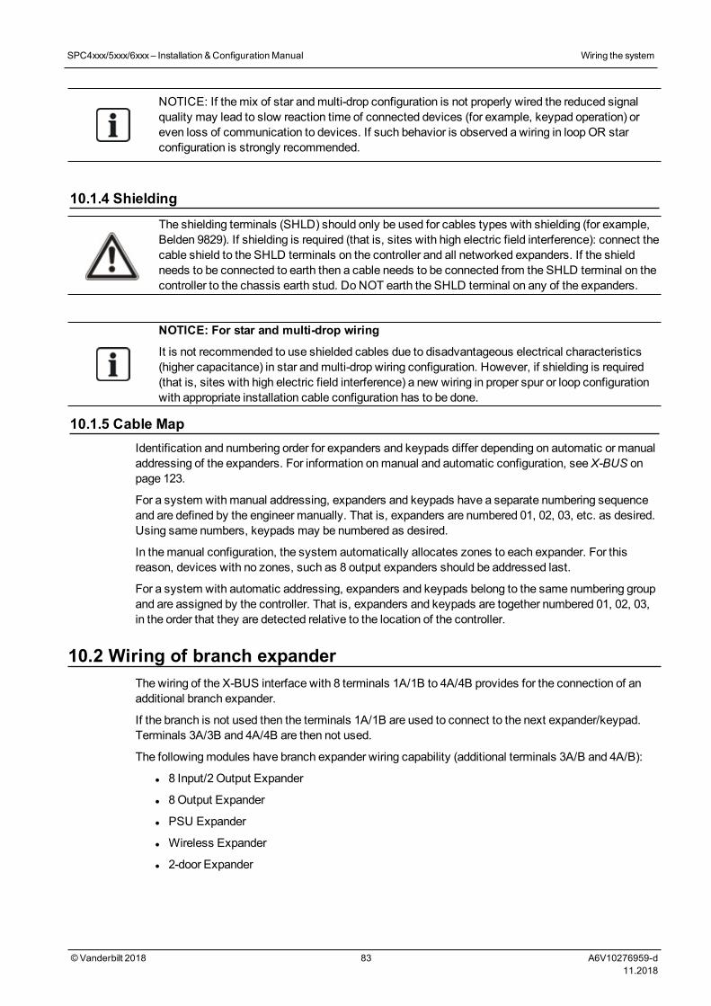
NOTICE: If themix of star andmulti-drop configuration is not properly wired the reduced signalquality may lead to slow reaction time of connected devices (for example, keypad operation) oreven loss of communication to devices. If such behavior is observed a wiring in loopOR starconfiguration is strongly recommended.
10.1.4 ShieldingThe shielding terminals (SHLD) should only be used for cables types with shielding (for example,Belden 9829). If shielding is required (that is, sites with high electric field interference): connect thecable shield to the SHLD terminals on the controller and all networked expanders. If the shieldneeds to be connected to earth then a cable needs to be connected from the SHLD terminal on thecontroller to the chassis earth stud. Do NOT earth the SHLD terminal on any of the expanders.
NOTICE: For star and multi-drop wiring
It is not recommended to use shielded cables due to disadvantageous electrical characteristics(higher capacitance) in star andmulti-drop wiring configuration. However, if shielding is required(that is, sites with high electric field interference) a new wiring in proper spur or loop configurationwith appropriate installation cable configuration has to be done.
10.1.5 Cable MapIdentification and numbering order for expanders and keypads differ depending on automatic or manualaddressing of the expanders. For information onmanual and automatic configuration, seeX-BUS onpage 123.
For a system with manual addressing, expanders and keypads have a separate numbering sequenceand are defined by the engineer manually. That is, expanders are numbered 01, 02, 03, etc. as desired.Using same numbers, keypads may be numbered as desired.
In themanual configuration, the system automatically allocates zones to each expander. For thisreason, devices with no zones, such as 8 output expanders should be addressed last.
For a system with automatic addressing, expanders and keypads belong to the same numbering groupand are assigned by the controller. That is, expanders and keypads are together numbered 01, 02, 03,in the order that they are detected relative to the location of the controller.
10.2 Wiring of branch expanderThe wiring of the X-BUS interface with 8 terminals 1A/1B to 4A/4B provides for the connection of anadditional branch expander.
If the branch is not used then the terminals 1A/1B are used to connect to the next expander/keypad.Terminals 3A/3B and 4A/4B are then not used.
The followingmodules have branch expander wiring capability (additional terminals 3A/B and 4A/B):
l 8 Input/2 Output Expander
l 8Output Expander
l PSU Expander
l Wireless Expander
l 2-door Expander
SPC4xxx/5xxx/6xxx– Installation &ConfigurationManual Wiring the system
©Vanderbilt 2018 83 A6V10276959-d11.2018
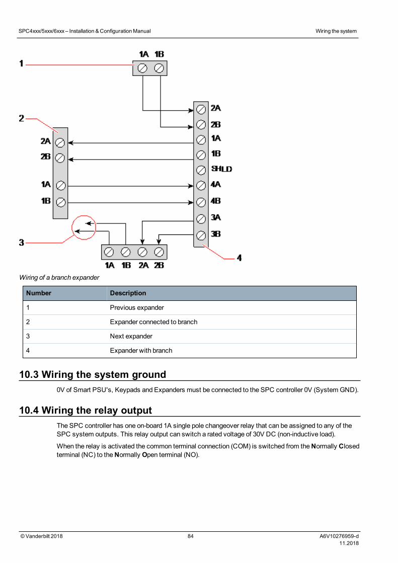
Wiring of a branch expander
Number Description
1 Previous expander
2 Expander connected to branch
3 Next expander
4 Expander with branch
10.3 Wiring the system ground0V of Smart PSU's, Keypads and Expanders must be connected to the SPC controller 0V (System GND).
10.4 Wiring the relay outputThe SPC controller has one on-board 1A single pole changeover relay that can be assigned to any of theSPC system outputs. This relay output can switch a rated voltage of 30V DC (non-inductive load).
When the relay is activated the common terminal connection (COM) is switched from theNormally Closedterminal (NC) to theNormally Open terminal (NO).
SPC4xxx/5xxx/6xxx– Installation &ConfigurationManual Wiring the system
©Vanderbilt 2018 84 A6V10276959-d11.2018
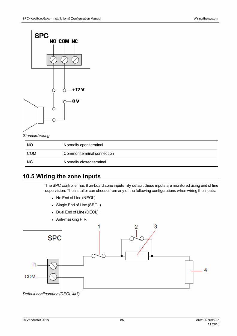
Standard wiring
NO Normally open terminal
COM Common terminal connection
NC Normally closed terminal
10.5 Wiring the zone inputsThe SPC controller has 8 on-board zone inputs. By default these inputs aremonitored using end of linesupervision. The installer can choose from any of the following configurations when wiring the inputs:
l NoEnd of Line (NEOL)
l Single End of Line (SEOL)
l Dual End of Line (DEOL)
l Anti-masking PIR
Default configuration (DEOL 4k7)
SPC4xxx/5xxx/6xxx– Installation &ConfigurationManual Wiring the system
©Vanderbilt 2018 85 A6V10276959-d11.2018
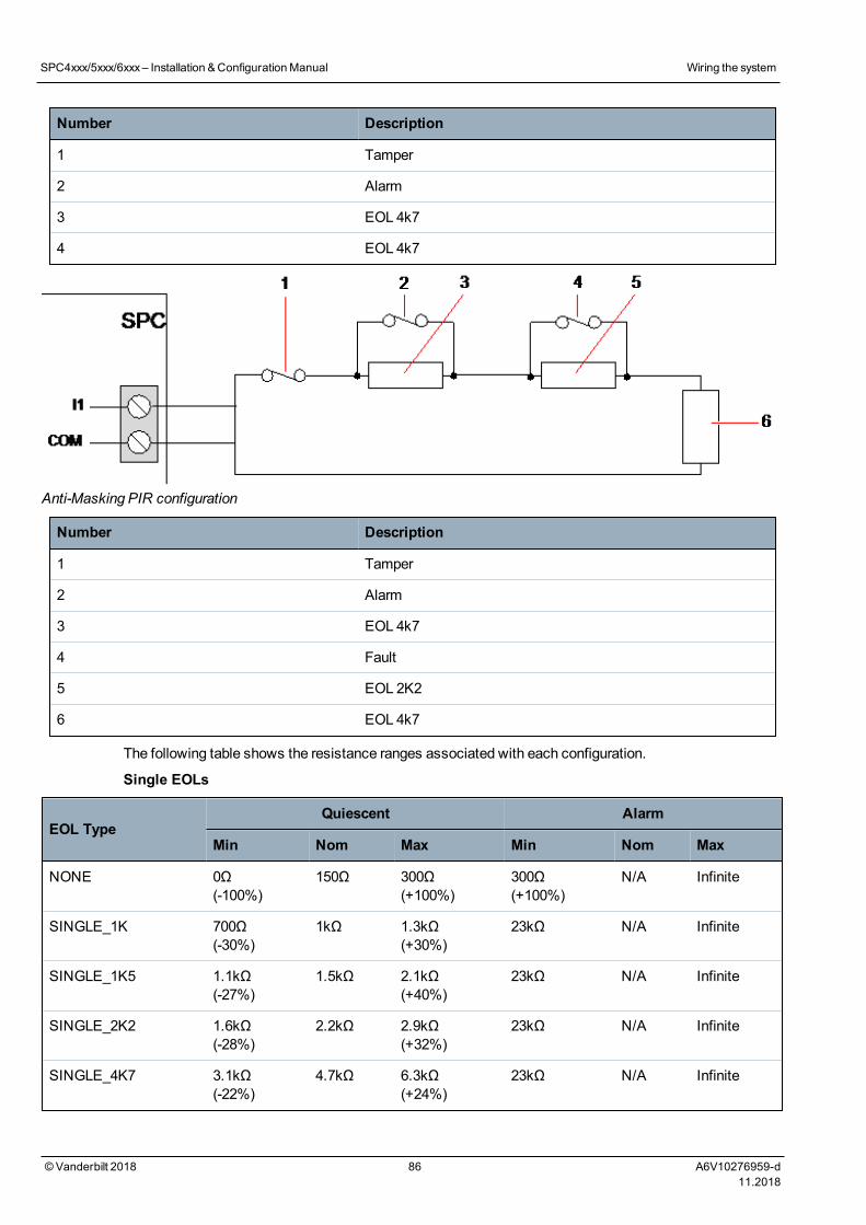
Number Description
1 Tamper
2 Alarm
3 EOL 4k7
4 EOL 4k7
Anti-Masking PIR configuration
Number Description
1 Tamper
2 Alarm
3 EOL 4k7
4 Fault
5 EOL 2K2
6 EOL 4k7
The following table shows the resistance ranges associated with each configuration.
Single EOLs
EOL TypeQuiescent Alarm
Min Nom Max Min Nom Max
NONE 0Ω(-100%)
150Ω 300Ω(+100%)
300Ω(+100%)
N/A Infinite
SINGLE_1K 700Ω(-30%)
1kΩ 1.3kΩ(+30%)
23kΩ N/A Infinite
SINGLE_1K5 1.1kΩ(-27%)
1.5kΩ 2.1kΩ(+40%)
23kΩ N/A Infinite
SINGLE_2K2 1.6kΩ(-28%)
2.2kΩ 2.9kΩ(+32%)
23kΩ N/A Infinite
SINGLE_4K7 3.1kΩ(-22%)
4.7kΩ 6.3kΩ(+24%)
23kΩ N/A Infinite
SPC4xxx/5xxx/6xxx– Installation &ConfigurationManual Wiring the system
©Vanderbilt 2018 86 A6V10276959-d11.2018
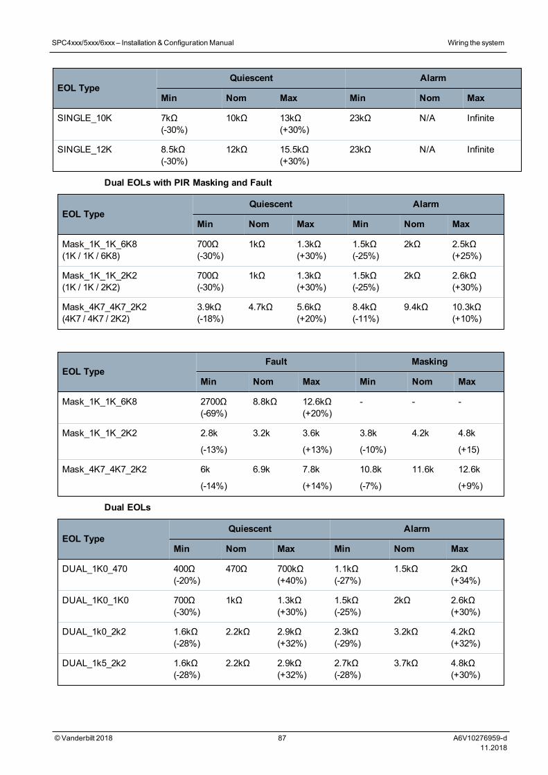
EOL TypeQuiescent Alarm
Min Nom Max Min Nom Max
SINGLE_10K 7kΩ(-30%)
10kΩ 13kΩ(+30%)
23kΩ N/A Infinite
SINGLE_12K 8.5kΩ(-30%)
12kΩ 15.5kΩ(+30%)
23kΩ N/A Infinite
Dual EOLs with PIR Masking and Fault
EOL TypeQuiescent Alarm
Min Nom Max Min Nom Max
Mask_1K_1K_6K8(1K / 1K / 6K8)
700Ω(-30%)
1kΩ 1.3kΩ(+30%)
1.5kΩ(-25%)
2kΩ 2.5kΩ(+25%)
Mask_1K_1K_2K2(1K / 1K / 2K2)
700Ω(-30%)
1kΩ 1.3kΩ(+30%)
1.5kΩ(-25%)
2kΩ 2.6kΩ(+30%)
Mask_4K7_4K7_2K2(4K7 / 4K7 / 2K2)
3.9kΩ(-18%)
4.7kΩ 5.6kΩ(+20%)
8.4kΩ(-11%)
9.4kΩ 10.3kΩ(+10%)
EOL TypeFault Masking
Min Nom Max Min Nom Max
Mask_1K_1K_6K8 2700Ω(-69%)
8.8kΩ 12.6kΩ(+20%)
- - -
Mask_1K_1K_2K2 2.8k
(-13%)
3.2k 3.6k
(+13%)
3.8k
(-10%)
4.2k 4.8k
(+15)
Mask_4K7_4K7_2K2 6k
(-14%)
6.9k 7.8k
(+14%)
10.8k
(-7%)
11.6k 12.6k
(+9%)
Dual EOLs
EOL TypeQuiescent Alarm
Min Nom Max Min Nom Max
DUAL_1K0_470 400Ω(-20%)
470Ω 700kΩ(+40%)
1.1kΩ(-27%)
1.5kΩ 2kΩ(+34%)
DUAL_1K0_1K0 700Ω(-30%)
1kΩ 1.3kΩ(+30%)
1.5kΩ(-25%)
2kΩ 2.6kΩ(+30%)
DUAL_1k0_2k2 1.6kΩ(-28%)
2.2kΩ 2.9kΩ(+32%)
2.3kΩ(-29%)
3.2kΩ 4.2kΩ(+32%)
DUAL_1k5_2k2 1.6kΩ(-28%)
2.2kΩ 2.9kΩ(+32%)
2.7kΩ(-28%)
3.7kΩ 4.8kΩ(+30%)
SPC4xxx/5xxx/6xxx– Installation &ConfigurationManual Wiring the system
©Vanderbilt 2018 87 A6V10276959-d11.2018
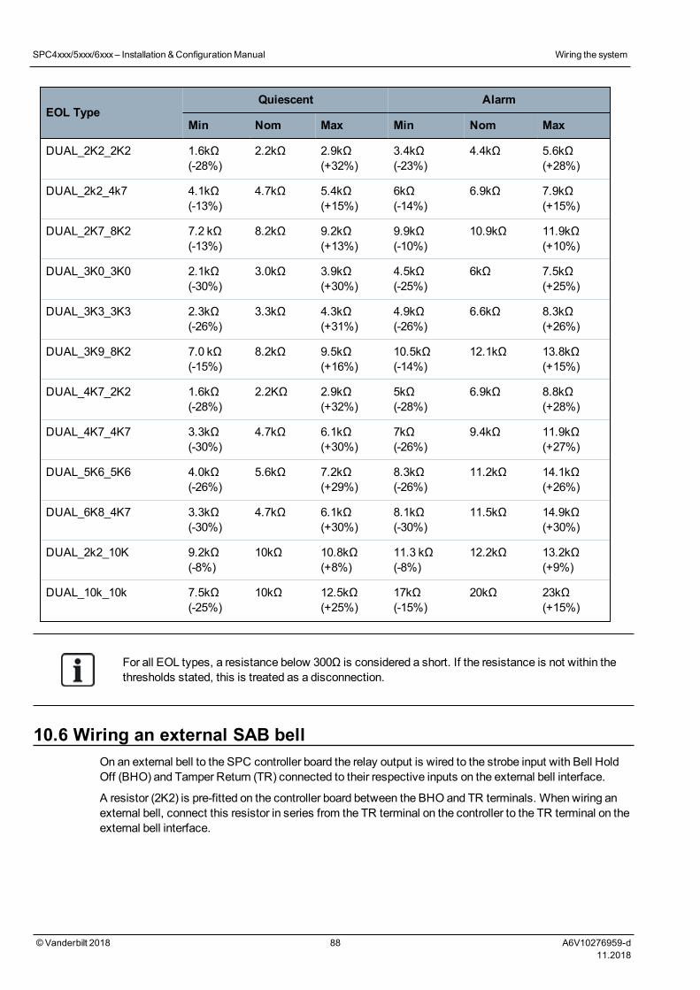
EOL TypeQuiescent Alarm
Min Nom Max Min Nom Max
DUAL_2K2_2K2 1.6kΩ(-28%)
2.2kΩ 2.9kΩ(+32%)
3.4kΩ(-23%)
4.4kΩ 5.6kΩ(+28%)
DUAL_2k2_4k7 4.1kΩ(-13%)
4.7kΩ 5.4kΩ(+15%)
6kΩ(-14%)
6.9kΩ 7.9kΩ(+15%)
DUAL_2K7_8K2 7.2 kΩ(-13%)
8.2kΩ 9.2kΩ(+13%)
9.9kΩ(-10%)
10.9kΩ 11.9kΩ(+10%)
DUAL_3K0_3K0 2.1kΩ(-30%)
3.0kΩ 3.9kΩ(+30%)
4.5kΩ(-25%)
6kΩ 7.5kΩ(+25%)
DUAL_3K3_3K3 2.3kΩ(-26%)
3.3kΩ 4.3kΩ(+31%)
4.9kΩ(-26%)
6.6kΩ 8.3kΩ(+26%)
DUAL_3K9_8K2 7.0 kΩ(-15%)
8.2kΩ 9.5kΩ(+16%)
10.5kΩ(-14%)
12.1kΩ 13.8kΩ(+15%)
DUAL_4K7_2K2 1.6kΩ(-28%)
2.2KΩ 2.9kΩ(+32%)
5kΩ(-28%)
6.9kΩ 8.8kΩ(+28%)
DUAL_4K7_4K7 3.3kΩ(-30%)
4.7kΩ 6.1kΩ(+30%)
7kΩ(-26%)
9.4kΩ 11.9kΩ(+27%)
DUAL_5K6_5K6 4.0kΩ(-26%)
5.6kΩ 7.2kΩ(+29%)
8.3kΩ(-26%)
11.2kΩ 14.1kΩ(+26%)
DUAL_6K8_4K7 3.3kΩ(-30%)
4.7kΩ 6.1kΩ(+30%)
8.1kΩ(-30%)
11.5kΩ 14.9kΩ(+30%)
DUAL_2k2_10K 9.2kΩ(-8%)
10kΩ 10.8kΩ(+8%)
11.3 kΩ(-8%)
12.2kΩ 13.2kΩ(+9%)
DUAL_10k_10k 7.5kΩ(-25%)
10kΩ 12.5kΩ(+25%)
17kΩ(-15%)
20kΩ 23kΩ(+15%)
For all EOL types, a resistance below 300Ω is considered a short. If the resistance is not within thethresholds stated, this is treated as a disconnection.
10.6 Wiring an external SAB bellOn an external bell to the SPC controller board the relay output is wired to the strobe input with Bell HoldOff (BHO) and Tamper Return (TR) connected to their respective inputs on the external bell interface.
A resistor (2K2) is pre-fitted on the controller board between the BHO and TR terminals. When wiring anexternal bell, connect this resistor in series from the TR terminal on the controller to the TR terminal on theexternal bell interface.
SPC4xxx/5xxx/6xxx– Installation &ConfigurationManual Wiring the system
©Vanderbilt 2018 88 A6V10276959-d11.2018
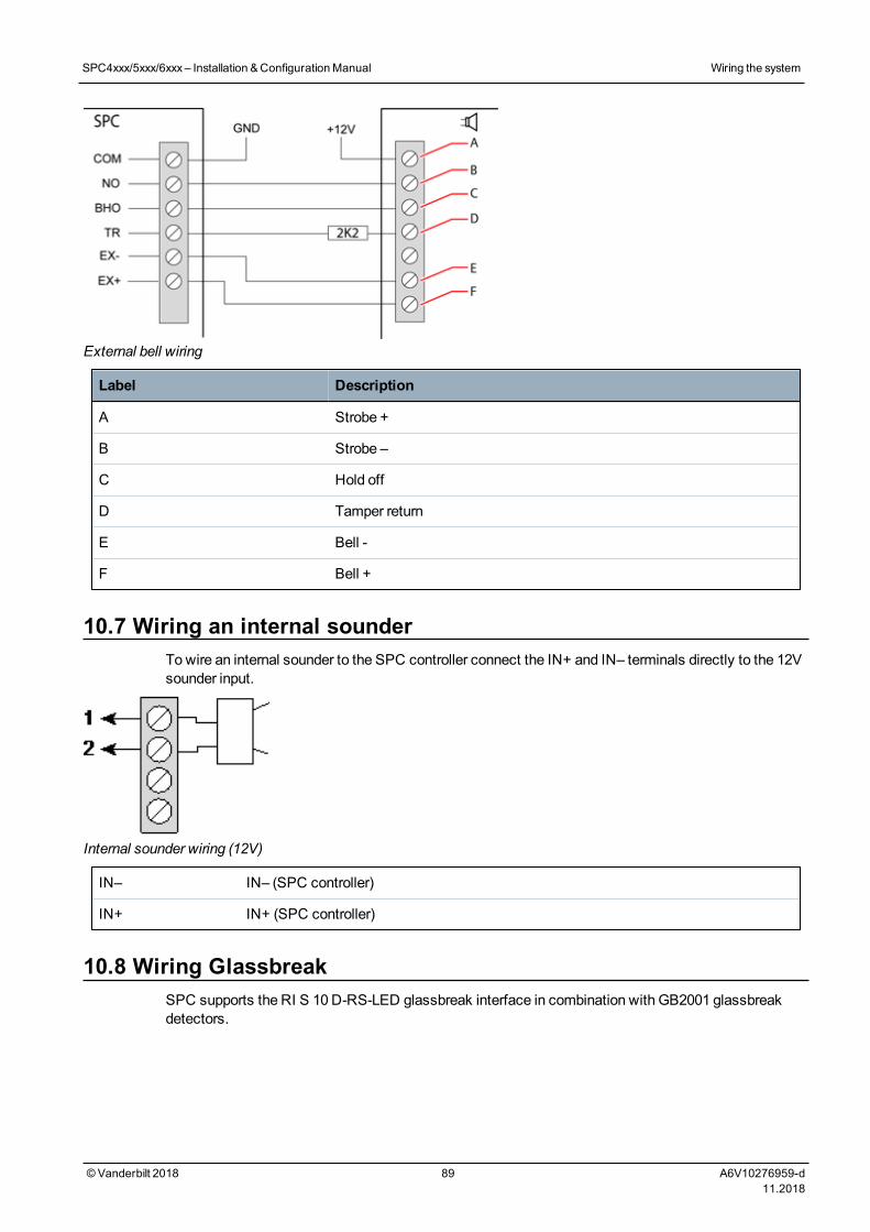
External bell wiring
Label Description
A Strobe +
B Strobe –
C Hold off
D Tamper return
E Bell -
F Bell +
10.7 Wiring an internal sounderTowire an internal sounder to the SPC controller connect the IN+ and IN– terminals directly to the 12Vsounder input.
Internal sounder wiring (12V)
IN– IN– (SPC controller)
IN+ IN+ (SPC controller)
10.8 Wiring GlassbreakSPC supports the RI S 10 D-RS-LED glassbreak interface in combination with GB2001 glassbreakdetectors.
SPC4xxx/5xxx/6xxx– Installation &ConfigurationManual Wiring the system
©Vanderbilt 2018 89 A6V10276959-d11.2018
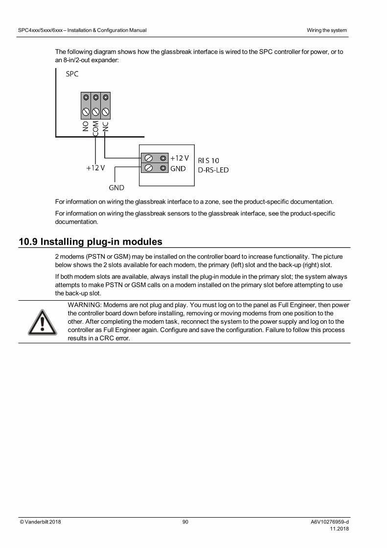
The following diagram shows how the glassbreak interface is wired to the SPC controller for power, or toan 8-in/2-out expander:
For information on wiring the glassbreak interface to a zone, see the product-specific documentation.
For information on wiring the glassbreak sensors to the glassbreak interface, see the product-specificdocumentation.
10.9 Installing plug-in modules2modems (PSTN or GSM)may be installed on the controller board to increase functionality. The picturebelow shows the 2 slots available for eachmodem, the primary (left) slot and the back-up (right) slot.
If bothmodem slots are available, always install the plug-in module in the primary slot; the system alwaysattempts tomake PSTN or GSM calls on amodem installed on the primary slot before attempting to usethe back-up slot.
WARNING: Modems are not plug and play. Youmust log on to the panel as Full Engineer, then powerthe controller board down before installing, removing or movingmodems from one position to theother. After completing themodem task, reconnect the system to the power supply and log on to thecontroller as Full Engineer again. Configure and save the configuration. Failure to follow this processresults in a CRC error.
SPC4xxx/5xxx/6xxx– Installation &ConfigurationManual Wiring the system
©Vanderbilt 2018 90 A6V10276959-d11.2018
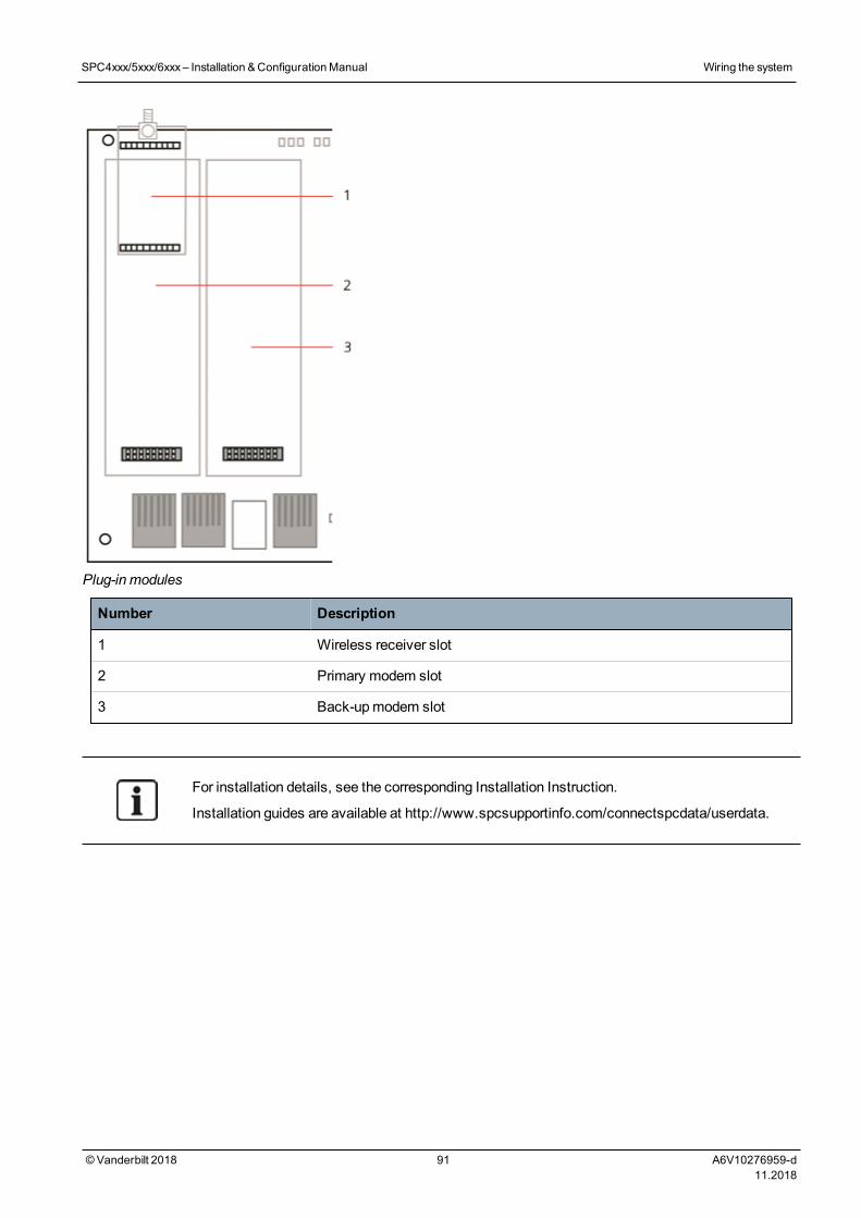
Plug-in modules
Number Description
1 Wireless receiver slot
2 Primary modem slot
3 Back-upmodem slot
For installation details, see the corresponding Installation Instruction.
Installation guides are available at http://www.spcsupportinfo.com/connectspcdata/userdata.
SPC4xxx/5xxx/6xxx– Installation &ConfigurationManual Wiring the system
©Vanderbilt 2018 91 A6V10276959-d11.2018

11 Powering up the SPC controllerThe SPC controller has two power sources, themains supply and the integral standby battery. A qualifiedelectrician should undertake connection to themains and themains supply should be connected from aspur that can be isolated. SeeWiring of mains cable to the controller on page 377 for full details ofconductor sizes/fuse ratings, etc.
The SPC should be powered from themains first and then the internal standby battery. For compliance toEN only one battery should be fitted of the appropriate capacity.
11.1 Powering from battery onlyIt is recommended that when powering a system from battery only, the battery should be in a fully chargedstate (>13.0V). The system will not power up when using a battery with less than 12V and nomains isapplied.
NOTICE: The battery will continue to power the system until deep discharge level (10.5V to 10.8V)has been detected. The time duration that the system will hold up on battery will depend on theexternal loading and Ah rating of the battery.
©Vanderbilt 2018 92 A6V10276959-d11.2018
12 Keypad user interfaceThe following keypadmodels are available:
l SPCK420/421— referred to throughout this document as the LCD Keypad
l SPCK620/623— referred to throughout this document as the Comfort Keypad
12.1 SPCK420/421This section covers:
12.1.1 About the LCD keypad 93
12.1.2 Using the LCD keypad interface 95
12.1.3 Data entry on the LCD keypad 98
12.1.1 About the LCD keypadThe LCD keypad is a wall-mounted interface that allows:
l Engineers to program the system through the Engineer Programmingmenus (password protected)and to set/unset the system; a user can control the system on a day-to-day basis.
l Users to enter User Programmingmenus (password protected), and to perform operationalprocedures (set/unset) on the system. (See theSPCK420/421 User Manual for more details of userprogramming.)
The LCD keypad unit includes an integral front tamper switch and has a 2 line x 16 character display. Itfeatures an easy-to-use navigation key to assist in locating required programming options, and has 2context sensitive soft keys (left and right) for selecting the requiredmenu or program setting. 3 LEDs onthe keypad provide an indication of AC power, system alerts, and communications status.
The LCD keypadmay be factory fitted with a Portable ACE (PACE) proximity device reader (seeOverview of keypad types on page 375).
©Vanderbilt 2018 93 A6V10276959-d11.2018
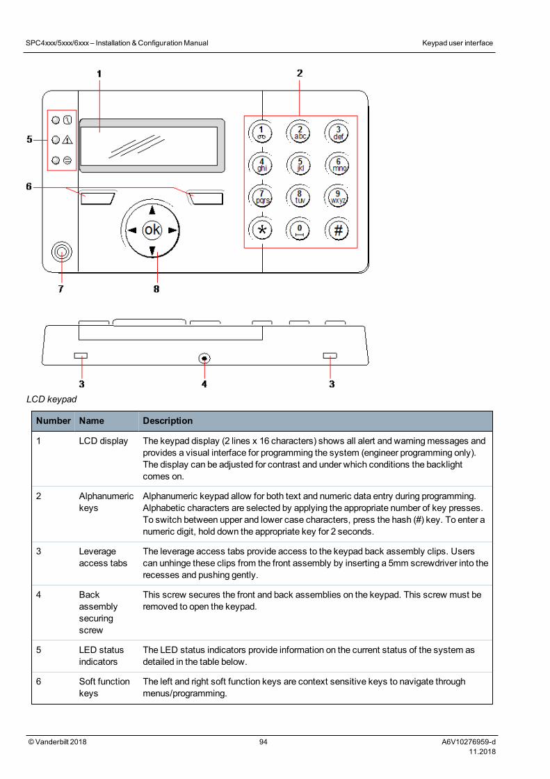
LCD keypad
Number Name Description
1 LCD display The keypad display (2 lines x 16 characters) shows all alert and warningmessages andprovides a visual interface for programming the system (engineer programming only).The display can be adjusted for contrast and under which conditions the backlightcomes on.
2 Alphanumerickeys
Alphanumeric keypad allow for both text and numeric data entry during programming.Alphabetic characters are selected by applying the appropriate number of key presses.To switch between upper and lower case characters, press the hash (#) key. To enter anumeric digit, hold down the appropriate key for 2 seconds.
3 Leverageaccess tabs
The leverage access tabs provide access to the keypad back assembly clips. Userscan unhinge these clips from the front assembly by inserting a 5mm screwdriver into therecesses and pushing gently.
4 Backassemblysecuringscrew
This screw secures the front and back assemblies on the keypad. This screw must beremoved to open the keypad.
5 LED statusindicators
The LED status indicators provide information on the current status of the system asdetailed in the table below.
6 Soft functionkeys
The left and right soft function keys are context sensitive keys to navigate throughmenus/programming.
SPC4xxx/5xxx/6xxx– Installation &ConfigurationManual Keypad user interface
© Vanderbilt 2018 94 A6V10276959-d11.2018
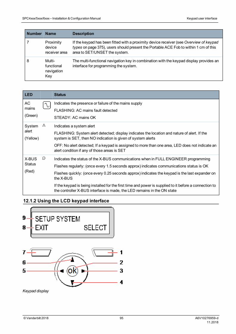
Number Name Description
7 Proximitydevicereceiver area
If the keypad has been fitted with a proximity device receiver (seeOverview of keypadtypes on page 375), users should present the Portable ACE Fob to within 1 cm of thisarea to SET/UNSET the system.
8 Multi-functionalnavigationKey
Themulti-functional navigation key in combination with the keypad display provides aninterface for programming the system.
LED Status
ACmains
(Green)
Indicates the presence or failure of themains supply
FLASHING: AC mains fault detected
STEADY: AC mains OK
Systemalert
(Yellow)
Indicates a system alert
FLASHING: System alert detected; display indicates the location and nature of alert. If thesystem is SET, then NO indication is given of system alerts
OFF: No alert detected; If a keypad is assigned tomore than one area, LED does not indicate analert condition if any of those areas is SET
X-BUSStatus
(Red)
Indicates the status of the X-BUS communications when in FULL ENGINEER programming
Flashes regularly: (once every 1.5 seconds approx) indicates communications status is OK
Flashes quickly: (once every 0.25 seconds approx) indicates the keypad is the last expander onthe X-BUS
If the keypad is being installed for the first time and power is supplied to it before a connection tothe controller X-BUS interface is made, the LED remains in the ON state
12.1.2 Using the LCD keypad interface
Keypad display
SPC4xxx/5xxx/6xxx– Installation &ConfigurationManual Keypad user interface
© Vanderbilt 2018 95 A6V10276959-d11.2018
Number Name Description
1 RIGHTSOFT KEY
This key is used to select the option presented on the right side of the bottom line display.
Possible values are:
l SELECT to select the option displayed on the top line
l ENTER to enter the data displayed on the top line
l NEXT to view the next alert after the one displayed on the top line
l CLEAR to clear the alert displayed on the top line
l SAVE to save a setting
2 OK TheOK button acts as a SELECT key for themenu option displayed on the top line andalso as an ENTER/SAVE key for data displayed on the top line.
3 In Programmingmode, the right arrow key advances the user through themenus in thesameway as pressing the SELECT option (right soft key).
In data entry mode, press this key tomove the cursor one position to the right.
4 In Programmingmode, the down arrow key moves the user to the next programmingoption in the samemenu level. Continually press this key to scroll through allprogramming options available on the current menu level.
In alphanumeric mode, press this key over an upper case character to change thecharacter to lower case.
When alerts are displayed, the down arrow key moves the user to the next alert messagein the order of priority. (SeePrioritization of display messages on the facing page.)
5 In Programmingmode, the left arrow key returns the user to the previous menu level.Pressing this key when in the topmenu level exits the user from programming.
In data entry mode, press this key tomove the cursor one position to the left.
6 In Programmingmode, the up arrow key moves the user to a previous programming optionin the samemenu level. Continually press this key to scroll through all programmingoptions available on the current menu level.
In Alphanumeric mode, press this key over a lower case character to change thecharacter to upper case.
7 LEFTSOFT KEY
This key is used to select the option presented on the left side of the bottom line display.
Possible values are:
l EXIT to exit programming
l BACK to return to previous menu
8 BOTTOMLINE OFDISPLAY
In the IDLE state, this line is blank.
In Programmingmode, this line displays options available to the user. These options alignover the left and right soft keys for selection as required.
9 TOP LINEOFDISPLAY
In the IDLE state, displays the current date and time. In Programmingmode, this linedisplays one of the following:
l The programming feature to be selected
l The current setting of the selected feature
l The nature of the current alert during an alert condition. (SeePrioritization of displaymessages on the facing page.)
SPC4xxx/5xxx/6xxx– Installation &ConfigurationManual Keypad user interface
© Vanderbilt 2018 96 A6V10276959-d11.2018
Prioritization of display messages
Troublemessages and alerts are displayed on the keypad in the following order:
l Zone
– Alarms
– Tamper
– Trouble
l Area Alerts
– Fail to set
– Entry time out
– Code tamper
l System Alerts
–Mains
– Battery
– PSU fault
– Aux fault
– External bell fuse
– Internal bell fuse
– Bell tamper
– Housing tamper
– Aux tamper 1
– Aux tamper 2
–Wireless jamming
–Modem 1 fault
– Modem 1 line
–Modem 2 fault
– Modem 2 line
– Fail to communicate
– User panic
– XBUS cable fault
– XBUS communications fault
– XBUS mains fault
– XBUS battery fault
– XBUS power supply fault
– XBUS fuse fault
– XBUS tamper fault
– XBUS antenna fault
– XBUS wireless jamming
– XBUS panic
– XBUS fire
SPC4xxx/5xxx/6xxx– Installation &ConfigurationManual Keypad user interface
© Vanderbilt 2018 97 A6V10276959-d11.2018

– XBUS medical
– XBUS Power supply link
– XBUS output tamper
– XBUS Low voltage
– Engineer restore Required
– Autoarm
l System information
– Soaked zones
–Open zones
– Area state
– Low battery (sensor)
– Sensor lost
–WPA* low battery
–WPA* lost
–WPA* test overdue
– Camera offline
– Fob low battery
– Xbus over current
– Installer name
– Installer phone
– Engineer enable
–Manufacture enable
– Reboot
– Hardware fault
– Aux over current
– Battery low
– Ethernet link
– System name
* A WPA is compatible with SiWay RF Kit (SPCW110, 111, 112, 114 ) only.
12.1.3 Data entry on the LCD keypadEntering data and navigating themenus on the LCD keypad is facilitated through the use of theprogramming interface. The use of the interface for each type of operation is detailed below.
Entering numeric values
In Numeric Entry mode, only the numeric digits (0–9) can be entered.
l Tomove the position of the cursor one character to the left and right respectively, press the left andright arrow keys.
l To exit from the feature without saving, press the BACK menu key.
l To save the programmed setting press ENTER or OK.
SPC4xxx/5xxx/6xxx– Installation &ConfigurationManual Keypad user interface
© Vanderbilt 2018 98 A6V10276959-d11.2018

Entering text
In Text Entry mode, both alphabetic characters (A–Z) and numeric digits (0–9) can be entered.
l To enter an alphabetic character, press the relevant key the required number of times.
l To enter a language specific special character (ä, ü, ö…) press button 1 to cycle through thespecial characters.
l To enter a space + special characters (+, -./[ ]…) press button 0.
l To enter a digit, hold the relevant key down for 2 seconds and release.
l Tomove the position of the cursor one character to the left and right respectively, press the leftand right arrow keys.
l To exit from the feature without saving, press BACK.
l To save the programmed setting press ENTER or OK.
l To change the case of an alphabetic character, press the up/down arrow keys when thecharacter is highlighted by the cursor.
l To toggle between upper and lower case for all subsequent characters, press the hash (#) key.
l To delete character to the left of the cursor, press the star key(*).
Selecting a programming option
In navigationmode, the Engineer/User selects one of a number of pre-defined programming optionsfrom a list.
l To scroll through the list of options available for selection, press the up and down arrow keys.
l To exit from the feature without saving, press BACK.
l To save the selected option, press SAVE or OK.
12.2 SPCK620/623This section covers:
12.2.1 About the Comfort keypad 99
12.2.2 LED description 103
12.2.3 Viewing mode description 103
12.2.4 Function keys in idle state 104
12.2.1 About the Comfort keypadThe Comfort keypad is a wall-mounted interface that allows:
l Engineers to program the system through the Engineer Programmingmenus (passwordprotected) and to set/unset the system; a user can control the system on a day-to-day basis.
l Users to enter User Programmingmenus (password protected), and to perform operationalprocedures (set/unset) on the system. (See theSPC620/623 User Manual for more details ofuser programming)
The SPCK620 is equipped with soft keys and large graphical LCD for easy operation. The functionalitycan be enhanced with key switch expander SPCE110 or indication expander SPCE120.
The SPCK623 is equipped with a proximity card reader (125 kHz EM 4102) for easy user access, softkeys, large graphical LCD and voice annunciation support. The functionality can be enhanced with keyswitch expander SPCE110 or indication expander SPCE120.
SPC4xxx/5xxx/6xxx– Installation &ConfigurationManual Keypad user interface
© Vanderbilt 2018 99 A6V10276959-d11.2018
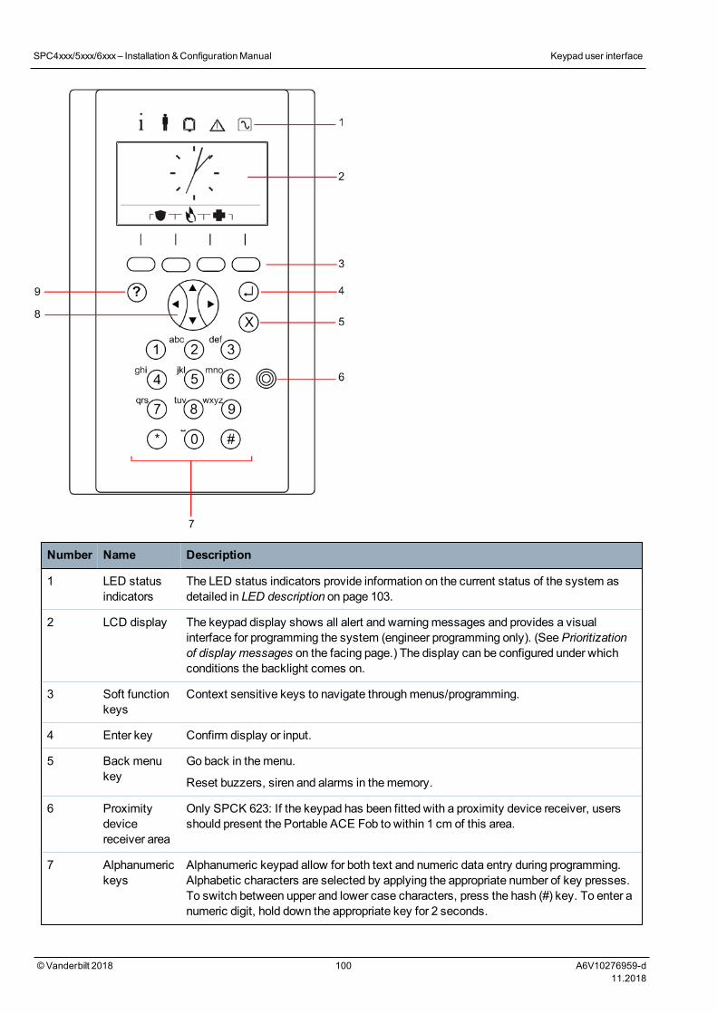
Number Name Description
1 LED statusindicators
The LED status indicators provide information on the current status of the system asdetailed in LED description on page 103.
2 LCD display The keypad display shows all alert and warningmessages and provides a visualinterface for programming the system (engineer programming only). (SeePrioritizationof display messages on the facing page.) The display can be configured under whichconditions the backlight comes on.
3 Soft functionkeys
Context sensitive keys to navigate throughmenus/programming.
4 Enter key Confirm display or input.
5 Back menukey
Go back in themenu.
Reset buzzers, siren and alarms in thememory.
6 Proximitydevicereceiver area
Only SPCK 623: If the keypad has been fitted with a proximity device receiver, usersshould present the Portable ACE Fob to within 1 cm of this area.
7 Alphanumerickeys
Alphanumeric keypad allow for both text and numeric data entry during programming.Alphabetic characters are selected by applying the appropriate number of key presses.To switch between upper and lower case characters, press the hash (#) key. To enter anumeric digit, hold down the appropriate key for 2 seconds.
SPC4xxx/5xxx/6xxx– Installation &ConfigurationManual Keypad user interface
© Vanderbilt 2018 100 A6V10276959-d11.2018

Number Name Description
8 Multi-functionalnavigationkey
Navigation throughmenus and to scroll through alert messages. (SeePrioritization ofdisplay messages below.)
9 Informationkey
Displays information.
Prioritization of display messages
Troublemessages and alerts are displayed on the keypad in the following order:
l Zone
– Alarms
– Tamper
– Trouble
l Area Alerts
– Fail to set
– Entry time out
– Code tamper
l System Alerts
–Mains
– Battery
– PSU fault
– Aux fault
– External bell fuse
– Internal bell fuse
– Bell tamper
– Housing tamper
– Aux tamper 1
– Aux tamper 2
–Wireless jamming
–Modem 1 fault
– Modem 1 line
–Modem 2 fault
– Modem 2 line
– Fail to communicate
– User panic
– XBUS cable fault
– XBUS communications fault
– XBUS mains fault
– XBUS battery fault
SPC4xxx/5xxx/6xxx– Installation &ConfigurationManual Keypad user interface
© Vanderbilt 2018 101 A6V10276959-d11.2018

– XBUS power supply fault
– XBUS fuse fault
– XBUS tamper fault
– XBUS antenna fault
– XBUS wireless jamming
– XBUS panic
– XBUS fire
– XBUS medical
– XBUS Power supply link
– XBUS output tamper
– XBUS Low voltage
– Engineer restore Required
– Autoarm
l System information
– Soaked zones
–Open zones
– Area state
– Low battery (sensor)
– Sensor lost
–WPA* low battery
–WPA* lost
–WPA* test overdue
– Camera offline
– Fob low battery
– Xbus over current
– Installer name
– Installer phone
– Engineer enable
–Manufacture enable
– Reboot
– Hardware fault
– Aux over current
– Battery low
– Ethernet link
– System name
*AWPA is compatible with SiWay RF Kit (SPCW110, 111, 112, 114 ) only.
SPC4xxx/5xxx/6xxx– Installation &ConfigurationManual Keypad user interface
© Vanderbilt 2018 102 A6V10276959-d11.2018
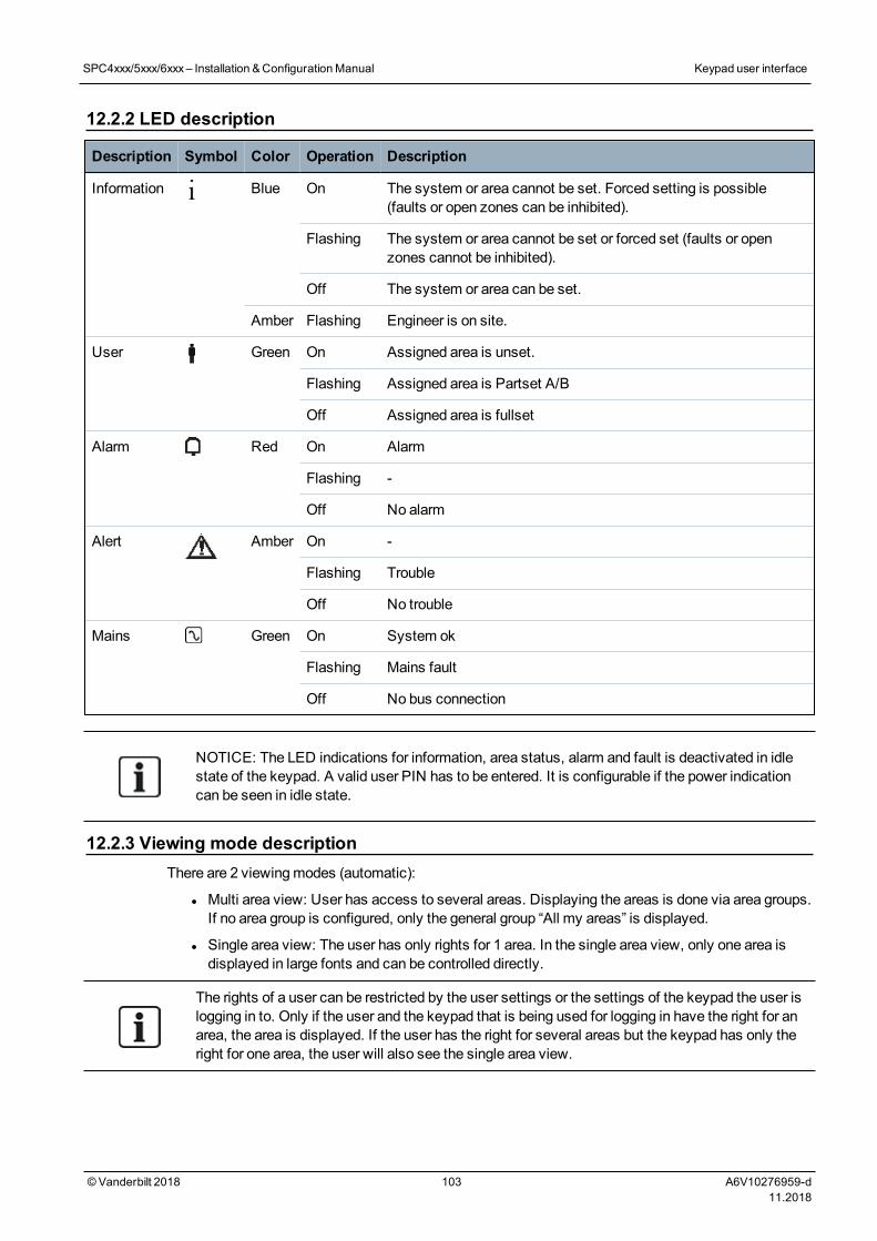
12.2.2 LED description
Description Symbol Color Operation Description
Information Blue On The system or area cannot be set. Forced setting is possible(faults or open zones can be inhibited).
Flashing The system or area cannot be set or forced set (faults or openzones cannot be inhibited).
Off The system or area can be set.
Amber Flashing Engineer is on site.
User Green On Assigned area is unset.
Flashing Assigned area is Partset A/B
Off Assigned area is fullset
Alarm Red On Alarm
Flashing -
Off No alarm
Alert Amber On -
Flashing Trouble
Off No trouble
Mains Green On System ok
Flashing Mains fault
Off No bus connection
NOTICE: The LED indications for information, area status, alarm and fault is deactivated in idlestate of the keypad. A valid user PIN has to be entered. It is configurable if the power indicationcan be seen in idle state.
12.2.3 Viewing mode descriptionThere are 2 viewingmodes (automatic):
l Multi area view: User has access to several areas. Displaying the areas is done via area groups.If no area group is configured, only the general group “All my areas” is displayed.
l Single area view: The user has only rights for 1 area. In the single area view, only one area isdisplayed in large fonts and can be controlled directly.
The rights of a user can be restricted by the user settings or the settings of the keypad the user islogging in to. Only if the user and the keypad that is being used for logging in have the right for anarea, the area is displayed. If the user has the right for several areas but the keypad has only theright for one area, the user will also see the single area view.
SPC4xxx/5xxx/6xxx– Installation &ConfigurationManual Keypad user interface
© Vanderbilt 2018 103 A6V10276959-d11.2018
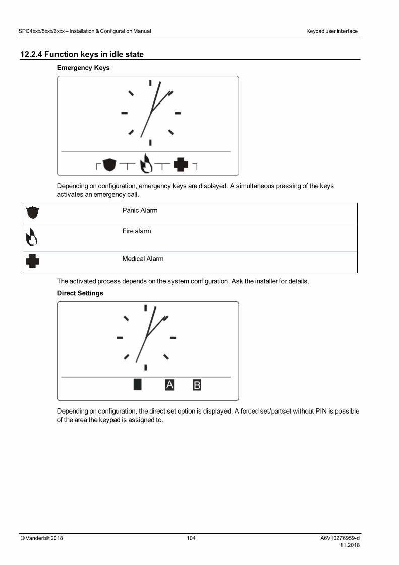
12.2.4 Function keys in idle stateEmergency Keys
Depending on configuration, emergency keys are displayed. A simultaneous pressing of the keysactivates an emergency call.
Panic Alarm
Fire alarm
Medical Alarm
The activated process depends on the system configuration. Ask the installer for details.
Direct Settings
Depending on configuration, the direct set option is displayed. A forced set/partset without PIN is possibleof the area the keypad is assigned to.
SPC4xxx/5xxx/6xxx– Installation &ConfigurationManual Keypad user interface
© Vanderbilt 2018 104 A6V10276959-d11.2018

13 Software support toolsThe following PC-based software tool is available to remotely manage an SPC panel:
l SPC Manager
Enables the remote creation, control andmodification of access based functionality within the SPCsystem.
©Vanderbilt 2018 105 A6V10276959-d11.2018

14 Starting the system
CAUTION: The SPC systemmust be installed by an authorised installation engineer.
1. Wire the keypad to the X-BUS interface on the controller.
2. Enter Engineer Programming by entering the default Engineer PIN (1111). For more details, seeEngineer PINs below.
14.1 Engineer modesThe SPC system works under 2 programmingmodes for authorised installation engineers: Full and Soft. Inthe browser, log off is only permitted in Soft Engineer mode.
Full Engineer Mode
All alerts, faults and tampers must first be isolated or cleared before exit from the Full Engineer modeis allowed.
Full Engineer mode provides extensive programming functionality. However, programming in Full Engineermode disables all alarm settings, reports and output programming for the system. For a full review of FullEngineer menu options, seeEngineer programming via the keypad on page 112.
[Soft] Engineer mode
Soft Engineer mode provides fewer programming functions and does not affect any outputs programmed inthe system. For a full review of [Soft] Engineer menu options, seeSoft Engineer programming via thekeypad on page 111.
14.1.1 Engineer PINsThe start up Engineer default programming PIN is ‘1111’.
If an installation is changed from Grade 2 to Grade 3 at any time after start-up, all PINs are prefixed with a0. Therefore, the default Engineer PIN will be ‘01111’.
Increasing the number of digits for the PIN (seeOptions on page 252) will add the relevant number of zerosto the front of an existing PIN (for example, 001111 for a 6 digit PIN).
NOTICE: If the default PIN 1111 is enabled, for example, a new SPC installation, youmust changethe engineer PIN at the panel. If you do not change your PIN, you will get an informationmessageforcing you to change your default PIN before logging out of full engineer mode.
14.2 Programming with the keypadThe keypad provides quick onsite access to systemmenus and programming. The authorised installationengineer must set initial default configurations using the keypad. Programming of proximity card/devicereader and assignment to users alsomust be done using the keypad.
©Vanderbilt 2018 106 A6V10276959-d11.2018
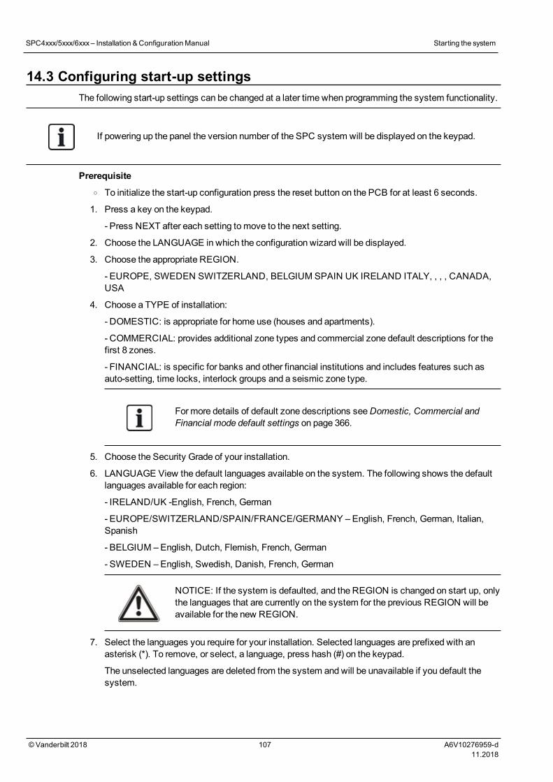
14.3 Configuring start-up settingsThe following start-up settings can be changed at a later time when programming the system functionality.
If powering up the panel the version number of the SPC system will be displayed on the keypad.
Prerequisiteo To initialize the start-up configuration press the reset button on the PCB for at least 6 seconds.
1. Press a key on the keypad.
- Press NEXT after each setting tomove to the next setting.
2. Choose the LANGUAGE in which the configuration wizard will be displayed.
3. Choose the appropriate REGION.
- EUROPE, SWEDEN SWITZERLAND, BELGIUM SPAIN UK IRELAND ITALY, , , , CANADA,USA
4. Choose a TYPE of installation:
- DOMESTIC: is appropriate for home use (houses and apartments).
- COMMERCIAL: provides additional zone types and commercial zone default descriptions for thefirst 8 zones.
- FINANCIAL: is specific for banks and other financial institutions and includes features such asauto-setting, time locks, interlock groups and a seismic zone type.
For more details of default zone descriptions seeDomestic, Commercial andFinancial mode default settings on page 366.
5. Choose the Security Grade of your installation.
6. LANGUAGE View the default languages available on the system. The following shows the defaultlanguages available for each region:
- IRELAND/UK -English, French, German
- EUROPE/SWITZERLAND/SPAIN/FRANCE/GERMANY – English, French, German, Italian,Spanish
- BELGIUM –English, Dutch, Flemish, French, German
- SWEDEN –English, Swedish, Danish, French, German
NOTICE: If the system is defaulted, and the REGION is changed on start up, onlythe languages that are currently on the system for the previous REGION will beavailable for the new REGION.
7. Select the languages you require for your installation. Selected languages are prefixed with anasterisk (*). To remove, or select, a language, press hash (#) on the keypad.
The unselected languages are deleted from the system and will be unavailable if you default thesystem.
SPC4xxx/5xxx/6xxx– Installation &ConfigurationManual Starting the system
©Vanderbilt 2018 107 A6V10276959-d11.2018
To add other languages to the panel, seeUpgrading Languages on page 340. To add otherlanguages to a keypad, see the documentation for that keypad. Installation guides are availableat http://www.spcsupportinfo.com/connectspcdata/userdata.
8. Enter the DATE and TIME.
The system scans the X-BUS for modems.
9. Enable SPC CONNECT to allow a panel to communicate with https://www.spcconnect.comonce the panel IP address is configured.
10. Enable DHCP to automatically assign an available network IP address to the panel. If you'veenabled SPC CONNECT and DHCP, an SPC CONNECT ATS is now added to the panel tocomplete the connection to https://www.spcconnect.com
11. For DHCP enabled panels, the automatically assigned IP address displays in the IP ADDRESSmenu. If DHCP is not enabled, the default IP address displays. Choose SELECT to continue. InEngineer Programmingmode, under COMMUNICATIONS, youmust manually enter the staticIP address for the panel.
12. Choose the X-BUS addressingmode:
- MANUAL: is recommended for most installation types, especially when doing apreconfiguration.
- AUTO: is recommended only for very small installations.
13. Choose the installation topology: LOOP (Ring) or SPUR (Chain).
The system scans for the quantity of keypads, expanders, door controllers and available zoneinputs.
14. Press NEXT to scan all X-BUS devices.
PROGRAMMINGMODE will be displayed.
The Start-up setting is complete.
15. Check the alerts in themenu SYSTEM STATUS > ALERTS. Otherwise you will not be allowedto exit the Engineer Mode.
16. Configure the system by keypad or web browser.
See also
Domestic, Commercial and Financial mode default settings on page 366
14.4 Creating system usersBy default the SPC system only allows engineer access on the system. The engineer must createUsers to allow on-site personnel to set, unset, and perform basic operations on the system as required.Users are restricted to a set of panel operations by assigning them to specific User Profiles.
The system allows all user PINs within the allowed PIN range, that is, if a 4 digit PIN is used then alluser PINs between 0000 and 9999 would be permissible.
SeeUsers on page 135 orUsers on page 196.
The ability to grant manufacturer access to the system (for example, allow a firmware upgrade ofthe panel) is configured as a user right for a user profile. If a user is going to be enabling firmwareupgrades, ensure that the user has the correct profile for this purpose.
See also
Engineer PINs on page 106
SPC4xxx/5xxx/6xxx– Installation &ConfigurationManual Starting the system
©Vanderbilt 2018 108 A6V10276959-d11.2018
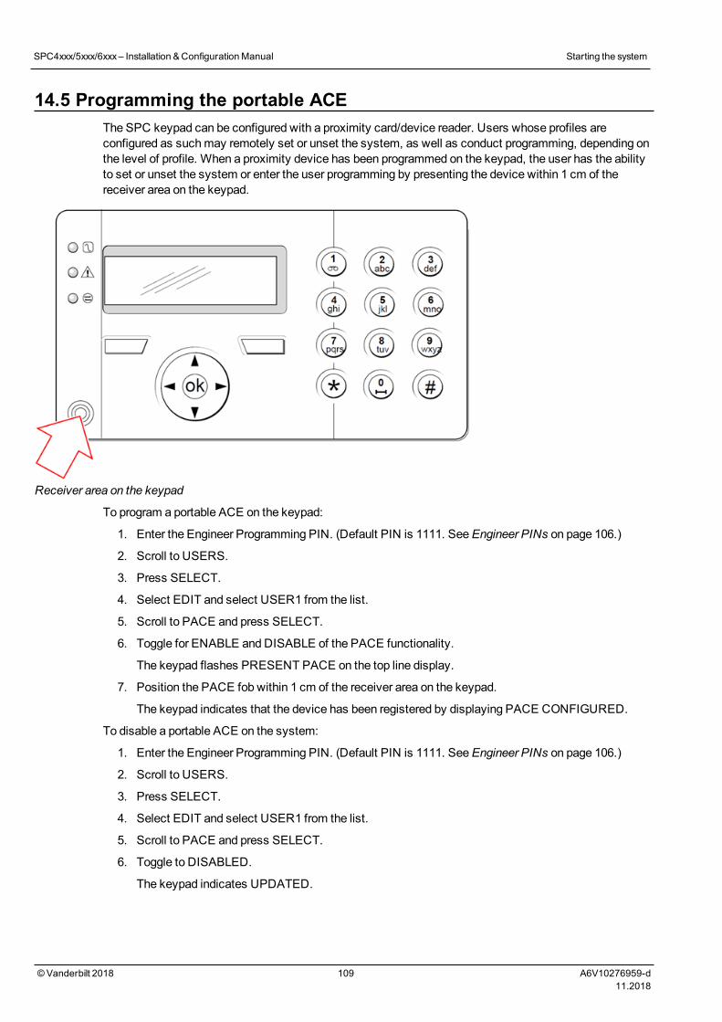
14.5 Programming the portable ACEThe SPC keypad can be configured with a proximity card/device reader. Users whose profiles areconfigured as suchmay remotely set or unset the system, as well as conduct programming, depending onthe level of profile. When a proximity device has been programmed on the keypad, the user has the abilityto set or unset the system or enter the user programming by presenting the device within 1 cm of thereceiver area on the keypad.
Receiver area on the keypad
To program a portable ACE on the keypad:
1. Enter the Engineer Programming PIN. (Default PIN is 1111. SeeEngineer PINs on page 106.)
2. Scroll to USERS.
3. Press SELECT.
4. Select EDIT and select USER1 from the list.
5. Scroll to PACE and press SELECT.
6. Toggle for ENABLE and DISABLE of the PACE functionality.
The keypad flashes PRESENT PACE on the top line display.
7. Position the PACE fob within 1 cm of the receiver area on the keypad.
The keypad indicates that the device has been registered by displaying PACE CONFIGURED.
To disable a portable ACE on the system:
1. Enter the Engineer Programming PIN. (Default PIN is 1111. SeeEngineer PINs on page 106.)
2. Scroll to USERS.
3. Press SELECT.
4. Select EDIT and select USER1 from the list.
5. Scroll to PACE and press SELECT.
6. Toggle to DISABLED.
The keypad indicates UPDATED.
SPC4xxx/5xxx/6xxx– Installation &ConfigurationManual Starting the system
©Vanderbilt 2018 109 A6V10276959-d11.2018
14.6 Configuring wireless fob devicesIf an 868MHz wireless receiver module is installed on the keypad or controller, a wireless fob devicecan be programmed via the keypad.
To program awireless fob device on the system:
1. Enter the Engineer Programming PIN. (Default PIN is 1111. SeeEngineer PINs on page 106.)
2. Using the up/down arrow keys, scroll to the USERS option.
3. Press SELECT.
4. Select the EDIT option and press SELECT.
5. Scroll to the preferred user and press SELECT.
6. Scroll to the RF FOB option and press SELECT.
7. Toggle the setting to ENABLED and press SELECT.
Themessage PRESS KEY ON FOB flashes on the top line.
8. Position the fob to within 8meters of the keypad and press one of the keys.
Themessage FOB CONFIGURED displays to indicate that the device has been registered.
To disable the wireless fob device on the system:
1. Enter the Engineer Programming PIN. (Default PIN is 1111. SeeEngineer PINs on page 106.)
2. Using the up/down arrow keys, scroll to the USERS option.
3. Select the EDIT option and press SELECT.
4. Scroll to the preferred user and press SELECT.
5. Scroll to the RF FOB option and press SELECT.
6. Toggle to DISABLED and press SAVE.
If no 868MHz wireless receiver is detected on the system, the RF FOB option is not displayed inthe keypadmenu.
Number of RF fobs per user:Only one fob device can be programmed for each user. To changefob devices among users, repeat the programming procedure for any new devices. Old fob devicesbecome available for use by different users.
14.6.1 Clearing alerts using the fobAlerts on the SPC system are normally cleared using the keypad RESTORE option. Clearing alertscan also be performed by using the wireless fob device.
If an active alert is displayed on the keypad when the system is UNSET, the alert can be cleared orrestored by pressing the UNSET key on the wireless fob five seconds after the system has been unset.
To enable this functionality, the KEYFOB RESTORE optionmust be enabled in System Options:
1. Login to the keypad with an Engineer PIN.
2. Scroll to FULL ENGINEER > OPTIONS.
3. Press SELECT.
4. Scroll to KEYFOB RESTORE and press SELECT.
5. Toggle the setting to ENABLED and press SAVE.
SPC4xxx/5xxx/6xxx– Installation &ConfigurationManual Starting the system
©Vanderbilt 2018 110 A6V10276959-d11.2018
15 Soft Engineer programming via the keypadThis section provides [Soft] Engineer programming options using the LCD keypad.
For eachmenu option, the keypadmust be in Engineer programming:
1. Enter a valid Engineer PIN. (Default Engineer PIN is 1111. For more details, seeEngineer PINs onpage 106.)
2. Using the up/down arrow keys, scroll to the desired programming option.
3. It is also possible to select a programming option using the keypad digits, enter the Engineerprogramming PIN plus the digit as shown in the table below.
If you change one of the programming options, the keypad displays UPDATED momentarily.
Number Name Description
1 SETTING Performs an Unset, Fullset or Partset on the system.
2 INHIBIT Displays a list of the Inhibited zones on the system.
3 ISOLATE Allows the engineer to isolate zones on the system. See Isolate onpage 166.
4 EVENT LOG Displays a list of themost recent events on the system. SeeEvent Log on page 166.
5 ACCESS LOG Displays a list of themost recent access to the system. SeeAccess Log on page 166.
6 ALARM LOG Displays a list of recent alarms. SeeAlarm Log on page 166.
7 CHANGEENGPIN
Allows the engineer to change the Engineer PIN. SeeChangeEngineer Pin on page 167.
8 USERS Allows the engineer to add, edit or delete users. SeeUsers onpage 135.
9 SMS Allows the user to add, edit or delete SMS details for users. SeeSMS on page 167.
See also
Test on page 162
Door Control on page 170
Engineer programming via the keypad on page 112
Installer Text on page 170
Set Date/Time on page 169
SMS on page 167
©Vanderbilt 2018 111 A6V10276959-d11.2018
16 Engineer programming via the keypadThis section provides [Full] Engineer programming options using the LCD keypad
For eachmenu option, the keypadmust be in Full Engineer programming:
1. Enter a valid Engineer PIN. (Default Engineer PIN is 1111. For more details, seeEngineer PINs onpage 106.)
2. Press SELECT for FULL ENGINEER programming.
3. Using the up/down arrow keys, scroll to the desired programming option.
4. A quick select function is implemented. Press # to select a parameter (for example, a zoneattribute). The selected parameter is displayed with a * (for example, *Inhibit).
Upon completion of the programming options, the keypad displays UPDATED momentarily.
Please note that a * at the start of a menu item indicates that the item is already selected.
16.1 System StatusThe System Status feature displays all faults on the system.
To view these faults:
1. Scroll to SYSTEM STATUS.
2. Press SELECT.
The status of the following items is displayed.
Click each item to display further details.
OPENZONES
Displays all open zones.
ALERTS Displays current alerts on the system.
SOAK Displays all zones on soak test.
ISOLATIONS Displays zones that are isolated.
FAIL TOSET Displays all areas that have failed to set. Select each area to display details of why the area failedto set.
BATTERY Displays remaining battery time, voltage and current of battery. Youmust enter theBatterycapacity andMax current values in OPTIONS to view the remaining battery time on the keypad inthe event of mains failure. This is indicated under the STATUS > BATTERY > BATT TIME menu.This menu also indicates if there is a battery fault.
AUX Displays voltage and current of auxiliary power.
NOTICE:Users cannot exit from FULL ENGINEER programming if any fault conditions exist. Thefirst fault will display on the keypad when you attempt to leave engineer mode. You can view andisolate all faults within the System Status menu under Alerts andOpen Zones.
©Vanderbilt 2018 112 A6V10276959-d11.2018
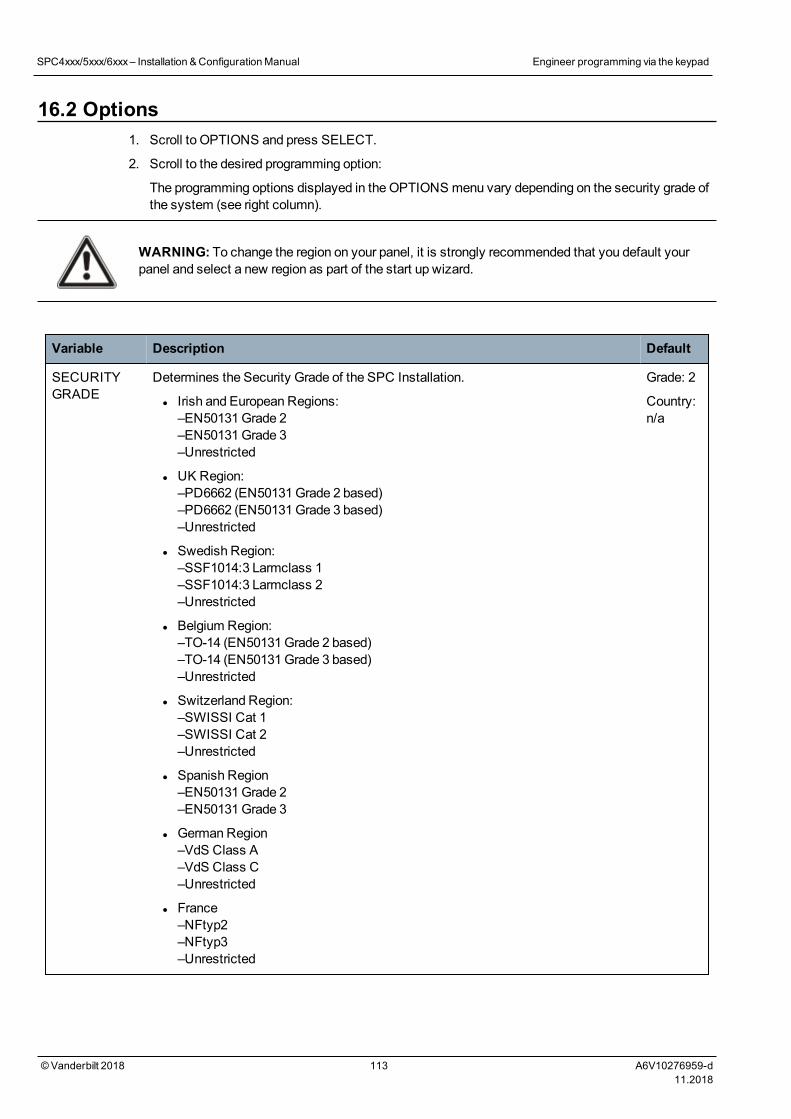
16.2 Options1. Scroll to OPTIONS and press SELECT.
2. Scroll to the desired programming option:
The programming options displayed in the OPTIONS menu vary depending on the security grade ofthe system (see right column).
WARNING: To change the region on your panel, it is strongly recommended that you default yourpanel and select a new region as part of the start up wizard.
Variable Description Default
SECURITYGRADE
Determines the Security Grade of the SPC Installation.
l Irish and European Regions:–EN50131Grade 2–EN50131Grade 3–Unrestricted
l UK Region:–PD6662 (EN50131Grade 2 based)–PD6662 (EN50131Grade 3 based)–Unrestricted
l Swedish Region:–SSF1014:3 Larmclass 1–SSF1014:3 Larmclass 2–Unrestricted
l Belgium Region:–TO-14 (EN50131Grade 2 based)–TO-14 (EN50131Grade 3 based)–Unrestricted
l Switzerland Region:–SWISSI Cat 1–SWISSI Cat 2–Unrestricted
l Spanish Region–EN50131Grade 2–EN50131Grade 3
l GermanRegion–VdS Class A–VdS Class C–Unrestricted
l France–NFtyp2–NFtyp3–Unrestricted
Grade: 2
Country:n/a
SPC4xxx/5xxx/6xxx– Installation &ConfigurationManual Engineer programming via the keypad
© Vanderbilt 2018 113 A6V10276959-d11.2018
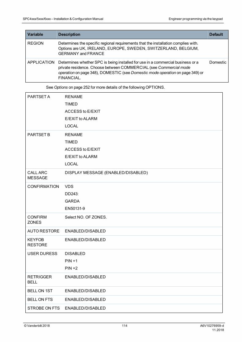
Variable Description Default
REGION Determines the specific regional requirements that the installation complies with.Options are UK, IRELAND, EUROPE, SWEDEN, SWITZERLAND, BELGIUM,GERMANY and FRANCE
APPLICATION Determines whether SPC is being installed for use in a commercial business or aprivate residence. Choose between COMMERCIAL (seeCommercial modeoperation on page 348), DOMESTIC (seeDomestic mode operation on page 349) orFINANCIAL.
Domestic
SeeOptions on page 252 for more details of the following OPTIONS.
PARTSET A RENAME
TIMED
ACCESS to E/EXIT
E/EXIT to ALARM
LOCAL
PARTSET B RENAME
TIMED
ACCESS to E/EXIT
E/EXIT to ALARM
LOCAL
CALL ARCMESSAGE
DISPLAY MESSAGE (ENABLED/DISABLED)
CONFIRMATION VDS
DD243:
GARDA
EN50131-9
CONFIRMZONES
Select NO. OF ZONES.
AUTORESTORE ENABLED/DISABLED
KEYFOBRESTORE
ENABLED/DISABLED
USER DURESS DISABLED
PIN +1
PIN +2
RETRIGGERBELL
ENABLED/DISABLED
BELLON 1ST ENABLED/DISABLED
BELLON FTS ENABLED/DISABLED
STROBE ON FTS ENABLED/DISABLED
SPC4xxx/5xxx/6xxx– Installation &ConfigurationManual Engineer programming via the keypad
© Vanderbilt 2018 114 A6V10276959-d11.2018
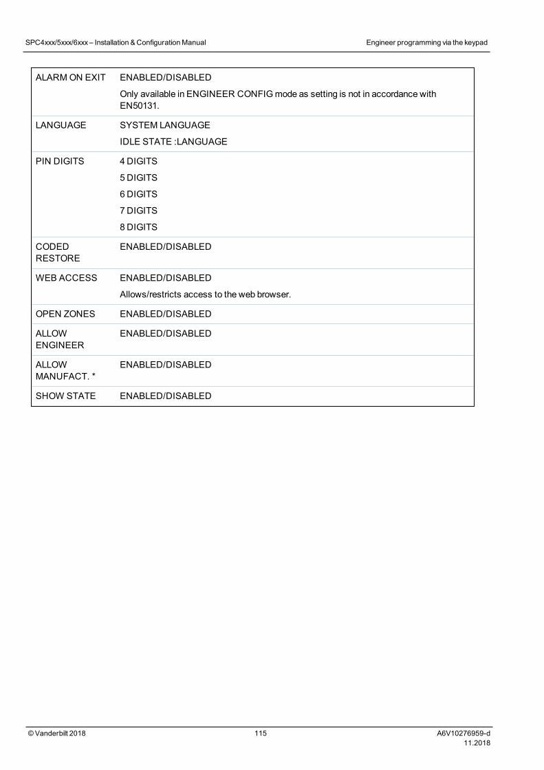
ALARMON EXIT ENABLED/DISABLED
Only available in ENGINEER CONFIGmode as setting is not in accordance withEN50131.
LANGUAGE SYSTEM LANGUAGE
IDLE STATE :LANGUAGE
PIN DIGITS 4DIGITS
5DIGITS
6DIGITS
7DIGITS
8DIGITS
CODEDRESTORE
ENABLED/DISABLED
WEB ACCESS ENABLED/DISABLED
Allows/restricts access to the web browser.
OPEN ZONES ENABLED/DISABLED
ALLOWENGINEER
ENABLED/DISABLED
ALLOWMANUFACT. *
ENABLED/DISABLED
SHOW STATE ENABLED/DISABLED
SPC4xxx/5xxx/6xxx– Installation &ConfigurationManual Engineer programming via the keypad
© Vanderbilt 2018 115 A6V10276959-d11.2018
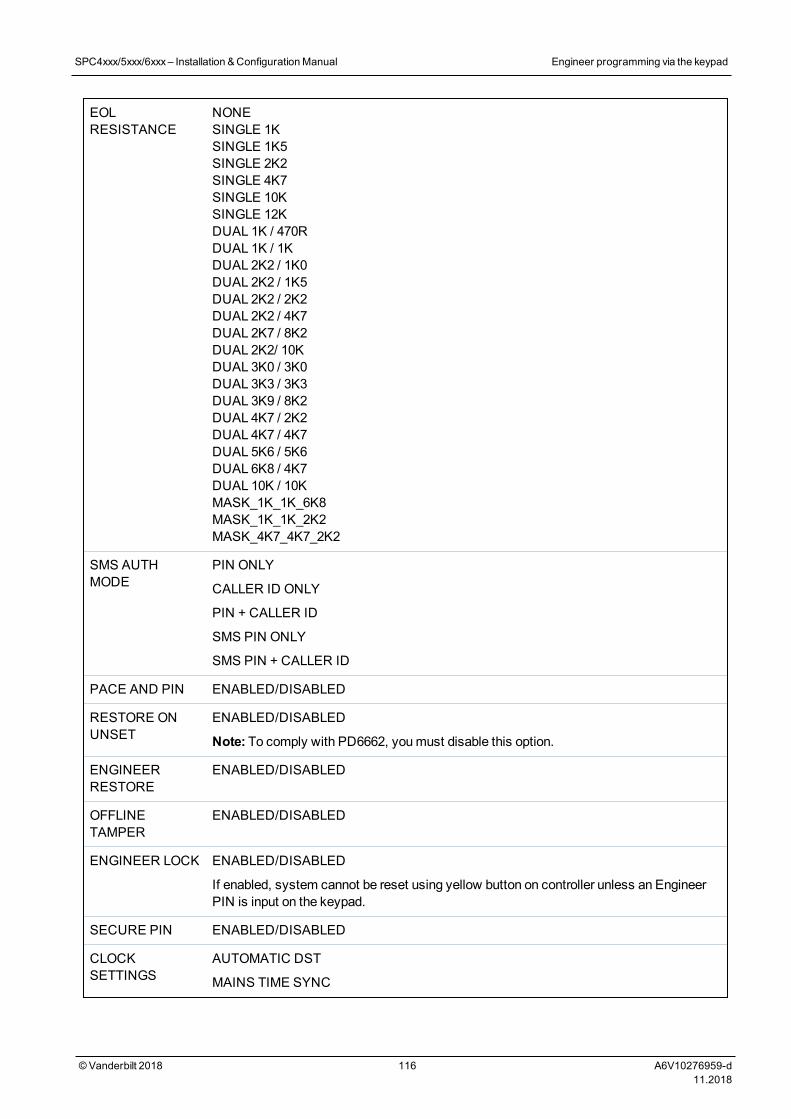
EOLRESISTANCE
NONESINGLE 1KSINGLE 1K5SINGLE 2K2SINGLE 4K7SINGLE 10KSINGLE 12KDUAL 1K / 470RDUAL 1K / 1KDUAL 2K2 / 1K0DUAL 2K2 / 1K5DUAL 2K2 / 2K2DUAL 2K2 / 4K7DUAL 2K7 / 8K2DUAL 2K2/ 10KDUAL 3K0 / 3K0DUAL 3K3 / 3K3DUAL 3K9 / 8K2DUAL 4K7 / 2K2DUAL 4K7 / 4K7DUAL 5K6 / 5K6DUAL 6K8 / 4K7DUAL 10K / 10KMASK_1K_1K_6K8MASK_1K_1K_2K2MASK_4K7_4K7_2K2
SMS AUTHMODE
PIN ONLY
CALLER ID ONLY
PIN + CALLER ID
SMS PIN ONLY
SMS PIN + CALLER ID
PACE AND PIN ENABLED/DISABLED
RESTORE ONUNSET
ENABLED/DISABLED
Note: To comply with PD6662, youmust disable this option.
ENGINEERRESTORE
ENABLED/DISABLED
OFFLINETAMPER
ENABLED/DISABLED
ENGINEER LOCK ENABLED/DISABLED
If enabled, system cannot be reset using yellow button on controller unless an EngineerPIN is input on the keypad.
SECURE PIN ENABLED/DISABLED
CLOCKSETTINGS
AUTOMATIC DST
MAINS TIME SYNC
SPC4xxx/5xxx/6xxx– Installation &ConfigurationManual Engineer programming via the keypad
© Vanderbilt 2018 116 A6V10276959-d11.2018
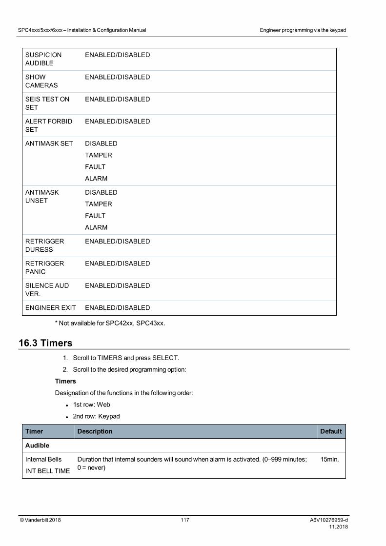
SUSPICIONAUDIBLE
ENABLED/DISABLED
SHOWCAMERAS
ENABLED/DISABLED
SEIS TEST ONSET
ENABLED/DISABLED
ALERT FORBIDSET
ENABLED/DISABLED
ANTIMASK SET DISABLED
TAMPER
FAULT
ALARM
ANTIMASKUNSET
DISABLED
TAMPER
FAULT
ALARM
RETRIGGERDURESS
ENABLED/DISABLED
RETRIGGERPANIC
ENABLED/DISABLED
SILENCE AUDVER.
ENABLED/DISABLED
ENGINEER EXIT ENABLED/DISABLED
* Not available for SPC42xx, SPC43xx.
16.3 Timers1. Scroll to TIMERS and press SELECT.
2. Scroll to the desired programming option:
Timers
Designation of the functions in the following order:
l 1st row: Web
l 2nd row: Keypad
Timer Description Default
Audible
Internal Bells
INT BELL TIME
Duration that internal sounders will sound when alarm is activated. (0–999minutes;0 = never)
15min.
SPC4xxx/5xxx/6xxx– Installation &ConfigurationManual Engineer programming via the keypad
© Vanderbilt 2018 117 A6V10276959-d11.2018
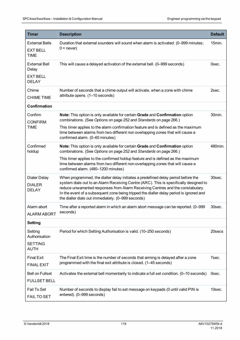
Timer Description Default
External Bells
EXT BELLTIME
Duration that external sounders will sound when alarm is activated. (0–999minutes;0 = never)
15min.
External BellDelay
EXT BELLDELAY
This will cause a delayed activation of the external bell. (0–999 seconds) 0sec.
Chime
CHIME TIME
Number of seconds that a chime output will activate, when a zone with chimeattribute opens. (1–10 seconds)
2sec.
Confirmation
Confirm
CONFIRMTIME
Note: This option is only available for certainGrade andConfirmation optioncombinations. (SeeOptions on page 252 andStandards on page 266.)
This timer applies to the alarm confirmation feature and is defined as themaximumtime between alarms from two different non overlapping zones that will cause aconfirmed alarm. (0–60minutes)
30min.
Confirmedholdup
Note: This option is only available for certainGrade andConfirmation optioncombinations. (SeeOptions on page 252 andStandards on page 266.)
This timer applies to the confirmed holdup feature and is defined as themaximumtime between alarms from two different non-overlapping zones that will cause aconfirmed alarm. (480–1200minutes)
480min.
Dialer Delay
DIALERDELAY
When programmed, the dialler delay initiates a predefined delay period before thesystem dials out to an Alarm Receiving Centre (ARC). This is specifically designed toreduce unwarranted responses from Alarm Receiving Centres and the constabulary.In the event of a subsequent zone being tripped the dialler delay period is ignored andthe dialler dials out immediately. (0–999 seconds)
30sec.
Alarm abort
ALARM ABORT
Time after a reported alarm in which an alarm abort message can be reported. (0–999seconds)
30sec.
Setting
SettingAuthorisation
SETTINGAUTH
Period for which Setting Authorisation is valid. (10–250 seconds) 20secs
Final Exit
FINAL EXIT
The Final Exit time is the number of seconds that arming is delayed after a zoneprogrammedwith the final exit attribute is closed. (1–45 seconds)
7sec.
Bell on Fullset
FULLSET BELL
Activates the external bell momentarily to indicate a full set condition. (0–10 seconds) 0sec.
Fail To Set
FAIL TOSET
Number of seconds to display fail to set message on keypads (0 until valid PIN isentered). (0–999 seconds)
10sec.
SPC4xxx/5xxx/6xxx– Installation &ConfigurationManual Engineer programming via the keypad
© Vanderbilt 2018 118 A6V10276959-d11.2018
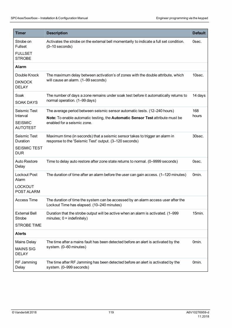
Timer Description Default
Strobe onFullset
FULLSETSTROBE
Activates the strobe on the external bell momentarily to indicate a full set condition.(0–10 seconds)
0sec.
Alarm
Double Knock
DKNOCKDELAY
Themaximum delay between activation’s of zones with the double attribute, whichwill cause an alarm. (1–99 seconds)
10sec.
Soak
SOAK DAYS
The number of days a zone remains under soak test before it automatically returns tonormal operation. (1–99 days)
14 days
Seismic TestInterval
SEISMICAUTOTEST
The average period between seismic sensor automatic tests. (12–240 hours)
Note: To enable automatic testing, theAutomatic Sensor Test attributemust beenabled for a seismic zone.
168hours
Seismic TestDuration
SEISMIC TESTDUR
Maximum time (in seconds) that a seismic sensor takes to trigger an alarm inresponse to the 'Seismic Test' output. (3–120 seconds)
30sec.
Auto RestoreDelay
Time to delay auto restore after zone state returns to normal. (0–9999 seconds) 0sec.
Lockout PostAlarm
LOCKOUTPOST ALARM
The duration of time after an alarm before the user can gain access. (1–120minutes) 0min.
Access Time The duration of time the system can be accessed by an alarm access user after theLockout Time has elapsed. (10–240minutes)
External BellStrobe
STROBE TIME
Duration that the strobe output will be active when an alarm is activated. (1–999minutes; 0 = indefinitely)
15min.
Alerts
Mains Delay
MAINS SIGDELAY
The time after amains fault has been detected before an alert is activated by thesystem. (0–60minutes)
0min.
RF JammingDelay
The time after RF Jamming has been detected before an alert is activated by thesystem. (0–999 seconds)
0min.
SPC4xxx/5xxx/6xxx– Installation &ConfigurationManual Engineer programming via the keypad
© Vanderbilt 2018 119 A6V10276959-d11.2018
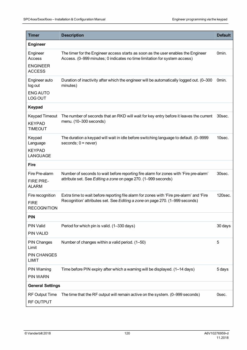
Timer Description Default
Engineer
EngineerAccess
ENGINEERACCESS
The timer for the Engineer access starts as soon as the user enables the EngineerAccess. (0–999minutes; 0 indicates no time limitation for system access)
0min.
Engineer autolog out
ENGAUTOLOGOUT
Duration of inactivity after which the engineer will be automatically logged out. (0–300minutes)
0min.
Keypad
Keypad Timeout
KEYPADTIMEOUT
The number of seconds that an RKD will wait for key entry before it leaves the currentmenu. (10–300 seconds)
30sec.
KeypadLanguage
KEYPADLANGUAGE
The duration a keypad will wait in idle before switching language to default. (0–9999seconds; 0 = never)
10sec.
Fire
Fire Pre-alarm
FIRE PRE-ALARM
Number of seconds to wait before reporting fire alarm for zones with ‘Fire pre-alarm’attribute set. SeeEditing a zone on page 270. (1–999 seconds)
30sec.
Fire recognition
FIRERECOGNITION
Extra time to wait before reporting file alarm for zones with ‘Fire pre-alarm’ and ‘FireRecognition’ attributes set. SeeEditing a zone on page 270. (1–999 seconds)
120sec.
PIN
PIN Valid
PIN VALID
Period for which pin is valid. (1–330 days) 30 days
PIN ChangesLimit
PIN CHANGESLIMIT
Number of changes within a valid period. (1–50) 5
PIN Warning
PIN WARN
Time before PIN expiry after which a warning will be displayed. (1–14 days) 5 days
General Settings
RFOutput Time
RF OUTPUT
The time that the RF output will remain active on the system. (0–999 seconds) 0sec.
SPC4xxx/5xxx/6xxx– Installation &ConfigurationManual Engineer programming via the keypad
© Vanderbilt 2018 120 A6V10276959-d11.2018
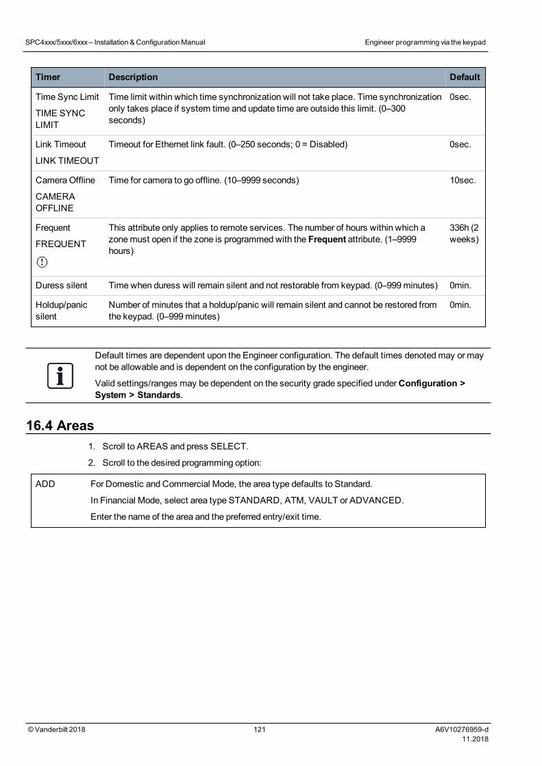
Timer Description Default
Time Sync Limit
TIME SYNCLIMIT
Time limit within which time synchronization will not take place. Time synchronizationonly takes place if system time and update time are outside this limit. (0–300seconds)
0sec.
Link Timeout
LINK TIMEOUT
Timeout for Ethernet link fault. (0–250 seconds; 0 = Disabled) 0sec.
Camera Offline
CAMERAOFFLINE
Time for camera to go offline. (10–9999 seconds) 10sec.
Frequent
FREQUENT
This attribute only applies to remote services. The number of hours within which azonemust open if the zone is programmedwith the Frequent attribute. (1–9999hours)
336h (2weeks)
Duress silent Timewhen duress will remain silent and not restorable from keypad. (0–999minutes) 0min.
Holdup/panicsilent
Number of minutes that a holdup/panic will remain silent and cannot be restored fromthe keypad. (0–999minutes)
0min.
Default times are dependent upon the Engineer configuration. The default times denotedmay or maynot be allowable and is dependent on the configuration by the engineer.
Valid settings/ranges may be dependent on the security grade specified underConfiguration >System > Standards.
16.4 Areas1. Scroll to AREAS and press SELECT.
2. Scroll to the desired programming option:
ADD For Domestic and Commercial Mode, the area type defaults to Standard.
In Financial Mode, select area type STANDARD, ATM, VAULT or ADVANCED.
Enter the name of the area and the preferred entry/exit time.
SPC4xxx/5xxx/6xxx– Installation &ConfigurationManual Engineer programming via the keypad
© Vanderbilt 2018 121 A6V10276959-d11.2018
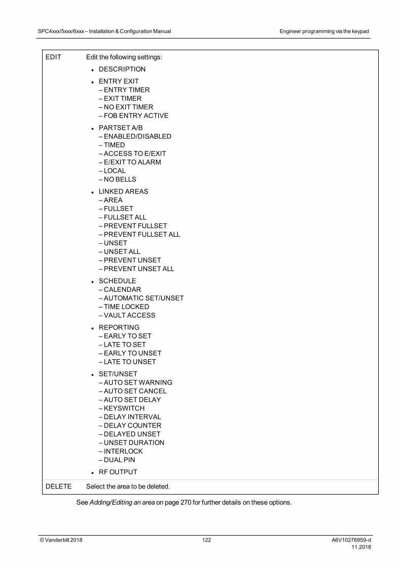
EDIT Edit the following settings:
l DESCRIPTION
l ENTRY EXIT– ENTRY TIMER– EXIT TIMER–NOEXIT TIMER– FOB ENTRY ACTIVE
l PARTSET A/B– ENABLED/DISABLED– TIMED– ACCESS TOE/EXIT– E/EXIT TOALARM– LOCAL–NOBELLS
l LINKED AREAS– AREA– FULLSET– FULLSET ALL– PREVENT FULLSET– PREVENT FULLSET ALL– UNSET–UNSET ALL– PREVENT UNSET– PREVENT UNSET ALL
l SCHEDULE–CALENDAR–AUTOMATIC SET/UNSET– TIME LOCKED– VAULT ACCESS
l REPORTING– EARLY TOSET– LATE TOSET– EARLY TOUNSET– LATE TOUNSET
l SET/UNSET– AUTOSETWARNING– AUTOSET CANCEL– AUTOSET DELAY– KEYSWITCH–DELAY INTERVAL–DELAY COUNTER–DELAYED UNSET–UNSET DURATION– INTERLOCK–DUAL PIN
l RFOUTPUT
DELETE Select the area to be deleted.
SeeAdding/Editing an area on page 270 for further details on these options.
SPC4xxx/5xxx/6xxx– Installation &ConfigurationManual Engineer programming via the keypad
© Vanderbilt 2018 122 A6V10276959-d11.2018
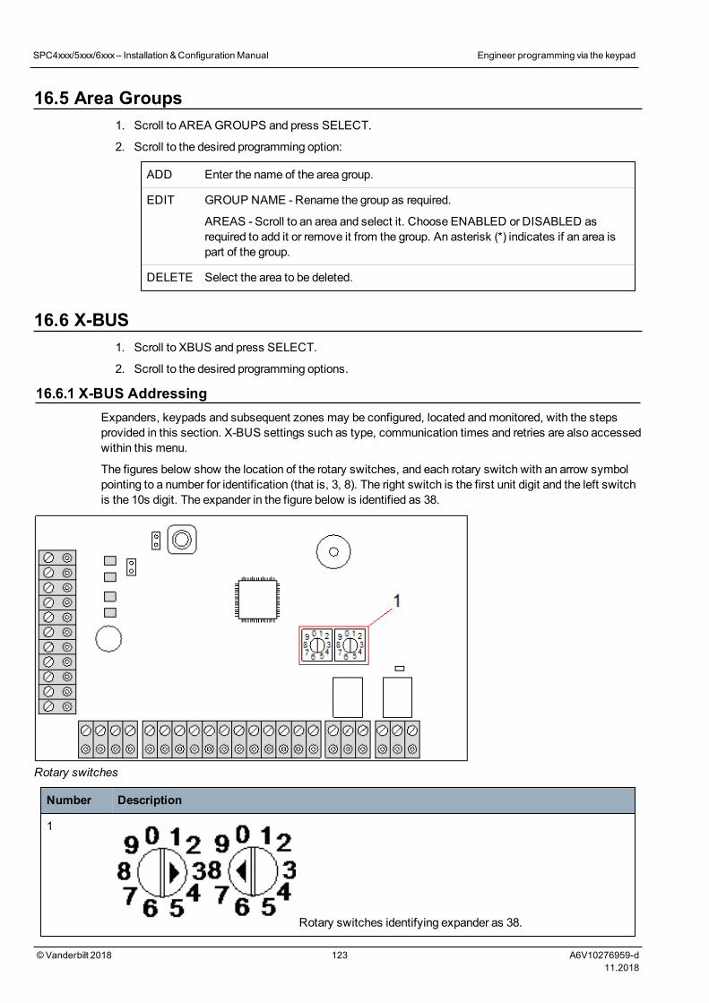
16.5 Area Groups1. Scroll to AREA GROUPS and press SELECT.
2. Scroll to the desired programming option:
ADD Enter the name of the area group.
EDIT GROUP NAME - Rename the group as required.
AREAS - Scroll to an area and select it. Choose ENABLED or DISABLED asrequired to add it or remove it from the group. An asterisk (*) indicates if an area ispart of the group.
DELETE Select the area to be deleted.
16.6 X-BUS1. Scroll to XBUS and press SELECT.
2. Scroll to the desired programming options.
16.6.1 X-BUS AddressingExpanders, keypads and subsequent zones may be configured, located andmonitored, with the stepsprovided in this section. X-BUS settings such as type, communication times and retries are also accessedwithin this menu.
The figures below show the location of the rotary switches, and each rotary switch with an arrow symbolpointing to a number for identification (that is, 3, 8). The right switch is the first unit digit and the left switchis the 10s digit. The expander in the figure below is identified as 38.
Rotary switches
Number Description
1
Rotary switches identifying expander as 38.
SPC4xxx/5xxx/6xxx– Installation &ConfigurationManual Engineer programming via the keypad
© Vanderbilt 2018 123 A6V10276959-d11.2018
For a system with automatic addressing, expanders and keypads belong to the same numberingsequence. For example, expanders and keypads are automatically numbered 01, 02, 03, etc., by thecontroller in the order in which they are detected, for example, its relevant location to controller. In thisconfiguration, zones are allocated to each input expander.
Automatically addressed expanders are not supported by SPC41xx.
16.6.2 XBUS RefreshThe X-Bus Refresh utility performs a discovery of the current status of the X-Bus and displays thecurrent X-Bus configuration.
To refresh the X-Bus status:
1. Scroll to XBUS REFRESH.
2. Press SELECT.
The number of online keypads is displayed.
3. Press the right soft key on the keypad after each display to view expanders, zones and offlineitems.
4. Press this key again to exit.
Refreshmakes no changes to the system, but is useful for detecting system faults, such as looseconnections, or inactive expanders, before performing aReconfigure.
16.6.3 Reconfigure
NOTICE: A reconfigure only applies to wired zones on an expander. Wireless zones on anexpander and controller zones will not be brought online after a reconfigure. To bring controllerzones online, youmust apply a zone type other than ‘Unused’ using the zones menu on thekeypad or web browser.
If the system has amixture of expander types (with and without rotary switches) then the system canonly be automatically reconfigured. If the system has all expanders with rotary switches, the systemcan still be automatically reconfigured and the system will ignore the rotary switches and autoaddresses all the expanders on the system.
It is recommended that you perform aRefresh before aReconfigure.
To reconfigure keypads/expanders:
1. Scroll to RECONFIGURE.
2. Press SELECT.
The number of online keypads is displayed.
3. Press NEXT.
The number of online expanders is displayed.
4. Press NEXT
SPC4xxx/5xxx/6xxx– Installation &ConfigurationManual Engineer programming via the keypad
© Vanderbilt 2018 124 A6V10276959-d11.2018
The number of online zones is displayed.
5. Press BACK to exit.
16.6.4 Keypads/Expanders/Door Controllers
16.6.4.1 Locate
To locate a keypad/expander/door controller:
1. Scroll to KEYPADS, EXPANDER or DOOR CONTROLLER and press SELECT.
2. Scroll to LOCATE and press SELECT.
3. Scroll to the expander/keypad/door controller to be located and press SELECT.
The selected device beeps and the LED flashes allowing Engineer to locate it.
4. Press BACK to exit.
Locate keypads using the samemenus and following the keypad choice instead of expander.
16.6.4.2 Monitor
To obtain an overview of the keypads/expanders/door controller connected to the system:
1. Scroll to KEYPADS, EXPANDER or DOOR CONTROLLER and press SELECT.
2. Scroll to MONITOR and press SELECT.
3. Scroll to desiredMonitor programming option.
4. Press SELECT.
A list of detected keypads/expanders is displayed.
5. Scroll through the list and press SELECT on preferred expander/keypad/door controller.
Parameters and details, if applicable, are displayed for editing as shown in the table below.
STATUS Online or offline
S/N Serial number (used to track and identify)
VER Firmware version
POWER Power parameters: real-time voltage and current readings
ADDRESSINFO
The addressingmode and the address of the keypad/expander/door controller.
AUX FUSE The status of the auxiliary fuse on the expander/door controller
PSU The type and status of the PSU. (PSU expanders only) Scroll to display thevoltage and current load on the outputs, the battery status. TheMode Link optionis also available, which shows the jumper setting on the panel for the Ah setting.7Ah and 17Ah are the available options. (This jumper is not present on the 5350or 6350models)
If you are using the SPC 5360 or 6350, this menu displays the battery status, andthe status of the fuses on the outputs.
BATTERY Battery voltage: battery voltage level (PSU expanders only)
INPUTSTATE
State of each zone input associated with an expander as follows:C: Closed, O: Open, D; Disconnected, S: Short (Expanders with inputs only)
6. Press BACK to exit.
SPC4xxx/5xxx/6xxx– Installation &ConfigurationManual Engineer programming via the keypad
© Vanderbilt 2018 125 A6V10276959-d11.2018
16.6.4.3 Edit Keypads
To edit keypads:
1. Scroll to KEYPADS > EDIT.
2. Press SELECT.
3. Scroll to the device to be edited and press SELECT.
The configuration settings for a standard keypad and comfort keypad are described in thesections below.
4. Press BACK to exit themenu.
LCD Keypad Settings
Configure the following settings for the keypad.
Setting Description
Description Enter a unique description to identify the keypad.
Function Keys (in idle state)
Panic Select Enable, Disable or Enabled Silent. If enabled, panic alarm is activated by pressing the 2soft keys together.
Verification If you assign a verification zone to the keypad, when a panic alarm is triggered by pressing 2 softkeys together or by entering a duress code, audio and video events are activated.
Visual Indications
Backlight Select when keypad backlight is on. Options are: On after key is pressed; Always on; Always off.
Indicators Enable or disable the LED’s on the keypad.
Settingstate
Select if setting state should be indicated in idle mode.
Audible Indications
Buzzer Enable or disable the buzzer on the keypad.
PartsetBuzzer
Enable or disable buzzer during exit time on Partset.
Keypress Select if the speaker volume for the key presses should be activated.
Deactivation
Calendar Select if the keypad should be limited by calendar. SeeCalendars on page 284.
Mappinggate
Select if keypad should be limited by amapping gate.
Keyswitch Select if keypad should be limited by a keyswitch.
PACEEntry
Tick this box to disable the keys on the keypad during the entry time when a PACE is configuredon the keypad.
Areas
Location Select the secured area where the keypad is located.
SPC4xxx/5xxx/6xxx– Installation &ConfigurationManual Engineer programming via the keypad
© Vanderbilt 2018 126 A6V10276959-d11.2018
Setting Description
Areas Select which areas can be controlled through keypad.
Options
DelayFullset
Select to configure a delayed set across all keypads. The location of the keypad is ignored and allareas will perform a full exit time count down.
NOTICE: An area should be assigned to a keypad only if the keypad is inside the assigned area, andif an entry/exit route is defined. If an area is assigned, when the particular area is set or unset thenentry and exit timers are used (if configured). Other features related to entry/exit routes also becomeavailable. If no area is assigned, the area is set or unset immediately and other entry/exit features arenot available.
Comfort Keypad Settings
Configure the following settings for the comfort keypad.
Setting Description
Description Enter a unique description to identify the keypad.
Function Keys (in idle state)
Panic Select Enable, Disable or Enabled Silent. If enabled, panic alarm is activated by pressing F1 andF2 soft keys together.
Fire Enable to allow fire alarm to be activated by pressing F2 and F3 soft keys together.
Medical Enable to allow medical alarm to be activated by pressing F3 and F4 soft keys together.
Fullset Enable to allow Fullset to be activated by pressing F2 key twice.
Partset A Enable to allow Partset A to be activated by pressing F3 key twice.
Partset B Enable to allow Partset B to be activated by pressing F4 key twice.
Verification If you assign a verification zone to the comfort keypad, when aMedical, Panic or Fire event istriggered, or if a user enters a duress code, then audio and video events are activated.
Visual indications
Backlight Select when keypad backlight is on. Options are: On after key is pressed; Always on; Always off.
BacklightLevel
Select the intensity of illumination of the backlight. Range 1–8 (High).
Indicators Enable or disable the LED’s on the keypad.
Setting state Enable if setting state should be indicated in idle mode. (LED)
Logo Enable if logo should be visible in idle mode.
AnalogClock
Select position of clock if visible in idle mode. Options are Left Aligned, Center Aligned, RightAligned or Disabled.
Emergency Enable if Panic, Fire andMedical function keys should be indicated in the LCD display.
SPC4xxx/5xxx/6xxx– Installation &ConfigurationManual Engineer programming via the keypad
© Vanderbilt 2018 127 A6V10276959-d11.2018
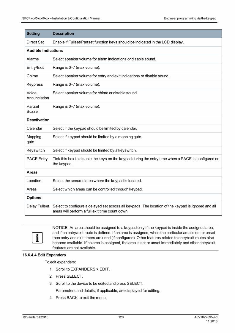
Setting Description
Direct Set Enable if Fullset/Partset function keys should be indicated in the LCD display.
Audible indications
Alarms Select speaker volume for alarm indications or disable sound.
Entry/Exit Range is 0–7 (max volume).
Chime Select speaker volume for entry and exit indications or disable sound.
Keypress Range is 0–7 (max volume).
VoiceAnnunciation
Select speaker volume for chime or disable sound.
PartsetBuzzer
Range is 0–7 (max volume).
Deactivation
Calendar Select if the keypad should be limited by calendar.
Mappinggate
Select if keypad should be limited by amapping gate.
Keyswitch Select if keypad should be limited by a keyswitch.
PACE Entry Tick this box to disable the keys on the keypad during the entry time when a PACE is configured onthe keypad.
Areas
Location Select the secured area where the keypad is located.
Areas Select which areas can be controlled through keypad.
Options
Delay Fullset Select to configure a delayed set across all keypads. The location of the keypad is ignored and allareas will perform a full exit time count down.
NOTICE: An area should be assigned to a keypad only if the keypad is inside the assigned area,and if an entry/exit route is defined. If an area is assigned, when the particular area is set or unsetthen entry and exit timers are used (if configured). Other features related to entry/exit routes alsobecome available. If no area is assigned, the area is set or unset immediately and other entry/exitfeatures are not available.
16.6.4.4 Edit Expanders
To edit expanders:
1. Scroll to EXPANDERS > EDIT.
2. Press SELECT.
3. Scroll to the device to be edited and press SELECT.
Parameters and details, if applicable, are displayed for editing.
4. Press BACK to exit themenu.
SPC4xxx/5xxx/6xxx– Installation &ConfigurationManual Engineer programming via the keypad
© Vanderbilt 2018 128 A6V10276959-d11.2018
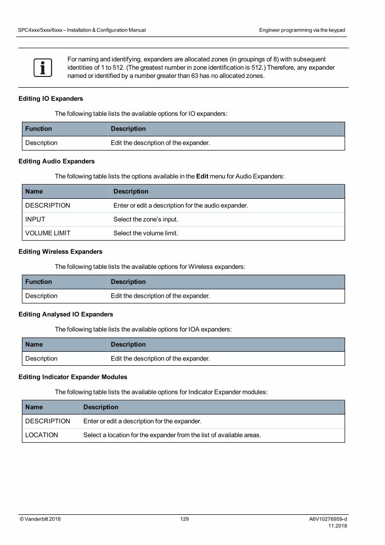
For naming and identifying, expanders are allocated zones (in groupings of 8) with subsequentidentities of 1 to 512. (The greatest number in zone identification is 512.) Therefore, any expandernamed or identified by a number greater than 63 has no allocated zones.
Editing IO Expanders
The following table lists the available options for IO expanders:
Function Description
Description Edit the description of the expander.
Editing Audio Expanders
The following table lists the options available in theEditmenu for Audio Expanders:
Name Description
DESCRIPTION Enter or edit a description for the audio expander.
INPUT Select the zone’s input.
VOLUME LIMIT Select the volume limit.
Editing Wireless Expanders
The following table lists the available options forWireless expanders:
Function Description
Description Edit the description of the expander.
Editing Analysed IO Expanders
The following table lists the available options for IOA expanders:
Name Description
Description Edit the description of the expander.
Editing Indicator Expander Modules
The following table lists the available options for Indicator Expander modules:
Name Description
DESCRIPTION Enter or edit a description for the expander.
LOCATION Select a location for the expander from the list of available areas.
SPC4xxx/5xxx/6xxx– Installation &ConfigurationManual Engineer programming via the keypad
© Vanderbilt 2018 129 A6V10276959-d11.2018
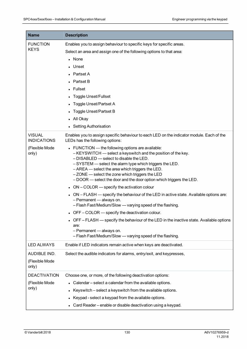
Name Description
FUNCTIONKEYS
Enables you to assign behaviour to specific keys for specific areas.
Select an area and assign one of the following options to that area:
l None
l Unset
l Partset A
l Partset B
l Fullset
l Toggle Unset/Fullset
l Toggle Unset/Partset A
l Toggle Unset/Partset B
l All Okay
l Setting Authorisation
VISUALINDICATIONS
(Flexible Modeonly)
Enables you to assign specific behaviour to each LED on the indicator module. Each of theLEDs has the following options:
l FUNCTION — the following options are available:– KEYSWITCH —select a keyswitch and the position of the key.– DISABLED —select to disable the LED.– SYSTEM—select the alarm type which triggers the LED.– AREA— select the area which triggers the LED.– ZONE—select the zone which triggers the LED–DOOR—select the door and the door option which triggers the LED.
l ON –COLOR—specify the activation colour
l ON – FLASH —specify the behaviour of the LED in active state. Available options are:– Permanent — always on.– Flash Fast/Medium/Slow — varying speed of the flashing.
l OFF –COLOR—specify the deactivation colour.
l OFF – FLASH —specify the behaviour of the LED in the inactive state. Available optionsare:– Permanent — always on.– Flash Fast/Medium/Slow — varying speed of the flashing.
LED ALWAYS Enable if LED indicators remain active when keys are deactivated.
AUDIBLE IND.
(Flexible Modeonly)
Select the audible indicators for alarms, entry/exit, and keypresses,
DEACTIVATION
(Flexible Modeonly)
Choose one, or more, of the following deactivation options:
l Calendar – select a calendar from the available options.
l Keyswitch – select a keyswitch from the available options.
l Keypad - select a keypad from the available options.
l Card Reader – enable or disable deactivation using a keypad.
SPC4xxx/5xxx/6xxx– Installation &ConfigurationManual Engineer programming via the keypad
© Vanderbilt 2018 130 A6V10276959-d11.2018
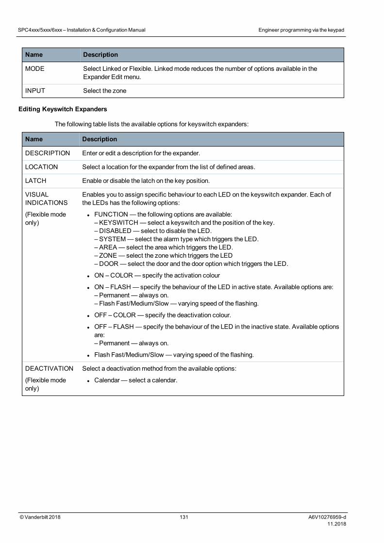
Name Description
MODE Select Linked or Flexible. Linkedmode reduces the number of options available in theExpander Edit menu.
INPUT Select the zone
Editing Keyswitch Expanders
The following table lists the available options for keyswitch expanders:
Name Description
DESCRIPTION Enter or edit a description for the expander.
LOCATION Select a location for the expander from the list of defined areas.
LATCH Enable or disable the latch on the key position.
VISUALINDICATIONS
(Flexible modeonly)
Enables you to assign specific behaviour to each LED on the keyswitch expander. Each ofthe LEDs has the following options:
l FUNCTION — the following options are available:– KEYSWITCH —select a keyswitch and the position of the key.– DISABLED —select to disable the LED.– SYSTEM—select the alarm type which triggers the LED.– AREA— select the area which triggers the LED.– ZONE—select the zone which triggers the LED–DOOR—select the door and the door option which triggers the LED.
l ON –COLOR—specify the activation colour
l ON – FLASH —specify the behaviour of the LED in active state. Available options are:– Permanent — always on.– Flash Fast/Medium/Slow — varying speed of the flashing.
l OFF –COLOR—specify the deactivation colour.
l OFF – FLASH —specify the behaviour of the LED in the inactive state. Available optionsare:– Permanent — always on.
l Flash Fast/Medium/Slow — varying speed of the flashing.
DEACTIVATION
(Flexible modeonly)
Select a deactivationmethod from the available options:
l Calendar— select a calendar.
SPC4xxx/5xxx/6xxx– Installation &ConfigurationManual Engineer programming via the keypad
© Vanderbilt 2018 131 A6V10276959-d11.2018
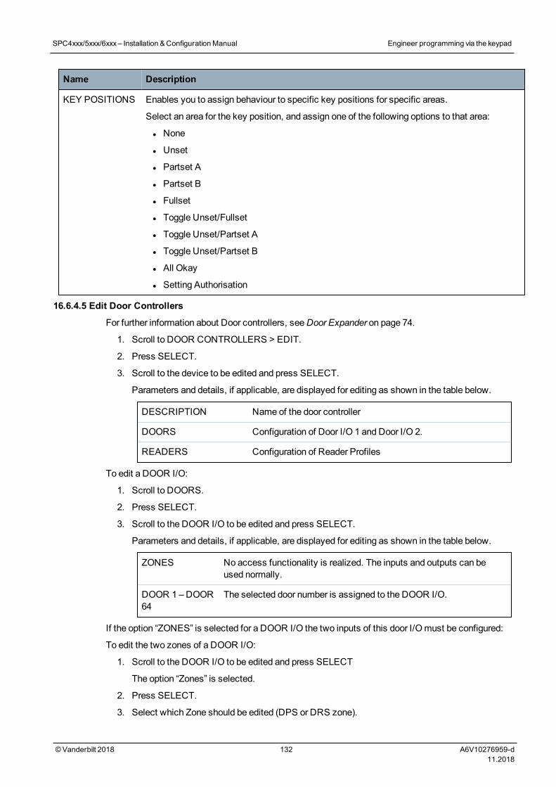
Name Description
KEY POSITIONS Enables you to assign behaviour to specific key positions for specific areas.
Select an area for the key position, and assign one of the following options to that area:
l None
l Unset
l Partset A
l Partset B
l Fullset
l Toggle Unset/Fullset
l Toggle Unset/Partset A
l Toggle Unset/Partset B
l All Okay
l Setting Authorisation
16.6.4.5 Edit Door Controllers
For further information about Door controllers, seeDoor Expander on page 74.
1. Scroll to DOOR CONTROLLERS > EDIT.
2. Press SELECT.
3. Scroll to the device to be edited and press SELECT.
Parameters and details, if applicable, are displayed for editing as shown in the table below.
DESCRIPTION Name of the door controller
DOORS Configuration of Door I/O 1 and Door I/O 2.
READERS Configuration of Reader Profiles
To edit a DOOR I/O:
1. Scroll to DOORS.
2. Press SELECT.
3. Scroll to the DOOR I/O to be edited and press SELECT.
Parameters and details, if applicable, are displayed for editing as shown in the table below.
ZONES No access functionality is realized. The inputs and outputs can beused normally.
DOOR 1 –DOOR64
The selected door number is assigned to the DOOR I/O.
If the option “ZONES” is selected for a DOOR I/O the two inputs of this door I/Omust be configured:
To edit the two zones of a DOOR I/O:
1. Scroll to the DOOR I/O to be edited and press SELECT
The option “Zones” is selected.
2. Press SELECT.
3. Select which Zone should be edited (DPS or DRS zone).
SPC4xxx/5xxx/6xxx– Installation &ConfigurationManual Engineer programming via the keypad
© Vanderbilt 2018 132 A6V10276959-d11.2018
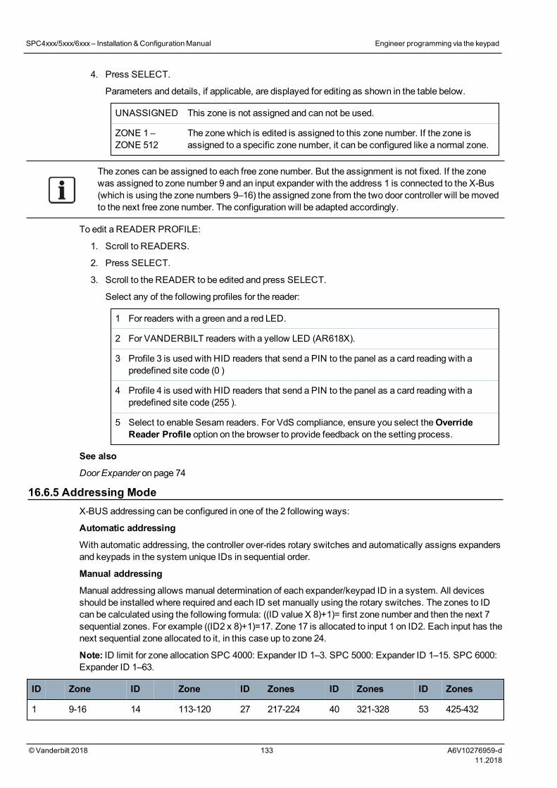
4. Press SELECT.
Parameters and details, if applicable, are displayed for editing as shown in the table below.
UNASSIGNED This zone is not assigned and can not be used.
ZONE 1 –ZONE 512
The zone which is edited is assigned to this zone number. If the zone isassigned to a specific zone number, it can be configured like a normal zone.
The zones can be assigned to each free zone number. But the assignment is not fixed. If the zonewas assigned to zone number 9 and an input expander with the address 1 is connected to the X-Bus(which is using the zone numbers 9–16) the assigned zone from the two door controller will bemovedto the next free zone number. The configuration will be adapted accordingly.
To edit a READER PROFILE:
1. Scroll to READERS.
2. Press SELECT.
3. Scroll to the READER to be edited and press SELECT.
Select any of the following profiles for the reader:
1 For readers with a green and a red LED.
2 For VANDERBILT readers with a yellow LED (AR618X).
3 Profile 3 is used with HID readers that send a PIN to the panel as a card reading with apredefined site code (0 )
4 Profile 4 is used with HID readers that send a PIN to the panel as a card reading with apredefined site code (255 ).
5 Select to enable Sesam readers. For VdS compliance, ensure you select theOverrideReader Profile option on the browser to provide feedback on the setting process.
See also
Door Expander on page 74
16.6.5 Addressing ModeX-BUS addressing can be configured in one of the 2 following ways:
Automatic addressing
With automatic addressing, the controller over-rides rotary switches and automatically assigns expandersand keypads in the system unique IDs in sequential order.
Manual addressing
Manual addressing allows manual determination of each expander/keypad ID in a system. All devicesshould be installed where required and each ID set manually using the rotary switches. The zones to IDcan be calculated using the following formula: ((ID value X 8)+1)= first zone number and then the next 7sequential zones. For example ((ID2 x 8)+1)=17. Zone 17 is allocated to input 1 on ID2. Each input has thenext sequential zone allocated to it, in this case up to zone 24.
Note: ID limit for zone allocation SPC 4000: Expander ID 1–3. SPC 5000: Expander ID 1–15. SPC 6000:Expander ID 1–63.
ID Zone ID Zone ID Zones ID Zones ID Zones
1 9-16 14 113-120 27 217-224 40 321-328 53 425-432
SPC4xxx/5xxx/6xxx– Installation &ConfigurationManual Engineer programming via the keypad
© Vanderbilt 2018 133 A6V10276959-d11.2018
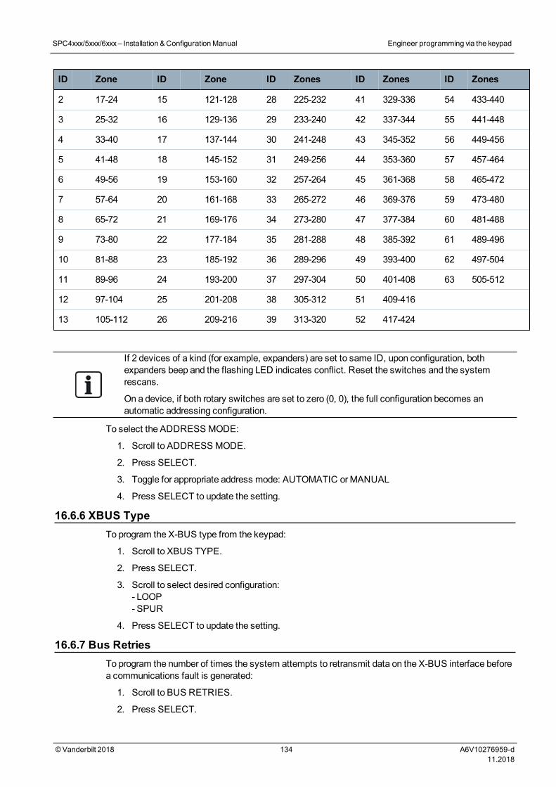
ID Zone ID Zone ID Zones ID Zones ID Zones
2 17-24 15 121-128 28 225-232 41 329-336 54 433-440
3 25-32 16 129-136 29 233-240 42 337-344 55 441-448
4 33-40 17 137-144 30 241-248 43 345-352 56 449-456
5 41-48 18 145-152 31 249-256 44 353-360 57 457-464
6 49-56 19 153-160 32 257-264 45 361-368 58 465-472
7 57-64 20 161-168 33 265-272 46 369-376 59 473-480
8 65-72 21 169-176 34 273-280 47 377-384 60 481-488
9 73-80 22 177-184 35 281-288 48 385-392 61 489-496
10 81-88 23 185-192 36 289-296 49 393-400 62 497-504
11 89-96 24 193-200 37 297-304 50 401-408 63 505-512
12 97-104 25 201-208 38 305-312 51 409-416
13 105-112 26 209-216 39 313-320 52 417-424
If 2 devices of a kind (for example, expanders) are set to same ID, upon configuration, bothexpanders beep and the flashing LED indicates conflict. Reset the switches and the systemrescans.
On a device, if both rotary switches are set to zero (0, 0), the full configuration becomes anautomatic addressing configuration.
To select the ADDRESS MODE:
1. Scroll to ADDRESS MODE.
2. Press SELECT.
3. Toggle for appropriate address mode: AUTOMATIC orMANUAL
4. Press SELECT to update the setting.
16.6.6 XBUS TypeTo program the X-BUS type from the keypad:
1. Scroll to XBUS TYPE.
2. Press SELECT.
3. Scroll to select desired configuration:- LOOP- SPUR
4. Press SELECT to update the setting.
16.6.7 Bus RetriesTo program the number of times the system attempts to retransmit data on the X-BUS interface beforea communications fault is generated:
1. Scroll to BUS RETRIES.
2. Press SELECT.
SPC4xxx/5xxx/6xxx– Installation &ConfigurationManual Engineer programming via the keypad
© Vanderbilt 2018 134 A6V10276959-d11.2018
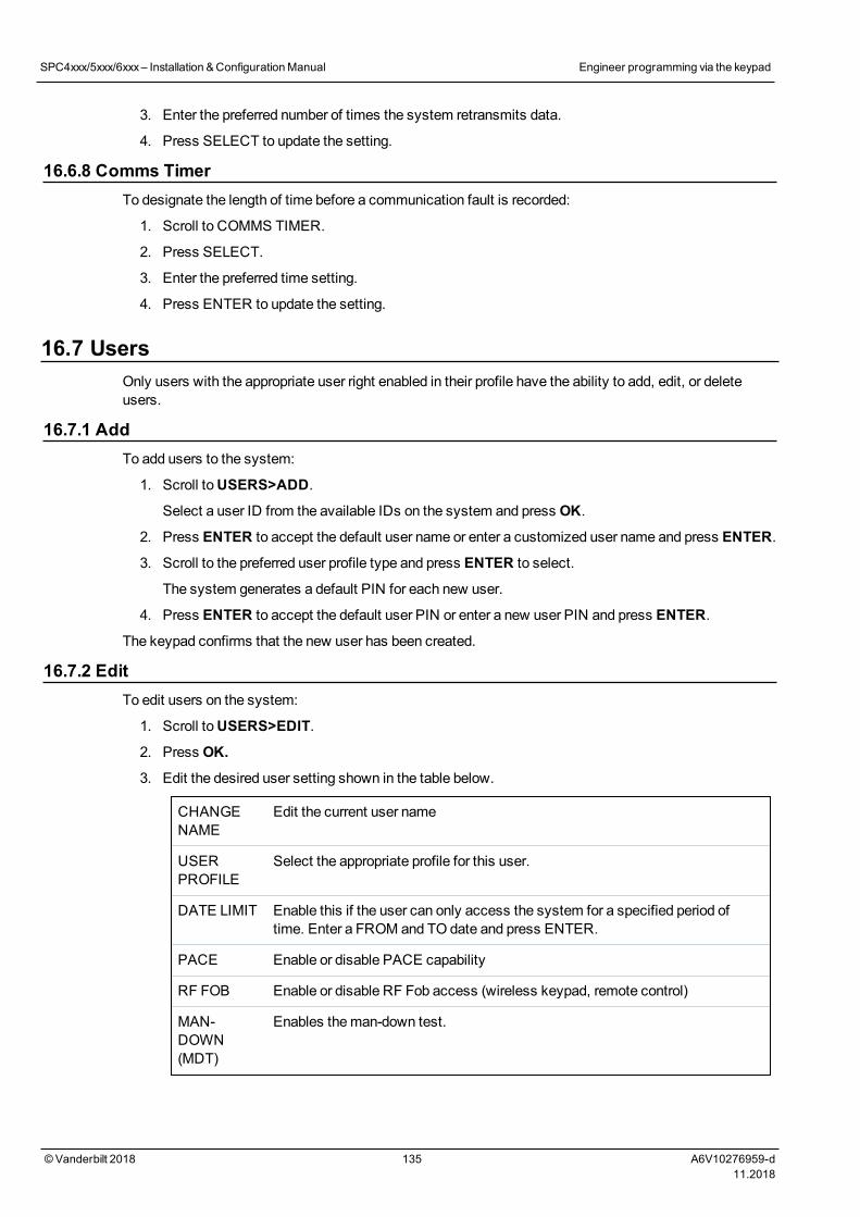
3. Enter the preferred number of times the system retransmits data.
4. Press SELECT to update the setting.
16.6.8 Comms TimerTo designate the length of time before a communication fault is recorded:
1. Scroll to COMMS TIMER.
2. Press SELECT.
3. Enter the preferred time setting.
4. Press ENTER to update the setting.
16.7 UsersOnly users with the appropriate user right enabled in their profile have the ability to add, edit, or deleteusers.
16.7.1 AddTo add users to the system:
1. Scroll toUSERS>ADD.
Select a user ID from the available IDs on the system and press OK.
2. Press ENTER to accept the default user name or enter a customized user name and press ENTER.
3. Scroll to the preferred user profile type and press ENTER to select.
The system generates a default PIN for each new user.
4. Press ENTER to accept the default user PIN or enter a new user PIN and press ENTER.
The keypad confirms that the new user has been created.
16.7.2 EditTo edit users on the system:
1. Scroll toUSERS>EDIT.
2. Press OK.
3. Edit the desired user setting shown in the table below.
CHANGENAME
Edit the current user name
USERPROFILE
Select the appropriate profile for this user.
DATE LIMIT Enable this if the user can only access the system for a specified period oftime. Enter a FROM and TO date and press ENTER.
PACE Enable or disable PACE capability
RF FOB Enable or disable RF Fob access (wireless keypad, remote control)
MAN-DOWN(MDT)
Enables theman-down test.
SPC4xxx/5xxx/6xxx– Installation &ConfigurationManual Engineer programming via the keypad
© Vanderbilt 2018 135 A6V10276959-d11.2018

ACCESSCONTROL
If no card assigned to the user:
l ADD CARD
l LEARN CARD
If a card assigned to the user:
l EDIT CARD–CARD NUMBER–CARD ATTRIBUTES
l RESET CARD
l DELETE CARD
LANGUAGE Select a language for this user that will be displayed on the system.
16.7.2.1 Access Control
One access card can be assigned to each of the users on the control panel.
To configure the access control for a user:
1. Scroll toUSERS>EDIT.
2. Press OK.
3. Select the user which should be configured and press OK.
4. Scroll toACCESS CONTROL and press OK.
The following sections provide programming steps found within the access control option of theselected user.
Add Card manually
If the card format of the card number is known, the card can be createdmanually.
The site code of the card is configured for the user profile that is assigned for this user.
1. Scroll toADD CARD.
2. Press OK.
An empty card has been added and can now be edited.
Learn Card
NOTICE: Only cards with supported card formats can be learned.
If the card number or the card format is not known, the card can be read and its information learned.
1. Scroll to LEARN CARD.
2. Press OK.
3. Select the door that the card will be presented.
4. Press OK.
NOTICE: The new card can be presented at the entry or the exit reader of theselected door.
SPC4xxx/5xxx/6xxx– Installation &ConfigurationManual Engineer programming via the keypad
© Vanderbilt 2018 136 A6V10276959-d11.2018
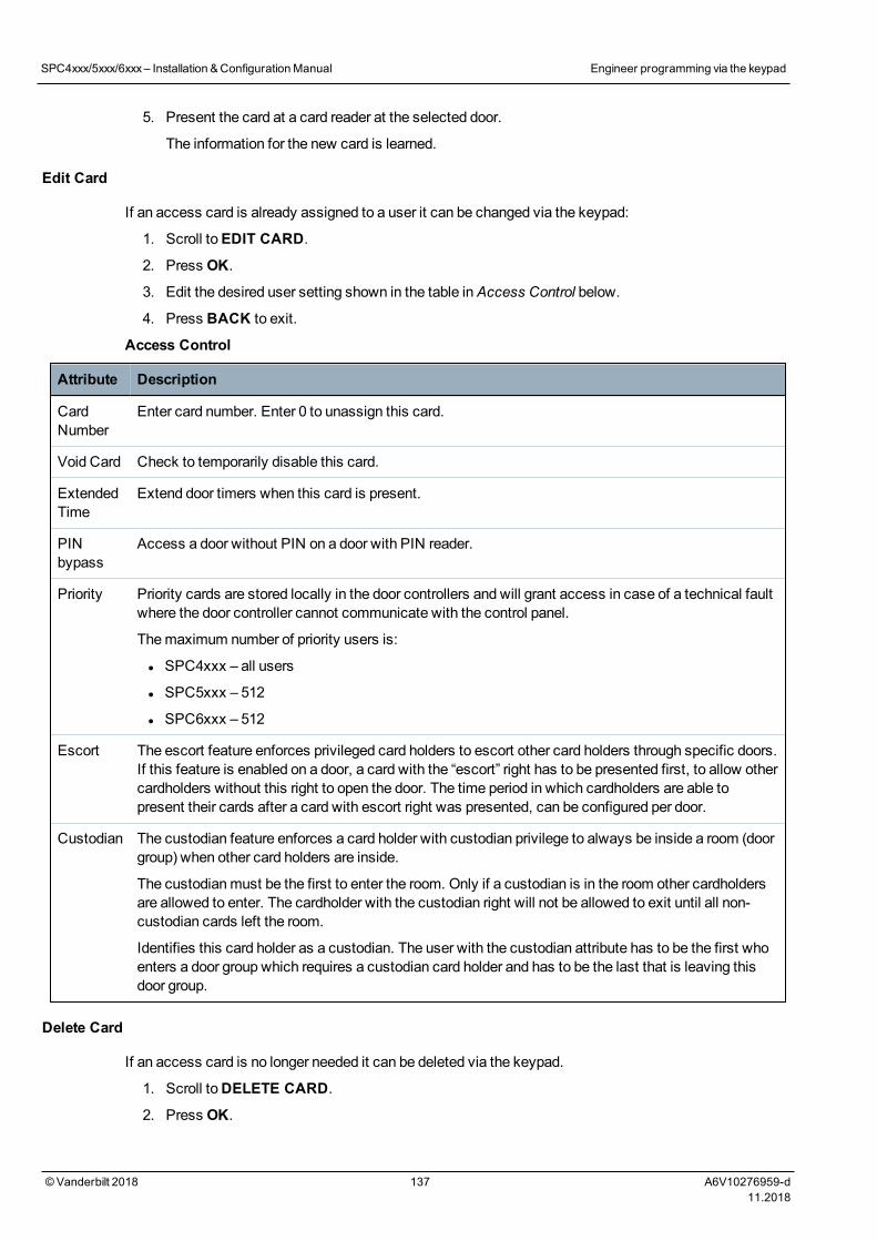
5. Present the card at a card reader at the selected door.
The information for the new card is learned.
Edit Card
If an access card is already assigned to a user it can be changed via the keypad:
1. Scroll toEDIT CARD.
2. Press OK.
3. Edit the desired user setting shown in the table inAccess Control below.
4. Press BACK to exit.
Access Control
Attribute Description
CardNumber
Enter card number. Enter 0 to unassign this card.
Void Card Check to temporarily disable this card.
ExtendedTime
Extend door timers when this card is present.
PINbypass
Access a door without PIN on a door with PIN reader.
Priority Priority cards are stored locally in the door controllers and will grant access in case of a technical faultwhere the door controller cannot communicate with the control panel.
Themaximum number of priority users is:
l SPC4xxx – all users
l SPC5xxx – 512
l SPC6xxx – 512
Escort The escort feature enforces privileged card holders to escort other card holders through specific doors.If this feature is enabled on a door, a card with the “escort” right has to be presented first, to allow othercardholders without this right to open the door. The time period in which cardholders are able topresent their cards after a card with escort right was presented, can be configured per door.
Custodian The custodian feature enforces a card holder with custodian privilege to always be inside a room (doorgroup) when other card holders are inside.
The custodianmust be the first to enter the room. Only if a custodian is in the room other cardholdersare allowed to enter. The cardholder with the custodian right will not be allowed to exit until all non-custodian cards left the room.
Identifies this card holder as a custodian. The user with the custodian attribute has to be the first whoenters a door group which requires a custodian card holder and has to be the last that is leaving thisdoor group.
Delete Card
If an access card is no longer needed it can be deleted via the keypad.
1. Scroll toDELETE CARD.
2. Press OK.
SPC4xxx/5xxx/6xxx– Installation &ConfigurationManual Engineer programming via the keypad
© Vanderbilt 2018 137 A6V10276959-d11.2018
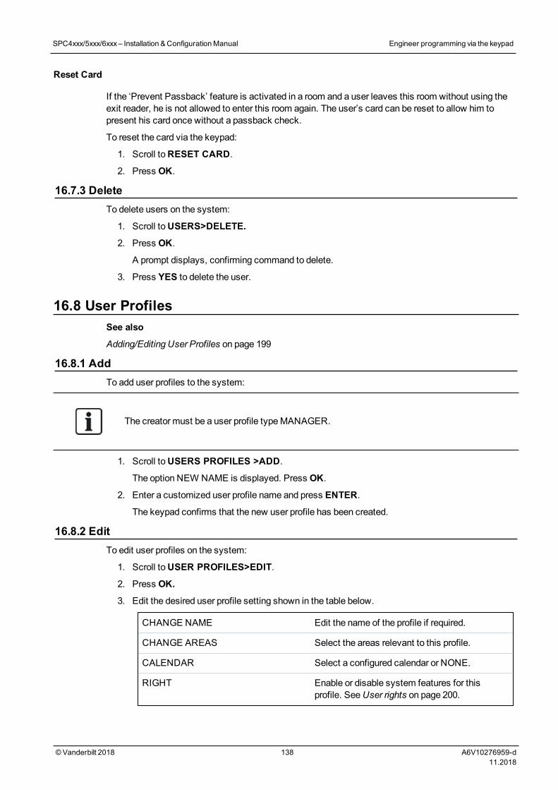
Reset Card
If the ‘Prevent Passback’ feature is activated in a room and a user leaves this room without using theexit reader, he is not allowed to enter this room again. The user’s card can be reset to allow him topresent his card once without a passback check.
To reset the card via the keypad:
1. Scroll toRESET CARD.
2. Press OK.
16.7.3 DeleteTo delete users on the system:
1. Scroll toUSERS>DELETE.
2. Press OK.
A prompt displays, confirming command to delete.
3. Press YES to delete the user.
16.8 User ProfilesSee also
Adding/Editing User Profiles on page 199
16.8.1 AddTo add user profiles to the system:
The creator must be a user profile typeMANAGER.
1. Scroll toUSERS PROFILES >ADD.
The option NEW NAME is displayed. Press OK.
2. Enter a customized user profile name and press ENTER.
The keypad confirms that the new user profile has been created.
16.8.2 EditTo edit user profiles on the system:
1. Scroll toUSER PROFILES>EDIT.
2. Press OK.
3. Edit the desired user profile setting shown in the table below.
CHANGE NAME Edit the name of the profile if required.
CHANGE AREAS Select the areas relevant to this profile.
CALENDAR Select a configured calendar or NONE.
RIGHT Enable or disable system features for thisprofile. SeeUser rights on page 200.
SPC4xxx/5xxx/6xxx– Installation &ConfigurationManual Engineer programming via the keypad
© Vanderbilt 2018 138 A6V10276959-d11.2018
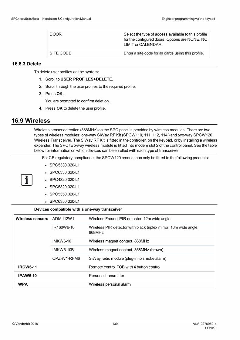
DOOR Select the type of access available to this profilefor the configured doors. Options are NONE, NOLIMIT or CALENDAR.
SITE CODE Enter a site code for all cards using this profile.
16.8.3 DeleteTo delete user profiles on the system:
1. Scroll toUSER PROFILES>DELETE.
2. Scroll through the user profiles to the required profile.
3. Press OK.
You are prompted to confirm deletion.
4. Press OK to delete the user profile.
16.9 WirelessWireless sensor detection (868MHz) on the SPC panel is provided by wireless modules. There are twotypes of wireless modules: one-way SiWay RF Kit (SPCW110, 111, 112, 114 ) and two-way SPCW120Wireless Transceiver. The SiWay RF Kit is fitted in the controller, on the keypad, or by installing a wirelessexpander. The SPC two-way wireless module is fitted into modem slot 2 of the control panel. See the tablebelow for information on which devices can be enrolled with each type of transceiver.
For CE regulatory compliance, the SPCW120 product can only be fitted to the following products:
l SPC5330.320-L1
l SPC6330.320-L1
l SPC4320.320-L1
l SPC5320.320-L1
l SPC5350.320-L1
l SPC6350.320-L1
Devices compatible with a one-way transceiver
Wireless sensors ADM-I12W1 Wireless Fresnel PIR detector, 12m wide angle
IR160W6-10 Wireless PIR detector with black triplex mirror, 18m wide angle,868MHz
IMKW6-10 Wireless magnet contact, 868MHz
IMKW6-10B Wireless magnet contact, 868MHz (brown)
OPZ-W1-RFM6 SiWay radiomodule (plug-in to smoke alarm)
IRCW6-11 Remote control FOB with 4 button control
IPAW6-10 Personal transmitter
WPA Wireless personal alarm
SPC4xxx/5xxx/6xxx– Installation &ConfigurationManual Engineer programming via the keypad
© Vanderbilt 2018 139 A6V10276959-d11.2018
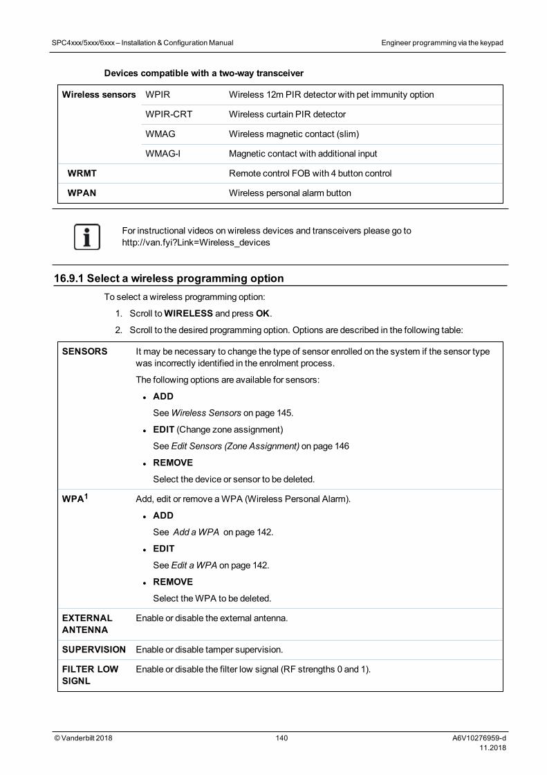
Devices compatible with a two-way transceiver
Wireless sensors WPIR Wireless 12m PIR detector with pet immunity option
WPIR-CRT Wireless curtain PIR detector
WMAG Wireless magnetic contact (slim)
WMAG-I Magnetic contact with additional input
WRMT Remote control FOB with 4 button control
WPAN Wireless personal alarm button
For instructional videos on wireless devices and transceivers please go tohttp://van.fyi?Link=Wireless_devices
16.9.1 Select a wireless programming optionTo select a wireless programming option:
1. Scroll toWIRELESS and press OK.
2. Scroll to the desired programming option. Options are described in the following table:
SENSORS It may be necessary to change the type of sensor enrolled on the system if the sensor typewas incorrectly identified in the enrolment process.
The following options are available for sensors:
l ADD
SeeWireless Sensors on page 145.
l EDIT (Change zone assignment)
SeeEdit Sensors (Zone Assignment) on page 146
l REMOVE
Select the device or sensor to be deleted.
WPA1 Add, edit or remove aWPA (Wireless Personal Alarm).
l ADD
See Add aWPA on page 142.
l EDIT
SeeEdit aWPA on page 142.
l REMOVE
Select theWPA to be deleted.
EXTERNALANTENNA
Enable or disable the external antenna.
SUPERVISION Enable or disable tamper supervision.
FILTER LOWSIGNL
Enable or disable the filter low signal (RF strengths 0 and 1).
SPC4xxx/5xxx/6xxx– Installation &ConfigurationManual Engineer programming via the keypad
© Vanderbilt 2018 140 A6V10276959-d11.2018
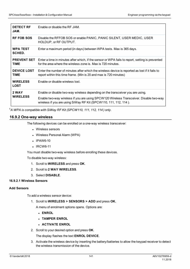
DETECT RFJAM.
Enable or disable the RF JAM.
RF FOB SOS Disable the RFFOB SOS or enable PANIC, PANIC SILENT, USER MEDIC, USERHOLDUP, or RF OUTPUT.
WPA TESTSCHED.
Enter amaximum period (in days) betweenWPA tests. Max is 365 days.
PREVENT SETTIME
Enter a time inminutes after which, if the sensor orWPA fails to report, setting is preventedfor the area where the wireless zone is. Max is 720minutes.
DEVICE LOSTTIME
Enter the number of minutes after which the wireless device is reported as lost if it fails toreport within this time frame. (Min is 20 andmax is 720minutes)
WIRELESSLOST
Enable or disable wireless lost.
2 WAYWIRELESS
Enable or disable two-way wireless depending on the transceiver you are using.
Enable two-way wireless if you are using SPCW120Wireless Transceiver. Disable two-waywireless if you are using SiWay RF Kit (SPCW110, 111, 112, 114 ).
1AWPA is compatible with SiWay RF Kit (SPCW110, 111, 112, 114 ) only.
16.9.2 One-way wirelessThe following devices can be enrolled on a one-way wireless transceiver:
l Wireless sensors
l Wireless Personal Alarm (WPA)
l IPAW6-10
l IRCW6-11
Youmust disable two-way wireless before enrolling these devices.
To disable two-way wireless:
1. Scroll toWIRELESS and press OK.
2. Scroll to 2 WAY WIRELESS.
3. Select DISABLE.16.9.2.1 Wireless Sensors
Add Sensors
To add a wireless sensor device:
1. Scroll toWIRELESS > SENSORS > ADD and press OK.
A menu of enrolment options opens. Options are:
l ENROL
l TAMPER ENROL
l ACTIVATE ENROL
2. Scroll to your desired option and press OK.
The display flashes the text ENROL DEVICE.
3. Activate the wireless device by inserting the battery/batteries to allow the keypad receiver to detectthe wireless transmission of the device.
SPC4xxx/5xxx/6xxx– Installation &ConfigurationManual Engineer programming via the keypad
© Vanderbilt 2018 141 A6V10276959-d11.2018
When the device has been detected the text FOUND SENSOR is displayed on the keypad. Thedevice ID, TYPE, andSIGNAL information is displayed beneath FOUND SENSOR.
4. Press OK.
A prompt to select the area is displayed.
5. Scroll to the desired option and press OK.
A prompt to select a zone type is displayed.
6. Scroll to the required zone type and press OK.
Edit Sensors (Zone Assignment)
It may be necessary to change the zone assignment of a sensor enrolled on the system.
To change the zone assignment of a wireless detector:
1. Scroll toEDIT and press OK.
2. Scroll to the sensor to be changed and press OK.
3. Scroll to ZONE and press OK.
4. Scroll to the appropriate zone number (only unoccupied zone numbers are displayed) and pressOK.
16.9.2.2 WPA
l You can only configure aWPA or check WPA status on the keypad if there is a wirelessmodule fitted on the panel or any of the panel expanders.
l AWPA is compatible with SiWay RF Kit (SPCW110, 111, 112, 114 ) only.
A WPA is not assigned to a user. Usually, aWPA is shared by several people, for example, securityguards working in shifts. Alternatively aWPA may be permanently attached to a surface such as undera desk or behind a till.
You can connect up to 128WPAs per SPC panel.
Add a WPA
To add aWPA with the keypad:
1. SelectWIRELESS > WPA > ADD.
2. SelectMANUALLY to manually enter aWPA ID.
Alternatively, the ID can be entered automatically by the panel by selecting the LEARN WPAoption. Press any button on theWPA when theACTIVATE WPA message is displayed, for thepanel to identify theWPA. The panel will not accept aWPA if theWPA ID is a duplicate of acurrently configuredWPA.
3. Exit theADD menu.
4. Select theEDITmenu to configure theWPA.
Edit a WPA
To edit aWPA, selectWIRELESS > WPA > EDIT and edit the relevant fields.
Editable fields for WPA
DESCRIPTION Enter a description to uniquely identify theWPA.
SPC4xxx/5xxx/6xxx– Installation &ConfigurationManual Engineer programming via the keypad
© Vanderbilt 2018 142 A6V10276959-d11.2018
TRANSMITTERID
Enter theWPA ID. The panel will not accept aWPA if theWPA ID is already in use.
FUNC. TOBUTTONS
Use this section to assign functions to button combinations. Available functions are Panic,Panic Silent, Holdup, Suspicion, RF User Output, Medical. More than one buttoncombination can be selected for the same function. For example:
l Yellow = Suspicion
l Red + Green = Holdup
l For Commercial or Domestic installations, the default is: Red + Green = Panic
Note: If no function is assigned to a button combination, it is still possible to use thatcombination by using a trigger. See Triggers on page 288.
SUPERVISION TheWPA may be configured to send periodic supervision signals. If supervision is enabledon theWPA (with the jumper), theWPA sends out a supervisionmessage about every 7.5minutes. The time betweenmessages is randomized to decrease the chances of collisionwith otherWPAs.
The supervision functionmust be enabled on the panel for the particularWPA for correctsupervision operation. If the panel does not get a supervision signal, it raises an alarm that isshown in the keypad and logged.
If supervision is not enabled, theWPA sends out a supervisionmessage about every 24hours to transmit theWPA battery status to the panel. Themessage interval is randomizedto decrease the chances of collision with otherWPAs.
Select ENABLE if supervision has been enabled for that particularWPA.
TEST Enables testing of theWPA signal.
See also
l Triggers on page 288
l Wireless on page 139
l WPA Test below
WPA Test
NOTICE: The test can only be performed by an engineer or a user that has aWPA Test right assignedto them. SeeUser rights on page 200.
To test theWPA from the keypad:
1. Scroll to TEST > WPA TEST and press OK.
2. When prompted withACTIVATE WPA, press the three buttons on theWPA simultaneously.
If the test succeeds, aWPA n OK message is shown, where n is the number of theWPA beingtested.
3. Repeat the test if required.
4. Press BACK orX to end the test.
16.9.2.3 IPAW6-10 personal alarm button
The IPAW6-10 personal alarm button is a device that is used to transmit Panic Alarm messages to theSPC system.
SPC4xxx/5xxx/6xxx– Installation &ConfigurationManual Engineer programming via the keypad
© Vanderbilt 2018 143 A6V10276959-d11.2018
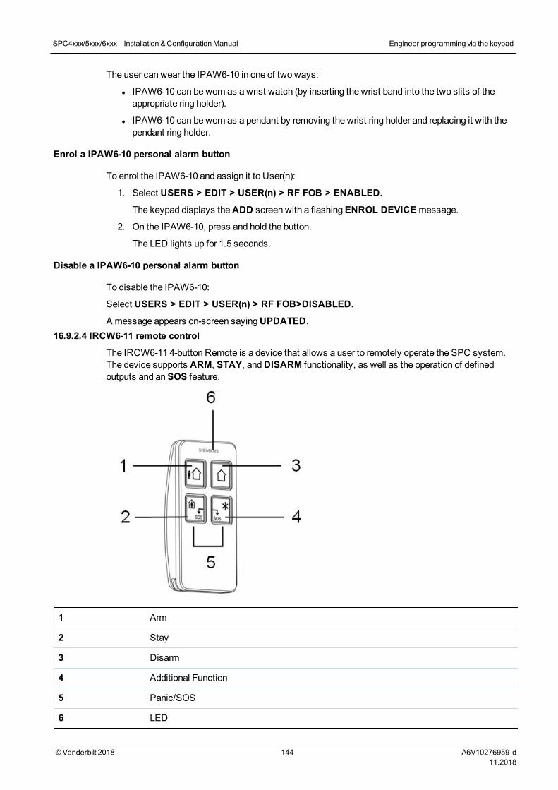
The user can wear the IPAW6-10 in one of two ways:
l IPAW6-10 can be worn as a wrist watch (by inserting the wrist band into the two slits of theappropriate ring holder).
l IPAW6-10 can be worn as a pendant by removing the wrist ring holder and replacing it with thependant ring holder.
Enrol a IPAW6-10 personal alarm button
To enrol the IPAW6-10 and assign it to User(n):
1. Select USERS > EDIT > USER(n) > RF FOB > ENABLED.
The keypad displays theADD screen with a flashingENROL DEVICEmessage.
2. On the IPAW6-10, press and hold the button.
The LED lights up for 1.5 seconds.
Disable a IPAW6-10 personal alarm button
To disable the IPAW6-10:
Select USERS > EDIT > USER(n) > RF FOB>DISABLED.
A message appears on-screen sayingUPDATED.16.9.2.4 IRCW6-11 remote control
The IRCW6-11 4-button Remote is a device that allows a user to remotely operate the SPC system.The device supports ARM, STAY, andDISARM functionality, as well as the operation of definedoutputs and anSOS feature.
1 Arm
2 Stay
3 Disarm
4 Additional Function
5 Panic/SOS
6 LED
SPC4xxx/5xxx/6xxx– Installation &ConfigurationManual Engineer programming via the keypad
© Vanderbilt 2018 144 A6V10276959-d11.2018
Enrol a IRCW6-11 remote control
To enrol an IRCW6-11 and assign it to User (n):
1. Select USERS > EDIT > USER (n) > RF FOB>ENABLED.
The keypad displays theADD screen with a flashingENROL DEVICEmessage.
2. On the IRCW6-11, press and hold any button.
The LED on the remote control lights. A message appears on the keypad screen saying FOBCONFIGURED. The IRCW6-11 is assigned to the User (n).
Disable a IRCW6-11 remote control
To disable a IRCW6-11:
l Select USERS > EDIT > USER (n) > RF FOB > DISABLED.
A message appears on-screen sayingUPDATED.
16.9.3 Two-way wirelessThe following devices can be enrolled on a two-way wireless transceiver:
l Wireless sensors
l WPAN personal alarm button
l WRMT remote control
Please note that youmust enable two-way wireless before enrolling these devices.
To enable two-way wireless:
1. Scroll toWIRELESS and press OK.
2. Scroll to 2 WAY WIRELESS.
3. Select ENABLE.16.9.3.1 Wireless Sensors
Add Sensors
To add a wireless sensor device:
1. Scroll toWIRELESS > SENSORS > ADD and press OK.
A menu of enrolment options opens. Options are:
l ENROL
l TAMPER ENROL
l ACTIVATE ENROL
2. Scroll to your desired option and press OK.
The display flashes the text ENROL DEVICE.
3. Activate the wireless device by inserting the battery/batteries to allow the keypad receiver to detectthe wireless transmission of the device.
When the device has been detected the text FOUND SENSOR is displayed on the keypad. Thedevice ID, TYPE, andSIGNAL information is displayed beneath FOUND SENSOR.
4. Press OK.
A prompt to select the area is displayed.
5. Scroll to the desired option and press OK.
SPC4xxx/5xxx/6xxx– Installation &ConfigurationManual Engineer programming via the keypad
© Vanderbilt 2018 145 A6V10276959-d11.2018

A prompt to select a zone type is displayed.
6. Scroll to the required zone type and press OK.
Edit Sensors (Zone Assignment)
It may be necessary to change the zone assignment of a sensor enrolled on the system.
To change the zone assignment of a wireless detector:
1. Scroll toEDIT and press OK.
2. Scroll to the sensor to be changed and press OK.
3. Scroll to ZONE and press OK.
4. Scroll to the appropriate zone number (only unoccupied zone numbers are displayed) and pressOK.
16.9.3.2 WPAN personal alarm button
TheWPAN personal alarm button is a device that is used to transmit Panic Alarm messages to theSPC system.
The user can wear theWPAN in one of two ways:
l WPAN can be worn as a wrist watch (by inserting the wrist band into the two slits of theappropriate ring holder).
l WPAN can be worn as a pendant by removing the wrist ring holder and replacing it with thependant ring holder.
Enrol a WPAN personal alarm button
To enrol theWPAN and assign it to a User(n):
1. Select USERS > EDIT > USER(n) > RF FOB > ENABLED.
The keypad displays theADD screen with a flashingENROL DEVICEmessage.
2. On theWPAN, press and hold the button.
The LEDs on the fob light in the following pattern: Red lights for 3 seconds, then no LED, thenRed lights for 1 second, and thenGreen lights for 1 second. TheWPAN is assigned to User (n).
Disable a WPAN personal alarm button
To disable theWPAN:
Select USERS > EDIT > USER(n) > RF FOB > DISABLED.
A message appears on-screen sayingUPDATED.
SPC4xxx/5xxx/6xxx– Installation &ConfigurationManual Engineer programming via the keypad
© Vanderbilt 2018 146 A6V10276959-d11.2018
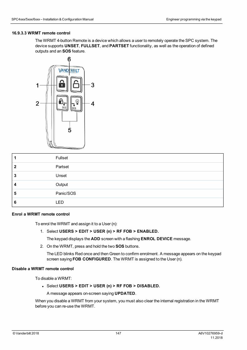
16.9.3.3 WRMT remote control
TheWRMT 4-button Remote is a device which allows a user to remotely operate the SPC system. Thedevice supports UNSET, FULLSET, andPARTSET functionality, as well as the operation of definedoutputs and anSOS feature.
1 Fullset
2 Partset
3 Unset
4 Output
5 Panic/SOS
6 LED
Enrol a WRMT remote control
To enrol theWRMT and assign it to a User (n):
1. Select USERS > EDIT > USER (n) > RF FOB > ENABLED.
The keypad displays theADD screen with a flashingENROL DEVICEmessage.
2. On theWRMT, press and hold the twoSOS buttons.
The LED blinks Red once and thenGreen to confirm enrolment. A message appears on the keypadscreen saying FOB CONFIGURED. TheWRMT is assigned to the User (n).
Disable a WRMT remote control
To disable aWRMT:
l Select USERS > EDIT > USER (n) > RF FOB > DISABLED.
A message appears on-screen sayingUPDATED.
When you disable aWRMT from your system, youmust also clear the internal registration in theWRMTbefore you can re-use theWRMT.
SPC4xxx/5xxx/6xxx– Installation &ConfigurationManual Engineer programming via the keypad
© Vanderbilt 2018 147 A6V10276959-d11.2018
To clear the internal registration:
l On theWRMT, press and hold thePARTSET andUNSET buttons.
The LED blinks Red andOrange to confirm that registration is cleared.
16.10 Zones1. Scroll to ZONES and press OK.
2. Scroll to the desired zone (ZONE 1-x).
3. Scroll to the desired programming option:
DESCRIPTION Used to help identify the zone: enter a specific and descriptive name.
ZONE TYPE Determines the zone type. See Zone types on page 379.
ATTRIBUTES Determines the attributes of the zone. See Zone attributes on page 384.
TO AREA Determines which zone is mapped to which area. This menu option isonly displayed if multiple areas are defined on the system. Selecting thisfeature allows users to build a set of zones that are identified with aparticular area in the building.
The number and type of attributes displayed in the keypadmenus for a particular zone varydepending on the type of zone that is selected.
16.11 Doors1. Scroll to DOORS and press SELECT.
2. Scroll to the door to be programmed and press SELECT.
3. Parameters and details, if applicable, are displayed for editing as follows:
- Description
- Door Inputs
- Door Group
- Door Attributes
- Door Timers
- Reader Information (Display only - format of last card used with configured reader)
SPC4xxx/5xxx/6xxx– Installation &ConfigurationManual Engineer programming via the keypad
© Vanderbilt 2018 148 A6V10276959-d11.2018
Door inputs
Each door has 2 inputs with predefined functionality. These two inputs, the door position sensor and thedoor release switch can be configured.
Name Description
Zone The door position sensor input can be used for the intrusion part as well. If the door position sensorinput is used also for the intrusion part, the zone number it is assigned to has to be selected. If thedoor position sensor is used only for the access part, the option “UNASSIGNED” has to be selected.
If the door position sensor is assigned to an intrusion zone, it can be configured like a normal zonebut only with limited functionality (for example, not all zone types are selectable).
If an area or the system is set with the card reader, the door position sensor input has to be assignedto a zone number and to the area or the system which have to be set.
Description
(Web only)
Description of the zone the door position sensor is assigned to.
Zone Type
(Web only)
Zone type of the zone the door position sensor is assigned to (not all zones types are available).
Zoneattributes
(Web only)
The attributes for the zone the door position sensor is assigned to can bemodified.
Area
(Web only)
The area the zone and the card reader are assigned to. (If the card reader is used for setting andunsetting, this area will be set/unset).
DoorPosition(Web)
DPS EndOf Line(keypads)
The resistor used with the door position sensor. Choose the used resistor value/combination.
DPSNormalOpen
Select if the door release switch is to be a normally open or normally closed input.
DoorRelease(Web)
DRS ENDOF LINE(Keypads)
The resistor used with the door release switch. Choose the used resistor value/combination.
DRSNormalOpen
Select if the door release switch is a normally open input or not.
No DRS
(Web only)
Select to ignore DRS.
If a DC2 is used on the door, this optionMUST be selected. If not selected, the door will open.
SPC4xxx/5xxx/6xxx– Installation &ConfigurationManual Engineer programming via the keypad
© Vanderbilt 2018 149 A6V10276959-d11.2018
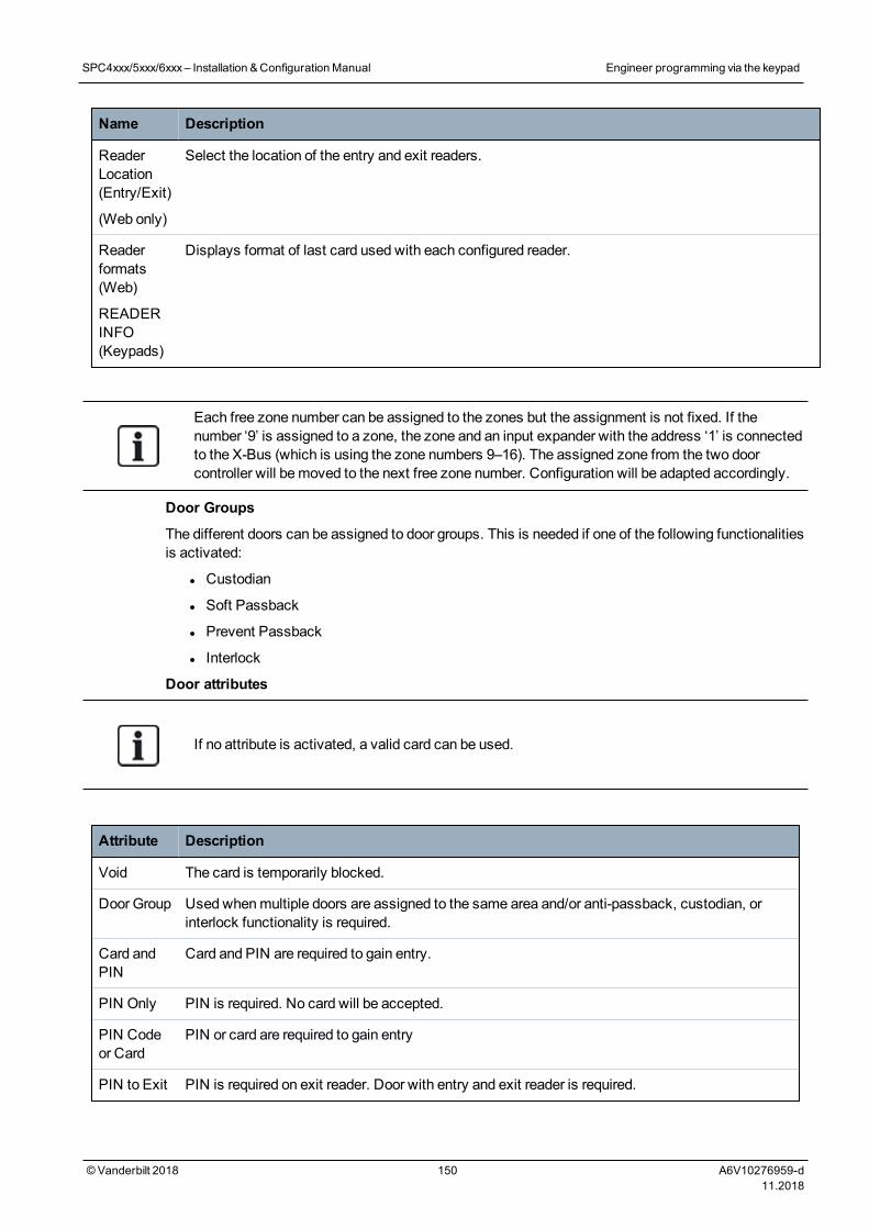
Name Description
ReaderLocation(Entry/Exit)
(Web only)
Select the location of the entry and exit readers.
Readerformats(Web)
READERINFO(Keypads)
Displays format of last card used with each configured reader.
Each free zone number can be assigned to the zones but the assignment is not fixed. If thenumber ‘9’ is assigned to a zone, the zone and an input expander with the address ‘1’ is connectedto the X-Bus (which is using the zone numbers 9–16). The assigned zone from the two doorcontroller will bemoved to the next free zone number. Configuration will be adapted accordingly.
Door Groups
The different doors can be assigned to door groups. This is needed if one of the following functionalitiesis activated:
l Custodian
l Soft Passback
l Prevent Passback
l Interlock
Door attributes
If no attribute is activated, a valid card can be used.
Attribute Description
Void The card is temporarily blocked.
Door Group Used whenmultiple doors are assigned to the same area and/or anti-passback, custodian, orinterlock functionality is required.
Card andPIN
Card and PIN are required to gain entry.
PIN Only PIN is required. No card will be accepted.
PIN Codeor Card
PIN or card are required to gain entry
PIN to Exit PIN is required on exit reader. Door with entry and exit reader is required.
SPC4xxx/5xxx/6xxx– Installation &ConfigurationManual Engineer programming via the keypad
© Vanderbilt 2018 150 A6V10276959-d11.2018
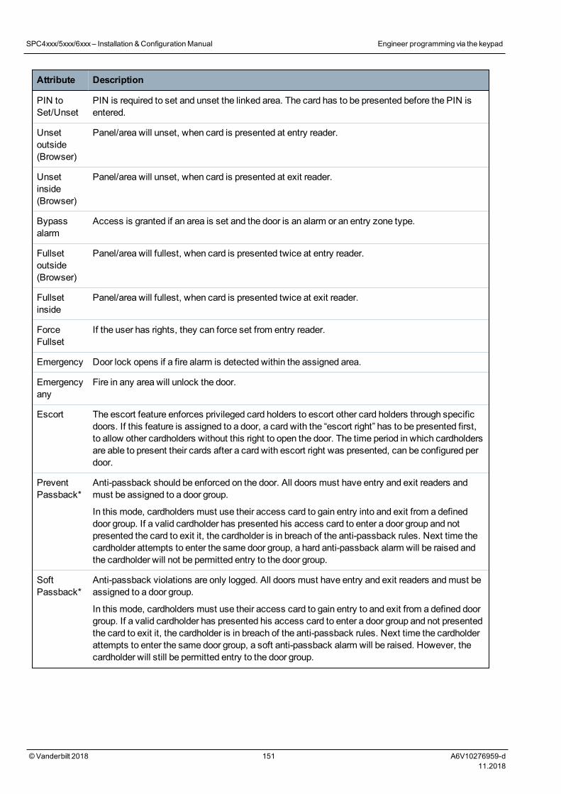
Attribute Description
PIN toSet/Unset
PIN is required to set and unset the linked area. The card has to be presented before the PIN isentered.
Unsetoutside(Browser)
Panel/area will unset, when card is presented at entry reader.
Unsetinside(Browser)
Panel/area will unset, when card is presented at exit reader.
Bypassalarm
Access is granted if an area is set and the door is an alarm or an entry zone type.
Fullsetoutside(Browser)
Panel/area will fullest, when card is presented twice at entry reader.
Fullsetinside
Panel/area will fullest, when card is presented twice at exit reader.
ForceFullset
If the user has rights, they can force set from entry reader.
Emergency Door lock opens if a fire alarm is detected within the assigned area.
Emergencyany
Fire in any area will unlock the door.
Escort The escort feature enforces privileged card holders to escort other card holders through specificdoors. If this feature is assigned to a door, a card with the “escort right” has to be presented first,to allow other cardholders without this right to open the door. The time period in which cardholdersare able to present their cards after a card with escort right was presented, can be configured perdoor.
PreventPassback*
Anti-passback should be enforced on the door. All doors must have entry and exit readers andmust be assigned to a door group.
In this mode, cardholders must use their access card to gain entry into and exit from a defineddoor group. If a valid cardholder has presented his access card to enter a door group and notpresented the card to exit it, the cardholder is in breach of the anti-passback rules. Next time thecardholder attempts to enter the same door group, a hard anti-passback alarm will be raised andthe cardholder will not be permitted entry to the door group.
SoftPassback*
Anti-passback violations are only logged. All doors must have entry and exit readers andmust beassigned to a door group.
In this mode, cardholders must use their access card to gain entry to and exit from a defined doorgroup. If a valid cardholder has presented his access card to enter a door group and not presentedthe card to exit it, the cardholder is in breach of the anti-passback rules. Next time the cardholderattempts to enter the same door group, a soft anti-passback alarm will be raised. However, thecardholder will still be permitted entry to the door group.
SPC4xxx/5xxx/6xxx– Installation &ConfigurationManual Engineer programming via the keypad
© Vanderbilt 2018 151 A6V10276959-d11.2018
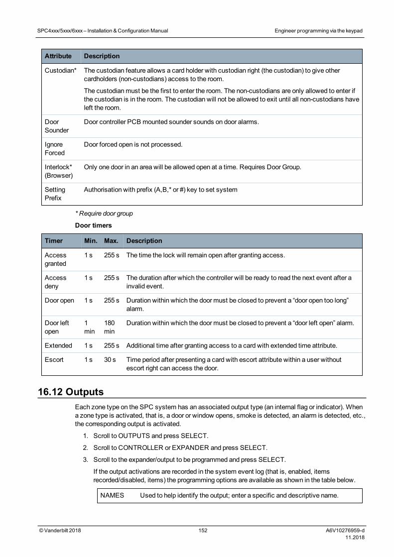
Attribute Description
Custodian* The custodian feature allows a card holder with custodian right (the custodian) to give othercardholders (non-custodians) access to the room.
The custodianmust be the first to enter the room. The non-custodians are only allowed to enter ifthe custodian is in the room. The custodian will not be allowed to exit until all non-custodians haveleft the room.
DoorSounder
Door controller PCB mounted sounder sounds on door alarms.
IgnoreForced
Door forced open is not processed.
Interlock*(Browser)
Only one door in an area will be allowed open at a time. Requires Door Group.
SettingPrefix
Authorisation with prefix (A,B,* or #) key to set system
* Require door group
Door timers
Timer Min. Max. Description
Accessgranted
1 s 255 s The time the lock will remain open after granting access.
Accessdeny
1 s 255 s The duration after which the controller will be ready to read the next event after ainvalid event.
Door open 1 s 255 s Duration within which the door must be closed to prevent a “door open too long”alarm.
Door leftopen
1min
180min
Duration within which the door must be closed to prevent a “door left open” alarm.
Extended 1 s 255 s Additional time after granting access to a card with extended time attribute.
Escort 1 s 30 s Time period after presenting a card with escort attribute within a user withoutescort right can access the door.
16.12 OutputsEach zone type on the SPC system has an associated output type (an internal flag or indicator). Whena zone type is activated, that is, a door or window opens, smoke is detected, an alarm is detected, etc.,the corresponding output is activated.
1. Scroll to OUTPUTS and press SELECT.
2. Scroll to CONTROLLER or EXPANDER and press SELECT.
3. Scroll to the expander/output to be programmed and press SELECT.
If the output activations are recorded in the system event log (that is, enabled, itemsrecorded/disabled, items) the programming options are available as shown in the table below.
NAMES Used to help identify the output; enter a specific and descriptive name.
SPC4xxx/5xxx/6xxx– Installation &ConfigurationManual Engineer programming via the keypad
© Vanderbilt 2018 152 A6V10276959-d11.2018
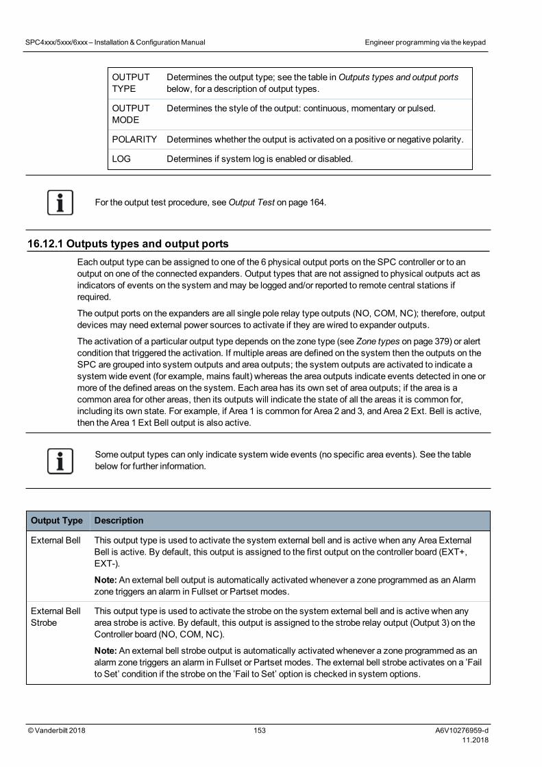
OUTPUTTYPE
Determines the output type; see the table inOutputs types and output portsbelow, for a description of output types.
OUTPUTMODE
Determines the style of the output: continuous, momentary or pulsed.
POLARITY Determines whether the output is activated on a positive or negative polarity.
LOG Determines if system log is enabled or disabled.
For the output test procedure, seeOutput Test on page 164.
16.12.1 Outputs types and output portsEach output type can be assigned to one of the 6 physical output ports on the SPC controller or to anoutput on one of the connected expanders. Output types that are not assigned to physical outputs act asindicators of events on the system andmay be logged and/or reported to remote central stations ifrequired.
The output ports on the expanders are all single pole relay type outputs (NO, COM, NC); therefore, outputdevices may need external power sources to activate if they are wired to expander outputs.
The activation of a particular output type depends on the zone type (see Zone types on page 379) or alertcondition that triggered the activation. If multiple areas are defined on the system then the outputs on theSPC are grouped into system outputs and area outputs; the system outputs are activated to indicate asystem wide event (for example, mains fault) whereas the area outputs indicate events detected in one ormore of the defined areas on the system. Each area has its own set of area outputs; if the area is acommon area for other areas, then its outputs will indicate the state of all the areas it is common for,including its own state. For example, if Area 1 is common for Area 2 and 3, and Area 2 Ext. Bell is active,then the Area 1 Ext Bell output is also active.
Some output types can only indicate system wide events (no specific area events). See the tablebelow for further information.
Output Type Description
External Bell This output type is used to activate the system external bell and is active when any Area ExternalBell is active. By default, this output is assigned to the first output on the controller board (EXT+,EXT-).
Note:An external bell output is automatically activated whenever a zone programmed as an Alarmzone triggers an alarm in Fullset or Partset modes.
External BellStrobe
This output type is used to activate the strobe on the system external bell and is active when anyarea strobe is active. By default, this output is assigned to the strobe relay output (Output 3) on theController board (NO, COM, NC).
Note:An external bell strobe output is automatically activated whenever a zone programmed as analarm zone triggers an alarm in Fullset or Partset modes. The external bell strobe activates on a ’Failto Set’ condition if the strobe on the ’Fail to Set’ option is checked in system options.
SPC4xxx/5xxx/6xxx– Installation &ConfigurationManual Engineer programming via the keypad
© Vanderbilt 2018 153 A6V10276959-d11.2018
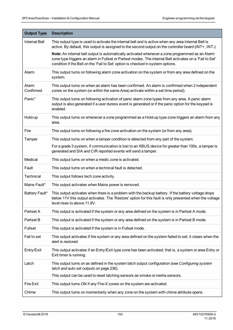
Output Type Description
Internal Bell This output type is used to activate the internal bell and is active when any area Internal Bell isactive. By default, this output is assigned to the second output on the controller board (INT+, INT-).
Note:An internal bell output is automatically activated whenever a zone programmed as an Alarmzone type triggers an alarm in Fullset or Partset modes. The internal Bell activates on a ’Fail to Set’condition if the Bell on the ’Fail to Set’ option is checked in system options.
Alarm This output turns on following alarm zone activation on the system or from any area defined on thesystem.
AlarmConfirmed
This output turns on when an alarm has been confirmed. An alarm is confirmed when 2 independentzones on the system (or within the same Area) activate within a set time period).
Panic* This output turns on following activation of panic alarm zone types from any area. A panic alarmoutput is also generated if a user duress event is generated or if the panic option for the keypad isenabled.
Hold-up This output turns on whenever a zone programmed as a Hold-up type zone triggers an alarm from anyarea.
Fire This output turns on following a fire zone activation on the system (or from any area).
Tamper This output turns on when a tamper condition is detected from any part of the system.
For a grade 3 system, if communication is lost to an XBUS device for greater than 100s, a tamper isgenerated and SIA and CIR reported events will send a tamper.
Medical This output turns on when amedic zone is activated.
Fault This output turns on when a technical fault is detected.
Technical This output follows tech zone activity.
Mains Fault* This output activates whenMains power is removed.
Battery Fault* This output activates when there is a problem with the backup battery. If the battery voltage dropsbelow 11V this output activates. The ’Restore’ option for this fault is only presented when the voltagelevel rises to above 11.8V.
Partset A This output is activated if the system or any area defined on the system is in Partset A mode.
Partset B This output is activated if the system or any area defined on the system is in Partset B mode.
Fullset This output is activated if the system is in Fullset mode.
Fail to set This output activates if the system or any area defined on the system failed to set; it clears when thealert is restored.
Entry/Exit This output activates if an Entry/Exit type zone has been activated; that is, a system or area Entry orExit timer is running.
Latch This output turns on as defined in the system latch output configuration (seeConfiguring systemlatch and auto set outputs on page 236).
This output can be used to reset latching sensors as smoke or inertia sensors.
Fire Exit This output turns ON if any Fire-X zones on the system are activated.
Chime This output turns onmomentarily when any zone on the system with chime attribute opens.
SPC4xxx/5xxx/6xxx– Installation &ConfigurationManual Engineer programming via the keypad
© Vanderbilt 2018 154 A6V10276959-d11.2018
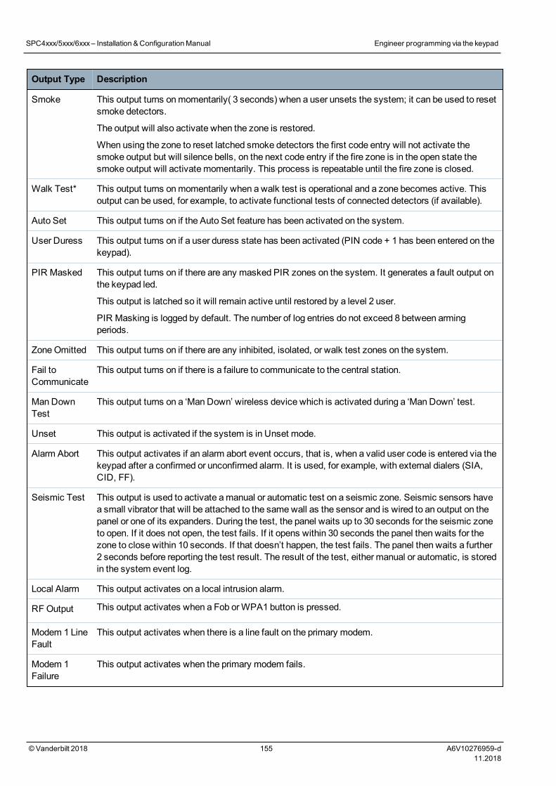
Output Type Description
Smoke This output turns onmomentarily( 3 seconds) when a user unsets the system; it can be used to resetsmoke detectors.
The output will also activate when the zone is restored.
When using the zone to reset latched smoke detectors the first code entry will not activate thesmoke output but will silence bells, on the next code entry if the fire zone is in the open state thesmoke output will activate momentarily. This process is repeatable until the fire zone is closed.
Walk Test* This output turns onmomentarily when a walk test is operational and a zone becomes active. Thisoutput can be used, for example, to activate functional tests of connected detectors (if available).
Auto Set This output turns on if the Auto Set feature has been activated on the system.
User Duress This output turns on if a user duress state has been activated (PIN code + 1 has been entered on thekeypad).
PIR Masked This output turns on if there are any masked PIR zones on the system. It generates a fault output onthe keypad led.
This output is latched so it will remain active until restored by a level 2 user.
PIR Masking is logged by default. The number of log entries do not exceed 8 between armingperiods.
ZoneOmitted This output turns on if there are any inhibited, isolated, or walk test zones on the system.
Fail toCommunicate
This output turns on if there is a failure to communicate to the central station.
Man DownTest
This output turns on a ‘Man Down’ wireless device which is activated during a ‘Man Down’ test.
Unset This output is activated if the system is in Unset mode.
Alarm Abort This output activates if an alarm abort event occurs, that is, when a valid user code is entered via thekeypad after a confirmed or unconfirmed alarm. It is used, for example, with external dialers (SIA,CID, FF).
Seismic Test This output is used to activate amanual or automatic test on a seismic zone. Seismic sensors havea small vibrator that will be attached to the samewall as the sensor and is wired to an output on thepanel or one of its expanders. During the test, the panel waits up to 30 seconds for the seismic zoneto open. If it does not open, the test fails. If it opens within 30 seconds the panel then waits for thezone to close within 10 seconds. If that doesn’t happen, the test fails. The panel then waits a further2 seconds before reporting the test result. The result of the test, either manual or automatic, is storedin the system event log.
Local Alarm This output activates on a local intrusion alarm.
RF Output This output activates when a Fob orWPA1 button is pressed.
Modem 1 LineFault
This output activates when there is a line fault on the primary modem.
Modem 1Failure
This output activates when the primary modem fails.
SPC4xxx/5xxx/6xxx– Installation &ConfigurationManual Engineer programming via the keypad
© Vanderbilt 2018 155 A6V10276959-d11.2018
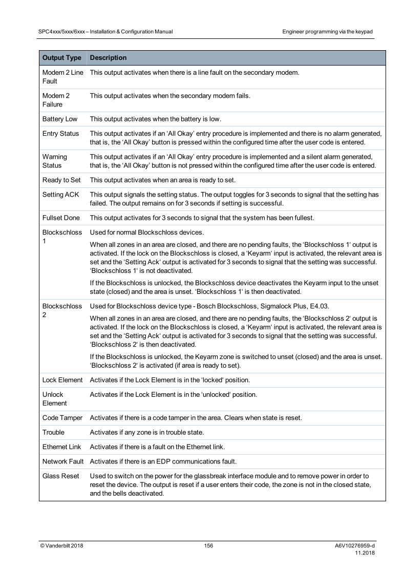
Output Type Description
Modem 2 LineFault
This output activates when there is a line fault on the secondary modem.
Modem 2Failure
This output activates when the secondary modem fails.
Battery Low This output activates when the battery is low.
Entry Status This output activates if an ‘All Okay’ entry procedure is implemented and there is no alarm generated,that is, the ‘All Okay’ button is pressed within the configured time after the user code is entered.
WarningStatus
This output activates if an ‘All Okay’ entry procedure is implemented and a silent alarm generated,that is, the ‘All Okay’ button is not pressed within the configured time after the user code is entered.
Ready to Set This output activates when an area is ready to set.
Setting ACK This output signals the setting status. The output toggles for 3 seconds to signal that the setting hasfailed. The output remains on for 3 seconds if setting is successful.
Fullset Done This output activates for 3 seconds to signal that the system has been fullest.
Blockschloss1
Used for normal Blockschloss devices.
When all zones in an area are closed, and there are no pending faults, the ‘Blockschloss 1‘ output isactivated. If the lock on the Blockschloss is closed, a ‘Keyarm‘ input is activated, the relevant area isset and the ‘Setting Ack‘ output is activated for 3 seconds to signal that the setting was successful.‘Blockschloss 1‘ is not deactivated.
If the Blockschloss is unlocked, the Blockschloss device deactivates the Keyarm input to the unsetstate (closed) and the area is unset. ‘Blockschloss 1‘ is then deactivated.
Blockschloss2
Used for Blockschloss device type - Bosch Blockschloss, Sigmalock Plus, E4.03.
When all zones in an area are closed, and there are no pending faults, the ‘Blockschloss 2‘ output isactivated. If the lock on the Blockschloss is closed, a ‘Keyarm‘ input is activated, the relevant area isset and the ‘Setting Ack‘ output is activated for 3 seconds to signal that the setting was successful.‘Blockschloss 2‘ is then deactivated.
If the Blockschloss is unlocked, the Keyarm zone is switched to unset (closed) and the area is unset.‘Blockschloss 2‘ is activated (if area is ready to set).
Lock Element Activates if the Lock Element is in the ‘locked‘ position.
UnlockElement
Activates if the Lock Element is in the ‘unlocked‘ position.
Code Tamper Activates if there is a code tamper in the area. Clears when state is reset.
Trouble Activates if any zone is in trouble state.
Ethernet Link Activates if there is a fault on the Ethernet link.
Network Fault Activates if there is an EDP communications fault.
Glass Reset Used to switch on the power for the glassbreak interfacemodule and to remove power in order toreset the device. The output is reset if a user enters their code, the zone is not in the closed state,and the bells deactivated.
SPC4xxx/5xxx/6xxx– Installation &ConfigurationManual Engineer programming via the keypad
© Vanderbilt 2018 156 A6V10276959-d11.2018
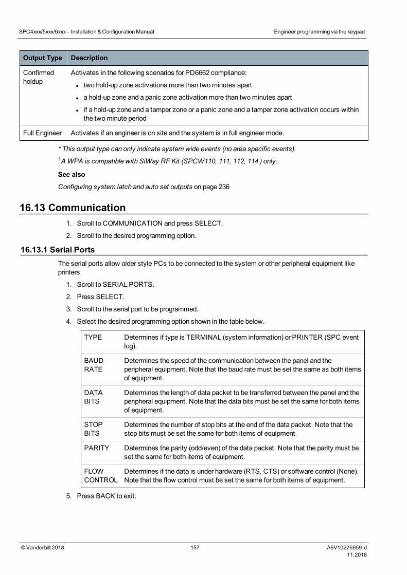
Output Type Description
Confirmedholdup
Activates in the following scenarios for PD6662 compliance:
l two hold-up zone activations more than twominutes apart
l a hold-up zone and a panic zone activationmore than twominutes apart
l if a hold-up zone and a tamper zone or a panic zone and a tamper zone activation occurs withinthe twominute period
Full Engineer Activates if an engineer is on site and the system is in full engineer mode.
* This output type can only indicate system wide events (no area specific events).1AWPA is compatible with SiWay RF Kit (SPCW110, 111, 112, 114 ) only.
See also
Configuring system latch and auto set outputs on page 236
16.13 Communication1. Scroll to COMMUNICATION and press SELECT.
2. Scroll to the desired programming option.
16.13.1 Serial PortsThe serial ports allow older style PCs to be connected to the system or other peripheral equipment likeprinters.
1. Scroll to SERIAL PORTS.
2. Press SELECT.
3. Scroll to the serial port to be programmed.
4. Select the desired programming option shown in the table below.
TYPE Determines if type is TERMINAL (system information) or PRINTER (SPC eventlog).
BAUDRATE
Determines the speed of the communication between the panel and theperipheral equipment. Note that the baud ratemust be set the same as both itemsof equipment.
DATABITS
Determines the length of data packet to be transferred between the panel and theperipheral equipment. Note that the data bits must be set the same for both itemsof equipment.
STOPBITS
Determines the number of stop bits at the end of the data packet. Note that thestop bits must be set the same for both items of equipment.
PARITY Determines the parity (odd/even) of the data packet. Note that the parity must beset the same for both items of equipment.
FLOWCONTROL
Determines if the data is under hardware (RTS, CTS) or software control (None).Note that the flow control must be set the same for both items of equipment.
5. Press BACK to exit.
SPC4xxx/5xxx/6xxx– Installation &ConfigurationManual Engineer programming via the keypad
© Vanderbilt 2018 157 A6V10276959-d11.2018
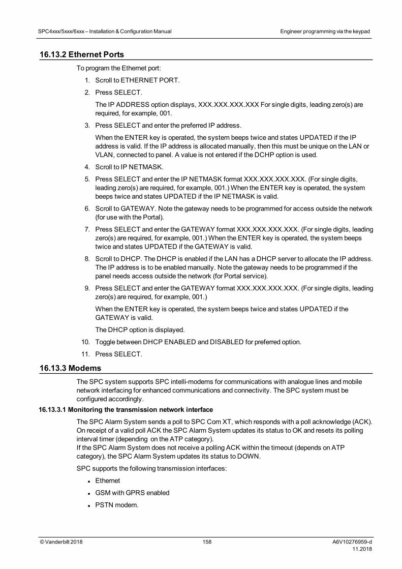
16.13.2 Ethernet PortsTo program the Ethernet port:
1. Scroll to ETHERNET PORT.
2. Press SELECT.
The IP ADDRESS option displays, XXX.XXX.XXX.XXX For single digits, leading zero(s) arerequired, for example, 001.
3. Press SELECT and enter the preferred IP address.
When the ENTER key is operated, the system beeps twice and states UPDATED if the IPaddress is valid. If the IP address is allocatedmanually, then this must be unique on the LAN orVLAN, connected to panel. A value is not entered if the DCHP option is used.
4. Scroll to IP NETMASK.
5. Press SELECT and enter the IP NETMASK format XXX.XXX.XXX.XXX. (For single digits,leading zero(s) are required, for example, 001.)When the ENTER key is operated, the systembeeps twice and states UPDATED if the IP NETMASK is valid.
6. Scroll to GATEWAY. Note the gateway needs to be programmed for access outside the network(for use with the Portal).
7. Press SELECT and enter the GATEWAY format XXX.XXX.XXX.XXX. (For single digits, leadingzero(s) are required, for example, 001.)When the ENTER key is operated, the system beepstwice and states UPDATED if the GATEWAY is valid.
8. Scroll to DHCP. The DHCP is enabled if the LAN has a DHCP server to allocate the IP address.The IP address is to be enabledmanually. Note the gateway needs to be programmed if thepanel needs access outside the network (for Portal service).
9. Press SELECT and enter the GATEWAY format XXX.XXX.XXX.XXX. (For single digits, leadingzero(s) are required, for example, 001.)
When the ENTER key is operated, the system beeps twice and states UPDATED if theGATEWAY is valid.
The DHCP option is displayed.
10. Toggle between DHCP ENABLED and DISABLED for preferred option.
11. Press SELECT.
16.13.3 ModemsThe SPC system supports SPC intelli-modems for communications with analogue lines andmobilenetwork interfacing for enhanced communications and connectivity. The SPC systemmust beconfigured accordingly.
16.13.3.1 Monitoring the transmission network interface
The SPC Alarm System sends a poll to SPC Com XT, which responds with a poll acknowledge (ACK).On receipt of a valid poll ACK the SPC Alarm System updates its status to OK and resets its pollinginterval timer (depending on the ATP category).If the SPC Alarm System does not receive a polling ACK within the timeout (depends on ATPcategory), the SPC Alarm System updates its status to DOWN.
SPC supports the following transmission interfaces:
l Ethernet
l GSMwith GPRS enabled
l PSTN modem.
SPC4xxx/5xxx/6xxx– Installation &ConfigurationManual Engineer programming via the keypad
© Vanderbilt 2018 158 A6V10276959-d11.2018
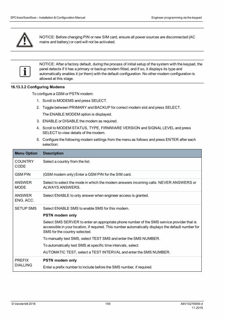
NOTICE: Before changing PIN or new SIM card, ensure all power sources are disconnected (ACmains and battery) or card will not be activated.
NOTICE: After a factory default, during the process of initial setup of the system with the keypad, thepanel detects if it has a primary or backupmodem fitted, and if so, it displays its type andautomatically enables it (or them) with the default configuration. No other modem configuration isallowed at this stage.
16.13.3.2 Configuring Modems
To configure aGSM or PSTN modem:
1. Scroll to MODEMS and press SELECT.
2. Toggle between PRIMARY and BACKUP for correct modem slot and press SELECT.
The ENABLE MODEM option is displayed.
3. ENABLE or DISABLE themodem as required.
4. Scroll to MODEM STATUS, TYPE, FIRMWARE VERSION and SIGNAL LEVEL and pressSELECT to view details of themodem.
5. Configure the followingmodem settings from themenu as follows and press ENTER after eachselection:
Menu Option Description
COUNTRYCODE
Select a country from the list.
GSM PIN (GSMmodem only) Enter a GSM PIN for the SIM card.
ANSWERMODE
Select to select themode in which themodem answers incoming calls: NEVER ANSWERS orALWAYS ANSWERS.
ANSWERENG. ACC.
Select ENABLE to only answer when engineer access is granted.
SETUP SMS Select ENABLE SMS to enable SMS for this modem.
PSTN modem only
Select SMS SERVER to enter an appropriate phone number of the SMS service provider that isaccessible in your location, if required. This number automatically displays the default number forSMS for the country selected.
Tomanually test SMS, select TEST SMS and enter the SMS NUMBER.
To automatically test SMS at specific time intervals, select
AUTOMATIC TEST, select a TEST INTERVAL and enter the SMS NUMBER.
PREFIXDIALLING
PSTN modem only
Enter a prefix number to include before the SMS number, if required.
SPC4xxx/5xxx/6xxx– Installation &ConfigurationManual Engineer programming via the keypad
© Vanderbilt 2018 159 A6V10276959-d11.2018
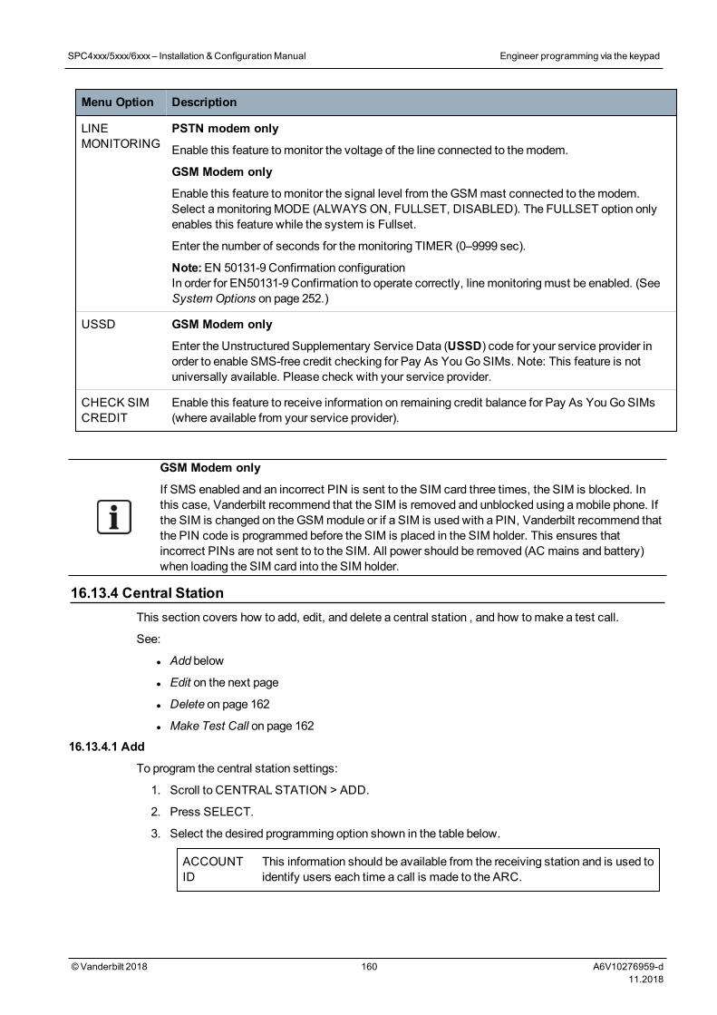
Menu Option Description
LINEMONITORING
PSTN modem only
Enable this feature tomonitor the voltage of the line connected to themodem.
GSM Modem only
Enable this feature tomonitor the signal level from theGSMmast connected to themodem.Select amonitoringMODE (ALWAYS ON, FULLSET, DISABLED). The FULLSET option onlyenables this feature while the system is Fullset.
Enter the number of seconds for themonitoring TIMER (0–9999 sec).
Note:EN 50131-9 Confirmation configurationIn order for EN50131-9 Confirmation to operate correctly, linemonitoringmust be enabled. (SeeSystem Options on page 252.)
USSD GSM Modem only
Enter the Unstructured Supplementary Service Data (USSD) code for your service provider inorder to enable SMS-free credit checking for Pay As YouGo SIMs. Note: This feature is notuniversally available. Please check with your service provider.
CHECK SIMCREDIT
Enable this feature to receive information on remaining credit balance for Pay As YouGo SIMs(where available from your service provider).
GSM Modem only
If SMS enabled and an incorrect PIN is sent to the SIM card three times, the SIM is blocked. Inthis case, Vanderbilt recommend that the SIM is removed and unblocked using amobile phone. Ifthe SIM is changed on theGSMmodule or if a SIM is used with a PIN, Vanderbilt recommend thatthe PIN code is programmed before the SIM is placed in the SIM holder. This ensures thatincorrect PINs are not sent to to the SIM. All power should be removed (AC mains and battery)when loading the SIM card into the SIM holder.
16.13.4 Central StationThis section covers how to add, edit, and delete a central station , and how tomake a test call.
See:
l Add below
l Edit on the next page
l Delete on page 162
l Make Test Call on page 162
16.13.4.1 Add
To program the central station settings:
1. Scroll to CENTRAL STATION > ADD.
2. Press SELECT.
3. Select the desired programming option shown in the table below.
ACCOUNTID
This information should be available from the receiving station and is used toidentify users each time a call is made to the ARC.
SPC4xxx/5xxx/6xxx– Installation &ConfigurationManual Engineer programming via the keypad
© Vanderbilt 2018 160 A6V10276959-d11.2018
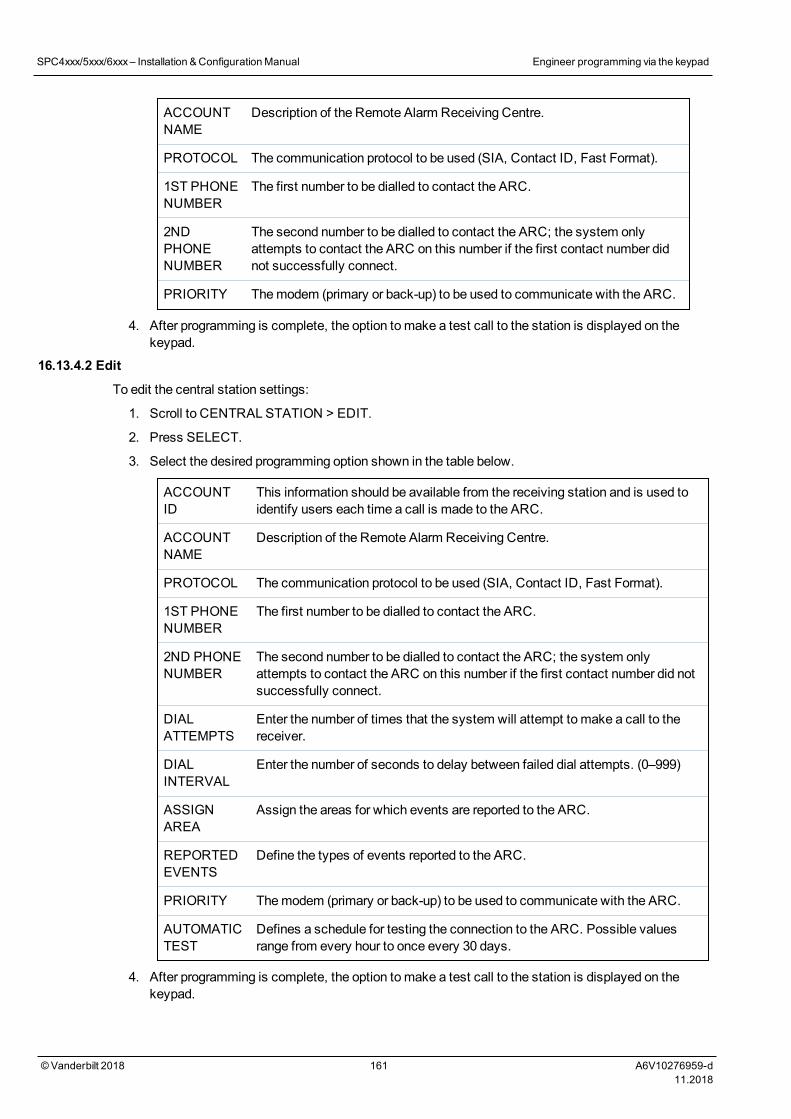
ACCOUNTNAME
Description of the Remote Alarm Receiving Centre.
PROTOCOL The communication protocol to be used (SIA, Contact ID, Fast Format).
1ST PHONENUMBER
The first number to be dialled to contact the ARC.
2NDPHONENUMBER
The second number to be dialled to contact the ARC; the system onlyattempts to contact the ARC on this number if the first contact number didnot successfully connect.
PRIORITY Themodem (primary or back-up) to be used to communicate with the ARC.
4. After programming is complete, the option tomake a test call to the station is displayed on thekeypad.
16.13.4.2 Edit
To edit the central station settings:
1. Scroll to CENTRAL STATION > EDIT.
2. Press SELECT.
3. Select the desired programming option shown in the table below.
ACCOUNTID
This information should be available from the receiving station and is used toidentify users each time a call is made to the ARC.
ACCOUNTNAME
Description of the Remote Alarm Receiving Centre.
PROTOCOL The communication protocol to be used (SIA, Contact ID, Fast Format).
1ST PHONENUMBER
The first number to be dialled to contact the ARC.
2ND PHONENUMBER
The second number to be dialled to contact the ARC; the system onlyattempts to contact the ARC on this number if the first contact number did notsuccessfully connect.
DIALATTEMPTS
Enter the number of times that the system will attempt to make a call to thereceiver.
DIALINTERVAL
Enter the number of seconds to delay between failed dial attempts. (0–999)
ASSIGNAREA
Assign the areas for which events are reported to the ARC.
REPORTEDEVENTS
Define the types of events reported to the ARC.
PRIORITY Themodem (primary or back-up) to be used to communicate with the ARC.
AUTOMATICTEST
Defines a schedule for testing the connection to the ARC. Possible valuesrange from every hour to once every 30 days.
4. After programming is complete, the option tomake a test call to the station is displayed on thekeypad.
SPC4xxx/5xxx/6xxx– Installation &ConfigurationManual Engineer programming via the keypad
© Vanderbilt 2018 161 A6V10276959-d11.2018
16.13.4.3 Delete
Enables you to delete a configured ARC.16.13.4.4 Make Test Call
Enables you to test the connection with the ARC.
Tomake a test call, do the following:
1. Select MAKE TEST CALL.
2. Select the ARC name.
3. Click SELECT.
4. Select themodem to use for the text call.
The test call is performed.
16.13.5 SPC Connect PROSPC Connect PRO is a desktop application designed to support the installation andmaintenance ofSPC systems. Using SPC Connect PRO, you can create installations and configure them prior toarriving at site. The tool can also be used in conjunction with the SPC cloud service SPC Connect toremotely connect to customer sites and support them.
To enable and configure SPC Connect PRO support:
1. Scroll to SPC CONNECT PRO and press SELECT.
2. Enable the SPC CONNECT PRO option.
3. Scroll to INTERFACES and press SELECT.
4. Enable/disable the ETHERNET, USB, SERIAL (X10) andMODEM interfaces as required.
5. To enable the TCP interface, select TCP PORT then enter the port number and press SELECT.
16.14 Test1. Scroll to TEST and press SELECT.
2. Scroll to the desired programming option.
16.14.1 Bell TestTo perform a bell test:
1. Scroll to TEST > BELL TEST.
2. Press SELECT.
When BELL TEST is selected, the following options available: EXTERNAL BELLS, STROBE,INTERNAL BELLS and BUZZER. When each of these options is selected, the device sounds toverify it is operating correctly.
16.14.2 Walk TestA walk test ensures that the sensors are operating correctly on the SPC system.
To perform awalk test:
1. Scroll to TEST > WALK TEST.
2. Press SELECT.
3. The display indicates the number of zones to be tested on the system with the text TO TEST XX(where XX is the number of valid walk test zones). Locate the sensor on the first zone andactivate it (open the door or window).
SPC4xxx/5xxx/6xxx– Installation &ConfigurationManual Engineer programming via the keypad
© Vanderbilt 2018 162 A6V10276959-d11.2018
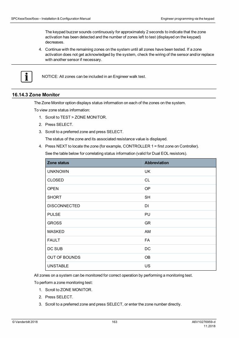
The keypad buzzer sounds continuously for approximately 2 seconds to indicate that the zoneactivation has been detected and the number of zones left to test (displayed on the keypad)decreases.
4. Continue with the remaining zones on the system until all zones have been tested. If a zoneactivation does not get acknowledged by the system, check the wiring of the sensor and/or replacewith another sensor if necessary.
NOTICE: All zones can be included in an Engineer walk test.
16.14.3 Zone MonitorThe ZoneMonitor option displays status information on each of the zones on the system.
To view zone status information:
1. Scroll to TEST > ZONE MONITOR.
2. Press SELECT.
3. Scroll to a preferred zone and press SELECT.
The status of the zone and its associated resistance value is displayed.
4. Press NEXT to locate the zone (for example, CONTROLLER 1 = first zone on Controller).
See the table below for correlating status information (valid for Dual EOL resistors).
Zone status Abbreviation
UNKNOWN UK
CLOSED CL
OPEN OP
SHORT SH
DISCONNECTED DI
PULSE PU
GROSS GR
MASKED AM
FAULT FA
DC SUB DC
OUTOF BOUNDS OB
UNSTABLE US
All zones on a system can bemonitored for correct operation by performing amonitoring test.
To perform a zonemonitoring test:
1. Scroll to ZONE MONITOR.
2. Press SELECT.
3. Scroll to a preferred zone and press SELECT, or enter the zone number directly.
SPC4xxx/5xxx/6xxx– Installation &ConfigurationManual Engineer programming via the keypad
© Vanderbilt 2018 163 A6V10276959-d11.2018
If the zone is located close to the keypad, the status of the keypad can be viewed as it changes.The Zone status and resistance value displays on the top right.
4. Change the state of the sensor; for example, for a door contact sensor, open the door.
The keypad buzzer beeps and the status of the sensor changes from CL (Closed) to OP (Open).The corresponding resistance value changes to a value that depends on the EOL resistancescheme.
It is advisable to check the operation of all zones on the system after installation is complete. Tolocate the zone select NEXT (bottom right) on the keypad. A zone status value of SH or DIindicates that the zone is shorted or disconnected.
16.14.4 Output TestTo perform an output test:
1. Scroll to OUTPUT TEST.
2. Press SELECT.
3. Toggle between CONTROLLER and EXPANDER for preferred option.
4. If testing the controller outputs, scroll to the preferred output and press SELECT. If testing theexpander outputs, select the expander and then the output.
The keypad display indicates the current state of the output on the top line.
5. Toggle the output state ON/OFF.
6. Check that the device connected to the selected output changes state accordingly.
16.14.5 Soak TestA Soak Test provides amethod of putting selected zones on test. Zones on soak test do not cause anyalarms but are recorded in the event log. Zones on soak test will remain on soak test until the soak testtimer expires as in the timers default (14 days).
To perform a soak test:
1. Scroll to SOAK TEST and press SELECT.
2. Toggle between ENABLE SOAK and CANCEL SOAK for preferred option.
3. Scroll to preferred zone and press SELECT.
A message confirming that the zone is in soak is displayed.
NOTICE: All zone types can be included in a Soak test.
16.14.6 Audible OptionsThe audible options are applied as indicators within a walk test.
To set the audible options:
1. Scroll to AUDIBLE OPTIONS.
2. Press SELECT.
3. Scroll to one of the following options: ALL, INT BELL, EXT BELL, KEYPAD.
4. Press SAVE.
5. Press BACK to exit.
SPC4xxx/5xxx/6xxx– Installation &ConfigurationManual Engineer programming via the keypad
© Vanderbilt 2018 164 A6V10276959-d11.2018
16.14.7 Visual IndicatorsThis test is used to test all the pixels on the LCD Keypad and all the pixels and LED indicators on theComfort Keypad, Indicator module and Keyswitch.
To test a keypad:
1. Scroll to VISUAL IND.
2. Press SELECT.
3. Press ENABLE.
On the LCD keypad, two rows of continuously changing characters are displayed.
On the Comfort keypad, all the LED indicators are lit and all screen pixels are displayed.
1. Press BACK to disable the test.
2. Press BACK to exit.
16.14.8 Seismic TestTo perform a seismic test:
1. Scroll to TEST > SEISMIC TEST.
2. Press SELECT.
3. Select TEST ALL AREAS, or select an individual area to test.
4. If you select an individual area to test, you can select either TEST ALL ZONES or select a specificseismic zone to test.
Themessage ‘SEISMIC TEST’ is display on the keypad while the test is being performed.
If the test fails, themessage ‘SEISMIC FAIL’ is displayed. If the “i” or VIEW key is pressed, a list ofthe failed zones is displayed which can be scrolled through.
If the test succeeds, ‘SEISMIC OK’ is displayed.
See also
Seismic Sensor Testing on page 354.
16.15 Utilities1. Scroll to UTILITIES and press SELECT.
2. Scroll to the desired programming option:
SYSTEMSOFTWARE
To view the current software version.
DEFAULTS To reset users or return the system to factory setting.
BACKUPCONFIG
To back-up a configuration.
RESTORECONFIG
To restore a configuration.
SYSTEMRESTART
To restart the system.
LICENSE Enter a license number to change the SPC license key. The system doesnot log or report a license change.
SPC4xxx/5xxx/6xxx– Installation &ConfigurationManual Engineer programming via the keypad
© Vanderbilt 2018 165 A6V10276959-d11.2018
16.16 IsolateZones, system alerts or alerts from X-BUS devices can bemanually isolated from the keypad. Isolatinga zone removes that zone from the system until the user de-isolates it.
To isolate zones, system alerts or alerts from X-BUS devices:
1. Scroll to ISOLATE and press SELECT.
2. Scroll to the desired option in the table below and press SELECT.
ZONE Select the required zone and toggle the setting from NOT ISOLATED toISOLATED.
SYSTEM Isolate the desired system alert.
XBUS Isolate the desired alert from EXPANDERS or KEYPADS:
l XBUS COMMS LOST
l XBUS FUSE FAULT (Expanders only)
l X-BUS TAMPER
VIEWISOLATIONS
To view a list of the isolated zones, system alerts and X-BUS devicesalerts.
16.17 Event LogRecent events on the system are displayed in the EVENT LOG option. Events flash in one secondintervals.
1. Scroll to EVENT LOG and press SELECT.
2. To view an event from a particular date, enter the date with the numeric keys.
Themost recent events are displayed on the bottom line of the display. All previous events aredisplayed for one second in turn.
16.18 Access LogZone access on the system is displayed in the ACCESS LOG option.
1. Scroll to ACCESS LOG and press SELECT.
2. Select a door on the system for which you want to display access events.
Themost recent access events are displayed with a date and time.
3. Scroll down through the access events or enter a date and press ENTER to find a particularaccess event.
16.19 Alarm LogThe ALARM LOG displays a list of alarm events.
l Select Log > System Log > Alarm Log.
The following types are displayed in this log:
l Zones
– Alarm
– Panic
SPC4xxx/5xxx/6xxx– Installation &ConfigurationManual Engineer programming via the keypad
© Vanderbilt 2018 166 A6V10276959-d11.2018
l System Events
– Confirmed Alarm
–User Duress
– XBus Panic
– User Panic
– RPA Panic
16.20 Change Engineer PinTo change the Engineer PIN:
1. Scroll to CHANGE ENGPIN and press SELECT.
A randomly generated PIN appears.
2. Enter a new PIN if required by overwriting the displayed PIN and press ENTER.
Theminimum number of digits required for this code depends on the security setting of the systemor on the selected length of the PIN Digits in the browser (Panel Settings > System Settings >Options) The system will not accept a PIN with fewer numbers than it is set to receive.
3. Confirm the new PIN, press SAVE.
4. Press BACK to return to the previous screen to amend the PIN.
If the display times out during the process, the old PIN remains valid.
16.21 SMSThe SPC system support the communication of SMS alerts from the panel to the engineer and selectedusers’ mobile phones (SMS events) in addition to allowing users to control the SPC system remotely viaSMS (SMS control). These two features work hand in hand as it allows the user to respond to a SMSnotification without the need to be physically at the premises.
A maximum of 32 (SPC4xxx), 50 (SPC5xxx) or 100 (SPC6xxx) SMS IDs can be configured for eachpanel. An SMS-enabledmodem and an appropriate system and user configuration are required to enableSMS communications.
Depending on the SMS AUTHENTICATION mode selected (seeOptions on page 113), SMS userauthentication can be configured to use various combinations of the user’s PIN and Caller ID or SMS PINand Caller PIN.
The SMS notification can operate with a PSTN modem if the PSTN operator supports SMS overPSTN whereas SMS control will need aGSMmodem at the panel. A GSMmodem will support bothSMS notification and control.
SMS control
The SMS control can be set up so that a remote user can send an SMS message to perform the followingactions at the panel:
l Setting/unsetting
l Enable/disable engineer
l Enable/disable manufacturer access
l Mapping gate on/off
SPC4xxx/5xxx/6xxx– Installation &ConfigurationManual Engineer programming via the keypad
© Vanderbilt 2018 167 A6V10276959-d11.2018
SMS events
The SMS notification can be set up to send a range of events that occur on the system such as:
l Alarm activation
l Confirmed alarms
l Fault and tamper
l Setting and unsetting
l Inhibit and isolate
l All other types of events
16.21.1 AddTo add a user
Prerequisiteso A modem is installed and identified by the system.o The functionSMS Authentication is activated in OPTIONS (seeOptions on page 113).
1. Scroll to SMS > ADD and press SELECT.
2. Select a user to add for SMS operation.
3. Enter an SMS NUMBER for this user and press ENTER.
4. Enter an SMS PIN for this user and press ENTER.
Keypad indicates that SMS details are updated.
16.21.2 EditPrerequisites
o A modem is installed and identified by the system.o The functionSMS Authentication is activated in OPTIONS (seeOptions on page 113).
1. Scroll to SMS > EDIT and press SELECT.
2. Select an engineer or user SMS ID to edit.
SMS NUMBER Enter the number to which the SMS will be sent (requires three-digit country codeprefix).
Note:Engineer SMS number can deleted by resetting it 0. User SMS numbers cannotbe deleted.
EDIT USER Select a new user for this SMS ID if required.
EVENT FITLTER Select the panel events which the user or engineer will receive via SMS. SelectENABLED or DISABLED. Events that are enabled are indicated with an asterisk *before the event in the list.
CONTROL RIGHTS Select the operations that the user or engineer can perform remotely on the panelthrough SMS. SeeSMS Commands on page 204
NOTICE: HOLDUP alarm events are not transmitted via SMS.
SPC4xxx/5xxx/6xxx– Installation &ConfigurationManual Engineer programming via the keypad
© Vanderbilt 2018 168 A6V10276959-d11.2018
If the phone line is connected to the PSTN network via a PBX, the appropriate line access digit shouldbe inserted before the called party number. Ensure that Calling Line Identity (CLI) is enabled on theline selected tomake the call to the SMS network. Consult the PBX administrator for details.
16.21.3 Delete1. Scroll to SMS > DELETE.
2. Scroll to the required SMS ID.
3. Press SELECT.
The keypad indicates that the SMS information is updated.
16.22 X-10
As of version 3.4, X-10 is in maintenance. The functionality remains in the product for backwardcompatibility.
X10 is a technology that allows peripheral devices, such as lights or appliances, to be controlled by thesystem and system events can be used to trigger outputs on the X10 devices. The SPC controllerprovides a dedicated serial port (serial port 1) for interfacing directly with standard X10 equipment.
1. Scroll to X-10 and press SELECT.
2. Scroll to the desired programming option:
ENABLE X-10 To enable or disable the X-10 functionality on the system.
DEVICES To add, edit, delete or test X-10 devices.
LOGGING To enable or disable the X-10 logging.
16.23 Set Date/TimeThe date and time can bemanually entered on the system. The time and date information is displayed onthe keypad and browser and is used on time-related programming features.
1. Scroll to SET DATE/TIME and press SELECT.
The date displays on the top line of the display.
2. To enter a new date, press the required numeric keys. Tomove the cursor to the left and right, pressthe left and right arrow keys.
3. Press ENTER to save the new date.
If an attempt is made to save an invalid date value, the text INVALID VALUE is displayed for 1second and the user is prompted to enter a valid date.
4. To enter a new time, press the required numeric keys. Tomove the cursor to the left and right, pressthe left and right arrow keys.
5. Press ENTER to save the new time.
If an attempt is made to save an invalid time value, the text INVALID VALUE is displayed for 1second and the user is prompted to enter a valid time.
SPC4xxx/5xxx/6xxx– Installation &ConfigurationManual Engineer programming via the keypad
© Vanderbilt 2018 169 A6V10276959-d11.2018
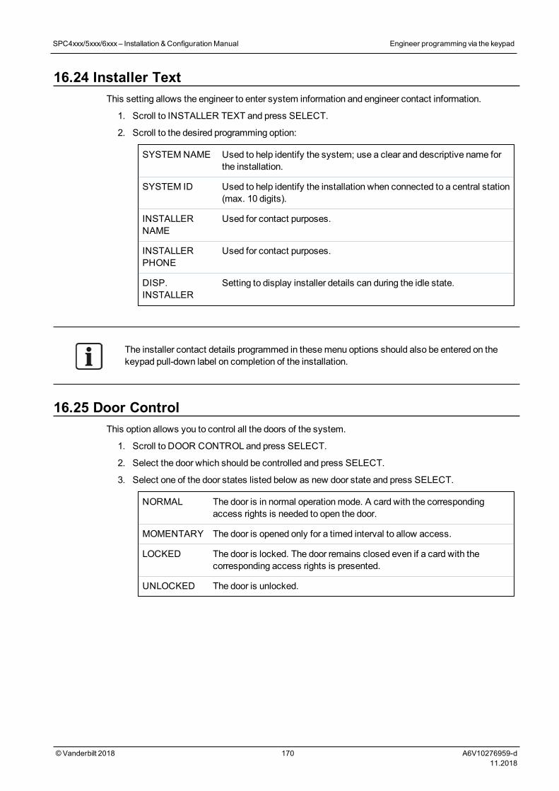
16.24 Installer TextThis setting allows the engineer to enter system information and engineer contact information.
1. Scroll to INSTALLER TEXT and press SELECT.
2. Scroll to the desired programming option:
SYSTEMNAME Used to help identify the system; use a clear and descriptive name forthe installation.
SYSTEM ID Used to help identify the installation when connected to a central station(max. 10 digits).
INSTALLERNAME
Used for contact purposes.
INSTALLERPHONE
Used for contact purposes.
DISP.INSTALLER
Setting to display installer details can during the idle state.
The installer contact details programmed in thesemenu options should also be entered on thekeypad pull-down label on completion of the installation.
16.25 Door ControlThis option allows you to control all the doors of the system.
1. Scroll to DOOR CONTROL and press SELECT.
2. Select the door which should be controlled and press SELECT.
3. Select one of the door states listed below as new door state and press SELECT.
NORMAL The door is in normal operationmode. A card with the correspondingaccess rights is needed to open the door.
MOMENTARY The door is opened only for a timed interval to allow access.
LOCKED The door is locked. The door remains closed even if a card with thecorresponding access rights is presented.
UNLOCKED The door is unlocked.
SPC4xxx/5xxx/6xxx– Installation &ConfigurationManual Engineer programming via the keypad
© Vanderbilt 2018 170 A6V10276959-d11.2018
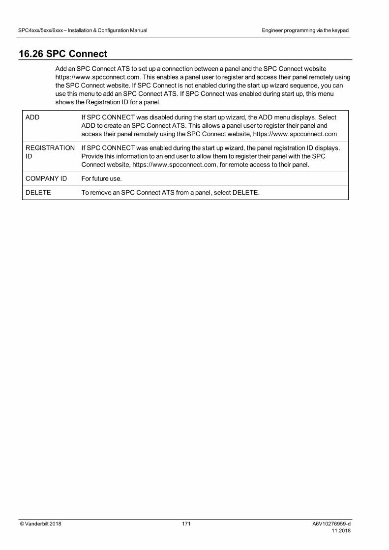
16.26 SPC ConnectAdd an SPC Connect ATS to set up a connection between a panel and the SPC Connect websitehttps://www.spcconnect.com. This enables a panel user to register and access their panel remotely usingthe SPC Connect website. If SPC Connect is not enabled during the start up wizard sequence, you canuse this menu to add an SPC Connect ATS. If SPC Connect was enabled during start up, this menushows the Registration ID for a panel.
ADD If SPC CONNECT was disabled during the start up wizard, the ADD menu displays. SelectADD to create an SPC Connect ATS. This allows a panel user to register their panel andaccess their panel remotely using the SPC Connect website, https://www.spcconnect.com
REGISTRATIONID
If SPC CONNECT was enabled during the start up wizard, the panel registration ID displays.Provide this information to an end user to allow them to register their panel with the SPCConnect website, https://www.spcconnect.com, for remote access to their panel.
COMPANY ID For future use.
DELETE To remove an SPC Connect ATS from a panel, select DELETE.
SPC4xxx/5xxx/6xxx– Installation &ConfigurationManual Engineer programming via the keypad
© Vanderbilt 2018 171 A6V10276959-d11.2018

17 Engineer programming via the browserEngineer programming options on the SPC panel can be accessed via any standard web browser on a PCand is PIN protected.
You can access Engineer Programming via the browser by entering the default Engineer PIN (1111). Formore details, seeEngineer PINs on page 106.
This web server provides access to the complete set of programming features used to install and configurethe SPC system.
This programming option should only be provided to authorized installers of the SPC system.
Engineer Programming features on the SPC are divided into the following categories:
Soft Engineer Features
These features can be programmedwithout requiring the alarm system to be deactivated; they areaccessible directly upon entering Engineer mode.
Full Engineer Features
These features require the alarm system to be deactivated before programming can commence; thesefeatures are accessible under the Full Engineer menu.
NOTICE: If ‘Engineer Exit’ option is enabled in System Options, the engineer is allowed leave FullEngineer mode with alerts active but must acknowledge all alerts listed on the keypad or in thebrowser before switching from Full Engineer mode to Soft Engineer mode.
The web server on SPC controller can be accessed using either the Ethernet or USB interface.
If programming with a browser interface, click Savewhenmaking changes.Click Refresh to view the current programming values on a web page.
17.1 System InformationClick the ? icon to view the Helpmenu which provides up-to-date information about the panel and thefunctionality that is currently licensed on the system.
17.2 Ethernet interface
©Vanderbilt 2018 172 A6V10276959-d11.2018
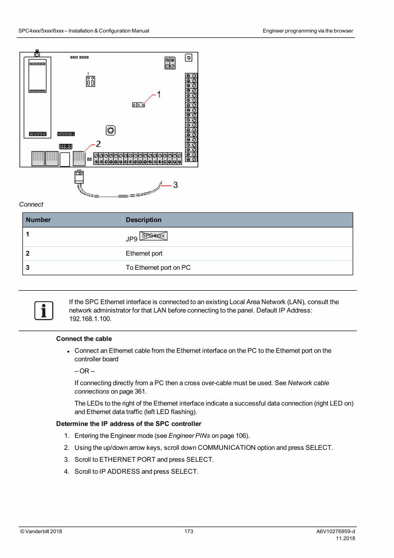
Connect
Number Description
1JP9
2 Ethernet port
3 To Ethernet port on PC
If the SPC Ethernet interface is connected to an existing Local Area Network (LAN), consult thenetwork administrator for that LAN before connecting to the panel. Default IP Address:192.168.1.100.
Connect the cable
l Connect an Ethernet cable from the Ethernet interface on the PC to the Ethernet port on thecontroller board
–OR –
If connecting directly from a PC then a cross over-cablemust be used. SeeNetwork cableconnections on page 361.
The LEDs to the right of the Ethernet interface indicate a successful data connection (right LED on)and Ethernet data traffic (left LED flashing).
Determine the IP address of the SPC controller
1. Entering the Engineer mode (seeEngineer PINs on page 106).
2. Using the up/down arrow keys, scroll downCOMMUNICATION option and press SELECT.
3. Scroll to ETHERNET PORT and press SELECT.
4. Scroll to IP ADDRESS and press SELECT.
SPC4xxx/5xxx/6xxx– Installation &ConfigurationManual Engineer programming via the browser
© Vanderbilt 2018 173 A6V10276959-d11.2018
17.3 Connecting to the panel via USB
If the panel is reset while the USB cable is connected, the cablemust be unplugged and plugged inagain.
The USB port on the controller connects to a PC via a standard USB type A or type B cable. Driversmust be installed tomake a USB connection from the controller to the PC.
Prerequisiteso Youmust have a USB cable connecting your PC to the panel.
1. Connect the USB cable from the controller to a USB interface on the PC.
The Found New Hardwarewizard is displayed.
2. Click Next.
Windows XP detects a Generic USB hub.
3. Click Finish.
Windows XP detects the SPC – Advanced Security System onCOM port N, where N is thenumber of the COM port assigned to the device.
4. Make a note of the COM port assigned to the device, it is required later in the process.
The Found New Hardwarewizard is displayed again.
5. Select Install the software automatically.
6. If theWindows XP driver installation wizard asks you to select the best match from a list,choose the following option:
Vanderbilt Intrunet SPC USB Local Connection
7. Click Next.
A dialog box regardingWindows certification appears. Vanderbilt deems this acceptable tocontinue. For further queries, contact your network administrator or a Vanderbilt technician.
8. Click Continue Anyway.
The installation finishes.
9. Click Finish.
The driver is installed.
Configuring the connection on Windows XP
To set up the new connection on the PC:
1. Click theStart command.
2. Select Connect To > Show All Connections > Create A New Connection.
3. In the New ConnectionWizard, select Setup an advanced connection.
4. Select the Advanced Connection Option, Connect directly to another computer.
5. Select Guest as the role for this PC.
6. Enter a name for the connection.
7. Select an available serial port for use with the connection. This port should be the COM port thatthe USB device is using.
8. Select if this connection is available to all users or just yourself.
SPC4xxx/5xxx/6xxx– Installation &ConfigurationManual Engineer programming via the browser
© Vanderbilt 2018 174 A6V10276959-d11.2018
9. On the last dialog of the wizard, click Finish.
10. The PC prompts for username and password for the USB connection. Enter the following details:
- Username: SPC
- Password: password (default)
11. Click Connect.
The PC initiates a data link with the controller. When the link has been established, a connectionicon appears on the task bar at the bottom of the PC screen.
12. Right-click the link and select Status.
A server IP address is displayed in the details window.
13. Enter this address into the address bar of an internet browser using the hyper text transfer protocolsecure (for example, https://192.168.5.1).
14. Login into the SPC browser application using your user PIN.
Your default PIN should be changed immediately and noted. Forgotten PINs are remedied only by afactory default of the system, resulting in a reset of the system configuration. The configuration canbe restored if a backup is available.
Windows 7
Prerequisiteso Youmust have Local Administrator rights to perform the actions in this task.
1. Open theWindows 7 Control Panel.
2. Select Phone and Modem.
ThePhone and Modem page is displayed.
3. Select theModems tab and click Add.
TheAdd Hardware Wizard – Install New Modem page is displayed.
4. Click Next twice.
TheAdd New Hardwarewizard displays a list of modems.
5. Select Communications cable between two computers.
6. Click Next.
7. Click Next, then Finish.
8. Return to theModems tab of thePhone and Modem page.
9. Select the new modem and click Properties.
TheCommunications cable between two computers Properties page is displayed.
10. In theGeneral tab, click Change Settings to allow editing of the properties.
11. Select theModem tab.
12. Change the value in theMaximum Port Speed to 115200 and click OK.
13. From theControl Panel, open theNetwork and Sharing Center.
14. Click Change Adapter Settings. If a new modem is present in the list of available connections,proceed to step 22. If themodem is not present, perform the following steps.
15. In theNetwork and Sharing Center, click Set up a new connection or network.
16. Select Set up a dial-up connection and click Next.
SPC4xxx/5xxx/6xxx– Installation &ConfigurationManual Engineer programming via the browser
© Vanderbilt 2018 175 A6V10276959-d11.2018
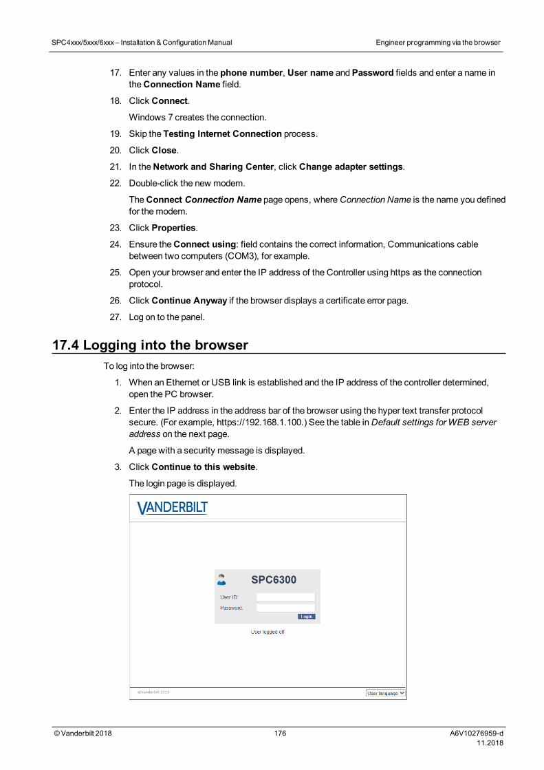
17. Enter any values in the phone number, User name andPassword fields and enter a name intheConnection Name field.
18. Click Connect.
Windows 7 creates the connection.
19. Skip the Testing Internet Connection process.
20. Click Close.
21. In theNetwork and Sharing Center, click Change adapter settings.
22. Double-click the new modem.
TheConnect Connection Name page opens, whereConnection Name is the name you definedfor themodem.
23. Click Properties.
24. Ensure theConnect using: field contains the correct information, Communications cablebetween two computers (COM3), for example.
25. Open your browser and enter the IP address of the Controller using https as the connectionprotocol.
26. Click Continue Anyway if the browser displays a certificate error page.
27. Log on to the panel.
17.4 Logging into the browserTo log into the browser:
1. When an Ethernet or USB link is established and the IP address of the controller determined,open the PC browser.
2. Enter the IP address in the address bar of the browser using the hyper text transfer protocolsecure. (For example, https://192.168.1.100.) See the table inDefault settings forWEB serveraddress on the next page.
A page with a security message is displayed.
3. Click Continue to this website.
The login page is displayed.
SPC4xxx/5xxx/6xxx– Installation &ConfigurationManual Engineer programming via the browser
© Vanderbilt 2018 176 A6V10276959-d11.2018
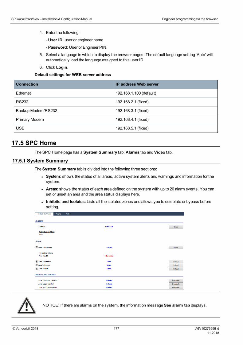
4. Enter the following:
-User ID: user or engineer name
-Password: User or Engineer PIN.
5. Select a language in which to display the browser pages. The default language setting ‘Auto’ willautomatically load the language assigned to this user ID.
6. Click Login.
Default settings for WEB server address
Connection IP address Web server
Ethernet 192.168.1.100 (default)
RS232 192.168.2.1 (fixed)
BackupModem/RS232 192.168.3.1 (fixed)
Primary Modem 192.168.4.1 (fixed)
USB 192.168.5.1 (fixed)
17.5 SPC HomeThe SPC Home page has aSystem Summary tab, Alarms tab andVideo tab.
17.5.1 System SummaryTheSystem Summary tab is divided into the following three sections:
l System: shows the status of all areas, active system alerts and warnings and information for thesystem.
l Areas: shows the status of each area defined on the system with up to 20 alarm events. You canset or unset an area and the area status displays here.
l Inhibits and Isolates: Lists all the isolated zones and allows you to deisolate or bypass beforesetting.
NOTICE: If there are alarms on the system, the informationmessageSee alarm tab displays.
SPC4xxx/5xxx/6xxx– Installation &ConfigurationManual Engineer programming via the browser
© Vanderbilt 2018 177 A6V10276959-d11.2018
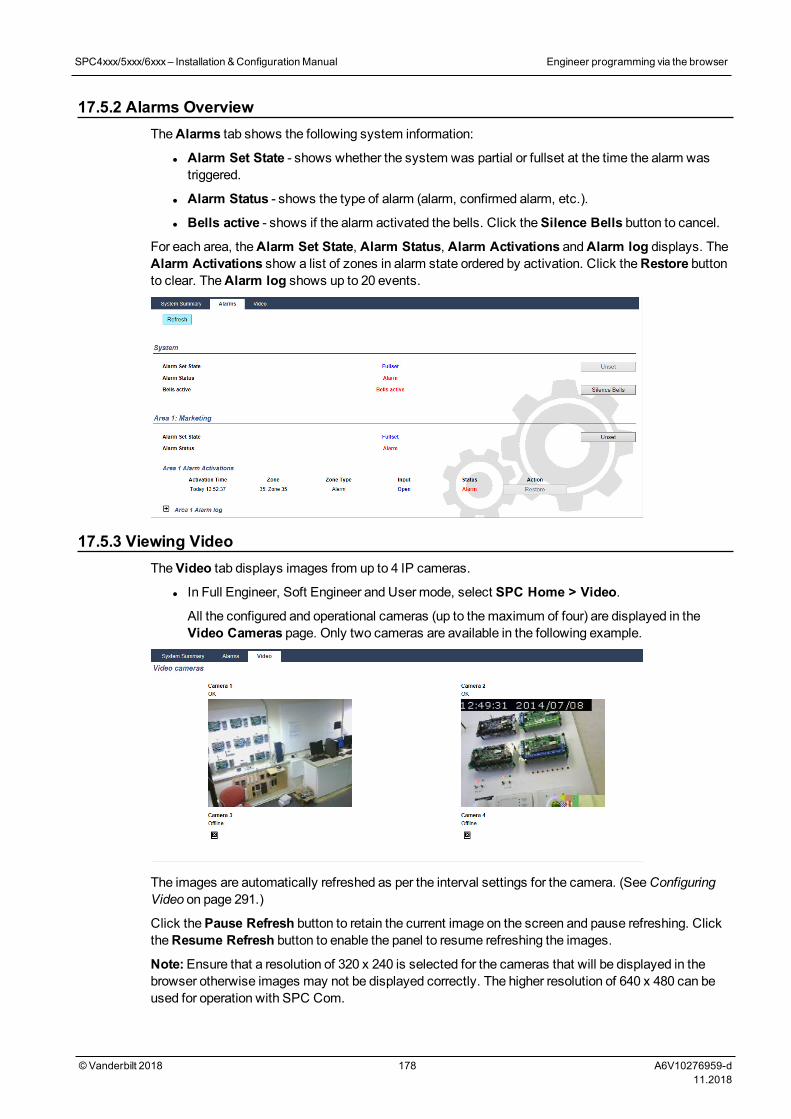
17.5.2 Alarms OverviewTheAlarms tab shows the following system information:
l Alarm Set State - shows whether the system was partial or fullset at the time the alarm wastriggered.
l Alarm Status - shows the type of alarm (alarm, confirmed alarm, etc.).
l Bells active - shows if the alarm activated the bells. Click theSilence Bells button to cancel.
For each area, theAlarm Set State, Alarm Status, Alarm Activations andAlarm log displays. TheAlarm Activations show a list of zones in alarm state ordered by activation. Click theRestore buttonto clear. TheAlarm log shows up to 20 events.
17.5.3 Viewing VideoTheVideo tab displays images from up to 4 IP cameras.
l In Full Engineer, Soft Engineer and User mode, select SPC Home > Video.
All the configured and operational cameras (up to themaximum of four) are displayed in theVideo Cameras page. Only two cameras are available in the following example.
The images are automatically refreshed as per the interval settings for the camera. (SeeConfiguringVideo on page 291.)
Click thePause Refresh button to retain the current image on the screen and pause refreshing. ClicktheResume Refresh button to enable the panel to resume refreshing the images.
Note:Ensure that a resolution of 320 x 240 is selected for the cameras that will be displayed in thebrowser otherwise images may not be displayed correctly. The higher resolution of 640 x 480 can beused for operation with SPC Com.
SPC4xxx/5xxx/6xxx– Installation &ConfigurationManual Engineer programming via the browser
© Vanderbilt 2018 178 A6V10276959-d11.2018
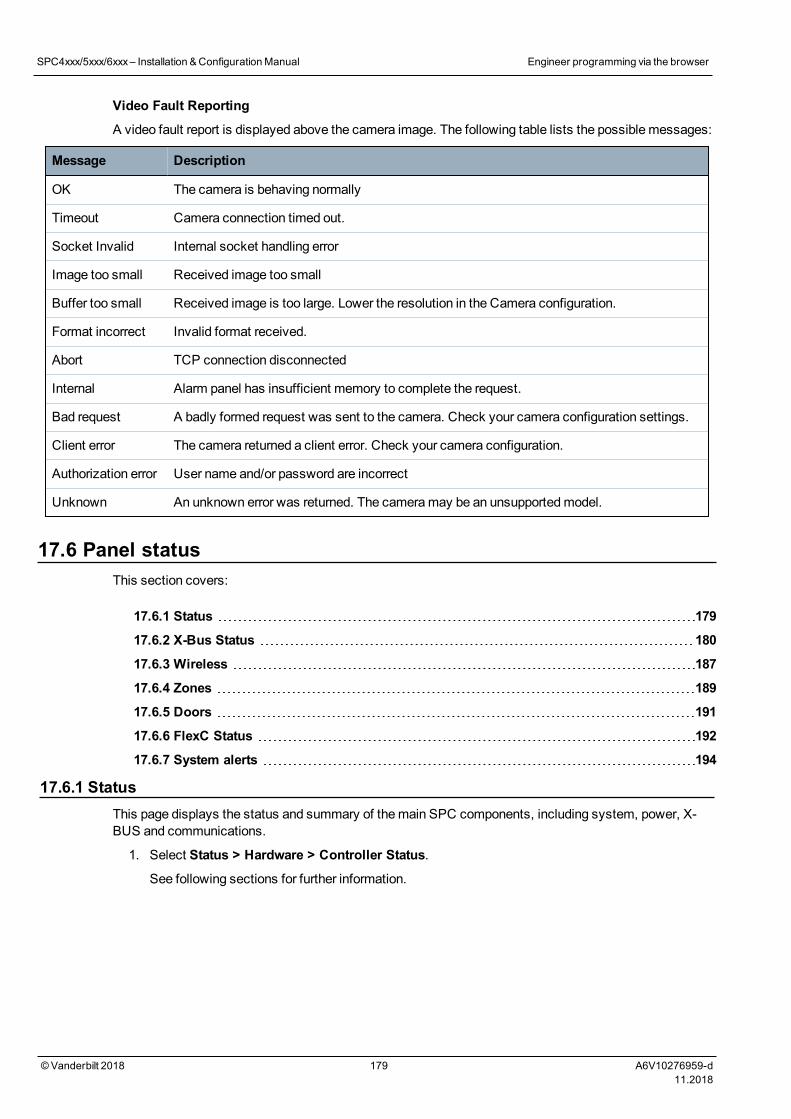
Video Fault Reporting
A video fault report is displayed above the camera image. The following table lists the possible messages:
Message Description
OK The camera is behaving normally
Timeout Camera connection timed out.
Socket Invalid Internal socket handling error
Image too small Received image too small
Buffer too small Received image is too large. Lower the resolution in the Camera configuration.
Format incorrect Invalid format received.
Abort TCP connection disconnected
Internal Alarm panel has insufficient memory to complete the request.
Bad request A badly formed request was sent to the camera. Check your camera configuration settings.
Client error The camera returned a client error. Check your camera configuration.
Authorization error User name and/or password are incorrect
Unknown An unknown error was returned. The cameramay be an unsupportedmodel.
17.6 Panel statusThis section covers:
17.6.1 Status 179
17.6.2 X-Bus Status 180
17.6.3 Wireless 187
17.6.4 Zones 189
17.6.5 Doors 191
17.6.6 FlexC Status 192
17.6.7 System alerts 194
17.6.1 StatusThis page displays the status and summary of themain SPC components, including system, power, X-BUS and communications.
1. Select Status > Hardware > Controller Status.
See following sections for further information.
SPC4xxx/5xxx/6xxx– Installation &ConfigurationManual Engineer programming via the browser
© Vanderbilt 2018 179 A6V10276959-d11.2018
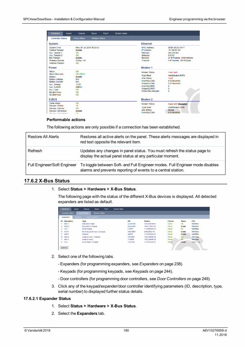
Performable actions
The following actions are only possible if a connection has been established.
Restore All Alerts Restores all active alerts on the panel. These alerts messages are displayed inred text opposite the relevant item.
Refresh Updates any changes in panel status. Youmust refresh the status page todisplay the actual panel status at any particular moment.
Full Engineer/Soft Engineer To toggle between Soft- and Full Engineer modes. Full Engineer mode disablesalarms and prevents reporting of events to a central station.
17.6.2 X-Bus Status1. Select Status > Hardware > X-Bus Status.
The following page with the status of the different X-Bus devices is displayed. All detectedexpanders are listed as default.
2. Select one of the following tabs.
- Expanders (for programming expanders, seeExpanders on page 238).
- Keypads (for programming keypads, seeKeypads on page 244).
- Door controllers (for programming door controllers, seeDoor Controllers on page 249).
3. Click any of the keypad/expander/door controller identifying parameters (ID, description, type,serial number) to displayed further status details.
17.6.2.1 Expander Status
1. Select Status > Hardware > X-Bus Status.
2. Select theExpanders tab.
SPC4xxx/5xxx/6xxx– Installation &ConfigurationManual Engineer programming via the browser
© Vanderbilt 2018 180 A6V10276959-d11.2018
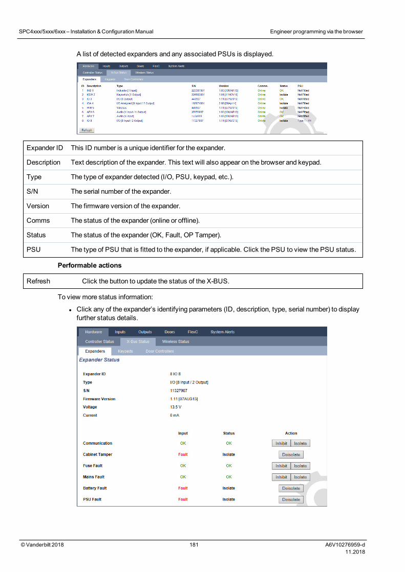
A list of detected expanders and any associated PSUs is displayed.
Expander ID This ID number is a unique identifier for the expander.
Description Text description of the expander. This text will also appear on the browser and keypad.
Type The type of expander detected (I/O, PSU, keypad, etc.).
S/N The serial number of the expander.
Version The firmware version of the expander.
Comms The status of the expander (online or offline).
Status The status of the expander (OK, Fault, OP Tamper).
PSU The type of PSU that is fitted to the expander, if applicable. Click the PSU to view the PSU status.
Performable actions
Refresh Click the button to update the status of the X-BUS.
To view more status information:
l Click any of the expander’s identifying parameters (ID, description, type, serial number) to displayfurther status details.
SPC4xxx/5xxx/6xxx– Installation &ConfigurationManual Engineer programming via the browser
© Vanderbilt 2018 181 A6V10276959-d11.2018
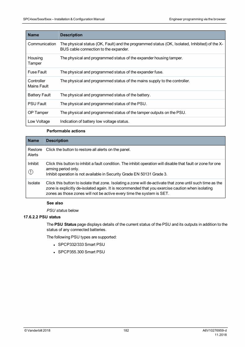
Name Description
Communication The physical status (OK, Fault) and the programmed status (OK, Isolated, Inhibited) of the X-BUS cable connection to the expander.
HousingTamper
The physical and programmed status of the expander housing tamper.
Fuse Fault The physical and programmed status of the expander fuse.
ControllerMains Fault
The physical and programmed status of themains supply to the controller.
Battery Fault The physical and programmed status of the battery.
PSU Fault The physical and programmed status of the PSU.
OP Tamper The physical and programmed status of the tamper outputs on the PSU.
Low Voltage Indication of battery low voltage status.
Performable actions
Name Description
RestoreAlerts
Click the button to restore all alerts on the panel.
Inhibit Click this button to inhibit a fault condition. The inhibit operation will disable that fault or zone for onearming period only.Inhibit operation is not available in Security Grade EN 50131Grade 3.
Isolate Click this button to isolate that zone. Isolating a zone will de-activate that zone until such time as thezone is explicitly de-isolated again. It is recommended that you exercise caution when isolatingzones as those zones will not be active every time the system is SET.
See also
PSU status below17.6.2.2 PSU status
ThePSU Status page displays details of the current status of the PSU and its outputs in addition to thestatus of any connected batteries.
The following PSU types are supported:
l SPCP332/333 Smart PSU
l SPCP355.300 Smart PSU
SPC4xxx/5xxx/6xxx– Installation &ConfigurationManual Engineer programming via the browser
© Vanderbilt 2018 182 A6V10276959-d11.2018
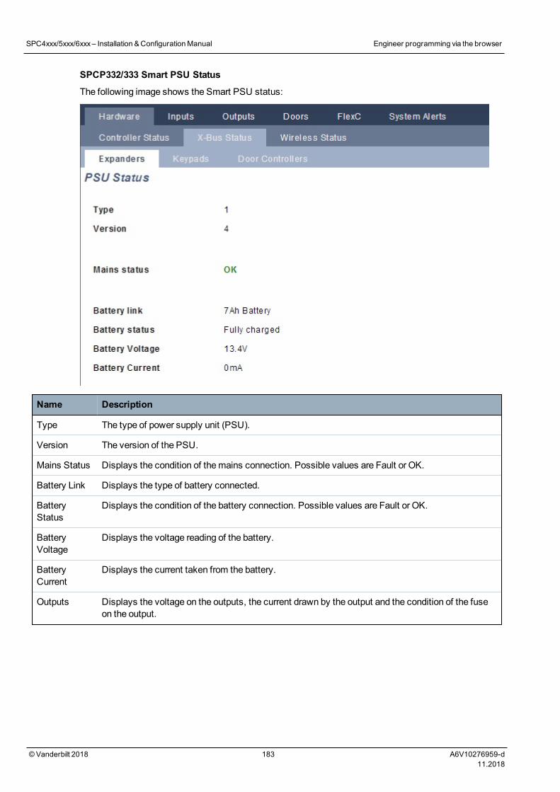
SPCP332/333 Smart PSU Status
The following image shows the Smart PSU status:
Name Description
Type The type of power supply unit (PSU).
Version The version of the PSU.
Mains Status Displays the condition of themains connection. Possible values are Fault or OK.
Battery Link Displays the type of battery connected.
BatteryStatus
Displays the condition of the battery connection. Possible values are Fault or OK.
BatteryVoltage
Displays the voltage reading of the battery.
BatteryCurrent
Displays the current taken from the battery.
Outputs Displays the voltage on the outputs, the current drawn by the output and the condition of the fuseon the output.
SPC4xxx/5xxx/6xxx– Installation &ConfigurationManual Engineer programming via the browser
© Vanderbilt 2018 183 A6V10276959-d11.2018
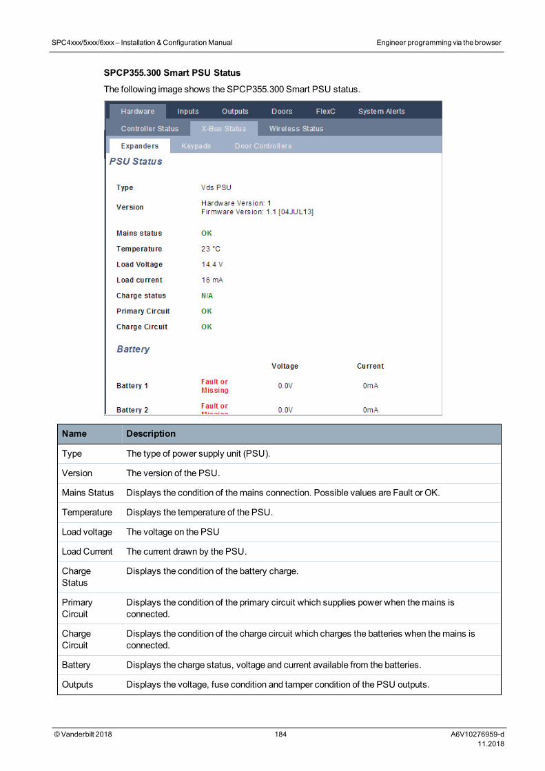
SPCP355.300 Smart PSU Status
The following image shows the SPCP355.300 Smart PSU status.
Name Description
Type The type of power supply unit (PSU).
Version The version of the PSU.
Mains Status Displays the condition of themains connection. Possible values are Fault or OK.
Temperature Displays the temperature of the PSU.
Load voltage The voltage on the PSU
Load Current The current drawn by the PSU.
ChargeStatus
Displays the condition of the battery charge.
PrimaryCircuit
Displays the condition of the primary circuit which supplies power when themains isconnected.
ChargeCircuit
Displays the condition of the charge circuit which charges the batteries when themains isconnected.
Battery Displays the charge status, voltage and current available from the batteries.
Outputs Displays the voltage, fuse condition and tamper condition of the PSU outputs.
SPC4xxx/5xxx/6xxx– Installation &ConfigurationManual Engineer programming via the browser
© Vanderbilt 2018 184 A6V10276959-d11.2018
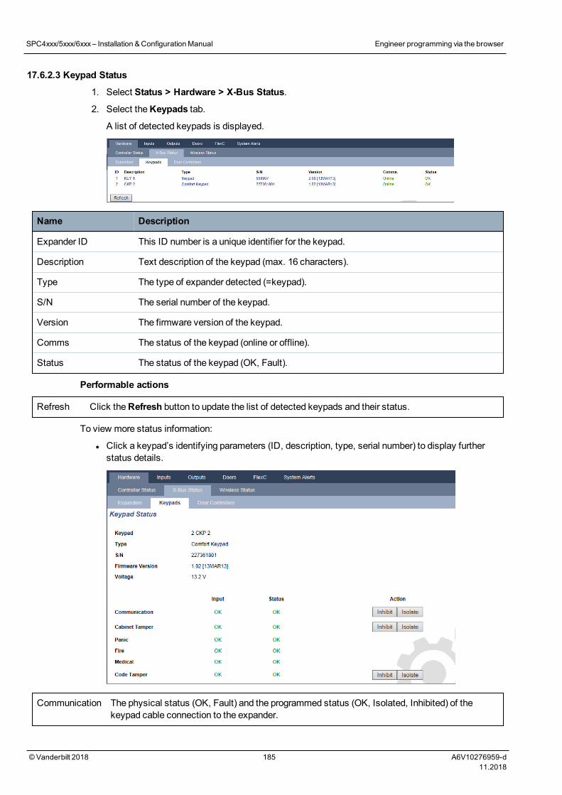
17.6.2.3 Keypad Status
1. Select Status > Hardware > X-Bus Status.
2. Select theKeypads tab.
A list of detected keypads is displayed.
Name Description
Expander ID This ID number is a unique identifier for the keypad.
Description Text description of the keypad (max. 16 characters).
Type The type of expander detected (=keypad).
S/N The serial number of the keypad.
Version The firmware version of the keypad.
Comms The status of the keypad (online or offline).
Status The status of the keypad (OK, Fault).
Performable actions
Refresh Click theRefresh button to update the list of detected keypads and their status.
To view more status information:
l Click a keypad’s identifying parameters (ID, description, type, serial number) to display furtherstatus details.
Communication The physical status (OK, Fault) and the programmed status (OK, Isolated, Inhibited) of thekeypad cable connection to the expander.
SPC4xxx/5xxx/6xxx– Installation &ConfigurationManual Engineer programming via the browser
© Vanderbilt 2018 185 A6V10276959-d11.2018
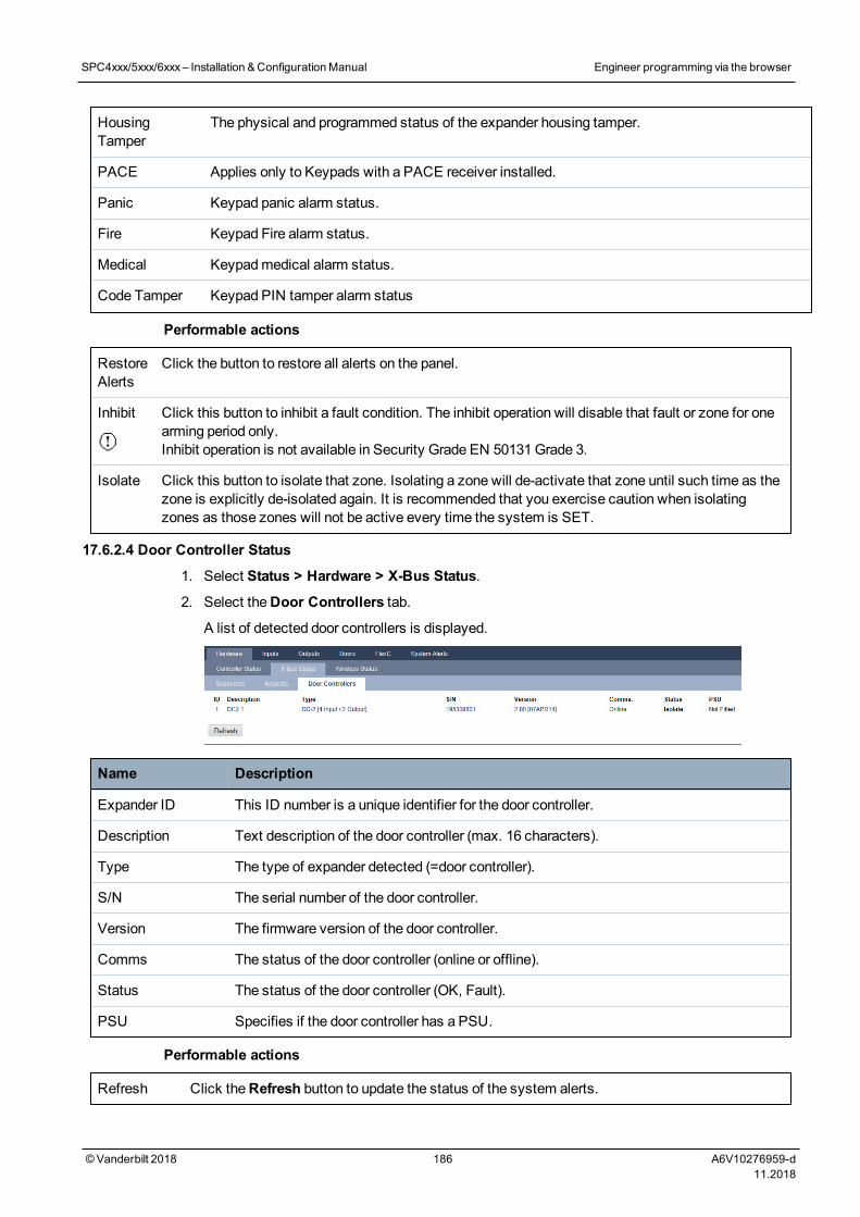
HousingTamper
The physical and programmed status of the expander housing tamper.
PACE Applies only to Keypads with a PACE receiver installed.
Panic Keypad panic alarm status.
Fire Keypad Fire alarm status.
Medical Keypadmedical alarm status.
Code Tamper Keypad PIN tamper alarm status
Performable actions
RestoreAlerts
Click the button to restore all alerts on the panel.
Inhibit Click this button to inhibit a fault condition. The inhibit operation will disable that fault or zone for onearming period only.Inhibit operation is not available in Security Grade EN 50131Grade 3.
Isolate Click this button to isolate that zone. Isolating a zone will de-activate that zone until such time as thezone is explicitly de-isolated again. It is recommended that you exercise caution when isolatingzones as those zones will not be active every time the system is SET.
17.6.2.4 Door Controller Status
1. Select Status > Hardware > X-Bus Status.
2. Select theDoor Controllers tab.
A list of detected door controllers is displayed.
Name Description
Expander ID This ID number is a unique identifier for the door controller.
Description Text description of the door controller (max. 16 characters).
Type The type of expander detected (=door controller).
S/N The serial number of the door controller.
Version The firmware version of the door controller.
Comms The status of the door controller (online or offline).
Status The status of the door controller (OK, Fault).
PSU Specifies if the door controller has a PSU.
Performable actions
Refresh Click theRefresh button to update the status of the system alerts.
SPC4xxx/5xxx/6xxx– Installation &ConfigurationManual Engineer programming via the browser
© Vanderbilt 2018 186 A6V10276959-d11.2018
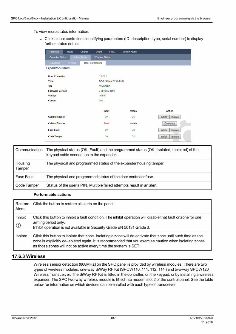
To view more status information:
l Click a door controller’s identifying parameters (ID, description, type, serial number) to displayfurther status details.
Communication The physical status (OK, Fault) and the programmed status (OK, Isolated, Inhibited) of thekeypad cable connection to the expander.
HousingTamper
The physical and programmed status of the expander housing tamper.
Fuse Fault The physical and programmed status of the door controller fuse.
Code Tamper Status of the user’s PIN. Multiple failed attempts result in an alert.
Performable actions
RestoreAlerts
Click the button to restore all alerts on the panel.
Inhibit Click this button to inhibit a fault condition. The inhibit operation will disable that fault or zone for onearming period only.Inhibit operation is not available in Security Grade EN 50131Grade 3.
Isolate Click this button to isolate that zone. Isolating a zone will de-activate that zone until such time as thezone is explicitly de-isolated again. It is recommended that you exercise caution when isolating zonesas those zones will not be active every time the system is SET.
17.6.3 WirelessWireless sensor detection (868MHz) on the SPC panel is provided by wireless modules. There are twotypes of wireless modules: one-way SiWay RF Kit (SPCW110, 111, 112, 114 ) and two-way SPCW120Wireless Transceiver. The SiWay RF Kit is fitted in the controller, on the keypad, or by installing a wirelessexpander. The SPC two-way wireless module is fitted into modem slot 2 of the control panel. See the tablebelow for information on which devices can be enrolled with each type of transceiver.
SPC4xxx/5xxx/6xxx– Installation &ConfigurationManual Engineer programming via the browser
© Vanderbilt 2018 187 A6V10276959-d11.2018
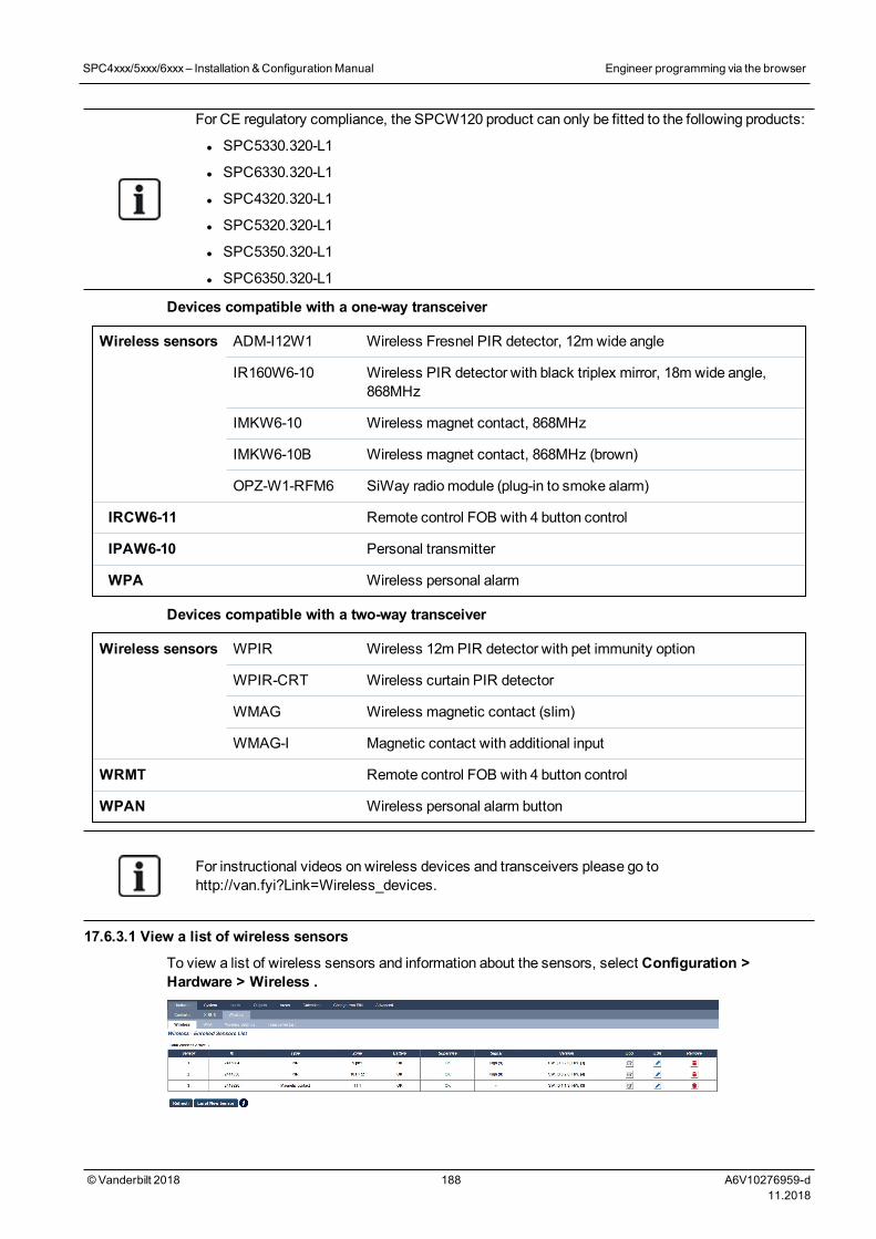
For CE regulatory compliance, the SPCW120 product can only be fitted to the following products:
l SPC5330.320-L1
l SPC6330.320-L1
l SPC4320.320-L1
l SPC5320.320-L1
l SPC5350.320-L1
l SPC6350.320-L1
Devices compatible with a one-way transceiver
Wireless sensors ADM-I12W1 Wireless Fresnel PIR detector, 12m wide angle
IR160W6-10 Wireless PIR detector with black triplex mirror, 18m wide angle,868MHz
IMKW6-10 Wireless magnet contact, 868MHz
IMKW6-10B Wireless magnet contact, 868MHz (brown)
OPZ-W1-RFM6 SiWay radiomodule (plug-in to smoke alarm)
IRCW6-11 Remote control FOB with 4 button control
IPAW6-10 Personal transmitter
WPA Wireless personal alarm
Devices compatible with a two-way transceiver
Wireless sensors WPIR Wireless 12m PIR detector with pet immunity option
WPIR-CRT Wireless curtain PIR detector
WMAG Wireless magnetic contact (slim)
WMAG-I Magnetic contact with additional input
WRMT Remote control FOB with 4 button control
WPAN Wireless personal alarm button
For instructional videos on wireless devices and transceivers please go tohttp://van.fyi?Link=Wireless_devices.
17.6.3.1 View a list of wireless sensors
To view a list of wireless sensors and information about the sensors, select Configuration >Hardware > Wireless .
SPC4xxx/5xxx/6xxx– Installation &ConfigurationManual Engineer programming via the browser
© Vanderbilt 2018 188 A6V10276959-d11.2018
Wireless sensor information
WirelessSensor
The number of the sensor enrolled on the system (1 = first, 2 = second, etc.).
ID A unique identity number for that sensor.
Type The type of wireless sensor detected (magnetic contact, inertia/shock, etc.).
Zone The zone to which the sensor has been enrolled.
Battery The status of the battery in the sensor.
Supervise The status of the supervisory operation (OK = supervisory signal received, Not Supervised = nosupervisory operation).
Signal The signal strength received from the sensor (01 = low, 09 = high).Note:Although it is not possible toenroll a device with a signal strength less than 3, devices whose signal drops below 3 after enrolment arenot dropped.
Version The version details of the sensor.
Performable actions
Log Click to view the wireless sensor Log. See Log -Wireless sensor X below.
Enrol New Sensor Click to enrol a new sensor.
Refresh Click to refresh the list of enrolled sensors.
Edit Click to edit the sensor attributes.
Remove Click to remove the sensor from the enrolled sensors list.
17.6.3.2 Log - Wireless sensor X
To view a quick log of events for a wireless sensor:
1. Click the Log button in the table row for that sensor.
2. TheMessage log for the sensor displays.
3. Optionally, you can create a text file of the log by clicking Text File.
Information provided in the message log
Time The date and time of the logged event.
Receiver The wireless receiver location, that is, wireless modulemounted on the keypad, controller or wirelessexpander.
Signal The signal strength received from the sensor (01=low, 09=high).
Status The physical status of the sensor.
Battery The status of the battery connected to the sensor (OK, Fault).
17.6.4 ZonesFor configuration, seeEditing a zone on page 270.
1. To view all zones, select Status > Inputs > All Zones. To view X-Bus only zones, select theX-Bus Zones tab or to view wireless zones only, select theWireless Zones tab.
SPC4xxx/5xxx/6xxx– Installation &ConfigurationManual Engineer programming via the browser
© Vanderbilt 2018 189 A6V10276959-d11.2018
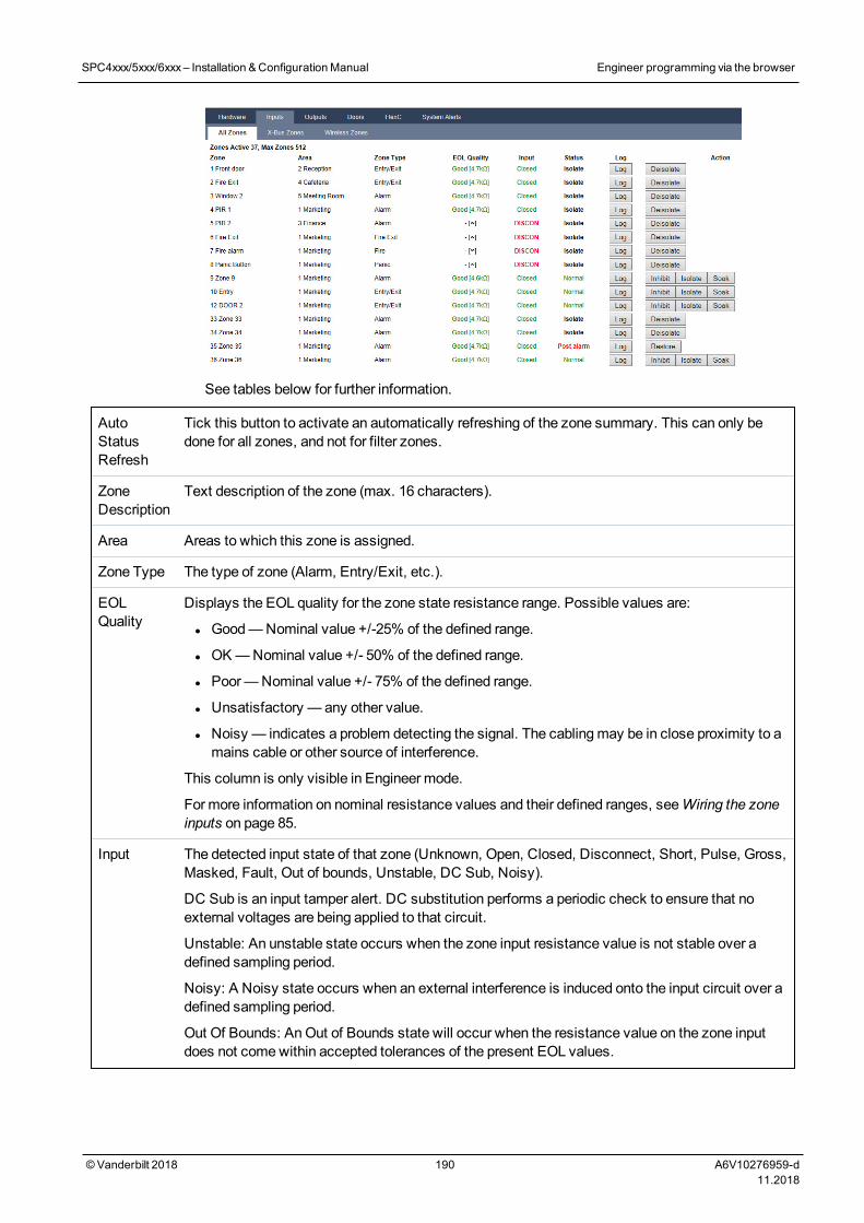
See tables below for further information.
AutoStatusRefresh
Tick this button to activate an automatically refreshing of the zone summary. This can only bedone for all zones, and not for filter zones.
ZoneDescription
Text description of the zone (max. 16 characters).
Area Areas to which this zone is assigned.
Zone Type The type of zone (Alarm, Entry/Exit, etc.).
EOLQuality
Displays the EOL quality for the zone state resistance range. Possible values are:
l Good—Nominal value +/-25% of the defined range.
l OK—Nominal value +/- 50% of the defined range.
l Poor—Nominal value +/- 75% of the defined range.
l Unsatisfactory — any other value.
l Noisy — indicates a problem detecting the signal. The cablingmay be in close proximity to amains cable or other source of interference.
This column is only visible in Engineer mode.
For more information on nominal resistance values and their defined ranges, seeWiring the zoneinputs on page 85.
Input The detected input state of that zone (Unknown, Open, Closed, Disconnect, Short, Pulse, Gross,Masked, Fault, Out of bounds, Unstable, DC Sub, Noisy).
DC Sub is an input tamper alert. DC substitution performs a periodic check to ensure that noexternal voltages are being applied to that circuit.
Unstable: An unstable state occurs when the zone input resistance value is not stable over adefined sampling period.
Noisy: A Noisy state occurs when an external interference is induced onto the input circuit over adefined sampling period.
Out Of Bounds: AnOut of Bounds state will occur when the resistance value on the zone inputdoes not comewithin accepted tolerances of the present EOL values.
SPC4xxx/5xxx/6xxx– Installation &ConfigurationManual Engineer programming via the browser
© Vanderbilt 2018 190 A6V10276959-d11.2018
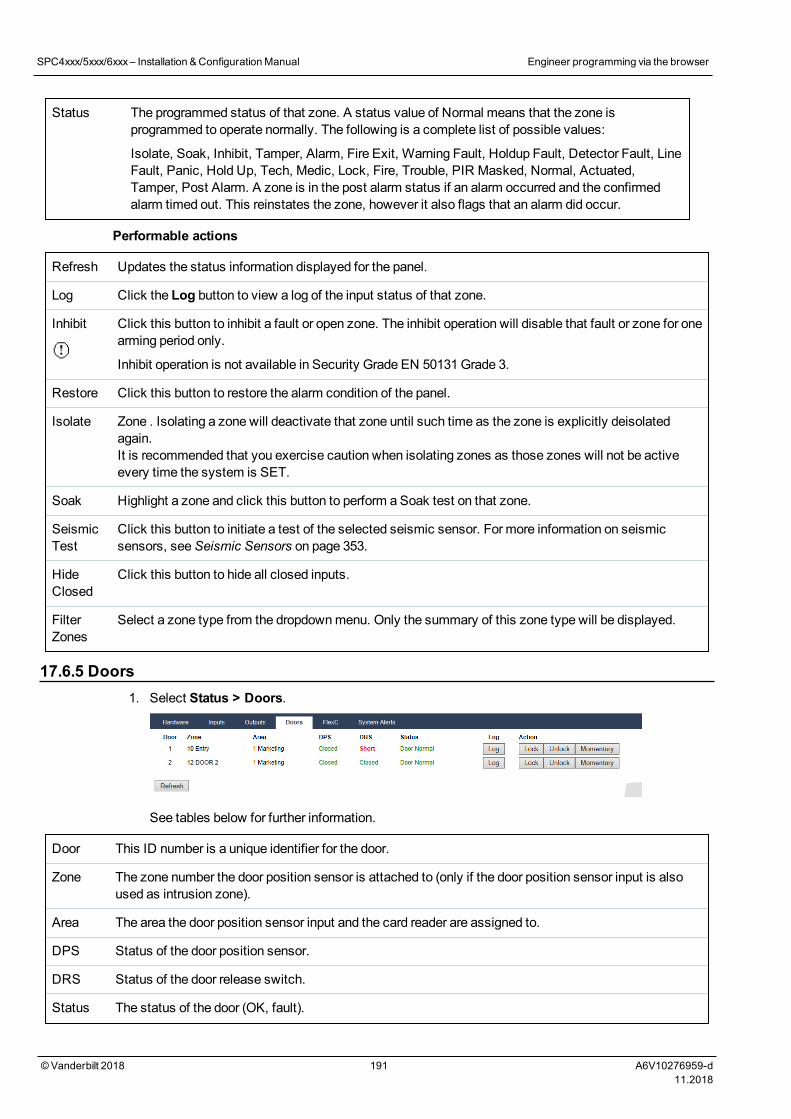
Status The programmed status of that zone. A status value of Normal means that the zone isprogrammed to operate normally. The following is a complete list of possible values:
Isolate, Soak, Inhibit, Tamper, Alarm, Fire Exit, Warning Fault, Holdup Fault, Detector Fault, LineFault, Panic, Hold Up, Tech, Medic, Lock, Fire, Trouble, PIR Masked, Normal, Actuated,Tamper, Post Alarm. A zone is in the post alarm status if an alarm occurred and the confirmedalarm timed out. This reinstates the zone, however it also flags that an alarm did occur.
Performable actions
Refresh Updates the status information displayed for the panel.
Log Click the Log button to view a log of the input status of that zone.
Inhibit Click this button to inhibit a fault or open zone. The inhibit operation will disable that fault or zone for onearming period only.
Inhibit operation is not available in Security Grade EN 50131Grade 3.
Restore Click this button to restore the alarm condition of the panel.
Isolate Zone . Isolating a zone will deactivate that zone until such time as the zone is explicitly deisolatedagain.It is recommended that you exercise caution when isolating zones as those zones will not be activeevery time the system is SET.
Soak Highlight a zone and click this button to perform a Soak test on that zone.
SeismicTest
Click this button to initiate a test of the selected seismic sensor. For more information on seismicsensors, seeSeismic Sensors on page 353.
HideClosed
Click this button to hide all closed inputs.
FilterZones
Select a zone type from the dropdownmenu. Only the summary of this zone type will be displayed.
17.6.5 Doors1. Select Status > Doors.
See tables below for further information.
Door This ID number is a unique identifier for the door.
Zone The zone number the door position sensor is attached to (only if the door position sensor input is alsoused as intrusion zone).
Area The area the door position sensor input and the card reader are assigned to.
DPS Status of the door position sensor.
DRS Status of the door release switch.
Status The status of the door (OK, fault).
SPC4xxx/5xxx/6xxx– Installation &ConfigurationManual Engineer programming via the browser
© Vanderbilt 2018 191 A6V10276959-d11.2018
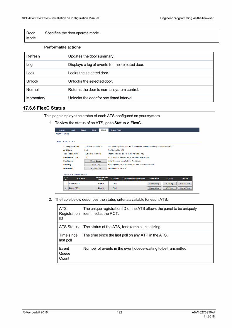
DoorMode
Specifies the door operatemode.
Performable actions
Refresh Updates the door summary.
Log Displays a log of events for the selected door.
Lock Locks the selected door.
Unlock Unlocks the selected door.
Normal Returns the door to normal system control.
Momentary Unlocks the door for one timed interval.
17.6.6 FlexC StatusThis page displays the status of each ATS configured on your system.
1. To view the status of an ATS, go toStatus > FlexC.
2. The table below describes the status criteria available for each ATS.
ATSRegistrationID
The unique registration ID of the ATS allows the panel to be uniquelyidentified at the RCT.
ATS Status The status of the ATS, for example, initializing.
Time sincelast poll
The time since the last poll on any ATP in the ATS.
EventQueueCount
Number of events in the event queue waiting to be transmitted.
SPC4xxx/5xxx/6xxx– Installation &ConfigurationManual Engineer programming via the browser
© Vanderbilt 2018 192 A6V10276959-d11.2018
EventQueue
List of the events currently in the Event Queue. The tables shows thefollowing:
l Event Seq No.
l Event Timestamp
l Event Description
l Additional Event Info
l Start Timestamp
l Report Duration
Event Log Event log history for all the events that have occurred on the ATS. The tableshows the same fields as Event Queue above and the following additionalfield:
l Event Seq No.
l Event Timestamp
l Event Description
l Additional Event Info
l Result
l Reported ATP
l Start Timestamp
l ACK/Fail Timestamp
l Report Duration
NetworkLog
Network log for the ATS showing the configured polling interval.
Status ofATPs withinATS
This table shows each ATP in the ATS. For each ATP, the table shows theATP sequence number, the ATP name, the communications interface, ATPStatus, Last successful transmission, Network Log, ATP Log and Test Callbutton.
Network Log:Click this button to show the network log.
ATP Log:Shows a list of poll transmissions. Click theRefresh button toupdate the log. Click theMost Recent Last button to change the viewingorder. By default themost recent event displays first.
Manual Test button: Click this button to force a test call. The Event is addedto the event queue.
SPC4xxx/5xxx/6xxx– Installation &ConfigurationManual Engineer programming via the browser
© Vanderbilt 2018 193 A6V10276959-d11.2018
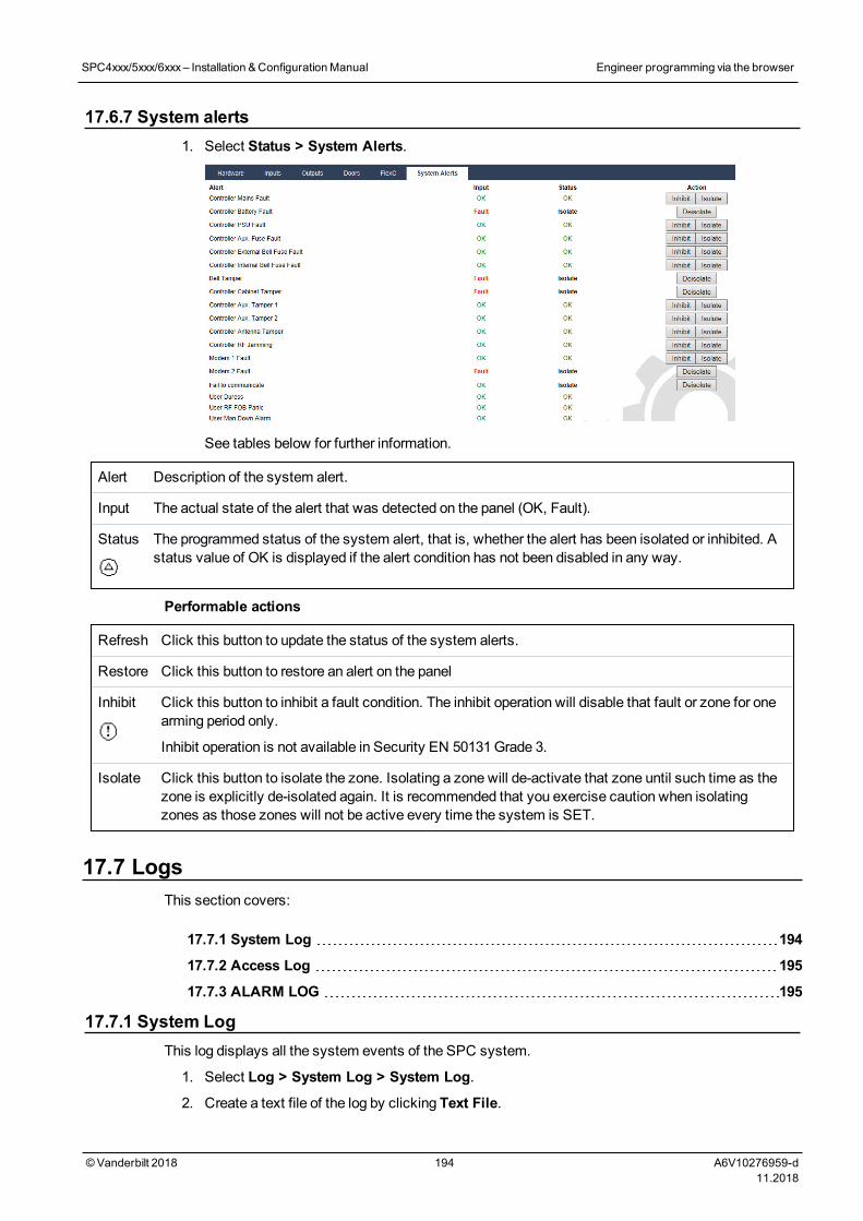
17.6.7 System alerts1. Select Status > System Alerts.
See tables below for further information.
Alert Description of the system alert.
Input The actual state of the alert that was detected on the panel (OK, Fault).
Status The programmed status of the system alert, that is, whether the alert has been isolated or inhibited. Astatus value of OK is displayed if the alert condition has not been disabled in any way.
Performable actions
Refresh Click this button to update the status of the system alerts.
Restore Click this button to restore an alert on the panel
Inhibit Click this button to inhibit a fault condition. The inhibit operation will disable that fault or zone for onearming period only.
Inhibit operation is not available in Security EN 50131Grade 3.
Isolate Click this button to isolate the zone. Isolating a zone will de-activate that zone until such time as thezone is explicitly de-isolated again. It is recommended that you exercise caution when isolatingzones as those zones will not be active every time the system is SET.
17.7 LogsThis section covers:
17.7.1 System Log 194
17.7.2 Access Log 195
17.7.3 ALARM LOG 195
17.7.1 System LogThis log displays all the system events of the SPC system.
1. Select Log > System Log > System Log.
2. Create a text file of the log by clicking Text File.
SPC4xxx/5xxx/6xxx– Installation &ConfigurationManual Engineer programming via the browser
© Vanderbilt 2018 194 A6V10276959-d11.2018
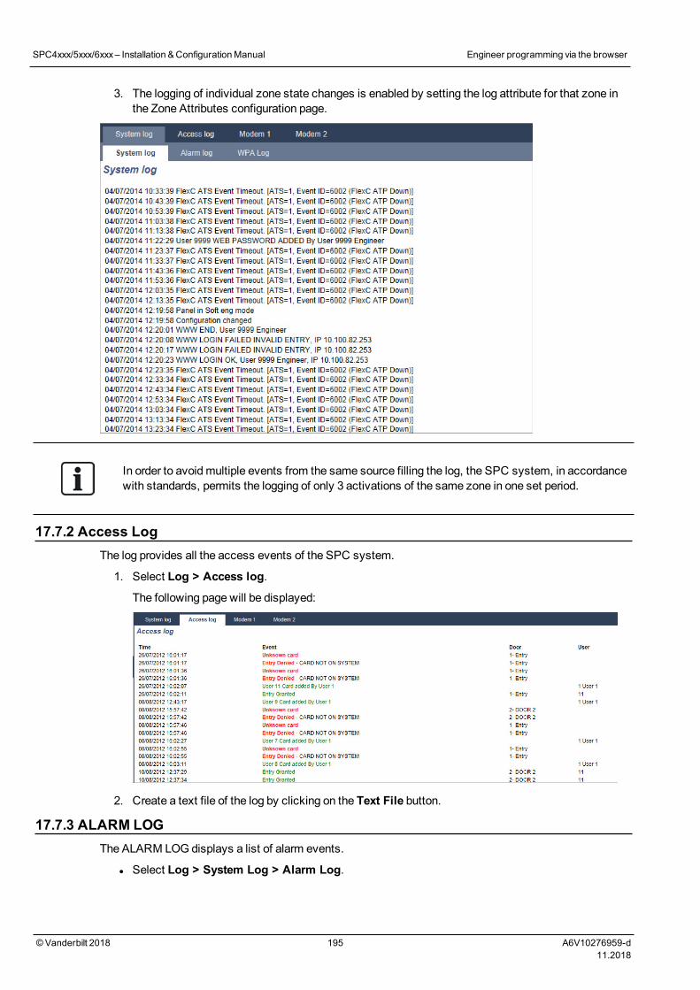
3. The logging of individual zone state changes is enabled by setting the log attribute for that zone inthe Zone Attributes configuration page.
In order to avoidmultiple events from the same source filling the log, the SPC system, in accordancewith standards, permits the logging of only 3 activations of the same zone in one set period.
17.7.2 Access LogThe log provides all the access events of the SPC system.
1. Select Log > Access log.
The following page will be displayed:
2. Create a text file of the log by clicking on the Text File button.
17.7.3 ALARM LOGThe ALARM LOG displays a list of alarm events.
l Select Log > System Log > Alarm Log.
SPC4xxx/5xxx/6xxx– Installation &ConfigurationManual Engineer programming via the browser
© Vanderbilt 2018 195 A6V10276959-d11.2018
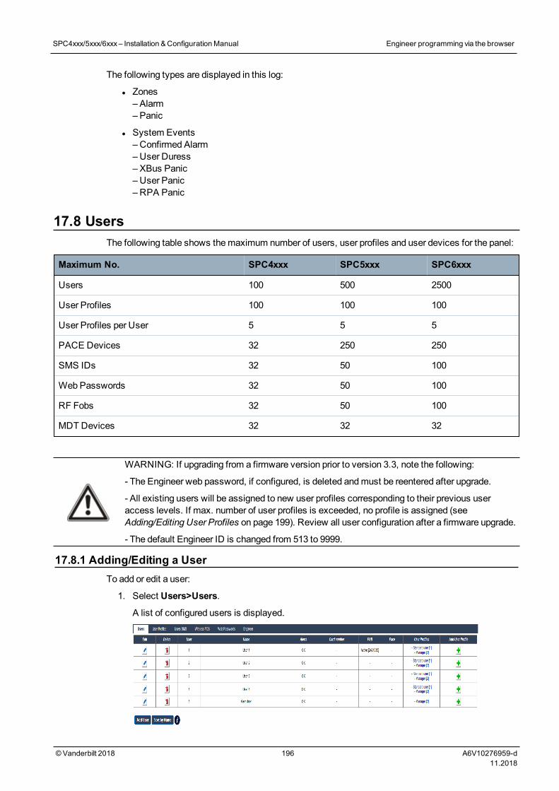
The following types are displayed in this log:
l Zones– Alarm– Panic
l System Events– Confirmed Alarm–User Duress– XBus Panic– User Panic– RPA Panic
17.8 UsersThe following table shows themaximum number of users, user profiles and user devices for the panel:
Maximum No. SPC4xxx SPC5xxx SPC6xxx
Users 100 500 2500
User Profiles 100 100 100
User Profiles per User 5 5 5
PACE Devices 32 250 250
SMS IDs 32 50 100
Web Passwords 32 50 100
RF Fobs 32 50 100
MDT Devices 32 32 32
WARNING: If upgrading from a firmware version prior to version 3.3, note the following:
- The Engineer web password, if configured, is deleted andmust be reentered after upgrade.
- All existing users will be assigned to new user profiles corresponding to their previous useraccess levels. If max. number of user profiles is exceeded, no profile is assigned (seeAdding/Editing User Profiles on page 199). Review all user configuration after a firmware upgrade.
- The default Engineer ID is changed from 513 to 9999.
17.8.1 Adding/Editing a UserTo add or edit a user:
1. Select Users>Users.
A list of configured users is displayed.
SPC4xxx/5xxx/6xxx– Installation &ConfigurationManual Engineer programming via the browser
© Vanderbilt 2018 196 A6V10276959-d11.2018
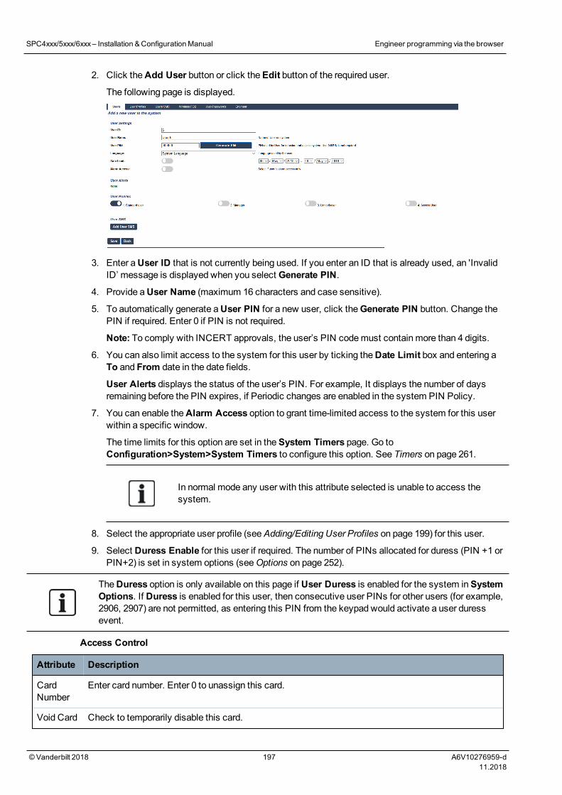
2. Click theAdd User button or click theEdit button of the required user.
The following page is displayed.
3. Enter aUser ID that is not currently being used. If you enter an ID that is already used, an 'InvalidID’ message is displayed when you select Generate PIN.
4. Provide aUser Name (maximum 16 characters and case sensitive).
5. To automatically generate aUser PIN for a new user, click theGenerate PIN button. Change thePIN if required. Enter 0 if PIN is not required.
Note: To comply with INCERT approvals, the user’s PIN codemust contain more than 4 digits.
6. You can also limit access to the system for this user by ticking theDate Limit box and entering aTo and From date in the date fields.
User Alerts displays the status of the user’s PIN. For example, It displays the number of daysremaining before the PIN expires, if Periodic changes are enabled in the system PIN Policy.
7. You can enable theAlarm Access option to grant time-limited access to the system for this userwithin a specific window.
The time limits for this option are set in theSystem Timers page. Go toConfiguration>System>System Timers to configure this option. See Timers on page 261.
In normal mode any user with this attribute selected is unable to access thesystem.
8. Select the appropriate user profile (seeAdding/Editing User Profiles on page 199) for this user.
9. Select Duress Enable for this user if required. The number of PINs allocated for duress (PIN +1 orPIN+2) is set in system options (seeOptions on page 252).
TheDuress option is only available on this page if User Duress is enabled for the system inSystemOptions. If Duress is enabled for this user, then consecutive user PINs for other users (for example,2906, 2907) are not permitted, as entering this PIN from the keypad would activate a user duressevent.
Access Control
Attribute Description
CardNumber
Enter card number. Enter 0 to unassign this card.
Void Card Check to temporarily disable this card.
SPC4xxx/5xxx/6xxx– Installation &ConfigurationManual Engineer programming via the browser
© Vanderbilt 2018 197 A6V10276959-d11.2018
Attribute Description
ExtendedTime
Extend door timers when this card is present.
PINbypass
Access a door without PIN on a door with PIN reader.
Priority Priority cards are stored locally in the door controllers and will grant access in case of a technical faultwhere the door controller cannot communicate with the control panel.
Themaximum number of priority users is:
l SPC4xxx – all users
l SPC5xxx – 512
l SPC6xxx – 512
Escort The escort feature enforces privileged card holders to escort other card holders through specific doors.If this feature is enabled on a door, a card with the “escort” right has to be presented first, to allow othercardholders without this right to open the door. The time period in which cardholders are able topresent their cards after a card with escort right was presented, can be configured per door.
Custodian The custodian feature enforces a card holder with custodian privilege to always be inside a room (doorgroup) when other card holders are inside.
The custodianmust be the first to enter the room. Only if a custodian is in the room other cardholdersare allowed to enter. The cardholder with the custodian right will not be allowed to exit until all non-custodian cards left the room.
Identifies this card holder as a custodian. The user with the custodian attribute has to be the first whoenters a door group which requires a custodian card holder and has to be the last that is leaving thisdoor group.
17.8.1.1 Unknown Devices
If an unknown device, such as a fob, PACE, or card, has been scanned but not assigned to a user, abutton is displayed in the relevant section of the edit user settings page.
l RF- FOB – Unknown Fob button or, if the device is assigned to the user, Delete FOB button
l Pace – Unknown Pace button or, if the device is assigned to the user, Delete Pace button
l Access Control – Unknown card button
To assign a fob, PACE or card to the user:
1. Click theUnknown button for the device. The User page displays the list of unknown devices.
2. Click Add to assign the device to the user.
Note: To assign a card to the user, the associated user profile must have the correct site code defined.
To unassign a fob or Pace from a user:
1. Click theDelete button.
The device is unassigned from the user and also deleted from the system.
2. To add the device again, youmust rescan it.
To unassign a card from a user:
1. Change the card number to zero (0).
2. Click Save.
SPC4xxx/5xxx/6xxx– Installation &ConfigurationManual Engineer programming via the browser
© Vanderbilt 2018 198 A6V10276959-d11.2018
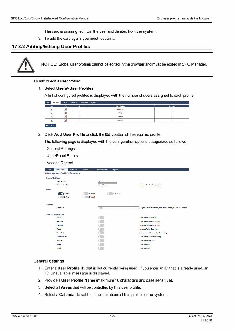
The card is unassigned from the user and deleted from the system.
3. To add the card again, youmust rescan it.
17.8.2 Adding/Editing User Profiles
NOTICE: Global user profiles cannot be edited in the browser andmust be edited in SPC Manager.
To add or edit a user profile:
1. Select Users>User Profiles.
A list of configured profiles is displayed with the number of users assigned to each profile.
2. Click Add User Profile or click theEdit button of the required profile.
The following page is displayed with the configuration options categorized as follows:
- General Settings
- User/Panel Rights
- Access Control
General Settings
1. Enter aUser Profile ID that is not currently being used. If you enter an ID that is already used, an‘ID Unavailable’ message is displayed.
2. Provide aUser Profile Name (maximum 16 characters and case sensitive).
3. Select all Areas that will be controlled by this user profile.
4. Select aCalendar to set the time limitations of this profile on the system.
SPC4xxx/5xxx/6xxx– Installation &ConfigurationManual Engineer programming via the browser
© Vanderbilt 2018 199 A6V10276959-d11.2018
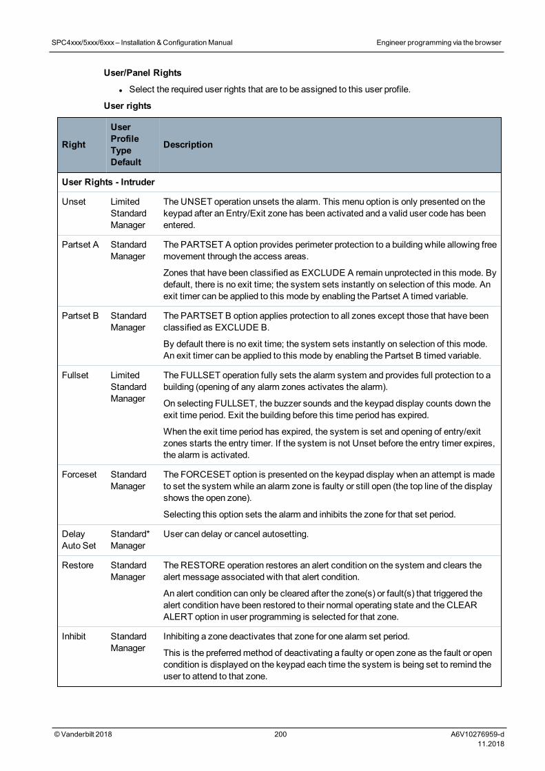
User/Panel Rights
l Select the required user rights that are to be assigned to this user profile.
User rights
Right
UserProfileTypeDefault
Description
User Rights - Intruder
Unset LimitedStandardManager
The UNSET operation unsets the alarm. This menu option is only presented on thekeypad after an Entry/Exit zone has been activated and a valid user code has beenentered.
Partset A StandardManager
The PARTSET A option provides perimeter protection to a building while allowing freemovement through the access areas.
Zones that have been classified as EXCLUDE A remain unprotected in this mode. Bydefault, there is no exit time; the system sets instantly on selection of this mode. Anexit timer can be applied to this mode by enabling the Partset A timed variable.
Partset B StandardManager
The PARTSET B option applies protection to all zones except those that have beenclassified as EXCLUDE B.
By default there is no exit time; the system sets instantly on selection of this mode.An exit timer can be applied to this mode by enabling the Partset B timed variable.
Fullset LimitedStandardManager
The FULLSET operation fully sets the alarm system and provides full protection to abuilding (opening of any alarm zones activates the alarm).
On selecting FULLSET, the buzzer sounds and the keypad display counts down theexit time period. Exit the building before this time period has expired.
When the exit time period has expired, the system is set and opening of entry/exitzones starts the entry timer. If the system is not Unset before the entry timer expires,the alarm is activated.
Forceset StandardManager
The FORCESET option is presented on the keypad display when an attempt is madeto set the system while an alarm zone is faulty or still open (the top line of the displayshows the open zone).
Selecting this option sets the alarm and inhibits the zone for that set period.
DelayAuto Set
Standard*Manager
User can delay or cancel autosetting.
Restore StandardManager
The RESTORE operation restores an alert condition on the system and clears thealert message associated with that alert condition.
An alert condition can only be cleared after the zone(s) or fault(s) that triggered thealert condition have been restored to their normal operating state and the CLEARALERT option in user programming is selected for that zone.
Inhibit StandardManager
Inhibiting a zone deactivates that zone for one alarm set period.
This is the preferredmethod of deactivating a faulty or open zone as the fault or opencondition is displayed on the keypad each time the system is being set to remind theuser to attend to that zone.
SPC4xxx/5xxx/6xxx– Installation &ConfigurationManual Engineer programming via the browser
© Vanderbilt 2018 200 A6V10276959-d11.2018
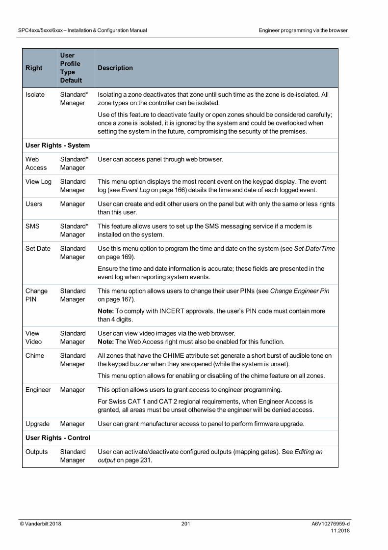
Right
UserProfileTypeDefault
Description
Isolate Standard*Manager
Isolating a zone deactivates that zone until such time as the zone is de-isolated. Allzone types on the controller can be isolated.
Use of this feature to deactivate faulty or open zones should be considered carefully;once a zone is isolated, it is ignored by the system and could be overlooked whensetting the system in the future, compromising the security of the premises.
User Rights - System
WebAccess
Standard*Manager
User can access panel through web browser.
View Log StandardManager
This menu option displays themost recent event on the keypad display. The eventlog (seeEvent Log on page 166) details the time and date of each logged event.
Users Manager User can create and edit other users on the panel but with only the same or less rightsthan this user.
SMS Standard*Manager
This feature allows users to set up the SMS messaging service if a modem isinstalled on the system.
Set Date StandardManager
Use this menu option to program the time and date on the system (seeSet Date/Timeon page 169).
Ensure the time and date information is accurate; these fields are presented in theevent log when reporting system events.
ChangePIN
StandardManager
This menu option allows users to change their user PINs (seeChange Engineer Pinon page 167).
Note: To comply with INCERT approvals, the user’s PIN codemust contain morethan 4 digits.
ViewVideo
StandardManager
User can view video images via the web browser.Note: TheWeb Access right must also be enabled for this function.
Chime StandardManager
All zones that have the CHIME attribute set generate a short burst of audible tone onthe keypad buzzer when they are opened (while the system is unset).
This menu option allows for enabling or disabling of the chime feature on all zones.
Engineer Manager This option allows users to grant access to engineer programming.
For Swiss CAT 1 and CAT 2 regional requirements, when Engineer Access isgranted, all areas must be unset otherwise the engineer will be denied access.
Upgrade Manager User can grant manufacturer access to panel to perform firmware upgrade.
User Rights - Control
Outputs StandardManager
User can activate/deactivate configured outputs (mapping gates). SeeEditing anoutput on page 231.
SPC4xxx/5xxx/6xxx– Installation &ConfigurationManual Engineer programming via the browser
© Vanderbilt 2018 201 A6V10276959-d11.2018
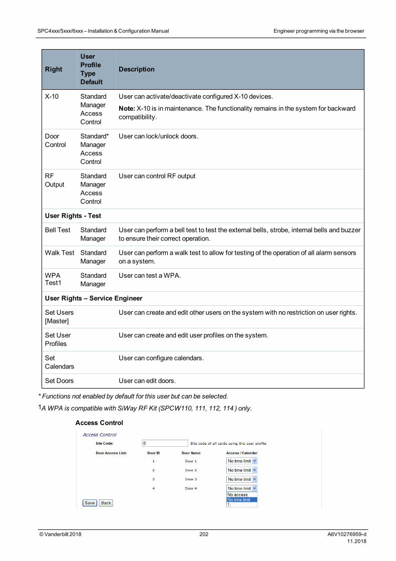
Right
UserProfileTypeDefault
Description
X-10 StandardManagerAccessControl
User can activate/deactivate configured X-10 devices.
Note:X-10 is in maintenance. The functionality remains in the system for backwardcompatibility.
DoorControl
Standard*ManagerAccessControl
User can lock/unlock doors.
RFOutput
StandardManagerAccessControl
User can control RF output
User Rights - Test
Bell Test StandardManager
User can perform a bell test to test the external bells, strobe, internal bells and buzzerto ensure their correct operation.
Walk Test StandardManager
User can perform awalk test to allow for testing of the operation of all alarm sensorson a system.
WPATest1
StandardManager
User can test aWPA.
User Rights – Service Engineer
Set Users[Master]
User can create and edit other users on the system with no restriction on user rights.
Set UserProfiles
User can create and edit user profiles on the system.
SetCalendars
User can configure calendars.
Set Doors User can edit doors.
* Functions not enabled by default for this user but can be selected.1AWPA is compatible with SiWay RF Kit (SPCW110, 111, 112, 114 ) only.
Access Control
SPC4xxx/5xxx/6xxx– Installation &ConfigurationManual Engineer programming via the browser
© Vanderbilt 2018 202 A6V10276959-d11.2018
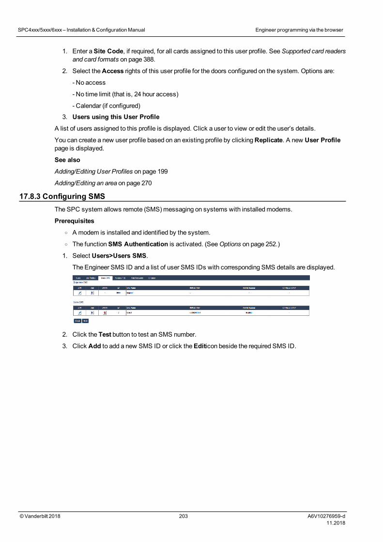
1. Enter aSite Code, if required, for all cards assigned to this user profile. SeeSupported card readersand card formats on page 388.
2. Select theAccess rights of this user profile for the doors configured on the system. Options are:
- No access
- No time limit (that is, 24 hour access)
- Calendar (if configured)
3. Users using this User Profile
A list of users assigned to this profile is displayed. Click a user to view or edit the user’s details.
You can create a new user profile based on an existing profile by clickingReplicate. A new User Profilepage is displayed.
See also
Adding/Editing User Profiles on page 199
Adding/Editing an area on page 270
17.8.3 Configuring SMSThe SPC system allows remote (SMS)messaging on systems with installedmodems.
Prerequisiteso A modem is installed and identified by the system.o The functionSMS Authentication is activated. (SeeOptions on page 252.)
1. Select Users>Users SMS.
The Engineer SMS ID and a list of user SMS IDs with corresponding SMS details are displayed.
2. Click the Test button to test an SMS number.
3. Click Add to add a new SMS ID or click theEditicon beside the required SMS ID.
SPC4xxx/5xxx/6xxx– Installation &ConfigurationManual Engineer programming via the browser
© Vanderbilt 2018 203 A6V10276959-d11.2018
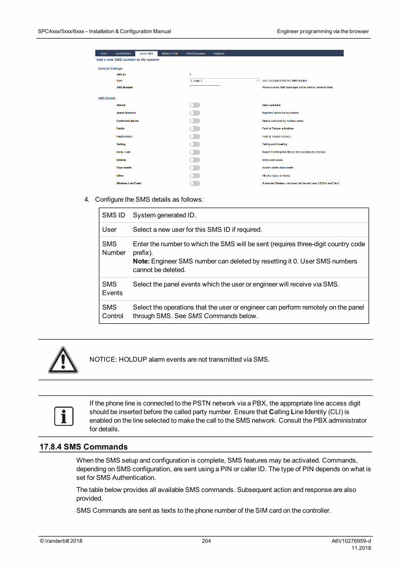
4. Configure the SMS details as follows:
SMS ID System generated ID.
User Select a new user for this SMS ID if required.
SMSNumber
Enter the number to which the SMS will be sent (requires three-digit country codeprefix).Note:Engineer SMS number can deleted by resetting it 0. User SMS numberscannot be deleted.
SMSEvents
Select the panel events which the user or engineer will receive via SMS.
SMSControl
Select the operations that the user or engineer can perform remotely on the panelthrough SMS. SeeSMS Commands below.
NOTICE: HOLDUP alarm events are not transmitted via SMS.
If the phone line is connected to the PSTN network via a PBX, the appropriate line access digitshould be inserted before the called party number. Ensure that Calling Line Identity (CLI) isenabled on the line selected tomake the call to the SMS network. Consult the PBX administratorfor details.
17.8.4 SMS CommandsWhen the SMS setup and configuration is complete, SMS features may be activated. Commands,depending on SMS configuration, are sent using a PIN or caller ID. The type of PIN depends on what isset for SMS Authentication.
The table below provides all available SMS commands. Subsequent action and response are alsoprovided.
SMS Commands are sent as texts to the phone number of the SIM card on the controller.
SPC4xxx/5xxx/6xxx– Installation &ConfigurationManual Engineer programming via the browser
© Vanderbilt 2018 204 A6V10276959-d11.2018
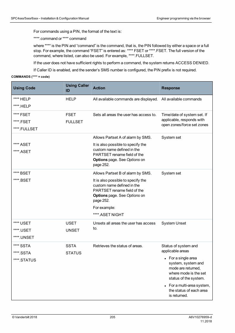
For commands using a PIN, the format of the text is:
****.command or **** command
where **** is the PIN and “command” is the command, that is, the PIN followed by either a space or a fullstop. For example, the command “FSET” is entered as: **** FSET or ****.FSET. The full version of thecommand, where listed, can also be used. For example, ****.FULLSET.
If the user does not have sufficient rights to perform a command, the system returns ACCESS DENIED.
If Caller ID is enabled, and the sender’s SMS number is configured, the PIN prefix is not required.COMMANDS (**** = code)
Using Code Using CallerID Action Response
**** HELP
****.HELP
HELP All available commands are displayed. All available commands
**** FSET
****.FSET
****.FULLSET
FSET
FULLSET
Sets all areas the user has access to. Time/date of system set. Ifapplicable, responds withopen zones/force set zones
**** ASET
****.ASET
Allows Partset A of alarm by SMS.
It is also possible to specify thecustom name defined in thePARTSET rename field of theOptions page. SeeOptions onpage 252.
System set
**** BSET
****.BSET
Allows Partset B of alarm by SMS.
It is also possible to specify thecustom name defined in thePARTSET rename field of theOptions page. SeeOptions onpage 252.
For example:
****.ASET NIGHT
System set
**** USET
****.USET
****.UNSET
USET
UNSET
Unsets all areas the user has accessto.
System Unset
**** SSTA
****.SSTA
****.STATUS
SSTA
STATUS
Retrieves the status of areas. Status of system andapplicable areas
l For a single areasystem, system andmode are returned,wheremode is the setstatus of the system.
l For amulti-area system,the status of each areais returned.
SPC4xxx/5xxx/6xxx– Installation &ConfigurationManual Engineer programming via the browser
© Vanderbilt 2018 205 A6V10276959-d11.2018
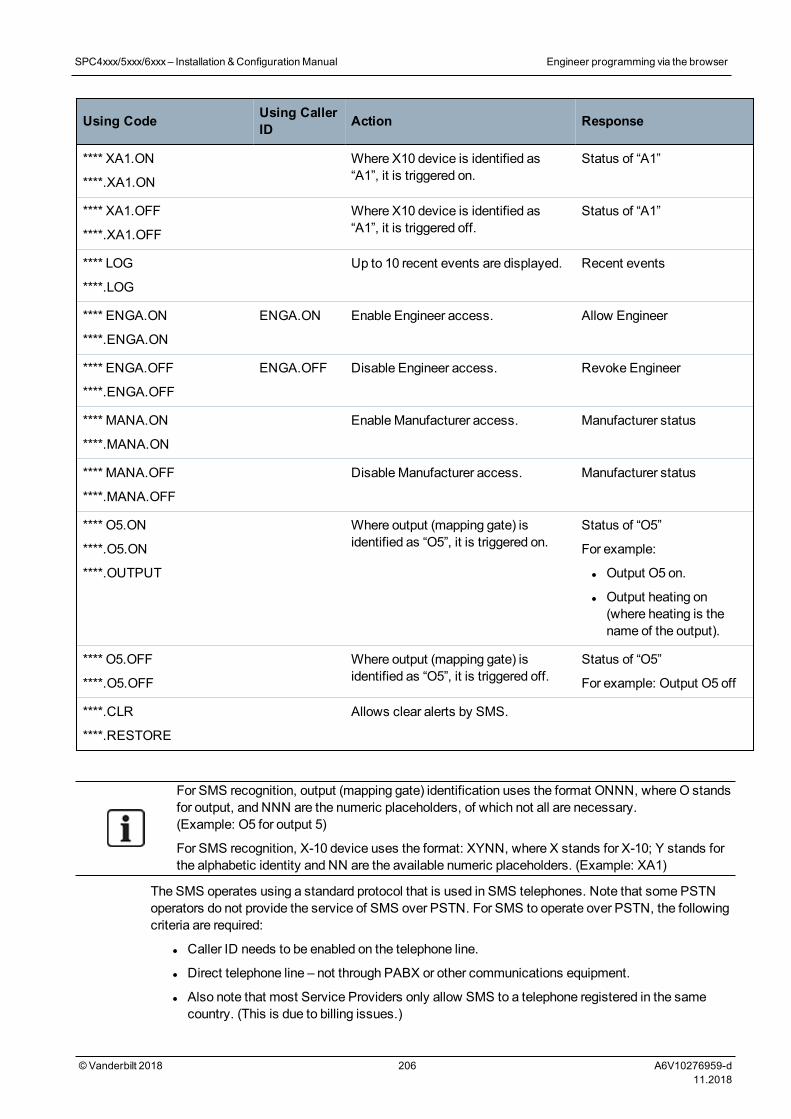
Using Code Using CallerID Action Response
**** XA1.ON
****.XA1.ON
Where X10 device is identified as“A1”, it is triggered on.
Status of “A1”
**** XA1.OFF
****.XA1.OFF
Where X10 device is identified as“A1”, it is triggered off.
Status of “A1”
**** LOG
****.LOG
Up to 10 recent events are displayed. Recent events
**** ENGA.ON
****.ENGA.ON
ENGA.ON Enable Engineer access. Allow Engineer
**** ENGA.OFF
****.ENGA.OFF
ENGA.OFF Disable Engineer access. Revoke Engineer
**** MANA.ON
****.MANA.ON
EnableManufacturer access. Manufacturer status
**** MANA.OFF
****.MANA.OFF
DisableManufacturer access. Manufacturer status
**** O5.ON
****.O5.ON
****.OUTPUT
Where output (mapping gate) isidentified as “O5”, it is triggered on.
Status of “O5”
For example:
l Output O5 on.
l Output heating on(where heating is thename of the output).
**** O5.OFF
****.O5.OFF
Where output (mapping gate) isidentified as “O5”, it is triggered off.
Status of “O5”
For example: Output O5 off
****.CLR
****.RESTORE
Allows clear alerts by SMS.
For SMS recognition, output (mapping gate) identification uses the format ONNN, where O standsfor output, and NNN are the numeric placeholders, of which not all are necessary.(Example: O5 for output 5)
For SMS recognition, X-10 device uses the format: XYNN, where X stands for X-10; Y stands forthe alphabetic identity and NN are the available numeric placeholders. (Example: XA1)
The SMS operates using a standard protocol that is used in SMS telephones. Note that some PSTNoperators do not provide the service of SMS over PSTN. For SMS to operate over PSTN, the followingcriteria are required:
l Caller ID needs to be enabled on the telephone line.
l Direct telephone line – not through PABX or other communications equipment.
l Also note that most Service Providers only allow SMS to a telephone registered in the samecountry. (This is due to billing issues.)
SPC4xxx/5xxx/6xxx– Installation &ConfigurationManual Engineer programming via the browser
© Vanderbilt 2018 206 A6V10276959-d11.2018
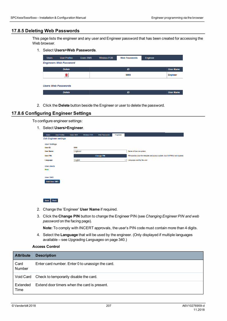
17.8.5 Deleting Web PasswordsThis page lists the engineer and any user and Engineer password that has been created for accessing theWeb browser.
1. Select Users>Web Passwords.
2. Click theDelete button beside the Engineer or user to delete the password.
17.8.6 Configuring Engineer SettingsTo configure engineer settings:
1. Select Users>Engineer.
2. Change the ’Engineer’ User Name if required.
3. Click theChange PIN button to change the Engineer PIN (seeChanging Engineer PIN and webpassword on the facing page).
Note: To comply with INCERT approvals, the user’s PIN codemust contain more than 4 digits.
4. Select the Language that will be used by the engineer. (Only displayed if multiple languagesavailable – seeUpgrading Languages on page 340.)
Access Control
Attribute Description
CardNumber
Enter card number. Enter 0 to unassign the card.
Void Card Check to temporarily disable the card.
ExtendedTime
Extend door timers when the card is present.
SPC4xxx/5xxx/6xxx– Installation &ConfigurationManual Engineer programming via the browser
© Vanderbilt 2018 207 A6V10276959-d11.2018
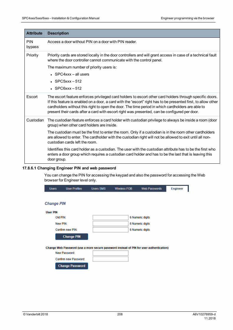
Attribute Description
PINbypass
Access a door without PIN on a door with PIN reader.
Priority Priority cards are stored locally in the door controllers and will grant access in case of a technical faultwhere the door controller cannot communicate with the control panel.
Themaximum number of priority users is:
l SPC4xxx – all users
l SPC5xxx – 512
l SPC6xxx – 512
Escort The escort feature enforces privileged card holders to escort other card holders through specific doors.If this feature is enabled on a door, a card with the “escort” right has to be presented first, to allow othercardholders without this right to open the door. The time period in which cardholders are able topresent their cards after a card with escort right was presented, can be configured per door.
Custodian The custodian feature enforces a card holder with custodian privilege to always be inside a room (doorgroup) when other card holders are inside.
The custodianmust be the first to enter the room. Only if a custodian is in the room other cardholdersare allowed to enter. The cardholder with the custodian right will not be allowed to exit until all non-custodian cards left the room.
Identifies this card holder as a custodian. The user with the custodian attribute has to be the first whoenters a door group which requires a custodian card holder and has to be the last that is leaving thisdoor group.
17.8.6.1 Changing Engineer PIN and web password
You can change the PIN for accessing the keypad and also the password for accessing theWebbrowser for Engineer level only.
SPC4xxx/5xxx/6xxx– Installation &ConfigurationManual Engineer programming via the browser
© Vanderbilt 2018 208 A6V10276959-d11.2018
1. Change the PIN as follows:
Old PIN Enter the existing Engineer PIN code. (Numeric digits only)
New PIN Enter the new Engineer PIN code. (Numeric digits only)
Confirm New PIN Re-enter the New Engineer PIN code.
2. Click theChange PIN button to activate the new PIN.
Theminimum number of digits required for the code depends on the securitysetting of the system or on the selected length of thePIN Digits in themenuPanel Settings > System Settings > Options.
3. Change theWeb password to amore secure password for accessing theWeb browser.
New Password Enter the new web access password (alphabetic characters A-Z,numeric digits 0-9).
Confirm NewPassword
Re-enter the new web access password.
4. Click theChange Password button to activate the new password.
The password is case sensitive – ensure that you enter the correct upper or lower case alphabeticcharacters in your new password.
17.9 WirelessWireless sensor detection (868MHz) on the SPC panel is provided by wireless modules. There are twotypes of wireless modules: one-way SiWay RF Kit (SPCW110, 111, 112, 114 ) and two-way SPCW120Wireless Transceiver. The SiWay RF Kit is fitted in the controller, on the keypad, or by installing a wirelessexpander. The SPC two-way wireless module is fitted into modem slot 2 of the control panel. See the tablebelow for information on which devices can be enrolled with each type of transceiver.
For CE regulatory compliance, the SPCW120 product can only be fitted to the following products:
l SPC5330.320-L1
l SPC6330.320-L1
l SPC4320.320-L1
l SPC5320.320-L1
l SPC5350.320-L1
l SPC6350.320-L1
SPC4xxx/5xxx/6xxx– Installation &ConfigurationManual Engineer programming via the browser
© Vanderbilt 2018 209 A6V10276959-d11.2018
Devices compatible with a one-way transceiver
Wireless sensors ADM-I12W1 Wireless Fresnel PIR detector, 12m wide angle
IR160W6-10 Wireless PIR detector with black triplex mirror, 18m wide angle,868MHz
IMKW6-10 Wireless magnet contact, 868MHz
IMKW6-10B Wireless magnet contact, 868MHz (brown)
OPZ-W1-RFM6 SiWay radiomodule (plug-in to smoke alarm)
IRCW6-11 Remote control FOB with 4 button control
IPAW6-10 Personal transmitter
WPA Wireless personal alarm
Devices compatible with a two-way transceiver
Wireless sensors WPIR Wireless 12m PIR detector with pet immunity option
WPIR-CRT Wireless curtain PIR detector
WMAG Wireless magnetic contact (slim)
WMAG-I Magnetic contact with additional input
WRMT Remote control FOB with 4 button control
WPAN Wireless personal alarm button
For instructional videos on wireless devices and transceivers please go tohttp://van.fyi?Link=Wireless_devices.
17.9.1 One-way wirelessThe following devices can be enrolled on a one-way wireless transceiver:
l Wireless sensors
l WPA-Wireless Personal Alarm
l IPAW6-10
l IRCW6-11
Please note that youmust disable two-way wireless before enrolling these devices.
To disable two-way wireless:
1. Select Configuration > Hardware > Wireless > Wireless Settings.
2. Disable Two Way Wireless.
SPC4xxx/5xxx/6xxx– Installation &ConfigurationManual Engineer programming via the browser
© Vanderbilt 2018 210 A6V10276959-d11.2018
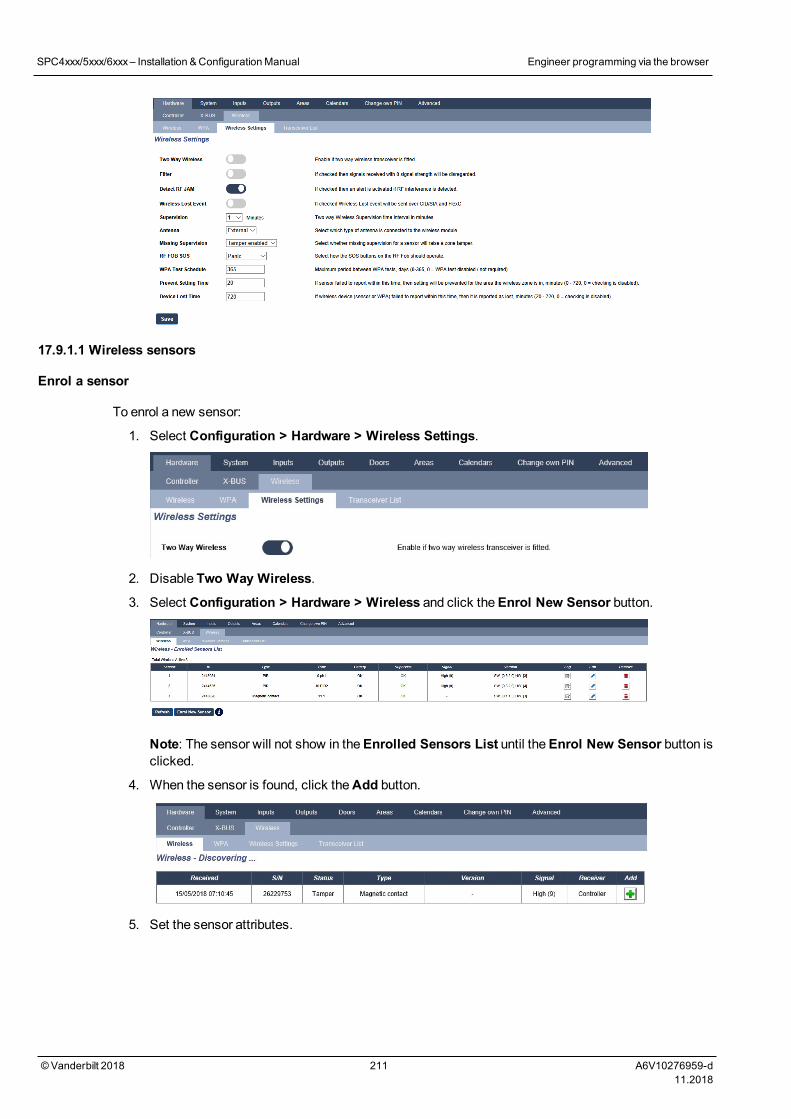
17.9.1.1 Wireless sensors
Enrol a sensor
To enrol a new sensor:
1. Select Configuration > Hardware > Wireless Settings.
2. Disable Two Way Wireless.
3. Select Configuration > Hardware > Wireless and click theEnrol New Sensor button.
Note: The sensor will not show in theEnrolled Sensors List until theEnrol New Sensor button isclicked.
4. When the sensor is found, click theAdd button.
5. Set the sensor attributes.
SPC4xxx/5xxx/6xxx– Installation &ConfigurationManual Engineer programming via the browser
© Vanderbilt 2018 211 A6V10276959-d11.2018
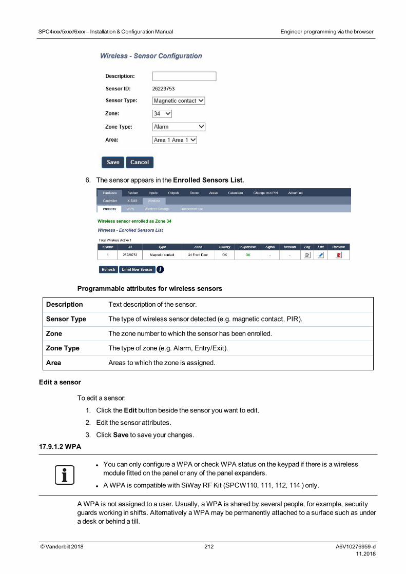
6. The sensor appears in theEnrolled Sensors List.
Programmable attributes for wireless sensors
Description Text description of the sensor.
Sensor Type The type of wireless sensor detected (e.g. magnetic contact, PIR).
Zone The zone number to which the sensor has been enrolled.
Zone Type The type of zone (e.g. Alarm, Entry/Exit).
Area Areas to which the zone is assigned.
Edit a sensor
To edit a sensor:
1. Click theEdit button beside the sensor you want to edit.
2. Edit the sensor attributes.
3. Click Save to save your changes.17.9.1.2 WPA
l You can only configure aWPA or check WPA status on the keypad if there is a wirelessmodule fitted on the panel or any of the panel expanders.
l AWPA is compatible with SiWay RF Kit (SPCW110, 111, 112, 114 ) only.
A WPA is not assigned to a user. Usually, aWPA is shared by several people, for example, securityguards working in shifts. Alternatively aWPA may be permanently attached to a surface such as undera desk or behind a till.
SPC4xxx/5xxx/6xxx– Installation &ConfigurationManual Engineer programming via the browser
© Vanderbilt 2018 212 A6V10276959-d11.2018
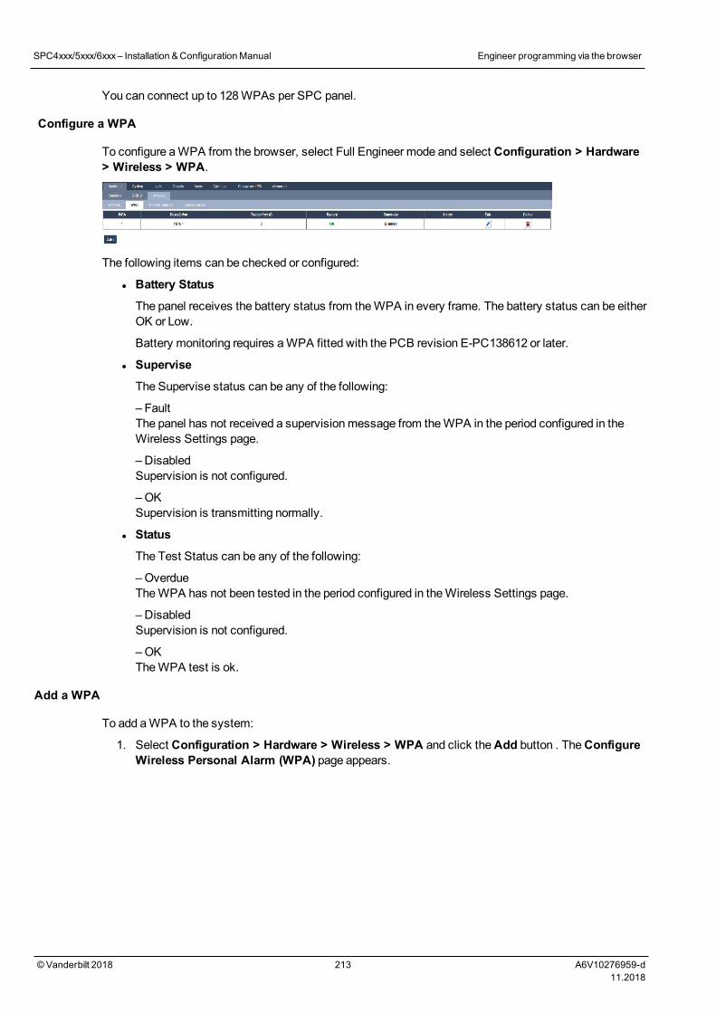
You can connect up to 128WPAs per SPC panel.
Configure a WPA
To configure aWPA from the browser, select Full Engineer mode and select Configuration > Hardware> Wireless > WPA.
The following items can be checked or configured:
l Battery Status
The panel receives the battery status from theWPA in every frame. The battery status can be eitherOK or Low.
Battery monitoring requires aWPA fitted with the PCB revision E-PC138612 or later.
l Supervise
The Supervise status can be any of the following:
– FaultThe panel has not received a supervisionmessage from theWPA in the period configured in theWireless Settings page.
– DisabledSupervision is not configured.
– OKSupervision is transmitting normally.
l Status
The Test Status can be any of the following:
– OverdueTheWPA has not been tested in the period configured in theWireless Settings page.
– DisabledSupervision is not configured.
– OKTheWPA test is ok.
Add a WPA
To add aWPA to the system:
1. Select Configuration > Hardware > Wireless > WPA and click theAdd button . TheConfigureWireless Personal Alarm (WPA) page appears.
SPC4xxx/5xxx/6xxx– Installation &ConfigurationManual Engineer programming via the browser
© Vanderbilt 2018 213 A6V10276959-d11.2018
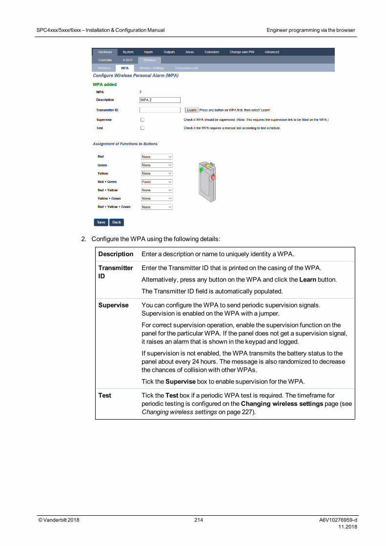
2. Configure theWPA using the following details:
Description Enter a description or name to uniquely identity aWPA.
TransmitterID
Enter the Transmitter ID that is printed on the casing of theWPA.
Alternatively, press any button on theWPA and click the Learn button.
The Transmitter ID field is automatically populated.
Supervise You can configure theWPA to send periodic supervision signals.Supervision is enabled on theWPA with a jumper.
For correct supervision operation, enable the supervision function on thepanel for the particularWPA. If the panel does not get a supervision signal,it raises an alarm that is shown in the keypad and logged.
If supervision is not enabled, theWPA transmits the battery status to thepanel about every 24 hours. Themessage is also randomized to decreasethe chances of collision with otherWPAs.
Tick theSupervise box to enable supervision for theWPA.
Test Tick the Test box if a periodic WPA test is required. The timeframe forperiodic testing is configured on theChanging wireless settings page (seeChanging wireless settings on page 227).
SPC4xxx/5xxx/6xxx– Installation &ConfigurationManual Engineer programming via the browser
© Vanderbilt 2018 214 A6V10276959-d11.2018
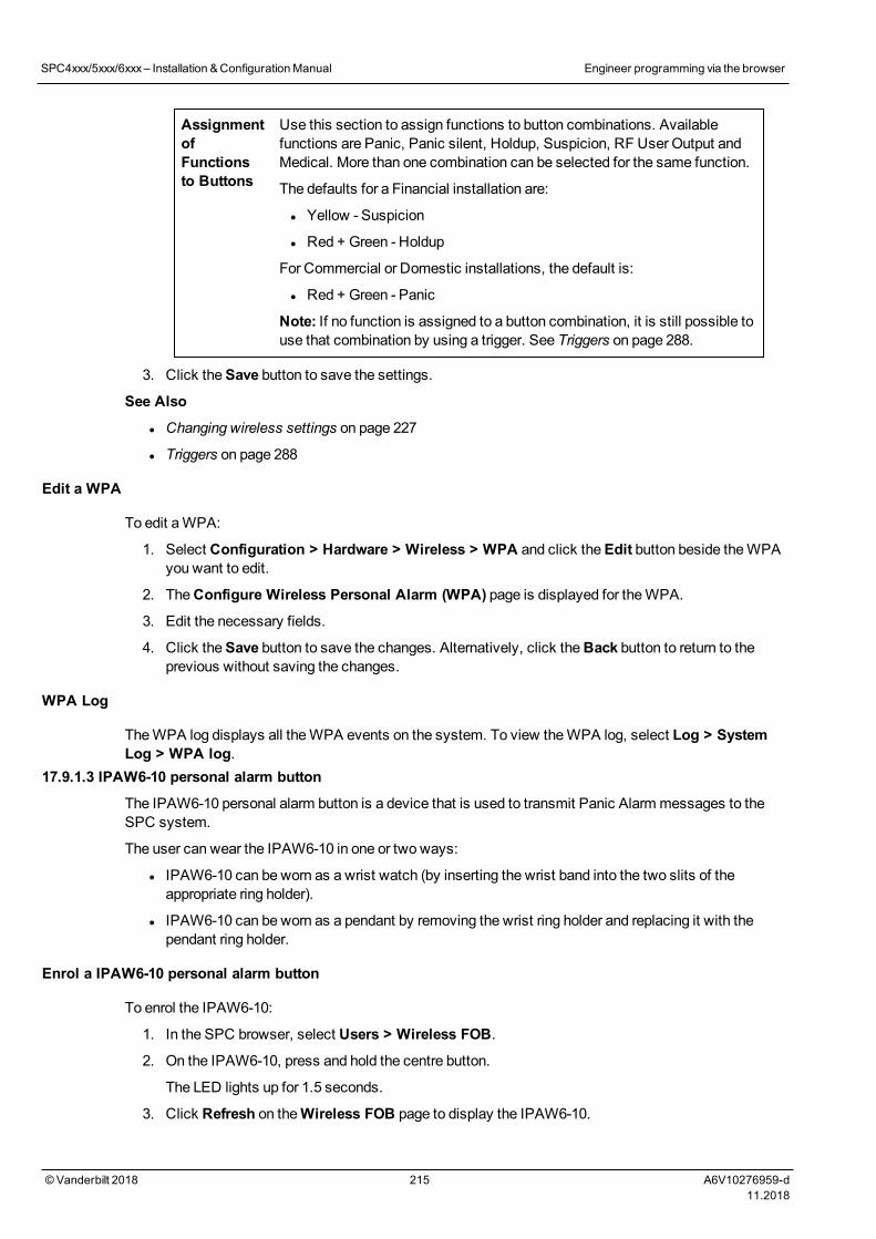
AssignmentofFunctionsto Buttons
Use this section to assign functions to button combinations. Availablefunctions are Panic, Panic silent, Holdup, Suspicion, RF User Output andMedical. More than one combination can be selected for the same function.
The defaults for a Financial installation are:
l Yellow - Suspicion
l Red + Green - Holdup
For Commercial or Domestic installations, the default is:
l Red + Green - Panic
Note: If no function is assigned to a button combination, it is still possible touse that combination by using a trigger. See Triggers on page 288.
3. Click theSave button to save the settings.
See Also
l Changing wireless settings on page 227
l Triggers on page 288
Edit a WPA
To edit aWPA:
1. Select Configuration > Hardware > Wireless > WPA and click theEdit button beside theWPAyou want to edit.
2. TheConfigure Wireless Personal Alarm (WPA) page is displayed for theWPA.
3. Edit the necessary fields.
4. Click theSave button to save the changes. Alternatively, click theBack button to return to theprevious without saving the changes.
WPA Log
TheWPA log displays all theWPA events on the system. To view theWPA log, select Log > SystemLog > WPA log.
17.9.1.3 IPAW6-10 personal alarm button
The IPAW6-10 personal alarm button is a device that is used to transmit Panic Alarm messages to theSPC system.
The user can wear the IPAW6-10 in one or two ways:
l IPAW6-10 can be worn as a wrist watch (by inserting the wrist band into the two slits of theappropriate ring holder).
l IPAW6-10 can be worn as a pendant by removing the wrist ring holder and replacing it with thependant ring holder.
Enrol a IPAW6-10 personal alarm button
To enrol the IPAW6-10:
1. In the SPC browser, select Users > Wireless FOB.
2. On the IPAW6-10, press and hold the centre button.
The LED lights up for 1.5 seconds.
3. Click Refresh on theWireless FOB page to display the IPAW6-10.
SPC4xxx/5xxx/6xxx– Installation &ConfigurationManual Engineer programming via the browser
© Vanderbilt 2018 215 A6V10276959-d11.2018
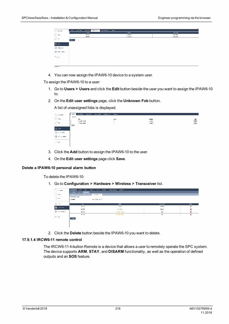
4. You can now assign the IPAW6-10 device to a system user.
To assign the IPAW6-10 to a user:
1. Go toUsers > Users and click theEdit button beside the user you want to assign the IPAW6-10to.
2. On theEdit user settings page, click theUnknown Fob button.
A list of unassigned fobs is displayed.
3. Click theAdd button to assign the IPAW6-10 to the user.
4. On theEdit user settings page click Save.
Delete a IPAW6-10 personal alarm button
To delete the IPAW6-10:
1. Go toConfiguration > Hardware > Wireless > Transceiver list.
2. Click theDelete button beside the IPAW6-10 you want to delete.
17.9.1.4 IRCW6-11 remote control
The IRCW6-11 4-button Remote is a device that allows a user to remotely operate the SPC system.The device supports ARM, STAY, andDISARM functionality, as well as the operation of definedoutputs and anSOS feature.
SPC4xxx/5xxx/6xxx– Installation &ConfigurationManual Engineer programming via the browser
© Vanderbilt 2018 216 A6V10276959-d11.2018
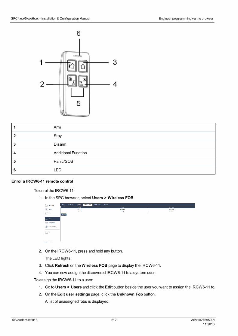
1 Arm
2 Stay
3 Disarm
4 Additional Function
5 Panic/SOS
6 LED
Enrol a IRCW6-11 remote control
To enrol the IRCW6-11:
1. In the SPC browser, select Users > Wireless FOB.
2. On the IRCW6-11, press and hold any button.
The LED lights.
3. Click Refresh on theWireless FOB page to display the IRCW6-11.
4. You can now assign the discovered IRCW6-11 to a system user.
To assign the IRCW6-11 to a user:
1. Go toUsers > Users and click theEdit button beside the user you want to assign the IRCW6-11 to.
2. On theEdit user settings page, click theUnknown Fob button.
A list of unassigned fobs is displayed.
SPC4xxx/5xxx/6xxx– Installation &ConfigurationManual Engineer programming via the browser
© Vanderbilt 2018 217 A6V10276959-d11.2018
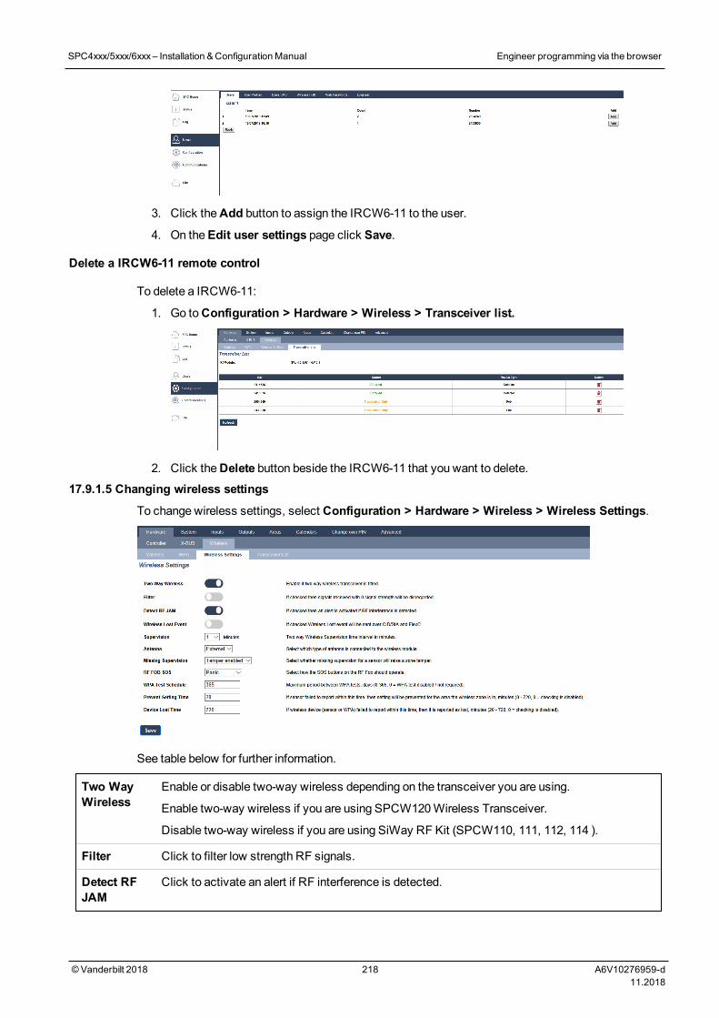
3. Click theAdd button to assign the IRCW6-11 to the user.
4. On theEdit user settings page click Save.
Delete a IRCW6-11 remote control
To delete a IRCW6-11:
1. Go toConfiguration > Hardware > Wireless > Transceiver list.
2. Click theDelete button beside the IRCW6-11 that you want to delete.
17.9.1.5 Changing wireless settings
To change wireless settings, select Configuration > Hardware > Wireless > Wireless Settings.
See table below for further information.
Two WayWireless
Enable or disable two-way wireless depending on the transceiver you are using.
Enable two-way wireless if you are using SPCW120Wireless Transceiver.
Disable two-way wireless if you are using SiWay RF Kit (SPCW110, 111, 112, 114 ).
Filter Click to filter low strength RF signals.
Detect RFJAM
Click to activate an alert if RF interference is detected.
SPC4xxx/5xxx/6xxx– Installation &ConfigurationManual Engineer programming via the browser
© Vanderbilt 2018 218 A6V10276959-d11.2018
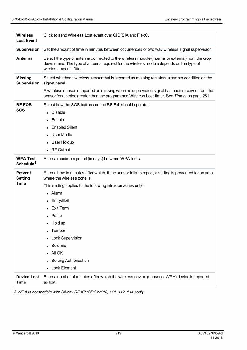
WirelessLost Event
Click to sendWireless Lost event over CID/SIA and FlexC.
Supervision Set the amount of time inminutes between occurrences of two way wireless signal supervision.
Antenna Select the type of antenna connected to the wireless module (internal or external) from the dropdownmenu. The type of antenna required for the wireless module depends on the type ofwireless module fitted.
MissingSupervision
Select whether a wireless sensor that is reported as missing registers a tamper condition on thesignet panel.
A wireless sensor is reported as missing when no supervision signal has been received from thesensor for a period greater than the programmedWireless Lost timer. See Timers on page 261.
RF FOBSOS
Select how the SOS buttons on the RF Fob should operate.:
l Disable
l Enable
l Enabled Silent
l UserMedic
l User Holdup
l RFOutput
WPA TestSchedule1
Enter amaximum period (in days) betweenWPA tests.
PreventSettingTime
Enter a time inminutes after which, if the sensor fails to report, a setting is prevented for an areawhere the wireless zone is.
This setting applies to the following intrusion zones only:
l Alarm
l Entry/Exit
l Exit Term
l Panic
l Hold up
l Tamper
l Lock Supervision
l Seismic
l All OK
l Setting Authorisation
l Lock Element
Device LostTime
Enter a number of minutes after which the wireless device (sensor orWPA) device is reportedas lost.
1AWPA is compatible with SiWay RF Kit (SPCW110, 111, 112, 114 ) only.
SPC4xxx/5xxx/6xxx– Installation &ConfigurationManual Engineer programming via the browser
© Vanderbilt 2018 219 A6V10276959-d11.2018
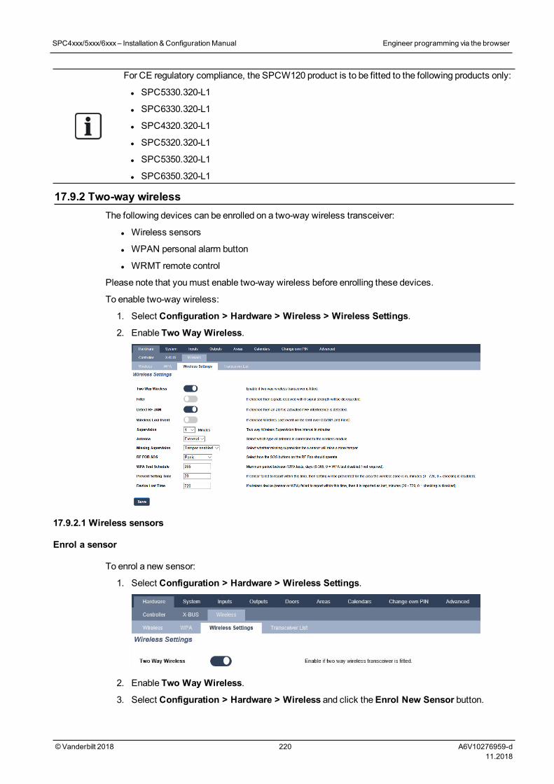
For CE regulatory compliance, the SPCW120 product is to be fitted to the following products only:
l SPC5330.320-L1
l SPC6330.320-L1
l SPC4320.320-L1
l SPC5320.320-L1
l SPC5350.320-L1
l SPC6350.320-L1
17.9.2 Two-way wirelessThe following devices can be enrolled on a two-way wireless transceiver:
l Wireless sensors
l WPAN personal alarm button
l WRMT remote control
Please note that youmust enable two-way wireless before enrolling these devices.
To enable two-way wireless:
1. Select Configuration > Hardware > Wireless > Wireless Settings.
2. Enable Two Way Wireless.
17.9.2.1 Wireless sensors
Enrol a sensor
To enrol a new sensor:
1. Select Configuration > Hardware > Wireless Settings.
2. Enable Two Way Wireless.
3. Select Configuration > Hardware > Wireless and click theEnrol New Sensor button.
SPC4xxx/5xxx/6xxx– Installation &ConfigurationManual Engineer programming via the browser
© Vanderbilt 2018 220 A6V10276959-d11.2018
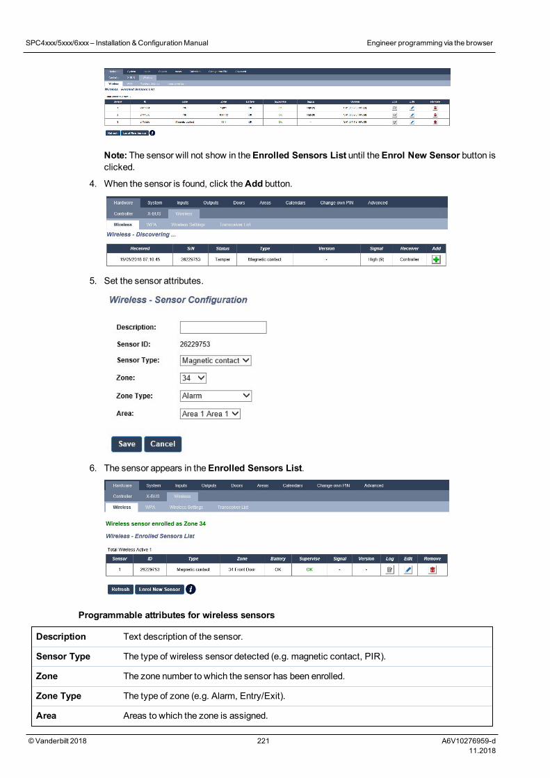
Note: The sensor will not show in theEnrolled Sensors List until theEnrol New Sensor button isclicked.
4. When the sensor is found, click theAdd button.
5. Set the sensor attributes.
6. The sensor appears in theEnrolled Sensors List.
Programmable attributes for wireless sensors
Description Text description of the sensor.
Sensor Type The type of wireless sensor detected (e.g. magnetic contact, PIR).
Zone The zone number to which the sensor has been enrolled.
Zone Type The type of zone (e.g. Alarm, Entry/Exit).
Area Areas to which the zone is assigned.
SPC4xxx/5xxx/6xxx– Installation &ConfigurationManual Engineer programming via the browser
© Vanderbilt 2018 221 A6V10276959-d11.2018
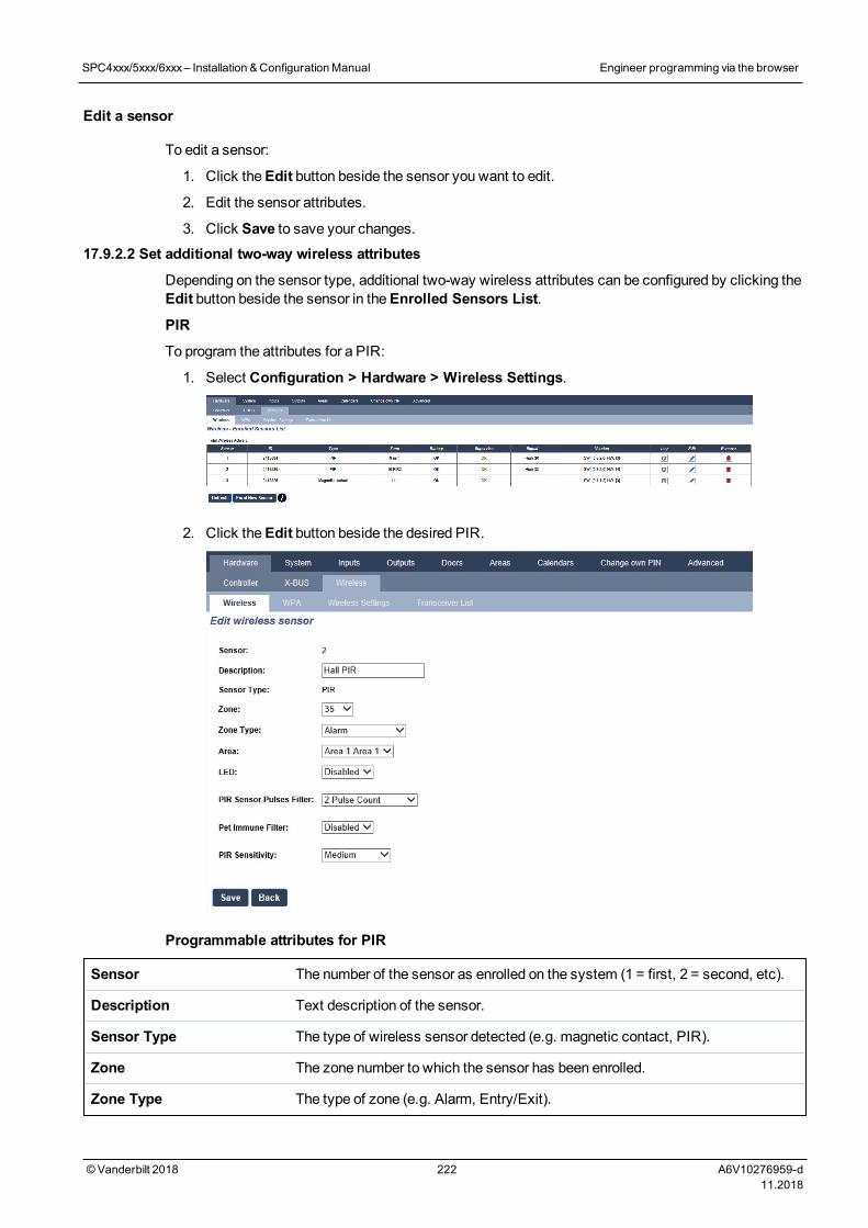
Edit a sensor
To edit a sensor:
1. Click theEdit button beside the sensor you want to edit.
2. Edit the sensor attributes.
3. Click Save to save your changes.17.9.2.2 Set additional two-way wireless attributes
Depending on the sensor type, additional two-way wireless attributes can be configured by clicking theEdit button beside the sensor in theEnrolled Sensors List.
PIR
To program the attributes for a PIR:
1. Select Configuration > Hardware > Wireless Settings.
2. Click theEdit button beside the desired PIR.
Programmable attributes for PIR
Sensor The number of the sensor as enrolled on the system (1 = first, 2 = second, etc).
Description Text description of the sensor.
Sensor Type The type of wireless sensor detected (e.g. magnetic contact, PIR).
Zone The zone number to which the sensor has been enrolled.
Zone Type The type of zone (e.g. Alarm, Entry/Exit).
SPC4xxx/5xxx/6xxx– Installation &ConfigurationManual Engineer programming via the browser
© Vanderbilt 2018 222 A6V10276959-d11.2018
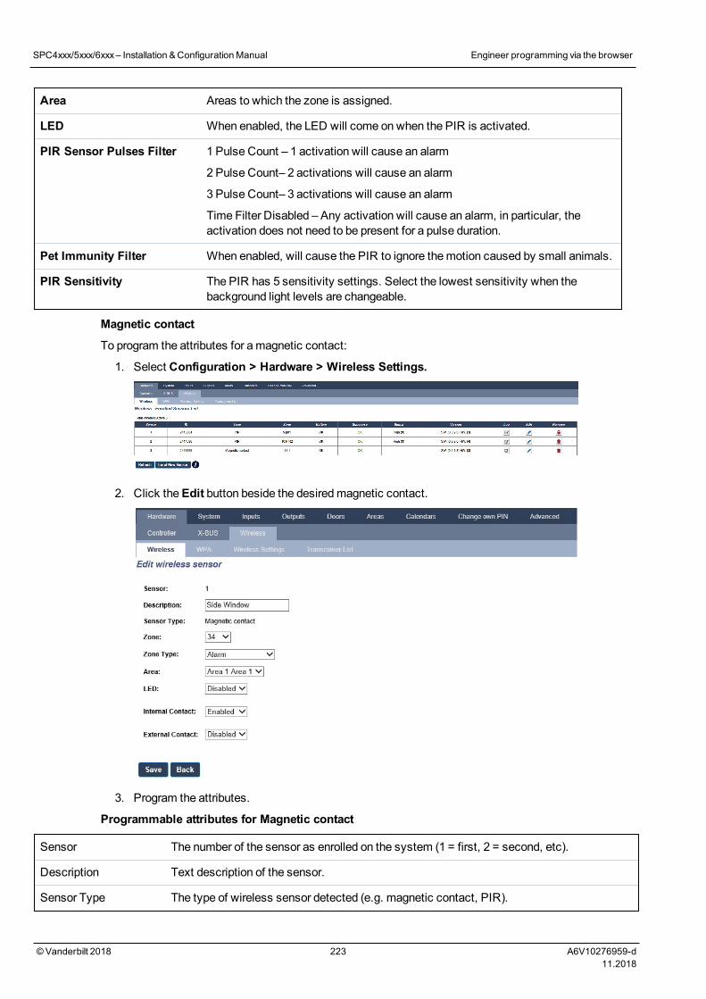
Area Areas to which the zone is assigned.
LED When enabled, the LED will come on when the PIR is activated.
PIR Sensor Pulses Filter 1 Pulse Count – 1 activation will cause an alarm
2 Pulse Count– 2 activations will cause an alarm
3 Pulse Count– 3 activations will cause an alarm
Time Filter Disabled – Any activation will cause an alarm, in particular, theactivation does not need to be present for a pulse duration.
Pet Immunity Filter When enabled, will cause the PIR to ignore themotion caused by small animals.
PIR Sensitivity The PIR has 5 sensitivity settings. Select the lowest sensitivity when thebackground light levels are changeable.
Magnetic contact
To program the attributes for amagnetic contact:
1. Select Configuration > Hardware > Wireless Settings.
2. Click theEdit button beside the desiredmagnetic contact.
3. Program the attributes.
Programmable attributes for Magnetic contact
Sensor The number of the sensor as enrolled on the system (1 = first, 2 = second, etc).
Description Text description of the sensor.
Sensor Type The type of wireless sensor detected (e.g. magnetic contact, PIR).
SPC4xxx/5xxx/6xxx– Installation &ConfigurationManual Engineer programming via the browser
© Vanderbilt 2018 223 A6V10276959-d11.2018
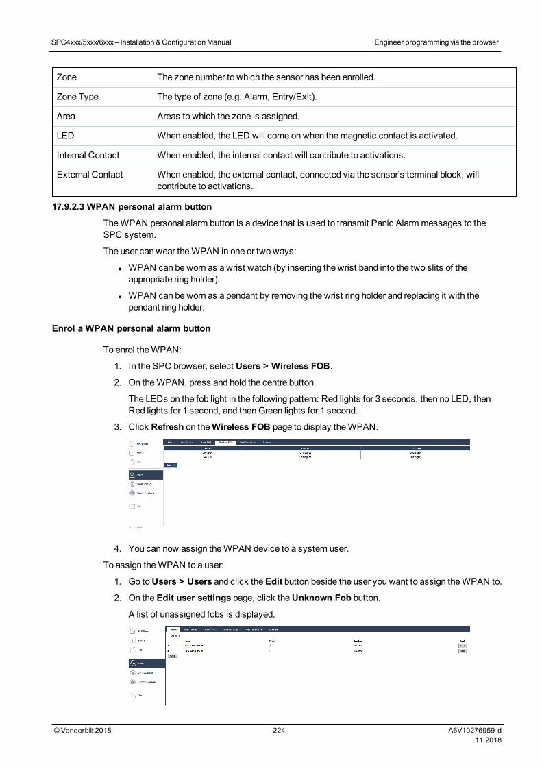
Zone The zone number to which the sensor has been enrolled.
Zone Type The type of zone (e.g. Alarm, Entry/Exit).
Area Areas to which the zone is assigned.
LED When enabled, the LED will come on when themagnetic contact is activated.
Internal Contact When enabled, the internal contact will contribute to activations.
External Contact When enabled, the external contact, connected via the sensor’s terminal block, willcontribute to activations.
17.9.2.3 WPAN personal alarm button
TheWPAN personal alarm button is a device that is used to transmit Panic Alarm messages to theSPC system.
The user can wear theWPAN in one or two ways:
l WPAN can be worn as a wrist watch (by inserting the wrist band into the two slits of theappropriate ring holder).
l WPAN can be worn as a pendant by removing the wrist ring holder and replacing it with thependant ring holder.
Enrol a WPAN personal alarm button
To enrol theWPAN:
1. In the SPC browser, select Users > Wireless FOB.
2. On theWPAN, press and hold the centre button.
The LEDs on the fob light in the following pattern: Red lights for 3 seconds, then no LED, thenRed lights for 1 second, and thenGreen lights for 1 second.
3. Click Refresh on theWireless FOB page to display theWPAN.
4. You can now assign theWPAN device to a system user.
To assign theWPAN to a user:
1. Go toUsers > Users and click theEdit button beside the user you want to assign theWPAN to.
2. On theEdit user settings page, click theUnknown Fob button.
A list of unassigned fobs is displayed.
SPC4xxx/5xxx/6xxx– Installation &ConfigurationManual Engineer programming via the browser
© Vanderbilt 2018 224 A6V10276959-d11.2018
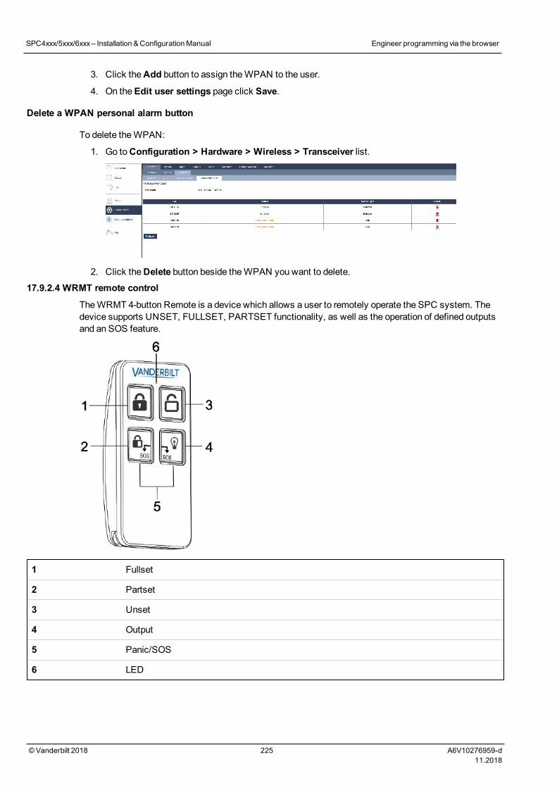
3. Click theAdd button to assign theWPAN to the user.
4. On theEdit user settings page click Save.
Delete a WPAN personal alarm button
To delete theWPAN:
1. Go toConfiguration > Hardware > Wireless > Transceiver list.
2. Click theDelete button beside theWPAN you want to delete.
17.9.2.4 WRMT remote control
TheWRMT 4-button Remote is a device which allows a user to remotely operate the SPC system. Thedevice supports UNSET, FULLSET, PARTSET functionality, as well as the operation of defined outputsand an SOS feature.
1 Fullset
2 Partset
3 Unset
4 Output
5 Panic/SOS
6 LED
SPC4xxx/5xxx/6xxx– Installation &ConfigurationManual Engineer programming via the browser
© Vanderbilt 2018 225 A6V10276959-d11.2018
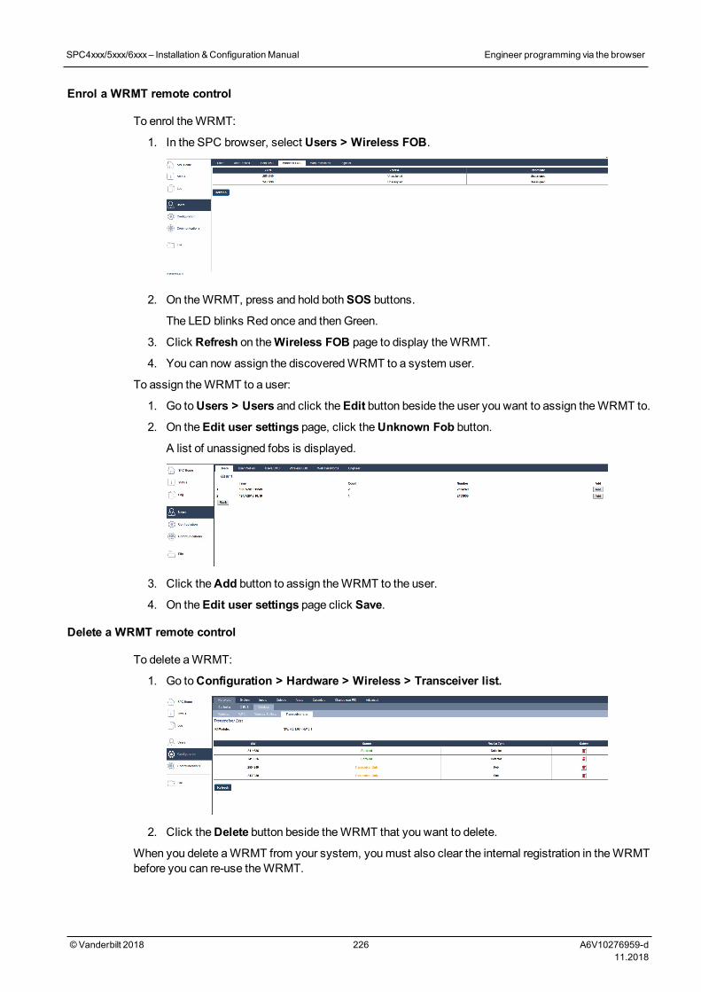
Enrol a WRMT remote control
To enrol theWRMT:
1. In the SPC browser, select Users > Wireless FOB.
2. On theWRMT, press and hold bothSOS buttons.
The LED blinks Red once and thenGreen.
3. Click Refresh on theWireless FOB page to display theWRMT.
4. You can now assign the discoveredWRMT to a system user.
To assign theWRMT to a user:
1. Go toUsers > Users and click theEdit button beside the user you want to assign theWRMT to.
2. On theEdit user settings page, click theUnknown Fob button.
A list of unassigned fobs is displayed.
3. Click theAdd button to assign theWRMT to the user.
4. On theEdit user settings page click Save.
Delete a WRMT remote control
To delete aWRMT:
1. Go toConfiguration > Hardware > Wireless > Transceiver list.
2. Click theDelete button beside theWRMT that you want to delete.
When you delete aWRMT from your system, youmust also clear the internal registration in theWRMTbefore you can re-use theWRMT.
SPC4xxx/5xxx/6xxx– Installation &ConfigurationManual Engineer programming via the browser
© Vanderbilt 2018 226 A6V10276959-d11.2018
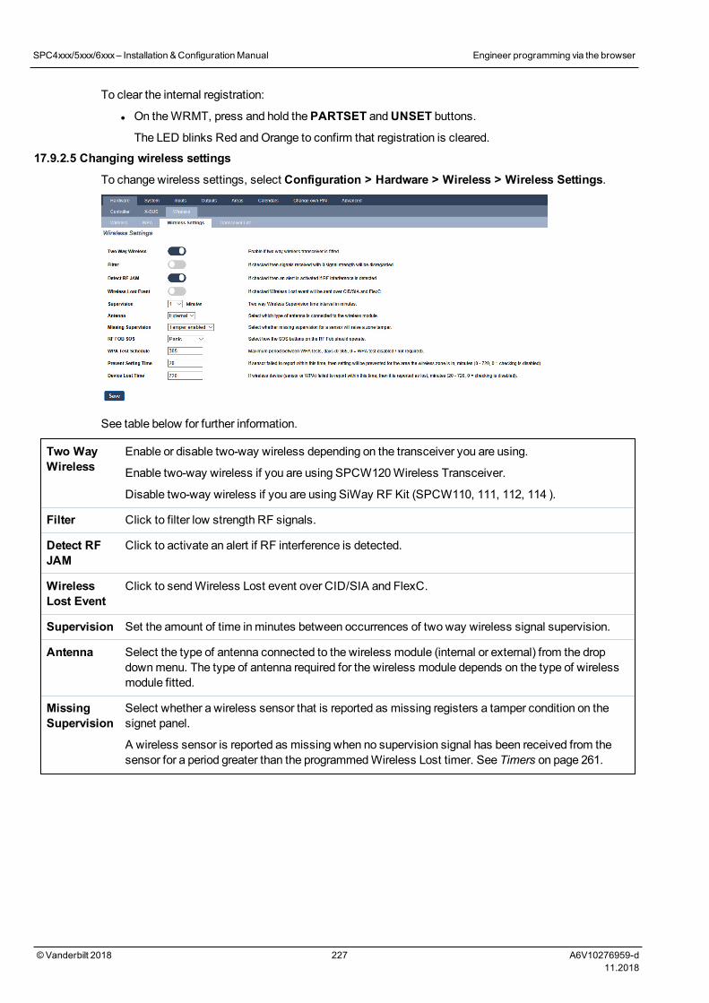
To clear the internal registration:
l On theWRMT, press and hold thePARTSET andUNSET buttons.
The LED blinks Red andOrange to confirm that registration is cleared.
17.9.2.5 Changing wireless settings
To change wireless settings, select Configuration > Hardware > Wireless > Wireless Settings.
See table below for further information.
Two WayWireless
Enable or disable two-way wireless depending on the transceiver you are using.
Enable two-way wireless if you are using SPCW120Wireless Transceiver.
Disable two-way wireless if you are using SiWay RF Kit (SPCW110, 111, 112, 114 ).
Filter Click to filter low strength RF signals.
Detect RFJAM
Click to activate an alert if RF interference is detected.
WirelessLost Event
Click to sendWireless Lost event over CID/SIA and FlexC.
Supervision Set the amount of time inminutes between occurrences of two way wireless signal supervision.
Antenna Select the type of antenna connected to the wireless module (internal or external) from the dropdownmenu. The type of antenna required for the wireless module depends on the type of wirelessmodule fitted.
MissingSupervision
Select whether a wireless sensor that is reported as missing registers a tamper condition on thesignet panel.
A wireless sensor is reported as missing when no supervision signal has been received from thesensor for a period greater than the programmedWireless Lost timer. See Timers on page 261.
SPC4xxx/5xxx/6xxx– Installation &ConfigurationManual Engineer programming via the browser
© Vanderbilt 2018 227 A6V10276959-d11.2018
RF FOBSOS
Select how the SOS buttons on the RF Fob should operate.:
l Disable
l Enable
l Enabled Silent
l UserMedic
l User Holdup
l RFOutput
WPA TestSchedule1
Enter amaximum period (in days) betweenWPA tests.
PreventSettingTime
Enter a time inminutes after which, if the sensor fails to report, a setting is prevented for an areawhere the wireless zone is.
This setting applies to the following intrusion zones only:
l Alarm
l Entry/Exit
l Exit Term
l Panic
l Hold up
l Tamper
l Lock Supervision
l Seismic
l All OK
l Setting Authorisation
l Lock Element
Device LostTime
Enter a number of minutes after which the wireless device (sensor orWPA) device is reported aslost.
1AWPA is compatible with SiWay RF Kit (SPCW110, 111, 112, 114 ) only.
For CE regulatory compliance, the SPCW120 product is to be fitted to the following products only:
l SPC5330.320-L1
l SPC6330.320-L1
l SPC4320.320-L1
l SPC5320.320-L1
l SPC5350.320-L1
l SPC6350.320-L1
17.10 ConfigurationThis section covers:
17.10.1 Configuring controller inputs and outputs 229
17.10.2 X-BUS 238
SPC4xxx/5xxx/6xxx– Installation &ConfigurationManual Engineer programming via the browser
© Vanderbilt 2018 228 A6V10276959-d11.2018
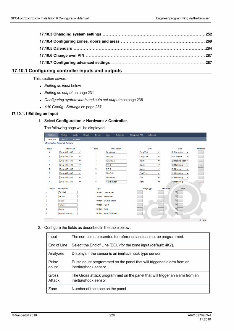
17.10.3 Changing system settings 252
17.10.4 Configuring zones, doors and areas 269
17.10.5 Calendars 284
17.10.6 Change own PIN 287
17.10.7 Configuring advanced settings 287
17.10.1 Configuring controller inputs and outputsThis section covers:
l Editing an input below
l Editing an output on page 231
l Configuring system latch and auto set outputs on page 236
l X10Config - Settings on page 237
17.10.1.1 Editing an input
1. Select Configuration > Hardware > Controller.
The following page will be displayed.
2. Configure the fields as described in the table below.
Input The number is presented for reference and can not be programmed.
End of Line Select the End of Line (EOL) for the zone input (default: 4K7).
Analyzed Displays if the sensor is an inertia/shock type sensor
Pulsecount
Pulse count programmed on the panel that will trigger an alarm from aninertia/shock sensor.
GrossAttack
TheGross attack programmed on the panel that will trigger an alarm from aninertia/shock sensor
Zone Number of the zone on the panel
SPC4xxx/5xxx/6xxx– Installation &ConfigurationManual Engineer programming via the browser
© Vanderbilt 2018 229 A6V10276959-d11.2018
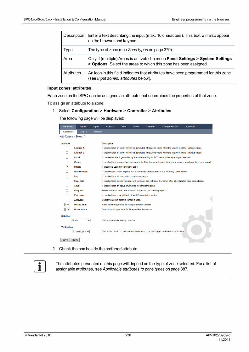
Description Enter a text describing the input (max. 16 characters). This text will also appearon the browser and keypad.
Type The type of zone (see Zone types on page 379).
Area Only if (multiple) Areas is activated in menuPanel Settings > System Settings> Options. Select the areas to which this zone has been assigned.
Attributes An icon in this field indicates that attributes have been programmed for this zone(see Input zones: attributes below).
Input zones: attributes
Each zone on the SPC can be assigned an attribute that determines the properties of that zone.
To assign an attribute to a zone:
1. Select Configuration > Hardware > Controller > Attributes.
The following page will be displayed:
2. Check the box beside the preferred attribute.
The attributes presented on this page will depend on the type of zone selected. For a list ofassignable attributes, seeApplicable attributes to zone types on page 387.
SPC4xxx/5xxx/6xxx– Installation &ConfigurationManual Engineer programming via the browser
© Vanderbilt 2018 230 A6V10276959-d11.2018
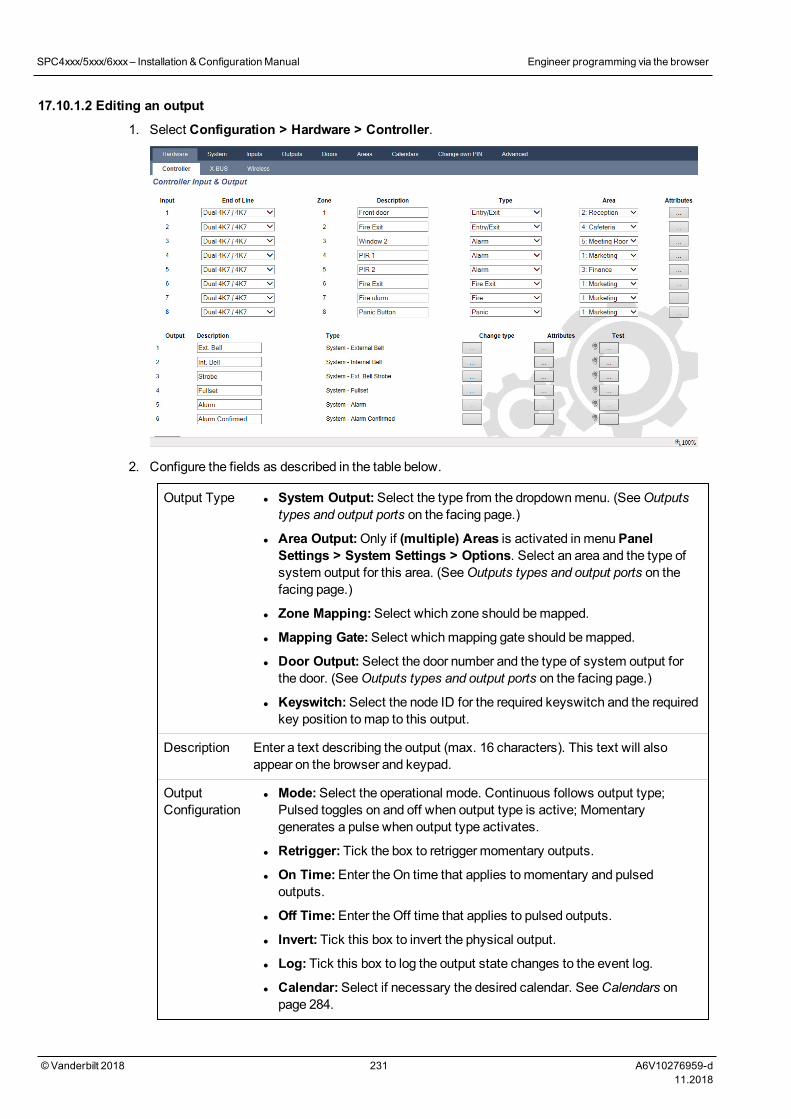
17.10.1.2 Editing an output
1. Select Configuration > Hardware > Controller.
2. Configure the fields as described in the table below.
Output Type l System Output:Select the type from the dropdownmenu. (SeeOutputstypes and output ports on the facing page.)
l Area Output:Only if (multiple) Areas is activated in menuPanelSettings > System Settings > Options. Select an area and the type ofsystem output for this area. (SeeOutputs types and output ports on thefacing page.)
l Zone Mapping:Select which zone should bemapped.
l Mapping Gate:Select whichmapping gate should bemapped.
l Door Output:Select the door number and the type of system output forthe door. (SeeOutputs types and output ports on the facing page.)
l Keyswitch:Select the node ID for the required keyswitch and the requiredkey position tomap to this output.
Description Enter a text describing the output (max. 16 characters). This text will alsoappear on the browser and keypad.
OutputConfiguration
l Mode:Select the operational mode. Continuous follows output type;Pulsed toggles on and off when output type is active; Momentarygenerates a pulse when output type activates.
l Retrigger: Tick the box to retrigger momentary outputs.
l On Time:Enter the On time that applies tomomentary and pulsedoutputs.
l Off Time:Enter the Off time that applies to pulsed outputs.
l Invert: Tick this box to invert the physical output.
l Log: Tick this box to log the output state changes to the event log.
l Calendar:Select if necessary the desired calendar. SeeCalendars onpage 284.
SPC4xxx/5xxx/6xxx– Installation &ConfigurationManual Engineer programming via the browser
© Vanderbilt 2018 231 A6V10276959-d11.2018
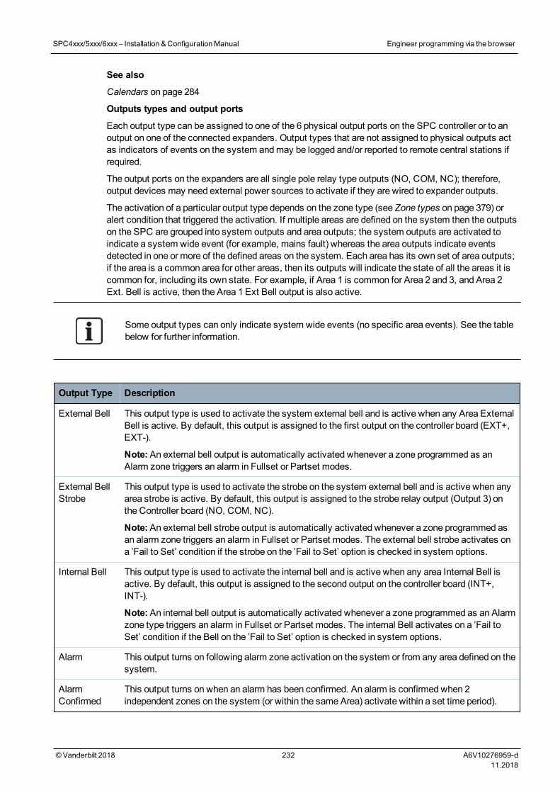
See also
Calendars on page 284
Outputs types and output ports
Each output type can be assigned to one of the 6 physical output ports on the SPC controller or to anoutput on one of the connected expanders. Output types that are not assigned to physical outputs actas indicators of events on the system andmay be logged and/or reported to remote central stations ifrequired.
The output ports on the expanders are all single pole relay type outputs (NO, COM, NC); therefore,output devices may need external power sources to activate if they are wired to expander outputs.
The activation of a particular output type depends on the zone type (see Zone types on page 379) oralert condition that triggered the activation. If multiple areas are defined on the system then the outputson the SPC are grouped into system outputs and area outputs; the system outputs are activated toindicate a system wide event (for example, mains fault) whereas the area outputs indicate eventsdetected in one or more of the defined areas on the system. Each area has its own set of area outputs;if the area is a common area for other areas, then its outputs will indicate the state of all the areas it iscommon for, including its own state. For example, if Area 1 is common for Area 2 and 3, and Area 2Ext. Bell is active, then the Area 1 Ext Bell output is also active.
Some output types can only indicate system wide events (no specific area events). See the tablebelow for further information.
Output Type Description
External Bell This output type is used to activate the system external bell and is active when any Area ExternalBell is active. By default, this output is assigned to the first output on the controller board (EXT+,EXT-).
Note:An external bell output is automatically activated whenever a zone programmed as anAlarm zone triggers an alarm in Fullset or Partset modes.
External BellStrobe
This output type is used to activate the strobe on the system external bell and is active when anyarea strobe is active. By default, this output is assigned to the strobe relay output (Output 3) onthe Controller board (NO, COM, NC).
Note:An external bell strobe output is automatically activated whenever a zone programmed asan alarm zone triggers an alarm in Fullset or Partset modes. The external bell strobe activates ona ’Fail to Set’ condition if the strobe on the ’Fail to Set’ option is checked in system options.
Internal Bell This output type is used to activate the internal bell and is active when any area Internal Bell isactive. By default, this output is assigned to the second output on the controller board (INT+,INT-).
Note:An internal bell output is automatically activated whenever a zone programmed as an Alarmzone type triggers an alarm in Fullset or Partset modes. The internal Bell activates on a ’Fail toSet’ condition if the Bell on the ’Fail to Set’ option is checked in system options.
Alarm This output turns on following alarm zone activation on the system or from any area defined on thesystem.
AlarmConfirmed
This output turns on when an alarm has been confirmed. An alarm is confirmed when 2independent zones on the system (or within the same Area) activate within a set time period).
SPC4xxx/5xxx/6xxx– Installation &ConfigurationManual Engineer programming via the browser
© Vanderbilt 2018 232 A6V10276959-d11.2018
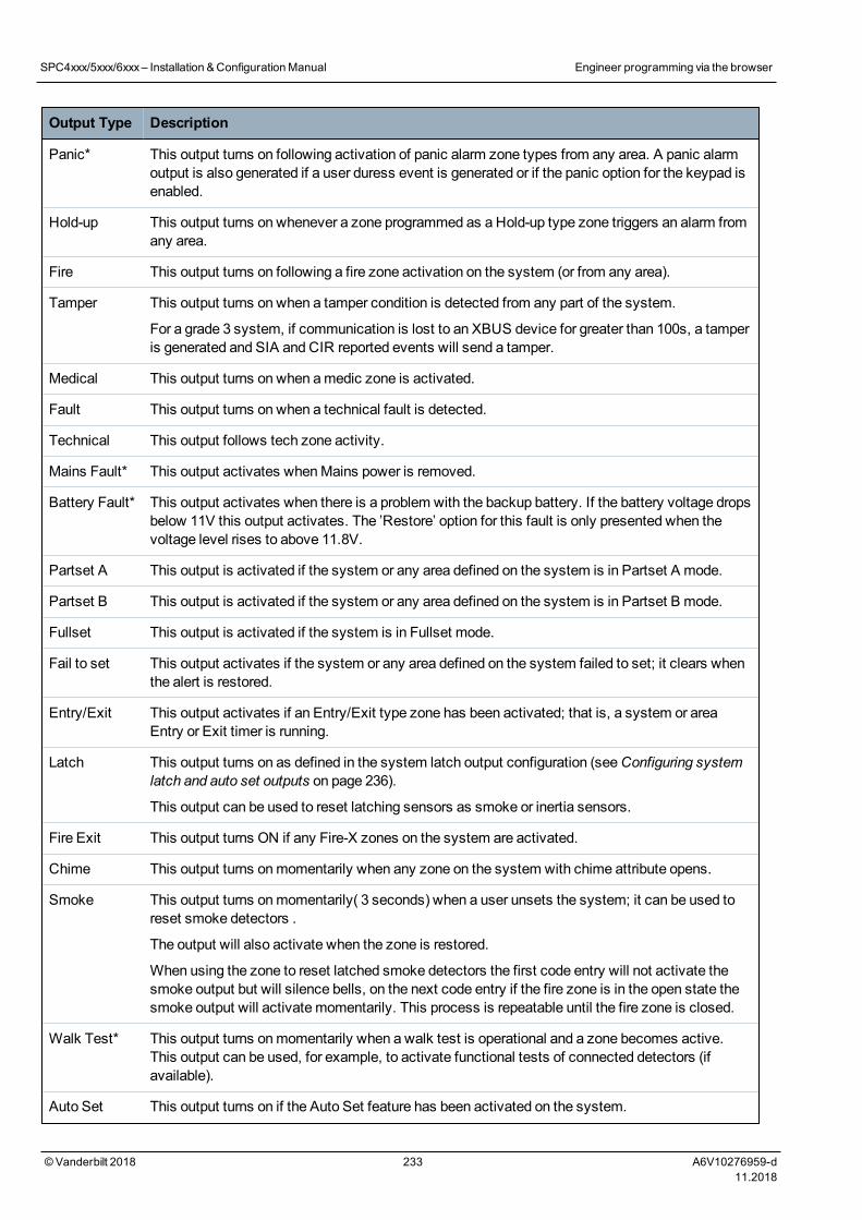
Output Type Description
Panic* This output turns on following activation of panic alarm zone types from any area. A panic alarmoutput is also generated if a user duress event is generated or if the panic option for the keypad isenabled.
Hold-up This output turns on whenever a zone programmed as a Hold-up type zone triggers an alarm fromany area.
Fire This output turns on following a fire zone activation on the system (or from any area).
Tamper This output turns on when a tamper condition is detected from any part of the system.
For a grade 3 system, if communication is lost to an XBUS device for greater than 100s, a tamperis generated and SIA and CIR reported events will send a tamper.
Medical This output turns on when amedic zone is activated.
Fault This output turns on when a technical fault is detected.
Technical This output follows tech zone activity.
Mains Fault* This output activates whenMains power is removed.
Battery Fault* This output activates when there is a problem with the backup battery. If the battery voltage dropsbelow 11V this output activates. The ’Restore’ option for this fault is only presented when thevoltage level rises to above 11.8V.
Partset A This output is activated if the system or any area defined on the system is in Partset A mode.
Partset B This output is activated if the system or any area defined on the system is in Partset B mode.
Fullset This output is activated if the system is in Fullset mode.
Fail to set This output activates if the system or any area defined on the system failed to set; it clears whenthe alert is restored.
Entry/Exit This output activates if an Entry/Exit type zone has been activated; that is, a system or areaEntry or Exit timer is running.
Latch This output turns on as defined in the system latch output configuration (seeConfiguring systemlatch and auto set outputs on page 236).
This output can be used to reset latching sensors as smoke or inertia sensors.
Fire Exit This output turns ON if any Fire-X zones on the system are activated.
Chime This output turns onmomentarily when any zone on the system with chime attribute opens.
Smoke This output turns onmomentarily( 3 seconds) when a user unsets the system; it can be used toreset smoke detectors .
The output will also activate when the zone is restored.
When using the zone to reset latched smoke detectors the first code entry will not activate thesmoke output but will silence bells, on the next code entry if the fire zone is in the open state thesmoke output will activate momentarily. This process is repeatable until the fire zone is closed.
Walk Test* This output turns onmomentarily when a walk test is operational and a zone becomes active.This output can be used, for example, to activate functional tests of connected detectors (ifavailable).
Auto Set This output turns on if the Auto Set feature has been activated on the system.
SPC4xxx/5xxx/6xxx– Installation &ConfigurationManual Engineer programming via the browser
© Vanderbilt 2018 233 A6V10276959-d11.2018
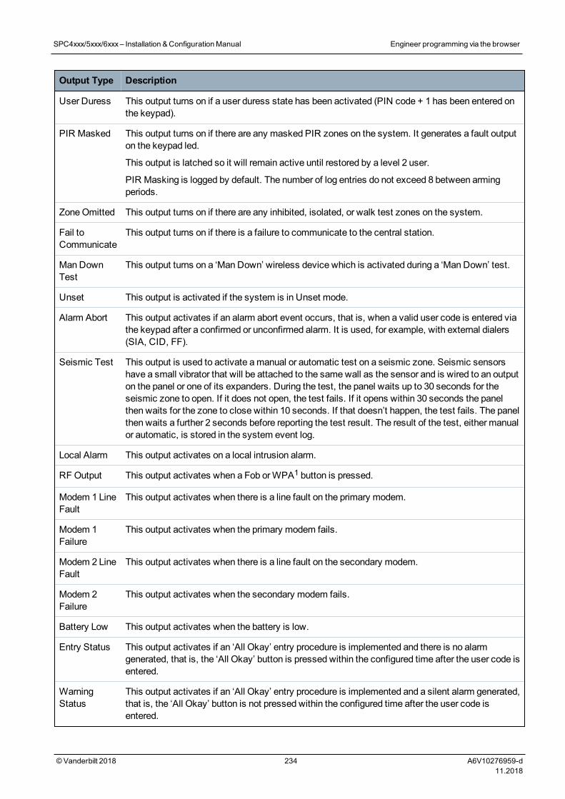
Output Type Description
User Duress This output turns on if a user duress state has been activated (PIN code + 1 has been entered onthe keypad).
PIR Masked This output turns on if there are any masked PIR zones on the system. It generates a fault outputon the keypad led.
This output is latched so it will remain active until restored by a level 2 user.
PIR Masking is logged by default. The number of log entries do not exceed 8 between armingperiods.
ZoneOmitted This output turns on if there are any inhibited, isolated, or walk test zones on the system.
Fail toCommunicate
This output turns on if there is a failure to communicate to the central station.
Man DownTest
This output turns on a ‘Man Down’ wireless device which is activated during a ‘Man Down’ test.
Unset This output is activated if the system is in Unset mode.
Alarm Abort This output activates if an alarm abort event occurs, that is, when a valid user code is entered viathe keypad after a confirmed or unconfirmed alarm. It is used, for example, with external dialers(SIA, CID, FF).
Seismic Test This output is used to activate amanual or automatic test on a seismic zone. Seismic sensorshave a small vibrator that will be attached to the samewall as the sensor and is wired to an outputon the panel or one of its expanders. During the test, the panel waits up to 30 seconds for theseismic zone to open. If it does not open, the test fails. If it opens within 30 seconds the panelthen waits for the zone to close within 10 seconds. If that doesn’t happen, the test fails. The panelthen waits a further 2 seconds before reporting the test result. The result of the test, either manualor automatic, is stored in the system event log.
Local Alarm This output activates on a local intrusion alarm.
RF Output This output activates when a Fob orWPA1 button is pressed.
Modem 1 LineFault
This output activates when there is a line fault on the primary modem.
Modem 1Failure
This output activates when the primary modem fails.
Modem 2 LineFault
This output activates when there is a line fault on the secondary modem.
Modem 2Failure
This output activates when the secondary modem fails.
Battery Low This output activates when the battery is low.
Entry Status This output activates if an ‘All Okay’ entry procedure is implemented and there is no alarmgenerated, that is, the ‘All Okay’ button is pressed within the configured time after the user code isentered.
WarningStatus
This output activates if an ‘All Okay’ entry procedure is implemented and a silent alarm generated,that is, the ‘All Okay’ button is not pressed within the configured time after the user code isentered.
SPC4xxx/5xxx/6xxx– Installation &ConfigurationManual Engineer programming via the browser
© Vanderbilt 2018 234 A6V10276959-d11.2018
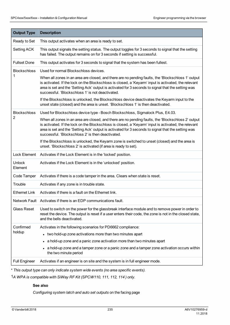
Output Type Description
Ready to Set This output activates when an area is ready to set.
Setting ACK This output signals the setting status. The output toggles for 3 seconds to signal that the settinghas failed. The output remains on for 3 seconds if setting is successful.
Fullset Done This output activates for 3 seconds to signal that the system has been fullest.
Blockschloss1
Used for normal Blockschloss devices.
When all zones in an area are closed, and there are no pending faults, the ‘Blockschloss 1‘ outputis activated. If the lock on the Blockschloss is closed, a ‘Keyarm‘ input is activated, the relevantarea is set and the ‘Setting Ack‘ output is activated for 3 seconds to signal that the setting wassuccessful. ‘Blockschloss 1‘ is not deactivated.
If the Blockschloss is unlocked, the Blockschloss device deactivates the Keyarm input to theunset state (closed) and the area is unset. ‘Blockschloss 1‘ is then deactivated.
Blockschloss2
Used for Blockschloss device type - Bosch Blockschloss, Sigmalock Plus, E4.03.
When all zones in an area are closed, and there are no pending faults, the ‘Blockschloss 2‘ outputis activated. If the lock on the Blockschloss is closed, a ‘Keyarm‘ input is activated, the relevantarea is set and the ‘Setting Ack‘ output is activated for 3 seconds to signal that the setting wassuccessful. ‘Blockschloss 2‘ is then deactivated.
If the Blockschloss is unlocked, the Keyarm zone is switched to unset (closed) and the area isunset. ‘Blockschloss 2‘ is activated (if area is ready to set).
Lock Element Activates if the Lock Element is in the ‘locked‘ position.
UnlockElement
Activates if the Lock Element is in the ‘unlocked‘ position.
Code Tamper Activates if there is a code tamper in the area. Clears when state is reset.
Trouble Activates if any zone is in trouble state.
Ethernet Link Activates if there is a fault on the Ethernet link.
Network Fault Activates if there is an EDP communications fault.
Glass Reset Used to switch on the power for the glassbreak interfacemodule and to remove power in order toreset the device. The output is reset if a user enters their code, the zone is not in the closed state,and the bells deactivated.
Confirmedholdup
Activates in the following scenarios for PD6662 compliance:
l two hold-up zone activations more than twominutes apart
l a hold-up zone and a panic zone activationmore than twominutes apart
l a hold-up zone and a tamper zone or a panic zone and a tamper zone activation occurs withinthe twominute period
Full Engineer Activates if an engineer is on site and the system is in full engineer mode.
* This output type can only indicate system wide events (no area specific events).1AWPA is compatible with SiWay RF Kit (SPCW110, 111, 112, 114 ) only.
See also
Configuring system latch and auto set outputs on the facing page
SPC4xxx/5xxx/6xxx– Installation &ConfigurationManual Engineer programming via the browser
© Vanderbilt 2018 235 A6V10276959-d11.2018
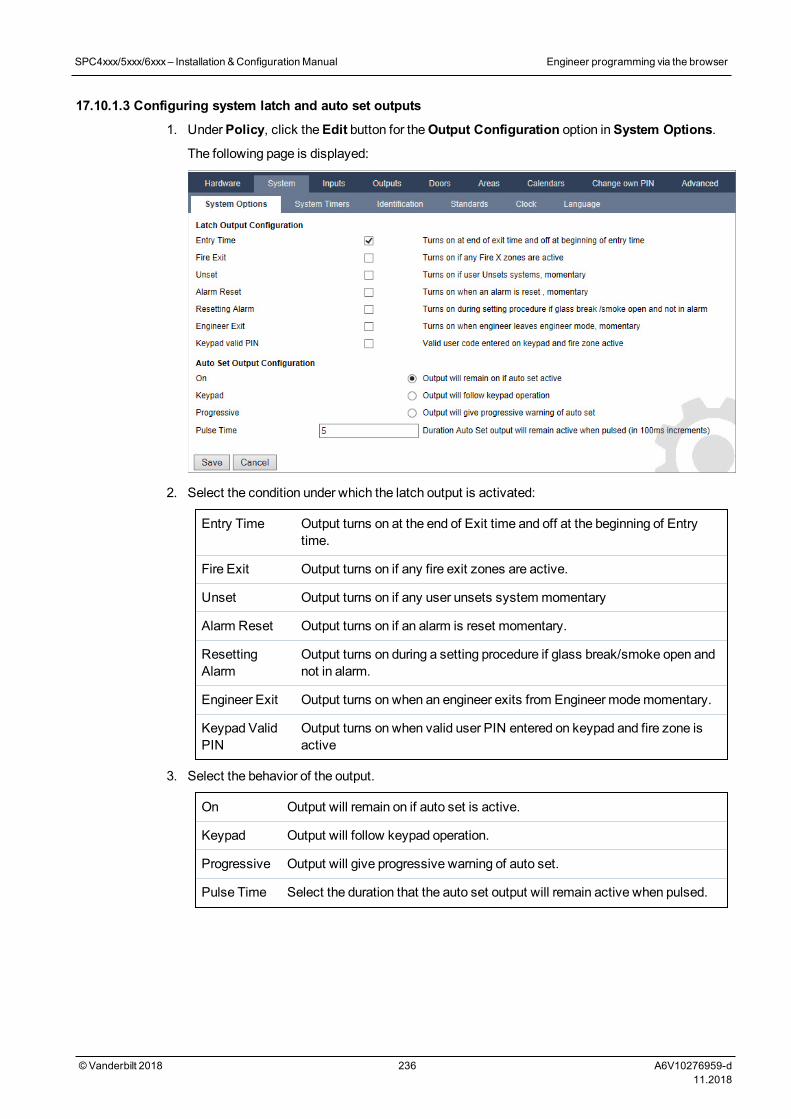
17.10.1.3 Configuring system latch and auto set outputs
1. UnderPolicy, click theEdit button for theOutput Configuration option inSystem Options.
The following page is displayed:
2. Select the condition under which the latch output is activated:
Entry Time Output turns on at the end of Exit time and off at the beginning of Entrytime.
Fire Exit Output turns on if any fire exit zones are active.
Unset Output turns on if any user unsets systemmomentary
Alarm Reset Output turns on if an alarm is reset momentary.
ResettingAlarm
Output turns on during a setting procedure if glass break/smoke open andnot in alarm.
Engineer Exit Output turns on when an engineer exits from Engineer modemomentary.
Keypad ValidPIN
Output turns on when valid user PIN entered on keypad and fire zone isactive
3. Select the behavior of the output.
On Output will remain on if auto set is active.
Keypad Output will follow keypad operation.
Progressive Output will give progressive warning of auto set.
Pulse Time Select the duration that the auto set output will remain active when pulsed.
SPC4xxx/5xxx/6xxx– Installation &ConfigurationManual Engineer programming via the browser
© Vanderbilt 2018 236 A6V10276959-d11.2018
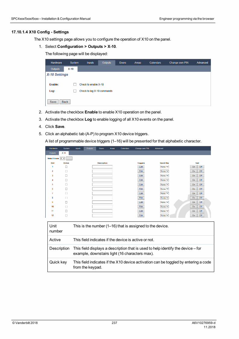
17.10.1.4 X10 Config - Settings
The X10 settings page allows you to configure the operation of X10 on the panel.
1. Select Configuration > Outputs > X-10.
The following page will be displayed:
2. Activate the checkbox Enable to enable X10 operation on the panel.
3. Activate the checkbox Log to enable logging of all X10 events on the panel.
4. Click Save.
5. Click an alphabetic tab (A-P) to program X10 device triggers.
A list of programmable device triggers (1–16) will be presented for that alphabetic character.
Unitnumber
This is the number (1–16) that is assigned to the device.
Active This field indicates if the device is active or not.
Description This field displays a description that is used to help identify the device – forexample, downstairs light (16 characters max).
Quick key This field indicates if the X10 device activation can be toggled by entering a codefrom the keypad.
SPC4xxx/5xxx/6xxx– Installation &ConfigurationManual Engineer programming via the browser
© Vanderbilt 2018 237 A6V10276959-d11.2018
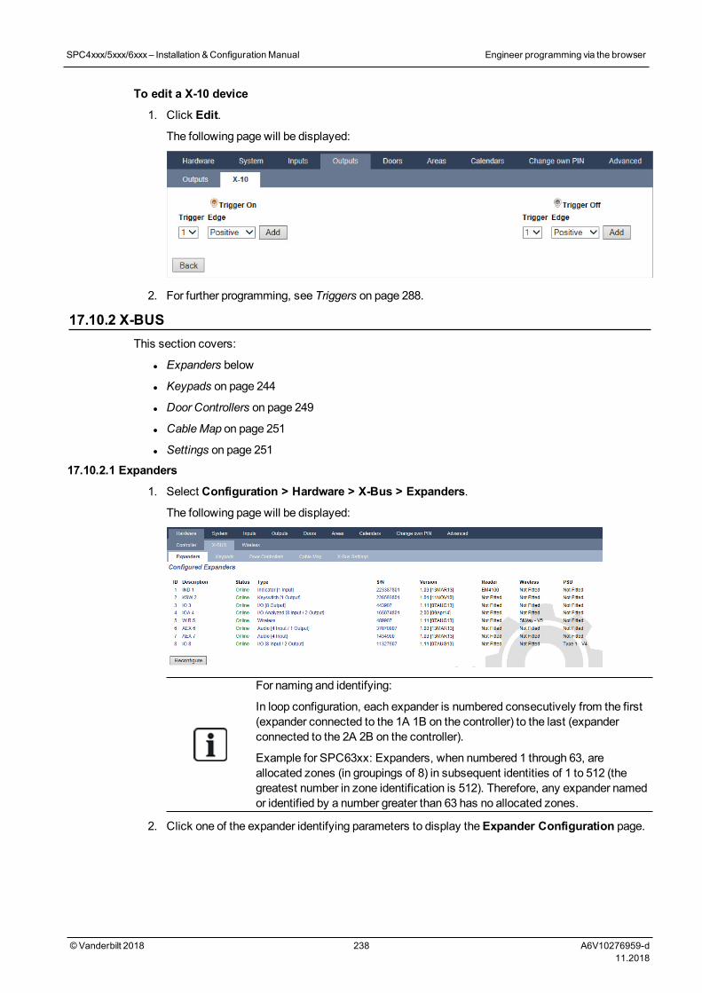
To edit a X-10 device
1. Click Edit.
The following page will be displayed:
2. For further programming, see Triggers on page 288.
17.10.2 X-BUSThis section covers:
l Expanders below
l Keypads on page 244
l Door Controllers on page 249
l CableMap on page 251
l Settings on page 251
17.10.2.1 Expanders
1. Select Configuration > Hardware > X-Bus > Expanders.
The following page will be displayed:
For naming and identifying:
In loop configuration, each expander is numbered consecutively from the first(expander connected to the 1A 1B on the controller) to the last (expanderconnected to the 2A 2B on the controller).
Example for SPC63xx: Expanders, when numbered 1 through 63, areallocated zones (in groupings of 8) in subsequent identities of 1 to 512 (thegreatest number in zone identification is 512). Therefore, any expander namedor identified by a number greater than 63 has no allocated zones.
2. Click one of the expander identifying parameters to display theExpander Configuration page.
SPC4xxx/5xxx/6xxx– Installation &ConfigurationManual Engineer programming via the browser
© Vanderbilt 2018 238 A6V10276959-d11.2018
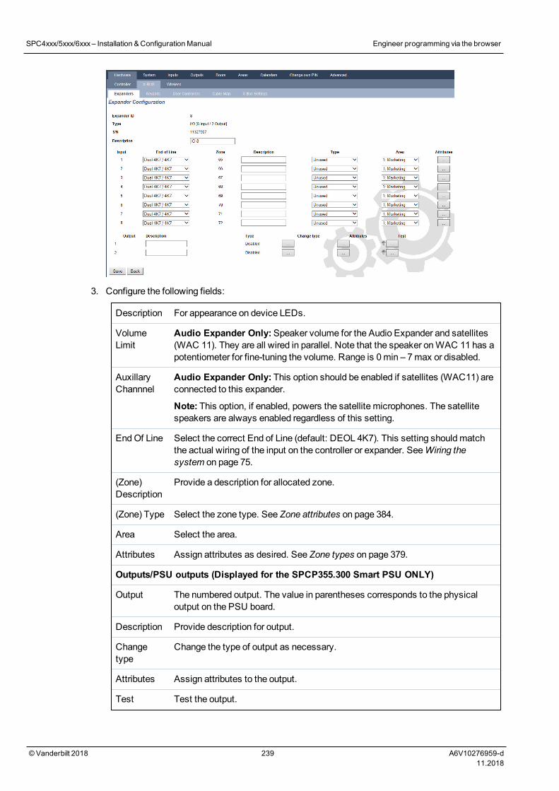
3. Configure the following fields:
Description For appearance on device LEDs.
VolumeLimit
Audio Expander Only:Speaker volume for the Audio Expander and satellites(WAC 11). They are all wired in parallel. Note that the speaker onWAC 11 has apotentiometer for fine-tuning the volume. Range is 0min – 7max or disabled.
AuxillaryChannnel
Audio Expander Only: This option should be enabled if satellites (WAC11) areconnected to this expander.
Note: This option, if enabled, powers the satellite microphones. The satellitespeakers are always enabled regardless of this setting.
EndOf Line Select the correct End of Line (default: DEOL 4K7). This setting shouldmatchthe actual wiring of the input on the controller or expander. SeeWiring thesystem on page 75.
(Zone)Description
Provide a description for allocated zone.
(Zone) Type Select the zone type. See Zone attributes on page 384.
Area Select the area.
Attributes Assign attributes as desired. See Zone types on page 379.
Outputs/PSU outputs (Displayed for the SPCP355.300 Smart PSU ONLY)
Output The numbered output. The value in parentheses corresponds to the physicaloutput on the PSU board.
Description Provide description for output.
Changetype
Change the type of output as necessary.
Attributes Assign attributes to the output.
Test Test the output.
SPC4xxx/5xxx/6xxx– Installation &ConfigurationManual Engineer programming via the browser
© Vanderbilt 2018 239 A6V10276959-d11.2018
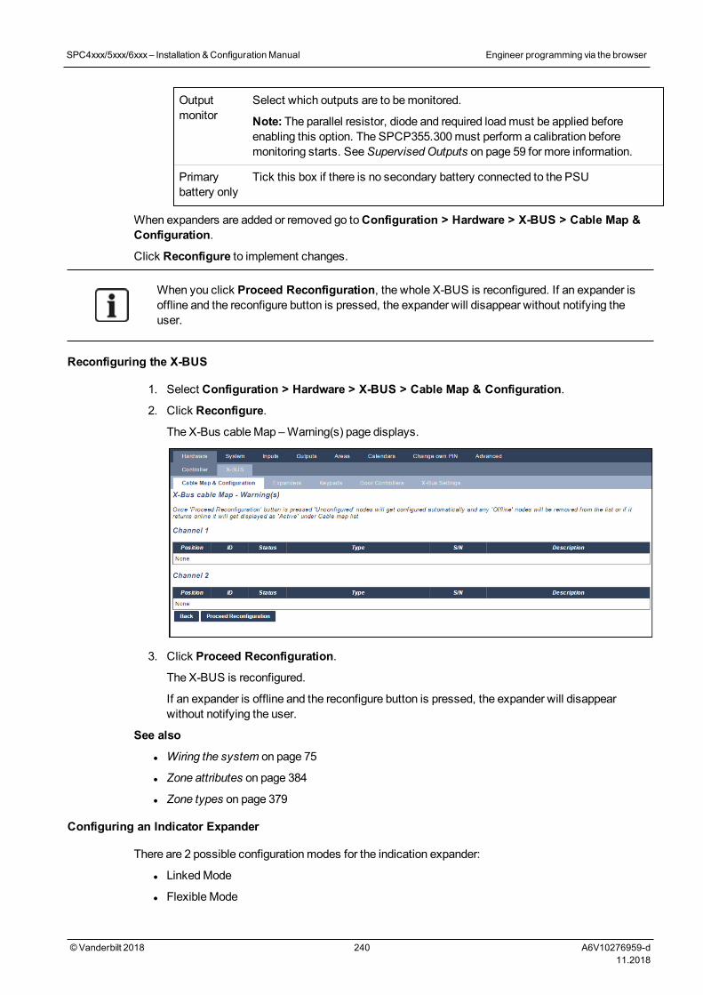
Outputmonitor
Select which outputs are to bemonitored.
Note: The parallel resistor, diode and required loadmust be applied beforeenabling this option. The SPCP355.300must perform a calibration beforemonitoring starts. SeeSupervised Outputs on page 59 for more information.
Primarybattery only
Tick this box if there is no secondary battery connected to the PSU
When expanders are added or removed go toConfiguration > Hardware > X-BUS > Cable Map &Configuration.
Click Reconfigure to implement changes.
When you click Proceed Reconfiguration, the whole X-BUS is reconfigured. If an expander isoffline and the reconfigure button is pressed, the expander will disappear without notifying theuser.
Reconfiguring the X-BUS
1. Select Configuration > Hardware > X-BUS > Cable Map & Configuration.
2. Click Reconfigure.
The X-Bus cableMap –Warning(s) page displays.
3. Click Proceed Reconfiguration.
The X-BUS is reconfigured.
If an expander is offline and the reconfigure button is pressed, the expander will disappearwithout notifying the user.
See also
l Wiring the system on page 75
l Zone attributes on page 384
l Zone types on page 379
Configuring an Indicator Expander
There are 2 possible configurationmodes for the indication expander:
l LinkedMode
l Flexible Mode
SPC4xxx/5xxx/6xxx– Installation &ConfigurationManual Engineer programming via the browser
© Vanderbilt 2018 240 A6V10276959-d11.2018
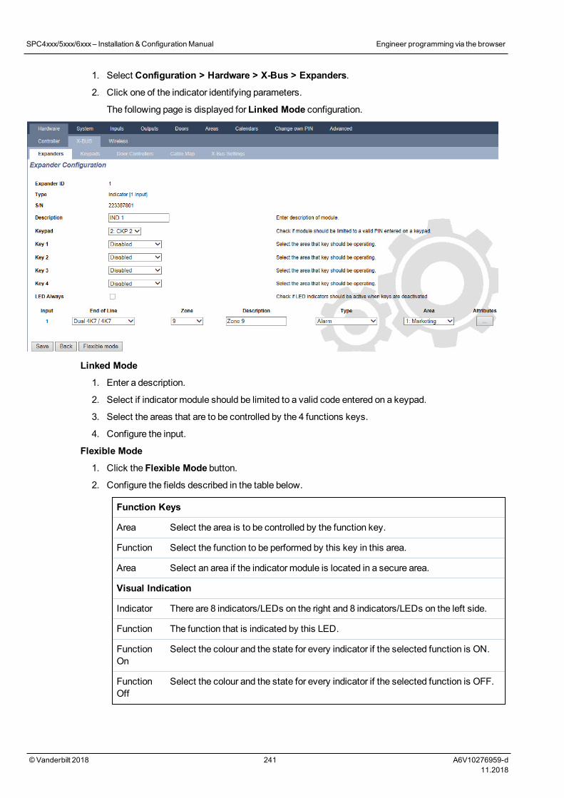
1. Select Configuration > Hardware > X-Bus > Expanders.
2. Click one of the indicator identifying parameters.
The following page is displayed for Linked Mode configuration.
Linked Mode
1. Enter a description.
2. Select if indicator module should be limited to a valid code entered on a keypad.
3. Select the areas that are to be controlled by the 4 functions keys.
4. Configure the input.
Flexible Mode
1. Click the Flexible Mode button.
2. Configure the fields described in the table below.
Function Keys
Area Select the area is to be controlled by the function key.
Function Select the function to be performed by this key in this area.
Area Select an area if the indicator module is located in a secure area.
Visual Indication
Indicator There are 8 indicators/LEDs on the right and 8 indicators/LEDs on the left side.
Function The function that is indicated by this LED.
FunctionOn
Select the colour and the state for every indicator if the selected function is ON.
FunctionOff
Select the colour and the state for every indicator if the selected function is OFF.
SPC4xxx/5xxx/6xxx– Installation &ConfigurationManual Engineer programming via the browser
© Vanderbilt 2018 241 A6V10276959-d11.2018
Changefunction
Click this button to change the function for this indicator. The function can beenabled or used for a system, area, zone or keyswitch.
Audible Indications
Alarms Select if the alarms should be audible.
Entry/Exit Select if entry/exit should be audible.
Key press Select if keypress should be audible.
Deactivation
Calendar Select if indicator expander should be limited by calendar.
Mappinggate
Select if indicator module should be limited by amapping gate.
Keyswitch Select if indicationmodule should be limited by a keyswitch.
Keypad Select if indicator module should be limited to a valid PIN entered on a keypad.(see warning above)
Cardreader
Select if indicator module should not be activated until a valid card/fob ispresented to the built-in card reader.
3. Configure the input.
WARNING: Your system will not comply with EN standards if you enable a function key to set thesystem without a valid PIN being required.
Configuring a Keyswitch Expander
1. Select Settings > X-Bus > Expanders.
2. Click one of the keyswitch identifying parameters.
SPC4xxx/5xxx/6xxx– Installation &ConfigurationManual Engineer programming via the browser
© Vanderbilt 2018 242 A6V10276959-d11.2018
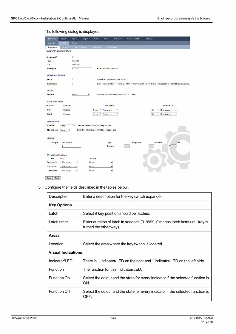
The following dialog is displayed.
3. Configure the fields described in the tables below.
Description Enter a description for the keyswitch expander.
Key Options
Latch Select if key position should be latched.
Latch timer Enter duration of latch in seconds (0–9999, 0means latch lasts until key isturned the other way).
Areas
Location Select the area where the keyswitch is located.
Visual Indications
Indicator/LED There is 1 indicator/LED on the right and 1 indicator/LED on the left side.
Function The function for this indicator/LED.
Function On Select the colour and the state for every indicator if the selected function isON.
Function Off Select the colour and the state for every indicator if the selected function isOFF.
SPC4xxx/5xxx/6xxx– Installation &ConfigurationManual Engineer programming via the browser
© Vanderbilt 2018 243 A6V10276959-d11.2018
Change function Click this button to change the function for this indicator. The function canbe enabled or used for a system, area, zone or keyswitch.
Deactivation
Calendar Select if the keyswitchmodule should be limited by calendar.
Mapping gate Select if the keyswitchmodule should be limited by amapping gate.
Output
Output x Configure and text the outputs for the keyswitch. SeeEditing an output onpage 231 for more details.
Keyswitch Functions
Centre, Right andLeft Positions
Select the Function that that this keyswitch position will perform and therelevant Area.
Keyswitch functions are:
l None
l Unset
l Partset A
l Partset B
l Fullset
l Toggle Unset / Fullset
l Toggle Unset / Partset A
l Toggle Unset / Partset B
l All Okay
l Setting authorisation
l Shunt
WARNING: Your system will not comply with EN standards if you enable a keyswitch function toset the system without a valid PIN being required.
17.10.2.2 Keypads
Editing a Standard Keypad
1. Select Configuration > Hardware > X-Bus > Keypads.
2. Click one of the standard keypad identifying parameters.
SPC4xxx/5xxx/6xxx– Installation &ConfigurationManual Engineer programming via the browser
© Vanderbilt 2018 244 A6V10276959-d11.2018
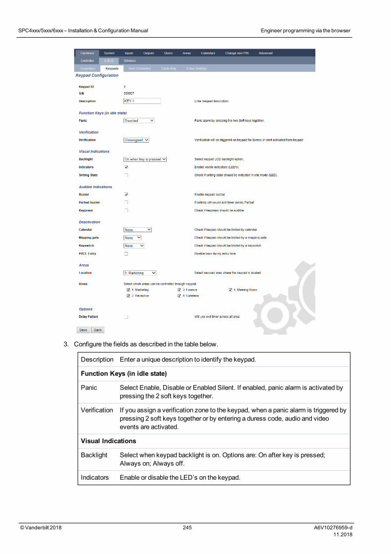
3. Configure the fields as described in the table below.
Description Enter a unique description to identify the keypad.
Function Keys (in idle state)
Panic Select Enable, Disable or Enabled Silent. If enabled, panic alarm is activated bypressing the 2 soft keys together.
Verification If you assign a verification zone to the keypad, when a panic alarm is triggered bypressing 2 soft keys together or by entering a duress code, audio and videoevents are activated.
Visual Indications
Backlight Select when keypad backlight is on. Options are: On after key is pressed;Always on; Always off.
Indicators Enable or disable the LED’s on the keypad.
SPC4xxx/5xxx/6xxx– Installation &ConfigurationManual Engineer programming via the browser
© Vanderbilt 2018 245 A6V10276959-d11.2018
Settingstate
Select if setting state should be indicated in idle mode.
Audible Indications
Buzzer Enable or disable the buzzer on the keypad.
PartsetBuzzer
Enable or disable buzzer during exit time on Partset.
Keypress Select if the speaker volume for the key presses should be activated.
Deactivation
Calendar Select if the keypad should be limited by calendar. SeeCalendars on page 284.
Mappinggate
Select if keypad should be limited by amapping gate.
Keyswitch Select if keypad should be limited by a keyswitch.
PACEEntry
Tick this box to disable the keys on the keypad during the entry time when aPACE is configured on the keypad.
Areas
Location Select the secured area where the keypad is located.
Areas Select which areas can be controlled through keypad.
Options
DelayFullset
Select to configure a delayed set across all keypads. The location of the keypadis ignored and all areas will perform a full exit time count down.
NOTICE: An area should be assigned to a keypad only if the keypad is inside the assigned area,and if an entry/exit route is defined. If an area is assigned, when the particular area is set or unsetthen entry and exit timers are used (if configured). Other features related to entry/exit routes alsobecome available. If no area is assigned, the area is set or unset immediately and other entry/exitfeatures are not available.
See also
Calendars on page 284
Editing a Comfort Keypad
1. Select Configuration > Hardware > X-Bus > Keypads.
2. Click one of the comfort keypad identifying parameters.
SPC4xxx/5xxx/6xxx– Installation &ConfigurationManual Engineer programming via the browser
© Vanderbilt 2018 246 A6V10276959-d11.2018
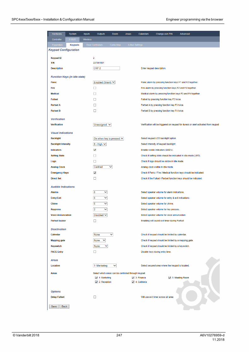
SPC4xxx/5xxx/6xxx– Installation &ConfigurationManual Engineer programming via the browser
© Vanderbilt 2018 247 A6V10276959-d11.2018
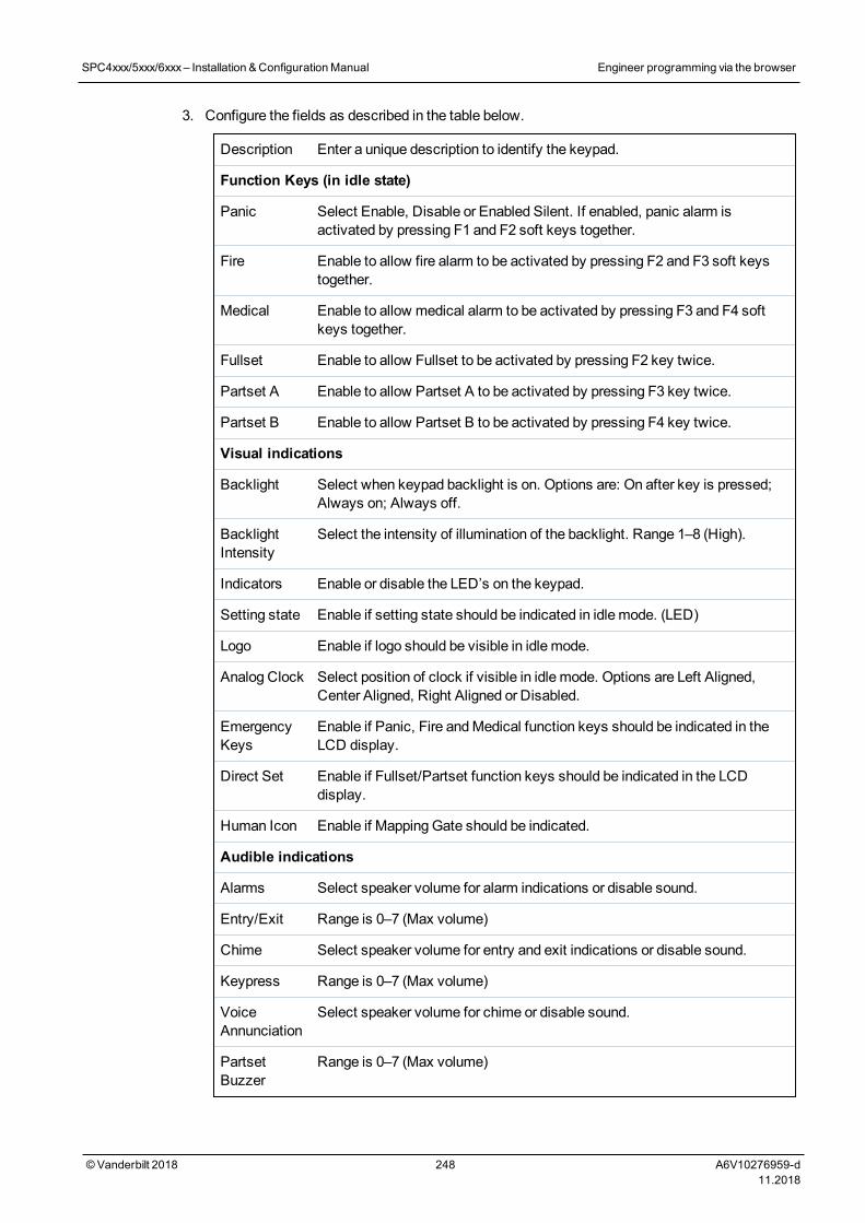
3. Configure the fields as described in the table below.
Description Enter a unique description to identify the keypad.
Function Keys (in idle state)
Panic Select Enable, Disable or Enabled Silent. If enabled, panic alarm isactivated by pressing F1 and F2 soft keys together.
Fire Enable to allow fire alarm to be activated by pressing F2 and F3 soft keystogether.
Medical Enable to allow medical alarm to be activated by pressing F3 and F4 softkeys together.
Fullset Enable to allow Fullset to be activated by pressing F2 key twice.
Partset A Enable to allow Partset A to be activated by pressing F3 key twice.
Partset B Enable to allow Partset B to be activated by pressing F4 key twice.
Visual indications
Backlight Select when keypad backlight is on. Options are: On after key is pressed;Always on; Always off.
BacklightIntensity
Select the intensity of illumination of the backlight. Range 1–8 (High).
Indicators Enable or disable the LED’s on the keypad.
Setting state Enable if setting state should be indicated in idle mode. (LED)
Logo Enable if logo should be visible in idle mode.
Analog Clock Select position of clock if visible in idle mode. Options are Left Aligned,Center Aligned, Right Aligned or Disabled.
EmergencyKeys
Enable if Panic, Fire andMedical function keys should be indicated in theLCD display.
Direct Set Enable if Fullset/Partset function keys should be indicated in the LCDdisplay.
Human Icon Enable if Mapping Gate should be indicated.
Audible indications
Alarms Select speaker volume for alarm indications or disable sound.
Entry/Exit Range is 0–7 (Max volume)
Chime Select speaker volume for entry and exit indications or disable sound.
Keypress Range is 0–7 (Max volume)
VoiceAnnunciation
Select speaker volume for chime or disable sound.
PartsetBuzzer
Range is 0–7 (Max volume)
SPC4xxx/5xxx/6xxx– Installation &ConfigurationManual Engineer programming via the browser
© Vanderbilt 2018 248 A6V10276959-d11.2018
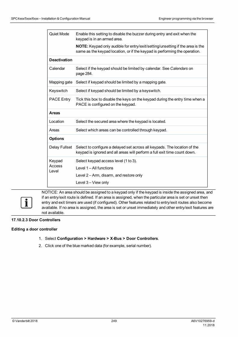
Quiet Mode Enable this setting to disable the buzzer during entry and exit when thekeypad is in an armed area.
NOTE:Keypad only audible for entry/exit/setting/unsetting if the area is thesame as the keypad location, or if the keypad is performing the operation.
Deactivation
Calendar Select if the keypad should be limited by calendar. SeeCalendars onpage 284.
Mapping gate Select if keypad should be limited by amapping gate.
Keyswitch Select if keypad should be limited by a keyswitch.
PACE Entry Tick this box to disable the keys on the keypad during the entry time when aPACE is configured on the keypad.
Areas
Location Select the secured area where the keypad is located.
Areas Select which areas can be controlled through keypad.
Options
Delay Fullset Select to configure a delayed set across all keypads. The location of thekeypad is ignored and all areas will perform a full exit time count down.
KeypadAccessLevel
Select keypad access level (1 to 3).
Level 1 – All functions
Level 2 – Arm, disarm, and restore only
Level 3 – View only
NOTICE: An area should be assigned to a keypad only if the keypad is inside the assigned area, andif an entry/exit route is defined. If an area is assigned, when the particular area is set or unset thenentry and exit timers are used (if configured). Other features related to entry/exit routes also becomeavailable. If no area is assigned, the area is set or unset immediately and other entry/exit features arenot available.
17.10.2.3 Door Controllers
Editing a door controller
1. Select Configuration > Hardware > X-Bus > Door Controllers.
2. Click one of the bluemarked data (for example, serial number).
SPC4xxx/5xxx/6xxx– Installation &ConfigurationManual Engineer programming via the browser
© Vanderbilt 2018 249 A6V10276959-d11.2018
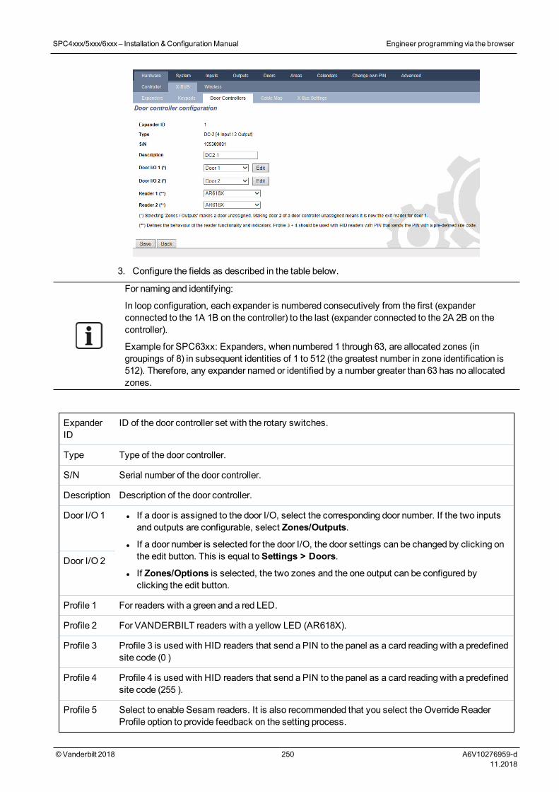
3. Configure the fields as described in the table below.
For naming and identifying:
In loop configuration, each expander is numbered consecutively from the first (expanderconnected to the 1A 1B on the controller) to the last (expander connected to the 2A 2B on thecontroller).
Example for SPC63xx: Expanders, when numbered 1 through 63, are allocated zones (ingroupings of 8) in subsequent identities of 1 to 512 (the greatest number in zone identification is512). Therefore, any expander named or identified by a number greater than 63 has no allocatedzones.
ExpanderID
ID of the door controller set with the rotary switches.
Type Type of the door controller.
S/N Serial number of the door controller.
Description Description of the door controller.
Door I/O 1 l If a door is assigned to the door I/O, select the corresponding door number. If the two inputsand outputs are configurable, select Zones/Outputs.
l If a door number is selected for the door I/O, the door settings can be changed by clicking onthe edit button. This is equal toSettings > Doors.
l If Zones/Options is selected, the two zones and the one output can be configured byclicking the edit button.
Door I/O 2
Profile 1 For readers with a green and a red LED.
Profile 2 For VANDERBILT readers with a yellow LED (AR618X).
Profile 3 Profile 3 is used with HID readers that send a PIN to the panel as a card reading with a predefinedsite code (0 )
Profile 4 Profile 4 is used with HID readers that send a PIN to the panel as a card reading with a predefinedsite code (255 ).
Profile 5 Select to enable Sesam readers. It is also recommended that you select the Override ReaderProfile option to provide feedback on the setting process.
SPC4xxx/5xxx/6xxx– Installation &ConfigurationManual Engineer programming via the browser
© Vanderbilt 2018 250 A6V10276959-d11.2018
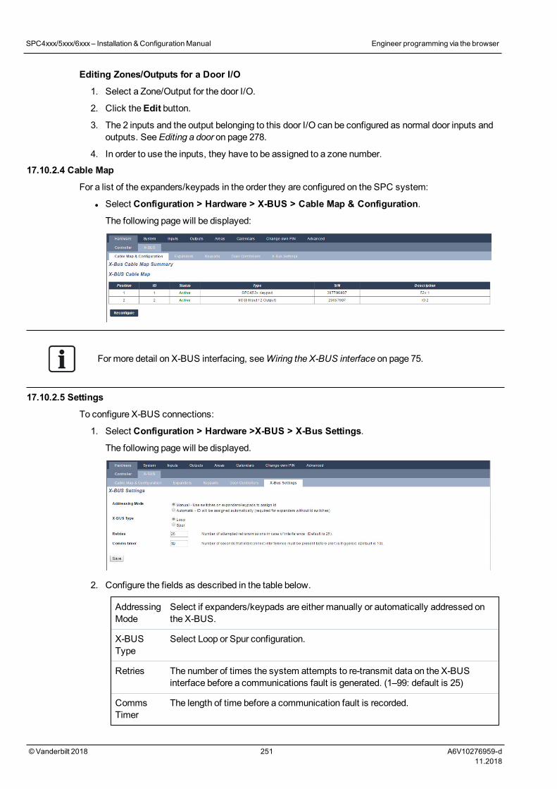
Editing Zones/Outputs for a Door I/O
1. Select a Zone/Output for the door I/O.
2. Click theEdit button.
3. The 2 inputs and the output belonging to this door I/O can be configured as normal door inputs andoutputs. SeeEditing a door on page 278.
4. In order to use the inputs, they have to be assigned to a zone number.
17.10.2.4 Cable Map
For a list of the expanders/keypads in the order they are configured on the SPC system:
l Select Configuration > Hardware > X-BUS > Cable Map & Configuration.
The following page will be displayed:
For more detail on X-BUS interfacing, seeWiring the X-BUS interface on page 75.
17.10.2.5 Settings
To configure X-BUS connections:
1. Select Configuration > Hardware >X-BUS > X-Bus Settings.
The following page will be displayed.
2. Configure the fields as described in the table below.
AddressingMode
Select if expanders/keypads are either manually or automatically addressed onthe X-BUS.
X-BUSType
Select Loop or Spur configuration.
Retries The number of times the system attempts to re-transmit data on the X-BUSinterface before a communications fault is generated. (1–99: default is 25)
CommsTimer
The length of time before a communication fault is recorded.
SPC4xxx/5xxx/6xxx– Installation &ConfigurationManual Engineer programming via the browser
© Vanderbilt 2018 251 A6V10276959-d11.2018
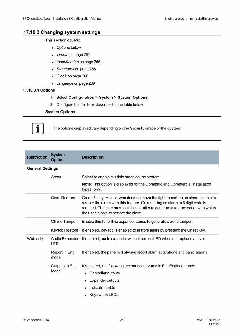
17.10.3 Changing system settingsThis section covers:
l Options below
l Timers on page 261
l Identification on page 266
l Standards on page 266
l Clock on page 268
l Language on page 269
17.10.3.1 Options
1. Select Configuration > System > System Options.
2. Configure the fields as described in the table below.
System Options
The options displayed vary depending on the Security Grade of the system.
Restriction SystemOption Description
General Settings
Areas Select to enablemultiple areas on the system.
Note: This option is displayed for the Domestic and Commercial installationtypes, only.
Code Restore Grade 3 only: A user, who does not have the right to restore an alarm, is able torestore the alarm with this feature. On resetting an alarm, a 6 digit code isrequired. The user must call the installer to generate a restore code, with whichthe user is able to restore the alarm.
Offline Tamper Enable this for offline expander zones to generate a zone tamper.
Keyfob Restore If enabled, key fob is enabled to restore alerts by pressing the Unset key.
Web only Audio ExpanderLED
If enabled, audio expander will not turn on LED whenmicrophone active.
Report in Engmode
If enabled, the panel will always report alarm activations and panic alarms.
Outputs in EngMode
If selected, the following are not deactivated in Full Engineer mode:
l Controller outputs
l Expander outputs
l Indicator LEDs
l Keyswitch LEDs
SPC4xxx/5xxx/6xxx– Installation &ConfigurationManual Engineer programming via the browser
© Vanderbilt 2018 252 A6V10276959-d11.2018
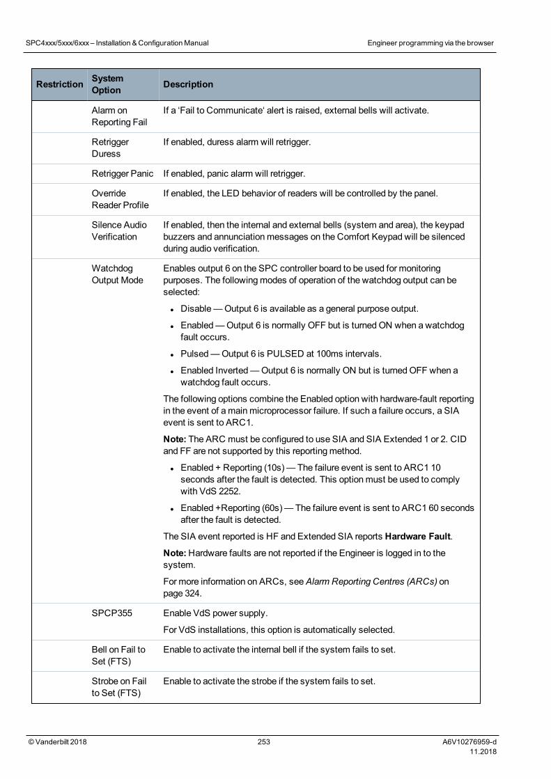
Restriction SystemOption Description
Alarm onReporting Fail
If a ‘Fail to Communicate‘ alert is raised, external bells will activate.
RetriggerDuress
If enabled, duress alarm will retrigger.
Retrigger Panic If enabled, panic alarm will retrigger.
OverrideReader Profile
If enabled, the LED behavior of readers will be controlled by the panel.
Silence AudioVerification
If enabled, then the internal and external bells (system and area), the keypadbuzzers and annunciationmessages on the Comfort Keypad will be silencedduring audio verification.
WatchdogOutput Mode
Enables output 6 on the SPC controller board to be used for monitoringpurposes. The followingmodes of operation of the watchdog output can beselected:
l Disable—Output 6 is available as a general purpose output.
l Enabled—Output 6 is normally OFF but is turnedON when a watchdogfault occurs.
l Pulsed—Output 6 is PULSED at 100ms intervals.
l Enabled Inverted—Output 6 is normally ON but is turnedOFF when awatchdog fault occurs.
The following options combine the Enabled option with hardware-fault reportingin the event of amainmicroprocessor failure. If such a failure occurs, a SIAevent is sent to ARC1.
Note: The ARC must be configured to use SIA and SIA Extended 1 or 2. CIDand FF are not supported by this reportingmethod.
l Enabled + Reporting (10s)— The failure event is sent to ARC1 10seconds after the fault is detected. This optionmust be used to complywith VdS 2252.
l Enabled +Reporting (60s)— The failure event is sent to ARC1 60 secondsafter the fault is detected.
The SIA event reported is HF and Extended SIA reports Hardware Fault.
Note:Hardware faults are not reported if the Engineer is logged in to thesystem.
For more information on ARCs, seeAlarm Reporting Centres (ARCs) onpage 324.
SPCP355 Enable VdS power supply.
For VdS installations, this option is automatically selected.
Bell on Fail toSet (FTS)
Enable to activate the internal bell if the system fails to set.
Strobe on Failto Set (FTS)
Enable to activate the strobe if the system fails to set.
SPC4xxx/5xxx/6xxx– Installation &ConfigurationManual Engineer programming via the browser
© Vanderbilt 2018 253 A6V10276959-d11.2018
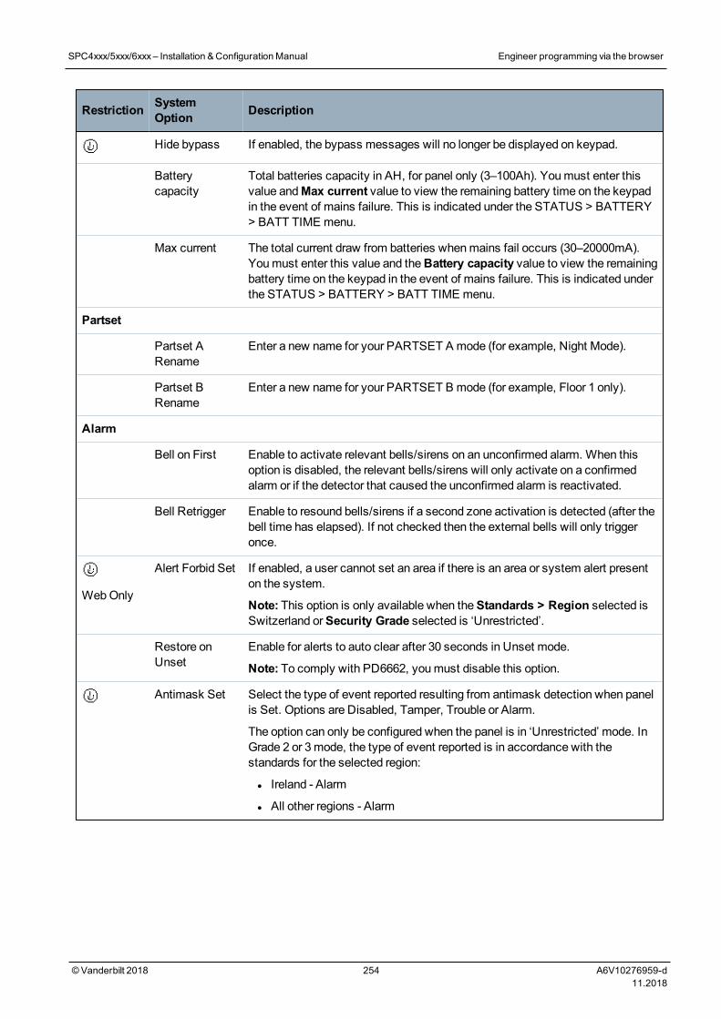
Restriction SystemOption Description
Hide bypass If enabled, the bypass messages will no longer be displayed on keypad.
Batterycapacity
Total batteries capacity in AH, for panel only (3–100Ah). Youmust enter thisvalue andMax current value to view the remaining battery time on the keypadin the event of mains failure. This is indicated under the STATUS > BATTERY> BATT TIME menu.
Max current The total current draw from batteries whenmains fail occurs (30–20000mA).Youmust enter this value and theBattery capacity value to view the remainingbattery time on the keypad in the event of mains failure. This is indicated underthe STATUS > BATTERY > BATT TIME menu.
Partset
Partset ARename
Enter a new name for your PARTSET A mode (for example, Night Mode).
Partset BRename
Enter a new name for your PARTSET B mode (for example, Floor 1 only).
Alarm
Bell on First Enable to activate relevant bells/sirens on an unconfirmed alarm. When thisoption is disabled, the relevant bells/sirens will only activate on a confirmedalarm or if the detector that caused the unconfirmed alarm is reactivated.
Bell Retrigger Enable to resound bells/sirens if a second zone activation is detected (after thebell time has elapsed). If not checked then the external bells will only triggeronce.
WebOnly
Alert Forbid Set If enabled, a user cannot set an area if there is an area or system alert presenton the system.
Note: This option is only available when theStandards > Region selected isSwitzerland orSecurity Grade selected is ‘Unrestricted’.
Restore onUnset
Enable for alerts to auto clear after 30 seconds in Unset mode.
Note: To comply with PD6662, youmust disable this option.
Antimask Set Select the type of event reported resulting from antimask detection when panelis Set. Options are Disabled, Tamper, Trouble or Alarm.
The option can only be configured when the panel is in ‘Unrestricted’ mode. InGrade 2 or 3mode, the type of event reported is in accordance with thestandards for the selected region:
l Ireland - Alarm
l All other regions - Alarm
SPC4xxx/5xxx/6xxx– Installation &ConfigurationManual Engineer programming via the browser
© Vanderbilt 2018 254 A6V10276959-d11.2018
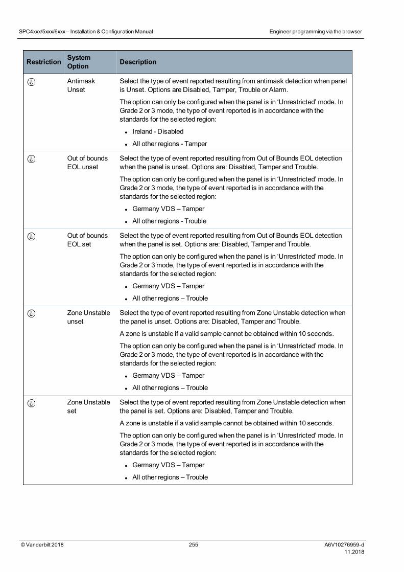
Restriction SystemOption Description
AntimaskUnset
Select the type of event reported resulting from antimask detection when panelis Unset. Options are Disabled, Tamper, Trouble or Alarm.
The option can only be configured when the panel is in ‘Unrestricted’ mode. InGrade 2 or 3mode, the type of event reported is in accordance with thestandards for the selected region:
l Ireland - Disabled
l All other regions - Tamper
Out of boundsEOL unset
Select the type of event reported resulting from Out of Bounds EOL detectionwhen the panel is unset. Options are: Disabled, Tamper and Trouble.
The option can only be configured when the panel is in ‘Unrestricted’ mode. InGrade 2 or 3mode, the type of event reported is in accordance with thestandards for the selected region:
l Germany VDS – Tamper
l All other regions - Trouble
Out of boundsEOL set
Select the type of event reported resulting from Out of Bounds EOL detectionwhen the panel is set. Options are: Disabled, Tamper and Trouble.
The option can only be configured when the panel is in ‘Unrestricted’ mode. InGrade 2 or 3mode, the type of event reported is in accordance with thestandards for the selected region:
l Germany VDS – Tamper
l All other regions – Trouble
Zone Unstableunset
Select the type of event reported resulting from Zone Unstable detection whenthe panel is unset. Options are: Disabled, Tamper and Trouble.
A zone is unstable if a valid sample cannot be obtained within 10 seconds.
The option can only be configured when the panel is in ‘Unrestricted’ mode. InGrade 2 or 3mode, the type of event reported is in accordance with thestandards for the selected region:
l Germany VDS – Tamper
l All other regions – Trouble
Zone Unstableset
Select the type of event reported resulting from Zone Unstable detection whenthe panel is set. Options are: Disabled, Tamper and Trouble.
A zone is unstable if a valid sample cannot be obtained within 10 seconds.
The option can only be configured when the panel is in ‘Unrestricted’ mode. InGrade 2 or 3mode, the type of event reported is in accordance with thestandards for the selected region:
l Germany VDS – Tamper
l All other regions – Trouble
SPC4xxx/5xxx/6xxx– Installation &ConfigurationManual Engineer programming via the browser
© Vanderbilt 2018 255 A6V10276959-d11.2018
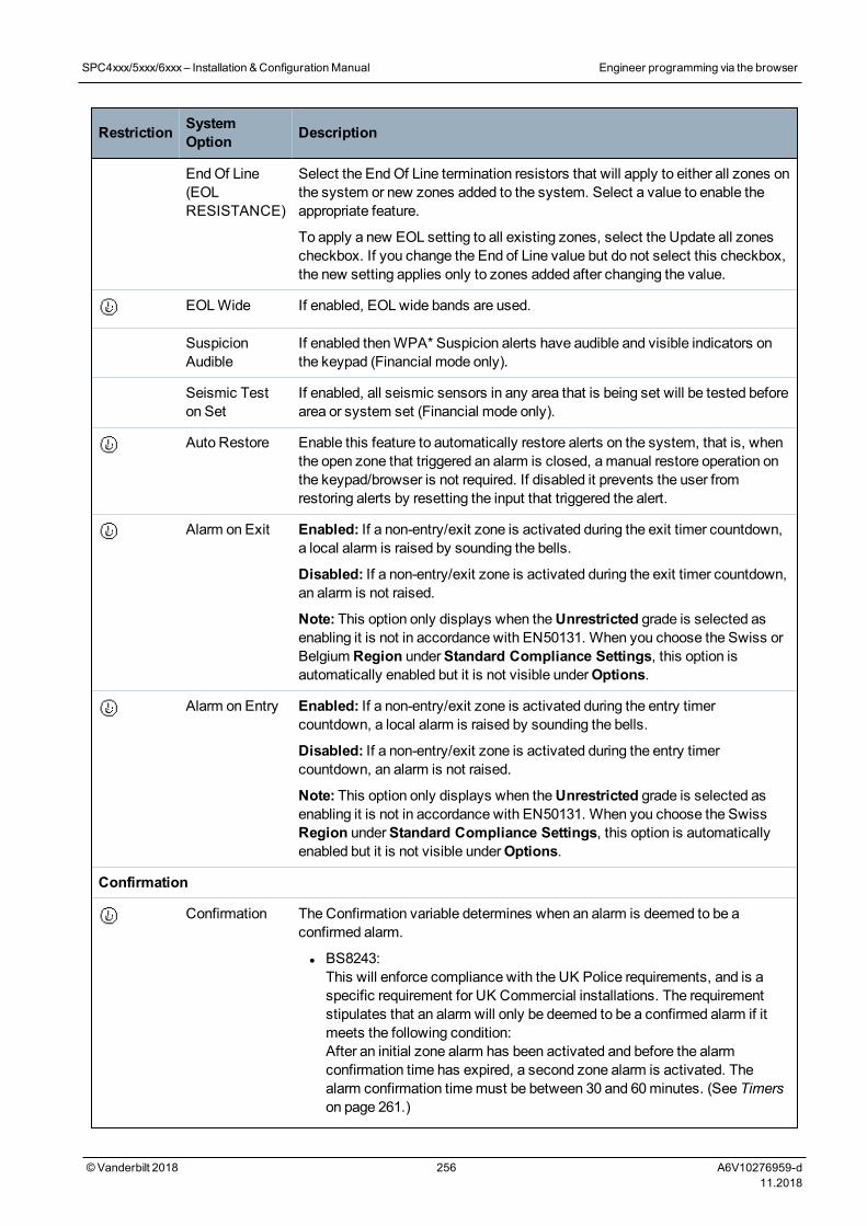
Restriction SystemOption Description
EndOf Line(EOLRESISTANCE)
Select the EndOf Line termination resistors that will apply to either all zones onthe system or new zones added to the system. Select a value to enable theappropriate feature.
To apply a new EOL setting to all existing zones, select the Update all zonescheckbox. If you change the End of Line value but do not select this checkbox,the new setting applies only to zones added after changing the value.
EOLWide If enabled, EOLwide bands are used.
SuspicionAudible
If enabled thenWPA* Suspicion alerts have audible and visible indicators onthe keypad (Financial mode only).
Seismic Teston Set
If enabled, all seismic sensors in any area that is being set will be tested beforearea or system set (Financial mode only).
Auto Restore Enable this feature to automatically restore alerts on the system, that is, whenthe open zone that triggered an alarm is closed, amanual restore operation onthe keypad/browser is not required. If disabled it prevents the user fromrestoring alerts by resetting the input that triggered the alert.
Alarm on Exit Enabled: If a non-entry/exit zone is activated during the exit timer countdown,a local alarm is raised by sounding the bells.
Disabled: If a non-entry/exit zone is activated during the exit timer countdown,an alarm is not raised.
Note: This option only displays when theUnrestricted grade is selected asenabling it is not in accordance with EN50131. When you choose the Swiss orBelgium Region underStandard Compliance Settings, this option isautomatically enabled but it is not visible underOptions.
Alarm on Entry Enabled: If a non-entry/exit zone is activated during the entry timercountdown, a local alarm is raised by sounding the bells.
Disabled: If a non-entry/exit zone is activated during the entry timercountdown, an alarm is not raised.
Note: This option only displays when theUnrestricted grade is selected asenabling it is not in accordance with EN50131. When you choose the SwissRegion underStandard Compliance Settings, this option is automaticallyenabled but it is not visible underOptions.
Confirmation
Confirmation The Confirmation variable determines when an alarm is deemed to be aconfirmed alarm.
l BS8243:This will enforce compliance with the UK Police requirements, and is aspecific requirement for UK Commercial installations. The requirementstipulates that an alarm will only be deemed to be a confirmed alarm if itmeets the following condition:After an initial zone alarm has been activated and before the alarmconfirmation time has expired, a second zone alarm is activated. Thealarm confirmation timemust be between 30 and 60minutes. (See Timerson page 261.)
SPC4xxx/5xxx/6xxx– Installation &ConfigurationManual Engineer programming via the browser
© Vanderbilt 2018 256 A6V10276959-d11.2018
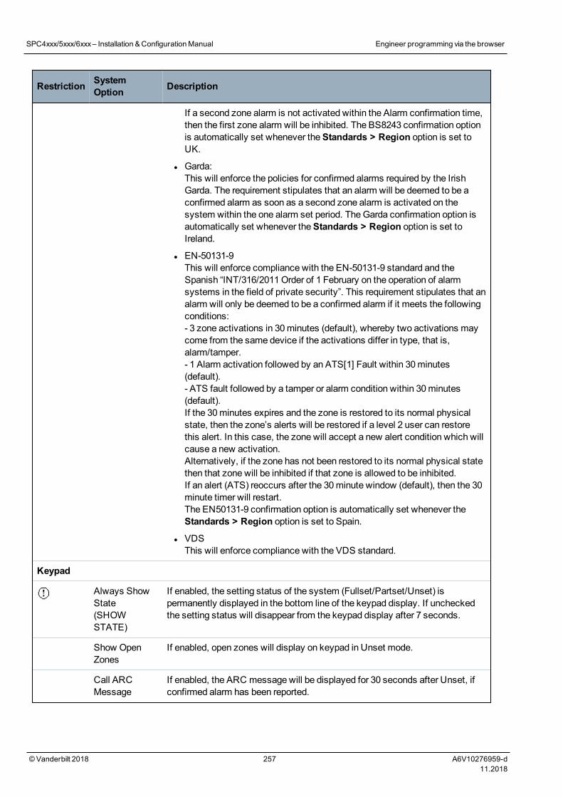
Restriction SystemOption Description
If a second zone alarm is not activated within the Alarm confirmation time,then the first zone alarm will be inhibited. The BS8243 confirmation optionis automatically set whenever theStandards > Region option is set toUK.
l Garda:This will enforce the policies for confirmed alarms required by the IrishGarda. The requirement stipulates that an alarm will be deemed to be aconfirmed alarm as soon as a second zone alarm is activated on thesystem within the one alarm set period. TheGarda confirmation option isautomatically set whenever theStandards > Region option is set toIreland.
l EN-50131-9This will enforce compliance with the EN-50131-9 standard and theSpanish “INT/316/2011Order of 1 February on the operation of alarmsystems in the field of private security”. This requirement stipulates that analarm will only be deemed to be a confirmed alarm if it meets the followingconditions:- 3 zone activations in 30minutes (default), whereby two activations maycome from the same device if the activations differ in type, that is,alarm/tamper.- 1 Alarm activation followed by an ATS[1] Fault within 30minutes(default).- ATS fault followed by a tamper or alarm condition within 30minutes(default).If the 30minutes expires and the zone is restored to its normal physicalstate, then the zone’s alerts will be restored if a level 2 user can restorethis alert. In this case, the zone will accept a new alert condition which willcause a new activation.Alternatively, if the zone has not been restored to its normal physical statethen that zone will be inhibited if that zone is allowed to be inhibited.If an alert (ATS) reoccurs after the 30minute window (default), then the 30minute timer will restart.The EN50131-9 confirmation option is automatically set whenever theStandards > Region option is set to Spain.
l VDSThis will enforce compliance with the VDS standard.
Keypad
Always ShowState(SHOWSTATE)
If enabled, the setting status of the system (Fullset/Partset/Unset) ispermanently displayed in the bottom line of the keypad display. If uncheckedthe setting status will disappear from the keypad display after 7 seconds.
Show OpenZones
If enabled, open zones will display on keypad in Unset mode.
Call ARCMessage
If enabled, the ARC message will be displayed for 30 seconds after Unset, ifconfirmed alarm has been reported.
SPC4xxx/5xxx/6xxx– Installation &ConfigurationManual Engineer programming via the browser
© Vanderbilt 2018 257 A6V10276959-d11.2018
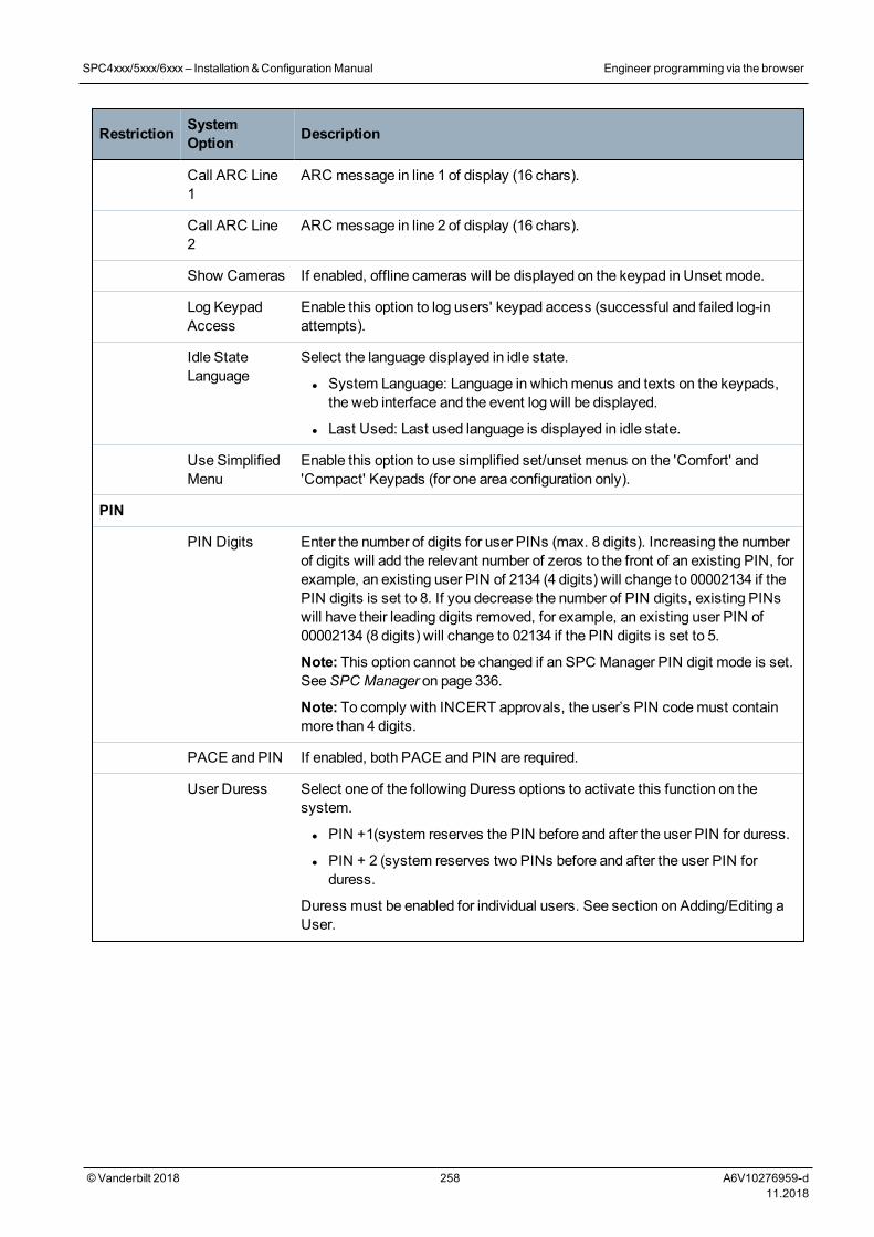
Restriction SystemOption Description
Call ARC Line1
ARC message in line 1 of display (16 chars).
Call ARC Line2
ARC message in line 2 of display (16 chars).
Show Cameras If enabled, offline cameras will be displayed on the keypad in Unset mode.
Log KeypadAccess
Enable this option to log users' keypad access (successful and failed log-inattempts).
Idle StateLanguage
Select the language displayed in idle state.
l System Language: Language in whichmenus and texts on the keypads,the web interface and the event log will be displayed.
l Last Used: Last used language is displayed in idle state.
Use SimplifiedMenu
Enable this option to use simplified set/unset menus on the 'Comfort' and'Compact' Keypads (for one area configuration only).
PIN
PIN Digits Enter the number of digits for user PINs (max. 8 digits). Increasing the numberof digits will add the relevant number of zeros to the front of an existing PIN, forexample, an existing user PIN of 2134 (4 digits) will change to 00002134 if thePIN digits is set to 8. If you decrease the number of PIN digits, existing PINswill have their leading digits removed, for example, an existing user PIN of00002134 (8 digits) will change to 02134 if the PIN digits is set to 5.
Note: This option cannot be changed if an SPC Manager PIN digit mode is set.SeeSPC Manager on page 336.
Note: To comply with INCERT approvals, the user’s PIN codemust containmore than 4 digits.
PACE and PIN If enabled, both PACE and PIN are required.
User Duress Select one of the following Duress options to activate this function on thesystem.
l PIN +1(system reserves the PIN before and after the user PIN for duress.
l PIN + 2 (system reserves two PINs before and after the user PIN forduress.
Duress must be enabled for individual users. See section on Adding/Editing aUser.
SPC4xxx/5xxx/6xxx– Installation &ConfigurationManual Engineer programming via the browser
© Vanderbilt 2018 258 A6V10276959-d11.2018
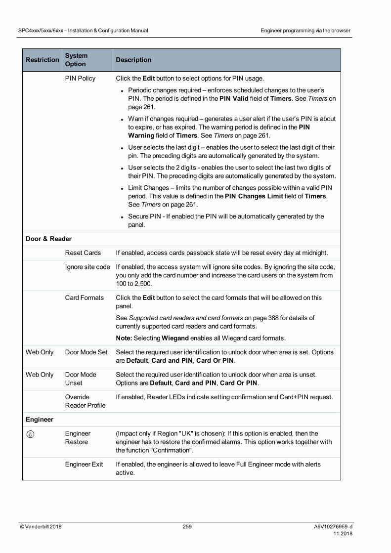
Restriction SystemOption Description
PIN Policy Click theEdit button to select options for PIN usage.
l Periodic changes required – enforces scheduled changes to the user’sPIN. The period is defined in thePIN Valid field of Timers. See Timers onpage 261.
l Warn if changes required – generates a user alert if the user’s PIN is aboutto expire, or has expired. The warning period is defined in thePINWarning field of Timers. See Timers on page 261.
l User selects the last digit – enables the user to select the last digit of theirpin. The preceding digits are automatically generated by the system.
l User selects the 2 digits - enables the user to select the last two digits oftheir PIN. The preceding digits are automatically generated by the system.
l Limit Changes – limits the number of changes possible within a valid PINperiod. This value is defined in thePIN Changes Limit field of Timers.See Timers on page 261.
l Secure PIN - If enabled the PIN will be automatically generated by thepanel.
Door & Reader
Reset Cards If enabled, access cards passback state will be reset every day at midnight.
Ignore site code If enabled, the access system will ignore site codes. By ignoring the site code,you only add the card number and increase the card users on the system from100 to 2,500.
Card Formats Click theEdit button to select the card formats that will be allowed on thispanel.
SeeSupported card readers and card formats on page 388 for details ofcurrently supported card readers and card formats.
Note:SelectingWiegand enables all Wiegand card formats.
WebOnly Door Mode Set Select the required user identification to unlock door when area is set. OptionsareDefault, Card and PIN, Card Or PIN.
WebOnly Door ModeUnset
Select the required user identification to unlock door when area is unset.Options areDefault, Card and PIN, Card Or PIN.
OverrideReader Profile
If enabled, Reader LEDs indicate setting confirmation and Card+PIN request.
Engineer
EngineerRestore
(Impact only if Region "UK" is chosen): If this option is enabled, then theengineer has to restore the confirmed alarms. This option works together withthe function "Confirmation".
Engineer Exit If enabled, the engineer is allowed to leave Full Engineer mode with alertsactive.
SPC4xxx/5xxx/6xxx– Installation &ConfigurationManual Engineer programming via the browser
© Vanderbilt 2018 259 A6V10276959-d11.2018
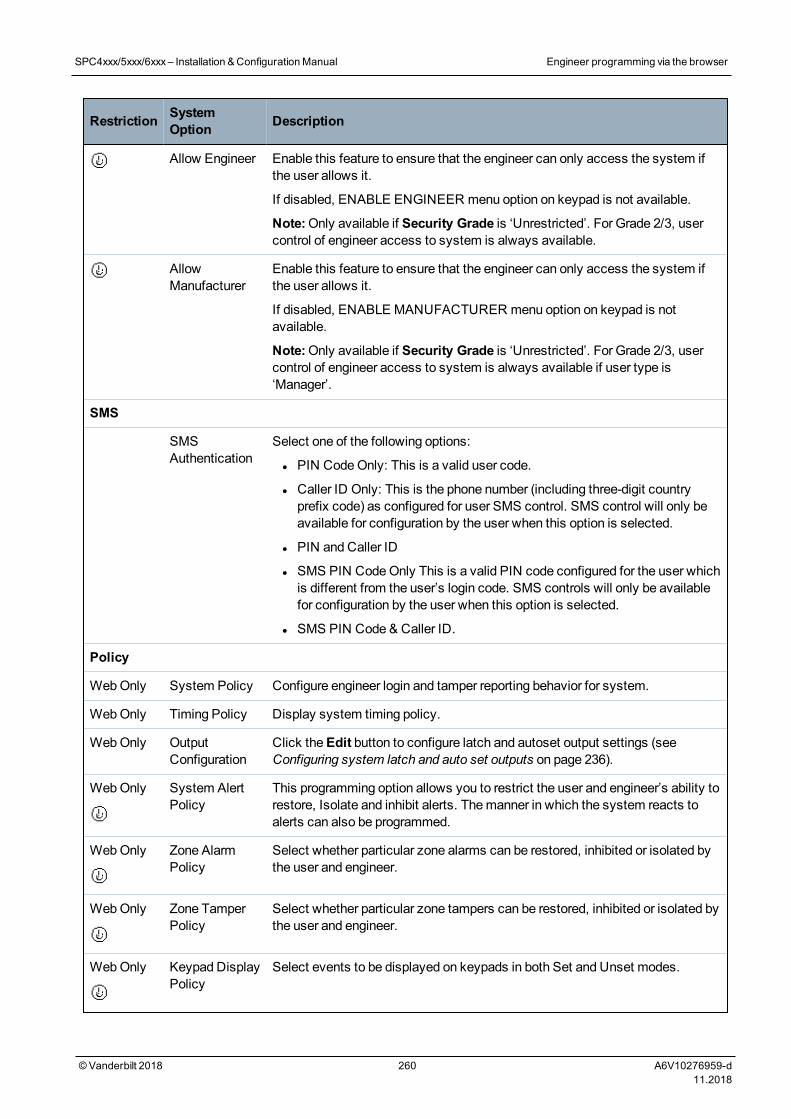
Restriction SystemOption Description
Allow Engineer Enable this feature to ensure that the engineer can only access the system ifthe user allows it.
If disabled, ENABLE ENGINEER menu option on keypad is not available.
Note:Only available if Security Grade is ‘Unrestricted’. For Grade 2/3, usercontrol of engineer access to system is always available.
AllowManufacturer
Enable this feature to ensure that the engineer can only access the system ifthe user allows it.
If disabled, ENABLE MANUFACTURER menu option on keypad is notavailable.
Note:Only available if Security Grade is ‘Unrestricted’. For Grade 2/3, usercontrol of engineer access to system is always available if user type is‘Manager’.
SMS
SMSAuthentication
Select one of the following options:
l PIN CodeOnly: This is a valid user code.
l Caller ID Only: This is the phone number (including three-digit countryprefix code) as configured for user SMS control. SMS control will only beavailable for configuration by the user when this option is selected.
l PIN and Caller ID
l SMS PIN CodeOnly This is a valid PIN code configured for the user whichis different from the user’s login code. SMS controls will only be availablefor configuration by the user when this option is selected.
l SMS PIN Code & Caller ID.
Policy
WebOnly System Policy Configure engineer login and tamper reporting behavior for system.
WebOnly Timing Policy Display system timing policy.
WebOnly OutputConfiguration
Click theEdit button to configure latch and autoset output settings (seeConfiguring system latch and auto set outputs on page 236).
WebOnly System AlertPolicy
This programming option allows you to restrict the user and engineer’s ability torestore, Isolate and inhibit alerts. Themanner in which the system reacts toalerts can also be programmed.
WebOnly Zone AlarmPolicy
Select whether particular zone alarms can be restored, inhibited or isolated bythe user and engineer.
WebOnly Zone TamperPolicy
Select whether particular zone tampers can be restored, inhibited or isolated bythe user and engineer.
WebOnly Keypad DisplayPolicy
Select events to be displayed on keypads in both Set and Unset modes.
SPC4xxx/5xxx/6xxx– Installation &ConfigurationManual Engineer programming via the browser
© Vanderbilt 2018 260 A6V10276959-d11.2018
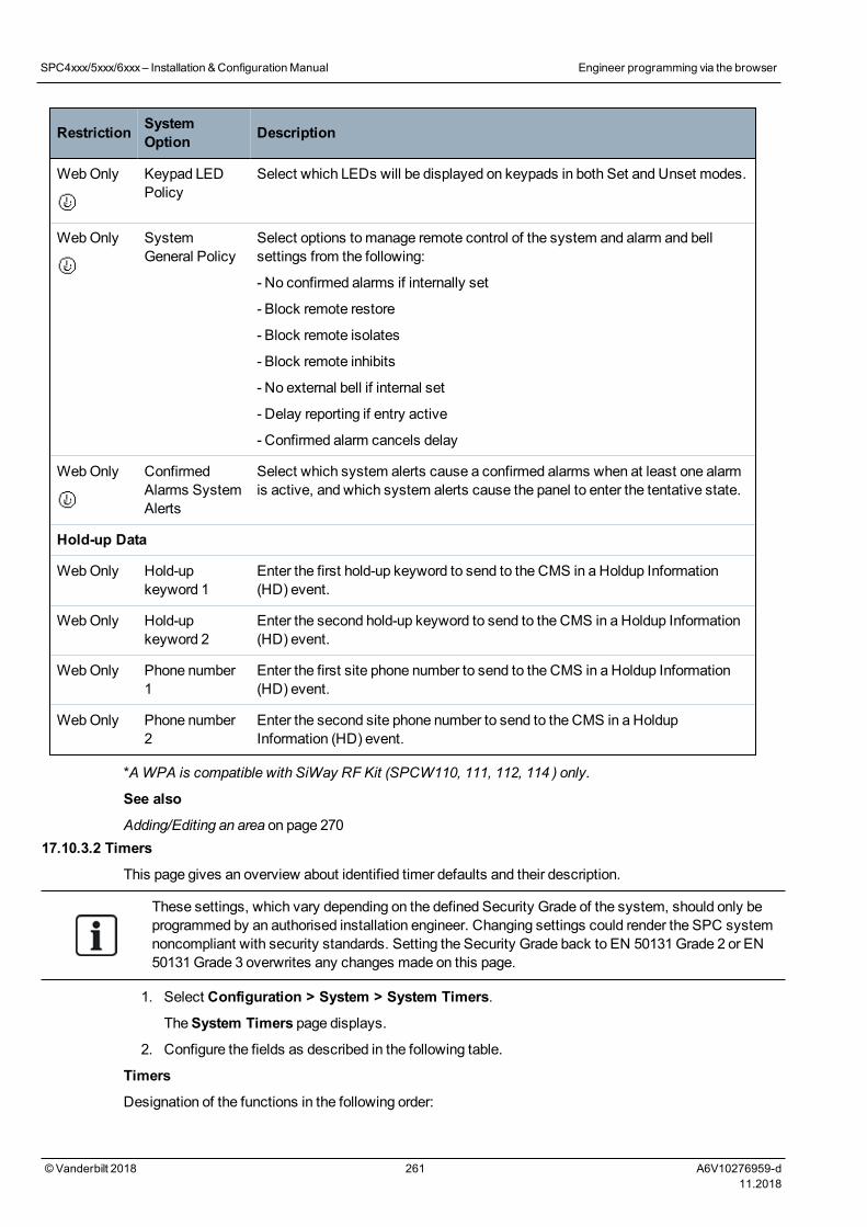
Restriction SystemOption Description
WebOnly Keypad LEDPolicy
Select which LEDs will be displayed on keypads in both Set and Unset modes.
WebOnly SystemGeneral Policy
Select options tomanage remote control of the system and alarm and bellsettings from the following:
- No confirmed alarms if internally set
- Block remote restore
- Block remote isolates
- Block remote inhibits
- No external bell if internal set
- Delay reporting if entry active
- Confirmed alarm cancels delay
WebOnly ConfirmedAlarms SystemAlerts
Select which system alerts cause a confirmed alarms when at least one alarmis active, and which system alerts cause the panel to enter the tentative state.
Hold-up Data
WebOnly Hold-upkeyword 1
Enter the first hold-up keyword to send to the CMS in a Holdup Information(HD) event.
WebOnly Hold-upkeyword 2
Enter the second hold-up keyword to send to the CMS in a Holdup Information(HD) event.
WebOnly Phone number1
Enter the first site phone number to send to the CMS in a Holdup Information(HD) event.
WebOnly Phone number2
Enter the second site phone number to send to the CMS in a HoldupInformation (HD) event.
*AWPA is compatible with SiWay RF Kit (SPCW110, 111, 112, 114 ) only.
See also
Adding/Editing an area on page 27017.10.3.2 Timers
This page gives an overview about identified timer defaults and their description.
These settings, which vary depending on the defined Security Grade of the system, should only beprogrammed by an authorised installation engineer. Changing settings could render the SPC systemnoncompliant with security standards. Setting the Security Grade back to EN 50131Grade 2 or EN50131Grade 3 overwrites any changes made on this page.
1. Select Configuration > System > System Timers.
TheSystem Timers page displays.
2. Configure the fields as described in the following table.
Timers
Designation of the functions in the following order:
SPC4xxx/5xxx/6xxx– Installation &ConfigurationManual Engineer programming via the browser
© Vanderbilt 2018 261 A6V10276959-d11.2018
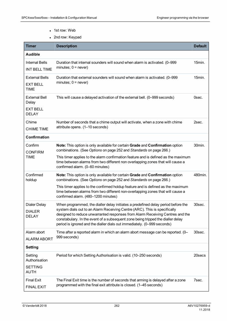
l 1st row: Web
l 2nd row: Keypad
Timer Description Default
Audible
Internal Bells
INT BELL TIME
Duration that internal sounders will sound when alarm is activated. (0–999minutes; 0 = never)
15min.
External Bells
EXT BELLTIME
Duration that external sounders will sound when alarm is activated. (0–999minutes; 0 = never)
15min.
External BellDelay
EXT BELLDELAY
This will cause a delayed activation of the external bell. (0–999 seconds) 0sec.
Chime
CHIME TIME
Number of seconds that a chime output will activate, when a zone with chimeattribute opens. (1–10 seconds)
2sec.
Confirmation
Confirm
CONFIRMTIME
Note: This option is only available for certainGrade andConfirmation optioncombinations. (SeeOptions on page 252 andStandards on page 266.)
This timer applies to the alarm confirmation feature and is defined as themaximumtime between alarms from two different non overlapping zones that will cause aconfirmed alarm. (0–60minutes)
30min.
Confirmedholdup
Note: This option is only available for certainGrade andConfirmation optioncombinations. (SeeOptions on page 252 andStandards on page 266.)
This timer applies to the confirmed holdup feature and is defined as themaximumtime between alarms from two different non-overlapping zones that will cause aconfirmed alarm. (480–1200minutes)
480min.
Dialer Delay
DIALERDELAY
When programmed, the dialler delay initiates a predefined delay period before thesystem dials out to an Alarm Receiving Centre (ARC). This is specificallydesigned to reduce unwarranted responses from Alarm Receiving Centres and theconstabulary. In the event of a subsequent zone being tripped the dialler delayperiod is ignored and the dialler dials out immediately. (0–999 seconds)
30sec.
Alarm abort
ALARM ABORT
Time after a reported alarm in which an alarm abort message can be reported. (0–999 seconds)
30sec.
Setting
SettingAuthorisation
SETTINGAUTH
Period for which Setting Authorisation is valid. (10–250 seconds) 20secs
Final Exit
FINAL EXIT
The Final Exit time is the number of seconds that arming is delayed after a zoneprogrammedwith the final exit attribute is closed. (1–45 seconds)
7sec.
SPC4xxx/5xxx/6xxx– Installation &ConfigurationManual Engineer programming via the browser
© Vanderbilt 2018 262 A6V10276959-d11.2018
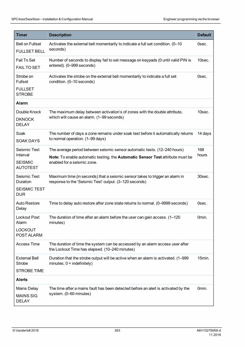
Timer Description Default
Bell on Fullset
FULLSET BELL
Activates the external bell momentarily to indicate a full set condition. (0–10seconds)
0sec.
Fail To Set
FAIL TOSET
Number of seconds to display fail to set message on keypads (0 until valid PIN isentered). (0–999 seconds)
10sec.
Strobe onFullset
FULLSETSTROBE
Activates the strobe on the external bell momentarily to indicate a full setcondition. (0–10 seconds)
0sec.
Alarm
Double Knock
DKNOCKDELAY
Themaximum delay between activation’s of zones with the double attribute,which will cause an alarm. (1–99 seconds)
10sec.
Soak
SOAK DAYS
The number of days a zone remains under soak test before it automatically returnsto normal operation. (1–99 days)
14 days
Seismic TestInterval
SEISMICAUTOTEST
The average period between seismic sensor automatic tests. (12–240 hours)
Note: To enable automatic testing, theAutomatic Sensor Test attributemust beenabled for a seismic zone.
168hours
Seismic TestDuration
SEISMIC TESTDUR
Maximum time (in seconds) that a seismic sensor takes to trigger an alarm inresponse to the 'Seismic Test' output. (3–120 seconds)
30sec.
Auto RestoreDelay
Time to delay auto restore after zone state returns to normal. (0–9999 seconds) 0sec.
Lockout PostAlarm
LOCKOUTPOST ALARM
The duration of time after an alarm before the user can gain access. (1–120minutes)
0min.
Access Time The duration of time the system can be accessed by an alarm access user afterthe Lockout Time has elapsed. (10–240minutes)
External BellStrobe
STROBE TIME
Duration that the strobe output will be active when an alarm is activated. (1–999minutes; 0 = indefinitely)
15min.
Alerts
Mains Delay
MAINS SIGDELAY
The time after amains fault has been detected before an alert is activated by thesystem. (0–60minutes)
0min.
SPC4xxx/5xxx/6xxx– Installation &ConfigurationManual Engineer programming via the browser
© Vanderbilt 2018 263 A6V10276959-d11.2018
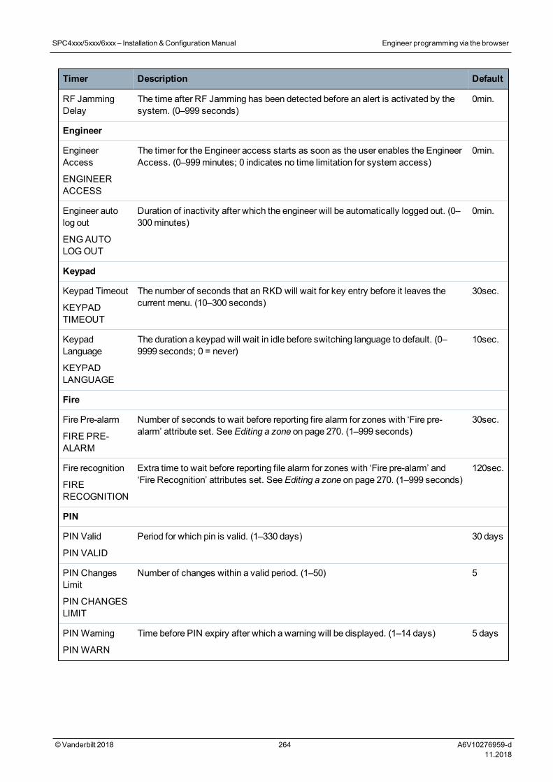
Timer Description Default
RF JammingDelay
The time after RF Jamming has been detected before an alert is activated by thesystem. (0–999 seconds)
0min.
Engineer
EngineerAccess
ENGINEERACCESS
The timer for the Engineer access starts as soon as the user enables the EngineerAccess. (0–999minutes; 0 indicates no time limitation for system access)
0min.
Engineer autolog out
ENGAUTOLOGOUT
Duration of inactivity after which the engineer will be automatically logged out. (0–300minutes)
0min.
Keypad
Keypad Timeout
KEYPADTIMEOUT
The number of seconds that an RKD will wait for key entry before it leaves thecurrent menu. (10–300 seconds)
30sec.
KeypadLanguage
KEYPADLANGUAGE
The duration a keypad will wait in idle before switching language to default. (0–9999 seconds; 0 = never)
10sec.
Fire
Fire Pre-alarm
FIRE PRE-ALARM
Number of seconds to wait before reporting fire alarm for zones with ‘Fire pre-alarm’ attribute set. SeeEditing a zone on page 270. (1–999 seconds)
30sec.
Fire recognition
FIRERECOGNITION
Extra time to wait before reporting file alarm for zones with ‘Fire pre-alarm’ and‘Fire Recognition’ attributes set. SeeEditing a zone on page 270. (1–999 seconds)
120sec.
PIN
PIN Valid
PIN VALID
Period for which pin is valid. (1–330 days) 30 days
PIN ChangesLimit
PIN CHANGESLIMIT
Number of changes within a valid period. (1–50) 5
PIN Warning
PIN WARN
Time before PIN expiry after which a warning will be displayed. (1–14 days) 5 days
SPC4xxx/5xxx/6xxx– Installation &ConfigurationManual Engineer programming via the browser
© Vanderbilt 2018 264 A6V10276959-d11.2018
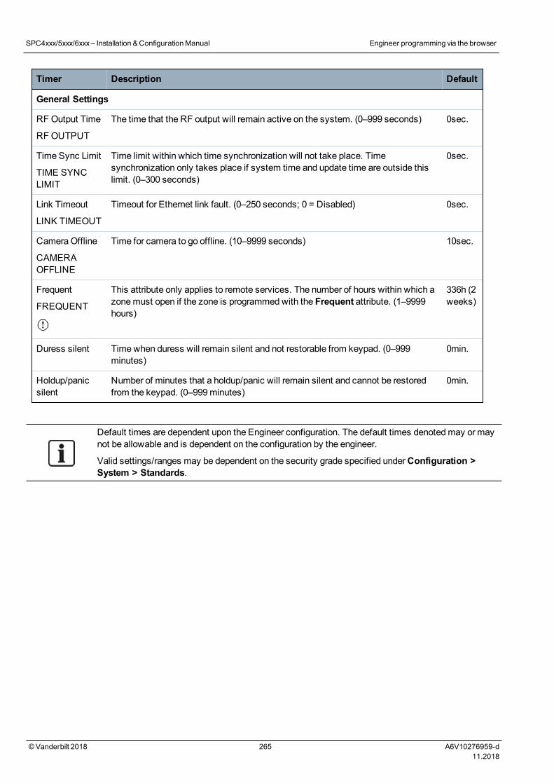
Timer Description Default
General Settings
RFOutput Time
RF OUTPUT
The time that the RF output will remain active on the system. (0–999 seconds) 0sec.
Time Sync Limit
TIME SYNCLIMIT
Time limit within which time synchronization will not take place. Timesynchronization only takes place if system time and update time are outside thislimit. (0–300 seconds)
0sec.
Link Timeout
LINK TIMEOUT
Timeout for Ethernet link fault. (0–250 seconds; 0 = Disabled) 0sec.
Camera Offline
CAMERAOFFLINE
Time for camera to go offline. (10–9999 seconds) 10sec.
Frequent
FREQUENT
This attribute only applies to remote services. The number of hours within which azonemust open if the zone is programmedwith the Frequent attribute. (1–9999hours)
336h (2weeks)
Duress silent Timewhen duress will remain silent and not restorable from keypad. (0–999minutes)
0min.
Holdup/panicsilent
Number of minutes that a holdup/panic will remain silent and cannot be restoredfrom the keypad. (0–999minutes)
0min.
Default times are dependent upon the Engineer configuration. The default times denotedmay or maynot be allowable and is dependent on the configuration by the engineer.
Valid settings/ranges may be dependent on the security grade specified underConfiguration >System > Standards.
SPC4xxx/5xxx/6xxx– Installation &ConfigurationManual Engineer programming via the browser
© Vanderbilt 2018 265 A6V10276959-d11.2018
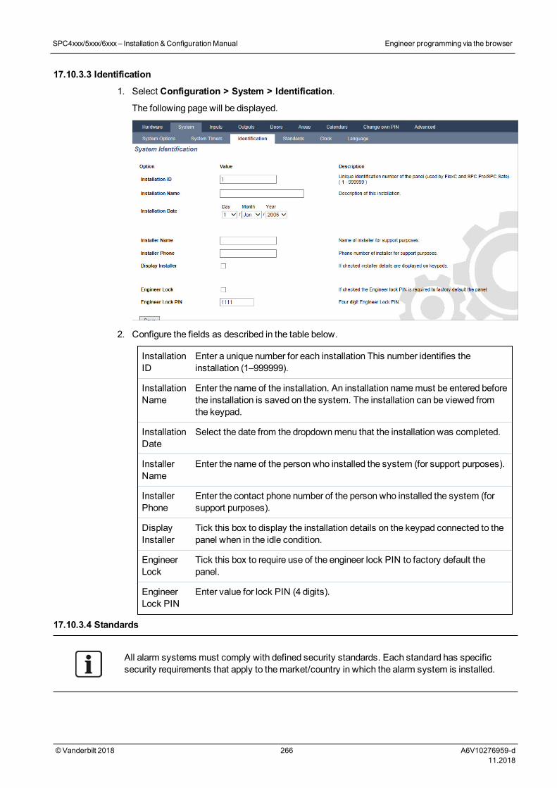
17.10.3.3 Identification
1. Select Configuration > System > Identification.
The following page will be displayed.
2. Configure the fields as described in the table below.
InstallationID
Enter a unique number for each installation This number identifies theinstallation (1–999999).
InstallationName
Enter the name of the installation. An installation namemust be entered beforethe installation is saved on the system. The installation can be viewed fromthe keypad.
InstallationDate
Select the date from the dropdownmenu that the installation was completed.
InstallerName
Enter the name of the person who installed the system (for support purposes).
InstallerPhone
Enter the contact phone number of the person who installed the system (forsupport purposes).
DisplayInstaller
Tick this box to display the installation details on the keypad connected to thepanel when in the idle condition.
EngineerLock
Tick this box to require use of the engineer lock PIN to factory default thepanel.
EngineerLock PIN
Enter value for lock PIN (4 digits).
17.10.3.4 Standards
All alarm systems must comply with defined security standards. Each standard has specificsecurity requirements that apply to themarket/country in which the alarm system is installed.
SPC4xxx/5xxx/6xxx– Installation &ConfigurationManual Engineer programming via the browser
© Vanderbilt 2018 266 A6V10276959-d11.2018
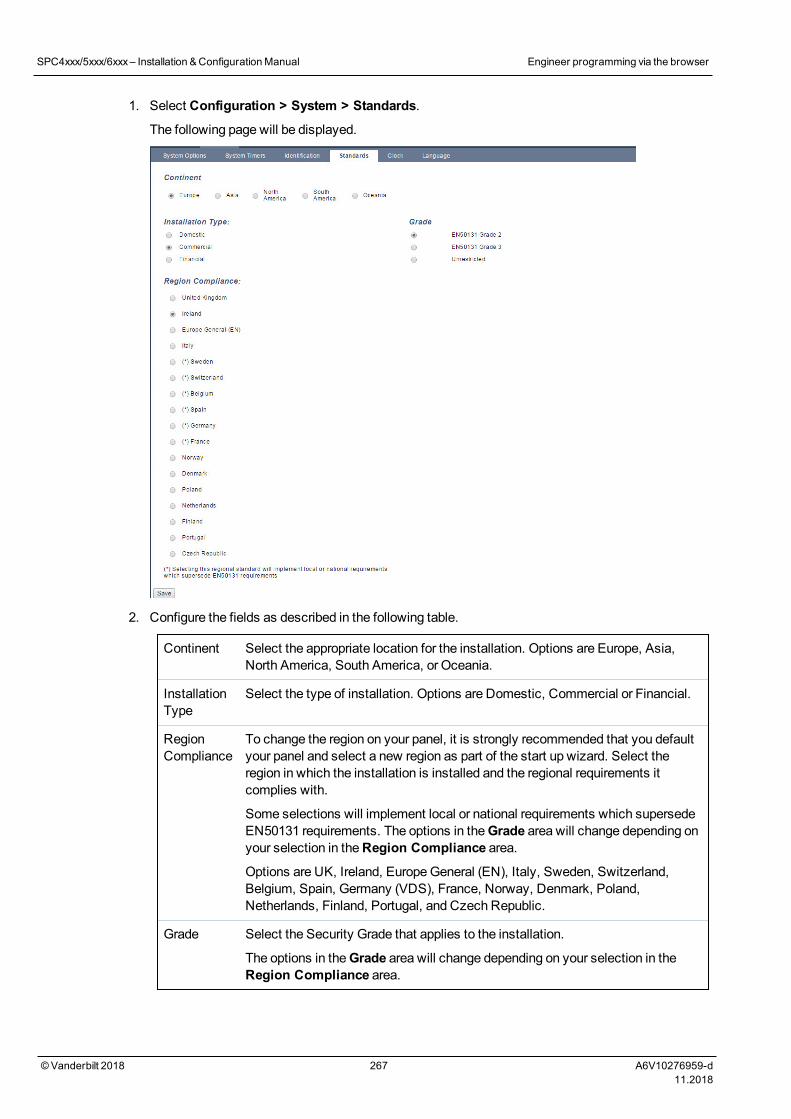
1. Select Configuration > System > Standards.
The following page will be displayed.
2. Configure the fields as described in the following table.
Continent Select the appropriate location for the installation. Options are Europe, Asia,North America, South America, or Oceania.
InstallationType
Select the type of installation. Options are Domestic, Commercial or Financial.
RegionCompliance
To change the region on your panel, it is strongly recommended that you defaultyour panel and select a new region as part of the start up wizard. Select theregion in which the installation is installed and the regional requirements itcomplies with.
Some selections will implement local or national requirements which supersedeEN50131 requirements. The options in theGrade area will change depending onyour selection in theRegion Compliance area.
Options are UK, Ireland, EuropeGeneral (EN), Italy, Sweden, Switzerland,Belgium, Spain, Germany (VDS), France, Norway, Denmark, Poland,Netherlands, Finland, Portugal, and Czech Republic.
Grade Select the Security Grade that applies to the installation.
The options in theGrade area will change depending on your selection in theRegion Compliance area.
SPC4xxx/5xxx/6xxx– Installation &ConfigurationManual Engineer programming via the browser
© Vanderbilt 2018 267 A6V10276959-d11.2018
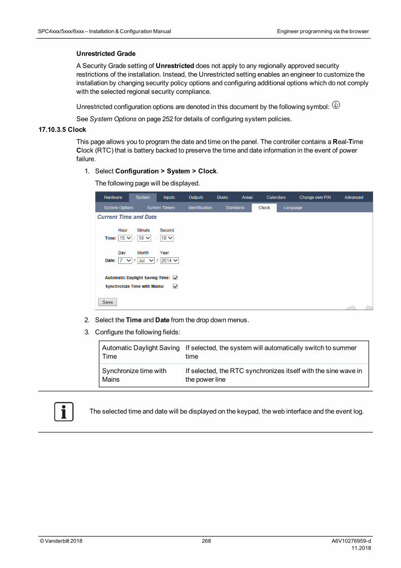
Unrestricted Grade
A Security Grade setting of Unrestricted does not apply to any regionally approved securityrestrictions of the installation. Instead, the Unrestricted setting enables an engineer to customize theinstallation by changing security policy options and configuring additional options which do not complywith the selected regional security compliance.
Unrestricted configuration options are denoted in this document by the following symbol:
SeeSystem Options on page 252 for details of configuring system policies.17.10.3.5 Clock
This page allows you to program the date and time on the panel. The controller contains aReal-TimeClock (RTC) that is battery backed to preserve the time and date information in the event of powerfailure.
1. Select Configuration > System > Clock.
The following page will be displayed.
2. Select the Time andDate from the drop downmenus.
3. Configure the following fields:
Automatic Daylight SavingTime
If selected, the system will automatically switch to summertime
Synchronize time withMains
If selected, the RTC synchronizes itself with the sine wave inthe power line
The selected time and date will be displayed on the keypad, the web interface and the event log.
SPC4xxx/5xxx/6xxx– Installation &ConfigurationManual Engineer programming via the browser
© Vanderbilt 2018 268 A6V10276959-d11.2018
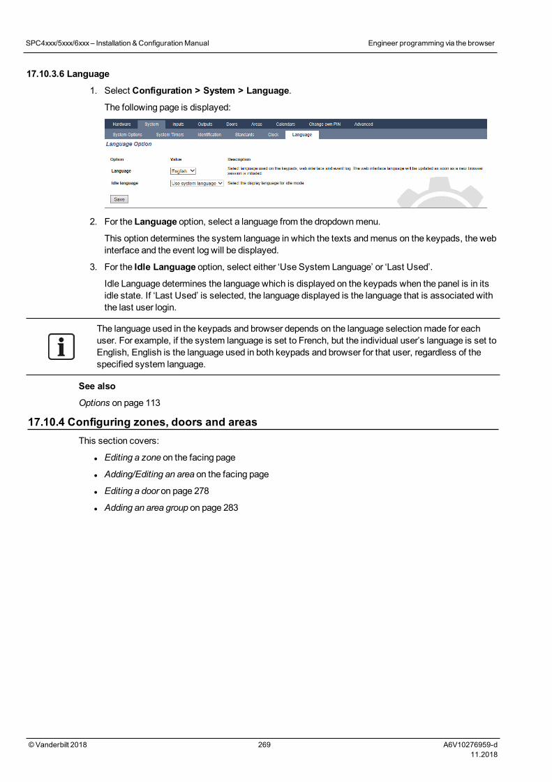
17.10.3.6 Language
1. Select Configuration > System > Language.
The following page is displayed:
2. For the Language option, select a language from the dropdownmenu.
This option determines the system language in which the texts andmenus on the keypads, the webinterface and the event log will be displayed.
3. For the Idle Language option, select either ‘Use System Language’ or ‘Last Used’.
Idle Language determines the language which is displayed on the keypads when the panel is in itsidle state. If ‘Last Used’ is selected, the language displayed is the language that is associated withthe last user login.
The language used in the keypads and browser depends on the language selectionmade for eachuser. For example, if the system language is set to French, but the individual user’s language is set toEnglish, English is the language used in both keypads and browser for that user, regardless of thespecified system language.
See also
Options on page 113
17.10.4 Configuring zones, doors and areasThis section covers:
l Editing a zone on the facing page
l Adding/Editing an area on the facing page
l Editing a door on page 278
l Adding an area group on page 283
SPC4xxx/5xxx/6xxx– Installation &ConfigurationManual Engineer programming via the browser
© Vanderbilt 2018 269 A6V10276959-d11.2018
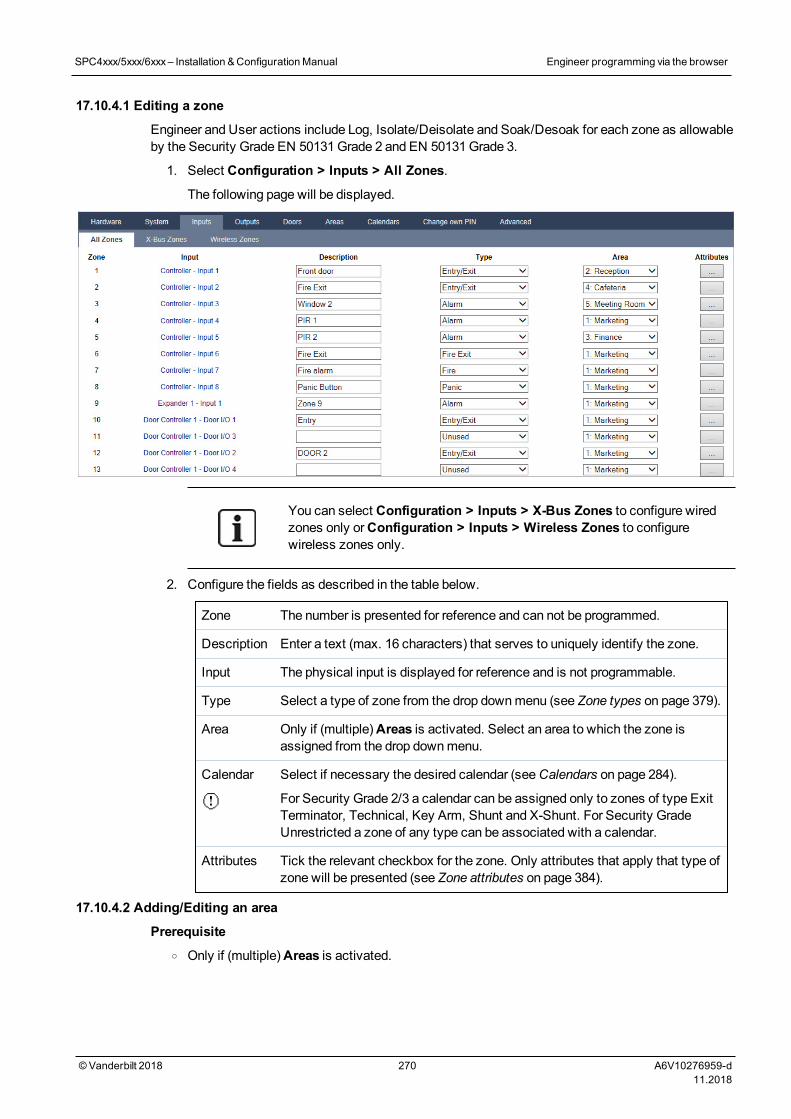
17.10.4.1 Editing a zone
Engineer and User actions include Log, Isolate/Deisolate and Soak/Desoak for each zone as allowableby the Security Grade EN 50131Grade 2 and EN 50131Grade 3.
1. Select Configuration > Inputs > All Zones.
The following page will be displayed.
You can select Configuration > Inputs > X-Bus Zones to configure wiredzones only orConfiguration > Inputs > Wireless Zones to configurewireless zones only.
2. Configure the fields as described in the table below.
Zone The number is presented for reference and can not be programmed.
Description Enter a text (max. 16 characters) that serves to uniquely identify the zone.
Input The physical input is displayed for reference and is not programmable.
Type Select a type of zone from the drop downmenu (see Zone types on page 379).
Area Only if (multiple)Areas is activated. Select an area to which the zone isassigned from the drop downmenu.
Calendar Select if necessary the desired calendar (seeCalendars on page 284).
For Security Grade 2/3 a calendar can be assigned only to zones of type ExitTerminator, Technical, Key Arm, Shunt and X-Shunt. For Security GradeUnrestricted a zone of any type can be associated with a calendar.
Attributes Tick the relevant checkbox for the zone. Only attributes that apply that type ofzone will be presented (see Zone attributes on page 384).
17.10.4.2 Adding/Editing an area
Prerequisiteo Only if (multiple)Areas is activated.
SPC4xxx/5xxx/6xxx– Installation &ConfigurationManual Engineer programming via the browser
© Vanderbilt 2018 270 A6V10276959-d11.2018
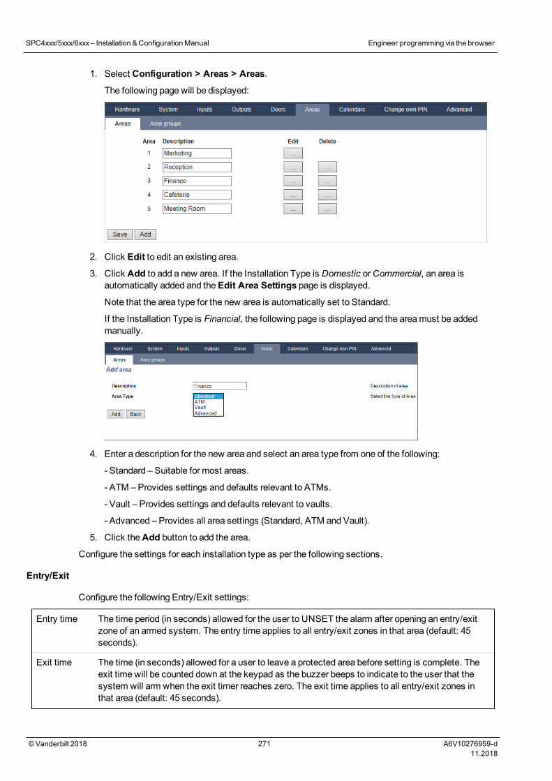
1. Select Configuration > Areas > Areas.
The following page will be displayed:
2. Click Edit to edit an existing area.
3. Click Add to add a new area. If the Installation Type is Domestic orCommercial, an area isautomatically added and theEdit Area Settings page is displayed.
Note that the area type for the new area is automatically set to Standard.
If the Installation Type is Financial, the following page is displayed and the areamust be addedmanually.
4. Enter a description for the new area and select an area type from one of the following:
- Standard – Suitable for most areas.
- ATM – Provides settings and defaults relevant to ATMs.
- Vault – Provides settings and defaults relevant to vaults.
- Advanced – Provides all area settings (Standard, ATM and Vault).
5. Click theAdd button to add the area.
Configure the settings for each installation type as per the following sections.
Entry/Exit
Configure the following Entry/Exit settings:
Entry time The time period (in seconds) allowed for the user to UNSET the alarm after opening an entry/exitzone of an armed system. The entry time applies to all entry/exit zones in that area (default: 45seconds).
Exit time The time (in seconds) allowed for a user to leave a protected area before setting is complete. Theexit time will be counted down at the keypad as the buzzer beeps to indicate to the user that thesystem will arm when the exit timer reaches zero. The exit time applies to all entry/exit zones inthat area (default: 45 seconds).
SPC4xxx/5xxx/6xxx– Installation &ConfigurationManual Engineer programming via the browser
© Vanderbilt 2018 271 A6V10276959-d11.2018
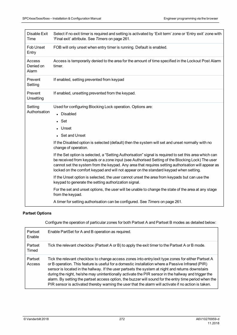
Disable ExitTime
Select if no exit timer is required and setting is activated by ‘Exit term’ zone or ‘Entry exit’ zone with‘Final exit’ attribute. See Timers on page 261.
Fob UnsetEntry
FOB will only unset when entry timer is running. Default is enabled.
AccessDenied onAlarm
Access is temporarily denied to the area for the amount of time specified in the Lockout Post Alarmtimer.
PreventSetting
If enabled, setting prevented from keypad
PreventUnsetting
If enabled, unsetting prevented from the keypad.
SettingAuthorisation
Used for configuring Blocking Lock operation. Options are:
l Disabled
l Set
l Unset
l Set and Unset
If the Disabled option is selected (default) then the system will set and unset normally with nochange of operation.
If the Set option is selected, a “Setting Authorisation” signal is required to set this area which canbe received from keypads or a zone input (see Authorised Setting of the Blocking Lock) The usercannot set the system from the keypad. Any area that requires setting authorisation will appear aslocked on the comfort keypad and will not appear on the standard keypad when setting.
If the Unset option is selected, the user cannot unset the area from keypads but can use thekeypad to generate the setting authorization signal.
For the set and unset options, the user will be unable to change the state of the area at any stagefrom the keypad.
A timer for setting authorisation can be configured. See Timers on page 261.
Partset Options
Configure the operation of particular zones for both Partset A and Partset B modes as detailed below:
PartsetEnable
Enable PartSet for A and B operation as required.
PartsetTimed
Tick the relevant checkbox (Partset A or B) to apply the exit timer to the Partset A or B mode.
PartsetAccess
Tick the relevant checkbox to change access zones into entry/exit type zones for either Partset Aor B operation. This feature is useful for a domestic installation where a Passive Infrared (PIR)sensor is located in the hallway. If the user partsets the system at night and returns downstairsduring the night, he/shemay unintentionally activate the PIR sensor in the hallway and trigger thealarm. By setting the partset access option, the buzzer will sound for the entry time period when thePIR sensor is activated thereby warning the user that the alarm will activate if no action is taken.
SPC4xxx/5xxx/6xxx– Installation &ConfigurationManual Engineer programming via the browser
© Vanderbilt 2018 272 A6V10276959-d11.2018
PartsetExit/Entry
Tick the relevant checkbox to change the behaviour of entry/exit zones to alarm zones when inPartset A or B mode. This feature is useful for a domestic installation when the system has beenset in partset mode. If the user partsets the system at night he/shemay wish the alarm to activateimmediately if the front or back door is opened during the night.
PartsetLocal
Tick the relevant checkbox to restrict the reporting of alarms in Partset Mode to local reporting only(No remote reporting).
No Bells If ticked, no bells will be activated for partset A or B.
Linked Areas
This section enables you to link areas for setting and unsetting purposes:
Fullset Fullset this area when all linked areas are Fullset.
Fullset All Fullset all areas when this area is Fullset.
Prevent Fullset Prevent this area from Fullset if all linked areas are Fullset.
Prevent Fullset All Prevent linked areas from Fullset if this area is not Fullset.
Unset Unset this area when all linked areas are Unset.
Unset All Unset all areas when this area is Unset.
Prevent Unset Prevent this area from Unset if any linked areas are Fullset.
Prevent Unset All Prevent linked areas from Unset if this area is Fullset.
Authorise Setting Enable authorised setting for linked areas. Refer Authorised Setting of the Blocking Lock.
Linked Areas Click the areas that you wish to link to this area.
Schedule
Configure scheduling with the following settings:
Calendar Select a calendar to control scheduling.
Unset Select if area should automatically Unset as per the time specified in the selected calendar.
Fullset Select this option to Fullset the area as per the time specified in the selected Calendar. The area willalso set when the Unset Duration or Delay Interval has elapsed (seeSetting/Unsetting on page 275). Ifthe Unset Duration overlaps the scheduled time, the area will use the calendar settings.
TimeLocked
Select this option to time lock the area as per the selected Calendar. (Vault type area in Financial modeonly)
VaultAccess
Enter the number of minutes (0–120) to activate this timer at the end of a Time Locked Unset period. Ifthe area is not unset after this timer expires, the area cannot be unset until the start of the next TimeLocked Unset period. (Vault type area in Financial mode only)
Reporting
The Reporting configuration settings are applicable for Standard Areas in Commercial and Financialinstallations only and are only relevant if a calendar has been selected. (SeeSchedule above.)
SPC4xxx/5xxx/6xxx– Installation &ConfigurationManual Engineer programming via the browser
© Vanderbilt 2018 273 A6V10276959-d11.2018
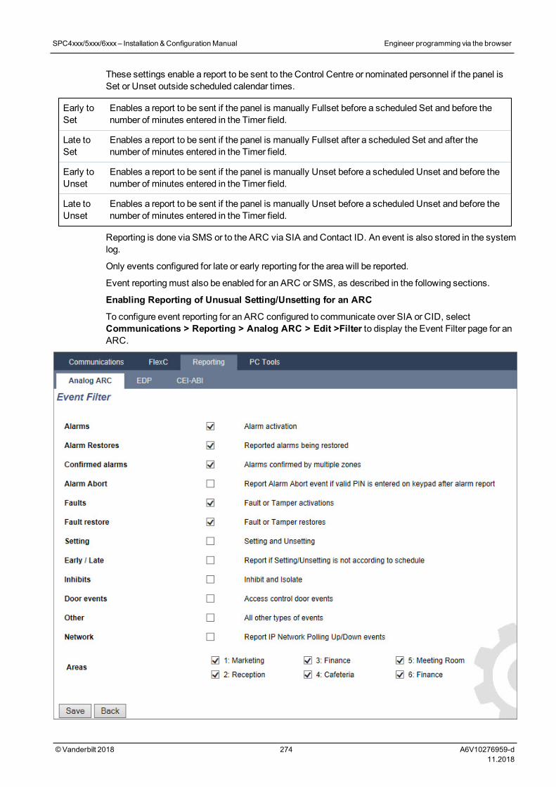
These settings enable a report to be sent to the Control Centre or nominated personnel if the panel isSet or Unset outside scheduled calendar times.
Early toSet
Enables a report to be sent if the panel is manually Fullset before a scheduled Set and before thenumber of minutes entered in the Timer field.
Late toSet
Enables a report to be sent if the panel is manually Fullset after a scheduled Set and after thenumber of minutes entered in the Timer field.
Early toUnset
Enables a report to be sent if the panel is manually Unset before a scheduled Unset and before thenumber of minutes entered in the Timer field.
Late toUnset
Enables a report to be sent if the panel is manually Unset before a scheduled Unset and before thenumber of minutes entered in the Timer field.
Reporting is done via SMS or to the ARC via SIA and Contact ID. An event is also stored in the systemlog.
Only events configured for late or early reporting for the area will be reported.
Event reportingmust also be enabled for an ARC or SMS, as described in the following sections.
Enabling Reporting of Unusual Setting/Unsetting for an ARC
To configure event reporting for an ARC configured to communicate over SIA or CID, selectCommunications > Reporting > Analog ARC > Edit >Filter to display the Event Filter page for anARC.
SPC4xxx/5xxx/6xxx– Installation &ConfigurationManual Engineer programming via the browser
© Vanderbilt 2018 274 A6V10276959-d11.2018
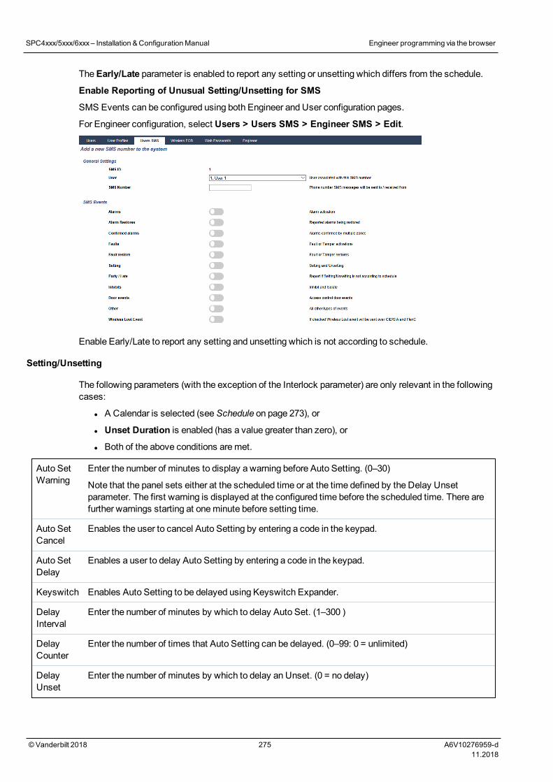
TheEarly/Late parameter is enabled to report any setting or unsetting which differs from the schedule.
Enable Reporting of Unusual Setting/Unsetting for SMS
SMS Events can be configured using both Engineer and User configuration pages.
For Engineer configuration, select Users > Users SMS > Engineer SMS > Edit.
Enable Early/Late to report any setting and unsetting which is not according to schedule.
Setting/Unsetting
The following parameters (with the exception of the Interlock parameter) are only relevant in the followingcases:
l A Calendar is selected (seeSchedule on page 273), or
l Unset Duration is enabled (has a value greater than zero), or
l Both of the above conditions aremet.
Auto SetWarning
Enter the number of minutes to display a warning before Auto Setting. (0–30)
Note that the panel sets either at the scheduled time or at the time defined by the Delay Unsetparameter. The first warning is displayed at the configured time before the scheduled time. There arefurther warnings starting at oneminute before setting time.
Auto SetCancel
Enables the user to cancel Auto Setting by entering a code in the keypad.
Auto SetDelay
Enables a user to delay Auto Setting by entering a code in the keypad.
Keyswitch Enables Auto Setting to be delayed using Keyswitch Expander.
DelayInterval
Enter the number of minutes by which to delay Auto Set. (1–300 )
DelayCounter
Enter the number of times that Auto Setting can be delayed. (0–99: 0 = unlimited)
DelayUnset
Enter the number of minutes by which to delay an Unset. (0 = no delay)
SPC4xxx/5xxx/6xxx– Installation &ConfigurationManual Engineer programming via the browser
© Vanderbilt 2018 275 A6V10276959-d11.2018
InterlockGroup
Select an Interlock Group to assign to this area. Interlocking only allows one area within the group tobe Unset at any time. Typically used in ATM areas.
UnsetDuration
If area is Unset for longer than this it will Set automatically. (Range 0–120mins: 0 = not active).
Dual PIN If this option is enabled, two PINs are required to Set or Unset the area with the keypad. Both PINsmust belong to users who have the required user right for the operation (Setting or Unsetting).
If the second PIN is not entered within 30 seconds, or it is wrong, then the area cannot be Set orUnset.
Force SetMode
Area options for Force-set operation (Normal or Blocked).
AutoRestoreon ForceSet
Check this option to auto-restore closed zones during force-set. If this option is selected, if an alert isactive or a zone needs to be restored, then it will be automatically restored.
Late Working Support
An example of using the setting and unsetting parameters is for late working situations where acalendar has been configured for automatic setting of a premises at a particular time but staff may needto work late on occasion and the automatic setting needs to be delayed.
Each delay is determined by the amount configured in theDelay Interval parameter, and theDelayCounter parameter determines the number of times that setting can be delayed. A user needs thecorrect value in theAuto Set Delay in order to use this feature.
There are three ways to delay setting:
1. Entering the PIN on the keypad.
DELAY is amenu option on the standard keypad. The buttons at the top of the comfort keypadare used to operate the delay feature
2. Using the keyswitch.
Turning the key to the right delays setting the system by the configured delay if themaximumnumber of times that setting can be delayed (Delay Counter) has not been exceeded. Turningthe key to the left sets the delay to threeminutes (non-configurable). This can be done regardlessof how many times setting was delayed.
3. Using a FOB, WPA or button which activates aDelay Autoset trigger action.
Temporary Unset
To allow a system to be temporarily unset in a time period specified by a calendar, the following threeparameters need to be configured:
1. Calendar
A calendar needs to be configured and selected for this area.
2. Time Locked
This box needs to be ticked so that the area can be unset only when allowed as per theconfigured calendar.
3. Unset Duration
This parameter needs to be set to a value greater than zero to set an upper limit on the time thearea will be unset.
SPC4xxx/5xxx/6xxx– Installation &ConfigurationManual Engineer programming via the browser
© Vanderbilt 2018 276 A6V10276959-d11.2018
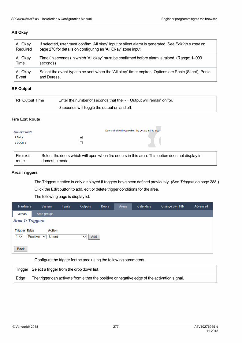
All Okay
All OkayRequired
If selected, user must confirm ‘All okay’ input or silent alarm is generated. SeeEditing a zone onpage 270 for details on configuring an ‘All Okay’ zone input.
All OkayTime
Time (in seconds) in which ‘All okay’ must be confirmed before alarm is raised. (Range: 1–999seconds)
All OkayEvent
Select the event type to be sent when the ‘All okay’ timer expires. Options are Panic (Silent), Panicand Duress.
RF Output
RFOutput Time Enter the number of seconds that the RF Output will remain on for.
0 seconds will toggle the output on and off.
Fire Exit Route
Fire exitroute
Select the doors which will open when fire occurs in this area. This option does not display indomestic mode.
Area Triggers
The Triggers section is only displayed if triggers have been defined previously. (See Triggers on page 288.)
Click theEdit button to add, edit or delete trigger conditions for the area.
The following page is displayed:
Configure the trigger for the area using the following parameters:
Trigger Select a trigger from the drop down list.
Edge The trigger can activate from either the positive or negative edge of the activation signal.
SPC4xxx/5xxx/6xxx– Installation &ConfigurationManual Engineer programming via the browser
© Vanderbilt 2018 277 A6V10276959-d11.2018
Action This is the action that is performed when the trigger is activated. Options are:
l Unset
l Partset A
l Partset B
l Fullset
l Delay autoset
This action will delay alarm setting when the autoset timer is running. The trigger will only add time ifthe Delay Limit has not been exceeded and each trigger activation will delay setting by the timedefined in Delay Interval (seeSetting/Unsetting on page 275).
l Restore alarms
This action will clear all alarms in the configured zone.
Note: Triggers cannot be configured from a keypad.
See also
Triggers on page 28817.10.4.3 Editing a door
1. Select Configuration > Doors.
A list of configured doors is displayed.
2. Click theEdit button.
3. Configure the fields as described in the tables below.
Door inputs
Each door has 2 inputs with predefined functionality. These two inputs, the door position sensor and thedoor release switch can be configured.
Name Description
Zone The door position sensor input can be used for the intrusion part as well. If the door positionsensor input is used also for the intrusion part, the zone number it is assigned to has to beselected. If the door position sensor is used only for the access part, the option “UNASSIGNED”has to be selected.
If the door position sensor is assigned to an intrusion zone, it can be configured like a normal zonebut only with limited functionality (for example, not all zone types are selectable).
If an area or the system is set with the card reader, the door position sensor input has to beassigned to a zone number and to the area or the system which have to be set.
Description
(Web only)
Description of the zone the door position sensor is assigned to.
Zone Type
(Web only)
Zone type of the zone the door position sensor is assigned to (not all zones types are available).
Zoneattributes
(Web only)
The attributes for the zone the door position sensor is assigned to can bemodified.
SPC4xxx/5xxx/6xxx– Installation &ConfigurationManual Engineer programming via the browser
© Vanderbilt 2018 278 A6V10276959-d11.2018
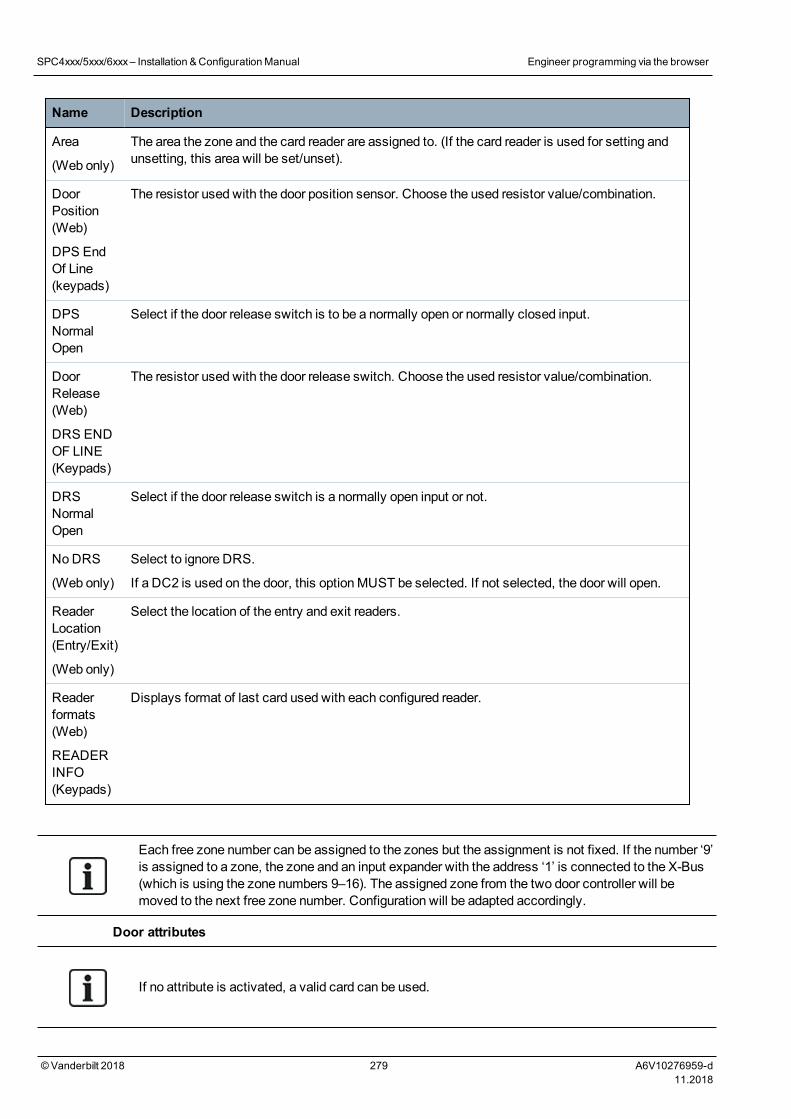
Name Description
Area
(Web only)
The area the zone and the card reader are assigned to. (If the card reader is used for setting andunsetting, this area will be set/unset).
DoorPosition(Web)
DPS EndOf Line(keypads)
The resistor used with the door position sensor. Choose the used resistor value/combination.
DPSNormalOpen
Select if the door release switch is to be a normally open or normally closed input.
DoorRelease(Web)
DRS ENDOF LINE(Keypads)
The resistor used with the door release switch. Choose the used resistor value/combination.
DRSNormalOpen
Select if the door release switch is a normally open input or not.
No DRS
(Web only)
Select to ignore DRS.
If a DC2 is used on the door, this optionMUST be selected. If not selected, the door will open.
ReaderLocation(Entry/Exit)
(Web only)
Select the location of the entry and exit readers.
Readerformats(Web)
READERINFO(Keypads)
Displays format of last card used with each configured reader.
Each free zone number can be assigned to the zones but the assignment is not fixed. If the number ‘9’is assigned to a zone, the zone and an input expander with the address ‘1’ is connected to the X-Bus(which is using the zone numbers 9–16). The assigned zone from the two door controller will bemoved to the next free zone number. Configuration will be adapted accordingly.
Door attributes
If no attribute is activated, a valid card can be used.
SPC4xxx/5xxx/6xxx– Installation &ConfigurationManual Engineer programming via the browser
© Vanderbilt 2018 279 A6V10276959-d11.2018
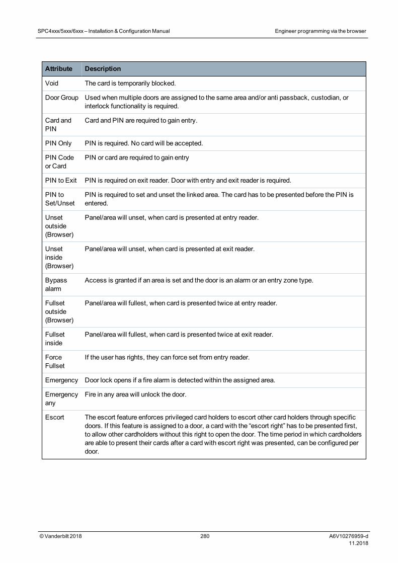
Attribute Description
Void The card is temporarily blocked.
Door Group Used whenmultiple doors are assigned to the same area and/or anti passback, custodian, orinterlock functionality is required.
Card andPIN
Card and PIN are required to gain entry.
PIN Only PIN is required. No card will be accepted.
PIN Codeor Card
PIN or card are required to gain entry
PIN to Exit PIN is required on exit reader. Door with entry and exit reader is required.
PIN toSet/Unset
PIN is required to set and unset the linked area. The card has to be presented before the PIN isentered.
Unsetoutside(Browser)
Panel/area will unset, when card is presented at entry reader.
Unsetinside(Browser)
Panel/area will unset, when card is presented at exit reader.
Bypassalarm
Access is granted if an area is set and the door is an alarm or an entry zone type.
Fullsetoutside(Browser)
Panel/area will fullest, when card is presented twice at entry reader.
Fullsetinside
Panel/area will fullest, when card is presented twice at exit reader.
ForceFullset
If the user has rights, they can force set from entry reader.
Emergency Door lock opens if a fire alarm is detected within the assigned area.
Emergencyany
Fire in any area will unlock the door.
Escort The escort feature enforces privileged card holders to escort other card holders through specificdoors. If this feature is assigned to a door, a card with the “escort right” has to be presented first,to allow other cardholders without this right to open the door. The time period in which cardholdersare able to present their cards after a card with escort right was presented, can be configured perdoor.
SPC4xxx/5xxx/6xxx– Installation &ConfigurationManual Engineer programming via the browser
© Vanderbilt 2018 280 A6V10276959-d11.2018
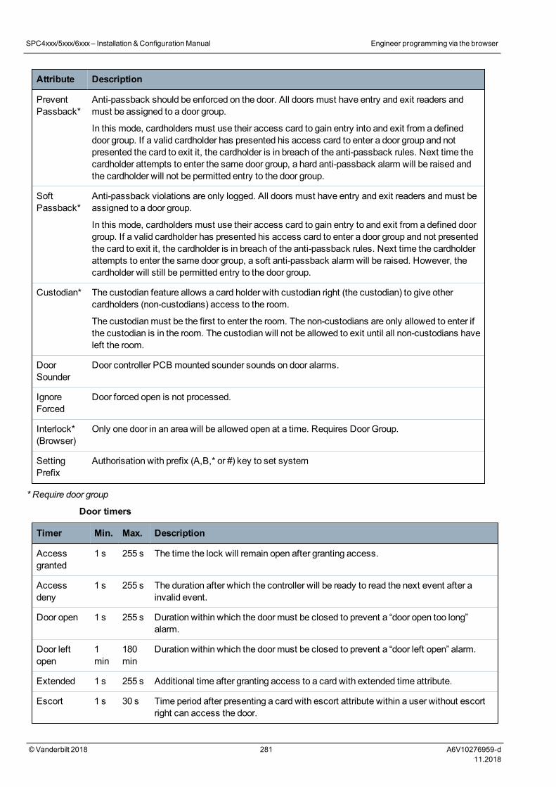
Attribute Description
PreventPassback*
Anti-passback should be enforced on the door. All doors must have entry and exit readers andmust be assigned to a door group.
In this mode, cardholders must use their access card to gain entry into and exit from a defineddoor group. If a valid cardholder has presented his access card to enter a door group and notpresented the card to exit it, the cardholder is in breach of the anti-passback rules. Next time thecardholder attempts to enter the same door group, a hard anti-passback alarm will be raised andthe cardholder will not be permitted entry to the door group.
SoftPassback*
Anti-passback violations are only logged. All doors must have entry and exit readers andmust beassigned to a door group.
In this mode, cardholders must use their access card to gain entry to and exit from a defined doorgroup. If a valid cardholder has presented his access card to enter a door group and not presentedthe card to exit it, the cardholder is in breach of the anti-passback rules. Next time the cardholderattempts to enter the same door group, a soft anti-passback alarm will be raised. However, thecardholder will still be permitted entry to the door group.
Custodian* The custodian feature allows a card holder with custodian right (the custodian) to give othercardholders (non-custodians) access to the room.
The custodianmust be the first to enter the room. The non-custodians are only allowed to enter ifthe custodian is in the room. The custodian will not be allowed to exit until all non-custodians haveleft the room.
DoorSounder
Door controller PCB mounted sounder sounds on door alarms.
IgnoreForced
Door forced open is not processed.
Interlock*(Browser)
Only one door in an area will be allowed open at a time. Requires Door Group.
SettingPrefix
Authorisation with prefix (A,B,* or #) key to set system
* Require door group
Door timers
Timer Min. Max. Description
Accessgranted
1 s 255 s The time the lock will remain open after granting access.
Accessdeny
1 s 255 s The duration after which the controller will be ready to read the next event after ainvalid event.
Door open 1 s 255 s Duration within which the door must be closed to prevent a “door open too long”alarm.
Door leftopen
1min
180min
Duration within which the door must be closed to prevent a “door left open” alarm.
Extended 1 s 255 s Additional time after granting access to a card with extended time attribute.
Escort 1 s 30 s Time period after presenting a card with escort attribute within a user without escortright can access the door.
SPC4xxx/5xxx/6xxx– Installation &ConfigurationManual Engineer programming via the browser
© Vanderbilt 2018 281 A6V10276959-d11.2018
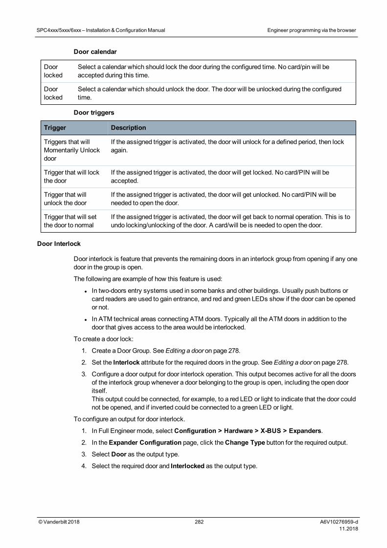
Door calendar
Doorlocked
Select a calendar which should lock the door during the configured time. No card/pin will beaccepted during this time.
Doorlocked
Select a calendar which should unlock the door. The door will be unlocked during the configuredtime.
Door triggers
Trigger Description
Triggers that willMomentarily Unlockdoor
If the assigned trigger is activated, the door will unlock for a defined period, then lockagain.
Trigger that will lockthe door
If the assigned trigger is activated, the door will get locked. No card/PIN will beaccepted.
Trigger that willunlock the door
If the assigned trigger is activated, the door will get unlocked. No card/PIN will beneeded to open the door.
Trigger that will setthe door to normal
If the assigned trigger is activated, the door will get back to normal operation. This is toundo locking/unlocking of the door. A card/will be is needed to open the door.
Door Interlock
Door interlock is feature that prevents the remaining doors in an interlock group from opening if any onedoor in the group is open.
The following are example of how this feature is used:
l In two-doors entry systems used in some banks and other buildings. Usually push buttons orcard readers are used to gain entrance, and red and green LEDs show if the door can be openedor not.
l In ATM technical areas connecting ATM doors. Typically all the ATM doors in addition to thedoor that gives access to the area would be interlocked.
To create a door lock:
1. Create a Door Group. SeeEditing a door on page 278.
2. Set the Interlock attribute for the required doors in the group. SeeEditing a door on page 278.
3. Configure a door output for door interlock operation. This output becomes active for all the doorsof the interlock group whenever a door belonging to the group is open, including the open dooritself.This output could be connected, for example, to a red LED or light to indicate that the door couldnot be opened, and if inverted could be connected to a green LED or light.
To configure an output for door interlock.
1. In Full Engineer mode, select Configuration > Hardware > X-BUS > Expanders.
2. In theExpander Configuration page, click theChange Type button for the required output.
3. Select Door as the output type.
4. Select the required door and Interlocked as the output type.
SPC4xxx/5xxx/6xxx– Installation &ConfigurationManual Engineer programming via the browser
© Vanderbilt 2018 282 A6V10276959-d11.2018
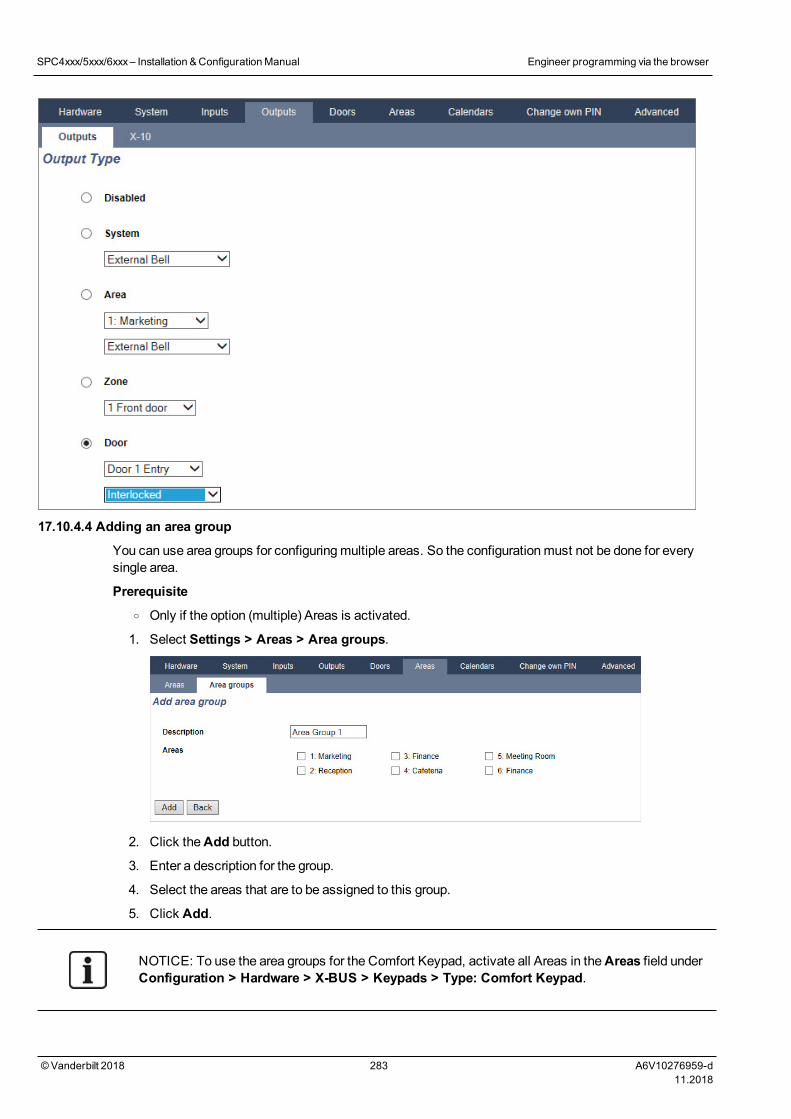
17.10.4.4 Adding an area group
You can use area groups for configuringmultiple areas. So the configurationmust not be done for everysingle area.
Prerequisiteo Only if the option (multiple) Areas is activated.
1. Select Settings > Areas > Area groups.
2. Click theAdd button.
3. Enter a description for the group.
4. Select the areas that are to be assigned to this group.
5. Click Add.
NOTICE: To use the area groups for the Comfort Keypad, activate all Areas in theAreas field underConfiguration > Hardware > X-BUS > Keypads > Type: Comfort Keypad.
SPC4xxx/5xxx/6xxx– Installation &ConfigurationManual Engineer programming via the browser
© Vanderbilt 2018 283 A6V10276959-d11.2018
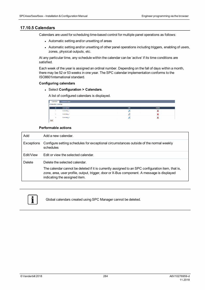
17.10.5 CalendarsCalendars are used for scheduling time-based control for multiple panel operations as follows:
l Automatic setting and/or unsetting of areas
l Automatic setting and/or unsetting of other panel operations including triggers, enabling of users,zones, physical outputs, etc.
At any particular time, any schedule within the calendar can be ‘active’ if its time conditions aresatisfied.
Each week of the year is assigned an ordinal number. Depending on the fall of days within amonth,theremay be 52 or 53 weeks in one year. The SPC calendar implementation conforms to theISO8601international standard.
Configuring calendars
l Select Configuration > Calendars.
A list of configured calendars is displayed.
Performable actions
Add Add a new calendar.
Exceptions Configure setting schedules for exceptional circumstances outside of the normal weeklyschedules
Edit/View Edit or view the selected calendar.
Delete Delete the selected calendar.
The calendar cannot be deleted if it is currently assigned to an SPC configuration item, that is,zone, area, user profile, output, trigger, door or X-Bus component. A message is displayedindicating the assigned item.
Global calendars created using SPC Manager cannot be deleted.
SPC4xxx/5xxx/6xxx– Installation &ConfigurationManual Engineer programming via the browser
© Vanderbilt 2018 284 A6V10276959-d11.2018
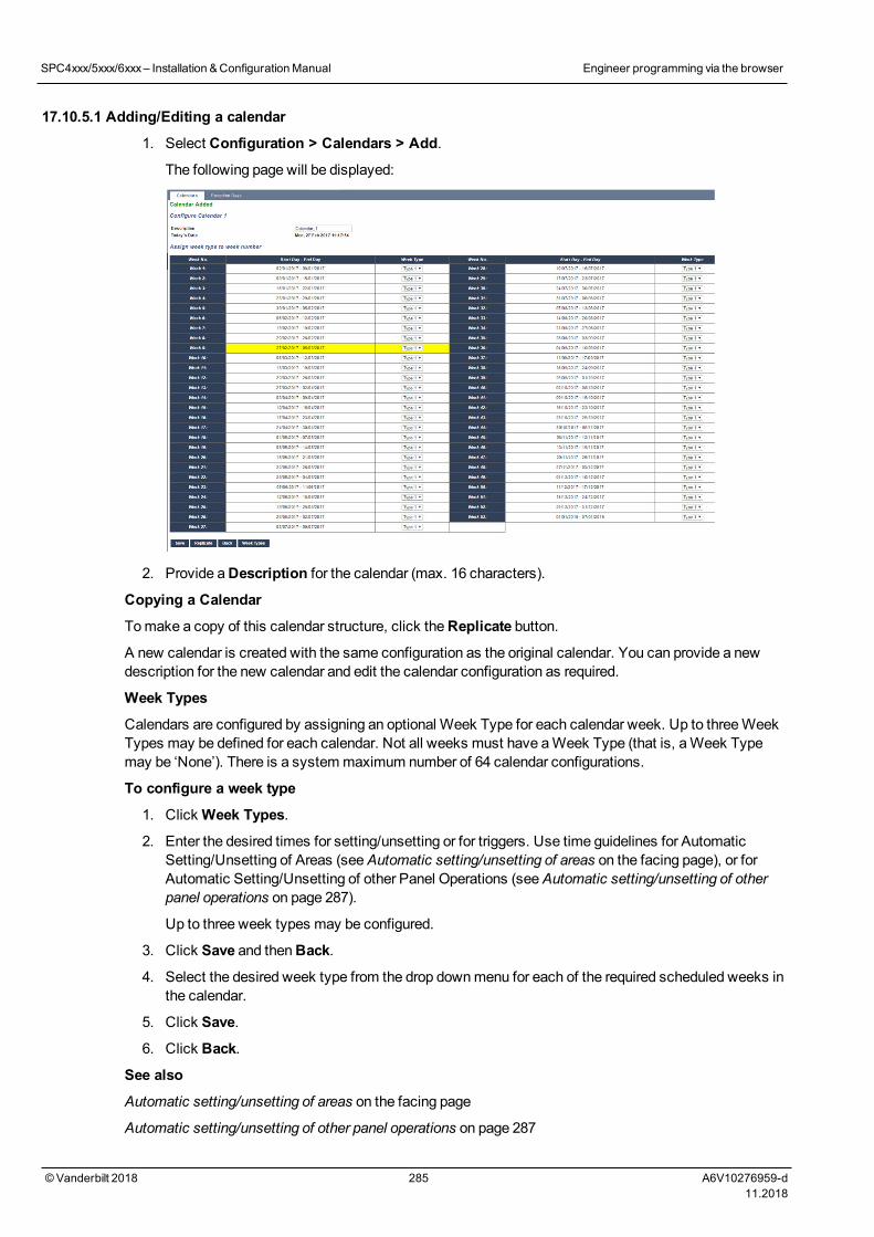
17.10.5.1 Adding/Editing a calendar
1. Select Configuration > Calendars > Add.
The following page will be displayed:
2. Provide aDescription for the calendar (max. 16 characters).
Copying a Calendar
Tomake a copy of this calendar structure, click theReplicate button.
A new calendar is created with the same configuration as the original calendar. You can provide a newdescription for the new calendar and edit the calendar configuration as required.
Week Types
Calendars are configured by assigning an optional Week Type for each calendar week. Up to threeWeekTypes may be defined for each calendar. Not all weeks must have aWeek Type (that is, aWeek Typemay be ‘None’). There is a systemmaximum number of 64 calendar configurations.
To configure a week type
1. ClickWeek Types.
2. Enter the desired times for setting/unsetting or for triggers. Use time guidelines for AutomaticSetting/Unsetting of Areas (seeAutomatic setting/unsetting of areas on the facing page), or forAutomatic Setting/Unsetting of other Panel Operations (seeAutomatic setting/unsetting of otherpanel operations on page 287).
Up to three week types may be configured.
3. Click Save and thenBack.
4. Select the desired week type from the drop downmenu for each of the required scheduled weeks inthe calendar.
5. Click Save.
6. Click Back.
See also
Automatic setting/unsetting of areas on the facing page
Automatic setting/unsetting of other panel operations on page 287
SPC4xxx/5xxx/6xxx– Installation &ConfigurationManual Engineer programming via the browser
© Vanderbilt 2018 285 A6V10276959-d11.2018
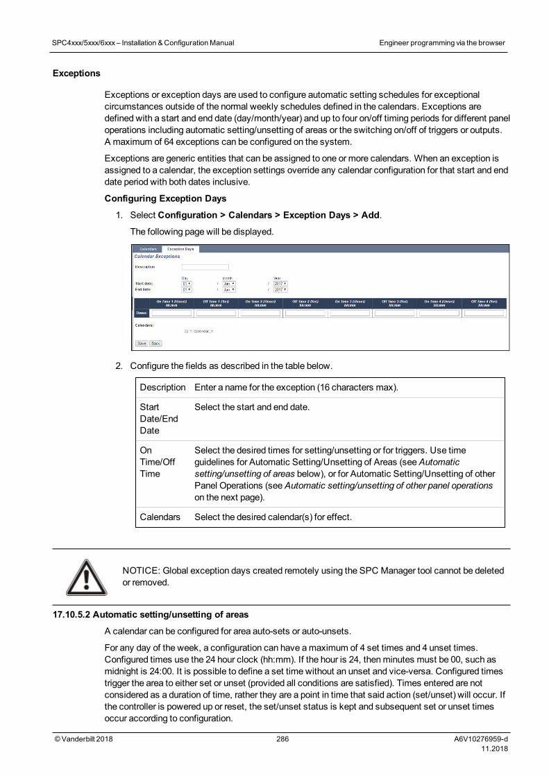
Exceptions
Exceptions or exception days are used to configure automatic setting schedules for exceptionalcircumstances outside of the normal weekly schedules defined in the calendars. Exceptions aredefined with a start and end date (day/month/year) and up to four on/off timing periods for different paneloperations including automatic setting/unsetting of areas or the switching on/off of triggers or outputs.A maximum of 64 exceptions can be configured on the system.
Exceptions are generic entities that can be assigned to one or more calendars. When an exception isassigned to a calendar, the exception settings override any calendar configuration for that start and enddate period with both dates inclusive.
Configuring Exception Days
1. Select Configuration > Calendars > Exception Days > Add.
The following page will be displayed.
2. Configure the fields as described in the table below.
Description Enter a name for the exception (16 characters max).
StartDate/EndDate
Select the start and end date.
OnTime/OffTime
Select the desired times for setting/unsetting or for triggers. Use timeguidelines for Automatic Setting/Unsetting of Areas (seeAutomaticsetting/unsetting of areas below), or for Automatic Setting/Unsetting of otherPanel Operations (seeAutomatic setting/unsetting of other panel operationson the next page).
Calendars Select the desired calendar(s) for effect.
NOTICE: Global exception days created remotely using the SPC Manager tool cannot be deletedor removed.
17.10.5.2 Automatic setting/unsetting of areas
A calendar can be configured for area auto-sets or auto-unsets.
For any day of the week, a configuration can have amaximum of 4 set times and 4 unset times.Configured times use the 24 hour clock (hh:mm). If the hour is 24, thenminutes must be 00, such asmidnight is 24:00. It is possible to define a set time without an unset and vice-versa. Configured timestrigger the area to either set or unset (provided all conditions are satisfied). Times entered are notconsidered as a duration of time, rather they are a point in time that said action (set/unset) will occur. Ifthe controller is powered up or reset, the set/unset status is kept and subsequent set or unset timesoccur according to configuration.
SPC4xxx/5xxx/6xxx– Installation &ConfigurationManual Engineer programming via the browser
© Vanderbilt 2018 286 A6V10276959-d11.2018

17.10.5.3 Automatic setting/unsetting of other panel operations
Panel operations including triggers, enabling of users, zones, physical outputs can be automatically set orunset using On/Off, True/False or Active/Inactive state configurations.
On/Off, True/False or Active/Inactive states can be assigned to an output that effectively turns on or offand can be configured for any day of the week. State configurations have amaximum of 4 set times and 4unset times. Configured times use the 24 hour clock (hh:mm). If the hour is 24, thenminutes must be 00,such as midnight is 24:00. Each configuration consists of a pairing of settings for On/Off, True/False,Active/Inactive states. Any one setting without a respective corresponding setting is disregarded.
17.10.6 Change own PINTo change a PIN, seeChanging Engineer PIN and web password on page 208.
17.10.7 Configuring advanced settingsThis section covers:
l Cause and Effect below
l Mapping Gates below
l Triggers on the facing page
l Audio/Video Verification on page 291
l Updating SPC Licenses on page 294
17.10.7.1 Cause and Effect
1. Select Configuration > Advanced > Cause and Effect.
The following page will be displayed.
2. Click an Assign button to perform one of the following actions:
l Output:Assign amapping gate (virtual output) to trigger a physical output. Select this option todisplay theMapping Gate - List page. For more information seeMapping Gates below.
l Area:Assign a trigger(virtual input) to trigger an area action. Choose anArea from the drop-down list before you click theAssign button. For more information see Triggers on the facingpage.
l Door:Assign a trigger (virtual input) to trigger door action. Choose aDoor from the drop-downlist before you click theAssign button.
To display the list of configured triggers and actions, select Configuration > Advanced > Cause &Effect > Cause & Effect List.
TheCause & Effect List page displays only fully functioning cause & effects. For example, if a mappinggate is not assigned to a trigger or to a quick key, it is not displayed in the list.
WARNING: Your system will not comply with EN standards if you enable a trigger to set the systemwithout a valid PIN being required.
17.10.7.2 Mapping Gates
Triggers are used with Mapping Gates, which are virtual outputs defined by the user that can bemapped toa physical output. There can be amaximum of 512Mapping Gates.
SPC4xxx/5xxx/6xxx– Installation &ConfigurationManual Engineer programming via the browser
© Vanderbilt 2018 287 A6V10276959-d11.2018
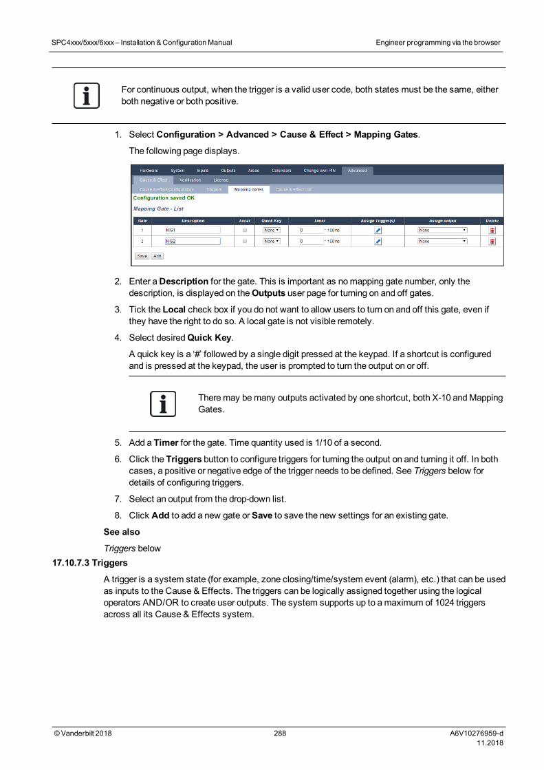
For continuous output, when the trigger is a valid user code, both states must be the same, eitherboth negative or both positive.
1. Select Configuration > Advanced > Cause & Effect > Mapping Gates.
The following page displays.
2. Enter aDescription for the gate. This is important as nomapping gate number, only thedescription, is displayed on theOutputs user page for turning on and off gates.
3. Tick the Local check box if you do not want to allow users to turn on and off this gate, even ifthey have the right to do so. A local gate is not visible remotely.
4. Select desiredQuick Key.
A quick key is a ‘#’ followed by a single digit pressed at the keypad. If a shortcut is configuredand is pressed at the keypad, the user is prompted to turn the output on or off.
Theremay bemany outputs activated by one shortcut, both X-10 andMappingGates.
5. Add a Timer for the gate. Time quantity used is 1/10 of a second.
6. Click the Triggers button to configure triggers for turning the output on and turning it off. In bothcases, a positive or negative edge of the trigger needs to be defined. See Triggers below fordetails of configuring triggers.
7. Select an output from the drop-down list.
8. Click Add to add a new gate orSave to save the new settings for an existing gate.
See also
Triggers below17.10.7.3 Triggers
A trigger is a system state (for example, zone closing/time/system event (alarm), etc.) that can be usedas inputs to the Cause & Effects. The triggers can be logically assigned together using the logicaloperators AND/OR to create user outputs. The system supports up to amaximum of 1024 triggersacross all its Cause & Effects system.
SPC4xxx/5xxx/6xxx– Installation &ConfigurationManual Engineer programming via the browser
© Vanderbilt 2018 288 A6V10276959-d11.2018
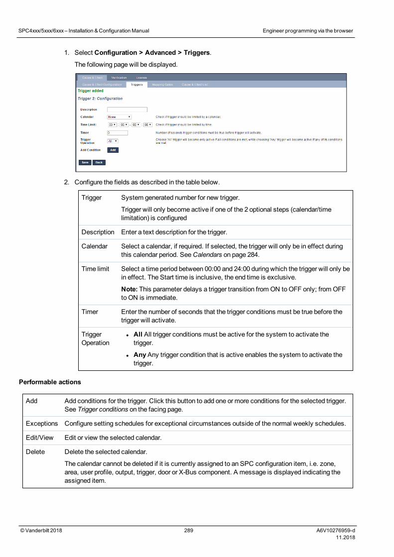
1. Select Configuration > Advanced > Triggers.
The following page will be displayed.
2. Configure the fields as described in the table below.
Trigger System generated number for new trigger.
Trigger will only become active if one of the 2 optional steps (calendar/timelimitation) is configured
Description Enter a text description for the trigger.
Calendar Select a calendar, if required. If selected, the trigger will only be in effect duringthis calendar period. SeeCalendars on page 284.
Time limit Select a time period between 00:00 and 24:00 during which the trigger will only bein effect. The Start time is inclusive, the end time is exclusive.
Note: This parameter delays a trigger transition from ON toOFF only; from OFFto ON is immediate.
Timer Enter the number of seconds that the trigger conditions must be true before thetrigger will activate.
TriggerOperation
l All All trigger conditions must be active for the system to activate thetrigger.
l AnyAny trigger condition that is active enables the system to activate thetrigger.
Performable actions
Add Add conditions for the trigger. Click this button to add one or more conditions for the selected trigger.See Trigger conditions on the facing page.
Exceptions Configure setting schedules for exceptional circumstances outside of the normal weekly schedules.
Edit/View Edit or view the selected calendar.
Delete Delete the selected calendar.
The calendar cannot be deleted if it is currently assigned to an SPC configuration item, i.e. zone,area, user profile, output, trigger, door or X-Bus component. A message is displayed indicating theassigned item.
SPC4xxx/5xxx/6xxx– Installation &ConfigurationManual Engineer programming via the browser
© Vanderbilt 2018 289 A6V10276959-d11.2018
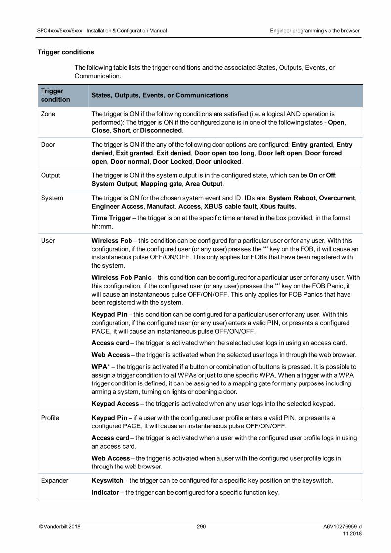
Trigger conditions
The following table lists the trigger conditions and the associated States, Outputs, Events, orCommunication.
Triggercondition States, Outputs, Events, or Communications
Zone The trigger is ON if the following conditions are satisfied (i.e. a logical AND operation isperformed): The trigger is ON if the configured zone is in one of the following states -Open,Close, Short, orDisconnected.
Door The trigger is ON if the any of the following door options are configured: Entry granted, Entrydenied, Exit granted, Exit denied, Door open too long, Door left open, Door forcedopen, Door normal, Door Locked, Door unlocked.
Output The trigger is ON if the system output is in the configured state, which can beOn orOff:System Output,Mapping gate, Area Output.
System The trigger is ON for the chosen system event and ID. IDs are: System Reboot, Overcurrent,Engineer Access,Manufact. Access, XBUS cable fault, Xbus faults.
Time Trigger – the trigger is on at the specific time entered in the box provided, in the formathh:mm.
User Wireless Fob – this condition can be configured for a particular user or for any user. With thisconfiguration, if the configured user (or any user) presses the ‘*’ key on the FOB, it will cause aninstantaneous pulse OFF/ON/OFF. This only applies for FOBs that have been registered withthe system.
Wireless Fob Panic – this condition can be configured for a particular user or for any user. Withthis configuration, if the configured user (or any user) presses the ‘*’ key on the FOB Panic, itwill cause an instantaneous pulse OFF/ON/OFF. This only applies for FOB Panics that havebeen registered with the system.
Keypad Pin – this condition can be configured for a particular user or for any user. With thisconfiguration, if the configured user (or any user) enters a valid PIN, or presents a configuredPACE, it will cause an instantaneous pulse OFF/ON/OFF.
Access card – the trigger is activated when the selected user logs in using an access card.
Web Access – the trigger is activated when the selected user logs in through the web browser.
WPA* – the trigger is activated if a button or combination of buttons is pressed. It is possible toassign a trigger condition to all WPAs or just to one specific WPA. When a trigger with aWPAtrigger condition is defined, it can be assigned to amapping gate for many purposes includingarming a system, turning on lights or opening a door.
Keypad Access – the trigger is activated when any user logs into the selected keypad.
Profile Keypad Pin – if a user with the configured user profile enters a valid PIN, or presents aconfigured PACE, it will cause an instantaneous pulse OFF/ON/OFF.
Access card – the trigger is activated when a user with the configured user profile logs in usingan access card.
Web Access – the trigger is activated when a user with the configured user profile logs inthrough the web browser.
Expander Keyswitch – the trigger can be configured for a specific key position on the keyswitch.
Indicator – the trigger can be configured for a specific function key.
SPC4xxx/5xxx/6xxx– Installation &ConfigurationManual Engineer programming via the browser
© Vanderbilt 2018 290 A6V10276959-d11.2018
Triggercondition States, Outputs, Events, or Communications
Communication FlexC ATP – the trigger activated by the selected ATS and ATP configuration.
FlexC ATS – the trigger activated by the selected ATS configuration.
*AWPA is compatible with SiWay RF Kit (SPCW110, 111, 112, 114 ) only.
WARNING: Your system will not comply with EN standards if you enable a trigger to set the systemwithout a valid PIN being required.
17.10.7.4 Audio/Video Verification
To set up Audio/Video Verification on an SPC system:
1. Install and configure Audio Expander(s).
2. Install and configure Video Camera(s).
3. Install and configure Audio Equipment.
4. Configure Verification Zone(s).
5. Test audio playback from verification zones.
6. Assign Verification Zone(s) to physical zone(s).
7. Configure Verification Settings.
8. View images from verification zones in web browser.
NOTICE: Keypads and access control may be disabled for several minutes while sending an audiofile to the panel, depending on the size of the file.
Configuring Video
Overview
Cameras are used for video verification. The SPC panel supports amaximum of four cameras. Only IPcameras are supported and the panel must have an Ethernet port.
NOTICE: Cameras must not be shared with other CCTV applications.
Cameras can only be configured with the web browser. Configuration with the keypad is not supported.
The panel supports two camera resolutions:
l 320X240
This setting is recommended if you want to view images on the browser)
l 640X480 (with some restrictions).
The following cameras are supported in addition to other generic cameras:
l Vanderbilt CCIC1410 (1/4” VGA IP Colour Camera)
l Vanderbilt CFMC1315 (1/3” 1.3MP Indoor DomeColour Camera)
SPC4xxx/5xxx/6xxx– Installation &ConfigurationManual Engineer programming via the browser
© Vanderbilt 2018 291 A6V10276959-d11.2018
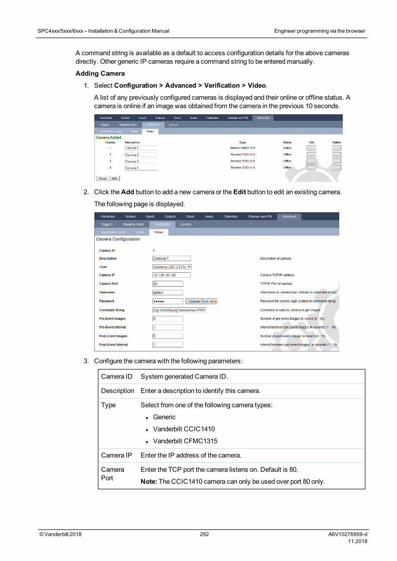
A command string is available as a default to access configuration details for the above camerasdirectly. Other generic IP cameras require a command string to be enteredmanually.
Adding Camera
1. Select Configuration > Advanced > Verification > Video.
A list of any previously configured cameras is displayed and their online or offline status. Acamera is online if an image was obtained from the camera in the previous 10 seconds.
2. Click theAdd button to add a new camera or theEdit button to edit an existing camera.
The following page is displayed.
3. Configure the camera with the following parameters:
Camera ID System generated Camera ID.
Description Enter a description to identify this camera.
Type Select from one of the following camera types:
l Generic
l Vanderbilt CCIC1410
l Vanderbilt CFMC1315
Camera IP Enter the IP address of the camera.
CameraPort
Enter the TCP port the camera listens on. Default is 80.
Note: The CCIC1410 camera can only be used over port 80 only.
SPC4xxx/5xxx/6xxx– Installation &ConfigurationManual Engineer programming via the browser
© Vanderbilt 2018 292 A6V10276959-d11.2018
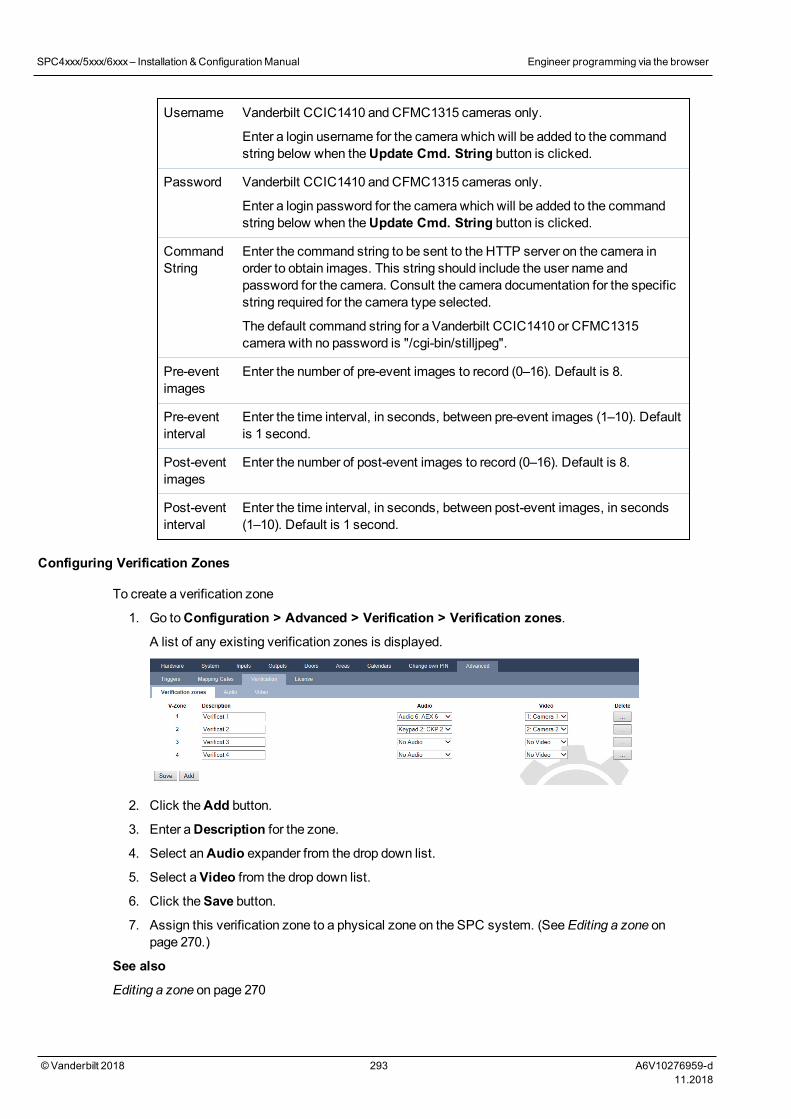
Username Vanderbilt CCIC1410 and CFMC1315 cameras only.
Enter a login username for the camera which will be added to the commandstring below when theUpdate Cmd. String button is clicked.
Password Vanderbilt CCIC1410 and CFMC1315 cameras only.
Enter a login password for the camera which will be added to the commandstring below when theUpdate Cmd. String button is clicked.
CommandString
Enter the command string to be sent to the HTTP server on the camera inorder to obtain images. This string should include the user name andpassword for the camera. Consult the camera documentation for the specificstring required for the camera type selected.
The default command string for a Vanderbilt CCIC1410 or CFMC1315camera with no password is "/cgi-bin/stilljpeg".
Pre-eventimages
Enter the number of pre-event images to record (0–16). Default is 8.
Pre-eventinterval
Enter the time interval, in seconds, between pre-event images (1–10). Defaultis 1 second.
Post-eventimages
Enter the number of post-event images to record (0–16). Default is 8.
Post-eventinterval
Enter the time interval, in seconds, between post-event images, in seconds(1–10). Default is 1 second.
Configuring Verification Zones
To create a verification zone
1. Go toConfiguration > Advanced > Verification > Verification zones.
A list of any existing verification zones is displayed.
2. Click theAdd button.
3. Enter aDescription for the zone.
4. Select anAudio expander from the drop down list.
5. Select aVideo from the drop down list.
6. Click theSave button.
7. Assign this verification zone to a physical zone on the SPC system. (SeeEditing a zone onpage 270.)
See also
Editing a zone on page 270
SPC4xxx/5xxx/6xxx– Installation &ConfigurationManual Engineer programming via the browser
© Vanderbilt 2018 293 A6V10276959-d11.2018
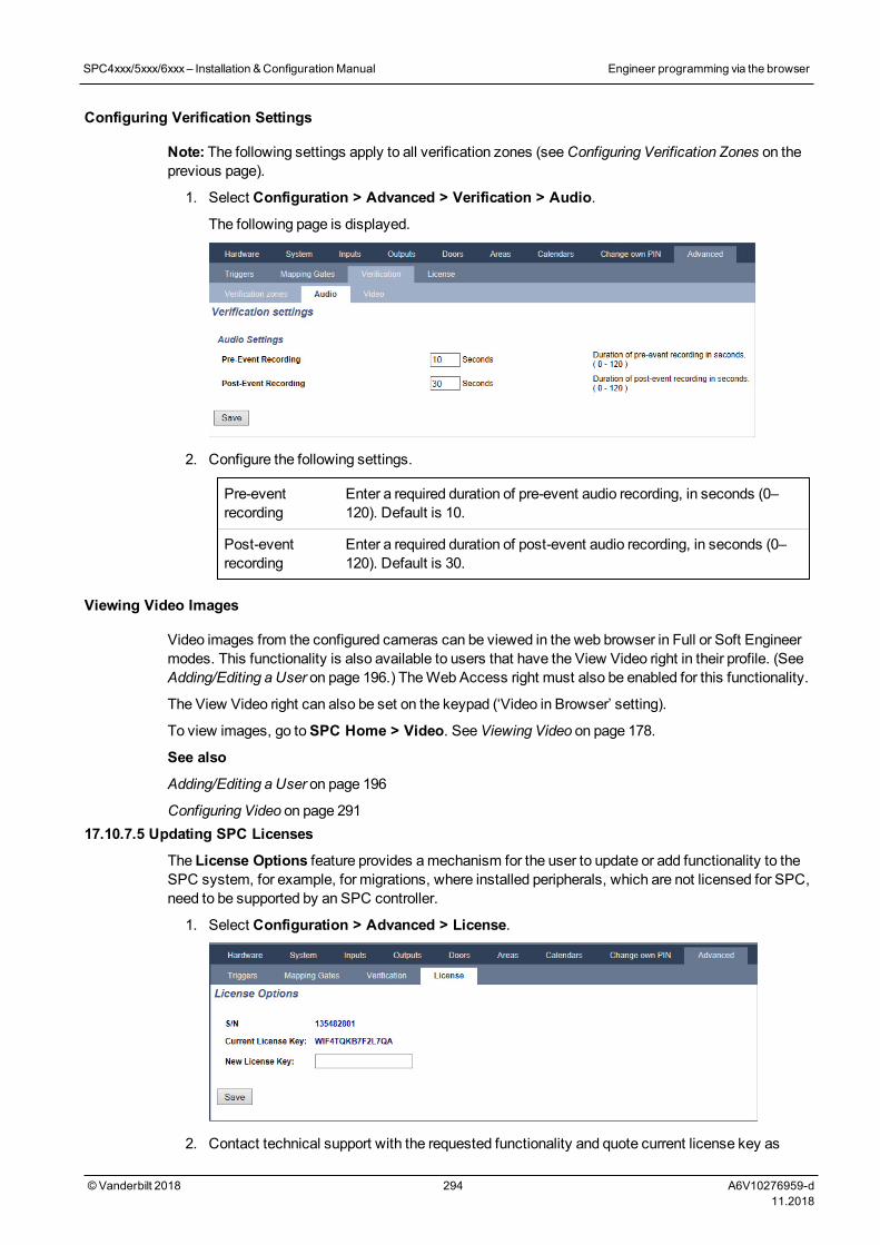
Configuring Verification Settings
Note: The following settings apply to all verification zones (seeConfiguring Verification Zones on theprevious page).
1. Select Configuration > Advanced > Verification > Audio.
The following page is displayed.
2. Configure the following settings.
Pre-eventrecording
Enter a required duration of pre-event audio recording, in seconds (0–120). Default is 10.
Post-eventrecording
Enter a required duration of post-event audio recording, in seconds (0–120). Default is 30.
Viewing Video Images
Video images from the configured cameras can be viewed in the web browser in Full or Soft Engineermodes. This functionality is also available to users that have the View Video right in their profile. (SeeAdding/Editing a User on page 196.) TheWeb Access right must also be enabled for this functionality.
The View Video right can also be set on the keypad (‘Video in Browser’ setting).
To view images, go toSPC Home > Video. SeeViewing Video on page 178.
See also
Adding/Editing a User on page 196
Configuring Video on page 29117.10.7.5 Updating SPC Licenses
The License Options feature provides amechanism for the user to update or add functionality to theSPC system, for example, for migrations, where installed peripherals, which are not licensed for SPC,need to be supported by an SPC controller.
1. Select Configuration > Advanced > License.
2. Contact technical support with the requested functionality and quote current license key as
SPC4xxx/5xxx/6xxx– Installation &ConfigurationManual Engineer programming via the browser
© Vanderbilt 2018 294 A6V10276959-d11.2018
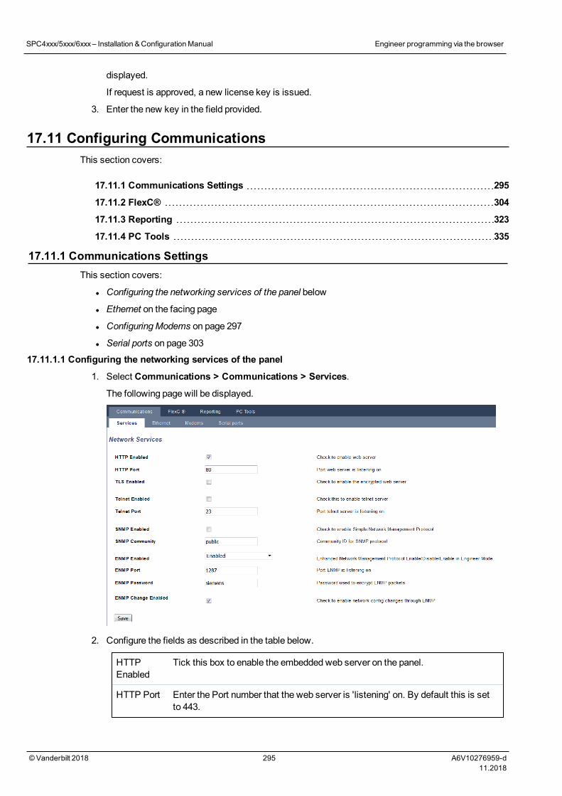
displayed.
If request is approved, a new license key is issued.
3. Enter the new key in the field provided.
17.11 Configuring CommunicationsThis section covers:
17.11.1 Communications Settings 295
17.11.2 FlexC® 304
17.11.3 Reporting 323
17.11.4 PC Tools 335
17.11.1 Communications SettingsThis section covers:
l Configuring the networking services of the panel below
l Ethernet on the facing page
l ConfiguringModems on page 297
l Serial ports on page 303
17.11.1.1 Configuring the networking services of the panel
1. Select Communications > Communications > Services.
The following page will be displayed.
2. Configure the fields as described in the table below.
HTTPEnabled
Tick this box to enable the embedded web server on the panel.
HTTP Port Enter the Port number that the web server is 'listening' on. By default this is setto 443.
SPC4xxx/5xxx/6xxx– Installation &ConfigurationManual Engineer programming via the browser
© Vanderbilt 2018 295 A6V10276959-d11.2018
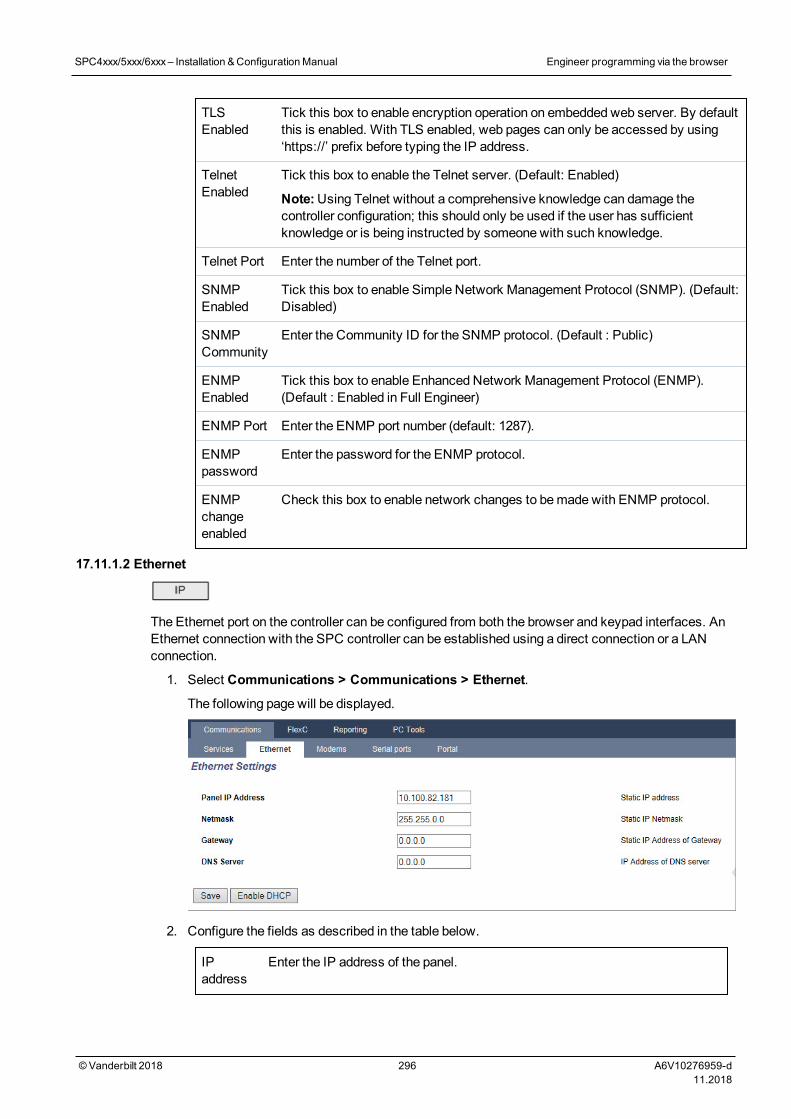
TLSEnabled
Tick this box to enable encryption operation on embedded web server. By defaultthis is enabled. With TLS enabled, web pages can only be accessed by using‘https://’ prefix before typing the IP address.
TelnetEnabled
Tick this box to enable the Telnet server. (Default: Enabled)
Note:Using Telnet without a comprehensive knowledge can damage thecontroller configuration; this should only be used if the user has sufficientknowledge or is being instructed by someone with such knowledge.
Telnet Port Enter the number of the Telnet port.
SNMPEnabled
Tick this box to enable Simple Network Management Protocol (SNMP). (Default:Disabled)
SNMPCommunity
Enter the Community ID for the SNMP protocol. (Default : Public)
ENMPEnabled
Tick this box to enable Enhanced Network Management Protocol (ENMP).(Default : Enabled in Full Engineer)
ENMP Port Enter the ENMP port number (default: 1287).
ENMPpassword
Enter the password for the ENMP protocol.
ENMPchangeenabled
Check this box to enable network changes to bemade with ENMP protocol.
17.11.1.2 Ethernet
The Ethernet port on the controller can be configured from both the browser and keypad interfaces. AnEthernet connection with the SPC controller can be established using a direct connection or a LANconnection.
1. Select Communications > Communications > Ethernet.
The following page will be displayed.
2. Configure the fields as described in the table below.
IPaddress
Enter the IP address of the panel.
SPC4xxx/5xxx/6xxx– Installation &ConfigurationManual Engineer programming via the browser
© Vanderbilt 2018 296 A6V10276959-d11.2018
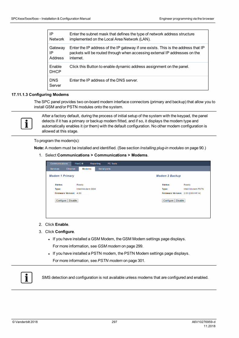
IPNetwork
Enter the subnet mask that defines the type of network address structureimplemented on the Local Area Network (LAN).
GatewayIPAddress
Enter the IP address of the IP gateway if one exists. This is the address that IPpackets will be routed through when accessing external IP addresses on theinternet.
EnableDHCP
Click this Button to enable dynamic address assignment on the panel.
DNSServer
Enter the IP address of the DNS server.
17.11.1.3 Configuring Modems
The SPC panel provides two on-boardmodem interface connectors (primary and backup) that allow you toinstall GSM and/or PSTN modules onto the system.
After a factory default, during the process of initial setup of the system with the keypad, the paneldetects if it has a primary or backupmodem fitted, and if so, it displays themodem type andautomatically enables it (or them) with the default configuration. No other modem configuration isallowed at this stage.
To program themodem(s):
Note:A modemmust be installed and identified. (See section Installing plug-in modules on page 90.)
1. Select Communications > Communications > Modems.
2. Click Enable.
3. Click Configure.
l If you have installed aGSMModem, the GSMModem settings page displays.
For more information, seeGSMmodem on page 299.
l If you have installed a PSTN modem, the PSTN Modem settings page displays.
For more information, seePSTN modem on page 301.
SMS detection and configuration is not available unless modems that are configured and enabled.
SPC4xxx/5xxx/6xxx– Installation &ConfigurationManual Engineer programming via the browser
© Vanderbilt 2018 297 A6V10276959-d11.2018
SMS test
Once the SIM feature is enabled for amodem, a test may be preformed to desired recipient number witha composedmessage.
1. Enter themobile phone number (including 3-digit country prefix) in the number field and a shorttext message in themessage box.
2. Click Send SMS and verify themessage is received on themobile phone.
The SMS test is provided only for the purpose of ensuring the SMS feature is operating correctly. Ashort text message using alphabetic characters (A-Z) should be used to test this feature.
The SMS operates using a standard protocol that is used in SMS telephones. Note that some PSTNoperators do not provide the service of SMS over PSTN. For SMS to operate over PSTN the followingcriteria is required:
l Caller ID needs to be enabled on the telephone line.
l Direct telephone line – not through PABX or other comms equipment.
l Also note that most Service Providers only allow SMS to a telephone registered in the samecountry (this is due to billing issues).
SMS feature
The SPC controller allows remote (SMS)messaging on systems with installedmodems. Once amodem is installed, the following configurations are necessary for SMS:
l SMS-enabledmodem
l SMS Authentication
l Engineer SMS Control
l User SMS Control
Depending on configurations, features include these SMS abilities:
l Event notification
l Remote Commands (users may be assigned select remote commands)
SMS system options
Once amodem is installed and the SMS feature enabled, for SMS operations the SPC systemmustapply the SMS Authentication.
1. Select Configuration > System > System Options.
2. Select the desired option from the drop-downmenuSMS Authentication:
l PIN Only: This is a valid user code. SeeCreating system users on page 108.
l Caller ID Only: This is the phone number (including 3-digit country prefix code) asconfigured for User SMS Control. Only when this option is selected will the SMS Control beavailable for configuration by the user.
l PIN and Caller ID
l SMS PIN Code Only: This is a valid PIN code configured for the user which different fromthe user’s login code. Only when this option is selected will the SMS Controls be availablefor configuration by the user.
l SMS PIN Code & Caller ID
SPC4xxx/5xxx/6xxx– Installation &ConfigurationManual Engineer programming via the browser
© Vanderbilt 2018 298 A6V10276959-d11.2018
SMS commands
SeeSMS Commands on page 204 for more information.
GSM modem
Prerequisiteo A GSMmodemmust be properly installed and functioning correctly.
1. Select Communications > Communications > Modems.
2. Click Configure.
3. Configure the following fields.
SGM Modem settings
Country Select the country that the SPC system is installed in.
SIM PIN Enter the PIN for the SIM card installed in the GSMmodule.
WirelessTechnology
GSM only
Select the signal type that you wish to themodem to use:
l 2G Only
This option enables connection to 2G networks only.
l 3G Only (Default)
This option enables connection to 3G networks only.
l Search 2G First
This option forces themodem to connect to 2G networks where available. If 2G is notavailable, themodem connects to 3G.
l Search 3G First
This option forces themodem to connect to 3G networks where available. If 3G is notavailable, themodem connects to 2G.
OperatorSurvey
Multi-network SIMs only
Enable this option for themodem to search for all available networks and to connect to thestrongest available signal.
AllowRoaming
Select to enable GSM roaming.
Warning: If this option is enabled, themodem can connect to a network in a different country.
Note:Changing this setting resets themodem.
Note:Supported onGSMmodems v3.08 or higher.
USSD Pay-As-You-Go SIM only
Enter the code that themodem can use to query the network for the credit balance of the SIM.This code is network-dependent, please check with your service provider.
SPC4xxx/5xxx/6xxx– Installation &ConfigurationManual Engineer programming via the browser
© Vanderbilt 2018 299 A6V10276959-d11.2018
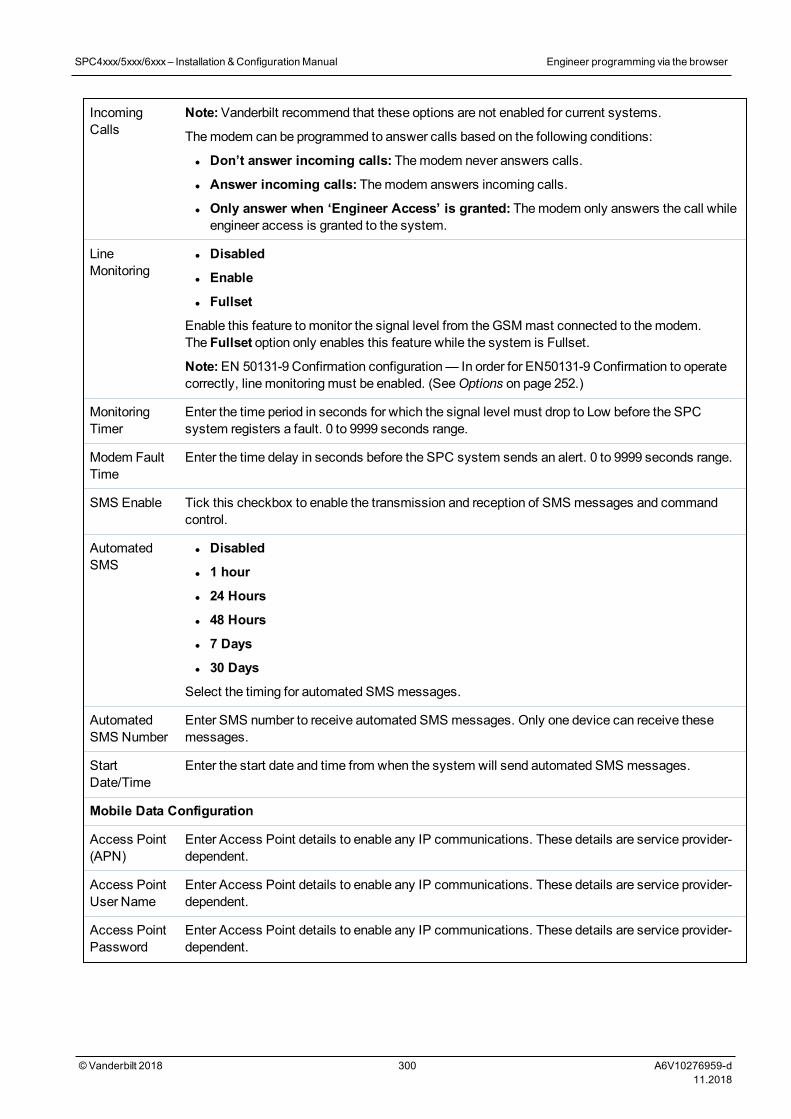
IncomingCalls
Note:Vanderbilt recommend that these options are not enabled for current systems.
Themodem can be programmed to answer calls based on the following conditions:
l Don’t answer incoming calls: Themodem never answers calls.
l Answer incoming calls: Themodem answers incoming calls.
l Only answer when ‘Engineer Access’ is granted: Themodem only answers the call whileengineer access is granted to the system.
LineMonitoring
l Disabled
l Enable
l Fullset
Enable this feature tomonitor the signal level from theGSMmast connected to themodem.The Fullset option only enables this feature while the system is Fullset.
Note:EN 50131-9 Confirmation configuration— In order for EN50131-9 Confirmation to operatecorrectly, linemonitoringmust be enabled. (SeeOptions on page 252.)
MonitoringTimer
Enter the time period in seconds for which the signal level must drop to Low before the SPCsystem registers a fault. 0 to 9999 seconds range.
Modem FaultTime
Enter the time delay in seconds before the SPC system sends an alert. 0 to 9999 seconds range.
SMS Enable Tick this checkbox to enable the transmission and reception of SMS messages and commandcontrol.
AutomatedSMS
l Disabled
l 1 hour
l 24 Hours
l 48 Hours
l 7 Days
l 30 Days
Select the timing for automated SMS messages.
AutomatedSMS Number
Enter SMS number to receive automated SMS messages. Only one device can receive thesemessages.
StartDate/Time
Enter the start date and time from when the system will send automated SMS messages.
Mobile Data Configuration
Access Point(APN)
Enter Access Point details to enable any IP communications. These details are service provider-dependent.
Access PointUser Name
Enter Access Point details to enable any IP communications. These details are service provider-dependent.
Access PointPassword
Enter Access Point details to enable any IP communications. These details are service provider-dependent.
SPC4xxx/5xxx/6xxx– Installation &ConfigurationManual Engineer programming via the browser
© Vanderbilt 2018 300 A6V10276959-d11.2018
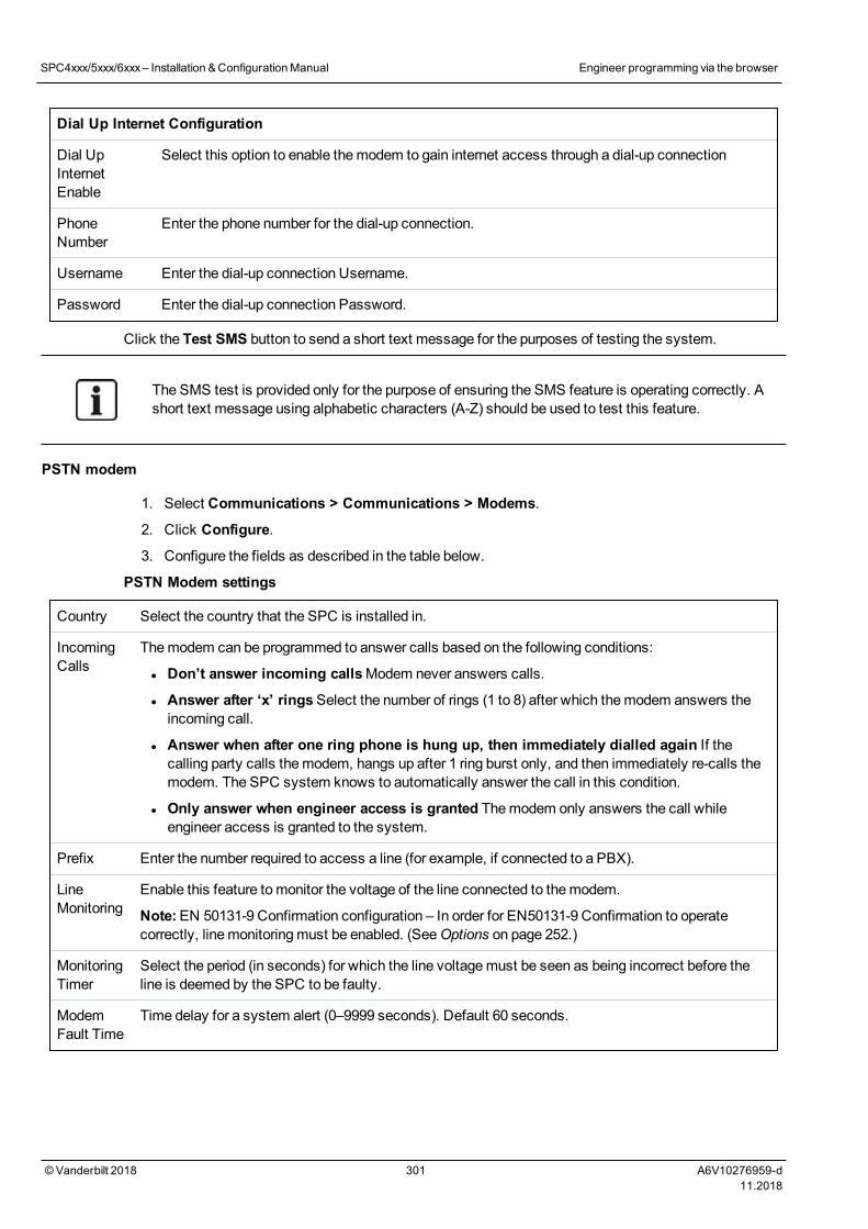
Dial Up Internet Configuration
Dial UpInternetEnable
Select this option to enable themodem to gain internet access through a dial-up connection
PhoneNumber
Enter the phone number for the dial-up connection.
Username Enter the dial-up connection Username.
Password Enter the dial-up connection Password.
Click the Test SMS button to send a short text message for the purposes of testing the system.
The SMS test is provided only for the purpose of ensuring the SMS feature is operating correctly. Ashort text message using alphabetic characters (A-Z) should be used to test this feature.
PSTN modem
1. Select Communications > Communications > Modems.
2. Click Configure.
3. Configure the fields as described in the table below.
PSTN Modem settings
Country Select the country that the SPC is installed in.
IncomingCalls
Themodem can be programmed to answer calls based on the following conditions:
l Don’t answer incoming callsModem never answers calls.
l Answer after ‘x’ ringsSelect the number of rings (1 to 8) after which themodem answers theincoming call.
l Answer when after one ring phone is hung up, then immediately dialled again If thecalling party calls themodem, hangs up after 1 ring burst only, and then immediately re-calls themodem. The SPC system knows to automatically answer the call in this condition.
l Only answer when engineer access is granted Themodem only answers the call whileengineer access is granted to the system.
Prefix Enter the number required to access a line (for example, if connected to a PBX).
LineMonitoring
Enable this feature tomonitor the voltage of the line connected to themodem.
Note:EN 50131-9 Confirmation configuration – In order for EN50131-9 Confirmation to operatecorrectly, linemonitoringmust be enabled. (SeeOptions on page 252.)
MonitoringTimer
Select the period (in seconds) for which the line voltagemust be seen as being incorrect before theline is deemed by the SPC to be faulty.
ModemFault Time
Time delay for a system alert (0–9999 seconds). Default 60 seconds.
SPC4xxx/5xxx/6xxx– Installation &ConfigurationManual Engineer programming via the browser
© Vanderbilt 2018 301 A6V10276959-d11.2018
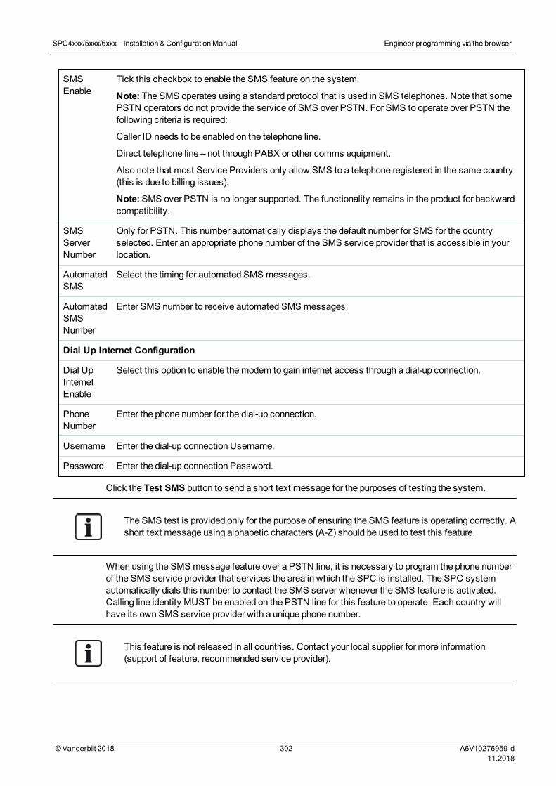
SMSEnable
Tick this checkbox to enable the SMS feature on the system.
Note: The SMS operates using a standard protocol that is used in SMS telephones. Note that somePSTN operators do not provide the service of SMS over PSTN. For SMS to operate over PSTN thefollowing criteria is required:
Caller ID needs to be enabled on the telephone line.
Direct telephone line – not through PABX or other comms equipment.
Also note that most Service Providers only allow SMS to a telephone registered in the same country(this is due to billing issues).
Note:SMS over PSTN is no longer supported. The functionality remains in the product for backwardcompatibility.
SMSServerNumber
Only for PSTN. This number automatically displays the default number for SMS for the countryselected. Enter an appropriate phone number of the SMS service provider that is accessible in yourlocation.
AutomatedSMS
Select the timing for automated SMS messages.
AutomatedSMSNumber
Enter SMS number to receive automated SMS messages.
Dial Up Internet Configuration
Dial UpInternetEnable
Select this option to enable themodem to gain internet access through a dial-up connection.
PhoneNumber
Enter the phone number for the dial-up connection.
Username Enter the dial-up connection Username.
Password Enter the dial-up connection Password.
Click the Test SMS button to send a short text message for the purposes of testing the system.
The SMS test is provided only for the purpose of ensuring the SMS feature is operating correctly. Ashort text message using alphabetic characters (A-Z) should be used to test this feature.
When using the SMS message feature over a PSTN line, it is necessary to program the phone numberof the SMS service provider that services the area in which the SPC is installed. The SPC systemautomatically dials this number to contact the SMS server whenever the SMS feature is activated.Calling line identity MUST be enabled on the PSTN line for this feature to operate. Each country willhave its own SMS service provider with a unique phone number.
This feature is not released in all countries. Contact your local supplier for more information(support of feature, recommended service provider).
SPC4xxx/5xxx/6xxx– Installation &ConfigurationManual Engineer programming via the browser
© Vanderbilt 2018 302 A6V10276959-d11.2018
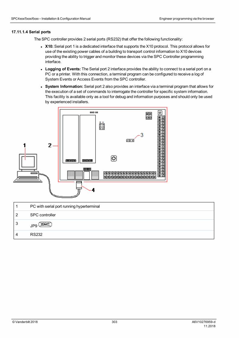
17.11.1.4 Serial ports
The SPC controller provides 2 serial ports (RS232) that offer the following functionality:
l X10:Serial port 1 is a dedicated interface that supports the X10 protocol. This protocol allows foruse of the existing power cables of a building to transport control information to X10 devicesproviding the ability to trigger andmonitor these devices via the SPC Controller programminginterface.
l Logging of Events: The Serial port 2 interface provides the ability to connect to a serial port on aPC or a printer. With this connection, a terminal program can be configured to receive a log ofSystem Events or Access Events from the SPC controller.
l System Information:Serial port 2 also provides an interface via a terminal program that allows forthe execution of a set of commands to interrogate the controller for specific system information.This facility is available only as a tool for debug and information purposes and should only be usedby experienced installers.
1 PC with serial port running hyperterminal
2 SPC controller
3 JP9
4 RS232
SPC4xxx/5xxx/6xxx– Installation &ConfigurationManual Engineer programming via the browser
© Vanderbilt 2018 303 A6V10276959-d11.2018
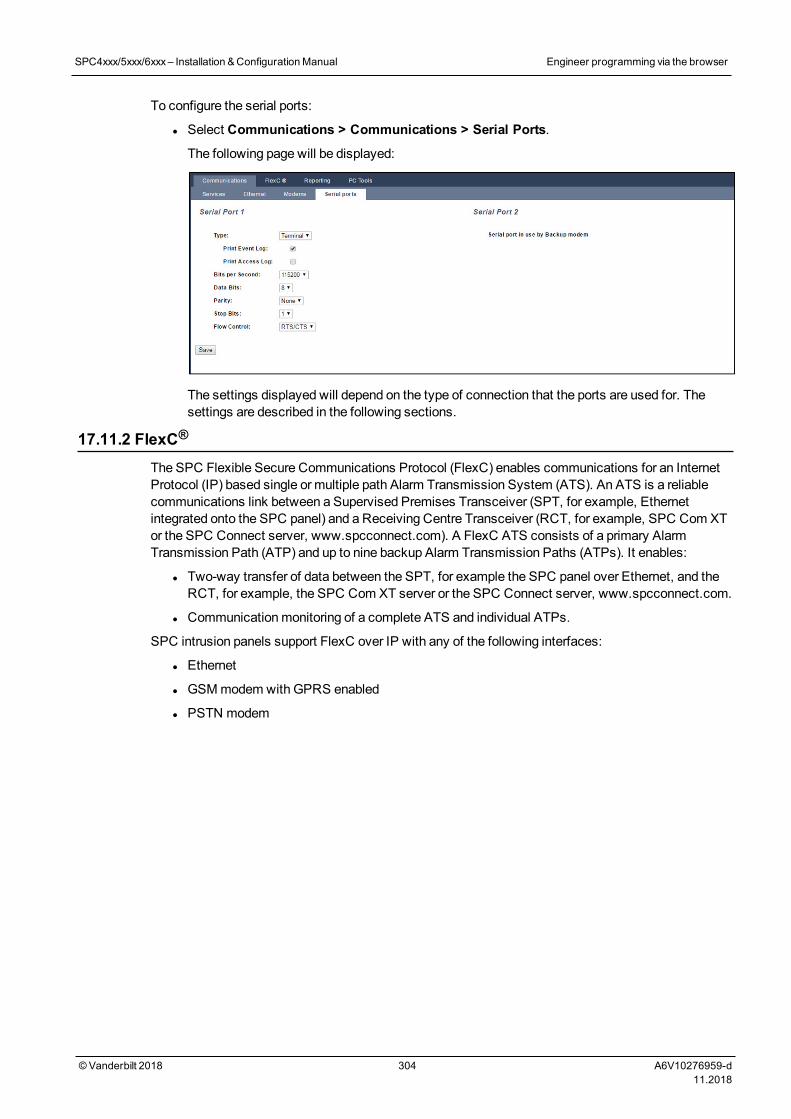
To configure the serial ports:
l Select Communications > Communications > Serial Ports.
The following page will be displayed:
The settings displayed will depend on the type of connection that the ports are used for. Thesettings are described in the following sections.
17.11.2 FlexC®
The SPC Flexible Secure Communications Protocol (FlexC) enables communications for an InternetProtocol (IP) based single or multiple path Alarm Transmission System (ATS). An ATS is a reliablecommunications link between a Supervised Premises Transceiver (SPT, for example, Ethernetintegrated onto the SPC panel) and a Receiving Centre Transceiver (RCT, for example, SPC Com XTor the SPC Connect server, www.spcconnect.com). A FlexC ATS consists of a primary AlarmTransmission Path (ATP) and up to nine backup Alarm Transmission Paths (ATPs). It enables:
l Two-way transfer of data between the SPT, for example the SPC panel over Ethernet, and theRCT, for example, the SPC Com XT server or the SPC Connect server, www.spcconnect.com.
l Communicationmonitoring of a complete ATS and individual ATPs.
SPC intrusion panels support FlexC over IP with any of the following interfaces:
l Ethernet
l GSMmodem with GPRS enabled
l PSTN modem
SPC4xxx/5xxx/6xxx– Installation &ConfigurationManual Engineer programming via the browser
© Vanderbilt 2018 304 A6V10276959-d11.2018
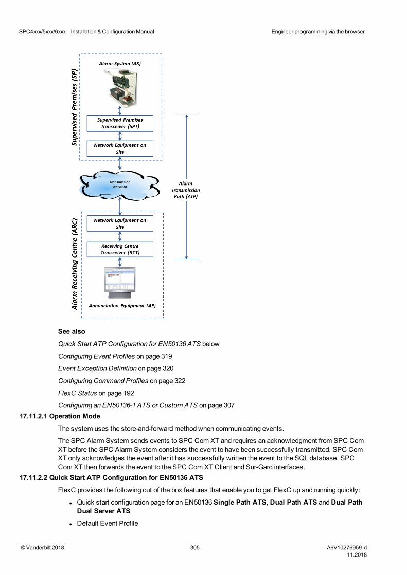
See also
Quick Start ATP Configuration for EN50136 ATS below
Configuring Event Profiles on page 319
Event Exception Definition on page 320
Configuring Command Profiles on page 322
FlexC Status on page 192
Configuring an EN50136-1 ATS or Custom ATS on page 30717.11.2.1 Operation Mode
The system uses the store-and-forwardmethod when communicating events.
The SPC Alarm System sends events to SPC Com XT and requires an acknowledgment from SPC ComXT before the SPC Alarm System considers the event to have been successfully transmitted. SPC ComXT only acknowledges the event after it has successfully written the event to the SQL database. SPCCom XT then forwards the event to the SPC Com XT Client and Sur-Gard interfaces.
17.11.2.2 Quick Start ATP Configuration for EN50136 ATS
FlexC provides the following out of the box features that enable you to get FlexC up and running quickly:
l Quick start configuration page for an EN50136Single Path ATS, Dual Path ATS andDual PathDual Server ATS
l Default Event Profile
SPC4xxx/5xxx/6xxx– Installation &ConfigurationManual Engineer programming via the browser
© Vanderbilt 2018 305 A6V10276959-d11.2018
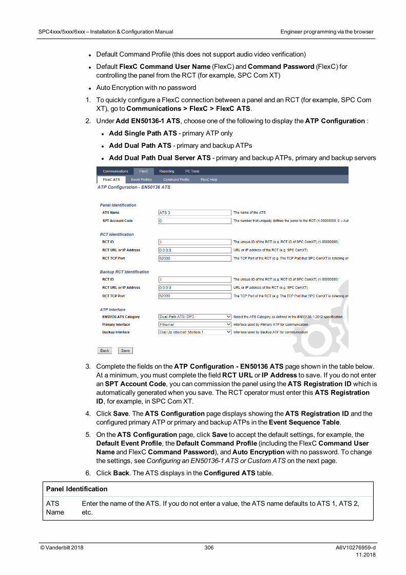
l Default Command Profile (this does not support audio video verification)
l Default FlexC Command User Name (FlexC) andCommand Password (FlexC) forcontrolling the panel from the RCT (for example, SPC Com XT)
l Auto Encryption with no password
1. To quickly configure a FlexC connection between a panel and an RCT (for example, SPC ComXT), go toCommunications > FlexC > FlexC ATS.
2. UnderAdd EN50136-1 ATS, choose one of the following to display theATP Configuration :
l Add Single Path ATS - primary ATP only
l Add Dual Path ATS - primary and backup ATPs
l Add Dual Path Dual Server ATS - primary and backup ATPs, primary and backup servers
3. Complete the fields on theATP Configuration - EN50136 ATS page shown in the table below.At aminimum, youmust complete the fieldRCT URL or IP Address to save. If you do not enteranSPT Account Code, you can commission the panel using theATS Registration ID which isautomatically generated when you save. The RCT operator must enter this ATS RegistrationID, for example, in SPC Com XT.
4. Click Save. TheATS Configuration page displays showing theATS Registration ID and theconfigured primary ATP or primary and backup ATPs in theEvent Sequence Table.
5. On theATS Configuration page, click Save to accept the default settings, for example, theDefault Event Profile, theDefault Command Profile (including the FlexC Command UserName and FlexC Command Password), andAuto Encryptionwith no password. To changethe settings, seeConfiguring an EN50136-1 ATS or Custom ATS on the next page.
6. Click Back. The ATS displays in theConfigured ATS table.
Panel Identification
ATSName
Enter the name of the ATS. If you do not enter a value, the ATS name defaults to ATS 1, ATS 2,etc.
SPC4xxx/5xxx/6xxx– Installation &ConfigurationManual Engineer programming via the browser
© Vanderbilt 2018 306 A6V10276959-d11.2018
SPTAccountCode
The number that uniquely identifies the panel to the RCT. Enter 0 if you do not have the SPTAccount Code. In this case, you can commission the panel using theATS Registration ID. For anEN50136 ATS, theATS Registration ID is automatically generated when you click Save. TheRCT can send theSPT Account Code to the panel when it is available.
RCT Identification & Backup RCT Identification (Dual Path Dual Server Only)
RCT ID Enter theRCT ID that uniquely identifies the RCT (for example, SPC Com XT) to the panel. Thismust match the value entered in the SPC Com XT Server ConfigurationManager tool in theServerRCT ID field in theServer Details tab. See theSPC Com XT Installation & ConfigurationManual.
RCT URLor IPAddress
Enter theRCT URL or IP Address for the RCT server location (for example, SPC Com XTserver).
RCT TCPPort
Enter the TCP port for the RCT (for example, SPC Com XT). This must be the same value enteredfor the fieldServer FlexC Port in the SPC Com XT Server ConfigurationManager tool.
ATP Interface
EN50136ATSCategory
Select the EN50136 ATS Category (SP1-SP6, DP1-DP4). For a description of categories, seeATS Category Timings on page 397.
PrimaryInterface
Select thePrimary Interface to apply to the primary communications path from the following:
l Ethernet
l GPRS: Modem 1
l GPRS: Modem 2
l Dial Up Internet: Modem 1
l Dial Up Internet: Modem 2
BackupInterface
For aDual Path ATS, select theBackup Interface to use for the backup communications pathfrom the following:
l Ethernet
l GPRS: Modem 1
l GPRS: Modem 2
l Dial Up Internet: Modem 1
l Dial Up Internet: Modem 2
17.11.2.3 Configuring an EN50136-1 ATS or Custom ATS
An ATS comprises an alarm panel, network paths and an RCT (for example, SPC Com XT). It combinesone or multiple paths between an SPC panel and an RCT. You can add up to 10 ATPs to an ATS.
NOTICE: For an EN50136-1 ATS, the ATS set up sequence starts with configuring an ATP for anATS. This provides you with a quick set up feature. SeeQuick Start ATP Configuration for EN50136ATS on page 305.
1. To configure an ATS, go toCommunications > FlexC > FlexC ATS.
2. Choose from one of the following options:
l Add Single Path ATS
l AddDual Path ATS
SPC4xxx/5xxx/6xxx– Installation &ConfigurationManual Engineer programming via the browser
© Vanderbilt 2018 307 A6V10276959-d11.2018
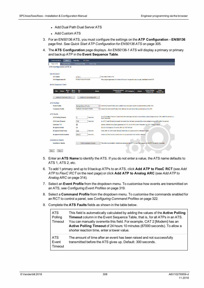
l AddDual Path Dual Server ATS
l AddCustom ATS
3. For an EN50136 ATS, youmust configure the settings on theATP Configuration - EN50136page first. SeeQuick Start ATP Configuration for EN50136 ATS on page 305.
4. TheATS Configuration page displays. An EN50136-1 ATS will display a primary or primaryand backup ATP in theEvent Sequence Table.
5. Enter anATS Name to identify the ATS. If you do not enter a value, the ATS name defaults toATS 1, ATS 2, etc.
6. To add 1 primary and up to 9 backup ATPs to an ATS, click Add ATP to FlexC RCT (seeAddATP to FlexC RCT on the next page) or click Add ATP to Analog ARC (seeAdd ATP toAnalog ARC on page 314).
7. Select anEvent Profile from the dropdownmenu. To customise how events are transmitted onan ATS, seeConfiguring Event Profiles on page 319.
8. Select aCommand Profile from the dropdownmenu. To customise the commands enabled foran RCT to control a panel, seeConfiguring Command Profiles on page 322.
9. Complete theATS Faults fields as shown in the table below.
ATSPollingTimeout
This field is automatically calculated by adding the values of theActive PollingTimeout column in the Event Sequence Table, that is, for all ATPs in an ATS.You canmanually overwrite this field. For example, CAT 2 [Modem] has anActive Polling Timeout of 24 hours 10minutes (87000 seconds). To allow ashorter reaction time, enter a lower value.
ATSEventTimeout
The amount of time after an event has been raised and not successfullytransmitted before the ATS gives up. Default: 300 seconds.
SPC4xxx/5xxx/6xxx– Installation &ConfigurationManual Engineer programming via the browser
© Vanderbilt 2018 308 A6V10276959-d11.2018
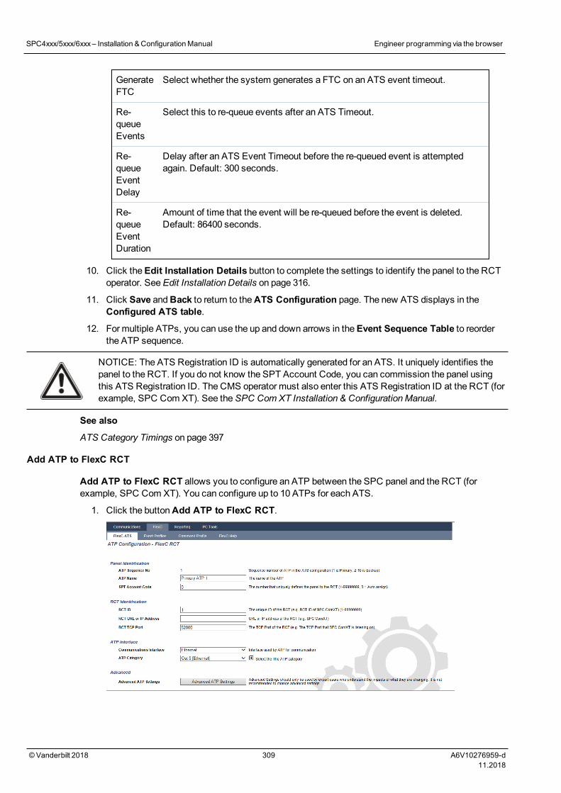
GenerateFTC
Select whether the system generates a FTC on an ATS event timeout.
Re-queueEvents
Select this to re-queue events after an ATS Timeout.
Re-queueEventDelay
Delay after an ATS Event Timeout before the re-queued event is attemptedagain. Default: 300 seconds.
Re-queueEventDuration
Amount of time that the event will be re-queued before the event is deleted.Default: 86400 seconds.
10. Click theEdit Installation Details button to complete the settings to identify the panel to the RCToperator. SeeEdit Installation Details on page 316.
11. Click Save andBack to return to theATS Configuration page. The new ATS displays in theConfigured ATS table.
12. For multiple ATPs, you can use the up and down arrows in theEvent Sequence Table to reorderthe ATP sequence.
NOTICE: The ATS Registration ID is automatically generated for an ATS. It uniquely identifies thepanel to the RCT. If you do not know the SPT Account Code, you can commission the panel usingthis ATS Registration ID. The CMS operator must also enter this ATS Registration ID at the RCT (forexample, SPC Com XT). See theSPC Com XT Installation & ConfigurationManual.
See also
ATS Category Timings on page 397
Add ATP to FlexC RCT
Add ATP to FlexC RCT allows you to configure an ATP between the SPC panel and the RCT (forexample, SPC Com XT). You can configure up to 10 ATPs for each ATS.
1. Click the buttonAdd ATP to FlexC RCT.
SPC4xxx/5xxx/6xxx– Installation &ConfigurationManual Engineer programming via the browser
© Vanderbilt 2018 309 A6V10276959-d11.2018
2. Complete the ATP fields described in the table below.
Panel Identification
ATP SequenceNo.
This field displays the sequence number of the ATP in the ATSconfiguration. Number 1 is primary, numbers 2–10 are backup.
ATP Unique ID When you save an ATP, the system assigns a unique ID to an ATP.This is the unique ID of the ATP so it can be recognised by the RCT.
ATP Name Enter a name for the ATP.
SPT AccountCode
Enter a number to uniquely identify the panel to the RCT.
RCT Identification
RCT ID Enter the number that uniquely identifies the RCT (for example, SPCCom XT) to the panel. This must match the number entered in the fieldServer RCT ID in the SPC Com XT Server ConfigurationManager tool.
RCT URL or IPAddress
Enter the URL or IP address of the RCT (for example, SPC Com XT).
RCT TCP Port Enter the TCP Port that the RCT (for example, SPC Com XT) listenson. The default is 52000. This must match the value in the fieldServerFlexC Port in the Server ConfigurationManager tool. See theSPCCom XT Installation & ConfigurationManual.
ATP Interface
CommunicationsInterface
From the dropdown list, select the interface this ATP uses forcommunication.
l Ethernet
l GPRS: Modem 1
l GPRS: Modem 2
l Dial Up Internet: Modem 1
l Dial Up Internet: Modem 2
ATP Category Select the category to apply to this ATP. For information on ATPCategories, seeATP Category Timings on page 398.
Advanced
Advanced ATPSettings
It is not recommended to change advanced settings. Changes mustonly bemade by expert users.
3. If required, click Advanced ATP Settings, for example, if you are using auto encryption you canoptionally enter a password in theEncryption Password field. SeeConfigure Advanced ATPSettings on the next page.
4. Click Save.
SPC4xxx/5xxx/6xxx– Installation &ConfigurationManual Engineer programming via the browser
© Vanderbilt 2018 310 A6V10276959-d11.2018
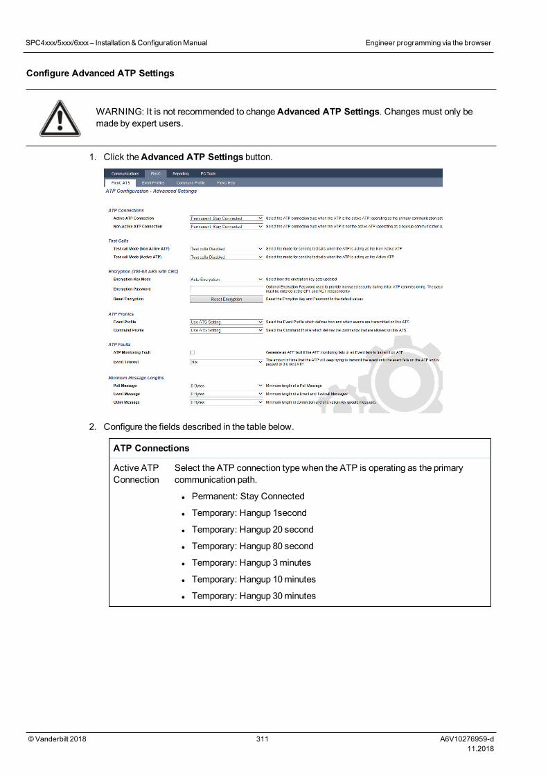
Configure Advanced ATP Settings
WARNING: It is not recommended to changeAdvanced ATP Settings. Changes must only bemade by expert users.
1. Click theAdvanced ATP Settings button.
2. Configure the fields described in the table below.
ATP Connections
Active ATPConnection
Select the ATP connection type when the ATP is operating as the primarycommunication path.
l Permanent: Stay Connected
l Temporary: Hangup 1second
l Temporary: Hangup 20 second
l Temporary: Hangup 80 second
l Temporary: Hangup 3minutes
l Temporary: Hangup 10minutes
l Temporary: Hangup 30minutes
SPC4xxx/5xxx/6xxx– Installation &ConfigurationManual Engineer programming via the browser
© Vanderbilt 2018 311 A6V10276959-d11.2018
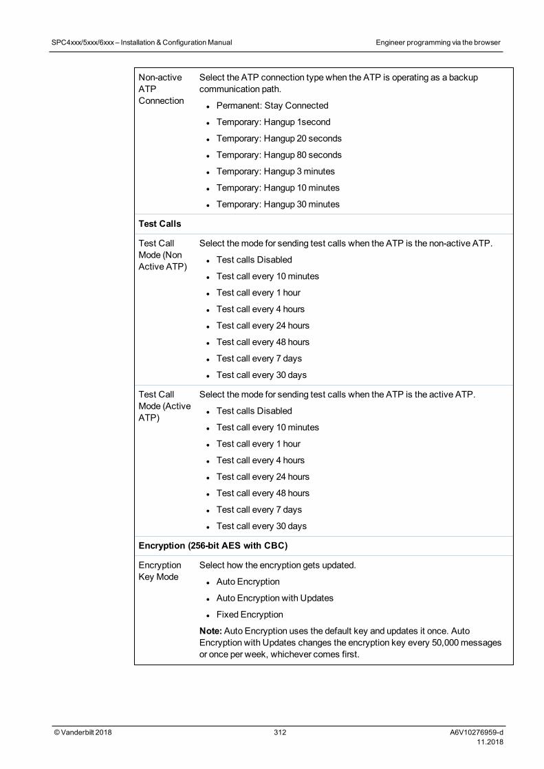
Non-activeATPConnection
Select the ATP connection type when the ATP is operating as a backupcommunication path.
l Permanent: Stay Connected
l Temporary: Hangup 1second
l Temporary: Hangup 20 seconds
l Temporary: Hangup 80 seconds
l Temporary: Hangup 3minutes
l Temporary: Hangup 10minutes
l Temporary: Hangup 30minutes
Test Calls
Test CallMode (NonActive ATP)
Select themode for sending test calls when the ATP is the non-active ATP.
l Test calls Disabled
l Test call every 10minutes
l Test call every 1 hour
l Test call every 4 hours
l Test call every 24 hours
l Test call every 48 hours
l Test call every 7 days
l Test call every 30 days
Test CallMode (ActiveATP)
Select themode for sending test calls when the ATP is the active ATP.
l Test calls Disabled
l Test call every 10minutes
l Test call every 1 hour
l Test call every 4 hours
l Test call every 24 hours
l Test call every 48 hours
l Test call every 7 days
l Test call every 30 days
Encryption (256-bit AES with CBC)
EncryptionKey Mode
Select how the encryption gets updated.
l Auto Encryption
l Auto Encryption with Updates
l Fixed Encryption
Note:Auto Encryption uses the default key and updates it once. AutoEncryption with Updates changes the encryption key every 50,000messagesor once per week, whichever comes first.
SPC4xxx/5xxx/6xxx– Installation &ConfigurationManual Engineer programming via the browser
© Vanderbilt 2018 312 A6V10276959-d11.2018
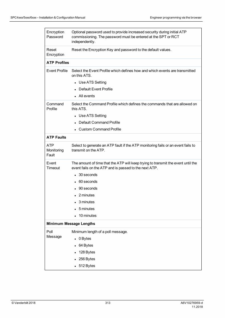
EncryptionPassword
Optional password used to provide increased security during initial ATPcommissioning. The passwordmust be entered at the SPT or RCTindependently.
ResetEncryption
Reset the Encryption Key and password to the default values.
ATP Profiles
Event Profile Select the Event Profile which defines how and which events are transmittedon this ATS.
l Use ATS Setting
l Default Event Profile
l All events
CommandProfile
Select the Command Profile which defines the commands that are allowed onthis ATS.
l Use ATS Setting
l Default Command Profile
l Custom Command Profile
ATP Faults
ATPMonitoringFault
Select to generate an ATP fault if the ATP monitoring fails or an event fails totransmit on the ATP.
EventTimeout
The amount of time that the ATP will keep trying to transmit the event until theevent fails on the ATP and is passed to the next ATP.
l 30 seconds
l 60 seconds
l 90 seconds
l 2minutes
l 3minutes
l 5minutes
l 10minutes
Minimum Message Lengths
PollMessage
Minimum length of a poll message.
l 0 Bytes
l 64 Bytes
l 128 Bytes
l 256 Bytes
l 512 Bytes
SPC4xxx/5xxx/6xxx– Installation &ConfigurationManual Engineer programming via the browser
© Vanderbilt 2018 313 A6V10276959-d11.2018
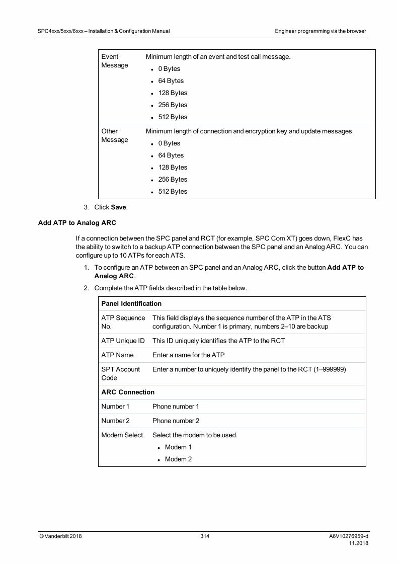
EventMessage
Minimum length of an event and test call message.
l 0 Bytes
l 64 Bytes
l 128 Bytes
l 256 Bytes
l 512 Bytes
OtherMessage
Minimum length of connection and encryption key and updatemessages.
l 0 Bytes
l 64 Bytes
l 128 Bytes
l 256 Bytes
l 512 Bytes
3. Click Save.
Add ATP to Analog ARC
If a connection between the SPC panel and RCT (for example, SPC Com XT) goes down, FlexC hasthe ability to switch to a backup ATP connection between the SPC panel and an Analog ARC. You canconfigure up to 10 ATPs for each ATS.
1. To configure an ATP between an SPC panel and an Analog ARC, click the buttonAdd ATP toAnalog ARC.
2. Complete the ATP fields described in the table below.
Panel Identification
ATP SequenceNo.
This field displays the sequence number of the ATP in the ATSconfiguration. Number 1 is primary, numbers 2–10 are backup
ATP Unique ID This ID uniquely identifies the ATP to the RCT
ATP Name Enter a name for the ATP
SPT AccountCode
Enter a number to uniquely identify the panel to the RCT (1–999999)
ARC Connection
Number 1 Phone number 1
Number 2 Phone number 2
Modem Select Select themodem to be used.
l Modem 1
l Modem 2
SPC4xxx/5xxx/6xxx– Installation &ConfigurationManual Engineer programming via the browser
© Vanderbilt 2018 314 A6V10276959-d11.2018
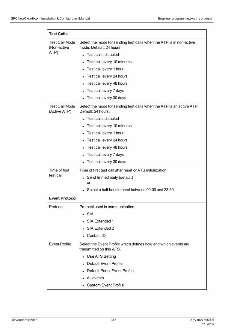
Test Calls
Test Call Mode(Non-activeATP)
Select themode for sending test calls when the ATP is in non-activemode. Default: 24 hours.
l Test calls disabled
l Test call every 10minutes
l Test call every 1 hour
l Test call every 24 hours
l Test call every 48 hours
l Test call every 7 days
l Test call every 30 days
Test Call Mode(Active ATP)
Select themode for sending test calls when the ATP is an active ATP.Default: 24 hours.
l Test calls disabled
l Test call every 10minutes
l Test call every 1 hour
l Test call every 24 hours
l Test call every 48 hours
l Test call every 7 days
l Test call every 30 days
Time of firsttest call
Time of first test call after reset or ATS initialization.
l Send Immediately (default)or
l Select a half hour interval between 00:00 and 23:30
Event Protocol
Protocol Protocol used in communication.
l SIA
l SIA Extended 1
l SIA Extended 2
l Contact ID
Event Profile Select the Event Profile which defines how and which events aretransmitted on this ATS.
l Use ATS Setting
l Default Event Profile
l Default Portal Event Profile
l All events
l Custom Event Profile
SPC4xxx/5xxx/6xxx– Installation &ConfigurationManual Engineer programming via the browser
© Vanderbilt 2018 315 A6V10276959-d11.2018
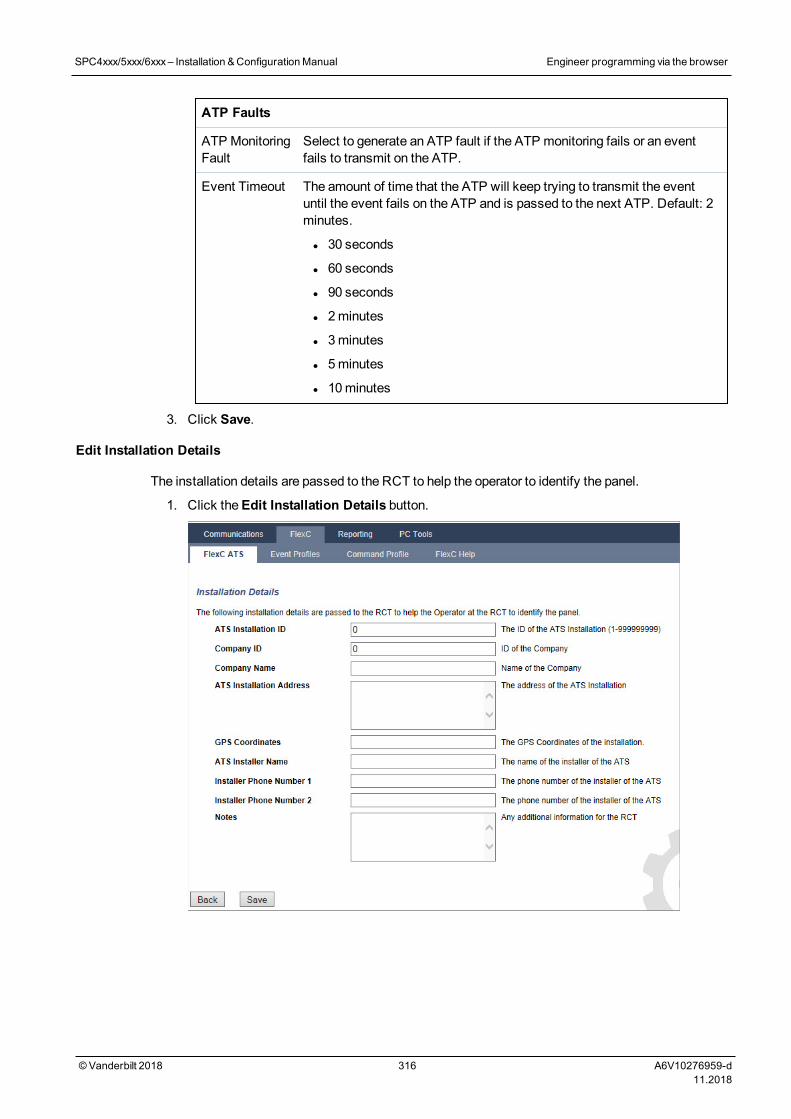
ATP Faults
ATP MonitoringFault
Select to generate an ATP fault if the ATP monitoring fails or an eventfails to transmit on the ATP.
Event Timeout The amount of time that the ATP will keep trying to transmit the eventuntil the event fails on the ATP and is passed to the next ATP. Default: 2minutes.
l 30 seconds
l 60 seconds
l 90 seconds
l 2minutes
l 3minutes
l 5minutes
l 10minutes
3. Click Save.
Edit Installation Details
The installation details are passed to the RCT to help the operator to identify the panel.
1. Click theEdit Installation Details button.
SPC4xxx/5xxx/6xxx– Installation &ConfigurationManual Engineer programming via the browser
© Vanderbilt 2018 316 A6V10276959-d11.2018
2. Complete the fields in the table below.
ATS Installation ID The ID of the ATS Installation (1–999999999).
Company ID For future use.
Company Name Name of the company.
ATS Installation Address The address of the ATS installation.
GPS Coordinates TheGPS coordinates of the installation.
ATS Installer Name The name of the installer of the ATS.
Installer Phone Number 1 The phone number of the installer of the ATS.
Installer Phone Number 2 The phone number of the installer of the ATS.
Notes Any additional information for the RCT.
3. Click Save.17.11.2.4 Configuring an SPC Connect ATS
TheAdd SPC ConnectATS functionality opens a communication between the panel (SPT) and theSPCConnect server (RCT), www.spcconnect.com. Using the generated SPC Connect ATS Registration ID, apanel user can register a user account and panel with the SPC Connect website to access their panelremotely.
1. To configure an SPC Connect ATS, go toCommunications > FlexC > FlexC ATS.
2. On theATS Configuration page, click Add SPC Connect to open a communication path with theSPC Connect server.
An SPC Connect ATS is added to theEvent Sequence Tablewith the following attributes:
l SPC Connect ATS Registration ID
l Default ATP over Ethernet. For information on ATP fields, seeAdd ATP to FlexC RCT onpage 309.
l Default Events Profile for SPC Connect
l Default Commands Profile for SPC Connect
l Default RCT URL is www.spcconnect.com
l The SPT Account Code for the ATP is populated.
l Make a note of the SPC Connect ATS Registration ID and provide this to the customer alongwith theSPC Connect System User Guide.
SPC4xxx/5xxx/6xxx– Installation &ConfigurationManual Engineer programming via the browser
© Vanderbilt 2018 317 A6V10276959-d11.2018
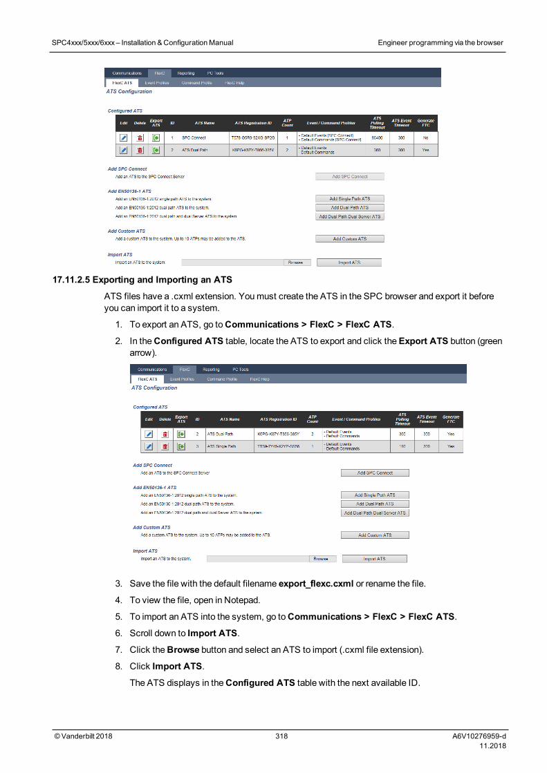
17.11.2.5 Exporting and Importing an ATS
ATS files have a .cxml extension. Youmust create the ATS in the SPC browser and export it beforeyou can import it to a system.
1. To export an ATS, go toCommunications > FlexC > FlexC ATS.
2. In theConfigured ATS table, locate the ATS to export and click theExport ATS button (greenarrow).
3. Save the file with the default filename export_flexc.cxml or rename the file.
4. To view the file, open in Notepad.
5. To import an ATS into the system, go toCommunications > FlexC > FlexC ATS.
6. Scroll down to Import ATS.
7. Click theBrowse button and select an ATS to import (.cxml file extension).
8. Click Import ATS.
The ATS displays in theConfigured ATS table with the next available ID.
SPC4xxx/5xxx/6xxx– Installation &ConfigurationManual Engineer programming via the browser
© Vanderbilt 2018 318 A6V10276959-d11.2018
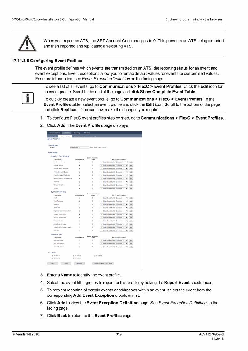
When you export an ATS, the SPT Account Code changes to 0. This prevents an ATS being exportedand then imported and replicating an existing ATS.
17.11.2.6 Configuring Event Profiles
The event profile defines which events are transmitted on an ATS, the reporting status for an event andevent exceptions. Event exceptions allow you to remap default values for events to customised values.For more information, seeEvent Exception Definition on the facing page.
To see a list of all events, go toCommunications > FlexC > Event Profiles. Click theEdit icon foran event profile. Scroll to the end of the page and click Show Complete Event Table.
To quickly create a new event profile, go toCommunications > FlexC > Event Profiles. In theEvent Profiles table, select an event profile and click theEdit icon. Scroll to the bottom of the pageand click Replicate. You can now make the changes you require.
1. To configure FlexC event profiles step by step, go toCommunications > FlexC > Event Profiles.
2. Click Add. TheEvent Profiles page displays.
3. Enter aName to identify the event profile.
4. Select the event filter groups to report for this profile by ticking theReport Event checkboxes.
5. To prevent reporting of certain events or addresses within an event, select the event from thecorrespondingAdd Event Exception dropdown list.
6. Click Add to view theEvent Exception Definition page. SeeEvent Exception Definition on thefacing page.
7. Click Back to return to theEvent Profiles page.
SPC4xxx/5xxx/6xxx– Installation &ConfigurationManual Engineer programming via the browser
© Vanderbilt 2018 319 A6V10276959-d11.2018
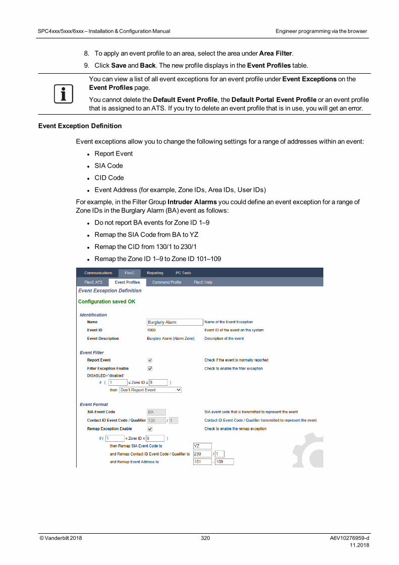
8. To apply an event profile to an area, select the area underArea Filter.
9. Click Save andBack. The new profile displays in theEvent Profiles table.
You can view a list of all event exceptions for an event profile underEvent Exceptions on theEvent Profiles page.
You cannot delete theDefault Event Profile, theDefault Portal Event Profile or an event profilethat is assigned to an ATS. If you try to delete an event profile that is in use, you will get an error.
Event Exception Definition
Event exceptions allow you to change the following settings for a range of addresses within an event:
l Report Event
l SIA Code
l CID Code
l Event Address (for example, Zone IDs, Area IDs, User IDs)
For example, in the Filter Group Intruder Alarms you could define an event exception for a range ofZone IDs in the Burglary Alarm (BA) event as follows:
l Do not report BA events for Zone ID 1–9
l Remap the SIA Code from BA to YZ
l Remap the CID from 130/1 to 230/1
l Remap the Zone ID 1–9 to Zone ID 101–109
SPC4xxx/5xxx/6xxx– Installation &ConfigurationManual Engineer programming via the browser
© Vanderbilt 2018 320 A6V10276959-d11.2018
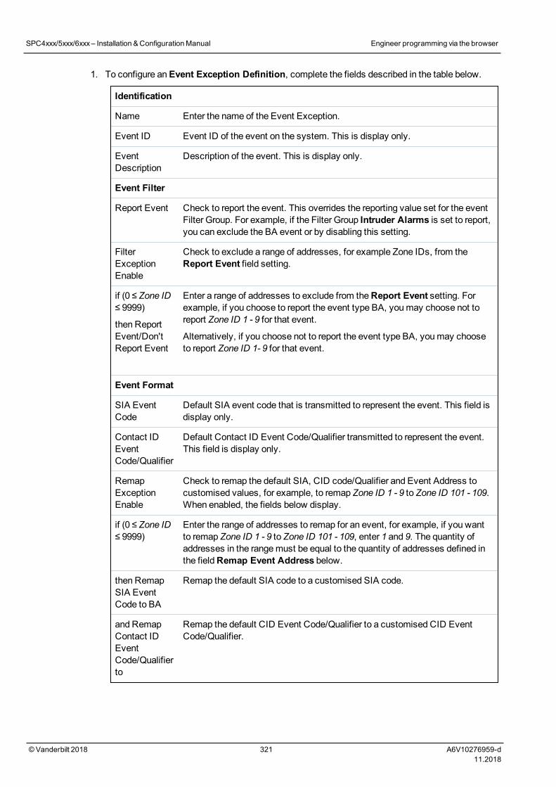
1. To configure anEvent Exception Definition, complete the fields described in the table below.
Identification
Name Enter the name of the Event Exception.
Event ID Event ID of the event on the system. This is display only.
EventDescription
Description of the event. This is display only.
Event Filter
Report Event Check to report the event. This overrides the reporting value set for the eventFilter Group. For example, if the Filter Group Intruder Alarms is set to report,you can exclude the BA event or by disabling this setting.
FilterExceptionEnable
Check to exclude a range of addresses, for example Zone IDs, from theReport Event field setting.
if (0 ≤ Zone ID≤ 9999)
then ReportEvent/Don'tReport Event
Enter a range of addresses to exclude from theReport Event setting. Forexample, if you choose to report the event type BA, youmay choose not toreport Zone ID 1 - 9 for that event.
Alternatively, if you choose not to report the event type BA, youmay chooseto report Zone ID 1- 9 for that event.
Event Format
SIA EventCode
Default SIA event code that is transmitted to represent the event. This field isdisplay only.
Contact IDEventCode/Qualifier
Default Contact ID Event Code/Qualifier transmitted to represent the event.This field is display only.
RemapExceptionEnable
Check to remap the default SIA, CID code/Qualifier and Event Address tocustomised values, for example, to remap Zone ID 1 - 9 to Zone ID 101 - 109.When enabled, the fields below display.
if (0 ≤ Zone ID≤ 9999)
Enter the range of addresses to remap for an event, for example, if you wantto remap Zone ID 1 - 9 to Zone ID 101 - 109, enter 1 and 9. The quantity ofaddresses in the rangemust be equal to the quantity of addresses defined inthe fieldRemap Event Address below.
then RemapSIA EventCode to BA
Remap the default SIA code to a customised SIA code.
and RemapContact IDEventCode/Qualifierto
Remap the default CID Event Code/Qualifier to a customised CID EventCode/Qualifier.
SPC4xxx/5xxx/6xxx– Installation &ConfigurationManual Engineer programming via the browser
© Vanderbilt 2018 321 A6V10276959-d11.2018
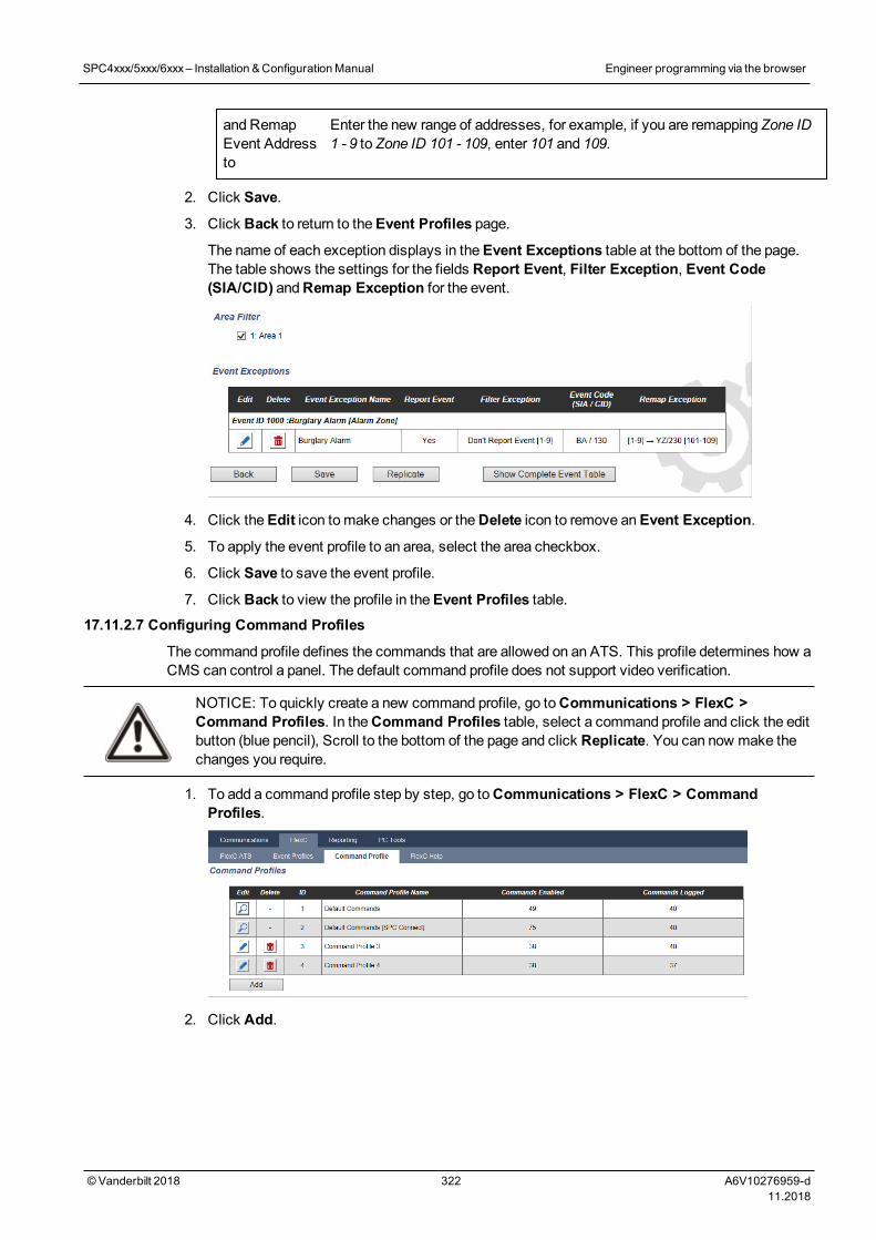
and RemapEvent Addressto
Enter the new range of addresses, for example, if you are remapping Zone ID1 - 9 to Zone ID 101 - 109, enter 101 and 109.
2. Click Save.
3. Click Back to return to theEvent Profiles page.
The name of each exception displays in theEvent Exceptions table at the bottom of the page.The table shows the settings for the fields Report Event, Filter Exception, Event Code(SIA/CID) andRemap Exception for the event.
4. Click theEdit icon tomake changes or theDelete icon to remove anEvent Exception.
5. To apply the event profile to an area, select the area checkbox.
6. Click Save to save the event profile.
7. Click Back to view the profile in theEvent Profiles table.17.11.2.7 Configuring Command Profiles
The command profile defines the commands that are allowed on an ATS. This profile determines how aCMS can control a panel. The default command profile does not support video verification.
NOTICE: To quickly create a new command profile, go toCommunications > FlexC >Command Profiles. In theCommand Profiles table, select a command profile and click the editbutton (blue pencil), Scroll to the bottom of the page and click Replicate. You can now make thechanges you require.
1. To add a command profile step by step, go toCommunications > FlexC > CommandProfiles.
2. Click Add.
SPC4xxx/5xxx/6xxx– Installation &ConfigurationManual Engineer programming via the browser
© Vanderbilt 2018 322 A6V10276959-d11.2018
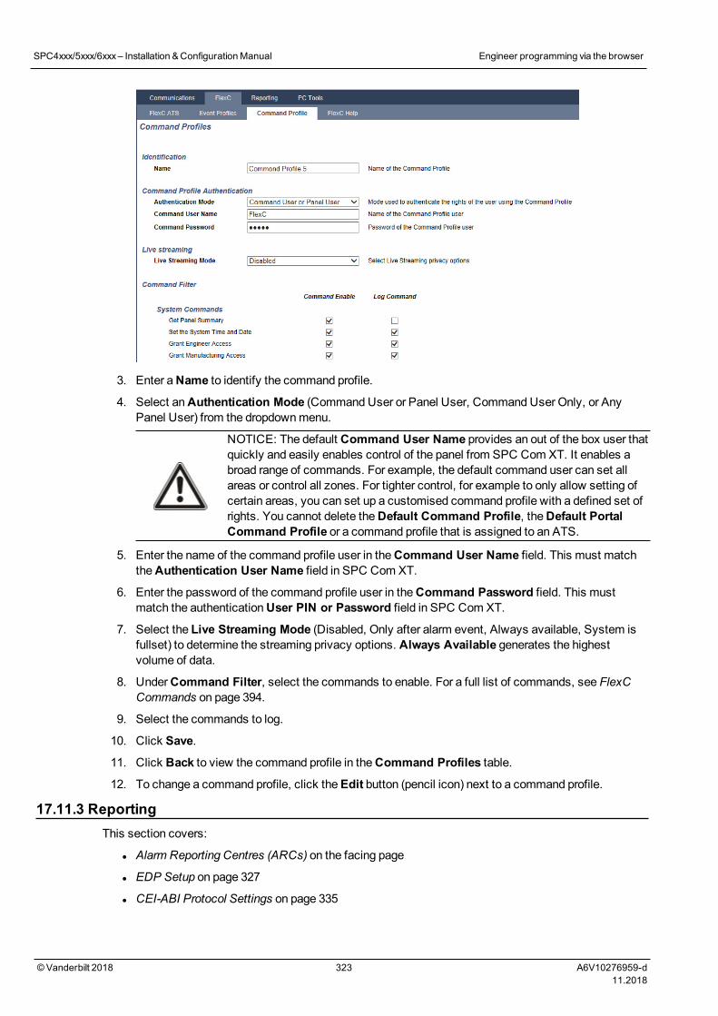
3. Enter aName to identify the command profile.
4. Select anAuthentication Mode (CommandUser or Panel User, CommandUser Only, or AnyPanel User) from the dropdownmenu.
NOTICE: The default Command User Name provides an out of the box user thatquickly and easily enables control of the panel from SPC Com XT. It enables abroad range of commands. For example, the default command user can set allareas or control all zones. For tighter control, for example to only allow setting ofcertain areas, you can set up a customised command profile with a defined set ofrights. You cannot delete theDefault Command Profile, theDefault PortalCommand Profile or a command profile that is assigned to an ATS.
5. Enter the name of the command profile user in theCommand User Name field. This must matchtheAuthentication User Name field in SPC Com XT.
6. Enter the password of the command profile user in theCommand Password field. This mustmatch the authenticationUser PIN or Password field in SPC Com XT.
7. Select the Live Streaming Mode (Disabled, Only after alarm event, Always available, System isfullset) to determine the streaming privacy options. Always Available generates the highestvolume of data.
8. UnderCommand Filter, select the commands to enable. For a full list of commands, see FlexCCommands on page 394.
9. Select the commands to log.
10. Click Save.
11. Click Back to view the command profile in theCommand Profiles table.
12. To change a command profile, click theEdit button (pencil icon) next to a command profile.
17.11.3 ReportingThis section covers:
l Alarm Reporting Centres (ARCs) on the facing page
l EDP Setup on page 327
l CEI-ABI Protocol Settings on page 335
SPC4xxx/5xxx/6xxx– Installation &ConfigurationManual Engineer programming via the browser
© Vanderbilt 2018 323 A6V10276959-d11.2018
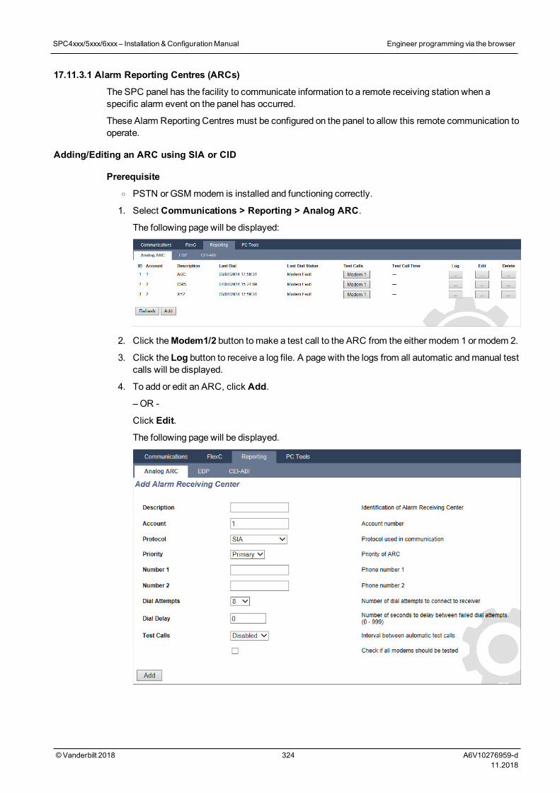
17.11.3.1 Alarm Reporting Centres (ARCs)
The SPC panel has the facility to communicate information to a remote receiving station when aspecific alarm event on the panel has occurred.
These Alarm Reporting Centres must be configured on the panel to allow this remote communication tooperate.
Adding/Editing an ARC using SIA or CID
Prerequisiteo PSTN or GSMmodem is installed and functioning correctly.
1. Select Communications > Reporting > Analog ARC.
The following page will be displayed:
2. Click theModem1/2 button tomake a test call to the ARC from the either modem 1 ormodem 2.
3. Click the Log button to receive a log file. A page with the logs from all automatic andmanual testcalls will be displayed.
4. To add or edit an ARC, click Add.
– OR -
Click Edit.
The following page will be displayed.
SPC4xxx/5xxx/6xxx– Installation &ConfigurationManual Engineer programming via the browser
© Vanderbilt 2018 324 A6V10276959-d11.2018
5. Configure the fields as described in the table below.
Description Enter a description of the remote Alarm Receiving Centre.
Account Enter your account number. This information should be available from thereceiving station and is used to identify you each time youmake a call to theARC.
For a Contact ID account, a maximum of 6 characters is allowed.
Protocol Enter the communication protocol that you intend to use (SIA, SIA Extended,Contact ID, Fast Format).
Note:SPC supports the extended SIA protocol. Select this protocol to supportadditional textual descriptions of the SIA events being sent to the AlarmReceiving Station.
Priority Select the priority for the ARC in terms of primary or back-up reporting.
Number 1 Enter the first number to be dialled to contact the ARC. This system will alwaysattempt to contact the ARC on this number before attempting another number.
Number 2 Enter the second number to be dialled to contact the ARC. The system will onlyattempt to contact the ARC on this number if the first contact number did notsuccessfully establish a call.
DialAttempts
Enter the number of times that the system will attempt to make a call to thereceiver. (Default is 8)
Dial Delay Number of seconds to delay between failed dial attempts (0–999).
DialInterval
Enter the number of seconds to delay between failed dial attempts. (0–999)
Test Calls Enable the test call by choosing a time interval. This will send out an automatictest call frommodem 1 to the primary ARC.
Test All Check this box if you want to initiate also an automatic test call frommodem 2 tothe backup ARC.
6. Click theAdd button to enter those details on the system.
A list of the configured ARC accounts will be displayed in the browser along with the accountinformation, description, protocol, dial-up status and time and date of the last call to the ARC.
SPC4xxx/5xxx/6xxx– Installation &ConfigurationManual Engineer programming via the browser
© Vanderbilt 2018 325 A6V10276959-d11.2018

Editing an ARC filter using SIA or CID
To configure the events on the SPC that will trigger the call to the ARC:
1. Select Select Communications > Reporting > Analog ARC > Edit > Filter.
The following page will be displayed:
2. Configure the following fields:
Check any of the following boxes if you want to initiate a remote call to the ARC to notify it of theparticular event.
Alarms Alarms are activated.
AlarmRestores
System alarms are restored.
ConfirmedAlarms
Alarms confirmed by multiple zones
AlarmAbort
Alarm Abort events. Alarms are aborted after a valid user code is entered viathe keypad after a confirmed or unconfirmed alarm,
Faults Faults and tampers are activated.
FaultRestores
Fault or tamper alarms are restored.
Settings System is Set and Unset.
Early/Late Unscheduled setting and unsetting of the system.
SPC4xxx/5xxx/6xxx– Installation &ConfigurationManual Engineer programming via the browser
© Vanderbilt 2018 326 A6V10276959-d11.2018
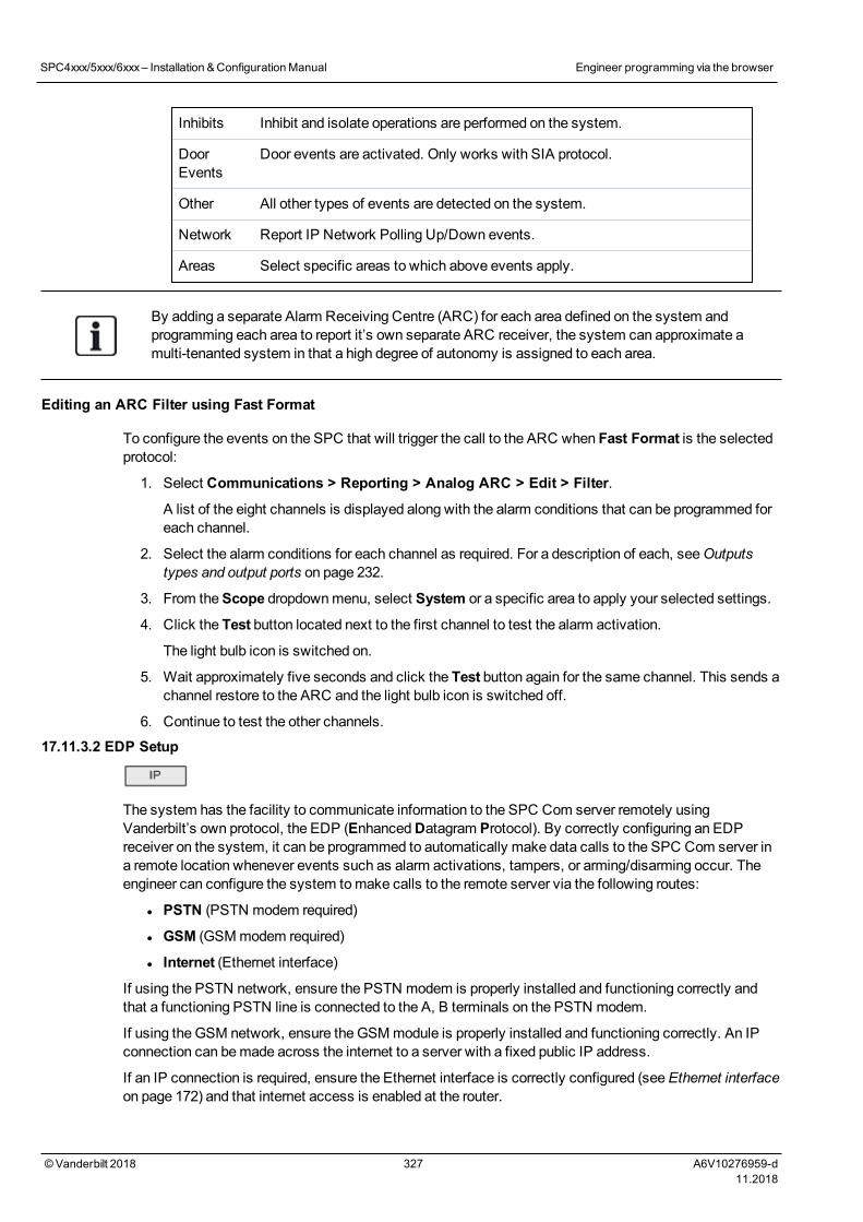
Inhibits Inhibit and isolate operations are performed on the system.
DoorEvents
Door events are activated. Only works with SIA protocol.
Other All other types of events are detected on the system.
Network Report IP Network Polling Up/Down events.
Areas Select specific areas to which above events apply.
By adding a separate Alarm Receiving Centre (ARC) for each area defined on the system andprogramming each area to report it’s own separate ARC receiver, the system can approximate amulti-tenanted system in that a high degree of autonomy is assigned to each area.
Editing an ARC Filter using Fast Format
To configure the events on the SPC that will trigger the call to the ARC when Fast Format is the selectedprotocol:
1. Select Communications > Reporting > Analog ARC > Edit > Filter.
A list of the eight channels is displayed along with the alarm conditions that can be programmed foreach channel.
2. Select the alarm conditions for each channel as required. For a description of each, seeOutputstypes and output ports on page 232.
3. From theScope dropdownmenu, select System or a specific area to apply your selected settings.
4. Click the Test button located next to the first channel to test the alarm activation.
The light bulb icon is switched on.
5. Wait approximately five seconds and click the Test button again for the same channel. This sends achannel restore to the ARC and the light bulb icon is switched off.
6. Continue to test the other channels.
17.11.3.2 EDP Setup
The system has the facility to communicate information to the SPC Com server remotely usingVanderbilt’s own protocol, the EDP (EnhancedDatagram Protocol). By correctly configuring an EDPreceiver on the system, it can be programmed to automatically make data calls to the SPC Com server ina remote location whenever events such as alarm activations, tampers, or arming/disarming occur. Theengineer can configure the system tomake calls to the remote server via the following routes:
l PSTN (PSTN modem required)
l GSM (GSMmodem required)
l Internet (Ethernet interface)
If using the PSTN network, ensure the PSTN modem is properly installed and functioning correctly andthat a functioning PSTN line is connected to the A, B terminals on the PSTN modem.
If using the GSM network, ensure the GSMmodule is properly installed and functioning correctly. An IPconnection can bemade across the internet to a server with a fixed public IP address.
If an IP connection is required, ensure the Ethernet interface is correctly configured (see Ethernet interfaceon page 172) and that internet access is enabled at the router.
SPC4xxx/5xxx/6xxx– Installation &ConfigurationManual Engineer programming via the browser
© Vanderbilt 2018 327 A6V10276959-d11.2018
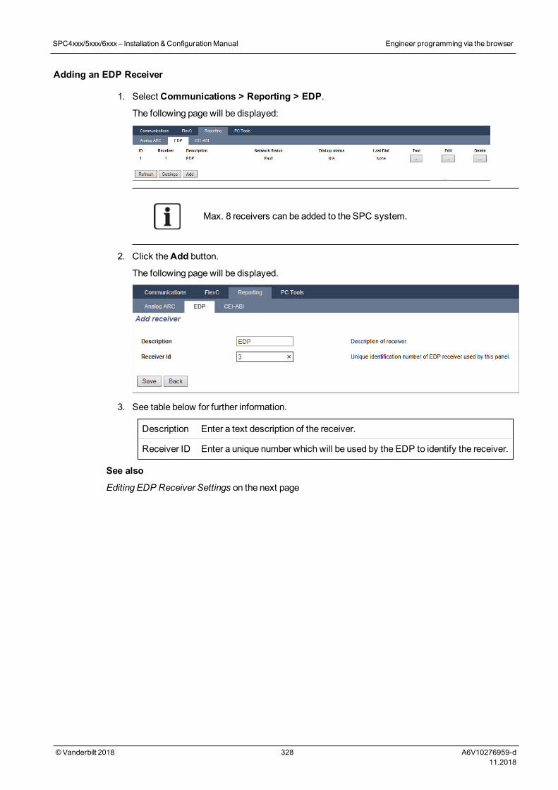
Adding an EDP Receiver
1. Select Communications > Reporting > EDP.
The following page will be displayed:
Max. 8 receivers can be added to the SPC system.
2. Click theAdd button.
The following page will be displayed.
3. See table below for further information.
Description Enter a text description of the receiver.
Receiver ID Enter a unique number which will be used by the EDP to identify the receiver.
See also
Editing EDP Receiver Settings on the next page
SPC4xxx/5xxx/6xxx– Installation &ConfigurationManual Engineer programming via the browser
© Vanderbilt 2018 328 A6V10276959-d11.2018
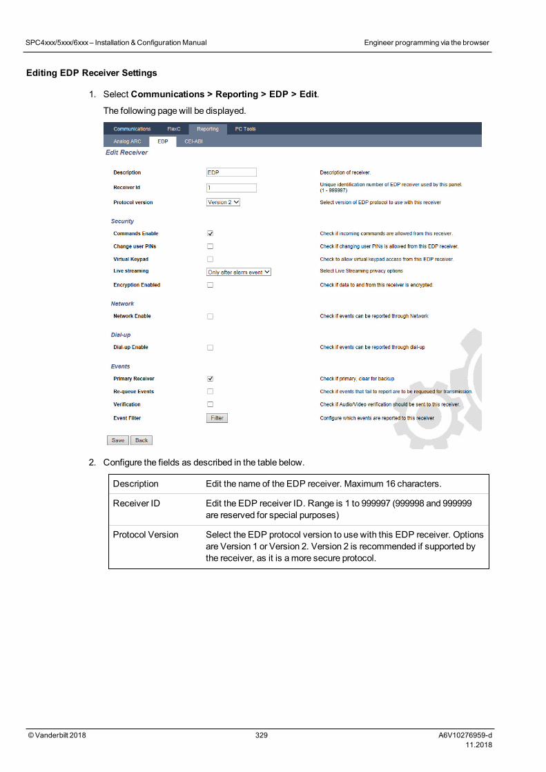
Editing EDP Receiver Settings
1. Select Communications > Reporting > EDP > Edit.
The following page will be displayed.
2. Configure the fields as described in the table below.
Description Edit the name of the EDP receiver. Maximum 16 characters.
Receiver ID Edit the EDP receiver ID. Range is 1 to 999997 (999998 and 999999are reserved for special purposes)
Protocol Version Select the EDP protocol version to use with this EDP receiver. Optionsare Version 1 or Version 2. Version 2 is recommended if supported bythe receiver, as it is amore secure protocol.
SPC4xxx/5xxx/6xxx– Installation &ConfigurationManual Engineer programming via the browser
© Vanderbilt 2018 329 A6V10276959-d11.2018
VdS 2471Compatible
(Vds standard only)
If this option is selected then the EDP receiver will enforce thefollowing settings for that receiver:
l 8s polling interval
l TCP protocol enforced
l TCP retries will fail before 10s (9s approx)
l EDP event retries are set to 1 independent of the global “RetryCount” setting in “EDP Settings”
l FTC will be generated within 20s of network failure.
Security
Commands Enable Check this box to allow commands to be accepted from the receiver.
Change User PINs Check this box to allow user PINs to be changed from a remotelocation. This feature is applicable only if commands are enabled fromthe receiver.
Encryption Enable Check this box to enable encryption on data to and from the receiver.
Encryption Key Enter a hexadecimal key (max. 32 digits) that will be used to encryptthe data.
Note: The same key will need to be used at the receiver.
Virtual Keypad Enables access to the panel with a virtual keypad, that is, a PCsoftwaremodule that looks and behaves like an SPC keypad. It isavailable with the SPC Com client.
LiveStreaming/StreamingMode
Specifies when live streaming of audio and video is available. Optionsare Never, Always or Only after an alarm event. Default is ‘Only afteran alarm event’.
Note: This setting has obvious privacy implications and thereforeshould be enabled only where appropriate and subject to local laws andregulations.
Network (Applies to the Ethernet connection only)
Network Enable Check this box to allow events to be reported through the network.
Network Protocol Select the type of network protocol for the receiver. Options are UDPand TCP. TCP is recommended if supported by the receiver.
Receiver ID Address Enter the IP address of the receiver.
Receiver IP Port Enter the IP port that the EDP receiver is listening on.
Always Connected If enabled the panel will keep a permanent connection to the receiver. Ifdisabled, the panel will only connect to the receiver after an alarmevent.
Panel Master If enabled the panel is master of pollingmessages. Only applicable toUDP connections.
Polling Interval Enter the number of seconds between polls.
SPC4xxx/5xxx/6xxx– Installation &ConfigurationManual Engineer programming via the browser
© Vanderbilt 2018 330 A6V10276959-d11.2018
Polling Trigger Enter the number of missing polls before a network connection fail isregistered. Only applicable to UDP connections.
Generate a NetworkFault
If polling fails, a network fault alert is generated.
Dial-up (Applies to the GPRS modem connection only)
Dial-up Enable Check this box to report events through a dial-up connection.
Call type Select type of call to use when dial up is enabled. Select GPRS.
GPRS protocol Select the transport layer protocol used over the GPRS connection.Options are UDP or TCP. Only applicable if Call Type is GPRS.
GPRS address Enter the IP address of EDP receiver for GPRS connections. Onlyapplicable if Call Type is GPRS.
GPRS port Enter the port that the EDP receiver is listening on for GPRSconnections Options are UDP or TCP. Only applicable if Call Type isGPRS. Default is 50000.
GPRS HangupTimeout
Enter the time in seconds after which the GPRS call will hang up.(0 = stay connected until IP connection is up)
GPRS Autoconnect Check this box to automatically trigger a GPRS call to the server if anIP network fault occurs.
Dial-up on Net Fault Check this box to report network faults on a dial-up test call.
Dial-up Interval 1* Enter the number of minutes between dial-up test calls when networklink is up.
Dial-up Interval 2* Enter number of minutes between dial-up test calls when network linkis down.
Network Address* Enter the IP address of the receiver. This is only required if theconnection to the EDP receiver is beingmade over the Ethernetinterface. If using one of the on-boardmodems then leave this fieldblank.
Phone Number* Enter the first phone number that themodem(s) will dial to contact thereceiver.
Phone Number 2* Enter a second phone number that themodem(s) will dial in the eventthat the first number dialled did not result in a call being successfullyestablished.
Events
Primary Receiver Check this box to indicate that this is the primary receiver. Ifunchecked, this is a backup receiver.
Re-queue Events Check this box if events that failed to report are to be re-queued fortransmission
Verification Check this box if Audio/Video verification is to be sent to this receiver.
Event Filter Click this button to edit the filter events that will trigger an EDP call.SeeEditing Event Filter Settings on the facing page.
SPC4xxx/5xxx/6xxx– Installation &ConfigurationManual Engineer programming via the browser
© Vanderbilt 2018 331 A6V10276959-d11.2018
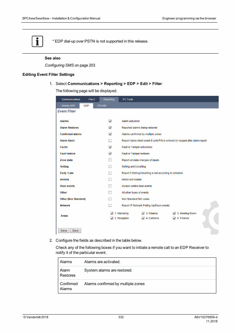
* EDP dial-up over PSTN is not supported in this release.
See also
Configuring SMS on page 203
Editing Event Filter Settings
1. Select Communications > Reporting > EDP > Edit > Filter.
The following page will be displayed.
2. Configure the fields as described in the table below.
Check any of the following boxes if you want to initiate a remote call to an EDP Receiver tonotify it of the particular event.
Alarms Alarms are activated.
AlarmRestores
System alarms are restored.
ConfirmedAlarms
Alarms confirmed by multiple zones
SPC4xxx/5xxx/6xxx– Installation &ConfigurationManual Engineer programming via the browser
© Vanderbilt 2018 332 A6V10276959-d11.2018
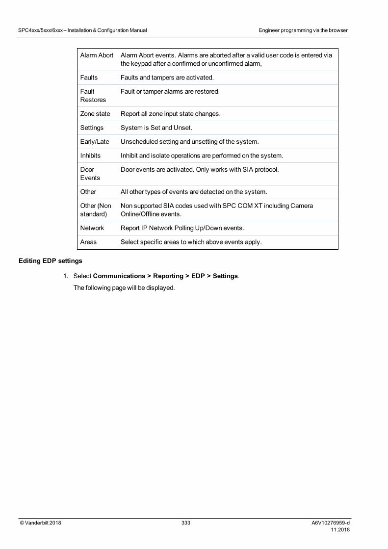
Alarm Abort Alarm Abort events. Alarms are aborted after a valid user code is entered viathe keypad after a confirmed or unconfirmed alarm,
Faults Faults and tampers are activated.
FaultRestores
Fault or tamper alarms are restored.
Zone state Report all zone input state changes.
Settings System is Set and Unset.
Early/Late Unscheduled setting and unsetting of the system.
Inhibits Inhibit and isolate operations are performed on the system.
DoorEvents
Door events are activated. Only works with SIA protocol.
Other All other types of events are detected on the system.
Other (Nonstandard)
Non supported SIA codes used with SPC COM XT including CameraOnline/Offline events.
Network Report IP Network Polling Up/Down events.
Areas Select specific areas to which above events apply.
Editing EDP settings
1. Select Communications > Reporting > EDP > Settings.
The following page will be displayed.
SPC4xxx/5xxx/6xxx– Installation &ConfigurationManual Engineer programming via the browser
© Vanderbilt 2018 333 A6V10276959-d11.2018
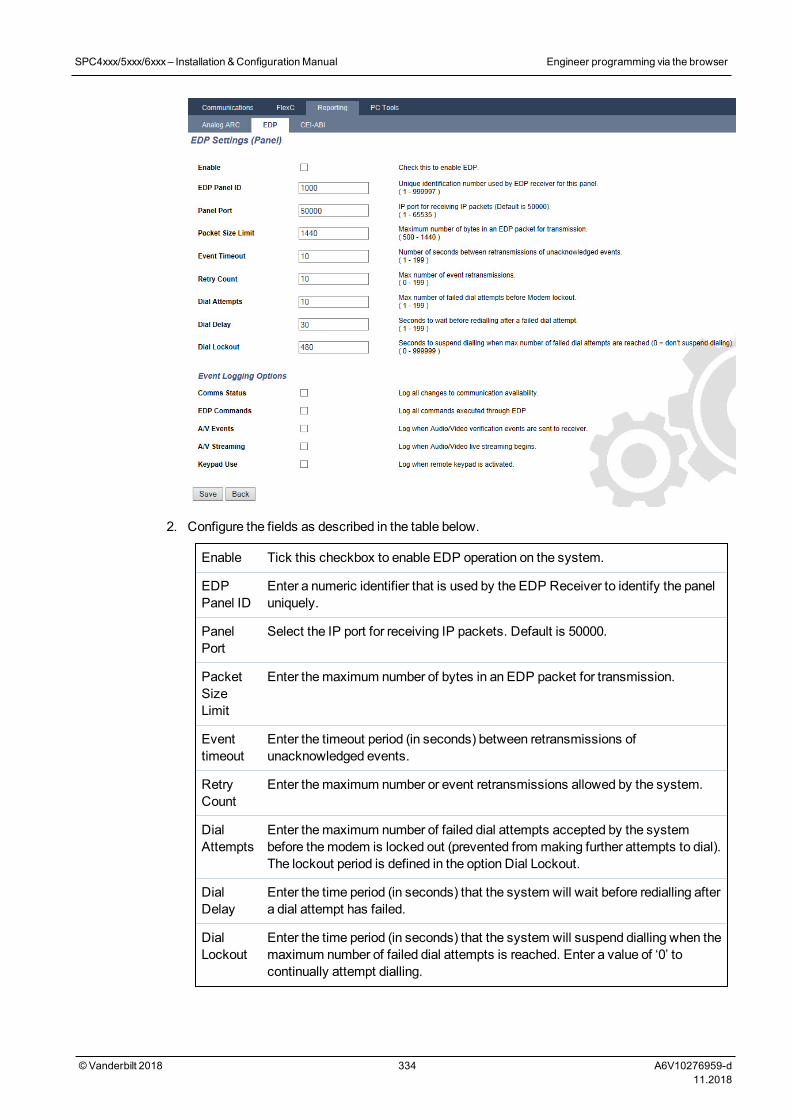
2. Configure the fields as described in the table below.
Enable Tick this checkbox to enable EDP operation on the system.
EDPPanel ID
Enter a numeric identifier that is used by the EDP Receiver to identify the paneluniquely.
PanelPort
Select the IP port for receiving IP packets. Default is 50000.
PacketSizeLimit
Enter themaximum number of bytes in an EDP packet for transmission.
Eventtimeout
Enter the timeout period (in seconds) between retransmissions ofunacknowledged events.
RetryCount
Enter themaximum number or event retransmissions allowed by the system.
DialAttempts
Enter themaximum number of failed dial attempts accepted by the systembefore themodem is locked out (prevented frommaking further attempts to dial).The lockout period is defined in the option Dial Lockout.
DialDelay
Enter the time period (in seconds) that the system will wait before redialling aftera dial attempt has failed.
DialLockout
Enter the time period (in seconds) that the system will suspend dialling when themaximum number of failed dial attempts is reached. Enter a value of ‘0’ tocontinually attempt dialling.
SPC4xxx/5xxx/6xxx– Installation &ConfigurationManual Engineer programming via the browser
© Vanderbilt 2018 334 A6V10276959-d11.2018
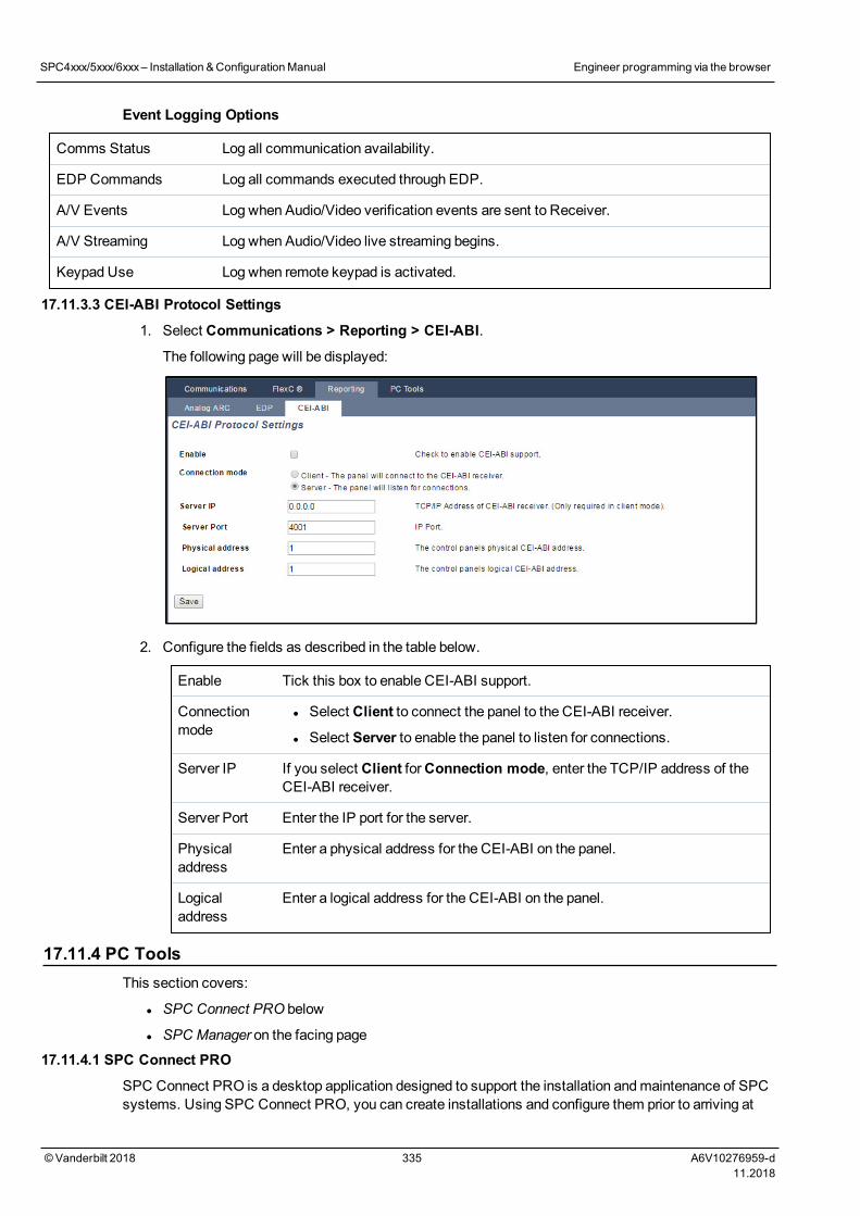
Event Logging Options
Comms Status Log all communication availability.
EDP Commands Log all commands executed through EDP.
A/V Events Log when Audio/Video verification events are sent to Receiver.
A/V Streaming Log when Audio/Video live streaming begins.
Keypad Use Log when remote keypad is activated.
17.11.3.3 CEI-ABI Protocol Settings
1. Select Communications > Reporting > CEI-ABI.
The following page will be displayed:
2. Configure the fields as described in the table below.
Enable Tick this box to enable CEI-ABI support.
Connectionmode
l Select Client to connect the panel to the CEI-ABI receiver.
l Select Server to enable the panel to listen for connections.
Server IP If you select Client forConnection mode, enter the TCP/IP address of theCEI-ABI receiver.
Server Port Enter the IP port for the server.
Physicaladdress
Enter a physical address for the CEI-ABI on the panel.
Logicaladdress
Enter a logical address for the CEI-ABI on the panel.
17.11.4 PC ToolsThis section covers:
l SPC Connect PRO below
l SPC Manager on the facing page
17.11.4.1 SPC Connect PRO
SPC Connect PRO is a desktop application designed to support the installation andmaintenance of SPCsystems. Using SPC Connect PRO, you can create installations and configure them prior to arriving at
SPC4xxx/5xxx/6xxx– Installation &ConfigurationManual Engineer programming via the browser
© Vanderbilt 2018 335 A6V10276959-d11.2018
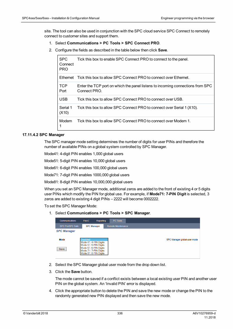
site. The tool can also be used in conjunction with the SPC cloud service SPC Connect to remotelyconnect to customer sites and support them.
1. Select Communications > PC Tools > SPC Connect PRO.
2. Configure the fields as described in the table below then click Save.
SPCConnectPRO
Tick this box to enable SPC Connect PRO to connect to the panel.
Ethernet Tick this box to allow SPC Connect PRO to connect over Ethernet.
TCPPort
Enter the TCP port on which the panel listens to incoming connections from SPCConnect PRO.
USB Tick this box to allow SPC Connect PRO to connect over USB.
Serial 1(X10)
Tick this box to allow SPC Connect PRO to connect over Serial 1 (X10).
Modem1
Tick this box to allow SPC Connect PRO to connect over Modem 1.
17.11.4.2 SPC Manager
The SPC manager mode setting determines the number of digits for user PINs and therefore thenumber of available PINs on a global system controlled by SPC Manager.
Mode41: 4-digit PIN enables 1,000 global users
Mode51: 5-digit PIN enables 10,000 global users
Mode61: 6-digit PIN enables 100,000 global users
Mode71: 7-digit PIN enables 1000,000 global users
Mode81: 8-digit PIN enables 10,000,000 global users
When you set an SPC Manager mode, additional zeros are added to the front of existing 4 or 5 digitsuser PINs whichmodify the PIN for global use. For example, ifMode71: 7-PIN Digit is selected, 3zeros are added to existing 4 digit PINs – 2222 will become 0002222.
To set the SPC Manager Mode:
1. Select Communications > PC Tools > SPC Manager.
2. Select the SPC Manager global user mode from the drop down list.
3. Click theSave button.
Themode cannot be saved if a conflict exists between a local existing user PIN and another userPIN on the global system. An ‘Invalid PIN’ error is displayed.
4. Click the appropriate button to delete the PIN and save the new mode or change the PIN to therandomly generated new PIN displayed and then save the new mode.
SPC4xxx/5xxx/6xxx– Installation &ConfigurationManual Engineer programming via the browser
© Vanderbilt 2018 336 A6V10276959-d11.2018
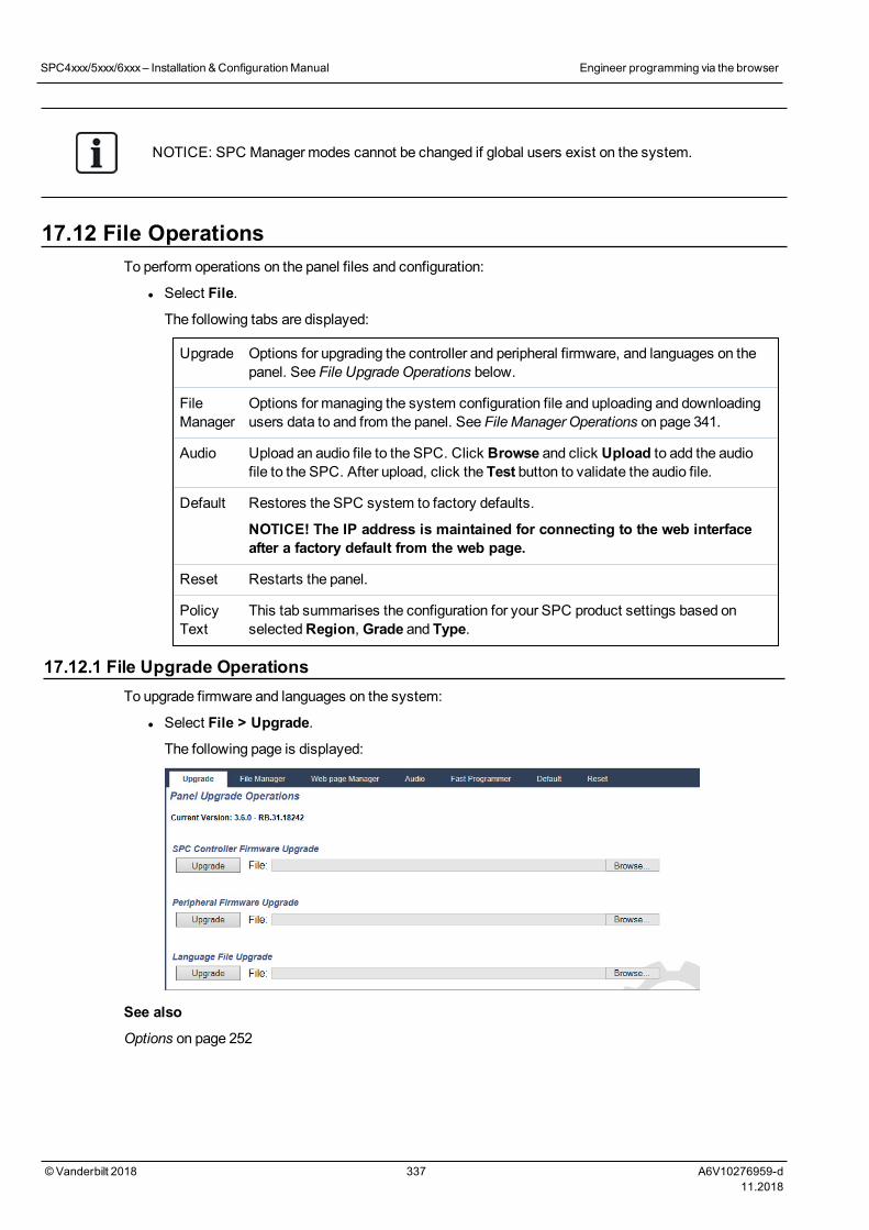
NOTICE: SPC Manager modes cannot be changed if global users exist on the system.
17.12 File OperationsTo perform operations on the panel files and configuration:
l Select File.
The following tabs are displayed:
Upgrade Options for upgrading the controller and peripheral firmware, and languages on thepanel. See File UpgradeOperations below.
FileManager
Options for managing the system configuration file and uploading and downloadingusers data to and from the panel. See File Manager Operations on page 341.
Audio Upload an audio file to the SPC. Click Browse and click Upload to add the audiofile to the SPC. After upload, click the Test button to validate the audio file.
Default Restores the SPC system to factory defaults.
NOTICE! The IP address is maintained for connecting to the web interfaceafter a factory default from the web page.
Reset Restarts the panel.
PolicyText
This tab summarises the configuration for your SPC product settings based onselectedRegion, Grade and Type.
17.12.1 File Upgrade OperationsTo upgrade firmware and languages on the system:
l Select File > Upgrade.
The following page is displayed:
See also
Options on page 252
SPC4xxx/5xxx/6xxx– Installation &ConfigurationManual Engineer programming via the browser
© Vanderbilt 2018 337 A6V10276959-d11.2018
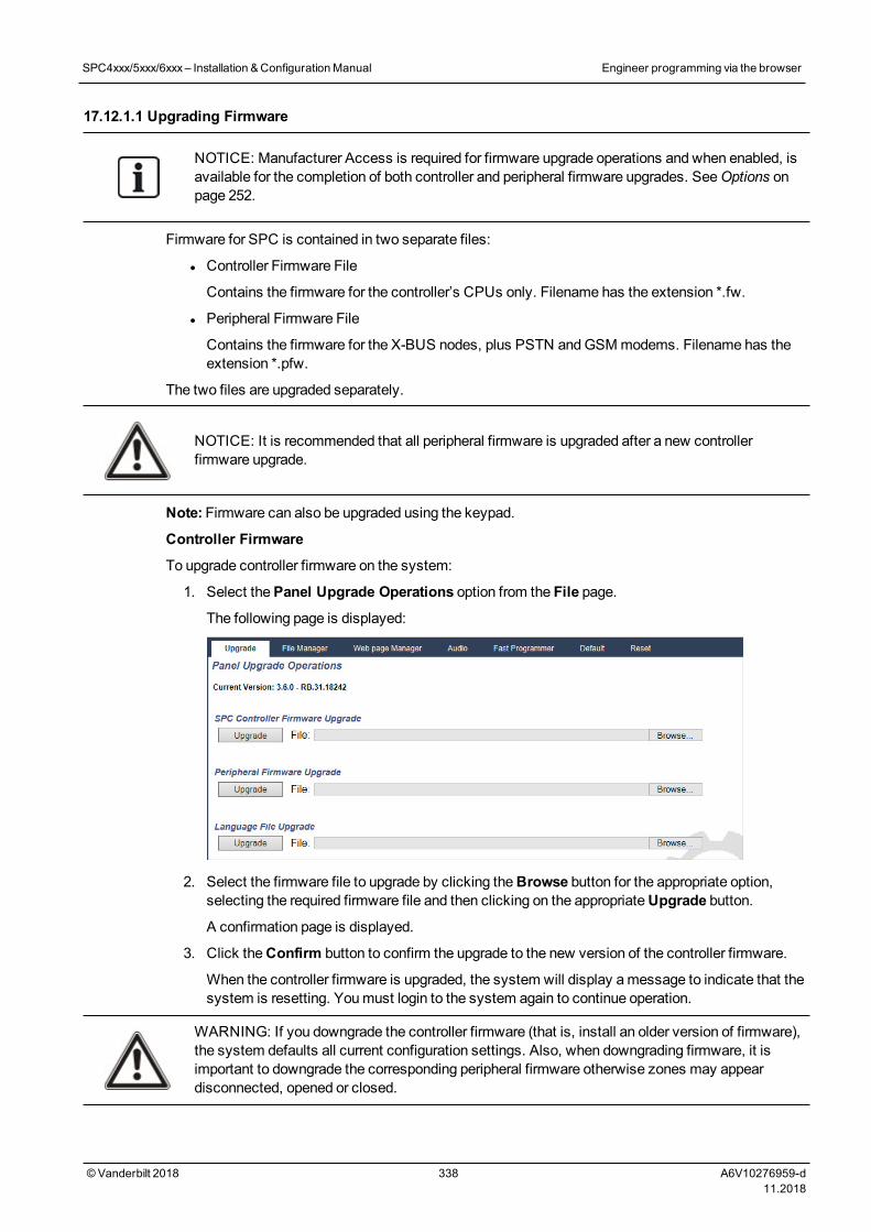
17.12.1.1 Upgrading Firmware
NOTICE: Manufacturer Access is required for firmware upgrade operations and when enabled, isavailable for the completion of both controller and peripheral firmware upgrades. SeeOptions onpage 252.
Firmware for SPC is contained in two separate files:
l Controller Firmware File
Contains the firmware for the controller’s CPUs only. Filename has the extension *.fw.
l Peripheral Firmware File
Contains the firmware for the X-BUS nodes, plus PSTN andGSMmodems. Filename has theextension *.pfw.
The two files are upgraded separately.
NOTICE: It is recommended that all peripheral firmware is upgraded after a new controllerfirmware upgrade.
Note: Firmware can also be upgraded using the keypad.
Controller Firmware
To upgrade controller firmware on the system:
1. Select thePanel Upgrade Operations option from the File page.
The following page is displayed:
2. Select the firmware file to upgrade by clicking theBrowse button for the appropriate option,selecting the required firmware file and then clicking on the appropriateUpgrade button.
A confirmation page is displayed.
3. Click theConfirm button to confirm the upgrade to the new version of the controller firmware.
When the controller firmware is upgraded, the system will display amessage to indicate that thesystem is resetting. Youmust login to the system again to continue operation.
WARNING: If you downgrade the controller firmware (that is, install an older version of firmware),the system defaults all current configuration settings. Also, when downgrading firmware, it isimportant to downgrade the corresponding peripheral firmware otherwise zones may appeardisconnected, opened or closed.
SPC4xxx/5xxx/6xxx– Installation &ConfigurationManual Engineer programming via the browser
© Vanderbilt 2018 338 A6V10276959-d11.2018
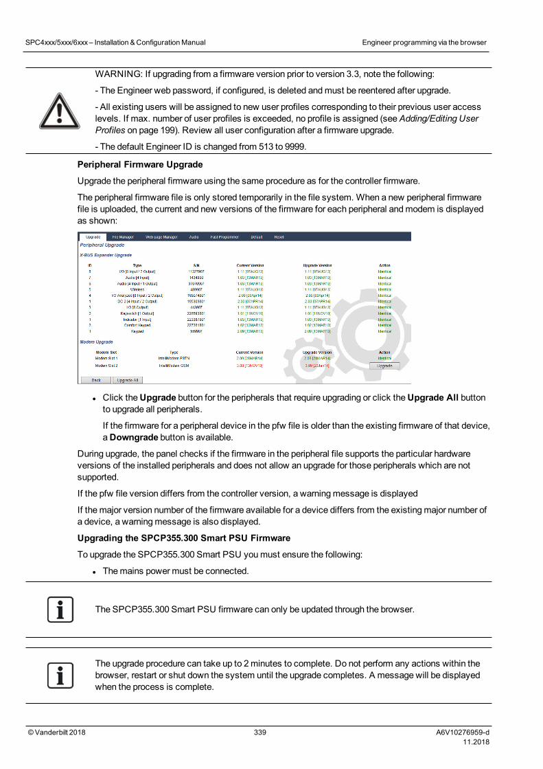
WARNING: If upgrading from a firmware version prior to version 3.3, note the following:
- The Engineer web password, if configured, is deleted andmust be reentered after upgrade.
- All existing users will be assigned to new user profiles corresponding to their previous user accesslevels. If max. number of user profiles is exceeded, no profile is assigned (seeAdding/Editing UserProfiles on page 199). Review all user configuration after a firmware upgrade.
- The default Engineer ID is changed from 513 to 9999.
Peripheral Firmware Upgrade
Upgrade the peripheral firmware using the same procedure as for the controller firmware.
The peripheral firmware file is only stored temporarily in the file system. When a new peripheral firmwarefile is uploaded, the current and new versions of the firmware for each peripheral andmodem is displayedas shown:
l Click theUpgrade button for the peripherals that require upgrading or click theUpgrade All buttonto upgrade all peripherals.
If the firmware for a peripheral device in the pfw file is older than the existing firmware of that device,aDowngrade button is available.
During upgrade, the panel checks if the firmware in the peripheral file supports the particular hardwareversions of the installed peripherals and does not allow an upgrade for those peripherals which are notsupported.
If the pfw file version differs from the controller version, a warningmessage is displayed
If themajor version number of the firmware available for a device differs from the existingmajor number ofa device, a warningmessage is also displayed.
Upgrading the SPCP355.300 Smart PSU Firmware
To upgrade the SPCP355.300 Smart PSU youmust ensure the following:
l Themains powermust be connected.
The SPCP355.300 Smart PSU firmware can only be updated through the browser.
The upgrade procedure can take up to 2minutes to complete. Do not perform any actions within thebrowser, restart or shut down the system until the upgrade completes. A message will be displayedwhen the process is complete.
SPC4xxx/5xxx/6xxx– Installation &ConfigurationManual Engineer programming via the browser
© Vanderbilt 2018 339 A6V10276959-d11.2018
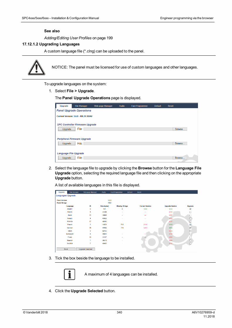
See also
Adding/Editing User Profiles on page 19917.12.1.2 Upgrading Languages
A custom language file (*.clng) can be uploaded to the panel.
NOTICE: The panel must be licensed for use of custom languages and other languages.
To upgrade languages on the system:
1. Select File > Upgrade.
ThePanel Upgrade Operations page is displayed.
2. Select the language file to upgrade by clicking theBrowse button for the Language FileUpgrade option, selecting the required language file and then clicking on the appropriateUpgrade button.
A list of available languages in this file is displayed.
3. Tick the box beside the language to be installed.
A maximum of 4 languages can be installed.
4. Click theUpgrade Selected button.
SPC4xxx/5xxx/6xxx– Installation &ConfigurationManual Engineer programming via the browser
© Vanderbilt 2018 340 A6V10276959-d11.2018
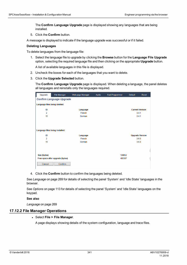
TheConfirm Language Upgrade page is displayed showing any languages that are beinginstalled.
5. Click theConfirm button.
A message is displayed to indicate if the language upgrade was successful or if it failed.
Deleting Languages
To delete languages from the language file:
1. Select the language file to upgrade by clicking theBrowse button for the Language File Upgradeoption, selecting the required language file and then clicking on the appropriateUpgrade button.
A list of available languages in this file is displayed.
2. Uncheck the boxes for each of the languages that you want to delete.
3. Click theUpgrade Selected button.
TheConfirm Language Upgrade page is displayed. When deleting a language, the panel deletesall languages and reinstalls only the languages required.
4. Click theConfirm button to confirm the languages being deleted.
See Language on page 269 for details of selecting the panel ‘System’ and ‘Idle State’ languages in thebrowser.
SeeOptions on page 113 for details of selecting the panel ‘System’ and ‘Idle State’ languages on thekeypad.
See also
Language on page 269
17.12.2 File Manager Operationsl Select File > File Manager.
A page displays showing details of the system configuration, language and trace files.
SPC4xxx/5xxx/6xxx– Installation &ConfigurationManual Engineer programming via the browser
© Vanderbilt 2018 341 A6V10276959-d11.2018
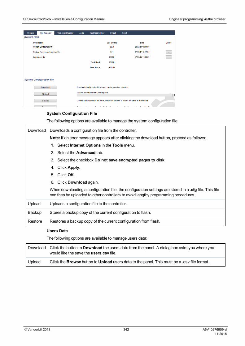
System Configuration File
The following options are available to manage the system configuration file:
Download Downloads a configuration file from the controller.
Note: If an error message appears after clicking the download button, proceed as follows:
1. Select Internet Options in the Toolsmenu.
2. Select theAdvanced tab.
3. Select the checkbox Do not save encrypted pages to disk.
4. Click Apply.
5. Click OK.
6. Click Download again.
When downloading a configuration file, the configuration settings are stored in a .cfg file. This filecan then be uploaded to other controllers to avoid lengthy programming procedures.
Upload Uploads a configuration file to the controller.
Backup Stores a backup copy of the current configuration to flash.
Restore Restores a backup copy of the current configuration from flash.
Users Data
The following options are available to manage users data:
Download Click the button toDownload the users data from the panel. A dialog box asks you where youwould like the save the users.csv file.
Upload Click theBrowse button toUpload users data to the panel. This must be a .csv file format.
SPC4xxx/5xxx/6xxx– Installation &ConfigurationManual Engineer programming via the browser
© Vanderbilt 2018 342 A6V10276959-d11.2018
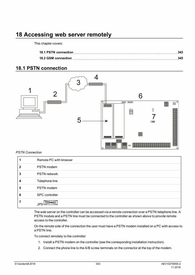
18 Accessing web server remotelyThis chapter covers:
18.1 PSTN connection 343
18.2 GSM connection 345
18.1 PSTN connection
PSTN Connection
1 Remote PC with browser
2 PSTN modem
3 PSTN network
4 Telephone line
5 PSTN modem
6 SPC controller
7JP9
The web server on the controller can be accessed via a remote connection over a PSTN telephone line. APSTN module and a PSTN linemust be connected to the controller as shown above to provide remoteaccess to the controller.
On the remote side of the connection the user must have a PSTN modem installed on a PC with access toa PSTN line.
To connect remotely to the controller:
1. Install a PSTN modem on the controller (see the corresponding installation instruction).
2. Connect the phone line to the A/B screw terminals on the connector at the top of themodem.
©Vanderbilt 2018 343 A6V10276959-d11.2018
3. Enter Engineer programming from the keypad and configure themodem (primary or backup) toanswer an incoming call.
4. On the keypad, scroll to Full Engineer Mode > Comms > Modems.
5. Select the following settings:
-Enable Modem:Set to enabled
- Type:Displays the type of modem (PSTN)
-Country Code:Select the relevant country code (Ireland, UK, Europe)
-Answer mode:Select numbered rings; this tells themodem to wait for a number of rings beforeanswering the incoming call
-Modem Rings:Select the number of rings to allow before answering the call (8 rings max)
6. Create a dial-up connection on the remote PC using the phone number of the telephone lineconnected to the PSTN module on the controller. The instructions to do this onWindows XPoperating system are listed below.
On Windows XP:
1. Open the New ConnectionWizard by browsing toControl Panel > Network Connections >Create New Connection (in theNetwork Tasks page).
2. On theNetwork Connection Type page, select Connect to the Internet.
3. On theGetting Ready page, chooseSetup my connection manually.
4. On the Internet Connection page, chooseConnect using Dialup modem.
5. On theConnection Name page, enter the connection name, for example, SPC remote connection.
6. On thePhone Number to Dial page, enter the phone number of the PSTN line connected to thePSTN modem.
7. On theConnection Availability page, choose whether this connection is available to all users.
8. On the Internet Account Information page, enter the following details:
- Username: SPC
- Password: password (default)
- Confirm Password: password
TheCompleting the New Connection Wizard page is displayed.
9. Click Finish to save the Dial-up connection to the PC.
Default code should be changed and noted accordingly as Vanderbilt is unable to retrieve this newcode. Forgotten codes are be remedied only by a factory default of the system, rendering loss ofprogramming. Programming can be restored if a backup is available.
To activate this dial-up connection:
l Click the icon located in theControl Panel > Network Connections page.
The PC makes a data call to the PSTN line connected to the SPC PSTN module.
The SPC PSTN module answers the incoming data call after the designated number of rings andestablishes an IP link with the remote computer.
The SPC system automatically assigns an IP address to the remote PC.
SPC4xxx/5xxx/6xxx– Installation &ConfigurationManual Accessing web server remotely
© Vanderbilt 2018 344 A6V10276959-d11.2018
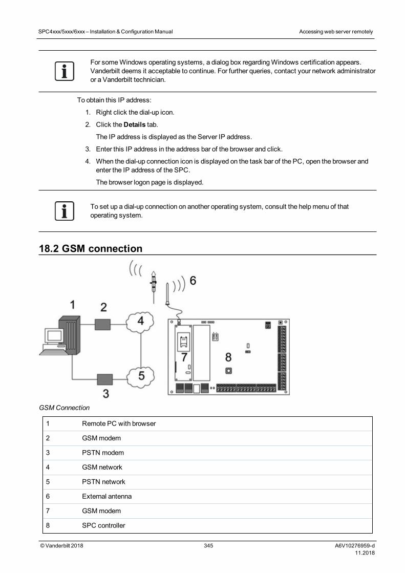
For someWindows operating systems, a dialog box regardingWindows certification appears.Vanderbilt deems it acceptable to continue. For further queries, contact your network administratoror a Vanderbilt technician.
To obtain this IP address:
1. Right click the dial-up icon.
2. Click theDetails tab.
The IP address is displayed as the Server IP address.
3. Enter this IP address in the address bar of the browser and click.
4. When the dial-up connection icon is displayed on the task bar of the PC, open the browser andenter the IP address of the SPC.
The browser logon page is displayed.
To set up a dial-up connection on another operating system, consult the helpmenu of thatoperating system.
18.2 GSM connection
GSMConnection
1 Remote PC with browser
2 GSMmodem
3 PSTN modem
4 GSM network
5 PSTN network
6 External antenna
7 GSMmodem
8 SPC controller
SPC4xxx/5xxx/6xxx– Installation &ConfigurationManual Accessing web server remotely
© Vanderbilt 2018 345 A6V10276959-d11.2018
The web server on the controller can be accessed via a remote connection over the GSM network. A GSMmodule (with SIM card) must be installed on the controller as shown above to provide remote access to theSPC. The data option of the SIM cardmust be activated and the data numbermust be used.
On the remote side of the connection the user must have a PSTN or GSMmodem installed on a PC withbrowser. If a PSTN modem is installed then it must be connected to a working PSTN line.
To connect remotely to the controller:
1. Install a GSMmodem on the controller (see the corresponding installation instructions).
2. Enter Full Engineer programming from the keypad and configure themodem (primary or backup) toanswer an incoming call.
3. On the keypad, scroll to the followingmenu: FULL ENGINEER > COMMUNICATION > MODEMS,and select the settings listed:
EnableModem Set to Modem Enabled.
Type Displays the type of modem (GSM).
Country Code Select the relevant country code.
AnswerMode Select numbered rings; this tells themodem to wait for a numberof rings before answering the incoming call.
Modem Rings Select the number of rings to allow before answering the call (8rings max).
On Windows XP:
1. Open theNew Connection Wizard by browsing toControl Panel > Network Connections >Create New Connection (in theNetwork Taskswindow).
2. On theNetwork Connection Typewindow, select Connect to the Internet.
3. On theGetting Readywindow, chooseSetup my connection manually.
4. On the Internet Connectionwindow, chooseConnect using Dialup modem.
5. On theConnection Namewindow enter the connection name, for example, SPC remoteconnection.
6. On thePhone Number to Dial window, enter the phone number of the GSM line connected to theGSMmodem.
7. On theConnection Availabilitywindow, choose whether this connection is available to all users.
8. On the Internet Account Informationwindow, enter the following details:
- Username: SPC
- Password: password
- Confirm Password: password
TheCompleting the New Connection Wizard page is displayed.
9. Click Finish to save the Dial-up connection to the PC.
To activate this dial-up connection:
l Click the icon located on theControl Panel > Network Connections page.
The PC makes a data call to the GSM line connected to the SPC GSMmodule.
The SPC GSMmodule answers the incoming data call after the designated number of rings andestablishes an IP link with the remote computer.
The SPC system automatically assigns an IP address to the remote PC.
SPC4xxx/5xxx/6xxx– Installation &ConfigurationManual Accessing web server remotely
© Vanderbilt 2018 346 A6V10276959-d11.2018
For someWindows operating systems, a dialog box regardingWindows certification appears.Vanderbilt deems it acceptable to continue. For further queries, contact your network administratoror a Vanderbilt technician.
To obtain this IP address:
1. Right click the dial-up icon.
2. Click theDetails tab.
The IP address is displayed as the Server IP address.
3. Enter this IP address in the address bar of the browser and click.
4. When the dial-up connection icon is displayed on the task bar of the PC, open the browser andenter the IP address of the SPC.
The browser logon page is displayed.
To set up a dial-up connection on another operating system, consult the helpmenu of thatoperating system.
SPC4xxx/5xxx/6xxx– Installation &ConfigurationManual Accessing web server remotely
© Vanderbilt 2018 347 A6V10276959-d11.2018
19 Intruder alarm functionalityThe SPC system can accommodate 3 distinct modes of intruder alarm operation, Financial, Commercialor Domestic mode, all of which support multiple areas.
Each area in turn can support 4 different alarm modes. Commercial and Financial mode present moreprogrammable alarm types than Domestic mode. The default zone name and type settings for eachmodeis listed inDomestic, Commercial and Financial mode default settings on page 366.
19.1 Financial mode operationFinancial mode is suitable banking and financial businesses that have special secure areas such as vaultsand ATMs.
Each area defined on the system supports the alarm modes listed below.
Alarm Mode Description
UNSET Area is disarmed, only alarm zones classified as 24Hour will activate the alarm.
PARTSET A This mode provides perimeter protection to a building while allowing freemovement through the exitand access areas.
Zones that have been classified as EXCLUDE A remain unprotected in this mode. By default there isno exit time (the system instantly sets on selection of this mode). An exit timer can be applied to thismode by enabling the Partset A Timed variable.
PARTSET B This settingmode applies protection to all zones except those that have been classified asEXCLUDE B.
By default there is no exit time (the system instantly sets on selection of this mode). An exit timer canbe applied to this mode by enabling the Partset B Timed variable.
FULL SET Area is fully armed; opening of entry/exit zones starts the entry timer. If the alarm is not unset beforeentry timer expires, the alarm is activated.
19.2 Commercial mode operationCommercial mode is suitable for business installations with multiple areas and a large number of alarmzones. Each area defined on the system supports the alarm modes listed below.
AlarmMode Description
UNSET Area is disarmed, only alarm zones classified as 24Hour will activate the alarm.
PARTSETA
This mode provides perimeter protection to a building while allowing freemovement through the exitand access areas.
Zones that have been classified as EXCLUDE A remain unprotected in this mode. By default there isno exit time (the system instantly sets on selection of this mode). An exit timer can be applied to thismode by enabling the Partset A Timed variable.
©Vanderbilt 2018 348 A6V10276959-d11.2018
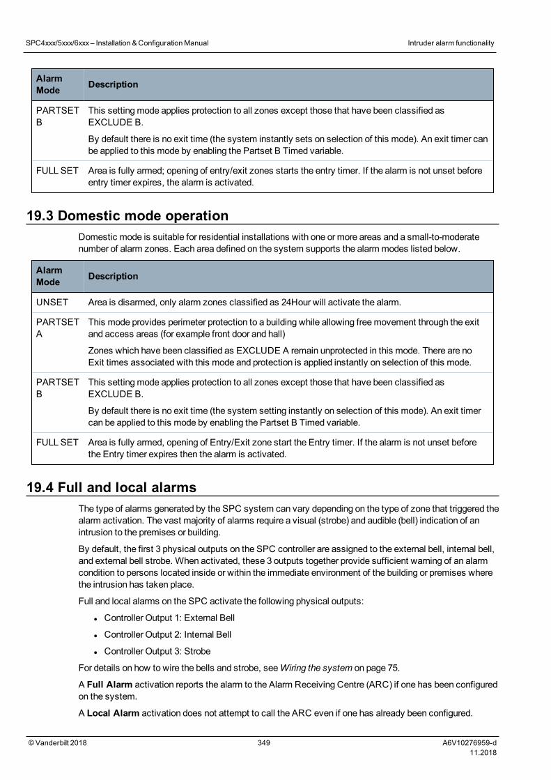
AlarmMode Description
PARTSETB
This settingmode applies protection to all zones except those that have been classified asEXCLUDE B.
By default there is no exit time (the system instantly sets on selection of this mode). An exit timer canbe applied to this mode by enabling the Partset B Timed variable.
FULL SET Area is fully armed; opening of entry/exit zones starts the entry timer. If the alarm is not unset beforeentry timer expires, the alarm is activated.
19.3 Domestic mode operationDomestic mode is suitable for residential installations with one or more areas and a small-to-moderatenumber of alarm zones. Each area defined on the system supports the alarm modes listed below.
AlarmMode Description
UNSET Area is disarmed, only alarm zones classified as 24Hour will activate the alarm.
PARTSETA
This mode provides perimeter protection to a building while allowing freemovement through the exitand access areas (for example front door and hall)
Zones which have been classified as EXCLUDE A remain unprotected in this mode. There are noExit times associated with this mode and protection is applied instantly on selection of this mode.
PARTSETB
This settingmode applies protection to all zones except those that have been classified asEXCLUDE B.
By default there is no exit time (the system setting instantly on selection of this mode). An exit timercan be applied to this mode by enabling the Partset B Timed variable.
FULL SET Area is fully armed, opening of Entry/Exit zone start the Entry timer. If the alarm is not unset beforethe Entry timer expires then the alarm is activated.
19.4 Full and local alarmsThe type of alarms generated by the SPC system can vary depending on the type of zone that triggered thealarm activation. The vast majority of alarms require a visual (strobe) and audible (bell) indication of anintrusion to the premises or building.
By default, the first 3 physical outputs on the SPC controller are assigned to the external bell, internal bell,and external bell strobe. When activated, these 3 outputs together provide sufficient warning of an alarmcondition to persons located inside or within the immediate environment of the building or premises wherethe intrusion has taken place.
Full and local alarms on the SPC activate the following physical outputs:
l Controller Output 1: External Bell
l Controller Output 2: Internal Bell
l Controller Output 3: Strobe
For details on how to wire the bells and strobe, seeWiring the system on page 75.
A Full Alarm activation reports the alarm to the Alarm Receiving Centre (ARC) if one has been configuredon the system.
A Local Alarm activation does not attempt to call the ARC even if one has already been configured.
SPC4xxx/5xxx/6xxx– Installation &ConfigurationManual Intruder alarm functionality
© Vanderbilt 2018 349 A6V10276959-d11.2018

A Silent Alarm activation does not activate outputs 1–3 (no visual or audible indications of the alarm).The alarm event is reported to the ARC. Silent alarms are only generated when alarm zones with theSilent attribute have been opened when the system is set.
SPC4xxx/5xxx/6xxx– Installation &ConfigurationManual Intruder alarm functionality
© Vanderbilt 2018 350 A6V10276959-d11.2018
20 System examples and scenariosThis chapter covers:
20.1 When to use a common area 351
20.1 When to use a common areaCommon areas provide a convenient way of settingmultiple areas within a single installation. A userassigned to a common area has the ability to SET ALL areas within that common area (even those areasthat have not been assigned to that user). However, the users can only UNSET areas assigned to them.
Common areas should only be used when a single keypad is installed at the primary access location and isshared by all users within the building (defining a common area on a system with multiple keypads indifferent areas is not recommended).
Scenario: 2 departments of a business (Accounts and Sales) share a common access point (front door)
In this case, create 3 areas on the system (Common Area, Accounts, and Sales). The Common Areamustinclude themain access point (front door). Assign the zones in Accounts to Area 2 and the zones in Salesto Area 3. Install a keypad at the front door and assign it to all 3 areas. Define 2 users (minimum) on thesystem, one for each department, and assign the users to their respective areas and the common area.
Operation: Setting the system
The Accounts Manager leaves the office at 5 pm. When he enters his code at the keypad, the FULLSEToption presents the following 3 sub-menus:
l ALL AREAS: sets all areas assigned to the common area (Common Area, Accounts, and Sales)and any additional areas assigned to the account manager; in this case there are no additionalareas. The exit timer for the front door informs the user to exit the building.
l COMMON: sets all areas assigned to the Common Area (Common Area, Accounts and Sales) andstarts the exit timer for the front door
l ACCOUNTS: sets the Accounts area only; the Sales area remains unset and access is stillpermitted through the front door
When the last worker in the Sales department is leaving the building, he/she closes all doors and windowsin AREA 3 and enters his/her code at the keypad. The FULLSET option presents the following 3 sub-menus:
l ALL AREAS: sets all areas assigned to the Common Area (Common area, Accounts, and Sales)and any additional areas assigned to the sales worker; in this case there are no additional areas. Theexit timer for the front door informs the user to exit the building.
l COMMON: sets all areas assigned to the Common Area (Common Area, Accounts, and Sales) andstarts the exit timer for the front door.
l SALES: sets ALL areas assigned to the Common Area (Common area, Accounts and Sales); this isbecause there are no other unarmed sub-areas on the system.
Operation: Unsetting the system
When the Accounts Manager returns to open the building and enters his code on the keypad, the UNSEToption presents the following 3 sub-menus:
l ALL AREAS: unsets all areas assigned to the accounts worker (Common Area, Accounts) and anyadditional area assigned to the accounts worker. In this case there are no additional areas.
Note: The accounts worker cannot UNSET the Sales area.
l COMMON: unsets ONLY the Common Area (Reception). This provides the option to unarm the
©Vanderbilt 2018 351 A6V10276959-d11.2018
reception area only while leaving the Accounts and Sales offices set.
l ACCOUNTS: unsets the Accounts area and the Common Area (Reception). In this case the Salesarea remains set while access is still permitted through the front door.
Use of common areas:
l Keyarm zone
If the entry/exit route in the common area is programmed as a keyarm zone, when it is activated allareas in the Common area are SET. Deactivating the keyarm zone UNSETs all areas in theCommon Areas.
l Multiple keypads
If areas assigned to the common area have their own keypads for entry/exit, it is important that theexit times associated with those areas provide sufficient time to allow the user to reach the commonarea exit. This is in case the area being armed is the last un-armed area on the system and thereforewill trigger arming of the entire common area.
As a rule it is advisable to use common areas in installations that have only one keypad located at thecommon access point, that is, front door access to the entire building.
SPC4xxx/5xxx/6xxx– Installation &ConfigurationManual System examplesand scenarios
© Vanderbilt 2018 352 A6V10276959-d11.2018
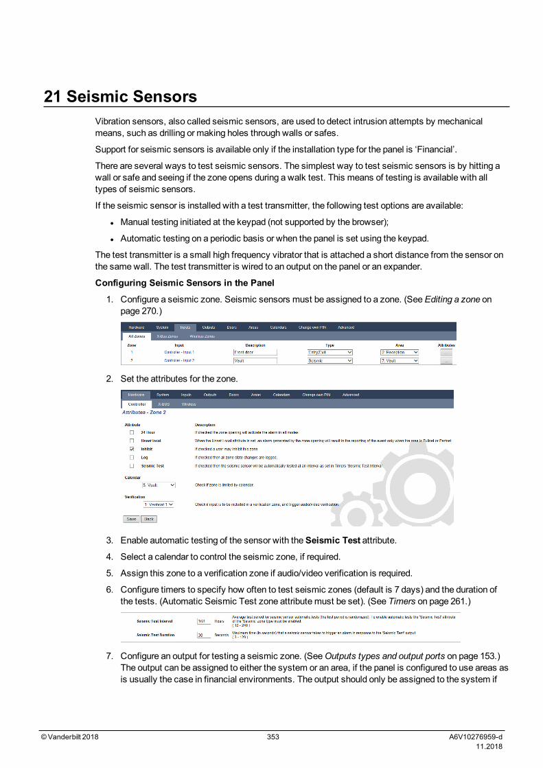
21 Seismic SensorsVibration sensors, also called seismic sensors, are used to detect intrusion attempts by mechanicalmeans, such as drilling or making holes through walls or safes.
Support for seismic sensors is available only if the installation type for the panel is ‘Financial’.
There are several ways to test seismic sensors. The simplest way to test seismic sensors is by hitting awall or safe and seeing if the zone opens during a walk test. This means of testing is available with alltypes of seismic sensors.
If the seismic sensor is installed with a test transmitter, the following test options are available:
l Manual testing initiated at the keypad (not supported by the browser);
l Automatic testing on a periodic basis or when the panel is set using the keypad.
The test transmitter is a small high frequency vibrator that is attached a short distance from the sensor onthe samewall. The test transmitter is wired to an output on the panel or an expander.
Configuring Seismic Sensors in the Panel
1. Configure a seismic zone. Seismic sensors must be assigned to a zone. (SeeEditing a zone onpage 270.)
2. Set the attributes for the zone.
3. Enable automatic testing of the sensor with theSeismic Test attribute.
4. Select a calendar to control the seismic zone, if required.
5. Assign this zone to a verification zone if audio/video verification is required.
6. Configure timers to specify how often to test seismic zones (default is 7 days) and the duration ofthe tests. (Automatic Seismic Test zone attributemust be set). (See Timers on page 261.)
7. Configure an output for testing a seismic zone. (SeeOutputs types and output ports on page 153.)The output can be assigned to either the system or an area, if the panel is configured to use areas asis usually the case in financial environments. The output should only be assigned to the system if
©Vanderbilt 2018 353 A6V10276959-d11.2018
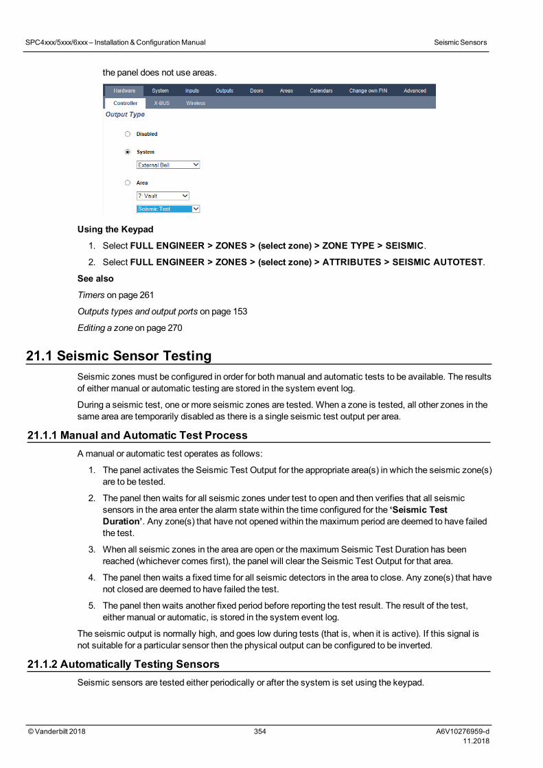
the panel does not use areas.
Using the Keypad
1. Select FULL ENGINEER > ZONES > (select zone) > ZONE TYPE > SEISMIC.
2. Select FULL ENGINEER > ZONES > (select zone) > ATTRIBUTES > SEISMIC AUTOTEST.
See also
Timers on page 261
Outputs types and output ports on page 153
Editing a zone on page 270
21.1 Seismic Sensor TestingSeismic zones must be configured in order for bothmanual and automatic tests to be available. The resultsof either manual or automatic testing are stored in the system event log.
During a seismic test, one or more seismic zones are tested. When a zone is tested, all other zones in thesame area are temporarily disabled as there is a single seismic test output per area.
21.1.1 Manual and Automatic Test ProcessA manual or automatic test operates as follows:
1. The panel activates the Seismic Test Output for the appropriate area(s) in which the seismic zone(s)are to be tested.
2. The panel then waits for all seismic zones under test to open and then verifies that all seismicsensors in the area enter the alarm state within the time configured for the ‘Seismic TestDuration’. Any zone(s) that have not opened within themaximum period are deemed to have failedthe test.
3. When all seismic zones in the area are open or themaximum Seismic Test Duration has beenreached (whichever comes first), the panel will clear the Seismic Test Output for that area.
4. The panel then waits a fixed time for all seismic detectors in the area to close. Any zone(s) that havenot closed are deemed to have failed the test.
5. The panel then waits another fixed period before reporting the test result. The result of the test,either manual or automatic, is stored in the system event log.
The seismic output is normally high, and goes low during tests (that is, when it is active). If this signal isnot suitable for a particular sensor then the physical output can be configured to be inverted.
21.1.2 Automatically Testing SensorsSeismic sensors are tested either periodically or after the system is set using the keypad.
SPC4xxx/5xxx/6xxx– Installation &ConfigurationManual SeismicSensors
© Vanderbilt 2018 354 A6V10276959-d11.2018
Periodic Automatic Testing
Periodic automatic tests are performed on all seismic zones for which automatic tests are enabled.
Automatic tests are randomized within the configured test period and are done independently for eacharea.
All seismic zones in the same area (for which automatic tests are enabled) are tested simultaneously.
TheSeismic Test Interval configuration option in theSystem Timersmenu (see Timers on page 261)determines the average test period for seismic sensors automatic tests. The default value is 168 hours(7 days) and the allowed values are in the range 12–240 hours.
The test time is random within the specified range +/- 15%. For example, if a test is scheduled every 24hours, a test may be performed between 20.4 and 27.6 hours after the last test.
A seismic test is performed after a reboot if automatic tests are enabled. If the panel was in FullEngineer mode before reboot, then the test is performed only after the panel is out of Full Engineermode after a reboot.
If a seismic test fails, a Trouble event is reported (SIA code “BT”). There is also a correspondingRestoration event (SIA code “BJ”).
Automatic Test on Setting
The optionSeismic Test on Set is configurable in theOptionsmenu (seeOptions on page 252). Ifenabled, all seismic zones in all areas that are to be set are tested before the usual setting sequence.This applies to keypad operation only.
While the test is being performed, ‘SEISMIC AUTOTEST’ is displayed on the keypad. If the seismictest succeeds, the setting proceeds as normal.
If all areas or an area group or a single area are selected to be set, and a seismic test fails, then‘SEISMIC FAIL’ will be displayed. PressingReturn displays a list of the failed zones which can bescrolled through using the up and down arrow keys.
Depending on the Inhibit settings for the failed seismic zones and your user profile, the following canoccur:
l If all of the seismic zones that failed the test have the Inhibit attribute set, and your user profileuser is configured with the Inhibit right:
1. Press Return on any of the failed zones.
Themessage “FORCE SET ALL?” is displayed.
2. Press Return again to inhibit all seismic zones that failed the test. (Alternatively, go back to theprevious menu.)
Setting proceeds as normal.
l If some of the seismic zones that failed the test do not have the Inhibit attribute set or your userprofile user does not have the Inhibit right, press Return.
Themessage ‘FAIL TOSET’ will be displayed and no areas will be set.
There is no automatic seismic test for areas that are auto-set for any reason (for example, areasactivated by a calendar or trigger). Likewise there is no automatic seismic test when the system is setwith SPC Com or the browser. However, there is an automatic seismic test when a virtual keypad isused with SPC Com.
No event is reported if seismic testing on set fails.
The periodic automatic system test timer restarts after a test is performed after setting.
21.1.3 Manually Testing SensorsTomanually test sensors, select the TEST > SEISMIC TEST option from the TESTmenu on thekeypad.
SPC4xxx/5xxx/6xxx– Installation &ConfigurationManual SeismicSensors
© Vanderbilt 2018 355 A6V10276959-d11.2018

A seismic manual test with the keypad can be done by the engineer in Full Engineer mode, and also by auser of typeManager or type Standard:
l An engineer is able to test all sensors in all areas configured in the system using any keypad.
l A user is able to test only the sensors in areas that are both assigned to him and to the particularkeypad he is using.
To perform a seismic test in Engineer mode, select FULL ENGINEER > TEST > SEISMIC TEST.
To perform a seismic test in User mode, select MENUS > TEST > SEISMIC TEST.
Note: The following instructions apply to both engineer and user modes but note that only a subset ofoptions may be available to a user.
The following options are available in the SEISMIC TESTmenu:
l TEST ALL AREASTests seismic zones in all available areas if there is more than one area that contains seismiczones.
l ‘AREA NAME’
The names of the areas containing seismic zones are listed individually. When a specific area isselected, the following options are available:
– TEST ALL ZONESTest all seismic zones in this area if there is more than one seismic zone.
– ‘ZONE NAME’The names of all seismic zones are listed and can be selected for testing individually.
Themessage ‘SEISMIC TEST’ is display on the keypad while the test is being performed,
If the test fails, themessage ‘SEISMIC FAIL’ is displayed. If the “i” or VIEW key is pressed, a list of thefailed zones is displayed which can be scrolled through.
If the test succeeds, ‘SEISMIC OK’ is displayed.
Entries are recorded in the event log with the following details:
l user who initiated the test
l result (OK or FAIL)
l area and zone number and name
No events are reported for manual tests.
SPC4xxx/5xxx/6xxx– Installation &ConfigurationManual SeismicSensors
© Vanderbilt 2018 356 A6V10276959-d11.2018
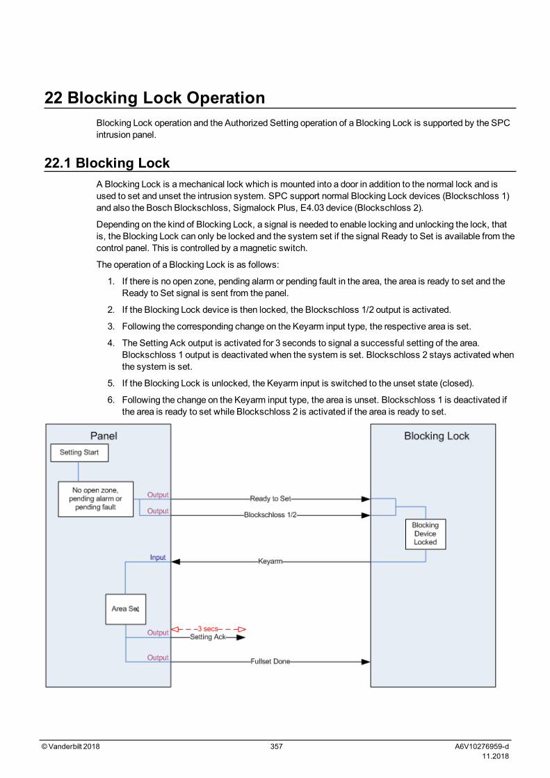
22 Blocking Lock OperationBlocking Lock operation and the Authorized Setting operation of a Blocking Lock is supported by the SPCintrusion panel.
22.1 Blocking LockA Blocking Lock is amechanical lock which is mounted into a door in addition to the normal lock and isused to set and unset the intrusion system. SPC support normal Blocking Lock devices (Blockschloss 1)and also the Bosch Blockschloss, Sigmalock Plus, E4.03 device (Blockschloss 2).
Depending on the kind of Blocking Lock, a signal is needed to enable locking and unlocking the lock, thatis, the Blocking Lock can only be locked and the system set if the signal Ready to Set is available from thecontrol panel. This is controlled by amagnetic switch.
The operation of a Blocking Lock is as follows:
1. If there is no open zone, pending alarm or pending fault in the area, the area is ready to set and theReady to Set signal is sent from the panel.
2. If the Blocking Lock device is then locked, the Blockschloss 1/2 output is activated.
3. Following the corresponding change on the Keyarm input type, the respective area is set.
4. The Setting Ack output is activated for 3 seconds to signal a successful setting of the area.Blockschloss 1 output is deactivated when the system is set. Blockschloss 2 stays activated whenthe system is set.
5. If the Blocking Lock is unlocked, the Keyarm input is switched to the unset state (closed).
6. Following the change on the Keyarm input type, the area is unset. Blockschloss 1 is deactivated ifthe area is ready to set while Blockschloss 2 is activated if the area is ready to set.
©Vanderbilt 2018 357 A6V10276959-d11.2018
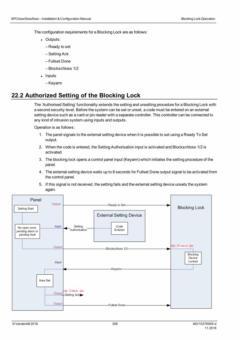
The configuration requirements for a Blocking Lock are as follows:
l Outputs:
– Ready to set
– Setting Ack
– Fullset Done
– Blockschloss 1/2
l Inputs
– Keyarm
22.2 Authorized Setting of the Blocking LockThe ‘Authorised Setting‘ functionality extends the setting and unsetting procedure for a Blocking Lock witha second security level. Before the system can be set or unset, a codemust be entered on an externalsetting device such as a card or pin reader with a separate controller. This controller can be connected toany kind of intrusion system using inputs and outputs.
Operation is as follows:
1. The panel signals to the external setting device when it is possible to set using a Ready To Setoutput.
2. When the code is entered, the Setting Authorisation input is activated and Blockschloss 1/2 isactivated.
3. The blocking lock opens a control panel input (Keyarm) which initiates the setting procedure of thepanel.
4. The external setting device waits up to 8 seconds for Fullset Done output signal to be activated fromthe control panel.
5. If this signal is not received, the setting fails and the external setting device unsets the systemagain.
SPC4xxx/5xxx/6xxx– Installation &ConfigurationManual Blocking LockOperation
© Vanderbilt 2018 358 A6V10276959-d11.2018
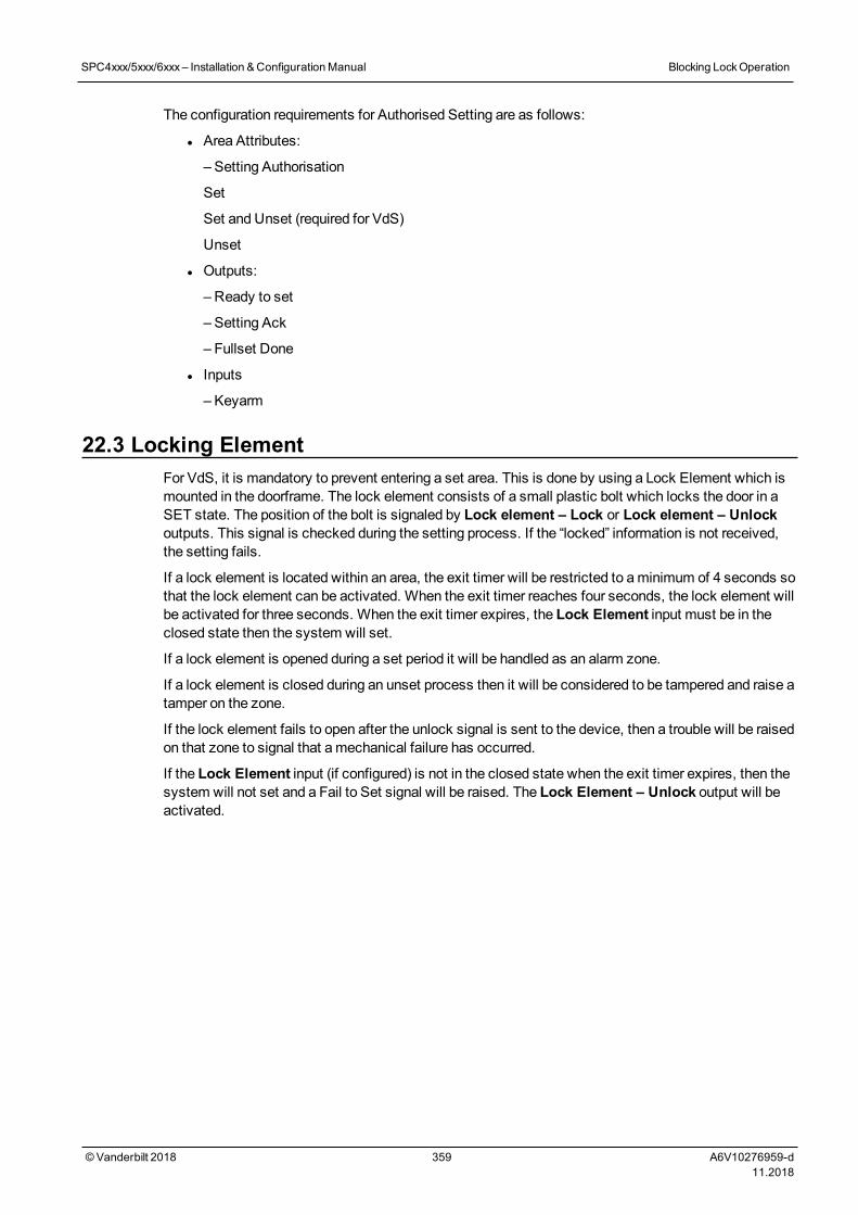
The configuration requirements for Authorised Setting are as follows:
l Area Attributes:
– Setting Authorisation
Set
Set and Unset (required for VdS)
Unset
l Outputs:
– Ready to set
– Setting Ack
– Fullset Done
l Inputs
– Keyarm
22.3 Locking ElementFor VdS, it is mandatory to prevent entering a set area. This is done by using a Lock Element which ismounted in the doorframe. The lock element consists of a small plastic bolt which locks the door in aSET state. The position of the bolt is signaled by Lock element – Lock or Lock element – Unlockoutputs. This signal is checked during the setting process. If the “locked” information is not received,the setting fails.
If a lock element is located within an area, the exit timer will be restricted to aminimum of 4 seconds sothat the lock element can be activated. When the exit timer reaches four seconds, the lock element willbe activated for three seconds. When the exit timer expires, the Lock Element input must be in theclosed state then the system will set.
If a lock element is opened during a set period it will be handled as an alarm zone.
If a lock element is closed during an unset process then it will be considered to be tampered and raise atamper on the zone.
If the lock element fails to open after the unlock signal is sent to the device, then a trouble will be raisedon that zone to signal that amechanical failure has occurred.
If the Lock Element input (if configured) is not in the closed state when the exit timer expires, then thesystem will not set and a Fail to Set signal will be raised. The Lock Element – Unlock output will beactivated.
SPC4xxx/5xxx/6xxx– Installation &ConfigurationManual Blocking LockOperation
© Vanderbilt 2018 359 A6V10276959-d11.2018
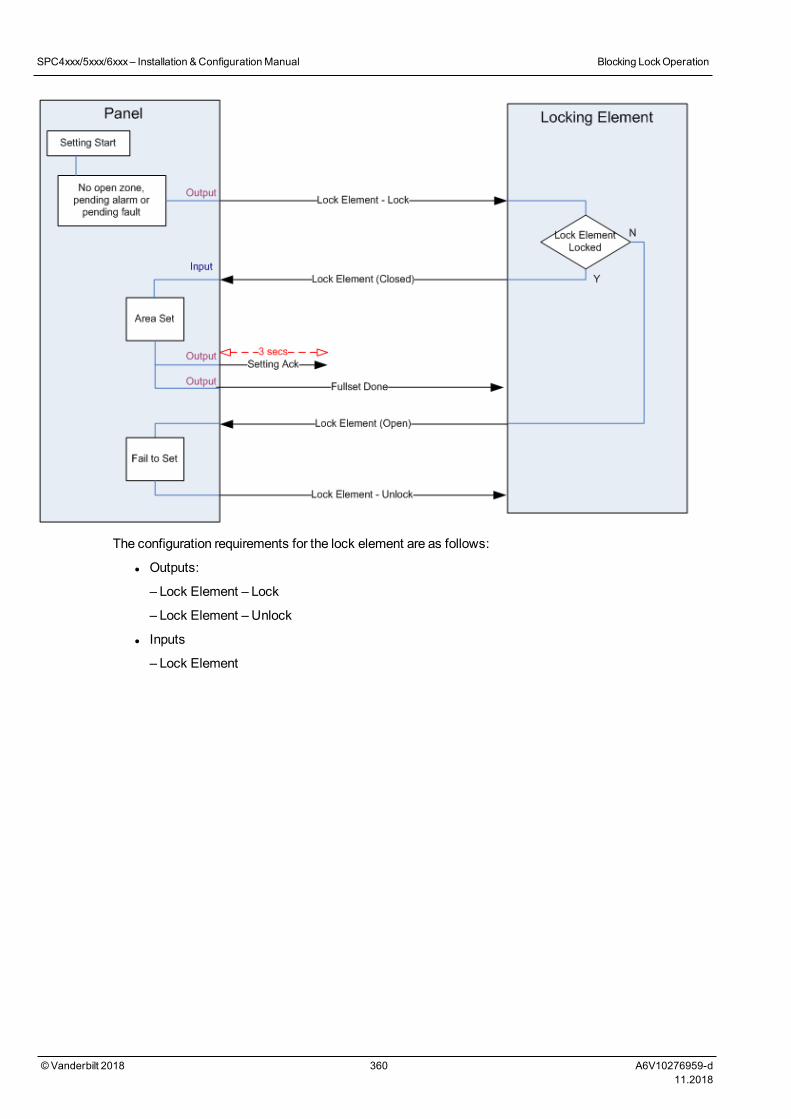
The configuration requirements for the lock element are as follows:
l Outputs:
– Lock Element – Lock
– Lock Element – Unlock
l Inputs
– Lock Element
SPC4xxx/5xxx/6xxx– Installation &ConfigurationManual Blocking LockOperation
© Vanderbilt 2018 360 A6V10276959-d11.2018
23 AppendixThis appendix covers:
23.1 Network cable connections 361
23.2 Controller status LEDs 362
23.3 Powering expanders from the auxiliary power terminals 363
23.4 Calculating the battery power requirements 364
23.5 Domestic, Commercial and Financial mode default settings 366
23.6 Wiring of the X10 interface 367
23.7 SIA Codes 368
23.8 CID Codes 373
23.9 Overview of keypad types 375
23.10 User PIN combinations 376
23.11 Duress PINs 376
23.12 Automatic inhibits 376
23.13 Wiring of mains cable to the controller 377
23.14 Maintenance controller 377
23.15 Maintenance Smart PSU 378
23.16 Zone types 379
23.17 Zone attributes 384
23.18 Applicable attributes to zone types 387
23.19 ATS levels and attenuation specifications 388
23.20 Supported card readers and card formats 388
23.21 SPC Support for E-Bus Devices 390
23.22 FlexC Glossary 393
23.23 FlexC Commands 394
23.24 ATS Category Timings 397
23.25 ATP Category Timings 398
23.1 Network cable connections
A PC can be connected directly to the Ethernet interface of the SPC controller or via a LAN connection.The tables below show the 2 possible connection configurations.
l If the SPC is connected to an existing network via a hub, then connect a straight through cable fromthe hub to the SPC and another from the hub to the PC.
l If the controller is not connected to a network (that is, a hub or switch is not used), then a crossovercable should be connected between the SPC controller and the PC.
Use the straight through cable for connecting the SPC controller to a PC via a hub.
©Vanderbilt 2018 361 A6V10276959-d11.2018
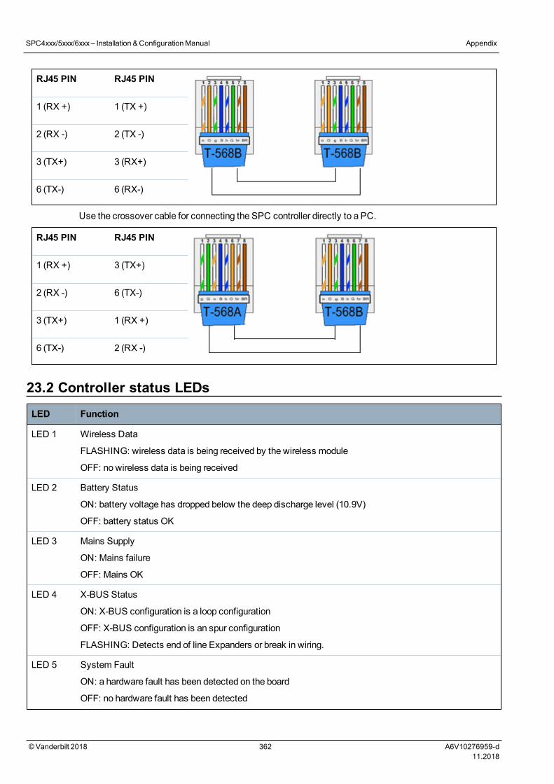
RJ45 PIN RJ45 PIN
1 (RX +) 1 (TX +)
2 (RX -) 2 (TX -)
3 (TX+) 3 (RX+)
6 (TX-) 6 (RX-)
Use the crossover cable for connecting the SPC controller directly to a PC.
RJ45 PIN RJ45 PIN
1 (RX +) 3 (TX+)
2 (RX -) 6 (TX-)
3 (TX+) 1 (RX +)
6 (TX-) 2 (RX -)
23.2 Controller status LEDsLED Function
LED 1 Wireless Data
FLASHING: wireless data is being received by the wireless module
OFF: no wireless data is being received
LED 2 Battery Status
ON: battery voltage has dropped below the deep discharge level (10.9V)
OFF: battery status OK
LED 3 Mains Supply
ON: Mains failure
OFF: Mains OK
LED 4 X-BUS Status
ON: X-BUS configuration is a loop configuration
OFF: X-BUS configuration is an spur configuration
FLASHING: Detects end of line Expanders or break in wiring.
LED 5 System Fault
ON: a hardware fault has been detected on the board
OFF: no hardware fault has been detected
SPC4xxx/5xxx/6xxx– Installation &ConfigurationManual Appendix
© Vanderbilt 2018 362 A6V10276959-d11.2018
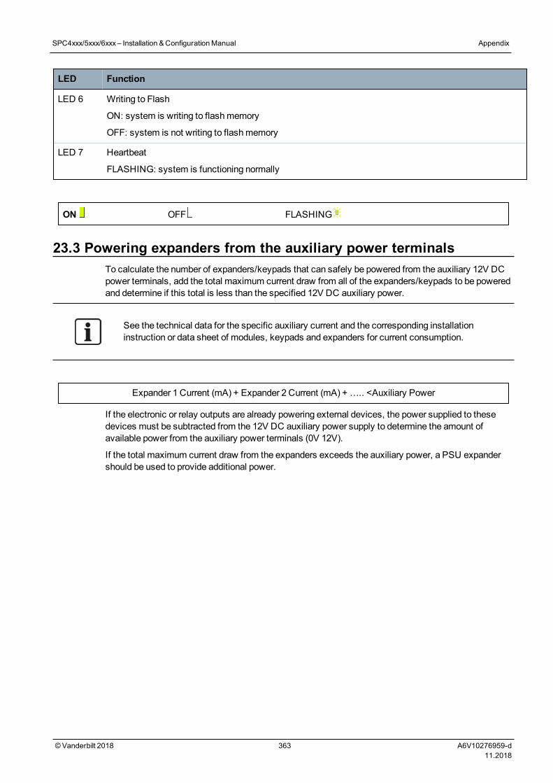
LED Function
LED 6 Writing to Flash
ON: system is writing to flashmemory
OFF: system is not writing to flashmemory
LED 7 Heartbeat
FLASHING: system is functioning normally
ON OFF FLASHING
23.3 Powering expanders from the auxiliary power terminalsTo calculate the number of expanders/keypads that can safely be powered from the auxiliary 12V DCpower terminals, add the total maximum current draw from all of the expanders/keypads to be poweredand determine if this total is less than the specified 12V DC auxiliary power.
See the technical data for the specific auxiliary current and the corresponding installationinstruction or data sheet of modules, keypads and expanders for current consumption.
Expander 1 Current (mA) + Expander 2 Current (mA) + ….. <Auxiliary Power
If the electronic or relay outputs are already powering external devices, the power supplied to thesedevices must be subtracted from the 12V DC auxiliary power supply to determine the amount ofavailable power from the auxiliary power terminals (0V 12V).
If the total maximum current draw from the expanders exceeds the auxiliary power, a PSU expandershould be used to provide additional power.
SPC4xxx/5xxx/6xxx– Installation &ConfigurationManual Appendix
© Vanderbilt 2018 363 A6V10276959-d11.2018
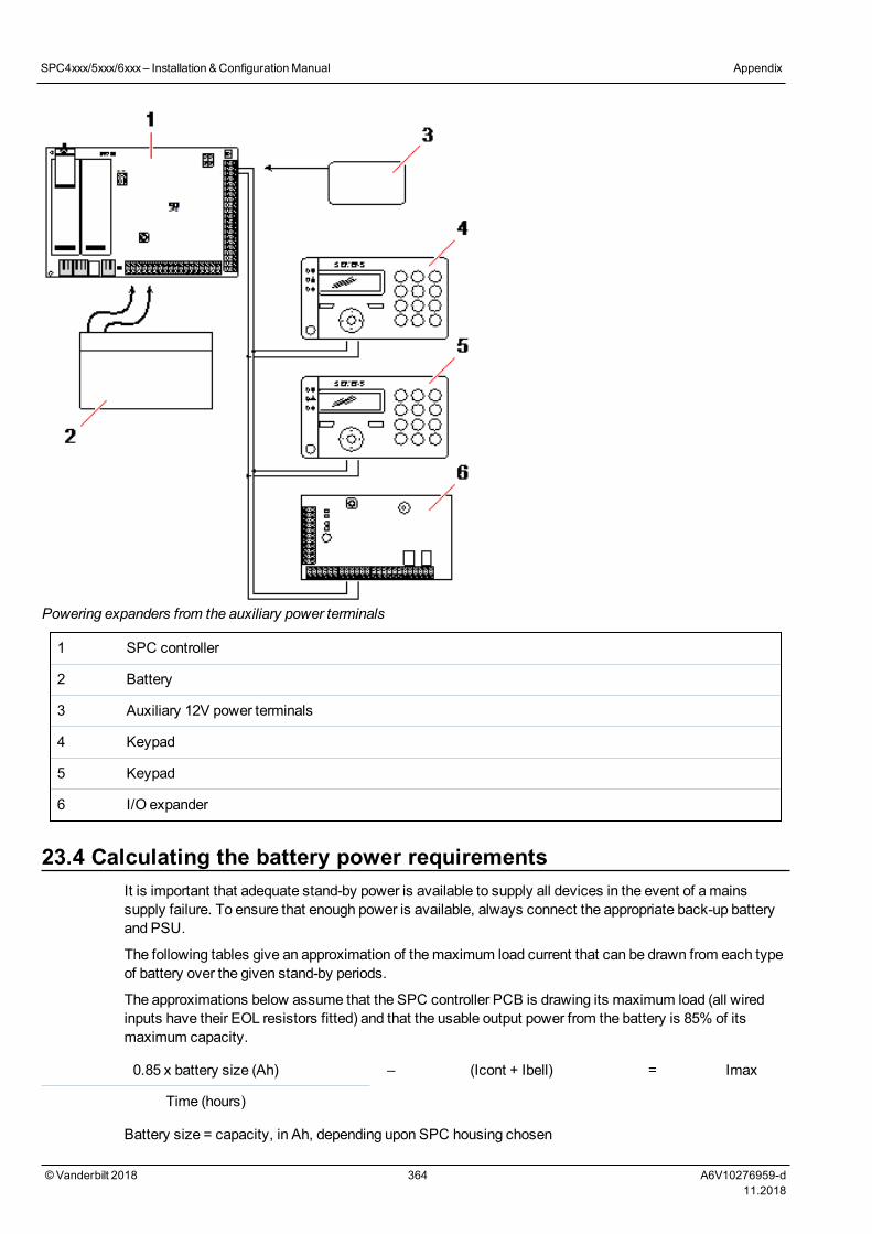
Powering expanders from the auxiliary power terminals
1 SPC controller
2 Battery
3 Auxiliary 12V power terminals
4 Keypad
5 Keypad
6 I/O expander
23.4 Calculating the battery power requirementsIt is important that adequate stand-by power is available to supply all devices in the event of amainssupply failure. To ensure that enough power is available, always connect the appropriate back-up batteryand PSU.
The following tables give an approximation of themaximum load current that can be drawn from each typeof battery over the given stand-by periods.
The approximations below assume that the SPC controller PCB is drawing its maximum load (all wiredinputs have their EOL resistors fitted) and that the usable output power from the battery is 85% of itsmaximum capacity.
0.85 x battery size (Ah) – (Icont + Ibell) = Imax
Time (hours)
Battery size = capacity, in Ah, depending upon SPC housing chosen
SPC4xxx/5xxx/6xxx– Installation &ConfigurationManual Appendix
© Vanderbilt 2018 364 A6V10276959-d11.2018
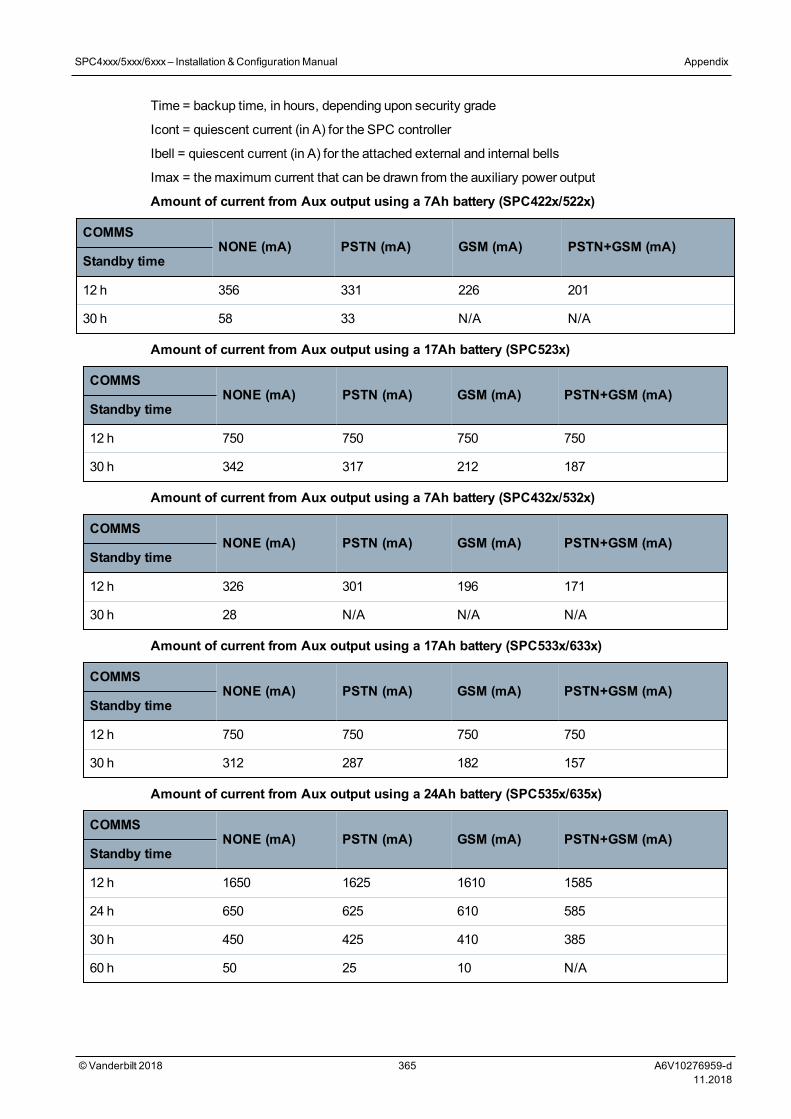
Time = backup time, in hours, depending upon security grade
Icont = quiescent current (in A) for the SPC controller
Ibell = quiescent current (in A) for the attached external and internal bells
Imax = themaximum current that can be drawn from the auxiliary power output
Amount of current from Aux output using a 7Ah battery (SPC422x/522x)
COMMSNONE (mA) PSTN (mA) GSM (mA) PSTN+GSM (mA)
Standby time
12 h 356 331 226 201
30 h 58 33 N/A N/A
Amount of current from Aux output using a 17Ah battery (SPC523x)
COMMSNONE (mA) PSTN (mA) GSM (mA) PSTN+GSM (mA)
Standby time
12 h 750 750 750 750
30 h 342 317 212 187
Amount of current from Aux output using a 7Ah battery (SPC432x/532x)
COMMSNONE (mA) PSTN (mA) GSM (mA) PSTN+GSM (mA)
Standby time
12 h 326 301 196 171
30 h 28 N/A N/A N/A
Amount of current from Aux output using a 17Ah battery (SPC533x/633x)
COMMSNONE (mA) PSTN (mA) GSM (mA) PSTN+GSM (mA)
Standby time
12 h 750 750 750 750
30 h 312 287 182 157
Amount of current from Aux output using a 24Ah battery (SPC535x/635x)
COMMSNONE (mA) PSTN (mA) GSM (mA) PSTN+GSM (mA)
Standby time
12 h 1650 1625 1610 1585
24 h 650 625 610 585
30 h 450 425 410 385
60 h 50 25 10 N/A
SPC4xxx/5xxx/6xxx– Installation &ConfigurationManual Appendix
© Vanderbilt 2018 365 A6V10276959-d11.2018
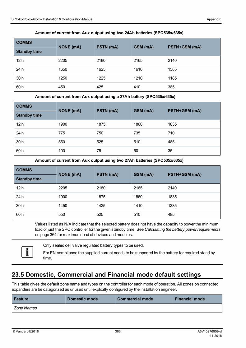
Amount of current from Aux output using two 24Ah batteries (SPC535x/635x)
COMMSNONE (mA) PSTN (mA) GSM (mA) PSTN+GSM (mA)
Standby time
12 h 2205 2180 2165 2140
24 h 1650 1625 1610 1585
30 h 1250 1225 1210 1185
60 h 450 425 410 385
Amount of current from Aux output using a 27Ah battery (SPC535x/635x)
COMMSNONE (mA) PSTN (mA) GSM (mA) PSTN+GSM (mA)
Standby time
12 h 1900 1875 1860 1835
24 h 775 750 735 710
30 h 550 525 510 485
60 h 100 75 60 35
Amount of current from Aux output using two 27Ah batteries (SPC535x/635x)
COMMSNONE (mA) PSTN (mA) GSM (mA) PSTN+GSM (mA)
Standby time
12 h 2205 2180 2165 2140
24 h 1900 1875 1860 1835
30 h 1450 1425 1410 1385
60 h 550 525 510 485
Values listed as N/A indicate that the selected battery does not have the capacity to power theminimumload of just the SPC controller for the given standby time. SeeCalculating the battery power requirementson page 364 for maximum load of devices andmodules.
Only sealed cell valve regulated battery types to be used.
For EN compliance the supplied current needs to be supported by the battery for required stand bytime.
23.5 Domestic, Commercial and Financial mode default settingsThis table gives the default zone name and types on the controller for eachmode of operation. All zones on connectedexpanders are be categorized as unused until explicitly configured by the installation engineer.
Feature Domestic mode Commercial mode Financial mode
Zone Names
SPC4xxx/5xxx/6xxx– Installation &ConfigurationManual Appendix
© Vanderbilt 2018 366 A6V10276959-d11.2018

Feature Domestic mode Commercial mode Financial mode
Controller - Zone 1 Front door Front door Front door
Controller - Zone 2 Sitting room Window 1 Window 1
Controller - Zone 3 Kitchen Window 2 Window 2
Controller - Zone 4 Upstairs front PIR 1 PIR 1
Controller - Zone 5 Upstairs rear PIR 2 PIR 2
Controller - Zone 6 PIR hallway Fire exit Fire exit
Controller - Zone 7 PIR landing Fire alarm Fire alarm
Controller - Zone 8 Panic button Panic button Panic button
Zone Types
Controller - Zone 1 ENTRY/EXIT ENTRY/EXIT ENTRY/EXIT
Controller - Zone 2 ALARM ALARM ALARM
Controller - Zone 3 ALARM ALARM ALARM
Controller - Zone 4 ALARM ALARM ALARM
Controller - Zone 5 ALARM ALARM ALARM
Controller - Zone 6 ALARM FIRE EXIT ALARM
Controller - Zone 7 ALARM FIRE ALARM
Controller - Zone 8 PANIC PANIC ALARM
23.6 Wiring of the X10 interface
X10wiring to the controller
PIN RJ45 RJ11
TX 8 4
GND 5 1
RX 1 2
SPC4xxx/5xxx/6xxx– Installation &ConfigurationManual Appendix
© Vanderbilt 2018 367 A6V10276959-d11.2018
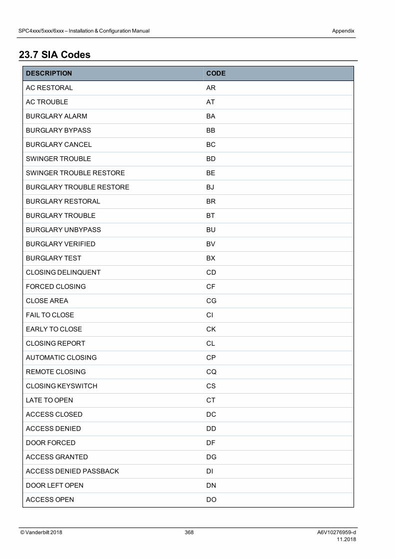
23.7 SIA CodesDESCRIPTION CODE
AC RESTORAL AR
AC TROUBLE AT
BURGLARY ALARM BA
BURGLARY BYPASS BB
BURGLARY CANCEL BC
SWINGER TROUBLE BD
SWINGER TROUBLE RESTORE BE
BURGLARY TROUBLE RESTORE BJ
BURGLARY RESTORAL BR
BURGLARY TROUBLE BT
BURGLARY UNBYPASS BU
BURGLARY VERIFIED BV
BURGLARY TEST BX
CLOSINGDELINQUENT CD
FORCED CLOSING CF
CLOSE AREA CG
FAIL TOCLOSE CI
EARLY TOCLOSE CK
CLOSINGREPORT CL
AUTOMATIC CLOSING CP
REMOTE CLOSING CQ
CLOSINGKEYSWITCH CS
LATE TOOPEN CT
ACCESS CLOSED DC
ACCESS DENIED DD
DOOR FORCED DF
ACCESS GRANTED DG
ACCESS DENIED PASSBACK DI
DOOR LEFT OPEN DN
ACCESS OPEN DO
SPC4xxx/5xxx/6xxx– Installation &ConfigurationManual Appendix
© Vanderbilt 2018 368 A6V10276959-d11.2018
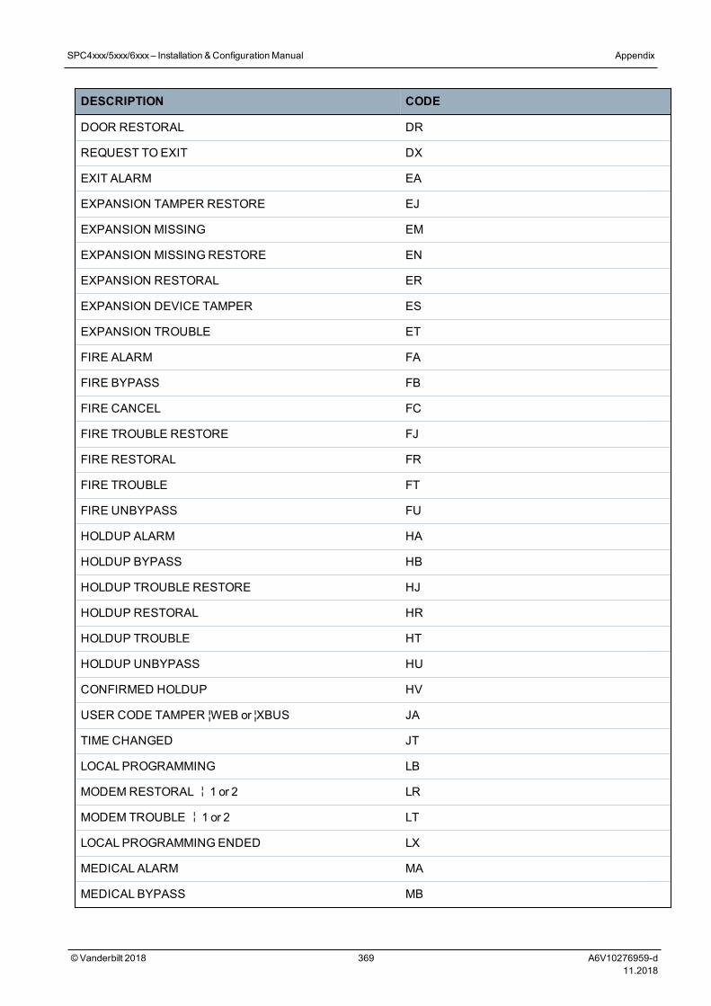
DESCRIPTION CODE
DOOR RESTORAL DR
REQUEST TOEXIT DX
EXIT ALARM EA
EXPANSION TAMPER RESTORE EJ
EXPANSION MISSING EM
EXPANSION MISSINGRESTORE EN
EXPANSION RESTORAL ER
EXPANSION DEVICE TAMPER ES
EXPANSION TROUBLE ET
FIRE ALARM FA
FIRE BYPASS FB
FIRE CANCEL FC
FIRE TROUBLE RESTORE FJ
FIRE RESTORAL FR
FIRE TROUBLE FT
FIRE UNBYPASS FU
HOLDUP ALARM HA
HOLDUP BYPASS HB
HOLDUP TROUBLE RESTORE HJ
HOLDUP RESTORAL HR
HOLDUP TROUBLE HT
HOLDUP UNBYPASS HU
CONFIRMED HOLDUP HV
USER CODE TAMPER ¦WEB or ¦XBUS JA
TIME CHANGED JT
LOCAL PROGRAMMING LB
MODEMRESTORAL¦1 or 2 LR
MODEM TROUBLE¦1 or 2 LT
LOCAL PROGRAMMINGENDED LX
MEDICAL ALARM MA
MEDICAL BYPASS MB
SPC4xxx/5xxx/6xxx– Installation &ConfigurationManual Appendix
© Vanderbilt 2018 369 A6V10276959-d11.2018
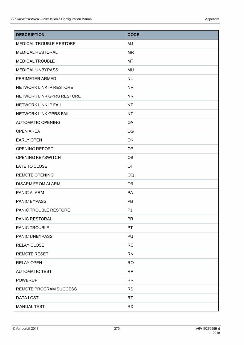
DESCRIPTION CODE
MEDICAL TROUBLE RESTORE MJ
MEDICALRESTORAL MR
MEDICAL TROUBLE MT
MEDICALUNBYPASS MU
PERIMETER ARMED NL
NETWORK LINK IP RESTORE NR
NETWORK LINK GPRS RESTORE NR
NETWORK LINK IP FAIL NT
NETWORK LINK GPRS FAIL NT
AUTOMATIC OPENING OA
OPEN AREA OG
EARLY OPEN OK
OPENINGREPORT OP
OPENINGKEYSWITCH OS
LATE TOCLOSE OT
REMOTE OPENING OQ
DISARM FROMALARM OR
PANIC ALARM PA
PANIC BYPASS PB
PANIC TROUBLE RESTORE PJ
PANIC RESTORAL PR
PANIC TROUBLE PT
PANIC UNBYPASS PU
RELAY CLOSE RC
REMOTE RESET RN
RELAY OPEN RO
AUTOMATIC TEST RP
POWERUP RR
REMOTE PROGRAM SUCCESS RS
DATA LOST RT
MANUAL TEST RX
SPC4xxx/5xxx/6xxx– Installation &ConfigurationManual Appendix
© Vanderbilt 2018 370 A6V10276959-d11.2018
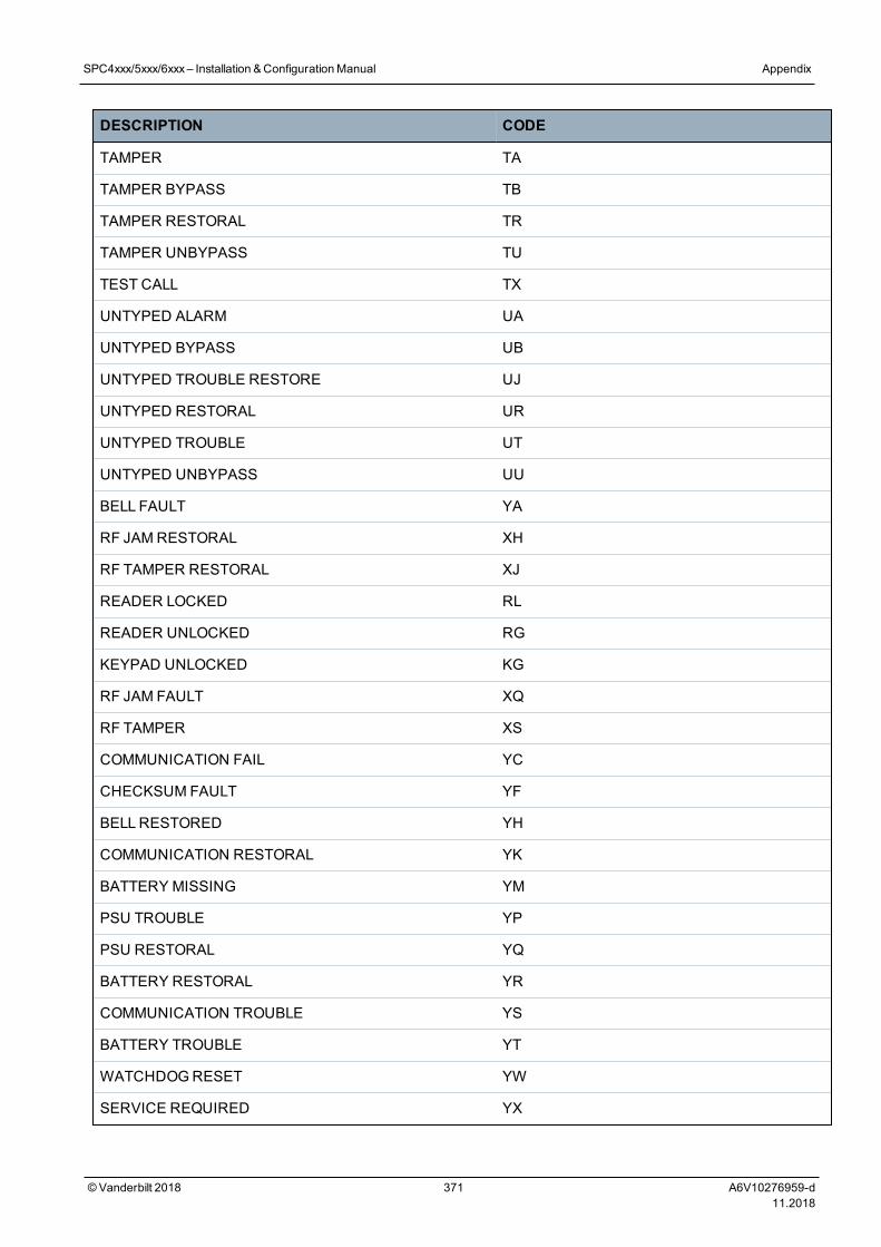
DESCRIPTION CODE
TAMPER TA
TAMPER BYPASS TB
TAMPER RESTORAL TR
TAMPER UNBYPASS TU
TEST CALL TX
UNTYPED ALARM UA
UNTYPED BYPASS UB
UNTYPED TROUBLE RESTORE UJ
UNTYPED RESTORAL UR
UNTYPED TROUBLE UT
UNTYPED UNBYPASS UU
BELL FAULT YA
RF JAM RESTORAL XH
RF TAMPER RESTORAL XJ
READER LOCKED RL
READER UNLOCKED RG
KEYPAD UNLOCKED KG
RF JAM FAULT XQ
RF TAMPER XS
COMMUNICATION FAIL YC
CHECKSUM FAULT YF
BELLRESTORED YH
COMMUNICATION RESTORAL YK
BATTERY MISSING YM
PSU TROUBLE YP
PSU RESTORAL YQ
BATTERY RESTORAL YR
COMMUNICATION TROUBLE YS
BATTERY TROUBLE YT
WATCHDOGRESET YW
SERVICE REQUIRED YX
SPC4xxx/5xxx/6xxx– Installation &ConfigurationManual Appendix
© Vanderbilt 2018 371 A6V10276959-d11.2018
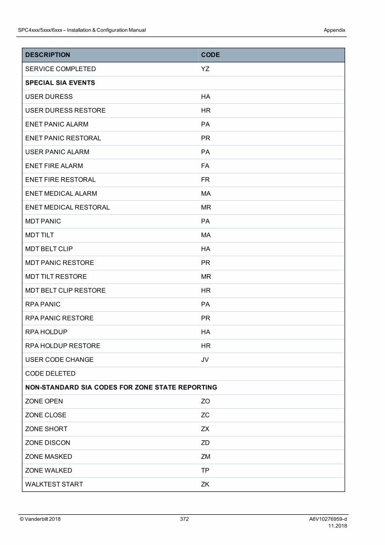
DESCRIPTION CODE
SERVICE COMPLETED YZ
SPECIAL SIA EVENTS
USER DURESS HA
USER DURESS RESTORE HR
ENET PANIC ALARM PA
ENET PANIC RESTORAL PR
USER PANIC ALARM PA
ENET FIRE ALARM FA
ENET FIRE RESTORAL FR
ENETMEDICAL ALARM MA
ENETMEDICALRESTORAL MR
MDT PANIC PA
MDT TILT MA
MDT BELT CLIP HA
MDT PANIC RESTORE PR
MDT TILT RESTORE MR
MDT BELT CLIP RESTORE HR
RPA PANIC PA
RPA PANIC RESTORE PR
RPA HOLDUP HA
RPA HOLDUP RESTORE HR
USER CODE CHANGE JV
CODE DELETED
NON-STANDARD SIA CODES FOR ZONE STATE REPORTING
ZONE OPEN ZO
ZONE CLOSE ZC
ZONE SHORT ZX
ZONE DISCON ZD
ZONE MASKED ZM
ZONEWALKED TP
WALKTEST START ZK
SPC4xxx/5xxx/6xxx– Installation &ConfigurationManual Appendix
© Vanderbilt 2018 372 A6V10276959-d11.2018
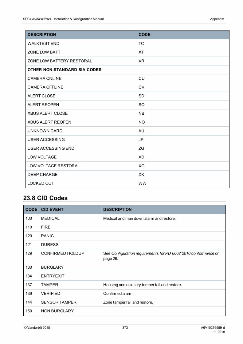
DESCRIPTION CODE
WALKTEST END TC
ZONE LOW BATT XT
ZONE LOW BATTERY RESTORAL XR
OTHER NON-STANDARD SIA CODES
CAMERA ONLINE CU
CAMERA OFFLINE CV
ALERT CLOSE SD
ALERT REOPEN SO
XBUS ALERT CLOSE NB
XBUS ALERT REOPEN NO
UNKNOWN CARD AU
USER ACCESSING JP
USER ACCESSINGEND ZG
LOW VOLTAGE XD
LOW VOLTAGE RESTORAL XG
DEEP CHARGE XK
LOCKED OUT WW
23.8 CID CodesCODE CID EVENT DESCRIPTION
100 MEDICAL Medical andman down alarm and restore.
110 FIRE
120 PANIC
121 DURESS
129 CONFIRMED HOLDUP SeeConfiguration requirements for PD 6662:2010 conformance onpage 26.
130 BURGLARY
134 ENTRYEXIT
137 TAMPER Housing and auxiliary tamper fail and restore.
139 VERIFIED Confirmed alarm.
144 SENSOR TAMPER Zone tamper fail and restore.
150 NON BURGLARY
SPC4xxx/5xxx/6xxx– Installation &ConfigurationManual Appendix
© Vanderbilt 2018 373 A6V10276959-d11.2018
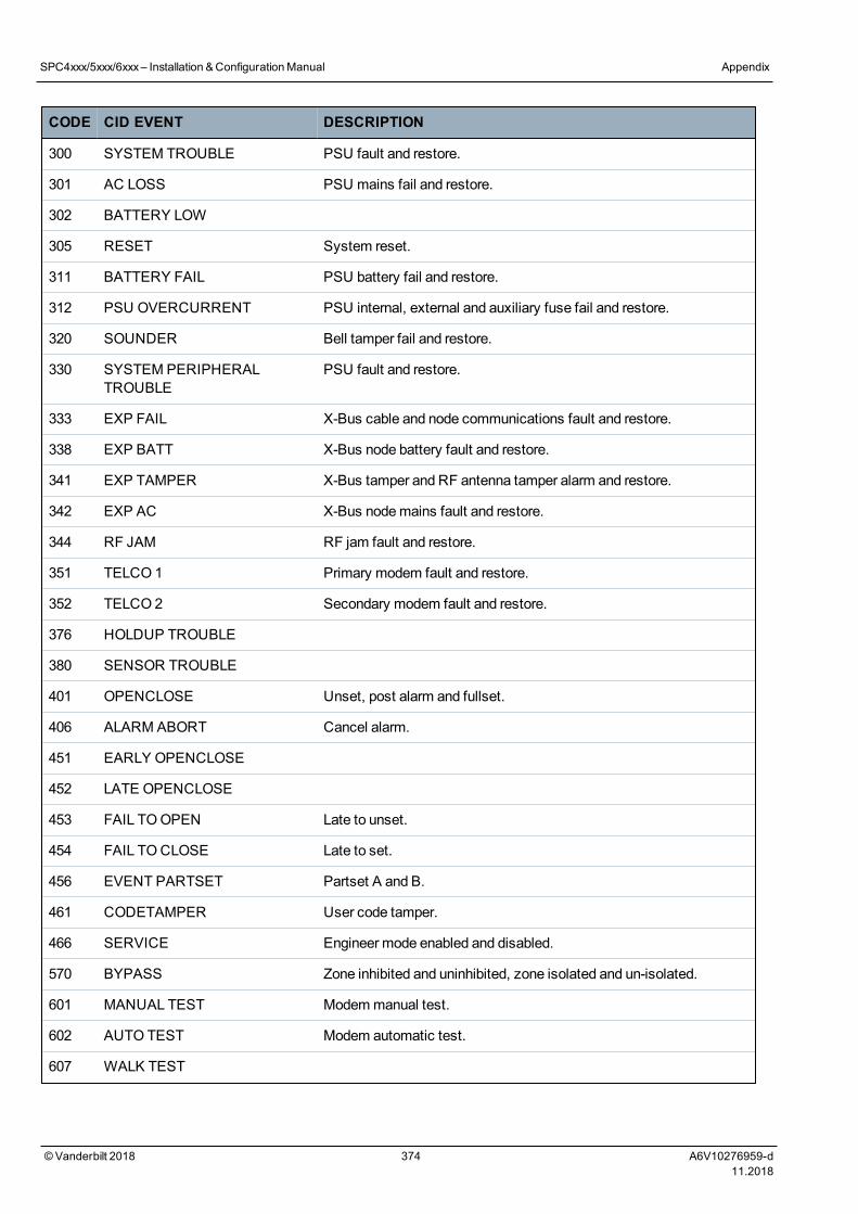
CODE CID EVENT DESCRIPTION
300 SYSTEM TROUBLE PSU fault and restore.
301 AC LOSS PSU mains fail and restore.
302 BATTERY LOW
305 RESET System reset.
311 BATTERY FAIL PSU battery fail and restore.
312 PSU OVERCURRENT PSU internal, external and auxiliary fuse fail and restore.
320 SOUNDER Bell tamper fail and restore.
330 SYSTEM PERIPHERALTROUBLE
PSU fault and restore.
333 EXP FAIL X-Bus cable and node communications fault and restore.
338 EXP BATT X-Bus node battery fault and restore.
341 EXP TAMPER X-Bus tamper and RF antenna tamper alarm and restore.
342 EXP AC X-Bus nodemains fault and restore.
344 RF JAM RF jam fault and restore.
351 TELCO 1 Primary modem fault and restore.
352 TELCO 2 Secondary modem fault and restore.
376 HOLDUP TROUBLE
380 SENSOR TROUBLE
401 OPENCLOSE Unset, post alarm and fullset.
406 ALARM ABORT Cancel alarm.
451 EARLY OPENCLOSE
452 LATE OPENCLOSE
453 FAIL TOOPEN Late to unset.
454 FAIL TOCLOSE Late to set.
456 EVENT PARTSET Partset A and B.
461 CODETAMPER User code tamper.
466 SERVICE Engineer mode enabled and disabled.
570 BYPASS Zone inhibited and uninhibited, zone isolated and un-isolated.
601 MANUAL TEST Modemmanual test.
602 AUTO TEST Modem automatic test.
607 WALK TEST
SPC4xxx/5xxx/6xxx– Installation &ConfigurationManual Appendix
© Vanderbilt 2018 374 A6V10276959-d11.2018
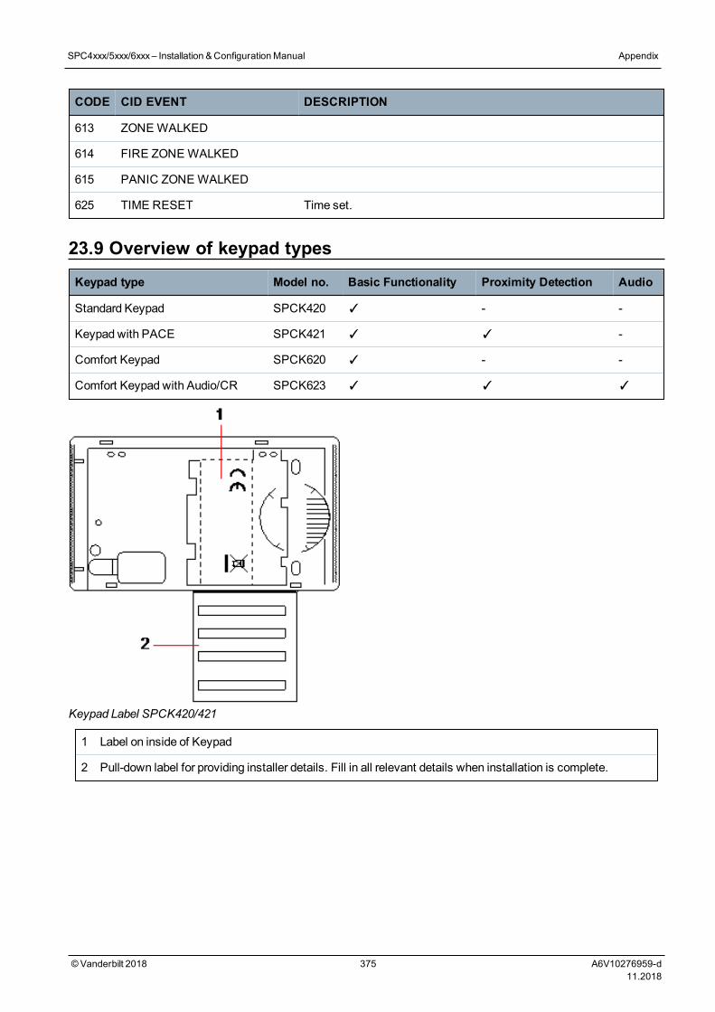
CODE CID EVENT DESCRIPTION
613 ZONEWALKED
614 FIRE ZONEWALKED
615 PANIC ZONEWALKED
625 TIME RESET Time set.
23.9 Overview of keypad typesKeypad type Model no. Basic Functionality Proximity Detection Audio
Standard Keypad SPCK420 ✓ - -
Keypad with PACE SPCK421 ✓ ✓ -
Comfort Keypad SPCK620 ✓ - -
Comfort Keypad with Audio/CR SPCK623 ✓ ✓ ✓
Keypad Label SPCK420/421
1 Label on inside of Keypad
2 Pull-down label for providing installer details. Fill in all relevant details when installation is complete.
SPC4xxx/5xxx/6xxx– Installation &ConfigurationManual Appendix
© Vanderbilt 2018 375 A6V10276959-d11.2018
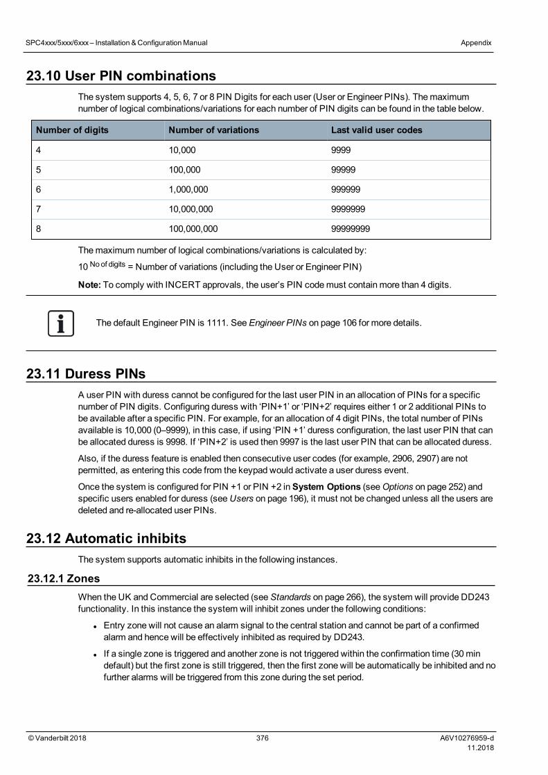
23.10 User PIN combinationsThe system supports 4, 5, 6, 7 or 8 PIN Digits for each user (User or Engineer PINs). Themaximumnumber of logical combinations/variations for each number of PIN digits can be found in the table below.
Number of digits Number of variations Last valid user codes
4 10,000 9999
5 100,000 99999
6 1,000,000 999999
7 10,000,000 9999999
8 100,000,000 99999999
Themaximum number of logical combinations/variations is calculated by:
10 Noof digits = Number of variations (including the User or Engineer PIN)
Note: To comply with INCERT approvals, the user’s PIN codemust contain more than 4 digits.
The default Engineer PIN is 1111. SeeEngineer PINs on page 106 for more details.
23.11 Duress PINsA user PIN with duress cannot be configured for the last user PIN in an allocation of PINs for a specificnumber of PIN digits. Configuring duress with ‘PIN+1’ or ‘PIN+2’ requires either 1 or 2 additional PINs tobe available after a specific PIN. For example, for an allocation of 4 digit PINs, the total number of PINsavailable is 10,000 (0–9999), in this case, if using ‘PIN +1’ duress configuration, the last user PIN that canbe allocated duress is 9998. If ‘PIN+2’ is used then 9997 is the last user PIN that can be allocated duress.
Also, if the duress feature is enabled then consecutive user codes (for example, 2906, 2907) are notpermitted, as entering this code from the keypad would activate a user duress event.
Once the system is configured for PIN +1 or PIN +2 inSystem Options (seeOptions on page 252) andspecific users enabled for duress (seeUsers on page 196), it must not be changed unless all the users aredeleted and re-allocated user PINs.
23.12 Automatic inhibitsThe system supports automatic inhibits in the following instances.
23.12.1 ZonesWhen the UK and Commercial are selected (seeStandards on page 266), the system will provide DD243functionality. In this instance the system will inhibit zones under the following conditions:
l Entry zone will not cause an alarm signal to the central station and cannot be part of a confirmedalarm and hence will be effectively inhibited as required by DD243.
l If a single zone is triggered and another zone is not triggered within the confirmation time (30mindefault) but the first zone is still triggered, then the first zone will be automatically be inhibited and nofurther alarms will be triggered from this zone during the set period.
SPC4xxx/5xxx/6xxx– Installation &ConfigurationManual Appendix
© Vanderbilt 2018 376 A6V10276959-d11.2018
23.12.2 Access PINsFor Grade 2 systems:After 10 unsuccessful attempts with the incorrect PIN, the keypad or browserwill be disabled for 90 s; after a further 10 attempts with the incorrect PIN, the keypad or browser will bedisabled for a further 90 s. Once a correct PIN has been entered, it will reset the counter back to zeroallowing for a further 10 attempts before disablement.
For Grade 3 systems:After 10 unsuccessful attempts with the incorrect PIN, the keypad or browserwill be disabled for 90 s; after each further attempt with an incorrect PIN the keypad or browser will bedisabled for a further 90 s. Once a correct PIN has been entered it will reset the counter back to zeroallowing for a further 10 attempts before disablement.
23.12.3 Engineer AccessAn Engineer can only access the system if permitted by a ‘Manager’ user type (see ‘Engineer’ attributeinUser rights on page 200) and only for a specified time duration (see ‘Engineer Access’ in Timers onpage 261).
23.12.4 Keypad User LogoffIf no keys are pressed on a keypad for a specific duration (see ‘Keypad Timeout’ in Timers onpage 261), the user is automatically logged off.
23.13 Wiring of mains cable to the controllerRequirements:
A readily accessible approved disconnect devicemust be incorporated in the building installationwiring. This must disconnect both phases at the same time. Acceptable devices are switches, circuitbreakers, or similar devices
l The disconnect devicemust have at least 3mm distance between the contacts
l Minimum size conductor used for connectingmains is 1.5mm square
l The circuit breakers must have amaximum rating of 16A
Themains cable is secured to themetal V shaped bend in the base plate via a tie wrap such that themetal bend is between the cable and the tie wrap. Ensure that the tie wrap is applied to thesupplementary insulation of themains cable, that is, the outer PVC cable sleeve. The tie wrapmust bepulled extremely tightly such that when the cable is tugged there is nomovement in the cable relative tothe tie wrap.
The Protective Earthing conductor should be fitted to the terminal block in such a way that if themainscable should slip in its anchorage, placing a strain on the conductors, the Protective Earthing conductorwill be the last item to take the strain.
Themains cablemust be an approved type andmarked HO5 VV-F or HO5 VVH2-F2.
The plastic tie wrapmust be flammability rated V-1.
23.14 Maintenance controllerThe system should be serviced in accordance with the service schedule that is in place. The onlyreplaceable parts on the controller are themains fuse, standby battery and the time and date battery(PCB mounted).
It is recommended that during a service the following be checked:
l The Event Log to check if any standby battery tests have failed since last service – if standbybattery tests have failed then the standby battery should be checked.
l The standby battery should be replaced as per the servicing schedule to ensure that it has
SPC4xxx/5xxx/6xxx– Installation &ConfigurationManual Appendix
© Vanderbilt 2018 377 A6V10276959-d11.2018
sufficient capacity to hold the system up for the time defined in the system design. The batteryshould be physically inspected for any deformation of the casing or any sign of leakage; if any ofthese conditions exist the battery should be immediately replaced.
NOTICE: The new battery should be of the same capacity or greater (up to themaximum the systemcan accommodate).
l If themain fuse blows then the system should be checked for any reasons. The fuse should bereplaced by a fuse with the same rating. The rating is stated on the system label in the rear of thehousing.
l The time and date onboard PCB lithium battery is only used when the system is left un-powered; inthis state that battery has a life of approximately 5 years. The battery should be visually checkedonce a year and all power removed from the system to ensure that system retains the time and date.If the system does not retain the time and date the battery should be replaced with a new Lithiumcell type CR1216.
l All electrical connections should be checked to ensure that the insulation is in place and there is norisk of shorting or becoming disconnected.
l It is also recommended that any firmware update release notes be checked for any additionalupdates that may improve the security of the system.
l Check all physical mountings are intact. Any brokenmountings should be replaced with the sameparts.
23.15 Maintenance Smart PSUThe system should be serviced in accordance with the service schedule that is in place. The onlyreplaceable parts on the Smart PSU are themains fuse and standby battery.
It is recommended that during a service the following be checked:
l The controller Event Log to check if any standby battery tests have failed since last service – ifstandby battery tests have failed then the standby battery should be checked.
l The standby battery should be replaced as per the servicing schedule to ensure that it has sufficientcapacity to hold the system up for the time defined in the system design. The battery should bephysically inspected for any deformation of the casing or any sign of leakage; if any of theseconditions exist the battery should be immediately replaced.
NOTICE: The new battery should be of the same capacity or greater (up to themaximum the systemcan accommodate).
l Check the LEDs on the PSU control board are in the expected state. See Smart PSU document forLED details.
l If themain fuse blows then the system should be checked for any reasons. The fuse should bereplaced by a fuse with the same rating. The rating is stated on the system label in the rear of thehousing.
l All electrical connections should be checked to ensure that the insulation is in place and there is norisk of shorting or becoming disconnected.
l It is also recommended that any firmware update release notes be checked for any additionalupdates that may improve the security of the system.
SPC4xxx/5xxx/6xxx– Installation &ConfigurationManual Appendix
© Vanderbilt 2018 378 A6V10276959-d11.2018
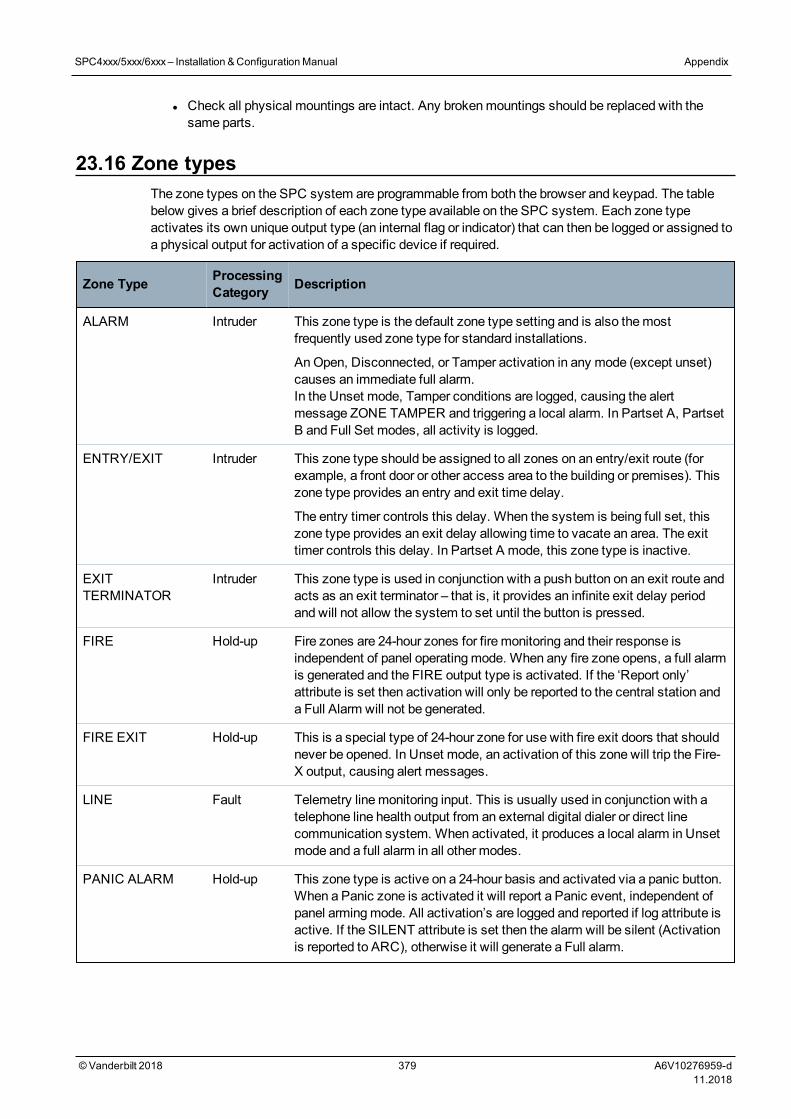
l Check all physical mountings are intact. Any brokenmountings should be replaced with thesame parts.
23.16 Zone typesThe zone types on the SPC system are programmable from both the browser and keypad. The tablebelow gives a brief description of each zone type available on the SPC system. Each zone typeactivates its own unique output type (an internal flag or indicator) that can then be logged or assigned toa physical output for activation of a specific device if required.
Zone Type ProcessingCategory Description
ALARM Intruder This zone type is the default zone type setting and is also themostfrequently used zone type for standard installations.
AnOpen, Disconnected, or Tamper activation in any mode (except unset)causes an immediate full alarm.In the Unset mode, Tamper conditions are logged, causing the alertmessage ZONE TAMPER and triggering a local alarm. In Partset A, PartsetB and Full Set modes, all activity is logged.
ENTRY/EXIT Intruder This zone type should be assigned to all zones on an entry/exit route (forexample, a front door or other access area to the building or premises). Thiszone type provides an entry and exit time delay.
The entry timer controls this delay. When the system is being full set, thiszone type provides an exit delay allowing time to vacate an area. The exittimer controls this delay. In Partset A mode, this zone type is inactive.
EXITTERMINATOR
Intruder This zone type is used in conjunction with a push button on an exit route andacts as an exit terminator – that is, it provides an infinite exit delay periodand will not allow the system to set until the button is pressed.
FIRE Hold-up Fire zones are 24-hour zones for fire monitoring and their response isindependent of panel operatingmode. When any fire zone opens, a full alarmis generated and the FIRE output type is activated. If the ‘Report only’attribute is set then activation will only be reported to the central station anda Full Alarm will not be generated.
FIRE EXIT Hold-up This is a special type of 24-hour zone for use with fire exit doors that shouldnever be opened. In Unset mode, an activation of this zone will trip the Fire-X output, causing alert messages.
LINE Fault Telemetry linemonitoring input. This is usually used in conjunction with atelephone line health output from an external digital dialer or direct linecommunication system. When activated, it produces a local alarm in Unsetmode and a full alarm in all other modes.
PANIC ALARM Hold-up This zone type is active on a 24-hour basis and activated via a panic button.When a Panic zone is activated it will report a Panic event, independent ofpanel armingmode. All activation’s are logged and reported if log attribute isactive. If the SILENT attribute is set then the alarm will be silent (Activationis reported to ARC), otherwise it will generate a Full alarm.
SPC4xxx/5xxx/6xxx– Installation &ConfigurationManual Appendix
© Vanderbilt 2018 379 A6V10276959-d11.2018
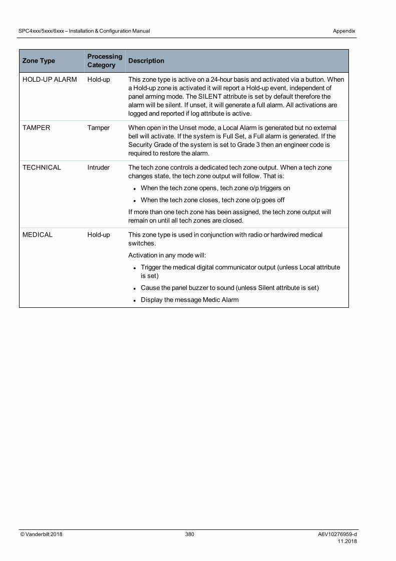
Zone Type ProcessingCategory Description
HOLD-UP ALARM Hold-up This zone type is active on a 24-hour basis and activated via a button. Whena Hold-up zone is activated it will report a Hold-up event, independent ofpanel armingmode. The SILENT attribute is set by default therefore thealarm will be silent. If unset, it will generate a full alarm. All activations arelogged and reported if log attribute is active.
TAMPER Tamper When open in the Unset mode, a Local Alarm is generated but no externalbell will activate. If the system is Full Set, a Full alarm is generated. If theSecurity Grade of the system is set to Grade 3 then an engineer code isrequired to restore the alarm.
TECHNICAL Intruder The tech zone controls a dedicated tech zone output. When a tech zonechanges state, the tech zone output will follow. That is:
l When the tech zone opens, tech zone o/p triggers on
l When the tech zone closes, tech zone o/p goes off
If more than one tech zone has been assigned, the tech zone output willremain on until all tech zones are closed.
MEDICAL Hold-up This zone type is used in conjunction with radio or hardwiredmedicalswitches.
Activation in any mode will:
l Trigger themedical digital communicator output (unless Local attributeis set)
l Cause the panel buzzer to sound (unless Silent attribute is set)
l Display themessageMedic Alarm
SPC4xxx/5xxx/6xxx– Installation &ConfigurationManual Appendix
© Vanderbilt 2018 380 A6V10276959-d11.2018
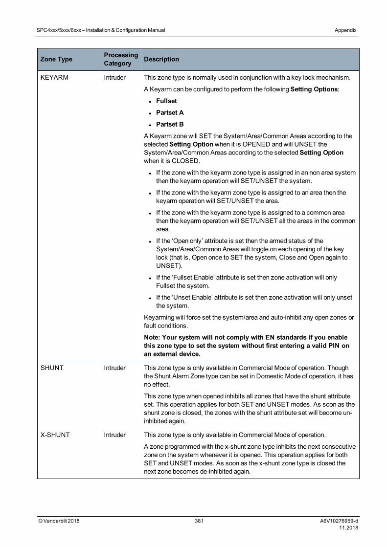
Zone Type ProcessingCategory Description
KEYARM Intruder This zone type is normally used in conjunction with a key lock mechanism.
A Keyarm can be configured to perform the followingSetting Options:
l Fullset
l Partset A
l Partset B
A Keyarm zone will SET the System/Area/Common Areas according to theselectedSetting Optionwhen it is OPENED and will UNSET theSystem/Area/Common Areas according to the selectedSetting Optionwhen it is CLOSED.
l If the zone with the keyarm zone type is assigned in an non area systemthen the keyarm operation will SET/UNSET the system.
l If the zone with the keyarm zone type is assigned to an area then thekeyarm operation will SET/UNSET the area.
l If the zone with the keyarm zone type is assigned to a common areathen the keyarm operation will SET/UNSET all the areas in the commonarea.
l If the ‘Open only’ attribute is set then the armed status of theSystem/Area/Common Areas will toggle on each opening of the keylock (that is, Open once to SET the system, Close andOpen again toUNSET).
l If the ‘Fullset Enable’ attribute is set then zone activation will onlyFullset the system.
l If the ‘Unset Enable’ attribute is set then zone activation will only unsetthe system.
Keyarming will force set the system/area and auto-inhibit any open zones orfault conditions.
Note: Your system will not comply with EN standards if you enablethis zone type to set the system without first entering a valid PIN onan external device.
SHUNT Intruder This zone type is only available in Commercial Mode of operation. Thoughthe Shunt Alarm Zone type can be set in Domestic Mode of operation, it hasno effect.
This zone type when opened inhibits all zones that have the shunt attributeset. This operation applies for both SET and UNSETmodes. As soon as theshunt zone is closed, the zones with the shunt attribute set will become un-inhibited again.
X-SHUNT Intruder This zone type is only available in Commercial Mode of operation.
A zone programmedwith the x-shunt zone type inhibits the next consecutivezone on the system whenever it is opened. This operation applies for bothSET and UNSETmodes. As soon as the x-shunt zone type is closed thenext zone becomes de-inhibited again.
SPC4xxx/5xxx/6xxx– Installation &ConfigurationManual Appendix
© Vanderbilt 2018 381 A6V10276959-d11.2018
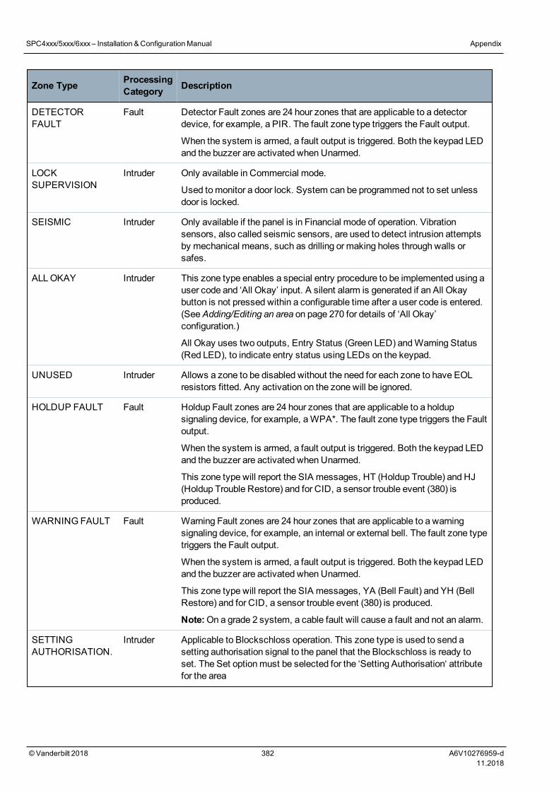
Zone Type ProcessingCategory Description
DETECTORFAULT
Fault Detector Fault zones are 24 hour zones that are applicable to a detectordevice, for example, a PIR. The fault zone type triggers the Fault output.
When the system is armed, a fault output is triggered. Both the keypad LEDand the buzzer are activated when Unarmed.
LOCKSUPERVISION
Intruder Only available in Commercial mode.
Used tomonitor a door lock. System can be programmed not to set unlessdoor is locked.
SEISMIC Intruder Only available if the panel is in Financial mode of operation. Vibrationsensors, also called seismic sensors, are used to detect intrusion attemptsby mechanical means, such as drilling or making holes through walls orsafes.
ALLOKAY Intruder This zone type enables a special entry procedure to be implemented using auser code and ‘All Okay’ input. A silent alarm is generated if an All Okaybutton is not pressed within a configurable time after a user code is entered.(SeeAdding/Editing an area on page 270 for details of ‘All Okay’configuration.)
All Okay uses two outputs, Entry Status (Green LED) andWarning Status(Red LED), to indicate entry status using LEDs on the keypad.
UNUSED Intruder Allows a zone to be disabled without the need for each zone to have EOLresistors fitted. Any activation on the zone will be ignored.
HOLDUP FAULT Fault Holdup Fault zones are 24 hour zones that are applicable to a holdupsignaling device, for example, aWPA*. The fault zone type triggers the Faultoutput.
When the system is armed, a fault output is triggered. Both the keypad LEDand the buzzer are activated when Unarmed.
This zone type will report the SIA messages, HT (Holdup Trouble) and HJ(Holdup Trouble Restore) and for CID, a sensor trouble event (380) isproduced.
WARNING FAULT Fault Warning Fault zones are 24 hour zones that are applicable to a warningsignaling device, for example, an internal or external bell. The fault zone typetriggers the Fault output.
When the system is armed, a fault output is triggered. Both the keypad LEDand the buzzer are activated when Unarmed.
This zone type will report the SIA messages, YA (Bell Fault) and YH (BellRestore) and for CID, a sensor trouble event (380) is produced.
Note:On a grade 2 system, a cable fault will cause a fault and not an alarm.
SETTINGAUTHORISATION.
Intruder Applicable to Blockschloss operation. This zone type is used to send asetting authorisation signal to the panel that the Blockschloss is ready toset. The Set optionmust be selected for the ‘Setting Authorisation‘ attributefor the area
SPC4xxx/5xxx/6xxx– Installation &ConfigurationManual Appendix
© Vanderbilt 2018 382 A6V10276959-d11.2018
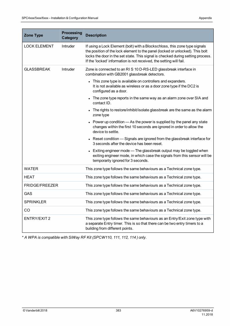
Zone Type ProcessingCategory Description
LOCK ELEMENT Intruder If using a Lock Element (bolt) with a Blockschloss, this zone type signalsthe position of the lock element to the panel (locked or unlocked). This boltlocks the door in the set state. This signal is checked during setting process.If the ‘locked‘ information is not received, the setting will fail.
GLASSBREAK Intruder Zone is connected to an RI S 10 D-RS-LED glassbreak interface incombination with GB2001 glassbreak detectors.
l This zone type is available on controllers and expanders.It is not available as wireless or as a door zone type if the DC2 isconfigured as a door.
l The zone type reports in the sameway as an alarm zone over SIA andcontact ID.
l The rights to restore/inhibit/isolate glassbreak are the same as the alarmzone type
l Power up condition—As the power is supplied by the panel any statechanges within the first 10 seconds are ignored in order to allow thedevice to settle.
l Reset condition—Signals are ignored from the glassbreak interface for3 seconds after the device has been reset.
l Exiting engineer mode—The glassbreak output may be toggled whenexiting engineer mode, in which case the signals from this sensor will betemporarily ignored for 3 seconds.
WATER This zone type follows the same behaviours as a Technical zone type.
HEAT This zone type follows the same behaviours as a Technical zone type.
FRIDGE/FREEZER This zone type follows the same behaviours as a Technical zone type.
GAS This zone type follows the same behaviours as a Technical zone type.
SPRINKLER This zone type follows the same behaviours as a Technical zone type.
CO This zone type follows the same behaviours as a Technical zone type.
ENTRY/EXIT 2 This zone type follows the same behaviours as an Entry/Exit zone type witha separate Entry timer. This is so that there can be two entry timers to abuilding from different points.
* AWPA is compatible with SiWay RF Kit (SPCW110, 111, 112, 114 ) only.
SPC4xxx/5xxx/6xxx– Installation &ConfigurationManual Appendix
© Vanderbilt 2018 383 A6V10276959-d11.2018
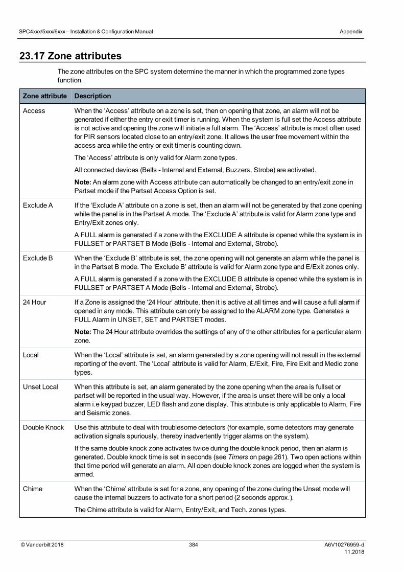
23.17 Zone attributesThe zone attributes on the SPC system determine themanner in which the programmed zone typesfunction.
Zone attribute Description
Access When the ‘Access’ attribute on a zone is set, then on opening that zone, an alarm will not begenerated if either the entry or exit timer is running. When the system is full set the Access attributeis not active and opening the zone will initiate a full alarm. The ‘Access’ attribute is most often usedfor PIR sensors located close to an entry/exit zone. It allows the user freemovement within theaccess area while the entry or exit timer is counting down.
The ‘Access’ attribute is only valid for Alarm zone types.
All connected devices (Bells - Internal and External, Buzzers, Strobe) are activated.
Note:An alarm zone with Access attribute can automatically be changed to an entry/exit zone inPartset mode if the Partset Access Option is set.
Exclude A If the ‘Exclude A’ attribute on a zone is set, then an alarm will not be generated by that zone openingwhile the panel is in the Partset A mode. The ‘Exclude A’ attribute is valid for Alarm zone type andEntry/Exit zones only.
A FULL alarm is generated if a zone with the EXCLUDE A attribute is opened while the system is inFULLSET or PARTSET B Mode (Bells - Internal and External, Strobe).
Exclude B When the ‘Exclude B’ attribute is set, the zone opening will not generate an alarm while the panel isin the Partset B mode. The ‘Exclude B’ attribute is valid for Alarm zone type and E/Exit zones only.
A FULL alarm is generated if a zone with the EXCLUDE B attribute is opened while the system is inFULLSET or PARTSET A Mode (Bells - Internal and External, Strobe).
24 Hour If a Zone is assigned the ‘24 Hour’ attribute, then it is active at all times and will cause a full alarm ifopened in any mode. This attribute can only be assigned to the ALARM zone type. Generates aFULL Alarm in UNSET, SET and PARTSETmodes.
Note: The 24 Hour attribute overrides the settings of any of the other attributes for a particular alarmzone.
Local When the ‘Local’ attribute is set, an alarm generated by a zone opening will not result in the externalreporting of the event. The ‘Local’ attribute is valid for Alarm, E/Exit, Fire, Fire Exit andMedic zonetypes.
Unset Local When this attribute is set, an alarm generated by the zone opening when the area is fullset orpartset will be reported in the usual way. However, if the area is unset there will be only a localalarm i.e keypad buzzer, LED flash and zone display. This attribute is only applicable to Alarm, Fireand Seismic zones.
Double Knock Use this attribute to deal with troublesome detectors (for example, some detectors may generateactivation signals spuriously, thereby inadvertently trigger alarms on the system).
If the same double knock zone activates twice during the double knock period, then an alarm isgenerated. Double knock time is set in seconds (see Timers on page 261). Two open actions withinthat time period will generate an alarm. All open double knock zones are logged when the system isarmed.
Chime When the ‘Chime’ attribute is set for a zone, any opening of the zone during the Unset mode willcause the internal buzzers to activate for a short period (2 seconds approx.).
The Chime attribute is valid for Alarm, Entry/Exit, and Tech. zones types.
SPC4xxx/5xxx/6xxx– Installation &ConfigurationManual Appendix
© Vanderbilt 2018 384 A6V10276959-d11.2018
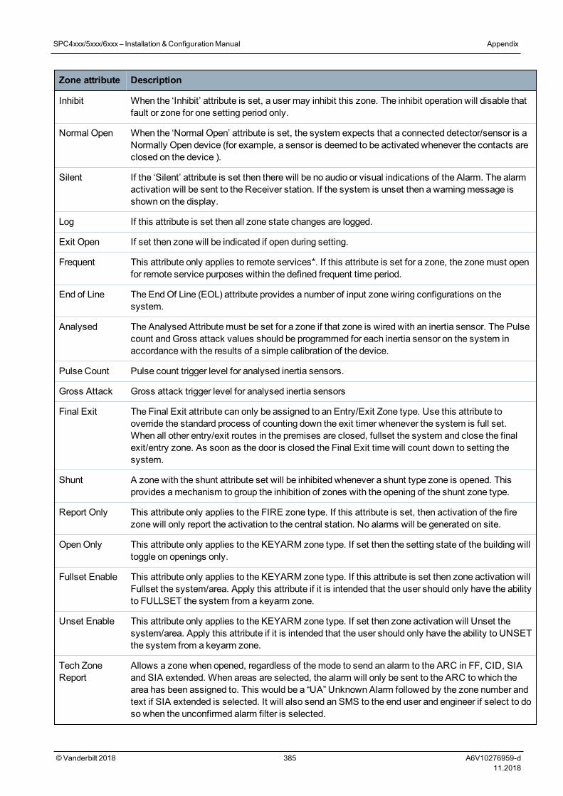
Zone attribute Description
Inhibit When the ‘Inhibit’ attribute is set, a user may inhibit this zone. The inhibit operation will disable thatfault or zone for one setting period only.
Normal Open When the ‘Normal Open’ attribute is set, the system expects that a connected detector/sensor is aNormally Open device (for example, a sensor is deemed to be activated whenever the contacts areclosed on the device ).
Silent If the ‘Silent’ attribute is set then there will be no audio or visual indications of the Alarm. The alarmactivation will be sent to the Receiver station. If the system is unset then a warningmessage isshown on the display.
Log If this attribute is set then all zone state changes are logged.
Exit Open If set then zone will be indicated if open during setting.
Frequent This attribute only applies to remote services*. If this attribute is set for a zone, the zonemust openfor remote service purposes within the defined frequent time period.
End of Line The EndOf Line (EOL) attribute provides a number of input zone wiring configurations on thesystem.
Analysed The Analysed Attributemust be set for a zone if that zone is wired with an inertia sensor. The Pulsecount andGross attack values should be programmed for each inertia sensor on the system inaccordance with the results of a simple calibration of the device.
Pulse Count Pulse count trigger level for analysed inertia sensors.
Gross Attack Gross attack trigger level for analysed inertia sensors
Final Exit The Final Exit attribute can only be assigned to an Entry/Exit Zone type. Use this attribute tooverride the standard process of counting down the exit timer whenever the system is full set.When all other entry/exit routes in the premises are closed, fullset the system and close the finalexit/entry zone. As soon as the door is closed the Final Exit time will count down to setting thesystem.
Shunt A zone with the shunt attribute set will be inhibited whenever a shunt type zone is opened. Thisprovides amechanism to group the inhibition of zones with the opening of the shunt zone type.
Report Only This attribute only applies to the FIRE zone type. If this attribute is set, then activation of the firezone will only report the activation to the central station. No alarms will be generated on site.
OpenOnly This attribute only applies to the KEYARM zone type. If set then the setting state of the building willtoggle on openings only.
Fullset Enable This attribute only applies to the KEYARM zone type. If this attribute is set then zone activation willFullset the system/area. Apply this attribute if it is intended that the user should only have the abilityto FULLSET the system from a keyarm zone.
Unset Enable This attribute only applies to the KEYARM zone type. If set then zone activation will Unset thesystem/area. Apply this attribute if it is intended that the user should only have the ability to UNSETthe system from a keyarm zone.
Tech ZoneReport
Allows a zone when opened, regardless of themode to send an alarm to the ARC in FF, CID, SIAand SIA extended. When areas are selected, the alarm will only be sent to the ARC to which thearea has been assigned to. This would be a “UA” Unknown Alarm followed by the zone number andtext if SIA extended is selected. It will also send an SMS to the end user and engineer if select to doso when the unconfirmed alarm filter is selected.
SPC4xxx/5xxx/6xxx– Installation &ConfigurationManual Appendix
© Vanderbilt 2018 385 A6V10276959-d11.2018
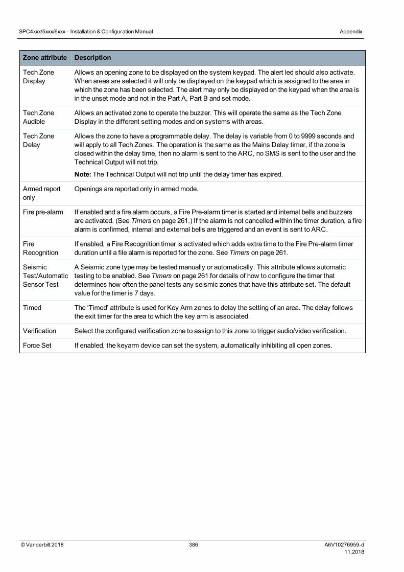
Zone attribute Description
Tech ZoneDisplay
Allows an opening zone to be displayed on the system keypad. The alert led should also activate.When areas are selected it will only be displayed on the keypad which is assigned to the area inwhich the zone has been selected. The alert may only be displayed on the keypad when the area isin the unset mode and not in the Part A, Part B and set mode.
Tech ZoneAudible
Allows an activated zone to operate the buzzer. This will operate the same as the Tech ZoneDisplay in the different settingmodes and on systems with areas.
Tech ZoneDelay
Allows the zone to have a programmable delay. The delay is variable from 0 to 9999 seconds andwill apply to all Tech Zones. The operation is the same as theMains Delay timer, if the zone isclosed within the delay time, then no alarm is sent to the ARC, no SMS is sent to the user and theTechnical Output will not trip.
Note: The Technical Output will not trip until the delay timer has expired.
Armed reportonly
Openings are reported only in armedmode.
Fire pre-alarm If enabled and a fire alarm occurs, a Fire Pre-alarm timer is started and internal bells and buzzersare activated. (See Timers on page 261.) If the alarm is not cancelled within the timer duration, a firealarm is confirmed, internal and external bells are triggered and an event is sent to ARC.
FireRecognition
If enabled, a Fire Recognition timer is activated which adds extra time to the Fire Pre-alarm timerduration until a file alarm is reported for the zone. See Timers on page 261.
SeismicTest/AutomaticSensor Test
A Seismic zone typemay be testedmanually or automatically. This attribute allows automatictesting to be enabled. See Timers on page 261 for details of how to configure the timer thatdetermines how often the panel tests any seismic zones that have this attribute set. The defaultvalue for the timer is 7 days.
Timed The ‘Timed’ attribute is used for Key Arm zones to delay the setting of an area. The delay followsthe exit timer for the area to which the key arm is associated.
Verification Select the configured verification zone to assign to this zone to trigger audio/video verification.
Force Set If enabled, the keyarm device can set the system, automatically inhibiting all open zones.
SPC4xxx/5xxx/6xxx– Installation &ConfigurationManual Appendix
© Vanderbilt 2018 386 A6V10276959-d11.2018
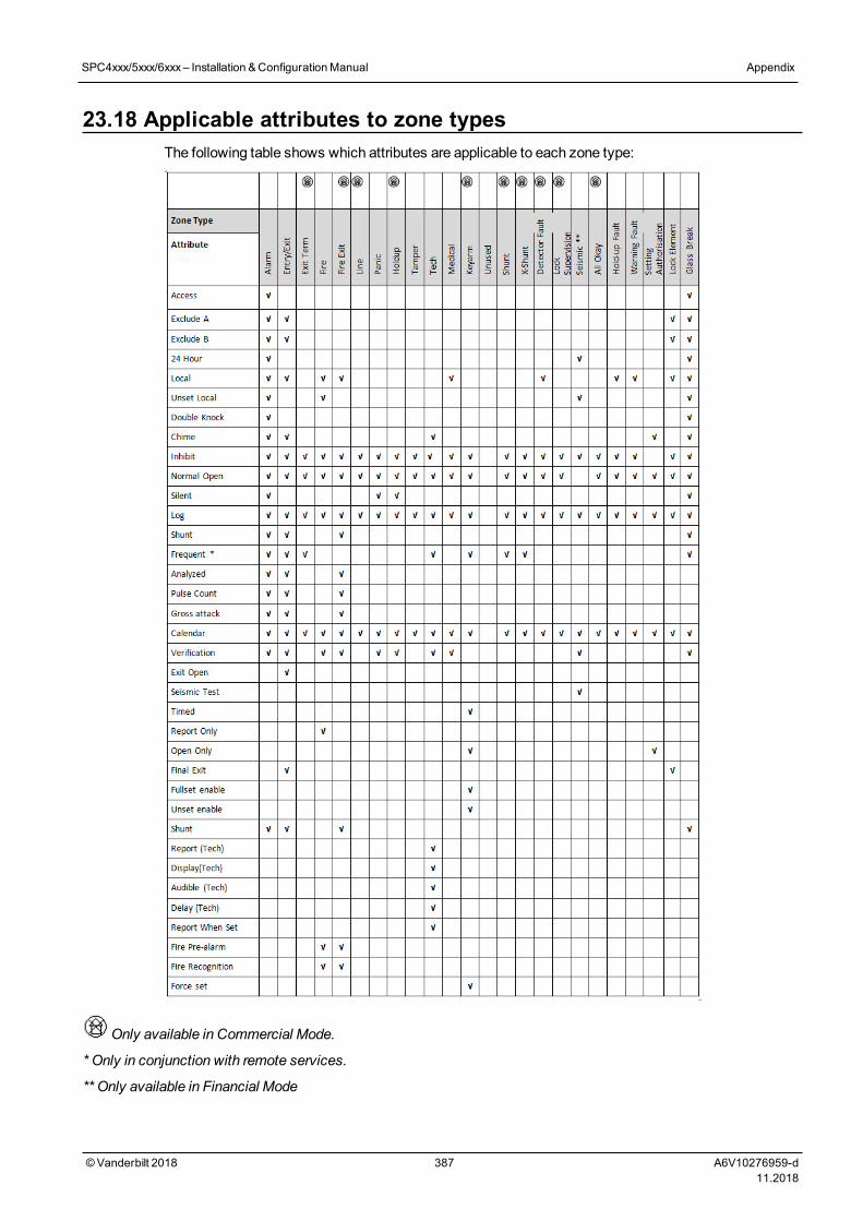
23.18 Applicable attributes to zone typesThe following table shows which attributes are applicable to each zone type:
Only available in Commercial Mode.
* Only in conjunction with remote services.
** Only available in Financial Mode
SPC4xxx/5xxx/6xxx– Installation &ConfigurationManual Appendix
© Vanderbilt 2018 387 A6V10276959-d11.2018
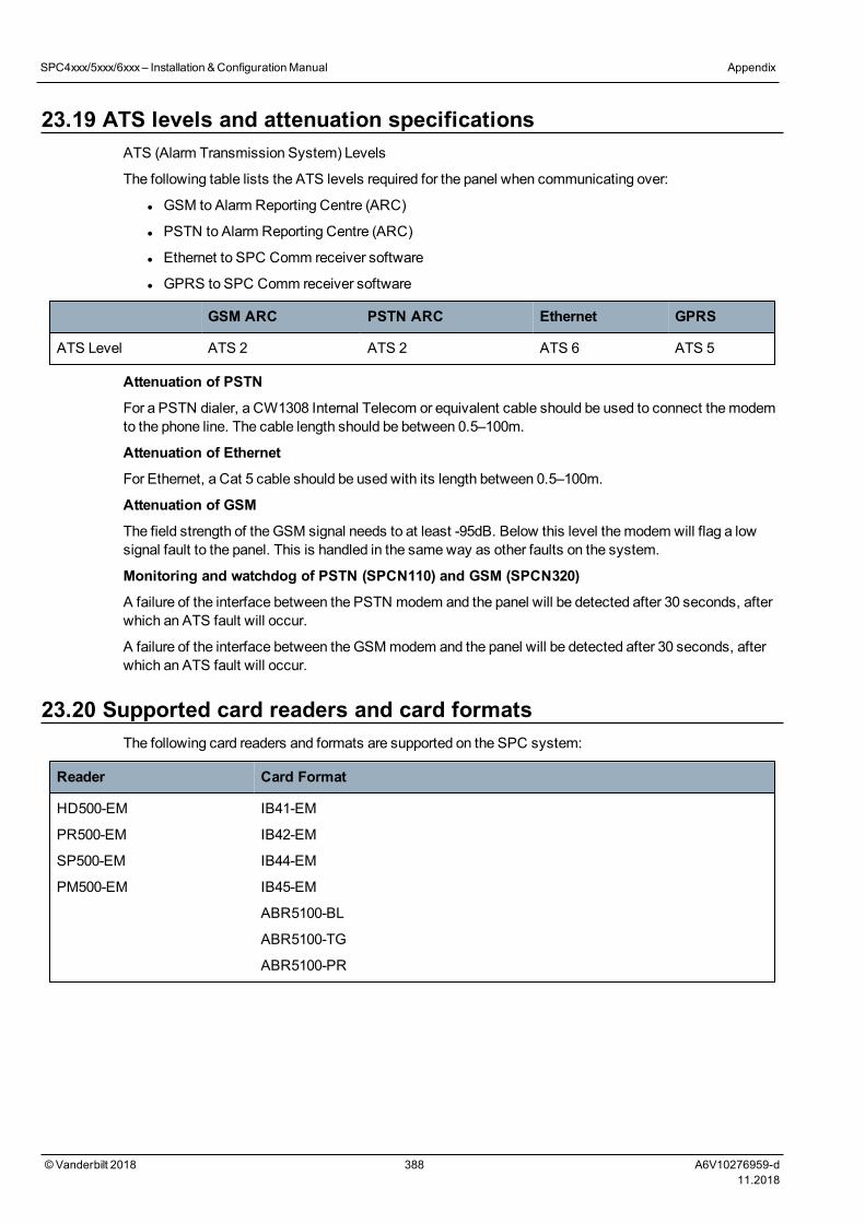
23.19 ATS levels and attenuation specificationsATS (Alarm Transmission System) Levels
The following table lists the ATS levels required for the panel when communicating over:
l GSM to Alarm Reporting Centre (ARC)
l PSTN to Alarm Reporting Centre (ARC)
l Ethernet to SPC Comm receiver software
l GPRS to SPC Comm receiver software
GSM ARC PSTN ARC Ethernet GPRS
ATS Level ATS 2 ATS 2 ATS 6 ATS 5
Attenuation of PSTN
For a PSTN dialer, a CW1308 Internal Telecom or equivalent cable should be used to connect themodemto the phone line. The cable length should be between 0.5–100m.
Attenuation of Ethernet
For Ethernet, a Cat 5 cable should be used with its length between 0.5–100m.
Attenuation of GSM
The field strength of the GSM signal needs to at least -95dB. Below this level themodem will flag a lowsignal fault to the panel. This is handled in the sameway as other faults on the system.
Monitoring and watchdog of PSTN (SPCN110) and GSM (SPCN320)
A failure of the interface between the PSTN modem and the panel will be detected after 30 seconds, afterwhich an ATS fault will occur.
A failure of the interface between theGSMmodem and the panel will be detected after 30 seconds, afterwhich an ATS fault will occur.
23.20 Supported card readers and card formatsThe following card readers and formats are supported on the SPC system:
Reader Card Format
HD500-EM
PR500-EM
SP500-EM
PM500-EM
IB41-EM
IB42-EM
IB44-EM
IB45-EM
ABR5100-BL
ABR5100-TG
ABR5100-PR
SPC4xxx/5xxx/6xxx– Installation &ConfigurationManual Appendix
© Vanderbilt 2018 388 A6V10276959-d11.2018
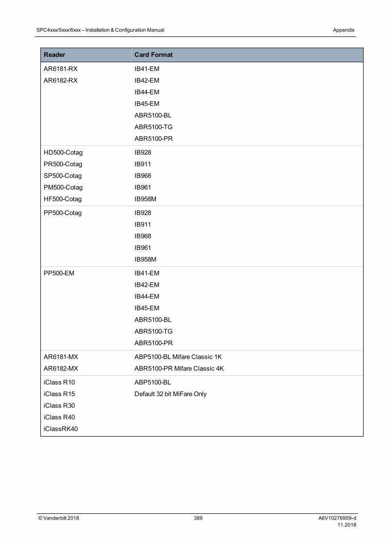
Reader Card Format
AR6181-RX
AR6182-RX
IB41-EM
IB42-EM
IB44-EM
IB45-EM
ABR5100-BL
ABR5100-TG
ABR5100-PR
HD500-Cotag
PR500-Cotag
SP500-Cotag
PM500-Cotag
HF500-Cotag
IB928
IB911
IB968
IB961
IB958M
PP500-Cotag IB928
IB911
IB968
IB961
IB958M
PP500-EM IB41-EM
IB42-EM
IB44-EM
IB45-EM
ABR5100-BL
ABR5100-TG
ABR5100-PR
AR6181-MX
AR6182-MX
ABP5100-BLMifare Classic 1K
ABR5100-PR Mifare Classic 4K
iClass R10
iClass R15
iClass R30
iClass R40
iClassRK40
ABP5100-BL
Default 32 bit MiFare Only
SPC4xxx/5xxx/6xxx– Installation &ConfigurationManual Appendix
© Vanderbilt 2018 389 A6V10276959-d11.2018
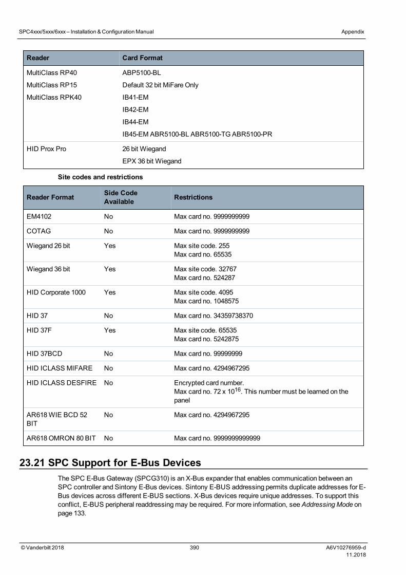
Reader Card Format
MultiClass RP40
MultiClass RP15
MultiClass RPK40
ABP5100-BL
Default 32 bit MiFare Only
IB41-EM
IB42-EM
IB44-EM
IB45-EM ABR5100-BL ABR5100-TG ABR5100-PR
HID Prox Pro 26 bit Wiegand
EPX 36 bit Wiegand
Site codes and restrictions
Reader Format Side CodeAvailable Restrictions
EM4102 No Max card no. 9999999999
COTAG No Max card no. 9999999999
Wiegand 26 bit Yes Max site code. 255Max card no. 65535
Wiegand 36 bit Yes Max site code. 32767Max card no. 524287
HID Corporate 1000 Yes Max site code. 4095Max card no. 1048575
HID 37 No Max card no. 34359738370
HID 37F Yes Max site code. 65535Max card no. 5242875
HID 37BCD No Max card no. 99999999
HID ICLASS MIFARE No Max card no. 4294967295
HID ICLASS DESFIRE No Encrypted card number.Max card no. 72 x 1016. This numbermust be learned on thepanel
AR618WIE BCD 52BIT
No Max card no. 4294967295
AR618OMRON 80 BIT No Max card no. 9999999999999
23.21 SPC Support for E-Bus DevicesThe SPC E-Bus Gateway (SPCG310) is an X-Bus expander that enables communication between anSPC controller and Sintony E-Bus devices. Sintony E-BUS addressing permits duplicate addresses for E-Bus devices across different E-BUS sections. X-Bus devices require unique addresses. To support thisconflict, E-BUS peripheral readdressingmay be required. For more information, seeAddressingMode onpage 133.
SPC4xxx/5xxx/6xxx– Installation &ConfigurationManual Appendix
© Vanderbilt 2018 390 A6V10276959-d11.2018
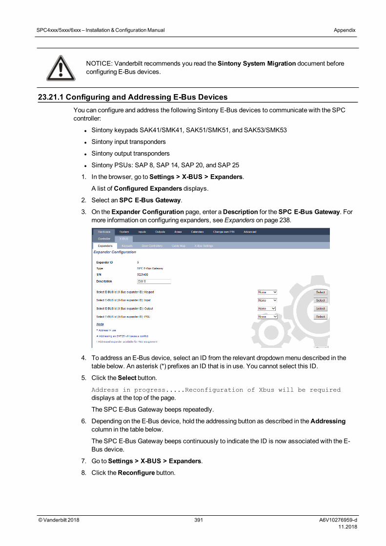
NOTICE: Vanderbilt recommends you read theSintony System Migration document beforeconfiguring E-Bus devices.
23.21.1 Configuring and Addressing E-Bus DevicesYou can configure and address the following Sintony E-Bus devices to communicate with the SPCcontroller:
l Sintony keypads SAK41/SMK41, SAK51/SMK51, and SAK53/SMK53
l Sintony input transponders
l Sintony output transponders
l Sintony PSUs: SAP 8, SAP 14, SAP 20, and SAP 25
1. In the browser, go toSettings > X-BUS > Expanders.
A list of Configured Expanders displays.
2. Select anSPC E-Bus Gateway.
3. On theExpander Configuration page, enter aDescription for theSPC E-Bus Gateway. Formore information on configuring expanders, seeExpanders on page 238.
4. To address an E-Bus device, select an ID from the relevant dropdownmenu described in thetable below. An asterisk (*) prefixes an ID that is in use. You cannot select this ID.
5. Click theSelect button.
Address in progress.....Reconfiguration of Xbus will be requireddisplays at the top of the page.
The SPC E-Bus Gateway beeps repeatedly.
6. Depending on the E-Bus device, hold the addressing button as described in theAddressingcolumn in the table below.
The SPC E-Bus Gateway beeps continuously to indicate the ID is now associated with the E-Bus device.
7. Go toSettings > X-BUS > Expanders.
8. Click theReconfigure button.
SPC4xxx/5xxx/6xxx– Installation &ConfigurationManual Appendix
© Vanderbilt 2018 391 A6V10276959-d11.2018
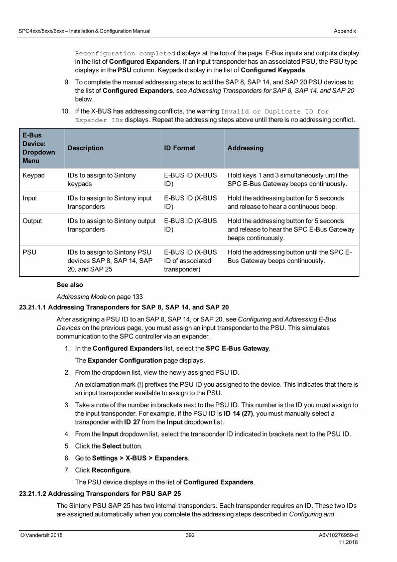
Reconfiguration completed displays at the top of the page. E-Bus inputs and outputs displayin the list of Configured Expanders. If an input transponder has an associated PSU, the PSU typedisplays in thePSU column. Keypads display in the list of Configured Keypads.
9. To complete themanual addressing steps to add the SAP 8, SAP 14, and SAP 20 PSU devices tothe list of Configured Expanders, seeAddressing Transponders for SAP 8, SAP 14, and SAP 20below.
10. If the X-BUS has addressing conflicts, the warning Invalid or Duplicate ID forExpander IDx displays. Repeat the addressing steps above until there is no addressing conflict.
E-BusDevice:DropdownMenu
Description ID Format Addressing
Keypad IDs to assign to Sintonykeypads
E-BUS ID (X-BUSID)
Hold keys 1 and 3 simultaneously until theSPC E-Bus Gateway beeps continuously.
Input IDs to assign to Sintony inputtransponders
E-BUS ID (X-BUSID)
Hold the addressing button for 5 secondsand release to hear a continuous beep.
Output IDs to assign to Sintony outputtransponders
E-BUS ID (X-BUSID)
Hold the addressing button for 5 secondsand release to hear the SPC E-Bus Gatewaybeeps continuously.
PSU IDs to assign to Sintony PSUdevices SAP 8, SAP 14, SAP20, and SAP 25
E-BUS ID (X-BUSID of associatedtransponder)
Hold the addressing button until the SPC E-Bus Gateway beeps continuously.
See also
AddressingMode on page 13323.21.1.1 Addressing Transponders for SAP 8, SAP 14, and SAP 20
After assigning a PSU ID to an SAP 8, SAP 14, or SAP 20, seeConfiguring and Addressing E-BusDevices on the previous page, youmust assign an input transponder to the PSU. This simulatescommunication to the SPC controller via an expander.
1. In theConfigured Expanders list, select theSPC E-Bus Gateway.
TheExpander Configuration page displays.
2. From the dropdown list, view the newly assigned PSU ID.
An exclamationmark (!) prefixes the PSU ID you assigned to the device. This indicates that there isan input transponder available to assign to the PSU.
3. Take a note of the number in brackets next to the PSU ID. This number is the ID youmust assign tothe input transponder. For example, if the PSU ID is ID 14 (27), youmust manually select atransponder with ID 27 from the Input dropdown list.
4. From the Input dropdown list, select the transponder ID indicated in brackets next to the PSU ID.
5. Click theSelect button.
6. Go toSettings > X-BUS > Expanders.
7. Click Reconfigure.
The PSU device displays in the list of Configured Expanders.23.21.1.2 Addressing Transponders for PSU SAP 25
The Sintony PSU SAP 25 has two internal transponders. Each transponder requires an ID. These two IDsare assigned automatically when you complete the addressing steps described inConfiguring and
SPC4xxx/5xxx/6xxx– Installation &ConfigurationManual Appendix
© Vanderbilt 2018 392 A6V10276959-d11.2018
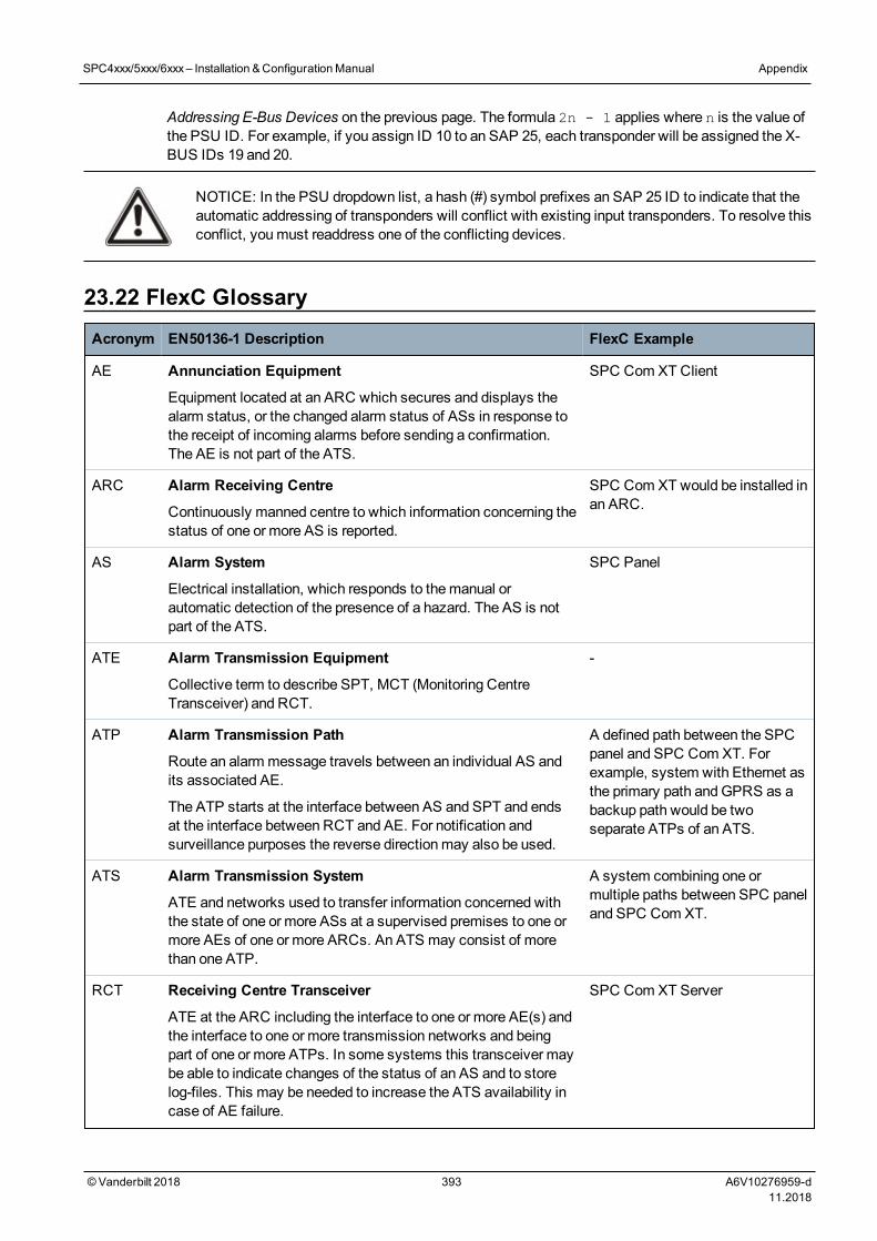
Addressing E-Bus Devices on the previous page. The formula 2n - 1 applies where n is the value ofthe PSU ID. For example, if you assign ID 10 to an SAP 25, each transponder will be assigned the X-BUS IDs 19 and 20.
NOTICE: In the PSU dropdown list, a hash (#) symbol prefixes an SAP 25 ID to indicate that theautomatic addressing of transponders will conflict with existing input transponders. To resolve thisconflict, youmust readdress one of the conflicting devices.
23.22 FlexC GlossaryAcronym EN50136-1 Description FlexC Example
AE Annunciation Equipment
Equipment located at an ARC which secures and displays thealarm status, or the changed alarm status of ASs in response tothe receipt of incoming alarms before sending a confirmation.The AE is not part of the ATS.
SPC Com XT Client
ARC Alarm Receiving Centre
Continuously manned centre to which information concerning thestatus of one or more AS is reported.
SPC Com XT would be installed inan ARC.
AS Alarm System
Electrical installation, which responds to themanual orautomatic detection of the presence of a hazard. The AS is notpart of the ATS.
SPC Panel
ATE Alarm Transmission Equipment
Collective term to describe SPT, MCT (Monitoring CentreTransceiver) and RCT.
-
ATP Alarm Transmission Path
Route an alarm message travels between an individual AS andits associated AE.
The ATP starts at the interface between AS and SPT and endsat the interface between RCT and AE. For notification andsurveillance purposes the reverse directionmay also be used.
A defined path between the SPCpanel and SPC Com XT. Forexample, system with Ethernet asthe primary path andGPRS as abackup path would be twoseparate ATPs of an ATS.
ATS Alarm Transmission System
ATE and networks used to transfer information concerned withthe state of one or more ASs at a supervised premises to one ormore AEs of one or more ARCs. An ATS may consist of morethan one ATP.
A system combining one ormultiple paths between SPC paneland SPC Com XT.
RCT Receiving Centre Transceiver
ATE at the ARC including the interface to one or more AE(s) andthe interface to one or more transmission networks and beingpart of one or more ATPs. In some systems this transceiver maybe able to indicate changes of the status of an AS and to storelog-files. This may be needed to increase the ATS availability incase of AE failure.
SPC Com XT Server
SPC4xxx/5xxx/6xxx– Installation &ConfigurationManual Appendix
© Vanderbilt 2018 393 A6V10276959-d11.2018
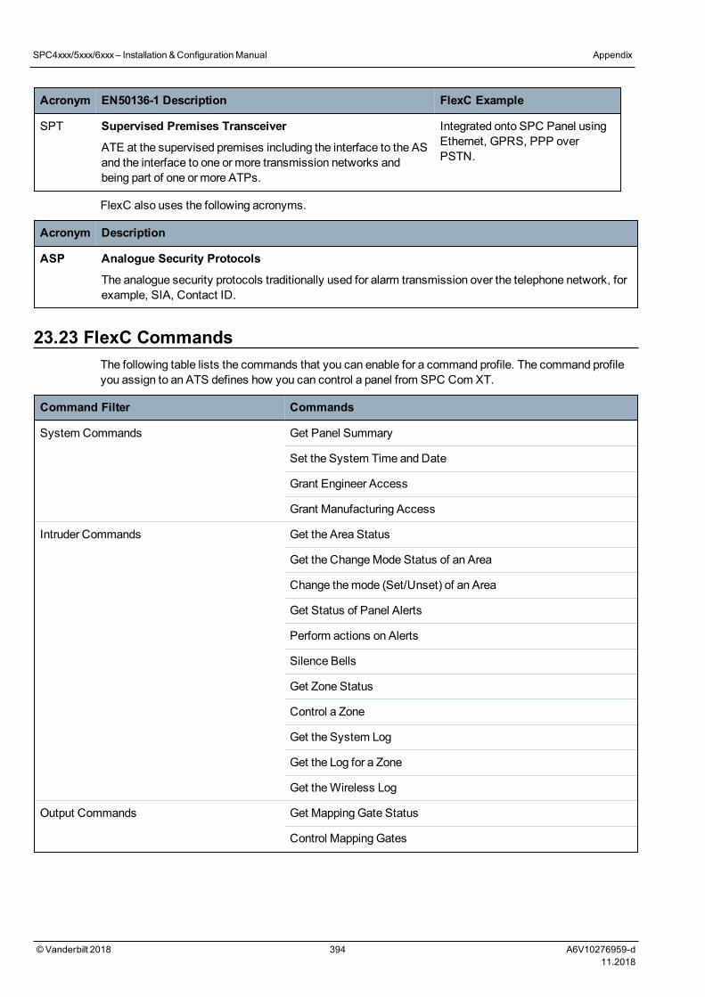
Acronym EN50136-1 Description FlexC Example
SPT Supervised Premises Transceiver
ATE at the supervised premises including the interface to the ASand the interface to one or more transmission networks andbeing part of one or more ATPs.
Integrated onto SPC Panel usingEthernet, GPRS, PPP overPSTN.
FlexC also uses the following acronyms.
Acronym Description
ASP Analogue Security Protocols
The analogue security protocols traditionally used for alarm transmission over the telephone network, forexample, SIA, Contact ID.
23.23 FlexC CommandsThe following table lists the commands that you can enable for a command profile. The command profileyou assign to an ATS defines how you can control a panel from SPC Com XT.
Command Filter Commands
System Commands Get Panel Summary
Set the System Time and Date
Grant Engineer Access
Grant Manufacturing Access
Intruder Commands Get the Area Status
Get the ChangeMode Status of an Area
Change themode (Set/Unset) of an Area
Get Status of Panel Alerts
Perform actions on Alerts
Silence Bells
Get Zone Status
Control a Zone
Get the System Log
Get the Log for a Zone
Get theWireless Log
Output Commands Get Mapping Gate Status
Control Mapping Gates
SPC4xxx/5xxx/6xxx– Installation &ConfigurationManual Appendix
© Vanderbilt 2018 394 A6V10276959-d11.2018
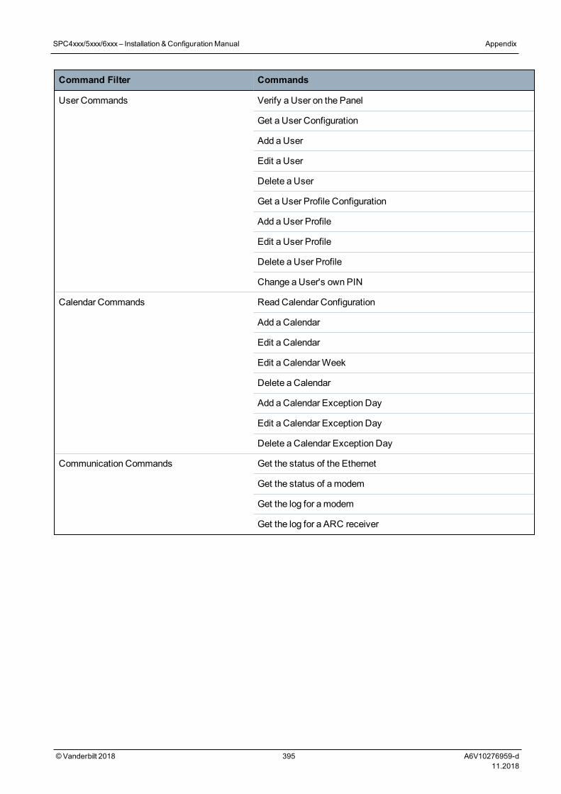
Command Filter Commands
User Commands Verify a User on the Panel
Get a User Configuration
Add a User
Edit a User
Delete a User
Get a User Profile Configuration
Add a User Profile
Edit a User Profile
Delete a User Profile
Change a User's own PIN
Calendar Commands Read Calendar Configuration
Add a Calendar
Edit a Calendar
Edit a CalendarWeek
Delete a Calendar
Add a Calendar Exception Day
Edit a Calendar Exception Day
Delete a Calendar Exception Day
Communication Commands Get the status of the Ethernet
Get the status of amodem
Get the log for amodem
Get the log for a ARC receiver
SPC4xxx/5xxx/6xxx– Installation &ConfigurationManual Appendix
© Vanderbilt 2018 395 A6V10276959-d11.2018
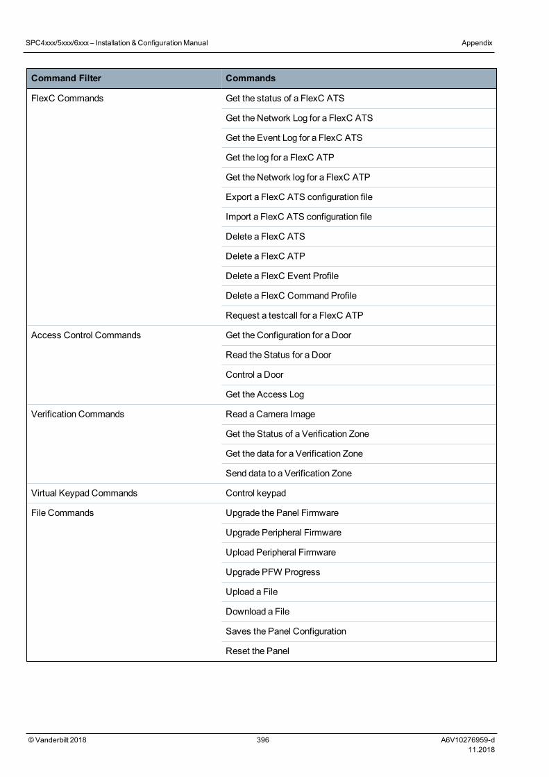
Command Filter Commands
FlexC Commands Get the status of a FlexC ATS
Get the Network Log for a FlexC ATS
Get the Event Log for a FlexC ATS
Get the log for a FlexC ATP
Get the Network log for a FlexC ATP
Export a FlexC ATS configuration file
Import a FlexC ATS configuration file
Delete a FlexC ATS
Delete a FlexC ATP
Delete a FlexC Event Profile
Delete a FlexC Command Profile
Request a testcall for a FlexC ATP
Access Control Commands Get the Configuration for a Door
Read the Status for a Door
Control a Door
Get the Access Log
Verification Commands Read a Camera Image
Get the Status of a Verification Zone
Get the data for a Verification Zone
Send data to a Verification Zone
Virtual Keypad Commands Control keypad
File Commands Upgrade the Panel Firmware
Upgrade Peripheral Firmware
Upload Peripheral Firmware
Upgrade PFW Progress
Upload a File
Download a File
Saves the Panel Configuration
Reset the Panel
SPC4xxx/5xxx/6xxx– Installation &ConfigurationManual Appendix
© Vanderbilt 2018 396 A6V10276959-d11.2018
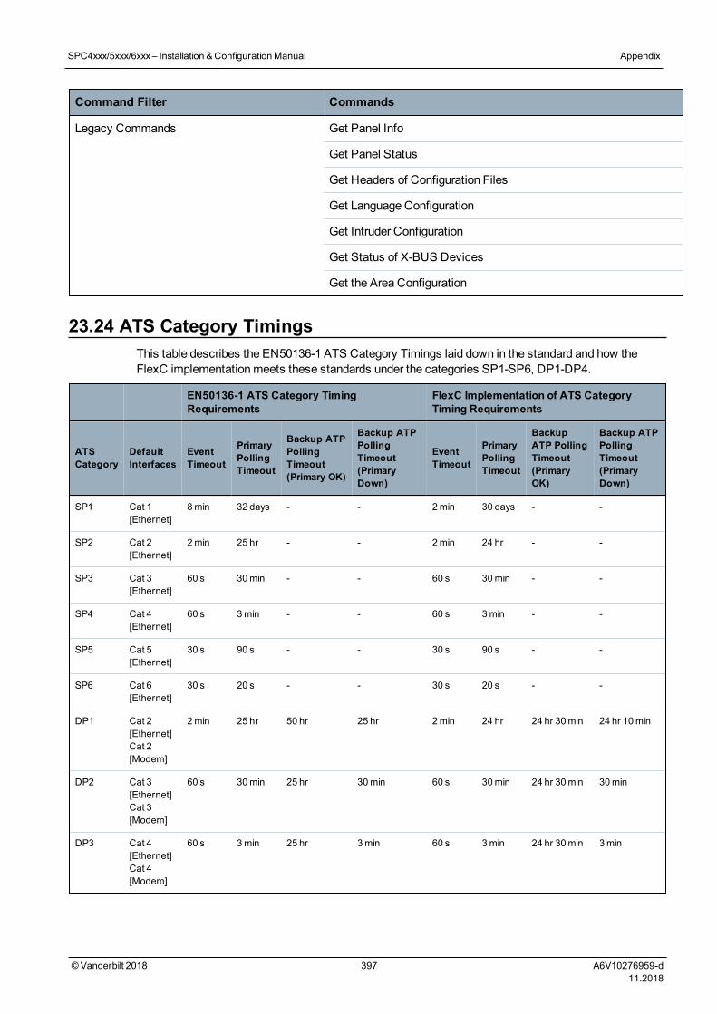
Command Filter Commands
Legacy Commands Get Panel Info
Get Panel Status
Get Headers of Configuration Files
Get Language Configuration
Get Intruder Configuration
Get Status of X-BUS Devices
Get the Area Configuration
23.24 ATS Category TimingsThis table describes the EN50136-1 ATS Category Timings laid down in the standard and how theFlexC implementationmeets these standards under the categories SP1-SP6, DP1-DP4.
EN50136-1 ATS Category TimingRequirements
FlexC Implementation of ATS CategoryTiming Requirements
ATSCategory
DefaultInterfaces
EventTimeout
PrimaryPollingTimeout
Backup ATPPollingTimeout(Primary OK)
Backup ATPPollingTimeout(PrimaryDown)
EventTimeout
PrimaryPollingTimeout
BackupATP PollingTimeout(PrimaryOK)
Backup ATPPollingTimeout(PrimaryDown)
SP1 Cat 1[Ethernet]
8 min 32 days - - 2min 30 days - -
SP2 Cat 2[Ethernet]
2 min 25 hr - - 2 min 24 hr - -
SP3 Cat 3[Ethernet]
60 s 30min - - 60 s 30min - -
SP4 Cat 4[Ethernet]
60 s 3min - - 60 s 3min - -
SP5 Cat 5[Ethernet]
30 s 90 s - - 30 s 90 s - -
SP6 Cat 6[Ethernet]
30 s 20 s - - 30 s 20 s - -
DP1 Cat 2[Ethernet]Cat 2[Modem]
2min 25 hr 50 hr 25 hr 2min 24 hr 24 hr 30min 24 hr 10min
DP2 Cat 3[Ethernet]Cat 3[Modem]
60 s 30min 25 hr 30min 60 s 30min 24 hr 30min 30min
DP3 Cat 4[Ethernet]Cat 4[Modem]
60 s 3min 25 hr 3min 60 s 3min 24 hr 30min 3min
SPC4xxx/5xxx/6xxx– Installation &ConfigurationManual Appendix
© Vanderbilt 2018 397 A6V10276959-d11.2018
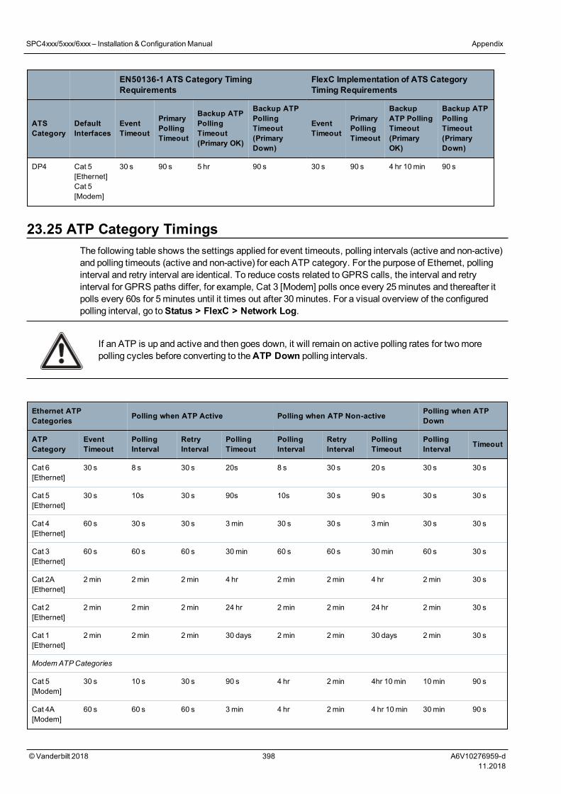
EN50136-1 ATS Category TimingRequirements
FlexC Implementation of ATS CategoryTiming Requirements
ATSCategory
DefaultInterfaces
EventTimeout
PrimaryPollingTimeout
Backup ATPPollingTimeout(Primary OK)
Backup ATPPollingTimeout(PrimaryDown)
EventTimeout
PrimaryPollingTimeout
BackupATP PollingTimeout(PrimaryOK)
Backup ATPPollingTimeout(PrimaryDown)
DP4 Cat 5[Ethernet]Cat 5[Modem]
30 s 90 s 5 hr 90 s 30 s 90 s 4 hr 10min 90 s
23.25 ATP Category TimingsThe following table shows the settings applied for event timeouts, polling intervals (active and non-active)and polling timeouts (active and non-active) for each ATP category. For the purpose of Ethernet, pollinginterval and retry interval are identical. To reduce costs related to GPRS calls, the interval and retryinterval for GPRS paths differ, for example, Cat 3 [Modem] polls once every 25minutes and thereafter itpolls every 60s for 5minutes until it times out after 30minutes. For a visual overview of the configuredpolling interval, go toStatus > FlexC > Network Log.
If an ATP is up and active and then goes down, it will remain on active polling rates for twomorepolling cycles before converting to theATP Down polling intervals.
Ethernet ATPCategories Polling when ATP Active Polling when ATP Non-active Polling when ATP
Down
ATPCategory
EventTimeout
PollingInterval
RetryInterval
PollingTimeout
PollingInterval
RetryInterval
PollingTimeout
PollingInterval Timeout
Cat 6[Ethernet]
30 s 8 s 30 s 20s 8 s 30 s 20 s 30 s 30 s
Cat 5[Ethernet]
30 s 10s 30 s 90s 10s 30 s 90 s 30 s 30 s
Cat 4[Ethernet]
60 s 30 s 30 s 3min 30 s 30 s 3min 30 s 30 s
Cat 3[Ethernet]
60 s 60 s 60 s 30min 60 s 60 s 30min 60 s 30 s
Cat 2A[Ethernet]
2 min 2min 2min 4 hr 2min 2min 4 hr 2min 30 s
Cat 2[Ethernet]
2 min 2min 2min 24 hr 2min 2min 24 hr 2min 30 s
Cat 1[Ethernet]
2 min 2min 2min 30 days 2min 2min 30 days 2min 30 s
ModemATPCategories
Cat 5[Modem]
30 s 10 s 30 s 90 s 4 hr 2min 4hr 10min 10min 90 s
Cat 4A[Modem]
60 s 60 s 60 s 3min 4 hr 2min 4 hr 10min 30min 90 s
SPC4xxx/5xxx/6xxx– Installation &ConfigurationManual Appendix
© Vanderbilt 2018 398 A6V10276959-d11.2018
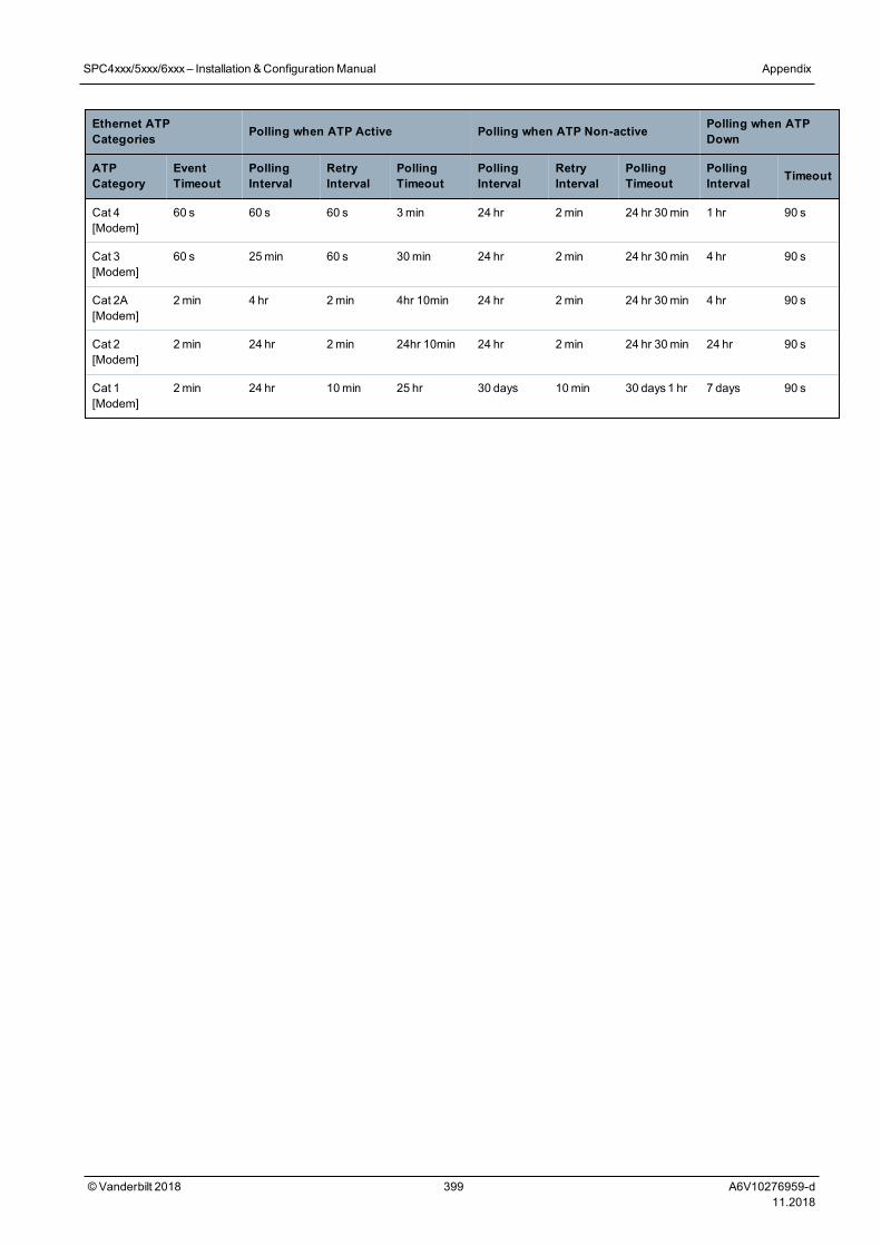
Ethernet ATPCategories Polling when ATP Active Polling when ATP Non-active Polling when ATP
Down
ATPCategory
EventTimeout
PollingInterval
RetryInterval
PollingTimeout
PollingInterval
RetryInterval
PollingTimeout
PollingInterval Timeout
Cat 4[Modem]
60 s 60 s 60 s 3min 24 hr 2min 24 hr 30min 1 hr 90 s
Cat 3[Modem]
60 s 25min 60 s 30min 24 hr 2min 24 hr 30min 4 hr 90 s
Cat 2A[Modem]
2min 4 hr 2min 4hr 10min 24 hr 2min 24 hr 30min 4 hr 90 s
Cat 2[Modem]
2min 24 hr 2min 24hr 10min 24 hr 2min 24 hr 30min 24 hr 90 s
Cat 1[Modem]
2min 24 hr 10min 25 hr 30 days 10min 30 days1 hr 7 days 90 s
SPC4xxx/5xxx/6xxx– Installation &ConfigurationManual Appendix
© Vanderbilt 2018 399 A6V10276959-d11.2018

24 Notes
©Vanderbilt 2018 400 A6V10276959-d11.2018

SPC4xxx/5xxx/6xxx– Installation &ConfigurationManual
© Vanderbilt 2018 401 A6V10276959-d11.2018

vanderbiltindustries.com
@VanderbiltInd Vanderbilt Industries
Issued by Vanderbilt International Ltd.Clonshaugh Business and Technology ParkClonshaugh, Dublin D17 KV 84, Ireland
vanderbiltindustries.com/contact
© Vanderbilt 2018
Data and design subject to change without notice.
Supply subject to availability.
Document ID: A6V10276959-d
Edition date: 11.2018
Related Documents