SpaceLogic PIBCV DN10…DN250 Pressure Independent Balancing and Control Valves – The correct and maximum design flow ensures a high differential in supply and return temperatures to provide high operational efficiency of the chiller or boiler. • Improved Comfort – The PIBCV valves are not affected by other valves in the system that may be opening and closing throughout the day or other piping system disturbances providing more constant and comfortable room temperature. • Reduced Pumping Costs – A reduction in overflows through the network reduces pumping costs. A smaller pump head and equipment is required compared to traditional configurations. • Reduced Installation Costs – Only one valve needs to be installed rather than two or three since the PIBCV covers the pressure balancing, flow limitation and control modulation. • Easy and quick Commissioning – SpaceLogic PIBCV setup time is significantly reduced with a simple and accurate flow setting procedure without the need for flow charts, calculations or measuring equipment. • Improved Reliability – Improved mechanical equipment reliability from reduced actuator movements. Product Description The SpaceLogic PIBCV range is a comprehensive selection of automatic balancing and control valves that provide flow limitation with full control authority over hydronic regulation. Automatic balancing within PIBCV valves provide stable flow regulation regardless of pressure fluctuations in the system and all valves have an adjustable flow limitation set point. The control valve portion of the PIBCV further regulates the media flow from close-off up to the maximum flow limit setting. Typical applications are temperature control of chillers, air- handling units, heat exchanges and terminal units such as fan coils, induction units and radiant panels. Features • Reduced Energy Consumption – Pressure independence ensures no overflow of water/glycol through the valve. Limiting media flow to the design load of the coil has a significant effect on energy efficiency since systems operate for the majority of the time on a partial load where overflow occurs. – Overflow of media causes a degradation in ∆T at the heat exchanger. Uncontrolled overflow of media is an extremely wasteful and inefficient use of heat. © 2021 Schneider Electric. All rights reserved. All trademarks are owned by Schneider Electric Industries SAS or its affiliated companies. July, 2021 tc Document Number: F-27946-9 www.schneider-electric.com schneider-electric.com | 1 Specification Sheet

Welcome message from author
This document is posted to help you gain knowledge. Please leave a comment to let me know what you think about it! Share it to your friends and learn new things together.
Transcript

SpaceLogic PIBCV DN10…DN250Pressure Independent Balancing and Control Valves
– The correct and maximum design flow ensures a high differential in supply and return temperatures to provide high operational efficiency of the chiller or boiler.
• Improved Comfort – The PIBCV valves are not affected by other
valves in the system that may be opening and closing throughout the day or other piping system disturbances providing more constant and comfortable room temperature.
• Reduced Pumping Costs – A reduction in overflows through the network reduces
pumping costs. A smaller pump head and equipment is required compared to traditional configurations.
• Reduced Installation Costs – Only one valve needs to be installed rather than two or
three since the PIBCV covers the pressure balancing, flow limitation and control modulation.
• Easy and quick Commissioning – SpaceLogic PIBCV setup time is significantly reduced
with a simple and accurate flow setting procedure without the need for flow charts, calculations or measuring equipment.
• Improved Reliability – Improved mechanical equipment reliability from
reduced actuator movements.
Product DescriptionThe SpaceLogic PIBCV range is a comprehensive selection of automatic balancing and control valves that provide flow limitation with full control authority over hydronic regulation.
Automatic balancing within PIBCV valves provide stable flow regulation regardless of pressure fluctuations in the system and all valves have an adjustable flow limitation set point. The control valve portion of the PIBCV further regulates the media flow from close-off up to the maximum flow limit setting.
Typical applications are temperature control of chillers, air-handling units, heat exchanges and terminal units such as fan coils, induction units and radiant panels.
Features• Reduced Energy Consumption
– Pressure independence ensures no overflow of water/glycol through the valve. Limiting media flow to the design load of the coil has a significant effect on energy efficiency since systems operate for the majority of the time on a partial load where overflow occurs.
– Overflow of media causes a degradation in ∆T at the heat exchanger. Uncontrolled overflow of media is an extremely wasteful and inefficient use of heat.
© 2021 Schneider Electric. All rights reserved. All trademarks are owned by Schneider Electric Industries SAS or its affiliated companies. July, 2021 tcDocument Number: F-27946-9
www.schneider-electric.com
schneider-electric.com | 1Specification Sheet

Product Selection: Threaded and Flanged Valves Table 1. Threaded Valves
Image DNQ
min (l/s)
Q nom 100% (l/s)
Q min (l/h)
Q nom (l/h)
Connection Part No.
Suitable Actuator Ext. Thread (ISO 228/1)
Without T/P Plugs With T/P Plugs
without plugs
with plugs
DN100.008 0.042 30 150
G 1/2AVP228E-10BQLNT VP228E-10BQL
SP90 MP120
(thermal)MP130
(Motoric)MP300-SR
(Spring Return)
0.015 0.076 55 275 VP228E-10BQSNT VP228E-10BQS
DN15
0.015 0.076 55 275
G 3/4A
VP228E-15BQLNT VP228E-15BQL
0.025 0.125 90 450 VP228E-15BQSNT VP228E-15BQS
0.063 0.315 227 1 135 VP229E-15BQHNT
DN200.050 0.250 180 900
G 1AVP228E-20BQSNT VP228E-20BQS
0.094 0.472 340 1 700 VP229E-20BQHNT
DN250.09 0.472 340 1 700
G 1 1/4AVP229E-25BQSNT VP229E-25BQS
0.15 0.75 545 2 724 VP229E-25BQHNT
DN320.18 0.89 640 3 200
G 1 1/2AVP229E-32BQSNT VP229E-32BQS
0.22 1.11 795 4 000 VP229E-32BQHNT
DN40 0.8 2.1 3 000 7 500 G 2A VP220E-40CQS
MP500CMP500C-SR
(Spring Return)DN50 1.4 3.5 5 000 12 500 G 2 1/2A VP220E-50CQS
Table 2. Flanged Valves
DNQ
min (l/s)
Q nom (l/s)
Q min (l/h)
Q nom (l/h)
Part No. With T/P Plugs Suitable Actuator
DN50 1.4 3.5 5 000 12 500 VP220F-50CQS
MP500CMP500C-SR
(Spring Return)
DN652.2 5.6 8 000 20 000 VP220F-65CQS
2.8 6.9 10 000 25 000 VP220F-65CQH
DN803.1 7.8 11 200 28 000 VP220F-80CQS
4.4 11.1 16 000 40 000 VP220F-80CQH
DN1004.2 10.6 15 200 38 000 VP220F-100CQS
6.6 16.4 23 600 59 000 VP220F-100CQH
DN12510 25 36 000 90 000 VP221F-125CQS
MP2000MP2000-SR
(Spring Return)
12 31 44 000 110 000 VP221F-125CQH
DN15016 40 58 000 145 000 VP221F-150CQS
21 53 76 000 190 000 VP221F-150CQH
DN20021 56 76 000 190 000 VP222F-200CQS
MP400028 75 100 000 250 000 VP222F-200CQH
DN25031 83 112 000 280 000 VP222F-250CQS
41 103 148 000 370 000 VP222F-250CQH
Note: A Higher flow, (Q max) is achievable on some sizes by increasing the pressure drop through the valve, please see technical data starting on page 9.
Accessories
The commissioning label set is a plasticized tag that allows the set flow rate to be recorded and attached to the valve via a cable tie. The handles allow the PIBCV to be used without an actuator as an automatic flow regulation valve, which could be very beneficial in certain networks, especially those closest to the pump that are subject high pressure drops.
Part Number Description
911 4060 000 Commissioning Label Set / Flow Tag Hanger ID
911 4070 000 DN40-DN100 Handle
911 4071 000 DN125-150 Handle
911 4072 000 DN200-250 Handle
© 2021 Schneider Electric. All rights reserved. All trademarks are owned by Schneider Electric Industries SAS or its affiliated companies. July, 2021 tcDocument Number: F-27946-9
2 | schneider-electric.com Specification Sheet

Main TypeSize and Material
-Family
Valve Type:P - PIBCV
Number of Ways: 2 - 2-Way
End Connection:E - G external thread (G.A)F - Flanged DINA - Flanged ANSI 150
Orifice - Examples: 15 - 15 DN200 - 200 DN
Material:C - Cast Iron bodyB - Bronze body, Brass trim
Flow:QL - Low FlowQS - Standard FlowQH - high flow
Flow 2 - Linear
Actuator Connection-Linear Valves:0 - Short-Yoke U-Bolt Forta1 - Connection design A2 - Connection design B8 - M30 x 1.5 (2.5 mm stroke)9 - M30 x 1.5 (up to 5.5 mm stroke)
Type Designation Explanation
V P 2 2
Table 3. Tail Pieces/Pipe Connections for threaded valves (2 pieces per pack) Valve DNSize Pipe Connection type Part No. Valve Connection End Fitting Connection
DN10
Solder
911 2113 010* G 1/2 15 mm*
DN15 911 2113 015 G 3/4 15 mm
DN15 911 2113 115* G 3/4 22 mm*
DN20 911 2113 020 G 1 15 mm
DN20 911 2113 120 G 1 22 mm
DN25 911 2113 025 G 1.1/4 28 mm
DN32 911 2113 032 G 1.1/2 35 mm
DN40 911 2113 040 G 2 42 mm
DN50 911 2113 050 G 2.1/2 54 mm
DN10
R taper External thread
911 2112 010 G 1/2 R 3/8
DN15 911 2112 015 G 3/4 R 1/2
DN20 911 2112 020 G 1 R 3/4
DN25 911 2112 025 G 1.1/4 R 1
DN32 911 2112 032 G 1.1/2 R 1.1/4
DN40 911 2112 040 G 2 R 1.1/2
DN50 911 2112 050 G 2.1/2 R2
DN10
Internal thread
911 2111 010* G 1/2 Rp 1/2*
DN15 911 2111 015* G 3/4 Rp 1/2*
DN20 911 2111 020 G 1 Rp 1/2
DN25 911 2111 025 G 1.1/4 Rp 3/4
DN32 911 2111 032 G 1.1/2 Rp 1
DN40 911 2111 040 G 2 Rp 1.1/4
DN50 911 2111 050 G 2.1/2 Rp 1.1/2
DN20
911 2115 020 G 1 26.9 mm
DN25 911 2115 025 G 1.1/4 33.7 mm
DN32 911 2115 032 G 1.1/2 42.4 mm
DN40 911 2115 040 G 2 48.3 mm
DN50 911 2115 050 G 2.1/2 60.3 mm
* one piece compact design, additional coupler either side of the valve may be needed to ease assembly / dissasembly
Weld
© 2021 Schneider Electric. All rights reserved. All trademarks are owned by Schneider Electric Industries SAS or its affiliated companies. July, 2021 tcDocument Number: F-27946-9
schneider-electric.com | 3Specification Sheet

Control Performance The SpaceLogic PIBCV has a linear control characteristic and is pressure independent which means the control char-acteristic is independent from the available pressure and is not influenced by a low authority.
The flow limitation on the PIBCV is achieved by limiting the valve stroke. Schneider Electric motoric actuators calibrate to the varying stroke of the valves. This means the PIBCV keeps a predictable linear characteristic independent of the flow setting or differential pressure.
PIBCV actuators electronically adjust the control character-istic from linear to logarithmic (equal percentage) always providing a perfect adaptation regardless of the flow setting. This makes PIBCV suitable for all applications, including AHUs, where the equal percentage characteristic is needed to get a stable control loop. All modulating actuators can be switched from linear to logarithmic by changing a dipswitch setting on Modulating actuators.
The integrated differential pressure controller enables the control valve to have 100 % authority and will always provide stable control. At partial system load there is no resulting
LIN se
tting st
ays c
onsta
nt at
any
avail
able
press
ure
LOG setting stays constant
at a
ny a
vaila
ble
pres
sure
0 10 V0
100%
For
any
giv
en 1
00 %
set
ting
Applications Variable flow systems: The focus application area of the PIBCV is for variable flow systems which includes terminal unit equipment like fan coils (FCU's) and radiation panels as well as larger plant equipment with air handling units (AHU's).
Constant flow systems: The PIBCV can work in numerous constant flow systems, In these applications the PIBCV is installed as an automatic flow limitation valve which may or may not be fitted with an actuator, ensuring the system is automatically balanced with energy efficient control.
Equipment area's for constant flow systems include radiant panels, fan coils (FCU's) and floor heating.
Variable Flow Air Handling Unit (AHU)
Constant Flow Fan Coil Unit (FCU)
Constant Flow Radiator System
Variable Flow Fan Coil Unit (FCU)Variable Flow Radiant Panel
Implementation Benefits of PIBCV• No Kv or authority calculations needed. Flow is the only
parameter to be considered when designing or selecting the SpaceLogic PIBCV.
– The PIBCV always works reliably within the flow range. The maximum setting of the PIBCV corresponds with international standards for flow velocity in pipes.
– The PIBCV can be used for all HVAC applications and the flow control can be modified from linear to logarithmic when combined with thermal electric or proportional actuators.
– Compact design, essential when only limited space is available, for example in fan-coil units.
– Easy commissioning. No specialized staff or measuring equipment needed.
– Fast start-up. PIBCV valves don’t need to be flushed or de-aired before use.
– Trouble-free segmentation of the building project. The PIBCV will automatically control the flow, even when sections of the installation are still unfinished. It’s not needed to re-adjust the PIBCV flow setting after finalization of the building project.
overflow downstream to the PIBCV, because the valve will always limit the flow to exactly what it is set to.
By installing the PIBCV the whole system is divided in completely independent control loops. There is a full range of Schneider Electric actuators suitable for every control strategy, including On/Off, 0…10 Volt or 4…20 mA modulating and 3-point floating.
© 2021 Schneider Electric. All rights reserved. All trademarks are owned by Schneider Electric Industries SAS or its affiliated companies. July, 2021 tcDocument Number: F-27946-9
4 | schneider-electric.com Specification Sheet
P1P3P2
P2 - P3
P1 - P3
∆p = (P1-P3)∆pCv = (P2-P3)
SX PIBCV DN10-32
DN50-100
P3P1
FunctionThe SpaceLogic PIBCV valve consists of two parts: 1. Differential pressure controller 2. Control valve
1. Differential Pressure Controller (DPC)
The differential pressure controller maintains a constant differential pressure across the control valve. The pressure difference ∆pCv (P2-P3) on the membrane is balanced with the force of the spring. Whenever the differential pressure across the control valve changes (due to a change in avail-able pressure, or movement of the control valve) the hollow cone is displaced to a new position which brings a new equilibrium and therefore keeps the differential pressure at a constant level.
2. Control Valve (CV)
The control valve has a linear characteristic. It features a stroke limitation function that allows adjustment of the Kv value. The percentage marked on the scale equals the percentage of 100 % flow marked on the pointer. Chang-ing the stroke limitation is done by lifting the blocking mechanism and turning the top of the valve to the desired position, showed on the scale as a percentage. A blocking mechanism automatically prevents unwanted changing of the setting.
12
3
45
6
7
8
1. DPC 2. CV
Direction of Flow
DN10-32 1 Spindle2 Stuffing box3 Pointer4 Control valve’s cone5 Membrane6 Main spring7 Hollow cone (pressure controller)8 Vulcanized seat (pressure controller)
Design
DN40, 50, 100 1. Shut off screw2. Main spring3. Membrane4. DP cone5. Seat 6. Valve body7. Control valves cone8. Locking screw9. Scale10. Stuffing box11. Spindle
© 2021 Schneider Electric. All rights reserved. All trademarks are owned by Schneider Electric Industries SAS or its affiliated companies. July, 2021 tcDocument Number: F-27946-9
schneider-electric.com | 5Specification Sheet

DN40-100
Note: 1 turn = 10 %
Max 25Nm
DN125-250
Note: DN125 & 150: 1 turn = 5.0 %DN200 & 250: 1 turn = 5.5 %
+
–Setting 60 %
+
–
② ④③
20 %100 % ≠h h+ 2 mm, DN10-20
h+ 4 mm, DN25-32
>100 %
h
Scale +90 %
①
PIBCV Flow PresettingDN10-32
The max flow setting can be adjusted easily with-out using special tools. To change the presetting of the max flow (factory setting is 100 %) follow the four steps below:
① Remove the grey protective pointer of the mounted actuator.
② Raise the green pointer dial.
③ Turn (clockwise to decrease) to the new max flow presetting value.
④ Press the dial back into the lock position. After the dial is clicked back into place the max flow presetting value is locked.
The presetting scale indicates values from 100 % flow to 0 %. Clockwise turning would decrease the flow value while counter-clockwise would increase it.
Example:If the valve is a DN15 then the nom flow = 450 l/h =100 % presetting. To set a flow of 270 l/h you have to set: 270/450 = 60 %.Schneider Electric recommends a presetting/flow from 20 % to 100 %. Factory presetting is 100 %.The DN10-32 valves can be set to a Qmax flow which is a setting above the Qnom setting of 100%. Table 4 details the Qmax setting which is either limited to 110% or 120%. The maximum reading on the scale is 100%; to adjust the flow setting beyond 100% the pointer will be adjusted counter-clockwise past the max scale setting.
The flow setting above the Qnom is the readable value + 90%. Thus in this zone the pointer at 20% position will be a flow setting of 110% and at the 30% position the flow setting will be 120%.
© 2021 Schneider Electric. All rights reserved. All trademarks are owned by Schneider Electric Industries SAS or its affiliated companies. July, 2021 tcDocument Number: F-27946-9
6 | schneider-electric.com Specification Sheet
P1P3P2
∆pcv
P1 - P3Blue
Red
Blue
∆pcv
DN40-250 DN10-32
Q nom = const
* ∆pmin = (P1-P3)min
** ∆pcv.min = (P2-P3)min
∆pcv
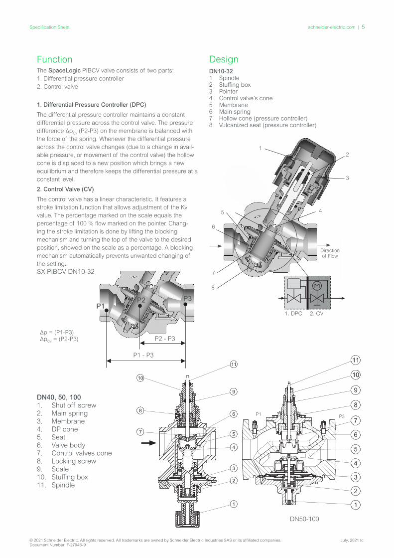
The P1 test plug can also be used to optimize the pump head. The pump head can be decreased until no more than the minimal required pressure is available on the most criti-cal valve (in terms of hydronic). As the P1 test plug is not possible on the DN10-32 valves, a separate pressure taping for the critical index circuit should be made available for this measurement.
Verifying the pressure can be done by using traditional or electronic manometers.
Pump Optimizing / Troubleshooting
Q
P2-P3
P2-P3
P2 Red
P3 Blue
P2-P3
Q=const. Q=const.
Pump optimization
Q
16kP a 400kPa
P1-P3
P1-P3
P1 P2 P3
(20kPa)
∆pcv
The DN10-100 PIBCV valves feature test plugs that allow measuring of the pressure difference ∆pcv (P2 to P3) across the control valve. With the DN40-250 PIBCV valves the meas-uring can also be done between P1 to P3. If the operating pressure differential exceeds the minimum required pressure differential as detailed in the technical tables, flow limitation to the set point will be achieved. The measuring function of the test ports can be used to verify if enough operating pressure differential is available and thus verify the flow or measure the flow directly.
Service Shut Off DN10-32
For the service shut off function, it is recommended to install the valve in the supply water pipe. Valves are equipped with plastic shut-off mechanism that is to be used for isolating function up to 1 bar differential pressure.
DN40-100
For the service shut off function, the valve can be installed in either supply or return pipe. Valves are equipped with manual shut-off for isolating function up to 16 bar.
Flow DirectionPIBCV valves are mono-directional, meaning the valve oper-ates when the arrow on the valve body is aligned with the flow direction. When this rule is ignored the valve acts like a variable orifice that causes water hammer at sudden closing when available pressure has increased or the valve has been
set to a lower value. In the case when a system condi-tion allows backflows, it is strongly recommended to use a backflow preventer in order to avoid possible water hammer that can damage to the valve as well as other elements in the system.
It is recommended to fit a strainer upstream of the valve to increase reliability and to follow water treatment guidelines as detailed in VDI 2035.
The pipework system should be flushed prior to the opera-tion.
© 2021 Schneider Electric. All rights reserved. All trademarks are owned by Schneider Electric Industries SAS or its affiliated companies. July, 2021 tcDocument Number: F-27946-9
schneider-electric.com | 7Specification Sheet

Q F
low
rang
e (l/
h)
DN
25H
DN
32H
DN
20H
DN
25
DN
15H
DN
65
HF D
N 8
0 H
F
DN
100 H
F
max
Thread version Flange version
© 2021 Schneider Electric. All rights reserved. All trademarks are owned by Schneider Electric Industries SAS or its affiliated companies. July, 2021 tcDocument Number: F-27946-9
8 | schneider-electric.com Specification Sheet
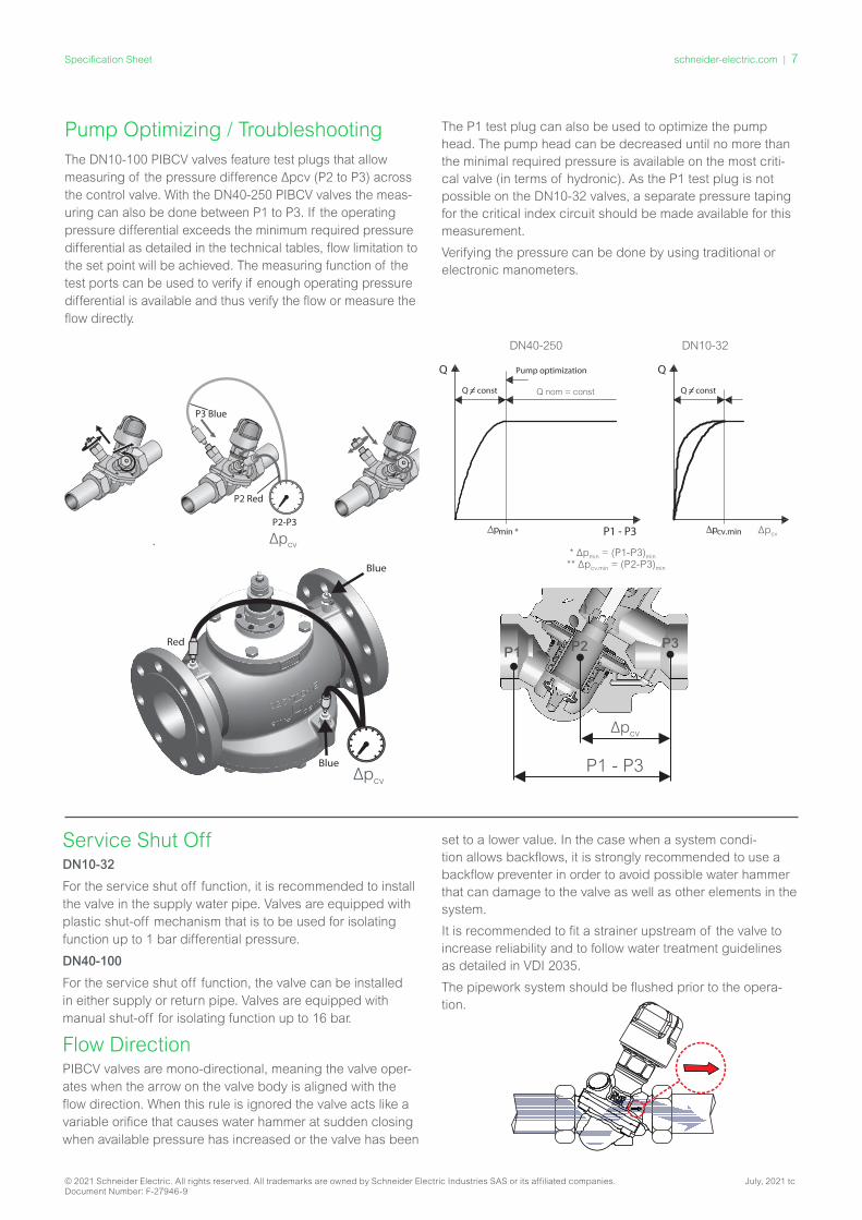
Technical Data
Table 4. Threaded version, DN15-50
Nominal diameter DN 10L 10S 15L 15S 15H 20S 20H 25S 25H 32S 32H 40 50
Test Plug No/Optional /Standard
Opt. No Opt. No Opt. No Opt. No Std. Std.
Flow range
Qnom (100%)1)
l/h150 275 275 450 1135 900 1700 1700 2700 3200 4000 7500 12500
Qmax 4) 180 330 330 540 1250 1080 1870 1870 2970 3520 4400 7500 12500
Setting range 2) %20-120% 20-110% 20-120% 20-110% 40-100%
Diff. pres-sure 3), 4), 5)
∆pQnom
(∆pQmax)kPa
16-600(18-600)
35-600 (40-600)
16-600(18-600)
35-600 (40-600)
20-600(25-600)
35-600 (40-600)
25-600(30-600)
35-600 (40-600)
30-600
Pressure class PN 16
Max. Close Off Pressure (∆pc)
Bar 16
Control range According to standard IEC 60534 control range is high as flow characteristic is linear (1:1000)
Control valve’s characteristic Linear (could be converted by actuator to equal percentage)
Leakage to IEC 60534 No visible leakage max. 0.05 % of Qnom
For shut off function According to ISO 5208 class A - no visible leakage
Flow mediumWater and water mixture for closed heating and cooling systems according to plant type I for DIN EN 14868.
When used in plant Type II for DIN EN 14868 appropriate protective measures are taken. The requirements of VDI 2035, part 1 + 2 are observed.
Medium temperature °C −10 ... +120
Stroke mm 2.25 4.0 2.25 4.0 4.5 10
Connec-tion
ext. thread (ISO 228/1)
G ½ A G ¾ A G 1 A G 1¼ A G 1½ AG 2 A G 2½ A
actuator M30 x 1.5, with 10.4 mmclosing height Short Yoke Forta U bolt
Materials in the water
Valve bodies DZR Brass (CuZn36Pb2As - CW 602N)Grey iron
EN-GJL-250 (GG 25)
Membranes and O-rings EPDM
Springs W.Nr. 1.4568, W.Nr. 1.4310
Cone (Pc) W.Nr. 1.4305CuZn40Pb3-CW
614N, W.Nr. 1.4305
Seat (Pc) EPDM W.Nr. 1.4305
Cone (Cv) CuZn40Pb3 - CW 614N
Seat (Cv) DZR Brass (CuZn36Pb2As - CW 602N) W.Nr. 1.4305
Screw Stainless Steel (A2)
Flat gasket NBR
Sealing agent (only for valves with test plugs)
Dimethacrylate Ester
Materials out of the water
Plastic parts PA POM
Insert parts and outer screws CuZn39Pd3 - CW614N -
1) Factory setting of the valve is done at nominal setting range.2) Regardless of the setting, the valve can modulate below 1 % of set flow.3) ∆p = (P1–P3) min~max4) When set above 100 %, minimum starting pressure needed is higher, see figures in the ().5) For ∆p above 400 kPa, static pressure (P1) must be greater than 2 x ∆p. For suitability and usage in non-oxygen tight systems please observe instructions of the coolant producer.
Pc - pressure controller part Cv - Control valve part
Note: Media Compatibility
It is the responsibility of the installer or product specifier to verify media compatibility of the valves construction materials with the supplier of water treatment/heat transfer solution.
Filtration
Strainers should always be fitted upstream of the valve.
© 2021 Schneider Electric. All rights reserved. All trademarks are owned by Schneider Electric Industries SAS or its affiliated companies. July, 2021 tcDocument Number: F-27946-9
schneider-electric.com | 9Specification Sheet

Technical Data
Table 5. Flange Version, DN50-DN100Nominal diameter DN 50 65 65 HF 80 80 HF 100 100 HF
Flow range Qnom l/h 12 500 20 000 25 000 28 000 40 000 38 000 59 000
Setting range 2) % 40-100%
Diff. pressure 3), 5) ∆pQnom kPa 30-600 30-600 60-600 30-600 60-600 30-600 60-600
Pressure class PN 16
Control valve’s characteristic Linear (could be converted by actuator to equal percentage)
Leakage to standard IEC 60534 max. 0.05 %
For shut off function According to ISO 5208 class A - no visible leakage
Flow medium
Water and water mixture for closed heating and cooling systems according to plant type I for DIN EN 14868.
When used in plant Type II for DIN EN 14868 appropriate protective measures are taken. The requirements of VDI 2035, part 1 + 2 are observed.
Medium temperature °C −10 ... +120
Stroke mm 10 15
Connectionflange PN 16
actuator Forta Short Yoke U bolt
Materials in the water
Valve bodies Grey iron EN-GJL-250 (GG25)
Membranes/ Bellow EPDM
O-rings EPDM
Springs W.Nr. 1.4568, W.Nr. 1.4310
Cone (Pc) CuZn40Pb3 - CW 614N, W.Nr. 1.4305
Seat (Pc) W.Nr. 1.4305
Cone (Cv) CuZn40Pb3 - CW 614N
Seat (Cv) W.Nr. 1.4305
Screw Stainless Steel (A2)
Flat gasket NBR
Table 6. Flange Version, DN125 - DN250Nominal diameter DN 125 125 HF 150 150 HF 200 200 HF 250 250 HF
Flow range Qnom
(Qmax)l/h
90 000 (100 000)
110 000 (120 000)
145 000 (160 000)
190 000 (209 000)
200 000(220 000)
270 000(300 000)
300 000(330 000)
370 000(407 000)
Setting range 2) % 40-110%
Diff. pressure 3), 4) ∆pQnom
(∆pQmax) kPa
40-600 (60-600)
60-600 (80-600)
40-600(60-600)
60-600 (80-600)
45-600(65-600)
60-600(80-600)
45-600(65-600)
60-600(80-600)
Pressure class PN 16
Control range According to standard IEC 60534 control range is high as flow characteristic is linear.
Control valve’s characteristic Linear (could be converted by actuator to equal percentage)
Leakage to standard IEC 60534 max.0.01 % of Qnom max. 0.01 % of Qnom
Flow mediumWater and water mixture for closed heating and cooling systems according to plant type I for DIN EN 14868. When used in plant Type II for DIN EN 14868 appropriate protective measures are taken. The requirements of VDI 2035,
part 1 + 2 are observed.
Medium temperature °C −10 ... +120
Stroke mm 30
Connectionflange PN 16
actuator Schneider Electric standard
Materials in the water
Valve bodies Grey iron EN-GJL-250 (GG 25)
Membranes/ Bellow W.Nr.1.4571 EPDM
O-rings EPDM
Springs W.Nr.1.4401 W.Nr.1.4310
Cone (Pc) W.Nr.1.4404NC W.Nr.1.4021
Seat (Pc) W.Nr.1.4027
Cone (Cv) W.Nr.1.4404NC W.Nr.1.4021
Seat (Cv) W.Nr.1.4027
Screw W.Nr.1.1181
Flat gasket Graphite gasket Non asbestos
1) factory setting of the valve is done at nominal setting range.2) Regardless of the setting, the valve can modulate below 1 % of set flow.3) ∆p = (P1–P3) min~max4) For ∆p above 400 kPa , static pressure (P1) must be greater than 2 x ∆p Pc - pressure controller partCv - Control valve part
© 2021 Schneider Electric. All rights reserved. All trademarks are owned by Schneider Electric Industries SAS or its affiliated companies. July, 2021 tcDocument Number: F-27946-9
10 | schneider-electric.com Specification Sheet

L2
L3 L1
b
H2
H1
L3
H2
H1
b
L1
L5
L5
H3
L4
L4
H3
L5
L4
H3
Dimensions (mm)
Table 7. Threaded Valves DN10…DN32
Table 9. Flanged Valves DN50-DN100 (mm)
Type L1 L2 H1 H2
H3 b (ISO
228/1)
Wght (kg)MP500C MP500C-SR
DN40 110 143 170 174 302 305 G 2A 6.9
DN50 130 181 170 174 302 305 G 2½A 7.8
Type L1 L2 H1 H2
H3 a (EN
1092-2)
Wght (kg)MP500 MP500C-SR
DN50 230 198 170 174 302 305 165 14.2
DN65 290 223 220 172 351 354 185 38.0
DN80 310 232 225 177 356 359 200 45.0
DN100 350 256 240 187 372 375 220 57.0
DN50-100DN50-100 with Forta MP500C(-SR)
With MP120 Actuator With MP130 Actuator With MP300-SR Actuator
With SP90 Actuator
L2
H2
H1
b
L1
DN10-32 with close off cap
L2
Type L1 L2L4 H1 H2 H3 b
(ISO 228/1)
Valve weight
(kg)SP90 MP120 MP130 MP300-SR SP90 MP120 MP130 MP300-SR
DN10 53 36 118 101 111 130 74 20 140 120 143 185 G½A 0.38
DN15 65 45 125 108 118 137 77 25 143 123 145 188 G¾A 0.48
DN20 82 56 133 117 127 146 79 31 145 125 148 190 G 1A 0.65
DN25 104 71 148 132 142 160 88 40 153 133 156 199 G 1¼A 1.45
DN32 130 90 166 149 160 178 99 49 164 144 167 210 G 1½A 2.21
Table 8. Threaded Valves DN40, DN50 (mm)
Closing point (measure
for DN10-32)
10.4
mm
H3
DN40, 50 with Forta MP500C(-SR)
L2
b
L1
H1
H2
H3
L1
a
H1
H2
H3
DN40, 50
L1
H1
H2
b
H2
L1
a
H1
H3
b
L1
H1
H2
H3
L1
a
H1
H2
H3
L2
L3 (plugs): 79 L5: MP130: 104; MP300: 146; SP90: 110.21.
© 2021 Schneider Electric. All rights reserved. All trademarks are owned by Schneider Electric Industries SAS or its affiliated companies. July, 2021 tcDocument Number: F-27946-9
schneider-electric.com | 11Specification Sheet

Size L1 L2 H1 H2
H3 a(EN 1092-2)
Weight(kg)MP4000
DN200 600 497 434 483 783 340 219
DN250 730 584 406 573 788 405 342
Table 11. Flanged DN200, DN250
Size L1 L2 H1 H2
H3
a(EN 1092-2)
Weight(kg)MP2000 MP2000-SR
DN125 400 367 272 518 511 532 250 85.3
DN150 480 403 290 481 547 568 285 138
Table 10. Flanged DN125, DN150
DN150 DN150 with MP2000-SR
L1 L2
H2
H1
a
H3
568
MP2000-SR
480
28
5
290
4
81
547
MP2000
403.46
DN150
DN125DN125 with MP2000-SRL1
H2
H1
a
H3
L2
532
MP2000-SR
400
25
0
254
5
17
511
MP2000
DN125
DN200 DN200 with MP4000
H3
783
MP4000
600
340
385
5
29
497.15
DN200
a
L1
H2
H1
783
MP4000
600
340
385
5
29
497.15
DN200
783
MP4000
600
340
385
5
29
497.15
DN200
L2
DN250
L2
788
MP4000
730
4
05
406
5
73
583.90
DN250
DN250 with MP4000
H3
788
MP4000
730
4
05
406
5
73
583.90
DN250
a
L1
H2
H1
788
MP4000
730
4
05
406
5
73
583.90
DN250
© 2021 Schneider Electric. All rights reserved. All trademarks are owned by Schneider Electric Industries SAS or its affiliated companies. July, 2021 tcDocument Number: F-27946-9
12 | schneider-electric.com Specification Sheet
Related Documents