Colleges, Universities, Non-Academic Handbook SL 2016 NASA Student Launch National Aeronautics and Space Administration

Welcome message from author
This document is posted to help you gain knowledge. Please leave a comment to let me know what you think about it! Share it to your friends and learn new things together.
Transcript

CollegesUniversitiesNon-Academic Handbook
SL2016NASAStudent Launch
National Aeronautics and Space Administration
Note For your convenience this document identifies Web links when available These links are correct as of this publishing however since Web links can be moved or disconnected at any time we have also provided source information as available to assist you in locating the information
Table of Contents
Timeline for NASA University Student Launch Initiative 1Acronym Dictionary 2
ProposalStatement of Work for CollegesUniversitiesNon-Academic Teams
Design Development and Launch of a Reusable Rocket and Autonomous Ground SupportEquipment Statement of Work (SOW) 4
Vehicle Requirements 5Recovery System Requirements 7Competition and Payload Requirements 8Safety Requirements 9General Requirements 10
Proposal Requirements 12
VehiclePayload Criteria
Preliminary Design Review (PDR) Vehicle and Payload Experiment Criteria 16Critical Design Review (CDR) Vehicle and Payload Experiment Criteria 20Flight Readiness Review (FRR) Vehicle and Payload Experiment Criteria 25Launch Readiness Review (LRR) Vehicle and Payload Experiment Criteria 30Post Launch Assessment Review (PLAR) Vehicle and Payload Experiment Criteria 30Educational Engagement Form 31
Safety
High Power Rocket Safety Code 34Minimum Distance Table 36
Related Documents
USLI Competition Awards 38NASA Project Life Cycle 39Hazard Analysis ndash Introduction to Managing Risk 47Example Hazard Analysis 57Understanding Material Safety Data Sheets (MSDS) 63
Timeline for NASA University Student Launch Initiative (Dates are subject to change)
August 2015 7 Request for Proposal (RFP) goes out to all teams
September 201511 Electronic copy of completed proposal due to project office by 5 pm CDT to
Ian Bryant (Jacobs ESSSA Group) ianlbryantnasagov
Katie Wallace katievwallacenasagov
Julie Clift juliedcliftnasagov
October 2015 2 Awarded proposals announced 7 Kickoff and PDR QampA 23 Team web presence established
November 2015 6 Preliminary Design Review (PDR) reports presentation slides and flysheet posted on the team
Website by 800 am Central Time 9-20 PDR video teleconferences
December 2015 4 CDR QampA
January 201615 Critical Design Review (CDR) reports presentation slides and flysheet posted on the team
Website by 800 am Central Time 19-29 CDR video teleconferences
February 20163 FRR QampA
March 2016 14 Flight Readiness Review (FRR) reports presentation slides and flysheet posted to team Website
by 800 am Central Time 17-30 FRR video teleconferences
April 201613 Teams travel to Huntsville AL 13 Launch Readiness Reviews (LRR) 14 LRRrsquos and safety briefing 15 Rocket Fair and Tours of MSFC 16 Launch Day 17 Backup launch day 29 Post-Launch Assessment Review (PLAR) posted on the team Website by 800 am Central Time
May 2016Winning team announced 11
1
Acronym Dictionary
AGL=Above Ground Level
APCP=Ammonium Perchlorate Composite Propellant
CDR=Critical Design Review
CC=Centennial Challenges
CG=Center of Gravity
CP=Center of Pressure
EIT=Electronics and Information Technology
FAA=Federal Aviation Administration
FN=Foreign National
FRR=Flight Readiness Review
HEO=Human Exploration and Operations
LCO=Launch Control Officer
LRR=Launch Readiness Review
MAV=Mars Ascent Vehicle
MSDS=Material Safety Data Sheet
MSFC=Marshall Space Flight Center
NAR=National Association of Rocketry
PDR=Preliminary Design Review
PLAR=Post Launch Assessment Review
PPE=Personal Protective Equipment
RFP=Request for Proposal
RSO=Range Safety Officer
USLI=University Student Launch Initiative
SME=Subject Matter Expert
SOW=Statement of Work
STEM=Science Technology Engineering and Mathematics
TRA=Tripoli Rocketry Association
2
ProposalStatement of Work for Colleges UniversitiesNon-Academic Teams
Design Development and Launch of a Reusable Rocket and Autonomous Ground Support Equipment Statement
of Work (SOW)
1 Project Name NASA University Student Launch Initiative for colleges and universities
2 Governing Office NASA Marshall Space Flight Center Academic Affairs Office
3 Period of Performance Eight (8) calendar months
4 IntroductionThe NASA University Student Launch Initiative (USLI) is a research-based competitive and experiential
exploration project that provides relevant and cost effective research and development Additionally NASA
University Student Launch Initiative connects learners educators and communities in NASA-unique
opportunities that align with STEM Challenges under the NASA Education Science Technology Engineering
and Mathematics (STEM) Engagement line of business NASArsquos missions discoveries and assets provide
opportunities for individuals that do not exist elsewhere The project involves reaching a broach audience of
colleges and universities across the nation in an 8-month commitment to design build launch and fly a
payload(s) and vehicle components that support NASA research on high-power rockets to an altitude of
5280 feet above ground level (AGL) The challenge is based on team selection of multiple options There is
a Student Launch option that consists of 7 different experiments and a Centennial Challenge (CC) option
that consists of designing and building a Mars Ascent Vehicle (MAV) Supported by the Office of Education
Human Exploration and Operations (HEO) Mission Directorate Centennial Challenges Office and
commercial industry USLI is a unique NASA-specific opportunity to provide resources and experiences thatis built around a mission not textbook knowledge
After a competitive proposal selection process teams participate in a series of design reviews that are
submitted to NASA via a team-developed website These reviews mirror the NASA engineering design
lifecycle providing a NASA-unique experience that prepares individuals for the HEO workforce Teams must
successfully complete a Preliminary Design Review (PDR) Critical Design Review (CDR) Flight Readiness
Review (FRR) Launch Readiness Review (LRR) that includes safety briefings and an analysis of vehicle
systems ground support equipment and flight data Each team must pass a review in order to move to a
subsequent review Teams will present their PDR CDR and FRR to a review panel of scientists engineers
technicians and educators via video teleconference Review panel members the Range Safety Officer
(RSO) and Subject Matter Experts (SME) provide feedback and ask questions in order to increase the
fidelity between the USLI and research needs and will score each team according to a standard scoring
rubric The partnership of teams and NASA is win-win which not only benefits from the research conducted
by the teams but also prepares a potential future workforce familiar with the NASA Engineering Design
Lifecycle
College and university teams must successfully complete the requirements of Tasks 1 or 2 and are eligible
for awards through Student Launch Any team who wishes to incorporate additional research through the use
of a separate payload may do so The team must provide documentation in all reports and reviews oncomponents and systems outside of what is required for the project The Centennial Challenges Office will
award prizes to college university and non-academic teams for successful demonstration of the MAV (see
CC supplemental handbook) The USLI awards listed at the end of this handbook will only be given to teams
from an academic institution
4
1 Vehicle Requirements 11 The vehicle shall deliver the payload to an apogee altitude of 5280 feet above ground level (AGL)
12 The vehicle shall carry one commercially available barometric altimeter for recording the official altitude
used in the competition scoring The altitude score will account for 10 of the teamrsquos overall competition
score Teams will receive the maximum number of altitude points (5280) if the official scoring altimeter
reads a value of exactly 5280 feet AGL The team will lose two points for every foot above the required
altitude and one point for every foot below the required altitude The altitude score will be equivalent to the percentage of altitude points remaining after any deductions
121The official scoring altimeter shall report the official competition altitude via a series of beeps to be checked after the competition flight
122Teams may have additional altimeters to control vehicle electronics and payload experiment(s) 1221 At the Launch Readiness Review a NASA official will mark the altimeter that will be used
for the official scoring
1222 At the launch field a NASA official will obtain the altitude by listening to the audible beeps reported by the official competition marked altimeter
1223 At the launch field to aid in determination of the vehiclersquos apogee all audible electronics except for the official altitude-determining altimeter shall be capable of being turned off
123The following circumstances will warrant a score of zero for the altitude portion of the competition
1231 The official marked altimeter is damaged andor does not report an altitude via a series of beeps after the teamrsquos competition flight
1232 The team does not report to the NASA official designated to record the altitude with their official marked altimeter on the day of the launch
1233 The altimeter reports an apogee altitude over 5600 feet AGL 1234 The rocket is not flown at the competition launch site
13 The launch vehicle shall be designed to be recoverable and reusable Reusable is defined as being able to launch again on the same day without repairs or modifications
14 The launch vehicle shall have a maximum of four (4) independent sections An independent section is defined as a section that is either tethered to the main vehicle or is recovered separately from the main vehicle using its own parachute
15 The launch vehicle shall be limited to a single stage
16 The launch vehicle shall be capable of being prepared for flight at the launch site within 2 hours from the time the Federal Aviation Administration flight waiver opens
17 The launch vehicle shall be capable of remaining in launch-ready configuration at the pad for a minimum of 1 hour without losing the functionality of any critical on-board component
18 The launch vehicle shall be capable of being launched by a standard 12 volt direct current firing system The firing system will be provided by the NASA-designated Range Services Provider
19 The launch vehicle shall use a commercially available solid motor propulsion system using ammonium perchlorate composite propellant (APCP) which is approved and certified by the National Association of Rocketry (NAR) Tripoli Rocketry Association (TRA) andor the Canadian Association of Rocketry (CAR)
191Final motor choices must be made by the Critical Design Review (CDR)
192Any motor changes after CDR must be approved by the NASA Range Safety Officer (RSO) and will only be approved if the change is for the sole purpose of increasing the safety margin
110The total impulse provided by a launch vehicle shall not exceed 5120 Newton-seconds (L-class) 111 Pressure vessels on the vehicle shall be approved by the RSO and shall meet the following criteria
1111 The minimum factor of safety (Burst or Ultimate pressure versus Max Expected Operating
Pressure) shall be 41 with supporting design documentation included in all milestone reviews
1112 Each pressure vessel shall include a pressure relief valve that sees the full pressure of the
tank
5
1113 Full pedigree of the tank shall be described including the application for which the tank was designed and the history of the tank including the number of pressure cycles put on the tank by whom and when
112 All teams shall successfully launch and recover a subscale model of their full-scale rocket prior to CDR
The subscale model should resemble and perform as similarly as possible to the full-scale model
however the full-scale shall not be used as the subscale model
113 All teams shall successfully launch and recover their full-scale rocket prior to FRR in its final flight
configuration The rocket flown at FRR must be the same rocket to be flown on launch day The purpose of
the full-scale demonstration flight is to demonstrate the launch vehiclersquos stability structural integrity
recovery systems and the teamrsquos ability to prepare the launch vehicle for flight A successful flight is
defined as a launch in which all hardware is functioning properly (ie drogue chute at apogee main
chute at a lower altitude functioning tracking devices etc) The following criteria must be met during the
full scale demonstration flight
1131 The vehicle and recovery system shall have functioned as designed 1132 The payload does not have to be flown during the full-scale test flight The following
requirements still apply
11321 If the payload is not flown mass simulators shall be used to simulate the payload mass
11322 The mass simulators shall be located in the same approximate location on the rocket as the missing payload mass
11323 If the payload changes the external surfaces of the rocket (such as with camera housings or external probes) or manages the total energy of the vehicle those systems shall be active during the full-scale demonstration flight
1133 The full-scale motor does not have to be flown during the full-scale test flight However it is
recommended that the full-scale motor be used to demonstrate full flight readiness and altitude verification If the full-scale motor is not flown during the full-scale flight it is desired that the motor simulate as closely as possible the predicted maximum velocity and maximum acceleration of the competition flight
1134 The vehicle shall be flown in its fully ballasted configuration during the full-scale test flight Fully
ballasted refers to the same amount of ballast that will be flown during the competition flight
1135 After successfully completing the full-scale demonstration flight the launch vehicle or any of its components shall not be modified without the concurrence of the NASA Range Safety Officer (RSO)
114Each team will have a maximum budget of $7500 they may spend on the rocket and its payload(s) (Exception Centennial Challenge payload task See supplemental requirements at httpwwwnasagovmavprize for more information) The cost is for the competition rocket and payload as it sits on the pad including all purchased components The fair market value of all donated items or
materials shall be included in the cost analysis The following items may be omitted from the total cost of the vehicle
Shipping costs
Team labor costs
6
115Vehicle Prohibitions 1151The launch vehicle shall not utilize forward canards 1152The launch vehicle shall not utilize forward firing motors
1153The launch vehicle shall not utilize motors that expel titanium sponges (Sparky Skidmark MetalStorm etc)
1154The launch vehicle shall not utilize hybrid motors
1155The launch vehicle shall not utilize a cluster of motors
2 Recovery System Requirements 21 The launch vehicle shall stage the deployment of its recovery devices where a drogue parachute is
deployed at apogee and a main parachute is deployed at a much lower altitude Tumble recovery or streamer recovery from apogee to main parachute deployment is also permissible provided the kinetic energy during drogue-stage descent is reasonable as deemed by the Range Safety Officer
22 Teams must perform a successful ground ejection test for both the drogue and main parachutes This must
be done prior to the initial subscale and full scale launches
23 At landing each independent section of the launch vehicle shall have a maximum kinetic energy of 75 ft-lbf
24 The recovery system electrical circuits shall be completely independent of any payload electrical circuits
25 The recovery system shall contain redundant commercially available altimeters The term ldquoaltimetersrdquo includes both simple altimeters and more sophisticated flight computers One of these altimeters may be chosen as the competition altimeter
26 Motor ejection is not a permissible form of primary or secondary deployment An electronic form of deployment must be used for deployment purposes
27 A dedicated arming switch shall arm each altimeter which is accessible from the exterior of the rocket airframe when the rocket is in the launch configuration on the launch pad
28 Each altimeter shall have a dedicated power supply
29 Each arming switch shall be capable of being locked in the ON position for launch
210 Removable shear pins shall be used for both the main parachute compartment and the drogue parachute compartment
211An electronic tracking device shall be installed in the launch vehicle and shall transmit the position of the tethered vehicle or any independent section to a ground receiver
2111 Any rocket section or payload component which lands untethered to the launch vehicle shall also carry an active electronic tracking device
2112 The electronic tracking device shall be fully functional during the official flight at the competition launch site
7
Task 1 (select any 2) Task 2 311 Atmospheric Measurements 318 Centennial Challenge ndash MAV 312 Landing Hazards Detection 313 Liquid Sloshing in Micro-G 314 Propulsion System Analysis 315 Payload Fairing Design and
Deployment 316 Aerodynamic Analysis 317 Design your own (limit of
one)
212The recovery system electronics shall not be adversely affected by any other on-board electronic devices during flight (from launch until landing)
2121 The recovery system altimeters shall be physically located in a separate compartment within the vehicle from any other radio frequency transmitting device andor magnetic wave producing
device
2122 The recovery system electronics shall be shielded from all onboard transmitting devices to avoid inadvertent excitation of the recovery system electronics
2123 The recovery system electronics shall be shielded from all onboard devices which may generate magnetic waves (such as generators solenoid valves and Tesla coils) to avoid inadvertent excitation of the recovery system
2124 The recovery system electronics shall be shielded from any other onboard devices which may adversely affect the proper operation of the recovery system electronics
3 Competition and Payload Requirements Each team shall choose any 2 payloads from Task 1 or have the choice to participate in the Centennial Challenge competition (Task 2)
31 The payload shall be designed to be recoverable and reusable Reusable is defined as being able to be launched again on the same day without repairs or modifications
32 (Task1) The team may choose to participate in 2 of the following payload options 321A payload that shall gather data for studying the atmosphere during descent and after landing
including measurements of pressure temperature relative humidity solar irradiance and ultraviolet radiation
3211 Measurements shall be made at least once every second during descent and every 60 seconds after landing Data collection shall terminate 10 minutes after landing
3212 The payload shall take at least 2 pictures during descent and 3 after landing The payload shall remain in orientation during descent and after landing such that the pictures taken portray the sky towards the top of the frame and the ground towards the bottom of the frame
3213 The data from the payload shall be stored onboard and transmitted wirelessly to the teamrsquos ground station at the time of completion of all surface operations
322A payload that scans the surface continuously during descent in order to detect potential landing hazards
3221 The data from the hazard detection camera shall be analyzed in real time by a custom designed on-board software package that shall determine if landing hazards are present
3222 The data collected shall be stored on board and transmitted wirelessly to the teamrsquos ground station
323Liquid sloshing research in microgravity to support liquid propulsion systems
8
324Structural and dynamic analysis of airframe propulsion and electrical systems during boost 3241 The team must use and array of electrical sensors to measure structural vibration
and to measure the stress and strain of the rocket in the axial and radial directions 3242 At a minimum structural analysis shall be performed on the finsfin joints all
separation points and the nose cone 325A payload fairing design and deployment mechanism
3251 The fairings and payload must be tethered to the main body to prevent small objects from getting lost in the field
326An aerodynamic analysis of structural protuberances 327Design your own payload (limit of 1) Must be approved by NASA review team
33 (Task 2) Centennial Challenge
NASA University Student Launch Initiative is collaborating with the NASA Centennial Challenges Mars Ascent Vehicle (MAV) Project to offer teams the chance to design and build autonomous ground support equipment (AGSE) The Centennial Challenges Program part of NASArsquos Science and Technology Mission Directorate awards incentive prizes to generate revolutionary solutions to problems of interest to NASA and the nation The goal of the MAV and its AGSE is to capture a simulated Martian payload sample seal it within a launch vehicle and prepare the vehicle for launch without the input from a human operator For specific rules regarding the MAV project and to learn more about Centennial Challenges please visit the Centennial Challenge website at httpwwwnasagovmavprize and review their project handbook NOTE The Centennial Challenge handbook is meant to be a complement to this handbook If a team chooses to participate in the Centennial Challenge they must abide by all the rules presented in this document
4 Safety Requirements
41 Each team shall use a launch and safety checklist The final checklists shall be included in the FRR report and used during the Launch Readiness Review (LRR) and launch day operations
42 For all academic institution teams a student safety officer shall be identified and shall be responsible for all items in section 43 For competing non-academic teams one participant who is not serving in the team mentor role shall serve as the designated safety officer
43 The role and responsibilities of each safety officer shall include but not limited to 431Monitor team activities with an emphasis on Safety during
4311 Design of vehicle and launcher 4312 Construction of vehicle and launcher 4313 Assembly of vehicle and launcher 4314 Ground testing of vehicle and launcher 4315 Sub-scale launch test(s) 4316 Full-scale launch test(s) 4317 Competition launch 4318 Recovery activities 4319 Educational Engagement activities
432Implement procedures developed by the team for construction assembly launch and recovery activities
433Manage and maintain current revisions of the teamrsquos hazard analyses failure modes analyses procedures and MSDSchemical inventory data
434Assist in the writing and development of the teamrsquos hazard analyses failure modes analyses and procedures
9
44 Each team shall identify a ldquomentorrdquo A mentor is defined as an adult who is included as a team member who will be supporting the team (or multiple teams) throughout the project year and may or may not be affiliated with the school institution or organization The mentor shall be certified by the National
Association of Rocketry (NAR) or Tripoli Rocketry Association (TRA) for the motor impulse of the launch vehicle and the rocketeer shall have flown and successfully recovered (using electronic staged recovery) a minimum of 2 flights in this or a higher impulse class prior to PDR The mentor is designated as the individual owner of the rocket for liability purposes and must travel with the team to the launch at the competition launch site One travel stipend will be provided per mentor regardless of the number of teams he or she supports The stipend will only be provided if the team passes FRR and the team and
mentor attend launch week in April
45 During test flights teams shall abide by the rules and guidance of the local rocketry clubrsquos RSO The allowance of certain vehicle configurations andor payloads at the NASA University Student Launch Initiative competition launch does not give explicit or implicit authority for teams to fly those certain vehicle configurations andor payloads at other club launches Teams should communicate their
intentions to the local clubrsquos President or Prefect and RSO before attending any NAR or TRA launch
46 Teams shall abide by all rules and regulations set forth by the FAA
5 General Requirements 51 Team members (students if the team is from an academic institution) shall do 100 of the project
including design construction written reports presentations and flight preparation The one exception deals with the handling of black powder ejection charges and installing electric matches These tasks
shall be performed by the teamrsquos mentor regardless if the team is from an academic institution or not
52 The team shall provide and maintain a project plan to include but not limited to the following items project milestones budget and community support checklists personnel assigned educational engagement events and risks and mitigations
53 Each team shall successfully complete and pass a review in order to move onto the next phase of the competition
54 Foreign National (FN) team members shall be identified by the Preliminary Design Review (PDR) and may or may not have access to certain activities during launch week due to security restrictions In addition FNrsquos will be separated from their team during these activities If participating in the MAV task less than 50 of the team make-up may be foreign nationals
55 The team shall identify all team members attending launch week activities by the Critical Design Review
(CDR) Team members shall include
551 Students actively engaged in the project throughout the entirety of the project lifespan and currently enrolled in the proposing institution
552One mentor (see requirement 44) 553No more than two adult educators per academic team
56 The team shall engage a minimum of 200 participants in educational hands-on science technology engineering and mathematics (STEM) activities as defined in the Educational Engagement form by FRR An educational engagement form shall be completed and submitted within two weeks after completion of each event A sample of the educational engagement form can be found in the handbook
57 The team shall develop and host a Website for project documentation
10
58 Teams shall post and make available for download the required deliverables to the team Web site by the due dates specified in the project timeline
59 All deliverables must be in PDF format
510In every report teams shall provide a table of contents including major sections and their respective sub-sections
511In every report the team shall include the page number at the bottom of the page
512The team shall provide any computer equipment necessary to perform a video teleconference with the
review board This includes but not limited to computer system video camera speaker telephone and a broadband Internet connection If possible the team shall refrain from use of cellular phones as a means of speakerphone capability
513Teams must implement the Architectural and Transportation Barriers Compliance Board Electronic and
Information Technology (EIT) Accessibility Standards (36 CFR Part 1194) Subpart B-Technical Standards (httpwwwsection508gov)
119421 Software applications and operating systems
119422 Web-based intranet and Internet information and applications
11
Proposal Requirements
At a minimum the proposing team shall identify the following in a written proposal due to NASA MSFC by the dates specified in the project timeline
General Information
1 A cover page that includes the name of the collegeuniversity or non-academic organization mailing address title of the project the date and which payload option(s) the team is participating in
2 Name title and contact information for up to two adult educators (for academic teams)
3 Name and title of the individual who will take responsibility for implementation of the safety plan (Safety Officer)
4 Name title and contact information for the team leader
5 Approximate number of participants who will be committed to the project and their proposed duties Include an outline of the project organization that identifies the key managers (participants andor educator administrators) and the key technical personnel Only use first names for identifying team members do not include surnames (See requirement 54 and 55 for definition of team members)
6 Name of the NARTRA section(s) the team is planning to work with for purposes of mentoring review of designs and documentation andor launch assistance
FacilitiesEquipment 1 Description of facilities and hours of accessibility necessary personnel equipment and supplies that are
required to design and build a rocket and the payload
Safety The Federal Aviation Administration (FAA) [wwwfaagov] has specific laws governing the use of airspace A
demonstration of the understanding and intent to abide by the applicable federal laws (especially as related to the use of airspace at the launch sites and the use of combustible flammable material) safety codes guidelines and procedures for building testing and flying large model rockets is crucial The procedures and safety regulations of the NAR [httpwwwnarorgsafetyhtml] shall be used for flight design and operations The NARTRA mentor and Safety Officer shall oversee launch operations and motor handling
1 Provide a written safety plan addressing the safety of the materials used facilities involved and team
member responsible ie Safety Officer for ensuring that the plan is followed A risk assessment should be done for all aspects in addition to proposed mitigations Identification of risks to the successful completion of the project should be included
11 Provide a description of the procedures for NARTRA personnel to perform Ensure the following
Compliance with NAR high power safety code requirements [httpnarorgNARhpschtml]
Performance of all hazardous materials handling and hazardous operations
12 Describe the plan for briefing team members on hazard recognition and accident avoidance and conducting pre-launch briefings
13 Describe methods to include necessary caution statements in plans procedures and other working documents including the use of proper Personal Protective Equipment (PPE)
12
14 Provide a plan for complying with federal state and local laws regarding unmanned rocket launches and motor handling Specifically regarding the use of airspace Federal Aviation Regulations 14 CFR Subchapter F Part 101 Subpart C Amateur Rockets Code of Federal Regulation 27 Part 55
Commerce in Explosives and fire prevention NFPA 1127 ldquoCode for High Power Rocket Motorsrdquo
15 Provide a plan for NRATRA mentor purchase storage transport and use of rocket motors and energetic devices
16 Provide a written statement that all team members understand and will abide by the following safety regulations 161 Range safety inspections of each rocket before it is flown Each team shall comply with the
determination of the safety inspection or may be removed from the program
162 The RSO has the final say on all rocket safety issues Therefore the RSO has the right to deny the launch of any rocket for safety reasons
163 Any team that does not comply with the safety requirements will not be allowed to launch their rocket
Technical Design 1 A proposed and detailed approach to rocket and payload design
a Include general vehicle dimensions material selection and justification and construction methods
b Include projected altitude and describe how it was calculated c Include projected parachute system design d Include projected motor brand and designation
e Include description of the teamrsquos projected payload f Address the requirements for the vehicle recovery system and payload g Address major technical challenges and solutions
Educational Engagement 1 Include plans and evaluation criteria for required educational engagement activities (See requirement 55)
Project Plan 1 Provide a detailed development scheduletimeline covering all aspects necessary to successfully
complete the project
2 Provide a detailed budget to cover all aspects necessary to successfully complete the project including team travel to launch week
3 Provide a detailed funding plan
4 Provide a written plan for soliciting additional ldquocommunity supportrdquo which could include but is not limited to expertise needed additional equipmentsupplies sponsorship services (such as free shipping for launch vehicle components if required advertisement of the event etc) or partnering with industry or other public or private schools
5 Develop a clear plan for sustainability of the rocket project in the local area This plan should include how to provide and maintain established partnerships and regularly engage successive teams in rocketry It should also include partners (industrycommunity) recruitment of team members funding sustainability and educational engagement
13
Prior to award all proposing entities may be required to brief NASA representatives The NASA MSFC Academic Affairs Office will determine the time and the place for the briefings Deliverables shall include 1 A reusable rocket and required payload ready for the official launch
2 A scale model of the rocket design with a payload prototype This model should be flown prior to the CDR A report of the data from the flight and the model should be brought to the CDR
3 Reports PDF slideshows and Milestone Review Flysheets due according to the provided timeline and shall be posted on the team Web site by the due date (Dates are tentative at this point Final dates will be announced at the time of award)
4 The team(s) shall have a Web presence no later than the date specified The Web site shall be maintained updated throughout the period of performance
5 Electronic copies of the Educational Engagement form(s) and lessons learned pertaining to the implemented educational engagement activities shall be submitted prior to the FRR and no later than two weeks after the educational engagement event
The team shall participate in a PDR CDR FRR LRR and PLAR (Dates are tentative and subject to change)
The PDR CDR FRR and LRR will be presented to NASA at a time andor location to be determined by NASA MSFC Academic Affairs Office
14
VehiclePayload Criteria
Preliminary Design Review (PDR) Vehicle and Payload Experiment Criteria
The PDR demonstrates that the overall preliminary design meets all requirements with acceptable risk and within the cost and schedule constraints and establishes the basis for proceeding with detailed design It shows that the correct design options have been selected interfaces have been identified and verification methods have been described Full baseline cost and schedules as well as all risk assessment management systems and metrics are presented
The panel will be expecting a professional and polished report It is advised to follow the order of sections as they appear below
Preliminary Design Review Report
All information contained in the general information section of the project proposal shallalso be included in the PDR Report
I) Summary of PDR report (1 page maximum)
Team Summary Team name and mailing address Name of mentor NARTRA number and certification level
Launch Vehicle Summary Size and mass
Motor choice Recovery system Milestone Review Flysheet
Payload Summary Payload title
Summarize payload experiment
II) Changes made since Proposal (1-2 pages maximum)
Highlight all changes made since the proposal and the reason for those changes Changes made to vehicle criteria Changes made to payload criteria
Changes made to project plan
III) Vehicle Criteria
Selection Design and Verification of Launch Vehicle Include a mission statement requirements and mission success criteria Review the design at a system level going through each systemrsquos functional requirements (includes
sketches of options selection rationale selected concept and characteristics)
Describe the subsystems that are required to accomplish the overall mission Describe the performance characteristics for the system and subsystems and determine the evaluation
and verification metrics
16
Describe the verification plan and its status At a minimum a table should be included that lists each requirement (in SOW) and for each requirement briefly describe the design feature that will satisfy that requirement and how that requirement will ultimately be verified (such as by inspection
analysis andor test)
Define the risks (time resource budget scopefunctionality etc) associated with the project Assign a likelihood and impact value to each risk Keep this part simple ie low medium high likelihood and low medium high impact Develop mitigation techniques for each risk Start with
the risks with higher likelihood and impact and work down from there If possible quantify the mitigation and impact For example including extra hardware to increase safety will have a quantifiable impact on budget Including this information in a table is highly encouraged
Demonstrate an understanding of all components needed to complete the project and how risksdelays impact the project
Demonstrate planning of manufacturing verification integration and operations (include component testing functional testing or static testing)
Describe the confidence and maturity of design Include a dimensional drawing of entire assembly The drawing set should include drawings of the entire
launch vehicle compartments within the launch vehicle (such as parachute bays payload bays and electronics bays) and significant structural design features of the launch vehicle (such as fins and bulkheads)
Include electrical schematics for the recovery system Include a Mass Statement Discuss the estimated mass of the launch vehicle its subsystems and
components What is the basis of the mass estimate and how accurate is it Discuss how much margin there is before the vehicle becomes too heavy to launch with the identified propulsion system Are you holding any mass in reserve (ie are you planning for any mass growth as the design matures) If so how much As a point of reference a reasonable rule of thumb is that the mass of a new product will grow between 25 and 33 between PDR and the delivery of the final product
Recovery Subsystem Demonstrate that analysis has begun to determine expected mass of launch vehicle and
parachute size attachment scheme deployment process and test resultsplans with ejection charges and electronics
Discuss the major components of the recovery system (such as the parachutes parachute harnesses attachment hardware and bulkheads) and verify that they will be robust enough to
withstand the expected loads
Mission Performance Predictions State mission performance criteria Show flight profile simulations altitude predictions with simulated vehicle data component weights
and simulated motor thrust curve and verify that they are robust enough to withstand the expected loads
Show stability margin simulated Center of Pressure (CP)Center of Gravity (CG) relationship and locations Calculate the kinetic energy at landing for each independent and tethered section of the launch vehicle Calculate the drift for each independent section of the launch vehicle from the launch pad for five
different cases no wind 5-mph wind 10-mph wind 15-mph wind and 20-mph wind The drift
calculations should be performed with the assumption that the rocket will be launched in the same direction as the wind
17
Interfaces and Integration Describe payload integration plan with an understanding that the payload must be co-developed with
the vehicle be compatible with stresses placed on the vehicle and integrate easily and simply
Describe the interfaces that are internal to the launch vehicle such as between compartments and subsystems of the launch vehicle
Describe the interfaces between the launch vehicle and the ground (mechanical electrical andor wirelesstransmitting)
Describe the interfaces between the launch vehicle and the ground launch system
Safety
Develop a preliminary checklist of final assembly and launch procedures
Identify a safety officer for your team Provide a preliminary Hazard analysis including hazards to personnel Also include the failure modes of
the proposed design of the rocket payload integration and launch operations Include proposed mitigations to all hazards (and verifications if any are implemented yet) Rank the risk of each Hazard
for both likelihood and severity
bull Include data indicating that the hazards have been researched (especially personnel)
Examples NAR regulations operatorrsquos manuals MSDS etc
Discuss any environmental concerns bull This should include how the vehicle affects the environment and how the environment can
affect the vehicle
IV) Payload Criteria
Selection Design and Verification of payload Review the design at a system level going through each systemrsquos functional requirements
(includes sketches of options selection rationale selected concept and characteristics)
Describe the payload subsystems that are required to accomplish the mission objectives Describe the performance characteristics for the system and subsystems and determine the
evaluation and verification metrics
Describe the verification plan and its status At a minimum a table should be included that lists each payload requirement and for each requirement briefly describe the design feature that will satisfy that requirement and how that requirement will ultimately be verified (such as by inspection analysis andor test)
Describe preliminary integration plan Determine the precision of instrumentation repeatability of measurement and recovery system
Include drawings and electrical schematics for the key elements of the payload Discuss the key components of the payload and how they will work together to achieve the
desired mission objectives
Payload Concept Features and Definition Creativity and originality Uniqueness or significance Suitable level of challenge
Science Value Describe payload objectives
State the payload success criteria Describe the experimental logic approach and method of investigation Describe test and measurement variables and controls
18
Show relevance of expected data and accuracyerror analysis
Describe the preliminary experiment process procedures
V) Project Plan
Show status of activities and schedule Budget plan (in as much detail as possible) Funding plan Timeline (in as much detail as possible) GANTT charts are encouraged with a discussion and
indication of the critical path The critical path is the sequence of events that must be completed before the next phase of the project can begin
Educational engagement plan and status
VI) Conclusion
Preliminary Design Review Presentation
Please include the following in your presentation
Vehicle dimensions materials and justifications Static stability margin Plan for vehicle safety verification and testing
Baseline motor selection and justification Thrust-to-weight ratio and rail exit velocity Launch vehicle verification and test plan overview
DrawingDiscussion of each major component and subsystem especially the recovery subsystem Baseline Payload design Payload verification and test plan overview
The PDR will be presented to a panel that may be comprised of any combination of scientists engineers safety experts education specialists and industry partners This review should be viewed as the opportunity to convince the NASA Review Panel that the preliminary design will meet all requirements has a high probability of meeting the mission objectives and can be safely constructed tested launched and recovered Upon successful completion of the PDR the team is given the authority to proceed into the final design phase of the life cycle that
will culminate in the Critical Design Review
It is expected that the team participants deliver the report and answer all questions The mentor shall only provide support in the presentation
The presentation of the PDR shall be well prepared with a professional overall appearance This includes but is not limited to the following easy-to-see slides appropriate placement of pictures graphs and videos professional appearance of the presenters speaking clearly and loudly looking into the camera referring to the slides not reading them and communicating to the panel in an appropriate and professional manner The slides should use dark text on a light background
19
Critical Design Review (CDR) Vehicle and Payload Experiment Criteria
The CDR demonstrates that the maturity of the design is appropriate to support proceeding to full-scale fabrication assembly integration and test that the technical effort is on track to complete the flight and ground
system development and mission operations in order to meet overall performance requirements within the identified cost schedule constraints Progress against management plans budget and schedule as well as risk assessment are presented The CDR is a review of the final design of the launch vehicle and payload system
All analyses should be complete and some critical testing should be complete The CDR Report and Presentation should be independent of the PDR Report and Presentation However the CDR Report and Presentation may have the same basic content and structure as the PDR documents but with final design information that may or
may not have changed since PDR Although there should be discussion of subscale models the CDR documents are to primarily discuss the final design of the full-scale launch vehicle and subsystems
The panel will be expecting a professional and polished report It is advised to follow the order of sections as they appear below
Critical Design Review Report
All information included in the general information sections of the project proposal andPDR shall be included
I) Summary of CDR report (1 page maximum)
Team Summary Team name and mailing address Name of mentor NARTRA number and certification level
Launch Vehicle Summary Size and mass Motor choice
Recovery system Rail size Milestone Review Flysheet
Payload Summary Payload title
Summarize experiment
II) Changes made since PDR (1-2 pages maximum)
Highlight all changes made since PDR and the reason for those changes Changes made to vehicle criteria Changes made to Payload criteria
Changes made to project plan
20
III) Vehicle Criteria
Design and Verification of Launch Vehicle Flight Reliability and Confidence Include mission statement requirements and mission success criteria Include major milestone schedule (project initiation design manufacturing verification operations
and major reviews)
Review the design at a system level
Final drawings and specifications Final analysis and model results anchored to test data
Test description and results Final motor selection
Demonstrate that the design can meet all system level functional requirements For each requirement
state the design feature that satisfies that requirement and how that requirement has been or will be verified
Specify approach to workmanship as it relates to mission success
Discuss planned additional component functional or static testing Status and plans of remaining manufacturing and assembly
Discuss the integrity of design Suitability of shape and fin style for mission Proper use of materials in fins bulkheads and structural elements Proper assembly procedures proper attachment and alignment of elements solid connection
points and load paths
Sufficient motor mounting and retention
Status of verification Drawings of the launch vehicle subsystems and major components Include a Mass Statement Discuss the estimated mass of the final design and its subsystems
and components Discuss the basis and accuracy of the mass estimate the expected mass
growth between CDR and the delivery of the final product and the sensitivity of the launch vehicle to mass growth (eg How much mass margin there is before the vehicle becomes too heavy to launch on the selected propulsion system)
Discuss the safety and failure analysis
Subscale Flight Results Include actual flight data from onboard computers if available
Compare the predicted flight model to the actual flight data Discuss the results Discuss how the subscale flight data has impacted the design of the full-scale launch vehicle
Recovery Subsystem Describe the parachute harnesses bulkheads and attachment hardware Discuss the electrical components and how they will work together to safely recover the launch vehicle
Include drawingssketches block diagrams and electrical schematics Discuss the kinetic energy at significant phases of the mission especially at landing Discuss test results Discuss safety and failure analysis
21
Mission Performance Predictions State the mission performance criteria Show flight profile simulations altitude predictions with final vehicle design weights and actual
motor thrust curve
Show thoroughness and validity of analysis drag assessment and scale modeling results
Show stability margin and the actual CP and CG relationship and locations
Payload Integration Ease of integration Describe integration plan Compatibility of elements
Simplicity of integration procedure Discuss any changes in the payload resulting from the subscale test
Launch concerns and operation procedures Submit a draft of final assembly and launch procedures including
Recovery preparation
Motor preparation Setup on launcher Igniter installation
Troubleshooting Post-flight inspection
Safety and Environment (Vehicle and Payload) Update the preliminary analysis of the failure modes of the proposed design of the rocket and payload
integration and launch operations including proposed and completed mitigations
Update the listing of personnel hazards and data demonstrating that safety hazards have been researched such as material safety data sheets operatorrsquos manuals and NAR regulations and that hazard mitigations have been addressed and enacted
Discuss any environmental concerns This should include how the vehicle affects the environment and how the environment can affect
the vehicle
IV) Payload Criteria
Testing and Design of Payload Equipment Review the design at a system level
Drawings and specifications
Analysis results Test results Integrity of design
Demonstrate that the design can meet all system-level functional requirements Specify approach to workmanship as it relates to mission success Discuss planned component testing functional testing or static testing
Status and plans of remaining manufacturing and assembly Describe integration plan Discuss the precision of instrumentation and repeatability of measurement
22
Discuss the payload electronics with special attention given to safety switches and indicators
Drawings and schematics Block diagrams
Batteriespower Switch and indicator wattage and location Test plans
Provide a safety and failure analysis
Payload Concept Features and Definition Creativity and originality Uniqueness or significance Suitable level of challenge
Science Value Describe payload objectives State the payload success criteria
Describe the experimental logic approach and method of investigation Describe test and measurement variables and controls Show relevance of expected data and accuracyerror analysis
Describe the experiment process procedures
V) Project Plan
Show status of activities and schedule Budget plan (in as much detail as possible) Funding plan Timeline (in as much detail as possible) GANTT charts are encouraged with a discussion and
indication of the critical path The critical path is the sequence of events that must occur before the
next phase of the project can begin
Educational engagement plan and status
VI) Conclusion
23
Critical Design Review Presentation
Please include the following information in your presentation
Final launch vehicle and payload dimensions Discuss key design features
Final motor choice Rocket flight stability in static margin diagram Thrust-to-weight ratio and rail exit velocity
Mass Statement and mass margin Parachute sizes recovery harness type size length and descent rates Kinetic energy at key phases of the mission especially landing Predicted drift from the launch pad with 5- 10- 15- and 20-mph wind
Test plans and procedures Scale model flight test Tests of the staged recovery system
Final payload design overview Payload integration Interfaces (internal within the launch vehicle and external to the ground)
Status of requirements verification
The CDR will be presented to a panel that may be comprised of any combination of scientists engineers safety experts education specialists and industry partners The team is expected to present and defend the final design of the launch vehicle (including the payload) showing that design meets the mission objectives and
requirements and that the design can be safety constructed tested launched and recovered Upon successful completion of the CDR the team is given the authority to proceed into the construction and verification phase of the life cycle which will culminate in a Flight Readiness Review
It is expected that the team participants deliver the report and answer all questions The mentor shall only provide support in the presentation
The presentation of the CDR shall be well prepared with a professional overall appearance This includes but is not limited to the following easy-to-see slides appropriate placement of pictures graphs and videos professional appearance of the presenters speaking clearly and loudly looking into the camera referring to the slides not reading them and communicating to the panel in an appropriate and professional manner The slides should be made with dark text on a light background
24
Flight Readiness Review (FRR) Vehicle and Payload Experiment Criteria
The FRR examines tests demonstrations analyses and audits that determine the overall system (all projects working together) readiness for a safe and successful flightlaunch and for subsequent flight operations of the as-
built rocket and payload system It also ensures that all flight and ground hardware software personnel and procedures are operationally ready
The panel will be expecting a professional and polished report It is advised to follow the order of sections as they appear below
Flight Readiness Review Report
I) Summary of FRR report (1 page maximum)
Team Summary Team name and mailing address
Name of mentor NARTRA number and certification level
Launch Vehicle Summary Size and mass Final motor choice Recovery system
Rail size Milestone Review Flysheet
Payload Summary Payload title Summarize the payload Summarize experiment
II) Changes made since CDR (1-2 pages maximum)
Highlight all changes made since CDR and the reason for those changes
Changes made to vehicle criteria Changes made to Payload criteria
Changes made to project plan
III) Vehicle Criteria
Design and Construction of Vehicle Describe the design and construction of the launch vehicle with special attention to the features that will
enable the vehicle to be launched and recovered safely
Structural elements (such as airframe fins bulkheads attachment hardware etc) Electrical elements (wiring switches battery retention retention of avionics boards etc)
Drawings and schematics to describe the assembly of the vehicle
25
Discuss flight reliability confidence Demonstrate that the design can meet mission success criteria
Discuss analysis and component functional or static testing
Present test data and discuss analysis and component functional or static testing of components and subsystems
Describe the workmanship that will enable mission success Provide a safety and failure analysis including a table with failure modes causes effects and risk
mitigations
Discuss full-scale launch test results Present and discuss actual flight data Compare and contrast flight data to the predictions from analysis and simulations
Provide a Mass Report and the basis for the reported masses
Recovery Subsystem Describe and defend the robustness of as-built and as-tested recovery system
Structural elements (such as bulkheads harnesses attachment hardware etc) Electrical elements (such as altimeterscomputers switches connectors)
Redundancy features Parachute sizes and descent rates Drawings and schematics of the electrical and structural assemblies
Rocket-locating transmitters with a discussion of frequency wattage and range Discuss the sensitivity of the recovery system to onboard devices that generate electromagnetic
fields (such as transmitters) This topic should also be included in the Safety and Failure Analysis section
Suitable parachute size for mass attachment scheme deployment process test results with ejection charge and electronics
Safety and failure analysis Include table with failure modes causes effects and risk mitigations
Mission Performance Predictions State mission performance criteria Provide flight profile simulations altitude predictions with real vehicle data component weights and
actual motor thrust curve Include real values with optimized design for altitude Include sensitivities
Thoroughness and validity of analysis drag assessment and scale modeling results Compare analyses and simulations to measured values from ground andor flight tests Discuss how the predictive analyses and simulation have been made more accurate by test and flight data
Provide stability margin with actual CP and CG relationship and locations Include dimensional moment diagram or derivation of values with points indicated on vehicle Include sensitivities
Discuss the management of kinetic energy through the various phases of the mission with special attention to landing
Discuss the altitude of the launch vehicle and the drift of each independent section of the launch vehicle for winds of 0- 5- 10- 15- and 20-mph It should be assumed that the rocket is launching in the same
direction as the wind
Verification (Vehicle) For each requirement (in SOW) describe how that requirement has been satisfied and by what method
the requirement was verified Note Design features of a product often satisfy requirements and one or more of the following methods usually verify requirements analysis inspection and test
The verification statement for each requirement should include results of the analysis inspection andor test which prove that the requirement has been properly verified
26
Safety and Environment (Vehicle) Provide a safety and mission assurance analysis Provide a Failure Modes and Effects Analysis (which
can be as simple as a table of failure modes causes effects and mitigationscontrols put in place to minimize the occurrence or effect of the hazard or failure) Discuss likelihood and potential consequences for the top 5 to 10 failures (most likely to occur andor worst consequences)
As the program is moving into the operational phase of the Life Cycle update the listing of personnel hazards including data demonstrating that safety hazards that will still exist after FRR Include a
table which discusses the remaining hazards and the controls that have been put in place to minimize those safety hazards to the greatest extent possible
Discuss any environmental concerns that remain as the project moves into the operational phase of the life cycle
Payload Integration Describe the integration of the payload into the launch vehicle Demonstrate compatibility of elements and show fit at interface dimensions Describe and justify payload-housing integrity
Demonstrate integration show a diagram of components and assembly with documented process
IV) Payload Criteria
Experiment Concept This concerns the quality of science Give clear concise and descriptive explanations Creativity and originality
Uniqueness or significance
Science Value Describe payload objectives in a concise and distinct manner State the mission success criteria Describe the experimental logic scientific approach and method of investigation
Explain how it is a meaningful test and measurement and explain variables and controls Discuss the relevance of expected data along with an accuracyerror analysis including tables and plots Provide detailed experiment process procedures
Payload Design Describe the design and construction of the payload and demonstrate that the design meets all mission
requirements
Structural elements (such as airframe bulkheads attachment hardware etc)
Electrical elements (wiring switches battery retention retention of avionics boards etc) Drawings and schematics to describe the design and assembly of the payload
Provide information regarding the precision of instrumentation and repeatability of measurement
(include calibration with uncertainty)
Provide flight performance predictions (flight values integrated with detailed experiment
operations)
Specify approach to workmanship as it relates to mission success
Discuss the test and verification program
27
Verification For each payload requirement describe how that requirement has been satisfied and by what
method the requirement was verified Note Design features often satisfy requirements and one or more of the following methods usually verify requirements analysis inspection and test
The verification statement for each payload requirement should include results of the analysis inspection andor test which prove that the requirement has been properly verified
Safety and Environment (payload) This will describe all concerns research and solutions to safety issues related to the payload Provide a safety and mission assurance analysis Provide a Failure Modes and Effects Analysis (which
can be as simple as a table of failure modes causes effects and mitigationscontrols put in place to minimize the occurrence or effect of the hazard or failure) Discuss likelihood and potential
consequences for the top 5 to 10 failures (most likely to occur andor worst consequences)
As the program is moving into the operational phase of the Life Cycle update the listing of personnel hazards including data demonstrating that safety hazards that will still exist after FRR Include a table which discusses the remaining hazards and the controls that have been put in place to minimize those safety hazards to the greatest extent possible
Discuss any environmental concerns that still exist
V) Launch Operations Procedures
Checklist Provide detailed procedure and check lists for the following (as a minimum) Recovery preparation Motor preparation
Setup on launcher Igniter installation Launch procedure
Troubleshooting Post-flight inspection
Safety and Quality Assurance Provide detailed safety procedures for each of the categories in the Launch Operations Procedures checklist
Include the following
Provide data demonstrating that risks are at acceptable levels
Provide risk assessment for the launch operations including proposed and completed mitigations Discuss environmental concerns Identify the individual that is responsible for maintaining safety quality and procedures checklists
VI) Project Plan
Show status of activities and schedule Budget plan (in as much detail as possible) Funding plan Timeline (in as much detail as possible) GANTT charts are encouraged with a discussion and
indication of the critical path The critical path is the sequence of events that must occur before the next phase of the project can begin
Educational Engagement plan and status
VII) Conclusion 28
Flight Readiness Review Presentation
Please include the following information in your presentation
Launch Vehicle and payload design and dimensions
Discuss key design features of the launch vehicle Motor description Rocket flight stability in static margin diagram
Launch thrust-to-weight ratio and rail exit velocity Mass statement Parachute sizes and descent rates
Kinetic energy at key phases of the mission especially at landing Predicted altitude of the launch vehicle with a 5- 10- 15- and 20-mph wind Predicted drift from the launch pad with a 5- 10- 15- and 20-mph wind Test plans and procedures
Full-scale flight test Present and discuss the actual flight test data Recovery system tests Summary of Requirements Verification (launch vehicle)
Payload design and dimensions Key design features of the launch vehicle Payload integration
Interfaces with ground systems Summary of requirements verification (payload)
The FRR will be presented to a panel that may be comprised of any combination of scientists engineers safety experts education specialists and industry partners The team is expected to present and defend the as-built
launch vehicle (including the payload) showing that the launch vehicle meets all requirements and mission objectives and that the design can be safely launched and recovered Upon successful completion of the FRR the team is given the authority to proceed into the Launch and Operational phases of the life cycle
It is expected that the team participants deliver the report and answer all questions The mentor shall only provide support in the presentation
The presentation of the FRR shall be well prepared with a professional overall appearance This includes but is not limited to the following easy to see slides appropriate placement of pictures graphs and videos
professional appearance of the presenters speaking clearly and loudly looking into the camera referring to the slides not reading them and communicating to the panel in an appropriate and professional manner The slides should be made with dark text on a light background
29
Launch Readiness Review (LRR) Vehicle and Payload Experiment Criteria
The Launch Readiness Review (LRR) will be held by NASA and the National Association of Rocketry (NAR) our launch services provider These inspections are only open to team members and mentors These names were
submitted as part of your team list All rocketspayloads will undergo a detailed deconstructive hands-on inspection Your team should bring all components of the rocket and payload except for the motor black powder and e-matches Be able to present anchored flight predictions anchored drift predictions (15 mph crosswind) procedures and checklists and CP and CG with loaded motor marked on the airframe The rockets will be assessed for structural electrical integrity and safety features At a minimum all teams should have
An airframe prepared for flight with the exception of energetic materials Data from the previous flight A list of any flight anomalies that occurred on the previous full-scale flight and the mitigation actions
A list of any changes to the airframe since the last flight Flight simulations Pre-flight checklist and Fly Sheet
A ldquopunch listrdquo will be generated for each team Items identified on the punch list should be corrected and verified by launch servicesNASA prior to launch day A flight card will be provided to teams to be completed and provided at the RSO booth on launch day
Post-Launch Assessment Review (PLAR) Vehicle and Payload Experiment Criteria
The PLAR is an assessment of system in-flight performance
The PLAR should include the following items at a minimum and be about 4-15 pages in length Team name
Motor used Brief payload description Vehicle Dimensions Altitude reached (Feet)
Vehicle Summary Data analysis amp results of vehicle Payload summary
Data analysis amp results of payload Scientific value Visual data observed
Lessons learned Summary of overall experience (what you attempted to do versus the results and how you felt your
results were how valuable you felt the experience was)
Educational Engagement summary
Budget Summary
30
Participantrsquos Grade Level
Education Outreach
Direct Interactions Indirect
Interactions Direct Interactions Indirect
Interactions
K‐4
5‐9
10‐12
12+
Educators (5‐9)
Educators (other)
Educational Engagement Form
Please complete and submit this form each time you host an educational engagement event (Return within 2 weeks of the event end date)
SchoolOrganization name
Date(s) of event
Location of event
Instructions for participant count
EducationDirect Interactions A count of participants in instructional hands‐on activities where participants engage in learning a STEM topic by actively participating in an activity This includes instructor‐ led facilitation around an activity regardless of media (eg DLN face‐to‐face downlinketc) Example Students learn about Newtonrsquos Laws through building and flying a rocket This type of interaction will count towards your requirement for the project
EducationIndirect Interactions A count of participants engaged in learning a STEM topic through instructor‐led facilitation or presentation Example Students learn about Newtonrsquos Laws through a PowerPoint presentation
OutreachDirect Interaction A count of participants who do not necessarily learn a STEM topic but are able to get a hands‐on look at STEM hardware For example team does a presentation to students about their Student Launch project brings their rocket and components to the event and flies a rocket at the end of the presentation
OutreachIndirect Interaction A count of participants that interact with the team For example The team sets up a display at the local museum during Science Night Students come by and talk to the team about their project
Grade level and number of participants (If you are able to break down the participants into grade levels PreK‐4 5‐9 10‐12 and 12+ this will be helpful)
Are the participants with a special grouporganization (ie Girl Scouts 4‐H school) Y N
If yes what grouporganization
31
Briefly describe your activities with this group
Did you conduct an evaluation If so what were the results
Describe the comprehensive feedback received
32
Safety
High Power Rocket Safety Code Provided by the National Association of Rocketry
1 Certification I will only fly high power rockets or possess high power rocket motors that are within the scope of my user certification and required licensing
2 Materials I will use only lightweight materials such as paper wood rubber plastic fiberglass or when necessary ductile metal for the construction of my rocket
3 Motors I will use only certified commercially made rocket motors and will not tamper with these motors or use them for any purposes except those recommended by the manufacturer I will not allow smoking open flames nor heat sources within 25 feet of these motors
4 Ignition System I will launch my rockets with an electrical launch system and with electrical motor igniters that are installed in the motor only after my rocket is at the launch pad or in a designated prepping area My launch system will have a safety interlock that is in series with the launch switch that is not installed until my rocket is ready for launch and will use a launch switch that returns to the ldquooffrdquo position when released The function of onboard energetics and firing circuits will be inhibited except when my rocket is in the launching position
5 Misfires If my rocket does not launch when I press the button of my electrical launch system I will remove the launcherrsquos safety interlock or disconnect its battery and will wait 60 seconds after the last launch attempt before allowing anyone to approach the rocket
6 Launch Safety I will use a 5-second countdown before launch I will ensure that a means is available to warn participants and spectators in the event of a problem I will ensure that no person is closer to the launch pad than allowed by the accompanying Minimum Distance Table When arming onboard energetics and firing circuits I will ensure that no person is at the pad except safety personnel and those required for arming and disarming operations I will check the stability of my rocket before flight and will not fly it if it cannot be determined to be stable When conducting a simultaneous launch of more than one high power rocket I will observe the additional requirements of NFPA 1127
7 Launcher I will launch my rocket from a stable device that provides rigid guidance until the rocket has attained a speed that ensures a stable flight and that is pointed to within 20 degrees of vertical If the wind speed exceeds 5 miles per hour I will use a launcher length that permits the rocket to attain a safe velocity before separation from the launcher I will use a blast deflector to prevent the motorrsquos exhaust from hitting the ground I will ensure that dry grass is cleared around each launch pad in accordance with the accompanying Minimum Distance table and will increase this distance by a factor of 15 and clear that area of all combustible material if the rocket motor being launched uses titanium sponge in the propellant
8 Size My rocket will not contain any combination of motors that total more than 40960 N-sec (9208 pound-seconds) of total impulse My rocket will not weigh more at liftoff than one-third of the certified average thrust of the high power rocket motor(s) intended to be ignited at launch
9 Flight Safety I will not launch my rocket at targets into clouds near airplanes nor on trajectories that take it directly over the heads of spectators or beyond the boundaries of the launch site and will not put any flammable or explosive payload in my rocket I will not launch my rockets if wind speeds exceed 20 miles per hour I will comply with Federal Aviation Administration airspace regulations when flying and will ensure that my rocket will not exceed any applicable altitude limit in effect at that launch site
10 Launch Site I will launch my rocket outdoors in an open area where trees power lines occupied buildings and persons not involved in the launch do not present a hazard and that is at least as large on its smallest dimension as one-half of the maximum altitude to which rockets are allowed to be flown at that site or 1500 feet whichever is greater or 1000 feet for rockets with a combined total impulse of less than 160 N-sec a total liftoff weight of less than 1500 grams and a maximum expected altitude of less than 610 meters (2000 feet)
34
11 Launcher Location My launcher will be 1500 feet from any occupied building or from any public highway on which traffic flow exceeds 10 vehicles per hour not including traffic flow related to the launch It will also be no closer than the appropriate Minimum Personnel Distance from the accompanying table from any boundary of the launch site
12 Recovery System I will use a recovery system such as a parachute in my rocket so that all parts of my rocket return safely and undamaged and can be flown again and I will use only flame-resistant or fireproof recovery system wadding in my rocket
13 Recovery Safety I will not attempt to recover my rocket from power lines tall trees or other dangerous places fly it under conditions where it is likely to recover in spectator areas or outside the launch site nor attempt to catch it as it approaches the ground
35
Installed Total Impulse (Newton-
Seconds)
Equivalent High Power Motor
Type
Minimum Diameter of
Cleared Area (ft)
Minimum Personnel Distance (ft)
Minimum Personnel Distance (Complex Rocket) (ft)
0 ndash 32000 H or smaller 50 100 200
32001 ndash 64000 I 50 100 200
64001 ndash 128000 J 50 100 200
128001 ndash 256000
K 75 200 300
256001 ndash 512000
L 100 300 500
512001 ndash 1024000
M 125 500 1000
1024001 ndash 2048000
N 125 1000 1500
2048001 ndash 4096000
O 125 1500 2000
Minimum Distance Table
Note A Complex rocket is one that is multi-staged or that is propelled by two or more rocket motors Revision of July 2008
Provided by the National Association of Rocketry (wwwnarorg)
36
Related Documents
Award Award Description Determined by When awarded
Vehicle Design Award
Awarded to the team with the most creative and innovative overall vehicle design for their intended payload while sti ll maximizing safety and
efficiency USLI pane l Launch Week
Experiment Design Award
Awarded to the team with the most creative and innovative payload design whil e maximi zing safety and science val ue USLI pane l Launch Week
Safety Award Awarded to the team that demonstrates the highest level of safety
according to the scoring rubric USLI pane l Launch Week
Project Review (PDRCDRFRR)
Award
Awarded to the team that is viewed to have the best combination of written reviews and formal presentations USLI pane l Launch Week
Educational Engagement
Award
Awarded to the team that is determi ned to have best inspired the study of rocketry and other science technology engineering and math (STEM)
related topics in their community This team not only presented a high number of activities to a large number of people but also delivered quality
activities to a wide range of audiences
USLI pane l Launch Week
Web Design Award Awarded to the team that has the best most efficient Web site with all
documentation posted on time USLI pane l Launch Week
Altitude Award Awarded to the team that achieves the best altitude score according to the
scoring rubric and requirement 12 USLI pane l Launch Week
Best Looking Rocket
Awarded to the team that is judged by their peers to have the ldquoBest Looking Rocketrdquo
Peers Launch Week
Best Team Spirit Award
Awarded to the team that is judged by their peers to display the ldquoBest Team Spiritrdquo on launch day
Peers Launch Week
Best Rocket Fair Display
Award
Awarded to the team that is judged by their peers to display the ldquoBest Team Spiritrdquo on launch day
Peers Launch Week
Rookie Award Awarded to the top overall rookie team using the same criteria as the
Overall Winner Award (Only given if the overall winner is not a rookie team)
USLI pane l May 11 2016
Overall Winner Awarded to the top overall team Design reviews outreach Web site safety and a successful flight will all factor into the Overall Winner USLI pane l May 11 2016
USLI Competition Awards
38
NAS
A Pr
ojec
t Life
Cyc
le
Char
les P
ierc
eDe
puty
Chi
ef S
pace
craf
t amp A
uxili
ary
Prop
ulsio
n Sy
stem
s Bra
nch
NAS
A -M
arsh
all S
pace
Flig
ht C
ente
r
39
Topi
cs
bullPu
rpos
e O
bjec
tive
bullPr
ojec
t Life
Cyc
lebull
Syst
em R
equi
rem
ents
Rev
iew
(NA
to N
ASA
Stud
ent L
aunc
h)bull
Prel
imin
ary
Desig
nbull
Criti
cal (
Fina
l) De
sign
bullFl
ight
Rea
dine
ss
40
Purp
ose
Obj
ectiv
es
of th
e N
ASA
Proj
ect L
ife C
ycle
bullPl
an fo
r the
des
ign
bui
ld v
erifi
catio
n fl
ight
op
erat
ions
and
disp
osal
of t
he d
esire
d sy
stem
bullM
aint
ain
cons
isten
cy b
etw
een
proj
ects
bullSe
t exp
ecta
tions
for P
roje
ct M
anag
ers
and
Syst
em E
ngin
eers
ndashPl
ans a
nd D
eliv
erab
les
ndashFi
delit
yndash
Tim
ing
41
Typi
cal N
ASA
Proj
ect L
ife C
ycle
Refe
renc
e N
PR 71
205
D F
igur
e 2-
4 ldquo
The
NAS
A Pr
ojec
t Life
Cyc
lerdquo
42
Stud
ent L
aunc
h Pr
ojec
ts L
ife C
ycle
Phas
e A
Phas
e B
Phas
e C
Phas
e D
Phas
e E
Phas
e F
Acqu
isiti
on amp
Pr
elim
inar
y De
sign
Fina
l Des
ign
Fabr
icat
ion
amp
Ope
ratio
ns amp
Di
spos
alRe
quire
men
tsLa
unch
Sust
ainm
ent
Auth
ority
to P
roce
edSR
RPD
RCD
RFR
R Laun
chbull
ATP
(Aut
horit
y to
Proc
eed)
ndashFu
ndin
g is
appl
ied
to th
e co
ntra
cte
ffort
and
wor
k per
form
ance
ca
n be
gin
bullSR
R (S
yste
m R
equi
rem
ents
Rev
iew
) ndashTo
p Le
vel R
equi
rem
ents
are
conv
erte
d in
to sy
stem
re
quire
men
ts S
yste
m R
equi
rem
ents
are
revi
ewed
and
aut
horit
y is g
iven
to p
roce
ed in
to
Prel
imin
ary
Desig
n T
he N
ASA
Stud
ent L
aunc
h Pr
ojec
t ski
ps th
is st
ep
bullPD
R (P
relim
inar
y Des
ign
Revi
ew) ndash
Prel
imin
ary
Desig
n is
revi
ewed
and
aut
horit
y is g
iven
to
proc
eed
into
Fin
al D
esig
nbull
CDR
(Crit
ical
Des
ign
Revi
ew) ndash
Fina
l Des
ign
is re
view
ed a
nd a
utho
rity i
s giv
en to
pro
ceed
to
build
the
syst
em
bullFR
R (F
light
Rea
dine
ss R
evie
w) ndash
As-b
uilt
desig
n an
d te
st d
ata
are
revi
ewed
and
aut
horit
y is
give
n fo
r Lau
nch
43
Prel
imin
ary
Desi
gn R
evie
wbull
Obj
ectiv
endash
Prov
e th
e fe
asib
ility
to b
uild
and
laun
ch th
e ro
cket
pay
load
des
ign
ndash
Prov
e th
at a
ll sy
stem
requ
irem
ents
will
be
met
ndash
Rece
ive
auth
ority
to p
roce
ed to
the
Fina
l Des
ign
Phas
ebull
Typi
cal P
rodu
cts (
Vehi
cle
and
Payl
oad)
ndashSc
hedu
le (d
esig
n b
uild
tes
t)ndash
Cost
Bud
get S
tate
men
tndash
Prel
imin
ary
Desig
n Di
scus
sion
bullDr
awin
gs s
ketc
hes
bullId
entif
icatio
n an
d di
scus
sion
of co
mpo
nent
sbull
Anal
yses
(suc
h as
Veh
icle
Traj
ecto
ry P
redi
ctio
ns)
bullRi
sks
bullM
ass S
tate
men
t and
Mas
s Mar
gin
ndashM
issio
n Pr
ofile
(Con
cept
of O
pera
tions
)ndash
Inte
rfac
es (w
ithin
the
syst
em an
d ex
tern
al to
the
syst
em)
ndashTe
st a
nd V
erifi
catio
n Pl
anndash
Gro
und
Supp
ort E
quip
men
t Des
igns
Ide
ntifi
catio
nndash
Safe
ty F
eatu
res
44
Criti
cal D
esig
n Re
view
bullO
bjec
tive
ndashCo
mpl
ete
the
final
des
ign
of th
e ro
cket
pay
load
sys
tem
ndashRe
ceiv
e au
thor
ity to
pro
ceed
into
Fab
ricat
ion
and
Verif
icat
ion
phas
e
bullTy
pica
l Pro
duct
s (Ve
hicl
e an
d Pa
yloa
d)ndash
PDR
Deliv
erab
les
(mat
ured
to re
flect
the
final
des
ign)
ndashRe
port
and
dis
cuss
com
plet
ed te
sts
ndashPr
oced
ures
and
Che
cklis
ts
45
Flig
ht R
eadi
ness
Rev
iew
bullO
bjec
tive
ndashPr
ove
that
the
Rock
etP
aylo
ad Sy
stem
has
bee
n fu
lly b
uilt
test
ed a
nd v
erifi
ed
to m
eet t
he sy
stem
requ
irem
ents
ndashPr
ove
that
all
syst
em re
quire
men
ts h
ave
been
or w
ill b
e m
etndash
Rece
ive
auth
ority
to La
unch
bullTy
pica
l Pro
duct
s (Ve
hicl
e an
d Pa
yloa
d)ndash
Sche
dule
ndashCo
st S
tate
men
tndash
Desig
n O
verv
iew
bullKe
y com
pone
nts
bullKe
y dra
win
gs an
d la
yout
sbull
Traj
ecto
ry an
d ot
her k
ey a
naly
ses
bullM
ass S
tate
men
t bull
Rem
aini
ng R
isks
ndashM
issio
n Pr
ofile
ndash
Pres
enta
tion
and
anal
ysis
of te
st d
ata
ndashSy
stem
Req
uire
men
ts V
erifi
catio
nndash
Gro
und
Supp
ort E
quip
men
t ndash
Proc
edur
es an
d Ch
eck
List
s
46
Haza
rd A
naly
sis
Intr
oduc
tion
to m
anag
ing
Risk
47
Wha
t is a
Haz
ard
Put s
impl
y itrsquo
s an
outc
ome
that
will
hav
e an
ad
vers
e af
fect
on
you
you
r pro
ject
or t
he
envi
ronm
ent
A cl
assic
exa
mpl
e of
a H
azar
d is
a Fi
re o
r Exp
losio
nndash
A ha
zard
has
man
y pa
rts
all
of w
hich
pla
y in
to
how
we
cate
goriz
e it
and
how
we
resp
ond
ndashN
ot a
ll ha
zard
s are
life
thre
aten
ing
or h
ave
cata
stro
phic
out
com
es T
hey
can
be m
ore
beni
gn
like
cuts
and
bru
ises
fund
ing
issue
s o
r sch
edul
e se
tbac
ks
48
Haza
rd D
escr
iptio
n
A ha
zard
des
crip
tion
is co
mpo
sed
of 3
par
ts
1Ha
zard
ndashSo
met
imes
cal
led
the
Haza
rdou
s ev
ent
or in
itiat
ing
even
t2
Caus
e ndash
How
the
Haza
rd o
ccur
s S
omet
imes
ca
lled
the
mec
hani
sm3
Effe
ct ndash
The
outc
ome
Thi
s is w
hat y
ou a
re
wor
ried
abou
t hap
peni
ng if
the
Haza
rd
man
ifest
s
49
Exam
ple
Haza
rd D
escr
iptio
n
Chem
ical
bur
ns d
ue to
mish
andl
ing
or sp
illin
g Hy
droc
hlor
ic A
cid
resu
lts in
serio
us in
jury
to
pers
onne
l
Haza
rdCa
use
Effe
ct
50
Risk
Risk
is a
mea
sure
of h
ow m
uch
emph
asis
a ha
zard
war
rant
sRi
sk is
def
ined
by
2 fa
ctor
sbull
Like
lihoo
d ndash
The
chan
ce th
at th
e ha
zard
will
oc
cur
This
is us
ually
mea
sure
d qu
alita
tivel
y bu
t can
be
quan
tifie
d if
data
exi
sts
bullSe
verit
y ndashIf
the
haza
rd o
ccur
s ho
w b
ad w
ill it
be
51
Risk
Mat
rix E
xam
ple
(exc
erpt
from
NAS
A M
PR 8
715
15)
TAB
LE
CH
11
RA
C
Prob
abili
ty
Seve
rity
1C
atas
trop
hic
2C
ritic
al3
Mar
gina
l4
Neg
ligib
le
A ndash
Freq
uent
1A2A
3A4A
B ndash
Prob
able
1B2B
3B4B
C ndash
Occ
asio
nal
1C2C
3C4C
D ndash
Rem
ote
1D2D
3D4D
E -
Impr
obab
le1E
2E3E
4E
Tabl
e C
H1
2
RIS
K A
CC
EPTA
NC
E A
ND
MA
NA
GEM
ENT
APP
RO
VA
L LE
VEL
Seve
rity
-Pro
babi
lity
Acc
epta
nce
Leve
lApp
rovi
ng A
utho
rity
Hig
h R
iskU
nacc
epta
ble
Doc
umen
ted
appr
oval
fro
m th
e M
SFC
EM
C o
r an
equ
ival
ent
leve
l in
depe
nden
t m
anag
emen
t co
mm
ittee
Med
ium
Risk
Und
esira
ble
D
ocum
ente
d ap
prov
al f
rom
the
faci
lity
oper
atio
n ow
nerrsquo
s D
epar
tmen
tLab
orat
ory
Off
ice
Man
ager
or d
esig
nee(
s) o
r an
equi
vale
nt l
evel
m
anag
emen
t co
mm
ittee
Low
Risk
Acc
epta
ble
Doc
umen
ted
appr
oval
fro
m th
e su
perv
isor
dire
ctly
res
pons
ible
for
op
erat
ing
the
faci
lity
or p
erfo
rmin
g th
e op
erat
ion
Min
imal
Risk
Acc
epta
ble
Doc
umen
ted
appr
oval
not
req
uire
d b
ut a
n in
form
al r
evie
w b
y th
e su
perv
isor
dire
ctly
res
pons
ible
for
ope
ratio
n th
e fa
cilit
y or
per
form
ing
the
oper
atio
n is
high
ly r
ecom
men
ded
U
se o
f a g
ener
ic J
HA
pos
ted
on th
e SH
E W
eb p
age
is re
com
men
ded
if
a ge
neric
JH
A h
as b
een
deve
lope
d
52
Risk
Con
tinue
d
Defin
ing
the
risk
on a
mat
rix h
elps
man
age
wha
t ha
zard
s ne
ed a
dditi
onal
wor
k a
nd w
hich
are
at
an a
ccep
tabl
e le
vel
Risk
shou
ld b
e as
sess
ed b
efor
e an
y co
ntro
ls or
m
itiga
ting
fact
ors a
re c
onsid
ered
AN
D af
ter
Upd
ate
risk
as y
ou im
plem
ent y
our s
afet
y co
ntro
ls
53
Miti
gatio
nsC
ontr
ols
Iden
tifyi
ng ri
sk is
nrsquot u
sefu
l if y
ou d
onrsquot
do th
ings
to
fix
itCo
ntro
lsm
itiga
tions
are
the
safe
ty p
lans
and
m
odifi
catio
ns y
ou m
ake
to re
duce
you
r risk
Ty
pes o
f Con
trol
sbull
Desig
nAn
alys
isTe
stbull
Proc
edur
esS
afet
y Pl
ans
bullPP
E (P
erso
nal P
rote
ctiv
e Eq
uipm
ent)
54
Verif
icat
ion
As y
ou p
rogr
ess t
hrou
gh th
e de
sign
revi
ew p
roce
ss
you
will
iden
tify m
any
way
s to
cont
rol y
our h
azar
ds
Even
tual
ly yo
u w
ill b
e re
quire
d to
ldquopro
verdquo t
hat t
he
cont
rols
you
iden
tify a
re va
lid T
his c
an b
e an
alys
is or
calc
ulat
ions
requ
ired
to sh
ow yo
u ha
ve st
ruct
ural
in
tegr
ity p
roce
dure
s to
laun
ch yo
ur ro
cket
or t
ests
to
valid
ate
your
mod
els
Verif
icat
ions
shou
ld b
e in
clud
ed in
your
repo
rts a
s th
ey b
ecom
e av
aila
ble
By
FRR
all v
erifi
catio
ns sh
all
be id
entif
ied
55
Exam
ple
Haza
rd A
naly
sis
In a
dditi
on to
this
hand
book
you
will
rece
ive
an
exam
ple
Haza
rd A
naly
sis T
he e
xam
ple
uses
a
mat
rix fo
rmat
for d
ispla
ying
the
Haza
rds
anal
yzed
Thi
s is n
ot re
quire
d b
ut it
typi
cally
m
akes
org
anizi
ng a
nd u
pdat
ing
your
ana
lysis
ea
sier
56
Safety Assessment Report (Hazard Analysis)
Hazard Analysis for the 12 ft Chamber IR Lamp Array - Foam Panel Ablation Testing
Prepared by Industrial Safety
Bastion Technologies Inc for
Safety amp Mission Assurance Directorate QD12 ndash Industrial Safety Branch
George C Marshall Space Flight Center
57
RAC CLASSIFICATIONS
The following tables and charts explain the Risk Assessment Codes (RACs) used to evaluate the hazards indentified in this report RACs are established for both the initial hazard that is before controls have been applied and the residualremaining risk that remains after the implementation of controls Additionally table 2 provides approvalacceptance levels for differing levels of remaining risk In all cases individual workers should be advised of the risk for each undertaking
TABLE 1 RAC
Probability Severity
1 2 3 4 Catastrophic Critical Marginal Negligible
A ndash Frequent 1A 2A 3A 4A B ndash Probable 1B 2B 3B 4B C ndash Occasional 1C 2C 3C 4C D ndash Remote 1D 2D 3D 4D E - Improbable 1E 2E 3E 4E
TABLE 2 Level of Risk and Level of Management Approval Level of Risk Level of Management ApprovalApproving Authority
High Risk Highly Undesirable Documented approval from the MSFC EMC or an equivalent level independent management committee
Moderate Risk Undesirable Documented approval from the facilityoperation ownerrsquos DepartmentLaboratoryOffice Manager or designee(s) or an equivalent level management committee
Low Risk Acceptable Documented approval from the supervisor directly responsible for operating the facility or performing the operation
Minimal Risk Acceptable Documented approval not required but an informal review by the supervisor directly responsible for operating the facility or performing the operation is highly recommended Use of a generic JHA posted on the SHE Webpage is recommended
58
TABLE 3 Severity Definitions ndash A condition that can cause Description Personnel
Safety and Health
FacilityEquipment Environmental
1 ndash Catastrophic Loss of life or a permanent-disabling injury
Loss of facility systems or associated hardware
Irreversible severe environmental damage that violates law and regulation
2 - Critical Severe injury or occupational-related illness
Major damage to facilities systems or equipment
Reversible environmental damage causing a violation of law or regulation
3 - Marginal Minor injury or occupational-related illness
Minor damage to facilities systems or equipment
Mitigatible environmental damage without violation of law or regulation where restoration activities can be accomplished
4 - Negligible First aid injury or occupational-related illness
Minimal damage to facility systems or equipment
Minimal environmental damage not violating law or regulation
TABLE 4 Probability Definitions Description Qualitative Definition Quantitative Definition A - Frequent High likelihood to occur immediately or Probability is gt 01
expected to be continuously experienced
B - Probable Likely to occur to expected to occur 01ge Probability gt 001 frequently within time
C - Occasional Expected to occur several times or 001 ge Probability gt 0001 occasionally within time
D - Remote Unlikely to occur but can be reasonably 0001ge Probability gt expected to occur at some point within 0000001 time
E - Improbable Very unlikely to occur and an occurrence 0000001ge Probability is not expected to be experienced within time
59
Haz
ard
C
ause
E
ffec
t P
re-
RA
C
Mit
igat
ion
Ver
ific
atio
n P
ost-
RA
C
Per
sonn
el
expo
sure
to
high
vol
tage
Con
tact
with
en
ergi
zed
lam
p ba
nk c
ircu
its
Dea
th o
r se
vere
pe
rson
nel i
njur
y 1C
1
D
urin
g te
st o
pera
tion
lam
p ba
nks
circ
uits
will
be
ener
gize
d on
ly w
hen
no
pers
onne
l are
insi
de c
ham
ber
2
D
oor
to c
ham
ber
wil
l be
clos
ed
prio
r to
ene
rgiz
ing
circ
uits
3
T
S30
0 ac
cess
con
trol
s ar
e in
pl
ace
for
the
test
1
304-
TC
P-0
16 S
ectio
n 3
13
requ
ires
di
sabl
ing
heat
er e
lect
rica
l cir
cuit
bef
ore
ente
ring
cha
mbe
r 2
P
er 3
04-T
CP
-016
tes
ts w
ill o
nly
be
perf
orm
ed u
nder
per
sona
l dir
ectio
n of
Tes
t E
ngin
eer
3
Acc
ess
cont
rols
for
this
test
are
in
clud
ed in
304
-TC
P-0
16 T
hese
incl
ude
o
L
ower
Eas
t Tes
t Are
a G
ate
6 a
nd T
urn
C6
Lig
ht to
RE
D
o
Low
er E
ast T
est A
rea
Gat
e 7
and
Tur
n C
7 L
ight
to R
ED
o
L
ower
Eas
t Tes
t Are
a G
ate
8 a
nd T
urn
C8
Lig
ht to
RE
D
o
Ver
ify
all G
over
nmen
t spo
nsor
ed v
ehic
les
are
clea
r of
the
area
o
V
erif
y al
l non
-Gov
ernm
ent s
pons
ored
ve
hicl
es a
re c
lear
of
the
area
o
M
ake
the
follo
win
g an
noun
cem
ent
ldquoAtte
ntio
n al
l per
sonn
el t
est o
pera
tions
ar
e ab
out t
o be
gin
at T
S30
0 T
he a
rea
is
clea
red
for
the
Des
igna
ted
Cre
w O
nly
and
wil
l rem
ain
until
fur
ther
not
ice
rdquo (R
EP
EA
T)
1E
Per
sonn
el
expo
sure
to a
n ox
ygen
de
fici
ent
envi
ronm
ent
Ent
ry in
to 1
2 ft
ch
ambe
r w
ith
unkn
own
atm
osph
ere
Dea
th o
r se
vere
pe
rson
nel i
njur
y 1C
1
O
xyge
n m
onito
rs a
re s
tatio
ned
insi
de c
ham
ber
and
cham
ber
entr
yway
2
C
ham
ber
air
vent
ilat
or o
pera
ted
afte
r ea
ch p
anel
test
to v
ent c
ham
ber
1
304-
TC
P-0
16 r
equi
res
inst
alla
tion
of
the
Tes
t Art
icle
usi
ng ldquo
Tes
t Pan
el
Inst
allR
emov
al P
roce
dure
rdquo T
his
proc
edur
e re
quir
es u
se o
f a
port
able
O2
mon
itor
in th
e se
ctio
n en
title
d ldquoP
ost T
est A
ctiv
ities
and
Tes
t P
anel
Rem
oval
rdquo S
tep
1
2
304-
TC
P-0
16 S
ectio
n 3
122
req
uire
s C
ham
ber
Ven
t Sys
tem
to r
un f
or 3
+ M
inut
es
prio
r to
ent
erin
g th
e ch
ambe
r to
rem
ove
the
pane
l
1E
60
Haz
ard
C
ause
E
ffec
t P
re-
RA
C
Mit
igat
ion
Ver
ific
atio
n P
ost-
RA
C
3
Atte
ndan
t will
be
post
ed o
utsi
de
cham
ber
to m
onit
or in
-cha
mbe
r ac
tivi
ties
fa
cili
tate
eva
cuat
ion
or r
escu
e if
req
uire
d
and
to r
estr
ict a
cces
s to
una
utho
rize
d pe
rson
nel
4
Fir
e D
ept
to b
e no
tifie
d th
at
conf
ined
spa
ce e
ntri
es a
re b
eing
mad
e
3
ldquoTes
t Pan
el I
nsta
llR
emov
al
Pro
cedu
rerdquo
pag
e 1
req
uire
s th
e us
e of
exi
stin
g M
ET
TS
con
fine
d sp
ace
entr
y pr
oced
ures
w
hich
incl
udes
req
uire
men
t for
an
atte
ndan
t w
hen
ente
ring
the
12 f
t vac
uum
cha
mbe
r re
fere
nce
Con
fine
d S
pace
Per
mit
0298
4
ldquoT
est P
anel
Ins
tall
Rem
oval
P
roce
dure
rdquo p
age
1 r
equi
res
the
use
of e
xist
ing
ME
TT
S c
onfi
ned
spac
e en
try
proc
edur
es
whi
ch in
clud
es r
equi
rem
ent t
o no
tify
the
Fir
e D
ept
prio
r to
ent
erin
g th
e 12
ft v
acuu
m
cham
ber
Ref
eren
ce C
onfi
ned
Spa
ce P
erm
it
0298
Per
sonn
el
expo
sure
to
lam
p th
erm
al
ener
gy
P
roxi
mit
y to
la
mps
whi
le
ener
gize
d
Acc
iden
tal
cont
act w
ith
lam
p or
ca
libra
tion
plat
e w
hile
out
Per
sonn
el b
urns
re
quir
ing
med
ical
tr
eatm
ent
3C
1
Dur
ing
test
ope
rati
on l
amp
bank
s ci
rcui
ts w
ill b
e en
ergi
zed
only
whe
n no
pe
rson
nel a
re in
side
cha
mbe
r
2
Doo
r to
cha
mbe
r w
ill c
lose
d pr
ior
to e
nerg
izin
g ci
rcui
ts
3
De s
igna
ted
pers
onne
l will
wea
r
leat
her
glov
es to
han
dle
calib
ratio
n pl
ate
if r
equi
red
1
304-
TC
P-0
16 S
ectio
n 3
13
requ
ires
di
sabl
ing
heat
er e
lect
rica
l cir
cuit
bef
ore
ente
ring
cha
mbe
r
2
Per
304
-TC
P-0
16 t
ests
wil
l onl
y be
pe
rfor
med
und
er p
erso
nal d
irec
tion
of T
est
Eng
inee
r 3
30
4-T
CP
-16
Sec
tion
14
Haz
ards
and
C
ontr
ols
req
uire
s in
sula
ted
glov
es a
s re
quir
ed
if h
ot it
ems
need
to b
e ha
ndle
d
3E
61
Haz
ard
C
ause
E
ffec
t P
re-
RA
C
Mit
igat
ion
Ver
ific
atio
n P
ost-
RA
C
Fai
lure
of
pres
sure
sy
stem
s
Ove
r-pr
essu
riza
tion
Per
sonn
el in
jury
Equ
ipm
ent
dam
age
1C
1
TS
300
faci
lity
pres
sure
sys
tem
s ar
e ce
rtif
ied
2
P
er E
T10
test
eng
inee
r h
igh
puri
ty a
ir s
yste
m w
ill b
e us
ed a
t lt 1
50
psig
ope
rati
ng p
ress
ure
ther
efor
e ce
rtif
icat
ion
not r
equi
red
3
A
ll n
on-c
erti
fied
test
equ
ipm
ent i
s pn
eum
atic
ally
pre
ssur
e te
sted
to 1
50
of
Max
imum
All
owab
le W
orki
ng P
ress
ure
(MA
WP
)
1
Per
the
MS
FC
Pre
ssur
e S
yste
ms
Rep
ortin
g T
ool (
PS
RT
) f
acili
ty s
yste
ms
have
be
en r
ecer
tifie
d un
der
TL
WT
-CE
RT
-10-
TS
300-
RR
2002
unt
il 3
320
20 T
he
cert
ific
atio
n in
clud
es G
aseo
us H
eliu
m G
aseo
us
Hyd
roge
n G
aseo
us N
itro
gen
Hig
h Pu
rity
Air
L
iqui
d H
ydro
gen
and
Liq
uid
Nitr
ogen
sys
tem
s
2
304-
TC
P-0
16 S
tep
21
14 r
equi
res
HO
R-1
2-12
8 2
nd S
tage
HP
Air
HO
R t
o be
L
oade
d to
75p
sig
3
S
ee P
ress
ure
Tes
t Rep
ort P
TR
-001
455
(App
endi
x A
) A
ll no
n-ce
rtif
ied
equi
pmen
t has
a
min
imum
fac
tor
of s
afet
y of
41
1E
Foa
m p
anel
ca
tche
s fi
re
duri
ng te
stin
g
Tes
t req
uire
s hi
gh
heat
wit
h po
ssib
ility
of
pane
l bu
rnin
g
Rel
ease
of
haza
rds
mat
eria
ls in
to te
st
cham
ber
1C
1
Byp
rodu
cts
of c
ombu
stio
n ha
ve
been
eva
luat
ed b
y In
dust
rial
Hyg
iene
pe
rson
nel a
nd a
ven
tilat
ion
requ
irem
ent o
f 10
min
utes
with
the
cham
ber
300
cfm
ve
ntila
tion
fan
has
been
est
ablis
hed
Thi
s w
ill p
rovi
de e
noug
h ai
r ch
ange
s so
ver
y lit
tle
or n
o re
sidu
al g
asse
s or
vap
ors
rem
ain
1
A m
inim
um v
enti
lati
on o
f th
e ch
ambe
r sh
ould
the
foam
pan
el b
urn
duri
ng o
r af
ter
test
ing
has
been
est
ablis
hed
by p
roce
dure
304
-T
CP
-016
whi
ch r
equi
res
the
min
imum
10
min
ute
vent
ilatio
n be
fore
per
sonn
el a
re a
llow
ed
to e
nter
Add
ition
ally
if
any
abno
rmal
ities
are
ob
serv
ed th
e In
dust
rial
Hea
lth r
epre
sent
ativ
e w
ill b
e ca
lled
to p
erfo
rm a
dditi
onal
air
sa
mpl
ing
befo
re p
erso
nnel
ent
ry
1E
62
Und
erst
andi
ng
MS
DS
rsquos
By
Jef
f Mitc
hell
MS
FC E
nviro
nmen
tal H
ealth
63
Wha
t is
an M
SD
S
A
Mat
eria
l Saf
ety
Dat
a S
heet
(M
SD
S) i
s a
docu
men
t pr
oduc
ed b
y a
man
ufac
ture
r of
a
parti
cula
r ch
emic
al a
nd is
in
tend
ed to
giv
e a
com
preh
ensi
ve o
verv
iew
of h
ow
to s
afel
y w
ork
with
or h
andl
e th
is
chem
ical
64
Wha
t is
an M
SD
S
M
SD
Srsquos
do
not h
ave
a st
anda
rd fo
rmat
bu
t the
y ar
e al
l req
uire
d to
hav
e ce
rtain
in
form
atio
n pe
r OS
HA
29
CFR
191
012
00
Man
ufac
ture
rs o
f che
mic
als
fulfi
ll th
e re
quire
men
ts o
f thi
s O
SH
A s
tand
ard
in
diffe
rent
way
s
65
Req
uire
d da
ta fo
r MS
DS
rsquos
Id
entit
y of
haz
ardo
us c
hem
ical
C
hem
ical
and
com
mon
nam
es
Phy
sica
l and
che
mic
al c
hara
cter
istic
s
Phy
sica
l haz
ards
H
ealth
haz
ards
R
oute
s of
ent
ry
Exp
osur
e lim
its
66
Req
uire
d da
ta fo
r MSD
Srsquos
(Con
t)
C
arci
noge
nici
ty
Pro
cedu
res
for s
afe
hand
ling
and
use
C
ontro
l mea
sure
s
Em
erge
ncy
and
Firs
t-aid
pro
cedu
res
D
ate
of la
st M
SD
S u
pdat
e
Man
ufac
ture
rrsquos n
ame
add
ress
and
pho
ne
num
ber
67
Impo
rtant
Age
ncie
s
A
CG
IH
The
Amer
ican
Con
fere
nce
of G
over
nmen
tal
Indu
stria
l Hyg
ieni
st d
evel
op a
nd p
ublis
h oc
cupa
tiona
l exp
osur
e lim
its fo
r man
y ch
emic
als
thes
e lim
its a
re c
alle
d TL
Vrsquos
(Thr
esho
ld L
imit
Valu
es)
68
Impo
rtant
Age
ncie
s (C
ont)
A
NS
I
The
Amer
ican
Nat
iona
l Sta
ndar
ds In
stitu
te is
a
priv
ate
orga
niza
tion
that
iden
tifie
s in
dust
rial
and
publ
ic n
atio
nal c
onse
nsus
sta
ndar
ds th
at
rela
te t
o sa
fe d
esig
n an
d pe
rform
ance
of
equi
pmen
t an
d pr
actic
es
69
Impo
rtant
Age
ncie
s (C
ont)
N
FPA
Th
e N
atio
nal F
ire P
rote
ctio
n As
soci
atio
n
amon
g ot
her
thin
gs e
stab
lishe
d a
ratin
g sy
stem
use
d on
man
y la
bels
of h
azar
dous
ch
emic
als
calle
d th
e N
FPA
Dia
mon
d
The
NFP
A D
iam
ond
give
s co
ncis
e in
form
atio
n on
the
Hea
lth h
azar
d
Flam
mab
ility
haza
rd R
eact
ivity
haz
ard
and
Sp
ecia
l pre
caut
ions
An
exa
mpl
e of
the
NFP
A D
iam
ond
is o
n th
e ne
xt s
lide
70
NFP
A D
iam
ond
71
Impo
rtant
Age
ncie
s (C
ont)
N
IOS
H
The
Nat
iona
l Ins
titut
e of
Occ
upat
iona
l Saf
ety
and
Hea
lth is
an
agen
cy o
f the
Pub
lic H
ealth
Se
rvic
e th
at te
sts
and
certi
fies
resp
irato
ry a
nd
air
sam
plin
g de
vice
s I
t als
o in
vest
igat
es
inci
dent
s an
d re
sear
ches
occ
upat
iona
l saf
ety
72
Impo
rtant
Age
ncie
s (C
ont)
O
SH
A
The
Occ
upat
iona
l Saf
ety
and
Hea
lth
Adm
inis
tratio
n is
a F
eder
al A
genc
y w
ith th
e m
issi
on to
mak
e su
re th
at th
e sa
fety
and
he
alth
con
cern
s of
all
Amer
ican
wor
kers
are
be
ing
met
73
Exp
osur
e Li
mits
O
ccup
atio
nal e
xpos
ure
limits
are
set
by
diffe
rent
age
ncie
s
Occ
upat
iona
l exp
osur
e lim
its a
re d
esig
ned
to re
flect
a s
afe
leve
l of e
xpos
ure
P
erso
nnel
exp
osur
e ab
ove
the
expo
sure
lim
its is
not
con
side
red
safe
74
Exp
osur
e Li
mits
(Con
t)
O
SH
A c
alls
thei
r exp
osur
e lim
its P
ELrsquo
s
whi
ch s
tand
s fo
r Per
mis
sibl
e E
xpos
ure
Lim
it
OSH
A PE
Lrsquos
rare
ly c
hang
e
AC
GIH
est
ablis
hes
TLV
rsquos w
hich
sta
nds
for T
hres
hold
Lim
it V
alue
s
ACG
IH T
LVrsquos
are
upd
ated
ann
ually
75
Exp
osur
e Li
mits
(Con
t)
A
Cei
ling
limit
(not
ed b
y C
) is
a co
ncen
tratio
n th
at s
hall
neve
r be
ex
ceed
ed a
t any
tim
e
An
IDLH
atm
osph
ere
is o
ne w
here
the
conc
entra
tion
of a
che
mic
al is
hig
h en
ough
th
at it
may
be
Imm
edia
tely
Dan
gero
us t
o Li
fe a
nd H
ealth
76
Exp
osur
e Li
mits
(Con
t)
A
STE
L is
a S
hort
Term
Exp
osur
e Li
mit
and
is u
sed
to re
flect
a 1
5 m
inut
e ex
posu
re t
ime
A
TW
A i
s a
Tim
e W
eigh
ted
Ave
rage
and
is
use
d to
refle
ct a
n 8
hour
exp
osur
e tim
e
77
Che
mic
al a
nd P
hysi
cal P
rope
rties
B
oilin
g P
oint
Th
e te
mpe
ratu
re a
t whi
ch th
e ch
emic
al c
hang
es fr
om liq
uid
phas
e to
va
por p
hase
M
eltin
g P
oint
Th
e te
mpe
ratu
re a
t whi
ch th
e ch
emic
al c
hang
es fr
om s
olid
pha
se to
liq
uid
phas
e
Vap
or P
ress
ure
Th
e pr
essu
re o
f a v
apor
in e
quilib
rium
with
its
non-
vapo
r pha
ses
Mos
t of
ten
the
term
is u
sed
to d
escr
ibe
a liq
uidrsquo
s te
nden
cy to
eva
pora
te
Vap
or D
ensi
ty
This
is u
sed
to h
elp
dete
rmin
e if
the
vapo
r will
rise
or fa
ll in
air
V
isco
sity
It
is c
omm
only
perc
eive
d as
thi
ckne
ss
or re
sist
ance
to p
ourin
g A
hi
gher
vis
cosi
ty e
qual
s a
thic
ker l
iqui
d
78
Che
mic
al a
nd P
hysi
cal P
rope
rties
(C
ont)
S
peci
fic G
ravi
ty
This
is u
sed
to h
elp
dete
rmin
e if
the
liqui
d wi
ll flo
at o
r sin
k in
wat
er
Sol
ubili
ty
This
is th
e am
ount
of a
sol
ute
that
will
diss
olve
in a
spe
cific
sol
vent
un
der g
iven
con
ditio
ns
Odo
r thr
esho
ld
The
lowe
st c
once
ntra
tion
at w
hich
mos
t peo
ple
may
sm
ell t
he c
hem
ical
Fl
ash
poin
t
The
lowe
st te
mpe
ratu
re a
t whi
ch th
e ch
emic
al c
an fo
rm a
n ig
nita
ble
mix
ture
with
air
U
pper
(UE
L) a
nd lo
wer
exp
losi
ve li
mits
(LE
L)
At c
once
ntra
tions
in a
ir be
low
the
LEL
ther
e is
not
eno
ugh
fuel
to
cont
inue
an
expl
osio
n a
t con
cent
ratio
ns a
bove
the
UEL
the
fuel
has
di
spla
ced
so m
uch
air t
hat t
here
is n
ot e
noug
h ox
ygen
to b
egin
a
reac
tion
79
Thin
gs y
ou s
houl
d le
arn
from
M
SDSrsquo
s
Is th
is c
hem
ical
haz
ardo
us
R
ead
the
Hea
lth H
azar
d se
ctio
n
Wha
t will
happ
en if
I am
exp
osed
Ther
e is
usu
ally
a s
ectio
n ca
lled
Sym
ptom
s of
E
xpos
ure
unde
r Hea
lth H
azar
d
Wha
t sho
uld
I do
if I a
m o
vere
xpos
ed
R
ead
Em
erge
ncy
and
Firs
t-aid
pro
cedu
res
H
ow c
an I
prot
ect m
ysel
f fro
m e
xpos
ure
R
ead
Rou
tes
of E
ntry
Pro
cedu
res
for
safe
han
dlin
g an
d us
e a
nd C
ontro
l mea
sure
s
80
Take
you
r tim
e
S
ince
MS
DS
rsquos d
onrsquot
have
a s
tand
ard
form
at w
hat y
ou a
re s
eeki
ng m
ay n
ot b
e in
the
first
pla
ce y
ou lo
ok
Stu
dy y
our
MS
DS
rsquos b
efor
e th
ere
is a
pr
oble
m s
o yo
u ar
enrsquot
rush
ed
Rea
d th
e en
tire
MS
DS
bec
ause
in
form
atio
n in
one
loca
tion
may
co
mpl
imen
t inf
orm
atio
n in
ano
ther
81
The
follo
win
g sl
ides
are
an
abb
revi
ated
ver
sion
of
a re
al M
SD
S
Stud
y it
and
beco
me
mor
e fa
milia
r with
this
che
mic
al
82
MSD
S M
ETH
YL E
THYL
KET
ON
E
SECT
ION
1 C
HEM
ICAL
PR
OD
UCT
AN
D C
OM
PAN
Y ID
ENTI
FICA
TIO
N
MD
L IN
FORM
ATIO
N S
YSTE
MS
IN
C14
600
CATA
LIN
A ST
REET
1-80
0-63
5-00
64 O
R1-
510-
895-
1313
FOR
EMER
GEN
CY S
OU
RCE
INFO
RMAT
ION
CON
TACT
1-
615-
366-
2000
USA
CAS
NU
MBE
R 7
8-93
-3RT
ECS
NU
MBE
R E
L647
5000
EU N
UM
BER
(EIN
ECS)
20
1-15
9-0
EU I
ND
EX N
UM
BER
606-
002-
00-3
SUBS
TAN
CE
MET
HYL
ETH
YL K
ETO
NE
TRAD
E N
AMES
SYN
ON
YMS
BUTA
NO
NE
2-B
UTA
NO
NE
ETH
YL M
ETH
YL K
ETO
NE
MET
HYL
ACE
TON
E 3
-BU
TAN
ON
E M
EK
SCO
TCH
-GRI
P reg
BRA
ND
SO
LVEN
T
3 (3
M)
STO
P S
HIE
LD P
EEL
RED
UCE
R (P
YRAM
IDPL
ASTI
CS I
NC
) S
TABO
ND
C-T
HIN
NER
(ST
ABO
ND
CO
RP)
O
ATEY
CLE
ANER
(O
ATEY
COM
PAN
Y)
RCRA
U15
9 U
N11
93
STCC
490
9243
C4H
8O
OH
S144
60
CHEM
ICAL
FAM
ILY
Keto
nes
alip
hatic
CREA
TIO
N D
ATE
Sep
28
1984
REVI
SIO
N D
ATE
Mar
30
1997
Last
rev
isio
n
Man
ufac
ture
r na
me
and
phon
e
Abbr
evia
ted
MSD
S
83
SECT
ION
2 C
OM
POSI
TIO
N I
NFO
RM
ATIO
N O
N I
NG
RED
IEN
TS
COM
PON
ENT
MET
HYL
ETH
YL K
ETO
NE
CAS
NU
MBE
R 7
8-93
-3PE
RCEN
TAG
E 1
00
SECT
ION
3 H
AZAR
DS
IDEN
TIFI
CATI
ON
NFP
A RA
TIN
GS
(SCA
LE 0
-4)
Hea
lth=
2 F
ire=
3 R
eact
ivity
=0
EMER
GEN
CY O
VERV
IEW
CO
LOR
col
orle
ssPH
YSIC
AL F
ORM
liq
uid
OD
OR
min
ty s
wee
t odo
rM
AJO
R H
EALT
H H
AZAR
DS
resp
irato
ry t
ract
irrit
atio
n s
kin
irrita
tion
eye
irrita
tion
cen
tral
ner
vous
sys
tem
dep
ress
ion
PHYS
ICAL
HAZ
ARD
S F
lam
mab
le li
quid
and
vap
or V
apor
may
cau
se fl
ash
fire
Goo
d in
fo fo
rla
belin
g co
ntai
ners
23
0
POTE
NTI
AL H
EALT
H E
FFEC
TS
INH
ALAT
ION
SH
ORT
TER
M E
XPO
SURE
irr
itatio
n n
ause
a v
omiti
ng d
iffic
ulty
bre
athi
ng
Wha
t hap
pens
whe
n ex
pose
d
84
SKIN
CO
NTA
CT
SHO
RT T
ERM
EXP
OSU
RE i
rrita
tion
LON
G T
ERM
EXP
OSU
RE s
ame
as e
ffect
s re
port
ed in
sho
rt t
erm
exp
osur
eEY
E CO
NTA
CThellip
ING
ESTI
ON
hellip
CARC
INO
GEN
STA
TUS
OSH
A N
NTP
NIA
RC N
SECT
ION
4 F
IRST
AID
MEA
SUR
ESIN
HAL
ATIO
Nhellip
SKIN
CO
NTA
CThellip
EYE
CON
TACT
hellipIN
GES
TIO
Nhellip
SECT
ION
5 F
IRE
FIG
HTI
NG
MEA
SUR
ES
Wha
t sho
uld
you
do if
exp
osed
Doe
s it
caus
e ca
ncer
85
SECT
ION
6 A
CCID
ENTA
L R
ELEA
SE M
EASU
RES
AIR
RELE
ASE
Redu
ce v
apor
s w
ith w
ater
spr
aySO
IL R
ELEA
SE
Dig
hol
ding
are
a su
ch a
s la
goon
pon
d or
pit
for
cont
ainm
ent
Abs
orb
with
hellip
SECT
ION
7 H
AND
LIN
G A
ND
STO
RAG
E
Stor
e an
d ha
ndle
in a
ccor
danc
e hellip
SECT
ION
8 E
XPO
SUR
E CO
NTR
OLS
PER
SON
AL P
RO
TECT
ION
EXPO
SURE
LIM
ITS
MET
HYL
ETH
YL K
ETO
NE
MET
HYL
ETH
YL K
ETO
NE
200
ppm
(59
0 m
gm
3) O
SHA
TWA
300
ppm
(88
5 m
gm
3) O
SHA
STEL
200
ppm
(59
0 m
gm
3) A
CGIH
TW
A30
0 pp
m (
885
mg
m3)
ACG
IH S
TEL
8 hr
avg
15 m
in a
vg
86
SECT
ION
9 P
HYS
ICAL
AN
D C
HEM
ICAL
PR
OPE
RTIE
S
COLO
R c
olor
less
PHYS
ICAL
FO
RM l
iqui
dO
DO
R m
inty
sw
eet o
dor
MO
LECU
LAR
WEI
GH
T 7
212
MO
LECU
LAR
FORM
ULA
C-H
3-C-
H2-
C-O
-C-H
3BO
ILIN
G P
OIN
T 1
76 F
(80
C)
FREE
ZIN
G P
OIN
T -1
23 F
(-8
6 C)
VAPO
R PR
ESSU
RE 1
00 m
mH
g
25
CVA
POR
DEN
SITY
(ai
r =
1)
25
SPEC
IFIC
GRA
VITY
(w
ater
= 1
) 0
805
4W
ATER
SO
LUBI
LITY
27
5PH
No
data
ava
ilabl
eVO
LATI
LITY
No
data
ava
ilabl
eO
DO
R TH
RESH
OLD
02
5-10
ppm
EVAP
ORA
TIO
N R
ATE
27
(et
her =
1)
VISC
OSI
TY 0
40
cP
25 C
SOLV
ENT
SOLU
BILI
TY a
lcoh
ol e
ther
ben
zene
ace
tone
oils
sol
vent
s
MYT
H i
f it
smel
ls b
ad it
is h
arm
ful
if it
smel
ls g
ood
it is
saf
e
MEK
vap
or is
hea
vier
than
air
MEK
liqu
id w
ill fl
oat o
n st
agna
nt w
ater
Not
ver
y so
lubl
e in
wat
er
Will
like
ly s
mel
l MEK
bef
ore
bein
g ov
erex
pose
d
Goe
s to
vap
or e
asy
87
SECT
ION
10
STA
BILI
TY A
ND
REA
CTIV
ITY
SECT
ION
11
TO
XICO
LOG
ICAL
IN
FOR
MAT
ION
SECT
ION
12
ECO
LOG
ICAL
IN
FOR
MAT
ION
SECT
ION
13
DIS
POSA
L CO
NSI
DER
ATIO
NS
SECT
ION
14
TR
ANSP
ORT
INFO
RM
ATIO
N
SECT
ION
15
REG
ULA
TOR
Y IN
FOR
MAT
ION
SECT
ION
16
OTH
ER IN
FOR
MAT
ION
MSD
Srsquos
have
an
abun
danc
e of
in
form
atio
n us
eful
in
man
y di
ffer
ent
aspe
cts
88
National Aeronautics and Space Administration
George C Marshall Space Flight CenterHuntsville AL 35812wwwnasagovmarshall
wwwnasagov
NP-2015-07-59-MSFCG-103255b
- 2016 NASA Student Launch SL Colleges Universities Non-Academic Handbook
-
- Table of Contents
-
- Timeline for NASA University Student Launch Initiative
- Acronym Dictionary
-
- ProposalStatementof Work for CollegesUniversitiesNon-AcademicTeams
-
- Design Development and Launch of a Reusable Rocket and Autonomous Ground Support Equipment Statement of Work (SOW)
-
- Vehicle Requirements
- Recovery System Requirements
- Competition and Payload Requirements
- Safety Requirements
- General Requirements
-
- Proposal Requirements
-
- VehiclePayload Criteria
-
- Preliminary Design Review (PDR)Vehicle and Payload Experiment Criteria
- Critical Design Review (CDR)Vehicle and Payload Experiment Criteria
- Flight Readiness Review (FRR)Vehicle and Payload Experiment Criteria
- Launch Readiness Review (LRR)Vehicle and Payload Experiment Criteria
- Post-Launch Assessment Review (PLAR)Vehicle and Payload Experiment Criteria
- Educational Engagement Form
-
- Safety
-
- High Power Rocket Safety Code
- Minimum Distance Table
-
- Related Documents
-
- USLI Competition Awards
- NASA Project Life Cycle
-
- Topics
- PurposeObjectives of the NASA Project Life Cycle
- Typical NASA Project Life Cycle
- Student Launch Projects Life Cycle
- Preliminary Design Review
- Critical Design Review
- Flight Readiness Review
-
- Hazard Analysis
-
- What is a Hazard
- Hazard Description
- Example Hazard Description
- Risk
- Risk Matrix Example
- Risk Continued
- MitigationsControls
- Verification
- Example Hazard Analysis
-
- Understanding MSDSrsquos
-
- What is an MSDS
- What is an MSDS
- Required data for MSDSrsquos
- Required data for MSDSrsquos (Cont)
- Important Agencies
- Important Agencies (Cont)
- Important Agencies (Cont)
- NFPA Diamond
- Important Agencies (Cont)
- Important Agencies (Cont)
- Exposure Limits
- Exposure Limits (Cont)
- Exposure Limits (Cont)
- Exposure Limits (Cont)
- Chemical and Physical Properties
- Chemical and Physical Properties (Cont)
- Things you should learn from MSDSrsquos
- Take your time
- Slide Number 20
- Slide Number 21
- Slide Number 22
- Slide Number 23
- Slide Number 24
- Slide Number 25
- Slide Number 26
-
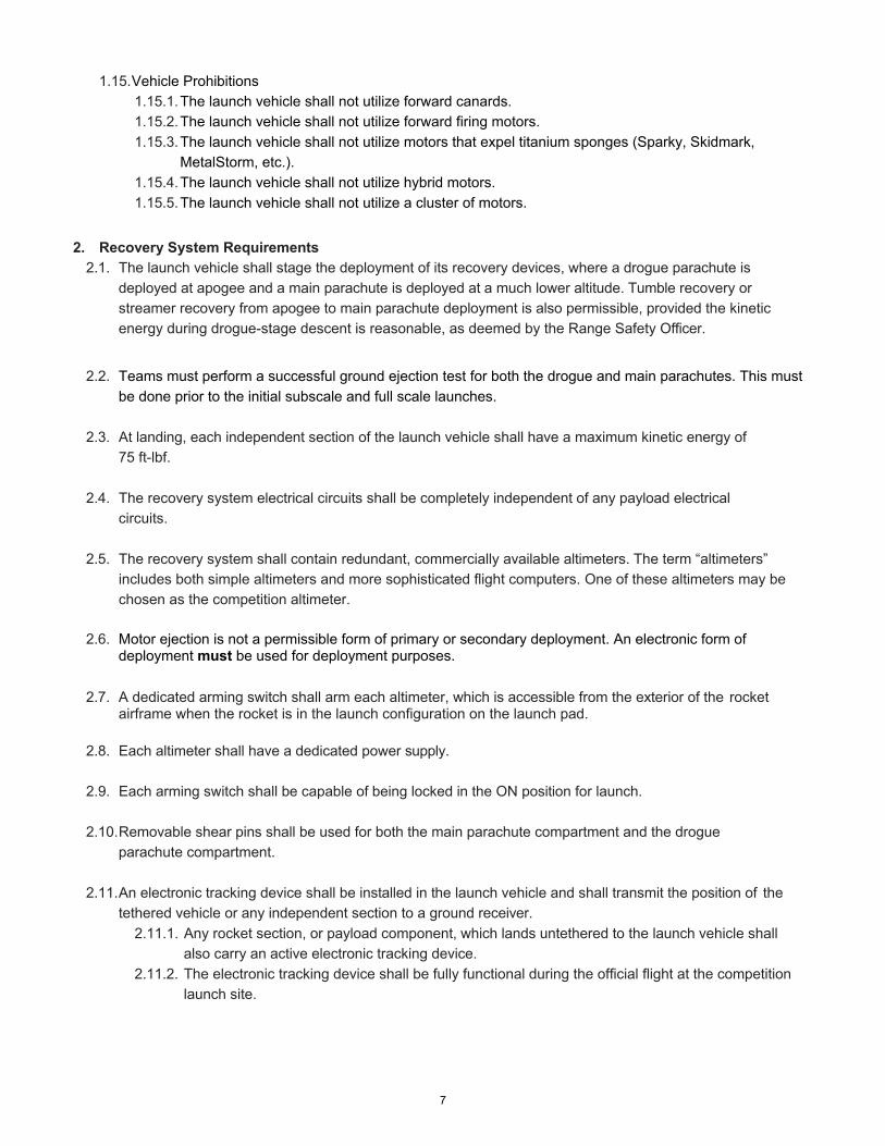


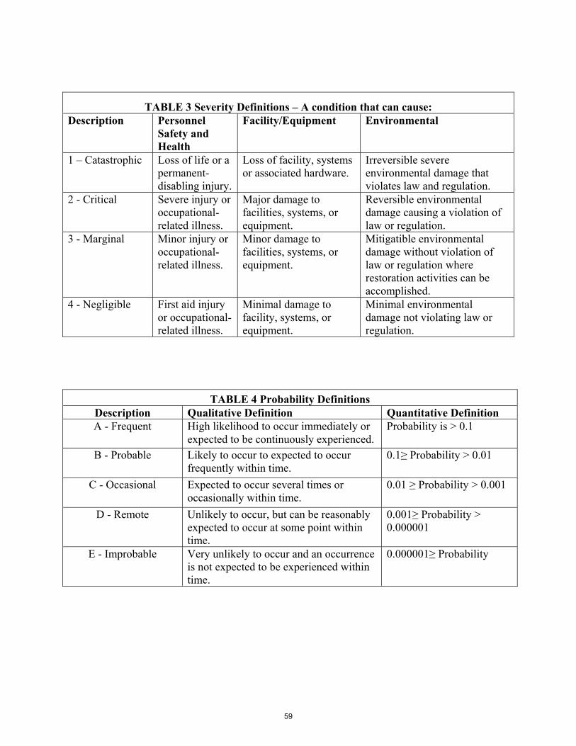


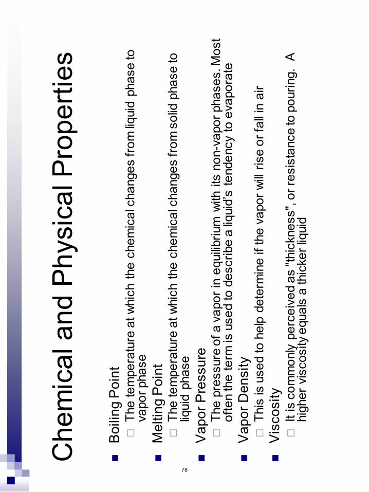


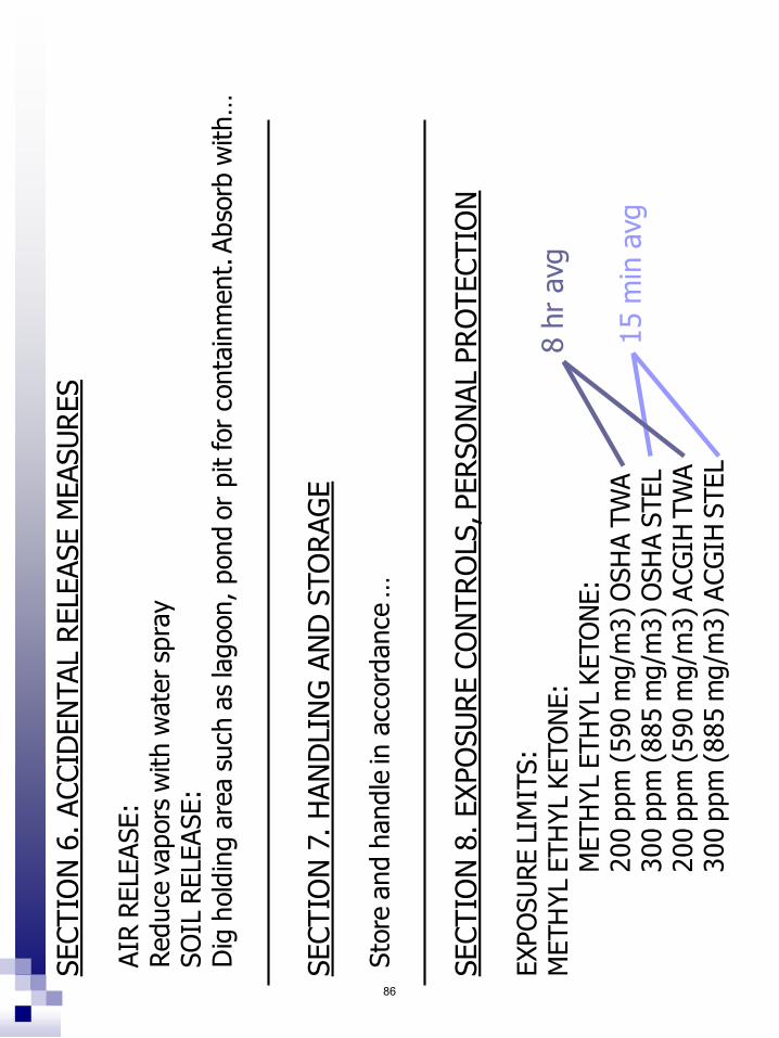


Related Documents