Warning about the use of Bosch products for Motorsport applications D 3 Oxygen Sensor T ype Code LSM 11 D 4 Oxyg en Sensor T ype Code LSU 4 D 8 History and Evolution The Modern Oxygen Sensor A 2 Bosch Oxygen Sensor Design T ypes A 3 T esting and S ervicing Procedures What is Lambda? A 6 Oxygen Sensor Construction and Operation [ Conventional Design incl. LSM 11 ] A 7 Oxygen Sensor Construction and Operation [ Broadband Design LSU 4 ] A 9 Oxygen Sensor - System Applications A 10 T esting of Oxygen Sensors A 11 Causes & Effects of Oxygen Sensor Failure A 12 Universal Oxygen Sensor Program Program Overview A 13 Cross Reference Direct Fit to Universal Sensor [ Incl. T est & Replace intervals ] A 14 Universal Sensor Installation Instructions A 28 A 1 Whilst every care has been taken in th e preparation of this public ation, Bosc h does not warrant the accuracy or completeness of the information in this publication and Bosch reserves the right to alter specific ations without notice. T o the extent permitted by law, Bosch excludes all liabilit y including neglige nce for any loss incurre d in relianc e on the cont ents of this public ation Product Information Direct Fit & Universal Sensors B 2 Sensor Images C 1 Wiring Harness Repair Components C37 Product Technical Information Motorsport and Industrial Applications Application

Welcome message from author
This document is posted to help you gain knowledge. Please leave a comment to let me know what you think about it! Share it to your friends and learn new things together.
Transcript

8/12/2019 Sonde Lambda Bosch
http://slidepdf.com/reader/full/sonde-lambda-bosch 1/31
Warning about the use of Bosch products forMotorsport applications D 3
Oxygen Sensor Type Code LSM 11 D 4
Oxygen Sensor Type Code LSU 4 D 8
History and Evolution
The Modern Oxygen Sensor A 2
Bosch Oxygen Sensor Design Types A 3
Testing and Servicing Procedures
What is Lambda? A 6
Oxygen Sensor Construction and Operation
[ Conventional Design incl. LSM 11 ] A 7
Oxygen Sensor Construction and Operation[ Broadband Design LSU 4 ] A 9
Oxygen Sensor - System Applications A 10
Testing of Oxygen Sensors A 11
Causes & Effects of Oxygen Sensor Failure A 12
Universal Oxygen Sensor Program
Program Overview A 13
Cross Reference Direct Fit to Universal Sensor
[ Incl. Test & Replace intervals ] A 14
Universal Sensor Installation Instructions A 28
A 1
Whilst every care has been taken in the preparation of this publication, Boschdoes not warrant the accuracy or completeness of the information in this publicationand Bosch reserves the right to alter specifications without notice.
To the extent permitted by law, Bosch excludes all liability including negligencefor anyloss incurred in reliance on the contents of this publication
Product Information
Direct Fit & Universal Sensors B 2
Sensor Images C 1
Wiring Harness Repair Components C37
Product Technical Information
Motorsport and Industrial Applications
Application

8/12/2019 Sonde Lambda Bosch
http://slidepdf.com/reader/full/sonde-lambda-bosch 2/31
A 2
The Modern Oxygen Sensor
Bosch pioneered the invention of the Oxygen Sensor in the early 1970’s drawing upon experience in the technology of high temperatureceramics developed from many years of spark plug development.The Oxygen Sensor’s first vehicle application came in 1976 used on aK-Jetronic equipped Volvo 260 Series for the Californian market.This was the start of one of the most widely used emission controldevices in automotive history.
Since then, Bosch has produced over 300 million Oxygen Sensorsworldwide, supplying the majority of global vehicle manufacturers.Currently Bosch produces approximately 30 million Oxygen Sensorsper year in plants located in Germany and the USA.
As a major worldwide developer of automotive technology, Bosch hascontinually improved the design and function of the engine management
systems we produce to optimise Oxygen Sensor functionality andconstantly improve vehicle exhaust emissions whilst improving overallvehicle performance.
Evolution of the sensor over the years has resulted in many designimprovements in both operation and replacement intervals. Startingas a simple single wire sensor, developments include the introduction of improved earth circuits, heating elements to stabilise sensor temperatureand now “planar” design sensors delivering superior sensitivity andaccuracy as well improved service life.
Vehicle emissions are a major factor in the design of new vehicles.Bosch research and development in the area of engine managementsystem and product technology has seen the introduction of “Broad-band” Oxygen Sensors, providing increased scope of operation of the
Oxygen Sensor for control of mixture values outside of the normalcontrol range. Future Bosch developments include the use of OxygenSensors in electronic diesel control [EDC] systems and “fuel quality”sensors, able to detect varying fuel qualities and their effect on thecombustion process.

8/12/2019 Sonde Lambda Bosch
http://slidepdf.com/reader/full/sonde-lambda-bosch 3/31
A 3
Bosch Oxygen Sensor Design Types
In the process of constant product improvement, Bosch has createdmany different oxygen sensor design types to meet the various re-quirements of our OE customers. As global emission legislation hasbecome increasingly important in engine management system design,we have produced oxygen sensors with higher accuracy, faster lightoff times and superior service life.
Thimble Type Sensors (Type Code LS, LSH, LSM 11)So called due to the design of the ceramic sensor element used. Thesesensors can be constructed in various formats from simple singlewire sensors to heated four wire sensors with either ground isolatedor grounded cases. Using a patented “Platinum Grid” design thimblethese sensors are manufactured in the following formats:
Single Wire Sensor - the original design, sensor output voltage via
the single pole connector, grounded via the sensor body.
Two Wire Sensor - for improved earth reference of sensor output sig-nal, a reference wire is also connected between control unit and sen-sor.
Three Wire Sensor - heated sensors provide various advantages in-cluding,
Earlier cut-in for closed loop operation Lower emissions with new and aged sensors Lower sensor deterioration caused by thermal stress Extended service life (from ~ 50,000km to 80,000km +) More accurate fuel management system calibration Greater flexibility in sensor location
Bosch manufactures heated sensors with either 12 or 18 watt ratings
for correct sensor operation during warm up and the complete vehicledrive cycle.
Note: Use of a sensor with an incorrect heating element rating will re-sult in overheating of the sensor measuring element causing thethimble to fracture.Four Wire Sensor - heated sensor with integrated earth
reference/supply circuit, these sensors may be either groundedthrough the body or earth isolated depending upon engine managementsystem design and customer requirement. Earth isolated sensors areprovided with an earthing circuit for the measuring cell by the enginemanagement control unit. The engine management control unitpurely references the earth of a sensor that has its body grounded.
Note: mis-matching of body ground/isolated sensors can result in thesignal earth being open circuit causing the sensor signal to not berecognised by the engine management control unit.
LSM 11 “Wideband” Sensor - where the standard sensors describedabove are “narrow band” or “two step” sensors that purely cycle when
the Lambda value of 1 is achieved, the LSM 11 sensor has a “wideband” operating characteristic. The LSM 11 sensor has a flatter operatingcurve than a standard sensor allowing it to measure lambda values of between ~ 0.80 and ~ 1.60.
Planar Type Sensors (Type Code LSF, LSU)
Improved designed sensor using “Planar” or thick film manufacturingtechnology. These are heated four wire sensors and whilst operatingon the same principle as the thimble type sensors, the planar designprovides a more effective heater design, more robust construction,faster switching time and superior service life.
Typical Heated Sensor1 = Sensor housing2 = Ceramic support tube3 = Electrical connections4 = Protective with slots5 = Active sensor ceramic6 = Contact element7 = Protective sleeve8 = Heating element
9 = Clamp type connections for heating element
Planar Type Sensor1 = Guard Tube2 = Ceramic seal assembly 3 = Sensor housing4 = Ceramic support tube5 = Planar sensor element6 = Protective cap7 = Connection cable
8/12/2019 Sonde Lambda Bosch
http://slidepdf.com/reader/full/sonde-lambda-bosch 4/31
A 4
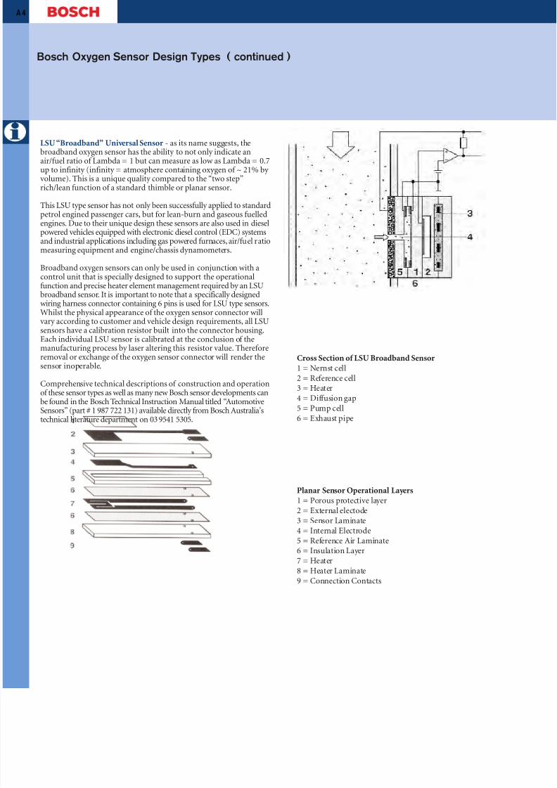
LSU “Broadband” Universal Sensor - as its name suggests, thebroadband oxygen sensor has the ability to not only indicate anair/fuel ratio of Lambda = 1 but can measure as low as Lambda = 0.7up to infinity (infinity = atmosphere containing oxygen of ~ 21% by volume). This is a unique quality compared to the “two step”rich/lean function of a standard thimble or planar sensor.
This LSU type sensor has not only been successfully applied to standardpetrol engined passenger cars, but for lean-burn and gaseous fuelledengines. Due to their unique design these sensors are also used in dieselpowered vehicles equipped with electronic diesel control (EDC) systemsand industrial applications including gas powered furnaces, air/fuel ratiomeasuring equipment and engine/chassis dynamometers.
Broadband oxygen sensors can only be used in conjunction with a
control unit that is specially designed to support the operationalfunction and precise heater element management required by an LSUbroadband sensor. It is important to note that a specifically designedwiring harness connector containing 6 pins is used for LSU type sensors.Whilst the physical appearance of the oxygen sensor connector willvary according to customer and vehicle design requirements, all LSUsensors have a calibration resistor built into the connector housing.Each individual LSU sensor is calibrated at the conclusion of themanufacturing process by laser altering this resistor value. Thereforeremoval or exchange of the oxygen sensor connector will render thesensor inoperable.
Comprehensive technical descriptions of construction and operationof these sensor types as well as many new Bosch sensor developments canbe found in the Bosch Technical Instruction Manual titled “Automotive
Sensors” (part # 1 987 722 131) available directly from Bosch Australia’stechnical literature department on 03 9541 5305.
Cross Section of LSU Broadband Sensor1 = Nernst cell2 = Reference cell3 = Heater4 = Diffusion gap5 = Pump cell6 = Exhaust pipe
Planar Sensor Operational Layers1 = Porous protective layer2 = External electode3 = Sensor Laminate4 = Internal Electrode5 = Reference Air Laminate
6 = Insulation Layer7 = Heater8 = Heater Laminate9 = Connection Contacts
Bosch Oxygen Sensor Design Types ( continued )

8/12/2019 Sonde Lambda Bosch
http://slidepdf.com/reader/full/sonde-lambda-bosch 5/31

8/12/2019 Sonde Lambda Bosch
http://slidepdf.com/reader/full/sonde-lambda-bosch 6/31
A 6
What is Lambda?
Lambda is a mathematical calculation representing air/fuel ratio. Thefigure is derived by dividing the actual air/fuel ratio of the engine by the theoretically correct value [14.7:1].
Rich mixtures produce Lambda values that are less than one, leanermixtures are higher than one.
Lambda is a compromise between power [lambda < 1] and economy [lambda > 1] as shown on the diagram below.
8/12/2019 Sonde Lambda Bosch
http://slidepdf.com/reader/full/sonde-lambda-bosch 7/31
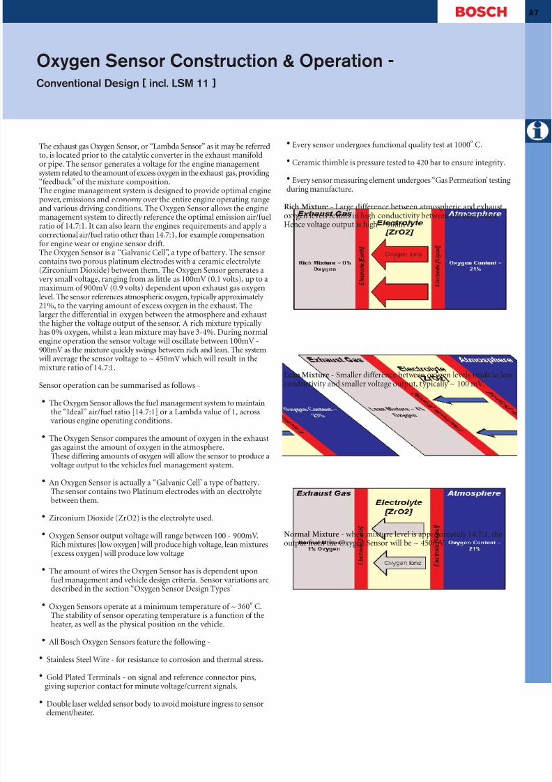
The exhaust gas Oxygen Sensor, or “Lambda Sensor” as it may be referredto, is located prior to the catalytic converter in the exhaust manifoldor pipe. The sensor generates a voltage for the engine managementsystem related to the amount of excess oxygen in the exhaust gas, providing“feedback” of the mixture composition.The engine management system is designed to provide optimal enginepower, emissions and economy over the entire engine operating rangeand various driving conditions. The Oxygen Sensor allows the enginemanagement system to directly reference the optimal emission air/fuelratio of 14.7:1. It can also learn the engines requirements and apply acorrectional air/fuel ratio other than 14.7:1, for example compensationfor engine wear or engine sensor drift.The Oxygen Sensor is a “Galvanic Cell”, a type of battery. The sensorcontains two porous platinum electrodes with a ceramic electrolyte
(Zirconium Dioxide) between them. The Oxygen Sensor generates avery small voltage, ranging from as little as 100mV (0.1 volts), up to amaximum of 900mV (0.9 volts) dependent upon exhaust gas oxygenlevel. The sensor references atmospheric oxygen, typically approximately 21%, to the varying amount of excess oxygen in the exhaust. Thelarger the differential in oxygen between the atmosphere and exhaustthe higher the voltage output of the sensor. A rich mixture typically has 0% oxygen, whilst a lean mixture may have 3-4%. During normalengine operation the sensor voltage will oscillate between 100mV -900mV as the mixture quickly swings between rich and lean. The systemwill average the sensor voltage to ~ 450mV which will result in themixture ratio of 14.7:1.
Sensor operation can be summarised as follows -
• The Oxygen Sensor allows the fuel management system to maintain
the “Ideal” air/fuel ratio [14.7:1] or a Lambda value of 1, acrossvarious engine operating conditions.
• The Oxygen Sensor compares the amount of oxygen in the exhaustgas against the amount of oxygen in the atmosphere.These differing amounts of oxygen will allow the sensor to produce avoltage output to the vehicles fuel management system.
• An Oxygen Sensor is actually a “Galvanic Cell’ a type of battery.The sensor contains two Platinum electrodes with an electrolytebetween them.
• Zirconium Dioxide (ZrO2) is the electrolyte used.
• Oxygen Sensor output voltage will range between 100 - 900mV.
Rich mixtures [low oxygen] will produce high voltage, lean mixtures[excess oxygen] will produce low voltage
• The amount of wires the Oxygen Sensor has is dependent uponfuel management and vehicle design criteria. Sensor variations aredescribed in the section “Oxygen Sensor Design Types’
• Oxygen Sensors operate at a minimum temperature of ~ 360º C.The stability of sensor operating temperature is a function of theheater, as well as the physical position on the vehicle.
• All Bosch Oxygen Sensors feature the following -
• Stainless Steel Wire - for resistance to corrosion and thermal stress.
• Gold Plated Terminals - on signal and reference connector pins,
giving superior contact for minute voltage/current signals.
• Double laser welded sensor body to avoid moisture ingress to sensorelement/heater.
A 7
Oxygen Sensor Construction & Operation -Conventional Design [ incl. LSM 11 ]
• Every sensor undergoes functional quality test at 1000º C.
• Ceramic thimble is pressure tested to 420 bar to ensure integrity.
• Every sensor measuring element undergoes “Gas Permeation’ testingduring manufacture.
Rich Mixture - Large difference between atmospheric and exhaustoxygen levels results in high conductivity between the electrodes.Hence voltage output is high ~ 900mV.
Lean Mixture - Smaller difference between oxygen levels result in lessconductivity and smaller voltage output, typically ~ 100 mV.
Normal Mixture - when mixture level is approximately 14.7:1, theoutput from the Oxygen Sensor will be ~ 450mV.

8/12/2019 Sonde Lambda Bosch
http://slidepdf.com/reader/full/sonde-lambda-bosch 8/31
A 8
Oxygen Sensor Voltage Output
Normal Sensor - Voltage “cycles” between 100 & 900 mV as the ECUsenses rich & lean and alternates the mixture accordingly. The averageoutput from the Oxygen Sensor will be ~ 450mV.
Oxygen Sensor Construction & Operation -
Conventional Design [ incl. LSM 11 ] ( continued )

8/12/2019 Sonde Lambda Bosch
http://slidepdf.com/reader/full/sonde-lambda-bosch 9/31
A 9
Whilst it is beyond the scope of this catalogue to fully explain theoperating principle and system support requirements of the “Broad-band” LSU series sensor, we can provide an overview of it’s basic designprinciple.Essentially in order to allow an infinite range of air/fuel ratio values(only as low as Lambda 0.7), the LSU sensor has two basic elements.Firstly it consists of a standard “Nernst” oxygen ion measuring cellthat would be found in any standard planar or thimble type oxygensensor. In order to be able to effect a much extended measuring range,an oxygen ion “pump” or pumping cell is also integrated into the sensor.This pump is controlled by a signal from the engine managementECU. The ECU will control the pump to maintain a constant signalfrom the conventional oxygen sensor cell, the amount of bias requiredto achieve this allows the ECU to determine how far rich or lean themixture is from the emission optimal value of 14.7:1.
A comprehensive understanding of the operation of the LSU typeoxygen sensor is essential for correct diagnosis. Comprehensive technicaldescriptions of the construction and operation of these sensor typescan be found in the Bosch Technical Instruction Manual titled “AutomotiveSensors” (part # 1 987 722 131) available directly from Bosch Australia’stechnical literature department on 03 9541 5305. Further practicaltesting and operational information can be obtained from the Bosch“Lambda Diagnosis” Training Course. Further information aboutBosch Workshop Training including course topics, schedule dates andlocations can be requested from Bosch Australia on 03 9541 5553.
Oxygen Sensor Construction & Operation[Broadband Design LSU 4]

8/12/2019 Sonde Lambda Bosch
http://slidepdf.com/reader/full/sonde-lambda-bosch 10/31
Oxygen Sensors - System ApplicationsWhy are there sensors before & after the catalytic converter?
Since the introduction of ADR 36 in 1986 requiring all new passenger vehicles to operate on unleaded fuel in Australia, we have seen constantimprovement and evolution of engine management systems. This major change also saw the introduction and broad use of Oxygen Sensors andCatalytic Converters in our market. Starting with fairly simple applications using one single wire sensor in the exhaust manifold, over the yearswe have seen the implementation of multiple sensors for “V” configuration engines providing more efficient air/fuel ratio control and diagnosticcapabilities.
In recent years in Australia, we have seen a rapid increase of vehicles on our roads using pre and post catalytic converter oxygen sensors. These arereferred to in this catalogue as Control (pre catalyst) and Diagnosis (post catalyst) oxygen sensors. The requirement for controlling the combustionprocess is now only one of the functions of the engine management system. Modern systems also control and monitor the operation of the vehicles’catalytic converter. With the fitment of sensors after the catalyst, the efficiency of the catalytic converter can now be evaluated and various enginecontrol strategies can be employed to reduce harmful exhaust emissions throughout various driving and engine operating conditions.
Diagnosis Sensor Operating Characteristics.Whilst the diagnosis sensor is often of the same design family as the conventional Control Sensor, sensor activity is quite different to whatwould be expected of a correctly operating pre-catalyst sensor. As shown below, the output signal from the diagnosis sensor is generally a flatoutput signal of approximately 500mV, this is in contrast to the control sensor normal activity as shown.
Further detailed information about oxygen sensors, including diagnosis sensor operation and catalytic converter technology, can be obtainedfrom the Bosch “Lambda Diagnosis” Training Course. Further information about the range of Bosch Workshop Training Programs includingcourse topics, schedule dates and locations can be requested from Bosch Australia on 9541 5553.
Diagnosis Sensor voltage output - typical Control Sensor voltage output - typical
10

8/12/2019 Sonde Lambda Bosch
http://slidepdf.com/reader/full/sonde-lambda-bosch 11/31
A 11
Testing of Oxygen Sensors
Conventional Design [incl. LSM11]
Whilst the physical appearance and design principle of the modern oxygen sensor has improved and changed over the years, the testing proceduresused to diagnose a faulty sensor have remained simple.The information here is a simple guide only and does not replace any technical service procedures quoted by a vehicle manufacturer. Testing of theoxygen sensor should be made after all basic system checks have been carried out, including testing of the fuel system pressure and performing allminor service adjustments and checks as recommended by the vehicle manufacturer.As previously mentioned the oxygen sensor will only operate correctly once it’s temperature is above ~ 360°C, so the engine should be fully warmed up prior to testing.Preferred method of testing is to utilise an automotive oscilloscope, however a good quality Digital Multimeter (DMM) with an analog bargraph function can indicate basic operation. Testing should be done in conjunction with a good quality gas analyser capable of Lambda orair/fuel ratio measurement to accurately determine sensor calibration as well as function.
Simplified Test Procedure
Locate the oxygen sensor and determine the wiring layout. On heated sensors check for heater element continuity, adequate 12 volt supply to
heater and correct ground when the engine is running.Note - Many late model vehicles have the ground circuit of the oxygen sensor heating element controlled by the engine management ECU forsensor temperature control purposes. Do not supply direct voltage or external ground to these circuits.With engine speed at ~ 2000 RPM the sensor voltage should be seen to cycle smoothly between 100 – 900 mV (0.1 – 0.9 Volts) approximately eight times or more every ten seconds as shown.A contaminated or tired sensor will be slow to cycle between the sensor voltage limits and may not generate the full potential of 900 mV. It may also be noticed that the lean swing may drop to zero voltage.
Remember!! – The oxygen sensor is a battery, a sensor that generates 900 mV constantly is generally not faulty. Faulty sensors, like a failing battery,will be slow to cycle between the control limits and be generally slower to react to mixture changes.
Broadband Design [LSU4]
Testing of LSU type Broadband sensors should be done in conjunction with the vehicles diagnostic system. Engine Management systems usingBroadband oxygen sensors have a vast array of integrated diagnostic and analytical software to determine the accuracy and performance of theLSU 4 type sensor. Physical checks of the sensor with either oscilloscope or multimeter will reveal little in relation to the sensors operation
without specialist knowledge.It should be noted that apart from monitoring the sensor output related to exhaust gas oxygen levels, the ECU also controls sensor temperaturevia a sophisticated closed loop control circuit. The physical measuring of this circuit will only prove the ECU control circuit is functioning; it isnot possible to determine sensor temperature values or other heater control strategies.
Bosch recommends that the oxygen sensor is tested and replaced as a part of a regular vehicle maintenance schedule. Suggested replacement intervalsfor oxygen sensors are listed in the vehicle application section of this catalogue. A numerical listing can also be found on page A14.Correct testing procedures are essential for accurate diagnosis of the oxygen sensor, particularly when dealing with modern LSU type sensors.The Bosch “Lambda Diagnosis” training course not only provides comprehensive practical training on the operation of the various oxygen sensordesign types and system formats, but also covers the correct testing procedures required for their diagnosis.Replacement of a faulty oxygen sensor will restore vehicle performance, improve fuel economy and reduce harmful exhaust emissions.

8/12/2019 Sonde Lambda Bosch
http://slidepdf.com/reader/full/sonde-lambda-bosch 12/31
Causes & Effects of Oxygen Sensor Failure
12
Whilst there are many factors that will contribute to accelerated oxygensensor failure, it should be remembered that an oxygen sensor is awearing part with a specific service life not unlike a platinum spark plug. The oxygen sensor should have a service life ranging from 50,000Km - 160,000 Km dependant on sensor design, however this can bedramatically reduced by various conditions including overheating of the sensor, chemical poisoning and impact damage.Excluding physical damage, the majority of these conditions will resultin the failure of the ceramic thimble by affecting its porous nature.This will result in a sensor that is slow to react to mixture change asshown below. A slow sensor will tend to make the air / fuel ratio of thevehicle drift rich.
Sensor Voltage OutputNormal Sensor - Voltage “cycles” between 100 & 900 mV. The averageoutput from the Oxygen Sensor will be ~ 450mV.
Slow, Contaminated or “Tired’ SensorVoltage slowly builds up and then rapidly drops off. The effect is thatthe average will drop causing a rich condition.
Important facts about Oxygen Sensors.
Oxygen Sensor life spans will vary between vehicle and sensor designs,and are effected by many factors including fuel quality and vehicleoperational characteristics.
Oxygen Sensors should be checked and/or replaced at -50,000 km for single and two wire sensors.80,000 km for three or four wire heated sensors.160,000 km for planar type sensors
Oxygen Sensors can be contaminated in many ways including -Lead fouling from incorrect fuel.Severe carbon/oil fouling from engine/emission control defects.
Contamination from silicon products.
Thermal stress damage [fracturing of the ceramic thimble] fromexcessive water in the exhaust, ie- blown head gasket.
Contamination of the Oxygen Sensor basically results in the coatingof the platinum electrodes and therefore insulates them.**NOTE** - Oxygen Sensors cannot be cleaned!!
Oxygen Sensors will die of “old age”, they are a wearing servicepart like a platinum spark plug.
As the Oxygen Sensor deteriorates over time, or is contaminatedthe output from the sensor “slows down”. This causes the “average”that the fuel management system calculates to reduce.
The lower average gives the impression that the engine is lean andthe fuel management system overcompensates to rich.
Due to the fact that the engine will operate in a rich condition atall times, fuel consumption is naturally higher.

8/12/2019 Sonde Lambda Bosch
http://slidepdf.com/reader/full/sonde-lambda-bosch 13/31
A 13
To further complement and enhance our Oxygen Sensor program, a“Universal” range of oxygen sensors is now offered by Bosch. Drawingfrom many years of engineering experience as an OE supplier andglobal manufacturer of oxygen sensors, a consolidated range of universalsensors are available that fully comply to the technical specificationsof the original sensor fitted to the vehicle.Bosch Universal Oxygen Sensors are correctly OE matched by ourengineering and development teams to ensure they meet or exceedthe original design standard. All sensors are designed and built to thelatest OE design types ensuring renowned Bosch quality, and completeconfidence in application.All sensors feature stainless steel wiring, double laser welded body andlatest design protection tubes. Connection is easy and reliable as allBosch 3 & 4 wire universal sensors are supplied with a patented “Posi-Lock”
weather-tight connector.The Bosch Universal Oxygen Sensor program consists of the followingrange of sensors,
Single Wire Sensors
0 258 986 501 – Standard single wire sensor with “bullet” style connection.
0 258 002 031 – Single wire sensor with “bullet” style connection, suppliedwith removable “flange” type mounting (54 mm pitch).
Two Wire Sensor
0 258 002 210 – Two wire sensor with “bullet” style connections, suppliedwith removable “flange” type mounting (54 mm pitch).Sensor can be used without mounting flange.
Three Wire Sensors
0 258 986 502 - Three wire sensor with 12 watt heater and grounded case.
0 258 986 504 - Three wire sensor with 18 watt heater and grounded case.
Four Wire Sensors
0 258 005 728 - Four wire sensor with “flange” type mounting.
0 258 005 732 - Four wire sensor with 12 watt heater, grounded case andspecial protection tube.
0 258 986 503 - Four wire sensor with 18 watt heater and grounded case.
0 258 986 505 - Four wire sensor with 18 watt heater and ground isolatedcase.
0 258 986 506 - Four wire sensor with 12 watt heater and grounded case.
0 258 986 507 - Four wire sensor with 12 watt heater and ground isolatedcase.
0 258 986 602 - Four wire “Planar” construction sensor.
0 258 986 617 - Four wire “Planar” construction sensor with “flange” typemounting.
Universal Oxygen Sensor Program Overview

8/12/2019 Sonde Lambda Bosch
http://slidepdf.com/reader/full/sonde-lambda-bosch 14/31
14
0 258 001 025 0 258 986 501 1 50,0000 258 001 026 0 258 986 501 1 50,0000 258 001 027 0 258 986 501 1 50,0000 258 001 028 0 258 986 501 1 50,0000 258 001 030 0 258 986 501 1 50,0000 258 001 031 0 258 986 501 1 50,0000 258 001 032 0 258 986 501 1 50,0000 258 001 035 0 258 986 501 1 50,0000 258 001 037 0 258 986 501 1 50,0000 258 001 038 0 258 986 501 1 50,000
0 258 001 039 0 258 986 501 1 50,0000 258 001 040 0 258 986 501 1 50,0000 258 001 041 0 258 986 501 1 50,0000 258 001 042 0 258 986 501 1 50,0000 258 001 047 0 258 986 501 1 50,0000 258 001 051 0 258 986 501 1 50,0000 258 001 052 0 258 986 501 1 50,0000 258 001 064 0 258 986 501 1 50,0000 258 001 097 0 258 986 501 1 50,0000 258 001 248 0 258 986 501 1 50,0000 258 001 929 0 258 986 501 1 50,0000 258 001 960 0 258 986 501 1 50,0000 258 001 961 0 258 986 501 1 50,0000 258 001 962 0 258 986 501 1 50,000
0 258 001 963 0 258 986 501 1 50,0000 258 001 964 0 258 986 501 1 50,0000 258 002 008 0 258 986 501 1 50,0000 258 002 009 0 258 986 501 1 50,0000 258 002 012 0 258 986 501 1 50,0000 258 002 014 0 258 986 501 1 50,0000 258 002 015 0 258 986 501 1 50,0000 258 002 017 0 258 986 501 1 50,0000 258 002 018 0 258 986 501 1 50,0000 258 002 020 0 258 986 501 1 50,0000 258 002 021 0 258 986 501 1 50,0000 258 002 022 0 258 986 501 1 50,0000 258 002 023 0 258 986 501 1 50,0000 258 002 024 0 258 986 501 1 50,000
0 258 002 025 0 258 986 501 1 50,0000 258 002 026 0 258 986 501 1 50,0000 258 002 027 0 258 986 501 1 50,0000 258 002 028 — 2 50,000
- 80,0000 258 002 029 0 258 986 501 1 50,0000 258 002 030 0 258 986 501 1 50,0000 258 002 031 0 258 002 031 1 50,0000 258 002 032 0 258 986 501 1 50,0000 258 002 033 0 258 986 501 1 50,0000 258 002 034 0 258 986 501 1 50,0000 258 002 035 0 258 986 501 1 50,0000 258 002 036 0 258 986 501 1 50,0000 258 002 038 0 258 986 501 1 50,0000 258 002 039 0 258 986 501 1 50,0000 258 002 040 0 258 986 501 1 50,0000 258 002 041 0 258 986 501 1 50,0000 258 002 042 0 258 986 501 1 50,0000 258 002 044 0 258 986 501 1 50,0000 258 002 045 0 258 986 501 1 50,000
0 258 002 046 0 258 986 501 1 50,0000 258 002 047 0 258 986 501 1 50,0000 258 002 049 0 258 986 501 1 50,0000 258 002 050 0 258 986 501 1 50,0000 258 002 051 0 258 002 031 1 50,0000 258 002 052 0 258 986 501 1 50,0000 258 002 053 0 258 986 501 1 50,0000 258 002 054 0 258 986 501 1 50,0000 258 002 055 0 258 986 501 1 50,0000 258 002 056 0 258 986 501 1 50,000
0 258 002 057 0 258 986 501 1 50,0000 258 002 058 0 258 986 501 1 50,0000 258 002 111 0 258 986 501 1 50,0000 258 002 201 0 258 002 210 2 50,0000 258 002 210 — 2 50,0000 258 002 908 0 258 986 501 1 50,0000 258 002 909 0 258 986 501 1 50,0000 258 002 919 0 258 986 501 1 50,0000 258 003 001 0 258 986 502 3 100,0000 258 003 002 0 258 986 502 3 100,0000 258 003 003 0 258 986 502 3 100,0000 258 003 004 0 258 003 957 0 258 986 502 3 100,0000 258 003 005 0 258 986 502 3 100,0000 258 003 006 0 258 003 957 0 258 986 502 3 100,000
0 258 003 008 0 258 986 502 3 100,0000 258 003 009 0 258 003 957 0 258 986 502 3 100,0000 258 003 010 0 258 986 502 3 100,0000 258 003 011 0 258 986 502 3 100,0000 258 003 012 0 258 986 502 3 100,0000 258 003 013 0 258 003 957 0 258 986 502 3 100,0000 258 003 014 0 258 003 957 0 258 986 502 3 100,0000 258 003 015 0 258 986 502 3 100,0000 258 003 016 0 258 986 502 3 100,0000 258 003 017 0 258 003 300 0 258 986 502 3 100,0000 258 003 018 0 258 986 502 3 100,0000 258 003 019 0 258 003 957 0 258 986 502 3 100,0000 258 003 020 0 258 003 060 0 258 986 502 3 100,0000 258 003 021 0 258 986 502 3 100,000
0 258 003 022 0 258 986 502 3 100,0000 258 003 023 0 258 986 502 3 100,0000 258 003 024 0 258 986 502 3 100,0000 258 003 025 0 258 986 502 3 100,0000 258 003 026 0 258 986 502 3 100,0000 258 003 027 0 258 003 060 0 258 986 502 3 100,0000 258 003 028 0 258 003 957 0 258 986 502 3 100,0000 258 003 030 0 258 986 502 3 100,0000 258 003 031 0 258 986 502 3 100,0000 258 003 032 0 258 003 957 0 258 986 502 3 100,0000 258 003 033 0 258 986 502 3 100,0000 258 003 034 0 258 986 504 3 100,0000 258 003 035 0 258 003 097 0 258 986 502 3 100,0000 258 003 036 0 258 986 502 3 100,0000 258 003 037 0 258 986 506 4 100,0000 258 003 038 0 258 986 503 4 100,0000 258 003 039 0 258 986 502 3 100,0000 258 003 040 0 258 003 957 0 258 986 502 3 100,0000 258 003 041 0 258 986 502 3 100,0000 258 003 042 F 00H L00 053 0 258 986 502 3 100,000
CheckOriginal Direct Fit Universal No. IntervalSensor Supersession Sensor of wires Km’s
CheckOriginal Direct Fit Universal No. IntervalSensor Supersession Sensor of wires Km’s
Cross Reference Direct Fit to Universal SensorIncluding Test and Replace Intervals

8/12/2019 Sonde Lambda Bosch
http://slidepdf.com/reader/full/sonde-lambda-bosch 15/31
CheckOriginal Direct Fit Universal No. IntervalSensor Supersession Sensor of wires Km’s
A 15
0 258 003 043 0 258 986 502 3 100,0000 258 003 044 0 258 986 502 3 100,0000 258 003 045 0 258 986 503 4 100,0000 258 003 046 0 258 986 502 3 100,0000 258 003 047 0 258 986 502 3 100,0000 258 003 048 0 258 986 502 3 100,0000 258 003 049 0 258 986 502 3 100,0000 258 003 050 0 258 003 950 0 258 986 502 3 100,0000 258 003 051 0 258 986 506 4 100,0000 258 003 052 0 258 005 313 0 258 986 506 4 100,000
0 258 003 054 0 258 986 502 3 100,0000 258 003 056 0 258 986 502 3 100,0000 258 003 057 0 258 003 957 0 258 986 502 3 100,0000 258 003 059 0 258 986 502 3 100,0000 258 003 060 0 258 986 502 3 100,0000 258 003 061 0 258 003 957 0 258 986 502 3 100,0000 258 003 062 0 258 986 503 4 100,0000 258 003 063 0 258 003 957 0 258 986 502 3 100,0000 258 003 064 0 258 005 324 0 258 986 503 4 160,0000 258 003 065 0 258 986 504 3 100,0000 258 003 067 0 258 005 325 0 258 986 503 4 100,0000 258 003 068 0 258 986 503 4 100,0000 258 003 069 0 258 005 325 0 258 986 503 4 100,0000 258 003 070 0 258 003 970 — 3 50,000
- 80,0000 258 003 072 0 258 986 502 3 100,0000 258 003 073 0 258 986 502 3 100,0000 258 003 074 0 258 986 506 4 100,0000 258 003 075 0 258 003 957 0 258 986 502 3 100,0000 258 003 077 0 258 003 189 0 258 986 502 3 100,0000 258 003 078 0 258 986 506 4 100,0000 258 003 079 0 258 986 504 3 100,0000 258 003 080 0 258 986 502 3 100,0000 258 003 081 0 258 003 189 0 258 986 502 3 100,0000 258 003 082 0 258 986 502 3 100,0000 258 003 083 0 258 003 995 0 258 986 504 3 50,000
- 80,0000 258 003 084 0 258 003 924 0 258 986 502 3 100,000
0 258 003 085 0 258 003 995 0 258 986 504 3 100,0000 258 003 086 0 258 003 189 0 258 986 502 3 100,0000 258 003 087 0 258 986 506 4 100,0000 258 003 088 0 258 986 503 4 100,0000 258 003 090 0 258 003 957 0 258 986 502 3 100,0000 258 003 091 — 3 100,0000 258 003 092 0 258 986 504 3 50,000
- 80,0000 258 003 093 0 258 986 502 3 100,0000 258 003 094 0 258 986 502 3 100,0000 258 003 095 0 258 986 504 3 100,0000 258 003 095 0 258 003 097 0 258 986 504 3 100,0000 258 003 096 0 258 986 502 3 100,0000 258 003 097 0 258 986 502 3 100,0000 258 003 099 0 258 986 502 3 100,0000 258 003 101 0 258 003 957 0 258 986 502 3 100,0000 258 003 102 0 258 986 502 3 100,0000 258 003 103 0 258 003 222 0 258 986 506 4 100,0000 258 003 104 0 258 986 502 3 100,0000 258 003 105 0 258 986 502 3 100,000
0 258 003 106 0 258 986 502 3 100,0000 258 003 107 0 258 986 503 4 100,0000 258 003 108 0 258 005 322 0 258 986 503 4 100,0000 258 003 109 0 258 986 503 4 100,0000 258 003 110 0 258 003 331 0 258 986 502 3 100,0000 258 003 112 0 258 986 502 3 100,0000 258 003 113 0 258 986 502 3 100,0000 258 003 114 0 258 986 504 3 100,0000 258 003 115 0 258 986 504 3 100,0000 258 003 116 0 258 003 171 0 258 986 504 3 50,000
- 80,0000 258 003 117 0 258 003 171 0 258 986 504 3 50,000
- 80,0000 258 003 118 0 258 986 506 4 100,0000 258 003 119 0 258 986 504 3 100,0000 258 003 120 0 258 003 222 0 258 986 506 4 100,0000 258 003 125 0 258 986 507 4 100,0000 258 003 127 0 258 986 507 4 100,0000 258 003 128 0 258 986 507 4 100,0000 258 003 129 0 258 986 507 4 100,0000 258 003 130 0 258 986 502 3 100,0000 258 003 131 0 258 986 502 3 100,0000 258 003 132 0 258 986 502 3 100,0000 258 003 133 0 258 986 502 3 100,000
0 258 003 134 0 258 986 502 3 100,0000 258 003 135 0 258 986 502 3 100,0000 258 003 136 0 258 986 502 3 100,0000 258 003 137 0 258 986 502 3 100,0000 258 003 138 0 258 986 502 3 100,0000 258 003 139 0 258 003 300 0 258 986 502 3 100,0000 258 003 140 0 258 986 502 3 100,0000 258 003 141 0 258 003 021 0 258 986 502 3 100,0000 258 003 142 0 258 986 502 3 100,0000 258 003 143 0 258 986 502 3 100,0000 258 003 144 0 258 986 504 3 100,0000 258 003 145 0 258 986 504 3 100,0000 258 003 146 0 258 986 504 3 100,0000 258 003 147 0 258 986 504 3 100,000
0 258 003 148 0 258 986 504 3 100,0000 258 003 149 0 258 986 504 3 100,0000 258 003 150 0 258 986 504 3 100,0000 258 003 151 0 258 986 504 3 100,0000 258 003 152 0 258 986 504 3 100,0000 258 003 153 0 258 986 504 3 100,0000 258 003 154 0 258 986 502 3 100,0000 258 003 155 0 258 986 502 3 100,0000 258 003 156 0 258 986 502 3 100,0000 258 003 157 0 258 986 502 3 100,0000 258 003 160 0 258 986 502 3 100,0000 258 003 161 0 258 986 502 3 100,0000 258 003 162 0 258 986 502 3 100,0000 258 003 163 0 258 986 503 4 100,0000 258 003 164 0 258 003 957 0 258 986 502 3 160,0000 258 003 165 0 258 986 502 3 100,0000 258 003 166 0 258 986 502 3 100,0000 258 003 167 0 258 003 331 0 258 986 502 3 100,0000 258 003 169 0 258 986 504 3 50,000
- 80,000
Check
Original Direct Fit Universal No. Interval
Sensor Supersession Sensor of wires Km’s

8/12/2019 Sonde Lambda Bosch
http://slidepdf.com/reader/full/sonde-lambda-bosch 16/31
16
0 258 003 170 0 258 003 169 0 258 986 504 3 50,000- 80,000
0 258 003 171 0 258 986 504 3 100,0000 258 003 172 0 258 986 504 3 100,0000 258 003 173 0 258 986 502 3 100,0000 258 003 174 0 258 986 502 3 100,0000 258 003 175 0 258 003 957 0 258 986 502 3 100,0000 258 003 177 0 258 986 507 4 100,0000 258 003 178 0 258 986 507 4 100,0000 258 003 179 0 258 003 331 0 258 986 502 3 100,000
0 258 003 181 0 258 003 331 0 258 986 502 3 100,0000 258 003 182 0 258 986 502 3 100,0000 258 003 183 0 258 986 507 4 100,0000 258 003 184 0 258 986 507 4 100,0000 258 003 186 0 258 986 507 4 100,0000 258 003 187 0 258 986 507 4 100,0000 258 003 188 0 258 986 507 4 100,0000 258 003 189 0 258 986 502 3 160,0000 258 003 190 0 258 986 502 3 100,0000 258 003 191 0 258 003 171 0 258 986 504 3 50,000
- 80,0000 258 003 192 0 258 003 171 0 258 986 504 3 50,000
- 80,0000 258 003 193 0 258 986 506 4 100,000
0 258 003 194 0 258 003 957 0 258 986 502 3 100,0000 258 003 195 0 258 003 429 0 258 986 503 4 100,0000 258 003 196 0 258 986 503 4 100,0000 258 003 197 0 258 986 503 4 100,0000 258 003 198 0 258 986 503 4 100,0000 258 003 199 0 258 003 427 0 258 986 503 4 100,0000 258 003 200 0 258 986 503 4 100,0000 258 003 201 0 258 003 189 0 258 986 502 3 100,0000 258 003 202 0 258 986 503 4 100,0000 258 003 203 0 258 986 506 4 100,0000 258 003 204 0 258 986 503 4 100,0000 258 003 206 0 258 003 957 0 258 986 502 3 100,0000 258 003 207 0 258 003 211 0 258 986 502 3 100,0000 258 003 211 0 258 986 502 3 100,000
0 258 003 212 0 258 986 502 3 100,0000 258 003 213 0 258 003 211 0 258 986 502 3 100,0000 258 003 215 0 258 005 324 0 258 986 503 4 100,0000 258 003 216 0 258 986 506 4 100,0000 258 003 217 0 258 986 506 4 100,0000 258 003 218 0 258 986 507 4 100,0000 258 003 219 0 258 005 324 0 258 986 503 4 100,0000 258 003 220 0 258 005 324 0 258 986 503 4 100,0000 258 003 222 0 258 986 506 4 160,0000 258 003 224 0 258 986 507 4 160,0000 258 003 226 0 258 986 507 4 160,0000 258 003 227 0 258 986 507 4 160,0000 258 003 228 0 258 986 507 4 160,0000 258 003 229 0 258 986 506 4 100,0000 258 003 231 0 258 005 324 0 258 986 503 4 100,0000 258 003 232 0 258 003 211 0 258 986 502 3 100,0000 258 003 233 0 258 986 502 3 100,0000 258 003 234 0 258 003 957 0 258 986 502 3 100,0000 258 003 236 0 258 986 503 4 100,0000 258 003 237 0 258 986 503 4 100,000
0 258 003 238 0 258 986 506 4 100,0000 258 003 239 0 258 986 506 4 100,0000 258 003 240 0 258 003 222 0 258 986 506 4 100,0000 258 003 241 0 258 003 995 0 258 986 504 3 50,000
- 80,0000 258 003 242 0 258 003 995 0 258 986 504 3 50,000
- 80,0000 258 003 243 0 258 003 021 0 258 986 502 3 100,0000 258 003 244 0 258 005 324 0 258 986 503 4 100,0000 258 003 245 0 258 005 334 0 258 986 502 3 100,000
0 258 003 246 0 258 003 060 0 258 986 502 3 100,0000 258 003 247 0 258 986 504 3 100,0000 258 003 248 0 258 986 504 3 100,0000 258 003 249 0 258 986 504 3 50,000
- 80,0000 258 003 250 0 258 003 249 0 258 986 504 3 50,000
- 80,0000 258 003 251 0 258 986 506 4 100,0000 258 003 252 0 258 986 506 4 100,0000 258 003 253 0 258 986 506 4 100,0000 258 003 254 0 258 003 995 0 258 986 504 3 50,000
- 80,0000 258 003 256 0 258 986 502 3 160,0000 258 003 257 0 258 986 502 3 160,000
0 258 003 258 0 258 986 504 3 50,000- 80,000
0 258 003 259 0 258 003 291 0 258 986 506 4 100,0000 258 003 260 0 258 986 503 4 100,0000 258 003 261 0 258 005 325 0 258 986 503 4 100,0000 258 003 262 0 258 003 222 0 258 986 506 4 100,0000 258 003 263 0 258 003 331 0 258 986 502 3 100,0000 258 003 264 0 258 986 502 3 100,0000 258 003 265 0 258 003 439 0 258 986 503 4 100,0000 258 003 267 0 258 986 503 4 100,0000 258 003 268 0 258 986 503 4 100,0000 258 003 269 0 258 003 829 0 258 986 503 4 50,000
- 80,0000 258 003 271 0 258 003 829 0 258 986 503 4 50,000
- 80,0000 258 003 273 0 258 986 502 3 50,000
- 80,0000 258 003 274 0 258 986 502 3 50,000
- 80,0000 258 003 275 0 258 986 507 4 100,0000 258 003 276 0 258 986 502 3 100,0000 258 003 277 0 258 986 502 3 160,0000 258 003 278 0 258 986 504 3 50,000
- 80,0000 258 003 279 0 258 003 957 0 258 986 502 3 100,0000 258 003 281 0 258 003 396 0 258 986 502 3 50,000
- 80,0000 258 003 283 0 258 986 502 3 160,0000 258 003 284 0 258 986 502 3 160,0000 258 003 285 0 258 986 504 3 50,000
- 80,0000 258 003 286 0 258 986 502 3 160,0000 258 003 287 0 258 986 502 3 160,0000 258 003 288 0 258 003 439 0 258 986 503 4 100,000
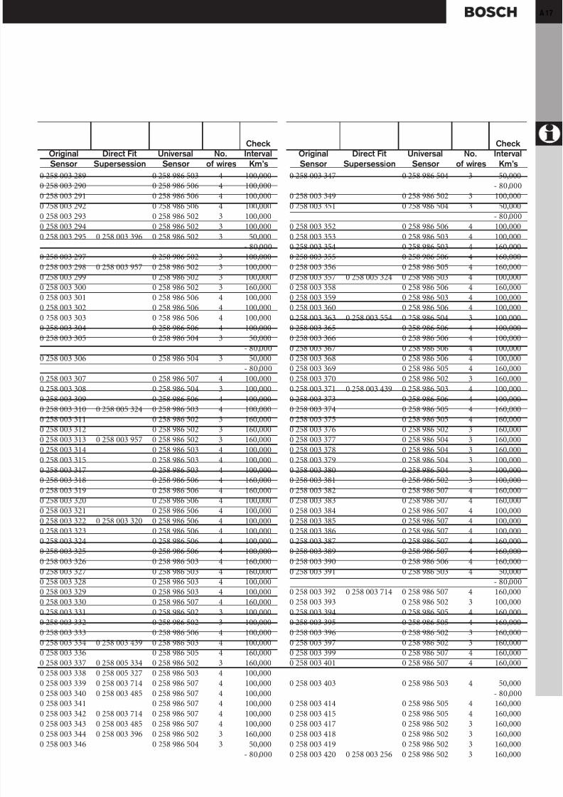
Cross Reference Direct Fit to Universal Sensor
Including Test and Replace Intervals ( continued )
CheckOriginal Direct Fit Universal No. IntervalSensor Supersession Sensor of wires Km’s
CheckOriginal Direct Fit Universal No. IntervalSensor Supersession Sensor of wires Km’s
8/12/2019 Sonde Lambda Bosch
http://slidepdf.com/reader/full/sonde-lambda-bosch 17/31
A 17
0 258 003 289 0 258 986 503 4 100,0000 258 003 290 0 258 986 506 4 100,0000 258 003 291 0 258 986 506 4 100,0000 258 003 292 0 258 986 506 4 100,0000 258 003 293 0 258 986 502 3 100,0000 258 003 294 0 258 986 502 3 100,0000 258 003 295 0 258 003 396 0 258 986 502 3 50,000
- 80,0000 258 003 297 0 258 986 502 3 100,0000 258 003 298 0 258 003 957 0 258 986 502 3 100,000
0 258 003 299 0 258 986 502 3 100,0000 258 003 300 0 258 986 502 3 160,0000 258 003 301 0 258 986 506 4 100,0000 258 003 302 0 258 986 506 4 100,0000 258 003 303 0 258 986 506 4 100,0000 258 003 304 0 258 986 506 4 100,0000 258 003 305 0 258 986 504 3 50,000
- 80,0000 258 003 306 0 258 986 504 3 50,000
- 80,0000 258 003 307 0 258 986 507 4 100,0000 258 003 308 0 258 986 504 3 100,0000 258 003 309 0 258 986 506 4 100,0000 258 003 310 0 258 005 324 0 258 986 503 4 100,000
0 258 003 311 0 258 986 502 3 160,0000 258 003 312 0 258 986 502 3 160,0000 258 003 313 0 258 003 957 0 258 986 502 3 160,0000 258 003 314 0 258 986 503 4 100,0000 258 003 315 0 258 986 503 4 100,0000 258 003 317 0 258 986 503 4 100,0000 258 003 318 0 258 986 506 4 160,0000 258 003 319 0 258 986 506 4 160,0000 258 003 320 0 258 986 506 4 100,0000 258 003 321 0 258 986 506 4 100,0000 258 003 322 0 258 003 320 0 258 986 506 4 100,0000 258 003 323 0 258 986 506 4 100,0000 258 003 324 0 258 986 506 4 100,0000 258 003 325 0 258 986 506 4 100,000
0 258 003 326 0 258 986 503 4 160,0000 258 003 327 0 258 986 503 4 160,0000 258 003 328 0 258 986 503 4 100,0000 258 003 329 0 258 986 503 4 100,0000 258 003 330 0 258 986 507 4 160,0000 258 003 331 0 258 986 502 3 100,0000 258 003 332 0 258 986 502 3 100,0000 258 003 333 0 258 986 506 4 100,0000 258 003 334 0 258 003 439 0 258 986 503 4 100,0000 258 003 336 0 258 986 505 4 160,0000 258 003 337 0 258 005 334 0 258 986 502 3 160,0000 258 003 338 0 258 005 327 0 258 986 503 4 100,0000 258 003 339 0 258 003 714 0 258 986 507 4 100,0000 258 003 340 0 258 003 485 0 258 986 507 4 100,0000 258 003 341 0 258 986 507 4 100,0000 258 003 342 0 258 003 714 0 258 986 507 4 100,0000 258 003 343 0 258 003 485 0 258 986 507 4 100,0000 258 003 344 0 258 003 396 0 258 986 502 3 160,0000 258 003 346 0 258 986 504 3 50,000
- 80,000
0 258 003 347 0 258 986 504 3 50,000- 80,000
0 258 003 349 0 258 986 502 3 100,0000 258 003 351 0 258 986 504 3 50,000
- 80,0000 258 003 352 0 258 986 506 4 100,0000 258 003 353 0 258 986 503 4 100,0000 258 003 354 0 258 986 503 4 160,0000 258 003 355 0 258 986 506 4 160,0000 258 003 356 0 258 986 505 4 160,000
0 258 003 357 0 258 005 324 0 258 986 503 4 100,0000 258 003 358 0 258 986 506 4 160,0000 258 003 359 0 258 986 503 4 100,0000 258 003 360 0 258 986 506 4 100,0000 258 003 363 0 258 003 554 0 258 986 504 3 100,0000 258 003 365 0 258 986 506 4 100,0000 258 003 366 0 258 986 506 4 100,0000 258 003 367 0 258 986 506 4 100,0000 258 003 368 0 258 986 506 4 100,0000 258 003 369 0 258 986 505 4 160,0000 258 003 370 0 258 986 502 3 160,0000 258 003 371 0 258 003 439 0 258 986 503 4 100,0000 258 003 373 0 258 986 506 4 100,0000 258 003 374 0 258 986 505 4 160,000
0 258 003 375 0 258 986 505 4 160,0000 258 003 376 0 258 986 502 3 160,0000 258 003 377 0 258 986 504 3 160,0000 258 003 378 0 258 986 504 3 160,0000 258 003 379 0 258 986 504 3 100,0000 258 003 380 0 258 986 504 3 100,0000 258 003 381 0 258 986 502 3 100,0000 258 003 382 0 258 986 507 4 160,0000 258 003 383 0 258 986 507 4 160,0000 258 003 384 0 258 986 507 4 100,0000 258 003 385 0 258 986 507 4 100,0000 258 003 386 0 258 986 507 4 100,0000 258 003 387 0 258 986 507 4 160,0000 258 003 389 0 258 986 507 4 160,000
0 258 003 390 0 258 986 506 4 160,0000 258 003 391 0 258 986 503 4 50,000
- 80,0000 258 003 392 0 258 003 714 0 258 986 507 4 160,0000 258 003 393 0 258 986 502 3 100,0000 258 003 394 0 258 986 505 4 160,0000 258 003 395 0 258 986 505 4 160,0000 258 003 396 0 258 986 502 3 160,0000 258 003 397 0 258 986 502 3 160,0000 258 003 399 0 258 986 507 4 160,0000 258 003 401 0 258 986 507 4 160,000
0 258 003 403 0 258 986 503 4 50,000- 80,000
0 258 003 414 0 258 986 505 4 160,0000 258 003 415 0 258 986 505 4 160,0000 258 003 417 0 258 986 502 3 160,0000 258 003 418 0 258 986 502 3 160,0000 258 003 419 0 258 986 502 3 160,0000 258 003 420 0 258 003 256 0 258 986 502 3 160,000
Check
Original Direct Fit Universal No. Interval
Sensor Supersession Sensor of wires Km’s
Check
Original Direct Fit Universal No. Interval
Sensor Supersession Sensor of wires Km’s

8/12/2019 Sonde Lambda Bosch
http://slidepdf.com/reader/full/sonde-lambda-bosch 18/31
18
0 258 003 421 0 258 986 502 3 160,0000 258 003 422 0 258 986 504 3 100,0000 258 003 423 0 258 986 507 4 100,0000 258 003 425 0 258 986 505 4 160,0000 258 003 426 0 258 005 324 0 258 986 503 4 100,0000 258 003 427 0 258 986 503 4 160,0000 258 003 428 0 258 986 503 4 160,0000 258 003 429 0 258 986 503 4 160,0000 258 003 430 0 258 986 503 4 160,0000 258 003 431 0 258 986 503 4 160,000
0 258 003 432 0 258 986 503 4 160,0000 258 003 433 0 258 986 503 4 160,0000 258 003 434 0 258 986 503 4 160,0000 258 003 436 0 258 986 505 4 160,0000 258 003 437 0 258 003 303 0 258 986 506 4 100,0000 258 003 439 0 258 986 503 4 100,0000 258 003 440 0 258 986 503 4 100,0000 258 003 441 0 258 986 504 3 50,000
- 80,0000 258 003 443 0 258 003 427 0 258 986 503 4 100,0000 258 003 444 0 258 986 503 4 100,0000 258 003 445 0 258 986 502 3 160,0000 258 003 446 0 258 003 448 0 258 986 502 3 160,0000 258 003 447 0 258 003 448 0 258 986 502 3 160,000
0 258 003 448 0 258 986 502 3 160,0000 258 003 450 0 258 986 506 4 100,0000 258 003 451 0 258 003 303 0 258 986 506 4 100,0000 258 003 453 0 258 003 810 0 258 986 503 4 100,0000 258 003 454 0 258 003 842 0 258 986 505 4 160,0000 258 003 456 0 258 003 714 0 258 986 507 4 160,0000 258 003 457 0 258 003 714 0 258 986 507 4 160,0000 258 003 458 0 258 986 505 4 160,0000 258 003 459 0 258 986 505 4 160,0000 258 003 460 0 258 005 324 0 258 986 503 4 100,0000 258 003 461 0 258 986 502 3 100,0000 258 003 462 0 258 986 506 4 50,000
- 80,0000 258 003 463 0 258 986 506 4 160,000
0 258 003 464 0 258 986 506 4 50,000- 80,000
0 258 003 465 0 258 986 503 4 50,000- 80,000
0 258 003 467 0 258 986 507 4 100,0000 258 003 468 0 258 986 507 4 160,0000 258 003 469 0 258 986 506 4 100,0000 258 003 470 0 258 986 505 4 160,0000 258 003 472 0 258 986 507 4 100,0000 258 003 473 0 258 986 502 3 160,0000 258 003 474 0 258 986 502 3 160,0000 258 003 475 0 258 986 505 4 160,0000 258 003 476 0 258 986 505 4 160,0000 258 003 477 0 258 986 505 4 160,0000 258 003 478 0 258 986 505 4 160,0000 258 003 479 0 258 986 505 4 160,0000 258 003 481 0 258 986 507 4 50,000
- 80,0000 258 003 483 0 258 986 502 3 160,0000 258 003 484 0 258 003 714 0 258 986 507 4 160,000
0 258 003 485 0 258 986 507 4 160,0000 258 003 486 0 258 003 714 0 258 986 507 4 160,0000 258 003 492 0 258 986 507 4 160,0000 258 003 494 0 258 986 507 4 160,0000 258 003 496 0 258 986 507 4 160,0000 258 003 498 0 258 986 507 4 160,0000 258 003 500 0 258 986 507 4 160,0000 258 003 503 0 258 986 502 3 50,000
- 80,0000 258 003 504 0 258 986 502 3 50,000
- 80,0000 258 003 505 0 258 986 502 3 50,000
- 80,0000 258 003 506 0 258 986 507 4 160,0000 258 003 507 0 258 986 507 4 160,0000 258 003 508 0 258 003 957 0 258 986 502 3 160,0000 258 003 509 0 258 986 502 3 160,0000 258 003 510 0 258 003 957 0 258 986 502 3 160,0000 258 003 512 0 258 005 324 0 258 986 503 4 100,0000 258 003 513 0 258 986 506 4 100,0000 258 003 514 0 258 986 506 4 100,0000 258 003 515 0 258 986 506 4 160,0000 258 003 516 0 258 986 506 4 160,0000 258 003 517 0 258 986 503 4 160,000
0 258 003 518 0 258 003 478 0 258 986 505 4 160,0000 258 003 521 0 258 986 507 4 160,0000 258 003 522 0 258 003 810 0 258 986 503 4 100,0000 258 003 523 0 258 003 810 0 258 986 503 4 100,0000 258 003 524 0 258 986 502 3 160,0000 258 003 525 0 258 986 502 3 160,0000 258 003 526 0 258 986 505 4 50,000
- 80,0000 258 003 528 0 258 986 503 4 50,000
- 80,0000 258 003 533 0 258 986 507 4 100,0000 258 003 535 0 258 986 507 4 100,0000 258 003 537 0 258 986 507 4 100,0000 258 003 539 0 258 986 503 4 50,000
- 80,0000 258 003 540 0 258 986 506 4 100,0000 258 003 541 0 258 986 507 4 160,0000 258 003 542 0 258 986 505 4 160,0000 258 003 543 0 258 986 505 4 160,0000 258 003 544 0 258 003 759 0 258 986 507 4 160,0000 258 003 546 0 258 003 548 0 258 986 503 4 160,0000 258 003 548 0 258 986 503 4 160,0000 258 003 549 0 258 986 503 4 160,0000 258 003 550 0 258 986 505 4 160,0000 258 003 551 0 258 986 505 4 160,0000 258 003 552 0 258 986 505 4 160,0000 258 003 553 0 258 986 505 4 160,0000 258 003 554 0 258 986 504 3 160,0000 258 003 555 0 258 986 504 3 160,0000 258 003 556 0 258 986 507 4 160,0000 258 003 557 0 258 986 507 4 160,0000 258 003 558 0 258 986 505 4 160,0000 258 003 559 0 258 986 505 4 160,000
Cross Reference Direct Fit to Universal Sensor
Including Test and Replace Intervals ( continued )
CheckOriginal Direct Fit Universal No. IntervalSensor Supersession Sensor of wires Km’s
CheckOriginal Direct Fit Universal No. IntervalSensor Supersession Sensor of wires Km’s

8/12/2019 Sonde Lambda Bosch
http://slidepdf.com/reader/full/sonde-lambda-bosch 19/31
A 19
0 258 003 560 0 258 986 503 4 50,000- 80,000
0 258 003 561 0 258 986 505 4 160,0000 258 003 564 0 258 986 505 4 160,0000 258 003 567 0 258 986 506 4 50,000
- 80,0000 258 003 568 0 258 986 506 4 100,0000 258 003 569 0 258 986 502 3 100,0000 258 003 570 0 258 986 506 4 100,0000 258 003 571 0 258 986 506 4 160,000
0 258 003 572 0 258 986 506 4 160,0000 258 003 573 0 258 986 506 4 100,0000 258 003 574 0 258 986 506 4 100,0000 258 003 575 0 258 986 503 4 160,0000 258 003 576 0 258 986 503 4 160,0000 258 003 577 0 258 986 505 4 160,0000 258 003 578 0 258 986 506 4 160,0000 258 003 579 0 258 986 506 4 160,0000 258 003 580 0 258 986 505 4 160,0000 258 003 581 0 258 986 505 4 160,0000 258 003 582 0 258 986 505 4 160,0000 258 003 583 0 258 986 505 4 160,0000 258 003 584 0 258 986 506 4 160,0000 258 003 585 0 258 986 506 4 160,000
0 258 003 586 0 258 003 548 0 258 986 503 4 160,0000 258 003 588 0 258 003 868 0 258 986 503 4 160,0000 258 003 590 0 258 986 507 4 160,0000 258 003 591 0 258 986 507 4 160,0000 258 003 592 0 258 986 505 4 160,0000 258 003 593 0 258 986 505 4 160,0000 258 003 596 0 258 986 503 4 160,0000 258 003 597 0 258 986 503 4 160,0000 258 003 598 0 258 986 503 4 160,0000 258 003 599 0 258 986 503 4 160,0000 258 003 600 0 258 986 503 4 160,0000 258 003 601 0 258 986 503 4 100,0000 258 003 602 0 258 986 503 4 100,0000 258 003 603 0 258 986 505 4 160,000
0 258 003 604 0 258 986 503 4 160,0000 258 003 605 0 258 986 503 4 160,0000 258 003 607 0 258 986 507 4 160,0000 258 003 611 0 258 003 630 0 258 986 505 4 160,0000 258 003 613 0 258 003 584 0 258 986 506 4 160,0000 258 003 621 0 258 986 507 4 160,0000 258 003 622 0 258 986 502 3 160,0000 258 003 623 0 258 986 502 3 160,0000 258 003 624 0 258 986 502 3 160,0000 258 003 625 0 258 986 502 3 160,0000 258 003 626 0 258 986 505 4 160,0000 258 003 627 0 258 986 506 4 100,0000 258 003 629 0 258 986 507 4 160,0000 258 003 630 0 258 986 505 4 160,0000 258 003 631 0 258 986 505 4 160,0000 258 003 632 0 258 986 503 4 160,0000 258 003 633 0 258 986 503 4 160,0000 258 003 634 0 258 986 502 3 160,0000 258 003 635 0 258 986 502 3 160,0000 258 003 636 0 258 986 506 4 160,000
0 258 003 637 0 258 986 506 4 160,0000 258 003 638 0 258 986 505 4 160,0000 258 003 639 0 258 986 505 4 160,0000 258 003 640 0 258 986 505 4 160,0000 258 003 641 0 258 986 505 4 160,0000 258 003 642 0 258 986 505 4 160,0000 258 003 643 0 258 986 505 4 160,0000 258 003 644 0 258 986 507 4 160,0000 258 003 645 0 258 986 505 4 160,0000 258 003 646 0 258 003 842 0 258 986 505 4 160,000
0 258 003 648 0 258 986 506 4 100,0000 258 003 649 0 258 986 506 4 100,0000 258 003 652 0 258 986 502 3 160,0000 258 003 653 0 258 986 502 3 160,0000 258 003 654 0 258 986 505 4 160,0000 258 003 655 0 258 986 505 4 160,0000 258 003 656 0 258 986 505 4 160,0000 258 003 657 0 258 986 505 4 160,0000 258 003 658 0 258 986 505 4 160,0000 258 003 660 0 258 986 507 4 160,0000 258 003 661 0 258 986 505 4 160,0000 258 003 662 0 258 986 505 4 160,0000 258 003 664 0 258 986 503 4 50,000
- 80,000
0 258 003 666 0 258 986 503 4 160,0000 258 003 669 0 258 003 718 0 258 986 506 4 100,0000 258 003 671 0 258 986 506 4 50,000
- 80,0000 258 003 672 0 258 986 506 4 50,000
- 80,0000 258 003 673 0 258 986 506 4 50,000
- 80,0000 258 003 674 0 258 986 503 4 50,000
- 80,0000 258 003 676 0 258 003 759 0 258 986 507 4 160,0000 258 003 678 0 258 986 507 4 160,0000 258 003 679 0 258 986 507 4 160,0000 258 003 681 0 258 986 507 4 160,000
0 258 003 683 0 258 986 507 4 160,0000 258 003 684 0 258 986 505 4 160,0000 258 003 685 0 258 986 505 4 160,0000 258 003 686 0 258 986 506 4 100,0000 258 003 687 0 258 986 503 4 50,000
- 80,0000 258 003 689 0 258 986 505 4 160,0000 258 003 690 0 258 003 630 0 258 986 505 4 160,0000 258 003 692 0 258 986 505 4 160,0000 258 003 693 0 258 986 505 4 160,0000 258 003 694 0 258 003 842 0 258 986 505 4 160,0000 258 003 696 0 258 003 842 0 258 986 505 4 160,0000 258 003 698 0 258 986 505 4 160,0000 258 003 699 0 258 986 505 4 160,0000 258 003 700 0 258 986 503 4 100,0000 258 003 703 0 258 986 502 3 160,0000 258 003 704 0 258 986 502 3 100,0000 258 003 705 0 258 986 503 4 50,000
- 80,0000 258 003 709 0 258 986 503 4 160,000
Check
Original Direct Fit Universal No. Interval
Sensor Supersession Sensor of wires Km’s
Check
Original Direct Fit Universal No. Interval
Sensor Supersession Sensor of wires Km’s

8/12/2019 Sonde Lambda Bosch
http://slidepdf.com/reader/full/sonde-lambda-bosch 20/31
20
0 258 003 710 0 258 986 503 4 160,0000 258 003 712 0 258 986 507 4 160,0000 258 003 713 0 258 003 714 0 258 986 507 4 160,0000 258 003 714 0 258 986 507 4 160,0000 258 003 715 0 258 986 502 3 160,0000 258 003 716 0 258 986 506 4 100,0000 258 003 717 0 258 986 506 4 100,0000 258 003 718 0 258 986 506 4 100,0000 258 003 719 0 258 986 506 4 100,0000 258 003 721 0 258 986 505 4 160,000
0 258 003 722 0 258 986 505 4 160,0000 258 003 723 0 258 986 505 4 160,0000 258 003 725 0 258 986 507 4 160,0000 258 003 726 0 258 986 507 4 160,0000 258 003 727 0 258 986 507 4 160,0000 258 003 729 0 258 986 507 4 160,0000 258 003 731 0 258 986 507 4 160,0000 258 003 733 0 258 986 507 4 160,0000 258 003 734 0 258 003 842 0 258 986 505 4 160,0000 258 003 736 0 258 986 505 4 160,0000 258 003 737 0 258 986 505 4 160,0000 258 003 738 0 258 003 842 0 258 986 505 4 160,0000 258 003 740 0 258 986 505 4 160,0000 258 003 741 0 258 986 505 4 160,000
0 258 003 742 0 258 986 502 3 160,0000 258 003 743 0 258 986 502 3 160,0000 258 003 744 0 258 986 504 3 50,000
- 80,0000 258 003 745 0 258 986 505 4 160,0000 258 003 746 0 258 986 505 4 160,0000 258 003 748 0 258 986 505 4 160,0000 258 003 749 0 258 986 505 4 160,0000 258 003 750 0 258 986 505 4 160,0000 258 003 751 0 258 986 505 4 160,0000 258 003 752 0 258 986 505 4 160,0000 258 003 754 0 258 986 503 4 160,0000 258 003 755 0 258 003 478 0 258 986 505 4 160,0000 258 003 757 0 258 986 505 4 160,000
0 258 003 758 0 258 986 505 4 160,0000 258 003 759 0 258 986 507 4 160,0000 258 003 760 0 258 986 507 4 160,0000 258 003 762 0 258 986 507 4 160,0000 258 003 763 0 258 986 504 3 160,0000 258 003 764 0 258 986 504 3 160,0000 258 003 765 0 258 986 504 3 160,0000 258 003 766 0 258 986 504 3 160,0000 258 003 769 0 258 986 506 4 160,0000 258 003 770 0 258 986 506 4 160,0000 258 003 771 0 258 986 505 4 160,0000 258 003 772 0 258 986 506 4 160,0000 258 003 773 0 258 986 505 4 160,0000 258 003 774 0 258 986 502 3 160,0000 258 003 776 0 258 986 507 4 160,0000 258 003 778 0 258 986 507 4 160,0000 258 003 779 0 258 986 507 4 160,0000 258 003 780 0 258 986 507 4 160,0000 258 003 781 0 258 986 507 4 160,0000 258 003 782 0 258 986 505 4 160,000
0 258 003 783 0 258 986 505 4 160,0000 258 003 784 0 258 986 503 4 160,0000 258 003 785 0 258 986 503 4 160,0000 258 003 786 0 258 986 503 4 100,0000 258 003 787 0 258 986 503 4 100,0000 258 003 788 0 258 986 503 4 160,0000 258 003 789 0 258 986 503 4 160,0000 258 003 790 0 258 986 503 4 160,0000 258 003 791 0 258 986 503 4 160,0000 258 003 792 0 258 986 503 4 100,000
0 258 003 793 0 258 986 503 4 100,0000 258 003 794 0 258 986 505 4 160,0000 258 003 795 0 258 986 505 4 160,0000 258 003 797 0 258 986 505 4 160,0000 258 003 798 0 258 986 505 4 160,0000 258 003 799 0 258 986 505 4 160,0000 258 003 800 0 258 986 505 4 50,000
- 80,0000 258 003 801 0 258 986 505 4 50,000
- 80,0000 258 003 802 0 258 986 505 4 160,0000 258 003 805 0 258 986 506 4 160,0000 258 003 806 0 258 986 505 4 160,0000 258 003 807 0 258 986 505 4 160,000
0 258 003 808 0 258 986 506 4 100,0000 258 003 809 0 258 986 506 4 100,0000 258 003 810 0 258 986 503 4 100,0000 258 003 811 0 258 986 505 4 160,0000 258 003 812 0 258 986 505 4 160,0000 258 003 813 0 258 986 507 4 160,0000 258 003 814 0 258 986 507 4 160,0000 258 003 815 0 258 986 507 4 160,0000 258 003 816 0 258 986 507 4 160,0000 258 003 817 0 258 005 074 0 258 986 505 4 160,0000 258 003 819 0 258 986 507 4 160,0000 258 003 820 0 258 986 505 4 160,0000 258 003 821 0 258 986 502 3 100,0000 258 003 822 0 258 986 502 3 100,000
0 258 003 823 0 258 986 505 4 160,0000 258 003 824 0 258 986 505 4 160,0000 258 003 825 0 258 003 759 0 258 986 507 4 160,0000 258 003 827 0 258 986 502 3 160,0000 258 003 828 0 258 986 502 3 160,0000 258 003 829 0 258 986 503 4 50,000
- 80,0000 258 003 830 0 258 986 503 4 50,000
- 80,0000 258 003 832 0 258 986 502 3 160,0000 258 003 833 0 258 986 502 3 160,0000 258 003 835 0 258 986 507 4 160,0000 258 003 837 0 258 986 507 4 160,0000 258 003 839 0 258 986 507 4 160,0000 258 003 841 0 258 986 502 3 160,0000 258 003 842 0 258 986 505 4 160,0000 258 003 843 0 258 986 505 4 160,0000 258 003 844 0 258 003 868 0 258 986 503 4 50,000
- 80,0000 258 003 846 0 258 005 081 0 258 986 505 4 160,000
Cross Reference Direct Fit to Universal Sensor
Including Test and Replace Intervals ( continued )
CheckOriginal Direct Fit Universal No. IntervalSensor Supersession Sensor of wires Km’s
CheckOriginal Direct Fit Universal No. IntervalSensor Supersession Sensor of wires Km’s

8/12/2019 Sonde Lambda Bosch
http://slidepdf.com/reader/full/sonde-lambda-bosch 21/31
A 21
0 258 005 004 0 258 986 505 4 160,0000 258 005 005 0 258 986 505 4 160,0000 258 005 006 0 258 986 505 4 160,0000 258 005 007 0 258 986 505 4 160,0000 258 005 009 0 258 986 507 4 160,0000 258 005 011 0 258 986 507 4 160,0000 258 005 013 0 258 986 507 4 160,0000 258 005 015 0 258 986 507 4 160,0000 258 005 017 0 258 986 507 4 160,0000 258 005 019 0 258 986 507 4 160,000
0 258 005 021 0 258 986 507 4 160,0000 258 005 023 0 258 986 507 4 160,0000 258 005 024 0 258 986 505 4 160,0000 258 005 025 0 258 986 505 4 160,0000 258 005 027 0 258 986 505 4 160,0000 258 005 030 0 258 986 503 4 160,0000 258 005 034 0 258 986 507 4 160,0000 258 005 036 0 258 986 507 4 160,0000 258 005 038 0 258 986 507 4 160,0000 258 005 047 0 258 986 506 4 160,0000 258 005 049 0 258 003 842 0 258 986 505 4 160,0000 258 005 051 0 258 986 506 4 160,0000 258 005 052 0 258 986 507 4 160,000
0 258 005 053 0 258 986 507 4 160,0000 258 005 054 0 258 986 505 4 160,0000 258 005 055 0 258 986 507 4 160,0000 258 005 058 0 258 986 503 4 160,0000 258 005 059 0 258 986 503 4 160,0000 258 005 061 0 258 986 507 4 160,0000 258 005 062 0 258 986 505 4 160,0000 258 005 063 0 258 986 505 4 160,0000 258 005 065 0 258 986 505 4 160,0000 258 005 066 0 258 003 842 0 258 986 505 4 160,0000 258 005 068 0 258 003 842 0 258 986 505 4 160,0000 258 005 070 0 258 986 507 4 160,0000 258 005 071 0 258 986 507 4 160,0000 258 005 074 0 258 986 505 4 160,000
0 258 005 075 0 258 003 842 0 258 986 505 4 160,0000 258 005 078 0 258 986 505 4 160,0000 258 005 079 0 258 986 505 4 160,0000 258 005 080 0 258 986 505 4 160,0000 258 005 081 0 258 986 505 4 160,0000 258 005 082 0 258 986 505 4 160,0000 258 005 083 0 258 986 507 4 160,0000 258 005 084 0 258 986 507 4 160,0000 258 005 087 0 258 986 506 4 160,0000 258 005 088 0 258 986 505 4 160,0000 258 005 089 0 258 986 505 4 160,0000 258 005 090 0 258 986 505 4 160,0000 258 005 091 0 258 986 505 4 160,0000 258 005 092 0 258 986 505 4 160,000
0 258 005 093 0 258 986 505 4 160,0000 258 005 094 0 258 986 505 4 160,0000 258 005 095 0 258 986 505 4 160,0000 258 005 096 0 258 986 503 4 160,0000 258 005 096 0 258 986 503 4 160,0000 258 005 097 0 258 986 505 4 160,000
0 258 003 848 0 258 005 143 0 258 986 505 4 160,0000 258 003 852 0 258 986 502 3 160,0000 258 003 853 0 258 986 502 3 160,0000 258 003 854 0 258 986 505 4 160,0000 258 003 855 0 258 986 507 4 160,0000 258 003 856 0 258 986 507 4 160,0000 258 003 857 0 258 003 478 0 258 986 505 4 160,0000 258 003 860 0 258 986 505 4 160,0000 258 003 861 0 258 986 505 4 160,0000 258 003 862 0 258 986 505 4 160,000
0 258 003 863 0 258 986 505 4 160,0000 258 003 864 0 258 986 505 4 160,0000 258 003 865 0 258 986 505 4 160,0000 258 003 866 0 258 003 548 0 258 986 503 4 160,0000 258 003 868 0 258 986 503 4 160,0000 258 003 869 0 258 986 503 4 160,0000 258 003 870 0 258 986 507 4 160,0000 258 003 871 0 258 986 507 4 160,0000 258 003 872 0 258 986 507 4 160,0000 258 003 873 0 258 986 507 4 160,0000 258 003 890 0 258 986 507 4 160,0000 258 003 891 0 258 986 507 4 160,0000 258 003 892 0 258 986 502 3 160,000
0 258 003 893 0 258 986 507 4 160,0000 258 003 894 0 258 986 507 4 160,0000 258 003 895 0 258 986 505 4 160,0000 258 003 896 0 258 986 505 4 160,0000 258 003 897 0 258 986 502 3 160,0000 258 003 898 0 258 986 502 3 160,0000 258 003 913 0 258 003 097 0 258 986 502 3 100,0000 258 003 915 0 258 986 502 3 100,0000 258 003 918 0 258 986 502 3 100,0000 258 003 924 0 258 986 502 3 100,0000 258 003 925 0 258 986 502 3 100,0000 258 003 926 0 258 986 502 3 100,0000 258 003 930 0 258 986 502 3 100,0000 258 003 931 0 258 003 957 0 258 986 502 3 100,000
0 258 003 936 0 258 003 973 0 258 986 502 3 100,0000 258 003 942 0 258 986 502 3 100,0000 258 003 943 0 258 986 502 3 100,0000 258 003 950 0 258 986 502 3 100,0000 258 003 953 0 258 986 502 3 100,0000 258 003 956 0 258 986 502 3 100,0000 258 003 957 0 258 986 502 3 100,0000 258 003 965 0 258 003 995 0 258 986 504 3 100,0000 258 003 970 — 3 50,000
- 80,0000 258 003 972 0 258 986 502 3 100,0000 258 003 973 0 258 986 502 3 100,0000 258 003 979 0 258 986 504 3 100,0000 258 003 980 0 258 986 502 3 100,000
0 258 003 994 0 258 986 502 3 100,0000 258 003 995 0 258 986 504 3 100,0000 258 003 999 0 258 986 502 3 100,0000 258 005 001 0 258 986 507 4 160,0000 258 005 002 0 258 986 507 4 160,0000 258 005 003 0 258 986 505 4 160,000
Check
Original Direct Fit Universal No. Interval
Sensor Supersession Sensor of wires Km’s
Check
Original Direct Fit Universal No. Interval
Sensor Supersession Sensor of wires Km’sµ
8/12/2019 Sonde Lambda Bosch
http://slidepdf.com/reader/full/sonde-lambda-bosch 22/31
22
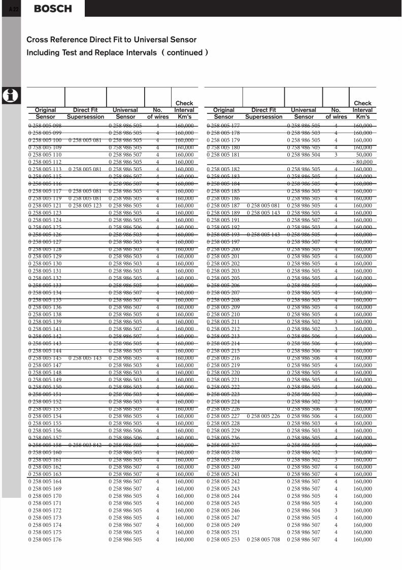
0 258 005 098 0 258 986 505 4 160,0000 258 005 099 0 258 986 505 4 160,0000 258 005 100 0 258 005 081 0 258 986 505 4 160,0000 258 005 109 0 258 986 505 4 160,0000 258 005 110 0 258 986 507 4 160,0000 258 005 112 0 258 986 505 4 160,0000 258 005 113 0 258 005 081 0 258 986 505 4 160,0000 258 005 115 0 258 986 507 4 160,0000 258 005 116 0 258 986 507 4 160,0000 258 005 117 0 258 005 081 0 258 986 505 4 160,000
0 258 005 119 0 258 005 081 0 258 986 505 4 160,0000 258 005 121 0 258 005 123 0 258 986 505 4 160,0000 258 005 123 0 258 986 505 4 160,0000 258 005 124 0 258 986 505 4 160,0000 258 005 125 0 258 986 506 4 160,0000 258 005 126 0 258 986 503 4 160,0000 258 005 127 0 258 986 503 4 160,0000 258 005 128 0 258 986 503 4 160,0000 258 005 129 0 258 986 503 4 160,0000 258 005 130 0 258 986 503 4 160,0000 258 005 131 0 258 986 503 4 160,0000 258 005 132 0 258 986 505 4 160,0000 258 005 133 0 258 986 505 4 160,0000 258 005 134 0 258 986 507 4 160,000
0 258 005 135 0 258 986 507 4 160,0000 258 005 136 0 258 986 507 4 160,0000 258 005 138 0 258 986 505 4 160,0000 258 005 139 0 258 986 505 4 160,0000 258 005 141 0 258 986 507 4 160,0000 258 005 142 0 258 986 507 4 160,0000 258 005 143 0 258 986 505 4 160,0000 258 005 144 0 258 986 505 4 160,0000 258 005 145 0 258 005 143 0 258 986 505 4 160,0000 258 005 147 0 258 986 503 4 160,0000 258 005 148 0 258 986 503 4 160,0000 258 005 149 0 258 986 503 4 160,0000 258 005 150 0 258 986 503 4 160,0000 258 005 151 0 258 986 503 4 160,000
0 258 005 152 0 258 986 503 4 160,0000 258 005 153 0 258 986 505 4 160,0000 258 005 154 0 258 986 505 4 160,0000 258 005 155 0 258 986 505 4 160,0000 258 005 156 0 258 986 506 4 160,0000 258 005 157 0 258 986 506 4 160,0000 258 005 158 0 258 003 842 0 258 986 505 4 160,0000 258 005 160 0 258 986 505 4 160,0000 258 005 161 0 258 986 505 4 160,0000 258 005 162 0 258 986 507 4 160,0000 258 005 163 0 258 986 507 4 160,0000 258 005 164 0 258 986 507 4 160,0000 258 005 169 0 258 986 507 4 160,0000 258 005 170 0 258 986 505 4 160,0000 258 005 171 0 258 986 505 4 160,0000 258 005 172 0 258 986 505 4 160,0000 258 005 173 0 258 986 505 4 160,0000 258 005 174 0 258 986 507 4 160,0000 258 005 175 0 258 986 505 4 160,0000 258 005 176 0 258 986 505 4 160,000
0 258 005 177 0 258 986 505 4 160,0000 258 005 178 0 258 986 503 4 160,0000 258 005 179 0 258 986 505 4 160,0000 258 005 180 0 258 986 505 4 160,0000 258 005 181 0 258 986 504 3 50,000
- 80,0000 258 005 182 0 258 986 505 4 160,0000 258 005 183 0 258 986 505 4 160,0000 258 005 184 0 258 986 505 4 160,0000 258 005 185 0 258 986 505 4 160,000
0 258 005 186 0 258 986 505 4 160,0000 258 005 187 0 258 005 081 0 258 986 505 4 160,0000 258 005 189 0 258 005 143 0 258 986 505 4 160,0000 258 005 191 0 258 986 507 4 160,0000 258 005 192 0 258 986 503 4 160,0000 258 005 193 0 258 005 143 0 258 986 505 4 160,0000 258 005 197 0 258 986 507 4 160,0000 258 005 200 0 258 986 505 4 160,0000 258 005 201 0 258 986 505 4 160,0000 258 005 202 0 258 986 505 4 160,0000 258 005 203 0 258 986 505 4 160,0000 258 005 205 0 258 986 505 4 160,0000 258 005 206 0 258 986 505 4 160,0000 258 005 207 0 258 986 505 4 160,000
0 258 005 208 0 258 986 505 4 160,0000 258 005 209 0 258 986 505 4 160,0000 258 005 210 0 258 986 505 4 160,0000 258 005 211 0 258 986 502 3 160,0000 258 005 212 0 258 986 502 3 160,0000 258 005 213 0 258 986 506 4 160,0000 258 005 214 0 258 986 506 4 160,0000 258 005 215 0 258 986 506 4 160,0000 258 005 216 0 258 986 506 4 160,0000 258 005 219 0 258 986 505 4 160,0000 258 005 220 0 258 986 505 4 160,0000 258 005 221 0 258 986 505 4 160,0000 258 005 222 0 258 986 505 4 160,0000 258 005 223 0 258 986 502 3 160,000
0 258 005 224 0 258 986 502 3 160,0000 258 005 226 0 258 986 506 4 160,0000 258 005 227 0 258 005 226 0 258 986 506 4 160,0000 258 005 228 0 258 986 503 4 160,0000 258 005 229 0 258 986 503 4 160,0000 258 005 236 0 258 986 505 4 160,0000 258 005 237 0 258 986 505 4 160,0000 258 005 238 0 258 986 502 3 160,0000 258 005 239 0 258 986 502 3 160,0000 258 005 240 0 258 986 507 4 160,0000 258 005 241 0 258 986 507 4 160,0000 258 005 242 0 258 986 507 4 160,0000 258 005 243 0 258 986 507 4 160,0000 258 005 244 0 258 986 505 4 160,0000 258 005 245 0 258 986 505 4 160,0000 258 005 246 0 258 986 504 3 160,0000 258 005 247 0 258 986 505 4 160,0000 258 005 249 0 258 986 507 4 160,0000 258 005 251 0 258 986 507 4 160,0000 258 005 253 0 258 005 708 0 258 986 507 4 160,000
Cross Reference Direct Fit to Universal Sensor
Including Test and Replace Intervals ( continued )
CheckOriginal Direct Fit Universal No. IntervalSensor Supersession Sensor of wires Km’s
CheckOriginal Direct Fit Universal No. IntervalSensor Supersession Sensor of wires Km’s

8/12/2019 Sonde Lambda Bosch
http://slidepdf.com/reader/full/sonde-lambda-bosch 23/31
A 23
0 258 005 254 0 258 986 507 4 160,0000 258 005 255 0 258 986 507 4 160,0000 258 005 256 0 258 986 507 4 160,0000 258 005 257 0 258 986 503 4 50,000
- 80,0000 258 005 258 0 258 986 505 4 160,0000 258 005 259 0 258 986 505 4 160,0000 258 005 260 0 258 986 504 3 160,0000 258 005 261 0 258 986 507 4 160,0000 258 005 262 0 258 986 507 4 160,000
0 258 005 263 0 258 986 507 4 160,0000 258 005 264 0 258 986 507 4 160,0000 258 005 265 0 258 986 507 4 160,0000 258 005 266 0 258 986 507 4 160,0000 258 005 267 0 258 986 506 4 160,0000 258 005 268 0 258 986 506 4 160,0000 258 005 269 0 258 986 506 4 50,000
- 80,0000 258 005 270 0 258 986 505 4 160,0000 258 005 271 0 258 986 505 4 160,0000 258 005 272 0 258 986 506 4 50,000
- 80,0000 258 005 273 0 258 986 506 4 50,000
- 80,000
0 258 005 274 0 258 986 502 3 160,0000 258 005 275 0 258 986 502 3 160,0000 258 005 276 0 258 986 506 4 160,0000 258 005 277 0 258 986 506 4 160,0000 258 005 278 0 258 986 506 4 160,0000 258 005 279 0 258 986 506 4 160,0000 258 005 281 0 258 986 505 4 160,0000 258 005 283 0 258 986 505 4 160,0000 258 005 285 0 258 986 506 4 160,0000 258 005 286 0 258 986 506 4 160,0000 258 005 287 0 258 986 506 4 160,0000 258 005 289 0 258 986 502 3 160,0000 258 005 292 0 258 986 507 4 160,0000 258 005 293 0 258 986 507 4 160,000
0 258 005 294 0 258 986 507 4 160,0000 258 005 295 0 258 986 507 4 160,0000 258 005 296 0 258 986 507 4 160,0000 258 005 297 0 258 986 505 4 160,0000 258 005 298 0 258 986 505 4 160,0000 258 005 302 0 258 986 507 4 160,0000 258 005 303 0 258 986 505 4 160,0000 258 005 304 0 258 986 505 4 160,0000 258 005 305 0 258 986 505 4 160,0000 258 005 306 0 258 986 505 4 160,0000 258 005 309 0 258 986 505 4 160,0000 258 005 310 0 258 986 505 4 160,0000 258 005 311 0 258 986 505 4 160,0000 258 005 312 0 258 986 507 4 160,0000 258 005 322 0 258 986 503 4 100,0000 258 005 324 0 258 986 503 4 100,0000 258 005 325 0 258 986 503 4 100,0000 258 005 334 0 258 986 502 3 100,0000 258 005 650 0 258 986 507 4 160,0000 258 005 651 0 258 986 505 4 160,000
0 258 005 652 0 258 986 505 4 160,0000 258 005 653 0 258 986 505 4 160,0000 258 005 654 0 258 986 507 4 160,0000 258 005 657 0 258 986 506 4 160,0000 258 005 658 0 258 986 507 4 160,0000 258 005 659 0 258 986 507 4 160,0000 258 005 701 0 258 986 504 3 160,0000 258 005 703 0 258 005 732 4 160,0000 258 005 704 0 258 986 507 4 160,0000 258 005 705 0 258 986 507 4 160,000
0 258 005 708 0 258 986 507 4 160,0000 258 005 709 0 258 986 507 4 160,0000 258 005 710 0 258 986 602 4 160,0000 258 005 711 0 258 005 728 4 160,0000 258 005 714 0 258 986 507 4 100,0000 258 005 716 0 258 986 507 4 160,0000 258 005 717 0 258 986 507 4 160,0000 258 005 718 0 258 986 507 4 160,0000 258 005 719 0 258 986 507 4 160,0000 258 005 720 0 258 005 732 4 160,0000 258 005 722 0 258 986 507 4 160,0000 258 005 735 0 258 986 507 4 160,0000 258 005 785 0 258 986 507 4 160,0000 258 005 786 0 258 986 507 4 160,000
0 258 006 011 — 4 160,0000 258 006 013 — 4 160,0000 258 006 014 — 4 160,0000 258 006 016 — 4 160,0000 258 006 017 0 258 006 022 — 4 160,0000 258 006 018 — 4 160,0000 258 006 020 — 4 160,0000 258 006 021 — 4 160,0000 258 006 022 — 4 160,0000 258 006 023 — 4 160,0000 258 006 026 — 4 160,0000 258 006 027 — 4 160,0000 258 006 028 — 4 160,0000 258 006 029 — 4 160,000
0 258 006 031 — 4 160,0000 258 006 033 — 4 160,0000 258 006 035 — 4 160,0000 258 006 037 — 4 160,0000 258 006 039 — 4 160,0000 258 006 041 — 5 (6) 160,0000 258 006 042 — 4 160,0000 258 006 044 — 5 (6) 160,0000 258 006 046 — 4 160,0000 258 006 047 — 5 (6) 160,0000 258 006 048 — 5 (6) 160,0000 258 006 049 — 5 (6) 160,0000 258 006 050 — 4 160,0000 258 006 051 0 258 986 602 4 160,0000 258 006 052 — 4 160,0000 258 006 053 — 4 160,0000 258 006 055 — 4 160,0000 258 006 057 — 4 160,0000 258 006 059 — 4 160,0000 258 006 061 — 4 160,000
CheckOriginal Direct Fit Universal No. IntervalSensor Supersession Sensor of wires Km’s
CheckOriginal Direct Fit Universal No. IntervalSensor Supersession Sensor of wires Km’s

8/12/2019 Sonde Lambda Bosch
http://slidepdf.com/reader/full/sonde-lambda-bosch 24/31

8/12/2019 Sonde Lambda Bosch
http://slidepdf.com/reader/full/sonde-lambda-bosch 25/31
A 25
0 258 006 262 — 4 160,0000 258 006 263 — 4 160,0000 258 006 266 — 4 160,0000 258 006 268 0 258 986 602 4 160,0000 258 006 270 — 4 160,0000 258 006 272 0 258 986 602 4 160,0000 258 006 274 0 258 986 602 4 160,0000 258 006 276 0 258 986 602 4 160,0000 258 006 280 — 4 160,0000 258 006 281 — 4 160,000
0 258 006 283 0 258 986 602 4 160,0000 258 006 285 0 258 986 602 4 160,0000 258 006 287 0 258 986 602 4 160,0000 258 006 287 — 4 160,0000 258 006 289 — 4 160,0000 258 006 290 — 4 160,0000 258 006 291 0 258 986 602 4 160,0000 258 006 292 0 258 986 602 4 160,0000 258 006 292 — 4 160,0000 258 006 293 — 4 160,0000 258 006 294 — 4 160,0000 258 006 295 — 4 160,0000 258 006 296 0 258 986 602 4 160,0000 258 006 300 — 4 160,000
0 258 006 302 — 4 160,0000 258 006 305 0 258 986 602 4 160,0000 258 006 307 0 258 986 602 4 160,0000 258 006 309 — 4 160,0000 258 006 310 — 4 160,0000 258 006 311 — 4 160,0000 258 006 312 0 258 986 602 4 160,0000 258 006 314 0 258 986 602 4 160,0000 258 006 316 — 4 160,0000 258 006 318 0 258 986 602 4 160,0000 258 006 320 — 4 160,0000 258 006 322 0 258 986 602 4 160,0000 258 006 324 — 4 160,0000 258 006 326 — 4 160,000
0 258 006 328 — 4 160,0000 258 006 330 — 4 160,0000 258 006 332 — 4 160,0000 258 006 334 — 4 160,0000 258 006 336 — 4 160,0000 258 006 338 — 4 160,0000 258 006 340 — 4 160,0000 258 006 342 — 4 160,0000 258 006 344 — 4 160,0000 258 006 345 — 4 160,0000 258 006 346 — 4 160,0000 258 006 347 — 4 160,0000 258 006 348 — 4 160,0000 258 006 351 — 4 160,0000 258 006 353 0 258 986 602 4 160,0000 258 006 355 — 4 160,0000 258 006 359 — 4 160,0000 258 006 361 — 4 160,0000 258 006 363 — 4 160,0000 258 006 366 — 4 160,000
0 258 006 368 — 4 160,0000 258 006 369 — 4 160,0000 258 006 371 — 4 160,0000 258 006 373 0 258 986 602 4 160,0000 258 006 374 — 4 160,0000 258 006 375 — 4 160,0000 258 006 376 — 4 160,0000 258 006 377 — 4 160,0000 258 006 378 — 4 160,0000 258 006 379 — 4 160,000
0 258 006 380 — 4 160,0000 258 006 381 — 4 160,0000 258 006 382 — 4 160,0000 258 006 384 — 4 160,0000 258 006 386 — 4 160,0000 258 006 387 — 4 160,0000 258 006 388 — 4 160,0000 258 006 389 — 4 160,0000 258 006 390 — 4 160,0000 258 006 391 — 4 160,0000 258 006 392 — 4 160,0000 258 006 394 — 4 160,0000 258 006 396 — 4 160,0000 258 006 398 — 4 160,000
0 258 006 400 — 4 160,0000 258 006 402 — 4 160,0000 258 006 404 — 4 160,0000 258 006 406 — 4 160,0000 258 006 408 — 4 160,0000 258 006 410 — 4 160,0000 258 006 411 — 4 160,0000 258 006 412 — 4 160,0000 258 006 414 — 4 160,0000 258 006 416 — 4 160,0000 258 006 418 — 4 160,0000 258 006 420 — 4 160,0000 258 006 422 0 258 986 602 4 160,0000 258 006 424 — 4 160,000
0 258 006 425 — 4 160,0000 258 006 426 — 4 160,0000 258 006 427 0 258 986 602 4 160,0000 258 006 428 — 4 160,0000 258 006 429 — 4 160,0000 258 006 431 — 4 160,0000 258 006 432 — 4 160,0000 258 006 433 — 4 160,0000 258 006 434 — 4 160,0000 258 006 435 — 4 160,0000 258 006 436 — 4 160,0000 258 006 438 — 4 160,0000 258 006 440 — 4 160,0000 258 006 442 — 4 160,0000 258 006 444 0 258 986 602 4 160,0000 258 006 446 — 4 160,0000 258 006 447 — 4 160,0000 258 006 448 — 4 160,0000 258 006 452 0 258 986 602 4 160,0000 258 006 454 — 4 160,000
CheckOriginal Direct Fit Universal No. IntervalSensor Supersession Sensor of wires Km’s
CheckOriginal Direct Fit Universal No. IntervalSensor Supersession Sensor of wires Km’s
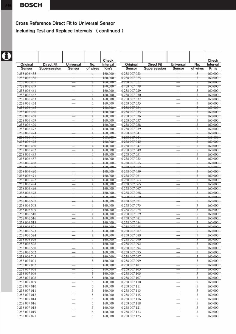
8/12/2019 Sonde Lambda Bosch
http://slidepdf.com/reader/full/sonde-lambda-bosch 26/31
26
0 258 006 455 — 4 160,0000 258 006 456 — 4 160,0000 258 006 457 — 4 160,0000 258 006 459 — 4 160,0000 258 006 461 — 4 160,0000 258 006 462 — 4 160,0000 258 006 463 — 4 160,0000 258 006 464 — 4 160,0000 258 006 465 — 4 160,0000 258 006 466 — 4 160,000
0 258 006 468 — 4 160,0000 258 006 469 — 4 160,0000 258 006 470 — 4 160,0000 258 006 472 — 4 160,0000 258 006 474 — 4 160,0000 258 006 476 — 4 160,0000 258 006 478 — 4 160,0000 258 006 480 — 4 160,0000 258 006 482 — 4 160,0000 258 006 485 — 4 160,0000 258 006 487 — 4 160,0000 258 006 488 — 4 160,0000 258 006 489 — 4 160,0000 258 006 490 — 4 160,000
0 258 006 491 — 4 160,0000 258 006 492 — 4 160,0000 258 006 494 — 4 160,0000 258 006 496 — 4 160,0000 258 006 498 — 4 160,0000 258 006 506 — 4 160,0000 258 006 507 — 4 160,0000 258 006 508 — 4 160,0000 258 006 509 — 4 160,0000 258 006 510 — 4 160,0000 258 006 516 — 4 160,0000 258 006 518 — 4 160,0000 258 006 521 — 4 160,0000 258 006 523 — 4 160,000
0 258 006 524 — 4 160,0000 258 006 526 — 4 160,0000 258 006 528 — 4 160,0000 258 006 530 — 4 160,0000 258 006 532 — 4 160,0000 258 006 743 — 4 160,0000 258 007 001 — 5 160,0000 258 007 002 — 5 160,0000 258 007 004 — 5 160,0000 258 007 006 — 5 160,0000 258 007 008 — 5 160,0000 258 007 009 — 5 160,0000 258 007 010 — 5 160,0000 258 007 011 — 5 160,0000 258 007 012 — 5 160,0000 258 007 014 — 5 160,0000 258 007 016 — 5 160,0000 258 007 018 — 5 160,0000 258 007 019 — 5 160,0000 258 007 021 — 5 160,000
0 258 007 023 — 5 160,0000 258 007 025 — 5 160,0000 258 007 027 — 5 160,0000 258 007 028 — 5 160,0000 258 007 029 — 5 160,0000 258 007 030 — 5 160,0000 258 007 032 — 5 160,0000 258 007 033 — 5 160,0000 258 007 034 — 5 160,0000 258 007 035 — 5 160,000
0 258 007 036 — 5 160,0000 258 007 037 — 5 160,0000 258 007 038 — 5 160,0000 258 007 039 — 5 160,0000 258 007 041 — 5 160,0000 258 007 044 — 5 160,0000 258 007 045 — 5 160,0000 258 007 047 — 5 160,0000 258 007 049 — 5 160,0000 258 007 051 — 5 160,0000 258 007 053 — 5 160,0000 258 007 055 — 5 160,0000 258 007 057 — 5 160,0000 258 007 059 — 5 160,000
0 258 007 061 — 5 160,0000 258 007 063 — 5 160,0000 258 007 065 — 5 160,0000 258 007 067 — 5 160,0000 258 007 068 — 5 160,0000 258 007 070 — 5 160,0000 258 007 071 — 5 160,0000 258 007 073 — 5 160,0000 258 007 075 — 5 160,0000 258 007 079 — 5 160,0000 258 007 081 — 5 160,0000 258 007 084 — 5 160,0000 258 007 085 — 5 160,0000 258 007 087 — 5 160,000
0 258 007 089 — 5 160,0000 258 007 090 — 5 160,0000 258 007 092 — 5 160,0000 258 007 094 — 5 160,0000 258 007 095 — 5 160,0000 258 007 097 — 5 160,0000 258 007 099 — 5 160,0000 258 007 101 — 5 160,0000 258 007 103 — 5 160,0000 258 007 105 — 5 160,0000 258 007 107 — 5 160,0000 258 007 110 — 5 160,0000 258 007 111 — 5 160,0000 258 007 113 — 5 160,0000 258 007 115 — 5 160,0000 258 007 116 — 5 160,0000 258 007 118 — 5 160,0000 258 007 121 — 5 160,0000 258 007 123 — 5 160,0000 258 007 125 — 5 160,000
Cross Reference Direct Fit to Universal Sensor
Including Test and Replace Intervals ( continued )
CheckOriginal Direct Fit Universal No. IntervalSensor Supersession Sensor of wires Km’s
CheckOriginal Direct Fit Universal No. IntervalSensor Supersession Sensor of wires Km’s
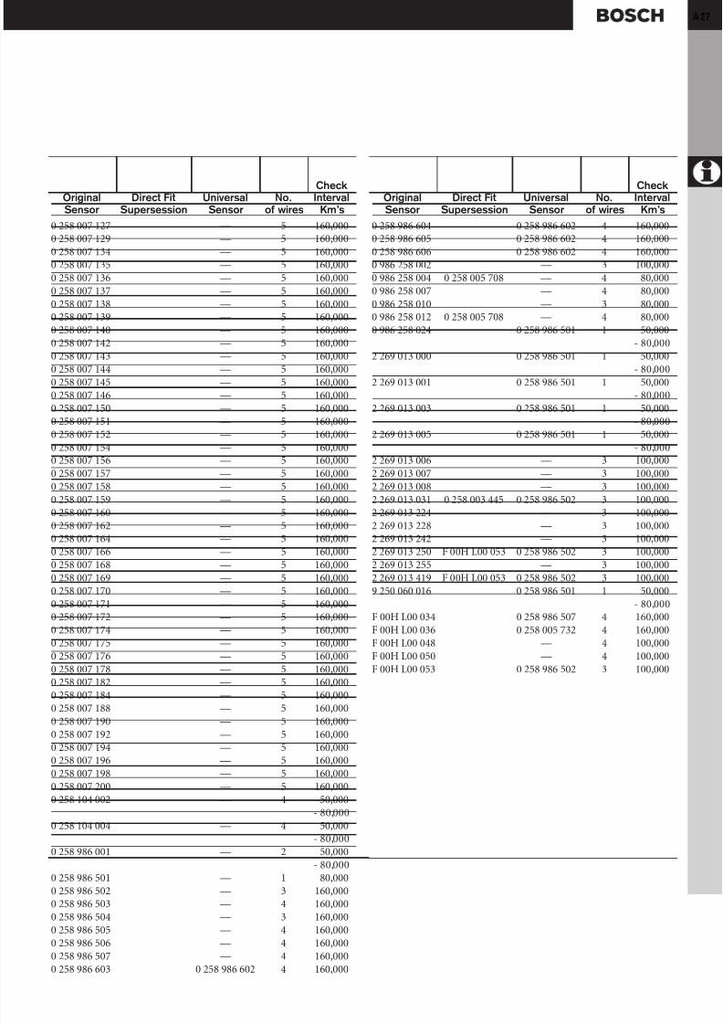
8/12/2019 Sonde Lambda Bosch
http://slidepdf.com/reader/full/sonde-lambda-bosch 27/31
A 27
0 258 007 127 — 5 160,0000 258 007 129 — 5 160,0000 258 007 134 — 5 160,0000 258 007 135 — 5 160,0000 258 007 136 — 5 160,0000 258 007 137 — 5 160,0000 258 007 138 — 5 160,0000 258 007 139 — 5 160,0000 258 007 140 — 5 160,0000 258 007 142 — 5 160,000
0 258 007 143 — 5 160,0000 258 007 144 — 5 160,0000 258 007 145 — 5 160,0000 258 007 146 — 5 160,0000 258 007 150 — 5 160,0000 258 007 151 — 5 160,0000 258 007 152 — 5 160,0000 258 007 154 — 5 160,0000 258 007 156 — 5 160,0000 258 007 157 — 5 160,0000 258 007 158 — 5 160,0000 258 007 159 — 5 160,0000 258 007 160 — 5 160,0000 258 007 162 — 5 160,000
0 258 007 164 — 5 160,0000 258 007 166 — 5 160,0000 258 007 168 — 5 160,0000 258 007 169 — 5 160,0000 258 007 170 — 5 160,0000 258 007 171 — 5 160,0000 258 007 172 — 5 160,0000 258 007 174 — 5 160,0000 258 007 175 — 5 160,0000 258 007 176 — 5 160,0000 258 007 178 — 5 160,0000 258 007 182 — 5 160,0000 258 007 184 — 5 160,0000 258 007 188 — 5 160,000
0 258 007 190 — 5 160,0000 258 007 192 — 5 160,0000 258 007 194 — 5 160,0000 258 007 196 — 5 160,0000 258 007 198 — 5 160,0000 258 007 200 — 5 160,0000 258 104 002 — 4 50,000
- 80,0000 258 104 004 — 4 50,000
- 80,0000 258 986 001 — 2 50,000
- 80,0000 258 986 501 — 1 80,0000 258 986 502 — 3 160,0000 258 986 503 — 4 160,0000 258 986 504 — 3 160,0000 258 986 505 — 4 160,0000 258 986 506 — 4 160,0000 258 986 507 — 4 160,0000 258 986 603 0 258 986 602 4 160,000
CheckOriginal Direct Fit Universal No. IntervalSensor Supersession Sensor of wires Km’s
0 258 986 604 0 258 986 602 4 160,0000 258 986 605 0 258 986 602 4 160,0000 258 986 606 0 258 986 602 4 160,0000 986 258 002 — 3 100,0000 986 258 004 0 258 005 708 — 4 80,0000 986 258 007 — 4 80,0000 986 258 010 — 3 80,0000 986 258 012 0 258 005 708 — 4 80,0000 986 258 024 0 258 986 501 1 50,000
- 80,000
2 269 013 000 0 258 986 501 1 50,000- 80,000
2 269 013 001 0 258 986 501 1 50,000- 80,000
2 269 013 003 0 258 986 501 1 50,000- 80,000
2 269 013 005 0 258 986 501 1 50,000- 80,000
2 269 013 006 — 3 100,0002 269 013 007 — 3 100,0002 269 013 008 — 3 100,0002 269 013 031 0 258 003 445 0 258 986 502 3 100,0002 269 013 224 — 3 100,0002 269 013 228 — 3 100,000
2 269 013 242 — 3 100,0002 269 013 250 F 00H L00 053 0 258 986 502 3 100,0002 269 013 255 — 3 100,0002 269 013 419 F 00H L00 053 0 258 986 502 3 100,0009 250 060 016 0 258 986 501 1 50,000
- 80,000F 00H L00 034 0 258 986 507 4 160,000F 00H L00 036 0 258 005 732 4 160,000F 00H L00 048 — 4 100,000F 00H L00 050 — 4 100,000F 00H L00 053 0 258 986 502 3 100,000
CheckOriginal Direct Fit Universal No. IntervalSensor Supersession Sensor of wires Km’s
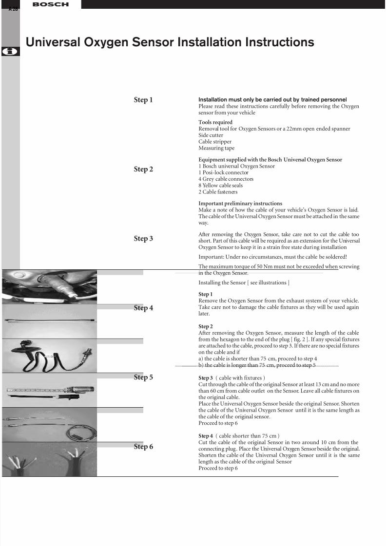
8/12/2019 Sonde Lambda Bosch
http://slidepdf.com/reader/full/sonde-lambda-bosch 28/31
Universal Oxygen Sensor Installation Instructions
28
Installation must only be carried out by trained personnelPlease read these instructions carefully before removing the Oxygensensor from your vehicle
Tools requiredRemoval tool for Oxygen Sensors or a 22mm open ended spannerSide cutterCable stripperMeasuring tape
Equipment supplied with the Bosch Universal Oxygen Sensor1 Bosch universal Oxygen Sensor1 Posi-lock connector4 Grey cable connectors8 Yellow cable seals
2 Cable fasteners
Important preliminary instructionsMake a note of how the cable of your vehicle’s Oxygen Sensor is laid.The cable of the Universal Oxygen Sensor must be attached in the sameway.
After removing the Oxygen Sensor, take care not to cut the cable tooshort. Part of this cable will be required as an extension for the UniversalOxygen Sensor to keep it in a strain free state during installation
Important: Under no circumstances, must the cable be soldered!
The maximum torque of 50 Nm must not be exceeded when screwingin the Oxygen Sensor.
Installing the Sensor [ see illustrations ]
Step 1Remove the Oxygen Sensor from the exhaust system of your vehicle.Take care not to damage the cable fixtures as they will be used againlater.
Step 2After removing the Oxygen Sensor, measure the length of the cablefrom the hexagon to the end of the plug [ fig. 2 ]. If any special fixturesare attached to the cable, proceed to step 3. If there are no special fixtureson the cable and if a) the cable is shorter than 75 cm, proceed to step 4b) the cable is longer than 75 cm, proceed to step 5
Step 3 ( cable with fixtures )
Cut through the cable of the original Sensor at least 13 cm and no morethan 60 cm from cable outlet on the Sensor. Leave all cable fixtures onthe original cable.Place the Universal Oxygen Sensor beside the original Sensor. Shortenthe cable of the Universal Oxygen Sensor until it is the same length asthe cable of the original sensor.Proceed to step 6
Step 4 ( cable shorter than 75 cm )Cut the cable of the original Sensor in two around 10 cm from theconnecting plug. Place the Universal Oxygen Sensor beside the original.Shorten the cable of the Universal Oxygen Sensor until it is the samelength as the cable of the original SensorProceed to step 6
Step 1
Step 2
Step 3
Step 4
Step 5
Step 6

8/12/2019 Sonde Lambda Bosch
http://slidepdf.com/reader/full/sonde-lambda-bosch 29/31
A 29
Step 5 ( cable longer than 75 cm )Place the Universal Oxygen Sensor beside the original Sensor. Cut thecable of the original sensor in two until it is as long as the cable fromthe Universal Oxygen Sensor ( fig. 5 ) Remove the cable fastener on theUniversal Oxygen Sensor. - Proceed to step 6
Step 6Using installation pliers , remove approx. 1 cm (important! ) of the cableinsulation (fig. 6) from all cable ends, taking care not to damage any wires.
Step 7Cable colour allocations for the Universal Oxygen Sensor are as follows,sensor output signal wire = black, sensor heater element cables =
White ( Note - heater is not polarity sensitive ) Sensor signal ground( where used ) = Grey Important: The cable allocations must be assigned correctly. Other-wise the Sensor could be destroyed . Put the large plug housing over thecable from the Universal Oxygen Sensor and the small plug cover overthe cable from the original Oxygen Sensor (fig. 7 ).
Step 8Put the yellow seals over each cable end in such a way that the narrow end of the seals points to the rear of the plug housing (fig. 8)
Step 9Insert the insulated cable ends from the Universal Oxygen Sensor intothe grey cable connectors. Screw the centre pieces of the cable connectorstogether (fig. 9) ensure the leads are fitted tightly inside the cable connectors.
Step 10Connect the Sensor to the cable harness in the vehicle (fig. 10) Check again that the cables are correctly assigned as in step 7 aboveNote: Cables must not be knotted. Pull the cable connections into theplug housing . Check that the tension is correct.
Step 11Insert the cable connectors into the plug housing. Press the plug coveronto the plug housing until it can be heard locking in place. (fig. 11)
Step 12Install the Universal Oxygen Sensor into the vehicle (fig 12).Secure the cable so that it is safe from extreme heat and scuffing .Use the cable fixtures from the original Sensor. If neccessary, use the
cable fasteners so that the plug housing is free from strain and does notvibrate. This ensures that the cable will not wear when the engine is inmotion.
Step 7
Step 8
Step 9
Step 10
Step 11
Step 12

8/12/2019 Sonde Lambda Bosch
http://slidepdf.com/reader/full/sonde-lambda-bosch 30/31

8/12/2019 Sonde Lambda Bosch
http://slidepdf.com/reader/full/sonde-lambda-bosch 31/31
Vehicle Applications
Vehicle make
Vehicle model
Series
Year of manufacutre
Engine code
No. of cylinders
Capacity
Fitment date foroxygen sensor
Abbreviationsrefer inside back cover
Direct fitoxygen sensor
Universal fitoxygen sensor
Recommendedreplacement
interval
Related Documents