3 Edition 06.17 AGA Technical Information · GB • Suitable for a max. inlet pressure of 500 mbar (7 psig) • Easy installation into a system • Compact design saves space • No extra valve required owing to integrated flow adjustment • Check indication by blue LED • Proof of closure switch with integrated visual position indicator • Suitable for high-duty cycling Solenoid valves for gas VAS, Double solenoid valves VCS

Welcome message from author
This document is posted to help you gain knowledge. Please leave a comment to let me know what you think about it! Share it to your friends and learn new things together.
Transcript

3 Edition 0617
AGA
Technical Information middot GB
bull Suitable for a max inlet pressure of 500 mbar (7 psig)
bull Easy installation into a system
bull Compact design saves space
bull No extra valve required owing to integrated flow adjustment
bull Check indication by blue LED
bull Proof of closure switch with integrated visual position indicator
bull Suitable for high-duty cycling
Solenoid valves for gas VAS Double solenoid valves VCS
VAS VCS middot Edition 0617 2
= To be continued
ContentsSolenoid valves for gas VAS Double solenoid valves VCS 1Contents 21 Application 411 Application examples 6
111 Solenoid valve for gas VAS 1thinspndashthinsp3 double solenoid valve VCS 1thinspndashthinsp3 6112 Gas solenoid valve with inlet and outlet pressure switch 7113 Double solenoid valve VCS with damping unit 7114 Solenoid valve for gas VAS 6thinspndashthinsp9 double solenoid valve VCS 6thinspndashthinsp9 8115 Solenoid valve for gas VAS 6thinspndashthinsp9 double solenoid valve VCS 6thinspndashthinsp9 with connection for adapter plates 9116 Gas solenoid valve with pilot gas valve and pressure switch 10117 Double solenoid valve with tightness control 10
2 Certification 113 Function 1331 Solenoid valve for gas VASN quick opening 1432 Solenoid valve for gas VASL slow opening 1533 Solenoid valve for gas VASSVASG proof of closure switch with visual position indicator 1634 Animation 1735 Connection diagram 18
351 VAS with M20 cable gland 18352 VAS with plug 18353 VASSVASG proof of closure switch with visual position indicator 18354 VCS with M20 cable gland 18355 VCS with plug 18
4 Replacement possibilities 1941 Solenoid valve for gas VG is to be replaced by VAS 19
411 Searching for an order number or type 2042 MODULINE solenoid valve for gas VS is to be replaced by VAS 21
5 Flow rate 2351 VAS 23
511 Calculating the nominal size 2352 VCS 24
521 Calculating the nominal size 2453 kv value 25
6 Selection 2761 Selection table for VAS 1thinspndashthinsp3 2762 Type code for VAS 1thinspndashthinsp3 2863 Selection table for VAS 6thinspndashthinsp9 2964 Type code for VAS 6ndashthinsp9 3065 Selection table for VCS 1thinspndashthinsp3 3166 Type code for VCS 1thinspndashthinsp3 3267 Selection table for VCS 6thinspndashthinsp9 3368 Type code for VCS 6ndashthinsp9 34
7 Project planning information 3571 Installation 3572 Electrical connection 3673 Tightness control TC 1V 36
8 Accessories 3781 Gas pressure switch DGC 37
811 Installation on VCS 1thinspndashthinsp3 38812 Installation on VAS 6thinspndashthinsp9 38813 Installation on VCS 6thinspndashthinsp9 38
82 Bypasspilot gas valve VAS 1 39821 Flow rate VAS 1 attached to VAS 1 VAS 2 VAS 3 39822 Scope of delivery of VAS 1 for VAS 1 VAS 2 VAS 3 40823 Flow rate VAS 1 attached to VAS 6thinspndashthinsp9 VCS 6thinspndashthinsp9 41824 Scope of delivery of VAS 1 for VAS 6 ndash 9 VCS 6 ndash 9 42
83 Bypasspilot gas valve VBY 8 43
VAS VCS middot Edition 0617 3
= To be continued
831 Scope of delivery VBY 8I as bypass valve 43832 Scope of delivery VBY 8R as pilot gas valve 43833 Selection 43834 Type code 43835 Flow rate 44836 Technical data 44
84 Pressure test point 4585 Cable gland set 4586 Attachment block VA 1thinspndashthinsp3 4587 Seal set VA 1thinspndashthinsp3 4688 Seal set VCS 1thinspndashthinsp3 4689 Adapter plates for VASVCS 6thinspndashthinsp9 47
891 Bypass adapter 47892 Measuring adapter 47893 Relief line adapter 48
810 Cable gland with pressure equalization element 48811 Measuring orifice VMO 49812 Filter module VMF 49813 Fine-adjusting valve VMV 49814 Tightness control TC 1V 50
8141 Selection table 508142 Type code 50
815 Valve connection cable 50816 Adapter for length compensation VAS 6thinspndashthinsp9 51
9 Technical data 5291 Safety-specific characteristic values for VAS 55
911 Determining the PFHD value the λD value and the MTTFd value 56912 Calculating the PFHD and PFDavg 56
92 Dimensions 57921 VAS 1thinspndashthinsp3 with Rp internal thread [mm] 57922 VAS 2thinspndashthinsp9 with ISO flange [mm] 58923 VCS 1thinspndashthinsp3 with Rp internal thread [mm] 59924 VCS 2thinspndashthinsp9 with ISO flange [mm] 60
925 VAS 1thinspndashthinsp3T with NPT internal thread [inch] 61926 VAS 6thinspndashthinsp9T with ANSI flange [inch] 62927 VCS 1thinspndashthinsp3T with NPT internal thread [inch] 63928 VCS 6thinspndashthinsp9T with ANSI flange [inch] 64
10 Converting units 6511 Maintenance cycles 6512 Glossary 66121 Diagnostic coverage DC 66122 Mode of operation 66123 Category 66124 Common cause failure CCF 66125 Fraction of undetected common cause failures β 66126 B10d value 66127 T10d value 66128 Hardware fault tolerance HFT 67129 Mean dangerous failure rate λD 671210 Safe failure fraction SFF 671211 Probability of dangerous failure PFHD 671212 Mean time to dangerous failure MTTFd 671213 Demand rate nop 671214 Average probability of dangerous failure on demand PFDavg 67
Feedback 68Contact 68
VAS VCS middot Edition 0617 4
Application
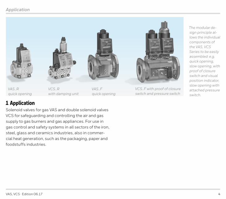
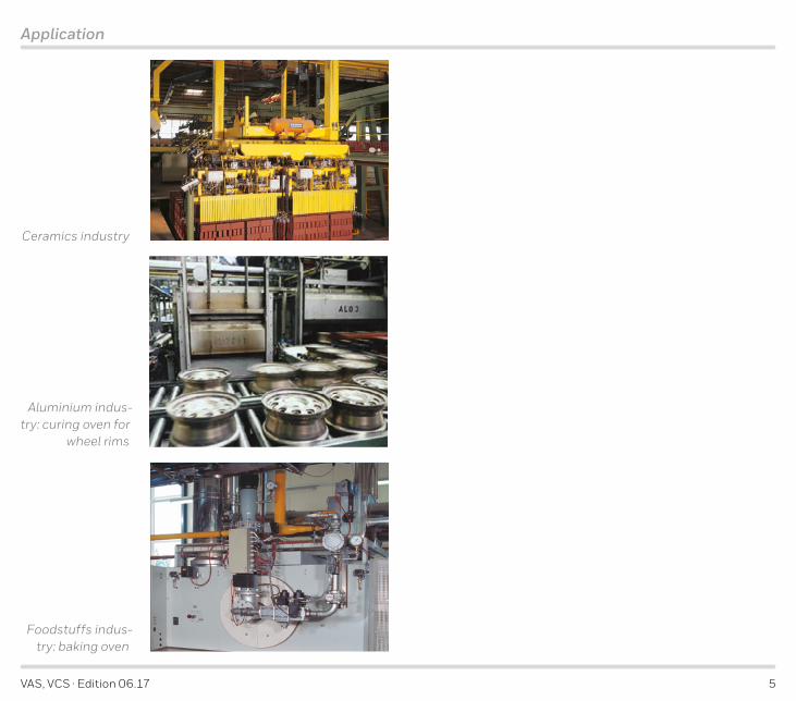
1 ApplicationSolenoid valves for gas VAS and double solenoid valves VCS for safeguarding and controlling the air and gas supply to gas burners and gas appliances For use in gas control and safety systems in all sectors of the iron steel glass and ceramics industries also in commer-cial heat generation such as the packaging paper and foodstuffs industries
The modular de-sign principle al-lows the individual components of the VAS VCS Series to be easily assembled eg quick opening slow opening with proof of closure switch and visual position indicator slow opening with attached pressure switch
VCSR with damping unit
VASFquick opening
VCSF with proof of closure switch and pressure switch
VASRquick opening
VAS VCS middot Edition 0617 5
Application
Ceramics industry
Foodstuffs indus-try baking oven
Aluminium indus-try curing oven for
wheel rims
VAS VCS middot Edition 0617 6
VCS 1thinspndashthinsp3VAS 1thinspndashthinsp3
Application
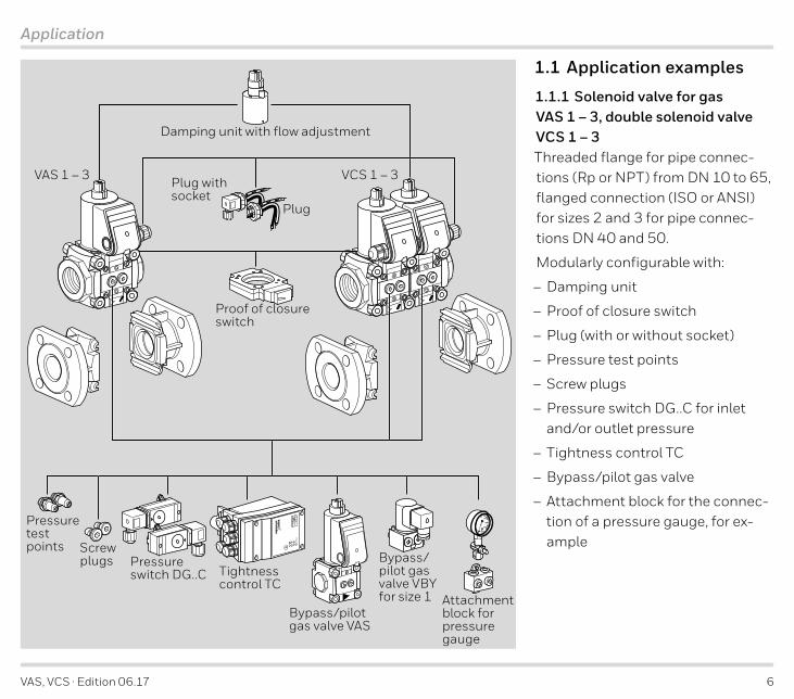
1 1 Application examples
1 1 1 Solenoid valve for gas VAS 1thinspndashthinsp3 double solenoid valve VCS 1thinspndashthinsp3Threaded flange for pipe connec-tions (Rp or NPT) from DN 10 to 65 flanged connection (ISO or ANSI) for sizes 2 and 3 for pipe connec-tions DN 40 and 50
Modularly configurable with
ndash Damping unit
ndash Proof of closure switch
ndash Plug (with or without socket)
ndash Pressure test points
ndash Screw plugs
ndash Pressure switch DGC for inlet andor outlet pressure
ndash Tightness control TC
ndash Bypasspilot gas valve
ndash Attachment block for the connec-tion of a pressure gauge for ex-ample
Plug with socket
Plug
Pressure test points Screw
plugs Pressure switch DGC Tightness
control TC
Bypasspilot gas valve VAS
Bypasspilot gas valve VBY for size 1 Attachment
block for pressure gauge
Proof of closure switch
Damping unit with flow adjustment
VAS VCS middot Edition 0617 7
VASN
DGCDGCPZ PZ
VCSNL
1
2
Application
1 1 2 Gas solenoid valve with inlet and outlet pressure switchVASN quick opening pressure switch DGC for inlet pressure pu and outlet pressure pd
1 1 3 Double solenoid valve VCS with damping unitVCSNL 1st valve quick opening quick closing with flow adjust-ment
2nd valve slow opening quick closing
VAS VCS middot Edition 0617 8
1
2
Power
VCS 6thinspndashthinsp9VAS 6thinspndashthinsp9
Application
1 1 4 Solenoid valve for gas VAS 6thinspndashthinsp9 double solenoid valve VCS 6thinspndashthinsp9Gas solenoid valve and double sole-noid valve with flanged connection (ISO or ANSI) for pipe connections from DN 65 to 125
Modularly configurable with
ndash Damping unit for VASVCS 6thinspndashthinsp8
ndash Proof of closure switch
ndash Plug
ndash Plug with socket
VCS 6thinspndashthinsp9 with threaded connec-tions for
ndash Screw plugs
ndash Pressure test points
ndash Pressure switch DGC for inletinterspace pressure
ndash Tightness control TC
Plug with socket
Plug
Pressure test points
Pressure switch DGC Tightness
control TC
Screw plugs
Proof of closure switch
Damping unit for VASVCS 6ndash8
Pressure test points
Pressure switch DGC
Screw plugs
VAS VCS middot Edition 0617 9
1
2
Power
VAS 6thinspndashthinsp9 VCS 6thinspndashthinsp9
Application
1 1 5 Solenoid valve for gas VAS 6thinspndashthinsp9 double solenoid valve VCS 6thinspndashthinsp9 with connection for adapter platesGas solenoid valve and double solenoid valve with flanged connection (ISO or ANSI) for pipe connections from DN 65 to 125Modularly configurable with
ndash Damping unit for VASVCS 6thinspndashthinsp8ndash Proof of closure switchndash Plugndash Plug with socketWith adapter plates expandable with
ndash Pressure switch DGC VAS 6thinspndashthinsp9 for inletoutlet pressure VCS 6thinspndashthinsp9 for interspaceoutlet pressure
ndash Pressure test pointsndash Screw plugndash Bypass or pilot gas valve VAS
VCS 6thinspndashthinsp9With two threaded connections for
ndash Screw plugsndash Pressure test pointsndash Pressure switch DGC for inletinterspace
pressurendash Tightness control TCExpandable with relief line adapter (1frac12 NPT Rp 1) for relief line
Plug with socket
Plug
Pressure test points
Pressure switch DGC
Tightness control TC
Bypass pilot gas valve VAS
Measuring adapter
Pressure switch DGC
Bypass adapter
Relief line adapter 1frac12 NPT Rp 1
Screw plugs
Proof of closure switch
Damping unit for VASVCS 6ndash8
VAS VCS middot Edition 0617 10
VASF
VAS 1PZ
DGC
VCSFN
PZ
TC 1V
1
2
Power
Application
1 1 6 Gas solenoid valve with pilot gas valve and pressure switchVASFN quick opening quick closing VAS 1 as pilot gas valve with pressure switch DGC
1 1 7 Double solenoid valve with tightness controlVCSFN quick opening quick closing valves tightness control TC 1V
VAS VCS middot Edition 0617 11
Certification
2 CertificationCertificates ndash see Docuthek
Certified to SIL and PL
For systems up to SIL 3 pursuant to EN 61508 and PL e pursuant to ISO 13849
EU certified pursuant to
Directive
ndash Gas Appliances Directive 2009142EU (valid until 20 April 2018) in conjunction with EN 13611 and EN 161
Meets the requirements of thendash Low Voltage Directive (201435EU)
ndash EMC Directive (201430EU)
Regulation
- Gas Appliances Regulation (EU) 2016426 (valid from 21 April 2018)
FM approved
Factory Mutual Research Class 7400 and 7411 Safety overpressure slam shut valves Designed for applica-tions pursuant to NFPA 85 and NFPA 86 wwwapprovalguidecom
ANSICSA approved
American National Standards InstituteCanadian Standards Association ndash ANSI Z2121CSA 65 wwwcsagrouporg ndash Class number 3371-83 (natural gas LPG) 3371-03 (natural gas propane)
VAS 1thinspndashthinsp3 (120 V AC) VAS 6thinspndashthinsp8 UL listed
Underwriters Laboratories ndash UL 429 ldquoElectrically oper-ated valvesrdquo wwwulcom Tools (at the bottom of the page) Online Certifications Directory
VAS VCS middot Edition 0617 12
Certification
AGA approved
AGA
Australian Gas Association Approval No 3968 httpwwwagaasnauproduct_directory
Eurasian Customs Union
The product VAS VCS meets the technical specifica-tions of the Eurasian Customs Union
Approval does not apply for 100 V AC and 200 V AC
VAS VCS middot Edition 0617 13
VAS 1thinspndashthinsp3N VAS 6thinspndashthinsp9N
Function
3 FunctionThe gas solenoid valve VAS is closed when it is discon-nected from the power supply
Opening connect the system to the electrical power supply (alternating voltage will be rectified) The blue LED lights up The coilrsquos magnetic field pulls the ar-mature with the attached valve discs upwards The gas solenoid valve VAS opens The double valve seat means that the forces from the inlet pressure are divided al-most equally between the two valve seats
Closing disconnect the VAS from the electrical power supply The blue LED goes out The armature is pressed into its initial position by the closing spring The gas so-lenoid valve closes within 1 s
The strainer in the inlet of the gas solenoid valve pre-vents deposits of dirt particles on the valve seats The pressure loss through the strainer is very low
VAS 1thinspndashthinsp8 N VAS 1thinspndashthinsp3 LThe flow rate can be varied by a flow adjusting screw on the actuator within a range from 20 to 100 On VAS 1thinspndashthinsp3 the setting can be monitored on an indicator
Solenoid coil Armature
Strainer
Valve disc
Closing spring
Flow adjusting screw
Indicator
Valve seat
VAS VCS middot Edition 0617 14
VAS 1thinspndashthinsp3N VAS 6thinspndashthinsp9N
Function
3 1 Solenoid valve for gas VAS N quick openingThe solenoid valve for gas VASN opens within 05 s
Solenoid coil Armature
Strainer
Valve disc
Closing spring
Flow adjusting screw
Indicator
Valve seat
VAS VCS middot Edition 0617 15
VAS 1thinspndashthinsp3L VAS 6thinspndashthinsp8L
t
p d
t
p dp S
Function
3 2 Solenoid valve for gas VAS L slow openingThe solenoid valve for gas VASL opens within 10 s
Start gas rate adjustment the gas solenoid valve opens with a quick initial lift and then continues slowly until it is fully open The start gas rate can be set This setting is required for example if a tightness control TC is to be used
By turning the damping unit the start gas rate can be set between 0 and 70 turning it clockwise will reduce the start gas rate turning it anti-clockwise will increase the start gas rate
Start gas
Fully damped
Damping unit
VAS VCS middot Edition 0617 16
Function
3 3 Solenoid valve for gas VAS SVAS G proof of closure switch with visual position indicatorOpening when the gas solenoid valve is opened the proof of closure switch is operated first The visual posi-tion indicator is activated The ldquoopenrdquo signal is marked in red Only then does the double valve seat open to re-lease the volume of gas (overtravel principle)
Closing the gas solenoid valve VAS is disconnected from the voltage supply and the closing spring presses the double valve disc on to the valve seat Then the proof of closure switch is actuated The visual position indicator is white for ldquoclosedrdquo
The actuator cannot be rotated on a gas solenoid valve with a proof of closure switch and visual position indi-cator
NOTE NFPA 86 ndash safety shut-off valve VASS must be fitted with an overtravel switch with a visual position indicator and the burner-side pressure regulator with gas solenoid valve VAxS must be fitted with a closed position switch with visual position indicator One gas solenoid valve must be verifiably closed The closed po-sition can be verified using the proof of closure switch of the gas solenoid valve VASSVASG
VAS VCS middot Edition 0617 17
Function
3 4 AnimationThe interactive animation shows the function of the gas solenoid valve VAS
Click on the picture The animation can be controlled using the control bar at the bottom of the window (as on a DVD player)
To play the animation you will need Adobe Reader 7 or a newer version If you do not have Adobe Reader on your system you can download it from the Internet
If the animation does not start to play you can down-load it from the document library (Docuthek) as an in-dependent application
VAS VCS middot Edition 0617 2
= To be continued
ContentsSolenoid valves for gas VAS Double solenoid valves VCS 1Contents 21 Application 411 Application examples 6
111 Solenoid valve for gas VAS 1thinspndashthinsp3 double solenoid valve VCS 1thinspndashthinsp3 6112 Gas solenoid valve with inlet and outlet pressure switch 7113 Double solenoid valve VCS with damping unit 7114 Solenoid valve for gas VAS 6thinspndashthinsp9 double solenoid valve VCS 6thinspndashthinsp9 8115 Solenoid valve for gas VAS 6thinspndashthinsp9 double solenoid valve VCS 6thinspndashthinsp9 with connection for adapter plates 9116 Gas solenoid valve with pilot gas valve and pressure switch 10117 Double solenoid valve with tightness control 10
2 Certification 113 Function 1331 Solenoid valve for gas VASN quick opening 1432 Solenoid valve for gas VASL slow opening 1533 Solenoid valve for gas VASSVASG proof of closure switch with visual position indicator 1634 Animation 1735 Connection diagram 18
351 VAS with M20 cable gland 18352 VAS with plug 18353 VASSVASG proof of closure switch with visual position indicator 18354 VCS with M20 cable gland 18355 VCS with plug 18
4 Replacement possibilities 1941 Solenoid valve for gas VG is to be replaced by VAS 19
411 Searching for an order number or type 2042 MODULINE solenoid valve for gas VS is to be replaced by VAS 21
5 Flow rate 2351 VAS 23
511 Calculating the nominal size 2352 VCS 24
521 Calculating the nominal size 2453 kv value 25
6 Selection 2761 Selection table for VAS 1thinspndashthinsp3 2762 Type code for VAS 1thinspndashthinsp3 2863 Selection table for VAS 6thinspndashthinsp9 2964 Type code for VAS 6ndashthinsp9 3065 Selection table for VCS 1thinspndashthinsp3 3166 Type code for VCS 1thinspndashthinsp3 3267 Selection table for VCS 6thinspndashthinsp9 3368 Type code for VCS 6ndashthinsp9 34
7 Project planning information 3571 Installation 3572 Electrical connection 3673 Tightness control TC 1V 36
8 Accessories 3781 Gas pressure switch DGC 37
811 Installation on VCS 1thinspndashthinsp3 38812 Installation on VAS 6thinspndashthinsp9 38813 Installation on VCS 6thinspndashthinsp9 38
82 Bypasspilot gas valve VAS 1 39821 Flow rate VAS 1 attached to VAS 1 VAS 2 VAS 3 39822 Scope of delivery of VAS 1 for VAS 1 VAS 2 VAS 3 40823 Flow rate VAS 1 attached to VAS 6thinspndashthinsp9 VCS 6thinspndashthinsp9 41824 Scope of delivery of VAS 1 for VAS 6 ndash 9 VCS 6 ndash 9 42
83 Bypasspilot gas valve VBY 8 43
VAS VCS middot Edition 0617 3
= To be continued
831 Scope of delivery VBY 8I as bypass valve 43832 Scope of delivery VBY 8R as pilot gas valve 43833 Selection 43834 Type code 43835 Flow rate 44836 Technical data 44
84 Pressure test point 4585 Cable gland set 4586 Attachment block VA 1thinspndashthinsp3 4587 Seal set VA 1thinspndashthinsp3 4688 Seal set VCS 1thinspndashthinsp3 4689 Adapter plates for VASVCS 6thinspndashthinsp9 47
891 Bypass adapter 47892 Measuring adapter 47893 Relief line adapter 48
810 Cable gland with pressure equalization element 48811 Measuring orifice VMO 49812 Filter module VMF 49813 Fine-adjusting valve VMV 49814 Tightness control TC 1V 50
8141 Selection table 508142 Type code 50
815 Valve connection cable 50816 Adapter for length compensation VAS 6thinspndashthinsp9 51
9 Technical data 5291 Safety-specific characteristic values for VAS 55
911 Determining the PFHD value the λD value and the MTTFd value 56912 Calculating the PFHD and PFDavg 56
92 Dimensions 57921 VAS 1thinspndashthinsp3 with Rp internal thread [mm] 57922 VAS 2thinspndashthinsp9 with ISO flange [mm] 58923 VCS 1thinspndashthinsp3 with Rp internal thread [mm] 59924 VCS 2thinspndashthinsp9 with ISO flange [mm] 60
925 VAS 1thinspndashthinsp3T with NPT internal thread [inch] 61926 VAS 6thinspndashthinsp9T with ANSI flange [inch] 62927 VCS 1thinspndashthinsp3T with NPT internal thread [inch] 63928 VCS 6thinspndashthinsp9T with ANSI flange [inch] 64
10 Converting units 6511 Maintenance cycles 6512 Glossary 66121 Diagnostic coverage DC 66122 Mode of operation 66123 Category 66124 Common cause failure CCF 66125 Fraction of undetected common cause failures β 66126 B10d value 66127 T10d value 66128 Hardware fault tolerance HFT 67129 Mean dangerous failure rate λD 671210 Safe failure fraction SFF 671211 Probability of dangerous failure PFHD 671212 Mean time to dangerous failure MTTFd 671213 Demand rate nop 671214 Average probability of dangerous failure on demand PFDavg 67
Feedback 68Contact 68
VAS VCS middot Edition 0617 4
Application
1 ApplicationSolenoid valves for gas VAS and double solenoid valves VCS for safeguarding and controlling the air and gas supply to gas burners and gas appliances For use in gas control and safety systems in all sectors of the iron steel glass and ceramics industries also in commer-cial heat generation such as the packaging paper and foodstuffs industries
The modular de-sign principle al-lows the individual components of the VAS VCS Series to be easily assembled eg quick opening slow opening with proof of closure switch and visual position indicator slow opening with attached pressure switch
VCSR with damping unit
VASFquick opening
VCSF with proof of closure switch and pressure switch
VASRquick opening
VAS VCS middot Edition 0617 5
Application
Ceramics industry
Foodstuffs indus-try baking oven
Aluminium indus-try curing oven for
wheel rims
VAS VCS middot Edition 0617 6
VCS 1thinspndashthinsp3VAS 1thinspndashthinsp3
Application
1 1 Application examples
1 1 1 Solenoid valve for gas VAS 1thinspndashthinsp3 double solenoid valve VCS 1thinspndashthinsp3Threaded flange for pipe connec-tions (Rp or NPT) from DN 10 to 65 flanged connection (ISO or ANSI) for sizes 2 and 3 for pipe connec-tions DN 40 and 50
Modularly configurable with
ndash Damping unit
ndash Proof of closure switch
ndash Plug (with or without socket)
ndash Pressure test points
ndash Screw plugs
ndash Pressure switch DGC for inlet andor outlet pressure
ndash Tightness control TC
ndash Bypasspilot gas valve
ndash Attachment block for the connec-tion of a pressure gauge for ex-ample
Plug with socket
Plug
Pressure test points Screw
plugs Pressure switch DGC Tightness
control TC
Bypasspilot gas valve VAS
Bypasspilot gas valve VBY for size 1 Attachment
block for pressure gauge
Proof of closure switch
Damping unit with flow adjustment
VAS VCS middot Edition 0617 7
VASN
DGCDGCPZ PZ
VCSNL
1
2
Application
1 1 2 Gas solenoid valve with inlet and outlet pressure switchVASN quick opening pressure switch DGC for inlet pressure pu and outlet pressure pd
1 1 3 Double solenoid valve VCS with damping unitVCSNL 1st valve quick opening quick closing with flow adjust-ment
2nd valve slow opening quick closing
VAS VCS middot Edition 0617 8
1
2
Power
VCS 6thinspndashthinsp9VAS 6thinspndashthinsp9
Application
1 1 4 Solenoid valve for gas VAS 6thinspndashthinsp9 double solenoid valve VCS 6thinspndashthinsp9Gas solenoid valve and double sole-noid valve with flanged connection (ISO or ANSI) for pipe connections from DN 65 to 125
Modularly configurable with
ndash Damping unit for VASVCS 6thinspndashthinsp8
ndash Proof of closure switch
ndash Plug
ndash Plug with socket
VCS 6thinspndashthinsp9 with threaded connec-tions for
ndash Screw plugs
ndash Pressure test points
ndash Pressure switch DGC for inletinterspace pressure
ndash Tightness control TC
Plug with socket
Plug
Pressure test points
Pressure switch DGC Tightness
control TC
Screw plugs
Proof of closure switch
Damping unit for VASVCS 6ndash8
Pressure test points
Pressure switch DGC
Screw plugs
VAS VCS middot Edition 0617 9
1
2
Power
VAS 6thinspndashthinsp9 VCS 6thinspndashthinsp9
Application
1 1 5 Solenoid valve for gas VAS 6thinspndashthinsp9 double solenoid valve VCS 6thinspndashthinsp9 with connection for adapter platesGas solenoid valve and double solenoid valve with flanged connection (ISO or ANSI) for pipe connections from DN 65 to 125Modularly configurable with
ndash Damping unit for VASVCS 6thinspndashthinsp8ndash Proof of closure switchndash Plugndash Plug with socketWith adapter plates expandable with
ndash Pressure switch DGC VAS 6thinspndashthinsp9 for inletoutlet pressure VCS 6thinspndashthinsp9 for interspaceoutlet pressure
ndash Pressure test pointsndash Screw plugndash Bypass or pilot gas valve VAS
VCS 6thinspndashthinsp9With two threaded connections for
ndash Screw plugsndash Pressure test pointsndash Pressure switch DGC for inletinterspace
pressurendash Tightness control TCExpandable with relief line adapter (1frac12 NPT Rp 1) for relief line
Plug with socket
Plug
Pressure test points
Pressure switch DGC
Tightness control TC
Bypass pilot gas valve VAS
Measuring adapter
Pressure switch DGC
Bypass adapter
Relief line adapter 1frac12 NPT Rp 1
Screw plugs
Proof of closure switch
Damping unit for VASVCS 6ndash8
VAS VCS middot Edition 0617 10
VASF
VAS 1PZ
DGC
VCSFN
PZ
TC 1V
1
2
Power
Application
1 1 6 Gas solenoid valve with pilot gas valve and pressure switchVASFN quick opening quick closing VAS 1 as pilot gas valve with pressure switch DGC
1 1 7 Double solenoid valve with tightness controlVCSFN quick opening quick closing valves tightness control TC 1V
VAS VCS middot Edition 0617 11
Certification
2 CertificationCertificates ndash see Docuthek
Certified to SIL and PL
For systems up to SIL 3 pursuant to EN 61508 and PL e pursuant to ISO 13849
EU certified pursuant to
Directive
ndash Gas Appliances Directive 2009142EU (valid until 20 April 2018) in conjunction with EN 13611 and EN 161
Meets the requirements of thendash Low Voltage Directive (201435EU)
ndash EMC Directive (201430EU)
Regulation
- Gas Appliances Regulation (EU) 2016426 (valid from 21 April 2018)
FM approved
Factory Mutual Research Class 7400 and 7411 Safety overpressure slam shut valves Designed for applica-tions pursuant to NFPA 85 and NFPA 86 wwwapprovalguidecom
ANSICSA approved
American National Standards InstituteCanadian Standards Association ndash ANSI Z2121CSA 65 wwwcsagrouporg ndash Class number 3371-83 (natural gas LPG) 3371-03 (natural gas propane)
VAS 1thinspndashthinsp3 (120 V AC) VAS 6thinspndashthinsp8 UL listed
Underwriters Laboratories ndash UL 429 ldquoElectrically oper-ated valvesrdquo wwwulcom Tools (at the bottom of the page) Online Certifications Directory
VAS VCS middot Edition 0617 12
Certification
AGA approved
AGA
Australian Gas Association Approval No 3968 httpwwwagaasnauproduct_directory
Eurasian Customs Union
The product VAS VCS meets the technical specifica-tions of the Eurasian Customs Union
Approval does not apply for 100 V AC and 200 V AC
VAS VCS middot Edition 0617 13
VAS 1thinspndashthinsp3N VAS 6thinspndashthinsp9N
Function
3 FunctionThe gas solenoid valve VAS is closed when it is discon-nected from the power supply
Opening connect the system to the electrical power supply (alternating voltage will be rectified) The blue LED lights up The coilrsquos magnetic field pulls the ar-mature with the attached valve discs upwards The gas solenoid valve VAS opens The double valve seat means that the forces from the inlet pressure are divided al-most equally between the two valve seats
Closing disconnect the VAS from the electrical power supply The blue LED goes out The armature is pressed into its initial position by the closing spring The gas so-lenoid valve closes within 1 s
The strainer in the inlet of the gas solenoid valve pre-vents deposits of dirt particles on the valve seats The pressure loss through the strainer is very low
VAS 1thinspndashthinsp8 N VAS 1thinspndashthinsp3 LThe flow rate can be varied by a flow adjusting screw on the actuator within a range from 20 to 100 On VAS 1thinspndashthinsp3 the setting can be monitored on an indicator
Solenoid coil Armature
Strainer
Valve disc
Closing spring
Flow adjusting screw
Indicator
Valve seat
VAS VCS middot Edition 0617 14
VAS 1thinspndashthinsp3N VAS 6thinspndashthinsp9N
Function
3 1 Solenoid valve for gas VAS N quick openingThe solenoid valve for gas VASN opens within 05 s
Solenoid coil Armature
Strainer
Valve disc
Closing spring
Flow adjusting screw
Indicator
Valve seat
VAS VCS middot Edition 0617 15
VAS 1thinspndashthinsp3L VAS 6thinspndashthinsp8L
t
p d
t
p dp S
Function
3 2 Solenoid valve for gas VAS L slow openingThe solenoid valve for gas VASL opens within 10 s
Start gas rate adjustment the gas solenoid valve opens with a quick initial lift and then continues slowly until it is fully open The start gas rate can be set This setting is required for example if a tightness control TC is to be used
By turning the damping unit the start gas rate can be set between 0 and 70 turning it clockwise will reduce the start gas rate turning it anti-clockwise will increase the start gas rate
Start gas
Fully damped
Damping unit
VAS VCS middot Edition 0617 16
Function
3 3 Solenoid valve for gas VAS SVAS G proof of closure switch with visual position indicatorOpening when the gas solenoid valve is opened the proof of closure switch is operated first The visual posi-tion indicator is activated The ldquoopenrdquo signal is marked in red Only then does the double valve seat open to re-lease the volume of gas (overtravel principle)
Closing the gas solenoid valve VAS is disconnected from the voltage supply and the closing spring presses the double valve disc on to the valve seat Then the proof of closure switch is actuated The visual position indicator is white for ldquoclosedrdquo
The actuator cannot be rotated on a gas solenoid valve with a proof of closure switch and visual position indi-cator
NOTE NFPA 86 ndash safety shut-off valve VASS must be fitted with an overtravel switch with a visual position indicator and the burner-side pressure regulator with gas solenoid valve VAxS must be fitted with a closed position switch with visual position indicator One gas solenoid valve must be verifiably closed The closed po-sition can be verified using the proof of closure switch of the gas solenoid valve VASSVASG
VAS VCS middot Edition 0617 17
Function
3 4 AnimationThe interactive animation shows the function of the gas solenoid valve VAS
Click on the picture The animation can be controlled using the control bar at the bottom of the window (as on a DVD player)
To play the animation you will need Adobe Reader 7 or a newer version If you do not have Adobe Reader on your system you can download it from the Internet
If the animation does not start to play you can down-load it from the document library (Docuthek) as an in-dependent application
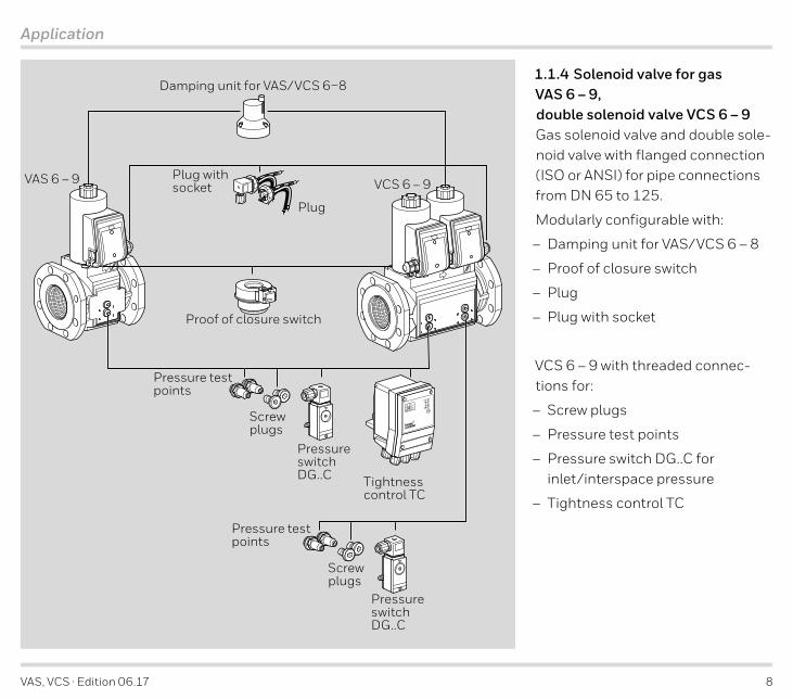
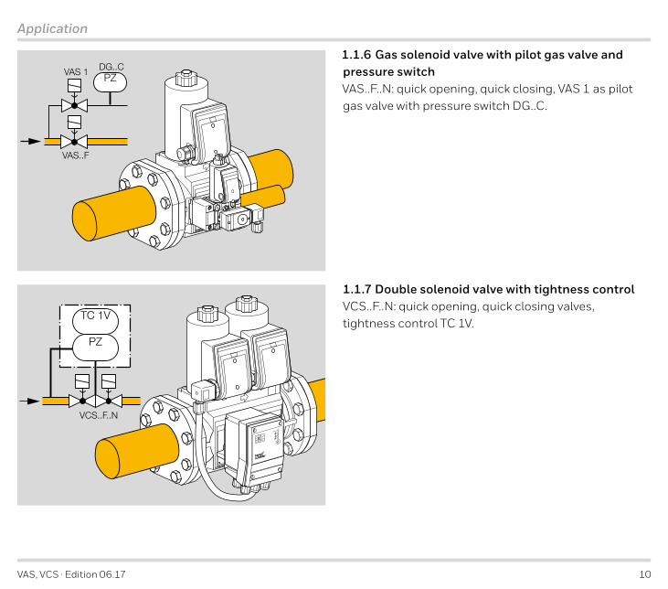
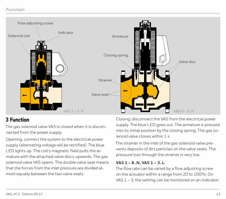
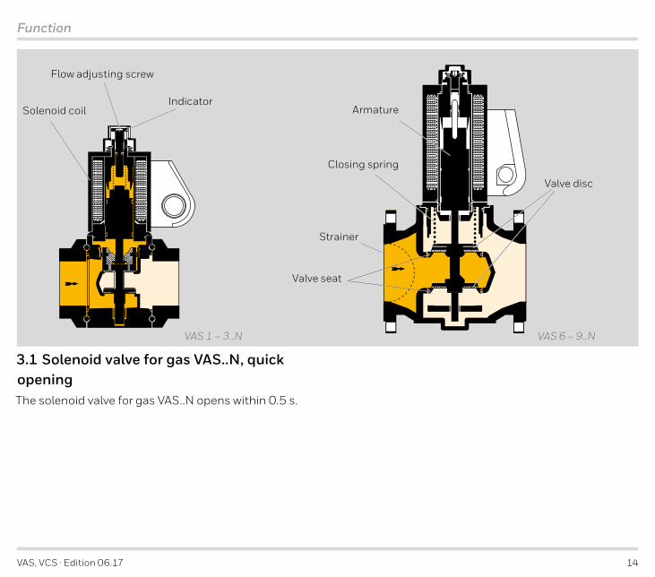
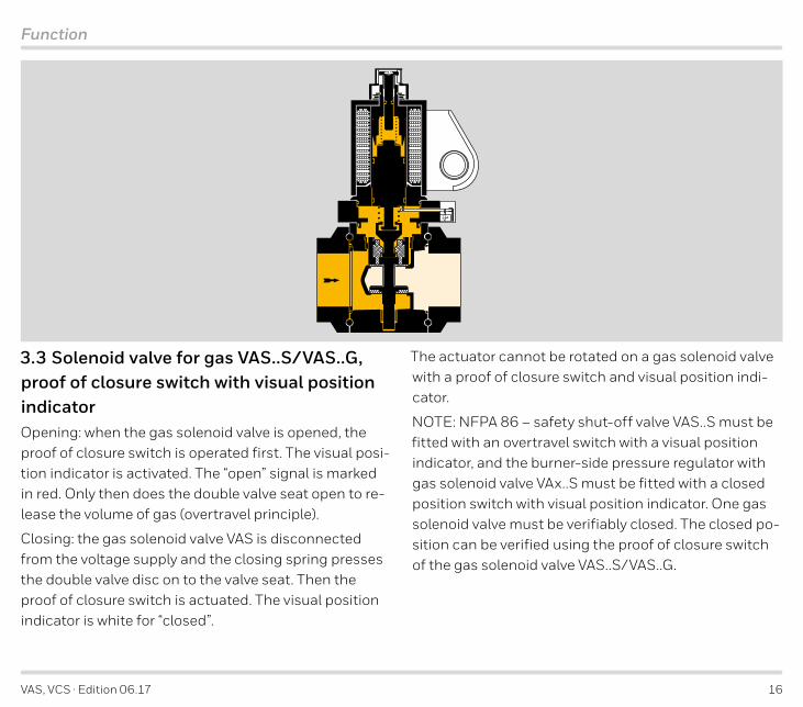
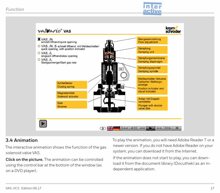
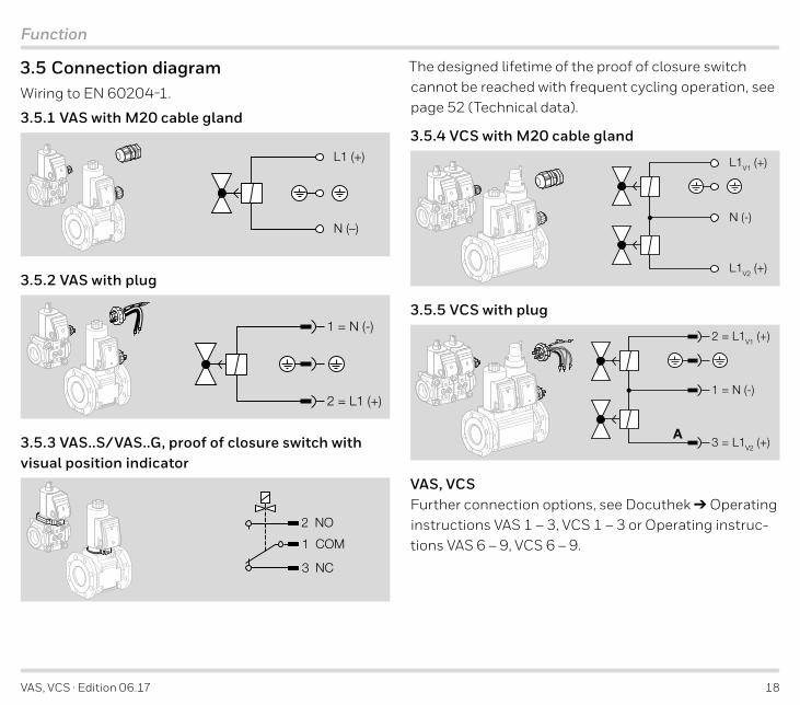
VAS VCS middot Edition 0617 18
Function
3 5 Connection diagramWiring to EN 60204-1
3 5 1 VAS with M20 cable gland
L1 (+)
N (ndash)
3 5 2 VAS with plug
1 = N (-)
2 = L1 (+)
3 5 3 VAS SVAS G proof of closure switch with visual position indicator
1 COM
2 NO
3 NC
The designed lifetime of the proof of closure switch cannot be reached with frequent cycling operation see page 52 (Technical data)
3 5 4 VCS with M20 cable gland
L1V1 (+)
N (-)
L1V2 (+)
3 5 5 VCS with plug
2 = L1V1 (+)
1 = N (-)
3 = L1V2 (+)A
VAS VCSFurther connection options see Docuthek Operating instructions VAS 1thinspndashthinsp3 VCS 1thinspndashthinsp3 or Operating instruc-tions VAS 6thinspndashthinsp9 VCS 6thinspndashthinsp9
VAS VCS middot Edition 0617 19
Replacement possibilities
4 Replacement possibilities4 1 Solenoid valve for gas VG is to be replaced by VAS
Type TypeVG Gas solenoid valve Gas solenoid valve VAS
1015 DN 10 internal 15 mm (059) Size 1 DN 10 11015 DN 15 Size 1 DN 15 115
1512 DN 15 internal 12 mm (047) ndash ndash ndash20 DN 20 Size 1 DN 20 12025 DN 25 Size 1 DN 25 125
2515 DN 25 internal 15 mm (059) ndash ndash ndash4032 DN 40 internal 32 mm (126) Size 2 DN 40 240
40 DN 40 Size 2 DN 40 2404033 DN 40 internal 33 mm (130) ndash ndash ndash
50 DN 50 Size 3 DN 50 3505039 DN 50 internal 39 mm (154) ndash ndash ndash5065 DN 50 internal 65 mm (259) Size 3 DN 50 350
65 DN 65 Size 3 DN 65 36565 DN 65 Size 6 DN 65 665
6549 DN 65 internal 49 mm (193) ndash ndash ndash80 DN 80 Size 7 DN 80 780
100 DN 100 Size 8 DN 100 8100T T-product T-product TR Rp internal thread Rp internal thread RN NPT internal thread NPT internal thread NF ISO fl ange ISO fl ange FA ANSI fl ange ANSI fl ange A
02 pu max 200 mbar (2 psig) pu max 500 mbar (7 psig) 03 360 mbar (5 psig) 500 mbar (7 psig) 10 1000 mbar (145 psig) ndash ndash18 1800 mbar (261 psig) ndash ndashN Quick opening Quick opening NL Slow opening Slow opening LK Mains voltage 24 V DC Mains voltage 24 V DC Kndash ndash 100 V AC PQ 120 V AC 120 V AC Qndash ndash 200 V AC YT 220240 V AC 230 V AC W
VAS VCS middot Edition 0617 20
Replacement possibilities
4 1 1 Searching for an order number or type
VG Order No VG type designationVAS Order No
VAS type designation
Hits
VG is to be replaced by VAS
Continuation
Type Type3 Electrical connection via terminals Electrical connection via terminals 36 Electrical connection via socket Electrical connection via socket 9 Metal terminal connection box Electrical connection via terminals 31 Screw plug at the inlet Screw plug at the inlet and outlet 3 Screw plug at the inlet and outlet Screw plug at the inlet and outlet 4 Pressure test point at the inlet Pressure test point at the inlet and outlet 6 Pressure test point at the inlet and outlet Pressure test point at the inlet and outlet D Flow adjustment Flow adjustment S Proof of closure switch Proof of closure switch with visual position indicator SG Proof of closure switch for 24 V Proof of closure switch for 24 V with visual position indicator G
OCS Overtravel switch Proof of closure switch with visual position indicator SCPS Proof of closure switch Proof of closure switch with visual position indicator S
VI Visual position indicator Proof of closure switch with visual position indicator SM Suitable for biogas Suitable for biogas V Viton valve disc seal ndash ndash
VG 25R02NT31DM Example Example VAS 125RNW
= standard availableFor length compensation when replacing VG by VAS 6 ndash 9 install an adapter for length compensation ndash see Accessories Adapter for length compensation Pressure test points may be attached at the left- andor right-hand side Proof of closure switch with visual position indicator can be attached at the left- or right-hand side Flow adjustment for VASVCSN 1 ndash 8 VASVCS 1 ndash 3L
VAS VCS middot Edition 0617 21
Replacement possibilities
4 2 MODULINE solenoid valve for gas VS is to be replaced by VAS
Type Flange TypeVS Gas solenoid valve Gas solenoid valve VAS
115125 38 Size 115
Size 125 Size 1 DN 10 110
115125 frac12 Size 115
Size 125 Size 1 DN 15 115
115125 frac34 Size 115
Size 125 Size 1 DN 20 120
115125 1 Size 115
Size 125 Size 1 DN 25 125
230240 1 Size 232
Size 240 Size 2 DN 25 225
232240 1frac12 Size 232
Size 240 Size 2 DN 40 240
350 1frac12 Size 350 Size 3 DN 40 340350 2 Size 350 Size 3 DN 50 350ML MODULINE + Rp internal thread connection fl anges Rp internal thread R
TML MODULINE + NPT internal thread connection fl anges NPT internal thread N
02 pu max 200 mbar (2 psig) pu max 500 mbar (7 psig)
03 pu max 360 mbar (3 psig) pu max 500 mbar (7 psig)
N Quick opening Quick opening NL Slow opening Slow opening LD Flow adjustment Flow adjustment
K Mains voltage 24 V DC Mains voltage 24 V DC Kndash ndash 100 V AC PM 120 V AC 120 V AC Qndash ndash 200 V AC YT 220240 V AC 230 V AC W
VAS VCS middot Edition 0617 22
Replacement possibilities
Continuation
Type Flange Type3 Electrical connection via terminals Electrical connection via terminals 36 Electrical connection via socket Electrical connection via socket
9 Metal terminal connection box Electrical connection via terminals 3 Pressure test point at the inlet Pressure test point at the inlet and outlet
S Proof of closure switch Proof of closure switch SG Proof of closure switch for 24 V Proof of closure switch for 24 V GM Contains no non-ferrous metals Contains no non-ferrous metals
V Viton valve disc seal ndash ndash
VS 350ML02LT3 with Rp 1frac12 connection fl anges Example Example VAS 340RLW with test points
Flow adjustment for VASVCSN 1 ndash 3 VASVCS 1 ndash 2L = standard available
VAS VCS middot Edition 0617 23
1
1
2
3
4
56
8
10
01
02
03
04
0506
08
20
30
40
5060
80
100
6 7 8 10 20 30 40 60 100 200 300 500
6 8 10 20 30 40 60 100 200 400 1000 2000
4 5 7 10 20 30 40 60 80 100 200 300
421
31 2
532 1000 2000
500 1000
∆p [m
bar]
Q [m3h (n)]
1
3
2
VAS
115
VAS
120
VAS
225
VAS
232
VAS
240
VAS
250
VAS
110
VAS
350
VAS
365
VAS
340
VAS
665
VAS
9125
VAS
780
VAS
8100
VAS
125
2
2001006040 300 1000 2000 3000 10000500 5000 30000 50000
1
3
4
56
810
20
30
40
04
0506
08
01
02
03
004
005006
008
Q [SCFH]
∆p [i
nch
WC
]
1
Flow rate
5 Flow rate5 1 VASWhen determining the pressure loss operating cubic metres must be entered Then the pressure loss Δp read must be multiplied by the absolute pressure in bar (positive pressure + 1) to account for the change in the mediumrsquos densityExample inlet pressure pu (positive pressure) = 03 bar gas type natural gas operating flow rate Q = 50 m3h (b) Δp in the diagram = 55 mbar Δp = 55 mbar x (1 + 03) = 72 mbar on the solenoid valve VAS 225
metric imperial
Enter densityFlow rate Q (standard)
Inlet pressure pu
Δpmax
Medium temperature
Flow rate Q (operation)
Product Δp v
5 1 1 Calculating the nominal size
Qmin
= natural gas (ρ = 080 kgm3) = propane (ρ = 201 kgm3) = air (ρ = 129 kgm3)
The characteristic flow rate curves have been measured with the specified flanges and a fitted strainer
Qmin = rough specification for fully re-stricted flow adjustment and ∆pmax
VAS VCS middot Edition 0617 24
1
10
8
65
4
3
2
1
01
02
03
04
0506
08
20
30
40
5060
80
100
∆p [m
bar]
1
3
2
1 6 7 8 10 20 30 40 60 100 200 300 500
6 8 10 20 30 40 60 100 200 400 1000 2000
4 5 7 10 20 30 40 60 80 100 200 300
421
31 2
532
Q [m3h (n)]
1000 2000
500 1000
12001006040 300 1000 2000 3000 10000500 5000
Q [SCFH]30000 50000
∆p [i
nch
WC
]
1
2
3
4
56
8
10
20
30
40
04
0506
08
01
02
03
004
005006
008
VCS
9125
VCS
8100
VCS
780
VCS
665
VCS
350
VC
S 36
5
VCS
340
VCS
240
VC
S 25
0
VCS
120
VCS
125
VCS
225
VCS
115
VCS
110
VCS
232
Flow rate
5 2 VCSWhen determining the pressure loss operating cubic metres must be entered Then the pressure loss Δp read must be multiplied by the absolute pressure in bar (positive pressure + 1) to account for the change in the mediumrsquos densityExample inlet pressure pu (positive pressure) = 03 bar gas type natural gas operating flow rate Q = 648 m3h (b) Δp in the diagram = 57 mbar Δp = 57 mbar x (1 + 03) = 74 mbar on the double solenoid valve VCS 232
metric imperial
Enter densityFlow rate Q (standard)
Inlet pressure pu
ΔpmaxMedium temperature
Flow rate Q (operation)
Product Δp v
5 2 1 Calculating the nominal size
= natural gas (ρ = 080 kgm3) = propane (ρ = 201 kgm3) = air (ρ = 129 kgm3)
The characteristic flow rate curves have been measured with the specified flanges and a fitted strainer
Qmin = rough specification for fully restrict-ed flow adjustment and ∆pmax
Qmin
VAS VCS middot Edition 0617 25
Flow rate
5 3 kv valueThe size and nominal flange diameter is determined us-ing the flow rate diagram or by calculation using the kV value
Q(n) = Flow rate (standard state) [msup3h]
kV = Valve coefficient (kV min = rough specification for fully restricted flow adjustment)
Δp = Pressure loss [bar]
pd = Outlet pressure (absolute) [bar]
ρn = Density [kgm3] (air 129 natural gas 080 propane 201 butane 271)
T = Medium temperature (absolute) [K]
see page 65 (Converting units)
kv =
)2 middot
middotρn middot T∆p middot pd
pd
Q(n)514
Q(n)
514 kv
ρn middot T
ρn middot T
∆p middot pd
∆p = (
Q(n) = 514 middot kv middot
VAS kV max m3h
kV min m3h VCS kV max
m3hkV minm3h
VAS 110 50 2 VCS 110 47 2VAS 115 64 2 VCS 115 57 2VAS 120 96 2 VCS 120 76 2VAS 125 109 2 VCS 125 81 2VAS 225 192 53 VCS 225 162 53VAS 232 241 53 VCS 232 190 53VAS 240 267 53 VCS 240 203 53VAS 250 272 53 VCS 250 206 53VAS 340 386 85 VCS 340 308 85VAS 350 418 85 VCS 350 327 85VAS 365 435 85 VCS 365 339 85VAS 665 764 153 VCS 665 595 119VAS 780 1093 219 VCS 780 846 169VAS 8100 1657 331 VCS 8100 1277 255VAS 9125 2479 ndash VCS 9125 1905 ndash
ExampleWe want to find the size and nominal flange diameter for a gas solenoid valve VAS
We have the maximum flow rate Q(n) max the inlet pres-sure pu and the natural gas temperature T
Q(n) max = 60 m3h
pu = 70 mbar = 007 bar pu absolute = 007 bar + 1 bar = 107 bar
Δpmax = 001 bar (desired)
pd absolute = pu absolute ndash Δpmax
pd absolute = 107 bar ndash 001 bar = 106 bar
T = 27degC Tabsolute = 27 + 273 K = 300 K
VAS VCS middot Edition 0617 26
Flow rate
kv = = 179middot083 middot 300001 middot 106
60514
The gas solenoid valve is selected using the next higher kv value (see table) VAS 225
VAS VCS middot Edition 0617 27
Selection
6 Selection6 1 Selection table for VAS 1thinspndashthinsp3
Type Nom
inal
size
DN
Rp NPT
ISO
Quic
k ope
ning
qu
ick c
losin
gSl
ow o
peni
ng
quic
k clo
sing
230
V AC
200
V AC
120
V AC
100
V AC
24 V
DC
Proo
f of c
losu
re sw
itch
1)3)
Proo
f of c
losur
e swi
tch 2
4 V1)
3)
View
ed fr
om th
e rig
ht1)
3)
View
ed fr
om th
e lef
t1)3)
M20
cabl
e gla
nd4)
Plug
with
sock
et4)
Plug
with
out s
ocke
t4)
Accessories right3) Accessories left3)
Scre
w pl
ugPr
essu
re te
st p
oint
DG 1
7VC2)
DG 4
0VC2)
DG 1
10VC
2)
DG 3
00VC
2)
Bypa
ssp
ilot v
alve
VBY
1)
Bypa
ssp
ilot v
alve
VAS
11)
Scre
w pl
ugPr
essu
re te
st p
oint
DG 1
7VC2)
DG 4
0VC2)
DG 1
10VC
2)
DG 3
00VC
2)
Bypa
ssp
ilot v
alve
VBY
1)
Bypa
ssp
ilot v
alve
VAS
11)
R N F N L W Y Q P K S G R LVAS 1
VAS 1 10thinspndashthinsp25
VAS 2
VAS 2 25
VAS 2 32
VAS 2 40
VAS 2 50
VAS 3
VAS 3 40
VAS 3 50
VAS 3 65
= standard = available1) Proof of closure switch and bypasspilot gas valve cannot be fi tted together on the same side2) Specify the test point for inlet pressure pu or outlet pressure pd3) Viewed from the rightleft looking into the valve body in the direction of fl ow see order example4) Viewing side for the electr connection looking at the connection box
3)
4)
Order exampleVAS 225RNWFitted pressure
switch for test point pu
Help for selecting the gas solenoid valve VAS can be found on the ProFi DVD wwwkromschroedercom Prod-ucts DVD Product finder ldquoProFirdquo
VAS VCS middot Edition 0617 28
Selection
6 2 Type code for VAS 1thinspndashthinsp3
Code DescriptionVAS Gas solenoid valve1thinspndashthinsp3 SizeT T-productndash-010thinspndashthinsp 65
No inlet and outlet fl angeBlind fl ange
Nominal inlet and outlet diameterRNF
Rp internal threadNPT internal thread
ISO fl angeNL
Quick opening quick closingSlow opening quick closing
KPQYW
Mains voltage 24 V DCMains voltage 100 V AC 5060 HzMains voltage 120 V AC 5060 HzMains voltage 200 V AC 5060 HzMains voltage 230 V AC 5060 Hz
SG
Proof of closure switch with visual position indicatorProof of closure switch for 24 V with visual position indicator
RL
Viewed from the right (in the direction of fl ow)Viewed from the left (in the direction of fl ow)
VAS VCS middot Edition 0617 29
Selection
6 3 Selection table for VAS 6thinspndashthinsp9
Type Nom
inal
size
DN
ISO
ANSI
500
mba
rQu
ick o
peni
ng q
uick
clos
ing
Slow
ope
ning
qui
ck cl
osin
g23
0 V
AC12
0thinspndashthinsp2
30 V
AC
120
V AC
24 V
DC
Proo
f of c
losu
re sw
itch1)
Proo
f of c
losu
re sw
itch
24 V
1)
View
ed fr
om th
e rig
ht1)
3)
View
ed fr
om th
e lef
t1)3)
M20
cabl
e gla
nd4)
Plug
with
sock
et4)
Plug
with
out s
ocke
t4)
Basic
Prep
ared
for a
dapt
er p
late
s
Accessories viewed from the right3)5)
Inlet Outlet
Scre
w pl
ugPr
essu
re te
st p
oint
DG 1
7VC
DG 4
0VC
DG 1
10V
C
DG 3
00V
C
Bypa
ss va
lve1)
Pilo
t gas
valv
e1)
1frac12 N
PT b
reat
her l
ine
Rp 1
bre
athe
r lin
e
Scre
w pl
ug
Pres
sure
test
poi
nt
DG 1
7VC
DG 4
0VC
DG 1
10V
CDG
300
VC
F A 05 N L W A Q K S G R L 3 B E P M 1 2 3 4 B Z V E P M 1 2 3 4VAS 6 65
VAS 7 80
VAS 8 100
VAS 9 125
= standard = available1) Proof of closure switch and bypasspilot gas valve cannot be fi tted together on the same side2) Specify the test point for inlet pressure pu or outlet pressure pd3) Viewed from the rightleft looking into the valve body in the direction of fl ow see order example4) Viewing side for the electr connection looking at the connection box see order example5) The same accessories can be selected for the other viewing side
Order exampleVAS 665F05NW3EP2PP
3)
4)
Help for selecting the gas solenoid valve VAS can be found on the ProFi DVD wwwkromschroedercom Prod-ucts DVD Product finder ldquoProFirdquo
VAS VCS middot Edition 0617 30
Selection
6 4 Type code for VAS 6ndashthinsp9Code DescriptionVAS Gas solenoid valve6thinspndashthinsp9 SizeT T-product65thinspndashthinsp125 Nominal inlet fl ange diameterFA
ISO fl angeANSI fl ange
05 Max inlet pressure pu max = 500 mbar (7 psig) NL
Quick opening quick closingSlow opening quick closing
WAQK
Mains voltage 230 V AC 5060 HzMains voltage 120thinspndashthinsp230 V AC 5060 Hz
Mains voltage 120 V AC 5060 HzMains voltage 24 V DC
SG
Proof of closure switch with visual position indicatorProof of closure switch for 24 V with visual position indicator
RL
Viewed from the right (in the direction of fl ow)Viewed from the left (in the direction of fl ow)
3 Electrical connection M20 cable glandBE
BasicPrepared for adapter plates
Code Description
PM1234BZVE
Accessories right inletScrew plug
Test point for inlet pressure puGas pressure switch DG 17VC Gas pressure switch DG 40VC
Gas pressure switch DG 110VC Gas pressure switch DG 300VC
Bypass valve VAS 1 fi ttedPilot gas valve VAS 1 fi tted
Prepared for 1frac12 NPT breather linePrepared for Rp 1 breather line
PM1234
Accessories right outletScrew plug
Test point for outlet pressure pdGas pressure switch DG 17VCGas pressure switch DG 40VC
Gas pressure switch DG 110VCGas pressure switch DG 300VC
PM1234BZVE
Accessories left inletScrew plug
Test point for inlet pressure puGas pressure switch DG 17VC Gas pressure switch DG 40VC
Gas pressure switch DG 110VC Gas pressure switch DG 300VC
Bypass valve VAS 1 fi ttedPilot gas valve VAS 1 fi tted
Prepared for 1frac12 NPT breather linePrepared for Rp 1 breather line
PM1234
Accessories left outletScrew plug
Test point for outlet pressure pdGas pressure switch DG 17VCGas pressure switch DG 40VC
Gas pressure switch DG 110VCGas pressure switch DG 300VC
VAS VCS middot Edition 0617 31
Selection
6 5 Selection table for VCS 1thinspndashthinsp3
Type Nom
inal
size
DN
Rp NPT
ISO
500
mba
rFi
lter m
odul
e VM
FV1
= qu
ick o
peni
ng q
uick
clos
ing
V1 =
slow
ope
ning
qui
ck cl
osin
gV2
= qu
ick o
peni
ng q
uick
clos
ing
V2 =
slow
ope
ning
qui
ck cl
osin
gFi
ne-a
djus
ting
valv
e VM
VM
easu
ring
orifi
ce V
MO
230
V AC
200
V AC
120
V AC
100
V AC
24 V
DC
Proo
f of c
losu
re sw
itch1)
Proo
f of c
losu
re sw
itch
24 V
1)
View
ed fr
om th
e rig
ht3)
View
ed fr
om th
e lef
t3)
M20
cabl
e gla
nd4)
Plug
with
sock
et4)
Plug
with
out s
ocke
t4)
Accessories3)
Viewed from the right Viewed from the left
Scre
w pl
ugPr
essu
re te
st p
oint
DG 1
7VC2)
DG 4
0VC2)
DG 1
10VC
2)
DG 3
00VC
2)
Scre
w pl
ugPr
essu
re te
st p
oint
DG 1
7VC2)
DG 4
0VC2)
DG 1
10VC
2)
DG 3
00VC
2)
Bypa
ss va
lve V
BY1)
Bypa
ss va
lve V
AS 1
1)
Pilo
t gas
valv
e VBY
1)
Pilo
t gas
valv
e VAS
11)
R N F 05 F N L N L V O W Y Q P K S G R L 3 P M 1 2 3 4 P M 1 2 3 4 BY BS ZY ZSVCS 1 VCS 1 10thinspndashthinsp25 VCS 2 VCS 2 25 VCS 2 32 VCS 2 40 VCS 2 50 VCS 3 VCS 3 40 VCS 3 50 VCS 3 65 = standard = available1) Proof of closure switch and bypasspilot gas valve cannot be fi tted together on the same side2) Specify the test point for inlet pressure pu interspace pressure pz or outlet pressure pd When
attaching DGVC for pz the installation space left at the other valve is only suffi cient for screw plugs3) Viewed from the rightleft looking into the valve body in the direction of fl ow see order example4) Viewing side for the electr connection looking at the connection box see order example
Order exampleVCS 240R40R05NNWR32-PPPPPP
V1V2
3)
4)
Fitted pressureswitch for test point pu
Selecting VMF VMV VMO and accessories see page 37 (Accessories)
VAS VCS middot Edition 0617 32
Selection
6 6 Type code for VCS 1thinspndashthinsp3
Code DescriptionVCS Gas solenoid valve1thinspndash 3 SizeET
EU certfi edT-product
ndash10thinspndashthinsp65
No inlet and outlet fl angeNominal inlet and outlet diameter
RNF
Rp internal threadNPT internal threadFlange to ISO 7005
05 Max inlet pressure pu = 500 mbar (7 psig)F Filter moduleNL
1st valve quick opening quick closing1st valve slow opening quick closing
NL
2nd valve quick opening quick closing2nd valve slow opening quick closing
VO10thinspndashthinspO32
Fine-adjusting valve VMVMeasuring orifi ce VMO Oslash 10thinspndashthinspOslash 32 mm
KPQYW
Mains voltage 24 V DCMains voltage 100 V AC 5060 HzMains voltage 120 V AC 5060 HzMains voltage 200 V AC 5060 HzMains voltage 230 V AC 5060 Hz
SG
Proof of closure switch with visual position indicatorProof of closure switch for 24 V with visual position indicator
RL
Flow from left to rightFlow from right to left
3 Electrical connection M20 cable gland
Code Description
PM1234
Accessories right inletScrew plug
Test point for inlet pressure puGas pressure switch DG 17VCGas pressure switch DG 40VC
Gas pressure switch DG 110VCGas pressure switch DG 300VC
PM1234
Accessories right interspace 1Screw plug
Test point for interspace pressure pzGas pressure switch DG 17VCGas pressure switch DG 40VC
Gas pressure switch DG 110VCGas pressure switch DG 300VC
PM1234BYZS
Accessories right interspace 2Screw plug
Test point for interspace pressure pzGas pressure switch DG 17VCGas pressure switch DG 40VC
Gas pressure switch DG 110VCGas pressure switch DG 300VC
Bypass valve VBY fi ttedPilot gas valve VAS 1 fi tted
PM1234BYZS
Accessories right outletScrew plug
Test point for outlet pressure pdGas pressure switch DG 17VCGas pressure switch DG 40VC
Gas pressure switch DG 110VCGas pressure switch DG 300VC
Bypass valve VBY fi ttedPilot gas valve VAS 1 fi tted
The same accessories can be selected for the other viewing side
VAS VCS middot Edition 0617 33
Selection
6 7 Selection table for VCS 6thinspndashthinsp9
Type Nom
inal
size
DN
ISO
ANSI
500
mba
rV1
= qu
ick o
peni
ng q
uick
clos
ing
V1 =
slow
ope
ning
qui
ck cl
osin
gV2
= qu
ick o
peni
ng q
uick
clos
ing
V2 =
slow
ope
ning
qui
ck cl
osin
g23
0 V
AC12
0thinspndashthinsp2
30 V
AC
120
V AC
24 V
DC
Proo
f of c
losu
re sw
itch1)
Proo
f of c
losu
re sw
itch
24 V
1)
View
ed fr
om th
e rig
ht3)
View
ed fr
om th
e lef
t3)
M20
cabl
e gla
nd4)
Plug
with
sock
et4)
Plug
with
out s
ocke
t4)
Basic
Prep
ared
for a
dapt
er p
late
s
Accessories viewed from the right3)5)
Inlet Interspace 1 Interspace 2 Outlet
Scre
w pl
ugPr
essu
re te
st p
oint
DG 1
7VC2)
DG 4
0VC2)
DG 1
10VC
2)
DG 3
00VC
2)
Scre
w pl
ugPr
essu
re te
st p
oint
DG 1
7VC2)
DG 4
0VC2)
DG 1
10VC
2)
DG 3
00VC
2)
Scre
w pl
ugPr
essu
re te
st p
oint
DG 1
7VC2)
DG 4
0VC2)
DG 1
10VC
2)
DG 3
00VC
2)
Bypa
ss va
lve
Pilo
t gas
valv
e1frac12
NPT
bre
athe
r lin
eRp
1 b
reat
her l
ine
Scre
w pl
ugPr
essu
re te
st p
oint
DG 1
7VC2)
DG 4
0VC2)
DG 1
10VC
2)
DG 3
00VC
2)
F A 05 N L N L W A Q K S G R L 3 B E P M 1 2 3 4 P M 1 2 3 4 P M 1 2 3 4 B Z V E P M 1 2 3 4VCS 6 65
VCS 7 80
VCS 8 100
VCS 9 125
= standard = available1) Specify wiring of 1st or 2nd proof of closure switch (or ldquononerdquo)2) Specify the test point for inlet pressure pu interspace pressure pz or outlet pressure pd3) Viewed from the rightleft looking into the valve body in the direction of fl ow4) Viewing side for the electr connection looking at the connection box see order example5) The same accessories can be selected for the other viewing side
Order exampleVCS 665F05NLW3E2B-PPPP
V1V2
3)
4)
VAS VCS middot Edition 0617 34
Selection
6 8 Type code for VCS 6ndashthinsp9Code DescriptionVCS Gas solenoid valve6thinspndashthinsp9 SizeT T-product65thinspndashthinsp125 Niminal inlet fl ange diameter sizeFA
ISO fl angeANSI fl ange
05 Max inlet pressure pu max 500 mbar (7 psig) NL
1st valve quick opening quick closing1st valve slow opening quick closing
NL
2nd valve quick opening quick closing2nd valve slow opening quick closing
KQWA
Mains voltage 24 V DCMains voltage 120 V AC 5060 HzMains voltage 230 V AC 5060 Hz
Mains voltage 120thinspndashthinsp230 V AC 5060 HzSG
Proof of closure switch with visual position indicatorProof of closure switch for 24 V with visual position indicator
RL
Viewed from the right (in the direction of fl ow)Viewed from the left (in the direction of fl ow)
3 Electrical connection M20 cable glandBE
BasicPrepared for adapter plates
Code Description
PM1234
Accessories right inletScrew plug
Test point for inlet pressure puGas pressure switch DG 17VC Gas pressure switch DG 40VC
Gas pressure switch DG 110VC Gas pressure switch DG 300VC
PM1234
Accessories right interspace 1Screw plug
Test point for interspace pressure pzGas pressure switch DG 17VCGas pressure switch DG 40VC
Gas pressure switch DG 110VCGas pressure switch DG 300VC
PM1234BZVE
Accessories right interspace 2Screw plug
Test point for interspace pressure pzGas pressure switch DG 17VC Gas pressure switch DG 40VC
Gas pressure switch DG 110VC Gas pressure switch DG 300VC
Bypass valve VAS 1 fi ttedPilot gas valve VAS 1 fi tted
Prepared for 1frac12 NPT breather linePrepared for Rp 1 breather line
PM1234
Accessories right outletScrew plug
Test point for outlet pressure pdGas pressure switch DG 17VCGas pressure switch DG 40VC
Gas pressure switch DG 110VCGas pressure switch DG 300VC
The same accessories can be selected for the other viewing side
VAS VCS middot Edition 0617 35
Project planning information
7 Project planning information7 1 Installation
GFK VCSGFK
VAS
Installation position black solenoid actuator in the ver-tical upright position or tilted up to the horizontal not upside down
Sealing material and thread cuttings must not be al-lowed to get into the valve housing Install a filter up-stream of every system
The pipe system must be designed in such a way so as to avoid strain at the connections
Do not store or install the unit in the open air
pdpu
pz
pdpzpu
pz
pd
pupd
pupd
pu pz
The inlet pressure pu the interspace pressure pz and the outlet pressure pd can be measured at the pressure test points on both sides
gt20 mmgt079
The unit must not be in contact with masonry Minimum clearance 20 mm (079 inches)
Ensure that there is sufficient space for installation and adjustment
If more than three valVario controls are installed in line the controls must be supported
The seals in some gas compression fittings are approved for temperatures of up to 70degC (158degF) This tempera-ture limit will not be exceeded if the flow through the pipe is at least 1 msup3h (3531 SCFH) of gas and the maxi-mum ambient temperature is 50degC (122degF)
VAS VCS middot Edition 0617 36
Project planning information
M
VMV
VAH
VASVAS
pd-
psa-psa
VMV
VAH pd-
psa-psa
It is not permitted to install a gas solenoid valve VAS downstream of flow rate regulator VAH and upstream of fine-adjusting valve VMV The VAS would no longer be able to perform its function as a second safety valve if installed in the above-mentioned position
The measuring orifice in the air line for impulse lines psa and psa- must always be installed downstream of the air control valve
7 2 Electrical connectionUse temperature-resistant cable (gt 90degC) for the elec-trical connection
The solenoid actuator heats up during operation Sur-face temperature approx 85degC (approx 185degF) pursu-ant to EN 60730-1
In the case of double solenoid valves the position of the connection box can only be changed by removing
the actuator and reinstalling it rotated by 90deg or 180deg The solenoid actuator cannot be rotated on solenoid valves with proof of closure switch VCxS or VCxG
VAS 1 ndash 3 L VCS 1 ndash 3 L
Damping speedThe opening speed can be influenced by turning the nozzle screw on the damping unit see operating in-structions in the Docuthek Operating instructions VAS 1thinspndashthinsp3 VCS 1thinspndashthinsp3
7 3 Tightness control TC 1VTightness control TC 1V can be mounted directly onto the valve see Accessories page 50 (Tightness con-trol TC 1V)
1
2
Power
VAS 6thinspndashthinsp9 VCS 6thinspndashthinsp9VAS 1thinspndashthinsp3 VCS 1thinspndashthinsp3
Tightness control TC 1V and bypasspilot gas valve cannot be fitted together on the same side of the dou-ble block valve
VAS VCS middot Edition 0617 37
pupd
50
6420527
37
DGVC
25
15
2511
08
DGVCT
Accessories
8 Accessories8 1 Gas pressure switch DG CMonitoring the inlet pressure pu the electrical plug of the pressure switch for gas points towards the inlet flange Monitoring the outlet pressure pd the electrical plug of the pressure switch for gas points towards the outlet flange
Scope of delivery 1 x pressure switch for gas 2 x retaining screws 2 x sealing rings
Also available with gold-plated contacts for voltages of 5 to 250 V
DG VC for VASVCSType Adjusting range [mbar]
DG 17VC 2 to 17DG 40VC 5 to 40
DG 110VC 30 to 110DG 300VC 100 to 300
DG VCT for VAS TVCS Twith AWG 18 connection wires
Type Adjusting range [WC]DG 17VCT 08 to 68DG 40VCT 2 to 16
DG 110VCT 12 to 44DG 300VCT 40 to 120
Fastening set DG C for VAx 1thinspndashthinsp3Order No 74921507 scope of delivery 2 x retaining screws 2 x sealing rings
VAS VCS middot Edition 0617 38
pd
pu pu pd
pd
pupu
pdpzpd
pz
pd
pz
pz
VAS 6thinspndashthinsp9
VCS 6thinspndashthinsp9
DGC1
DGC1DGC9
pu
pz
DGC9
VCS 1thinspndashthinsp3
Accessories
8 1 1 Installation on VCS 1thinspndashthinsp3If when monitoring the inlet or outlet pressure and the interspace pressure both pressure switches should be fitted on the same side of the valve only the com-bination DGC1 and DGC9 may be used for design reasons The socket of the gas pressure switch DGC1 points towards the test point pu (towards the inlet flan-ge) The DGC9 is also optionally available for moni-toring the interspace pressure pz The socket points towards the outlet flange
8 1 2 Installation on VAS 6thinspndashthinsp9Monitoring the inlet pressure pu the pressure switch for gas is mounted on the inlet side
Monitoring the outlet pressure pd the pressure switch for gas is mounted on the outlet side
8 1 3 Installation on VCS 6thinspndashthinsp9Monitoring the inlet pressure pu interspace pressure pz outlet pressure pd for this attach the pressure switch for gas at the relevant position in each case
VAS VCS middot Edition 0617 39
2
3
456
810
20
30
405060
80100
∆p
[mba
r]
005 01 02 03 05 08 1 2 3 4 51
3
2
Qn [m3h]
1
01
02
03
0405
08
003
002
6 8 10
005 01 02 03 05 08 1 2 3 4 5003 6 8 10
20
005 01 02 03 05 08 1 2 3 4 5003 6 8 10 20
30
Δp [i
nch
WC
]
1
2
3
456
810
20
30
40
04
004
006
008
01
02
03
0506
08
Qn [SCFH]10 40 60 100 200 3001 500 10002 3 4 5
120 306 8
21 3 4 5 6 7 8 910
Accessories
8 2 Bypasspilot gas valve VAS 1
8 2 1 Flow rate VAS 1 attached to VAS 1 VAS 2 VAS 3
The characteristic flow rate curves have been measured for bypass valve VAS 1 with connection pipe diameter 1 to 10 mm (004 to 04) and for the pilot gas valve with 10 mm (04) connection pipe
Scope of delivery and connection pipes see page 40 (Scope of delivery of VAS 1 for VAS 1 VAS 2 VAS 3)
= Natural gas (ρ = 080 kgm3) = Propane (ρ = 201 kgm3) = Air (ρ = 129 kgm3)
Bypass valve connection pipe diameter [mm]
Pilo
t gas
val
ve 1
0 m
m (0
4)
con
nect
ion
pipe
dia
met
er
VAS VCS middot Edition 0617 40
A
VAS 1 rarr VAx 1
VAS 1 rarr VAx 2 VAx 3
C
A
D
F
B
E
C
D
F
B
E
Accessories
8 2 2 Scope of delivery of VAS 1 for VAS 1 VAS 2 VAS 3A 1 x bypasspilot gas valve VAS 1 B 4 x O-rings C 4 x double nuts for VAS 1 rarr VAx 1 C 4 x spacer sleeves for VAS 1 rarr VAx 2VAx 3 D 4 x connection parts E 1 x mounting aid
Pilot gas valve VAS 1 F 1 x connection pipe 1 x sealing plug if the pilot gas
valve has a threaded flange on the outlet side
Bypass valve VAS 1 F 2 x connection pipes if the bypass valve has a blind
flange on the outlet side Standard diameter 10 mm
Other connection pipes with bypass diameter as of 1 mm are available
Oslash Order No1 mm 749238772 mm 749239103 mm 749239114 mm 749239125 mm 749239136 mm 749239147 mm 749239158 mm 749239169 mm 7492391710 mm 74923918
VAS VCS middot Edition 0617 41
2
3
456
810
20
30
405060
80100
Δp [m
bar]
1
01
02
03
0405
08
4 5 6 8 10 20 30 40 60 80 1001
4 5 6 8 10 20 30 40 50 60 803
4 5 6 8 10 20 30 40 602
3
3
1 2 3
1 2
1 2
100040 50 60 80 100 200 300 4001
2000 3000600
Q [m3h (n)]
Q [SCFH (n)]
∆p
[inch
WC
]
1
2
3
456
810
20
30
40
04
004
006
008
01
02
03
0506
08
Accessories
8 2 3 Flow rate VAS 1 attached to VAS 6thinspndashthinsp9 VCS 6thinspndashthinsp9
The adjusting range for the bypass valve and pilot gas valve VAS 1 was determined using the values measured for open flow adjustment (Qmax) and fully reduced flow adjustment (Qmin)
Scope of delivery see page 42 (Scope of delivery of VAS 1 for VAS 6 ndash 9 VCS 6 ndash 9)
Adjusting range
= Natural gas (ρ = 080 kgm3) = Propane (ρ = 201 kgm3) = Air (ρ = 129 kgm3)
VAS VCS middot Edition 0617 42
B
C
A
DVAS 1 VAS 6thinspndashthinsp9 VCS 6thinspndashthinsp9
Accessories
8 2 4 Scope of delivery of VAS 1 for VAS 6 ndash 9 VCS 6 ndash 9A 1 x bypass or pilot gas valve VAS 1 B 2 x flange O-rings C 4 x connecting screws
Bypass valve VAS 1 D 2 x adapter flanges
Pilot gas valve VAS 1 D 1 x adapter flange
1 x adapter flange with threaded hole
For connection to VAS 6 ndash 9 VCS 6 ndash 9 the adapter plate must be ordered separately see page 47 (By-pass adapter)
VAS VCS middot Edition 0617 43
Accessories
8 3 Bypasspilot gas valve VBY 8
B
C
AVBY 8
VAS 1
55
(217)40(157)
70 (276)
80(315)
Rp frac14(pilot gas valve)
For mounting on gas solenoid valve VAS 1 and double solenoid valve VCS 1
8 3 1 Scope of delivery VBY 8I as bypass valveA 1 x bypass valve VBY 8I
B 2 x retaining screws with 4 x O-rings both retaining screws have a bypass orifice
C 1 x grease for O-rings
8 3 2 Scope of delivery VBY 8R as pilot gas valveA 1 x pilot gas valve VBY 8R
B 2 x retaining screws with 5 x O-rings one retaining screw has a bypass orifice (2 x O-rings) the other does not (3 x O-rings)
C 1 x grease for O-rings
8 3 3 Selection
Type I R W Q K 6L -R -L E B D 05
VBY 8
Order exampleVBY 8RW6L-LED
8 3 4 Type code
Code DescriptionVBY Gas solenoid valve8 Nominal sizeIR
For internal gas pick-up as bypass valveFor external gas pick-up as pilot gas valve
KQW
Mains voltage 24 V DC Mains voltage 120 V AC 5060 HzMains voltage 230 V AC 5060 Hz
6L Electrical connection via plug and socket with LED-R-L
Attachment side of main valve right-hand sideAttachment side of main valve left-hand side
EB
Attached to the VASEnclosed (separate packing unit)
D05
Flow adjustmentNozzle diameter = 05 mm (002)
VAS VCS middot Edition 0617 44
2
01
02
03
05
081
3
456
810
20
30
405060
80100
Δp [m
bar]
1
3
201 02 03 05 1 2 3001 003 4
Qn [m3h]
02 03 05 1 2
01 02 05
002 006
002
002 006 1
0010006 005 01
001
0003
0006 2 3
VBY 8DVBY 805
Δp [i
nch
WC
]
1
2
3
456
810
20
30
40
040506
08
1
Qn [SCFH]10 40 60 1005 2081 2 30402
01
02
03
004005006
008
Accessories
Adjusting range
8 3 5 Flow rate
VBY 8 D
+
-
The flow rate can be set by turning the flow rate restric-tor (4 mm016 Allen screw) frac14 of a turn Flow rate 10 to 100
VBY 8 05The flow is routed through a 05 mm (002) nozzle and thus has a fixed characteristic flow rate curve Adjust-ment is not possible
8 3 6 Technical dataInlet pressure pu max 500 mbar (7 psig)
Ambient temperature 0 to +60degC (32 to 140degF) no condensation permitted
Storage temperature 0 to +40degC (32 to 104degF)
Power consumption 24 V DC = 8 W 120 V AC = 8 W 230 V AC = 95 W
Enclosure IP 54
= Natural gas (ρ = 080 kgm3) = Propane (ρ = 201 kgm3) = Air (ρ = 129 kgm3)
VAS VCS middot Edition 0617 45
VCx 1 VCx 2VCx 3
BA
C
Accessories
8 4 Pressure test pointTest point to check the inlet pressure pu and outlet pres-sure pd
Scope of delivery 1 x test point with 1 x profiled sealing ring Rp frac14 Order No 74923390 frac14 NPT Order No 75455894
8 5 Cable gland setWhen wiring double solenoid valve VCS 1thinspndashthinsp3 the con-nection boxes are to be connected using a cable gland set
The cable gland set can only be used if the connection boxes are at the same height and on the same side and if both valves are equipped either with or without a proof of closure switch
VA 1 Order No 74921985 VA 2 Order No 74921986 VA 3 Order No 74921987
8 6 Attachment block VA 1thinspndashthinsp3For locked installation of pressure gauge or other acces-sories on the gas solenoid valve VAS 1thinspndashthinsp3
Attachment block Rp frac14 Order No 74922228 Attachment block frac14 NPT Order No 74926048
Scope of delivery A 1 x attachment block B 2 x self-tapping screws for installation C 2 x O-rings
VAS VCS middot Edition 0617 46
C
A BC
E
D
Accessories
8 7 Seal set VA 1thinspndashthinsp3VA 1 Order No 74921988 VA 2 Order No 74921989 VA 3 Order No 74921990
Scope of delivery A 1 x double block seal B 1 x retaining frame C 2 x O-rings (flange) D 2 x O-rings (pressure switch) for pressure test pointscrew plug E 2 x sealing rings (flat sealing)
2 x profiled sealing rings
8 8 Seal set VCS 1thinspndashthinsp3VCS 1 Order No 74924978 VCS 2 Order No 74924979 VCS 3 Order No 74924980
Scope of delivery A 1 x double block seal B 1 x retaining frame
VAS VCS middot Edition 0617 47
A
B
C
A
B D
C
Accessories
8 9 Adapter plates for VASVCS 6thinspndashthinsp9
8 9 1 Bypass adapterFor the connection of the bypasspilot gas valve VAS 1
Order No 74923023
Scope of delivery A 1 x seal B 1 x bypass plate C 4 x M5 set screws
8 9 2 Measuring adapterFor the connection of the pressure switch DGC with a screw plug or pressure test point
VASVCS 6thinspndashthinsp9 Order No 74923021 VASTVCST 6thinspndashthinsp9 Order No 74923022
Scope of delivery A 1 x seal B 1 x measuring plate C 4 x M5 set screws D 2 x screw plugs with sealing rings
VAS VCS middot Edition 0617 48
DB
A C
Accessories
8 9 3 Relief line adapterFor the connection of a relief line (1frac12 NPT Rp 1) with a screw plug or pressure test point
Rp 1 VASVCS 6 ndash 9 Order No 74923025 1frac12 NPT VASTVCST 6thinspndashthinsp9 Order No 74923024
Scope of delivery A 1 x seal B 1 x Z flange C 4 x M5 set screws D 1 x screw plug with sealing ring
8 10 Cable gland with pressure equalization elementTo avoid the formation of condensation the cable gland with pressure equalization element can be used instead of the standard M20 cable gland The diaphragm in the gland is designed to ventilate the device without allow-ing water to enter
1 x cable gland Order No 74924686
VAS VCS middot Edition 0617 49
Accessories
8 11 Measuring orifice VMOThe measuring orifice VMO is designed to reduce the gas and air flow rates and is installed downstream of the valVario control The measuring orifice is available with Rp internal thread (NPT internal thread) or flange to ISO 7005
See wwwdocuthekcom Technical Information
VMO
8 12 Filter module VMFUsing the filter module VMF the gas flow upstream of the gas solenoid valve VAS and the airgas ratio control is cleaned The filter module is available with Rp internal thread (NPT internal thread) or flange to ISO 7005 and can also be supplied with fitted pressure switch as an option See wwwdocuthekcom Technical Information
VMF
8 13 Fine-adjusting valve VMVThe flow rate is set using the fine-adjusting valve VMV The fine-adjusting valve is available with Rp internal thread (NPT internal thread) or flange to ISO 7005
See wwwdocuthekcom Technical Information
VMV
VAS VCS middot Edition 0617 50
Accessories
8 14 Tightness control TC 1VTC 1V checks the tightness of two safety valves before or after burner run For further information see wwwdocuthekcom Technical Information TC
1
2
Power
VAS 6thinspndashthinsp9 VCS 6thinspndashthinsp9VAS 1thinspndashthinsp3 VCS 1thinspndashthinsp3
Control voltage = mains voltageTC 1V05WW Order No 84765541 TC 1V05QQ Order No 84765543 TC 1V05KQ Order No 84765545
Control voltage 24 V DCTC 1V05WK Order No 84765542 TC 1V05QK Order No 84765544
8 14 1 Selection table
R N 05 WW QQ KK WK QKTC 1V
= standard = availableOrder exampleTC 1V05WK
8 14 2 Type code
Code DescriptionTC Tightness control1V For attachment to valVario05 pu max 500 mbar
WQK
Mains voltage230 V AC 5060 Hz120 V AC 5060 Hz
24 V DC
WQK
Control voltage230 V AC 5060 Hz120 V AC 5060 Hz
24 V DC
8 15 Valve connection cable
Standard socket 3 pins + PE black 4-core electrical cable cable length 045 m Order No 74960689
VAS VCS middot Edition 0617 51
A
D E
CB
Accessories
8 16 Adapter for length compensation VAS 6thinspndashthinsp9For length compensation when replacing VG by VAS 6thinspndashthinsp9
Adapter for length compensation VAS 6 Order No 74923271 VAS 7 Order No 74923272 VAS 8 Order No 74923273 VAS 9 Order No 74923274
Scope of delivery VASVCS 6 A 1 x adapter for length compensation B 4 x threaded bolts C 8 x nuts D 6 x washers E 2 x serrated lock washers
Scope of delivery VASVCS 7 to 9 A 1 x adapter for length compensation B 8 x threaded bolts C 16 x nuts D 14 x washers E 2 x serrated lock washers
VAS VCS middot Edition 0617 52
Technical data
9 Technical dataGas types natural gas LPG (gaseous) biogas (max 01 -by-vol H2S) or clean air other gases on request The gas must be clean and dry in all temperature conditions and must not contain condensate
CE and FM approved UL listed max inlet pressure pu 500 mbar (7 psig)
FM approved non operational pressure 700 mbar (10 psig)
ANSICSA approved 350 mbar (5 psig)
Flow adjustment limits the maximum flow volume be-tween approx 20 and 100 On VAS 1thinspndashthinsp3 the setting can be monitored on an indicator
Adjustment of the start gas rate 0 to approx 70
Opening times VASN quick opening lethinsp1 s VASL slow opening up to 10 s
t
Q
10 s
80
Closing time VASN VASL quick closing lt 1 s
Medium and ambient temperatures -20 to +60degC (-4 to +140degF) no condensation permitted Long-term use in the upper ambient temperature range accelerates the ageing of the elastomer materials and reduces the service life (please contact manufacturer)
Storage temperature -20 to +40degC (-4 to +104degF)
Safety valve Class A Group 2 pursuant to EN 13611 and EN 161 Factory Mutual (FM) Research Class 7400 and 7411 ANSI Z2121 and CSA 65
Mains voltage 230 V AC +10-15 5060 Hz 200 V AC +10-15 5060 Hz 120 V AC +10-15 5060 Hz 100 V AC +10-15 5060 Hz 24 V DC plusmn20
Cable gland M20 x 15 Electrical connection cable with max 25 mm2 (AWG 12) or plug with socket to EN 175301-803
VAS VCS middot Edition 0617 53
Technical data
Power consumption
Type 24 V DC[W]
100 V AC [W]
120 V AC [W]
200 V AC [W]
230 V AC [W]
VAS 1 25 25 (26 VA) 25 (26 VA) 25 (26 VA) 25 (26 VA)VAS 2 36 36 (40 VA) 40 (44 VA) 40 (44 VA) 40 (44 VA)VAS 3 36 36 (40 VA) 40 (44 VA) 40 (44 VA) 40 (44 VA)
VAS 6 70 ndash 63 ndash 63
VAS 7 75 ndash 90 ndash 83
VAS 8 99 ndash 117 ndash 113
VAS 9 ndash ndash 200 (15) ndash 200 (15)
VCS 1 50 50 50 50 50
VCS 2 72 72 80 80 80
VCS 3 72 72 80 80 80
VCS 6 140 ndash 126 ndash 126
VCS 7 150 ndash 180 ndash 166
VCS 8 198 ndash 234 ndash 226
VCS 9 ndash ndash 400 (30) ndash 400 (30)
After opening
Enclosure IP 65
Duty cycle 100
Power factor of the solenoid coil cos φ = 09
Switching frequency VASN 1 ndash 8 VCSN 1 ndash 8 max 30 x per minute VASL VCSL there must be a period of 20 seconds between switching off and on again so that the damp-ing is fully effective
Valve housing aluminium Valve seal NBR
Connection flanges VASVCS 1thinspndashthinsp3 with internal thread Rp pursuant to ISO 7-1 NPT pursuant to ANSIASME VASVCS 2thinspndashthinsp9 with ISO flange (pursuant to ISO 7005) PN 16 with ANSI flange pursuant to ANSI 150
Proof of closure switch contact rating
Type Voltage Min current(resistive load)
Max current(resistive load)
VASSVCSS
12thinspndashthinsp250 V AC5060 Hz 100 mA 3 A
VASGVCSG 12thinspndashthinsp30 V DC 2 mA 01 A
Proof of closure switching frequency max 5 x per minute
Switching current [A]Switching cycles
cos φ = 1 cos φ = 0601 500000 50000005 300000 2500001 200000 1000003 100000 ndash
Limited to max 200000 cycles for heating systems
VAS 6thinspndashthinsp8VCS 6thinspndashthinsp8Mains voltage 120 V AC +10-15 5060 Hz 230 V AC +10-15 5060 Hz 24 V DC plusmn 20
VAS VCS middot Edition 0617 54
Technical data
VAS 9VCS 9Mains voltage 120thinspndashthinsp230 V AC +10-15 5060 Hz
Switching frequency max 1 xordm66 per minute
Max temperature of solenoid coil +20degC (+68degF) above ambient temperature
Current consumption at 20degC (68degF) pick-up current 18 A holding current 03 A
VAS VCS middot Edition 0617 55
Technical data
9 1 Safety-specific characteristic values for VAS
For SILSuitable for Safety Integrity Level SIL 1 2 3 Diagnostic coverage DC 0Type of subsystem Type A to EN 61508-2 74413
Mode of operation High demand mode pursuant to EN 61508-4 3516
For PLSuitable for Performance Level PL a b c d eCategory B 1 2 3 4Common cause failure CCF gt 65Application of essential safety requirements Satisfied
Application of tried-and-tested safety requirements Satisfied
For SIL and PL
B10d value
Operating cycles VAS 1 15845898 VAS 2thinspndashthinsp3 15766605 VAS 6thinspndashthinsp9 6700000
Hardware fault tolerance (1 valve) HFT 0Hardware fault tolerance (2 valves) HFT 1Safe failure fraction SFF gt 90Fraction of undetected common cause failures β 2
Max service life under operating conditions 10 years after date of production plus max 12 year in storage prior to first use or once the given number of operating cycles has been reached depending on which is achieved first
The solenoid valves are suitable for single-channel systems (HFT = 0) up to SIL 2PL d and up to SIL 3PL e when two redundant valves are installed in a double-channel architecture (HFT = 1) provided that the complete system complies with the requirements of EN 61508ISO 13849
For a glossary of terms see page 66 (Glossary)
VAS VCS middot Edition 0617 56
nop 1hnop 1a
sB10d
T10d aPFHD (1 VAS) 1h
PFHD (2 VAS) 1h
PFDavg (1 VAS)
PFDavg (2 VAS)
Technical data
9 1 1 Determining the PFHD value the λD value and the MTTFd value
PFHD = λD = x nop= 1MTTFd
01B10d
Type
Cycle time
suitable for
suitable for
9 1 2 Calculating the PFHD and PFDavg
PFHD = Probability of dangerous failure (HDM = high demand mode) [1hour]
PFDavg = Average probability of dangerous failure on demand (LDM = low demand mode)
λD = Mean dangerous failure rate [1hour]
MTTFd = Mean time to dangerous failure [hours]
nop = Demand rate (mean number of annual operations) [1hour]
VAS VCS middot Edition 0617 57
H1
H2
E
LF
F
Rp frac14
H3
H4
H5
G
VAS 1thinspndashthinsp3VAS 1thinspndashthinsp3S VAS 1thinspndashthinsp3G
Technical data
9 2 Dimensions
9 2 1 VAS 1thinspndashthinsp3 with Rp internal thread [mm]
TypeConnection
DimensionsWeight
L E F G H1 H2 H3 H4 H5Rp DN mm mm mm mm mm mm mm mm mm kg
VAS 110 38 10 75 75 15 673 143 32 208 161 226 14VAS 115 12 15 75 75 15 673 143 32 208 161 226 14VAS 120 34 20 91 75 23 673 143 32 208 161 226 15VAS 125 1 25 91 75 23 673 143 32 208 161 226 14VAS 225 1 25 127 85 29 982 170 47 235 191 256 38VAS 232 114 32 127 85 29 982 170 47 235 191 256 38VAS 240 112 40 127 85 29 982 170 47 235 191 256 38VAS 250 2 50 127 85 29 982 170 47 235 191 256 36VAS 340 112 40 155 85 36 1133 180 59 245 201 266 52VAS 350 2 50 155 85 36 1133 180 59 245 201 266 50VAS 365 212 65 155 85 36 1133 180 59 245 201 266 48
VAS VCS middot Edition 0617 58
H2
H1
H2
H3
LFF
Rp frac14
n
E
B
VAS 240thinspndashthinsp350N VAS 240thinspndashthinsp350L
H1
H2
E
L
B
H3n
Rp frac14
VAS 6thinspndashthinsp9N VAS 6thinspndashthinsp8L
VAS 6thinspndashthinsp9NS VAS 6thinspndashthinsp8LS VAS 6thinspndashthinsp9NG VAS 6thinspndashthinsp8LG
VAS 240thinspndashthinspVAS 350S VAS 240thinspndashthinspVAS 350G
H2
H4H5
G
H4H5
Technical data
9 2 2 VAS 2thinspndashthinsp9 with ISO flange [mm]
TypeConnection
DimensionsWeight
L E F G Bn
H1 H2 H3 H4 H5DN mm mm mm mm mm mm mm mm mm mm kg
VAS 240 40 200 85 66 982 150 4 175 56 240 196 258 5VAS 350 50 230 85 74 1133 165 4 180 65 245 200 265 65VAS 665 65 190 106 ndash ndash 175 4 285 77 340 310 365 11VAS 780 80 203 106 ndash ndash 190 8 295 88 350 320 380 12VAS 8100 100 229 120 ndash ndash 210 8 350 103 405 380 430 23VAS 9125 125 254 120 ndash ndash 240 8 365 114 ndash 395 ndash 27 VAS 9 only available without damping unit
VAS VCS middot Edition 0617 59
H1
H2
LF
F
Rpfrac14
H3
E
VCS 1thinspndashthinsp3NL
H4H5
G
VCS 1thinspndashthinsp3NLS VCS 1thinspndashthinsp3NLG
Technical data
9 2 3 VCS 1thinspndashthinsp3 with Rp internal thread [mm]
TypeConnection
DimensionsWeight
L E F G H1 H2 H3 H4 H5Rp DN mm mm mm mm mm mm mm mm mm kg
VCS 110 38 10 120 75 15 673 143 32 208 161 226 26VCS 115 12 15 120 75 15 673 143 32 208 161 226 26VCS 120 34 20 136 75 23 673 143 32 208 161 226 27VCS 125 1 25 136 75 23 673 143 32 208 161 226 25VCS 225 1 25 196 85 29 982 170 47 235 191 256 68VCS 232 114 32 196 85 29 982 170 47 235 191 256 69VCS 240 112 40 196 85 29 982 170 47 235 191 256 68VCS 250 2 50 196 85 29 982 170 47 235 191 256 66VCS 340 112 40 238 85 36 1133 180 59 245 201 266 88VCS 350 2 50 238 85 36 1133 180 59 245 201 266 86VCS 365 212 65 238 85 36 1133 180 59 245 201 266 85
VAS VCS middot Edition 0617 60
H3
H2
E
B
Rp frac14
L
H1
n
VCS 2thinspndashthinsp3NLVCS 2thinspndashthinsp3NLS VCS 2thinspndashthinsp3NLG VCS 6thinspndashthinsp9NL
H2
H1
H2
H3
LF
FRp frac14
E
B
n
H2
H4H5
G
H5H4
VCS 6thinspndashthinsp9NLS VCS 6thinspndashthinsp9NLG
Technical data
9 2 4 VCS 2thinspndashthinsp9 with ISO flange [mm]
TypeConnection
DimensionsWeight
L E F G Bn
H1 H2 H3 H4 H5DN mm mm mm mm mm mm mm mm mm mm kg
VCS 240 40 270 85 66 982 150 4 175 56 240 196 258 83VCS 350 50 314 85 74 1133 165 4 180 65 245 200 265 108VCS 665 65 295 106 ndash ndash 175 4 285 77 340 310 365 18VCS 780 80 310 106 ndash ndash 190 8 295 88 350 320 380 21VCS 8100 100 350 120 ndash ndash 210 8 350 103 405 380 430 40VCS 9125 125 400 120 ndash ndash 240 8 365 114 ndash 395 ndash 45 VAS 9 only available without damping unit
VAS VCS middot Edition 0617 61
VAS 1thinspndashthinsp3TVAS 1thinspndashthinsp3TS VAS 1thinspndashthinsp3TG
H4
H5
G
H1
H2
E
LF
F
Rp frac14
H3
NPT frac14
Technical data
9 2 5 VAS 1thinspndashthinsp3 T with NPT internal thread [inch]
TypeConnection
DimensionsWeight
L E F G H1 H2 H3 H4 H5NPT DN inch inch inch inch inch inch inch inch inch lbs
VAS 110 38 10 295 295 059 265 563 126 819 634 89 308VAS 115 12 15 295 295 059 265 563 126 819 634 89 308VAS 120 34 20 358 295 091 265 563 126 819 634 89 330VAS 125 1 25 358 295 091 265 563 126 819 634 89 308VAS 225 1 25 500 332 114 387 669 185 925 752 101 836VAS 232 114 32 500 332 114 387 669 185 925 752 101 836VAS 240 112 40 500 332 114 387 669 185 925 752 101 836VAS 250 2 50 500 332 114 387 669 185 925 752 101 792VAS 340 112 40 610 332 142 446 709 23 965 791 105 1140VAS 350 2 50 610 332 142 446 709 23 965 791 105 1100VAS 365 212 65 610 332 142 446 709 23 965 791 105 1056
VAS VCS middot Edition 0617 62
VAS 6thinspndashthinsp9TN VAS 6thinspndashthinsp8TL
H4H5H1
H2
E
L
B
H3n
Rp frac14NPT frac14
Technical data
9 2 6 VAS 6thinspndashthinsp9 T with ANSI flange [inch]
TypeConnection
DimensionsWeight
L E Bn
H1 H2 H3 H4 H5DN inch inch inch inch inch inch inch inch lbs
VAS 665 65 748 417 689 4 112 303 134 122 144 2425VAS 780 80 799 417 748 4 116 346 138 126 150 2645VAS 8100 100 9 472 827 8 138 406 159 150 169 5071VAS 9125 125 10 472 945 8 144 449 ndash 156 ndash 5952 VAS 9 only available without damping unit
VAS VCS middot Edition 0617 63
H1
H2
LF
F
Rpfrac14
H3
E
NPT frac14
H4H5
G
VCS 1thinspndashthinsp3TNL VCS 1thinspndashthinsp3TNLS VCS 1thinspndashthinsp3TNLG
Technical data
9 2 7 VCS 1thinspndashthinsp3 T with NPT internal thread [inch]
TypeConnection
DimensionsWeight
L E F G H1 H2 H3 H4 H5NPT DN inch inch inch inch inch inch inch inch inch lbs
VCS 110 38 10 472 295 059 265 563 126 819 634 89 572VCS 115 12 15 472 295 059 265 563 126 819 634 89 572VCS 120 34 20 535 295 091 265 563 126 819 634 89 594VCS 125 1 25 535 295 091 265 563 126 819 634 89 572VCS 225 1 25 772 332 114 387 669 185 925 752 101 1496VCS 232 114 32 772 332 114 387 669 185 925 752 101 1518VCS 240 112 40 772 332 114 387 669 185 925 752 101 1496VCS 250 2 50 772 332 114 387 669 185 925 752 101 1452VCS 340 112 40 937 332 142 446 709 23 965 791 105 1936VCS 350 2 50 937 332 142 446 709 23 965 791 105 1892VCS 365 212 65 937 332 142 446 709 23 965 791 105 1870
VAS VCS middot Edition 0617 64
H5H4
H3
H2
E
B
Rp frac14
L
H1
n
NPT frac14
VCS 6thinspndashthinsp9TNLVCS 6thinspndashthinsp9TNLS VCS 6thinspndashthinsp9TNLG
Technical data
9 2 8 VCS 6thinspndashthinsp9 T with ANSI flange [inch]
TypeConnection
DimensionsWeight
L E Bn
H1 H2 H3 H4 H5DN inch inch inch inch inch inch inch inch lbs
VCS 665 65 1141 417 689 4 112 303 134 122 144 3968VCS 780 80 1220 417 748 4 116 346 138 126 150 4630VCS 8100 100 1378 472 827 8 138 406 159 150 169 8818VCS 9125 125 1575 472 945 8 144 449 ndash 156 ndash 9921 VCS 9 only available without damping unit
VAS VCS middot Edition 0617 65
Converting units
10 Converting unitssee wwwadlatusorg
11 Maintenance cyclesAt least once per annum at least twice per annum for biogas
If the flow rate drops clean the strainer
VAS
VCS
VAS VCS middot Edition 0617 66
Glossary
12 Glossary12 1 Diagnostic coverage DCMeasure of the effectiveness of diagnostics which may be determined as the ratio between the failure rate of detected dangerous failures and the failure rate of total dangerous failures
NOTE Diagnostic coverage can exist for the whole or parts of a safety-related system For example diagnos-tic coverage could exist for sensors andor logic system andor final elements Unit from EN ISO 13849-1
12 2 Mode of operationHigh demand mode or continuous mode
Operating mode where the frequency of demands for operation made on a safety-related system is greater than one per year or greater than twice the proof-test frequencyfrom EN 61508-4
12 3 CategoryClassification of the safety-related parts of a control system in respect of their resistance to faults and their subsequent behaviour in the fault condition and which is achieved by the structural arrangement of the parts fault detection andor by their reliability from EN ISO 13849-1
12 4 Common cause failure CCFFailures of different items resulting from a single event where these failures are not consequences of each otherfrom EN ISO 13849-1
12 5 Fraction of undetected common cause failures β Fraction of undetected failures of redundant compo-nents due to a single event whereby these failures are not based on mutual causes
NOTE β is expressed as a fraction in the equations and as a percentage elsewherefrom EN 61508-6
12 6 B10d valueMean number of cycles until 10 of the components fail dangerouslyfrom EN ISO 13849-1
12 7 T10d valueMean time until 10 of the components fail danger-ouslyfrom EN ISO 13849-1
VAS VCS middot Edition 0617 67
Glossary
12 8 Hardware fault tolerance HFTA hardware fault tolerance of N means that N + 1 is the minimum number of faults that could cause a loss of the safety functionfrom IEC 61508-22010
12 9 Mean dangerous failure rate λD Mean rate of dangerous failures during operation time (T10d) Unit 1hfrom EN ISO 13849-12008
12 10 Safe failure fraction SFFFraction of safe failures related to all failures which are assumed to appear
from EN 13611A22011
12 11 Probability of dangerous failure PFHD Value describing the likelihood of dangerous failure per hour of a component for high demand mode or con-tinuous mode Unit 1hfrom EN 13611A22011
12 12 Mean time to dangerous failure MTTFd Expectation of the mean time to dangerous failurefrom EN ISO 13849-12008
12 13 Demand rate nop Mean number of annual operationsfrom EN ISO 13849-12008
12 14 Average probability of dangerous failure on demand PFDavg (LDM = 1 ndash 10 switching cyclesyear)
Average probability of a dangerous failure of the safety function on demand (LDM = low demand mode)see EN 61508-6
VAS VCS middot Edition 0617
Finally we are offering you the opportunity to assess this ldquoTechnical Information (TI)rdquo and to give us your opinion so that we can improve our documents further and suit them to your needs
ClarityFound information quicklySearched for a long timeDidnrsquot find informationWhat is missing
ComprehensionCoherentToo complicatedNo answer
ScopeToo littleSufficientToo wideNo answer
No answer
NavigationI can find my way aroundI got ldquolostrdquoNo answer
UseTo get to know the productTo choose a productPlanningTo look for information
My scope of functionsTechnical departmentSalesNo answer
Remarks
Elster GmbH Postfach 2809 middot 49018 Osnabruumlck Strotheweg 1 middot 49504 Lotte (Buumlren) GermanyTel +49 541 1214-0 Fax +49 541 1214-370 htslottehoneywellcomwwwkromschroedercom
ContactThe current addresses of our international agents are available on the Internet wwwkromschroederdeWeltweit200htmlampL=1
We reserve the right to make technical modifications in the interests of progressCopyright copy 2017 Elster GmbH All rights reserved
Feedback
Contact
03
25
05
28
- Solenoid valves for gas VAS Double solenoid valves VCS
- Contents
- 1 Application
-
- 11 Application examples
-
- 111 Solenoid valve for gas VAS 1thinspndashthinsp3 double solenoid valve VCS 1thinspndashthinsp3
- 112 Gas solenoid valve with inlet and outlet pressure switch
- 113 Double solenoid valve VCS with damping unit
- 114 Solenoid valve for gas VAS 6thinspndashthinsp9 double solenoid valve VCS 6thinspndashthinsp9
- 115 Solenoid valve for gas VAS 6thinspndashthinsp9 double solenoid valve VCS 6thinspndashthinsp9 with connection for adapter plates
- 116 Gas solenoid valve with pilot gas valve and pressure switch
- 117 Double solenoid valve with tightness control
-
- 2 Certification
- 3 Function
-
- 31 Solenoid valve for gas VASN quick opening
- 32 Solenoid valve for gas VASL slow opening
- 33 Solenoid valve for gas VASSVASG proof of closure switch with visual position indicator
- 34 Animation
- 35 Connection diagram
-
- 351 VAS with M20 cable gland
- 352 VAS with plug
- 353 VASSVASG proof of closure switch with visual position indicator
- 354 VCS with M20 cable gland
- 355 VCS with plug
-
- 4 Replacement possibilities
-
- 41 Solenoid valve for gas VG is to be replaced by VAS
-
- 411 Searching for an order number or type
-
- 42 MODULINE solenoid valve for gas VS is to be replaced by VAS
-
- 5 Flow rate
-
- 51 VAS
-
- 511 Calculating the nominal size
-
- 52 VCS
-
- 521 Calculating the nominal size
-
- 53 kv value
-
- 6 Selection
-
- 61 Selection table for VAS 1thinspndashthinsp3
- 62 Type code for VAS 1thinspndashthinsp3
- 63 Selection table for VAS 6thinspndashthinsp9
- 64 Type code for VAS 6ndashthinsp9
- 65 Selection table for VCS 1thinspndashthinsp3
- 66 Type code for VCS 1thinspndashthinsp3
- 67 Selection table for VCS 6thinspndashthinsp9
- 68 Type code for VCS 6ndashthinsp9
-
- 7 Project planning information
-
- 71 Installation
- 72 Electrical connection
- 73 Tightness control TC 1V
-
- 8 Accessories
-
- 81 Gas pressure switch DGC
-
- 811 Installation on VCS 1thinspndashthinsp3
- 812 Installation on VAS 6thinspndashthinsp9
- 813 Installation on VCS 6thinspndashthinsp9
-
- 82 Bypasspilot gas valve VAS 1
-
- 821 Flow rate VAS 1 attached to VAS 1 VAS 2 VAS 3
- 822 Scope of delivery of VAS 1 for VAS 1 VAS 2 VAS 3
- 823 Flow rate VAS 1 attached to VAS 6thinspndashthinsp9 VCS 6thinspndashthinsp9
- 824 Scope of delivery of VAS 1 for VAS 6 ndash 9 VCS 6 ndash 9
-
- 83 Bypasspilot gas valve VBY 8
-
- 831 Scope of delivery VBY 8I as bypass valve
- 832 Scope of delivery VBY 8R as pilot gas valve
- 833 Selection
- 834 Type code
- 835 Flow rate
- 836 Technical data
-
- 84 Pressure test point
- 85 Cable gland set
- 86 Attachment block VA 1thinspndashthinsp3
- 87 Seal set VA 1thinspndashthinsp3
- 88 Seal set VCS 1thinspndashthinsp3
- 89 Adapter plates for VASVCS 6thinspndashthinsp9
-
- 891 Bypass adapter
- 892 Measuring adapter
- 893 Relief line adapter
-
- 810 Cable gland with pressure equalization element
- 811 Measuring orifice VMO
- 812 Filter module VMF
- 813 Fine-adjusting valve VMV
- 814 Tightness control TC 1V
-
- 8141 Selection table
- 8142 Type code
-
- 815 Valve connection cable
- 816 Adapter for length compensation VAS 6thinspndashthinsp9
-
- 9 Technical data
-
- 91 Safety-specific characteristic values for VAS
-
- 911 Determining the PFHD value the λD value and the MTTFd value
- 912 Calculating the PFHD and PFDavg
-
- 92 Dimensions
-
- 921 VAS 1thinspndashthinsp3 with Rp internal thread [mm]
- 922 VAS 2thinspndashthinsp9 with ISO flange [mm]
- 923 VCS 1thinspndashthinsp3 with Rp internal thread [mm]
- 924 VCS 2thinspndashthinsp9 with ISO flange [mm]
- 925 VAS 1thinspndashthinsp3T with NPT internal thread [inch]
- 926 VAS 6thinspndashthinsp9T with ANSI flange [inch]
- 927 VCS 1thinspndashthinsp3T with NPT internal thread [inch]
- 928 VCS 6thinspndashthinsp9T with ANSI flange [inch]
-
- 10 Converting units
- 11 Maintenance cycles
- 12 Glossary
-
- 121 Diagnostic coverage DC
- 122 Mode of operation
- 123 Category
- 124 Common cause failure CCF
- 125 Fraction of undetected common cause failures β
- 126 B10d value
- 127 T10d value
- 128 Hardware fault tolerance HFT
- 129 Mean dangerous failure rate λD
- 1210 Safe failure fraction SFF
- 1211 Probability of dangerous failure PFHD
- 1212 Mean time to dangerous failure MTTFd
- 1213 Demand rate nop
- 1214 Average probability of dangerous failure on demand PFDavg
-
- Feedback
- Contact
-
- naechste_Seite 17
- naechste_Seite 18
- naechste_Seite 32
- naechste_Seite 36
- naechste_Seite 23
- naechste_Seite 24
- ftSuchbegriff vg 15
- btnSuchen
- fatAlt [88000562]
- ftVAS_Matnr 88000562
- fzTreffer 54
- ftVAS_Typbez VAS 115RLK
- ftMeldung
- fbArbeitspunkt Ja
- ftProgramm Standard-Programm
- fz_kv
- ftEinheit_Druck mbar
- fatTyp [89]
- fbArbeitspunkt_2 Ja
- ftProgramm_2 Standard-Programm
- fz_kv_2
- fatMedium [08]
- fzDichte 08
- ftEinheit_Dichte kgm3
- fzV_Norm 100
- ftEinheit_Volstrom m3h
- fz_pe 300
- fzDelta_p_max 10
- fzTemp 0
- ftEinheit_Temp degC
- fzV_Betrieb 7715156130997715
- ftEinheit_Volstrom_Betr m3h
- ftEinheit_Druck2 [mbar]
- ftEinheit_Volstrom2 [m3h]
- ftEinheit_Geschw [ms]
- fatTyp_2 [67]
- fatSchaltleistung [15845898]
- fz_nop_Stunde 1
- fz_nop_Jahr 8760
- fzZyklus 3600
- fzB10d 15845898
- fzT10d 10
- fzPFHd_1V 6310781503200387e-9
- fzPFDavg_1V
- ftGeeignet_1V PL d SIL 2
- fzPFHd_2V 12956622976543842e-10
- fzPFDavg_2V
- ftGeeignet_2V PL e SIL 3
- ftUebersicht Info nicht gefunden
- ftVerstaendlichkeit Off
- ftFehlende_Info wefwefgwef
- ftUmfang Off
- ftVerwendung_1 Produkt kennenlernen
- ftVerwendung_2 Off
- ftVerwendung_3 Off
- ftVerwendung_4 Info nachschlagen
- ftNavigation Off
- ftTaetigkeitsbereich Off
- ftBemerkung wefgwefwefg
- Michael Rehkamp Elster Kromschroumlder>btnSenden
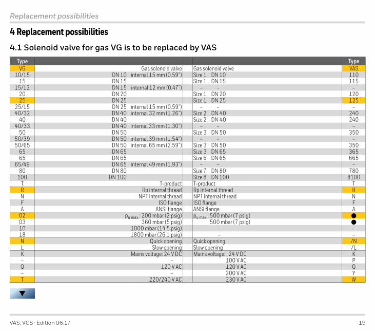
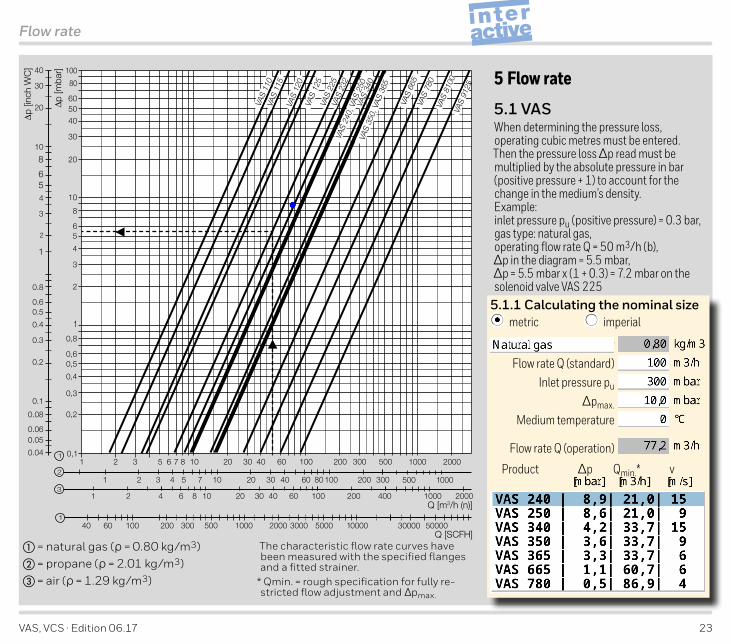
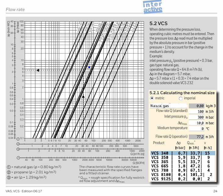
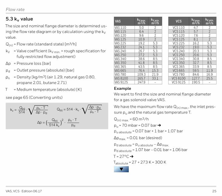
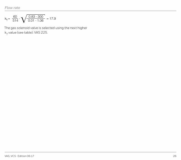
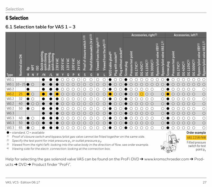
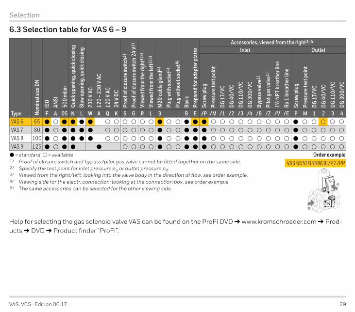
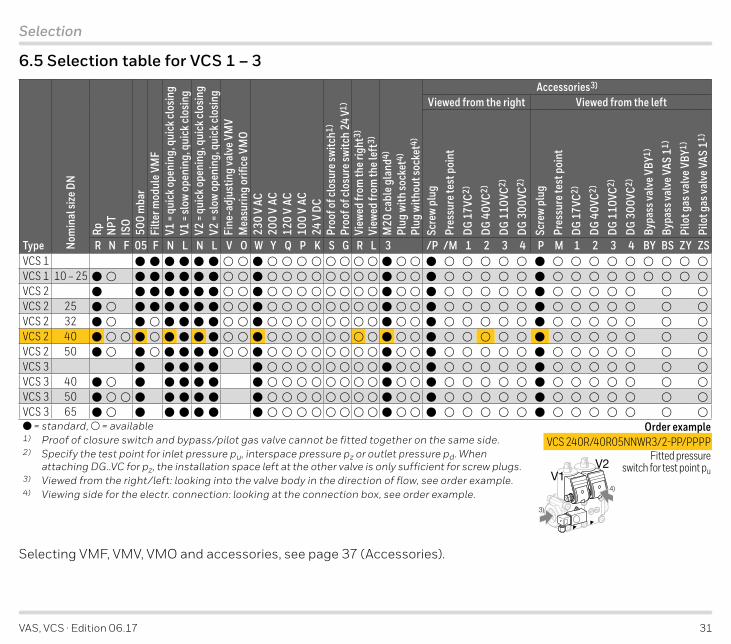
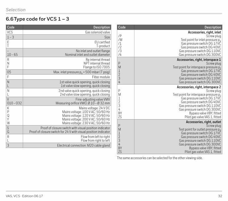
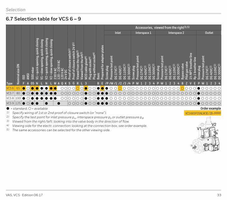
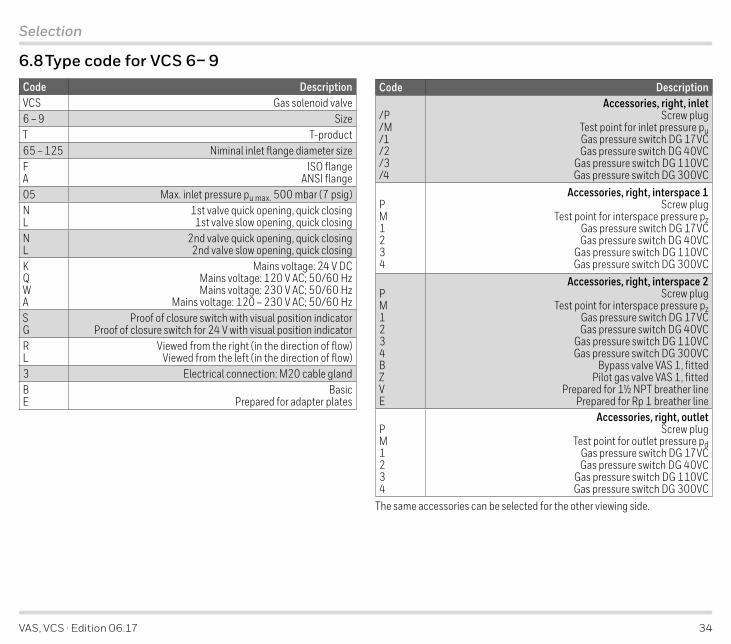
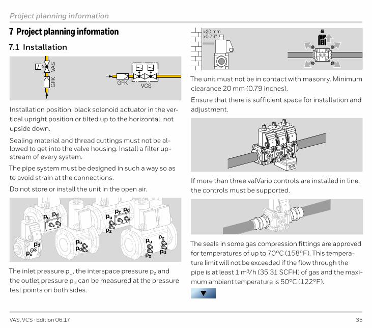
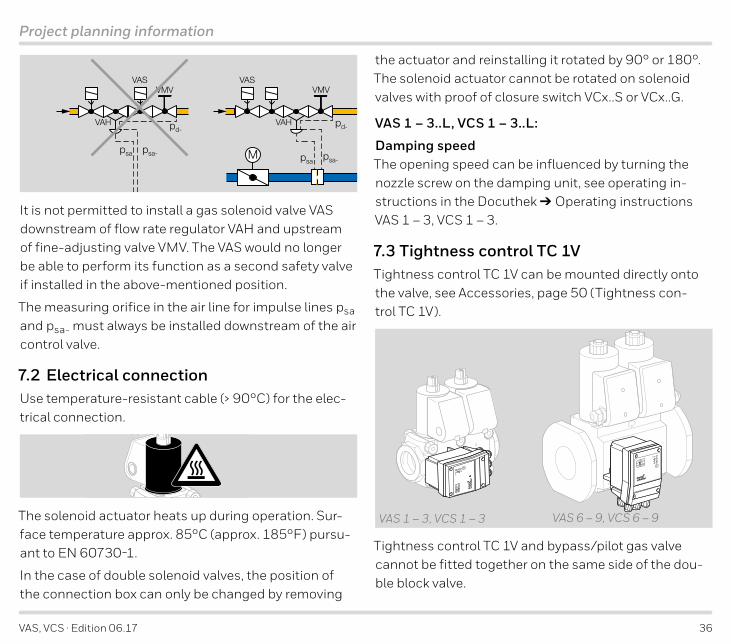
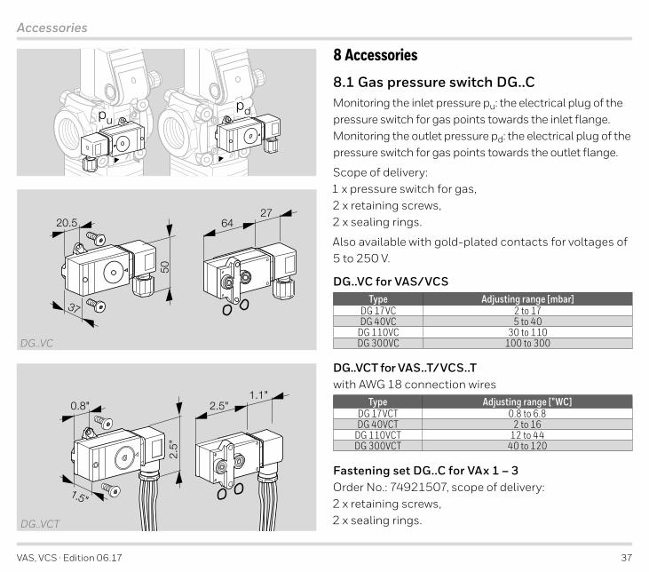
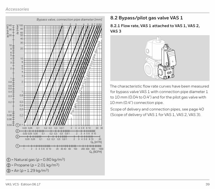
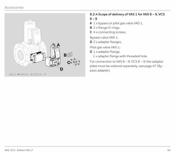
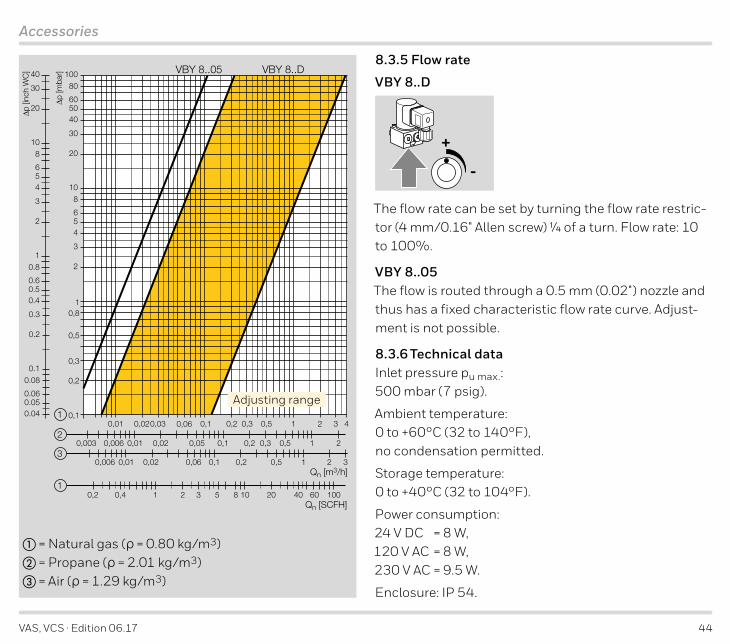
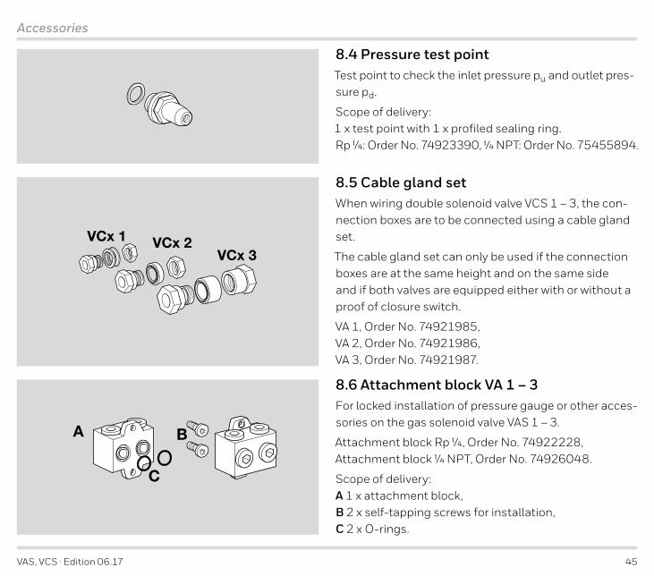
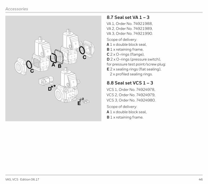
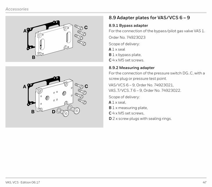
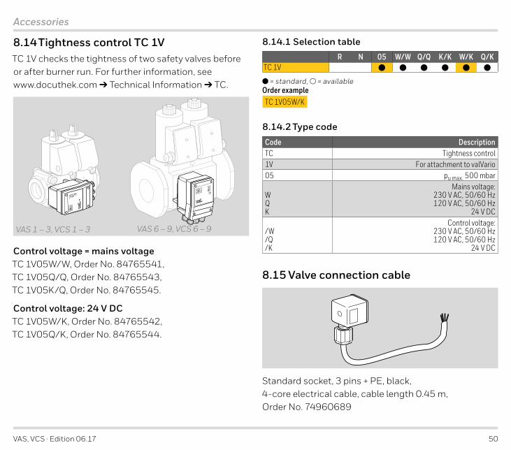
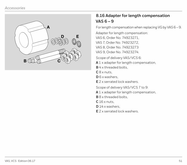
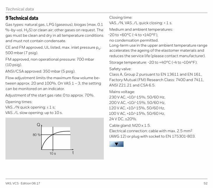
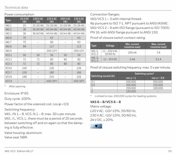
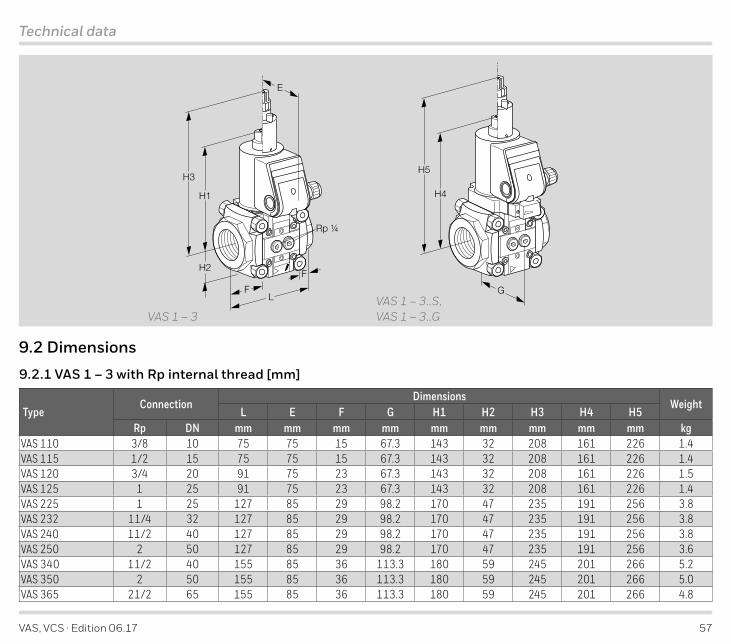
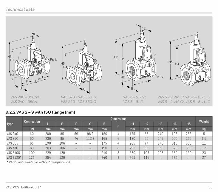
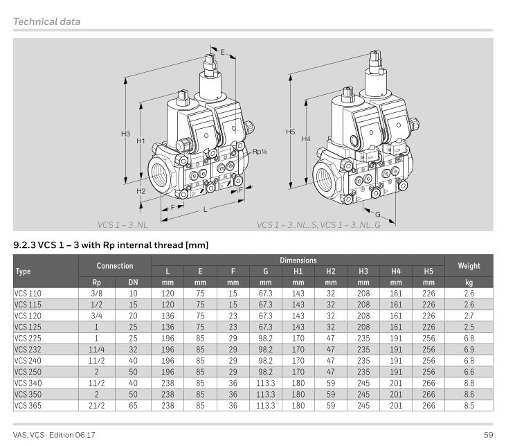
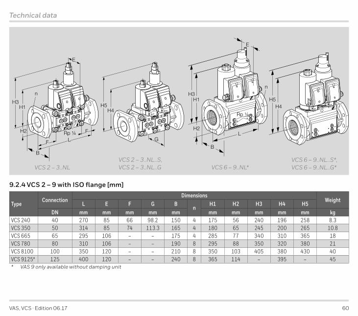
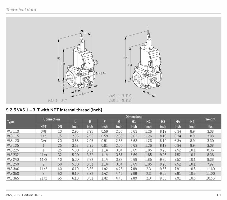
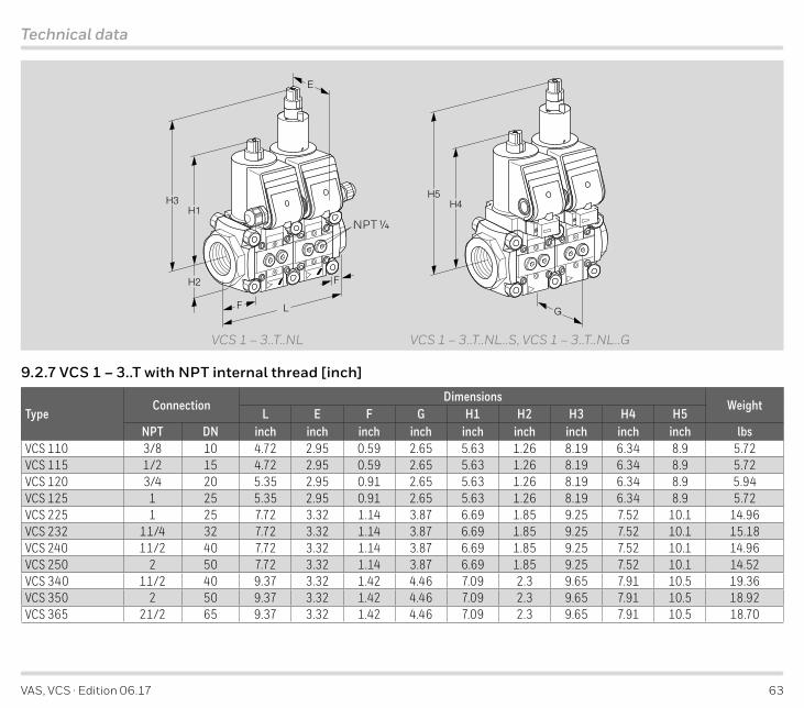
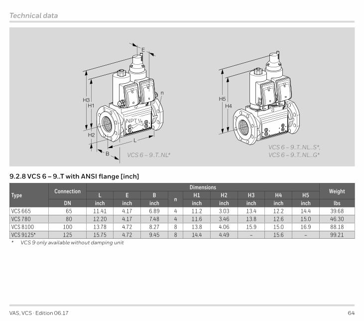
Related Documents