TECHNICAL LECTURE REPORT ON SOLAR SAILS 1

Solar Sails
Jan 10, 2016
Harnessing the power of the Sun to propel a spacecraft may appear somewhat ambitious and the observation that light exerts a force contradicts everyday experiences. However, it is and accepted phenomenon that the quantum packets of energy which compose Sunlight, that is to say photons, perturb the orbit attitude of spacecraft through conservation of momentum; this perturbation is known as solar radiation pressure (SRP). To be exact, the momentum of the electromagnetic energy from the Sun pushes the spacecraft and from Newton’s second law momentum is transferred when the energy strikes and when it is reflected. The concept of solar sailing is thus the use of these quantum packets of energy, i.e. SRP, to propel a spacecraft,potentially providing a continuous acceleration limited only by the lifetime of the sail materials in the space environment. The momentum carried by individual photons is extremely small; at best a solar sail will experience 9 N of force per square kilometre of sail located in Earth orbit (McInnes, 1999), thus to provide a suitably large momentum transfer the sail is required to have a large surface area while maintaining as low a mass as possible.
Welcome message from author
This document is posted to help you gain knowledge. Please leave a comment to let me know what you think about it! Share it to your friends and learn new things together.
Transcript
7/18/2019 Solar Sails
http://slidepdf.com/reader/full/solar-sails-5692692d7bf79 1/24
TECHNICAL LECTURE REPORT ON
SOLAR SAILS
1
7/18/2019 Solar Sails
http://slidepdf.com/reader/full/solar-sails-5692692d7bf79 2/24
2
GUIDE’S OBSERVATION:
HOF (L)’S OBSERVATION:

7/18/2019 Solar Sails
http://slidepdf.com/reader/full/solar-sails-5692692d7bf79 3/24
CONTENTS
SL NO CHAPTER PAGE NO
01 Introduction to Solar Sails 4
02 History
0! Pr"s"nt Sc"nario #
04 Princi$l" o% Solar Sails &
0' Construction o% Solar Sails 11
0 (or)in* o% Solar Sails 12
0+ Ca$a,ility 1
0# A$$lications 1#
0& Conclusion 21
10 R"%"r"nc"s 22
3
7/18/2019 Solar Sails
http://slidepdf.com/reader/full/solar-sails-5692692d7bf79 4/24
CHAPTER 1
INTRO-UCTION TO SOLAR SAILS
1.1 Introduction.Harnessing the power of the Sun to propel a spacecraft may appear somewhat ambitious and
the observation that light exerts a force contradicts everyday experiences. However, it is and
accepted phenomenon that the quantum packets of energy which compose Sunlight, that is to
say photons, perturb the orbit attitude of spacecraft through conservation of momentum; this
perturbation is known as solar radiation pressure S!"#. $o be exact, the momentum of the
electromagnetic energy from the Sun pushes the spacecraft and from %ewton&s second law
momentum is transferred when the energy strikes and when it is reflected. $he concept of solar
sailing is thus the use of these quantum packets of energy, i.e. S!", to propel a
spacecraft,potentially providing a continuous acceleration limited only by the lifetime of the sail
materials in the space environment. $he momentum carried by individual photons is extremely
small; at best a solar sail will experience ' % of force per square kilometre of sail located in (arth
orbit )c*nnes, 1'''#, thus to provide a suitably large momentum transfer the sail is required to
have a large surface area while maintaining as low a mass as possible.
+dding the impulse due to incident and reflected photons it is found that the idealised thrust
vector is directed normal to the surface of the sail, hence by controlling the orientation of the sail
relative to the Sun orbital angular momentum can be gained or reduced. sing momentum change
through reflecting such quantum packets of energy the sail slowly but continuously accelerates to
accomplish a wide-range of potential missions.
1. Solar sails also called light sails or photon sails# are a form of spacecraft propulsion using
the radiation pressure also called solar pressure# from stars to push large ultra-thin mirrors to
high speeds. /ight sails could also be driven by energy beams to extend their range of
operations, which is strictly beam sailing rather than solar sailing.
4
7/18/2019 Solar Sails
http://slidepdf.com/reader/full/solar-sails-5692692d7bf79 5/24
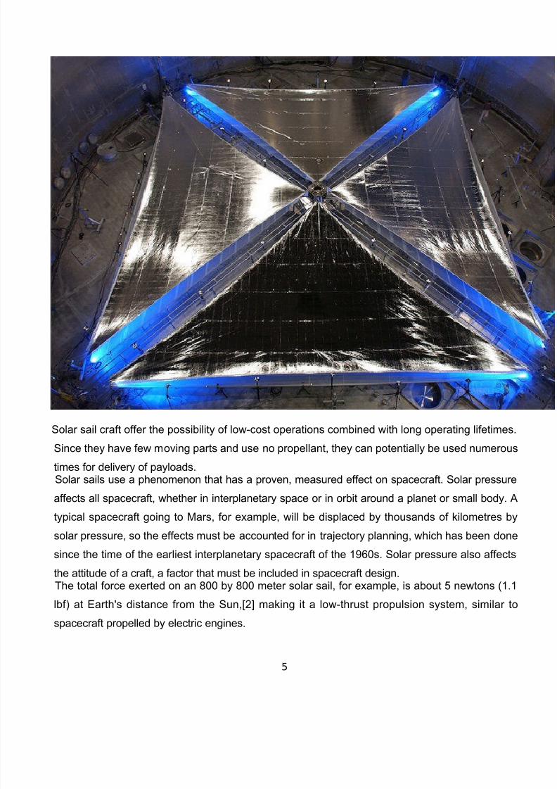
Solar sail craft offer the possibility of low-cost operations combined with long operating lifetimes.
Since they have few moving parts and use no propellant, they can potentially be used numerous
times for delivery of payloads. Solar sails use a phenomenon that has a proven, measured effect on spacecraft. Solar pressure
affects all spacecraft, whether in interplanetary space or in orbit around a planet or small body. +
typical spacecraft going to )ars, for example, will be displaced by thousands of kilometres by
solar pressure, so the effects must be accounted for in tra0ectory planning, which has been done
since the time of the earliest interplanetary spacecraft of the 1'2s. Solar pressure also affects
the attitude of a craft, a factor that must be included in spacecraft design. $he total force exerted on an 322 by 322 meter solar sail, for example, is about 4 newtons 1.1
lbf# at (arth5s distance from the Sun,67 making it a low-thrust propulsion system, similar to
spacecraft propelled by electric engines.
5
7/18/2019 Solar Sails
http://slidepdf.com/reader/full/solar-sails-5692692d7bf79 6/24
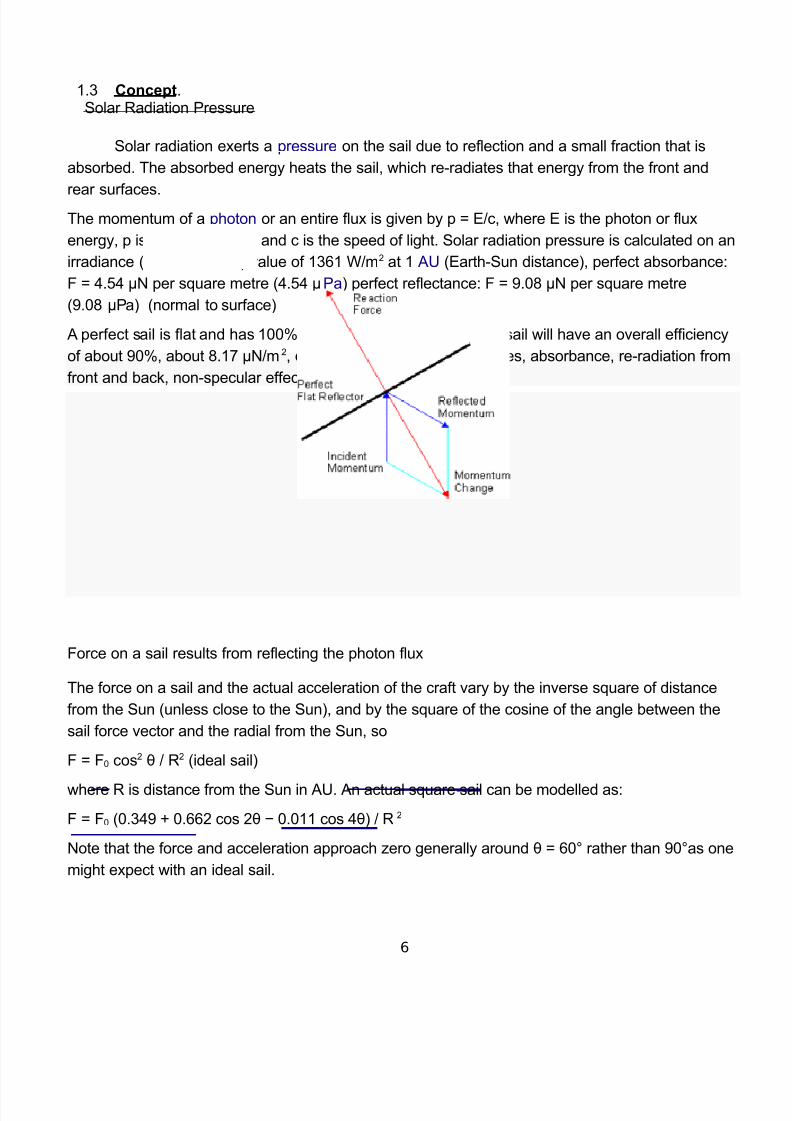
1.8 Conc"$t. Solar !adiation "ressure
Solar radiation exerts a pressure on the sail due to reflection and a small fraction that is
absorbed. $he absorbed energy heats the sail, which re-radiates that energy from the front and
rear surfaces.$he momentum of a photon or an entire flux is given by p 9 (:c, where ( is the photon or flux
energy, p is the momentum, and c is the speed of light. Solar radiation pressure is calculated on an
irradiance solar constant# value of 181 :m at 1 + (arth-Sun distance#, perfect absorbance<
= 9 >.4> ?% per square metre >.4> ?"a# perfect reflectance< = 9 '.23 ?% per square metre
'.23 ?"a# normal to surface#
+ perfect sail is flat and has 122@ specular reflection. +n actual sail will have an overall efficiency
of about '2@, about 3.1A ?%:m, due to curvature billow#, wrinkles, absorbance, re-radiation from
front and back, non-specular effects, and other factors.
=orce on a sail results from reflecting the photon flux
$he force on a sail and the actual acceleration of the craft vary by the inverse square of distance
from the Sun unless close to the Sun#, and by the square of the cosine of the angle between the
sail force vector and the radial from the Sun, so
= 9 =2 cos B : ! ideal sail#
where ! is distance from the Sun in +. +n actual square sail can be modelled as<
= 9 =2 2.8>' C 2. cos B D 2.211 cos >B# : !
%ote that the force and acceleration approach Eero generally around B 9 2F rather than '2Fas one
might expect with an ideal sail.
6

7/18/2019 Solar Sails
http://slidepdf.com/reader/full/solar-sails-5692692d7bf79 7/24
Solar wind, the flux of charged particles blown out from the Sun, exerts a nominal dynamic
pressure of about 8 to > n"a, three orders of magnitude less than solar radiation pressure on a
reflective sail.
Sail "arameters
Sail loading areal density# is an important parameter, which is the total mass divided by the sailarea, expressed in g:m. *t is represented by the Greek letter .
+ sail craft has a characteristic acceleration, ac, which it would experience at 1 + when facing the
Sun. sing the value from above of '.23 ?% per square metre of radiation pressure at 1 +, ac is
related to areal density by<ac 9 '.23efficiency# : mm:s
+ssuming '2@ efficiency, ac 9 3.1A : mm:s$he lightness number, I, is the dimensionless ratio of maximum vehicle acceleration divided by the
Sun5s local gravity. sing the values at 1 +<
I 9 ac : 4.'8$he lightness number is also independent of distance from the Sun because both gravity and light
pressure fall off as the inverse square of the distance from the Sun. $herefore, this number defines
the types of orbit maneuvers that are possible for a given vessel.$he table presents some example values. "ayloads are not included. $he first two are from the
detailed design effort at J"/ in the 1'A2s. $he third, the lattice sailer, might represent about the
best possible performance level. $he dimensions for square and lattice sails are edges. $he
dimension for heliogyro is blade tip to blade tip.
Ty$" .
/*2ac/s2 3
Si"
/)
Square sail 4.A 1.4 2. 2.32
Heliogyro .8' 1.' 2. 14
/attice sailer 2.2A 11A 2 1
7
7/18/2019 Solar Sails
http://slidepdf.com/reader/full/solar-sails-5692692d7bf79 8/24
CHAPTER 2
HISTOR5
.1 Johannes Kepler observed that comet tails point away from the Sun and suggested that the
Sun caused the effect. *n a letter to Galileo in 112, he wrote, L"rovide ships or sails adapted to
the heavenly breeEes, and there will be some who will brave even that void.L He might have had
the comet tail phenomenon in mind when he wrote those words, although his publications on
comet tails came several years later.
James Mlerk )axwell, in 131N>, published his theory of electromagnetic fields and radiation,
which shows that light has momentum and thus can exert pressure on ob0ects. )axwell5s
equations provide the theoretical foundation for sailing with light pressure. So by 13>, the physics
community and beyond knew sunlight carried momentum that would exert a pressure on ob0ects.
. Jules Oerne, in =rom the (arth to the )oon, published in 134, wrote Lthere will some day
appear velocities far greater than these 6of the planets and the pro0ectile7, of which light or
electricity will probably be the mechanical agent, we shall one day travel to the moon, the planets,
and the stars.L $his is possibly the first published recognition that light could move ships through
space. Given the date of his publication and the widespread, permanent distribution of his work, it
appears that he should be regarded as the originator of the concept of space sailing by lightpressure, although he did not develop the concept further6original research. Oerne probably got the
idea directly and immediately from )axwell5s 13> theory although it cannot be ruled out that
)axwell or an intermediary recogniEed the sailing potential and became the source for Oerne#.
8
7/18/2019 Solar Sails
http://slidepdf.com/reader/full/solar-sails-5692692d7bf79 9/24
+lbert (instein provided a different formalism by his recogniEing the equivalence of mass and
energy. He simply wrote p 9 (:c as the relationship between the momentum, the energy, and the
speed of light.
$he first formal technology and design effort for a solar sail began in 1'A at Jet "ropulsion
/aboratory for a proposed mission to rendeEvous with Halley5s Mome
CHAPTER !
PRESENT SCENARIO
8.1 =ollowing the Momet Halley studies solar sailing entered a hiatus until the early 1''2&s
when further advances in spacecraft technology led to renewed interest in the concept. $he first
ever ground deployment of a solar sail was performed in KPln in Qecember 1''' by the
German space agency, Q/!, in association with (S+ and *%O(%$ GmbH when they deployed a
square 2-m solar sail, shown in =ig. 1 /eipold et al, 222; Sebolt et al, 222#.
$his ground deployment and the associated technology developed by Q/! and (S+ has
struggled to progress to flight, initially an in-orbit deployment was planned for 22 however this
pro0ect floundered, with a similar, but smaller, demonstration now planned for 218 as part of a
three-step solar sail technology development program /ura et al, 212#.
*n 224 %+S+ completed dual solar sail development programs, funding a solar sail design by
+$K and another by /&Garde *nc. who used the inflatable boom technology developed under the
*+( program. Roth solar sail systems were deployed to 2-m side length# in the large vacuum
chamber at %+S+ Glenn !esearch Menter5s Space "ower =acility at "lum Rrook Station in
Sandusky, hio, .S.+, the world5s largest vacuum chamber /ichodEie0ewski et al, 228;
)urphy et al, 228 T 22>#.
=ollowing the deployment demonstrations the /&Garde design was down-selected due to its
perceived scalability to much larger sail siEes for the subsequent %+S+ %ew )illennium Space
$echnology ' S$-'# proposal, prior to the S$-' program being cancelled. However, it should be
noted that the +$K sail was considered a lower risk option. $he intention of the %+S+ funding
9
7/18/2019 Solar Sails
http://slidepdf.com/reader/full/solar-sails-5692692d7bf79 10/24
was to develop solar sail technology to $echnology !eadiness /evel $!/# six, however a
subsequent assessment found that actually both the /&Garde and +$K sail failed to fully achieve
either $!/ 4 or , with the +$K sail achieving 3'@ and 3@, respectively and the /&Garde sail
reaching 3> @ and A3 @, respectively Uoung et al, 22A#.
*n )ay 212 the first spacecraft to use solar radiation pressure as its primary form of propulsion
was launched by the Japanese space agency, J+V+, onboard an H-**+ launch vehicle from the
$anegashima Space Menter as an auxiliary payload alongside the Japanese Oenus orbiter
+katsuki, formerly known as the Oenus Mlimate rbiter OM# and "lanet-M,and four micro-
spacecraft. $he solar sail spacecraft is called *K+!S *nterplanetary Kite-craft +ccelerated by
!adiation f the Sun# and like the +katsuki spacecraft was launched onto a near-Oenus transfer
tra0ectory. $he *K+!S is a square solar sail, deployed using spinning motion and 2.4 kg tip
masses, the polyimide film used for solar sailing also has thin-film solar arrays embedded in the
film for power generation and liquid crystal devises which can, using electrical power, be
switched from diffusely to specularly reflective for attitude control )oriet al, 212#. *K+!S has
demonstrated a propulsive force of 1.1m% )ori et al, 212# and is shown in =ig. 8. $he
*K+!S mission is envisaged as a technology demonstrated towards a power sail spacecraft,
using the large deployable structure to host thin-film solar cells to generate large volumes of
power to drive a S(" system Kawaguchi, 212#.
*n addition to the traditional view of solar sailing as a very large structure several organisations,
including %+S+ and the "lanetary Society, are developing MubeSat based solar sails. *ndeed,
%+S+ flew the first MubeSat solar sails on board the third SpaceV =alcon1 launch on +ugust
223 which failed approximately minutes after launch. *t is however unclear how such
MubeSail programs will complement traditional solar sailing and whether they will provide
sufficient confidence in the technology to enable larger, more advanced solar sail demonstrator
missions. *t is clear that the technology of solar sailing is beginning to emerge from the drawing
board. +dditionally, since the %+S+ Momet Halley mission studies a large number of solar sail
mission concepts have been devised and promoted by solar sail proponents. +s such, thisrange of mission applications and concepts enables technology requirements derivation and a
technology application pull roadmap to be developed based on the key features of missions
which are enabled, or significantly enhance, through solar sail propulsion. $his book chapter will
thus attempt to link the technology application pull to the current technology developments and
to establish a new vision for the future of solar sailing.
10
7/18/2019 Solar Sails
http://slidepdf.com/reader/full/solar-sails-5692692d7bf79 11/24
CHAPTER 4
PRINCIPLE O6 SOLAR SAILS
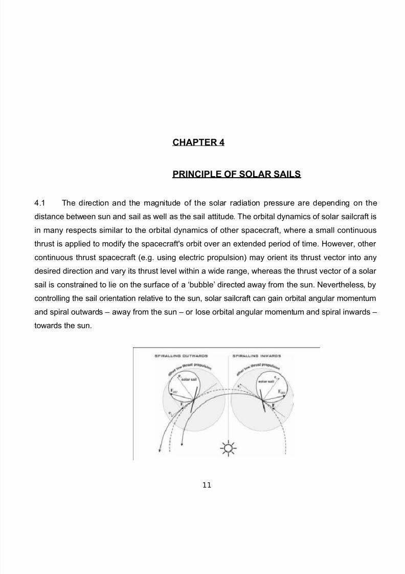
>.1 $he direction and the magnitude of the solar radiation pressure are depending on the
distance between sun and sail as well as the sail attitude. $he orbital dynamics of solar sailcraft is
in many respects similar to the orbital dynamics of other spacecraft, where a small continuous
thrust is applied to modify the spacecraft5s orbit over an extended period of time. However, other
continuous thrust spacecraft e.g. using electric propulsion# may orient its thrust vector into any
desired direction and vary its thrust level within a wide range, whereas the thrust vector of a solar
sail is constrained to lie on the surface of a Wbubble& directed away from the sun. %evertheless, by
controlling the sail orientation relative to the sun, solar sailcraft can gain orbital angular momentumand spiral outwards N away from the sun N or lose orbital angular momentum and spiral inwards N
towards the sun.
11
7/18/2019 Solar Sails
http://slidepdf.com/reader/full/solar-sails-5692692d7bf79 12/24
12
7/18/2019 Solar Sails
http://slidepdf.com/reader/full/solar-sails-5692692d7bf79 13/24
CHAPTER '
CONSTRUCTION O6 SOLAR SAILS
4.1 Solar Sail 7at"rials
hile solar sails have been designed before %+S+5s had a solar sail program back in the 1'A2s#,
materials available until the last decade or so were much too heavy to design a practical solar
sailing vehicle. Resides being lightweight, the material must be highly reflective and able to tolerate
extreme temperatures. $he giant sails being tested by %+S+ today are made of very lightweight,
reflective material that is upwards of 122 times thinner than an average sheet of stationery. $his
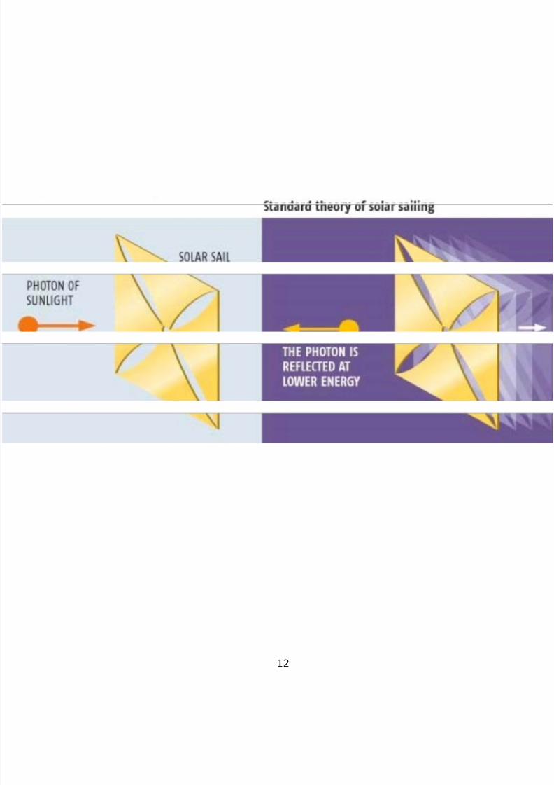
LaluminiEed, temperature-resistant materialL is called M"-1. $he reflective nature of the sails is key. +s photons light particles# bounce off the reflective material, they gently push the sail along by
transferring momentum to the sail. Recause there are so many photons from sunlight, and
because they are constantly hitting the sail, there is a constant pressure force per unit area#
exerted on the sail that produces a constant acceleration of the spacecraft. +lthough the force on a
solar-sail spacecraft is less than a conventional chemical rocket, such as the space shuttle, the
solar-sail spacecraft constantly accelerates over time and achieves a greater velocity.Uou might be
wondering what happens when the spacecraft finds itself far from sunlight. +n onboard laser could
take over providing the necessary propulsion to the sails.
$he material developed for the Qrexler solar sail was a thin aluminium film with a baseline
thickness of 2.1 Xm, to be fabricated by vapor deposition in a space-based system. Qrexler used a
similar process to prepare films on the ground. +s anticipated, these films demonstrated adequate
13
7/18/2019 Solar Sails
http://slidepdf.com/reader/full/solar-sails-5692692d7bf79 14/24
strength and robustness for handling in the laboratory and for use in space, but not for folding,
launch, and deployment.
$he most common material in current designs is aluminiEed Xm Kapton film. *t resists the heat of
a pass close to the Sun and still remains reasonably strong. $he aluminium reflecting film is on the
Sun side. $he sails of Mosmos 1 were made of aluminiEed "($ film )ylar#.
$here has been some theoretical speculation about using molecular manufacturing techniques to
create advanced, strong, hyper-light sail material, based on nanotube mesh weaves, where the
weave LspacesL are less than half the wavelength of light impinging on the sail. hile such
materials have so far only been produced in laboratory conditions, and the means for
manufacturing such material on an industrial scale are not yet available, such materials could
mass less than 2.1 g:m, making them lighter than any current sail material by a factor of at least
82. =or comparison, 4 micrometre thick )ylar sail material mass A g:m, aluminiEed Kapton films
have a mass as much as 1 g:m, and (nergy Science /aboratories5 new carbon fiber material
masses 8 g:m.
$he least dense metal is lithium, about 4 times less dense than aluminium. =resh, unoxidiEed
surfaces are reflective. +t a thickness of 2 nm, lithium has an areal density of 2.211 g:m. + high-
performance sail could be made of lithium alone at 2 nm no emission layer#. *t would have to be
fabricated in space and not used to approach the Sun. *n the limit, a sail craft might be constructed
with a total areal density of around 2.2 g:m, giving it a lightness number of A and ac of about
>22 mm:s. )agnesium and beryllium are also potential materials for high-performance sails.
$hese 8 metals can be alloyed with each other and with aluminium.
'82 R"%l"cti9" and Eissi9" lay"rs : +luminium is the common choice for the reflection layer. *t
typically has a thickness of at least 2 nm, with a reflectivity of 2.33 to 2.'2. Mhromium is a good
14
7/18/2019 Solar Sails
http://slidepdf.com/reader/full/solar-sails-5692692d7bf79 15/24
choice for the emission layer on the face away from the Sun. *t can readily provide emissivity
values of 2.8 to 2.A8 for thicknesses from 4 to 2 nm on plastic film. sable emissivity values are
empirical because thin-film effects dominate; bulk emissivity values do not hold up in these cases
because material thickness is much thinner than the emitted wavelengths.
'8! 6a,rication
Sails are fabricated on (arth on long tables where ribbons are unrolled and 0oined to create the
sails. $hese sails are packed, launched, and unfurled in space.
*n the future, fabrication could take place in orbit inside large frames that support the sail. $his
would result in lower mass sails and elimination of the risk of deployment failure.
CHAPTER
(OR;ING O6 SOLAR SAIL
81 C<an*in* or,its
Sailing operations are simplest in interplanetary orbits, where attitude changes are done at low
rates. =or outward bound tra0ectories, the sail force vector is oriented forward of the Sun line,
which increases orbital energy and angular momentum, resulting in the craft moving farther from
the Sun. =or inward tra0ectories, the sail force vector is oriented behind the Sun line, which
decreases orbital energy and angular momentum, resulting in the craft moving in toward the Sun.
*t is worth noting that only the Sun5s gravity pulls the craft toward the SunYthere is no analog to a
sailboat5s tacking to windward. $o change orbital inclination, the force vector is turned out of the
plane of the velocity vector.
15
7/18/2019 Solar Sails
http://slidepdf.com/reader/full/solar-sails-5692692d7bf79 16/24
*n orbits around planets or other bodies, the sail is oriented so that its force vector has a
component along the velocity vector, either in the direction of motion for an outward spiral, or
against the direction of motion for an inward spiral.
$ra0ectory optimiEations can often require intervals of reduced or Eero thrust. $his can be achieved
by rolling the craft around the Sun line with the sail set at an appropriate angle to reduce or
remove the thrust.
82 S=in*>,y 7an"u9"rs
+ close solar passage can be used to increase a craft5s energy. $he increased radiation pressure
combines with the efficacy of being deep in the Sun5s gravity well to substantially increase the
energy for runs to the outer Solar System. $he optimal approach to the Sun is done by increasing
the orbital eccentricity while keeping the energy level as high as practical. $he minimum approach
distance is a function of sail angle, thermal properties of the sail and other structure, load effects
on structure, and sail optical characteristics reflectivity and emissivity#. + close passage can result
in substantial optical degradation. !equired turn rates can increase substantially for a close
passage. + sail craft arriving at a star can use a close passage to reduce energy, which also
applies to a sail craft on a return trip from the outer Solar System.
+ lunar swing-by can have important benefits for tra0ectories leaving from or arriving at (arth. $his
can reduce trip times, especially in cases where the sail is heavily loaded. + swing-by can also be
used to obtain favorable departure or arrival directions relative to (arth.
+ planetary swing-by could also be employed similar to what is done with coasting spacecraft, but
good alignments might not exist due to the requirements for overall optimiEation of the tra0ectory.
8! Sart lin"s
+ smart line could be a critical element of sailing operations. +s with maritime ships, lines are
essential for a wide range of uses. ne difference is that some lines may be very long and need tobe self-guiding. $he lines could extend from and retract into the sail craft.
+ maneuverable grappling device can be used at the end of a line to place or pick up payload
containers, to secure a ship to a structure such as a station, to pick up samples from an asteroid or
comet, or to engage in towing. $he maneuvering unit is like a small spacecraft, with many of the
16
7/18/2019 Solar Sails
http://slidepdf.com/reader/full/solar-sails-5692692d7bf79 17/24
same sensors and control systems. *t could draw power from and communicate with the sail craft
through the line. $hese operations could be done autonomously.
/ines a few hundred kilometers long may be used to move a ship from a space station to an orbit
farther out where it could begin sailing.
84 To=in*
Smart lines can enable towing operations by being able to attach to or release ob0ects at the
remote end of the line. +ttached ob0ects might be pulled in to the body of the sailer or remain at the
end of the deployed line. b0ects to be towed may have attachment points that allow multiple sail
craft to engage in the towing. $owing operations can include deflecting large bodies that pose a
haEard to (arth, bringing natural bodies to (arth or other sites for resource recovery, and
transporting disabled spacecraft or other structures.
$o tow or deflect a large body, poles can be inserted on the spin axis of the body. Sail craft can
attach to the embedded poles using smart lines. Slip rings enable the craft to tow without the lines
getting wrapped up as a result of rotation of the body.
CHAPTER +
CAPA?ILIT5
A.1 ;"y c<aract"ristics
Solar sailing has traditionally been perceived as an enabling technology for high-energy emissions;
however, as has been shown in the preceding sections the key characteristics of a mission which
is enabled, or significantly enhanced by solar sailing are more complex than simply this. Solar
sailing is, due to the lack of propellant mass, often noted as reducing the launch mass of an
equivalent chemical or S(" concept, which is in-turn noted as reducing launch and emission cost.
However, while it is accurate that the launch mass is typically reduced this does not directly result
17
7/18/2019 Solar Sails
http://slidepdf.com/reader/full/solar-sails-5692692d7bf79 18/24
in a reduced launch vehicle cost as the reduction may not be sufficient to allow the use of a less
capable, and hence lower cost, launch vehicle. +s such the launch cost is only reduced if the
reduced launch mass allows a smaller launch vehicle to be used, meaning that launch cost varies
as a step function while launch mass linearly increases. =inally, it should be noted that if the total
mission cost is high, say, 422C )Z then reducing the launch mass cost by 12 N 2 )Z is a cost
saving of order N > @, which may not be considered a good cost:risk ratio for the pro0ect and
indeed, the cost saving may be insufficient to pay for the additional development of the technology.
$hus for the reduction in launch mass to be an enabling, or significantly enhancing aspect of a
solar sail mission concept the cost saving must also be a significant percentage of the total
mission cost. +ll solar sail mission concepts can be sub-divided into two classes, these are<
[ Mlass ne
here the solar sail is used to reach a high-energy target and after which the sail can be
0ettisoned by the spacecraft, for example the Solar "olar rbiter mission.
[ Mlass $wo
here the solar sail is required to maintain a novel or otherwise unsustainable observation
outpost, for example, highly non-keplerian or non-inertial orbit applications, such as Geostorm and
GeoSail.
$his distinction is important as the later compares very favourably against most other propulsion
systems, especially as the mission duration and hence reaction mass is increased.
However, a solar sail is a very large structure and could adversely impact the mission ob0ectives
either through a characteristically low pointing accuracy due to low frequency structural flexing, or
due to the solar sail interfering with the local environment in, for example, particle and field
measurements. $hus, a critical requirement on early solar sail demonstration missions must be to
validate the simulated pointing accuracy of the platform and the effect of the sail on the local space
environment.
=rom the mission catalogue it is seen that solar sail propulsion has been considered for a large
range of mission applications, some of which it is more suitable for than others. (ach of the solar sail applications within the mission catalogue are sub-divided by the level of enhancement offered
by solar sail propulsion.
18
7/18/2019 Solar Sails
http://slidepdf.com/reader/full/solar-sails-5692692d7bf79 19/24
CHAPTER #
APPLICATIONS
3.1 "lanet-centred and other short orbit period applications.
$his category is essentially planet, minor-planet and small body centred tra0ectories.
"lanet centered tra0ectory design has been largely restricted to escape manoeuvres or relatively
simplistic orbit manoeuvring, such as lunar fly-by&s or orbit inclination change. Such tra0ectories
place significant technology demands on the solar sail architecture, for example a locally optimal
energy gain control profile for an (arth-centered orbit requires the sail to be rotated through 132
degrees once per orbit and then rapidly reset to maximise energy gain; as the sail siEe grows
clearly this becomes an increasingly demanding technology requirement.
19
7/18/2019 Solar Sails
http://slidepdf.com/reader/full/solar-sails-5692692d7bf79 20/24
3. Highly non-keplerian orbit applications.
$his category is, in some regards, an extension of the concept embodied by non-inertial
orbits, with the sail providing a small but continuous acceleration to enable an otherwise
unattainable or unsustainable observation outpost to be maintained. $wo primary solar sail
applications of Highly %Ks are found in the literature; Geostorm and "olesitter also called "olar
bserver# Riggs T )c*nnes, 22'; Mhen-wan, 22>; Qriver, 1'32; =orward, 1''1; )atloff, 22>;
)c*nnes et al, 1''>; Sauer, Jr., 22>; aters T )c*nnes, 22A; est, 1'', 222, 22>#. $he
Geostorm mission concept provides real-time monitoring of solar activity; the spacecraft would
operate sunward of the (arth&s /1 point, thus increasing the warning time for geomagnetic storms.
Ry imparting a radial outward force from the Sun the solar radiation pressure in-effect reduces
solar gravity and allows the /1 point to be moved sunward. +s sail performance is increased solar
gravity is further Wreduced&, thus providing enhanced solar storm warning.
$he "olesitter concept extends the Geostorm concept from a singular equilibrium point to
derive equilibrium surfaces which extend out of the ecliptic plane and are again parameterised by
the sail performance )c*nnes et al, 1''>#. Ry extending the artificial equilibrium points out of the
ecliptic plane, the small but continuous acceleration allows a spacecraft to be stationed above, or
below, the second body within the 8-body problem. + further example of a highly non-keplerian
orbit application is the Statite proposed by =orward 1''1#, which would use a high-performance
solar sail to directly balance the solar gravity to hover stationary over the poles of the Sun.
3.8 *nner solar system rendeEvous missions
$his category covers missions which use the solar sail to rendeEvous, and perhaps bound
the orbit to, a body in the inner solar system; defined as all bodies from the asteroid belt inwards,
specifically excluding bodies which are, in-effect, part of the Jupiter system, for example the Hilda
and Jupiter $ro0an asteroids. Solar sailing, like other forms of low-thrust propulsion ,requires that if
a bound orbit about the target body is desired then at arrival the spacecraft must have, in-effect,
Eero hyperbolic excess velocity. $herefore, any wholly low-thrust interplanetary mission is required,unlike high-thrust missions, to slow-down prior to arrival at the target body and subsequently the
transfer duration is typically significantly increased; this is especially true for bodies which can be
relatively easily reached by high-thrust, chemical propulsion systems such as )ars and Oenus.
=urthermore, once the solar sail has been captured into a bound-orbit about the target body it then
has the typical disadvantages discussed previously for planet-centred solar sail application
20
7/18/2019 Solar Sails
http://slidepdf.com/reader/full/solar-sails-5692692d7bf79 21/24
3.> uter solar system rendeEvous missions
$he use of solar sails for outer solar system rendeEvous missions has been long discussed within
the literature Garner et al, 221; /eipold, 1'''; right, 1''; right T armke,1'A#.
=urthermore, an assessment study was previously conducted by the +uthors and Hughes looking
at a range of solar sail Jupiter missions )c*nnes et al, 228e, 22>a#, including concepts for
exploration of the Galilean moons. +s with low-thrust inner solar system rendeEvous missions the
hyperbolic excess velocity at the target outer solar system body must be lower than high-thrust
missions. $he inverse squared variation in S!" with solar distance however means that the sail
performance is significantly reduced over the same sail at (arth. +s such the requirement to
reduce the hyperbolic excess velocity prior to arrival at the outer solar system body leads to
prolonged transfer durations
3.4 uter solar system flyby missions
uter solar system fly-by missions remove the requirement to reduce the hyperbolic excess
velocity prior to arrival at the target body and as such negate much of the negative elements of
solar sail outer solar system rendeEvous missions. + Jupiter atmospheric probe mission was
considered by the +uthors and Hughes )c*nnes et al, 228e# as a potential Jupiter flyby mission.
*t was concluded that due to the mass of the atmospheric probes, of which three were required,
and the relative ease of such a mission with chemical propulsion that solar sail propulsion offered
little to such a mission. *t is of note that as the target flyby body moves further from the Sun,
3. Solar missions
$he lysses spacecraft used a Jupiter gravity assist to pass over the solar poles, obtaining field
and particle measurements but no images of the poles. =urthermore, the lysses orbit is highly
elliptical, with a pole revisit time of approximately years. *t is desired that future solar analysis be
performed much closer to the sun, as well as from an out-of-ecliptic perspective. $he MosmicOisions mission concept Solar rbiter intends to deliver a science suite of order 132 kg to a
maximum inclination of order 84 deg with respect to the solar equator and to a minimum solar
approach radius of 2. au using S(". $he inability of the Solar rbiter mission to attain a solar
polar orbit highlights the difficulty of such a goal with conventional propulsion.
21
7/18/2019 Solar Sails
http://slidepdf.com/reader/full/solar-sails-5692692d7bf79 22/24
3.A Reyond %eptune
*t has been shown that solar sail propulsion offers significant benefits to missions concepts which
aim to deliver a spacecraft beyond %eptune, for either a Kuiper Relt or *nterstellar Heliopause at
approximately 22 au# mission. Such outer solar system missions initially exploit the inverse
squared variation in S!" with solar distance by approaching the Sun to gain a rapid energy boast
which generates a hyperbolic tra0ectory and allows the spacecraft to rapidly escape the solar
system. Solar sails mission concepts significantly beyond the *nterstellar Heliopause were
considered by )acdonald et al 212#. *n-order to determine the limit of the solar sail concept an
ort cloud mission was examined using solely S!" to propel the spacecraft. *t was found that
although no fundamental reason existed why such a mission may not be possible the practicalities
were such that the *nterstellar Heliopause "robe *H"# mission concept could be considered
representative of the upper limiting bound of the solar sail concept.
22
7/18/2019 Solar Sails
http://slidepdf.com/reader/full/solar-sails-5692692d7bf79 23/24
CHAPTER &
CONCLUSION
'.1
+ solar sail mission catalogue has been developed and presented. $he mission catalogue
was sub-divided into applications which were enabled, or significantly enhanced by solar
sailing, of which solar sailing is of marginal benefit and of which solar sailing could
beconsidered unconstructive. =rom this the key characteristics of solar sail enabled,
orsignificantly enhanced, missions were detailed prior to a detailed discussion of three key
applications of solar sailing and the presentation of a solar sail application pull technology
development roadmap. Monsidering the solar sail application pull technology development
roadmap it was noted that the near-term was sparsely populated, with the significantma0ority of applications clustered in the mid to far term. $he concept of a system level
+dvancement Qegree of Qifficulty was introduced and it was illustrated that how through, for
example, hybridisation with solar electric propulsion the pro0ect risk of solar sailing could be
reduced while simultaneously.
23
7/18/2019 Solar Sails
http://slidepdf.com/reader/full/solar-sails-5692692d7bf79 24/24
CHAPTER 10
RE6ERENCES
1. Georgevic, !. ). 1'A8# L$he Solar !adiation "ressure =orces and $orques )odelL, $he
Journal of the +stronautical Sciences, Ool. A, %o. 1, JanN=eb. =irst known publication
describing how solar radiation pressure creates forces and torques that affect
spacecraft.
. Jerome right 1''#, Space Sailing, Gordon and Rreach Science "ublishers
8. Jump up\ =riedrich ]ander5s 1'4 paper, L"roblems of flight by 0et propulsion<
interplanetary flightsL, was translated by %+S+. See %+S+ $echnical $ranslation =-1>A
1'>#
>. LQesign of a High "erformance Solar Sail System, )S $hesis,L "Q=#. Qept. of
+eronautics and +stronautics, )assachusetts *nstitute of $echniology, Roston.
4.
24
Related Documents
![Solar Sails[1]](https://static.cupdf.com/doc/110x72/577d22ae1a28ab4e1e97fcd0/solar-sails1.jpg)