Solar and Wind Hybrid Power Generation A Project report submitted in partial fulfilment of the requirements for the degree of B. Tech in Electrical Engineering By Kousik Ghosh (11701616055) Pradeepta Chowdhury (11701617011) Sarjana Singh (11701616036) Arghadeep pradhan (11701616065) ......................................................... Under the supervision of Mr. Nijam Uddin Molla Assistant Professor Dept. of Electrical Engineering Department of Electrical Engineering RCC INSTITUTE OF INFORMATION TECHNOLOGY CANAL SOUTH ROAD, BELIAGHATA, KOLKATA – 700015, WEST BENGAL Maulana Abul Kalam Azad University of Technology (MAKAUT)

Welcome message from author
This document is posted to help you gain knowledge. Please leave a comment to let me know what you think about it! Share it to your friends and learn new things together.
Transcript
Solar and Wind Hybrid Power Generation
A Project report submitted in partial fulfilment
of the requirements for the degree of B. Tech in Electrical Engineering
By
Kousik Ghosh (11701616055)
Pradeepta Chowdhury (11701617011)
Sarjana Singh (11701616036)
Arghadeep pradhan (11701616065)
.........................................................
Under the supervision of
Mr. Nijam Uddin Molla
Assistant Professor Dept. of Electrical Engineering
Department of Electrical Engineering
RCC INSTITUTE OF INFORMATION TECHNOLOGY
CANAL SOUTH ROAD, BELIAGHATA, KOLKATA – 700015, WEST BENGAL
Maulana Abul Kalam Azad University of Technology (MAKAUT)
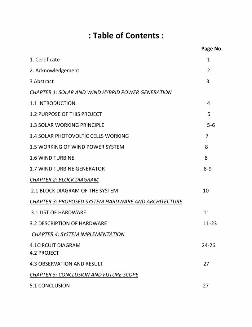
: Table of Contents :
Page No.
1. Certificate 1
2. Acknowledgement 2
3 Abstract 3
CHAPTER 1: SOLAR AND WIND HYBRID POWER GENERATION
1.1 INTRODUCTION 4
1.2 PURPOSE OF THIS PROJECT 5
1.3 SOLAR WORKING PRINCIPLE 5-6
1.4 SOLAR PHOTOVOLTIC CELLS WORKING 7
1.5 WORKING OF WIND POWER SYSTEM 8
1.6 WIND TURBINE 8
1.7 WIND TURBINE GENERATOR 8-9
CHAPTER 2: BLOCK DIAGRAM
2.1 BLOCK DIAGRAM OF THE SYSTEM 10
CHAPTER 3: PROPOSED SYSTEM HARDWARE AND ARCHITECTURE
3.1 LIST OF HARDWARE 11
3.2 DESCRIPTION OF HARDWARE 11-23
CHAPTER 4: SYSTEM IMPLEMENTATION
4.1 CIRCUIT DIAGRAM 24-26
4.2 PROJECT
4.3 OBSERVATION AND RESULT 27
CHAPTER 5: CONCLUSION AND FUTURE SCOPE
5.1 CONCLUSION 27

5.2 FUTURE SCOPE AND APPLICATIONS 28
5.3 REFERENCE 29
Department of Electrical Engineering
RCC INSTITUTE OF INFORMATION TECHNOLOGY
GROUND FLOOR, NEW BUILDING,
CANAL SOUTH ROAD, BELIAGHATA, KOLKATA – 700015, WEST BENGAL
………………………………………………………………………………………………………………………....
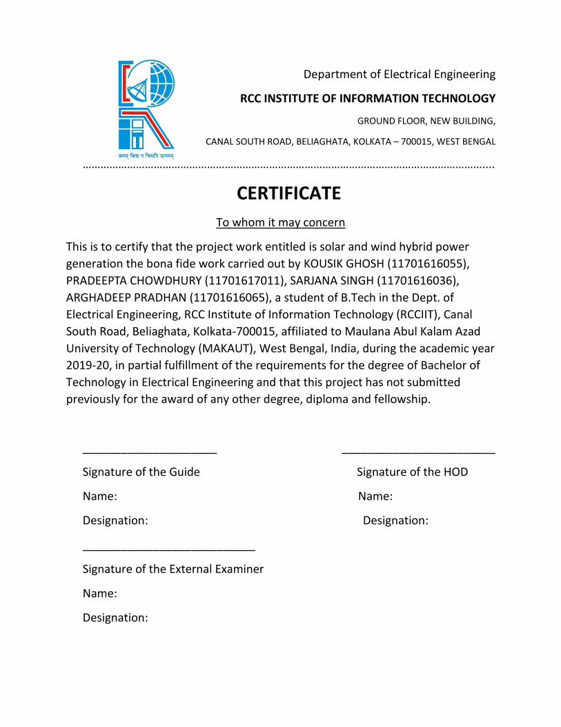
CERTIFICATE
To whom it may concern
This is to certify that the project work entitled is solar and wind hybrid power
generation the bona fide work carried out by KOUSIK GHOSH (11701616055),
PRADEEPTA CHOWDHURY (11701617011), SARJANA SINGH (11701616036),
ARGHADEEP PRADHAN (11701616065), a student of B.Tech in the Dept. of
Electrical Engineering, RCC Institute of Information Technology (RCCIIT), Canal
South Road, Beliaghata, Kolkata-700015, affiliated to Maulana Abul Kalam Azad
University of Technology (MAKAUT), West Bengal, India, during the academic year
2019-20, in partial fulfillment of the requirements for the degree of Bachelor of
Technology in Electrical Engineering and that this project has not submitted
previously for the award of any other degree, diploma and fellowship.
_____________________ ________________________
Signature of the Guide Signature of the HOD
Name: Name:
Designation: Designation:
___________________________
Signature of the External Examiner
Name:
Designation:

ACKNOWLEDGMENT
It is my great fortune that I have got opportunity to carry out this project work
under the supervision of Mr. Nijam Uddin Molla assistant professor in the
Department of Electrical Engineering, RCC Institute of Information Technology
(RCCIIT), Canal South road, Beliaghata, Kolkata-700015, affiliated to Maulana
Abul Kalam Azad University of Technology (MAKAUT), West Bengal, India. I
express my sincere thanks and deepest sense of gratitude to my guide for his
constant support, unparalleled guidance and limitless encouragement.
I wish to convey my gratitude to Prof. (Dr.) Debasish Mondal, HOD,
Department of Electrical Engineering, RCCIIT and to the authority of RCCIIT for
providing all kinds of infrastructural facility towards the research work.
I would also like to convey my gratitude to all the faculty members and staffs
of the Department of Electrical Engineering, RCCIIT for their whole hearted
cooperation to make this work turn into reality.
Date:
Place:
-----------------------------------------------
Full Signature of the Student

1. ABSTRACT
Reaching the non electrified rural population is currently not possible through the
extension of the grid, since the connection is neither economically feasible, nor
encouraged by the main actors. Further, the increases in oil prices and the
unbearable impacts of this energy source on the users and on the environment,
are slowly removing conventional energy solutions, such as fuel genets based
systems, from the rural development agendas.
This problem can overcome by using “HYBRID POWER GENERATION USING SOLAR
AND WIND ENERGY”. Hybrid systems have proved to be the best option to deliver
“high quality” power.
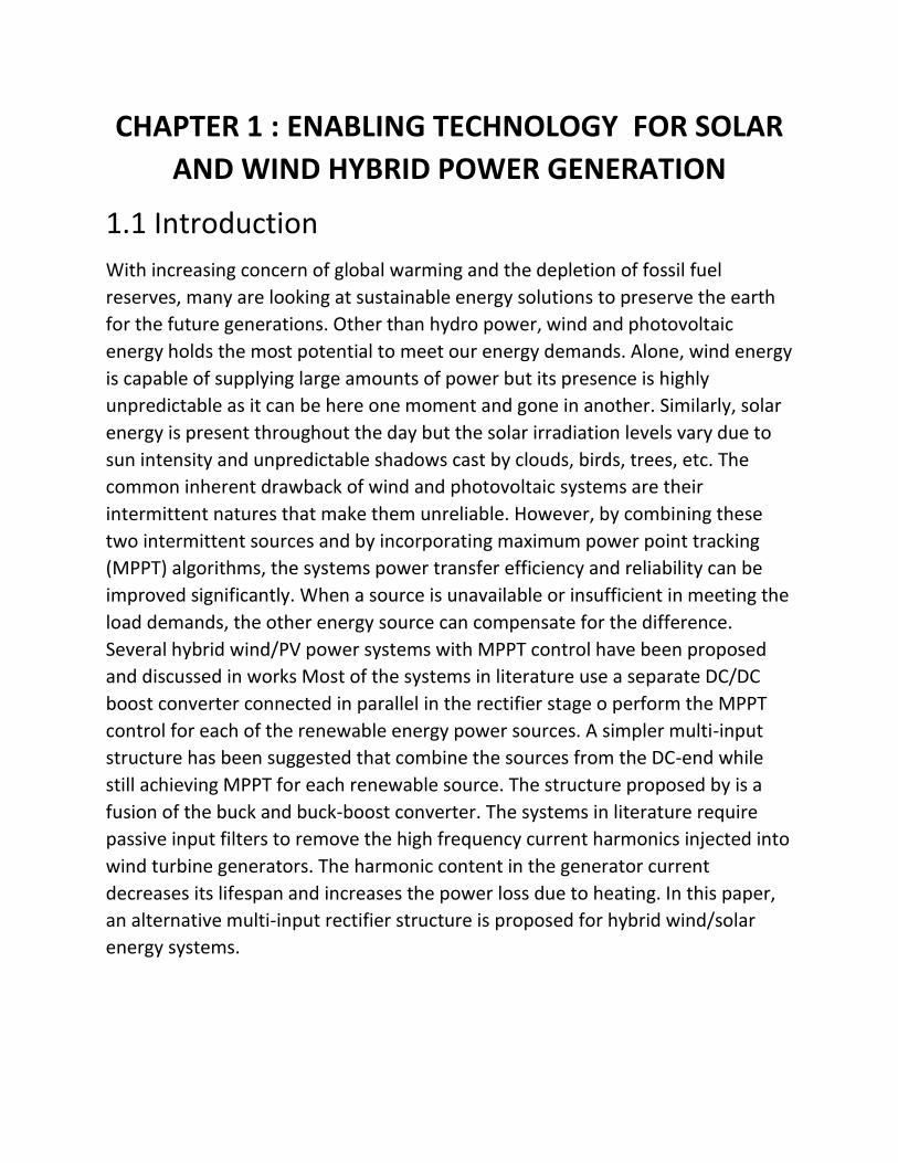
CHAPTER 1 : ENABLING TECHNOLOGY FOR SOLAR
AND WIND HYBRID POWER GENERATION
1.1 Introduction
With increasing concern of global warming and the depletion of fossil fuel
reserves, many are looking at sustainable energy solutions to preserve the earth
for the future generations. Other than hydro power, wind and photovoltaic
energy holds the most potential to meet our energy demands. Alone, wind energy
is capable of supplying large amounts of power but its presence is highly
unpredictable as it can be here one moment and gone in another. Similarly, solar
energy is present throughout the day but the solar irradiation levels vary due to
sun intensity and unpredictable shadows cast by clouds, birds, trees, etc. The
common inherent drawback of wind and photovoltaic systems are their
intermittent natures that make them unreliable. However, by combining these
two intermittent sources and by incorporating maximum power point tracking
(MPPT) algorithms, the systems power transfer efficiency and reliability can be
improved significantly. When a source is unavailable or insufficient in meeting the
load demands, the other energy source can compensate for the difference.
Several hybrid wind/PV power systems with MPPT control have been proposed
and discussed in works Most of the systems in literature use a separate DC/DC
boost converter connected in parallel in the rectifier stage o perform the MPPT
control for each of the renewable energy power sources. A simpler multi-input
structure has been suggested that combine the sources from the DC-end while
still achieving MPPT for each renewable source. The structure proposed by is a
fusion of the buck and buck-boost converter. The systems in literature require
passive input filters to remove the high frequency current harmonics injected into
wind turbine generators. The harmonic content in the generator current
decreases its lifespan and increases the power loss due to heating. In this paper,
an alternative multi-input rectifier structure is proposed for hybrid wind/solar
energy systems.
1.2 Purpose of this Project 2. In Remote areas implementing power systems units at each apartment.
3. Multistoried buildings
4. Homes, schools.
5. Street lightings covering a large area.
6. Off grid applications.
7. Solar water heaters. Electric kettles solar vehicles
8. Traffic signaling and in many applications.
1.3 Solar Working Principle
Every device we use in our day-to-day life such as mobile phone, computer,
induction cookers, washing machines, vacuum cleaners, etc., requires electric
power supply. Thus, the advancement in technology is increasing the electrical
and electronic appliances usage – which, in turn – is increasing the power
demand. Thus, to meet the load demand, different techniques are used for
electric power generation. In the recent times, to avoid pollution and to
conserve non-renewable energy resources like coal, petroleum, etc.,
renewable energy sources like solar, wind, etc., are being preferred for power
generation. The combination of renewable energy sources can also be used for
generating power called as hybrid power system. As a special case, we will
discuss about the working of solar-wind hybrid system in this article.
Solar and wind hybrid power systems are designed using solar panels and
small wind turbine generators for generating electricity. Generally, these solar
wind hybrid systems are capable of small capabilities. The typical power
generation capacities of solar wind hybrid systems are in the range from 1 kW
to 10 kW. Before discussing in brief about the solar and wind hybrid power
system, we should know about solar power generation systems and wind-
power generation systems.
To better understand the working of solar wind hybrid system, we must know
the working of solar energy system and wind energy system. Solar power
system can be defined as the system that uses solar energy for power
generation with solar panels. The block diagram of solar wind hybrid system is
shown in the figure in which the solar panels and wind turbine are used for
power generation.
Solar energy is one of the major renewable energy resources that can be used
for different applications, such as solar power generation, solar water heaters,
solar calculators, solar chargers, solar lamps, and so on. There are various
advantages of solar energy usage in electric power generation including low
pollution, cost-effective power generation (neglecting installation cost),
maintenance free power system, etc. Solar power system consists of three
major blocks namely solar panels, solar photovoltaic cells, and batteries for
storing energy. The electrical energy (DC power) generated using solar panels
can be stored in batteries or can be used for supplying DC loads or can be used
for inverter to feed AC loads.
The solar panel output is electric power and is measured in terms of Watts or Kilo
watts. These solar panels are designed with different output ratings like 5 watts, 10
watts, 20 watts, 100 watts etc. So, based on the requirement of output power, we
can choose appropriate solar panel.
But, in fact, the solar panels output is affected by number of factors like climate,
panel orientation to the sun, sun light intensity, the presence of sunlight duration,
and so on. During normal sunlight a 12 volt 15 watts solar panel produces around
1 Ampere current. Generally, solar panels maintained properly will work for 25
years. It is essential for designing the solar panel arrangement on the roof top for
efficient usage and typically solar panels are arranged such that they face the East
at an angle of 45 degree.
1.4 Solar Photovoltaic Cells Working We must also know the working of the solar cells to understand how the solar
panels convert solar energy into electrical energy. Solar cells or solar photovoltaic
cells are the devices that are used for converting solar energy into electrical
energy by utilizing the photovoltaic effect. These cells are used in many real-time
applications such as railway signaling systems, street lighting systems, domestic
lighting systems, and remote telecommunication systems.
Solar photovoltaic cell consists of a P-type of silicon layer that is placed in contact
with an N-type silicon layer. The electrons diffuse from the N-type material to the
P-type material. The holes in the P-type material accept the electrons but there
are more electrons in the N-type material. So, with the influence of the solar
energy, these electrons in the N-type material moves from N-type to P-type.
Thus, these electrons and holes combine in the P-N junction. Due, to this
combination a charge on either side of the P-N junction is created and this charge
creates an electric field. This formation of electric field results in developing a
diode like system that promotes the charge flow. This is called as drift current and
the diffusion of electrons and holes is balanced by drift current. This drift current
occurs in an area where mobile charge carriers are lacking and is called as the
depletion zone or space charge region. Thus, during night time or in the darkness,
these solar photovoltaic cells behave like reverse bias diodes.
Generally solar panel open circuit voltage (voltage when battery is not connected)
is higher than solar panel rated voltage. For example, consider a 12 volt solar
panel giving an output voltage of around 20 volts in bright sun light- but,
whenever a battery is connected to the solar panel, then the voltage drops to 14-
15 volts. Solar cells are made of most frequently used semiconductor materials
such as silicon.
Solar photovoltaic (SPV) effect is a process to convert solar energy into DC
electricity using an array of solar panels. This, DC electricity can be stored in
batteries shown in the figure or can be used to feed DC loads directly or can be
used to feed AC loads using an inverter that turns DC electricity into 120-volt AC
electricity.
1.5 Working of Wind Power System
Wind energy is also one of the renewable energy resources that can be used for
generating electrical energy with wind turbines coupled with generators. There
are various advantages of wind energy, such as wind turbines power generation,
for mechanical power with windmills, for pumping water using wind pumps, and
so on.
Large wind turbines are made to rotate with the blowing wind and accordingly
electricity can be generated. The minimum wind speed required for connecting
the generator to the power grid is called as cut in speed and maximum wind
speed required for the generator for disconnecting the generator from the power
grid is called as cut off speed. Generally, wind turbines work in the range of speed
between cut in and cut off speeds.
1.6 Wind Turbine
Wind turbine can be defined as a fan consisting of 3 blades that rotate due to
blowing wind such that the axis of rotation must be aligned with the direction of
blowing wind. A gear box is used for converting energy from one device to
another device using mechanical method; hence, it is termed as a high-precision
mechanical system. There are different types of wind turbines, but the frequently
used wind turbines are horizontal axis turbines and vertical axis turbines. The
figure shows different blocks of the wind turbine generator system.
1.7 Wind Turbine Generator
An electrical generator is coupled with wind turbine; hence, it is named as wind
turbine generator. There are different types of wind turbine generators and these
wind turbine generators can be directly connected to the power grid or loads or
batteries based on different criteria. In general, there are of four types:
1. Squirrel cage induction generator is directly connected to the power grid or
to feed AC loads or DC loads using appropriate converters.
2. A generator along with an AC to DC to AC converter is connected to power
grid.
3. A wound rotor induction generator, which is connected to power grid or
batteries whose speed can be adjusted using rheostats for maintaining
required outputs.
4. A double fed induction generator, which is connected to power grid whose
speed can be controlled using back-to-back converters.
Consider DFIG double fed induction generator with 3-phase wound rotor and 3-
phase wound stator. An AC current is induced in the rotor windings due to three
phase AC signal fed to rotor windings. Due to mechanical force produced from
wind energy the rotor starts rotation and produces a magnetic field. The speed of
the rotor and frequency of AC signal applied to rotor windings are proportional to
each other. This result of constant magnetic flux passing through stator windings
produces AC current in the stator winding. Due to variation of speed in wind
speed there is chance of getting AC signal output with varying frequency. But, the
AC signal with constant frequency is desired. So, by varying the frequency of input
AC signal given to the rotor windings we can obtain AC output signal with
constant frequency. Grid side converter can be used for providing regulated DC
voltage to charge batteries. Rotor side converter can be used for providing
controlled AC voltage to the rotor.
Thus, as shown in the above solar wind hybrid system figure the electric power
generated from solar energy system and wind energy system can be used for
charging the batteries or for feeding DC loads or we can use the entire power for
feeding AC loads. Hybrid solar wind charger is a practical project in which the
electric power generated from solar energy and wind energy are used for
charging the batteries.
Do you know how does the hybrid solar wind charger work? If yes, then share
your answers, in addition, for designing interesting & innovative electrical and
electronics projects on your own you can download our free eBook or you can
approach us by posting your comments in the comment section below.
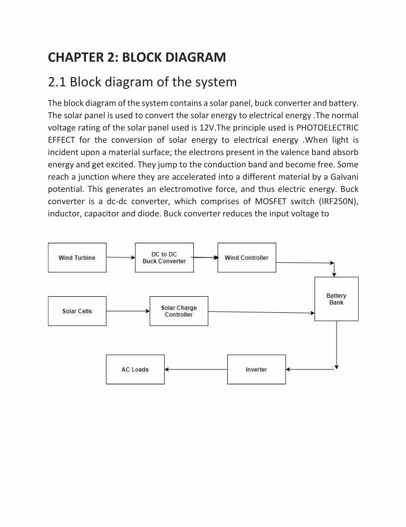
CHAPTER 2: BLOCK DIAGRAM
2.1 Block diagram of the system
The block diagram of the system contains a solar panel, buck converter and battery.
The solar panel is used to convert the solar energy to electrical energy .The normal
voltage rating of the solar panel used is 12V.The principle used is PHOTOELECTRIC
EFFECT for the conversion of solar energy to electrical energy .When light is
incident upon a material surface; the electrons present in the valence band absorb
energy and get excited. They jump to the conduction band and become free. Some
reach a junction where they are accelerated into a different material by a Galvani
potential. This generates an electromotive force, and thus electric energy. Buck
converter is a dc-dc converter, which comprises of MOSFET switch (IRF250N),
inductor, capacitor and diode. Buck converter reduces the input voltage to
CHAPTER 3: PROPOSED SYSTEM HARDWARE AND
ARCHITECTURE
3.1 list of hardware
a) Solar panel
b) Dc motor
c) Boost converter
d) Solar charge controller
e) LM317 Regulator
f) Battery
g) Inverter
h) Ac load
3.2 Description of hardware
a) Solar panel
A solar panel is a set of solar photovoltaic modules electrically
connected and mounted on a supporting structure. A photovoltaic module
is a packaged, connected assembly of solar cells. The solar panel can be
used as a component of a larger photovoltaic system to generate and
supply electricity in commercial and residential applications. A
photovoltaic system typically includes a panel or an array of solar
modules, an inverter, and sometimes a battery and/or solar tracker and
interconnection wiring. Photovoltaic cells or panels are only one way of
generating electricity from solar energy. They are not the most efficient,
but they are the most convents to use on a small to medium scale. PV
cells are made of silicon, similar to that used in computer "chips". While
silicon itself is a very abundant mineral, the manufacture of solar cells
(as with computer chips) has to be in a very clean environment. This
causes production costs to be high. A PV cell is constructed from two
types of silicon, which when hit by solar energy, produce a voltage
difference across them, and, if connected to an electrical circuit, a
current will flow. A number of photovoltaic cells will be connected
together in a "Module", and usually encapsulated in glass held a frame
which can then be mounted as required. The cells in a module will be
wired in series or parallel to produce a specified voltage. What may be
referred to as a 12 volt panel may produce around 16 volts in full sun
to charge to 12 volt battery.
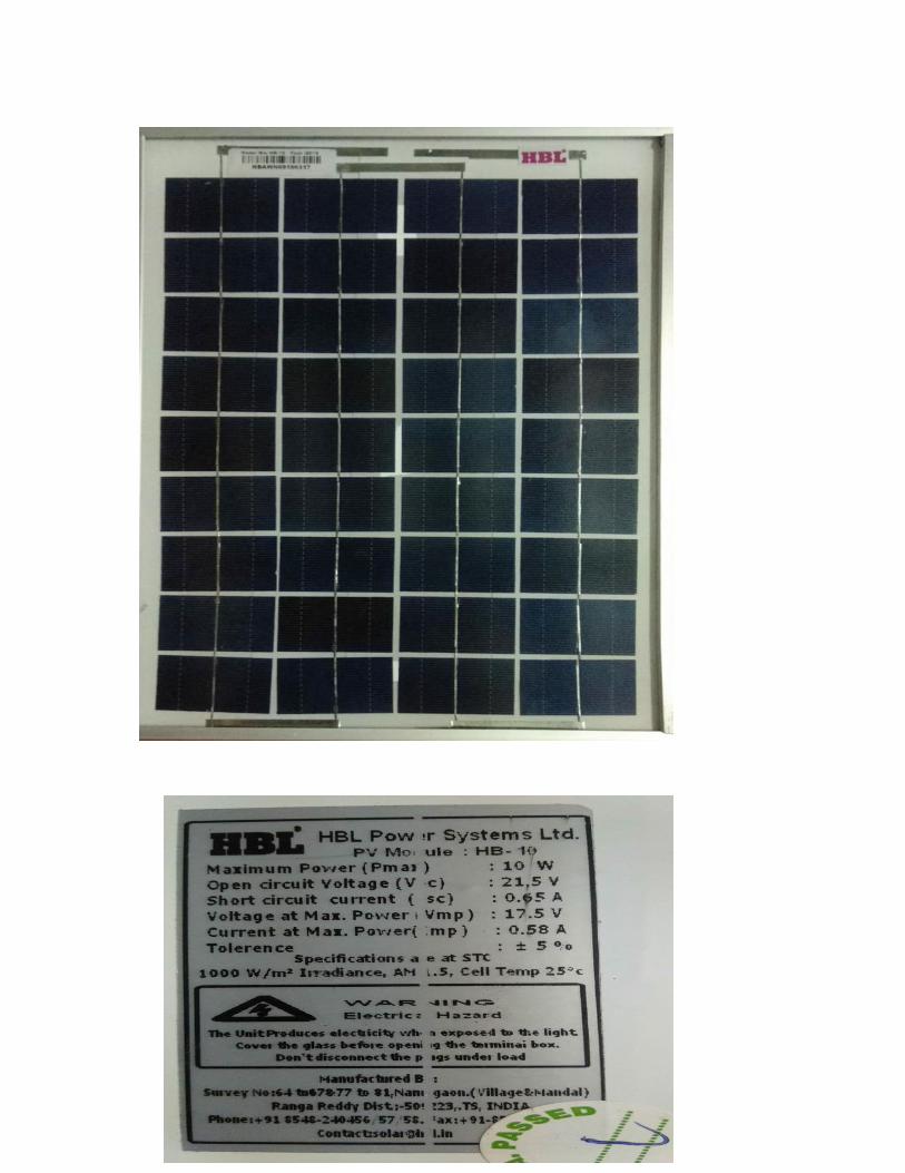
Here we use Energia company solar panel. The mechanical characteristics
made from high efficiency crystalline silicon solar cells. Cells encapsulated
in low iron, high transmission, toughened glass using UV stable ethylene
vinyl acetate (EVA) sheets. Premium quality back sheet protect the
module from environmental conditions. Laminate framed with strong
anodized aluminum profile with fitted junction box.
Specification of the solar panel:
1. Material : Silicon
2. Wattage : 10W
3. Type : Polycrystalline
4. No of Cells : 64
5. Output Voltage : 21.5V
6. Short circuit current: 0.65A
7.voltage at maximum power: 17.5 V
8. Current at max. Power: 0.58 A
9. Tollerance : 5%
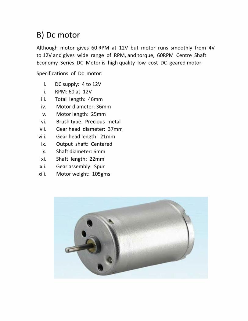
B) Dc motor
Although motor gives 60 RPM at 12V but motor runs smoothly from 4V
to 12V and gives wide range of RPM, and torque, 60RPM Centre Shaft
Economy Series DC Motor is high quality low cost DC geared motor.
Specifications of Dc motor:
i. DC supply: 4 to 12V
ii. RPM: 60 at 12V
iii. Total length: 46mm
iv. Motor diameter: 36mm
v. Motor length: 25mm
vi. Brush type: Precious metal
vii. Gear head diameter: 37mm
viii. Gear head length: 21mm
ix. Output shaft: Centered
x. Shaft diameter: 6mm
xi. Shaft length: 22mm
xii. Gear assembly: Spur
xiii. Motor weight: 105gms
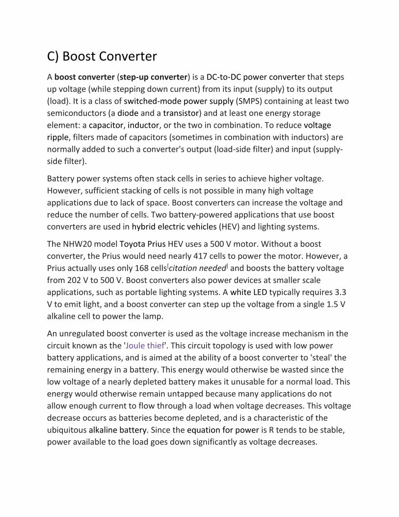
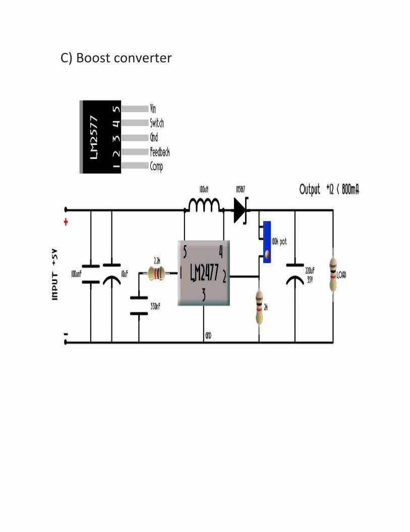
C) Boost Converter
A boost converter (step-up converter) is a DC-to-DC power converter that steps
up voltage (while stepping down current) from its input (supply) to its output
(load). It is a class of switched-mode power supply (SMPS) containing at least two
semiconductors (a diode and a transistor) and at least one energy storage
element: a capacitor, inductor, or the two in combination. To reduce voltage
ripple, filters made of capacitors (sometimes in combination with inductors) are
normally added to such a converter's output (load-side filter) and input (supply-
side filter).
Battery power systems often stack cells in series to achieve higher voltage.
However, sufficient stacking of cells is not possible in many high voltage
applications due to lack of space. Boost converters can increase the voltage and
reduce the number of cells. Two battery-powered applications that use boost
converters are used in hybrid electric vehicles (HEV) and lighting systems.
The NHW20 model Toyota Prius HEV uses a 500 V motor. Without a boost
converter, the Prius would need nearly 417 cells to power the motor. However, a
Prius actually uses only 168 cells[citation needed] and boosts the battery voltage
from 202 V to 500 V. Boost converters also power devices at smaller scale
applications, such as portable lighting systems. A white LED typically requires 3.3
V to emit light, and a boost converter can step up the voltage from a single 1.5 V
alkaline cell to power the lamp.
An unregulated boost converter is used as the voltage increase mechanism in the
circuit known as the 'Joule thief'. This circuit topology is used with low power
battery applications, and is aimed at the ability of a boost converter to 'steal' the
remaining energy in a battery. This energy would otherwise be wasted since the
low voltage of a nearly depleted battery makes it unusable for a normal load. This
energy would otherwise remain untapped because many applications do not
allow enough current to flow through a load when voltage decreases. This voltage
decrease occurs as batteries become depleted, and is a characteristic of the
ubiquitous alkaline battery. Since the equation for power is R tends to be stable,
power available to the load goes down significantly as voltage decreases.
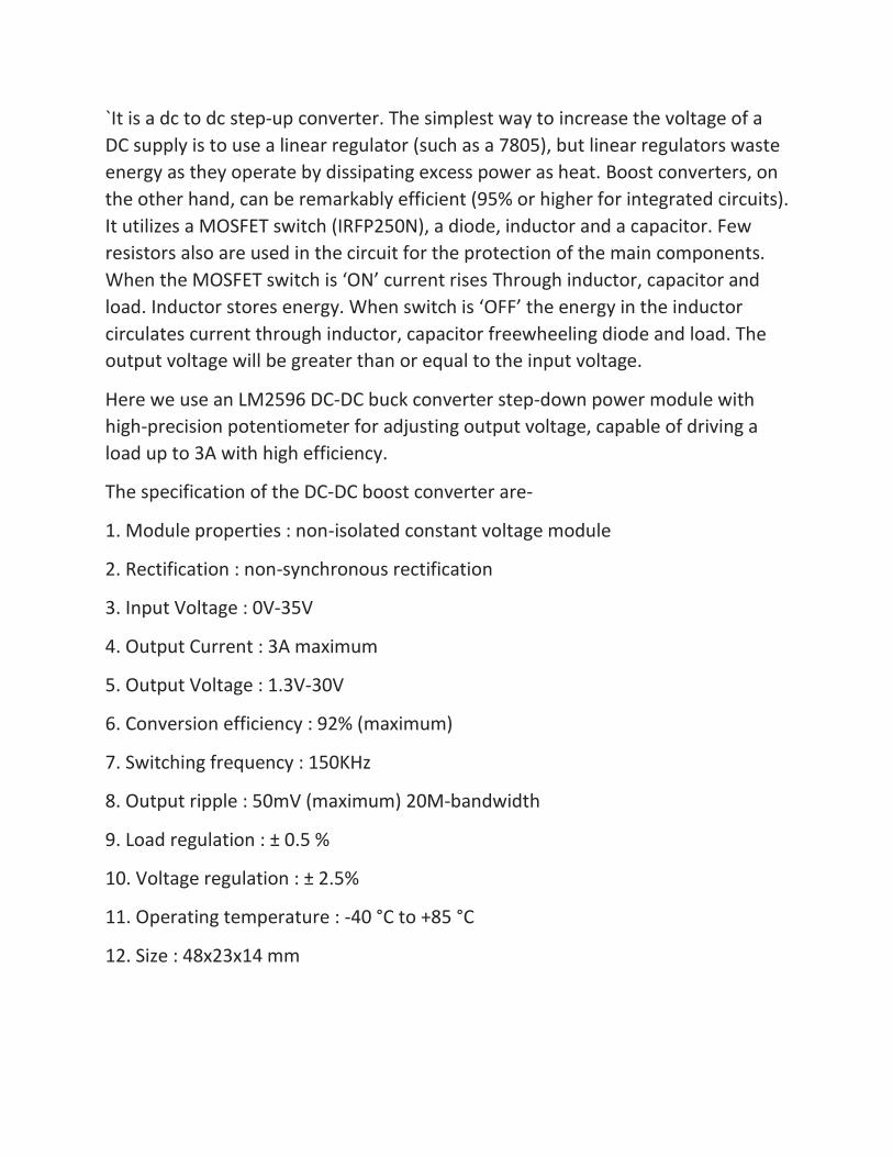
`It is a dc to dc step-up converter. The simplest way to increase the voltage of a
DC supply is to use a linear regulator (such as a 7805), but linear regulators waste
energy as they operate by dissipating excess power as heat. Boost converters, on
the other hand, can be remarkably efficient (95% or higher for integrated circuits).
It utilizes a MOSFET switch (IRFP250N), a diode, inductor and a capacitor. Few
resistors also are used in the circuit for the protection of the main components.
When the MOSFET switch is ‘ON’ current rises Through inductor, capacitor and
load. Inductor stores energy. When switch is ‘OFF’ the energy in the inductor
circulates current through inductor, capacitor freewheeling diode and load. The
output voltage will be greater than or equal to the input voltage.
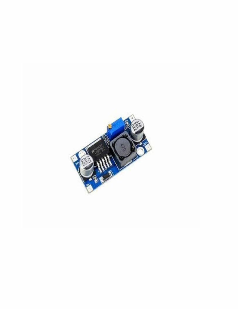
Here we use an LM2596 DC-DC buck converter step-down power module with
high-precision potentiometer for adjusting output voltage, capable of driving a
load up to 3A with high efficiency.
The specification of the DC-DC boost converter are-
1. Module properties : non-isolated constant voltage module
2. Rectification : non-synchronous rectification
3. Input Voltage : 0V-35V
4. Output Current : 3A maximum
5. Output Voltage : 1.3V-30V
6. Conversion efficiency : 92% (maximum)
7. Switching frequency : 150KHz
8. Output ripple : 50mV (maximum) 20M-bandwidth
9. Load regulation : ± 0.5 %
10. Voltage regulation : ± 2.5%
11. Operating temperature : -40 °C to +85 °C
12. Size : 48x23x14 mm
D) Solar Charge Controller
A charge controller or charge regulator is basically a voltage and/or current
regulator to keep batteries from overcharging. It regulates the voltage and
current coming from the solar panels going to the battery. Most "12 volt" panels
put out about 16 to 20 volts, so if there is no regulation the batteries will be
damaged from overcharging. Most batteries need around 14 to 14.5 volts to get
fully charged.
Not always, but usually. Generally, there is no need for a charge controller with
the small maintenance, or trickle charge panels, such as the 1 to 5-watt panels. A
rough rule is that if the panel puts out about 2 watts or less for each 50 battery
amp-hours, then you don't need one.
Charge controls come in all shapes, sizes, features, and price ranges. They range
from the small 4.5 amp (SunGard) control, up to the 60 to 80 amp MPPT
programmable controllers with computer interface. Often, if currents over 60
amps are required, two or more 40 to 80 amp units are wired in parallel. The
most common controls used for all battery based systems are in the 4 to 60 amp
range, but some of the new MPPT controls such as the Outback Power
FlexMax go up to 80 amps.
Charge controls come in 3 general types (with some overlap):
Simple 1 or 2 stage controls which rely on relays or shunt transistors to control the voltage in one or two steps. These essentially just short or disconnect the solar panel when a certain voltage is reached. For all practical purposes these are dinosaurs, but you still see a few on old systems - and some of the super cheap ones for sale on the internet. Their only real claim to fame is their reliability - they have so few components, there is not much to break.
3-stage and/or PWM such Morningstar, Xantrex, Blue Sky, Steca, and many others. These are pretty much the industry standard now, but you will occasionally still see some of the older shunt/relay types around, such as in the very cheap systems offered by discounters and mass marketers.
Maximum power point tracking (MPPT), such as those made by Midnite Solar, Xantrex, Outback Power, Morningstar and others. These are the ultimate in
controllers, with prices to match - but with efficiencies in the 94% to 98% range, they can save considerable money on larger systems since they provide 10 to 30% more power to the battery. For more information, see our article on MPPT.
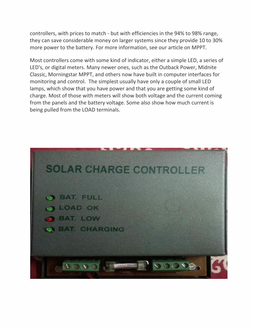
Most controllers come with some kind of indicator, either a simple LED, a series of LED's, or digital meters. Many newer ones, such as the Outback Power, Midnite Classic, Morningstar MPPT, and others now have built in computer interfaces for monitoring and control. The simplest usually have only a couple of small LED lamps, which show that you have power and that you are getting some kind of charge. Most of those with meters will show both voltage and the current coming from the panels and the battery voltage. Some also show how much current is being pulled from the LOAD terminals.

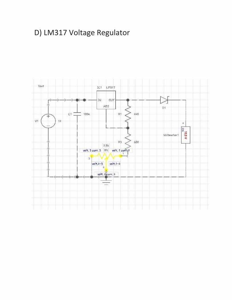
E) LM317 Regulator
The LM317T is an adjustable 3-terminal positive voltage regulator capable of supplying different DC voltage outputs other than the fixed voltage power supply of +5 or +12 volts, or as a variable output voltage from a few volts up to some maximum value all with currents of about 1.5 amperes.
With the aid of a small bit of additional circuitry added to the output of the PSU we can have a bench power supply capable of a range of fixed or variable voltages either positive or negative in nature. In fact this is more simple than you may think as the transformer, rectification and smoothing has already been done by the PSU beforehand all we need to do is connect our additional circuit to the +12 volt yellow wire output. But firstly, lets consider a fixed voltage output.
There are a wide variety of 3-terminal voltage regulators available in a standard TO-220 package with the most popular fixed voltage regulator being the 78xx series positive regulators which range from the very common 7805, +5V fixed voltage regulator to the 7824, +24V fixed voltage regulator. There is also a 79xx series of fixed negative voltage regulators which produce a complementary negative voltage from -5 to -24 volts but in this tutorial we will only use the positive 78xx types.
The fixed 3-terminal regulator is useful in applications were an adjustable output is not required making the output power supply simple, but very flexible as the voltage it outputs is dependant only upon the chosen regulator. They are called 3-terminal voltage regulators because they only have three terminals to connect to and these are the Input, Common and Output respectively.
The input voltage to the regulator will be the +12v yellow wire from the PSU (or separate transformer supply), and is connected between the input and common terminals. The stabilised +9 volts is taken across the output and common as shown.
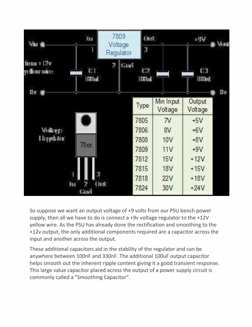
So suppose we want an output voltage of +9 volts from our PSU bench power supply, then all we have to do is connect a +9v voltage regulator to the +12V yellow wire. As the PSU has already done the rectification and smoothing to the +12v output, the only additional components required are a capacitor across the input and another across the output.
These additional capacitors aid in the stability of the regulator and can be anywhere between 100nF and 330nF. The additional 100uF output capacitor helps smooth out the inherent ripple content giving it a good transient response. This large value capacitor placed across the output of a power supply circuit is commonly called a “Smoothing Capacitor”.
These 78xx series regulators give a maximum output current of about 1.5 amps at fixed stabilised voltages of 5, 6, 8, 9, 12, 15, 18 and 24V respectively. But what if we wanted an output voltage of +9V but only had a 7805, +5V regulator?. The +5V output of the 7805 is referenced to the “ground, Gnd” or “0v” terminal.
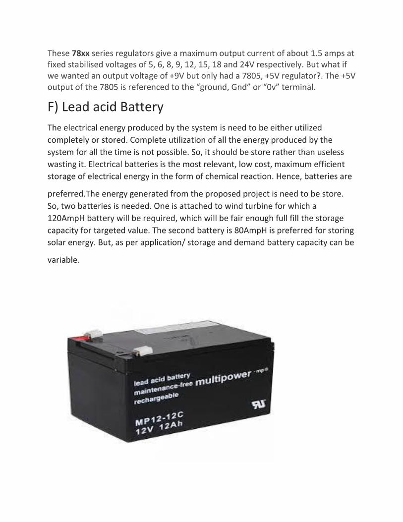
F) Lead acid Battery
The electrical energy produced by the system is need to be either utilized
completely or stored. Complete utilization of all the energy produced by the
system for all the time is not possible. So, it should be store rather than useless
wasting it. Electrical batteries is the most relevant, low cost, maximum efficient
storage of electrical energy in the form of chemical reaction. Hence, batteries are
preferred.The energy generated from the proposed project is need to be store.
So, two batteries is needed. One is attached to wind turbine for which a
120AmpH battery will be required, which will be fair enough full fill the storage
capacity for targeted value. The second battery is 80AmpH is preferred for storing
solar energy. But, as per application/ storage and demand battery capacity can be
variable.
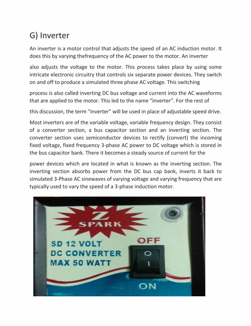
G) Inverter
An inverter is a motor control that adjusts the speed of an AC induction motor. It
does this by varying thefrequency of the AC power to the motor. An inverter
also adjusts the voltage to the motor. This process takes place by using some
intricate electronic circuitry that controls six separate power devices. They switch
on and off to produce a simulated three phase AC voltage. This switching
process is also called inverting DC bus voltage and current into the AC waveforms
that are applied to the motor. This led to the name “inverter”. For the rest of
this discussion, the term “inverter” will be used in place of adjustable speed drive.
Most inverters are of the variable voltage, variable frequency design. They consist
of a converter section, a bus capacitor section and an inverting section. The
converter section uses semiconductor devices to rectify (convert) the incoming
fixed voltage, fixed frequency 3-phase AC power to DC voltage which is stored in
the bus capacitor bank. There it becomes a steady source of current for the
power devices which are located in what is known as the inverting section. The
inverting section absorbs power from the DC bus cap bank, inverts it back to
simulated 3-Phase AC sinewaves of varying voltage and varying frequency that are
typically used to vary the speed of a 3-phase induction motor.
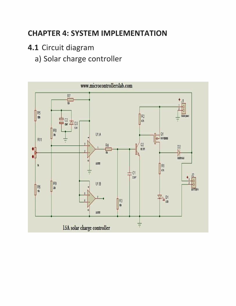
CHAPTER 4: SYSTEM IMPLEMENTATION
4.1 Circuit diagram
a) Solar charge controller
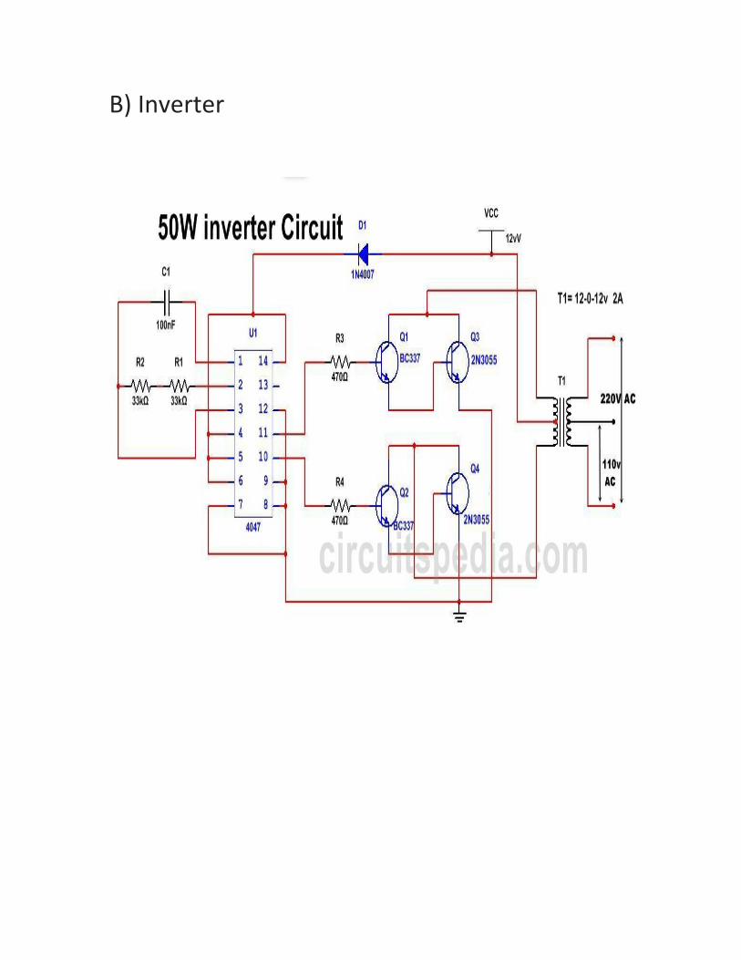
B) Inverter
C) Boost converter
D) LM317 Voltage Regulator
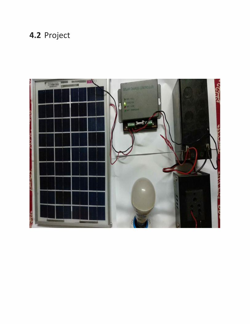
4.2 Project
4.3 Observation and Results
Let the solar and wind current be i1 and i2 respectively, and voltage be V and i be the internal drop
current in charger controller module
Now,
Total power : -
V (i1+i2-i)
Now, let efficiency of the inverter, ŋ = 0.85
So, hybrid power in the form of the AC of the system, ŋ = 0.85 V (i1+i2-i) The process has not completed yet, it will be completed soon.
CHAPTER 5: CONCLUSION AND FUTURE SCOPE
5.1 Conclusion
Reaching the non electrified rural population is currently not possible through the
extension of the grid, since the connection is neither economically feasible, nor
encouraged by the main actors. Further, the increases in oil prices and the
unbearable impacts of this energy source on the users and on the environment, are
slowly removing conventional energy solutions, such as fuel genset based systems,
from the rural development agendas.Therefore, infrastructure investments in rural
areas have to be approached with cost competitive, reliable and efficient tools in
order to provide a sustainable access to electricity and to stimulate development.
Renewable energy sources are currently one of the most, if not the only, suitable
option to supply electricity in fragmented areas or at certain distances from the
grid. Indeed, renewableare already contributing to the realization of important
economic, environmental and social objectives by the enhancement of security of
energy supply, the reduction of Green house gases and other pollutants and by the
creation of local employment which leads to the improvement of general social
welfare and living conditions.Hybrid systems have proved to be the best option to
deliver “high quality” community energy services to rural areas at the lowest
economic cost, and with maximum social and environmental benefits. Indeed, by
choosing renewable energy, developing countries can stabilize their CO2 emissions
while increasing consumption through economic growth.
5.2 Future scope and Application
India ranks fifth in the world in wind power generation at 9600 MW. The coastal
region and some parts of Gujarat and Rajasthan in India witness very favourable
wind regime, and therefore, the wind power development in these areas has been
significant. For commercial exploitation of wind energy, wind velocity at a site
should be more than 6 meter per second and corresponding wind power density
more than 200 watt per meter sq. In Northern India such high wind velocities are
found only on high hilly regions where installation of large scale wind power
projects is itself not feasible due to lack of infrastructure. Haryana has a very limited
sub mountainous region on the foot hills of the Shivalik range in the northern part
of the State and in south Haryana there are mainly the Arawali hills.Wind
monitoring carried out by Haryana Renewable Energy Development Agency
(HAREDA) through Centre for Wind Energy Technology(CWET) during 1998-99,
indicated that the wind velocity at Morni(Panchkula) and Abheypur (Gurgaon) at
25 meter above ground level was 14.9-20.9 kmph and 12.5-17.12 kmph for for
considerably long period in a year. Promoting wind energy in Haryana was a real
challenge with technological barriers in such low wind speed areas. It was then
mooted that Haryana should go for a small wind energy system which requires
average wind velocity of 4 m/s. The idea to utilise the wind-solar power potential
of the Morni Hills area adjoining Himachal Pradesh was conceived keeping in view
the availability of good solar insolation levels( approx.500 W/m2) supplemented by
fairly good wind speeds required for small wind hybrid projects. Sun & wind
normally complement each other with sun energy being available for the period
when wind energy is comparatively low and vice-versa. Thus the combination of
sun and wind provided an ideal solution. HAREDA then invited tenders for the
project.
The wind-solar project had been installed by the Haryana Renewable Energy
Development
Agency(HAREDA) in November 2008 at a cost of Rs 34 lakh with financial assistance
from the Union Ministry of New and Renewable Energy(MNRE). The power plant
has 6.6 kW power generation from wind energy and 3.4 kW power generation from
solar. The power so generated is being supplied to 24 houses of Chakli and Ramsar
villages for two lights, one
fan and six street lights.
The hybrid power plant has been generating 12 units of electricity per day on an
average basis and sometimes when the wind velocity is high, the power generated
is about 30 units per day. The average cost of generation power in this mode comes
out to be about Rs. 15/-per unit. The plant has generated about 2865 units of
electricity in one year. The villagers are contributing Rs.50/- per month towards
energy charges and are enjoying 24x7 electricity. The power availability in these
villages has increased from about 50% to 100%. i.e; form 7-12 hours in the pre
project scenario to 24 hours in the post project period.
The project has been an exciting learning experience for HAREDA while successfully
demonstrating solar wind hybrid power generation technology on the ground. It
has also had a significant spread effect in terms of creating a “demand” for
renewable energy projects among local inhabitants, that too, in an ecologically
sensitive zone like the Morni hills.
5.3 Reference
[1] T.S. Balaji Damodhar and A. Sethil Kumar, “Design of high step up modified for
hybrid solar/wind energy system,” Middle-East
Journal of Scientific Research 23 (6) pp. 1041-1046, ISSN 1990-9233, 2015.
[2] Walaa Elshafee Malik Elamin, “Hybrid wind solar electric power system,” report,
University of Khartoum, Index-084085, July
2013.
[3] Sandeep Kumar and Vijay Garg, “Hybrid system of PV solar/wind & fuel cell,”
IJAREEIE, Vol. 2, Issue 8, ISSN 2320-3765,
August 2013.
[4] Rakeshkumar B. Shah, “Wind solar hybrid energy conversion system- leterature
review,” International Journal of Scientific
Research, Vol. 4, Issue 6, ISSN 2277-8179, June 2015.
[5] Ugur FESLI, Raif BAYIR, Mahmut OZER, “Design & Implementation of Domestic
Solar-Wind Hybrid Energy System”,
Zonguldak Karaelmas University, Department of Electrical and Electronics
Engineering, Zonguldak, Turkey.
[6] Nazih Moubayed, Ali El-Ali, Rachid Outbib, “Control of an Hybrid Solar-Wind
System with Acid Battery for Storage”, Wseas
Transactions on Power System, Labortory of Science in Information and System
(LSI), Axi-Marseille University, France
Related Documents