S Soils and Aggregate Technician Course Tennessee Department of Transportation Volume 18.2 A

Welcome message from author
This document is posted to help you gain knowledge. Please leave a comment to let me know what you think about it! Share it to your friends and learn new things together.
Transcript

S Soils and Aggregate Technician Course
Tennessee Department of Transportation
Volume 18.2
A

Soils and Aggregate Technician Course
Instructors: Jason Mellons, P.E. [email protected]
(615) 350-4152
Derek Gaw, P.E. [email protected]
(615) 350-4106
Traci Smith [email protected]
(615) 350-4126
David Black [email protected]
(615) 350-4163
Training Coordinator: Kim Whitby [email protected]
(615) 350-4158
Tennessee Department of Transportation Division of Materials and Tests • Field Operations 6601 Centennial Blvd. • Nashville • Tennessee • 37243-0360 Phone 615.350.4100 • Fax 615.350.4128
Chris Hampton [email protected]
(615) 350-3314

Soils & Aggregate Technician CourseVolume 18.2
Class Schedule
Day 1:
1. Registration2. Introduction to the Course3. Sampling Aggregates4. Reducing Samples of Aggregates to Testing Size5. Total Evaporable Moisture Content of Aggregate by Drying6. Break7. Material Finer Than the No. 200 (75µm)8. Sieve Analysis of Fine and Coarse Aggregate9. Lunch (Provided)10. Embankments and Embankment Materials11. Compaction and Density Concepts12. Break13. Embankment Placement14. Quality Acceptance Testing
Day 2:
15. Review for Exam16. Written Exam

Soils & Aggregate Technician Course
Tennessee Department of Transportation
Volume 18.2
Table of Contents
I. Introduction……………………………… ............................... …………………………………….....….1
1. Sampling Aggregates .................................................................................................. 7
2. Reducing Samples of Aggregates to Testing Size ................................................... 20
3. Total Evaporable Moisture Content of Aggregate by Drying ................................28
4 . Material Finer Than the No. 200 (75µm) ................................................................... 36
5 . Sieve Analysis of Fine and Coarse Aggregate ........................................................... 46
6 . Embankments and Embankment Materials ................................................................61
7 . Compaction and Density Concepts ..............................................................................78
8. Embankment Placement .............................................................................................. 89
9 . Quality Acceptance Testing ........................................................................................ 106
1 0 . TDOT Forms........................................................................................................................ ...128
11. SOP 1-1 ......................................................................................................................... 130
12. . SOP 7-1 .......................................................................................................................... 140
13. SOP 7-2..................................................................................................................... ...145
14.TDOT Specs.............................................................................................................. ...150

Introduction
Welcome!
Soils and Aggregate Technician Certification
Introduction• Technician Certification Program• Purpose• Who’s Who• Course Highlights• Written Examination• Results/Certification• Resources/Contacts• Summary/Questions
S & A Technician Certification
1

Introduction
Instructors• Jason Mellons, P.E.
• Derek Gaw, [email protected]
• Traci [email protected]
• David [email protected]
• Chris [email protected]
S & A Technician Certification
Technician Certification Program
• Asphalt Roadway Inspector• Asphalt Plant Inspector• Asphalt Mix Design• Concrete Field Testing• Concrete Plant Quality Control• Concrete Mix Design• Soils and Aggregate• Nuclear Gauge Safety (TDOT Employees Only)
S & A Technician Certification
2

Introduction
Purpose of Certification
• To ensure proper performance of tests• To improve reliability of results• For quality control• To comply with federal requirements
S & A Technician Certification
Course Highlights• Course schedule
• Slide presentations• Introduction to Soils and Aggregates• 5 Test methods for Aggregate• Soil Testing and Properties• TDOT Specifications
• Written exam• Results• Certification
• Recertification• Every 5 years
S & A Technician Certification
3

Introduction
Written Examination• Consists of:• 51 questions• Open-book• Two hours to complete
• To Pass:• Must get 70% overall
S & A Technician Certification
Results
• Available within one week of completion
• Contact the Headquarters Materials & TestsTraining Coordinator, Kim Whitby
• [email protected]• 615-350-4158
S & A Technician Certification
4

Introduction
Resources Course materials
Course textbook Presentation slides and videos
TDOT Standard Specifications, January 1, 2015 Special Provisions
Contacts Region 1: Brad Baskette Region 2: Tony Renfro Region 3: Kevin Isenberg Region 4: Mitch Blankenship
S & A Technician Certification
Resources Tennessee Department of Transportation
https://www.tn.gov/tdot.html American Road & Transportation Builders Association
https://www.artba.org/ Tennessee Road Builders Association
www.trba.org/ Tennessee Ready Mixed Concrete Association
www.tnconcrete.org/ American Association of State Highway Transportation
Officials https://www.transportation.org
American Society for Testing and Materials https://www.astm.org/
American Concrete Institute https://www.concrete.org/
Construction Materials Engineering Council https://www.cmec.org/
Portland Cement Association www.cement.org/
S & A Technician Certification
5

Introduction
ADA Notice of Requirements
• Can be found at the following website:▫ https://www.tn.gov/tdot/government/g/public-accessibility-office/ada.html
• To be in compliance with TDOTs requirements listed on thewebsite above, it is our goal to provide reasonableaccommodations to those who identify themselves as having adisability and request such accommodations.
• Please feel free to bring it to any of the course instructors andaccommodations will be administered as discretely as possible.
Concrete Mix Design Technician Certification
Questions
6

1 Sampling of Aggregates
AASHTO T 2
ASTM D 75
Sampling
ReferencesTDOT Standard Specifications
AASHTO T 2ASTM D 75
• Shovel• Scoops• Brushes• Sampling tubes• Sample containers• Tags
Apparatus
Soils and Aggregate Technician Certification
7

Sampling
• Preliminary investigation of the potentialsource of supply• Sample at source• Complete quality testing (dependent upon application)
• Control of the product at the source
• Control of the operations at the site of use• Project site• Concrete plant
• Acceptance or rejection of the materials• TDOT Standard Specifications
Purpose
Soils and Aggregate Technician Certification
• Nominal maximum size of aggregate isthe smallest sieve opening throughwhich the entire amount of theaggregate is permitted to pass.
• Maximum size of aggregate is thesmallest sieve opening through whichthe entire amount of aggregate isrequired to pass.
Size of Aggregate
Soils and Aggregate Technician Certification
8

SizeNominal
Size 4” 3.5” 3” 2.5” 2” 1.5” 1” ¾” ½” 3/8” #4 #8 #16 #50 #100
1 3.5‐1.5” 100 90‐100 ‐ 25‐60 ‐ 0‐15 ‐ 0‐5
2 2.5‐1.5” 100 90‐100 35‐70 0‐15 0‐5
24 2.5‐¾” 100 90‐100 25‐60 0‐10 0‐5
3 2‐1” 100 90‐100 35‐70 0‐15 0‐5
357 2”‐#4 100 95‐100 35‐70 10‐30 0‐5
4 1.5‐¾” 100 90‐100 20‐55 0‐15 0‐5
467 1.5”‐#4 100 95‐100 35‐70 10‐30 0‐5
5 1‐½” 100 90‐100 20‐55 0‐10 0‐5
56 1‐3/8” 100 90‐100 40‐85 10‐40 0‐15 0‐5
57 1”‐#4 100 95‐100 25‐60 0‐10 0‐5
6 ¾ ‐ 3/8” 100 90‐100 20‐55 0‐15 0‐5
67 ¾”‐#4 100 90‐100 20‐55 0‐10 0‐5
68 ¾”‐#8 100 90‐100 30‐65 5‐25 0‐10 0‐5
7 ½” ‐#4 100 90‐100 40‐70 0‐15 0‐5
78 ½” ‐#8 100 90‐100 40‐75 5‐25 0‐10 0‐5
8 3/8”‐#8 100 85‐100 10‐30 0‐10 0‐5
89 3/8”‐#16 100 90‐100 20‐55 5‐30 0‐10 0‐5
9 #4‐#16 100 85‐100 10‐40 0‐10 0‐5
10 #4‐screenings 100 85‐100 10‐30
Sizes of Coarse Aggregate Table 903.22-1
9

Field Sample Size
Soils and Aggregate Technician Certification
(Nominal Maximum Size)
10

Soils and Aggregate Technician Certification
Aggregate Production and Use
https://www.youtube.com/watch?v=qWEci7TbjBk&feature=youtu.be
11

Aggregate Production and Use
Soils and Aggregate Technician Certification12

Sampling
• Flowing aggregate stream• Conveyor belt• Stockpiles
• With power equipment• Without power equipment
• Roadways• Transportation units
Methods of Sampling
Soils and Aggregate Technician Certification
• From bins, for example• Three increments• Each increment obtained using a
suitable sampling device• Device must be capable of
interrupting the entire flow ofmaterial as it passes off the belt
Flowing Aggregate Stream
Soils and Aggregate Technician Certification
13

Sampling
• Three increments• Production suspended
while sampling• Designated sampling area• Templates useful for
defining sampling area• All material within
sampling area is removedincluding fines (with abrush)
Conveyor Belts
Soils and Aggregate Technician Certification
• Stockpile must be checked forsegregation and noted in log
• Segregation is the separation of varyingsizes of aggregate
• Power equipment is recommended• Portions collected at various locations
around the main stockpile
Stockpiles
Soils and Aggregate Technician Certification
14

Sampling
• Loader enters stockpilewith bucketapproximately 6” aboveground level
• Loader bucket is raisedperpendicular to theground
• Bucket is tilted forwardto roll material out into aseparate stockpile
With Power Equipment
Soils and Aggregate Technician Certification
• The loader is then used tobackblade the smaller stockpileONE time
• Divide the sample pad into 4quadrants, and sample equalamounts
• Avoid sampling within 1 ft. ofsample pad edge
• The FOUR increments are thencombined to comprise the finalfield sample
With Power Equipment
Soils and Aggregate Technician Certification
15

Sampling
If power equipment is not available:
• The pile is visually divided into threeeven sections: top third, mid-point,and bottom third of the elevation ofthe stockpile
• Portions are obtained from eachsection at least 12” below the surfaceby removing the outer layer ofmaterial
• The three increments are thencombined to comprise the final fieldsample
Without Power Equipment
Soils and Aggregate Technician Certification
12
3
In lieu of shoveling:
• Sampling tubes may be usedon fine aggregate only
• Sample shall be taken at aminimum height of 3 ft fromthe surrounding grade
•At least five tube insertionsrandomly spaced across faceof stockpile
Without Power Equipment
Soils and Aggregate Technician Certification
16

Sampling
Without Power Equipment (Sampling Tube)
1 ¼” min.
6 ft min.
Soils and Aggregate Technician Certification
• Three increments
• Sample obtained from uncompacted or loosely-compactedbase or sub base material
• Predetermined random locations
• Full depth of layer must be sampled
• Avoid contamination from underlying material
Roadways
Soils and Aggregate Technician Certification
17

Sampling
• Railroad cars, barges, trucks• Avoid if at all possible• Power equipment is
recommended• Various levels and random
locations• Three or more trenches
• Three increments from each trench
Transportation Units
1’
1’
Soils and Aggregate Technician Certification
• Durable• Able to be carried
[ 50 lbs. (23 kg) ]• Portion the sample if
necessary• Appropriate container for
test to be performed
Sample Containers
Soils and Aggregate Technician Certification
18

Sampling
Tagging the Sample
Project Number:_______________________________
Date Sampled:____________ Submitted:____________
Sampled by:___________________________________
Submitted by:__________________________________
Producer:_____________________________________
Pit Number:__________ Sampled from:_____________
County:________________ Region:________________
55001-3231-18
11 Mar 02 12 Mar 02
F. Flintstone
F. Flintstone
Stone Materials, Inc.
185 Stockpile
Davidson 3
Soils and Aggregate Technician Certification
Questions
19

2 Reducing Samples of Aggregate to Testing
Size AASHTO R 76
ASTM C 702

Reducing
ReferencesTDOT Standard Specifications
AASHTO R 76ASTM C 702
TDOT Standard Method of Test forReducing Samples of Aggregate to
Testing Size
• Method A - Mechanical Splitter
• Method B - Cone and Quarter
• Method C - Miniature Stockpile
Methods of Reduction
Soils and Aggregate Technician Certification
20

Reducing
• Moisture condition of the aggregate• Dry
• Moist
• SSD/Absorption
• Wet/Free Moisture
To Determine Method
Soils and Aggregate Technician Certification
• Size of aggregate
• Coarse
• Fine
• Combined
To Determine Method
Soils and Aggregate Technician Certification
21

Reducing
Determine Method
• Method A - Mechanical Splitter• Method B - Cone and Quarter• Method C - Miniature Stockpile
SplittingMethod
Coarse Combined Fine
Drier than saturated-surface-dry and SSD
Free moisture on surface
B, C
AggregateSize
Moisture
B
A, B A, B A
Soils and Aggregate Technician Certification
A, B
• Even number of chutes• Chutes of equal width• At least 8 chutes• Individual chutes about
50% larger than largestparticles
Mechanical Splitter / Method A
Rolled Edges
Feed Chute
For Coarse and Combined Aggregate
Soils and Aggregate Technician Certification
22

Reducing
For Fine Aggregate
• Even number of chutes• Chutes of equal width• At least 12 chutes• Individual chutes ½” to
¾” wide
Mechanical Splitter / Method A
Soils and Aggregate Technician Certification
Cone and Quarter / Method B• Cone the sample on a
hard, clean, levelsurface.
• Turn sample over 3times and place into acone.
• Flatten the cone to auniform thickness.
• Diameter = 4 to 8 timesthe thickness
Soils and Aggregate Technician Certification
23

Reducing
Cone and Quarter / Method B• Divide the flattened
cone.
• After dividing, removetwo diagonal quarters(including fines).
• Mix and quarter theremaining materialuntil sample isadequately reduced.
Soils and Aggregate Technician Certification
Cone and Quarter / Method BFine Aggregate
Soils and Aggregate Technician Certification
1
4
2
3
24

Reducing
Quartering Alternative/Method B
Mix by rolling on canvas. Flatten aggregate pile to a diameter 4 to 8 times the
thickness.
Soils and Aggregate Technician Certification
Divide the aggregate into four separate quarters using a shovel or stick.
Quartering Alternative/Method B
Soils and Aggregate Technician Certification
Remove two diagonally opposite quarters
including fines.
25

Reducing
• Place sample on hard, clean, levelsurface
• Mix thoroughly by turning over threetimes
• Form a cone with the last turning• Flatten, if desired, to a uniform
thickness• Select at least five increments at
random locations using a shovel,scoop, or spoon
Miniature Stockpile / Method C
Soils and Aggregate Technician Certification
Miniature Stockpile / Method C
Soils and Aggregate Technician Certification
26

Reducing
27
3 Total Evaporable Moisture Content of
Aggregate by Drying
AASHTO T 255
ASTM C 566

Moisture Content
ReferencesTDOT Standard Specifications
AASHTO T 255ASTM C566
TDOT Standard Method of Test for
• Balance• Heat Source• Sample Container• Stirring Spoon
Apparatus
Soils and Aggregate Technician Certification
28

Moisture Content
Sample Size
Soils and Aggregate Technician Certification
Samples
Soils and Aggregate Technician Certification
29

Moisture Content
• Weigh the sampleto the nearest 0.1of a unit of theoriginal samplemass
Determine Sample Mass
6285.6 g
Soils and Aggregate Technician Certification
Dry the Sample
• Dry theaggregate to aconstant massin an oven at110 5°C (230 9°F)
• Allow thematerial to cool
Soils and Aggregate Technician Certification
30

Moisture Content
• Weigh thesample to thenearest 0.1 of aunit of theoriginal samplemass
Reweigh the Sample
6163.8 g
Soils and Aggregate Technician Certification
Calculations
100,
Dry
DryOriginalTotalMoisture M
MMP
100
D
DWP
Soils and Aggregate Technician Certification
31

Moisture Content
Given:
• Weight of the original sample (W) = 1092.4 g
• Weight of sample after drying (D) = 1080.5 g
Determine:
Total percent (P) moisture content of the aggregate.
Problem
Soils and Aggregate Technician Certification
Solution
100
D
DWP
Soils and Aggregate Technician Certification
32

Moisture Content
Practice
Soils and Aggregate Technician Certification
Solutions 1 588.3 570.92 1556.8 1540.93 1225.0 1220.14 1665.2 1650.5
Soils and Aggregate Technician Certification
33

Moisture Content
DRY900g
MOIST930g
SSD955g
WET975g
Determine the percent moisture content in the wet condition:
Determine the percent moisture of the aggregate at SSD (Absorption):
Soils and Aggregate Technician Certification
Determine the percent of free moisture on the sample:
Determine the amount of water the aggregate has in the wet condition:
DRY900g
MOIST930g
SSD955g
WET975g
Soils and Aggregate Technician Certification
34

Moisture Content
35

4 Materials Finer Than 75-µm (No.200) Sieve
In Mineral Aggregates by Washing
AASHTO T 11
ASTM C 117
Finer Than #200
ReferencesTDOT Standard Specifications
AASHTO T 11ASTM C 117
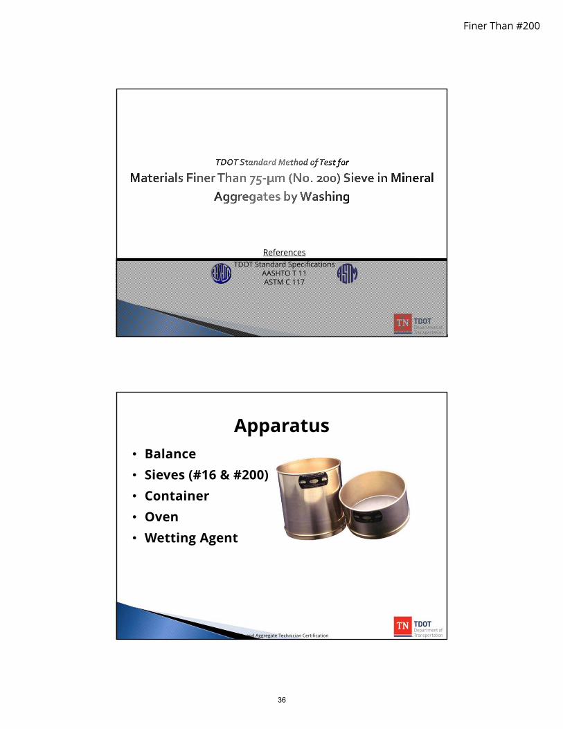
• Balance• Sieves (#16 & #200)• Container• Oven• Wetting Agent
Apparatus
Soils and Aggregate Technician Certification
36

Finer Than #200
Sample Size
Soils and Aggregate Technician Certification
Nominal Maximum SizeA Minimum Mass, g
4.75 mm (No. 4) or smaller 300
9.5 mm (3/8") 1000
12.5 mm to 19.0 mm (1/2" to 3/4") 2500
25 mm (1") or larger 5000
A Based on sieve sizes meeting Specification E11.
Minus 200 Material
Soils and Aggregate Technician Certification
37
Finer Than #200
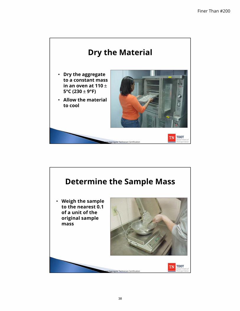
Dry the Material
• Dry the aggregateto a constant massin an oven at 110 5°C (230 9°F)
• Allow the materialto cool
Soils and Aggregate Technician Certification
• Weigh the sampleto the nearest 0.1of a unit of theoriginal samplemass
Determine the Sample Mass
Soils and Aggregate Technician Certification
38

Finer Than #200
Procedure A - Washing with plain water• Dust of Fracture
Procedure B - Washing using a wetting agent• Clay Particles
Two Procedures
Soils and Aggregate Technician Certification
• Place the samplein the container
• Add water tocover the sample
• Add wettingagent ifperformingProcedure B
Procedure
Soils and Aggregate Technician Certification
39

Finer Than #200
• Agitate the sample• Use a spoon to stir,
if desired• Ensure complete
separation ofparticles
Procedure
Soils and Aggregate Technician Certification
• Pour the washwater withsuspended solidsover the nestedsieves
Procedure
Soils and Aggregate Technician Certification
40

Finer Than #200
• Repeat thewashing with plainwater
• Repeat until washwater is clear
• Use wetting agentfirst wash only
Procedure
Soils and Aggregate Technician Certification
Dry the Material
• Dry the aggregateto a constant massin an oven at 110 5°C (230 9°F)
• Allow the materialto cool
Soils and Aggregate Technician Certification
41

Finer Than #200
• Weigh the sampleto the nearest 0.1of a unit of theoriginal samplemass
Determine the Sample Mass
Soils and Aggregate Technician Certification
Calculations
100,
,,75
BeforeDry
AfterDryBeforeDrym M
MMP
Soils and Aggregate Technician Certification
42

Finer Than #200
• If the amount of material finer than 75-m isless than 10% then report the results to thenearest 0.1.
• If the amount of material finer than 75- m isgreater than 10% then report the results tothe nearest whole number.
Results
Soils and Aggregate Technician Certification
Given:
• Original mass of the sample = 595.6 g
• Mass of the sample after washing = 579.3 g
Determine:• The percent (P) of material finer than the No. 200
sieve in the sample.
Problem
Soils and Aggregate Technician Certification
43

Finer Than #200
Solution
Soils and Aggregate Technician Certification
75 mP
100,
,,75
BeforeDry
AfterDryBeforeDrym M
MMP
Given:
• Original mass of the sample = 6895.5 g
• Mass of the sample after washing = 6045.0 g
Determine:• The percent (P) of material finer than the No. 200
sieve in the sample
Practice
Soils and Aggregate Technician Certification
44

Finer Than #200
Solution
75 mP
Soils and Aggregate Technician Certification
100,
,,75
BeforeDry
AfterDryBeforeDrym M
MMP
45

5 Sieve Analysis of Fine and Coarse Aggregates
AASHTO T 27
ASTM C 136

Sieve Analysis
TDOT Standard Method of Test for
Sieve Analysis of Fine and Coarse Aggregates
ReferencesTDOT Standard Specifications
AASHTO T 27ASTM C 136
• Balance• Oven• Sieves• Mechanical Shaker
Apparatus
Soils and Aggregate Technician Certification
46

Aggregate Gradation
Well-Graded
Gap-Graded
Uniformly-Graded
Soils and Aggregate Technician Certification47

Field Sample Size
Soils and Aggregate Technician Certification48

Test Sample Size
Soils and Aggregate Technician Certification49

Sieve Analysis
Dry the Material
• Dry theaggregate to aconstant mass inan oven at 110 5°C (230 9°F)
• Allow thematerial to cool
Soils and Aggregate Technician Certification
Determine the Sample Mass
• Weigh thesample to thenearest 0.1 ofa unit of theoriginalsample mass
Soils and Aggregate Technician Certification
50
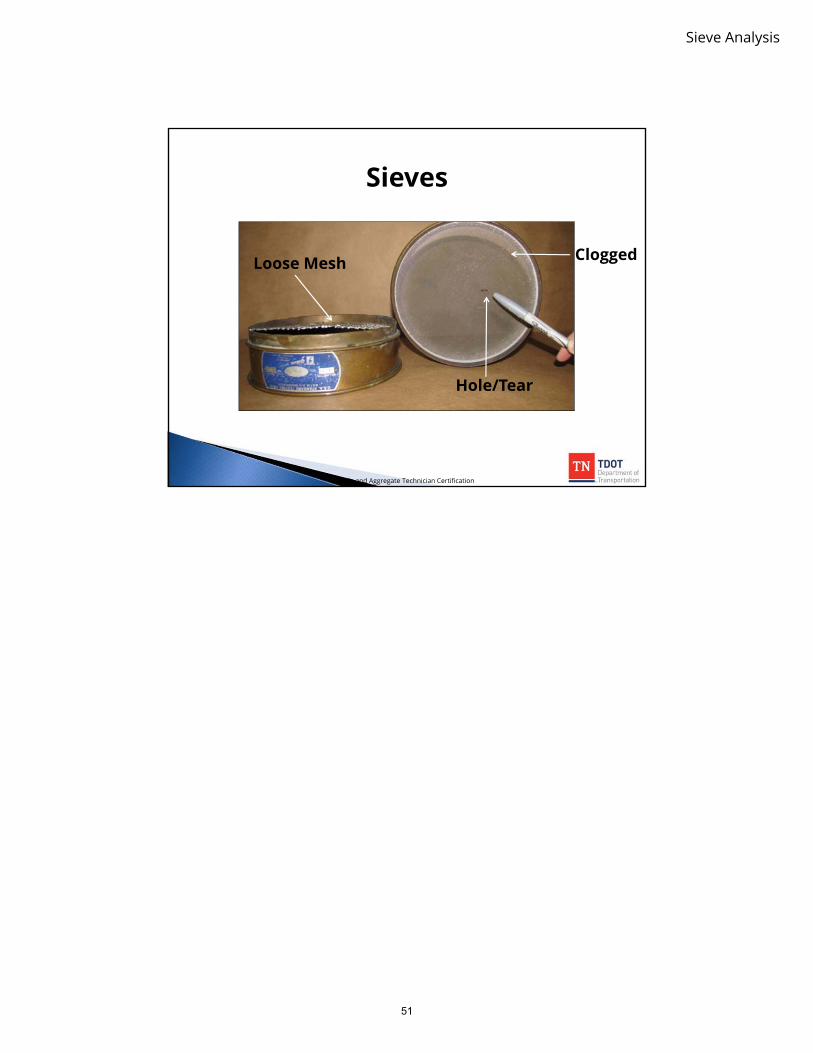
Sieve Analysis
Sieves
Loose Mesh
Hole/Tear
Clogged
Soils and Aggregate Technician Certification
51

Maximum Loading of Sieves
Soils and Aggregate Technician Certification52

Sieve Analysis
Options for Overloading• Use larger sieve
• Portion the sample
• Place another sieve in the nest
Overloaded Sieve
12” Round 18” x 26”
Tray
Soils and Aggregate Technician Certification
• Use a mechanicalshaker to agitate thesieves
Mechanical Shaker
Soils and Aggregate Technician Certification
53

Sieve Analysis
• Weigh the sampleto the nearest 0.1of a unit of theoriginal samplemass
Weighing
Soils and Aggregate Technician Certification
54

Sieve Analysis
Sample Problem #1
4.75 mm No. 4 0.02.36 mm No. 8 51.01.18 mm No. 16 98.0600 um No. 30 106.0300 um No. 50 117.0150 um No. 100 95.075 um No. 200 29.0< 75 um < No. 200 11.0
Total
Original Sample Mass (g)
Sieve Size or Designation
Individual Weight Retained (g)
507.8
Soils and Aggregate Technician Certification
AASHTOLoss
.
x 100
AASHTOLoss
Sample Problem #1
Soils and Aggregate Technician Certification
55

Sample Problem # 1
Soils and Aggregate Technician Certification
4.75 mm No. 42.36 mm No. 81.18 mm No. 16600 um No. 30300 um No. 50150 um No. 10075 um No. 200< 75 um < No. 200
Individual Percent Retained
Cumulative Percent Retained
Cumulative Percent Passing
Sieve Size or Designation
Individual Weight Retained (g)
Original Sample
507.8
0.051.098.0106.0117.095.029.011.0
56
Sieve Analysis
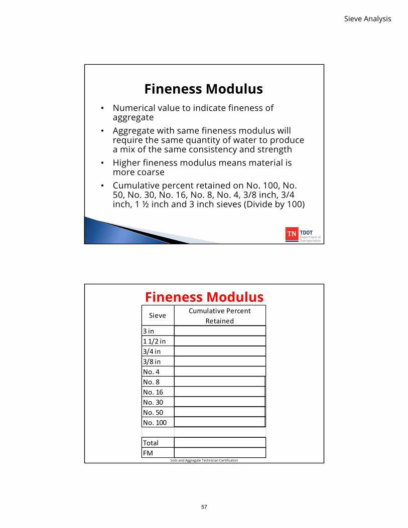
• Numerical value to indicate fineness ofaggregate
• Aggregate with same fineness modulus willrequire the same quantity of water to producea mix of the same consistency and strength
• Higher fineness modulus means material ismore coarse
• Cumulative percent retained on No. 100, No.50, No. 30, No. 16, No. 8, No. 4, 3/8 inch, 3/4inch, 1 ½ inch and 3 inch sieves (Divide by 100)
Fineness Modulus
Fineness Modulus
3 in1 1/2 in3/4 in3/8 inNo. 4No. 8No. 16No. 30No. 50No. 100
TotalFM
Sieve Cumulative Percent Retained
Soils and Aggregate Technician Certification
57

Sieve Analysis
Sample Problem #2
75 mm 3 in 0.050 mm 2 in 0.037.5 mm 1 1/2 in 6.025 mm 1 in 20.019 mm 3/4 in 16.012.5 mm 1/2 in 13.09.5 mm 3/8 in 28.04.75 mm No. 4 8.0< 4.75 mm< No. 4 0.0
Total
Original Sample Mass (g)
Sieve Size or Designation
Individual Weight Retained (g)
91.2
Soils and Aggregate Technician Certification
AASHTOLoss
x 100
AASHTOLoss
Sample Problem #2
Soils and Aggregate Technician Certification
58

Sample Problem # 2Original Sample
91.2
75 mm 3 in 0.050 mm 2 in 0.037.5 mm 1 1/2 in 6.025 mm 1 in 20.019 mm 3/4 in 16.012.5 mm 1/2 in 13.09.5 mm 3/8 in 28.04.75 mm No. 4 8.0< 4.75 mm< No. 4 0.0
Cumulative Percent Retained
Cumulative Percent Passing
Sieve Size or Designation
Individual Weight Retained
Individual Percent Retained
Soils and Aggregate Technician Certification59

Sieve Analysis
Fineness Modulus
3 in1 1/2 in3/4 in3/8 inNo. 4No. 8No. 16No. 30No. 50No. 100
TotalFM
Sieve Cumulative Percent Retained
Soils and Aggregate Technician Certification
60

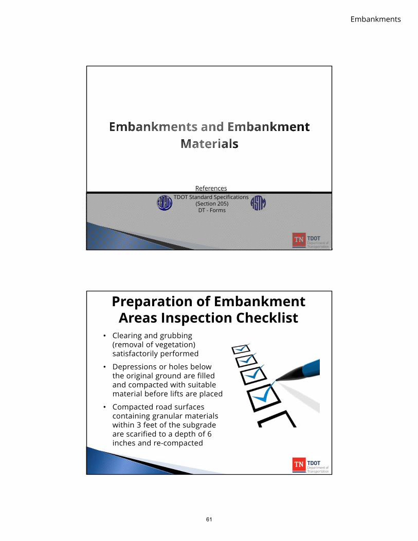
6 Embankments and Embankment
Materials
Embankments
ReferencesTDOT Standard Specifications
(Section 205)DT - Forms
• Clearing and grubbing(removal of vegetation)satisfactorily performed
• Depressions or holes belowthe original ground are filledand compacted with suitablematerial before lifts are placed
• Compacted road surfacescontaining granular materialswithin 3 feet of the subgradeare scarified to a depth of 6inches and re-compacted
Preparation of Embankment Areas Inspection Checklist
61

Embankments
• Concrete pavements andbases are removed andbroken
• Embankment material mustbe placed in lifts
• Lifts are not placed onsurfaces which are frozen orcontain snow, mud or ice
Preparation of Embankment Areas Inspection Checklist
Where the original ground surface is less than three feet belowthe subgrade, the following apply:
- All sod and vegetation is removed- Unsuitable material is replaced with suitable material- The cleared surface is broken up to a depth of six inches and
re-compacted- Cultivated sod not required to be removed before constructing
the embankment- Compacted road surface containing granular materials lies
within 3 feet of subgrade, scarify at least 6 inches and re-compact the scarified material
Preparation of Embankment Areas Inspection Checklist
62

Embankments
Major Embankment Materials
• Rock fragments• Gravel• Sand• Silt• Clay
Soils and Aggregate Technician Certification
63

Form DT-0332 Proctor Density Report
Soils and Aggregate Technician Certification64

Gradation
4.75 mm No. 4
2.36 mm No. 8
1.18 mm No. 16
600 m No. 30
300 m No. 50
150 m No. 100
75 m No. 200
< 75 m < No. 200
2"1-1/2"1"3/4"3/8"#4#10#40#100#200Silt and ClayClay
Coarse to medium gravel
Medium to fine gravel
Fine gravelCoarse sandMedium sandFine sand
Soils and Aggregate Technician Certification65
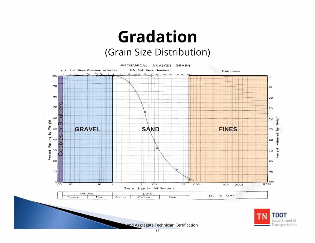
Gradation(Grain Size Distribution)
Soils and Aggregate Technician Certification66

Embankments
Gradation Example
MCMINN
2"
74.07439
1-1/2"
86
7782
74
Sample No.
Sampled BySampled From
GRADATION - TOTAL PERCENT PASSING
1-A 2-A 3-A 4-A
Serial No.ContractorProducer
09-Jan-03Date SampledDate Reported
Project Supervisor
County
S-3
Region 254000-1500-04 Contract No.
04-Jan-03
Station 21+50 27+00 27+000'---5'C/L
10099
9899
9898.09874
0'---8'60' Lt. C/L
1009893
8'---17'60' Lt. C/L
100938476
4855
4545.04518
27+000'---3'C/L
1009694
8686868654
5-A23+000'---13'
30' Lt. C/L
1009791
7876767645
6-A32+000'---8'C/L
100978883
6363606026
Depth, ft.
Location, ft.
1"
3/4"
3/8"
No. 4
No. 10
No. 40
No. 100
No. 200
Silt and Clay
Clay
6601 CENTENNIAL BLVD.NASHVILLE, TENNESSEE 37243-0360
PROCTOR DENSITY REPORT
Project Reference No.Project No.MaterialReport No.
Soil
STATE OF TENNESSEEDEPARTMENT OF TRANSPORTATION
DIVISION OF MATERIALS AND TESTS
No. 16 89 82 71
Original to: Headquarters Materials and TestsCopies to: Regional Materials and Tests Project Supervisor
Soils and Aggregate Technician Certification
Soil Constants
MCMINN
Sampled BySampled From
Serial No.ContractorProducer
09-Jan-03Date SampledDate Reported
Project Supervisor
County
S-3
Region 254000-1500-04 Contract No.
04-Jan-03
6601 CENTENNIAL BLVD.NASHVILLE, TENNESSEE 37243-0360
PROCTOR DENSITY REPORT
Project Reference No.Project No.MaterialReport No.
Soil
STATE OF TENNESSEEDEPARTMENT OF TRANSPORTATION
DIVISION OF MATERIALS AND TESTS
Original to: Headquarters Materials and Tests
Copies to: Regional Materials and Tests Project Supervisor
20-24.5 19-25 15.5-20.5Moisture Range Above Subgrade 30-37.5 19.5-25.5 10-15.5
Approved for Information Only
Regional Materials and Tests
Moisture Range Below Subgrade
105.0
Liquid Limit
SOIL CONSTANTS
60 51 28 54 50 34Plastic Limit 40 24 17 25 29 22
A-7-6 A-7-6 A-6
Plasticity Index 20
Type A-7-5 A-7-6
Calculated PI 20
Group 27 20 2A-6
95 % Density 81.2 93.6
Optimum Moisture 33.0 22.5
27 17 5
23.0 17.597.522.0
97.0DENSITY CORRECTED FOR +4 MATERIAL
Proctor Density 85.512.5
98.5 117.5
Engineer of Materials and Tests
111.6 92.6 92.2 99.8
927 11 29 21 1222 6 26 17
Form DT-0332 English (Rev. 10-02)
Soils and Aggregate Technician Certification
67

Embankments
Consistency• Atterberg limits are measures of moisture
content at which the soil changes physicalstates• shrinkage limit• plastic limit• liquid limit• plasticity index
• Soil constants indicate the load-carrying capacity of the embankment material
• They are based on the water-holdingcapacity of soils under various conditionsand are expressed as a moisturepercentage
100 weightsoildry -oven
weightsoildry -oven- weightsoilwet w
Soils and Aggregate Technician Certification
Shrinkage Limit
• Shrinkage limit is the moisture contentbelow which a soil will no longer changevolume
Soils and Aggregate Technician Certification
68

Embankments
Plastic Limit• Plastic limit is the moisture content at which a
soil passes from a semisolid to a plastic state
• Plastic limit is influenced by the clay content ofa soil
• Sand is a nonplastic material
• Reduction of moisture content below the P.L.leads to a rapid increase in load-carryingcapacity
• Increased moisture content above the P.L.leads to a rapid decrease in load-carryingcapacity
Soils and Aggregate Technician Certification
Liquid Limit• Liquid limit is the moisture content at which a soil passes
from a plastic to a liquid state
• High liquid limits indicate soils of high clay content and lowload-carrying capacity
Soils and Aggregate Technician Certification
69

Embankments
Plasticity Index
• Plasticity index is the moisture content range at which a soil is in aplastic state
• The plasticity index is the numerical difference between the liquidlimit and the plastic limit
Given: LL = 56, PL = 37PI = 56-37 PI = 19
• Low P.I. Values (<10) indicate that a soil will go from its P.L. to itsL.L. with small additions of water
• High P.I. Values (>20) indicate that a considerable amount of watercan be added to a soil before it will go from its P.L. to its L.L.
• If L.L.< P.L., the material is considered nonplastic (N.P.)
Soils and Aggregate Technician Certification
Calculated Plasticity Index
• The calculated P.I. is significant when the material containslarge amounts of granular particles
• It relates the P.I. to the total sample rather than just the < 40material
• The calculated P.I. is determined as follows:
100.... sieve #40passing material
actualcalculated
IPIP
Soils and Aggregate Technician Certification
70

AASHTO Soil ClassificationAASHTO Recommended Practice for
Classification of Soils and Soil-Aggregate Mixtures
General Classification Granular materials( 35 percent of total sample passing No. 200)
Silt-clay materials( 35 percent of total sample passing No. 200)
Group Classification A-1 A-3 A-2 A-4 A-5 A-6 A-7
Subgroup A-1-a A-1-b A-2-4 A-2-5 A-2-6 A-2-7 A-7-5 A-7-6
Sieve Analysis, percent passing
No. 10 ……………………………………………… 50
No. 40 ……………………………………………… 30 50 51
No. 200, F ……………………………………….…. 15 25 10
Characteristics of fraction passing 0.425 mm (No. 40)
Liquid Limit, LL ………………………………….. 40 41 40 41 40 41 40 41 41
Plasticity Index, PI c ………………………………... 6 NP 10 10 11 11 10 10 11 (LL-30) (LL-30)
Group Index, GI ………………………………….. 0 0 0 4 8 12 16 20
Soils and Aggregate Technician Certification71

Embankments
Plasticity Index
Liqu
id L
imit
6050403020100 70
10
20
30
40
50
60
70
80
90
100
A - 4 A - 6
A - 5 A - 7
AASHTO Soil Classification
Plasticity Index
Liquid Limit
0
10
20
30
40
50
60
70
10 20 30 40 50 60 70 80 90 1000
A-2-4
A-4
A-6
A-5
A-2-7
A-7-5
A-7-6
A-2-5
A-2-6
Soils and Aggregate Technician Certification
Group A-1• Usually well-graded mixture of coarse to
fine particles.
• They may have soil binders.
• Soils in Group A-1 are the bestembankment material.
• They have stable load-carrying capacitiesregardless of their moisture contents.• Subgroup A-1-a is predominantly stone
fragments or gravel• Subgroup A-1-b is predominantly coarse
sand
Soils and Aggregate Technician Certification
72

Embankments
• Includes a variety of granular materials which are borderline between Groups A-1 and A-3, and silt-clay materials
• Stable when dry but may be subject to frost damage
• Soils in Group A-2 can generally be used for blanketing plastic subgrades of some silty or clayey materials to prevent moisture (capillary water) from creeping to the pavement course• Subgroups A-2-4 and A-2-5 are satisfactory base
course materials when properly compacted; they are usually granular materials with silty or loamy soil-binder characteristics of Groups 4 and 5.
• Subgroups A-2-6 and A-2-7 are usually granular materials with clay or loamy soil-binder characteristics of Groups 6 and 7. These soils may lose their stability under capillary action or from lack of proper drainage.
Group A-2
Soils and Aggregate Technician Certification
• Consists of sands with limited coarse materials or soil binders.
• Examples of this group are fine desert sand, fine beach sand and stream-deposited sand.
• These soils make suitable subgrades when confined and damp, but are subject to erosion.
• They can be compacted by vibratory, pneumatic-tire and steel-wheel rollers, but not with sheepsfoot rollers.
Group A-3
Soils and Aggregate Technician Certification
73

Embankments
• Consists of common silty soils withtextures varying from sandy loams tosilty and clayey loams.
• These soils have an affinity for waterand will swell and lose considerablestability unless properly compactedand drained.
• Silty loams are often difficult tocompact--pneumatic rollers usuallyare needed for proper compaction.
• Careful field control of moisturecontent is required.
Soils and Aggregate Technician Certification
Group A-4
• Similar to A-4 but the soilsare more elastic withhigher liquid limit.
Soils and Aggregate Technician Certification
Group A-5
74

Embankments
• Consist of soils which usually havehigh volume changes between wetand dry states.
• If moisture content is properlycontrolled, they will compact readilyunder a sheepsfoot roller or apneumatic-tired roller.
• These soils will compress when wetand shrink and swell with changes inmoisture content.
• A-6 soils do not drain readily.
Soils and Aggregate Technician Certification
Group A-6
• Similar to A-6, except that the soilsmay be elastic as well as subject toconsiderable volume changes.
• Soils in Group A-7 are not preferredas embankment materials.• Subgroup A-7-5 soils usually have
moderate P.I.s in relation to their L.L.s.These soils are highly elastic andsubject to high volume changes.
• Subgroup A-7-6 soils have high P.I.s inrelation to their L.L.s. These soils arehighly elastic and subject to highervolume changes than A-7-5 soils.
Soils and Aggregate Technician Certification
Group A-7
75

Embankments
Group Index• Group refers to the Group Index rating.
• It is based on gradation, liquid limit, and plasticity index of thematerial.
• It allows a within-group evaluation of the clayey granularmaterials and the silt-clay materials in the AASHTO classification.
• If the group index is known, the material can be rated within theAASHTO groups.
• The lower value of the index indicates better grades of materialwithin the same group.
Soils and Aggregate Technician Certification
Group Index
40455055606570750
1
2
3
4
5
6
7
8
9
10
11
12
Percent Passing No. 200 Sieve
Parti
al G
roup
Inde
x
or more or less35
or morePercent Passing No. 200 Sieve
0
1
2
3
4
5
6
7
8
35 40 45 50 553025or less
2015
PI 10 or less
Partial Group Index
Soils and Aggregate Technician Certification
76

Embankments
77

7 Compaction and Density
Concepts

Compaction
Compaction - Definition
• Compaction is the process of mechanicallydensifying a soil.
• Densification is accomplished by pressing thesoil particles together into a close state ofcontact with air being expelled from the soilmass in the process.
Soils and Aggregate Technician Certification
78

Compaction
Compaction - Definition (cont’d)
• Compaction, as used here, implies dynamiccompaction or densification by the application ofmoving loads to the soil mass.
• In relation to compaction, the density of a soil isnormally expressed in terms of dry density or dryunit weight. Occasionally, the wet density or wetunit weight is used.
• These values are typically described in a numberof pounds per cubic foot (lb/ft3)
Soils and Aggregate Technician Certification
Soil Properties Affected by Compaction
• Settlement• Shearing resistance• Movement of water• Volume change
Soils and Aggregate Technician Certification
79

Compaction
Settlement
• Consolidation is minimized by compaction
• Closer arrangement of soil particles
Soils and Aggregate Technician Certification
Shearing Resistance
• Compaction increases shearing resistancewhich may allow
• a thinner pavement structure
• steeper side slopes
Soils and Aggregate Technician Certification
80
Compaction
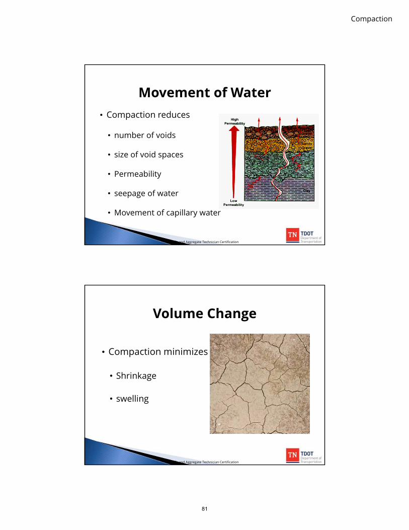
Movement of Water• Compaction reduces
• number of voids
• size of void spaces
• Permeability
• seepage of water
• Movement of capillary water
Soils and Aggregate Technician Certification
Volume Change
• Compaction minimizes
• Shrinkage
• swelling
Soils and Aggregate Technician Certification
81

Compaction
Earthwork Requiring Moisture-Density Tests
Pipe backfill
CL
Embankments
Pipe backfill
Structure backfill
Soils and Aggregate Technician Certification
Moisture-Density Tests
• TDOT uses the Proctor density test to determine the densities to which a soil can be compacted with various moisture contents
• The highest density obtained is called the maximum density (Proctor density) and the corresponding moisture content is called the optimum moisture
Soils and Aggregate Technician Certification
82

Compaction
Density Ranges
• High maximum densities will range from 125to 145 pounds per cubic foot, oven-dry weight
• Low maximum densities will range from 85 to100 pounds per cubic foot, oven-dry weight
Soils and Aggregate Technician Certification
Moisture Ranges
• A low optimum moisture corresponds to ahigh maximum density and will be around 8percent
• A high optimum moisture corresponds to alow maximum density and will be around 30percent
Soils and Aggregate Technician Certification
83

Compaction
AASHTO T99 & T180
• AASHTO T99 Standard Proctor Test
• AASHTO T180 Modified Proctor Test• prescribes a compacting force and procedure
that closely approximates densities that can beobtained on soils in the field with tampingrollers
Soils and Aggregate Technician Certification
Proctor Density Test
Soils and Aggregate Technician Certification
84

Compaction
Proctor Density Test
Soils and Aggregate Technician Certification
Proctor Density Test
Soils and Aggregate Technician Certification
85

Compaction
Compaction Theory
• When dry densities of thesample are determinedand plotted as a functionof moisture content, thecurve is called acompaction curve.
• The peak of the curverepresents the maximumdry density at theoptimum moisturecontent
Soils and Aggregate Technician Certification
86

Moisture-Density Curve
95
96
97
98
99
100
101
102
103
104
105
15 17 19 21 23 25 27 29
Dry
Dens
ity, p
cf
w %
Maximum drydensity = 102.5 pcf
optimum w % = 21.0
TOO “WET”
TOO “DRY”
JUST RIGHT!
Soils and Aggregate Technician Certification87

Compaction
88

8 Embankment Placement

Embankment Placement
Organic Materials
• Topsoil or otherorganic materialshould never be usedas embankmentmaterial
WHY?
Soils and Aggregate Technician Certification
89

Embankment Placement
Sources of Embankment Materials
CLGrading template
Slope stake
Slope stake
Cut areaFill area
Topsoil (organic) not to be used as embankment material
To be used as embankment material if suitable
Soils and Aggregate Technician Certification
Earthwork Balances• Embankments are typically designed to achieve
earthwork balances at intervals along the project
• The contractor is expected to haul within thebalances shown on the plans or as adjusted by theproject supervisor
Balance point Balance point
705+
00
720+
50
Soils and Aggregate Technician Certification
90

Embankment Placement
Equipment for Placement
• The embankment isplaced on naturalground usually byscrapers used forexcavation or bytrucks if the hauldistance is long
• It is spread andleveled in specifiedlifts
Soils and Aggregate Technician Certification
Placement Equipment and Procedures
• The equipment and procedures involved in thedumping and spreading of the embankment materialwill depend on:• the type of equipment available• the type of material used
• Embankments must be built up in uniform, well-mixed layers for the full width of the roadway
• The contractor must have enough equipment and useprocedures that will enable proper moisture andcompaction requirements to be met
Soils and Aggregate Technician Certification
91

Embankment Placement
Embankment PlacementStandard Specifications Section 205.04
• Perishable materials, such as stumps and brush, are not buried inthe embankment
• Crowns are maintained
• Individual lifts do not exceed 10 inches before compaction• When excavated material consists predominantly of rock fragments
that are too large to place in 10-inch lifts, the material may be placed inthe embankment in layers not exceeding 3 feet
• All rock to be placed in the embankment is broken into sizes notexceeding 2 feet in the maximum dimension and each of these rocklifts is leveled and smoothed with finer material
• The embankment is built up evenly and uniformly
• Embankments are constructed with similar materials
Soils and Aggregate Technician Certification
Compaction of EmbankmentsStandard Specifications Section 205.04
• Embankments that consistof predominantly fine-grained soil must be placedin horizontal lifts not thickerthan 10 inches beforecompaction
• Each layer, excluding thetop 6 inches of the roadbedmust be compacted to adensity not less than 95percent of maximumdensity
Soils and Aggregate Technician Certification
92

Embankment Placement
• When a minimum of 95percent maximum density isrequired, the moisturecontent of the materialmust be within the range ofvalues at which this densitycan be obtained
Soils and Aggregate Technician Certification
Compaction of EmbankmentsStandard Specifications Section 205.04
• When a 100 percentmaximum density isrequired, the moisturecontent of the materialmust not vary fromoptimum moisture by morethan 3 percentage points
Soils and Aggregate Technician Certification
Compaction of EmbankmentsStandard Specifications Section 205.04
93

Embankment Placement
• The contractor is required to aerate the material or distribute and incorporate water uniformly to control moisture content within appropriate limits
• If the moisture is within the appropriate limits but the density is not, additional compaction is necessary
Soils and Aggregate Technician Certification
Compaction of EmbankmentsStandard Specifications Section 205.04
Top Six Inches SpecificationsStandard Specifications Subsection 205.04
• In both cut and fill sections, the top six inches of roadbed must be compacted to 100 percent of maximum density
Soils and Aggregate Technician Certification
94
Embankment Placement
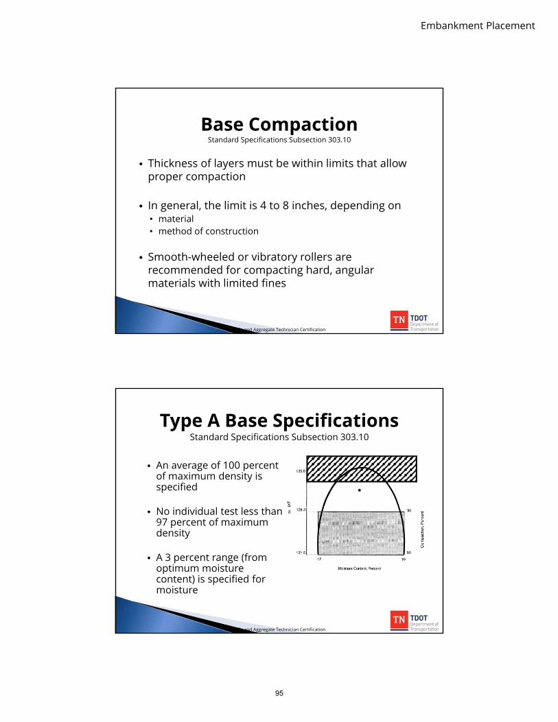
Base CompactionStandard Specifications Subsection 303.10
• Thickness of layers must be within limits that allowproper compaction
• In general, the limit is 4 to 8 inches, depending on• material• method of construction
• Smooth-wheeled or vibratory rollers arerecommended for compacting hard, angularmaterials with limited fines
Soils and Aggregate Technician Certification
Type A Base SpecificationsStandard Specifications Subsection 303.10
• An average of 100 percentof maximum density isspecified
• No individual test less than97 percent of maximumdensity
• A 3 percent range (fromoptimum moisturecontent) is specified formoisture
Soils and Aggregate Technician Certification
95

Embankment Placement
Type B Base SpecificationsStandard Specifications Subsection 303.10
• An average of 97 percentof maximum density isspecified
• No individual test less than95 percent of maximumdensity
• A 3 percent range (fromoptimum moisturecontent) is specified formoisture
Soils and Aggregate Technician Certification
Compaction of Embankments
• Rollers are used to obtain the requireddensities and should be operatedcontinuously while embankment materialsare being placed
Soils and Aggregate Technician Certification
96

Embankment Placement
Sheepsfoot Roller• Compacts all fine-grained materials
• Will not compact cohesionless granularmaterials
• Compacts from the bottom up and is usedespecially for plastic materials
• The lift thickness for sheepsfoot rollers islimited to 6 inches in compacted depth
• If the required densities are not beingobtained, it is often necessary to change to athinner lift to ensure that the specified densityis obtained
Soils and Aggregate Technician Certification
Tamping-Foot Roller• A tamping-foot roller is a
modification of the sheepsfootroller
• The tamping feet are trapezoidalpads attached to a drum
• Tamping-foot rollers are normallyself-propelled, and the drum maybe capable of vibrating
• The tamping-foot roller is suitablefor use with a wide range of soiltypes
Soils and Aggregate Technician Certification
97

Embankment Placement
Steel-Wheeled Roller• The steel-wheeled roller is much less
versatile than the pneumatic roller
• Although extensively used, it isnormally operated in conjunction withone of the other types of compactionrollers
• It is used for compacting granularmaterials in thin lifts
• Probably its most effective use insubgrade work is in the final finish of asurface, following immediately behindthe blade, forming a dense andwatertight surface
Soils and Aggregate Technician Certification
Self-Propelled, Smooth-Drum Vibratory Roller
• Compacts with a vibratoryaction that rearranges the soilparticles into a denser mass
• The best results are obtained oncohesionless sands and gravels
• Compaction efficiency isimpacted by the ground speedof the roller and the frequencyand amplitude of the vibratingdrum
Soils and Aggregate Technician Certification
98

Embankment Placement
Pneumatic Rollers• Variants include
▫ pneumatic-tired roller▫ self-propelled pneumatic-tired roller
• Suitable for granular materials;however, it is not recommendedfor fine-grained clay soils except asnecessary for sealing the surfaceafter a sheepsfoot roller has“walked out”
• It compacts from the top down andis used for finishing all types ofmaterials, following immediatelybehind the blade and water truck
Soils and Aggregate Technician Certification
Pneumatic Rollers
• Pneumatic rollers have an uneven number of wheels andshould never have fewer than 7 wheels. The tires arearranged so that the gaps between the tires of one axle willbe covered by the tires of the other.
Soils and Aggregate Technician Certification
99

Embankment Placement
Corrective Actions
• Overcompaction
• Undercompaction
• Too Wet
• Too Dry
Soils and Aggregate Technician Certification
Overcompaction
• Occurs when material is densified in excess ofspecified range
• The material may be stronger than required,which indicates• wasted construction effort• sheared material
Soils and Aggregate Technician Certification
100

Embankment Placement
Undercompaction
• Undercompaction may indicate A missed roller pass Insufficient roller weight A change in operating frequency or amplitude
(if vibratory rollers are in use) A defective roller drum The use of an improper type of compaction
equipment A change in soil type
Soils and Aggregate Technician Certification
Too Wet
• Soils that are too wet when compacted aresusceptible to shearing and strength loss
• Corrective action for a soil compacted too wetis to: Scarify Aerate Retest the moisture content Recompact, if moisture content is within the specified range Retest for both moisture and density
Soils and Aggregate Technician Certification
101

Embankment Placement
Too Dry
• Soils that are too dry when compacted do notachieve the specified degree of densificationas do properly moistened soils
• Corrective action for a soil compacted too dryis to:
Scarify Add water Mix thoroughly Retest the moisture content Recompact, if moisture content is within the specified
range Retest for both moisture and density
Soils and Aggregate Technician Certification
Pipes in Fill Sections• Where pipes must be placed in fill sections, it is not necessary that the
entire embankment be constructed before cutting the trench but theembankment must be built up in the immediate vicinity of the pipe
10’ Min.
Embankmentfor pipe trenchand bedding
Pipe trench
Natural ground
1’ Min.10’ Min.
Soils and Aggregate Technician Certification
102

Embankment Placement
Class A Culvert Bedding
• The bedding consists of a continuous concrete cradle for the pipe
Concrete bedding
Concrete shaped to fit pipe exterior
Soils and Aggregate Technician Certification
Class B Culvert Bedding• The embankment is built up to at least one foot above the top of the proposed pipe before
digging the trench
• The trench is then excavated to a depth which will allow the placement of six inches of beddingmaterial below the pipe
• Additional bedding material is added so that it can be shaped by a template to fit the lowerpart of the pipe exterior for at least 10 percent of its overall height
Vertical wall5’ or less
Bedding material compacted inlayers not more than 6” in loosethickness around the pipe.Bedding material must bebrought up to “springline.”
Bedding material must bebrought up evenly on both sidesof the pipe and tamped under thehaunches.
1’ minimum
“Springline”widest pointon pipe
Top ofembankment
6’ or less
OUTSIDE VERTICAL PIPEDIMENSION 6’ OR LESS
Soils and Aggregate Technician Certification
103

Embankment Placement
• Safety points:• Vertical walls must never exceed 5 feet• Where trenches must be deeper than 5 feet, the safety treatment
depends on the outside vertical dimension of the pipe; the safetymeasures include sloping, benching, or both
5’
Top ofembankment
Greaterthan 6’
4’ Min. bench
OUTSIDE VERTICAL PIPEDIMENSION GREATER THAN 6’
4’ Min. bench
Soils and Aggregate Technician Certification
Class B Culvert Bedding
• The pipe is bedded in a shallow trench cut in the naturalground or the compacted embankment
• The trench must be cut to a depth not less than 10% of theoutside vertical pipe dimension and shaped to fit the lowerpipe exterior
Natural ground or embankment
Min. trench depth = 10% of O.D.
O.D.
Trench shaped to fit pipe exterior
Soils and Aggregate Technician Certification
Class C Culvert Bedding
104

Embankment Placement
Backfill Requirements• After the pipe is properly bedded, backfill material must be placed in 6-inch
loose layers and each layer compacted as the backfill is brought up to thetop of the trench
• Each layer must be mechanically tamped to 100 percent of maximumdensity and the backfill material must be within the moisture range at whichthis density can be obtained
• Backfill material must consist of bedding material or fine, compactible soilselected from excavation or borrow as indicated on the plans
Bedding
Backfill - brought upuniformly in 6-inch layers onboth sides of the pipe for thefull length of the trench
Soils and Aggregate Technician Certification
105

9 Quality Acceptance Testing

QA Testing
ReferencesSOP 7-1 (Nuclear Density Testing)
Quality Acceptance Testing
• Generally, a quality-acceptance plan consists of breaking the total jobdown into lots
• A lot is accepted or rejected depending on the test results obtainedthrough random sampling that represent the lot
• By handling the acceptance procedure in this way, the project engineeris able to determine the quality of the job on a lot-by-lot basis
• This benefits the construction unit and project engineer by identifyingthe lots that will be accepted and the lots that will be rejected
• As this type of information is accumulated from lot to lot, a betterpicture of the quality of the entire project is obtained
Soils and Aggregate Technician Certification
106

QA Testing
Quality Acceptance Testing: Best Practices
Use a “test strip” to determine the approximate number of passesneeded to attain proper densities
Test every lift as soon as compaction is completed Test every roller lane Test obvious weak spots Test roads and runways every 250 linear feet, staggering tests
about the centerline Test parking lots and storage areas every 250 square yards Test trenches every 50 linear feet Remove all oversized materials Remove any pockets of organic or unsuitable soil material Increase the distance between tests as construction progresses, if
initial checks are satisfactory
Soils and Aggregate Technician Certification
Quality Acceptance Testing: Procedure
• Identify Density/Moisture Requirements• Based on type of material being placed• Target values are determined by Materials and Tests and
submitted to Project Supervisor.
• Determine Required Lot Size/Number of Tests
• Determine Test Locations
• Perform Test(s)
• Report Results
Soils and Aggregate Technician Certification
107

QA Testing
Identify Density/Moisture Requirements
• Acceptance criteria are different for Embankment,Aggregate Base, Etc. (as discussed in the lastpresentation)
• This information can be found in the correspondingsection in the TDOT specs.
• The target values are determined by TDOT Materials andTests personnel and will be made available by the TDOTProject Supervisor. *These values may change during thecourse of the project, so be sure to make sure you havethe most current numbers.
Soils and Aggregate Technician Certification
Determine Required: Lot Size/Number of Tests/Test
Locations• S.O.P. 1-1: Sampling and Testing Guide• Describes the testing frequency for all materials• Lists the person responsible for either obtaining
the sample of performing the test.• Available in PDF format at:
http://www.tdot.state.tn.us/materials/fieldops/sop/default.htm
(see example in Part Five of S.O.P. 1-1)
Soils and Aggregate Technician Certification
108

QA Testing
TDOT Sampling Procedure(base stone example)
• SOP 1-1• 5 moisture/density tests are required for every
10,000-square-yard (SY) lot of materialinstalled.
• Tests are to be performed immediately beforeplacing pavement structure
• Specific test/sample locations are to bedetermined RANDOMLY
Soils and Aggregate Technician Certification
Random Sampling
• Any portion of the population has equalchance of being selected
• Bias is introduced when judgment is used
• Use random number tables
Soils and Aggregate Technician Certification
109

QA Testing
Why must we divide lots into sublots?LOT
SUBLOT
Random Sampling
StratifiedRandom Sampling
Soils and Aggregate Technician Certification
TDOT Sampling Procedure(base stone example)
• 5 tests per LOT with each LOT divided into 5sublots (1 test per sublot)
• The location longitudinally shall be takenrandomly (using a number table)
• The lateral location should also bedetermined by a random number.
Soils and Aggregate Technician Certification
110

QA Testing
Random Number Table(example)
.20 .68 .98 .30 .27 .84 .54 .31 .05 .88
.61 .17 .38 .62 .55 .59 .67 .73 .43 .23
.27 .38 .84 .99 .72 .51 .48 .81 .77 .76
.24 .38 .40 .34 .76 .87 .60 .75 .49 .56
.88 .52 .25 .51 .79 .41 .33 .08 .32 .47
.62 .36 .97 .61 .28 .50 .81 .29 .75 .82
.94 .83 .35 .66 .42 .70 .44 .30 .54 .45
Soils and Aggregate Technician Certification
LOT
5 equally-sized sub-lots
CL
Lateral Distance
Longitudinal Distance
Soils and Aggregate Technician Certification
111

QA Testing
Testing Locations• STEP 1-• Determine LOT size, and with known lane
width, determine LOT and sub-lot lengths
• STEP 2-• With known beginning station, determine
beginning sub-lot stations
• STEP 3-• Using random number table, or calculator,
select 5 numbers
Soils and Aggregate Technician Certification
• STEP 4-• Multiply random number by Sub- Lot Length,
and add to beginning Sub-lot stations todetermine longitudinal testing locations
• STEP 5-• Multiply random number by either lane or
cross-sectional width to determine lateraltesting location within each sublot
Soils and Aggregate Technician Certification
Testing Locations
112

QA Testing
Example Problem
Situation
• Placing Type A Base Material
• Typical base stone cross-section is 30 Feet
• Beginning Station 100+00
Soils and Aggregate Technician Certification
A Bit About Station Numbers
• One “station” is equal to 100 linear feet.
• Locations between stations are described as astation number “+ XX” in additional feet.
• For example: If station “1 + 00” is the number thatdescribes the first 100 feet of the project, thenstation “1 + 25” would be 25 feet past the firststation.
• How many feet into the project would stationnumber 100 + 00 be?
Soils and Aggregate Technician Certification
113
QA Testing
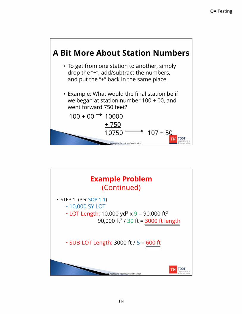
A Bit More About Station Numbers• To get from one station to another, simply
drop the “+”, add/subtract the numbers,and put the “+” back in the same place.
• Example: What would the final station be ifwe began at station number 100 + 00, andwent forward 750 feet?
100 + 00 10000+ 75010750 107 + 50
Soils and Aggregate Technician Certification
Example Problem (Continued)
• STEP 1- (Per SOP 1-1) 10,000 SY LOT LOT Length: 10,000 yd2 x 9 = 90,000 ft2
90,000 ft2 / 30 ft = 3000 ft length
SUB-LOT Length: 3000 ft / 5 = 600 ft
Soils and Aggregate Technician Certification
114
QA Testing
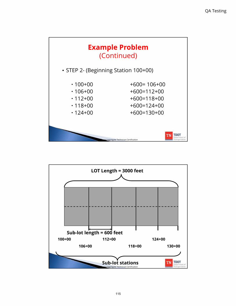
• STEP 2- (Beginning Station 100+00)
100+00 +600= 106+00 106+00 +600=112+00 112+00 +600=118+00 118+00 +600=124+00 124+00 +600=130+00
Soils and Aggregate Technician Certification
Example Problem (Continued)
LOT Length = 3000 feet
Sub-lot length = 600 feet100+00 112+00 124+00
106+00 118+00 130+00
Sub-lot stationsSoils and Aggregate Technician Certification
115

QA Testing
• STEP 3-
• Using a random number table, select 5numbers
Soils and Aggregate Technician Certification
Example Problem (Continued)
Random Number Table
.20 .68 .98 .30 .27 .84 .54 .31 .05 .88
.61 .17 .38 .62 .55 .59 .67 .73 .43 .23
.27 .38 .84 .99 .72 .51 .48 .81 .77 .76
.24 .38 .40 .34 .76 .87 .60 .75 .49 .56
.88 .52 .25 .51 .79 .41 .33 .08 .32 .47
.62 .36 .97 .61 .28 .50 .81 .29 .75 .82
.94 .83 .35 .66 .42 .70 .44 .30 .54 .45
Soils and Aggregate Technician Certification
116

QA Testing
• Step 4 -
• Use• Sub-lot Length from Step 1• Sub-lot Stations from Step 2• Random Numbers from Step 3
Soils and Aggregate Technician Certification
Example Problem (Continued)
• STEP 4 -• 0.41 x 600’ = 246’
•2+46 + 100+00 = 102+46• 0.30 x 600’ = 180’
•1+80 + 106+00 = 107+80• 0.43 x 600’ = 258’
•2+58 + 112+00 = 114+58• 0.55 x 600’ = 330’
•3+30 + 118+00 = 121+30• 0.24 x 600’ = 144’
•1+44 + 124+00 = 125+44Soils and Aggregate Technician Certification
Example Problem (Continued)
117

QA Testing
• STEP 5-
• Randomly select the transverse location fortesting
Soils and Aggregate Technician Certification
Example Problem (Continued)
100+00 112+00 124+00
106+00 118+00 130+00
102+46 107+80 114+58 121+30 125+44
Lateral Distance is determined by multiplying random numbers by road width.
Soils and Aggregate Technician Certification
118

QA Testing
Nuclear Density/Moisture Testing
• You must have attended aRadiation Safety course priorto using a Nuclear Gauge!
(click for example)
• TDOT references AASHTOT-310 as the standard testmethod.
• SAFETY FIRST!!!!
Soils and Aggregate Technician Certification
• Never handle anuclear gaugewithout wearing yourown personalradiation dosimeter.
• Never leave anuclear gaugeunattended on a jobsite.
Soils and Aggregate Technician Certification
Nuclear Density/Moisture Testing
119

QA Testing
• Regardless of gaugemanufacturer (Troxler,Humbolt, Instrotek, etc.),all gauges utilize the samebasic components.
• All tests performed on soiland aggregate will be usingthe Direct Transmissionmethod.
Soils and Aggregate Technician Certification
Nuclear Density/Moisture Testing
Soils and Aggregate Technician Certification
Nuclear Density/Moisture Testing
120

QA Testing
• When taking a test the gaugemeasures the amount ofradiation detected over apredetermined timeframe,such as one minute.
• The detector tubes count theradiation that is able to passthrough the material betweenthe bottom of the source rodand the detector tubes.
• The denser the material, thelower the amount of radiationthat is able to reach thedetector tubes to be counted.
Soils and Aggregate Technician Certification
Nuclear Density/Moisture Testing
Standard Counts• Standard counts measure the
number of counts received fromthe density and moisture sourcesand provide a quick referencecheck to ensure that the gauge isoperating correctly.
• A standard count should be takendaily and the results should be veryclose to previous standard counts,typically 1% for density and 2% formoisture.
Soils and Aggregate Technician Certification
121

QA Testing
Standard Counts(Continued)
• If the last count has been longerthan 60 days a new standardcount average may need to beestablished. This can be doneby taking three more tests andaveraging these most recentresults to establish a new count.
• If the gauge still does not matchit’s standard count values, itmust not be used.
• Check the gauge manual andAASHTO T-310 for additionalinformation.
Soils and Aggregate Technician Certification
Enter the predetermined proctor density and moisture content for the material you will be testing. This will enable the gauge to calculate the dry density and determine the percent compaction.
Where does this information come from?
Soils and Aggregate Technician Certification
Nuclear Density/Moisture Testing
122

QA Testing
When testing on soils always prepare the ground by using the scraper plate to smooth out any obstacles or fill in any voids.
This will reduce the chance that open pockets or protruding objects impact the reading.
Soils and Aggregate Technician Certification
Nuclear Density/Moisture Testing
When using the drill rod to make a hole in the compacted material for testing, always make sure to first place the drill rod removal device – this is a mistake that will probably be made only once.
Soils and Aggregate Technician Certification
Nuclear Density/Moisture Testing
123

QA Testing
• Etch around the baseof the scraper platebefore picking it up,then place the gaugedown inside of thisetched area.
• The opening for thesource rod will bepositioned over thehole that was drilled.
Soils and Aggregate Technician Certification
Nuclear Density/Moisture Testing
• Pull or depress the gaugetrigger and drop the rod into thehole.
• Before taking a test push thegauge towards the side of thehole with the detector tubes.This ensures that there is no airgap between the source rod andthe side of the hole.
• Make sure that the source rod iswell seated in the depth positionnotch. Any misalignment willimpact the results.
Soils and Aggregate Technician Certification
Nuclear Density/Moisture Testing
124

QA Testing
IMPORTANT: Do not extend the source rod to guide it into the hole! This exposes you and others to an
unnecessary exposure of radiation.Soils and Aggregate Technician Certification
Nuclear Density/Moisture Testing
• Secure and record oneor more 1-minutereadings.
• The gauge may berotated about the axisof the probe to obtainadditional readings.
• Do not stand right nextto the gauge whilerunning a test.
• Never run a test within30 ft of another gauge.
Soils and Aggregate Technician Certification
Nuclear Density/Moisture Testing
125

QA Testing
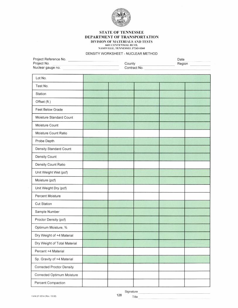
• Report test results onTDOT Form no. DT-0314
• All forms are available at:
http://www.tn.gov/tdot/article/transportation-materials-tests-division-field-operations-forms
How do we know if the results are acceptable?
If they’re not, what should we do?
Soils and Aggregate Technician Certification
Nuclear Density/Moisture Testing
Nuclear Gauge Contacts
Headquarters Radiation Safety Officer (RSO):Jimmy Britt (615) 350-4164Rocky Kelley (321) 482-3071
Regional RSOsRegion 1: Billy Goins (865) 806-1935Region 2: Jeff Yarworth (423) 510-1159Region 3: Mark Hand (615) 389-5217Region 4: Marc Turner (731) 234-6048
Soils and Aggregate Technician Certification
126
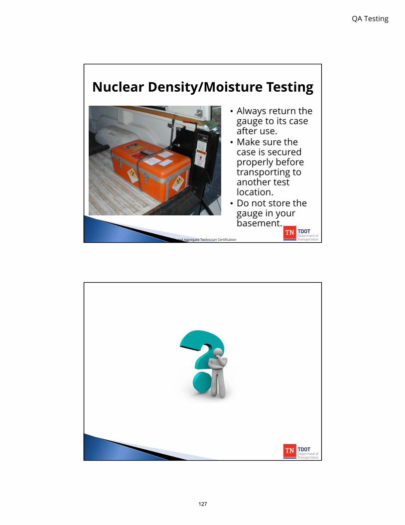
QA Testing
• Always return thegauge to its caseafter use.
• Make sure thecase is securedproperly beforetransporting toanother testlocation.
• Do not store thegauge in yourbasement.
Soils and Aggregate Technician Certification
Nuclear Density/Moisture Testing
127

10TDOT Forms
128

129
11 Standard Operating
Procedure 1-1, Part 2
(SOP 1-1)
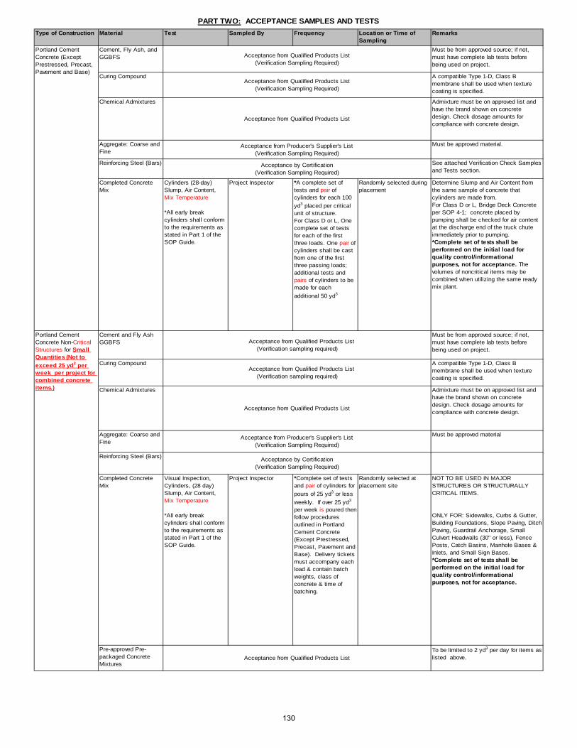
Type of Construction Material Test Sampled By Frequency Location or Time of Sampling
Remarks
Cement, Fly Ash, and GGBFS
Must be from approved source; if not, must have complete lab tests before being used on project.
Curing Compound A compatible Type 1-D, Class B membrane shall be used when texture coating is specified.
Chemical Admixtures Admixture must be on approved list and have the brand shown on concrete design. Check dosage amounts for compliance with concrete design.
Aggregate: Coarse and Fine
Must be approved material.
Reinforcing Steel (Bars) See attached Verification Check Samples and Tests section.
Completed Concrete Mix
Cylinders (28-day) Slump, Air Content, Mix Temperature
*All early breakcylinders shall conformto the requirements asstated in Part 1 of the SOP Guide.
Project Inspector *A complete set of tests and pair of cylinders for each 100
yd3 placed per criticalunit of structure.For Class D or L, One complete set of testsfor each of the firstthree loads. One pair of cylinders shall be castfrom one of the firstthree passing loads;additional tests andpairs of cylinders to be made for each
additional 50 yd3
Randomly selected during placement
Determine Slump and Air Content from the same sample of concrete that cylinders are made from.For Class D or L, Bridge Deck Concrete per SOP 4-1; concrete placed by pumping shall be checked for air content at the discharge end of the truck chute immediately prior to pumping. *Complete set of tests shall beperformed on the initial load for quality control/informationalpurposes, not for acceptance. The volumes of noncritical items may be combined when utilizing the same readymix plant.
Cement and Fly Ash GGBFS
Must be from approved source; if not, must have complete lab tests before being used on project.
Curing Compound A compatible Type 1-D, Class B membrane shall be used when texture coating is specified.
Chemical Admixtures Admixture must be on approved list and have the brand shown on concrete design. Check dosage amounts for compliance with concrete design.
Aggregate: Coarse and Fine
Must be approved material
Reinforcing Steel (Bars)
Completed Concrete Mix
Visual Inspection, Cylinders, (28 day) Slump, Air Content, Mix Temperature
*All early breakcylinders shall conformto the requirements asstated in Part 1 of the SOP Guide.
Project Inspector *Complete set of testsand pair of cylinders for
pours of 25 yd3 or less
weekly. If over 25 yd3
per week is poured then follow proceduresoutlined in Portland Cement Concrete (Except Prestressed,Precast, Pavement and Base). Delivery ticketsmust accompany each load & contain batch weights, class of concrete & time of batching.
Randomly selected at placement site
NOT TO BE USED IN MAJOR STRUCTURES OR STRUCTURALLY CRITICAL ITEMS.
ONLY FOR: Sidewalks, Curbs & Gutter, Building Foundations, Slope Paving, Ditch Paving, Guardrail Anchorage, Small Culvert Headwalls (30" or less), Fence Posts, Catch Basins, Manhole Bases & Inlets, and Small Sign Bases.*Complete set of tests shall beperformed on the initial load for quality control/informationalpurposes, not for acceptance.
Pre-approved Pre-packaged Concrete Mixtures
To be limited to 2 yd3 per day for items as listed above.
Acceptance by Certification(Verification Sampling Required)
Acceptance from Qualified Products List(Verification Sampling Required)
Acceptance by Certification(Verification Sampling Required)
Acceptance from Qualified Products List
Acceptance from Qualified Products List(Verification sampling required)
Acceptance from Qualified Products List
Acceptance from Producer's Supplier's List(Verification Sampling Required)
Acceptance from Producer's Supplier's List(Verification Sampling Required)
PART TWO: ACCEPTANCE SAMPLES AND TESTS
Portland Cement Concrete (Except Prestressed, Precast, Pavement and Base)
Acceptance from Qualified Products List(Verification sampling required)
Acceptance from Qualified Products List(Verification Sampling Required)
Acceptance from Qualified Products List
Portland Cement Concrete Non-Critical Structures for Small Quantities (Not to exceed 25 yd3 per week per project for combined concrete items.)
130

Type of Construction Material Test Sampled By Frequency Location or Time of Sampling
Remarks
Cement, Fly Ash, and GGBFS
Must be from approved source. If not, must have complete lab analysis and approved before being used.
Curing Compound A compatible Type 1-D, Class B membrane shall be used when texture coating is specified.
Chemical Admixtures Admixture must be on approved list and have the brand shown on concrete design. Check dosage amounts for compliance with concrete design.
Aggregate: Coarse and Fine
Must be approved material.
Compressive Strength (Cylinders)Slump, Air Content, Mix Temperature
*All early breakcylinders shall conformto the requirements asstated in Part 1 of the SOP Guide.
Project Inspector *One pair each 400 yd3; In areas where class Ais allowed, the frequency shall be the same as Portland Cement Concrete.
Placement site Additional test specimens will be required if pavement is to be opened to traffic within 14 days after placement.Determine Slump and Air Content from same sample of mix used for cylinders. Make additional Slump and Air Content determinations as required for control. Class CP concrete use 6x12 cylinders. *Complete set of tests shall beperformed on the initial load for quality control/informationalpurposes, not for acceptance.
Depth Measurement Contractor Monitored by Project Inspector
One core per 1,000 linear feet of poured width, with a minimum of 1 core for each interchange ramp
Completed pavement When thickness of core from a unit is deficient more than 1/4" and not more than 1" from Plan thickness, take 2 additional cores at intervals of not less than 300' within the unit. Use the average of the three cores to determine thickness.
Dowel and Tie Bars Assembly to be approved by the Engineer.
Sealant
Cement, Fly Ash, and GGBFS
Must be from approved source; if not, must have complete lab tests before being used on project.
Curing Compound
Chemical Admixtures Admixture must be on approved list and have the brand shown on concrete design. Check dosage amounts for compliance with concrete design.
Aggregate: Coarse and Fine
Must be approved material.
Reinforcing Steel (Bars)
Prestressing Strands
Finished Product Visual Inspection Materials & Tests After casting and before shipment
Prestress producer's plant Each item to be inspected for straightness, cracks, honeycomb, size and appearance. Cosmetic Patching shall be cured prior to shipment.
Slump, Air and Mix Temperatures
Materials & Tests or Contractor monitored by TDOT personnel.
1 set of tests per pair of cylinders
At the discretion of the Inspector or a minimum of one per pour.
Additional tests performed when apparent slump change is indicated or as directed.
Cylinders (Beams) Materials & Tests or Contractor monitored by TDOT personnel.
At least 1 pair at the beginning,middle and end of the bed
1 pair for 28 day strength, 1 pair for back up
Cylinders (Panels/Piling)
Materials & Tests or Contractor monitored by TDOT personnel.
One pair at beginning, and one pair at the end of the pour
1 pair for 28 day strength, 1 pair for back up
Cylinders (Tension Release)
Materials & Tests or Contractor monitored by TDOT personnel.
One pair at beginning, and one pair at the end for tension release of the bed
Additional specimens may be necessary
Acceptance by Qualified Products List
Acceptance by Certified Mill Test Report(Verification Sampling Required)
Acceptance from Producer's Supplier's List(Verification Sampling Required)
Acceptance from Producer's Supplier's List(Verification Sampling Required)
Acceptance from Qualified Products List(Verification sampling required)
Completed Concrete Mix
Acceptance by Certified Mill Test Report(Verification Sampling Required)
Prestressed Concrete Acceptance from Qualified Products List
(Verification sampling required)
PART TWO: ACCEPTANCE SAMPLES AND TESTS
Acceptance from Qualified Products List(Verification sampling required)
Portland Cement Concrete - Pavement & Base
Acceptance from Qualified Products List
Acceptance by Qualified Products List
Acceptance from Qualified Products List(Verification sampling required)
Completed Concrete Mix
Acceptance by Certification(Verification sampling required)
131

Type of Construction Material Test Sampled By Frequency Location or Time of Sampling
Remarks
Precast concrete noise wall panels, retaining wall panels, and precast drainage structures including pipes, headwalls, manholes, catch basins, box culverts, and structural spans
Finished Product Each shipment must be accompanied by a completed certification form. Each item shall be inspected after delivery to the project for cracks, spalls and/or appearance by project personnel prior to incorporating product into the work.
Slump, Temperature, and Air
Materials & Tests or Contractor monitored by TDOT personnel
Minimum 1 set of test per pour
Precast producer plant
Cylinders Materials & Tests or Contractor monitored by TDOT personnel
One set at beginning, and 1 set at the end of the pour
Precast producer plant
Density Project inspector 1 per every 500 tons or fraction there of
Project site
Must be approved material.
QualitypHInternal angle of friction
Materials & Tests 1 @ beginning of Project and then every 6 months
Aggregate plant
Density Project inspector 1 per every 500 tons Project siteEletro-Chemical Analysis
Producer 1 per Source @ Beg of Project & every 2 years thereafter
Aggregate plant Additional Test required w/ appearance change
Materials & Tests Beginning of project Aggregate plant or Roadway
Project Inspector One test every 1000 tons (Min. 1 per week)
Aggregate plant or Roadway
Precast concrete Products
Modular block Verification required before use
Prime, Tack and Sealer Emulsions Each shipment must be accompanied by TDOT form DT-0293E materials certification report.
Prime Tack and Sealers (Small Quantities)
Emulsions Visually inspect for contamination
Project Inspector 1 per project Project Site Not to exceed 3 tons tack and 3 tons prime per project. Supplier to furnish certification (may be non-project specific) and delivery tickets showing quantities.
Must be approved material.
Fractured Face Count, Glassy particles by weight
Project Inspector Min. of 1 per project Coarse aggregate Stockpile
Plus #4 (4.75mm) Material
Performance-Graded Asphalt Cement
Governed by process See SOP 3-1
Each shipment must be accompanied by TDOT form DT-0293PG materials certification report.
Mix temperature On Roadway by Project Insp.
Every fifth load. From truck prior to leaving plant and on roadway prior to deposit into paver or transfer device.
Temperatures to be recorded on the delivery ticket.Tests at the plant by producer at the discretion of Materials & Tests Supervisor.
Stripping-10 min. boil test
Project Inspector Once daily Truck and Asphalt Plant Plus #4 (4.75mm) Material on selected visually from mix sample.
Precast Concrete Abutment Blocks and Approach Slabs
Finished Product
AggregateAcceptance from Producer's Supplier's List
(Verification Sampling Required)
Project Inspector As soon as practical after compaction, when nuclear method is used. When used, cores will be obtained in accordance with SP407DEN.
Earth Retaining Structures
Each lot shall be divided into 5 equal-sized sublots, and one test should be performed per each sublot. Longitudinal test locations should be determined randomly. Transverse locations are determined randomly with one test 1' off each edge, one test in each wheel path, and one test in the center of the lane.
Plant Mix Asphalt Gradings A, B, BM, BM2, C, CW, D, E, and E Shoulder
1,000 tons
Gradation
Acceptance by Certification in accordance with SOP 5-3(Verification sampling required)
Acceptance in accordance w/SOP 5-3 andSpecial Provision 624 Retaining Walls (Verification testing required)
Bituminous Plant Mix Pavements
Acceptance by Certification in accordance with SOP 3-2(Verification Sampling Required)
All Plant Mix Asphalt
Select Granular Backfill
Finished Product
PART TWO: ACCEPTANCE SAMPLES AND TESTS
Density
Backfill
Acceptance by Certification in accordance with SOP 3-1(Verification Required in accordance with Part Three herein)
Acceptance in accordance w/Special Provision 624 Retaining Walls (Verification testing required)
Acceptance from Producer's Supplier's List(Verification Sampling Required)
132

Type of Construction
Material Test Sampled By Frequency Location or Time of Sampling
Remarks
Asphalt Content AASHTO T-164, Method E-II by extraction, or AASHTO T-308 by ignition oven
Aggregate Gradation AASHTO T-30 and AASHTO T-11
Air Voids & Volumetric Properties (T166, T209, T269)
Project Inspector or Materials and Tests
During Test Strip Construction or Mix Verif ication
Completed mix in truck or on roadw ay
Applies only to mixes requiring a design. Verif ication Sample required to be submitted to Regional Lab.
LOI (Surface Mix only)
Project Inspector One sample per day for Surface Mix only
Completed mix in truck If daily sample fails, take 3 cores per lot placed that day to determine LOI. Penalty for failure to meet.
Plant Mix Asphalt Grading A, A-S, A-CRL, & Asphalt Treated Permeable Base
Aggregate Gradation AASHTO T-30 and AASHTO T-11
Project Inspector 1 test for every 1000 tons randomly
Completed mix in truck or on roadw ay
AASHTO T-164 Method E-II w ill be performed by pouring the extracted asphalt and solvent through nested No. 16 and No. 200 mesh sieves.AASHTO T 164 Method A may be used for modif ied asphalt or w hen problems are encountered f iltering according to Method E-II.May not be required on production days of less than 100 tons.Ignition oven may be utilized to determine gradation.
Bituminous Plant Mix Pavements for Small Quantities
Bituminous Mixture Visual Inspection Project Inspector Occasionally. Delivery ticket must accompany each load & contain w eight of mix.
Placement site Not to exceed 1000 tons of each type mix per project. Supplier to furnish certif ication show ing type of mix and compliance w ith TDOT specif ications. TDOT reserves right to perform any testing deemed necessary. Mix shall be formulated from a previously approved Job Mix Formula.
Gradation & Washing Project Inspector or Materials & Tests
One each 500 tons for each size aggregate.
At source or at project prior to incorporating into w ork.
Inspection required before material use.
Fractured face count Project Inspector or Materials & Tests
Minimum of 1 per project
At project prior to incorporating into w ork
Plus No. 4 (4.75mm) sieve material, gravel mixes only.
Loss on Ignition (LOI) Project Inspector or Materials & Tests
Minimum of 1 per w eek
From stockpiled materials. If blended aggregate, then after blending.
Accept/deduct in accordance w ith 407.20.C.3, pgf 6
Glassy particles by w eight
Project Inspector or Materials & Tests
Minimum of 1 per project
At project prior to incorporating into w ork
Plus No. 4 (4.75mm) sieve material, slag mixes only.
Must be approved material.
Emulsions Each shipment must be accompanied by a notarized materials certif ication report. DT0293E See attached Verif ication/Check Samples & Tests section.
Treated Permeable Base
Asphalt Treated Permeable Base or Portland Cement Treated Permeable Base
Thickness Contractor to obtain specimen at locations identif ied by Project Inspector
One core per unit or fraction of unit. A unit is equal to a paver mat w idth 1,000 ft in length.
Prior to being overlaid When thickness of core from a unit is deficient more than 1/4" and not more than 1" from Plan thickness, take 2 additional cores at intervals of not less than 300' w ithin the unit. Use the averaged of the three cores to determine thickness.
Bituminous Surface: Surface Treatment, Microsurfacing, Slurry Sealing, and related similar processes
Acceptance by Certif ication in accordance w ith SOP 3-2.(Verif ication Sampling Required)
Plant Mix Asphalt Grading B, BM, BM2, C, CW, D, E, CS, TLD, & TL
Bituminous Plant Mix Pavements
Aggregate
Acceptance from Producer's Supplier's List(Verif ication Sampling Required)
AASHTO T-164 Method E-II w ill be performed by pouring the extracted asphalt and solvent through nested No. 16 and No. 200 mesh sieves.AASHTO T 164 Method A may be used for modif ied asphalt or w hen problems are encountered f iltering according to Method E-II.May not be required on production days of less than 100 tons.Ignition oven may be utilized to determine AC content and gradation.
Project Inspector Completed mix in truck or on roadw ay
1 test for every 1000 tons randomly
PART TWO: ACCEPTANCE SAMPLES AND TESTS
128133

Type of Construction
Material Test Sampled By Frequency Location or Time of Sampling
Remarks
Proctor Density & Optimum Moisture
Materials & Tests As required by material changes
Cuts sampled prior to construction. Borrow pits sampled as required prior to placement.
Density, Moisture Project Inspector One test each 10" of lif t not to exceed 1500 ft roadw ay or 5000 yd3. Exception: Within 50 ft of a bridge end (deck or box) 1 test w ill be performed for each lif t. The test w ill be performed alternately on the embankment and on the backfill material.
All tests w ill be performed at random locations. During construction, immediately after compaction.
Density tests w ill not be required for embankment containing more than 50% of plus 3/4" sieve material.
See Standard Specs. 205 for correct formation of embankment.
Proctor Density & Optimum Moisture
Materials & Tests As required by material changes.
May be sampled before grading construction or after grading prior to sub-grade preparation.
Density, Moisture Project Inspector 5 tests per10,000 yd2
lot for top 6 inchesImmediately before placing pavement structure
Average of 5 tests in lot used to determine pass-fail, w ith no individual test below 95% of Proctor.Average lot to be no less than 100%.
Proctor Density, Optimum Moisture
Project Inspector Prior to beginning of construction
At beginning of compaction
Additional tests may be required to account for material changes.
Prior to beginning of construction, samples of soil & lime w ill be submitted to Central Lab for Proctor Density lab tests.
Density, Moisture Project Inspector 5 tests per 10,000 yd2 lot
Immediately follow ing compaction
Average of 5 tests in lot to determine pass - fail.
Pulverization Project Inspector 1 test per 10,000 yd2 At the beginning of compaction
Sieve test requirementSee Standard Specs. 304.06
Thickness Project Inspector 5 tests per 10,000 yd2
Job site
Cement Cement must be from an approved source or be approved prior to use.
Water Visual Inspection Project Inspector At the beginning of w ork
As source changes
Pulverization Project Inspector 1 test per 10,000 yd2 After mixing, before compaction
See Standard Specs. 304.06
Density, Moisture Project Inspector 5 tests per 10,000 yd2 lot
Immediately follow ing compaction
Average of 5 tests in lot to determine pass - fail
Thickness Project Inspector 5 tests per 10,000 yd2 lot
After f inal f inish of base
PART TWO: ACCEPTANCE SAMPLES AND TESTS
Embankment Soil
Soil-Cement Base
Soil-Cement Mixture
Subgrade Preparation Soil
Subgrade Treatment: Lime
Soil-Lime Mixture
Acceptance by Certif ication(Verif ication Sampling Required)
134

Type of Construction
Material Test Sampled By Frequency Location or Time of Sampling
Remarks
Must be approved material.
Proctor, Sp. Gravity, Optimum Moisture
Materials & Tests Once per year for producers or as material changes
Sampled at source Quality report required for each project
Gradation, Moisture Project Inspector Initial and each 2500 tons
Sampled from plant or roadw ay
A minimum of 1 sample per w eek for small quantities not to exceed 500 tons per w eek. Note: A minimum of 1 sample per w eek w hen aggregate is used for maintenance or incidental purposes. First sample should be taken at beginning of day.
Density, Moisture Project Inspector 5 tests per 10,000 yd2 lot
Immediately follow ing Compaction
Average of 5 test in lot used to determine pass - fail. (Check sp. gravity not alw ays required. See Standard Specs. 303.09
Thickness Project Inspector or Survey Party
Five test holes per lot of approximately 10,000 yd2 or profile check at each break point at 50 ft intervals
After base completed On test holes - lot average considered one test
Calcium Chloride, Sodium Chloride
Quality Project Inspector One sample each shipment to project
Sample from stock before use
Mineral Aggregate Base and Surface for Small Quantities
Mineral Aggregate Visual Inspection Project Inspector As directed by Project Engineer
Project site Not to exceed 500 tons per project. Must be from approved source.
Aggregate for Underdrains
Mineral Aggregate Gradation Project inspector or Material and Tests representative
One test every 1000 tons (Min. 1 per w eek)
Project site or plant stockpile
Must be from an Approved Source
Cement Cement must be from approved source or to be accepted prior to use.
Gradation Project Inspector One each 2500 tons Sampled from plant stockpile
In special cases, this test run by Materials & Tests.
Must be approved material.
Water Quality Project Inspector At the beginning of construction and w hen source changes
Source prior to start of w ork
Water of potable quality may be used w ithout testing.
Density, Moisture Project Inspector 5 tests per lot of approx. 10,000 yd2
Immediately follow ing compaction
Average of 5 tests in lot used to determine pass - fail. Not required for Cement Treated Permeable Base.
Thickness Project Inspector or Survey Party
Five test holes per lot of approx. 10,000 yd2
or profile check at each break point at 50 ft intervals
After base completed On test holes - lot average considered one test
Moisture Project Inspector 1 each 2500 tons or 2 per day
At time of w eighing First sample should be taken at beginning of day.
PART TWO: ACCEPTANCE SAMPLES AND TESTS
Mineral Aggregate Base & Surface
Aggregate
Acceptance from Producer's Supplier's List(Verif ication Sampling Required)
Aggregate-Cement Base Courses
Aggregate-Cement Mixture
Acceptance by Certif ication(Verif ication Sampling Required)
Aggregate Acceptance from Producer's Supplier's List(Verif ication Sampling Required)
135

Type of Construction
Material Test Sampled By Frequency Location or Time of Sampling
Remarks
Hydrated Lime Must be from approved source or tested and approved prior to use.
Fly Ash Must be from approved source or tested and approved prior to use.
Aggregate Gradation Project Inspector One each 2500 tons Sampled from plant stockpile.
Must be from approved source. In special cases, this test is performed by Materials & Tests.
Water Quality Project Inspector At the beginning of construction and w hen source changes
Source prior to start of w ork
Water of potable quality may be used w ithout testing.
Density, Moisture Project Inspector 5 tests per lot of approximately 10,000 yd2
Immediately follow ing compaction
Average of 5 tests in lot used to determine pass - fail. Not required for Cement Treated Permeable Base.
Thickness Project Inspector or Survey Party
Five test holes per lot of approximately 10,000 yd2 or profile check at each break point at 50 ft intervals
After base completed On test holes - lot average considered one test
Moisture Project Inspector 1 each 2500 tons or 2 per day
At time of w eighing First sample should be taken at beginning of day
Optimum Moisture Materials & Tests 1 per project and as materials change
Sampled from roadw ay prior to beginning the conditioning
Proctor Materials & Tests 1 per year for producers or as material changes
Sampled from roadw ay prior to beginning the conditioning
Density, Moisture Project Inspector 5 tests per 10,000yd2
lotImmediately follow ing compaction
Average of 5 tests per lot used to determine pass - fail
Calcium Chloride, Sodium Chloride
Chemical Analysis Project Inspector 1 sample each shipment to project
Sampled from stock before use
Submit sample to Headquarters Lab for testing
Aggregate: For use other than in Portland Cement Concrete
Visually inspect for contamination
Project Inspector Occasionally Placement site Must be from approved source. Not to exceed 100 tons per day nor more than 500 tons per project. For use in pipe bedding, underdrains, etc.
Masonry Items including: Concrete Block, Brick, R/W Markers
Visual Inspection and Dimension Check
Project Inspector Occasionally Placement site Supplier to furnish certif ication. Not to exceed: Concrete block - 100 Brick -------------- 1,000 R/W markers --- 20
Fence Fabric or Wire, Fence Posts & Braces, etc.
Visual Inspection and Dimension Check
Project Inspector Occasionally Placement site Not to exceed 1000 lin. Ft. (300 m) per project. Supplier to furnish certif ication.
P.V.C. Pipe and Underdrain Pipe 300 mm (12”) D
Visual Inspection and Dimension Check
Project Inspector Occasionally Placement site Not to exceed 500 lin. f t. per project. Supplier to furnish certif ication.
Delineators & Posts Not to exceed 100 pieces of each per project. Supplier to furnish certif ication.
Miscellaneous and Small Quantities For Non-Critical Items
AggregateConditioning Mineral Aggregate Base
Aggregate - Lime Fly Ash Base Course
Aggregate-Lime-Fly Ash Mixture
PART TWO: ACCEPTANCE SAMPLES AND TESTS
Acceptance from Qualif ied Products List(No Verif ication Sampling Required)
Acceptance from Qualif ied Products List(Verif ication Sampling Required)
Acceptance by Certif ication(Verif ication Sampling Required)
136

Type of Construction
Material Test Sampled By Frequency Location or Time of Sampling
Remarks
Cement, Fly Ash, GGBFS
Laboratory Analysis Materials & Tests Take a sample upon the initial use of a ready mix facility. This sample w ill represent any contracts from that ready mix facility for the next 45 days. Any new contracts after 45 days w ill require a new sample. Additional samples w ill be required annually for active contracts.
Concrete plant Must be from approved source. If not, must be tested and approved prior to use.
Chemical Admixtures Visual Project Inspector Each Design Mix Design Must be on approved list and brand show n on Concrete Design. Admixture concentration should be checked.
Quality Materials & Tests One every 6 months or every 200,000 tons from permanent plants. One initially on new or temporary source.
Aggregate plant Must be from approved source. Also as appearance changes or locations in quarry are changed. Additional samples to be obtained w hen production exceeds normal output.
Gradation and Wash Materials & Tests 1 per month Concrete plant Perform w ash test on f ine aggregate only w hen percent passing the No. 200 sieve dry exceeds 2.0%
Reinforcing Steel (Bars)
Materials & Tests Verify monthly In-state fabricator's plant. Samples should be taken randomly from stock.
Out of state Producer's Project Inspector Verify approximately 10% of heat Nos. per shipment.
Project site Samples should be taken from every shipment.
Portland Cement Concrete Non-Structural Concrete for Small Quantities
Aggregate: Coarse & Fine
Quality Materials & Tests One every 6 months or every 200,000 tons from permanent plants. One initially on new or temporary source.
Aggregate plant Must be from approved source. Also as appearance changes or locations in quarry are changed. Additional samples to be obtained w hen production exceeds normal output.
Cement, Fly Ash, GGBFS
Laboratory Analysis Materials & Tests Take a sample upon the initial use of a ready mix facility. This sample w ill represent any contracts from that ready mix facility for the next 45 days. Any new contracts after 45 days w ill require a new sample. Additional samples w ill be required annually for active contracts.
Concrete plant Must be from approved source. If not, must be tested and approved prior to use.
Chemical Admixtures Visual Project Inspector Each Design Mix Design Must be on approved list and brand show n on Concrete Design. Admixture concentration should be checked.
Quality Materials & Tests One every 6 months or every 200,000 tons from permanent plants. One initially on new or temporary source.
Aggregate plant Must be from approved source. Also as appearance changes or locations in quarry are changed. Additional samples to be obtained w hen production exceeds normal output.
Gradation and Wash Materials & Tests 1 per month Concrete plant Must be from an approved source. Perform w ash test on f ine aggregate only w hen percent passing the No. 200 sieve dry exceeds 2.0%
Cement, Fly Ash, GGBFS
Laboratory Analysis Materials & Tests Verify 1 per month. In-state fabricator's plant. Must be from approved sources.
Aggregate: Coarse & Fine
Quality Materials & Tests One every 6 months or every 200,000 tons from permanent plants. One initially on new or temporary source.
Aggregate plant Must be from approved source. Also as appearance changes or locations in quarry are changed. Additional samples to be obtained w hen production exceeds normal output.
Gradation and Wash Materials & Tests 1 per month Concrete plant Must be from an approved source. Perform w ash test on f ine aggregate only w hen percent passing the No. 200 sieve dry exceeds 2.0%
Materials & Tests
Out of State Fabricator
Aggregate: Coarse & Fine
Tw o bars per sample (2ft pieces).
Each reel or pack to have identif ication tags show ing size, grade, and reel number. Each shipment to have stress/strain curves and manufacturers certif ication. Sample shall consist of 2 strands 42" ± 2".
Portland Cement Concrete - Pavement and Base
Laboratory Analysis Verify a minimum of 10% of heat Nos. used.
Laboratory AnalysisPrestressing Steel Strands
Prestress producers plantMaterials & Tests
Portland Cement Concrete - (All except precast, prestressed, pavement and base)
Aggregate: Coarse & Fine
Each Shipment Verify a minimum of 10% of heat Nos. used.
Reinforcing Steel (Bars)
Prestressed Concrete
PART THREE: VERIFICATION/CHECK SAMPLES AND TESTS
Laboratory Analysis
137

Type of Construction
Material Test Sampled By Frequency Location or Time of Sampling
Remarks
Cement, Fly Ash, GGBFS
Laboratory Analysis Materials & Tests 1 per month Precast Concrete plant Must be from approved source. If not, must be tested and approved prior to use.
Chemical Admixtures Visual Materials & Tests Each Design Mix Design Must be on approved list and brand show n on Concrete Design. Admixture concentration should be checked and compared against design.
Aggregate - Coarse & Fine
Gradation and Wash Materials & Tests 1 per month Precast Concrete plant Perform w ash test on f ine aggregate only w hen percent passing the No. 200 sieve dry exceeds 2.0%
Materials & Tests Verify every 2 w eeks. In-state fabricator's plant.
Materials & Tests Verify approximately 10% of heat Nos. used.
In-state/Out-of-state fabricator's plant.
Finished Product Must be from approved plantThe Frequency of Verif ication testing w ill vary at the discretion of the Regional Materials Supervisor. A min. of 1 w et cast and 1 dry cast product per w eek must be tested.Records to be maintained for documentation.
Quality Materials & Tests One every 6 months or every 200,000 tons from permanent plants. One initially on new or temporary source.
Aggregate plant Must be from an approved source
Gradation Materials & Tests 1 @ beginning of Project and then monthly
Aggregate plant or Roadw ay
Proctor/Unit Weight Materials & Tests Prior to start or 1 per year Producer to run gradation w eekly as in Quality Control Plan.
Precast concrete items
In-State Producer yard
Out-of-State Project Site
Sub-grade Treatment Lime
Hydrated Lime or quick lime
Laboratory Analysis Project Inspector One at beginning of project and 1 per month thereafter per project.
On project before incorporated into w ork
Gradation Materials & Tests 1 @ beginning of Project and then monthly
Aggregate plant or Roadw ay
Proctor/Unit Weight Materials & Tests Prior to start or 1 per year Producer to run gradation w eekly or as stated in Quality Control Plan.
Soil - Cement Base Cement Laboratory Analysis Project Inspector One at beginning of project and 1 per month thereafter per project.
Mixing Site Must be from approved source or tested and approved prior to use.
Mineral Aggregate Base & Surface
Aggregate Quality Materials & Tests Once every 6 months from permanent plants. One initially on new or temporary source.
Sampled at source. Quality report required for each project.
Aggregate Quality* Materials & Tests Once every 6 months from permanent plants. One initially on new or temporary source.
Sampled at source. *Only required if blended w ith a recycled material
Cement Laboratory Analysis Project Inspector One at beginning of project and 1 per month thereafter per project.
Mixing Site Must be from approved list and brand show n on concrete design. Add Mixture dose rate should be checked.
Earth Retaining Structures
Precast concrete noise w all panels, retaining w all panels, and precast drainage structures including pipes, headw alls, manholes, catch basins, box culverts, and structural spans.
Verif ication in accordance w ith SOP 5-3
StrengthAbsorption
Materials & Tests
Laboratory Analysis
PART THREE: VERIFICATION/CHECK SAMPLES AND TESTS
Aggregate Cement Base Course
Aggregate for Underdrains
Samples should be taken from every shipment.
Reinforcing Steel (Bars)
Per lot/production run
Backfill
Mineral Aggregate
Verif ication sampling required for every lot. (One lot consists of a production run) Results of verif ication test must comply prior to use.
Verif ication in accordance w ith SOP 5-3
Modular Blocks
138

Type of Construction
Material Test Sampled By Frequency Location or Time of Sampling
Remarks
Fly AshLime
Laboratory Analysis Project Inspector One per project. Mixing Site Must be from approved source or tested and approved prior to use.
Aggregate Quality Materials & Tests Once every 6 months from permanent plants. One initially on new or temporary source.
Sampled at source. Quality report required for each project.
Hydrated Lime Laboratory Analysis Project Inspector One at beginning of project and 1 per month thereafter per project.
Mixing Site Must be from approved source or tested and approved prior to use.
Materials & Tests Once a month Asphalt Terminal
Project Inspector Beginning of job and w eekly thereafter
Contractor's Storage Tank
Project Inspector At beginning of project, then once per w eek thereafter.
Distributor Truck Samples must be received at central lab less than tw o w eeks after sampling. For Field samples, viscosity and residue test to meet specif ications, sieve test results < 0.3 w ill be considered passing. Field samples w ith sieve results > 0.3 w ill be evaluated on a case by case basis by the Regional Materials Engineer and the State Bituminous Engineer to determine if the sample passes or fails.
Failing Test Results for Sieve Tests - Project Supervisor shall make a note as to w hether or not an acceptable uniform spread w as achieved.
Materials & Tests Once a month Asphalt Terminal Terminal samples to verify certif ications.
Aggregate Quality Materials & Tests 1 initially from new or temporary plants and 1 every 6 months.
Aggregate plant Also, test as the appearance changes or location in quarry changes. Additional samples to be obtained w hen production exceeds normal output. Reports must be issued w ith initial shipment to project.
Project Inspector One at beginning of project and once per w eek thereafter
Contactor storage tank Field samples to meet specif ications*. Samples must be received at central lab less than tw o w eeks after sampling. *Sieve test maybe w aived for f ield samples if successful application isachieved in the f ield.
Materials & Tests Once a month Asphalt Terminal Terminal samples to verify certif ications.
Plant Mix Asphalt Grading B, BM, BM2, C, CW, D, E, CS, TLD, and TL
Air Voids(T166, T209, T269)
Project Inspector During Test Strip Construction or Mix Verif ication.
Completed mix in truck or on roadw ay.
Projects w ith less than 1000 tons of asphalt shall be exempt from verif ication testing.
Aggregate Quality Materials & Tests One every 6 months or every 200,000 tons from permanent plants. One initially on new or temporary source.
Aggregate plant Also, test as appearance changes or locations in quarry are changed. Additional samples to be obtained w hen production exceeds normal output.
Aggregate - Lime Fly Ash Base Course
Bituminous Surface: Surface Treatment, Microsurfacing, Slurry sealing and related similar processes
PART THREE: VERIFICATION/CHECK SAMPLES AND TESTS
Liquid Bituminous Material (All Types)
Complete Analysis
Emulsions
Prime, Tack, Sealer Only
Performance Graded Asphalt Cement
Bituminous Plant Mix Pavements
Emulsions
Test to be performed at TDOT Headquarters Laboratory. (Excludes all non-critical items for small quantities) Producer to perform compliance test on split sample.
Laboratory Analysis
Laboratory Analysis
139

12 Standard Operating
Procedure 7-1
(SOP 7-1)

August 6, 2015
Tennessee Department of Transportation
Division of Materials and Tests
Nuclear Density Testing (SOP 7-1)
Purpose: The purpose of this document is to provide guidance for conducting nuclear density tests
on hot mix asphalt, backfill, soil, aggregate base, embankments, and other materials
requiring density tests in accordance with SOP 1-1.
Discussion: Many compacted materials on TDOT projects are accepted by means of testing with
nuclear density gauges. This document intends to provide guidance and define best
practices for operation of these gauges to unify testing operations statewide. Testing
details of common concern include proper setup of gauge information, depth of test
probes, time length of tests, and recording of data.
Basic
Procedure: All test procedures shall be in accordance with AASHTO T310, “In-Place Density and
Moisture Content of Soil and Soil-Aggregate by Nuclear Methods (Shallow Depth)” and
ASTM D2950, “Standard Test Method for Density of Bituminous Concrete In-Place by
Nuclear Methods” except as revised herein.
Specific instructions on conducting standard counts, entering maximum specific gravity
values, offsets, correction factors, and proctor information can be found in the users’
manuals corresponding to the make and model of the gauge in use.
PART ONE – ACCEPTANCE TESTING
Hot Mix Asphalt
Mixtures: 307-A, 307-B, 307-BM, 307-BM2, 307-C, 307-CW, 411-D, 411-Es
Step 1: Conduct Standard Count
Step 2: Enter maximum specific gravity (Gmm) value from asphalt mix design.
Step 3: Enter gauge correction factor from test strip. See Part Two for determining
correction factors.
Step 4: Set gauge setting to Backscatter.
Step 5: Place gauge in location to be tested.
Footnote 1: For guidance on testing frequencies, random numbers, and selecting test
locations, see SOP 1-1.
140

Step 6: Activate a test. When collecting a density test, the following approach shall be
used:
o “Four Nineties” Test: Four tests may be conducted at a single location, rotating
around the test location 90 degrees at a time, as shown in Figure 1. The four test
results will then be averaged to obtain a single test value for that location. Test
counts for this approach should be 15 seconds or longer.
Figure 1. Testing at four 90° locations
Step 7: Record the test value into the appropriate paperwork.
o DT-0315, Daily Asphalt Density Report
Test 2
Test 1
Test 3
Test 4
Test location
141

Soil and Aggregate Materials
Materials: Backfill (Earth retaining structures), Select granular backfill (Earth retaining
structures), Embankments, Subgrade preparation, Lime-treated subgrade, Soil-Cement Base,
Mineral Aggregate Base and Surface, Aggregate for Underdrains, Aggregate-Cement base
course, Aggregate Lime fly ash base course, & Conditioned mineral aggregate base.
Step 1: Conduct Standard Count
Step 2: Enter maximum dry density and optimum moisture content from Proctor Density
report.
Step 3: Select Test location. Create a test hole using the scraper plate and drill rod
provided with the gauge.
Footnote 2: For guidance on selecting test locations, see SOP 1-1.
Step 4: Set gauge setting to Direct Transmission at a depth reasonably close to one half
the depth of the compacted lift.
Step 5: Place gauge in location to be tested and insert test probe into test hole at a depth
reasonably close to one half the depth of the compacted lift. Pull gauge back to
ensure probe makes contact with material being tested.
Step 6: Activate a test. When collecting a density test, the following approach shall be
used:
Single Count Test: A single test may be conducted at any test location, given that
the test count is greater than or equal to 60 seconds.
Step 7: Record the test value into the appropriate paperwork.
o DT-0298, Daily Report on Soil and Aggregate Stabilization
o DT-0304, Daily Report on Embankment
o DT-0307, Daily Report on Mineral Aggregate Base
o DT-0314, Density Worksheet – Nuclear Method (Aggregate, Soil)
142

PART TWO – DETERMINATION OF ASPHALT CALIBRATION FACTORS
Conduct test strips in accordance with most current version of TDOT Standard specifications,
subsection 407.15
Test strips are required for the following mixtures:
307-A, 307-B, 307-BM, 307-BM2, 307-C, 307-CW, 411-D, 411-Es
The minimum size of a single test strip is 400 yd2, but a larger area is recommended. The
following roadway lengths provide an area of 400 yd2 :
o 9’ wide= 400’ long
o 10’ wide= 360’ long
o 11’ wide= 330’ long
o 12’ wide= 300’ long
Compaction of the test strip shall commence immediately after placement of the bituminous
mixture.
TDOT form DT-0316, Density and Roller Pattern Test Strip
Step 1: After a single pass of the breakdown roller, conduct a density test in accordance with Part
One, above. Record the uncorrected test value in lbs/ft3.
Step 2: After a second pass of the breakdown roller, conduct a second density test and record the
uncorrected test value in lbs/ft3.
Step 3: Repeat the roller pass/testing process until a value is obtained that does not increase from
the previous pass more than 1 lb/ft3. This number of passes or the pass before it shall be
the target number of passes for the breakdown roller.
Step 4: After compacting an additional area with the breakdown roller at the correct target
number of passes, repeat steps 1-3 for the intermediate roller.
Step 5: After compacting an additional area with the breakdown and intermediate rollers at the
correct target number of passes, repeat steps 1-3 for the finish roller. Often times, the
resulting target number of passes will only be 1 or 2 passes for finish rollers.
Step 6: Compact test strip area with all three rollers at the correct target number of passes.
Step 7: Layout test strip test locations and conduct and record ten uncorrected density tests on the
compacted test strip area and record test information
Step 8: Cores should be cut at same locations as nuclear density tests and tested by TDOT Plant
Technician for laboratory density in accordance with AASHTO T166.
143

Footnote 3: Only Method A of T166 shall apply when testing test strip cores for density.
Cores shall be COMPLETELY DRY before testing. Accelerated drying in accordance
with ASTM D 7227 (core drying device) is permitted.
Step 9: The nuclear gauge correction factor shall be the difference between the average of ten
nuclear gauge readings and the average of ten core density values.
Additional notes on test strips and correction factors:
Nuclear gauges are specific to an individual gauge, mix, and project. It is poor practice to
develop a correction factor with a different gauge unit than the one to be used during
mainline acceptance testing.
Developing correction factors based on cores that were not allowed to dry completely will
influence results in a manner that can mislead test results into appearing as if they are higher
than they actually are. In other words, wet cores appear heavier or denser than they actually
are.
In accordance with TDOT Specifications, a new test strip is required when:
There is a change in job mix formulas
A change in the source of materials occurs
A change in the material from the same source is observed
There is reason to believe that the test strip density is not representative of the
mixture being placed. For example, test results are consistently above 100% density
or test results have been consistent for a steady number of days and had suddenly
changed significantly.
A change in paving or compaction equipment occurs.
Test variables selected during test strips (i.e. - length of count, single test for 60 seconds,
testing at “four 90’s”, backscatter, driving test holes, etc) must be consistent between what is
chosen during development of correction factors and what is done during subsequent
acceptance testing. i.e. – If a correction factor is set up by testing 307A mix in backscatter,
then all acceptance tests using that correction factor must be tested in backscatter.
When testing large aggregate mixtures such as 307-A mixture that have a large amount of
surface texture, clean natural sand may be spread to fill surface voids prior to testing.
144

13 Standard Operating
Procedure 7-2
(SOP 7-2)

May 1, 2017
Tennessee Department of Transportation Division of Materials and Tests
Standard Operating Procedure 7-2 Nuclear Gauge Safety Plan
Purpose - The purpose of this document is to establish guidelines on nuclear density gauge daily usage, gauge transportation, and outline an Emergency Response Plan for TDOT Radiation Safety Technicians. A TDOT Radiation Safety Technician is an individual who has successfully completed the TDOT Radiation Safety training and demonstrated a basic understanding of: radiation safety and compliance, nuclear density gauge operation, testing procedures, and maintenance.
Background- Tennessee Radioactive Material License No. R-19017-K16 requires that TDOT technicians attend the appropriate training to operate and transport nuclear density gauges. The license also requires TDOT to have a radiation safety emergency response plan.
Each Regional Materials and Tests Office has a regional Radiation Safety Officer (RSO) in the Materials and Tests Office as well as the Statewide RSO in Headquarters Materials and Tests. Each gauge operator is responsible for knowing the current contact information of their regional RSO.
1 Storage Site
1.1 The handle shall be locked and the gauge stored in its transport case. 1.2 The transport case shall be locked. 1.3 The gauge and transport case shall be stored at least 15ft (5 m) from work areas, in a locked
closet/storage area in a dry location (indoors). 1.4 The storage area shall be marked with a radiation sign that reads "CAUTION RADIOACTIVE
MATERIALS" (can be obtained from HQ RSO). 1.5 Do not store a nuclear gauge in a motor vehicle except:
1.5.1 The nuclear gauge may be stored inside the gauge operator’s truck when not in use on a construction site or at a location in transit between the permanent storage site and the project site. With permission of the gauge operator’s supervisor, the gauge operator may store the gauge overnight in their truck, provided it is secured per section 4, at a location between the permanent storage site and the project site. In all other cases the gauge operator shall return the gauge to the permanent storage location.
1.5.2 Any time the gauge is stored in the truck it shall be secured for transport per section 4. 1.6 A log of all gauges stored at the site will be maintained at the storage site. All gauges must be
checked in when not stored and checked out by the operator when in use. 1.7 Storage site must be enclosed (four walls and a roof) and it must protect gauges from the elements. 1.8 Only nuclear gauges are allowed to be stored inside the storage site. No tools/equipment/debris of
any kind is allowed to be place inside the storage site.
2 Inspections:
2.1 Inspect the gauge before use to ensure proper operation of all safety features as follows: 2.1.1 Push the source rod down into the backscatter position, and then raise it back to the
SAFE (shielded) position. The source rod opening in the bottom of the gauge is equipped with a spring- loaded tungsten sliding block that shuts when the source rod is in the SAFE position. Turn the gauge over and verify that the sliding block is completely shut.
145

May 1, 2017
If any portion of the opening is uncovered, the clean the sliding block before using, transporting, or storing the gauge.
2.1.2 Do not store or transport the gauge unless the sliding block is completely closed. Increased radiation levels may violate transportation regulations and cause excessive personal radiation exposure.
2.1.3 If a radiation survey instrument is available, verify that the radioactive gamma source is in place by measuring the exposure rate at the surface of the gauge. If the exposure rate is not in the approximately range of 10 - 20 mrem per hour contact the regional RSO and discontinue use of the gauge until further notice.
2.2 Biannual Inspection 2.2.1 Gauges shall be leak tested every April and October. The Regional RSO shall conduct a
‘swipe’ test and submit the sample to the HQ RSO who will submit all samples to the lab for testing. In conjunction with the ‘swipe’ test, an inventory check must be completed. This means that the gauge must be physically located and accounted for.
3 Operator Certification and Monitoring: 3.1 Anyone operating a nuclear gauge shall be a certified TDOT Radiation Safety Technician. 3.2 The technician must wear their assigned dosimeter while operating or transporting the nuclear
gauge. Dosimeter may not be shared between individuals and may only be used by the person who is named on the dosimeter.
3.3 Badges shall be turned in every March, June, September, and December to the regional RSO to be checked for individual exposure.
4 Transporting Nuclear Gauge to Project 4.1 The handle for the gauge shall be locked into the safe position during transport. 4.2 The nuclear gauge shall be locked inside the transport case during transport. 4.3 Transport the nuclear gauge in the rearmost part of the bed of a truck inside either:
4.3.1 a locked bed cover with the device secured in place with heavy chain to prevent the case from moving or
4.3.2 a mounted transportation box, specifically designed for the nuclear gauge case. 4.4 No one other than the operator of the nuclear gauge is allowed in the vehicle while the nuclear
gauge is in the vehicle. 4.5 While in transit the following paperwork must be in the vehicle and readily accessible by the
driver: • nuclear gauge bill of lading (BOL),• operator’s nuclear safety certificate,• nuclear gauge shipping paper,• TDOT Radiation Safety Plan (SOP 7-2),
4.6 At any time the vehicle is parked while the gauge is stowed for transit, the shipping paper must be place face up in the driver’s seat.
5 Operating Nuclear Gauge at the Project 5.1 See SOP 7-1 for instructions on how to calibrate and run tests. 5.2 Only remove the nuclear gauge from the truck when testing is eminent.
146

May 1, 2017
5.3 If the gauge is unsecured (i.e. not stored for transport per section 4 or stored per section 1), it shall be in the possession of the operator. The nuclear gauge shall never be left unattended on site.
5.4 If it becomes necessary to move between locations inside the project, lock the handle into the SAFE position and replace the nuclear gauge into the transport case and place in the rear of truck bed. At no time shall the nuclear gauge be placed into the cab of the tuck.
5.4.1 It is not necessary to lock the case and bed cover for short trips inside the project limits
5.5 When the nuclear gauge is in operation all personnel besides the operator must be a minimum of 30’ away from the gauge.
5.6 Once the operator has set the gauge and it is reading, the operator shall walk a minimum distance of 30’ away from the gauge.
6 Emergency Response Plan: In the case of accident, damage, loss, or theft of nuclear gauge adhere to the following procedure:
6.1 Priority Response Actions To Be Taken By Gauge Operator6.1.1 FIRST PRIORITY: Render aid as necessary for lifesaving, first aid, control of fire and
other hazards. (Note: Radiation presents minimal risks to lives of persons during transportation accidents. Packages identified as “Type A” by markings on the shipping containers contain only non-life endangering amounts of radioactive materials.)
6.1.2 ADDITIONAL ACTIONS BY GAUGE OPERATOR: 6.1.2.1 Visually inspect gauge for damage, including visual inspection of source rod.
Determine if sources are, or can be placed in their shielded positions. 6.1.2.2 Locate sources if separated from the gauge. DO NOT TOUCH OR MOVE
RADIOACTIVE SOURCES. Locate, mark, and secure but do not pick up with bare hands.
6.1.2.3 Secure Area – Evacuate an area of at least a 15 ft. radius around the damaged gauge and/or radioactive sources. (Note: if a source cannot be located, THEN evacuate and secure an area large enough to include any possible locations where the source might be located. Prevent entry by all unauthorized persons into the evacuated area.
6.1.2.4 If a vehicle or construction equipment is involved in the incident, detain the equipment until it is determined that there is no contamination.
6.1.2.5 As soon as possible after these actions have been accomplished, notify the RSO of the incident.
6.1.2.6 Describe in detail the incident, condition of the gauge, and actions taken. Follow any additional instructions given by the RSO as soon as possible.
6.2 Response Actions to Be Taken By the Regional RSO6.2.1 Give additional advice to gauge operator (if needed).6.2.2 Notify the police, fire, or other emergency agencies as needed or required.6.2.3 Notify the HQ RSO6.2.4 The HQ RSO will notify the Tennessee Department of Environmental Conservation
Division of Radiological Health at (615) 532-0364.6.2.5 The HQ RSO will notify the following as needed or if required:
TEMA 1 (800) 262-3300 Troxler 24-Hour Hazmat Emergency (919) 549-9539
147
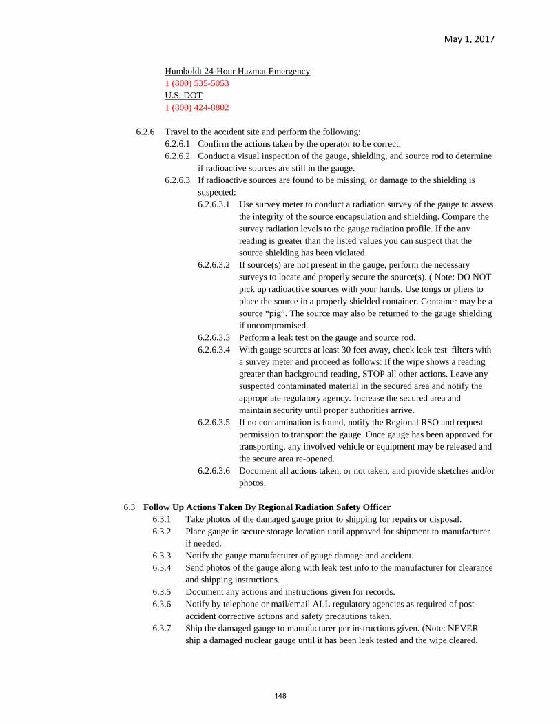
May 1, 2017
Humboldt 24-Hour Hazmat Emergency 1 (800) 535-5053 U.S. DOT 1 (800) 424-8802
6.2.6 Travel to the accident site and perform the following:6.2.6.1 Confirm the actions taken by the operator to be correct.6.2.6.2 Conduct a visual inspection of the gauge, shielding, and source rod to determine
if radioactive sources are still in the gauge.6.2.6.3 If radioactive sources are found to be missing, or damage to the shielding is
suspected:6.2.6.3.1 Use survey meter to conduct a radiation survey of the gauge to assess
the integrity of the source encapsulation and shielding. Compare the survey radiation levels to the gauge radiation profile. If the any reading is greater than the listed values you can suspect that the source shielding has been violated.
6.2.6.3.2 If source(s) are not present in the gauge, perform the necessary surveys to locate and properly secure the source(s). ( Note: DO NOT pick up radioactive sources with your hands. Use tongs or pliers to place the source in a properly shielded container. Container may be a source “pig”. The source may also be returned to the gauge shielding if uncompromised.
6.2.6.3.3 Perform a leak test on the gauge and source rod.6.2.6.3.4 With gauge sources at least 30 feet away, check leak test filters with
a survey meter and proceed as follows: If the wipe shows a reading greater than background reading, STOP all other actions. Leave any suspected contaminated material in the secured area and notify the appropriate regulatory agency. Increase the secured area and maintain security until proper authorities arrive.
6.2.6.3.5 If no contamination is found, notify the Regional RSO and request permission to transport the gauge. Once gauge has been approved for transporting, any involved vehicle or equipment may be released and the secure area re-opened.
6.2.6.3.6 Document all actions taken, or not taken, and provide sketches and/or photos.
6.3 Follow Up Actions Taken By Regional Radiation Safety Officer6.3.1 Take photos of the damaged gauge prior to shipping for repairs or disposal.6.3.2 Place gauge in secure storage location until approved for shipment to manufacturer
if needed.6.3.3 Notify the gauge manufacturer of gauge damage and accident.6.3.4 Send photos of the gauge along with leak test info to the manufacturer for clearance
and shipping instructions.6.3.5 Document any actions and instructions given for records.6.3.6 Notify by telephone or mail/email ALL regulatory agencies as required of post-
accident corrective actions and safety precautions taken.6.3.7 Ship the damaged gauge to manufacturer per instructions given. (Note: NEVER
ship a damaged nuclear gauge until it has been leak tested and the wipe cleared.
148

May 1, 2017
6.3.8 Review accident causes and measures taken. Establish new or revised guidelines to prevent similar future occurrences.
149

14 TDOT
Standard Specifications
January 1, 2015
Section 205 – Embankments
Section 303 – Mineral Aggregate Base

SECTION 205 – EMBANKMENTS
205.01 Description ................................................................................... 172 205.02 Materials ...................................................................................... 172 205.03 Preparation of Embankment Areas............................................... 173 205.04 Formation of Embankments ......................................................... 174 205.05 Stability of Embankments and Cut Slopes ................................... 178 205.06 Disposal of Excess or Unsuitable Material .................................. 178 205.07 Method of Measurement .............................................................. 178 205.08 Basis of Payment .......................................................................... 179
DESCRIPTION
205.01 Description
This work consists of constructing roadway embankments, including preparing the area upon which they are to be placed; constructing dikes within or outside the right-of-way; placing and compacting approved material within roadway areas where unsuitable material has been removed; and placing and compacting embankment material in holes, pits, and other depressions within the roadway area.
MATERIALS
205.02 Materials
For embankment and backfill, only use approved materials, consisting of Road and Drainage Excavation, Channel Excavation, and Borrow Excavation material as specified in 203, or excess material as specified in 204.
150

CONSTRUCTION REQUIREMENTS
205.03 Preparation of Embankment Areas
Before beginning embankment construction in any area, complete Clearing and Grubbing, Removal of Structures and Obstructions, and installation of preliminary erosion control measures according to the approved SWPPP as specified in 201, 202, and 209 respectively.
Address both natural and created steep slope areas as required in the TN Construction General Permit. Maintain and stabilize steep slopes according to the TN Construction General Permit and all applicable environmental permits.
Remove snow, ice, and mud before placing embankment materials on the ground. Do not place embankment materials on top of ground surfaces and existing embankment layers that are frozen.
Fill all depressions or holes below the natural ground surface, whether caused by grubbing or otherwise, with suitable material and compact to the ground surface before starting embankment construction.
Unless otherwise shown on the Plans or specified in the Special Provisions, if constructing embankment of less than 3 feet below subgrade:
1. Remove all sod and vegetable matter from the surface.
2. Remove unsuitable material and replace with suitable material.
3. Break up the cleared surface by plowing, scarifying, or stripping toa minimum depth of 6 inches, and then re-compact this area.
4. Cultivate sod not required to be removed before constructing theembankment.
5. If a compacted road surface containing granular materials lieswithin 3 feet of the subgrade, scarify the old road surface to adepth of at least 6 inches, and then re-compact the scarifiedmaterial.
Remove and dispose of concrete pavement, parking strip, and base, all with or without bituminous overlay, concrete curb and gutter, sidewalk,
151
driveways, and similar features as specified in 202.06 or as otherwise directed by the Engineer.
When placing embankment material on or against existing slopes that are steeper than 4:1, cut benches into the existing slope while bringing up the new embankment material in layers. Cut each bench of sufficient width to accommodate the operation of placing and compacting equipment. Begin each successive cut at the intersection of the original ground and the vertical side of the previous cut. Re-compact the cut material along with the new embankment material at no additional cost to the Department.
Before placing embankment material on a structure or any unit of a structure, ensure that the surrounding backfill has been completed and thoroughly compacted to ground surface.
205.04 Formation of Embankments
Do not incorporate or bury any perishable materials, such as brush, hedge, roots, stumps, and parts of trees, in the embankments. Do not place rock, broken concrete, or other solid objects in embankments areas where piling will be installed.
Construct embankments so as to provide adequate surface drainage at all times. If roadway embankment materials consist predominantly of soil, place the material in horizontal layers not to exceed 10 inches in loose thickness, and compact each layer to a density not less than 95% of maximum density. Unless otherwise specified, compact the top 6 inches of the roadbed in both cut and fill sections to 100% of maximum density.
The Engineer will determine maximum density and optimum moisture according to AASHTO T 99. For material with less than 5% retained on a No. 4 sieve, method A with 4-inch mold will be used. For material with more than 5% retained on a No. 4 sieve but less than 50% retained on a 3/4-inch sieve, Method D with corrections according to AASHTO T 224 will be used.
Use the correction on soils containing less than 50% plus 3/4-inch material.
Determine the density of the soil in place according to an approved AASHTO method. Compact each embankment layer to the required density, and obtain the Engineer’s approval before placing material for the next succeeding layer. Keep placing and compacting areas separate.
152

If the Contract includes the placement of base stone or other components of a pavement structure upon the subgrade, compact the top 6 inches in both cut and fill sections to a density equal to 100% of the maximum density as specified in 207.04.
When constructing embankment across low swampy ground that will not support earth moving equipment, construct the lower part of the fill in a uniformly distributed layer of a thickness not greater than necessary to support the hauling equipment while placing subsequent layers. Construct the embankment full width unless otherwise shown on the Plans or approved by the Engineer. The Engineer will waive the density requirement for such a lift, but the moisture content of the material used shall not exceed the optimum moisture range for 95% density for that material. Comply with the maximum thickness and minimum density requirements for all succeeding layers of the embankment.
When a minimum of 95% of maximum density is required, ensure that the moisture content of the material being compacted meets both of the following conditions:
1. The moisture content shall be within the range of values at which95% of the maximum density can be obtained as indicated by themoisture-density relationship curve; and
2. The moisture content shall not exceed the optimum moisturecontent to the extent that the material pumps under loads appliedby the construction equipment.
Even if the required density is achieved and the moisture content is in range, if pumping occurs, remove the affected sections.
When 100% of maximum density is required, the moisture content of the material being compacted shall meet condition (2) above and shall not vary from the optimum moisture content by more than ±3%.
Aerate the material, or distribute and incorporate water uniformly into the material, as necessary, to control the moisture content within the applicable limits.
If the excavated material consists predominantly of rock, the following shall apply:
153

A. Definition of Material
If deemed necessary by the Engineer, the Contractor shall conduct testor tests with a 60,000-pound static tamping foot roller (costs to beincluded in other items) to determine whether the material isdegradable or non-degradable. Consider material that readily breaksdown under three passes of the 60,000-pound static tamping foot rolleras degradable.
B. Non-Degradable Rock
If sound, non-degradable rock is encountered in the unclassifiedexcavation, the Engineer may require the Contractor to provide amechanical means for separating the sound rock from degradable rockand other soils. The Engineer may allow the use of sound, non-degradable rock in the backfilling of benches, lower and outsideportions of embankments, rock buttresses, or other areas.
If the material for embankments consists of sound, non-degradable rockof a size that makes placing the material in 10-inch layersimpracticable, place the material in layers no thicker than 3 feet. Donot use rock fragments greater than 2 feet in maximum dimension.With the Engineer’s approval, the Contractor may place occasionalindividual rocks and boulders not exceeding 4 feet in height in theexterior portions of the embankment next to the slope face. Place suchrocks to prevent nesting, and fill the adjacent voids with fine fragmentsto form a dense and compact mass.
Do not dump rock material into its final position. Place rock byblading or dozing in a manner that will minimize voids, pockets, andbridging. Ensure that each layer is leveled the full width of theembankment. Rolling is not required if the rock embankment consistsof sound, non-degradable material placed in greater than 10-inch layers.
C. Degradable Rock
Compact degradable rock for use in embankment with an approvedvibratory tamping-foot roller in conjunction with a static tamping-footroller. The minimum weight for the static tamping-foot roller shall be60,000 pounds. The minimum compaction effort, as rated by themanufacturer, for the vibratory tamping-foot roller shall be55,000 pounds. Submit roller specifications to the Engineer forapproval before use.
154

Place degradable rock in 10-inch maximum loose lifts, and provide a minimum of three passes with the static roller and two passes with the vibratory roller. The Engineer may direct additional passes with either or both rollers until satisfactory breakdown and compaction is accomplished. Do not place degradable rock in the top 5 feet of an embankment unless approved by the Engineer.
If embankment composed of degradable rock does not contain sufficient moisture to compact properly, the Engineer will require the Contractor to apply water in sufficient quantities to achieve the approximate optimum moisture for the particular material involved. Uniformly mix the added water with the material for the entire depth of the lift by blading, discing, or other approved methods.
D. Combination of Degradable and Non-Degradable Rock
Do not blend or combine degradable rock and non-degradable rock in acommon lift without the Engineer’s written approval.
If approved, place embankment material consisting of a mixture ofdegradable rock and non-degradable rock, or rock and soil, in layers notexceeding 10 inches in thickness unless otherwise directed by theEngineer. If the combined material is predominantly sound, non-degradable rock with fragments thicker than 10 inches, the Engineermay increase the layer thickness to be consistent with the size of thematerial, not to exceed 3 feet. Place the mixture by blading or dozingin a manner that will minimize voids, pockets, and bridging. Compactthe mixture with suitable compaction equipment as defined in205.04.A, and apply water to facilitate compaction as directed by theEngineer. Uniformly mix the added water with the material for theentire depth of the lift by blading, discing, or other approved methods.
E. Density Requirements
Density requirements will not apply to portions of embankmentsconstructed of materials that cannot be tested by approved methods.
When the Plans require Solid Rock Fill, the material shall consist of sound, non-degradable rock (granite, gneiss, limestone, or other approved material). When the material is subjected to five alternations of the sodium sulfate soundness test performed according to AASHTO T 104, the weighted percentage of loss shall not exceed 12. Do not use plastic soil or
155

shale material. Place Solid Rock Fill as shown on the Plans or as directed by the Engineer.
Construct the roadway through rock fills to the grading line shown on the Plans with an allowable working tolerance of plus 1 to minus 3 inches. Bring up to grade those portions of the roadway that are then below grade with spalls or other suitable granular material that is available from the excavation within the balance. If no such excavation is available, the Engineer may direct the Contractor to use approved base material for bringing the fill to grade, not to exceed the specified 3-inch limit.
If embankment material is to be placed on both sides of a concrete wall or box type structure, bring the material up equally on both sides of the structure.
At the location of abutments, bents, and similar features, construct embankment to the finished grade before starting excavation on the respective section of the substructure, unless otherwise shown on the Plans. If embankment material is to be placed on only one side of abutments, wing walls, piers, and similar features, do not begin construction until the superstructure is in place. Perform compaction operations without causing wedge action or placing excessive pressure against the structure.
205.05 Stability of Embankments and Cut Slopes
Assume responsibility for the stability of all embankments and cut slopes until final acceptance. Replace, at no additional cost to the Department, all portions which, in the Engineer’s opinion, have become displaced or damaged due to carelessness or negligence.
205.06 Disposal of Excess or Unsuitable Material
Dispose of excess or unsuitable material as specified in 203.07.
COMPENSATION
205.07 Method of Measurement
The Department will not measure embankment. The Contractor shall construct embankments under the items described in 203 and 204 that apply to the materials used to construct the embankments.
156

The Department will measure excavation to bench side-hill slopes for embankment construction in accordance with 203.09.A.2.
205.08 Basis of Payment
The Department will not directly pay for embankments. The contract unit prices for the materials with which embankments are acceptably constructed is full compensation for all embankment construction, including materials, equipment, labor, and incidentals to complete the work as specified.
If the Contractor encounters pumping of soil despite having achieved the required density and moisture content, the Department will pay for the removal of these sections as Undercutting by the cubic yard in cut sections only. No such payment will be made in fill sections.
If the excavated material consists predominantly of rock, the Department will pay for water required and provided by the Contractor to facilitate compaction at the unit price per M.G. (1,000 gallons) for Water, which price is full compensation for furnishing and applying the water, mixing, labor, and equipment. The Department will consider all other costs associated with the constructing embankment of material consisting predominantly of rock, including providing suitable compaction equipment and separating sound rock from degradable rock and soils, as included in the unit price for Road and Drainage Excavation (Unclassified).
If the Engineer directs the Contractor to use approved base material to bring portions of the roadway that are less than 3 inches below grade up to grade, the Department will measure and pay for the furnishing and placing of such base material in tons under the applicable item in 303.15. If base material is not a bid item in the Contract, the Contractor shall provide the material under the provisions of 104.02.D.
If, despite proper construction and protection, damage to the embankments or cut slopes occurs due to unusual natural causes such as cloudbursts, floods, slides or subsidence, the Department will pay for the material used to make the necessary repairs at the contract unit price for the material classification designated by the Engineer to be used for this purpose. The Department will pay for removal of slides in accordance with 203.10.
157

SECTION 303 – MINERAL AGGREGATE BASE
303.01 Description ................................................................................... 220 303.02 Aggregate ..................................................................................... 220 303.03 Calcium Chloride ......................................................................... 221 303.04 Sodium Chloride .......................................................................... 221 303.05 Emulsified Asphalt ....................................................................... 221 303.06 Equipment .................................................................................... 221 303.07 General ......................................................................................... 222 303.08 Mixing .......................................................................................... 223 303.09 Spreading ..................................................................................... 224 303.10 Shaping and Compaction ............................................................. 225 303.11 Maintenance ................................................................................. 227 303.12 Thickness Requirements .............................................................. 228 303.13 Surface Requirements .................................................................. 228 303.14 Method of Measurement .............................................................. 228 303.15 Basis of Payment .......................................................................... 229
DESCRIPTION
303.01 Description
This work consists of furnishing and placing one or more courses of aggregates, and additives if required, on a prepared subgrade.
Mineral aggregates base shall be Type A or Type B, whichever is shown on the Plans and called for in the bid schedule.
MATERIALS
303.02 Aggregate
Depending upon whether the Plans require Type A or Type B base, provide mineral aggregate meeting 903.05. For Type A base, use aggregate of
158

Grading D. For Type B base, the Contractor may use aggregate of Grading C or D.
The Engineer will accept aggregate for gradation as follows:
1. When the stationary plant method for mixing is used, the Engineerwill accept aggregate immediately after or prior to mixing, basedon periodic samples taken from the pugmill output or from the beltfeeding the pugmill.
2. When two or more materials are blended on the road usingmechanical mixers, the Engineer will accept aggregate aftermixing and before compaction, based on samples taken from eachlayer of base material.
3. For aggregate that does not require blending, the Engineer willaccept aggregate at the aggregate production plant, based onsamples taken from stockpiles of plant production immediatelybefore delivery to the road.
303.03 Calcium Chloride
Provide calcium chloride meeting 921.02 for Type 1, Type 2 or calcium chloride liquor.
303.04 Sodium Chloride
Provide sodium chloride meeting 921.03.
303.05 Emulsified Asphalt
Use emulsified asphalt of a type allowed for Prime Coat in 401, meeting the test requirements specified in 904.03.
EQUIPMENT
303.06 Equipment
Provide a stationary mixing plant, mechanical road mixer, or motor grader, whichever is applicable to the type of work to be performed, as specified in 303.08.
159
A. Stationary Mixing Plant
Provide an approved twin-shaft pugmill capable of producing aconstant, uniform mixture. Equip the mixing plant with the following:
1. A suitable truck-loading hopper with a gate that will preventsegregation of the material when dumped into the truck;
2. A spray bar, capable of ensuring an even wetting of theaggregate, mounted at the entrance of or above the pugmill;
3. A meter, valve, or other approved type of regulating device tocontrol the flow of water through the spray bar to maintain auniform moisture content in the mixture;
4. A separate, quick, and automatically operating on-and-offdevice to shut the water off instantly when the pugmill stops;and
5. Adjustable mechanical feeders for each size material capableof regulating a constant, uniform flow of material.
B. Mechanical Mixer (for Road Mixing)
Provide a pugmill or rotary type mechanical mixer capable ofproducing a uniform blend of all materials to the full depth of thecourse being placed. The mixer may be either self-propelled or trailer-drawn.
C. Compaction Equipment
Provide one or more rollers of a type and sufficient weight to obtain therequired density and seal the surface of the base course.
CONSTRUCTION REQUIREMENTS
303.07 General
Construct Mineral Aggregate Base, Type A or Type B, in one or more layers, to the compacted thickness shown on the Plans.
160

Prepare the subgrade as specified in 205, 207, or 302, whichever is applicable.
Obtain the Engineer’s approval of the subgrade before spreading any mineral aggregate. Subgrade that has been previously checked and approved, but subsequently subjected to freezing conditions or prolonged wet weather, shall be rechecked for approval.
Do not spread mineral aggregate on a subgrade that is frozen or contains frost.
Do not haul over any material that has been placed until it has been spread, mixed, shaped and compacted to the required density.
303.08 Mixing
A. Mixing Methods
Unless otherwise specified, mix the base course material, including anadditive if shown on the Plans, by one or more of the following threemethods:
1. Stationary Plant Method. Mix the base course material andwater in an approved stationary mixing plant as specified in303.06.A. Add sufficient water during the mixing operation toprovide a moisture content satisfactory for compacting. Ifcombining materials to meet the grading requirements, blend thematerials, as specified in 903.05, before mixing. Ensure that allmaterial fed into the plant travels the full length of the pugmill.
2. Road Mix Method (Mechanical Mixer). After placing thematerial for each layer of base course through an aggregatespreader or windrow-sizing device, mix the material usingapproved mechanical mixing machines as specified in 303.06.B.
During mixing, add sufficient water to provide a moisture contentsatisfactory for compacting.
3. Road Mix Method (Motor Grader). After depositing anduniformly spreading material for each layer of base course,sprinkle it with just enough water to moisten all particles, butwithout causing segregation of sizes or softening of the subgrade.Immediately after applying water, thoroughly mix the material by
161

windrowing and spreading with motor graders until the mixture is uniform throughout.
For Mineral Aggregate Base, Type A, use the stationary plant method. For Mineral Aggregate Base, Type B, requiring the blending of two or more materials, use either the stationary plant method or the road mix method (mechanical mixer), except as provided for in 903.05. For Mineral Aggregate Base, Type B, requiring additive, use either stationary plant mixing or road mixing.
B. Use of Calcium Chloride and Sodium Chloride
If using calcium chloride, incorporate it in either the solid or liquidform, at the approximate rate of 6 pounds per ton of aggregate, notingthat:
• 6 pounds is equivalent to 1.29 gallons 60 °F 32% solution• 6 pounds is equivalent to 1.02 gallons 60 °F 38% solution
If using sodium chloride, incorporate it at the approximate rate of 5 pounds per ton of aggregate.
For stationary plant mixing, proportion chloride material, in solid form, through a hopper equipped with an approved vibratory feeder and an adjustable opening capable of accurately controlling the flow of material. Proportion calcium chloride liquor using an approved calibrated meter that has a registering capacity capable of indicating the total amount of liquid used during any single day’s operation.
For road mixing, add the chloride material to the aggregate at the point in the mixing operation and in the manner directed by the Engineer.
303.09 Spreading
Spread material as follows according to the mix method used:
A. Stationary Plant Mixing
After mixing, transport material to the site for each layer of base whileit contains the proper moisture content. Spread the material to therequired thickness and cross-section using an approved mechanicalspreader.
162
B. Road Mixing (Mechanical Mixer)
Before mixing, spread material with an approved mechanical spreaderthat can be adjusted to spread materials in the proper proportions.
C. Road Mixing (Motor Grader)
After thoroughly mixing the aggregate and water, spread the basematerial while at optimum moisture content in layers of specifiedthickness and cross-section using approved motor graders.
If the required compacted depth of the base course exceeds 6 inches, construct the base in two or more layers of approximate equal thickness. The maximum compacted thickness of any one layer shall not exceed 6 inches; however, if vibrating or other approved types of special compacting equipment are used, the Contractor may increase the compacted depth of a single base course layer to 8 inches with the Engineer’s approval.
In some cases, the Plans may show the base as extending for the full width of the roadbed. In other cases, the edges of the base may be shown as coinciding with the inside edges of the shoulders. In the latter case, place shoulder material to a minimum width of 3 feet before spreading each layer of base material in order to confine the base material and to allow for proper compaction.
The Contractor may spread and mix any base material used for constructing detours, for maintenance of traffic, for backfilling rock cuts, and for capping rock fills as specified in 303.09.C.
303.10 Shaping and Compaction
A. Final Shaping
Immediately after spreading, shape the base material to the requireddegree of uniformity and smoothness. Except where using mechanicalaggregate spreading equipment to place the base material, use a motorgrader to shape each layer before compacting. If the mechanicalspreading equipment fails to shape the base material properly, use amotor grader or other approved means to perform final shaping.
163

B. Compaction
Compact the base material to the required density before anyappreciable evaporation of surface moisture occurs. Continuouslycompact each layer until the minimum density requirement, asspecified in 303.10.C.2, is achieved. The Contractor may use any typeof compacting equipment provided the required density is attained.
If, as provided for in 303.10.C.3, the density requirement does notapply, gradually compact the base material, progressing from the edgesof the base to the center, parallel with the center-line of the road.Continue compacting until the base layer has been compacted to its fullwidth as directed by the Engineer. Where lifts of shoulder materials areplaced to confine the base material, overlap the initial pass of thecompacting equipment with the shoulder to a width of not less than12 inches.
Construct the surface of each layer so that the aggregates becomefirmly keyed and a uniform texture is produced. Maintain the surface inthis condition until it is covered by the following stage of constructionor until final acceptance of the project. Correct irregularities byloosening the material at those places and adding or removing materialas required.
Use approved distributors to apply water uniformly over the basematerials during compaction in sufficient quantity to allow for propercompaction without causing softening of the underlying subgrade dueto excessive water use.
C. Compaction Acceptance
1. Lot Sizes and Testing. For density testing purposes, theDepartment will divide each completed layer into lots ofapproximately 10,000 square yards, and will average the results offive density tests performed on each lot. Smaller lots may beconsidered as directed or approved by the Engineer.
164

2. Density Requirements
a. Type A Base. The average density of each lot of Type Abase, unless otherwise specified, shall be not less than 100%of maximum density as determined according to AASHTOT 99, Method D, with no individual test less than 97% ofmaximum density.
b. Type B Base. The average density of each lot of Type B base,unless otherwise specified, shall be not less than 97% ofmaximum density as determined according to AASHTO T 99,Method D, with no individual test being less than 95% ofmaximum density.
If the specified density is not obtained for either type of base, rework or replace the material to comply with the density requirement.
3. Exclusions. Unless otherwise specified, the density requirementsspecified in 303.10.C.2 will not apply to:
a. Type A or Type B base construction on projects that donot include the construction of a surface upon the base, orto
b. Projects having a specified total base thickness of lessthan 4 inches.
When the specified density requirements do not apply, the Engineer will consider the desired degree of compaction to have been reached when the surface is tightly bound and shows no undue rutting or displacement under operation of the roller or other equipment. Obtain the Engineer’s approval of the compaction of each layer before placing material for the next successive layer. Keep placing and compacting areas separate.
303.11 Maintenance
Maintain the completed base in a smooth and uniform condition until it is covered by the following stage of construction or the Project has been completed and accepted. Comply with the requirements of 104.05 regarding maintenance and protection.
165
303.12 Thickness Requirements
The thickness of the completed base shall be in reasonably close conformity to the thickness shown on the Plans. The thickness will be measured at such frequency as established by the Department using test holes or other approved methods.
303.13 Surface Requirements
The surface of the finished base shall be in reasonably close conformity to the lines, grades, and cross-sections shown on the Plans or established by the Engineer and shall have a satisfactorily smooth riding quality.
COMPENSATION
303.14 Method of Measurement
A. Mineral Aggregate for Mineral Aggregate Base, Type A or Type B
The Department will measure Mineral Aggregate for MineralAggregate Base, Type A or Type B, by the ton, in accordance with 109.
B. Water
The Department will deduct the weight of total moisture, as determinedby dry weights, of the base material at the time of weighing in excess of3% of optimum moisture content.
The Department will not measure or pay for water when mixing isperformed in a stationary plant,
When road mixing is performed, the Department will measure wateradded to the material at the direction of the Engineer by the M.G.(1,000 gallons) using calibrated tanks or distributors, or accurate watermeters.
C. Sodium Chloride
The Department will measure sodium chloride by the ton in accordancewith 109.
166
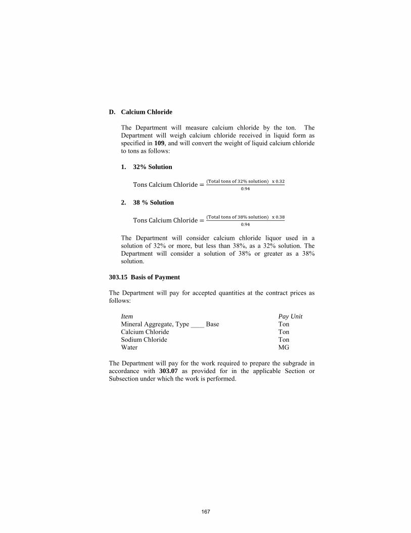
D. Calcium Chloride
The Department will measure calcium chloride by the ton. TheDepartment will weigh calcium chloride received in liquid form asspecified in 109, and will convert the weight of liquid calcium chlorideto tons as follows:
1. 32% Solution
Tons Calcium Chloride = (Total tons of 32% solution) x 0.320.94
2. 38 % Solution
Tons Calcium Chloride = (Total tons of 38% solution) x 0.380.94
The Department will consider calcium chloride liquor used in a solution of 32% or more, but less than 38%, as a 32% solution. The Department will consider a solution of 38% or greater as a 38% solution.
303.15 Basis of Payment
The Department will pay for accepted quantities at the contract prices as follows:
Item Pay Unit Mineral Aggregate, Type ____ Base Ton Calcium Chloride Ton Sodium Chloride Ton Water MG
The Department will pay for the work required to prepare the subgrade in accordance with 303.07 as provided for in the applicable Section or Subsection under which the work is performed.
167
Related Documents