E-1 2011 v1.0 Mid-Atlantic Region Technician Certification Program AGGREGATE TECHNICIAN MANUAL

Welcome message from author
This document is posted to help you gain knowledge. Please leave a comment to let me know what you think about it! Share it to your friends and learn new things together.
Transcript

E-12011 v1.0
Mid-Atlantic RegionTechnician Certification Program
AGGREGATE TECHNICIAN MANUAL

E-2 2011 v1.0
FOREWORD
This manual does not propose to be the last authority regarding Aggregate Testing. It is intended to act as a guide and reference to obtaining Certified Status
in the field of Aggregate Testing in the Mid-Atlantic Region.
ACKNOWLEDGEMENTSMARTCP TEAM MEMBERS:
Mr. Robert A. Kochen, Chair - Maryland Dept. of Transportation
Mr. David P. Van Kavelaar - Delaware Dept. of Transportation
Mr. George W. Hall III - Maryland Dept. of Transportation
Mr. Quinton D. Davis - New Jersey Dept. of Transportation
Mr. Paul M. Ingram - Pennsylvania Dept. of Transportation
Mr. Kerry W. Petrasic - Pennsylvania Dept. of Transportation
Mr. Stanley L. Hite - Virginia Dept. of Transportation
Mr. Larry J. Lundy - Virginia Dept. of Transportation Mr. Ralph I. Adams West Virginia Dept. of Transportation
Ms. Carolyn S. Baird - West Virginia Dept. of Transportation
Mr. Lawrence Chung - Washington D.C. Dept. of Public Works
Special thanks to:
Mr. Robert Dineen - Pennsylvania Dept. of Transportation For his contribution to the Geology section of this manual.
Mr. Woody Hood Maryland Dept. of Transportation Team Facilitator/Coordinator MARTCP
National Stone Sand and Gravel Association
E-32011 v1.0
TEST DESCRIPTIONS
1.1 OVERVIEW - TEST DESCRIPTIONS
1.1.1 MARTCP METHOD SA-1.1 - MARTCP ROUNDING PROCEDURE
This method addresses rounding-off of numbers from test results and calculations.
1.1.2 AASHTO T 2 – SAMPLING OF AGGREGATES
This test procedure defines a standard method in obtaining quality representative samples of aggregate.
Procedures defined in this test method were developed to minimize adverse impacts on sample quality caused by improper sample collection. Following these procedures assures the state agency, as well as the supplier, that a fair and representative sample has been collected for testing.
1.1.3 AASHTO T 248 – REDUCING SAMPLES OF AGGREGATE TO TESTING SIZE
This test procedure provides a standard method of taking a large representative sample and reducing it to a size suitable for testing. This procedure assures the smaller sample is representative of the total supply. This procedure describes both the uses of a mechanical splitter and the quartering method that may be used to reduce sample size.
1.1.4 AASHTO T 11 – MATERIALS FINER THAN 75µm (No.200) SIEVE IN MINERAL AGGREGATES BY WASHING
This test washes the fine particles through the 75 µm (No. 200) sieve to give an accurate determination of minus 75 µm (No. 200) portion in the sample. The determination of minus 75 µm (No. 200) material is used to compare material performance with gradation specifications, and indirectly to gauge such properties as plasticity, permeability, and soils classifications.

E-4 2011 v1.0
1.1.5 AASHTO T 27 – SIEVE ANALYSIS OF FINE AND COARSE AGGREGATE
This procedure defines a standard method to determine by mechanical means the distribution of various particle sizes of an aggregate mixture. The procedure can be adapted to fit the design sieves for aggregate mixtures that are defined by each state’s specifications.
1.1.6 AASHTO T 19 – BULK DENSITY (“UNIT WEIGHT”) AND VOIDS IN AGGREGATES
This procedure defines the method for determining the Unit Weight and Voids in Aggregates containing particles not exceeding a nominal maximum size of five inches (125 mm). The unit weight is necessary for selecting proper proportions in concrete mix designs. Calculation of voids in fine, coarse, or mixed aggregate is based upon the determination of the unit weight.
1.1.7 MARTCP SA-1.3 - PERCENT MOISTURE CONTENT PROCEDURE
This procedure establishes a uniform test method for pan-drying soils and aggregate samples on the project.
1.1.9 AASHTO T 89 – DETERMINING THE LIQUID LIMIT OF SOILS
This method determines the Liquid Limit of Soils. The Liquid Limit is the moisture content at which a specific soil moves from a plastic to a liquid state. Generally, soils with high Liquid Limits are clays with poor engineering properties. Soils with a high clay content are cohesive (stick together), plastic (moldable), compressible (able to be consolidated), and nearly impervious (impenetrable by water).
1.1.11 AASHTO T 90 – DETERMINING THE PLASTIC LIMIT AND PLASTICITY INDEX OF SOILS
This method determines the Plastic Limit of Soils. The minimum moisture content at which a soil behaves as a plastic is called the Plastic Limit. This method also determines the Plasticity Index of a material. The Plasticity Index is a calculated value derived by subtracting the Plastic Limit from the Liquid Limit;
i.e. , PI = LL - PL
E-52011 v1.0
1.2 - TEST METHODS
1.1.1 MARTCP METHOD SA-1.1 - MARTCP ROUNDING PROCEDURE
This Method addresses rounding off of numbers from test results and calculations.
If the number following the last number to be retained is less than 5, the last number to be retained is left unchanged and the number(s) following the last number to be retained is/are discarded (e.g. 14.649 = 14.6, 14.749 = 14.7).
If the number following the last number to be retained is greater than 5, increase the last number to be retained by 1 and discard the number(s) following the last number to be retained (e.g. 14.66 = 14.7, 14.76 = 14.8).
If the number following the last number to be retained is 5, and there are no numbers beyond 5, only zeros, the last number to be retained is increased by 1 if odd, or left unchanged if even. The number(s) following the last number to be retained is/are discarded (e.g. 14.750 = 14.8, 14.650 = 14.6).
If the number(s) following the last number to be retained is 5 and there is/are numbers following the 5, the last number to be retained is increased by 1 regardless of being odd or even. The number(s) following the last number to be retained is/are discarded (e.g. 14.751 = 14.8, 14.651 = 14.7).
For questions involving significant figures, refer to AASHTO R 11. In most instances, the individual state specifications and test procedures will define the level of accuracy needed for the test results.
1.2.2 AASHTO T 2 - SAMPLING OF AGGREGATES
Aggregates compose a major portion of most highway construction. They are used in all phases, including base construction, pavement mixes, granular shoulders, granular surfacing, drainage and erosion control. For aggregates to perform as intended, they must meet certain physical requirements such as proper gradation, durability to resist the effects of weathering, and resistance to abrasion loss.
The most important phase of an aggregate technician’s duties is securing a representative sample. At this point, all the money and time which will be expended on the remaining activities of testing and evaluation may be lost or rendered useless by an improper sampling technique. In other words, if the samples taken are not representative of the total material, it is impossible to obtain meaningful test results. At the completion of this instruction, the technician must know how to obtain a proper sample. Without this knowledge, it is useless to proceed further into the areas of the test procedures.

E-6 2011 v1.0
Test samples should represent the total amount of the material being produced or used. This is normally accomplished by random sampling. All material should have an equal chance of being tested. Random samples are taken when the plant or operation is processing at the usual rate. During production at the source, care must be taken to assure that the virgin material being processed is normal to the overall consistency of the available material. Clay pockets, boulders or varying seams in a gravel pit, mine, or quarry may create short-term variations in the consistency of the product.
It must be pointed out that not all samples are random samples. At times the technician must choose the time of sampling, especially during the production phase. Control samples may be needed during start-up, equipment changes or changes in the material. These circumstances will directly affect the gradation of the material and must be checked to keep the material within proper limits. During a normal day’s operation, all samples taken may be random samples if all operations are running consistently. Random samples may not be taken every day, such as the first days run to establish crusher settings, etc. A combination of random and control check samples may be taken on the same day. The technician should sample based on random sampling techniques and not by judgement.
Keep in mind that, during normal and steady operations, samples should be selected in a random method prescribed by state specifications.
When securing processed aggregate samples, at least three increments of coarse aggregate shall be taken by an appropriate method as described in this instruction. There should be five increments of fine aggregate sampled using the sampling tube or other suitable device. When practical, more increments should be taken to build the field sample. Taking more increments provides a better cross-section of the total material.
The discussion of securing samples would not be complete without mentioning safety. The production and placement of aggregates require the use of heavy equipment and large bins. The conditions are frequently dusty and noisy. The aggregate technicians must use extreme caution to insure that sampling locations are safe.
1.2.2.1 SUMMARY OF AGGREGATE SAMPLING
There are four methods approved by AASHTO for securing aggregate samples. The method the technician uses depends on the type of aggregate to be sampled, the location of the sample, and the sampling equipment available. The four methods are Flowing Aggregate Stream, Conveyor Belt, Stockpiles or Transportation Units, and Roadway (Bases and Sub-bases), as illustrated below in Figures 1 through 4.

E-72011 v1.0
Figure 1 - Flowing Aggregate Stream (Bins or Belt Discharge)
Figure 2 - Conveyor Belt

E-8 2011 v1.0
Figure 3 - Stockpiles or Transportation Units
Figure 4 - Roadway (Bases and Subbases)
The most accurate way to insure that processed aggregates meet requirements would be to test the entire stockpile. This would be impractical. Accurate, representative samples must be secured for testing to insure that the required characteristics are measured.
Aggregate samples may be obtained at different stages of production or construction as required by state specifications:
E-92011 v1.0
• Preliminary source investigation. These samples are normally obtained by the party responsible for development of the source.
• During aggregate production at the source, samples for quality control of the production are obtained by the manufacturer, contractor or other responsible party.
• Control of the operations at the job site is also the responsibility of the producer, contractor or other qualified party.
• Samples to determine acceptance or rejection by the states are obtained by the purchaser or an authorized representative.
Samples secured for the purpose of quality testing such as soundness, clay content, resistance to abrasion, etc., should be obtained from the finished product when practical. Samples from the finished product to be tested for resistance to abrasion shall not be subjected to further crushing or manual reduction in particle size (unless the size of the finished product is such that it requires further reduction for testing purposes).
COMMON TESTING ERRORS
• Using an improper sampling device.• Sampling in segregated areas.• Not obtaining enough increments.• Improper sampling method for a particular aggregate.• Allowing overflow in a streamflow device. • Obtaining a biased or non-representative sample.
1.2.2.2 NUMBER AND MASS OF FIELD SAMPLES
The number of field samples required depends on each state’s sampling program. The number of field samples obtained during production must be sufficient to give the desired confidence in the test results. A single field sample should neither be so large as to mask the effects of significant variability within the unit, nor so small as to be affected by the inherent variability between small portions of any bulk material.
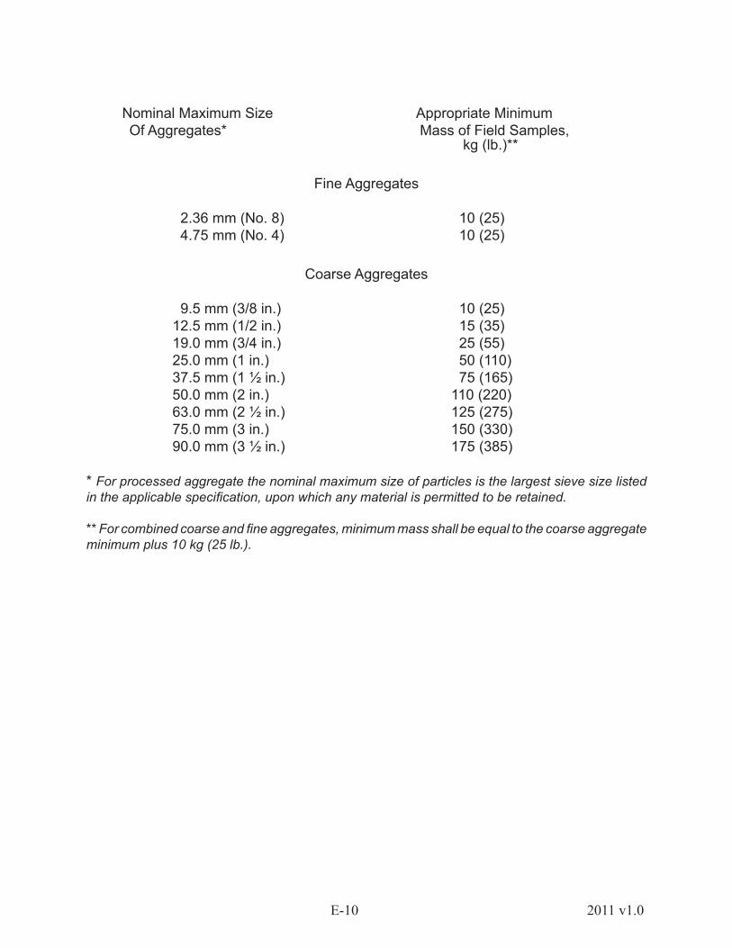
Field sample size must be based on the type and number of tests to be run on the aggregate. Standard acceptance and control tests are covered by AASHTO/ASTM Standards and specify the portion of the field sample required for each specific test. Generally speaking, the masses shown in the following table will provide sufficient material for routine grading and quality analysis. Extract test portions from the field sample according to AASHTO T 248.
E-10 2011 v1.0
Nominal Maximum Size Appropriate Minimum Of Aggregates* Mass of Field Samples,
kg (lb.)**
Fine Aggregates
2.36 mm (No. 8) 10 (25) 4.75 mm (No. 4) 10 (25)
Coarse Aggregates
9.5 mm (3/8 in.) 10 (25) 12.5 mm (1/2 in.) 15 (35) 19.0 mm (3/4 in.) 25 (55) 25.0 mm (1 in.) 50 (110) 37.5 mm (1 ½ in.) 75 (165) 50.0 mm (2 in.) 110 (220) 63.0 mm (2 ½ in.) 125 (275) 75.0 mm (3 in.) 150 (330) 90.0 mm (3 ½ in.) 175 (385)
* For processed aggregate the nominal maximum size of particles is the largest sieve size listed in the applicable specification, upon which any material is permitted to be retained.
** For combined coarse and fine aggregates, minimum mass shall be equal to the coarse aggregate minimum plus 10 kg (25 lb.).

E-112011 v1.0
1.2.2.3 SHIPPING SAMPLES
Transport the aggregate samples in bags made for that purpose or other suitable containers constructed so as to prevent loss, contamination or damage to the sample during handling and shipping.
The sample containers shall have proper identification that is attached to or enclosed within, to facilitate field reporting, laboratory logging and test reporting.
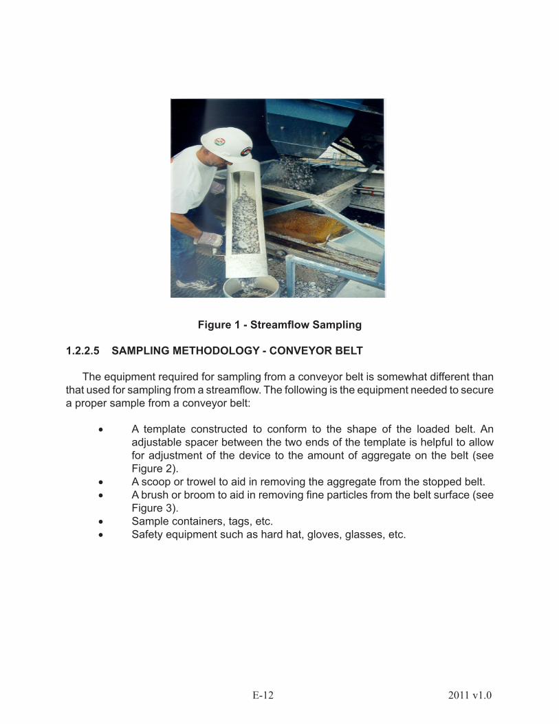
1.2.2.4 SAMPLING METHODOLOGY - AGGREGATE STREAMFLOW
Before taking a sample, you must first gather all equipment necessary to obtain the sample. To obtain a sample using the aggregate streamflow, you will need the following:
• Sampling device designed for use at each particular plant. This device consists of a pan of sufficient size to intercept the entire cross section of the discharge stream and retain the required quantity of material without overflowing. In some situations, a set of rails may be necessary to support the pan as it is passed through the streamflow.
• Safety equipment such as hard hat, glasses, etc.• Sample containers, tags, etc.
Sampling Procedure and Guidelines
Pass the sampling device through the streamflow, being sure to cut through the entire cross section of the material as it is being discharged. Care must be taken to pass the device through the stream rapidly enough to prevent any overflow of material during the sampling procedure. Obtain a minimum of three increments for each sample. Be sure to obtain equal increments. Obtain the appropriate size to accommodate all tests to be performed on the sample. Allow an amount of time to elapse between passes to get a representative sample of the material. When sampling aggregate from a loaded bin, increments should not be obtained when the belt first starts or when the bin is nearly empty. This minimizes the natural segregation that may occur as the material exits the bin.
E-12 2011 v1.0
Figure 1 - Streamflow Sampling
1.2.2.5 SAMPLING METHODOLOGY - CONVEYOR BELT
The equipment required for sampling from a conveyor belt is somewhat different than that used for sampling from a streamflow. The following is the equipment needed to secure a proper sample from a conveyor belt:
• A template constructed to conform to the shape of the loaded belt. An adjustable spacer between the two ends of the template is helpful to allow for adjustment of the device to the amount of aggregate on the belt (see Figure 2).
• A scoop or trowel to aid in removing the aggregate from the stopped belt.• A brush or broom to aid in removing fine particles from the belt surface (see
Figure 3). • Sample containers, tags, etc.• Safety equipment such as hard hat, gloves, glasses, etc.

E-132011 v1.0
Figure 2 - Belt Cut Using Template
Figure 3 - Cleaning fines from belt.
E-14 2011 v1.0
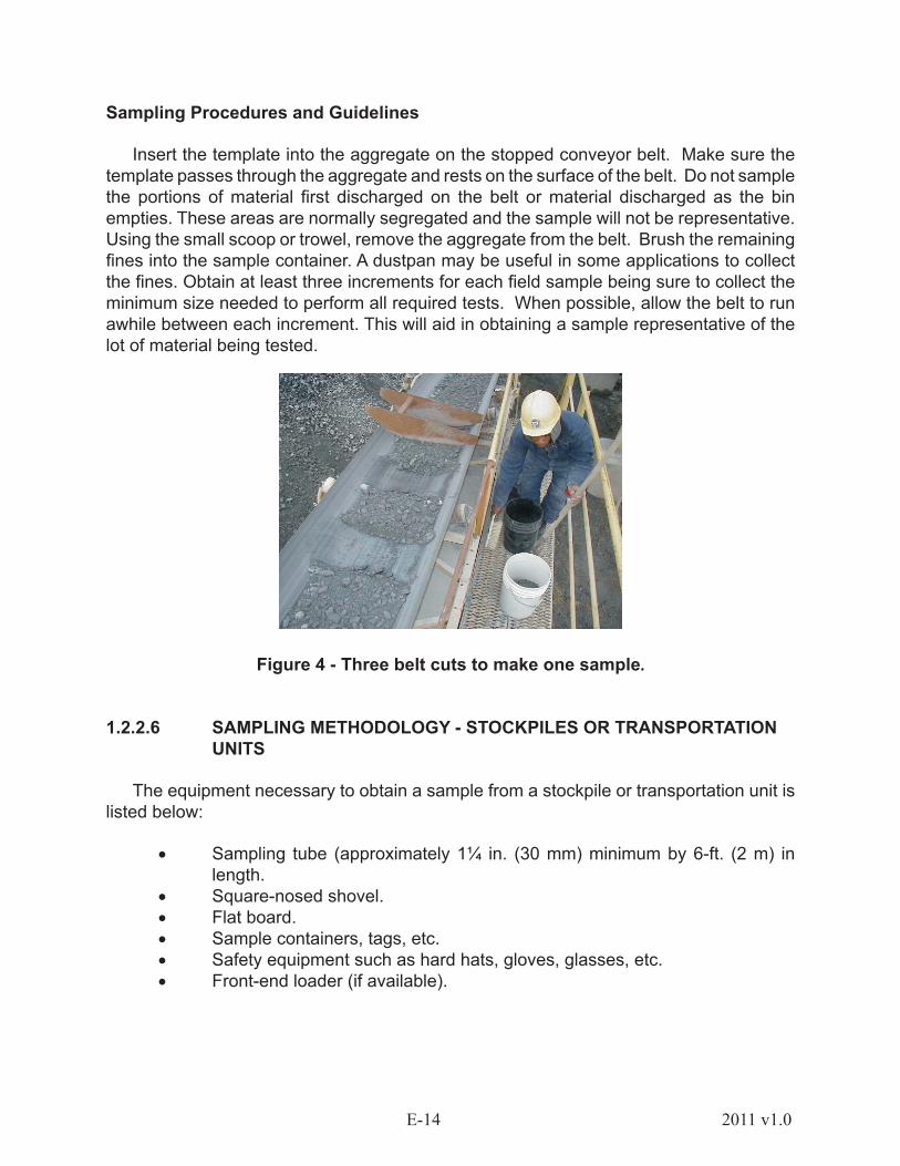
Sampling Procedures and Guidelines
Insert the template into the aggregate on the stopped conveyor belt. Make sure the template passes through the aggregate and rests on the surface of the belt. Do not sample the portions of material first discharged on the belt or material discharged as the bin empties. These areas are normally segregated and the sample will not be representative. Using the small scoop or trowel, remove the aggregate from the belt. Brush the remaining fines into the sample container. A dustpan may be useful in some applications to collect the fines. Obtain at least three increments for each field sample being sure to collect the minimum size needed to perform all required tests. When possible, allow the belt to run awhile between each increment. This will aid in obtaining a sample representative of the lot of material being tested.
Figure 4 - Three belt cuts to make one sample.
1.2.2.6 SAMPLING METHODOLOGY - STOCKPILES OR TRANSPORTATION UNITS
The equipment necessary to obtain a sample from a stockpile or transportation unit is listed below:
• Sampling tube (approximately 1¼ in. (30 mm) minimum by 6-ft. (2 m) in length.
• Square-nosed shovel.• Flat board.• Sample containers, tags, etc.• Safety equipment such as hard hats, gloves, glasses, etc.• Front-end loader (if available).

E-152011 v1.0
Sampling Procedure and Guidelines
To obtain stockpile samples of coarse or combined aggregates, follow the sampling procedures of the respective state agency. General principles for sampling from stockpiles apply to sampling from transportation units such as trucks, rail cars and barges.
When available, have the power equipment operator create a small stockpile for sampling by drawing material from various levels and locations from the main pile. Several increments should then be sampled from this pile using the square-nosed shovel. A flat board shoved vertically into the pile just above the sampling point aids in preventing further segregation. This will hold the material above the location in place.
When power equipment is not available, the same method may be employed at various levels and locations around the main pile. A minimum of three increments must be obtained, one from the top third, one from the midpoint, and one from the bottom third of the pile.
If it is necessary to determine the degree of variability existing within the pile, separate samples should be drawn from separate areas of the pile.
When sampling from transportation units, reference should be made to respective state specifications and procedures. In the absence of such procedures, the following methods may be used.
A common sampling procedure when power equipment is not available requires trenching at three or more locations across the unit in areas that visually represent the characteristics of the load. The trench bottom should be approximately level and at least 0.3 m (1 ft.) in width and depth. A minimum of three increments from approximately equally spaced points along each trench should be taken by pushing the shovel downward into the material.
Sampling of fine aggregates from stockpiles or transportation units could be accomplished with a sampling tube. The technician must be careful to avoid segregated areas located around the base of the stockpile or transportation unit to be sampled. Use a square-nosed shovel or other means to dig into the pile before insertion of the sampling tube. Insert the tube into the pile at several locations to extract a minimum of five increments of material to create the field sample. This method should not be used for coarse or combined aggregates.
The technician may choose to sample the fine aggregate by creating a vertical face in the selected sample areas with a square-nosed shovel and then carefully slide the nose of the shovel in an upward motion from the base of the prepared sample area. The shovel should be held at an approximate ninety degree angle to the vertical face and inserted into the fine aggregate approximately 50 mm (2 in.). The aggregate should be in a damp condition to use this method.
E-16 2011 v1.0
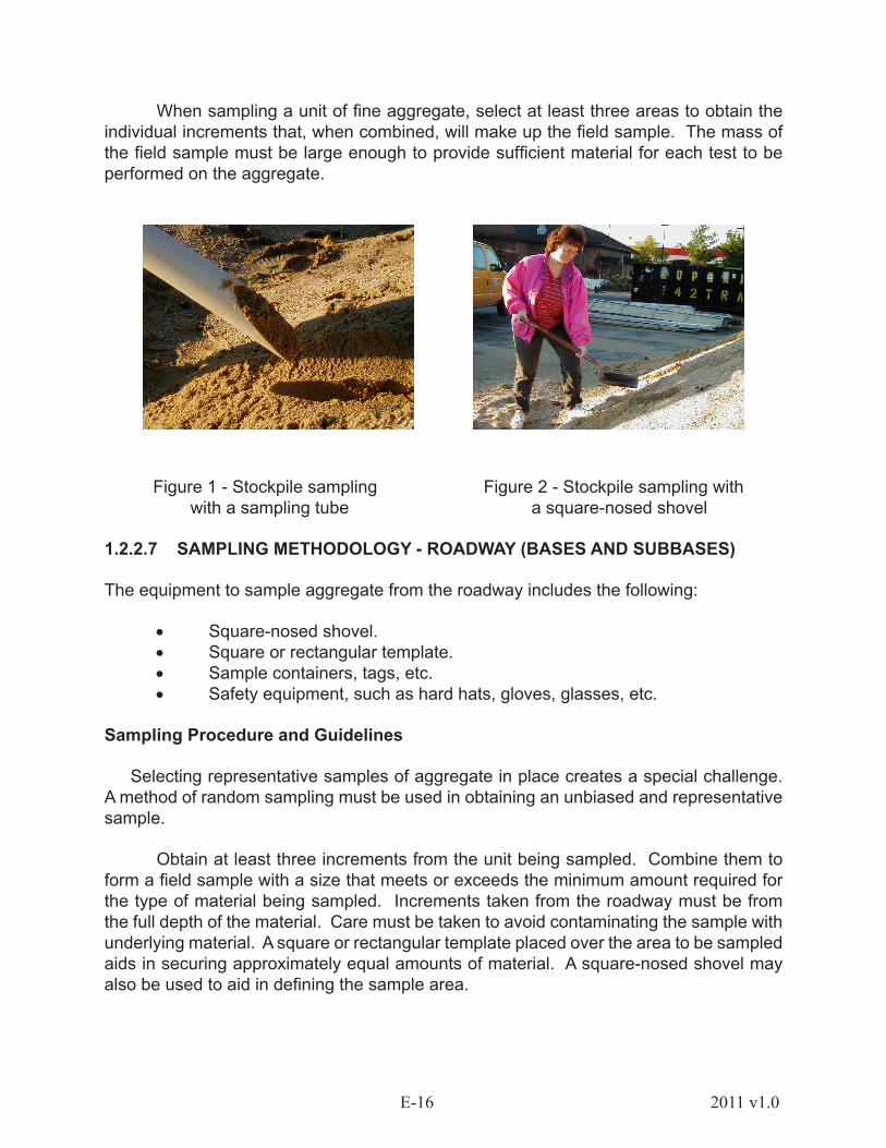
When sampling a unit of fine aggregate, select at least three areas to obtain the individual increments that, when combined, will make up the field sample. The mass of the field sample must be large enough to provide sufficient material for each test to be performed on the aggregate.
Figure 1 - Stockpile sampling Figure 2 - Stockpile sampling with with a sampling tube a square-nosed shovel
1.2.2.7 SAMPLING METHODOLOGY - ROADWAY (BASES AND SUBBASES)
The equipment to sample aggregate from the roadway includes the following:
• Square-nosed shovel. • Square or rectangular template. • Sample containers, tags, etc. • Safety equipment, such as hard hats, gloves, glasses, etc.
Sampling Procedure and Guidelines
Selecting representative samples of aggregate in place creates a special challenge. A method of random sampling must be used in obtaining an unbiased and representative sample.
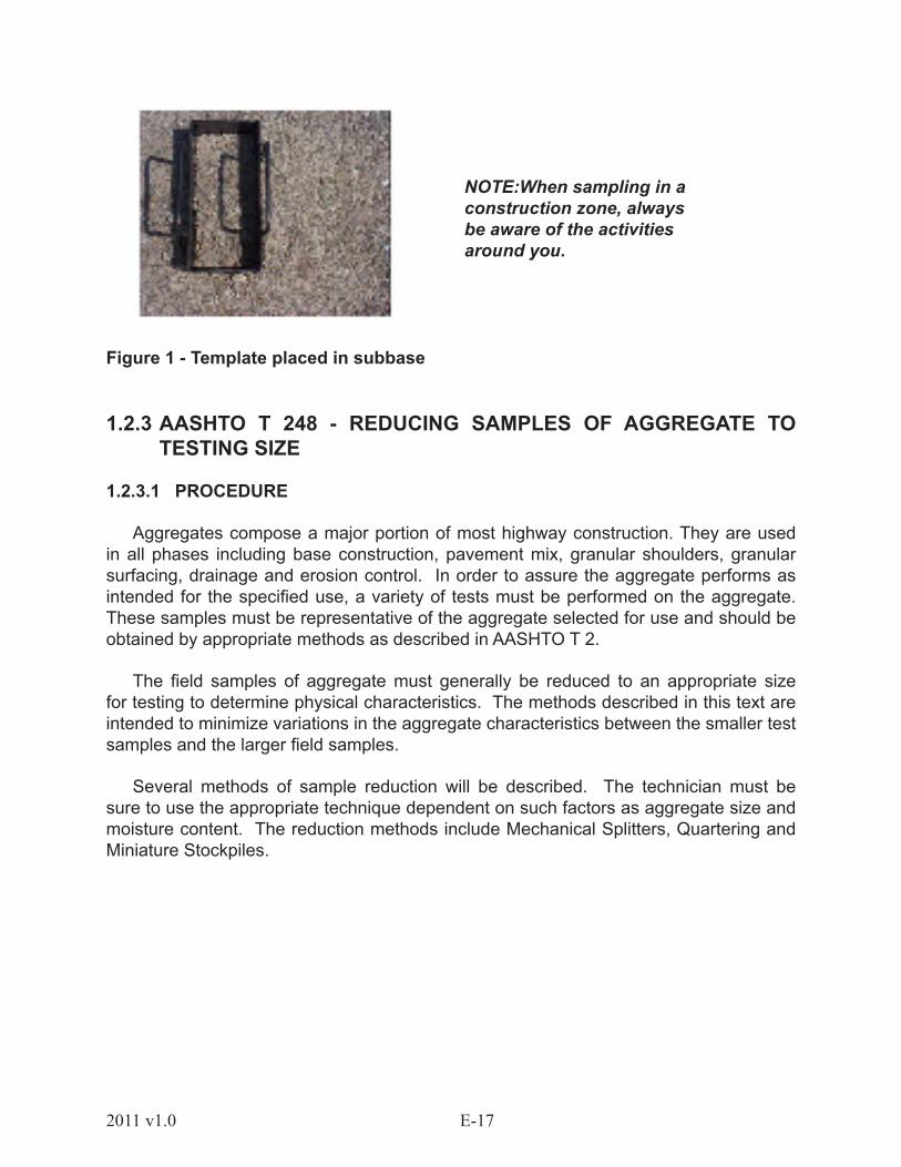
Obtain at least three increments from the unit being sampled. Combine them to form a field sample with a size that meets or exceeds the minimum amount required for the type of material being sampled. Increments taken from the roadway must be from the full depth of the material. Care must be taken to avoid contaminating the sample with underlying material. A square or rectangular template placed over the area to be sampled aids in securing approximately equal amounts of material. A square-nosed shovel may also be used to aid in defining the sample area.
E-172011 v1.0
Figure 1 - Template placed in subbase
1.2.3 AASHTO T 248 - REDUCING SAMPLES OF AGGREGATE TO TESTING SIZE
1.2.3.1 PROCEDURE
Aggregates compose a major portion of most highway construction. They are used in all phases including base construction, pavement mix, granular shoulders, granular surfacing, drainage and erosion control. In order to assure the aggregate performs as intended for the specified use, a variety of tests must be performed on the aggregate. These samples must be representative of the aggregate selected for use and should be obtained by appropriate methods as described in AASHTO T 2.
The field samples of aggregate must generally be reduced to an appropriate size for testing to determine physical characteristics. The methods described in this text are intended to minimize variations in the aggregate characteristics between the smaller test samples and the larger field samples.
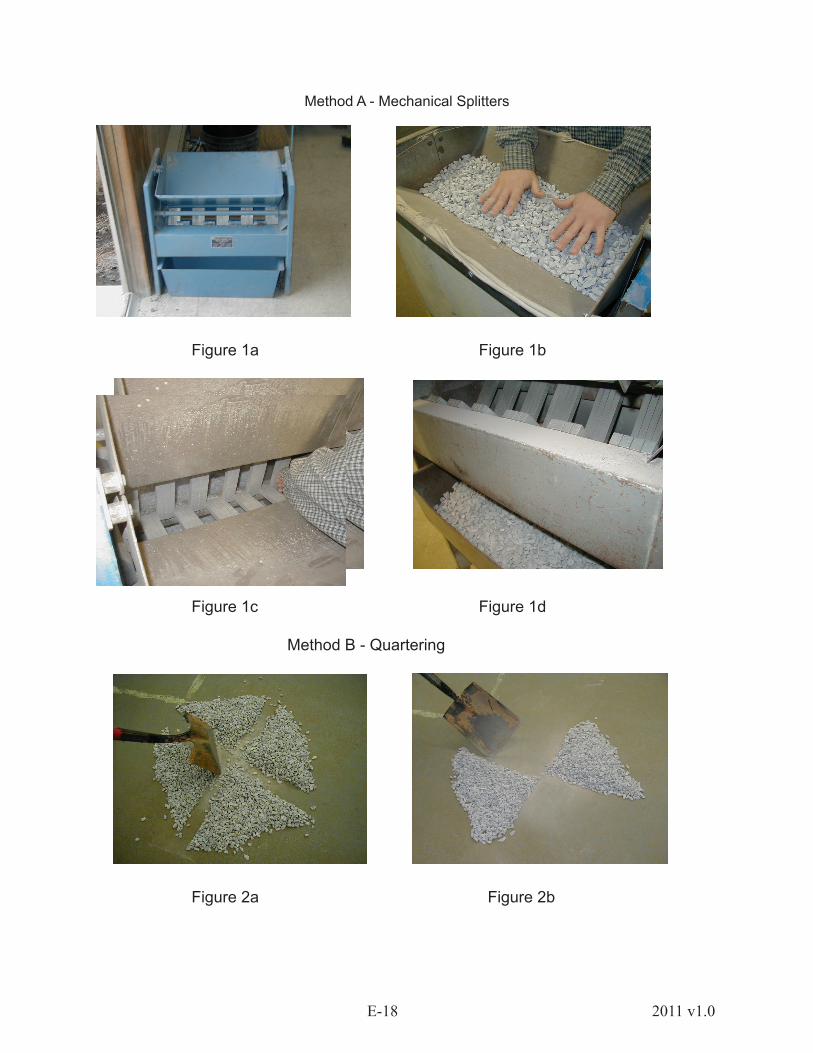
Several methods of sample reduction will be described. The technician must be sure to use the appropriate technique dependent on such factors as aggregate size and moisture content. The reduction methods include Mechanical Splitters, Quartering and Miniature Stockpiles.
NOTE:When sampling in a construction zone, always be aware of the activities around you.
E-18 2011 v1.0
Method A - Mechanical Splitters
Figure 1a Figure 1b
Figure 1c Figure 1d
Method B - Quartering
Figure 2a Figure 2b
E-192011 v1.0
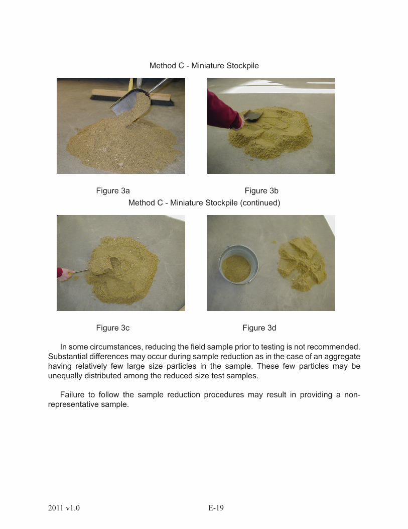
Method C - Miniature Stockpile
Figure 3a Figure 3bMethod C - Miniature Stockpile (continued)
Figure 3c Figure 3d
In some circumstances, reducing the field sample prior to testing is not recommended. Substantial differences may occur during sample reduction as in the case of an aggregate having relatively few large size particles in the sample. These few particles may be unequally distributed among the reduced size test samples.
Failure to follow the sample reduction procedures may result in providing a non-representative sample.
E-20 2011 v1.0
1.2.3.2 SUMMARY OF SAMPLE REDUCTION
Aggregates sampled in the field need to be reduced to appropriate sample size for testing. It is, therefore, necessary to reduce field samples while minimizing the chance of variability during handling. In some instances, a few particles on a given sieve might affect a gradation significantly enough to alter an interpretation of the field sample and subsequently the entire lot’s compliance with specifications.
The appropriate field sample reduction method depends chiefly on the nominal maximum size of the aggregate, the amount of free moisture in the sample, and the equipment available.
The following chart may be used in selecting the appropriate reduction method for the aggregate to be tested.
Mechanical Splitter Quartering Miniature Stockpile*
Fine Aggregates - Fine Aggregates - Fine Aggregates - Air Dry Free Moisture on Free Moisture on
the Particle Surface Particle Surface
Coarse Aggregates Coarse Aggregates Not Appropriate forCoarse Aggregates
Combined Aggregates Combined Aggregates Not Appropriate forwith Free Moisture on Combined the Particle Surface Aggregates
* Note: Obtain a sample for each test by selecting at least five increments of material at random locations from the miniature stockpile.

E-212011 v1.0
1.2.3.3 COMMON SAMPLE REDUCTION ERRORS
• Failure to obtain a field sample using the methods and guidelines given in AASHTO T 2.
• Failure to select proper method for sample reduction based on aggregate moisture content.
• When using a mechanical splitter, failure to uniformly distribute the field sample from edge to edge while placing it in the hopper or pan prior to pouring it through the chutes.
Figure 4 - AASHTO Standards
Figure 5 - Sample spread uniformly in splitter

E-22 2011 v1.0
Figure 6 - Sample not spread uniformly in splitter
• Failure to control the rate at which the materials are poured through the chutes of a mechanical splitter such that the material is free flowing into the receptacle pans below. This includes using a hopper or straight-edged pan that, per AASHTO T 248, has a width equal to or slightly less than the overall width of the chute assembly.
Figure 7 - Proper sized pan to fit splitter
E-232011 v1.0
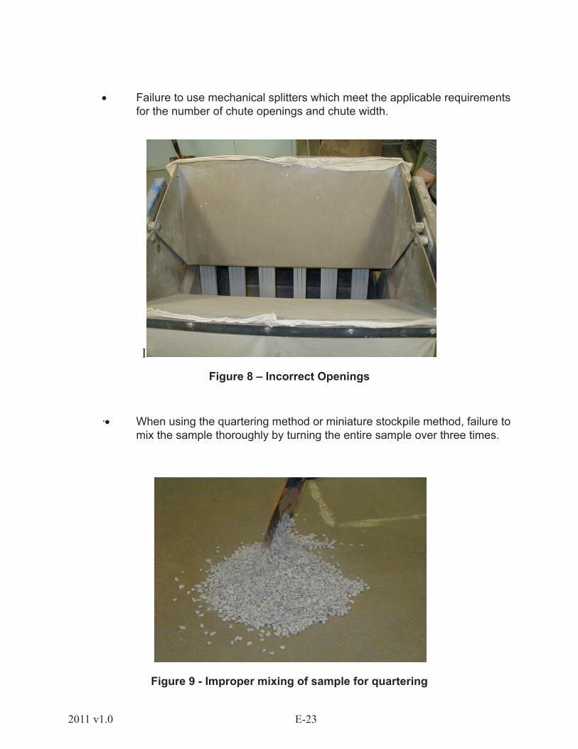
• Failure to use mechanical splitters which meet the applicable requirements for the number of chute openings and chute width.
I
Figure 8 – Incorrect Openings
·• When using the quartering method or miniature stockpile method, failure to mix the sample thoroughly by turning the entire sample over three times.
Figure 9 - Improper mixing of sample for quartering
E-24 2011 v1.0
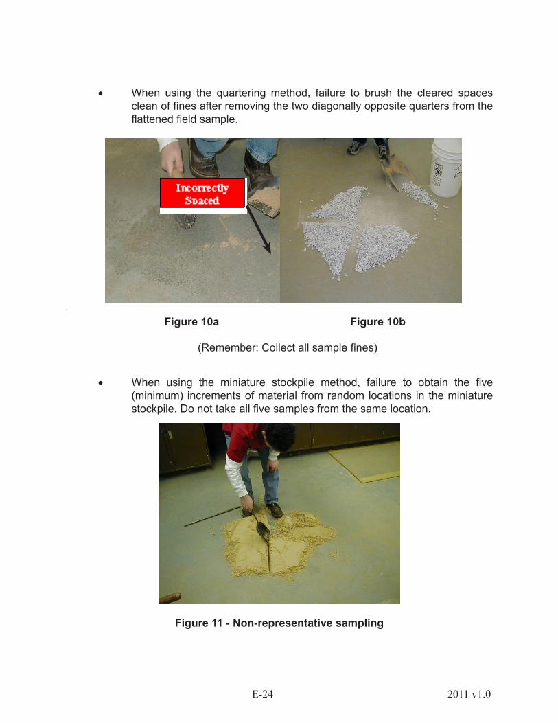
• When using the quartering method, failure to brush the cleared spaces clean of fines after removing the two diagonally opposite quarters from the flattened field sample.
·
Figure 10a Figure 10b
(Remember: Collect all sample fines)
• When using the miniature stockpile method, failure to obtain the five (minimum) increments of material from random locations in the miniature stockpile. Do not take all five samples from the same location.
Figure 11 - Non-representative sampling

E-252011 v1.0
1.2.4 AASHTO T 11 - MATERIALS FINER THAN 75 mm (No. 200) SIEVE IN MINERAL AGGREGATES BY WASHING
1.2.4.1 SCOPE
Aggregates compose a major portion of most highway construction. They are used in all phases including base construction, pavement mix, granular shoulders, granular surfacing, drainage and erosion control. In order to insure the aggregate performs as intended for the specific use, a variety of tests must be performed on the aggregate. One such test is determining materials finer than 75 µm (No. 200) sieve in mineral aggregates by washing. Fine materials, such as clay particles or water-soluble particles removed by washing, can cling to larger particles and do not dislodge readily. In this test, the fine particles are washed through the 75 µm (No. 200) sieve to give an accurate determination of the minus 75 µm (No. 200) portion in the sample. Determination of the minus 75 µm (No. 200) material is utilized to compare material performance with gradation specifications and indirectly to gauge such properties as plasticity and permeability. This knowledge helps in determining whether a material is potentially frost susceptible and whether permeability (measurement of material capacity to allow water flow through it) will be affected.
1.2.4.2 SUMMARY OF TEST
A measured amount of material is placed in a wash container and covered with water (containing a wetting agent, if required) and agitated to suspend the finer sized particles. The rinse water is then poured through a 75 µm (No. 200) sieve. After thorough washing, transfer the remaining sample to a pan, dry and weigh. The percentage passing through the 75 µm (No. 200) sieve is then calculated.
Figure 1 - Fines suspended in the water are washed over a 2.36 mm(No. 8) or 1.18 mm (No. 16) and a 75 µm (No. 200) sieve.

E-26 2011 v1.0
1.2.4.3 EQUIPMENT
• Balance - general purpose (AASHTO M 231).• Sieves - a 2.36 mm (No. 8) or 1.18 mm (No. 16) and a 75 µm (No. 200).• Container - of sufficient size to properly agitate the sample without losing
material.• Oven - capable of maintaining a temperature of 110 ± 5 °C (230 ± 9 °F).• Wetting agent (if required).
1.2.4.4 SAMPLE PREPARATION
Dry sample to a constant mass in an oven regulated at 110 ± 5 °C (230 ± 9 °F). Determine the proper dried sample mass from the following
table (Table 1.1) based on the maximum nominal size of the sample to be tested.
E-272011 v1.0
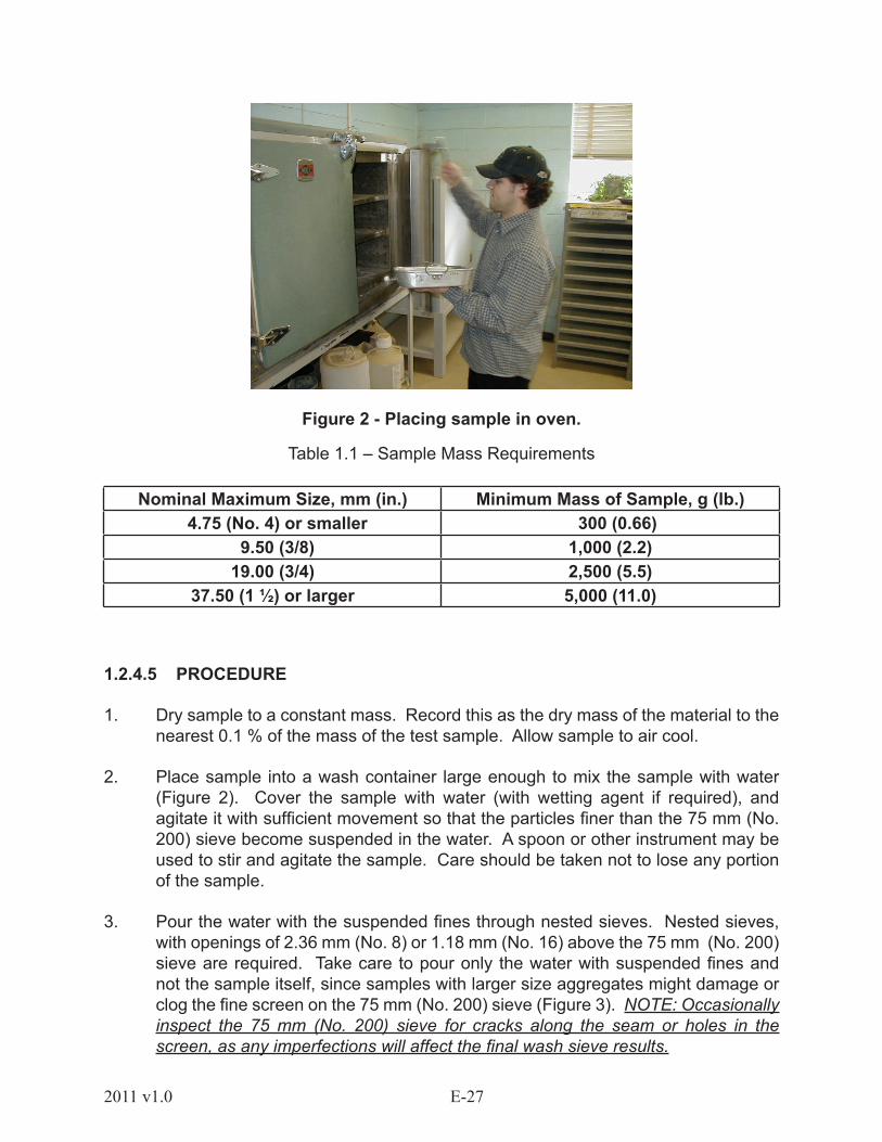
Figure 2 - Placing sample in oven.
Table 1.1 – Sample Mass Requirements
Nominal Maximum Size, mm (in.) Minimum Mass of Sample, g (lb.) 4.75 (No. 4) or smaller 300 (0.66)
9.50 (3/8) 1,000 (2.2)19.00 (3/4) 2,500 (5.5)
37.50 (1 ½) or larger 5,000 (11.0)
1.2.4.5 PROCEDURE
1. Dry sample to a constant mass. Record this as the dry mass of the material to the nearest 0.1 % of the mass of the test sample. Allow sample to air cool.
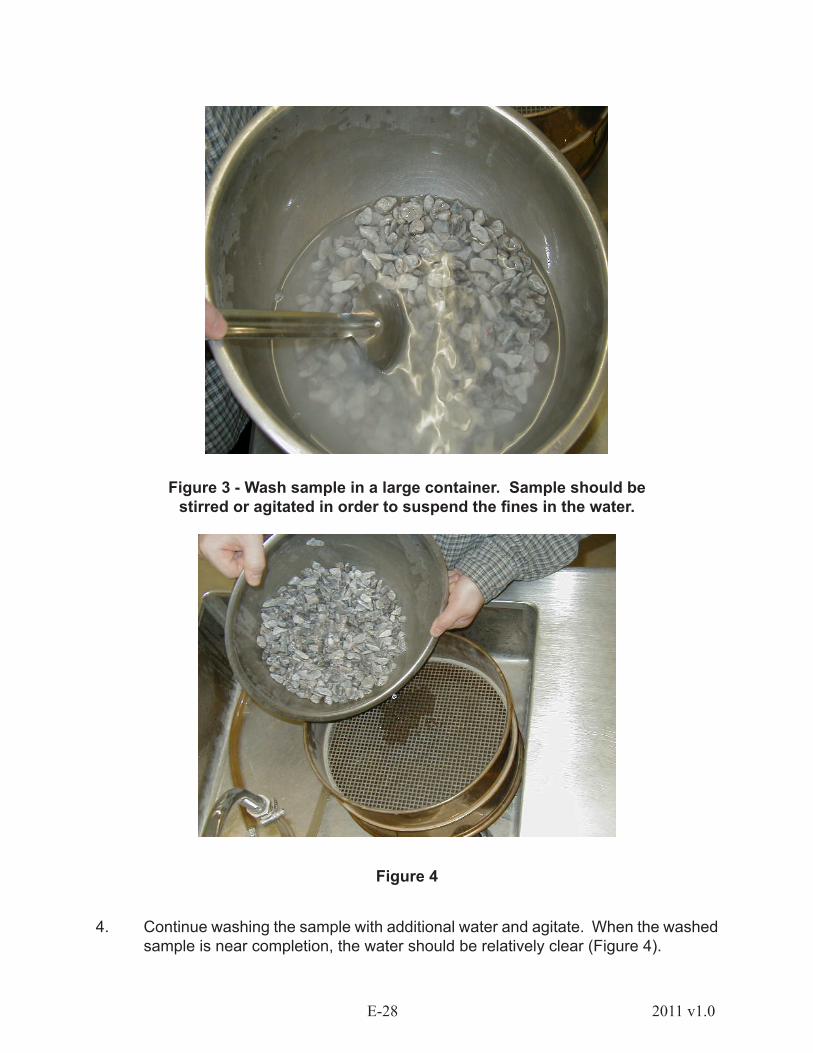
2. Place sample into a wash container large enough to mix the sample with water (Figure 2). Cover the sample with water (with wetting agent if required), and agitate it with sufficient movement so that the particles finer than the 75 mm (No. 200) sieve become suspended in the water. A spoon or other instrument may be used to stir and agitate the sample. Care should be taken not to lose any portion of the sample.
3. Pour the water with the suspended fines through nested sieves. Nested sieves, with openings of 2.36 mm (No. 8) or 1.18 mm (No. 16) above the 75 mm (No. 200) sieve are required. Take care to pour only the water with suspended fines and not the sample itself, since samples with larger size aggregates might damage or clog the fine screen on the 75 mm (No. 200) sieve (Figure 3). NOTE: Occasionally inspect the 75 mm (No. 200) sieve for cracks along the seam or holes in the screen, as any imperfections will affect the final wash sieve results.
E-28 2011 v1.0
Figure 3 - Wash sample in a large container. Sample should be stirred or agitated in order to suspend the fines in the water.
Figure 4
4. Continue washing the sample with additional water and agitate. When the washed sample is near completion, the water should be relatively clear (Figure 4).
E-292011 v1.0
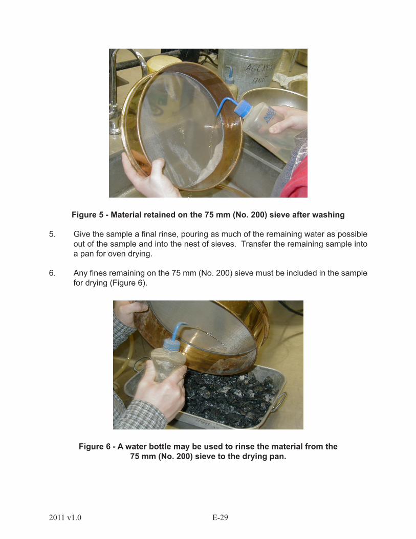
Figure 5 - Material retained on the 75 mm (No. 200) sieve after washing
5. Give the sample a final rinse, pouring as much of the remaining water as possible out of the sample and into the nest of sieves. Transfer the remaining sample into a pan for oven drying.
6. Any fines remaining on the 75 mm (No. 200) sieve must be included in the sample for drying (Figure 6).
Figure 6 - A water bottle may be used to rinse the material from the 75 mm (No. 200) sieve to the drying pan.
E-30 2011 v1.0
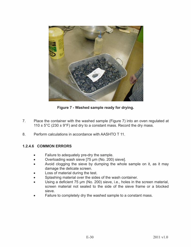
Figure 7 - Washed sample ready for drying.
7. Place the container with the washed sample (Figure 7) into an oven regulated at 110 ± 5°C (230 ± 9°F) and dry to a constant mass. Record the dry mass.
8. Perform calculations in accordance with AASHTO T 11.
1.2.4.6 COMMON ERRORS
• Failure to adequately pre-dry the sample.• Overloading wash sieve [75 µm (No. 200) sieve].• Avoid clogging the sieve by dumping the whole sample on it, as it may
damage the delicate screen.• Loss of material during the test.• Splashing material over the sides of the wash container.• Using a deficient 75 µm (No. 200) sieve, i.e., holes in the screen material,
screen material not sealed to the side of the sieve frame or a blocked sieve.
• Failure to completely dry the washed sample to a constant mass.

E-312011 v1.0
1.2.5 AASHTO T 27 - SIEVE ANALYSIS OF FINE AND COARSE AGGREGATE
1.2.5.1 Scope
The sieve analysis, commonly known as the gradation test, is a basic and essential test. The sieve analysis determines the gradation (the distribution of aggregate particles, by size, within a given sample) in order to verify compliance with design, production control requirements and specifications. This data can be used to calculate relationships between various aggregates and to predict trends during production by plotting gradation curves graphically. Used in conjunction with other tests, the sieve analysis is a quality control and quality acceptance tool.
NOTE: Accurate determination of material passing the 75 µm (No. 200) sieve cannot be made with this test alone. It is recommended to use this test in conjunction with AASHTO T 11 in order to determine the amount of material finer than the 75 µm (No. 200) sieve.
1.2.5.2 Summary of Test
A measured amount (mass) of material is placed on the top of a set of nested sieves, and shaken by mechanical means for a specified period of time. The amount of material is determined by the nominal maximum size of the aggregate. The top sieve has the largest screen openings and the screen opening size decreases with each successive sieve. After shaking the material through the nested sieves, the material retained on each of the sieves is weighed using one of two methods. The method used will depend on the individual state’s requirements.
In the cumulative method (percent retained), material from the largest sieve is placed in a tared container and weighed. The contents of the next smaller sieve are then added to the tared container and the accumulated weight is recorded. Repeat this procedure until the material from all the sieves and the pan, if required, has been weighed and recorded.
In the non-cumulative method (percent passing), the contents of each sieve and the pan, if required, are individually weighed and recorded. Do not discard material until the entire test is completed. The amount retained on and passing each sieve is then calculated.
1.2.5.3 EQUIPMENT
• Balance - general purpose class (AASHTO M 231).• Sieves - mounted on suitable frames, shall conform to AASHTO M 92.• Mechanical sieve shaker - if used, must provide a vertical or lateral and
vertical motion to the sieve. Sieve shaker must provide sieving thoroughness within a reasonable time.
• Oven - capable of maintaining 110 ± 5 °C (230 ± 9 °F).
E-32 2011 v1.0
1.2.5.4 SAMPLE PREPARATION
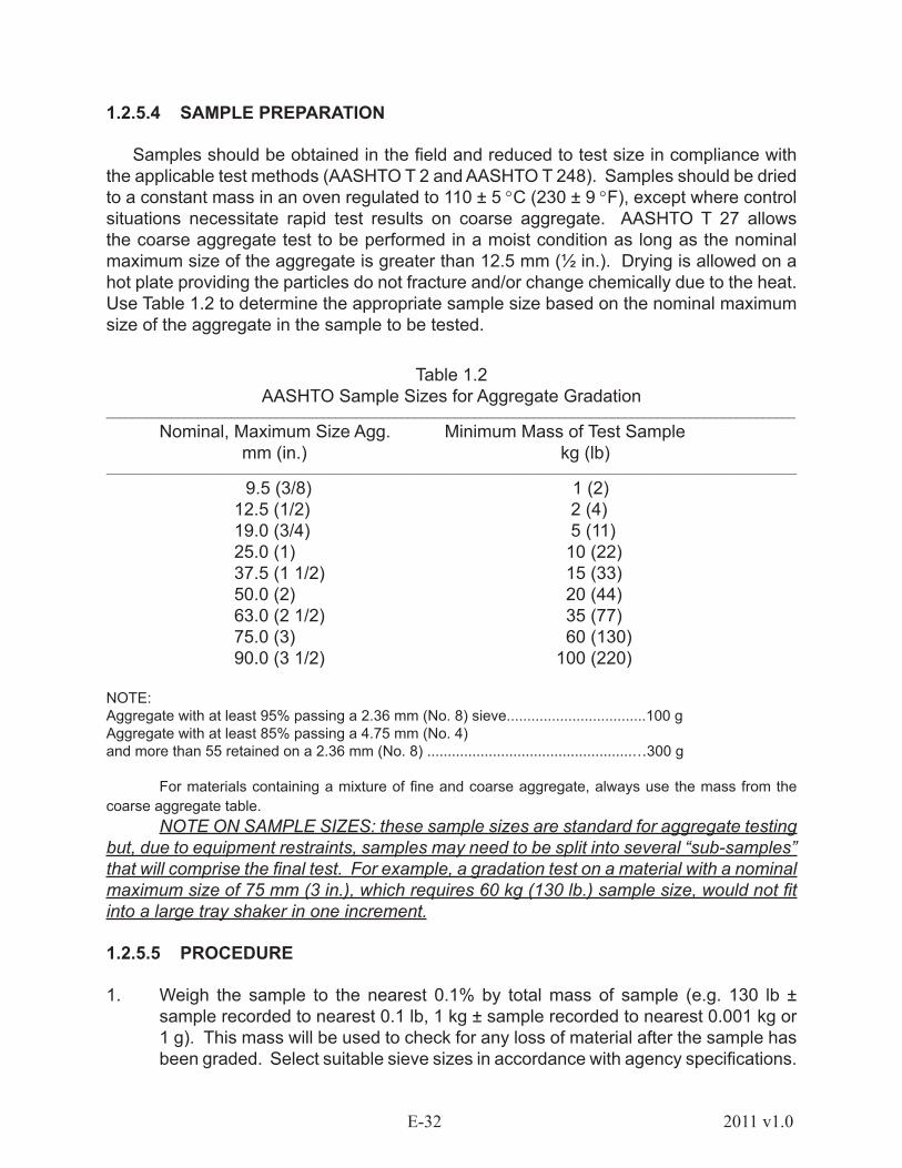
Samples should be obtained in the field and reduced to test size in compliance with the applicable test methods (AASHTO T 2 and AASHTO T 248). Samples should be dried to a constant mass in an oven regulated to 110 ± 5 °C (230 ± 9 °F), except where control situations necessitate rapid test results on coarse aggregate. AASHTO T 27 allows the coarse aggregate test to be performed in a moist condition as long as the nominal maximum size of the aggregate is greater than 12.5 mm (½ in.). Drying is allowed on a hot plate providing the particles do not fracture and/or change chemically due to the heat. Use Table 1.2 to determine the appropriate sample size based on the nominal maximum size of the aggregate in the sample to be tested.
Table 1.2AASHTO Sample Sizes for Aggregate Gradation
_________________________________________________________________________________________________________
Nominal, Maximum Size Agg. Minimum Mass of Test Sample mm (in.) kg (lb)
_____________________________________________________________________________________________________________________
9.5 (3/8) 1 (2) 12.5 (1/2) 2 (4) 19.0 (3/4) 5 (11) 25.0 (1) 10 (22) 37.5 (1 1/2) 15 (33) 50.0 (2) 20 (44) 63.0 (2 1/2) 35 (77) 75.0 (3) 60 (130) 90.0 (3 1/2) 100 (220)
NOTE:Aggregate with at least 95% passing a 2.36 mm (No. 8) sieve..................................100 gAggregate with at least 85% passing a 4.75 mm (No. 4) and more than 55 retained on a 2.36 mm (No. 8) ..................................................…300 g
For materials containing a mixture of fine and coarse aggregate, always use the mass from the coarse aggregate table.
NOTE ON SAMPLE SIZES: these sample sizes are standard for aggregate testing but, due to equipment restraints, samples may need to be split into several “sub-samples” that will comprise the final test. For example, a gradation test on a material with a nominal maximum size of 75 mm (3 in.), which requires 60 kg (130 lb.) sample size, would not fit into a large tray shaker in one increment.
1.2.5.5 PROCEDURE
1. Weigh the sample to the nearest 0.1% by total mass of sample (e.g. 130 lb ± sample recorded to nearest 0.1 lb, 1 kg ± sample recorded to nearest 0.001 kg or 1 g). This mass will be used to check for any loss of material after the sample has been graded. Select suitable sieve sizes in accordance with agency specifications.

E-332011 v1.0
Standard sieve sizes recognized by AASHTO may differ from region to region. Always consult agency specifications in order to determine the proper sieve sizes.
Figure 1 - Large Tray Shaker
Figure 1a - Large Tray Shaker
2. Nest the sieves in order of decreasing size from top to bottom and begin shaking the sample for a sufficient amount of time. For coarse aggregate, the large tray shaker is most commonly used (Figure 1 & 1a). This device provides a clamping mechanism, which holds the sieve in place during shaking. Shakers of this make usually need to be run a minimum of 7 minutes to adequately grade the sample.
For fine aggregate, round 203.2 mm (8 in.) sieves are commonly used (Figure 2). These sieves are self-nesting and supported in a shaking mechanism at the top and bottom by a variety of clamping and/or holding mechanisms. Small shakers of this type usually require shaking times of 10 minutes to adequately grade the fine aggregate sample.

E-34 2011 v1.0
NOTE: Every effort should be made to avoid overloading the sieves. AASHTO defines overloading large sieves as mass retained in excess of 2.5 times the sieve opening in mm, as expressed in kg/m2. For a 19.0 mm (3/4 in.) sieve, this means an excess of 47.5 kg/m2 (9.7 lb/ft2) is considered an overloaded sieve. For fine aggregate, no mass shall be in excess of 7 kg/m2. This amounts to 200 g on any small round 203.2 mm (8 in.) sieve below the 4.75 mm (No. 4) sieve.
Figure 2 - Small Sieve Shaker
3. For coarse aggregates, after the material has been sieved, remove each tray, weigh and record the mass to the nearest 0.1% of total mass. Be sure to remove any aggregate trapped within the sieve openings by gently working from either or both sides with your hands until the aggregate is freed. Banging the sieve on the floor or hitting it with hammer will damage the sieve. The final total of the masses retained on each sieve should be within 0.3% of the original mass of the sample prior to grading. Particles larger than 75 mm (3 in.) should be hand-sieved. When passing large stones through sieves, do not force the aggregate through the sieve openings.
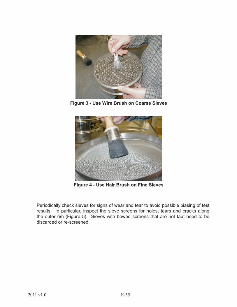
4. For fine aggregates, weigh the material retained on each sieve size to the nearest 0.1% by total mass (e.g. 300 g ± sample recorded to nearest 0.1 g). Insure that all material entrapped within the openings of the sieve is cleaned out and included in the mass retained. This can be done using brushes to gently dislodge entrapped materials. The 203.2 mm (8 in.) round sieves need to be handled with special care due to the delicate nature of their screen mesh. As a rule, use coarse wire brushes to clean the 203.2-mm (8-in.) sieves down through the 600 µm (No. 30) sieve (Figure 3). Any sieve with an opening size smaller then the 600 µm (No. 30) should be cleaned with a soft cloth hairbrush (Figure 4). The final total of the masses retained on each sieve should be within 0.3% of the original mass of the sample prior to grading.
E-352011 v1.0
Figure 3 - Use Wire Brush on Coarse Sieves
Figure 4 - Use Hair Brush on Fine Sieves
Periodically check sieves for signs of wear and tear to avoid possible biasing of test results. In particular, inspect the sieve screens for holes, tears and cracks along the outer rim (Figure 5). Sieves with bowed screens that are not taut need to be discarded or re-screened.
E-36 2011 v1.0
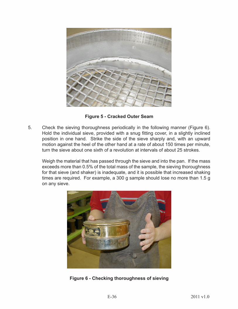
Figure 5 - Cracked Outer Seam
5. Check the sieving thoroughness periodically in the following manner (Figure 6). Hold the individual sieve, provided with a snug fitting cover, in a slightly inclined position in one hand. Strike the side of the sieve sharply and, with an upward motion against the heel of the other hand at a rate of about 150 times per minute, turn the sieve about one sixth of a revolution at intervals of about 25 strokes.
Weigh the material that has passed through the sieve and into the pan. If the mass exceeds more than 0.5% of the total mass of the sample, the sieving thoroughness for that sieve (and shaker) is inadequate, and it is possible that increased shaking times are required. For example, a 300 g sample should lose no more than 1.5 g on any sieve.
Figure 6 - Checking thoroughness of sieving
E-372011 v1.0
1.2.5.6 CALCULATION
Two methods, cumulative or non-cumulative, are typically used to calculate a gradation in order to determine the percentage of material either retained on or passing each sieve. Both are shown here to illustrate the calculation. The method used will depend on the individual agency’s requirements.
Cumulative Method
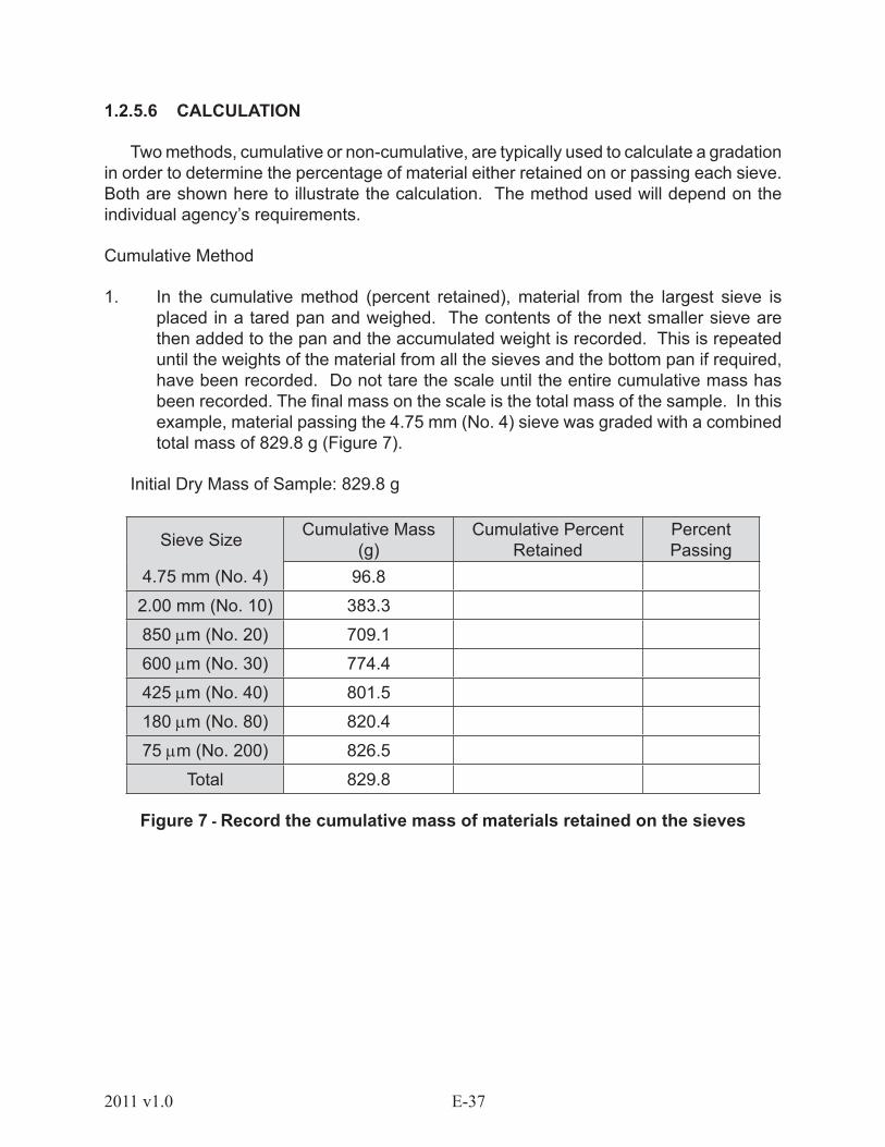
1. In the cumulative method (percent retained), material from the largest sieve is placed in a tared pan and weighed. The contents of the next smaller sieve are then added to the pan and the accumulated weight is recorded. This is repeated until the weights of the material from all the sieves and the bottom pan if required, have been recorded. Do not tare the scale until the entire cumulative mass has been recorded. The final mass on the scale is the total mass of the sample. In this example, material passing the 4.75 mm (No. 4) sieve was graded with a combined total mass of 829.8 g (Figure 7).
Initial Dry Mass of Sample: 829.8 g
Sieve Size Cumulative Mass (g)
Cumulative Percent Retained
Percent Passing
4.75 mm (No. 4) 96.8
2.00 mm (No. 10) 383.3
850 µm (No. 20) 709.1
600 µm (No. 30) 774.4
425 µm (No. 40) 801.5
180 µm (No. 80) 820.4
75 µm (No. 200) 826.5
Total 829.8
Figure 7 - Record the cumulative mass of materials retained on the sieves

E-38 2011 v1.0
2. Cumulative Percent Retained is calculated by dividing the Cumulative Mass retained on each sieve by the total mass of the sample and multiplying by 100 (Figure 8). In this example the 4.75 mm (No. 4) sieve had 96.8 g retained. This mass divided by the total mass (829.8) and multiplied by 100 is 11.7 %. This process is repeated for the remainder of the sieves.
Sieve Size Cumulative Mass (g)
Cumulative Percent Retained
Percent Passing
4.75 mm (No. 4) 96.8 11.7
2.00 mm (No. 10) 383.3
850 µm (No. 20) 709.1
600 µm (No. 30) 774.4
425 µm (No. 40) 801.5
180 µm (No. 80) 820.4
75 µm (No. 200) 826.5
Total 829.8
Figure 8 - 96.8 grams retained on the 4.75 mm sieve, divided by the total mass (829.8g) and multiplied by 100, is 11.7%
3. Percentage passing is determined for each sieve by taking the cumulative percent retained on that sieve and subtracting it from 100%. In this example, 100 - 11.7 = 88.3 % passing the 4.75 mm (No. 4) sieve (Figure 9). This process is repeated for the remainder of the sieves.
Sieve Size Cumulative Mass (g)
Cumulative Percent Retained
Percent Passing
4.75 mm (No. 4) 96.8 11.7 88.3
2.00 mm (No. 10) 383.3 46.2
850 µm (No. 20) 709.1 85.5
600 µm (No. 30) 774.4 93.3
425 µm (No. 40) 801.5 96.6
180 µm (No. 80) 820.4 98.9
75 µm (No. 200) 826.5 99.6
Total 829.8 100.0
Figure 9: 100 – 11.7 = 88.3% Passing
E-392011 v1.0
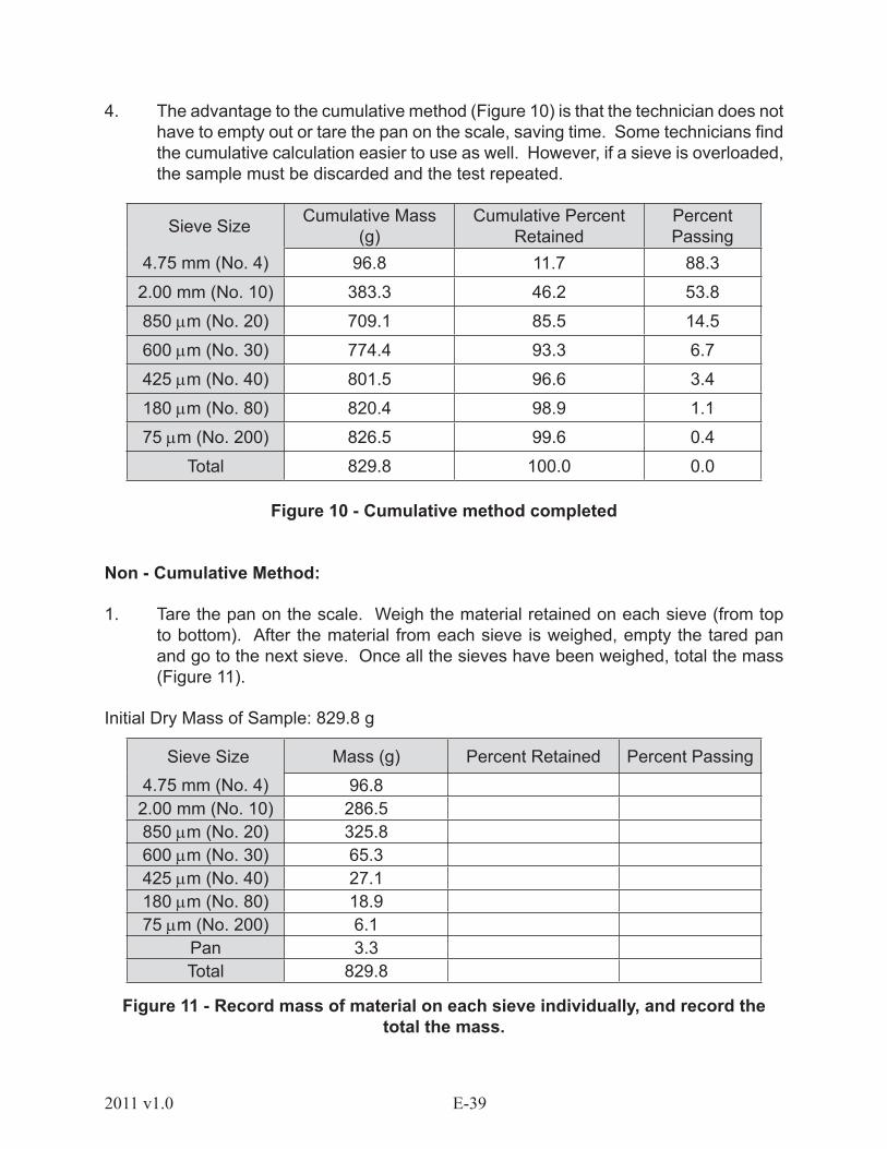
4. The advantage to the cumulative method (Figure 10) is that the technician does not have to empty out or tare the pan on the scale, saving time. Some technicians find the cumulative calculation easier to use as well. However, if a sieve is overloaded, the sample must be discarded and the test repeated.
Sieve Size Cumulative Mass (g)
Cumulative Percent Retained
Percent Passing
4.75 mm (No. 4) 96.8 11.7 88.3
2.00 mm (No. 10) 383.3 46.2 53.8
850 µm (No. 20) 709.1 85.5 14.5
600 µm (No. 30) 774.4 93.3 6.7
425 µm (No. 40) 801.5 96.6 3.4
180 µm (No. 80) 820.4 98.9 1.1
75 µm (No. 200) 826.5 99.6 0.4
Total 829.8 100.0 0.0
Figure 10 - Cumulative method completed
Non - Cumulative Method:
1. Tare the pan on the scale. Weigh the material retained on each sieve (from top to bottom). After the material from each sieve is weighed, empty the tared pan and go to the next sieve. Once all the sieves have been weighed, total the mass (Figure 11).
Initial Dry Mass of Sample: 829.8 g
Sieve Size Mass (g) Percent Retained Percent Passing4.75 mm (No. 4) 96.8
2.00 mm (No. 10) 286.5850 µm (No. 20) 325.8600 µm (No. 30) 65.3425 µm (No. 40) 27.1180 µm (No. 80) 18.975 µm (No. 200) 6.1
Pan 3.3Total 829.8
Figure 11 - Record mass of material on each sieve individually, and record the total the mass.

E-40 2011 v1.0
2. Calculate the percent retained by dividing the mass retained on each sieve by the total and multiply by 100 (Figure 12). Example: for the 4.75 mm (No. 4) sieve, (96.8 ÷ 829.8) x 100 = 11.7 %. Calculate the percentage retained for each sieve using the above method.
Sieve Size Mass (g) Percent Retained
Percent Passing
4.75 mm (No. 4) 96.8 11.72.00 mm (No. 10) 286.5 34.5850 µm (No. 20) 325.8 39.3600 µm (No. 30) 65.3425 µm (No. 40) 27.1180 µm (No. 80) 18.975 µm (No. 200) 6.1
Pan 3.3Total 829.8
Figure 12 - Calculate percent of material retained on each sieve individually by dividing the mass of material retained on that sieve by the initial dry mass of the
material and multiply by 100.
3. Once you have calculated the “percent retained” column, add the percentages to make sure they equal 100. In this example, they total 100.1 %. In cases where odd percentages occur (either 99.9 or 100.1), increase or decrease the largest percentage in the gradation by 0.1%. In this example, 39.3 was decreased to 39.2 in order to sum up to an even 100. (Figure 13).
Sieve Size Mass (g) Percent Retained Percent Passing
4.75 mm (No. 4) 96.8 11.72.00 mm (No. 10) 286.5 34.5850 µm (No. 20) 325.8 39.3 ← change to 39.2600 µm (No. 30) 65.3 7.9425 µm (No. 40) 27.1 3.3180 µm (No. 80) 18.9 2.375 µm (No. 200) 6.1 0.7
Pan 3.3 0.4Total 829.8 100.1 ← change to
Figure 13 - When the percent retained does not add up to 100, change the percentage by 0.1 on the sieve which retained the most material.
E-412011 v1.0
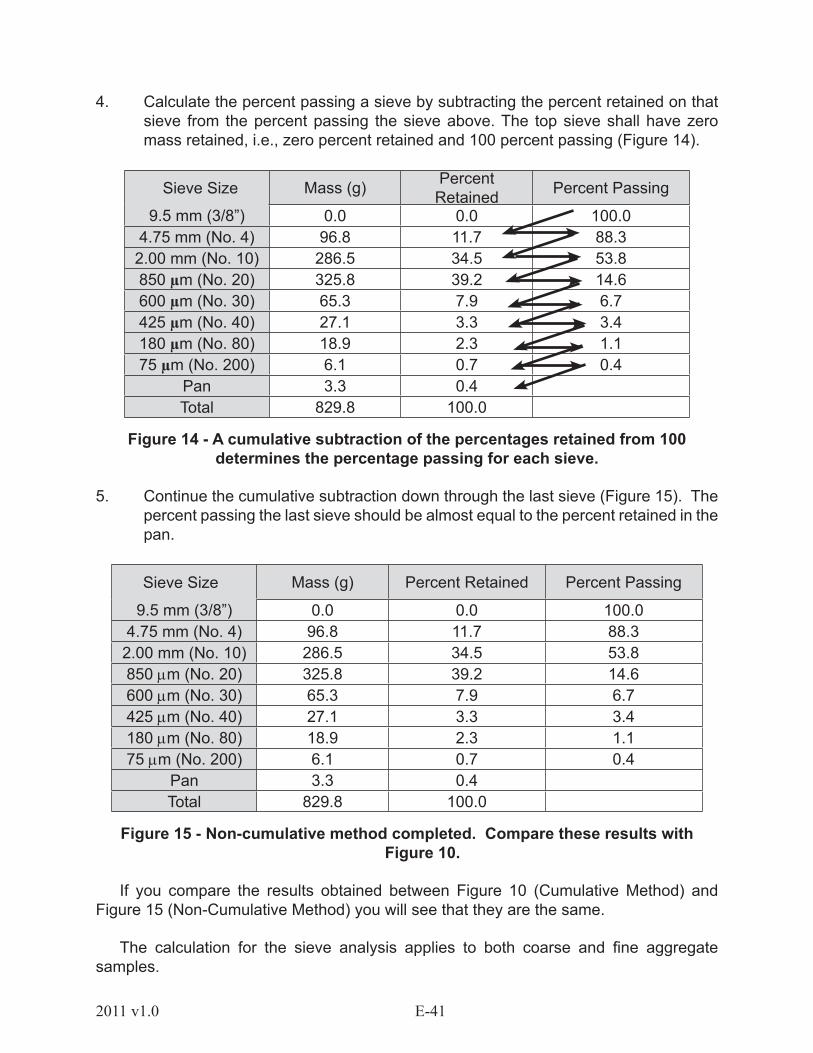
4. Calculate the percent passing a sieve by subtracting the percent retained on that sieve from the percent passing the sieve above. The top sieve shall have zero mass retained, i.e., zero percent retained and 100 percent passing (Figure 14).
Sieve Size Mass (g) Percent Retained Percent Passing
9.5 mm (3/8”) 0.0 0.0 100.04.75 mm (No. 4) 96.8 11.7 88.3
2.00 mm (No. 10) 286.5 34.5 53.8850 µm (No. 20) 325.8 39.2 14.6600 µm (No. 30) 65.3 7.9 6.7425 µm (No. 40) 27.1 3.3 3.4180 µm (No. 80) 18.9 2.3 1.175 µm (No. 200) 6.1 0.7 0.4
Pan 3.3 0.4Total 829.8 100.0
Figure 14 - A cumulative subtraction of the percentages retained from 100 determines the percentage passing for each sieve.
5. Continue the cumulative subtraction down through the last sieve (Figure 15). The percent passing the last sieve should be almost equal to the percent retained in the pan.
Sieve Size Mass (g) Percent Retained Percent Passing
9.5 mm (3/8”) 0.0 0.0 100.04.75 mm (No. 4) 96.8 11.7 88.3
2.00 mm (No. 10) 286.5 34.5 53.8850 µm (No. 20) 325.8 39.2 14.6600 µm (No. 30) 65.3 7.9 6.7425 µm (No. 40) 27.1 3.3 3.4180 µm (No. 80) 18.9 2.3 1.175 µm (No. 200) 6.1 0.7 0.4
Pan 3.3 0.4Total 829.8 100.0
Figure 15 - Non-cumulative method completed. Compare these results with Figure 10.
If you compare the results obtained between Figure 10 (Cumulative Method) and Figure 15 (Non-Cumulative Method) you will see that they are the same.
The calculation for the sieve analysis applies to both coarse and fine aggregate samples.

E-42 2011 v1.0
TABLE 1Maximum Allowable Quantity of Material Retained on a Sieve, (kg)
Nominal Dimensions of SieveA
Sieve Opening Size, mm
203.2-mmdiaB
(8 in)
254-mmdiaB
(10 in)
304.8-mmdiaB
(12 in)
350 by 350 mm
(14 x 14 in)
372 by 580 mm(16 x 24 in)
Sieving Area, m2
0.0285 0.0457 0.0670 0.1225 0.2158125 C C C C 67.4100 C C C 30.6 53.990 C C 15.1 27.6 48.575 C 8.6 12.6 23.0 40.563 C 7.2 10.6 19.3 34.050 3.6 5.7 8.4 15.3 27.0
37.5 2.7 4.3 6.3 11.5 20.225.0 1.8 2.9 4.2 7.7 13.519.0 1.4 2.2 3.2 5.8 10.212.5 0.89 1.4 2.1 3.8 6.79.5 0.67 1.1 1.6 2.9 5.14.75 0.33 0.54 0.80 1.5 2.6
Notes:A Sieve frame dimensions in inch units: 8.0-in. diameter; 10.0-in. diameter; 12.0-in. diameter; 13.8 by 13.8 in. (14 by
14 in. nominal); 14.6 by 22.8 in. (16 by 24 in nominal).B The sieve area for round sieve frames is based on an effective diameter 12.7 mm (1/2 in.) less than the nominal frame
diameter, because Specification M92 permits the sealer between the sieve cloth and the frame to extend 6.35 mm (1/4 in.) over the sieve cloth. Thus the effective sieving diameter for a 203.2-mm (8.0-in.) diameter sieve frame is 190.5 mm (7.5 in.). Some manufactures of sieves may not infringe on the sieve cloth by the full 6.35 mm (1/4 in.).
C Sieves indicated have less than five full openings and should not be used for sieve testing except as provided in 8.6.
1.2.5.7 COMMON TEST ERRORS
• Insufficient sample size
• Overloading the sieves
• Loss of material during the test
• Insufficient cleaning of the sieves
• Using defective (e.g., worn, cracked, etc.) sieves
• Lack of thorough sieving
• Not pre-drying the sample

E-432011 v1.0
1.2.6 - AASHTO T 19 - BULK DENSITY (“UNIT WEIGHT”) AND VOIDS IN AGGREGATE
1.2.6.1 - SCOPE
This test procedure is used to determine the unit weight of oven dried aggregates in a compacted or loose condition using a calibrated measure. After the unit weight has been determined, the void content (the space between the aggregate particles) can be calculated. The main reason for determining the void content is to establish accurate material proportions for designing concrete mixes.
1.2.6.2 - SUMMARY OF TESTING
This test method is often used to determine unit weight values, which are necessary for many methods of selecting proportions for concrete mixtures.
1.2.6.3 - EQUIPMENT
• Balance (Scale) - the balance will have sufficient capacity to determine the mass of the sample and measure to the nearest 50 grams (0.1 lb).
• Tamping Rod - a round, straight steel rod 16 mm (5/8 in.) in diameter and a minimum 600 mm (24 in.) in length, having one end rounded to a hemispherical tip of the same diameter as the rod.
• Measure - a cylindrical metal measure with handles on the sides. The capacity of the measure is determined by the nominal size of the aggregate to be tested. See Table 1.4. The top rim will be smooth and true. See Section 1.2.6.4 for calibration of measure.
• Glass Plate - a piece of plate glass that is a minimum of 6 mm (1/4 in.) thick and at least 25 mm (1 in.) larger than the diameter of the calibrated measure.
• Miscellaneous - square-nosed shovel, flat metal dustpan or scoop, rake, counter brush and broom.

E-44 2011 v1.0
Figure 1 - 1/3 cubic foot measure.
Table 1.4 - CAPACITY OF MEASURESNominal Maximum Size
of AggregateCapacity of the Measure
mm in. L (m3) ft3
12.5 ½ 2.8 (0.0028) 1/1025.0 1 9.3 (0.0093) 1/337.5 1 ½ 14 (0.014) ½75 3 28 (0.028) 1112 4 ½ 70 (0.070) 2 ½125 6 100 (0.100) 3 ½
Figure 2 - 1/10 cubic foot measure.
1.2.6.4 CALIBRATION OF MEASURE
1. Determine the mass of the measure to the nearest 50 grams (0.1 lb).
2. Determine the mass of the measure with plate glass to the nearest 50 grams (0.1 lb).
E-452011 v1.0
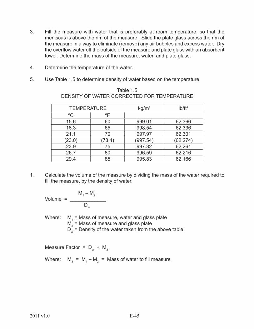
3. Fill the measure with water that is preferably at room temperature, so that the meniscus is above the rim of the measure. Slide the plate glass across the rim of the measure in a way to eliminate (remove) any air bubbles and excess water. Dry the overflow water off the outside of the measure and plate glass with an absorbent towel. Determine the mass of the measure, water, and plate glass.
4. Determine the temperature of the water.
5. Use Table 1.5 to determine density of water based on the temperature.
Table 1.5DENSITY OF WATER CORRECTED FOR TEMPERATURE
TEMPERATURE kg/m3 lb/ft3
ºC ºF15.6 60 999.01 62.36618.3 65 998.54 62.33621.1 70 997.97 62.301
(23.0) (73.4) (997.54) (62.274)23.9 75 997.32 62.26126.7 80 996.59 62.21629.4 85 995.83 62.166
1. Calculate the volume of the measure by dividing the mass of the water required to fill the measure, by the density of water.
M1 – M2 Volume = _____________ Dw
Where: M1 = Mass of measure, water and glass plate M2 = Mass of measure and glass plate Dw = Density of the water taken from the above table
Measure Factor = Dw ÷ M3
Where: M3 = M1 – M2 = Mass of water to fill measure
E-46 2011 v1.0
EXAMPLE CALIBRATION CALCULATION:
Given: Measure = 0.014 m³ (1/2 ft³) Temperature = 29.4°C (85°F)
Mass of measure, water, and plate glass = M1 = 23800 gramsMass of measure and plate glass = M2 = 9350 gramsWater Mass = M3 = 14450 grams
Volume = ((14450 g ÷ 1000 g/kg) ÷ 995.83 kg/m³) = 0.015 m³Measure Factor = (995.83 kg/m³ ÷ 14.45 kg) = 68.916/ m³
1.2.6.5 TEST SAMPLE:
• Representative materials should be sampled and reduced to the appropriate sample size by AASHTO T 2 & T 248 test methods.
• Sample size should be 125 – 200% more than the capacity of your calibrated measure.
• The test sample shall be dried to a constant mass in an oven at 110º ± 5ºC (230° ± 9°F).
1.2.6.6 TESTING PROCEDURE – RODDING/JIGGING:
• Test procedure and size of the measure are normally determined by the largest nominal size of aggregate to be tested.
Rodding – Nominal 37.5 mm (1½ in.) or less.
Jigging – Nominal greater than 37.5 mm (1½ in.) up to 125 mm (5 in.).
• Thoroughly mix the sample before filling the measure.
• Fill the calibrated measure in thirds. After each third, rod or jig as explained below.
Rodding – rod each layer with the tamping rod 25 strokes distributed equally over the entire layer surface. On the first layer do not allow the rod to forcibly strike the bottom of the measure. On the second and third layers use only enough force for the rod to reach but not penetrate the previous layer.
Jigging – jig each layer 50 times, 25 times each side by raising the opposite sides alternately about 50 mm (2 in.) and letting the measure drop in such a manner to sharply hit the base.

E-472011 v1.0
The final layer should overflow the top of the measure before and after the rodding/jigging procedure. Level the surface of the aggregate with a straight edge, by hand or rolling a rod in a manner such that slight projections of aggregate above the rim are balanced with the voids below the rim.
• Determine the mass of the aggregate and measure.
• Follow this procedure a minimum of two times on a given sample as long as the results are within tolerances. The tolerance between two consecutive tests for one operator is 40 kg/m³ (2.5 lb/ft3.).
1.2.6.7 TESTING PROCEDURE – SHOVELING (Loose Method):
• The size of the measure is normally determined by the largest nominal size of aggregate to be tested.
• Place the prepared sample into a miniature stockpile on a level, clean, smooth, dry surface. Thoroughly mix the material by re-shoveling.
• Fill your calibrated measure to overflowing by discharging the aggregate from a height not to exceed 50 mm (2 in.) above the rim of the measure.
• Level the surface of the aggregate with a straight edge, by hand, or rolling a rod in a manner such that slight projections of aggregate above the rim are balanced with the voids below the rim.
• Determine the mass of the aggregate and measure.
• Follow this procedure a minimum of two times on a given sample as long as the results are within tolerances. The tolerance between two consecutive tests for one operator is 40 kg/m³ (2.5 lb/ft3.).
1.2.6.8 COMMON TESTING ERRORS:
• Failure to thoroughly mix sample
• Inconsistent leveling of top layer
• Sample not oven dried
• Rodding too hard or penetrating underlying layers
• Not placing material in equal layers

E-48 2011 v1.0
1.2.7 MARTCP SA 1.3 - PERCENT MOISTURE CONTENT PROCEDURE
1.2.7.1 SCOPE
The moisture content of a material influences its ability or inability to be excavated, consolidated, moved, screened, weighed, dried out or reabsorbed. Moisture content calculations used for soils and aggregates are by convention defined as the mass of water lost through drying divided by the dry mass of the material. The moisture content is used to calculate a variety of properties such as dry density, plasticity, permeability etc.
1.2.7.2 MATERIALS AND EQUIPMENT
• Electric hot plate or gas burner.
• Scale or balance as required by state specifications.
• Metal container, such as a large frying pan or equivalent.
• Pointing trowel or large spoon.
1.2.7.3 TEST PROCEDURE
Select a representative quantity of material based on the following table, or state specifications:
TABLE 1.6Aggregate Moisture Content Test Sample Sizes
Nominal Maximum Size, mm (in.) Minimum Sample Mass, kg (lbs.) 4.75 (No. 4) 0.5 (1.1) 9.5 (3/8) 1.5 (3.3) 12.5 (1/2) 2.0 (4.4) 19.0 (3/4) 3.0 (6.6) 25.0 (1) 4.0 (8.8) 37.5 (1 ½) 6.0 (13.2) 50.0 (2) 8.0 (17.6) All Soil Moisture Content Sample Sizes must be a minimum of 500 grams
Weigh a clean, dry container.
Place the sample in the container and weigh.Place the container on the stove or hot plate and, while drying, mix the sample continuously to expedite drying and prevent burning of the aggregate. Always use a low flame or heat setting.
E-492011 v1.0
When the sample looks dry, remove it from the stove, cool, and weigh. Put sample back on the stove, continue drying for another two to three minutes, cool, and re-weigh. When a constant mass has been achieved, the sample is dry. Record the mass of the sample and container
Note: Care must be taken to avoid losing any portion of the sample.
1.2.7.4 COMMON TESTING ERRORS
• Spillage or loss of sample – loss of sample voids test results
• Insufficient sample quantity (size) to yield accurate results
• Overheating sample during drying process causing a loss of organic material or partial oxidation of other sample constituents.
1.2.7.5 CALCULATIONS
Moisture content of aggregate: (Wwet – Wdry) w, % = x 100 (Wdry – Wcon)
Where:
w, % = percent moistureWwet = mass of wet aggregate and containerWdry = mass of dry aggregate and containerWcon = mass of container
1.2.7.6 REPORT
Report the moisture content according to required state specifications.

E-50 2011 v1.0
1.2.10 AASHTO T 89 – DETERMINING THE LIQUID LIMIT OF SOILS
1.2.10.1 SCOPE
ATTERBERG LIMITS
Earth materials form the foundation of all transportation facilities. The final structure will be no more durable than the foundation upon which it rests. In order to ensure that these materials function as intended, it is necessary for all designers to have basic information about them. Designers use this information to decide if naturally occurring materials can support the anticipated traffic load or if they will require modification (e.g., stabilization, lime treatment or treatment with fly ash) to enable it to perform as a highway foundation.
Several laboratory tests are performed that provide information to the designer about materials which may be used as the foundation for a roadway. The Atterberg Limits are among these tests. In 1911, a Swedish scientist, A. Atterberg, developed some simple tests for determining the moisture contents of a soil at which the soil moves from a solid to a semisolid, to a plastic and to a liquid state. The moisture contents generated by these tests are used to quantitatively describe the effect of varying water contents on the fines of a material. As the moisture content of a material increases, the properties of the fine fraction (passing No. 40 sieve) material will eventually change from a solid to a liquid state.
The Atterberg Limits are:
• Shrinkage Limit - The water content at which material changes from a solid to a semisolid state.
• Plastic Limit - The water content at which material changes from a semisolid to a plastic state.
• Liquid Limit - The water content at which material changes from a plastic to a liquid state.
E-512011 v1.0
After exceeding the optimum moisture necessary to achieve compaction, material becomes less stable as moisture increases (moving from left to right on the diagram). A material whose moisture content is greater than the Liquid Limit is soft and unstable.
The Liquid Limit and Plastic Limit are used to determine the Plasticity Index. The Plasticity Index is not an Atterberg Limit. It is a number that is derived by subtracting the Plastic Limit of a soil from its Liquid Limit.
PI = LL – PL
The Plasticity Index of a material is a measure of the cohesive properties of the material. It is the numerical range of moisture contents in which a cohesive material is plastic. Many state highway departments specify Plasticity Index values for materials to be used in construction.
The Shrinkage Limit is not used in determining the Plasticity Index and is not used as widely in highway construction specifications. The point at which a material moves from a solid to a semisolid state is not as significant as the Liquid Limit in determining the material’s suitability for highway construction.
When samples are received by the laboratory, they may be identified by a field classification (e.g., plastic, non-plastic, hard, friable, etc.) based on moisture content and consistency at the time of sampling. This field classification provides an indication of a material’s suitability for use in construction. However, a more accurate determination of the material’s behavior at varying moisture contents is needed to ensure that materials will perform as necessary in a pavement structure. It is critical that the tests for Atterberg Limits be properly performed. These values are used to classify a soil in terms of its suitability for a specific use.
LIQUID LIMIT
The Liquid Limit is the moisture content at which a specific material moves from a plastic to a liquid state. Generally, soils with high Liquid Limits are clays with poor engineering properties. Soils with a high clay content are cohesive (stick together), plastic (moldable), compressible (able to be consolidated), and nearly impervious (impenetrable by water). Their compressibility leads to rutting under load and can even cause the soil structure to shear under its own weight, causing embankment failure.
Clay soils may become unstable when they absorb water. Materials with high clay content also are subject to swelling and shrinking during normal changes in moisture content. The swell/shrinkage cycle may also lead to foundation failure. Swelling and shrinkage are directly related to shear failure. When clay soils are disturbed by construction, they lose their shear strength and are subject to failure.
The Liquid Limit is used in conjunction with the Plasticity Index to identify materials with a clay content high enough to keep them from performing well in construction.

E-52 2011 v1.0
1.2.10.2 SUMMARY OF TEST
There are two methods (A and B) approved by AASHTO to determine the Liquid Limit of a material. The basic test steps are the same for both methods. The differences are in the initial quantity of water added to the test specimen, the number of specimens which are tested, the mandatory blow count range and the calculations involved.
If using Method B or using tap water results in questionable test values, Method A with special parameters must be used to establish the validity of the values.
The Liquid Limit test is performed on material passing the 0.425 mm (No. 40) sieve. First mix the test specimen with water, alternately stirring and chopping the sample. Continue adding water until it is at a uniform stiff consistency. You will need some experience to recognize when you have reached the correct consistency for each material. Place some of the test specimen in the cup of the Liquid Limit device. Use the spatula to press and spread the material to the correct thickness. Be careful not to trap air bubbles in the test specimen when spreading it in the cup.
Use the grooving tool to divide the test specimen in the cup through its center. Move the tool from back to front only one time for each stroke. Be sure to form a clean, sharp groove. Use no more than six strokes of the grooving tool to divide the specimen. Only the last stroke of the grooving tool is to scrape the bottom of the cup.
If you are using a manual device, turn the crank approximately 2 revolutions per second. If you are using an automatic device, turn on the machine. Count the number of blows of the machine or use the automatic counter if the device is equipped with one. When the groove closes to 13 mm (0.5 inch), stop the device. Record the number of blows required to close the groove.
For Method A, repeat these steps two more times until you have blow counts within the following ranges:
Trial No. of Blows1 25 to 352 20 to 303 15 to 25
There must be a difference of at least ten blows between the high and low blow count for the test result to be valid.
For Method B, the blow count must be within the range of 22-28, and only one specimen is used for testing. A second specimen is run to verify the blow count.

E-532011 v1.0
From each test specimen, remove a slice of material approximately the width of the spatula, extending from edge to edge of the specimen at right angles to the groove. Be sure to take that portion of the groove in which the material flowed together. Determine the moisture content of each specimen in accordance with AASHTO T 265. The Liquid Limit is a mathematical calculation based on the moisture content and number of blows at closure.
TYPICAL TEST RESULTS
Liquid Limits vary widely. It is possible to obtain values as high as 80 - 100. Values between 40 - 60 are typical of clay soils. For silty soils, typical values are between 25 - 50. The Liquid Limit test will not produce a result for granular and non-plastic materials.
1.2.10.3 EQUIPMENT
Before beginning any procedure, you must first assemble all the equipment you will need to perform the test. To determine the Liquid Limit of the fines portion of a material, you will need the following.
• Dish - An unglazed porcelain container (or similar mixing container) approximately 115 mm (4½ in.) in diameter.
• Spatula - A flat blade or pill knife approximately 75 - 100 mm (3 - 4 in.) long and approximately 20 mm (3/4 in.) wide
• Liquid Limit Device - Manual or mechanically operated conforming to AASHTO T 89
• Grooving Tool - Conforming to AASHTO T 89
Gage - Conforming to AASHTO T 89 or a metal bar 10.0 ±0.2 mm (0.394 ±0.008 inches) thick and approximately 50 mm (2 inches) long
• Containers - Enough containers with close-fitting lids to provide one container for each moisture content determination. Containers must be resistant to corrosion and not subject to change in mass with repeated heating and cooling.
• Balance - Conforming to AASHTO M 231, Class C
• Oven - A thermostatically controlled oven capable of maintaining a temperature of 110 ± 5º C (230 ± 9º F)
• Distilled or Demineralized Water (or tap water, if approved)
• Semi-logarithmic Graph Paper
• Stable, flat surface - Support for testing apparatus to ensure uniform impact and base stability of device

E-54 2011 v1.0
Figure 1 - Testing Equipment
1.1.10.4 EQUIPMENT CALIBRATION
1. Inspect the Liquid Limit device and grooving tool.
• Check that the pin connecting the cup is not worn to the point of allowing side play.
• Check that the screws connecting the cup to the hanger arm are tight. Loose screws allow excessive cup movement and cause erratic blow counts.
• Check that the points of contact on the cup and base are not excessively worn. Excessive wear is defined as exceeding approximately 13 mm (0.5 inches) in diameter.
• Check the lip of the cup for excessive wear. Excessive wear is defined as any point on the cup rim which is worn to approximately one half the original thickness.
• Check the center of the cup to ensure that use has not worn a groove into the cup. (Replace any cup in which there is a pronounced groove.)
E-552011 v1.0
• Check the cam follower. It should not be worn beyond the tolerance allowed nor allow any rocking on the height gage when checking height of drop.
• Check the adjusting screws. All screws in the adjusting assembly must be tight with no noticeable movement.
• Check the dimensions of the grooving tool to ensure that the tool conforms to the tolerances of AASHTO T 89.
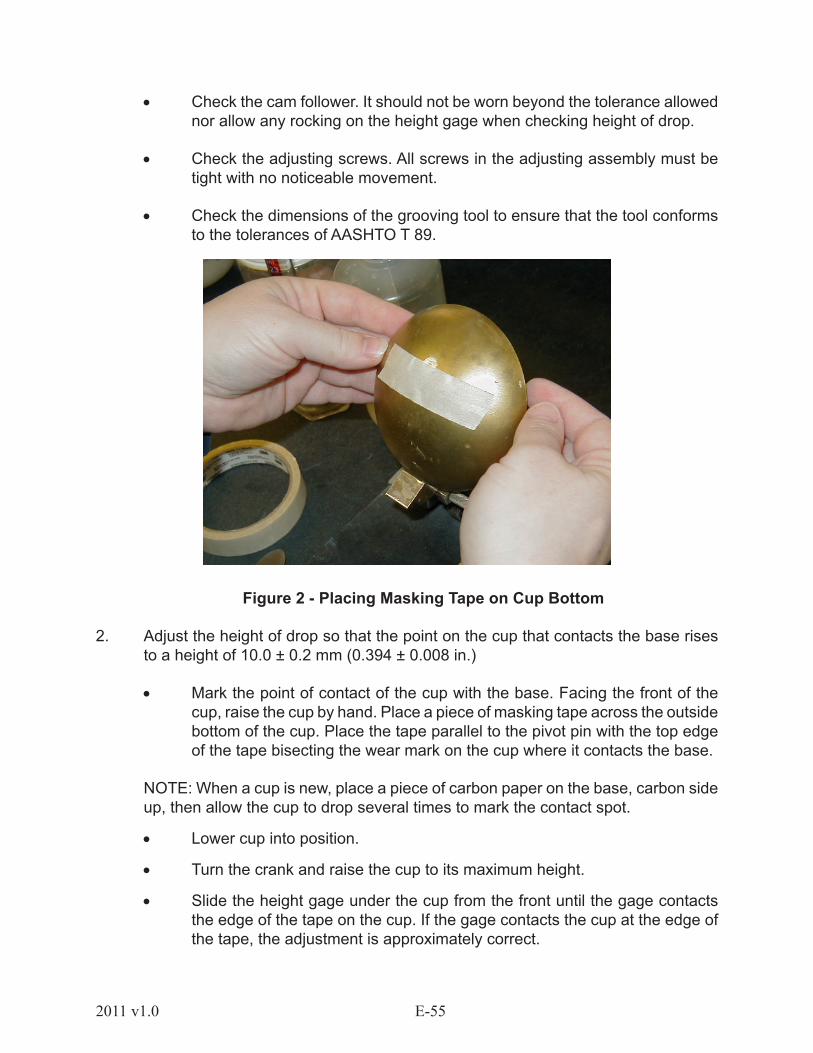
Figure 2 - Placing Masking Tape on Cup Bottom
2. Adjust the height of drop so that the point on the cup that contacts the base rises to a height of 10.0 ± 0.2 mm (0.394 ± 0.008 in.)
• Mark the point of contact of the cup with the base. Facing the front of the cup, raise the cup by hand. Place a piece of masking tape across the outside bottom of the cup. Place the tape parallel to the pivot pin with the top edge of the tape bisecting the wear mark on the cup where it contacts the base.
NOTE: When a cup is new, place a piece of carbon paper on the base, carbon side up, then allow the cup to drop several times to mark the contact spot.
• Lower cup into position.
• Turn the crank and raise the cup to its maximum height.
• Slide the height gage under the cup from the front until the gage contacts the edge of the tape on the cup. If the gage contacts the cup at the edge of the tape, the adjustment is approximately correct.

E-56 2011 v1.0
NOTE: You may remove the cup from the device to apply the tape. If this was done, place cup on device and install pivot pin.
Figure 3 - Checking Contacts with Height Gage
• If the gage does not contact the cup at the edge of the tape, use the adjusting screw device to adjust the height until the cup is in proper position. Lock the adjustment assembly into proper position.
• Leave the gage in position. Check the adjustment by turning the handle at two revolutions per second. If the cup does not move and a ringing or clicking sound is heard, the adjustment is correct. If no sound is heard or if the cup rises from the gage, re-adjust the height of the drop.
• Remove the tape as soon as the check procedure is completed.
E-572011 v1.0
1.2.10.5 SAMPLE PREPARATION
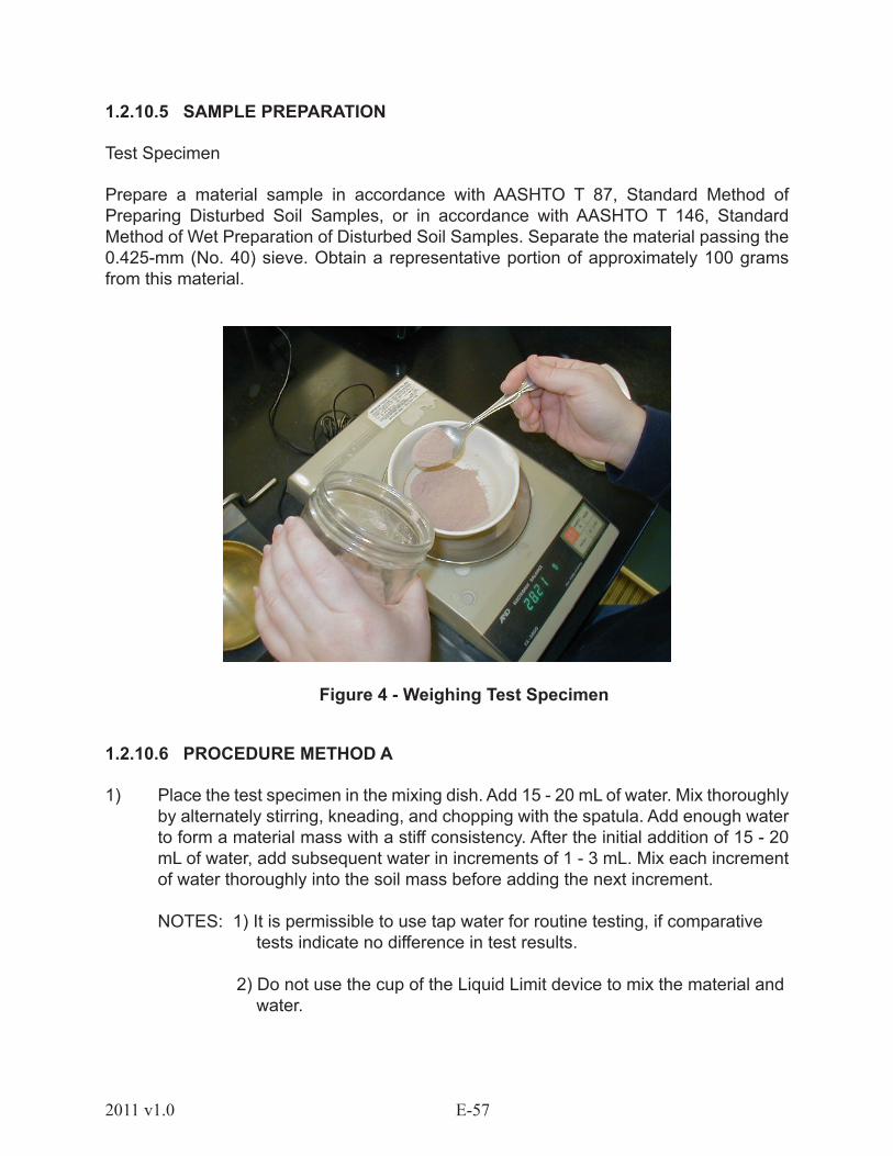
Test Specimen
Prepare a material sample in accordance with AASHTO T 87, Standard Method of Preparing Disturbed Soil Samples, or in accordance with AASHTO T 146, Standard Method of Wet Preparation of Disturbed Soil Samples. Separate the material passing the 0.425-mm (No. 40) sieve. Obtain a representative portion of approximately 100 grams from this material.
Figure 4 - Weighing Test Specimen
1.2.10.6 PROCEDURE METHOD A
1) Place the test specimen in the mixing dish. Add 15 - 20 mL of water. Mix thoroughly by alternately stirring, kneading, and chopping with the spatula. Add enough water to form a material mass with a stiff consistency. After the initial addition of 15 - 20 mL of water, add subsequent water in increments of 1 - 3 mL. Mix each increment of water thoroughly into the soil mass before adding the next increment.
NOTES: 1) It is permissible to use tap water for routine testing, if comparative tests indicate no difference in test results.
2) Do not use the cup of the Liquid Limit device to mix the material and water.

E-58 2011 v1.0
Figure 5a - Adding water Figure 5b - Blending water and soil
2) If too much water is added, either discard the test specimen or continue to mix and knead the material until natural evaporation lowers the moisture content to the proper consistency.
3) Do not add additional dry material to the test specimen.
NOTE: Some soils (fine silts and clays) are slow to absorb water. When testing these soils, allow additional mixing time to ensure water absorption. If water is added too quickly to these soils, it is possible to obtain a false value for the liquid limit.
4) Use the spatula to scoop a representative specimen of the mixed material about the size of a golf ball. Immediately cover mixing dish to eliminate moisture loss.
5) Place this specimen in the cup of the liquid limit device directly above the point where the cup rests on the base.
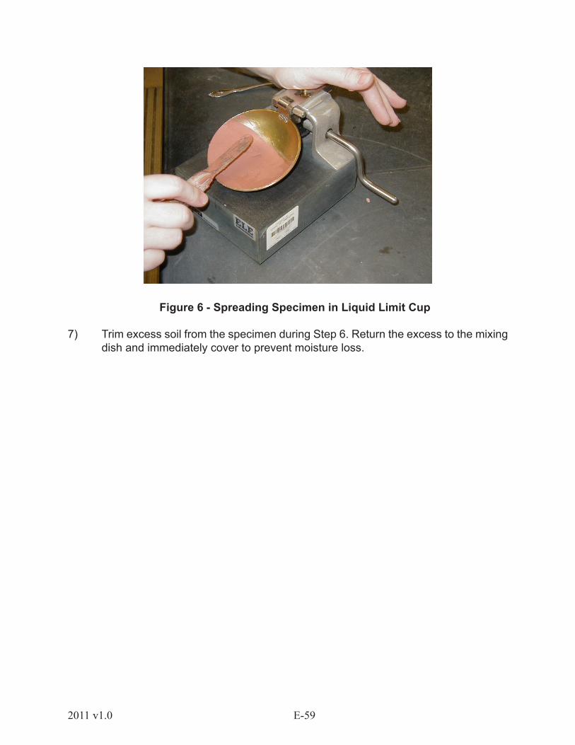
6) Use the spatula to press, spread, and level the specimen so that the material is no more than 10 mm (0.4 in.) thick at its maximum depth and is centered as close as possible over the contact point of the cup and the base. Use as few spatula strokes as possible. Do not trap air bubbles within the mass.
E-592011 v1.0
Figure 6 - Spreading Specimen in Liquid Limit Cup
7) Trim excess soil from the specimen during Step 6. Return the excess to the mixing dish and immediately cover to prevent moisture loss.
E-60 2011 v1.0
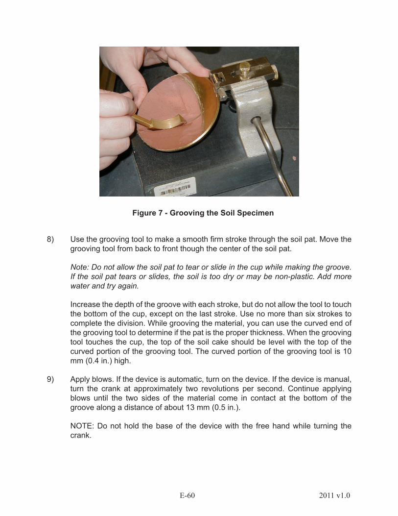
Figure 7 - Grooving the Soil Specimen
8) Use the grooving tool to make a smooth firm stroke through the soil pat. Move the grooving tool from back to front though the center of the soil pat.
Note: Do not allow the soil pat to tear or slide in the cup while making the groove. If the soil pat tears or slides, the soil is too dry or may be non-plastic. Add more water and try again.
Increase the depth of the groove with each stroke, but do not allow the tool to touch the bottom of the cup, except on the last stroke. Use no more than six strokes to complete the division. While grooving the material, you can use the curved end of the grooving tool to determine if the pat is the proper thickness. When the grooving tool touches the cup, the top of the soil cake should be level with the top of the curved portion of the grooving tool. The curved portion of the grooving tool is 10 mm (0.4 in.) high.
9) Apply blows. If the device is automatic, turn on the device. If the device is manual, turn the crank at approximately two revolutions per second. Continue applying blows until the two sides of the material come in contact at the bottom of the groove along a distance of about 13 mm (0.5 in.).
NOTE: Do not hold the base of the device with the free hand while turning the crank.
E-612011 v1.0
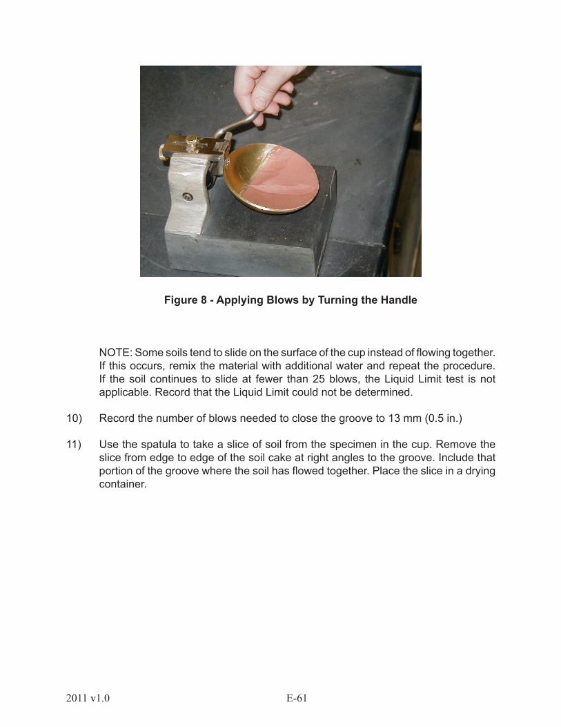
Figure 8 - Applying Blows by Turning the Handle
NOTE: Some soils tend to slide on the surface of the cup instead of flowing together. If this occurs, remix the material with additional water and repeat the procedure. If the soil continues to slide at fewer than 25 blows, the Liquid Limit test is not applicable. Record that the Liquid Limit could not be determined.
10) Record the number of blows needed to close the groove to 13 mm (0.5 in.)
11) Use the spatula to take a slice of soil from the specimen in the cup. Remove the slice from edge to edge of the soil cake at right angles to the groove. Include that portion of the groove where the soil has flowed together. Place the slice in a drying container.
E-62 2011 v1.0
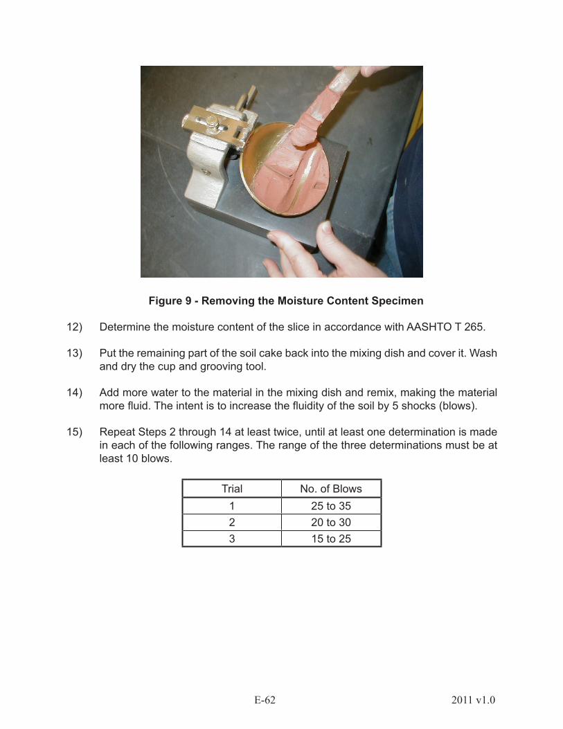
Figure 9 - Removing the Moisture Content Specimen
12) Determine the moisture content of the slice in accordance with AASHTO T 265.
13) Put the remaining part of the soil cake back into the mixing dish and cover it. Wash and dry the cup and grooving tool.
14) Add more water to the material in the mixing dish and remix, making the material more fluid. The intent is to increase the fluidity of the soil by 5 shocks (blows).
15) Repeat Steps 2 through 14 at least twice, until at least one determination is made in each of the following ranges. The range of the three determinations must be at least 10 blows.
Trial No. of Blows1 25 to 352 20 to 303 15 to 25
E-632011 v1.0
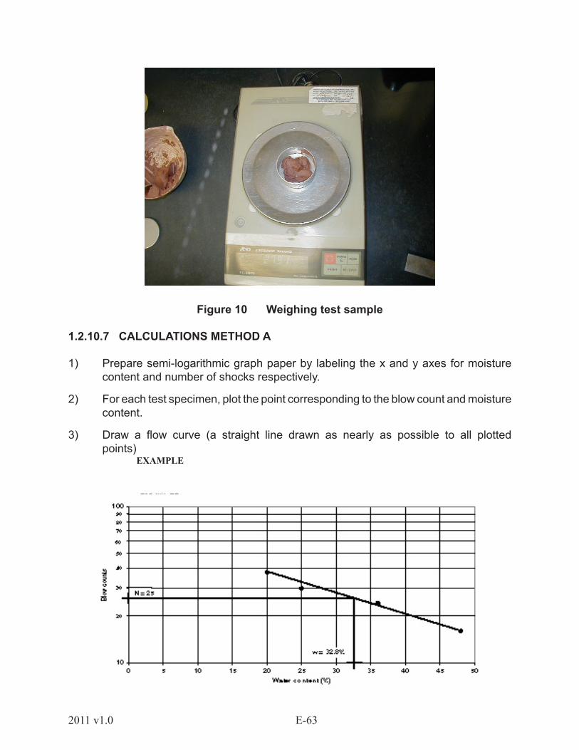
Figure 10 Weighing test sample
1.2.10.7 CALCULATIONS METHOD A
1) Prepare semi-logarithmic graph paper by labeling the x and y axes for moisture content and number of shocks respectively.
2) For each test specimen, plot the point corresponding to the blow count and moisture content.
3) Draw a flow curve (a straight line drawn as nearly as possible to all plotted points)
EXAMPLE
E-64 2011 v1.0
4) Determine the Liquid Limit: The moisture content at the intersection of the flow curve and the 25-blow line is the Liquid Limit. Record the Liquid Limit to the nearest whole number.
NOTE: The lower point, although recorded, was outside the 25 - 35 range. The course developers, unlike AASHTO directions, prefer that all points be recorded.
1.2.10.8 REFERENCE TEST
When performing Method A as a reference test, use the following time schedule:
• Mixing of soil with water: 5 - 10 minutes The more plastic the soil, the longer the mixing time should be.
• Seasoning in the humidifier: 30 minutes
• Remixing the material before placing it in the brass cup: Add 1 mL of water and mix: 1 minute
• Placing the material in the brass cup and testing: 3 minutes maximum
• Adding water and remixing: 3 minutes
1.2.10.9 PROCEDURE METHOD B
Method B is a quicker determination of Liquid Limit, because it is only necessary to run one complete point. If results from Method B are questionable, use Method A as a referee test with the special parameters listed under reference test. You will need the same equipment as for Method A except semi-logarithmic graph paper. In addition to the equipment listed for Method A, you will need one of the following:
• Liquid Limit Slide Rule
• Calculator
• Liquid Limit Nomograph
• Other Approved Charts or Graphs
Obtain a test specimen of approximately 50g and perform in accordance with Method A except as noted.
1) Prepare the test specimen and perform the test exactly like Method A, with the following exception. Use approximately 8 - 10 mL of water for initial specimen preparation.
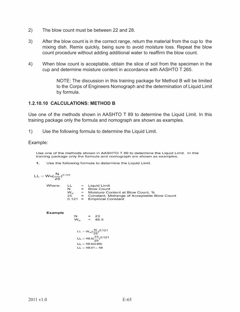
E-652011 v1.0
2) The blow count must be between 22 and 28.
3) After the blow count is in the correct range, return the material from the cup to the mixing dish. Remix quickly, being sure to avoid moisture loss. Repeat the blow count procedure without adding additional water to reaffirm the blow count.
4) When blow count is acceptable, obtain the slice of soil from the specimen in the cup and determine moisture content in accordance with AASHTO T 265.
NOTE: The discussion in this training package for Method B will be limited to the Corps of Engineers Nomograph and the determination of Liquid Limit by formula.
1.2.10.10 CALCULATIONS: METHOD B
Use one of the methods shown in AASHTO T 89 to determine the Liquid Limit. In this training package only the formula and nomograph are shown as examples.
1) Use the following formula to determine the Liquid Limit.
Example:

E-66 2011 v1.0
2) Use the Nomograph to determine the Liquid Limit. (Refer to the Nomograph in AASHTO T 89.)
• Plot the moisture content (WN ) on the left vertical column.• Plot the blow count (N) on the right vertical column. • Using a straightedge, connect the two points. • Read the Liquid Limit from the middle column.
Developed by the Waterways Experiment Station, Corps of EngineersU. S. Army, to determine Liquid Limit Using Mean Slope Method
1.2.10.11 COMMON TESTING ERRORS
• Improperly adjusted Liquid Limit device.
• Loose adjusting screws.
• Excessively worn pin.
• Excessively worn base or cup.
• Worn grooving tool.
• Automatic counter not zeroed.
• Miscounting blows on manual device.
• Restraining the base of the Liquid Limit device during testing.
• Trapping air bubbles in the test specimen.
• Soil cake of improper thickness.
• Moisture content test specimen not representative of Liquid Limit test specimen.
• Plotting or calculation errors.
• Non-uniform moisture content in sample.
• Performing test before moisture content in soil specimen is equalized.
• Contaminated water used for testing.
• Adding water too quickly for the soil to absorb it during the mixing process.

E-672011 v1.0
1.2.11 AASHTO T 90 – DETERMINING THE PLASTIC LIMIT AND PLASTICITY INDEX OF SOILS
1.2.11.1 SCOPE: PLASTIC LIMIT AND PLASTICITY INDEX
PLASTIC LIMIT
As the moisture content of a material moves below the Liquid Limit, the material can be considered plastic. External force is needed to make the soil deform. Its bearing capacity begins to increase. Material is considered to be in a plastic state when it can be molded or worked into a new shape without crumbling. The minimum moisture content at which a material is in the plastic state is called the Plastic Limit. The Plastic Limit is determined by a simple test where the material is repeatedly rolled into threads approximately 3 mm in diameter. During the repeated rolling, the material gradually loses moisture until it reaches the point where it will no longer hold together and breaks into short pieces. The moisture content at which the material begins to break up is identified as the Plastic Limit.
PLASTICITY INDEX
The range of moisture contents at which a material is considered to be plastic are those which fall between the Liquid Limit and the Plastic Limit. This range is identified as the Plasticity Index (PI). The Plasticity Index is a calculated value derived by subtracting the Plastic Limit from the Liquid Limit.
PI = LL – PL
The Plasticity Index is an indicator of the suitability of the clay or silt fraction of a material for use in highway construction. The Plasticity Index is used in classifying soils, the quality control of aggregates and in specifications by many highway departments. When the Plasticity Index of the binder fraction of a material is too high, the material will tend to soften under wet conditions. Pavement structures constructed with material having a high PI tend to have problems with rutting, shifting and shoving. They may develop a washboard surface or other failures that are caused by foundation failures. When such materials are used, they tend to become slippery in wet weather. When the Plasticity Index is too low or the soil fraction is non-plastic, the material will tend to become friable in dry weather. It may ravel at the edges and abrade under traffic. Surfaces constructed with low PI material tend to be dusty and may lose much of their binder during dry periods.
The Plasticity Index is the numerical range of moisture contents through which a material behaves plastic. Materials become less stable as the moisture content increases through this range (moves left to right on the graph).

E-68 2011 v1.0
It is possible for a material to have a PI of zero, if the Plastic Limit and Liquid Limit are the same. Such a material is considered non-plastic, since the range of moisture contents at which the material behaves as a plastic is so severely limited that the range cannot be determined by standard laboratory tests. Non-plastic materials are almost totally free of clay particles. Non-plastic materials never reach a cohesive state, but change abruptly from a viscous liquid state to a dry granular state. A non-plastic material will not solidify. It will not form clods or other solid masses. It cannot be rolled into a thread as small as 3 mm (1/8 inch), ergo; the material cannot be tested for a Plastic Limit.
1.2.11.2 SUMMARY OF TESTING
To determine the Plastic Limit of a material, you will first add water to a dried sample and mix it thoroughly. When the moisture content is uniform, place the test specimen on a flat smooth impermeable surface and with the heel of the hand roll it into a thin thread. Remold the test specimen without adding additional water. Repeat the procedure until the specimen crumbles. The moisture content of the test specimen is determined in accordance with AASHTO T 265. The moisture content obtained is the Plastic Limit. Finally, determine the Plasticity Index by subtracting the Plastic Limit from the Liquid Limit.
TYPICAL TEST RESULTS
The Plastic Limit test was designed to be performed on silts and clays. Normally, silty soils have lower Plastic Limits than clay soils. The Plastic Limit usually falls in the range of 5 - 30. Non-plastic materials (e.g., sand) cannot be tested by this procedure. Non-plastic materials lack the cohesiveness to be rolled into a thread. The Plasticity Index can range as high as 70 or 80 for very plastic clays. However, most clays have a PI of 20 - 40 and silts have a PI of 10 - 20.
CRUMBLING
Different types of materials exhibit different modes of breaking up during rolling. Some materials fall apart in many small aggregations; others form a tubular layer on the outside

E-692011 v1.0
that splits at both ends. When this occurs, the splitting tends to progress toward the middle until the thread falls apart in many small platy particles. Heavy clay requires a lot of pressure to deform, especially as it approaches the Plastic Limit. With clay, the thread often breaks into a series of barrel-shaped segments about 6 – 9 mm (1/4 - 3/8 in.) in length. The technician is never to attempt to produce failure at exactly 3 mm (1/8 in.) by reducing the rate of rolling or modifying hand pressure. It is acceptable to reduce the amount of rolling required for materials with low plasticity by making the initial diameter of the ellipsoidal test specimen near the 3 mm (1/8 in.) final diameter.
1.2.11.3 EQUIPMENT
Before beginning any procedure, you must first assemble all the equipment you will need to perform the test. To determine the Plastic Limit of a specimen, you will need the following.
Dish - An unglazed porcelain container (or similar mixing container) approximately 115 mm (4½ in.) in diameter.
Spatula - A flat blade or pill knife approximately 75 - 100 mm (3 - 4 in.) long and approximately 20 mm (3/4 in.) wide
Surface for Rolling – Ground glass plate or smooth, unglazed paper
Containers - Enough containers with close-fitting lids to provide one container per moisture content determination. Containers must be resistant to corrosion and not subject to change in mass with repeated heating and cooling.
Balance - Conforming to AASHTO M 231, Class C
Oven - A thermostatically controlled oven capable of maintaining a temperature of 110 ± 5º C (230 ± 9º F)
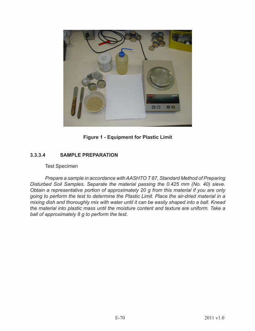
E-70 2011 v1.0
Figure 1 - Equipment for Plastic Limit
3.3.3.4 SAMPLE PREPARATION
Test Specimen
Prepare a sample in accordance with AASHTO T 87, Standard Method of Preparing Disturbed Soil Samples. Separate the material passing the 0.425 mm (No. 40) sieve. Obtain a representative portion of approximately 20 g from this material if you are only going to perform the test to determine the Plastic Limit. Place the air-dried material in a mixing dish and thoroughly mix with water until it can be easily shaped into a ball. Knead the material into plastic mass until the moisture content and texture are uniform. Take a ball of approximately 8 g to perform the test.
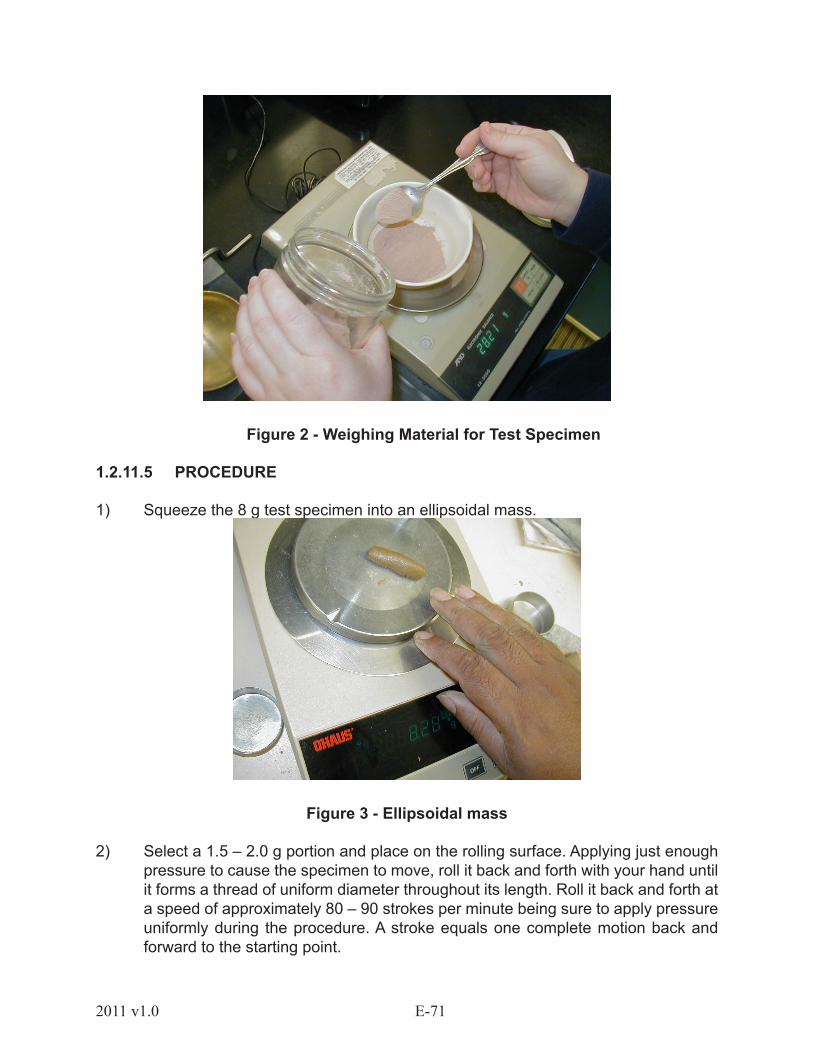
E-712011 v1.0
Figure 2 - Weighing Material for Test Specimen
1.2.11.5 PROCEDURE
1) Squeeze the 8 g test specimen into an ellipsoidal mass.
Figure 3 - Ellipsoidal mass
2) Select a 1.5 – 2.0 g portion and place on the rolling surface. Applying just enough pressure to cause the specimen to move, roll it back and forth with your hand until it forms a thread of uniform diameter throughout its length. Roll it back and forth at a speed of approximately 80 – 90 strokes per minute being sure to apply pressure uniformly during the procedure. A stroke equals one complete motion back and forward to the starting point.

E-72 2011 v1.0
Figure 4 - Rolling sample
3) When the diameter of the thread becomes 3 mm (1/8 inch), stop rolling. Break the thread into six or eight reasonably equal-sized pieces.
Figure 5 - Individual Pieces
4) Squeeze the pieces between the thumbs and fingers to create a uniform ellipsoidal mass.
5) Repeat Steps 2 - 4, until the thread crumbles under the pressure required for rolling and the specimen can no longer be rolled into a thread.

E-732011 v1.0
6) Gather the pieces of the crumbled thread together. Place them in a tared container to determine the moisture content.
7) Repeat this process until all the portions are tested.
8) Determine the moisture content in accordance with AASHTO T 265 and record the results.
NOTE: The test specimen may crumble when the thread has a diameter greater than 3 mm (1/8 inch). It is acceptable to end the rolling procedure at this point if the specimen has previously been rolled to the 3 mm diameter.
1.2.11.6 CALCULATIONS
1. Determine the Plastic Limit using the following formula and report the result to the nearest whole number.
Mass of Water
PL = ____________________ x 100 Mass of Oven - Dry Soil
Example:
Mass of Water = 5.34 gMass of Oven Dry Soil = 22.01 g
5.34
PL = ________ X 100 22.01
PL = 0.2426 x 100
PL = 24.26 = 24
2. Determine the Plasticity Index using the following formula and report the result to the nearest whole number.
PI = LL – PL

E-74 2011 v1.0
Example: LL = 70PL = 24
PI = 70 – 24PI = 46
1.2.11.7 COMMON TESTING ERRORS
• Non-uniform mixing of material and water
• Contaminated water
• Improperly blended sample
• Too thin or too thick material threads
• Errors in determining mass
• Applying too much pressure or non-uniform pressure in rolling
• Rolling on the wrong type surface
Related Documents