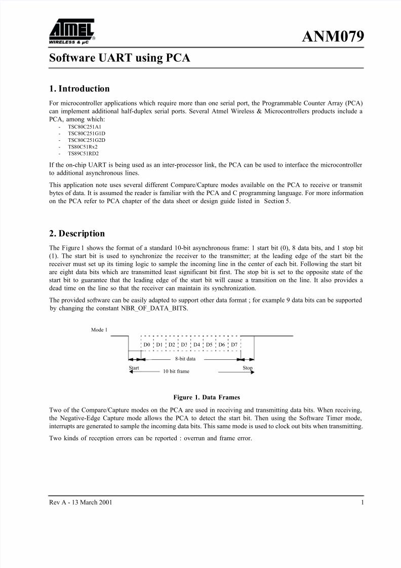
Rev A - 13 March 2001 1 ANM079 Software UART using PCA 1. Intr oducti on For microcontroller applications which require more than one serial port, the Programmable Counter Array (PCA) can implement additional half-duplex serial ports. Several Atmel Wireless & Microcontrollers products include a PCA, among which: - TSC80C251A1 - TSC80C251G1D - TSC80C251G2D - TS80C51Rx2 - TS89C51RD2 If the on-chip UART is being used as an inter-processor link, the PCA can be used to interface the microcontroller to additional asynchronous lines. This application note uses several different Compare/Capture modes available on the PCA to receive or transmit bytes of data. It is assumed the reader is familiar with the PCA and C programming language. For more information on the PCA refer to PCA chapter of the data sheet or design guide listed in Sec tion 5. 2. Des cri pti on The Fig ure 1 shows the format of a standard 10-bit asynchronous frame: 1 start bit (0), 8 data bits, and 1 stop bit (1). The start bit is used to synchronize the receiver to the transmitter; at the leading edge of the start bit the receiver must set up its timing logic to sample the incoming line in the center of each bit. Following the start bit are eight data bits which are transmitted least significant bit first. The stop bit is set to the opposite state of the start bit to guarantee that the leading edge of the start bit will cause a transition on the line. It also provides a dead time on the line so that the receiver can maintain its synchronization. The provided software can be easily adapted to support other data format ; for example 9 data bits can be supported by changing the constant NBR_OF_DATA_BITS. Figure 1. Data Frames Two of the Compare/Capture modes on the PCA are used in receiving and transmitting data bits. When receiving, the Negative-Edge Capture mode allows the PCA to detect the start bit. Then using the Software Timer mode, interrupts are generated to sample the incoming data bits. This same mode is used to clock out bits when transmitting. Two kinds of reception errors can be reported : overrun and frame error. Start D0 D1 D2 D3 D4 D5 D6 D7 8-bit data 10 bit frame Stop Mode 1

Welcome message from author
This document is posted to help you gain knowledge. Please leave a comment to let me know what you think about it! Share it to your friends and learn new things together.
Transcript
8/3/2019 Software UART Using PCA
http://slidepdf.com/reader/full/software-uart-using-pca 1/13
Rev A - 13 March 2001 1
ANM079
Software UART using PCA
1. Introduction
For microcontroller applications which require more than one serial port, the Programmable Counter Array (PCA)
can implement additional half-duplex serial ports. Several Atmel Wireless & Microcontrollers products include a
PCA, among which:- TSC80C251A1
- TSC80C251G1D
- TSC80C251G2D
- TS80C51Rx2
- TS89C51RD2
If the on-chip UART is being used as an inter-processor link, the PCA can be used to interface the microcontroller
to additional asynchronous lines.
This application note uses several different Compare/Capture modes available on the PCA to receive or transmit
bytes of data. It is assumed the reader is familiar with the PCA and C programming language. For more information
on the PCA refer to PCA chapter of the data sheet or design guide listed in Section 5.
2. Description
The Figure 1 shows the format of a standard 10-bit asynchronous frame: 1 start bit (0), 8 data bits, and 1 stop bit
(1). The start bit is used to synchronize the receiver to the transmitter; at the leading edge of the start bit the
receiver must set up its timing logic to sample the incoming line in the center of each bit. Following the start bit
are eight data bits which are transmitted least significant bit first. The stop bit is set to the opposite state of the
start bit to guarantee that the leading edge of the start bit will cause a transition on the line. It also provides a
dead time on the line so that the receiver can maintain its synchronization.
The provided software can be easily adapted to support other data format ; for example 9 data bits can be supported by changing the constant NBR_OF_DATA_BITS.
Figure 1. Data Frames
Two of the Compare/Capture modes on the PCA are used in receiving and transmitting data bits. When receiving,
the Negative-Edge Capture mode allows the PCA to detect the start bit. Then using the Software Timer mode,
interrupts are generated to sample the incoming data bits. This same mode is used to clock out bits when transmitting.
Two kinds of reception errors can be reported : overrun and frame error.
Start
D0 D1 D2 D3 D4 D5 D6 D7
8-bit data
10 bit frameStop
Mode 1
8/3/2019 Software UART Using PCA
http://slidepdf.com/reader/full/software-uart-using-pca 2/13
2 Rev A - 13 March 2001
ANM079
3. Hardware
PCA pin CEX0 is used as RxD and pin CEX1 as TxD.
4. Software
This Application Note contains six sections of code:- Macro and constants definitions
- Main program
- PCA initialization routine
- PCA interrupt handler
- Receive rout ine
- Transmit routine.
A complete listing of the routines and the test loop which was used to verify their operation is found in the Section 6
4.1. Constants and Variables
Section 6.2 shows the constants used in both the receive and transmit routines.
NBR_OF_DATA_BITS defines the number of data bits in the transmission frame.
XTAL is the Crystal frequency in MHz
BAUD_RATE is the baud rate for transmission and reception.
ONE_BIT_TIME is the one-full bit times in units of PCA timer ticks. (One bit time = 1 / baud rate.). With the
PCA timer incremented every machine cycle, the equation to calculate one bit time can be written as:
ONE_BIT_TIME = XTAL*106 / (12* BAUD_RATE)
HALF_BIT_TIME is half of this value.
The macro TRANSMIT_1 is used to set up the PCA transmit module in capture mode, negative edge and to
generate the 1 to 0 transition of the start bit, thus creating a PCA interrupt.
Others constants are used to define PCA control words, errors codes, …
4.2. Main program
Section 6.1.1 contains the main program loop. This program echoes on PCA channel 1 any byte received on PCA
channel 0.
The received_byte_0 and transmit_byte_1 simulate the on-chip serial port SBUF as two separate buffer registers.
When a byte is receive, it is stored in temporary register tmp. As soon as the previous transmission is completed,
the received byte is be transmitted; for this the main program moves the data byte into the transmit_byte_1 register
and generate a PCA interrupt.
4.3. PCA Initialization routine
Section 6.1.2 contains the initialization code for the receive and transmit process.
Module 0 of the PCA is used as a receiver and is first set up to detect a negative edge from the start bit.
Module 1 of the PCA is used as a transmitter and is first disable.
The PCA is set to use Fosc/12 as main clock, the PCA counter is reset and then started.
8/3/2019 Software UART Using PCA
http://slidepdf.com/reader/full/software-uart-using-pca 3/13
Rev A - 13 March 2001 3
ANM0794.4. PCA interrupt handler
Section 6.1.3 contains the PCA interrupt handler. According to the received interrupt (channel 0 and channel 1),
it calls either the receive or transmit routine.
4.5. Receive Routine
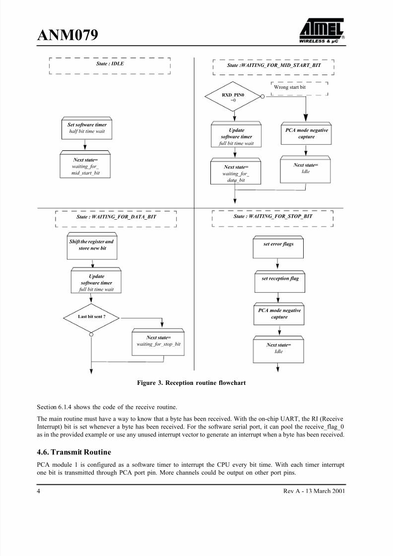
Two operating modes of the PCA are needed to receive bits. The module must first be able to detect the leading
edge of a start bit so it is initially set up to capture a 1-to-0 transition (i.e. Negative-Edge Capture mode). The
module is then reconfigured as a software timer to cause an interrupt at the center of each bit to deserialize the
incoming data.
The temporary register, tmp_received_byte is used to save bits as they are received.
Finally, one counter registers nbr_of_rxd_bits_left keep track of how many bits are still to be received.
Receptions errors are reported if RXD_STATUS is set. In this case, receive_status_0 contains the error information:
• Bit 4 OverRun
• Bit 5 Frame Error
Flag receive_flag_0 is set when reception is finished and the received byte is stored in received_byte_0. The user
has to clear receive_flag_0 when a byte has been read. Otherwise an overrun error will be generated on the next
received byte (If RXD_STATUS is used).
Frame Error is set when there is no stop bit.
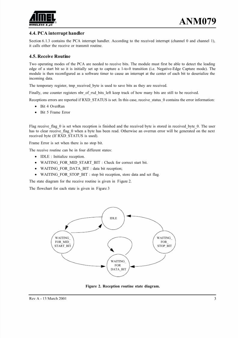
The receive routine can be in four different states:
• IDLE : Initialize reception.
• WAITING_FOR_MID_START_BIT : Check for correct start bit.
• WAITING_FOR_DATA_BIT : data bit reception;
• WAITING_FOR_STOP_BIT : stop bit reception, store data and set flag.
The state diagram for the receive routine is given in Figure 2.
The flowchart for each state is given in Figure 3
Figure 2. Reception routine state diagram.
WAITING_
FOR_MID_
START_BIT
WAITING_
FOR_
STOP_BIT
IDLE
WAITING_
FOR_
DATA_BIT
8/3/2019 Software UART Using PCA
http://slidepdf.com/reader/full/software-uart-using-pca 4/13
4 Rev A - 13 March 2001
ANM079
Figure 3. Reception routine flowchart
Section 6.1.4 shows the code of the receive routine.
The main routine must have a way to know that a byte has been received. With the on-chip UART, the RI (Receive
Interrupt) bit is set whenever a byte has been received. For the software serial port, it can pool the receive_flag_0
as in the provided example or use any unused interrupt vector to generate an interrupt when a byte has been received.
4.6. Transmit Routine
PCA module 1 is configured as a software timer to interrupt the CPU every bit time. With each timer interrupt
one bit is transmitted through PCA port pin. More channels could be output on other port pins.
Update
software timer
full bit time wait
Last bit sent ?
RXD_PIN0=0
Next state=
waiting_for_
data_bit
Set software timer
half bit time wait
Next state=
waiting_for_
mid_start_bit
PCA mode negative
capture
Next state=
Idle
Shift the register and
store new bit set error flags
Next state=
waiting_for_stop_bit
Next state=
Idle
PCA mode negative
capture
set reception flag
State : IDLE State :WAITING_FOR_MID_START_BIT
State : WAITING_FOR_STOP_BIT State : WAITING_FOR_DATA_BIT
Wrong start bit
Update
software timer
full bit time wait
8/3/2019 Software UART Using PCA
http://slidepdf.com/reader/full/software-uart-using-pca 5/13
Rev A - 13 March 2001 5
ANM079
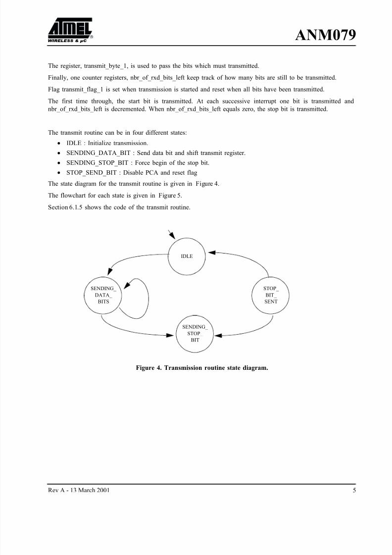
The register, transmit_byte_1, is used to pass the bits which must transmitted.
Finally, one counter registers, nbr_of_rxd_bits_left keep track of how many bits are still to be transmitted.
Flag transmit_flag_1 is set when transmission is started and reset when all bits have been transmitted.
The first time through, the start bit is transmitted. At each successive interrupt one bit is transmitted and
nbr_of_rxd_bits_left is decremented. When nbr_of_rxd_bits_left equals zero, the stop bit is transmitted.
The transmit routine can be in four different states:
• IDLE : Initialize transmission.
• SENDING_DATA_BIT : Send data bit and shift transmit register.
• SENDING_STOP_BIT : Force begin of the stop bit.
• STOP_SEND_BIT : Disable PCA and reset flag
The state diagram for the transmit routine is given in Figure 4.
The flowchart for each state is given in Figure 5.
Section 6.1.5 shows the code of the transmit routine.
Figure 4. Transmission routine state diagram.
SENDING_
DATA_
BITS
STOP_
BIT_
SENT
IDLE
SENDING_
STOP_
BIT
8/3/2019 Software UART Using PCA
http://slidepdf.com/reader/full/software-uart-using-pca 6/13
6 Rev A - 13 March 2001
ANM079
Figure 5. Transmission routine flowchart
4.7. Conclusion
The software routines in the Section 6 can be altered to vary the baud rate and number of channels to fit a particular
application. The number of channels which can be implemented is limited by the CPU time required to service
the PCA interrupt. At higher baud rates, fewer channels can be run.
The test program verifies the simultaneous operation the on-chip full-duplex channel at 9600 Baud, leaving about
80% CPU resource free at 16 Mhz.
Last bit sent ?
Set software timer pin already at 0 for
start bit
Next state=
sending_data_bit
Next state=
Idle
Send new bit and Shift the register
Next state=
sending_stop_bit
Disable PCA module
1
State : IDLE State :SENDING_DATA_BIT
State : STOP_BIT_SENT State : SENDING_STOP_BIT
set transmission flag
set port pin =1
reset transmission
flag
Update
software timer
full bit time wait
Update
software timer
full bit time wait
Next state=
stop_bit_sent
8/3/2019 Software UART Using PCA
http://slidepdf.com/reader/full/software-uart-using-pca 7/13
Rev A - 13 March 2001 7
ANM079
5. Bibliography
[1] TSC80251G1 Design Guide
[2] TS80C51Rx2 data sheet
[3] T89C51RD2 data sheet
8/3/2019 Software UART Using PCA
http://slidepdf.com/reader/full/software-uart-using-pca 8/13
8 Rev A - 13 March 2001
ANM079
6. Appendix A: Software
6.1. MAIN.C/****************************************************************************Project: Soft UART for Atmel W&M microcontrollers
Module: MAIN.CVersion: 1.1Original ver: 970902Updated: 970904Updated: 20000112/JDWritten by: Jan Gripsborn*****************************************************************************/
#include "def.h" /* Include register declaration, local definitions andmacros */
void init_pca(void); /* Init the PCA block */void receive0(void); /* Receive routine called from PCA interrupt */
void transmit1(void); /* Transmit routine called from PCA interrupt */
bit receive_flag_0 = FALSE;/* Flag indicating the reception on channel 0 */
unsigned char receive_status_0 = 0;/* Reveive status for channel 0Bit 4 = O verRunBit 5 = FrameError */
data_type received_byte_0; /* The received byte on channel 0The definition of "data_type" depends onthe number of data bits used */
bit transmit_flag_1 = FALSE; /* Flag indicating transmission onon channel 1 */
data_type transmit_byte_1; /* Byte to tranmit */
6.1.1. Main program/*---------------------------------------------------------------------------
Main program
To transmit a byte, call the macro TRANSMIT_1(byte). See DEF.hThe test program Echoes a received byte. If an error condition ocures theprogram stops.
---------------------------------------------------------------------------*/void main (void) using 1{
data_type tmp;init_pca(); /* Enable reception and transmission */while (1) /* Loop forever */{
if (receive_flag_0) /* Check if a byte has been received */{
tmp = received_byte_0;receive_flag_0 = FALSE; /* Clear reception flag */if (receive_status_0)
while(1); /* Stop if we have an error */while (transmit_flag_1); /* Wait if transmission is going on */
TRANSMIT_1(tmp); /* Echo the received byte */
8/3/2019 Software UART Using PCA
http://slidepdf.com/reader/full/software-uart-using-pca 9/13
Rev A - 13 March 2001 9
ANM079}
}}
6.1.2. PCA initialization routine/*---------------------------------------------------------------------------
Init_pca
Initilizes the PCA block:CEXO = Channel0 for receptionCEX1 = Channlel1 for tranmission
---------------------------------------------------------------------------*/void init_pca(void){
/* Init PCA */
CMOD = 0; /* The PCA uses Fosc/12 */CCON = 0; /* Clear status flags */CCAPM0 = NEG_EDGE; /* Set-up Module 0 for Negative Edge capture mode */
CCAPM1 = 0; /* Disable Module 1 CCF0 interrupt */CL = 0; /* Clear the PCA counter */CH = 0; /* -"- */EC = 1; /* Enable the PCA interrupt */EA = 1; /* Start the interrupt system */
CR =1; /* Start the PCA counter */
}
6.1.3. PCA interrupt handler/*---------------------------------------------------------------------------
interrupt_pca - PCA Interrupt
Interrupt is generated on:1. By the user at the beginning of an tranmission2. By a negative capture on channel 0 when a start bit arrives2. By the software Timer on channel 0 or 1 during transmission/reception
The interrupt routine uses register bank 2.
---------------------------------------------------------------------------*/void interrupt_pca (void) interrupt 6 using 2{
if (CCON&0x01) /* Module 0 */{
receive0 ();
CCF0=0; /* Clear interrupt flag */}if (CCON&0x02) /* Module 1 */{
transmit1 ();CCF1=0; /* Clear interrupt flag */
}}
6.1.4. Receive routine/*---------------------------------------------------------------------------
Receive0
8/3/2019 Software UART Using PCA
http://slidepdf.com/reader/full/software-uart-using-pca 10/13
10 Rev A - 13 March 2001
ANM079
Performs reception of a byte on channel 0.receive_flag _0 is set to TRUE when reception is finished and the receivedbyte is stored in received_byte_0.If RXD_STATUS is enabled (see DEF.h) receive_status_0 will contain theerror information:
Bit 4 = O verRunBit 5 = FrameError
The user has to clear receive_flag_0 when a byte has been read. Othervisean overRun will be generated on the next received byte (If RXD_STATUS isused).
---------------------------------------------------------------------------*/void receive0(void){
enum {WAITING_FOR_DATA_BITS, /* States used by the variable state */WAITING_FOR_MID_START_BIT,WAITING_FOR_STOP_BIT,IDLE};
static unsigned char state= IDLE;static unsigned char nbr_of_rxd_bits_left;/* Indicates number of bits left
to transmit */static data_type tmp_received_byte = 0; /* The received byte is stored here */union countertype /* tmp holds the CCAP0 counter value */{
unsigned int tmp;char byte[2];
};static union countertype counter;
switch (state){
case IDLE: /* State = IDLE, No reception is going on */counter.byte[1] = CCAP0L; /* Store the present counter value */counter.byte[0] = CCAP0H;CCAP0L= (counter.tmp+=HALF_BIT_TIME); /* Increase module 0 counter
with 1/2 bit time */CCAP0H= counter.byte[0];
CCAPM0 = S_W_TIMER; /* Set up the Module 0 for Software Timer mode */state = WAITING_FOR_MID_START_BIT; /* Wait for the start bit */break;
case WAITING_FOR_MID_START_BIT:if (!RXD_PIN0) /* Check if we have a correct start bit */{
CCAP0L= (counter.tmp+=ONE_BIT_TIME); /* Increase module0 counter with 1 bit time */
CCAP0H= counter.byte[0]; /*-" - */
nbr_of_rxd_bits_left = NBR_OF_DATA_BITS; /* Init variable */state = WAITING_FOR_DATA_BITS; /* Wait for the data bits */}else{
CCAPM0 = NEG_EDGE; /* Set-up Module 0 for Negative Edge capture mode */state = IDLE; /* Exit reception */
}break;
case WAITING_FOR_DATA_BITS:
8/3/2019 Software UART Using PCA
http://slidepdf.com/reader/full/software-uart-using-pca 11/13
Rev A - 13 March 2001 11
ANM079tmp_received_byte = (tmp_received_byte>>1); /* Shift the received byte */
if (RXD_PIN0) /* Add the new bit */tmp_received_byte += (1<<(NBR_OF_DATA_BITS-1));
CCAP0L= (counter.tmp+=ONE_BIT_TIME); /* Increase module 0counter with 1 bit time */
CCAP0H= counter.byte[0];
if (!--nbr_of_rxd_bits_left) /* Are we finshed? */state = WAITING_FOR_STOP_BIT; /* Yes, wait for the stop bit */
break;
case WAITING_FOR_STOP_BIT:
#if RXD_STATUS == TRUE /* See DEF.h for definition */if (receive_flag_0) /* Check for overRun */
receive_status_0 = OverRun;if (!RXD_PIN0) /* Check the stop bit. */
receive_status_0 += FrameError; /* If no stop bit a FrameErroris generated */
#endifreceive_flag_0 = TRUE; /* Set flag to indicate a received byte */
received_byte_0 = tmp_received_byte; /* Store the received byte */CCAPM0 = NEG_EDGE; /* Set-up Module 0 for Negative Edge capture mode */
state = IDLE; /* Exit reception */break;
}}
6.1.5. Transmit routine.
/*---------------------------------------------------------------------------Transmit1
Transmits the byte stored in transmit_byte_1 on channel 1.transmit_flag_1 is set to TRUE before the START bit and FALSE aftertransmision of the STOP bit.
---------------------------------------------------------------------------*/void transmit1(void){
enum {SENDING_DATA_BITS, /* States used by the variable state */SENDING_STOP_BIT,STOP_BIT_SENT,IDLE};
static unsigned char state=IDLE;static unsigned char nbr_of_txd_bits_left;
union countertype /* counter holds the CCAP1 counter value */{
unsigned int tmp;char byte[2];
};static union countertype counter;
switch (state){
case IDLE: /* State = IDLE, No tranmission is going on */counter.byte[1] = CCAP1L; /* Store the counter value */
counter.byte[0] = CCAP1H;
8/3/2019 Software UART Using PCA
http://slidepdf.com/reader/full/software-uart-using-pca 12/13
12 Rev A - 13 March 2001
ANM079CCAP1L= (counter.tmp+=ONE_BIT_TIME); /* Increase module 1 counter
with 1 bit time */CCAP1H= counter.byte[0]; /* -" - */
CCAPM1 = S_W_TIMER; /* Set-up Module 1 for Software Timer mode */nbr_of_txd_bits_left = NBR_OF_DATA_BITS; /* Init variable */
transmit_flag_1 = TRUE; /* Set flag to indicate transmission */
state = SENDING_DATA_BITS;break;
case SENDING_DATA_BITS:TXD_PIN1 = transmit_byte_1; /* Send data bit */
transmit_byte_1 = transmit_byte_1 >> 1; /* Shift out the sent bit */if (!(--nbr_of_txd_bits_left)) /* Are we finished with data bits? */
state = SENDING_STOP_BIT; /* Yes! */CCAP1L= (counter.tmp+=ONE_BIT_TIME); /* Increase module 1 counter
with 1 bit time */CCAP1H= counter.byte[0]; /* -" - */
break;case SENDING_STOP_BIT:
TXD_PIN1 = 1; /* Send stop bit */CCAP1L= (counter.tmp+=ONE_BIT_TIME); /* Increase module 1 counter
with 1 bit time */CCAP1H= counter.byte[0]; /* -" - */
state = STOP_BIT_SENT;break;
case STOP_BIT_SENT:CCAPM1 = 0; /* Disable PCA Module 1 */
transmit_flag_1=FALSE; /* Clear flag and indicate transmission is over */state = IDLE; /* Exit tranmission */
break;}
}
8/3/2019 Software UART Using PCA
http://slidepdf.com/reader/full/software-uart-using-pca 13/13
Rev A - 13 March 2001 13
ANM0796.2. def.h#include "reg51f.h" /* Include register declarations */
#define NBR_OF_DATA_BITS 8 /* Number of data bits used for reception andtransmission */#define XTAL 16 /* Crystal frequency, MHz */
#define BAUD_RATE 9600 /* Baudrate of transmission and reception */#define ONE_BIT_TIME (((long int) XTAL*1000000)/((long int) 12*BAUD_RATE))#define HALF_BIT_TIME ONE_BIT_TIME/2
#define TRUE 1#define FALSE 0#define RXD_STATUS TRUE /* TRUE if "receive_status" should be active */
#define RXD_PIN0 CEX0 /* CEX0 Pin used for reception */#define TXD_PIN1 CEX1 /* CEX1 Pin used for transmission */
#define NEG_EDGE 0x11 /* Sets up PCA Module for Negative Edge Capture Mode */#define S_W_TIMER 0x49 /* Sets up PCA Module for Software Timer Mode */
#define OverRun 0x04 /* Bit used in receive_status_0 */#define FrameError 0x08 /* Bit used in receive_status_0 */
#if (NBR_OF_DATA_BITS > 8) /* The type used for the byte to transmitand receive */
#define data_type unsigned int /* (int or char) depends on the number of bits used */#else
#define data_type unsigned char#endif
#define TRANSMIT_1(A) transmit_byte_1 = (A); /* Macro used for transmitting a byte */\CCAPM1 = NEG_EDGE; /* Enable the interrupt */ \
TXD_PIN1 = 0; /* Send startbit and generate an interrupt */
Related Documents


![[PPT]UART and UART Driver - University at Buffalobina/cse321/fall2009/UARTDriver.ppt · Web viewUART and UART Driver B. Ramamurthy * UART UART: Universal Asynchronous Receiver/Transmitter](https://static.cupdf.com/doc/110x72/5b2ab3637f8b9a55068b752f/pptuart-and-uart-driver-university-at-binacse321fall2009uartdriverppt.jpg)

