APPLICATION BRIEF AB-41 August 1988 Software Serial Port Implemented with the PCA BETSY JONES ECO APPLICATIONS ENGINEER Order Number: 270531-002

Welcome message from author
This document is posted to help you gain knowledge. Please leave a comment to let me know what you think about it! Share it to your friends and learn new things together.
Transcript
APPLICATIONBRIEF
AB-41
August 1988
Software Serial PortImplemented with the PCA
BETSY JONES
ECO APPLICATIONS ENGINEER
Order Number: 270531-002

Information in this document is provided in connection with Intel products. Intel assumes no liability whatsoev-er, including infringement of any patent or copyright, for sale and use of Intel products except as provided inIntel’s Terms and Conditions of Sale for such products.
Intel retains the right to make changes to these specifications at any time, without notice. MicrocomputerProducts may have minor variations to this specification known as errata.
*Other brands and names are the property of their respective owners.
²Since publication of documents referenced in this document, registration of the Pentium, OverDrive andiCOMP trademarks has been issued to Intel Corporation.
Contact your local Intel sales office or your distributor to obtain the latest specifications before placing yourproduct order.
Copies of documents which have an ordering number and are referenced in this document, or other Intelliterature, may be obtained from:
Intel CorporationP.O. Box 7641Mt. Prospect, IL 60056-7641
or call 1-800-879-4683
COPYRIGHT © INTEL CORPORATION, 1995
SOFTWARE SERIAL PORTIMPLEMENTED WITH THE
PCA
CONTENTS PAGE
Introduction ÀÀÀÀÀÀÀÀÀÀÀÀÀÀÀÀÀÀÀÀÀÀÀÀÀÀÀÀÀÀÀÀ 1
Variables ÀÀÀÀÀÀÀÀÀÀÀÀÀÀÀÀÀÀÀÀÀÀÀÀÀÀÀÀÀÀÀÀÀÀÀ 1
Initialization ÀÀÀÀÀÀÀÀÀÀÀÀÀÀÀÀÀÀÀÀÀÀÀÀÀÀÀÀÀÀÀÀ 3
Receive Routine ÀÀÀÀÀÀÀÀÀÀÀÀÀÀÀÀÀÀÀÀÀÀÀÀÀÀÀ 3
Transmit Routine ÀÀÀÀÀÀÀÀÀÀÀÀÀÀÀÀÀÀÀÀÀÀÀÀÀÀÀ 7
Conclusion ÀÀÀÀÀÀÀÀÀÀÀÀÀÀÀÀÀÀÀÀÀÀÀÀÀÀÀÀÀÀÀÀÀ 8
APPENDIX ÀÀÀÀÀÀÀÀÀÀÀÀÀÀÀÀÀÀÀÀÀÀÀÀÀÀÀÀÀÀ A-1


AB-41
For microcontroller applications which require morethan one serial port, the 83C51FA ProgrammableCounter Array (PCA) can implement additional half-duplex serial ports. If the on-chip UART is being usedas an inter-processor link, the PCA can be used to in-terface the 83C51FA to additional asynchronous lines.
This application uses several different Compare/Cap-ture modes available on the PCA to receive or transmitbytes of data. It is assumed the reader is familiar thePCA and ASM51. For more information on the PCArefer to the ‘‘Hardware Description of the 83C51FA’’chapter in the Embedded Controller Handbook (OrderNo. 210918).
Introduction
The figure below shows the format of a standard 10-bitasynchronous frame: 1 start bit (0), 8 data bits, and 1stop bit (1). The start bit is used to synchronize thereceiver to the transmitter; at the leading edge of thestart bit the receiver must set up its timing logic tosample the incoming line in the center of each bit. Fol-lowing the start bit are eight data bits which are trans-mitted least significant bit first. The stop bit is set to theopposite state of the start bit to guarantee that the lead-ing edge of the start bit will cause a transition on theline. It also provides a dead time on the line so that thereceiver can maintain its synchronization.
Two of the Compare/Capture modes on the PCA areused in receiving and transmitting data bits. When re-ceiving, the Negative-Edge Capture mode allows thePCA to detect the start bit. Then using the SoftwareTimer mode, interrupts are generated to sample the in-coming data bits. This same mode is used to clock outbits when transmitting.
This Application Note contains four sections of code:
(1) List of variables(2) Initialization routine
(3) Receive routine(4) Transmit routine.
A complete listing of the routines and the test loopwhich was used to verify their operation is found in theAppendix. A total of three half-duplex channels wererun at 2400 Baud in the test program. The listingsshown here are simplified to one channel (Channel 0).
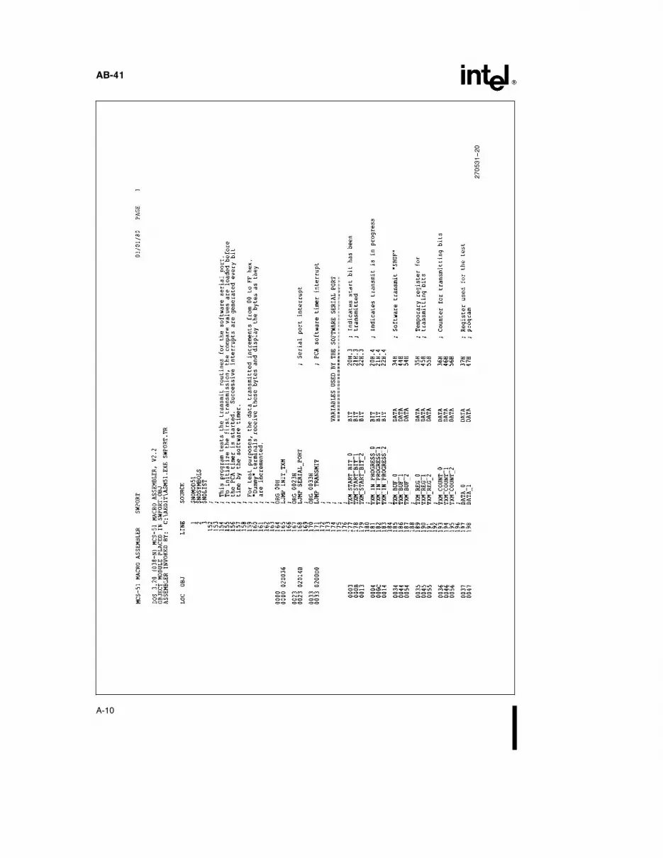
Variables
Listing 1 shows the variables used in both the receiveand transmit routines. Flags are defined to signify thestatus of the reception or transmission of a byte(e.g. RCVÐSTARTÐBIT, TXMÐSTARTÐBIT).RCVÐBUF and TXMÐBUF simulate the on-chip se-rial port SBUF as two separate buffer registers. Thetemporary registers, RCVÐREG and TXMÐREG,are used to save bits as they are received or transmitted.Finally, two counter registers keep track of how manybits have been received or transmitted.
Variables are also needed to define one-half and one-full bit times in units of PCA timer ticks. (One bit timee 1 / baud rate.) With the PCA timer incrementedevery machine cycle, the equation to calculate one bittime can be written as:
Osc. Freq.
(12) c (baud rate)e 1 bit time (in PCA timer ticks)
In this example, the baud rate is 2400 at 16 MHz.
16 MHz
(12) c (2400)e 556 counts e 22C Hex
The high and low byte of this value is placed in the varia-bles FULLÐBITÐHIGH and FULLÐBITÐLOW,respectively. 115H is the value loaded intoHALFÐBITÐHIGH and HALFÐBITÐLOW.
270531–1
1

AB-41
Listing 1. Variables used by the software serial port. Channel 0
270531–4
2
AB-41
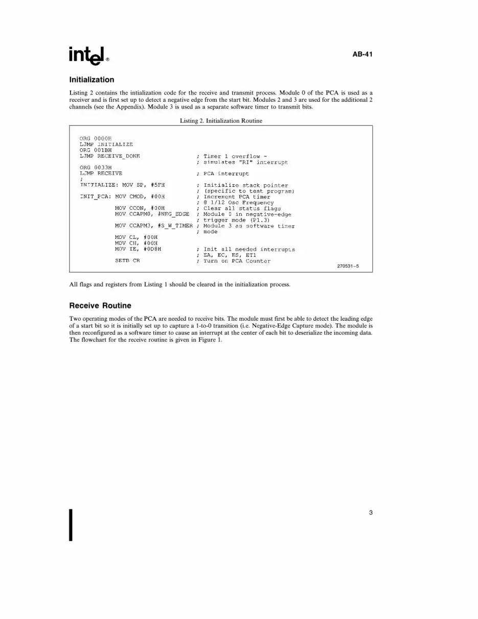
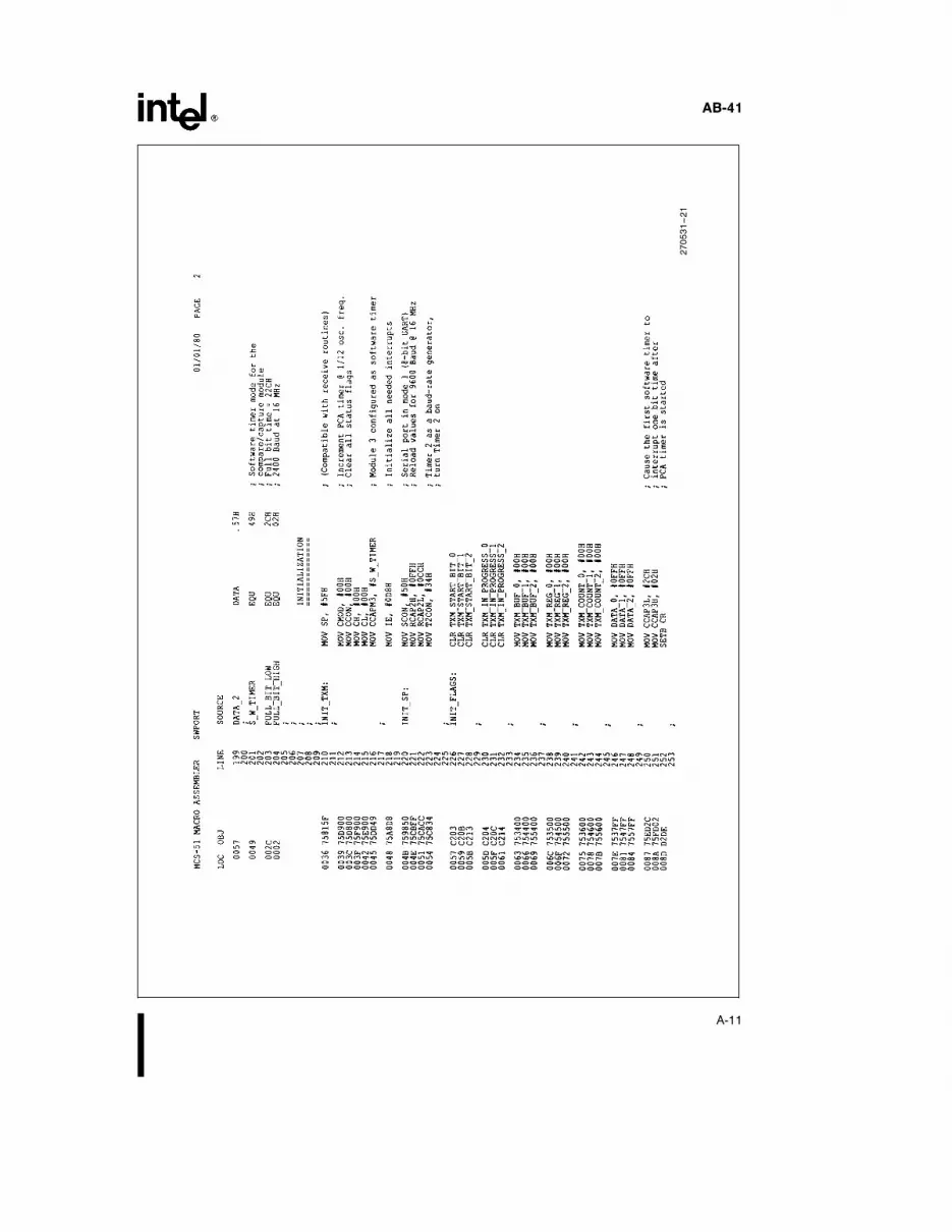
Initialization
Listing 2 contains the intialization code for the receive and transmit process. Module 0 of the PCA is used as areceiver and is first set up to detect a negative edge from the start bit. Modules 2 and 3 are used for the additional 2channels (see the Appendix). Module 3 is used as a separate software timer to transmit bits.
Listing 2. Initialization Routine
270531–5
All flags and registers from Listing 1 should be cleared in the initialization process.
Receive Routine
Two operating modes of the PCA are needed to receive bits. The module must first be able to detect the leading edgeof a start bit so it is initially set up to capture a 1-to-0 transition (i.e. Negative-Edge Capture mode). The module isthen reconfigured as a software timer to cause an interrupt at the center of each bit to deserialize the incoming data.The flowchart for the receive routine is given in Figure 1.
3

AB-41
270531–2
Figure 1. Flowchart for the Receive Routine
4
AB-41
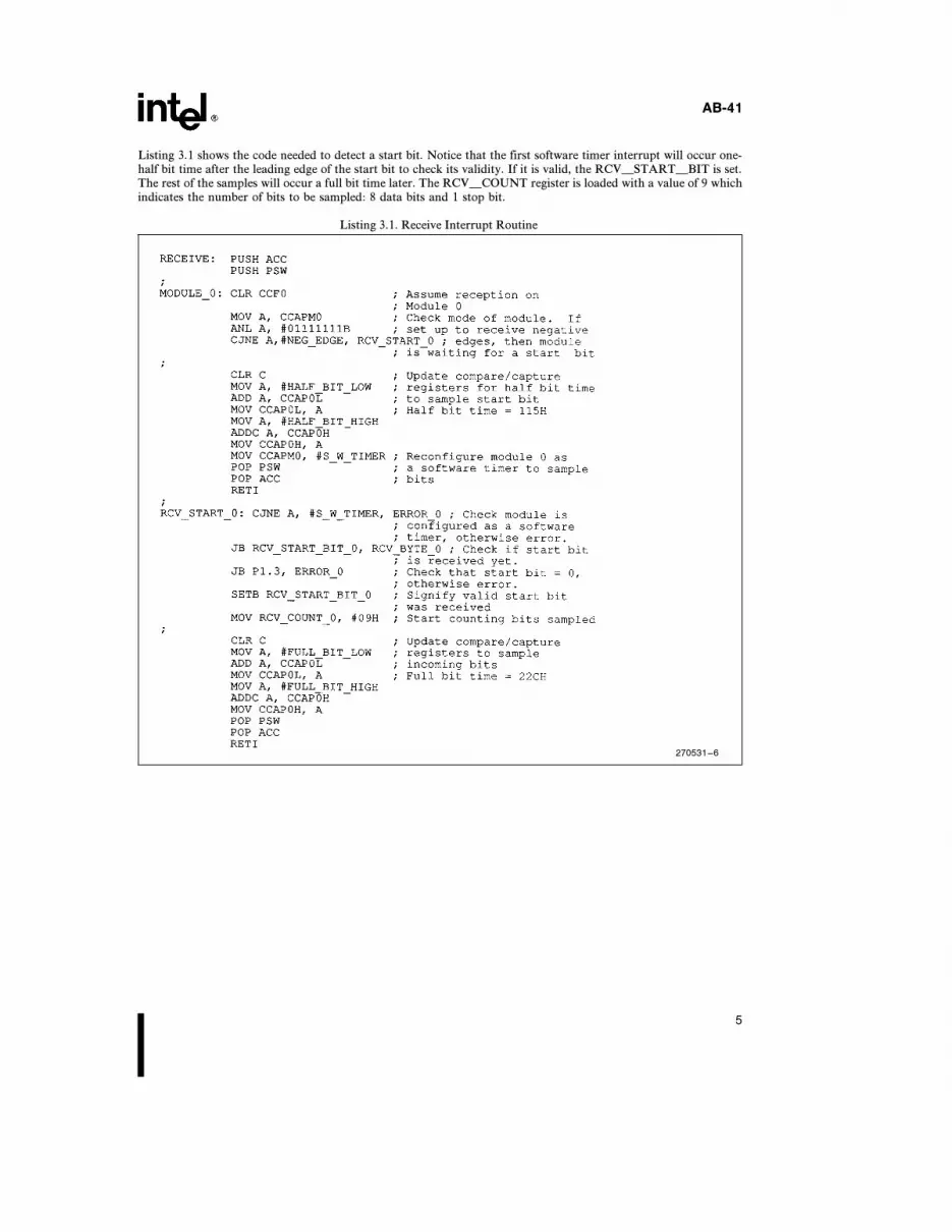
Listing 3.1 shows the code needed to detect a start bit. Notice that the first software timer interrupt will occur one-half bit time after the leading edge of the start bit to check its validity. If it is valid, the RCVÐSTARTÐBIT is set.The rest of the samples will occur a full bit time later. The RCVÐCOUNT register is loaded with a value of 9 whichindicates the number of bits to be sampled: 8 data bits and 1 stop bit.
Listing 3.1. Receive Interrupt Routine
270531–6
5

AB-41
The next 8 timer interrupts will receive the incoming data bits; the RCVÐCOUNT register keeps track of how manybits have been sampled. As each bit is sampled, it is shifted through the Carry Flag and saved in RCVÐREG. Theninth sample checks the validity of the stop bit. If it is valid, the data byte is moved into RCVÐBUF.
The main routine must have a way to know that a byte has been received. With the on-chip UART, the RI (ReceiveInterrupt) bit is set whenever a byte has been received. For the software serial port, any unimplemented interruptvector can be used to generate an interrupt when a byte has been received. This routine uses the Timer 1 Overflowinterrupt (its selection is arbitrary). A routine to test this interrupt is included in the listing in the Appendix.
Listing 3.2. Receive Interrupt Routine (Continued)
270531–7
In addition, an error routine (Listing 3.3) is included for invalid start or stop bits to offer some protection againstnoise. If an error occurs, the module is re-initialized to look for another start bit.
Listing 3.3 Error Routine for Receive Routine
270531–8
6

AB-41
Transmit Routine
Another PCA module is configured as a software timer to interrupt the CPU every bit time. With each timerinterrupt one or more bits can be transmitted through port pins. In the test program three channels were operatedsimultaneously, but in the listings below, one channel is shown for simplicity. The selection of port pins is userprogrammable. The flowchart for the transmit routine is given in Figure 2.
270531–3
Figure 2. Flowchart for the Transmit Routine
When a byte is ready to be transmitted, the main program moves the data byte into the TXMÐBUF register and setsthe corresponding TXMÐINÐPROGRESS bit. This bit informs the interrupt routine which channel is transmit-ting. The data byte is then moved in the storage register TXMÐREG, and the TXMÐCOUNT is loaded. This mainroutine is shown in Listing 4.1.
Listing 4.1 Transmit Set Up Routine. Channel 0.
270531–9
7

AB-41
Listing 4.2 shows the transmit interrupt routine. The first time through, the start bit is transmitted. As eachsuccessive interrupt outputs a bit, the contents of TXMÐREG is shifted right one place into the Carry flag, and theTXMÐCOUNT is decremented. When TXMÐCOUNT equals zero, the stop bit is transmitted.
Listing 4.2. Transmit Interrupt Routine
270531–10
Conclusion
The software routines in the Appendix can be altered to vary the baud rate and number of channels to fit a particularapplication. The number of channels which can be implemented is limited by the CPU time required to service thePCA interrupt. At higher baud rates, fewer channels can be run.
The test program verifies the simultaneous operation of three half-duplex channels at 2400 Baud and the on-chipfull-duplex channel at 9600 Baud. Thirty-three percent of the CPU time is required to operate all four channels. Thetest was run for several hours with no apparent malfunctions.
8

AB-41
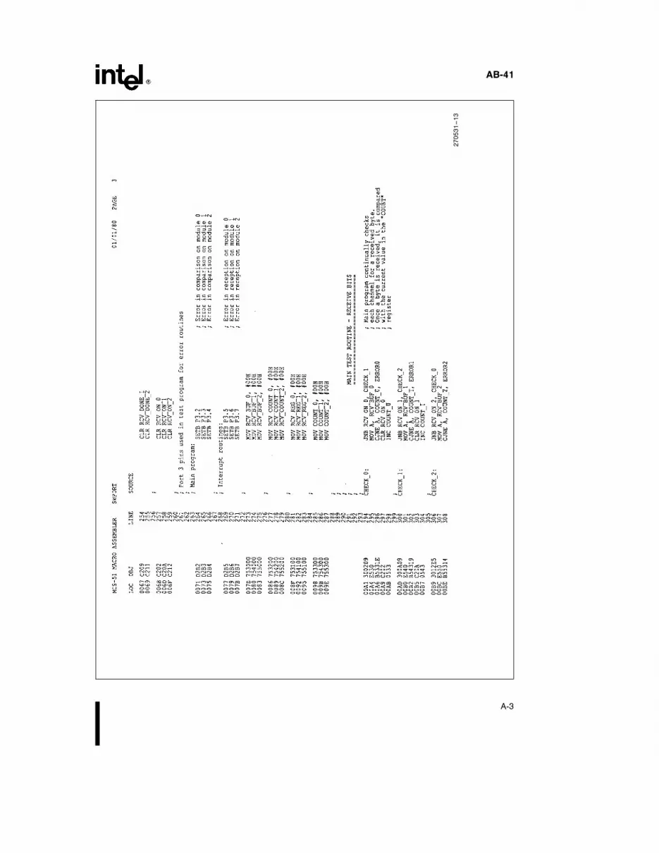
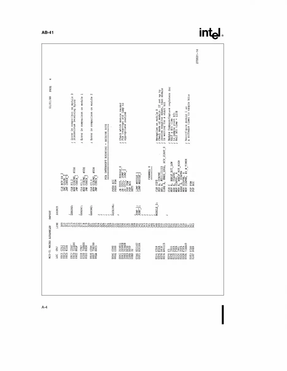
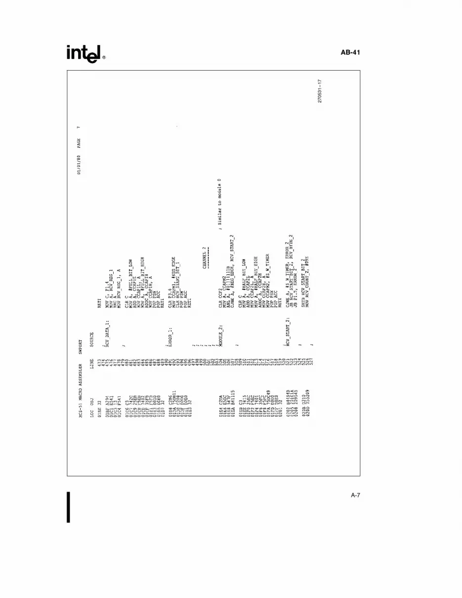
APPENDIX
270531–11
A-1

AB-41
270531–12
A-2
AB-41
270531–13
A-3
AB-41
270531–14
A-4

AB-41
270531–15
A-5

AB-41
270531–16
A-6
AB-41
270531–17
A-7

AB-41
270531–18
A-8

AB-41
270531–19
A-9
AB-41
270531–20
A-10
AB-41
270531–21
A-11

AB-41
270531–22
A-12

AB-41
270531–23
A-13

AB-41
270531–24
A-14
Related Documents