Plaza 600 Building 600 Stewart Street, Suite 1700 Seattle, Washington 98101 206.728.2674 September 12, 2013 Puget Sound Energy 355 110 th Avenue NE, EST-04W Bellevue, Washington 98004 Attention: Jason Henry, PE Subject: Addendum Letter Geotechnical Engineering Services Snoqualmie Switch Improvements Snoqualmie, Washington File No. 0186-679-10 INTRODUCTION The purpose of this letter is to provide an addendum to our geotechnical recommendations for the proposed improvements at the Snoqualmie Switch station located east of Salish Lodge off Railroad Avenue in Snoqualmie, Washington. Our geotechnical report for the project was dated March 25, 2013. Since we issued our report, Puget Sound Energy (PSE) has changed the retaining wall from a cast-in-place concrete wall to a RediRock wall. This letter provides revised design recommendations and calculations for the planned wall heights, based on our review of preliminary plans provided by PSE. RediRock Retaining Walls General The grade transition will be accomplished by using RediRock retaining walls up to 8 feet in height. We previously noted that loose soils must be overexcavated below the retaining walls and backfilled with CDF, and that detail is shown on the plans provided by PSE. We concur with the drainage details shown on the plans, which include a drainage zone and a collector pipe that daylights below the wall. Design Parameters We evaluated the RediRock retaining walls using the parameters presented in the table below, which are consistent with the values previously presented in our report.

Welcome message from author
This document is posted to help you gain knowledge. Please leave a comment to let me know what you think about it! Share it to your friends and learn new things together.
Transcript

Plaza 600 Building 600 Stewart Street, Suite 1700
Seattle, Washington 98101 206.728.2674
September 12, 2013
Puget Sound Energy 355 110th Avenue NE, EST-04W Bellevue, Washington 98004
Attention: Jason Henry, PE
Subject: Addendum Letter Geotechnical Engineering Services Snoqualmie Switch Improvements Snoqualmie, Washington File No. 0186-679-10
INTRODUCTION
The purpose of this letter is to provide an addendum to our geotechnical recommendations for the proposed improvements at the Snoqualmie Switch station located east of Salish Lodge off Railroad Avenue in Snoqualmie, Washington. Our geotechnical report for the project was dated March 25, 2013.
Since we issued our report, Puget Sound Energy (PSE) has changed the retaining wall from a cast-in-place concrete wall to a RediRock wall. This letter provides revised design recommendations and calculations for the planned wall heights, based on our review of preliminary plans provided by PSE.
RediRock Retaining Walls
General
The grade transition will be accomplished by using RediRock retaining walls up to 8 feet in height. We previously noted that loose soils must be overexcavated below the retaining walls and backfilled with CDF, and that detail is shown on the plans provided by PSE. We concur with the drainage details shown on the plans, which include a drainage zone and a collector pipe that daylights below the wall.
Design Parameters
We evaluated the RediRock retaining walls using the parameters presented in the table below, which are consistent with the values previously presented in our report.
Puget Sound Energy | September 12, 2013 Page 2
File No. 0186-679-10
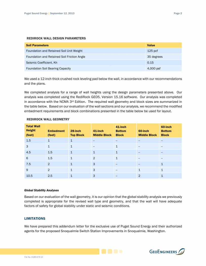
REDIROCK WALL DESIGN PARAMETERS
Soil Parameters Value
Foundation and Retained Soil Unit Weight 125 pcf
Foundation and Retained Soil Friction Angle 35 degrees
Seismic Coefficient, Kh 0.15
Foundation Soil Bearing Capacity 4,000 psf
We used a 12-inch thick crushed rock leveling pad below the wall, in accordance with our recommendations and the plans.
We completed analysis for a range of wall heights using the design parameters presented above. Our analysis was completed using the RediRock GEO5, Version 15.16 software. Our analysis was completed in accordance with the NCMA 3rd Edition. The required wall geometry and block sizes are summarized in the table below. Based on our evaluation of the wall sections and our analysis, we recommend the modified embedment requirements and block combinations presented in the table below be used for layout.
REDIROCK WALL GEOMETRY
Total Wall Height
(feet) Embedment (feet)
28-inch Top Block
41-inch Middle Block
41-inch Bottom Block
60-inch Middle Block
60-inch Bottom Block
1.5 1 1 -- -- -- --
3 1 1 -- 1 -- --
4.5 1.5 1 1 1 -- --
6 1.5 1 2 1 -- --
7.5 2 1 3 -- -- 1
9 2 1 3 -- 1 1
10.5 2.5 1 3 -- 2 1
Global Stability Analyses
Based on our evaluation of the wall geometry, it is our opinion that the global stability analysis we previously completed is appropriate for the revised wall type and geometry, and that the wall will have adequate factors of safety for global stability under static and seismic conditions.
LIMITATIONS
We have prepared this addendum letter for the exclusive use of Puget Sound Energy and their authorized agents for the proposed Snoqualmie Switch Station Improvements in Snoqualmie, Washington.


ATTACHMENT A RediRock Calculations

TDBPSE Snoqualmie Switch
1[GEO5 pro Redi - Redi Rock Wall | version 5.15.16.0 | Copyright © 2013 Fine spol. s r.o. All Rights Reserved | www.finesoftware.eu]
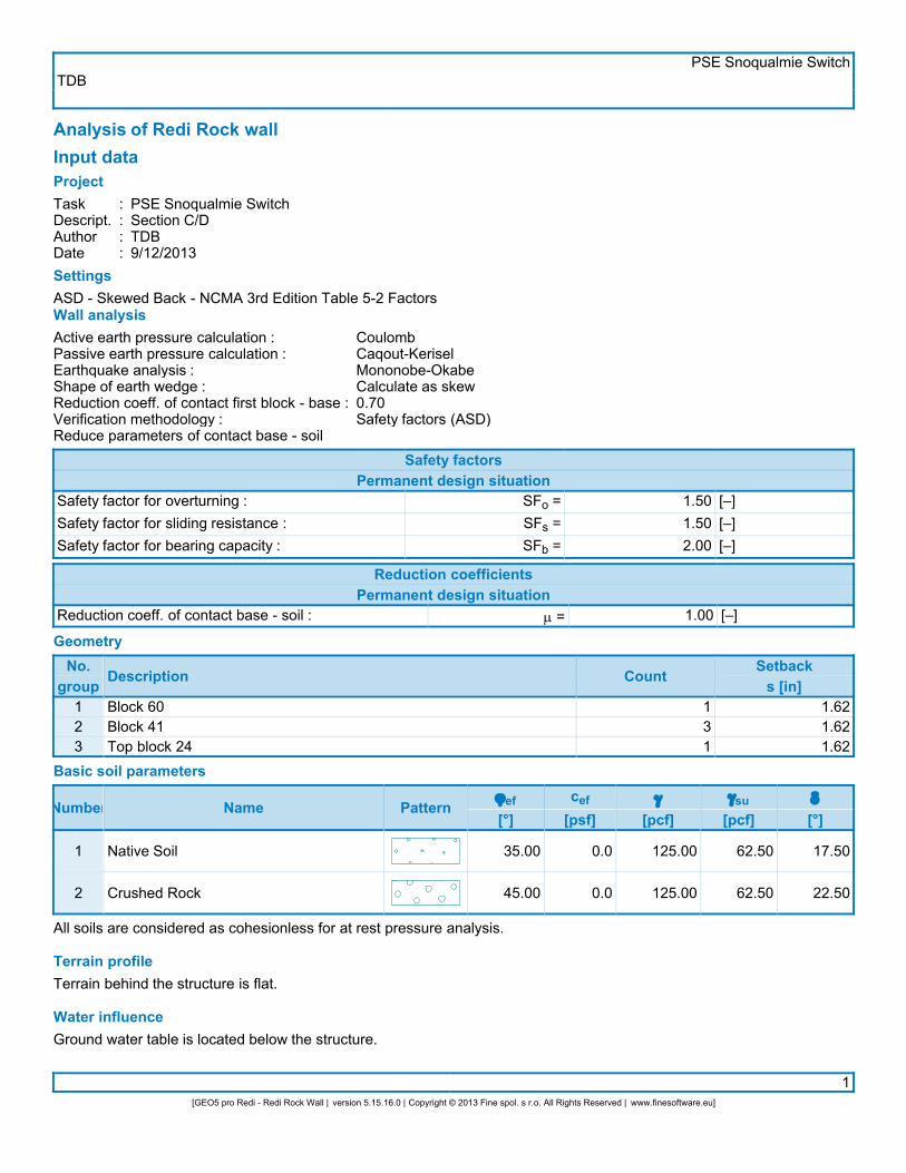
Analysis of Redi Rock wallInput dataProjectTaskDescript.AuthorDate
::::
PSE Snoqualmie SwitchSection C/DTDB9/12/2013
SettingsASD - Skewed Back - NCMA 3rd Edition Table 5-2 FactorsWall analysisActive earth pressure calculation :Passive earth pressure calculation :Earthquake analysis :Shape of earth wedge :Reduction coeff. of contact first block - base :Verification methodology :Reduce parameters of contact base - soil
CoulombCaqout-KeriselMononobe-OkabeCalculate as skew0.70Safety factors (ASD)
Safety factorsPermanent design situation
Safety factor for overturning :Safety factor for sliding resistance :Safety factor for bearing capacity :
SFo =SFs =SFb =
1.501.502.00
[–][–][–]
Reduction coefficientsPermanent design situation
Reduction coeff. of contact base - soil : m = 1.00 [–]
GeometryNo.
group Description Count Setbacks [in]
1 Top block 24 1 1.62Basic soil parameters
Number Name Patternjef[°]
cef[psf]
g[pcf]
gsu[pcf]
d[°]
1
2
Native Soil
Crushed Rock
35.00
45.00
0.0
0.0
125.00
125.00
62.50
62.50
17.50
22.50
All soils are considered as cohesionless for at rest pressure analysis. Terrain profileTerrain behind the structure is flat. Water influenceGround water table is located below the structure.

TDBPSE Snoqualmie Switch
2[GEO5 pro Redi - Redi Rock Wall | version 5.15.16.0 | Copyright © 2013 Fine spol. s r.o. All Rights Reserved | www.finesoftware.eu]
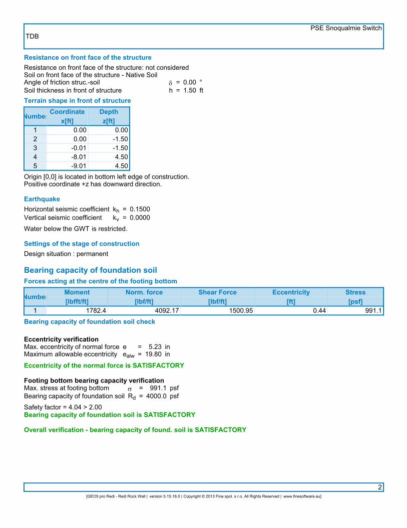
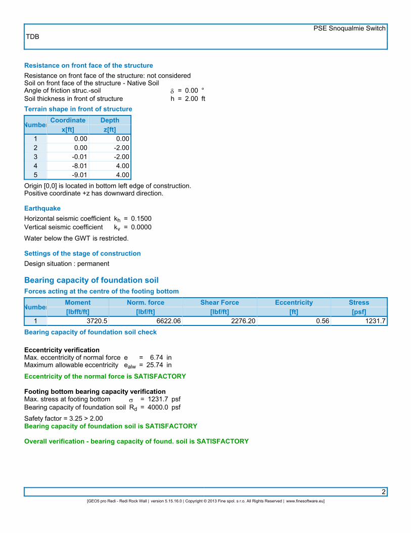
Resistance on front face of the structureResistance on front face of the structure: not consideredSoil on front face of the structure - Native SoilAngle of friction struc.-soilSoil thickness in front of structure
dh
==
0.001.00
°ft
Terrain shape in front of structure
Number Coordinatex[ft]Depthz[ft]
12345
0.000.00
-0.01-8.01-9.01
0.00-1.00-1.005.005.00
Origin [0,0] is located in bottom left edge of construction.Positive coordinate +z has downward direction. EarthquakeHorizontal seismic coefficientVertical seismic coefficient
khkv
==
0.15000.0000
Water below the GWT is restricted. Settings of the stage of constructionDesign situation : permanent Bearing capacity of foundation soilForces acting at the centre of the footing bottom
Number Moment[lbfft/ft]
Norm. force[lbf/ft]
Shear Force[lbf/ft]
Eccentricity[ft]
Stress[psf]
1 -122.3 1160.67 289.78 0.00 290.2Bearing capacity of foundation soil check
Eccentricity verificationMax. eccentricity of normal forceMaximum allowable eccentricity
eealw
==
0.0015.84
inin
Eccentricity of the normal force is SATISFACTORY
Footing bottom bearing capacity verificationMax. stress at footing bottomBearing capacity of foundation soil
sRd
==
290.24000.0
psfpsf
Safety factor = 13.79 > 2.00Bearing capacity of foundation soil is SATISFACTORY
Overall verification - bearing capacity of found. soil is SATISFACTORY

TDBPSE Snoqualmie Switch
3[GEO5 pro Redi - Redi Rock Wall | version 5.15.16.0 | Copyright © 2013 Fine spol. s r.o. All Rights Reserved | www.finesoftware.eu]
Dimensioning No. 1Forces acting on constructionName Fhor
[lbf/ft]App.Pt.Z [ft]
Fvert[lbf/ft]
App.Pt.X [ft]
Designcoefficient
Weight - wallEarthq.- constr.Weight - earth wedgeEarthquake - soil wedgeActive pressureEarthq.- act.pressure
0.045.60.0
11.533.413.6
-0.75-0.60-1.29-1.29-0.51-1.02
304.70.0
76.80.0
15.315.6
1.000.941.161.161.971.90
1.0001.0001.0001.0001.0001.000
Verification of block No.1
Check for overturning stabilityResisting momentOverturning moment
MresMovr
==
453.173.0
lbfft/ftlbfft/ft
Safety factor = 6.21 > 1.50Joint for overturning stability is SATISFACTORY
Check for slipResisting horizontal forceActive horizontal force
HresHact
==
288.63104.18
lbf/ftlbf/ft
Safety factor = 2.77 > 1.50Joint for verification is SATISFACTORY
Verification of bearing capacity of soil:Maximum stressBearing capacity of footing material
sRd
==
223.68000.0
psfpsf
Safety factor = 35.78 > 2.00Footing bearing capacity is SATISFACTORY

TDBPSE Snoqualmie Switch
1[GEO5 pro Redi - Redi Rock Wall | version 5.15.16.0 | Copyright © 2013 Fine spol. s r.o. All Rights Reserved | www.finesoftware.eu]
Analysis of Redi Rock wallInput dataProjectTaskDescript.AuthorDate
::::
PSE Snoqualmie SwitchSection C/DTDB9/12/2013
SettingsASD - Skewed Back - NCMA 3rd Edition Table 5-2 FactorsWall analysisActive earth pressure calculation :Passive earth pressure calculation :Earthquake analysis :Shape of earth wedge :Reduction coeff. of contact first block - base :Verification methodology :Reduce parameters of contact base - soil
CoulombCaqout-KeriselMononobe-OkabeCalculate as skew0.70Safety factors (ASD)
Safety factorsPermanent design situation
Safety factor for overturning :Safety factor for sliding resistance :Safety factor for bearing capacity :
SFo =SFs =SFb =
1.501.502.00
[–][–][–]
Reduction coefficientsPermanent design situation
Reduction coeff. of contact base - soil : m = 1.00 [–]
GeometryNo.
group Description Count Setbacks [in]
12
Block 41Top block 24
11
1.621.62
Basic soil parameters
Number Name Patternjef[°]
cef[psf]
g[pcf]
gsu[pcf]
d[°]
1
2
Native Soil
Crushed Rock
35.00
45.00
0.0
0.0
125.00
125.00
62.50
62.50
17.50
22.50
All soils are considered as cohesionless for at rest pressure analysis. Terrain profileTerrain behind the structure is flat. Water influenceGround water table is located below the structure.

TDBPSE Snoqualmie Switch
2[GEO5 pro Redi - Redi Rock Wall | version 5.15.16.0 | Copyright © 2013 Fine spol. s r.o. All Rights Reserved | www.finesoftware.eu]
Resistance on front face of the structureResistance on front face of the structure: not consideredSoil on front face of the structure - Native SoilAngle of friction struc.-soilSoil thickness in front of structure
dh
==
0.001.00
°ft
Terrain shape in front of structure
Number Coordinatex[ft]Depthz[ft]
12345
0.000.00
-0.01-8.01-9.01
0.00-1.00-1.005.005.00
Origin [0,0] is located in bottom left edge of construction.Positive coordinate +z has downward direction. EarthquakeHorizontal seismic coefficientVertical seismic coefficient
khkv
==
0.15000.0000
Water below the GWT is restricted. Settings of the stage of constructionDesign situation : permanent Bearing capacity of foundation soilForces acting at the centre of the footing bottom
Number Moment[lbfft/ft]
Norm. force[lbf/ft]
Shear Force[lbf/ft]
Eccentricity[ft]
Stress[psf]
1 -65.9 2348.47 640.15 0.00 469.7Bearing capacity of foundation soil check
Eccentricity verificationMax. eccentricity of normal forceMaximum allowable eccentricity
eealw
==
0.0019.80
inin
Eccentricity of the normal force is SATISFACTORY
Footing bottom bearing capacity verificationMax. stress at footing bottomBearing capacity of foundation soil
sRd
==
469.74000.0
psfpsf
Safety factor = 8.52 > 2.00Bearing capacity of foundation soil is SATISFACTORY
Overall verification - bearing capacity of found. soil is SATISFACTORY

TDBPSE Snoqualmie Switch
3[GEO5 pro Redi - Redi Rock Wall | version 5.15.16.0 | Copyright © 2013 Fine spol. s r.o. All Rights Reserved | www.finesoftware.eu]
Dimensioning No. 1Forces acting on constructionName Fhor
[lbf/ft]App.Pt.Z [ft]
Fvert[lbf/ft]
App.Pt.X [ft]
Designcoefficient
Weight - wallEarthq.- constr.Weight - earth wedgeEarthquake - soil wedgeActive pressureEarthq.- act.pressure
0.0144.4
0.036.3
137.156.7
-1.22-1.18-2.36-2.36-1.04-2.04
962.80.0
241.70.0
104.488.5
1.511.492.162.163.192.96
1.0001.0001.0001.0001.0001.000
Verification of block No.1
Check for overturning stabilityResisting momentOverturning moment
MresMovr
==
2575.1512.8
lbfft/ftlbfft/ft
Safety factor = 5.02 > 1.50Joint for overturning stability is SATISFACTORY
Check for slipResisting horizontal forceActive horizontal force
HresHact
==
978.20374.39
lbf/ftlbf/ft
Safety factor = 2.61 > 1.50Joint for verification is SATISFACTORY
Verification of bearing capacity of soil:Maximum stressBearing capacity of footing material
sRd
==
473.58000.0
psfpsf
Safety factor = 16.90 > 2.00Footing bearing capacity is SATISFACTORY Dimensioning No. 2Forces acting on constructionName Fhor
[lbf/ft]App.Pt.Z [ft]
Fvert[lbf/ft]
App.Pt.X [ft]
Designcoefficient
Weight - wallEarthq.- constr.Weight - earth wedgeEarthquake - soil wedgeActive pressureEarthq.- act.pressure
0.045.60.0
11.533.413.6
-0.75-0.60-1.29-1.29-0.51-1.02
304.70.0
76.80.0
15.315.6
1.000.941.161.161.971.90
1.0001.0001.0001.0001.0001.000
Verification of block No.2
Check for overturning stabilityResisting momentOverturning moment
MresMovr
==
453.173.0
lbfft/ftlbfft/ft

TDBPSE Snoqualmie Switch
1[GEO5 pro Redi - Redi Rock Wall | version 5.15.16.0 | Copyright © 2013 Fine spol. s r.o. All Rights Reserved | www.finesoftware.eu]
Analysis of Redi Rock wallInput dataProjectTaskDescript.AuthorDate
::::
PSE Snoqualmie SwitchSection C/DTDB9/12/2013
SettingsASD - Skewed Back - NCMA 3rd Edition Table 5-2 FactorsWall analysisActive earth pressure calculation :Passive earth pressure calculation :Earthquake analysis :Shape of earth wedge :Reduction coeff. of contact first block - base :Verification methodology :Reduce parameters of contact base - soil
CoulombCaqout-KeriselMononobe-OkabeCalculate as skew0.70Safety factors (ASD)
Safety factorsPermanent design situation
Safety factor for overturning :Safety factor for sliding resistance :Safety factor for bearing capacity :
SFo =SFs =SFb =
1.501.502.00
[–][–][–]
Reduction coefficientsPermanent design situation
Reduction coeff. of contact base - soil : m = 1.00 [–]
GeometryNo.
group Description Count Setbacks [in]
12
Block 41Top block 24
21
1.621.62
Basic soil parameters
Number Name Patternjef[°]
cef[psf]
g[pcf]
gsu[pcf]
d[°]
1
2
Native Soil
Crushed Rock
35.00
45.00
0.0
0.0
125.00
125.00
62.50
62.50
17.50
22.50
All soils are considered as cohesionless for at rest pressure analysis. Terrain profileTerrain behind the structure is flat. Water influenceGround water table is located below the structure.

TDBPSE Snoqualmie Switch
2[GEO5 pro Redi - Redi Rock Wall | version 5.15.16.0 | Copyright © 2013 Fine spol. s r.o. All Rights Reserved | www.finesoftware.eu]
Resistance on front face of the structureResistance on front face of the structure: not consideredSoil on front face of the structure - Native SoilAngle of friction struc.-soilSoil thickness in front of structure
dh
==
0.001.50
°ft
Terrain shape in front of structure
Number Coordinatex[ft]Depthz[ft]
12345
0.000.00
-0.01-8.01-9.01
0.00-1.50-1.504.504.50
Origin [0,0] is located in bottom left edge of construction.Positive coordinate +z has downward direction. EarthquakeHorizontal seismic coefficientVertical seismic coefficient
khkv
==
0.15000.0000
Water below the GWT is restricted. Settings of the stage of constructionDesign situation : permanent Bearing capacity of foundation soilForces acting at the centre of the footing bottom
Number Moment[lbfft/ft]
Norm. force[lbf/ft]
Shear Force[lbf/ft]
Eccentricity[ft]
Stress[psf]
1 557.9 3208.48 1029.38 0.17 689.7Bearing capacity of foundation soil check
Eccentricity verificationMax. eccentricity of normal forceMaximum allowable eccentricity
eealw
==
2.0919.80
inin
Eccentricity of the normal force is SATISFACTORY
Footing bottom bearing capacity verificationMax. stress at footing bottomBearing capacity of foundation soil
sRd
==
689.74000.0
psfpsf
Safety factor = 5.80 > 2.00Bearing capacity of foundation soil is SATISFACTORY
Overall verification - bearing capacity of found. soil is SATISFACTORY

TDBPSE Snoqualmie Switch
3[GEO5 pro Redi - Redi Rock Wall | version 5.15.16.0 | Copyright © 2013 Fine spol. s r.o. All Rights Reserved | www.finesoftware.eu]
Dimensioning No. 1Forces acting on constructionName Fhor
[lbf/ft]App.Pt.Z [ft]
Fvert[lbf/ft]
App.Pt.X [ft]
Designcoefficient
Weight - wallEarthq.- constr.Weight - earth wedgeEarthquake - soil wedgeActive pressureEarthq.- act.pressure
0.0243.1
0.036.3
287.0123.4
-1.92-1.89-3.86-3.86-1.55-3.07
1620.90.0
241.70.0
139.5154.2
1.661.652.302.303.343.13
1.0001.0001.0001.0001.0001.000
Verification of block No.1
Check for overturning stabilityResisting momentOverturning moment
MresMovr
==
4200.81422.5
lbfft/ftlbfft/ft
Safety factor = 2.95 > 1.50Joint for overturning stability is SATISFACTORY
Check for slipResisting horizontal forceActive horizontal force
HresHact
==
1509.42689.73
lbf/ftlbf/ft
Safety factor = 2.19 > 1.50Joint for verification is SATISFACTORY
Verification of bearing capacity of soil:Maximum stressBearing capacity of footing material
sRd
==
836.88000.0
psfpsf
Safety factor = 9.56 > 2.00Footing bearing capacity is SATISFACTORY Dimensioning No. 2Forces acting on constructionName Fhor
[lbf/ft]App.Pt.Z [ft]
Fvert[lbf/ft]
App.Pt.X [ft]
Designcoefficient
Weight - wallEarthq.- constr.Weight - earth wedgeEarthquake - soil wedgeActive pressureEarthq.- act.pressure
0.0144.4
0.036.3
137.156.7
-1.22-1.18-2.36-2.36-1.04-2.04
962.80.0
241.70.0
104.488.5
1.511.492.162.163.192.96
1.0001.0001.0001.0001.0001.000
Verification of block No.2
Check for overturning stabilityResisting momentOverturning moment
MresMovr
==
2575.1512.8
lbfft/ftlbfft/ft

TDBPSE Snoqualmie Switch
4[GEO5 pro Redi - Redi Rock Wall | version 5.15.16.0 | Copyright © 2013 Fine spol. s r.o. All Rights Reserved | www.finesoftware.eu]
Safety factor = 5.02 > 1.50Joint for overturning stability is SATISFACTORY
Check for slipResisting horizontal forceActive horizontal force
HresHact
==
6915.28374.39
lbf/ftlbf/ft
Safety factor = 18.47 > 1.50Joint for verification is SATISFACTORY
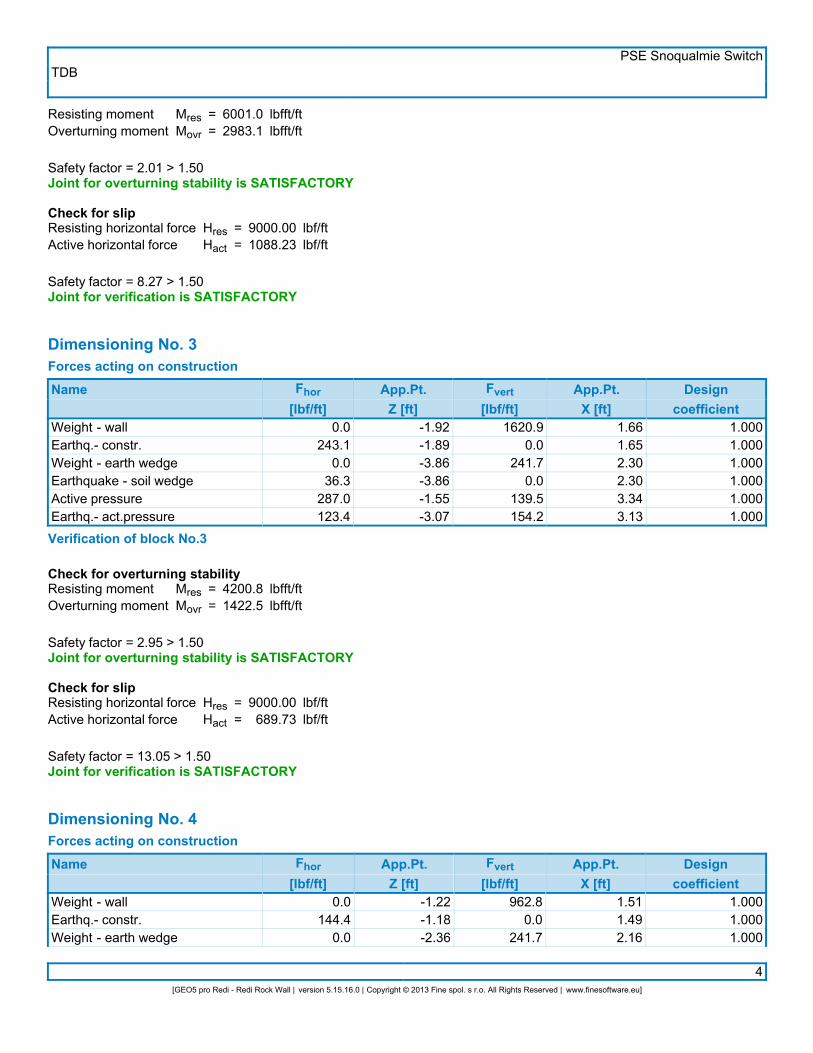
Dimensioning No. 3Forces acting on constructionName Fhor
[lbf/ft]App.Pt.Z [ft]
Fvert[lbf/ft]
App.Pt.X [ft]
Designcoefficient
Weight - wallEarthq.- constr.Weight - earth wedgeEarthquake - soil wedgeActive pressureEarthq.- act.pressure
0.045.60.0
11.533.413.6
-0.75-0.60-1.29-1.29-0.51-1.02
304.70.0
76.80.0
15.315.6
1.000.941.161.161.971.90
1.0001.0001.0001.0001.0001.000
Verification of block No.3
Check for overturning stabilityResisting momentOverturning moment
MresMovr
==
453.173.0
lbfft/ftlbfft/ft
Safety factor = 6.21 > 1.50Joint for overturning stability is SATISFACTORY
Check for slipResisting horizontal forceActive horizontal force
HresHact
==
3238.82104.18
lbf/ftlbf/ft
Safety factor = 31.09 > 1.50Joint for verification is SATISFACTORY

TDBPSE Snoqualmie Switch
1[GEO5 pro Redi - Redi Rock Wall | version 5.15.16.0 | Copyright © 2013 Fine spol. s r.o. All Rights Reserved | www.finesoftware.eu]
Analysis of Redi Rock wallInput dataProjectTaskDescript.AuthorDate
::::
PSE Snoqualmie SwitchSection C/DTDB9/12/2013
SettingsASD - Skewed Back - NCMA 3rd Edition Table 5-2 FactorsWall analysisActive earth pressure calculation :Passive earth pressure calculation :Earthquake analysis :Shape of earth wedge :Reduction coeff. of contact first block - base :Verification methodology :Reduce parameters of contact base - soil
CoulombCaqout-KeriselMononobe-OkabeCalculate as skew0.70Safety factors (ASD)
Safety factorsPermanent design situation
Safety factor for overturning :Safety factor for sliding resistance :Safety factor for bearing capacity :
SFo =SFs =SFb =
1.501.502.00
[–][–][–]
Reduction coefficientsPermanent design situation
Reduction coeff. of contact base - soil : m = 1.00 [–]
GeometryNo.
group Description Count Setbacks [in]
12
Block 41Top block 24
31
1.621.62
Basic soil parameters
Number Name Patternjef[°]
cef[psf]
g[pcf]
gsu[pcf]
d[°]
1
2
Native Soil
Crushed Rock
35.00
45.00
0.0
0.0
125.00
125.00
62.50
62.50
17.50
22.50
All soils are considered as cohesionless for at rest pressure analysis. Terrain profileTerrain behind the structure is flat. Water influenceGround water table is located below the structure.
TDBPSE Snoqualmie Switch
2[GEO5 pro Redi - Redi Rock Wall | version 5.15.16.0 | Copyright © 2013 Fine spol. s r.o. All Rights Reserved | www.finesoftware.eu]
Resistance on front face of the structureResistance on front face of the structure: not consideredSoil on front face of the structure - Native SoilAngle of friction struc.-soilSoil thickness in front of structure
dh
==
0.001.50
°ft
Terrain shape in front of structure
Number Coordinatex[ft]Depthz[ft]
12345
0.000.00
-0.01-8.01-9.01
0.00-1.50-1.504.504.50
Origin [0,0] is located in bottom left edge of construction.Positive coordinate +z has downward direction. EarthquakeHorizontal seismic coefficientVertical seismic coefficient
khkv
==
0.15000.0000
Water below the GWT is restricted. Settings of the stage of constructionDesign situation : permanent Bearing capacity of foundation soilForces acting at the centre of the footing bottom
Number Moment[lbfft/ft]
Norm. force[lbf/ft]
Shear Force[lbf/ft]
Eccentricity[ft]
Stress[psf]
1 1782.4 4092.17 1500.95 0.44 991.1Bearing capacity of foundation soil check
Eccentricity verificationMax. eccentricity of normal forceMaximum allowable eccentricity
eealw
==
5.2319.80
inin
Eccentricity of the normal force is SATISFACTORY
Footing bottom bearing capacity verificationMax. stress at footing bottomBearing capacity of foundation soil
sRd
==
991.14000.0
psfpsf
Safety factor = 4.04 > 2.00Bearing capacity of foundation soil is SATISFACTORY
Overall verification - bearing capacity of found. soil is SATISFACTORY
TDBPSE Snoqualmie Switch
3[GEO5 pro Redi - Redi Rock Wall | version 5.15.16.0 | Copyright © 2013 Fine spol. s r.o. All Rights Reserved | www.finesoftware.eu]
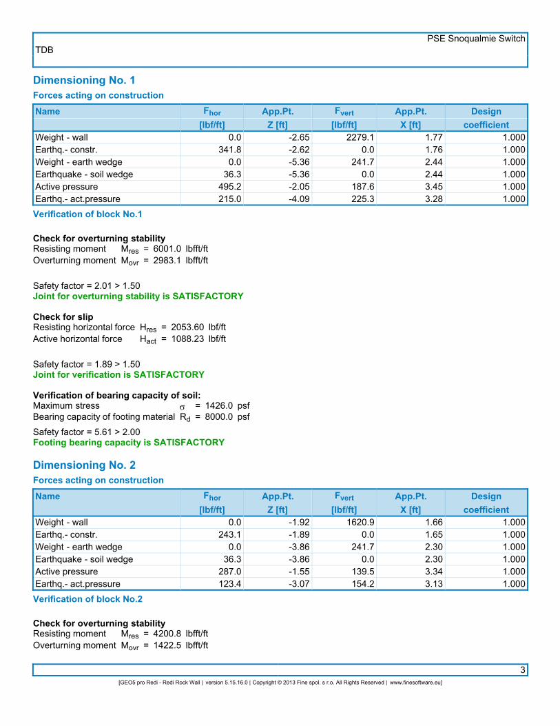
Dimensioning No. 1Forces acting on constructionName Fhor
[lbf/ft]App.Pt.Z [ft]
Fvert[lbf/ft]
App.Pt.X [ft]
Designcoefficient
Weight - wallEarthq.- constr.Weight - earth wedgeEarthquake - soil wedgeActive pressureEarthq.- act.pressure
0.0341.8
0.036.3
495.2215.0
-2.65-2.62-5.36-5.36-2.05-4.09
2279.10.0
241.70.0
187.6225.3
1.771.762.442.443.453.28
1.0001.0001.0001.0001.0001.000
Verification of block No.1
Check for overturning stabilityResisting momentOverturning moment
MresMovr
==
6001.02983.1
lbfft/ftlbfft/ft
Safety factor = 2.01 > 1.50Joint for overturning stability is SATISFACTORY
Check for slipResisting horizontal forceActive horizontal force
HresHact
==
2053.601088.23
lbf/ftlbf/ft
Safety factor = 1.89 > 1.50Joint for verification is SATISFACTORY
Verification of bearing capacity of soil:Maximum stressBearing capacity of footing material
sRd
==
1426.08000.0
psfpsf
Safety factor = 5.61 > 2.00Footing bearing capacity is SATISFACTORY Dimensioning No. 2Forces acting on constructionName Fhor
[lbf/ft]App.Pt.Z [ft]
Fvert[lbf/ft]
App.Pt.X [ft]
Designcoefficient
Weight - wallEarthq.- constr.Weight - earth wedgeEarthquake - soil wedgeActive pressureEarthq.- act.pressure
0.0243.1
0.036.3
287.0123.4
-1.92-1.89-3.86-3.86-1.55-3.07
1620.90.0
241.70.0
139.5154.2
1.661.652.302.303.343.13
1.0001.0001.0001.0001.0001.000
Verification of block No.2
Check for overturning stabilityResisting momentOverturning moment
MresMovr
==
4200.81422.5
lbfft/ftlbfft/ft
TDBPSE Snoqualmie Switch
4[GEO5 pro Redi - Redi Rock Wall | version 5.15.16.0 | Copyright © 2013 Fine spol. s r.o. All Rights Reserved | www.finesoftware.eu]
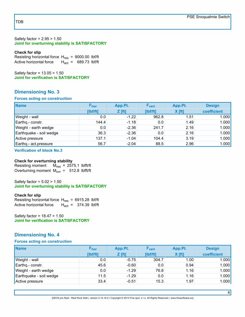
Safety factor = 2.95 > 1.50Joint for overturning stability is SATISFACTORY
Check for slipResisting horizontal forceActive horizontal force
HresHact
==
9000.00689.73
lbf/ftlbf/ft
Safety factor = 13.05 > 1.50Joint for verification is SATISFACTORY
Dimensioning No. 3Forces acting on constructionName Fhor
[lbf/ft]App.Pt.Z [ft]
Fvert[lbf/ft]
App.Pt.X [ft]
Designcoefficient
Weight - wallEarthq.- constr.Weight - earth wedgeEarthquake - soil wedgeActive pressureEarthq.- act.pressure
0.0144.4
0.036.3
137.156.7
-1.22-1.18-2.36-2.36-1.04-2.04
962.80.0
241.70.0
104.488.5
1.511.492.162.163.192.96
1.0001.0001.0001.0001.0001.000
Verification of block No.3
Check for overturning stabilityResisting momentOverturning moment
MresMovr
==
2575.1512.8
lbfft/ftlbfft/ft
Safety factor = 5.02 > 1.50Joint for overturning stability is SATISFACTORY
Check for slipResisting horizontal forceActive horizontal force
HresHact
==
6915.28374.39
lbf/ftlbf/ft
Safety factor = 18.47 > 1.50Joint for verification is SATISFACTORY
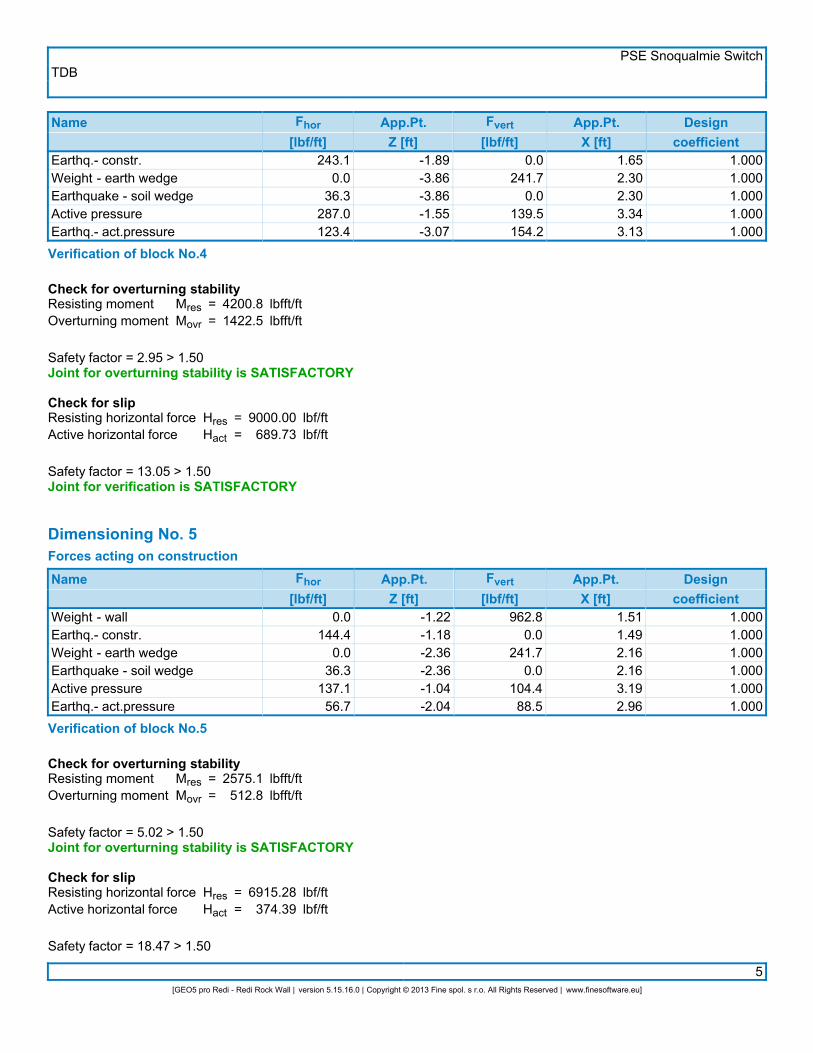
Dimensioning No. 4Forces acting on constructionName Fhor
[lbf/ft]App.Pt.Z [ft]
Fvert[lbf/ft]
App.Pt.X [ft]
Designcoefficient
Weight - wallEarthq.- constr.Weight - earth wedgeEarthquake - soil wedgeActive pressure
0.045.60.0
11.533.4
-0.75-0.60-1.29-1.29-0.51
304.70.0
76.80.0
15.3
1.000.941.161.161.97
1.0001.0001.0001.0001.000
TDBPSE Snoqualmie Switch
5[GEO5 pro Redi - Redi Rock Wall | version 5.15.16.0 | Copyright © 2013 Fine spol. s r.o. All Rights Reserved | www.finesoftware.eu]
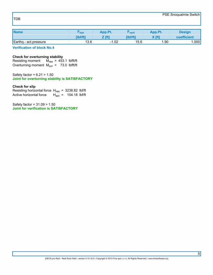
Name Fhor[lbf/ft]
App.Pt.Z [ft]
Fvert[lbf/ft]
App.Pt.X [ft]
Designcoefficient
Earthq.- act.pressure 13.6 -1.02 15.6 1.90 1.000Verification of block No.4
Check for overturning stabilityResisting momentOverturning moment
MresMovr
==
453.173.0
lbfft/ftlbfft/ft
Safety factor = 6.21 > 1.50Joint for overturning stability is SATISFACTORY
Check for slipResisting horizontal forceActive horizontal force
HresHact
==
3238.82104.18
lbf/ftlbf/ft
Safety factor = 31.09 > 1.50Joint for verification is SATISFACTORY

TDBPSE Snoqualmie Switch
4[GEO5 pro Redi - Redi Rock Wall | version 5.15.16.0 | Copyright © 2013 Fine spol. s r.o. All Rights Reserved | www.finesoftware.eu]
Safety factor = 6.21 > 1.50Joint for overturning stability is SATISFACTORY
Check for slipResisting horizontal forceActive horizontal force
HresHact
==
3238.82104.18
lbf/ftlbf/ft
Safety factor = 31.09 > 1.50Joint for verification is SATISFACTORY
TDBPSE Snoqualmie Switch
1[GEO5 pro Redi - Redi Rock Wall | version 5.15.16.0 | Copyright © 2013 Fine spol. s r.o. All Rights Reserved | www.finesoftware.eu]
Analysis of Redi Rock wallInput dataProjectTaskDescript.AuthorDate
::::
PSE Snoqualmie SwitchSection C/DTDB9/12/2013
SettingsASD - Skewed Back - NCMA 3rd Edition Table 5-2 FactorsWall analysisActive earth pressure calculation :Passive earth pressure calculation :Earthquake analysis :Shape of earth wedge :Reduction coeff. of contact first block - base :Verification methodology :Reduce parameters of contact base - soil
CoulombCaqout-KeriselMononobe-OkabeCalculate as skew0.70Safety factors (ASD)
Safety factorsPermanent design situation
Safety factor for overturning :Safety factor for sliding resistance :Safety factor for bearing capacity :
SFo =SFs =SFb =
1.501.502.00
[–][–][–]
Reduction coefficientsPermanent design situation
Reduction coeff. of contact base - soil : m = 1.00 [–]
GeometryNo.
group Description Count Setbacks [in]
123
Block 60Block 41Top block 24
131
1.621.621.62
Basic soil parameters
Number Name Patternjef[°]
cef[psf]
g[pcf]
gsu[pcf]
d[°]
1
2
Native Soil
Crushed Rock
35.00
45.00
0.0
0.0
125.00
125.00
62.50
62.50
17.50
22.50
All soils are considered as cohesionless for at rest pressure analysis. Terrain profileTerrain behind the structure is flat. Water influenceGround water table is located below the structure.
TDBPSE Snoqualmie Switch
2[GEO5 pro Redi - Redi Rock Wall | version 5.15.16.0 | Copyright © 2013 Fine spol. s r.o. All Rights Reserved | www.finesoftware.eu]
Resistance on front face of the structureResistance on front face of the structure: not consideredSoil on front face of the structure - Native SoilAngle of friction struc.-soilSoil thickness in front of structure
dh
==
0.002.00
°ft
Terrain shape in front of structure
Number Coordinatex[ft]
Depthz[ft]
12345
0.000.00
-0.01-8.01-9.01
0.00-2.00-2.004.004.00
Origin [0,0] is located in bottom left edge of construction.Positive coordinate +z has downward direction. EarthquakeHorizontal seismic coefficientVertical seismic coefficient
khkv
==
0.15000.0000
Water below the GWT is restricted. Settings of the stage of constructionDesign situation : permanent Bearing capacity of foundation soilForces acting at the centre of the footing bottom
Number Moment[lbfft/ft]
Norm. force[lbf/ft]
Shear Force[lbf/ft]
Eccentricity[ft]
Stress[psf]
1 3720.5 6622.06 2276.20 0.56 1231.7Bearing capacity of foundation soil check
Eccentricity verificationMax. eccentricity of normal forceMaximum allowable eccentricity
eealw
==
6.7425.74
inin
Eccentricity of the normal force is SATISFACTORY
Footing bottom bearing capacity verificationMax. stress at footing bottomBearing capacity of foundation soil
sRd
==
1231.74000.0
psfpsf
Safety factor = 3.25 > 2.00Bearing capacity of foundation soil is SATISFACTORY
Overall verification - bearing capacity of found. soil is SATISFACTORY

TDBPSE Snoqualmie Switch
3[GEO5 pro Redi - Redi Rock Wall | version 5.15.16.0 | Copyright © 2013 Fine spol. s r.o. All Rights Reserved | www.finesoftware.eu]
Dimensioning No. 1Forces acting on constructionName Fhor
[lbf/ft]App.Pt.
Z [ft]Fvert
[lbf/ft]App.Pt.
X [ft]Design
coefficientWeight - wallEarthq.- constr.Weight - earth wedgeEarthquake - soil wedgeWeight - earth wedgeEarthquake - soil wedgeActive pressureEarthq.- act.pressure
0.0488.0
0.035.80.0
36.3874.4345.7
-3.13-3.11-2.35-2.35-6.86-6.86-2.50-5.02
3254.10.0
238.80.0
241.70.0
986.6463.3
2.082.084.064.062.572.574.363.74
1.0001.0001.0001.0001.0001.0001.0001.000
Verification of block No.1
Check for overturning stabilityResisting momentOverturning moment
MresMovr
==
14401.85775.6
lbfft/ftlbfft/ft
Safety factor = 2.49 > 1.50Joint for overturning stability is SATISFACTORY
Check for slipResisting horizontal forceActive horizontal force
HresHact
==
3629.071780.18
lbf/ftlbf/ft
Safety factor = 2.04 > 1.50Joint for verification is SATISFACTORY
Verification of bearing capacity of soil:Maximum stressBearing capacity of footing material
sRd
==
1557.98000.0
psfpsf
Safety factor = 5.14 > 2.00Footing bearing capacity is SATISFACTORY Dimensioning No. 2Forces acting on constructionName Fhor
[lbf/ft]App.Pt.
Z [ft]Fvert
[lbf/ft]App.Pt.
X [ft]Design
coefficientWeight - wallEarthq.- constr.Weight - earth wedgeEarthquake - soil wedgeActive pressureEarthq.- act.pressure
0.0341.8
0.036.3
495.2215.0
-2.65-2.62-5.36-5.36-2.05-4.09
2279.10.0
241.70.0
187.6225.3
1.771.762.442.443.453.28
1.0001.0001.0001.0001.0001.000
Verification of block No.2
Check for overturning stability
TDBPSE Snoqualmie Switch
4[GEO5 pro Redi - Redi Rock Wall | version 5.15.16.0 | Copyright © 2013 Fine spol. s r.o. All Rights Reserved | www.finesoftware.eu]
Resisting momentOverturning moment
MresMovr
==
6001.02983.1
lbfft/ftlbfft/ft
Safety factor = 2.01 > 1.50Joint for overturning stability is SATISFACTORY
Check for slipResisting horizontal forceActive horizontal force
HresHact
==
9000.001088.23
lbf/ftlbf/ft
Safety factor = 8.27 > 1.50Joint for verification is SATISFACTORY
Dimensioning No. 3Forces acting on constructionName Fhor
[lbf/ft]App.Pt.
Z [ft]Fvert
[lbf/ft]App.Pt.
X [ft]Design
coefficientWeight - wallEarthq.- constr.Weight - earth wedgeEarthquake - soil wedgeActive pressureEarthq.- act.pressure
0.0243.1
0.036.3
287.0123.4
-1.92-1.89-3.86-3.86-1.55-3.07
1620.90.0
241.70.0
139.5154.2
1.661.652.302.303.343.13
1.0001.0001.0001.0001.0001.000
Verification of block No.3
Check for overturning stabilityResisting momentOverturning moment
MresMovr
==
4200.81422.5
lbfft/ftlbfft/ft
Safety factor = 2.95 > 1.50Joint for overturning stability is SATISFACTORY
Check for slipResisting horizontal forceActive horizontal force
HresHact
==
9000.00689.73
lbf/ftlbf/ft
Safety factor = 13.05 > 1.50Joint for verification is SATISFACTORY
Dimensioning No. 4Forces acting on constructionName Fhor
[lbf/ft]App.Pt.
Z [ft]Fvert
[lbf/ft]App.Pt.
X [ft]Design
coefficientWeight - wallEarthq.- constr.Weight - earth wedge
0.0144.4
0.0
-1.22-1.18-2.36
962.80.0
241.7
1.511.492.16
1.0001.0001.000

TDBPSE Snoqualmie Switch
5[GEO5 pro Redi - Redi Rock Wall | version 5.15.16.0 | Copyright © 2013 Fine spol. s r.o. All Rights Reserved | www.finesoftware.eu]
Name Fhor[lbf/ft]
App.Pt.Z [ft]
Fvert[lbf/ft]
App.Pt.X [ft]
Designcoefficient
Earthquake - soil wedgeActive pressureEarthq.- act.pressure
36.3137.156.7
-2.36-1.04-2.04
0.0104.488.5
2.163.192.96
1.0001.0001.000
Verification of block No.4
Check for overturning stabilityResisting momentOverturning moment
MresMovr
==
2575.1512.8
lbfft/ftlbfft/ft
Safety factor = 5.02 > 1.50Joint for overturning stability is SATISFACTORY
Check for slipResisting horizontal forceActive horizontal force
HresHact
==
6915.28374.39
lbf/ftlbf/ft
Safety factor = 18.47 > 1.50Joint for verification is SATISFACTORY
Dimensioning No. 5Forces acting on constructionName Fhor
[lbf/ft]App.Pt.
Z [ft]Fvert
[lbf/ft]App.Pt.
X [ft]Design
coefficientWeight - wallEarthq.- constr.Weight - earth wedgeEarthquake - soil wedgeActive pressureEarthq.- act.pressure
0.045.60.0
11.533.413.6
-0.75-0.60-1.29-1.29-0.51-1.02
304.70.0
76.80.0
15.315.6
1.000.941.161.161.971.90
1.0001.0001.0001.0001.0001.000
Verification of block No.5
Check for overturning stabilityResisting momentOverturning moment
MresMovr
==
453.173.0
lbfft/ftlbfft/ft
Safety factor = 6.21 > 1.50Joint for overturning stability is SATISFACTORY
Check for slipResisting horizontal forceActive horizontal force
HresHact
==
3238.82104.18
lbf/ftlbf/ft
Safety factor = 31.09 > 1.50Joint for verification is SATISFACTORY

TDBPSE Snoqualmie Switch
6[GEO5 pro Redi - Redi Rock Wall | version 5.15.16.0 | Copyright © 2013 Fine spol. s r.o. All Rights Reserved | www.finesoftware.eu]

TDBPSE Snoqualmie Switch
1[GEO5 pro Redi - Redi Rock Wall | version 5.15.16.0 | Copyright © 2013 Fine spol. s r.o. All Rights Reserved | www.finesoftware.eu]
Analysis of Redi Rock wallInput dataProjectTaskDescript.AuthorDate
::::
PSE Snoqualmie SwitchSection C/DTDB9/12/2013
SettingsASD - Skewed Back - NCMA 3rd Edition Table 5-2 FactorsWall analysisActive earth pressure calculation :Passive earth pressure calculation :Earthquake analysis :Shape of earth wedge :Reduction coeff. of contact first block - base :Verification methodology :Reduce parameters of contact base - soil
CoulombCaqout-KeriselMononobe-OkabeCalculate as skew0.70Safety factors (ASD)
Safety factorsPermanent design situation
Safety factor for overturning :Safety factor for sliding resistance :Safety factor for bearing capacity :
SFo =SFs =SFb =
1.501.502.00
[–][–][–]
Reduction coefficientsPermanent design situation
Reduction coeff. of contact base - soil : m = 1.00 [–]
GeometryNo.
group Description Count Setbacks [in]
123
Block 60Block 41Top block 24
231
1.621.621.62
Basic soil parameters
Number Name Patternjef[°]
cef[psf]
g[pcf]
gsu[pcf]
d[°]
1
2
Native Soil
Crushed Rock
35.00
45.00
0.0
0.0
125.00
125.00
62.50
62.50
17.50
22.50
All soils are considered as cohesionless for at rest pressure analysis. Terrain profileTerrain behind the structure is flat. Water influenceGround water table is located below the structure.

TDBPSE Snoqualmie Switch
2[GEO5 pro Redi - Redi Rock Wall | version 5.15.16.0 | Copyright © 2013 Fine spol. s r.o. All Rights Reserved | www.finesoftware.eu]
Resistance on front face of the structureResistance on front face of the structure: not consideredSoil on front face of the structure - Native SoilAngle of friction struc.-soilSoil thickness in front of structure
dh
==
0.002.00
°ft
Terrain shape in front of structure
Number Coordinatex[ft]Depthz[ft]
12345
0.000.00
-0.01-8.01-9.01
0.00-2.00-2.004.004.00
Origin [0,0] is located in bottom left edge of construction.Positive coordinate +z has downward direction. EarthquakeHorizontal seismic coefficientVertical seismic coefficient
khkv
==
0.15000.0000
Water below the GWT is restricted. Settings of the stage of constructionDesign situation : permanent Bearing capacity of foundation soilForces acting at the centre of the footing bottom
Number Moment[lbfft/ft]
Norm. force[lbf/ft]
Shear Force[lbf/ft]
Eccentricity[ft]
Stress[psf]
1 6565.7 7911.97 2973.24 0.83 1634.6Bearing capacity of foundation soil check
Eccentricity verificationMax. eccentricity of normal forceMaximum allowable eccentricity
eealw
==
9.9625.74
inin
Eccentricity of the normal force is SATISFACTORY
Footing bottom bearing capacity verificationMax. stress at footing bottomBearing capacity of foundation soil
sRd
==
1634.64000.0
psfpsf
Safety factor = 2.45 > 2.00Bearing capacity of foundation soil is SATISFACTORY
Overall verification - bearing capacity of found. soil is SATISFACTORY

TDBPSE Snoqualmie Switch
3[GEO5 pro Redi - Redi Rock Wall | version 5.15.16.0 | Copyright © 2013 Fine spol. s r.o. All Rights Reserved | www.finesoftware.eu]
Dimensioning No. 1Forces acting on constructionName Fhor
[lbf/ft]App.Pt.Z [ft]
Fvert[lbf/ft]
App.Pt.X [ft]
Designcoefficient
Weight - wallEarthq.- constr.Weight - earth wedgeEarthquake - soil wedgeWeight - earth wedgeEarthquake - soil wedgeActive pressureEarthq.- act.pressure
0.0634.3
0.035.80.0
36.31199.5494.8
-3.74-3.72-3.85-3.85-8.36-8.36-3.09-6.04
4229.10.0
238.80.0
241.70.0
1058.6633.4
2.282.284.194.192.712.714.533.95
1.0001.0001.0001.0001.0001.0001.0001.000
Verification of block No.1
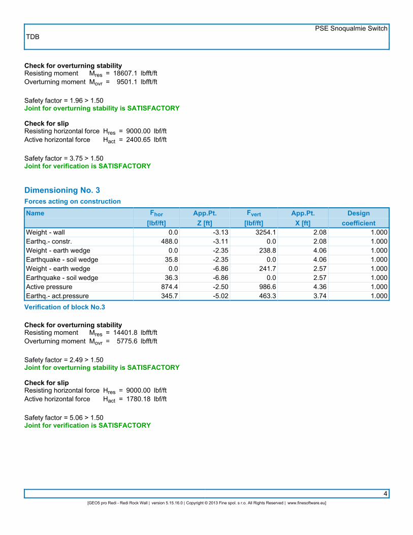
Check for overturning stabilityResisting momentOverturning moment
MresMovr
==
18607.19501.1
lbfft/ftlbfft/ft
Safety factor = 1.96 > 1.50Joint for overturning stability is SATISFACTORY
Check for slipResisting horizontal forceActive horizontal force
HresHact
==
4481.072400.65
lbf/ftlbf/ft
Safety factor = 1.87 > 1.50Joint for verification is SATISFACTORY
Verification of bearing capacity of soil:Maximum stressBearing capacity of footing material
sRd
==
2250.18000.0
psfpsf
Safety factor = 3.56 > 2.00Footing bearing capacity is SATISFACTORY Dimensioning No. 2Forces acting on constructionName Fhor
[lbf/ft]App.Pt.Z [ft]
Fvert[lbf/ft]
App.Pt.X [ft]
Designcoefficient
Weight - wallEarthq.- constr.Weight - earth wedgeEarthquake - soil wedgeWeight - earth wedgeEarthquake - soil wedgeActive pressureEarthq.- act.pressure
0.0488.0
0.035.80.0
36.3874.4345.7
-3.13-3.11-2.35-2.35-6.86-6.86-2.50-5.02
3254.10.0
238.80.0
241.70.0
986.6463.3
2.082.084.064.062.572.574.363.74
1.0001.0001.0001.0001.0001.0001.0001.000
Verification of block No.2
TDBPSE Snoqualmie Switch
4[GEO5 pro Redi - Redi Rock Wall | version 5.15.16.0 | Copyright © 2013 Fine spol. s r.o. All Rights Reserved | www.finesoftware.eu]
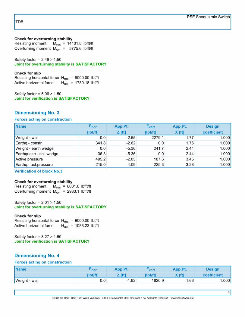
Check for overturning stabilityResisting momentOverturning moment
MresMovr
==
14401.85775.6
lbfft/ftlbfft/ft
Safety factor = 2.49 > 1.50Joint for overturning stability is SATISFACTORY
Check for slipResisting horizontal forceActive horizontal force
HresHact
==
9000.001780.18
lbf/ftlbf/ft
Safety factor = 5.06 > 1.50Joint for verification is SATISFACTORY
Dimensioning No. 3Forces acting on constructionName Fhor
[lbf/ft]App.Pt.Z [ft]
Fvert[lbf/ft]
App.Pt.X [ft]
Designcoefficient
Weight - wallEarthq.- constr.Weight - earth wedgeEarthquake - soil wedgeActive pressureEarthq.- act.pressure
0.0341.8
0.036.3
495.2215.0
-2.65-2.62-5.36-5.36-2.05-4.09
2279.10.0
241.70.0
187.6225.3
1.771.762.442.443.453.28
1.0001.0001.0001.0001.0001.000
Verification of block No.3
Check for overturning stabilityResisting momentOverturning moment
MresMovr
==
6001.02983.1
lbfft/ftlbfft/ft
Safety factor = 2.01 > 1.50Joint for overturning stability is SATISFACTORY
Check for slipResisting horizontal forceActive horizontal force
HresHact
==
9000.001088.23
lbf/ftlbf/ft
Safety factor = 8.27 > 1.50Joint for verification is SATISFACTORY
Dimensioning No. 4Forces acting on constructionName Fhor
[lbf/ft]App.Pt.Z [ft]
Fvert[lbf/ft]
App.Pt.X [ft]
Designcoefficient
Weight - wall 0.0 -1.92 1620.9 1.66 1.000
TDBPSE Snoqualmie Switch
5[GEO5 pro Redi - Redi Rock Wall | version 5.15.16.0 | Copyright © 2013 Fine spol. s r.o. All Rights Reserved | www.finesoftware.eu]
Name Fhor[lbf/ft]
App.Pt.Z [ft]
Fvert[lbf/ft]
App.Pt.X [ft]
Designcoefficient
Earthq.- constr.Weight - earth wedgeEarthquake - soil wedgeActive pressureEarthq.- act.pressure
243.10.0
36.3287.0123.4
-1.89-3.86-3.86-1.55-3.07
0.0241.7
0.0139.5154.2
1.652.302.303.343.13
1.0001.0001.0001.0001.000
Verification of block No.4
Check for overturning stabilityResisting momentOverturning moment
MresMovr
==
4200.81422.5
lbfft/ftlbfft/ft
Safety factor = 2.95 > 1.50Joint for overturning stability is SATISFACTORY
Check for slipResisting horizontal forceActive horizontal force
HresHact
==
9000.00689.73
lbf/ftlbf/ft
Safety factor = 13.05 > 1.50Joint for verification is SATISFACTORY
Dimensioning No. 5Forces acting on constructionName Fhor
[lbf/ft]App.Pt.Z [ft]
Fvert[lbf/ft]
App.Pt.X [ft]
Designcoefficient
Weight - wallEarthq.- constr.Weight - earth wedgeEarthquake - soil wedgeActive pressureEarthq.- act.pressure
0.0144.4
0.036.3
137.156.7
-1.22-1.18-2.36-2.36-1.04-2.04
962.80.0
241.70.0
104.488.5
1.511.492.162.163.192.96
1.0001.0001.0001.0001.0001.000
Verification of block No.5
Check for overturning stabilityResisting momentOverturning moment
MresMovr
==
2575.1512.8
lbfft/ftlbfft/ft
Safety factor = 5.02 > 1.50Joint for overturning stability is SATISFACTORY
Check for slipResisting horizontal forceActive horizontal force
HresHact
==
6915.28374.39
lbf/ftlbf/ft
Safety factor = 18.47 > 1.50
TDBPSE Snoqualmie Switch
6[GEO5 pro Redi - Redi Rock Wall | version 5.15.16.0 | Copyright © 2013 Fine spol. s r.o. All Rights Reserved | www.finesoftware.eu]
Joint for verification is SATISFACTORY
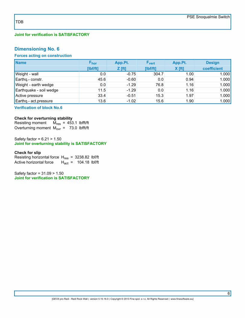
Dimensioning No. 6Forces acting on constructionName Fhor
[lbf/ft]App.Pt.Z [ft]
Fvert[lbf/ft]
App.Pt.X [ft]
Designcoefficient
Weight - wallEarthq.- constr.Weight - earth wedgeEarthquake - soil wedgeActive pressureEarthq.- act.pressure
0.045.60.0
11.533.413.6
-0.75-0.60-1.29-1.29-0.51-1.02
304.70.0
76.80.0
15.315.6
1.000.941.161.161.971.90
1.0001.0001.0001.0001.0001.000
Verification of block No.6
Check for overturning stabilityResisting momentOverturning moment
MresMovr
==
453.173.0
lbfft/ftlbfft/ft
Safety factor = 6.21 > 1.50Joint for overturning stability is SATISFACTORY
Check for slipResisting horizontal forceActive horizontal force
HresHact
==
3238.82104.18
lbf/ftlbf/ft
Safety factor = 31.09 > 1.50Joint for verification is SATISFACTORY

TDBPSE Snoqualmie Switch
1[GEO5 pro Redi - Redi Rock Wall | version 5.15.16.0 | Copyright © 2013 Fine spol. s r.o. All Rights Reserved | www.finesoftware.eu]
Analysis of Redi Rock wallInput dataProjectTaskDescript.AuthorDate
::::
PSE Snoqualmie SwitchSection C/DTDB9/12/2013
SettingsASD - Skewed Back - NCMA 3rd Edition Table 5-2 FactorsWall analysisActive earth pressure calculation :Passive earth pressure calculation :Earthquake analysis :Shape of earth wedge :Reduction coeff. of contact first block - base :Verification methodology :Reduce parameters of contact base - soil
CoulombCaqout-KeriselMononobe-OkabeCalculate as skew0.70Safety factors (ASD)
Safety factorsPermanent design situation
Safety factor for overturning :Safety factor for sliding resistance :Safety factor for bearing capacity :
SFo =SFs =SFb =
1.501.502.00
[–][–][–]
Reduction coefficientsPermanent design situation
Reduction coeff. of contact base - soil : m = 1.00 [–]
GeometryNo.
group Description Count Setbacks [in]
123
Block 60Block 41Top block 24
331
1.621.621.62
Basic soil parameters
Number Name Patternjef[°]
cef[psf]
g[pcf]
gsu[pcf]
d[°]
1
2
Native Soil
Crushed Rock
35.00
45.00
0.0
0.0
125.00
125.00
62.50
62.50
17.50
22.50
All soils are considered as cohesionless for at rest pressure analysis. Terrain profileTerrain behind the structure is flat. Water influenceGround water table is located below the structure.

TDBPSE Snoqualmie Switch
2[GEO5 pro Redi - Redi Rock Wall | version 5.15.16.0 | Copyright © 2013 Fine spol. s r.o. All Rights Reserved | www.finesoftware.eu]
Resistance on front face of the structureResistance on front face of the structure: not consideredSoil on front face of the structure - Native SoilAngle of friction struc.-soilSoil thickness in front of structure
dh
==
0.002.50
°ft
Terrain shape in front of structure
Number Coordinatex[ft]Depthz[ft]
12345
0.000.00
-0.01-8.01-9.01
0.00-2.50-2.503.503.50
Origin [0,0] is located in bottom left edge of construction.Positive coordinate +z has downward direction. EarthquakeHorizontal seismic coefficientVertical seismic coefficient
khkv
==
0.15000.0000
Water below the GWT is restricted. Settings of the stage of constructionDesign situation : permanent Bearing capacity of foundation soilForces acting at the centre of the footing bottom
Number Moment[lbfft/ft]
Norm. force[lbf/ft]
Shear Force[lbf/ft]
Eccentricity[ft]
Stress[psf]
1 10468.9 9233.41 3749.00 1.13 2181.6Bearing capacity of foundation soil check
Eccentricity verificationMax. eccentricity of normal forceMaximum allowable eccentricity
eealw
==
13.6125.74
inin
Eccentricity of the normal force is SATISFACTORY
Footing bottom bearing capacity verificationMax. stress at footing bottomBearing capacity of foundation soil
sRd
==
2181.65000.0
psfpsf
Safety factor = 2.29 > 2.00Bearing capacity of foundation soil is SATISFACTORY
Overall verification - bearing capacity of found. soil is SATISFACTORY

TDBPSE Snoqualmie Switch
3[GEO5 pro Redi - Redi Rock Wall | version 5.15.16.0 | Copyright © 2013 Fine spol. s r.o. All Rights Reserved | www.finesoftware.eu]
Dimensioning No. 1Forces acting on constructionName Fhor
[lbf/ft]App.Pt.Z [ft]
Fvert[lbf/ft]
App.Pt.X [ft]
Designcoefficient
Weight - wallEarthq.- constr.Weight - earth wedgeEarthquake - soil wedgeWeight - earth wedgeEarthquake - soil wedgeActive pressureEarthq.- act.pressure
0.0780.5
0.035.80.0
36.31582.9668.7
-4.40-4.38-5.35-5.35-9.86-9.86-3.64-7.07
5204.10.0
238.80.0
241.70.0
1144.7808.9
2.432.434.334.332.842.844.694.14
1.0001.0001.0001.0001.0001.0001.0001.000
Verification of block No.1
Check for overturning stabilityResisting momentOverturning moment
MresMovr
==
23097.614458.6
lbfft/ftlbfft/ft
Safety factor = 1.60 > 1.50Joint for overturning stability is SATISFACTORY
Check for slipResisting horizontal forceActive horizontal force
HresHact
==
5346.663104.26
lbf/ftlbf/ft
Safety factor = 1.72 > 1.50Joint for verification is SATISFACTORY
Verification of bearing capacity of soil:Maximum stressBearing capacity of footing material
sRd
==
3376.68000.0
psfpsf
Safety factor = 2.37 > 2.00Footing bearing capacity is SATISFACTORY Dimensioning No. 2Forces acting on constructionName Fhor
[lbf/ft]App.Pt.Z [ft]
Fvert[lbf/ft]
App.Pt.X [ft]
Designcoefficient
Weight - wallEarthq.- constr.Weight - earth wedgeEarthquake - soil wedgeWeight - earth wedgeEarthquake - soil wedgeActive pressureEarthq.- act.pressure
0.0634.3
0.035.80.0
36.31199.5494.8
-3.74-3.72-3.85-3.85-8.36-8.36-3.09-6.04
4229.10.0
238.80.0
241.70.0
1058.6633.4
2.282.284.194.192.712.714.533.95
1.0001.0001.0001.0001.0001.0001.0001.000
Verification of block No.2
TDBPSE Snoqualmie Switch
4[GEO5 pro Redi - Redi Rock Wall | version 5.15.16.0 | Copyright © 2013 Fine spol. s r.o. All Rights Reserved | www.finesoftware.eu]
Check for overturning stabilityResisting momentOverturning moment
MresMovr
==
18607.19501.1
lbfft/ftlbfft/ft
Safety factor = 1.96 > 1.50Joint for overturning stability is SATISFACTORY
Check for slipResisting horizontal forceActive horizontal force
HresHact
==
9000.002400.65
lbf/ftlbf/ft
Safety factor = 3.75 > 1.50Joint for verification is SATISFACTORY
Dimensioning No. 3Forces acting on constructionName Fhor
[lbf/ft]App.Pt.Z [ft]
Fvert[lbf/ft]
App.Pt.X [ft]
Designcoefficient
Weight - wallEarthq.- constr.Weight - earth wedgeEarthquake - soil wedgeWeight - earth wedgeEarthquake - soil wedgeActive pressureEarthq.- act.pressure
0.0488.0
0.035.80.0
36.3874.4345.7
-3.13-3.11-2.35-2.35-6.86-6.86-2.50-5.02
3254.10.0
238.80.0
241.70.0
986.6463.3
2.082.084.064.062.572.574.363.74
1.0001.0001.0001.0001.0001.0001.0001.000
Verification of block No.3
Check for overturning stabilityResisting momentOverturning moment
MresMovr
==
14401.85775.6
lbfft/ftlbfft/ft
Safety factor = 2.49 > 1.50Joint for overturning stability is SATISFACTORY
Check for slipResisting horizontal forceActive horizontal force
HresHact
==
9000.001780.18
lbf/ftlbf/ft
Safety factor = 5.06 > 1.50Joint for verification is SATISFACTORY

TDBPSE Snoqualmie Switch
5[GEO5 pro Redi - Redi Rock Wall | version 5.15.16.0 | Copyright © 2013 Fine spol. s r.o. All Rights Reserved | www.finesoftware.eu]
Dimensioning No. 4Forces acting on constructionName Fhor
[lbf/ft]App.Pt.Z [ft]
Fvert[lbf/ft]
App.Pt.X [ft]
Designcoefficient
Weight - wallEarthq.- constr.Weight - earth wedgeEarthquake - soil wedgeActive pressureEarthq.- act.pressure
0.0341.8
0.036.3
495.2215.0
-2.65-2.62-5.36-5.36-2.05-4.09
2279.10.0
241.70.0
187.6225.3
1.771.762.442.443.453.28
1.0001.0001.0001.0001.0001.000
Verification of block No.4
Check for overturning stabilityResisting momentOverturning moment
MresMovr
==
6001.02983.1
lbfft/ftlbfft/ft
Safety factor = 2.01 > 1.50Joint for overturning stability is SATISFACTORY
Check for slipResisting horizontal forceActive horizontal force
HresHact
==
9000.001088.23
lbf/ftlbf/ft
Safety factor = 8.27 > 1.50Joint for verification is SATISFACTORY
Dimensioning No. 5Forces acting on constructionName Fhor
[lbf/ft]App.Pt.Z [ft]
Fvert[lbf/ft]
App.Pt.X [ft]
Designcoefficient
Weight - wallEarthq.- constr.Weight - earth wedgeEarthquake - soil wedgeActive pressureEarthq.- act.pressure
0.0243.1
0.036.3
287.0123.4
-1.92-1.89-3.86-3.86-1.55-3.07
1620.90.0
241.70.0
139.5154.2
1.661.652.302.303.343.13
1.0001.0001.0001.0001.0001.000
Verification of block No.5
Check for overturning stabilityResisting momentOverturning moment
MresMovr
==
4200.81422.5
lbfft/ftlbfft/ft
Safety factor = 2.95 > 1.50Joint for overturning stability is SATISFACTORY
Check for slip
TDBPSE Snoqualmie Switch
6[GEO5 pro Redi - Redi Rock Wall | version 5.15.16.0 | Copyright © 2013 Fine spol. s r.o. All Rights Reserved | www.finesoftware.eu]
Resisting horizontal forceActive horizontal force
HresHact
==
9000.00689.73
lbf/ftlbf/ft
Safety factor = 13.05 > 1.50Joint for verification is SATISFACTORY
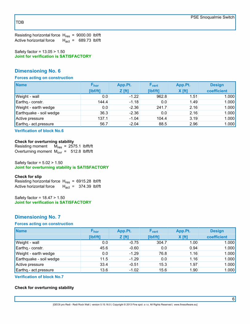
Dimensioning No. 6Forces acting on constructionName Fhor
[lbf/ft]App.Pt.Z [ft]
Fvert[lbf/ft]
App.Pt.X [ft]
Designcoefficient
Weight - wallEarthq.- constr.Weight - earth wedgeEarthquake - soil wedgeActive pressureEarthq.- act.pressure
0.0144.4
0.036.3
137.156.7
-1.22-1.18-2.36-2.36-1.04-2.04
962.80.0
241.70.0
104.488.5
1.511.492.162.163.192.96
1.0001.0001.0001.0001.0001.000
Verification of block No.6
Check for overturning stabilityResisting momentOverturning moment
MresMovr
==
2575.1512.8
lbfft/ftlbfft/ft
Safety factor = 5.02 > 1.50Joint for overturning stability is SATISFACTORY
Check for slipResisting horizontal forceActive horizontal force
HresHact
==
6915.28374.39
lbf/ftlbf/ft
Safety factor = 18.47 > 1.50Joint for verification is SATISFACTORY
Dimensioning No. 7Forces acting on constructionName Fhor
[lbf/ft]App.Pt.Z [ft]
Fvert[lbf/ft]
App.Pt.X [ft]
Designcoefficient
Weight - wallEarthq.- constr.Weight - earth wedgeEarthquake - soil wedgeActive pressureEarthq.- act.pressure
0.045.60.0
11.533.413.6
-0.75-0.60-1.29-1.29-0.51-1.02
304.70.0
76.80.0
15.315.6
1.000.941.161.161.971.90
1.0001.0001.0001.0001.0001.000
Verification of block No.7
Check for overturning stability

TDBPSE Snoqualmie Switch
7[GEO5 pro Redi - Redi Rock Wall | version 5.15.16.0 | Copyright © 2013 Fine spol. s r.o. All Rights Reserved | www.finesoftware.eu]
Resisting momentOverturning moment
MresMovr
==
453.173.0
lbfft/ftlbfft/ft
Safety factor = 6.21 > 1.50Joint for overturning stability is SATISFACTORY
Check for slipResisting horizontal forceActive horizontal force
HresHact
==
3238.82104.18
lbf/ftlbf/ft
Safety factor = 31.09 > 1.50Joint for verification is SATISFACTORY
Related Documents