SMART INFORMATION EXCHANGE IN SPARSELY CONNECTED NETWORKS USING DISRUPTION TOLERANT NETWORKING TECHNOLOGY by Ryan Charles Metzger A Thesis Presented to the Graduate Committee of Lehigh University in Candidacy for the Degree of Master of Science in Computer Engineering Lehigh University May 2008

Welcome message from author
This document is posted to help you gain knowledge. Please leave a comment to let me know what you think about it! Share it to your friends and learn new things together.
Transcript
SMART INFORMATION EXCHANGE
IN SPARSELY CONNECTED
NETWORKS USING DISRUPTION
TOLERANT NETWORKING
TECHNOLOGY
by
Ryan Charles Metzger
A Thesis
Presented to the Graduate Committee
of Lehigh University
in Candidacy for the Degree of
Master of Science
in
Computer Engineering
Lehigh University
May 2008

c© Copyright 2008 by Ryan Charles Metzger
All Rights Reserved
ii

This thesis is accepted in partial
fulfillment of the requirements for the degree of
Master of Science.
(Date)
Mooi Choo Chuah
Hank Korth
iii

iv
Contents
List of Tables vii
List of Figures ix
1 Abstract 1
2 Introduction 3
2.1 DTN System . . . . . . . . . . . . . . . . . . . . . . . . . . . . . . . 3
2.2 Support of Legacy Applications . . . . . . . . . . . . . . . . . . . . . 4
2.3 Security Design . . . . . . . . . . . . . . . . . . . . . . . . . . . . . . 5
2.3.1 Key Management . . . . . . . . . . . . . . . . . . . . . . . . . 6
2.3.2 Data-Centric Security . . . . . . . . . . . . . . . . . . . . . . 7
3 DTN Jabber Proxy 9
3.1 Introduction . . . . . . . . . . . . . . . . . . . . . . . . . . . . . . . . 9
3.2 Overview of Jabber Application . . . . . . . . . . . . . . . . . . . . . 10
3.2.1 Overview of Basic Jabber Protocol . . . . . . . . . . . . . . . 10
3.2.2 Group Chat Features . . . . . . . . . . . . . . . . . . . . . . . 19
3.3 DTN Jabber Proxy Design . . . . . . . . . . . . . . . . . . . . . . . . 20
3.3.1 Jabber Protocol Details that Affect Proxy Design . . . . . . . 20
3.3.2 DTN Jabber Proxy Design . . . . . . . . . . . . . . . . . . . . 21
3.3.3 Multicast Extension . . . . . . . . . . . . . . . . . . . . . . . 28
v
4 DTN Key Management 33
4.1 Introduction . . . . . . . . . . . . . . . . . . . . . . . . . . . . . . . . 33
4.2 Overview of BSP Bundle Processing with Security Blocks . . . . . . . 34
4.3 Dynamic Keys for BAB, PSB and CB . . . . . . . . . . . . . . . . . . 36
4.3.1 Key for BAB . . . . . . . . . . . . . . . . . . . . . . . . . . . 36
4.3.2 Key for CB . . . . . . . . . . . . . . . . . . . . . . . . . . . . 39
4.3.3 Key for PSB . . . . . . . . . . . . . . . . . . . . . . . . . . . . 41
4.4 Experiment . . . . . . . . . . . . . . . . . . . . . . . . . . . . . . . . 44
4.5 Discussion . . . . . . . . . . . . . . . . . . . . . . . . . . . . . . . . . 51
5 Data Centric Security in DTN 53
5.1 Overview . . . . . . . . . . . . . . . . . . . . . . . . . . . . . . . . . . 53
5.2 Overview of Lehigh’s Secure Data Retrieval (SEDAR) System . . . . 55
5.2.1 Authentication . . . . . . . . . . . . . . . . . . . . . . . . . . 58
5.2.2 Producer . . . . . . . . . . . . . . . . . . . . . . . . . . . . . . 59
5.2.3 Storage . . . . . . . . . . . . . . . . . . . . . . . . . . . . . . 61
5.2.4 Subscriber . . . . . . . . . . . . . . . . . . . . . . . . . . . . . 61
5.3 Testbed Demonstration . . . . . . . . . . . . . . . . . . . . . . . . . . 63
5.4 Future Work . . . . . . . . . . . . . . . . . . . . . . . . . . . . . . . . 63
Bibliography 67
A Vita 69
vi
List of Tables
3.1 Outgoing Server Connection Table . . . . . . . . . . . . . . . . . . . 24
3.2 Incoming Connections Established by Remote Servers . . . . . . . . . 25
vii

viii

List of Figures
3.1 Unicast Jabber Chat . . . . . . . . . . . . . . . . . . . . . . . . . . . 11
3.2 Jabber Client Login . . . . . . . . . . . . . . . . . . . . . . . . . . . . 13
3.3 Jabber Message Content . . . . . . . . . . . . . . . . . . . . . . . . . 14
3.4 Jabber Server to Server Dialback Process (from RFC3920) . . . . . . 16
3.5 Streaming XML Structure (RFC3920) . . . . . . . . . . . . . . . . . 18
3.6 Unicast Groupchat Message . . . . . . . . . . . . . . . . . . . . . . . 19
3.7 Dtnjabber Main Loop . . . . . . . . . . . . . . . . . . . . . . . . . . 22
3.8 Dtnjabberd Main Loop . . . . . . . . . . . . . . . . . . . . . . . . . . 27
3.9 Dtnjabberd Main Loop Multicast Changes . . . . . . . . . . . . . . . 29
3.10 Dtnjabber Main Loop Multicast Change . . . . . . . . . . . . . . . . 30
3.11 Testbed for Demonstrating Multicast Feature . . . . . . . . . . . . . 32
4.1 Program Flow for Processing of Security Blocks . . . . . . . . . . . . 35
4.2 Program Flow for the BAB Finalize Function . . . . . . . . . . . . . 37
4.3 Program Flow for the BAB Validate Function . . . . . . . . . . . . . 38
4.4 Program Flow for Processing of CB . . . . . . . . . . . . . . . . . . . 40
4.5 Program Flow for Processing of PSB . . . . . . . . . . . . . . . . . . 42
4.6 4 Node Testbed . . . . . . . . . . . . . . . . . . . . . . . . . . . . . . 44
4.7 BAB Negotiation Result . . . . . . . . . . . . . . . . . . . . . . . . . 45
4.8 Wireshark Examination of Bundle Payload . . . . . . . . . . . . . . . 46
4.9 Turning on BAB, CB and PSB Features . . . . . . . . . . . . . . . . 47
5.1 Category-Based Hierarchical Key Tree . . . . . . . . . . . . . . . . . 57
ix

5.2 Screendumps from Different Nodes . . . . . . . . . . . . . . . . . . . 65
x
Chapter 1
Abstract
As computing becomes more ambiguous in our day to day lives, there is an emerging
new class of networks which break conventional networking assumptions. This new
class of network is an ad-hoc wireless network in which the assumption of the exis-
tence of an end to end connectivity can no longer be made. To operate in this new
class of network, DARPA has created a project to create a next generation network
protocol known as Disruption Tolerant Networking (DTN). This work investigates
three main topics, namely (a) how legacy applications can be supported in DTN
, (b) key management and distribution for DTN, and (c) a data-centric security
approach for DTN. For the first topic, we develop a Jabber DTN proxy to allow
legacy Jabber application to work in DTN. Several security features were designed
for DTN by the IRTF DTNRG working group but no key management and dis-
tribution mechanism is defined. Thus, we design and implement an initial version
of an identity-based key management and distribution mechanism for DTNs. We
further design and implement a data centric security solution that allows data to be
published and retrieved based on data content rather than based on the traditional
approach where there is a pairwise security association between two hosts.
1

CHAPTER 1. ABSTRACT
2
Chapter 2
Introduction
2.1 DTN System
When the technologies underlying the current Internet were developed, all networks
were wired networks. Thus, the technologies assumed that the networks were static,
and have high connectivity, and low latency. In most modern networks, these as-
sumptions still hold true, but there are some cases in which they do not. These
include (a) space communications where latency is no longer in milliseconds, but
hours or weeks, (b) sensor and tactical networks with sparse connectivity, (c) tactical
networks with extremely dynamic topologies. In all these challenged networks, the
key difference they have with the standard wired networks is the lack of end-to-end
connectivity between any two hosts.
Disruption tolerant networking (DTN) (RFC4838) [2] technologies are designed
by the IRTF working group to allow communications in the absence of an end to
end connection. This is achieved through the use of a store and forward approach.
Instead of trying to deliver a data packet immediately from a source to a destina-
tion, DTN tries to get a bundle (a complete message instead of just a portion of a
message) of data closer to the destination when opportunities arise. If the bundle
cannot be forwarded closer toward the destination, it is written to persistent storage
until a link which allows the bundle to be pushed closer to the destination becomes
3
CHAPTER 2. INTRODUCTION
available. Eventually, this process will result in the destination receiving the bun-
dle. Since the bundle is stored in persistent storage instead of being dropped, the
DTN bundle delivery protocol is a connectionless protocol with guaranteed delivery
for challenged networks e.g. sparsely connected military ad hoc networks or high
latency space communications.
DTN uses a flexible naming scheme in which a plain text URL is used as the
Endpoint Identifier (EID) instead of something like an IP address. This means a
network entity needs not be bound to an IP address at the beginning stage of a com-
munication. Routers closer to the destination can map the EID to an IP address
much later in the communication process. Such late binding of a network address to
an EID is referred to as the late binding feature. The late binding feature is useful
for content-based routing, especially for sending spatial queries to sensors deployed
within a particular geographical area.
Much DTN related research work has been done for the past three years. How-
ever, much of the work is focused on designing efficient routing protocols in DTN.
There are other important issues that need to be considered e.g. support of legacy
applications over DTN, security design, easy information access, development of
standard ontology framework for mapping data objects to EIDs etc. In this thesis,
we focus on two of these topics, namely (a) development of a proxy to support one
legacy application, and (b) security design.
2.2 Support of Legacy Applications
The DTN bundle delivery protocol alone is not useful unless we can adapt the
legacy TCP/IP based applications to work in DTNs. There are two ways to achieve
this: either (a) by rewriting the applications to use DTN technology, or (b) through
the use of an application-specific proxy. The first approach is very time-consuming
and also mandates others to deploy new softwares. The second approach is more
user friendly. In this work, we use the second approach, and choose the Jabber
4
2.3. SECURITY DESIGN
application as our application. This choice is made because there are multiple Jab-
ber servers and clients implementations that are publicly available. Specifically, we
choose the Wildfire Jabber server and the Gaim/Gajim Jabber clients.
When developing a DTN application proxy, there are two importation issues to
keep in mind, namely data delivery, and application timeout. The first is fairly
obvious: the proxy must intercept the data which is being transmitted at the source
end, and put this data within a bundle which is sent to the other side of the proxy
tunnel. Once on the other side of the tunnel, this data must be unpackaged, and
delivered to the application in such a way that the application is unaware that the
data is ever packaged in the first place. Interception of the data transmissions can
be done in several ways depending on the application that the proxy is written for,
but generally involves configuring the application to send its data to the source side
of the proxy tunnel instead of its normal destination.
By far the most difficult part of designing a proxy like this is that every appli-
cation has application specific timeouts. The types of timeouts are as varied and
different as the applications they are associated with. In the case of the jabber pro-
tocol, there are no particular timeouts to worry about. Thus, the only real difficulty
is making sure the right data gets to the right place.
2.3 Security Design
With the popularity of Internet and the ability to access information on the Inter-
net on the fly using mobile devices, robust security and privacy design issues have
become very important. The DTN designed by IRTF DTNRG working group has
taken security into consideration. The working group has developed a bundle secu-
rity specification [9] that provides three specific security features for DTNs: namely
(a) the Cipher Block (CB) feature which provides end to end payload encryption,
(b) the Payload Security Block (PSB) feature which provides the end to end payload
integrity, and source verification via public key digital signature, and (c) the Bundle
5
CHAPTER 2. INTRODUCTION
Authentication Bundle (BAB) feature which provides a hop by hop source authen-
tication, and bundle integrity mechanism. The BAB feature is used to minimize the
impact of DDoS attacks. A version of these security features was implemented by
SPARTA but there is no key distribution and management feature. Thus, in this
thesis, the first piece of security work we did is to develop a key distribution and
management feature to work with SPARTA’s bundle security implementation. In
the bundle security solution, the information is encrypted on a per connection basis.
This means that one needs to know the EID of the destination ahead of time. It is
conceivable that this sort of information isn’t available ahead of time, but security is
still an important feature of any network system. So instead of doing security based
on the network source or destination information, we propose using a data-centric
security approach. The second piece of security work we did in this thesis is the
development and testing of a data-centric security solution. Below, we elaborate
more on these two topics:
2.3.1 Key Management
We implemented a series of key distribution and management extensions to SPARTA’s
work in order have a complete security system. Each of the 3 security features re-
quires a different sort of key/system over a different scope. So each of the features
has its own system for distributing and managing keys.
The BAB feature uses a keyed hash algorithm and therefore requires a symmetric
key. We use a robust negotiation protocol secured with Identity Based Encryption
(IBE) which is a form of elliptic curve cryptography. The use IBE removes the need
for every node to get the public key of every next hop node from a centralized source,
since the public key of a node is simply the EID of that node. Since BAB is a hop
by hop security feature, using a negotiation between the two nodes is reasonable,
where if the two nodes were farther apart it’s not reasonable to assume that there
is an efficient two way path between the nodes.
PSB is an end to end cryptographic signing algorithm. SPARTA’s code provides
6
2.3. SECURITY DESIGN
the SHA256 hash, but leaves the signing of that hash value for the key management
module. In our implementation we used HESS signing [3] , a signing solution which
is based on the elliptic curve cryptography. This has the same advantage in the
public key format as IBE. This part of the system has extra flexibility built in so
that it can support multi local EIDs easily. The support of multiple local EIDs is
required for multicast scenarios.
CB is a simple end to end encryption of the payload. We only need to set the key
manually through the DTN configuration system. This key is then used by AES to
encrypt/decrypt the payload at the respective ends of a communication transaction.
2.3.2 Data-Centric Security
Our data-centric security solution leverages a tree-based ontology for data classifica-
tion. Our system is broken into four parts: (a) data producer, (b) data subscriber,
(c) data storage, and (d) Mobile Key Server (MKS).
A data producer produces data belonging to a certain data category. This data
is then encrypted using a key for that data category. Meta data descriptions about
the file, and the type of data are then appended to the front of the encrypted data
block, and the bundle is then sent to the storage nodes. The storage nodes will build
aggregated indices for all the data items that they cache. Data subscriber nodes
inform a data storage node what data types it is authorized to view. Storage nodes
then distribute the authorized data they receive to the subscriber nodes based on
the data type of the files. This data-centric solution has the nice advantage that
the storage nodes do not have to decrypt, and re-encrypt the data for different sub-
scribers. They only need to append the meta data descriptions to the front the
encrypted data block. A Mobile Key Server is used to distribute appropriate access
keys to subscribers or publishers after their credentials are verified. Identify-based
cryptography is used for the authentication process between a MKS and a publisher
or subscriber.
7

CHAPTER 2. INTRODUCTION
8
Chapter 3
DTN Jabber Proxy
3.1 Introduction
In this report, we describe the design and implementation of a DTN Jabber Proxy
that we developed for the jabber messaging system. This proxy software allows
Jabber program to work in DTN environments. The proxy provides several func-
tions: (i) redirects the jabber traffic through the Delay Tolerant Networking (DTN)
stack, (ii) ensure that the internal timeout timers inherent to TCP will not expire as
a result of link unavailability and intermittent connectivity, (iii) parses disconnect
messages to allow jabber components to leave, and join at will, and (iv) adds a
feature to allow multicast bundles to be sent out as broadcast packets and hence
reduces the bandwidth usage for delivering multicast traffic.
The report is organized as follows: In Section 2, we give a high level overview of
the Jabber Protocol. Then, in Section 3, we describe the design issues that need to
be addressed for the DTN jabber proxy. Lastly, we describe our implementation of
the DTN jabber proxy.
9
CHAPTER 3. DTN JABBER PROXY
3.2 Overview of Jabber Application
In our development and testbed environment, we use exclusively the Openfire (for-
mally known as Wildfire) jabber server on all server nodes. This jabber software
includes a multi-user chat room plugin by default. The multi-user chat room is
the program we used for demonstrating DTN multicast feature. The client nodes
composed of a mixture of Gaim, Gajim, and the jabber client that is included in
Internet Tablet OS 2006 on the Nokia 770 internet table.
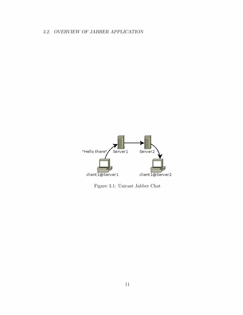
3.2.1 Overview of Basic Jabber Protocol
To help our discussion of the basics of the Jabber protocol, we use a scenario that
consists of two clients and two servers as shown in Figure 3.1 . The two servers
are named Server1 and Server2. One client will be associated with each server.
Each client as a client Jabber ID (JID) which is composed of a hostname, the
symbol ‘@’ and the name of the server it is associated with. The JID can also
have an optional resource tag that allows a particular user to log in from multiple
locations simultaneously with different resource tags. Thus, a JID has the follow-
ing form node@server[/resource]. The clients in our scenario will have the JIDs
client1@server1 and client2@server2.
10
3.2. OVERVIEW OF JABBER APPLICATION
Figure 3.1: Unicast Jabber Chat
11
CHAPTER 3. DTN JABBER PROXY
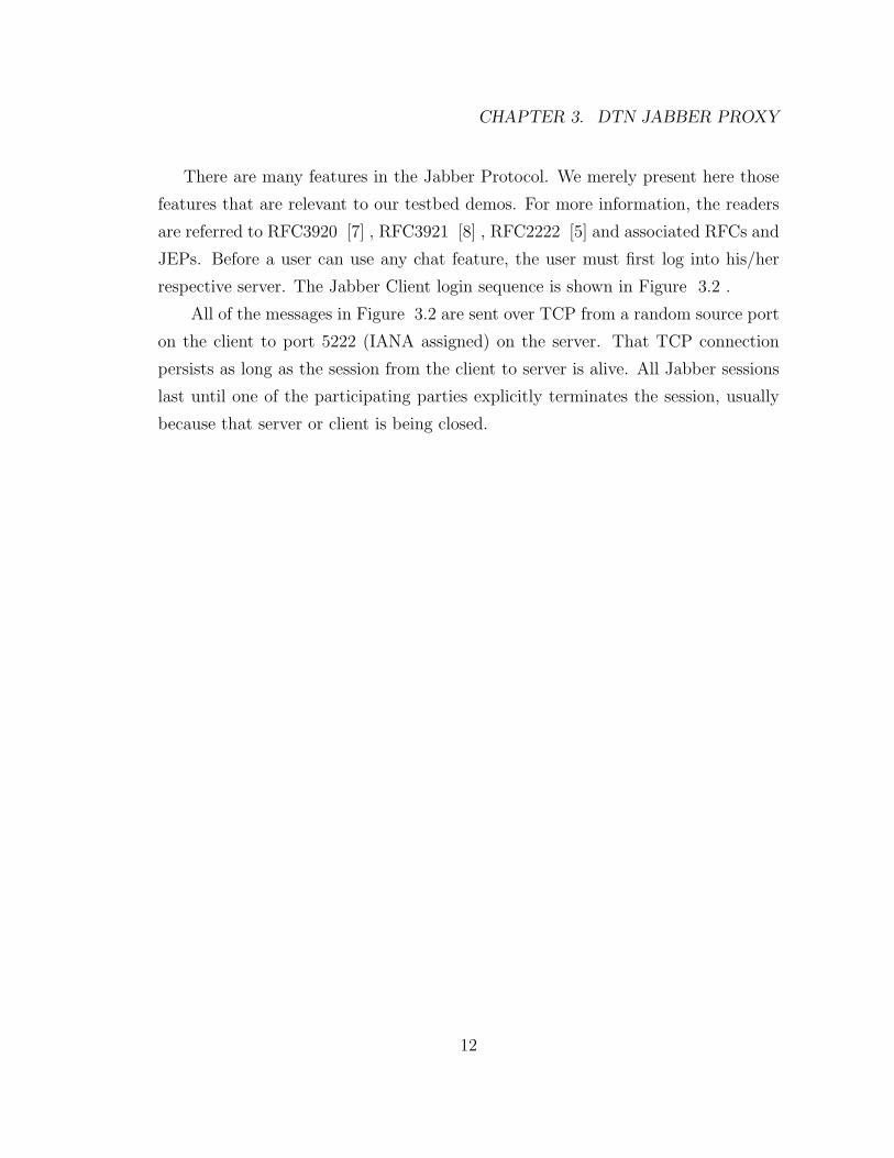
There are many features in the Jabber Protocol. We merely present here those
features that are relevant to our testbed demos. For more information, the readers
are referred to RFC3920 [7] , RFC3921 [8] , RFC2222 [5] and associated RFCs and
JEPs. Before a user can use any chat feature, the user must first log into his/her
respective server. The Jabber Client login sequence is shown in Figure 3.2 .
All of the messages in Figure 3.2 are sent over TCP from a random source port
on the client to port 5222 (IANA assigned) on the server. That TCP connection
persists as long as the session from the client to server is alive. All Jabber sessions
last until one of the participating parties explicitly terminates the session, usually
because that server or client is being closed.
12
3.2. OVERVIEW OF JABBER APPLICATION
Client Server
------ ------
| |
| [Begin Stream Auth] |
| Stream Header |
|--------------------------------------------->|
| |
| Stream Header |
|<---------------------------------------------|
| |
| Stream Auth Features |
|<---------------------------------------------|
| |
| Select Auth Mechanism |
|--------------------------------------------->|
| |
| MD5 Challenge |
|<---------------------------------------------|
| |
| MD5 Response |
|--------------------------------------------->|
| |
| Auth Result |
|<---------------------------------------------|
| [End Stream Auth] |
| |
| [Begin Resource Binding] |
| Stream Header |
|--------------------------------------------->|
| |
| Stream Bind Features |
|<---------------------------------------------|
| |
| Resource SET |
|--------------------------------------------->|
| |
| Resource Bind Result |
|<---------------------------------------------|
| [End Resource Binding] |
| |
| [Session Establishment] |
| Session Set Request |
|--------------------------------------------->|
| |
| Session Creation Result |
|<---------------------------------------------|
| [Session Established] |
| |
Figure 3.2: Jabber Client Login
13

CHAPTER 3. DTN JABBER PROXY
<message type=chat to=client1@server2/Home from=client1@server1/Home>
<body>
Hello there
</body>
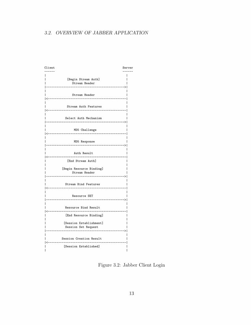
Figure 3.3: Jabber Message Content
14
3.2. OVERVIEW OF JABBER APPLICATION
Once both clients have logged into their respective servers, the Jabber system
is in a stable state. This changes when client1@server1 tries to send a message to
client1@server2 through its established TCP session with server1. The basic format
of this message is as shown in Figure 3.3 .
The example in Figure 3.3 has tabs and new lines added for the clarity of the
presentation, but this white space is not present in the actual transmitted message.
There are several child tags of the message and message tag parameters that may
be present. When this message is sent from client1@server1, it will be sent over
the established TCP session to server1. Server1 will see that in the “to” parameter,
the destination server is not the local server. It will extract the destination server
from the “to” parameter and attempt to send the message to server2. Since there is
no established session between Server1 and Server2, Server1 will first use the server
dialback mechanism to establish a session with Server 2. This will proceed similar
to what is shown in Figure 3.2 , except the stream authentication will use server
dialback instead of MD5 handshake. The server dialback mechanism is detailed in
Figure 3.4 .
15
CHAPTER 3. DTN JABBER PROXY
Originating ReceivingServer Server
----------- ---------| || establish connection || ----------------------> || || send stream header ||------------------------>|| || send stream header ||<------------------------|| | Authoritative| send dialback key | Server| | (Same as Originating Server| | in our testbed setup)|------------------------>| -------------| | |
| establish connection || -------------------------> || || send stream header || -------------------------> || || send stream header || <------------------------- || || send verify request || -------------------------->|| || send verify response || <--------------------------||
| report dialback result ||<------------------------|| |
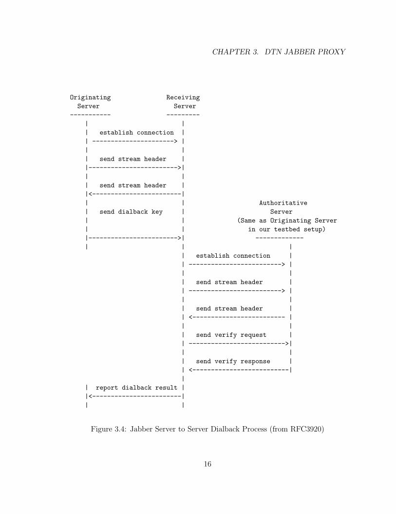
Figure 3.4: Jabber Server to Server Dialback Process (from RFC3920)
16
3.2. OVERVIEW OF JABBER APPLICATION
All messages from the Originating Server (OS) to the Receiving Server (RS) go
over a single TCP connection that persists as long as the session from the OS to
RS is alive. This TCP connection is from a random port at the OS to port 5269 at
the RS. Then, when RS connects to the Authoritative Server (AS), this is done over
a separate TCP connection that is created for this verification step, and destroyed
after the verification step has concluded. This second TCP connection is from a
random port at the RS to port 5269 at the AS (also OS in our case). This means
that during the verification step, there are simultaneously 2 TCP connections, one
from the OS to the RS, and another from the RS to the AS. Since in our case, the
AS is the same as OS, these 2 TCP connections are between the same two machines.
Once this process is completed, there is a Jabber session from the OS to the RS but
there is NOT a session from the RS to the OS. If client1@server2 wants to send a
message to client1@server1, then server2 will have to repeat this same process to
create a Jabber session with server1, but in this case server2 will be the OS, and
server1 will be the RS. During the setup of the server, one needs to specify the DNS
name of the server, the dialback process at both sides resolves the DNS names of
each other. The resulting IPs are used as seeds for creating the keys used in the
dialback sequence. This of course means that the specified DNS names must be
resolvable, and must resolve to the SAME IP by all involved parties.
Once the Jabber session from server1 to server2 is established, server1 will for-
ward the message sent by client1@server1 to server2. Server2 will examine the “to”
parameter of the message and see that it is the destination server. Server2 will
then check to see if client1@server2 is logged in. If the client1@server2 is logged in,
then the message is sent to the client. Otherwise, the message is put into persistent
storage to be delivered when the client logs in.
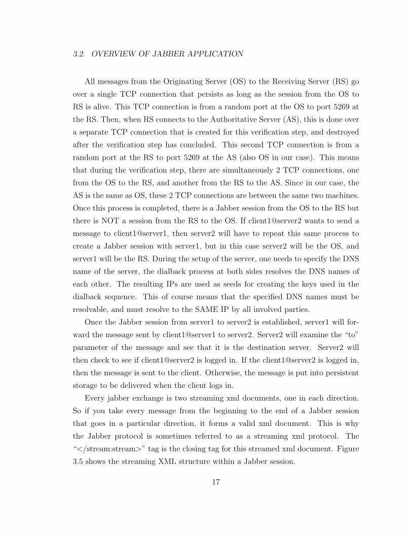
Every jabber exchange is two streaming xml documents, one in each direction.
So if you take every message from the beginning to the end of a Jabber session
that goes in a particular direction, it forms a valid xml document. This is why
the Jabber protocol is sometimes referred to as a streaming xml protocol. The
“</stream:stream>” tag is the closing tag for this streamed xml document. Figure
3.5 shows the streaming XML structure within a Jabber session.
17
CHAPTER 3. DTN JABBER PROXY
|-------------------------|
| <stream> |
|-------------------------|
| <presence> |
| <show/> |
| </presence> |
|-------------------------|
| <message to=’foo’> |
| <body/> |
| </message> |
|-------------------------|
| <iq to=’bar’> |
| <query/> |
| </iq> |
|-------------------------|
| ... |
|-------------------------|
| </stream> |
|-------------------------|
Figure 3.5: Streaming XML Structure (RFC3920)
18
3.2. OVERVIEW OF JABBER APPLICATION
There can be as many message and iq tags as needed within a session. The
stream tags enclose the session. If a crash causes the stream to not be properly
closed, the system relies on the timeout of the underlying TCP socket to force the
other side of the stream to terminate.
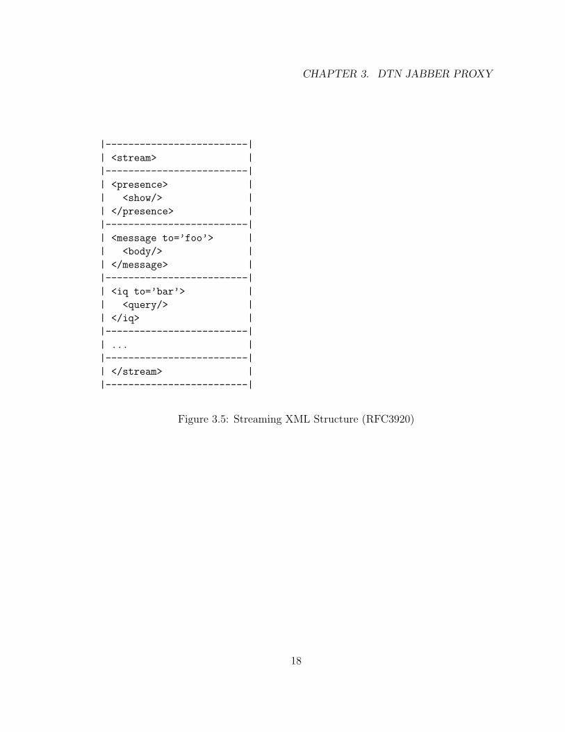
3.2.2 Group Chat Features
The servers are equipped with a multicast plugin that provides a group chat feature.
Using the same scenario described earlier, once all sessions are established, the clients
can use these sessions to send a special iq message to chat [email protected].
The special name conference.server2 within the iq message allows the message to
be “routed” to the chatroom plugin on server2. This iq message allows the send-
ing client to join the chatroom named chat room1 on server2. If a second client
client2@server2 were to establish a session with server2 and join the chatroom,
then, there would be 3 users in the chatroom. If client1@server1 wants to send a
message to the chatroom, the flow of messages will be as shown in Figure 3.6 .
Figure 3.6: Unicast Groupchat Message
19
CHAPTER 3. DTN JABBER PROXY
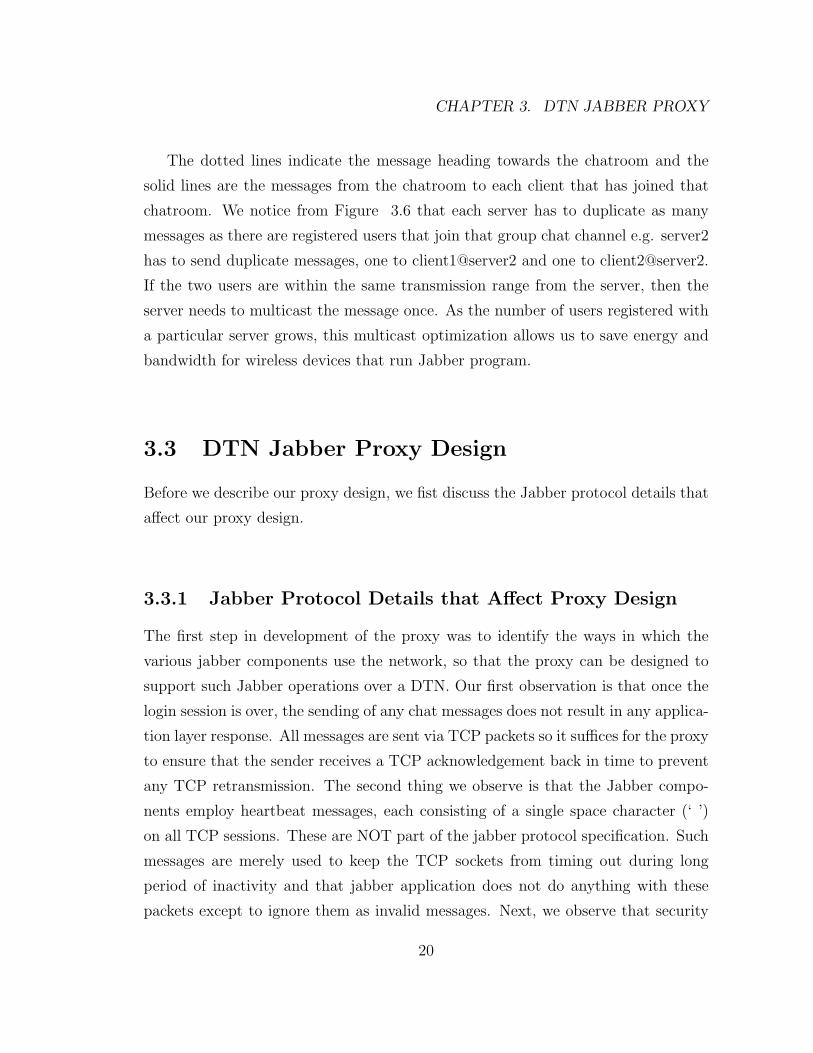
The dotted lines indicate the message heading towards the chatroom and the
solid lines are the messages from the chatroom to each client that has joined that
chatroom. We notice from Figure 3.6 that each server has to duplicate as many
messages as there are registered users that join that group chat channel e.g. server2
has to send duplicate messages, one to client1@server2 and one to client2@server2.
If the two users are within the same transmission range from the server, then the
server needs to multicast the message once. As the number of users registered with
a particular server grows, this multicast optimization allows us to save energy and
bandwidth for wireless devices that run Jabber program.
3.3 DTN Jabber Proxy Design
Before we describe our proxy design, we fist discuss the Jabber protocol details that
affect our proxy design.
3.3.1 Jabber Protocol Details that Affect Proxy Design
The first step in development of the proxy was to identify the ways in which the
various jabber components use the network, so that the proxy can be designed to
support such Jabber operations over a DTN. Our first observation is that once the
login session is over, the sending of any chat messages does not result in any applica-
tion layer response. All messages are sent via TCP packets so it suffices for the proxy
to ensure that the sender receives a TCP acknowledgement back in time to prevent
any TCP retransmission. The second thing we observe is that the Jabber compo-
nents employ heartbeat messages, each consisting of a single space character (‘ ’)
on all TCP sessions. These are NOT part of the jabber protocol specification. Such
messages are merely used to keep the TCP sockets from timing out during long
period of inactivity and that jabber application does not do anything with these
packets except to ignore them as invalid messages. Next, we observe that security
20
3.3. DTN JABBER PROXY DESIGN
settings are required for the server to server dialback mechanism to work. To sup-
port this mechanism, a server may have two or more established TCP sessions one
to each server it attempts to communicate with and one to the authorization server
during the verification step. Finally, the jabber proxy needs to process close stream
messages immediately since the established connection needs to be torn down upon
proper termination of a session e.g. the connection related to the verification step.
As mentioned earlier, the close stream message is simply the “</stream:stream>”
xml tag.
3.3.2 DTN Jabber Proxy Design
The DTN Jabber Proxy consists of two modules, one that runs near a jabber client,
dtnjabber, and another which runs near a jabber server, dtnjabberd. Our proxy
design allows a proxy module to be run on a separate machine from the one that
runs the Jabber components. However, in our testbed set up, the proxy module
runs on the same machine that runs the Jabber components since our current im-
plementation does not handle a disconnect between the jabber component and its
associated proxy component yet. This feature is left for future work. All sockets
created by our proxies are non-blocking to avoid having to create a multi-threaded
dtnjabberd or dtnjabber.
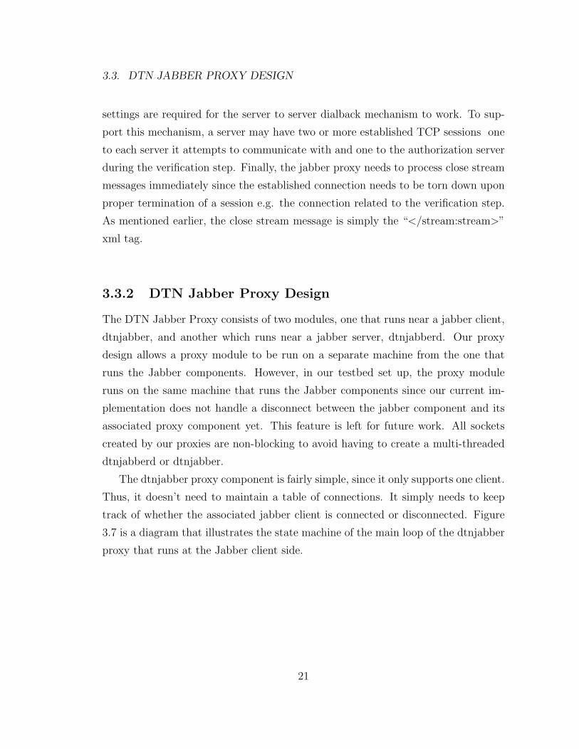
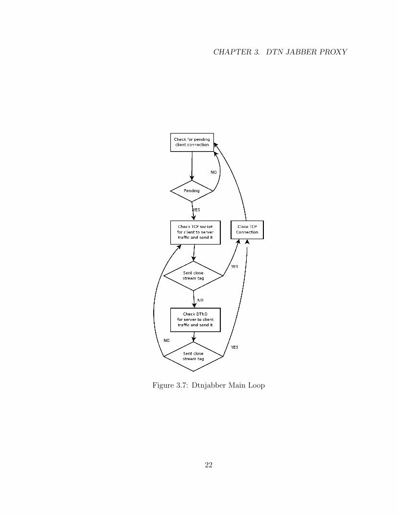
The dtnjabber proxy component is fairly simple, since it only supports one client.
Thus, it doesn’t need to maintain a table of connections. It simply needs to keep
track of whether the associated jabber client is connected or disconnected. Figure
3.7 is a diagram that illustrates the state machine of the main loop of the dtnjabber
proxy that runs at the Jabber client side.
21
CHAPTER 3. DTN JABBER PROXY
Figure 3.7: Dtnjabber Main Loop
22
3.3. DTN JABBER PROXY DESIGN
The jabber client must be configured to send its traffic to dtnjabber instead of
directly to the jabber server it wants to sign into. In all client software packages
that we use, this is done easily via the “connect to server and port” configuring pa-
rameters. Then, dtnjabber simply opens a listening TCP port (the port number is
specified via a command line argument) and waits for the jabber client to connect to
that port. This causes the client TCP session to be terminated locally, so that in the
case of a disconnect between the proxy components, the local TCP session will not
time out while waiting for a TCP ACK packet. Also specified at the command line
of dtnjabber is the EID of the dtnjabberd that is associated with the jabber server
that the jabber client attempts to log into. Once a Jabber session is established,
the dtnjabber proxy will look for a “</stream:stream>” tag. When the proxy sees
this closing tag, it will forward the message and then close the link.
The server-side proxy, dtnjabberd proxy, must be designed to scale since it needs
to keep track of numerous connections simultaneously. The dtnjabberd proxy main-
tains two connection tables. When a dtnjabberd proxy is invoked, it reads a configu-
ration file that contains a list of servers that this particular server (say Server2) can
connect to. For each remote server listed in the configuration file, a listening port
is created and the listening port number is captured in a connection table referred
to as Table 1. Table 1 captures all the outgoing connections initiated from Server
2. Each entry in Table 1 contains the following information: (i) TCP outgoing con-
nection socket, (ii) an EID to which to send information received on that socket,
and (iii) the last time there was traffic on the TCP socket. Currently, two outgoing
connections for each remote server is supported. This design decision is made to
support the server-to-server dialback mechanism (shown in Fig 3.4 ) where two
TCP connections are launched for each server that Server2 wants to communicate
with. One connection is for the authorization purpose. Our current design does
not remove the connection entry associated with the authorization server even after
that connection goes away upon completion. Table 3.1 is an example of what Table
1 would look like on server2 in our original unicast chat scenario in Figure 3.1 .
23
CHAPTER 3. DTN JABBER PROXY
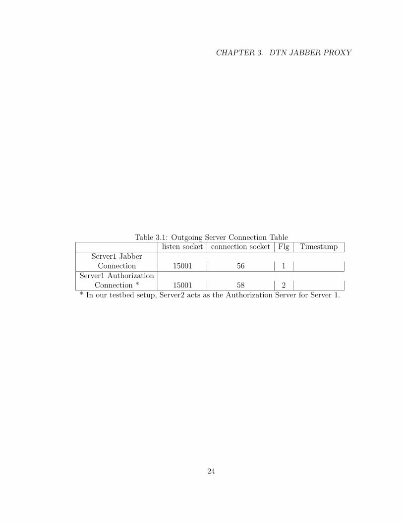
Table 3.1: Outgoing Server Connection Tablelisten socket connection socket Flg Timestamp
Server1 JabberConnection 15001 56 1
Server1 AuthorizationConnection * 15001 58 2
* In our testbed setup, Server2 acts as the Authorization Server for Server 1.
24
3.3. DTN JABBER PROXY DESIGN
The proxy will insert a flag byte in all the outgoing bundles from Server2 to a
remote server (Server1 in our example). The flag value is set according to whether
the established connection is the first or second outgoing connection to that remote
server. The remote server will insert a flag value of 3 in all bundles sent in the
reverse direction that contain responses to the first outgoing connection. A flag
value of 4 will be used by the remote server for bundles sent in the reverse direction
for the second outgoing connection. Note that once the session between two servers
is established, the data bundles often flow in one direction e.g. from Server2 to
Server1 or from Server1 to Server 2.
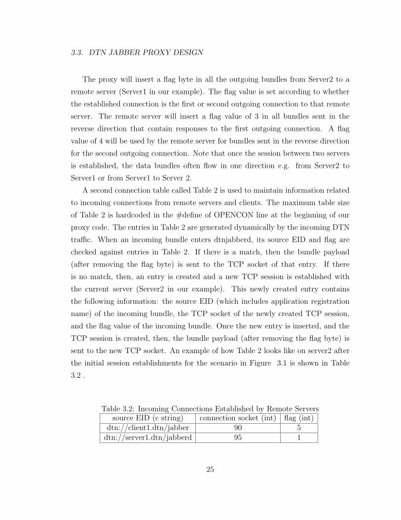
A second connection table called Table 2 is used to maintain information related
to incoming connections from remote servers and clients. The maximum table size
of Table 2 is hardcoded in the #define of OPENCON line at the beginning of our
proxy code. The entries in Table 2 are generated dynamically by the incoming DTN
traffic. When an incoming bundle enters dtnjabberd, its source EID and flag are
checked against entries in Table 2. If there is a match, then the bundle payload
(after removing the flag byte) is sent to the TCP socket of that entry. If there
is no match, then, an entry is created and a new TCP session is established with
the current server (Server2 in our example). This newly created entry contains
the following information: the source EID (which includes application registration
name) of the incoming bundle, the TCP socket of the newly created TCP session,
and the flag value of the incoming bundle. Once the new entry is inserted, and the
TCP session is created, then, the bundle payload (after removing the flag byte) is
sent to the new TCP socket. An example of how Table 2 looks like on server2 after
the initial session establishments for the scenario in Figure 3.1 is shown in Table
3.2 .
Table 3.2: Incoming Connections Established by Remote Serverssource EID (c string) connection socket (int) flag (int)
dtn://client1.dtn/jabber 90 5dtn://server1.dtn/jabberd 95 1
25
CHAPTER 3. DTN JABBER PROXY
Our proxy inserts a one byte flag at the beginning of every bundle payload
sent between proxy components. Currently, the flag value is used to distinguish
bundles that arrive from different incoming connections between two jabber servers
(for supporting the dial back mechanism). The flag byte is inserted because source
EID alone is not sufficient to distinguish different incoming connections (recall that
we need two separate connections from the same server because the same machine
is used as the authorization server in our setup). The flag value is simply an integer
between 0 and 255. A flag of zero is reserved for future use. The flag is set to
one for all traffic sent via the first outgoing server to server session and to two if
it is the second session. A flag of three is used for bundles that contain response
messages to the first server-to-server connection set up by a remote server. Similarly,
a flag of four is used for the second server to server session created remotely by that
same remote server. Finally, a flag value of five is attached to any bundles sent in
any server to client or client to server connection. In future versions, a flag value of
greater then 5 may be used to allow multiple clients to connect to a single dtnjabber
instance to differentiate the traffic to and from the different clients. In our current
dtnjabber version, only one jabber client may associate with a dtnjabber instance
so a flag value greater than five is not used. When a Jabber session ends, the
dtnjabberd proxy will receive a bundle containing a closing tag. The dtnjabberd
proxy forwards this bundle, and then deletes the associated connection entry from
its connection table.
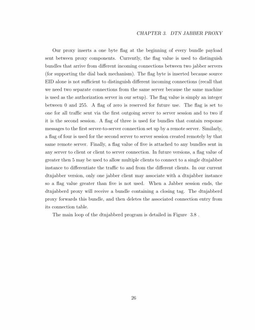
The main loop of the dtnjabberd program is detailed in Figure 3.8 .
26
3.3. DTN JABBER PROXY DESIGN
Figure 3.8: Dtnjabberd Main Loop
27
CHAPTER 3. DTN JABBER PROXY
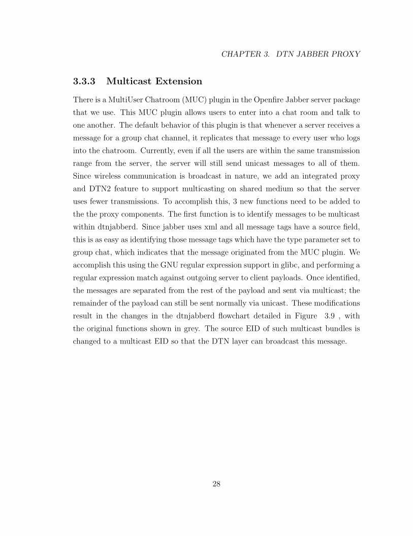
3.3.3 Multicast Extension
There is a MultiUser Chatroom (MUC) plugin in the Openfire Jabber server package
that we use. This MUC plugin allows users to enter into a chat room and talk to
one another. The default behavior of this plugin is that whenever a server receives a
message for a group chat channel, it replicates that message to every user who logs
into the chatroom. Currently, even if all the users are within the same transmission
range from the server, the server will still send unicast messages to all of them.
Since wireless communication is broadcast in nature, we add an integrated proxy
and DTN2 feature to support multicasting on shared medium so that the server
uses fewer transmissions. To accomplish this, 3 new functions need to be added to
the the proxy components. The first function is to identify messages to be multicast
within dtnjabberd. Since jabber uses xml and all message tags have a source field,
this is as easy as identifying those message tags which have the type parameter set to
group chat, which indicates that the message originated from the MUC plugin. We
accomplish this using the GNU regular expression support in glibc, and performing a
regular expression match against outgoing server to client payloads. Once identified,
the messages are separated from the rest of the payload and sent via multicast; the
remainder of the payload can still be sent normally via unicast. These modifications
result in the changes in the dtnjabberd flowchart detailed in Figure 3.9 , with
the original functions shown in grey. The source EID of such multicast bundles is
changed to a multicast EID so that the DTN layer can broadcast this message.
28
3.3. DTN JABBER PROXY DESIGN
Figure 3.9: Dtnjabberd Main Loop Multicast Changes
29
CHAPTER 3. DTN JABBER PROXY
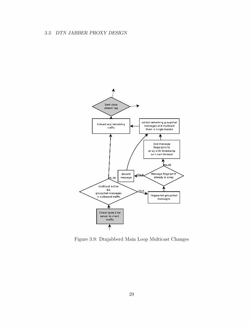
The second function that must be added is related to how incoming multicast
bundles will be handled in dtnjabber. One of the other fields that the message
tag contains is a “to” field which is the destination jabber ID that the message is
destined for. Since we change the destination ID of group chat messages is changed
to a multicast EID, dtnjabber at the receiving side needs to change it back to a
client Jabber ID at the receiving end so that that multicast bundle can be passed
to the Jabber layer . These modifications result in the changes in the dtnjabber
flowchart detailed in Figure 3.10 , with original functions shown in grey.
Figure 3.10: Dtnjabber Main Loop Multicast Change
30
3.3. DTN JABBER PROXY DESIGN
The last function that must be added is the pruning of duplicate messages,
which is shown in Figure 3.9 . In the current Jabber implementation, a server will
generate as many messages as there are users associated with it even if all these users
are within the same transmission range. Since we cannot modify the Jabber server
software, we have to insert this pruning function to remove redundant messages that
need to be multicast. The complicating factor in this is that with even moderate
traffic there is no guarantee of the order of packets being sent from the MUC plugin.
Thus, duplicate message detection will be done by generating a hash of the body of
all outgoing multicast messages. This hash will be compared to an array of hashes.
If there is no match, the hash is added to the array for a period of several seconds
(since duplicate messages shouldn’t be far behind). If there is a match, then the
message is a duplicate, and will be discarded.
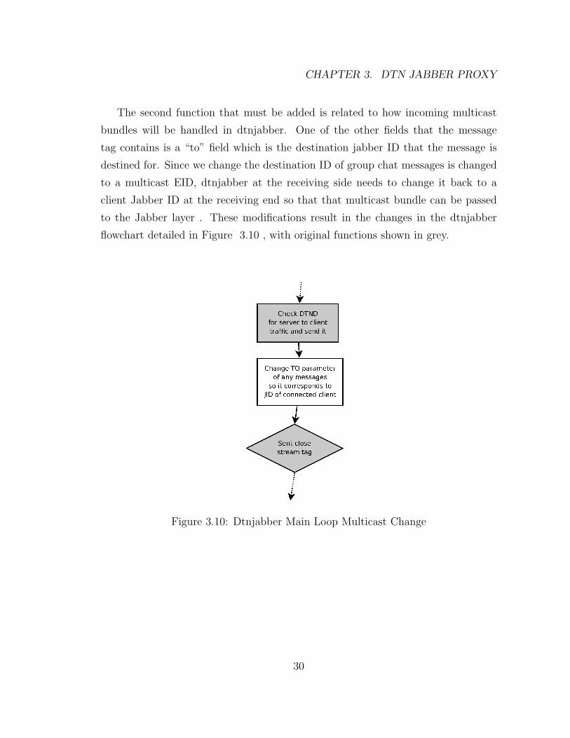
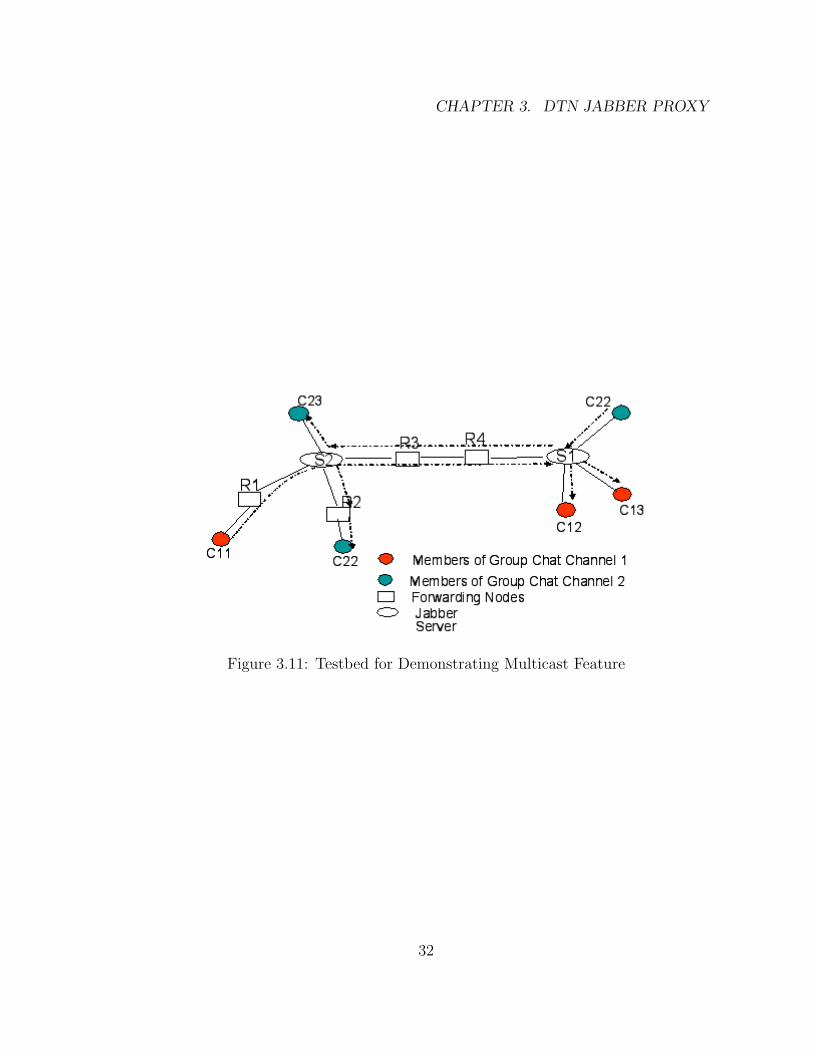
We have set up a testbed shown in Fig 3.11 to test this multicast feature and
it is working well. In this testbed setup, there are two group chat channels. When
traffic is sent by a client, C11, to group chat channel 1, S2 will send a copy to S1.
S1 will multicast so that clients C12, and C13 can receive it. Similarly, when a
client C22 sends a message to group chat channel 2, S1 will forward a copy to S2.
S2 will multicast so that clients C22, and C23 can receive it. Currently, there is no
support for dynamic group membership yet. Forwarding nodes are configured with
the appropriate multicast EIDs so they will re-broadcast traffic received from those
multicast EIDs. In the future, we intend to provide a dynamic group membership
protocol like IGMP in DTN.
31
CHAPTER 3. DTN JABBER PROXY
Figure 3.11: Testbed for Demonstrating Multicast Feature
32
Chapter 4
DTN Key Management
4.1 Introduction
The Bundle Security Protocol (BSP) [9] has three main features, the Bundle Au-
thentication Block (BAB), the Payload Security Block (PSB), and the Confiden-
tiality Block (CB). The BAB provides a per hop source and bundle integrity check.
It achieves this by applying the HMAC-SHA1 [4] , a symmetric keyed hashing
algorithm, over the entire bundle using the per-hop BAB key negotiated between
two nodes. PSB provides an end-to-end source and payload integrity check. This
is achieved through the public key signing of a SHA256 [6] hash of the payload.
CB provides for the encryption of the entire bundle payload and such encryption
is usually done at the source and decrypted at the final destination. In our imple-
mentation, the encryption is done using the 128-bit AES in Galois/Counter Mode
(GCM).
In this chapter, we document some descriptions of a key management module
that Lehigh has developed that works with the Nov 1st, 2007 version of the Sparta’s
BSP implementation made available via the BBN CVS tree. This BSP implemen-
tation has incorporated some enhancements that BBN has implemented. BBN’s
enhancements include (a) a simple key storage that allows the storage of a key with
an associated Ciphersuite number, (b) a simple BSP policy class that is used to
33
CHAPTER 4. DTN KEY MANAGEMENT
turn on dtnd BSP block processing. Our report is organized as follows: In Section
2, we provide a high level description of how Sparta’s BSP implementation creates
or validates the security blocks. In Section 3, we describe how the keys for the BAB,
CB and PSB features are created. Specifically, we discuss our implementation for
BAB key negotiation in Section 3.1. In Section 3.2, we describe how the key for CB
is created and in Section 3.3, we discuss how the key for PSB is created. In Section
4, we describe an experiment we conduct to demonstrate these three DTN security
features. We conclude by discussing future work that needs to be done to provide a
more flexible DTN key management framework.
4.2 Overview of BSP Bundle Processing with Se-
curity Blocks
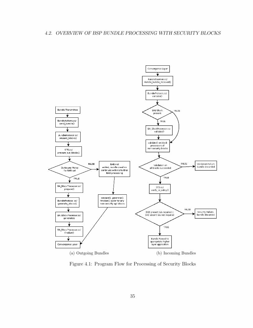
In Figure 4.1(a) , we illustrate the overall program flow with a focus on the BSP
features starting from the bundle creation process to the instant when a bundle is
sent with the BAB feature activated. All API blocks go through the same “pre-
pare”, “generate”, and “finalize” cycle. When the BAB feature is turned on for all
outbound bundles i.e. when the outbound policy for BAB is set, the appropriate
“prepare”, “generate” and “finalize” functions of the BAB block processor will be
called. The program flow for the CB or PSB feature is the same except that the
corresponding CB or PSB block processing is called.
34
4.2. OVERVIEW OF BSP BUNDLE PROCESSING WITH SECURITY BLOCKS
(a) Outgoing Bundles (b) Incoming Bundles
Figure 4.1: Program Flow for Processing of Security Blocks
35
CHAPTER 4. DTN KEY MANAGEMENT
In Figure 4.1(b) , we illustrate how received bundles are processed with a focus
on the processing of the security blocks. A bundle is processed block by block, and
each block has an identifier that lets the daemon know which function should the
block be passed to for processing. Figure 4.1(b) illustrates that if a BAB is present,
then the validate function will be called to determine if the BSP block is valid. Any
failure in verifying the BSP block will result in that received bundle being dropped.
The verify in policy function is called to ensure that the received bundle contains
all the necessary blocks before it is passed to higher layer. The processing rule for
CB and PSB is similar. When all DTN security features are turned on, BAB will
be verified first, followed by PSB and then CB.
4.3 Dynamic Keys for BAB, PSB and CB
4.3.1 Key for BAB
We use the key management module that we described in [1] for dynamic key
negotiation. This module allows a node to securely negotiate a symmetric key with
a next hop node for use with BAB. The implementation has its own key store which
also stores some negotiation state information. The Spartas BSP implementation,
however, was written to use the BBN key store. To achieve compatibility, we modify
our key negotiation code to duplicate and insert the negotiated key into the BBN
key store. The BAB code was also modified so that it could support different keys
for different links, instead of the original code that only supports a single global key.
36
4.3. DYNAMIC KEYS FOR BAB, PSB AND CB
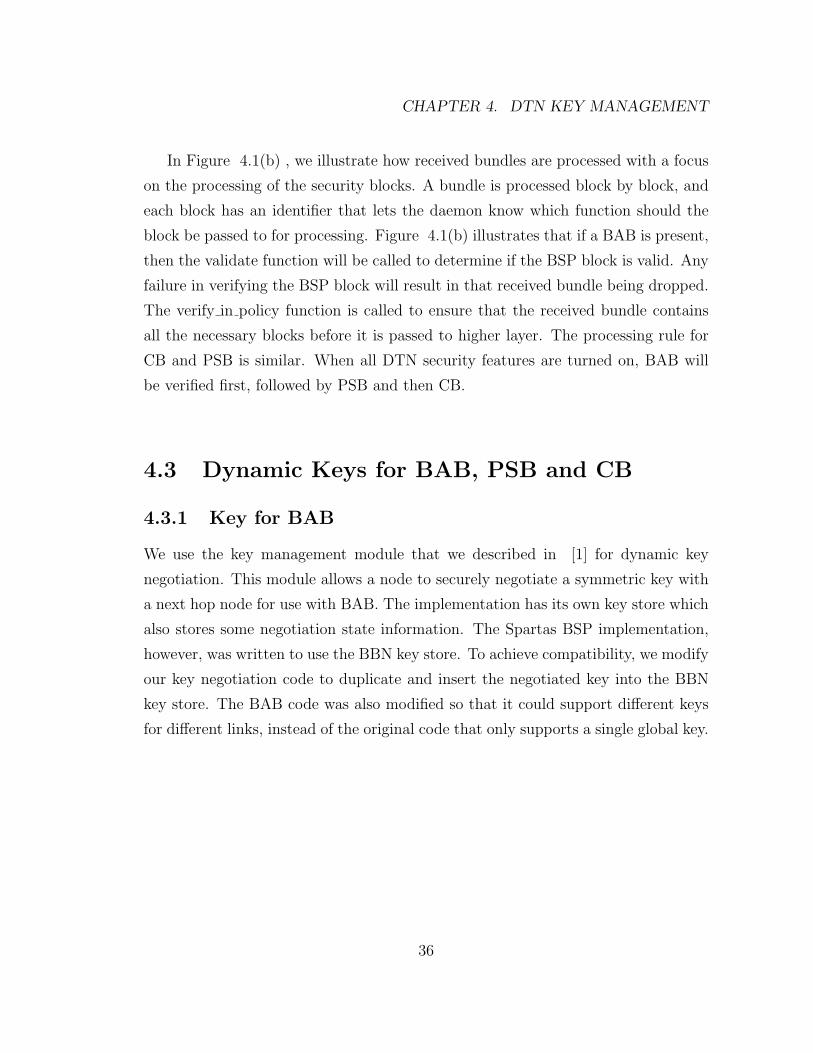
Figure 4.2: Program Flow for the BAB Finalize Function
37
CHAPTER 4. DTN KEY MANAGEMENT
Figure 4.2 shows the details of the implemented BAB “finalize” function. The
request for the key is highlighted since the key mentioned here is the one populated
by our key management module after the key negotiation process.
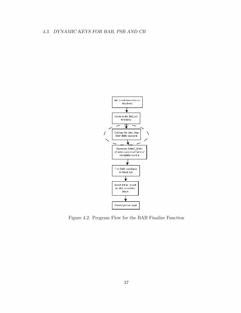
Figure 4.3: Program Flow for the BAB Validate Function
38
4.3. DYNAMIC KEYS FOR BAB, PSB AND CB
Figure 4.3 shows the details of the implemented BAB validate function. Again,
we highlight the key retrieval part for this is where our code ensures that the correct
key is made available for the validation of the received security blocks.
4.3.2 Key for CB
The CB implementation uses a symmetric ephemeral key to encrypt the payload.
This key is then handed off to the key management module to be encrypted. The
encrypted key is attached to the bundle that uses it. At the receiving end, the receiv-
ing node passes the encrypted key to the key management module for decryption.
Then, the decrypted key is used to decrypt the payload. In our implementation,
we use AES for the encryption and decryption of the ephemeral key. We use the
security setkey command of the BBN key store to manually configure a key that is
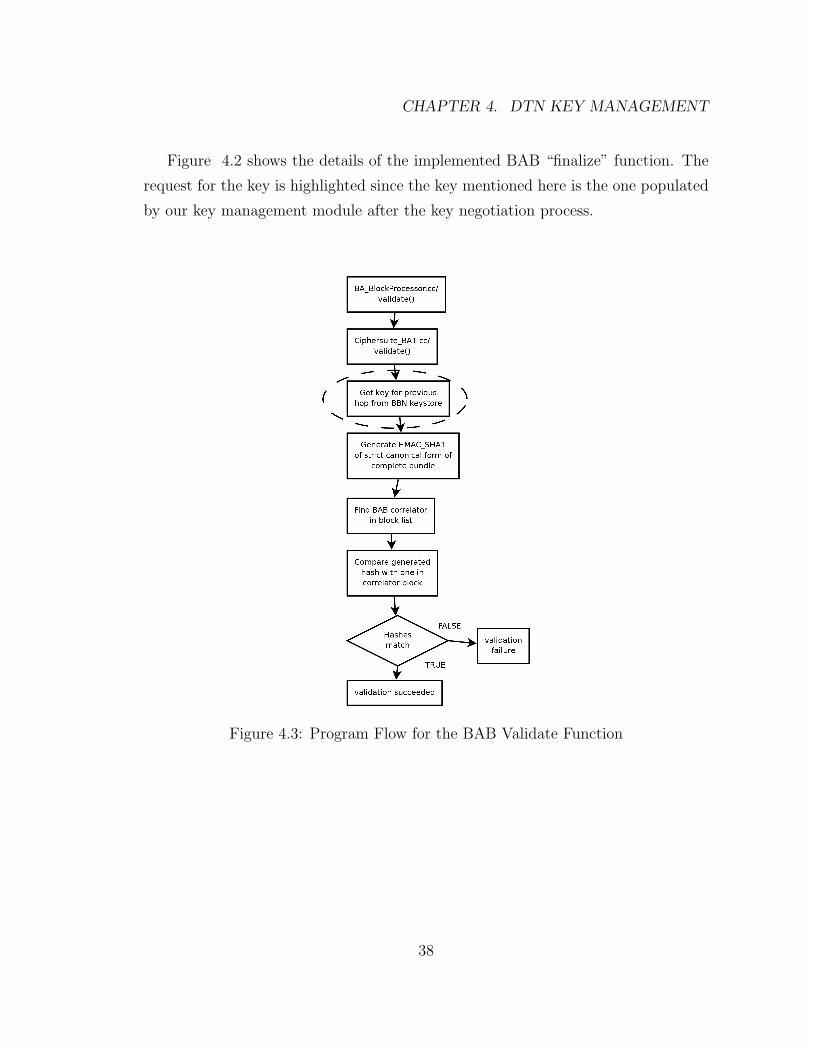
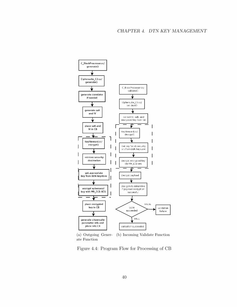
used for the AES operations. Figure 4.4(a) shows the details of the implementation
of the CB generate function. The outlined area is where Lehigh’s code is inserted.
Lehigh’s contribution is a non-trivial implementation of KeySteward::encrypt() that
uses AES. Figure 4.4(b) shows the details of the implementation of the CB validate
function. Again, we highlight the part where we contribute the code. Lehigh’s con-
tribution is a non-trivial implementation of KeySteward::decrypt() that uses AES.
39
CHAPTER 4. DTN KEY MANAGEMENT
(a) Outgoing Gener-ate Function
(b) Incoming Validate Function
Figure 4.4: Program Flow for Processing of CB
40

4.3. DYNAMIC KEYS FOR BAB, PSB AND CB
4.3.3 Key for PSB
The PSB feature as implemented in SPARTA’s code makes a SHA-256 hash of
the payload, and passes this to the key management module to be signed. At the
receiving end, the receiver decrypts this signed hash value, and compares it to a
hash value that is generated from the received payload. Such verification provides
source authentication and data integrity checking.
41

CHAPTER 4. DTN KEY MANAGEMENT
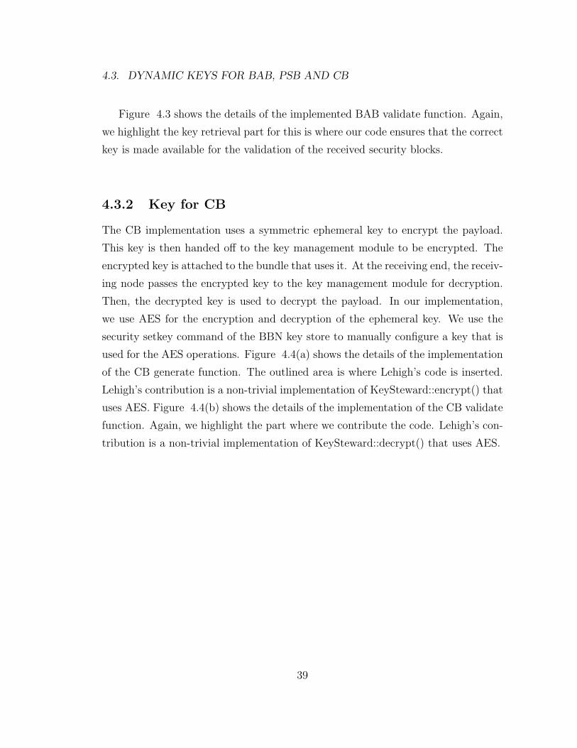
(a) Outgoing Finalize Func-tion
(b) Incoming Validate Function
Figure 4.5: Program Flow for Processing of PSB
42
4.3. DYNAMIC KEYS FOR BAB, PSB AND CB
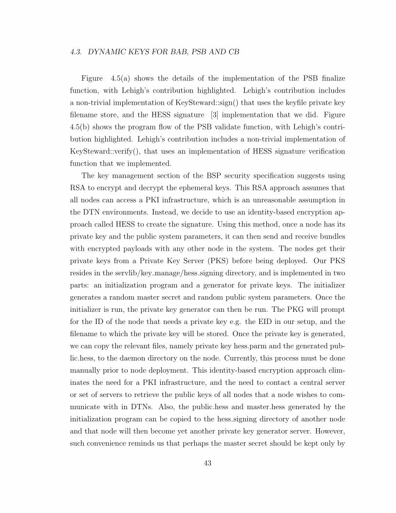
Figure 4.5(a) shows the details of the implementation of the PSB finalize
function, with Lehigh’s contribution highlighted. Lehigh’s contribution includes
a non-trivial implementation of KeySteward::sign() that uses the keyfile private key
filename store, and the HESS signature [3] implementation that we did. Figure
4.5(b) shows the program flow of the PSB validate function, with Lehigh’s contri-
bution highlighted. Lehigh’s contribution includes a non-trivial implementation of
KeySteward::verify(), that uses an implementation of HESS signature verification
function that we implemented.
The key management section of the BSP security specification suggests using
RSA to encrypt and decrypt the ephemeral keys. This RSA approach assumes that
all nodes can access a PKI infrastructure, which is an unreasonable assumption in
the DTN environments. Instead, we decide to use an identity-based encryption ap-
proach called HESS to create the signature. Using this method, once a node has its
private key and the public system parameters, it can then send and receive bundles
with encrypted payloads with any other node in the system. The nodes get their
private keys from a Private Key Server (PKS) before being deployed. Our PKS
resides in the servlib/key manage/hess signing directory, and is implemented in two
parts: an initialization program and a generator for private keys. The initializer
generates a random master secret and random public system parameters. Once the
initializer is run, the private key generator can then be run. The PKG will prompt
for the ID of the node that needs a private key e.g. the EID in our setup, and the
filename to which the private key will be stored. Once the private key is generated,
we can copy the relevant files, namely private key hess.parm and the generated pub-
lic.hess, to the daemon directory on the node. Currently, this process must be done
manually prior to node deployment. This identity-based encryption approach elim-
inates the need for a PKI infrastructure, and the need to contact a central server
or set of servers to retrieve the public keys of all nodes that a node wishes to com-
municate with in DTNs. Also, the public.hess and master.hess generated by the
initialization program can be copied to the hess signing directory of another node
and that node will then become yet another private key generator server. However,
such convenience reminds us that perhaps the master secret should be kept only by
43
CHAPTER 4. DTN KEY MANAGEMENT
the centralized key server and not replicated elsewhere.
In an environment with multicast groups, nodes might be associated with mul-
tiple EIDs and thus there may have multiple private keys, one for each EID that a
node is associated with. Thus, we add the set keyfile sub-command to the security
command. This sub-command allows the specification of the filename of a file con-
taining a particular private key associated with a local EID of that node.
4.4 Experiment
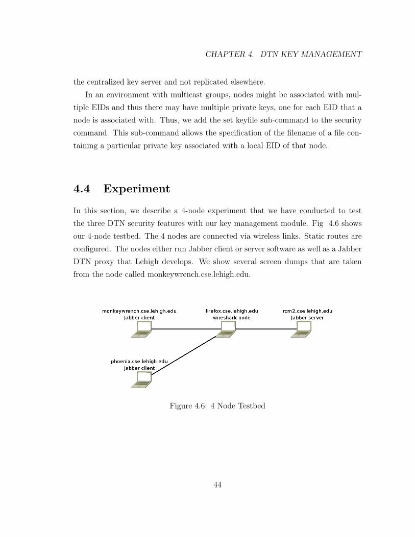
In this section, we describe a 4-node experiment that we have conducted to test
the three DTN security features with our key management module. Fig 4.6 shows
our 4-node testbed. The 4 nodes are connected via wireless links. Static routes are
configured. The nodes either run Jabber client or server software as well as a Jabber
DTN proxy that Lehigh develops. We show several screen dumps that are taken
from the node called monkeywrench.cse.lehigh.edu.
Figure 4.6: 4 Node Testbed
44

4.4. EXPERIMENT
In Fig 4.7(a) , we show that initially this node has no security keys. Then, we
run
dtnsend -s dtn://monkeywrench.cse.lehigh.edu.dtn/key management d
dtn://firefox.cse.lehigh.edu.dtn/key management -t m -p “00”.
That command triggers the BAB key negotiation between the nodes monkeywrench
and firefox. In Fig 4.7(b) , we see that a BAB key for firefox will appear after the
successful BAB key negotiation. Next, we run the setpolicy commands to turn on
the BAB processing for both incoming and outgoing bundles. We then send a jabber
message from the Jabber client running on monkeywrench to the server running on
rcm2.
(a) Before (b) After
Figure 4.7: BAB Negotiation Result
45

CHAPTER 4. DTN KEY MANAGEMENT
Figure 4.8(a) shows the output of the wireshark [11] program running on the
machine, Firefox. Since only the BAB and NOT the CB feature is active at this
point, the message sent can be easily readable by anyone who can get their hands
on the bundle. Only the CB feature provides for payload encryption. Next, we run
the setkey and setkeyfile commands to turn on the CB feature. Figure 4.8(b) shows
that the bundle payload content is unreadable after the CB feature is turned on.
(a) No CB (b) With CB
Figure 4.8: Wireshark Examination of Bundle Payload
46
4.4. EXPERIMENT
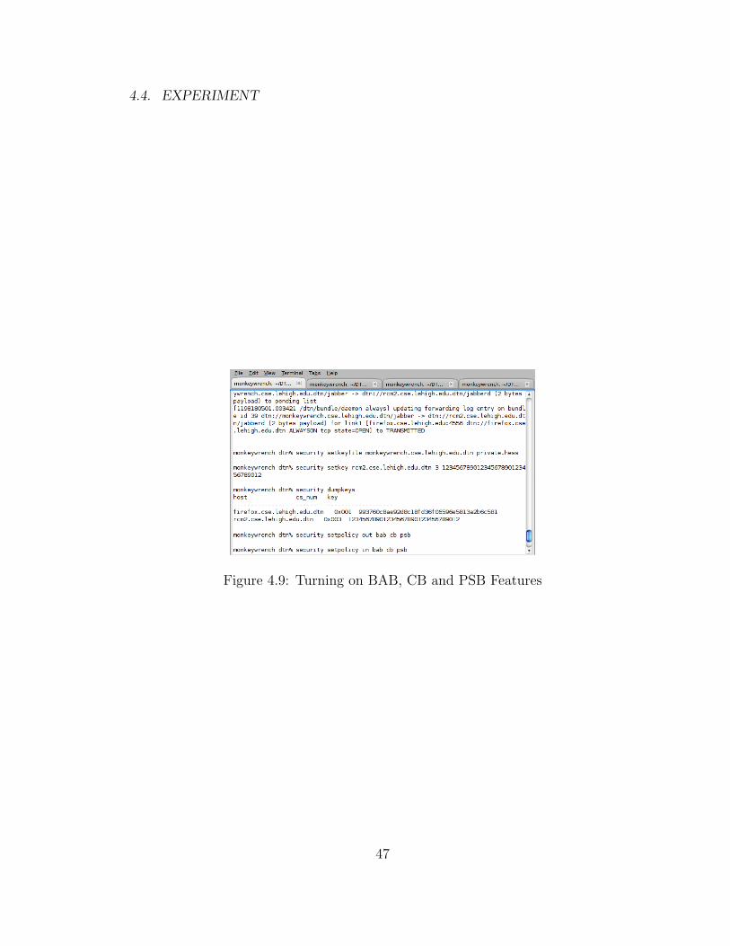
Figure 4.9: Turning on BAB, CB and PSB Features
47
CHAPTER 4. DTN KEY MANAGEMENT
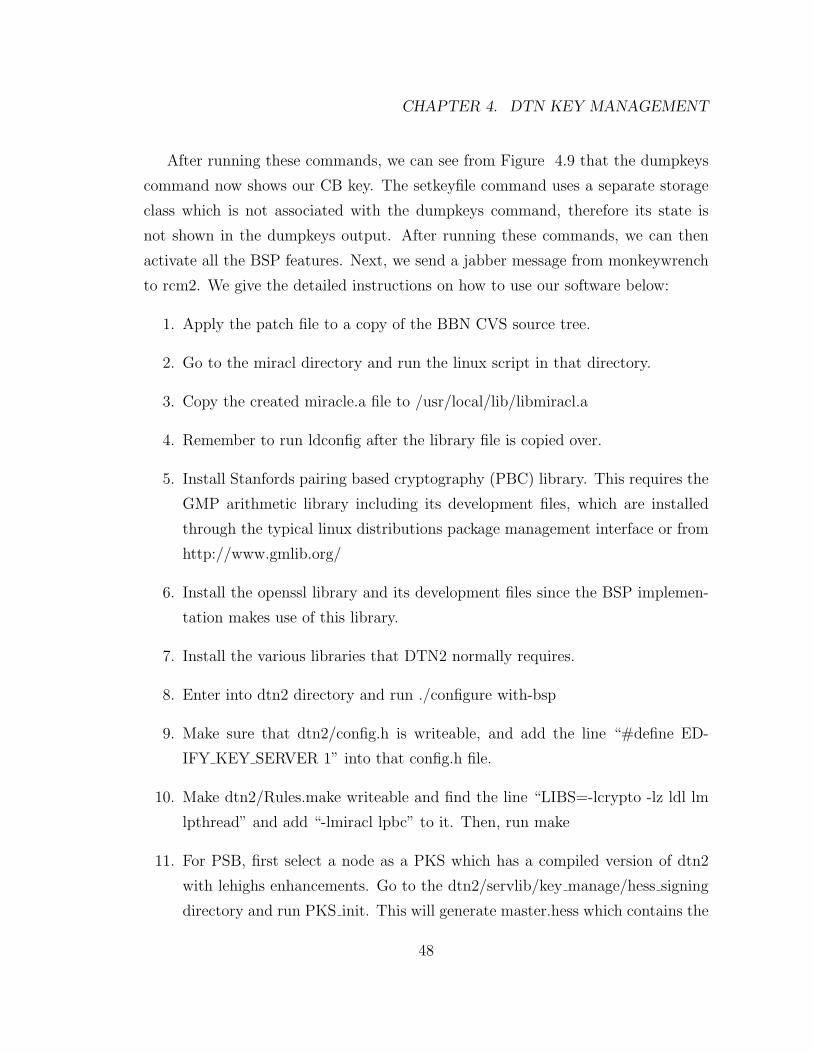
After running these commands, we can see from Figure 4.9 that the dumpkeys
command now shows our CB key. The setkeyfile command uses a separate storage
class which is not associated with the dumpkeys command, therefore its state is
not shown in the dumpkeys output. After running these commands, we can then
activate all the BSP features. Next, we send a jabber message from monkeywrench
to rcm2. We give the detailed instructions on how to use our software below:
1. Apply the patch file to a copy of the BBN CVS source tree.
2. Go to the miracl directory and run the linux script in that directory.
3. Copy the created miracle.a file to /usr/local/lib/libmiracl.a
4. Remember to run ldconfig after the library file is copied over.
5. Install Stanfords pairing based cryptography (PBC) library. This requires the
GMP arithmetic library including its development files, which are installed
through the typical linux distributions package management interface or from
http://www.gmlib.org/
6. Install the openssl library and its development files since the BSP implemen-
tation makes use of this library.
7. Install the various libraries that DTN2 normally requires.
8. Enter into dtn2 directory and run ./configure with-bsp
9. Make sure that dtn2/config.h is writeable, and add the line “#define ED-
IFY KEY SERVER 1” into that config.h file.
10. Make dtn2/Rules.make writeable and find the line “LIBS=-lcrypto -lz ldl lm
lpthread” and add “-lmiracl lpbc” to it. Then, run make
11. For PSB, first select a node as a PKS which has a compiled version of dtn2
with lehighs enhancements. Go to the dtn2/servlib/key manage/hess signing
directory and run PKS init. This will generate master.hess which contains the
48
4.4. EXPERIMENT
master secret and global public.hess containing the global public parameters
for the hess procedure.
12. Now for each node in the network, you must produce its private key. This is
done by running PKS gen. PKS gen will ask for a filename where the private
key will be stored. Then, PKS gen will ask for the EID whose private key you
want to generate e.g. monkeywrench.cse.lehigh.edu.dtn. Once you have run
PKS gen for each EID associated with a node, copy over the global public.hess,
hess.param and all the private keys generated to the dtn2/daemon directory on
that node. Delete all the private keys from PKS and start generating private
keys for other remaining nodes.
13. The method employed for dealing with the keys used for encryption of the
BAB key negotiation messages is similar to that used for the PSB keys. Again
you must select a node to serve as the PKS for this set of keys. On this
node go to the dtn2/servlib/key manage/bab ibe directory and run “make -f
PKSMake” without the quotes. Note that you must run this on a dtn2 that
has been configured and compiled or it will not have the object files it needs
to link against. This will produce the binaries ibe ext and ibe set.
14. ibe set must be run first, and it will generate the files common.ibe and mas-
ter.ibe. Master.ibe is the master secret for this system, and is analogous to
master.hess. Common.ibe contains the various parameters used to define the
elliptic curve to be used in the system.
15. Now you can generate your private keys with the ibe ext program. It will ask
for the EID of the node that you’re generating a private key for and produce a
private.ibe. Unlike PSB the BAB negotiation is incompatible with multicast
communications, so we don’t have to worry about multiple private keys. Once
the private.ibe is generated, copy this file and common.ibe to the daemon
directory of the node the private key was generated for.
16. There are three commands for configuring each node for DTN security features.
49
CHAPTER 4. DTN KEY MANAGEMENT
These commands can either be placed in the dtn conf file or entered into the
command interpreter once dtn2 is running.
(a) The first command is “security setkeyfile EID <filename>” e.g. “secu-
rity setkeyfile monkeywrench.cse.lehigh.edu.dtn private.hess”. This com-
mand makes an association between the EID associated with the local
node and the filename containing the private key for that EID.
(b) The second command is “security setkey EID cs num key in hex” eg.
“security setkey rcm2.cse.lehigh.edu.dtn 3
12345678901234567890123456789012”. The EID is the EID of the desti-
nation that the key should be used for. The cs num is set to 3 for CB
and this key is a 128-bit (or 32 hex digits) to be used for CB. A node
can send bundles with CB feature to any remote node that has a CB key
set with the setkey command, as long as that remote node has also been
configured to send bundles with CB feature to the current node with the
same key.
(c) The last command is “security setpolicy <out|in> <cb|psb|bab>” e.g.
“security setpolicy in cb bab” turns on both CB and BAB feature for all
incoming bundles. This command sets the binary flags in the BBN policy
manager that adds the specified BSP features to incoming bundles. To
deactivate a feature, run the command again without the feature you
want to disable in the list.
(d) Currently, the initiation of BAB key exchange must be done manually.
First, make sure BAB is not turned on for both incoming and outgoing
bundles on both nodes which intend to negotiate BAB keys. Then, the
key negotiation can be initiated via the dtnsend command. To initiate
key negotiation, issue the following command
“./dtnsend s dtn://monkeywrench.cse.lehigh.edu.dtn/key management -
d dtn://firefox.cse.lehigh.edu.dtn/key management -t m -p “00” ”.
(e) For PSB, once the private keys are generated, copied into place, and
50
4.5. DISCUSSION
associated with the “security setkeyfile” command, that node can use
PSB to any other node which has also been configured.
4.5 Discussion
There are several outstanding issues that should be addressed before the key man-
agement system can be considered complete. These issues involve every part of the
DTN security system ranging from the BBN’s policy manager to the choice of public
keys in the IBE system.
Currently, the BBN policy management class only allows security options to be
configured based on outgoing or incoming bundles, regardless of where the bundles
are received from or being sent to or which link is being used. On the incoming
side, the policy can be set to expect and process a particular BSP block or any
combination of BSP blocks. If any of the expected blocks is absent, this is consid-
ered a security failure and the bundle will be discarded. Similarly, at the sending
side, the policy can be set so that a BSP block or any combination of BSP blocks
are computed and added to the outgoing bundles. Both of these options set simple
binary flags.
The simplistic nature of the current policy manager causes issues in the negoti-
ation process for BAB. A node encountering a second node that has been told to
expect BAB on all incoming bundles will be unable to negotiate a BAB key since
the negotiation bundles do not contain a BAB and thus the second node would
automatically drop all the negotiation bundles and not process them. Therefore the
policy class needs to be modified to allow negotiation bundles without a BAB even
though a node has been configured to expect BAB on all incoming bundles. Also,
currently the negotiation must be initiated manually, in the hopes that in future,
the policy class can be enhanced to allow for key negotiations with nodes that a
node has not negotiated BAB keys yet. In addition, the Identity Based Encryption
(IBE) portion of the current key negotiation module uses simple AES with hard
coded keys, thus the IBE portion of the code needs to be completed.
51
CHAPTER 4. DTN KEY MANAGEMENT
For the CB feature, we use the security setkey command of the BBN key store
to manually set the key that is used for AES encryption and decryption. Optimally,
when the IBE features of the BAB negotiation protocol are completed, the same
system could be used for encrypting the CB ephemeral key.
Currently, the private key used in the PSB feature never expires as long as the
EID doesn’t change. Once the various pending IBE elements in BAB and CB are
implemented, it would be wise to consider the ID to be a concatenation of a time
field and the EID. Periodically, the private keys can be updated. This only requires
some fairly straight forward modifications to the IBE code. The net result would be
that the issued private keys would only be valid for a certain period (e.g a day or a
month). The advantage is that a compromised private key would become completely
useless after it expires.
Manual distribution of private keys becomes unreasonable when the nodes all
need to periodically get a new private key from the PKS. Thus the PKS should also
be updated such that the private keys can be updated automatically and in a secure
manner. In addition, the key update process should ensure that compromised nodes
will not get access to the new keys.
Currently, the key negotiation for multicast group is not defined well. Our cur-
rent implementation allows the key for a static multicast group to be configured
manually via the security setkey command. However, more needs to be done for
managing the group key of a dynamic group. Most likely, the BAB key for a dy-
namic multicast group should be generated by a source node and distributed to any
node that requests to join the group. In addition, several other enhancements need
to be done before group communications can take place. First, a dynamic multicast
group management protocol needs to be added to DTN2 along with the underly-
ing support of multicast routing within the daemon code. Once that is completed,
then, perhaps a Logical Key Hierarchy (LKH) system can be added for managing
the group keys. This finished system will then allow for both secure group commu-
nications.
52
Chapter 5
Data Centric Security in DTN
5.1 Overview
In conventional cryptography systems, the security associations are established be-
tween the source and destination pair. For example, SSL [10] creates an encrypted
session between a pair of hosts. SSL makes use of both symmetric and asymmetric
cryptography. Symmetric key algorithms may be used to encrypt messages sent be-
tween a pair of hosts while asymmetric key algorithms are used for key negotiation
between these two hosts. When data needs to be disseminated to many hosts, such
a pairwise key arrangement is not scalable. Thus, we are interested in exploring a
data-centric approach where subscribers of a particular data category are given the
same key by either the publisher of the data or its agents. The data-centric approach
provides a more scalable solution that is independent of the source/destination pair
and the number of subscribers.
A core prerequisite of this approach is of course assigning and maintaining the
category information of all published data items in the system. We use an ontology
based approach for classifying the data while being careful to not predefine the ontol-
ogy tree so that the system will not be constrained to that particular ontology tree.
As the first step, we define a node labeling scheme for a generic ontology tree. All
labels are strings, with the root node being a special case with a label of “*”. Other
53
CHAPTER 5. DATA CENTRIC SECURITY IN DTN
ontology nodes are labeled with alternating numbers and underscores. The numbers
refer to the count of children at successive levels of the ontology tree. For example,
a label such as “2 45 0 235”, refers to the 235th child of the 0th child of the 45th
child of the 2nd child of the root, assuming the children of a node are labeled from
left to right starting at zero. Such a generic labeling scheme can be applied to an
ontology tree of any arbitrary structure as long as it conforms to the mathematical
definition of a tree. There are two unique and useful features of this labeling scheme:
(a) if a node is added to the ontology tree after the system is already running, then
that new node will be added as the right most child of the appropriate node and will
not change the label of ANY existing ontology node; (b) it is trivial to determine
if a node is in the sub-tree of another node by simply performing the longest prefix
string matching; if the prefix match includes the entirety of the parent node, then
the child node is indeed in the sub-tree of the parent. Each ontology tree is assigned
its own ontology tree identifier (treeID) e.g. Google and Microsoft have different
ontology tree identifiers. A subscriber may subscribe to data categories offered by
different companies (and hence different ontology tree identifiers) so its subscription
request must specify both the treeID as well as the node label since a particular
node label may mean different things in different ontology trees.
To ensure that published data is only accessed by authorized users, one needs to
design a data-centric security mechanism. In our approach, we create a category-
based hierarchical key tree such that the encryption keys for the children categories
can be derived from a parent but it is hard to derive the parent key given any of
the children keys.
The rest of the chapter is organized as follows: In Section 2, we first give an
overview of our data-centric security design which is called the Lehighs Secure Data
Retrieval (SEDAR) system. Then, we elaborate in more details the user authen-
tication procedure, and the operations of the producer, storage node, subscriber.
Next, we present a description of a small size prototype that we have created to
demonstrate our design. Last but not least, we discuss near future work that we
intend to explore.
54
5.2. OVERVIEW OF LEHIGH’S SECURE DATA RETRIEVAL (SEDAR) SYSTEM
5.2 Overview of Lehigh’s Secure Data Retrieval
(SEDAR) System
In our SEDAR system, there are 4 network entities namely (a) publishers, (b) sub-
scribers, (c) storage nodes, and (d) a mobile key server. Data items generated by
the publishers are encrypted using AES. A plaintext meta-data describing the data
item is added to the encrypted data block. The encrypted data item together with
its plaintext meta-data descriptor is then sent to a storage node. Subscribers send
their subscriptions to a particular storage node. The storage node will send all
data stored or subsequently received that match the subscription of a particular
subscriber. A subscriber which subscribes to a particular ontology node implicitly
subscribes to all data items that belong to the categories which are children of that
ontology node.
The keys used for encryption and decryption follow a very specific scheme them-
selves. A system-wide key for the root node of the ontology tree is stored at the
Mobile Key Servers (MKS). The keys for the other data categories (represented by
the ontology tree nodes) are derived from this root key. This ability to derive keys
is consistent through out, such that given the key for any particular node within the
ontology tree, you can derive the key for any of its children, but you CANNOT de-
rive the key of its parent. To derive the key of the child node, we take the key of the
current node and append the number of the child node to it. Then, the augmented
key is hashed via Secure Hash Algorithm (SHA), the resulting hash is the key of the
child. For example the key of 3 45 6 is SHA(SHA(SHA(root key||3)||45)||3), where
|| is the concatenation operator.
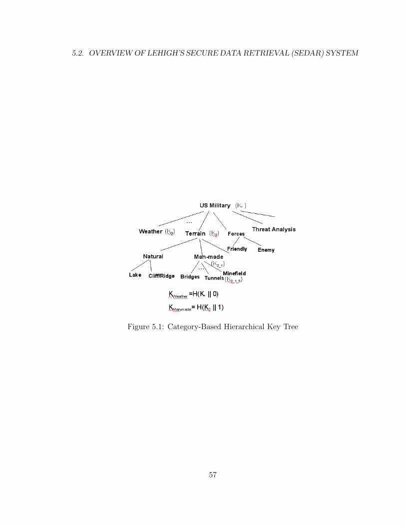
Let us consider the hierarchical key tree shown in Fig 5.1 . The key tree is de-
signed such that given a parent key, all the child keys can be easily derived but given
a child key, it is computationally infeasible to derive a parent key. For example, in
Fig 5.1, the encryption keys must be designed such that a subscriber that wants
to access data items that belong to “man-made” category, and another subscriber
that wants to access data items in the “terrain” category can derive the encryption
55

CHAPTER 5. DATA CENTRIC SECURITY IN DTN
keys used to encrypt all data items in the “tunnels” subcategory. The subscriber
that only subscribes to data items in the “weather” category should not be able to
derive encryption keys for any data items in the “tunnels” subcategory.
We describe how an encryption key, Ke, for a data item is derived. Let kls be
the string that represents a subcategory. For example the kls for the “man-made”
subcategory in Fig 5.1 is 2 1. The encryption key for any data item within the
category c is denoted as:
Ke = Kkls(c)
Let us assume that the root element for Publisher P1 uses the key K∗ for US-
Military. To determine the encryption key, Ke, for the data items in the “tunnels”
category, a publisher first determines the binary string, kls, that represents the
“tunnels” category, which is 2 1 5. Then, Ke = H(H(H(K∗||2)||1)||5).
A subscriber can subscribe to any category within the category-based hierarchi-
cal tree. Assume that a subscriber subscribes to the “terrain” category, then he
has the access key, K2. When he wants to access the data items belonging to the
“tunnels” category, he knows that the kls for that category is 2 1 5 so he needs to
perform the following operation to his access key to derive K2 1 5, the encryption
key for data items that belong to the “tunnels” subcategory.
K2 1 5 = H(H(K2||1)||5)
56
5.2. OVERVIEW OF LEHIGH’S SECURE DATA RETRIEVAL (SEDAR) SYSTEM
Figure 5.1: Category-Based Hierarchical Key Tree
57
CHAPTER 5. DATA CENTRIC SECURITY IN DTN
Note that a subscriber is allowed to subscribe to multiple categories. For exam-
ple, a subscriber may subscribe to items related to both “weather”, and “man-made”
categories. This subscriber will be given the access key for the weather category i.e.
K0 , and the access key for the man-made category i.e. K2 1.
In subsequent sections, we elaborate on (a) the authentication procedure per-
formed by a user with the Mobile Key Server to retrieve encryption keys that are
used for encrypting published data items or for decrypting the subscribed data items
that have been retrieved, (b) the publishing procedure, (c) the storage node proce-
dure, and (c) the subscribing procedure.
5.2.1 Authentication
As a security system it would of course be completely useless without some method
for constraining who has access to what. There are two components for the au-
thentication function: namely a Mobile Key Server (MKS) that holds the root key
and a user authentication client. You must authenticate in order to use either a
publisher or a subscriber since both of these applications require the use of encryp-
tion/decryption keys for handling the data. When a user wishes to use either of
these applications at a DTN node, then he/she runs the user authentication appli-
cation. The user authentication (UA) application is configured with a list of MKSs
to authenticate against since one needs to authenticate with one MKS in each in-
stantiation of the system which one wishes to publish or subscribe to. The UA
application will prompt for a username and password for each MKS in the list. It
will then send the entered username and password to the corresponding MKS, but
first encrypts the message with the Identity Based Encryption (IBE). The MKS
stores the usernames and the SHA hash of the passwords in a file. Thus, if the pass-
word file is ever compromised, then the passwords themselves are not compromised.
When the MKS receives an authentication request packet, it decrypts the message,
and extracts the username and password. Then, it hashes the password, and com-
pares it with the hash value stored on file for that username. If either the username
58
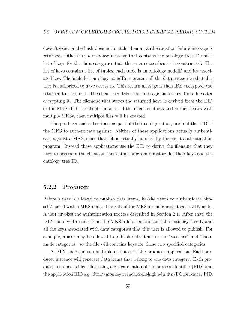
5.2. OVERVIEW OF LEHIGH’S SECURE DATA RETRIEVAL (SEDAR) SYSTEM
doesn’t exist or the hash does not match, then an authentication failure message is
returned. Otherwise, a response message that contains the ontology tree ID and a
list of keys for the data categories that this user subscribes to is constructed. The
list of keys contains a list of tuples, each tuple is an ontology nodeID and its associ-
ated key. The included ontology nodeIDs represent all the data categories that this
user is authorized to have access to. This return message is then IBE encrypted and
returned to the client. The client then takes this message and stores it in a file after
decrypting it. The filename that stores the returned keys is derived from the EID
of the MKS that the client contacts. If the client contacts and authenticates with
multiple MKSs, then multiple files will be created.
The producer and subscriber, as part of their configuration, are told the EID of
the MKS to authenticate against. Neither of these applications actually authenti-
cate against a MKS, since that job is actually handled by the client authentication
program. Instead these applications use the EID to derive the filename that they
need to access in the client authentication program directory for their keys and the
ontology tree ID.
5.2.2 Producer
Before a user is allowed to publish data items, he/she needs to authenticate him-
self/herself with a MKS node. The EID of the MKS is configured at each DTN node.
A user invokes the authentication process described in Section 2.1. After that, the
DTN node will receive from the MKS a file that contains the ontology treeID and
all the keys associated with data categories that this user is allowed to publish. For
example, a user may be allowed to publish data items in the “weather” and “man-
made categories” so the file will contains keys for those two specified categories.
A DTN node can run multiple instances of the producer application. Each pro-
ducer instance will generate data items that belong to one data category. Each pro-
ducer instance is identified using a concatenation of the process identifier (PID) and
the application EID e.g. dtn://monkeywrench.cse.lehigh.edu.dtn/DC producer.PID.
59
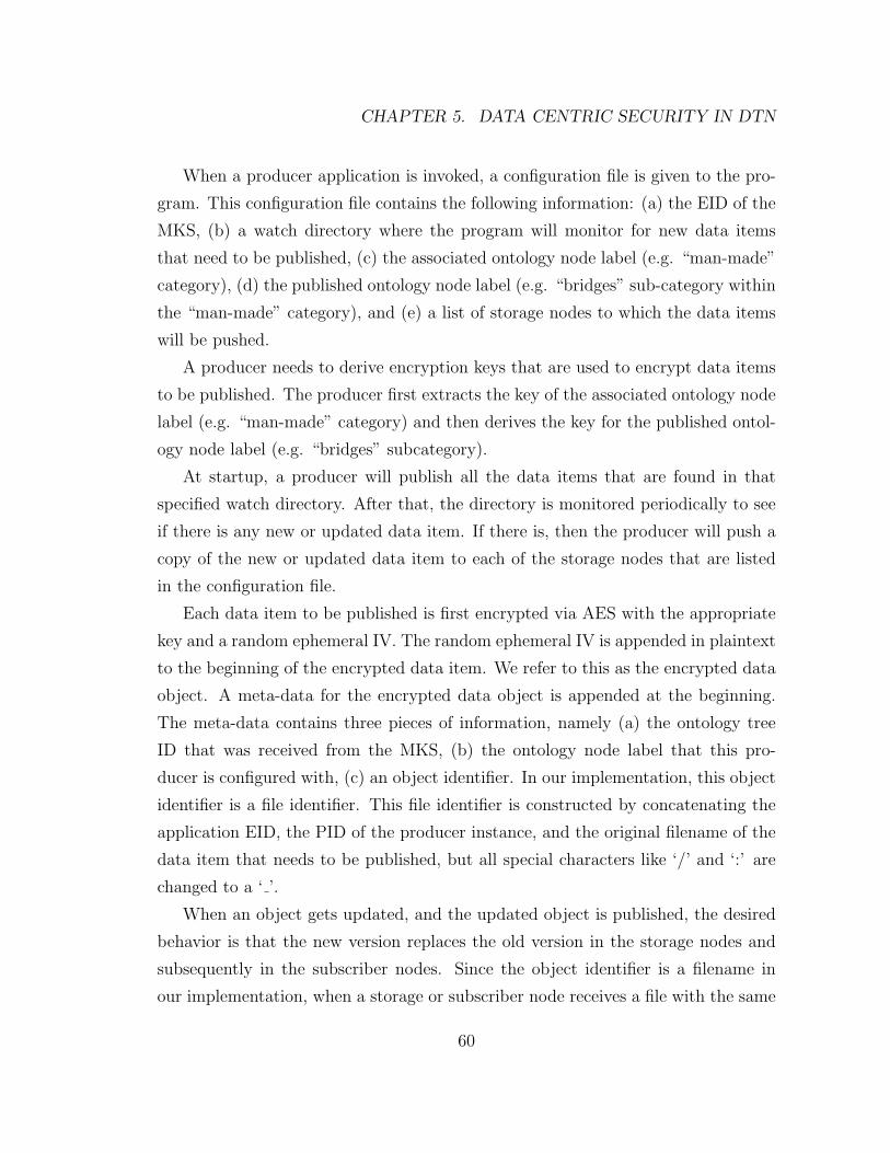
CHAPTER 5. DATA CENTRIC SECURITY IN DTN
When a producer application is invoked, a configuration file is given to the pro-
gram. This configuration file contains the following information: (a) the EID of the
MKS, (b) a watch directory where the program will monitor for new data items
that need to be published, (c) the associated ontology node label (e.g. “man-made”
category), (d) the published ontology node label (e.g. “bridges” sub-category within
the “man-made” category), and (e) a list of storage nodes to which the data items
will be pushed.
A producer needs to derive encryption keys that are used to encrypt data items
to be published. The producer first extracts the key of the associated ontology node
label (e.g. “man-made” category) and then derives the key for the published ontol-
ogy node label (e.g. “bridges” subcategory).
At startup, a producer will publish all the data items that are found in that
specified watch directory. After that, the directory is monitored periodically to see
if there is any new or updated data item. If there is, then the producer will push a
copy of the new or updated data item to each of the storage nodes that are listed
in the configuration file.
Each data item to be published is first encrypted via AES with the appropriate
key and a random ephemeral IV. The random ephemeral IV is appended in plaintext
to the beginning of the encrypted data item. We refer to this as the encrypted data
object. A meta-data for the encrypted data object is appended at the beginning.
The meta-data contains three pieces of information, namely (a) the ontology tree
ID that was received from the MKS, (b) the ontology node label that this pro-
ducer is configured with, (c) an object identifier. In our implementation, this object
identifier is a file identifier. This file identifier is constructed by concatenating the
application EID, the PID of the producer instance, and the original filename of the
data item that needs to be published, but all special characters like ‘/’ and ‘:’ are
changed to a ‘ ’.
When an object gets updated, and the updated object is published, the desired
behavior is that the new version replaces the old version in the storage nodes and
subsequently in the subscriber nodes. Since the object identifier is a filename in
our implementation, when a storage or subscriber node receives a file with the same
60
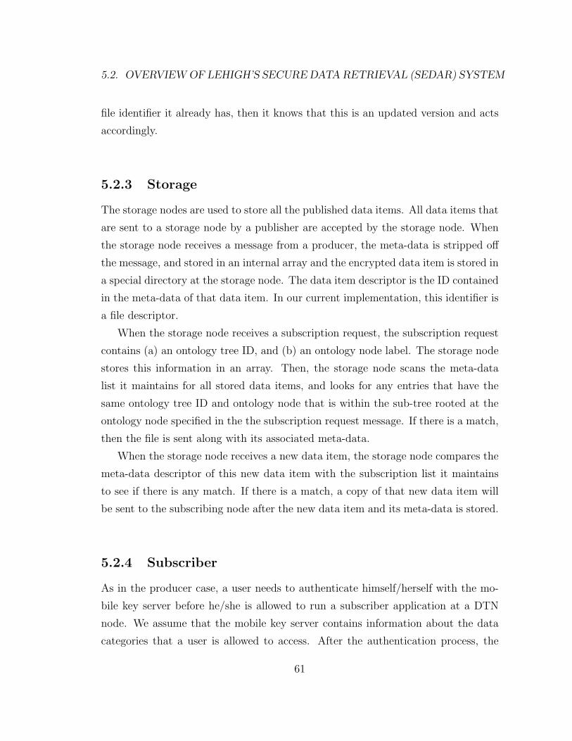
5.2. OVERVIEW OF LEHIGH’S SECURE DATA RETRIEVAL (SEDAR) SYSTEM
file identifier it already has, then it knows that this is an updated version and acts
accordingly.
5.2.3 Storage
The storage nodes are used to store all the published data items. All data items that
are sent to a storage node by a publisher are accepted by the storage node. When
the storage node receives a message from a producer, the meta-data is stripped off
the message, and stored in an internal array and the encrypted data item is stored in
a special directory at the storage node. The data item descriptor is the ID contained
in the meta-data of that data item. In our current implementation, this identifier is
a file descriptor.
When the storage node receives a subscription request, the subscription request
contains (a) an ontology tree ID, and (b) an ontology node label. The storage node
stores this information in an array. Then, the storage node scans the meta-data
list it maintains for all stored data items, and looks for any entries that have the
same ontology tree ID and ontology node that is within the sub-tree rooted at the
ontology node specified in the the subscription request message. If there is a match,
then the file is sent along with its associated meta-data.
When the storage node receives a new data item, the storage node compares the
meta-data descriptor of this new data item with the subscription list it maintains
to see if there is any match. If there is a match, a copy of that new data item will
be sent to the subscribing node after the new data item and its meta-data is stored.
5.2.4 Subscriber
As in the producer case, a user needs to authenticate himself/herself with the mo-
bile key server before he/she is allowed to run a subscriber application at a DTN
node. We assume that the mobile key server contains information about the data
categories that a user is allowed to access. After the authentication process, the
61
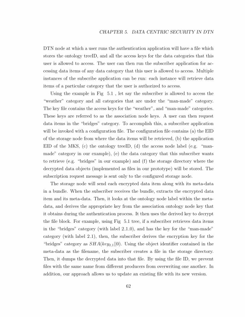
CHAPTER 5. DATA CENTRIC SECURITY IN DTN
DTN node at which a user runs the authentication application will have a file which
stores the ontology treeID, and all the access keys for the data categories that this
user is allowed to access. The user can then run the subscriber application for ac-
cessing data items of any data category that this user is allowed to access. Multiple
instances of the subscribe application can be run: each instance will retrieve data
items of a particular category that the user is authorized to access.
Using the example in Fig 5.1 , let say the subscriber is allowed to access the
“weather” category and all categories that are under the “man-made” category.
The key file contains the access keys for the “weather”, and “man-made” categories.
These keys are referred to as the association node keys. A user can then request
data items in the “bridges” category. To accomplish this, a subscriber application
will be invoked with a configuration file. The configuration file contains (a) the EID
of the storage node from where the data items will be retrieved, (b) the application
EID of the MKS, (c) the ontology treeID, (d) the access node label (e.g. “man-
made” category in our example), (e) the data category that this subscriber wants
to retrieve (e.g. “bridges” in our example) and (f) the storage directory where the
decrypted data objects (implemented as files in our prototype) will be stored. The
subscription request message is sent only to the configured storage node.
The storage node will send each encrypted data item along with its meta-data
in a bundle. When the subscriber receives the bundle, extracts the encrypted data
item and its meta-data. Then, it looks at the ontology node label within the meta-
data, and derives the appropriate key from the association ontology node key that
it obtains during the authentication process. It then uses the derived key to decrypt
the file block. For example, using Fig 5.1 tree, if a subscriber retrieves data items
in the “bridges” category (with label 2 1 0), and has the key for the “man-made”
category (with label 2 1), then, the subscriber derives the encryption key for the
“bridges” category as SHA(key2 1||0). Using the object identifier contained in the
meta-data as the filename, the subscriber creates a file in the storage directory.
Then, it dumps the decrypted data into that file. By using the file ID, we prevent
files with the same name from different producers from overwriting one another. In
addition, our approach allows us to update an existing file with its new version.
62
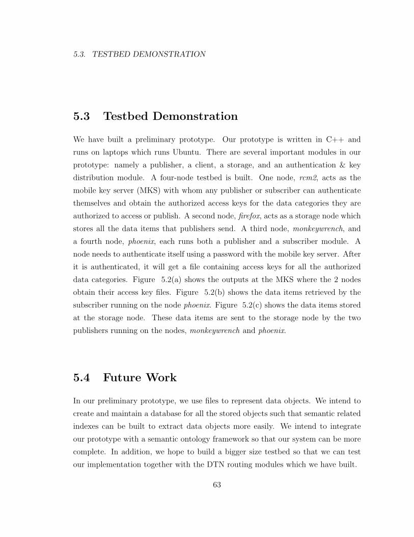
5.3. TESTBED DEMONSTRATION
5.3 Testbed Demonstration
We have built a preliminary prototype. Our prototype is written in C++ and
runs on laptops which runs Ubuntu. There are several important modules in our
prototype: namely a publisher, a client, a storage, and an authentication & key
distribution module. A four-node testbed is built. One node, rcm2, acts as the
mobile key server (MKS) with whom any publisher or subscriber can authenticate
themselves and obtain the authorized access keys for the data categories they are
authorized to access or publish. A second node, firefox, acts as a storage node which
stores all the data items that publishers send. A third node, monkeywrench, and
a fourth node, phoenix, each runs both a publisher and a subscriber module. A
node needs to authenticate itself using a password with the mobile key server. After
it is authenticated, it will get a file containing access keys for all the authorized
data categories. Figure 5.2(a) shows the outputs at the MKS where the 2 nodes
obtain their access key files. Figure 5.2(b) shows the data items retrieved by the
subscriber running on the node phoenix. Figure 5.2(c) shows the data items stored
at the storage node. These data items are sent to the storage node by the two
publishers running on the nodes, monkeywrench and phoenix.
5.4 Future Work
In our preliminary prototype, we use files to represent data objects. We intend to
create and maintain a database for all the stored objects such that semantic related
indexes can be built to extract data objects more easily. We intend to integrate
our prototype with a semantic ontology framework so that our system can be more
complete. In addition, we hope to build a bigger size testbed so that we can test
our implementation together with the DTN routing modules which we have built.
63

CHAPTER 5. DATA CENTRIC SECURITY IN DTN
64
5.4. FUTURE WORK
(a) Output from the Mobile Key Server
(b) Output from the Subscribing Node
(c) Output from the Storage Node
Figure 5.2: Screendumps from Different Nodes
65

CHAPTER 5. DATA CENTRIC SECURITY IN DTN
66
Bibliography
[1] M. Bollinger and M. Chuah. Lehigh EDIFY Key Management System for
DTN2. 2007.
[2] V. Cerf, S. Burleigh, A. Hooke, L. Torgerson, R. Durst, K. Scott, K. Fall,
and H. Weiss. Delay-Tolerant Networking Architecture. RFC 4838, Internet
Engineering Task Force, April 2007.
[3] F. Hess. Efficient Identity Based Signature Schemes Based on Pairings. In Lec-
ture Notes in Computer Science, volume 2595, pages 310–324. Springer Berlin
/ Heidelberg, 2000.
[4] H. Krawczyk, M. Bellare, and R. Canetti. HMAC: Keyed-Hashing for Message
Authentication. RFC 2104, Internet Engineering Task Force, February 1997.
[5] J. Myers. Simple Authentication and Security Layer (SASL). RFC 2222, In-
ternet Engineering Task Force, October 1997.
[6] U.S. Department of Commerce, National Institute of Standards, Technology
(NIST), and Information Technology Laboratory (ITL). SECURE HASH
STANDARD. FIPS 180–2, National Institute of Standards and Technology
(NIST), August 2002.
[7] P. Saint-Andre. Extensible Messaging and Presence Protocol (XMPP): Core.
RFC 3920, Internet Engineering Task Force, October 2004.
67
BIBLIOGRAPHY
[8] P. Saint-Andre. Extensible Messaging and Presence Protocol (XMPP): Instant
Messaging and Presence. RFC 3921, Internet Engineering Task Force, October
2004.
[9] S. Symington, S. Farrell, H. Weiss, and P. Lovell. Bundle Security Protocol
Specification. Internet-Draft draft-irtf-dtnrg-bundle-security-05, Internet Engi-
neering Task Force, February 2008. Work in progress.
[10] J. Viega, M. Messier, and P. Chandra. Network Security with OpenSSL.
O’Reilly Media, Inc., 2002.
[11] wireshark. http://www.wireshark.org.
68
Appendix A
Vita
• Place of Birth: San Luis Obispo, California
• Date of Birth: January 1, 1985
• Parents: Heather P. Metzger, Carl J. Metzger
• Institutions:
– Lehigh University, BS Computer Engineering, May 2007
highest academic honors
– Lehigh University, MS Computer Engineering, May 2008
• I was awarded with a Presidential scholarship to pursue my master degree in
Computer Engineering. During the master degree program, I worked under
Prof Mooi Choo Chuah to investigate new approaches for securing data ex-
change in disruption tolerant networks. After my master degree, I intend to
pursue networking research and network systems engineering as a career path.
69
Related Documents