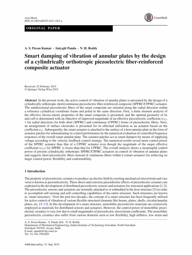
Acta Mech DOI 10.1007/s00707-015-1363-x ORIGINAL PAPER A. S. Pavan Kumar · Satyajit Panda · N. H. Reddy Smart damping of vibration of annular plates by the design of a cylindrically orthotropic piezoelectric fiber-reinforced composite actuator Received: 25 February 2015 © Springer-Verlag Wien 2015 Abstract In the present work, the active control of vibration of annular plates is presented by the design of a cylindrically orthotropic short/continuous piezoelectric fiber-reinforced composite (SPFRC/CPFRC) actuator. The unidirectional piezoelectric fibers of the smart composite are oriented along the radial direction within a reference cylindrical coordinate frame and poled in the same direction. First, a finite element analysis of the effective electro-elastic properties of the smart composite is presented, and the optimal geometry of its unit cell is determined with an objective of improved magnitude of an effective piezoelectric coefficient (e 11 , 1 for radial direction) for both short (SPFRC) and continuous (CPFRC) forms of piezoelectric fibers. Next, an arrangement of surface electrodes is presented for its effectual utilization as an actuator based on the coefficient e 11 . Subsequently, the smart actuator is attached to the surface of a host annular plate in the form of actuator patches for substantiating its control performance by the numerical evaluation of controlled frequency responses of the overall smart annular plate. The actuator patches act as smart dampers by means of supplying voltage according to the velocity feedback control strategy. The numerical results reveal more control power of the SPFRC actuator than that of a CPFRC actuator even though the magnitude of the major effective coefficient (e 11 ) for SPFRC is lesser than that for CPFRC. The overall analysis shows a meaningful control power of present cylindrically orthotropic SPFRC/CPFRC actuators in control of vibration of annular plates and suggests short piezoelectric fibers instead of continuous fibers within it (smart actuator) for achieving its larger control power, flexibility and conformability. 1 Introduction The property of piezoelectric ceramics to produce an electric field by exerting mechanical stress/strain and vice versa is known as piezoelectricity. These direct and converse piezoelectric effects of piezoelectric ceramics are exploited in the development of distributed piezoelectric sensors and actuators for structural applications [1, 2]. The piezoelectric sensors and actuators are normally attached to or embedded in the host structure [3] in order to accomplish self-sensing and self-controlling capabilities of the entire structure. Such structures are known as ’smart structures.’ Over the past two decades, the concept of a smart structure has been frequently utilized for active control of vibration of various flexible structural elements like beams, plates, shells, circular/annular plates, etc. [3–13]. In this development of a smart structure, monolithic piezoelectric materials are extensively employed as materials for distributed sensors and actuators. However, the control power of monolithic piezo- electric ceramics is very low due to small magnitudes of piezoelectric stress/strain coefficients. The monolithic piezoelectric ceramics also suffer from various demerits such as low flexibility, high stiffness, low strain and A. S. Pavan Kumar · S. Panda (B ) · N. H. Reddy Department of Mechanical Engineering, Indian Institute of Technology Guwahati, North Guwahati, Guwahati 781039, Assam, India E-mail: [email protected] Tel.: 91-361-2582664

Welcome message from author
This document is posted to help you gain knowledge. Please leave a comment to let me know what you think about it! Share it to your friends and learn new things together.
Transcript
Acta MechDOI 10.1007/s00707-015-1363-x
ORIGINAL PAPER
A. S. Pavan Kumar · Satyajit Panda · N. H. Reddy
Smart damping of vibration of annular plates by the designof a cylindrically orthotropic piezoelectric fiber-reinforcedcomposite actuator
Received: 25 February 2015© Springer-Verlag Wien 2015
Abstract In the present work, the active control of vibration of annular plates is presented by the design of acylindrically orthotropic short/continuous piezoelectric fiber-reinforced composite (SPFRC/CPFRC) actuator.The unidirectional piezoelectric fibers of the smart composite are oriented along the radial direction withina reference cylindrical coordinate frame and poled in the same direction. First, a finite element analysis ofthe effective electro-elastic properties of the smart composite is presented, and the optimal geometry of itsunit cell is determined with an objective of improved magnitude of an effective piezoelectric coefficient (e11,1 for radial direction) for both short (SPFRC) and continuous (CPFRC) forms of piezoelectric fibers. Next,an arrangement of surface electrodes is presented for its effectual utilization as an actuator based on thecoefficient e11. Subsequently, the smart actuator is attached to the surface of a host annular plate in the form ofactuator patches for substantiating its control performance by the numerical evaluation of controlled frequencyresponses of the overall smart annular plate. The actuator patches act as smart dampers by means of supplyingvoltage according to the velocity feedback control strategy. The numerical results reveal more control powerof the SPFRC actuator than that of a CPFRC actuator even though the magnitude of the major effectivecoefficient (e11) for SPFRC is lesser than that for CPFRC. The overall analysis shows a meaningful controlpower of present cylindrically orthotropic SPFRC/CPFRC actuators in control of vibration of annular platesand suggests short piezoelectric fibers instead of continuous fibers within it (smart actuator) for achieving itslarger control power, flexibility and conformability.
1 Introduction
The property of piezoelectric ceramics to produce an electric field by exerting mechanical stress/strain and viceversa is known as piezoelectricity. These direct and converse piezoelectric effects of piezoelectric ceramics areexploited in the development of distributed piezoelectric sensors and actuators for structural applications [1,2].The piezoelectric sensors and actuators are normally attached to or embedded in the host structure [3] in orderto accomplish self-sensing and self-controlling capabilities of the entire structure. Such structures are knownas ’smart structures.’ Over the past two decades, the concept of a smart structure has been frequently utilizedfor active control of vibration of various flexible structural elements like beams, plates, shells, circular/annularplates, etc. [3–13]. In this development of a smart structure, monolithic piezoelectric materials are extensivelyemployed as materials for distributed sensors and actuators. However, the control power of monolithic piezo-electric ceramics is very low due to small magnitudes of piezoelectric stress/strain coefficients. The monolithicpiezoelectric ceramics also suffer from various demerits such as low flexibility, high stiffness, low strain and
A. S. Pavan Kumar · S. Panda (B) · N. H. ReddyDepartment of Mechanical Engineering, Indian Institute of Technology Guwahati, North Guwahati,Guwahati 781039, Assam, IndiaE-mail: [email protected].: 91-361-2582664

A. S. Pavan Kumar et al.
energy density [14–16]. These disadvantages in the utilization of monolithic piezoelectric actuators are caredby many researchers resulting in various piezoelectric fiber-reinforced composites (PFRCs) [17–26]. Amongthe different piezoelectric composites, the microfiber composite (MFC) and the active-fiber composite (AFC)[19,20] are popular smart composite materials for distributed actuators in control of structural vibration. TheAFC/MFC actuator consists of unidirectional continuous monolithic piezoelectric fibers (longitudinally poled)embedded within the polymer matrix. The special arrangement of inter-digitized electrodes (IDE) on the topand bottom surfaces of AFC/MFC results in an electrically induced actuation force along the longitudinal direc-tion of the fibers. Because of the uses of a polymer matrix and thin piezoelectric fibers, an AFC/MFC actuatoris a more flexible and conformable actuator than a monolithic piezoelectric actuator [27]. As a consequence,the use of continuous piezoelectric fibers in smart composite actuators may cause difficulties in their practicalstructural applications, especially when the overall smart structure undergoes large/nonlinear deformation orwhen the actuator is to be integrated over the curved surface of the host structure. The thin, brittle and longpiezoelectric fibers within the actuator may break in these cases and this may eventually hamper its controlperformance. For avoiding these practical difficulties, the smart actuator may be used in the form of a patch.But the aforesaid shortcomings persist depending on the size of the actuator patch and also on the location ofthe same over the curved surface of the host structure. Another possible option is to use short piezoelectricfibers instead of continuous fibers. By the use of short fibers, all the aforesaid shortcomings can be eliminatedalong with the advantages of enhanced flexibility and conformability of a smart composite actuator. Althoughthese advantages can be achieved by the use of short piezoelectric fibers instead of continuous fibers, thecorresponding change in the magnitudes of the effective piezoelectric coefficients is a major concern for its(smart composite) use as an actuator in structural applications. So, the use of short piezoelectric fibers in thedesign of a smart composite actuator not only provides the aforesaid advantages but also imposes a criticalaspect of the magnitudes of effective piezoelectric coefficients.
The different piezoelectric composite actuators including MFC/AFC actuators are substantially employedin control of vibration of various host structures such as beams, plates, shells and airfoils [28–36]. Similar tothese structural elements, the plane structures of revolution like circular and annular plates are also equallyimportant structural elements for their wide applications in different engineering fields. For controlling flexuralmodes of vibration of such plane structures of revolution, any of the existing piezoelectric composite actuatorsmaybe utilized. Itmaynot be an effective use of existing smart composite actuators. Because, themicrostructureof any of the existing piezoelectric composite actuators is designed based on a specific coordinate frame andalso it is for controlling a specific mode of deformation of the host structure. Since none of the availablepiezoelectric composite actuators is specially designed for controlling the flexural vibration of plane structuresof revolution, presently a cylindrically orthotropic piezoelectric fiber-reinforced composite (PFRC) actuatoris designed and analyzed for its control performance.
In the present work, a cylindrically orthotropic PFRC actuator is designed for its utilization in controlof the vibration of annular plates. The smart composite is comprised of unidirectional piezoelectric fibersembedded within the epoxy matrix. The fibers are oriented along the radial direction within the referencecylindrical coordinate frame and also poled in the same direction so as to achieve an improved magnitude of aneffective piezoelectric coefficient (e11, 1 for the radial direction). The piezoelectric fibers are first consideredin continuous form (CPFRC). Next, the same fibers are considered in a discontinuous form (SPFRC) toconstitute unidirectional short piezoelectric fibers along the radial direction. For both the forms of piezoelectricfibers, the effective electro-elastic properties of the cylindrically orthotropic PFRC are evaluated using a finiteelement (FE) procedure. A numerical analysis of effective properties is performed in order to determinethe geometrical dimensions of the corresponding representative volume element (RVE) with an objectiveof improved magnitude of the major effective piezoelectric coefficient (e11). For effective utilization of themajor piezoelectric coefficient (e11) of the SPFRC/CPFRC, the arrangement of surface electrodes over the topand bottom surfaces of the composite layer is presented. Subsequently, its (SPFRC/CPFRC actuator) controlperformance is substantiated by the vibration analysis of an annular plate integrated with the patches of thesame (SPFRC/CPFRC) actuator. Specifically, the change in the control performance of the present cylindricallyorthotropic PFRC actuator due to the use of short piezoelectric fibers (SPFRC) instead of continuous fibers(CPFRC) is investigated considering the same arrangement of surface electrodes. To the best knowledge of theauthors, similar design and analysis of cylindrically orthotropic SPFRC actuators for controlling the vibrationof plane structures of revolution are not yet available in the literature.
Smart damping of vibration of annular plates
2 Present cylindrically orthotropic SPFRC
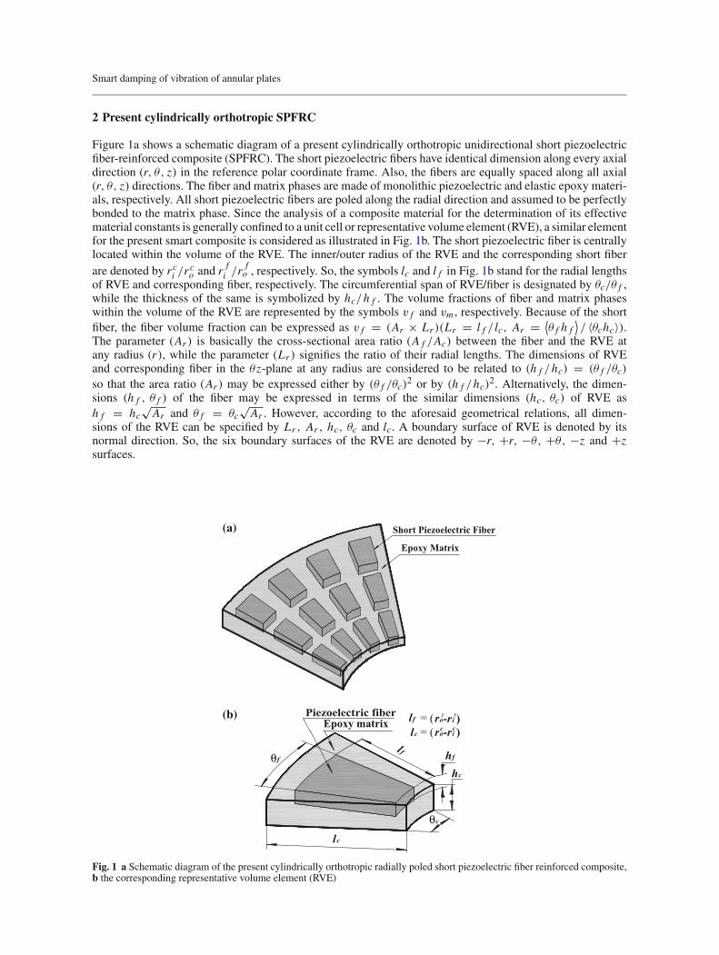
Figure 1a shows a schematic diagram of a present cylindrically orthotropic unidirectional short piezoelectricfiber-reinforced composite (SPFRC). The short piezoelectric fibers have identical dimension along every axialdirection (r, θ, z) in the reference polar coordinate frame. Also, the fibers are equally spaced along all axial(r, θ, z) directions. The fiber and matrix phases are made of monolithic piezoelectric and elastic epoxy materi-als, respectively. All short piezoelectric fibers are poled along the radial direction and assumed to be perfectlybonded to the matrix phase. Since the analysis of a composite material for the determination of its effectivematerial constants is generally confined to a unit cell or representative volume element (RVE), a similar elementfor the present smart composite is considered as illustrated in Fig. 1b. The short piezoelectric fiber is centrallylocated within the volume of the RVE. The inner/outer radius of the RVE and the corresponding short fiberare denoted by rci /r
co and r
fi /r f
o , respectively. So, the symbols lc and l f in Fig. 1b stand for the radial lengthsof RVE and corresponding fiber, respectively. The circumferential span of RVE/fiber is designated by θc/θ f ,while the thickness of the same is symbolized by hc/h f . The volume fractions of fiber and matrix phaseswithin the volume of the RVE are represented by the symbols v f and vm , respectively. Because of the shortfiber, the fiber volume fraction can be expressed as v f = (Ar × Lr )(Lr = l f / lc, Ar = ⟨
θ f h f⟩/ 〈θchc〉).
The parameter (Ar ) is basically the cross-sectional area ratio (A f /Ac) between the fiber and the RVE atany radius (r), while the parameter (Lr ) signifies the ratio of their radial lengths. The dimensions of RVEand corresponding fiber in the θ z-plane at any radius are considered to be related to (h f /hc) = (θ f /θc)
so that the area ratio (Ar ) may be expressed either by (θ f /θc)2 or by (h f /hc)2. Alternatively, the dimen-
sions (h f , θ f ) of the fiber may be expressed in terms of the similar dimensions (hc, θc) of RVE ash f = hc
√Ar and θ f = θc
√Ar . However, according to the aforesaid geometrical relations, all dimen-
sions of the RVE can be specified by Lr , Ar , hc, θc and lc. A boundary surface of RVE is denoted by itsnormal direction. So, the six boundary surfaces of the RVE are denoted by −r, +r, −θ, +θ, −z and +zsurfaces.
Short Piezoelectric Fiber
Epoxy Matrix
θf hf
θc
hc
lf
lc
fflf = (ro-ri )lc = (ro-ri )ccEpoxy matrix
(a)
(b)
Fig. 1 a Schematic diagram of the present cylindrically orthotropic radially poled short piezoelectric fiber reinforced composite,b the corresponding representative volume element (RVE)

A. S. Pavan Kumar et al.
3 Effective electro-elastic constants of the piezoelectric composite
In the theory of linear piezoelectricity without thermal effect, the coupled interaction between the electric andelastic fields is described by four different piezoelectric constitutive formulations [37,38]. Among these fourdifferent constitutive formulations, the piezoelectric stress formulation is commonly employed when the strainand electric fields are considered as natural variables. According to this constitutive formulation, the naturalvariables (strain and electric fields) are related to the stress and electric displacement fields by
σi j = Ci jklεkl − esi j Es, Di = eiklεkl+ ∈is Es (1)
where i, j, k, l, s = 1, 2, 3; Ci jkl , esi j and ∈is denote the elements of stiffness, piezoelectric and permittivitytensors, respectively; σi j , εkl , Di and Es are the elements of stress, strain, electric displacement and electricfield tensors, respectively. In Eq. (1), the mathematical objects are symmetric in i and j , and also in k andl. So, using Voigt notation, i j/kl for i, j, k, l = 1, 2, 3 could be represented as 11 → 1, 22 → 2, 33 →3, 23/32 → 4, 13/31 → 5 and 12/21 → 6. Using this notation, Eq. (1) can be rewritten as
σξ = Cξηεη − e�ξ E�, D� = e�ηεη+ ∈�ζ Eζ (2)
where ξ, η = 1, 2, 3, 4, 5, 6 and �, ζ = 1, 2, 3. In Eq. (2), the elements of stiffness, piezoelectric and permit-tivity matrices are defined by [39,40]
Cξη =(
∂σξ
∂εη
)E
, e�ξ = −(
∂σξ
∂E�
)ε
or e�η =(
∂D�
∂εη
)E
, ∈�ζ =(
∂D�
∂Eζ
)ε
. (3)
The superscriptE [Eq. (3)] indicates a zero or constant electric field, and the superscript ε [Eq. (3)] indicateszero or constant strain field. The constitutive relations and material constants in Eqs. (2) and (3), respectively,are given for a perfect homogeneous piezoelectric solid. Analogous to this homogeneous piezoelectric solid,the present piezoelectric composite is considered to be a macroscopically homogeneous piezoelectric solid,and its macroscopic behavior can be defined by effective constitutive relations according to standard microme-chanical theories for composites. These effective constitutive relations are valid only for specially statisticallyhomogeneous fields within the composite, which (fields) can be produced within a heterogeneous body bythe imposition of homogeneous boundary conditions over the boundary surfaces of the body [41,42]. Makinguse of this analogy, the effective material properties of asymptotically homogeneous composites could beestimated by the application of volume-average strain field and/or electric field by means of homogeneouskinematic boundary conditions (displacement and/or electric potential) [43]. Following that at present, theeffective material constants of the piezoelectric composite are estimated by applying RVE volume-averagestrain field and/or electric field. The volume-average field quantities over a volume (Vd) are defined by
σ ξ = 1
Vd
∫
VdσξdVd , εη = 1
Vd
∫
VdεηdVd , E� = 1
Vd
∫
VdE�dVd , Dζ = 1
V
∫
VDζdV (4)
where the over-bar signifies a volume-average quantity. Equation (4) indicates general expressions for thevolume averages of field quantities. These expressions could be utilized for any volume among the volumes ofthe RVE, fiber phase and matrix phase by specifying the corresponding fields (σξ , εη, E�, Dζ ) and volume(Vd). The constitutive relations for fiber ( f ) and matrix (m) phase materials within the RVE can be written interms of the volume-average field quantities as follows:
σfξ = C f
ξηεfη − e f
�ξ Ef� , (5)
σmξ = Cm
ξηεmη , (6)
Df� = e f
�ηεfη + ∈ f
�ζ Efζ , (7)
Dm� = ∈m
�ζ Emζ . (8)
Smart damping of vibration of annular plates
The volume-average field quantities of the RVE could be expressed in terms of the similar quantities ofconstituent phases as follows:
σ ξ =(v f σ
fξ + vmσm
ξ
), (9)
D� =(v f D
f� + vmD
m�
), (10)
εη =(v f ε
fη + vmεmη
), (11)
Eζ =(v f E
fζ + vmE
mζ
). (12)
Substituting Eqs. (5)–(6) in Eq. (9) and then using Eq. (11), the following expression can be obtained:
σ ξ = Cmξαεα + v f
(C f
ξα − Cmξα
)ε fα − v f e
f�ξ E
f� (13)
where α = 1, 2, 3, 4, 5, 6. Similarly, substituting Eqs. (7)–(8) into Eq. (10) and then using Eq. (12), thefollowing expression can be obtained:
D� =∈m�β Eβ + v f
(∈ f
�β − ∈m�β
)E
fβ + v f e
f�ηε
fη (14)
where β = 1, 2, 3. According to the definitions of piezoelectric constants [Eq. (3)], the following expressionsfor the effective electro-elastic constants of the piezoelectric composite can be obtained:
Cξη = Cmξη + v f
(C f
ξα − Cmξα
)(∂εfα
∂εη
)
− v f efζ ξ
⎛
⎝∂E
fζ
∂εη
⎞
⎠ for Eζ = 0, (15)
e�η = v f
(∈ f
�β − ∈m�β
)⎛
⎝∂E
fβ
∂εη
⎞
⎠ + v f ef�ξ
(∂ε
fξ
∂εη
)
for Eζ = 0, (16)
∈�ζ = ∈m�ζ +v f
(∈ f
�β − ∈m�β
)⎛
⎝∂E
fβ
∂Eζ
⎞
⎠ + v f ef�η
(∂ε
fη
∂Eζ
)
for εη = 0. (17)
It should be noted that the fiber-phase volume-average electric field (Efζ ) may have a nonzero value for
a zero value of RVE volume-average electric field (Eζ = 0) because of the electro-elastic coupling withinthe same (fiber) volume. This electro-elastic coupling may also cause a nonzero fiber-phase volume-averagestrain field (ε
fη ) even though the RVE volume-average strain field (εη) has zero value. So, the electro-elastic
coupling terms (∂Efζ
/∂εη, ∂ε
fη
/∂Eζ ) appear in the expressions [Eqs. (15)–(17)] of the effective electro-elastic
constants.It is clear fromEqs. (15)–(17) that the effective electro-elastic constants could bedeterminedby computation
of volume-average-field quantities for RVE and fiber phase and it is performed at present by the imposition ofRVE volume-average strain and electric fields by means of homogeneous displacement and electric potentialboundary conditions as discussed earlier within this section. However, for this computation, an electro-elasticanalysis of RVE is to be carried out and this is done at present using a finite element (FE) procedure. TheFE procedure is generally a very time-consuming and expensive procedure. But it may provide more realisticresults in the prediction of electro-elastic constants of piezoelectric composites [44]. So, the FE procedure isutilized at present by the derivation of a three-dimensional FE model of RVE as presented in the next section.The solutions from the FE model of RVE for applied homogeneous kinematic boundary conditions yield thevolume-average field quantities according to the following expressions:
εη = 1
Vd
⎛
⎝NVd∑
i=1
∫
V id
εiηdVid
⎞
⎠ , Eζ = 1
Vd
⎛
⎝NVd∑
i=1
∫
V id
EiζdV
id
⎞
⎠ (18)
where NVd is the number of elementswithin a volumeVd (RVE/fiber phase/matrix phase); εiη/Eiζ is a component
of strain/electric field vector within the i th-element having the elemental volume of V id . However, in the
A. S. Pavan Kumar et al.
determination of material constants, the volume-average strain and electric field quantities in RVE and fiberphase [Eq. (18)] are computed at present by choosing nine sets of homogeneous kinematic boundary conditions.The RVE is initially considered as a stress/strain/electric field free solid, and then, every set of boundaryconditions over its boundary surfaces is applied separately. Every set of boundary conditions yields only onenonzero element of strain (εη at Eζ = 0) or electric (Eζ at εη = 0) field vector. Corresponding to such anonzero element (say,
⟨εη = ε1 for η =1; εη = 0 for η = 2, 3, . . . 6; Eζ = 0
⟩or⟨Eζ = E1 for ζ =1; Eζ = 0
for ζ = 2, 3; εη = 0⟩), the gradient terms in Eqs. (15)–(17) could be written as
∂εfα
∂ε1= ε
fα
ε1for Eζ = 0, (19)
∂Efζ
∂ε1= E
fζ
ε1for Eζ = 0, (20)
∂εfη
∂E1= ε
fη
E1for εη = 0, (21)
∂Ef�
∂E1= E
f�
E1for εη = 0. (22)
Introducing these terms in Eqs. (15)–(17), the effective constants, Cξ1 , e�1 and ∈�1, can be obtained.A similar computation for all sets of boundary conditions yields all material constants. However, it is nowimportant to consider the appropriate homogeneous electro-elastic kinematic boundary conditions for thecomputation of material constants, and these are given as follows. In specifying the boundary conditions,the displacements along r, θ and z directions are denoted by u(r, θ, z), v(r, θ, z) and w(r, θ, z), respectively,while the electric potential is denoted by φ(r, θ, z).
(a) Effective constants (Cξ1, e�1):Boundary conditions: u|−r = 0, u|+r = (ε01 × lc) , v|±θ = 0, w|±z = 0, φ|±r, ±θ, ±z = 0.Elements (εη, Eζ ): ε1 ≈ ε01; εη = 0 for η = 2, 3, 4, 5, 6; Eζ = 0.Effective material constants:
Cξ1 = Cmξ1 + v f
(C f
ξα − Cmξα
)(εfα
ε01
)
− v f efζ ξ
⎛
⎝E
fζ
ε01
⎞
⎠ ,
e�1 = v f
(∈ f
�β − ∈m�β
)⎛
⎝E
fβ
ε01
⎞
⎠ + v f ef�ξ
(εfξ
ε01
)
. (23)
(b) Effective constants (Cξ2, e�2):Boundary conditions: u|±r = 0, v|−θ = 0, v|+θ = (ε02 × θc), w|±z = 0, φ|±r, ±θ, ±z = 0.Elements (εη, Eζ ): ε2 ≈ ε02; εη = 0 for η = 1, 3, 4, 5, 6; Eζ = 0.Effective material constants:
Cξ2 = Cmξ2 + v f
(C f
ξα − Cmξα
)(εfα
ε02
)
− v f efζ ξ
⎛
⎝E
fζ
ε02
⎞
⎠ ,
e�2 = v f
(∈ f
�β − ∈m�β
)⎛
⎝E
fβ
ε02
⎞
⎠ + v f ef�ξ
(εfξ
ε02
)
. (24)
(c) Effective constants (Cξ3, e�3):Boundary conditions: u|±r = 0, v|±θ = 0, w|−z = 0, w|+z = (ε03 × hc), φ|±r, ±θ, ±z = 0.Elements (εη, Eζ ): ε3 ≈ ε03; εη = 0 for η = 1, 2, 4, 5, 6; Eζ = 0.
Smart damping of vibration of annular plates
Effective material constants:
Cξ3 = Cmξ3 + v f
(C f
ξα − Cmξα
)(εfα
ε03
)
− v f efζ ξ
⎛
⎝E
fζ
ε03
⎞
⎠ ,
e�3 = v f
(∈ f
�β − ∈m�β
)⎛
⎝E
fβ
ε03
⎞
⎠ + v f ef�ξ
(εfξ
ε03
)
. (25)
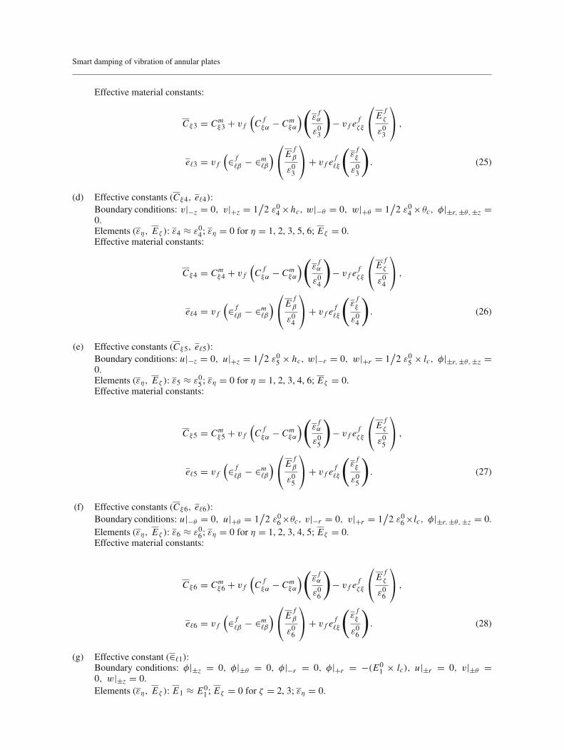
(d) Effective constants (Cξ4, e�4):Boundary conditions: v|−z = 0, v|+z = 1
/2 ε04 ×hc, w|−θ = 0, w|+θ = 1
/2 ε04 × θc, φ|±r, ±θ, ±z =
0.Elements (εη, Eζ ): ε4 ≈ ε04; εη = 0 for η = 1, 2, 3, 5, 6; Eζ = 0.Effective material constants:
Cξ4 = Cmξ4 + v f
(C f
ξα − Cmξα
)(εfα
ε04
)
− v f efζ ξ
⎛
⎝E
fζ
ε04
⎞
⎠ ,
e�4 = v f
(∈ f
�β − ∈m�β
)⎛
⎝E
fβ
ε04
⎞
⎠ + v f ef�ξ
(εfξ
ε04
)
. (26)
(e) Effective constants (Cξ5, e�5):Boundary conditions: u|−z = 0, u|+z = 1
/2 ε05 × hc, w|−r = 0, w|+r = 1
/2 ε05 × lc, φ|±r, ±θ, ±z =
0.Elements (εη, Eζ ): ε5 ≈ ε05; εη = 0 for η = 1, 2, 3, 4, 6; Eζ = 0.Effective material constants:
Cξ5 = Cmξ5 + v f
(C f
ξα − Cmξα
)(εfα
ε05
)
− v f efζ ξ
⎛
⎝E
fζ
ε05
⎞
⎠ ,
e�5 = v f
(∈ f
�β − ∈m�β
)⎛
⎝E
fβ
ε05
⎞
⎠ + v f ef�ξ
(εfξ
ε05
)
. (27)
(f) Effective constants (Cξ6, e�6):Boundary conditions: u|−θ = 0, u|+θ = 1
/2 ε06×θc, v|−r = 0, v|+r = 1
/2 ε06×lc, φ|±r, ±θ, ±z = 0.
Elements (εη, Eζ ): ε6 ≈ ε06; εη = 0 for η = 1, 2, 3, 4, 5; Eζ = 0.Effective material constants:
Cξ6 = Cmξ6 + v f
(C f
ξα − Cmξα
)(εfα
ε06
)
− v f efζ ξ
⎛
⎝E
fζ
ε06
⎞
⎠ ,
e�6 = v f
(∈ f
�β − ∈m�β
)⎛
⎝E
fβ
ε06
⎞
⎠ + v f ef�ξ
(εfξ
ε06
)
. (28)
(g) Effective constant (∈�1):Boundary conditions: φ|±z = 0, φ|±θ = 0, φ|−r = 0, φ|+r = −(E0
1 × lc), u|±r = 0, v|±θ =0, w|±z = 0.Elements (εη, Eζ ): E1 ≈ E0
1 ; Eζ = 0 for ζ = 2, 3; εη = 0.

A. S. Pavan Kumar et al.
Effective material constants:
∈�1 = ∈m�1 +v f
(∈ f
�β − ∈m�β
)⎛
⎝E
fβ
E01
⎞
⎠ + v f ef�η
(εfη
E01
)
. (29)
(h) Effective constant (∈�2):Boundary conditions: φ|±r = 0, φ|±z = 0, φ|−θ = 0, φ|+θ = −(E0
2 × θc), u|±r = 0, v|±θ =0, w|±z = 0.Elements (εη, Eζ ): E2 ≈ E0
2 ; Eζ = 0 for ζ = 1, 3; εη = 0.Effective material constants:
∈�2 = ∈m�2 +v f
(∈ f
�β − ∈m�β
)⎛
⎝E
fβ
E02
⎞
⎠ + v f ef�η
(εfη
E02
)
. (30)
(i) Effective constant (∈�3):Boundary conditions: φ|±r = 0, φ|±θ = 0, φ|−z = 0, φ|+z = −(E0
3 × hc), u|±r = 0, v|±θ =0, w|±z = 0.Elements (εη, Eζ ): E3 ≈ E0
3 ; Eζ = 0 for ζ = 1, 2; εη = 0.Effective material constants:
∈�3 = ∈m�3 +v f
(∈ f
�β − ∈m�β
)⎛
⎝E
fβ
E03
⎞
⎠ + v f ef�η
(εfη
E03
)
. (31)
4 FE model of RVE
The constitutive relations for fiber and matrix phases within the RVE can be expressed as{
σ q
Dq
}= Cq
{+ε−E
}. (32)
The superscript q in Eq. (32) denotes the quantities within the fiber or the matrix phase volume accordingto its value as 1 or 2, respectively. The different matrix and vector quantities in Eq. (32) are as follows:
{+ε−E
}= {
ε1 ε2 ε3 ε4 ε5 ε6 −E1 −E2 −E3}T
,
{σD
}= {
σ1 σ2 σ3 σ4 σ5 σ6 D1 D2 D3}T
,
C1 =[C f eTfe f −∈ f
],C2 =
[Cm 00 −∈m
](33)
where C f /Cm is the stiffness matrix for the fiber/matrix phase; ∈ f / ∈m is the permittivity matrix of thefiber/matrix phase; e f is the piezoelectric matrix of the fiber phase. The form of these property matrices isgiven in Eq. (A.1). It should be noted that Eq. (A.1) represents the material properties for longitudinally (radialdirection) poled piezoelectric fibers. The electro-elastic state at any point within the RVE can be defined by anelectro-elastic state vector (d ) as
d = [u v w φ
]T. (34)
Using this electro-elastic state vector (d), the strain (ε) and electric (E) field vectors at any point within theRVE can be expressed in terms of an operator matrix (L) as
{+ε−E
}= Ld. (35)
Smart damping of vibration of annular plates
The form of the operator matrix (L) is given in Eq. (A.2). Using Eq. (32), the first variation of the electro-elasticinternal energy of RVE can be written as [45]
δU =2∑
q=1
(∫
Vq
⟨⌊δε −δE
⌋Cq
{+ε−E
}⟩dVq
)(36)
where δ is an operator for the first variation; Vq is the volume of the fiber phase (q = 1) or matrix phase(q = 2); introducing Eq. (35) in Eq. (36), the following form of δU can be obtained:
δU =2∑
q=1
(∫
Vq
⟨δdTLTCqLd
⟩dVq
). (37)
For deriving the finite element model, the volume of the RVE is discretized by 27-node isoparametrichexahedral elements. At any point within a typical elements, the electro-elastic state vector (d) can be writtenas
d = Nde (38)
where N is the shape function matrix and de is the elemental nodal electro-elastic state vector. Introducing Eq.(38) in Eq. (37), the simplified expression for the first variation of the electro-elastic internal energy (δUe) ofa typical element can be obtained as
δUe = (δde)T⟨K e de
⟩
Ke =∫
Vqe
(NT LT Cq L N
)dVq
e (39)
where Vqe is the elemental volume within the fiber phase (q = 1) or matrix phase (q = 2). Assembling the
elemental equations [Eq. (39)] in the global space, the global expression for the internal energy of an RVE canbe obtained as
δU = (δX)T 〈KX〉 (40)
where K is the global electro-elastic coefficient matrix; X is the global nodal electro-elastic state vector. Thepresent electro-elastic FE analysis of RVE is due to the applied kinematic boundary conditions [Eqs. (23)–(31)]over its (RVE) boundary surfaces. If these boundary conditions are directly applied to the boundary surfacesof RVE, then it results in over-constrained RVE edges [44]. This kind of over-constrained deformation of RVEcould be avoided by applying the kinematic boundary conditions over the full FE model of RVE instead ofapplying the same directly to the RVE boundary surfaces [44]. So, the kinematic boundary conditions [Eqs.(23)–(31)] are presently applied over the FE model of RVE [Eq. (40)] following a procedure described in[46]. For a specified nodal electric potential or displacement over the boundary surface, the first variation ofthe corresponding element of X (say, Xi ) is zero (δXi = 0 ). Thus, the corresponding (i th) row of K is to bedeleted, while a column (Pi ) of K with the same index (i) is to be removed for the formation of the electricpotential or displacement–load vector as
δU = (δXr )T 〈Kr Xr + Pi Xi 〉 (41)
where Kr and Xr are the reduced electro-elastic coefficient matrix and nodal electro-elastic state vector,respectively. For a number (Nb) of specified values of nodal degrees of freedoms over the boundary surfacesof RVE, Eq. (41) can be written in general form as
δU = (δXr )T
⟨
Kr Xr +Nb∑
i=1
Pi Xi
⟩
. (42)
Employing the principle of minimum potential energy, Eq. (42) can be written as follows:
Kr Xr = −Nb∑
i=1
Pi Xi . (43)

A. S. Pavan Kumar et al.
Equation (43) represents the electro-elastic finite element model of RVE under the specified nodal valuesof electric potential and/or displacement. Using Eq. (43), the nodal solutions for electric potential and dis-placement fields within the RVE corresponding to every set of boundary conditions [Eqs. (23)–(31)] can beobtained. Subsequently, the volume-average (RVE/phase) strain and electric fields can be computed accordingto Eq. (18) using these nodal solutions.
5 Arrangement of electrodes
The present cylindrically orthotropic piezoelectric composite is designed to utilize it as amaterial of distributedactuator in control of the vibration of plane structures of revolution. So, the electrodes are to be provided overits boundary surfaces in order to activate it by supplying external voltage. The external voltage induces anelectric field within the smart composite resulting in necessary control activity. According to the geometricalconstruction and poling direction of the present smart composite, the magnitude of one effective piezoelectriccoefficient (e11, 1 for radial direction) is significantly larger than themagnitudes of other effective piezoelectriccoefficients. Thus, this effective coefficient (e11) is utilized for its (smart composite) better control performance,and it could be achieved by applying the electric field in the radial direction by an arrangement of electrodesover the top and bottom surfaces of the composite layer as illustrated in Fig. 2a. Figure 2a shows the top/bottomsurface of the SPFRC layer over which a surface electrode is provided at the radial gap of any two consecutiveshort fibers. The uniform polarity of external voltage is considered for the top and bottom surface electrodeslying on the same radial location, while any two consecutive electrodes along the radial direction are of oppositepolarity. Any two consecutive electrodes of opposite polarity are denoted as a pair of electrodes. Across all pairsof electrodes, a uniform value of applied voltage is considered that yields uniform magnitude of the electricthe field within all such pairs. But the radial component of the electric field within a pair of electrodes is inopposite direction to that of the same within the consecutive pairs of electrodes. For obtaining the electrically
lclf
(lc-lf)(lc-lf)/2
(+φ)Electrode
(-φ)Electrode
(+φ)Electrode
(-φ)Electrode
hfhc
(hc-hf)/2
+φ (TSE)
−φ (TSE)
+φ (BSE) -φ (BSE)(lc-l f)/2 (lc-l f)/2
lflc
TSE: Top surface electrode, BSE: Bottom surface electrode
(a)
(b)
Fig. 2 a Top/bottom surface of the cylindrically orthotropic piezoelectric composite with electrodes, b the RVE with electrodesurfaces
Smart damping of vibration of annular plates
induced actuation force in the same direction from all pairs of electrodes, the corresponding piezoelectric fibersare poled along the radial direction in alternate manner. However, according to the present arrangements ofsurface electrodes and short piezoelectric fibers, the macroscopic behavior of the smart composite actuator canbe estimated by defining an elemental volume as illustrated in Fig. 2b that is basically a volume of RVE withsurface electrodes.
In this arrangement, it seems a too small radial gap between any two consecutive surface electrodes. Butthis facilitates to achieve a significant magnitude of externally induced electric field in expense of small appliedvoltage across the pairs of surface electrodes. The difficulty may arise in the fabrication of electrodes becauseof the small gap between any two consecutive electrodes, but this gap can be increased by increasing the lengthof the fibers in terms of the increase in fiber aspect ratio. The fiber aspect ratio does not have much effect onthe magnitude of the effective coefficient (e11) as it is shown in a later section (Sect. 7.1). So, the aforesaiddifficulty may be mitigated considering higher fiber aspect ratio. In this case (higher aspect ratio), the onlychange would be the requirement of more external voltage for the same magnitude of the applied electric field.
It is now required to determine the magnitude of the induced electric field for an applied voltage across thepairs of electrodes in order to use the smart composite as an actuator. In this evaluation of the induced electricfield, the difficulty arises due to the material heterogeneity. The effective properties or constitutive behavior ofthe smart composite is valid only for specially statistically homogeneous fields, which could be produced bymeans of homogeneous kinematic/kinetic boundary conditions over the surface of a large composite [42]. Thepresent applied electric potentials over the surface electrodes do not satisfy the conditions for homogeneouskinematic boundary conditions. So, in a strict sense, the corresponding statistically homogeneous electric fieldwould not be adequate to the effective constitutive relation.As a consequence, for a situationwhere the aforesaidspecially statistically homogeneous fields do not arise or could not be produced, an assumption of local averagesof fields over the volume of an RVEmay be made to salvage the analysis [42]. Following this assumption in thepresent analysis, the local electric field within the elemental volume (RVE) with surface electrodes (Fig. 2b) isconsidered as local volume-average electric field over the same volume (RVE). Without this assumption in thepresent analysis, it is difficult to model the induced electric field within a local heterogeneous volume of thelarge smart composite actuator. However, as per this consideration, the induced electric field due to an externalvoltage could be taken as its volume-average quantity over the volume of the RVE according to Eq. (12).Now, for structural applications of the smart actuator under the assumption of small strain, the induced electricfield due to strain of overall structure is of negligibly small magnitude as compared to the large magnitude ofthe applied electric field by means of external voltage. So, the magnitude of an RVE volume-average electricfield (E) may be considered as a function of applied voltage (V ) only. Since one value of applied voltageyields one magnitude of E within the actuator, E is a single-valued function of applied voltage (V ). Thisfunctional relation may be represented by the following expressions [Eq. (44)], in which Gr (V ),Gθ (V ) andGz(V ) are the functions of applied voltage corresponding to the components of the volume-average electricfield (Er , Eθ , Ez):
Er = Gr (V ) V, Eθ = Gθ (V ) V, Ez = Gz(V ) V . (44)
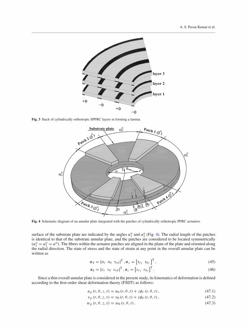
The forgoing demonstration is for a layer of present SPFRC actuator comprised of one layer of short piezo-electric fibers. Similar SPFRC layers can be stackedwith proper alignment of electrode polarities to form a lam-ina of SPFRC actuator as illustrated in Fig. 3. The electrodes of the same polarity of this smart actuator laminaare vertically coincident, and their (electrodes) ends are exposed on the circumferential edge surfaces (+θ and−θ surfaces) of the lamina. So, the external voltage can be provided through these exposed ends of electrodes.
6 FE model of a smart annular plate
The present cylindrically orthotropic SPFRC actuator is designed mainly for controlling the vibration ofplane structures of revolution. In order to substantiate this objective, a vibration analysis of an annular plateintegrated with the patches of the present SPFRC actuator is performed by deriving a close-loop FE model ofthe overall smart annular plate. Figure 4 shows a substrate annular plate integrated with four identical patchesof a presently designed cylindrically orthotropic SPFRC actuator. The middle plane of the substrate annularplate is considered as the reference plane, and the origin of the reference cylindrical coordinate system (r, θ, z)is located at the center of this reference annular plane. The inner and outer radii of the overall plate are denotedby ri and ro, respectively. The thickness of the substrate plate and actuator patches are symbolized by h andh p, respectively. The circumferential span of every patch is denoted by βo, and their locations on the top
A. S. Pavan Kumar et al.
+φ−φ
+φ−φ
layer 1
layer 2
layer 3
Fig. 3 Stack of cylindrically orthotropic SPFRC layers in forming a lamina
hPatch
4 (β )
Patch 1 (β )
Patch 2 (β )
Patch 3 (β )
oo
o
o
θz r
h/2 hp
ro
ri
Substrate plate
oα1
α1o
oα2
α2o
Fig. 4 Schematic diagram of an annular plate integrated with the patches of cylindrically orthotropic PFRC actuators
surface of the substrate plate are indicated by the angles αo1 and αo
2 (Fig. 4). The radial length of the patchesis identical to that of the substrate annular plate, and the patches are considered to be located symmetrically(αo
1 = αo1 = αo). The fibers within the actuator patches are aligned in the plane of the plate and oriented along
the radial direction. The state of stress and the state of strain at any point in the overall annular plate can bewritten as
σ b = [σr σθ τrθ ]T , σ s = [
τr z τθ z]T
, (45)
εb = [εr εθ εrθ ]T , εs = [
εr z εθ z]T
. (46)
Since a thin overall annular plate is considered in the present study, its kinematics of deformation is definedaccording to the first-order shear deformation theory (FSDT) as follows:
u p (r, θ, z, t) = u0 (r, θ, t) + zφr (r, θ, t) , (47.1)
vp (r, θ, z, t) = v0 (r, θ, t) + zφθ (r, θ, t) , (47.2)
wp (r, θ, z, t) = w0 (r, θ, t) . (47.3)
Smart damping of vibration of annular plates
The generalized displacements in Eqs. (47.1)–(47.3) can be represented by a displacement vector (dp) asfollows:
dp = {uo vo wo φr φθ }T, (48)
According to this displacement field [Eq. (47)], the linear strain-displacement relations at any point of theoverall annular plate can be written in terms of the operator matrices (Lbt , Lbr , Ls) as
εb = (Lbt + zLbr ) dp, εs = Lsdp. (49)
In Eq. (49), the forms of operator matrices are given in Eqs. (A.3)–(A.5). The constitutive relations for thesubstrate isotropic annular plate can be written as
σ kb = Ck
bεb , σ ks = Ck
sεs, k = 1 (50)
where Ckb and Ck
s (k = 1) are the stiffness matrices for the isotropic material of substrate plate. The forms ofthese stiffness matrices are given in Eq. (A.6) in which the symbols E and ν stand for Young’s modulus andPoisson’s ratio, respectively. The constitutive relations for the cylindrically orthotropic piezoelectric compositecan be written as
σ kb = Ck
bεb − ebE, σ ks = Ck
sεs − esE, D = eTbεb + eTs εs + ∈E, k = 2. (51)
In Eqs. (50) and (51), the superscript k denotes the substrate plate or the actuator patch according to its valueas 1 or 2, respectively. The forms of elastic matrices (Ck
b , Cks , k = 2), piezoelectric matrices (eb, es) and
permittivity matrix (∈) appearing in Eq. (51) are given in Eqs. (A.7)–(A.9). The present analysis deals withthe small amplitude vibration of the overall smart annular plate with an assumption of small strain. Under thesmall strain of overall smart annular plate and uniform value of applied voltage (V ) across all pairs of surfaceelectrodes, the components (Er , Eθ , Ez) of the volume-average electric field (E) within the actuator patchmay be assumed as functions of applied voltage (V ) only as it is discussed in the previous section [Eq. (44)].The electric field (E) then can be written as
E = [Gr (V ) Gθ (V ) Gz(V )
]TV . (52)
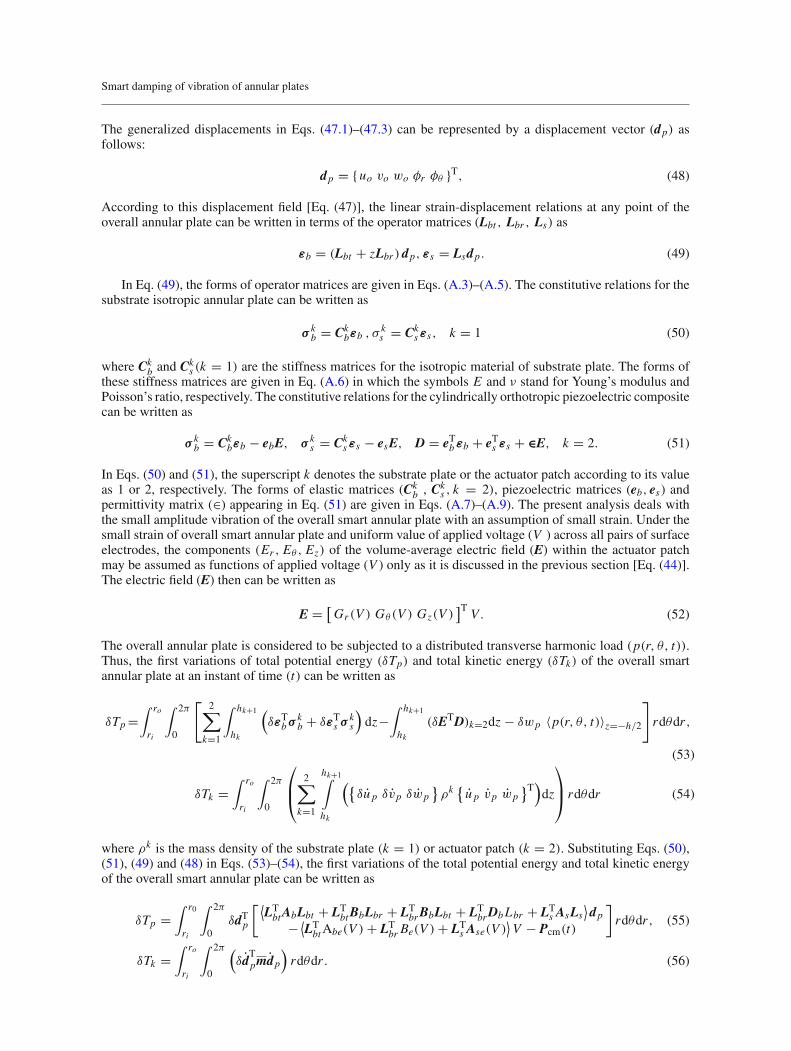
The overall annular plate is considered to be subjected to a distributed transverse harmonic load (p(r, θ, t)).Thus, the first variations of total potential energy (δTp) and total kinetic energy (δTk) of the overall smartannular plate at an instant of time (t) can be written as
δTp =∫ ro
ri
∫ 2π
0
[2∑
k=1
∫ hk+1
hk
(δεTbσ k
b + δεTs σ ks
)dz−
∫ hk+1
hk(δETD)k=2dz − δwp 〈p(r, θ, t)〉z=−h/2
]
rdθdr ,
(53)
δTk =∫ ro
ri
∫ 2π
0
⎛
⎜⎝
2∑
k=1
hk+1∫
hk
({δu p δvp δwp
}ρk { u p vp wp
}T)dz
⎞
⎟⎠ rdθdr (54)
where ρk is the mass density of the substrate plate (k = 1) or actuator patch (k = 2). Substituting Eqs. (50),(51), (49) and (48) in Eqs. (53)–(54), the first variations of the total potential energy and total kinetic energyof the overall smart annular plate can be written as
δTp =∫ r0
ri
∫ 2π
0δdTp
[ ⟨LTbtAbLbt + LT
btBbLbr + LTbrBbLbt + LT
brDbLbr + LTs AsLs
⟩dp
− ⟨LTbtAbe(V ) + LT
br Be(V ) + LTs Ase(V )
⟩V − Pcm(t)
]rdθdr , (55)
δTk =∫ ro
ri
∫ 2π
0
(δd
Tpmdp
)rdθdr . (56)
A. S. Pavan Kumar et al.
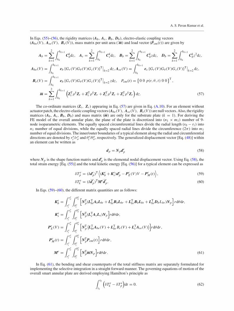
In Eqs. (55)–(56), the rigidity matrices (Ab, As, Bb, Db), electro-elastic coupling vectors(Abe(V ), Ase(V ), Be(V )), mass matrix per unit area ( m) and load vector (Pcm(t)) are given by
Ab =2∑
k=1
∫ hk+1
hkCkbdz, As =
2∑
k=1
∫ hk+1
hkCksdz, Bb =
2∑
k=1
∫ hk+1
hkCkbzdz, Db =
2∑
k=1
∫ hk+1
hkCkbz
2dz,
Abe(V ) =∫ hk+1
hkeb {Gr (V )Gθ (V )Gz(V )}T∣∣k=2 dz,Ase(V ) =
∫ hk+1
hkes {Gr (V )Gθ (V )Gz(V )}T∣∣k=2 dz,
Be(V ) =∫ hk+1
hkeb {Gr (V )Gθ (V )Gz(V )}T∣∣k=2 zdz, Pcm(t) = {
0 0 p(r, θ, t) 0 0}T
,
m =2∑
k=1
∫ hk+1
hk
(ZTt ρkZt + ZT
t ρkZr + ZTr ρkZt + ZT
r ρkZr)dz. (57)
The co-ordinate matrices (Zt , Zr ) appearing in Eq. (57) are given in Eq. (A.10). For an element withoutactuator patch, the electro-elastic couplingvectors (Abe(V ), Ase(V ), Be(V )) are null vectors.Also, the rigiditymatrices (Ab, As, Bb, Db) and mass matrix (m) are only for the substrate plate (k = 1). For deriving theFE model of the overall annular plate, the plane of the plate is discretized into (n1 × m1) number of 9-node isoparametric elements. The equally spaced circumferential lines divide the radial length (r0 − ri ) inton1 number of equal divisions, while the equally spaced radial lines divide the circumference (2π) into m1number of equal divisions. The inner/outer boundaries of a typical element along the radial and circumferentialdirections are denoted by rei /r
eo and θei /θ
eo , respectively. The generalized displacement vector [Eq. (48)] within
an element can be written as
dp = Npdep (58)
where Np is the shape function matrix and dep is the elemental nodal displacement vector. Using Eq. (58), thetotal strain energy [Eq. (55)] and the total kinetic energy [Eq. (56)] for a typical element can be expressed as
δT ep = (δdep)
T⟨(Ke
b + Kes)d
ep − Pe
E (V )V − PeM (t)
⟩, (59)
δT ek = (δd
ep)
TMedep. (60)
In Eqs. (59)–(60), the different matrix quantities are as follows:
Keb =
∫ reo
rei
∫ θeo
θei
[NT
p(LTbtAbLbt + LT
btBbLbr + LTbrBbLbt + LT
brDbLbr )Np
]rdθdr,
Kes =
∫ reo
rei
∫ θeo
θei
[NT
p(LTs AsLs)Np
]rdθdr,
PeE (V ) =
∫ reo
rei
∫ θeo
θei
[NT
p
⟨LTbtAbe(V ) + LT
br Be(V ) + LTs Ase(V )
⟩]rdθdr ,
PeM (t) =
∫ reo
rei
∫ θeo
θei
[NT
pPcm(t)]rdθdr ,
Me =∫ reo
rei
∫ θeo
θei
[NT
pmNp
]rdθdr . (61)
In Eq. (61), the bending and shear counterparts of the total stiffness matrix are separately formulated forimplementing the selective integration in a straight forward manner. The governing equations of motion of theoverall smart annular plate are derived employing Hamilton’s principle as
∫ t2
t1
(δT e
k − δT ep
)dt = 0. (62)
Smart damping of vibration of annular plates
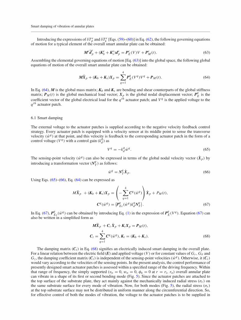
Introducing the expressions of δT ep and δT e
k [Eqs. (59)–(60)] in Eq. (62), the following governing equationsof motion for a typical element of the overall smart annular plate can be obtained:
Medep + (Ke
b + Kes)d
ep = Pe
E (V )V + PeM (t). (63)
Assembling the elemental governing equations of motion [Eq. (63)] into the global space, the following globalequations of motion of the overall smart annular plate can be obtained:
MXp + (Kb + Ks)Xp =4∑
q=1
PqE (V q)Vq + PM (t). (64)
In Eq. (64),M is the global mass matrix; Kb and Ks are bending and shear counterparts of the global stiffnessmatrix; PM (t) is the global mechanical load vector; Xp is the global nodal displacement vector; Pq
E is thecoefficient vector of the global electrical load for the qth actuator patch; and Vq is the applied voltage to theqth actuator patch.
6.1 Smart damping
The external voltage to the actuator patches is supplied according to the negative velocity feedback controlstrategy. Every actuator patch is equipped with a velocity sensor at its middle point to sense the transversevelocity (wq) at that point, and this velocity is feedback to the corresponding actuator patch in the form of acontrol voltage (Vq) with a control gain (kqd ) as
Vq = −kqd wq . (65)
The sensing-point velocity (wq) can also be expressed in terms of the global nodal velocity vector (Xp) byintroducing a transformation vector (Nq
T ) as follows:
wq = NqT Xp. (66)
Using Eqs. (65)–(66), Eq. (64) can be expressed as
MXp + (Kb + Ks)Xp =⎛
⎝−4∑
q=1
Cq(wq)
⎞
⎠ Xp + PM (t),
Cq(wq) = ⟨PqEc(w
q)kqdNqT
⟩. (67)
In Eq. (67), PqEc(w
q) can be obtained by introducing Eq. (1) in the expression of PqE (Vq). Equation (67) can
also be written in a simplified form as
MXp + Ct Xp + KtXp = PM (t),
Ct =4∑
q=1
Cq(wq),Kt = (Kb + Ks). (68)
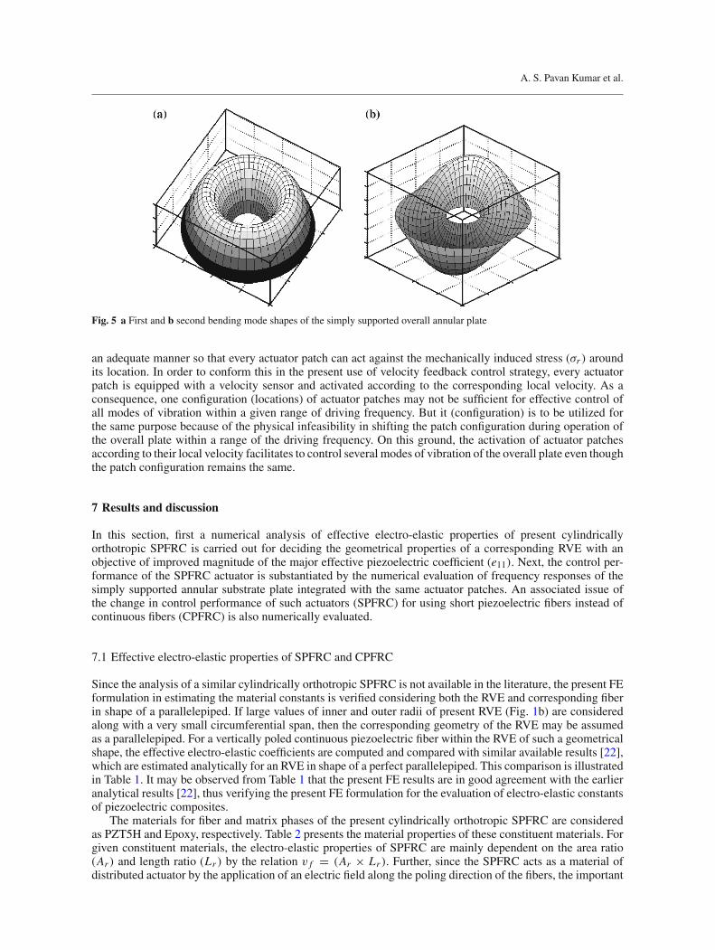
The damping matrix (Ct ) in Eq. (68) signifies an electrically induced smart damping in the overall plate.For a linear relation between the electric field (E) and applied voltage (V ) or for constant values of Gr ,Gθ andGz , the damping coefficient matrix (Ct ) is independent of the sensing-point velocities (wq). Otherwise, it (Ct )would vary according to the velocities of the sensing points. In the present analysis, the control performance ofpresently designed smart actuator patches is assessed within a specified range of the driving frequency. Withinthat range of frequency, the simply supported (vo = 0, wo = 0, φθ = 0 at r = ri, ro) overall annular platecan vibrate in a shape of its first or second bending mode (Fig. 5). Since the actuator patches are attached tothe top surface of the substrate plate, they act mainly against the mechanically induced radial stress (σr ) onthe same substrate surface for every mode of vibration. Now, for both modes (Fig. 5), the radial stress (σr )at the top substrate surface may not be distributed in uniform manner along the circumferential direction. So,for effective control of both the modes of vibration, the voltage to the actuator patches is to be supplied in
A. S. Pavan Kumar et al.
Fig. 5 a First and b second bending mode shapes of the simply supported overall annular plate
an adequate manner so that every actuator patch can act against the mechanically induced stress (σr ) aroundits location. In order to conform this in the present use of velocity feedback control strategy, every actuatorpatch is equipped with a velocity sensor and activated according to the corresponding local velocity. As aconsequence, one configuration (locations) of actuator patches may not be sufficient for effective control ofall modes of vibration within a given range of driving frequency. But it (configuration) is to be utilized forthe same purpose because of the physical infeasibility in shifting the patch configuration during operation ofthe overall plate within a range of the driving frequency. On this ground, the activation of actuator patchesaccording to their local velocity facilitates to control several modes of vibration of the overall plate even thoughthe patch configuration remains the same.
7 Results and discussion
In this section, first a numerical analysis of effective electro-elastic properties of present cylindricallyorthotropic SPFRC is carried out for deciding the geometrical properties of a corresponding RVE with anobjective of improved magnitude of the major effective piezoelectric coefficient (e11). Next, the control per-formance of the SPFRC actuator is substantiated by the numerical evaluation of frequency responses of thesimply supported annular substrate plate integrated with the same actuator patches. An associated issue ofthe change in control performance of such actuators (SPFRC) for using short piezoelectric fibers instead ofcontinuous fibers (CPFRC) is also numerically evaluated.
7.1 Effective electro-elastic properties of SPFRC and CPFRC
Since the analysis of a similar cylindrically orthotropic SPFRC is not available in the literature, the present FEformulation in estimating the material constants is verified considering both the RVE and corresponding fiberin shape of a parallelepiped. If large values of inner and outer radii of present RVE (Fig. 1b) are consideredalong with a very small circumferential span, then the corresponding geometry of the RVE may be assumedas a parallelepiped. For a vertically poled continuous piezoelectric fiber within the RVE of such a geometricalshape, the effective electro-elastic coefficients are computed and compared with similar available results [22],which are estimated analytically for an RVE in shape of a perfect parallelepiped. This comparison is illustratedin Table 1. It may be observed from Table 1 that the present FE results are in good agreement with the earlieranalytical results [22], thus verifying the present FE formulation for the evaluation of electro-elastic constantsof piezoelectric composites.
The materials for fiber and matrix phases of the present cylindrically orthotropic SPFRC are consideredas PZT5H and Epoxy, respectively. Table 2 presents the material properties of these constituent materials. Forgiven constituent materials, the electro-elastic properties of SPFRC are mainly dependent on the area ratio(Ar ) and length ratio (Lr ) by the relation v f = (Ar × Lr ). Further, since the SPFRC acts as a material ofdistributed actuator by the application of an electric field along the poling direction of the fibers, the important
Smart damping of vibration of annular plates
Table 1 Verification of the present FE formulation for an estimation of effective electro-elastic constants of piezoelectric com-posites (∗R31 = (e31)composite/(e31)piezoelectric fiber)
v f Source ∗R31 C11 (GPa) C12 (GPa) C22 (GPa)
0.2 Present 0.6654 18.71 3.396 5.27Ray [22] 0.6859 17.93 3.191 4.794
0.4 Present 1.3334 34.55 4.752 6.62Ray [22] 1.3563 32.35 4.207 6.325
0.6 Present 1.9837 49.06 6.795 10.10Ray [22] 1.9902 47.63 6.177 9.293
Table 2 Material properties of constituent materials [22]
Fiber/matrix C11 (GPa) C12 (GPa) C23 (GPa) C22 (GPa) C44 (GPa)
Epoxy 3.86 2.57 2.57 3.86 0.64PZT-5H 124 96 98 151 26.5
Fiber/matrix e11 (C/m2) e12/e13 (C/m2) e26/e35 (C/m2) ∈11 (C/Vm × 10−09) ∈22 / ∈33 (C/Vm × 10−09)
Epoxy 0 0 0 0.079 0.079PZT-5H 27 −5.1 17 13.27 13.4
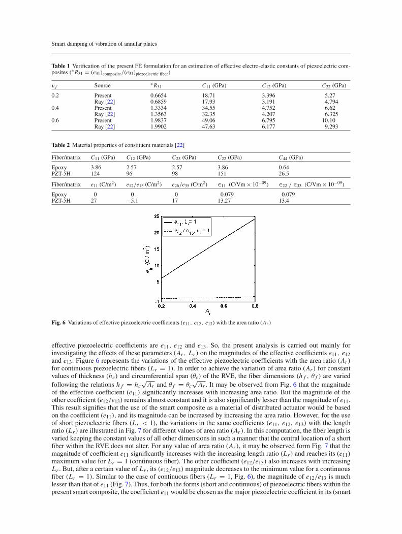
Fig. 6 Variations of effective piezoelectric coefficients (e11, e12, e13) with the area ratio (Ar )
effective piezoelectric coefficients are e11, e12 and e13. So, the present analysis is carried out mainly forinvestigating the effects of these parameters (Ar , Lr ) on the magnitudes of the effective coefficients e11, e12and e13. Figure 6 represents the variations of the effective piezoelectric coefficients with the area ratio (Ar )for continuous piezoelectric fibers (Lr = 1). In order to achieve the variation of area ratio (Ar ) for constantvalues of thickness (hc) and circumferential span (θc) of the RVE, the fiber dimensions (h f , θ f ) are variedfollowing the relations h f = hc
√Ar and θ f = θc
√Ar . It may be observed from Fig. 6 that the magnitude
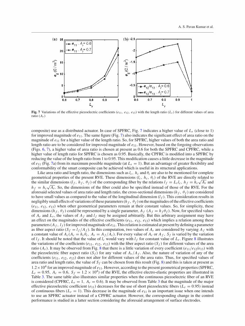
of the effective coefficient (e11) significantly increases with increasing area ratio. But the magnitude of theother coefficient (e12/e13) remains almost constant and it is also significantly lesser than the magnitude of e11.This result signifies that the use of the smart composite as a material of distributed actuator would be basedon the coefficient (e11), and its magnitude can be increased by increasing the area ratio. However, for the useof short piezoelectric fibers (Lr < 1), the variations in the same coefficients (e11, e12, e13) with the lengthratio (Lr ) are illustrated in Fig. 7 for different values of area ratio (Ar ). In this computation, the fiber length isvaried keeping the constant values of all other dimensions in such a manner that the central location of a shortfiber within the RVE does not alter. For any value of area ratio (Ar ), it may be observed form Fig. 7 that themagnitude of coefficient e11 significantly increases with the increasing length ratio (Lr ) and reaches its (e11)maximum value for Lr = 1 (continuous fiber). The other coefficient (e12/e13) also increases with increasingLr . But, after a certain value of Lr , its (e12/e13) magnitude decreases to the minimum value for a continuousfiber (Lr = 1). Similar to the case of continuous fibers (Lr = 1, Fig. 6), the magnitude of e12/e13 is muchlesser than that of e11 (Fig. 7). Thus, for both the forms (short and continuous) of piezoelectric fibers within thepresent smart composite, the coefficient e11 would be chosen as the major piezoelectric coefficient in its (smart
A. S. Pavan Kumar et al.
Fig. 7 Variations of the effective piezoelectric coefficients (e11, e12, e13) with the length ratio (Lr ) for different values of arearatio (Ar )
composite) use as a distributed actuator. In case of SPFRC, Fig. 7 indicates a higher value of Lr (close to 1)for improved magnitude of e11. The same figure (Fig. 7) also indicates the significant effect of area ratio on themagnitude of e11 for a higher value of the length ratio. So, for SPFRC, higher values of both the area ratio andlength ratio are to be considered for improved magnitude of e11. However, based on the forgoing observations(Figs. 6, 7), a higher value of area ratio is chosen at present as 0.6 for both the SPFRC and CPFRC, while ahigher value of length ratio for SPFRC is chosen as 0.95. Basically, the CPFRC is modified into a SPFRC byreducing the value of the length ratio from 1 to 0.95. This modification causes a little decrease in the magnitudeof e11 (Fig. 7a) from its maximum possible magnitude (at Lr = 1). But an advantage of greater flexibility andconformability of the smart composite can be achieved which is useful in its structural applications.
Like area ratio and length ratio, the dimensions such as lc, hc and θc are also to be mentioned for completegeometrical properties of the present RVE. These dimensions (lc, hc, θc) of the RVE are directly related tothe similar dimensions (l f , h f , θ f ) of the corresponding fiber by the relations l f = Lrlc, h f = hc
√Ar and
h f = hc√Ar . So, the dimensions of the fiber could also be specified instead of those of the RVE. For the
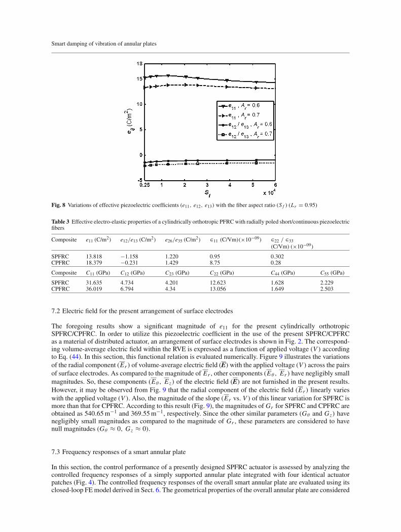
aforesaid selected values of area ratio and length ratio, the cross-sectional dimensions (h f , θ f ) are consideredto have small values as compared to the value of the longitudinal dimension (l f ). This consideration results innegligibly small effects of variations of these parameters (h f , θ f )on themagnitudes of the effective coefficients(e11, e12, e13) when other geometrical parameters remain at their constant values. So, for simplicity, thesedimensions (h f , θ f ) could be represented by a single parameter, A f (A f = h f θ f ). Now, for specified valuesof Ar and Lr , the values of A f and l f may be assigned arbitrarily. But this arbitrary assignment may havean effect on the magnitudes of the effective coefficients (e11, e12, e13) which implies a relation among theseparameters (A f , l f ) for improvedmagnitude of e11. This relation is estimated at present by defining a parameteras fiber aspect ratio (S f = l f /A f ). In this computation, two values of Ar are considered by varying A f witha constant value of Ac(Ac = hcθc, Ar = A f /Ac). For every value of Ar or A f , S f is varied by the variationof l f . It should be noted that the value of lc would vary with l f for constant value of Lr . Figure 8 illustratesthe variations of the coefficients (e11, e12, e13) with the fiber aspect ratio (S f ) for different values of the arearatio (Ar ). It may be observed from Fig. 8 that there is a little variation of every coefficient (e11/e12/e13) withthe piezoelectric fiber aspect ratio (S f ) for any value of Ar/A f . Also, the nature of variation of any of thecoefficients (e11, e12, e13) does not alter for different values of the area ratio. Thus, for specified values ofarea ratio and length ratio, the value of S f can be chosen from this result (Fig. 8) and this is taken at present as1.2×104 for an improvedmagnitude of e11. However, according to the present geometrical properties (SPFRC,Lr = 0.95, Ar = 0.6, S f = 1.2 × 10⁴) of the RVE, the effective electro-elastic properties are illustrated inTable 3. The same table also illustrates similar properties when the continuous piezoelectric fiber of an RVEis considered (CPFRC, Lr = 1, Ar = 0.6). It may be observed from Table 3 that the magnitude of the majoreffective piezoelectric coefficient (e11) decreases for the use of short piezoelectric fibers (Lr = 0.95) insteadof continuous fibers (Lr = 1). This decrease in the magnitude of e11 is an important issue when one intendsto use an SPFRC actuator instead of a CPFRC actuator. However, the corresponding change in the controlperformance is studied in a latter section considering the aforesaid arrangement of surface electrodes.
Smart damping of vibration of annular plates
Fig. 8 Variations of effective piezoelectric coefficients (e11, e12, e13) with the fiber aspect ratio (S f ) (Lr = 0.95)
Table 3 Effective electro-elastic properties of a cylindrically orthotropic PFRCwith radially poled short/continuous piezoelectricfibers
Composite e11 (C/m2) e12/e13 (C/m2) e26/e35 (C/m2) ∈11 (C/Vm)(×10−09) ∈22 / ∈33(C/Vm) (×10−09)
SPFRC 13.818 −1.158 1.220 0.95 0.302CPFRC 18.379 −0.231 1.429 8.75 0.28
Composite C11 (GPa) C12 (GPa) C23 (GPa) C22 (GPa) C44 (GPa) C55 (GPa)
SPFRC 31.635 4.734 4.201 12.623 1.628 2.229CPFRC 36.019 6.794 4.34 13.056 1.649 2.503
7.2 Electric field for the present arrangement of surface electrodes
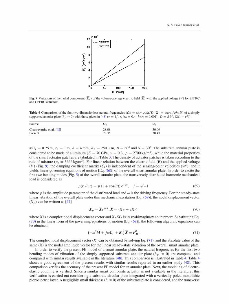
The foregoing results show a significant magnitude of e11 for the present cylindrically orthotropicSPFRC/CPFRC. In order to utilize this piezoelectric coefficient in the use of the present SPFRC/CPFRCas a material of distributed actuator, an arrangement of surface electrodes is shown in Fig. 2. The correspond-ing volume-average electric field within the RVE is expressed as a function of applied voltage (V ) accordingto Eq. (44). In this section, this functional relation is evaluated numerically. Figure 9 illustrates the variationsof the radial component (Er ) of volume-average electric field (E)with the applied voltage (V ) across the pairsof surface electrodes. As compared to the magnitude of Er , other components (Eθ , Er ) have negligibly smallmagnitudes. So, these components (Eθ , Ez) of the electric field (E) are not furnished in the present results.However, it may be observed from Fig. 9 that the radial component of the electric field (Er ) linearly varieswith the applied voltage (V ). Also, the magnitude of the slope (Er vs. V ) of this linear variation for SPFRC ismore than that for CPFRC. According to this result (Fig. 9), the magnitudes of Gr for SPFRC and CPFRC areobtained as 540.65m−1 and 369.55m−1, respectively. Since the other similar parameters (Gθ and Gz) havenegligibly small magnitudes as compared to the magnitude of Gr , these parameters are considered to havenull magnitudes (Gθ ≈ 0, Gz ≈ 0).
7.3 Frequency responses of a smart annular plate
In this section, the control performance of a presently designed SPFRC actuator is assessed by analyzing thecontrolled frequency responses of a simply supported annular plate integrated with four identical actuatorpatches (Fig. 4). The controlled frequency responses of the overall smart annular plate are evaluated using itsclosed-loop FEmodel derived in Sect. 6. The geometrical properties of the overall annular plate are considered
A. S. Pavan Kumar et al.
Fig. 9 Variations of the radial component (Er ) of the volume-average electric field (E) with the applied voltage (V ) for SPFRCand CPFRC actuators
Table 4 Comparison of the first two dimensionless natural frequencies (�0 = ω0r0√
ρh/D, �1 = ω1r0√
ρh/D) of a simplysupported annular plate (h p ≈ 0) with those given in [48] (ν = 1/, ri/r0 = 0.4, h/r0 = 0.001), D = Eh3/12(1 − ν2))
Source �0 �1
Chakravarthy et al. [48] 28.08 30.09Present 28.35 30.43
as ri = 0.25m, ro = 1m, h = 4mm, h p = 250μm, β = 60o and α = 30o. The substrate annular plate isconsidered to be made of aluminum (E = 70GPa, ν = 0.3, ρ = 2700 kg/m2), while the material propertiesof the smart actuator patches are tabulated in Table 3. The density of actuator patches is taken according to therule of mixture (ρc = 3666 kg/m2). For linear relation between the electric field (E) and the applied voltage(V ) (Fig. 9), the damping coefficient matrix (Ct ) is independent of the sensing-point velocities (wq), and ityields linear governing equations of motion [Eq. (68)] of the overall smart annular plate. In order to excite thefirst two bending modes (Fig. 5) of the overall annular plate, the transversely distributed harmonic mechanicalload is considered as
p(r, θ, t) = p 〈1 + cos(θ)〉 e jωt , j = √−1 (69)
where p is the amplitude parameter of the distributed load and ω is the driving frequency. For the steady-statelinear vibration of the overall plate under this mechanical excitation [Eq. (69)], the nodal displacement vector(Xp) can be written as [47]
Xp = Xe jωt ,X = (XR + jXI ) (70)
where X is a complex nodal displacement vector and XR /XI is its real/imaginary counterpart. Substituting Eq.(70) in the linear form of the governing equations of motion [Eq. (68)], the following algebraic equations canbe obtained:
(−ω2M + jωCt + Kt)X = P0
M . (71)
The complex nodal displacement vector (X) can be obtained by solving Eq. (71), and the absolute value of thesame (X) is the nodal amplitude vector for the linear steady-state vibration of the overall smart annular plate.
In order to verify the present FE model of a smart annular plate, the natural frequencies for the first twobending modes of vibration of the simply supported substrate annular plate (h p ≈ 0) are computed andcompared with similar results available in the literature [48]. This comparison is illustrated in Table 4. Table 4shows a good agreement of the present results with similar results reported in an earlier study [48]. Thiscomparison verifies the accuracy of the present FE model for an annular plate. Next, the modeling of electro-elastic coupling is verified. Since a similar smart composite actuator is not available in the literature, thisverification is carried out considering a substrate circular plate integrated with a vertically poled monolithicpiezoelectric layer. A negligibly small thickness (h ≈ 0) of the substrate plate is considered, and the transverse
Smart damping of vibration of annular plates
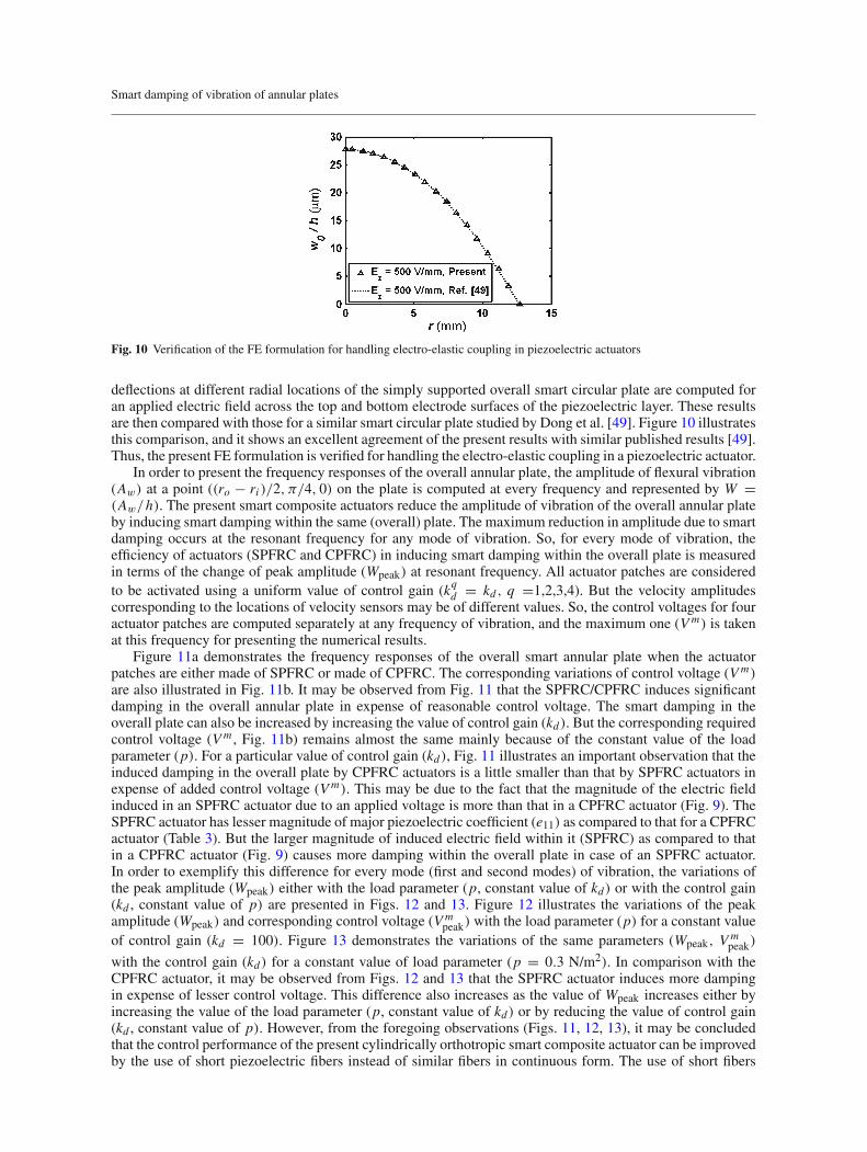
Fig. 10 Verification of the FE formulation for handling electro-elastic coupling in piezoelectric actuators
deflections at different radial locations of the simply supported overall smart circular plate are computed foran applied electric field across the top and bottom electrode surfaces of the piezoelectric layer. These resultsare then compared with those for a similar smart circular plate studied by Dong et al. [49]. Figure 10 illustratesthis comparison, and it shows an excellent agreement of the present results with similar published results [49].Thus, the present FE formulation is verified for handling the electro-elastic coupling in a piezoelectric actuator.
In order to present the frequency responses of the overall annular plate, the amplitude of flexural vibration(Aw) at a point ((ro − ri )/2, π/4, 0) on the plate is computed at every frequency and represented by W =(Aw/h). The present smart composite actuators reduce the amplitude of vibration of the overall annular plateby inducing smart damping within the same (overall) plate. The maximum reduction in amplitude due to smartdamping occurs at the resonant frequency for any mode of vibration. So, for every mode of vibration, theefficiency of actuators (SPFRC and CPFRC) in inducing smart damping within the overall plate is measuredin terms of the change of peak amplitude (Wpeak) at resonant frequency. All actuator patches are consideredto be activated using a uniform value of control gain (kqd = kd , q =1,2,3,4). But the velocity amplitudescorresponding to the locations of velocity sensors may be of different values. So, the control voltages for fouractuator patches are computed separately at any frequency of vibration, and the maximum one (Vm) is takenat this frequency for presenting the numerical results.
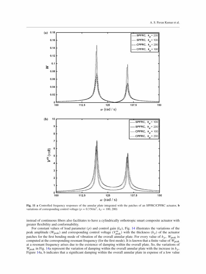
Figure 11a demonstrates the frequency responses of the overall smart annular plate when the actuatorpatches are either made of SPFRC or made of CPFRC. The corresponding variations of control voltage (Vm)are also illustrated in Fig. 11b. It may be observed from Fig. 11 that the SPFRC/CPFRC induces significantdamping in the overall annular plate in expense of reasonable control voltage. The smart damping in theoverall plate can also be increased by increasing the value of control gain (kd). But the corresponding requiredcontrol voltage (Vm , Fig. 11b) remains almost the same mainly because of the constant value of the loadparameter (p). For a particular value of control gain (kd), Fig. 11 illustrates an important observation that theinduced damping in the overall plate by CPFRC actuators is a little smaller than that by SPFRC actuators inexpense of added control voltage (Vm). This may be due to the fact that the magnitude of the electric fieldinduced in an SPFRC actuator due to an applied voltage is more than that in a CPFRC actuator (Fig. 9). TheSPFRC actuator has lesser magnitude of major piezoelectric coefficient (e11) as compared to that for a CPFRCactuator (Table 3). But the larger magnitude of induced electric field within it (SPFRC) as compared to thatin a CPFRC actuator (Fig. 9) causes more damping within the overall plate in case of an SPFRC actuator.In order to exemplify this difference for every mode (first and second modes) of vibration, the variations ofthe peak amplitude (Wpeak) either with the load parameter (p, constant value of kd) or with the control gain(kd , constant value of p) are presented in Figs. 12 and 13. Figure 12 illustrates the variations of the peakamplitude (Wpeak) and corresponding control voltage (Vm
peak) with the load parameter (p) for a constant valueof control gain (kd = 100). Figure 13 demonstrates the variations of the same parameters (Wpeak, Vm
peak)
with the control gain (kd) for a constant value of load parameter (p = 0.3 N/m2). In comparison with theCPFRC actuator, it may be observed from Figs. 12 and 13 that the SPFRC actuator induces more dampingin expense of lesser control voltage. This difference also increases as the value of Wpeak increases either byincreasing the value of the load parameter (p, constant value of kd) or by reducing the value of control gain(kd , constant value of p). However, from the foregoing observations (Figs. 11, 12, 13), it may be concludedthat the control performance of the present cylindrically orthotropic smart composite actuator can be improvedby the use of short piezoelectric fibers instead of similar fibers in continuous form. The use of short fibers
A. S. Pavan Kumar et al.
Fig. 11 a Controlled frequency responses of the annular plate integrated with the patches of an SPFRC/CPFRC actuator, bvariations of corresponding control voltage (p = 0.3N/m2, kd = 100, 200)
instead of continuous fibers also facilitates to have a cylindrically orthotropic smart composite actuator withgreater flexibility and conformability.
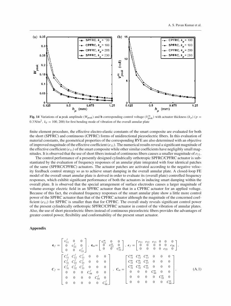
For constant values of load parameter (p) and control gain (kd), Fig. 14 illustrates the variations of thepeak amplitude (Wpeak) and corresponding control voltage (Vm
peak) with the thickness (h p) of the actuatorpatches for the first bending mode of vibration of the overall annular plate. For every value of h p, Wpeak iscomputed at the corresponding resonant frequency (for the first mode). It is known that a finite value of Wpeakat a resonant frequency arises due to the existence of damping within the overall plate. So, the variations ofWpeak in Fig. 14a represent the variation of damping within the overall annular plate with the increase in h p.Figure 14a, b indicates that a significant damping within the overall annular plate in expense of a low value

Smart damping of vibration of annular plates
Fig. 12 Variations of a peak amplitude (Wpeak) and b corresponding control voltage (Vmpeak) with the load parameter (p) for the
first two bending modes of vibration of the overall annular plate (kd = 100)
Fig. 13 Variations of a peak amplitude (Wpeak) and b corresponding control voltage (Vmpeak) with control gain kd for first two
bending modes of vibration of the overall annular plate (p = 0.3N/m2)
of control voltage could be achieved by increasing the thickness of the SPFRC/CPFRC actuator patches. But,for constant values of kd and p, this increase in damping continues up to a certain value of increasing h p.Beyond that value of h p, the negligibly small rate of decrease inWpeak with increasing h p (Fig. 14a) indicatesan insignificant effect of h p on the smart damping within the overall plate.
8 Conclusions
In the present work, a cylindrically orthotropic short piezoelectric fiber-reinforced composite (SPFRC) actuatoris designed for active damping of the vibration of annular plates. The SPFRC is comprised of unidirectionalshort piezoelectric fibers embedded within the epoxy matrix. The unidirectional fibers are oriented in the radialdirection within a reference cylindrical coordinate frame and poled in the same direction so as to achieve animproved magnitude of the effective piezoelectric coefficient (e11, 1 for radial direction). For the use of thissmart composite as a material of distributed actuator based on the effective coefficient (e11), an arrangementof surface electrodes over the top and bottom surfaces of the smart composite layer is presented. Utilizing a
A. S. Pavan Kumar et al.
Fig. 14 Variations of a peak amplitude (Wpeak) and b corresponding control voltage (Vmpeak) with actuator thickness (h p) (p =
0.3N/m2, kd = 100, 200) for first bending mode of vibration of the overall annular plate
finite element procedure, the effective electro-elastic constants of the smart composite are evaluated for boththe short (SPFRC) and continuous (CPFRC) forms of unidirectional piezoelectric fibers. In this evaluation ofmaterial constants, the geometrical properties of the corresponding RVE are also determined with an objectiveof improvedmagnitude of the effective coefficient (e11). The numerical results reveal a significantmagnitude ofthe effective coefficient (e11) of the smart composite while other similar coefficients have negligibly small mag-nitudes. It is observed that the use of short fibers instead of continuous fibers causes a smaller magnitude of e11.
The control performance of a presently designed cylindrically orthotropic SPFRC/CPFRC actuator is sub-stantiated by the evaluation of frequency responses of an annular plate integrated with four identical patchesof the same (SPFRC/CPFRC) actuators. The actuator patches are activated according to the negative veloc-ity feedback control strategy so as to achieve smart damping in the overall annular plate. A closed-loop FEmodel of the overall smart annular plate is derived in order to evaluate its (overall plate) controlled frequencyresponses, which exhibit significant performance of both the actuators in inducing smart damping within theoverall plate. It is observed that the special arrangement of surface electrodes causes a larger magnitude ofvolume-average electric field in an SPFRC actuator than that in a CPFRC actuator for an applied voltage.Because of this fact, the evaluated frequency responses of the smart annular plate show a little more controlpower of the SPFRC actuator than that of the CPFRC actuator although the magnitude of the concerned coef-ficient (e11) for SPFRC is smaller than that for CPFRC. The overall study reveals significant control powerof the present cylindrically orthotropic SPFRC/CPFRC actuator in control of the vibration of annular plates.Also, the use of short piezoelectric fibers instead of continuous piezoelectric fibers provides the advantages ofgreater control power, flexibility and conformability of the present smart actuator.
Appendix
∈ f =⎡
⎢⎣
∈ f11 0 00 ∈ f
22 00 0 ∈ f
33
⎤
⎥⎦ , ∈m=
[∈m11 0 00 ∈m
22 00 0 ∈m
33
]
, e f =[e11 e12 e13 0 0 00 0 0 0 0 e260 0 0 0 e35 0
]
,
C f =
⎡
⎢⎢⎢⎢⎢⎢⎢⎢⎢⎣
C f11 C f
12 C f13 0 0 0
C f21 C f
22 C f23 0 0 0
C f31 C f
32 C f33 0 0 0
0 0 0 C f44 0 0
0 0 0 0 C f55 0
0 0 0 0 0 C f66
⎤
⎥⎥⎥⎥⎥⎥⎥⎥⎥⎦
, Cm =
⎡
⎢⎢⎢⎢⎢⎢⎢⎢⎣
Cm11 Cm
12 Cm13 0 0 0
Cm21 Cm
22 Cm23 0 0 0
Cm31 Cm
32 Cm33 0 0 0
0 0 0 Cm44 0 0
0 0 0 0 Cm55 0
0 0 0 0 0 Cm66
⎤
⎥⎥⎥⎥⎥⎥⎥⎥⎦
, (A.1)
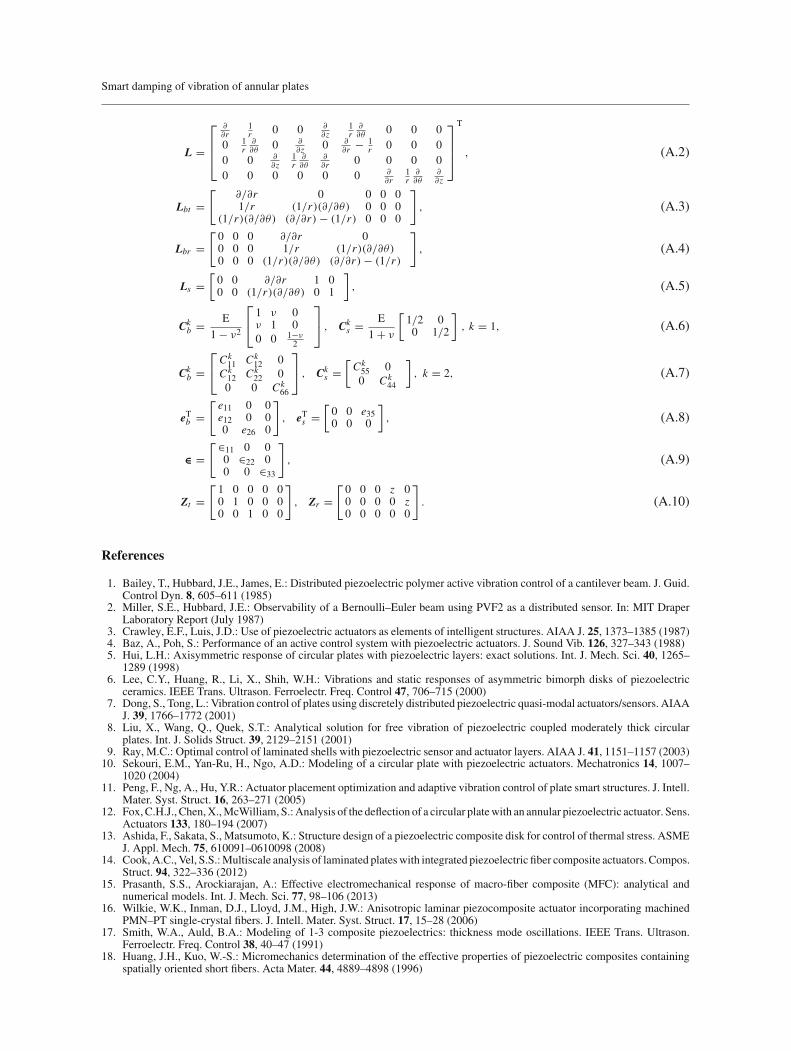
Smart damping of vibration of annular plates
L =
⎡
⎢⎢⎣
∂∂r
1r 0 0 ∂
∂z1r
∂∂θ
0 0 00 1
r∂∂θ
0 ∂∂z 0 ∂
∂r − 1r 0 0 0
0 0 ∂∂z
1r
∂∂θ
∂∂r 0 0 0 0
0 0 0 0 0 0 ∂∂r
1r
∂∂θ
∂∂z
⎤
⎥⎥⎦
T
, (A.2)
Lbt =[
∂/∂r 0 0 0 01/r (1/r)(∂/∂θ) 0 0 0
(1/r)(∂/∂θ) (∂/∂r) − (1/r) 0 0 0
]
, (A.3)
Lbr =[0 0 0 ∂/∂r 00 0 0 1/r (1/r)(∂/∂θ)0 0 0 (1/r)(∂/∂θ) (∂/∂r) − (1/r)
]
, (A.4)
Ls =[0 0 ∂/∂r 1 00 0 (1/r)(∂/∂θ) 0 1
], (A.5)
Ckb = E
1 − ν2
⎡
⎣1 ν 0ν 1 00 0 1−ν
2
⎤
⎦ , Cks = E
1 + ν
[1/2 00 1/2
], k = 1, (A.6)
Ckb =
⎡
⎣Ck11 Ck
12 0Ck12 Ck
22 00 0 Ck
66
⎤
⎦ , Cks =
[Ck55 00 Ck
44
], k = 2, (A.7)
eTb =[e11 0 0e12 0 00 e26 0
]
, eTs =[0 0 e350 0 0
], (A.8)
∈ =[∈11 0 0
0 ∈22 00 0 ∈33
]
, (A.9)
Zt =[1 0 0 0 00 1 0 0 00 0 1 0 0
]
, Zr =[0 0 0 z 00 0 0 0 z0 0 0 0 0
]
. (A.10)
References
1. Bailey, T., Hubbard, J.E., James, E.: Distributed piezoelectric polymer active vibration control of a cantilever beam. J. Guid.Control Dyn. 8, 605–611 (1985)
2. Miller, S.E., Hubbard, J.E.: Observability of a Bernoulli–Euler beam using PVF2 as a distributed sensor. In: MIT DraperLaboratory Report (July 1987)
3. Crawley, E.F., Luis, J.D.: Use of piezoelectric actuators as elements of intelligent structures. AIAA J. 25, 1373–1385 (1987)4. Baz, A., Poh, S.: Performance of an active control system with piezoelectric actuators. J. Sound Vib. 126, 327–343 (1988)5. Hui, L.H.: Axisymmetric response of circular plates with piezoelectric layers: exact solutions. Int. J. Mech. Sci. 40, 1265–
1289 (1998)6. Lee, C.Y., Huang, R., Li, X., Shih, W.H.: Vibrations and static responses of asymmetric bimorph disks of piezoelectric
ceramics. IEEE Trans. Ultrason. Ferroelectr. Freq. Control 47, 706–715 (2000)7. Dong, S., Tong, L.: Vibration control of plates using discretely distributed piezoelectric quasi-modal actuators/sensors. AIAA
J. 39, 1766–1772 (2001)8. Liu, X., Wang, Q., Quek, S.T.: Analytical solution for free vibration of piezoelectric coupled moderately thick circular
plates. Int. J. Solids Struct. 39, 2129–2151 (2001)9. Ray, M.C.: Optimal control of laminated shells with piezoelectric sensor and actuator layers. AIAA J. 41, 1151–1157 (2003)
10. Sekouri, E.M., Yan-Ru, H., Ngo, A.D.: Modeling of a circular plate with piezoelectric actuators. Mechatronics 14, 1007–1020 (2004)
11. Peng, F., Ng, A., Hu, Y.R.: Actuator placement optimization and adaptive vibration control of plate smart structures. J. Intell.Mater. Syst. Struct. 16, 263–271 (2005)
12. Fox,C.H.J., Chen,X.,McWilliam, S.:Analysis of the deflection of a circular platewith an annular piezoelectric actuator. Sens.Actuators 133, 180–194 (2007)
13. Ashida, F., Sakata, S., Matsumoto, K.: Structure design of a piezoelectric composite disk for control of thermal stress. ASMEJ. Appl. Mech. 75, 610091–0610098 (2008)
14. Cook,A.C., Vel, S.S.:Multiscale analysis of laminated plateswith integrated piezoelectric fiber composite actuators. Compos.Struct. 94, 322–336 (2012)
15. Prasanth, S.S., Arockiarajan, A.: Effective electromechanical response of macro-fiber composite (MFC): analytical andnumerical models. Int. J. Mech. Sci. 77, 98–106 (2013)
16. Wilkie, W.K., Inman, D.J., Lloyd, J.M., High, J.W.: Anisotropic laminar piezocomposite actuator incorporating machinedPMN–PT single-crystal fibers. J. Intell. Mater. Syst. Struct. 17, 15–28 (2006)
17. Smith, W.A., Auld, B.A.: Modeling of 1-3 composite piezoelectrics: thickness mode oscillations. IEEE Trans. Ultrason.Ferroelectr. Freq. Control 38, 40–47 (1991)
18. Huang, J.H., Kuo, W.-S.: Micromechanics determination of the effective properties of piezoelectric composites containingspatially oriented short fibers. Acta Mater. 44, 4889–4898 (1996)

A. S. Pavan Kumar et al.
19. Bent, A.A., Hagood, N.W.: Piezoelectric fiber composites with interdigitated electrodes. J. Intell. Mater. Syst. Struct. 8, 903–919 (1997)
20. High, J.W., Wilkie, W.K.: Method of fabricating NASA-standard macro-fiber composite piezoelectric actuators. In: NationalAeronautics and Space Administration, Langley Research Center (2003)
21. Mallik, N., Ray, M.C.: Effective coefficients of piezoelectric fiber reinforced composites. AIAA J. 41, 704–710 (2003)22. Ray, M.C.: Micromechanics of piezoelectric composites with improved effective piezoelectric constant. Int. J. Mech. Mater.
Des. 3, 361–371 (2006)23. Shu, D., Della, C.N.: The performance of 1–3 piezoelectric composites with a porous non-piezoelectric matrix. Acta
Mater. 56, 754–761 (2008)24. Chakaraborty, D., Kumar, A.: Effective properties of thermo-electro-mechanically coupled piezoelectric fiber reinforced
composites. Mater. Des. 30, 1216–1222 (2009)25. Arockiarajan, A., Sakthivel, M.: Thermo-electro-mechanical response of 1–3–2 piezoelectric composites: effect of fiber
orientations. Acta Mech. 223, 1353–1369 (2012)26. Kalamkarov, A.L., Savi,M.A.:Micromechanicalmodeling and effective properties of the smart grid reinforced composites. J.
Braz. Soc. Mech. Sci. Eng. XXXIV, 343–351 (2012)27. William, K.W., Robert, G.B., James, W.H., Robert, L.F., Richard, F.H., Anthony, J. Jr., Bruce, D.L., Paul, H.M.: Low-cost
piezocomposite actuator for structural control applications. In: Proceedings of SPIE 3991, Smart Structures and Materials2000: Industrial and Commercial Applications of Smart Structures Technologies 323 (2000)
28. Park, S., Inman, D.J., Yun, C.B.: An outliner analysis of MFC-based impedance sensing data for wireless structural healthmonitoring of railroad tracks. Eng. Struct. 30, 2792–2799 (2008)
29. Choi, S.C., Park, J.S., Kim, J.H.: Active damping of rotating composite thin-walled beams using MFC actuators and PVDFsensors. Compos. Struct. 76, 362–374 (2006)
30. Kovalovs, A., Barkanov, E., Gluhihs, S.: Active control of structures using macro-fiber composite (MFC). J. Phys. Conf.Ser. 93, 012034 (2007)
31. Bilgen, O., Kochersberger, K.B., Inman, D.J., Ohanian, O.J.: Macro-fiber composite actuated simply supported thin air-foils. Smart Mater. Struct. 19, 055010 (2010)
32. Bent, A.A.: Active fiber composite material systems for structural control applications. In: Proceedings of SPIE 3674, SmartStructures and Materials 1999: Industrial and Commercial Applications of Smart Structures Technologies 166, (1999)
33. Sodano, H.A., Park, G., Inman, D.J.: An investigation into the performance of macro-fiber composites for sensing andstructural vibration applications. Mech. Syst. Signal Process. 18, 683–697 (2004)
34. Sohn, J.W., Kim, H.S., Choi, S.B., Kim, K.S.: Experimental investigation of smart hull structures based on macro fibercomposite actuators. Key Eng. Mater. 326, 1419–1422 (2006)
35. Azzouz, M.S., Bevan, J.S., Ro, J.-J., Mei, C.: Finite element modeling of MFC/AFC actuators. In: Proceedings of SPIE 326:Smart Structures and Materials 2001: Modeling, Signal Processing, and Control in Smart Structures (2001)
36. Ray, M.C., Reddy, J.N.: Performance of piezoelectric fiber-reinforced composites for active structural acoustic control oflaminated composite plates. IEEE Trans. Ultrason. Ferroelectr. Freq. Control 51, 1477–1490 (2004)
37. Ikeda, T.: Fundamentals of Piezoelectricity. Oxford University Press, Oxford (1990)38. Dunn, M.L., Taya, M.: Micromechanics predictions of the effective electroelastic moduli of piezoelectric composites. Int. J.
Solids Struct. 30, 161–175 (1993)39. Furukawa, T.: Piezoelectricity and pyroelectricity in polymers. IEEE Trans. Electr. Insul. 24, 375–395 (1989)40. Cady, W.G.: Piezolectricity. McGraw-Hill, New York (1946)41. Hasin, Z.: Viscoelastic behavior of heterogeneous media. J. Appl. Mech. 32, 630 (1965)42. Hasin, Z.: Complex moduli of viscoelastic composites-I, general theory and application to particulate composites. Int. J.
Solids Struct. 6, 539–552 (1970)43. Aboudi, J., Arnold, S.M., Bednarcyk, B.A.: Micromechanics of Composite Materials. Academic Press, New York (2013)44. Odegard, G.M.: Constitutive modeling of piezoelectric polymer pomposities. Acta Mater. 52, 5315–5330 (2004)45. Tiersten, H.F.: Linear Piezoelectric Plate Vibrations. Plenum, New York (1969)46. Cook, R.D., Malkus, D.S., Plesha, M.E., Witt, R.J.: Concepts and Applications of Finite Element Analysis. Wiley, New
York (2001)47. Meirovitch, L.: Elements of Vibration Analysis. McGraw-Hill, New York (2007)48. Chakraverty, S., Bhat, R.B., Stiharu, I.: Free vibration of annular elliptic plates using boundary characteristic orthogonal
polynomials as shape functions in the Rayleigh–Ritz method. J. Sound. Vib. 241, 524–539 (2001)49. Dong, S., Uchino, K., Li, L., Viehland, D.: Analytical solutions for the transverse deflection of a piezoelectric circular
axisymmetric unimorph actuator. IEEE Trans. Ultrason. Ferroelectr. Freq. Control 54, 1240–1248 (2007)
Related Documents