ARTICLE Skin-electrode iontronic interface for mechanosensing Pang Zhu 1,5 , Huifeng Du 2,5 , Xingyu Hou 1,5 , Peng Lu 1 , Liu Wang 1,2,3 , Jun Huang 1 , Ningning Bai 1 , Zhigang Wu 1,4 , Nicholas X. Fang 2 ✉ & Chuan Fei Guo 1,3 ✉ Electrodermal devices that capture the physiological response of skin are crucial for mon- itoring vital signals, but they often require convoluted layered designs with either electronic or ionic active materials relying on complicated synthesis procedures, encapsulation, and packaging techniques. Here, we report that the ionic transport in living systems can provide a simple mode of iontronic sensing and bypass the need of artificial ionic materials. A simple skin-electrode mechanosensing structure (SEMS) is constructed, exhibiting high pressure- resolution and spatial-resolution, being capable of feeling touch and detecting weak physiological signals such as fingertip pulse under different skin humidity. Our mechanical analysis reveals the critical role of instability in high-aspect-ratio microstructures on sensing. We further demonstrate pressure mapping with millimeter-spatial-resolution using a fully textile SEMS-based glove. The simplicity and reliability of SEMS hold great promise of diverse healthcare applications, such as pulse detection and recovering the sensory capability in patients with tactile dysfunction. https://doi.org/10.1038/s41467-021-24946-4 OPEN 1 Department of Materials Science and Engineering, Southern University of Science and Technology, Shenzhen, Guangdong, China. 2 Department of Mechanical Engineering, Massachusetts Institute of Technology, Cambridge, MA, USA. 3 Centers for Mechanical Engineering Research and Education at MIT and SUSTech, Southern University of Science and Technology, Shenzhen, Guangdong, China. 4 State Key Laboratory of Digital Manufacturing Equipment and Technology, Huazhong University of Science and Technology, Wuhan, China. 5 These authors contributed equally: Pang Zhu, Huifeng Du, Xingyu Hou. ✉ email: [email protected]; [email protected] NATURE COMMUNICATIONS | (2021)12:4731 | https://doi.org/10.1038/s41467-021-24946-4 | www.nature.com/naturecommunications 1 1234567890():,;

Welcome message from author
This document is posted to help you gain knowledge. Please leave a comment to let me know what you think about it! Share it to your friends and learn new things together.
Transcript
ARTICLE
Skin-electrode iontronic interface formechanosensingPang Zhu1,5, Huifeng Du 2,5, Xingyu Hou1,5, Peng Lu1, Liu Wang 1,2,3, Jun Huang1, Ningning Bai1,
Zhigang Wu1,4, Nicholas X. Fang2✉ & Chuan Fei Guo 1,3✉
Electrodermal devices that capture the physiological response of skin are crucial for mon-
itoring vital signals, but they often require convoluted layered designs with either electronic
or ionic active materials relying on complicated synthesis procedures, encapsulation, and
packaging techniques. Here, we report that the ionic transport in living systems can provide a
simple mode of iontronic sensing and bypass the need of artificial ionic materials. A simple
skin-electrode mechanosensing structure (SEMS) is constructed, exhibiting high pressure-
resolution and spatial-resolution, being capable of feeling touch and detecting weak
physiological signals such as fingertip pulse under different skin humidity. Our mechanical
analysis reveals the critical role of instability in high-aspect-ratio microstructures on sensing.
We further demonstrate pressure mapping with millimeter-spatial-resolution using a fully
textile SEMS-based glove. The simplicity and reliability of SEMS hold great promise of diverse
healthcare applications, such as pulse detection and recovering the sensory capability in
patients with tactile dysfunction.
https://doi.org/10.1038/s41467-021-24946-4 OPEN
1 Department of Materials Science and Engineering, Southern University of Science and Technology, Shenzhen, Guangdong, China. 2 Department ofMechanical Engineering, Massachusetts Institute of Technology, Cambridge, MA, USA. 3 Centers for Mechanical Engineering Research and Education at MITand SUSTech, Southern University of Science and Technology, Shenzhen, Guangdong, China. 4 State Key Laboratory of Digital Manufacturing Equipment andTechnology, Huazhong University of Science and Technology, Wuhan, China. 5These authors contributed equally: Pang Zhu, Huifeng Du, Xingyu Hou.✉email: [email protected]; [email protected]
NATURE COMMUNICATIONS | (2021) 12:4731 | https://doi.org/10.1038/s41467-021-24946-4 | www.nature.com/naturecommunications 1
1234
5678
90():,;
The richness of sensory function of skin is made possiblewith a large variety of receptors to provide afferent infor-mation related to touch (mechanoreceptors), pain (noci-
ceptors), and temperature (thermoreceptors)1–3. Recently, a greatneed of monitoring vital signals of the human body4–6, as well asthe precise measurement of finger or hand manipulation undereither external or internal stimuli has promoted the scientific andtechnological breakthroughs on wearable and epidermal electro-nic sensors7,8. To mimic the dynamic and micromechanicalsensory function of skins, the current form of electronic skinsoften takes a layered structure of two electrodes sandwichinga piezoresistive9, dielectric7,8,10–12, or piezoelectric layer13.However, these electronic skins often suffer from sophisticatedmaterial synthesis protocols and the need of extra encapsulationto maintain the hydrated functional environment. For example,Xia et al. reported a capacitive-type electronic skin, of which alayer of microgels is used as the deformation component andtwo layers of Ag-coated PDMS films serve as electrodes. Themultilayer structure is sealed using tapes before it is attached onthe human skin to detect physiological signals14. In addition, theaccuracy of recording such vital signal with desired spatial andtemporal resolution might be significantly compromised by thepresence of an epidermal barrier consisting of dead cell material(the stratum corneum). Electrical noise is a challenge of high-quality signal recording for epidermal and wearable electronicsensors, and is dominantly attributed to the relative motion at theskin-electrode interfaces15. Although most wearables such assmartwatches can display real-time heart rates using photo-plethysmographic (PPG) sensors that detect changes in tissueblood volume using a photodetector16, the accuracy of suchdevices is subject to noise introduced by the variation of skincontact on the patient or device movement, environmental con-ditions, and ectopic beats17, therefore using wearable devices forthe analysis of heart rate anomaly is often limited.
On the other hand, the skin keeps naturally wet thanks to thepresence of the sweat glands and the porous nature of thestratum corneum. Under physiological conditions, the stratumcorneum is always partially hydrated. The sweat ducts functionas pumps to pour sweats toward the skin surface, and the sweatpenetrates into the porous corneum as a result of high pressurein the duct and/or diffusion18. Since sweat contains numerousions such as Na+ and Cl– on the order of 10 mM inconcentration19, the ionic conductance of the corneum increaseswhen being soaked with sweat. As a result, when we put a metalelectrode in conformal contact with the skin, free electrons serveas the carriers in the electrodes while ionic fluxes contribute tothe conduction in the tissue to exchange electronic and ionicsignals20. This is a natural iontronic interface, since the ionsinvolved in the current flow through ductal sweat and interstitialfluid are accumulating at these boundaries, followed by thebuildup of a potential difference across the cell membrane, thedirection of which is opposite to the applied voltage—hencecalled “counter electromotive force”.
Laminating electrodes on skin for collecting bioelectricity sig-nals, such as electrodermal response and electrocardiographic(ECG) signals has been widely used in healthcare for over 100years21. The electrode-skin interface is of iontronic nature. For aniontronic interface, electrons and ions are separated withoutelectrochemical reaction when applied with a small voltage22, andthe capacitance is proportional to the interfacial contact areabetween the electrode and the electrolyte23–26. Whereas such an“electrodes-on-skin” configuration is widely applied in electro-dermal signal recording and stimulation, to our knowledge, it hasnot been used in tactile sensing despite its huge potential. Thenaturally possessed internal ion-exchanging capability andwaterproof protective enclosure of epidermis make human skin
an ideal selection of overcoming the giant challenges in imple-menting synthetic conductive gel-based sensors.
In this work, we utilized the ionic transport in living systemsto construct an iontronic sensing structure: skin-electrodemechanosensing structure (SEMS), which simply consists oftwo electrodes and the skin. It exhibited high pressure resolutionand spatial resolution, being capable of feeling touch anddetecting weak physiological signals such as fingertip pulse underdifferent skin humidity. We studied the influence of motionartifacts on the detection of pulse signals. We were delighted tofind that motion-related frequencies can be conveniently dis-tinguished from the characteristic frequencies of pulse in thefrequency domain, thus the extraction of physiological signal canbe finished without being affected by motion artifacts. We furtherfabricated a fully textile SEMS-based glove for pressure mappingwith millimeter-spatial resolution. The simplicity and reliabilityof the SEMS hold much potential in a wide range of healthcareapplications, such as pulse detection in daily life and helping thepatients with tactile dysfunction to recover sensory capability.
ResultsPrinciple, structure, and performance of the skin-electrodemechanosensing structure. The apparent contrast between ECG(mainly an internal stimulation) and tactile sensing to graspedobjects (a response of the skin to external mechanical stimula-tion) can be elaborated by their underlying working principles.For measurements of epidermal conductance and ECG, electro-des are required to maintain an intimate and conformable contactwith the skin to ensure stable potential signal recording (Sup-plementary Fig. 1a). For sensing, however, a tunable interfacialcontact or capacitance signal that is sensitive to mechanical sti-muli is expected (Supplementary Fig. 1b). These crucial yetcontradictory requirements necessitate a comprehensive strategyof the design, behavioral prediction, and fabrication of skin-interfaced pressure sensing structures.
Here we demonstrate a SEMS that utilizes the skin as an ionicmaterial for measuring both physiological signals and externalmechanical stimuli. A SEMS simply consists of the skin, a sensingelectrode (SE) with microstructured surfaces that allow for subtlechange in skin-electrode contact, and a highly conformablecounter electrode (CE) (Fig. 1a). These soft electrodes areeffortlessly fixated on skin using a piece of transparent andbreathable healthcare film (details are seen in “Methods”), whichapplies a base-pressure of ~5 kPa on the SEMS. In contrast withcomplicated design of existing e-skins which often have a layeredstructure, the SEMS has a much simpler structure with electrodeslaminated on the skin surface in parallel without employing anysynthesized ionic gels or hydrogels. Moreover, on top of the highspecific capacitance of the iontronic interface, we provide physicalinsights into the important geometric features that govern theinstability-enabled pressure sensitivity increase from mechanicalanalysis and simulation, which accurately predicts the deforma-tion response and guides the design of microstructures on theelectrodes.
To illustrate our concept of SEMS, we fabricated Au-coatedpolydimethylsiloxane (PDMS) micropillars (Fig. 1b) with a length(L) to radius (R) aspect ratio of 6 as the SE. PDMS is a softmaterial whose biocompatibility and breathability have beenrepeatedly confirmed by in vitro and in vivo studies27,28. Uponloading, the soft micropillared structures allow a sensitive changein contact area of the skin-electrode interface (Fig. 1c), whichbehaves like a capacitor with a much higher unit area capacitancethan conventional capacitors. The SE also presents desiredbiocompatibility and breathability as an on-skin adhesive patchbecause of the minimized contact with the skin, as well as the
ARTICLE NATURE COMMUNICATIONS | https://doi.org/10.1038/s41467-021-24946-4
2 NATURE COMMUNICATIONS | (2021) 12:4731 | https://doi.org/10.1038/s41467-021-24946-4 | www.nature.com/naturecommunications
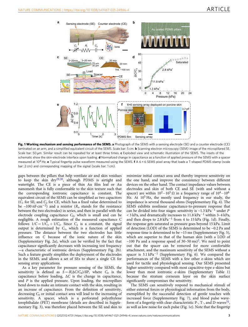
gaps between the pillars that help ventilate air and skin residuesto keep the skin dry29,30, although PDMS is airtight andwatertight. The CE is a piece of thin Au film leaf or Aunanomesh that is fully conformable to the skin texture such thatthe corresponding iontronic capacitance is constant. Theequivalent circuit of the SEMS can be simplified as two capacitors(C1 for SE; and C2 for CE, which has a fixed value determined tobe ~100 nF·cm−2) and a resistor (Ri, stands for the resistancebetween the two electrodes) in series, and then in parallel with theelectrode coupling capacitance CE, which is small and can benegligible. A rough estimation of the measured capacitance Cfollows 1/C= 1/C1+ 1/C2. Since C2 is a constant, the signaloutput is determined by C1, which is a function of appliedpressure. The distance between the two electrodes has littleinfluence on C because of the ionic nature of the skin(Supplementary Fig. 2a), which can be verified by the fact thatcapacitance significantly decreases with increasing test frequency—a characteristic of iontronic devices (Supplementary Fig. 2b).Such a feature greatly simplifies the deployment of the electrodesin the SEMS, and allows a set of SEs to share a single CE forsensing array applications.
As a key parameter for pressure sensing of the SEMS, thesensitivity is defined as S= δ(ΔC/C0)/δP, where C0 is thecapacitance before loading, ΔC is the change in capacitance,and P is the applied pressure. Upon loading, the micropillarsbend down to make an intimate contact with the skin, resulting inan increase of capacitance. From the definition of sensitivity,decreasing C0 or initial contact area will lead to the increasing ofsensitivity. A spacer, which is a perforated polyethyleneterephthalate (PET) membrane (details are described in Supple-mentary Fig. 3), was therefore placed between the SE and skin to
minimize initial contact area and thereby improve sensitivity onthe one hand, and improve the consistency between differentdevices on the other hand. The contact impedance values betweenelectrodes and skin of both CE and SE (with and without aspacer) are within 102−105Ω in a frequency range of 104−106
Hz. At 105 Hz, the mostly used frequency in our study, theimpedance is several thousand ohms (Supplementary Fig. 4). TheSEMS exhibits nonlinear capacitance-to-pressure response thatcan be divided into four stages: sensitivity is ~1.3 kPa−1 under P< 3 kPa, and dramatically increases to 11.8 kPa−1 within 3–4 kPa,and then drops to 2.8 kPa−1 from 4 to 15 kPa (Fig. 1d). Finally,the response gets saturated as pressure goes beyond 15 kPa. Limitof detection (LOD) of the SEMS is determined to be ~0.2 Pa andresponse time is determined to be ~15 ms (Supplementary Fig. 5),which are superior to that of the human skin (with a LOD of~100 Pa and a response speed of 30–50 ms)2. We need to pointout that the spacer can be removed for more comfortableattachment, and the maximum sensitivity of the SEMS without aspacer is 3.1 kPa−1 (Supplementary Fig. 6). We compared theperformances of the SEMS with a few other e-skins which areused for tactile and physiological sensing. Our SEMS presentedhigher sensitivity compared with most capacitive-type e-skins butlower than most iontronic e-skins (Supplementary Table 1)because the stratum corneum layer on the skin surfacesignificantly compromises the sensitivity.
The SEMS can sensitively respond to mechanical stimuli ofeither external forces or physiological information from the body,exemplified by the successful detection of gentle touches withincreased force (Supplementary Fig. 7), and blood pulse wave-form of a fingertip with clear characteristic P-, T-, and D-waves31,as well as low noise for each pulse (Fig. 1e). Note that the fingertip
Fig. 1 Working mechanism and sensing performance of the SEMS. a Photograph of the SEMS with a sensing electrode (SE) and a counter electrode (CE)laminated on an arm, and a simplified equivalent circuit of the SEMS. Scale bar: 5 cm. b Scanning electron microscopy (SEM) image of the micropillared SE.Scale bar: 50 μm. Similar result can be repeated for at least three times. c Exploded view and schematic illustration of the SEMS. The insets of theschematic show the skin-electrode interface upon loading. d Normalized change in capacitance as a function of applied pressure of the SEMS with a spacermeasured at 104 Hz. e Typical fingertip pulse waveform measured using the SEMS. f A 6 × 6 SEMS pixel array that loads a T-shaped PDMS stamp (scalebar: 2 cm) and corresponding mapping of the signal (scale bar: 1 cm).
NATURE COMMUNICATIONS | https://doi.org/10.1038/s41467-021-24946-4 ARTICLE
NATURE COMMUNICATIONS | (2021) 12:4731 | https://doi.org/10.1038/s41467-021-24946-4 | www.nature.com/naturecommunications 3
pulse causes a tiny pressure variation of only ~10 Pa which is farweaker than the radial artery pulse, and thus can hardly bedetected using existing e-skins or by the human skin for whichpressure resolution is only ~7%32. By contrast, our SEMS exhibitsan extremely high pressure resolution of ~1 Pa, or ~0.02% at abase-pressure of ~5 kPa, and is able to detect the feature of the P-,T-, and D-waves with sharp peaks. The pulse is usually detectedfrom the radial artery, but the concave surface of the wrist causesunstable signal during hand motion. By contrast, the convexsurface of fingertips guarantees the signal stability even when thefinger is moving.
A SEMS pixel array is further demonstrated in Fig. 1f forpressure mapping. The pixel array is 1.87 cm × 1.87 cm in areaconsisting of 36 circular SEs with a diameter of 1.7 mm and oneshared CE. The capacitance distribution recorded by the pixelarray precisely reflects the applied pressure from a piece of “T”shaped PDMS stamp. In addition, our result shows that the SEMSis capable of resolving pressure at a submillimeter spatialresolution (Supplementary Fig. 8) while exhibiting high signal-to-noise ratio and negligible crosstalk between neighboringsensing elements.
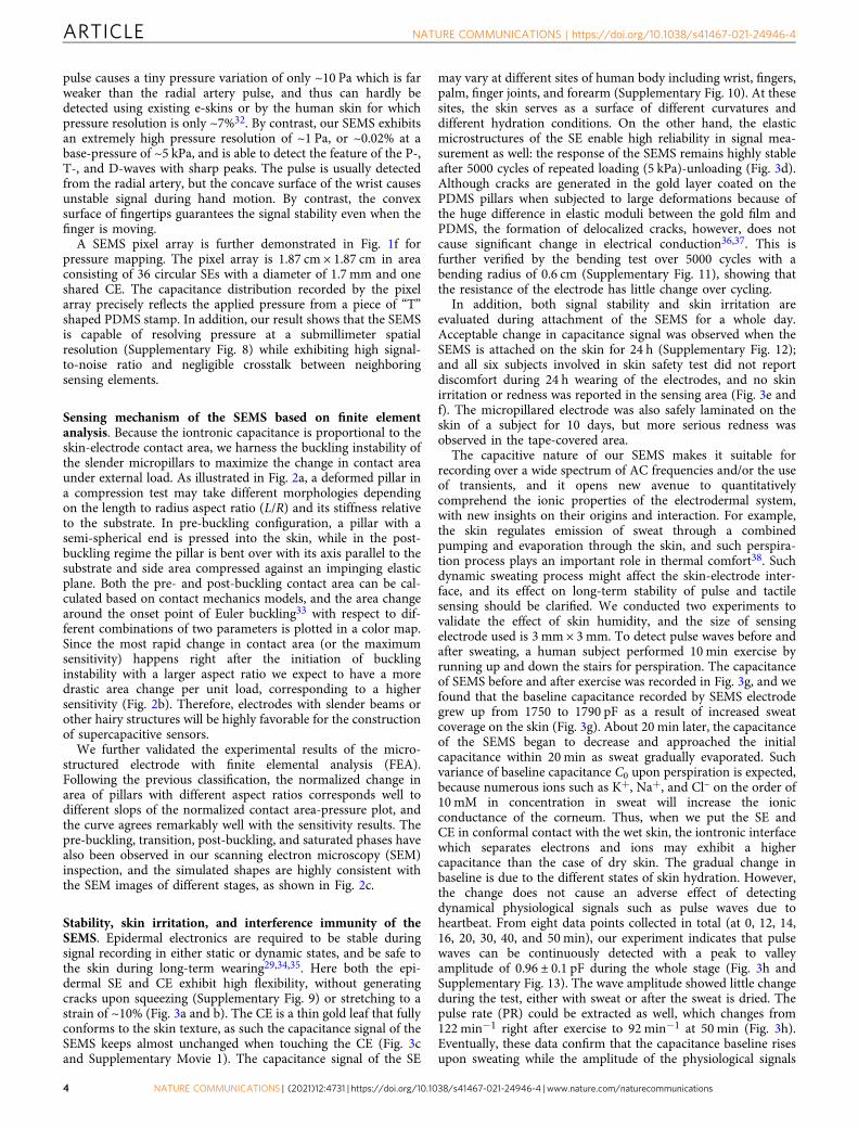
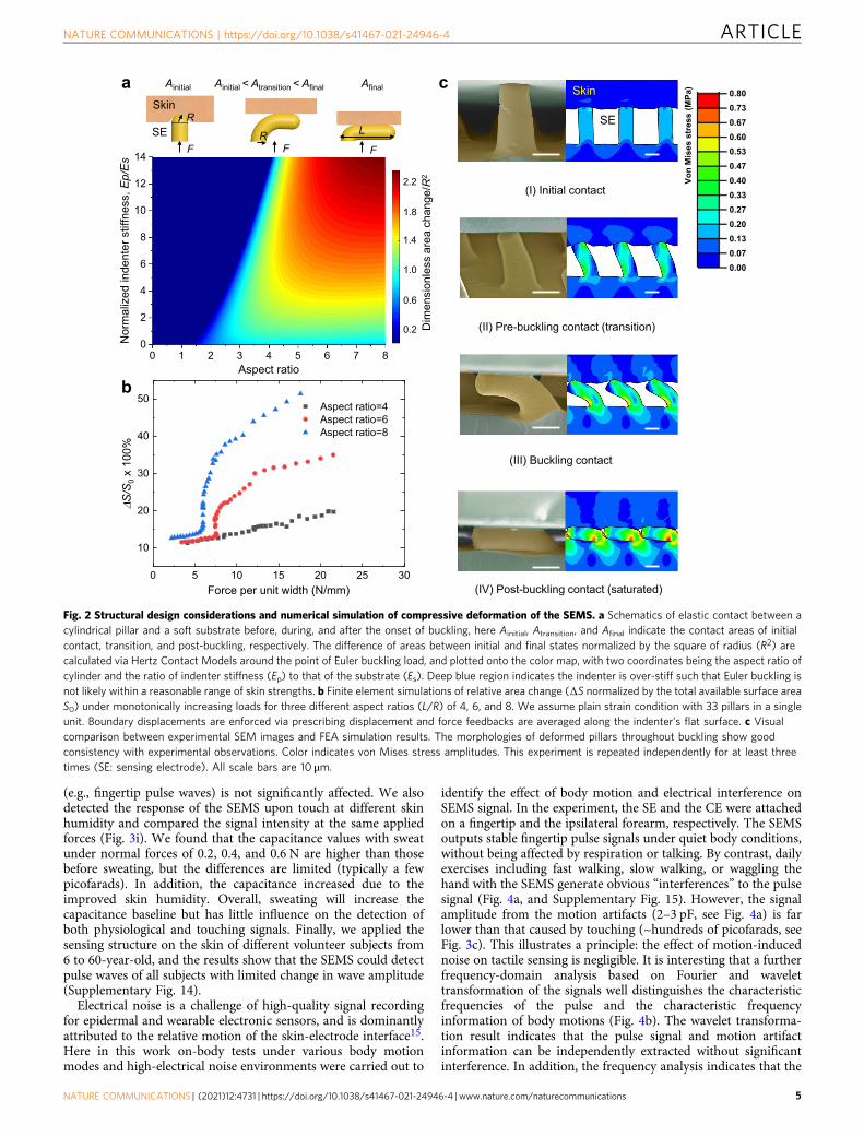
Sensing mechanism of the SEMS based on finite elementanalysis. Because the iontronic capacitance is proportional to theskin-electrode contact area, we harness the buckling instability ofthe slender micropillars to maximize the change in contact areaunder external load. As illustrated in Fig. 2a, a deformed pillar ina compression test may take different morphologies dependingon the length to radius aspect ratio (L/R) and its stiffness relativeto the substrate. In pre-buckling configuration, a pillar with asemi-spherical end is pressed into the skin, while in the post-buckling regime the pillar is bent over with its axis parallel to thesubstrate and side area compressed against an impinging elasticplane. Both the pre- and post-buckling contact area can be cal-culated based on contact mechanics models, and the area changearound the onset point of Euler buckling33 with respect to dif-ferent combinations of two parameters is plotted in a color map.Since the most rapid change in contact area (or the maximumsensitivity) happens right after the initiation of bucklinginstability with a larger aspect ratio we expect to have a moredrastic area change per unit load, corresponding to a highersensitivity (Fig. 2b). Therefore, electrodes with slender beams orother hairy structures will be highly favorable for the constructionof supercapacitive sensors.
We further validated the experimental results of the micro-structured electrode with finite elemental analysis (FEA).Following the previous classification, the normalized change inarea of pillars with different aspect ratios corresponds well todifferent slops of the normalized contact area-pressure plot, andthe curve agrees remarkably well with the sensitivity results. Thepre-buckling, transition, post-buckling, and saturated phases havealso been observed in our scanning electron microscopy (SEM)inspection, and the simulated shapes are highly consistent withthe SEM images of different stages, as shown in Fig. 2c.
Stability, skin irritation, and interference immunity of theSEMS. Epidermal electronics are required to be stable duringsignal recording in either static or dynamic states, and be safe tothe skin during long-term wearing29,34,35. Here both the epi-dermal SE and CE exhibit high flexibility, without generatingcracks upon squeezing (Supplementary Fig. 9) or stretching to astrain of ~10% (Fig. 3a and b). The CE is a thin gold leaf that fullyconforms to the skin texture, as such the capacitance signal of theSEMS keeps almost unchanged when touching the CE (Fig. 3cand Supplementary Movie 1). The capacitance signal of the SE
may vary at different sites of human body including wrist, fingers,palm, finger joints, and forearm (Supplementary Fig. 10). At thesesites, the skin serves as a surface of different curvatures anddifferent hydration conditions. On the other hand, the elasticmicrostructures of the SE enable high reliability in signal mea-surement as well: the response of the SEMS remains highly stableafter 5000 cycles of repeated loading (5 kPa)-unloading (Fig. 3d).Although cracks are generated in the gold layer coated on thePDMS pillars when subjected to large deformations because ofthe huge difference in elastic moduli between the gold film andPDMS, the formation of delocalized cracks, however, does notcause significant change in electrical conduction36,37. This isfurther verified by the bending test over 5000 cycles with abending radius of 0.6 cm (Supplementary Fig. 11), showing thatthe resistance of the electrode has little change over cycling.
In addition, both signal stability and skin irritation areevaluated during attachment of the SEMS for a whole day.Acceptable change in capacitance signal was observed when theSEMS is attached on the skin for 24 h (Supplementary Fig. 12);and all six subjects involved in skin safety test did not reportdiscomfort during 24 h wearing of the electrodes, and no skinirritation or redness was reported in the sensing area (Fig. 3e andf). The micropillared electrode was also safely laminated on theskin of a subject for 10 days, but more serious redness wasobserved in the tape-covered area.
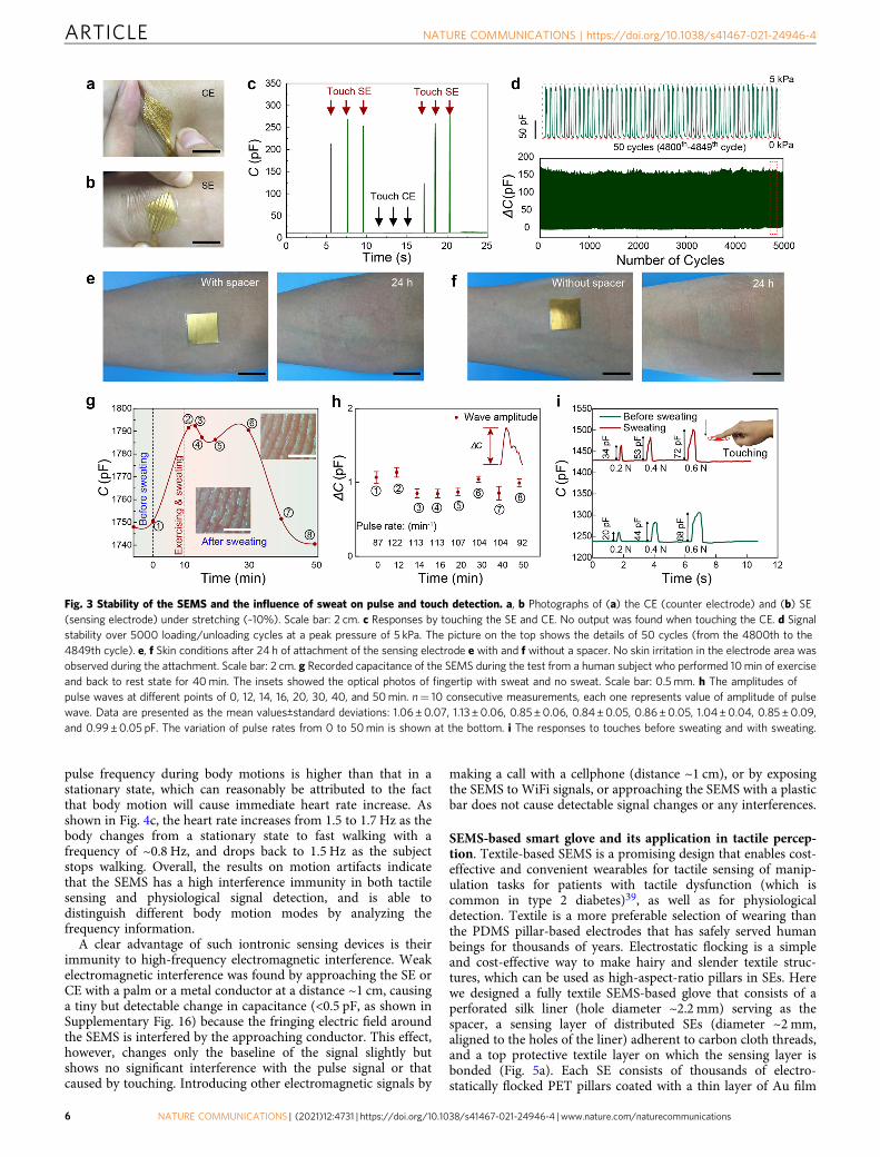
The capacitive nature of our SEMS makes it suitable forrecording over a wide spectrum of AC frequencies and/or the useof transients, and it opens new avenue to quantitativelycomprehend the ionic properties of the electrodermal system,with new insights on their origins and interaction. For example,the skin regulates emission of sweat through a combinedpumping and evaporation through the skin, and such perspira-tion process plays an important role in thermal comfort38. Suchdynamic sweating process might affect the skin-electrode inter-face, and its effect on long-term stability of pulse and tactilesensing should be clarified. We conducted two experiments tovalidate the effect of skin humidity, and the size of sensingelectrode used is 3 mm × 3mm. To detect pulse waves before andafter sweating, a human subject performed 10 min exercise byrunning up and down the stairs for perspiration. The capacitanceof SEMS before and after exercise was recorded in Fig. 3g, and wefound that the baseline capacitance recorded by SEMS electrodegrew up from 1750 to 1790 pF as a result of increased sweatcoverage on the skin (Fig. 3g). About 20 min later, the capacitanceof the SEMS began to decrease and approached the initialcapacitance within 20 min as sweat gradually evaporated. Suchvariance of baseline capacitance C0 upon perspiration is expected,because numerous ions such as K+, Na+, and Cl– on the order of10 mM in concentration in sweat will increase the ionicconductance of the corneum. Thus, when we put the SE andCE in conformal contact with the wet skin, the iontronic interfacewhich separates electrons and ions may exhibit a highercapacitance than the case of dry skin. The gradual change inbaseline is due to the different states of skin hydration. However,the change does not cause an adverse effect of detectingdynamical physiological signals such as pulse waves due toheartbeat. From eight data points collected in total (at 0, 12, 14,16, 20, 30, 40, and 50 min), our experiment indicates that pulsewaves can be continuously detected with a peak to valleyamplitude of 0.96 ± 0.1 pF during the whole stage (Fig. 3h andSupplementary Fig. 13). The wave amplitude showed little changeduring the test, either with sweat or after the sweat is dried. Thepulse rate (PR) could be extracted as well, which changes from122 min−1 right after exercise to 92 min−1 at 50 min (Fig. 3h).Eventually, these data confirm that the capacitance baseline risesupon sweating while the amplitude of the physiological signals
ARTICLE NATURE COMMUNICATIONS | https://doi.org/10.1038/s41467-021-24946-4
4 NATURE COMMUNICATIONS | (2021) 12:4731 | https://doi.org/10.1038/s41467-021-24946-4 | www.nature.com/naturecommunications
(e.g., fingertip pulse waves) is not significantly affected. We alsodetected the response of the SEMS upon touch at different skinhumidity and compared the signal intensity at the same appliedforces (Fig. 3i). We found that the capacitance values with sweatunder normal forces of 0.2, 0.4, and 0.6 N are higher than thosebefore sweating, but the differences are limited (typically a fewpicofarads). In addition, the capacitance increased due to theimproved skin humidity. Overall, sweating will increase thecapacitance baseline but has little influence on the detection ofboth physiological and touching signals. Finally, we applied thesensing structure on the skin of different volunteer subjects from6 to 60-year-old, and the results show that the SEMS could detectpulse waves of all subjects with limited change in wave amplitude(Supplementary Fig. 14).
Electrical noise is a challenge of high-quality signal recordingfor epidermal and wearable electronic sensors, and is dominantlyattributed to the relative motion of the skin-electrode interface15.Here in this work on-body tests under various body motionmodes and high-electrical noise environments were carried out to
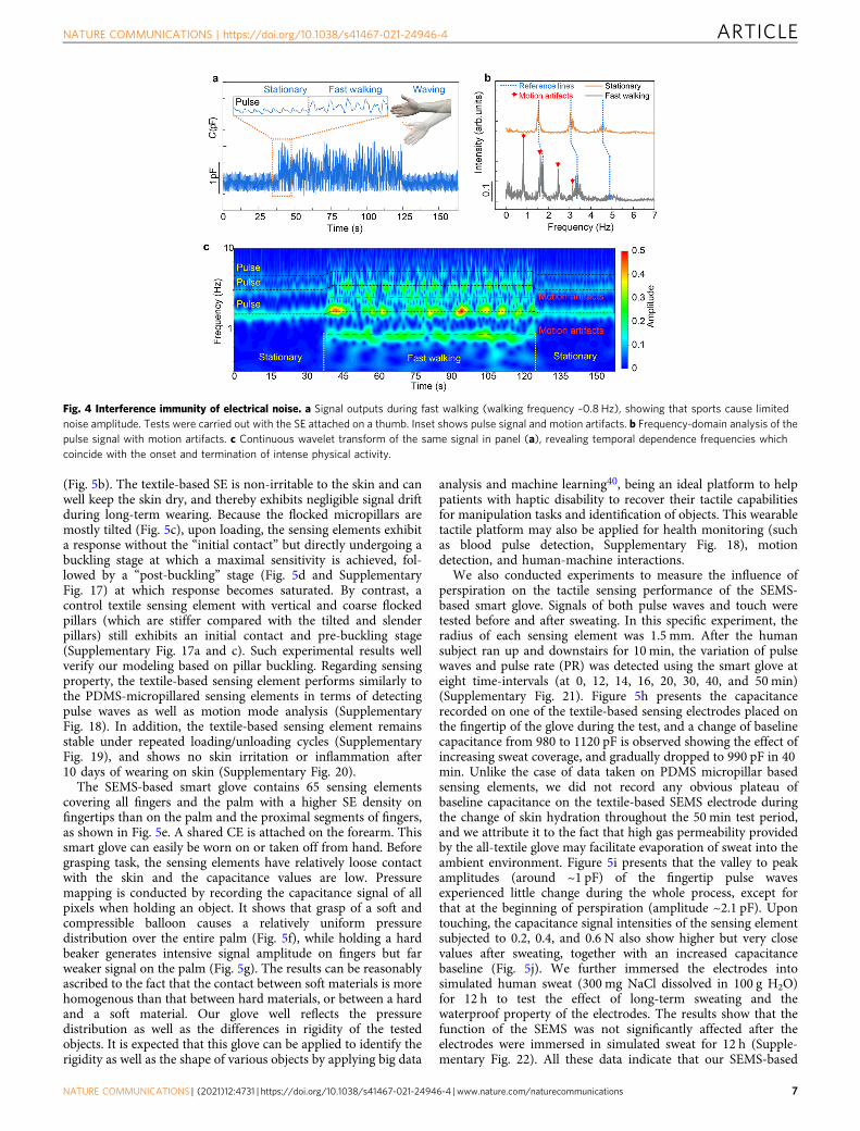
identify the effect of body motion and electrical interference onSEMS signal. In the experiment, the SE and the CE were attachedon a fingertip and the ipsilateral forearm, respectively. The SEMSoutputs stable fingertip pulse signals under quiet body conditions,without being affected by respiration or talking. By contrast, dailyexercises including fast walking, slow walking, or waggling thehand with the SEMS generate obvious “interferences” to the pulsesignal (Fig. 4a, and Supplementary Fig. 15). However, the signalamplitude from the motion artifacts (2–3 pF, see Fig. 4a) is farlower than that caused by touching (~hundreds of picofarads, seeFig. 3c). This illustrates a principle: the effect of motion-inducednoise on tactile sensing is negligible. It is interesting that a furtherfrequency-domain analysis based on Fourier and wavelettransformation of the signals well distinguishes the characteristicfrequencies of the pulse and the characteristic frequencyinformation of body motions (Fig. 4b). The wavelet transforma-tion result indicates that the pulse signal and motion artifactinformation can be independently extracted without significantinterference. In addition, the frequency analysis indicates that the
a
0 5 10 15 20 25 30
10
20
30
40
50Aspect ratio=4Aspect ratio=6Aspect ratio=8
�S/S
0x
100%
Force per unit width (N/mm)
(I) Initial contact
(III) Buckling contact
(II) Pre-buckling contact (transition)
(IV) Post-buckling contact (saturated)
b
c
0 1 2 3 4 5 6 7 80
2
4
6
8
10
12
14
2.2
1.8
1.4
1.0
0.6
Nor
mal
ized
inde
nter
stiff
ness
,Ep/Es
Aspect ratio
0.2 Dim
ensi
onl e
ssar
each
ange
/R2
Ainitial Ainitial <Atransition <Afinal Afinal
F F F
R
R L
VonMisesstress(MPa)
0.800.730.670.600.530.470.400.330.270.200.130.070.00
Skin
SE
Skin
SE
Fig. 2 Structural design considerations and numerical simulation of compressive deformation of the SEMS. a Schematics of elastic contact between acylindrical pillar and a soft substrate before, during, and after the onset of buckling, here Ainitial, Atransition, and Afinal indicate the contact areas of initialcontact, transition, and post-buckling, respectively. The difference of areas between initial and final states normalized by the square of radius (R2) arecalculated via Hertz Contact Models around the point of Euler buckling load, and plotted onto the color map, with two coordinates being the aspect ratio ofcylinder and the ratio of indenter stiffness (Ep) to that of the substrate (Es). Deep blue region indicates the indenter is over-stiff such that Euler buckling isnot likely within a reasonable range of skin strengths. b Finite element simulations of relative area change (ΔS normalized by the total available surface areaS0) under monotonically increasing loads for three different aspect ratios (L/R) of 4, 6, and 8. We assume plain strain condition with 33 pillars in a singleunit. Boundary displacements are enforced via prescribing displacement and force feedbacks are averaged along the indenter’s flat surface. c Visualcomparison between experimental SEM images and FEA simulation results. The morphologies of deformed pillars throughout buckling show goodconsistency with experimental observations. Color indicates von Mises stress amplitudes. This experiment is repeated independently for at least threetimes (SE: sensing electrode). All scale bars are 10 μm.
NATURE COMMUNICATIONS | https://doi.org/10.1038/s41467-021-24946-4 ARTICLE
NATURE COMMUNICATIONS | (2021) 12:4731 | https://doi.org/10.1038/s41467-021-24946-4 | www.nature.com/naturecommunications 5
pulse frequency during body motions is higher than that in astationary state, which can reasonably be attributed to the factthat body motion will cause immediate heart rate increase. Asshown in Fig. 4c, the heart rate increases from 1.5 to 1.7 Hz as thebody changes from a stationary state to fast walking with afrequency of ~0.8 Hz, and drops back to 1.5 Hz as the subjectstops walking. Overall, the results on motion artifacts indicatethat the SEMS has a high interference immunity in both tactilesensing and physiological signal detection, and is able todistinguish different body motion modes by analyzing thefrequency information.
A clear advantage of such iontronic sensing devices is theirimmunity to high-frequency electromagnetic interference. Weakelectromagnetic interference was found by approaching the SE orCE with a palm or a metal conductor at a distance ~1 cm, causinga tiny but detectable change in capacitance (<0.5 pF, as shown inSupplementary Fig. 16) because the fringing electric field aroundthe SEMS is interfered by the approaching conductor. This effect,however, changes only the baseline of the signal slightly butshows no significant interference with the pulse signal or thatcaused by touching. Introducing other electromagnetic signals by
making a call with a cellphone (distance ~1 cm), or by exposingthe SEMS to WiFi signals, or approaching the SEMS with a plasticbar does not cause detectable signal changes or any interferences.
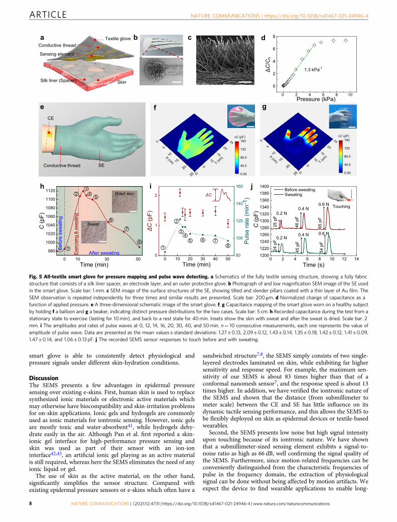
SEMS-based smart glove and its application in tactile percep-tion. Textile-based SEMS is a promising design that enables cost-effective and convenient wearables for tactile sensing of manip-ulation tasks for patients with tactile dysfunction (which iscommon in type 2 diabetes)39, as well as for physiologicaldetection. Textile is a more preferable selection of wearing thanthe PDMS pillar-based electrodes that has safely served humanbeings for thousands of years. Electrostatic flocking is a simpleand cost-effective way to make hairy and slender textile struc-tures, which can be used as high-aspect-ratio pillars in SEs. Herewe designed a fully textile SEMS-based glove that consists of aperforated silk liner (hole diameter ~2.2 mm) serving as thespacer, a sensing layer of distributed SEs (diameter ~2 mm,aligned to the holes of the liner) adherent to carbon cloth threads,and a top protective textile layer on which the sensing layer isbonded (Fig. 5a). Each SE consists of thousands of electro-statically flocked PET pillars coated with a thin layer of Au film
Fig. 3 Stability of the SEMS and the influence of sweat on pulse and touch detection. a, b Photographs of (a) the CE (counter electrode) and (b) SE(sensing electrode) under stretching (~10%). Scale bar: 2 cm. c Responses by touching the SE and CE. No output was found when touching the CE. d Signalstability over 5000 loading/unloading cycles at a peak pressure of 5 kPa. The picture on the top shows the details of 50 cycles (from the 4800th to the4849th cycle). e, f Skin conditions after 24 h of attachment of the sensing electrode e with and f without a spacer. No skin irritation in the electrode area wasobserved during the attachment. Scale bar: 2 cm. g Recorded capacitance of the SEMS during the test from a human subject who performed 10min of exerciseand back to rest state for 40min. The insets showed the optical photos of fingertip with sweat and no sweat. Scale bar: 0.5 mm. h The amplitudes ofpulse waves at different points of 0, 12, 14, 16, 20, 30, 40, and 50min. n= 10 consecutive measurements, each one represents value of amplitude of pulsewave. Data are presented as the mean values±standard deviations: 1.06±0.07, 1.13±0.06, 0.85±0.06, 0.84±0.05, 0.86±0.05, 1.04±0.04, 0.85±0.09,and 0.99±0.05 pF. The variation of pulse rates from 0 to 50min is shown at the bottom. i The responses to touches before sweating and with sweating.
ARTICLE NATURE COMMUNICATIONS | https://doi.org/10.1038/s41467-021-24946-4
6 NATURE COMMUNICATIONS | (2021) 12:4731 | https://doi.org/10.1038/s41467-021-24946-4 | www.nature.com/naturecommunications
(Fig. 5b). The textile-based SE is non-irritable to the skin and canwell keep the skin dry, and thereby exhibits negligible signal driftduring long-term wearing. Because the flocked micropillars aremostly tilted (Fig. 5c), upon loading, the sensing elements exhibita response without the “initial contact” but directly undergoing abuckling stage at which a maximal sensitivity is achieved, fol-lowed by a “post-buckling” stage (Fig. 5d and SupplementaryFig. 17) at which response becomes saturated. By contrast, acontrol textile sensing element with vertical and coarse flockedpillars (which are stiffer compared with the tilted and slenderpillars) still exhibits an initial contact and pre-buckling stage(Supplementary Fig. 17a and c). Such experimental results wellverify our modeling based on pillar buckling. Regarding sensingproperty, the textile-based sensing element performs similarly tothe PDMS-micropillared sensing elements in terms of detectingpulse waves as well as motion mode analysis (SupplementaryFig. 18). In addition, the textile-based sensing element remainsstable under repeated loading/unloading cycles (SupplementaryFig. 19), and shows no skin irritation or inflammation after10 days of wearing on skin (Supplementary Fig. 20).
The SEMS-based smart glove contains 65 sensing elementscovering all fingers and the palm with a higher SE density onfingertips than on the palm and the proximal segments of fingers,as shown in Fig. 5e. A shared CE is attached on the forearm. Thissmart glove can easily be worn on or taken off from hand. Beforegrasping task, the sensing elements have relatively loose contactwith the skin and the capacitance values are low. Pressuremapping is conducted by recording the capacitance signal of allpixels when holding an object. It shows that grasp of a soft andcompressible balloon causes a relatively uniform pressuredistribution over the entire palm (Fig. 5f), while holding a hardbeaker generates intensive signal amplitude on fingers but farweaker signal on the palm (Fig. 5g). The results can be reasonablyascribed to the fact that the contact between soft materials is morehomogenous than that between hard materials, or between a hardand a soft material. Our glove well reflects the pressuredistribution as well as the differences in rigidity of the testedobjects. It is expected that this glove can be applied to identify therigidity as well as the shape of various objects by applying big data
analysis and machine learning40, being an ideal platform to helppatients with haptic disability to recover their tactile capabilitiesfor manipulation tasks and identification of objects. This wearabletactile platform may also be applied for health monitoring (suchas blood pulse detection, Supplementary Fig. 18), motiondetection, and human-machine interactions.
We also conducted experiments to measure the influence ofperspiration on the tactile sensing performance of the SEMS-based smart glove. Signals of both pulse waves and touch weretested before and after sweating. In this specific experiment, theradius of each sensing element was 1.5 mm. After the humansubject ran up and downstairs for 10 min, the variation of pulsewaves and pulse rate (PR) was detected using the smart glove ateight time-intervals (at 0, 12, 14, 16, 20, 30, 40, and 50 min)(Supplementary Fig. 21). Figure 5h presents the capacitancerecorded on one of the textile-based sensing electrodes placed onthe fingertip of the glove during the test, and a change of baselinecapacitance from 980 to 1120 pF is observed showing the effect ofincreasing sweat coverage, and gradually dropped to 990 pF in 40min. Unlike the case of data taken on PDMS micropillar basedsensing elements, we did not record any obvious plateau ofbaseline capacitance on the textile-based SEMS electrode duringthe change of skin hydration throughout the 50 min test period,and we attribute it to the fact that high gas permeability providedby the all-textile glove may facilitate evaporation of sweat into theambient environment. Figure 5i presents that the valley to peakamplitudes (around ~1 pF) of the fingertip pulse wavesexperienced little change during the whole process, except forthat at the beginning of perspiration (amplitude ~2.1 pF). Upontouching, the capacitance signal intensities of the sensing elementsubjected to 0.2, 0.4, and 0.6 N also show higher but very closevalues after sweating, together with an increased capacitancebaseline (Fig. 5j). We further immersed the electrodes intosimulated human sweat (300 mg NaCl dissolved in 100 g H2O)for 12 h to test the effect of long-term sweating and thewaterproof property of the electrodes. The results show that thefunction of the SEMS was not significantly affected after theelectrodes were immersed in simulated sweat for 12 h (Supple-mentary Fig. 22). All these data indicate that our SEMS-based
Fig. 4 Interference immunity of electrical noise. a Signal outputs during fast walking (walking frequency ~0.8 Hz), showing that sports cause limitednoise amplitude. Tests were carried out with the SE attached on a thumb. Inset shows pulse signal and motion artifacts. b Frequency-domain analysis of thepulse signal with motion artifacts. c Continuous wavelet transform of the same signal in panel (a), revealing temporal dependence frequencies whichcoincide with the onset and termination of intense physical activity.
NATURE COMMUNICATIONS | https://doi.org/10.1038/s41467-021-24946-4 ARTICLE
NATURE COMMUNICATIONS | (2021) 12:4731 | https://doi.org/10.1038/s41467-021-24946-4 | www.nature.com/naturecommunications 7
smart glove is able to consistently detect physiological andpressure signals under different skin-hydration conditions.
DiscussionThe SEMS presents a few advantages in epidermal pressuresensing over existing e-skins. First, human skin is used to replacesynthesized ionic materials or electronic active materials whichmay otherwise have biocompatibility and skin-irritation problemsfor on-skin applications. Ionic gels and hydrogels are commonlyused as ionic materials for iontronic sensing. However, ionic gelsare mostly toxic and water-absorbent41, while hydrogels dehy-drate easily in the air. Although Pan et al. first reported a skin-ionic gel interface for high-performance pressure sensing andskin was used as part of their sensor with an ion-ioninterface42,43, an artificial ionic gel playing as an active materialis still required, whereas here the SEMS eliminates the need of anyionic liquid or gel.
The use of skin as the active material, on the other hand,significantly simplifies the sensor structure. Compared withexisting epidermal pressure sensors or e-skins which often have a
sandwiched structure7,8, the SEMS simply consists of two single-layered electrodes laminated on skin, while exhibiting far highersensitivity and response speed. For example, the maximum sen-sitivity of our SEMS is about 83 times higher than that of aconformal nanomesh sensor7, and the response speed is about 13times higher. In addition, we have verified the iontronic nature ofthe SEMS and shown that the distance (from submillimeter tometer scale) between the CE and SE has little influence on itsdynamic tactile sensing performance, and this allows the SEMS tobe flexibly deployed on skin as epidermal devices or textile-basedwearables.
Second, the SEMS presents low noise but high signal intensityupon touching because of its iontronic nature. We have shownthat a submillimeter-sized sensing element exhibits a signal-to-noise ratio as high as 66 dB, well confirming the signal quality ofthe SEMS. Furthermore, since motion-related frequencies can beconveniently distinguished from the characteristic frequencies ofpulse in the frequency domain, the extraction of physiologicalsignal can be done without being affected by motion artifacts. Weexpect the device to find wearable applications to enable long-
c
f ge
b
1.3 kPa-1
d
SE
CE
Conductive thread
a
Sensing element
Conductive threadTextile glove
Silk liner (Spacer) Skin
h i j
0
5
10
15
20
250
5
10
15
20
25
Y (cm)X (cm)
0.00
40.0
80.0
120
160∆C (pF)
0
5
10
15
20
250
5
10
15
20
25
Y (cm)X (cm)
0.00
40.0
80.0
120
160∆C (pF)
0 2 4 6 8 10
0
2
4
6
8
Δ C/C
0
Pressure (kPa)
1
23
45
6
7
8
980
1000
1020
1040
1060
1080
1100
1120
5030
C(p
F)
Time (min)
Exer
cising
&sw
eati n
g
Befo
resw
eatin
g
After sweating0 10
0.2 N
0.2 N
0.4 N
0.4 N
0.6 N
0.6 N Touching
0 2 4 6 8 10 12 1412001220124012601280130013201340136013801400
65pF
46pF
25pF
45pF
2 4pF
C( p
F)Time (s)
Before sweatingSweating
54pF
Sweat
Dried skin
0 10 20 30 40 500
1
2
ΔC
(pF )
Time (min)80
100
120
140
160
Puls
era
te(m
in-1
)1
2
34
5 6 78
ΔC
Fig. 5 All-textile smart glove for pressure mapping and pulse wave detecting. a Schematics of the fully textile sensing structure, showing a fully fabricstructure that consists of a silk liner spacer, an electrode layer, and an outer protective glove. b Photograph of and low magnification SEM image of the SE usedin the smart glove. Scale bar: 1 mm. c SEM image of the surface structures of the SE, showing tilted and slender pillars coated with a thin layer of Au film. TheSEM observation is repeated independently for three times and similar results are presented. Scale bar: 200 μm. d Normalized change of capacitance as afunction of applied pressure. e A three-dimensional schematic image of the smart glove. f, g Capacitance mapping of the smart glove worn on a healthy subjectby holding f a balloon and g a beaker, indicating distinct pressure distributions for the two cases. Scale bar: 5 cm. h Recorded capacitance during the test from astationary state to exercise (lasting for 10min), and back to a rest state for 40min. Insets show the skin with sweat and after the sweat is dried. Scale bar: 2mm. i The amplitudes and rates of pulse waves at 0, 12, 14, 16, 20, 30, 40, and 50min. n= 10 consecutive measurements, each one represents the value ofamplitude of pulse wave. Data are presented as the mean values± standard deviations: 1.27±0.13, 2.09±0.12, 1.43±0.14, 1.35±0.18, 1.42±0.12, 1.41±0.09,1.47±0.14, and 1.06±0.13 pF. j The recorded SEMS sensor responses to touch before and with sweating.
ARTICLE NATURE COMMUNICATIONS | https://doi.org/10.1038/s41467-021-24946-4
8 NATURE COMMUNICATIONS | (2021) 12:4731 | https://doi.org/10.1038/s41467-021-24946-4 | www.nature.com/naturecommunications
term monitoring of patient vital signals such as pulse irregularity,analysis of motion modes for athletes, and recovery of sensingcapability of people with tactile dysfunctions, and so forth. Aportable system may further be integrated to enable continuousmonitoring of body motion or touch without affecting the sub-jects’ daily life activities (Supplementary Movie 2). In addition,biotissues other than skins can also form an iontronic interfacewith electrodes. As such, the sensing mode is also expected to beextended to other living systems, being applied in intelligentplants, pressure sensing for epidermal and implantable medicaldevices.
MethodsFabrication of the micropillar sensing electrodes. A silicon template withmicroholes (10 μm in diameter, 30 μm in depth, and 30 μm in pitch) was preparedin two steps. First, a gold disc array of tetragonal lattice (disc diameter: 10 μm,pitch: 30 μm) was made on a silicon wafer by photolithography followed by cat-alytic wet etching to form the hole array, to be used as a master template for thepillar formation. Next, the master template was treated by air plasma (TS-PL05,Dong Xin Gao Ke CO., Ltd) at 500W for 10 min, and further surface-modifiedwith 1H,1H,2H,2H-perfluorooctyltrichlorosilane (Macklin) in a vacuum desiccatorfor 24 h. Using the as-prepared silicon mold as the master template, a secondpolycarbonate (PC, Dongguan Ling Mei New Materials Co., Ltd) mold withmicropillars was fabricated by using a hot embossing technique. Then, a mixture ofSylgard 184 base and curing agent in a weight ratio of 10:1 (Dow Corning Co., Ltd)was casted onto the PC mold, and cured at 70 °C for 3 h. After that, the curedPDMS layer with well-defined microholes was slowly peeled off from the PC mold,and was exposed to air plasma at 500W for 5 min, followed by treating with1H,1H,2H,2H-perfluorooctyltrichlorosilane in a vacuum desiccator for 24 h forbetter demolding.
Micropillared PDMS film was prepared by spin-coating PDMS solution ontothe surface-treated PDMS mold at 800 rpm for 1 min. Then, the film was cured at70 °C for 3 h and peeled off from the PDMS mold. Finally, a layer of Au film with athickness of 100 nm was deposited onto the PDMS film by using electron-beamevaporation, forming a flexible electrode with micropillar arrays. The thickness ofthe Au film on the side surface of pillars was determined to be ~10 nm, judgedfrom the period of surface wrinkles on the pillar side surface. A mask withpatterned tetragonal array of holes (1.7 mm in diameter and 3.4 mm in hole pitch)and threads was used for depositing a layer of Au film with a thickness of 100 nmfor the fabrication of micropillared electrode array. The electrodes were fixed onskin by using breathable 3M tapes (Tegaderm film 1626 W), a layer of transparentdressing which shows gentle adhesive and high comfort on skin and forms a sterilebarrier to external liquids, bacteria, and viruses. The fabrication of themicropillared electrodes is illustrated in Supplementary Fig. 23.
The spacer was made by laser-cutting a 38-μm-thick PET membrane withpatterned microholes. For our sensing tests, spacers with tetragonal circular-hole arraywith a hole diameter of 1.45mm and a hole fraction area of 66% were adopted.
Fabrication of SEMS pixel array and the test of pressure mapping. We used amask for the fabrication of the sensing element array, with 1.7 mm in diameter and3.4 mm in hole pitch. The experiment was conducted on a piece of porcine skin.The T-shaped rubber was cut using a blade, and then placed on the sensingelements array and the capacitance of each sensing element was measured.
Fabrication of smart glove. The textile glove, carbon cloth, and silk cloth wereused as purchased. The conductive carbon cloth (from Shenzhen Meicheng Co.,Ltd) was laser-cut into threads (0.8 mm in width) with a rounded end, which is 2.0mm in diameter and consists of electrostatically flocked PET pillars that werecoated with 100 nm Au by sputtering, serving as SEs. The conductive threads withthe SEs were then bonded to the glove. The silk cloth (0.08 mm thickness) was cutinto stripes with holes (2.2 mm in diameter) aligned to the sensing elements. Thesignal mapping was carried with 65 sensing elements; linear interpolation of thesignals was used to make images smooth.
Characterization and measurements. The surface morphology of the sensingelectrode was characterized by field-emission scanning electron microscopy (FE-SEM, TESCAN). The capacitance of the SEMS was measured using an LCR meter(E4980AL, KEYSIGHT) at a frequency of 105 Hz, if not specified. The area of CEwas 20 mm × 20 mm, and the area of SE for fingertip pulse detection was 5 mm × 5mm, if not specified otherwise. A force gauge with a computer-controlled stage(XLD-20E, Jingkong Mechanical Testing Co., Ltd) was used to apply and recordthe external pressure loaded on the sensor. Porcine skin was used for the sensitivitytests. Before test, the porcine skin was immersed into 0.9% NaCl solution for 24 hat 2 °C.
The skin-irritation test was conducted by laminating the SE and CE on the skinof forearm of six subjects, the electrode-covered skins were observed after removing
the electrodes, and reports from the subjects was collected. The on-skin experimentwas confirmed and approved by the IRB committee of the Southern University ofScience and Technology (Nos. 20190007 and 20200031).
Mechanical simulation. Finite element analysis (FEA) was conducted usingAbaqus/Explicit. We numerically simulated the displacement-controlled com-pression test of the SE. The scenario of PET spacer with a thickness of 38 µm and apercolated area ratio of 66% was used to match the experimental conditions. Theskin and PDMS were modeled as linear elastic and incompressible neo-Hookeanwith Young’s modulus Eskin= 450 kPa and EPDMS= 2.0 MPa. PET spacers wereassumed to be rigid. A compressive pressure of 20 kPa was applied on the topsurface of the PDMS layer. All interfacial contacts were assumed to have aCoulomb friction coefficient of 0.4 to ensure numerical stability.
Statistics and reproducibility. All experiments were repeated independently withsimilar results for at least three times.
Experiments on human subjects. Informed consent was given by each humansubject, or a parent of the subject (for the 6-year-old child), and all experimentswere conducted under approval from the Institutional Review Board at theSouthern University of Science and Technology under protocol number: 20200031.
Reporting summary. Further information on research design is available in the NatureResearch Reporting Summary linked to this article.
Data availabilityAll relevant data sets generated during and/or analyzed during the current study areavailable from the corresponding author upon request.
Received: 18 September 2020; Accepted: 29 June 2021;
References1. Johnson, K. O. The roles and functions of cutaneous mechanoreceptors. Curr.
Opin. Neurobiol. 11, 455–461 (2001).2. Johansson, R. S. & Flanagan, J. R. Coding and use of tactile signals from the
fingertips in object manipulation tasks. Nat. Rev. Neurosci. 10, 345–359 (2009).3. Schepers, R. J. & Ringkamp, M. Thermoreceptors and thermosensitive
afferents. Neurosci. Biobehav. Rev. 34, 177–184 (2010).4. Yang, J. C. et al. Electronic skin: recent progress and future prospects for skin‐
attachable devices for health monitoring, robotics, and prosthetics. Adv.Mater. 31, 1904765 (2019).
5. Chung, H. U. et al. Skin-interfaced biosensors for advanced wirelessphysiological monitoring in neonatal and pediatric intensive-care units. Nat.Med. 26, 418–429 (2020).
6. Kim, D.-H. et al. Epidermal electronics. Science 333, 838–843 (2011).7. Sunghoon, Lee et al. Nanomesh pressure sensor for monitoring finger
manipulation without sensory interference. Science 370, 966–970 (2020).8. Insang, You et al. Artificial multimodal receptors based on ion relaxation
dynamics. Science 370, 961–965 (2020).9. Zhu, S.-E., Ghatkesar, M. K., Zhang, C. & Janssen, G. C. A. M. Graphene based
piezoresistive pressure sensor. Appl. Phys. Lett. 102, 161904 (2013).10. Lipomi, D. J. et al. Skin-like pressure and strain sensors based on transparent
elastic films of carbon nanotubes. Nat. Nanotech. 6, 788 (2011).11. Cai, L. et al. Super-stretchable, transparent carbon nanotube-based capacitive
strain sensors for human motion detection. Sci. Rep. 3, 3048 (2013).12. Wang, Y. et al. Giant Poisson’s effect for wrinkle‐free stretchable transparent
electrodes. Adv. Mater. 31, 1902955 (2019).13. Lee, J. ‐H. et al. Micropatterned P(VDF‐TrFE) film‐based piezoelectric
nanogenerators for highly sensitive self‐powered pressure sensors. Adv. Funct.Mater. 25, 3203–3209 (2015).
14. Xia, X., Zhang, X., Serpe, M. J. & Zhang, Q. Microgel‐based devices aswearable capacitive electronic skins for monitoring cardiovascular risks. Adv.Mater. Technol. 5, 1900818 (2020).
15. Heikenfeld, J. et al. Wearable sensors: modalities, challenges, and prospects.Lab Chip 18, 217–248 (2018).
16. Askarian, B., Jung, K. & Chong, J. W. Monitoring of heart rate fromphotoplethysmographic signals using a Samsung Galaxy Note8 in underwaterenvironments. Sensors 19, 2846 (2019).
17. Asada, H. H. et al. Mobile monitoring with wearable photoplethysmographicbiosensors. IEEE Eng. Med. Biol. Mag. 22, 28–40 (2003).
18. Edwards, D. A. & Langer, R. A linear theory of transdermal transportphenomena. J. Pharm. Sci. 83, 1315–1334 (1994).
NATURE COMMUNICATIONS | https://doi.org/10.1038/s41467-021-24946-4 ARTICLE
NATURE COMMUNICATIONS | (2021) 12:4731 | https://doi.org/10.1038/s41467-021-24946-4 | www.nature.com/naturecommunications 9
19. Gao, W. et al. Fully integrated wearable sensor arrays for multiplexed in situperspiration analysis. Nature 529, 509–514 (2016).
20. Yuk, H., Lu, B. & Zhao, X. Hydrogel bioelectronics. Chem. Soc. Rev. 48,1642–1667 (2019).
21. Barold, S. S. Willem Einthoven and the birth of clinical electrocardiography ahundred years ago. Card. Electrophysiol. Rev. 7, 99–104 (2003).
22. Christoph, K. et al. Stretchable, transparent, ionic conductors. Science 341,984–987 (2013).
23. Nie, B., Xing, S., Brandt, J. D. & Pan, T. Droplet-based interfacial capacitivesensing. Lab Chip 12, 1110–1118 (2012).
24. Li, R. et al. Supercapacitive iontronic nanofabric sensing. Adv. Mater. 29,1700253 (2017).
25. Cho, S. H. et al. Micropatterned pyramidal ionic gels for sensing broad-rangepressures with high sensitivity. ACS Appl. Mater. Interfaces 9, 10128–10135 (2017).
26. Bai, N. et al. Graded intrafillable architecture-based iontronic pressure sensorwith ultra-broad-range high sensitivity. Nat. Commun. 11, 209 (2020).
27. Bélanger, M.-C. & Marois, Y. Hemocompatibility, biocompatibility,inflammatory and in vivo studies of primary reference materials low‐densitypolyethylene and polydimethylsiloxane: a review. J. Biomed. Mater. Res. 6,467–477 (2001).
28. Liu, Q. et al. Thermal, waterproof, breathable, and antibacterial cloth with ananoporous structure. ACS Appl. Mater. Interfaces 10, 2026–2032 (2018).
29. Kwak, M. K., Jeong, H. E. & Suh, K. Y. Rational design and enhancedbiocompatibility of a dry adhesive medical skin patch. Adv. Mater. 23,3949–3953 (2011).
30. Bae, W. G. et al. Enhanced skin adhesive patch with modulus‐tunablecomposite micropillars. Adv. Healthc. Mater. 2, 109–113 (2013).
31. Zhang, X. et al. A highly sensitive and cost‐effective flexible pressure sensorwith micropillar arrays fabricated by novel metal‐assisted chemical etching forwearable electronics. Adv. Mater. Technol. 4, 1900367 (2019).
32. Pang, X.-D., Tan, H. Z. & Durlach, N. I. Manual discrimination of force usingactive finger motion. Percept. Psychophys. 49, 531–540 (1991).
33. Timoshenko, S. P. & James, M. G. Theory of Elastic Stability 2nd edn. (CourierCorporation, 2009).
34. Miyamoto, A. et al. Inflammation-free, gas-permeable, lightweight, stretchableon-skin electronics with nanomeshes. Nat. Nanotech. 12, 907 (2017).
35. Qiao, Y. C. et al. Multilayer graphene epidermal electronic skin. ACS Nano 12,8839–8846 (2018).
36. Guo, C. F., Sun, T., Liu, Q., Suo, Z. & Ren, Z. Highly stretchable andtransparent nanomesh electrodes made by grain boundary lithography. Nat.Commun. 5, 3121–3121 (2014).
37. Lacour, S. P., Chan, D., Wagner, S., Li, T. & Suo, Z. Mechanisms of reversiblestretchability of thin metal films on elastomeric substrates. Appl. Phys. Lett. 88,204103 (2006).
38. Sim, J. K., Yoon, S. & Cho, Y.-H. Wearable sweat rate sensors for humanthermal comfort monitoring. Sci. Rep. 8, 1181 (2018).
39. Gorniak, S. L. et al. Sex-based differences and aging in tactile function loss inpersons with type 2 diabetes. PLos ONE 15, e0242199 (2020).
40. Sundaram, S. et al. Learning the signatures of the human grasp using a scalabletactile glove. Nature 569, 698 (2019).
41. Pham, T. P. T., Cho, C. W. & Yun, Y. S. Environmental fate and toxicity ofionic liquids: a review. Water Res. 44, 352–372 (2010).
42. Zhu, Z., Li, R. & Pan, T. Imperceptible epidermal–iontronic interface forwearable sensing. Adv. Mater. 30, 1705122 (2018).
43. Zhu, Z., Li, R. & Pan, T. EIS: a wearable device for epidermal pressure sensing.in 2018 IEEE Haptics Symposium (HAPTICS), San Francisco, CA, USA (2018).
AcknowledgementsThe work conducted in SUSTech was funded by the National Natural Science Foundationof China (No. 52073138), the “Guangdong Innovative and Entrepreneurial Research TeamProgram” under contract No. 2016ZT06G587, the “Science Technology and InnovationCommittee of Shenzhen Municipality” (Grant No. JCYJ20170817111714314), the“Guangdong Provincial Key Laboratory Program” (No. 2021B1212040001), and theShenzhen Sci-Tech Fund (No. KYTDPT20181011104007). H.D. and N.X.F. acknowledgethe financial support from SUSTech-MechE joint center. The authors thank ProfessorZhigang Suo and Dr. Siya Huang for deep discussion.
Author contributionsC.F.G. conceived the idea and designed the research. C.F.G. and N.F. directed the wholestudy. P.Z. and X.H. performed the majority of the experiments, P.L. designed theelectrodes. P.Z., H.D., N.F., and C.F.G. analyzed the experimental data. H.D. and L.W.performed the finite elemental analysis, and H.D. and N.F. analyzed the deformation ofthe micro-electrodes and the sensing mechanism. H.D., N.F., P.Z., and C.F.G. analyzedthe motion interference data. J.H., X.H., P.L., N.B., and Z.W. discussed the results andassisted in experimental design. X.H. and P.L. demonstrated the influence of perspirationon the SEMS. C.F.G., H.D., P.Z., and N.F. drafted the manuscript, and all authorscontributed to the writing of the manuscript.
Competing interestsThe authors declare no competing interests.
Additional informationSupplementary information The online version contains supplementary materialavailable at https://doi.org/10.1038/s41467-021-24946-4.
Correspondence and requests for materials should be addressed to N.X.F. or C.F.G.
Peer review information Nature Communications thanks Tingrui Pan and the otheranonymous reviewers for their contribution to the peer review of this work. Peer reviewerreports are available.
Reprints and permission information is available at http://www.nature.com/reprints
Publisher’s note Springer Nature remains neutral with regard to jurisdictional claims inpublished maps and institutional affiliations.
Open Access This article is licensed under a Creative CommonsAttribution 4.0 International License, which permits use, sharing,
adaptation, distribution and reproduction in any medium or format, as long as you giveappropriate credit to the original author(s) and the source, provide a link to the CreativeCommons license, and indicate if changes were made. The images or other third partymaterial in this article are included in the article’s Creative Commons license, unlessindicated otherwise in a credit line to the material. If material is not included in thearticle’s Creative Commons license and your intended use is not permitted by statutoryregulation or exceeds the permitted use, you will need to obtain permission directly fromthe copyright holder. To view a copy of this license, visit http://creativecommons.org/licenses/by/4.0/.
© The Author(s) 2021
ARTICLE NATURE COMMUNICATIONS | https://doi.org/10.1038/s41467-021-24946-4
10 NATURE COMMUNICATIONS | (2021) 12:4731 | https://doi.org/10.1038/s41467-021-24946-4 | www.nature.com/naturecommunications
Related Documents