This is a repository copy of Site investigation for energy geostructures. White Rose Research Online URL for this paper: http://eprints.whiterose.ac.uk/112202/ Version: Accepted Version Article: Loveridge, F orcid.org/0000-0002-6688-6305, Low, J and Powrie, W (2017) Site investigation for energy geostructures. Quarterly Journal of Engineering Geology and Hydrogeology, 50 (2). pp. 158-168. ISSN 1470-9236 https://doi.org/10.1144/qjegh2016-027 © 2017 The Author(s). Published by The Geological Society of London. All rights reserved. This is an author produced version of a paper published in Quarterly Journal of Engineering Geology and Hydrogeology. Uploaded in accordance with the publisher's self-archiving policy. [email protected] https://eprints.whiterose.ac.uk/ Reuse Items deposited in White Rose Research Online are protected by copyright, with all rights reserved unless indicated otherwise. They may be downloaded and/or printed for private study, or other acts as permitted by national copyright laws. The publisher or other rights holders may allow further reproduction and re-use of the full text version. This is indicated by the licence information on the White Rose Research Online record for the item. Takedown If you consider content in White Rose Research Online to be in breach of UK law, please notify us by emailing [email protected] including the URL of the record and the reason for the withdrawal request.

Welcome message from author
This document is posted to help you gain knowledge. Please leave a comment to let me know what you think about it! Share it to your friends and learn new things together.
Transcript
This is a repository copy of Site investigation for energy geostructures.
White Rose Research Online URL for this paper:http://eprints.whiterose.ac.uk/112202/
Version: Accepted Version
Article:
Loveridge, F orcid.org/0000-0002-6688-6305, Low, J and Powrie, W (2017) Site investigation for energy geostructures. Quarterly Journal of Engineering Geology and Hydrogeology, 50 (2). pp. 158-168. ISSN 1470-9236
https://doi.org/10.1144/qjegh2016-027
© 2017 The Author(s). Published by The Geological Society of London. All rights reserved. This is an author produced version of a paper published in Quarterly Journal of Engineering Geology and Hydrogeology. Uploaded in accordance with the publisher's self-archiving policy.
[email protected]://eprints.whiterose.ac.uk/
Reuse
Items deposited in White Rose Research Online are protected by copyright, with all rights reserved unless indicated otherwise. They may be downloaded and/or printed for private study, or other acts as permitted by national copyright laws. The publisher or other rights holders may allow further reproduction and re-use of the full text version. This is indicated by the licence information on the White Rose Research Online record for the item.
Takedown
If you consider content in White Rose Research Online to be in breach of UK law, please notify us by emailing [email protected] including the URL of the record and the reason for the withdrawal request.
Site investigation for energy geostructures1
2
Fleur Loveridge*1,2, Jasmine Low3, 4 & William Powrie13
4
1. University of Southampton, Faculty of Engineering and the Environment, Highfield,5
Southampton, SO17 1BJ6
2. University of Leeds, School of Civil Engineering, Woodhouse Lane, Leeds, LS2 9JT7
3. Formerly University of Southampton8
4. Max Fordham, 42-43 Gloucester Crescent, London, NW1 7PE9
10
* corresponding author: [email protected]
12
Abstract13
Energy geostructures are structure or infrastructure foundations used as heat exchangers as14
part of a ground source heat pump system. While piles remain the most common type of15
energy geostructure, increasingly infrastructure projects are considering the use of other16
buried structures such as retaining walls and tunnels for heat exchange. To design and plan17
for construction of such systems, site investigations must provide appropriate information to18
derive analysis input parameters. This paper presents a review of what information regarding19
the ground, and also the structures themselves, would be required for the ground energy20
system design process. Appropriate site investigation methods for energy gesotructures are21
reviewed, from desk study stages through in situ testing to laboratory testing of samples22
recovered. Available methods are described and critically appraised and guidance for23
practical application is given.24
Site investigation for energy geostructures25
Energy geostructures are structure or infrastructure foundations used as heat exchangers26
within a ground source heat pump system. Dual use of the geostructure is achieved by27
equipping the structural elements with heat transfer pipes during construction and28
subsequently connecting these pipes, through a series of headers and manifolds, to the29
ground source heat pump system. In this way the geostructure and the surrounding ground30
can contribute to the heating and cooling of buildings during the winter and summer months31
respectively. Providing the system is designed and constructed appropriately there will be long32
term financial and carbon savings from such schemes, and the energy associated with them33
is classed as renewable.34
Energy geostructures have been successfully constructed using a variety of different types of35
underground structures including piles, basement slabs, retaining walls and cut and cover36
tunnels (e.g Brandl, 2006). Successful trials have also been carried out using bored and37
sprayed concreted tunnel linings and using ground anchors (Adam & Markiewicz, 2009,38
Franzius & Pralle, 2011). However, piles remain the most commonly constructed type of39
energy energy geostructure for a number of reasons. First, their relative simplicity of40
construction. Secondly, piles are commonly constructed to support an overlying building, and41
use of the heating and cooling energy within that building is straightforward. Thirdly, there are42
recognised design approaches for piles so that clients may consider the project to be lower43
risk. By contrast, for other geostructure types, including metro stations and tunnels, projects44
are always more complicated as the end user for the heat may not be the infrastructure asset45
owner. Nonetheless, the benefits of ground energy systems mean that they are now more46
routinely under consideration for major infrastructure schemes (e.g Soga et al, 2014,47
Nicholson et al, 2015, Barla & Perino, 2015).48
As interest in energy geostructures becomes more common, engineering geologists and49
geotechnical engineers will increasingly be asked to consider these structures when designing50
and carrying out site investigations for projects. This paper presents a review of the additional51
information (compared with a traditional ground investigation) regarding the ground, and also52
the geostructure themselves, required for the ground source heat pump design process. It53
then considers how such information can be obtained. The paper is arranged to mirror the54
ground investigation and design process. Section 2 deals with the design objectives and55
parameters required, Section 3 considers available desk study sources, Section 4 gives56
guidance on in situ thermal conductivity testing and Section 5 compares in situ and laboratory57
methods.58
1 Design Parameters & Considerations59
1.1 Objectives of Design60
The recently published Ground Source Heat Pump Association Thermal Pile Standard61
(GSHPA, 2012) provides a useful review of the relevant parties and their roles in the design62
and construction process for foundation piles used as heat exchangers. While the document63
is specific to piles, much of the content could be applicable to energy geostructures more64
widely. In terms of design, there are two important objectives:65
Determining the energy output of the geostructures within appropriate soil and heat66
pump temperature limits;67
Ensuring that any additional temperature changes experienced by the geostructure as68
a result of their dual use do not lead to exceedance of any geotechnical limit states.69
The first objective will require information regarding the thermal properties of the soil and70
concrete that would not normally be considered in routine site investigation. The second71
objective depends on the geotechnical properties of the system, and whether these are72
affected by temperature. Additionally, thermal expansion characteristics become relevant.73
Required design parameters for the two objectives are considered in Section 1.3 below.74

1.2 Design Stages75
As with any civil engineering scheme, the level of detail and certainty required will depend on76
the stage of the design. For example, at the planning stage it may be acceptable to make a77
determination of the likely energy output of a scheme based on “rules of thumb” (see Section78
2.1 for further details) to gain an idea of that scheme’s feasibility. At conceptual design stage,79
analysis of the energy output may be carried out based on values of thermal properties80
determined from the literature (see Section 2.2) before finally using parameters determined81
from in situ site specific testing (see Section 3) during detailed design.82
Refinement of the soil and concrete thermal and geotechnical properties must also occur in83
parallel with the development of the mechanical and electrical design which determines the84
expected building thermal demand. These thermal loads, while beyond the scope of this paper,85
are as important as the thermal and geotechnical properties. How a ground energy system86
behaves thermally, in terms of both energy efficiency and the resultant temperature changes87
in the ground, will depend significantly on the nature of the thermal demand. In addition, the88
balance between heat demand and cooling demand will also affect the sensitivity of the ground89
source heat pump system design to the thermal parameters. For unbalanced systems that are90
dominated by either heating or cooling, the heat exchange rate is sensitive to the ground and91
geostructure thermal properties in particular. However, for balanced systems with equal92
demand for heating and cooling this sensitivity is much reduced (Low, 2015).93
1.3 Design Parameters94
The key parameters required for the design of an energy geostructure are summarised in95
Table 1. They can be split into those parameters required for determination of energy output96
and those required for the geotechnical and structural design of the geostructure. For the97
former the main focus is on thermal parameters, but groundwater conditions are also very98
important. In most cases conduction is the dominant heat transfer process within the ground99
(Farouki, 1986), but flowing groundwater can provide significant additional heat transfer by100
advection. The impact of this enhanced heat transfer depends on the thermal load101

requirements. For example, a cooling dominated system exposed to high groundwater flow102
velocities would experience a more effective transfer of energy to the ground. Conversely, a103
balanced system designed to provide inter-seasonal storage, would be adversely affected by104
groundwater flow, which would remove heat and make it unavailable for retrieval when needed.105
Groundwater flow also leads to thermal pollution over wider areas, which can impact long term106
sustainability when multiple systems may be in operation within the same locality. Analytical107
and numerical studies suggest that heat transfer due to groundwater flow may become108
significant when Darcy velocities reach 1 to 10 m/year (Sutton et al 2003, Claesson &109
Hellstrom, 2000, Chiasson et al, 2000, Gehlin & Hellstrom, 2003, Banks, 2014).110
Undisturbed soil temperature is also an important parameter, because it determines the initial111
position of a system within the required operational temperature limits. Of particular112
importance is the lower operational temperature limit, designed to prevent ground freezing. A113
lower initial ground temperature will therefore offer a lower range within which the system can114
operate before reaching this limit.115
For geotechnical design, many of the relevant parameters will be the same as for a standard116
geostructure. This will include the strength, stiffness and in situ stress and pore water117
conditions. No detail is given here on the determination of these parameters, in view of the118
many suitable texts already available (e.g Gaba et al, 2003, Clayton, 2011). However, the119
coefficient of thermal expansion may now be important, to estimate the relative expansion120
potentials of the soil and the geostructure concrete (Bourne-Webb et al, 2015). Furthermore,121
there is also a need to understand whether and in what way traditional soil mechanical122
parameters may be influenced by the additional temperature changes controlled by the123
operation of the ground energy system. A brief discussion of these aspects is given below124
(Section 1.3.1), but the majority of this paper will focus on determining the thermal parameters125
which are not normally considered during routine investigations.126
1.3.1 Non-isothermal Soil Behaviour and impact on Geotechnical Parameters127
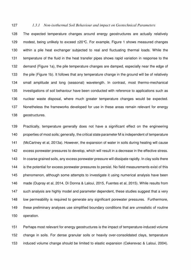
The expected temperature changes around energy geostructures are actually relatively128
modest, being unlikely to exceed ±20°C. For example, Figure 1 shows measured changes129
within a pile heat exchanger subjected to real and fluctuating thermal loads. While the130
temperature of the fluid in the heat transfer pipes shows rapid variation in response to the131
demand (Figure 1a), the pile temperature changes are damped, especially near the edge of132
the pile (Figure 1b). It follows that any temperature change in the ground will be of relatively133
small amplitude and long (seasonal) wavelength. In contrast, most thermo-mechanical134
investigations of soil behaviour have been conducted with reference to applications such as135
nuclear waste disposal, where much greater temperature changes would be expected.136
Nonetheless the frameworks developed for use in these areas remain relevant for energy137
geostructures.138
Practically, temperature generally does not have a significant effect on the engineering139
properties of most soils; generally, the critical state parameter M is independent of temperature140
(McCartney et al, 2013a). However, the expansion of water in soils during heating will cause141
excess porewater pressures to develop, which will result in a decrease in the effective stress.142
In coarse grained soils, any excess porewater pressure will dissipate rapidly. In clay soils there143
is the potential for excess porewater pressures to persist. No field measurements exist of this144
phenomenon, although some attempts to investigate it using numerical analysis have been145
made (Dupray et al, 2014, Di Donna & Laloui, 2015, Fuentes et al, 2015). While results from146
such analysis are highly model and parameter dependent, these studies suggest that a very147
low permeability is required to generate any significant porewater pressures. Furthermore,148
these preliminary analyses use simplified boundary conditions that are unrealistic of routine149
operation.150
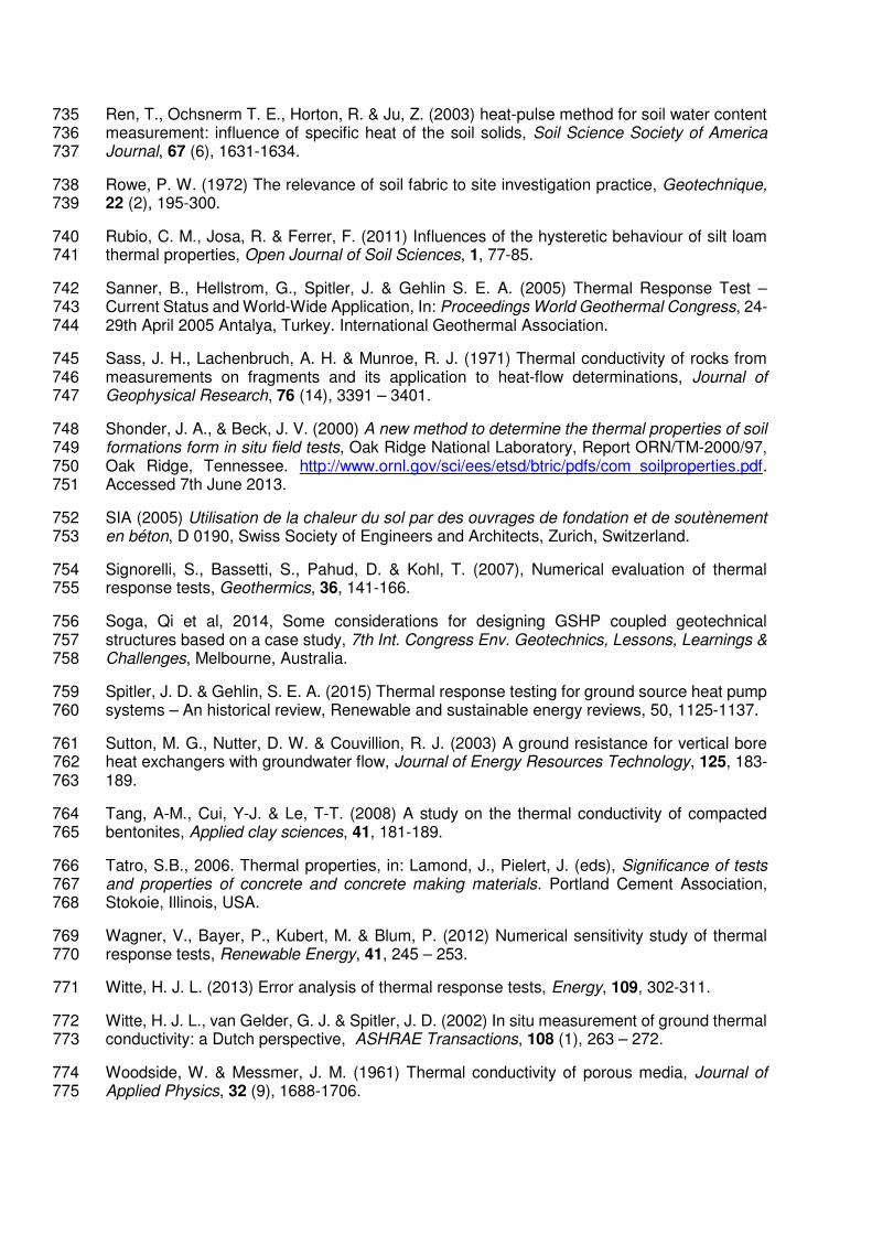
Perhaps most relevant for energy geostructures is the impact of temperature-induced volume151
change in soils. For dense granular soils or heavily over-consolidated clays, temperature152
induced volume change should be limited to elastic expansion (Cekerevac & Laloui, 2004).153
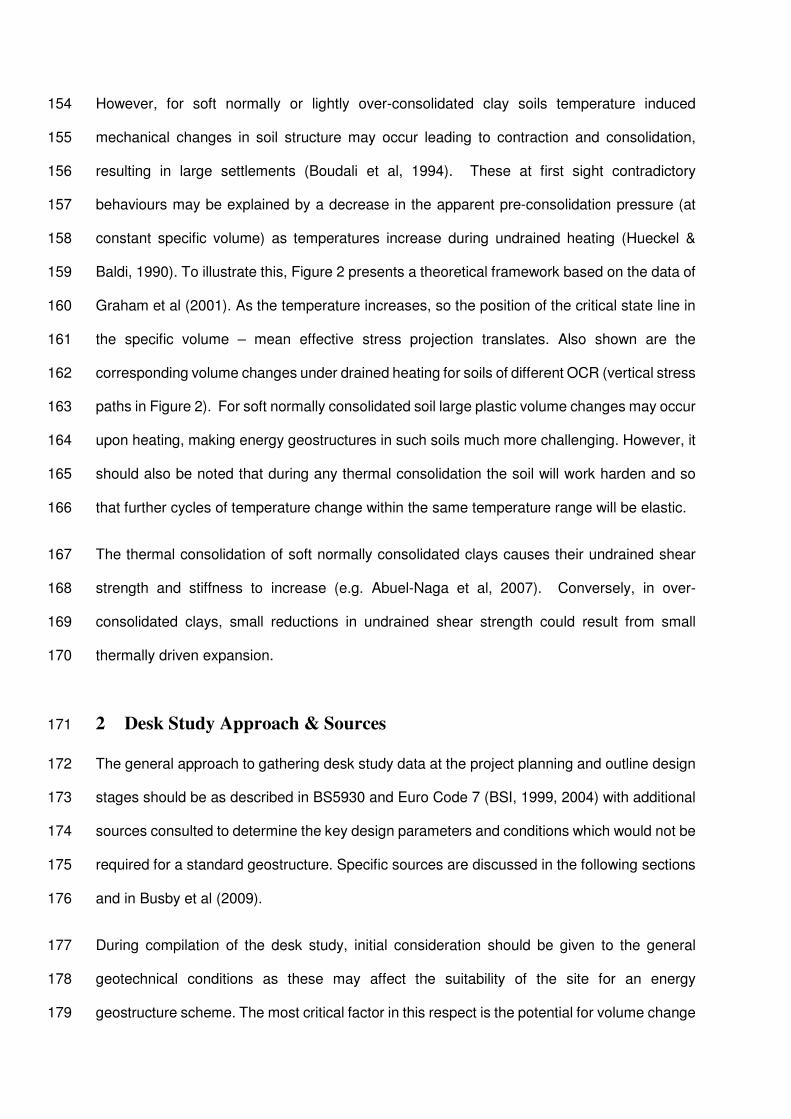
However, for soft normally or lightly over-consolidated clay soils temperature induced154
mechanical changes in soil structure may occur leading to contraction and consolidation,155
resulting in large settlements (Boudali et al, 1994). These at first sight contradictory156
behaviours may be explained by a decrease in the apparent pre-consolidation pressure (at157
constant specific volume) as temperatures increase during undrained heating (Hueckel &158
Baldi, 1990). To illustrate this, Figure 2 presents a theoretical framework based on the data of159
Graham et al (2001). As the temperature increases, so the position of the critical state line in160
the specific volume – mean effective stress projection translates. Also shown are the161
corresponding volume changes under drained heating for soils of different OCR (vertical stress162
paths in Figure 2). For soft normally consolidated soil large plastic volume changes may occur163
upon heating, making energy geostructures in such soils much more challenging. However, it164
should also be noted that during any thermal consolidation the soil will work harden and so165
that further cycles of temperature change within the same temperature range will be elastic.166
The thermal consolidation of soft normally consolidated clays causes their undrained shear167
strength and stiffness to increase (e.g. Abuel-Naga et al, 2007). Conversely, in over-168
consolidated clays, small reductions in undrained shear strength could result from small169
thermally driven expansion.170
2 Desk Study Approach & Sources171
The general approach to gathering desk study data at the project planning and outline design172
stages should be as described in BS5930 and Euro Code 7 (BSI, 1999, 2004) with additional173
sources consulted to determine the key design parameters and conditions which would not be174
required for a standard geostructure. Specific sources are discussed in the following sections175
and in Busby et al (2009).176
During compilation of the desk study, initial consideration should be given to the general177
geotechnical conditions as these may affect the suitability of the site for an energy178
geostructure scheme. The most critical factor in this respect is the potential for volume change179

of the soil due to heating, as discussed in Section 1.3.1 above. Normally consolidated clays180
may be unsuitable for energy geostructure projects owing to the potential for large settlements.181
However, if a structure could accommodate such movements initially, later cycles of182
temperature change would be expected to be thermo-elastic and further movements small.183
Other aspects of the ground conditions should not be such that they rule out the use of energy184
geostructures, although the thermal parameters and ground water conditions will clearly have185
the potential to influence the energy efficiency of the scheme. However, the designer should186
always additionally take account of whether construction of a ground energy system could187
have adverse impacts on other such systems in the vicinity, or on the natural environment188
more generally. These potential impacts should all be assessed during compilation and review189
of desk study sources.190
2.1 Rules of Thumb191
Rules of thumb for the outline design or feasibility assessment for ground source heat pump192
systems are commonplace for most of the routine types of ground heat exchanger (e.g. MIS,193
2011) and are usually expressed as power per metre of heat exchanger length. For piles, initial194
guidance is given by the SIA (2005) and Brandl (2006). The former suggest heat extraction195
rates from 25 W/m to 50 W/m depending on the ground and groundwater conditions, with196
higher conductivity soils and sites with Darcy velocities greater than 1m/year representing the197
upper end of the range. For heat injection (building cooling), it is suggested that heat exchange198
rates be limited to 30 W/m. This is due to the reduced efficiency inherent in cooling as the199
electricity supplied to the heat pump becomes waste heat to be disposed of. Heat exchange200
rates suggested by Brandl (2006) are 40 W/m to 60 W/m for piles less than 500m in diameter.201
For large diameter piles Brandl (2006) prefers a surface area approach and suggests 35202
W/m2.These values are of a similar order to the SIA recommendations, albeit slightly larger.203
A review of published values of measured energy outputs from thermal response tests and204
longer term trials of energy geostructures was carried out by Bourne-Webb (2013) and is205
summarised in Table 2. The longer term data are broadly in keeping with the rules of thumb206
suggested above. However, the shorter tests show much greater variation, reflecting the207
influence of the test method and duration on the output. As has already been observed in208
Figure 1, the actual heat exchange values will also varying throughout the year during209
operation. For other types of energy geostructure there are no published rules of thumb. Table210
2 gives results from two individual wall and slab case studies, but this is a very small database211
on which to make outline design decisions.212
2.2 Thermal Properties213
2.2.1 Soil214
Published tables of soil thermal properties give indicative values of thermal conductivity and215
specific heat capacity for different soil types, rock lithologies, or specific stratigraphic units.216
These databases typically draw on a variety of laboratory testing data, for example see Banks217
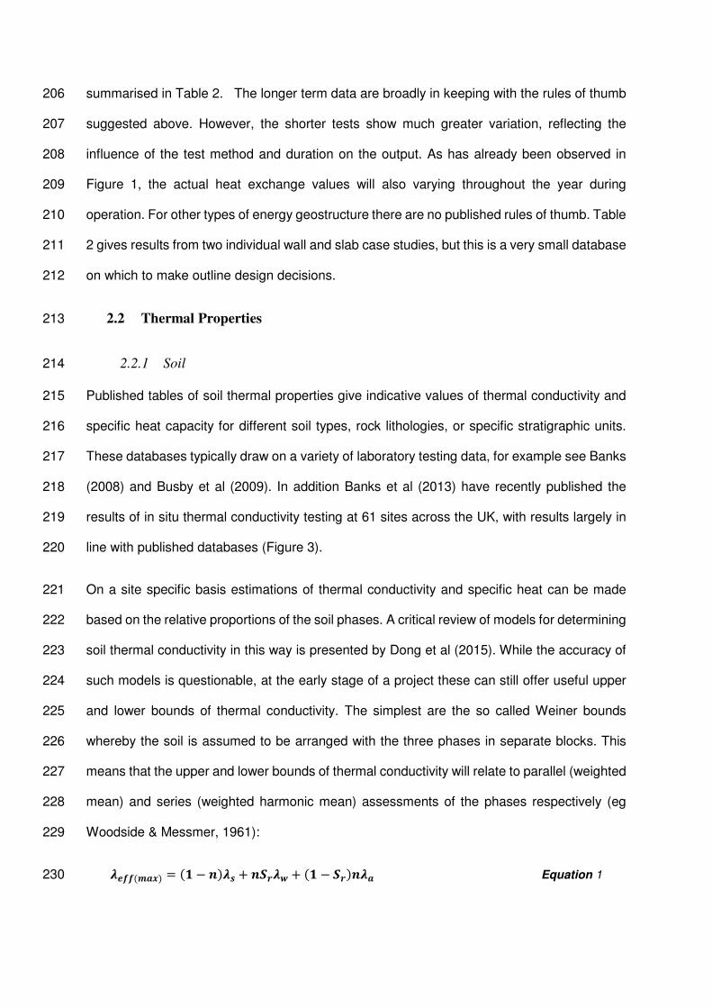
(2008) and Busby et al (2009). In addition Banks et al (2013) have recently published the218
results of in situ thermal conductivity testing at 61 sites across the UK, with results largely in219
line with published databases (Figure 3).220
On a site specific basis estimations of thermal conductivity and specific heat can be made221
based on the relative proportions of the soil phases. A critical review of models for determining222
soil thermal conductivity in this way is presented by Dong et al (2015). While the accuracy of223
such models is questionable, at the early stage of a project these can still offer useful upper224
and lower bounds of thermal conductivity. The simplest are the so called Weiner bounds225
whereby the soil is assumed to be arranged with the three phases in separate blocks. This226
means that the upper and lower bounds of thermal conductivity will relate to parallel (weighted227
mean) and series (weighted harmonic mean) assessments of the phases respectively (eg228
Woodside & Messmer, 1961):229
() = (െ ( + + ( െ ( Equation 1230

() = (ି) + + (ି) Equation 2231
where n is the porosity, Sr is the degree of saturation and the thermal conductivity of each232
phase, with the subscripts s, w and a represent soil, water and air respectively. Volumetric233
heat capacity, Svc (in J/m3K) in soils can be expressed similarly so that:234
= (െ ି( + ି + (െ ି( Equation 3235
In this case x is the proportion of each different phase by weight. A drawback to these236
approaches is the need to determine the thermal conductivity and specific heat capacity of the237
individual phases. While this may be straightforward for air and water, for soil minerals a range238
of values exists. Quartz has a thermal conductivity of up to 8 W/mK, while other minerals tend239
to be less conductive with ranges between 1 W/mK and 5 W/mK. Ren et al (2003) quote240
specific heat capacities for soil solids in the range 650 J/kgK to 950 J/kgK.241
National data on ground temperatures have recently been compiled by the British Geological242
Survey and are interrogated at a national scale in Busby et al (2011). Median values at 100m243
depth are approximately 12.5 oC. However, ground temperature does vary due to natural244
geological conditions. For example, consistently higher ground temperatures are observed in245
the north east of England and the East Midlands. Large cities also see elevated ground246
temperatures owing to urban heat island effects (e.g. Ferguson & Woodbury, 2004). Buildings,247
especially those with basements (Menberg et al, 2012), and other infrastructure give rise to248
an accumulation of heat over long periods of time and can even result in a reversal of the249
geothermal gradient (Banks et al, 2009). As well as changing the boundary conditions for250
analysis, this can lead to an increase in stored heat available for exploitation by energy251
geostructures (Zhu et al, 2010).252
2.2.2 Concrete253
The thermal conductivity of concrete covers a similar range of values to that of soil, from254
approximately 1 W/mK to over 4 W/mK, depending on the mix design (Neville, 1995; Tatro,255
2006). Concrete thermal conductivity depends mainly on the aggregate lithology, aggregate256

volume ratio and water content; some typical values are given in Table 3. Additionally, some257
admixtures can reduce the thermal conductivity of concrete (GSHPA, 2012). The specific heat258
capacity of concrete is important for storage of heat within the geostructure. It is typically in259
the range 840 – 1170 J/kgK and would be expected to increase with water content and260
temperature (Neville, 1995).261
An additional parameter not normally considered in foundation analysis is the linear thermal262
expansion of the concrete itself. This parameter will determine any additional stresses that263
may occur within the geostructure concrete and will depend on the constituents of the concrete.264
The coefficient of linear expansion depends on the concrete mix, both in terms of cement265
aggregate ratio and the aggregate type. Age and water content will also affect the overall266
coefficient, but it would typically be in the range 7x10⁻⁶ to 13x10-6, with 10x10-6 oC-1 often used267
as a general value (Tatro, 2006).268
2.3 Thermal Resistance269
The thermal resistance of a geostructure is a lumped parameter that accounts for both its270
thermal conductivity and geometry. Generally, the thermal resistance, Rb, is given by:271
qTRb
Equation 4272
where T is the difference between the average temperature of the fluid within the pipes of273
the heat exchanger and the average temperature at the edge of the geostructure. q is the274
applied heat transfer rate in W/m. The parameter is normally determined at a thermal steady275
state so that the temperature change and hence the resistance is a constant.276
Pile thermal resistance can be determined by in situ testing, although this has a number of277
disadvantages (refer to Section 3). At desk study stage some general values can be taken278
from SIA (2005) or Pahud (2007), as summarised in Table 4. Table 4 shows that the number279
of pipes has a significant impact on Rb. However, thermal resistance is also strongly280
dependent on concrete conductivity (c), a value not considered in Table 4. More specific281
calculations can be made using either the multipole method (Bennet et al, 1987) or a simplified282
model as presented by Loveridge & Powrie (2014).The latter includes use of a dimensionless283
shape factor, Sc, such that:284
= + Equation 5285
where c is the concrete thermal conductivity (W/mK) and Rp is the pipe resistance. Rp can be286
calculated using simple analytical solutions (for example see Loveridge & Powrie, 2014) and287
is typically between 0.01 and 0.05 mK/W assuming turbulent flow in the pipes. Lower values288
in the range are appropriate for larger numbers of heat transfer pipes. An indication of the289
shape factor can be taken from Figure 4.290
The resistance approach is not yet well developed for types of energy geostructure other than291
piles. A resistance model has been proposed for diaphragm walls by Kurten et al (2014), but292
its use so far has been limited to a small number of numerical applications and no database293
of values for use in analytical design approaches is available.294
Caution must also be exercised when using thermal resistance values for large diameter piles295
as these are unlikely to be at a thermal steady state during routine operation (e.g. Figure 1).296
While outline design using steady state resistances may be safe in terms of energy output297
assessment, it could be overly conservative for detailed design and lead to under-prediction298
of available energy output (Loveridge & Powrie, 2013).299
3 In Situ Thermal Testing300
3.1 Traditional Thermal Response Testing301
Thermal response testing (TRT) is an in situ technique to determine the thermal conductivity302
of the ground and the thermal resistance of the heat exchanger. Heat is typically injected into303
the ground at a constant and known rate via a borehole heat exchanger. The temperature304
change of the fluid circulating in the borehole is monitored and the results used to determine305
the thermal properties. There are several international and national guidelines for the test to306

encourage high quality testing and interpretation (Sanner et al, 2005; IGSHPA, 2007; GSHPA,307
2011).308
3.2 Interpretation Approaches309
Thermal response tests have traditionally been interpreted using the simple line source310
method. This is based on the assumption that the borehole behaves like an infinitely long and311
infinitesimally thin heat source of constant power. The approach also assumes an infinite and312
homogeneous soil medium with a uniform initial temperature field. When the heat diffusion313
equation is solved for this case, the evolution of the temperature of the circulating fluid314
becomes a linear function of the natural logarithm of time, provided that sufficient time has315
elapsed. Therefore if the gradient of the average of the change in inlet and outlet temperature316
to the borehole during the test are plotted against the natural logarithm of time (for example,317
see Figure 5):318
= Equation 6319
where is the soil thermal conductivity (W/mK), q is the total applied thermal power (W/m),320
and k is the gradient of the graph. Owing to the mathematical simplifications involved in the321
line source model, it is important to include a minimum time criterion after which those322
simplifications are valid. It is normally recommended that the results prior to a non-dimensional323
time Fo=5 are neglected. Fo is the Fourier number, with ܨ = ݐߙ ଶΤݎ in this application. In this324
expression is the soil thermal diffusivity (m2/s), t is the elapsed time (s) and rb is the borehole325
radius (m).326
Additionally the borehole thermal resistance can be determined from the straight line intercept:327
2
4ln
4
1
b
br
RqI Equation 7328
where is the soil thermal diffusivity, rb is the borehole radius and is Euler’s constant. The329
advantage of this approach is its simplicity. However, the tendency for the ground not to be330
homogeneous and isotropic can lead to errors. These have been quantified and are generally331
within 10% providing the test is well conducted (Witte, 2013, Signorelli et al, 2006, Spitler &332
Gehlin, 2015).333
Various other interpretation methods have also been suggested. Instead of assuming that the334
borehole acts as a line heat source, it is possible to interpret the results assuming it acts as a335
cylindrical heat source. This approach tends to give values of thermal conductivity and thermal336
resistance that are higher by around 10% (Gehlin, 2002). It is also more complicated to apply337
as the two variables cannot be obtained separately and parameter estimation techniques must338
be used. Therefore it does not offer much advantage over the line source assumption.339
Further disadvantages of both the line and cylindrical source approaches are the assumptions340
that the borehole resistance is constant (and equal to the steady state value) and that the heat341
flux applied is constant. The latter can be challenging to achieve in the field when test times342
of several days are required. These disadvantages can be overcome by using more343
sophisticated models to interpret the test results. The most accessible is the Geothermal344
Properties Measurement (GPM) tool, developed by Oak Ridge National Laboratory and freely345
available. The tool uses numerical solutions to the one dimensional diffusion equation in radial346
coordinates to determine the best fit thermal resistance and ground thermal conductivity for347
TRT data (Shonder & Beck, 2000). Other analytical and numerical methods are available (e.g.348
Javed & Claesson, 2011, Austin et al 2000), but are not yet readily accessible on a routine349
basis.350
3.3 Undisturbed Ground Temperature351
Thermal response testing also provides an opportunity to investigate the undisturbed ground352
temperature. This can be done in several ways. One approach is to lower a sensor down the353
heat exchange pipes and record the output every few metres. However, care must be taken354
to prevent mixing of the fluid between different depths (IEA, 2013). An alternative approach,355
which does not require any additional equipment, is to use data from the fluid temperatures356
prior to heating. If the fluid is circulated round the ground loop prior to the heaters being turned357

on for the heat injection part of the test, then temperatures during this period can provide full358
details of the ground thermal profile, providing the measurement interval is short enough. Full359
details of the approach are given in Gehlin & Nordell (2003).360
3.4 Applicability to Piles361
The minimum time criterion requirement of Fo>5 for interpretation of thermal response tests362
by the line source approach has major implications for the application of the test to piles used363
as ground heat exchangers (Table 5). As the pile size increases the theoretical minimum time364
also increases. This means that the time required to carry out a test rapidly escalates beyond365
that which is both economical and practicable. As well as dealing with the mathematical366
simplifications in the model, the minimum time criterion also allows time for the pile to reach a367
thermal steady state so that the thermal resistance is constant. Tests that do not allow this will368
see the influence from the concrete thermal conductivity in the derived soil thermal conductivity369
results (e.g. Loveridge et al, 2014a, Franco et al, 2016). Research to date suggests that to370
keep test times within 100 hours, thermal response testing should not be applied to piles371
greater than 300mm or possibly 450mm in diameter (Loveridge et al, 2014a, b).372
Consequently, alternative approaches to test larger piles in practical timescales need to be373
developed and verified. One challenge is the co-linearity of and Rb. When using a line source374
approach the two parameters can be determined independently. When using other non-linear375
solutions, parameter estimation must be used. It is always possible to find the best fit thermal376
conductivity and thermal resistance from the test data, but there will always be a range of pairs377
of parameters that give similar fits. An example is shown in Figure 6.378
An alternative approach is to carry out a thermal response test on a borehole at the site379
investigation stage of a project. This approach has many advantages, not least cost (owing to380
the shorter test duration) and programme (owing to the removal of the need to wait for the381
heat of hydration in a curing pile to subside). However, by conducting the test at an earlier382
stage in the project the likely depth of the future foundations may not have been finalised. It383
is also not possible to make any inferences about the pile thermal resistance.384
3.5 Group Thermal Response Testing385
Another potential problem of applying thermal response tests to pile is the short length of the386
heat exchanger compared with more typical borehole installations. Many commercial TRT test387
rigs are set up to deliver the power levels needed for heat exchangers in excess of 100m deep.388
Therefore the electric heaters used are typically in the range 2 kW to 6 kW, delivering the389
recommended 30 W/m to 80 W/m (Sanner et al., 2005) to the ground. Delivering the same390
total power to a 10m or 20m long pile can rapidly lead to overheating and curtailment of the391
test (for example see Hemingway & Long, 2013). One solution to this problem is to test a392
group of piles in a single circuit, thereby increasing the total heat exchange length and393
reducing the power applied per drilled metre. This also has the advantage of testing a larger394
volume of soil. However this approach does introduce the potential for additional heat losses395
from the lengths of pipe between the piles. This is illustrated by the pile tests results of Murphy396
et al (2014), in which horizontal pipe run out lengths were inversely correlated to apparent397
thermal conductivity, suggesting reduced heat transfer to the ground for tests with extensive398
surface or near surface pipe lengths. It will also be necessary to consider whether the piles399
within the group will interact thermally within the timescale of the test (Loveridge et al, 2015).400
4 Laboratory Testing for Thermal Properties401
Laboratory testing holds a number of attractions over field testing in geotechnics, the most402
obvious being speed and cost. Both of these are applicable in the case of energy403
geostructures. However, small scale testing also brings drawbacks which will be discussed404
further below, following a review of the common methods.405
Testing for soil thermal properties usually follows one of two approaches. The first involves406
development of a thermal steady state within a soil specimen such that Fourier’s Law can be407
applied directly. The second uses measurement of transient temperature changes over time408
and compares the results to an appropriate solution to the diffusion equation. Both approaches409
have advantages and disadvantages which are discussed below.410
4.1 Steady State Methods411
While there are standard methods for steady state thermal conductivity testing, none are412
explicitly for use with soils. The guarded hot plate method (or its variants) has been413
standardised (BSI, 2001a,b, ASTM, 2012) and applied to soils (Farouki, 1986, Mitchell & Kao,414
1978), although it is more commonly used for building materials. A heating unit is sandwiched415
between two thin, flat specimens, which are then subjected to vertical heat flow while the416
power to the heater is measured. The “guards” are present to prevent lateral heat loss and417
ensure one dimensional flow. The thermal conductivity can be calculated directly from the418
temperature gradient across the specimen. A similar approach is used to test rock core and419
rock fragments using the divided bar method (Birch, 1950, Sass et al, 1971) which has also420
been applied to stiff soils. In both cases testing takes a long time since a steady state must421
first be obtained within the specimen. If the specimen is unsaturated, this may result in422
substantial moisture migration which will affect the accuracy of the result, typically giving lower423
values of thermal conductivity compared with transient methods. Farouki (1986) also reports424
differences in results for the upper and lower specimens due to the direction of heat flow (up425
or down). The guarded hot plate apparatus is also rather large with a minimum specimen426
diameter of 300mm. This can make it rather impractical for use with routine site investigation427
samples.428
As part of the then Department for Trade and Industry Partners in Innovation Programme,429
Clarke et al (2008) developed an alternative steady state thermal cell apparatus based on430
readily available triaxial apparatus to take routine 100mm diameter soil samples. However,431
subsequent work by Low (2015) comparing the thermal cell and transient methods confirmed432
the importance of minimising heat losses from any steady state tests. Failure to account for433
heat losses in steady state testing can lead to an overestimate of the applied power and hence434
of the thermal conductivity. This is also highlighted by Alrtimi et al (2014), who went on to435
develop the Clarke et al (2008) thermal cell into a dual specimen arrangement to eliminate436
losses from the base of the apparatus. Alrtimi et al (2014) also reduced radial losses by the437
use of a thermal jacket to better control the side boundary condition of the apparatus. This438
approach appears more reliable.439
4.2 Transient Methods440
The alternative to steady state thermal conductivity testing is to use transient methods like the441
needle probe (sometimes called the hot wire method) or the dual needle probe. The needle442
probe acts as a miniature thermal response test and has been standardised by the IEEE (1996)443
and ASTM (2014). A needle containing both a wire heating element and temperature sensors444
is inserted into a specimen. The heater is switched on and the resulting temperature change445
is measured and then interpreted using a line source approach (see also 4.2). The test is446
rapid and only results in temperature changes of a few degrees at the most. Hence it minimises447
moisture migration effects that may be problematic in steady state tests. However a key448
disadvantage is that a much smaller volume of soil is tested.449
The dual needle probe (Campbell et al, 1991) is similar, but contains a second temperature450
monitoring point in a second needle located a few millimetres from the first. A short heat pulse451
is released from the heater and the temperature change at both needles monitored. The main452
advantage of the dual needle probe is that by including two monitoring points the thermal453
diffusivity and the specific heat capacity can both be calculated. However, the results are very454
sensitive to the separation of the two needles, which can diverge when inserted into the soil.455
4.3 Differences between Steady State and Transient Results456
It is often reported (e.g. Alrtimi et al, 2014) that steady state methods are more accurate than457
transient approaches. However, this is not necessarily the case, and reasonable results from458
steady state tests can only be achieved if the heat losses can be truly controlled (see 4.1459
above and Low et al, 2015). Nonetheless there are other commonly reported discrepancies460
between steady state and transient test methods and the reasons for these differences are461
not always clear. For example, Midtomme & Roaldset (1999) review a range of studies462
comparing the divided bar method with the needle probe. Some studies provide comparable463
results but often the needle probe values are higher than those of steady state tests by 10%464
to 20%. Midtomme & Roaldset (1999) variously attributed these discrepancies to different465
factors including drying of soil samples during long steady state testing and the vertical versus466
radial heat flow paths in the two tests. They also highlighted the potential for soil anisotropy to467
affect results; in standard samples cored perpendicular to the stratigraphy, needle probes are468
more likely to measure horizontal and steady state tests vertical thermal conductivity. However,469
this can be easily accounted for in site investigation through an appropriate sampling strategy.470
4.4 Sampling Issues471
Testing of soil specimens to determine their physical properties must always be undertaken472
with a knowledge of sample scale and quality (Rowe, 1972, Graham, 2006) and thermal473
properties are no different. It is important to understand that thermal properties depend on the474
moisture content, density and structure of samples, all of which may change during sampling.475
Like soil water retention properties, thermal conductivity is a hysteretic property which will vary476
depending on whether a soil is being wetted or dried (e.g. Tang et al, 2008, Rubio et al, 2011).477
Thermal conductivity is also dependent on particle contacts (e.g Choo et al, 2013) which may478
be reduced by stress release on sampling. All these factors mean that additional care must479
be taken with laboratory testing to ensure samples are either truly undisturbed or reconstituted480
to appropriate field conditions.481
Stress induced changes in porosity leading to thermal conductivity changes have been482
examined by Abuel-Naga et al (2009) and McCartney et al (2013b), using needle probes483
installed within modified Rowe Cells and triaxial cells respectively. Both found largely linear484
relationships between porosity and thermal conductivity, with the latter showing a full recovery485
in thermal conductivity on unloading even though the soil exhibits a stiffer response.486
4.5 Scale in Thermal Conductivity Testing487
Few studies compare laboratory tests for thermal conductivity with larger scale tests such as488
borehole thermal response tests. A number of small scale comparisons have been made as489
part of other studies, which appear to show good comparability between the needle probe and490
TRT scale testing (e.g. Witte et al, 2002, Breier et al, 2011) where due care is applied during491
both tests. In addition, there are a number of recent comparisons using pile heat exchangers.492
With the exception of Loveridge et al (2014a), these all determined higher values of thermal493
conductivity from larger scale tests (Table 6, Figure 7). Some of this discrepancy may be494
attributable to using the line source method with piles, while sample quality could also play a495
role. It should also be noted that in some of these cases the numbers of laboratory tests was496
relatively small. In such cases the small volume of soil tested in the laboratory will always be497
a concern when dealing with inherently heterogeneous natural materials. For example, King498
et al (2013) have applied the needle probe test to field sites, using the equipment to take499
multiple measurements in trial pits. Their study showed that at least fifteen separate500
determinations of thermal conductivity were required for the average value to be501
representative of the bulk thermal conductivity at the site. Any laboratory to field scale502
comparison based on only a small number of samples therefore has the potential to be503
misleading.504
A further larger scale study was carried out using boreholes in the Oslo region in Norway,505
where Leibel et al (2010) compared the results of 1398 thermal conductivity tests on rock core506
with 67 thermal response tests. The laboratory tests were carried out using a transient method507
with one dimensional heat flow proposed by Middleton (1993). The thermal conductivity values508
from the in situ testing were on average approximately 20% greater than the laboratory tests,509
depending on the rock lithology (Figure 7). The authors attributed some of the differences to510
the effect of groundwater movements in the field. However, it is also possible to overestimate511
the heat transfer to the ground in thermal response tests if heat losses from the equipment512
are not effectively controlled. In such cases the thermal conductivity from TRTs would be an513
overestimate. Witte et al (2002) advise placing the fluid temperature sensors as close to the514
ground as possible to minimise this effect. This effect could also have an impact on the pile515
tests results.516
Given the potential difficulties associated with both laboratory and field testing for thermal517
conductivity, care is required in both test approaches to achieve suitable quality results.518
5 Summary519
Energy geostructures offer the opportunity to access heat storage volumes beneath and520
around our buried infrastructure, including building deep foundations, retaining walls and521
metro tunnels. Inclusion of energy geostructures in projects means that site investigations522
must expand their scope to consider additional ground parameters which may be required in523
the design of the energy system.524
This paper reviews the thermal parameters required for analysis of ground energy systems,525
and how they may be estimated or measured in desk studies and laboratory and in situ testing.526
As with conventional geotechnical properties, particular attention must be paid to527
understanding the effects of soil sampling and how changes in scale may affect thermal528
properties. While laboratory testing may be quicker and cheaper than multi-day in situ testing,529
it requires high quality samples and numerous careful tests to arrive at reliable results.530
Consideration is also given to the potential impact of temperature changes on geotechnical531
properties of soils. The potential for induced porewater pressure and volumetric changes are532
discussed. The latter may be particularly problematic for normally consolidated soils which will533
consolidate upon heating. Consequently these soils will require much more careful534
consideration when proposed as a possible host geology for energy geostructures.535
536
Acknowledgements537
Much of the work contained in this paper was carried out under the EPSRC project538
“Performance of Ground Energy Systems installed in Foundations” (ref EP/H0490101/1).539
Subsequent funding from the Royal Academy of Engineering under their research fellow540
scheme is also gratefully acknowledged.541
References542
Abuel-Naga, H. M., Bergado, D. T., Bouazza, A. & Pender, M. J. (2009) Thermal conductivity543of soil Bangkok clay from laboratory and field measurement, Engineering Geology, 105, 211-544219.545
Abuel-Naga, H. M., Bergado, D. T. & Lim, B. F. (2007) Effect of temperature on shear strength546and yielding behavior of soft Bangkok clay, Soils and Foundations, 47 (3), 423-436.547
Adam, D. & Markiewicz, R. (2009). Energy from earth-coupled structures, foundations, tunnels548and sewers, Géotechnique, 59 (3), 229-236.549
Alrtimi A. A., Rouainia M. & Manning D. A. C. (2014) An improved steady-state apparatus for550measuring thermal conductivity of soils, International Journal of Heat and Mass Transfer, 72:551630–636.552
ASTM (2014) Standard Test Method for Determination of Thermal Conductivity of Soil and553Soft Rock by Thermal Needle Probe Procedure, ASTM D5334 – 14, ASTM International.554
ASTM (2012) Standard Practice for Using a Guarded-Hot-Plate Apparatus or Thin-Heater555Apparatus in the Single-Sided Mode, ASTM C1044 – 12, ASTM International.556
Austin, W., Yavuzturk, C. & Spitler, J. D. (2000) Development of an in situ system for557measuring ground thermal properties, ASHRAE Transactions, 106 (1), 365 – 379.558
Bamforth, P. B. (2007) Early-age thermal crack control in concrete, CIRIA 660, London.559
Banks, D. (2014) A review of the importance of regional groundwater advection for ground560heat exchange, Environ Earth Science, 75, 2555-2565.561
Banks, D. (2008), An Introduction to Thermogeology: Ground Source Heating and Cooling,562Blackwell Publishing.563
Banks, D., Withers, J. G., Cashmore, G., & Dimelow, C. (2013), An overview of the results of56461 in situ thermal response tests in the UK, Quarterly Journal of Engineering Geology &565Hydrogeology, 46, 281-291.566
Banks, D., Gandy, C.J., Younger, P.L., Withers, J., & Underwood, C. (2009) Anthropogenic567thermogeological 'anomaly' in Gateshead, Tyne and Wear, UK. Quarterly Journal of568Engineering Geology and Hydrogeology, 42(3), 307-312.569
Barla, M. & Perino, A. (2015) Energy from geo-structures: a topic of growing interest, Proc ICE570Environmental Geotechnics, 2 (1), 3–7.571
Bennet, J., Claesson, J., Hellstrom, G., 1987. Multipole method to compute the conductive572heat flow to and between pipes in a composite cylinder. Report. University of Lund,573Department of Building and Mathematical Physics. Lund, Sweden.574
Birch, F (1950). Flow of heat in the Front Range Colorado, Geol Soc America Bulletin, 61, 567575– 630.576
Bouazza, A., Wang, B. & Singh, R. M., 2013. Soil effective thermal conductivity from energy577pile thermal tests. Coupled Phenomena in Environmental Geotechnics: Proceedings of the578International Symposium, Torino, Italy, 1-3 July 2013, Taylor & Francis, London, pp. 211-219.579
Boudali,M., Leroueil, S. & Srinivasa, M. B. R.(1994) Viscous behaviour of natural clays,580Proceedings of 13th International Conference on Soil Mechanics and Foundation Engineering,581New Delhi, 411–416.582
Bourne-Webb, P. (2013) Observed response of energy geostructures, In: Energy583Geostructures, Laloui & Di Donna (Eds), Wiley, London. p 45 – 77.584
Bourne-Webb, P. J., Bodas Freitas, T. M. & Freitas Assunção, R. M. (2015) Soil–pile thermal585interactions in energy foundations, Geotechnique, http://dx.doi.org/10.1680/jgeot.15.T.017.586
Brandl, H. (2006). Energy foundations and other thermo active ground structures,587Géotechnique, 56 (2), 81 – 122.588
Breier, R. A., Smith, M. D. & Spitler, J. D. (2011) Reference data sets for vertical boreholes589ground heat exchanger models and thermal response tests analysis, Geothermics, 40, 79 –59085.591
BSI (1999) Code of Practice for Site Investigation, BS 5930:1999+A2:2010, British Standards592Institute,593
BSI (2004) Eurocode 7: Geotechnical design, BS EN 1997, British Standards Institute594
BSI (2001a) Thermal performance of building materials and products – Determination of595thermal resistance by means of guarded hot plate and heat flow meter methods – Dry and596moist products of medium and low thermal resistance, BS EN 12664:2001, British Standards597Institute.598
BSI (2001b), Thermal performance of building materials and products – Determination of599thermal resistance by means of guarded hot plate and heat flow meter methods – Products of600high and medium thermal resistance, BS EN 12667:2001, British Standards Institute..601
Busby, J., Lewis, M., Reeves, H. & Lawley, R. (2009) Initial geological considerations before602installing ground source heat pump systems, Quarterly Journal of Engineering Geology &603Hydrogeology, 42, 295-306.604
Busby, J., Kingdom, A. & Williams, J (2013) The measured shallow temperature field in Britain,605Quarterly Journal of Engineering Geology & Hydrogeology, 44, 373-387.606
Campbell, G. S., Calissendorff, C. and Williams, J. H. (1991), Probe for measuring soil specific607heat using a heat-pulse method, Soil Science Society of America Journal, 55, 291–293.608
Cekerevac, C. & Laloui, L. (2004) Experimental study of thermal effects of the mechanical609behaviour of a clay, International Journal for Numerical and Analytical Methods in610Geomechanics, 28, 209-228.611

Chiasson, A. C., Rees, S. J. & Spitler, J. D. (2000) A preliminary assessment of the effects of612groundwater flow on closed loop ground source heat pump systems, ASHRAE Transactions,613106 (1), 380-393.614
Choo, J., Kim, Y. J., Lee, J H., Yun, T S., Lee, J. & Kim, Y. S. (2013) Stress induced evolution615of anisotropic thermal conductivity of dry granular materials, Acta Geotechnica, 8, 91-106.616
Claesson, J. & Hellstrom, G. (2000) Analytical studies on the influence of regional groundwater617flow on the performance of borehole heat exchangers. In: Benner, M. & Hahne, E. (eds.)618Proceedings 8th International Conference on Thermal Energy Storage Terrastock 2000,619August 28 – September 1, Stuttgart, Germany, University of Stuttgart, Institute of620Thermodynamics and Thermal Engineering, vol. 1, pp.195-200.621
Clarke, B. G., Agab, A. and Nicholson, D. (2008), Model specification to determine thermal622conductivity of soils, Proc ICE Geotechnical Engineering, 161, 161–168.623
Clayton, C.R.I. (2011) Stiffness at small strain: research and practice, Geotechnique, 61, (1),6245-37.625
Di Donna, A. & Laloui, L. (2015) Numerical analysis of geotechnical behaviour of energy piles,626International Journal for Numerical and Analytical Methods in Geomechanics, 39, 861 – 888.627
Dong, Y., McCartney, J. S. & Lu, N. (2015), Critical review of thermal conductivity models for628unsaturated soils, Geotech Geol Eng, doi 10.1007/210706-015-9843-2.629
Dupray F, Laloui L and Kazangba A (2014) Numerical analysis of seasonal heat storage in an630energy pile foundation. Computers and Geotechnics, 55, 67-77631
Farouki, O. (1986) Thermal properties of soils, Trans Tech Publications, D-3392. Clausthal-632Zellerfeld,Germany.633
Ferguson, G. & Woodbury, A. (2004) Subsurface heat flow in an urban environment, Journal634of Geophysical Research, 109, B02402635
Franco, A., Moffat, R., Toledo, M. & Herrera, P. (2016) Numerical sensitivity analysis of636thermal response tests (TRT) in energy piles, Renewable Energy, 86, 985-992.637
Franzius, J. N., Pralle, N. (2011). Turning segmental tunnels into sources of renewable energy,638Proceedings of the Institution of Civil Engineers – Civil Engineering, 164 (1), 35 – 40.639
Fuentes, R., Pinyol, N. & Alonso, E. (2015) Effect of temperature induced excess pore water640pressure on the shaft bearing capacity of geothermal piles, International Symposium on641Energy Geotechnics, SEG2015, Barcelona, Spain, 2nd to 4th June 2015, 3pp.642
Gaba, A. R., Simpson, B., Powrie, W. & Beadman, D. R. (2003) Embedded retaining walls –643guidance for economic design, CIRIA C580, Construction Industry Research and Information644Association, London, UK.645
Gehlin, S. (2002) Thermal response test, model development and evaluation, Doctoral Thesis,646Lulea Technical University.647
Gehlin, S. E. A. & Nordel, B. (2013) Determining undisturbed ground temperature for thermal648response test, ASHRAE Transactions, 109 (1), 151 – 156.649
Gehlin, S. E. A. & Hellstrom, G. (2003) Influence on thermal response test by groundwater650flow in vertical fractures in hard rock, Renewable Energy, 28, 2221-2238.651

Graham, J., 2006. The 2003 R.M. Hardy Lecture: Soil parameters for numerical analysis in652clay, Canadian Geotechnical Journal, 43, 187–209.653
Graham, J., Tanaka, N., Crilly, T. & Alfaro, M. (2001) Modified Cam-Clay modelling of654temperature effects in clays, Canadian Geotechnical Journal, 38, 608 – 621.655
GSHPA (2011). Closed-loop Vertical Borehole Design, Installation & Materials Standards656Issue 1.0, September 2011. Ground Source Heat Pump Association, Milton Keynes, UK.657
GSHPA (2012). Thermal pile design installation and materials standards, Issue 1.0, Ground658Source Heat Pump Association, Milton Keynes, UK, p. 85659http://www.gshp.org.uk/Standards.html660
Hemmingway, P. & Long, M. 2013. Energy piles: site investigation and analysis, Proc. Inst.661Civil. Eng. Geotechnical Engineering 166(6), 561-575.662
Hueckel, T. & Baldi, G. (1990) Thermoplasticity of saturated soils and clays: experimental663constitutive study, J. Geotech. Eng., 116 (12), 1778–1796.664
IGSHPA (2007) Closed-loop/geothermal heat pump systems: Design and installation665standards, International Ground Source Heat Pump Association/Oklahoma State University.666
IEA (2013) IEA ECES Annex 21 Thermal Response Test (TRT), Final Report, November 2013,667International Energy Agency, France.668
IEEE (1996). IEEE Std 442–1981 Guide for Soil Thermal Resistivity Measurements, IEEE,669New York.670
Javed, S. & Claesson, J. (2011) New analytical and numerical solutions for the short time671analysis of vertical ground heat exchangers, ASHRAE Transactions, 117 (1), 13 – 21.672
King, W., Banks., D. & Findlay J., 2013. Field determination of shallow soil thermal conductivity673using a short-duration needle probe test, Quarterly Journal of Engineering Geology and674Hydrogeoloy, 45, 497–504.675
Kürten, S., Mottaghy, D., Ziegler, M. (2014). A new model for the description of the heat676transfer for plane thermo-active geotechnical systems based on thermal resistances. Acta677Geotechnica, 10, 219-229678
Liebel, H.T., Huber, K., Frengstad, B. S., Kalskin Ramstad, R. & Brattli B. (2010) Rock core679samples cannot replace thermal response tests - A statistical comparison based on thermal680conductivity data from the Oslo Region (Norway). Proceedings of ”Renewable Energy681Research Conference”, 7th – 8th June 2010, Trondheim, Norway, pp. 10.682
Low, J. (2015) Thermal conductivity of soils for energy foundation applications, PhD Thesis,683University of Southampton684
Low, J., Loveridge, F. & Powrie, W. (2015) A comparison of laboratory and in situ methods to685determine soil thermal conductivity for energy foundations and other ground heat exchanger686applications, Acta Geotechnica, 10, 209-218.687
Loveridge, F. & Powrie, W. (2013) Temperature response functions (G-functions) for single688pile heat exchangers, Energy, 57, 554 – 564.689
Loveridge, F. & Powrie, W. (2014) On the thermal resistance of pile heat exchangers,690Geothermics, 50, 122 – 135.691
Loveridge, F., Holmes, G., Powrie, W. & Roberts, T. (2013) Thermal response testing through692the Chalk aquifer, Proceedings of the Institution of Civil Engineers Geotechnical Engineering,693166 (2), 197 – 210.694
Loveridge, F., Brettmann, T., Olgun, G. & Powrie, W. (2014a) Assessing the applicability of695thermal response testing to energy piles, DFI-EFFC International Conference on Piling and696Deep Foundations, Stockholm, Sweden, 20-21 May 2014.697
Loveridge, F., Olgun, C. G. , Brettmann, Tracy & Powrie, W. (2014b) The thermal behaviour698of three different auger pressure grouted piles used as heat exchangers, Geotechnical and699Geological Engineering, 33, 273-289.700
Loveridge, F., Olgun. C. G., Brettmann, T. & Powrie, W. (2015). Group thermal response701testing for energy piles, European conference for Soil Mechanics and Geotechnical702Engineering, Edinburgh, UK, 13 – 17 September 2015.703
McCartney, J. S., Coccia, C. J. R., Alsherif, N. & Stewart, M. (2013a) Energy geostructures in704unsaturated soils, In: Energy Geostructures, Laloui & Di Donna (Eds), Wiley, London. p 157 –705174.706
McCartney, J., Jensen, E. & Counts, B. (2013b) Measurement of Subgrade Thermal707Conductivity Using a Modified Triaxial Test, Transportation Research Board 92nd Annual708Meeting, Washington, 13 to 17 January 2013, Paper #13-1866, 9pp.709
Menberg, K., Bayer, P., Zosseder, K., Rumohr, S., Blum, P. (2013) Subsurface urban heat710islands in German cities, Science of The Total Environment, 442(1), 123-133.711
Middleton, M. F. (1993) A transient method of measuring the thermal properties of rocks,712Geophysics, 58, 357 – 365.713
Midttømme, K. and Roaldset, E. (1999), Thermal condcutviity of sedimentary rocks:714uncertainties in measurement and modelling, In: Aplin et al (eds) Muds and Mudstones:715Physical and Fluid Flow Properties. Geological Society of London Special Publications, 158,71645-60.717
MIS (2011) MCS 022 Ground Heat Exchanger Look Up Tables, Supplementary materials to718MIS 2055, Issue 1, Department for Energy and Climate Change, London, UK.719
Mitchell, J. K. and Kao, T. C. (1978), ‘Measurement of soil thermal resistivity’, Journal of the720Geotechnical Engineering Division 104, 1307–1320.721
Murphy, K. D. & McCartnery, J. S. & Henry, K. S. (2014) Impact of horizontal run out length722on the thermal response of full scale energy foundations, In: Puppala, A. J. et al (Eds) Geo-723Congress 2014: Technical papers and Keynote Lectures: Geo-characterisation and modelling724for sustainability: Proceedings of the 2014 Geo-Congress, February 23-26, 2014, Atlanta, GA.725
Neville, A.M., 1995. Properties of concrete, 4th edition. Longman, London726
Nicholson, Chen et al, 2014, The design of thermal tunnel energy segments for Crossrail, UK,727P I Civil Eng-Sust, 167 (3), 118 – 134.728
Pahud, D. (2007) PILESIM2, Simulation Tool for Heating/Cooling Systems with Heat729Exchanger Piles or Borehole Heat Exchangers, User Manual, Scuola Universitaria730Professionale della Svizzera Italiana, Lugano, Switzerland.731
Park, H., Lee, S. R., Yoon, S. & Choi, J. C. (2013) Evaluation of thermal response and732performance of PHC energy pile: field experiments and numerical simulation, Appl. Energy,733103 (3), 12–24.734
Ren, T., Ochsnerm T. E., Horton, R. & Ju, Z. (2003) heat-pulse method for soil water content735measurement: influence of specific heat of the soil solids, Soil Science Society of America736Journal, 67 (6), 1631-1634.737
Rowe, P. W. (1972) The relevance of soil fabric to site investigation practice, Geotechnique,73822 (2), 195-300.739
Rubio, C. M., Josa, R. & Ferrer, F. (2011) Influences of the hysteretic behaviour of silt loam740thermal properties, Open Journal of Soil Sciences, 1, 77-85.741
Sanner, B., Hellstrom, G., Spitler, J. & Gehlin S. E. A. (2005) Thermal Response Test –742Current Status and World-Wide Application, In: ProceedingsWorld Geothermal Congress, 24-74329th April 2005 Antalya, Turkey. International Geothermal Association.744
Sass, J. H., Lachenbruch, A. H. & Munroe, R. J. (1971) Thermal conductivity of rocks from745measurements on fragments and its application to heat-flow determinations, Journal of746Geophysical Research, 76 (14), 3391 – 3401.747
Shonder, J. A., & Beck, J. V. (2000) A new method to determine the thermal properties of soil748formations form in situ field tests, Oak Ridge National Laboratory, Report ORN/TM-2000/97,749Oak Ridge, Tennessee. http://www.ornl.gov/sci/ees/etsd/btric/pdfs/com_soilproperties.pdf.750Accessed 7th June 2013.751
SIA (2005) Utilisation de la chaleur du sol par des ouvrages de fondation et de soutènement752en béton, D 0190, Swiss Society of Engineers and Architects, Zurich, Switzerland.753
Signorelli, S., Bassetti, S., Pahud, D. & Kohl, T. (2007), Numerical evaluation of thermal754response tests, Geothermics, 36, 141-166.755
Soga, Qi et al, 2014, Some considerations for designing GSHP coupled geotechnical756structures based on a case study, 7th Int. Congress Env. Geotechnics, Lessons, Learnings &757Challenges, Melbourne, Australia.758
Spitler, J. D. & Gehlin, S. E. A. (2015) Thermal response testing for ground source heat pump759systems – An historical review, Renewable and sustainable energy reviews, 50, 1125-1137.760
Sutton, M. G., Nutter, D. W. & Couvillion, R. J. (2003) A ground resistance for vertical bore761heat exchangers with groundwater flow, Journal of Energy Resources Technology, 125, 183-762189.763
Tang, A-M., Cui, Y-J. & Le, T-T. (2008) A study on the thermal conductivity of compacted764bentonites, Applied clay sciences, 41, 181-189.765
Tatro, S.B., 2006. Thermal properties, in: Lamond, J., Pielert, J. (eds), Significance of tests766and properties of concrete and concrete making materials. Portland Cement Association,767Stokoie, Illinois, USA.768
Wagner, V., Bayer, P., Kubert, M. & Blum, P. (2012) Numerical sensitivity study of thermal769response tests, Renewable Energy, 41, 245 – 253.770
Witte, H. J. L. (2013) Error analysis of thermal response tests, Energy, 109, 302-311.771
Witte, H. J. L., van Gelder, G. J. & Spitler, J. D. (2002) In situ measurement of ground thermal772conductivity: a Dutch perspective, ASHRAE Transactions, 108 (1), 263 – 272.773
Woodside, W. & Messmer, J. M. (1961) Thermal conductivity of porous media, Journal of774Applied Physics, 32 (9), 1688-1706.775

Zhu, K., Blum, P. Ferguson, G. Balke, K-D. & Bayer, P. (2010) The geothermal potential of776urban heat islands, Environmental Research Letters, 5. 044002 (6pp)777
778

Table 1 Key design parameters779
Design Parameter Required For Comments
Soil thermalconductivity
Energy output An average value is used in most designapproaches, although real conditions are likely tobe anisotropic and heterogeneous.Soil specific heat
capacityEnergy output
Undisturbed soiltemperature
Energy output Average value, or preferably a profile with depth
Groundwater flow rate(Darcy velocity)
Energy output As a minimum, an indication is required ofwhether significant groundwater flow is to beexpected at the site.
Soil strength Geotechnical design In total or effective stress terms as appropriate;should include an estimate of whether likely to besignificantly temperature dependent
Soil stiffness Geotechnical design For serviceability considerations
In situ stresses (K0)and pore water regime
Geotechnical design “Apparent” pre-consolidation pressure can beaffected by temperature
Stress history Geotechnical design
Over ConsolidationRatio (OCR)
Geotechnical design Determines the nature of the thermo-elastic (orthermo-plastic) response
Concrete thermalconductivity
Energy output Often included within the thermal resistanceparameter
Concrete specific heat Energy output For storage of heat within the concrete
Thermal resistance ofheat exchanger
Energy output A lumped parameter that includes for the thermalproperties and geometry of the heat exchanger
Concrete coefficient ofthermal expansion
Geotechnical design To determine the potential expansion of thegeostructure
Soil coefficient ofthermal expansion
Geotechnical design Expansion of soil relative to concrete may beimportant for soil structure interactions
Concrete limiting stress Structural design Additional stresses may develop due to restraintof the geostructure as it tries to expand onheating
780
Table 2 Energy exchange rates for different energy geostructures (data from Bourne-Webb,7812013)782
Short term test Study >1 year
Concrete piles 25 – 210 W/m 15 – 45 W/m
Steel piles (fluid infilled) 15 – 140 W/m
Steel piles (sand/water infilled) 25 – 55 W/m
Steel piles (concrete infilled) 15 – 20 W/m
Diaphragm wall 30 – 100 W/m
Slabs 5 W/m2
783
Table 3 Typical values of concrete thermal conductivity by aggregate lithology (after Bamforth,7842007)785
Aggregate Lithology Concrete Thermal Conductivity (W/mK)
Sand and aggregate fromsame rock type
Aggregate from defined rocktype with siliceous sand
Quartzite and siliceous gravelswith high quartz content
2.9 2.9
Granite, gabbros, hornfels 1.4 2.0
Dolerite, basalt 1.3 1.9
Limestone, sandstone, chert 1.0 1.8
786

Table 4 Typical values of thermal resistance (Rb) for concrete piles of 0.3m to 1.5m in diameter787(after Pahud, 2007)788
Double U-pipe placed on reinforcing cage 0.1 to 0.11 mK/W
Triple U-pipe placed on reinforcing cage 0.07 to 0.08 mK/W
Quadruple U-pipe placed on reinforcing cage 0.06 mK/W
789
Table 5 Minimum elapsed time for interpretation of thermal response tests using a line source790approach when Fo > 5791
Pile Diameter tmin (=0.5x10⁻⁶m2/s) tmin (=1.5x10⁻⁶m2/s)
200mm 28 hours 9 hours
300mm 63 hours 21 hours
450mm 141 hours 47 hours
600mm 250 hours 83 hours
900mm 563 hours 188 hours
1200mm 1000 hours 333 hours
792Table 6 Summary of comparisons between thermal conductivity from laboratory needle probe793tests and field scale thermal response testing (line source interpretation unless otherwise794
indicated)795
Reference No. of laboratorymeasurements
Average laboratorythermal conductivityW/mK
TRT thermalconductivityW/mK
Comments
Beier et al2011
4 locations 2.8 ± 0.1 2.9 TRT is laboratory sandbox, not full scale
Witte et al2002
13 locations;18 determinations
2.1 ± 0.1 2.1 ± 0.2 Borehole TRT
Loveridge etal 2014a
3 locations 3.0 2.7 TRT on pile, 300mmdiameter
Low et al2015
6 locations;30 determinations
1.3* 2.5 TRT on pile, 300mmdiameter
Park et al,2013
5 determinations (atdifferent moisturecontents)
2.0 2.2 TRT on pile, 400mmdiameter, interpretation bynumerical simulation
Bouazza etal, 2013
28 determiantions(at differentmoisture contents)
2 - 3 4.3 TRT on pile, 600mmdiameter, average ofthree tests
Murphy et al,2014
3 locations 1.2 2.0 TRT on piles, 610mmdiameter, resultscorrected for horizontalpipe length
* long time period between sampling and testing suggests some sample drying may have796contributed to size of discrepancy with field test797
798
799

800
Figure 1 Energy exchanged with and resulting temperature variations within a 1200mm pile801with heat transfer pipes installed in the centre (see inset). a) Measured variations in total802applied thermal load (absolute value); b) Reduced temperature variations near the edge the803pile compared with the central pipe position; c) Plant room air temperature. All data from804twelve months of monitoring of a real pile heat exchanger scheme under operational805conditions.806
807
808
809
810
811
812
813
814
815
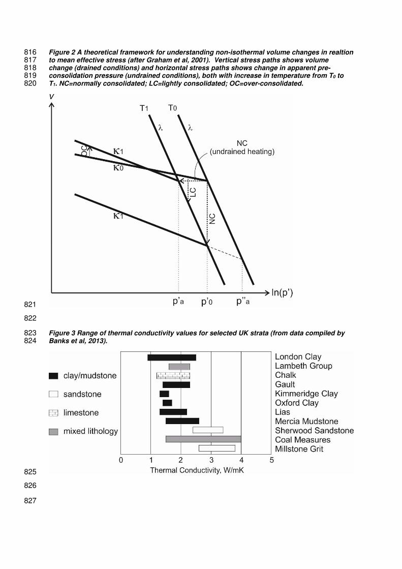
Figure 2 A theoretical framework for understanding non-isothermal volume changes in realtion816to mean effective stress (after Graham et al, 2001). Vertical stress paths shows volume817change (drained conditions) and horizontal stress paths shows change in apparent pre-818consolidation pressure (undrained conditions), both with increase in temperature from T0 to819T1. NC=normally consolidated; LC=lightly consolidated; OC=over-consolidated.820
821
822
Figure 3 Range of thermal conductivity values for selected UK strata (from data compiled by823Banks et al, 2013).824
825
826
827
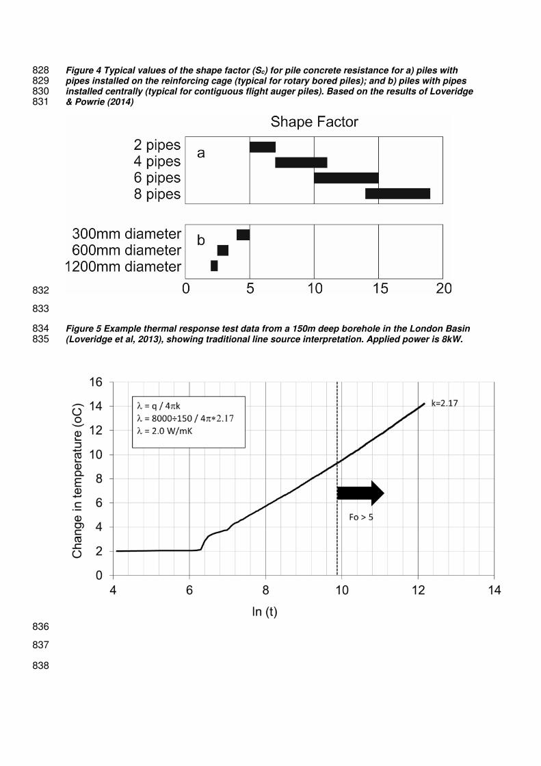
Figure 4 Typical values of the shape factor (Sc) for pile concrete resistance for a) piles with828pipes installed on the reinforcing cage (typical for rotary bored piles); and b) piles with pipes829installed centrally (typical for contiguous flight auger piles). Based on the results of Loveridge830& Powrie (2014)831
832
833
Figure 5 Example thermal response test data from a 150m deep borehole in the London Basin834(Loveridge et al, 2013), showing traditional line source interpretation. Applied power is 8kW.835
836
837
838
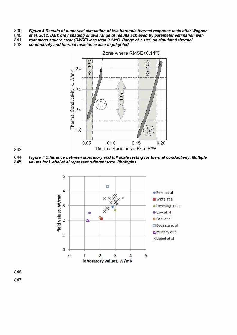
Figure 6 Results of numerical simulation of two borehole thermal response tests after Wagner839et al, 2012. Dark grey shading shows range of results achieved by parameter estimation with840root mean square error (RMSE) less than 0.14oC. Range of ± 10% on simulated thermal841conductivity and thermal resistance also highlighted.842
843
Figure 7 Difference between laboratory and full scale testing for thermal conductivity. Multiple844values for Liebel et al represent different rock lithologies.845
846
847
Related Documents


![Numerical modelling of different applications in Energy … · 2020. 12. 10. · as energy geostructures by installing the absorber pipes directly in the structures [3]. In particular,](https://static.cupdf.com/doc/110x72/60d9185914306b69c8684e2b/numerical-modelling-of-different-applications-in-energy-2020-12-10-as-energy.jpg)