International Journal of Mechanical Engineering and Applications 2016; 4(3): 123-129 http://www.sciencepublishinggroup.com/j/ijmea doi: 10.11648/j.ijmea.20160403.14 ISSN: 2330-023X (Print); ISSN: 2330-0248 (Online) A Study on Energy Optimization of Heat Exchangers in a Gasification System Le Minh Nhut 1 , Young-Sub Moon 2 , Youn Cheol Park 3, * 1 Department of Thermal Engineering, Faculty of Vehicle and Energy Engineering, Ho Chi Minh City University of Technology and Education, Ho Chi Minh City, Vietnam 2 Research and Development Center, POSCO E&C, Incheon City, Republic of Korea 3 Department of Thermal Engineering, Faculty Mechanical Engineering, Jeju National University, Jeju, Republic of Korea Email address: [email protected] (Le M. N.), [email protected] (Young-Sub M.), [email protected] (Youn C. P.) * Corresponding author To cite this article: Le Minh Nhut, Young-Sub Moon, Youn Cheol Park. A Study on Energy Optimization of Heat Exchangers in a Gasification System. International Journal of Mechanical Engineering and Applications. Vol. 4, No. 3, 2016, pp. 123-129. doi: 10.11648/j.ijmea.20160403.14 Received: May 16, 2016; Accepted: May 27, 2016; Published: June 13, 2016 Abstract: The objective of this research is the optimization of energy parameters such as the temperature and flow rate of the fluid in heat exchangers in the gasification system in order to increase the recovery rate of energy in the system. A mathematical model of these heat exchangers is developed to predict their operating performance under the specified gasification system. The optimal flow rate and temperature of the fluid in the heat exchanger based on the effectiveness - number of transfer units(NTU) method is investigated. The result of the simulation shows that the optimal mass flow rate and temperature of the high pressure (HP) boiler feed water are determined at 175,907 kg/h and 110°C, respectively, while the optimal mass flow rate and temperature of high pressure saturated steam of boiler are determined at 238,430 kg/h, 290.5°C, respectively. At these values, the total heat amount obtained at these heat exchangers is highest with 169 MW. Besides, the total heat amount obtained at heat exchangers could be increased by 4.61% (7.8 MW) when sixty percent of the heat release amount from air cooler (12.78 MW) is used. Keywords: Optimization, Heat Exchanger, Gasification System, Effectiveness-NTU 1. Introduction The demand for natural gas due to the increased population and economic growth of the world’s population has caused the depletion of natural gas resources, as well as price increments, in recent years. It is necessary to discover alternative ways to develop a substitute for natural gas resources. Natural gas obtained from the coal gasification process is counted as a substitute resource to satisfy the growing demands of power generation and home utilization in the near future. Synthesized natural gas (SNG) has many advantages. It can be produced from inexpensive carbonaceous feedstocks and the removal of contaminants such as sulphur from coal makes coal gasification a more environmentally friendly means of energy conversion compared to the normal combustion of solid coal. Also, it has a high conversion efficiency, is easy, and it is cost effective to remove carbon dioxide by the separation of highly concentrated CO 2 – stream, as inherent to all SNG- processes [1-3]. The gasification process of a pressurized, oxygen-blown, entrained-flow E-Gas like gasifier through numerical modeling is investigated by solving the 3-D, steady-state Navier–Stokes equations with the Eulerian– Lagrangian method [4]. The study indicates that the increasing O 2 /Coal ratio results in a decrease of CO, but an increase of CO 2 and exit temperature. Jaojaruek [5] presented a study to predict the temperature profile, feedstock consumption rate (FCR) and reaction equivalence ratio (RER). A mathematical model for the entire length of a downdraft gasifier is proposed using thermochemical principles to derive energy and mass conversion equations. The analysis results show that model-predicted temperature fitted well with experimental data especially on the pyrolysis zone. Combustion and gasification zones had maximum temperature error of 52°C or 7.8%. In this study, a simulation program is developed, based on the mathematical model of the waste heat recovery heat

Welcome message from author
This document is posted to help you gain knowledge. Please leave a comment to let me know what you think about it! Share it to your friends and learn new things together.
Transcript

International Journal of Mechanical Engineering and Applications 2016; 4(3): 123-129
http://www.sciencepublishinggroup.com/j/ijmea
doi: 10.11648/j.ijmea.20160403.14
ISSN: 2330-023X (Print); ISSN: 2330-0248 (Online)
A Study on Energy Optimization of Heat Exchangers in a Gasification System
Le Minh Nhut1, Young-Sub Moon
2, Youn Cheol Park
3, *
1Department of Thermal Engineering, Faculty of Vehicle and Energy Engineering, Ho Chi Minh City University of Technology and Education,
Ho Chi Minh City, Vietnam 2Research and Development Center, POSCO E&C, Incheon City, Republic of Korea 3Department of Thermal Engineering, Faculty Mechanical Engineering, Jeju National University, Jeju, Republic of Korea
Email address: [email protected] (Le M. N.), [email protected] (Young-Sub M.), [email protected] (Youn C. P.) *Corresponding author
To cite this article: Le Minh Nhut, Young-Sub Moon, Youn Cheol Park. A Study on Energy Optimization of Heat Exchangers in a Gasification System.
International Journal of Mechanical Engineering and Applications. Vol. 4, No. 3, 2016, pp. 123-129. doi: 10.11648/j.ijmea.20160403.14
Received: May 16, 2016; Accepted: May 27, 2016; Published: June 13, 2016
Abstract: The objective of this research is the optimization of energy parameters such as the temperature and flow rate of the
fluid in heat exchangers in the gasification system in order to increase the recovery rate of energy in the system. A mathematical
model of these heat exchangers is developed to predict their operating performance under the specified gasification system. The
optimal flow rate and temperature of the fluid in the heat exchanger based on the effectiveness - number of transfer units(NTU)
method is investigated. The result of the simulation shows that the optimal mass flow rate and temperature of the high pressure
(HP) boiler feed water are determined at 175,907 kg/h and 110°C, respectively, while the optimal mass flow rate and temperature
of high pressure saturated steam of boiler are determined at 238,430 kg/h, 290.5°C, respectively. At these values, the total heat
amount obtained at these heat exchangers is highest with 169 MW. Besides, the total heat amount obtained at heat exchangers
could be increased by 4.61% (7.8 MW) when sixty percent of the heat release amount from air cooler (12.78 MW) is used.
Keywords: Optimization, Heat Exchanger, Gasification System, Effectiveness-NTU
1. Introduction
The demand for natural gas due to the increased
population and economic growth of the world’s population
has caused the depletion of natural gas resources, as well as
price increments, in recent years. It is necessary to discover
alternative ways to develop a substitute for natural gas
resources. Natural gas obtained from the coal gasification
process is counted as a substitute resource to satisfy the
growing demands of power generation and home utilization
in the near future. Synthesized natural gas (SNG) has many
advantages. It can be produced from inexpensive
carbonaceous feedstocks and the removal of contaminants
such as sulphur from coal makes coal gasification a more
environmentally friendly means of energy conversion
compared to the normal combustion of solid coal. Also, it
has a high conversion efficiency, is easy, and it is cost
effective to remove carbon dioxide by the separation of
highly concentrated CO2 – stream, as inherent to all SNG-
processes [1-3]. The gasification process of a pressurized,
oxygen-blown, entrained-flow E-Gas like gasifier through
numerical modeling is investigated by solving the 3-D,
steady-state Navier–Stokes equations with the Eulerian–
Lagrangian method [4]. The study indicates that the
increasing O2/Coal ratio results in a decrease of CO, but an
increase of CO2 and exit temperature. Jaojaruek [5]
presented a study to predict the temperature profile,
feedstock consumption rate (FCR) and reaction equivalence
ratio (RER). A mathematical model for the entire length of a
downdraft gasifier is proposed using thermochemical
principles to derive energy and mass conversion equations.
The analysis results show that model-predicted temperature
fitted well with experimental data especially on the pyrolysis
zone. Combustion and gasification zones had maximum
temperature error of 52°C or 7.8%.
In this study, a simulation program is developed, based on
the mathematical model of the waste heat recovery heat

124 Le Minh Nhut et al.: A Study on Energy Optimization of Heat Exchangers in a Gasification System
exchangers to predict their operating performance and to
obtain optimal information of the temperature and flow rate
of the fluid in the heat exchangers of the gasification process.
2. Mathematical Model of Heat
Exchanger
Gasification is a proven manufacturing process that
converts hydrocarbons such as coal, petroleum coke, and
biomass to a synthesis gas (syngas). In the coal gasification
process of converting coal to SNG, coal is gasified with steam
and oxygen. The gasification process produces carbon
monoxide (CO), hydrogen (H2), carbon dioxide (CO2),
methane (CH4), and higher hydrocarbons such as ethane and
propane [5]. Methanation reaction is the main process of
converting coal to gas. In the methanation reactors CO, CO2, and H2 are converted into CH4 according to the following
reactions:
heatOHCHHCO ++⇔+ 2423 (1)
heatOHCHHCO ++⇔+ 2422 24 (2)
Parallel with these methanation reactions, the water gas
shift reaction will arouse to make equilibrium in all
methanators:
heatHCOOHCO ++⇔+ 222 (3)
Methanation reactions in equations (1) and (2) are highly
exothermic. In order to recover the waste heat from these
reactions, heat exchangers need to be installed between each
methanator to improve system performance and in order to
utilize the highly pressurized superheated steam for power
generation with a steam turbine.
The heat exchanger used in this gasification system for the
waste heat recovery is the counterflow heat exchanger, while
the effectiveness - number of transfer units (NTU) method is
used for the analysis. The exchanger heat transfer
effectiveness is determined by Sadik Kakac [20]:
maxQ
Q=ε (4)
This is the ratio of the actual heat transfer rate Q in a heat
exchanger to the thermodynamically limited maximum
possible heat transfer rate maxQ if an infinite heat transfer
area were available in a counterflow heat exchanger. The
value of ε ranges between 0 and 1 and the actual heat
transfer is calculated by:
( ) ( )12
.
21
.
)()( cccphhhp TTcmTTcmQ −=−= (5)
where hpcm )(
. and
cpcm )(.
are the capacity rate of the hot
fluid and the cold fluid, respectively. 1hT and 2hT are the
inlet temperature and the outlet temperature of the hot fluid
and 1cT and 2cT are the inlet temperature and the outlet
temperature of the cold fluid, respectively.
The maximum possible heat transfer is expressed as:
( )11
.
max )( chcp TTcmQ −=
if
hphpc cmCcmC )()(..
=<= (6)
and
( )11
.
max )( chhp TTcmQ −=
if
cpcph cmCcmC )()(..
=<= (7)
The heat transfer area number is given by Sadik Kakac [9]:
minC
AUNTU = (8)
where U and A are the overall heat transfer coefficient and the
heat transfer surface area between the hot fluid and the cold
fluid, respectively, and minC is the smaller of hC and cC .
Eq. (4) may be re-written using Eqs. (5, 6), (7), (8), and (9)
as follows:
[ ][ ])/1(exp)/(1
)/1(exp1
maxminmaxmin
maxmin
CCNTUCC
CCNTU
−−−−−−=ε (9)
In this study, the total inlet energy of the heat exchangers of
the gasification system was calculated as follows:
iHPSTBiHPBFWi HHH += (10)
where iHPBFW
H , iHPSTBH are the inlet energy of the high
pressure boiler feed water (HPBFW) and the inlet energy of
the high pressure saturated steam of the boiler (HPSTB),
respectively.
The total outlet energy of the heat exchangers of the
gasification system was given by Eq. (11):
oLPCDoFPREoHPSSToHHHH ++= (11)
where oHPSST
H , oFPRE
H and oLPCD
H are the outlet energy
of the high pressure superheated steam to turbine (HPSST)
and the outlet energy of the feed preheater (FPRE), and the
outlet energy of the low pressure condensate drum (LPCD),
respectively.
The total recovery energy of the heat exchangers was given
as Eq. (12)
ioHHH −=δ (12)

International Journal of Mechanical Engineering and Applications 2016; 4(3): 123-129 125
From the mathematical model of heat exchanger based on
the effectiveness-NTU method, an EES (Engineering
Equation Solver) program is written to simulate the optimal
mass flow rate and temperature of the fluid in the heat
exchangers of the gasification system.
3. System Description
The schematic diagram of the steam production by waste
heat recovery from methanation reactions of the gasification
system is presented in Fig. 1. Normally, the main process in
the methanation unit include gas cleaning, bulk methanation,
trim methanation, catalytic oxidation, and drying processes.
However, this investigation is focused only on the main heat
exchangers and methanators because the gasification system
has too many devices with complexities.
The designed methanation process has production capacity
with 500,000 metric tons per year based on feedstock from a
coal gasification unit. During the methanation process, the
plant also generates highly pressurized superheated steam at
70 bar, 490°C from the waste heat recovery of methanation
reactions for steam turbine uses.
Fig. 1. Schematic diagram of the steam production by waste heat recovery of the gasification system.In the methanator, CO, CO2, and H2 are converted into CH4
that is highly exothermic. In order to optimize the conversion of CO, CO2, and H2 to CH4 and to utilize the amount of heat of the reaction, the process is divided
into a series of adiabatic methanators with interstage cooling, as illustrated in Fig. 1.
After the 1st methanator, the process gas is cooled down at
the downstream waste heat recovery section by the 1st waste
heat boiler and the 2nd waste heat boiler. The 2nd waste heat
boiler is followed by two super heaters, the 1st HP steam
superheater and 2nd HP steam superheater, and the temperature
of the process gas is reduced from 675°C to 320°C.
(a) Effect of the total inlet energy (Hi)
(b) Effect of the total recovery energy Hδ
Fig. 2. Effect of the inlet mass flow rate of the high pressure boiler feed water
on the total inlet energy, the total outlet energy and the total recovery energy.
The total outlet energy (Ho); The inlet energy of the HPBFW (HiHPBFW) and
the outlet energy of the HPSST (HoHPSST)
126 Le Minh Nhut et al.: A Study on Energy Optimization of Heat Exchangers in a Gasification System
The major part of the conversion of CO, CO2, is completed
in the two subsequent methanators: the 2nd
methanator and
the 3rd
methanator. The 2nd
methanator operates at a high
temperature while the 3rd
methanator operates at a lower
temperature. After the 2nd
methanator, the process gas is
cooled by the 3rd
methanator’s waste heat boiler and the 3rd
methanator’s boiler feed water (BFW) pre-heater. While
after 3rd
methanator the process gas is cooled by 4th
the waste
heat boiler that is followed by a series of heat exchangers,
where the heat is utilized to preheat boiler feed water and
demineralised water in the 4th
BFW Preheater, and DMW
Preheater, respectively. The process gas is finally cooled in
an Air Cooler. After cooling the process gas, the process
condensate is separated in the 1st Process Condensate
Separator and enters into the 4th
methanator. The effluent gas
from the 4th
methanator is cooled in the 2nd
BFW Pre-heater
and the process gas continually enters into the 5th
methanator.
4. Results and Discussion
The optimization of energy parameters such as the
temperature and flow rate of the fluid in the heat exchanger in
the gasification system based on several reasons as follows.
The temperature and pressure of the high pressure superheated
steam supply to the steam turbine are 490°C and 70 bar,
respectively. The heat transfer process at the heat exchanger
should be ensured that the temperature of the process gas
after the th5 Methanator is 280°C.
Fig. 2(a) shows the effect of the inlet mass flow rate of the
high pressure boiler feed water on the inlet energy of its
HiHPBFW, and the outlet energy of the high pressure
superheated steam to turbine HoHPSST, and the total inlet
energy Hi and total outlet energy Ho of the heat exchangers of
the gasification system. When the mass flow rate of the high
pressure boiler feed water in the range of 123,134 kg/h to
175,907 kg/h, the total outlet energy of the heat exchangers
Ho and the total outlet energy of the high pressure
superheated steam to turbine HoHPSST increased quickly and
then increased slowly. This is explained briefly as follows. In
the range of mass flow rate from 123,134 kg/h to 175,907
kg/h, the state of the work liquid in the steam drum is
superheated vapor state and reduces gradually to saturated
vapor state. Therefore, its enthalpy is also corresponding
reduction. However, the increasing of the mass flow rate of
the high pressure boiler feed water rather than the reducing
of the enthalpy lead to the outlet energy HoHPSST and Ho are
increase (see Fig. 2(a)). After the value of 175,907 kg/h, its
state is reduced from saturated vapor state to saturated
water-vapor mixture state but is close to saturated state.
Therefore, its enthalpy is strongly decreased from the
saturated vapor enthalpy to near the saturated water enthalpy.
For this reason, the outlet energy HoHPSST and Ho are slowly
augmented.
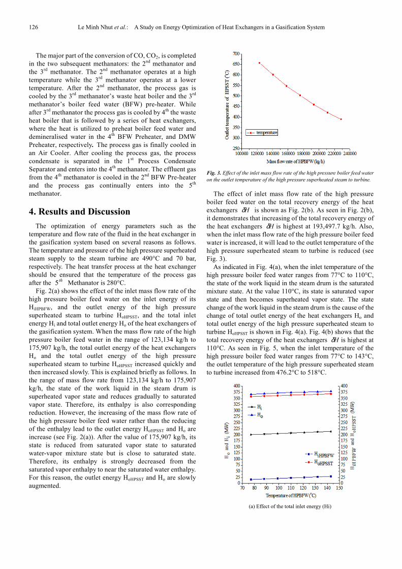
Fig. 3. Effect of the inlet mass flow rate of the high pressure boiler feed water
on the outlet temperature of the high pressure superheated steam to turbine.
The effect of inlet mass flow rate of the high pressure
boiler feed water on the total recovery energy of the heat
exchangers Hδ is shown as Fig. 2(b). As seen in Fig. 2(b),
it demonstrates that increasing of the total recovery energy of
the heat exchangers Hδ is highest at 193,497.7 kg/h. Also,
when the inlet mass flow rate of the high pressure boiler feed
water is increased, it will lead to the outlet temperature of the
high pressure superheated steam to turbine is reduced (see
Fig. 3).
As indicated in Fig. 4(a), when the inlet temperature of the
high pressure boiler feed water ranges from 77°C to 110°C,
the state of the work liquid in the steam drum is the saturated
mixture state. At the value 110°C, its state is saturated vapor
state and then becomes superheated vapor state. The state
change of the work liquid in the steam drum is the cause of the
change of total outlet energy of the heat exchangers Ho and
total outlet energy of the high pressure superheated steam to
turbine HoHPSST is shown in Fig. 4(a). Fig. 4(b) shows that the
total recovery energy of the heat exchangers Hδ is highest at
110°C. As seen in Fig. 5, when the inlet temperature of the
high pressure boiler feed water ranges from 77°C to 143°C,
the outlet temperature of the high pressure superheated steam
to turbine increased from 476.2°C to 518°C.
(a) Effect of the total inlet energy (Hi)

International Journal of Mechanical Engineering and Applications 2016; 4(3): 123-129 127
(b) Effect of the total recovery energy Hδ
Fig. 4. Effect of inlet temperature of the high pressure boiler feed water on the
total inlet energy, the total outlet energy and the total recovery energy.
The total outlet energy (Ho); The inlet energy of the HPBFW (HiHPBFW) and
the outlet energy of the HPSST (HoHPSST)
Fig. 5. Effect of inlet temperature of the high pressure boiler feed water on
outlet temperature of the high pressure superheated steam to turbine.
Although the highest value of total recovery energy of the
heat exchangers Hδ obtained at 193,497.7 kg/h (see Fig.
2(b)). However, at the value 193,497.7 kg/h, the outlet
temperature of the high pressure superheated steam to turbine
is 458°C, this temperature does not meet the above
requirement temperature. Furthermore, in the range of inlet
mass flow rate of the high pressure boiler feed water from
175,907 kg/h to 193,497.7 kg/h, the increasing of total
recovery energy of the heat exchangers Hδ is slightly. From
the above analyses, the optimal mass flow rate and
temperature of high pressure boiler feed water are determined
at 175,907 kg/h and 110°C, respectively. At these values, the
outlet temperature of high pressure superheated steam to
turbine is 499.8°C. In addition, these values also satisfy the
above requirements.
To calculate for case of the high pressure saturated steam of
the boiler, the parameters of the high pressure boiler feed
water such as mass flow rate, temperature and pressure are
kept constant at value of 175,907 kg/h, 110°C and 100 bars,
respectively. As seen in Fig. 6(a), when the inlet mass flow
rate of the high pressure saturated steam of the boiler rises, the
inlet energy of its iHPSTBH and the outlet energy of the high
pressure superheated steam to turbine HoHPSST, and the total
inlet energy Hi and total outlet energy Ho of the heat
exchangers of the gasification system are increased. This
increasing is due to the main increasing of inlet mass flow rate
of the high pressure saturated steam of the boiler because of its
saturated vapor enthalpy does not change state. For this
reasons, the amount of the total recovery energy of the heat
exchangers is almost unchanged (see Fig. 6(a)). However, the
outlet temperature of the high pressure superheated steam to
turbine is reduced when the inlet mass flow rate of the high
pressure saturated steam of the boiler is increased (see Fig. 7).
At the value of 238,430 kg/h, the outlet temperature of the
high pressure superheated steam to turbine is 499.8°C.
(a) Effect of the total inlet energy (Hi)
(b) Effect of the total recovery energy Hδ
Fig. 6. Effect of inlet mass flow rate of the high pressure saturated steam of
the boiler on the total inlet energy, the total outlet energy and the total
recovery energy.
The total outlet energy (Ho); The inlet energy of the HPBFW (HiHPBFW)
and the outlet energy of the HPSST (HoHPSST)

128 Le Minh Nhut et al.: A Study on Energy Optimization of Heat Exchangers in a Gasification System
Fig. 7. Effect of inlet mass flow rate of the high pressure saturated steam of
the boiler on outlet temperature of the high pressure superheated steam to
turbine.
(a) Effect of the total inlet energy (Hi)
(b) Effect of the total recovery energy Hδ
Fig. 8. Effect of inlet temperature of the high pressure saturated steam of the
boiler on the total inlet energy, the total outlet energy and the total recovery
energy.
The total outlet energy (Ho); The inlet energy of the HPBFW (HiHPBFW) and
the outlet energy of the HPSST (HoHPSST)
Fig. 8 (a) shows the variations of the inlet energy of the
high pressure saturated steam of the boiler iHPSTBH , the
outlet energy of the high pressure superheated steam to
turbine HoHPSST, and the total inlet energy Hi and total outlet
energy Ho of the heat exchangers with respect to the inlet
temperature of the high pressure saturated steam of the boiler.
By increasing the inlet temperature of the high pressure
saturated steam of the boiler until the value of 261.45°C, the
inlet energy of the high pressure saturated steam of the boiler
iHPSTBH , the outlet energy of the high pressure superheated
steam to turbine HoHPSST, and the total inlet energy Hi and
total outlet energy Ho of the heat exchangers increased
slowly; however, from 261.45°C to 290.5°C, they increase
quickly and then increased slowly. This is because, in the
range of temperatures from 203.35°C to 261.45°C, the state
of the high pressure saturated steam of the boiler is saturated
liquid-vapor mixture state but close to saturated liquid state
while at 290.5°C it is saturated vapor state and then becomes
superheated vapor state. Therefore, enthalpy changes that
correspond to the state of the high pressure saturated steam
of the boiler lead to the highest total recovery energy of the
heat exchangers Hδ at 290.5°C (see Fig. 8 (b)). Fig. 9
shows the effect of inlet temperature of the high pressure
saturated steam of the boiler on outlet temperature of the
high pressure superheated steam to turbine. In the range of
203.35°C to 261.45°C, the outlet temperature of the high
pressure superheated steam to turbine is constant at 289°C;
however, from 261.45°C to 290.5°C, it increase quickly and
then increased slowly. As the above analysis shows, the
optimal mass flow rate of high pressure saturated steam of
the boiler is determined at 238, 430kg/h while optimal
temperature is 290.5°C and pressure is 74 bars.
In this study, the waste heat amount from air cooler is also
investigated. The simulation results show that, when sixty
percent of the heat release amount of the air cooler (12.78MW)
is used, the total recovery energy of the heat exchangers Hδ
could be increased by 4.61% (7.8MW).
Fig. 9. Effect of inlet temperature of the high pressure saturated steam of the
boiler on outlet temperature of the high pressure superheated steam to
turbine.

International Journal of Mechanical Engineering and Applications 2016; 4(3): 123-129 129
5. Conclusions
In this study, a mathematical model of a heat exchanger
based on the effectiveness-NTU method is developed to
predict its operating performance for the purpose of optimal
temperature and mass flow rate of the fluid in the heat
exchangers of the gasification system. Computational
simulations have proved that the optimal mass flow rate,
temperature and pressure of the high pressure boiler feed
water are determined at 175,907kg/h, 110°C and 100 bars,
respectively, while the optimal mass flow rate, temperature
and pressure of the high pressure saturated steam of the boiler
are determined at 238,430 kg/h, 290.5°C and 74 bars,
respectively. Moreover, the sixty percent of the heat release
amount of the air cooler (12.78MW) is also proposed to use
because the total recovery energy of the heat exchangers Hδcould be increased by 4.61% (7.8MW).
Acknowledgements
This work was supported by the Technology Innovation
Program (No. 2011T100200036, Technology development
for the demo-scale SNG synthesis) funded by the Ministry of
Knowledge Economy (MKE, Republic of Korea)
References
[1] Kopyscinski J., Schildhauer T. J., Boillaz S. M. A., Production of synthetic natural gas (SNG) from coal and dry biomass – A technology review from 1950 to 2009, Fuel, Vol. 89, pp. 1763-1783, 2010
[2] Cronomarkovic N., Repic B., Neskovic O., Veljkovic M., Mladenovic R., Experimental investigation of role of steam in entrained flow coal gasification, Fuel, Vol. 86, pp. 194-202, 2007
[3] Bell D. A., Towler B. F., Fan M. H., Coal Gasification and its Applications, Oxford OX5 1GB, UK, 2011
[4] Luan Y. T., Chyou Y. P., Wang T., Numerical analysis of gasification performance via finite-rate model in a cross-type two-stage gasifier, International Journal of Heat and Mass Transfer, Vol. 57, pp. 558-566, 2013
[5] Jaojaruek K., Mathematical model to predict temperature profile and air–fuel equivalence ratio of a downdraft gasification process, Energy Conversion and Management, Vol. 83, pp. 223-231, 2014
[6] Materazzi & et al., Thermodynamic modelling and evaluation of a two-stage thermal process for waste gasification, Fuel, Vol. 108, pp. 356-369, 2013
[7] Choi Y. C., Li X. Y., Park T. J., Kim J. H., Lee J. G., Numerical study on the coal gasification characteristics in an entrained flow coal gasifier, Fuel, Vol. 80, pp. 2193-2201, 2001
[8] Morris M., Waldheim L., Energy recovery from solid waste fuels using advanced gasification technology, Waste management, Vol. 18, pp. 557-564, 1998
[9] Stoecker W. F., Design of thermal system, 3th ed. McGraw-Hill Book, pp. 82-93, 1989
[10] Incropera F. P., Dewitt D. P., Bergman T. L., Lavine A. S., Fundamentals of Heat and Mass Transfer, 6th ed. John Wiley & Sons Inc., 2006, pp. 669-723, 2006
[11] Hodge B. K., Analysis and Design of Energy system. Prentice-Hall, Inc., 1985
[12] Zedtwitz P. V., Steinfeld A., The solar thermal gasification of coal-energy conversion efficiency and CO2 mitigation potential, Energy, Vol. 28, pp. 441-456, 2003
[13] Ye D. P., Agnew J. B., Zhang D. K., Gasification of a South Australian low-rank coal with carbon dioxide and steam: kinetics and reactivity studies, Fuel, Vol. 77, pp. 1209-1219, 1998
[14] Chavan P. D., Sharma T., Mall B. K., Rajurkar B. D., Sharma B. K., Kulkarni B. D., Development of data-driven models for fluidized-bed coal gasification process, Fuel, Vol. 93, pp. 44-51, 2012
[15] Abani N., Ghoniem A. F., Large eddy simulation of coal gasification in an entrained flow gasifier, Fuel, Vol. 104, pp. 664-680, 2013
[16] Andrew J. M., Coal gasification for advanced power generation, Fuel, Vol. 84, pp. 2222- 2235, 2005
[17] Ahmed I., Gupta A. K., Evolution of syngas from cardboard gasification, Applied Energy, Vol. 86, pp. 1732-1740, 2009
[18] Kruse A., Hydrothermal biomass gasification, Journal of Supercritical Fluids, Vol. 47, pp. 391-399, 2009
[19] Erlach B., Harder B., Tsatsaronis G., Combined hydrothermal carbonization and gasification of biomass with carbon capture, Vol. 45, pp. 329-338, 2012
[20] Kakac S., Boilers, Evaporators, and Condensers, New York, John Wiley & Sons Inc., pp. 11-67, 1991
Biography
Le Minh Nhut received his B.S in Heat and
Refrigeration Technology from Danang
University of Technology in 2003 and M.S.
degrees (in Thermal Engineering) from
Vietnam National University, Ho Chi Minh
City University of Technology in 2006,
respectively. He then received his Ph.D
degree from Jeju National University,
Republic of Korea. He is currently a lecturer
at the Ho Chi Minh City University of Technology and Education,
Vietnam. His fields of interest include solar energy and
application, refrigeration and air conditioning, and renewable
energy.
Youn Cheol Park received his B.E. in
Mechanical Engineering, M.S., and Ph.D.
degrees from Korea University in 1990, 1992
and 1997 respectively. He is now a Professor
of the faculty of Mechanical Engineering,
Jeju National University, Republic of Korea.
His current research interests include
Refrigeration, and Air conditioning.
Related Documents