SIPAT STAGE-II, 2X500MW FGD OF NTPC Limited (A Government of India Enterprise) TECHNICAL SPECIFICATION FOR COMPRESSED AIR SYSTEM SPECIFICATION NO.: PE-TS-491-555-A001 BHARAT HEAVY ELECTRICALS LIMITED POWER SECTOR PROJECT ENGINEERING MANAGEMENT NOIDA (INDIA) Page 1 of 487

Welcome message from author
This document is posted to help you gain knowledge. Please leave a comment to let me know what you think about it! Share it to your friends and learn new things together.
Transcript

SIPAT STAGE-II, 2X500MW FGD
OF
NTPC Limited
(A Government of India Enterprise)
TECHNICAL SPECIFICATION
FOR
COMPRESSED AIR SYSTEM
SPECIFICATION NO.: PE-TS-491-555-A001
BHARAT HEAVY ELECTRICALS LIMITED
POWER SECTOR
PROJECT ENGINEERING MANAGEMENT
NOIDA (INDIA)
Page 1 of 487

SPECIFICATION NO: PE-TS-491-555-A001
SIPAT STAGE-II, 2X500MW FGD VOLUME: II B & III
REV: 00 COMPRESSED AIR SYSTEM DATE: July 22
SHEET: 1 OF 1
VOLUME – IIB
SECTIONS TITLE Page No
SECTION-A INTENT OF SPECIFICATION 03
SECTION-B PROJECT INFORMATION WITH WIND AND SEISMIC DESIGN CRITERIA 06
SECTION-C TECHNICAL SPECIFICATIONS
SECTION-C1 SCOPE OF SUPPLY & SERVICES, TERMINAL POINTS, EXCLUSIONS AMD OTHER PROJECT SPECIFIC DETAILS
19
SECTION-C2 CUSTOMER SPECIFICATION
C2 - A TECHNICAL REQUIREMENT 40
C2 - B PROJECT SPECIFIC GENERAL REQUIREMENTS 67
C2 - C PERFROMANCE GUARANTEE TESTS 171
C2 - D QUALITY ASSURANCE
186
SECTION-C3 TECHNICAL SPECIFICATION (ELECTRICAL PORTION) 232
SECTION-C4 TECHNICAL SPECIFICATION (C&I PORTION) 296
SECTION-E ANNEXURE-I LIST OF MAKES OF SUB-VENDOR ITEMS 383
ANNEXURE-II PAINTING & COLOUR SCHEME 404
ANNEXURE-III MASTER DRAWING LIST WITH SCHEDULE OF SUBMISSION
406
ANNEXURE-IV SITE STORAGE AND PRESERVATION 408
ANNEXURE-V PACKING PROCEDURE 437
ANNEXURE-VI LIST OF OPERATIONAL SPARES 469
VOLUME-III
SECTIONS TITLE Page No
1 LIST OF DOCUMENTS TO BE SUBMITTED WITH BID 472
2 COMPLIANCE CUM CONFIRMATION CERTIFICATE 474
3 PRE BID CLARIFICATION SCHEDULE 477
4 ELECTRICAL LOAD DATA 479
5 LIST OF DRAWINGS
481 DRG TITLE DRG NO
A SCHEMATIC DRAWING OF COMPRESSED AIR SYSTEM
0011-109-POM-A-006
6 GUATANTEED POWER CONSUMPTION FOR COMPRESSED AIR SYSTEM 483
7 ANNUAL MAINTENANCE CONTRACT SERVICES 485 – 487.
Page 2 of 487
SIPAT STAGE-II, 2X500MW FGD SPECIFICATION NO: PE-TS-491-555-A001
VOLUME: II B SECTION: A
COMPRESSED AIR SYSTEM REV: 00 DATE: JULY 22
Sheet: 1 OF 3
SECTION-A
INTENT OF SPECIFICATION
Page 3 of 487

SIPAT STAGE-II, 2X500MW FGD SPECIFICATION NO: PE-TS-491-555-A001
VOLUME: II B SECTION: A
COMPRESSED AIR SYSTEM REV: 00 DATE: JULY 22
Sheet: 2 OF 3
1.0 INTENT OF SPECIFICATION 1.1 The specification is intended to cover design, engineering, manufacture, inspection and
testing at vendor's/ sub-vendor’s works, painting, forwarding, proper packing and shipment and delivery at site, unloading, handling & transportation at site, Erection & Commissioning, minor civil works as required on FOR site basis, Performance and guarantee testing and handing over of Compressed Air System as per details in different sections / volumes of this specification for SIPAT STAGE-II, 2X500MW FGD.
1.2 The contractor shall be responsible for providing all material, equipment & services, which
are required to fulfil the intent of ensuring operability, maintainability, reliability and complete safety of the complete work covered under this specification, irrespective of whether it has been specifically listed herein or not. Omission of specific reference to any component / accessory necessary for proper performance of the equipment shall not relieve the contractor of the responsibility of providing such facilities to complete the supply of Compressed Air System within quoted price.
1.3 It is not the intent to specify herein all the details of design and manufacturing. However,
the equipment shall conform in all respects to highest standards of design, engineering and workmanship and shall be capable of performing the required duties in a manner acceptable to purchaser who will interpret the meaning of drawings and specifications and shall be entitled to reject any work or material which in his judgement is not in full accordance herewith.
1.4 The extent of supply under the contract includes all items shown in the drawings,
notwithstanding the fact that such items may have been omitted from the specification or schedules. Similarly, the extent of supply also includes all items mentioned in the specification and /or schedules, notwithstanding the fact that such items may have been omitted in the drawing. Similarly, the extent of supply also includes all items required for completion of the system and not withstanding that they may have been omitted in drawings / specifications or schedules.
1.5 The general term and conditions, instructions to tenderers and other attachment referred
to elsewhere are made part of the tender specification. The equipment materials and works covered by this specification is subject to compliance to all attachments referred to in the specification. The bidder shall be responsible for and governed by all requirements stipulated herein.
1.6 While all efforts have been made to make the specification requirement complete & unambiguous, it shall be bidders’ responsibility to ask for missing information, ensure completeness of specification, to bring out any contradictory / conflicting requirement in different sections of the specification and within a section itself to the notice of BHEL and to seek any clarification on specification requirement in the format enclosed under Vol-III of the specification within 10 days of receipt of tender documents. In absence of any such clarifications, in case of any contradictory requirement, the more stringent requirement as per interpretation of Purchaser / Customer shall prevail and shall be complied by the bidder
Page 4 of 487

SIPAT STAGE-II, 2X500MW FGD SPECIFICATION NO: PE-TS-491-555-A001
VOLUME: II B SECTION: A
COMPRESSED AIR SYSTEM REV: 00 DATE: JULY 22
Sheet: 3 OF 3
without any commercial implication on account of the same. Further in case of any missing information in the specification not brought out by the prospective bidders as part of pre-bid clarification, the same shall be furnished by Purchaser/ Customer as and when brought to their notice either by the bidder or by purchaser/ customer themselves. However, such requirements shall be binding on the successful bidder without any commercial & delivery implication.
1.7 The bidder’s offer shall not carry any sections like clarification, interpretations and /or
assumptions. 1.8 Deviations, if any, should be very clearly brought out clause by clause in the enclosed
schedule; otherwise, it will be presumed that the vendor's offer is strictly in line with NIT specification.
1.9 In case all above requirements are not complied with, the offer may be considered as
incomplete and would become liable for rejection. 1.10 Unless specified otherwise in GCC, all through the specification, the word contractor shall
have same meaning as successful bidder /vendor and Customer/ Purchaser/Employer will mean BHEL and /or NTPC including their consultant as interpreted by BHEL in the relevant context.
Page 5 of 487

SIPAT STAGE-II, 2X500MW FGD
COMPRESSED AIR SYSTEM
SPECIFICATION No: PE-TS-491-555-A001
VOLUME: II B
SECTION : B
REV. 00 DATE: JULY 22
SHEET : 1 OF 1
SECTION: B
PROJECT INFORMATION WITH WIND AND SEISMIC DESIGN CRITERIA
Page 6 of 487

CLAUSE NO.
PROJECT INFORMATION
LOT-6 PROJECTS
FLUE GAS DESULPHURISATION (FGD) SYSTEM PACKAGE
TECHNICAL SPECIFICATION
SECTION-VI
BID DOC NO.: CS-0011-109-(6)2
SUB-SECTION-II A3
PROJECT INFORMATION
SIPAT STPP-II (2X500 MW)
PAGE 1 OF 24
1.00.00 BACKGROUND Sipat Super Thermal Power Project (Coal Based) stage-II (2X500MW) is set up in the
state of Chhattisgarh, located near Sipat in Bilaspur district.The capacity of the project in Stage-II is 1000 MW comprising of 2 x 500 MW units and the ultimate capacity of the project is 2980 MW (3X660 + 2X500 MW).
1.01.00 LOCATION AND APPROACH
The site is located east of the Kurung left bank canal and is bounded by villages Rank, Kaudia and Janji in the Bilaspur district of Chhattisgarh. It is in between
latitudes 22o05' & 22o09' North and longitudes 82o 16' & 82o 18' East. The site is approx. 20 kms. from Bilaspur city and is approachable via the Bilaspur - Sipat state highway which takes off to the North-East from Bilaspur City. The nearest railway station is Jairamnagar on the Nagpur-Raipur-Calcutta mainline. Raipur, which is approximately 140 kms. from the site is the nearest commercial airport.
1.02.00 LAND REQUIREMENT
Land required for the ultimate stage of project i.e. 2980 MW is acquired.
1.03.00 WATER
The water requirement for the ultimate stage of the project is 120 million cubic meter/ annum. Source/ arrangement to meet water requirement is from Hasdeo Barrage Right Bank Canal (RBC) has been accorded by MP Water Resource Deptt. CWC has also concurred for 120 MCM drawal, sufficient for Stage-I & Stage-II of the project.
Water is drawn from the RBC, originated from Hasdeo Barrage pond, at chainage 37.95 km. nearest to Sipat STPP. One month's in-plant storage reservoir is provided for meeting the water requirement during the canal closure period.
1.04.00 COAL AVAILABILITY AND TRANSPORTATION Coal Availability SLC (LT) had accorded long term linkage of 10 million tonne / year. Coal Transportation Coal is being transported through merry-go-round system. Coal Quality Parameters / Fuel Oil Characteristics The coal quality parameters and ash characteristics/parameters (Table-1, Annexure-
BI) and Fuel oil Characteristics (Table-2A & 2B, AnnexureBI) is attached under this sub-section.
Page 7 of 487
CLAUSE NO.
PROJECT INFORMATION
LOT-6 PROJECTS
FLUE GAS DESULPHURISATION (FGD) SYSTEM PACKAGE
TECHNICAL SPECIFICATION
SECTION-VI
BID DOC NO.: CS-0011-109-(6)2
SUB-SECTION-II A3
PROJECT INFORMATION
SIPAT STPP-II (2X500 MW)
PAGE 2 OF 24
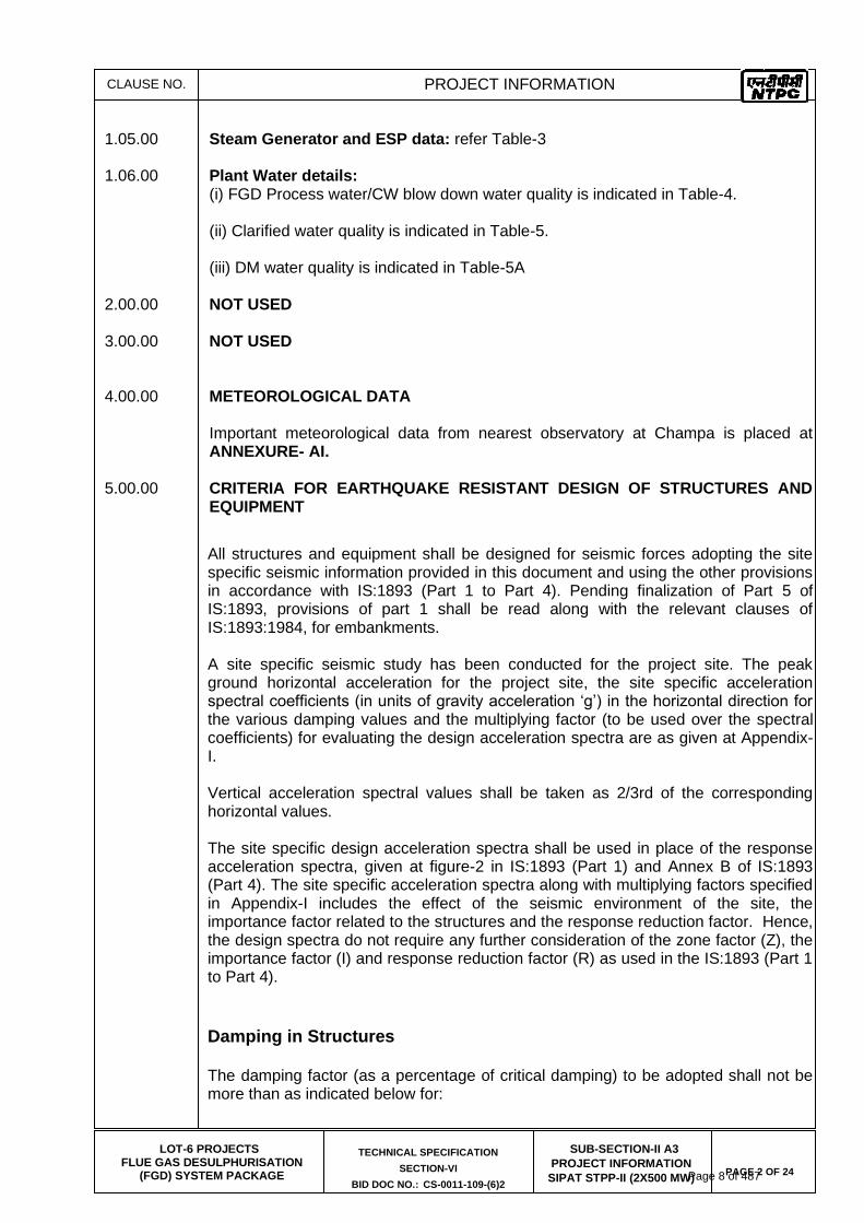
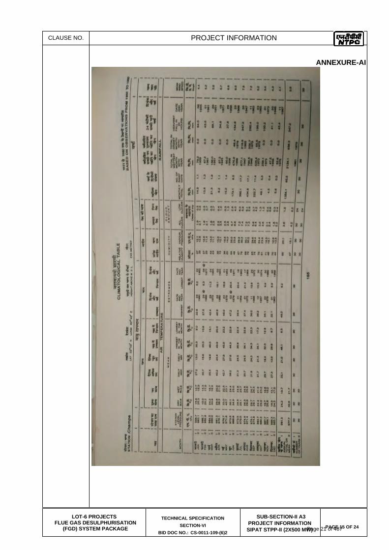
1.05.00 Steam Generator and ESP data: refer Table-3 1.06.00 Plant Water details: (i) FGD Process water/CW blow down water quality is indicated in Table-4. (ii) Clarified water quality is indicated in Table-5. (iii) DM water quality is indicated in Table-5A 2.00.00 NOT USED 3.00.00 NOT USED 4.00.00 METEOROLOGICAL DATA Important meteorological data from nearest observatory at Champa is placed at
ANNEXURE- AI. 5.00.00 CRITERIA FOR EARTHQUAKE RESISTANT DESIGN OF STRUCTURES AND
EQUIPMENT
All structures and equipment shall be designed for seismic forces adopting the site specific seismic information provided in this document and using the other provisions in accordance with IS:1893 (Part 1 to Part 4). Pending finalization of Part 5 of IS:1893, provisions of part 1 shall be read along with the relevant clauses of IS:1893:1984, for embankments. A site specific seismic study has been conducted for the project site. The peak ground horizontal acceleration for the project site, the site specific acceleration spectral coefficients (in units of gravity acceleration ‘g’) in the horizontal direction for the various damping values and the multiplying factor (to be used over the spectral coefficients) for evaluating the design acceleration spectra are as given at Appendix-I. Vertical acceleration spectral values shall be taken as 2/3rd of the corresponding horizontal values. The site specific design acceleration spectra shall be used in place of the response acceleration spectra, given at figure-2 in IS:1893 (Part 1) and Annex B of IS:1893 (Part 4). The site specific acceleration spectra along with multiplying factors specified in Appendix-I includes the effect of the seismic environment of the site, the importance factor related to the structures and the response reduction factor. Hence, the design spectra do not require any further consideration of the zone factor (Z), the importance factor (I) and response reduction factor (R) as used in the IS:1893 (Part 1 to Part 4).
Damping in Structures The damping factor (as a percentage of critical damping) to be adopted shall not be more than as indicated below for:
Page 8 of 487

CLAUSE NO.
PROJECT INFORMATION
LOT-6 PROJECTS
FLUE GAS DESULPHURISATION (FGD) SYSTEM PACKAGE
TECHNICAL SPECIFICATION
SECTION-VI
BID DOC NO.: CS-0011-109-(6)2
SUB-SECTION-II A3
PROJECT INFORMATION
SIPAT STPP-II (2X500 MW)
PAGE 3 OF 24
a)
Steel structures : 2%
b)
Reinforced Concrete structures : 5%
c)
Reinforced Concrete Stacks : 3%
d)
Steel stacks : 2%
Method of Analysis
Since most structures in a power plant are irregular in shape and have irregular distribution of mass and stiffness, dynamic analysis for obtaining the design seismic forces shall be carried out using the response spectrum method. The number of vibration modes used in the analysis should be such that the sum total of modal masses of all modes considered is at least 90 percent of the total seismic mass and shall also meet requirements of IS:1893 (Part 1). Modal combination of the peak response quantities shall be performed as per Complete Quadratic Combination (CQC) method or by an acceptable alternative as per IS:1893 (Part 1). In general, seismic analysis shall be performed for the three orthogonal (two principal horizontal and one vertical) components of earthquake motion. The seismic response from the three components shall be combined as specified in IS:1893 (Part 1). The spectral acceleration coefficient shall get restricted to the peak spectral value if the fundamental natural period of the structure falls to the left of the peak in the spectral acceleration curve. For buildings, if the design base shear (VB) obtained from modal combination is less
than the base shear (VB) computed using the approximate fundamental period (Ta) given in IS:1893:Part 1 and using site specific acceleration spectra with appropriate multiplying factor, the response quantities (e.g. member forces, displacements, storey forces, storey shears and base reactions) shall be enhanced in the ratio of
VB/ VB. However, no reduction is permitted if VB is less than VB.
Design/Detailing for Ductility for Structures
The site specific design acceleration spectra is a reduced spectra and has an in-built allowance for ductility. Structures shall be engineered and detailed in accordance with relevant Indian/International standards to achieve ductility.
Page 9 of 487
CLAUSE NO.
PROJECT INFORMATION
LOT-6 PROJECTS
FLUE GAS DESULPHURISATION (FGD) SYSTEM PACKAGE
TECHNICAL SPECIFICATION
SECTION-VI
BID DOC NO.: CS-0011-109-(6)2
SUB-SECTION-II A3
PROJECT INFORMATION
SIPAT STPP-II (2X500 MW)
PAGE 4 OF 24
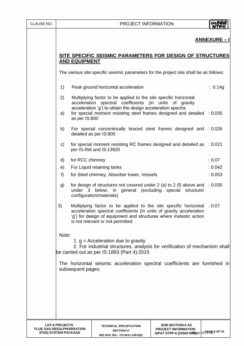
ANNEXURE – I
SITE SPECIFIC SEISMIC PARAMETERS FOR DESIGN OF STRUCTURES AND EQUIPMENT
The various site specific seismic parameters for the project site shall be as follows:
a) for special moment resisting steel frames designed and detailed as per IS:800
: 0.035
b) For special concentrically braced steel frames designed and detailed as per IS:800
: 0.026
c) for special moment resisting RC frames designed and detailed as per IS:456 and IS:13920
: 0.021
d) for RCC chimney : 0.07
e) For Liquid retaining tanks : 0.042
f) for Steel chimney, Absorber tower, Vessels
: 0.053
g) for design of structures not covered under 2 (a) to 2 (f) above and under 3 below, in general (excluding special structure/ configuration/materials)
: 0.035
3) Multiplying factor to be applied to the site specific horizontal acceleration spectral coefficients (in units of gravity acceleration ‘g’) for design of equipment and structures where inelastic action is not relevant or not permitted
: 0.07
Note: 1. g = Acceleration due to gravity
2. For industrial structures, analysis for verification of mechanism shall be carried out as per IS:1893 (Part 4):2015
The horizontal seismic acceleration spectral coefficients are furnished in subsequent pages.
1) Peak ground horizontal acceleration
: 0.14g
2) Multiplying factor to be applied to the site specific horizontal acceleration spectral coefficients (in units of gravity acceleration ‘g’) to obtain the design acceleration spectra
Page 10 of 487

CLAUSE NO.
PROJECT INFORMATION
LOT-6 PROJECTS
FLUE GAS DESULPHURISATION (FGD) SYSTEM PACKAGE
TECHNICAL SPECIFICATION
SECTION-VI
BID DOC NO.: CS-0011-109-(6)2
SUB-SECTION-II A3
PROJECT INFORMATION
SIPAT STPP-II (2X500 MW)
PAGE 5 OF 24
ANNEXURE – I
HORIZONTAL SEISMIC ACCELERATION SPECTRAL COEFFICIENTS In units of ‘g’ for SIPAT STPP
Period Damping Factor (as a percentage of critical damping)
(Sec) 0.80% 1% 1.60% 2% 3% 5%
.04 0.9914 0.9877 0.9867 0.9859 0.9849 0.9839
.05 1.2262 1.1579 1.1467 1.1392 1.1299 1.1009
.06 1.4516 1.3487 1.3272 1.3104 1.2892 1.2449
.07 1.8388 1.6845 1.6345 1.5944 1.5666 1.5076
.08 2.3009 2.1316 2.0801 1.9571 1.8387 1.7396
.09 3.6683 3.3390 2.9378 2.6591 2.1409 1.9978
.10 4.5596 3.8254 3.3886 3.1526 2.4177 2.1830
.12 5.1376 4.4231 3.9292 3.6907 2.8694 2.4421
.14 5.4416 4.7467 4.2463 4.0499 3.2878 2.6563
.16 5.6857 5.0086 4.4829 4.2566 3.4812 2.8190
.18 5.8457 5.2097 4.6616 4.4118 3.5682 2.8920
.20 5.8971 5.3013 4.7794 4.5035 3.5972 2.9322
.22 5.9439 5.3612 4.8599 4.5652 3.6281 2.9490
.24 5.9729 5.3977 4.9076 4.5942 3.6383 2.9528
.26 5.9860 5.4369 4.9319 4.5793 3.6299 2.9406
.28 5.9850 5.4398 4.9291 4.5540 3.6028 2.9172
.30 5.9579 5.4239 4.8917 4.4231 3.5308 2.8770
.40 5.4248 4.7794 4.1453 3.5701 2.9584 2.5122
.50 3.8946 3.6309 3.1978 2.8761 2.4290 2.0867
.60 3.1651 3.0098 2.6638 2.4215 2.0334 1.7509
.70 2.6956 2.5674 2.3270 2.0885 1.7378 1.4899
.80 2.3345 2.2232 2.0418 1.8510 1.5498 1.3300
.90 2.0633 1.9548 1.8407 1.6892 1.4366 1.2224
1.00 1.8884 1.7874 1.6957 1.5844 1.3590 1.1532
1.10 1.7602 1.6695 1.5825 1.4899 1.2851 1.1037
1.20 1.6518 1.5564 1.4825 1.3955 1.2103 1.0503
1.30 1.5498 1.4619 1.3908 1.3104 1.1467 1.0148
1.40 1.4600 1.3730 1.3048 1.2281 1.0896 .9746
1.50 1.3693 1.2917 1.2281 1.1551 1.0373 .9344
1.60 1.2935 1.2112 1.1532 1.0887 .9821 .8923
Page 11 of 487

CLAUSE NO.
PROJECT INFORMATION
LOT-6 PROJECTS
FLUE GAS DESULPHURISATION (FGD) SYSTEM PACKAGE
TECHNICAL SPECIFICATION
SECTION-VI
BID DOC NO.: CS-0011-109-(6)2
SUB-SECTION-II A3
PROJECT INFORMATION
SIPAT STPP-II (2X500 MW)
PAGE 6 OF 24
ANNEXURE – I
HORIZONTAL SEISMIC ACCELERATION SPECTRAL COEFFICIENTS In units of ‘g’ for SIPAT STPP
Period Damping Factor (as a percentage of critical damping)
(Sec) 0.80% 1% 1.60% 2% 3% 5%
1.70 1.2178 1.1411 1.0887 1.0176 .9372 .8549
1.80 1.1514 1.0812 1.0242 .9587 .8885 .8165
1.90 1.0850 1.0111 .9606 .9044 .8455 .7782
2.00 1.0204 .9549 .9072 .8567 .7969 .7426
2.10 .9690 .8988 .8577 .8118 .7482 .6996
2.20 .9185 .8511 .8147 .7772 .7062 .6519
2.30 .8801 .8109 .7810 .7389 .6669 .6154
2.40 .8455 .7782 .7473 .7090 .6285 .5771
2.50 .8090 .7445 .7155 .6744 .5995 .5387
2.75 .7333 .6706 .6407 .6014 .5341 .4536
3.00 .6566 .6061 .5808 .5406 .4714 .3910
3.25 .5920 .5509 .5210 .4798 .4162 .3535
3.50 .5369 .4976 .4705 .4302 .3732 .3227
3.75 .4910 .4602 .4312 .3910 .3311 .2956
4.00 .4536 .4228 .3966 .3564 .3012 .2750
6.00.00 CRITERIA FOR WIND RESISTANT DESIGN OF STRUCTURES AND EQUIPMENT
All structures shall be designed for wind forces in accordance with IS:875 (Part-3) and as specified in this document. See Annexure – C1 for site specific information. Along wind forces shall generally be computed by the Peak (i.e. 3 second gust) Wind Speed method as defined in the standard. Along wind forces on slender and wind sensitive structures and structural elements shall also be computed, for dynamic effects, using the Gust Factor or Gust Effectiveness Factor Method as defined in the standard. The structures shall be designed for the higher of the forces obtained from Gust Factor method and the Peak Wind Speed method. Analysis for dynamic effects of wind must be undertaken for any structure which has a height to minimum lateral dimension ratio greater than “5” and/or if the fundamental frequency of the structure is less than 1 Hz.
Page 12 of 487

CLAUSE NO.
PROJECT INFORMATION
LOT-6 PROJECTS
FLUE GAS DESULPHURISATION (FGD) SYSTEM PACKAGE
TECHNICAL SPECIFICATION
SECTION-VI
BID DOC NO.: CS-0011-109-(6)2
SUB-SECTION-II A3
PROJECT INFORMATION
SIPAT STPP-II (2X500 MW)
PAGE 7 OF 24
Susceptibility of structures to across-wind forces, galloping, flutter, ovalling etc. should be examined and designed/detailed accordingly following the recommendations of IS:875(Part-3) and other relevant Indian standards. It should be estimated if size and relative position of other structures are likely to enhance the wind loading on the structure under consideration. Enhancement factor, if necessary, shall suitably be estimated and applied to the wind loading to account for the interference effects. Damping in Structures The damping factor (as a percentage of critical damping) to be adopted shall not be more than as indicated below for: a) Welded steel structures : 1.0% b) Bolted steel structures : 2.0% c) Reinforced concrete structures :1.6% d) Steel stacks : As per IS:6533 & CICIND Model Code
whichever is more critical.
Page 13 of 487

CLAUSE NO.
PROJECT INFORMATION
LOT-6 PROJECTS
FLUE GAS DESULPHURISATION (FGD) SYSTEM PACKAGE
TECHNICAL SPECIFICATION
SECTION-VI
BID DOC NO.: CS-0011-109-(6)2
SUB-SECTION-II A3
PROJECT INFORMATION
SIPAT STPP-II (2X500 MW)
PAGE 8 OF 24
ANNEXURE-C1
SITE SPECIFIC DESIGN PARAMETERS The various design parameters, as defined in IS: 875 (Part-3), to be adopted for the project site shall be as follows: a) The basic wind speed “Vb” at ten metres above the mean ground level
: 45 metres/second b) The risk coefficient “K1” : 1.07
c) Category of terrain : Category-2
7.00.0 FOUNDATION SYSTEM AND GEOTECHNICAL DATA
7.01.0 Soil Data
Owner has carried out geotechnical investigation in the proposed area of Sipat STPP. Bearing capacity for design of foundations and Bore logs data are given at Annexure – C2 of this specification. The geotechnical investigation report comprising of Boreholes, Laboratory tests, Chemical analysis, etc. in respect of the sub-strata prevailing at site will be made available for the Bidder's study at the Employer's office, if required. The onus of correct assessment / interpretation and understanding of the existing subsoil condition / data is on the Bidder. In case, bidder feels that the available data is inadequate, he may carry out his own geotechnical investigation. Geotechnical Investigation layout/location of borehole/field test where investigation has been carried out and is enclosed as Annexure-C3. Further, if any change in layout or area not covered as per enclosed Geotechnical Investigation layout, Contractor shall carry out geotechnical investigation in the area at no cost to owner. The scheme for geotechnical investigation shall be approved by owner before execution. Geotechnical investigation work shall got executed by the Contractor through the agencies as mentioned in Clause No. 7.07.00. However, no time extension shall be given on account of soil investigation carried out by the Bidder. The geotechnical investigation report shall be prepared with detailed recommendations regarding type of foundation and allowable bearing pressure for various structures/ facilities and other soil parameters. The report shall be submitted for Owner’s approval prior to commencement of design of foundation.
Site levelling & grading had been carried out and achieved finished ground level (FGL). Bidder may refer topographical survey drawing for variation in existing/ natural ground level (NGL) and FGL. Ground water table is varying from 2.0m to 5.0m at the time of geotechnical investigation and may fluctuate with seasonal variation
7.01.01 The furnished borelog details are specific to the co-ordinates where the boreholes
have been carried out and are provided for bidder’s information only. Soil profile in the proposed area may vary with respect to the borelogs enclosed for bidder’s information. Bidder has to consider all such variations in his estimation, over the extent of the work to be carried out. The Bidder should note that nothing extra whatsoever on account of variation between soil data collected by Owner and that
Page 14 of 487
CLAUSE NO.
PROJECT INFORMATION
LOT-6 PROJECTS
FLUE GAS DESULPHURISATION (FGD) SYSTEM PACKAGE
TECHNICAL SPECIFICATION
SECTION-VI
BID DOC NO.: CS-0011-109-(6)2
SUB-SECTION-II A3
PROJECT INFORMATION
SIPAT STPP-II (2X500 MW)
PAGE 9 OF 24
found by the Bidder during geotechnical investigation by him or during execution of works, shall be Payable.
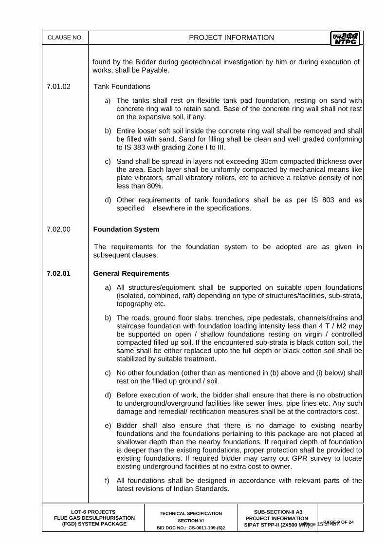
7.01.02 Tank Foundations
a) The tanks shall rest on flexible tank pad foundation, resting on sand with concrete ring wall to retain sand. Base of the concrete ring wall shall not rest on the expansive soil, if any.
b) Entire loose/ soft soil inside the concrete ring wall shall be removed and shall be filled with sand. Sand for filling shall be clean and well graded conforming to IS 383 with grading Zone I to III.
c) Sand shall be spread in layers not exceeding 30cm compacted thickness over the area. Each layer shall be uniformly compacted by mechanical means like plate vibrators, small vibratory rollers, etc to achieve a relative density of not less than 80%.
d) Other requirements of tank foundations shall be as per IS 803 and as specified elsewhere in the specifications.
7.02.00 Foundation System
The requirements for the foundation system to be adopted are as given in subsequent clauses.
7.02.01 General Requirements
a) All structures/equipment shall be supported on suitable open foundations (isolated, combined, raft) depending on type of structures/facilities, sub-strata, topography etc.
b) The roads, ground floor slabs, trenches, pipe pedestals, channels/drains and staircase foundation with foundation loading intensity less than 4 T / M2 may be supported on open / shallow foundations resting on virgin / controlled compacted filled up soil. If the encountered sub-strata is black cotton soil, the same shall be either replaced upto the full depth or black cotton soil shall be stabilized by suitable treatment.
c) No other foundation (other than as mentioned in (b) above and (i) below) shall rest on the filled up ground / soil.
d) Before execution of work, the bidder shall ensure that there is no obstruction to underground/overground facilities like sewer lines, pipe lines etc. Any such damage and remedial/ rectification measures shall be at the contractors cost.
e) Bidder shall also ensure that there is no damage to existing nearby foundations and the foundations pertaining to this package are not placed at shallower depth than the nearby foundations. If required depth of foundation is deeper than the existing foundations, proper protection shall be provided to existing foundations. If required bidder may carry out GPR survey to locate existing underground facilities at no extra cost to owner.
f) All foundations shall be designed in accordance with relevant parts of the latest revisions of Indian Standards.
Page 15 of 487

CLAUSE NO.
PROJECT INFORMATION
LOT-6 PROJECTS
FLUE GAS DESULPHURISATION (FGD) SYSTEM PACKAGE
TECHNICAL SPECIFICATION
SECTION-VI
BID DOC NO.: CS-0011-109-(6)2
SUB-SECTION-II A3
PROJECT INFORMATION
SIPAT STPP-II (2X500 MW)
PAGE 10 OF 24
g) The water table for design purpose shall be considered at Finished Ground Level.
h) A combination of open and pile foundations shall not be permitted under the same equipment / structure / building.
i) Foundation for equipment on ground floor
For equipment of static weight upto 1.5 T, the equipment may be supported on the ground floor slab by locally thickening the slab. Thickening of the ground floor slab shall be done upto an extent of about 0.6 m beyond the plan area of the equipment on all the sides. Further, the load intensity below the equipment shall be limited to 4T/m2. Other requirements of floor slab and compaction below the floor slab shall be adhered, as specified elsewhere in the specifications. For equipment’s of static weight between 1.5 T and 20 T, the equipment may be supported on compacted sand filling with the load intensity below the equipment limited to 4T/m2. The minimum depth of foundation is 1.0m below FFL. Other requirements of sand compaction below the foundation shall be adhered, as specified elsewhere in the specifications.
For equipment of static weight more than 20 T, the equipment foundation shall be taken to the founding level or shall be built up with PCC from the level as mentioned in the Annexure C2 -Table 2. The pedestal of equipment foundation or the foundation Block shall be isolated from the adjoining floor slab by providing bitumen impregnated fiber board of minimum 50 mm thick, conforming to IS: 1838 all around the equipment pedestal for the full depth of the floor slab.
7.02.02 Open Foundations
In case open foundations are adopted, following shall be adhered to.
a) The minimum width of foundation shall be 1.0 m.
b) Minimum depth of foundation shall be 1.0m below Ground Level.
c) It shall be ensured that all foundations of a particular structure/ buildings/ facility shall rest on one bearing stratum.
d) Wherever the intended bearing sub-strata is virgin soil stratum but the actual stratum encountered during foundation excavation consists of filled up soil at founding level, under such cases either the foundation shall be lowered completely into the virgin stratum or the filled up soil upto the virgin layers shall be removed and built up through PCC (1:4:8) up to designed foundation level.
e) Wherever the intended bearing stratum is weathered rock, but the actual strata encountered during excavation consists of both overburden soil and weathered rock at founding level, under such cases, the overburden upto the weathered rock level including 0.5 m into the weathered rock shall be removed and built up through PCC (1:3:6) upto the designed founding level. Thus, maintaining the same founding level for all the footings of a structure. The treatment at the base of foundation before laying the PCC shall be carried out as per IS: 12070.
Page 16 of 487

CLAUSE NO.
PROJECT INFORMATION
LOT-6 PROJECTS
FLUE GAS DESULPHURISATION (FGD) SYSTEM PACKAGE
TECHNICAL SPECIFICATION
SECTION-VI
BID DOC NO.: CS-0011-109-(6)2
SUB-SECTION-II A3
PROJECT INFORMATION
SIPAT STPP-II (2X500 MW)
PAGE 11 OF 24
f) The last layer of about 300 mm before reaching the founding level shall be
excavated carefully by such equipment so that soil / rock at the required level will be left in its natural condition.
g) If joints, fissures or other discontinuities in rock are encountered at founding level, then treatment of such rock defects shall be carried out as per IS: 13063-1991 in consultation with the Engineer.
7.03.00 Special Requirements
Details of treatment for foundations / underground structures required to counteract soil / water chemical environment, cement type, grade of concrete, type of reinforcement, cover to reinforcement and protective coating to foundations, etc. shall be as mentioned in Annexure-C2 of this specification.
7.04.00 Excavation, Filling and Dewatering
7.04.01 For excavation works, comprehensive dewatering with well point or deep wells arrangement, if required, shall be adopted. Scheme for dewatering and design with all computations and back up data for dewatering shall be submitted for the owner’s information. The water table shall be maintained at 0.5m below the founding depth.
7.04.02 Excavation for shallow foundations shall be covered with PCC immediately after reaching the founding level. In case of any local loosening of soil or any loose pockets are encountered at founding level during excavation the same shall be removed and compensated by PCC M7.5. The final layer of about 300 mm thickness above the founding level shall be excavated by suitable means, so as to avoid disturbance to founding stratum.
7.04.03 Backfilling around foundations, pipes, trenches, sumps, pits, plinths, etc. shall be carried out with approved material in layers not exceeding 300 mm compacted thickness (higher thickness of layers upto 500mm with heavy mechanical compacting equipment) and each layer shall be compacted to 90% of standard proctor density for cohesive soils and to 80% of relative density for non cohesive soils. In any case, black cotton soil shall not be used in back filling without providing cusion of 1m of non expansive cohesive soil/moorum around the footings. In case of roads in the area of black cotton soil, minimum 0.4m moorum shall be provided.
Rock pieces having size less than 150 mm and interstices filled with soil may be
used for backfilling around foundation, plinths etc. and shall be compacted to minimum of 85% of original stack of material after filling the interstices.
7.04.04 Founding level for trenches/channels shall be decided as per functional requirement. The bottom of excavation shall be properly compacted prior to casting of bottom slab of trenches / channels.
7.04.05 CBR tests for pavement/road design shall be carried out by the Contractor after earth filling (if applicable) has been completed up to the formation level.
7.04.06 The contractor shall take all necessary measures during excavation to prevent the hazards of falling or sliding of material or article from any bank or side of such excavation which is more than one and a half meter above the footing by providing adequate piling, shoring, bracing etc. Against such bank or sides.
Adequate and suitable warning signs shall be put up at conspicuous places at the excavation work to prevent any persons or vehicles falling into the excavation trench.
Page 17 of 487
CLAUSE NO.
PROJECT INFORMATION
LOT-6 PROJECTS
FLUE GAS DESULPHURISATION (FGD) SYSTEM PACKAGE
TECHNICAL SPECIFICATION
SECTION-VI
BID DOC NO.: CS-0011-109-(6)2
SUB-SECTION-II A3
PROJECT INFORMATION
SIPAT STPP-II (2X500 MW)
PAGE 12 OF 24
No worker should be allowed to work where he may be stuck or endangered by excavation machinery or collapse of excavations or trenches.
7.05.00 EXCAVATION IN ROCK
Excavation in rock shall be carried out by mechanical means and if blasting is required for founding of some of the structures under this package, control blasting only shall be carried out.
7.05.01 Controlled blasting shall be done by a specialized agency duly approved by Engineer. All controlled blasting shall be done by using time delay detonators (i.e. excel type).
7.05.02 (a) Contractor shall engage an agency expert in blasting such as, NIRM (National
Institute of Rock Mechanics), CMPDIL, Central Institute of Mining and Fuel Research Dhanbad, Dept. of Mining of Govt. Institutions etc. to design detailed blasting scheme and get the same approved from Engineer before carrying out the blasting operation. All blasting shall be done as per the approved blasting scheme & initial blasting operations shall be done under the supervision & guidance of the representative of the blasting expert.
b) All the statutory laws, (Explosives Act etc.) rules, regulations, Indian Standards,
etc. pertaining to the acquisition, transport, storage, handling and use of explosives, etc. shall be strictly followed.
c) The Contractor shall obtain Licenses from Competent Authorities for undertaking
blasting work as well as for procuring, transporting to site and storing the explosives as per explosives act. The Contractor shall be responsible for the safe transport, use, custody and proper accounting of the explosive Materials.
d) The Contractor shall be responsible and liable for any accident and injury /
damage which may occur to any person or property of the project or public on account of any operations connected with the storage, transportation, handling or use of explosive and blasting operations.
7.06.00 Sheeting & Shoring
The contractor shall ascertain for himself the nature of materials to be excavated and difficulties, if any, likely to be encountered in excavation while executing the work. Sheet piling, sheeting and shoring, bracing and maintaining suitable slopes, drainage, etc. shall be provided and installed by the Contractor, to the satisfaction of the Engineer.
7.07.00.00 Geotechnical investigation work shall be got executed by the Contractor through the following agencies.
1. C.E.TESTING COMPANY Pvt. Ltd, Kolkata
2. Cengrs Geotechnica Pvt. Ltd, New Delhi
3. KCT Consultancy Services, Ahemdabad
4. M.K. Soil Testing Laboratory, Ahemdabad
Page 18 of 487

CLAUSE NO.
PROJECT INFORMATION
LOT-6 PROJECTS
FLUE GAS DESULPHURISATION (FGD) SYSTEM PACKAGE
TECHNICAL SPECIFICATION
SECTION-VI
BID DOC NO.: CS-0011-109-(6)2
SUB-SECTION-II A3
PROJECT INFORMATION
SIPAT STPP-II (2X500 MW)
PAGE 13 OF 24
Annexure-C2
SOIL DATA AND FOUNDATION SYSTEM
Employer has carried out geotechnical investigation in the proposed area. Logs of boreholes of proposed area are enclosed separately as Annexure-C4.
a) The foundation system to be adopted for different structures shall be as given in Table – 1 below
Table – 1:
STRUCTURE TYPE OF FOUNDATION TO
BE ADOPTED
Chimney, Absorber, LHP, GHP area structures, FGD control room building and other structures
Open
b) The minimum founding level and the corresponding net allowable bearing pressure
shall be as given in Table – 2 below.
Table – 2: Net Allowable Bearing Pressure
Founding Depth/ Stratum Net Allowable Bearing Pressure T/m2
Isolated and combined footings for 40mm permissible settlement in case of soil and 12mm in case of rocky strata
Rafts (width > 6m) for 75mm permissible settlement in case of soil and 12mm in case of rocky strata
Width upto 6.0m
In case of Soil
1.0m below NGL 12 12 12
2.0m below NGL 15 15 15
In case of rocky strata
0.30m Embedment in Fine grained weathered sand stone / Mud stone.
30 30 30
0.6m Embedment in Fine grained weathered sand stone / Mud stone.
40 40 40
1.0m Embedment in Fine grained weathered sand stone / Mud stone.
50 50 50
Page 19 of 487
CLAUSE NO.
PROJECT INFORMATION
LOT-6 PROJECTS
FLUE GAS DESULPHURISATION (FGD) SYSTEM PACKAGE
TECHNICAL SPECIFICATION
SECTION-VI
BID DOC NO.: CS-0011-109-(6)2
SUB-SECTION-II A3
PROJECT INFORMATION
SIPAT STPP-II (2X500 MW)
PAGE 14 OF 24
For NGL, topographical survey drawing along with borehole details shall be referred.
The net allowable bearing pressure higher than above mentioned values shall not be
permitted. At intermediate levels the bearing capacity shall be same as the net
allowable bearing pressure corresponding to the immediate shallower level
mentioned above.
In case any loose/soft pockets in rocky strata is encountered at founding level, the same shall be removed completely upto the hard strata and filled up with PCC (1:4:8).
c) Permissible Settlement of Foundations:
For open foundations, the total permissible settlement and differential settlement
shall be governed by IS: 1904 and from functional requirements whichever is more
stringent. However, total settlement shall be restricted to the following:
Isolated & Strip 40 mm
Raft (widths greater than 6 m) 75 mm
Foundations in rock 12 mm
In case the total permissible settlement is to be restricted to less than as above specified from functional requirements, then the net allowable bearing pressure shall be reduced after review in consultation with Engineer.
Page 20 of 487
CLAUSE NO.
PROJECT INFORMATION
LOT-6 PROJECTS
FLUE GAS DESULPHURISATION (FGD) SYSTEM PACKAGE
TECHNICAL SPECIFICATION
SECTION-VI
BID DOC NO.: CS-0011-109-(6)2
SUB-SECTION-II A3
PROJECT INFORMATION
SIPAT STPP-II (2X500 MW)
PAGE 15 OF 24
ANNEXURE-AI
Page 21 of 487

CLAUSE NO.
PROJECT INFORMATION
LOT-6 PROJECTS
FLUE GAS DESULPHURISATION (FGD) SYSTEM PACKAGE
TECHNICAL SPECIFICATION
SECTION-VI
BID DOC NO.: CS-0011-109-(6)2
SUB-SECTION-II A3
PROJECT INFORMATION
SIPAT STPP-II (2X500 MW)
PAGE 16 OF 24
Page 22 of 487

CLAUSE NO.
PROJECT INFORMATION
LOT-6 PROJECTS
FLUE GAS DESULPHURISATION (FGD) SYSTEM PACKAGE
TECHNICAL SPECIFICATION
SECTION-VI
BID DOC NO.: CS-0011-109-(6)2
SUB-SECTION-II A3
PROJECT INFORMATION
SIPAT STPP-II (2X500 MW)
PAGE 22 OF 24
Table-4
WATER ANALYSIS
COOLING WATER ANALYSIS /CW BLOW DOWN WATER ANALYSIS
Sl. Constituent as mg per litre No. ------------------------------------------------------------------------------------------------------ 1. Calcium CaCO3 256
2. Magnesium CaCO3 70
3. Sodium CaCO3 125
4. Potassium CaCO3 0
5. Total Cations CaCO3 451
6. Bicarbonates CaCO3 178.5
7. Carbonates CaCO3 0
8. Nitrate CaCO3 0
9. Chloride CaCO3 75
10. Sulphate CaCO3 197.5
11. Total Anions CaCO3 451
12. Silica SiO2 55
13. Iron Fe 1.5 14. pH Value - 7.8-8.2 15. Turbidity NTU 100 16. Total Dissolved solids CaCO3 528.05
17. Organic matter (Oxygen absorbed from Acid Permanganate In 4 Hrs.) mg/l 0.25 Note : The C.W system is expected to operate at about 5 Cycles of Concentration.
Page 23 of 487

CLAUSE NO.
PROJECT INFORMATION
LOT-6 PROJECTS
FLUE GAS DESULPHURISATION (FGD) SYSTEM PACKAGE
TECHNICAL SPECIFICATION
SECTION-VI
BID DOC NO.: CS-0011-109-(6)2
SUB-SECTION-II A3
PROJECT INFORMATION
SIPAT STPP-II (2X500 MW)
PAGE 23 OF 24
Table-5 CLARIFIED WATER ANALYSIS
-------------------------------------------------------------------------------------------------------
Sl. Constituent as mg per litre No. ------------------------------------------------------------------------------------------------------ 1. Calcium CaCO3 51.2
2. Magnesium CaCO3 14
3. Sodium CaCO3 25
4. Potassium CaCO3 0
5. Total Cations CaCO3 90.2
6. Bicarbonates CaCO3 35.7
7. Carbonates CaCO3 0
8. Nitrate CaCO3 0
9. Chloride CaCO3 15
10. Sulphate CaCO3 39.5
11. Total Anions CaCO3 90.2
12. Silica SiO2 11
13. Iron Fe 0.3
14. pH Value - 6.8-8
15. Turbidity NTU 20 16. Total Dissolved solids CaCO3 105.61
17. Organic matter (Oxygen absorbed from Acid Permanganate In 4 Hrs.) mg/l 0.05
Table-5A ANALYSIS OF DM WATER
-------------------------------------------------------------------------------------------------------
Sl. Constituent as mg per litre No.------------------------------------------------------------------------------------------------------
1. Silica SiO2
.02 ppm
2. Iron Fe
Nil
3. Total Hardness Nil
4. PH Value
6.8 to 7.2
5. Conductivity Not more than 0.1 excluding
6. Bicarbonates the effects of free CO2
Drawings are enclosed as per Table-6 for initial overview to the Bidder.
Page 24 of 487

SIPAT STAGE-II, 2X500MW FGD
COMPRESSED AIR SYSTEM
SPECIFICATION No: PE-TS-491-555-A001
VOLUME: II B
SECTION : C
REV. 00 DATE: JULY 22
Sheet: 1 of 1
SECTION: C
TECHNICAL SPECIFICATIONS
Page 25 of 487

SIPAT STAGE-II, 2X500MW FGD
COMPRESSED AIR SYSTEM
SPECIFICATION No: PE-TS-491-555-A001
VOLUME: II B
SECTION : C1
REV. 00 DATE: JULY 22
Sheet: 1 OF 1
SECTION: C1
SPECIFIC TECHNICAL REQUIREMENT
Page 26 of 487

SIPAT STAGE-II, 2X500MW FGD
COMPRESSED AIR SYSTEM
SPECIFICATION No: PE-TS-491-555-A001
VOLUME: II B
SECTION : C1
REV. 00 DATE: JULY 22
SHEET 1 OF 1
VOLUME - II B
SECTION: C1
SCOPE OF SUPPLY & SRVICES, TERMINAL POINTS, EXCLUSIONS AND OTHER PROJECT
SPECIFIC DETAILS
Page 27 of 487

SIPAT STAGE-II, 2X500MW FGD
COMPRESSED AIR SYSTEM
SPECIFICATION No: PE-TS-491-555-A001
VOLUME - IIB
SECTION C1
REV.00 DATE: JULY 22
SHEET: 1 OF 7
M-
66;N
LB
KL
KH
L
HK
LL
HJL
HJL
6
6-0
1. SCOPE OF WORK:
The specification covers Supply part, Services part and Mandatory Spares comprising of design (i.e. preparation and submission of drawing /documents including “As Built” drawings and O&M manuals), engineering, manufacture, fabrication, assembly, inspection / testing at vendor's & sub-vendor’s works, painting, maintenance tools & tackles, fill of lubricants & consumables, Mandatory spares along with spares for erection, start up and commissioning as required, forwarding, proper packing, shipment and delivery at site, unloading, handling, transportation & storage at site, in-site transportation, assembly, erection & commissioning, final painting at site, minor civil work, trial run at site, preparation of layout drawings and carrying out Performance guarantee tests at site, training of customer/client and O&M staff and handover in flawless condition of the package to the end customer complete with all accessories for the total scope defined as per BHEL NIT & tender technical specification, amendment & agreements till placement of order for SIPAT STAGE-II, 2X500MW FGD.
Items not specifically mentioned but deemed necessary by the Tenderer for making the system completely reliable and efficient shall also be considered as if included.
2. SCOPE OF SUPPLY:
Scope of supply by bidder shall include but not limited to the following:
2.1 Two (2) Nos. Air Compressors (Oil Free Screw type) each of minimum 15 NM3/Min capacity at 8.5 Kg/cm2 (g) discharge pressure, along with motor, suction filter with silencer, inter cooler and after cooler with moisture separators, automatic drain traps, instruments, control system and other accessories.
2.2 Two (2) Nos. Air Drying Plants Heat of Compression (HOC) - Rotary / Twin tower type of min. 15 NM3/min. capacity with all instruments, control panels and other accessories as specified.
2.3 Two (2) nos air receivers of 02 cu.m capacity located near the compressor house building.
2.4 Sequential panel for ensuring equal no. of running hours of each compressor – 1 Lot.
2.5 Online Electronic Dew point meter.
2.6 Pipes & fittings for compressed air line, cooling water & drain line including hanger/supports, auxiliary structural members etc. inclusive of all fittings, flanges & Counter flanges, bolts, nuts, gaskets etc. at all piping terminals.
2.7 All airline valves, cooling water valves, drain valves etc.– 1 Lot.
2.8 Necessary instruments for control and interlocks, instruments indicated in the P&I Diagram for the compressed air system to be considered as a minimum. Any additional instrument / valves required for successful operation of the system, to the discretion of BHEL, shall be provided to BHEL by successful bidder without any price implication.
2.9 Commissioning spares with proper packing suitable for long duration storage – 1 Lot (refer Annexure-VI).
2.10 Mandatory Spares as specified in the price schedule inclusive of proper packing for long
duration storage purpose – 1 Lot.
2.11 Compressor & Dryer mounted local control panel.
Page 28 of 487

SIPAT STAGE-II, 2X500MW FGD
COMPRESSED AIR SYSTEM
SPECIFICATION No: PE-TS-491-555-A001
VOLUME - IIB
SECTION C1
REV.00 DATE: JULY 22
SHEET: 2 OF 7
M-
66;N
LB
KL
KH
L
HK
LL
HJL
HJL
6
6-0
2.12 Erection, start up and commissioning consumable & spares as required for completing these activities.
2.13 All flanges, fasteners and counter flanges at all TPs.
2.14 Pipe supporting structure over the insert plate for pedestal supported pipe, wall supported pipe, insert plate and supporting structure for floor supported pipe.
2.15 All MS structures for cross overs, valve, instrument, equipment operating and maintenance platform; approach ladder for access to pit/ trench.
2.16 All Equipment base plate, foundation anchor bolts.
2.17 Grout for civil work grouting below base plate for all structures/equipment & for grouting of foundation / anchor bolt.
2.18 Paint required for painting of all items under the package for corrosion protection and to meet color coding required by customer.
2.19 Any other item mentioned under NTPC specification and enclosed under Section SECTION-C2 of this Specification
2.20 Any other item covered under the price format.
2.21 Electrical scope as per details furnished under Section – C3: TECHNICAL SPECIFICATION (ELECTRICAL PORTION).
2.22 Instrumentation & control System including instruments, interlocking & protection devices with bare minimum instrumentation as shown in P&I Diagram of Compressed Air System (SCHEMATIC DRAWING OF COMPRESSEDAIR SYSTEM) and any other instruments required for safe, efficient and reliable operation of the system and to be read in conjunction with C&I potion of specification (Refer Section – C4).
2.23 Any other item required for making the installation complete in all respect and for satisfactory
operation of the system , meet layout and accessibility & operability requirements for the scope within the terminal point , for compliance to GTR ( General Technical Requirement), GCC ( General Condition of Contract) , SCC ( Special Condition of Contract), ECC ( Erection condition of contract) as relevant to Compressed Air System as well as to meet any statutory requirement relevant to the package, unless specifically EXCLUDED from scope of supply.
3. SCOPE OF SERVICES:
Scope of services by bidder shall include but not necessarily limited to the following:
3.1 Erection & Commissioning of Compressed Air System. 3.2 Unloading, Storage, handling and transportation at site (Pl. refer Section-E, Annexure - IV). 3.3 Minor civil work like requirement of wall opening (if applicable), grouting below base plate for
all structures, equipment, grouting of anchor bolts wherever these are not placed in the foundation during casting of foundation itself.
3.4 Pre- Commissioning work such as flushing, hydraulic testing etc. Necessary consumables and instrumentation as required for inspection and testing at works as well as at site including pre-commissioning activities shall be arranged by the successful bidder at their own cost.
Page 29 of 487

SIPAT STAGE-II, 2X500MW FGD
COMPRESSED AIR SYSTEM
SPECIFICATION No: PE-TS-491-555-A001
VOLUME - IIB
SECTION C1
REV.00 DATE: JULY 22
SHEET: 3 OF 7
M-
66;N
LB
KL
KH
L
HK
LL
HJL
HJL
6
6-0
3.5 Performance Guarantee test (Refer Section C2-C). 3.6 Painting of all items within bidder’s scope of supply equipment within the battery limit.
3.7 Electrical scope as per enclosure elsewhere in the specification.
3.8 Preparation of drawing showing common facilities, if any, between BHEL & Vendor supplied
equipment.
3.9 Supply of temporary equipment and services for Erection, commissioning and test etc. as applicable.
3.10 Making good/ repairing/ replacement of any damage done by the bidder to adjacent structures, pipes, etc. while erecting and commissioning equipment related to Compressed Air System
3.11 Site support during DCS commissioning.
3.12 Any other services mentioned under NTPC specification and enclosed under SECTION-C2 of
this Specification.
3.13 Any other service covered under the price format.
3.14 Preparation of civil assignment drawings i.e. pedestals details, insert plates / embedment’s plates required for supporting pipes and equipment etc. and review of civil drawing prepared by customer based on civil assignment drawing of bidder. In case any modification is required in the civil work already done based on civil inputs given by vendor, rework shall be done at the cost and risk of the vendor.
3.15 Training of plant Owner’s personnel, O&M operators’ personnel on plant and Equipment operation and maintenance.
3.16 Any other services required for making the installation complete in all respect and for
satisfactory operation of the system , meet layout and accessibility & operability requirements for the scope within the terminal point , for compliance to GTR (General Technical Requirement), GCC ( General Condition of Contract) , SCC ( Special Condition of Contract), ECC ( Erection condition of contract) as relevant to Compressed Air System as well as to meet any statutory requirement relevant to the package, unless specifically EXCLUDED from scope of supply.
4. EQUIPMENT SELECTION & DESIGN CRITERIA
The minimum design criteria/ technical details to be followed for various equipment shall be as per Data Sheets / Design criteria under Section – C2 including NTPC specification and other details placed elsewhere in the specification. In case of any contradictory requirement for specification of particular equipment, and clarifications not having been sought by the bidders, the most stringent requirement as per interpretation of the BHEL will prevail. Successful bidder will furnish detailed data sheets/ specifications / design calculations for various equipment for customer’s/ consultant’s approval during detail engineering. For items for which specific technical specification is not enclosed, data sheet / dwgs / design calculations for such items shall be subject to customer/ consultant approval during detail engineering. All comments made by customer/ consultant shall be incorporated by the successful bidder without any commercial and delivery implication.
Page 30 of 487
SIPAT STAGE-II, 2X500MW FGD
COMPRESSED AIR SYSTEM
SPECIFICATION No: PE-TS-491-555-A001
VOLUME - IIB
SECTION C1
REV.00 DATE: JULY 22
SHEET: 4 OF 7
M-
66;N
LB
KL
KH
L
HK
LL
HJL
HJL
6
6-0
5. TERMINAL POINTS:
5.1 Bidder shall terminate compressed air piping, common for IA and SA at outlet of air receiver (80 NB header), approx. 5M away from vicinity of Compressor house.
5.2 Cooling water supply will be provided by the purchaser outside the compressor house (5m within vicinity of Compressor house). The return hot water shall be terminated by the contractor at the same location. Parameters at T.P. shall be as below: INLET TEMP. TO PHE :38 °C DESIGN PRESSURE = 10 KG/SQ.CM(G) Pipe Size at cooling water T.P. = 100 NB (both for inlet & outlet)
5.3 All the drains shall be terminated to plant garland drain outside compressor house by bidder.
6. EXCLUSIONS:
6.1 MCC / Switchgear for power supply to Air Compressors and other drives and panels.
6.2 Civil works like construction of compressor house, foundation of all compressor, air dryer and air receiver, pipe/cable trenches.
6.3 Lighting and ventilation of compressor house.
6.4 Fire protection & Detection system of Compressor House.
6.5 Monorail with Electric Hoists as necessary for handling of equipment after erection.
6.6 DCS control. However, all logic for implementation of control and monitoring from DCS shall
be provided by successful bidder during detail engineering.
6.7 Relevant exclusion as per GTR, GCC, SCC & ECC.
6.8 Exclusions, if any, indicated in Electrical and C&I portion of the technical specification.
7. SERVICES TO BE PROVIDED BY THE CUSTOMER
Relevant services as per GCC, SCC & ECC.
8. PERFOMACE GUARANTEES
Performance test for CAS shall be carried as per Section – C2-C. All consumable and instruments required during PG Test will be arranged by the bidder. Instruments will be duly calibrated from customer authorised/ approved laboratory.
9. QUALITY ASSURANCE, QUALITY PLANS, INSPECTION & TESTING PROCEDURE
For Quality assurance, Quality Plans and Inspection & Testing, pl. refer Section – C2-D. The quality requirements specified are only indicative, any additional test, as required by NTPC shall be provided by bidder without any commercial and delivery implication to BHEL.
Page 31 of 487

SIPAT STAGE-II, 2X500MW FGD
COMPRESSED AIR SYSTEM
SPECIFICATION No: PE-TS-491-555-A001
VOLUME - IIB
SECTION C1
REV.00 DATE: JULY 22
SHEET: 5 OF 7
M-
66;N
LB
KL
KH
L
HK
LL
HJL
HJL
6
6-0
10. SUB-VENDOR ITEMS
The make of Sub-vendor items shall be generally as per enclosed sub vendor list, which is subject to customer approval during detail engineering (Refer). The tentative make of Sub-vendor items shall be generally as per Section-E, Annexure-I enclosed which is subject to NTPC approval during detail engineering. Make of any unlisted items shall be subject to NTPC approval during detail engineering. For such items, bidder to furnish list of sub-vendors during detail engineering stage for BHEL’s review and approval. Bidder shall furnish the following supporting documentation within 1 month of placement of LOI. Thereafter no request for additional sub-vendor shall be entertained. a) Documentation to show that the equipment /system has been supplied for a plant
of similar or higher capacity. b) Documentation in the form of certificate that the equipment/system has been
operating satisfactorily for one year.
c) Filled NTPC sub-questionnaire with complete credentials.
The successful bidder will get the makes of all items approved from Customer/ Consultant during detail engineering within two months of placement of LOI. The complete list of sub vendors will necessarily be submitted by the successful bidder within one month of placement of LOI. Bidder to assess the capability of their proposed sub-vendors in terms of preparation of drawings, calculations, documents, quality assurance, supply of material etc. as per project schedule before placing the order on them. Dealers are not acceptable for any item of the package. Bidder shall procure all items including plates, structural, flanges, counter flanges etc. from approved sub vendor only.
11. DRAWINGS AND DOCUMENTS TO BE SUBMITTED WITH THE BID
The drawings and documents to be submitted with the bid shall strictly be as mentioned under Volume III (section-1). Any documents other than those indicated in Volume III (Section-1) will not be reviewed and will not form part of contract.
12. DRAWINGS/ DOCUMENTS REQUIRED DURING DETAIL ENGINEERING
Tentative list of drawing / document required during detail engineering is attached in Volume-II (Refer Section-E, Annexure-III). Any other drawings and documents as required by BHEL / Customer / Consultant shall be furnished by the successful bidder during detail engineering stage for which no commercial implication shall be entertained by BHEL.
13. DRAWINGS DISTRIBUTION SCHEDULE
Vendor needs to submit drawing/document during detail engineering along with editable soft copy of the same (Refer Section C2-B).
Page 32 of 487

SIPAT STAGE-II, 2X500MW FGD
COMPRESSED AIR SYSTEM
SPECIFICATION No: PE-TS-491-555-A001
VOLUME - IIB
SECTION C1
REV.00 DATE: JULY 22
SHEET: 6 OF 7
M-
66;N
LB
KL
KH
L
HK
LL
HJL
HJL
6
6-0
14. DRAWINGS ENCLOSED WITH THE SPECIFICATION
Following drawings enclosed will form part of the specification. 1) SCHEMATIC DRAWING OF COMPRESSEDAIR SYSTEM (Pl. refer section 5, Vol.-III). The P&I diagrams are indicative and show the minimum requirement to be followed including minimum requirement of instruments. Any other item and instruments required (within the terminal points) to make the system complete in all respect and for satisfactory operation of the system shall also deemed to have been included by the bidder in their scope. The detailed P&I diagrams for compressed air system in line with specification requirement shall be developed by the vendor during detail engineering for customer’s approval and without any commercial implication to customer. Bidder to note that the while preparing PIDs after placement of order, successful bidder shall incorporate line numbers Instrument tag nos., KKS Numbering, equipment no, Line Spec, Line MOCs, legend / symbol chart, equipment capacity, relief valve capacity and set pressure, control valve capacity, range, fail position etc. in these drawing and same are subject to the customer approval.
15. ADDITIONAL POINTS TO BE NOTED BY BIDDER
15.1 Compressed Air system shall be offered as turnkey basis meeting specification requirements.
15.2 Basis of design, all calculations, equipment selection criterion, layout drawings/schemes/G.A. drg. and documents like data sheet/Technical particulars etc. are subject to Customer & BHEL approval during detail engineering stage.
15.3 All commissioning spares & consumables for trouble free operation shall be provided, with
minimum to what specified elsewhere in the specification. 15.4 Performance test for compressors shall be carried out at shops with job motor only. 15.5 Compressor and air dryer shall be designed for cooling water (passivated DM water) with inlet
temp of thermal 38 deg C (max.). Further the temperature of the air at the outlet of after cooler shall be limited to 7 deg.C above cooling water inlet temperature i.e. outlet air temperature from air dryer in any case shall not be more than 45 deg. C. The Compressors coolers, dryer’s coolers & / or after coolers shall be designed to withstand 10 kg/cm2 i.e., shutoff head of BHEL DM cooling water pumps. The pressure drop across the complete cooling water circuit shall be 10 MWC. Successful bidder shall furnish break-up of pressure drop for individual components and compressors as a whole in the datasheet to be submitted for approval at the time of detail engineering.
15.6 Corrosion allowance of 3 mm shall be provided for air receiver. 15.7 Only KKS tagging shall be used in all document/drawings and in the field for all
items/equipment/signals etc. No other tagging method is acceptable. The successful bidder shall provide detailed drawing with KKS only. Operational write up of the system should strictly contain KKS code for identification and description.
15.8 Packaging of items / equipment and mandatory spares (Pl. refer Section-E, Annexure - V). 15.9 Inspection & testing (Refer Section C2-D).
Page 33 of 487
SIPAT STAGE-II, 2X500MW FGD
COMPRESSED AIR SYSTEM
SPECIFICATION No: PE-TS-491-555-A001
VOLUME - IIB
SECTION C1
REV.00 DATE: JULY 22
SHEET: 7 OF 7
M-
66;N
LB
KL
KH
L
HK
LL
HJL
HJL
6
6-0
16. LAYOUT CONSIDERATIONS
16.1 A separate Compressed Air System building, housing compressors with drives, air drying units, headers, piping, supports, valves etc. has been envisaged.
16.2 The air receivers will be located outdoors adjacent to the compressor room.
Page 34 of 487

KAHALGAON TPS – FGD
COMPRESSED AIR SYSTEM
SPECIFICATION No: PE-TS-481-555-A001
VOLUME: II B
SECTION : C1-B
REV. 00 DATE: Nov. 20
SHEET: 1 OF 1
VOLUME - II B
SECTION: C1-B SPECIFIC TECHNICAL REQUIREMENT
Page 35 of 487
SIPAT STAGE-II, 2X500MW FGD
COMPRESSED AIR SYSTEM
BHEL Doc No: PE-TS-491-555-A001
VOLUME-IIB
SECTION C1-B
REV: 00 DATE: JULY 22
SHEET 1 OF 3
1.1
P E M - 6 6 6 6 - 0
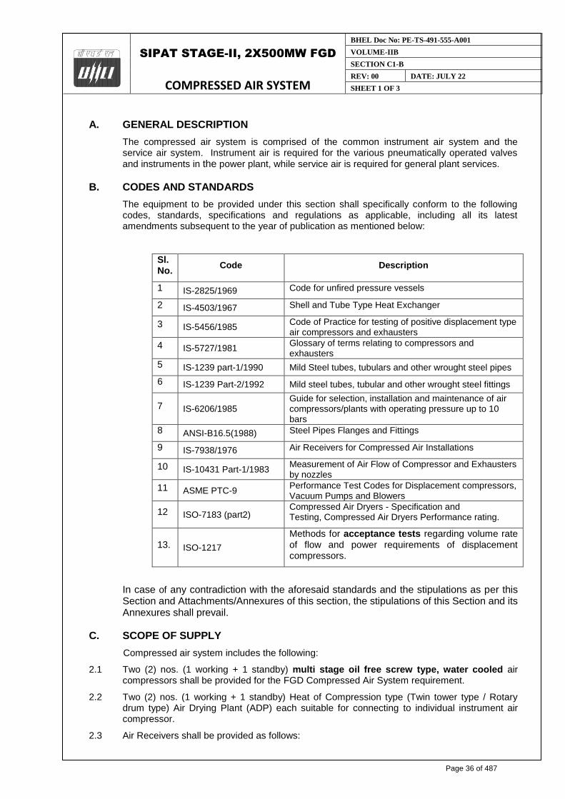
A. GENERAL DESCRIPTION
The compressed air system is comprised of the common instrument air system and the service air system. Instrument air is required for the various pneumatically operated valves and instruments in the power plant, while service air is required for general plant services.
B. CODES AND STANDARDS
The equipment to be provided under this section shall specifically conform to the following codes, standards, specifications and regulations as applicable, including all its latest amendments subsequent to the year of publication as mentioned below:
Sl. No.
Code Description
1 IS-2825/1969 Code for unfired pressure vessels
2 IS-4503/1967 Shell and Tube Type Heat Exchanger
3 IS-5456/1985 Code of Practice for testing of positive displacement type air compressors and exhausters
4 IS-5727/1981 Glossary of terms relating to compressors and exhausters
5 IS-1239 part-1/1990 Mild Steel tubes, tubulars and other wrought steel pipes
6 IS-1239 Part-2/1992 Mild steel tubes, tubular and other wrought steel fittings
7 IS-6206/1985 Guide for selection, installation and maintenance of air compressors/plants with operating pressure up to 10 bars
8 ANSI-B16.5(1988) Steel Pipes Flanges and Fittings
9 IS-7938/1976 Air Receivers for Compressed Air Installations
10 IS-10431 Part-1/1983 Measurement of Air Flow of Compressor and Exhausters by nozzles
11 ASME PTC-9 Performance Test Codes for Displacement compressors, Vacuum Pumps and Blowers
12 ISO-7183 (part2) Compressed Air Dryers - Specification and Testing, Compressed Air Dryers Performance rating.
13. ISO-1217 Methods for acceptance tests regarding volume rate of flow and power requirements of displacement compressors.
In case of any contradiction with the aforesaid standards and the stipulations as per this Section and Attachments/Annexures of this section, the stipulations of this Section and its Annexures shall prevail.
C. SCOPE OF SUPPLY
Compressed air system includes the following:
2.1 Two (2) nos. (1 working + 1 standby) multi stage oil free screw type, water cooled air compressors shall be provided for the FGD Compressed Air System requirement.
2.2 Two (2) nos. (1 working + 1 standby) Heat of Compression type (Twin tower type / Rotary drum type) Air Drying Plant (ADP) each suitable for connecting to individual instrument air compressor.
2.3 Air Receivers shall be provided as follows:
Page 36 of 487

SIPAT STAGE-II, 2X500MW FGD
COMPRESSED AIR SYSTEM
BHEL Doc No: PE-TS-491-555-A001
VOLUME-IIB
SECTION C1-B
REV: 00 DATE: JULY 22
SHEET 2 OF 3
1.1
P E M - 6 6 6 6 - 0
Two (2) nos air receiver (one each for each compressor) of 02 cu.m capacity located near the compressor house building.
2.4 All interconnecting piping including compressed air piping, cooling water piing & drain pipes, valves, fittings, supports etc. for safe and satisfactory operation of air compressors.
2.5 All instruments including the electronic online dew point meter with suitable sampling connection.
2.6 Compressor mounted local control panel.
D. EQUIPMENT DESIGN & TESTING CRITERIA
3.1 Air Compressor
a) The capacity of air compressor shall be 15 NM3/min with discharge pressure of 8.5 kg/cm2 (g). Delivery pressure at the outlet of ADP will be 8.0 Kg/cm2 (g). Each compressor will be designed to deliver the nominal capacity at the required delivery pressure.
b) The compressors and Air Drying plants shall operate under the following ambient conditions.
i. Minimum temperature: 10 deg.C
ii. Maximum temperature: 50 deg. C
iii. Design condition (temperature: 45 deg. C & 75% RH Relative humidity)
iv. Height above MSL (m): (+) 282.5 M
c) Testing of compressor will be as per ISO: 1217.
d) Air compressors will be designed for continuous operation with high efficiency to satisfy the performance requirement.
e) Satisfactory operation in parallel will be ensured without any uneven load sharing, undue vibration, noise etc.
f) Compressor noise level shall not exceed 85 dBA to a reference of 0.0002 microbar when measured at a distance of 1.5 metre above the floor.
g) The compressors shall operate at 100% capacity with load / unload feature.
For details refer customer specification.
3.2 AIR DRYING PLANT
Air-drying plant shall be of heat of compression desiccant type (Twin tower type or rotary drum type), drying by adsorption process through a desiccant medium.
The capacity of air drying plant for instrument air compressor shall be of matching capacity to that with instrument air compressor.
Quality of outlet air from ADP shall be in accordance to ISO 8573.
i. Dew point at outlet of the air drying plant will be minus (-) 400 C at atmospheric pressure.
Desiccant shall be silica gel / activated alumina as per manufacturer’s standard.
Hot air piping from compressor to air dryer shall be insulated.
For details refer customer specification.
3.3 AIR RECEIVER
a) The quantity and capacity of air receivers shall be as specified in clause no. 2.3 above.
b) The air receivers will be vertical self-supporting cylindrical vessels with supporting legs for resting on their foundation.
c) Operation & maintenance platform for each air receiver along with access ladders shall also be provided.
Page 37 of 487
SIPAT STAGE-II, 2X500MW FGD
COMPRESSED AIR SYSTEM
BHEL Doc No: PE-TS-491-555-A001
VOLUME-IIB
SECTION C1-B
REV: 00 DATE: JULY 22
SHEET 3 OF 3
1.1
P E M - 6 6 6 6 - 0
d) A corrosion allowance of 3 mm shall be provided.
e) The air receiver shall be hydraulically tested to a pressure of 1.5 times the design pressure.
For additional details refer customer specification.
E. LAYOUT CONSIDERATIONS
5.1 A separate Compressed Air System building, housing compressors with drives, air drying units, headers, piping, supports, valves etc. has been envisaged.
5.2 The air receivers will be located outdoors adjacent to the compressor room.
F. POWER SUPPLY ARRANGEMENT
Pl. refer electrical specification for details.
Page 38 of 487

SIPAT STAGE-II, 2X500MW FGD
COMPRESSED AIR SYSTEM
SPECIFICATION No: PE-TS-491-555-A001
VOLUME: II B
SECTION : C2
REV. 00 DATE: JULY 22
SHEET: 1 OF 1
SECTION: C2
CUSTOMER SPECIFICATIONS
Page 39 of 487

SIPAT STAGE-II, 2X500MW FGD
COMPRESSED AIR SYSTEM
SPECIFICATION No: PE-TS-491-555-A001
VOLUME: II B
SECTION : C2-A
REV. 00 DATE: JULY 22
SHEET: 1 OF 1
SECTION: C2-A
TECHNICAL REQUIREMENT
Page 40 of 487

CLAUSE NO.
SCOPE OF SUPPLY & SERVICES
LOT-6 PROJECTS
FLUE GAS DESULPHURISATION (FGD) SYSTEM PACKAGE
TECHNICAL SPECIFICATION
SECTION – VI, PART-A
BID DOC. NO.:CS-0011-109(6)-9
SUB SECTION-III-A2
AIR CONDITIONING, VENTILATION SYSTEM & COMPRESSED AIR
SYSTEM
Page 3 of 4
g) Contractor shall provide microprocessor/PLC/GIU based control system for control and monitoring of ventilation system as per manufacturer’s standard practice. Control and monitoring of ventilation system from FGD control system is also acceptable.
3.00.00 COMPRESSED AIR SYSTEM
a) Two (2) numbers (1 working+ 1 standby) oil free, rotary screw type air compressors for Instrument air and service air applications for FGD plant each of adequate capacity & adequate pressure, with their motor drives and other accessories as per equipment sizing criteria mentioned in Part A, Sub-section ‘Salient design data’ of technical specification. However, minimum capacity of each air compressor shall be 15Nm3/min at discharge pressure of 8.5 Kgf/cm2 (g).
b) Two (2) numbers (1 working+ 1 standby) Air Drying Plants (one for each air compressor) of adequate capacity with all interconnecting piping, valves, fittings, etc.
c) Two number Air Receiver each of capacity 2 m3 (normal) at the discharge of each Air compressor.
d) Monorail with electric hoist of minimum 2 tons or 125% of heaviest parts of equipment to be lifted whichever is more.
e) Complete instruments, control system with panels as required for compressed air system.
f) Complete compressed air and piping network for service air and instrument air application in FGD system shall be as per Tender drawing of compressed air system.
g) Supply of Mandatory spares as specified.
h) Any additional items required to make the system complete.
NOTE: Tapping for Instrument air and Service air shall be taken from nearby
existing header of compressed air system.
4.00.00 General
i. All associated Civil & structural work for air conditioning and Ventilation system and compressed air system.
ii. Set of commissioning spares as may be required during erection and commissioning.
iii. One (1) set Special tools and tackles required for maintenance of all the Mechanical, Electrical and C & I equipment under the scope of bidder.
iv. All steel / cast iron inserts, plates, bolts, nuts, sleeves, metallic-fasteners etc. to be grouted in concrete work and used to hold/ support the equipment/piping / ducting being supplied and erected under this specifications.
v. Any additional items required to make the system complete.
Page 41 of 487

CLAUSE NO.
SCOPE OF SUPPLY & SERVICES
LOT-6 PROJECTS
FLUE GAS DESULPHURISATION (FGD) SYSTEM PACKAGE
TECHNICAL SPECIFICATION
SECTION – VI, PART-A
BID DOC. NO.:CS-0011-109(6)-9
SUB SECTION-III-A2
AIR CONDITIONING, VENTILATION SYSTEM & COMPRESSED AIR
SYSTEM
Page 4 of 4
vi. Initial charge of all lubricants and grease, etc. Further, all consumables required for PG tests shall also be in Bidder’s scope of supply. Grouting, dressing and final finishing of all foundations of various equipment, etc.
vii. Repairing and making good/ sealing of cutouts / openings in floors, roofs and walls, for executing the works under this system and making them water tight as directed by the engineer.
Corrosion protection painting for all equipment / items by Bidder as detailed in relevant clauses of technical specification.
Page 42 of 487

CLAUSE NO. SALIENT DESIGN DATA
LOT-6 PROJECTS
FLUE GAS DESULPHURISATION (FGD)
SYSTEM PACKAGE
TECHNICAL SPECIFICATION SECTION – VI, PART-A
BID DOC. NO.:CS-0011-109(6)-9
SUB-SECTION-V
SALIENT DESIGN DATA PAGE 20 OF 26
push buttons etc.) shall be closed loop type and shall be supervised for open and short circuiting. The trouble signal also be annunciated in the respective panels.
v. Facilities shall be provided on the fire alarm panel for simulating fire conditions, sensitivity adjustment, isolation of detectors etc. from the panel.
8.00.00 Compressed Air System
DESIGN CRITERIA / BASIS AND PERFORMANCE GUARANTEE
1. All the equipments shall be designed for continuous duty and as well as for intermittent operation. Frequent start/stop of the system shall not result deterioration in performance nor damage to the equipment.
2. The compressors and Air Drying plants shall operate under the following ambient conditions.
i. Minimum temperature : 10 deg.C
ii. Maximum temperature : 50 deg. C
iii. Design condition (temperature & : 45 deg.C& 75% RH
Relative humidity)
iv. Height above MSL (m) : Refer Chapter “Project Information”
3. The design ambient conditions for the motors shall be as mentioned in relevant Electrical sub-sections.
8.01.00 Selection of Capacity of Air Compressor
a) Air Compressor
Air Compressor shall be designed to meet the Instrument air and service air requirement of all the equipments/plant/systems to be supplied by the Contractor for FGD Plant as follows:-
Sl. No. Continuous Requirement Quantity (in NM3/min)
1. Instrument air requirement for FGD plant (Continuous)
A
2. Service air requirement for FGD plant B
3. Total Air requirement = A+B
4. Capacity of air compressor = 2(A+B)
Notes: While calculating the air requirement of Bidder’s equipments/plant/systems, for continuous requirements of instrument air and service air, no diversity factor shall be considered and they are to be assumed to be of “Simultaneous Requirements”. The intermittent requirement of instrument air and service air, if any
Page 43 of 487

CLAUSE NO. SALIENT DESIGN DATA
LOT-6 PROJECTS
FLUE GAS DESULPHURISATION (FGD)
SYSTEM PACKAGE
TECHNICAL SPECIFICATION SECTION – VI, PART-A
BID DOC. NO.:CS-0011-109(6)-9
SUB-SECTION-V
SALIENT DESIGN DATA PAGE 21 OF 26
shall be converted into continuous requirement by considering frequency of such requirements or selecting an appropriate diversity factor and such diversity factor shall not be less than 0.4.
1. The capacity of air drying plant shall be equal to the capacity of the individual air compressors. The Air drying plant, at its rated capacity, shall be designed to deliver continuously air at dew point of minus (-) 40 deg C at atmospheric pressure and the Quality of dry outlet air to conform to Instrument Society of American Standard S7.3 "Quality Standard for Instrument Air".
2. Discharge pressure available at the outlet of Air drying Plant shall be minimum 7.5 Kg/cm2 (g) or more as per the requirement of Contractor.
3. The discharge pressure of compressor shall be minimum 8.5 Kg/cm2 (g).
4. The heat exchangers are DMCW cooled and the maximum cooling water temperature at compressor coolers inlet to be considered same as that of PHE outlet cooled DMCW temperature.
5. The temperature rise of cooling water in the heat exchangers of the Compressed air system shall be limited to 5-10 deg C.
6. Noise level shall not exceed 85 dBA to a reference level of 0.0002 microbar when measured at a distance of 1.5 meter above the floor. Required acoustic enclosures may be provided to meet the above condition. The discharge blow-off silencer and intake silencers shall be designed to meet the above noise limitation level.
7. Parallel operation of compressors shall be possible without any undue vibration and noise.
8. The flow in compressed air piping shall be designed for the design capacity of each compressor and the flow in header and ring mains to be designed for the total capacity of working compressors.
9. All hot vessels/pipelines/ valves shall be insulated to restrict the outside temperature within 60 deg.C or less with mineral wool (or equivalent), GI wire netting and aluminum cladding/cover.
9.00.00 LIMESTONE AND GYPSUM HANDLING PLANTS
9.01.00 a. Rated capacity of Limestone handling system for truck unloading and reclaim conveyors from storage shed/silo to limestone mill bunkers shall be 150 MTPH (min).
b. The rated capacity of all Gypsum handling conveyors shall be 150MTPH.
d. Belt speed for 150 MTPH conveyors shall not be more than 2.0 m/s.
9.02.00 All conveyors shall be designed for 110% of rated capacity.
Rated capacity (corresponding to LHP & GHP capacity) shall be guaranteed capacity for 100%duty equipment. For 50% duty equipment design capacity shall be guaranteed capacity.
Page 44 of 487

CLAUSE NO.
TECHNICAL REQUIREMENTS
LOT-6 PROJECTS
FLUE GAS DESULPHURISATION (FGD) SYSTEM
PACKAGE
TECHNICAL SPECIFICATION
SECTION-VI
BID DOC. NO.:CS-0011-109(6)-9
PART-B
SUB-SECTION-I-M3
COMPRESSED AIR
SYSTEM
PAGE 1 OF 6
COMPRESSED AIR SYSTEM
1.00.00 SYSTEM DESCRIPTION
1.01.00 The compressed air system shall consist of Air compressors & their motor drives, Air Drying (ADPs) Plants, air receivers for each Air compressors, instrumentation and control, control panels, compressed air piping, Instrument Air Piping network, service air piping network etc.
1.02.00 Air from air compressors shall be dried in respective Air Drying Plants in compressor house and delivered to the Air receivers. From the Compressed air piping header at the downstream of Air receivers, one common header to be provided to meet the service and instrument air requirement for FGD Plant.
2.00.00 SCREW AIR COMPRESSORS
The minimum requirements of design and construction features of various components of Compressed air system (screw type air compressor, air dryer, air receiver, etc.) are described below.
2.01.00 CODES AND STANDARDS
2.01.01 The design, manufacture, testing and performance of the various components of the Rotary Screw type Air Compressors shall comply with the requirements of relevant codes ( IS-5456, IS-10431 [part -1], ASME PTC-9, IS-6206, IS-5727 and CAGI).
2.01.02 Other International Standards like American/BS/DIN etc. equivalent or superior to above mentioned standards are acceptable. Where IS specification is not available, the equipment shall conform to one such International Standard, which shall be indicated in the proposal.
2.01.03 The materials of the various components shall conform to the applicable IS/BS/ASTM/DIN Standards.
2.02.00 DESIGN AND CONSTRUCTION
2.02.01 The compressor shall be oil free multistage, horizontal, water cooled, rotary screw type, heavy duty, rugged construction. Their speed shall be so selected as to result in low maintenance and trouble-free operation under specified conditions.
2.02.02 The rotor and shaft shall be of single piece construction, made of forged steel (AISI C1141 or equivalent). The stator (casing) shall be of Cast-Iron (IS-210 grade) Construction with integral jacket cooling. The rotors shall be dynamically balanced to reduce vibration.
2.02.03 The seal rings and retainers shall be of stainless steel construction and be free for radial self adjustment along the rotor shafts.
2.02.04 Bearings shall be high precision antifriction type IS- 25 Grade 84). The axial thrust load shall be minimized by dividing the axial load of compression on the main and auxiliary bearings through suitable balancing arrangement.
2.02.05 Lubrication system shall be as per manufacturer standard practices
2.03.00 Gear Box
2.03.01 Gears shall have a rating of AGMA-12 or equivalent. Speed increasing gears between the motor and compressor stages shall consist of a common helical gear driving the pinion of each stage. Helical timing gears shall be mounted on the rotor shafts to maintain accurate relative rotor position.
Page 45 of 487

CLAUSE NO.
TECHNICAL REQUIREMENTS
LOT-6 PROJECTS
FLUE GAS DESULPHURISATION (FGD) SYSTEM
PACKAGE
TECHNICAL SPECIFICATION
SECTION-VI
BID DOC. NO.:CS-0011-109(6)-9
PART-B
SUB-SECTION-I-M3
COMPRESSED AIR
SYSTEM
PAGE 2 OF 6
3.00.00 PERFORMANCE REQUIREMENT
3.01.00 Air Compressors (screw type) shall be designed for continuous operation with high efficiency to satisfy the performance requirement as per approved data sheet submitted by the bidder during detailed engineering.
3.02.00 The power rating of the driver shall be selected such that a minimum margin of 10% is available over the power required to deliver rated capacity against rated pressure.
3.03.00 As more than one compressor with drive is specified, satisfactory operation in parallel shall be ensured without any uneven load sharing, undue vibration, keeping noise level within permissible limits for a number of compressors working simultaneously in the same room.
4.00.00 INTERCOOLER, AFTERCOOLER & OIL COOLERS (FOR SCREW)
4.01.00 Intercoolers, After coolers and Oil coolers shall be of water cooled & shell-and-tube type with water on the tube side. Intercoolers & after coolers shall be designed in accordance with Section VIII, Division 1 of ASME Code or equivalent.
4.02.00 Outlet temperature of air from intercooler shall be suitable to suit the equipment and outlet temperature of air from the compressor house outlet header shall be limited to 45 deg.C. However, the instruments or the pneumatic devices requires air temperature less than 45 deg.C., the same shall be achieved at the outlet header.
4.03.00 Coolers shall be provided with removable tube bundle design in accordance with design code TEMA Class C and shall be constructed with removable shell cover.
4.04.00 Oil Coolers shall be equipped with vent & drain connections on oil and water sides. Oil temperature control valve with manual override feature or bypass construction shall be provided to maintain constant temperature. Vent & drain connections for intercoolers and aftercoolers shall be provided.
4.05.00 Design pressure shall be 8 Kg/cm2 (g) or based on shut-off head of cooling water pumps.
4.06.00 The coolers shall be designed for maximum heat load and atleast 10 percent design margin shall be provided in the number of tubes.
4.07.00 Adequately sized safety valves shall be provided for both intercoolers and after coolers.
4.08.00 Each intercooler and aftercooler shall be provided with moisture separator units with suitable baffling. Moisture separator units shall be equipped with a level gauge glass with isolating cock.
4.09.00 Electrically operated automatic drain trap stations with bypass and isolating valves shall be provided for moisture separators for automatically draining of condensed moisture. The drain trap shall be timer based. Manual draining facility shall also be provided in the drain trap.
4.10.00 Cooler shells, channels and covers shall be of carbon steel (SA 285 Gr C / SA 516 Gr 70 / equivalent).Tube sheet shall be of Brass or SS and the tubes shall be of Admiralty brass or Aluminium brass or Copper or SS 304.
4.11.00 For the instrument air compressors offered with "Heat of compression" type air drying plants, the after coolers shall be provided at downstream of Air Drying Plant.
5.00.00 AIR RECEIVERS
5.01.00 The design pressure and temperature shall be minimum 10 Kg/cm2 (g) and 50 deg.C respectively. Receivers shall be designed in accordance with Section VIII, Division 1 of ASME Code or equivalent.
5.02.00 Air receivers are to be provided with gasketted inspection manhole of minimum 500 mm diameter with cover plate, lifting handle, davit cap etc.
Page 46 of 487

CLAUSE NO.
TECHNICAL REQUIREMENTS
LOT-6 PROJECTS
FLUE GAS DESULPHURISATION (FGD) SYSTEM
PACKAGE
TECHNICAL SPECIFICATION
SECTION-VI
BID DOC. NO.:CS-0011-109(6)-9
PART-B
SUB-SECTION-I-M3
COMPRESSED AIR
SYSTEM
PAGE 3 OF 6
5.03.00 Receivers shall be of welded construction with minimum number of joints. Longitudinal seam in adjacent sections shall not be in same line. Welding shall be as per relevant codes. Filler material to have composition & structure as that of material welded. Welding electrodes to be approved by Employer. Electrodes to be dried before use.
5.04.00 Relief valves shall be provided to suit compressor capacity and set pressure of the same shall be atleast 10% above working pressure. The spring in relief valve shall not reset for any pressure more than 10% above or below the design set pressure.
5.05.00 Each receiver shall be provided with drain connection with electrically operated automatic drain trap arrangement with isolation and bypass valves.
5.06.00 The material of construction of shell, dished ends, flanges, etc of the air receivers shall be of carbon steel as per IS:2062 or equivalent.
6.00.00 INTAKE AIR FILTER AND SILENCER
6.01.00 Filters with multiple elements quick removal type for easy cleaning shall be provided at suction of each air compressor and also be of heavy-duty dry type.
6.02.00 The filters shall be complete with integral silencers. Separate silencers, if specified, shall be provided. The filtering elements shall be easily removable for cleaning.
6.03.00 The filters shall be designed for an efficiency of not less than 99% for particles 2 microns and larger.
7.00.00 AIR DRYING PLANTS
7.01.00 One number Air drying plant shall be provided for each air compressor. Drying shall be by adsorption process through a desiccant medium.
7.02.00 Air Drying (ADP) Plant may be of "Open Through type (Blower reactivated)” OR “Heat of (HOC) Compression type".
7.03.00 Regeneration of desiccant shall be achieved by "open through" or "Heat of compression" method without any air purge loss.
7.04.00 Hot unsaturated compressed air shall be used for regeneration of exhausted desiccant in case of "Heat of compression type ADP" and air from blower shall be used for regeneration after heating by electrical heater in case of "Open through type ADP".
7.05.00 Each ADP shall be provided with two adsorber towers each sized for design drying cycle of minimum 8 hours. After this period, the adsorber tower which was under drying mode shall be put under regeneration/reactivation mode while the other tower will take over the drying duty. The change of drying mode to reactivation mode or vice-versa shall be automatic with provision for manual operation also. The change over from one mode to another shall be through automatic solenoid operated valves.
7.06.00 In "Open Through" type ADP, for regeneration of desiccant, atmospheric air shall be filtered, heated through an electric heater and passed through the desiccant before exhausted to atmosphere. The reactivated desiccant shall be cooled through same atmospheric air without heater in operation.
In case of HOC type drier, the reactivation shall be achieved by the heat of the compressed air itself. The hot unsaturated compressed air from the outlet of last stage of compressor shall be passed through the adsorber tower. The moist air shall be cooled in dehumidifier and passed through the second adsorber for final drying.
The design reactivation cycle/period of the tower shall be less than 8 hours including cooling period for desiccant for both the types of ADP.
7.07.00 Each ADP shall be provided with two (2) numbers of 100 percent capacity pre-filters and two (2) numbers of 100 percent capacity after-filters at the upstream & downstream of towers.
Page 47 of 487

CLAUSE NO.
TECHNICAL REQUIREMENTS
LOT-6 PROJECTS
FLUE GAS DESULPHURISATION (FGD) SYSTEM
PACKAGE
TECHNICAL SPECIFICATION
SECTION-VI
BID DOC. NO.:CS-0011-109(6)-9
PART-B
SUB-SECTION-I-M3
COMPRESSED AIR
SYSTEM
PAGE 4 OF 6
The filtering media shall be of ceramic candle type elements designed to withstand atleast 50% of static pressure as differential pressure. The pre-filters shall be provided with automatic electrically operated drain trap arrangement with isolation and bypass valves.
7.08.00 The electric heaters (if required) (2x100% capacity for each ADP) shall be provided with thermostatic control for heater and relief valve for safety and shall be flanged type to facilitate easy replacement of element.
7.09.00 Each electric motor driven blower (2x100% capacity for each ADP) shall be provided with individual dry type filters at inlet.
7.10.00 The adsorber tower shall be designed with sufficient cross sectional area resulting low air velocity and pressure drop. Minimum 20% of desiccant depth shall be provided as free board in adsorber vessels. Adsorber vessels to be provided with suitable number of inspection/sight windows of "Persplex" for observation of adsorbent condition. Desiccant filling and removal connections shall be provided for the adsorber vessels.
7.11.00 The coolers/heat exchangers/ dehumidifiers of ADP shall be designed & constructed as per the requirements specified for “Intercoolers, After coolers & Oil coolers" above.
7.12.00 All pressure vessels such as pre-filters, after-filters, adsorber vessels, heaters, heat exchangers/de-humidifiers / coolers etc associated with ADP shall be designed in accordance with Section VIII, Division 1, of ASME Code or equivalent. The pressure vessels shall be provided with air tight gasketted manholes/handholes and relief valves.
7.13.00 Quantity of desiccant to be calculated shall take into account residual moisture content at the end of regeneration cycle.
714.00 Adsorption capacity and density to be considered for silica gel shall not be more than 10% and 550 kg/m3 respectively. In case of activated alumina the same shall be 8% (max) and 900 kg/m3 (max.) respectively.
7.15.00 In case of Heat of compression type, adsorbers shall be sized so that even when the compressor is operating at part load, complete regeneration shall be achieved within the cycle time and quality of air (dew point) shall be maintained throughout the design cycle period.
7.16.00 Complete ADP equipment shall preferably be mounted on a skid.
7.17.00 Required sample connections in piping be provided for sampling of air at desired locations.
7.18.00 Non-lubricated two way / three way / four way valves ball valves with pneumatic actuators be provided.
7.19.00 The material of Construction for various components of ADP shall be as as per manufacturer’s proven standard.
7.20.00 HOC dryers of single rotating drum type design using packed dessicant with in-built regeneration and adsorption compartments are also acceptable in place of specified twin-tower type dryers, if the design ensures specified performance guarantee. In case, the Contractor offers such a type, the same shall be of proven design.
8.00.00 INTERCONNECTING PIPING, FITTING AND VALVES
The interconnecting piping & valves within compressor house for compressed air & cooling water etc shall be designed in line with the specification furnished in subsection titled "Low Pressure Piping" of Part-B of this Technical Specification.
Page 48 of 487

CLAUSE NO.
TECHNICAL REQUIREMENTS
LOT-6 PROJECTS
FLUE GAS DESULPHURISATION (FGD) SYSTEM
PACKAGE
TECHNICAL SPECIFICATION
SECTION-VI
BID DOC. NO.:CS-0011-109(6)-9
PART-B
SUB-SECTION-I-M3
COMPRESSED AIR
SYSTEM
PAGE 5 OF 6
9.00.00 CONTROL PHILOSPHY
9.01.00 GENERAL
9.01.01 The minimum requirements are specified herein and the same shall be elaborated by contractor. The Contractor shall include controls & instrumentation to facilitate safe, reliable and efficient operation for the system. The controls, protection, interlock and instrumentation system offered by the contractor shall be subjected to approval of the Employer during post award engineering stage.
9.01.02 Any of the compressor and Air drying Plant may be selectable for "shutdown", "working" or "standby" duty.
9.01.03 On tripping of working equipment, the standby equipment shall come into operation automatically in case of very low air pressure in the system.
9.01.04 All abnormal conditions used for tripping the compressor or any other equipment shall be provided with pre-trip audio-visual indication/annunciation in the control panel.
9.01.05 An electrically operated automatic valve shall be provided on cooling water supply line of each compressor & dryer (if applicable) which will automatically shut off the cooling water supply, in case any of the compressor/dryer is not running for more than set time duration. Suitable interlock shall also be provided for opening the valve before starting of any of the compressor.
9.01.06 The following indications shall be made available in the control panels for repeating the same in main plant Control System / Panels.
(a) Status of each compressor
(b) Instrument air pressure low/high
(c ) Service air pressure low/high
(d) Dew point of instrument air
(e) Status of each ADP
9.01.07 Lube oil pressure and temperature in the oil circuit of compressor shall be automatically controlled.
9.01.08 Unless otherwise mentioned in the relevant electrical sub-section, automatic motor overload control system shall be included to permit continuous operation of compressors at minimum ambient air without exceeding the name plate rating of the motor.
9.02.00 Screw Compressor
9.02.01 Each compressor shall be in the control panel to operate either in Base duty (Auto Load-Unload) or Standby duty (Auto On-Off) mode in case of Screw and unload/modulate/energy optimization (Auto Dual Mode) in case of centrifugal
9.02.02 In "Base duty" mode, whenever air supply from compressors exceeds the demand, control system shall operate the load-unload circuit at a predetermined set pressure, throttle the inlet valve and open the blow off valve. The compressor shall run in unloaded condition. When system pressure drops due to more demand, the load-unload circuit shall operate again to bring the compressor to 100% load after closing the blow -off valve.
9.02.03 In "Stand-by" mode the compressor shall automatically assist base load compressors during periods of peak air demand. When air pressure in the system reaches a pre-set lower limit, compressor should start in unloaded condition and the compressor shall be fully loaded. When the pressure in the system rises to pre-set high value, the compressor shall be unloaded and shall run in idling mode for a specific period (set by a timer). The compressor may be loaded to full load in case of drop in system pressure or compressor may be stopped
Page 49 of 487

CLAUSE NO.
TECHNICAL REQUIREMENTS
LOT-6 PROJECTS
FLUE GAS DESULPHURISATION (FGD) SYSTEM
PACKAGE
TECHNICAL SPECIFICATION
SECTION-VI
BID DOC. NO.:CS-0011-109(6)-9
PART-B
SUB-SECTION-I-M3
COMPRESSED AIR
SYSTEM
PAGE 6 OF 6
in case the system pressure does not drop and compressor continues to idle for more than a pre-set time.
9.02.04 The control system shall provide warning to the operator that a hot-start condition exists for the motor driver and adequate cool-down period has not occurred after the motor was shut down.
9.02.05 The alarms and shutdown scheme mentioned below are suggestive and shall be provided as per manufacturer's standard practice meeting the safe operational requirement of the equipment/system each compressor:-
(a) "Air temperature high" at inlet to last stage Alarm & trip
(b) "Low lube oil pressure" Alarm & trip
(c) "High Lube oil supply temperature" Alarm & trip
(d) "High oil filter differential pressure" Alarm
(e) "Low lube oil level in lube oil sump" Alarm
(f) "High inlet air filter differential pressure" Alarm & trip
(g) "Low cooling water flow to air compressor" Alarm
9.03.00 Air Drying Plant
9.03.01 Sequential operation of the adsorber towers & air compressors shall be controlled automatically with a provision for manual take over.
9.03.02 Change over of tower from drying mode to regeneration mode shall happen automatically if the dew point is high at the outlet of ADP sensed by the dew point (using aluminium oxide probe) meter/sensor. Automatic operation during regeneration, starting and stopping of blowers, starting and stopping of heaters, etc shall be timer controlled. During the process, in case, operation is taken over manually from the panel through push button or selector switch, the sequential operation shall start with the manual initiation for each of the steps.
9.02.03 The control system shall provide the (as minimum) alarms, "High Reactivation air temperature", "Low Reactivation air temperature", "Low cooling water flow", "Low air pressure at the outlet of ADP" and "High dew point at the outlet of ADP". Adequate number of temperature elements etc. shall be provided for measurement and monitoring of the same.
9.02.04 For rotary drum type Air drying plant, control philosophy as per manufacture’s standard and proven practice is also acceptable.
10.00.00 PAINTING
All the equipments shall be protected against external corrosion by providing suitable painting.
The surface of SS, galvanized steel, Gun metal, Brass, Bronze and non-metallic components shall not be applied with any painting.
The steel surface to be applied with painting shall be thoroughly cleaned before applying painting by brushing, shot blasting etc as per standard procedure.
Page 50 of 487

CLAUSE NO.
LOW PRESSURE PIPING
LOT-6 PROJECTS
FLUE GAS DESULPHURISATION (FGD) SYSTEM
PACKAGE
TECHNICAL SPECIFICATION
SECTION-VI
BID DOC. NO.:CS-0011-109(6)-9
PART-B
SUB-SECTION-I-M7
PIPING
PAGE 1 OF 16
1.00.00 EQUIPMENT SIZING CRITERIA
1.01.00 All the piping systems and equipment supplied under this package shall be designed to operate without replacement and with normal maintenance for a plant service life of 30 years, and shall withstand the operating parameter fluctuations and cycling which can be normally expected during this period.
1.02.00 For all Low Pressure piping systems covered under this specification, sizing and system
design shall be to the requirements of relevant codes and standard indicated. In addition to this, requirements of any statutory code as applicable shall also be taken into consideration.
1.03.00 Inside diameters of piping shall be calculated for the flow requirements of various systems.
The velocities for calculating the inside diameters shall be limited to the following:
a) Water Application Water Velocity in m/sec Pipe Size Below 50-150 200 mm 50 mm mm & above (a) Pump suction ------ 1.2-1.5 1.2-1.8 (b) Pump discharge and recirculation 1.2-1.8 1.8-2.4 2.1-2.5 (c) Header ------ 1.5-2.4 2.1-2.4
Pipe line under gravity flow shall be restricted to a flow velocity of 1 m/sec generally. Channels under gravity flow shall be sized for a maximum flow velocity of 0.6 m/sec.
WILLIAM & HAZEN formula shall be used for calculating the friction loss in piping systems with the following "C" value:
(i) Carbon steel pipe 100 (ii) Ductile Iron. 140 (iii) Rubber lined steel pipe 120
(iv) Stainless steel pipe 100
For calculating the required pump head for pump selection, at least 10% margin
shall be taken over the pipe friction losses and static head shall be calculated from
the minimum water level of the tank/ sump/ reservoir from which the pumps draw
water.
(b) Compressed Air Application
Compressed air 15.0 m/sec.(under Average Pressure & Temp. conditions)
Page 51 of 487

CLAUSE NO.
LOW PRESSURE PIPING
LOT-6 PROJECTS
FLUE GAS DESULPHURISATION (FGD) SYSTEM
PACKAGE
TECHNICAL SPECIFICATION
SECTION-VI
BID DOC. NO.:CS-0011-109(6)-9
PART-B
SUB-SECTION-I-M7
PIPING
PAGE 2 OF 16
1.04.00 The pipes shall be sized for the worst (i.e. maximum flow, temp. and pressure values)
operating conditions.
1.05.00 Based on the inside dia. so established, thickness calculation shall be made as per ANSI B 31.1 OD and thickness of pipes shall than be selected as per ANSI B 36.10/IS-1239 Heavy grade/IS-3589/ASTM-A-53/API-5L/ANSI B 36.19 as the case may be.
1.06.00 Corrosion allowance of 1.6 mm will be added to the calculated thickness being considered (except stainless steel piping). 1.07.00 Bend thinning allowance/manufacturing allowance etc. shall be as per the requirement of the
design code provision. 1.08.00 High points in piping system shall be provided with vents along with valves as per the system
requirement. Low points shall be provided with drains along with drain valves as per the system requirement. Drain lines shall be adequately sized so as to clear condensate in the lines. Material for drain and vent lines shall be compatible with that of the parent pipe material.
1.09.00 Material of construction for pipes carrying various fluids shall be as specified elsewhere. 1.10.00 Compressed air pipe work shall be adequately drained to prevent internal moisture
accumulation and moisture traps shall be provided at strategic locations in the piping systems.
1.11.00 Depending upon the size and system pressure, joints in compressed air pipe work shall be
screwed or flanged. The flange shall be welded with the parent pipe at shop and shall be hot dip galvanized before dispatch to site. Alternatively, the flanges on GI pipes may be screwed-on flanges also.
1.12.00 Threaded joints shall be provided with Teflon sealant tapes.
1.13.00 Following types of valves shall be used for the system/service indicated.
SYSTEM TYPES OF VALVES Butterfly Gate Globe Check Ball Plug Water x x x x x Air x x x x Drains & vents x x x
Fuel oil (if any) x x x x x
1.14.0 Recirculation pipes along with valves, breakdown orifices etc. shall be provided for
important pumping systems as indicated in respective process and instrumentation diagrams
(P&IDs). The recirculation pipe shall be sized for minimum 30%design flow of single pump
operation or the recommended flow of the pump manufacturer whichever is higher.
Page 52 of 487

CLAUSE NO.
LOW PRESSURE PIPING
LOT-6 PROJECTS
FLUE GAS DESULPHURISATION (FGD) SYSTEM
PACKAGE
TECHNICAL SPECIFICATION
SECTION-VI
BID DOC. NO.:CS-0011-109(6)-9
PART-B
SUB-SECTION-I-M7
PIPING
PAGE 3 OF 16
2.00.00 TECHNICAL SPECIFICATION 2.01.00 GENERAL
Specific technical requirements of low-pressure piping, fittings, supports, valves, specialties and tanks etc. have been covered under this Sub-section. It includes details pertaining to design and material of construction for piping, fittings, valves, equipment, etc. cleaning/surface preparation application of primer and painting on over ground piping. It also includes detailed technical requirement of laying underground/buried piping including water proofing/anti corrosive protection. It also covers design, engineering, manufacturing, fabrication, technical details of piping, valves, specialties, piping hangers / supports, tanks etc.
2.02.00 Pipes and fittings 2.02.01 All low pressure piping systems shall be capable of withstanding the maximum pressure in
the corresponding lines at the relevant temperatures. However, the minimum thickness as specified in the following clauses and or respective codes for pipes and fittings shall be adhered to. The bidder shall furnish the pipe sizing/ thickness calculation as per the criteria mentioned above under LP piping equipment sizing criteria of this Technical Specification.
2.02.02 Piping and fittings coming under the purview of IBR shall be designed satisfying the
requirements of IBR as a minimum. 2.02.03 Supporting arrangement of piping systems shall be properly designed for systems where
hydraulic shocks and pressure surges may arise in the system during operation. Bidder should provide necessary protective arrangement like anchor blocks/anchor bolt etc. for the safeguard of the piping systems under above mentioned conditions. The requirement will be, however, worked out by the contractor and he will submit the detailed drawings for thrust/anchor block to the Employer. External, and internal, attachments to piping shall be designed so as not to cause flattening of pipes and excessive localized bending stresses.
2.02.04 Bends, loops, off sets, expansion or flexible joints shall be used as required in order to
prevent overstressing the piping system and to provide adequate flexibility. Flexibility analysis (using software packages such as Caesar-II etc.) shall be carried out for sufficiently long piping (straight run more than 300M).
2.02.05 Wherever Bidder's piping coming under this specification, terminates at an equipments or
terminal point not included in this specification, the reaction and the thermal movement imposed by bidder's piping on equipment terminal point shall be within limits to be approved by the Employer.
2.02.06 The hot lines shall be supported with flexible connections to permit axial and lateral
movements. Flexibility analysis shall be carried out for pipelines which have considerable
straight run as indicated above and necessary loops/ expansion joint etc. shall be provided
as may be necessary depending on layout.
2.02.07 Piping and fittings shall be manufactured by an approved manufacturer of repute. They should be truly cylindrical of clear internal diameter, of uniform thickness, smooth and strong, free from dents, cracks and holes and other defects.
2.02.08 For rubber lined ERW pipes, beads shall be removed for pipe size 80 NB and above. 2.02.09 Inspection holes shall be provided at suitable locations for pipes 800 Nb and above as
required for periodic observations and inspection purposes.
Page 53 of 487
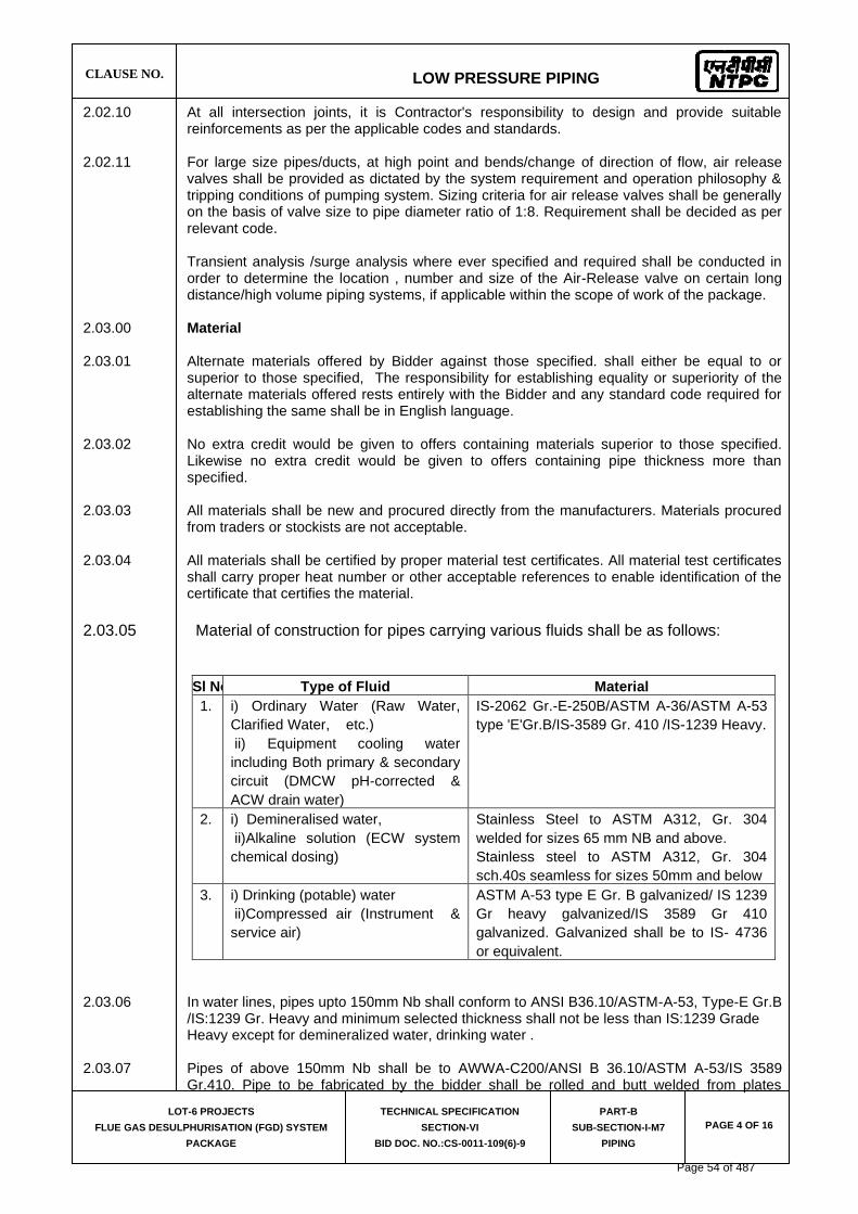
CLAUSE NO.
LOW PRESSURE PIPING
LOT-6 PROJECTS
FLUE GAS DESULPHURISATION (FGD) SYSTEM
PACKAGE
TECHNICAL SPECIFICATION
SECTION-VI
BID DOC. NO.:CS-0011-109(6)-9
PART-B
SUB-SECTION-I-M7
PIPING
PAGE 4 OF 16
2.02.10 At all intersection joints, it is Contractor's responsibility to design and provide suitable reinforcements as per the applicable codes and standards.
2.02.11 For large size pipes/ducts, at high point and bends/change of direction of flow, air release
valves shall be provided as dictated by the system requirement and operation philosophy & tripping conditions of pumping system. Sizing criteria for air release valves shall be generally on the basis of valve size to pipe diameter ratio of 1:8. Requirement shall be decided as per relevant code.
Transient analysis /surge analysis where ever specified and required shall be conducted in order to determine the location , number and size of the Air-Release valve on certain long distance/high volume piping systems, if applicable within the scope of work of the package.
2.03.00 Material 2.03.01 Alternate materials offered by Bidder against those specified. shall either be equal to or
superior to those specified, The responsibility for establishing equality or superiority of the alternate materials offered rests entirely with the Bidder and any standard code required for establishing the same shall be in English language.
2.03.02 No extra credit would be given to offers containing materials superior to those specified.
Likewise no extra credit would be given to offers containing pipe thickness more than specified.
2.03.03 All materials shall be new and procured directly from the manufacturers. Materials procured
from traders or stockists are not acceptable. 2.03.04 All materials shall be certified by proper material test certificates. All material test certificates
shall carry proper heat number or other acceptable references to enable identification of the certificate that certifies the material.
2.03.05 Material of construction for pipes carrying various fluids shall be as follows:
Sl No. Type of Fluid Material
1. i) Ordinary Water (Raw Water,
Clarified Water, etc.)
ii) Equipment cooling water
including Both primary & secondary
circuit (DMCW pH-corrected &
ACW drain water)
IS-2062 Gr.-E-250B/ASTM A-36/ASTM A-53
type 'E'Gr.B/IS-3589 Gr. 410 /IS-1239 Heavy.
2. i) Demineralised water,
ii)Alkaline solution (ECW system
chemical dosing)
Stainless Steel to ASTM A312, Gr. 304
welded for sizes 65 mm NB and above.
Stainless steel to ASTM A312, Gr. 304
sch.40s seamless for sizes 50mm and below
3. i) Drinking (potable) water
ii)Compressed air (Instrument &
service air)
ASTM A-53 type E Gr. B galvanized/ IS 1239
Gr heavy galvanized/IS 3589 Gr 410
galvanized. Galvanized shall be to IS- 4736
or equivalent.
2.03.06 In water lines, pipes upto 150mm Nb shall conform to ANSI B36.10/ASTM-A-53, Type-E Gr.B
/IS:1239 Gr. Heavy and minimum selected thickness shall not be less than IS:1239 Grade Heavy except for demineralized water, drinking water .
2.03.07 Pipes of above 150mm Nb shall be to AWWA-C200/ANSI B 36.10/ASTM A-53/IS 3589
Gr.410. Pipe to be fabricated by the bidder shall be rolled and butt welded from plates
Page 54 of 487

CLAUSE NO.
LOW PRESSURE PIPING
LOT-6 PROJECTS
FLUE GAS DESULPHURISATION (FGD) SYSTEM
PACKAGE
TECHNICAL SPECIFICATION
SECTION-VI
BID DOC. NO.:CS-0011-109(6)-9
PART-B
SUB-SECTION-I-M7
PIPING
PAGE 5 OF 16
conforming to ASTM A-53 type 'E' Gr. B/IS 2062 Gr.E-250B/ASTM-A-36. However, larger pipes, i.e. 1000mm Nb and above shall be made from plates conforming to ASTM A 36/IS 2062 Gr.E-250B and shall meet the requirements of AWWA-M-11 (for deflection & buckling criteria considering water filled pipe as well as vacuum condition that may prevail during transient/surge conditions, truck-load, rail-load and weight density for compacted soil or any other load as the case may be).
2.03.08 In demineralised water service, the pipes upto 50 Nb shall be of stainless steel ASTM A 312,
Gr. 304 sch. 40 Seamless. The size for these pipes shall be to ANSI B 36.19. These shall be socket welded. The material for pipe from 65mm NB upto and including 400 NB shall be to ASTM A 312, Gr. 304 (welded). In no case the thickness of fittings shall be less than parent pipe thickness.
Bidder/Contractor shall note that pipes offered as per a particular code shall conform to that code in all respects i.e. Dimension, tolerances, manufacturing methods, material, heat treatment, testing requirements, etc. unless otherwise mentioned elsewhere in the specification.
2.03.09 Instrument air, Plant (service) air lines and Drinking water lines shall be to ASTM A 53 type E
grade B/ANSI B 36. 10/IS 3589, Gr. 410 / IS: 1239 Heavy (in case thickness calculated is more than gr. Heavy, ANSI B 36.10 Schedule numbers shall be followed) and galvanized to IS 4736 or any equivalent internationally reputed standard. The material of the pipes shall be to ASTM A 53 type 'E' Gr. B / IS: 3589, Gr. 410 / IS: 1239 Gr. Heavy. The fittings shall be of either same as parent material or malleable iron to IS-1879 (galvanized).
2.03.10 Spiral welded pipes as per API-5L/IS-3589 are also acceptable for pipe of size above 150
NB. However minimum thickness of the pipes shall be as elaborated in above clauses. 2.03.11 Condensate lines shall be to ASTM A 106 Gr. B and dimension to ANSI B 36.10 schedule
"standard" as minimum to be maintained. 2.03.12 If carbon steel plates of thickness more than 12 mm are used for manufacture of pipes,
fittings and other appurtenances, then the same shall be control-cooled or normalized as the case may be following the guidelines of the governing code.
2.04.00 Field routed pipes: 2.04.01 Pipe lines of NB 50 size and below are regarded as field run piping. It is Bidder's
responsibility to plan suitable layouts for these system insitu. Bidder shall prepare drawings indicating the layout of field run pipe work. These drawings shall be approved by Project Manager to the installation of the field run pipe work. Based on these approved layouts the Bidder shall prepare the BOQ of field run-pipes and submit to Employer for approval.
2.05.00 Slope/Drains and Vents 2.05.01 Suitable slope shall be provided for all pipelines towards drain points. It is Bidder
responsibility to identify the requirements of drains and vents, and supply the necessary pipe work, valves, fittings, hangers and supports etc. As per the system requirement low points in the pipelines shall be provided with suitable draining arrangement and high points shall be provided with vent connections where air or gas pockets may occur. Vent for use during hydrostatic test shall be plugged after the completion of the test. Vent shall not be less than 15mm size. Drains shall be provided at low points and at pockets in piping such that complete drainage of all systems is possible. Drain shall not be less than 15mm for line size up to 150mm, not less than 20mm up to 300mm and not less than 25mm for 350mm to 600mm pipes and not less than 50mm for 600mm and above pipes.
2.05.02 Air piping shall be sloped so that any part of the system can be drained through the shut-off
drain valve or drain plugs. 2.06.00 Pipe Joints
Page 55 of 487

CLAUSE NO.
LOW PRESSURE PIPING
LOT-6 PROJECTS
FLUE GAS DESULPHURISATION (FGD) SYSTEM
PACKAGE
TECHNICAL SPECIFICATION
SECTION-VI
BID DOC. NO.:CS-0011-109(6)-9
PART-B
SUB-SECTION-I-M7
PIPING
PAGE 6 OF 16
In general all water lines 65mm NB and above, are to be joined generally by butt welding except the locations where valves/fittings are to be installed with flanged connections and 50mm and below by socket welding unless mentioned otherwise specifically. All air lines shall be of screwed connection and rubber lined pipes of flanged connections.
2.06.01 Screwed Joints (a) Threading of pipes shall be carried out after bending, heat treatment etc. If not
possible, threading may be done prior to these operations but proper care should be taken to protect them from damage. Threads shall be to ANSI B 2.1 (taper) NPT/ ANSI B1.20.1 (taper) NPT / IS: 554 unless specified otherwise.
(b) Galvanized pipe shall generally be joined by screwing into sockets. The exposed
threaded portion on the outside of the pipes shall be given a zinc silicate coating. Galvanized pipes shall not be field joined by welding for protection of Galvanising Zinc layer. Screwed ends of GI pipes shall be thoroughly cleaned and painted with a mixture of red and white lead before jointing. For galvanized pipe sizes above 150 mm NB, screw & socket jointing as per ASTM-A-865 shall be employed for both pipe-to-pipe and pipe-to-fitting jointing. For pipe to fitting connection since no direct threading can be done on the fittings (supplied as per ASTM-A-234 Gr. WPB and ANSI B-16.9) necessary straight pipe lengths acting as match pieces shall be welded to the fitting at both ends and subsequently the free ends of the straight lengths shall be threaded as per ASTM A-865 for jointing with main pipe. Once welding of fittings with match pieces and threading of free ends of match pieces are over, the entire fabricated piece shall be galvanized, or in case match pipes and fittings are already galvanized before the above mentioned fabrication then suitable application of Zinc-Silicate paste adequately at the welded surface (both in side & out side) after welding with zinc rich electrode, along with the nascent threaded metal portions at both free ends given the same application of Zinc Silicate paste. Alternatively flanged jointing may be employed for pipe sizes 100 NB and above. However, the bidder shall ensure the galvanized pipe joints do not fail during hydro test.
(c) Teflon tapes shall be used to seal out screwed joints and shall be applied to the male
threads only. Threaded parts shall be wiped clean of oil or grease with appropriate solvent if necessary and allowing proper time for drying before applying the sealant. Pipe ends shall be reamed and all chips shall be removed. Screwed flanges shall be attached by screwing the pipe through the flange and the pipe and flange shall be refaced accurately.
(d) For pipe sizes from 350 mm NB to 550 mm NB (including 350 NB & 550 NB) the GI
pipes shall be of flanged connection. However, the pipes after welding of flanges shall be completely galvanized. Any site welding done on galvanized pipes shall be done with zinc-rich special electrodes and the welded surfaces whether inside or outside shall be coated with zinc-silicate paste. Seal welding of flanges with zinc-rich electrode will be permitted only when any flange is leak-prone during hydro testing.
(e) For pipe sizes 600 mm NB and above, the GI pipes shall be of welded connection
(with zinc-rich special electrodes) followed by application of zinc silicate coating at welded surfaces both inside and outside the pipe, except for the last blank/blind flange, or, equipment connection where application of zinc-silicate paste after welding cannot be done due to inaccessibility of the inside welded surface and where galvanic protection has been impaired due to welding of pipe-to-pipe joint. Thus the last erection joint shall be flanged joint.
2.06.02 Welded Joints (a) For making up welded joints (butt weld or socket weld) the welding shall be
performed by manual shielded metal arc process in accordance with the
Page 56 of 487

CLAUSE NO.
LOW PRESSURE PIPING
LOT-6 PROJECTS
FLUE GAS DESULPHURISATION (FGD) SYSTEM
PACKAGE
TECHNICAL SPECIFICATION
SECTION-VI
BID DOC. NO.:CS-0011-109(6)-9
PART-B
SUB-SECTION-I-M7
PIPING
PAGE 7 OF 16
requirements specified elsewhere in the spec. Any welder employed for carrying butt welding shall be qualified as per ASME section IX for the type of joints he is going to weld. Jointing by butt weld, or socket weld shall depend upon the respective piping material specifications.
2.06.03 Flanged Joints (a) Flanged connections for pipes are to be kept to the minimum and used only for
connections to vessel, equipments, flanged valves and other fittings like strainer/traps/orifices etc. for ease of connection and maintenance etc. Rubber lined pipes shall be flange joined only.
(b) All flanged valves intended for installation on steel piping system, shall have their
flanges drilled to ANSI B 16.5 (or equivalent) and according to the pressure class stated in their respective piping material specification.
(c) Drilling on flanges of flanged valves must correspond to the drilling of flanges on the
piping system on which the valves are installed. 2.07.00 Bends/elbows/mitre bends/ Tees/ Reducers & other fittings 2.07.01 For pipe fittings such as elbows (long radius), reducers, tees, etc. the material shall be to
ASTM-A-234 Gr. WPB/ASTM-105 up to 300 NB. For pipe fittings above 300 NB, the fittings may be fabricated conforming to parent pipe material. Provision of compensation pads shall be kept as per ANSI B 31.1. The fitting shall conform to the dimensional standard of ANSI B-16.9/ 16.11.Further branching in pipes for sizes 65nb and above is also acceptable (ANSI B 31.1).
However, for pipes up to 150 NB, pipe fittings may be supplied with material and dimension
conforming to IS 1239 in case parent pipes also conform to IS 1239. 2.07.02 For pipe size 350Nb and above mitre bends may be used for all pipes except rubber lined
pipes. However, mitre bends are also acceptable for rubber lined pipes above 1200 NB. The bend radius shall be 1½ times the nominal pipe diameter. 90 deg. bends (mitre) shall be in 4 pieces (3 cuts) and 45 deg. mitre bends shall be in 3 pieces 22½ deg. Fabrication of mitre bends shall be as detailed in BS 2633/BS534.
2.07.03 For pipes, above 1200 NB, reducer and tees shall be to dimensional standard of AWWA-C-
208. 2.07.04 Stainless steel fittings shall conform to either ASTM-A-182 Gr. 304 or ASTM-A-403 Grade
WP. 304 Class-S, for sizes upto and including 50 mm NB, i.e. the fittings shall be of seamless construction. However, for stainless fittings above 50 mm NB, the same shall conform to ASTM-A-403 Gr. WP 304 Class W i.e. the fittings shall be of welded construction strictly in accordance with ASTM-A-403.
2.07.07 In no case, the thickness of fittings shall be less than the thickness of parent pipe, irrespective of material of construction.
2.08.00 Flanges 2.08.01 Flanges shall be slip on type or weld neck type. Welding of flanges in tension is not
permitted. 2.08.02 All flanges and-flanged drilling shall be to ANSI B 16.5 / BS EN-1092 / AWWA C - 207 of
relevant pressure/temperature class. Flanges shall be fabricated from steel plates conforming to ASTM A 105/IS 2062 Gr. E-250B. However stainless steel flanges shall be fabricated from SS plates to ASTM-A-240, Gr. 304 or equivalent.
Page 57 of 487

CLAUSE NO.
LOW PRESSURE PIPING
LOT-6 PROJECTS
FLUE GAS DESULPHURISATION (FGD) SYSTEM
PACKAGE
TECHNICAL SPECIFICATION
SECTION-VI
BID DOC. NO.:CS-0011-109(6)-9
PART-B
SUB-SECTION-I-M7
PIPING
PAGE 8 OF 16
2.09.00 Specific technical requirement of laying buried pipe with anti-corrosive treatment
The pipe in general shall be laid with the top of the pipe minimum 1.0 (one) meter below finished general ground level.
2.09.01 Trenching (a) The trench shall be cut true to the line and level and shall follow the gradient of the
pipeline. The width of the trench shall be sufficient to give free working space on each side of the pipe. Trenches shall conform to IS 5822 or any international standard.
2.09.02 Preparation and cleaning of piping (a) The pipeline shall be thoroughly cleaned of all rust, grease, dirt, weld scales and
weld burrs etc. moisture or other foreign matter by power cleaning method such as sand or grit blasting, power tool cleaning, etc. Grease or heavy oil shall be removed by washing with a volatile solvent such as gasoline. Certain inaccessible portions of the pipeline (which otherwise not possible to be cleaned by power cleaning methods) may be scrubbed manually with a stiff wire brush and scrapped where necessary with specific permission of the Project Manager.
(b) On the internal surface for pipes 1000 Nb and above, a coat of primer followed by a
hot coal-tar enamel or coal tar epoxy painting (cold) shall be applied. 2.09.03 Coating and wrapping/ Anti corrosive Protection Coal tar tape a. Buried piping shall be coated and wrapped, as per specification, after completion of
welded and/or flanged connections, and after completion and approval of Hydro testing. Materials to be used for coating and wrapping of underground pipelines are:
(1) Coating primer (coal tar primer) (2) Coating enamel (coal tar enamel) (3) Wrapping materials. All primer/coating/wrapping materials and methods of application shall conform to IS:
10221 except asphalt/bitumen material. Materials (primer/coating/wrapping) as per AWWA-C-203 are also acceptable.
Protective coating shall consist of coal tar primer, coal tar enamel coating, glass
fiber, tissue inner wrap followed by glass fiber or coal tar impregnated Kraft outer wrap or finish coat.
Number of coats and wraps, minimum thickness for each layer of application shall be as per IS-10221. Number of. Coats and wraps shall be decided based on soil corrosivity/resistivity as indicated in IS-10221. Soil data-for this purpose shall be made available.
Total thickness of completed coating and wrapping shall not be less than 4.0 mm. b. Alternatively, the anti-corrosive protection for buried pipes can consist of anti-
corrosive protection Coal-tar tapes. Material and application of tapes shall conform to IS 15337 or equivalent. These-tapes shall be applied hot over the cold coal tar primer in steps of 2mm thickness so as to cover the spiral edges of the first tape by the application of second tape. The total thickness of the finished protective coating shall be 4.0 mm minimum.
Page 58 of 487

CLAUSE NO.
LOW PRESSURE PIPING
LOT-6 PROJECTS
FLUE GAS DESULPHURISATION (FGD) SYSTEM
PACKAGE
TECHNICAL SPECIFICATION
SECTION-VI
BID DOC. NO.:CS-0011-109(6)-9
PART-B
SUB-SECTION-I-M7
PIPING
PAGE 9 OF 16
2.09.04 Trench bed preparation and back filling
Prior to lowering and laying pipe in any excavated trench, the bottom of the trench may require to be back filled and compacted (or as the case may be) to provide an acceptable bed for placing the pipe. Bed preparation in general shall be as per IS: 5822.
2.09.05 Laying of galvanized steel (GI) pipes
All the joints shall be screwed with socket or flanged. Screwed ends of GI pipes shall be thoroughly cleaned and painted with a mixture of red and white lead before jointing Threaded portion on either side of the socket joint shall be applied with Zinc silicate paste. All the provisions for trenching' bed preparation' laying the pipe application of primer' coating' wrapping with tapes and back filling etc. as indicated for "laying of buried piping" and " anti corrosive protection for buried piping" are applicable for buried galvanized steel (GI) pipes also.
2.10.00 Cleaning and flushing 2.10.01 All piping shall be cleaned by the Bidder before and after erection to remove grease, dirt,
dust, scale and welding slag. 2.10.02 Before erection all pipe work, assemblies, sub-assemblies, fittings, and components, etc.
shall be thoroughly cleaned internally and externally by blast cleaning or by power driven wire brushes and followed by air-blowing . However for pipe sizes below 100nb the pipes may be cleaned internally by compressed air blowing as an alternative to internal blast cleaning. The brushes shall be of the same or similar material as the metal being cleaned. Cleaning of Galvanized pipes shall be done by air blowing only.
2.10.03 After erection, all water lines shall be mass flushed with water. The cleaning velocities in
water lines shall be 1.2-1.5 times the operating velocities in the pipelines. 2.10.04 All compressed air pipe work shall be cleaned by blowing compressed air. 2.11.00 Specification for hangers and supports 2.11.01 All supports and parts shall conform to the requirement of power piping code ANSI B 31.1 or
approved equivalent. 2.11.02 The maximum spans of the supports of straight length shall not exceed the recommended
values indicated in ANSI B 31.1.
2.11.03 At all sliding surfaces of supports suitable arrangement is to be provided to minimize sliding
friction.
2.12.00 Design/Construction/Material Particulars of Gate/ Globe /Check /Butterfly / Ball / Air
release /Float valves / Moisture Traps.
2.12.01 GENERAL (a) All valves shall have indicators or direction clearly marked on the hand-wheel so that
the valves opening/closing can be readily determined. (b) Special attention shall be given to operating mechanism for large size valves with a
view to obtaining quick and easy operation ensuring that a minimum of maintenance is required.
Page 59 of 487

CLAUSE NO.
LOW PRESSURE PIPING
LOT-6 PROJECTS
FLUE GAS DESULPHURISATION (FGD) SYSTEM
PACKAGE
TECHNICAL SPECIFICATION
SECTION-VI
BID DOC. NO.:CS-0011-109(6)-9
PART-B
SUB-SECTION-I-M7
PIPING
PAGE 10 OF 16
(c) The valves coming in vacuum lines shall be of extended gland type and/or water
sealed.
(d) The actuator-operated valves shall be designed on the basis of the following:
(1) The internal parts shall be suitable to support the pressure caused by the actuators;
(2) The valve-actuator unit shall be suitably stiff so as not to cause vibrations,
misalignments, etc. (3) All actuator-operated valves shall be provided with hand operated gearing
mechanism also. (4) All actuators operated valves shall open/ close fully within time required
by the process. (e) Valves coming under the purview of IBR shall meet IBR requirements. (f) All valves shall be provided with embossed name plate giving details such as tag
number, type, size etc. (g) Wherever required valves shall be provided with chain operator, extension spindles
and floor stands or any other arrangement approved by employer so that they can be operated with ease from the nearest operating floor. Wherever necessary for safety purpose locking device shall be provided. Further, necessary small platforms for facilitating easy valve operation shall be provided by the contractor wherever necessary in consultation with project manager within the bid price at no extra cost to employer
2.12.02 VALVE BODY MATERIAL Valve body material for various services shall be as follows:
Valve body material for water application like Secondary circuit auxiliary cooling water of ECW system, clarified water, DM cooling water (pH corrected) , drinking water etc. shall be cast iron for sizes 65NB and above; gun-metal for sizes 50 Nb and below.
For compressed air application, valve body material shall be cast carbon steel or forged carbon steel for sizes 65 mm NB & above and Gun metal for sizes 50 NB and below.
DM water: SS body and disc along with SS internals. However for butterfly valves, Cast Iron /Ductile Iron/SG iron/carbon steel body and disc with elastomer lining are also acceptable.
2.12.03 The design, material, construction, manufacture, inspection, testing and performance of
valves shall comply with all currently applicable statutes, regulations and safety codes in the locality where the valves will be installed. The valves shall conform to the latest editions of applicable codes and standards as mentioned elsewhere. Nothing in this specification shall be construed to relieve the Bidder of his responsibility. Valves in general shall conform to the requirements of the following standards.
Standards and Codes AWWA-C-504 Rubber seated butterfly valves.
BS-5155/EN-593 Cast iron and steel body butterfly valves for general
purpose.
Page 60 of 487

CLAUSE NO.
LOW PRESSURE PIPING
LOT-6 PROJECTS
FLUE GAS DESULPHURISATION (FGD) SYSTEM
PACKAGE
TECHNICAL SPECIFICATION
SECTION-VI
BID DOC. NO.:CS-0011-109(6)-9
PART-B
SUB-SECTION-I-M7
PIPING
PAGE 11 OF 16
IS-778 Gun-metal gate, globe and check valves for general purpose.
BS-5154 Copper alloy globe/globe stop and check and gate
valves for general purpose. IS-780 Sluice valves for water works purpose (50-300 mm size) IS-2906 Sluice valves for water works purpose (350-1200 mm size)
IS-5150 Cast iron wedge and double disc gate for general purpose.
BS-5152 Specification for cast iron globe valves. BS-5153 Cast iron check valves for general purpose. IS-5312 Swing check type reflux (non-return) valves. ANSI B 16.34 Standard for valves. API-594 Standard for Dual-check valves. API-600 Steel gate valves. ANSI-B-16.10 Valves face to face and other relevant dimension. API-598 Valves inspection test. 2.12.04 End Connections The end connections, shall comply with the following: Socket welding (SW) - ANSI B 16.11 Butt Welding (BW) - ANSI B 16.25. Threaded (SC) - ANSI B 2.1 Flanged (FL) - ANSI B 16.5& AWWA-C-207 (steel flanges), ANSI B 16.1 (Cast Iron flanges). 2.13.00 Gate/Globe/Check Valves (a) All cast iron body valves (gate, globe and non-return) shall have flanged end
connections; (screwed ends for Ductile D.2NI body valves are not acceptable).
(b) All steel and stainless steel body valves of sizes 65 mm and above shall have flanged or butt welding ends. Valves of sizes below 65mm shall have flanged or socket welded ends. Compatibility of welding between valve body material and connecting pipe material is a pre-requisite in case of butt-welded joints.
(c) All gun metal body valves shall have screwed ends.
(d) All flanged end valves/specialties. shall be furnished along with matching counter flanges, fasteners, gaskets etc. as required to complete the joints.
(e) Gate/sluice valves shall be used for isolation of flow. All gate valves shall be of the full-way type, and when in the full open position the bore of the valve shall not be constricted by any part of the gate.
Page 61 of 487

CLAUSE NO.
LOW PRESSURE PIPING
LOT-6 PROJECTS
FLUE GAS DESULPHURISATION (FGD) SYSTEM
PACKAGE
TECHNICAL SPECIFICATION
SECTION-VI
BID DOC. NO.:CS-0011-109(6)-9
PART-B
SUB-SECTION-I-M7
PIPING
PAGE 12 OF 16
Gate valves shall be of the solid/elastic or articulated wedge disc. Gate valves shall be provided with the following accessories in addition to other standard items:
(1) Hand wheel (2) Position indicator (for above 50 mm NB valve size) (3) Draining arrangement wherever required. (f) Globe valves shall be used for regulation purposes. They shall be provided with hand
wheel, position indicator, draining arrangement (wherever required) and arrow indicating flow direction. Preferably, the valves shall be of the vertical stem type. Globe valves shall preferably have radiused or spherical seating and discs shall be free to revolve on the spindle.
The pressure shall preferably be under the disc of the valve. However, globe valves,
with pressure over the disc shall also be accepted provided (i) no possibility exists that flow from above the disc can remove either the disc from stem or component from disc (ii) manual globe valves can easily be operated by hand. If the fluid load on the top of the disc is higher than 40-60 KN, bypass valve shall be provided which permits the downstream system to be pressurized before the globe valve is opened.
(g) Check valves shall be used for non-return service. They shall be swing. check type
or double door (Dual plate)check type with a permanent arrow inscription on the valve body indicating the fluid flow direction. In long distance pipes lines with possibility of surge-occurrence, dual plate check valves are preferable for its spring controlled opening /closing of flaps/doors against flow reversals. However, dual plate check valves shall not be used for sizes more than 600mm NB.
(h) For bore greater than 2" the valves must be swing check type or dual plate check
type suitable for installation in all positions (vertical and horizontal); (i) For bore smaller than or equal to 2" the valves must be of the piston type to be
installed, in horizontal position. (j) All gate and globe valves shall be provided with back seating arrangement to enable
on line changing of gland packing. The valves shall be preferably outside screw & yoke type.
(k) All gate and globe valves shall be rising stem type and shall have limit switches for
full OPEN and full CLOSED indication wherever required. This will include motor-operated valves also wherever required. In such cases the limit switches shall form an integral part of the valve. Stop-gap arrangement in this respect is not acceptable.
(l) All valves except those with rising stems shall be provided with continuous mechanical position indicators; rising stem valves shall have only visual indication through plastic/metallic stem cover for sizes above 50 mm nominal bore.
(m) For Cl gate, globe and check valves wherever thickness of body/bonnet is not
mentioned in the valves standards, thickness mentioned in IS- 1538 for fitting shall be applicable.
2.13.01 MATERIAL OF CONSTRUCTION (GATE/GLOBE/CHECK VALVE) (a) The materials shall generally comply with the following:
(1) Cast Steel Valves
Body & bonnet ASTM A 216 Gr. WCB/ ASTM A 105
Page 62 of 487

CLAUSE NO.
LOW PRESSURE PIPING
LOT-6 PROJECTS
FLUE GAS DESULPHURISATION (FGD) SYSTEM
PACKAGE
TECHNICAL SPECIFICATION
SECTION-VI
BID DOC. NO.:CS-0011-109(6)-9
PART-B
SUB-SECTION-I-M7
PIPING
PAGE 13 OF 16
Disc for non-return ASTM A 216 Gr. WCB/ Valves ASTM A 105 Trim. ASTM A 182 Gr. F6 or Equivalent (2) Stainless steel valves Body & Bonnet SS 304 Disc -do- Trim. SS 316
(3) Cast iron valves Body & bonnet BS 1452 Gr. 14/ IS-210 Gr. FG 260 Seating surfaces and rings 13% chromium steel/ 13% Chrome overlay Disc for non-return valves BS 1452 Gr. 14/IS-210 Gr FG 260 Hinge pin for non-return valves AISI 316 Stem for gate globe valves 13% chromium steel or Equivalent Back seat 13 % chromium steel / 13% Chrome overlay (4) Gun Metal valves Body and bonnet IS 318 Gr. 2/ Equivalent Standard Trim. -do- (b) Cast iron body valves shall have high alloy steel stem and seat.
(c) Material for counter flanges shall be the same as for the piping.
(d) Forged carbon steel valves are also acceptable in place of Gun metal valves.
2.14.00 Air Release Valve (a) The air release valves shall be of automatic double air valve with two orifices and two
floats. The float shall not close the valve at higher air velocities. The orifice contact joint with the float shall be leak tight joint.
(b) The valve shall efficiently discharge the displaced air automatically from ducts/pipes
while filling them and admit air automatically into the ducts/pipes while they are being emptied. The valve shall also automatically release trapped air from ducts/pipes during operation at the normal working pressure.
(c) Body material of automatic air release valves shall comply generally with BS 1452
Gr. 14/IS: 210 Gr. FG 260. and spindle shall conform to high tensile brass.
Page 63 of 487

CLAUSE NO.
LOW PRESSURE PIPING
LOT-6 PROJECTS
FLUE GAS DESULPHURISATION (FGD) SYSTEM
PACKAGE
TECHNICAL SPECIFICATION
SECTION-VI
BID DOC. NO.:CS-0011-109(6)-9
PART-B
SUB-SECTION-I-M7
PIPING
PAGE 14 OF 16
(d) Air release valves shall not have any integral isolation device within them. Each Air release valve shall be mounted, preceded by a separate isolation gate/ butterfly valve.
2.15.00 Butterfly valves 2.15.01 Design/Construction
(a) The valves shall be designed for the design pressure/temperature of the system on which it is installed and in accordance with AWWA-C-504, EN-593 or any other approved equivalent standard latest edition. Fabricated steel (IS: 2062 GR. E-250B) butterfly valves instead of cast iron body valves are also acceptable for size above 300 mm nb diameter.
(b) The valves shall be suitable for installation in any position (horizontal/vertical etc.) and shall be generally of double-flanged construction. However for sizes 600 NB and below the valves of Wafer construction are also acceptable (c) Valves-350Nb and above shall have pressure equalizing bypass valves, wherever
system parameters warrant the same. (d) Valves-200Nb and above shall also be provided with gear operator arrangement as a
standard practice suitable for manual operation. Manual operation of valve shall be through gear arrangement having totally enclosed gearing with hand wheel diameter and gear ratio designed to meet the required operating torque It shall be designed to hold the valve disc in intermediate position between full open and full closed position without creeping or fluttering. Adjustable stops shall be provided to prevent over travel in either direction.
Limit and torque switches (if applicable) shall be enclosed in water tight enclosures along with suitable space heaters for motor actuated valves, which may be either for On-Off operation or inching operation with position transmitter.
2.15.02 Material of Construction (Butterfly Valves) Materials and other design details shall be as indicated below : (a) Cast Iron Butterfly Valves Body & Disc ASTM A48, Gr. 40 with 2% Ni / IS: 210. Gr. FG-260, with 2% Ni / SG iron BSEN 1563, Gr EN GJS-400-15 with 2%Ni and epoxy coated Shaft BS 970 431 S: 291 / EN 57, or AISI-410 or AWWA-permitted shaft material equivalent to EN-57/AISI-410 or better.
Seat ring 18-8 Stainless steel
Seal Nitrile Rubber
(b) Stainless Steel Butterfly Valves Body & Disc SS 304 . Shaft SS 316 Seat Rings EPT/BUNA-N/Neoprene
Page 64 of 487

CLAUSE NO.
LOW PRESSURE PIPING
LOT-6 PROJECTS
FLUE GAS DESULPHURISATION (FGD) SYSTEM
PACKAGE
TECHNICAL SPECIFICATION
SECTION-VI
BID DOC. NO.:CS-0011-109(6)-9
PART-B
SUB-SECTION-I-M7
PIPING
PAGE 15 OF 16
(c) Carbon steel Butterfly Valves Body & Disc ASTM A 216, Gr. WCB Shaft SS 304 Disc & Seat Rings EPT/BUNA-N/Neoprene (d) Elstomer lined Butterfly Valves Body & Disc ASTM A48, Gr. 40 / IS: 210. Gr. FG-260 / SG Iron (ductile
iron) IS 1865 Gr 400-15 or BSEN 1563, Gr EN GJS-400-15 / ASTM A 216, Gr. WCB with elastomer lining.
Shaft SS 316 2.15.03 Proof of Design Test (Type Test) for Butterfly Valves
Proof of Design (P.O.D.) test certificates shall be furnished by the bidder for all applicable size-ranges and classes of Butterfly valves supplied by him, in the absence of which actual P.O.D. test shall be conducted by the bidder.
All valves that are designed and manufactured as per AWWA-C-504 / AWWA-C-516 shall be governed by the relevant clauses of P.O.D test in AWWA-C-504/AWWA-C-516. For Butterfly valves, designed and manufactured to EN-593 or equivalent, the P.O.D. test methods and procedures shall generally follow the guidelines of AWWA-C-504 in all respect except that Body & seat hydro test and disc-strength test shall be conducted at the pressures specified in EN-593 or the applicable code. Actuators shall also meet requirements of P.O.D. test of AWWA-C-504/AWWA-C-516.
2.16.00 Float operated valves (a) Valve shall automatically control the rate of filling and will shut off when a
predetermined level is reached and close to prevent over flow on pre-set maximum water level. Valve shall also open and close in direct proportion to rise or fall of water level.
(b) DESIGN AND CONSTRUCTION FEATURES
The following design and construction feature of the valve shall be the minimum acceptable.
(c) Valves shall be right-angled or globe pattern. (d) Valves shall be balance piston type with float ball. (e) Leather liner shall not be provided. (f) The body and cover material shall be cast iron conforming to ASTM-A 126 Grade 'B'
or IS: 210 Grade 200 or equivalent, and Float shall be of copper with epoxy painting of two (2) coats.
(g) Valves shall be suitable for flow velocities of 2 to 2.5 m/sec. (h) The valves shall have flanged connections.
2.17.00 Surface preparation and Painting for external piping surfaces (non-coastal projects)
a) Surface preparation - Power tool cleaning / Shot blasting/ abrasive blasting
Page 65 of 487

TECHNICAL
SPECIFICATIONS
SECTION VI, PART-B
TECHNICAL
REQUIREMENTS surface preparation & painting
b) Type of Primer - Red Oxide Zinc Phosphate primer (Alkyd base) to IS 12744 (2 X 25 microns)
c) Intermediate Coat – Synthetic Enamel (long oil alkyd) to IS2932 (1 X 30 microns)
d) Final Coat - Synthetic Enamel (long oil alkyd) to IS2932 (2 X 35 microns)
Min. Total DFT (Microns) to be maintained – 150 (Min) and Color shall be as per NTPC Color Coding Scheme Note: No painting is required on Galvanized, Stainless Steel, Gun Metal surfaces
Page 66 of 487

SIPAT STAGE-II, 2X500MW FGD
COMPRESSED AIR SYSTEM
SPECIFICATION No: PE-TS-491-555-A001
VOLUME: II B
SECTION : C2-B
REV. 00 DATE: JULY 22
SHEET: 1 OF 1
SECTION: C2-B
PROJECT SPECIFIC GENERAL REQUIREMENTS
Page 67 of 487

CLAUSE NO.
GENERAL TECHNICAL REQUIREMENTS
LOT-6 PROJECTS
FLUE GAS DESULPHURISATION (FGD)
SYSTEM PACKAGE
TECHNICAL SPECIFICATION
SECTION – VI
BID DOC. NO.:CS-0011-109(6)-9
PART-C
GENERAL TECHNICAL REQUIREMENTS
PAGE
1 OF 75
1.00.00 INTRODUCTION
This part covers technical requirements which will form an integral part of the
Contract. The following provisions shall supplement all the detailed technical
specifications and requirements brought out in Section-VI, the Technical
Specification and the Technical Data Sheets.
2.00.00 BRAND NAME
Whenever a material or article is specified or described by the name of a particular
brand, manufacturer or vendor, the specific item mentioned shall be understood to
be indicative of the function and quality desired, and not restrictive; other
manufacturer's products may be considered provided sufficient information is
furnished to enable the Employer to determine that the products proposed are
equivalent to those named.
3.00.00 BASE OFFER & ALTERNATE PROPOSALS
The Bidder's proposal shall be based upon the use of equipment and material
complying fully with the requirements specified herein. It is recognised that the
Contractor may have standardized on the use of certain components, materials,
processes or procedures different than those specified herein. Alternate proposals
offering similar equipment based on the manufacturer's standard practice will also be
considered, provided the base offer is in line with technical specifications and such
proposals meet the specified design standards and performance requirement and
are acceptable to the Employer. Sufficient amount of information for justifying such
proposals shall be furnished to Employer alongwith the bid to enable the Employer
to determine the acceptability of these proposals.
4.00.00 COMPLETENESS OF FACILITIES
4.01.00 Bidders may note that this is a contract inclusive of the scope as indicated
elsewhere in the specification. Each of the plant shall be engineered and designed in
accordance with the specification requirement. All engineering and associated
services are required to ensure a completely engineered plant shall be provided.
4.02.00 All equipments furnished by the Contractor shall be complete in every respect, with
all mountings, fittings, fixtures and standard accessories normally provided with such
equipment and/or those needed for erection, completion and safe operation of the
equipment and for the safety of the operating personnel, as required by applicable
codes, though they may not have been specifically detailed in the respective
specifications, unless included in the list of exclusions.
All same standard components/ parts of same equipment provided, shall be
interchangeable with one another.
Page 68 of 487
CLAUSE NO.
GENERAL TECHNICAL REQUIREMENTS
LOT-6 PROJECTS
FLUE GAS DESULPHURISATION (FGD)
SYSTEM PACKAGE
TECHNICAL SPECIFICATION
SECTION – VI
BID DOC. NO.:CS-0011-109(6)-9
PART-C
GENERAL TECHNICAL REQUIREMENTS
PAGE
2 OF 75
4.03.00 For the C&I systems, the Contractor shall be required to provide regular information
about future upgrades and migration paths to the Employer.
5.00.00 RULES, REGULATIONS, CODES & STANDARDS
5.01.00 In addition to the codes and standards specifically mentioned in the relevant
technical specifications for the equipment / plant / system, all equipment parts,
systems and works covered under this specification shall comply with all currently
applicable statutory regulations and safety codes of the Republic of India, NTPC
rules/codes of practices as well as of the locality where they will be installed,
including the following:
a) Indian Electricity Act
b) Indian Electricity Rules
c) Indian Explosives Act
d) Indian Factories Act and State Factories Act
e) Indian Boiler Regulations (IBR)
f) Regulations of the Central Pollution Control Board, India
g) Regulations of the Ministry of Environment & Forest (MoEF), Government of
India
h) Pollution Control Regulations of Department of Environment, Government of
India
i) State Pollution Control Board.
(j.) Rules for Electrical installation by Tariff Advisory Committee (TAC).
(k.) Building and other construction workers (Regulation of Employment and
Conditions of services) Act, 1996
(l.) Building and other construction workers (Regulation of Employment and
Conditions of services) Central Rules, 1998
(m.) Explosive Rules, 1983
(n.) Petroleum Act, 1984
(o.) Petroleum Rules, 1976,
Page 69 of 487

CLAUSE NO.
GENERAL TECHNICAL REQUIREMENTS
LOT-6 PROJECTS
FLUE GAS DESULPHURISATION (FGD)
SYSTEM PACKAGE
TECHNICAL SPECIFICATION
SECTION – VI
BID DOC. NO.:CS-0011-109(6)-9
PART-C
GENERAL TECHNICAL REQUIREMENTS
PAGE
3 OF 75
(p.) Gas Cylinder Rules, 1981
(q.) Static and Mobile Pressure Vessels (Unified) Rules, 1981
(r.) Workmen's Compensation Act, 1923
(s.) Workmen's Compensation Rules, 1924
(t.) NTPC Safety Rules for Construction and Erection
(u.) NTPC Safety Policy
(v.) Any other statutory codes / standards / regulations, as may be applicable.
5.02.00 Unless covered otherwise in the specifications, the latest editions (as applicable as
on date of bid opening), of the codes and standards given below shall also apply:
a) Bureau of Indian standards (BIS)
b) Japanese Industrial Standards (JIS)
c) American National Standards Institute (ANSI)
d) American Society of Testing and Materials (ASTM)
e) American Society of Mechanical Engineers (ASME)
f) American Petroleum Institute (API)
g) Standards of the Hydraulic Institute, U.S.A.
h) International Organisation for Standardisation (ISO)
i) Tubular Exchanger Manufacturer's Association (TEMA)
j) American Welding Society (AWS)
k) National Electrical Manufacturers Association (NEMA)
l) National Fire Protection Association (NFPA)
m) International Electro-Technical Commission (IEC)/European Norm (EN)
n) Expansion Joint Manufacturers Association (EJMA)
o) Heat Exchange Institute (HEI)
Page 70 of 487
CLAUSE NO.
GENERAL TECHNICAL REQUIREMENTS
LOT-6 PROJECTS
FLUE GAS DESULPHURISATION (FGD)
SYSTEM PACKAGE
TECHNICAL SPECIFICATION
SECTION – VI
BID DOC. NO.:CS-0011-109(6)-9
PART-C
GENERAL TECHNICAL REQUIREMENTS
PAGE
4 OF 75
p) IEEE standard
q) JEC standard
5.03.00 Other International/ National standards such as DIN, JIS, VDI, EN, BS, GOST etc.
shall also be accepted for only material codes and manufacturing standards, subject
to the Employer's approval, for which the Bidder shall furnish, adequate information
to justify that these standards are equivalent or superior to the standards mentioned
above. In all such cases the Bidder shall furnish specifically the variations and
deviations from the standards mentioned elsewhere in the specification together with
the complete word to word translation of the standard that is normally not published
in English.
5.04.00 Not used.
5.05.00 In the event of any conflict between the codes and standards referred to in the
above clauses and the requirement of this specification, the requirement of
Technical Specification shall govern.
5.06.00 Two (2) English language copies of all national and international codes and/or
standards used in the design of the plant, equipment, civil, structural and
architectural works shall be provided by the Contractor to the Employer within two
calendar months from the date of the Notification of Award.
5.07.00 In case of any change in codes, standards & regulations between the date of bid
opening and the date when vendors proceed with fabrication, the Employer shall
have the option to incorporate the changed requirements or to retain the original
standard. It shall be the responsibility of the Contractor to bring to the notice of the
Employer such changes and advise Employer of the resulting effect.
5.08.00 A detailed list of standards apart from those mentioned in the respective detailed
specifications in other parts of Section-VI to which all equipment/systems/civil works
should conform as indicated in this Part C and elsewhere in the specification.
6.00.00 EQUIPMENT FUNCTIONAL GUARANTEE
6.01.00 The functional guarantees of the equipment under the scope of the Contract is given
in Section-VI Part - A of Technical Specifications. These guarantees shall
supplement the general functional guarantee provisions covered under Defect
liabilities Section-IV, General Conditions of Contract.
6.02.00 Liquidated damages for shortfall in meeting functional guarantee(s) during the
performance and guarantee tests shall be assessed and recovered from the
Contractor as specified elsewhere in this specification.
Page 71 of 487
CLAUSE NO.
GENERAL TECHNICAL REQUIREMENTS
LOT-6 PROJECTS
FLUE GAS DESULPHURISATION (FGD)
SYSTEM PACKAGE
TECHNICAL SPECIFICATION
SECTION – VI
BID DOC. NO.:CS-0011-109(6)-9
PART-C
GENERAL TECHNICAL REQUIREMENTS
PAGE
5 OF 75
7.00.00 DESIGN OF FACILITIES/ MAINTENANCE & AVAILABILITY CONSIDERATIONS
7.01.00 DESIGN OF FACILITIES
All the design procedures, systems and components proposed shall have already
been adequately developed and shall have demonstrated good reliability under
similar conditions elsewhere.
The Contractor shall be responsible for the selection and design of appropriate
equipments to provide the best co-ordinated performance of the entire system. The
basic requirements are detailed out in various clauses of the Technical
Specifications. The design of various components, assemblies and subassemblies
shall be done so that it facilitates easy field assembly and dismantling. All the
rotating components shall be so selected that the natural frequency of the complete
unit is not critical or close to the operating range of the unit.
7.02.00 MAINTENANCE AND AVILABILITY CONSIDERATIONS
Equipment/works offered shall be designed for high availability, low maintenance
and ease of maintenance. The Bidder shall specifically state the design features
incorporated to achieve high degree of reliability/ availability and ease of
maintenance. The Bidder shall also furnish details of availability records in the
reference plants stated in his experience list.
Bidder shall state in his offer the various maintenance intervals, spare parts and
man-hour requirement during such operation. The intervals for each type of
maintenance namely inspection of the furnace, inspection of the entire hot gas path
and the minor and major overhauls shall be specified in terms of fired hours , clearly
defining the spare parts and man-hour requirement for each stage.
Lifting devices i.e. hoists and chain pulley jacks ,etc. shall be provided by the
contractor for handling of any equipment or any of its part having weight in excess of
500 Kgs during erection and maintenance activities.
Lifting devices like lifting tackles, slings, etc. to be connected to hook of the hoist /
crane shall be provided by the contractor for lifting the equipment and accessories
covered under the specification.
8.00.00 DOCUMENTS, DATA AND DRAWINGS TO BE FURNISHED BY
CONTRACTOR
8.01.00 Bidders may note that this is a contract inclusive of the scope as indicated elsewhere in the specification. Each of the plant and equipment shall be fully
integrated, engineered and designed to perform in accordance with the technical
specification. All engineering and technical services required to ensure a completely
Page 72 of 487
CLAUSE NO.
GENERAL TECHNICAL REQUIREMENTS
LOT-6 PROJECTS
FLUE GAS DESULPHURISATION (FGD)
SYSTEM PACKAGE
TECHNICAL SPECIFICATION
SECTION – VI
BID DOC. NO.:CS-0011-109(6)-9
PART-C
GENERAL TECHNICAL REQUIREMENTS
PAGE
6 OF 75
engineered plant shall be provided in respect of mechanical, electrical, control &
instrumentation, civil & structural works as per the scope.
Each main and auxiliary equipment/item of the plant including instruments shall be assigned a unique tag number. The assignment of tag numbers shall be in accordance with KKS system. In all drawings/documents/data sheet etc. KKS tag number of the equipment/item/instrument etc. shall be indicated.
The Contractor shall furnish engineering data /drawings in accordance with the
schedule of information as specified in Technical Data Sheets and Technical
Specification.
A comprehensive engg and quality coordination procedure shall be finalized with
the successful bidder covering salient features as described in this section of
specifications.
8.02.00 The number of copies/prints/CD-ROMs/manuals to be furnished for various types of
document is given in Annexure-VI to this Part-C, Section-VI of the Technical
Specification.
8.03.00 The documentation that shall be provided by the Contractor is indicated in the
various sections of specification. This documentation shall include but not be limited
to the following:
8.03.01 A) BASIC ENGINEERING DOCUMENTATION
Prior to commencement of the detailed engineering work, the Contractor
shall furnish a Plant Definition Manual within 12 weeks from the date of the
Notification of Award. This manual shall contain the following as a minimum:
i) System description of all the mechanical, electrical, control &
instrumentation & civil systems.
ii) Technology scan for each system / sub-system & equipment.
iii) Selection of appropriate technology / schemes for various systems/
subsystems including techno-economic studies between various
options.
iv) Optimisation studies including thermal cycle optimisation.
v) Sizing criteria of all the systems, sub-systems/ equipments/
structures/ equipment foundations alongwith all calculations justifying
and identifying the sizing and the design margins.
vi) Schemes and Process & Instrumentation diagrams for the various
systems/ sub-system with functional write-ups.
Page 73 of 487
3062805
Line
3062805
Line
3062805
Line

CLAUSE NO.
GENERAL TECHNICAL REQUIREMENTS
LOT-6 PROJECTS
FLUE GAS DESULPHURISATION (FGD)
SYSTEM PACKAGE
TECHNICAL SPECIFICATION
SECTION – VI
BID DOC. NO.:CS-0011-109(6)-9
PART-C
GENERAL TECHNICAL REQUIREMENTS
PAGE
7 OF 75
vii) Operation Philosophy and the control philosophy of the
equipments/system covered under the scope.
ix) General Layout plan of the FGD System incorporating all facilities in
Bidder's as well as those in the Employer's scope. This drawing shall
also be furnished in the form of CD-ROMs to the Employer for
engineering of areas not included in bidder's scope.
x) Basic layouts and cross sections of the main plant building (various
floor elevations), boiler, fuel oil area and other areas included in the
scope of the bidder.
xi) Documentation in respect of Quality Assurance System as listed out
elsewhere in this specification.
The successful bidder shall furnish within three (3) weeks from the
date of Notification of Award, a list of contents of the Plant Definition
Manual (PDMs) including techno-economic studies, which shall then
be mutually discussed & finalised with the Employer.
B) DETAILED ENGINEERING DOCUMENTS
i) General layout plan of the FGD System.
ii) Layouts, general arrangements, elevations and cross-sections
drawings for all the equipment and facilities of the plant.
iii) Flow diagram, process and instrumentation diagrams along with write
up and system description.
iv) Performance curves for Absorber
v) Piping isometric, composite layout and fabrication drawings.
vi) Piping engineering diagrams, pipe and fittings schedules, valve
schedules, hanger and support schedules, insulation schedules.
vii) Technical data sheets for all bought out and manufactured items.
Contractor shall use the Employer’s specifications as a base for
placement of orders on their sub vendors.
viii) Detailed design calculations for components, system, piping etc.,
wherever applicable including sizing calculations for all auxiliaries like
mills, fans etc. as per criteria specified elsewhere in specification.
ix) Absorber sizing calculations. Absorber performance data.
Page 74 of 487
3062805
Line
3062805
Line
3062805
Line
3062805
Line
3062805
Line

CLAUSE NO.
GENERAL TECHNICAL REQUIREMENTS
LOT-6 PROJECTS
FLUE GAS DESULPHURISATION (FGD)
SYSTEM PACKAGE
TECHNICAL SPECIFICATION
SECTION – VI
BID DOC. NO.:CS-0011-109(6)-9
PART-C
GENERAL TECHNICAL REQUIREMENTS
PAGE
8 OF 75
x) Mass Balance Diagram
xi) Characteristic Curves/ Performance Correction Curves.
xii) Comprehensive list of all terminal points which interface with
Employer's facilities, giving details of location, terminal pressure,
temperature, fluid handled & end connection details, forces, moments
etc.
xiii) Power supply single line diagram, block logics, control schematics,
electrical schematics, etc.
xiv) Protection system diagrams and relay settings.
xv) Cables schedules and interconnection diagrams.
xvii) Cable routing plan.
xviii) Instrument schedule, measuring point list, I/O list, Interconnection &
wiring diagram, functional write-ups, and installation drawings for field
mounted instruments, logic diagrams, control schematics, wiring and
tubing diagrams of panels and enclosures etc. Drawings for open
loop and close loop controls (both hardware and software). Motor list
and valve schedule including type of actuator etc.
xix) Alarm and annunciation/ Sequence of Event (SOE) list and alarms &
trip set points.
xx) Sequence and protection interlock schemes.
xxi) Type test reports, insulation co-ordination study report
xxii) Control system configuration diagramsand card circuit diagrams and
maintenance details.
xxiii) Detailed Control system manuals.
xxiv) Detailed flow chart for digital control system.
xv) Mimic diagram layout, Assignment for other application
engg.drawings and documents.
xxvi) Civil and Structural works drawings and documents for all structures,
facilities, architectural works, foundations underground and
overground works and super-structural works as included in the
Page 75 of 487
3062805
Line
3062805
Line

CLAUSE NO.
GENERAL TECHNICAL REQUIREMENTS
LOT-6 PROJECTS
FLUE GAS DESULPHURISATION (FGD)
SYSTEM PACKAGE
TECHNICAL SPECIFICATION
SECTION – VI
BID DOC. NO.:CS-0011-109(6)-9
PART-C
GENERAL TECHNICAL REQUIREMENTS
PAGE
9 OF 75
scope of the bidder civil calculation sheets including structural
analysis and design alongwith output results.
xxvii) Underground facilities, levelling, sanitary, land scaping drawings.
xxviii) Geotechnical investigation and site survey reports (if and as
applicable).
xxix) Model study reports wherever applicable.
xxx) Functional & guarantee test procedures and test reports.
xxxi) Documentation in respect of Quality Assurance System, and
Documentation in respect of Commissioning, as listed out elsewhere
in this specification.
xxxii) Maintenance schedule for Absorber & auxiliaries clearly indicating interval, duration if shutdown required, manhours required and tools & tackles required for maintenance.
The Contractor's while submitting the above documents/ drawings for approval/
reference as the case may be, shall mark on each copy of submission the reference
letter alongwith the date vide which the submissions are made.
8.03.02 INSTRUCTION MANUALS
The Contractor shall make first submission of instruction manual for all the
equipments covered under the Contract as per agreed engineering information
schedule. The Instruction manuals shall contain full details required for erection,
commissioning, operation and maintenance of each equipment. The manual shall be
specifically compiled for this project. After finalisation and approval of the Employer
the Instruction Manuals shall be submitted as indicated in Annexure-IV. The
Contract shall not be considered to be completed for purposes of taking over until
the final Instructions manuals have been supplied to the Employer. The Instruction
Manuals shall comprise of the following.
A) ERECTION MANUALS
The erection manuals shall be submitted atleast three (3) months prior to the
commencement of erection activities of particular equipment/system. The
erection manual should contain the following as a minimum.
a) Erection strategy.
b) Sequence of erection.
Page 76 of 487
3062805
Line
3062805
Line
3062805
Line
3062805
Line
3062805
Line
CLAUSE NO.
GENERAL TECHNICAL REQUIREMENTS
LOT-6 PROJECTS
FLUE GAS DESULPHURISATION (FGD)
SYSTEM PACKAGE
TECHNICAL SPECIFICATION
SECTION – VI
BID DOC. NO.:CS-0011-109(6)-9
PART-C
GENERAL TECHNICAL REQUIREMENTS
PAGE
10 OF 75
c) Erection instructions.
d) Critical checks and permissible deviation/tolerances.
e) List of tool, tackles, heavy equipments like cranes, dozers, etc.
f) Bill of Materials
g) Procedure for erection and General Safety procedures to followed
during erection/installation.
h) Procedure for initial checking after erection.
i) Procedure for testing and acceptance norms.
j) Procedure / Check list for pre-commissioning activities.
k) Procedure / Check list for commissioning of the system.
l) Safety precautions to be followed in electrical supply distribution
during erection.
B) OPERATION & MAINTENANCE MANUALS
a) The manual shall be a two rim PVC bound stiff sided binder able to
withstand constant usage or where a thicker type is required it shall
have locking steel pins, the size of the manual shall not be larger than
international size A3. The cover shall be printed with the Project
Name, Services covered and Volume / Book number Each section of
the manual shall be divided by a stiff divider of the same size as the
holder. The dividers shall clearly state the section number and title.
All written instructions within the manual not provided by the
manufacturers shall be typewritten with a margin on the left hand
side.
b) The arrangement and contents of O & M manuals shall be as follows:
1) Chapter 1 - Plant Description: To contain the following
sections specific to the
equipment/system
supplied
(a) Description of operating principle of equipment / system with
schematic drawing / layouts.
Page 77 of 487

CLAUSE NO.
GENERAL TECHNICAL REQUIREMENTS
LOT-6 PROJECTS
FLUE GAS DESULPHURISATION (FGD)
SYSTEM PACKAGE
TECHNICAL SPECIFICATION
SECTION – VI
BID DOC. NO.:CS-0011-109(6)-9
PART-C
GENERAL TECHNICAL REQUIREMENTS
PAGE
11 OF 75
(b) Functional description of associated accessories / controls. Control
interlock protection write up.
(c) Integrated operation of the equipment alongwith the intended system.
(This is to be given by the supplier of the Main equipment by taking
into account the operating instruction given by the associated
suppliers).
(d) Exploded view of the main equipment, associated accessories and
auxiliaries with description. Schematic drawing of the equipment
alongwith its accessories and auxiliaries.
(e) Design data against which the plant performance will be compared.
(f) Master list of equipments, Technical specification of the equipment/
system and approved data sheets.
(g) Identification system adopted for the various components, (it will be of
a simple process linked tagging system).
(h) Master list of drawings (as built drawing - Drawings to be enclosed in
a separate volume).
2) Chapter 2.0 - Plant Operation: To contain the following sections specific to the
equipment supplied
(a) Protection logics provided for the equipment alongwith brief
philosophy behind the logic, Drawings etc.
(b) Limiting values of all protection settings.
(c) Various settings of annunciation/interlocks provided.
(d) Startup and shut down procedure for equipment alongwith the
associated systems in step mode.
(e) Do's and Don'ts related to operation of the equipment.
(f) Safety precautions to be take during normal operation. Emergency
instruction on total power failure condition/lubrication failure/any other
conditions.
(g) Parameters to be monitored with normal value and limiting values.
(h) Equipment isolating procedures.
Page 78 of 487

CLAUSE NO.
GENERAL TECHNICAL REQUIREMENTS
LOT-6 PROJECTS
FLUE GAS DESULPHURISATION (FGD)
SYSTEM PACKAGE
TECHNICAL SPECIFICATION
SECTION – VI
BID DOC. NO.:CS-0011-109(6)-9
PART-C
GENERAL TECHNICAL REQUIREMENTS
PAGE
12 OF 75
(i) Trouble shooting with causes and remedial measures.
(j) Routine testing procedure to ascertain healthiness of the safety
devices alongwith schedule of testing.
(k) Routine Operational Checks, Recommended Logs and Records
(l) Change over schedule if more than one auxiliary for the same
purpose is given.
(m) Preservation procedure on long shut down.
(n) System/plant commissioning procedure.
3) Chapter 3.0 - Plant Maintenance- To contain the following sections specific to
the equipment supplied.
(a) Exploded view of each of the equipments. Drawings alongwith bill of
materials including name, code no. & population.
(b) Exploded view of the spare parts and critical components with
dimensional drawings (In case of Electronic cards, the circuit diagram
to be given) and spare parts catalogue for each equipment.
(c) List of Special T/ P required for Overhauling /Trouble shooting
including special testing equipment required for calibration etc.
(d) Stepwise dismantling and assembly procedure clearly specifying the
tools to be used, checks to be made, records to be maintained etc.
Clearance to be maintained etc.
(e) Preventive Maintenance schedules linked with running
hours/calendar period alongwith checks to be carried out.
(f) Overhauling schedules linked with running hours/calendar period
alongwith checks to be done.
(g) Long term maintenance schedules
(h) Consumables list alongwith the estimated quantity required during
normal running and during maintenance like Preventive Maintenance
and Overhauling.
(i) List of lubricants with their Indian equivalent, Lubrication Schedule
including charts showing lubrication checking, testing and
replacement procedure to be carried daily, weekly, monthly & at
Page 79 of 487

CLAUSE NO.
GENERAL TECHNICAL REQUIREMENTS
LOT-6 PROJECTS
FLUE GAS DESULPHURISATION (FGD)
SYSTEM PACKAGE
TECHNICAL SPECIFICATION
SECTION – VI
BID DOC. NO.:CS-0011-109(6)-9
PART-C
GENERAL TECHNICAL REQUIREMENTS
PAGE
13 OF 75
longer intervals to ensure trouble free operation and quantity required
for complete replacement.
(j) Tolerance for fitment of various components.
(k) Details of sub vendors with their part no. in case of bought out items.
(l) List of spare parts with their Part No, total population, life expediency
& their interchangeability with already supplied spares to NTPC.
(m) List of mandatory and recommended spare list along with
manufacturing drawings, material specification & quality plan for fast
moving consumable spares.
(n) Lead time required for ordering of spares from the equipment
supplier, instructions for storage and preservation of spares.
(o) General information on the equipment such as modification carried
out in the equipment from its inception, equipment population in the
country / foreign country and list of utilities where similar equipments
have been supplied.
8.03.03 After finalization and approval of the Employer, the O & M Manuals shall be
submitted as indicated in Annexure-VI. The Contract shall not be considered to be
completed for purposes of taking over until the final Instructions manuals (both
erection and O & M manuals have been supplied to the Employer.
If after the commissioning and initial operation of the plant, the instruction
manuals (Erection and /or O &M manuals) require modifications/additions/
changes, the same shall be incorporated and the updated final instruction
manuals shall be submitted by the Contractor to the Employer for records
and number of copies shall be as mentioned in Annexure-VI.
8.03.03 PLANT HANDBOOK AND PROJECT COMPLETION REPORT
8.03.03.01 PLANT HANDBOOK
The Contractor shall submit to the Employer a preliminary plant hand book
preferably in A-4 size sheets which shall contain the design and performance data of
various plants, equipments and systems covering the complete project including
i) Design and performance data.
ii) Process & Instrumentation diagrams.
iii) Single line diagrams.
Page 80 of 487
CLAUSE NO.
GENERAL TECHNICAL REQUIREMENTS
LOT-6 PROJECTS
FLUE GAS DESULPHURISATION (FGD)
SYSTEM PACKAGE
TECHNICAL SPECIFICATION
SECTION – VI
BID DOC. NO.:CS-0011-109(6)-9
PART-C
GENERAL TECHNICAL REQUIREMENTS
PAGE
14 OF 75
iv) Sequence & Protection Interlock Schemes.
v) Alarm and trip values.
vi) Performance Curves.
vii) General layout plan and layout of main plant building and auxiliary buildings
viii) Important Do's & Don't's
The plant handbook shall be submitted within twelve (12) months from the date of
award of contract. After the incorporation of Employer's comments, the final plant
handbook complete in all respects shall be submitted three (3) months before start-
up and commissioning activities.
8.03.03.02 PROJECT COMPLETION REPORT
The Contractor shall submit a Project Completion Report at the time of handing over
the plant.
8.03.04 DRAWINGS
a) i) All the FGD plant layouts shall be made in computerised 3D
modelling system. The Employer reserves the right to review the 3D
model at different stages during the progress of engineering. The
layout drawings submitted for Employer's review shall be fully
dimensioned and extracted from 3D model after interference check.
ii) All documents submitted by the Contractor for Employer's review
shall be in electronic form (soft copies) along with the desired number
of hard copies as per Annexure-VI of Part-C. The soft copies shall be
uploaded by the vendors in C-folders, a Web-based system of NTPC
ERP, for which a username and password will be allotted to the new
vendor by NTPC.
Similarly, the vendor can download the drawings/documents,
approved/ commented by NTPC, through above site.
The soft copies of identified drawings/documents shall be in pdf
format, whereas the attachments/reply to the submitted document(s)
can be in .doc, .xls, .pdf, .dwg or .std formats.
iii) Final copies of the approved drawings along with requisite number of
hard copies shall be submitted as per Annexure-VI of Part-C.
iv) Contractor shall prepare the model of all the facilities located in FLUE GAS DESULPHURISATION (FGD) SYSTEM PACKAGE (including all
Page 81 of 487
3062805
Line
3062805
Line

CLAUSE NO.
GENERAL TECHNICAL REQUIREMENTS
LOT-6 PROJECTS
FLUE GAS DESULPHURISATION (FGD)
SYSTEM PACKAGE
TECHNICAL SPECIFICATION
SECTION – VI
BID DOC. NO.:CS-0011-109(6)-9
PART-C
GENERAL TECHNICAL REQUIREMENTS
PAGE
15 OF 75
facilities), and any other facility in an integrated & intelligent 3D software solution using rule-based, data centric 3D Design software with equipment drawings, data sheets, intelligent P&ID correlated with intelligent 3D Model, BOQ, schematics and logic diagrams etc. attached to the respective equipment / systems in the aforesaid 3D model. Contractor shall make a presentation on 3D model every 3 months from LOA to enable NTPC to review the progress of engineering. After the completion of engineering the corresponding complete 3D review model shall be handed over to the employer for its reference.
Contractor shall provide 3D model (which shall include visual interference check, walk-through animation, video simulation for major equipment placement and removal, visual effect, photo realism etc), which is extracted from intelligent 3D model, for employer’s review as & when desired by employer. However, all piping layouts, equipment layouts, floor plans, ducting layout (Air/flue gas, A/C, Ventilation etc.), General Arrangement drawings of major buildings, structural arrangement drawings and RCC layout drawings shall necessarily be extracted from the aforesaid 3D model and submitted for employer’s review along with the 3D review model to enable NTPC to review and approve these drawings.
b) All documents/text information shall be in latest version of MS Office / MS
Excel / PDF FORMAT as applicable.
c) All drawings submitted by the Contractor including those submitted at the
time of bid shall be in sufficient detail indicating the type, size, arrangement,
weight of each component for packing and shipment, the external
connection, fixing arrangement required, the dimensions required for
installation and interconnections with other equipments and materials,
clearance and spaces required between various portions of equipment and
any other information specifically requested in the drawing schedules.
d) Each drawing submitted by the Contractor (including those of subvendors)
shall bear a title block at the right hand bottom corner with clear mention of
the name of the Employer, the system designation, the specifications title,
the specification number, the name of the Project, drawing number and
revisions. If standard catalogue pages are submitted the applicable items
shall be indicated therein. All titles, notings, markings and writings on the
drawing shall be in English. All the dimensions should be in metric units.
e) The drawings submitted by the Contractor (or their subvendors) shall bear
Employer's drawing number in addition to contractor's (their sub-vendor's)
own drawing number. Employer's drawing numbering system shall be made
available to the successful bidder so as to enable him to assign Employer's
drawing numbers to the drawings to be submitted by him during the course of
execution of the Contract.
Page 82 of 487
3062805
Line
3062805
Line

CLAUSE NO.
GENERAL TECHNICAL REQUIREMENTS
LOT-6 PROJECTS
FLUE GAS DESULPHURISATION (FGD)
SYSTEM PACKAGE
TECHNICAL SPECIFICATION
SECTION – VI
BID DOC. NO.:CS-0011-109(6)-9
PART-C
GENERAL TECHNICAL REQUIREMENTS
PAGE
16 OF 75
The Contractor shall also furnish a "Master Drawing List" which shall be a
comprehensive list of all drawings/ documents/ calculations envisaged to be
furnished by him during the detailed engineering to the Employer. Such list
should clearly indicate the purpose of submission of these drawings i.e.
"FOR APPROVAL" or "FOR INFORMATION ONLY".
Similarly, all the drawings/ documents submitted by the Contractor during
detailed engineering stage shall be marked "FOR APPROVAL" or "FOR
INFORMATION" prior to submission. Further, space shall be identified on
each drawing for Approval stamp and electronic signature.
f) The furnishing of detailed engineering data and drawings by the Contractor
shall be in accordance with the time schedule for the project. The review of
these documents/ data/ drawings by the Employer will cover only general
conformance of the data/ drawings/ documents to the specifications and
contract, interfaces with the equipments provided by others and external
connections & dimensions which might affect plant layout. The review by the
Employer should not be construed to be a thorough review of all dimensions,
quantities and details of the equipments, materials, any devices or items
indicated or the accuracy of the information submitted. The review and/ or
approval by the Employer/ Project Manager shall not relieve the Contractor of
any of his responsibilities and liabilities under this contract.
g) After the approval of the drawings, further work by the Contractor shall be in
strict accordance with these approved drawings and no deviation shall be
permitted without the written approval of the Employer.
h) All manufacturing, fabrication and execution of work in connection with the
equipment / system, prior to the approval of the drawings, shall be at the
Contractor's risk. The Contractor is expected not to make any changes in the
design of the equipment /system, once they are approved by the Employer.
However, if some changes are necessitated in the design of the
equipment/system at a later date, the Contractor may do so, but such
changes shall promptly be brought to the notice of the Employer indicating
the reasons for the change and get the revised drawing approved again in
strict conformance to the provisions of the Technical Specification.
i) Drawings shall include all installations and detailed piping layout drawings.
Layout drawings for all piping of 65 mm and larger diameter shall be
submitted for review/ approval of Employer piror to erection. Small diameter
pipes shall however be routed as per site conditions in consultation with site
authority/ representative of Employer based on requirements of such piping
indicated in approved/ finalised Flow Scheme/ Process & Instrumentation
Diagrams and/or the requirements cropping up for draining & venting of
larger diameter piping or otherwise after their erection as per actual physical
condition for the entire scope of work of this package.
Page 83 of 487
CLAUSE NO.
GENERAL TECHNICAL REQUIREMENTS
LOT-6 PROJECTS
FLUE GAS DESULPHURISATION (FGD)
SYSTEM PACKAGE
TECHNICAL SPECIFICATION
SECTION – VI
BID DOC. NO.:CS-0011-109(6)-9
PART-C
GENERAL TECHNICAL REQUIREMENTS
PAGE
17 OF 75
Assessing & anticipating the requirement and supply of all piping and
equipment shall be done by the contractor well in advance so as not to
hinder the progress of piping & equipment erection, subsequent system
charging and its effective draining & venting arrangement as per site
suitability.
j) As Built Drawings
After final acceptance of individual equipment / system by the Employer, the
Contractor will update all original drawings and documents for the equipment
/ system to “as built” conditions and submit no. of copies as per Annexure
VI.
k) Drawings must be checked by the Contractor in terms of its completeness,
data adequacy and relevance with respect to Engineering schedule prior to
submission to the Employer. In case drawings are found to be submitted
without proper checking by the Contractor, the same shall not be reviewed
and returned to the Contractor for re-submission. The contractor shall make
a visit to site to see the existing facilities and understand the layout
completely and collect all necessary data/ drawings at site which are needed
as an input to the engineering. The contractor shall do the complete
engineering including interfacing and integration of all his equipment,
systems & facilities within his scope of work as well as interface engineering
& integration of systems, facilities, equipment & works under Employer's
scope and submit all necessary drawings/ documents for the same.
l) The Contractor shall submit adequate prints of drawing / data / document for
Employer's review and approval. The Employer shall review the drawings
and return soft copy to the Contractor authorizing either to proceed with
manufacture or fabrication, or marked to show changes desired. When
changes are required, drawings shall be re-submitted promptly, with
revisions clearly marked, for final review. Any delays arising out of the failure
of the Contractor to submit/rectify and resubmit in time shall not be accepted
as a reason for delay in the contract schedule.
m) All engineering data submitted by the Contractor after final process including
review and approval by the Project Manager/ Employer shall form part of the
contract documents and the entire works covered under these specification
shall be performed in strict conformity with technical specifications unless
otherwise expressly requested by the Project Manager in writing.
n) The Contractor shall submit drawings in line with the suggestive MDL covered
in Part-B, Section-VI of Technical Specification and which shall be duly
integrated with approved PERT network.
Page 84 of 487

CLAUSE NO.
GENERAL TECHNICAL REQUIREMENTS
LOT-6 PROJECTS
FLUE GAS DESULPHURISATION (FGD)
SYSTEM PACKAGE
TECHNICAL SPECIFICATION
SECTION – VI
BID DOC. NO.:CS-0011-109(6)-9
PART-C
GENERAL TECHNICAL REQUIREMENTS
PAGE
18 OF 75
8.04.00 ENGINEERING INFORMATION SUBMISSION SCHEDULE
Prior to the award of Contract, a Detailed Engineering Information Submission
Scheduler/Master Drawing List duly integrated with approved PERT network shall be
tied up with the Employer. For this, the bidder shall furnish a detailed list of
engineering information alongwith the proposed submission schedule. This list would
be a comprehensive one including all engineering data / drawings / information for
all bought out items and manufactured items. The information shall be categorized
into the following parts.
i) Information that shall be submitted for the approval to the Employer before
proceeding further, and
ii) Information that would be submitted for Employer's information only.
The Master Drawing List (MDL) shall be updated periodically and submitted to the
employer, highlighting the changes made in MDL.
The schedule should allow adequate time for proper review and incorporation of
changes/ modifications, if any, to meet the contract without affecting the equipment
delivery schedule and overall project schedule. The early submission of drawings
and data is as important as the manufacture and delivery of equipment and
hardware and this shall be duly considered while determining the overall
performance and progress.
8.05.00 ENGINEERING PROGRESS AND EXCEPTION REPORT
8.05.01 The Contractor shall submit every month an Engineering progress and Exception
Report giving the status of each engineering information including
a) A list of drawings/engineering information which remains unapproved for
more than four (4) weeks after the date of first submission
b) Drawings which were not submitted as per agreed schedule.
8.05.02 The draft format for this report shall be furnished to the Employer within four (4)
weeks of the award of the contract, which shall then be discussed and finalised with
the Employer.
8.06.00 Engineering Co-ordination Procedure
8.06.01 The following principal coordinators will be identified by respective organizations at
time of award of contract:
NTPC Engineering Coordinator (NTPC EC):
Page 85 of 487

CLAUSE NO.
GENERAL TECHNICAL REQUIREMENTS
LOT-6 PROJECTS
FLUE GAS DESULPHURISATION (FGD)
SYSTEM PACKAGE
TECHNICAL SPECIFICATION
SECTION – VI
BID DOC. NO.:CS-0011-109(6)-9
PART-C
GENERAL TECHNICAL REQUIREMENTS
PAGE
19 OF 75
Name :
Designation :
Address :
a) Postal :
b) Telegraphic / e-Mail :
c) FAX : TELEPHONE :
Contractor’s/ Vendor’s Engineering Coordinator (VENDOR EC):
Name :
Designation :
Address :
a) Postal :
b) Telegraphic / e-Mail :
c) FAX : TELEPHONE :
8.06.02 All engineering correspondence shall be in the name of above coordinators on
behalf of the respective organizations.
8.06.03 Contractor’s/Vendor’s Drawing Submission and Approval Procedure:
a) All data/information furnished by Vendor in the form of drawings/
documents/catalogues or in any other form for NTPC’s information/ interface
and or review and approval are referred by the general term “drawings”.
b) The ‘Master drawings list’ indicating titles, Drawing Number, Date of
submission and approval etc. shall be finalised mutually between Contractor
and Employer before the award of contract. This list shall be updated if
required at suitable interval during detailed engineering.
c) All drawings (including those of subvendor’s) shall bear at the right hand
bottom corner the ‘title plate’ with all relevant information duly filled in. The
Contractor shall furnish this format to his subvendor along with his purchase
order for subvendor’s compliance.
Page 86 of 487

CLAUSE NO.
GENERAL TECHNICAL REQUIREMENTS
LOT-6 PROJECTS
FLUE GAS DESULPHURISATION (FGD)
SYSTEM PACKAGE
TECHNICAL SPECIFICATION
SECTION – VI
BID DOC. NO.:CS-0011-109(6)-9
PART-C
GENERAL TECHNICAL REQUIREMENTS
PAGE
20 OF 75
d) Employer and contractor shall follow their own numbering systems for the
drawings. However, Employer shall intimate the contractor, NTPC drawing
number on receipt of the first submission of each drawing. Vendor,
thereafter, shall indicate NTPC’s drawing number in subsequent Submission,
in the space provided for this purpose in title plate, in addition to his own
drawing number.
e) The contractor shall make a visit to site to see the existing facilities and
understand the layout completely and collect all necessary data / drawings at
site which are needed as an input to the engineering. The contractor shall do
the complete engineering including interfacing and integration of all his
equipment, systems & facilities within his scope of work as well as interface
engineering & integration of systems, facilities, equipment & works under
Employer’s scope and submit all necessary drawings/ documents for the
same.
f) Drawings must be checked by the Contractor in terms of its completeness,
data adequacy and relevance with respect to engineering schedule prior to
submission to the Employer. In case drawings are found to be submitted
without proper endorsement for checking by the Contractor, the same shall
not be reviewed and returned to the Contractor for re-submission.
g) The Contractor shall submit adequate prints of drawing / data / document for
Employer’s review and approval. The drawings submitted by the
Contractor/vendor shall be reviewed by NTPC and their comments shall be
forwarded within four (4) weeks of receipt of drawings. Upon review of each
drawing, depending on the correctness and completeness of the drawing, the
same will be categorized and approval accorded in one of the following
categories :
CATEGORY- I : Approved
CATEGORY- II Approved, subject to incorporation of comments/
modification as noted. Resubmit revised drawing
incorporating the comments.
CATEGORY –III Not approved. Resubmit revised drawings for approval
after incorporating comments/ modification as noted.
CATEGORY -IV For information and records.
h) Contractor shall resubmit the drawings approved under Category II, III & IVR
within three (3) weeks of receipt of comments on the drawings, incorporating
all comments. Every revision of the drawing shall bear a revision index
wherein such revisions shall be highlighted in the form of description or
marked up in the drawing identifying the same with relevant revision Number
Page 87 of 487
3062805
Text Box
two (2)

CLAUSE NO.
GENERAL TECHNICAL REQUIREMENTS
LOT-6 PROJECTS
FLUE GAS DESULPHURISATION (FGD)
SYSTEM PACKAGE
TECHNICAL SPECIFICATION
SECTION – VI
BID DOC. NO.:CS-0011-109(6)-9
PART-C
GENERAL TECHNICAL REQUIREMENTS
PAGE
21 OF 75
enclosed in a triangle (eg. 1, 2, 3 etc). Contractor shall not make any
changes in the portions of the drawing other than those commented. If
changes are required to be made in the portions already approved, the
Contractor shall resubmit the drawing identifying the changes for Employer’s
review and approval. Drawings resubmitted shall show clearly the
portions where the same are revised marking the relevant revision
numbers and Employer shall review only such revised portion of
documents.
i) In case, the Contractor/ Vendor does not agree with any specific comment,
he shall furnish the explanation for the same to NTPC for consideration. In all
such cases the Contractor shall necessarily enclose explanations along with
the revised drawing (taking care of balance comments) to avoid any delay
and/or duplication in review work.
j) It is responsibility of the Contractor/ Vendor to get all the drawings approved
in the Category I & IV (as the case may be) and complete engineering
activities within the agreed schedule. Any delay arising out of submission and
modification of drawings shall not alter the contract completion schedule.
k) If Contractor/ Vendor fails to resubmit the drawings as per the schedule,
construction work at site will not be held up and work will be carried out on
the basis of comments furnished on previous issues of the drawing.
l) These comments will be taken care by the contractor while submitting the
revised drawing.
The contractor shall use a single transmittal for drawings. Submission. This shall include transmittal numbers and date, number of copies being sent, names of the agencies to whom copies being sent, drawing number and titles, remarks or special notes if any etc.
9.00.00 TECHNICAL CO-ORDINATION MEETING
9.01.00 The Contractor shall be called upon to organise and attend monthly Design/
Technical Co-ordination Meetings (TCMs) with the Employer/Employer's
representatives and other Contractors of the Employer during the period of
contract. The Contractor shall attend such meetings at his own cost at NEW DELHI
/ NOIDA or at mutually agreed venue as and when required and fully co-operate with
such persons and agencies involved during the discussions.
9.02.00 The Contractor should note that Time is the essence of the contract. In order to
expedite the early completion of engineering activities, the Contractor shall submit all
drawings as per the agreed Engineering Information Submission Schedule. The
drawings submitted by the Contractor will be reviewed by the Employer as far as
practicable within three (3) weeks from the date of receipt of the drawing .The
Page 88 of 487

CLAUSE NO.
GENERAL TECHNICAL REQUIREMENTS
LOT-6 PROJECTS
FLUE GAS DESULPHURISATION (FGD)
SYSTEM PACKAGE
TECHNICAL SPECIFICATION
SECTION – VI
BID DOC. NO.:CS-0011-109(6)-9
PART-C
GENERAL TECHNICAL REQUIREMENTS
PAGE
22 OF 75
comments of the Employer shall then be discussed across the table during the
above Technical Co-ordination Meeting (s) wherein best efforts shall be made by
both sides to ensure the approval of the drawing.
9.02.01 The Contractor shall ensure availability of the concerned experts / consultants/
personnel who are empowered to take necessary decisions during these meetings.
The Contractor shall be equipped with necessary tools and facilities so that the
drawings/documents can be resubmitted after incorporating necessary changes and
approved during the meeting itself.
9.02.02 Should any drawing remain unapproved for more than six (6) weeks after it's first
submission ,this shall be brought out in the monthly Engineering Progress and
Exception Report with reasons thereof.
9.03.0 Any delays arising out of failure by the Contractor to incorporate Employer's
comments and resubmit the same during the TCM shall be considered as a default
and in no case shall entitle the Contractor to alter the Contract completion date.
10.00.00 DESIGN IMPROVEMENTS
The Employer or the Contractor may propose changes in the specification of the
equipment or quality thereof and if the parties agree upon any such changes the
specification shall be modified accordingly.
If any such agreed upon change is such that it affects the price and schedule of
completion, the parties shall agree in writing as to the extent of any changing the
price and/or schedule of completion before the Contractor proceeds with the change.
Following such agreement, the provision thereof, shall be deemed to have been
amended accordingly.
11.00.00 EQUIPMENT BASES
A cast iron or welded steel base plate shall be provided for all rotating
equipment which is to be installed on a concrete base, unless otherwise specifically
agreed to by the Employer. Each base plate shall support the unit and its drive
assembly, shall be of a neat design with pads for anchoring the units, shall have a
raised lip all around, and shall have threaded drain connections.
12.00.00 PROTECTIVE GUARDS
Suitable guards shall be provided for protection of personnel on all exposed rotating
and/or moving machine parts. All such guards shall be designed for easy installation
and removal for maintenance purpose.
Page 89 of 487

CLAUSE NO.
GENERAL TECHNICAL REQUIREMENTS
LOT-6 PROJECTS
FLUE GAS DESULPHURISATION (FGD)
SYSTEM PACKAGE
TECHNICAL SPECIFICATION
SECTION – VI
BID DOC. NO.:CS-0011-109(6)-9
PART-C
GENERAL TECHNICAL REQUIREMENTS
PAGE
23 OF 75
13.00.00 LUBRICANTS, SERVO FLUIDS AND CHEMICALS
13.01.00 I. All the first fills of consumables and one years topping requirement of consumables such as greases, oil, lubricants, servo fluids / control fluids, gases and essential chemicals etc. which will be required to put the equipment covered under the scope of specifications, into successful commissioning / initial operation and to establish completion of facilities shall be supplied by the Contractor. Suitable standard lubricants as available in India are desired. Efforts should be made to limit the variety of lubricants to minimum.
Bidder shall supply a quantity not less than 10 % of the full charge or one (1)
year topping requirement mentioned above ( whichever is higher) of each variety of lubricants, servo fluids, gases, chemicals etc ( as detailed above) which is expected to be utilized during the first year of operation. The additional quantity shall be supplied in separate container.
13.02.00 As far as possible lubricants marketed by the Indian Oil Corporation shall be used.
The variety of lubricants shall be kept to a minimum possible.
Detailed specifications for the lubricating oil, grease, gases, servo fluids, control
fluids, chemicals etc. required for the complete plant covered herein shall be
furnished. On completion of erection, a complete list of bearings/ equipment giving
their location and identification marks shall be furnished to the Employer alongwith
lubrication requirements.
14.00.00 LUBRICATION
14.01.00 Equipment shall be lubricated by systems designed for continuous operation.
Lubricant level indicators shall be furnished and marked to indicate proper levels
under both standstill and operating conditions.
15.00.00 MATERIAL OF CONSTRUCTION
15.01.00 All materials used for the construction of the equipment shall be new and shall be in
accordance with the requirements of this specification. Materials utilised for various
components shall be those which have established themselves for use in such
applications.
16.00.00 RATING PLATES, NAME PLATES & LABELS
16.01.00 Each main and auxiliary item of plant including instruments shall have permanently
attached to it in a conspicuous position, a rating plate of non-corrosive material upon
which shall be engraved manufacturer’s name, equipment, type or serial number
together with details of the ratings, service conditions under which the item of plant
in question has been designed to operate, and such diagram plates as may be
required by the Employer.
Page 90 of 487

CLAUSE NO.
GENERAL TECHNICAL REQUIREMENTS
LOT-6 PROJECTS
FLUE GAS DESULPHURISATION (FGD)
SYSTEM PACKAGE
TECHNICAL SPECIFICATION
SECTION – VI
BID DOC. NO.:CS-0011-109(6)-9
PART-C
GENERAL TECHNICAL REQUIREMENTS
PAGE
24 OF 75
16.02.00 Each item of plant shall be provided with nameplate or label designating the service
of the particular equipment. The inscriptions shall be approved by the Employer or
as detailed in appropriate section of the technical specifications.
16.03.00 Such nameplates or labels shall be of white nonhygroscopic material with engraved
black lettering or alternately, in the case of indoor circuit breakers, starters, etc. of
transparent plastic material with suitably coloured lettering engraved on the back.
The name plates shall be suitably fixed on both front and rear side.
16.04.00 Items of plant such as valves, which are subject to handling, shall be provided with
an engraved chromium plated nameplate or label with engraving filled with enamel.
The name plates for valves shall be marked in accordance with MSS standard SP-
25 and ANSI B 16.34 as a minimum.
16.05.00 Hanger/ support numbers shall be marked on all pipe supports, anchors, hangers,
snubbers and restraint assemblies. Each constant and variable spring support shall
also have stamped upon it the designed hot and cold load which it is intended to
support. Suitable scale shall also be provided to indicate load on support or hanger.
16.06.00 Valves, steam traps and strainers shall be identified by Employer's tag number of a
metal tap permanently attached to non pressure parts such as the yoke by a
stainless steel wire. The direction of flow shall also be marked on the body.
16.07.00 Safety and relief valves shall be provided with the following:
a) Manufacturer's identification.
b) Nominal inlet and outlet sizes in mm.
c) Set pressure in Kg/cm2 (abs).
d) Blowdown and accumulation as percentage of set pressure.
e) Certified capacity in Kg of saturated steam per hour or in case of liquid
certified capacity in litres of water per minute.
16.08.00 All such plates, instruction plates, etc. shall be bilingual with Hindi inscription first,
followed by English. Alternatively, two separate plates one with Hindi and the other
with English inscriptions may be provided.
16.09.00 All segregated phases of conductors or bus ducts, indoor or outdoor, shall be
provided with coloured phase plates to clearly identify the phase of the system.
Page 91 of 487

CLAUSE NO.
GENERAL TECHNICAL REQUIREMENTS
LOT-6 PROJECTS
FLUE GAS DESULPHURISATION (FGD)
SYSTEM PACKAGE
TECHNICAL SPECIFICATION
SECTION – VI
BID DOC. NO.:CS-0011-109(6)-9
PART-C
GENERAL TECHNICAL REQUIREMENTS
PAGE
25 OF 75
17.00.00 TOOLS AND TACKLES
The Contractor shall supply with the equipment one complete set of all special tools
and tackles and other instruments required and other instruments for the erection,
assembly, disassembly and proper maintenance of the plant and equipment and
systems (including software). These special tools will also include special material
handling equipment, jigs and fixtures for maintenance and calibration / readjustment,
checking and measurement aids etc. A list of such tools and tackles shall be
submitted by the Bidder alongwith the offer.
The price of each tool / tackle shall be deemed to have been included in the total bid
price. These tools and tackles shall be separately packed and sent to site. The
Contractor shall also ensure that these tools and tackles are not used by him during
erection, commissioning and initial operation. For this period the Contractor should
bring his own tools and tackles. In case these tools and tackles are used by the
Contractor during erection, commissioning or initial operation the same shall be
refurbished repaired/replaced as required to the satisfaction of the Employer before
handing over to the Employer. All the tools and tackles shall be of reputed make
acceptable to the Employer.
18.00.00 WELDING
18.01.00 If the manufacturer has special requirements relating to the welding procedures for
welds at the terminals of the equipments to be per formed by others the
requirements shall be submitted to the Employer in advance of commencement of
erection work.
19.00.00 COLOUR CODE FOR ALL EQUIPMENTS/ PIPINGS/ PIPE SERVICES
19.01.00 All equipment/ piping/ pipe services are to be painted by the Contractor in
accordance with Employer's standard colour coding scheme, which will be furnished
to the Contractor during detailed engineering stage.
20.00.00 PROTECTION AND PRESERVATIVE SHOP COATING
20.01.00 PROTECTION
All coated surfaces shall be protected against abrasion, impact, discoloration and
any other damages. All exposed threaded portions shall be suitably protected with
either metallic or a nonmetallic protection device. All ends of all valves and piping
and conduit equipment connections shall be properly sealed with suitable devices to
protect them from damage. The parts which are likely to get rusted, due to exposure
to weather, should also be properly treated and protected in a suitable manner. All
primers/paints/coatings shall take into account the hot humid, corrosive & alkaline,
subsoil or over ground environment as the case may be. The requirements for
Page 92 of 487

CLAUSE NO.
GENERAL TECHNICAL REQUIREMENTS
LOT-6 PROJECTS
FLUE GAS DESULPHURISATION (FGD)
SYSTEM PACKAGE
TECHNICAL SPECIFICATION
SECTION – VI
BID DOC. NO.:CS-0011-109(6)-9
PART-C
GENERAL TECHNICAL REQUIREMENTS
PAGE
26 OF 75
painting specification shall be complied with as detailed out in Part-A & B of the
Technical Specification.
20.02.00 PRESERVATIVE SHOP COATING
All exposed metallic surfaces subject to corrosion shall be protected by shop
application of suitable coatings. All surfaces which will not be easily accessible after
the shop assembly, shall be treated beforehand and protected for the life of the
equipment. All surfaces shall be thoroughly cleaned of all mill scales, oxides and
other coatings and prepared in the shop. The surfaces that are to be finish-painted
after installation or require corrosion protection until installation, shall be shop
painted as per the requirements covered in the relevant part of the Technical
Specification.
Transformers and other electrical equipments, if included shall be shop finished with
one or more coats of primer and two coats of high grade resistance enamel. The
finished colors shall be as per manufacturer's standards, to be selected and
specified by the Employer at a later date.
20.03.00 Shop primer for all steel surfaces which will be exposed to operating temperature
below 95 degrees Celsius shall be selected by the Contractor after obtaining specific
approval of the Employer regarding the quality of primer proposed to be applied.
Special high temperature primer shall be used on surfaces exposed to temperature
higher than 95 degrees Celsius and such primer shall also be subject to the approval
of the Employer.
20.04.00 All other steel surfaces which are not to be painted shall be coated with suitable dust
preventive compound subject to the approval of the Employer.
20.05.00 All piping shall be cleaned after shop assembly by shot blasting or other means
approved by the Employer. Lube oil piping or carbon steel shall be pickled.
20.06.00 Painting for Civil structures and equipment/system covered under this package shall
be done as specified under technical requirements on civil works in relevant part of
this specifications.
21.00.00 QUALITY ASSURANCE PROGRAMME
21.01.00 To ensure that the equipment and services under the scope of contract whether
manufactured or performed within the Contractor’s works or at his sub-contractor’s
premises or at the Employer’s site or at any other place of work are in accordance
with the specifications, the Contractor shall adopt suitable quality assurance
programme to control such activities at all points, as necessary. Such programmes
shall be outlined by the Contractor and shall be finally accepted by the
Employer/authorised representative after discussions before the award of the
contract. The QA programme shall be generally in line with ISO-9001/IS-14001. A
Page 93 of 487

CLAUSE NO.
GENERAL TECHNICAL REQUIREMENTS
LOT-6 PROJECTS
FLUE GAS DESULPHURISATION (FGD)
SYSTEM PACKAGE
TECHNICAL SPECIFICATION
SECTION – VI
BID DOC. NO.:CS-0011-109(6)-9
PART-C
GENERAL TECHNICAL REQUIREMENTS
PAGE
27 OF 75
quality assurance programme of the contractor shall generally cover the following:
a) His organisation structure for the management and implementation of the
proposed quality assurance programme
b) Quality System Manual
c) Design Control System
d) Documentation Control System
e) Qualification data for Bidder’s key Personnel.
f) The procedure for purchase of materials, parts, components and selection of
sub-contractor’s services including vendor analysis, source inspection,
incoming raw-material inspection, verification of materials purchased etc.
g) System for shop manufacturing and site erection control including process
controls and fabrication and assembly controls.
h) Control of non-conforming items and system for corrective actions.
i) Inspection and test procedure both for manufacture and field activities.
j) Control of calibration and testing of measuring testing equipments.
k) System for Quality Audits.
l) System for indication and appraisal of inspection status.
m) System for authorising release of manufactured product to the Employer.
n) System for handling storage and delivery.
o) System for maintenance of records, and
p) Furnishing of quality plans for manufacturing and field activities detailing out
the specific quality control procedure adopted for controlling the quality
characteristics relevant to each item of equipment/component as per formats
enclosed as Annexure-I and Annexure-II respectively.
22.00.00 GENERAL REQUIREMENTS - QUALITY ASSURANCE
22.01.00 All materials, components and equipment covered under this specification shall be
procured, manufactured, erected, commissioned and tested at all the stages, as per
a comprehensive Quality Assurance Programme. An indicative programme of
Page 94 of 487

CLAUSE NO.
GENERAL TECHNICAL REQUIREMENTS
LOT-6 PROJECTS
FLUE GAS DESULPHURISATION (FGD)
SYSTEM PACKAGE
TECHNICAL SPECIFICATION
SECTION – VI
BID DOC. NO.:CS-0011-109(6)-9
PART-C
GENERAL TECHNICAL REQUIREMENTS
PAGE
28 OF 75
inspection/tests to be carried out by the contractor for some of the major items is
given in the respective technical specification. This is, however, not intended to form
a comprehensive programme as it is the contractor’s responsibility to draw up and
implement such programme duly approved by the Employer. The detailed Quality
Plans for manufacturing and field activities shall be drawn up by the Bidder and will
be submitted to Employer for approval. Schedule of finalisation of such quality plans
will be finalised before award on enclosed format No. QS-01-QAI-P-1/F3-R0.
Monthly progress reports shall be furnished.
22.02.00 Manufacturing Quality Plan will detail out for all the components and equipment,
various tests/inspection, to be carried out as per the requirements of this
specification and standards mentioned therein and quality practices and procedures
followed by Contractor’s/ Sub-contractor’s/ sub-supplier's Quality Control
Organisation, the relevant reference documents and standards, acceptance norms,
inspection documents raised etc., during all stages of materials procurement,
manufacture, assembly and final testing/performance testing. The Quality Plan shall
be submitted on electronic media through C-folders, a web based system of NTPC
ERP in addition to hard copy, for review and approval. After approval the same shall
be submitted in compiled form on CD-ROM (As per format at Annexure-I)
22.03.00 Field Quality Plans will detail out for all the equipment, the quality practices and
procedures etc. to be followed by the Contractor’s "Site Quality Control
Organisation", during various stages of site activities starting from receipt of
materials/equipment at site (As per format at Annexure – II).
22.04.00 The Bidder shall also furnish copies of the reference documents/plant
standards/acceptance norms/tests and inspection procedure etc., as referred in
Quality Plans along with Quality Plans. These Quality Plans and reference
documents/standards etc. will be subject to Employer’s approval without which
manufacturer shall not proceed. These approved documents shall form a part of the
contract. In these approved Quality Plans, Employer shall identify customer hold
points (CHP), i.e. test/checks which shall be carried out in presence of the
Employer’s Project Manager or his authorised representative and beyond which the
work will not proceed without consent of Employer in writing. All deviations to this
specification, approved quality plans and applicable standards must be documented
and referred to Employer along with technical justification for approval and
dispositioning.
22.05.00 The contractor shall submit to the Employer Field Welding Schedule for field welding
activities in the format enclosed at Annexure-V. The field welding schedule shall be
submitted to the Employer along with all supporting documents, like welding
procedures, heat treatment procedures, NDT procedures etc. at least ninety days
before schedule start of erection work at site.
22.06.00 The contractor shall have suitable Field Quality Organization with adequate
manpower at Employer's site, to effectively implement the Field Quality Plan (FQP)
Page 95 of 487

CLAUSE NO.
GENERAL TECHNICAL REQUIREMENTS
LOT-6 PROJECTS
FLUE GAS DESULPHURISATION (FGD)
SYSTEM PACKAGE
TECHNICAL SPECIFICATION
SECTION – VI
BID DOC. NO.:CS-0011-109(6)-9
PART-C
GENERAL TECHNICAL REQUIREMENTS
PAGE
29 OF 75
and Field Quality Management System for site activities. The contractor shall submit
the details of proposed FQA setup (organizational structure and manpower) for
employer's approval. The FQA setup shall be in place at least one month before the
start of site activities.
22.07.00 No material shall be dispatched from the manufacturer’s works before the same is
accepted, by Employer's Project Manager/Authorised representative and duly
authorised for dispatch by issuance of Material Dispatch Clearance Certificate
(MDCC / CHP Clearance.
22.08.00 All material used for equipment manufacture including casting and forging etc. shall
be of tested quality as per relevant codes/standards. Details of results of the tests
conducted to determine the mechanical properties; chemical analysis and details of
heat treatment procedure recommended and actually followed shall be recorded on
certificates and time temperature chart. Tests shall be carried out as per applicable
material standards and/or agreed details
22.09.00 All welding and brazing shall be carried out as per procedure drawn and qualified in
accordance with requirements of ASME Section IX/BS-4870 or other International
equivalent standard acceptable to the Employer.
All welding/brazing procedures shall be submitted to the Employer or its authorised
representative for approval prior to carrying out the welding/brazing.
22.10.00 All brazers, welders and welding operators employed on any part of the contract
either in Contractor’s/his sub-contractor’s works or at site or elsewhere shall be
qualified as per ASME Section-IX or BS-4871 or other equivalent International
Standards acceptable to the Employer.
22.11.00 Welder qualification test results shall be furnished to the Employer for approval.
However, where required by the Employer, tests shall be conducted in presence of
Employer/authorized representative.
22.12.00 For all IBR pressure parts and high pressure piping welding, the latest applicable
requirements of the IBR (Indian Boiler Regulations) shall also be essentially
complied with. However, other piping system ASME B31.1 or other relevant code as
applicable shall be followed. Similarly, any other statutory requirements for the
equipment/systems shall also be complied with. On all back-gauged welds MPI/LPI
shall be carried before seal welding
22.13.00 All the heat treatment results shall be recorded on time temperature charts and
verified with recommended regimes.
22.14.00 No welding shall be carried out on cast iron components for repair.
22.15.00 Unless otherwise proven and specifically agreed with the Employer, welding of
Page 96 of 487

CLAUSE NO.
GENERAL TECHNICAL REQUIREMENTS
LOT-6 PROJECTS
FLUE GAS DESULPHURISATION (FGD)
SYSTEM PACKAGE
TECHNICAL SPECIFICATION
SECTION – VI
BID DOC. NO.:CS-0011-109(6)-9
PART-C
GENERAL TECHNICAL REQUIREMENTS
PAGE
30 OF 75
dissimilar materials and high alloy materials shall be carried out at shop only.
22.16.00 All non-destructive examination shall be performed in accordance with written
procedures as per International Standards. The NDT operator shall be qualified as
per SNT-TC-IA (of the American Society of non-destructive examination) or
equivalent. NDT shall be recorded in a report, which includes details of methods
and equipment used, result/evaluation, job data and identification of personnel
employed and details of co-relation of the test report with the job.
In general all plates of thickness greater than 40mm & for pressure parts plates of
thickness equal to or greater than 25mm shall be ultrasonically tested otherwise as
specified in respective equipment specification. All bar stock/Forging of diameter
equal to or greater than 40 mm shall be ultrasonically tested.
22.17.00 The Contractor shall list out all major items/ equipment/ components to be
manufactured in house as well as procured from sub-contractors (BOI). All the sub-
contractor proposed by the Contractor for procurement of major bought out items
including castings, forging, semi-finished and finished components/equipment etc.,
list of which shall be drawn up by the Contractor and finalised with the Employer,
shall be subject to Employer's approval on enclosed format No. QS-01-QAI-P-01/F3.
The contractor’s proposal shall include vendor’s facilities established at the
respective works, the process capability, process stabilization, QC systems followed,
experience list, etc. along with his own technical evaluation for identified sub-
contractors enclosed and shall be submitted to the Employer for approval within the
period agreed at the time of pre-awards discussion and identified in "DR" category
prior to any procurement. Monthly progress reports on sub-contractor detail
submission / approval shall be furnished preferably on enclosed format at
Annexure-IV. Such vendor approval shall not relieve the contractor from any
obligation, duty or responsibility under the contract.
22.17.00a An indicative list of sub-vendors accepted by NTPC in the past for Corporate
Awarded similar packages is enclosed for reference purpose as Indicative
Sub-vendors List. The bidders’ specific attention is drawn to the ‘Disclaimer
for the Indicative Vendor List’ placed at the start of the Indicative Sub-vendor
List. This is attached separately with the QA specification.
22.18.00 For components/equipment procured by the contractors for the purpose of the
contract, after obtaining the written approval of the Employer, the contractor’s
purchase specifications and inquiries shall call for quality plans to be submitted by
the suppliers. The quality plans called for from the sub-contractor shall set out,
during the various stages of manufacture and installation, the quality practices and
procedures followed by the vendor’s quality control organisation, the relevant
reference documents/standards used, acceptance level, inspection of
documentation raised, etc.
Such quality plans of the successful vendors shall be finalised with the Employer
Page 97 of 487

CLAUSE NO.
GENERAL TECHNICAL REQUIREMENTS
LOT-6 PROJECTS
FLUE GAS DESULPHURISATION (FGD)
SYSTEM PACKAGE
TECHNICAL SPECIFICATION
SECTION – VI
BID DOC. NO.:CS-0011-109(6)-9
PART-C
GENERAL TECHNICAL REQUIREMENTS
PAGE
31 OF 75
and such approved Quality Plans shall form a part of the purchase order/contract
between the Contractor and sub-contractor. With in three weeks of the release of the
purchase orders /contracts for such bought out items /components, a copy of the
same without price details but together with the detailed purchase specifications,
quality plans and delivery conditions shall be furnished to the Employer on the
monthly basis by the Contractor along with a report of the Purchase Order placed so
far for the contract.
22.19.00 Employer reserves the right to carry out quality audit and quality surveillance of the
systems and procedures of the Contractor’s or their sub-contractor’s quality
management and control activities. The contractor shall provide all necessary
assistance to enable the Employer carry out such audit and surveillance.
22.20.00 The contractor shall carry out an inspection and testing programme during
manufacture in his work and that of his sub-contractor’s and at site to ensure the
mechanical accuracy of components, compliance with drawings, conformance to
functional and performance requirements, identity and acceptability of all materials
parts and equipment. Contractor shall carry out all tests/inspection required to
establish that the items/equipment conform to requirements of the specification and
the relevant codes/standards specified in the specification, in addition to carrying out
tests as per the approved quality plan.
22.21.00 Quality audit/surveillance/approval of the results of the tests and inspection will not,
however, prejudice the right of the Employer to reject the equipment if it does not
comply with the specification when erected or does not give complete satisfaction in
service and the above shall in no way limit the liabilities and responsibilities of the
Contractor in ensuring complete conformance of the materials/equipment supplied to
relevant specification, standard, data sheets, drawings, etc.
22.22.00 For all spares and replacement items, the quality requirements as agreed for the
main equipment supply shall be applicable.
22.23.00 Repair/rectification procedures to be adopted to make the job acceptable shall be
subject to the approval of the Employer/ authorised representative.
22.24.00 Environmental Stress Screening
Environmental stress screening test process / procedure for eliminating infant mortile
components for DDCMIS / PLC based system & for other systems having
substantial electronics components (as determined by employer) like Electronic
transmitter, CCTV components, PA systems etc. shall be furnished for owner
acceptance.
22.25.00 The Contractor / Sub-contractor shall carry out routine test on 100% item at contractor / sub-contractor's works. The quantum of check / test for routine & acceptance test by employer shall be generally as per criteria / sampling plan defined in referred standards. Wherever standards have not been mentioned
Page 98 of 487
3062805
Line

CLAUSE NO.
GENERAL TECHNICAL REQUIREMENTS
LOT-6 PROJECTS
FLUE GAS DESULPHURISATION (FGD)
SYSTEM PACKAGE
TECHNICAL SPECIFICATION
SECTION – VI
BID DOC. NO.:CS-0011-109(6)-9
PART-C
GENERAL TECHNICAL REQUIREMENTS
PAGE
32 OF 75
quantum of check / test for routine / acceptance test shall be as agreed during detailed engineering stage.
22.26.00 Software Reliability / Quality Certification
Certification from OEM’s authorized signatory that software offered with DDCMIS, PLC, CCTV, PA, Pyrometer, CEMS, AAQMS, EQMS, BHMS etc. declaring that the all the offered software(s) had gone through the established software quality test and offered software is not of β-version and offered software is also free from all known bugs as on date of approval of systems documents by NTPC as a part of quality documentation review and approval process during detail engineering.
23.00.00 QUALITY ASSURANCE DOCUMENTS
23.01.00 The Contractor shall be required to submit the QA Documentation in two hard copies
and two CD ROMs, as identified in respective quality plan with tick ( ✓)mark.
23.01.01 Each QA Documentation shall have a project specific Cover Sheet bearing name &
identification number of equipment and including an index of its contents with page
control on each document.
The QA Documentation file shall be progressively completed by the Supplier’s sub-
supplier to allow regular reviews by all parties during the manufacturing.
The final quality document will be compiled and issued at the final assembly place of
equipment before dispatch. However CD-Rom may be issued not later than three
weeks.
23.02.00 Typical contents of QA Documentation is as below:-
(a.) Quality Plan
(b.) Material mill test reports on components as specified by the specification and
approved Quality Plans.
(c.) Manufacturer / works test reports/results for testing required as per
applicable codes and standard referred in the specification and approved
Quality Plans.
(d.) Non-destructive examination results /reports including radiography
interpretation reports. Sketches/drawings used for indicating the method of
traceability of the radiographs to the location on the equipment.
(e.) Heat Treatment Certificate/Record (Time- temperature Chart)
(f.) All the accepted Non-conformance Reports (Major/Minor)/deviation, including
complete technical details / repair procedure).
Page 99 of 487
3062805
Line

CLAUSE NO.
GENERAL TECHNICAL REQUIREMENTS
LOT-6 PROJECTS
FLUE GAS DESULPHURISATION (FGD)
SYSTEM PACKAGE
TECHNICAL SPECIFICATION
SECTION – VI
BID DOC. NO.:CS-0011-109(6)-9
PART-C
GENERAL TECHNICAL REQUIREMENTS
PAGE
33 OF 75
(g.) CHP / Inspection reports duly signed by the Inspector of the Employer and
Contractor for the agreed Customer Hold Points.
(h.) Certificate of Conformance (COC) wherever applicable.
(i.) MDCC
23.03.00 Similarly, the contractor shall be required to submit two sets (two hard copies and
two CD ROMs), containing QA Documentation pertaining to field activities as per
Approved Field Quality Plans and other agreed manuals/ procedures, prior to
commissioning of individual system.
23.04.00 Before dispatch / commissioning of any equipment, the Supplier shall make sure that
the corresponding quality document or in the case of protracted phased deliveries,
the applicable section of the quality document file is completed. The supplier will
then notify the Inspector regarding the readiness of the quality document (or
applicable section) for review.
(a.) If the result of the review carried out by the Inspector is satisfactory, the
Inspector shall stamp the quality document (or applicable section) for
release.
(b.) If the quality document is unsatisfactory, the Supplier shall endeavor to
correct the incompleteness, thus allowing to finalize the quality document (or
applicable section) by time compatible with the requirements as per contract
documents. When it is done, the quality document (or applicable section) is
stamped by the Inspector.
(c.) If a decision is made for dispatch, whereas all outstanding actions cannot be
readily cleared for the release of the quality document by that time, the
supplier shall immediately, upon shipment of the equipment, send a copy of
the quality document Review Status signed by the Supplier Representative to
the Inspector and notify of the committed date for the completion of all
outstanding actions & submission. The Inspector shall stamp the quality
document for applicable section when it is effectively completed. The
submission of QA documentation package shall not be later than 3 weeks
after the dispatch of equipment.
23.05.00 TRANSMISSION OF QA DOCUMENTATION
On release of QA Documentation by Inspector, one set of quality document shall be
forwarded to Corporate Quality Assurance Department and other set to respective
Project Site of Employer.
Page 100 of 487

CLAUSE NO.
GENERAL TECHNICAL REQUIREMENTS
LOT-6 PROJECTS
FLUE GAS DESULPHURISATION (FGD)
SYSTEM PACKAGE
TECHNICAL SPECIFICATION
SECTION – VI
BID DOC. NO.:CS-0011-109(6)-9
PART-C
GENERAL TECHNICAL REQUIREMENTS
PAGE
34 OF 75
For the particular case of phased deliveries, the complete quality document to the
Employer shall be issued not later than 3 weeks after the date of the last delivery of
equipment.
24.00.00 PROJECT MANAGER’S SUPERVISION
24.01.00 To eliminate delays and avoid disputes and litigation, it is agreed between the
parties to the Contract that all matters and questions shall be referred to the Project
Manager and without prejudice to the provisions of ‘Arbitration’ clause in Section
GCC, the Contractor shall proceed to comply with the Project Manager's decision.
24.02.00 The work shall be performed under the supervision of the Project Manager.
The scope of the duties of the Project Manager pursuant to the Contract, will include
but not be limited to the following:
(a.) Interpretation of all the terms and conditions of these documents and
specifications
(b.) Review and interpretation of all the Contractor’s drawing, engineering data,
etc
(c.) Witness or his authorised representative to witness tests and trials either at
the manufacturer’s works or at site, or at any place where work is performed
under the contract
(d.) Inspect, accept or reject any equipment, material and work under the
contract
(e.) Issue certificate of acceptance and/or progressive payment and final
payment certificates
(f.) Review and suggest modifications and improvement in completion schedules
from time to time, and
(g.) Supervise Quality Assurance Programme implementation at all stages of the
works.
25.00.00 INSPECTION, TESTING AND INSPECTION CERTIFICATES
25.01.00 The word ‘Inspector’ shall mean the Project Manager and/or his authorised
representative and/or an outside inspection agency acting on behalf of the Employer
to inspect and examine the materials and workmanship of the works during its
manufacture or erection.
Page 101 of 487

CLAUSE NO.
GENERAL TECHNICAL REQUIREMENTS
LOT-6 PROJECTS
FLUE GAS DESULPHURISATION (FGD)
SYSTEM PACKAGE
TECHNICAL SPECIFICATION
SECTION – VI
BID DOC. NO.:CS-0011-109(6)-9
PART-C
GENERAL TECHNICAL REQUIREMENTS
PAGE
35 OF 75
25.02.00 The Project Manager or his duly authorised representative and/or an outside
inspection agency acting on behalf of the Employer shall have access at all
reasonable times to inspect and examine the materials and workmanship of the
works during its manufacture or erection and if part of the works is being
manufactured or assembled on other premises or works, the Contractor shall obtain
for the Project Manager and for his duly authorised representative permission to
inspect as if the works were manufactured or assembled on the Contractor’s own
premises or works.
25.03.00 The Contractor shall give the Project Manager/Inspector fifteen (15) days written
notice of any material being ready for testing. Such tests shall be to the Contractor’s
account except for the expenses of the Inspector’s. The Project Manager/Inspector,
unless the witnessing of the tests is virtually waived and confirmed in writing, will
attend such tests within fifteen (15) days of the date on which the equipment is
noticed as being ready for test/inspection failing which the contractor may proceed
with test which shall be deemed to have been made in the inspector’s presence and
he shall forthwith forward to the inspector duly certified copies of test reports in two
(2) copies.
25.04.00 The Project Manager or Inspector shall within fifteen (15) days from the date of
inspection as defined herein give notice in writing to the Contractor, or any objection
to any drawings and all or any equipment and workmanship which is in his opinion
not in accordance with the contract. The Contractor shall give due consideration to
such objections and shall either make modifications that may be necessary to meet
the said objections or shall inform in writing to the Project Manager/Inspector giving
reasons therein, that no modifications are necessary to comply with the contract.
25.05.00 When the factory tests have been completed at the Contractor’s or sub-contractor’s
works, the Project Manager /Inspector shall issue a certificate to this effect Ten (10)
days after completion of tests but if the tests are not witnessed by the Project
Manager /Inspectors, the certificate shall be issued within Ten (10) days of the
receipt of the Contractor’s test certificate by the Project Manager /Inspector. Failure
on the part of Project Manager /Inspector to issue such a certificate shall not prevent
the Contractor from proceeding with the works. The completion of these tests or the
issue of the certificates shall not bind the Employer to accept the equipment should
it, on further tests after erection be found not to comply with the contract.
25.06.00 In all cases where the contract provides for tests whether at the premises or works
of the Contractor or any sub-contractor, the Contractor, except where otherwise
specified shall provide free of charge such items as labour, material, electricity, fuel,
water, stores, apparatus and instruments as may be reasonably demanded by the
Project Manager /Inspector or his authorised representatives to carry out effectively
such tests on the equipment in accordance with the Contractor and shall give
facilities to the Project Manager/Inspector or to his authorised representative to
accomplish testing.
Page 102 of 487
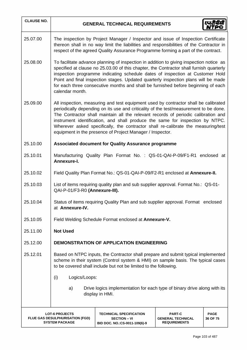
CLAUSE NO.
GENERAL TECHNICAL REQUIREMENTS
LOT-6 PROJECTS
FLUE GAS DESULPHURISATION (FGD)
SYSTEM PACKAGE
TECHNICAL SPECIFICATION
SECTION – VI
BID DOC. NO.:CS-0011-109(6)-9
PART-C
GENERAL TECHNICAL REQUIREMENTS
PAGE
36 OF 75
25.07.00 The inspection by Project Manager / Inspector and issue of Inspection Certificate
thereon shall in no way limit the liabilities and responsibilities of the Contractor in
respect of the agreed Quality Assurance Programme forming a part of the contract.
25.08.00 To facilitate advance planning of inspection in addition to giving inspection notice as
specified at clause no 25.03.00 of this chapter, the Contractor shall furnish quarterly
inspection programme indicating schedule dates of inspection at Customer Hold
Point and final inspection stages. Updated quarterly inspection plans will be made
for each three consecutive months and shall be furnished before beginning of each
calendar month.
25.09.00 All inspection, measuring and test equipment used by contractor shall be calibrated
periodically depending on its use and criticality of the test/measurement to be done.
The Contractor shall maintain all the relevant records of periodic calibration and
instrument identification, and shall produce the same for inspection by NTPC.
Wherever asked specifically, the contractor shall re-calibrate the measuring/test
equipment in the presence of Project Manager / Inspector.
25.10.00 Associated document for Quality Assurance programme
25.10.01 Manufacturing Quality Plan Format No. : QS-01-QAI-P-09/F1-R1 enclosed at
Annexure-I.
25.10.02 Field Quality Plan Format No.: QS-01-QAI-P-09/F2-R1 enclosed at Annexure-II.
25.10.03 List of items requiring quality plan and sub supplier approval. Format No.: QS-01-
QAI-P-01/F3-R0 (Annexure-III).
25.10.04 Status of items requiring Quality Plan and sub supplier approval. Format enclosed
at Annexure-IV.
25.10.05 Field Welding Schedule Format enclosed at Annexure-V.
25.11.00 Not Used
25.12.00 DEMONSTRATION OF APPLICATION ENGINEERING
25.12.01 Based on NTPC inputs, the Contractor shall prepare and submit typical implemented
scheme in their system (Control system & HMI) on sample basis. The typical cases
to be covered shall include but not be limited to the following.
(i) Logics/Loops:
a) Drive logics implementation for each type of binary drive along with its
display in HMI.
Page 103 of 487

CLAUSE NO.
GENERAL TECHNICAL REQUIREMENTS
LOT-6 PROJECTS
FLUE GAS DESULPHURISATION (FGD)
SYSTEM PACKAGE
TECHNICAL SPECIFICATION
SECTION – VI
BID DOC. NO.:CS-0011-109(6)-9
PART-C
GENERAL TECHNICAL REQUIREMENTS
PAGE
37 OF 75
b) Sequence implementation along with its display in HMI.
c) Single non-cascade controller implementation.
d) Cascade loop implementation.
e) Master slave implementation with different slave combination.
f) Temperature & pressure compensation for flow signals & pressure
compensation for level signals as applicable.
(ii) HMI Functions:
a) LVS Annunciation.
b) Graphics.
c) HSR
d) Logs/Reports.
e) Calculations ( Basic & Performance Calculations).
25.12.02 The above typical cases shall be finalized with the Employer through Technical Co-
ordination meetings.
After review and finalization of the typical cases, the implementation of each logic &
control loop shall be carried out by the Contractor based on NTPC inputs. After
implementation of these logics & loops, the Contractor shall test each logic /loop and
record the observations in a format to be provided by the Employer and demonstrate
to Employer at Employer premises during engineering finalization. Any modifications
as a result of the demonstration shall be done and documented as part of the test
report along with the final scheme. Similarly, HMI functions shall also be
demonstrated by the Contractor at Employer premises & the results shall be
documented as part of test report.
25.12.03 During the integrated testing at the Contractor’s works, only sample checks shall be
done by the Employer for the items covered in above application engineering
demonstration.
26.00.00 PRE-COMMISSIONING AND COMMISSIONING FACILITIES
26.01.00 (a) As soon as the facilities or part thereof has been completed operationally and
structurally and before start-up, each item of the equipment and systems
forming part of facilities shall be thoroughly cleaned and then inspected
jointly by the Employer and the Contractor for correctness of and
completeness of facility or part thereof and acceptability for initial pre-
Page 104 of 487

CLAUSE NO.
GENERAL TECHNICAL REQUIREMENTS
LOT-6 PROJECTS
FLUE GAS DESULPHURISATION (FGD)
SYSTEM PACKAGE
TECHNICAL SPECIFICATION
SECTION – VI
BID DOC. NO.:CS-0011-109(6)-9
PART-C
GENERAL TECHNICAL REQUIREMENTS
PAGE
38 OF 75
commissioning tests, commissioning and start-up at Site. The list of pre-
commissioning tests to be performed shall be as mutually agreed and
included in the Contractor’s quality assurance programme as well as those
included in Part-D, Section-VI and elsewhere in the Technical Specifications.
(b) The Contractor’s pre-commissioning/ commissioning/start-up engineers,
specially identified as far as possible, shall be responsible for carrying out all
the pre-commissioning tests at Site. On completion of inspection, checking
and after the pre-commissioning tests are satisfactorily over, the
commissioning of the complete facilities shall be commenced during which
period the complete facilities, equipments shall be operated integral with sub-
systems and supporting equipment as a complete plant.
(c) All piping system shall be flushed, steam blown, air blown as required and
cleanliness demonstrated using acceptable industry standards. Procedures
to accomplish this work shall be submitted for approval to the Employer six
months prior to the respective implementations. The Employer will approve
final verification of cleanliness.
(d) The time consumed in the inspection and checking of the units shall be
considered as a part of the erection and installation period.
(e) The check outs during the pre - commissioning period should be
programmed to follow the construction completion schedule. Each
equipment/system, as it is completed in construction and turned over to
Employer's commissioning (start-up) Engineer(s), should be checked out and
cleaned. The checking and inspection of individual systems should then
follow a prescribed commissioning documentation [SLs(standard check
list)/TS(testing schedule)/CS(commissioning schedule)] approved by the
employer.
(f) The Contractor during initial operation and performance testing shall conduct
vibration testing to determine the ‘base line’ of performance of all plant
rotating equipment. These tests shall be conducted when the equipment is
running at the base load, peak load as well as lowest sustained operating
condition as far as practicable.
26.01.00 Contractor shall furnish the commissioning organization chart for review &
acceptance of employer at least twelve months prior to the schedule date of
commissioning of 1st unit. The chart should contain:
(1.) Biodata including experience of the Commissioning Engineers.
(2.) Role and responsibilities of the Commissioning Organisation members.
(3.) Expected duration of posting of the above Commissioning Engineers at site.
Page 105 of 487

CLAUSE NO.
GENERAL TECHNICAL REQUIREMENTS
LOT-6 PROJECTS
FLUE GAS DESULPHURISATION (FGD)
SYSTEM PACKAGE
TECHNICAL SPECIFICATION
SECTION – VI
BID DOC. NO.:CS-0011-109(6)-9
PART-C
GENERAL TECHNICAL REQUIREMENTS
PAGE
39 OF 75
26.02.00 Initial Operation
(a) On completion of all pre-commissioning activities/ tests and as a part of
commissioning the complete facilities shall be put on 'Initial Operation' during
which period all necessary adjustments shall be made while operating over
the full load range enabling the facilities to be made ready for the Guarantee
Tests.
(b) The 'Initial Operation' of the complete facility as an integral unit shall be
conducted for 720 continuous hours. During the period of initial operation of
720 hours, the FGD System shall operate continuously at full load for a
period not less than 72 hours.
The Initial Operation shall be considered successful, provided that each item/
part of the facility can operate continuously at the specified operating
characteristics, for the period of Initial Operation with all operating
parameters within the specified limits and at or near the predicted
performance of the equipment/ facility.
The Contractor shall intimate the Employer about the commencement of
initial operation and shall furnish adequate notice to the Employer in this
respect.
(c) Any operational interruption in the FGD System due to constraints
attributable to the Employer shall be construed as Deemed to be in
operation.
(d) An Initial Operation report comprising of observations and recordings of
various parameters to be measured in respect of the above Initial Operation
shall be prepared by the Contractor. This report, besides recording the
details of the various observations during initial operation shall also include
the dates of start and finish of the Initial Operation and shall be signed by the
representatives of both the parties. The report shall have sheets, recording
all the details of interruptions occurred, adjustments made and any minor
repairs done during the Initial Operation. Based on the observations,
necessary modifications/repairs to the plant shall be carried out by the
Contractor to the full satisfaction of the Employer to enable the latter to
accord permission to carry out the Guarantee tests on the facilities.
However, minor defects which do not endanger the safe operation of the
equipment, shall not be considered as reasons for with- holding the aforesaid
permission.
26.03.00 Guarantee Tests
a) The final test as to prove the Functional Guarantees shall be conducted at
Site by the Contractor in presence of the Employer. The contractor's
Page 106 of 487

CLAUSE NO.
GENERAL TECHNICAL REQUIREMENTS
LOT-6 PROJECTS
FLUE GAS DESULPHURISATION (FGD)
SYSTEM PACKAGE
TECHNICAL SPECIFICATION
SECTION – VI
BID DOC. NO.:CS-0011-109(6)-9
PART-C
GENERAL TECHNICAL REQUIREMENTS
PAGE
40 OF 75
Commissioning, start-up Engineer shall make the unit ready to conduct such
test before start of initial operation. Such test shall be conducted along with
the Initial Operations.
b) These tests shall be binding on both the parties of the Contract to determine
compliance of the equipment with the functional guarantee.
c) For performance/ demonstration tests instrumentations, of accuracy class
shall be as per specified test codes. The numbers and location of the
instruments shall be as per the specified test codes. In addition the values
of parameters shall be logged from the information system provided under
Employer's Distributed Digital Control Monitoring and Information system.
Test will be conducted at specified load points.
d) Any special equipment, tools and tackles required for the successful
completion of the Guarantee Tests shall be provided by the Contractor, free
of cost.
e) The Guarantee tests and specific tests to be conducted on equipments have
been brought out in detail elsewhere in the specifications.
27.00.00 TAKING OVER
Upon successful completion of Initial Operations and all the tests conducted to the
Employer's satisfaction, the Employer shall issue to the Contractor a Taking over
Certificate as a proof of the final acceptance of the equipment. Such certificate shall
not unreasonably be with held nor will the Employer delay the issuance thereof, on
account of minor omissions or defects which do not affect the commercial operation
and/or cause any serious risk to the equipment. Such certificate shall not relieve the
Contractor of any of his obligations which otherwise survive, by the terms and
conditions of the Contract after issuance of such certificate.
28.00.00 TRAINING OF EMPLOYER'S PERSONNEL
28.01.00 Training for Employers O&M Personnel
The scope of service under training of Employer's engineers shall include a training
module covering upto six (6) man months in the areas of Operation & Maintenance.
Such training should enable the personnel to individually take the responsibility of
operating and maintaining the FGD system in a manner acceptable to the Employer.
Page 107 of 487

CLAUSE NO.
GENERAL TECHNICAL REQUIREMENTS
LOT-6 PROJECTS
FLUE GAS DESULPHURISATION (FGD)
SYSTEM PACKAGE
TECHNICAL SPECIFICATION
SECTION – VI
BID DOC. NO.:CS-0011-109(6)-9
PART-C
GENERAL TECHNICAL REQUIREMENTS
PAGE
41 OF 75
28.02.00 Training for Employers Engineering Personnel
The scope of services under training for Employer's engineering personnel shall also
necessarily include three (3) man months. This shall cover all disciplines viz,
Mechanical, Electrical, C&I, & QA etc. and shall include all the related areas like
Design familiarization, training on product design features and product design
softwares of major equipment and systems, engineering, manufacturing, erection,
commissioning, training on operating features of equipment, quality assurance and
testing, plant visits and visits to manufacturer's works, exposure to various kinds of
problems which may be encountered in fabrication, manufacturing, erection, welding
etc. An indicative module of the training requirement of Employer's Engineering
personnel is attached as Annexure-VII.
28.03.00 Bidder shall furnish in his offer, details of training module(s) covering above
requirements which shall be subject to Employer's approval. Consolidated training
period included above (i.e. 6 man months and 3 man months respectively for O&M
and Engineering) is indicative only. Employer reserves the right to re appropriate the
training period between O&M and engineering depending upon the details of training
module proposed by the Bidder.
28.04.00 Exact details, extent of training and the training schedule shall be finalised based on
the Bidder's proposal within two (2) months from placement of award.
28.05.00 In all the above cases, wherever the training of Employer's personnel is arranged at
the works of the manufacturer's it shall be noted that the lodging and boarding of the
Employer's personnel shall be at the cost of Contractor. The Contractor shall make
all necessary arrangements towards the same.
28.06.00 Take off prices (product wise) should be indicated by the Bidder in the Bid Proposal
Sheets. Employer reserves the right to include or exclude these item(s) during
placement of Award.
Note: For training purposes, one (1) man month implies 30 working days (excluding
all intervening holidays) per person.
29.00.00 SAFETY ASPECTS DURING CONSTRUCTION AND ERECTION
In addition to the requirements given in Erection Conditions of Contract (ECC) the
following shall also cover:
i) Working platforms should be fenced and shall have means of access.
Page 108 of 487

CLAUSE NO.
GENERAL TECHNICAL REQUIREMENTS
LOT-6 PROJECTS
FLUE GAS DESULPHURISATION (FGD)
SYSTEM PACKAGE
TECHNICAL SPECIFICATION
SECTION – VI
BID DOC. NO.:CS-0011-109(6)-9
PART-C
GENERAL TECHNICAL REQUIREMENTS
PAGE
42 OF 75
ii) Ladders in accordance with Employer’s safety rules for construction and
erection shall be used. Rungs shall not be welded on columns. All the
stairs shall be provided with handrails immediately after its erection.
30.00.00 NOISE LEVEL
The equivalent 'A' weighted sound pressure level measured at a height of 1.5 m above floor level in elevation and at a distance of one (1) metre horizontally from the nearest surface of any equipment/machine, furnished and installed under these specifications, expressed in decibels to a reference of 0.0002 microbar, shall not exceed 85 dBA . However for Ball Mills the noise levels as per following shall also be acceptable:
a) Ball Mill 90 dBA
31.00.00 PACKAGING AND TRANSPORTATION
All the equipments shall be suitably protected, coated, covered or boxed and crated
to prevent damage or deterioration during transit, handling and storage at Site till the
time of erection. While packing all the materials, the limitation from the point of view
of the sizes of railway wagons available in India should be taken account of. The
Contractor shall be responsible for any loss or damage during transportation,
handling and storage due to improper packing. The Contractor shall ascertain the
availability of Railway wagon sizes from the Indian Railways or any other agency
concerned in India well before effecting despatch of equipment. Before despatch it
shall be ensured that complete processing and manufacturing of the components is
carried out at shop, only restricted by transport limitation, in order to ensure that site
works like grinding, welding, cutting & preassembly to bare minimum. The
Employer's Inspector shall have right to insist for completion of works in shops
before despatch of materials for transportation.
32.00.00 ELECTRICAL EQUIPMENTS/ENCLOSURES
32.01.00 All electrical equipments and devices, including insulation, heating and ventilation
devices shall be designed for ambient temperature and a maximum relative humidity
as specified elsewhere in the specifications.
33.00.00 INSTRUMENTATION AND CONTROL
All instrumentation and control systems/ equipment/ devices/ components, furnished
under this contract shall be in accordance with the requirements stated herein,
unless otherwise specified in the detailed specifications.
33.01.00 All instrument scales and charts shall be calibrated and printed in metric units and
shall have linear graduation. The ranges shall be selected to have the normal
reading at 75% of full scale.
Page 109 of 487

CLAUSE NO.
GENERAL TECHNICAL REQUIREMENTS
LOT-6 PROJECTS
FLUE GAS DESULPHURISATION (FGD)
SYSTEM PACKAGE
TECHNICAL SPECIFICATION
SECTION – VI
BID DOC. NO.:CS-0011-109(6)-9
PART-C
GENERAL TECHNICAL REQUIREMENTS
PAGE
43 OF 75
All scales and charts shall be calibrated and printed in Metric Units as follows:
1 Temperature - Degree centigrade (deg C)
2. Pressure - Kilograms per square centimetre
(Kg/cm2). Pressure instrument shall
have the unit suffixed with 'a' to
indicate absolute pressure. If nothing
is there, that will mean that the
indicated pressure is gauge pressure.
3. Draught - Millimetres of water column (mm wc).
4. Vacuum - Millimeters of mercury gauge (mm Hg)
or water column (mm Wcl).
5. Flow (Gas) - Tonnes/ hour
6. Flow (Steam) - Tonnes/ hour
7. Flow (Liquid) - Tonnes / hour
8. Flow base - 760 mm Hg. 0 deg.C
9. Density - Grams per cubic centimeter.
33.02.00 All instruments and control devices provided on panels shall be of miniaturized
design, suitable for modular flush mounting on panels with front draw out facility and
flexible plan-in connection at rear.
33.03.00 All electronic modules shall have gold plated connector fingers and further all input
and output modules shall be short circuit proof. These shall also be tropicalised &
components shall be of industrial grade or better.
34.00.00 ELECTRICAL NOISE CONTROL
The equipment furnished by the Contractor shall incorporate necessary techniques
to eliminate measurement and control problems caused by electrical noise. Areas in
Contractor's equipment which are vulnerable to electrical noise shall be hardened to
eliminate possible problems. Any additional equipment, services required for
effectively eliminating the noise problems shall be included in the proposal. The
equipment shall be protected against ESD as per IEC-61000-2. Radio Frequency
interference (RFI) and Electro Magnetic Interference (EMI) protection against
hardware damage and control system mal-operations/errors shall be provided for all
systems as per EN-50082-2 (1995).
Page 110 of 487

CLAUSE NO.
GENERAL TECHNICAL REQUIREMENTS
LOT-6 PROJECTS
FLUE GAS DESULPHURISATION (FGD)
SYSTEM PACKAGE
TECHNICAL SPECIFICATION
SECTION – VI
BID DOC. NO.:CS-0011-109(6)-9
PART-C
GENERAL TECHNICAL REQUIREMENTS
PAGE
44 OF 75
35.00.00 SURGE PROTECTION FOR SOLID STATE EQUIPMENT
All solid state systems /equipment shall be able to withstand the electrical noise and
surge as encountered in actual service conditions and inherent in a power plant and
shall meet the requirements of surge protection as defined in ANSI C37.90.1-1989
on its suitable equivalent class of IEC 254-4. Details of the features incorporated and
relevant tests carried out. The test certificates. etc. shall be submitted by the Bidder.
36.00.00 INSTRUMENT AIR SYSTEM
The instrument air supply system as supplied by the Bidder for various pneumatic
control & instrumentation devices like pneumatic actuators, power cylinders, E/P
converters, piping / tubing etc.
Each pneumatic instrument shall have an individual air shut - off valve. The pressure
regulating valve shall be equipped with an internal filter, a 50 mm pressure gauge
and a built-in filter housing blow down valve.
37.00.00 TAPPING POINTS FOR MEASUREMENTS
Tapping points shall include probes, wherever applicable, for analytical
measurements and sampling.
For direct temperature measurement of all working media, one stub with internal
threading of approved pattern shall be provided along with suitable plug and washer.
The Contractor will be intimated about thread standard to be adopted.
The following shall be provided on equipment by the Bidder. The standard which is
to be adopted, will be intimated to the Contractor.
i) Temperature test pockets with stub and thermowell
ii) Pressure test pockets
38.00.00 SYSTEM DOCUMENTATION
The Bidder shall provide drawings, system overview & description, hardware/
software details, technical literature, functional & hardware schemes, bill of material,
parts list, interconnection diagrams, data sheets, erection/ installation/
commissioning procedures, instruction/ operating manuals, etc. for each of the C& I
system / sub-systems/ equipment supplied under this package. The documentation
shall include complete details of the C&I systems/ sub-systems/ equipment to enable
review by Employer during detailed engineering stage and to provide information to
plant personnel for operation & Maintenance (including quick diagnostics & trouble
shooting) of these C&I systems/ sub-systems/ equipment at site. The minimum
documentation requirements for C&I systems shall be as stipulated under C&I
Page 111 of 487
CLAUSE NO.
GENERAL TECHNICAL REQUIREMENTS
LOT-6 PROJECTS
FLUE GAS DESULPHURISATION (FGD)
SYSTEM PACKAGE
TECHNICAL SPECIFICATION
SECTION – VI
BID DOC. NO.:CS-0011-109(6)-9
PART-C
GENERAL TECHNICAL REQUIREMENTS
PAGE
45 OF 75
"Techncial Data Sheets" Part of specifications. In addition to this, system
documentation for control system shall include as a minimum to that specified
elsewhere in the Technical Specification.
The exact format, submission schedule and contents of various documents shall be
as finalised during detailed engineering stage.
38.01.00 Bill of material (instrument list) for all C&I equipment/ devices shall be furnished by
the bidder in standard formats as approved by the Employer.
39.00.00 MAINTENANCE MANUALS OF ELECTRONIC MODULES
The Contractor shall have to furnish two (2) sets of all maintenance manual of each
and every electronic card/module as employed on the various systems and
equipment including peripherals etc., offered by him. The Contractor will also have to
furnish the data regarding the expected failure rate of various modules and other
system components. Further , the contractor shall furnish a set of operating manuals
which should include block diagrams ,make, model/type ,details wiring and external
connection drawings etc as required to do the testing and maintenance of the
electronic modules.
Page 112 of 487

ANNEXURE-I
MFGR.’s LOGO
MANUFACTURER’S NAME AND ADDRESS MANUFACTURING QUALITY PLAN PROJECT :
PACKAGE :
CONTRACT NO. :
MAIN-SUPPLIER:
ITEM : SUB-SYSTEM:
QP NO.: REV.NO.: DATE: PAGE: …. OF….
LOT-6 PROJECTS
FLUE GAS DESULPHURISATION (FGD)
SYSTEM PACKAGE
TECHNICAL SPECIFICATION
SECTION – VI
BID DOC. NO.:CS-0011-109(6)-9
PART-C
GENERAL TECHNICAL REQUIREMENT
PAGE 76 OF 83
SL. NO
COMPONENT &
OPERATIONS
CHARACTERISTICS
CLASS
TYPE OF
CHECK
QUANTUM
OF CHECK REFERENCE
DOCUMENT
ACCEPTANCE
NORMS
FORMAT OF
RECORD
AGENCY REMARKS
M C / N M C N
1. 2. 3. 4. 5. 6. 7. 8. 9. D* ** 10. 11.
LEGEND: * RECORDS, INDENTIFIED WITH “TICK” ( ) SHALL BE
ESSENTIALLY INCLUDED BY SUPPLIER IN QA DOCUMENTATION. ** M: MANUFACTURER/SUB-SUPPLIER C: MAIN SUPPLIER, N: NTPC P: PERFORM W: WITNESS AND V: VERIFICATION. AS APPROPRIATE, CHP: NTPC SHALL IDENTIFY IN COLUM “N” AS ‘ W”
DOC. NO.: REV…… CAT…..
MANUFACTURER/ SUB-SUPPLIER
MAIN-SUPPLIER FOR NTPC USE SIGNATURE REVIEWED BY APPROVED BY APPROVAL
SEAL
FORMAT NO.: QS-01-QAI-P-09/F1-R1 1/1 ENGG. DIV./QA&I
Page 113 of 487

ANNEXURE-II
SUPPLIER’S LOGO
SUPPLIER’S NAME AND ADDRESS FIELD QUALITY PLAN PROJECT :
PACKAGE :
CONTRACT NO. :
MAIN-SUPPLIER:
ITEM : SUB-SYSTEM:
QP NO.: REV. NO.: DATE: PAGE: …. OF….
LOT-6 PROJECTS
FLUE GAS DESULPHURISATION (FGD)
SYSTEM PACKAGE
TECHNICAL SPECIFICATION
SECTION – VI
BID DOC. NO.:CS-0011-109(6)-9
PART-C
GENERAL TECHNICAL REQUIREMENT
PAGE 77 OF 83
S
l
.
N
o
ACTIVITY AND
OPERATION
CHARACTERISTICS / INSTRUMENTS
CLASS OF
CHECK #
TYPE OF
CHECK
QUANTUM
OF CHECK
REFERENCE
DOCUMENT
ACCEPTANCE
NORMS
FORMAT OF RECORD
REMARKS
1. 2. 3. 4. 5. 6. 7. 8. 9. D* 10.
LEGEND: * RECORDS, INDENTIFIED WITH “TICK” () SHALL BE ESSENTIALLY INCLUDED BY SUPPLIER IN QA DOCUMENTATION. LEGEND TO BE USED: CLASS # : A = CRITICAL, B=MAJOR, C=MINOR; ‘A’ SHALL BE WITNESSED BY NTPC FQA, ‘B’ SHALL BE WITNESSED BY NTPC ERECTION / CONSTRUCTION DEPTT. AND ‘C’ SHALL BE WITNESSED BY MAIN SUPPLIER (A & B CHECK SHALL BE NTPC CHP STAGE)
DOC. NO.: REV……
MANUFACTURER/ SUB-SUPPLIER
MAIN-SUPPLIER FOR NTPC USE SIGNATURE REVIEWED BY APPROVED BY APPROVAL SEAL
Page 114 of 487

ANNEXURE-II
SUPPLIER’S LOGO
SUPPLIER’S NAME AND ADDRESS FIELD QUALITY PLAN PROJECT :
PACKAGE :
CONTRACT NO. :
MAIN-SUPPLIER:
ITEM : SUB-SYSTEM:
QP NO.: REV. NO.: DATE: PAGE: …. OF….
LOT-6 PROJECTS
FLUE GAS DESULPHURISATION (FGD)
SYSTEM PACKAGE
TECHNICAL SPECIFICATION
SECTION – VI
BID DOC. NO.:CS-0011-109(6)-9
PART-C
GENERAL TECHNICAL REQUIREMENT
PAGE 77 OF 83
FORMAT NO.: QS-01-QAI-P-09/F2-R1 1/1 ENGG. DIV./QA&I
Page 115 of 487

LOT-6 PROJECTS
FLUE GAS DESULPHURISATION (FGD)
SYSTEM PACKAGE
TECHNICAL SPECIFICATION
SECTION – VI
BID DOC. NO.:CS-0011-109(6)-9
PART-C
GENERAL TECHNICAL REQUIREMENT
PAGE 78 OF 83
ANNEXURE-III
Project : Stage : : Package : Supplier : Contractor No. :
LIST OF ITEMS REQUIRING QUALITY PLAN AND SUB-SUPPLIER APPROVAL SUB-SYSTEM :
DOC. NO.:
REV. NO.:
DATE :
PAGE : OF
S.
N.
Item QP/ Insp. Cat.
QP No.
QP Sub. Schedule
QP approval schedule
Proposed sub-supplier
Place Sub-suppliers approval status / category
Sub-supplier Details submission schedule
Remarks
LEGENDS SYSTEM SUPPLIER/SUB-SUPPLIER APPROVAL STATUS CATEGORY (SHALL BE FILLED BY NTPC) A – For these items proposed vendor is acceptable to NTPC. To be indicated with letter “A” in the list alongwith the condition of approval, if any. DR – For these items “Detailed required” for NTPC review. To be identified with letter “DR” in the list. NOTED – For these items vendors are approved by Main Supplier and accepted by NTPC without specific vendor approval from NTPC. To be identified with “NOTED.’ QP/INSPN CATEGORY: CAT-I : For these items the Quality Plans are approved by NTPC and the final acceptance will be on physical inspection witness by NTPC. CAT-II : For these items the Quality Plans approved by NTPC. However no physical inspection shall be done by NTPC. The final acceptance by NTPC shall be on the basis review of documents as per approved QP. CAT-III : For these items Main Supplier approves the Quality Plans. The final acceptance by NTPC shall be on the basis certificate of conformance by the main supplier. UNITS/WORKS : Place of manufacturing Place of Main Supplier of multi units/works.
FORMAT NO.: QS-01-QAI-P-1/F3-R0
1/1 Engg. Div. / QA&I
Page 116 of 487

LOT-6 PROJECTS
FLUE GAS DESULPHURISATION (FGD)
SYSTEM PACKAGE
TECHNICAL SPECIFICATION
SECTION – VI
BID DOC. NO.:CS-0011-109(6)-9
PART-C
GENERAL TECHNICAL REQUIREMENT
PAGE 79 OF 83
ANNEXURE-IV
Project : Stage : : Package : Contractor : Contractor No. :
STATUS OF ITEM REQUIRING QP& SUB-SUPPLIER APPROVAL
DOC. NO.:
REV. NO.:
DATE :
PAGE : OF
S. N.
Item / Service QP/ Insp. Cat.
QP Sub. Schedule Approval schedule
Date of sub-mission
Date of commt Appl.
Status Code C/II/I
Proposed Sub-suppliers Place of manufacturing works
Approval Status
Sub-supplier detail submission schedule
Remarks
FORMAT 1/1 Engg. Div. / QA&I
Page 117 of 487

LOT-6 PROJECTS
FLUE GAS DESULPHURISATION (FGD)
SYSTEM PACKAGE
TECHNICAL SPECIFICATION
SECTION – VI
BID DOC. NO.:CS-0011-109(6)-9
PART-C
GENERAL TECHNICAL REQUIREMENT
PAGE 80 OF 83
ANNEXURE-V
Project : Stage : Contractor : Contractor No. : System :
FIELD WELDING SCHEDULE (To be raised by the contractor) Welding Code: ………………………………………
DOC. NO.:
REV. NO.:
DATE :
PAGE : OF
Sl.
No.
DRG No. for Weld Location and Identification mark
Description of parts to welded
Matl. Spec.
Dimensions
Process of welding
Type of Weld
Electrode filler spec.
WPS. No.
Min. pre-heat
Heat treatment NDT method/ Quantum
REF Remarks
Temp. Holding
time Spec. No.
ACC Norm Ref.
NOTES:
SIGNATURE
FORMAT 1/1 Engg. Div. / QA&I
Page 118 of 487

CLAUSE NO.
GENERAL TECHNICAL REQUIREMENTS (Annexure-VI)
LOT-6 PROJECTS
FLUE GAS DESULPHURISATION (FGD)
SYSTEM PACKAGE
TECHNICAL SPECIFICATION
SECTION – VI
BID DOC. NO.:CS-0011-109(6)-9
PART-C
GENERAL TECHNICAL REQUIREMENTS
Annexure-VI
PAGE
81 OF 83
S.No Description of Drgs/Docs No of Prints
No of CD ROMs/DVDs/Portable Hard Disk
1 Drawings, Data sheets, Design calculations, Purchase specifications and other documents
First submission and submission with major changes
▪ Layout (A0&A1 sizes)
4
-
▪ Other Drawings/Documents (A0&A1 sizes)
2
-
▪ P&ID (All sizes) 4 -
a) Final drawings/documents (Directly to site)
6 2
b) “As Built” Drawing/Documents
(Directly to site)
6
2
c) Analysis reports of Equipments / piping /structures components/system employing software packages as detailed in the specifications.
2
2
2 Erection Manual (Directly to site)
4 sets
2
3 Operation & Maintenance manual i) First Submission
1 set
--
ii) Final Submission (Directly to site)
4 sets 2
4 Plant Hand Book i) First Submission
1
1
5
Commissioning and Performance Test Procedure manual i) First Submission
1 set
--
ii) Final Submission (Directly to site)
4 sets
2
Page 119 of 487

CLAUSE NO.
GENERAL TECHNICAL REQUIREMENTS (Annexure-VI)
LOT-6 PROJECTS
FLUE GAS DESULPHURISATION (FGD)
SYSTEM PACKAGE
TECHNICAL SPECIFICATION
SECTION – VI
BID DOC. NO.:CS-0011-109(6)-9
PART-C
GENERAL TECHNICAL REQUIREMENTS
Annexure-VI
PAGE
82 OF 83
S.No Description of Drgs/Docs No of Prints
No of CD ROMs/DVDs/Portable Hard Disk
6 Performance and Functional Guarantee Test Report i) First Submission
2 sets
--
ii) Approved Copies (Direct to Site)
4 sets 2
7 Project Completion Report (Directly to site)
6 sets
2
8 QA programme including Organisation for implementation and QA system manual(with revisions)
1 --
9 Vendor details in respect of proposed vendors including contractor’s evaluation report.
2 --
10 Manufacturing QPs, Field QPs, Field welding schedules and their reference document like test procedures, WPS, POR etc i) For review/comment
1
--
ii) Approved final copies of Field QPs, Field welding schedules and their reference document like test procedures, WPS, POR etc (Direct to Site)
4 2
11 Welding Manual, Heat Treatment Manuals, Storage & preservation manuals i) For review/comment
1 set
--
ii) Approved copies (Direct to Site)
4 sets
2
12 QA Documentation Package for items / equipment manufactured and despatched to site
2 sets 2
13 QA Documentation Package for field activities on equipment/systems at site
2 sets 2
Page 120 of 487

CLAUSE NO.
GENERAL TECHNICAL REQUIREMENTS
ANNEXURE-VII
LOT-6 PROJECTS
FLUE GAS DESULPHURISATION (FGD)
SYSTEM PACKAGE
TECHNICAL SPECIFICATION
SECTION – VI
BID DOC. NO.:CS-0011-109(6)-9
PART-C
GENERAL TECHNICAL REQUIREMENTS
ANNEXURE-VII
PAGE 83 OF 83
PRODUCT AREAS OF TRAINING REQUIEMENT
PRODUCT DESIGN Plant Visit Visit to Manufacturer’s Work
Operation & Maintenance of Plant
FGD
Layout & model of FGD area, cable & piping trestles etc. FGD
• Mass balance, Design, selection and sizing calculations of FGD
• Training on factors affecting sizing/ efficiency of FGD system, equipments & auxiliaries
• Materials for FGD & selection
• Basic concepts, Design and sizing calculations on slurry systems including piping, valves, etc..
• FGD electrical system
• FGD control system Erection strategies, erection procedures Performance as per applicable code and demonstration tests.
Familiarization with various system and equipment Performance, data collection analysis and review O&M feed back Operation history of various equipments and system Failure analysis
Manufacturing process of Absorber and equipments Welding process Testing facilities Product development in process Future plan for technology induction R&D work in progress
Control philosophy operation, notices, logic & protection schemes, O&M manual familiarization O&M issues. Familiarization of special maintenance techniques Special tool and tackles familiarization
MANMONTH 2 0.5 0.5 6
-
-
-
-
-
Page 121 of 487

LOT 4 PROJECTS FLUE GAS DESULPHURISATION (FGD) SYSTEM
PACKAGE BID DOCUMENT NO. : CS-0011-109-(4)-9
SECTION - IV GENERAL CONDITIONS OF CONTRACT (GCC)
PAGE
43 OF 68
Clause No.
GENERAL CONDITIONS OF CONTRACT (GCC)
F. Guarantees and Liabilities
26. Completion Time Guarantee
26.1 The Contractor guarantees that it shall attain Completion of the Facilities (or a part for which a separate time for completion is specified in the SCC) within the Time for Completion specified in the SCC pursuant to GCC Sub-Clause 8.2, or within such extended time to which the Contractor shall be entitled under GCC Clause 40 (Extension of Time for Completion) hereof.
26.2 If the Contractor fails to attain Completion of the Facilities or any part thereof within the Time for Completion or any extension thereof under GCC Clause 40 (Extension of Time for Completion), the Contractor shall pay to the Employer liquidated damages in the amount computed at the rates specified in the SCC. The aggregate amount of such liquidated damages shall in no event exceed the amount specified as “Maximum” in the SCC. Once the “Maximum” is reached, the Employer may consider termination of the Contract, pursuant to GCC Sub-Clause 42.2.2.
Such payment shall completely satisfy the Contractor’s obligation to attain Completion of the Facilities or the relevant part thereof within the Time for Completion or any extension thereof under GCC Clause 40 (Extension of Time for Completion). The Contractor shall have no further liability whatsoever to the Employer in respect thereof.
However, the payment of liquidated damages shall not in any way relieve the Contractor from any of its obligations to complete the Facilities or from any other obligations and liabilities of the Contractor under the Contract.
Save for liquidated damages payable under this GCC Sub-Clause 26.2, the failure by the Contractor to attain any milestone or other act, matter or thing by any date specified in Appendix 4 (Time Schedule) to the Contract Agreement and/or other program of work prepared pursuant to GCC Clause 18 (Program of Performance) shall not render the Contractor liable for any loss or damage thereby suffered by the Employer.
26.3 No bonus shall be given for earlier completion of the facilities or part thereof.
27. Defect Liability
27.1 The Contractor warrants that the Facilities or any part thereof shall be free from defects in the design, engineering, materials and workmanship of the Plant and Equipment supplied and of the work executed.
27.2 The Defect Liability Period shall be eighteen (18) months from the date of Completion of the Facilities (or any part thereof) or twelve (12) months from the date of Operational Acceptance of the Facilities (or any part thereof), whichever first occurs, unless specified otherwise in the SCC.
Page 122 of 487
3062805
Line
3062805
Text Box

LOT 4 PROJECTS FLUE GAS DESULPHURISATION (FGD) SYSTEM
PACKAGE BID DOCUMENT NO. : CS-0011-109-(4)-9
SECTION - IV GENERAL CONDITIONS OF CONTRACT (GCC)
PAGE
44 OF 68
Clause No.
GENERAL CONDITIONS OF CONTRACT (GCC)
If during the Defect Liability Period any defect should be found in the design, engineering, materials and workmanship of the Plant and Equipment supplied or of the work executed by the Contractor, the Contractor shall promptly, in consultation and agreement with the Employer regarding appropriate remedying of the defects, and at its cost, repair, replace or otherwise make good (as the Contractor shall, at its discretion, determine) such defect as well as any damage to the Facilities caused by such defect. The Contractor shall not be responsible for the repair, replacement or making good of any defect or of any damage to the Facilities arising out of or resulting from any of the following causes:
(a) improper operation or maintenance of the Facilities by the Employer
(b) operation of the Facilities outside specifications provided in the Contract
(c) normal wear and tear.
27.3 The Contractor’s obligations under this GCC Clause 27 shall not apply to
(a) any materials that are supplied by the Employer under GCC Sub-Clause 21.2 (Employer-Supplied Plant, Equipment and Materials), are normally consumed in operation, or have a normal life shorter than the Defect Liability Period stated herein
(b) any designs, specifications or other data designed, supplied or specified by or on behalf of the Employer or any matters for which the Contractor has disclaimed responsibility herein
(c) any other materials supplied or any other work executed by or on behalf of the Employer, except for the work executed by the Employer under GCC Sub-Clause 27.7.
27.4 The Employer shall give the Contractor a notice stating the nature of any such defect together with all available evidence thereof, promptly following the discovery thereof. The Employer shall afford all reasonable opportunity for the Contractor to inspect any such defect.
27.5 The Employer shall afford the Contractor all necessary access to the Facilities and the Site to enable the Contractor to perform its obligations under this GCC Clause 27.
The Contractor may, with the consent of the Employer, remove from the Site any Plant and Equipment or any part of the Facilities that are defective if the nature of the defect, and/or any damage to the Facilities caused by the defect, is such that repairs cannot be expeditiously carried out at the Site.
27.6 If the repair, replacement or making good is of such a character that it may affect the efficiency of the Facilities or any part thereof, the Employer may give to the Contractor a notice requiring that tests of the defective part of the Facilities shall be made by the Contractor immediately upon completion of such remedial work, whereupon the Contractor shall carry out such tests.
Page 123 of 487
3062805
Text Box
LOT 4 PROJECTS FLUE GAS DESULPHURISATION (FGD) SYSTEM
PACKAGE BID DOCUMENT NO. : CS-0011-109-(4)-9
SECTION - IV GENERAL CONDITIONS OF CONTRACT (GCC)
PAGE
45 OF 68
Clause No.
GENERAL CONDITIONS OF CONTRACT (GCC)
If such part fails the tests, the Contractor shall carry out further repair, replacement or making good (as the case may be) until that part of the Facilities passes such tests. The tests in character shall in any case be not less than what has already been agreed by the Employer and the Contractor for the original equipment/part of the Facilities.
27.7 If the Contractor fails to commence the work necessary to remedy such defect or any damage to the Facilities caused by such defect within a reasonable time (which shall in no event be considered to be less than fifteen (15) days), the Employer may, following notice to the Contractor, proceed to do such work, and the reasonable costs incurred by the Employer in connection therewith shall be paid to the Employer by the Contractor or may be deducted by the Employer from any monies due to the Contractor or claimed under the Performance Security.
27.8 If the Facilities or any part thereof cannot be used by reason of such defect and/or making good of such defect, the Defect Liability Period of the Facilities or such part, as the case may be, shall be extended by a period equal to the period during which the Facilities or such part cannot be used by the Employer because of any of the aforesaid reasons. Upon correction of the defects in the Facilities or any part thereof by repair/replacement, such repair/replacement shall have the Defect Liability Period extended by a period of twelve (12) month from the time such replacement/repair of the Facilities or any part therof.
27.8.1 At the end of the Defect Liability Period, the contractor liability ceases except for latent defects. The contractor's liability for latent defects warranty shall be limited to a period of five (5) years from the end of Defect Liability Period. For the purpose of the this clause, the latent defects shall be the defects inherently lying within the material or arising out of design deficiency which do not manifest themselves during the Defect Liability Period in this GCC clause 27, but later.
27.9 Except as provided in GCC Clauses 27 and 33 (Loss of or Damage to Property / Accident or Injury to Workers/Indemnification), the Contractor shall be under no liability whatsoever and howsoever arising, and whether under the Contract or at law, in respect of defects in the Facilities or any part thereof, the Plant and Equipment, design or engineering or work executed that appear after Completion of the Facilities or any part thereof, except where such defects are the result of the gross negligence, fraud, criminal or wilful action of the Contractor.
27.10 In addition, the Contractor shall also provide an extended warranty for any such component of the Facilities and during the period of time as may be specified in the SCC. Such obligation shall be in addition to the defect liability specified under GCC Sub-Clause 27.2.
28. Functional Guarantees
28.1 The Contractor guarantees that during the Guarantee Test, the Facilities and all parts thereof shall attain the Functional Guarantees specified in Appendix 8 (Functional Guarantees) to the Contract Agreement, subject to and upon the conditions therein specified.
28.2 If, for reasons attributable to the Contractor, the guaranteed level of the Functional Guarantees specified in Appendix 8 (Functional Guarantees)
Page 124 of 487
3062805
Text Box

CLAUSE NO.
ERECTION CONDITIONS OF CONTRACT
LOT-6 PROJECTS
FLUE GAS DESULPHURISATION (FGD) SYSTEM PACKAGE
TECHNICAL SPECIFICATION
SECTION – VI
BID DOC. NO. CS-0011-109(6)-9
PART-D ERECTION CONDITIONS OF
CONTRACT
PAGE
1 OF 53
1.00.00 GENERAL 1.01.00 The following provisions shall supplement the conditions already contained in the
other parts of these specifications and documents and shall govern that portion of the work of this contract which is to be performed at site. The erection requirements and procedures not specified in these documents shall be in accordance with the recommendations of the equipment manufacturer, or as mutually agreed to between the Employer and the Contractor prior to commencement of erection work.
1.02.00 The Contractor upon signing of the Contract shall, in addition to a Project Co-
ordinator, nominate another responsible officer as his representative at Site suitably designated for the purpose of overall responsibility and co-ordination of the Works to be performed at Site. Such a person shall function from the Site office of the Contractor during the pendency of Contract.
2.00.00 REGULATION OF LOCAL AUTHORITIES AND STATUTES 2.01.00 In addition to the local laws and regulations, the Contractor shall also comply with
the Minimum Wages Act and the Payment of Wages Act (both of the Government of India) and the rules made there under in respect of its labour and the labour of its sub-contractors currently employed on or connected with the contract.
2.02.00 All registration and statutory inspection fees, if any, in respect of his work pursuant
to this Contract shall be to the account of the Contractor. However, any registration, statutory inspection fees lawfully pay-able under the provisions of the Indian Boiler Regulations and any other statutory laws and its amendments from time to time during erection in respect of the plant equipment ultimately to be owned by the Employer, shall be to the account of the Employer. Should any such inspection or registration need to be re-arranged due to the fault of the Contractor or his Sub-Contractor, the additional fees for such inspection and/or registration shall be borne by the Contractor.
3.00.00 WELDING OF PRESSURE PARTS AND HIGH PRESSURE PIPING The welding of all pressure parts and high pressure piping shall be in accordance
with the following requirements: 3.01.00 Qualification of Weld Procedures Only qualified welding procedures as per ASME Section IX shall be used by
contractor at site. Procedure qualification records along with WPS shall be submitted to NTPC for review. Welding procedure shall indicate all essential and non-essential parameters as per ASME Section IX. Makes of welding consumables shall be subject to employer's approval.
3.02.00 Welder's Qualification Only welders who are qualified in accordance with the latest applicable requirements
of the Indian Boiler Regulations, shall be permitted to perform any welding work on the pressure parts and its attachment welding. In addition to such statutory qualification requirements, the welders shall also undergo a satisfactory
Page 125 of 487

CLAUSE NO.
ERECTION CONDITIONS OF CONTRACT
LOT-6 PROJECTS
FLUE GAS DESULPHURISATION (FGD) SYSTEM PACKAGE
TECHNICAL SPECIFICATION
SECTION – VI
BID DOC. NO. CS-0011-109(6)-9
PART-D ERECTION CONDITIONS OF
CONTRACT
PAGE
2 OF 53
pre-production qualification test to be conducted by the Contractor at site as per ASME Sec IX in presence of employer's representative(s), prior to performing work under these specifications. The services of an independent testing laboratory shall be retained by the Contractor to perform welder qualification tests for welders.
All the welders carrying out welding at site shall carry an identification badge, which
shall indicate the category and the grade of welding for which they have been tested and authorised to carry out welding.
3.03.00 Records Welders performance shall be monitored regularly and record of their performance
shall be maintained by contractor in a manner acceptable to the employer. Contractor shall maintain such records including record of procedure qualification & welder qualification and hand-over to the employer at the end of work.
3.04.00 MARKING On completion of each welded joint, the welder shall mark his regularly assigned
identification mark near the joint. The welder's identification numbers, inspection stamps or code symbol stamps and any other information shall not be directly stamped on any alloy steel piping. In alloy steel piping, all such information shall be stamped on separate marking plate which shall be tack welded on pipe near the weld.
4.00.00 HEAT TREATMENT 4.01.00 Pre-heating, post-heating and post-weld stress relief operations of all welds, shall be
performed in accordance with the requirements of applicable code. Local post weld stress relieving heat treatments shall be adopted only in cases where it is normally impracticable to subject the entire assembly as such for stress relieving operations. Heating may be by means of electric induction coils or electric resistance coils. Oxy-acetylene flame heating or exothermic chemical heating methods will not be permitted. Complete recording of the temperatures through out the stress relieving cycle of the material and the weld subjected to heat treatment shall be made by means of a potentiometric recorder. Recorders other than those of potentiometric type shall not be used for such temperature recording during stress relieving operations.
The contractor & employer's representative, at start and at the end of HT Cycle shall
sign the time and temperature charts for heat-treatment. 4.02.00 Not Used. 4.03.00 After setting up the weld joint for heat treatment operation, the Employer's signature
shall be obtained on the strips chart of the recorder prior to starting of heat treatment cycle. The right hand corner of the strip chart at the starting point of the heat treatment cycle shall contain details like the weld number, material, diameter and thickness, method of heating adopted, prescribed ranges of heat treatment temperatures, date of heat treatment, reference to item number of the Field welding Schedule (as specified at clause no 7.00.00- of this chapter) etc.
Page 126 of 487

CLAUSE NO.
ERECTION CONDITIONS OF CONTRACT
LOT-6 PROJECTS
FLUE GAS DESULPHURISATION (FGD) SYSTEM PACKAGE
TECHNICAL SPECIFICATION
SECTION – VI
BID DOC. NO. CS-0011-109(6)-9
PART-D ERECTION CONDITIONS OF
CONTRACT
PAGE
3 OF 53
5.00.00 WELD EDGE PREPARATION Preparation at site of weld joint shall be in accordance with details acceptable to the
Employer. Wherever possible, machining or automatic flame cutting shall be used for edge preparation. Hand flame cutting will be permitted only where edge preparation otherwise is impractical. All slag shall be removed from cuts and all the hand cuts shall be ground smooth to the satisfaction of the Employer. Flame cutting of alloy steel pipe shall be avoided. Wherever such cutting is done, a 200mm length at the cut face shall be removed by machining. Pneumatic hand tools such as edge preparation, tube cutting machine can be used.
6.00.00 CLEANING AND SERVICING 6.01.00 The inside of all tubes, pipes, valves and fittings shall be free from dirt, and loose
scales before being erected. All the pipelines shall be thoroughly blown and/or flushed. Each steam and water tubes shall be blown with compressed air and shall be subjected to 'ball test' before erection to ensure that no obstructions exist. A system for recording of all such operations shall be developed and maintained in a manner to ensure that no obstructions are left inside the tubes and no tubes are left uncleaned and untested.
6.02.00 All valves and valve actuators, and dampers and damper actuators, if any, shall be
thoroughly cleaned and serviced prior to pre-commissioning tests and/or Initial Operations of the plant. A system for recording of such servicing operation shall be developed and maintained in a manner acceptable to the Employer and to ensure that no valves or dampers including their actuators are left unserviced.
6.03.00 All interior surfaces of the turbine shall be thoroughly cleaned prior to boxing - up to
remove all traces of oil preservations. 7.00.00 FIELD WELDING SCHEDULE The Contractor shall submit to the Employer, a certified and complete field welding
schedule for all the field welding activities to be carried out in respect of the pressure parts involved in the equipment furnished and erected by him, at least 90 days prior to the scheduled start of erection work at site. Such schedule will be strictly followed by the Contractor during the process of erection. The above field-welding schedule to be issued by the Contractor shall contain the following:
(a.) Drawing No (s) (b.) Location of the weld (c.) Size of the weld (outside diameter and thickness) (d.) Type of joints (e.) Material specifications (f.) Size of fillet on backing ring, when the type of joint is with backing ring (g.) Electrode/ filler metal specifications
Page 127 of 487

CLAUSE NO.
ERECTION CONDITIONS OF CONTRACT
LOT-6 PROJECTS
FLUE GAS DESULPHURISATION (FGD) SYSTEM PACKAGE
TECHNICAL SPECIFICATION
SECTION – VI
BID DOC. NO. CS-0011-109(6)-9
PART-D ERECTION CONDITIONS OF
CONTRACT
PAGE
4 OF 53
(h.) Number of welds per unit (i.) Quantity of filler metal per weld (j.) Indication of required Non-destructive Examination (NDE) for each weld (k.) Pre-heat temperatures for welding (l.) Process of welding (m.) Post-welding heat treatment temperature ranges, duration, under as
specified at clause no 4.00.00 of this chapter entitled "Heat Treatment". (n.) Qualification details of weld procedures to be adopted as specified at clause
no 3.01.00 of this chapter entitled 'Qualification of Weld Procedures'. 8.00.00 SITE RUN MISCELLANEOUS PIPING Sketches or diagrams of the proposed routings of all piping, not already indicated
and routed on the shop drawings which were reviewed by the Employer, shall be submitted to the Employer for review, Employer's acceptance of such site routings shall be obtained before the piping is erected. All these site run piping shall be installed in such a manner as to present an orderly and neat installation. They shall be located as to avoid obstruction of access and passages. Valves, instruments or any other special items shall be located convenient for operation by the operating personnel. Pipe runs shall be plumb or level except where pitch for drainage is required. Pipe runs that are not parallel to the building structure, walls or column rows shall be avoided so that deflection of pipes between hangers does not exceed 6 mm. No miscellaneous pipe shall be routed and installed above or adjacent to electrical equipment.
9.00.00 THERMAL EXPANSIONS All piping installation shall be such that no excessive or destructive expansion forces
exist either in the cold condition or under condition of maximum temperature. All bends, expansion joints and any other special fittings, necessary to provide proper expansion, shall be incorporated. During installation of expansion joints and anchors, care must be taken to make sure that full design movement is available at all times for maximum to minimum temperature and vice-versa.
10.00.00 PIPING SUPPORTS 10.01.00 Hangers, supports and anchors shall be installed as required to obtain a safe,
reliable and complete pipe installation. All supports shall be properly levelled and anchored when installed. The anchors shall be so placed that thermal expansion will be absorbed by bends without subjecting the valves or equipment to excessive strains.
10.02.00 The hanger assemblies shall not be used for the attachment of rigging to hoist the
pipe into place. Other means shall be used to securely hold the pipe in place till the pipe support is completely assembled and attached to the pipe and building
Page 128 of 487

CLAUSE NO.
ERECTION CONDITIONS OF CONTRACT
LOT-6 PROJECTS
FLUE GAS DESULPHURISATION (FGD) SYSTEM PACKAGE
TECHNICAL SPECIFICATION
SECTION – VI
BID DOC. NO. CS-0011-109(6)-9
PART-D ERECTION CONDITIONS OF
CONTRACT
PAGE
5 OF 53
structures and spring support is set to accommodate the pipe way. All temporary rigging shall be removed in such a way that the pipe support is not subjected to any sudden load. All piping, having variable spring type supports, shall be held securely in place by temporary means during the hydraulic test of pipe system. Constant support type spring hangers used during hydraulic test shall be pinned or blocked solid during the test. After complete installation and insulation of the piping and filling of the piping with its normal operating medium, the pipe support springs shall be adjusted to the cold positions. If necessary, the spring support shall be re-adjusted to the hot positions after the line has been placed for service at its normal maximum operating temperature conditions. Electric arc welding only shall be used to weld all pipe supports to structural steel members that form part of the building supporting structure. The structural beams shall not be heated more than necessary during welding of supports and such welds shall run parallel to the axis of the span. All lugs or any other attachments welded to the piping shall be of the same material as the pipe.
11.00.00 PRESSURE TESTING 11.01.00 On completion of erection of pressure parts, a hydraulic test in accordance with the
requirements of the Indian Boiler Regulations shall be performed by the Contractor. 11.02.00 All the valves, high pressure pipes and inter-connected pipes connecting the
pressure parts shall be tested along with pressure parts. All blank flanges or any removable plugs required for openings not closed by the valves, and piping provided, shall be furnished by the Contractor. The pressurization equipment including water piping from the supply, needed for the above test shall also be furnished by the Contractor. Any defects noticed during the testing are to be rectified and the unit re-tested. If any welding is done on the pressure parts after the Hydraulic test, the Hydraulic test for that portion of pressure parts shall be repeated. Water as required for such pressure testing shall be provided by the employer.
11.03.00 Thy hydraulic test shall be considered successful only on certification to that effect
by the concerned inspecting Authority as per the provisions of the Indian Boiler Regulations and the Employer.
12.00.00 THERMOWELLS AND FLOW NOZZLES 12.01.00 All the thermowells and flow nozzles in the equipment furnished under the technical
specifications shall be installed as a part of this work. 12.02.00 All thermowell connections incorporated in the steam service shall be plugged during
the pressure testing and the blow out of steam piping systems. Upon completion of the blow out operation, all thermowells shall be installed and seam welded. Similarly, all flow nozzles in the steam lines shall also be installed only on completion of steam blowing operations unless otherwise agreed to by the Employer, depending upon the sequence of cleaning and purging operations to be adopted by the Contractor at the field.
13.00.00 INSULATION, LAGGING AND CLADDING The provision of insulation, lagging and cladding of the various equipments and
portion of the equipment covered under the Contract, shall be furnished by the
Page 129 of 487

CLAUSE NO.
ERECTION CONDITIONS OF CONTRACT
LOT-6 PROJECTS
FLUE GAS DESULPHURISATION (FGD) SYSTEM PACKAGE
TECHNICAL SPECIFICATION
SECTION – VI
BID DOC. NO. CS-0011-109(6)-9
PART-D ERECTION CONDITIONS OF
CONTRACT
PAGE
6 OF 53
Contractor as specified elsewhere or agree to separately in writing. Welds required for holding insulation on pressure parts shall be carried out by IBR qualified welder.
13.01.00 Piping, Pipe Fittings & Valves All piping insulation and metal cladding furnished with the equipment to be erected
shall be applied as specified herein. 13.01.01 Piping The insulation on piping shall be applied using wire loops on 150mm centres. These
wire loops shall be thoroughly embedded into the outer insulation surface and all cracks, voids and depressions shall be filled with insulating cement suitable for the piping temperature so as to form a smooth base for application of cladding. The wires used for piping insulation shall be of 16 SWG. The surface shall be smooth and uniform before applying the outer covering. All piping insulation ends shall be terminated at a sufficient distance from flanges to facilitate removal of bolts.
13.01.02 Flanges Insulation on flanges shall be by means of blocks of insulating material securely
bound to the flange by wire loops. Such blocks of insulation shall be long enough to overlap the adjacent pipe insulation by an amount equal to the thickness of adjacent pipe insulation. Smooth finish shall be obtained by the application of insulating cement. Alternatively, sectional pipe insulation of proper diameter may be used. Insulation on flanges shall not be done until the pipe and equipment have been in service during the initial operation and till all the flange bolts have been retightened.
13.01.03 Bends and Elbows Insulation on bends and elbows shall be cut into sections sufficiently short to form a
reasonable smooth external surface. After the application of insulation material in place, it shall be smoothly coated with insulating cement. Elbows may be insulated as above or alternatively by means of specially moulded insulation enclosures.
13.01.04 Cladding Cladding shall be of aluminium sheet of thickness as per details given in detail
Technical Specification or will be provided during detail engineering shall be machine rolled and formed to accurately fit insulation curvatures. Cladding shall be secured using self-tapping screws. Screws shall be adequate number and so located as to produce tight joints. The spacing of screws shall be as far as possible uniform and on centres not exceeding 150 mm. For outside diameters less than 230 mm, spacing of screws shall be on centres not exceeding 100 mm. adequate number of screws shall be provided for fixing the cladding and be so placed in such locations, as to produce a smooth cladding finish without bellying'. Insulated elbows having insulated diameters less than 330 mm shall be provided with preformed smooth aluminium elbow jackets. Wherever possible, all joints should be lapped a minimum of 50 mm with joints facing downwards and so placed that they are obscured from normal points of vision. All the joints in the cladding shall be made with suitable provisions for expansions. All butt joints such as those at piping tees
Page 130 of 487

CLAUSE NO.
ERECTION CONDITIONS OF CONTRACT
LOT-6 PROJECTS
FLUE GAS DESULPHURISATION (FGD) SYSTEM PACKAGE
TECHNICAL SPECIFICATION
SECTION – VI
BID DOC. NO. CS-0011-109(6)-9
PART-D ERECTION CONDITIONS OF
CONTRACT
PAGE
7 OF 53
shall be made using rolled seams. In addition, to prevent galvanic corrosion, suitable action, as specified at clause no 13.02.00 of this chapter, shall be taken.
13.01.05 Valves and Fittings All valves and fittings (above valve size of 2 inches) installed in the steam pipelines
shall also be applied with insulation and furnished with suitably shaped boxes so as to facilitate easy dismantling of the fittings. The insulation thickness for valves, valve fittings etc., shall be same as that used on the line on which they are installed. All voids shall be properly filled up with insulating material and as per the directions of the Employer.
13.02.00 Protection of Equipment during Insulation Applications All equipment and structures shall be suitably protected from damage while applying
insulation after completion of insulation. All equipment and structures shall be thoroughly cleaned and remove insulating materials which might have fallen on them.
14.00.00 CODE REQUIREMENTS The erection requirements and procedures to be followed during the installation of
the equipment shall be in accordance with the relevant Indian Electricity Rules & Codes, Indian Boiler Regulations, ASME codes and accepted good practices, the Employer's Drawings and other applicable Indian recognised codes and laws and regulations of the Government of India.
15.00.00 ELECTRICAL SAFETY REGULATIONS 15.01.00 In no circumstances will the Contractor interfere with fuses and electrical equipment
belonging to the other Contractor or Employer. 15.02.00 Before the Contractor connects any electrical appliances to any plug or socket
belonging to the other Contractor or Employer, he shall:
(a) Satisfy the Employer that the appliance is in good working condition. (b) Inform the Employer of the maximum current rating,voltage and phase of the
appliances. (c) Obtain permission of the Employer detailing the socket to which the
appliances may be connected. The Employer will not grant permission to connect unitl he is satisfied that
(d) The appliance is in good condition and is fitted with suitable plug. (e) The appliance is fitted with a suitable cable having two earth conductors, one
of which shall be an earthened metal sheath surrounding the cores.
Page 131 of 487
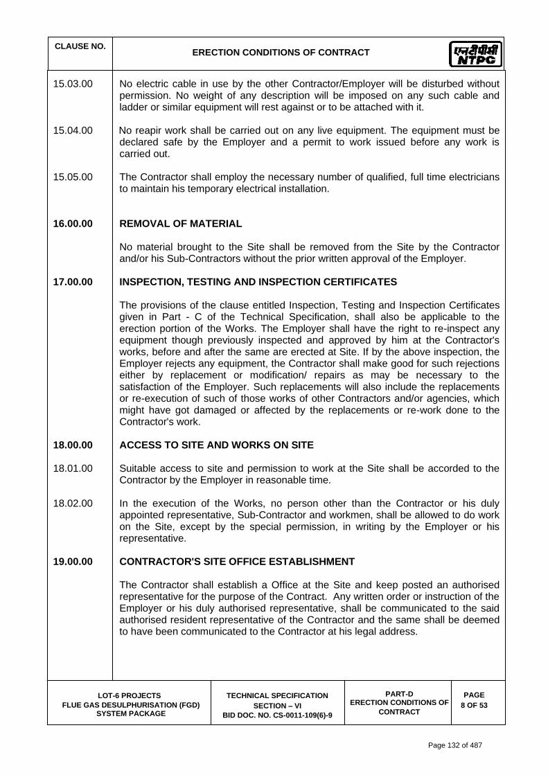
CLAUSE NO.
ERECTION CONDITIONS OF CONTRACT
LOT-6 PROJECTS
FLUE GAS DESULPHURISATION (FGD) SYSTEM PACKAGE
TECHNICAL SPECIFICATION
SECTION – VI
BID DOC. NO. CS-0011-109(6)-9
PART-D ERECTION CONDITIONS OF
CONTRACT
PAGE
8 OF 53
15.03.00 No electric cable in use by the other Contractor/Employer will be disturbed without permission. No weight of any description will be imposed on any such cable and ladder or similar equipment will rest against or to be attached with it.
15.04.00 No reapir work shall be carried out on any live equipment. The equipment must be
declared safe by the Employer and a permit to work issued before any work is carried out.
15.05.00 The Contractor shall employ the necessary number of qualified, full time electricians
to maintain his temporary electrical installation. 16.00.00 REMOVAL OF MATERIAL No material brought to the Site shall be removed from the Site by the Contractor
and/or his Sub-Contractors without the prior written approval of the Employer. 17.00.00 INSPECTION, TESTING AND INSPECTION CERTIFICATES The provisions of the clause entitled Inspection, Testing and Inspection Certificates
given in Part - C of the Technical Specification, shall also be applicable to the erection portion of the Works. The Employer shall have the right to re-inspect any equipment though previously inspected and approved by him at the Contractor's works, before and after the same are erected at Site. If by the above inspection, the Employer rejects any equipment, the Contractor shall make good for such rejections either by replacement or modification/ repairs as may be necessary to the satisfaction of the Employer. Such replacements will also include the replacements or re-execution of such of those works of other Contractors and/or agencies, which might have got damaged or affected by the replacements or re-work done to the Contractor's work.
18.00.00 ACCESS TO SITE AND WORKS ON SITE 18.01.00 Suitable access to site and permission to work at the Site shall be accorded to the
Contractor by the Employer in reasonable time. 18.02.00 In the execution of the Works, no person other than the Contractor or his duly
appointed representative, Sub-Contractor and workmen, shall be allowed to do work on the Site, except by the special permission, in writing by the Employer or his representative.
19.00.00 CONTRACTOR'S SITE OFFICE ESTABLISHMENT The Contractor shall establish a Office at the Site and keep posted an authorised
representative for the purpose of the Contract. Any written order or instruction of the Employer or his duly authorised representative, shall be communicated to the said authorised resident representative of the Contractor and the same shall be deemed to have been communicated to the Contractor at his legal address.
Page 132 of 487

CLAUSE NO.
ERECTION CONDITIONS OF CONTRACT
LOT-6 PROJECTS
FLUE GAS DESULPHURISATION (FGD) SYSTEM PACKAGE
TECHNICAL SPECIFICATION
SECTION – VI
BID DOC. NO. CS-0011-109(6)-9
PART-D ERECTION CONDITIONS OF
CONTRACT
PAGE
9 OF 53
20.00.00 CO-OPERATION WITH OTHER CONTRACTORS 20.01.00 Employer, who may be performing other works on behalf of the Employer and the
workmen who may be employed by the Employer and doing work in the vicinity of the works under the Contract. The Contractor shall also arrange to perform his work as to minimise, to the maximum extent possible, interference with the work of other Contracts and their workmen. Any injury or damage that may be sustained by the employees of the other Contractors and the Employer, due to the Contractor's work shall promptly be made good at his own expense. The Employer shall determine the resolution of any difference or conflict that may arise between the Contractor and other Contractors or between the Contractor and the workmen of the Employer in regard to their work. If the work of the Contractor is delayed because of the any acts of omission of another Contractor, the Contractor shall have no claim against the Employer on that account other than an extension of time for completing his works.
Employer shall have full access to visit the contractor's site at any time for inspection and surveillance checks.
20.02.00 The Employer shall be notified promptly by the Contractor of any defects in the other
Contractor's works that could affect the Contractor's Works. The Employer shall determine the corrective measures if any, required to rectify this situation after inspection of the works and such decisions by the Employer shall be binding on the Contractor.
21.00.00 DISCIPLINE OF WORKMEN The Contractor shall adhere to the disciplinary procedure set by the Employer in
respect of his employees and workmen at Site. The Employer shall be at liberty to object to the presence of any representative or employee of the Contractor at the Site, if in the opinion of the Employer such employee has misconducted himself or is incompetent, negligent or otherwise undesirable then the Contractor shall remove such a person objected to and provide in his place a competent replacement.
22.00.00 CONTRACTOR'S FIELD OPERATION 22.01.00 The Contractor shall keep the Employer informed in advance regarding his field
activity plans and schedules for carrying out each part of the works. Any review of such plan or schedule or method of work by the Employer shall not relieve the Contractor of any of his responsibilities towards the field activities. Such reviews shall also not be considered as an assumption of any risk or liability by the Employer or any of his representatives and no claim of the Contractor will be entertained because of the failure or inefficiency of any such plan or schedule or method of work reviewed. The Contractor shall be solely responsible for the safety, adequacy and efficiency of plant and equipment and his erection methods.
22.02.00 The Contractor shall have the complete responsibility for the conditions of the Work-
Site including the safety of all persons employed by him or his Sub-Contractor and all the properties under his custody during the performance of the work. This requirement shall apply continuously till the completion of the Contract and shall not be limited to normal working hours. The construction review by the Employer is not intended to include review of Contractor's safety measures in, on or near the Work-Site, and their adequacy or otherwise.
Page 133 of 487
CLAUSE NO.
ERECTION CONDITIONS OF CONTRACT
LOT-6 PROJECTS
FLUE GAS DESULPHURISATION (FGD) SYSTEM PACKAGE
TECHNICAL SPECIFICATION
SECTION – VI
BID DOC. NO. CS-0011-109(6)-9
PART-D ERECTION CONDITIONS OF
CONTRACT
PAGE
10 OF 53
23.00.00 PHOTOGRAPHS AND PROGRESS REPORT 23.01.00 The Contractor shall furnish three (3) prints each to the Employer of progress
photographs of the work done at Site. Photographs shall be taken as and when indicated by the Employer or his representative. Photographs shall be adequate in size and number to indicate various stages of erection. Each photograph shall contain the date, the name of the Contractor and the title of the photograph.
23.02.00 The above photographs shall accompany the monthly progress report detailing out
the progress achieved on all erection activities as compared to the schedules. The report shall also indicate the reasons for the variance between the scheduled and actual progress and the action proposed for corrective measures, wherever necessary.
23.03.00 The Contractor shall submit the progress of work in soft and hard form (as decided
by employer) quarterly highlighting the progress and constraints at site. 24.00.00 MAN-POWER REPORT 24.01.00 The Contractor shall submit to the Employer, on the first day of every month, a man
hour schedule for the month, detailing the man hours scheduled for the month, skill-wise and area-wise.
24.02.00 The Contractor shall also submit to the Employer on the first day of every month, a
man power report of the previous month detailing the number of persons scheduled to have been employed and actually employed, skill- wise and the areas of employment of such labour.
25.00.00 PROTECTION OF WORK The Contractor shall have total responsibility for protecting his works till it is finally
taken over by the Employer. No claim will be entertained by the Employer or the representative of the Employer for any damage or loss to the Contractor's works and the Contractor shall be responsible for complete restoration of the damaged works to original conditions to comply with the specification and drawings. Should any such damage to the Contractor's Works occur because of other party not being under his supervision or control, the Contractor shall make his claim directly with the party concerned. If disagreement or conflict or dispute develops between the Contractor and the other party or parties concerned regarding the responsibility for damage to the Contractor's Works the same shall be resolved as per the provisions of the as specified at clause no 21.00.00 of this chapter entitled "Co-operation with other Contractors." The Contractor shall not cause any delay in the repair of such damaged Works because of any delay in the resolution of such disputes. The Contractor shall proceed to repair the Work immediately and no cause thereof will be assigned pending resolution of such disputes.
26.00.00 EMPLOYMENT OF LABOUR 26.01.00 In addition to all local laws and regulations pertaining to the employment of labour to
be complied with by the Contractor pursuant to GCC, the Contractor will be expected to employ on the work only his regular skilled employees with experience of the
Page 134 of 487

CLAUSE NO.
ERECTION CONDITIONS OF CONTRACT
LOT-6 PROJECTS
FLUE GAS DESULPHURISATION (FGD) SYSTEM PACKAGE
TECHNICAL SPECIFICATION
SECTION – VI
BID DOC. NO. CS-0011-109(6)-9
PART-D ERECTION CONDITIONS OF
CONTRACT
PAGE
11 OF 53
particular work. No female labour shall be employed after darkness. No person below the age of eighteen years shall be employed.
26.02.00 All travelling expenses including provisions of all necessary transport to and from
Site, lodging allowances and other payments to the Contractor's employees shall be the sole responsibility of the Contractor.
26.03.00 The hours of work on the Site shall be decided by the Employer and the Contractor
shall adhere to it. Working hours will normally be eight (8) hours per day - Monday through Saturday.
26.04.00 Contractor's employees shall wear identification badges while on work at Site. 26.05.00 In case the Employer becomes liable to pay any wages or dues to the labour or any
Government agency under any of the provisions of the Minimum Wages Act, Workmen Compensation Act, Contact Labour Regulation Abolition Act or any other law due to act of omission of the Contractor, the Employer may make such payments and shall recover the same from the Contractor's Bills.
27.00.00 FACILITIES TO BE PROVIDED BY THE EMPLOYER 27.01.00 Electricity
Refer clause 1.14.00 (Construction Power) Sub-Section III-B, Part-A, Section VI of Technical Specification.
27.02.00 Water Contractor shall make all arrangements himself for the supply of construction water
as well as potable water for labour and other personnel at the worksite/colony. However, drawl of construction/potable water from bore-well shall be permitted if found suitable. Any statutory clearance required shall be obtained by the contractor. Assistance, if required shall be provided by the owner.
27.03.00 Communication The Employer will extend the telephone facilities, if available at Site, for purposes of
Contract. The Contractor shall be charged at actuals for such facilities. 27.04.00 Railway Siding Railway siding shall be provided by owner (up to plant entry point) for coal
transportation to site. However the same may not be available to the bidder for material/supplies transport etc. Bidder has to plan its own arrangement for movement of ODC consignment to plant site.
Page 135 of 487
3062805
Line

CLAUSE NO.
ERECTION CONDITIONS OF CONTRACT
LOT-6 PROJECTS
FLUE GAS DESULPHURISATION (FGD) SYSTEM PACKAGE
TECHNICAL SPECIFICATION
SECTION – VI
BID DOC. NO. CS-0011-109(6)-9
PART-D ERECTION CONDITIONS OF
CONTRACT
PAGE
12 OF 53
28.00.00 FACILITIES TO BE PROVIDED BY THE CONTRACTOR
28.01.00 Contractor's site office Establishment
The Contractor shall establish a site office at the site and keep posted an authorized representative for the purpose of the contract, pursuant to GCC. The site office will include one conference meeting room for site meetings between the Contractor and the Employer.
28.02.00 Tools, tackles and scaffoldings The Contractor shall provide all the construction equipments, tools, tackles and
scaffoldings required for pre-assembly, installation, testing, commissioning and conducting Guarantee tests of the equipments covered under the Contract. He shall submit a list of all such materials to the Employer before the commencement of pre-assembly at Site. These tools and tackles shall not be removed from the Site without the written permission of the Employer. The Contractor shall arrange Dozer, Hydra, Cranes, Trailer, etc. for the purpose of fabrication, erection and commissioning.
28.03.00 Testing Equipment and Facilities: The contractor shall provide the necessary testing, equipment and facilities. 28.04.00 Site laboratory for civil works: Contractor shall provide and maintain a site laboratory for the testing of construction
material under the direction and general supervision of employer. 28.05.00 First-aid 28.05.01 The Contractor shall provide necessary first-aid facilities for all his employees,
representatives and workmen working at the Site. Enough number of Contractor's personnel shall be trained in administering first-aid.
28.05.02 The Employer will provide the Contractor, in case of any emergency, the services of an ambulance for transportation to the nearest hospital.
28.06.00 Cleanliness 28.06.01 The Contractor shall be responsible for keeping the entire area allotted to him clean
and free from rubbish, debris etc. during the period of Contract. The Contractor shall employ enough number of special personnel to thoroughly clean his work-area at least once in a day. All such rubbish and scrap material shall be stacked or disposed in a place to be identified by the Employer. Materials and stores shall be so arranged to permit easy cleaning of the area. In areas where equipment might drip oil and cause damage to the floor surface, a suitable protective cover of a flame resistant, oil proof sheet shall be provided to protect the floor from such damage.
28.06.02 Similarly the offices shall be kept clean and neat to the entire satisfaction of the
Employer. Proper sanitary arrangements shall be provided by the Contractor, in the work-areas and office areas of the Contractor.
29.00.00 LINES AND GRADES
Page 136 of 487
3062805
Line

CLAUSE NO.
ERECTION CONDITIONS OF CONTRACT
LOT-6 PROJECTS
FLUE GAS DESULPHURISATION (FGD) SYSTEM PACKAGE
TECHNICAL SPECIFICATION
SECTION – VI
BID DOC. NO. CS-0011-109(6)-9
PART-D ERECTION CONDITIONS OF
CONTRACT
PAGE
13 OF 53
All the Works shall be performed to the lines, grades and elevations indicated on the
drawings. The Contractor shall be responsible to locate and layout the Works. Basic horizontal and vertical control points will be established and marked by the Employer at Site at suitable points. These points shall be used as datum for the works under the Contract. The Contractor shall inform the Employer well in advance of the times and places at which he wishes to do work in the area allotted to him so that suitable datum points may be established and checked by the Employer to enable the Contractor to proceed with his works. Any work done without being properly located may be removed and/or dismantled by the Employer at Contractor's expense.
30.00.00 FIRE PROTECTION 30.01.00 The work procedures that are to be used during the erection shall be those which
minimise fire hazards to the extent practicable. Combustible materials, combustible waste and rubbish shall be collected and removed from the Site at least once each day. Fuels, oils and volatile or flammable materials shall be stored away from the construction and equipment and materials storage areas in safe containers. Untreated canvas, paper, plastic or other flammable flexible materials shall not at all be used at Site for any other purpose unless otherwise specified. If any such materials are received with the equipment at the Site, the same shall be removed and replaced with acceptable material before moving into the construction or storage area.
30.02.00 Similarly corrugated paper fabricated cartons etc. will not be permitted in the
construction area either for storage or for handling of materials. All such materials used shall be of water proof and flame resistant type. All the other materials such as working drawings, plans etc. which are combustible but are essential for the works to be executed shall be protected against combustion resulting from welding sparks, cutting flames and other similar fire sources.
30.03.00 All the Contractor's supervisory personnel and sufficient number of workers shall be
trained for fire-fighting and shall be assigned specific fire protection duties. Enough of such trained personnel must be available at the Site during the entire period of the Contract.
30.04.00 The Contractor shall provide enough fire protection equipment of the types and
number for the warehouses, office, temporary structures, labour colony area etc. Access to such fire protection equipment, shall be easy and kept open at all time.
31.00.00 SECURITY The Contractor shall have total responsibility for all equipment and materials in his
custody stores, loose, semi-assembled and/or erected by him at Site. The Contractor shall make suitable security arrangements including employment of security personnel to ensure the protection of all materials, equipment and works from theft, fire, pilferage and any other damages and loss. All materials of the Contractor shall enter and leave the Employer Site only with the written permission of the Employer in the prescribed manner.
Page 137 of 487

CLAUSE NO.
ERECTION CONDITIONS OF CONTRACT
LOT-6 PROJECTS
FLUE GAS DESULPHURISATION (FGD) SYSTEM PACKAGE
TECHNICAL SPECIFICATION
SECTION – VI
BID DOC. NO. CS-0011-109(6)-9
PART-D ERECTION CONDITIONS OF
CONTRACT
PAGE
14 OF 53
32.00.00 CONTRACTOR'S AREA LIMITS The Employer will mark-out the boundary limits of access roads, parking spaces,
storage and construction areas for the Contractor and the Contractor shall not trespass the areas not so marked out for him. The Contractor shall be responsible to ensure that none of his personnel move out of the areas marked out for his operations. In case of such a need for the Contactor's personnel to work out of the areas marked out for him the same shall be done only with the written permission of the Employer.
33.00.00 CONTRACTOR'S CO-OPERATION WITH THE EMPLOYER In case where the performance of the erection work by the Contractor affects the
operation of the system facilities of the Employer, such erection work of the Contractor shall be scheduled to be performed only in the manner stipulated by the Employer and the same shall be acceptable at all times to the Contractor. The Employer may impose such restrictions on the facilities provided to the Contractor such as electricity, etc. as he may think fit in the interest of the Employer and the Contractor shall strictly adhere to such restrictions and co-operate with the Employer. It will be the responsibility of the Contractor to provide all necessary temporary instrumentation and other measuring devices required during start-up and operation of the equipment systems which are erected by him. The Contractor shall also be responsible for flushing and initial filling of all the oil and lubricants required for the equipment furnished and installed by him, so as to make such equipment ready for operation. The Contractor shall be responsible for supplying such flushing oil and other lubricants unless otherwise specified elsewhere in documents and specifications.
34.00.00 PRE-COMMISSIONING AND COMMISSIONING ACTIVITIES 34.01.00 GENERAL 34.01.01 The Contractor upon completion of installation of equipments and systems, shall
conduct pre-commissioning and commissioning activities, to make the equipment/systems ready for safe, reliable and efficient operation on sustained basis. All pre-commissioning/commissioning activities considered essential for such readiness of the equipment/systems including those mutually agreed and included in the Contractor’s quality assurance programme as well as those indicated in clauses elsewhere in the technical specifications shall be performed by the contractor.
34.01.02 The pre-commissioning and commissioning activities including Guarantee/
demonstration/ acceptability tests, checks and trial operations of the equipment/systems furnished and installed by the contractor shall be the responsibility of the Contractor as detailed in relevant clauses in Technical Specification. The Contractor shall provide, in addition, test instruments, calibrating devices etc. and labour required for successful performance of these operations. If it is anticipated that the above test may prolong for a long time, the Contractor's workmen required for the above test shall always be present at site during such operations.
Page 138 of 487

CLAUSE NO.
ERECTION CONDITIONS OF CONTRACT
LOT-6 PROJECTS
FLUE GAS DESULPHURISATION (FGD) SYSTEM PACKAGE
TECHNICAL SPECIFICATION
SECTION – VI
BID DOC. NO. CS-0011-109(6)-9
PART-D ERECTION CONDITIONS OF
CONTRACT
PAGE
15 OF 53
34.01.03 The following activities shall be carried out by the contractor, 18 month prior to schedule date of commissioning of the equipment/systems installed by him.
(a.) The contractor shall furnish the organization chart of his operation and
commissioning engineers for the acceptance of employer. Adequate number of operation and commissioning engineers shall be deployed by the contractor to effectively meet the requirement of round the clock operation in shifts also, till the plant is taken over by the employer.
(b.) The contractor shall submit the bio-data containing the details of experience
of his operation and commissioning engineers for the acceptance of employer.
(c.) The contractor shall furnish the deployment schedule of his operation and
commissioning engineers for the acceptance of the employer. (d.) Apart from above, contractor shall ensure deployment of sufficient
skilled/semi-skilled/unskilled manpower during pre-commissioning and commissioning activities.
34.01.04 It shall be the responsibility of the Contractor to provide all necessary temporary
instrumentation and other measuring devices required during start-up and initial operation of the equipment/systems which are installed by him.
34.01.05 The Contractor shall also be responsible for flushing and initial filling of all oils and
lubricants required for the equipment furnished and installed by him so as to make such equipment ready for operation. The Contractor shall be responsible for supplying such flushing oil and other lubricants unless otherwise specified elsewhere in these specifications and documents.
34.02.00 COMMISSIONING DOCUMENTATION 34.02.01 The contractor shall submit the commissioning documentation, comprising of
Standard checklists, pre-commissioning procedures, testing schedules, commissioning schedules and commissioning networks for various equipment/systems covered under the contract, for the approval of employer.
34.02.02 Standard checklist, as the name suggests, shall be a fairly general documents,
containing the list of all checks required to be carried out for similar and repetitive type of equipment to ensure consistent and thorough checking. An indicative list of such equipment is enclosed as Annexure I.
34.02.03 The testing schedule is a document, designed for safe and systematic
commissioning of individual equipment/sub-system (for example compressor etc.) Commissioning schedule is a document envisaged for commissioning of a system (for example Compressed Air system, Unit commissioning etc.). The testing/Commissioning schedule shall have a standard format in order to maintain consistency of presentation, content and reporting. A brief write up on the contents of the Testing Schedule/Commissioning Schedule is enclosed as Annexure-II.
Page 139 of 487

CLAUSE NO.
ERECTION CONDITIONS OF CONTRACT
LOT-6 PROJECTS
FLUE GAS DESULPHURISATION (FGD) SYSTEM PACKAGE
TECHNICAL SPECIFICATION
SECTION – VI
BID DOC. NO. CS-0011-109(6)-9
PART-D ERECTION CONDITIONS OF
CONTRACT
PAGE
16 OF 53
34.02.04 The contractor shall submit the list of commissioning documentation to be submitted by him, along with their submission schedule for various equipment/systems covered under the contract, with in 6(six) month from the date of award of contract, for the acceptance of employer.
34.02.05 The Contractor shall submit the commissioning documentation, for various
equipment/covered under the contract, for the approval of employer, at least 18 months before the scheduled date of commissioning of the equipment/systems.
34.03.00 COMMISSIONING ACTIVITIES 34.03.01 Upon completion of pre-commissioning activities/tests, the contractor shall initiate
commissioning of facilities. During commissioning the Contractor shall carry out system checking and reliability trials on various parts of the facilities.
34.03.02 Contractor shall carry out the checks/tests at site to prove to the Employer that each
equipment of the supply complies with requirements stipulated and is installed in accordance with requirements specified.
34.03.03 Before the plant is put into initial operation the Contractor shall be required to
conduct test to demonstrate to the Employer that each item of the plant is capable of correctly performing the functions for which it was specified and its performance, parameters etc. are as per the specified/approved values. These tests may be conducted concurrently with those required under commissioning sequence.
34.03.04 The Contractor shall also demonstrate the performance of all C&I equipment, the
tests on main equipment of prior to that as the case may be. 34.03.05 Other tests shall be conducted, if required by the Employer, to establish that the
plant equipment are in accordance with requirements of the specifications. 34.03.06 The Contractor shall conduct all the commissioning tests and undertake
commissioning activities pertaining to all other auxiliaries and equipments including all electrical and C&I equipment/systems not specifically brought out above but are within the scope of work and facilities being supplied and installed by the Contractor and follow the guidelines indicated above or elsewhere in these technical specifications.
34.05.00 Initial Operation Upon completion of system checking/Tests as above and as a part of commissioning
of facilities, complete plant/facilities shall be put on initial operation as stipulated in General Technical Requirements.
35.00.00 MATERIALS HANDLING AND STORAGE 35.01.00 All the equipments furnished under the Contract and arriving at Site shall be
promptly received, unloaded and transported and stored in the storage spaces by the Contractor.
Page 140 of 487

CLAUSE NO.
ERECTION CONDITIONS OF CONTRACT
LOT-6 PROJECTS
FLUE GAS DESULPHURISATION (FGD) SYSTEM PACKAGE
TECHNICAL SPECIFICATION
SECTION – VI
BID DOC. NO. CS-0011-109(6)-9
PART-D ERECTION CONDITIONS OF
CONTRACT
PAGE
17 OF 53
35.02.00 Contractor shall be responsible for examining all the shipment and notify the Employer immediately of any damage, shortage, discrepancy etc. for the purpose of Employer's information only. The Contractor shall submit to the Employer every week a report detailing all the receipts during the week. However, the Contractor shall be solely responsible for any shortages or damage in transit, handling and / or in storage and erection of the equipment at Site. Any demurrage, wharfage and other such charges claimed by the transporters, railways etc. shall be to the account of the Contractor.
35.03.00 The Contractor shall maintain an accurate and exhaustive record detailing out the
list of all equipment received by him for the purpose of erection and keep such record open for the inspection of the Employer.
35.04.00 All equipment shall be handled very carefully to prevent any damage or loss. No
bare wire ropes, slings, etc. shall be used for unloading and/or handling of the equipment without the specific written permission of the Employer. The equipment stored shall be properly protected to prevent damage either to the equipment or to the floor where they are stored. The equipment from the store shall be moved to the actual location at the appropriate time so as to avoid damage of such equipment at Site.
35.05.00 All electrical panels, controls gear, motors and such other devices shall be properly
dried by heating before they are installed and energised. Motor bearings, slip rings, commutators and other exposed parts shall be protected against moisture ingress and corrosion during storage and periodically inspected. Heavy rotating parts in assembled conditions shall be periodically rotated to prevent corrosion due to prolonged storage.
35.06.00 All the electrical equipment such as motors, etc. shall be tested for insulation
resistance at least once in three months from the date of receipt till the date of commissioning and a record of such measured insulation values maintained by the Contractor. Such records shall be open for inspection by the Employer.
35.07.00 The Contractor shall ensure that all the packing materials and protection devices
used for the various equipments during transit and storage are removed before the equipment are installed.
35.08.00 The consumables and other supplies likely to deteriorate due to storage must be
thoroughly protected and stored in a suitable manner to prevent damage or deterioration in quality by storage.
35.09.00 All the materials stored in the open or dusty location must be covered with suitable
weatherproof and flame-proof covering material wherever applicable. 35.10.00 If the materials belonging to the Contractor are stored in areas other than those
earmarked for him, the Employer will have the right to get it moved to the area earmarked for the Contractor at the Contractor's cost.
35.11.00 The Contractor shall be responsible for making suitable indoor storage facilities to
store all equipment which require indoor storage. Normally, all the electrical equipments such as motors, control gear, generators, exciters and consumables like
Page 141 of 487

CLAUSE NO.
ERECTION CONDITIONS OF CONTRACT
LOT-6 PROJECTS
FLUE GAS DESULPHURISATION (FGD) SYSTEM PACKAGE
TECHNICAL SPECIFICATION
SECTION – VI
BID DOC. NO. CS-0011-109(6)-9
PART-D ERECTION CONDITIONS OF
CONTRACT
PAGE
18 OF 53
electrodes, lubricants etc. shall be stored in the closed storage space. The Employer, in addition, may direct the Contractor to move certain other materials, which in his opinion will require indoor storage, to indoor storage areas which the Contractor shall strictly comply with.
36.00.00 CONSTRUCTION MANAGEMENT 36.01.00 The field activities of the Contractors working at Site, will be coordinated by the
Employer and the Employer decision shall be final in resolving any disputes or conflicts between the Contractor and other Contractors and tradesmen of the Employer regarding scheduling and co- ordination of work. Such decision by the Employer shall not be a cause for extra compensation or extension of time for the Contractor.
36.02.00 The Employer shall hold weekly meetings of all the Contractors working at Site, at a
time and place to be designated by the Employer. The Contractor shall attend such meetings and take notes of discussions during the meeting and the decisions of the Employer and shall strictly adhere to those decisions in performing his Works. In addition to the above weekly meeting, the Employer may call for other meeting either with individual Contractors or with selected number of Contractors and in such a case the Contractor if called, will also attend such meetings.
36.03.00 Time is the essence of the Contract and the Contractor shall be responsible for
performance of his works in accordance with the specified construction schedule. If at any time, the Contractor is falling behind the schedule, he shall take necessary action to make good for such delays by increasing his work force or by working overtime or otherwise accelerate the progress of the work to comply with the schedule and shall communicate such actions in writing to the Employer, satisfying that his action will compensate for the delay. The Contractor shall not be allowed any extra compensation for such action.
36.04.00 The Employer shall however not be responsible for provision of additional labour
and/or materials or supply or any other services to the Contractor except for the co-ordination work between various Contractors as set out earlier.
36.05.00 Site management during construction phase till handing over of plant Bidder shall ensure that the plant site within the plant boundary is managed in a
coordinated and professional way all through the construction phase till handing over of plant, ensuring safe, easy & unhindered working conditions and a healthy & hygienic working environment at site. He shall ensure the following measures at site while executing the project.
a) Proper housekeeping by systematic and proper disposal of earth from excavations
(separately for usable & surplus earth), muck (from pile bores or otherwise), wastes (from dismantling of pile tops, concrete works etc), packing & insulation wastes, steel scrap, cable wastes etc generated during construction / erection works. Suitable disposal sites for each of above shall be identified in the layout and at site in the beginning of the project itself. It shall be ensured that all agencies engaged by the bidder follow the discipline to dispose off of earth spoils and wastes at the
Page 142 of 487
CLAUSE NO.
ERECTION CONDITIONS OF CONTRACT
LOT-6 PROJECTS
FLUE GAS DESULPHURISATION (FGD) SYSTEM PACKAGE
TECHNICAL SPECIFICATION
SECTION – VI
BID DOC. NO. CS-0011-109(6)-9
PART-D ERECTION CONDITIONS OF
CONTRACT
PAGE
19 OF 53
designated places. Preferably once in a week suitable time slot will be identified for housekeeping by all agencies and suitable instructions shall be issued in this regard. Bidder may engage a separate agency or identify a gang for collection of wastes and disposal to designated places. Suitable arrangement / tieup will also be made for periodic disposal of wastes/ scrap from the designated places.
b) All fabrication areas shall be suitably hard crusted to provide a water free and proper
working platforms. Suitable sheds preferably pre engineered structures to be provided for paint shops, fabrication workshops etc for ensuring all weather work conditions for onsite structural works. For the main plant and auxiliary buildings, bidder should preferably plan the works in such a way that structural fabrication is done in suppliers' offsite works / workshops and onsite fabrication works are avoided / kept minimum.
c) Suitable onsite maintenance workshop for day to day breakdown maintenance
heavy plant and equipment like batching plants, cranes, earth moving equipment, poclains, welding equipment etc. The workshop shall have stock of frequently needed spares and suitable repair facilities with experienced technicians/mechanics. A central test laboratory equipped with test equipment for routine tests like tests on soil, concrete, bricks, aggregates, welds etc with experienced staff shall be established at the start of the project itself.
d) All office and covered store buildings of the bidder and its agencies shall be of
prefab/ pre-engineered / porta cabin construction. Shabby semi finished constructions in brickwork/ GI / asbestos roof etc shall not be permitted.
e) First aid facilities and amenities like rest rooms, suitable pre engineered toilets (
separate for men and women), drinking water fountains/tanks, canteen, crèche for women workers shall be planned and established at the beginning of the project itself. These facilities shall be located distributed over the plant area to enable easy access by the construction workers and staff and shall be marked on the plant layout. Suitable treatment for toilet discharge, like bio digesters etc shall be planned and conventional septic tanks / soak pits etc shall be avoided.
f) Proper lighting of all construction / erection areas. Bidder shall erect adequate
number of high lighting masts in main plant, offsite, office and store areas for lighting during night. DG sets of adequate capacity shall be provided for emergency backup. The street lighting along the roads shall also be priortised along with road construction. The construction power ring main shall be planned and erected immediately after the award.
g) Well planned and coordinated storage and movement of plant, equipment and
construction materials. System wise / agency wise storage / laydown areas shall be planned and marked on the plant layout at the beginning itself. Bidder shall ensure that all its agencies comply to the areas allocated to them and follow the designated storage and movement plans. Adequate covered storage shall be constructed for storage of critical equipments like switchgears, MCCs, insulation etc.
h) Proper access control for construction workers, staff and visitors. Bidder shall ensure
that suitable electronic based gate pass system is in place from start of project itself
Page 143 of 487

CLAUSE NO.
ERECTION CONDITIONS OF CONTRACT
LOT-6 PROJECTS
FLUE GAS DESULPHURISATION (FGD) SYSTEM PACKAGE
TECHNICAL SPECIFICATION
SECTION – VI
BID DOC. NO. CS-0011-109(6)-9
PART-D ERECTION CONDITIONS OF
CONTRACT
PAGE
20 OF 53
to keep record and track of all workers, staff and visitors entering/exiting the plant premises shift wise on daily basis.
i) Compliance to all safety requirements as specified elsewhere in the tender
documents. Bidders shall establish a safety centre at the start of the project itself. It shall have a 24X7 manned safety control room in addition to a permanent safety equipment display room, separate training / lecture hall with AV facilities for safety training, store room with adequate stock of specified safety equipment, a first aid room and other amenities. Bidder shall install CCTV cameras at all strategic locations in the plant area which shall be linked to the safety control room.
j) Compliance to all environment and other conditions stipulated by the concerned
statutory authorities while according clearance / NOC to the project. Bidder shall ensure adequate sprinkling of water by deploying water tankers to prevent the fugitive dust nuisance during construction.
k) Development of suitable landscape & green belt areas and rainwater harvesting
within the plant premises. Bidder shall plan to develop the landscape & green belt areas and rainwater harvesting from the start of the project itself. The landscape and rainwater harvesting plan shall be finalized immediately after award of work and suitable work plan with priority and schedule shall also be finalized thereafter. Top soil before excavation shall be suitably preserved and stacked for landscape and green belt development.
l) Provision of adequate shelters, water supply, sanitation and lighting in construction
workers and staff camps. No camps for workers and staff shall be permitted within the plant premises and Bidder shall make separate arrangement outside the plant premises for locating and development of camps for construction workers and staff. The designated areas shall be suitably developed with infrastructure like roads, drains, water supply and sewerage and shall be free from water logging. Suitable low cost shelters will be provided for the workers. Complete area shall be secured by fencing and shall be provided adequate area lighting. Suitable waste disposal, shopping and recreation facilities will be developed in these camps.
Contractor shall ensure that due importance is given to site management as
discussed above and a detailed work plan considering the above aspects is finalized immediately after the award. A senior level executive shall be identified who shall be responsible for implementation of the work plan. Suitable format for progress reporting on site management plan shall be developed and made part of the project progress report. The progress on implementation of above work plan shall be reviewed along with project progress in the monthly project review meetings with owner. In case the progress on site management plan is unsatisfactory, Engineer-in Charge may withhold upto 1% of the monthly running bill (for civil and site erection works) till such time the required progress is demonstrated. Incase in the opinion of Engineer-in-charge, bidder's actions on site management aspects is not adequate, Engineer-in- charge may get the relevant work executed through a separate agency and deduct the expenses incurred from Bidder's bill along with overheads @10 %.
37.00.00 FIELD OFFICE RECORDS
Page 144 of 487

CLAUSE NO.
ERECTION CONDITIONS OF CONTRACT
LOT-6 PROJECTS
FLUE GAS DESULPHURISATION (FGD) SYSTEM PACKAGE
TECHNICAL SPECIFICATION
SECTION – VI
BID DOC. NO. CS-0011-109(6)-9
PART-D ERECTION CONDITIONS OF
CONTRACT
PAGE
21 OF 53
The Contractor shall maintain at his Site Office up-to- date copies of all drawings, specifications and other Contract Documents and any other supplementary data complete with all the latest revisions thereto. The Contractor shall also maintain in addition the continuous record of all changes to the above Contract Documents, drawings, specifications, supplementary data, etc. effected at the field and on completion of his total assignment under the Contract shall incorporate all such changes on the drawings and other Engineering data to indicate as installed conditions of the equipment furnished and erected under the Contract. Such drawings and Engineering data shall be submitted to the Employer in required number of copies.
38.00.00 CONTRACTOR'S MATERIALS BROUGHT ON TO SITE 38.01.00 The Contractor shall bring to Site all equipment, components, parts, materials,
including construction equipment, tools and tackles for the purpose of the Works under intimation to the Employer. All such goods shall, from the time of their being brought vest in the Employer, but may be used for the purpose of the Works only and shall not on any account be removed or taken away by the Contractor without the written permission of the Employer. The Contractor shall nevertheless be solely liable and responsible for any loss or destruction thereof and damage thereto.
38.02.00 The Employer shall have a lien on such goods for any sum or sums which may at
any time be due or owing to him by the Contractor, under, in respect of or by reasons of the Contract. After giving a fifteen (15) days notice in writing of his intention to do so, the Employer shall be at liberty to sell and dispose off any such goods, in such manner as he shall think fit including public auction or private treaty and to apply the proceeds in or towards the satisfaction of such sum or sums due as aforesaid.
38.03.00 After the completion of the Works, the Contractor shall remove from the Site under
the direction of the Employer the materials such as construction equipment, erection tools and tackles, scaffolding etc. with the written permission of the Employer. If the Contractor fails to remove such materials, within fifteen (15) days of issue of a notice by the Employer to do so then the Employer shall have the liberty to dispose off such materials as detailed under as specified at clause no 39.02.00 of this chapter and credit the proceeds thereto to the account of the Contractor.
39.00.00 PROTECTION OF PROPERTY AND CONTRACTOR'S LIABILITY 39.01.00 The Contractor shall be responsible for any damage resulting from his operations.
He shall also be responsible for protection of all persons including members of public and employees of the Employer and the employees of other Contractors and Sub- Contractors and all public and private property including structures, building, other plants and equipments and utilities either above or below the ground.
39.02.00 The Contractor will ensure provision of necessary safety equipment such as barriers,
sign - boards, warning lights and alarms, etc. to provide adequate protection to persons and property. The Contractor shall be responsible to give reasonable notice to the Employer and the Employers of public or private property and utilities when such property and utilities are likely to get damaged or injured during the performance of his Works and shall make all necessary arrangements with such
Page 145 of 487

CLAUSE NO.
ERECTION CONDITIONS OF CONTRACT
LOT-6 PROJECTS
FLUE GAS DESULPHURISATION (FGD) SYSTEM PACKAGE
TECHNICAL SPECIFICATION
SECTION – VI
BID DOC. NO. CS-0011-109(6)-9
PART-D ERECTION CONDITIONS OF
CONTRACT
PAGE
22 OF 53
Employers, related to removal and/or replacement or protection of such property and utilities.
40.00.00 PAINTING For painting refer Part-A, sub section-III, Section VI of Technical specification. Painting for structures shall conform to the painting specification specified in Part-B
under Civil. Painting for Electrical equipments/systems shall conform to the painting specification
given in Electrical portion of Part-A and Part-B of technical specifications.
41.00.00 INSURANCE 41.01.00 In addition to the conditions covered under the Clause entitled "Insurance" in Section
General Conditions of Contract (GCC), the following provisions will also apply to the portion of works to be done beyond the Contractor's own or his Sub-Contractor's manufacturing Works.
41.02.00 Workmen's Compensation Insurance This insurance shall protect the Contractor against all claims applicable under the
Workmen's Compensation Act, 1948 (Government of India). This policy shall also cover the Contractor against claims for injury, disability disease or death of his or his Sub-Contractor's employees, which for any reason are not covered under the Workmen’s Compensation Act, 1948. The liabilities shall not be less than the following:
Workmen's Compensation - As per Statutory Provisions Employee's Liability - As per Statutory Provisions 41.03.00 Comprehensive Automobile Insurance This insurance shall be in such a form to protect the Contractor against all claims for
injuries, disability, disease and death to members of public including the Employer's men and damage to the property of other arising from the use of motor vehicles during on or off the Site operations, irrespective of the Ownership of such vehicles. The liability covered shall be as herein indicated :
Fatal Injury : Rs.100,000 each person
: Rs.200,000 each occurrence
Property Damage : Rs.100,000 each occurrence 41.04.00 Comprehensive General Liability Insurance 41.04.01 The insurance shall protect the Contractor against all claims arising from injuries,
disabilities, disease or death of members of public or damage to property of others,
Page 146 of 487
3062805
Line

CLAUSE NO.
ERECTION CONDITIONS OF CONTRACT
LOT-6 PROJECTS
FLUE GAS DESULPHURISATION (FGD) SYSTEM PACKAGE
TECHNICAL SPECIFICATION
SECTION – VI
BID DOC. NO. CS-0011-109(6)-9
PART-D ERECTION CONDITIONS OF
CONTRACT
PAGE
23 OF 53
due to any act or omission on the part of the Contractor, his agents, his employees, his representatives and Sub-Contractors or from riots, strikes and civil commotion. This insurance shall also cover all the liabilities of the Contractor arising out of the Clause entitled "Defence of Suits" in Section General Conditions of Contract (GCC).
41.04.02 The hazards to be covered will pertain to all the Works and areas where the
Contractor, his Sub-Contractors, his agents and his employees have to perform work pursuant to the Contract.
41.05.00 The above are only illustrative list of insurance covers normally required and it will
be the responsibility of the Contractor to maintain all necessary insurance coverage to the extent both in time and amount to take care of all his liabilities either direct or indirect, in pursuance of the Contract.
42.00.00 UNFAVOURABLE WORKING CONDITIONS The Contractor shall confine all his field operations to those works which can be
performed without subjecting the equipment and materials to adverse effects during inclement weather conditions, like monsoon, storms, etc. and during other unfavourable construction conditions. No field activities shall be performed by the Contractor under conditions which might adversely affect the quality and efficiency thereof, unless special precautions or measures are taken by the Contractor in a proper and satisfactory manner in the performance of such Works and with the concurrence of the Employer. Such unfavourable construction conditions will in no way relieve the Contractor of his responsibility to perform the Works as per the schedule.
43.00.00 PROTECTION OF MONUMENTS AND REFERENCE POINTS The Contractor shall ensure that any finds such as relic, antiquity, coins, fossils, etc.
which he may come across during the course of performance of his Works either during excavation or elsewhere, are properly protected and handed over to the Employer. Similarly the Contractor shall ensure that the bench marks, reference points, etc., which are marked either with the help of Employer or by the Employer shall not be disturbed in any way during the performance of his Works. If, any work is to be preformed which disturb such reference, the same shall be done only after these are transferred to other suitable locations under the direction of the Employer. The Contractor shall provide all necessary materials and assistance for such relocation of reference points etc.
44.00.00 WORK & SAFETY REGULATIONS 44.01.00 General
i) The contractor shall comply with all the requirements of "The Building and Other Construction Workers (Regulation of Employment & Conditions of Service) Act," 1996 and its Central Rule 1998 / State Rules and any other statutory requirements as applicable.
Page 147 of 487
3062805
Line

CLAUSE NO.
ERECTION CONDITIONS OF CONTRACT
LOT-6 PROJECTS
FLUE GAS DESULPHURISATION (FGD) SYSTEM PACKAGE
TECHNICAL SPECIFICATION
SECTION – VI
BID DOC. NO. CS-0011-109(6)-9
PART-D ERECTION CONDITIONS OF
CONTRACT
PAGE
24 OF 53
ii) The Contractor shall follow NTPC Safety Rules as issued from time to time with respect to safety in construction & erection.
iii) The contractor shall have the approved Safety, Health and Environment (SHE) Policy in respect of Safety and health of Building Workers and it shall be circulated widely and displayed at conspicuous place in Hindi and local language understood by the majority of the workers. A copy of the safety policy should be submitted to Engineer in charge.
iv) The contractor shall submit the safety plan comprising of methods to implement the Safety Policy/ Rules, Risk assessment and ensuring Safety at work areas, Safety audits, inspections and its compliance, Supervision and responsibility to ensure Safety at various levels, Safety training to employees, review of Safety and accident analysis, ensure Health and Safety Procedures to prevent accidents to Engineer I/c for approval as per the format of Safety plan as annexed at Annexure - III.
v) The Contractors shall ensure proper safety of all the workmen, materials, plant and equipment belonging to him or to the Employer or to others, working at the Site.
vi) All equipments used in construction and erection by the contractor shall meet BIS / International Standards and where such standards do not exist, the Contractor shall ensure these to be absolutely safe. All equipments shall be strictly operated and maintained by the contractor in accordance with manufacturer's operation manual. The contractor should also follow Guidelines / Rules of the Employer in this regard.
vii) The Contractors shall provide suitable latest Personal Protective Equipments of prescribed standard to all their employees and workmen according to the need. The Engineer I/c shall have the right to examine these safety equipments to determine their suitability, reliability, acceptability and adaptability. The contractor should also ensure these before their use at worksite.
viii) The Contractor shall provide safe working conditions to all workmen and employees at his workplace including safe means of access, railings, stairs, and ladders, scaffolding, work platforms, toe boards etc. The scaffoldings shall be erected under the control and supervision of an experienced and competent person. For erection of scaffolds, access, work platforms etc. shall be good and the contractor shall use standard quality of material.
ix) The Contractor shall follow and comply with all the Safety Rules, standards, code of practices of NTPC and relevant provisions of applicable laws pertaining to the safety of workmen, employees, plant and equipment as may be prescribed from time to time without any protest or contest or reservation. In case of any unconformity between statutory requirement and the Safety Rules of the Employer referred above, the latter shall be binding on the Contractor unless the statutory provisions are more stringent. As and when required he can refer / obtain copy of NTPC safety documents as stated above.
Page 148 of 487

CLAUSE NO.
ERECTION CONDITIONS OF CONTRACT
LOT-6 PROJECTS
FLUE GAS DESULPHURISATION (FGD) SYSTEM PACKAGE
TECHNICAL SPECIFICATION
SECTION – VI
BID DOC. NO. CS-0011-109(6)-9
PART-D ERECTION CONDITIONS OF
CONTRACT
PAGE
25 OF 53
x) The contractor shall have his own arrangements with nearby hospitals for shifting and treatment of sick and injured.
The medical examination of the workers employed in hazardous areas shall be conducted as per Rule 223 0f The Building and Other Construction Worker (Regulation of Employment and Condition of Service) Central Rule 1998 Their health records shall be maintained accordingly and to be submitted to Engineer I/c when asked for. If any worker found suffering from occupational health hazard, the worker should be shifted to suitable place of working and properly treated under intimation to Engineer I/c. The medical fitness certificate to be submitted to Engineer (I/c).
xi) First Aid boxes equipped with requisite articles as specified in the Rule 231 of The Building and Other Construction Worker (Regulation of Employment and Condition of Service) Central Rule 1998 shall be provided at construction sites for the use of workers. Training has to be provided on first aid to workmen & office bearers working at site.
xii) Bidder also requested to refer the safety rules under http://www.ntpctender.com/ applicable for FGD package. Safety rules shall be followed as per the safety rules indicated under http://www.ntpctender.com/
44.01.01 Emergency Action Plan
The contractor shall prepare an emergency action plan approved by his competent authority to handle any emergency occurred during construction work. Regular mock drills shall be organized to practice this emergency plan. The Emergency Action Plan should be widely circulated to all the employees and suitable infrastructure shall be provided to handle the emergencies.
44.01.02 Scaffolding The contractor shall take all precautions to prevent any accidental collapse of
scaffolding or fall of persons from scaffolding. The contractor should ensure that scaffolding are designed by a competent person and it erection and repairs should be done under the expert supervision. The scaffolding shall meet the required strength and other requirements for the purpose for which the scaffold is erected. The material used for scaffold should conform to the BIS / International standards.
44.01.03 Opening The contractor shall ensure that there is no opening in any working platform/any
floor of the building, which may cause fall of workers or material. When ever an opening on a platform/any floor of the building is unavoidable, the opening should be suitably fenced and necessary measures for protection against falling objects or building workers from such platform are taken by providing suitable safety nets, safety belts or other similar means.
44.01.04 Explosives
Page 149 of 487

CLAUSE NO.
ERECTION CONDITIONS OF CONTRACT
LOT-6 PROJECTS
FLUE GAS DESULPHURISATION (FGD) SYSTEM PACKAGE
TECHNICAL SPECIFICATION
SECTION – VI
BID DOC. NO. CS-0011-109(6)-9
PART-D ERECTION CONDITIONS OF
CONTRACT
PAGE
26 OF 53
The contractor shall take all precautions while handling, using, storing or transporting of all explosives. Before usage of any explosive necessary warning / danger signals be erected at conspicuous places to warn the workers and general public. The contractor should strictly ensure that all measures and precautions required to be complied for use, handling, storing or transportation of explosives under the rules framed under the Explosives Act, 1884.
44.02.00 Fencing of Machinery The contractor shall provide suitable fencing or guard to all dangerous and moving
parts of machinery. The contractor shall not allow any of the employees to clean, lubricate, repair, adjust
or examine during machinery in motion, which may cause injury to the person. 44.03.00 Carrying of Excessive Weight by a Worker The worker shall not be allowed to lift by hand or carry over his head, back or
shoulder more than the maximum limit set by the prescribed rules for the construction Workers.
44.04.00 Dangerous and Harmful Gases / Equipment The contractor shall ensure that the workers are not exposed to any harmful gases
during any construction activity including excavation, tunneling, confined spaces etc. The contractor should not allow any worker to go into the confined space unless it is
certified by Engineer (I/c) to be safe and fit for the entry to such work place. Proper record and work permits should be followed to carry out such works.
44.05.00 Overhead Protection The contractor shall ensure that any area exposed to risk of falling materials, articles
or objects is roped off or cordoned off or otherwise suitably guarded from inadvertent entry of any person.
Wherever there is a possibility of falling of any material, equipment or construction
workers while working at heights, a suitable and adequate safety net should be provided. The safety net should be in accordance with BIS Standards.
44.06.00 Working at Heights All working platforms, ways and other places of construction work shall be free from
accumulations of debris or any other material causing obstructions and tripping. Wherever workers are exposed to the hazard of falling into water, the contractor
shall provide adequate equipment for saving the employees from drowning and rescuing from such hazards. The contractor shall provide boat or launch equipped with sufficient number of life buoys, life jackets etc. manned with trained personnel at the site of such work.
Page 150 of 487

CLAUSE NO.
ERECTION CONDITIONS OF CONTRACT
LOT-6 PROJECTS
FLUE GAS DESULPHURISATION (FGD) SYSTEM PACKAGE
TECHNICAL SPECIFICATION
SECTION – VI
BID DOC. NO. CS-0011-109(6)-9
PART-D ERECTION CONDITIONS OF
CONTRACT
PAGE
27 OF 53
Every opening at elevation from ground level through which a building worker, vehicle, material equipment etc. may fall at a construction work shall be covered and/or guarded suitably by the contractor to prevent such falls.
Wherever the workers are exposed to the hazards of falling from height, the
contractor shall provide full harness safety belts fitted with fall arresting systems to all the employees working at higher elevations and life line of 8 mm diameter wire rope with turn buckles for anchoring the safety belts while working or moving at higher elevations. Safety nets shall also be provided for saving them from fall from heights and such equipment should be in accordance with BIS standards.
Wherever there is a possibility of falling of any material, equipment or construction
workers while working at heights, a suitable and adequate safety net should be provided. The safety net should be in accordance with BIS Standards.
The contractor shall provide standard prefabricated ladders on the columns where
the workers are required to use them as an access for higher elevations till permanent staircase is provided. The workers shall be provided with safety belts fitted with suitable fall arresting system (Fall arrestors) for climbing/getting down through ladders to prevent fall from height.
44.07.00 Handling of Hazardous Chemicals The Contractor will notify well in advance to the Engineer I/c of his intention to bring
to the Site any container filled with liquid or gaseous fuel or explosive or petroleum substance or such chemicals which may involve hazards. NTPC shall have the right to prescribe the conditions, under which such container is to be stored, handled and used during the performance of the works and the Contract shall strictly adhere to and comply with such instructions. The Engineer I/c shall have the right at his sole discretion to inspect any such container or such construction plant / equipment for which material in the container is required to be used and if in his opinion, its use is not safe, he may forbid its use. No claim due to such prohibition shall be entertained by NTPC and NTPC shall not entertain any claim of the Contractor towards additional safety provisions / conditions to be provided for / constructed.
Further, any such decision of the Engineer I/c shall not, in any way, absolve the
Contractor of his responsibilities and in case, use of such a container or entry thereof into the Site area is forbidden by NTPC, the Contractor shall use alternative methods with the approval of the NTPC without any cost implication to the NTPC or extension of work schedule.
Where it is necessary to provide and / or store petroleum products or petroleum
mixtures and explosives, the Contractor shall be responsible for carrying-out such provision and / or storage in accordance with the rules and regulations laid down in Petroleum Act 1934, Explosives Act 1948, and Petroleum and Carbide of Calcium Manual published by the Chief Inspector of Explosives of India. All such storage shall have prior approval of the Engineer I/c. In case any approvals are necessary from the Chief Inspector (Explosives) or any statutory authorities, the Contractor shall be responsible for obtaining the same.
Page 151 of 487

CLAUSE NO.
ERECTION CONDITIONS OF CONTRACT
LOT-6 PROJECTS
FLUE GAS DESULPHURISATION (FGD) SYSTEM PACKAGE
TECHNICAL SPECIFICATION
SECTION – VI
BID DOC. NO. CS-0011-109(6)-9
PART-D ERECTION CONDITIONS OF
CONTRACT
PAGE
28 OF 53
The Contractor shall be fully responsible for the safe storage of his and his Sub-contractor's radio-active sources in accordance with BARC/DAE (Bhabha Atomic Research Centre/ Department of Atomic Energy, Govt. of India) Rules and other applicable provisions. All precautionary measures stipulated by BARC/DAE in connection with use, the contractor would take storage and handling of such material.
The contractor shall provide suitable personal protective equipments to the workers
who are handling the hazardous and corrosive substances including alkalis and acids.
As a precautionary measure the contractor should keep the bottles filled with distilled
water in cupboard / Boxes near work place for emergency eye wash by worker exposed to such hazardous chemicals.
44.08.00 Eye Protection The contractor shall provide suitable personal protective equipment to his workmen
depending upon the nature of hazards and ensure their usage by the workers engaged in operations like welding, cutting, chipping, grinding or similar operations which may cause injuries to his eyes.
44.09.00 Excavation The contractor shall take all necessary measures during excavation to prevent the
hazards of falling or sliding material or article from any bank or side of such excavation which is more than one and a half meter above his footing by providing adequate piling, shoring, bracing etc. against such bank or sides.
Adequate and suitable warning signs shall be put up at conspicuous places at the
excavation work to prevent any persons or vehicles falling into the excavation trench. No worker should be allowed to work where he may be stuck or endangered by excavation machinery or collapse of excavations or trenches.
44.10.00 Electrical Hazards The contractor should ensure that all electrical installations at the construction work
comply with the requirements of latest electricity acts / rules. The contractor shall take all adequate measures to prevent any worker from coming
into physical contact with any electrical equipment or apparatus, machines or live electrical circuits which may cause electrical hazards during the construction work. The contractor shall provide the sufficient ELCBs / RCCBs for all the portable equipments, electrical switchboards, distribution panels etc. to prevent electrical shocks.
The contractor should ensure use of single / double insulated hand tools or low
voltage i.e., 110 volts hand tools. The contractor should also ensure that all temporary electrical installations at the
construction works are provided with earth leakage circuit breakers.
Page 152 of 487

CLAUSE NO.
ERECTION CONDITIONS OF CONTRACT
LOT-6 PROJECTS
FLUE GAS DESULPHURISATION (FGD) SYSTEM PACKAGE
TECHNICAL SPECIFICATION
SECTION – VI
BID DOC. NO. CS-0011-109(6)-9
PART-D ERECTION CONDITIONS OF
CONTRACT
PAGE
29 OF 53
44.11.00 Vehicular Traffic The contractor should employ vehicle drivers who hold a valid driving license under
the Motor Vehicles Act, 1988. 44.12.00 Lifting Appliances, Tools & Tackles, Lifting Gear And Pressure Plant &
Equipment etc. The contractor shall ensure all the lifting appliances, tools & tackles including cranes
etc., lifting gear including fixed or movable and any plant or gear, hoists, Pressure Plant and equipment etc. are in good condition and shall be examined by competent person and only certified shall be used at sites. Periodical Examination and the tests for all lifting / hoisting equipment & tackles shall be carried out. A register of such examinations and tests shall be properly maintained by the Contractor and will be promptly produced as and when desired by the Engineer I/c or by the person authorized by him.
44.13.00 Excessive Noise, Vibration The contractor shall take adequate measures to protect the workers against the
harmful effect of excessive noise or vibration. The noise should not exceed the limits prescribed under the concerned rules, Noise Pollution (Regulation and Control) Rules, 2000.
44.14.00 Electrical Installations 44.14.01 The Contractor shall not interfere or disturb electric fuses, wiring and other electrical
equipment belonging to the Employer or other contractors under any circumstances, whatsoever, unless expressly permitted in writing by the Engineer I/c to handle such fuses, wiring or electrical equipment.
Before the Contractor connects any electrical appliances to any plug or socket belonging to the other contractor or the NTPC, he shall
i) Satisfy the Engineer I/C that the appliance is in good working condition; ii) Inform the Engineer I/C of the maximum current rating, voltage and phases
of the appliances; iii) Obtain permission of the Engineer I/C detailing the sockets to which the
appliances may be connected. The Engineer I/C will not grant permission to connect until he is satisfied that: The appliance is in good condition and is fitted with suitable plug; having
earth connection with the body. Wherever armored / metallic sheathed multi core cable is used, the same
armored / sheathed should be connected to earth. iv) No repair work shall be carried out on any live equipment. The Engineer I/c
must declare the equipment safe and a permit to work shall be issued by the
Page 153 of 487

CLAUSE NO.
ERECTION CONDITIONS OF CONTRACT
LOT-6 PROJECTS
FLUE GAS DESULPHURISATION (FGD) SYSTEM PACKAGE
TECHNICAL SPECIFICATION
SECTION – VI
BID DOC. NO. CS-0011-109(6)-9
PART-D ERECTION CONDITIONS OF
CONTRACT
PAGE
30 OF 53
NTPC / contractor as the case may be to carry out any repair / maintenance work. While working on electric lines / equipments whether live or dead, suitable type and sufficient quantity of tools will have to be provided by the contractor to electricians / workmen / Officers.
v) The contractor shall employ necessary number of qualified, full time
Electricians / Electrical Supervisors to maintain his temporary electrical installation.
The installations are provided with suitable ELCBs and RCCBs wherever
required.
44.15.00 Safety Organisation 44.15.01 The contractor employing more than 250 workmen whether temporary, casual,
probationary, regular or permanent shall employ at least one full time safety officer exclusively to supervise safety aspects of the equipments and workmen, who will coordinate with the NTPC Safety Officer. Further requirement of safety officers, if any, shall be guided by Rule 209 of The Building and Other Construction Worker (Regulation of Employment and Conditions of Service) Central Rule 1998. In case the work is being carried out through subcontractor, the employees / workmen of the sub contractor shall also be considered as the contractor's employees/workmen for the above purpose.
In case of contractor deploying less than 250 workmen he should designate one of
his Engr / supervisor or the contractor himself (if he is directly supervising the work) as safety officer in addition to his existing responsibilities. The Engr./ supervisor should get atleast 2days safety training from any reputed organization or from NTPC before resuming the work. If already trained in past the declaration along with trg. certificate to be furnished to NTPC safety officer.
44.15.02 The name and address of such Safety Officer of the Contractor will be promptly
informed in writing to the EIC with a copy to the Project Safety Officer before he starts work or immediately after any change of the incumbent is made during currency of the Contract.
44.16.00 Reporting of Accident and Investigation In case any accident occurs during the construction / erection or other associated
activities undertaken by the Contractor thereby causing any near miss, minor or major or fatal injury to his employees due to any reason, whatsoever, it shall be the responsibility of the Contractor to promptly inform the same to the Engineer I/C, NTPC Safety Officer with a copy to NTPC Head of Project in the prescribed form and also to all the authorities envisaged under the applicable laws.
44.17.00 Right to stop Work 44.17.01 The Engineer I/C shall have the right at his sole discretion to stop the work, if in his
opinion the work is being carried out in such a way that it may cause accidents and endanger the safety of the persons and / or property, and / or equipments. In such cases, the contractor shall be informed in writing about the nature of hazards and
Page 154 of 487

CLAUSE NO.
ERECTION CONDITIONS OF CONTRACT
LOT-6 PROJECTS
FLUE GAS DESULPHURISATION (FGD) SYSTEM PACKAGE
TECHNICAL SPECIFICATION
SECTION – VI
BID DOC. NO. CS-0011-109(6)-9
PART-D ERECTION CONDITIONS OF
CONTRACT
PAGE
31 OF 53
possible injury / accident and he shall comply to remove shortcomings promptly. The Contractor after stopping the specific work can, if felt necessary appeal against the order of stoppage of work to the Project Manager within 3 days of such stoppage of work and decision of the Project Manager in this respect shall be conclusive and binding on the Contractor.
44.17.02 The Contractor shall not be entitled for any damages / compensation for stoppage of
work, {Sub-Clause XVIII (I)} due to safety reasons and the period of such stoppage of work shall not be taken as an extension of time for Completion of the Facilities and will not be the ground for waiver of levy of liquidated damages.
44.18.00 Fire Protection The contractor shall provide sufficient fire extinguishers at place /s of work. The fire
extinguishers shall be properly maintained as per relevant BIS Standards. The employees shall be trained to operate the fire extinguishers / equipment.
44.19.00 Penalties
I If the Contractor fails in providing safe working environment as per the Safety Rules of NTPC or continues the work even after being instructed to stop the work by the Engineer I/C as provided in Clause XVIII (1) above, the Contractor shall be penalized at the rate of Rs. 25,000/- per day or part thereof till the instructions are complied with and so certified by the Engineer I/C. However, in case of accident, the provisions contained in Sub-Clause XX (II) below shall also apply in addition to the penalties mentioned in this sub-clause.
II If the Contractor does not take all safety precautions and / or fails to comply
with the Safety Rules as prescribed by the Employer or under the applicable law for the safety of the plant and equipment and for the safety of personnel and the contractor does not prevent hazardous conditions which cause injury to this own employees or employees of other contractors, or NTPC's employees or any other person who are at the Site or adjacent thereto, the Contractor shall be responsible for payment of penalty to NTPC as per the following schedule:-
a) Fatal injury or accident causing death: Penalty @10% of contract value or Rs. 5,00,000/- per person, which
ever is less. b) Major injuries or accident causing 25% or more permanent
disablement to workmen or employees: Penalty @2.5% of contract value or Rs. 1,00,000/- per person which
ever is less Permanent disablement shall have the same meaning as indicated in
The Workmen's Compensation Act' 1923. The penalty mentioned above shall be in addition to the compensation payable to the workmen / employees under the relevant provisions of the Workmen's
Page 155 of 487

CLAUSE NO.
ERECTION CONDITIONS OF CONTRACT
LOT-6 PROJECTS
FLUE GAS DESULPHURISATION (FGD) SYSTEM PACKAGE
TECHNICAL SPECIFICATION
SECTION – VI
BID DOC. NO. CS-0011-109(6)-9
PART-D ERECTION CONDITIONS OF
CONTRACT
PAGE
32 OF 53
Compensation Act' 1923 and rules framed there under or any other applicable laws as applicable from time to time.
III If any contractor worker found working without using the safety equipment
like safety helmet, safety shoes, safety belts, etc. or without anchoring the safety belts while working at height the Engineer I/c / Safety Officer of NTPC shall have the right to penalize the contractor for Rs. 200/- per person per day and such worker shall be sent out of the workplace immediately and shall not be allowed to work on that day. Engineer I/c / Safety Officer of NTPC will also issue a notice in this regard to the contractor.
IV If two or more fatal accidents occur at same NTPC site under the control of
contractor during the period of contract and he has
(1) not complied with keeping adequate PPEs in stock or (2) defaulted in providing PPEs to his workmen (3) not followed statutory requirements / NTPC safety rules (4) been issued warning notice/s by NTPC head of the project on non
observance of safety norms (5) not provided safety training to all his workmen, the contractor can
be debarred from getting tender documents in NTPC for two years from the date of last accident.
The safety performance will also be one of the overriding criteria for evaluation of
overall performance of the contractors by NTPC. The contractor shall submit the accident data including fatal / non-fatal accidents for the last 3 years where he has undertaken the construction activities Projects-wise along with the tender documents. This will also be considered for evolution of tender documents. If the information given by the contractor found incorrect, his contract will be liable to be terminated.
44.20.00 The Contractor will make available minimum quantity of all safety equipments and
safety personal protection equipments (PPEs) of required specifications as per suggestive list included bidding documents as a part of "List of minimum T & P". Further Contractor will ensure availabilitty of additional requirement for individual worker and safety equipment as per site requirement during execution of the contract till its completion.
44.21.00 Award If the Contractor's performance on safety front is found satisfactory i.e. without any
fatal/reportable accident in the year of consideration; he may be considered for suitable award "ACCIDENT FREE SAFETY MERITORIOUS AWARD" as per scheme of the employer.
44.22.00 The Contractor shall abide by the following during Construction and Erection
activities:
Page 156 of 487

CLAUSE NO.
ERECTION CONDITIONS OF CONTRACT
LOT-6 PROJECTS
FLUE GAS DESULPHURISATION (FGD) SYSTEM PACKAGE
TECHNICAL SPECIFICATION
SECTION – VI
BID DOC. NO. CS-0011-109(6)-9
PART-D ERECTION CONDITIONS OF
CONTRACT
PAGE
33 OF 53
I. Chain pulley block shall not be used for loads more than 2 (Two) tonne.
II. Hydra shall not be used for material transport.
III. Cage shall necessarily be provided to Monkey ladders of height more than 4
m.
IV. Fencing shall be provided to all Electrical Distribution boards and
transformers etc. 45.00.00 FOREIGN PERSONNEL 45.01.00 The Contractor shall submit to the Employer data on all personnel he proposes to
bring into India from abroad for the performance of the Works under the Contract, at least sixty (60) days prior to their departure to India. Such data will include for each person the name, his present address, his assignment and responsibility in connection with the works, and a short resume of his qualification, experience etc. in relation to the work to be performed by him.
45.02.00 Any person unsuitable and unacceptable to the Employer shall not be brought to India. Any person brought to India, if found unsuitable or unacceptable by the Employer, the Contractor shall within a reasonable time make alternate arrangements for providing a suitable replacement and repatriation of such unsuitable personnel.
45.03.00 No person brought to India for the purposes of the works shall be repatriated without
the consent of the Employer in writing, based on a written request from the Contractor for such repatriation giving reasons for such an action to the Employer. The Employer may give permission for such repatriation provided he is satisfied that the progress of work will not suffer due to such repatriation.
45.04.00 The cost of passports, visas and all other travel expenses to and from India, incurred
by the Contractor shall be to his account. The Employer will not provide any residential accommodation and/or furniture for any of the Contractor's personnel including foreign personnel and Contractor shall make his own arrangements for such facilities in the area allotted at Site, to him by the Employer for that purpose.
45.05.00 The Contractor and his expatriate personnel shall respect all Indian Acts, Laws,
rules and regulations and shall not in any way interfere with Indian political and religious affairs and shall conform to any other rules and regulations which the Government of India and the Employer may establish from time to time, on them. The Contractor's expatriate personnel shall work and live in close co-operation and coordination with their co-workers and the community and shall not engage themselves in any other employment neither part-time nor full-time nor shall they take part in any local politics.
45.06.00 The Employer shall assist the Contractor, to the extent possible, in obtaining
necessary permits to travel to India and back, by issue of necessary certificates and other information needed by the Government agencies.
Page 157 of 487
CLAUSE NO.
ERECTION CONDITIONS OF CONTRACT
LOT-6 PROJECTS
FLUE GAS DESULPHURISATION (FGD) SYSTEM PACKAGE
TECHNICAL SPECIFICATION
SECTION – VI
BID DOC. NO. CS-0011-109(6)-9
PART-D ERECTION CONDITIONS OF
CONTRACT
PAGE
34 OF 53
46.00.00 FOUNDATION DRESSING & GROUTING FOR EQUIPMENT/ EQUIPMENT BASES
46.01.00 The surfaces of foundations shall be dressed to bring the top surface of the
foundations to the required level, prior to placement of equipment/equipment bases on the foundations.
46.02.00 All the equipment/ equipment bases, shall be grouted and finished by bidder as per
these specifications unless otherwise recommended by the equipment manufacturer.
46.03.00 The concrete foundation surfaces shall be properly prepared by bidder by chipping,
grinding as required to bring the top of such foundation to the required level, to provide the necessary roughness for bondage and to assure enough bearing strength.
46.04.00 Grout The grout for equipment foundation shall be high strength grout having a minimum
characteristic compressive strength of 60 N/mm2 at 28 days. The grout shall be ready mix non-shrink, chloride - free, cement based, free flowing, non-metallic grout as recommended by equipment manufacturer. The ready mix grout shall be of reputed make as approved by the Employer.
The Grout shall have good flowability even at very low water/ grout powder ratio. The Grout shall have characteristics of controlled expansion to be able to occupy its
original volume to fill the voids and to compensate for shrinkage. Grout shall be of pre-mix variety so that only water needs to be added before use.
The mixing of the Grout shall conform to the recommendations of the manufacturer
of the Grout. 46.05.00 Placing of Grout 46.05.01 After the base has been prepared, its alignment and level has been checked and
approved and before actually placing the grout, a low dam shall be set around the base at a distance that will permit pouring and manipulation of the grout. The height of such dam shall be at least 25mm above the bottom of the base. Suitable size and number of chains shall be introduced under the base before placing the grout, so that such chains can be moved back & forth to push the grout into every part of the space under the base.
46.05.02 The grout shall be poured either through grout holes if provided or shall be poured at
one side or at two adjacent sides to make the grout move in a solid mass under the base and out in the opposite side. Pouring shall be continued until the entire space below the base is thoroughly filled and the grout stands at least 25 mm higher all around than the bottom of the base. Enough care should be taken to avoid any air or water pockets beneath the bases.
46.05.03 In addition to the above, recommendations of Grout manufacturer shall also be
followed.
Page 158 of 487

CLAUSE NO.
ERECTION CONDITIONS OF CONTRACT
LOT-6 PROJECTS
FLUE GAS DESULPHURISATION (FGD) SYSTEM PACKAGE
TECHNICAL SPECIFICATION
SECTION – VI
BID DOC. NO. CS-0011-109(6)-9
PART-D ERECTION CONDITIONS OF
CONTRACT
PAGE
35 OF 53
46.06.00 Finishing of the Edges of the Grout The poured grout should be allowed to stand undisturbed until it is well set.
Immediately thereafter, the dam shall be removed and grout which extends beyond the edges of the structural or equipment base plates shall be cut off, flushed and removed. The edges of the grout shall then be pointed and finished with 1:2 cement mortar pressed firmly to bond with the body of the grout and smoothened with a tool to present a smooth vertical surface. The work shall be done in a clean and scientific manner and the adjacent floor spaces, exposed edges of the foundations, and structural steel and equipment base plates shall be thoroughly cleaned of any spillage of the grout.
46.07.00 Checking of Equipment After Grouting After the grout is set and cured, the Contractor shall check and verify the alignment
of equipments, alignment of shafts of rotating machinery, the slopes of all bearing pedestals, centering of rotors with respect to their sealing bores, couplings, etc. as applicable and the like items to ensure that no displacement had taken place during grouting. The values recorded prior to grouting shall be used during such post grouting check- up and verifications. Such pre and post grout records of alignment details shall be maintained by the Contractor in a manner acceptable to the Employer.
47.00.00 SHAFT ALIGNMENTS All the shafts of rotating equipment shall be properly aligned to those of the matching
equipments to as perfect an accuracy as practicable. The equipment shall be free from excessive vibration so as to avoid overheating of bearings or other conditions which may tend to shorten the life of the equipment. The vibration level of rotating equipments measured at bearing housing shall conform to Zone A of ISO 10816. All bearings, shafts and other rotating parts shall be thoroughly cleaned and suitably lubricated before starting.
48.00.00 DOWELLING All the motors and other equipment shall be suitably doweled after alignment of
shafts with tapered machined dowels as per the direction of the Employer. 49.00.00 CHECK OUT OF CONTROL SYSTEMS After completion of wiring, cabling furnished under separate specification and laid
and terminated by the Employer, the Contractor shall check out the operation of all control systems for the equipment furnished and installed under these specifications and documents.
50.00.00 COMMISSIONING SPARES 50.01.00 It will be the responsibility of the Contractor to provide all commissioning spares
including consumable spares required for initial operation till the Completion of Facilities. The Contractor shall furnish a list of all commissioning spares within 60
Page 159 of 487

CLAUSE NO.
ERECTION CONDITIONS OF CONTRACT
LOT-6 PROJECTS
FLUE GAS DESULPHURISATION (FGD) SYSTEM PACKAGE
TECHNICAL SPECIFICATION
SECTION – VI
BID DOC. NO. CS-0011-109(6)-9
PART-D ERECTION CONDITIONS OF
CONTRACT
PAGE
36 OF 53
days from the date of Notification of Award and such list shall be reviewed by the Employer and mutually agreed to. However. such review and agreement will not absolve the Contractor of his responsibilities to supply all commissioning spares so that initial operation do not suffer for want of commissioning spares. All commissioning spares shall be deemed to be included in the scope of the Contract at no extra cost to the Employer.
50.02.00 These spare will be received and stored by the Contractor atleast 3 months prior to
the schedule date of commencement of initial operation of the respective equipment and utilised as and when required. The unutilised spares and replaced parts, if any, at the end of successful completion of guarantee tests shall be the property of the Contractor and he will be allowed to take these parts back at his own cost with the permission of Employer.
51.00.00 CABLING 51.01.00 All cables shall be supported by conduits or cable tray run in air or in cable channels.
These shall be installed in exposed runs parallel or perpendicular to dominant surfaces with right angle turn made of symmetrical bends or fittings. When cables are run on cable trays, they shall be clamped at a minimum intervals of 2000mm or otherwise as directed by the Employer.
51.02.00 Each cable, whether power or control, shall be provided with a metallic or plastic tag
of an approved type, bearing a cable reference number indicated in the cable and conduit list (prepared by the Contractor), at every 5 meter run or part thereof and at both ends of the cable adjacent to the terminations. Cable routing is to be done in such a way that cables are accessible for any maintenance and for easy identification.
51.03.00 Sharp bending and kinking of cables shall be avoided. The minimum radii for PVC
insulted cables 1100 V grade shall be 15 D where D is the overall diameter of the cable. Installation of other cables like high voltage, coaxial, screened, compensating, mineral insulated shall be in accordance with the cable manufacturer's recommendations. Wherever cables cross roads and water, oil, sewage or gaslines, special care should be taken for the protection of the cables in designing the cable channels.
51.04.00 In each cable run some extra length shall be kept at a suitable point to enable one or
two straight through joints to be made, should the cable develop fault at a later date. 51.05.00 Control cable terminations shall be made in accordance with wiring diagrams, using
identifying codes subject to the Employer's approval. Multicore control cable jackets shall be removed as required to train and terminate the conductors. The cable jacket shall be left on the cable, as far as possible, to the point of the first conductor branch. The insulated conductors from which the jacket is removed shall be neatly twined in bundles and terminated. The bundles shall be firmly but not tightly tied utilising plastic or nylon ties or specifically treated fungus protected cord made for this purpose. Control cable conductor insulation shall be securely and evenly cut.
51.06.00 The connectors for control cables shall be covered with a transparent insulating
sleeve so as to prevent accidental contact with ground or adjacent terminals and
Page 160 of 487

CLAUSE NO.
ERECTION CONDITIONS OF CONTRACT
LOT-6 PROJECTS
FLUE GAS DESULPHURISATION (FGD) SYSTEM PACKAGE
TECHNICAL SPECIFICATION
SECTION – VI
BID DOC. NO. CS-0011-109(6)-9
PART-D ERECTION CONDITIONS OF
CONTRACT
PAGE
37 OF 53
shall preferably terminate in Elmex terminals and washers. The insulating sleeve shall be fire resistant and shall be long enough to over pass the conductor insulation. All control cables shall be fanned out and connection made to terminal blocks and test equipment for proper operation before cables are corded together.
52.00.00 EQUIPMENT DELIVERY AND ERECTION 52.01.00 General Requirements (a.) This part covers Contractor's responsibilities for packing, shipping, ware-
housing and the installation of all equipment and materials furnished and installed under this specification.
(b.) The Contractor shall submit for Employer's approval draft manual for
Equipment Delivery and Erection (EDE Manual) covering detailed instructions, write up, technical data, drawings, check-lists, documentation formats for all activities after equipment manufacture upto installation of equipment. This manual shall cover general instructions for all equipment and specific instructions for individual equipment wherever required and shall include at least the following :
(1.) Instructions for packing, shipping, receiving handling, ware-housing
and storage. (2.) Instructions for location and installation of equipment furnished by this
specification. (3.) Installation drawings for field mounted equipment, panels, cubicles
and other equipment covered under this specification. (4.) Instruction relating installation of piping/ tubing, support and routing
drawings of impulse pipes/signal tubes and tube/cable trays. (5.) Check lists and quality assurance hold points. (6.) Format for all related documentation. (c.) The EDE Manual shall conform to the requirements of this specification, all
applicable codes and standards, recommendations of equipment manufacturers and accepted good engineering practices and shall be subject to Employer approval during detailed engineering.
(d.) The Contractor shall ensure that all work under this part shall be performed
as per the requirements of this specification, Employer approved EDE Manual and drawing/documents approved by the Employer during detailed engg.
52.02.00 Crating
Page 161 of 487
CLAUSE NO.
ERECTION CONDITIONS OF CONTRACT
LOT-6 PROJECTS
FLUE GAS DESULPHURISATION (FGD) SYSTEM PACKAGE
TECHNICAL SPECIFICATION
SECTION – VI
BID DOC. NO. CS-0011-109(6)-9
PART-D ERECTION CONDITIONS OF
CONTRACT
PAGE
38 OF 53
(a.) All equipment and materials shall be suitably coated, wrapped, or covered and boxed or crated for moist humid tropical shipment and to prevent damage or deterioration during handling and storage at the site.
(b.) Equipment shall be packed with suitable desiccants, sealed in water proof vapour-proof wrapping and packed in lumber of plywood enclosures, suitably braced, tied and skidded. Lumber enclosures shall be solid, not slatted.
(c.) Desiccants shall be either silica gel or calcium sulphate, sufficiently ground to
provide the required surface area and activated prior to placing in the packaging. Calcium sulphate desiccants shall be of a chemical nature to absorb moisture. In any case, the desiccant shall not be of a type that will absorb enough moisture to go into solution. Desiccants shall be packed in porous containers, strong enough to withstand handling encountered during normal shipment. Enough desiccant shall be used for the volumes enclosed in wrapping.
(d.) Review by the Employer of the Contractor's proposed packaging methods
shall not relieve the Contractor of responsibility for damage or deterioration to the equipment and materials specified.
(e.) All accessory items shall be shipped with the equipment. ; Boxes and crates
containing accessory items shall be marked so that they are identified with the main equipment. The contents of each box and crates shall be indicated by markings on the exterior.
(f.) All boxes, crates, cases bundles, loose pieces, etc. shall be marked
consecutively from No.1 upward throughout all shipments from a given port to completion of the order without repeating the same number.
(g.) An itemized list of contents shall be enclosed inside each case and one other
copy securely fastened to the outside of the case in a tin or light weight sheet metal envelope or pocket. The lists shall be plainly marked and placed in accessible locations to facilitate receipt and inspection. The packing list shall indicate whether shipment is partial or complete and shall incorporate the following information on each container, etc., according to its individual shipping number:
a) Export case markings b) Case number c) Gross weight and net weight in Kilograms d) Dimensions in centimeters e) Complete description of material (h.) Packaging or shipping units shall be designed within the limitations of
unloading facilities and the equipment which will be used for transport. Complications involved with ocean shipment and the limitations of ports, railways and roads shall be considered. It shall be the Contractor's
Page 162 of 487

CLAUSE NO.
ERECTION CONDITIONS OF CONTRACT
LOT-6 PROJECTS
FLUE GAS DESULPHURISATION (FGD) SYSTEM PACKAGE
TECHNICAL SPECIFICATION
SECTION – VI
BID DOC. NO. CS-0011-109(6)-9
PART-D ERECTION CONDITIONS OF
CONTRACT
PAGE
39 OF 53
responsibility to investigate these limitations and to provide suitable packaging to permit safe handling during transit and at the job site.
(i.) Electrical equipment, control and instrumentation shall be protected against
moisture and water damage. All external gasket surfaces and flange faces, couplings, motor pump shafts, bearing and like items shall be thoroughly cleaned and coated with rust preventive compound as specified above and protected with suitable wood, metal or other substantial type covering to ensure their full protection.
(j.) Equipment having antifriction or sleeve bearings shall be protected by
weather tight enclosures. (k.) Coated surfaces shall be protected against impact, abrasion, discolouration
and other damage. Surfaces which are damaged shall be repaired. (l.) All exposed threaded parts shall be greased and protected with metallic or
other substantial type protectors. All female threaded openings shall be closed with forged steel plugs. All pipings, tubing, and conduit equipment and other equipment openings shall be sealed with metallic or other rough usage covers and tapped to seal the interior of the equipment piping, tubing, or conduit.
(m.) Provisions shall be made to ensure that water does not enter any equipment
during shipment or in storage at the plant site. (n.) Returnable containers and special shipping devices shall be returned by the
manufacturer's field representative at the Contractor's expense. (o.) While packaging the material, care shall be taken for the limitation from the
point of view of availability of railway wagon sizes in India. 52.03.00 Factory Assembly (a.) Instrument enclosures shall be supplied and erected completely in the factory
with instrument, air supply and blow down piping with necessary valves, fittings, etc. and also all electrical wiring between the instruments and the enclosure terminal blocks. Control panel and cubicles shall also be fully wired in the factory. Control panel mounted equipments are to be dismounted from the panels before shipment and individually packed for shipment. Electronic control modules of the plug-in type are to be removed from equipment racks after factory checkout are individually packed for shipment. Other equipment shall be fully assembled at the factory, except for necessary shipping splits in panels.
(b.) All separately packaged accessories items and parts shall be shipped with
the equipment. Containers for separately packaged items shall be marked so that they are identified with the main equipment. An itemized packing slip, indicating what is in that carton only, shall be attached to the outside and inside of each container used for packing.
Page 163 of 487

CLAUSE NO.
ERECTION CONDITIONS OF CONTRACT
LOT-6 PROJECTS
FLUE GAS DESULPHURISATION (FGD) SYSTEM PACKAGE
TECHNICAL SPECIFICATION
SECTION – VI
BID DOC. NO. CS-0011-109(6)-9
PART-D ERECTION CONDITIONS OF
CONTRACT
PAGE
40 OF 53
A master packing slip covering all accessories items for a given piece of equipment which are shipped in separate containers, shall be attached to one container.
52.04.00 Equipment Installation (a.) General Requirements (1.) The Contractor shall furnish all construction materials, tools and
equipment and shall perform all work required for complete installation of all control and instrument equipment furnished under this specification.
(2.) Contractor shall prepare detailed installation drawings for each
equipment furnished under this specification for Employer’s approval. Installation of all equipment/systems furnished by this specification shall be as per Employer's approval.
(3.) Erection procedures not specified herein shall be in accordance with
the recommendations of the equipment manufacturers. The procedures shall be acceptable to the Employer.
(4.) The Contractor shall coordinate his work with other suppliers where
their instruments and devices are to be installed under specifications. (b.) Installation Materials All materials required for installation, testing and commissioning of the
equipment shall be furnished by the Contractor. (c.) Regulatory Requirements All installation procedures shall confirm with the accepted good engineering
practice and with all applicable governmental laws, regulations and codes. (d.) Cleaning All equipment shall be cleaned of all sand, dirt and other foreign materials
immediately after removal from storage and before the equipment is brought inside the power plant building or to other installation sites. All piping and tubes shall be air blown.
(e.) Equipment Assembly Equipment installed under these specifications shall be assembled if shipped
unassembled. The equipment shall be dismantled and reassembled as required to perform the installation and commissioning work described in these specifications.
(f.) Equipment Setting
Page 164 of 487

CLAUSE NO.
ERECTION CONDITIONS OF CONTRACT
LOT-6 PROJECTS
FLUE GAS DESULPHURISATION (FGD) SYSTEM PACKAGE
TECHNICAL SPECIFICATION
SECTION – VI
BID DOC. NO. CS-0011-109(6)-9
PART-D ERECTION CONDITIONS OF
CONTRACT
PAGE
41 OF 53
Field mounted instruments and accessories shall be bracket or sub panel
mounted on the nearest suitable firm steel work or masonry. The brackets, stands, supports and other miscellaneous hardware required for mounting instruments and accessories such as receiver gauge, air set, valve manifold, purge-meter etc. shall be furnished and installed. No field mounted instruments shall be installed such that it depends for support or rigidity on the impulse piping or on electrical connection to it.
Indicating type field mounted instruments shall be installed in such a way that
centre of indicating dial shall be about 1600-1800mm from operating floor level. Non-indicating type field instruments shall be installed such that operating handle of manifold block / isolating cock comes within 1600 mm from operating floor level.
(g.) Free-Standing Equipment Free-standing Cabinets shall be attached to the floor, concrete equipment
bases or supporting steel as indicated on the manufacturer's drawings and the Employer's Plant Arrangement Drawings. The cabinets shall be shimmed for proper alignment before bolting them to the floor. Adjacent enclosures shall be shimmed to maintain mutually level appearance before they are attached to floor. Vibration dampening mounts shall be installed between supporting structures and panels when specified.
(h.) Non-free Standing Equipment (1.) Non-free standing local enclosures and cabinets shall be mounted in
accessible locations on columns, walls, or stands in locations as indicated on the Employer's Plant Arrangement Drawings. Bracket and stands shall be fabricated as required to install the local enclosures and cabinets in a workman like manner.
(2.) Rough edges and welds on all fabricated supports shall be ground
smooth. The supports shall be finished with two coats of primer and two coats of paint as specified in this part.
(i.) Equipment Location
(1.) All individual items of equipment not located in cabinets or on panels and racks are located approximately according to the floor elevation and the nearest building column designated by the Employer.
(2.) Solenoid valves not located in enclosures or mounted on valves shall
be mounted in easily accessible protected locations near the components with which they are associated.
(3.) All brackets, stands, supports and other miscellaneous hardware
required for mounting devices shall be furnished and installed.
Page 165 of 487

CLAUSE NO.
ERECTION CONDITIONS OF CONTRACT
LOT-6 PROJECTS
FLUE GAS DESULPHURISATION (FGD) SYSTEM PACKAGE
TECHNICAL SPECIFICATION
SECTION – VI
BID DOC. NO. CS-0011-109(6)-9
PART-D ERECTION CONDITIONS OF
CONTRACT
PAGE
42 OF 53
(4.) Thermometers shall be installed in the process lines and ducts as required and adjusted for ease in reading.
(5.) Permanent temperature wells on the main steam, hot reheat and cold
reheat piping shall not be installed until steam blowing has been completed. Temporary temperature wells shall be installed in the main and reheat steam piping during steam blow and discarded after completion.
(6.) Any required adapting hardware such as pipe bushings, nipples,
drilled caps and the like shall be provided for complete installation of control devices into process connections.
For location of C&I related equipment/devices, the requirement
specified elsewhere in the technical specification may be referred. (j.) Installation of Field Mounted Instruments and Devices The Contractor shall submit installation drawings for all field mounted
equipment furnished under this specification for Employer's approval. These drawings shall meet the requirements of this specification, installation drawings, applicable codes and standards and recommendations of manufacturers of instruments/devices. All installation work under this specification shall be strictly as per installation drawings approved by the Employer during detailed engineering stage.
In addition to above relevant Portion as specified elsewhere in technical
specification may be referred. (k.) Piping Connections (1.) All equipment having piping connections shall be levelled, aligned
and wedged in place but shall not be grouted or bolted prior to the initial fitting and alignment of connecting piping. All equipment shall, however, be grouted or bolted to its foundation prior to final bolting or welding of the connection piping.
(2.) All flanged joints shall be checked and retightened after
approximately 10 days of operation at normal operating temperature. (l.) Equipment Checkout (1.) All equipment shall be cleaned after installation. Equipment subject
to pressure differentials shall be checked for leakage. (2.) After erection, all equipment having moving parts, having electrical
apparatus, or subject to pressure differentials shall be trial-operated. (m.) Defects
Page 166 of 487

CLAUSE NO.
ERECTION CONDITIONS OF CONTRACT
LOT-6 PROJECTS
FLUE GAS DESULPHURISATION (FGD) SYSTEM PACKAGE
TECHNICAL SPECIFICATION
SECTION – VI
BID DOC. NO. CS-0011-109(6)-9
PART-D ERECTION CONDITIONS OF
CONTRACT
PAGE
43 OF 53
(1.) All defects in erection shall be corrected to the satisfaction of the Employer and the Project Manager. The dismantling and reassembly of Contractor furnished equipment to remove defective parts, replace parts, or make adjustments shall be included as a part of the work under these specifications.
(2.) The removal of control and instrument equipment in order to allow
bench calibration, if required, and the re-installation of the said equipment after calibration shall also be included as a part of the work under these specifications.
(n.) Equipment Protection (1.) All equipment to be erected under these specifications shall be
protected from damage of any kind from the time of contract award until commissioning of each unit.
(2.) The equipment shall be protected during storage as described herein. (3.) Equipment shall be protected from weld spatter during construction. (4.) Suitable guards shall be provided for protection of personnel on all
exposed rotating or moving machine parts. All such guards with necessary spares and accessories shall be designed for easy removal and maintenance.
(5.) Equipment having glass components such as gauges, or equipment
having other easily breakable components, shall be protected during the construction period with plywood enclosures or other suitable means. Broken, stolen, or lost components shall be replaced by the Contractor.
(6.) Machine finished surfaces, polished surfaces, or other bare metal
surfaces which are not to be painted, such as machinery shafts and couplings shall be provided temporary protection during storage and constructional periods by a coating of a suitable non- drying, oily type, rust preventive compound.
53.00.00 WELDING - SPECIAL REQUIREMENTS If the manufacturer has special requirements relating to the welding procedures for
welds at the terminals of the equipments to be performed under separate specifications, the requirements shall be submitted to the Project Manager in advance of commencement of erection work.
54.00.00 DEVIATIONS DISPOSITIONING: Any deviation to the contract and employer approved documents shall be properly
recorded in the format prescribed by NTPC. All the deviations shall be bought to the knowledge of employer's representative for suitable dispositioning.
Page 167 of 487

CLAUSE NO.
ERECTION CONDITIONS OF CONTRACT
LOT-6 PROJECTS
FLUE GAS DESULPHURISATION (FGD) SYSTEM PACKAGE
TECHNICAL SPECIFICATION
SECTION – VI
BID DOC. NO. CS-0011-109(6)-9
PART-D ERECTION CONDITIONS OF
CONTRACT
PAGE
44 OF 53
55.00.00 NON-DESTRUCTIVE TESTING (NDT): The contractor shall record results of NDTs carried out at site in the format
acceptable to employer. All the radiographs & its report duly signed & correlated to the job shall be handed over to the employer. Sensitivity of all the test equipment shall be compatible to the job & acceptance norms agreed.
56.00.00 TESTING EQUIPMENT & FACILITIES: Contractor shall provide the testing equipment and facilities necessary to carry out
tests & inspections.
Page 168 of 487
CLAUSE NO.
ERECTION CONDITIONS OF CONTRACT
LOT-6 PROJECTS
FLUE GAS DESULPHURISATION (FGD) SYSTEM PACKAGE
TECHNICAL SPECIFICATION
SECTION – VI
BID DOC. NO. CS-0011-109(6)-9
PART-D ERECTION CONDITIONS OF
CONTRACT
PAGE
52 OF 53
ANNEXURE-II
BRIEF WRITE UP ON THE CONTENTS OF TESTING SCHEDULE / COMMISSIONING SCHEDULE
Testing Schedules should be designed to ensure that the plant area, equipment or
apparatus are tested and commissioned and will operate as per the employer's specifications and good engineering practices.
Testing Schedule/Commissioning Schedule is required to be of a standard format in
order to maintain consistency of presentation, content and reporting. Testing Schedule/Commissioning Schedule should contain the following sections to
make the document a self contained one: 1. Plant Details/Design data 2. Testing Objective/Proposals 3. State of the Plant a) Erection Status with respect to Mech. Elect and C&I b) Availability of the services required c) Safety requirements as per Manufacturer's 4. Test method including completion/acceptance criteria 5. Results 6. Appendix a) Testing Programme b) Mech/Elect/C&I -Plant item completing list c) List of Drawing/documents required for carrying out the testing.
Page 169 of 487

CLAUSE NO.
ERECTION CONDITIONS OF CONTRACT
LOT-6 PROJECTS
FLUE GAS DESULPHURISATION (FGD) SYSTEM PACKAGE
TECHNICAL SPECIFICATION
SECTION – VI
BID DOC. NO. CS-0011-109(6)-9
PART-D ERECTION CONDITIONS OF
CONTRACT
PAGE
53 OF 53
ANNEXURE - III SAFETY PLAN
01. Safety Policy of the Contractor to be enclosed:
02. When was the Safety Policy last reviewed:
03. Details of implementation procedure / methods to implement Safety Policy / Safety Rules:
04. Name, Qualification, experience of Safety Officer
05. Review of Accidents Analysis Method, Methods to ensure Safety and Health:
06. Unit executive responsible to ensure Safety at various levels in work area:
07. List of employees trained in safety employed before execution of the job. Give the details of training:
08. Safety Training Targets, Schedules, methods Adopting to providing safety training to all employees:
09. Details of checklist for different jobs / work and responsible person to ensure compliance (copy of checklist to be enclosed):
10. Regular Safety Inspection Methods and Periodicity and list of members to be enclosed:
11. Risk Assessment, Safety Audit by Professional Agencies, Periodicity:
12. Implementation of Recommendations of Audit / Inspections. Procedures for implementation and follow up:
13. Provision for treatment of injured persons at work site:
14. Review of overall safety by top Management and Periodicity:
15. System for Implementation of Statutory legislations:
16. Issue of PPEs to employees, Periodicity / stock on hand etc: Signature Head of the Organisation
with date & stamp
Page 170 of 487
SIPAT STAGE-II, 2X500MW FGD
COMPRESSED AIR SYSTEM
SPECIFICATION No: PE-TS-491-555-A001
VOLUME: II B
SECTION : C2-C
REV. 00 DATE: JULY 22
SHEET: 1 OF 1
SECTION: C2-C PERFROMANCE GUARANTEE TESTS
Page 171 of 487

CLAUSE NO. FUNCTIONAL GUARANTEES AND LIQUIDATED DAMAGES
LOT-6 PROJECTS
FLUE GAS DESULPHURISATION (FGD) SYSTEM
PACKAGE
TECHNICAL SPECIFICATION SECTION – VI, PART-A
BID DOC. NO.:CS-0011-109(6)-9
SUB-SECTION-VI
FUNCTIONAL
GUARANTEES &
LIQUIDATED DAMAGES
PAGE 1 OF 18
FUNCTIONAL GUARANTEES, LIQUIDATED DAMAGES FOR SHORTFALL IN PERFORMANCE AND PERFORMANCE GUARANTEE TESTS
1.00.00 GENERAL
The term “Performance Guarantees” wherever appears in the Technical
Specifications shall have the same meaning and shall be synonymous to “Functional
Guarantees”. Similarly the term “Performance Tests” wherever appears in the
Technical Specifications shall have the same meaning and shall be synonymous to
“Guarantee Test(s)”.
2.00.00 PERFORMANCE GUARANTEES / PERFORMANCE TESTS
2.01.00 General Requirements
2.01.01 The Contractor shall guarantee that the equipment offered shall meet the ratings and
performance requirements stipulated for various equipment covered in these
specifications.
2.01.02 The guaranteed performance parameters furnished by the Bidder in his offer, shall
be without any tolerance values whatsoever. All margins required for instrument
inaccuracies and other uncertainties shall be deemed to have been included in the
guaranteed figures. No tolerance or allowance on the test result will be permitted for
instrument errors or inaccuracy, the method of testing or any other causes.
2.01.03 The Contractor shall conduct performance test and demonstrate all the guarantees
covered herein. The various tests which are to be carried out during performance
guarantee tests are listed in this Sub-section. The guarantee tests shall be
conducted by the Contractor at site in presence of Employer on each unit
individually.
2.01.04 All costs associated with the tests including cost associated with the supply,
calibration, installation and removal of the test instrumentation shall be included in
the contract price.
2.01.05 The performance tests shall be performed using only the normal number of
Employer supplied operating staff. Contractor, vendor or other subcontractor
personnel shall be used only for instructional purposes or data collection. At all times
during the Performance Tests the emissions and effluents from the Plant shall not
exceed the Guaranteed Emission and Effluent Limits.
2.01.06 It shall be responsibility of the Contractor to make the plant ready for the
performance guarantee tests.
2.02.00 Test Instrumentation, Flow Measurement and their Calibration
Page 172 of 487

CLAUSE NO. FUNCTIONAL GUARANTEES AND LIQUIDATED DAMAGES
LOT-6 PROJECTS
FLUE GAS DESULPHURISATION (FGD) SYSTEM
PACKAGE
TECHNICAL SPECIFICATION SECTION – VI, PART-A
BID DOC. NO.:CS-0011-109(6)-9
SUB-SECTION-VI
FUNCTIONAL
GUARANTEES &
LIQUIDATED DAMAGES
PAGE 2 OF 18
2.02.01 All instruments required for performance testing shall be of the type and accuracy
required by the code and prior to the test, the Contractor shall get these instruments
calibrated in an independent test Institute approved by the Employer and submit the
same to Employer prior to commencement of test. All test instrumentation required
for performance tests shall be supplied by the Contractor and shall be retained by
him upon satisfactory completion of all such tests at site. All calibration procedures
and standards shall be subject to the approval of the Employer prior to
commencement of test. The protecting tubes, pressure connections and other test
connections required for conducting guarantee test shall conform to the relevant
codes.
Tools and tackles, thermowells (both screwed and welded) instruments/devices
including flow devices, matching flanges, impulse piping & valves etc. and any
special equipment, required for the successful completion of the tests, shall be
provided by the Contractor free of cost.
The Performance test shall be carried out as per the agreed procedure. The detailed
PG test procedure shall be submitted within 90 days of the date of Notification of
Award and finalization of the PG test procedure shall be done within 180 days from
the date of Notification of Award.
All test instrumentation, Personal computer(s), necessary server and required interface, software for on line computation of test results & report as required for performance guarantee tests shall be supplied by the contractor and shall be retained by the Employer.
Category II guarantees, which shall not possible to demonstrate on line as per agreed PG test procedure, shall be excluded for on line demonstration.
2.02.02 The P&G test procedures shall be submitted for equipments/system & subsystem
under Contractor's scope for all Guarantees as mentioned below, as per latest
International codes / standard including correction curves, meeting the specification
requirements along with sample calculations & detailed activity plan of preparation
(including test instrumentation), conductance and evaluation of Guarantees.
2.02.03 The Contractor shall submit for Employer’s approval the detailed Performance Test
procedure containing the following:
(a) Object of the test.
(b) Various guaranteed parameters & tests as per contract.
(c) Method of conductance of test and test code.
(d) Duration of test, frequency of readings & number of test runs.
(e) Method of calculation.
Page 173 of 487

CLAUSE NO. FUNCTIONAL GUARANTEES AND LIQUIDATED DAMAGES
LOT-6 PROJECTS
FLUE GAS DESULPHURISATION (FGD) SYSTEM
PACKAGE
TECHNICAL SPECIFICATION SECTION – VI, PART-A
BID DOC. NO.:CS-0011-109(6)-9
SUB-SECTION-VI
FUNCTIONAL
GUARANTEES &
LIQUIDATED DAMAGES
PAGE 3 OF 18
(f) Correction calculations & curves.
(g) Instrument list consisting of range, accuracy, least count, and location of
instruments.
(h) Scheme showing measurement points.
(i) Sample calculation.
(j) Acceptance criteria.
(k) Any other information required for conducting the test.
2.03.00 Test Reports
After the conductance of Performance test, the Contractor shall submit the test
evaluation report of Performance test results to Employer promptly but not later than
one month from the date of conductance of Performance test. Preliminary test
reports shall be submitted to the Employer after completing each test run. Four (4)
hard copies and two (2) soft copies on CD-ROM of each test report of final
conducted test on each equipment/plant/system shall be submitted to Employer for
approval.
2.03.01 Performance Guarantee Tests on the equipments/systems not covered in this Sub-
section shall be carried out as per the procedure/test codes specified in respective
detailed specifications.
2.04.00 Acceptance of Guarantee Test Results
(i) For Category-I Guarantees
In case during performance guarantee test(s) it is found that the
equipment/system has failed to meet the guarantees, the Contractor shall
carry out all necessary modifications and/or replacements to make the
equipment/system comply with the guaranteed requirements at no extra cost
to the Employer and re-conduct the performance guarantee test(s) with
Employer’s consent. In case the specified performance guarantee(s) are still
not met but are achieved within the Acceptable Shortfall Limit as specified at
clause 3.00.00 of this sub-section, Employer will accept the
equipment/system/plant after levying liquidated damages as per clause
3.00.00 of this sub-section. However, if, the demonstrated performance
guarantee(s) continue to be beyond the stipulated Acceptable Shortfall Limit,
even after the above modifications/replacements within ninety (90) days or a
reasonable period allowed by the Employer, after the tests have been
completed, the Employer will have the right to either of the following:
Page 174 of 487

CLAUSE NO. FUNCTIONAL GUARANTEES AND LIQUIDATED DAMAGES
LOT-6 PROJECTS
FLUE GAS DESULPHURISATION (FGD) SYSTEM
PACKAGE
TECHNICAL SPECIFICATION SECTION – VI, PART-A
BID DOC. NO.:CS-0011-109(6)-9
SUB-SECTION-VI
FUNCTIONAL
GUARANTEES &
LIQUIDATED DAMAGES
PAGE 4 OF 18
Reject the equipment / system / plant and recover from the Contractor the
payments already made
OR
Accept the equipment /system/ plant after levying Liquidated Damages. The
liquidated damages for shortfall in performance indicated in clause 3.00.00 of
this sub-section shall be levied separately for each unit. The rates indicated
in clause 3.00.00 of this sub-section are on per unit basis. The liquidated
damages shall be pro-rated for the fractional parts of the deficiencies.
(ii) For Category-II Guarantees
In case during performance guarantee test(s) it is found that the equipment/
system has failed to meet the guarantees, the Contractor shall carry out all
necessary modifications and/or replacements to make the equipment/system
comply with the guaranteed requirements at no extra cost to the Employer
and re-conduct the performance guarantee test(s) with Employer's consent.
In case the specified performance guarantee(s) are still not met even after
the above modifications/replacements with in ninety (90) days or a
reasonable period allowed by the Employer, after the tests have been
completed, the Employer will have the right to either of the following:
Reject the equipment /system / plant and recover from the Contractor the
payments already made.
OR
Accept the equipment/system after assessing the deficiency in respect of the
various ratings, performance parameters and capabilities and recover from
the contract price an amount equivalent to the damages as determined by
the Employer. Such damages shall, however be limited to the cost of
replacement of the equipment(s)/system(s), replacement of which shall
remove the deficiency so as to achieve the guaranteed performance. These
parameters/capacities shall be termed as “Category-II” Guarantees.
3.00.00 AMOUNT OF LIQUIDATED DAMAGES (LD) APPLICABLE FOR GUARANTEES
FOR EACH PROJECT
The rate of liquidated damages and acceptable shortfall limits for different
guarantees shall be as under and such liquidated damages shall be deducted from
the Contract Price of the project.
Page 175 of 487

CLAUSE NO. FUNCTIONAL GUARANTEES AND LIQUIDATED DAMAGES
LOT-6 PROJECTS
FLUE GAS DESULPHURISATION (FGD) SYSTEM
PACKAGE
TECHNICAL SPECIFICATION SECTION – VI, PART-A
BID DOC. NO.:CS-0011-109(6)-9
SUB-SECTION-VI
FUNCTIONAL
GUARANTEES &
LIQUIDATED DAMAGES
PAGE 5 OF 18
SIPAT-II (2X500 MW)
Sl.No Guarantee Rate of Liquidated
Damage (LD)
Acceptable
Shortfall Limit
with LD
i) SO2 Removal
Efficiency
For shortfall in
guaranteed SO2
removal efficiency in
percentage points
under conditions
stipulated in clause
4.01.00 (i) of Sub-
Section-VI, Part A,
Section-VI.
INR 2,525,692/- (INR Two
Million Five Hundred
Twenty Five Thousand
Six Hundred Ninety Two
only) for every 0.1% point
shortfall in SO2 removal
efficiency from the
guaranteed value.
(-)0.25% point
from the
guaranteed SO2
removal
efficiency.
ii) Limestone
Consumption
For increase in the
limestone consumption
of FGD system in
Kg/hr under conditions
stipulated in clause
4.01.00 (ii) of Sub-
Section-VI, Part A,
Section-VI.
INR 16,422,350/- (INR
Sixteen Million Four
Hundred Twenty Two
Thousand Three Hundred
fifty only) for every 100
kg/hr increase in
Limestone consumption
from guaranteed value.
(+)10% of the guaranteed limestone consumption.
iii) Auxiliary Power
Consumption
For increase in the
auxiliary power
consumption in KW
guaranteed as per the
requirements of clause
4.01.00 (iii), of Sub-
Section-VI, Part A,
Section-VI.
INR 107,730/- (INR One
Hundred Seven
Thousand Seven Hundred
Thirty only) for every KW
increase in Auxiliary
power consumption from
the guaranteed value.
(+)5% of the
guaranteed
auxiliary power
consumption
Page 176 of 487

CLAUSE NO. FUNCTIONAL GUARANTEES AND LIQUIDATED DAMAGES
LOT-6 PROJECTS
FLUE GAS DESULPHURISATION (FGD) SYSTEM
PACKAGE
TECHNICAL SPECIFICATION SECTION – VI, PART-A
BID DOC. NO.:CS-0011-109(6)-9
SUB-SECTION-VI
FUNCTIONAL
GUARANTEES &
LIQUIDATED DAMAGES
PAGE 9 OF 18
NOTES APPLICABLE FOR EACH PROJECT:
i) Each of the liquidated damages specified above shall be independent and
these liquidated damages shall be levied concurrently as applicable.
ii) All these liquidated damages for short fall in performance shall be deducted
from the contract price as detailed in accompanying General Conditions of
Contract (GCC)/ Special Conditions of Contract (SCC)
iii) Contractor’s aggregate liability to pay Liquidated Damages (LD) for failure to
attain the functional guarantee shall not exceed twenty five percent (25%) of
the Contract Price.
iv) The LD values are applicable on per unit basis.
4.00.00 GUARANTEES PARAMETERS
4.01.00 Guarantees Under Category-I
The Performance Guarantees which attract Liquidated Damages (LD) are as
follows:
The following shall be guaranteed by the Bidder under guarantee point condition of
Sub- Section-V, Part-A of section- VI:
(i) SO2 removal Efficiency
The Contractor shall guarantee that SO2 removal efficiency shall not be less
than the value specified under guarantee point conditions (as specified in
Sub-section-V, Part-A of Section-VI applicable for respective project). (To be
conducted as per the stipulation of Cl. no. 6.00.00 of this sub-section.)
(ii) Limestone Consumption
The Contractor shall guarantee that limestone consumption of FGD system
in kg/hr shall not be more than the value specified under guarantee point
conditions (as specified in Sub-section-V, Part-A of Section-VI applicable for
respective project).
(iii) Auxiliary Power Consumption
The Contractor shall guarantee that total auxiliary power consumption for the
unit in normal operation shall not be more than the value specified under
guarantee point conditions (as specified in Sub-section-V, Part-A of Section-
VI applicable for complete scope of work for the respective project), inline
with the requirements stipulated in clause 5.00.00 of this Sub-Section.
iv) Transformer losses
Page 177 of 487
3062805
Line
3062805
Line

CLAUSE NO. FUNCTIONAL GUARANTEES AND LIQUIDATED DAMAGES
LOT-6 PROJECTS
FLUE GAS DESULPHURISATION (FGD) SYSTEM
PACKAGE
TECHNICAL SPECIFICATION SECTION – VI, PART-A
BID DOC. NO.:CS-0011-109(6)-9
SUB-SECTION-VI
FUNCTIONAL
GUARANTEES &
LIQUIDATED DAMAGES
PAGE 10 OF 18
The Contractor shall guarantee that total losses of following FGD Tie transformers & transformers for Owner’s use supplied under this contract shall not exceed the values indicated in the table below:
For fulfilment of guarantee, the maximum losses measured during factory tests shall
be considered. The rate of liquidated damages for shortfall in performance shall be
as specified for Auxiliary power consumption in Clause 3.00.00 Sub-section-VI, Part-
A of Section-VI as applicable for respective project.
4.02.00 Guarantees Under Category-II (applicable for Barauni & Kanti)
The parameters/capabilities shall be demonstrated for various systems/
equipments shall include but not limited to the following:-
(i) Wet ball Mill capacity at rated fineness
The contractor shall demonstrate the guaranteed capacity of each limestone
pulverizer under the following conditions:
i) Limestone Output fineness : 90% or higher (as per the requirement
of the absorber) through 325 mesh (for
spray tower process)
(OR)
90% or higher (as per the requirement
of the absorber) through 200 mesh (for
bubbling process)
ii) Limestone Quality : All available quality from the specified
range.
(ii) Wet ball Mill wear parts guarantee
Contractor shall demonstrate the life of wet ball Mill wear parts in line with
requirements stipulated in Part B of the Technical Specification. The
establishment of the above guarantee shall be based on the operating
records available at the Power station and will be computed for each
pulverizer based on actual total hours of operation.
(iii) Wet ball Mill ball consumption
S No.
Project Rating (MVA)
Voltage ratio (kV)
Total Losses at 75oC : No load loss + Load Loss (@100%) + Aux losses (kW)
1 Rihand 50 MVA 132/34 .5 208
12.5 MVA 33/11.5 80
Page 178 of 487
3062805
Line
3062805
Line
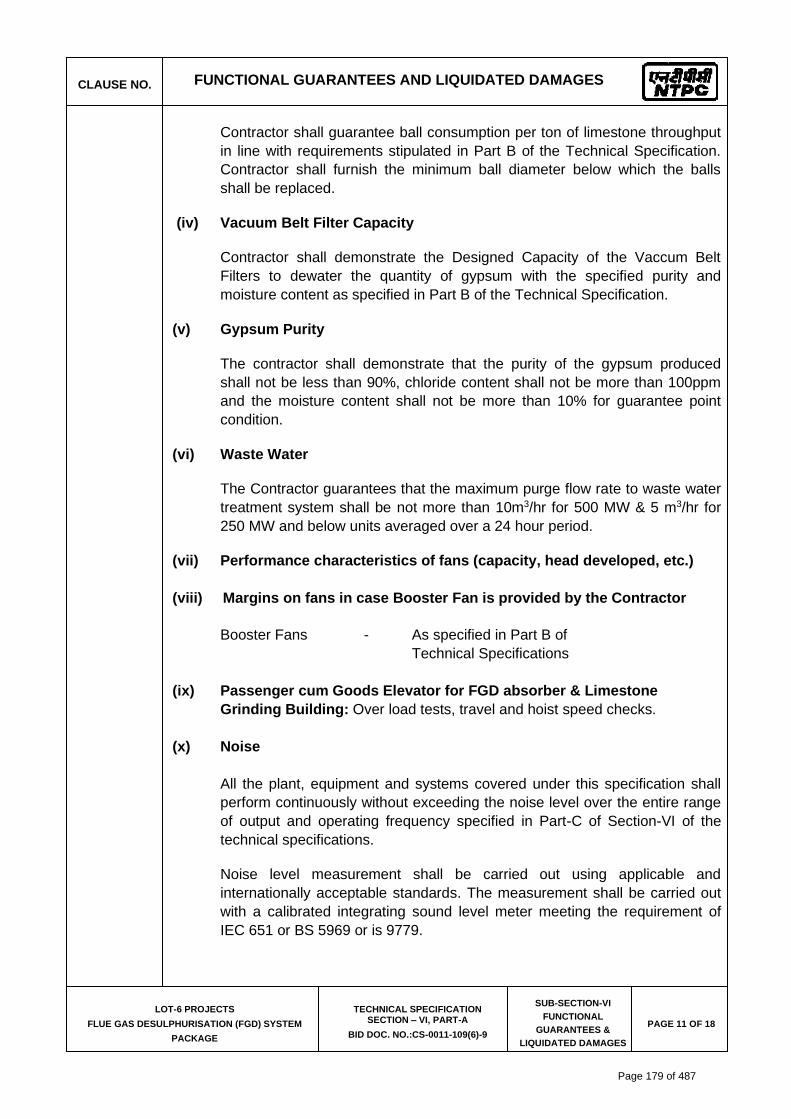
CLAUSE NO. FUNCTIONAL GUARANTEES AND LIQUIDATED DAMAGES
LOT-6 PROJECTS
FLUE GAS DESULPHURISATION (FGD) SYSTEM
PACKAGE
TECHNICAL SPECIFICATION SECTION – VI, PART-A
BID DOC. NO.:CS-0011-109(6)-9
SUB-SECTION-VI
FUNCTIONAL
GUARANTEES &
LIQUIDATED DAMAGES
PAGE 11 OF 18
Contractor shall guarantee ball consumption per ton of limestone throughput
in line with requirements stipulated in Part B of the Technical Specification.
Contractor shall furnish the minimum ball diameter below which the balls
shall be replaced.
(iv) Vacuum Belt Filter Capacity
Contractor shall demonstrate the Designed Capacity of the Vaccum Belt
Filters to dewater the quantity of gypsum with the specified purity and
moisture content as specified in Part B of the Technical Specification.
(v) Gypsum Purity
The contractor shall demonstrate that the purity of the gypsum produced
shall not be less than 90%, chloride content shall not be more than 100ppm
and the moisture content shall not be more than 10% for guarantee point
condition.
(vi) Waste Water
The Contractor guarantees that the maximum purge flow rate to waste water
treatment system shall be not more than 10m3/hr for 500 MW & 5 m3/hr for
250 MW and below units averaged over a 24 hour period.
(vii) Performance characteristics of fans (capacity, head developed, etc.)
(viii) Margins on fans in case Booster Fan is provided by the Contractor
Booster Fans - As specified in Part B of
Technical Specifications
(ix) Passenger cum Goods Elevator for FGD absorber & Limestone
Grinding Building: Over load tests, travel and hoist speed checks.
(x) Noise
All the plant, equipment and systems covered under this specification shall
perform continuously without exceeding the noise level over the entire range
of output and operating frequency specified in Part-C of Section-VI of the
technical specifications.
Noise level measurement shall be carried out using applicable and
internationally acceptable standards. The measurement shall be carried out
with a calibrated integrating sound level meter meeting the requirement of
IEC 651 or BS 5969 or is 9779.
Page 179 of 487
3062805
Line
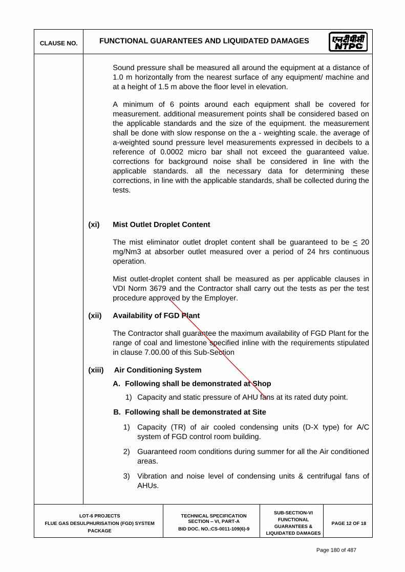
CLAUSE NO. FUNCTIONAL GUARANTEES AND LIQUIDATED DAMAGES
LOT-6 PROJECTS
FLUE GAS DESULPHURISATION (FGD) SYSTEM
PACKAGE
TECHNICAL SPECIFICATION SECTION – VI, PART-A
BID DOC. NO.:CS-0011-109(6)-9
SUB-SECTION-VI
FUNCTIONAL
GUARANTEES &
LIQUIDATED DAMAGES
PAGE 12 OF 18
Sound pressure shall be measured all around the equipment at a distance of
1.0 m horizontally from the nearest surface of any equipment/ machine and
at a height of 1.5 m above the floor level in elevation.
A minimum of 6 points around each equipment shall be covered for
measurement. additional measurement points shall be considered based on
the applicable standards and the size of the equipment. the measurement
shall be done with slow response on the a - weighting scale. the average of
a-weighted sound pressure level measurements expressed in decibels to a
reference of 0.0002 micro bar shall not exceed the guaranteed value.
corrections for background noise shall be considered in line with the
applicable standards. all the necessary data for determining these
corrections, in line with the applicable standards, shall be collected during the
tests.
(xi) Mist Outlet Droplet Content
The mist eliminator outlet droplet content shall be guaranteed to be < 20
mg/Nm3 at absorber outlet measured over a period of 24 hrs continuous
operation.
Mist outlet-droplet content shall be measured as per applicable clauses in
VDI Norm 3679 and the Contractor shall carry out the tests as per the test
procedure approved by the Employer.
(xii) Availability of FGD Plant
The Contractor shall guarantee the maximum availability of FGD Plant for the
range of coal and limestone specified inline with the requirements stipulated
in clause 7.00.00 of this Sub-Section
(xiii) Air Conditioning System
A. Following shall be demonstrated at Shop
1) Capacity and static pressure of AHU fans at its rated duty point.
B. Following shall be demonstrated at Site
1) Capacity (TR) of air cooled condensing units (D-X type) for A/C
system of FGD control room building.
2) Guaranteed room conditions during summer for all the Air conditioned
areas.
3) Vibration and noise level of condensing units & centrifugal fans of
AHUs.
Page 180 of 487
3062805
Line

CLAUSE NO. FUNCTIONAL GUARANTEES AND LIQUIDATED DAMAGES
LOT-6 PROJECTS
FLUE GAS DESULPHURISATION (FGD) SYSTEM
PACKAGE
TECHNICAL SPECIFICATION SECTION – VI, PART-A
BID DOC. NO.:CS-0011-109(6)-9
SUB-SECTION-VI
FUNCTIONAL
GUARANTEES &
LIQUIDATED DAMAGES
PAGE 13 OF 18
(xiv) Ventilation System
A. Following shall be demonstrated at Shop
1) Capacity and discharge pressure of pumps of UAF units at its rated
duty point of Ventilation system.
2) Capacity and static pressure of UAF fans at its rated duty point of
Ventilation system.
B. Following shall be demonstrated at Site
1) Vibration & Noise level of centrifugal fans & pumps of UAF units.
(xv) Compressed Air System
a) Following shall be demonstrated at shop:
i) Capacity and discharge pressure of each air compressor.
b) Following shall be demonstrated at site:
i) Dew point of air at the outlet of air drying plants of air
compressor.
ii) Pressure drop across air drying plant.
iii) Vibration and noise level of air compressors, blowers of air
drying plant (if applicable)
(xvi) Equipment Cooling Water System
i) Vibration, noise and parallel operation without hunting & abnormal noise
and with flow sharing within 10% of each other at the rated duty point
shall be demonstrated at site.
ii) Design heat load of plate type heat exchangers and Inlet & Outlet
temperatures of the Plate type heat exchangers on the primary and
secondary side to be demonstrated at site. Pressure drop across the Plate
type heat exchanger on the primary & secondary water circuit to be
demonstrated at site.
(xvii) Limestone Handling System (applicable for Barauni & Kanti only) and
Gypsum Handling System (applicable for all)
a) Limestone Handling Plant
(i) The Bidder shall demonstrate the unloading at truck tippler, crushing and
conveying to storage shed/silo and then reclaim from storage shed/silos
and conveying to mill bunker at the guaranteed capacity including all
intermediate equipment & conveyors.
(ii) Bidder shall also demonstrate the guaranteed tippling rate of truck
tipplers.
Page 181 of 487
3062805
Line
3062805
Line

CLAUSE NO. FUNCTIONAL GUARANTEES AND LIQUIDATED DAMAGES
LOT-6 PROJECTS
FLUE GAS DESULPHURISATION (FGD) SYSTEM
PACKAGE
TECHNICAL SPECIFICATION SECTION – VI, PART-A
BID DOC. NO.:CS-0011-109(6)-9
SUB-SECTION-VI
FUNCTIONAL
GUARANTEES &
LIQUIDATED DAMAGES
PAGE 14 OF 18
b) Gypsum Handling Plant
The Bidder shall demonstrate the guaranteed conveying from belt filter to
storage shed/silo including all intermediate equipment & conveyors.
5.00.00 AUXILIARY POWER CONSUMPTION (PA) FOR EACH PROJECT
The unit auxiliary power consumption shall be calculated using the following relationship.
Pan = Pun + TLu Pan = Guaranteed Auxiliary Power Consumption for unit # n (Where “n” is the unit number e.g. 1, 2, ……) Pun = Power consumed by the auxiliaries of the unit under test TLu = Proportional Losses of transformers for one Unit/Block TL = Losses of all the transformers supplied by bidder based on works test Reports (excluding FGD Tie transformers(220 kV & 132kV class) & transformers for Owner’s use listed in Clause 4.01.00 iv) as applicable in respective project) Tlu shall be calculated as below:
TLu=(TL / Total MW capacity under the present contract) x (capacity in MW for FGD
(unit/block) under test)
While guaranteeing the auxiliary power consumption of each project the bidder shall
necessarily include all continuously operating auxiliaries under this package. The
auxiliaries to be considered shall include but not be limited to the following:
i. Absorber Recirculation Pump(s)/Gas Cooling Pumps
ii. Absorber Oxidation Air Blower(s)
iii. Absorber Oxidation Tank Agitators
iv. Gypsum Bleed Pumps
v. Limestone Gravimetric feeder, Wet ball mill and their integral Auxiliaries
divided by the number of units in the project
vi. Limestone Slurry Pump(s)
vii. Vacuum Belt Filter, Vacuum Pump and its integral auxiliaries divided by the
number of units in the project
viii. Power consumption of all working Booster water pumps (if provided) to ACW
pumps after PHE divided by the number of units in the project
Page 182 of 487
3062805
Line
3062805
Line
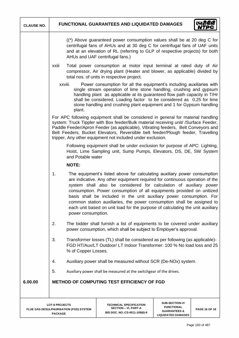
CLAUSE NO. FUNCTIONAL GUARANTEES AND LIQUIDATED DAMAGES
LOT-6 PROJECTS
FLUE GAS DESULPHURISATION (FGD) SYSTEM
PACKAGE
TECHNICAL SPECIFICATION SECTION – VI, PART-A
BID DOC. NO.:CS-0011-109(6)-9
SUB-SECTION-VI
FUNCTIONAL
GUARANTEES &
LIQUIDATED DAMAGES
PAGE 16 OF 18
((*) Above guaranteed power consumption values shall be at 20 deg C for
centrifugal fans of AHUs and at 30 deg C for centrifugal fans of UAF units
and at an elevation of RL (referring to GLP of respective projects) for both
AHUs and UAF centrifugal fans.)
xxiii Total power consumption at motor input terminal at rated duty of Air
compressor, Air drying plant (Heater and blower, as applicable) divided by
total nos. of units in respective project.
xxviii. Power consumption for all the equipment’s including auxiliaries with single stream operation of lime stone handling, crushing and gypsum handling plant as applicable at its guaranteed flow path capacity in T/Hr shall be considered. Loading factor to be considered as 0.25 for lime stone handling and crushing plant equipment and 1 for Gypsum handling plant.
For APC following equipment shall be considered in general for material handling system: Truck Tippler with Box feeder/Bulk material receiving unit/ /Surface Feeder, Paddle Feeder/Apron Feeder (as applicable), Vibrating feeders, Belt Conveyors and Belt Feeders, Bucket Elevators, Reversible belt feeder/Plough feeder, Travelling tripper, Any other equipment not included under exclusion.
Following equipment shall be under exclusion for purpose of APC: Lighting,
Hoist, Lime Sampling unit, Sump Pumps, Elevators, DS, DE, SW System
and Potable water
NOTE:
1. The equipment’s listed above for calculating auxiliary power consumption
are indicative. Any other equipment required for continuous operation of the
system shall also be considered for calculation of auxiliary power
consumption. Power consumption of all equipments provided on unitized
basis shall be included in the unit auxiliary power consumption. For
common station auxiliaries, the power consumption shall be assigned to
each unit based on unit load for the purpose of calculating the unit auxiliary
power consumption.
2. The bidder shall furnish a list of equipments to be covered under auxiliary
power consumption, which shall be subject to Employer’s approval.
3. Transformer losses (TL) shall be considered as per following (as applicable)-
FGD HT/Aux/LT Outdoor/ LT Indoor Transformer: 100 % No load loss and 25
% of Copper Losses.
4. Auxiliary power shall be measured without SCR (De-NOx) system.
5. Auxiliary power shall be measured at the switchgear of the drives.
6.00.00 METHOD OF COMPUTING TEST EFFICIENCY OF FGD
Page 183 of 487
3062805
Line
3062805
Line

CLAUSE NO. FUNCTIONAL GUARANTEES AND LIQUIDATED DAMAGES
LOT-6 PROJECTS
FLUE GAS DESULPHURISATION (FGD) SYSTEM
PACKAGE
TECHNICAL SPECIFICATION SECTION – VI, PART-A
BID DOC. NO.:CS-0011-109(6)-9
SUB-SECTION-VI
FUNCTIONAL
GUARANTEES &
LIQUIDATED DAMAGES
PAGE 17 OF 18
The performance tests shall be carried out in accordance with ASME PTC 40 (2017)
code. No tolerance or allowance on the test result will be permitted for instrument
errors or inaccuracy, the method of testing or any other causes. The details of the
test shall, however be mutually agreed upon between the employer and the
contractor.
7.00.00 METHOD OF COMPUTING AVAILABILITY
The Contractor shall guarantee 98 % availability of FGD plant for a continuous
period of 120 days. An availability guarantee test shall be conducted to assure this
level of availability for a period of 240 days as per the procedure indicated below.
Availability 'A' in %:
A= Tc x 100%
Tk
Tc – recorded time of FGD operation, expressed in hours,
Tk – recorded time of boiler operation, expressed in hours,
However, it is required that:
(i) In order to calculate the FGD availability, operation hours will be
counted except boiler start-ups when the operation hours counting
will start on the moment of shut down of all oil burners,
(ii) FGD will be regarded as a FGD in operation, when by-pass damper is
closed and total flow of flue gas from boiler goes via FGD, and SO2
content is as below in cleaned flue gas for the range of specified
coals & loads:
(a) 200 mg/Nm3 (6% O2 dry) for units having capacity of 500 MW and
MTPS Unit #3
(b) 100 mg/Nm3 (6% O2 dry) for Barauni (2x250 MW) & MTPS Unit #4
If FGD is out of operation during the boiler operation time as a result
of the Employer’s decision, this time will not be counted as boiler
operation time for calculating the FGD availability,
(iv) Boiler operation hours will be counted based on the recorded boiler
operation hours and the recorded data will be made available to the
Contractor by the Employer.
Mandatory spares have been identified in the Employer. Contractor can use
the mandatory spares supplied under the contract during this period in
agreement with the Employer. However, if other additional spares are
Page 184 of 487

CLAUSE NO. FUNCTIONAL GUARANTEES AND LIQUIDATED DAMAGES
LOT-6 PROJECTS
FLUE GAS DESULPHURISATION (FGD) SYSTEM
PACKAGE
TECHNICAL SPECIFICATION SECTION – VI, PART-A
BID DOC. NO.:CS-0011-109(6)-9
SUB-SECTION-VI
FUNCTIONAL
GUARANTEES &
LIQUIDATED DAMAGES
PAGE 18 OF 18
required for demonstration of availability demonstration guarantee, Bidder to
should clearly indicate along with their offer.
If the calculated availability after 120 days availability test is lower than the
guaranteed value, the Contractor will undertake actions as per clause
2.04.00 (ii) of this Sub-Section to achieve the guaranteed availability.
Page 185 of 487

SIPAT STAGE-II, 2X500MW FGD
COMPRESSED AIR SYSTEM
SPECIFICATION No: PE-TS-491-555-A001
VOLUME: II B
SECTION : C2-D
REV. 00 DATE: JULY 22
SHEET: 1 OF 1
SECTION: C2-D QUALITY ASSURANCE
Page 186 of 487

���������������� �������������� ��� �������������������� �������� �� � �������� ����� ��������� ���������� ����� ��!������ �" � ����#�������������#�����������" � ����� ������$ %�� � �������#���������� �������������� ��� ���������������������������� �� �������� �������������������� ������� �#��������
�
��������������� �� �������� ���������������* �� ��������<������=������� ������������� �� �������� �����������" � ����� ������$ %�� � ��������>� �����#��������������� �#��������
�
����� ��� ��� �� ��� �� �� � %������ � %�� � ����� ��� * � � ���� �� ��� � ���� ���� ���?#� @�?Z�� �� �����* ������= ������� ���� ����������������� ����������� �������������������������������������������>%��� ���?�#����� ��������� ���� ����������� ������?��������� ���� ��
[����������������� � �� ������������� ���������* ��� ���� ���� ���������
�� �%������� %�� � ������ ��� ����������� ������=����=���\�
]!� �������� ���������^!� �����*�����������
��� ��� �� ��� �� � �*�� � �=�� �������� �� � � ���� ?� @�� ?� ��� �� �� ����� �� � � %�� �� ��� * �� ����� ��� �� ����� ��������������������� �?� %��� ��?������ ��?����� �� ���
����� �� ��������� ����� �������� �� � �������� � � ����� ����� �=���� ������� �!� � ����� �� ������������������� �?� %��� ��?������ ��?����� �� ���
�� �%������� %�� � ������ ��� ������������� �������������� �� ������������ �������������� ��������� _������ ��
�
Page 187 of 487
CLAUSE NO.
QUALITY ASSURANCE
LOT-6 PROJECTS
FLUE GAS DESULPHURISATION (FGD) SYSTEM PACKAGE
TECHNICAL SPECIFICATION
SECTION – VI, PART-B
BID DOC. NO:CS-0011-109(6)-9
SUB-SECTION -V- QM5
COMPRESSED AIR SYSTEM
Page
1 of 2
1.00.00 AIR COMPRESSOR SYSTEM
1.01.00 AIR COMPRESSORS:
a) All pressure parts shall be hydraulically tested at not less than 150% of design pressure prior to painting and lining, if applicable. The test pressure will be maintained for 30 minutes.
b) All other parts including inter-connecting piping shall be hydraulically tested wherever possible, as per relevant codes.
c) Ultrasonic testing shall be carried out on all forgings and shafts (if dia.> 40mm). MPI/DP test will be done on machined areas of the above components.
e. Rotor shall be statically and dynamically balanced. 1.01.01 PERFORMANCE TEST (SHOP TEST) : a) Performance test on the compressors shall be carried out in
accordance relevant standard. The test shall also include demonstration of loading and unloading mechanism (Capacity control) and operation of safety valves.
b) Power consumption at motor input terminal at rated capacity as well as
at fully unloaded condition of all the compressor shall be measured. c) Vibration and noise level measurement will be done during shop
performance test. d) Test shall be carried out on all compressors with contract drive motor
where power consumption for compressors has been indicated as a guaranteed parameter
1.02.00 AIR RECEIVER, HEAT EXCHANGERS, MOISTURE SEPERATORS,
AIR DRYING PLANT:
a) Each finished vessel shall be hydraulically tested to 150% of the design pressure for a duration of 30 minutes.
b) NDT on weld joints shall be as per respective code requirements or
the minimum as specified below:
(i) 100 % DPT on root run of butt welds. (ii) 100% DPT on all finished butt welds and fillet welds (iii) 10% RT on butt welds which shall include all T- joints.
c) Tube to Tube sheet joint of the heat exchangers shall be subject to
Mock-up test as per the relevant standards.
Page 188 of 487

CLAUSE NO.
QUALITY ASSURANCE
LOT-6 PROJECTS
FLUE GAS DESULPHURISATION (FGD) SYSTEM PACKAGE
TECHNICAL SPECIFICATION
SECTION – VI, PART-B
BID DOC. NO:CS-0011-109(6)-9
SUB-SECTION -V- QM5
COMPRESSED AIR SYSTEM
Page
2 of 2
d) Reactivation blowers shall be tested for FAD, temp. rise noise & vibration. Rotating parts shall be dynamically balanced.
e) Completely assembled ADP shall be pneumatically tested at design
pressure for a duration of 5 minutes. Functional and sequential operation testing of the completely assembled ADP shall be demonstrated at shop. Other accessories shall be tested as per relevant code and sections. Dew point measurement shall be done.
1.04.00 E.O.T. CRANE: a) Chain pulley Blocks shall be tested as per IS: 3832. b) Following NDT requirements shall be met:
(i) 100% RT of Butt welds in tension and 10% RT of butt welds in
compression. (ii) DP at random on all weldments.
Deflection, load, overload & travel check on HOT crane assembly Shall be carried out as per IS: 3177.
1.05.00 PIPINGS, VALVES, AND FITTINGS
a. All pipes and fittings shall be tested as per applicable code. b. All valves shall be hydraulically tested for body, seat and back-seat (if
applicable) as per relevant standard. Check valves shall also be tested for leak tightness test at 25% of the specified seat test pressure.
c. Valves shall be offered for hydro test in unpainted condition. d. Functional checks of the valves for smooth opening and closing shall
also be done. All bar stocks/ forgings, dia ≥ 40 mm shall be Ultrasonic Tested irrespective of the type, size & rating of the valve.
Page 189 of 487

���������� ������������ ����
�
������� ����������������������� �������������
���������������
��������������������������������
���������!���""##�#"$����$�
�� ������������������#�
�� �������#���z�
���
������
��������������������������������
����@<��]�������
� ���$
��
~��
����
���
�
��
�@�>
��@�
���
\�@_
����
��
]�>�
���
�����
�����
���
���@
<��
���]
����
�����
�
�~
��@~
]@�
]�@`
��
���
���
\��
�>�
����
����
��<�
���
����
�����
���
���\
@��
���\
�]�
@]�
� �
"�
�����
��
����
�\
�����
�<�
���
����
�����
">�
�$�
��@^
��@
]���
�$��
����
��
����
��
�<�
���
����
�����
�$�
��$�
�
~>�
���
���
���
�\�
��$
�����
����
����
���
����
����
��
����
����
�;@��
�!+�
���@
����
��*�
@���
��!*
@��<
'���
!±��
<��
'��+
���@�
���
��'�
;��
{��
����
�#�
�����
���
���
����
����
|��
#���
\��
����
����
���
����
����
����
�
]��
����
���
���
����
����
���
����
���
]����� |��� ������ |����� ������������������������
¦� ¦� ¦� ¦� ¦� � � � ¦� � � � � � � � � � �
��|�� ¦� ¦� ¦� ¦� ¦� ¦� � � ¦� � � � � � � � � � ��\������������� ¦� ¦� ¦� ¦� � � ¦� � � ¦� � ¦� � � � � � � �������<�����@��$����$�� ¦� ¦� ¦� ¦� � � ¦� � ¦� � � � � � � � � � �������������� ¦� ¦� ¦� ¦� � � ¦� � ¦� � � ¦� � � � � � � ��<����\� ¦� ¦� ¦� ¦� ¦� � ¦� ¦� ¦� � � � � � � � � � ����$����\�������� ¦� � ¦� ¦� � � ¦� � � � � ¦� � � � � � � ��${����|���<������ ¦� ¦� ¦� ¦� ¦� � � � ¦� � ¦� � � � � � � � �����#�������\� ¦� ¦� ¦� ¦� ¦� � � � ¦� � ¦� � � � � � � � ������@���������������<����� ¦� ¦� ¦� � � � ¦� ¦� � � � � � � � � � � �<����\��� ������ |������������� {��� ��� � {����\���$���\������
¦� ¦� ¦� ¦� ¦� � � ¦� � � � � � � � � � � �
�{�������� �� �������\� �|�����������������������{���
¦� ¦� � � ¦� � � ¦� ¦� � � � � � � � � � �
Page 190 of 487

���������� ������������ ����
�
������� ����������������������� �������������
���������������
��������������������������������
���������!���""##�#"$����$�
�� ������������������#�
�� �������z���z�
���
��$��������� ¦� ¦� � � � � ¦� ¦� � � � � � � � � � � ���$����������� ¦� ¦� � � � � ¦� ¦� � � � � � � � � � � ���������������� ¦� ¦� � � � � ¦� � � � � � ¦� ¦� � � � � ���������� ������� ������������������������{�>�
¦� ¦� � � � � ¦� � � � � � � � � � � � �
������������� ��~�� ��~�<�������� ������� ���|��������{����\��\�����������
¦� ¦� ¦� � � � � � � � � � � � � � � � �
<�������������� ¦� ¦� ¦� � � � � � � � � � � � ¦� ¦� ¦� ¦�� ¦�=\]����������������������#��������|������@���������������$|��$���������|$����������������$���>���]�����������\����������������]�����$���|�����������\����������#�������������������$�������\����$�������$���\��]�|�����������"���#����|�������\����������\>����{��|��������|��������������<��\����������������������� �`�� ��� ;�� ���� <������� ���������� �|� ������ $�� ��� ;�� ��� ��� {���� ��� <�<� �|� ���� ��$|��$���� �� ���� ���� <��������� ���|�������|����������������������{�� ��{�#��;��������$�����+;����<��������������$|��$����������#������>��$��������������\���|�������������]<��������#��{
����#�����|���{������{�������������|�������@���������������~�|����������$������������$�������������������#�����$�������������|���$���������������������������������������;����\������<�<��|�������$|��$�����������<������������|�����\���]<�����������
{��� ��{�#��;��������$�����+;����<�����������������$|��$��������������]<�����#����$���>�]����� ��{�#��+;�����<�������������]<�����#����$���>�]���
���������������������������$������������|������������|�������������{�������{�������������#�������������������������������|������{�$\����$��������|���"����������������{���${����������]<�����#��������������!��¦��²�|���"��������@������������>��
��
Page 191 of 487

Page 192 of 487
Page 193 of 487

Page 194 of 487

Page 195 of 487

Page 196 of 487

Page 197 of 487

Page 198 of 487

Page 199 of 487
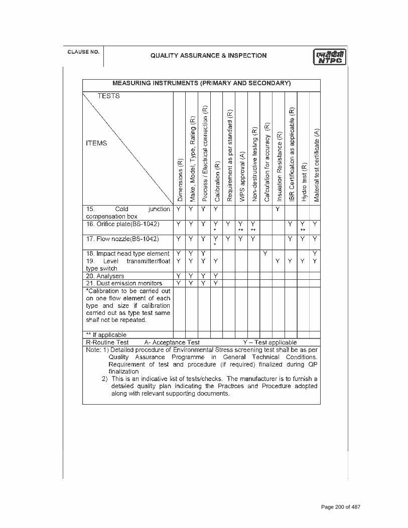
Page 200 of 487

Page 201 of 487

CLAUSE NO. QUALITY ASSURANCE & INSPECTION
NORTH KARANPURA STPP (3X660 MW) FLUE GAS DESULPHURISATION SYSTEM
PACKAGE
TECHNICAL SPECIFICATION SECTION – VI, PART-B
BID DOC. NO CS-4410-109-2
SUB-SECTION-V-QC3 INSTRUMENTATION
CABLES
PAGE 1 OF 1
INSTRUMENTATION CABLE TESTS
ITEMS
Con
duct
or R
esis
tanc
e ®
& (A
) H
igh
Volta
ge ®
& (A
)
Insu
latio
n R
esis
tanc
e ®
& (
A)
Con
stru
ctio
nal d
etai
l, di
men
sion
s (A
)
Out
er-S
heat
he/c
ore
mar
king
, end
sea
ling
(A)
Ther
mal
Sta
bilit
y (A
) +
Visu
al, S
urfa
ce fi
nish
(A) +
Elec
trica
l Par
amet
ers
** (A
) +
Pers
ulph
ate
Test
(A) +
Ove
rall/
Cov
erag
e/C
ontin
uity
(A)
Swid
esh
chim
ney
Tes
t (SS
-424
1475
) (A)
++
FRLS
Tes
t * (A
) ++
Tens
ile &
Elo
ngat
ion
befo
re &
afte
r agi
ng (A
) ++
Vol.
Res
istiv
ity. a
t roo
m &
Ele
vate
d Te
mp.
(A) +
+
Spar
k te
st re
port
revi
ew ®
1. Instrument cable twisted and shielded
Conductor(IS-8130) Y Y Y Insulation(VDE-207) Y Y Y Y Y Y Pairing/Twisting Y Y Y Shielding Y Y Y Drain wire Y Y Y Y Y Inner Sheath Y Y Y Y Y Y Outer Sheath Y Y Y Y Y Y Over all cable Y Y Y Y Y Y Y Y Y Cable Drums(IS-10418) Y Y
Note : High Temp. cables shall be subjected to tests as per VDE-207(Part-6) Compensating cables shall be checked for Thermal EMF/Endurance test as per IS 8784.Note : This is an indicative list of tests/checks. The manufacture is to furnish a detailed Quality Plan indicating his practice & Procedure along with relevant supporting documents during QP finalization for all items. Note : ® - Routine Test A - Acceptance Test Y - Test Applicable Note : Sampling Plan for Acceptance test shall be as per IS 8784 (As applicable) � * FRLS Tests: Oxygen / Temp Index ( ASTM D-2863), Smoke Density Rating ( ASTM
– D 2843), HCL Emission ( IEC-754-1) � ** Characteristic Impedance, Attenuation, Mutual Capacitance, Cross Talk ( As
applicable) + Sample size will be One No. of each size/type per lot. ++ Sample size will be One No. sample for complete lot offered irrespective of size/type.
Page 202 of 487

END USER & BHEL
Page 159 of 400 Page 203 of 487

END USER & BHEL
Page 160 of 400 Page 204 of 487

END USER & BHEL
Page 161 of 400 Page 205 of 487

END USER & BHEL
Page 162 of 400 Page 206 of 487

BHEL DRG.NO:PE-VO-306-555-A003
NTPC DRG. NO. 4610-101-PEM-QVM-Q-003
N: END USER & BHEL
Page 163 of 400 Page 207 of 487

BHEL DRG.NO:PE-VO-306-555-A003
NTPC DRG. NO. 4610-101-PEM-QVM-Q-003
N: END USER & BHEL
Page 164 of 400 Page 208 of 487

Page 165 of 400 Page 209 of 487

BHEL
Page 166 of 400 Page 210 of 487

MANUFACTURER’S NAME AND ADDRESS
SUMMITS HYGRONICS PVT. LTD. S.F 192, EARI THOTTAM, KANNAMPALAYAM, COIMBATORE-641 402
MANUFACTURING QUALITY PLAN OWNER : NTPC Limited.
ITEM HEAT OF COMPRESSION AIR DRYER (model : SH 240 BM) (Flow capacity:55 Nm³/ min)
QP NO SUM/SH-QAP/E033-15-16 /R00 CONSULTANT : BHEL
REV 00 PROJECT : 3X660MW NTPC NABINAGAR SUPER THERMAL POWER PLANT ,STAGE-1
SUBSYSTEM COMPRESSED AIR SYSTEM.
DATE 30.01.015 PACKAGE VENDOR : ELGI EQUIPMENTS LIMITED PAGE Page 1 OF 4 BHEL DOC NO : PE-V0-393-555-A002
SLNO COMPONENT & OPERATIONS
CHARACTERISTICS CLASS TYPE OF CHECK
QUANTUM OF CHECK REFERENCE
DOCUMENT ACCEPTANCE
NORM FORMAT OF
RECORD AGENCY REMARKS
M C/N M C N 1. 2. 3. 4. 5. 6. 7. 8. 9. D 10. 11.
LEGEND : CL: (ACRITICAL, B:MAJOR C:MINOR)** M: MANUFACTURER/SUB-SUPPLIER, C: DOOSAN / NOMINATED INSPECTION AGENCY N: CUSTOMER , CHP: NTPC SHALL IDENTIFY IN COLUM “N” AS ‘ W” P: PERFORM, W: WITNESS AND V: VERIFICATION. ND:NDT LAB R:TEST / DIMENTIONAL REPORT
* RECORDS, INDENTIFIED WITH “TICK” ( � ) SHALL BE ESSENTIALLY INCLUDED BY SUPPLIER IN QA DOCUMENTATION.
DOC NO : 0370-102-PE-PVM-Q-003
MANUFACTURERS / SUB-SUPPLER
MAIN SUPPLIER
SIGNATURE Page 1 OF 4 FOR NTPC USE REVIWED BY APPROVED BY APPROVAL SEAL
1.0 RAW MATERIAL INSPECTION
1.1 MS PLATE FOR SHELL & DISHED END,
CHEMICAL PROPERTIES B CHEMICAL ANALYSIS 1 SAMPLE / HEAT RELEVANT MATERIAL SPECIFICATION AS
PER APPROVED DATA SHEET / APPROVED DRAWING
MILL TC / LAB TC � P V V REFER NOTE 1 MECHANICAL
PROPERTIES B MECHANICAL TESTS 1 SAMPLE / HEAT
INTERNAL DEFECTS B U. T. (32 MM & ABOVE THICK 100 % ASME SEC. V / ASTM
A 435 ASTM A 435 U. T. REPORT � P V V
1.2 PIPES CHEMICAL PROPERTIES B CHEMICAL
ANALYSIS 1 SAMPLE / HEAT RELEVANT MATERIAL SPECIFICATION AS PER APPROVED DATA SHEET / APPROVED DRAWING
MILL TC / LAB TC � P V V REFER NOTE 2 MECHANICAL
PROPERTIES B MECHANICAL TESTS 1 SAMPLE / HEAT
1.3 BOUGHT OUT ITEMS VISUAL, DIMENSIONAL B ITEM, MAKE, RANGE, DIMENSIONAL
100% APPROVED DATA SHEET / APPROVED DRAWING
MTC / CALIBRATION
REPORT � P V V REFER NOTE - 6
2.0 IN PROCESS INSPECTION
2.1 DISHED END
CORRECT DIMENSIONS B MEASURE 100% MANUFACTURING DRAWING IR � P V V
IN CASE OF JOINT IN DISH END, 100% RT ON JOINT
TO BE DONE.
RT ON DISHED ENDS (IF APPLICABLE) B RT AFTER FINAL
WELDING 100% ASME SEC. V ASME SEC VIII
DIV.1-UW-51 RT FILM, RT REPORT � P V V
DPT ON KNUCKLE B DP TEST 100% ASME SEC. V ASME SEC. V DPT REPORT � P V V
THICKNESS THINNING B MEASURE 100% APPROVED DRAWING./MANUFACTURING DRAWING / TECHNICAL SPECIFICATION
I.R. � P V V
2.2
FABRICATION OF AIR DRYER
CUTTING OF PLATES B VISUAL & MEASURE 100% -
CUTTING PLAN / MANUFACTURING DRAWINGS REGISTER P - -
EDGE PREPARATION AND FIT UP B VISUAL &
MEASURE 100 % -APPROVED WPS /
FABRICATION DRAWING REGISTER P - -
WPS / WELDER QUALIFICATION B
VISUAL & MECHANICAL
TEST 100 % ASME SEC. IX ASME SEC. IX QW 482, 483,
484 � P V V REFER NOTE : 3
NDT ON BUTT WELDS (LONGITUDINAL & CIRCUMFERENTIAL WELD JOINT FOR ADSORPTION TOWERS) AFTER BACK GOUGING & FINAL WELDING
B DPT AFTER BACK GOUGING 100 % ASME SEC. V ASME SEC. VIII DIV.
1 APPENDIX 8 NDT
REPORT � P V V
B RT AFTER FINAL WELDING
10 % ON BUTT JOINT INCLUDING 100% CROSS JOINT
ASME SEC. V ASME SEC VIII DIV.1-UW-52 RT REPORT � P V V RT FILMS & REPORT WILL BE
REVIEWED BY NTPC. CHP.
NDT ON BUTT WELDS & FILLET JOINTS IN SHELL & DISH AFTER FINAL WELDING
B DPT 100 % ASME SECTION V
ASME SEC. VIII DIV. 1 APPENDIX 8
NDT REPORT � P V V
Records, indentified with “Tick” ( ) shall be essentially included by SUPPLIER in QA documentation.
Page 167 of 400 Page 211 of 487

MANUFACTURER’S NAME AND ADDRESS
SUMMITS HYGRONICS PVT. LTD. S.F 192, EARI THOTTAM, KANNAMPALAYAM, COIMBATORE-641 402
MANUFACTURING QUALITY PLAN OWNER : NTPC Limited.
ITEM HEAT OF COMPRESSION AIR DRYER (model : SH 240 BM) (Flow capacity:55 Nm³/ min)
QP NO SUM/SH-QAP/E033-15-16 /R00 CONSULTANT : BHEL
REV 00 PROJECT : 3X660MW NTPC NABINAGAR SUPER THERMAL POWER PLANT ,STAGE-1
SUBSYSTEM COMPRESSED AIR SYSTEM.
DATE 30.01.015 PACKAGE VENDOR : ELGI EQUIPMENTS LIMITED PAGE Page 2 OF 4 BHEL DOC NO : PE-V0-393-555-A002
SLNO COMPONENT & OPERATIONS
CHARACTERISTICS CLASS TYPE OF CHECK
QUANTUM OF CHECK REFERENCE
DOCUMENT ACCEPTANCE
NORM FORMAT OF
RECORD AGENCY REMARKS
M C/N M C N 1. 2. 3. 4. 5. 6. 7. 8. 9. D 10. 11.
LEGEND : CL: (ACRITICAL, B:MAJOR C:MINOR)** M: MANUFACTURER/SUB-SUPPLIER, C: DOOSAN / NOMINATED INSPECTION AGENCY N: CUSTOMER , CHP: NTPC SHALL IDENTIFY IN COLUM “N” AS ‘ W” P: PERFORM, W: WITNESS AND V: VERIFICATION. ND:NDT LAB R:TEST / DIMENTIONAL REPORT
* RECORDS, INDENTIFIED WITH “TICK” ( � ) SHALL BE ESSENTIALLY INCLUDED BY SUPPLIER IN QA DOCUMENTATION.
DOC NO : 0370-102-PE-PVM-Q-003
MANUFACTURERS / SUB-SUPPLER
MAIN SUPPLIER
SIGNATURE Page 2 OF 4 FOR NTPC USE REVIWED BY APPROVED BY APPROVAL SEAL
2.3 WELD QUALITY OF PIPE WELD & FILTERS WELD
DPT ON ROOT RUN & FINAL OF BUTT WELD B NDT - DPT 100% ASME SEC V ASME SEC. VIII DIV.
1 APPENDIX 8 IR � P V V
2.4 HEAT EXCHANGER TUBE TO TUBE SHEET FILLET WELD JOINT B NDT - DPT 100% ASME SEC V ASME SEC. VIII DIV.
1 APPENDIX 8 IR � P V V
2.5
VESSEL (TOWER) MOISTURE SEPARATOR & HEAT EXCHANGERS
BOD SHELL STRENGTH TEST B HYDRO TEST 100 %
HYDRO TEST PRESSURE @ 1.3 TIMES OF DESIGN PRESSURE FOR 30 MIN
NO LEAKAGE & NO PRESSURE DROP IR � P V V
2.6 PNEUMATIC TEST FOR COMPLETE ASSEMBLY OF AIR DRYER
B PNEUMATIC TEST WITH
SOAP BUBBLE 100%
PNEUMATIC TEST PRESSURE @ 1.1 TIMES OF DESIGN PRESSURE FOR 30MIN
NO LEAKAGE & NO PRESSURE DROP IR � P W W CHP ‘W’ AT THE TIME OF
FINAL INSPECTION
3.0 FINAL INSPECTION 3.1 FINAL INSPECTION DIMENSION,
ORIENTATION B VISUAL 100% AS PER APPROVED GA DRAWING / DATA SHEET IR · P W W
3.2 FUNCTIONAL TEST PERFORMANCE TEST AT NO LOAD CONDITIONS
B FUNCTIONAL /
OPERATION OF VALVES & AUTO
DRAIN TRAP 100%
APPROVED FUNCTIONAL TEST PROCEDURE (ENCLOSED) / APPROVED
DRAWING / DATASHEET IR · P W W
3.2 CONTROL PANEL
WORKMANSHIP FINISH, SHADE B VISUAL 100% 100% AS PER ELECTRIAL DRAWING / APPROVED DATA
SHEET/ MFG STANDARD IR P W W
DRY FILM THICKNESS B MEASURE 100% RANDOM MINIMUM 50 MICRONS (POWDER COATED), 70 MICRONS (PAINTED)
IR
P W W
ADHESION TEST (PEEL OFF TEST) B MEASURE 100% 1 PANEL
(RANDOM) ASTM D 3359 NO PEEL OFF IR P W W
WIRING & COMPONENT LAYOUT, FITTING ACCESSIBILITY & SAFETY
B VERIFICATION 100% RANDOM AS PER ELECTRIAL DRAWING / APPROVED DATA SHEET IR
P V V
COMPONENTS MAKE IDENTIFICATION (MARKING / NAME PLATES)
B VERIFICATION 100% 100% AS PER ELECTRIAL DRAWING / APPROVED DATA SHEET IR
· P V V
PROPER WIRE TERMINATION B VERIFICATION 100% RANDOM NO LOOSE CONNECTIONS. ALL TERMINATIONS TO
BE LUGGED IR P V V
DOOR AND LOCK FUNCTIONING B FUNCTIONAL 100% RANDOM PROPER OPENING & CLOSING, NO
MISMATCH IR P W W
EARTHING CHECK B VERIFICATION 100% RANDOM APPROVED DRAWING / AS PER ELECTRIAL DRAWING IR P V V
Records, indentified with “Tick” ( ) shall be essentially included by SUPPLIER in QA documentation. 3
Page 168 of 400 Page 212 of 487

MANUFACTURER’S NAME AND ADDRESS
SUMMITS HYGRONICS PVT. LTD. S.F 192, EARI THOTTAM, KANNAMPALAYAM, COIMBATORE-641 402
MANUFACTURING QUALITY PLAN OWNER : NTPC Limited.
ITEM HEAT OF COMPRESSION AIR DRYER (model : SH 240 BM) (Flow capacity:55 Nm³/ min)
QP NO SUM/SH-QAP/E033-15-16 /R00 CONSULTANT : BHEL
REV 00 PROJECT : 3X660MW NTPC NABINAGAR SUPER THERMAL POWER PLANT ,STAGE-1
SUBSYSTEM COMPRESSED AIR SYSTEM.
DATE 30.01.015 PACKAGE VENDOR : ELGI EQUIPMENTS LIMITED PAGE Page 3 OF 4 BHEL DOC NO : PE-V0-393-555-A002
SLNO COMPONENT & OPERATIONS
CHARACTERISTICS CLASS TYPE OF CHECK
QUANTUM OF CHECK REFERENCE
DOCUMENT ACCEPTANCE
NORM FORMAT OF
RECORD AGENCY REMARKS
M C/N M C N 1. 2. 3. 4. 5. 6. 7. 8. 9. D 10. 11.
LEGEND : CL: (ACRITICAL, B:MAJOR C:MINOR)** M: MANUFACTURER/SUB-SUPPLIER, C: DOOSAN / NOMINATED INSPECTION AGENCY N: CUSTOMER , CHP: NTPC SHALL IDENTIFY IN COLUM “N” AS ‘ W” P: PERFORM, W: WITNESS AND V: VERIFICATION. ND:NDT LAB R:TEST / DIMENTIONAL REPORT
* RECORDS, INDENTIFIED WITH “TICK” ( � ) SHALL BE ESSENTIALLY INCLUDED BY SUPPLIER IN QA DOCUMENTATION.
DOC NO : 0370-102-PE-PVM-Q-003
MANUFACTURERS / SUB-SUPPLER
MAIN SUPPLIER
SIGNATURE Page 3 OF 4 FOR NTPC USE REVIWED BY APPROVED BY APPROVAL SEAL
OVERALL DIMENSIONS B MEASURE 100% RANDOM AS PER ELECTRICAL DRAWING / DATA SHEET IR P V V
DEGREE OF PROTECTION BY PAPER INSERTION
A MEASURE 100% 100% AS PER ELECTRICAL DRAWING /
DATA SHEET IR · P V V
IR TEST & HIGH VOLTAGE TEST
A MEASURE 100% 100%
HV TEST AT 1.5 KV FOR ONE MINUTE IR TEST FOR 500V
WITH STOOD More than 50 MOhms
IR · P W W
FUNCTIONAL TEST A VISUAL, MEASURE, VERIFICATION 100%
1 PANEL RANDOM
LY SELECT
ED
AS PER ELECTRICAL DRAWING / DATA SHEET/ FINCTION TEST PROCEDURE IR P W W
3.4 PAINTING DFT / SURFACE FINISH B VISUAL & MEASURE 100% AS PER MANUFACTURING STANDARDS, IR · P V -
3.5 INSULATION / CLADDING (AS APPLICABLE)
COMPLETENESS B VARIFICATION 100% APPROVED DRAWING / DATASHEET IR · P V -
3.3 PACKING / AVAILABILITY OF ACCESSORIES
VISUAL B VISUAL 100% -- MANFACTURER PROCEDURE. IR · P V -
NOTE 1 MS PLATES USED SHALL BE REPUTED MANUFACTURERS ONLY & BEING THE TOTAL PLATES QTY IS LESS. THESE PLATES SHALL BE SOURCED FROM AUTHORIZED DEALERS LIKE SAIL, JINDAL,
ESSAR, LLOYD, & WELLSPUN, ETC. 2 ALL THE INTERCONNECTING PIPING USED SHALL BE REPUTED MAKES & BEING THE TOTAL PIPE QTY IS LESS. THESE PIPES SHALL BE SOURCED FROM AUTHORIZED DEALERS OF TATA, JINDAL,
SURYA ROSHINI & WELLSPUN
3 NTPC / LLOYDS/BVQI/BSI/BHEL/TUV APPROVED WPS WILL BE USED, QUALIFIED WELDERS WILL BE DEPLOYED. IF WELDERS ARE ALREADY QUALIFIED BY NTPC / LLOYDS/BVQI/BSI/BHEL/TUV AND DOING THE SIMILAR JOBS THEN SAME SHALL BE VERIFIED IN PLACE OF WITNESSING. RECORD WILL BE VERIFIED BY NTPC DURING INSPECTION.
4 MEASUREMENT OF DEW POINT AND PERFORMANCE TEST DURING FINAL INSPECTION IS DEMONSTRATIVE AND INDICATIVE ONLY AND WILL BE DONE AT NO-LOAD AND THE SAME WILL BE ACCEPTED.FINAL DEW POINT & PERFORMANCE PARAMETER WILL BE DEMONSTRATED AT SITE ONLY.
5. BOUGHT OUT ITEMS
Records, indentified with “Tick” ( ) shall be essentially included by SUPPLIER in QA documentation.
Page 169 of 400 Page 213 of 487
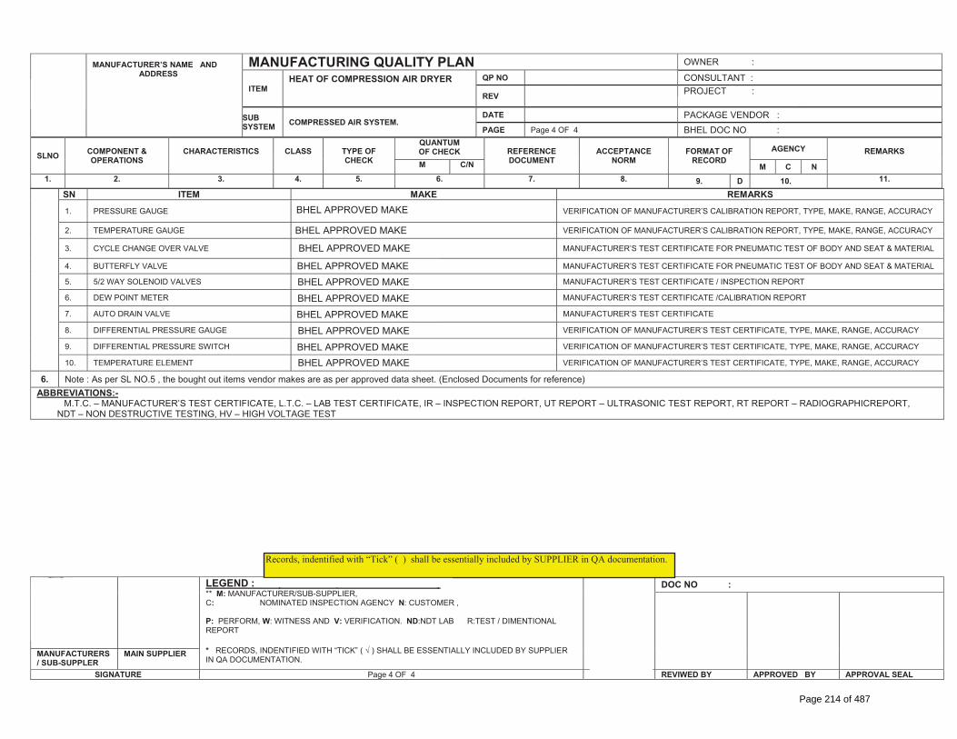
MANUFACTURER’S NAME AND ADDRESS
SUMMITS HYGRONICS PVT. LTD. S.F 192, EARI THOTTAM, KANNAMPALAYAM, COIMBATORE-641 402
MANUFACTURING QUALITY PLAN OWNER : NTPC Limited.
ITEM HEAT OF COMPRESSION AIR DRYER (model : SH 240 BM) (Flow capacity:55 Nm³/ min)
QP NO SUM/SH-QAP/E033-15-16 /R00 CONSULTANT : BHEL
REV 00 PROJECT : 3X660MW NTPC NABINAGAR SUPER THERMAL POWER PLANT ,STAGE-1
SUBSYSTEM COMPRESSED AIR SYSTEM.
DATE 30.01.015 PACKAGE VENDOR : ELGI EQUIPMENTS LIMITED PAGE Page 4 OF 4 BHEL DOC NO : PE-V0-393-555-A002
SLNO COMPONENT & OPERATIONS
CHARACTERISTICS CLASS TYPE OF CHECK
QUANTUM OF CHECK REFERENCE
DOCUMENT ACCEPTANCE
NORM FORMAT OF
RECORD AGENCY REMARKS
M C/N M C N 1. 2. 3. 4. 5. 6. 7. 8. 9. D 10. 11.
LEGEND : CL: (ACRITICAL, B:MAJOR C:MINOR)** M: MANUFACTURER/SUB-SUPPLIER, C: DOOSAN / NOMINATED INSPECTION AGENCY N: CUSTOMER , CHP: NTPC SHALL IDENTIFY IN COLUM “N” AS ‘ W” P: PERFORM, W: WITNESS AND V: VERIFICATION. ND:NDT LAB R:TEST / DIMENTIONAL REPORT
* RECORDS, INDENTIFIED WITH “TICK” ( � ) SHALL BE ESSENTIALLY INCLUDED BY SUPPLIER IN QA DOCUMENTATION.
DOC NO : 0370-102-PE-PVM-Q-003
MANUFACTURERS / SUB-SUPPLER
MAIN SUPPLIER
SIGNATURE Page 4 OF 4 FOR NTPC USE REVIWED BY APPROVED BY APPROVAL SEAL
SN ITEM MAKE REMARKS
1. PRESSURE GAUGE BAUMER VERIFICATION OF MANUFACTURER’S CALIBRATION REPORT, TYPE, MAKE, RANGE, ACCURACY
2. TEMPERATURE GAUGE BAUMER VERIFICATION OF MANUFACTURER’S CALIBRATION REPORT, TYPE, MAKE, RANGE, ACCURACY
3. CYCLE CHANGE OVER VALVE VI/FLOCON/FLOWCHEM /XOMOX MANUFACTURER’S TEST CERTIFICATE FOR PNEUMATIC TEST OF BODY AND SEAT & MATERIAL
4. BUTTERFLY VALVE VI/FLOCON/FLOWCHEM /XOMOX MANUFACTURER’S TEST CERTIFICATE FOR PNEUMATIC TEST OF BODY AND SEAT & MATERIAL
5. 5/2 WAY SOLENOID VALVES JANATICS/ROTEX MANUFACTURER’S TEST CERTIFICATE / INSPECTION REPORT
6. DEW POINT METER XENTAUR MANUFACTURER’S TEST CERTIFICATE /CALIBRATION REPORT
7. AUTO DRAIN VALVE SUMMITS MANUFACTURER’S TEST CERTIFICATE
8. DIFFERENTIAL PRESSURE GAUGE BAUMER/HIRLEKAR VERIFICATION OF MANUFACTURER’S TEST CERTIFICATE, TYPE, MAKE, RANGE, ACCURACY
9. DIFFERENTIAL PRESSURE SWITCH BAUMER/HIRLEKAR VERIFICATION OF MANUFACTURER’S TEST CERTIFICATE, TYPE, MAKE, RANGE, ACCURACY
10. TEMPERATURE ELEMENT BAUMER VERIFICATION OF MANUFACTURER’S TEST CERTIFICATE, TYPE, MAKE, RANGE, ACCURACY
6. Note : As per SL NO.5 , the bought out items vendor makes are as per approved data sheet. (Enclosed Documents for reference) ABBREVIATIONS:-
M.T.C. – MANUFACTURER’S TEST CERTIFICATE, L.T.C. – LAB TEST CERTIFICATE, IR – INSPECTION REPORT, UT REPORT – ULTRASONIC TEST REPORT, RT REPORT – RADIOGRAPHICREPORT, NDT – NON DESTRUCTIVE TESTING, HV – HIGH VOLTAGE TEST
Records, indentified with “Tick” ( ) shall be essentially included by SUPPLIER in QA documentation.
BHEL APPROVED MAKE
BHEL APPROVED MAKE
BHEL APPROVED MAKE
BHEL APPROVED MAKEBHEL APPROVED MAKEBHEL APPROVED MAKEBHEL APPROVED MAKEBHEL APPROVED MAKEBHEL APPROVED MAKEBHEL APPROVED MAKE
Page 170 of 400 Page 214 of 487

PE-TS-436-555-A001
Page 171 of 400 Page 215 of 487

PE-TS-436-555-A001
Page 172 of 400 Page 216 of 487

PE-TS-436-555-A001
Page 173 of 400 Page 217 of 487

PE-TS-436-555-A001
Page 174 of 400 Page 218 of 487

PE-TS-436-555-A001
Page 175 of 400 Page 219 of 487
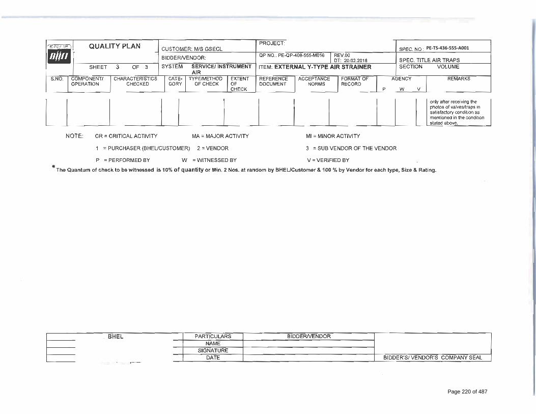
PE-TS-436-555-A001
Page 176 of 400 Page 220 of 487

Page 177 of 400
Page 221 of 487

Page 178 of 400
Page 222 of 487

Page 179 of 400
Page 223 of 487
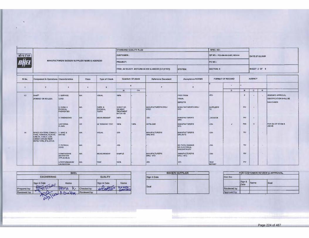
Page 180 of 400
Page 224 of 487

Page 181 of 400
Page 225 of 487

Page 182 of 400
Page 226 of 487

Page 183 of 400
Page 227 of 487

Page 184 of 400
Page 228 of 487

Page 185 of 400
Page 229 of 487

Page 186 of 400
Page 230 of 487

Page 187 of 400
Page 231 of 487

SIPAT STAGE-II, 2X500MW FGD
COMPRESSED AIR SYSTEM
SPECIFICATION No: PE-TS-491-555-A001
VOLUME: II B
SECTION : C-3
REV. 00 DATE: JULY 22
SHEET: 1 OF 1
SECTION: C-3 TECHNICAL SPECIFICATION (ELECTRICAL PORTION)
Page 232 of 487

13
Page 233 of 487

TITLE : ELECTRICAL EQUIPMENT SPECIFICATION
FOR COMPRESSED AIR SYSTEM
2x500MW SIPAT STPP-II
(FGD PACKAGE)
SPECIFICATION NO. VOLUME NO. : II-B SECTION : I REV NO. : 00 DATE : 11.07.2022 SHEET : 1 OF 3
TECHNICAL SPECIFICATION
FOR
COMPRESSED AIR SYSTEM
(ELECTRICAL PORTION)
Page 234 of 487

TITLE : ELECTRICAL EQUIPMENT SPECIFICATION
FOR COMPRESSED AIR SYSTEM
2x500MW SIPAT STPP-II
(FGD PACKAGE)
SPECIFICATION NO. VOLUME NO. : II-B SECTION : I REV NO. : 00 DATE : 11.07.2022 SHEET : 2 OF 3
1.0 EQUIPMENT & SERVICES TO BE PROVIDED BY BIDDER:
a) Services and equipment as per “Electrical Scope between BHEL and Vendor”. b) Any item/work either supply of equipment or erection material which have not
been specifically mentioned but are necessary to complete the work for trouble free and efficient operation of the plant shall be deemed to be included within the scope of this specification. The same shall be provided by the bidder without any extra charge.
c) Supply of mandatory spares as specified in the specifications of mechanical equipments.
d) Electrical load requirement for COMPRESSED AIR SYSTEM (all AC & DC loads at different voltage levels like 415V AC, 240 V AC, 220 V DC etc).
e) All equipment shall be suitable for the power supply fault levels and other climatic conditions mentioned in the enclosed project information.
f) Bidder to furnish list of makes for each equipment at contract stage, which shall be subject to customer/BHEL approval without any commercial and delivery implications to BHEL
g) Various drawings, data sheets as per required format, Quality plans, calculations, test reports, test certificates, operation and maintenance manuals etc shall be furnished as specified at contract stage. All documents shall be subject to customer/BHEL approval without any commercial implication to BHEL.
h) Motor shall meet minimum requirement of motor specification. i) Vendor to clearly indicate equipment locations and local routing lengths in their
cable listing furnished to BHEL. j) Cable BOQ worked out based on routing of cable listing provided by the vendor
for “ both end equipment in vendor’s scope”shall be binding to the vendor with +10 % margin to take care of slight variation in routing length & wastages.
2.0 EQUIPMENT & SERVICES TO BE PROVIDED BY PURCHASER FOR
ELECTRICAL & TERMINAL POINTS:
Refer “Electrical Scope between BHEL and Vendor”.
3.0 DOCUMENTS TO BE SUBMITTED ALONG WITH BID
3.1 The electrical specification without any deviation from the technical/quality assurance requirements stipulated shall be deemed to be complied by the bidder in case bidder furnishes the overall compliance of package technical specification in the form of compliance certificate/No deviation certificate.
Page 235 of 487

TITLE : ELECTRICAL EQUIPMENT SPECIFICATION
FOR COMPRESSED AIR SYSTEM
2x500MW SIPAT STPP-II
(FGD PACKAGE)
SPECIFICATION NO. VOLUME NO. : II-B SECTION : I REV NO. : 00 DATE : 11.07.2022 SHEET : 3 OF 3
3.2 No technical submittal such as copies of data sheets, drawings, write-up, quality plans,
type test certificates, technical literature, etc, is required during tender stage. Any such submission even if made, shall not be considered as part of offer.
4.0 List of enclosures : a) Electrical scope between BHEL & vendor (Annexure –I) b) Technical specification for motors. c) Datasheets & quality plan for motors. d) Electrical Load data format (Annexure –II) e) BHEL cable listing format (Annexure –III)
Page 236 of 487

REV-0, DATE: 11.07.2022 ELECTRICAL SCOPE BETWEEN BHEL AND VENDOR
PACKAGES : COMPRESSED AIR SYSTEM SCOPE OF VENDOR: SUPPLY, ERECTION & COMMISSIONING OF VENDOR’S EQUIPMENT PROJECT: 2x500MW SIPAT STPP-II (FGD PACKAGE)
S.NO
DETAILS SCOPE
SUPPLY
SCOPE E&C
REMARKS
1 11 kV/ 6.6 KV / 3.3 KV / 415 V Switchgear
BHEL BHEL 240 V AC (supply feeder)/415 V AC (3 PHASE 4 WIRE) supply shall be provided by BHEL based on load data provided by vendor at contract stage for all equipment supplied by vendor as part of contract. Any other voltage level (AC/DC) required will be derived by the vendor.
2 Local Push Button Station ( for motors) BHEL BHEL Located near the motors. 3 Power cables, control cables and screened control
cables for a) both end equipment in BHEL’s scope b) both end equipment in vendor’s scope c) one end equipment in vendor’s scope
BHEL BHEL BHEL
BHEL Vendor BHEL
1. For 3.b) & c): Sizes of cables required shall be informed by vendor at contract stage (based on inputs provided by BHEL) in the form of cable listing. Finalisation of cable sizes shall be done by BHEL. Vendor shall provide lugs & glands accordingly. 2. Termination at BHEL equipment terminals by BHEL. 3. Termination at Vendor equipment terminals by Vendor.
4 Junction box for control & instrumentation cable Vendor Vendor Number of Junction Boxes shall be sufficient and positioned in the field to minimize local cabling ( max 10-12 mtrs) and trunk cable.
5 Any special type of cable like compensating, co-axial, prefab, MICC, etc.
Vendor Vendor
Refer C&I portion of specification for scope of fibre Optical cables if used between PLC/ microprocessor & DCS.
6 Cable trays, accessories & cable trays supporting system. 100/50 mm cable trays/Conduits/Galvanised steel cable troughs for local cabling
BHEL
Vendor
BHEL
Vendor
Local cabling from nearby main route cable tray (BHEL scope) to equipment terminal (vendor’s scope) shall be through 100/ 50 mm. cable trays/ conduits/ Galvanised steel cable troughs as per approved layout drawing during contract stage.
7 Cable glands, lugs & bimetallic strip for equipments supplied by Vendor
Vendor Vendor 1. Double compression Ni-Cr plated brass cable glands 2. Solder less crimping type heavy duty tinned copper lugs for power & control cables.
8 Conduit and conduit accessories for cabling between equipments supplied by vendor.
Vendor Vendor Conduits shall be medium duty, hot dip galvanised cold rolled mild steel rigid conduit as per IS: 9537.
9 Lighting BHEL BHEL -- 10 Equipment grounding (including electronic earthing)
& lightning protection BHEL BHEL Refer note no. 4 for electronic earthing
11 Below grade grounding BHEL BHEL -- 12 Motors with base plate and foundation hardware Vendor Vendor Makes shall be subject to customer/ BHEL approval at contract stage. 13 Mandatory spares Vendor - Vendor to quote as per specification.
Page 237 of 487

REV-0, DATE: 11.07.2022 ELECTRICAL SCOPE BETWEEN BHEL AND VENDOR
PACKAGES : COMPRESSED AIR SYSTEM SCOPE OF VENDOR: SUPPLY, ERECTION & COMMISSIONING OF VENDOR’S EQUIPMENT PROJECT: 2x500MW SIPAT STPP-II (FGD PACKAGE)
14 Recommended O & M spares Vendor - As specified elsewhere in specification 15 Any other equipment/material/service required for
completeness of system based on the system offered by vendor (to ensure trouble free and efficient operation of the system).
Vendor Vendor --
16 a. Input cable schedules (C & I) b. Cable interconnection detail for the above c. Cable block diagram
Vendor Vendor Vendor
- - -
Cable listing for Control and Instrumentation Cable and electronic earthing cable in enclosed excel format shall be submitted by vendor during detailed engineering stage.
17 Cabling layout drawings BHEL/ Vendor
-
a. In case of Compressor are HT motors, cable tray/trench layout inside compressed air building shall be prepared by BHEL. Vendor to furnish drawing (both in print form as well as in AUTOCAD) of compressor room layout clearly indicating all motors, panels, JB’s etc. which require cabling alongwith their terminal box/location/ Foundation etc.
b. In case of Compressor are LT motors, for ensuring cabling requirements are met, vendor shall prepare & submit cable tray/trench & equipment layout (both in print form as well as in AUTOCAD) of the complete plant (including electrical area) indicating location and identification of all equipment requiring cabling for BHEL review & approval.
18 Electrical equipment GA drawing Vendor - For necessary interface review. NOTES:
1. Make of all electrical equipments/items supplied shall be reputed make & shall be subject to approval of BHEL/customer after award of contract. 2. All QPs shall be subject to approval of BHEL/customer after award of contract without any commercial implication. 3. In case the requirement of junction box arises on account of power cable size mismatch due to vendor engineering at later stage, vendor shall supply
the junction box for suitable termination. 4. Vendor shall indicate location of Electronic Earth pit in their Civil assignment drawing.
Page 238 of 487

LOAD TITLE
RATING (KW / A)
UN
IT (
U)/
ST
N (
S) Nos.
VO
LT
AG
E C
OD
E*
FE
ED
ER
CO
DE
**
EM
ER
. L
OA
D (
Y)
CO
NT
.(C
)/ IN
TT
.(I)
ST
AR
TIN
G T
IME
>
5 S
EC
(Y
)
LOCATION BOARD
NO.
CABLE
BL
OC
K C
AB
LE
D
RG
. N
o.
CONTROL
CODE
REMARKS
LOAD No.
VERIFICATION FROM MOTOR
DATASHEET (Y/N)
KKS NO
NAME PLATE
MAX. CONT.
DEMAND (MCR)
RU
NN
ING
ST
AN
DB
Y
SIZE CODE
NOs
1 2 3 4 5 6 7 8 9 10 11 12 13 14 15 16 17 18 19 20 21
NOTES: 1. COLUMN 1 TO 12 & 18 SHALL BE FILLED BY THE REQUISITIONER (ORIGINATING AGENCY); REMAINING COLUMNS ARE TO BE FILLED UP BY PEM (ELECTRICAL)/ CUSTOMER
2. ABBREVIATIONS : * VOLTAGE CODE (7):- (ac) A=11 KV, B=6.6 KV, C=3.3 KV, D=415 V, E=240 V (1 PH), F=110 V (cc): G=220 V, H=110 V, J=48 V, K=+24V, L=-24 V
: ** FEEDER CODE (8):- U=UNIDIRECTIONAL STARTER, B=BI-DIRECTIONAL STARTER, S=SUPPLY FEEDER, D=SUPPLY FEEDER (CONTACTER CONTROLLED)
PROJECT TITLE
2x500 MW SIPAT STPP-II NAME
DATA FILLED UP ON
SYSTEM COMPRESSED AIR SYSTEM SIGN. DATA ENTERED ON DEPTT. / SECTION
MAUX SHEET 1 OF 1 REV. 00
DE’S SIGN. & DATE
ANNEXURE-II
Page 239 of 487

CABLE SCHEDULE FORMAT ANNEXURE III
UNITCABLENO FROM TO PURPOSE
CABLE SCOPE (BHEL PEM/ VENDOR) REMARKS CABLESIZE PATHCABLENO
TENTATIVE CABLE LENGTH
Page 240 of 487

LOT-6 PROJECTS FLUE GAS DESULPHURISATION (FGD) SYSTEM PACKAGE
TECHNICAL SPECIFICATION SECTION-VI
BID DOCUMENT NO.: CS-0011-109(6)-9
SUB-SECTION-II-E2
MOTORS
Page 241 of 487

CLAUSE NO.
TECHNICAL REQUIREMENTS
LOT-6 PROJECTS
FLUE GAS DESULPHURISATION (FGD) SYSTEM PACKAGE
TECHNICAL SPECIFICATION SECTION – VI, PART-B
BID DOC NO : CS-0011-109(6)-9
SUB SECTION-II-E2 MOTORS
PAGE 1 OF 9
MOTORS
1.00.00 GENERAL REQUIREMENTS
1.01.00 For the purpose of design of equipment/systems, an ambient temperature of 50 deg. Centigrade and relative humidity of 95% (at 40 deg C) shall be considered. The equipment shall operate in a highly polluted environment.
1.02.00 All equipment’s shall be suitable for rated frequency of 50 Hz with a variation of +3% & -5%, and 10% combined variation of voltage and frequency unless specifically brought out in the specification.
1.03.00 Contactor shall provide fully compatible electrical system, equipment’s, accessories and services.
1.04.00 All the equipment, material and systems shall, in general, conform to the latest edition of relevant National and international Codes & Standards, especially the Indian Statutory Regulations.
1.05.00 Paint shade shall be as per RAL 5012 (Blue) for indoor and outdoor equipment.
1.06.00 The responsibility of coordination with electrical agencies and obtaining all necessary clearances for Contactors equipment and systems shall be under the Contactor scope.
1.07.00 Degree of Protection
Degree of protection for various enclosures as per IEC60034-05 shall be as follows :-
i) Indoor motors - IP 54
ii) Outdoor motors - IP 55
iii) Cable box-indoor area - IP 54
iv) Cable box-Outdoor area - IP 55
2.00.00 CODES AND STANDARDS
1) Three phase induction motors : IS/IEC:60034
2) Single phase AC motors : IS/ IEC:60034
3) Crane duty motors : IS:3177, IS/IEC:60034
4) DC motors/generators : IS:4722, IS/IEC:60034
5) Energy Efficient motors : IS 12615, IEC:60034-30
Page 242 of 487

CLAUSE NO.
TECHNICAL REQUIREMENTS
LOT-6 PROJECTS
FLUE GAS DESULPHURISATION (FGD) SYSTEM PACKAGE
TECHNICAL SPECIFICATION SECTION – VI, PART-B
BID DOC NO : CS-0011-109(6)-9
SUB SECTION-II-E2 MOTORS
PAGE 2 OF 9
3.00.00 TYPE
3.01.00 AC Motors:
a) Squirrel cage induction motor suitable for direct-on-line starting.
b) Continuous duty LT motors upto 200 KW Output rating (at 50 deg.C ambient temperature), shall be Premium Efficiency class-IE3, conforming to IS 12615, or IEC:60034-30. HT motors shall have minimum design efficiency of 95 %. However, tolerance on this efficiency value shall be applicable as per IEC 60034
c) Crane duty motors shall be slip ring/ squirrel cage Induction motor as per the requirement.
d) Motor operating through variable frequency drives shall be suitable for inverter duty with VPI insulation. Also these motors shall comply the requirements stipulated in IEC: 60034-18-41 and IEC: 60034-18-42 as applicable.
e) Motors operating through variable frequency drives shall also meet the
requirements mentioned in subsection for VFD.
3.02.00 DC Motors Shunt wound.
4.00.00 RATING
(a) Continuously rated (S1). However, crane motors shall be rated for S4 duty, 40% cyclic duration factor.
(b) Whenever the basis for motor or driven equipment ratings are not specified in the corresponding mechanical specification sub-sections, maximum continuous motor ratings shall be at least 10% above the maximum load demand of the driven equipment under entire operating range including voltage and frequency variations.
5.00.00 TEMPERATURE RISE
Air cooled motors
70 deg. C by resistance method for both thermal class 130(B) & 155(F) insulation.
Water cooled
80 deg. C over inlet cooling water temperature mentioned elsewhere, by resistance method for both thermal class 130(B) & 155(F) insulation.
Page 243 of 487

CLAUSE NO.
TECHNICAL REQUIREMENTS
LOT-6 PROJECTS
FLUE GAS DESULPHURISATION (FGD) SYSTEM PACKAGE
TECHNICAL SPECIFICATION SECTION – VI, PART-B
BID DOC NO : CS-0011-109(6)-9
SUB SECTION-II-E2 MOTORS
PAGE 3 OF 9
6.00.00 OPERATIONAL REQUIREMENTS
6.01.00 Starting Time
6.01.01 For motors with starting time upto 20 secs. at minimum permissible voltage during starting, the locked rotor withstand time under hot condition at highest voltage limit shall be at least 2.5 secs. more than starting time.
6.01.02 For motors with starting time more than 20 secs. and upto 45 secs. at minimum permissible voltage during starting, the locked rotor withstand time under hot condition at highest voltage limit shall be at least 5 secs. more than starting time.
6.01.03 For motors with starting time more than 45 secs. at minimum permissible voltage during starting, the locked rotor withstand time under hot condition at highest voltage limit shall be more than starting time by at least 10% of the starting time.
6.01.04 Speed switches mounted on the motor shaft shall be provided in cases where above requirements are not met.
6.02.00 Torque Requirements
6.02.01 Accelerating torque at any speed with the lowest permissible starting voltage shall be at least 10% motor rated torque.
6.02.02 Pull out torque at rated voltage shall not be less than 205% of rated torque. It shall be 275% for crane duty motors.
6.03.00 Starting voltage requirement
(a) Up to 85% of rated voltage for ratings below 110 KW
(b) Up to 80% of rated voltage for ratings from 110 KW to 200 KW
(c) Up to 85% of rated voltage for ratings from 201 KW to 1000 KW
(d) Up to 80% of rated voltage for ratings from 1001 KW to 4000 KW
(e) Up to 75 % of rated voltage for ratings above 4000KW
7.00.00 DESIGN AND CONSTRUCTIONAL FEATURES
7.01.00 Suitable single phase space heaters shall be provided on motors rated 30KW and above to maintain windings in dry condition when motor is standstill. Separate terminal box for space heaters & RTDs shall be provided. However for flame proof motors, space heater terminals inside the main terminal box may be acceptable.
7.02.00 All motors shall be either Totally enclosed fan cooled (TEFC) or totally enclosed tube ventilated (TETV) or Closed air circuit air cooled (CACA) type. However, motors rated 3000KW or above can be Closed air circuit water cooled (CACW). The method of movement of primary and secondary coolant shall be self-circulated by fan or pump directly mounted on the rotor of the main motor as per
Page 244 of 487

CLAUSE NO.
TECHNICAL REQUIREMENTS
LOT-6 PROJECTS
FLUE GAS DESULPHURISATION (FGD) SYSTEM PACKAGE
TECHNICAL SPECIFICATION SECTION – VI, PART-B
BID DOC NO : CS-0011-109(6)-9
SUB SECTION-II-E2 MOTORS
PAGE 4 OF 9
IEC 60034-6. However VFD driven motors can be offered with forced cooling type with machine mounted fan or pump driven by separate electric motor. Motors and EPB located in hazardous areas shall have flame proof enclosures conforming to IS:2148 as detailed below
(a) Fuel oil area : Group – IIB
(b) Hydrogen generation : Group - IIC or (Group-I, Div-II as per plant area NEC) or (Class-1, Group-B, Div-II as per NEMA /IEC60034)
7.03.00 Winding and Insulation
(a) Type : Non-hygroscopic, oil resistant, flame resistant
(b) Starting duty : Two hot starts in succession, with motor initially at normal running temperature.
(c) 11kV, 6.6 KV & 3.3 kV AC motors
: Thermal class 155 (F) insulation. The winding insulation process shall be total Vacuum Presure Impregnated i.e resin poor method. The lightning Impulse & interturn insulation surge withstand level shall be as per IEC-60034 part-15.
(d) 240VAC, 415V AC & 220V DC motors
: Thermal Class ( B ) or better
7.04.00 Motors rated above 1000KW shall have insulated bearings/housing to prevent flow of shaft currents.
7.05.00 Motors with heat exchangers shall have dial type thermometer with adjustable alarm contacts to indicate inlet and outlet primary air temperature.
7.06.00 Noise level for all the motors shall be limited to 85 dB(A) except for BFP motor for which the maximum limit shall be 90dB(A). Vibration shall be limited within the limits prescribed in IS:12075 / IEC 60034-14 . Motors shall withstand vibrations produced by driven equipment. HT motor bearing housings shall have flat surfaces, in both X and Y directions, suitable for mounting 80mmX80mm vibration pads.
7.07.00 In HT motors, at least four numbers simplex / two numbers duplex platinum resistance type temperature detectors shall be provided in each phase stator winding. Each bearing of HT motor shall be provided with dial type thermometer and minimum 2 numbers duplex platinum resistance type temperature detectors.
7.08.00 Motor body shall have two earthing points on opposite sides.
7.09.00 11 KV motors shall be offered with Separable Insulated Connector (SIC) as per IEEE 386. The offered SIC terminations shall be provided with protective cover and trifurcating sleeves. SIC termination kit shall be suitable for fault level of 25 KA for 0.17 seconds.
Page 245 of 487

CLAUSE NO.
TECHNICAL REQUIREMENTS
LOT-6 PROJECTS
FLUE GAS DESULPHURISATION (FGD) SYSTEM PACKAGE
TECHNICAL SPECIFICATION SECTION – VI, PART-B
BID DOC NO : CS-0011-109(6)-9
SUB SECTION-II-E2 MOTORS
PAGE 5 OF 9
7.10.00 3.3/6.6 KV motors shall be offered with dust tight phase separated double walled (metallic as well as insulated barrier) Terminal box. Contractor shall provide termination kit for the offered Terminal box. The offered Terminal Box shall be suitable for fault level of 250 MVA for 0.12 sec. Removable gland plates of thickness 3 mm (hot/cold rolled sheet steel) or 4 mm (non magnetic material for single core cables) shall be provided.
7.11.00 The spacing between gland plate & centre of bottom terminal stud shall be as per Table-I.
7.12.00 All motors shall be so designed that maximum inrush currents and locked rotor and pullout torque developed by them at extreme voltage and frequency variations do not endanger the motor and driven equipment.
7.13.00 The motors shall be suitable for bus transfer schemes provided on the 11kV, 6.6 KV, 3.3 kV /415V systems without any injurious effect on its life.
7.14.00 For motors rated 2000 KW & above, neutral current transformers of PS class shall be provided on each phase in a separate neutral terminal box.
7.15.00 The size and number of cables (for HT motors) to be intimated to the successful Contactor during detailed engineering and the Contactor shall provide terminal box suitable for the same.
8.00.00 The ratio of locked rotor KVA at rated voltage to rated KW shall not exceed the following (without any further tolerance):
(a) From 50KW & upto 110KW : 11.0
(b) From 110 KW & upto 200 KW : 9.0
(c) Above 200 KW & upto 1000KW : 10.0
(d) From 1001KW & upto 4000KW : 9.0
(e) Above 4000KW : 6 to 6.5
10.00.00 TYPE TEST
10.01.00 HT MOTORS
10.01.01 The Contactor shall carry out the type tests as listed in this specification on the equipment to be supplied under this contract. The Contactor shall indicate the charges for each of these type tests separately in the relevant schedule of Section - VII- (BPS) and the same shall be considered for the evaluation of the bids. The type tests charges shall be paid only for the test(s) actually conducted successfully under this contract and upon certification by the Employer’s engineer.
10.01.02 The type tests shall be carried out in presence of the Employer’s representative, for which minimum 15 days notice shall be given by the Contactor. The Contactor shall obtain the Employer’s approval for the type test procedure before conducting
Page 246 of 487
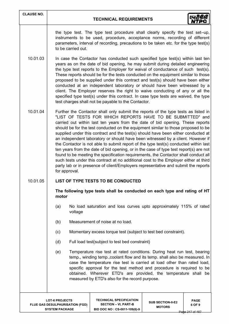
CLAUSE NO.
TECHNICAL REQUIREMENTS
LOT-6 PROJECTS
FLUE GAS DESULPHURISATION (FGD) SYSTEM PACKAGE
TECHNICAL SPECIFICATION SECTION – VI, PART-B
BID DOC NO : CS-0011-109(6)-9
SUB SECTION-II-E2 MOTORS
PAGE 6 OF 9
the type test. The type test procedure shall clearly specify the test set–up, instruments to be used, procedure, acceptance norms, recording of different parameters, interval of recording, precautions to be taken etc. for the type test(s) to be carried out.
10.01.03 In case the Contactor has conducted such specified type test(s) within last ten years as on the date of bid opening, he may submit during detailed engineering the type test reports to the Employer for waival of conductance of such test(s). These reports should be for the tests conducted on the equipment similar to those proposed to be supplied under this contract and test(s) should have been either conducted at an independent laboratory or should have been witnessed by a client. The Employer reserves the right to waive conducting of any or all the specified type test(s) under this contract. In case type tests are waived, the type test charges shall not be payable to the Contactor.
10.01.04 Further the Contactor shall only submit the reports of the type tests as listed in "LIST OF TESTS FOR WHICH REPORTS HAVE TO BE SUBMITTED" and carried out within last ten years from the date of bid opening. These reports should be for the test conducted on the equipment similar to those proposed to be supplied under this contract and the test(s) should have been either conducted at an independent laboratory or should have been witnessed by a client. However if the Contactor is not able to submit report of the type test(s) conducted within last ten years from the date of bid opening, or in the case of type test report(s) are not found to be meeting the specification requirements, the Contactor shall conduct all such tests under this contract at no additional cost to the Employer either at third party lab or in presence of client/Employers representative and submit the reports for approval.
10.01.05 LIST OF TYPE TESTS TO BE CONDUCTED
The following type tests shall be conducted on each type and rating of HT motor
(a) No load saturation and loss curves upto approximately 115% of rated voltage
(b) Measurement of noise at no load.
(c) Momentary excess torque test (subject to test bed constraint).
(d) Full load test(subject to test bed constraint)
(e) Temperature rise test at rated conditions. During heat run test, bearing temp., winding temp.,coolant flow and its temp. shall also be measured. In case the temperature rise test is carried at load other than rated load, specific approval for the test method and procedure is required to be obtained. Wherever ETD's are provided, the temperature shall be measured by ETD's also for the record purpose.
Page 247 of 487

CLAUSE NO.
TECHNICAL REQUIREMENTS
LOT-6 PROJECTS
FLUE GAS DESULPHURISATION (FGD) SYSTEM PACKAGE
TECHNICAL SPECIFICATION SECTION – VI, PART-B
BID DOC NO : CS-0011-109(6)-9
SUB SECTION-II-E2 MOTORS
PAGE 7 OF 9
10.01.06 LIST OF TESTS FOR WHICH REPORTS HAVE TO BE SUBMITTED
The following type test reports shall be submitted for each type and rating of HT motor
(a) Degree of protection test for the enclosure followed by IR, HV and no load run test.
(b) Terminal box-fault level withstand test for each type of terminal box of HT motors only.
(c) Lightning Impulse withstand test on the sample coil shall be as per clause no. 4.3 IEC-60034, part-15
(d) Surge-withstand test on inter-turn insulation shall be as per clause no. 4.2 of IEC 60034, part-15
10.02.00 LT Motors
10.02.01 LT Motors supplied shall be of type tested design. During detailed engineering, the Contactor shall submit for Employer's approval the reports of all the type tests as listed in this specification and carried out within last ten years from the date of bid opening. These reports should be for the test conducted on the equipment similar to those proposed to be supplied under this contract and the test(s) should have been either conducted at an independent laboratory or should have been witnessed by a client.
10.02.02 However if the Contactor is not able to submit report of the type test(s) conducted within last ten years from the date of bid opening, or in the case of type test report(s) are not found to be meeting the specification requirements, the Contactor shall conduct all such tests under this contract at no additional cost to the Employer either at third party lab or in presence of client/Employers representative and submit the reports for approval.
10.02.03 LIST OF TESTS FOR WHICH REPORTS HAVE TO BE SUBMITTED
The following type test reports shall be submitted for each type and rating of LT motor of above 100 KW only 1. Measurement of resistance of windings of stator and wound rotor. 2. No load test at rated voltage to determine input current power and speed
3. Open circuit voltage ratio of wound rotor motors ( in case of Slip ring
motors) 4. Full load test to determine efficiency power factor and slip 5. Temperature rise test
Page 248 of 487
CLAUSE NO.
TECHNICAL REQUIREMENTS
LOT-6 PROJECTS
FLUE GAS DESULPHURISATION (FGD) SYSTEM PACKAGE
TECHNICAL SPECIFICATION SECTION – VI, PART-B
BID DOC NO : CS-0011-109(6)-9
SUB SECTION-II-E2 MOTORS
PAGE 8 OF 9
6. Momentary excess torque test. 7. High voltage test
8. Test for vibration severity of motor. 9. Test for noise levels of motor(Shall be limited as per clause no 7.06.00 of
this section) 10. Test for degree of protection and 11. Overspeed test. 12. Type test reports for motors located in fuel oil area having flame proof
enclosures as per IS 2148 / IEC 60079-1
10.03.00 All acceptance and routine tests as per the specification and relevant standards shall be carried out. Charges for these shall be deemed to be included in the equipment price.
10.04.00 The type test reports once approved for any projects shall be treated as reference. For subsequent projects of NTPC, an endorsement sheet will be furnished by the manufacturer confirming similarity and “No design Change”. Minor changes if any shall be highlighted on the endorsement sheet.
Page 249 of 487

CLAUSE NO.
TECHNICAL REQUIREMENTS
LOT-6 PROJECTS
FLUE GAS DESULPHURISATION (FGD) SYSTEM PACKAGE
TECHNICAL SPECIFICATION SECTION – VI, PART-B
BID DOC NO : CS-0011-109(6)-9
SUB SECTION-II-E2 MOTORS
PAGE 9 OF 9
TABLE - I
DIMENSIONS OF TERMINAL BOXES FOR LV MOTORS
Motor MCR in KW Minimum distance between centre of bottom terminal stud and gland plate in mm
UP to 3 KW As per manufacturer's practice. Above 3 KW - upto 7 KW 85 Above 7 KW - upto 13 KW 115 Above 13 KW - upto 24 KW 167 Above 24 KW - upto 37 KW 196 Above 37 KW - upto 55 KW 249 Above 55 KW - upto 90 KW 277 Above 90 KW - upto 125 KW 331 Above 125 KW-upto 200 KW 385/203 (For Single
core cables only) For HT motors the distance between gland plate and the terminal studs shall not
be less than 500 mm. PHASE TO PHASE/ PHASE TO EARTH AIR CLEARANCE: NOTE: Minimum inter-phase and phase-earth air clearances for LT motors with
lugs installed shall be as follows: Motor MCR in KW Clearance UP to 110 KW 10mm Above 110 KW and upto 150 KW 12.5mm Above 150 KW 19mm
Page 250 of 487

GS FLAT( )
Page 251 of 487

CLAUSE NO.
Bidder’s Name ………………………..
LOT 6 PROJECTS
FLUE GAS DESULPHURISATION (FGD)
SYSTEM PACKAGE
ATTACHMENT-12 TO
SECTION-VII
TECHNICAL DATA SHEETS
BID DOC. NO.: CS-0011-109(6)-9
PART-F CHAPTER-II MODULE-II
SUB-SECTION:DE1 MOTORS
PAGE
13 OF 17
DE-1B LT MOTORS
A. GENERAL
5. Manufacturer & Country of origin. (Shall be as per
approved QA make)
6. Equipment driven by motor
7. Motor type
8. Quantity
B. DESIGN AND PERFORMANCE DATA
18. Frame size
19. Type of duty
20. Type of enclosure /Method of cooling/ Degree of
protection
21. Applicable standard to which motor generally
conforms
22. Efficiency class as per IS 12615
23. (a)Whether motor is flame proof Yes/No
(b)If yes, the gas group to which it conforms as
per IS:2148
24. Type of mounting
25. Direction of rotation as viewed from DE END
26. Standard continuous rating at 40 deg.C. ambient
temp. as per Indian Standard (KW)
27. Derated rating for specified normal condition i.e.
50 deg. C ambient temperature (KW)
28. Maximum continuous load demand of driven
equipment in KW
29. Rated Voltage (volts)
30. Permissible variation of :
a. Voltage (Volts)
b. Frequency (Hz)
c. Combined voltage and frequency
31. Rated speed at rated voltage and
frequency(RPM)
32. At rated Voltage and frequency:
a. Full load current
Page 252 of 487
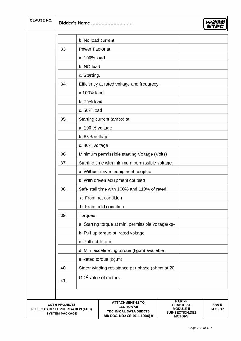
CLAUSE NO.
Bidder’s Name ………………………..
LOT 6 PROJECTS
FLUE GAS DESULPHURISATION (FGD)
SYSTEM PACKAGE
ATTACHMENT-12 TO
SECTION-VII
TECHNICAL DATA SHEETS
BID DOC. NO.: CS-0011-109(6)-9
PART-F CHAPTER-II MODULE-II
SUB-SECTION:DE1 MOTORS
PAGE
14 OF 17
b. No load current
33. Power Factor at
a. 100% load
b. NO load
c. Starting.
34. Efficiency at rated voltage and frequrecy,
a.100% load
b. 75% load
c. 50% load
35. Starting current (amps) at
a. 100 % voltage
b. 85% voltage
c. 80% voltage
36. Minimum permissible starting Voltage (Volts)
37. Starting time with minimum permissible voltage
a. Without driven equipment coupled
b. With driven equipment coupled
38. Safe stall time with 100% and 110% of rated
voltage
a. From hot condition
b. From cold condition
39. Torques :
a. Starting torque at min. permissible voltage(kg-
mtr.)
b. Pull up torque at rated voltage.
c. Pull out torque
d. Min accelerating torque (kg.m) available
e.Rated torque (kg.m)
40. Stator winding resistance per phase (ohms at 20
Deg.C.)
41. GD2 value of motors
Page 253 of 487

CLAUSE NO.
Bidder’s Name ………………………..
LOT 6 PROJECTS
FLUE GAS DESULPHURISATION (FGD)
SYSTEM PACKAGE
ATTACHMENT-12 TO
SECTION-VII
TECHNICAL DATA SHEETS
BID DOC. NO.: CS-0011-109(6)-9
PART-F CHAPTER-II MODULE-II
SUB-SECTION:DE1 MOTORS
PAGE
15 OF 17
42. No of permissible successive starts when motor is
in hot condition
43. Locked Rotor KVA Input
44. Locked Rotor KVA/KW
45. Vibration limit :Velocity (mm/s)
46. Noise level limit (dBA)
C. CONSTRUCTIONAL FEATURES
1. Stator winding insulation
a. Class & Type
b. Winding Insulation Process
c. Tropicalised (Yes/No)
d. Temperature rise over specified maximum
ambient temperature of 50 deg C
e. Method of temperature measurement
f. Stator winding connection
2. Main Terminal Box
a. Type
b. Location(viewed from NDE side)
c. Entry of cables(bottom/side)
d. Recommended cable size(To be matched with
cable size envisaged by owner)
e. Fault level (MVA),Fault level duration(sec)
f. Cable glands & lugs details (shall be suitable for
power cable)
3. Type of DE/NDE Bearing
4. Motor Paint shade
5. Weight of
a. Motor stator (KG)
b. Motor Rotor (KG)
c. Total weight (KG)
Page 254 of 487

CLAUSE NO.
Bidder’s Name ………………………..
LOT 6 PROJECTS
FLUE GAS DESULPHURISATION (FGD)
SYSTEM PACKAGE
ATTACHMENT-12 TO
SECTION-VII
TECHNICAL DATA SHEETS
BID DOC. NO.: CS-0011-109(6)-9
PART-F CHAPTER-II MODULE-II
SUB-SECTION:DE1 MOTORS
PAGE
16 OF 17
D. List of accessories.
1. 3
.
Space Heaters (Applicable for 30 KW & above
motor) (Nos./Power in watts/supply voltage)
2. Terminal Box for Space Heater (Yes/No)
3. Speed switch (Yes/No)
No of contacts and contact ratings of speed
switch
4. Insulation of bearing (Yes/No)
5. Noise reducer(Yes/No)
6. Grounding pads
i) No and size on motor body
ii) Nos on terminal Box
7. Vibration pads
i) Nos and size
ii) Location
8. Any other fitments
E. List of curves.
1. Torque speed characteristic of the motor
2. Thermal withstand characteristic
3. Starting. current Vs. Time
4. Starting. current Vs speed
5. P.F. and Effi. Vs Load
F. Additional Data to be filled for each rating of
DC Motor
1. Rated armature voltage (Volt)
2. Rated field excitation (Amp)
3. Permissible % variation in voltage
4. Minimum Permissible Starting voltage (volt)
5. At rated voltage
i)Full load Armature current.(Amp)
Page 255 of 487

CLAUSE NO.
Bidder’s Name ………………………..
LOT 6 PROJECTS
FLUE GAS DESULPHURISATION (FGD)
SYSTEM PACKAGE
ATTACHMENT-12 TO
SECTION-VII
TECHNICAL DATA SHEETS
BID DOC. NO.: CS-0011-109(6)-9
PART-F CHAPTER-II MODULE-II
SUB-SECTION:DE1 MOTORS
PAGE
17 OF 17
ii)Full load Field current (Amp)
iii)No load Armature current (Amp)
6. Full load Field current (Amp)
7. No load Aramature current (Amp)
8. Minimum permissible field current(Amp) to avoid
overspeeding at
i) Maximum permissible voltage
ii) Rated voltage
iii) Minimum Permissible Voltage
9. Resistance (indicative Values) in ohm
i)Armature winding(Arm + IP + Series) at 25
deg.C
ii) Field Winding at 25 deg. C
10.. Inductance (indicative values)
i) Armature winding
ii) Field winding
11 Value of trimmer resistance (ohm) to be
connected in series with the shunt field to
obtain rated
speed at
i) 220 V DC
ii) 250 V DC
iii) 187 V DC
12 Value of the external resistance (ohm)required to
be connected in series with armature during
starting only
13 Technical data sheet for external resistance box
14 GA drawing of motor
15 Starting time calculation
16 Starter resistance design calculation
17 Electrical connection diagram of motor
Page 256 of 487

SECTION : D
TITLE : GENERAL TECHNICAL REQUIREMENTs
FOR
LV MOTORS
SPECIFICATION NO. PE-SS-999-506-E101
VOLUME NO. : II-B
REV NO. : 00 DATE : 29/08/2005
SHEET : 1 OF 1
GENERAL TECHNICAL REQUIREMENTS
FOR
LV MOTORS
SPECIFICATION NO.: PE-SS-999-506-E101 Rev 00
Page 257 of 487
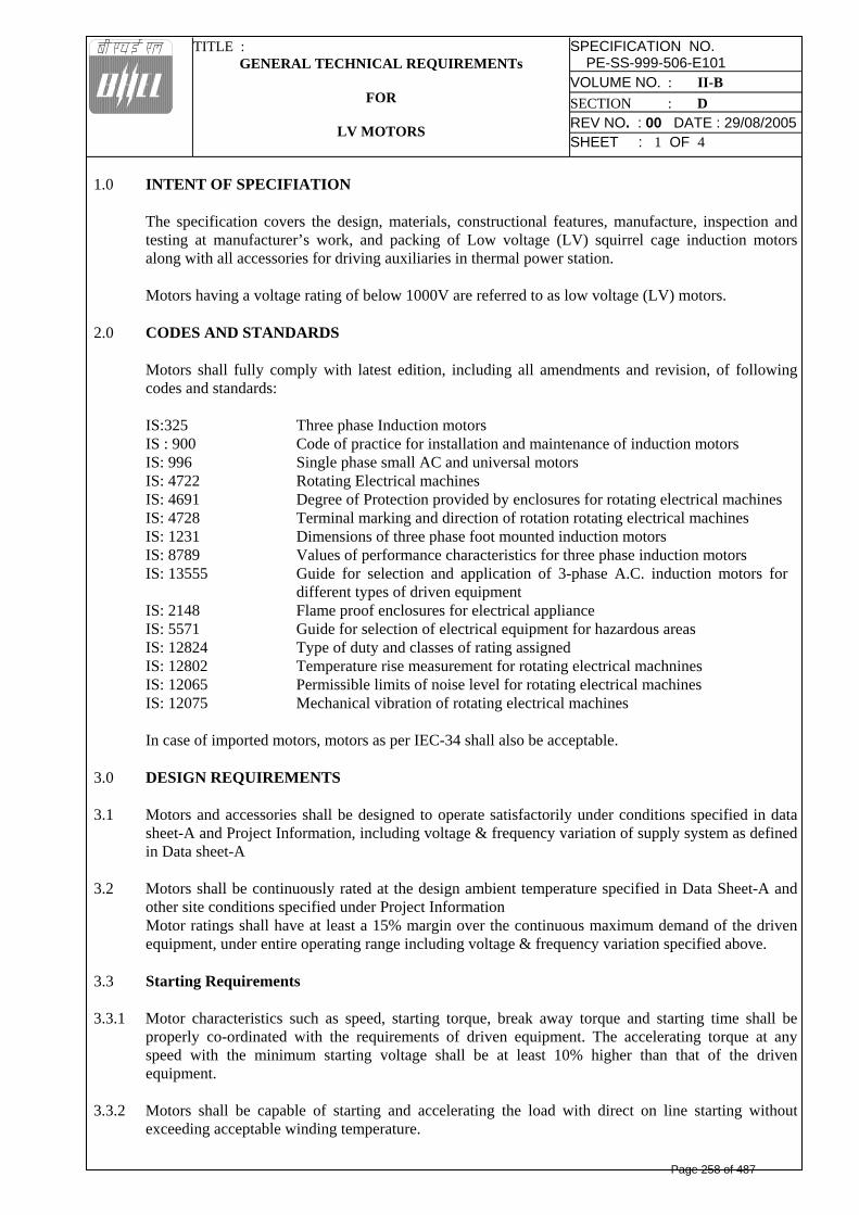
TITLE : GENERAL TECHNICAL REQUIREMENTs
FOR
LV MOTORS
SPECIFICATION NO. PE-SS-999-506-E101
VOLUME NO. : II-B SECTION : D REV NO. : 00 DATE : 29/08/2005
SHEET : 1 OF 4
1.0 INTENT OF SPECIFIATION
The specification covers the design, materials, constructional features, manufacture, inspection and testing at manufacturer’s work, and packing of Low voltage (LV) squirrel cage induction motors along with all accessories for driving auxiliaries in thermal power station.
Motors having a voltage rating of below 1000V are referred to as low voltage (LV) motors. 2.0 CODES AND STANDARDS Motors shall fully comply with latest edition, including all amendments and revision, of following
codes and standards: IS:325 Three phase Induction motors IS : 900 Code of practice for installation and maintenance of induction motors IS: 996 Single phase small AC and universal motors IS: 4722 Rotating Electrical machines IS: 4691 Degree of Protection provided by enclosures for rotating electrical machines IS: 4728 Terminal marking and direction of rotation rotating electrical machines IS: 1231 Dimensions of three phase foot mounted induction motors IS: 8789 Values of performance characteristics for three phase induction motors IS: 13555 Guide for selection and application of 3-phase A.C. induction motors for
different types of driven equipment IS: 2148 Flame proof enclosures for electrical appliance IS: 5571 Guide for selection of electrical equipment for hazardous areas IS: 12824 Type of duty and classes of rating assigned IS: 12802 Temperature rise measurement for rotating electrical machnines IS: 12065 Permissible limits of noise level for rotating electrical machines IS: 12075 Mechanical vibration of rotating electrical machines In case of imported motors, motors as per IEC-34 shall also be acceptable.
3.0 DESIGN REQUIREMENTS 3.1 Motors and accessories shall be designed to operate satisfactorily under conditions specified in data
sheet-A and Project Information, including voltage & frequency variation of supply system as defined in Data sheet-A
3.2 Motors shall be continuously rated at the design ambient temperature specified in Data Sheet-A and
other site conditions specified under Project Information Motor ratings shall have at least a 15% margin over the continuous maximum demand of the driven equipment, under entire operating range including voltage & frequency variation specified above.
3.3 Starting Requirements 3.3.1 Motor characteristics such as speed, starting torque, break away torque and starting time shall be
properly co-ordinated with the requirements of driven equipment. The accelerating torque at any speed with the minimum starting voltage shall be at least 10% higher than that of the driven equipment.
3.3.2 Motors shall be capable of starting and accelerating the load with direct on line starting without
exceeding acceptable winding temperature.
Page 258 of 487

TITLE : GENERAL TECHNICAL REQUIREMENTs
FOR
LV MOTORS
SPECIFICATION NO. PE-SS-999-506-E101
VOLUME NO. : II-B SECTION : D REV NO. : 00 DATE : 29/08/2005
SHEET : 2 OF 4
The limiting value of voltage at rated frequency under which a motor will successfully start and
accelerate to rated speed with load shall be taken to be a constant value as per Data Sheet - A during the starting period of motors.
3.3.3 The following frequency of starts shall apply
i) Two starts in succession with the motor being initially at a temperature not exceeding the rated load temperature.
ii) Three equally spread starts in an hour the motor being initially at a temperature not exceeding
the rated load operating temperature. (not to be repeated in the second successive hour)
iii) Motors for coal conveyor and coal crusher application shall be suitable for three consecutive hot starts followed by one hour interval with maximum twenty starts per day and shall be suitable for mimimum 20,000 starts during the life time of the motor
3.4 Running Requirements 3.4.1 Motors shall run satisfactorily at a supply voltage of 75% of rated voltage for 5 minutes with full load
without injurious heating to the motor. 3.4.2 Motor shall not stall due to voltage dip in the system causing momentary drop in voltage upto 70% of
the rated voltage for duration of 2 secs. 3.5 Stress During bus Transfer 3.5.1 Motors shall withstand the voltage, heavy inrush transient current, mechanical and torque stress
developed due to the application of 150% of the rated voltage for at least 1 sec. caused due to vector difference between the motor residual voltage and the incoming supply voltage during occasional auto bus transfer.
3.5.2 Motor and driven equipment shafts shall be adequately sized to satisfactorily withstand transient
torque under above condition. 3.6 Maximum noise level measured at distance of 1.0 metres from the outline of motor shall not exceed
the values specified in IS 12065. 3.7 The max. vibration velocity or double amplitude of motors vibration as measured at motor bearings
shall be within the limits specified in IS: 12075. 4.0 CONSTRUCTIONAL FEATURES 4.1 Indoor motors shall conform to degree of protection IP: 54 as per IS: 4691. Outdoor or semi-indoor
motors shall conform to degree of protection IP: 55 as per IS: 4691and shall be of weather-proof construction. Outdoor motors shall be installed under a suitable canopy
4.2 Motors upto 160KW shall have Totally Enclosed Fan Cooled (TEFC) enclosures, the method of
cooling conforming to IC-0141 or IC-0151 of IS: 6362.
Motors rated above 160 KW shall be Closed Air Circuit Air (CACA) cooled 4.3 Motors shall be designed with cooling fans suitable for both directions of rotation.
Page 259 of 487

TITLE : GENERAL TECHNICAL REQUIREMENTs
FOR
LV MOTORS
SPECIFICATION NO. PE-SS-999-506-E101
VOLUME NO. : II-B SECTION : D REV NO. : 00 DATE : 29/08/2005
SHEET : 3 OF 4
4.4. Motors shall not be provided with any electric or pneumatic operated external fan for cooling the
motors. 4.5 Frames shall be designed to avoid collection of moisture and all enclosures shall be provided with
facility for drainage at the lowest point. 4.6 In case Class ‘F’ insulation is provided for LV motors, temperature rise shall be limited to the limits
applicable to Class ‘B’ insulation. In case of continuous operation at extreme voltage limits the temperature limits specified in table-1 of IS:325 shall not exceed by more than 10°C.
4.7 Terminals and Terminal Boxes 4.7.1 Terminals, terminal leads, terminal boxes, windings tails and associated equipment shall be suitable
for connection to a supply system having a short circuit level, specified in the Data Sheet-A. Unless otherwise stated in Data Sheet-A, motors of rating 110 kW and above will be controlled by
circuit breaker and below 110 kW by switch fuse-contactor. The terminal box of motors shall be designed for the fault current mentioned in data sheet “A”.
4.7.2 unless otherwise specified or approved, phase terminal boxes of horizontal motors shall be positioned
on the left hand side of the motor when viewed from the non-driving end. 4.7.3 Connections shall be such that when the supply leads R, Y & B are connected to motor terminals A B
& C or U, V & W respectively, motor shall rotate in an anticlockwise direction when viewed from the non-driving end. Where such motors require clockwise rotation, the supply leads R, Y, B will be connected to motor terminals A, C, B or U W & V respectively.
4.7.4 Permanently attached diagram and instruction plate made preferably of stainless steel shall be
mounted inside terminal box cover giving the connection diagram for the desired direction of rotation and reverse rotation.
4.7.5 Motor terminals and terminal leads shall be fully insulated with no bar live parts. Adequate space
shall be available inside the terminal box so that no difficulty is encountered for terminating the cable specified in Data Sheet-A.
4.7.6 Degree of protection for terminal boxes shall be IP 55 as per IS 4691. 4.7.7 Separate terminal boxes shall be provided for space heaters.. If this is not possible in case of LV
motors, the space heater terminals shall be adequately segregated from the main terminals in the main terminal box. Detachable gland plates with double compression brass glands shall be provided in terminal boxes.
4.7.8. Phase terminal boxes shall be suitable for 360 degree of rotation in steps of 90 degree for LV motors. 4.7.9 Cable glands and cable lugs as per cable sizes specified in Data Sheet-A shall be included. Cable lugs
shall be of tinned Copper, crimping type. 4.8 Two separate earthing terminals suitable for connecting G.I. or MS strip grounding conductor of size
given in Data Sheet-A shall be provided on opposite sides of motor frame. Each terminal box shall have a grounding terminal.
4.9 General Page 260 of 487
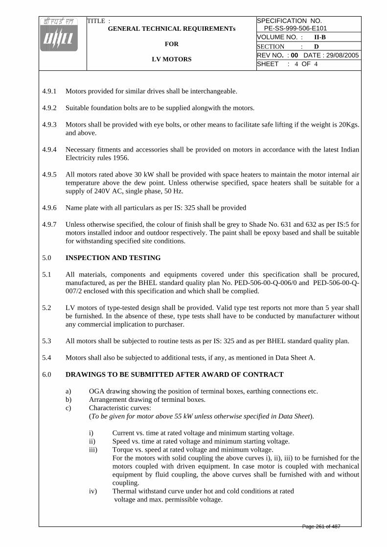
TITLE : GENERAL TECHNICAL REQUIREMENTs
FOR
LV MOTORS
SPECIFICATION NO. PE-SS-999-506-E101
VOLUME NO. : II-B SECTION : D REV NO. : 00 DATE : 29/08/2005
SHEET : 4 OF 4
4.9.1 Motors provided for similar drives shall be interchangeable. 4.9.2 Suitable foundation bolts are to be supplied alongwith the motors. 4.9.3 Motors shall be provided with eye bolts, or other means to facilitate safe lifting if the weight is 20Kgs.
and above. 4.9.4 Necessary fitments and accessories shall be provided on motors in accordance with the latest Indian
Electricity rules 1956. 4.9.5 All motors rated above 30 kW shall be provided with space heaters to maintain the motor internal air
temperature above the dew point. Unless otherwise specified, space heaters shall be suitable for a supply of 240V AC, single phase, 50 Hz.
4.9.6 Name plate with all particulars as per IS: 325 shall be provided 4.9.7 Unless otherwise specified, the colour of finish shall be grey to Shade No. 631 and 632 as per IS:5 for
motors installed indoor and outdoor respectively. The paint shall be epoxy based and shall be suitable for withstanding specified site conditions.
5.0 INSPECTION AND TESTING 5.1 All materials, components and equipments covered under this specification shall be procured,
manufactured, as per the BHEL standard quality plan No. PED-506-00-Q-006/0 and PED-506-00-Q-007/2 enclosed with this specification and which shall be complied.
5.2 LV motors of type-tested design shall be provided. Valid type test reports not more than 5 year shall
be furnished. In the absence of these, type tests shall have to be conducted by manufacturer without any commercial implication to purchaser.
5.3 All motors shall be subjected to routine tests as per IS: 325 and as per BHEL standard quality plan. 5.4 Motors shall also be subjected to additional tests, if any, as mentioned in Data Sheet A. 6.0 DRAWINGS TO BE SUBMITTED AFTER AWARD OF CONTRACT a) OGA drawing showing the position of terminal boxes, earthing connections etc. b) Arrangement drawing of terminal boxes. c) Characteristic curves: (To be given for motor above 55 kW unless otherwise specified in Data Sheet). i) Current vs. time at rated voltage and minimum starting voltage. ii) Speed vs. time at rated voltage and minimum starting voltage.
iii) Torque vs. speed at rated voltage and minimum voltage. For the motors with solid coupling the above curves i), ii), iii) to be furnished for the motors coupled with driven equipment. In case motor is coupled with mechanical equipment by fluid coupling, the above curves shall be furnished with and without coupling.
iv) Thermal withstand curve under hot and cold conditions at rated voltage and max. permissible voltage.
Page 261 of 487

Page 262 of 487

Page 263 of 487

Page 264 of 487

Page 265 of 487

Page 266 of 487

Page 267 of 487
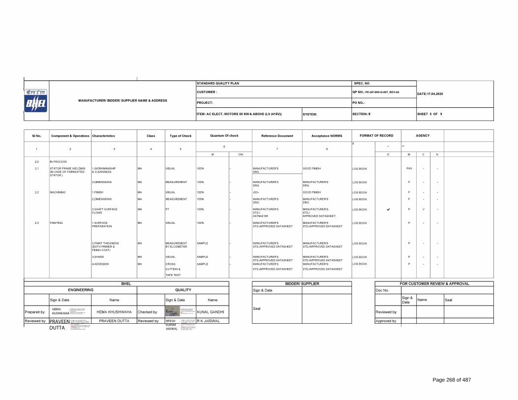
Page 268 of 487
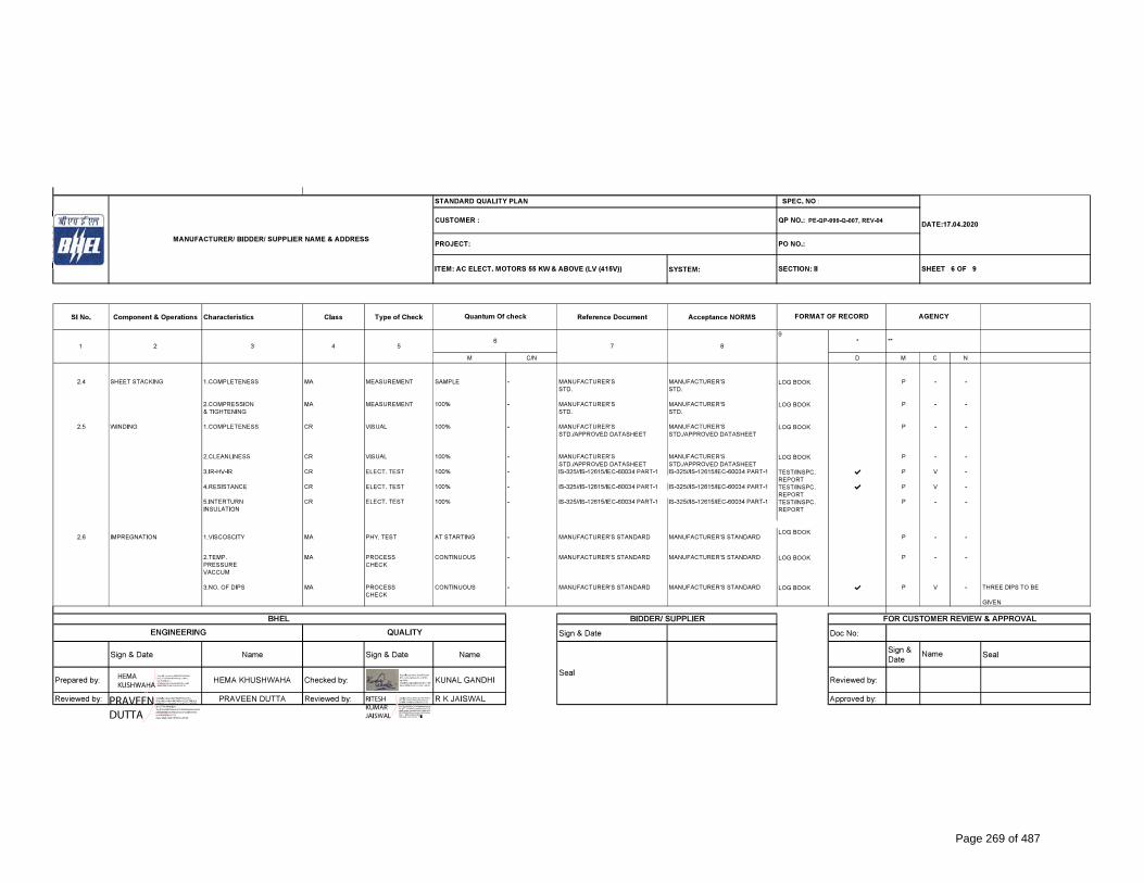
Page 269 of 487

Page 270 of 487

Page 271 of 487

Page 272 of 487

CLAUSE NO. QUALITY ASSURANCE
LOT-6 PROJECTS
FLUE GAS DESULPHURISATION (FGD)
SYSTEM PACKAGE
TECHNICAL SPECIFICATION
SECTION – VI
BID DOC. NO.:CS-0011-109(6)-9
PART-B
SUB-SECTION-V-QE1
MOTORS
PAGE 1 OF 2
MOTOR
TESTS/CHECKS
TEMS/COMPONENTS
Vis
ual
Dim
ensio
na
l
Ma
ke/T
yp
e/R
ating
/Ge
nera
l
Ph
ysic
al In
spe
ctio
n
Me
ch/C
hem
. P
ropert
ies
ND
T /
DP
/MP
I/U
T
Me
tallo
gra
ph
y
Ele
ctr
ica
l C
hara
cte
ristics
We
ldin
g/B
razin
g(W
PS
/PQ
R)
He
at
Tre
atm
ent
Ma
gn
etic C
hara
cte
ristics
Hyd
rau
lic/L
ea
k/P
ressure
Test
The
rma
l C
hara
cte
ristics
Ru
n o
ut
Dyn
am
ic B
ala
ncin
g
Ro
utin
e &
A
cce
pta
nce te
sts
a
s
per
IS-3
25
/IS
-472
2 /IS
- 9
28
3/I
S
214
8/I
EC
600
34
\IE
C
600
79
-I/
IS-
12615
Vib
ratio
n
Ove
r sp
ee
d
Tan
d
elta,
sh
aft
volta
ge
&
pola
rizatio
n in
de
x te
st
Pa
int
sh
ad
e,
thic
kn
ess
&
adh
esio
n
Plates for stator frame, end shield, spider etc.
Y Y Y Y Y Y
Shaft Y Y Y Y Y Y Y
Magnetic Material Y Y Y Y Y Y Y
Rotor Copper/Aluminium Y Y Y Y Y Y
Stator copper Y Y Y Y Y Y Y
SC Ring Y Y Y Y Y Y Y Y
Insulating Material Y Y Y Y Y
Tubes, for Cooler Y Y Y Y Y Y Y
Sleeve Bearing Y Y Y Y Y Y Y
Stator/Rotor, Exciter Coils Y Y Y Y Y
Castings, stator frame, terminal box and bearing housing etc.
Y Y Y Y Y Y
Fabrication & machining of stator, rotor, terminal box
Y Y Y Y Y
Page 273 of 487

CLAUSE NO. QUALITY ASSURANCE
LOT-6 PROJECTS
FLUE GAS DESULPHURISATION (FGD)
SYSTEM PACKAGE
TECHNICAL SPECIFICATION
SECTION – VI
BID DOC. NO.:CS-0011-109(6)-9
PART-B
SUB-SECTION-V-QE1
MOTORS
PAGE 2 OF 2
Wound stator Y Y Y Y
Wound Exciter Y Y Y Y
Rotor complete Y Y Y Y Y
Exciter, Stator, Rotor, Terminal Box assembly
Y Y Y
Accessories, RTD, BTD,CT, Space heater, antifriction bearing, gaskets etc.
Y Y Y
Complete Motor Y Y Y Y Y Y Y1 Y
Note: 1. This is an indicative list of tests/checks. The manufacture is to furnish a detailed Quality Plan indicating the practices & Procedure followed along with relevant supporting documents during QP finalization. However, following methodology to be followed for Inspection Categorisation: a) Up to 50 KW: Cat-III: Acceptance of Motor up to 50 KW is based on COC of the manufacturer & the Main Contractor confirming NTPC's technical specifications. b.i) Above 50 KW and up to 75KW: Cat-III : For manufacturers who have already supplied this range of motors to NTPC which have been commissioned and
no adverse feedback has been reported from RIO/project-site AND for skid mounted motor supplied with the driven equipment. Acceptance based on review of Routine Test Inspection report as per IS-325 along with COC of the Manufacturer and Main Contractor confirming NTPC's technical specifications.
b.ii) Above 50 KW and up to 75KW: Cat-I: For Other Manufacturers, as per NTPC approved Quality Plan
c) Above 75 KW: Cat-I: as per NTPC approved Quality Plan 2. Additional routine tests for Flame proof motors shall be applicable as per relevant standard 3. Makes of major bought out items for HT motors will be subject to NTPC approval. 4. Y1 = for HT Motor / Machines only.
Page 274 of 487

LOT-6 PROJECTS FLUE GAS DESULPHURISATION (FGD) SYSTEM PACKAGE
TECHNICAL SPECIFICATION SECTION-VI
BID DOCUMENT NO.: CS-0011-109(6)-9
SUB-SECTION-II-E6
CABLING EARTHING & LIGHTNING PROTECTION
Page 275 of 487
6190456
Line

CLAUSE NO. TECHNICAL REQUIREMENTS
LOT-6 PROJECTS
FLUE GAS FLUE GAS DESULPHURISATION (FGD) SYSTEM
PACKAGE
TECHNICAL SPECIFICATION SECTION – VI, PART-B
BID DOC NO : CS-0011-109(6)-9
SUB SECTION-II-E6 CABLING, EARTHING &
LIGHTNING PROTECTION Page
1 of 27
1.00.00 CODES AND STANDARDS 1.01.00 All standards, specifications and codes of practice referred to herein shall be the
latest editions including all applicable official amendments and revisions as on date of opening of bid. In case of conflict between this specification and those (IS codes, standards, etc.) referred to herein, the former shall prevail. All work shall be carried out as per the following standards/ codes as applicable .
IS:513 Cold rolled low carbon steel sheets and strips. IS:802 Code of practice for the use of Structural Steel in
Overhead Transmission Line Towers. IS:1079 Hot Rolled carbon steel sheet & strips IS:1239 Mild steel tubes, tubulars and other wrought steel fIttings IS:1255 Code of practice for installation and maintenance of power
cables upto and including 33 KV rating IS:1367 Part-13 Technical supply conditions for threaded Steel fasteners.
(Hot dip galvanized coatings on threaded fasteners). IS:2147 Degree of protection provided by enclosures for low
voltage switchgear and control gear IS:2309 Code of Practice for the protection of building and allied
structures against lightning. IS:2629 Recommended practice for hot dip galvanising of iron &
steel IS:2633 Method for testing uniformity of coating on zinc coated
articles. IS:3043 Code of practice for Earthing IS:3063 Fasteners single coil rectangular section spring washers. IS:6745 Methods for determination of mass of zinc coating on zinc
coated iron & steel articles. IS:8308 Compression type tubular in- line connectors for aluminium
conductors of insulated cables IS:8309 Compression type tubular terminal ends for aluminium
conductors of insulated cables. IS:9537 Conduits for electrical installation. IS:9595 Metal - arc welding of carbon and carbon manganese
steels - recommendations.
Page 276 of 487

CLAUSE NO. TECHNICAL REQUIREMENTS
LOT-6 PROJECTS
FLUE GAS FLUE GAS DESULPHURISATION (FGD) SYSTEM
PACKAGE
TECHNICAL SPECIFICATION SECTION – VI, PART-B
BID DOC NO : CS-0011-109(6)-9
SUB SECTION-II-E6 CABLING, EARTHING &
LIGHTNING PROTECTION Page
2 of 27
IS:13573 Joints and terminations for polymeric cables. BS:476 Fire tests on building materials and structures IEEE:80 IEEE guide for safety in AC substation grounding IEEE:142 Grounding of Industrial & commercial power systems DIN 46267 (Part-II) Non tension proof compression joints for Aluminium
conductors. DIN 46329 Cable lugs for compression connections, ring type ,for
Aluminium conductors BS:6121 Specification for mechanical Cable glands for elastomers
and plastic insulated cables. Indian Electricity Act. Indian Electricity Rules. 1.02.00 Equipment complying with other internationally accepted standards such as IEC,
BS, DIN, USA, VDE, NEMA etc. will also be considered if they ensure performance and constructional features equivalent or superior to standards listed above. In such a case, the Bidder shall clearly indicate the standard(s) adopted, furnish a copy in English of the latest revision of the standards alongwith copies of all official amendments and revisions in force as on date of opening of bid and shall clearly bring out the salient features for comparison.
2.00.00 DESIGN AND CONSTRUCTIONAL FEATURE 2.01.00 Inter Plant Cabling 2.01.01 Interplant cabling for main routes shall be laid along overhead trestles. Cables from
main plant to control room shall be laid in overhead trestles . However cable trenches/slit may also be acceptable, for some areas, if found to be required during detailed engineering. Two separate cable routes shall be provided for cable routing of working and standby drives or different set/group (say 50% capacity) of auxiliaries. Necessary statutory clearance if required shall be taken by Bidder. All HT, LT and control cable shall be armoured type.
2.01.02 Transformer yard Deleted 2.01.03 Trenches PCC flooring of built up trenches shall be sloped for effective drainage with sump
pits and sump pumps.
Page 277 of 487
6190456
Line

CLAUSE NO. TECHNICAL REQUIREMENTS
LOT-6 PROJECTS
FLUE GAS FLUE GAS DESULPHURISATION (FGD) SYSTEM
PACKAGE
TECHNICAL SPECIFICATION SECTION – VI, PART-B
BID DOC NO : CS-0011-109(6)-9
SUB SECTION-II-E6 CABLING, EARTHING &
LIGHTNING PROTECTION Page
3 of 27
2.01.04 No sub zero level cable vault/trenches shall be provided below control building/switchgear rooms.
2.01.05 Cable Vault
The cable vault/ / cable spreader room space below the HT / LT switchgear room, Control Rooms, unit control equipment room, Programmer room, UPS, Charger & Battery Rooms, shall have 800 mm wide and 2.1 m high movement passage all around the cable trays in the cable vault/ cable spreader room for easy laying/maintenance of cables
Cable vaults shall be provided with adequate drainage facilities for drainage of fire
water. Each cable vault should have at least two doors. Exit signs shall be provided near doors for personnel escape in case of emergency 2.01.06 Boiler Area Deleted. 2.01.08 OffSite Area For feeder in bidder’s scope for offsite areas, overhead cable tray arrangement
shall be followed. However cable trenches/slit may also be acceptable, for some areas, if found to be required during detailed engineering.
2.01.09 The cable slits to be used for motor/equipment power/control supply shall be sand
filled & covered with PCC after cabling. 2.01.10 Sizing criteria, derating factors for the cables shall be met as per respective
chapters. However for the power cables, the minimum conductor size shall be 6 sq.mm. for aluminium conductor and 2.5 sq.mm. for copper conductor cable.
2.01.11 Conscious exceptions to the above guidelines may be accepted under special
conditions but suitable measures should be taken at such location to:
Meet all safety requirements Safeguard against fire hazards, mechanical damage, flooding of water, oil
accumulation, electrical faults/interferences, etc 3.00.00 EQUIPMENT DESCRIPTION 3.01.00 Cable trays, Fittings & Accessories 3.01.01 Cable trays shall be ladder/perforated type as specified complete with matching
fittings (like brackets, elbows, bends, reducers, tees, crosses, etc.) accessories (like side coupler plates, etc. and hardware (like bolts, nuts, washers, G.I. strap, hook etc.) as required. Cable tray shall be ladder type for power & control cables and perforated for instrumentation cables.
Page 278 of 487
6190456
Line

CLAUSE NO. TECHNICAL REQUIREMENTS
LOT-6 PROJECTS
FLUE GAS FLUE GAS DESULPHURISATION (FGD) SYSTEM
PACKAGE
TECHNICAL SPECIFICATION SECTION – VI, PART-B
BID DOC NO : CS-0011-109(6)-9
SUB SECTION-II-E6 CABLING, EARTHING &
LIGHTNING PROTECTION Page
4 of 27
3.01.02 Cable trays, fittings and accessories shall be fabricated out of rolled mild steel
sheets free from flaws such as laminations, rolling marks, pitting etc. These (including hardware) shall be hot dip galvanized as per Clause No. 3.13.00 of this chapter.
3.01.03 Cable trays shall have standard width of 150 mm, 300 mm & 600 mm and standard
lengths of 2.5 metre. Thickness of mild steel sheets used for fabrication of cable trays and fittings shall be 2 mm. The thickness of side coupler plates shall be 3 mm.
3.01.04 Cable troughs shall be required for branching out few cables from main cable
route. These shall be U-shaped, fabricated of mild steel sheets of thickness 2 mm and shall be hot dip galvanised as per Clause No. 3.13.00 of this chapter. Troughs shall be standard width of 50 mm & 75 mm with depth of 25 mm.
3.01.05 The tolerance for cable tray and accessories shall be as per IS 2102 (Part-1). Tolerance Class: - Coarse 3.02.00 Support System for Cable Trays 3.02.01 Cable tray support system shall be pre-fabricated out of single sheet as per
enclosed tender drawings. 3.02.02 Support system for cable trays shall essentially comprise of the two components i.e.
main support channel and cantilever arms. The main support channel shall be of two types : (i) C1:- having provision of supporting cable trays on one side and (ii) C2:-having provision of supporting cable trays on both sides. The support system shall be the type described hereunder
a. Cable supporting steel work for cable racks/cables shall comprise of various channel sections, cantilever arms, various brackets, clamps, floor plates, all hardwares such as lock washers, hexagon nuts, hexagon head bolt, support hooks, stud nuts, hexagon head screw, channel nut, channel nut with springs, fixing studs, etc.
b. The system shall be designed such that it allows easy assembly at site by
using bolting. All cable supporting steel work, hardwares fitings and accessories shall be prefabricated factory galvanised.
c. The main support and cantilever arms shall be fixed at site using necessary
brackets, clamps, fittings, bolts, nuts and other hardware etc. to form various arrangements required to support the cable trays. Welding of the components shall not be allowed. However, welding of the bracket (to which the main support channel is bolted) to the overhead beams, structural steel, insert plates or reinforcement bars will be permitted. Any cutting or welding of the galvansied surface shall be brushed and red lead primer, oil primer & aluminium paint shall be applied
d. All steel components, accessories, fittings and hardware shall be hot dip
galvanised after completing welding, cutting, drilling and other machining operation.
Page 279 of 487

CLAUSE NO. TECHNICAL REQUIREMENTS
LOT-6 PROJECTS
FLUE GAS FLUE GAS DESULPHURISATION (FGD) SYSTEM
PACKAGE
TECHNICAL SPECIFICATION SECTION – VI, PART-B
BID DOC NO : CS-0011-109(6)-9
SUB SECTION-II-E6 CABLING, EARTHING &
LIGHTNING PROTECTION Page
5 of 27
e. The typical arrangement of flexible support system is shown in the enclosed drawings and described briefly below:
The main support channel and cantilever arms shall be fabricated out of 2.5
thick rolled steel sheet conforming to IS 1079. f. Cantilever arms of 320 mm, 620mm and 750 mm in length are required,
and shall be as shown in the enclosed drawing. The arm portion shall be suitable for assembling the complete arm assembly on to component constructed of standard channel section. The back plate shall allow sufficient clearance for fixing bolt to be tightened with tray in position.
g. Support system shall be able to withstand
weight of the cable trays weight of the cables (75 Kg/Metre run of each cable tray) Concentrated load of 75 Kg between every support span. Factor of safety of minimum 1.5 shall be considered.
3.02.03 The size of structural steel members or thickness of sheet steel of main support
channel and cantilever arms and other accessories as indicated above or in the enclosed drawings are indicative only. Nevertheless, the support system shall be designed by the bidder to fully meet the requirements of type tests as specified. In case the system fails in the tests, the components design modification shall be done by the Bidder without any additional cost to the Employer. The bidder shall submit the detailed drawings of the system offered by him alongwith the bid.
3.02.04 Four legged structure shall be provided wherever there is change in elevation and
change in direction 3.02.05 FOR COAL HANDLING PLANT/FGD PLANT/ ESP AREA THE FOLLOWING
SHALL ALSO BE APPLICABLE: a) All overhead cable routes shall be along the route of the conveyor gallery on
separate supporting structures and cables shall be laid in vertical trays. The bottom of the steel shall be such that the existing facilities, movement of trucks/human beings etc. does not get affected. The cable trestle shall have a minimum 600mm clear walk way and shall have maintenance platforms as required. The bottom of the steel supporting structure shall be generally at 3.0M above the grade level except for rail/road crossings where it shall be at 8.0M above grade level. Tap offs from the overhead cable trestle can be through shallow trenches with prior approval of the Employer. Directly buried cable, if essential, shall not have concentration of more than 4 cables on one route.
b) deleted c) Cables shall not be routed through the conveyor galleries except for the
equipment located in the conveyor galleries for a particular conveyor i.e. protection switches, receptacles etc.
Page 280 of 487
6190456
Line
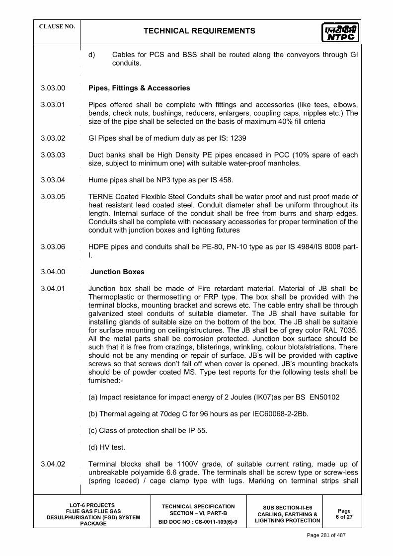
CLAUSE NO. TECHNICAL REQUIREMENTS
LOT-6 PROJECTS
FLUE GAS FLUE GAS DESULPHURISATION (FGD) SYSTEM
PACKAGE
TECHNICAL SPECIFICATION SECTION – VI, PART-B
BID DOC NO : CS-0011-109(6)-9
SUB SECTION-II-E6 CABLING, EARTHING &
LIGHTNING PROTECTION Page
6 of 27
d) Cables for PCS and BSS shall be routed along the conveyors through GI conduits.
3.03.00 Pipes, Fittings & Accessories 3.03.01 Pipes offered shall be complete with fittings and accessories (like tees, elbows,
bends, check nuts, bushings, reducers, enlargers, coupling caps, nipples etc.) The size of the pipe shall be selected on the basis of maximum 40% fill criteria
3.03.02 GI Pipes shall be of medium duty as per IS: 1239 3.03.03 Duct banks shall be High Density PE pipes encased in PCC (10% spare of each
size, subject to minimum one) with suitable water-proof manholes. 3.03.04 Hume pipes shall be NP3 type as per IS 458. 3.03.05 TERNE Coated Flexible Steel Conduits shall be water proof and rust proof made of
heat resistant lead coated steel. Conduit diameter shall be uniform throughout its length. Internal surface of the conduit shall be free from burrs and sharp edges. Conduits shall be complete with necessary accessories for proper termination of the conduit with junction boxes and lighting fixtures
3.03.06 HDPE pipes and conduits shall be PE-80, PN-10 type as per IS 4984/IS 8008 part-
I. 3.04.00 Junction Boxes 3.04.01 Junction box shall be made of Fire retardant material. Material of JB shall be
Thermoplastic or thermosetting or FRP type. The box shall be provided with the terminal blocks, mounting bracket and screws etc. The cable entry shall be through galvanized steel conduits of suitable diameter. The JB shall have suitable for installing glands of suitable size on the bottom of the box. The JB shall be suitable for surface mounting on ceiling/structures. The JB shall be of grey color RAL 7035. All the metal parts shall be corrosion protected. Junction box surface should be such that it is free from crazings, blisterings, wrinkling, colour blots/striations. There should not be any mending or repair of surface. JB’s will be provided with captive screws so that screws don’t fall off when cover is opened. JB’s mounting brackets should be of powder coated MS. Type test reports for the following tests shall be furnished:-
(a) Impact resistance for impact energy of 2 Joules (IK07)as per BS EN50102 (b) Thermal ageing at 70deg C for 96 hours as per IEC60068-2-2Bb. (c) Class of protection shall be IP 55. (d) HV test. 3.04.02 Terminal blocks shall be 1100V grade, of suitable current rating, made up of
unbreakable polyamide 6.6 grade. The terminals shall be screw type or screw-less (spring loaded) / cage clamp type with lugs. Marking on terminal strips shall
Page 281 of 487

CLAUSE NO. TECHNICAL REQUIREMENTS
LOT-6 PROJECTS
FLUE GAS FLUE GAS DESULPHURISATION (FGD) SYSTEM
PACKAGE
TECHNICAL SPECIFICATION SECTION – VI, PART-B
BID DOC NO : CS-0011-109(6)-9
SUB SECTION-II-E6 CABLING, EARTHING &
LIGHTNING PROTECTION Page
7 of 27
correspond to the terminal numbering in wiring diagrams. All metal parts shall be of non-ferrous material. In case of screw type terminals the screw shall be captive, preferably with screw locking design. All terminal blocks shall be suitable for terminating on each side the required cables/wire size. All internal wiring shall be of cu. Conductor PVC wire.
3.05.00 Terminations & Straight Through Joints 3.05.01 Termination and jointing kits for 33kV, 11 kV, 6.6 KV and 3.3 kV grade XLPE
insulated cables shall be of proven design and make which have already been extensively used and type tested. Termination kits and jointing kits shall be Pre-moulded type or heat shrinkable type. Further Cold shrinkable type termination and jointing kits are also acceptable. The Cold shrinkable type kits shall be type tested as per relevant standards. Calculation to withstand the required fault level shall also be furnished in case of cold shrinkable type kits. 33 kV, 11 kV, 6.6 KV and 3.3kV grade joints and terminations shall be type tested and Type test reports as per IS:13573 Part-II and IEC60502 shall be furnished. Also, heat shrink material shall comply with requirements of ESI 09-13 (external tests). Critical components used in cable accessories shall be of tested and proven quality as per relevant product specification/ESI specification. Cable joints and terminations should be with FRLS properties as per IEC 60754-1&2. Kit contents shall be supplied from the same source as were used for type testing. The kit shall be complete with the tinned copper solderless crimping type cable lugs & ferrule or mechanical connectors (wherein bolts are tightened that shear off at an appropriate torque) as per DIN standard suitable for aluminium compacted conductor cables. (Tender drg. no 0000-211-POE –A-51-RA of cable lug attached at the end of this chapter).
3.05.02 Straight through joint and termination shall be capable of withstanding the fault level
of 21 KA for 0.12 Sec. with dynamic peak of 52 KA for 33 KV system & of 40 kA for 0.12 sec with a dynamic peak of 100 kA for 11 kV, 6.6 KV & 3.3 KV system. Straight through joints shall have provisions for shield connection and earthing wherever required and complete with all accessories and consumables suitable for storage without deterioration at a temperature of 50 deg. C with shelf life of more than five years. 1.1 kV grade straight through joints shall also be of proven design
3.05.03 1.1 KV grade Straight Through Joint shall be of proven design. 3.06.00 Cable glands 3.06.01 Cable shall be terminated using double compression type cable glands. Testing
requirements of Cable glands shall conform to BS:6121 and gland shall be of robust construction capable of clamping cable and cable armour (for armoured cables) firmly without injury to insulation. Cable glands shall be made of heavy duty brass machine finished and nickel chrome plated. Thickness of plating shall not be less than 10 micron. All washers and hardware shall also be made of brass with nickel chrome plating Rubber components shall be of neoprene or better synthetic material and of tested quality. Cable glands shall be suitable for the sizes of cable supplied/erected.
Page 282 of 487
6190456
Line

CLAUSE NO. TECHNICAL REQUIREMENTS
LOT-6 PROJECTS
FLUE GAS FLUE GAS DESULPHURISATION (FGD) SYSTEM
PACKAGE
TECHNICAL SPECIFICATION SECTION – VI, PART-B
BID DOC NO : CS-0011-109(6)-9
SUB SECTION-II-E6 CABLING, EARTHING &
LIGHTNING PROTECTION Page
8 of 27
3.07.00 Cable lugs/ferrules 3.07.01
Cable lugs/ferrules shall be solderless crimping type suitable for power and control cables as per the DIN 46239. Aluminium solderless crimping lugs/ ferrules shall be used for Aluminium cables and Copper lugs/ferrules shall be used for Copper cables. Bimetallic washers or bimetallic type lugs shall be used for bimetallic connections. Crimping tool for crimping (from 1.5sqmm cable to 630sqmm cables) above mentioned lugs shall be of Hexagonal Type crimp profile, with suitable die of crimp match code. Characteristics of crimping tool: 1) To should generate enough pressure to pass pull out test as per IEC 61238-1.
Relevant type test to be produced for the sizes specified in the tender. 2) Tool die shall be replaceable for assorted sizes and crimp code to be mentioned
on both part the die. 3) Tool should be compliant of testing according to IEC, UL and GS standards.
Tool shall have features such as:
Auto retraction system Manual retraction stop. Feedback signals for improper pressure Better battery capacity and with status display Flexible and rotating head for easy crimping.
3.08.00 Trefoil clamps 3.08.01 Trefoil clamps for single core cables shall be pressure die cast aluminum or fibre
glass or nylon and shall include necessary fixing accessories like G.I. nuts, bolts, washers, etc. Trefoil clamps shall have adequate mechanical strength, when installed at 1 mtr intervals, to withstand the forces generated by the peak value of maximum system short circuit current.
3.09.00 Cable Clamps & Ties 3.09.01 The cable clamps/ties required to clamp multicore cables shall be of SS-316
material, 12mm wide, polyster coated ladder lock type. The clamps/ties shall have self locking arrangement & shall have sufficient strength. The cable clamps/ties shall be supplied in finished individual pieces of suitable length to meet the site requirements.
3.10.00 Receptacles 3.10.01 Receptacles boxes shall be fabricated out of MS sheet of 2mm thickness and hot
dipped gavanised or of die-cast aluminium alloy of thickness not less than 2.5 mm. The boxes shall be provided with two nos. earthing terminals, gasket to achieve IP55 degree of protection, terminal blocks for loop-in loop-out for cable of specified sizes, mounting brackets suitable for surface mounting on wall/column/structure, gland plate etc. The ON-OFF switch shall be rotary type heavy duty, double
Page 283 of 487
6190456
Line

CLAUSE NO. TECHNICAL REQUIREMENTS
LOT-6 PROJECTS
FLUE GAS FLUE GAS DESULPHURISATION (FGD) SYSTEM
PACKAGE
TECHNICAL SPECIFICATION SECTION – VI, PART-B
BID DOC NO : CS-0011-109(6)-9
SUB SECTION-II-E6 CABLING, EARTHING &
LIGHTNING PROTECTION Page
9 of 27
break,AC23 category, suitable for AC supply. Plug and Socket shall be shrouded Die-cast aluminium. Socket shall be provided with lid safety cover. Robust mechanical interlock shall be provided such that the switch can be put ON only when the plug is fully engaged and plug can be withdrawn only when the switch is in OFF position. Also cover can be opened only when the switch is in OFF position. Wiring shall be carried out with 1100 V grade PVC insulated stranded aluminium/copper wire of adequate size. The Terminal blocks shall be of 1100 V grade. The Terminal blocks shall be of 1100 V grade made up of unbreakable polymide 6.6 grade with adequate current rating and size. The welding receptacles shall be provided with RCCB/RCD of 30mA sensitivity having facility for manual testing/checking of operation of RCCB/RCD.
3.11.00 Cable Drum Lifting Jack
The jack for cable drum lifting shall be of screw type with 10 ton capacity. The cable drum jacks shall be manufactured from fabricated steel. The spindles supplied with the cable drum jack shall be manufactured using BSEN-24 grade steel bar with locking collars. Jack nests shall be of SG cast steel. Cable drum jack supplied shall have undergone load testing and reports for the same shall be submitted. At least Two Nos. of jacks shall be supplied for NTPC use. Contractor has to make arrangements for his own jacks for cable reeling/unreeling under his scope of installation.
3.12.00 Galvanising 3.12.01 Galvanising of steel components and accessories shall conform to IS:2629 , IS4759
& IS:2633. Additionally galvanising shall be uniform, clean smooth, continuous and free from acid spots.
3.12.02 The amount of zinc deposit over threaded portion of bolts, nuts, screws and
washers shall be as per IS:1367 . The removal of extra zinc on threaded portion of components shall be carefully done to ensure that the threads shall have the required zinc coating on them as specified
3.13.00 Welding 3.13.01 The welding shall be carried out in accordance with IS:9595. All welding procedures
and welders qualification shall also be followed strictly in line with IS:9595 4.00.00 INSTALLATION 4.01.00 Cable tray and Support System Installation 4.01.01 Cables shall run in cable trays mounted horizontally or vertically on cable tray
support system which in turn shall be supported from floor, ceiling, overhead structures, trestles, pipe racks, trenches or other building structures.
4.01.02 Horizontally running cable trays shall be clamped by bolting to cantilever arms and
vertically running cable trays shall be bolted to main support channel by suitable bracket/clamps on both top and bottom side rails at an interval of 2000 mm in general. For vertical cable risers/shafts cable trays shall be supported at an interval of 1000mm in general. Fixing of cable trays to cantilever arms or main support
Page 284 of 487
6190456
Line

CLAUSE NO. TECHNICAL REQUIREMENTS
LOT-6 PROJECTS
FLUE GAS FLUE GAS DESULPHURISATION (FGD) SYSTEM
PACKAGE
TECHNICAL SPECIFICATION SECTION – VI, PART-B
BID DOC NO : CS-0011-109(6)-9
SUB SECTION-II-E6 CABLING, EARTHING &
LIGHTNING PROTECTION Page
10 of 27
channel by welding shall not be accepted. Cable tray installation shall generally be carried out as per the approved guidelines/ drawings. Vendor shall design the support system along with tray, spacing etc in line with tray loadings/drawings.
4.01.03 The cantilever arms shall be positioned on the main support channel with a
minimum vertical spacing of 300 mm unless otherwise indicated. 4.01.04 The contractor shall fix the brackets/ clamps/ insert plates using anchor fasteners.
Minimum size of anchor fasteners shall be M 8 X 50 and material shall be stainless steel grade 316 or better. Anchor fastener shall be fixed as recommended by manufacturer and as approved by site engineer. For brick wall suitable anchor fasteners shall be used as per the recommendations of manufacturer. Make of anchor fasteners subject to QA approval and the same shall be finalized at pre-award stage.
4.01.05 All cable way sections shall have identification, designations as per cable way layout drawings and painted/stenciled at each end of cable way and where there is a branch connection to another cable way. Minimum height of letter shall be not less than 75 mm. For long lengths of trays, the identification shall be painted at every 10 meter. Risers shall additionally be painted/stenciled with identification numbers at every floor.
4.01.06 In certain cases it may be necessary to site fabricate portions of trays, supports and
other non standard bends where the normal prefabricated trays, supports and accessories may not be suitable. Fabricated sections of trays, supports and accessories to make the installation complete at site shall be neat in appearance and shall match with the prefabricated sections in the dimensions. They shall be applied with one coat of red lead primer, one coat of oil primer followed by two finishing coats of aluminium paint.
4.02.00 Conduits/Pipes/Ducts Installation 4.02.01 The Contractor shall ensure for properly embedding conduit pipe sleeves wherever
necessary for cabling work. All openings in the floor/roof/wall / cable tunnel/cable trenches made for conduit installation shall be sealed and made water proof by the Contractor.
4.02.02 GI pull wire of adequate size shall be laid in all conduits before installation. Metallic
conduit runs at termination shall have two lock nuts wherever required for junction boxes etc.
4.02.03 Conduit runs/sleeves shall be provided with PVC bushings having round edge at
each end. All conduits/pipes shall have their ends closed by caps until cables are pulled. After cables are pulled, the ends of conduits/pipes shall be sealed with Glass wool/Cement Mortar/Putty to prevent entrance of moisture and foreign material
4.02.04 Exposed conduit/pipe shall be adequately supported by racks, clamps, straps or by
other approved means. Conduits /pipe support shall be installed square and true to line and grade with an average spacing between the supports as given below, unless specified otherwise
Page 285 of 487

CLAUSE NO. TECHNICAL REQUIREMENTS
LOT-6 PROJECTS
FLUE GAS FLUE GAS DESULPHURISATION (FGD) SYSTEM
PACKAGE
TECHNICAL SPECIFICATION SECTION – VI, PART-B
BID DOC NO : CS-0011-109(6)-9
SUB SECTION-II-E6 CABLING, EARTHING &
LIGHTNING PROTECTION Page
11 of 27
Conduit /pipe size (dia). Spacing Upto 40 mm 1 M 50 mm 2.0 M 65-85 mm 2.5 M 100 mm and above 3.0 M 4.02.05 For bending of conduits, bending machine shall be arranged at site by the
contractor to facilitate cold bending. The bends formed shall be smooth. 4.03.00 Junction Boxes Installation 4.03.01 Junction boxes shall be mounted at a height of 1200mm above floor level or as
specified in the drawings and shall be adequately supported/mounted on masonry wall by means of anchor fasteners/ expandable bolts or shall be mounted on an angle, plate or other structural supports fixed to floor, wall, ceiling or equipment foundations.
4.04.00 Cable Installation 4.04.01 Cable installation shall be carried out as per IS:1255 and other applicable
standards. 4.04.02 For Cable unloading, pulling etc following guidelines shall be followed in general: a) Cable drums shall be unloaded, handled and stored in an approved manner
on hard and well drained surface so that they may not sink. In no case shall be drum be stored flat i.e. with flange horizontal. Rolling of drums shall be avoided as far as possible. For short distances, the drums may be rolled provided they are rolled slowly and in proper direction as marked on the drum. In absence of any indication, the drums may be rolled in the same direction as it was rolled during taking up the cables. For unreeling the cable, the drum shall be mounted on suitable jacks or on cable wheels and shall be rolled slowly so that cable comes out over the drum and not from below. All possible care shall be taken during unreeling and laying to avoid damage due to twist, kink or sharp bends. Cable ends shall be provided with sealed plastic caps to prevent damage and ingress of moisture.
b) While laying cable, ground rollers shall be used at every 2 meter interval to
avoid cable touching ground. The cables shall be pushed over the rollers by a gang of people positioned in between the rollers. Cables shall not be pulled from the end without having intermediate pushing arrangements. Pulling tension shall not exceed the values recommended by cable manufacturer. Selection of cable drums for each run shall be so planned so as to avoid using straight through joints. Care should be taken while laying the cables so as to avoid damage to cables. If any particular cable is damaged, the same shall be repaired or changed to the satisfaction of Project Manager.
Page 286 of 487

CLAUSE NO. TECHNICAL REQUIREMENTS
LOT-6 PROJECTS
FLUE GAS FLUE GAS DESULPHURISATION (FGD) SYSTEM
PACKAGE
TECHNICAL SPECIFICATION SECTION – VI, PART-B
BID DOC NO : CS-0011-109(6)-9
SUB SECTION-II-E6 CABLING, EARTHING &
LIGHTNING PROTECTION Page
12 of 27
4.04.03 Cables shall be laid on cable trays strictly in line with cable schedule 4.04.04 Power and control cables shall be laid on separate tiers inline with the approved
guidelines/drawings. The laying of different voltage grade cables shall be on different tiers according to the voltage grade of the cables. In horizontal tray stacks, H.T. cables shall be laid on top most tier and cables of subsequent lower voltage grades on lower tiers of trays. Single core cable in trefoil formation shall be laid with a distance of four times the diameter of cable between trefoil center lines and clamped at every two metre. All multicore cables shall be laid in touching formation. Power and control cables shall be secured fixed to trays/support with cable clamps/ties with self locking arrangement. For horizontal trays arrangements, multicore power cables and control cables shall be secured at every five meter interval. For vertical tray arrangement, individual multicore power cables and control cables shall be secured at every one meter. After completion of cable laying work in the particular vertical tray, all the control cables shall be binded to trays/supports by cable clamps/ties with self locking arrangement at every five meter interval and at every bend.
Fibre Optical cable shall be laid in trenches/trays or as decided by Employer. 4.04.05 Bending radii for cables shall be as per manufacturer's recommendations and
IS:1255. 4.04.06 Where cables cross roads/rail tracks, the cables shall be laid in hume pipe/ HDPE
pipe. 4.04.07 No joints shall be allowed in trip circuits, protection circuits and CT/PT circuits. Also
joints in critical equipment in main plant area shall not be permitted. Vendor shall identify and accordingly procure the cable drum length.
4.04.08 In each cable run some extra length shall be kept at suitable point to enable one
LT/two HT straight through joints to made, should the cable develop fault at a later stage. Control cable termination inside equipment enclosure shall have sufficient lengths so that shifting of termination in terminal blocks can be done without requiring any splicing.
4.04.09 Wherever few cables are branching out from main trunk route troughs shall be
used. 4.04.10 Wind loading shall be considered for designing support as well Cable trays
wherever required. 4.04.11 Where there is a considerable risk of steam, hot oil or mechanical damage cable
routes shall be protected by barriers or enclosures. 4.04.12 The installation work shall be carried out in a neat workman like manner & areas of
work shall be cleaned of all scraps, water, etc. after the completion of work in each area every day. Contractor shall replace RCC/Steel trench covers after the Installation work in that particular area is completed or when further work is not likely to be taken up for some time.
4.04.13 Separation
Page 287 of 487

CLAUSE NO. TECHNICAL REQUIREMENTS
LOT-6 PROJECTS
FLUE GAS FLUE GAS DESULPHURISATION (FGD) SYSTEM
PACKAGE
TECHNICAL SPECIFICATION SECTION – VI, PART-B
BID DOC NO : CS-0011-109(6)-9
SUB SECTION-II-E6 CABLING, EARTHING &
LIGHTNING PROTECTION Page
13 of 27
At least 300mm clearance shall be provided between: - HT power & LT power cables, - LT power & LT control/instrumentation cables, 4.04.14 Segregation 1) Segregation means physical isolation to prevent fire jumping. 2) All cables associated with the unit shall be segregated from cables of other
units. 3) Interplant cables of station auxiliaries and unit critical drives shall be
segregated in such a way that not more than half of the drives are lost in case of single incident of fire. Power and control cables for AC drives and corresponding emergency AC or DC drives shall be laid in segregated routes. Cable routes for one set of auxiliaries of same unit shall be segregated from the other set.
4) In switchyard, control cables of each bay shall be laid on separate
racks/trays. 4.04.15 Minimum number of spare cores required to be left for interconnection in control
cables shall be as follows: Minimum number of spare cores required to be left for interconnection in control
cables shall be as follows: No. of cores in cable No. of spare cores 2C,3C NIL 5C 1 7C-10C 2 14C and above 3 4.04.16 Directly Buried Cables a) Cable trenches shall be constructed for directly buried cables. Construction
of cable trench for cables shall include excavation, preparation of sieved sand bedding, riddled soil cover, supply and installation of brick or concrete protective covers, back filling and compacting, supply and installation of route markers and joint markers. Laying of cables and providing protective covering shall be as per IS:1255 and the enclosed drawings showing cabling details.
b) RCC cable route and RCC joint markers shall be provided wherever
required. The voltage grade of the higher voltage cables in route shall be engraved on the marker. Location of underground cable joints shall be
Page 288 of 487

CLAUSE NO. TECHNICAL REQUIREMENTS
LOT-6 PROJECTS
FLUE GAS FLUE GAS DESULPHURISATION (FGD) SYSTEM
PACKAGE
TECHNICAL SPECIFICATION SECTION – VI, PART-B
BID DOC NO : CS-0011-109(6)-9
SUB SECTION-II-E6 CABLING, EARTHING &
LIGHTNING PROTECTION Page
14 of 27
indicated with cable marker with an additional inscription "Cable Joint". The marker shall project 150 mm above ground and shall be spaced at an interval of 30 meters and at every change in direction. They shall be located on both sides of road crossings and drain crossings. Top of cable marker/joint marker shall be sloped to avoid accumulation of water/dust on marker.
4.04.17 Cable tags shall be provided on all cables at each end (just before entering the
equipment enclosure), on both sides of a wall or floor crossing, on each duct/conduit entry, and at every 20 meters in cable tray/trench runs. Cable tags shall also be provided inside the switchgear, motor control centers, control and relay panels etc. where a number of cables enter together through a gland plate. Cable tag shall be of rectangular shape for power cables and control cables. Cable tag shall be of 2 mm thick aluminum with number punched on it and securely attached to the cable by not less than two turns of 20 SWG GI wire conforming to IS:280. Alternatively, the Contractor may also provide cable tags made of nylon, cable marking ties with cable number heat stamped on the cable tags. The cable tag requirements mentioned above shall prevail over Tag requirements mentioned elsewhere in this document for HT power, LT power & control cables.
4.04.18 While crossing the floors, unarmoured cables shall be protected in conduits upto a
height of 500 mm from floor level if not laid in tray. 4.05.00 Cable Terminations & Connections 4.05.01 The termination and connection of cables shall be done strictly in accordance with
cable termination kit manufacturer'' instructions, drawings and/or as directed by Project Manager. Cable jointer shall be qualified to carryout satisfactory cable jointing/termination. Contractor shall furnish for review documentary evidence/experience reports of the jointers to be deployed at site.
4.05.02 Work shall include all clamps, fittings etc. and clamping, fitting, fixing, plumbing,
soldering, drilling, cutting, taping, preparation of cable end, crimping of lug, insulated sleeving over control cable lugs, heat shrinking (where applicable), connecting to cable terminal, shorting and grounding as required to complete the job to the satisfaction of the Project Manager.
4.05.03 The equipment will be generally provided with undrilled gland plates for
cables/conduit entry. The Contractor shall be responsible for punching of gland plates, painting and touching up. Holes shall not be made by gas cutting. The holes shall be true in shape. All cable entry points shall be sealed and made vermin and dust proof. Unused openings shall be effectively sealed by 2mm thick aluminium sheets.
4.05.04 Control cable cores entering control panel/switchgear/MCC/miscellaneous panels
shall be neatly bunched, clamped and tied with self locking type nylon cable ties with de interlocking facility to keep them in position.
4.05.05 All the cores of the control cable to be terminated shall have identification by providing ferrules at either end of the core, each ferrule shall be indelible, printed single tube ferrule and shall include the complete wire number and TB number as
Page 289 of 487

CLAUSE NO. TECHNICAL REQUIREMENTS
LOT-6 PROJECTS
FLUE GAS FLUE GAS DESULPHURISATION (FGD) SYSTEM
PACKAGE
TECHNICAL SPECIFICATION SECTION – VI, PART-B
BID DOC NO : CS-0011-109(6)-9
SUB SECTION-II-E6 CABLING, EARTHING &
LIGHTNING PROTECTION Page
20 of 27
7.02.00 Type Test reports shall be furnished for the following 7.02.01 Type tests on Cable Trays support system a) Test 1A:
On main support channel type-C2 for cantilever arms fixed on one side only. A 3.5 meter length of main support channel shall be fixed vertically at each end to a rigid structure as per the fixing arrangement as shown in the enclosed drawing. Eight (8) nos. 750 mm cantilever arms shall be fixed to the main channel and each arm shall be loaded over the outboard 600 mm with a uniform working load of 100 kg. Subsequently a point load of 100 kg shall be applied on arm 2. A uniform proof load on all the arms equal to twice the working load shall be then be applied. Deflections shall be measured at the points shown in the enclosed drawings and at the following load intervals:
i) Working load ii) Working load + point load iii) Off load iv) Proof load + point load v) Off load
The deflection measured at working loads shall not exceed 16mm. The permanent deflection after removing the combination of working load and point load shall not exceed 10 mm at the arm tips and 6 mm on the channel. No collapse of the structure shall occur with a combination of proof load and point load applied.
B) Test 1B:
Test 1A shall be repeated with Eight Cantilever arms uniformly loaded and with the same point load on arm 2
Test 2: On Main support channel type -C2 for cantilever arms fixed on
both sides
a) Test 2A: A 3.5 m length of main support channel C2 for cantilever arms fixing on both sides shall be fixed at each end to rigid structure as per the fixing arrangement as shown in the enclosed drawing. Six (6), 750 mm cantilever arms shall be attached to each sides and each arm uniformly loaded to a working load of 100 kg over the out board 600 mm. A point load of 100 kg shall than be applied to arm 2, followed by a uniform proof load of twice the working load on all the arms; deflection shall be measured at points shown in the enclosed drawings at the following load intervals.
i) Working load
Page 290 of 487

CLAUSE NO. TECHNICAL REQUIREMENTS
LOT-6 PROJECTS
FLUE GAS FLUE GAS DESULPHURISATION (FGD) SYSTEM
PACKAGE
TECHNICAL SPECIFICATION SECTION – VI, PART-B
BID DOC NO : CS-0011-109(6)-9
SUB SECTION-II-E6 CABLING, EARTHING &
LIGHTNING PROTECTION Page
21 of 27
ii) Working load + Point load iii) Off load iv) Proof load + Point load v) Off load
The deflection measured at working loads shall not exceed 16mm. The permanent deflection after removing the combination of working load and point load shall not exceed 10 mm at the arm tips and 6 mm on the channel. No collapse of the structure shall occur with a combination of proof load and point load applied
b) Test 2 B: The test 2 A shall be repeated with the assembly but with an
asymmetrical load on the C2 column and point load applied to arm 8. The 100 kg and 200 kg uniformly distributed loads shall be applied to the upper three arms on one side and the lower three arms on the opposite side.
Test 3 : Tests on Channel Fixed on Beam/Floor A length of main support channel section shall be fixed to steel structure/floor and
have loads applied as shown in the drawing enclosed and as detailed below a) Test 3A : A length of steel structure shall be rigidly supported. It should be
fitted on a meter length of channel section using beam clamps welded/bolted. A point load of 1200 kg shall be applied to the centre point via two brackets. No distortion or pulling of the components shall take place.
b) Test 3B: With the components assembled as in Test 3A, two perpendicular
point loads of 600 kg shall be simultaneously applied at positions 150 mm either side of the centre line, no distortion or pulling of the components shall take place.
c) Test 3C: With the components assembled as in Test 3A, a perpendicular point
load shall be applied at a point 150 mm on one side of the centre line. The load shall be gradually increased to the maximum value that can
be applied without causing distortion or pulling of the components. This value shall be recorded.
Test 4 : Channel Insert Test A 2.5 m length of C1 channel fixed to the concrete wall/ steel structure
as per actual site installation conditions. 6 nos. of 750 mm cantilever arms shall be attached to C1 channel as shown in enclosed drawing. Each arm uniformly loaded to a working load of 100 kg over the out board 600 mm. A point load of 100 kg shall than be applied to arm 2, followed by a uniform proof load of twice the working load on all the arms; deflection shall be measured at points shown in the enclosed drawings at the following load intervals.
Page 291 of 487

CLAUSE NO. TECHNICAL REQUIREMENTS
LOT-6 PROJECTS
FLUE GAS FLUE GAS DESULPHURISATION (FGD) SYSTEM
PACKAGE
TECHNICAL SPECIFICATION SECTION – VI, PART-B
BID DOC NO : CS-0011-109(6)-9
SUB SECTION-II-E6 CABLING, EARTHING &
LIGHTNING PROTECTION Page
22 of 27
i) Working Load
ii) Working Load + Point Load
iii) Off Load
iv) Proof Load + Point Load
v) Off load
The deflection measured at working loads shall not exceed 16mm. The permanent deflection after removing the combination of working load and point load shall not exceed 10 mm at the arm tips and 6 mm on the channel. No collapse of the structure shall occur with a combination of proof load and point load applied
Test 5 : Channel nut slip characteristics (what ever applicable)
Tests 5A1,5A2,5A3 : A length of channel C1 section 200mm long shall have fitted bracket with the two bolt fixing as shown in drawing enclosed.
With loads applied at the position shown in drawing enclosed nut slip shall be determined with bolt torque of 30NM, 50 NM and 65 NM No fewer than three measurements shall be made for each torque setting.
A minimum loading of 720 kg shall be obtained before nut slip with bolt torque
of 65 NM. Tests 5B1,5B2,5B3: The length of channel C1 section 200 mm long shall have
fitted bracket with the one bolt fixing as shown in drawing enclosed. With loads applied at the position shown in drawing, nut slip shall be determined with bolt torques of 30 NM, 50 NM and 65 NM. No fewer than three measurements shall be made for each torque setting.
A minimum loading of 350 kg shall be obtained before nut slip with a bolt torque
of 65 NM. Test 6 Weld Integrity Test After deflection test as per test 1A, 1B, 2, 3 & 4 weld integrity shall be checked
by magnetic particle inspection to detect sub-surface cracks developed, if any. 7.02.02 Cable termination kit and straight through joints should have been tested as per
IS:13573 for 3.3kV grade & above. 7.03.00 Routine/ Acceptance Tests 7.03.01 Routine Tests
a) Routine tests as per specification and applicable standards shall be carried out on all requirements/items covered in the specification.
Page 292 of 487

CLAUSE NO. TECHNICAL REQUIREMENTS
LOT-6 PROJECTS
FLUE GAS FLUE GAS DESULPHURISATION (FGD) SYSTEM
PACKAGE
TECHNICAL SPECIFICATION SECTION – VI, PART-B
BID DOC NO : CS-0011-109(6)-9
SUB SECTION-II-E6 CABLING, EARTHING &
LIGHTNING PROTECTION Page
23 of 27
b) Physical & dimensional check on all equipments as per approved drawings/standards
. c) HV/IR as applicable. d) Check/measurement of thickness of paint/zinc coating/nickel-chrome plating
as per specification & applicable standard. 7.03.02 Acceptance Test a) Galvanising Tests as per applicable standards b) Welding checks
c) Deflection tests on cable trays: d) One piece each of 2.5m length of cable tray of 300mm & above shall be
taken as sample from each offered lot. It shall be supported at both end & loaded with uniform load of 76 kg/meter along the length of cable tray. The maximum deflection at the mid-span of each size shall not exceed 7mm.
d) Proof load tests on cable tray support system
i) Tests on Main Support Channel shall be done if only C1 Channel are in scope of supply and cantilever arms shall be fitted on one side. This test shall be same as test 4 of type test.
ii) Test on Main Support Channel shall be done with C2 channel and cantilever
arms fitted on both sides, if C2 channels are in scope of supply. This test shall be same as test 2A of type test. Then test (i) above shall not be done.
iii) Nut slip characteristic test (it shall support minimum load of 350kg before nut slips with a bolt torque of 65 NM). This test shall be same as test 5B3 of type test.
The procedure for carrying out tests at “d” above shall be as per details given in Type Tests in specification thereafter Die-Penetration test shall be carried out to check weld integrity.
e) The above acceptance tests shall be done only on one sample from each
offered lot. 8.00.00 COMMISSIONING 8.01.01 The Contractor shall carry out the following commissioning tests and checks after
installation at site. In addition the Contractor shall carry out all other checks and tests as recommended by the Manufacturers or else required for satisfactory performance..
8.01.02 Cables
Page 293 of 487
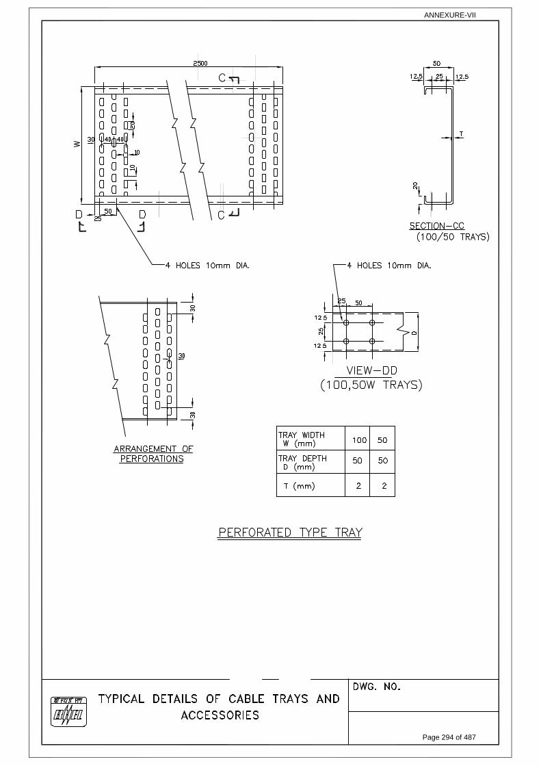
ANNEXURE-VII
Page 294 of 487
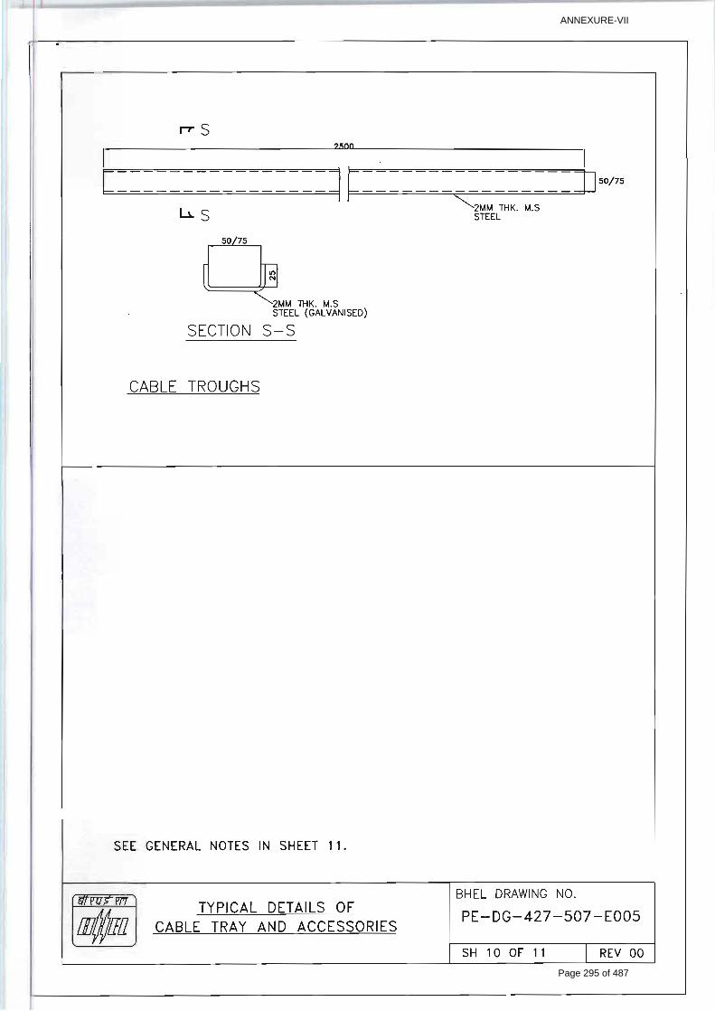
ANNEXURE-VII
Page 295 of 487
SIPAT STAGE-II, 2X500MW FGD
COMPRESSED AIR SYSTEM
SPECIFICATION No: PE-TS-491-555-A001
VOLUME: II B
SECTION : C-4
REV. 00 DATE: JULY 22
SHEET: 1 OF 1
SECTION: C-4 TECHNICAL SPECIFICATION (C&I PORTION)
Page 296 of 487

� ���������������� �������������������
��������������������������������������������������� ��������������
�
����������
�����������
������������� �
�������������
�������������
����������������� �������������������
�
!�
���
���
��"#
###"
��
�
�
� ����$��
�������� �����������
�� ������������
�� ����$�������
%� �����!���������������&����������'�(�)�
� ������������(�������������!��������
*� ��������$���������+�����������(�����
#� �����������������������
�� &�����,�����������!��������������
�� ��������������
�� ��������������������������+����
��� �����������������������������������������,�
� �
Page 2 of 100
Page 297 of 487

� ���������������� �������������������
��������������������������������������������������� ��������������
�
����������
�����������
������������� �
�������������
�������������
����������������� �������������������
�
!�
���
���
��"#
###"
��
�
��
� ���������
�����!���������������&����������'�(�)��
��
� � �
Page 3 of 100
Page 298 of 487

� ���������������� �������������������
��������������������������������������������������� ��������������
�
����������
�����������
������������� �
�������������
�������������
����������������� �������������������
�
!�
���
���
��"#
###"
��
�
������������������ !�������
�-.�/.456/.7.89:�68�9-6:�:.;96<8�=/.�:>.;6?6;�?</�9-6:�>/<@.;9���8�;=:.�<?�=8A�;<89/=B6;96<8�C.9D..8� 9-6:������!���������������&����������=8B�;5:9<7./������!�������=99=;-.B� ?5/9-./E� 9-.�;5:9<7./������!�������:-=FF�>/.G=6F�=8B����H:�B.;6:6<8�:-=FF�C.�?68=F��������9<�;<7>FA�9-.�:9/68I.89�/.456/.7.89�=:�>./�����B.;6:6<8�D69-<59�=8A�;<77./;6=F�</�967.�67>F6;=96<8��
���� �<7>F.9.� ;<7>/.::.B� =6/� :A:9.7� ;<7>/6:68I� <?� ?6.FB� 68:9/57.89:E� ;<89/<F� :A:9.7E�
./.;96<8E�7=9./6=F� .9;�� 6:� 68�6BB./J:� :;<>.�<?� :5>>FA���������������� �,����� ?</�!���>F=89�6:��6;/<>/<;.::</�C=:.B�:A:9.7�D69-�<>./=9</�689./?=;.�=8B�6:�;<77<8�?</�9D<�5869:���
��� �89.I/=9.B� 76;/<>/<;.::</� C=:.B� ;<89/<F� :A:9.7� =F<8I� D69-� :569=CF.� <>./=9</� 689./?=;.�:-=FF� C.� >/<G6B.B� ?</� .=;-� �8:9/57.89� �6/� �<7>/.::</E� �./G6;.� �6/� �<7>/.::</� (� 9-.6/��/A./:���FF�9/=8:7699./�:5;-�=:���E����E����=8B�<9-./�68:9/57.89:�68:6B.�=8B�<59:6B.�9-.�;<7>/.::</� :K6B� :-=FF� =F:<� C.� -<<K.B� 5>� 9<� 9-6:� :A:9.7�� �<7>/.::</:� ;<88.;96G69A� 9<�!��� ���� '!��� ���� 68� ���� :;<>.)� :-=FF� C.� >/<G6B.B� ?</� 68?</7=96<8� =8B� <G./=FF�;<89/<F��
�%�� �-.�<>./=96<8=F�?=;6F69A�<?�.=;-�;<7>/.::</�:-=FF�=F:<�C.�>/<G6B.B�?/<7�68B.>.8B.89�F<;=F�
;<89/<F�>=8.F�B.B6;=9.B�?</�.=;-�;<7>/.::</�=8B�<8.�'�)�F<;=F�;<89/<F�>=8.F�?</��6/��/A68I��F=89�:-=FF�C.�>/<G6B.B��
� �� �8858;6=96<8� D68B<D:� =8B� -<<9./� D6FF� C.� B/6G.8� ?/<7� 76;/<>/<;.::</� L� 76;/<;<89/<FF./�
<59>59� ;=/B� =8B� /.456/.B� =8858;6=96<8� :.45.8;.� D6FF� C.� >/<I/=77.B� 68� =>>F6;=96<8�:<?9D=/.�<?�76;/<>/<;.::</L�76;/<;<89/<FF./�C=:.B�;<89/<F�:A:9.7��
�*�� �FF� 68B6;=96<8:�<8� 9-.�>=8.FE�=8B� 6FF5768=96<8�<?�=8858;6=96<8�D68B<D:�:-=FF�C.�>/<G6B.B�
D69-�;F5:9./.B�����<?�/.456/.B�;<F</:�=:�=>>F6;=CF.���
#�� �FF� ;<77=8B:� ?/<7� :9=96<8� !��� ���� 9<� ?6.FB� B.G6;.:E� ���L�+��� :-=FF� C.� 9-/<5I-�689./><:68I�/.F=A:�=8B�:-=FF�C.�/<59.B�9-/<5I-�76;/<;<89/<FF./:�<?�68B6G6B5=F�;<7>/.::</:��
���� �/<G6:6<8� :-=FF� =F:<� C.� 7=B.� 9<� -<<K"5>� 9-.� ;<7>/.::</� ;<89/<F� :A:9.7� D69-� �������
9-/<5I-� -=/BD=/.� 689./?=;.� ?</� /.7<9.� :9=/9L:9<>� =8B� ?..BC=;K� 9<L?/<7� ������� =8B�7<869</68I�<?�;/696;=F�>=/=7.9./:�<?�;<7>/.::</:�=8B�=6/�B/A68I�>F=89:���
��� �8�=BB696<8�9<�69E��<?9�:6I8=F�.M;-=8I.�C.9D..8�9-.�76;/<>/<;.::</�9<�!�������:-=FF�C.�689./?=;.B�9-/<5I-��<BC5:�<8���" �*�G6=�9D6:9.B�>=6/�;=CF.�'68�C6BB./H:�:;<>.)�?</�7<869</68I�=FF� 9-.�>=/=7.9./:�=8B� :9=95:� ?..BC=;K�<?� B/6G.:� <?� ;<7>/.::.B�=6/� :A:9.7���-.� �.D� ><689� 7.=:5/.7.89� ?/<7� !��� ���� 9<� =FF� 9-.� ;<7>/.::</:� (� 9-.6/� :9=95:�?..BC=;K:�9<�!�������:-=FF�=F:<�C.�>/<G6B.B��
�
Page 4 of 100
Page 299 of 487
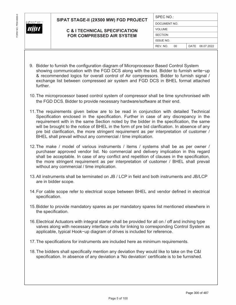
� ���������������� �������������������
��������������������������������������������������� ��������������
�
����������
�����������
������������� �
�������������
�������������
����������������� �������������������
�
!�
���
���
��"#
###"
��
�
��
��� 6BB./�9<�?5/86:-�9-.�;<8?6I5/=96<8�B6=I/=7�<?��6;/<>/<;.::</�=:.B��<89/<F��A:9.7�:-<D68I�;<77586;=96<8�D69-�9-.�!�������=F<8I�D69-�9-.�C6B��6BB./�9<�?5/86:-�D/69.O5>�(� /.;<77.8B.B� F<I6;:� ?</� <G./=FF� ;<89/<F� <?��6/� ;<7>/.::</:��6BB./� 9<� ?5/86:-� :6I8=F� L�.M;-=8I.� F6:9�C.9D..8�;<7>/.::.B�=6/�:A:9.7�=8B�!������� 68����� ?</7=9�=99=;-.B�?5/9-./���
�����-.�76;/<>/<;.::</�C=:.B�;<89/<F�:A:9.7�<?�;<7>/.::</�:-=FF�C.�967.�:A8;-/<86:.B�D69-�9-.�!��������6BB./�9<�>/<G6B.�8.;.::=/A�-=/BD=/.L:<?9D=/.�=9�9-.6/�.8B��
������-.� /.456/.7.89:� I6G.8� C.F<D� =/.� 9<� C.� /.=B� 68� ;<8@58;96<8� D69-� B.9=6F.B� �.;-86;=F�
�>.;6?6;=96<8� .8;F<:.B� 68� 9-.� :>.;6?6;=96<8�� !5/9-./� 68� ;=:.� <?� =8A� B6:;/.>=8;A� 68� 9-.�/.456/.7.89�D69-� 68� 9-.�:=7.��.;96<8�8<9.B�CA� 9-.�C6BB./� 68� 9-.�:>.;6?6;=96<8E� 9-.�:=7.�D6FF�C.�C/<5I-9�9<�9-.�8<96;.�<?�����68�9-.�?</7�<?�>/.�C6B�;F=/6?6;=96<8���8�=C:.8;.�<?�=8A�>/.� C6B� ;F=/6?6;=96<8E� 9-.� 7</.� :9/68I.89� /.456/.7.89� =:� >./� 689./>/.9=96<8� <?� ;5:9<7./� L�����:-=FF�>/.G=6F�D69-<59�=8A�;<77./;6=F�L�967.�67>F6;=96<8��
������-.� 7=K.� L� 7<B.F� <?� G=/6<5:� 68:9/57.89:� L� 69.7:� L� :A:9.7:� :-=FF� C.� =:� >./� <D8./� L�
>5/;-=:./� =>>/<G.B� G.8B</� F6:9�� �<� ;<77./;6=F� =8B� B.F6G./A� 67>F6;=96<8� 68� 9-6:� /.I=/B�:-=FF�C.�=;;.>9=CF.���8�;=:.�<?�=8A�;<8?F6;9�=8B�/.>.9696<8�<?�;F=5:.:�68�9-.�:>.;6?6;=96<8E�9-.� 7</.� :9/68I.89� /.456/.7.89� =:� >./� 689./>/.9=96<8� <?� ;5:9<7./� L� ���� :-=FF� >/.G=6F�D69-<59�=8A�;<77./;6=F�L�967.�67>F6;=96<8��
��%���FF�68:9/57.89:�:-=FF�C.�9./768=9.B�<8���L�����68�?6.FB�=8B�C<9-�68:9/57.89:�=8B��L����
=/.�68�C6BB./�:;<>.���
� ��!</�;=CF.�:;<>.�/.?./�9<�.F.;9/6;=F�:;<>.�C.9D..8�����=8B�G.8B</�B.?68.B�68�.F.;9/6;=F�:>.;6?6;=96<8��
��*��6BB./�9<�>/<G6B.�7=8B=9</A�:>=/.:�=:�>./�7=8B=9</A�:>=/.:�F6:9�7.896<8.B�.F:.D-./.�68�
9-.�:>.;6?6;=96<8���
�#���F.;9/6;=F��;95=9</:�D69-�689.I/=F�:9=/9./�:-=FF�C.�>/<G6B.B�?</�=FF�<8�L�<??�=8B�68;-68I�9A>.�G=FG.:�=F<8I�D69-�8.;.::=/A�689./?=;.�5869:�?</�F68K68I�9<�;<//.:><8B68I��<89/<F��A:9.7�=:�=>>F6;=CF.E�9A>6;=F��<<KO5>�B6=I/=7�<?�B/6G.:�6:�68;F5B.B�?</�/.?./.8;.���
�����-.�:>.;6?6;=96<8:�?</�68:9/57.89:�=/.�68;F5B.B�-./.�=:�7686757�/.456/.7.89:����
�����-.�C6BB./:�:-=FF�:>.;6?6;=FFA�7.896<8�=8A�B.G6=96<8�9-.A�D<5FB�F6K.�9<�9=K.�<8�9-.��(��:>.;6?6;=96<8���8�=C:.8;.�<?�=8A�B.G6=96<8�=�Q�<�B.G6=96<8H�;./96?6;=9.�6:�9<�C.�?5/86:-.B��
Page 5 of 100
Page 300 of 487

� ���������������� �������������������
��������������������������������������������������� ��������������
�
����������
�����������
������������� �
�������������
�������������
����������������� �������������������
�
!�
���
���
��"#
###"
��
�
��
�����-.� 45=8969A� <?� 68:9/57.89:� ?</� 9-.� :A:9.7� :-=FF� C.� =:� >./� 9.8B./� �� (��� D-./.G./�>/<G6B.B�<?� 9-.� /.:>.;96G.�:A:9.7�=:�=�7686757E� ?</�C6BB68I�>5/><:.���<D.G./E�6BB./�:-=FF�=F:<�68;F5B.�68�-6:�>/<><:=F�=FF�9-.�68:9/57.89:�=8B�B.G6;.:�9-=9�=/.�8..B.B�?</�9-.�;<7>F.9.8.::�<?�9-.�>F=89�=5M6F6=/A�:A:9.7�L�.456>7.89�:5>>F6.B�CA�9-.�C6BB./E�.G.8�6?�9-.�:=7.�6:�8<9�:>.;6?6;=FFA�=>>.=/68I�68�9-.���(������5/68I�B.9=6F�.8I68../68I�6?�=8A�=BB696<8=F�68:9/57.89:� =/.� /.456/.B� ?</� :=?.� (� /.F6=CF.� <>./=96<8� <?� >F=89E� C6BB./� :-=FF� :5>>FA� 9-.�:=7.� D69-<59� =8A� >/6;.� L� 967.� 67>F6;=96<8�� �-.� ;<89/=;9</� :-=FF� >/<G6B.� ;<7>F.9.��8:9/57.89=96<8�?</�;<89/<FE�7<869</68I�=8B�<>./=96<8�<?�.896/.�������
�����6BB./�9<�9./768=9.�=FF�68:9/57.89=96<8�=8B�;<89/<F�.F.7.89:�68�@58;96<8�C<M.:����
�����FF� 9-.� 9/=8:7699./:� L� 9/=8:B5;./:� :5>>F6.B� CA� C6BB./� :-=FF� C.� /=;K� 7<589.B�� �-.�9/=8:7699./� /=;K:� :-=FF� C.� 68� C6BB./J:� :;<>.� <?� :5>>FA�� �FF� 9/=8:7699./:� :-=FF� C.� �����;<7>=96CF.���
����6BB./� 9<�>./?</7�9.:9:�<?��(�� 69.7:�L� 68:9/57.89:� L�:A:9.7:�=:�>./�&5=F69A�>F=8:� L� 9A>.�9.:9�=99=;-.B�68�9-.�:>.;6?6;=96<8���<D.G./E�6?�=8A�9.:9�8<9�:>.;6?6.B�68�9-.�45=F69A�>F=8�C59�:>.;6?6.B�68�:>.;6?6;=96<8��.:9:�?</��(��.456>7.89�68;F5B.B�.F:.D-./.�68�:>.;6?6;=96<8�D6FF�-=G.�9<�>./?</7�CA�6BB./�D69-<59�=8A�;<:9�67>F6;=96<8���
�%����8:9/57.89�68:9=FF=96<8�=8B�=;;.::</6.:�/.456/.B�?</�9-.�:=7.�:-=FF�C.�68�6BB./J:�:;<>.�=8B� :-=FF� C.� :5C7699.B� =?9./� =D=/B� <?� ;<89/=;9�� �<D.G./E� =8A� 68:9/57.89L� =8=FAS./�68:9=FF=96<8� 8<9� ;<G./.B� 68� 9-.� :=7.� :-=FF� C.� :5C@.;9� 9<� ;5:9<7./� =8B� ���� =>>/<G=F�B5/68I�B.9=6F.B�.8I68../68I��
�� ��6BB./�9<�>/<G6B.�9.7>./=95/.�9/=8:7699./:�?</�=FF�9-.����J:�L��-./7<;<5>F.:E��L�=;K�(�
<9-./�./.;96<8�-=/BD=/.���.7>./=95/.�.F.7.89:�:-=FF�C.�:5>>F6.B�D69-�9-./7<"D.FF���
�*���/.::5/.�I=5I.:E�>/.::5/.�:D69;-.:�=8B�>/.::5/.�L�B6??./.896=F�>/.::5/.�9/=8:7699./:�:-=FF�C.� >/<G6B.B� D69-� B6=>-/=I7� :.=F� 68� ;=:.� <?� B6/9AE� ;<//<:6G.� (� G6:;<5:� ?F56B� =>>F6;=96<8���6=>-/=I7�7=9./6=F�:-=FF�C.�:569=CF.�?</�>/<;.::�?F56B���676F=/FAE�9-.�D.99.B�>=/9�7=9./6=F�?</� F.G.F� 9/=8:7699./� L� :D69;-.:� L� I=5I.:� L� =8=FA:./:� 68� ;<//<:6G.� =>>F6;=96<8� :-=FF� -=G.�:569=CF.�I/=B.�7=9./6=F� ;<7>=96CF.�D69-� 9-.�;<//<:6G.� ?F56B� 68�;<89=;9�� �8�=FF� <9-./� ;=:.:�7=9./6=F�I/=B.�<?�9-.�D.99.B�>=/9�:-=FF�68�8<�;=:.�C.�F<D./�9-=8�:9=68F.::�:9..F�58F.::�9-.�>/<;.::�?F56B�;=FF:�?</�:<7.�<9-./�7=9./6=F���
�#��6BB./�9<�?5/86:-�.F.;9/6;=F�F<=BL����F<=B�B=9=�B5/68I�B.9=6F.B�.8I68../68I��
Page 6 of 100
Page 301 of 487

� ���������������� �������������������
��������������������������������������������������� ��������������
�
����������
�����������
������������� �
�������������
�������������
����������������� �������������������
�
!�
���
���
��"#
###"
��
�
��
��������:5>>FA�'�%������)�:-=FF�C.�>/<G6B.B�CA�����=9�=�:68IF.�><689E�?5/9-./�B6:9/6C596<8�9<�G=/6<5:� 68:9/57.89:� L� �456>7.89H:� <?� 9-.� :A:9.7� :-=FF� C.� 68� C6BB./� :;<>.�� 6BB./� 9<�68;F5B.�8.;.::=/A�><D./�B6:9/6C596<8�C<=/B� 68� 9-.6/�:;<>.���8A�><D./�:5>>FA�<9-./� 9-=8�9-.�=C<G.E�6?�/.456/.B�CA�=8A�68:9/57.89�L�.456>7.89�-=:�9<�C.�B./6G.B�CA�9-.�C6BB./�?/<7�9-.�=C<G.�:5>>FA�(�=FF�8.;.::=/A�-=/BD=/.�?</�9-.�:=7.�:-=FF�C.�68�C6BB./�:;<>.��6BB./�9<�:5C769�9-.�����><D./�/.456/.7.89�=F<8I�D69-�9-.�C6B���9=96;��D69;-�C=:.B��-=8I.<G./�:;-.7.� ?</� /.B58B=89�����!..B./:�:-=FF�C.�5:.B�� �9�:-=FF�C.�.8:5/.B� 9-=9�;-=8I.<G./�967.�C.9D..8�?..B./:�:-=FF�C.�:5;-�9-=9�9-=9�;<7>/.::</�;<89/<FF./� ?=6F5/.�:-=FF�8<9� 9=K.�>F=;.�B5/68I�;-=8I.<G./���
�����<89/=;9</�:-=FF�?5/86:-��8:9/57.89��;-.B5F.E��L�F6:9E��/6G.�F6:9E��=CF.��;-.B5F.E��=CF.�689./;<88.;96<8E���I/<5>68IE��8858;6=96<8�F6:9E����F6:9E��6:9�<?��8:9/57.89:�L�B.G6;.:�?</������ 68� ���� =>>/<G.B� ?</7=9�� �-.� /.5:=CF.� B=9=C=:.� ?</7=9� F6K.� ��� �M;.FE� ����;;.::�.9;��<?� 9-.:.�B<;57.89:�:-=FF�=F:<�C.�>/<G6B.B�CA�;<89/=;9</� 68�����=>>/<G.B�?</7=9���<?9�;<>A�<?�9-.�?</7=9:�:-=FF�C.�>/<G6B.B�9<�9-.�:5;;.::?5F�C6BB./���
�����89./?=;.� <?� ���E� ��� �+��E� ?6.FB� 68:9/57.89:E� �;95=9</:� .9;�� D69-� ������� C=:.B�;<89/<F� :A:9.7� :-=FF� C.� =:� >./� �/6G.� �<89/<F� �-6F<:<>-A� L� D6/68I� B6=I/=7� .8;F<:.B� 68�:>.;6?6;=96<8���
%����-.�:<F.8<6B�<>./=9.B�G=FG.:�L��=7>./:�L��=9.�:-=FF�-=G.�=�F6769�:D69;-�?</�<>.8L;F<:.�?..BC=;K���<F.8<6B�G=FG.�:-=FF�C.�/=9.B�?</�� ������<8FA���
%����6;/<>/<;.::</�C=:.B�;<89/<F�:A:9.7�:-=FF�-=G.�/.B58B=89�>/<;.::</L;<89/<FF./���
%����.B58B=8;A�<?�:.8:</:�:-=FF�C.�>/<G6B.B��)��/6>F.�/.B58B=8;A�?</�=FF�=8=F<I�=8B�C68=/A�68>59:�/.456/.B�?</�>/<9.;96<8�<?��A:9.7:�L�B/6G.:��)� !</� =FF� ;<89/<F� ?58;96<8:� B5=F� /.B58B=8;A� <?� 9-.� :.8:</:� :-=FF� C.� >/<G6B.B� CA� 9-.�C6BB./���
%%���<5CF.�/<<9�G=FG.:�:-=FF�C.�>/<G6B.B�?</�=FF�>/.::5/.�9=>68I:�D-./.�9-.�>/.::5/.�������.M;..B:� ��KIL;7����% ���:.�<?�>/<;.::�=;95=9.B�:D69;-.:�:-=FF�C.�=G<6B.B�58F.::�69�6:�>/<>/6.9=/A�/.456/.7.89��
�%*���57C./�<?�>=6/�9<�C.�:.F.;9.B�?</�:;/..8�;<89/<F�;=CF.�'�6S.����*�77�)��
!O9A>.��� � ��L �L��L������ �O9A>.��� � ��L �L��L������ �</.��=CF.�� � %�$��*:477�L�*�$��*:477�L����$��*:477��
Page 7 of 100
Page 302 of 487

� ���������������� �������������������
��������������������������������������������������� ��������������
�
����������
�����������
������������� �
�������������
�������������
����������������� �������������������
�
!�
���
���
��"#
###"
��
�
�� �
���������
������������(�������������!��������
Page 8 of 100
Page 303 of 487

SUB-SECTION-III-C2
MEASURING INSTRUMENTS (PRIMARY AND SECONDARY)
Page 9 of 100
Page 304 of 487

1.00.00 MEASURING INSTRUMENTS (PRIMARY AND SECONDARY)
1.01.00 Measuring instruments/equipment and subsystems offered by the Bidder shall be from reputed experienced manufacturers of specified type and range of equipment, whose guaranteed and trouble free operation has been proven. Refer Sub-section Basic Design Criteria. Further, all instruments shall be of proven reliability, accuracy, and repeatability requiring a minimum of maintenance and shall comply with the acceptable international standards and shall be subject to Employer's approval.
1.02.00 Every panel-mounted instrument requiring power supply shall be provided with easily replaceable glass cartridge fuses of suitable rating. Every instrument shall be provided with a grounding terminal and shall be suitably connected to the panel grounding bus.
1.03.00 All transmitters, sensors, switches and gauges for parameters like pressure, temperature, level, flow etc. as required for the safe and efficient operation and maintenance as well as for operator and management information (including all computation) of equipment in the system under the scope of specification shall be provided on as required basis with in quoted lump sum price. The Contractor shall furnish all Instrumentation / Control equipment & accessories under this specification as per technical specification, ranges, makes & model as approved by the Employer during detailed engineering.
1.04.00 The necessary root valves, impulse piping, drain cocks, gauge-zeroing cocks, valve manifolds and all the other accessories required for mounting/erection of these local instruments shall be furnished, even if not specifically asked for, on as required basis. The contacts of equipment mounted instruments, sensors, switches etc. for external connection including spare contacts shall be wired out in flexible/rigid conduits, independently to suitably located common junction boxes. The proposal shall include the necessary cables, flexible conduits, junction boxes and accessories for the above purpose. Double root valves shall be provided for all pressure tapping where the pressure exceeds 40 Kg./sq.cm.
1.05.00 All instruments envisaged for sea water applications, shall be provided with wetted parts made of Monel/ Hastelloy C or any other material (if provenness experience of the proposed material for such applications is established by contractor).
For Chlorine application: Instruments shall be provided with wetted parts (e.g. diaphragm seal, etc.) made of Hastelloy C. Also, filled liquid shall be Fluorolube oil/ Inert Hydrocarbon / CTFE etc., for these applications.
For applications of FECL3 solution: Instruments shall be provided with wetted parts (e.g. diaphragm seal, etc.) made of Tantalum.
1.06.00 For coastal areas, all instruments shall be provided with durable epoxy coating for housings and all exposed surfaces of the instruments.
1.07.00 The instruments, for which technical specification is not attached, shall be supplied as per the standard and proven practice of the contractor. The same shall be established by the contractor during detailed engineering by providing detailed explanation/concepts, if required by the employer, of such implementation along with standard documentation.
Page 10 of 100
Page 305 of 487

2.00.00 SPECIFICATION FOR ELECTRONIC TRANSMITTERS
2.01.00 SPECIFICATION FOR ELECTRONIC TRANSMITTER FOR PRESSURE, DIFF PRESS AND DP BASED FLOW / LEVEL MEASUREMENTS
Sl.No. Features Essential/Minimum Requirements
1. Type of Transmitter Microprocessor based 2 wire type (loop powered), Hart protocol compatible.
2 Output signal 4-20 mA DC (Analog) along with superimposed digital signal based on HART protocol
3 Accuracy ± 0.060 % of calibrated range (minimum) for calibrated range greater than 400 mmwc.
+0.065% of calibrated range (minimum) forcalibrated range greater than 250 kg/cm2.
± 0.10 % of calibrated range (minimum) for calibrated range less than 400 mmwc
4. Turn down
(minimum)
50:1 for greater than or equal to span of 400mmwcl.
20:1 for span below 400mmwcl.
10:1 for span greater than 250 kg/cm2
5. Stability 0.25 % of calibrated range for 10 years for calibrated range greater than equal to 400 mmwc on standard conditions of manufacturer.
0.2 % of calibrated range for 1 years for calibrated range less than 400 mmwc on standard conditions of manufacturer.
0.15% of calibrated range for 5 years for static pressure greater than 250 kg/cm2.
(Above mentioned (3, 4, 5) parameters/features of offered models shall be strictly as defined in standard published catalogue of the manufacturer only).
+/- 0.015% per deg.C at max span
6. Zero and span drift +/- 0.015 per degC at max span
+/-0.11% per degC at min. Span
Power Supply 24V DC ± 10%.
7. Load impedance 500 ohm (minimum)
8. Housing Weather proof as per IP-67, metallic housing with durable corrosion resistant coating
9. Over Pressure 150% of max. Operating pressure
Page 11 of 100
SPECIFICATION FOR ELECTRONIC TRANSMITTERS
Page 306 of 487

10. Electrical Connection
Plug and socket type except in hazardous area
11. Process connection 1/2 inch NPT (F)
12. Span and Zero Continuous, tamper proof, Remote as well as manual adjustability from instrument with zero suppression and elevation facility.
13. Accessories -Diaphragm seal, pulsation dampeners, syphon etc. as required by service and operating condition.
Diagnostics and Display
Self-Indicating feature and digital display
14. Accessories 2 valve manifold for absolute & Gauge pressure transmitters,
3-valve manifold for Differential Pressure and 5 valve manifold for Level /Flow applications.
The valve manifold shall be non integral type (except Fuel Oil area).
-For hazardous area, enclosure as described in NEC article 500
-2 inch pipe for mounting with Enclosure /Rack/Canopy
15. Certification SIL 2 or Better
16. Adjustment/calibration/maintenance
From hand held HART calibrator
Notes:
1) LVDT type is not acceptable.
2) For primary air/ secondary air/flue gas applications, DP type transmitters shall be provided for pressure measurement below range of 2000 mmwc.
3) Where the process fluids are corrosive, viscous, solid bearing or slurry type, diaphragm seals shall be provided. Parts below the diaphragm shall be removable for cleaning. The entire volume above the diaphragm shall be completely filled with an inert liquid suitable for the application.
2.02.00 GUIDED WAVE RADAR TYPE LEVEL TRANSMITTER
Type Microprocessor based 2 wire type (loop powered), HART protocol
compatible Guided wave radar transmitter.
Principle TDR (Time domain reflectometry)
Probe Type & (i) Coaxial probe of SS316/316L. If required, probe shall be
Page 12 of 100
LVDT type is not acceptable.
GUIDED WAVE RADAR TYPE LEVEL TRANSMITTER
Page 307 of 487

output shall be provided. Power supply required for such transmitters shall be 240V AC / 24V DC.
2.06.00 HART Hand Held calibrator
Hand held calibrator shall be provided for adjustment/calibration/maintenance of the HART compatible transmitters. The hand held calibrator shall be suitable for all types of transmitters supplied in the package. If one type of hand held type calibrator is not suitable for communicating with all types of transmitters then separate hand held calibrator will be provided for that specific type of transmitter.
3.00.00 Temperature Elements and accessories
3.01.00 Thermocouple
Sr. No.
Features Essential/Minimum Requirements
1 Type of Thermocouple. : 16 AWG wire of Chromel-Alumel (Type K) or 24 AWG wire Pt-Rhodium Pt (Type R) depending on operating temperature Range (ungrounded separate junction type).
2 No. of element : Duplex
3 Housing/Head : IP-65/Diecast Aluminium. Head of TE to be provided with sufficient space and arrangement to mount head mounted temperature transmitter (as applicable). Plug in connectors are to be provided for external signal cable connection. TE terminal head shall be spring loaded for positive contacts with the thermo well.
4 Insulation and Sheathing of Thermocouple
: Swaged type mineral (magnesium oxide)insulation and SS316 sheath.
5 Calibration and accuracy : As per IEC-584/ ANSI-MC-96.1 (special limits of errors/ class1) for T/C.
6 Accessories : Thermo well and associated fittings
7 Standard : IEC-584/ ANSI MC 96.1 for Thermocouple and ASME PTC-19.3 for Thermo-well
3.02.00 Resistance Temperature Detector ( RTD )
Sr. Features Essential/Minimum Requirements
Page 13 of 100
HART Hand Held calibrator
Temperature Elements and accessories
ocoupleTThermo
Resistance Temperature Detector ( RTD )
Page 308 of 487

No.
1 Type of RTD. : Four wire, Pt-100 (100 Ohms resistance at zero degree Centigrade).
2 No. of element : Duplex
3 Housing/Head : IP-65/Diecast Aluminium. Head of TE to be provided with sufficient space and arrangement to mount head mounted temperature transmitter (as applicable). Plug in connectors are to be provided for external signal cable connection. TE terminal head shall be spring loaded for positive contacts with the thermo well
4 Insulation and sheathing of RTD
: Mineral (magnesium oxide) insulation and SS316 sheath,
5 Calibration and accuracy : As per As per IEC-751/ DIN-43760 Class-A for RTD
6 Accessories : Thermo well and associated fittings
7 Standard : IEC-751/ DIN-43760 for RTD and ASME PTC-19.3 for Thermo-well.
NOTES :
1) The specifications for RTDs of winding/ bearings of motor/pump, can be as per their manufacturer standards. The manufacturer shall submit the adequate supporting documents for establishing their standard practice. However the type of RTD shall be Pt100.
2) The specifications of temp elements for air conditioning & ventilation system / process can be as per system manufacturer’s standards. The manufacturer shall submit the adequate supporting documents for establishing their standard practice.
3.03.00 Metal Temperature Thermocouples
Measuring Medium Metal Temperature
Material of Thermocouple.
Chromel Alumel Type K
Type of Thermocouple Duplex with ungrounded separate hot junctions
Insulation Mineral Insulation (Magnesium Oxide).
Thermocouple wire gauge
16 AWG
Page 14 of 100
Page 309 of 487

Protective sheath SS 321
Protective sheath dia 8 mm OD
Calibration & accuracy As per IEC-584/ ANSI-MC-96.1 (special limits of error) for T/C
Mounting accessories 1/2" BSP SS sliding end connector, weld pad, clamps of heat resistant steel SS310. Adjustable gland fitting for connection at the junction box end as per manufacturer’s standard.
Cold end sealing SS pot seal with colour coded PTFE Insulated flexible tails. Sealing compound- Epoxy resin. Length of PTFE insulated flying leads shall be minimum 750 mm.
Minimum bending radius
30 mm
Length of T/C On as required basis considering location of measurement point and the JB/TTJB location.
Notes :
1) The specification for thermocouples of bearings metal temp measurements can be as per their manufacturer standards. The manufacturer shall submit the adequate supporting documents for establishing their standard practice. However type of thermocouples shall be K-type.
3.04.00 Thermo well (for all process temp. elements)
(a) Shall be one piece solid bored type of 316 SS of step-less tapered design. (As per ASME PTC 19.3, 1974)
(b) For Mill classifier outlet long life solid sintered tungsten carbide material of high abrasion resistance shall be provided.
(c) For Air & Flue gas 316 SS protecting tube with welded cap. (However contractor shall provide better material for Flue gas service if required based on the specified boiler design parameters).
(d) For furnace zone, impervious ceramic protecting tube of suitable material along with Incoloy supporting tubes and adjustable flanges.
3.05.00 TEMPERATURE TRANSMITTER (TT)
Following specifications are applicable for Dual input/ Single input temperature transmitter.
Temperature transmitter shall be 2-wire (loop powered) directly powered from 4-20mA input cards of DDCMIS. TT shall be fully compatible with thermocouples and RTDs being provided by the contractor. Temperature compensation for thermocouples shall be performed in the temperature transmitter itself.
Page 15 of 100
TEMPERATURE TRANSMITTER (TT)
Page 310 of 487

catalogue shall be first converted to deg C, and then percentage of this converted accuracy in specified span shall be calculated to compare with the specified composite accuracy figures. All temperature transmitters shall be interchangeable (i.e. can be used for either RTD or thermocouple) and composite accuracy shall be met for each type of input as specified above.
4. Above mentioned parameters/features of offered models shall be strictly as defined in standard published catalogue of the manufacturer only.
5. Dual input temperature transmitters can also be accepted in place of single input TT.
4.00.00 SPECIFICATIONS FOR PR. GAUGE, D.P. GAUGE, TEMP. GAUGE AND LEVEL GAUGE.
Sl.No
FEATURES ESSENTIAL/MINIMUM REQUIREMENTS
Pr. Gauge/ DP Gauge/ Draught gauges
Temperature Gauge
Level Gauge
1 Sensing Element
Bourdon for high pressure, Diaphragm/ Bellow for low pr.
Inert gas actuated/ Liquid filled other than mercury
Tempered * toughened Borosilicate gauge glass steel armoured reflex or transparent type.
2 Material of sensing element
SS 316 SS 316
3 Material of movement
SS 304 SS 304
4 Body material Die-castaluminium
Die-cast aluminium
Forged carbon steel/304 SS
5 Dial size 150mm 150 mm Tubular covering entire range
6 End connection
1/2 inch NPT (M) 1/2 inch or 3/4 inch NPT (M).
Process connection as per ASME PTC and drain/vent 15 NB
7 Accuracy ±1% of span ± 1% of span ± 2%
8 Scale Linear, 270° arc graduated in metric units
Linear, 270° arc graduated in °C
Linear vertical
9 Range selection
Shall cover 125% of max. operating press
Shall cover 125% of max. operating temp
Shall cover max. Operating level.
Page 16 of 100
PR. GAUGE, D.P. GAUGE, TEMP. GAUGE AND LEVELGAUGE.
Page 311 of 487

10 Over range 125% of FSD 125% of FSD -
11 Housing Weather and dust proof as per IP-55
Weather and dust proof as per IP-55
CS/304 SS leak proof
12 Zero/span adjustment
Provided Provided --
13 Identification Engraved with service legend or laminated phenolic name plate
14 Accessories Blow out disc, siphon, snubber, pulsation dampener, chemical seal (if required by process) gauge isolation valve
SS Thermowell Gasket for all KEL-F shield for transparent type vent and drain valves of Steel/SS as per CS/Alloy process Requirement.
Notes:-
*Bicolour type level gauges will be provided for applications involving steam and water except for condensate and feed water services.
Length of gauge glass shall not be more than 1400 mm. If the vessel is higher, multiple gauge glasses with 50 mm overlapping shall be provided.
Where the process fluids are corrosive, viscous, solid bearing or slurry type, diaphragm seals shall be provided. Parts below the diaphragm shall be removable for cleaning. The entire volume above the diaphragm shall be completely filled with an inert liquid suitable for the application.
5.00.00 PROCESS ACTUATED SWITCHES
FEATURES ESSENTIAL / MINIMUM REQUIREMENTS
Pressure/ Draft Switches/ DP Switches
Temperature switches Level switches
Sensing Element Piston actuated for high pressure and diaphragm or bellows for low pr./ vacuum.
Vapor pressure sensing, liquid filled bellow type with SS bulb and capillary (5 m minimum, to suit application)
Capacitance types, float type, conductivity type, RF type, Ultrasonic type as per suitability to the application.
Material 316 SS Bulb 316 SS/ capillary 304 SS
316 SS
End connection ½ inch NPT (F) ½ inch NPT (F) Manufacturer standard
Page 17 of 100
SWITCHES
Page 312 of 487

Over range/ proof pressure
150% of maximum operating pr.
- 150% of maximum operating pr.
Repeatability +/- 0.5% of full range
No. of contacts 2 NO+ 2NC SPDT snap action dry contact
Rating of contacts 60 V DC, 6 VA (or more if required by DDCMIS)
Elect. Connection Plug in socket.
Set point adjustment
Provided over full range.
Dead band adjustment
Adjustable/ fixed as per requirement of application.
Enclosure Weather and dust proof as per IP-55, metallic housing.
Accessories Siphon, snubber, chemical seal, pulsation dampeners as required by process
Thermo well of 316 SS and packing glands
All mounting accessories
Mounting Suitable for enclosure/ rack mounting or direct mounting
Suitable for rack mounting or direct mounting
-
Power Supply(wherever required)
As per Contractor’s Standard practice.
Notes :-
1) Where the process fluids are corrosive, viscous, solid bearing or slurry type, diaphragm seals shall be provided. Parts below the diaphragm shall be removable for cleaning. The entire volume above the diaphragm shall be completely filled withan inert liquid suitable for the application.
2) Pressure/ Diff pressure switches for very low press/ DP measurements can have sensor material other than SS316 in case of any technical limitation and the offered product is standard product of the manufacture for very low pressure applications.
3) Repeatability can be upto +/-1% of full range in case of switches with diaphragm seals or very low pressure/DP range.
4) The specifications of switches for air conditioning & ventilation system / process can be as per system manufacturer’s standards. The manufacturer shall submit the adequate supporting documents for establishing their standard practice.
6.00.00 SOLENOID VALVES
Solenoid valves shall fulfill the following requirements: -
Type 2/3/4 way SS 316/ forged brass (depending on the application subject to Employer’s approval during detailed engg.)
Page 18 of 100
SOLENOID VALVES
Page 313 of 487

Power supply 24V DC.
Plug in connector connection.
Insulation : Class “H”
7.00.00 Limit switches
Limit switches shall be silver plated with high conductivity and non-corrosive type. Contact rating shall be sufficient to meet the requirement of Fire alarm Control System subject to a minimum of 60V, 6VA rating. Protection class shall be IP-55.
8.00.00 SPECIFICATION FOR CORIOLIS FLOW TRANSMITTER
Type Coriolis
Material of Wetted Parts 316 SS
Material of Housing 304L SS
Accuracy ± 0.2% of Rate
Repeatability ± 0.1% of Rate
Output 4-20 mA DC, HART Compatible
Power Supply 230 VAC or 24VDC operated
Process Temperature range 0-200 degree Celsius
Others Drain / purging arrangement shall be provided as per standard practice.
The offered Coriolis type flow transmitter shall be suitable for intended application. Contractor shall submit flow and sizing calculation for Employer’s approval. For each type of Coriolis type flow transmitter general arrangement and assembly drawing and cable wiring diagram shall be submitted for Employer’s approval.
9.00.00 SPECIFICATION FOR FLOW ELEMENTS9.01.00 Orifice Plate
Features Essential/Minimum Requirements
Type Concentric as per ASME PTC-19.5 (Part-II), ISA RP-3.2, 1960 or BS-1042, ISO 5167
Material 316 SS
Thickness 3 mm for main pipe diameter up to 300 mm and6 mm for main pipe dia above300 mm.
Material of branch pipe Same as main pipe
Root valve type Globe
Root valve material Same as pipe material
Page 19 of 100
Limit switches
silver plated
R CORIOLIS FLOW TRANSMITTER
R FLOW ELEMENTS
Concentric as per ASME PTC-19.5 (Part-II),
Page 314 of 487

shall be provided from the monitor for sensor fault.- The facility shall be available for online functional checking of monitors.- All vibration monitoring equipment shall be functionally tested for circuit
continuity and output response. All the components & interconnection cables shall be tested to ensure compliance with the specification requirements & all other applicable codes & standards.
In case it is the proven standard practice of a Contractor to provide vibration monitoring PC with TFT LCD monitor, instead of dedicated monitors with the signal conditioning equipment in control equipment room, the same shall also be acceptable. However, all relevant functional requirements detailed above shall be met and the system shall be subject to Employer’s approval.
13.00.00 FIELD INSTRUMENTS BASED ON FIELDBUS
The following instruments shall be connected to DDCMIS through fieldbus i.e. FOUNDATION Fieldbus/PROFIBUS PA protocol complying to IEC 61158 directly from transmitter. For all fieldbus based instru-ments, GSD and DTM files are to be provided which shall be con-figured/ tested with DCS for proper interfacing and diagnos-tics.
13.01.00 Electronic Transmitter for Pressure, Differential Pressure and DP based Flow / Level measurements.
S No. Features Essential/Minimum Requirements
1. Type of Transmitter FOUNDATION Fieldbus/PROFIBUS PA based output
2. Accuracy ± 0.060 % of calibrated range (minimum) for calibrated range greater than 400 mmwc.
+0.065% of calibrated range (minimum) for calibrated range greater than 250 kg/cm2.
± 0.10 % of calibrated range (minimum) for calibrated range less than 400 mmwc.
3. Stability 0.25 % of calibrated range for 10 years for calibrated range greater than equal to 400 mmwc on standard conditions of manufacturer.
0.2 % of calibrated range for 1 years for calibrated range less than 400 mmwc on standard conditions ofmanufacturer.
0.15% of calibrated range for 5 years for DPT with static pressure greater than 250 kg/cm2.
4 Turn down 50:1 for greater than or equal to span of 400mmwcl.
20:1 for span below 400mmwcl.
10:1 for span greater than 250 kg/cm2
(Above mentioned (2,3,4) parameters/features of offered models shall be strictly as defined in standard published catalogue of the manufacturer only).
Page 20 of 100
Page 315 of 487

5 Housing Weather proof as per IP-67, metallic housing with durable corrosion resistant coating
6. Electrical connection ½” NPT(F) FOUNDATION Fieldbus/PROFIBUS PA compatible
7. Process connection ½” NPT (F)
8. Operating Ambient temperature
85 deg C without display.
70 deg C with display.
Overpressure 150% of max operating pressure
9. Accessories -Diaphragm seal, pulsation dampeners, syphon etc. as required by service and operating condition.
-2 valve manifold for absolute & gauge pressure transmitters, -3-valve for DP and 5 valve manifold for level/flow applications.
-The valve manifold shall be non-integral type.
-For hazardous area, enclosure as described in NEC article 5.
10. Mounting 2 inch pipe mounting with Enclosure/Rack/Canopy.
11. Diagnostics & display
Self-Indicating feature and digital display on transmitter
Notes
- For primary air/ secondary air/flue gas/ furnace pressure applications, DP type transmitters shall be provided for pressure measurement below 2000 mmwc.
- LVDT type is not acceptable.
- Where the process fluids are corrosive, viscous, solid bearing or slurry type, diaphragm seals shall be provided. Parts below the diaphragm shall be removable for cleaning. The entire volume above the diaphragm shall be completely filled with an inert liquid suitable for the application.
13.02.00 Temperature Transmitter
13.02.01 Single Input /Dual Input Temperature transmitter
Temperature transmitter shall be provided which shall be fully compatible with thermocouples and RTDs being provided by the contractor. Temperature compensation for thermocouples shall be performed in the temperature transmitter itself. Transmitters shall be capable of withstanding ambient temperature up to 85 deg C.
Following specifications are applicable for dual input/single input temperature transmitter.
Page 21 of 100
Page 316 of 487

S No. Features Essential/Minimum Requirements
1. Output FOUNDATION fieldbus /PROFIBUS PA
2. Input Same transmitter shall be capable to handle Pt-100 RTD, Thermocouples –K, R & ,S types
3. Housing Weather proof as per IP-67, metallic housing with durable corrosion resistant coating
4. Electrical connection ½” NPT(F) FOUNDATION Fieldbus/PROFIBUS PA compatible
5. Diagnostics & display Self-Indicating feature and digital display on transmitter
6. Operating Ambient temperature
85 deg C without display.
70 deg C with display.
7. Mounting 2 inch pipe mounting with Canopy.
8. Accessories As required by service and operating condition.
9. Composite Accuracy (Refer note 2 )
RTD =<0.25% of 0-250 deg C span
T/C-K type =<0.2% of 0-600 deg C span
CJC accuracy (for thermocouples) shall be =< 1 deg C
Notes:
1. In case of failure (open or burn-out) of RTD/thermocouple, transmitter shall provide low temperature output.
2. Dual input temperature transmitter shall have bump less changeover facility to second sensor in case first sensor fails. This changeover is to be alarmed.
3. Composite accuracy is to be calculated as summation of all applicable accuracies of temperature transmitter for converting sensor input to output (e.g., basic accuracy, digital accuracy, etc.) and temperature effect on these accuracies at ambient temperature of 50 deg C, based on the figure/ formula given in the standard product catalogue for span as specified above for various types of temperature elements specified. All such accuracy/ temperature effect figures in catalogue shall be first converted to deg C, and then percentage of this converted accuracy in specified span shall be calculated to compare with the specified composite accuracy figures. All temperature transmitters shall be interchangeable (i.e. can be used for either RTD or thermocouple) and composite accuracy shall be met for each type of input as specified above.
4. Above mentioned parameters/features of offered models shall be strictly as defined in standard published catalogue of the manufacturer only.
5. Dual input temperature transmitters can also be accepted in place of single input TT.
Page 22 of 100
Page 317 of 487

Telangana State Power Generation Corporation Ltd. EPC Bid Document 1x800 MW Kothagudem TPS e-PCT/TS/K/02/2014-15
DEVELOPMENT CONSULTANTS V VI/S-VII/SS-A: 39 (PCT-K-03-2013-14_V-VI_S VII_SS A.DOC)
individual weighbridge terminals located at Track Hopper complex. The quantity & location however shall be decided during detail engineering stage. The accuracy of weighing shall fall within ± 0.25%.
7.07.00 ANEMOMETER shall be provided on the stacker & re-claimer to measure the wind velocity and direction of wind. Instrument shall comprise of sensors, control unit and display unit. Interface with PLC shall be furnished for alarm.
8.00.00 DEW POINT METER
1. Type : Direct Mounting Capacitance type
with change in output proportional to
moisture present.
2. Sensing Element : Ceramic / Aluminum Oxide sensor
3. Service : Dry Air
4. Range : -90 Deg.C to 10 Deg.C Dew Point
Temperature
5. Sensor Accuracy : ± 2 Deg. C Dew Point
6. Repeatability : 0.5 Deg. C Dew Point
7. Operating Ambient
Temperature
: -40 Deg C to 50 Deg C
8. Operating Pressure : 0- 10 kg/ Sq. cm
9. Display : Combined enclosure with 5 Digit
seven segments LED display.
10. Element Filter : 80 micron sintered stainless steel
11. Output : 4- 20 mA DC Loop powered
12. Power Supply : 24 VDC nominal
13. Enclosure class : IP 65
14. Interchangeability : Fully Interchangeable transmitters
15. Accessories : Sampling system, cables, sensor
holder, desiccant chambers, double
compression fittings, ¾ “ Cable gland,
mounting fixture etc.
Page 23 of 100
Page 318 of 487

Page 24 of 100Page 319 of 487

SUB-SECTION-III-C8
ELECTRIC ACTUATOR
Page 25 of 100
Page 320 of 487

1.01.00 Actuators shall be designed for valve operation to ensure proper function in accordance with specifications given below and complying to EN15714-2or equivalent. All standards, specifications and codes of practice referred to herein shall be the latest editions including all applicable official amendments and revisions.
1.02.00 This sub-section of specification is applicable for following types of electric actuators:
1.02.01 Modulating duty electric actuators:These shall be provided as per standard practice of OEM of equipment,meeting other requirements of specifications. For specifications of Blade pitch actuators, refer clause no. 5.00.00 of this chapter.
1.02.02 Electric actuators for valves/ dampers/ gates (other than covered in 1.02.01):These actuators shall be Non-Intrusive type electric actuators. The interface of these actuators with DDCMIS shall be of two types viz. with Hardwired interface and with Fieldbus interface. The common requirements of both these type of actuators are specified at clause 2.00.00, specificrequirements of Non-Intrusive hardwired actuators are specified at clause 3.00.00 and specific requirements of Non-Intrusive fieldbus actuators are specified at clause 4.00.00. The applications where these two types of actuators are to be provided is specified in Part-A of Technical Specifications.
2.00.00 COMMON REQUIREMENTS FOR NON INTRUSIVE ELECTRIC ACTUATORS 2.01.00 TYPE:2.01.01 The actuators shall have integral starters with built in SPP(Single Phasing Preventer).415 V,
3 phase 3 wire power supply shall be given to the actuator from switch board as applicable through a switch fuse unit. Control voltage of the motor starter shall be 110 V AC / 24 V DC, derived suitably from 415V power supply.
2.01.02 The actuators shall be Non- Intrusive electric actuator. All actuator settings including torque, limit shall be possible without opening the actuator cover and LCD indication shall be available integral to actuator body.
2.02.00 RATING:(a) Supply Voltage & frequency: 415V +/- 10%, 3 Phase, 3 Wire &50HZ +/-5%.
(b) Sizing:
Open/Close at rated speed against designed differential pressure at 90% of rated voltage.
For ON/OFF type: Three successive open-close operations or 15 minutes, whichever is higher.
For inching type:150 starts per hour or required cycles, whichever is higher.
2.03.00 CONSTRUCTION:
(a) Enclosure:
Totally enclosed weatherproof, minimum IP-68 degree of protection.
(b) Manual Wheel:
Shall disengage automatically during motor operation.
Page 26 of 100
integral starters
Page 321 of 487

2.04.00 MOTOR:
(a) Type :
Squirrel cage induction motor suitable for Direct On Line ( DOL )starting.
(b) Enclosure:
Totally enclosed, self-ventilated.
(c) Insulation
Class F. Temperature rise 70 Deg C. over 50 Deg C ambient.
(d) Bearings:
Double shielded, grease lubricated antifriction.
(e) Earth Terminals:
Two
(f) Protection:
Single Phasing Protection, Over heating protection through Thermostat (as applicable) and wrong phase sequence protection shall be provided over and above other protection features standard to bidder's design. Suitable means shall be provided to diagnose the type of fault locally.
2.05.00 POSITION/TORQUE TRANSMITTER:The Position/ Limit measurement shall be done using absolute encoders which will give information of position/ limit in both the directions. Electronic measurement of torque shall be provided.
2.06.00 LOCAL OPERATION:It shall be possible to operate the actuator locally also. Lockable local/remote selection shall be provided on the actuator.
2.07.00 LCD DISPLAY:A local LCD display shall be provided to give information regarding actuator alarms, status and valve position indications as a minimum in local.
2.08.00 WIRING:
Suitable voltage grade copper wire.
2.09.00 TERMINAL BLOCK:
For power cables,the grade of TBs shall be minimum 650V.
2.10.00 ACCESSORIES:
All required accessories (if applicable) for calibration/ settings/ configuration of various parameters of actuator shall be provided. For quantities, please refer Part A of technical specifications.
Page 27 of 100
Squirrel cage induction motor suitable for Direct On Line ( DOL )starting.
Page 322 of 487

2.11.00 SIL CERTIFICATION:All actuators shall be certified for SIL 2 or better.
3.00.00 SPECIFIC REQUREMENTS FOR NON INTRUSIVE HARDWIRED ACTUATORS3.01.00 INTERFACES:
For ON-OFF and INCHING typeactuators interface with the control system shall be through hardwired signal only.
(a) Open/Close command, open/ close statusand disturbance monitoring signal (common contact for Overload, Thermostat, control supply failure, L/R selector switch at local & other protections operated) shall be provided hardwired.
(b) The actuator shall be able to accept open/close command at 24V DC with max. 2.5VA load from control system.Accordingly suitable isolated interface in the actuator shall be provided.
(c) Open/close command termination logic shall be suitably built inside actuator.
(d) For typical wiring diagram Refer Tender Drawing No. 0000-999-POI-A-063 (Except plug & socket connector, if not applicable)
(e For INCHING type actuators, hard-wired analog position signal (4-20mA) derived from absolute encoder to be provided for actuator position.
3.02.00 TERMINAL BOX:Suitable terminals/ connectors, integral to actuator, for terminating instrumentation & power cables shall be provided. Necessary glands for power cables and instrumentation cables shall be provided.
3.03.00 TRAINING:
Contractor shall provide training on Non-Intrusive hardwired Electric Actuator for Employer’s personnel. The duration of the training shall be as elaborated in Part-C, Section-VI of technical specifications.
4.00.00 SPECIFIC REQUIREMENTS FOR NON INTRUSIVE FIELDBUS ACTUATORS4.01.00 INTERFACES:
For ON-OFF and INCHING typeactuators interface with the control system shall be through fieldbus network.
(a) Open/ close commands, open/ close feedback status,disturbance signal etc. shall be available to the Control System through the fieldbus network along with diagnostics.The detailed diagnostics including the actuator operating data shall be available to the DDCMIS through the fieldbus network.
Page 28 of 100
Page 323 of 487

(b) All actuators shall be Foundation Fieldbus/ Profibus compatible. However the exact protocol shall be based on finalized protocol of DDCMIS. If Profibus DP protocol is envisaged then actuator shall have two (redundant) Profibus DP ports for connecting the redundant Profibus DP cables. That is if one profibus cable is cut or not working/ not available, then complete actuator functionality shall be available through the second redundant cable without any manual intervention.Also, for Profibus DP cable connection, suitable connector integral to the actuator, or external devices/ accessories (mounted inside minimum IP65 protection class enclosure) shall be provided so that the actuator can be isolated online from the profibus network without disturbing the Profibus communication of other actuators of the segment.
(c) Open/close command termination logic shall be suitably built inside actuator.
(d) For all actuators GSD and DTM files are to be provided which shall be configured/ tested with DCS for proper interfacing and diagnostics.
4.02.00 TERMINAL BOX:Suitable terminals/ connectors, integral to actuator, for terminating fieldbus cables and power cables shall be provided. Necessary glands for power cables and armored fieldbus cables shall be provided.
4.03.00 TRAINING:Contractor shall provide training on Non-Intrusive Fieldbus Electric Actuator along with detail training on Foundation Fieldbus/ Profibusinterface used in actuator for Employer’s personnel. The duration of the training shall be as elaborated in Part-C, Section-VI of technical specifications.
5.00.00 SPECIFIC REQUIREMENTS FOR BLADE PITCH ACTUATORS
SlNo.
Description Requirement
1. Duty Continuous duty / Modulation,2. Operating Ambient Temperature -20 to +60 Deg C or better 3. Enclosure Protection IP 68 4. Resolution/ Precision 0.1%- 0.2% or better of total travel5. Supply Voltage & frequency 415V +/- 10%, 3 Phase, 50HZ +/-5%
or230V +/- 10%, Single Phase, 50Hz +/- 5%
6. Motor Suitable for Continuous Duty7. Motor insulation Class F8. Analog Control 4-20mA, (24VDC)9. Position Transmitter 4-20mA (24VDC) 10. Integral Starter Yes11. Terminal Block For power cables,the grade of TBs shall be
minimum 600V12. Accessories (if applicable) for calibration/ settings/ configuration of
various parameters of actuator shall be provided
13. Hand wheel Yes14. Standard Compliance EN 15714-2 Class D or equivalent
Page 29 of 100
Page 324 of 487

� ���������������� �������������������
��������������������������������������������������� ��������������
�
����������
�����������
������������� �
�������������
�������������
����������������� �������������������
�
!�
���
���
��"#
###"
��
�
�����������
�����������$���������+�����������(�����
Page 30 of 100
Page 325 of 487

Page 31 of 100Page 326 of 487
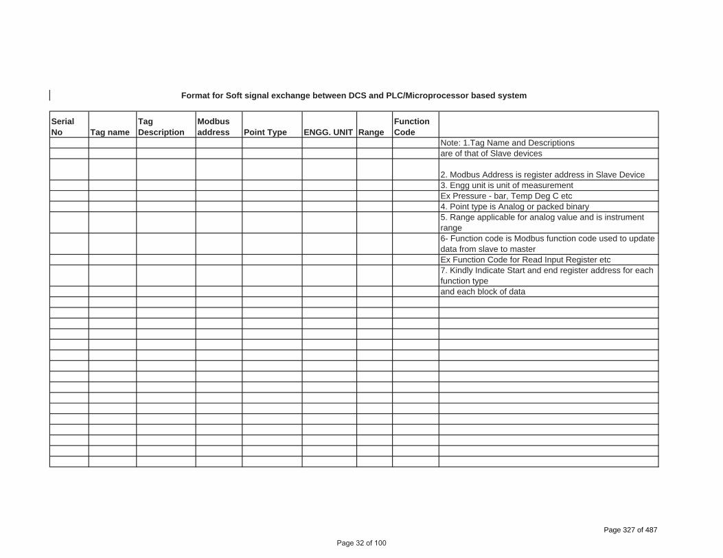
SerialNo Tag name
TagDescription
Modbusaddress Point Type ENGG. UNIT Range
FunctionCode
Note: 1.Tag Name and Descriptions are of that of Slave devices
2. Modbus Address is register address in Slave Device3. Engg unit is unit of measurementEx Pressure - bar, Temp Deg C etc4. Point type is Analog or packed binary5. Range applicable for analog value and is instrument range6- Function code is Modbus function code used to update data from slave to masterEx Function Code for Read Input Register etc7. Kindly Indicate Start and end register address for each function typeand each block of data
Format for Soft signal exchange between DCS and PLC/Microprocessor based system
Page 32 of 100
Page 327 of 487

� ���������������� �������������������
��������������������������������������������������� ��������������
�
����������
�����������
������������� �
�������������
�������������
����������������� �������������������
�
!�
���
���
��"#
###"
��
�
�����������
�����!���������L������������
Page 33 of 100
Page 328 of 487

������� ���� ����� ���� ���������������� ��� ���
� ������������������� �������������������������� ���!��������� �
" �����������������"� ���������!������ ����� �#���$�����������������������%� �
& �����������������&� !������������������!������� �
� ������������������ ������������!���������!�����������
� ������������������� ���������#��� ���$���%� �
' �����������������' ��������������������������������������!�����������
( �����������������(� �����)$�������*������������������ �
+ �����������������+� ���!����� ������������*�)$,*�-./�� �
� ������������������� 0�����������#�����������*����-./�%� �
�� ������������������ ����������!��1�������� �
�� ������������������ �!����������2�� ���������� �
�" �����������������& �$�����!����������������������
�& ������������������ ���������������������
�����3��%������!����������������������� ����������� ������ ��!���$����������$��$��������!���������������������������������
"%��������������$�������$�����$��� ��������$!������������������ �������1������4���*���������� �������������1��������������!�����*���������*����������* �����)$�����������*��$�����!����������������������*�-./���� �������� � ������!���$�������������������� ���$������
�������� �����#"4������%� ����)���
������� �������$����� �������������������� ��������������������
Page 34 of 100
Page 329 of 487

� ���������������� �������������������
��������������������������������������������������� ��������������
�
����������
�����������
������������� �
�������������
�������������
����������������� �������������������
�
!�
���
���
��"#
###"
��
�
�����������
�������������������������������������
Page 35 of 100
Page 330 of 487

Page 36 of 100
Page 331 of 487

Page 37 of 100
Page 332 of 487

Page 38 of 100
Page 333 of 487

Page 39 of 100
Page 334 of 487
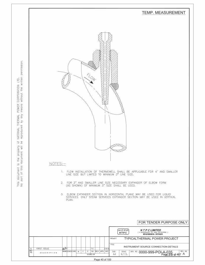
Page 40 of 100
Page 335 of 487

Page 41 of 100
Page 336 of 487
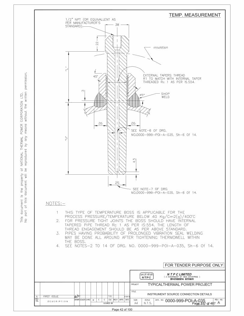
Page 42 of 100
Page 337 of 487

Page 43 of 100
Page 338 of 487

Page 44 of 100
Page 339 of 487
SUB-SECTION-III-C3
PROCESS CONNECTION AND PIPING
Page 45 of 100
Page 340 of 487

PROCESS CONNECTION AND PIPING
1.00.00 PROCESS CONNECTION PIPING
1.01.00 The Contractor shall provide, install and test all required material for completeness of Impulse Piping System and Air Piping System as per the requirements of this Sub-Section on as required basis for the connection of all instruments and control equipments of entire plant.
1.01.01 IMPULSE PIPING, TUBING, FITTINGS, VALVES AND VALVE MANIFOLDS
1.01.02 All impulse pipes shall be of seamless type conforming to ANSI B36.10 for schedule numbers. The size of impulse pipe shall be ½” for Steam & Water Application and ¾” for Air & Flue Gas applications. The rating of material of impulse pipes, tubes, fittings, valves and their installation thereof shall conform to the latest edition of standards as per following table:
Impulse Pipes, Tubes (Material, Rating) ANSI B31.1, ANSI B31.1a, ANSI/ISA 77.70
Valves (Material, Pr. Class, Size) ASTM A182/ASTM A105 as per ASME 16.34
Fittings (Size, Rating, Material) ANSI B31.1, ANSI B31.1a, ASME B16.11-2009
Installation Schemes BS 6739-2009, ANSI/ISA 77.70
Stainless steel tube shall be provided inside enclosures & racks from tee connection to valve manifold and then to instrument. The source shut-off (primary process root valve) and blow down valve shall be of 1/2 inch size globe valve type for all applications except for air and flue gas service wherein no source shut-off valves are to be provided. Two root valves are to be used wherever pressure is more than 40 Kg/cm2 or Temp>280 oC. The end connections of valves shall be of socket welded type. Typical installation scheme of DP Transmitter (inside LIE/LIR) mounted below instrument source point is indicated in Drg. No. 0000-999-POI-A-036. Same scheme with necessary changes shall be applied for other instruments.
1.01.03 The valve manifolds of 316 SS with pressure rating suitable for intended application shall be provided as given below:
Manifold Application/Measurement 2 Valve Pressure measurements using pressure transmitters/pressure switches 3 Valve Pressure measurements using differential pressure transmitter/ switches 5 Valve Differential Pressure, Flow and Level Measurements
For Pr./D.P gauges, two-way globe/gate valve shall be provided on each impulse line to the instrument in Fluid/Air & Flue Gas applications respectively .
2.00.00 AIR SUPPLY PIPING
2.01.01 All pneumatic piping, fittings, valves, air filter cum regulator, purge rotameter and other accessories required for instrument air for the various pneumatic devices/ instruments shall be provided. This will include as a minimum air supply to pneumatically operated control valves, actuators, instruments, continuous and intermittent purging requirements etc.
2.02.00 Instrument air and Service air supply shall be provided for continuous and intermittent purging respectively for all transmitters of mill, dirty air and flue gas applications. Purging Scheme shall be as per Drg. No. 0000-999-POI-A-036.
2.03.00 The Contractor shall also provide SS Tubing and associated fittings (screwed type) of suitable sizes for all pneumatic equipments/actuators (including supply air, signal air and output to actuators) conforming to ANSI 31.1 and 31.3 standard. All other air supply lines shall be of mild steel hot dipped galvanized inside and outside as per IS-
Page 46 of 100
Page 341 of 487

1239, heavy duty with threaded ends. Fittings for air supply line shall be of forged carbon steel A234 Gr. WPB galvanized inside and outside, screwed as per ASA B2.1. Dimensions of fittings shall be as per ASA B16.11 of rating 3000 lbs. Air supply piping shall be adequately sloped to prevent accumulation of condensed water within the pipe. The air supply headers, sub-headers and branch pipes shall be supported properly by clamps or supports.
2.04.00 The instrument/service air supply to each equipment/devices requiring air supply shall be provided by a well designed air distribution scheme comprising of 2” GI Pipe Header feeding 1” GI Pipe sub-header feeding ½” pipe at each equipment/device. Instrument air filters cum regulator set with mounting accessories shall be provided for each pneumatic device requiring air supply except for Ash Handling System wherein it shall be provided on instrument air header at each location.
2.05.00 All the isolation valves in the air supply line shall be gate valves as per ASTM B62 inside screw rising stem, screwed female ends as per ASA B2.1. Valve bonnet shall be union type & trim material shall be stainless steel, body rating 150 pounds ASA. The valve sizes shall be ½ inch to 2 inch.
2.06.00 Instrument air filters cum regulator set with mounting accessories shall be provided for pneumatic device requiring air supply. The filter regulators shall be suitable for 10-kg/ sq.cm max. Inlet pressure. The filter shall be of size 5 microns and of material sintered bronze. The air set shall have 2-inch size pressure gauge and built in filter housing blowdown valve. The end connection shall be as per the requirement to be finalized during detailed engineering.
3.00.00 INSTALLATION AND ROUTING 3.01.01 All instrument piping, tubing and its accessories shall be supported in a safe manner
to prevent excessive vibrations and anchored sufficiently to prevent undue strain on connected equipment. Impulse piping shall be supported at an interval not exceeding 1.5 meters. The slope of the impulse pipe form the process connection to the instrument shall be as per ANSI/ISA 77.70 latest edition and BS 6739-2009. All impulse piping shall be installed to permit free movement due to thermal expansion. Wherever required expansion loops shall be provided.
Condensate pots shall be provided for all level measurements in steam and water services, all flow measurement in steam services and for flow measurements in water services above 120 Deg. C. Colour coding of all impulse pipes shall be done by the Contractor in line with the colour coding being followed for the parent pipes.
4.00.00 SHOP AND SITE TESTS 4.01.01 The equipment and work performed as per this Sub-section shall be subject to shop
and site test as per requirements of Sub-section-IIIE-04 (Quality Assurance & Inspection) other applicable clauses of this Sub-section and Employer approved quality assurance plan.
4.01.02 Hydrostatic and Pneumatic leakage tests shall be performed on all pipes, tubing and systems and shall conform to ANSI B31.1.
5.00.00 LOCAL INSTRUMENT ENCLOSURE AND RACKS
All transmitters, switches etc. for FGD system and other system being provided under the contract shall be suitably grouped together and mounted inside (i) local instruments enclosures in case of open areas of the plant and (ii) In local instrument racks in case of covered areas. The GA of LIE with purging indicated in the Drg. No. 0000-999-POI-A-036 is to be followed by contractor. The GA of LIR shall be similar to LIE except for front/rear doors and side panels. The internal layout shall be such that the impulse piping/ blow down lines are accessible from back side of the enclosure / rack and the transmitters etc. are accessible from front
Page 47 of 100
Page 342 of 487

side for easy maintenance. Bulkheads, especially designed to provide isolation from process line vibration shall be installed on instrument enclosures/racks to meet the process sensing line connection requirement. Vibration dampeners shall be installed for each enclosure / rack. The Degree of Protection of LIE and JB of LIE/LIR shall be IP-55.
The enclosures shall be constructed of 3 mm sheet plate and shall be of modular construction with one or more modules and two end assemblies bolted together to form an enclosure. Double inter locking doors shall be provided. The doors shall be the three-point locking type constructed of not less than 1.6 mm thick steel. Doors shall have concealed quick removal type pinned hinges and locking handles. Door locks shall accept the same key.
The instrument racks shall be free standing type constructed of suitable 5 mm thick channel frame of steel and shall be provided with a canopy to protect the equipment mounted in racks from falling objects, water etc. The canopy shall not be less than 3 mm thick steel, and extended beyond the ends of the rack. Enclosures/Racks shall be reinforced as required to ensure true surface and to provide adequate support for instruments and equipment mounted therein. Centre posts or any member which would reduce access shall not be provided. Contractor shall provide not more than three variants for LIE/LIR with respect to max. no. transmitters mounted in each LIE/LIR.
5.01.00 ENCLOSURE / RACKS FOR DUAL I/P TEMPERATURE TRANSMITTERS
All Dual Input temperature transmitters for FGD system and other system being provided under the contract shall be suitably grouped together and mounted inside (i) Enclosures in case of open areas of the plant and (ii) Racks in case of covered areas. Integral JB shall be provided with each Enclosure and Rack. The internal layout shall be such that the transmitters are accessible from both front and back side of the enclosure / rack for easy maintenance. Enclosure/ Racks shall be of robust and rugged design. Vibration dampeners shall be installed for each enclosure / rack. The Degree of Protection of Enclosure and JB shall be IP-55. Enclosure and Racks shall be free standing type. Enclosures/Racks shall be reinforced as required to ensure true surface and to provide adequate support for instruments and equipment mounted therein. Contractor shall provide not more than five variants for Enclosure/ Rack with respect to max. no. transmitters mounted in each Enclosure/ Rack. However, the maximum number of Transmitters that can be grouped in one Enclosure/ Rack shall be decided during detail Engineering.
6.00.00 INSTALLATION OF OTHER INSTRUMENTS:
For installation and routing of other field mounted instruments which are not covered in Cl. No. 5.00.00, please refer Cl. No 52.04.00(J) of Section-VI, Part-D, Erection Conditions of Contract (ECC) of Technical Specifications.
7.00.00 For Sea Water Applications following to be provided
System/Line Description Sea Water Applications Piping Class S Impulse Pipe Material ASTM-A 213 TP 316L Schedule (Size) 80(1/2 inch) Materials for Fitting/Valve Body ASTM-A 182 316L
Page 48 of 100
Page 343 of 487

Valve Stem Material -do- Rating of Piping/ Fittings 3000lb Pr. Class of Valve 800
Page 49 of 100
Page 344 of 487

Page 50 of 100Page 345 of 487

Page 51 of 100Page 346 of 487

SUB-SECTION-III-C6
TYPE TEST REQUIREMENTS
Page 52 of 100
Page 347 of 487

1.00.00 TYPE TEST REQUIREMENTS
1.01.00 General Requirements
1.01.01 The Contractor shall furnish the type test reports of all type tests as per relevant standards and codes as well as other specific tests indicated in this specification. If the bidder proposes a different standard/code from that indicated at clause no 2.01.00 and at table 3.00.00, same is acceptable provided the equivalence of the proposed standard is established by the bidder. A list of such tests are given for various equipment in table titled 'TYPE TEST REQUIREMENT FOR OTHER C&I SYSTEMS' at the end of this chapter and under the item “Special Requirement for Solid State Equipments/Systems”.
(a) Out of the tests listed, the Bidder/ sub-vendor/ manufacturer is required to conduct certain type tests specifically for this contract (and witnessed by Employer or his authorized representative) even if the same had been conducted earlier, as clearly indicated subsequently against such tests.
(b) For the rest, submission of type test results and certificate shall be acceptable provided.
i. The same has been carried out by the Bidder/ sub-vendor on exactly the same model /rating of equipment.
ii. There has been no change in the components from the offered equipment & tested equipment.
iii. The test has been carried out as per the latest standards alongwith amendments as on the date of Bid opening.
(c) In case the approved equipment is different from the one on which the type test had been conducted earlier or any of the above grounds, then the tests have to berepeated and the cost of such tests shall be borne by the Bidder/ sub-vendor within the quoted price and no extra cost will be payable by the Employer on this account.
1.01.02 The schedule of conduction of type tests/ submission of reports shall be submitted andfinalized during pre-award discussion.
1.01.03 For the type tests to be conducted, Contractor shall submit detailed test procedure for approval by Employer. This shall clearly specify test setup, instruments to be used, procedure, acceptance norms (wherever applicable), recording of different parameters, interval of recording precautions to be taken etc. for the tests to be carried out.
1.01.04 The Bidder shall indicate in the relevant BPS schedule, the cost of the type test for each item only for which type tests are to be conducted specifically for this project. The cost shall only be payable after conduction of the respective type test in presence of authorize representative of Employer. If a test is waived off, then the cost shall not be payable.
2.00.00 SPECIAL REQUIREMENT FOR SOLID STATE EQUIPMENTS/ SYSTEMS
2.01.00 The type test reports which are to be submitted for each of the C&I systems( indicated in clause 2.01.01) shall be as indicated below:
i) Surge Withstand Capability ( SWC) for Solid State Equipments/ Systems
All solid state systems/ equipments shall be able to withstand the electrical noise
Page 53 of 100
TYPE TEST REQUIREMENTS
Page 348 of 487

and surges as encountered in actual service conditions and inherent in a power plant. All the solid state systems/ equipments shall be provided with all required protections that needs the surge withstand capability as defined in ANSI / IEEE C37.90.1.. Hence, all front end cards/ devices which receive external signals like Analog input & output modules, Binary input & output modules etc. including power supply, data highway, data links shall be provided with protections that meets the surge withstand capability as defined in ANSI / IEEE C37.90.1. Complete details of the features incorporated in electronics systems to meet this requirement, the relevant tests carried out, the test certificates etc. shall be submitted along with the proposal. As an alternative to compliance to ANSI / IEEE C37.90.1, the system shall comply to IEC-61000-4-4, IEC-61000-4-5 and IEC-61000-4-18.
ii) Dry Heat test as per IEC-60068-2-2 or equivalent.
iii) Damp Heat test as per IEC-60068-2-30 or IEC-60068-2-78 or equivalent.
iv) Vibration test as per IEC-60068-2-6 or equivalent.
v) Electrostatic discharge tests as per IEC 61000-4-2 or equivalent.
vi) Radio frequency immunity test as per IEC 61000-4-6 or equivalent.
vii) Electromagnetic Field immunity as per IEC 61000-4-3 or equivalent.
2.01.01 C&I Systems-
Sl. No
Item Remark Test To Be Specifically Conducted
NTPC’s Approval Req. On TestCertificate
1 Control System of DDCMIS No Yes
2 PLC, excluding its HMI Not applicable for integral PLCs and PLCs which are governed by standard practice of OEM
No Yes
3 VMS System (Applicable for each module of VMS)
No Yes
4 Main Turbine & BFP Drive Turbine TSI System (Applicable for each module of TSI System)
No Yes
5 Vibration Analysis System (Applicable for each module of Vibration Analysis System)
No Yes
Page 54 of 100
Page 349 of 487

6 TG related Special modules like Auto synchronizer, Load transducer module and speed measurement module
No Yes
7 Master Clock No Yes
Note:
Type Tests are to be conducted only for the items, which are being supplied as a part of this Package.
3.00.00 TYPE TEST REQUIREMENT FOR OTHER C&I SYSTEMS
Sl. No
Item Test Requirement
Standard Test To Be Specifically Conducted
NTPC’s Approval Req. On TestCertificate
Col 1 Col 2 Col 3 Col 4 Col 5 Col 6
1 Electronic transmitter
As per standard (col 4)
BS-6447 / IEC-60770
No Yes
2 Instrumentation Cables Twisted & Shielded*
-Conductor Resistance test
VDE-0815 No Yes
Diameter test IS-10810 No Yes
Tin Coating test (Persul-phate test)
IS-8130 No Yes
-Insulation Loss of mass VDE 0472 No Yes
Ageing in air ovens**
VDE 0472 No Yes
Tensile strength and elongation test before and after ageing**
VDE 0472 No Yes
Heat shock VDE 0472 No Yes
Hotdeformation
VDE 0472 No Yes
Page 55 of 100
TYPE TEST REQUIREMENT FOR OTHER C&I SYSTEMS
1 Electronic As per BS-6447 / IEC- No Yestransmitter standard 60770
(col 4)
Page 350 of 487
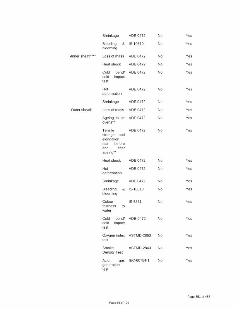
Shrinkage VDE 0472 No Yes
Bleeding & blooming
IS-10810 No Yes
-Inner sheath*** Loss of mass VDE 0472 No Yes
Heat shock VDE 0472 No Yes
Cold bend/ cold impact test
VDE 0472 No Yes
Hotdeformation
VDE 0472 No Yes
Shrinkage VDE 0472 No Yes
-Outer sheath Loss of mass VDE 0472 No Yes
Ageing in air ovens**
VDE 0472 No Yes
Tensile strength and elongation test before and after ageing**
VDE 0472 No Yes
Heat shock VDE 0472 No Yes
Hotdeformation
VDE 0472 No Yes
Shrinkage VDE 0472 No Yes
Bleeding & blooming
IS-10810 No Yes
Colour fastness to water
IS-5831 No Yes
Cold bend/ cold impact test
VDE-0472 No Yes
Oxygen index test
ASTMD-2863 No Yes
Smoke Density Test
ASTMD-2843 No Yes
Acid gas generation test
IEC-60754-1 No Yes
Page 56 of 100
Page 351 of 487

-fillers Oxygen index test
ASTMD-2863 No Yes
Acid gas generation test
IEC-60754-1 No Yes
-AL-MYLAR shield
Continuity test
No Yes
Shield thickness
No Yes
Overlap test No Yes
-Over all cable Flammability Test
IEEE 383 No Yes
Swedish Chimney Test
SEN 4241475 No Yes
Noise interference
IEEE Trans-actions
No Yes
Dimensional checks
IS 10810 No Yes
Cross talk VDE-0472 No Yes
Mutual capacitance
VDE-0472 No Yes
HV test VDE-0815 No Yes
Drain wire continuity
No Yes
* 1.0 All cables to be supplied shall be of type tested quality. The Contractor shall submit for Owner's approval the reports of all the type tests as listed in this specification and carried out within last Ten years from the date of bid opening. These reports should be for the tests conducted on the equipment similar to those proposed to be supplied under this contract and the test(s) should have been either conducted at an independent laboratory or should have been witnessed by a client.
2.0 In case the Contractor is not able to submit report of the type test(s) conducted within last Ten years from the date of bid opening, or in case the type test report(s) are not found to be meeting the specification requirements, the Contractorshall conduct all such tests either in an independent laboratory or at manufacturer’s works in presence of Owner’s representative under this contract free of cost to the Owner and submit the reports for approval.
**These tests shall be carried out as per VDE0207 Part 6 & ASTMD-2116 for TEFLON insulated & outer sheathed cables
***Applicable for armoured cables only
Page 57 of 100
Page 352 of 487

3 DC Power Supply System (Applicable for each model and rating)
1)The Type Test reports for offered rectifier module and the controller module irrespective of the rectifier bank shall be acceptable
Surge Withstand Capability( SWC)
(ANSI / IEEEC37.90.1)or (IEC-61000-4-4, IEC-61000-4-5and IEC-61000-4-18).
No Yes
Dry Heat Test IEC-60068-2-2or equivalent
No Yes
Damp Heat test IEC-60068-2-30or IEC-60068-2-78 or equivalent
No Yes
Vibration test IEC-60068-2-6or equivalent
No Yes
Electrostatic discharge test
IEC 61000-4-2or equivalent
No Yes
Radio frequency immunity test
IEC-61000-4-6or equivalent
No Yes
Electromagnetic field immunity
IEC 61000-4-3or equivalent
No Yes
Degree of Protection
IS-13947 orequivalent
No Yes
4 Battery ## As per standard (col 4)
IS-10918 (Ni-Cd Batteries)
IS-1652 (Lead Acid Plante Batteries)
No
No
Yes
5 UPS ( Applicable for each model and rating )
1) Type Test reports of same series of UPS with similar PCB’s cards and controllers as the target UPS system shall be acceptable.
2) For Dry heat, Damp heat and vibration, the tests conducted on individual PCB’s shall be acceptable.
Surge Withstand Capability( SWC)
(ANSI / IEEEC37.90.1)or
No Yes
Page 58 of 100
Page 353 of 487

(IEC-61000-4-4, IEC-61000-4-5and IEC-61000-4-18).
Dry Heat Test IEC-60068-2-2or equivalent
No Yes
Damp Heat test IEC-60068-2-30or IEC-60068-2-78 or equivalent
No Yes
Vibration test IEC-60068-2-6or equivalent
No Yes
Electrostatic discharge test
IEC 61000-4-2or equivalent
No Yes
Radio frequency immunity test
IEC-61000-4-6or equivalent
No Yes
Electromagnetic field immunity
IEC 61000-4-3or equivalent
No Yes
Degree of protection test
IS-13947 No Yes
Fuse Clearing Capability
Approved procedure
No Yes
Short Circuit current capability
IEC 60146-2 No Yes
6 Public Address System
IP based PA system components
As per Standard
IEC 60268-16 No Yes
7 Control Valves CV test ISA 75.02&75.11
No Yes
8 Flow Nozzle Orifice plates
Calibration ASME PTC
BS 1042
No Yes
## The contractor shall submit for Employers approval the reports of all the type test as per latest IS-10918 carried out within last ten years from the date of Bid opening and the test(s) should have been either conducted at an independent laboratory or in presence of owner’srepresentative. The complete type test reports shall be for any rating of Battery in a particular group based on plate dimensions being manufactured by supplier.
Note:
Type Tests are to be conducted only for the items, which are being supplied as a part of this Package.
Page 59 of 100
7 Control Valves CV test ISA 75.02& No Yes75.11
Flow Nozzle Calibration ASME PTC No Yes8Orifice plates BS 1042
##
Page 354 of 487

� ���������������� �������������������
��������������������������������������������������� ��������������
�
����������
�����������
������������� �
�������������
�������������
����������������� �������������������
�
!�
���
���
��"#
###"
��
�
����������
&�����,�����������!��������������
Page 60 of 100
Page 355 of 487

MEASURING INSTRUMENTS (PRIMARY AND SECONDARY) PAGE- 1/2
TESTS
ITEMS
Dim
ensi
ons
(R)
Mak
e, M
odel
, Typ
e, R
atin
g (R
)Pr
oces
s / E
lect
rical
con
nect
ion
(R)
Cal
ibra
tion
(R)
Test
as
per s
tand
ard(
R)
Insu
latio
n R
esis
tanc
e (R
)
IBR
Cer
tific
atio
n (if
app
licab
le )(
R)
Hyd
ro T
est(R
)
Mat
eria
l Tes
t cer
tific
ate
®
1. PR Gauge (IS-3624) Y Y Y Y Y2. Temp. Gauge (BS-5235) Y Y Y Y Y3. Pr./D.P.Switch(BS-6134) Y Y Y Y Y Y4. Electronic Transmitter(IEC-60770)
Y Y Y Y Y Y
5. Temp. Switch Y Y Y Y Y Y6. Recorder(IS-9319/ANSI C-39.4) Y Y Y Y Y Y7. Vertical indicators Y Y Y Y Y8. Digital Indicators Y Y Y Y Y9. Integrators Y Y Y Y10. Electrical Metering Instrument (IS-1248)
Y Y Y Y Y Y
11. Transducer (IEC-688) Y Y Y Y Y Y12. Thermocouples (IEC – 754 / ANSI-MC-96.1)
Y Y Y Y Y Y
13. RTD(IEC-751) Y Y Y Y Y Y14. Thermowell Y Y Y Y YR-Routine Test A- Acceptance Test Y – Test applicable: Note: 1) This is an indicative list of tests/checks. The manufacturer is to
furnish a detailed quality plan indicating the Practices and Procedure adopted along with relevant supporting documents.
Page 61 of 100
Page 356 of 487

MEASURING INSTRUMENTS (PRIMARY AND SECONDARY) Page- 2/2
TESTS
ITEMSD
imen
sion
s (R
)
Mak
e, M
odel
, Typ
e, R
atin
g (R
)
Proc
ess
/ Ele
ctric
al c
onne
ctio
n (R
)
Cal
ibra
tion
(R)
Req
uire
men
t as
per s
tand
ard
(R)
WPS
app
rova
l (A)
Non
-des
truct
ive
test
ing
(R)
Cal
cula
tion
for a
ccur
acy
(R)
Insu
latio
n R
esis
tanc
e (R
)
IBR
Cer
tific
atio
n as
app
licab
le (R
)
Hyd
ro te
st (R
)
Mat
eria
l tes
t cer
tific
ate
(A)
15. Cold junction compensation box
Y Y Y Y Y
16. Orifice plate(BS-1042) Y Y Y Y*
Y Y**
Y**
Y Y**
Y
17. Flow nozzle(BS-1042) Y Y Y Y*
Y Y Y Y Y Y
18. Impact head type element Y Y Y Y Y19. Level transmitter/float type switch
Y Y Y Y Y Y Y Y
20. Analysers Y Y Y Y21. Dust emission monitors Y Y Y Y*Calibration to be carried out on one flow element of each type and size if calibration carried out as type test same shall not be repeated.
** If applicableR-Routine Test A- Acceptance Test Y – Test applicableNote: 1) This is an indicative list of tests/checks. The manufacturer is to furnish a
detailed quality plan indicating the Practices and Procedure adopted along with relevant supporting documents.
Page 62 of 100
Page 357 of 487

STANDARD CHECK LIST FOR C&I INSTRUMENTS (for Maux Pkgs)
Sl. Test / Checks Quantum Reference Doc. / RemarksNo. of check Acceptance Norms M C B
CHECK FOR 100%TYPEMODEL/TAG NO.RANGE/SCALEEND CONNECTION
2 DIMENSIONS CHECK 100% P W V3 ACCURACY 100% P W V4 SWITCHING DIFFERENTIAL 100% P W V5 CONTACT RATING / No. OF
CONTACTSRANDOM P W V
6 MATERIAL TC FOR BULB, CAPILLARY, ARMOUR
ONE / LOT P V V
7 HV / IR RANDOM P W V8 DEGREE OF PROTECTION TYPE TEST P V V
THERMOWELLSDIMENSIONS,PROCESS CONN 100% P W VMATERIAL TC ONE / LOT P V VHYD TEST 100% P W VIBR CERTIFICATE, IF APPLICABLE
P V V
10 REPEATABILITY 100% P V V11 HYSTERISIS 100% P V V12 ACCESSORIES AS APPLICABLE SEE NOTE-1
BELOWP W V
Legend : ** M = Manufacturer / Sub-contractor, C = Contractor / Nominated Inspecting Agency, B = BHEL, P = Perform, W = Witness, V = Verification
Note :1. Quantum of check shall be as below : 100 % - By Manufacturer2. Manufacturer to maintain calibrated instrument having better accuracy than the item under test. Inspecting engineer shall check the same. 3. Contractor to provide compliance certificate for tests/checks verifid by contractor and submit the same alongwith test certificates to be verified by BHEL.4. Manufacturer to carry out routine test for 100%
APPROVED SPEC./ DATA SHEETS
P W V
Agency **
1
9
CHECK LIST FOR TEMPERATURE SWITCH
Page 63 of 100
Page 358 of 487

STANDARD CHECK LIST FOR C&I INSTRUMENTS (for Maux Pkgs)
Sl. Test / Checks Reference Doc. / RemarksNo. Acceptance Norms M C B
CHECK FOR 1.1 MODEL NO/TAG NO1.2 RANGE1.3 END CONN1.4 NO. OF CONTACTCALIBRATION 2.1 REPEATABILITY2.2 SET POINT ADJUSTMENT2.3 DIFFERENTIAL
3 OVER PR & LEAK TEST P V V4 ELECT. INSULATION/HV TEST ONE P V V
REVIEW OF TC FOR MATERIALS OF5.1 SENSOR5.2 MOVEMENT5.3 PROCESS CONNECTION 5.4 HOUSING
6 REVIEW OF TC FOR DEGREE OF PROTECTION
TYPE TEST V V V
7 REVIEW OF TC OF MICROSWITCH
FOR LOT V V V
** M = Manufacturer / Sub-contractor, C = Contractor / Nominated Inspecting Agency, B = BHEL, P = Perform, W = Witness, V = Verification
Note :1. Quantum of check shall be as below : 100 % - By Manufacturer2. Manufacturer to carry out ROUTINE TEST on 100 %.
Agency **
APPROVED SPEC./ DATA SHEETS
SEE NOTE-1 BELOW
3. Contractor to provide compliance certificate for tests/checks verifid by contractor and the same alongwith test certificates to be verified by BHEL
1
2
5 V V
P V V
P V V
FOR LOT V
Quantum of check
CHECK LIST FOR PRESSURE SWITCH
Page 64 of 100
Page 359 of 487

STANDARD CHECK LIST FOR C&I INSTRUMENTS (for Maux Pkgs)
Sl. Test / Checks Quantum Reference Doc. / RemarksNo. of check Acceptance Norms M C B
CHECK FOR
VISUALMAKE, MODEL No.POWER SUPPLYTYPE
2 DIMENSIONS CHECK P V V3 FUNCTIONAL CHECK P V V4 LEAKAGE TEST P V V5 HV / IR TEST P V V6 LINEARITY P V V7 RESPONSE TIME P V V8 ENCLOSURE CLASS P V V9 ACCESSORIES, AS APPLICABLE P V V
10 ACCURACY / CALIBRATION P V V11 ALARM CONTACT TEST P V V12 ANALOG OUTPUT CHECK P V V13 BURN-IN TEST OF ELECTRONIC
PARTS1/LOT P V V
14 IN-BUILT INDICATOR, ZERO, SPAN, RANGE SCALE SELECTION ETC
SEE NOTE-1 BELOW
P V V
Legend : ** M = Manufacturer / Sub-contractor, C = Contractor / Nominated Inspecting Agency, B = BHEL, P = Perform, W = Witness, V = Verification
Note :1. Quantum of check shall be as below : 100 % - By Manufacturer2. Manufacturer to maintain calibrated instrument having better accuracy than the item under test. Inspecting engineer shall check the same. 3. Contractor to provide compliance certificate for tests/checks verifid by contractor and submit the same alongwith test certificates to be verified by BHEL.
APPROVED SPEC./ DATA SHEETS
SEE NOTE-1 BELOW
Agency **
P V V1
CHECK LIST FOR ANALYTICAL INSTRUMENTS
Page 65 of 100
Page 360 of 487

STANDARD CHECK LIST FOR C&I INSTRUMENTS (for Maux Pkgs)
Sl. Test / Checks Quantum Reference Doc. / RemarksNo. of check Acceptance Norms M C B
1 CHECKS FOR
VISUAL.MODEL/TAG No
2 PROCESS CONNECTION P W V3 ACCURACY P W V4 REPEATABILITY P W V5 HYSTERESIS P W V6 EFFECT OF TEMP VARIATION
ON ACCURACYP W V
7 SPAN / ZERO ADJUSTMENT P W V8 EFFECT OF SUPPLY VOLTAGE
VARIATIONP W V
9 EFFECT OF LOADING (500 OHM METERS)
P W V
10 HIGH PRESSURE TEST SEE NOTE-1 BELOW
P W V
11 BURN-IN TEST P W V12 DEGREE OF PROTECTION P W V13
ACCESSORIES AS APPLICABLESEE NOTE-1
BELOWV V V
Legend : ** M = Manufacturer / Sub-contractor, C = Contractor / Nominated Inspecting Agency, B = BHEL, P = Perform, W = Witness, V = Verification
Note :1. Quantum of check shall be as below : 100 % - By Manufacturer2. Manufacturer to maintain calibrated instrument having better accuracy than the item under test. Inspecting engineer shall check the same. 3. When material corelation are not available manufacturer's compliance to be provided.4. Contractor to provide compliance certificate for tests/checks verifid by contractor and submit the same alongwith test certificates to be verified by BHEL.
APPROVED SPEC./ DATA SHEETS
SEE NOTE-1 BELOW
ONE / TYPE
ONE / TYPE
CHECK LIST FOR TRANSMITTER
Agency **
P W V
Page 66 of 100
Page 361 of 487

STANDARD CHECK LIST FOR C&I INSTRUMENTS (for Maux Pkgs)
Sl. Test / Checks Quantum Reference Doc. / RemarksNo. of check Acceptance Norms M C B
CHECK FOR TYPEMODEL No./TAG No.PROCESS CONNECTION
2 STABILITY P W V3 INSULATION RESISTANCE P W V4 ENCLOSURE CLASS P W V5 RESPONSE TIME P W V7 ACCURACY P W V8 HYDROSTATIC TEST P W V9 ELECTRICAL CHARACTERISTIC
OF SENSOR (CONTINUTY OF T/C WIRES & INSULATION RESISTANCE OF RTD LEADS w.r.t. BODY
P W V
10 TEMP CURVES / CHARTS P V V11 AMBIENT TEMP. EFFECT
CHECKP W V
12 HV TEST P W V
Legend : ** M = Manufacturer / Sub-contractor, C = Contractor / Nominated Inspecting Agency, B = BHEL, P = Perform, W = Witness, V = Verification
Note :1. Quantum of check shall be as below : 100 % - By Manufacturer2. Manufacturer to maintain calibrated instrument having better accuracy than the item under test. Inspecting engineer shall check the same. 3. Contractor to provide compliance certificate for tests/checks verifid by contractor and submit the same alongwith test certificates to be verified by BHEL.4. IBR certificate to be provided, if applicable
Agency **
SEE NOTE-1 BELOW
APPROVED SPEC./ DATA SHEETS
CHECK LIST FOR TEMPERATURE ELEMENT
P W V1
Page 67 of 100
Page 362 of 487

STANDARD CHECK LIST FOR C&I INSTRUMENTS (for Maux Pkgs)
Sl. Test / Checks Quantum Reference Doc. / RemarksNo. of check Acceptance Norms M C B
CHECK FOR
TYPE MAKE MODEL No.
2 MATERIAL (BODY. PLUNGER/TRIM)
P W V
3 PORT SIZE P W V4 CABLE CONNECTION SIZE P W V
5 ENCLOSURE CLASS
P W V TYPE TEST CERTIFICATE TO BE FURNISHED BY VENDOR
6 No. OF COILS & INSULATION CLASS
P W V TEST CERTIFICATE TO BE FURNISHED FOR INSULATION CLASS BY VENDOR
7 POWER SUPPLY CHECK P W V8 IR / HV TEST P W V
9 FUCTIONAL TEST P W V
Legend : ** M = Manufacturer / Sub-contractor, C = Contractor / Nominated Inspecting Agency, B = BHEL, P = Perform, W = Witness, V = Verification
Note :1. Quantum of check shall be as below : 100 % - By Manufacturer2. Manufacturer to maintain calibrated instrument having better accuracy than the item under test. Inspecting engineer shall check the same. 3. Contractor to provide compliance certificate for tests/checks verifid by contractor and submit the same alongwith test certificates to be verified by BHEL.
SEE NOTE-1 BELOW
APPROVED SPEC./ DATA SHEETS
Agency **
1 P W V
CHECK LIST FOR SOLENOID VALVES
Page 68 of 100
Page 363 of 487

STANDARD CHECK LIST FOR C&I INSTRUMENTS (for Maux Pkgs)
Sl. Test / Checks Quantum Reference Doc. / RemarksNo. of check Acceptance Norms M C B
CHECK FOR DIAL SIZEMODEL NO./TAG NO./TYPERANGE/SCALEEND CONNECTIONCALIBRATION ACCURACYREPEATABILITYHYSTERESIS
3 OVER TEMP. TEST P W V4 AMBIENT TEMP.
COMPENSATION CHECK1 OF TYPE P V V
REVIEW OF TC FOR MATERIALS OFSENSORMOVEMENTPROCESS CONNECTIONTHERMOWELLHOUSING
6 REVIEW OF TC FOR DEGREE OF PROTECTION
TYPE TEST V V V
THERMOWELLMATERIAL TC & DIMN. CHECKHYD.TESTOVER RANGE TEST
Legend : ** M = Manufacturer / Sub-contractor, C = Contractor / Nominated Inspecting Agency, B = BHEL, P = Perform, W = Witness, V = Verification
Note :1. Quantum of check shall be as below : 100 % - By Manufacturer2. Manufacturer to maintain calibrated instrument having better accuracy than the item under test. Inspecting engineer shall check the same. 3. Manufacturer to carry out ROUTINE TEST on 100 %.4. IBR certificate to be provided if called for in specn.5. Contractor to provide compliance certificate for tests/checks verifid by contractor and submit the same alongwith test certificates to be verified by BHEL.
Agency **
W V
P
SEE NOTE-1 BELOW
AS PER APPD DWG V V7
2
FOR LOT V V
P
5
1
SEE NOTE-1 BELOW
W V
V
CHECK LIST FOR TEMPERATURE GAUGE
APPROVED SPEC./ DATA SHEETS
Page 69 of 100
Page 364 of 487
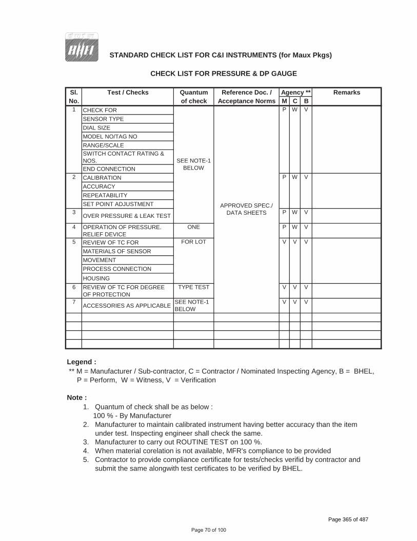
STANDARD CHECK LIST FOR C&I INSTRUMENTS (for Maux Pkgs)
Sl. Test / Checks Quantum Reference Doc. / RemarksNo. of check Acceptance Norms M C B
CHECK FORSENSOR TYPEDIAL SIZEMODEL NO/TAG NORANGE/SCALESWITCH CONTACT RATING & NOS.END CONNECTIONCALIBRATION ACCURACYREPEATABILITYSET POINT ADJUSTMENT
3 OVER PRESSURE & LEAK TEST P W V
4 OPERATION OF PRESSURE. RELIEF DEVICE
ONE P W V
REVIEW OF TC FORMATERIALS OF SENSORMOVEMENTPROCESS CONNECTIONHOUSING
6 REVIEW OF TC FOR DEGREE OF PROTECTION
TYPE TEST V V V
7 ACCESSORIES AS APPLICABLE SEE NOTE-1 BELOW
V V V
Legend : ** M = Manufacturer / Sub-contractor, C = Contractor / Nominated Inspecting Agency, B = BHEL, P = Perform, W = Witness, V = Verification
Note :1. Quantum of check shall be as below : 100 % - By Manufacturer2. Manufacturer to maintain calibrated instrument having better accuracy than the item under test. Inspecting engineer shall check the same. 3. Manufacturer to carry out ROUTINE TEST on 100 %.4. When material corelation is not available, MFR's compliance to be provided5. Contractor to provide compliance certificate for tests/checks verifid by contractor and submit the same alongwith test certificates to be verified by BHEL.
Agency **
5 FOR LOT V V V
2 P W V
1 P W V
APPROVED SPEC./ DATA SHEETS
SEE NOTE-1 BELOW
CHECK LIST FOR PRESSURE & DP GAUGE
Page 70 of 100
Page 365 of 487

� ���������������� �������������������
��������������������������������������������������� ��������������
�
����������
�����������
������������� �
�������������
�������������
����������������� �������������������
�
!�
���
���
��"#
###"
��
�
���������
�������������������������������������������,�
Page 71 of 100
Page 366 of 487

TABLE A: CABLE TERMINATION TO BE FOLLOWED
Application Type Of Termination Type Of Cable
FROM (A) TO (B) END A END B
Valves/dampers drives (Integral Junction box)
Marshalling / Marshalling – cum Termination Cubicle / local group JB
Plug in connector
Post mount cage clamp type.
G
Transmitters, Process Actuated switches mounted in LIE/LIR
Integral Junction box of LIE/LIR
Plug in connector
Cage clamp (Rail mount) type.
F,G
RTD heads Local junction box Plug in connector
Cage clamp (Rail mount) type.
F
Thermocouple Local junction box / CJC box (if applicable)
Plug in connector
Cage clamp (Rail mount) type.
A, B, C*
Other Field mounted Instrument
Local JB / Group JB Plug in connector
Cage clamp (Rail mount) type.
F,G
RTD Temperature transmitter
Plug in connector
Screwed, Cage clamp type
F
Thermocouple Temperature transmitter
Plug in connector
Screwed, Cage clamp type
A, B, C*
Local Junction box, Temperature Transmitter, Int. Junction box of LIE/ LIR/ MCC/SWGR
Group JB Cage clamp (Rail mount) type.
Cage clamp (Rail mount) type.
F,G
Local Junction box, Temperature Transmitter, Int. Junction box of LIE/ LIR/ Group JB / MCC/SWGR
Marshalling / Marshalling – cum Termination Cubicle
Cage clamp (Rail mount) type.
Cage clamp (Post mounted) type.
F,G
Marshalling cubicle/ Termination Cabinet
Electronic system cabinet
Cage clamp (Post mounted) type.
Plug-in connector / other system as per Mfr.’s Standard
Internal wiring
Page 72 of 100
Page 367 of 487

Application Type Of Termination Type Of Cable
FROM (A) TO (B) END A END B
Marshalling/ Termination System Cabinets
UCD mounted equipments
Cage clamp (Post mounted) type.
Plug in connector / Cage clamp type (rail mounted).
F,G (with plug-in connector at oneend)
DDCMIS/PLCcabinets
PC, Printers etc. Plug in connector
Plug in connector
Mfr.’s Standard
Notes 1 Normally 10% spare cores shall be provided when the numbers of pairs of cables are more than four pairs, except for pre-fabricated cables which shall be as per manufacturer’s standard.
2
3
For analog signals, individual pair shielding & overall shielding & for Binary signals, only overall shielding of instrumentation cables shall be provided.
* For high temperature applications only.
4 . For connection between field/JB and DDCMIS marshalling cabinet
Minimum 4 pair instrumentation cable shall be used.
5 All the spare cores of instrumentation cable have to be terminated in Marshalling cabinets/ DCS panel end.
6 Not used.
6.00.00 TERMINAL BLOCKS
6.01.00 All terminal blocks shall be rail mounted/post mounted, cage clamp type with high quality non-flammable insulating material of melamine suitable for working temperature of 105 deg. C. The terminal blocks in field mounted junction boxes, temperature transmitters, instrument enclosures/racks, etc., shall be suitable for cage clamp connections. The terminal blocks in Control Equipment Room logic/termination/marshalling cubicles shall be suitable for post mounted cage clamp connection at the field input end. The exact type of terminal blocks to be provided by the Bidder and the technical details of the same including width etc. shall be subject to Employer’s approval.
6.02.00 All the terminal blocks shall be provided complete with all required accessories including assembly rail, locking pin and section, end brackets, partitions, small partitions, transparent covers, support brackets, distance sleeves, warning label, marking, etc.
6.03.00 The marking on terminal strips shall correspond to the terminal numbering on wiring diagrams. At least 20% spare unused terminals shall be provided everywhere including local junction boxes, instrument racks/enclosures, termination/marshalling cabinets, etc. All terminal blocks shall be numbered for identification and grouped according to the function. Engraved labels shall be provided on the terminal blocks.
Page 73 of 100
All terminal blocks shall be rail mounted/post mounted, cage clamp type
At least 20% spare unused terminals shall be provided everywhere
Page 368 of 487

6.04.00 For terminating each process actuated switches, drive actuators, control valves, Thermocouple, RTD, etc. in Local Junction Boxes, etc, refer Drg no. 0000-999-POI-A-065.
6.05.00 The terminal blocks shall be arranged with at least 100 mm clearance between two sets of terminal blocks and between terminal blocks and junction box walls.
7.00.00 INTERNAL PANELS/ SYSTEM CABINETS WIRING
7.01.00 Internal panel/cabinet wiring shall be of multi-stranded copper conductor with FRLS PVC insulation without shield and outer sheath meeting the requirements of VDE 0815.
7.02.00 All internal wires shall be provided with tag and identification nos. etched on tightly fitted ferules at both ends. All wires directly connected to trip devices shall be distinguished by one additional red colour ferrule.
7.03.00 All external connection shall be made with one wire per termination point. Wires shall not be tapped or spliced between terminal points.
7.04.00 All floor slots of desk/panels/cabinets used for cable entrance shall be provided with removable gasketed gland plates and sealing material. Split type grommets shall be used for prefabricated cables.
7.05.00 All the special tools as may be required for solder less connections shall be provided by Bidder.
7.06.00 Wire sizes to be utilised for internal wiring.
(i) Current (4-20 mA), low voltage signals (48V); Ammeter/Voltmeter circuit, control switches etc. for electrical system.
0.5 Sq.mm.
(ii) Power supply and internal illumination. 2.5Sq.mm. minimum (shall be as per load requirement.)
8.00.00 INSTRUMENTATION CABLE INSTALLATION AND ROUTING
8.01.00 All cables assigned to a particular duct/conduit shall be grouped and pulled in simultaneously using cable grips and suitable lubricants. Cables removed from one duct/conduit shall not be reused without approval of Employer.
8.02.00 Cables shall be segregated as per IEEE Std.-422. In vertically stacked trays, the higher voltage cable shall be in higher position and instrumentation cable shall be in bottom tier of the tray stack. The distance between instrumentation cables and those of other system shall be as follows:
From 11 kV/6.6 kV/3.3 kV tray system - 914 mm
From 415V tray system - 610 mm
From control cable tray system - 305 mm
8.03.00 Cables shall terminate in the enclosure through cable glands. All cable glands shall be properly gasketed. Sealing (to prevent ingress of dust entry and propagation of fire) shall be provided for all floor slots used for cable entrance. Compression cable glands (double for armoured and single for other cables) shall be provided.
Page 74 of 100
Page 369 of 487

8.04.00 Not in use
8.05.00 The cables emanating from redundant equipment/devices shall be routed through different paths. The above segregation of cables & wiring for redundant equipments/devices shall be in accordance with IEEE-Std-422.
9.00.00 CABLE LAYING AND ACCESSORIES
9.01.00 CABLE LAYING
1 Cables shall be laid strictly in line with cable schedule.
2 Identification tags for cables.
Indelible tags to be provided at all terminations, on both sides of wall or floor crossing, on each conduit/duct/pipe entry/exit, and at every 20 m in cable trench/tray.
3 Cable tray numbering and marking.
To be provided at every 10m and at each end of cable way & branch connection.
4 No jointing is permissible for Instrumentation cables. For other cables Jointing for more than 250 Meters run of cable shall be permitted.
5 Buried cable protection
With concrete slabs; Route markers at every 20 Meters along the route & at every bend.
6 Road Crossings
Cables to pass through buried high density PE pipes encased in PCC. At least 300 mm clearance shall be provided between
- HT power & LT power cables,
- LT power & LT control/instrumentation cables,
Spacing between cables of same voltage grade shall be in accordance with the derating criteria adopted for cable sizing.
7 Segregation (physical isolation to prevent fire jumping)
a All cable associated with the unit shall be segregated from cables of other Units.
b Interplant cables of station auxiliaries and unit critical drives shall be segregated in such a way that not more than half of the drives are lost in case of single incident of fire.
8 Cable clamping
All cables laid on trays shall be neatly dressed up & suitably clamped/tied to the tray. For cables in trefoil formation, trefoil clamps shall be provided.
Page 75 of 100
Page 370 of 487

9 Optical fiber cables ( OFCs) :
Outside Building Area - to be laid necessarily inside GI conduit with support from cable tray/Trestle structure
Inside Building Area – to be laid on separate cable sub-trays
While buried- in separate burried trench approx.1.0 meter depth, to be laid in 2” rodent proof HDPE conduits covered with sand, brick, laid breadth-wise and soil along the pipe line route by contractor;
While crossing roads - to be laid in GI/ rodent proof HDPE conduits with sand filling at bottom and sand, soil filling at top with cement concrete;
While crossing canals/river- to be laid in rodent proof HDPE conduits within hume pipe.
10 Laying of Network Cable (UTP/STP) :
Out side Building Area- to be laid necessarily inside GI conduits with support from cable tray / Trestle structure.
Inside Building Area- to be laid necessarily inside GI conduits on separate cable sub-trays.
9.02.00 Bidder shall supply and install all cable accessories and fittings like Light Interface Units, Surge suppressors, Opto isolators, Interface Converters, Fibre Optic Card Cage, Fibre Optic Line Driver, Repeater / Modem (for Optical Fibre Cables), cable glands, grommets, lugs, termination kits etc. on as required basis.
9.03.00 Cables, which terminate in cabinets of draw out sections shall have sufficient cable coiled in the bottom of the cabinet to permit full withdrawal of draw out sections without disconnecting the cables. When prefabricated cables with factory connectors on both ends are longer than required, the excess cable shall be coiled in the bottom of one or both termination cabinets.
9.04.00 The Bidder shall be responsible for proper grounding of all equipment under this package. Further, proper termination of cable shields shall be verified and the grounding of the same shall be coordinated so as to achieve grounding of all instrumentation cable shields at same potential. This shall be completed prior to system tests.
9.05.00 The Contractor shall take full care while laying / installing cables as recommended by cable manufacturers regarding pulling tensions and cable bends. Cables damaged in any way during installation shall be replaced at the expense of the Contractor.
10.00.00 FIELD MOUNTED LOCAL JUNCTION BOXES
(i) No. of ways 12/24/36/48/64/72/96/128 with 20% spares terminals.
(ii) Material and Thickness
4mm thick Fiberglass Reinforced Polyester (FRP).
(iii) Type Screwed at all four corners for door. Door gasket shall be of synthetic rubber.
(iv) Mounting clamps and accessories
Suitable for mounting on walls, columns, structures etc. The brackets, bolts, nuts, screws, glands required for erection shall
Page 76 of 100
FIELD MOUNTED LOCAL JUNCTION BOXES
4mm thick Fiberglass Reinforced Polyester (FRP).
Page 371 of 487

be of SS, included in Bidders scope of supply.
(v) Type of terminal blocks
Rail mounted cage-clamp type suitable for conductor size upto 2.5 mm2. A M6 earthing stud shall be provided.
(vi) Protection Class IP: 55 minimum for indoor & IP-65 minimum for outdoor applications.
(vii) Grounding To be provided.
(viii) Color RAL 7035
11.00.00 CONDUITS
11.01.00 Conduits shall be generally used for interconnecting cables from field instruments to Local JB’s. All rigid conduits, couplings and elbows shall be hot dipped galvanised rigid mild steel in accordance with IS: 9537 Part-I (1980) and Part-II (1981). The conduit interior and exterior surfaces shall have continuous zinc coating with an overcoat of transparent enamel lacker or zinc chromate. Flexible conduit shall be heat resistant terne coated steel with , water leak, fire and rust proof protected for the areas of Mills,Drum, Main Steam, RH steam Air Heatersand Furnace, BFPDT’s .
And for remaining applications, water leak, fire and rust proof flexible GI conduits shall be provided. The temperature rating of flexible conduit shall be suitable for actual application.
11.02.00 All rigid conduit fittings shall conform to the requirements of IS: 2667, 1976. Galvanized steel fitting shall be used with steel conduit. All flexible conduit fittings shall be liquid tight, galvanized steel. The end fittings shall be compatible with the flexible conduit supplied.
11.03.00 Conduit sealing, explosion proof, dust proof and other types of special fittings shall be provided as required by these specifications and shall be consistent with the area and equipment with which they are installed. Fittings installed outdoors and in damp locations shall be sealed and gasketed. Hazardous area fittings and conduits sealing shall conform with NEC requirements for the area classification.
11.04.00 Contractor shall provide double locknuts on all conduit terminations not provided with threaded hubs and couplings. Water tight conduit unions and rain tight conduit hubs shall beutilised for all the application which shall be exposed to weather. Moisture pockets shall be eliminated from conduits.
11.05.00 Conduits shall be securely fastened to all boxes and cabinets.
12.00.00 CABLE SUB-TRAY & SUPPORT
12.01.00 The cable sub-trays and the supporting system, to be generally used between Local/Group JBs and the main cable trays and the same shall be furnished and installed by the Contractor. It is the assembly of sections and associated fittings forming a rigid structural system used to support the cable from the equipment or instrument enclosure upto the main cable trays (trunk route).
12.02.00 The covers on the cable sub-trays shall be used for protection of cables in areas where damage may occur from falling objects, welding spark, corrosive environment, etc. & shall be electrically continuous and solidly grounded.
Page 77 of 100
Color RAL 7035
Page 372 of 487

Page 78 of 100Page 373 of 487

Page 79 of 100Page 374 of 487

Page 80 of 100Page 375 of 487

Page 81 of 100Page 376 of 487

Page 82 of 100Page 377 of 487

PLC
Page 83 of 100
Page 378 of 487

Page 84 of 100Page 379 of 487

PLC
Page 85 of 100
Page 380 of 487

Page 86 of 100Page 381 of 487

PLC
Page 87 of 100
Page 382 of 487

SIPAT STAGE-II, 2X500MW FGD
COMPRESSED AIR SYSTEM
SPECIFICATION NO. PE-TS-491-555-A001
VOLUME : II B
SECTION : E / ANNEXURE-I
REV 00 DATE: JULY 22
SHEET: 1 OF 1
1.1
P E M - 6 6 6 6 - 0
ANNEXURE-I
LIST OF MAKES OF SUB-VENDOR ITEMS
Page 383 of 487
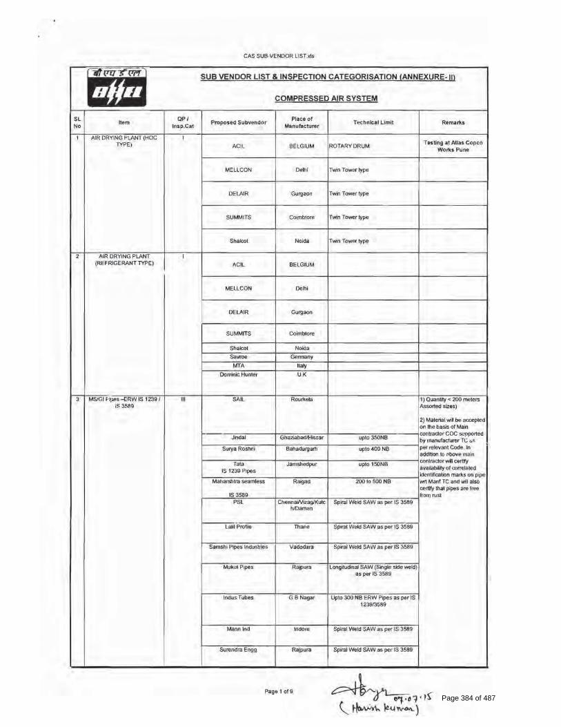
Page 384 of 487

Page 385 of 487

Page 386 of 487

Page 387 of 487

Page 388 of 487

Page 389 of 487

Page 390 of 487

Page 391 of 487

Page 392 of 487

ByAmitkumargargat12:27pm,Apr09,2018
Page 393 of 487

ByAmitkumargargat12:27pm,Apr09,2018
Page 394 of 487

Page 395 of 487

Page 396 of 487

Sl No Package Name Supplier Name Supplier Communication Address
1 PRESSURE SWITCH/DIFF. PRESSURE SWITCH
Kaustubha Udyog, S.No. 36/1/1, Sinhgad Road, Vadgaon Khurd, Near Lokmat Press, Pune, Phone- 020-24393577, Pincode : Email : [email protected],
2 PRESSURE SWITCH/DIFF. PRESSURE SWITCH
PRECISION MASS PRODUCTS PVT. LTD.
Mr. Nishit Patel/Mr. Anuj Verma Plot No.2306, Phase II, GIDC Chhatral Kalol Phone- 9999464663 Pincode :382729 Email : [email protected]
3 PRESSURE SWITCH/DIFF. PRESSURE SWITCH
SWITZER PROCESS INSTRUMENTS PVT. LTD.
Mr. V S Jayaprakash, 128, SIDCO North Phase, Ambattur Estates CHENNAI Phone- 044-26252017/2018 Pincode : 600050 Email : [email protected]
4 PRESSURE SWITCH/DIFF. PRESSURE SWITCH
DRESSER INDUSTRIES INC. Mr. Nishit Patel/Mr. Anuj Verma Plot No.2306, Phase II, GIDC Chhatral Kalol Phone- 02764-233682 Pincode :382729 Email : [email protected]
5 PRESSURE SWITCH/DIFF. PRESSURE SWITCH
SOR INC. LARRY DEGARMO/Avdhesh Chandra, 14685 W. 105TH STREET LENEXA Phone- 09810905139, Pincode :66215 Email : [email protected], [email protected],
6 PRESSURE SWITCH/DIFF. PRESSURE SWITCH
GENERAL INSTRUMENTS CONSORTIUM
Mr. Amarendra Kulkarni 194/195, Gopi Tank Road, Off.Pandurang Naik Marg, Mahim Mumbai Phone- 9323195251 Pincode : 400016 Email :[email protected]
7 PRESSURE SWITCH/DIFF. PRESSURE SWITCH
Barksdale GmbH, Germany Michael Weileder Dorn Assenheimer, Strasse 27 Reichelsheim Phone- +91-9999107840 Pincode : D-61203 Email : [email protected]
8 PRESSURE SWITCH/DIFF. PRESSURE SWITCH
INDFOS INDUSTRIES LIMITED B-20-21, INDUSTRIAL AREA, MEERUT ROAD, GHAZIABAD Phone- 0120-2712016 Pincode : Email :[email protected]
9 PRESSURE SWITCH/DIFF. PRESSURE SWITCH
INDFOS (INDIA) LIMITED MR.L.C.VENKATRANGAN/MR.B.KANNAN New No.17, II Floor, Adwave Towers, Dr.Sevalia Shivaji Salai, T.NagarChennai Phone- +91 44 24353407 Pincode : 600017Email : [email protected]
10 PRESSURE GAUGE/ DIFF.PRESSURE GAUGE
FORBES MARSHALL (HYD) LTD. MR SAILESH PATALAY/MR. M K SRINIVASAN PLOT NO.A-19/2, & T-4/2, IDA, NACHARAM, HYDERABAD Phone- 9849913704 Pincode : 500 076 Email :[email protected]
11 PRESSURE GAUGE/ DIFF.PRESSURE GAUGE
PRECISION MASS PRODUCTS PVT. LTD.
Mr. Nishit Patel/Mr. Anuj Verma Plot No.2306, Phase II, GIDC Chhatral Kalol Phone- 9999464663 Pincode :382729 Email : [email protected]
12 PRESSURE GAUGE/ DIFF.PRESSURE GAUGE
Baumer Technologies India Pvt. Ltd.
Mr. Shyam Warilani/Mr. V Suresh Babu 36, DAMJI SHAMJI INDUSTRIAL COMPLEX, OFF.-MAHAKALI CAVES ROAD, ANDHERI(E) MUMBAI Phone- +91 99589 25151 Pincode : 400093 Email : [email protected]
13 PRESSURE GAUGE/ DIFF.PRESSURE GAUGE
H.GURU INSTRUMENTS (SOUTH INDIA) P. LTD
32,INDUSTRIAL SUBURB YESWANTHAPURBANGALORE Phone- 080-23370300, Pincode : 560022Email : [email protected]
14 PRESSURE GAUGE/ DIFF.PRESSURE GAUGE
H.GURU INDUSTRIES Mr. G. D. Hazra/Mr. P. K. Mitra 10 B, HO-CHI-MINH SARANI, KOLKATA Phone- 033 2282 2463 / 1637 Pincode : 700071 Email : [email protected]
15 PRESSURE GAUGE/ DIFF.PRESSURE GAUGE
GAUGE BOURDON INDIA PVT. LTD.
194/195, Gopi Tank Road, Off Pandurang Naik Marg,Mahim Mumbai, Phone- 011-41607463, Pincode :400016, Email : [email protected],
16 PRESSURE GAUGE/ DIFF.PRESSURE GAUGE
BOSE PANDA INSTRUMENTS PVT.LTD.
Mr. Partha Bose 44, Saheed Hemanta Kumar Bose,Sarani, Kolkata Phone- +91 33 2548 7220 Pincode :700074 Email : [email protected]; bosepanda@vsnl net
17 PRESSURE GAUGE/ DIFF.PRESSURE GAUGE
A.N. INSTRUMENTS PVT. LTD. MARKETING DIVISION, 5th FLOOR, 59-B, CHOWRINGHEE ROAD, KOLKATA Phone- 24757784,22472509 Pincode : 700020 Email :[email protected]
PACKAGE WISE REGISTERED SUPPLIER LIST (PERMANENT CATEGORY) AS ON 11/3/2020 2:11:20 PM
Page 397 of 487

18 PRESSURE GAUGE/ DIFF.PRESSURE GAUGE
Nesstech Instruments Private Limited
26/2, G Type, Global Industrial Park Near Nahuli Railway Crossing, Valvada Vapi Phone- 9920576002 Pincode :396105 Email : [email protected]
19 PRESSURE GAUGE/ DIFF.PRESSURE GAUGE
SCIENTIFIC DEVICES (BOMBAY) PVT LTD,
Office no. 53, Shree Manoshi Complex, Plot No. 5 & 6, Sec-3, Ghansoli (East), Navi Mumbai, Phone- 9892230623, Pincode : 400 701, Email :[email protected]
20 TEMPERATURE GAUGE PRECISION MASS PRODUCTS PVT. LTD.
Mr. Nishit Patel/Mr. Anuj Verma Plot No.2306, Phase II, GIDC Chhatral Kalol Phone- 9999464663 Pincode :382729 Email : [email protected]
21 TEMPERATURE GAUGE Baumer Technologies India Pvt. Ltd.
Mr. Shyam Warilani/Mr. V Suresh Babu 36, DAMJI SHAMJI INDUSTRIAL COMPLEX, OFF.-MAHAKALI CAVES ROAD, ANDHERI(E) MUMBAI Phone- +91 99589 25151 Pincode : 400093 Email : [email protected]
22 TEMPERATURE GAUGE H.GURU INSTRUMENTS (SOUTH INDIA) P. LTD
32,INDUSTRIAL SUBURB YESWANTHAPURBANGALORE Phone- 080-23370300, Pincode : 560022Email : [email protected]
23 TEMPERATURE GAUGE GAUGE BOURDON INDIA PVT. LTD.
194/195, Gopi Tank Road, Off Pandurang Naik Marg,Mahim Mumbai, Phone- 011-41607463, Pincode :400016, Email : [email protected],
24 TEMPERATURE GAUGE H.GURU INDUSTRIES Mr. G. D. Hazra/Mr. P. K. Mitra 10 B, HO-CHI-MINH SARANI, KOLKATA Phone- 033 2282 2463 / 1637 Pincode : 700071 Email : [email protected]
25 TEMPERATURE GAUGE GOA THERMOSTATIC INSTRUMENTS PVT.LTD.
FLAT -B , GF, HILL CROWN APTS., COLLEGE ROAD,MAPUSA Phone- Pincode : 403525 Email :[email protected]
26 TEMPERATURE GAUGE GOA INSTRUMENTS INDUSTRIES PVT.LTD.,
D2/5, Mapusa Industrial Estate, Mapusa, Goa, Phone- 09326054551, Pincode : 403507, Email :[email protected],
27 TEMPERATURE GAUGE A.N. INSTRUMENTS PVT. LTD. MARKETING DIVISION, 5th FLOOR, 59-B, CHOWRINGHEE ROAD, KOLKATA Phone- 24757784,22472509 Pincode : 700020 Email :[email protected]
28 TEMPERATURE GAUGE FORBES MARSHALL (HYD) LTD. MR SAILESH PATALAY/MR. M K SRINIVASAN PLOT NO.A-19/2, & T-4/2, IDA, NACHARAM, HYDERABAD Phone- 9849913704 Pincode : 500 076 Email :[email protected]
29 FLOW ELEMENT TM TECNOMATIC SPA MR. ANTONIO NOVIELLO/Mrs. Enrica Bazzocc VIA DELLE INDUSTRIE, 36 CREMONA Phone- 39037221574 Pincode : 26100 Email : [email protected]
30 FLOW ELEMENT STAR-MECH CONTROLS (I) PVT.LTD.
SUSHILLOTAM, SUSHILLOTAM, 29/3A/3, SASANE NAGAR, HADAPSAR, PUNE Phone- 02026970450 Pincode : 411028 Email : [email protected]
31 FLOW ELEMENT INSTRUMENTATION LTD. KANJIKODE WEST, PALALKKAD, PALAKKAD Phone- 2566127-130,2567128 Pincode : 678623 Email :[email protected];[email protected]
32 FLOW ELEMENT MICRO PRECISION PRODUCTS PVT. LTD.
Mr. Anil Bhati, H.B. No.-40, Revenue Estate, Village-Dudhola,Tehsil & Distt. Palwal FARIDABAD Phone- 9560742713;095607427 Pincode : 121002 Email :[email protected]
33 TEMP. ELEMENT DETRIVE INSTRUMENTATION & ELECTRONICS LTD.
320, TV INDUSTIAL ESTATE, OFF.DR.A.BESANT ROAD,BEHIND GLAXO, WORLI, MUMBAI Phone- 24934125,24938403 Pincode : 400025 Email :[email protected]
34 TEMP. ELEMENT Nesstech Instruments Private Limited
26/2, G Type, Global Industrial Park Near Nahuli Railway Crossing, Valvada Vapi Phone- 9920576002 Pincode :396105 Email : [email protected]
35 TEMP. ELEMENT Thermal Instrument India Pvt. Ltd.
Mr. Raghavendra M. Kulkarni 194/195, Gopi Tank RoadBehind Citylight Cinema,Mahim Mumbai Phone- 09322664709 Pincode : 400016 Email :[email protected]
36 TEMP. ELEMENT Baumer Technologies India Pvt. Ltd.
Mr. Shyam Warilani/Mr. V Suresh Babu 36, DAMJI SHAMJI INDUSTRIAL COMPLEX, OFF.-MAHAKALI CAVES ROAD, ANDHERI(E) MUMBAI Phone- +91 99589 25151 Pincode : 400093 Email : [email protected]
Page 398 of 487

37 TEMP. ELEMENT PYRO ELECTRIC INSTRUMENTS GOA PVT.LTD.
M. D. BICHU/R. M. BICHU G.B, HILL CROWN APARTMENTS, COLLEGE ROAD, MAPUSA Phone- 9326114601 Pincode : 403507 Email :[email protected]
38 TEMP. ELEMENT GAUGE BOURDON INDIA PVT. LTD.
194/195, Gopi Tank Road, Off Pandurang Naik Marg,Mahim Mumbai, Phone- 011-41607463, Pincode :400016, Email : [email protected],
39 TEMP. ELEMENT GOA INSTRUMENTS INDUSTRIES PVT.LTD.,
D2/5, Mapusa Industrial Estate, Mapusa, Goa, Phone- 09326054551, Pincode : 403507, Email :[email protected],
40 TEMP. ELEMENT SCIENTIFIC DEVICES (BOMBAY) PVT LTD,
Office no. 53, Shree Manoshi Complex, Plot No. 5 & 6, Sec-3, Ghansoli (East), Navi Mumbai, Phone- 9892230623, Pincode : 400 701, Email :[email protected]
41 TEMP. ELEMENT TOSHNIWAL INDUSTRIES PVT. LTD.,
Industrial Estate, Makhupura, Ajmer, Phone- 9352009000, Pincode : 305002, Email : [email protected],
42 TEMP. ELEMENT Tempsens Instrument (I) Pvt Ltd
MR. V.P.RATHI/MR. HEMANT RATHI B-188A ROAD NO.5 , M.I.A UDAIPUR Phone- 09352420069 Pincode :313003 Email : [email protected]
43 TRANSMITTERS ABB INDIA LIMITED MR. RAJIV GOVIL 14, MATHURA ROAD, FARIDABAD Phone- 09971085678 Pincode : 121003 Email :[email protected]
44 TRANSMITTERS V. AUTOMAT & INTRUMENTS (P) LTD.
Mr. R. K. BASSI/Mr. PRAVEEN KUMAR F-61, OKHLA INDL.AREA, PH-1 NEW DELHI Phone- 9810005826 Pincode : 110 020 Email : [email protected]
45 TRANSMITTERS Pune Techtrol Pvt. Ltd. N.P.Khatan/Sudhakar Badiger S-18, MIDC Bhosari, Pune Phone- 9850560042 Pincode : 411 026 Email :[email protected]
46 TRANSMITTERS YOKOGAWA INDIA LIMITED, PLOT NO.96, ELECTRONICS CITY COMPLEX, HOSUR ROAD, BANGALORE, Phone- 080-41586000, Pincode : Email : [email protected],
47 TRANSMITTERS PANAM ENGINEERS Mr. Santosh Shukla 203, Jaisingh Business,Parsiwada, Sahar road,Andheri(East), Mumbai, Phone- 9892179529, Pincode : 400099, Email :[email protected],
48 TRANSMITTERS TOSHNIWAL INDUSTRIES PVT. LTD.,
Industrial Estate, Makhupura, Ajmer, Phone- 9352009000, Pincode : 305002, Email : [email protected],
49 TRANSMITTERS SBEM PVT. LTD. MR.N.K. BEDARKAR/MR. VISHWANATH KARANDIK 39, ELECTRONIC CO.OP. ESTATE, PUNE SATARA ROADPUNE, Phone- 912041030100 Pincode : 411009 Email : [email protected]
50 TRANSMITTERS Endress + Hauser (India) Pvt. Ltd.,
Mr. Prakash Vaghela 215-216, DLF Tower 'A', Jasola District Centre, New Delhi, Phone- 9717593001, Pincode : 110025, Email : [email protected],
51 TRANSMITTERS Moore Industries International Inc.
Leonard.W. Moore/ Matt Moren 16650 Schoenborn St.North Hills Phone- +1 818 830 5548 Pincode : 91343Email : [email protected]
52 TRANSMITTERS NIVO CONTROLS PVT. LTD. Mr. Praveen Toshniwal 104-115, Electronic Complex, Indore Phone- 0731-4081305 Pincode : 452010 Email : [email protected]
53 TRANSMITTERS EMERSON PROCESS MANAGEMENT (INDIA) PVT.LTD.
Mr. Amit Paithankar/Vikram Raj Singh 206-210,BALARAMA BUILDING 2ND FLR. BANDRA EASTMUMBAI Phone- 9619121500 Pincode : 400051 Email : [email protected]
54 TRANSMITTERS SIEMENS LIMITED Dr. Armin Bruck/Sandeep Mathur 130, Pandurang Budhkar Marg Worli Mumbai Phone- 0124 383 7377 Pincode : 400018 Email : [email protected]
55 TRANSMITTERS SMART INSTRUMENTS LTD, BRAZIL
Agents: Digital Electronic Ltd. 74/11 'C' Cross RoadMIDC Andheri (East) MUMBAI Phone- 28208477 Pincode : 400093 Email : [email protected]
Page 399 of 487

56 TRANSMITTERS Honeywell Automation India Limited
Mr. Ritwij Kulkarni 917, INTERNATIONAL TRADE TOWER, NEHRU PLACE, NEW DELHI Phone- 9890200584 Pincode : 110019 Email :[email protected]
57 TEMPERATURE SWITCH DRESSER INDUSTRIES INC. Mr. Nishit Patel/Mr. Anuj Verma Plot No.2306, Phase II, GIDC Chhatral Kalol Phone- 02764-233682 Pincode :382729 Email : [email protected]
58 TEMPERATURE SWITCH TOSHNIWAL BROTHERS PVT.LTD.
WORKS:TOSHNIWAL IND.PVT.LTD, INDUSTRIAL ESTATE MAKHUPURA, AJMER Phone- 441171 Pincode :305002 Email : [email protected]
59 TEMPERATURE SWITCH INDFOS (INDIA) LIMITED MR.L.C.VENKATRANGAN/MR.B.KANNAN New No.17, II Floor, Adwave Towers, Dr.Sevalia Shivaji Salai, T.NagarChennai Phone- +91 44 24353407 Pincode : 600017Email : [email protected]
60 TEMPERATURE SWITCH SWITZER PROCESS INSTRUMENTS PVT. LTD.
Mr. V S Jayaprakash, 128, SIDCO North Phase, Ambattur Estates CHENNAI Phone- 044-26252017/2018 Pincode : 600050 Email : [email protected]
61 TEMPERATURE SWITCH SOR INC. LARRY DEGARMO/Avdhesh Chandra, 14685 W. 105TH STREET LENEXA Phone- 09810905139, Pincode :66215 Email : [email protected], [email protected],
62 SIGHT FLOW INDICATORS V. AUTOMAT & INTRUMENTS (P) LTD.
Mr. R. K. BASSI/Mr. PRAVEEN KUMAR F-61, OKHLA INDL.AREA, PH-1 NEW DELHI Phone- 9810005826 Pincode : 110 020 Email : [email protected]
63 SIGHT FLOW INDICATORS BLISS ANAND PVT. LTD. Mr. Vikas Anand/ Mr.RGRajan 92B & 93 B , IMT MANESAR Gurgaon Phone- 0124-4366000 TO 9 Pincode: 122001 Email : [email protected]
64 SIGHT FLOW INDICATORS SCIENTIFIC DEVICES (BOMBAY) PVT LTD,
Office no. 53, Shree Manoshi Complex, Plot No. 5 & 6, Sec-3, Ghansoli (East), Navi Mumbai, Phone- 9892230623, Pincode : 400 701, Email :[email protected]
65 SIGHT FLOW INDICATORS B.K.EQUIPMENTS PVT.LTD. T. BALAKRlSHNAN/S.VENKATESH 217 , ARCOT ROAD PORUR , CHENNAI Phone- 9444057761 Pincode :600116 Email : [email protected]
66 SIGHT FLOW INDICATORS SIGMA INSTRUMENTS CO. Gopal Kannan/R Gopinath 201, ANANDRAJ INDUSTRIAL ESTATE, OFF.LBS MARG, SONAPUR LANE, BHANDUP (W) MUMBAI Phone- +919821038162 Pincode :400078 Email : [email protected]
67 SIGHT FLOW INDICATORS INSTRUMENTATION ENGINEERS PVT LTD
SH.N.V.RAM GOPAL/MS. N.NIHARIKA PLOTS 1,2,3, PHASE-III, IDA, JEEDIMETLA HYDERABAD Phone- 9848407365 Pincode : 500055 Email :[email protected]
68 DIFFERENTIAL PRESSURE SWITCH SOR INC. LARRY DEGARMO/Avdhesh Chandra, 14685 W. 105TH STREET LENEXA Phone- 09810905139, Pincode :66215 Email : [email protected], [email protected],
69 ANUBAR ( DELTA TUBE) STAR-MECH CONTROLS (I) PVT.LTD.
SUSHILLOTAM, SUSHILLOTAM, 29/3A/3, SASANE NAGAR, HADAPSAR, PUNE Phone- 02026970450 Pincode : 411028 Email : [email protected]
70 ANUBAR ( DELTA TUBE) DYNAFLUID VALVES AND FLOW CONTROLS (P) LTD.
Mr. Yogish M. Kulkarni Plot # 23, Udyambag, Belgaum Phone- 0831-4210386 Pincode : 590008 Email :[email protected]
71 ANUBAR ( DELTA TUBE) MICRO PRECISION PRODUCTS PVT. LTD.
Mr. Anil Bhati, H.B. No.-40, Revenue Estate, Village-Dudhola,Tehsil & Distt. Palwal FARIDABAD Phone- 9560742713;095607427 Pincode : 121002 Email :[email protected]
72 ANUBAR ( DELTA TUBE) SWITZER PROCESS INSTRUMENTS PVT. LTD.
Mr. V S Jayaprakash, 128, SIDCO North Phase, Ambattur Estates CHENNAI Phone- 044-26252017/2018 Pincode : 600050 Email : [email protected]
73 ANUBAR ( DELTA TUBE) MINCO (INDIA) PRIVATE LIMITED
Mr. Rajeev Vasudeva, D/35, TIVIM INDUSTRIAL ESTATE, KARASWADA, MAPUSA, Goa, Phone- 9313637073 Pincode : 403526, Email : [email protected]
Page 400 of 487

74 JUNCTION BOX K.S.INSTRUMENTS PVT.LTD. S Raghavan No. 72, 3rd Main, 1st Stage Industrial Suburb, Yeshwanthpur Bangalore Phone- 9880385770 Pincode : 560022 Email : [email protected]
75 JUNCTION BOX SUCHITRA INDUSTRIES NO-2,OPP-27 AECS LAYOUT 2ND STG REJAMAHALVILAS EXTN 2ND STG BANGALORE Phone- Pincode :Email : [email protected]
76 JUNCTION BOX FLEXPRO ELECTRICALS PVT. LTD.
Mr. Dineshbhai Zaveri C-1/ 27&37, GIDC, Kabilpore,Navsari Phone- 02637-265140,265003 Pincode : 396424 Email : [email protected]
77 JUNCTION BOX Shrenik & Company, Mr. Mitesh Shah/Mr. Pulin Shah 39 A/3 ,Panchratna Industrial Estate, Sarkhej-Bavla Road Ahmedabad Phone- 9825024921 Pincode : 382213 Email :[email protected], [email protected]
78 JUNCTION BOX AJMERA INDUSTRIAL & ENGINEERING WORKS
JIGNESH MAHENDRA AJMERA DENA BANK BLDG.,SHREE NAGESH INDL. ESTATE,STATION ROAD, MUMBAI Phone- 022 67973578 Pincode : 400 088 Email :[email protected], [email protected]
79 Cold Junction Compensation Box (CJCB)
CREATIVE INSTRUMENTS & CONTROLS
NO-17/1 , 1ST FLOOR , 11TH CROSS 1ST K BLOCK , RAJAJINAGAR, BANGALORE-560010 Phone- Pincode : Email : [email protected]
80 INSTRUMENTS TUBE FITTINGS VIKAS INDUSTRIAL PRODUCTS S.R.SINGH/NAVEEN SINGH B - 2, SECTOR - 6, NOIDA Phone- +91-9810122070 Pincode : 201301 Email :[email protected]
81 INSTRUMENTS TUBE FITTINGS PRECISION ENGINEERING INDUSTRIES
K. SITARAM/ K. SRINIVAS 7,SIDHAPURA INDUSTRIAL ESTATE S.V. ROAD,GOREGAON(W) MUMBAI Phone- 022 42631700 Pincode : 400 062 Email :[email protected]
82 INSTRUMENTS TUBE FITTINGS AURA INCORPORATED NIRAJ SHARAN/SUJIT KUMAR W-167A, GREATER KAILASH-II NEW DELHI Phone- 9810182430 Pincode : 110048 Email : [email protected]
83 INSTRUMENTS TUBE FITTINGS Fluid Controls Pvt. Ltd. Sophie Y. Moochhala/Mayur Rajput J.V.PATEL, I.T.I CMPD, B.MADHUKAR MARG, ELPHINSTONE ROADSTN.(WR), MUMBAI Phone- (022) 43338000 Pincode : 400013 Email : [email protected]
84 ROTAMETER INSTRUMENTATION ENGINEERS PVT LTD
SH.N.V.RAM GOPAL/MS. N.NIHARIKA PLOTS 1,2,3, PHASE-III, IDA, JEEDIMETLA HYDERABAD Phone- 9848407365 Pincode : 500055 Email :[email protected]
85 ROTAMETER TANSA EQUIPMENTS PVT. LTD. Mr. Vardhan Tamhankar, Unit No35/36/41,Om Anand Industrial Est. Mohanjee Sundarjee Road,Raghunath Nagar, Thane Phone- 022-25832323 Pincode : 400604Email : [email protected]
86 ROTAMETER EUREKA INDUSTRIAL EQUIPMENTS PVT.LTD.
Mr V. K. Pandit/Mr Ashish Shaha 17-20, Royal chambers, Paud Road Pune Phone- 9370469466 Pincode :411038 Email : [email protected]
87 ROTAMETER SCIENTIFIC DEVICES (BOMBAY) PVT LTD,
Office no. 53, Shree Manoshi Complex, Plot No. 5 & 6, Sec-3, Ghansoli (East), Navi Mumbai, Phone- 9892230623, Pincode : 400 701, Email :[email protected]
88 INSTRUMENTS PIPE FITTINGS AURA INCORPORATED NIRAJ SHARAN/SUJIT KUMAR W-167A, GREATER KAILASH-II NEW DELHI Phone- 9810182430 Pincode : 110048 Email : [email protected]
89 INSTRUMENTS PIPE FITTINGS PRECISION ENGINEERING INDUSTRIES
K. SITARAM/ K. SRINIVAS 7,SIDHAPURA INDUSTRIAL ESTATE S.V. ROAD,GOREGAON(W) MUMBAI Phone- 022 42631700 Pincode : 400 062 Email :[email protected]
90 INSTRUMENTS PIPE FITTINGS VIKAS INDUSTRIAL PRODUCTS S.R.SINGH/NAVEEN SINGH B - 2, SECTOR - 6, NOIDA Phone- +91-9810122070 Pincode : 201301 Email :[email protected]
91 INSTRUMENTS PIPE FITTINGS Fluid Controls Pvt. Ltd. Sophie Y. Moochhala/Mayur Rajput J.V.PATEL, I.T.I CMPD, B.MADHUKAR MARG, ELPHINSTONE ROADSTN.(WR), MUMBAI Phone- (022) 43338000 Pincode : 400013 Email : [email protected]
92 ULTRASONIC FLOW METERS Electronet Equipments Pvt Ltd. Mr. Rajendra Nagaonkar/MD, Plot No. 84, 85 & 86, Tiny Industrial Estate Kondhwa Budruk, Pune Phone- 9822015256 Pincode : 411048 Email :[email protected]
Page 401 of 487

93 ULTRASONIC FLOW METERS Adept Fluidyne Pvt. Ltd. Vinayak Gadre Plot No 4,S.No.17/1-B Kothrud Industrial Estate Pune Phone- 020 25464551 Pincode : 411038Email : [email protected]
94 ULTRASONIC FLOW METERS FLEXIM Flexible Industriemesstechnik GmbH
Boxberger Str., 4, Berlin Berlin Phone- 0049 30 93 66 76 60 Pincode : 12681 Email : [email protected]
95 ULTRASONIC FLOW METERS Rockwin Flowmeter India Pvt. Ltd.
B-24, Site-IV, Sahibabad Industrial Area Ghaziabad, Phone- 9810129687 Pincode : 201010, Email :[email protected]
96 ULTRASONIC FLOW METERS FLASH FORGE PVT LTD Mr. Gautam Makker, 503, 'A'-wing, Delphi, Orchard Avenue Road, Powai Mumbai Phone- 022-42784300 Pincode : 400076 Email : [email protected]
97 ULTRASONIC FLOW METERS TOSHNIWAL INDUSTRIES PVT. LTD.,
Industrial Estate, Makhupura, Ajmer, Phone- 9352009000, Pincode : 305002, Email : [email protected],
98 ULTRASONIC FLOW METERS NIVUS GMBH Mr. Marcus Fischer Im Taele 2, D - 75031 Eppingen Phone- 00491712233770 Pincode : Email :[email protected]
99 FLOW ELEMENT - ORIFICE TANSA EQUIPMENTS PVT. LTD. Mr. Vardhan Tamhankar, Unit No35/36/41,Om Anand Industrial Est. Mohanjee Sundarjee Road,Raghunath Nagar, Thane Phone- 022-25832323 Pincode : 400604Email : [email protected]
100 FLOW ELEMENT - ORIFICE MINCO (INDIA) PRIVATE LIMITED
Mr. Rajeev Vasudeva, D/35, TIVIM INDUSTRIAL ESTATE, KARASWADA, MAPUSA, Goa, Phone- 9313637073 Pincode : 403526, Email : [email protected]
101 FLOW ELEMENT - ORIFICE SCIENTIFIC DEVICES (BOMBAY) PVT LTD,
Office no. 53, Shree Manoshi Complex, Plot No. 5 & 6, Sec-3, Ghansoli (East), Navi Mumbai, Phone- 9892230623, Pincode : 400 701, Email :[email protected]
102 FLOW ELEMENT - ORIFICE Electronet Equipments Pvt Ltd. Mr. Rajendra Nagaonkar/MD, Plot No. 84, 85 & 86, TinyIndustrial Estate Kondhwa Budruk, Pune Phone- 9822015256 Pincode : 411048 Email :[email protected]
103 FLOW ELEMENT - ORIFICE INSTRUMENTATION LTD. KANJIKODE WEST, PALALKKAD, PALAKKAD Phone- 2566127-130,2567128 Pincode : 678623 Email :[email protected];[email protected]
104 FLOW ELEMENT - ORIFICE MICRO PRECISION PRODUCTS PVT. LTD.
Mr. Anil Bhati, H.B. No.-40, Revenue Estate, Village-Dudhola,Tehsil & Distt. Palwal FARIDABAD Phone- 9560742713;095607427 Pincode : 121002 Email :[email protected]
105 FLOW ELEMENT - ORIFICE MINCO (INDIA) FLOW ELEMENTS PVT. LTD.
Mr. Raghavendra M. Kulkarni D2-49/50, Tivim Industrial Estate, Karaswada Mapusa Phone- 0832-2257059 Pincode : 403526 Email :[email protected]
106 FLOW ELEMENT - ORIFICE STAR-MECH CONTROLS (I) PVT.LTD.
SUSHILLOTAM, SUSHILLOTAM, 29/3A/3, SASANE NAGAR, HADAPSAR, PUNE Phone- 02026970450 Pincode : 411028 Email : [email protected]
107 FLOW ELEMENT - ORIFICE CHEMTROLS INDUSTRIES PVT. LTD.
Mr. K. NANDAKUMAR AMAR HILL, SAKI VIHAR ROAD,POWAI, MUMBAI Phone- 022-67151261 Pincode :400072 Email : [email protected]
108 FLOW ELEMENT - ORIFICE INSTRUMENTATION ENGINEERS PVT LTD
SH.N.V.RAM GOPAL/MS. N.NIHARIKA PLOTS 1,2,3, PHASE-III, IDA, JEEDIMETLA HYDERABAD Phone- 9848407365 Pincode : 500055 Email :[email protected]
109 FLOW ELEMENT - ORIFICE DYNAFLUID VALVES AND FLOW CONTROLS (P) LTD.
Mr. Yogish M. Kulkarni Plot # 23, Udyambag, Belgaum Phone- 0831-4210386 Pincode : 590008 Email :[email protected]
110 FLOW ELEMENT - NOZZLE MICRO PRECISION PRODUCTS PVT. LTD.
Mr. Anil Bhati, H.B. No.-40, Revenue Estate, Village-Dudhola,Tehsil & Distt. Palwal FARIDABAD Phone- 9560742713;095607427 Pincode : 121002 Email :[email protected]
111 FLOW ELEMENT - NOZZLE MINCO (INDIA) FLOW ELEMENTS PVT. LTD.
Mr. Raghavendra M. Kulkarni D2-49/50, Tivim Industrial Estate, Karaswada Mapusa Phone- 0832-2257059 Pincode : 403526 Email :[email protected]
Page 402 of 487

112 FLOW ELEMENT - NOZZLE STAR-MECH CONTROLS (I) PVT.LTD.
SUSHILLOTAM, SUSHILLOTAM, 29/3A/3, SASANE NAGAR, HADAPSAR, PUNE Phone- 02026970450 Pincode : 411028 Email : [email protected]
113 FLOW ELEMENT - NOZZLE DYNAFLUID VALVES AND FLOW CONTROLS (P) LTD.
Mr. Yogish M. Kulkarni Plot # 23, Udyambag, Belgaum Phone- 0831-4210386 Pincode : 590008 Email :[email protected]
114 FLOW ELEMENT - NOZZLE INSTRUMENTATION LTD. KANJIKODE WEST, PALALKKAD, PALAKKAD Phone- 2566127-130,2567128 Pincode : 678623 Email :[email protected];[email protected]
115 FLOW ELEMENT - NOZZLE MINCO (INDIA) PRIVATE LIMITED
Mr. Rajeev Vasudeva, D/35, TIVIM INDUSTRIAL ESTATE, KARASWADA, MAPUSA, Goa, Phone- 9313637073 Pincode : 403526, Email : [email protected]
116 INSTRUMENT FITTINGS HP VALVES & FITTINGS INDIA PVT. LTD.
S. Harichandran/P.S. Pandi B-11, Mugappair Industrial Estate, CHENNAI Phone- 044 26252537 Pincode :600037 Email : [email protected]
117 INSTRUMENT FITTINGS Perfect Instrumentation Control (India) Pvt. Ltd.
MD Hussain Shaikh/Shahanawaz Khan Gala No. 168, Loheki Chwal,216/ 218, Maulana Azad Rd. Nagpada Junction Mumbai Phone- 91-9324383121 Pincode :400008 Email :[email protected]
118 INSTRUMENT FITTINGS Arya Crafts & Engineering Pvt. Ltd.
Mr.Sanjay Brahman/Mr.Shyam Vazirani 102, Vora Industrial Estate No.4 Navghar, Vasai Road (E)Dist.Thane, Mumbai Phone- +91-250-2392246 Pincode : 401210 Email : [email protected]
119 INSTRUMENT FITTINGS FLUIDFIT ENGINEERS PVT. LTD. Mr. Abbas Bhola Potia Building No. 2, Office No. 3,292,Bellasis Road,Mumbai Central (East) Mumbai Phone- 9920044113 Pincode : 400008 Email :[email protected]
120 INSTRUMENT FITTINGS VIKAS INDUSTRIAL PRODUCTS S.R.SINGH/NAVEEN SINGH B - 2, SECTOR - 6, NOIDA Phone- +91-9810122070 Pincode : 201301 Email :[email protected]
121 INSTRUMENT FITTINGS Fluid Controls Pvt. Ltd. Sophie Y. Moochhala/Mayur Rajput J.V.PATEL, I.T.I CMPD, B.MADHUKAR MARG, ELPHINSTONE ROADSTN.(WR), MUMBAI Phone- (022) 43338000 Pincode : 400013 Email : sales@fluidcontrols com
122 INSTRUMENT FITTINGS PANAM ENGINEERS Mr. Santosh Shukla 203, Jaisingh Business,Parsiwada, Sahar road,Andheri(East), Mumbai, Phone- 9892179529, Pincode : 400099, Email :[email protected],
123 INSTRUMENT FITTINGS PRECISION ENGINEERING INDUSTRIES
K. SITARAM/ K. SRINIVAS 7,SIDHAPURA INDUSTRIAL ESTATE S.V. ROAD,GOREGAON(W) MUMBAI Phone- 022 42631700 Pincode : 400 062 Email :[email protected]
124 INSTRUMENT FITTINGS AURA INCORPORATED NIRAJ SHARAN/SUJIT KUMAR W-167A, GREATER KAILASH-II NEW DELHI Phone- 9810182430 Pincode : 110048 Email : [email protected]
125 INSTRUMENT FITTINGS Comfit & Valve Pvt. Ltd. Mr. Jeetu Jain/Mr. Vinay Sosa Survey No. 23/1, Part 2, Ahmedabad-Mehsana Highway Laxmipura, Nandasan Phone- 02764-267036/37 Pincode : 382705 Email :[email protected]
126 ELECTROMAGNETIC FLOW METER Adept Fluidyne Pvt. Ltd. Vinayak Gadre Plot No 4,S.No.17/1-B Kothrud Industrial Estate Pune Phone- 020 25464551 Pincode : 411038Email : [email protected]
127 ELECTROMAGNETIC FLOW METER Electronet Equipments Pvt Ltd. Mr. Rajendra Nagaonkar/MD, Plot No. 84, 85 & 86, Tiny Industrial Estate Kondhwa Budruk, Pune Phone- 9822015256 Pincode : 411048 Email :[email protected]
128 ELECTROMAGNETIC FLOW METER V.A Valves Mr.Vishal Jain, Udyog Nagar, Gadaipur, Jalandhar Phone- 9872626376 Pincode : 144004 Email :[email protected]
129 ELECTROMAGNETIC FLOW METER SCIENTIFIC DEVICES (BOMBAY) PVT LTD,
Office no. 53, Shree Manoshi Complex, Plot No. 5 & 6, Sec-3, Ghansoli (East), Navi Mumbai, Phone- 9892230623, Pincode : 400 701, Email :[email protected]
130 ELECTROMAGNETIC FLOW METER NIVO CONTROLS PVT. LTD. Mr. Praveen Toshniwal 104-115, Electronic Complex, Indore Phone- 0731-4081305 Pincode : 452010 Email : [email protected]
Page 403 of 487

SIPAT STAGE-II, 2X500MW FGD
COMPRESSED AIR SYSTEM
SPECIFICATION NO. PE-TS-491-555-A001
VOLUME : II B
SECTION : E / ANNEXURE-II
REV 00 DATE: JULY 22
SHEET: 1 OF 1
1.1
P E M - 6 6 6 6 - 0
ANNEXURE-II
PAINTING & COLOUR SCHEME
Page 404 of 487

CLAUSE NO.
TECHNICAL REQUIREMENTS
LOT-6 PROJECTS
FLUE GAS DESULPHURISATION (FGD) SYSTEM
PACKAGE
TECHNICAL SPECIFICATION
SECTION-VI
BID DOC. NO.:CS-0011-109(6)-9
PART-B
SUB-SECTION-I-M3
COMPRESSED AIR
SYSTEM
PAGE 6 OF 6
in case the system pressure does not drop and compressor continues to idle for more than a pre-set time.
9.02.04 The control system shall provide warning to the operator that a hot-start condition exists for the motor driver and adequate cool-down period has not occurred after the motor was shut down.
9.02.05 The alarms and shutdown scheme mentioned below are suggestive and shall be provided as per manufacturer's standard practice meeting the safe operational requirement of the equipment/system each compressor:-
(a) "Air temperature high" at inlet to last stage Alarm & trip
(b) "Low lube oil pressure" Alarm & trip
(c) "High Lube oil supply temperature" Alarm & trip
(d) "High oil filter differential pressure" Alarm
(e) "Low lube oil level in lube oil sump" Alarm
(f) "High inlet air filter differential pressure" Alarm & trip
(g) "Low cooling water flow to air compressor" Alarm
9.03.00 Air Drying Plant
9.03.01 Sequential operation of the adsorber towers & air compressors shall be controlled automatically with a provision for manual take over.
9.03.02 Change over of tower from drying mode to regeneration mode shall happen automatically if the dew point is high at the outlet of ADP sensed by the dew point (using aluminium oxide probe) meter/sensor. Automatic operation during regeneration, starting and stopping of blowers, starting and stopping of heaters, etc shall be timer controlled. During the process, in case, operation is taken over manually from the panel through push button or selector switch, the sequential operation shall start with the manual initiation for each of the steps.
9.02.03 The control system shall provide the (as minimum) alarms, "High Reactivation air temperature", "Low Reactivation air temperature", "Low cooling water flow", "Low air pressure at the outlet of ADP" and "High dew point at the outlet of ADP". Adequate number of temperature elements etc. shall be provided for measurement and monitoring of the same.
9.02.04 For rotary drum type Air drying plant, control philosophy as per manufacture’s standard and proven practice is also acceptable.
10.00.00 PAINTING
All the equipments shall be protected against external corrosion by providing suitable painting.
The surface of SS, galvanized steel, Gun metal, Brass, Bronze and non-metallic components shall not be applied with any painting.
The steel surface to be applied with painting shall be thoroughly cleaned before applying painting by brushing, shot blasting etc as per standard procedure.
Page 405 of 487
3062805
Line

SIPAT STAGE-II, 2X500MW FGD
COMPRESSED AIR SYSTEM
SPECIFICATION NO. PE-TS-491-555-A001
VOLUME : II B
SECTION : E / ANNEXURE-III
REV 00 DATE: JULY 22
SHEET: 1 OF 1
1.1
P E M - 6 6 6 6 - 0
ANNEXURE-III
MASTER DRAWING LIST WITH SCHEDULE OF SUBMISSION
Page 406 of 487

PROJECT KAHALGAON TPS PACKAGE-COMPRESSED AIR SYSTEM NOA DATE
"A"
S NO
"B"
VENDOR_DRG_NO.
"D"
DRAWING TITLE
"E"
PURPOSE
"G"
NAME OF BOI
"H"
SCHEDULED
SUBMISSION (NO. OF
WEEKS FROM LOA
DATE/SCH PO
DATE)(*)
1 PE-V0-491-555-A001QUALITY PLAN OF AIR COMPRESSOR FOR FGD COMPRESSED AIR
SYSTEMA-CUST
CAS 2
2 PE-V0-491-555-A002QUALITY PLAN OF AIR DRYING PLANT FOR FGD COMPRESSED AIR
SYSTEMA-CUST
CAS 2
3 PE-V0-491-555-A003QUALITY PLAN OF AIR RECEIVER FOR FGD COMPRESSED AIR
SYSTEMA-CUST
CAS 3
4 PE-V0-491-555-A004 QUALITY PLAN OF MOTOR FOR FGD COMPRESSED AIR SYSTEM A-CUSTCAS
3
5 PE-V0-491-555-A005 TDS OF AIR COMPRESSOR FOR FGD COMPRESSED AIR SYSTEM A-CUSTCAS
2
6 PE-V0-491-555-A006 TDS OF AIR DRYING PLANT FOR FGD COMPRESSED AIR SYSTEM A-CUSTCAS
2
7 PE-V0-491-555-A007TDS & CHARACTERISTIC CURVES OF MOTOR FOR FGD
COMPRESSED AIR SYSTEMA-CUST
CAS 3
8 PE-V0-491-555-A008 TDS & GA OF VALVES FOR FGD COMPRESSED AIR SYSTEM I-CUSTCAS
5
9 PE-V0-491-555-A010 TDS OF INSTRUMENTS FOR FGD COMPRESSED AIR SYSTEM I-CUSTCAS
5
10 PE-V0-491-555-A011GA DRAWING OF AIR COMPRESSOR FOR FGD COMPRESSED AIR
SYSTEMI-CUST
CAS 3
11 PE-V0-491-555-A012 GA DRAWING OF AIR DRYER FOR FGD COMPRESSED AIR SYSTEM I-CUSTCAS
3
12 PE-V0-491-555-A013 GA DRAWING OF MOTOR FOR FGD COMPRESSED AIR SYSTEM I-CUSTCAS
3
13 PE-V0-491-555-A014 GA DRAWING OF AIR RECEIVER FOR FGD COMPRESSED AIR SYSTEM I-CUSTCAS
3
14 PE-V0-491-555-A015 COMPRESSOR HOUSE LAYOUT A-CUSTCAS
4
15 PE-V0-491-555-A016P & I DIAGRAM OF AIR COMPRESSOR FOR FGD COMPRESSED AIR
SYSTEMI-CUST
CAS 2
16 PE-V0-491-555-A017 P&I DIAGRAM OF AIR DRYER FOR FGD COMPRESSED AIR SYSTEM I-CUSTCAS
2
17 PE-V0-491-555-A018P&I DIAGRAM OF FGD COMPRESSED AIR SYSTEM WITHIN
COMPRESSOR HOUSEA-CUST
CAS 3
18 PE-V0-491-555-A019OPERATION & CONTROL PHILOSOPHY OF FGD COMPRESSED AIR
SYSTEMA-CUST
CAS 3
19 PE-V0-491-555-A020ELECTRICAL & INTERNAL WIRING DIAGRAM FOR COMPRESSOR
PANEL FOR FGD COMPRESSED AIR SYSTEM.I-CUST
CAS 2
20 PE-V0-491-555-A021 ELECTRICAL FEEDER LIST FOR FGD COMPRESSED AIR SYSTEM I-G-PCAS
3
21 PE-V0-491-555-A022 CONTROL CABLE SCHEDULE FOR FGD COMPRESSED AIR SYSTEM I-G-PCAS
5
22 PE-V0-491-555-A023 PG TEST PROCEDURE FOR FGD COMPRESSED AIR SYSTEM I-CUSTCAS
7
23 PE-V0-491-555-A024 O&M MANUAL-FGD COMP AIR SYSTEM I-CUSTCAS
12
24 PE-V0-491-555-A029SUB-VENDOR LIST WITH INSPECTION CATEGORISATION PLAN FOR FGD COMPRESSED AIR SYSTEM
A-CUST
CAS
1
MDL FOR CAS PACKAGE FOR SIPAT STAGE-II, 2X500MW FGD
Page No : 1 of 1
Page 407 of 487

SIPAT STAGE-II, 2X500MW FGD
COMPRESSED AIR SYSTEM
SPECIFICATION NO. PE-TS-491-555-A001
VOLUME : II B
SECTION : E / ANNEXURE-IV
REV 00 DATE: JULY 22
SHEET: 1 OF 1
1.1
P E M - 6 6 6 6 - 0
ANNEXURE-IV
SITE STORAGE AND PRESERVATION
Page 408 of 487

MATERIAL STORAGE AND PRESERVATION GUIDELINES
DOC. NO. : QS-01-CQA-W-21 REV. NO. : 0 REV. DATE : PAGE : 1 OF 33
ENGINEERING DIVISON
DEPARTMENTAL MANUAL
WORK INSTRUCTION CORPORATE QUALITY ASSURANCE
PURPOSE
To implement uniform system of storage and preservation throughout
NTPC projects in order to ensure that all equipment/ materials/ spares/
components received at site are stored and preserved in accordance with
the relevant preservation requirements to minimize impairment to
equipment/materials/spares and financial loss to company due to
improper storage and preservation.
1.0 SCOPE
These guidelines cover the requirements of storage and preservation of
all equipment/ materials/ spares/ components received at site for
corporate awarded and site awarded Contracts/Purchase Orders during
Project construction stage/O&M phase of NTPC Projects/Power stations.
2.0 DEFINITIONS
As per ISO 9001-2000 and Divisional Procedure (Doc. No. QS-01-QAI-
Q-00 – Quality System (General).
3.0 REFERENCES
3.1 ISO 9001-2008- Clause No. 7.4
4.0 PROCESS
4.1 The responsibility for distribution of the applicable “Material Storage and Preservation
Guideline” at site (to concerned departments) shall rest with the Head (FQA).Implementation of
the same shall be the responsibility of concerned departments.
4.2 Where storage is the responsibility of contractor: The execution/Erection/Construction
department shall ensure proper storage and preservation of
equipment/materials/spares/components as per supplier’s instructions. In absence of any
supplier’s instructions and not specifically tied up, these guidelines shall be followed. It should
be ensured that contractor’s stores for the materials are located within the Project area.
Page 409 of 487

MATERIAL STORAGE AND PRESERVATION GUIDELINES
DOC. NO. : QS-01-CQA-W-21 REV. NO. : 0 REV. DATE : PAGE : 2 OF 33
ENGINEERING DIVISON
DEPARTMENTAL MANUAL
WORK INSTRUCTION CORPORATE QUALITY ASSURANCE
4.3 Where storage is the responsibility of NTPC: Material Management Department at site shall
ensure proper storage and preservation of equipment/materials/spares/components as per
supplier’s instructions. In absence of any supplier’s instructions these guidelines shall be
followed.
For long term storage, provisions of OGN, No.: OGN/OPS/SYST/017 issued by Corporate OS
shall also be applicable in the above cases.
4.4 FQA engineer shall Audit storage and preservation activities at site as per QS-01-FQA-P-
09(both NTPC and Contractor’s stores.)
4.5 Any system deficiencies noticed by the FQA Engineer during Audit shall be brought to the
notice of the HEAD (FQA). Exceptions shall be put up to the HEAD of Project by HEAD
(FQA). FQA may avail the services of CQA for preparation of Audit Check Lists.
5.0 ASSOCIATED DOCUMENT: Nil
Page 410 of 487

MATERIAL STORAGE AND PRESERVATION GUIDELINES
DOC. NO. : QS-01-CQA-W-21 REV. NO. : 0 REV. DATE : PAGE : 3 OF 33
ENGINEERING DIVISON
DEPARTMENTAL MANUAL
WORK INSTRUCTION CORPORATE QUALITY ASSURANCE
LEGEND Type of Storage: Type I Open Yard: Open yard shall be levelled & raised platform (Wooden sleeper/Concrete/Brick
paved) free from water logging/shrubs/vegetation etc., with a provision of feeder road along
with access roads running all sides. Fire fighting arrangements shall be provided at strategic
locations.
While stacking provide space for inserting slings for easy handling without disturbing nearby
components. The components shall be stored in such a way that the identification marks are
visible. The number of components stacked one over the other shall be restricted, as given
below:
a) Coils received in crates shall be stored independently.
b) Panels shall not be stacked more than five numbers.
c) Stacking of duct wall, plates etc, shall be restricted to seven numbers.
d) Stacking of columns shall be restricted to three numbers. e) APH modules shall be stored independently.
Type II Open Yard with Tarpaulin Cover/Canopy: In the open Yard, some of the critical components (such as components having machined parts/components susceptible of water ingression) which
may be adversely affected due to direct contact of water are covered with Tarpaulin/polyethylene sheet/Canopy.
Type III Semi closed Shed: Raised & paved (Concrete/Cemented) levelled platform with covered Shed (Pre-coated profile sheets/GI sheets may be used for roofing) clean & free from rain, acid,
fumes and direct sunlight. Sides need not be closed. Item to be stored in packed condition as supplied by Manufacturer. Item should be properly identified, tagged, each package should be
accessible through walkway for material handling equipment. Adequate fire fighting equipments shall be provided & shall be suitably located in such a way that during emergency
situation they could be easily handled. Small components properly identified, tagged and stored
over steel racks/shelf. Type IV Fully closed Shed: Raised & paved (Concrete/ Cemented) platform with all sides covered shed
in dry, dust free & ventilated environment. Shed shall be free from insect, rodent and pest. Item
should be stored in packed condition as supplied by Manufacturer. Item should be properly
Identified, Tagged, Accessible for material handling equipment. Adequate fire fighting
equipments shall be provided & shall be suitably located in such a way that during emergency
situation they could be easily handled. Components shall be stacked properly taking into
consideration of handling and preservation. Small components shall be stored on racks/shelf
with the components identification Nos. Written on tags. In no case, components which do not
have packing shall be placed directly on the floor. Adequate space shall be left between the
stacking for easy handling during storage, preservation and issue of components. Type V Fully closed Shed with dry, clean and controlled atmosphere: Fully closed Shed with
additional provision of false ceiling & the room shall be maintained with dry, clean & Temperature and Humidity controlled atmosphere suitable for storing components like process
instruments/ fitting/electronic control panels/ C&I items etc.
The instruments shall be properly identified, tagged and stored over steel racks/shelf, cupboards
as appropriate. The original packing need not be disturbed unless otherwise warranted.
Page 411 of 487

MATERIAL STORAGE AND PRESERVATION GUIDELINES
DOC. NO. : QS-01-CQA-W-21 REV. NO. : 0 REV. DATE : PAGE : 4 OF 33
ENGINEERING DIVISON
DEPARTMENTAL MANUAL
WORK INSTRUCTION CORPORATE QUALITY ASSURANCE
Preservation Class:
A Preservation of machined surface with Temporary Rust Preventive Fluid
(TRPF)/primer/grease.
B Preservation of machined surface with Temporary Rust Preventive Fluid (TRPF)/grease,
covered with fire proof Tarpaulin.
C Cleaning and applying De-oxy aluminate or primer on weld edges and Zinc chromate primer
on all other surfaces.
D Application of Rust Guard/ Multipurpose Grease for Bearings etc.
E Preservation with Zinc Chrome Primer/ Red Oxide for un-machined surfaces & multipurpose grease for threaded portion, for all storage types.
F Preservation of internal surface of Tubes using Silica Gel (SS items).
G Preservation of Control Panels using Silica Gel.
H Nitrogen/Oil filled Transformer Tanks.
General Notes-
(1) If storage type and preservation class have not been mentioned for items/components, the same
shall be done as per OEM guidelines/manual.
(2) Before storing the equipment it should be checked for any damage to packing.
(3) Handling of equipments should be done with utmost care without damaging package/equipments
and only by authorised manpower & requisite tools tackles.
(4) All equipment should be accommodated in the designated place of storage immediately after
arrival at destination. This is very essential particularly during the rainy season.
(5) The store houses and areas around them should have proper drainage facility for the sub-soil,
surface and rain water. The water should not be allowed to stand or get accumulated in these
areas, especially where the material has been stored.
(6) Level should be maintained for all the packages and equipment and should be uniformly
supported to avoid distortion. The long packages should be supported at intermediate places also,
so as to avoid sagging during storage.
(7) Store houses should preferably be equipped with proper lifting devices to ensure normal
handling of equipment.
(8) Small and medium size parts can be kept on shelves with proper identification tags.
(9) For heavier components under Type ‘III’, the roof/walls may be constructed/fabricated after
placement of the component on cemented/pucca hard floor
Page 412 of 487

MATERIAL STORAGE AND PRESERVATION GUIDELINES
DOC. NO. : QS-01-CQA-W-21 REV. NO. : 0 REV. DATE : PAGE : 5 OF 33
ENGINEERING DIVISON
DEPARTMENTAL MANUAL
WORK INSTRUCTION CORPORATE QUALITY ASSURANCE
GENERAL GUIDELINES FOR STORAGE AND PRESERVATION
System /Package Description of the Item/Components
Type of Storage
Preservation Class
Checks Periodicity of checking
Remarks
Boiler & Aux. ( Pressure parts)
Drum with Internal I E Damage, Painting, end cap,
6 months
‘U’ Rod II A&E Damage, painting, preservation of thread
do
Drum Internals (if sent
loose)
IV E Damage, preservation do
Water wall Headers &
Links
I C, E Damage, painting,
protective coating to threads, End cap
do
Water wall panels I C, E, F do do
Down comer pipes I C, E do do
Riser tubes I C, E do do
Hanger tubes I C, E do do
Arch tubes I C, E do do
Transition tubes I C, E do do
Furnace insert tubes I C, E do do
Water wall and down
comer suspension
I A, E do do
Transition tubes & Furnace insert tubes
I C, E, F Damage, End cap, painting
do
Constant Load Hanger &
Variable Load Hanger III A, E Protective coating to
threads
do Protection of threads
portion to be ensured
Seismic guide IV E Damage, painting do
Pressure parts seals, hand hold plate and seal weld removal tool
IV A, E Damage, painting, protective coating
do
Welding consumable IV - Damage to packing,
dryness room
do Refer weld
consumable storage
work instruction QS-01-CQA-W-19
Buck stays & Furnace
bottom supports
I E Damage & painting do
Fasteners & other small components
IV A Damage & protective coating
do
Seal boxes I E Damage, painting, do
Instrument tapings IV E do do
Super heater Headers I E, F Damage, painting,
End caps
do
Super heater coils, SH screen tubes and panels
I C, E, F do do
Connecting tubes, terminal tubes, steam cooled spacer tubes and
hanger tubes.
I C, E, F do do
Supports, Roof casing &
pressure parts
attachment, Baffles
I E Damage, painting &
protection for threads
do
Vibration snubber and
mechanical spacer
IV E Mechanical damage do
Economiser coil/ headers/ Hanger tube
I C, E, F Damage, painting, End caps
do
Economiser links and feed pipes
I E, F do do
Page 413 of 487

MATERIAL STORAGE AND PRESERVATION GUIDELINES
DOC. NO. : QS-01-CQA-W-21 REV. NO. : 0 REV. DATE : PAGE : 6 OF 33
ENGINEERING DIVISON
DEPARTMENTAL MANUAL
WORK INSTRUCTION CORPORATE QUALITY ASSURANCE
Boiler & Aux. (Soot blowing
System)
Long retractable soot
blower
II B, E Damage, painting
preservative & end cap
6 months
Wall/ Rotary blowers IV A, E do do
Temperature probe IV B. E do do
Soot Blowing System Piping
I C, E, F do
do
Blower for seal oil IV E do do
HP/LP Bypass System IV A Damage, Preservative do
Boiler integral piping &
fittings
I E Damage, painting &
End cap
do
Instruments IV A Damage do
Valves, water level
gauges, Sample cooler
IV A Damage, preservative
& End cap
do
Boiler & Aux. (Fixing
Components, Lining &
Insulation)
Doors III A, E Damage & painting do
Fixing components for
boiler lining & insulation
IV A do do
Skin casing I A do do
Fixing components for
insulation (Boiler area)
I E do do
Lining & insulation IV _ Damage to packing do
Refractory material IV _ do do
Pourable insulation IV _ do do
Fire clay IV _ do do
Binding mortar IV _ do do
Mineral wool II - do do
Boiler & Aux. (structure
including Bunker
building, TPs etc)
Boiler casing I E Damage Painting do
Foundation materials, column, Base plates
I E Protective coating for thread, damage
painting, cement
wash
do
Ceiling girders I A, E Damage, painting & perseveration
do
Welded /rolled beams I E do do
Plates/ Gusset plates I A, E do do Preservative for drilled holes only
Fasteners and Foundation
bolts, HSFG Bolts & Girder Pin connection
IV A Damage &
preservative
do
Floor component:
Beams, channels, angles & bracings
I E Damage & painting do
Floor / Inter connecting
walkway components: Post , hangers, Stairs,
ladders, floor grills, hand rails
I E do do
External structure:
Column, beams, channels , angles, plates, Floor
grills, Stairs and ladders, Posts and hand rails.
I E do do
Boiler & Aux. (Fuel Oil System)
Oil Burners,Eddy plate,
Ignitor scanner, Head assembly, HEA Ignitor.
IV A Damage &
preservative
do
Pipes & tubes: Fittings,
Sleeves, Flanges/
Support
IV A, C do do
Page 414 of 487

MATERIAL STORAGE AND PRESERVATION GUIDELINES
DOC. NO. : QS-01-CQA-W-21 REV. NO. : 0 REV. DATE : PAGE : 7 OF 33
ENGINEERING DIVISON
DEPARTMENTAL MANUAL
WORK INSTRUCTION CORPORATE QUALITY ASSURANCE
Boiler & Aux. (Fuel Oil System)
Tees/ Elbows IV A, C, E Damage & painting 6 months LFO Pumping units,
Heating units
IV A,E do do
Ignitor Air System: Ducts, Ignitor Air fan
with drive unit, Butterfly valves, Auto dampers
IV A Damage do
Ignitor Air System: Gaskets
IV _ Damage do
Scanner Air System:
Scanner air fan with drive unit, Fasteners,
HSFG Bolts, Foundation bolts, & Girder Pin connections
IV A Damage &
Preservative
do
Boiler & Aux. (Coal Burner &
P.F. Piping)
Wind Box II E,A Damage & painting do
Pulverised Fuel piping:
Pipes
I E Damage, painting &
end cap
do
Pulverised Fuel piping: Flanges, Couplings with bolt & Supports Tie rods
IV A,E Damage, painting/ preservative & end
cap
do
Constant Load Hangers III A,E do do
Isolating gate III B & E do do
Boiler & Aux. (Ducts, Dampers & Expansion
pieces)
Fabricated ducts I E damage painting do
Elbow, walls, plates I E do do
Expansion Pieces I E do do
Gates II A & E do do
Suspensions, Fasteners IV A & E Damage to thread,
protective coating
do
Actuators IV A Damage & oil leak do
Boiler & Aux. (SCAPH & APH)
SCAPH III A & E Damage, End caps do
Expansion arrangement IV E Damage to carbon ring
do
Main pedestal, side
pedestal
I E Damage do
Drive panels & other
panels
IV E Damage painting do
Centre section II B Damage, painting do
Jack actuator assembly,
Seals, Pin rack segment, Rotor drive unit
III A Damage, painting,
Rust preventive coating on the machined area
do Oil level in the gear
box
Support & Guide Bearing
IV D Oil level, check for any water collection
do
T-Bar, Water washing
system
I E Damage, painting,
End caps
do
Rotor post II A & E Rust preventive coating
do
Oil circulating unit II A Damage, End caps do
Cleaning device IV A Damage, painting, Rust preventive
coating
do
Module assembly (with
heating elements)
IV B & E do do
Thermo states, thermocouples
IV ---- Damage do
Page 415 of 487

MATERIAL STORAGE AND PRESERVATION GUIDELINES
DOC. NO. : QS-01-CQA-W-21 REV. NO. : 0 REV. DATE : PAGE : 8 OF 33
ENGINEERING DIVISON
DEPARTMENTAL MANUAL
WORK INSTRUCTION CORPORATE QUALITY ASSURANCE
Boiler & Aux. (Fans)
Foundation Bolts and
nuts, Coupling &its Bolts
IV A Protection to
threaded portion
6 months
Base plates, sole plates III E Damage, painting & Preservation
do
Machined packers and Shims
IV A do do
Suction chamber assy. I E do do
Impeller housing I B & E do do
Diffuser/Damper assly. I E do do
Rigiflex shaft coupling IV A do do
Coupling (Flexible) IV A do do
Inlet wane control II A do do
Blades IV ---- do do
Outlet guide assembly I E do do
Shaft with Brg. Assly, & Rotor assembly
IV A & E do do
Impeller with servo
motor assembly.
IV A & E do do
Bearing & Bearing
Housing
IV B,D & E do do
Bearing Pedestal I B & E Damage painting do
Lube oil system/Console II E do do
Silencer II E do do
Expansion piece (rubber) IV ---- Damage do
Pipes and Fittings III B Damage paintings do
Fan drive (HT motors) II B & E do do
Base /Wear/sole plates I B & E do do
Machined packers and shims
IV A do
do
Spiral casing parts I E do do
Diffuser cone II E do do
Hydraulic Couplings IV - Damage,
preservation, Oil leak
do
Labyrinth seal assy. IV E Damage do
Boiler & Aux. (Mills)
Foundation fasteners IV A Damage , painting /
preservation
do
Studs, nuts & washers IV A do do
Mounting plates IV A do do
Mill base assembly II B & E do do
Bowl assembly II B & E do do
Mill side liner assembly II B & E do do
Separator body and
classifiers assembly
II B & E do do
Journal assembly IV A do do
Spring assembly III B & E do do
Coupling and oil seals IV A do do
Electric motors III B Damage ,Rotation Three months
Instruments IV A Damage to packing do
Tools and special
accessories
IV A Damage , painting /
preservation
do
Mill outlet port III B,E do 6 months
Mill discharge valve III A do do
Converter Head (suction) III A do do
Exhauster discharge valve(suction)
III B do do
Exhaust Brg-Housing
(Suction)
III B do do
Page 416 of 487

MATERIAL STORAGE AND PRESERVATION GUIDELINES
DOC. NO. : QS-01-CQA-W-21 REV. NO. : 0 REV. DATE : PAGE : 9 OF 33
ENGINEERING DIVISON
DEPARTMENTAL MANUAL
WORK INSTRUCTION CORPORATE QUALITY ASSURANCE
Boiler & Aux. (Mills)
Multiport outlet
assembly (pressurised)
III B Damage, condition of
preservative/ painting
6 months
Lube oil unit III B & E do do
Mill body II E,A do do
Beater wheel &Girth gear
II B do do
Main bearing assembly III D do do
Counter shaft bearing
assembly
III A do do
Separator II B & E do do
Screw conveyor II A & E do do
Trunion tubes II B do do
Conveyor body with
sealing air box
II B do do
Hot air box II E do do
Classifier body (upper ) II E do do
Top cover I E do do
PF outlet I B & E do do
Loose Items: Liners III B do do
Grinding steel bar II E do do
Slide plates IV A do do
Beater wheel fixing/ Pointer device
III A do do
Adjustable packing ring III A do do
Hydraulic ring III B do do
Double bearing IV D do do
Drive with coupling III B & E do do
Mill door transport trolley motor
III A do do
Gas re-circulation duct
with gate valve
II B & E do do
Reduction duct
tensioning device
II A & E do do
Connection of flue gas duct
I E do do
Beater wheel II B do do
Intermediate piece I E do do
Mill housing I E do do
Foundation frame I B & E do do
Sealing Air System
classifier
III B do do
Gravimetric feeder III B do do
Mill plant Auxiliaries III B & E do do
Boiler & Aux. (ESP)
Supporting structure: Pipes Floor grills,
Stairways
I E Damage & painting do
Hopper & Funnel walls,
ridges, Roof beams, Walls & roof panels
I E do do Not more than 5 Nos.
shall be stacked
Slide Support Bearings IV D Damage , painting /
preservation
Three months
Insulator Housing I E do 6 months
Collective and Emitting
Suspension frame
I E do do
Shock bars, shock beams I E do do
Vertical Beams/Stays I E do do
Suspension Rods IV ---- do do
Page 417 of 487

MATERIAL STORAGE AND PRESERVATION GUIDELINES
DOC. NO. : QS-01-CQA-W-21 REV. NO. : 0 REV. DATE : PAGE : 10 OF 33
ENGINEERING DIVISON
DEPARTMENTAL MANUAL
WORK INSTRUCTION CORPORATE QUALITY ASSURANCE
Boiler & Aux. (ESP)
Deflection Plates II E Damage, painting 6 months
Ridge covers I E do do
Distribution Baffles II E do do
Screen sheets II E do do
Insulators IV ----- Damage do
Rapping shafts III B Damage, preservative do
Rapping motors IV B & E Damage, Rotation 3 months
Couplings IV B Damage 6 months
Emitting electrodes IV B Damage & rusting do
Collecting Electrodes II E do do Max.3 Nos. stacking
Rectifier Transformer II ---- Damage , condition
of silica gel, painting
do
Control panel, Interlocks, Thermostats, connecting
switches, Heater element, Ash level Indicators
IV G Damage to packing do If packet is damage shall be kept in
type-V
Hangers: Variable Load
hangers, Constant Load hangers, Tie rods
III A & E Damage, protective
coating to threaded portions
do
Valves IV A & E Damage , painting / preservation
do
Boiler & Aux. (Fuel Firing
Control)
Flame scanner head V A & E Damage to packing do
FSS, LGM Switch box IV G do do
FSSS cabinet Console cabinet
IV G do do
SADC field instruments V G do do
SADC console IV G do do
Mill control cabinet IV G do do
Pulveriser Lube Oil
panel
IV G do do
UCB, Instruments
Calibration kit
IV G do do If packet is damage
shall be kept in type-V
FSS panel IV G do do
SADC panel IV G do do
FLOS Erection materials IV A do do
Control cabinet IV G do do
AC distribution cabinet IV G do do
Electrical actuators in A
& FG system
IV A do do
Auxiliary control commissioning spares
IV A do do
SB control panels V G do do
Temperature pad clamp J/C Junction Box
IV A do do
Boiler & Aux. (Misc).
Various lifting Tools & Tackles(Fan/Mill/ASH
Handling DSL/Crane
/FWH/Beams etc)
II B Damage, painting & protective coating to
threads
do
Furnace maintenance
platform
I E Damage, painting do
Pressure Vessels, Storage Tanks, Fabricated
Structural Items, Air Dryers, Gratings,
Agitators, Dampers (Fire/ Volume control), Pan Humidifiers,
I E do do
Page 418 of 487

MATERIAL STORAGE AND PRESERVATION GUIDELINES
DOC. NO. : QS-01-CQA-W-21 REV. NO. : 0 REV. DATE : PAGE : 11 OF 33
ENGINEERING DIVISON
DEPARTMENTAL MANUAL
WORK INSTRUCTION CORPORATE QUALITY ASSURANCE
Condensing Units, Cable
Trays, Earthing Flats
Turbine & Aux. Including Station
Piping
Valves all type, TG area
except Butterfly valve
IV B Damage, painting 3 Months
CI /SS Butterfly Valve III B do do CRH , Deareator,Hotwell III B do do
Plate heat exchanger III B do do
Condensing pots III B do do
BFP-pump casing (outer)
BFP disch. cover/inner
III B do do
BFP shaft, BFP balance drum spring disc
IV E Damage, Rotation/Preservation
do Thread portion to be covered, preserved as
per OEM guideline
BFP impellers/diffusers III A do do
BFP suction branch/ring
section
III B do do
Pumps : BFP, Booster pump, Seal Oil Pump,
Primary water pump, Vacuum pump, MOP &
JOP & Hydraulic oil
pump, Drip pump), CEP, CCW pumps, Vert/hor./
Submersible pumps & Sump/screw pumps
III B do do Preservative compound to be
applied as per OEM guideline
CEP impeller, CEP water rings
IV A do do do
BP pump casing/impeller III A do do
BP wear rings (spun pipes) IV A do do
Bell mouth ( suction bell) II A Damage do
Stage (delivery) bowl II A do do
Journal bearing (BFP &
BP)
IV D Packing & greasing do Preservation as per
OEM guideline Journal bearing cum thrust bearing for CEP
IV D do do do
Hydraulic coupling/ connecting coupling
between motor and HC BFP&BP & CEP
IV A Damage, Rotation do do
Strainers, Filters ,Pr.
Damping devices,Orifice
IV B Damage do
LPT inner/outer casing & stop valve body casing
IV B do do
Intermediate piece valve cover & chamber
II B do do
Guide blade carrier II B do do
Steam chamber II B do do
Gear box, Drive turbine, Disconnecting couplings,
Centrifuge
III B Damage, Rotation do Preservation as per OEM guideline
HP/IP turbine assembly,
LP/IP rotor assembly
IV A do do do
Vapour exhauster III A do do do
Turning gear IV A do do do
Foundation frame for
BFP,BP , drive turbine, Suspension & Motor
III B Damage do
Page 419 of 487

MATERIAL STORAGE AND PRESERVATION GUIDELINES
DOC. NO. : QS-01-CQA-W-21 REV. NO. : 0 REV. DATE : PAGE : 12 OF 33
ENGINEERING DIVISON
DEPARTMENTAL MANUAL
WORK INSTRUCTION CORPORATE QUALITY ASSURANCE
Turbine & Aux. Including Station
Piping
LP/HP heaters II B Damage 3 Months
Drain cooler/GSC III B do do
Dearator spary valves/ Dearator tray assembly
IV B do do
Safety relief valve IV B do do
HP inner casing Casting & M/C LP stationary
casings only
II B do do
HP joint bolt & turbine assely & U seal
III A do do Thread portion to be protected
Breach Nut III E do do do
HP support & thrust ring III C do do
HP inlet insert casting
HP exhaust flange
III B do do
Sealing rings all type IV A Damage do
IP inlet connections, IP
inlet insert
III A do do
LPT compensators III B do do
LP cross over pipe II B do do
Coupling bolts & Nuts(HP/IP/LP)
IV E do do Thread portion to be protected
HP joint bolt III A do do do
BRG shell for journal Brg
IV D Packing & greasing do
Bearing shell & thrust
pad M/C
IV D do do
Bearing pedestal with cover ( casting)& (M/C)
III B Damage do
Thermal insulation III - Damage to Packing do
Measuring/Heating Devices
IV A do do
P W tank including PW piping
III E do do
HP outer casing casting
exhaust & inlet
II A do do
HP valve assembly III A Damage, Painting do
Casing upper part, casing
side wall(L&R), front wall (TS & GS)
III B Damage to Packing do
EHA for turbine valves IV A Physical Damage,
Painting
do
Air cooled condenser III B do do
Servomotors IV A do do
Turbine integral piping II B do do
Oil module & oil purification system
III B do do
Compensator for cross over pipe
III B do do
Satellite bushes IV A do do
Valve assembly and IP & HP servomotor assly.
IV A do do
Tube/Plate cooler,
Control fluid cooler & other Misc.Coolers
IV B do do
Main oil tank/Flash tank II B do do
Changeover double filter IV A do do
TG hall EOT cranes II B do do
Page 420 of 487

MATERIAL STORAGE AND PRESERVATION GUIDELINES
DOC. NO. : QS-01-CQA-W-21 REV. NO. : 0 REV. DATE : PAGE : 13 OF 33
ENGINEERING DIVISON
DEPARTMENTAL MANUAL
WORK INSTRUCTION CORPORATE QUALITY ASSURANCE
Turbine & Aux. Including Station
Piping
RE Joints, Metallic
expansion joints/ compensator
III B Damage, Painting 3 Months
Drain /Leakage/Dirty
fluid/Other misc. tanks
II B do do
Continuous tube cleaning
equipment, Debris filter
III B do do
Secondary cooling water pumps (ACW/DMCW)
III A do do preservation as per OEM guideline
AUX. cranes & hoists III B do do
LP pipes &fittings(CS/ SS) III B do do
Condenser tube & LP /
HP heater tube
III B Damage, End caps do
TG casings (all) II B Damage, Painting do
Blade ring all type III A do do
Dummy rings IV A do do
Nozzle chamber IV B do do
HP & IP thermal shield IV A do do
LP 1&2 steam chamber/
deflector(upper & lower)
IV B do do
LP 6C/7C diaphragm (LP
-1&2 /GOV & Gen end) IV B do do Preservation as per
OEM guideline
LP flow guide ring (upper) /(lower) LP 1&2
/GOV & GEN END
IV A do do
HP/LP & IP inner/outer gland (upper & lower/
Gov& Gen end)
IV A do do
HP pedestal cover II B do do
Thrust bearing case
(upper & lower)
IV A do do
Spacer ( HP & IP-LP ) &
( LP-1-2)
IV A do do
HP pedestal base III A do do
Bearing covers II A do do
Coupling cover (HP&IP-
LP) & coupling guard cover (LP-1-2) &
coupling cover T/G
II B do do
Condenser wall/ Dom wall, Stiffening Pipe/Rods
II B do do
Hot well & Deaerator II B do do
Lower exhaust neck II B do do
SAW (spiral welded/ rolled & welded) pipes
as per IS -3589
I B Damage, End caps do
ERW pipe (IS 1239/ 3589) I B do do
SS pipe (weld/ seamless)
as per ASTM A 312
II B do do
CS seamless pipe as per ASTM A 106
II B do do
Fitting (MS/SS) (forged/ formed)
III B do do
Mono Rail Hoist III B do do
MS/GI/SS/forged flanges III B do do
Oil / Steam hoses IV E do do
Moisture trap IV - do do
Page 421 of 487

MATERIAL STORAGE AND PRESERVATION GUIDELINES
DOC. NO. : QS-01-CQA-W-21 REV. NO. : 0 REV. DATE : PAGE : 14 OF 33
ENGINEERING DIVISON
DEPARTMENTAL MANUAL
WORK INSTRUCTION CORPORATE QUALITY ASSURANCE
Misc. Items including
items of Off- site
areas e.g
AHS,CHP,MGR
etc
Hor. & Vert. Pumps, Ash
Slurry Pumps, Vacuum Pump, Submersible
Pumps, Metering Pumps (Diaphragm Type)
III B Damage, Painting&
condition of preservation
6 months
CW Pumps – Casing,
Column Pipe, Motor Stool, Shafts
II B do do
CW Pumps – Impeller,
Hub, Bearings,
Couplings, Loose
Components
II B do do
Valves various types (Dual Plate Check
Valves, Balancing Valves, Ball/ Plug
Valves, Gate/ Globe/
Check Valves, Air Release Valves,
Diaphragm Valves, Pr. Reducing Valves,
Hydrant Valves, Deluge Valves, Alarm Valves
etc)
IV B do do
Butterfly Valves III B do do Pipes( MS/ GI/ SS/ CS/
CI/ DI/ Basalt Lined)
I B do do
Pipe Fittings II B do do Air Blowers (Lobe/
Centrifugal)
II B do do
Electric Hoist III B do do Gantry Crane II B do do Chain Pulley Block III - do do Ventilation Fans (Axial/
Radial/ Propeller/ Exhaust)
III B do do
Hydraulic Actuators
(Power Pack/ Cylinders)
IV B do do
Motors III B do do Wrapping & Coating Material
III - do do
PVC Fills/ Drift Eliminators
II - do do
Diesel Engine II B do do Fire Hose, Bag Filters,
Pre/ Fine Filters
III - do do
Fire Extinguishers -
Portable
III B do do
Spray Nozzles (HV/ MV), QB Detectors,
Water Monitor
IV - do do
Pr. Relief Damper III B do do Hose Box, Foam System Components
III - do do
Page 422 of 487

MATERIAL STORAGE AND PRESERVATION GUIDELINES
DOC. NO. : QS-01-CQA-W-21 REV. NO. : 0 REV. DATE : PAGE : 15 OF 33
ENGINEERING DIVISON
DEPARTMENTAL MANUAL
WORK INSTRUCTION CORPORATE QUALITY ASSURANCE
Misc. & Common Items(Off site areas e.g AHS,CHP,MGR etc)
CO2/ Clean Agent Fire
Suppression Sys. Components
III B Damage, painting &
condition of preservation
6 months
Stacker/ Reclaimer I A do do Wagon Tippler & Side
arm Charger
I A do do
Idlers/Pulleys III B do do Apron/Paddle Feeder,
Ring Granulator, Grizzly Feeder, Travelling Tripper
I B do do
Conveyor Belts II - do do Bearings all type IV D do do Gear Box (Helical/ Planetary), Fluid
Couplings
III B do do
Couplings (Geared/ Flexible)
III B do do
Gates (Flap/ Rod/ R&P) III B do do Dust Extraction/ Suppression System
Components
I B do do
Elevators II B do do Vibration Isolation System Components
II B do do
Air Conditioners
(Window/ Split/ Package/ Cassette), Air
Handling Units
III B do do
Coal Sampler System Components
II - do do
Ducting Materials I A do do
Chimney Shells I E do do Air Compressors (Screw/ Centrifugal/Reciprocating)
I B do do
Air Intake Valves, Feed
Gate, Clinker Grinder, rotary Feeders, Fly Ash/
Branch Header Valve, jet Pump, Centrifugal
pumps, Jetting Nozzle
IV B do do
Pipe Couplings, Trench Liners, Branch pipe
I A do do
Paints III - do do Screw Chillers II - do do Gaskets, Asbestos ropes , pads
IV - do do
Fasteners IV A do do
Instruments Misc.
IV - do do
Page 423 of 487

MATERIAL STORAGE AND PRESERVATION GUIDELINES
DOC. NO. : QS-01-CQA-W-21 REV. NO. : 0 REV. DATE : PAGE : 16 OF 33
ENGINEERING DIVISON
DEPARTMENTAL MANUAL
WORK INSTRUCTION CORPORATE QUALITY ASSURANCE
ELECTRICAL -Transformer (Oil
Filled)
Storage of Main Unit
transported with Nitrogen / Dry Air Filled
I H Ensure Positive
Pressure of dry air / Nitrogen
- If the oil cannot be filled immediately after receipt at site.
- After satisfactory observation for one
week, the frequency of recording pressure
readings can be done
once in seven days
Daily
Dew point
measurement (shall be -40 0C or better), if the transformer is
filled with dry air or nitrogen
Once in a
month Upto 90 days
Transformer shall be filled under vacuum with treated oil
After 90 days
Carry out oil test for BDV, Moisture
content and resistivity
Monthly
Oil Circulation to
achieve BDV & Moisture content of oil
See remark At the time of oil
filling and as & when required
Open the valves between tank & heat
exchanger and run
the fan or/& oil pumps for two hours
After Oil Filling -
Quarterly
Oil Level readings of MOG & Prismatic Oil Gauge
Weekly
IR & Tan Delta of windings & bushings
6 months
BDV & Moisture
content of diverter switch oil
Operate Tap Changer 2-3 times over full range
Quarterly
LV Routine Tests on the transformer
6 months
Storage of Main Unit
transported with Oil Filled
I H Carry out oil test for
BDV, Moisture content and
resistivity
Monthly
Oil Circulation to
achieve BDV & Moisture content of oil
See remark At the time of oil
filling and as & when
required
Open the valves between tank & heat
exchanger and run the fan or/& oil
Quarterly
Page 424 of 487

MATERIAL STORAGE AND PRESERVATION GUIDELINES
DOC. NO. : QS-01-CQA-W-21 REV. NO. : 0 REV. DATE : PAGE : 17 OF 33
ENGINEERING DIVISON
DEPARTMENTAL MANUAL
WORK INSTRUCTION CORPORATE QUALITY ASSURANCE
pumps for two hours
ELECTRICAL -Transformer (Oil
Filled)
Storage of Main Unit
transported with Oil Filled
I H Oil Level readings of
MOG & Prismatic Oil Gauge
Weekly
IR & Tan Delta of windings & bushings
6 months
BDV & Moisture
contact of diverter switch oil
Operate Tap Changer 2-3 times over full range
Quarterly
LV Routine Tests on the transformer
6 months
Accessories - (Bushing
CTs, Bushing Leads, MOG, Buchholtz Relay,
PRV, RPRR, WTI, OTI, RTD, Prismatic Oil Gauge, Pressure Gauge,
Breather, Explosion Vent with Diapharms, Oil
Operated Relay, Oil
Surge relay, etc)
I - Physical Damage,
Rusting etc
Quarterly Preservation as per
OEM guideline, if required
Accessories - Fans,
Pumps, etc.
IV - Visual check to
ensure covered storage for identified
items. Rotate the motor rotor at least 10 complete turns.
Shaft after rotations
should rest at 90
degrees to where it was before rotation
Quarterly do
Condenser Bushings I - Oil level in
Condenser bushings
Monthly do
I - Safe Storage in
vertical or angular
position (bushing oil end side shall be
down)
do
I - IR & Tan Delta measurement &
earthing point shall be ensured to
restored to original position
6 months do
Conservator, Radiator,
Turrets, Coolers, Terminal Connector, etc.
II - - Storage on raised
platform to ensure protection against
humidity from ground and sinking into soil
- Blanking of openings with
suitable blanking plates.
6 months do
Page 425 of 487

MATERIAL STORAGE AND PRESERVATION GUIDELINES
DOC. NO. : QS-01-CQA-W-21 REV. NO. : 0 REV. DATE : PAGE : 18 OF 33
ENGINEERING DIVISON
DEPARTMENTAL MANUAL
WORK INSTRUCTION CORPORATE QUALITY ASSURANCE
ELECTRICAL -Transformer (Oil
Filled)
Oil Drums II - Storage on raised
platform / hard surface. Ensure
horizontal storage with bungs at 45 deg. This position ensures
that bungs are under a positive oil
pressure. Protection of oil drums from
water, fire &
explosion hazards
6 months
Marshalling Box, RTCC,
Cable Boxes, etc
III - - Ensure vertical
storage in their respective cases - Checking the
condition of gaskets - Space heater
should be connected
to electric supply to be kept ON
6 months Preservation as per
OEM guideline, if required
Silica Gel IV - Condition/Colour of Silica Gel
Dry before use
do
Porcelain / Epoxy Bushing & Pin/Post
Insulators
III - Physical Damage 6 months do
OLTC & its Motor Drive Unit
IV - - Space heater should be connected to electric supply to
be kept ON - All openings must
be blanked off
Quarterly do
ELECTRICAL -Transformer (Dry
Type)
Storage of Main Unit IV - LV Routine Tests on the transformer
6 months do
Accessories - (CTs, WTI, OTI, RTD, Thermistor , etc)
IV - Physical Damage, Rusting etc
Quarterly do
Marshalling Box, RTCC, Cable Boxes, etc
III - -Ensure vertical storage in their
respective cases - Checking the condition of gaskets
- Space heater should be connected
to electric supply to be kept ON
6 months do
Porcelain / Epoxy
Bushing & Pin/Post Insulators
III - Physical Damage do do
Gasket IV - do do do
ELECTRICAL: (Misc.)
Cables & Cable Tray
(Galv & FRP) , Flexible Cable Support, Conduit,
Lightning & Earthing Material, Lighting Mast,
Rail Pole
I E Damage &
Painting
do do
Generator stator/Rotor II H IR & N2 gas pr. Weekly do Exciter Rotor II - IR value do do
Page 426 of 487

MATERIAL STORAGE AND PRESERVATION GUIDELINES
DOC. NO. : QS-01-CQA-W-21 REV. NO. : 0 REV. DATE : PAGE : 19 OF 33
ENGINEERING DIVISON
DEPARTMENTAL MANUAL
WORK INSTRUCTION CORPORATE QUALITY ASSURANCE
ELECTRICAL: (Misc.)
Gen. Aux.(Primary water
system/Seal oil System/H2 Drier)
III B IR value Monthly Preservation as per
OEM guideline, if required
LT Bus duct, H.T. JB II - do do do Lightning Arrestor,
Insulator, Overhead Conductor, Clamps &
Connector, Instrument Transformer, AC Switch
II - do do do
Magnetic Separators (SM
& ILMS)& Metal Detector
II - do do do
EM & EHT Brake II - do do do HT Motor III B Damage & rotation 3months For sleeve, Brg.
,Motor ,bearing
part & journal shall be preserved as per
OEM guideline LT Motor, D.C. Motor III B Damage 3months WDB,ACDB, DCDB, ACFB, DCFB, LPBS,
EPBS, MLDB, Lightning
Panel, Battery & Battery Charger, Local Starter,
Control Panel (PLC &
Non-PLC), VFD/VMS
Panel, Load Break Switch Panel
IV G No damage to
packing
Monthly Preservation as per OEM guideline, if
required
HT & LT Switchgear III - do do do Belt Weigher / Weigh
Bridge (Load cell & Controller), Belt
Indication System,
Heavy Duty Limit
Switch
IV - do do do
Junction Box (Galv.,
FRP & Painted), Cable Gland, Lug, HT Termination & Jointing
kit, Welding Receptacle, Trefoil Clamp, Switch
Box, Fan,
IV - do do do
Linear /Rotary Actuator IV - do do do Control Desk, Anemometer, Conveyor
Switch (BSS & PCS), CCTV & PA System
Components, Measuring Instruments, PC, Printer
IV - do do do
Light Fitting& Luminary IV - do do do Push Button Stations, Push Buttons, Panel Mountings, Cable Lugs,
Cable Gland
IV - do do do
Electric Heaters
IV A do do do
Page 427 of 487

MATERIAL STORAGE AND PRESERVATION GUIDELINES
DOC. NO. : QS-01-CQA-W-21 REV. NO. : 0 REV. DATE : PAGE : 20 OF 33
ENGINEERING DIVISON
DEPARTMENTAL MANUAL
WORK INSTRUCTION CORPORATE QUALITY ASSURANCE
ELECTRICAL: (Switchyard Equipments & Accessories)
Gas insulated sub-station
comprising of CKT BKR, ISO, CT, CVT,PT
& Surge arrester.
III - No damage to
packing. To be
stored vertically
Monthly Preservation as per
OEM guideline, if required
CT,CVT & PT III - do do do
Surge arrester III - No damage to
packing
do do
Circuit Breaker III - do do do
Isolator II - do do do
WAVE TRAP III - do do do
Post insulator I - do do do
Disc insulator/ Pin
insulator
I - do do do
Control & Relay Panels IV G do do do
Substation/ Workstation V - do do do
Numerical Relays V - do do do
Energy Meter V - do do do
Event Logger V - do do do
GPS TIME
Synchronisation
Equipment
V - do do do
RELAY TEST KIT V - do do do
Disturbance Recorder V - do do do Operational Analyser
with DCRM KIT
V - do do do
Leakage current analyser
for surge arrestor
V - do do do
LARGE VIDEO SCREEN (LVS)
V - do do do
ACSR CONDUCTOR II - Physical Damage Quarterly do
Aluminium tube II - do do do
FIBRE OPTIC CABLE/
OPGW CABLE
III - do do do
Clamps & connectors &
welding sleeves
II - do do do
BMK'S/ JB'S (ALL
TYPES) / lighting panels
III - do do do
Insulator hardware,
conductor accessories &
earth wire accessories
II - No damage to package.
Monthly do
AC Kiosk II - do do do
Industrial receptacles III - do do do
GS FLAT I - do do do
40MM DIA M.S
EARTH RODS
I - do do do
Page 428 of 487

MATERIAL STORAGE AND PRESERVATION GUIDELINES
DOC. NO. : QS-01-CQA-W-21 REV. NO. : 0 REV. DATE : PAGE : 21 OF 33
ENGINEERING DIVISON
DEPARTMENTAL MANUAL
WORK INSTRUCTION CORPORATE QUALITY ASSURANCE
ELECTRICAL: (Switchyard Equipments & Accessories)
GI PIPE /GI EARTH
PIPE
I
-
No damage to
packing
Monthly Preservation as per
OEM guideline, if required
GI Conduit (including
bends)
I - do do do
GS Earth wire / Lighting
wire
I - do do do
Vibration Damper I - do do do
SAG Compensating
Spring
I - do do do
Nitrogen gas Filling
device
IV - do do do
SF6 GAS Filling and
evacuating plant
IV - do do do
Gas recycling &
Purifying plant
IV - do do do
Gas Leakage Detector IV - do do do
SF6 Gas cylinders IV - To be kept away
from direct sunlight.
do do
Power transformer do do do
Circuit Breaker III - do do do
Isolator II - do do do
Page 429 of 487

MATERIAL STORAGE AND PRESERVATION GUIDELINES
DOC. NO. : QS-01-CQA-W-21 REV. NO. : 0 REV. DATE : PAGE : 22 OF 33
ENGINEERING DIVISON
DEPARTMENTAL MANUAL
WORK INSTRUCTION CORPORATE QUALITY ASSURANCE
C & I
DDC MIS / HMI System V - No damage to
package Monthly Preservation as per
OEM guideline, if required
Operator work stations V - do do do
Flame Monitoring System(Scanner )
V - do do do
HEA ignitor IV - do do do
Furnace Flame viewing
system(High Temperature CCTV Components )
V - do do do
Coal Flow Monitoring System
V - do do do
Acoustic pyrometers V - do do do
Coal feeder control system
IV - do do do
Acoustic Coal Flow Detector
IV - do do do
On line carbon in Ash
Analyser IV - do do do
Furnace Exit Gas Temperature Probe IV - do do do
Boiler tube leak detection system
IV - do do do
Coal bunker Level
monitor IV - do do do
Tube thickness Meter IV - do do do
Positive displacement Flow meter/ Transmitter
IV - do do do
Coriolios Type Mass
Flow meter IV - do do do
Control Valves for different System IV E do do do
Conduits/Pipe(GI ) I E do do do
Thermocouples, RTD &
Thermo well IV - do do do
Transmitter (Temp./ Level/ Pr./ DP/ Flow etc) IV - do do do
Gauges/ Indicators (Temp./ Pr./ DP/
Vacuum/ Level/ Flow/ Density/ Reverse Rotation etc)
IV
- do do do
Level gauge (Transparent & Reflex, Tubular type )
IV - do do do
Switches(Temp./ Pr./ DP/
Vacuum/ Level/ Flow/ Limit etc)
IV - do do do
Condensing Pots IV E do do do
Electric to Pneumatic converter
IV - do do do
Conduits lead coated
(Flexible ) II E do do do
Intelligent Battery
charger 24V DC & DCDB /BHM S
IV - do do do
Page 430 of 487

MATERIAL STORAGE AND PRESERVATION GUIDELINES
DOC. NO. : QS-01-CQA-W-21 REV. NO. : 0 REV. DATE : PAGE : 23 OF 33
ENGINEERING DIVISON
DEPARTMENTAL MANUAL
WORK INSTRUCTION CORPORATE QUALITY ASSURANCE
C & I
Battery Health
Monitoring System IV - No damage to
package Monthly Preservation as per
OEM guideline, if required
Battery different types &
Battery Chargers IV - do do do
Socket weld fittings I - do do do
Impulse pipe & tubes I - do do do
Compression fittings IV - do do do
Instrument valves IV - do do do
Valve manifolds IV - do do do
Local Instrument Enclosure/Rack
IV - do do do
Instrument Cables/ Fibre
Optic Cables I - do do do
Actuators Elect./Pneum. IV - do do do
Flow nozzle / Vernturi assembly, Orifice Plate
IV - do do do
HIGH Temp. cable
(PTFE/FEP ) I - do do do
Transducers IV - do do do
Mini UPS up to 3.5 KV A
IV - do do do
Air filter regulator IV - do do do
Copper tubing/Brass connectors
II - do do do
Coupling / Interposing relays
IV - do do do
Solenoid valve IV - do do do
Guided wave Radar type level transmitter
IV - do do do
Maintenance and
Calibration Equipment IV - do do do
Furniture’s IV - do do do Terminal Block (Cage
and Clamp type )
IV - do do do
FRP Junction Box IV - do do do PLC System IV - do do do Smart Positioner IV - do do do Rotameter IV - do do do Single and multi-point temperature recorder
(Micorprocessor based )
IV - do do do
Reverse Rotation Indicator (RRI )
IV - do do do
Instrument Tube Fittings II - do do do pH/ Conductivity Analyser/ Meter
IV - do do do
PADO IV - do do do DEW Point Sensor
/meter
IV - do do do
Blank Panels / Cabinets
IV - do do do
CCTV Components (IP) IV
- do do do
Page 431 of 487

MATERIAL STORAGE AND PRESERVATION GUIDELINES
DOC. NO. : QS-01-CQA-W-21 REV. NO. : 0 REV. DATE : PAGE : 24 OF 33
ENGINEERING DIVISON
DEPARTMENTAL MANUAL
WORK INSTRUCTION CORPORATE QUALITY ASSURANCE
C&I
Control Desk, Server /
PC Rack for Unit Control room and Auxiliary
control room.
IV - No damage to
package
Monthly Preservation as per
OEM guideline, if required
Digital Indicators IV - do do do Dust Emission Monitor IV - do do do Electrical Indicating Instruments (Mosaic
Compatible )
IV - do do do
Flue Gas Analyser (CO, CO2,SO2,Nox & O2 -
HT/LT )
IV - do do do
Flue Gas Analyser Panel IV - do do do Graphic Interface Unit IV - do do do Hand Held Calibrator IV - do do do Hart Management
System IV - do do do
Impact Head Type Flow Element
II - do do do
Isolator IV - do do do Master Slave Clock System
IV - do do do
Mosaic Tiles / Console
Items
III - do do do
Network Components IV - do do do Online Mercury Analyser IV - do do do P A System (IP Based ) IV - do do do Printer (Dot Matrix/ Inkjet/ Laser)
IV - do do do
Semaphore Indicators IV - do do do Synchronising Relay IV - do do do Synchroscope IV - do do do Ultrasonic Type Flow Meter (for Stack )
IV - do do do
UPS / ACDB V - do do do Vibration Monitoring
System for BOP
IV do do do
Voltmeter IV - do do do Watt-hour Meters IV - do do do Wireless Solution (Microwave Tower
Communication)
IV - do do do
Large Video Screen
(LED Based )
IV - do do do
CJC Box (If applicable ) IV - do do do 3 D level Scanner for Solid Application
IV - do do do
Dust Sensor IV - do do do Pulse jet Controller IV - do do do Solid Mass Flow Meter IV - do do do Nucleonic Density meter IV - do do do Humidistat / Thermostat / Gyserstat / Air stat
V - do do do
Page 432 of 487

MATERIAL STORAGE AND PRESERVATION GUIDELINES
DOC. NO. : QS-01-CQA-W-21 REV. NO. : 0 REV. DATE : PAGE : 25 OF 33
ENGINEERING DIVISON
DEPARTMENTAL MANUAL
WORK INSTRUCTION CORPORATE QUALITY ASSURANCE
C & I Turbine supervisory
Instruments along with Vibration Analysis
System
IV - No damage to
package
Monthly Preservation as per
OEM guideline, if required
Generator end winding monitoring system
IV - do do do
Analysers(SAWS ,H2 Gas, Concentration)
IV - do do do
Electromagnetic Flow
Meter
IV - do do do
Flow Nozzle for Performance Calibration.
IV - do do do
Impulse/ Pneumatic Piping, Valve Manifolds,
Compression Fittings
IV - do do do
FRP/ GI Junction Box, Terminal Box
IV - do do do
ORP Monitor & Analyser
IV - do do do
Corrosion Rate Monitor IV - do do do HART Communicator IV - do do do Smoke Detectors IV - do do do Fire Alarm Panels IV - do do do UPS, Computers,
Printers, PLC System
V - do do do
Note-1: If items are unpacked and their covers are opened, then Type-IV storage category item should be
moved to Type-V (air conditioned environment). -Valves and actuators are to be sent separately at site to avoid any damage to actuator due to improper
handling, when both are in assembled condition.
Page 433 of 487

MATERIAL STORAGE AND PRESERVATION GUIDELINES
DOC. NO. : QS-01-CQA-W-21 REV. NO. : 0 REV. DATE : PAGE : 26 OF 33
ENGINEERING DIVISON
DEPARTMENTAL MANUAL
WORK INSTRUCTION CORPORATE QUALITY ASSURANCE
CIVIL: Construction
materials
Mooram, fly ash, coarse
& fine aggregates, bricks, stone boulders,
RCC pipes, RCC covers, PSC Sleepers etc.
I - 6 months Cleanliness
from mud, water and
other deleterious materials
Materials to be
stacked over levelled and raised ground
free from grass & vegetation. (Refer IS:4082)
Reinforcement steel, structural steel including
I-section beams, channels, SS plates, MS
pipes, GI Pipes, etc.
I - 3 months Damage of paints &
primers, formation of
rust.
(Refer IS:4082)
Steel doors/windows, rails, steel sleepers, Flooring materials Lime
stocks/Tiles, Precoated profiled shed sheets,
CGI/Asbestos/PVC/FRP sheets, Translucent
polymer sheets, Bitumen impregnated fibre boards, expansion boards
III - 3 months Physical Damage
-do-
Cement, Lime, IV - 3 months Expiry date of materials.
Hydration/lump formation
due to
atmospheric conditions.
Materials to be stacked in gunny
bags/sacks as per Technical
Specification/
manufacturer’s recommendation.
Expiry date to be checked regularly. (Refer IS:4082)
Blasting materials (Explosives)
- - Daily Note-2
Bentonite IV - As per
manufacturer’s guideline
Expiry date.
Hydration & Moisture
effect from atmosphere
Materials to be
stored in stacks of gunny bags as per
Technical specification/Manufacturer’s details.
(Refer IS:4082)
Admixtures, plasticizers,
accelerators/chemicals, Paints & Primers etc., Damp proof course
(DPC) items, Ready mix Grouts for any purpose
Grease & Lubricants.
IV - 3months Expiry date.
Protection from fire, dust etc.
To be placed on
paved surface in containers having batch no., date of
manufacture and expiry etc. To be
kept under fire protection
arrangement.
(Refer IS:4082)
Wooden doors/Windows,
Wooden partitions, false ceiling material, Kraft paper, PVC doors, Fire
Proof Doors, Aluminium doors/Windows, frames
(Aluminium), Glass Glazy/ Glass Strips, structural glazy,
IV - 3 months Damage of
paint/protecting cover/ anodization.
Damage due to worms &
white ants.
To be placed on
paved ground with bottom support of wooden sleepers or
concrete blocks. Glass & Glass strips
to be kept in wooden packing.
Page 434 of 487

MATERIAL STORAGE AND PRESERVATION GUIDELINES
DOC. NO. : QS-01-CQA-W-21 REV. NO. : 0 REV. DATE : PAGE : 27 OF 33
ENGINEERING DIVISON
DEPARTMENTAL MANUAL
WORK INSTRUCTION CORPORATE QUALITY ASSURANCE
CIVIL: Construction
materials
Asbestos ropes, glass
wool and rock wool insulation material.
Steel bearings, MS nuts
& bolts including foundation bolts,
washers, screws, Anchor Fasteners, water supply
& sanitary fittings of Mild steel/G.I/C.P.
brass/Chinaclay /WS/
Wash basins/Other costly fittings & fixtures
IV ‘D’ & ‘E’ 3 months Damage of
galvanization, paints,
protecting cover etc.
Material to be kept
on shelves and preferably in
bags/sacks. To be seen after every three
months for protection from dust and
damage etc.
PVC water stoppers,
water tanks, Bitumen drums
II - To be checked time
to time preferably 3 months
Damage of
material
Materials to be
stored on paved ground preferably on
support. To be inspected after
every three months for protection from atmospheric effects.
Lead sheets, Expansion compensators with
bulsters, MS circumferential
reinforcing bands.
IV - 3 months Damage of materials
Materials to be stored on paved
grounds and fire protection
arrangement to be
done at store.
Bio reactors (PP), MS epoxy coated bar screen,
Tube settler, Dual Media Filters, flocculators.
V - 3 months Damage of materials
Materials to be kept on paved ground
preferably on supports.
CIVIL: Fabricated Structures/Factory fabricated structures
Column, beam, post,
truss, handrail, walkway, gusset plates etc.
I E Protective coating for
thread, damage,paint
do
Fasteners and Foundation bolts, HSFG Bolts & Girder Pin connection
IV A Damage & preservative
do
Note- 1) This document is to be read in conjunction with the provision of IS: 4082-“STACKING AND
STORAGE OF CONSTRUCTION MATERIALS AND COMPONENTS AT SITE-
RECOMMENDATIONS”
2) Materials to be kept on levelled and raised ground with concrete/brick paving below. Steel members
to be kept on the support of wooden sleepers or concrete blocks to maintain distance from existing
ground. Spacers of wood or steel to be provided after every three continuous layers. In case of
damage or peeling off of the paints/primers and rust formation, materials to be cleaned
appropriately and reapplied with paint/primer.
Page 435 of 487

MATERIAL STORAGE AND PRESERVATION GUIDELINES
DOC. NO. : QS-01-CQA-W-21 REV. NO. : 0 REV. DATE : PAGE : 28 OF 33
ENGINEERING DIVISON
DEPARTMENTAL MANUAL
WORK INSTRUCTION CORPORATE QUALITY ASSURANCE
3) Blasting materials/explosives are to be stored in isolated magazines specially constructed for the
same. Storage magazines should be constructed at place free from grass vegetation, charged electric
line etc. to avoid the chances of fire/spark. Blasting materials are to be stored and handled strictly
as per Indian Explosive Act and explosive rules. Blasting materials are to be kept in dry, clean &
well ventilated and fire proof closed magazines constructed in accordance with Indian Explosive
Act and fenced with barbed wire for safety and security.
4) Cement and ready mix grouts to be stored in a way that they are used in ‘first in-first out’ principle.
Page 436 of 487

SIPAT STAGE-II, 2X500MW FGD
COMPRESSED AIR SYSTEM
SPECIFICATION No: PE-TS-491-555-A001
VOLUME : II B
SECTION : E / ANNEXURE-V
REV 00 DATE: JULY 22
SHEET: 1 OF 1
1.1
P E M - 6 6 6 6 - 0
ANNEXURE-V
PACKING PROCEDURE
Page 437 of 487

CORPORATE STANDARD
AA0490010
Rev. No. 02
PAGE 1 of 24
Revisions: APPROVED:
PROCEDURAL GUIDELINES COMMITTEE – PGC (Packing)
Rev. No. 02 Amd. No. Reaffirmed Prepared
HPBP, Trichy
Issued
Corp. R&D
Dt. of 1st Issue
31-05-2018 Dt: 28-08-2018 Dt: Year:
CO
PY
RIG
HT
AN
D C
ON
FID
EN
TIA
L
Th
e I
nfo
rma
tio
n o
n t
his
do
cu
me
nt
is t
he
pro
pe
rty o
f B
HA
RA
T H
EA
VY
EL
EC
TR
ICA
LS
LIM
ITE
D.
It m
ust
no
t b
e u
se
d d
ire
ctl
y o
r in
dir
ectl
y i
n a
ny w
ay d
etr
ime
nta
l to
th
e I
nte
rest
of
the
co
mp
an
y.
D
RC
-51
97
DOMESTIC PACKING
COMMON GUIDELINES
1 GENERAL:
This standard lays down packing instructions for domestic packing of Components/ Assemblies/ Equipment to be despatched against Customer's contracts, for which there are no special instructions issued by the Engineering Departments. For Seaworthy Packing refer standard AA0490004 wherever applicable.
The Components/Assemblies need to be packed suitably to avoid physical damage & corrosion during transit & storage. For specific applications the concerned engineering department shall issue a product standard. Reference of this product standard, must appear in the Shipping list/Packing List.
2 SCOPE:
This procedure gives minimum guidelines to be complied with for domestic packing of Components /Assemblies/ Equipment. This domestic packing shall be suitable for different handling operations and for the adverse conditions during transportation and during indoor / ou tdoor storage of materials.
3 WOOD SPECIFICATION
Based on availability, the wood shall conform to specification AA51401 or AA51402.
4 TYPES OF PACKING:
The following 5 types of packing have been standardized for packing of General Components/ Assemblies.
1) 'OP' - Open Type.
2) 'PP' - Partially Packed.
3) 'CP' – Crate/Box Packing - Components/Equipment requiring physical protection.
4) ‘CQ' - Case Packing – Machined components-Small & Medium Components/ Assemblies/ Equipment which require corrosion & physical protection.
5) ‘CR’ - Case Packing – Electrical/Electronic Components/ Assemblies, which require special packing viz. Water Proof, Shock Proof etc…
5 DESCRIPTION OF TYPES OF PACKING:
The various types of packing, as standardized above, are described below.
5.1 'OP’ - Open Type
In case, of components which are not affected by water & dust and do not require special protection, are generally not machined, shall be sent as open packages. However, these components may be sent in crates, wherever necessary.
5.2 'PP’ - Partially Packed
Components which need special protection at selected portions only shall be despatched partially packed. Machined surfaces should not be allowed to come directly in contact with the wood. Such surfaces should be protected with 100GSM(Colourless) Multi Layered Cross Laminated Polyethylene
Page 438 of 487

AA0490010
CORPORATE STANDARD
Rev. No. 02
PAGE 2 of 24
Film to Specification No. AA51420. All sharp corners and edges shall be protected by rubber mats to prevent damage to the polyethylene film
5.3 'CP’ - Crate Packing
Assemblies/Components which need only physical protection from the point of view of handling shall be despatched duly packed in crates.
5.4 ‘CQ’ - Case Packing - Machined Components/Assemblies/Equipment
Small and medium sized components/assemblies/equipment due to size/weight and to avoid handling and pilferage problems shall be packed in Case/Containers. Wherever required adequate quantity of silica gel to AA55619 or VCI Powder/Tablets, packed in thin muslin cloth cotton bags shall be suitably placed. Small machines/components of less weight shall be provided with suitable cushioning by Rubberised coir. The components inside the case shall be entirely covered with 100GSM(Colourless) Multi Layered Cross Laminated Polyethylene Film Specification No. AA51420, wherever required. This may be prescribed for electronic parts/cri tical machined components/surfaces.
For mechanical product like valves where motors are separately securely wrapped in polyethylene, the requirement of individual component wrapping shall be exempted.
5.5 'CR’ - Case Packing - Electrical & Electronic Components/Assemblies
Delicate components likely to be damaged e.g. Gauges, Instruments etc. are to be wrapped in waxed paper or polyethylene air bubble film and packed in cartons. Adequate quantity of Silica gel to AA55619 packed in cotton bags of 100grams each are to be suitably placed in the cartons. The cartons shall be entirely covered with 100GSM(Colourless) Multi Layered Cross Laminated Polyethylene Film Specification No. AA51420 before being packed in the cases. VCI Powder/Tablets can be used as an alternative to Silica Gel to AA55619.
Empty space in the cartons shall be filled with rubberized coir to get proper cushioning effect. The cartons shall be manufactured from corrugated Fiber Board, meeting requirements of AA51414 .
6 PREPARATION OF PACKING CASES
6.1 DIMENSIONS:
a) Thickness of planks for Front, rear, top and bottom sides and binding, jointing battens shall be 25/20mm +2/-3 mm as per applicable drawings of the respective units.
b) Width of all planks including the tongue shall be more than 125mm and after pla ining it shall be minimum 100mm.
c) Minimum number of planks shall be used for a shook.
d) Horizontal, vertical, diagonal planks shall be given for binding (number of such planks depend on the dimension of panel.
e) Width of binding planks shall be minimum 100mm.
f) Distance between any 2 binding planks shall be less than 750mm.
g) diagonal planks shall be used in between vertical binding planks when distance between inner to inner of vertical planks is more than 750mm
h) Distance of the outer edges of these planks from the edge of case shall be less than 250mm.
i) Diagonal planks are not required for top planks and width side, if the width of pallet is less than 750mm.
6.2 JOINTING OF PLANKS
Single length planks shall be used for cubicles whose overall length is less than 2400mm. For cubicles of length more than 2400mm, jointing is permitted. The jointing shall be done with one single or maximum of 2 planks of wood same as other planks of width 250 mm (minimum) with two rows of nails on either side of the joint in zigzag manner. From the joint along height side, it shall be of lap joint with overlap of at least the width of plank.
Page 439 of 487

CORPORATE STANDARD
AA0490010
Rev. No. 02
PAGE 3 of 24
6.3 TONGUE AND GROOVE JOINTS
Two consecutive planks shall be joined by tongue and groove joint. Depth of tongue shall be 12+1 mm, thickness of tongue shall be 8 +1 mm. The groove dimensions shall be such that the tongue fits tightly into the groove to make a good joint. This type of joint can be done based on the product requirement wherever required.
6.4 PERMISSIBLE DEFECTS
Wood shall be free from knots, bows, visible sign of infection and any kind of decay caused by insects, fungus, etc.
End splits: Longest end splits at each end shall be measured and lengths added together. The added length shall not exceed 60mm per meter run of shook’s. Wood pins shall be used to prevent further development of split.
Surface cracks: Surface cracks with a maximum depth of 3mm are permissible. A continuous crack of any depth all along the length is not allowed.
6.5 OTHER MATERIALS
6.5.1 NAILS
The dia. of the nails shall be 3.15mm. The length of the nails shall be 65mm wherever two planks of 25mm thickness are joined and 75mm wherever a 25mm planks is joined to a 50mm plank.
6.5.2 BLUE NAILS
These are used for nailing bituminized Kraft paper/hessian cloth to the planks. The length of the nails shall be 16mm.
6.5.3 HOOP IRON STRIPS
These are used for strapping the boxes. The width of the strips shall be 19+1mm and thickness 0.6+0.01mm. The material shall be free from rust. If sufficient nailing is done for bigger boxes, strapping need not be done.
6.5.4 CLIPS
These shall be used for strapping the hoop iron strips on the boxes.
6.5.5 BRACKETS
These brackets are used for nailing to the corners of cubicle boxes. The brackets shall be of mild steel of thickness min 2mm and width 25+1mm. The brackets shall be of “L" shape, the length of each side being 100+2mm. Two holes shall be provided towards the end of each side for screwing /nailing.
6.5.6 FASTENERS
Bolts, double nuts, spring washers will have to be used for packing of some special items like transformers, reactors, breakers, etc., to hold the job to the bottom plank of the box. The bolts, nuts, washers will be provided by the vendor. Drilling of holes will have to be done using contractor's tools.
6.5.7 MULTI LAYERED CROSS LAMINATED POLYTHELENE FILM
100GSM (Colourless) Multi Layered Cross Laminated Polythelene Film Specification No: AA51420 are used to make covers to the jobs individually. The cross lamination gives qualities of extra toughness, together with flexibility and lightness coupled with good weather resistance to ultra violet rays.
6.5.8 RUBBERISED COIR:
The rubberized coir is used as cushioning material. For the packing of loose items, items are to be arrested by using rubberized coir. For the packing of cubicles rubberized coir of thickness 25mm and width 75mm shall be used.
6.5.9 FOAM RUBBER / 'U' FOAM:
This is used for covering the delicate items. This material is provided by the vendor.
Page 440 of 487

AA0490010
CORPORATE STANDARD
Rev. No. 02
PAGE 4 of 24
6.5.10 MARKING PLATE:
This shall be of anodized aluminium sheet. Size of the marking plate shall be maintained minimum of size as per the details specified in the Figure 4.
6.5.11 PACKING SLIP HOLDER:
This shall be of galvanized iron tinned sheet /Aluminium sheet
6.5.12 SILICA GEL:
This shall be of indicating type to conform to IS: 3401/AA55619.Silical gel shall be used for such products only where moisture needs to be avoided.
6.5.13 COTTON BAGS:
These are used for holding silica gel. The bags shall have the following matter indicated on them:
------------------------------------------------------------------------------------------------------------------------------
BHEL-UNIT NAME PLACE-PINCODE
SILICA GEL INDICATING TYPE
BLUE : ACTIVE
ROSE : REDUCED ACTIVITY
WHITE : NO ACTIVITY. TO BE REPLACED WITH FRESH SILICA GEL
--------------------------------------------------------------------------------------------------------------------------------
6.5.14 COTTON/ PLASTIC TAPE:
This is used for tying small items. And also to prevent vibrations of moving parts within the cubicles.
6.5.15 MARKING INK:
The ink used normally is black in color. In some special cases other color also will have to be used. The ink shall be non-fading/indelible and non-washable by water.
6.5.16 POLYETHYLENE BAGS:
These are to be used for keeping the Packing slips. The bag shall be of size 70mm X 100mm (minimum).
6.5.17 Hessian cloth, twine thread, paint will have to be used in packing certain items.
6.5.18 Mechanical Latching clamps:
For CLW Railway panels and similar Panels self -locking clamps can also be used on need basis in conjunction with or apart from regular bolt and nut fixing arrangement. For reusable boxes, these clamps provide easy locking and unlocking arrangement. These clamps will be made available from BHEL in some cases.
6.5.19 STICKERS
The following stickers to be put by the vendor on cubicles/Boxes after packing.
1) Case No sticker: 2 nos. Size 25.Cm x 0.45Cm
2) BHEL Monogram sticker: 1 no. Size 1.75Cm x 2.3Cm
3) Address sticker: 2 nos. Size 3.8Cm x 3.0Cm
4) Direction sticker “Front” & “Back” - 4 nos. Size 2.0Cm x 0.75Cm
5) Chain Mark Sticker: 4 Nos. Size – 3.0Cm x 0.75Cm
6) "Fragile” sticker: 2 Nos. Size. 2.1Cm x 1.5Cm
7) "DO NOT STACK” sticker - 2 Nos. Size 3.0Cm x 2.2Cm
Page 441 of 487

CORPORATE STANDARD
AA0490010
Rev. No. 02
PAGE 5 of 24
In place of stickers, writing all the details legibly with paint shall be allowed & respective units may take decision accordingly.
7 PACKING OF CUBICLES:
7.1 The packing is to be done as per clause 5 in all respects.
7.2 The cubicles are already fixed on wooden pallets. Hence the contractor need not arrange the bottom pallets normally.
7.3 The cubicles will be of different sizes both width wise and lengthwise. The cubicles may be made up of single suite, 2 Suite, 3 Suite, 4 Suite, etc., The width of the cubicles generally varies from 400 mm to 1650mm.The length of the cubicle, generally varies from 1500 mm to 4800 mm. The height is normally 2430 mm. In some cases, the height may be less/more .
7.4 MULTI LAYER CROSS LAMINATED POLY FILM
The inner surface of 4 sides of shook's shall be nailed with Multi-layer cross laminated poly film (as per 6.5.7) using blue nails (as per 6.5.2) wherever 2 pieces of Cross laminated poly film are used, the joint shall have an overlap of minimum 20mm.
The inner surface of top cover shall be nailed with Multi -layer cross laminated poly film (as per 6.5.7). This sheet shall project outside on 4 sides by at least 100mm and shall be nailed properly on sides. Joining of sheets should have overlap of minimum 20mm.
The cubicles shall be covered with Multi-layer cross laminated poly film (as per 6.5.7).
7.5 SILICA GEL:
Silica gel (as per 6.5.12) packed in cotton bags shall be kept at different places inside the cubicle as per BHEL-Unit directions. Each suit of cubicle shall be provided with 1 kg of Silica gel (for a 4 suit cubicle 4 kgs of Silica Gel to be used. The bag containing silica gel to be as per 6.5.13).
7.6 LOOSE PARTS:
Any loose parts in the cubicles shall be tied using cotton/ plastic tape. Wooden battens shall be provided wherever necessary.
7.7 WOODEN BATTENS:
In case of cubicle which are not rectangular in shape like control desks, sufficient number of wooden rafters/battens of proper size shall be provided to give strength to the package.
7.8 RUBBERISED COIR:
Gap between the cubicle and the case shall be filled with rubberized coir (as per 6.5.8) with distance between consecutive layers less than 500mm.
7.9 CLAMPING:
Packing shall be bound at edges by nailing M.S. Clamps / Brackets (as per 6.5.5). Each vertical edge shall have minimum 3 clamps. Top horizontal edges will have one clamp for every meter length of package. However, minimum 4 clamps shall be nailed at the top for any cubicle.
7.10 PACKING SLIP:
Packing slip kept in the polyethylene bag (As per 6.5.16) shall be placed in the box at appropriate place. In addition, one more packing slip covered in polyethylene cover and packing slip holder (as per 6.5.11) shall be nailed to front / rear of case.
7.11 MARKING PLATE:
One no. (As per 6.5.10) shall be nailed to the front side of the case.
7.12 CASE MOUNTING:
After complete packing, stencil marking of various details and marking of symbols shall be done as per BHEL instructions using indelible / non washable marking ink.
Page 442 of 487

AA0490010
CORPORATE STANDARD
Rev. No. 02
PAGE 6 of 24
7.13 Different types (Typical) of Cubicles with sizes for Packing
1. Single suite cubicle - 900 x 950 x2500
2. Two suite cubicle - 1650 x 950 x 2500
3. Three suite cubicle - 2400 x 950 x2500
4. Four suite cubicle - 3150 x 950 x 2500
5. Regulation cub - 1300 x 1350 x 2500
6. Thy cub - 2870 x 1350 x 2500
7. VFD Cub - 3800 x 1550 x 2500
7.14 PACKING OF CUBICLES FOR EXPORT
Refer Corporate Standard AA0490009.
8 PACKING OF LOOSE ITEMS/SPARES
1) Shape of cases shall be square, rectangular with single gabled roof or with double gabled roof depending on the nature of the job to be packed. Construction shall be as per drawings enclosed. Only gable will be additional as required.
2) Wood shall conform to specification AA51401 or AA51402 with Tongue and Groove joint as per clause 6.3.
3) Width of planks shall be at least 100 mm. Width of binding planks (battens) shall be at least 75mm.
4) External surface of planks on front and rear shall be plane 100% (except bottom plank).
5) Inner surfaces of all 6 sides shall be lined with Multi Layered Cross Laminated Polythelene Film (as per clause 6.5.7) using blue nails.
6) Rubberized coir of minimum 25mm thickness and 100 mm width shall be nailed to inner surfaces of bottom and 4 sides of box.
7) Internal packing: Items that go into the box shall be packed using 100GSM, (Colourless) Multi Layered Cross Laminated Polyethylene Film Specification No: AA51420. Any space left between the job and the sides and the top of the box shall be filled with rubberized coir to get proper cushioning effect.
8) Certain items like transformers, reactors, breakers, etc., shall be bolted to the bottom of the box using bolts, nuts and washers.
9) Silica gel as per clause 6.5.12 held in cotton bags as per clause 6.5.13 shall be kept at proper places in the box.
10) Packing slip kept in polyethylene bag (clause 6.5.16) shall be placed in the box.
11) Marking plate as per clause 6.5.10 shall be nailed to side of the box.
12) Two numbers of hoop iron strips as per clause 6.5.3 shall be strapped tightly on the case using clips.
13) Stencil marking of various details and marking of various symbols shall be done as per BHEL instructions using indelible/non-washable marking ink.
14) Loose items to be kept inside the cubicle
- The components which are removed from cubicle for shipping purpose only, such as meters shall be kept inside the cubicle individually, kept in wooden box and tied firmly in bottom of Cubicle.
- Other items which are given loose in addition to cubicle shall be packed in separate boxes.
9 BOX SIZES
9.1 BOX SIZES
Page 443 of 487

CORPORATE STANDARD
AA0490010
Rev. No. 02
PAGE 7 of 24
CO
PY
RIG
HT
AN
D C
ON
FID
EN
TIA
L
Th
e I
nfo
rma
tio
n o
n t
his
do
cu
me
nt
is t
he
pro
pe
rty o
f B
HA
RA
T H
EA
VY
EL
EC
TR
ICA
LS
LIM
ITE
D.
It m
ust
no
t b
e u
se
d d
ire
ctl
y o
r in
dir
ectl
y i
n a
ny w
ay d
etr
ime
nta
l to
th
e I
nte
rest
of
the
co
mp
an
y.
Table 1 – SPARES WOODEN BOX DETAILS
SNO BOX
TYPE
BOX SIZE
(in mm)
BOX Wt
(in KG)
Carrying Capacity
1 A 800 X 200 X 200 15
2 B 1500 X 200 X 200 22
3 C 2000 X 200 X 200 27
4 D 1100 X 200 X 200 15
5 E 200 X 200 X 200 5
6 F 320 X 250 X 260 13
7 G 320 X 250 X 430 16
8 H 430 X 370 X 430 23
9 I 1100 X 400 X 400 45
10 J 1500 X 500 X 400 65
11 K 2000 X 500 X 400 93
12 L 2500 X 500 X 400 88
13 M 900 X 600 X 600 100
14 N 3000 X 400 X 400 60
15 P 600 X 500 X 400 35
16 Q 710 X 630 X 600 90
17 R 850 X 630 X 670 102
18 S 1000 X 770 X 670 140
19 T 2500 X 850 X 800 180
20 U 1500 X 700 X 700 120
21 W 1200X900X600 120
22 Y 450 X 200 X 200 10
Table 2 – WOODEN BOX DETAILS
BOX
TYPE
BOX SIZE
(in MM)
BOX Wt
(in KG)
Carrying Capacity
1 320X250X260 10
2 320X250X430 15
3 430X370X430 25
4 670X670X470 65
5 720X630X600 75
6 1000X770X660 100
7 1100X430X670 80
8 1200X1200X900 80
9 1300X770X1050 155
10 2500X850X800 225
11 2000X1500X1200 305
12 1850X1050X1250 260
13 2000X800X800 180
14 2600X1500X1600 470
15 250X250X600 20
16 250X250X880 30
17 300X300X700 25
18 380X380X880 45
19 510X510X1400 60
20 570X570X1400 80
21 575X575X1875 105
22 3600X1100X1100 390
23 900X500X800 110
24 2000X950X740 225
25 1600X1120X700 220
26 2500X2000X1200 490
27 2900X1900X1400 525
28 3000X1000X900 370
29 3200X2200X950 450
30 2150X1100X750 325
31 2000X2000X700 130
32 700X1200X1325 130
Page 444 of 487

AA0490010
CORPORATE STANDARD
Rev. No. 02
PAGE 8 of 24
Table 3 – STEEL BOXES
SL NO TYPE DIMENSION IN MM WEIGHT CARRYING CAPACITY
(KGS) LENGTH BREADTH HEIGHT
1 I 2480 1680 1500 339 4500
2 II 1200 900 600 061 2000
3 IIB 1800 850 950 115 2500
4 III 900 600 600 029 1000
5 IV 600 450 500 019 750
6 V 400 350 300 011 500
TYPICAL PATTERN OF WOODEN BOX
Figure 1
Page 445 of 487

CORPORATE STANDARD
AA0490010
Rev. No. 02
PAGE 9 of 24
Figure 2
9.2 STEEL CONTAINERS:
Steel containers for packing can be used in case of repeated supplies of the same equipment. Empty steel containers are to be returned back from customer's end and to be reused for the next supplies. The containers are to be made of structural steel as per AA10108 with proper reinforcement with I, C and T Sections. Depends on the availability of resources & requirements units may be allowed to use standard cargo containers also instead of fabricated steel boxes.
a) Following precautions are to be taken during packing: -
b) Put the machine in the steel container properly,
c) Cover the machine with polythene.
d) To arrest the movement in the steel container necessary wooden Blocks/Battons may be put.
e) Put cover on steel, container and Bolt Properly
9.3 SEALED PACKING:
Components sub-assemblies and assemblies sensitive to climatic conditions shall be packed seal tight. All the openings of the sensitive components, sub-assemblies and assemblies shall be blanketed to prevent the ingress of dust and moisture. The components sub-assemblies and assemblies are completely covered with 2 layers of polyethylene sheet. All sharp corners and edges are to be protected by rubber mats to prevent the polyethylene sheet from damage. Top surface of the case shall be free from dents to prevent rain water pockets.
Page 446 of 487

AA0490010
CORPORATE STANDARD
Rev. No. 02
PAGE 10 of 24
10 MARKINGS/STENCILINGS
Center of Gravity
Figure 3
Page 447 of 487

CORPORATE STANDARD
AA0490010
Rev. No. 02
PAGE 11 of 24
DESIGN-ATION
DIMENSION IN MM
a1 a2 a3 a4 b1 b2 b3 b4 b5 b l h1 h2 h3 h4 h5 k1 k2 k3 l1 l2 l3 R
A 1 12 5 5 4 52 25 19 8 21 2 84 23
2 17 7 7 6 75 36 29 11 30 3 119 33
3 24 10 10 8 104 50 38 16 42 4 168 46
4 34 14 14 11 147 71 59 23 60 5 239 65
B 1 5 5 50 33 2 84 25
2 7 7 71 47 3 119 36
3 10 10 100 66 4 168 50
4 14 14 142 94 5 239 71
C 1 4 3 66 2 80 39 19 5 11 6
2 6 4 85 3 114 55 27 7 16 9
3 8 6 120 4 160 78 38 10 22 12
4 11 9 170 5 227 110 54 14 31 17
D 1 6 30 4 148 30 30 10
2 9 42 5 209 42 42 14
E 1 3 69 47 10 16 2 91 26 17 8 11
2 4 98 67 15 23 3 128 33 24 11 16
3 6 138 94 20 32 4 182 62 34 16 22
Table 4
Black and Red Marking Ink to IS:1234 "Ink, Stencil, Oil Base, For Marking Porous Surfaces" or duplicating ink stencilling, oil base for marking porous surfaces.
All cases containing fragile items are to be stencilled with red marking and stencilling paint/ink
"HANDLE WITH CARE", "FRAGILE DO NOT TURN OVER".
Besides the caution signs the product information’s shall be stencilled of letters with 13mm to 50mm height.
In case of consignment consists of more than one package, each package shall carry its package no as given in shipping list. All caution signs shall be stencilled in high quality full glossy out door finishing paint red in colour (AA56126). All other markings shall be carried out in black enamel(AA56126).
Caution signs & other markings shall be stencilled on both the end shooks & the side shooks.
Caution sign (for slinging) shall be stencilled only on side shooks at the appropriate place.
Note: Incase the size of package is small for using the stencils, then hand written letters/figures shall be allowed.
Page 448 of 487
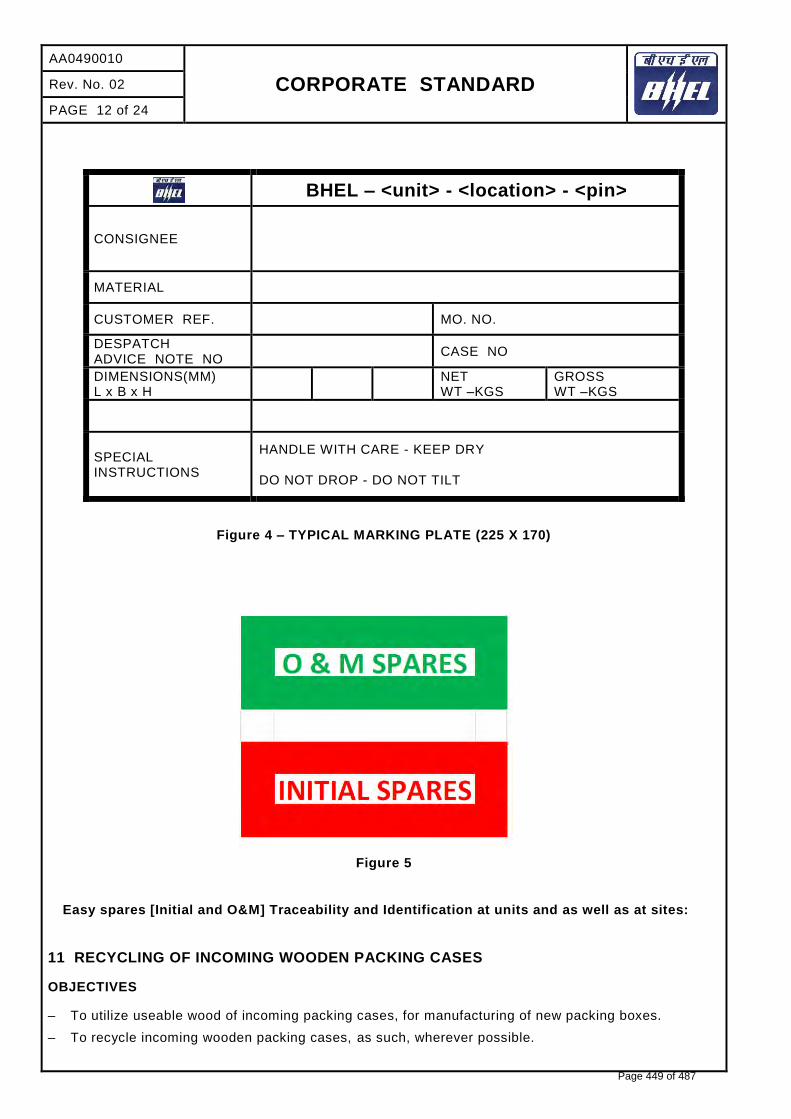
AA0490010
CORPORATE STANDARD
Rev. No. 02
PAGE 12 of 24
BHEL – <unit> - <location> - <pin>
CONSIGNEE
MATERIAL
CUSTOMER REF. MO. NO.
DESPATCH ADVICE NOTE NO
CASE NO
DIMENSIONS(MM) L x B x H
NET WT –KGS
GROSS WT –KGS
SPECIAL INSTRUCTIONS
HANDLE WITH CARE - KEEP DRY DO NOT DROP - DO NOT TILT
Figure 4 – TYPICAL MARKING PLATE (225 X 170)
Figure 5
Easy spares [Initial and O&M] Traceability and Identification at units and as well as at sites:
11 RECYCLING OF INCOMING WOODEN PACKING CASES
OBJECTIVES
– To utilize useable wood of incoming packing cases, for manufacturing of new packing boxes.
– To recycle incoming wooden packing cases, as such, wherever possible.
Page 449 of 487

CORPORATE STANDARD
AA0490010
Rev. No. 02
PAGE 13 of 24
1) All incoming wooden packing cases received from suppliers /customers will be opened carefully, with
the intention of reusing them, by Shop.
2) After carefully taking out the contents, the empty wooden packing cases will be shifted by Shop to the specified locations i.e. bin / nearly spaces, already earmarked in stores.
3) Material shifting contractor engaged by store, will collect all such wooden packing cases and scrap wood from specified points, on a regular basis.
4) After collecting / loading the empty packing cases/ scrap wood, contractor will take the carrier first to Weighment Bridge for weighment, thereafter; he will go to Carpentry, where Carpentry representative will identify the packing cases which can be used by Carpentry for m anufacturing of New Packing Boxes. All such identified packing boxes will be unloaded and handed over to Carpentry by contractor.
5) These packing boxes will be made re-useable after necessary rectification and additional work.
6) Contractor will again take the carrier for weighment and this second reading will also be recorded on the same “Weighment Slip”.
7) Weight of empty packing cases / scrap wood taken will be calculated on the basis of 1st and 2nd weighment readings recorded on the “Weighment Slip”. A copy of “Weighment Slip” (where both the weighment readings are recorded) will be given by the contractor to the carpentry representative. Based on this “Weighment Slip”, carpentry will maintain a register in which details of quantity received will be recorded.
8) All “Weighment Slips” will invariably be signed by carpentry representative (even when no boxes have been unloaded by carpentry). Store will accept the scrap wood only if “Weighment Slips” are signed by carpentry representative.
9) Balance empty packing cases / scrap wood will be handed over by contractor to Store, for storing in scrap yard.
10) A separate area in Scrap yard will be provided, for executing the work of denailing of wooden packing cases, under supervision of carpentry.
11) Carpentry contractor will identify packing cases / scrap wood for denailing, which will behanded over to him by Store, at Scrap yard, for denailing and further operation.
12) Quality and Carpentry will jointly inspect the wood generated by de-nailing process and will prepare “INSPECTION CUM RECEIPT REPORT OF USEABLE WOOD RECEIVED FROM TPS – STORE BY CARPENTRY”.
13) After acceptance of the wood by Quality and Carpentry, the same will be shifted to carpentry for receipt and its record will be maintained by carpentry.
14) This will be a Permanent Productivity Project executed by carpentry. “Productivity Savings “duly verified at the current Purchase Order rate of wood, will be sent every month to Resource Management Department, for highlighting it in their monthly progress report.
12 STANDARD METHOD OF PACKING
Table 5 - Standard Method of Packing
DESCRIPTION CASE CRATE SKID BUNDLE BARE DRUM METAL DRUM FIBRE DRUM
PRESSUE VESSELS
TOWERS O
TANKS O
VESSELS O
GASKETS O
FASTENERS O
COVERS O
EXCHANGERS
Page 450 of 487

AA0490010
CORPORATE STANDARD
Rev. No. 02
PAGE 14 of 24
DESCRIPTION CASE CRATE SKID BUNDLE BARE DRUM METAL DRUM FIBRE DRUM
HEAT EXCHANGERS O
TUBE BUNDLE O
SHELL O
AIR FIN COOLERS O
COLOUMNS, MOTOR SUSPENSIONS, PLENUM CHAMBERS, SCREEN GUARDS, ETC
O
BEARING BLOCKS O
FANS O O
MOTORS O
GASKETS O
FASTENERS O
TEST FLANGES O
TEST RINGS O
COVERS O
CRYOGENIC VESSELS
COLD CONVERTERS O
HORIZONTAL STORAGE TANKS O
TRANSPORTATION TANK O
COLD BOX O
DRYING UNIT O
DRYING BOTTLES O
MOISTURE SEPARATORS O
SILENCERS O
ONGC SKIDS O
VAPORISER O
SPECIAL PRODUCTS
SI/VI PIPING O
CRO BIO CONTAINERS O
AIR BOTTLES O
TITANIUM BOTTLE O
WAR HEAD CONTAINER O
MISSILE CONTAINER O
FUEL CONTAINER O
AIR LOCK ASSEMBLY O
BOILER DRUMS O
BOILER ITEMS
COILS O
PANELS O
HEADERS O O
FEEDERS
MACHINED ITEMS
SHELL SEGMENTS O
Page 451 of 487

CORPORATE STANDARD
AA0490010
Rev. No. 02
PAGE 15 of 24
DESCRIPTION CASE CRATE SKID BUNDLE BARE DRUM METAL DRUM FIBRE DRUM
SHELL SEGMENTS IN STACKS O
SPHERE PETALS
COLOUMNS, BASE PLATES, TIERCOS, PIPES, NOZZLE E1, F1, INTERNAL PIPES, PADS ETC.
O
ROLLERS O
VALVE TRAYS
VALVE TRAY COMPONENTS O
LATTICE GIRDERS O
FASTENERS O
GASKETS O
SUB CONTRACTS
FAB STRUCTURALS O
SUPPORTING STRUCTURALS O
STRUCTURE SUB ASSEMBLY O
FAB PIPES O
GRATINGS O
STAIR CASES O
HANDRAILS/ PLATFORMS O
BOUGHT OUT COMPONENTS
IRON & STEEL (LIKE PLATES, BEAMS, ANGLES, CHANNELS ETC.)
O
PIPE FITTINGS
CS PIPES, TUBES O
SS PIPES, TUBES O
FIN TUBES O
ELBOWS O O
FLANGES O O
VALVES O
GAUGES O
DEMISTERS O
ABSCRBANTS (LIKE MOLECULAR SIEVES, ACTIVATED ALUMINA, MOBILE SORBID)
O
PAINT TINS O
PAINT DRUMS O
IGNITORS O
SPRAY NOZZLES O
ELECTRICAL INSTRUMENTATION
MOTORS, PUMPS, COMPRESSORS, TURBINES
O
SWITCH BOARDS, DISTRIBUTION BOARDS, STARTERS, JUNCTION BOXES
O
INDICATORS, VIBRATOR SWITCHES
O
Page 452 of 487

AA0490010
CORPORATE STANDARD
Rev. No. 02
PAGE 16 of 24
DESCRIPTION CASE CRATE SKID BUNDLE BARE DRUM METAL DRUM FIBRE DRUM
CABLE BUNDLES, CABLE DRUMS O
CABLE TRAYS, CABLE RACKS, EARTHING MATERIAL
O
OPERATIONAL SPARES O
13 PROCEDURE FOR HANDLING OF COMPONENTS
The purpose of this procedure is to protect the quality of the components/e quipment while handling in various stages of manufacturing packing & despatching.
13.1 Adequate care shall be taken in handling the material, and com ponents to avoid damage during receipts, storage issue manufacture & despatch operations.
13.2 Appropriate material handling equipment like fork lifters, cranes etc. shall be used where needed.
13.3 Lifting by crane and transportation by trolley of critical items and large components like rotors castings etc. shall be done carefully.
13.4 For critical items, where specified, special handling fixtures shall be used for lifting.
13.5 Slings and shackles used for lifting the components/equipment shall be checked for fitness and suitability before use.
13.6 Slings used on machined surfaces shall be suitably padded. No slings shall be used on journal surfaces.
13.7 Precision machined components like blades, catches, rollers etc. shall be lifted using suitable wooden pallets.
13.8 HANDLING OF COMPONENTS ON RECEIPT/DESPATCH
Before loading/unloading a packing case from the carrier look for the following shipping instructions painted on the packing case.
a) The markings showing the upright position.
b) The markings showing the sling position
c) Markings showing the fragile contents.
d) Other required markings as per clause no.10
13.8.1 Appropriate cranes and slings should be used for different components/ cases. Slings should normally make an angle as minimum as possible (width wise) but in no case more than 15º.
13.8.2 Handling and lifting should be done without jerks or impacts.
13.8.3 Immediately after receipt of the goods, the packing should be examined all -round for any sign of damage. If necessary, lift the cover or a number of boards of the case so as to make the contents visible. In the event of sealed packing being used the plastic sheeting sh ould not be damaged. It is imperative that the packing material is restored in original condition after the inspection.
13.8.4 On receipt of the equipment it should be checked with the shipping list and missing or damage if any should be reported immediately. It is important to arrange for immediate examination to determine the extent of the damage, the cause of the damage and where applicable the person or persons responsible for the damage. According to general practice when transporting by railway or by road vehicle the carrier concerned should be immediately called upon (within specified periods) for jointly establishing a statement of the damage. This is essential as a basis for a subsequent claim and possible damage report to the insurance company.
13.8.5 Protective coating applied on machined surfaces should not be disturbed. The plastic covering should be put back carefully so that it prevents ingress of dust and moisture. Some packing may have vapour phase inhibitor (VPI) paper enclosed inside the packing cases. T his should be restored to its original place as far as possible.
Page 453 of 487

CORPORATE STANDARD
AA0490010
Rev. No. 02
PAGE 17 of 24
13.8.6 Silica gel and such other chemicals kept in the box as desiccants and indicators should also be
left in the box itself.
14 GENERAL GUIDELINES FOR ODC TRANSPORTATION/DESPATCH
Based on the Dimensions/Weight indicated in the Transportation Sketch, the type of Trailer is decided
and indicated in the Tender Enquiry.
14.1 TRANSPORTATION:
1. LOW BED TRAILERS (LB 8):
Well Bed Length : 10000mm Over Gooseneck : 13000mm Width : 3000mm Carrying Capacity : 40MT
2. LOW BED TRAILERS (LB 16):
Well Bed Length : 12000mm Over Gooseneck : 16000mm Width : 3000mm Carrying Capacity : 75MT
3. TOW TYPE TRAILERS (WITH FRONT DOLLEY 16 TYRES): 12000MM length
(for Exceptional equipment length: 30000mm and above) Bigger Dia equipment are loaded in the Well with overhanging. Smaller Dia equipment with excess length are loaded over Gooseneck with rear hanging. The Vehicle Dimensions are defined above are only guidelines for selection based on actual Dimensions/ Weight of the Consignment
14.2 PACKING:
For all ODCs, Wooden Saddles are cut to the diameter of equipment as per the Transportation Sketch .
Wooden Saddles For Diameter up to 4000mm For Diameter above 4000mm
Length: 1836/2743mm (6’0”/9’0”) 3353mm (11’0”)
Width: 300mm (1’0”) 300mm (1’0”)
Height: Saddle + one/two wedges a top Saddle + three/four wedges a top
Number of Saddles:
Minimum 3 in case of Loading inside Well
+1 when loaded on Gooseneck
Maximum: 4 in case of Loading inside Well
+2 when loaded on Gooseneck
For Securing the equipment firmly on the Trailer, 19mm (3/4”), wire rope with 25mm (1”) Heavy Duty Turn Buckles / BD Clamps are used as Lashing for the equipment.
14.3 NUMBER OF LASHINGS:
Page 454 of 487

AA0490010
CORPORATE STANDARD
Rev. No. 02
PAGE 18 of 24
CONSIGNMENT LOADED INSIDE
WELL BED CONSIGNMENT LOADED OVER
GOOSENECK
a) up to 40MT 4 (2 Single Line lashing 2 Double Line Lashing)
5 (3 Single Line Lashing 2 Double Line Lashing)
b) 40MT to 60MT 5 (3 Single Line Lashing 2 Double Line Lashing)
5 (Single Line Lashing 3Double Line Lashing)
c) 60MT and above 5 (2 Single Line Lashing 3 Double Line Lashing)
6 (3 Single Line Lashing 3 Double Line Lashing)
15 GUIDELINES FOR HANDLING/LOADING/LASHING
15.1 HANDLING
Figure 6
Before unloading the jobs Completely painted and neatly stencilled will be checked.
Pipes with split type end cover will be checked
Page 455 of 487

CORPORATE STANDARD
AA0490010
Rev. No. 02
PAGE 19 of 24
Figure 7
All Coil Tubes to be provided with End Caps.
Figure 8
Neatly stacked Coil Assemblies.
Page 456 of 487

AA0490010
CORPORATE STANDARD
Rev. No. 02
PAGE 20 of 24
Figure 9
Columns to be lifted with Nylon belts. This protect painting, edges and attachments.
Figure 10
15.2 LOADING
All the components to be transported by putting inside the properly fabricated Crating
Page 457 of 487

CORPORATE STANDARD
AA0490010
Rev. No. 02
PAGE 21 of 24
Figure 11
Small components may fall down while transporting without closed crating and there are chances of missing of small parts. Hence, it is always better to transport small components in closed containers/crating. Loose to be being shipped in a closed crating.
Figure 12
Page 458 of 487

AA0490010
CORPORATE STANDARD
Rev. No. 02
PAGE 22 of 24
No component loaded over the crating.
Figure 13
Headers supported with wooden V blocks at 3 meters interval.
Figure 14
Spacers in between each coil assembly.
Page 459 of 487

CORPORATE STANDARD
AA0490010
Rev. No. 02
PAGE 23 of 24
Figure 15
Goose pipe to be provided with rubber pad protects removal of painting and damage to the job.
Figure 16
15.3 LASHING
Use Nylon belts only for lashing of all components. It prevents removal off painting and cut in the materials.
Page 460 of 487

AA0490010
CORPORATE STANDARD
Rev. No. 02
PAGE 24 of 24
Figure 17
Nylon Belts used for lashing the beams.
Figure 18
16 PRODUCT WISE SPECIAL INSTRUCTION
Additional instructions of packing not included in this standard shall be covered by individual product standard.
17 REFERRED STANDARDS (Latest publications including amendments):
1) AA51420 2) AA55619 3) AA51414 4) IS:3401 5) AA10108
6) AA56126 7) AA51402 8) AA51401 9) IS:1234
Page 461 of 487

CORPORATE STANDARD
AA0490006
Rev. No. 01
PAGE 1 of 3
Revisions: APPROVED:
PROCEDURAL GUIDELINES COMMITTEE – PGC (Packing)
Rev. No. 01 Amd. No. Reaffirmed Prepared
EDN, Bangalore
Issued
Corp. R&D
Dt. of 1st Issue
31-05-2018 Dt: 12-06-2018 Dt: Year:
CO
PY
RIG
HT
AN
D C
ON
FID
EN
TIA
L
Th
e I
nfo
rma
tio
n o
n t
his
do
cu
me
nt
is t
he
pro
pe
rty o
f B
HA
RA
T H
EA
VY
EL
EC
TR
ICA
LS
LIM
ITE
D.
It m
ust
no
t b
e u
se
d d
ire
ctl
y o
r in
dir
ectl
y i
n a
ny w
ay d
etr
ime
nta
l to
th
e I
nte
rest
of
the
co
mp
an
y.
D
RC
-51
90
VACUUM PACKING FOR ELECTRONIC COMPONENTS
1 GENERAL
This standard lays down the packing instructions for packing of components / Electronic module / Assemblies to be dispatched against Customer contracts.
2 SCOPE
This procedure covers method of packing electronic components using vacuum packing in a wooden packing boxes.
3 OBJECTIVE
To establish a rust proof safe packing procedure and where the components required to protect against temperature and humidity. In general minimum temperature +5 deg C and maximum temperature 45 deg C, and relative humidity between 10% to 40%.
4 PACKING BOX
Wooden Box shall be made as per BHEL Standard AA0490010 for Domestic/ AA0490009 for Export/ AA0490004 for Seaworthy packing. Size of the box as per the contract requirement which has to be checked by QC.
5 PACKING PROCEDURE
a) Cleaning parts shall be thoroughly cleaned just before VCI (Volatile Corrosion Inhibitor) Vacuum packing. Finger prints on cleaned items are to be avoided as the same are very corrosive.
b) VCI Rust preventive oil (Ferrous grade oil base) shall be applied to all the components to withstand any corrosion.
6 VCI VACUUM PACKING
a) Bubble wrapping the items VCI vacuum packing.
b) Appropriate vapour corrosive packets one pouch (1 gm. /pouch) of VCI Anticorrosive Powder and one pouch (10gm./ pouch) of VCI Desiccant per 1000 cub. meter packing space shall be placed inside the VCI vacuum packing.
c) All the components shall be separately packed using VCI laminated Aluminium foils from which air/moisture are removed by the air vacuum device and sealed thoroughly using heat sealing machine. At the time of the evacuation the vacuum inside the pack should be less than 0.5 ata.
d) One identification slip containing component information such as description of item, Material No. Customer PO, Item No. Quantity etc. shall be put inside the VCI vacuum packing.
e) Top cover of the wooden box shall be sealed only after final clearance from QC for confirmation of above.
f) All boxes should be covered by water proof tarpaulin over top and on all sides.
g) The packing boxes shall be covered with GI sheets (0.25 -0.4mm thick) on all the sides for Export / Seaworthy packing.
h) Vacuum packing room temperature and Relative Humidity should be maintained as mentioned below:
Min. +5 deg. C and Max. 45 deg. C, Relative humidity between 10% to 40%.
Page 462 of 487
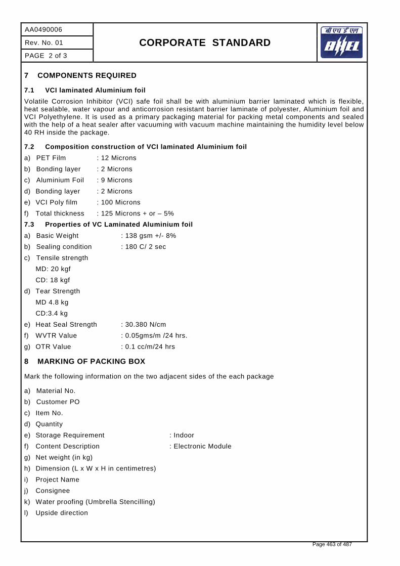
AA0490006
CORPORATE STANDARD
Rev. No. 01
PAGE 2 of 3
7 COMPONENTS REQUIRED
7.1 VCI laminated Aluminium foil
Volatile Corrosion Inhibitor (VCI) safe foil shall be with aluminium barrier laminated which is flexible, heat sealable, water vapour and anticorrosion resistant barrier laminate of polyester, Aluminium foil and VCI Polyethylene. It is used as a primary packaging material for packing metal components and sealed with the help of a heat sealer after vacuuming with vacuum machine maintaining the humidity level below 40 RH inside the package.
7.2 Composition construction of VCI laminated Aluminium foil
a) PET Film : 12 Microns
b) Bonding layer : 2 Microns
c) Aluminium Foil : 9 Microns
d) Bonding layer : 2 Microns
e) VCI Poly film : 100 Microns
f) Total thickness : 125 Microns + or – 5%
7.3 Properties of VC Laminated Aluminium foil
a) Basic Weight : 138 gsm +/- 8%
b) Sealing condition : 180 C/ 2 sec
c) Tensile strength
MD: 20 kgf
CD: 18 kgf
d) Tear Strength
MD 4.8 kg
CD:3.4 kg
e) Heat Seal Strength : 30.380 N/cm
f) WVTR Value : 0.05gms/m /24 hrs.
g) OTR Value : 0.1 cc/m/24 hrs
8 MARKING OF PACKING BOX
Mark the following information on the two adjacent sides of the each package
a) Material No.
b) Customer PO
c) Item No.
d) Quantity
e) Storage Requirement : Indoor
f) Content Description : Electronic Module
g) Net weight (in kg)
h) Dimension (L x W x H in centimetres)
i) Project Name
j) Consignee
k) Water proofing (Umbrella Stencilling)
l) Upside direction
Page 463 of 487

CORPORATE STANDARD AA0490006
Rev. No. 01
PAGE 3 of 3
Figure 1
Page 464 of 487

CORPORATE STANDARD
AA0490008
Rev. No. 01
PAGE 1 of 4
Revisions: APPROVED:
PROCEDURAL GUIDELINES COMMITTEE – PGC (Packing)
Rev. No. 01 Amd. No. Reaffirmed Prepared
EDN, Bangalore
Issued
Corp. R&D
Dt. of 1st Issue
31-05-2018 Dt: 12-06-2018 Dt: Year:
CO
PY
RIG
HT
AN
D C
ON
FID
EN
TIA
L
Th
e I
nfo
rma
tio
n o
n t
his
do
cu
me
nt
is t
he
pro
pe
rty o
f B
HA
RA
T H
EA
VY
EL
EC
TR
ICA
LS
LIM
ITE
D.
It m
ust
no
t b
e u
se
d d
ire
ctl
y o
r in
dir
ectl
y i
n a
ny w
ay d
etr
ime
nta
l to
th
e I
nte
rest
of
the
co
mp
an
y.
D
RC
-51
92
VACUUM PACKING FOR ELECTRICAL COMPONENT
1 GENERAL
This standard lays down the packing instructions for packing of components / Electrical components Stator/ Rim punching, Wound Pole/ Field Coils and Stator coils / bars to be dispatched against Customer contracts.
2 SCOPE
This procedure covers method of packing component in a wooden packing boxes.
3 OBJECTIVE
To establish a rust proof safe packing procedure and where the components required to protect against temperature and humidity. In general minimum temperature +5 deg C and maximum temperature 45 deg C, and relative humidity between 10% to 40%.
4 PACKING BOX
Wooden Box shall be made as per BHEL Standard AA0490010 for Domestic/AA0490009 for Export/ AA0490004 for Seaworthy packing. Size of the box as per the contract requirement, which has to be checked by QC.
5 PACKING PROCEDURE
a) All items packed are to be marked by QC with “OK” stickers. Varnished stator punchings are to be brought down to room temperature before labelling them “OK” for packing. Do not pack hot/warm stator punchings that have is just received from the varnishing.
b) Packing of stator punchings, wound pole/ field coils and stator coils / bars should be done in a covered shed.
c) Packed materials are to be stacked in proper alignment and to be kept in wooden packing.
6 Additional Packing Methodology for Stator / Rim Punchings (Double stacking) only
In order to eliminate the use of studs avoid double stack packaging per box. Where double stacked packing boxes are unavoidable, the stator /rim punchings are to be securely tightened using GI studs, nuts and soft material washers (rubber/plastic). GI studs, nuts and soft material only to be used in case of double stacking of rim / stator punchings (with holes). Use soft rubber washers to seal the punctured opening at the bottom from where the studs pass in each layer of VCI (Volatile Corrosion Inhibitor) paper, polythene and tarpaulin sheet in case of rim /stator punchings (with holes).
a) GI studs with rubber washer to be placed initially inside the wooden packing box.
b) Over the wooden base, place water proof tarpaulin sheet.
c) Rubber washer shall be placed after the layer of tarpaulin sheet.
d) Then place a layer of porous plastic sheet with total thickness of at least 5mm (for cushioning and reduces the chances of damage to punchings).
e) Place the Aluminium Barrier laminated Bags over this porous sheet, place the rubber washer over it.
f) Place VCI papers on the Aluminium barrier bag and fix with rubber washer.
Page 465 of 487

AA0490008
CORPORATE STANDARD
Rev. No. 01
PAGE 2 of 4
g) PVC Pipes shall be inserted over the GI studs. These pipes are to be used to cover each stud, to
protect its direct contact and hence rubbing with punchings.
h) Now place the stack of punchings over the VCI paper and securely tighten the punchings using nuts and soft material, washers.
i) Each layer should be secured in position. Wrap the punchings with VCI paper and properly sealed separately using an adhesive tape.
j) Silica Gel packets are to be placed over the VCI paper and uniformly distributed inside the boxes on the VCI paper to remove/prevent moisture.
k) Aluminium barrier laminated bag has secured in position and properly sealed by using heat sealing machine and air to be drained out by using vacuum pump. At the time of the evacuation the vacuum inside the pack should be less than 0.5ata.
Use two separate VCI papers for doubled stacked boxes independently covering each stack. Similarly two Aluminium barrier laminated bag are to be used to wrap the two stacks independently, as explained above.
7 Additional Packing Methodology for Wound Pole/ Field Coils and Stator Coils/Bars only
a) Over the wooden base, place the waterproof tarpaulin sheet.
b) Then place a layer of porous plastic sheet with total thickness of at least 5mm (for cushioning and reduces the chances of damage to Wound pole/field coils and stator coils/ bars.
c) Place the Aluminium barrier laminated bag over this porous sheet.
d) Place the VCI paper (Volatile Corrosion Inhibitor as per BHEL Standard AA51406) on the Aluminium barrier laminated bag along with rubber washer.
e) Bare copper portion of field coils and stator coils / bars to be covered by VCI paper pouch and fasten with VCI tape.
f) Now place the wound pole, stack of field coil and stator coil / bars over the VCI paper.
g) Each layer should be secured in position. Wrap wound pole / field coils and stator coils / bars with VCI paper and properly sealed separately using an adhesive tape.
h) Silica Gel packets are to be placed and uniformly distributed inside the boxes on the VCI paper to remove/prevent moisture.
i) Then Aluminium barrier laminated bag has secured in position and properly sealed by using heat sealing machine and air to be drained out by using vacuum pump. At the time of evacuation the vacuum inside the pack should be less than 0.5ata.
j) The VCI paper must contact the stator / rim punchings, wound pole / field coils and stator coils/bars. It has to ensure that the VCI paper, Aluminium barrier bag should not get damage / puncture during the packing process.
k) Top cover of the wooden box shall be sealed only after final clearance from QC for confirmation of above.
l) All boxes should be covered by water proof tarpaulin over top and on all sides.
m) The packing boxes shall be covered with GI sheets (0.25 -0.4mm thick) on all the sides for Export / Seaworthy packing.
n) Vacuum packing room temperature and Relative Humidity should be maintained as mentioned below:
Min. +5 deg. C and Max. 45 deg. C, Relative humidity between 10% to 40%.
Page 466 of 487

CORPORATE STANDARD AA0490008
Rev. No. 01
PAGE 3 of 4
8 COMPONENT REQUIRED
8.1 VCI laminated Aluminium foil
Volatile Corrosion Inhibitor (VCI) safe foil shall be with aluminium barrier laminated which is flexible, heat sealable, water vapour and anticorrosion resistant barrier laminate of polyester, Aluminium foil & VCI Polyethylene. It is used as a primary packaging material for packing metal components and sealed with the help of a heat sealer after vacuuming with vacuum machine maintaining the humidity level below 40 RH inside the package.
8.2 Composition construction of VCI laminated Aluminium foil
a) PET Film : 12 Microns
b) Bonding layer : 2 Microns
c) Aluminium Foil : 9 Microns
d) Bonding layer : 2 Microns
e) VCI Poly film : 100 Microns
f) Total thickness : 125 Microns + or – 5%
8.3 Properties of Aluminium Barrier laminated Bag
a) Basic Weight : Unit: g/sq. m 150 +/- 5
b) Tensile strength : Unit: N/sq. mm MD: 40 (min.)
Unit: N/sq. mm TD: 41 (min.)
c) Water Vapour Transmission : Unit: g/m2 0.01 in 24 hrs. at 38 deg C & 90% RH(max)
d) Oxygen Transmission : Unit: cm3/m2 0.02 in 24 hrs. at 38 deg C & 90% RH (max)
e) Sealing Temp. : Unit : Degree C 180-220 deg C
9 MARKING ON PACKING BOX
Mark the following information on the two adjacent sides of the each package.
a) Box No.
b) Customer PO
c) Product Name.
d) Project Name
e) Quantity
f) Storage Requirement : Indoor
g) Net weight (in kg)
h) Dimension (L x W x H in centimetres)
i) Consignee
j) Water proofing (Umbrella Stencilling)
k) Upside direction
l) Sling position indicator
Page 467 of 487
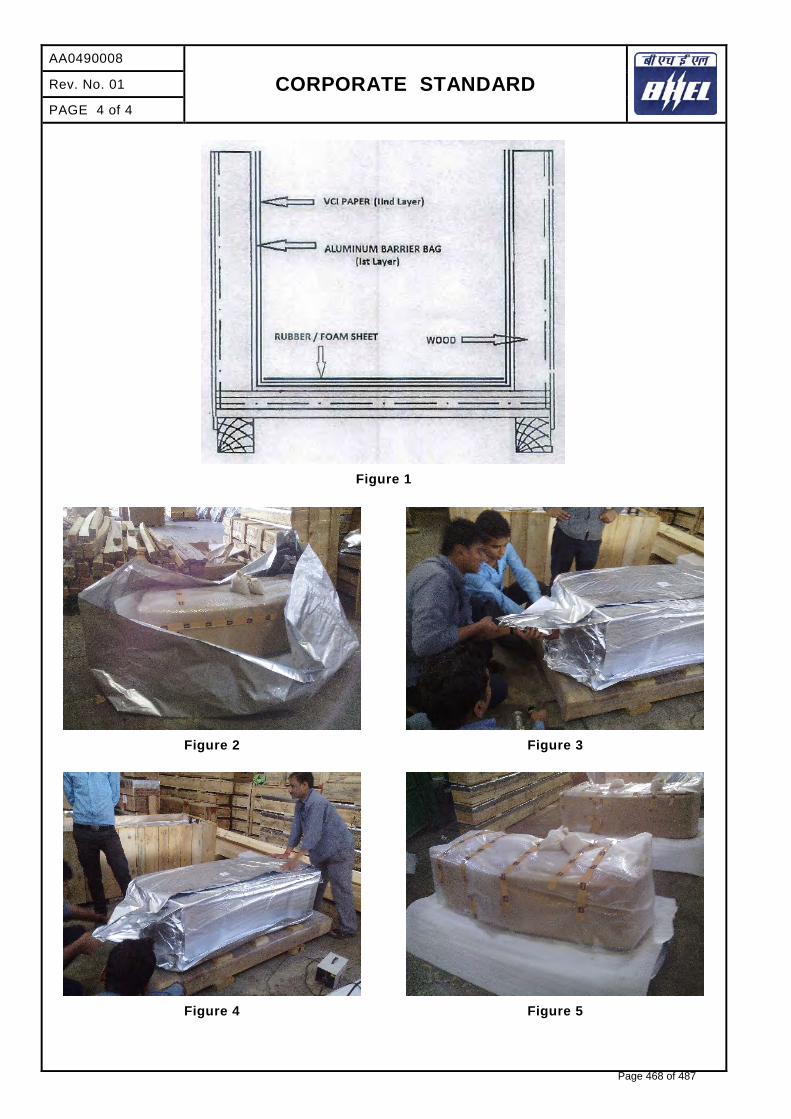
AA0490008
CORPORATE STANDARD
Rev. No. 01
PAGE 4 of 4
Figure 1
Figure 2
Figure 3
Figure 4
Figure 5
Page 468 of 487

SIPAT STAGE-II, 2X500MW FGD
COMPRESSED AIR SYSTEM
SPECIFICATION No: PE-TS-491-555-A001
VOLUME : II B
SECTION : E / ANNEXURE-VI
REV 00 DATE: JULY 22
SHEET: 1 OF 2
1.1
P E M - 6 6 6 6 - 0
ANNEXURE-VI
LIST OF OPERATIONAL SPARES
Page 469 of 487

SIPAT STAGE-II, 2X500MW FGD
COMPRESSED AIR SYSTEM
SPECIFICATION No: PE-TS-491-555-A001
VOLUME : II B
SECTION : E / ANNEXURE-VI
REV 00 DATE: JULY 22
SHEET: 2 OF 2
1.1
P E M - 6 6 6 6 - 0
LIST OF OPERATIONAL SPARES
Sl.no Description
Qty. (Each compressor)
Unit
Qty. for 2 nos.
Compressors
Initial fill (at vendor
works)
Intervening Period
During PG
Test
1 Lube oil Included NA 1 Lot / Compressor 2
2 Lube oil filters with seals Included 1 1 Sets / Compressor 4
3 Air filters with gaskets (as applicable)
Included 1 1 Sets / Compressor / Dryer
4
4 Service kit including seals, washers and rings for intercooler (as applicable)
NA NA 1 Sets / Compressor / Dryer
2
5 Service kit including seals, washers and rings for after cooler (as applicable)
NA NA 1 Sets / Compressor / Dryer
2
Page 470 of 487
SIPAT STAGE-II, 2X500MW FGD
TECHNICAL SPECIFICATION
FOR
COMPRESSED AIR SYSTEM
VOLUME-III
(TECHNICAL SCHEDULES)
BHARAT HEAVY ELECTRICALS LTD
POWER SECTOR PROJECT ENGINEERING MANAGEMENT PPEI, NOIDA-INDIA
Page 471 of 487

SIPAT STAGE-II, 2X500MW FGD
COMPRESSED AIR SYSTEM
SPECIFICATION NO. PE-TS-491-555-A001
VOLUME : III
SECTION : 1
REV: 00 DATE: JULY 22
SHEET 1 OF 1
1.1
P E M - 6 6 6 6 - 0
VOLUME: III SECTION: 1
LIST OF DOCUMENTS TO BE SUBMITTED WITH BID
Page 472 of 487

SIPAT STAGE-II, 2X500MW FGD
COMPRESSED AIR SYSTEM
SPEC. NO.: PE-TS-491-555-A001 VOLUME: III SECTION: 1 REV. NO. 0 DATE: JULY 22 SHEET 1 OF 1
CHECK LIST FOR LIST OF DOCUMENTS TO BE SUBMITTED BY BIDDER ALONG WITH
THE BID
Sl No. Item Description Yes/No 1 Schedules to be submitted dully filled up with bidder’s
signature and stamp. 1) Technical Deviation Schedule, if any. 2) Filled, Signed & Stamped copy of Guaranteed Power
Consumption for Compressed Air System. 3) Compliance cum Confirmation certificate.
2 Resolution to pre-bid clarifications, if any, duly stamped and signed by the bidder enclosed with the bid
3 Un-priced bid- clearly indicating ‘QUOTED’ and ‘NOT-QUOTED’ against each item.
4 Signed & stamped copy of Electrical feeder list attached with specification.
5 Supporting Documents meeting PQR requirements
Name: _________________________
Signature: ______________________
Designation: ____________________
Company: ______________________
Date: __________________________
Bidder Stamp
Page 473 of 487

SIPAT STAGE-II, 2X500MW FGD
COMPRESSED AIR SYSTEM
SPECIFICATION NO. PE-TS-491-555-A001
VOLUME : III
SECTION : 2
REV: 00 DATE: JULY 22
SHEET 1 OF 1
1.1
P E M - 6 6 6 6 - 0
VOLUME-III SECTION 2
COMPLIANCE CUM CONFIRMATION CERTIFICATE
Page 474 of 487

SIPAT STAGE-II, 2X500MW FGD
COMPRESSED AIR SYSTEM
SPEC. NO.: PE-TS-491-555-A001 VOLUME: III SECTION: 2 REV. NO. 0 DATE: JULY 22 SHEET 1 OF 2
COMPLIANCE CUM CONFIRMATION CERTIFICATE
The bidder shall confirm compliance with following by signing/ stamping this compliance certificate (every sheet) and furnish same with the offer.
a) The scope of supply, technical details, construction features, design parameters etc. shall be as per technical specification & there are no exclusions other than those mentioned under “exclusion” and those resolved as per ‘Schedule of Deviations’, if applicable, with regard to same.
b) There are no other deviations w.r.t. specifications other than those furnished in the ‘Schedule
of Deviations’. Any other deviation, stated or implied, taken elsewhere in the offer stands withdrawn unless specifically brought out in the ‘Schedule of Deviations’.
c) Bidder shall submit QP in the event of order based on the guidelines given in the
specification & QP enclosed therein. QP will be subject to BHEL/ NTPC approval & customer hold points for inspection/ testing shall be marked in the QP at the contract stage. Inspection/ testing shall be witnessed as per same apart from review of various test certificates/ Inspection records etc. This shall be within the contracted price with no extra implications to BHEL after award of the contract.
d) All drawings/ data-sheets/ calculations etc. submitted along with the offer shall be
considered for reference only, same shall be subject to BHEL/ NTPC approval in the event of order.
e) The offered materials shall be either equivalent or superior to those specified in the
specification & shall meet the specified/ intended duty requirements. In case the material specified in the specifications is not compatible for intended duty requirements then same shall be resolved by the bidder with BHEL during the pre - bid discussions, otherwise BHEL/ NTPC decision shall be binding on the bidder whenever the deficiency is pointed out. For components where materials are not specified, same shall be suitable for intended duty, all materials shall be subject to approval in the event of order.
f) The commissioning spares shall be supplied on ‘As Required Basis’ & prices for same
included in the base price itself.
g) All sub vendors shall be subject to BHEL/ NTPC approval in the event of order. h) Guarantee for plant/equipment as applicable, shall be as per relevant clause of GCC /SCC
/Other Commercial Terms & Conditions.
i) In the event of order, all the material required for completing the job at site shall be supplied by the bidder within the ordered price even if the same are additional to approved billing break up, approved drawing or approved Bill of quantities. This clause will apply in case during site commissioning additional requirements emerges due to NTPC comments. No extra claims shall be put on this account.
j) Schedule of drawings submissions, comment incorporations & approval shall be as stipulated in the specifications. The successful bidder shall depute his design personnel to BHEL / NTPC office for across the table resolution of issues and to get documents approved in the stipulated time.
Page 475 of 487

SIPAT STAGE-II, 2X500MW FGD
COMPRESSED AIR SYSTEM
SPEC. NO.: PE-TS-491-555-A001 VOLUME: III SECTION: 2 REV. NO. 0 DATE: JULY 22 SHEET 2 OF 2
k) As built drawings shall be submitted as and when required during the project execution.
l) The bidder has not tempered with this compliance cum confirmation certificate and if at any
stage any tempering in the signed copy of this document is noticed then same shall be treated as breach of contract and suitable actions shall be taken against the bidder.
SIGNATURE: ___________________ NAME : ___________________ DESIGNATION: __________________ COMPANY: _____________________ DATE: __________________________
COMPANY SEAL
Page 476 of 487

SIPAT STAGE-II, 2X500MW FGD
COMPRESSED AIR SYSTEM
SPECIFICATION No: PE-TS-491-555-A001
VOLUME: III
SECTION : 3
REV. 00 DATE: JULY 22
SHEET 1 OF 1
VOLUME: III SECTION: 3
PRE-BID CLARIFICATION SCHEDULE
Page 477 of 487

SPECIFICATION NO. PE-TS-491-555-A001
SIPAT STAGE-II, 2X500MW FGD VOLUME: III SECTION: 3
COMPRESSED AIR SYSTEM REV 00 DATE: JULY 22
SHEET: 1 OF 1
PRE-BID CLARIFICATION SCHEDULE
S.No. Section/Clause/ Page No.
Statement of the referred clause
Clarification required
The bidder hereby certifies that above mentioned are the only clarifications required on the technical specification for the subject package.
SIGNATURE :_________________
NAME : _________________
DESIGNATION :__________________ COMPANY : _________________ DATE :__________________
COMPANY SEAL
Page 478 of 487
SIPAT STAGE-II, 2X500MW FGD
COMPRESSED AIR SYSTEM
SPECIFICATION NO. PE-TS-491-555-A001
VOLUME : III
SECTION : 4
REV: 00 DATE: JULY 22
SHEET 1 OF 1
1.1
P E M - 6 6 6 6 - 0
VOLUME-III SECTION 4
ELECTRICAL LOAD DATA
Page 479 of 487

RANGE BOUND ELECTRICAL LOAD LIST FOR COMPRESSED AIR SYSTEM
LOAD TITLE
RATING (KW )
UN
IT (
U)/
ST
N (
S) Nos.
VO
LT
AG
E C
OD
E*
FE
ED
ER
CO
DE
**
EM
ER
. L
OA
D (
Y)
CO
NT
.(C
)/ I
NT
T.(
I)
ST
AR
TIN
G T
IME
>5
SE
C (
Y)
LOCATION BOARD
NO.
CABLE
BL
OC
K C
AB
LE
DR
G.
No
. CONTROL CODE
REMARKS LOAD
No.
NAME PLATE (KW)
MAX. CONT.
DEMAND
(MCR)
RU
NN
ING
ST
AN
DB
Y
SIZE CODE
NOs
1 2 3 4 5 6 7 8 9 10 11 12 13 14 15 16 17 18 19
NOTES: 1. COLUMN 1 TO 12 & 18 SHALL BE FILLED BY THE REQUISITIONER (ORIGINATING AGENCY); REMAINING COLUMNS ARE TO BE FILLED UP BY PEM (ELECTRICAL)
2. ABBREVIATIONS : * VOLTAGE CODE (7):- (ac) A=11 KV, B=6.6 KV, C=3.3 KV, D=415 V, E=240 V (1 PH), F=110 V (cc): G=220 V, H=110 V, J=48 V, K=+24V, L=-24 V
: ** FEEDER CODE (8):- U=UNIDIRECTIONAL STARTER, B=BI-DIRECTIONAL STARTER, S=SUPPLY FEEDER, D=SUPPLY FEEDER (CONTACTER CONTROLLED)
LOAD DATA
(ELECTRICAL)
JOB NO. 491 ORIGINATING AGENCY PEM (ELECTRICAL)
PROJECT TITLE SIPAT STAGE-II, 2X500MW FGD NAME AMIT GARG DATA FILLED UP ON SYSTEM COMPRESSED AIR SYSTEM SIGN. -sd- DATA ENTERED ON DEPTT. / SECTION MAUX / PF SHEET 1 OF 1 REV. 00 DE’S SIGN. & DATE
Common Compressor (Instrument Air & Service Air) Motor 160 S 1 1 D U C Compressor
House
Common Compressor (Instrument Air & Service Air) Oil pump / cubicle fan (if applicable)
2 – 3.5 S 1 1 D S C Compressor House
Common Compressor (Instrument Air & Service Air) Control Panel 0.5-1.5 S 1 1 E S C Compressor
House Refer remark
below ‘*’
Sequential Panel 1 S 1 0 E S C Compressor House
Air Dryer Panel 0.12 - 0.5 S 1 1 E S C Compressor House
AUTO DRAIN TRAP 0.3 S 2 0 E S I
2 nos. feeder for air receivers outside compressor house.
* Common UPS grade supply by BHEL at one point. Further distribution by CAS supplier.
Page 480 of 487

SIPAT STAGE-II, 2X500MW FGD
COMPRESSED AIR SYSTEM
SPECIFICATION No: PE-TS-491-555-A001
VOLUME: III
SECTION: 5
REV. 00 DATE: JULY 22
SHEET 1 OF 1
SECTION: 5
LIST OF DRAWINGS
Page 481 of 487

0070011-109(2)-POM-A-007Page 482 of 487

SIPAT STAGE-II, 2X500MW FGD
COMPRESSED AIR SYSTEM
SPECIFICATION NO. PE-TS-491-555-A001
VOLUME : III
SECTION : 6
REV: 00 DATE: JULY 22
SHEET 1 OF 1
1.1
P E M - 6 6 6 6 - 0
VOLUME-III SECTION 6
Guaranteed Power Consumption for Compressed Air System
(To be filled by bidder & be submitted along with offer)
Page 483 of 487
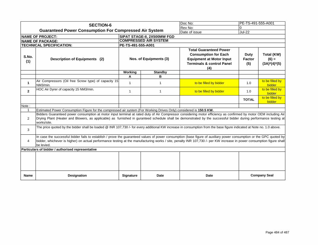
Doc No: Rev No: Date of issue
S.No.
(1)Description of Equipments (2)
Total Guaranteed Power
Consumption for Each
Equipment at Motor Input
Terminals & control Panel
(4)
Duty
Factor
(5)
Total (KW)
(6) =
(3A)*(4)*(5)
Working Standby
A B
1Air Compressors (Oil free Screw type) of capacity 15NM3/min. 1 1 to be filled by bidder 1.0 to be filled by
bidder
2HOC Air Dyrer of capacity 15 NM3/min. 1 1 to be filled by bidder 1.0 to be filled by
bidder
TOTALto be filled by
bidderNote :
1
2
3
4
Name Designation Signature Date Date
PE-TS-491-555-A0010Jul-22
SECTION-6
Guaranteed Power Consumption For Compressed Air System
Nos. of Equipments (3)
NAME OF PROJECT: SIPAT STAGE-II, 2X500MW FGD
NAME OF PACKAGE: COMPRESSED AIR SYSTEM
PE-TS-491-555-A001TECHNICAL SPECIFICATION:
Company Seal
Particulars of bidder / authorised representative
The price quoted by the bidder shall be loaded @ INR 107,730 /- for every additional KW increase in consumption from the base figure indicated at Note no. 1.0 above.
In case the successful bidder fails to establish / prove the guaranteed values of power consumption (base figure of auxiliary power consumption or the GPC quoted bybidder, whichever is higher) on actual performance testing at the manufacturing works / site, penalty INR 107,730 /- per KW increase in power consumption figure shallbe levied.
Estimated Power Consumption Figure for the compressed air system (For Working Drives Only) considered is 150.5 KW.
Bidders Guaranteed power consumption at motor input terminal at rated duty of Air Compressor considering motor efficiency as confirmed by motor OEM including AirDrying Plant (Heater and Blowers, as applicable) as furnished in guranteed schedule shall be demonstrated by the successful bidder during performance testing atworks/site.
Page 484 of 487

SIPAT STAGE-II, 2X500MW FGD
COMPRESSED AIR SYSTEM
SPECIFICATION No: PE-TS-491-555-A001
VOLUME: III
SECTION-7
REV. 00 DATE: JULY 2022
VOLUME-III
SECTION – 7
ANNUAL MAINTENANCE CONTRACT SERVICES
Page 485 of 487

SIPAT STAGE-II, 2X500MW FGD
COMPRESSED AIR SYSTEM
SPECIFICATION No: PE-TS-491-555-A001
VOLUME: III
SECTION-7
REV. 00 DATE: JULY 2022
ANNUAL MAINTENANCE CONTRACT SERVICES The bidder scope covers the Annual maintenance contract (AMC) for Preventive / Breakdown maintenance for a period of One (1) year from the date of successful handover of Compressed air system to end customer or the date as agreed mutually between the construction manager and the successful bidder. AMC scope also covers all regular maintenance by certified and trained service engineers. Total Six visits (06) (Including 2 Breakdown visit) shall be provided in a year. And each visit consists 1 to 2 days, depending upon the nature of work.
1.0 Scope of Work: The scope of work includes: 1. To carry out Preventive Maintenance checks as per mentioned schedule provided by bidder ensuring min. one
routine visit per quarter, to attend Air compressors, its motor, Air dryer and all its accessories.
2. In case of breakdown, bidder shall depute qualified Service manpower and rectify the same with in strict time frame, not exceeding 48 hours.
3. Spares, consumables, maintenance kits etc. required for preventive AMC / breakdown shall be provided to
successful bidder’s service provider by BHEL on the written request basis. Any specific item not available in BHEL inventory, shall be provided by bidder on mutual settlement of related commercial issues.
2.0 Detail description of major equipment: -
SL.
NO.
EQUIPMENT MAKE & MODEL Qty.
1 AIR COMPRESSOR WITH MOTOR (15
Nm3/min. @ 8.5 kg/cm2(g))
As per Bidder 2 nos. (1W+ 1S)
2 AIR DRYER (15 Nm3/min. @ 8.5 kg/cm2(g)) As per Bidder 2 nos. (1W+ 1S)
3.0 General Checklist for Air compressor: - The checklists are intended for general description of work to be carried out. They are not intended to cover all minute details. The work shall be executed in accordance with Manufacturer’s O&M Manuals and modern techniques. Preventive Maintenance checks includes but not limited to as specified below:
MAINTENANCE OF SCREW COMPRESSOR
Carry out external cleaning of equipment.
Check the oil level in the tank if low top-up with oil.
Change the lube oil & lube oil filter element.
Check the tightness of foundation bolt & take corrective action, if applicable.
Check the coupling gear installed between compressor and motor.
Check & clean the air breather in oil tank.
Setting and checking of safety valves
Pressure switch setting, Trips condition checking.
Page 486 of 487
SIPAT STAGE-II, 2X500MW FGD
COMPRESSED AIR SYSTEM
SPECIFICATION No: PE-TS-491-555-A001
VOLUME: III
SECTION-7
REV. 00 DATE: JULY 2022
Blow down valve functioning and repairing if necessary
Clean the inlet air filter / oil filter element.
Checking / cleaning of all heat exchangers.
Checks the leakage in oil line, water line and airline if found then rectify the same.
Cleaning of cooling water inlet line strainer, back flushing of air and oil cooler, air purging oil scavenging & connecting tube, Cleaning & servicing of moisture separator installed at compressor outlet, cleaning of all moisture & dust separating filter elements as prescribed by manufacturer.
Check for Electrical connections intact.
Check for compressor control panel as per manufacturer recommendation.
Any other maintenance as recommended by manufacturer.
MAINTENANCE OF AIR DRIER
Carry out external cleaning of equipment.
Clean the suction filter/ moisture strainer.
Check the tightness of foundation bolts & take corrective action if required.
Assisting for inspection / repair / servicing during expert visit as per instructions.
Check change over valve.
Check for any leakages in pipeline.
Check for Electrical connections intact.
Equipment external and internal cleaning.
Any other maintenance as recommended by manufacturer.
4.0 Tools and tackles Tools and tackles required for handling the component will be provided to the Bidder (successful bidder) on the written request basis. Bidder shall not claim any delay or compensation due to unavailability of these items, if any. In such cases bidder need to arrange the required tools and tackles at his own cost.
5.0 Bidder is to arrange all the safety gears like helmets, air plugs, safety shoes etc. during the maintenance.
6.0 In case of breakdown, Bidder is to depute service manpower within 48 hrs. without fail.
7.0 For Breakdown Maintenance, Bidder is to service and operate the compressor with satisfactory operating parameters within a week (6 working days) of reporting.
8.0 Bidder is to submit the Servicing Report (SR) of completed Breakdown Maintenance.
9.0 If any damage to the equipment and its accessories due to improper maintenance by bidder shall be recovered from the bidder.
Page 487 of 487
Related Documents