SIPART Electropneumatic positioners SIPART PS2 with 4 to 20 mA/HART Operating Instructions 6DR50.. 6DR51.. 6DR52.. 6DR53.. 6DR59.. 01/2019 A5E00074631-AD Introduction 1 Safety information 2 Description 3 Installing and mounting 4 Connection 5 Operating 6 Commissioning 7 Functional safety 8 Parameter assignment 9 Alarm, error, and system messages 10 Service and maintenance 11 Technical data 12 Dimension drawings 13 Spare parts / accessories / scope of delivery 14 Appendix A External position detection B Pressure gauge block C Sealing plug / thread adapter D Booster E Positioner with remote control electronics F Abbreviations G

Welcome message from author
This document is posted to help you gain knowledge. Please leave a comment to let me know what you think about it! Share it to your friends and learn new things together.
Transcript

SIPART
Electropneumatic positionersSIPART PS2 with 4 to 20 mA/HART
Operating Instructions
6DR50..6DR51..6DR52..6DR53..6DR59..
01/2019A5E00074631-AD
Introduction 1Safety information 2Description 3Installing and mounting 4Connection 5Operating 6Commissioning 7Functional safety 8Parameter assignment 9Alarm, error, and system messages 10Service and maintenance 11Technical data 12Dimension drawings 13Spare parts / accessories / scope of delivery 14Appendix AExternal position detection BPressure gauge block CSealing plug / thread adapter DBooster EPositioner with remote control electronics FAbbreviations G
Legal informationWarning notice system
This manual contains notices you have to observe in order to ensure your personal safety, as well as to prevent damage to property. The notices referring to your personal safety are highlighted in the manual by a safety alert symbol, notices referring only to property damage have no safety alert symbol. These notices shown below are graded according to the degree of danger.
DANGERindicates that death or severe personal injury will result if proper precautions are not taken.
WARNINGindicates that death or severe personal injury may result if proper precautions are not taken.
CAUTIONindicates that minor personal injury can result if proper precautions are not taken.
NOTICEindicates that property damage can result if proper precautions are not taken.If more than one degree of danger is present, the warning notice representing the highest degree of danger will be used. A notice warning of injury to persons with a safety alert symbol may also include a warning relating to property damage.
Qualified PersonnelThe product/system described in this documentation may be operated only by personnel qualified for the specific task in accordance with the relevant documentation, in particular its warning notices and safety instructions. Qualified personnel are those who, based on their training and experience, are capable of identifying risks and avoiding potential hazards when working with these products/systems.
Proper use of Siemens productsNote the following:
WARNINGSiemens products may only be used for the applications described in the catalog and in the relevant technical documentation. If products and components from other manufacturers are used, these must be recommended or approved by Siemens. Proper transport, storage, installation, assembly, commissioning, operation and maintenance are required to ensure that the products operate safely and without any problems. The permissible ambient conditions must be complied with. The information in the relevant documentation must be observed.
TrademarksAll names identified by ® are registered trademarks of Siemens AG. The remaining trademarks in this publication may be trademarks whose use by third parties for their own purposes could violate the rights of the owner.
Disclaimer of LiabilityWe have reviewed the contents of this publication to ensure consistency with the hardware and software described. Since variance cannot be precluded entirely, we cannot guarantee full consistency. However, the information in this publication is reviewed regularly and any necessary corrections are included in subsequent editions.
Siemens AGDivision Process Industries and DrivesPostfach 48 4890026 NÜRNBERGGERMANY
Document order number: A5E00074631Ⓟ 01/2019 Subject to change
Copyright © Siemens AG 2019.All rights reserved
Table of contents
1 Introduction.................................................................................................................................................13
1.1 Purpose of this documentation...............................................................................................13
1.2 Document history ...................................................................................................................13
1.3 Product compatibility ..............................................................................................................14
1.4 Checking the consignment.....................................................................................................14
1.5 Security information ...............................................................................................................14
1.6 Transportation and storage ....................................................................................................15
1.7 Notes on warranty ..................................................................................................................15
2 Safety information.......................................................................................................................................17
2.1 Precondition for use ...............................................................................................................17
2.2 Warning symbols on the device .............................................................................................17
2.3 Laws and directives................................................................................................................17
2.4 Conformity with European directives......................................................................................18
2.5 Improper device modifications ...............................................................................................18
2.6 Improper modification on positioner 6DR5...6........................................................................18
2.7 Requirements for special applications ...................................................................................19
2.8 Use in hazardous areas .........................................................................................................19
3 Description..................................................................................................................................................21
3.1 Function .................................................................................................................................21
3.2 Structure.................................................................................................................................213.2.1 Overview of structure .............................................................................................................213.2.2 Nameplate layout ...................................................................................................................243.2.3 Explanation of Ex information ................................................................................................25
3.3 Device components................................................................................................................263.3.1 Overview of device components ............................................................................................263.3.2 Basic electronics ....................................................................................................................27
3.4 Mode of operation ..................................................................................................................283.4.1 Block circuit diagram for single-acting or double-acting actuators .........................................303.4.2 Mode of operation of the HART function................................................................................313.4.3 HART system configuration ...................................................................................................313.4.4 SIMATIC PDM........................................................................................................................32
4 Installing and mounting...............................................................................................................................35
4.1 Basic safety instructions.........................................................................................................354.1.1 Use in hazardous area ...........................................................................................................354.1.2 Proper mounting.....................................................................................................................38
SIPART PS2 with 4 to 20 mA/HARTOperating Instructions, 01/2019, A5E00074631-AD 3

4.2 Mounting to linear actuator.....................................................................................................39
4.3 Mounting to part-turn actuator................................................................................................44
4.4 Setting and locking the transmission ratio..............................................................................47
4.5 Installing option modules........................................................................................................504.5.1 General information on installing option modules ..................................................................504.5.1.1 Opening the standard and and intrinsically safe version........................................................504.5.1.2 Closing the standard and and intrinsically safe version .........................................................524.5.1.3 Opening the device version with "flameproof enclosure" .......................................................534.5.1.4 Closing the device version with "flameproof enclosure".........................................................564.5.2 Position feedback module 6DR4004-6J/-8J...........................................................................574.5.3 Alarm module 6DR4004-6A/-8A.............................................................................................584.5.4 Slit initiator alarm module (SIA) 6DR4004 6G/-8G.................................................................604.5.5 Mechanical limit switch module 6DR4004-6K/-8K .................................................................624.5.6 Internal NCS module (iNCS) 6DR4004-5L/-5LE ....................................................................664.5.7 EMC filter module 6DR4004-6F/-8F.......................................................................................69
5 Connection .................................................................................................................................................73
5.1 Basic safety instructions.........................................................................................................73
5.2 Electrical wiring ......................................................................................................................775.2.1 Connection diagram for basic electronics ..............................................................................775.2.2 Connection diagram split range .............................................................................................805.2.3 Option modules ......................................................................................................................815.2.3.1 Alarm modules 6DR4004-6A and -8A....................................................................................815.2.3.2 Position feedback modules 6DR4004-6J and -8J ..................................................................825.2.3.3 SIA modules 6DR4004-6G and -8G.......................................................................................825.2.3.4 Mechanical limit switch modules 6DR4004-6K and -8K.........................................................835.2.3.5 EMC filter module 6DR4004-6F/-8F.......................................................................................855.2.4 Option device version M12 connector....................................................................................865.2.4.1 M12 connector socket in the basic device .............................................................................865.2.4.2 M12 connector for connecting the position feedback module 6DR4004-6J / 8J (-Z D53)......875.2.4.3 M12 connector for connecting the external position detection system (-Z D54) ....................875.2.4.4 M12 connector for connecting the alarm module 6DR4004-6A / -8A (-Z D55) ......................875.2.4.5 M12 connector for connecting the SIA module 6DR4004-6G /-8G (-Z D56)..........................885.2.4.6 M12 connector for connecting the mechanical limit switch module 6DR4004-6K (-Z D57)......88
5.3 Pneumatic connection............................................................................................................885.3.1 Basic safety instructions for the pneumatic connection .........................................................885.3.2 Pneumatic connection for 6DR5..0/1/2/3 ...............................................................................895.3.2.1 Structure of pneumatic connection.........................................................................................895.3.2.2 Integrated pneumatic connection ...........................................................................................895.3.3 Pneumatic connection for 6DR5..5/6 .....................................................................................905.3.4 Reaction to failure of auxiliary powers ...................................................................................91
5.4 Restrictors ..............................................................................................................................91
6 Operating....................................................................................................................................................93
6.1 Operating elements................................................................................................................936.1.1 Display ...................................................................................................................................936.1.2 Buttons ...................................................................................................................................946.1.3 Firmware version ...................................................................................................................95
Table of contents
SIPART PS2 with 4 to 20 mA/HART4 Operating Instructions, 01/2019, A5E00074631-AD
6.2 Operating modes....................................................................................................................966.2.1 Overview of operating modes ................................................................................................966.2.2 Changing the operating mode................................................................................................966.2.3 Overview of configuration.......................................................................................................976.2.4 Description of operating modes .............................................................................................976.2.5 Optimization of controller data ...............................................................................................99
7 Commissioning .........................................................................................................................................103
7.1 Basic safety instructions.......................................................................................................103
7.2 Overview ..............................................................................................................................105
7.3 Sequence of automatic initialization.....................................................................................107
7.4 Setting the friction clutch ......................................................................................................113
7.5 Purge air switching...............................................................................................................114
7.6 Commissioning linear actuators ...........................................................................................1147.6.1 Preparing linear actuators for commissioning ......................................................................1147.6.2 Automatic initialization of linear actuators ............................................................................1167.6.3 Manual initialization of linear actuators ................................................................................118
7.7 Commissioning part-turn actuators ......................................................................................1217.7.1 Preparing part-turn actuators for commissioning .................................................................1217.7.2 Automatic initialization of part-turn actuators .......................................................................1227.7.3 Manual initialization of part-turn actuators ...........................................................................123
7.8 Canceling initialization..........................................................................................................125
7.9 Device replacement .............................................................................................................126
8 Functional safety ......................................................................................................................................129
8.1 Range of applications for functional safety ..........................................................................129
8.2 Safety function .....................................................................................................................129
8.3 Safety Integrity Level (SIL)...................................................................................................131
8.4 Settings ................................................................................................................................132
8.5 Safety characteristics ...........................................................................................................133
8.6 Maintenance/check ..............................................................................................................134
9 Parameter assignment .............................................................................................................................135
9.1 Introduction to parameter assignment section .....................................................................135
9.2 Configuration schematic for parameter operating principle..................................................136
9.3 Tabular overview of the parameters.....................................................................................1379.3.1 Overview of initialization parameters 1 to 5 .........................................................................1379.3.2 Overview of application parameters 6 to 52.........................................................................1389.3.3 Overview of advanced diagnostic parameters A to U ..........................................................141
9.4 Description of parameters ....................................................................................................1459.4.1 Initialization parameters 1 to 5 .............................................................................................1459.4.1.1 '1.YFCT' type of actuator......................................................................................................1459.4.1.2 '2.YAGL' Rated angle of rotation of feedback ......................................................................1479.4.1.3 '3.YWAY' Range of stroke....................................................................................................148
Table of contents
SIPART PS2 with 4 to 20 mA/HARTOperating Instructions, 01/2019, A5E00074631-AD 5
9.4.1.4 '4.INITA' Initialization (automatically) ...................................................................................1489.4.1.5 '5.INITM' Initialization (manual) ............................................................................................1499.4.2 Application parameters 6 to 52 ............................................................................................1499.4.2.1 '6.SCUR' Current range of setpoint......................................................................................1499.4.2.2 '7.SDIR' Setpoint direction ...................................................................................................1509.4.2.3 '8.SPRA' Setpoint split range start / '9.SPRE' Setpoint split range start end .......................1509.4.2.4 '10.TSUP' Setpoint ramp UP / '11.TSDO' Setpoint ramp DOWN.........................................1519.4.2.5 '12.SFCT' Setpoint function..................................................................................................1529.4.2.6 '13.SL0' ... '33.SL20' Setpoint turning point..........................................................................1529.4.2.7 '34.DEBA' Deadband of closed-loop controller ....................................................................1539.4.2.8 '35.YA' Start of manipulated variable limit / '36.YE' End of manipulated variable limit.........1549.4.2.9 '37.YNRM' Standardization of manipulated variable ............................................................1549.4.2.10 '38.YDIR' Direction of manipulated variable for display and position feedback ...................1569.4.2.11 '39.YCLS' Tight closing/fast closing with manipulated variable............................................1569.4.2.12 '40.YCDO' Value for tight closing/fast closing Down............................................................1579.4.2.13 '41.YCUP' Value for tight closing/fast closing Up.................................................................1579.4.2.14 '42.BIN1' / '43.BIN2' Function binary input ...........................................................................1589.4.2.15 '44.AFCT' Alarm function .....................................................................................................1599.4.2.16 '45.A1' / '46.A2' Response threshold of alarm......................................................................1619.4.2.17 '47.\\FCT' Function for fault message output .......................................................................1619.4.2.18 '48.\\TIM' Monitoring time for setting of fault message 'Control deviation' ...........................1629.4.2.19 '49.\\LIM' Response threshold of fault message 'Control deviation' .....................................1629.4.2.20 '50.PRST' Preset..................................................................................................................1639.4.2.21 '51.PNEUM' Pneumatics type ..............................................................................................1639.4.2.22 '52.XDIAG' Activating for extended diagnostics ...................................................................1659.4.3 Advanced diagnostic parameters A to U..............................................................................1669.4.3.1 Partial stroke test 'A.\\PST'...................................................................................................1669.4.3.2 Monitoring of dynamic control valve behavior 'b.\\DEVI' ......................................................1719.4.3.3 Monitoring/compensation of pneumatic leakage 'C.\\LEAK'.................................................1739.4.3.4 Monitoring of stiction (slipstick) 'd.\\STIC'.............................................................................1769.4.3.5 Monitoring of deadband 'E.\\DEBA'......................................................................................1789.4.3.6 Monitoring of lower endstop 'F.\\ZERO' ...............................................................................1799.4.3.7 Monitoring the upper endstop 'G.\\OPEN' ............................................................................1809.4.3.8 Monitoring the low limit temperature 'H.\\TMIN' ...................................................................1829.4.3.9 Monitoring the high limit temperature 'J.\\TMAX'..................................................................1849.4.3.10 Monitoring of number of total strokes 'L.\\STRK'..................................................................1859.4.3.11 Monitoring of number of changes in direction 'O.\\DCHG' ...................................................1879.4.3.12 Monitoring the position average value 'P.\\PAVG'................................................................1889.4.3.13 Pressure monitoring 'U.\\PRES' ...........................................................................................191
10 Alarm, error, and system messages.........................................................................................................193
10.1 Output of system messages in the display...........................................................................19310.1.1 System messages before initialization .................................................................................19310.1.2 System messages during initialization .................................................................................19310.1.3 System messages when exiting the Configuration mode ....................................................19610.1.4 System messages during operation.....................................................................................196
10.2 Diagnostics...........................................................................................................................19810.2.1 Display of diagnostics values ...............................................................................................19810.2.2 Saving the diagnostics values..............................................................................................19810.2.3 Overview of diagnostics values............................................................................................19910.2.4 Meaning of the diagnostics values .......................................................................................20110.2.4.1 Diagnostic value '1.STRKS - Number of total strokes' .........................................................201
Table of contents
SIPART PS2 with 4 to 20 mA/HART6 Operating Instructions, 01/2019, A5E00074631-AD
10.2.4.2 Diagnostic value '2.CHDIR - Number of changes in direction' .............................................20110.2.4.3 Diagnostic value '3.\\CNT - Number of fault messages' .......................................................20110.2.4.4 Diagnostic value '4.A1CNT - Number of alarms 1' / '5.A2CNT - Number of alarms 2' .........20110.2.4.5 Diagnostic value '6.HOURS - Number of operating hours' ..................................................20210.2.4.6 Diagnostic value '7.HOURR - Resettable operating hours counter' .....................................20210.2.4.7 Diagnostic value '8.WAY - Determined travel'......................................................................20210.2.4.8 Diagnostic value '9.TUP - Travel time up' / '10.TDOWN - Travel time down' ......................20210.2.4.9 Diagnostic value '11.LEAK - Leakage test' ..........................................................................20310.2.4.10 Diagnostic value '12.PST - Monitoring of partial stroke test' ................................................20410.2.4.11 Diagnostic value '12.PST - Monitoring of partial stroke test' (version with pressure
sensors) ...............................................................................................................................20510.2.4.12 Diagnostic value '13.PRPST - Time since last partial stroke test' (version without
pressure sensors) ................................................................................................................20610.2.4.13 Diagnostic value '13.PRPST' - Time since last partial stroke test' (version with pressure
sensors) ...............................................................................................................................20610.2.4.14 Diagnostic value '14.NXPST - Time until next partial stroke test' ........................................20610.2.4.15 Diagnostics value '15.DEVI - Dynamic control valve behavior' ............................................20710.2.4.16 Diagnostic value '16.ONLK - Pneumatic leakage'................................................................20710.2.4.17 Diagnostic value '17.STIC - Stiction (slipstick)' ....................................................................20710.2.4.18 Diagnostic value '18.ZERO - Lower endstop'.......................................................................20710.2.4.19 Diagnostic value '19.OPEN - Upper endstop' ......................................................................20810.2.4.20 Diagnostic value '20.PAVG - Average value of position' ......................................................20810.2.4.21 Diagnostic value '21.P0 - Potentiometer value of lower endstop (0%)' / '22.P100 -
Potentiometer value of upper endstop (100%)' ....................................................................20810.2.4.22 Diagnostic value '23.IMPUP - Pulse length up' / '24.IMPDN - Pulse length down' .............21010.2.4.23 Diagnostic value '25.PAUTP - Pulse interval'.......................................................................21010.2.4.24 Diagnostic value '26.DBUP - Deadband up' / '27.DBDN - Deadband down'........................21010.2.4.25 Diagnostic value '28.SSUP - Slow step zone up' / '29.SSDN - Slow step zone down' ........21110.2.4.26 Diagnostic value '30.TEMP - Current temperature' ..............................................................21110.2.4.27 Diagnostic value '31.TMIN - Minimum temperature' / '32.TMAX - Maximum temperature'....21110.2.4.28 Diagnostic value '33.T1' ... '41.T9' - Number of operating hours in the temperature range
1 to 9 ....................................................................................................................................21210.2.4.29 Diagnostic value '42.VENT1' / '43.VENT2' ..........................................................................21210.2.4.30 Diagnostic value '44.VEN1R' / '45.VEN2R' ..........................................................................21310.2.4.31 Diagnostic value '46.STORE - Save maintenance data' ......................................................21310.2.4.32 Diagnostic value '47.PRUP - Prediction up' / '48.PRDN - Prediction down' .........................21310.2.4.33 Diagnostic value '49.WT00' ... '56.WT95' - Number of operating hours in the travel range
WT00 to WT95 .....................................................................................................................21410.2.4.34 Diagnostic value '57.LKPUL - Length of the leakage compensation pulse' .........................21410.2.4.35 Diagnostic value '58.LKPER - Period of the leakage compensation pulse' .........................21410.2.4.36 Diagnostic value '59.mA - Setpoint current' .........................................................................21510.2.4.37 Diagnostic value '60.PZ Supply air pressure (PZ)' ...............................................................21510.2.4.38 Diagnostic value '63.PZMAX Supply pressure (PZ) min/max pointer ..................................21510.2.4.39 Diagnostic value '64.N_MIN Event counter' .........................................................................215
10.3 Online diagnostics................................................................................................................21610.3.1 Overview of error codes .......................................................................................................21610.3.2 Overview of online diagnostics.............................................................................................21810.3.3 XDIAG parameter ................................................................................................................21810.3.4 Meaning of error codes ........................................................................................................21910.3.4.1 1 Remaining control deviation..............................................................................................21910.3.4.2 2 Device not in "Automatic" mode........................................................................................21910.3.4.3 3 Binary input BIN1 or BIN2 active.......................................................................................219
Table of contents
SIPART PS2 with 4 to 20 mA/HARTOperating Instructions, 01/2019, A5E00074631-AD 7
10.3.4.4 4 Monitoring the number of total strokes..............................................................................21910.3.4.5 5 Monitoring the number of changes in direction .................................................................21910.3.4.6 6 Monitoring the lower endstop / 7 Monitoring the upper endstop .......................................22010.3.4.7 8 Monitoring deadband ........................................................................................................22010.3.4.8 9 Partial stroke test ..............................................................................................................22010.3.4.9 10 Monitoring of dynamic control valve behavior .................................................................22110.3.4.10 11 Monitoring/compensation of pneumatic leakage ............................................................22110.3.4.11 12 Monitoring of stiction (slipstick) .......................................................................................22110.3.4.12 13 Monitoring the lower limit temperature ............................................................................22110.3.4.13 14 Monitoring the upper limit temperature ...........................................................................22110.3.4.14 15 Monitoring the position average value ............................................................................22110.3.4.15 16 Monitoring the plausibility of values for the partial stroke test.........................................22110.3.4.16 17 Monitoring the pressure sensors.....................................................................................22110.3.4.17 18 Monitoring low limit of supply pressure (PZLIM) .............................................................22110.3.4.18 19 Monitoring PS2-specific limit values of supply pressure .................................................222
10.4 Fault correction ....................................................................................................................22210.4.1 Fault identification ................................................................................................................22210.4.2 Remedial measures table 1 .................................................................................................22310.4.3 Remedial measures table 2 .................................................................................................22310.4.4 Remedial measures table 3 .................................................................................................22410.4.5 Corrective measures Table 4 ...............................................................................................22510.4.6 Remedial measures table 5 .................................................................................................22510.4.7 Corrective measures table 6 ................................................................................................226
11 Service and maintenance .........................................................................................................................227
11.1 Basic safety instructions.......................................................................................................227
11.2 Cleaning of the screens .......................................................................................................22811.2.1 Positioners 6DR5..0, 6DR5..3 and 6DR5..5.........................................................................22811.2.2 Positioners 6DR5..1, 6DR5..2 and 6DR5..6.........................................................................229
11.3 Maintenance and repair work...............................................................................................22911.3.1 Repair/Upgrading .................................................................................................................230
11.4 Replace basic electronics ....................................................................................................230
11.5 Replace pneumatic block .....................................................................................................232
11.6 Replace the pressure sensor module ..................................................................................233
11.7 Return procedure .................................................................................................................236
11.8 Disposal ...............................................................................................................................236
12 Technical data ..........................................................................................................................................237
12.1 Rated conditions ..................................................................................................................237
12.2 Pneumatic data ....................................................................................................................237
12.3 Construction .........................................................................................................................238
12.4 Controller..............................................................................................................................240
12.5 Explosion protection.............................................................................................................24112.5.1 Breakdown of the article numbers........................................................................................24112.5.2 Protection against explosion device and option modules ....................................................24212.5.3 Maximal permissible ambient temperature ranges ..............................................................243
Table of contents
SIPART PS2 with 4 to 20 mA/HART8 Operating Instructions, 01/2019, A5E00074631-AD
12.6 Certificates and approvals....................................................................................................244
12.7 Electrical data.......................................................................................................................244
12.8 Electrical data for pressure sensors.....................................................................................246
12.9 Communication (HART) .......................................................................................................247
12.10 Technical data for natural gas as actuator medium .............................................................247
12.11 Option modules ....................................................................................................................24812.11.1 Alarm module .......................................................................................................................24812.11.2 Position feedback module ....................................................................................................25012.11.3 SIA module...........................................................................................................................25012.11.4 Mechanical limit switch module............................................................................................25112.11.5 EMC filter module.................................................................................................................25312.11.6 Internal NCS modules 6DR4004-5L and 6DR4004-5LE......................................................25312.11.7 Other technical specifications ..............................................................................................254
13 Dimension drawings .................................................................................................................................255
13.1 Positioner in non-flameproof enclosure................................................................................255
13.2 Terminal strip for enclosures 6DR5..0 and 6DR5..3 ............................................................256
13.3 Positioner in flameproof enclosure.......................................................................................257
14 Spare parts / accessories / scope of delivery ...........................................................................................259
14.1 Overview ..............................................................................................................................259
14.2 Spare parts...........................................................................................................................261
14.3 Scope of delivery of mechanical limit switch module ...........................................................264
14.4 Scope of delivery EMC filter module ...................................................................................265
14.5 Accessories..........................................................................................................................266
14.6 Order data ............................................................................................................................266
A Appendix...................................................................................................................................................267
A.1 Technical support.................................................................................................................267
A.2 QR code label ......................................................................................................................268
A.3 Overview of the assignment of the HART variables.............................................................268
B External position detection .......................................................................................................................269
B.1 Introduction ..........................................................................................................................269
B.2 Non-Contacting Sensor........................................................................................................270B.2.1 Principle of operation of NCS...............................................................................................270B.2.2 Mounting the NCS................................................................................................................271B.2.2.1 Mounting on part-turn actuator ............................................................................................272B.2.2.2 Mounting on linear actuator up to 14 mm (0.55 inch)...........................................................274B.2.2.3 Mounting on linear actuator > 14 mm (0.55 inch).................................................................276B.2.3 Connecting NCS to EMC filter module.................................................................................279B.2.4 Commissioning of NCS ........................................................................................................280B.2.4.1 Prerequisites / default settings .............................................................................................280B.2.4.2 Initialization of part-turn actuators ........................................................................................281
Table of contents
SIPART PS2 with 4 to 20 mA/HARTOperating Instructions, 01/2019, A5E00074631-AD 9
B.2.4.3 Initializing linear actuators with a stroke range up to 14 mm (0.55 inch) .............................281B.2.4.4 Initializing linear actuators with a stroke range > 14 mm (0.55 inch) ...................................281B.2.5 Technical specifications NCS...............................................................................................281B.2.6 Dimensional drawing of non-contacting sensor ...................................................................283B.2.7 NCS sensor scope of delivery..............................................................................................283B.2.7.1 Scope of delivery of NCS for part-turn actuators .................................................................283B.2.7.2 Scope of delivery of NCS for linear actuators up to 14 mm (0.55 inch) . .............................284B.2.7.3 Scope of delivery of NCS for linear actuators > 14 mm (0.55 inch) . ...................................285
B.3 External position detection system.......................................................................................285B.3.1 Principle of operation of external position detection systems ..............................................285B.3.2 Mounting the external position detection systems ...............................................................286B.3.3 Connecting the external position detection system to the EMC filter module ......................286B.3.4 Technical specifications of the external position detection system ......................................287
C Pressure gauge block...............................................................................................................................289
D Sealing plug / thread adapter ...................................................................................................................291
D.1 Intended use of accessory part ............................................................................................291
D.2 Safety instructions for accessory part ..................................................................................291
D.3 Technical specifications of accessory part...........................................................................292
D.4 Dimensional drawings for accessory part ............................................................................293
E Booster .....................................................................................................................................................295
E.1 Booster introduction .............................................................................................................295
E.2 Operating principle of booster ..............................................................................................296
E.3 Mounting booster, without flameproof enclosure .................................................................297
E.4 Booster mounting, flameproof enclosure .............................................................................301
E.5 Booster commissioning ........................................................................................................305
E.6 Booster dimension drawings ................................................................................................308E.6.1 For positioners in non-flameproof enclosure........................................................................308E.6.2 For positioners in flameproof enclosure ...............................................................................309
E.7 Technical specifications of booster ......................................................................................309
F Positioner with remote control electronics ................................................................................................311
F.1 Introduction to remote control electronics ............................................................................311
F.2 19" slide-in module...............................................................................................................311F.2.1 Description of 19" slide-in module 4 to 20 mA .....................................................................311F.2.2 Connecting the 19" slide-in module 4 to 20 mA ...................................................................312F.2.2.1 Grounding concept of 19" slide-in module 4 to 20 mA.........................................................312F.2.2.2 Electrical connection of 19" slide-in module 4 to 20 mA ......................................................314F.2.3 Technical specifications of 19" slide-in module 4 to 20 mA .................................................316F.2.4 Dimensional drawing of 19" slide-in module 4 to 20 mA......................................................318F.2.5 Scope of delivery of remote control electronics ...................................................................318
F.3 Positioner without basic electronics 6DR5910 .....................................................................318
G Abbreviations............................................................................................................................................321
G.1 Abbreviations for positioners................................................................................................321
Table of contents
SIPART PS2 with 4 to 20 mA/HART10 Operating Instructions, 01/2019, A5E00074631-AD

G.2 Abbreviations for functional safety .......................................................................................322
Glossary ...................................................................................................................................................325
Index.........................................................................................................................................................333
Table of contents
SIPART PS2 with 4 to 20 mA/HARTOperating Instructions, 01/2019, A5E00074631-AD 11

Table of contents
SIPART PS2 with 4 to 20 mA/HART12 Operating Instructions, 01/2019, A5E00074631-AD

Introduction 11.1 Purpose of this documentation
These instructions contain all information required to commission and use the device. Read the instructions carefully prior to installation and commissioning. In order to use the device correctly, first review its principle of operation.
The instructions are aimed at persons mechanically installing the device, connecting it electronically, configuring the parameters and commissioning it, as well as service and maintenance engineers.
1.2 Document historyThe most important changes in the documentation when compared with the respective previous edition are given in the following table.
Edition Note01/2019 ● Changes for FW 5.02.00, HART device revision 7
● Ex "nA" (non-sparking equipment) is replaced by Ex "ec" (increased safety)● Option -Z P01 Extended diagnostics supported by pressure sensors
– Parameter assignment: U.\\PRES (Page 191)– Diagnostics values: 60.PZ, 63.PZMAX und 64.N_Min (Page 215)– Online diagnostics: Error codes 17 to 19 (Page 221)Section "Installing and mounting (Page 35)"– New markings on the lever with carrier pin (Page 39)– Revised section "Setting and locking the transmission ratio (Page 47)"
● Section "Pneumatic connection (Page 88)"– Revised section "Reaction to failure of auxiliary powers (Page 91)"
● Section "Commissioning (Page 103)"– Revised section "Setting the friction clutch (Page 113)"
● Section "Service and maintenance (Page 227)"– Section "Replacing the basic electronics" with the "Fail in Place" function has
been revised and is now called "Replace basic electronics (Page 230)"– New section "Replace pneumatic block (Page 232)" and "Replace the
pressure sensor module (Page 233)"● Section "Technical data (Page 237)"
– Explosion protection (Page 241) restructured and contains a breakdown of the article number (Page 241)
● Section "Spare parts / accessories / scope of delivery (Page 259)" extended
SIPART PS2 with 4 to 20 mA/HARTOperating Instructions, 01/2019, A5E00074631-AD 13
See alsoPartial stroke test 'A.\\PST' (Page 166)
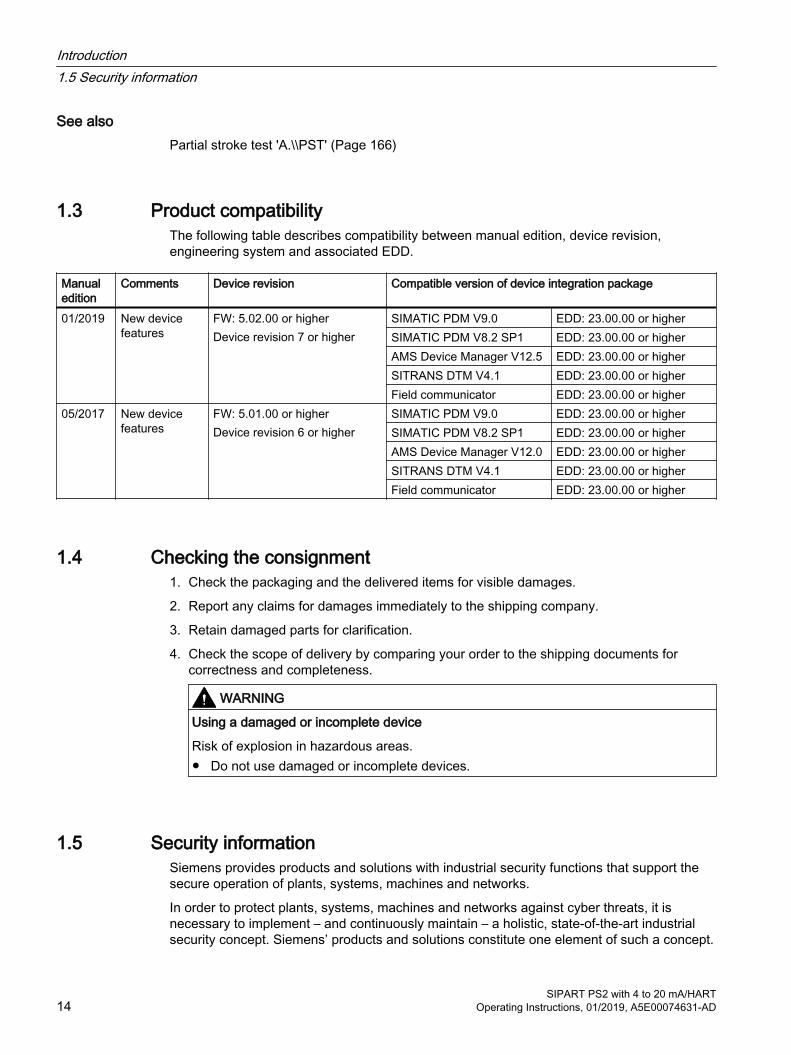
1.3 Product compatibilityThe following table describes compatibility between manual edition, device revision, engineering system and associated EDD.
Manual edition
Comments Device revision Compatible version of device integration package
01/2019 New device features
FW: 5.02.00 or higherDevice revision 7 or higher
SIMATIC PDM V9.0 EDD: 23.00.00 or higherSIMATIC PDM V8.2 SP1 EDD: 23.00.00 or higherAMS Device Manager V12.5 EDD: 23.00.00 or higherSITRANS DTM V4.1 EDD: 23.00.00 or higherField communicator EDD: 23.00.00 or higher
05/2017 New device features
FW: 5.01.00 or higherDevice revision 6 or higher
SIMATIC PDM V9.0 EDD: 23.00.00 or higherSIMATIC PDM V8.2 SP1 EDD: 23.00.00 or higherAMS Device Manager V12.0 EDD: 23.00.00 or higherSITRANS DTM V4.1 EDD: 23.00.00 or higherField communicator EDD: 23.00.00 or higher
1.4 Checking the consignment1. Check the packaging and the delivered items for visible damages.
2. Report any claims for damages immediately to the shipping company.
3. Retain damaged parts for clarification.
4. Check the scope of delivery by comparing your order to the shipping documents for correctness and completeness.
WARNING
Using a damaged or incomplete device
Risk of explosion in hazardous areas.● Do not use damaged or incomplete devices.
1.5 Security informationSiemens provides products and solutions with industrial security functions that support the secure operation of plants, systems, machines and networks.
In order to protect plants, systems, machines and networks against cyber threats, it is necessary to implement – and continuously maintain – a holistic, state-of-the-art industrial security concept. Siemens’ products and solutions constitute one element of such a concept.
Introduction1.5 Security information
SIPART PS2 with 4 to 20 mA/HART14 Operating Instructions, 01/2019, A5E00074631-AD
Customers are responsible for preventing unauthorized access to their plants, systems, machines and networks. Such systems, machines and components should only be connected to an enterprise network or the internet if and to the extent such a connection is necessary and only when appropriate security measures (e.g. firewalls and/or network segmentation) are in place.
For additional information on industrial security measures that may be implemented, please visit https://www.siemens.com/industrialsecurity.
Siemens’ products and solutions undergo continuous development to make them more secure. Siemens strongly recommends that product updates are applied as soon as they are available and that the latest product versions are used. Use of product versions that are no longer supported, and failure to apply the latest updates may increase customer’s exposure to cyber threats.
To stay informed about product updates, subscribe to the Siemens Industrial Security RSS Feed under https://www.siemens.com/industrialsecurity.
1.6 Transportation and storageTo guarantee sufficient protection during transport and storage, observe the following:
● Keep the original packaging for subsequent transportation.
● Devices/replacement parts should be returned in their original packaging.
● If the original packaging is no longer available, ensure that all shipments are properly packaged to provide sufficient protection during transport. Siemens cannot assume liability for any costs associated with transportation damages.
NOTICE
Insufficient protection during storage
The packaging only provides limited protection against moisture and infiltration.● Provide additional packaging as necessary.
Special conditions for storage and transportation of the device are listed in Technical data (Page 237).
1.7 Notes on warrantyThe contents of this manual shall not become part of or modify any prior or existing agreement, commitment or legal relationship. The sales contract contains all obligations on the part of Siemens as well as the complete and solely applicable warranty conditions. Any statements regarding device versions described in the manual do not create new warranties or modify the existing warranty.
The content reflects the technical status at the time of publishing. Siemens reserves the right to make technical changes in the course of further development.
Introduction1.7 Notes on warranty
SIPART PS2 with 4 to 20 mA/HARTOperating Instructions, 01/2019, A5E00074631-AD 15

Introduction1.7 Notes on warranty
SIPART PS2 with 4 to 20 mA/HART16 Operating Instructions, 01/2019, A5E00074631-AD
Safety information 22.1 Precondition for use
This device left the factory in good working condition. In order to maintain this status and to ensure safe operation of the device, observe these instructions and all the specifications relevant to safety.
Observe the information and symbols on the device. Do not remove any information or symbols from the device. Always keep the information and symbols in a completely legible state.
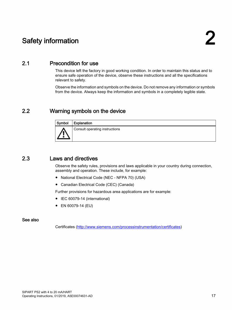
2.2 Warning symbols on the device
Symbol ExplanationConsult operating instructions
2.3 Laws and directivesObserve the safety rules, provisions and laws applicable in your country during connection, assembly and operation. These include, for example:
● National Electrical Code (NEC - NFPA 70) (USA)
● Canadian Electrical Code (CEC) (Canada)
Further provisions for hazardous area applications are for example:
● IEC 60079-14 (international)
● EN 60079-14 (EU)
See alsoCertificates (http://www.siemens.com/processinstrumentation/certificates)
SIPART PS2 with 4 to 20 mA/HARTOperating Instructions, 01/2019, A5E00074631-AD 17
2.4 Conformity with European directivesThe CE marking on the device shows conformity with the regulations of the following European guidelines:
Electromagnetic com‐patibility EMC 2014/30/EU
Directive of the European Parliament and of the Council on the har‐monization of the laws of the Member States relating to electromag‐netic compatibility.
Atmosphère explosible ATEX 2014/34/EU
Directive of the European Parliament and of the Council on the har‐monization of the laws of the Member States relating to equipment and protective systems intended for use in potentially explosive atmos‐pheres.
2011/65/EU RoHS Directive of the European Parliament and of the Council on the restric‐tion of the use of certain hazardous substances in electrical and elec‐tronic equipment
The directives applied can be found in the EU declaration of conformity for the associated device.
2.5 Improper device modifications
WARNING
Improper device modifications
Risk to personnel, system and environment can result from modifications to the device, particularly in hazardous areas.● Only carry out modifications that are described in the instructions for the device. Failure to
observe this requirement cancels the manufacturer's warranty and the product approvals.
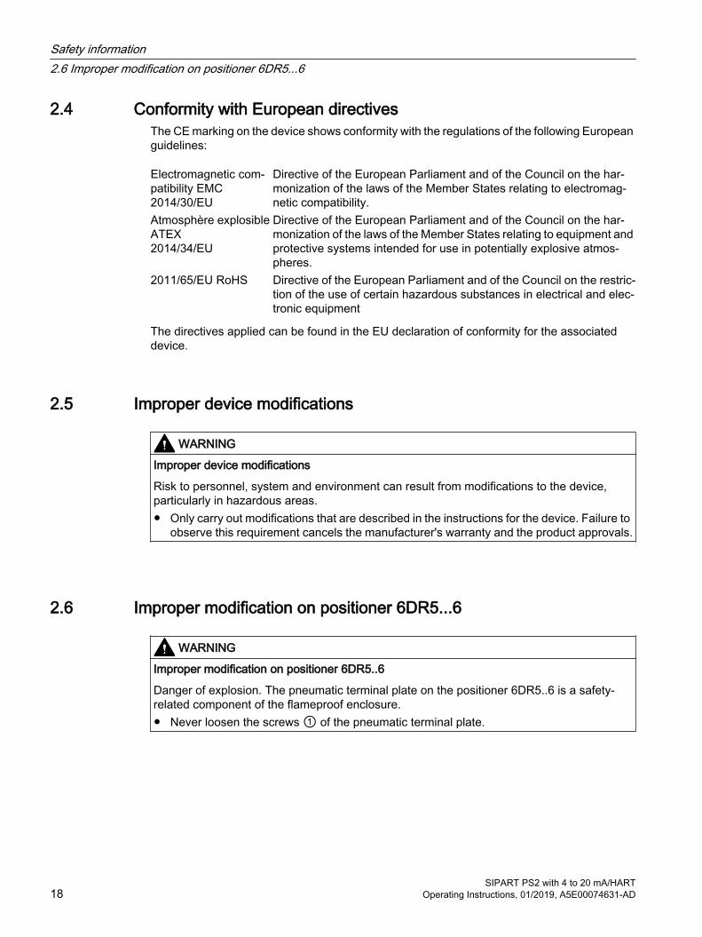
2.6 Improper modification on positioner 6DR5...6
WARNING
Improper modification on positioner 6DR5..6
Danger of explosion. The pneumatic terminal plate on the positioner 6DR5..6 is a safety-related component of the flameproof enclosure.● Never loosen the screws ① of the pneumatic terminal plate.
Safety information2.6 Improper modification on positioner 6DR5...6
SIPART PS2 with 4 to 20 mA/HART18 Operating Instructions, 01/2019, A5E00074631-AD

Figure 2-1 Screws of the pneumatic terminal plate on the positioner 6DR5..6
2.7 Requirements for special applicationsDue to the large number of possible applications, each detail of the described device versions for each possible scenario during commissioning, operation, maintenance or operation in systems cannot be considered in the instructions. If you need additional information not covered by these instructions, contact your local Siemens office or company representative.
NoteOperation under special ambient conditions
We highly recommend that you contact your Siemens representative or our application department before you operate the device under special ambient conditions as can be encountered in nuclear power plants or when the device is used for research and development purposes.
2.8 Use in hazardous areas
Qualified personnel for hazardous area applicationsPersons who install, connect, commission, operate, and service the device in a hazardous area must have the following specific qualifications:
● They are authorized, trained or instructed in operating and maintaining devices and systems according to the safety regulations for electrical circuits, high pressures, aggressive, and hazardous media.
● They are authorized, trained, or instructed in carrying out work on electrical circuits for hazardous systems.
● They are trained or instructed in maintenance and use of appropriate safety equipment according to the pertinent safety regulations.
Safety information2.8 Use in hazardous areas
SIPART PS2 with 4 to 20 mA/HARTOperating Instructions, 01/2019, A5E00074631-AD 19
WARNING
Use in hazardous area
Risk of explosion.● Only use equipment that is approved for use in the intended hazardous area and labeled
accordingly.● Do not use devices that have been operated outside the conditions specified for hazardous
areas. If you have used the device outside the conditions for hazardous areas, make all Ex markings unrecognizable on the nameplate.
WARNING
Loss of safety of device with type of protection "Intrinsic safety Ex i"
If the device or its components have already been operated in non-intrinsically safe circuits or the electrical specifications have not been observed, the safety of the device is no longer ensured for use in hazardous areas. There is a risk of explosion.● Connect the device with type of protection "Intrinsic safety" solely to an intrinsically safe
circuit.● Observe the specifications for the electrical data on the certificate and/or in Technical data
(Page 237).
Safety information2.8 Use in hazardous areas
SIPART PS2 with 4 to 20 mA/HART20 Operating Instructions, 01/2019, A5E00074631-AD
Description 33.1 Function
● The electropneumatic positioner and an actuator form a control system. The current position of the actuator is recorded by a servo potentiometer and the actual value x is fed back. The setpoint and the actual value are also shown simultaneously on the display.
● The control system provides the setpoint w digitally to the positioner over the bus.
● The positioner works as a predictive five-point positioner, through whose output value ±Δy the integrated valves can be controlled by pulse length modulation.
● These input signals change pressure in the actuator chamber(s) and displace the actuator until the control deviation becomes zero.
● Using the three buttons and the display with the enclosure cover removed, operation (manual mode) and configuration (structuring, initialization, and parameter assignment) can be performed.
● By default, the basic unit has a binary input (BIN). This binary input can be individually configured and used, for example, to block the control levels.
● It has a friction clutch and a switchable gear so that the positioner can be used with different mechanical part-turn and linear actuators.
● In the case of positioners with the "Fail in Place" function, the current position of the actuator is held if the electric and/or pneumatic auxiliary power fails. Does not function in conjunction with SIL.
3.2 Structure
3.2.1 Overview of structureThe following sections describe the mechanical and electrical structure, components, and principle functionality of the positioner.
The positioner is used to move and control pneumatic actuators. The positioner works electropneumatically, using compressed air as auxiliary power. The positioner is used to control valves, for example, with:
● Linear actuator
● Part-turn actuator VDI/VDE 3845
Various add-on extensions are available for linear actuators:
● IEC 60534-6-1 (NAMUR)
● Integrated mounting on ARCA, except with flameproof stainless steel enclosure (6DR5..6)
● Integrated mounting on SAMSON, not for Ex d
SIPART PS2 with 4 to 20 mA/HARTOperating Instructions, 01/2019, A5E00074631-AD 21
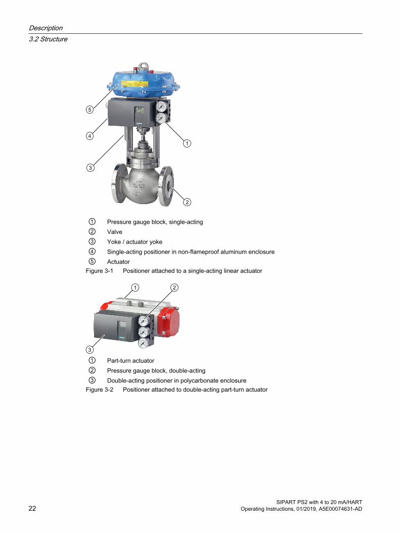
① Pressure gauge block, single-acting ② Valve③ Yoke / actuator yoke④ Single-acting positioner in non-flameproof aluminum enclosure⑤ Actuator
Figure 3-1 Positioner attached to a single-acting linear actuator
① Part-turn actuator② Pressure gauge block, double-acting③ Double-acting positioner in polycarbonate enclosure
Figure 3-2 Positioner attached to double-acting part-turn actuator
Description3.2 Structure
SIPART PS2 with 4 to 20 mA/HART22 Operating Instructions, 01/2019, A5E00074631-AD
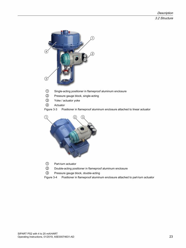
① Single-acting positioner in flameproof aluminum enclosure② Pressure gauge block, single-acting③ Yoke / actuator yoke④ Actuator
Figure 3-3 Positioner in flameproof aluminum enclosure attached to linear actuator
① Part-turn actuator② Double-acting positioner in flameproof aluminum enclosure③ Pressure gauge block, double-acting
Figure 3-4 Positioner in flameproof aluminum enclosure attached to part-turn actuator
Description3.2 Structure
SIPART PS2 with 4 to 20 mA/HARTOperating Instructions, 01/2019, A5E00074631-AD 23
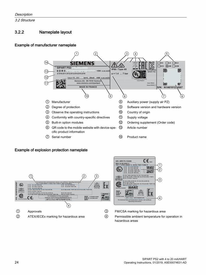
3.2.2 Nameplate layout
Example of manufacturer nameplate
-
Siemens AG, DE-76181 Karlsruhe
www.siemens.com/sipartps2
KCC-REM-S49
SIPART PS2
MADE IN FRANCE
-
-
IP66 / Type 4X6 D R 5 0 2 1 - 0 K * 0 2 - 0 A A 0 -<SW: x.xx.xx(2)>
- NCS
- Iw=4…20mA
-Z S10;S11;S12;S13;S14;S15;S16
-
p = 1.4 … 7 bar
SIPART PS2 i/p Positioner
- Imax=100mA
-
- -
PROCESS CONTROL
EQUIPMENT
Umax=35VDC
<HW: x.xx.xx(2)>
-
-
S/N: N1A6101234567
ILS MLS
AOM-AIM
-
X
DIO -
① Manufacturer ⑧ Auxiliary power (supply air PZ)② Degree of protection ⑨ Software version and hardware version③ Observe the operating instructions ⑩ Country of origin④ Conformity with country-specific directives ⑪ Supply voltage⑤ Built-in option modules ⑫ Ordering supplement (Order code)⑥ QR code to the mobile website with device-spe‐
cific product information⑬ Article number
⑦ Serial number ⑭ Product name
Example of explosion protection nameplate
05
18
CSA18CA70166848X
FM17US0053X
Zn 21 AEx tb IIIC T100°C Db / Zn 21 Ex tb IIIC T100°C Db
/ BRA-18-GE-0006 X
Zn 21 AEx ib IIIC, T130°C Db / Zn 21 Ex ib IIIC, T130°C Db
-
NI Cl I Div 2 Gp A-DDIP Cl II, III Div 1 Gp E-G
TÜV 17 ATEX 205947 X / IECEx TUN 17.0023 XFor technical data and temperature classes, see certificate / Operating Instructions
II 2 G Ex ia IIC T6/T4 GbII 2 D Ex ia IIIC T130°C Db
II 3 G Ex ec IIC T6/T4 GcCl I Zn 1 AEx ib IIC Gb / Cl I Zn 1 Ex ib IIC Gb
IS Cl I, II, III Div 1 Gp A-G
Cl I Zn 2 AEx nA IIC Gc / Cl I Zn 2 Ex nA IIC Gc
-
-30°C ≤ Ta ≤
N1
A6
101
23
45
67
S/N
: 13-KB4BO-0369XFor installations in U.S.A. and Canada:
Install per control drawing A5E00065622D Rev.1615-AV4BO-0297-
II 2 D Ex tb IIIC T100°C Db
-
+60°C(T6)/80°C(T4)
GYJ18.1168X
-
II 3 G Ex ic IIC T6/T4 Gc
-
-
BRA-18-GE-0006 X /
Cl I Zn 2 AEx nA IIC Gc / Cl I Zn 2 Ex nA IIC GcNI Cl I Div 2 Gp A-DZn 21 AEx tb IIIC T100°C Db / Zn 21 Ex tb IIIC T100°C DbDIP Cl II, III Div 1 Gp E-G
II 3 G Ex ec IIC T6/T4 GcII 2 D Ex tb IIIC T100°C Db
II 2 G Ex ia IIC T6/T4 Gb
FM17US0360X
S/N: ARR P3-1234560518
TÜV 17 ATEX 205947 X / IECEx TUN 17.0023 X
II 2 D Ex ia IIIC T130°C DbII 3 G Ex ic IIC T6/T4 Gc
CSA18CA70166848X
Cl I Zn 1 AEx ib IIC Gb / Cl I Zn 1 Ex ib IIC Gb
GYJ18.1168X
Zn 21 AEx ib IIIC, T130°C Db / Zn 21 Ex ib IIIC, T130°CIS Cl I, II, III Div 1 Gp A-G-
For technical data and temperature classes, see certificate/ Operating Instructions
-30°C ≤ Ta ≤ +60°C(T6)/80°C(T4)-
-
13-KB4BO-0369X -
-
-
BRA-18-GE-0006 X /
Cl I Zn 2 AEx nA IIC Gc / Cl I Zn 2 Ex nA IIC GcNI Cl I Div 2 Gp A-DZn 21 AEx tb IIIC T100°C Db / Zn 21 Ex tb IIIC T100°C DbDIP Cl II, III Div 1 Gp E-G
II 3 G Ex ec IIC T6/T4 GcII 2 D Ex tb IIIC T100°C Db
II 2 G Ex ia IIC T6/T4 Gb
FM17US0053X
S/N: ARR P3-1234560518
TÜV 17 ATEX 205947 X / IECEx TUN 17.0023 X
II 2 D Ex ia IIIC T130°C DbII 3 G Ex ic IIC T6/T4 Gc
CSA18CA70166848X
Cl I Zn 1 AEx ib IIC Gb / Cl I Zn 1 Ex ib IIC Gb
GYJ18.1168X
Zn 21 AEx ib IIIC, T130°C Db / Zn 21 Ex ib IIIC, T130°CIS Cl I, II, III Div 1 Gp A-G-
For technical data and temperature classes, see certificate/ Operating Instructions
-30°C ≤ Ta ≤ +60°C(T6)/80°C(T4)-
-
13-KB4BO-0369X -
-
-
① Approvals ③ FM/CSA marking for hazardous area② ATEX/IECEx marking for hazardous area ④ Permissible ambient temperature for operation in
hazardous areas
Description3.2 Structure
SIPART PS2 with 4 to 20 mA/HART24 Operating Instructions, 01/2019, A5E00074631-AD
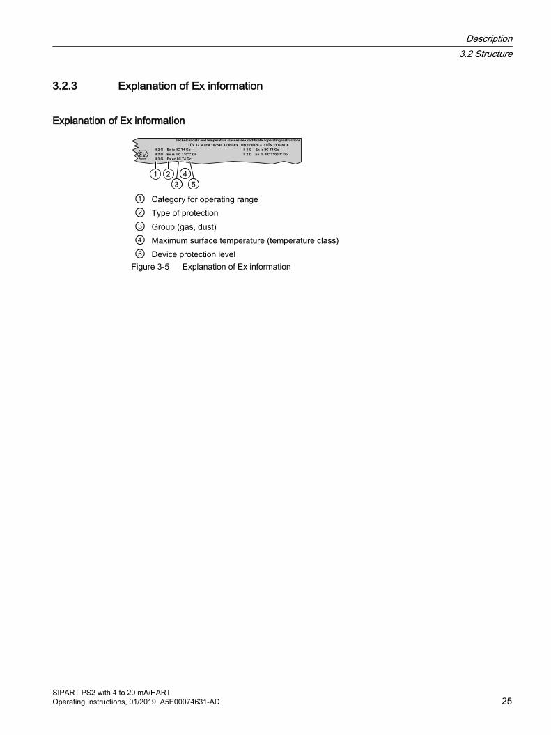
3.2.3 Explanation of Ex information
Explanation of Ex information
TÜV 12 ATEX 107540 X / IECEx TUN 12.0028 X / TÜV 11.0287 XTechnical data and temperature classes see certificate / operating instructions
II 3 G Ex ec IIC T4 Gc
II 2 G Ex ia IIC T4 Gb II 3 G Ex ic IIC T4 Gc
TÜV 12 ATEX 107540 X / IECEx TUN 12.0028 X / TÜV 11.0287 X
II 2 D Ex ia IIIC 110°C Db II 2 D Ex tb IIIC T100°C Db
① Category for operating range② Type of protection③ Group (gas, dust)④ Maximum surface temperature (temperature class)⑤ Device protection level
Figure 3-5 Explanation of Ex information
Description3.2 Structure
SIPART PS2 with 4 to 20 mA/HARTOperating Instructions, 01/2019, A5E00074631-AD 25

3.3 Device components
3.3.1 Overview of device components
Arrowhead means: Turn the device to see the corresponding view① Wiring diagram on module cover ⑩ Restrictor Y1 for double-acting actuators② Display ⑪ Exhaust air outlet with a sound absorber③ Output: Actuating pressure Y1 ⑫ Transmission ratio selector2)
④ Input: Supply air PZ ⑬ Friction clutch adjustment wheel⑤ Output: Actuating pressure Y21) ⑭ Basic electronics⑥ Purge air switch ⑮ Connecting terminals of option modules⑦ Buttons ⑯ Blanking plug⑧ Restrictor Y2 for double-acting actuators1) ⑰ Cable gland⑨ Restrictor Y1 for single-acting actuators 1) for double-acting actuators 2) visible when the positioner is open
Figure 3-6 View of positioner with cover open
See alsoStructure of pneumatic connection (Page 89)
Description3.3 Device components
SIPART PS2 with 4 to 20 mA/HART26 Operating Instructions, 01/2019, A5E00074631-AD

- +
1
10
138
238
9
① Display ⑧ Output: Actuating pressure Y21)
② Restrictor Y1 ⑨ Restrictor Y21)
③ Output: Actuating pressure Y1 ⑩ Buttons④ Input: Supply air PZ ⑪ Ground terminal⑤ Safety catch ⑫ Connecting terminals of option modules⑥ Transmission ratio selector2) ⑬ Connecting terminals of basic electronics⑦ Friction clutch adjustment wheel Analog-to-digital converter1) for double-acting actuators2) visible when the positioner is open
Figure 3-7 View of positioner in flameproof enclosure, cover opened
See alsoPneumatic connection for 6DR5..5/6 (Page 90)
3.3.2 Basic electronics
Figure 3-8 Basic electronics, schematic representation
The basic electronics contains:
● CPU
● Memory
Description3.3 Device components
SIPART PS2 with 4 to 20 mA/HARTOperating Instructions, 01/2019, A5E00074631-AD 27
● Analog-to-digital converter
● Display
● Buttons
● Terminal strips to connect the option module to the basic electronics
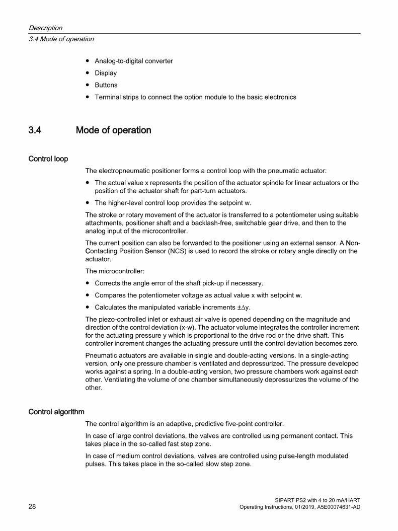
3.4 Mode of operation
Control loopThe electropneumatic positioner forms a control loop with the pneumatic actuator:
● The actual value x represents the position of the actuator spindle for linear actuators or the position of the actuator shaft for part-turn actuators.
● The higher-level control loop provides the setpoint w.
The stroke or rotary movement of the actuator is transferred to a potentiometer using suitable attachments, positioner shaft and a backlash-free, switchable gear drive, and then to the analog input of the microcontroller.
The current position can also be forwarded to the positioner using an external sensor. A Non-Contacting Position Sensor (NCS) is used to record the stroke or rotary angle directly on the actuator.
The microcontroller:
● Corrects the angle error of the shaft pick-up if necessary.
● Compares the potentiometer voltage as actual value x with setpoint w.
● Calculates the manipulated variable increments ±∆y.
The piezo-controlled inlet or exhaust air valve is opened depending on the magnitude and direction of the control deviation (x-w). The actuator volume integrates the controller increment for the actuating pressure y which is proportional to the drive rod or the drive shaft. This controller increment changes the actuating pressure until the control deviation becomes zero.
Pneumatic actuators are available in single and double-acting versions. In a single-acting version, only one pressure chamber is ventilated and depressurized. The pressure developed works against a spring. In a double-acting version, two pressure chambers work against each other. Ventilating the volume of one chamber simultaneously depressurizes the volume of the other.
Control algorithmThe control algorithm is an adaptive, predictive five-point controller.
In case of large control deviations, the valves are controlled using permanent contact. This takes place in the so-called fast step zone.
In case of medium control deviations, valves are controlled using pulse-length modulated pulses. This takes place in the so-called slow step zone.
Description3.4 Mode of operation
SIPART PS2 with 4 to 20 mA/HART28 Operating Instructions, 01/2019, A5E00074631-AD

Figure 3-9 Functional principle of five-point controller
Small control deviations do not send control pulses in the zone. This takes place in the so-called adaptive deadband. The deadband adaptation and the continuous adaptation of minimum pulse lengths in "Automatic" mode ensure the best possible control accuracy with the smallest number of operating cycles. The start parameters are determined during the initialization phase and stored in the non-volatile memory. The most important start parameters are:
● The real actuator travel with end positions
● Travel times
● The deadband size
The number of fault messages, changes in direction, and the number of total strokes are continuously determined during operation and saved every 15 minutes. You can read and document these parameters using communication programs such as SIMATIC PDM and AMS. By comparing the old values with the current ones, you can draw conclusions about the wear and tear of the valve. You can use the diagnostics function for this.
Description3.4 Mode of operation
SIPART PS2 with 4 to 20 mA/HARTOperating Instructions, 01/2019, A5E00074631-AD 29
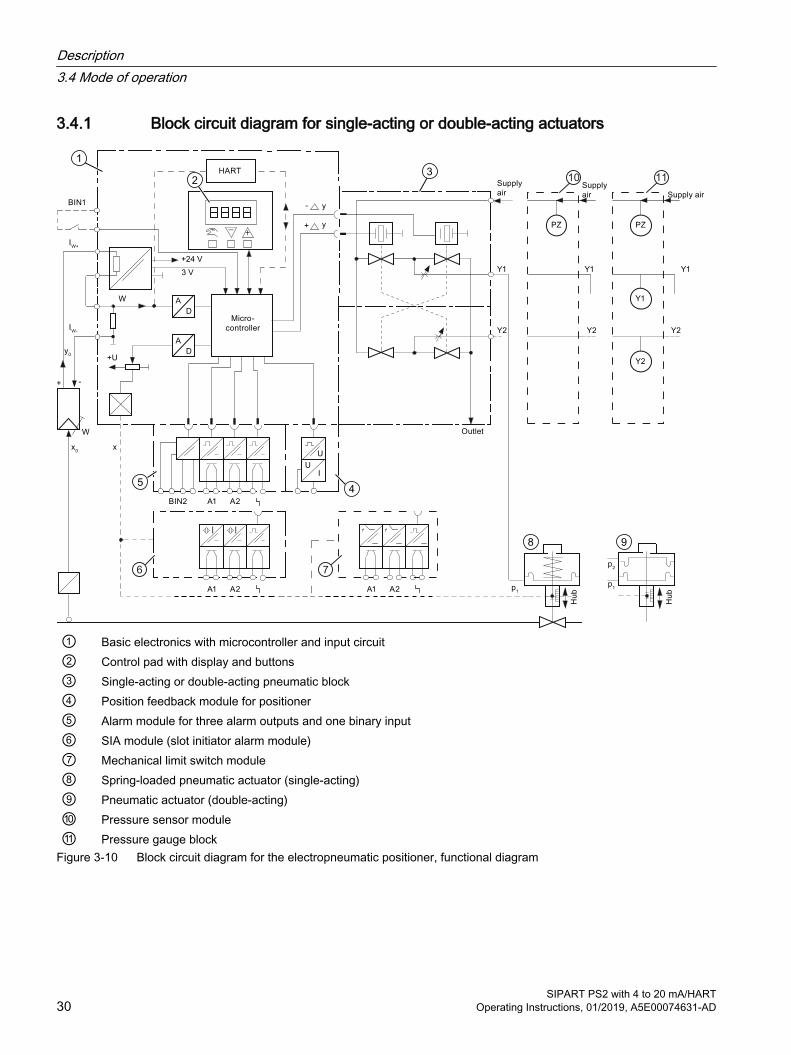
3.4.1 Block circuit diagram for single-acting or double-acting actuators
① Basic electronics with microcontroller and input circuit② Control pad with display and buttons③ Single-acting or double-acting pneumatic block④ Position feedback module for positioner⑤ Alarm module for three alarm outputs and one binary input⑥ SIA module (slot initiator alarm module) ⑦ Mechanical limit switch module⑧ Spring-loaded pneumatic actuator (single-acting)⑨ Pneumatic actuator (double-acting)⑩ Pressure sensor module⑪ Pressure gauge block
Figure 3-10 Block circuit diagram for the electropneumatic positioner, functional diagram
Description3.4 Mode of operation
SIPART PS2 with 4 to 20 mA/HART30 Operating Instructions, 01/2019, A5E00074631-AD

NoteAlarm module, SIA module and mechanical limit switch module
Alarm module ⑤, SIA module ⑥ and mechanical limit switch module ⑦ can only be alternatively used.
3.4.2 Mode of operation of the HART function
NotePriority of operation / failure of power supply● Operation at the positioner has priority over specifications from the HART communicator.● Failure of the auxiliary power to the positioner also interrupts communications.
FunctionThe positioner is also available with built-in HART functionality. The HART protocol allows you to communicate with your device using a HART communicator, PC, or programming unit. You can do the following with your device:
● Convenient configuration
● Store configurations
● Call up diagnostic data
● Show online measured values
Communication takes place as frequency modulation on the existing signal lines for the setpoint of 4 to 20 mA.
The positioner is integrated into the following parameter assignment tools:
● HART communicator
● PDM (Process Device Manager)
● AMS (Asset Management System)
3.4.3 HART system configuration
OverviewThe positioner can be used in a number of system configurations:
● Stand-alone, supplied with the required auxiliary power supply; communication with supplementary units (handheld), for example
● As part of a complex system environment, e.g. SIMATIC S7
Description3.4 Mode of operation
SIPART PS2 with 4 to 20 mA/HARTOperating Instructions, 01/2019, A5E00074631-AD 31

System communicationCommunication is via the HART protocol, using:
● HART Communicator (load 230 ... 1100 Ω)
● PC with HART modem, on which appropriate software is installed, e.g. SIMATIC PDM (load 230 ... 500 Ω)
● Control system which can communicate via the HART protocol, e.g. SIMATIC PCS7
SIMATIC PCS 7 Engineering Station
with SIMATIC PDM
S7-400H
AR
T
PROFIBUS DP
Industrial Ethernet
ET 200M
Figure 3-11 Typical system configurations
3.4.4 SIMATIC PDMSIMATIC PDM is a software package for configuring, parameter assignment, commissioning, diagnostics and maintenance of this device and other process devices.
SIMATIC PDM offers simple monitoring of process values, alarms, and device status information.
SIMATIC PDM allows the process device data to be:
● displayed
● set
● modified
● saved
● diagnosed
● checked for plausibility
● managed
● simulated
Additional information on SIMATIC PDM can be found at www.siemens.com/simatic-pdm (www.siemens.com/simatic-pdm).
Description3.4 Mode of operation
SIPART PS2 with 4 to 20 mA/HART32 Operating Instructions, 01/2019, A5E00074631-AD
See alsoOverview of the assignment of the HART variables (Page 268)
Description3.4 Mode of operation
SIPART PS2 with 4 to 20 mA/HARTOperating Instructions, 01/2019, A5E00074631-AD 33

Description3.4 Mode of operation
SIPART PS2 with 4 to 20 mA/HART34 Operating Instructions, 01/2019, A5E00074631-AD
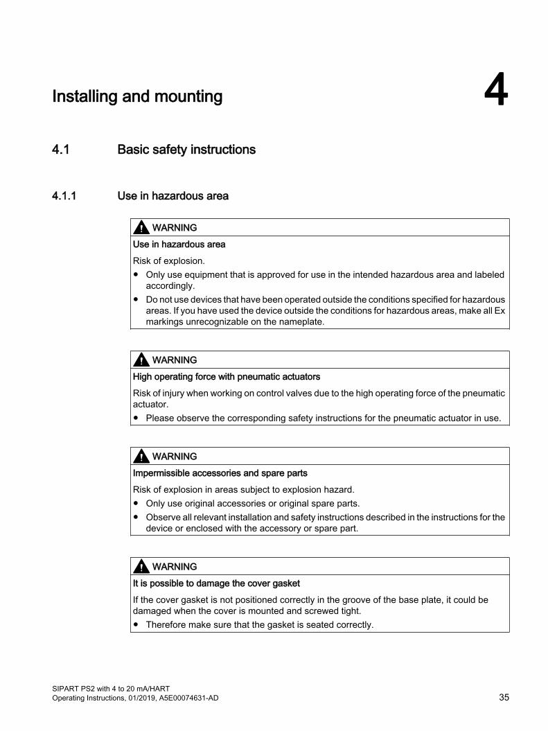
Installing and mounting 44.1 Basic safety instructions
4.1.1 Use in hazardous area
WARNING
Use in hazardous area
Risk of explosion.● Only use equipment that is approved for use in the intended hazardous area and labeled
accordingly.● Do not use devices that have been operated outside the conditions specified for hazardous
areas. If you have used the device outside the conditions for hazardous areas, make all Ex markings unrecognizable on the nameplate.
WARNING
High operating force with pneumatic actuators
Risk of injury when working on control valves due to the high operating force of the pneumatic actuator.● Please observe the corresponding safety instructions for the pneumatic actuator in use.
WARNING
Impermissible accessories and spare parts
Risk of explosion in areas subject to explosion hazard.● Only use original accessories or original spare parts.● Observe all relevant installation and safety instructions described in the instructions for the
device or enclosed with the accessory or spare part.
WARNING
It is possible to damage the cover gasket
If the cover gasket is not positioned correctly in the groove of the base plate, it could be damaged when the cover is mounted and screwed tight.● Therefore make sure that the gasket is seated correctly.
SIPART PS2 with 4 to 20 mA/HARTOperating Instructions, 01/2019, A5E00074631-AD 35
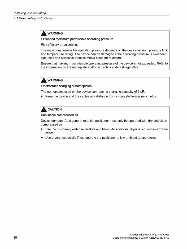
WARNING
Exceeded maximum permissible operating pressure
Risk of injury or poisoning.
The maximum permissible operating pressure depends on the device version, pressure limit and temperature rating. The device can be damaged if the operating pressure is exceeded. Hot, toxic and corrosive process media could be released.
Ensure that maximum permissible operating pressure of the device is not exceeded. Refer to the information on the nameplate and/or in Technical data (Page 237).
WARNING
Electrostatic charging of nameplates
The nameplates used on the device can reach a charging capacity of 5 pF.● Keep the device and the cables at a distance from strong electromagnetic fields.
CAUTION
Unsuitable compressed air
Device damage. As a general rule, the positioner must only be operated with dry and clean compressed air. ● Use the customary water separators and filters. An additional dryer is required in extreme
cases. ● Use dryers, especially if you operate the positioner at low ambient temperatures.
Installing and mounting4.1 Basic safety instructions
SIPART PS2 with 4 to 20 mA/HART36 Operating Instructions, 01/2019, A5E00074631-AD

CAUTION
Please note the following before working on the control valve and when attaching the positioner
Danger of injury.● Prior to working on the control valve, you must move the control valve into a completely
pressureless state. Proceed as follows: – Depressurize the actuator chambers. – Switch off the supply air PZ.– Lock the valve in its position.
● Make sure that the valve has reached the pressureless state.● If you interrupt the pneumatic auxiliary power to the positioner, the pressureless position
may only be reached after a certain waiting time.● When mounting, observe the following sequence imperatively to avoid injuries or
mechanical damage to the positioner/mounting kit:– Mount the positioner mechanically.– Connect the electrical auxiliary power supply.– Connect the pneumatic auxiliary power supply.– Commission the positioner.
WARNING
Mechanical impact energy
In order to ensure the degree of protection of the housing (IP66), protect the housing versions of the positioners listed here from mechanical impact energy:● 6DR5..3; not greater than 2 Joule● 6DR5..0; not greater than 1 Joule● 6DR5..1 with inspection window; not greater than 1 Joule
NOTICE
Torque with NPT screwed gland
Device damage. The maximum torque of the cable gland must not be exceeded. ● To avoid damage to the device, the NPT adapter must be held in place while the NPT gland
is screwed into the NPT adapter. Refer to the section "Technical specifications > Construction (Page 238)" for the torque value.
Installing and mounting4.1 Basic safety instructions
SIPART PS2 with 4 to 20 mA/HARTOperating Instructions, 01/2019, A5E00074631-AD 37
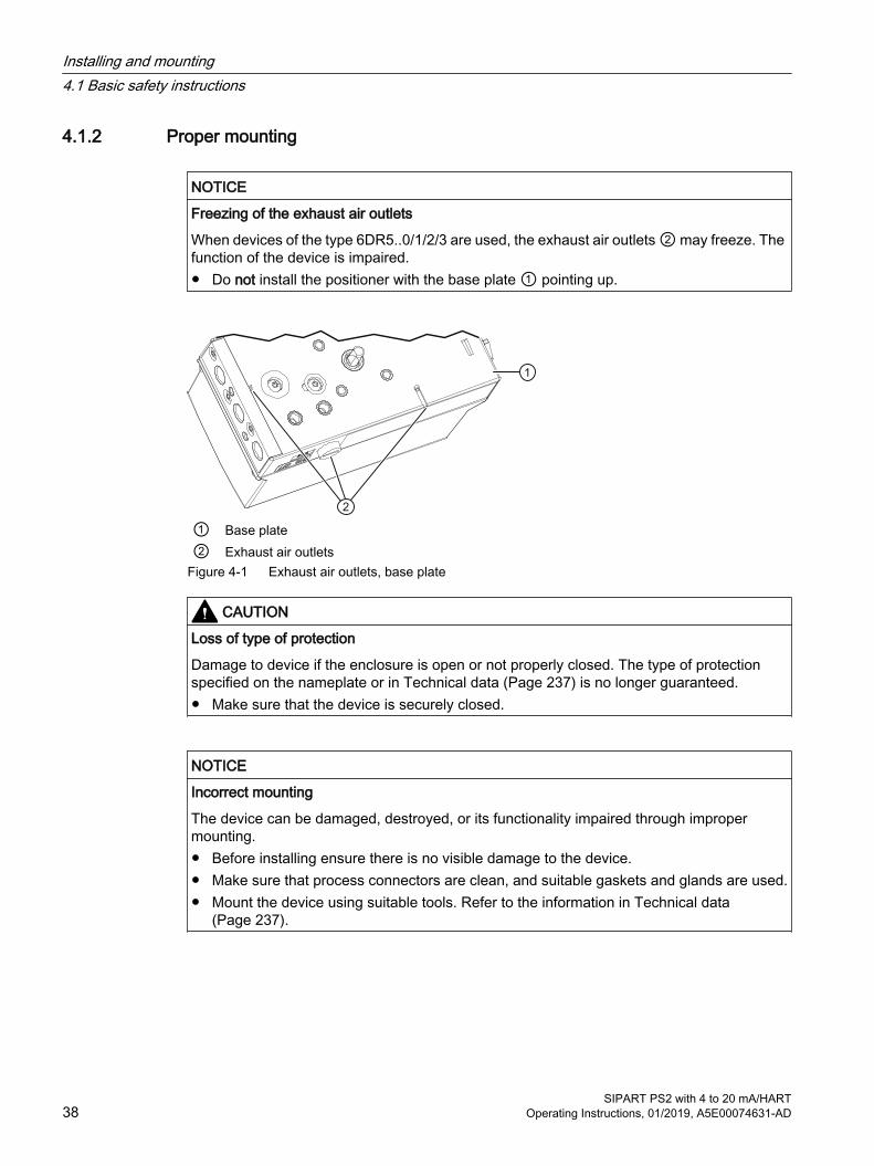
4.1.2 Proper mounting
NOTICE
Freezing of the exhaust air outlets
When devices of the type 6DR5..0/1/2/3 are used, the exhaust air outlets ② may freeze. The function of the device is impaired.● Do not install the positioner with the base plate ① pointing up.
① Base plate② Exhaust air outlets
Figure 4-1 Exhaust air outlets, base plate
CAUTION
Loss of type of protection
Damage to device if the enclosure is open or not properly closed. The type of protection specified on the nameplate or in Technical data (Page 237) is no longer guaranteed.● Make sure that the device is securely closed.
NOTICE
Incorrect mounting
The device can be damaged, destroyed, or its functionality impaired through improper mounting.● Before installing ensure there is no visible damage to the device.● Make sure that process connectors are clean, and suitable gaskets and glands are used.● Mount the device using suitable tools. Refer to the information in Technical data
(Page 237).
Installing and mounting4.1 Basic safety instructions
SIPART PS2 with 4 to 20 mA/HART38 Operating Instructions, 01/2019, A5E00074631-AD
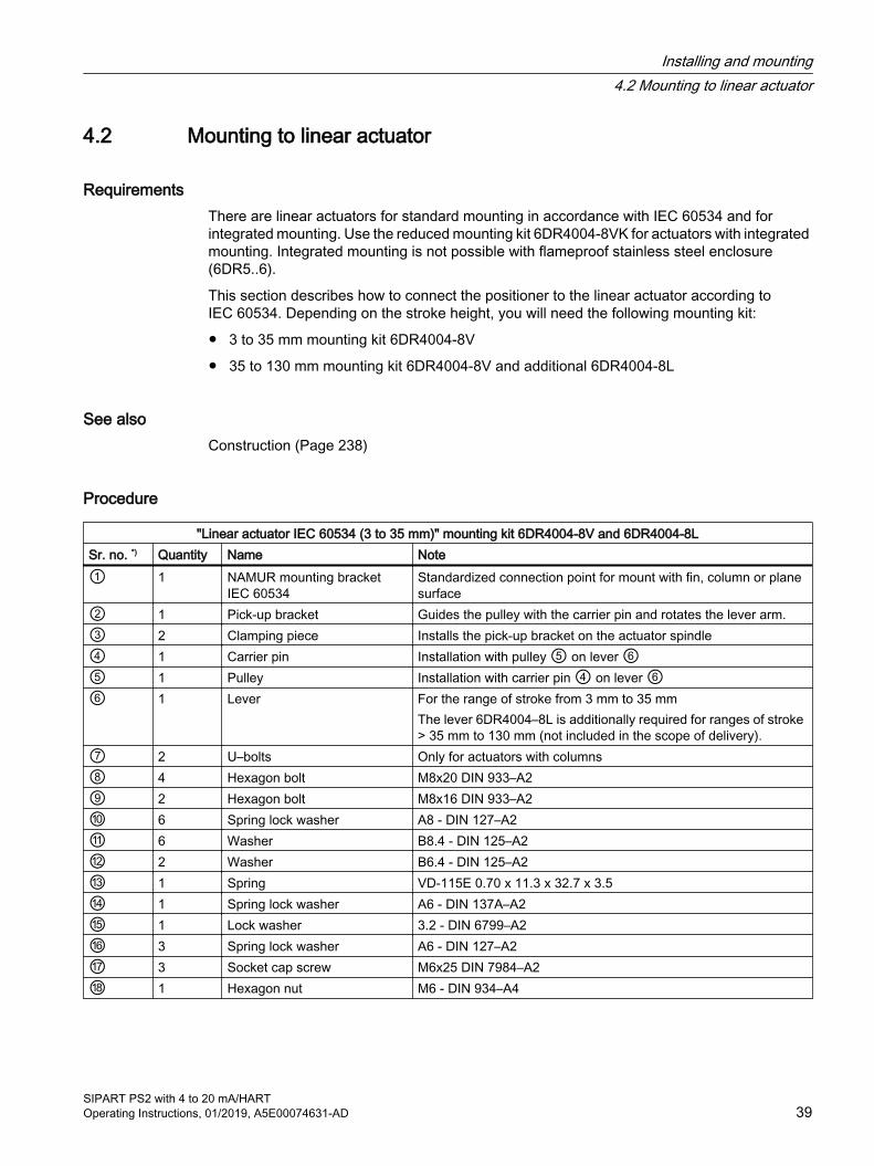
4.2 Mounting to linear actuator
RequirementsThere are linear actuators for standard mounting in accordance with IEC 60534 and for integrated mounting. Use the reduced mounting kit 6DR4004-8VK for actuators with integrated mounting. Integrated mounting is not possible with flameproof stainless steel enclosure (6DR5..6).
This section describes how to connect the positioner to the linear actuator according to IEC 60534. Depending on the stroke height, you will need the following mounting kit:
● 3 to 35 mm mounting kit 6DR4004-8V
● 35 to 130 mm mounting kit 6DR4004-8V and additional 6DR4004-8L
See alsoConstruction (Page 238)
Procedure
"Linear actuator IEC 60534 (3 to 35 mm)" mounting kit 6DR4004-8V and 6DR4004-8LSr. no. *) Quantity Name Note① 1 NAMUR mounting bracket
IEC 60534Standardized connection point for mount with fin, column or plane surface
② 1 Pick-up bracket Guides the pulley with the carrier pin and rotates the lever arm.③ 2 Clamping piece Installs the pick-up bracket on the actuator spindle④ 1 Carrier pin Installation with pulley ⑤ on lever ⑥⑤ 1 Pulley Installation with carrier pin ④ on lever ⑥⑥ 1 Lever For the range of stroke from 3 mm to 35 mm
The lever 6DR4004–8L is additionally required for ranges of stroke > 35 mm to 130 mm (not included in the scope of delivery).
⑦ 2 U–bolts Only for actuators with columns⑧ 4 Hexagon bolt M8x20 DIN 933–A2⑨ 2 Hexagon bolt M8x16 DIN 933–A2⑩ 6 Spring lock washer A8 - DIN 127–A2⑪ 6 Washer B8.4 - DIN 125–A2⑫ 2 Washer B6.4 - DIN 125–A2⑬ 1 Spring VD-115E 0.70 x 11.3 x 32.7 x 3.5⑭ 1 Spring lock washer A6 - DIN 137A–A2⑮ 1 Lock washer 3.2 - DIN 6799–A2⑯ 3 Spring lock washer A6 - DIN 127–A2⑰ 3 Socket cap screw M6x25 DIN 7984–A2⑱ 1 Hexagon nut M6 - DIN 934–A4
Installing and mounting4.2 Mounting to linear actuator
SIPART PS2 with 4 to 20 mA/HARTOperating Instructions, 01/2019, A5E00074631-AD 39
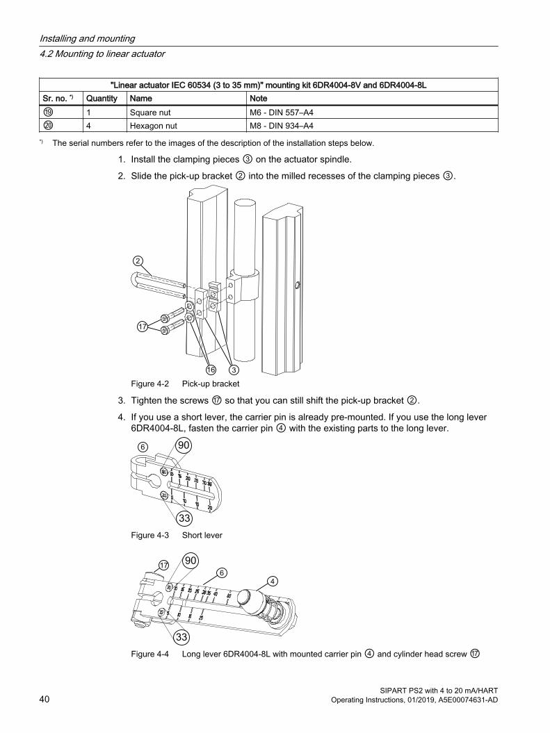
"Linear actuator IEC 60534 (3 to 35 mm)" mounting kit 6DR4004-8V and 6DR4004-8LSr. no. *) Quantity Name Note⑲ 1 Square nut M6 - DIN 557–A4⑳ 4 Hexagon nut M8 - DIN 934–A4
*) The serial numbers refer to the images of the description of the installation steps below.
1. Install the clamping pieces ③ on the actuator spindle.
2. Slide the pick-up bracket ② into the milled recesses of the clamping pieces ③.
Figure 4-2 Pick-up bracket
3. Tighten the screws ⑰ so that you can still shift the pick-up bracket ②.
4. If you use a short lever, the carrier pin is already pre-mounted. If you use the long lever 6DR4004-8L, fasten the carrier pin ④ with the existing parts to the long lever.
Figure 4-3 Short lever
Figure 4-4 Long lever 6DR4004-8L with mounted carrier pin ④ and cylinder head screw ⑰
Installing and mounting4.2 Mounting to linear actuator
SIPART PS2 with 4 to 20 mA/HART40 Operating Instructions, 01/2019, A5E00074631-AD

5. Set the stroke value. The stroke value is specified on the nameplate of the actuator. Position the pin center of the carrier pin ④ on the corresponding value of the scale. If none of the values on the lever scale matches the stroke value of the actuator, select the next higher value on the scale. For strokes ≥ 25 mm, select the scale (90). For strokes < 25 mm, select the scale (33).
6. Set the transmission ratio selector (Page 47) to the value of the selected scale.
7. If you need the value of actuator travel after initialization in mm: ensure that the configured stroke value matches the value of the "3.YWAY" parameter.
8. Push the pre-installed lever ⑥ up to the endstop on the positioner shaft. Fasten the lever ⑥ with socket cap screw ⑰.
9. Install the mounting bracket ① at the rear side of the positioner. Use 2 hexagon bolts ⑨, 2 spring lock washers ⑩ and 2 flat washers ⑪ for this purpose.
Figure 4-5 Installation with mounting bracket
Figure 4-6 Installation with mounting bracket, flameproof enclosure
10.Select the row of holes. The selection of the row of holes depends on the yoke width of the actuator. Select the row of holes in such a way that the carrier pin ④ meshes with the pick-up bracket ② near the spindle.
Installing and mounting4.2 Mounting to linear actuator
SIPART PS2 with 4 to 20 mA/HARTOperating Instructions, 01/2019, A5E00074631-AD 41

11.Keep the positioner and the fastening bracket on the actuator. Ensure that the carrier pin ④ for the entire range of stroke of the actuator is guided inside the pick-up bracket ②. Ensure that the carrier pin ④ does not touch the clamping pieces ③.
Installing and mounting4.2 Mounting to linear actuator
SIPART PS2 with 4 to 20 mA/HART42 Operating Instructions, 01/2019, A5E00074631-AD

12.Tighten the pick-up bracket ②.
13.Fasten the positioner on the yoke. Use the installation parts suitable for the corresponding actuator.
Actuator type Required installation compo‐nents
Yoke with fin ● Hexagon bolt ⑧● Washer ⑪● Spring lock washer ⑩
Yoke with plane surface
● Four hexagon bolts ⑧● Washer ⑪● Spring lock washer ⑩
Yoke with col‐umns
● Two U–bolts ⑦● Four hexagon nuts ⑳● Washer ⑪● Spring lock washer ⑩
Installing and mounting4.2 Mounting to linear actuator
SIPART PS2 with 4 to 20 mA/HARTOperating Instructions, 01/2019, A5E00074631-AD 43

NoteHeight adjustment of the positioner
When you fasten the positioner on the yoke, the following applies to its height adjustment:1. Set the height of the positioner in such a way that the horizontal lever position is near the
center of the stroke.2. Orient yourself by the lever scale of the actuator.3. If symmetrical mounting is not possible, you must always ensure that the horizontal lever
position is maintained within the range of stroke.
4.3 Mounting to part-turn actuator
RequirementsYou require an actuator-specific VDI/VDE 3845 mount to install the positioner on a part-turn actuator. Because of the high weight of the version in the flameproof stainless steel enclosure 6DR5..6, you should select a particularly stable mount.
Procedure
"Part-turn actuator" mounting kit 6DR4004–8DSr. no. *)
Quantity
Name Note
① 1 Coupling wheel Installation on positioner shaft② 1 Carrier Installing on the actuator shaft③ 1 Multiple plate Display of the position, consisting of scale ⑤ and pointer mark ⑥④ 8 Scale Different divisions⑤ 2 Pointer mark Reference point for scale⑥ Mount Actuator-specific, VDI/VDE 3845⑦ 4 Hexagon bolt M6x12 DIN 933, torque see the section "Technical specifications > Construction
(Page 238)"⑧ 4 Lock washer S6⑨ 1 Socket cap screw M6x16 DIN 84⑩ 1 Washer 6.4 DIN 125⑪ 1 Hex socket-head
screwFor coupling wheel
1 Machinist's wrench For hexagon socket-head screw ⑪*) The serial numbers refer to the images of the description of the installation steps below.
Installing and mounting4.3 Mounting to part-turn actuator
SIPART PS2 with 4 to 20 mA/HART44 Operating Instructions, 01/2019, A5E00074631-AD

1. Rest the actuator-specific VDI/VDE 3845 mount ⑥ on the rear side of the positioner. Tighten the mount using the hexagon bolts ⑦ and lock washers ⑧.
2. Push the coupling wheel ① or the stainless steel coupling up to the endstop on the positioner shaft. Then retract the coupling wheel or the stainless steel coupling by approximately 1 mm. Tighten the hexagon socket-head screw ⑪ using the machinist's wrench provided. Maximum tightening torque = 1 Nm. If you are using the stainless steel coupling, omit the next step.
NoteCoupling wheel
Instead of the polycarbonate coupling wheel ①, it is possible to use a stainless steel coupling (article number TGX: 16300-1556).
Figure 4-7 Left: Coupling wheel, right: Coupling wheel, flameproof enclosure
3. Place the carrier ② on the actuator shaft. Tighten the carrier ② using the socket cap screw ⑨ and the washer ⑩.
Figure 4-8 Carrier
Installing and mounting4.3 Mounting to part-turn actuator
SIPART PS2 with 4 to 20 mA/HARTOperating Instructions, 01/2019, A5E00074631-AD 45

4. Place the positioner and the mount on the actuator carefully. One of the two pins ⑫ of the coupling wheel ① must fit in the carrier ② when you do this.
Figure 4-9 Left: Orientation of mount; right: Orientation of mount, flameproof enclosure
5. When using the stainless steel coupling (article number TGX: 16300-1556): Place the positioner and the mount on the actuator carefully. Place the stainless steel coupling on the stump of the actuator's positioner shaft.
6. Align the positioner with mount at the center of the actuator.
7. Fasten the positioner with mount.
8. Initialize the positioner.
9. After commissioning, drive the positioner to the end position.
10.Stick the scale ④ with the direction of rotation or the swivel range on the coupling wheel ①. The stickers with scale are self-adhesive.
Figure 4-10 Left: Adhesive label with scale; right: Adhesive label with scale, flameproof enclosure
Installing and mounting4.3 Mounting to part-turn actuator
SIPART PS2 with 4 to 20 mA/HART46 Operating Instructions, 01/2019, A5E00074631-AD
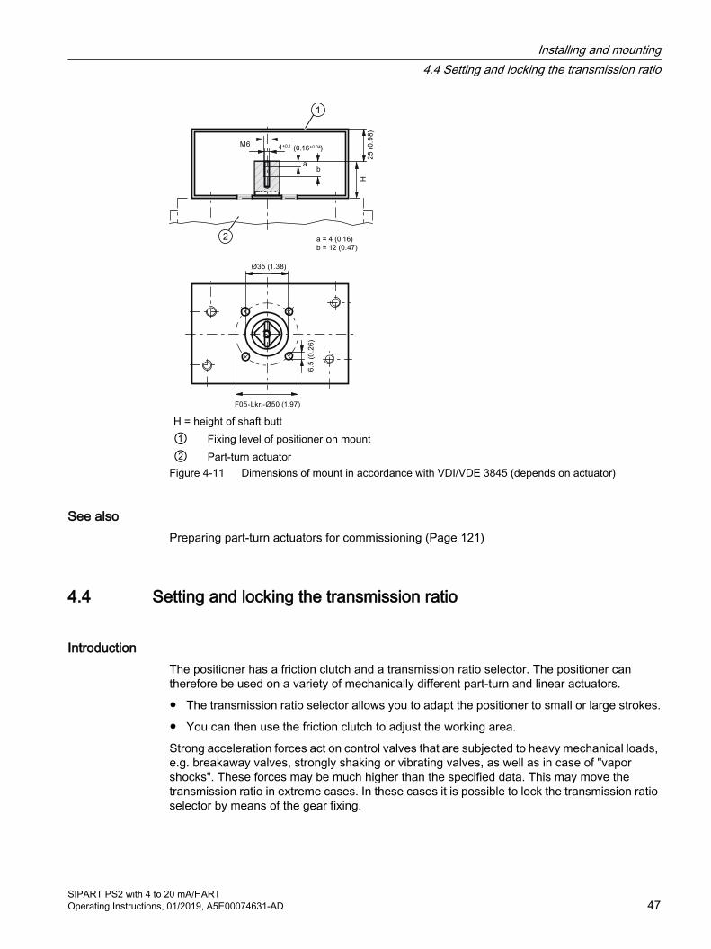
F05-Lkr.-Ø50 (1.97)
Ø35 (1.38)
6.5
(0
.26)
H = height of shaft butt ① Fixing level of positioner on mount② Part-turn actuator
Figure 4-11 Dimensions of mount in accordance with VDI/VDE 3845 (depends on actuator)
See alsoPreparing part-turn actuators for commissioning (Page 121)
4.4 Setting and locking the transmission ratio
IntroductionThe positioner has a friction clutch and a transmission ratio selector. The positioner can therefore be used on a variety of mechanically different part-turn and linear actuators.
● The transmission ratio selector allows you to adapt the positioner to small or large strokes.
● You can then use the friction clutch to adjust the working area.
Strong acceleration forces act on control valves that are subjected to heavy mechanical loads, e.g. breakaway valves, strongly shaking or vibrating valves, as well as in case of "vapor shocks". These forces may be much higher than the specified data. This may move the transmission ratio in extreme cases. In these cases it is possible to lock the transmission ratio selector by means of the gear fixing.
Installing and mounting4.4 Setting and locking the transmission ratio
SIPART PS2 with 4 to 20 mA/HARTOperating Instructions, 01/2019, A5E00074631-AD 47
When the positioner is mounted and fully operational, set the friction clutch as described under "Setting the friction clutch (Page 113)" in the section "Commissioning (Page 103)".
NOTICE
Wrong registration of the rotary or part-turn movement
A different setting of the transmission ratio selector and the gear latch results in a hysteresis in position registration. The hysteresis in position registration can result in unstable control response of the higher level control loop.● Make sure the transmission ratio selector ⑤ and the gear latch ① are set to the same
value, either to 33° or to 90°.
NoteUse of external NCS sensor / internal NCS module
If you use the accessory part "NCS sensor for contactless position measurement" or a built-in internal NCS module, the locking and fixing measures described in this section are not necessary.
Requirement● The positioner is mounted.
● You know whether the transmission ratio is to be set to 33° or 90°.
Installing and mounting4.4 Setting and locking the transmission ratio
SIPART PS2 with 4 to 20 mA/HART48 Operating Instructions, 01/2019, A5E00074631-AD

ProcedureOn the right in the graphic the positioner is shown in the flameproof enclosure Ex d with open cover. The procedure is the same for both enclosure versions.
① Wheel for gear latch (yellow) ④ Locking transmission ratio to 90°② Locking transmission ratio to 33° ⑤ Transmission ratio selector (yellow)③ Neutral position
Figure 4-12 Locking the transmission ratio
1. Ensure that the wheel for the gear latch ① is in neutral position ③. The neutral position is between 33° and 90°. The setting of the transmission ratio selector ⑤ can only be changed effectively if the gear latch ① is in the neutral position ③.
2. Make sure the transmission ratio selector ⑤ is set to the same value as the gear latch ①, either to 33° or to 90°.
3. Turn the wheel for the gear latch ① until the gear latch ① perceptibly locks. Use an approx. 4 mm wide standard screwdriver.Turning right locks the transmission ratio to 33° ②. Turning left locks the transmission ratio to 90° ④.
The transmission ratio ② is set and locked.
Installing and mounting4.4 Setting and locking the transmission ratio
SIPART PS2 with 4 to 20 mA/HARTOperating Instructions, 01/2019, A5E00074631-AD 49
See alsoOpening the device version with "flameproof enclosure" (Page 53)
Commissioning (Page 103)
4.5 Installing option modules
4.5.1 General information on installing option modules
WARNING
Use in hazardous area
Risk of explosion.● Only use equipment that is approved for use in the intended hazardous area and labelled
accordingly.● Don't use devices that have been operated outside the conditions secified for hazardous
areas. If you have used the device outside the conditions for hazardous areas permanently make all Ex markings unrecognizable on the nameplate.
4.5.1.1 Opening the standard and and intrinsically safe version
IntroductionThe following option modules are available for the positioner in the standard and intrinsically safe version:
● Position feedback module 6DR4004-6J
● Alarm module 6DR4004-6A (Page 58)
● Slit initiator alarm module (SIA) 6DR4004-6G (Page 60)
● Mechanical limit switch module 6DR4004-6K (Page 62)
● Internal NCS module (iNCS) 6DR4004-5L (Page 66)
● EMC filter module 6DR4004-6F (Page 69)
Installing and mounting4.5 Installing option modules
SIPART PS2 with 4 to 20 mA/HART50 Operating Instructions, 01/2019, A5E00074631-AD
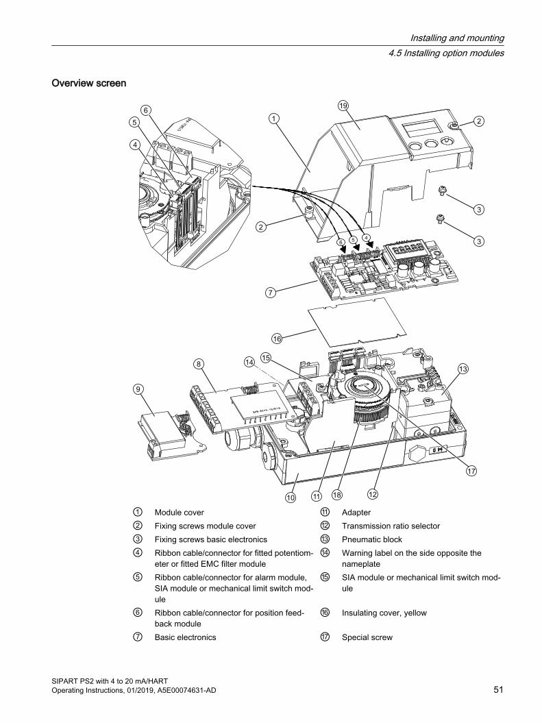
Overview screen
① Module cover ⑪ Adapter② Fixing screws module cover ⑫ Transmission ratio selector ③ Fixing screws basic electronics ⑬ Pneumatic block ④ Ribbon cable/connector for fitted potentiom‐
eter or fitted EMC filter module⑭ Warning label on the side opposite the
nameplate ⑤ Ribbon cable/connector for alarm module,
SIA module or mechanical limit switch mod‐ule
⑮ SIA module or mechanical limit switch mod‐ule
⑥ Ribbon cable/connector for position feed‐back module
⑯ Insulating cover, yellow
⑦ Basic electronics ⑰ Special screw
Installing and mounting4.5 Installing option modules
SIPART PS2 with 4 to 20 mA/HARTOperating Instructions, 01/2019, A5E00074631-AD 51
⑧ Alarm module ⑱ Friction clutch adjustment wheel⑨ Position feedback module ⑲ Wiring diagram on module cover⑩ Nameplate
Figure 4-13 Installing the optional modules in the standard and intrinsically safe version
Procedure for opening the device1. Open the positioner.
2. Loosen the four fixing screws of the enclosure cover. Remove the enclosure cover.
3. Disconnect the power supply lines or de-energize the power supply lines.
4. Disconnect all other electrical connections of the device.
5. Loosen the two fixing screws ② of the module cover ①.
6. Remove the module cover ①.
If you install an option module, proceed as described for the respective option modules. For slot initiator alarm module (SIA), mechanical limit switch module, internal non-contacting sensor module and EMC filter module, remove the basic electronics.
If you replace the basic electronics, a pneumatic block or pressure sensor module, proceed as described in the respective chapters under "Service and maintenance (Page 227)".
See alsoPosition feedback module 6DR4004-6J/-8J (Page 57)
4.5.1.2 Closing the standard and and intrinsically safe versionThe legend numbers refer to the figure in "Opening the standard and and intrinsically safe version (Page 50)"
1. Now start with the assembly. Place on the module cover ①. Make sure that the ribbon cable is not trapped.
2. Turn the fixing screws ② counterclockwise until they noticeably engage in the thread pitch.
3. Carefully tighten both fixing screws ② in a clockwise direction.The module cover protects and locks the optional modules mechanically.
NoteUntimely wear
The module cover is fastened using self-tapping screws, one screw for the base plate and one screw for the valve. ● In order to avoid premature wear of the base plate and valve, proceed as described here.
4. Connect the power supply lines or supply the power supply lines with voltage.
5. Put on the enclosure cover.
6. Tighten the fixing screws of the enclosure cover.
Installing and mounting4.5 Installing option modules
SIPART PS2 with 4 to 20 mA/HART52 Operating Instructions, 01/2019, A5E00074631-AD
4.5.1.3 Opening the device version with "flameproof enclosure"
IntroductionThe following option modules are available for the positioner in the flameproof enclosure:
● Position feedback module 6DR4004-8J (Page 57)
● Alarm module 6DR4004-8A (Page 58)
● Internal NCS module 6DR4004-5LE (Page 66)
DANGER
Risk of explosion
Before supplying the positioner with auxiliary power in potentially hazardous areas, ensure the following:● The installed electronic unit has been approved.● The enclosure of the positioner is closed.● The duct openings for electronic connections must be closed. Only use the Ex d certified
cable entries or sealing plugs.● If you use a "conduit piping system", install an ignition trap. The maximum distance
between the ignition trap and the positioner enclosure is 46 cm (18 inch).
Installing and mounting4.5 Installing option modules
SIPART PS2 with 4 to 20 mA/HARTOperating Instructions, 01/2019, A5E00074631-AD 53
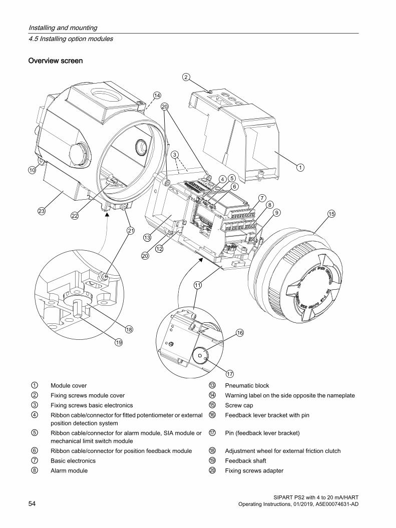
Overview screen
① Module cover ⑬ Pneumatic block ② Fixing screws module cover ⑭ Warning label on the side opposite the nameplate ③ Fixing screws basic electronics ⑮ Screw cap④ Ribbon cable/connector for fitted potentiometer or external
position detection system⑯ Feedback lever bracket with pin
⑤ Ribbon cable/connector for alarm module, SIA module or mechanical limit switch module
⑰ Pin (feedback lever bracket)
⑥ Ribbon cable/connector for position feedback module ⑱ Adjustment wheel for external friction clutch⑦ Basic electronics ⑲ Feedback shaft⑧ Alarm module ⑳ Fixing screws adapter
Installing and mounting4.5 Installing option modules
SIPART PS2 with 4 to 20 mA/HART54 Operating Instructions, 01/2019, A5E00074631-AD
⑨ Position feedback module 21 Safety catch⑩ Nameplate 22 Claw⑪ Adapter 23 Enclosure⑫ Transmission ratio selector
Figure 4-14 Installing the optional modules in the "flameproof enclosure" version
Opening the device version with "flameproof enclosure"1. Disconnect the power supply lines or de-energize the power supply lines.
2. Open the safety catch 21 .
3. Unscrew the screw cap ⑮.
4. Completely dismount the positioner from the actuator.
5. Turn the feedback shaft ⑲ on the positioner until the pin (feedback lever bracket) ⑰ below the adapter ⑪ shows in the direction of removal. If you look into the enclosure below the adapter, you will see the position of the pin.
6. Loosen the four fixing screws ⑳ of the adapter ⑪.
7. Completely remove the adapter ⑪ carefully from the enclosure 23 .The positioner comes with a claw 22 and a pin (feedback lever bracket) ⑰ which interlock and ensure backlash-free position feedback. To ensure backlash-free position feedback make sure you remove the adapter ⑪ carefully.
NOTICE
Displaced O-rings
There are several O-rings between adapter ⑪ and enclosure 23 . These O-rings may come off during removal.● Carefully remove the adapter. Make sure the O-rings do not get lost during removal.
8. Loosen the two fixing screws ② of the module cover ①.
9. Remove the module cover ①.
If you install an option module, proceed as described for the respective option module. Remove the basic electronics with an internal NCS module.
If you replace the basic electronics or a pneumatic block, proceed as described in the respective chapters under "Service and maintenance (Page 227)".
Installing and mounting4.5 Installing option modules
SIPART PS2 with 4 to 20 mA/HARTOperating Instructions, 01/2019, A5E00074631-AD 55
4.5.1.4 Closing the device version with "flameproof enclosure"
Closing the device version with "flameproof enclosure"1. Now start with the assembly. Place on the module cover ①. Make sure that the ribbon cable
is not trapped.
2. Turn the fixing screws ② counterclockwise until they noticeably engage in the thread pitch. Carefully tighten both fixing screws ② in a clockwise direction.The module cover protects and locks the optional modules mechanically.
NoteUntimely wear
The module cover is fastened using a self-tapping screw for the valve.● In order to avoid premature wear of the valve, proceed as described here.
3. Check whether the position of the O-rings is correct before inserting the adapter into the enclosure.
– With an enclosure made from aluminum 6DR5..5, O rings are inside the enclosure and on the back of the adapter.
– With an enclosure made from stainless steel 6DR5..6, O-rings are inside the enclosure and on the back of the adapter.
4. Make sure no loose items in the enclosure interfere with the assembly.
5. Insert the adapter ⑪ fully into the enclosure 23 .The positioner comes with a claw 22and a pin (feedback lever bracket) ⑰ which interlock and ensure backlash-free position feedback. To ensure backlash-free position feedback, insert the adapter ⑪ carefully into the enclosure.
6. Screw in the four mounting screws ⑳ of the adapter ⑪. Tighten the screws.Check carefully whether the feedback shaft ⑲ can be smoothly turned by 360°. If you feel resistance, do not continue to turn but turn the feedback shaft ⑲ back again to the point of removal.
7. Mount the positioner on the actuator.
8. Unscrew the screw cap ⑮.
9. Close the safety catch 21 .
10.Connect the power supply lines or supply the power supply lines with voltage.
Installing and mounting4.5 Installing option modules
SIPART PS2 with 4 to 20 mA/HART56 Operating Instructions, 01/2019, A5E00074631-AD
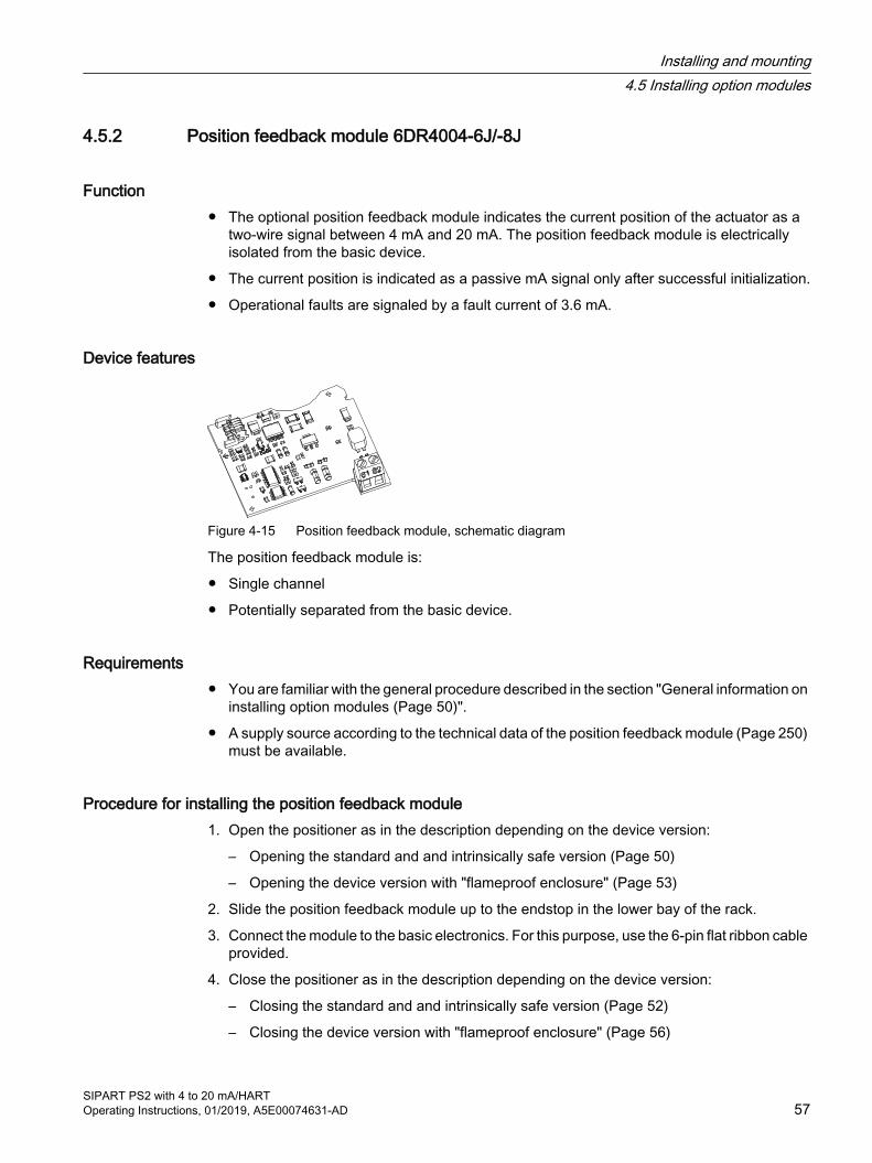
4.5.2 Position feedback module 6DR4004-6J/-8J
Function ● The optional position feedback module indicates the current position of the actuator as a
two-wire signal between 4 mA and 20 mA. The position feedback module is electrically isolated from the basic device.
● The current position is indicated as a passive mA signal only after successful initialization.
● Operational faults are signaled by a fault current of 3.6 mA.
Device features
Figure 4-15 Position feedback module, schematic diagram
The position feedback module is:
● Single channel
● Potentially separated from the basic device.
Requirements● You are familiar with the general procedure described in the section "General information on
installing option modules (Page 50)".
● A supply source according to the technical data of the position feedback module (Page 250) must be available.
Procedure for installing the position feedback module1. Open the positioner as in the description depending on the device version:
– Opening the standard and and intrinsically safe version (Page 50)
– Opening the device version with "flameproof enclosure" (Page 53)
2. Slide the position feedback module up to the endstop in the lower bay of the rack.
3. Connect the module to the basic electronics. For this purpose, use the 6-pin flat ribbon cable provided.
4. Close the positioner as in the description depending on the device version:
– Closing the standard and and intrinsically safe version (Page 52)
– Closing the device version with "flameproof enclosure" (Page 56)
Installing and mounting4.5 Installing option modules
SIPART PS2 with 4 to 20 mA/HARTOperating Instructions, 01/2019, A5E00074631-AD 57
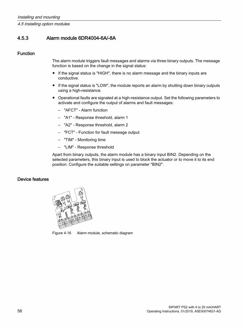
4.5.3 Alarm module 6DR4004-6A/-8A
FunctionThe alarm module triggers fault messages and alarms via three binary outputs. The message function is based on the change in the signal status:
● If the signal status is "HIGH", there is no alarm message and the binary inputs are conductive.
● If the signal status is "LOW", the module reports an alarm by shutting down binary outputs using a high-resistance.
● Operational faults are signaled at a high-resistance output. Set the following parameters to activate and configure the output of alarms and fault messages:
– "AFCT" - Alarm function
– "A1" - Response threshold, alarm 1
– "A2" - Response threshold, alarm 2
– "FCT" - Function for fault message output
– "TIM" - Monitoring time
– "LIM" - Response threshold
Apart from binary outputs, the alarm module has a binary input BIN2. Depending on the selected parameters, this binary input is used to block the actuator or to move it to its end position. Configure the suitable settings on parameter "BIN2".
Device features
Figure 4-16 Alarm module, schematic diagram
Installing and mounting4.5 Installing option modules
SIPART PS2 with 4 to 20 mA/HART58 Operating Instructions, 01/2019, A5E00074631-AD
The alarm module has the following features:
● Available in two versions.
– Explosion-proof version for connecting to a switching amplifier in conformity with EN 60947-5-6.
– Non-explosion-proof version for connecting to power sources having a maximum of 35 V.
● Three binary outputs. Binary inputs are potentially separated from the basic configuration and from each other.
● The binary input BIN2 has two inputs. Both inputs are implemented as logical OR combination.
– Input 1 at terminals 11/12: Is electrically isolated, and is triggered by an active signal.
– Input 2 at terminals 21/22: Is not electrically isolated, and is triggered by a passive NO contact.
Requirement● You are familiar with the general procedure described in the section "General information on
installing option modules (Page 50)".
Procedure for installing the alarm module1. Open the positioner as in the description depending on the device version:
– Opening the standard and and intrinsically safe version (Page 50)
– Opening the device version with "flameproof enclosure" (Page 53)
2. Slide the alarm module into the rack below the basic electronics . Ensure that you slide it up to the endstop.
3. Connect the module to the basic electronics. For this purpose, use the 8-pin flat ribbon cable provided.
4. Close the positioner as in the description depending on the device version:
– Closing the standard and and intrinsically safe version (Page 52)
– Closing the device version with "flameproof enclosure" (Page 56)
Installing and mounting4.5 Installing option modules
SIPART PS2 with 4 to 20 mA/HARTOperating Instructions, 01/2019, A5E00074631-AD 59
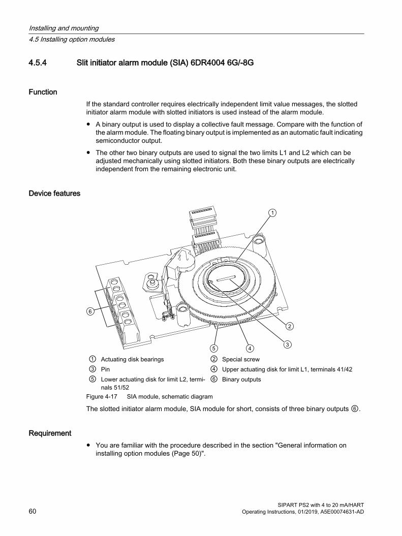
4.5.4 Slit initiator alarm module (SIA) 6DR4004 6G/-8G
FunctionIf the standard controller requires electrically independent limit value messages, the slotted initiator alarm module with slotted initiators is used instead of the alarm module.
● A binary output is used to display a collective fault message. Compare with the function of the alarm module. The floating binary output is implemented as an automatic fault indicating semiconductor output.
● The other two binary outputs are used to signal the two limits L1 and L2 which can be adjusted mechanically using slotted initiators. Both these binary outputs are electrically independent from the remaining electronic unit.
Device features
① Actuating disk bearings ② Special screw③ Pin ④ Upper actuating disk for limit L1, terminals 41/42⑤ Lower actuating disk for limit L2, termi‐
nals 51/52⑥ Binary outputs
Figure 4-17 SIA module, schematic diagram
The slotted initiator alarm module, SIA module for short, consists of three binary outputs ⑥.
Requirement● You are familiar with the procedure described in the section "General information on
installing option modules (Page 50)".
Installing and mounting4.5 Installing option modules
SIPART PS2 with 4 to 20 mA/HART60 Operating Instructions, 01/2019, A5E00074631-AD

Procedure for installing the slot initiator alarm module1. Open the positioner as described in section "Opening the standard and and intrinsically safe
version (Page 50)".
2. Remove the ribbon cable from the basic electronics.
3. Tighten the two fixing screws of the basic electronics. Remove the basic electronics.
4. Insert the SIA module from the top up to the upper printed circuit board guide of the rack.
5. Slide the module in the printed circuit board of the rack approx. 3 mm to the right.
6. Screw the special screw ② through the module into the positioner shaft. Tighten the special screw ② with a torque of 2 Nm.
NotePin in the actuating disk bearing
A pin ③ is pressed in the actuating disk bearing①. 1. Align pin ③ with the groove of the special screw before inserting the head of the special
screw ② into the actuating disk bearing ①.2. Rotate the actuating disk bearing ① and the special screw ② simultaneously so that the
pin ③ is inserted into the groove of the special screw ②.
7. Set the limits L1 and L2 as described below.
8. An insulating cover (yellow) is required over the module. This insulating cover is supplied with the module. Place the insulating cover on one side under the basic electronics seat of the rack. The recesses of the insulating cover must fit in the corresponding webs of the rack. To tighten the insulating cover, bend the walls of the adapter slightly outwards. Firmly press the other end until the insulating cover is underneath the contact surface of the basic electronics. The recesses of the insulating cover must fit in the corresponding webs of the rack.
9. Place the basic electronics onto the four holders of the rack.
10.Tighten the two fixing screws of the basic electronics. Tighten the screws.
11.Reestablish all electrical connections between the basic electronics and the option modules.
12.Connect the basic electronics with the option modules and the potentiometer. Use the corresponding ribbon cables.
13.Put on the supplied module cover. Make sure that the ribbon cable is not trapped.
NoteModule cover
Do not use the standard module cover. The provided module cover has a larger recess.
14.Select the labels that already exist on the standard version of the module cover from the label set provided. Affix the selected labels on the installed module cover as per the standard version.
15.Close the positioner as described in section "Closing the standard and and intrinsically safe version (Page 52)".
Installing and mounting4.5 Installing option modules
SIPART PS2 with 4 to 20 mA/HARTOperating Instructions, 01/2019, A5E00074631-AD 61

Procedure: Determining the switch status of the slotted initiatorsYou will require a suitable display device to determine the switch status. For example, use the initiator tester type 2 / Ex from Pepperl + Fuchs.
1. Connect the display device to the following terminals of the SIA module:
– 41 and 42
– 51 and 52
2. Read the switch status of slotted initiators.
Procedure: Setting the L1 and L2 limitsThe consecutive numbers in the following text refer to the above image in this section. Proceed as follows to set the limits:
1. Move the actuator to the first desired mechanical position.
2. Adjust the upper actuating disk ④ manually until the output signal at terminals 41 and 42 changes. Set a high-low or a low-high switchover as follows:
– Rotate the actuating disc ④ beyond the switching point until you reach the next switching point.
3. Move the actuator to the second desired mechanical position.
4. Adjust the lower actuating disk ⑤ manually until the output signal at terminals 51 and 52 changes. Set a high-low or a low-high switchover as follows:
– Rotate the actuating disc ⑤ beyond the switching point until you reach the next switching point.
NoteAdjusting the actuating disk
The actuating disks ④ and ⑤ are relatively difficult to move. This design prevents their unintentional movement during operation. You can achieve an easier and finer adjustment by reducing stiction temporarily. ● Move the actuator to and fro while simultaneously holding the actuating disks ④
and ⑤.
4.5.5 Mechanical limit switch module 6DR4004-6K/-8K
FunctionThis module is used to report two limits. These limits are reported using galvanic switching contacts.
Installing and mounting4.5 Installing option modules
SIPART PS2 with 4 to 20 mA/HART62 Operating Instructions, 01/2019, A5E00074631-AD

Device features
① Actuating disk bearings ④ Upper actuating disk for limit L1, terminals 51/52
② Special screw ⑤ Lower actuating disk for limit L2, terminals 41/42
③ Pin Figure 4-18 Limit contact module, schematic diagram
The mechanical limit switch module consists of:
● One binary output to display a collective fault message. Compare with the device features of the alarm module.
● Two switches to report two mechanically adjustable limits. Both these switches are electrically independent from the remaining electronic unit.
See alsoGeneral information on installing option modules (Page 50)
Requirement● You are familiar with the procedure described in the section "General information on
installing option modules (Page 50)".
Procedure for installing the mechanical limit switch module1. Open the positioner as described in section "Opening the standard and and intrinsically safe
version (Page 50)".
2. Remove the ribbon cable from the basic electronics.
3. Tighten the two fixing screws of the basic electronics. Remove the basic electronics.
Installing and mounting4.5 Installing option modules
SIPART PS2 with 4 to 20 mA/HARTOperating Instructions, 01/2019, A5E00074631-AD 63
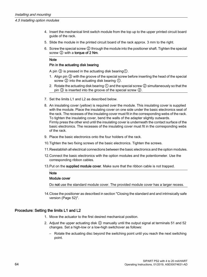
4. Insert the mechanical limit switch module from the top up to the upper printed circuit board guide of the rack.
5. Slide the module in the printed circuit board of the rack approx. 3 mm to the right.
6. Screw the special screw ② through the module into the positioner shaft. Tighten the special screw ② with a torque of 2 Nm.
NotePin in the actuating disk bearing
A pin ③ is pressed in the actuating disk bearing①. 1. Align pin ③ with the groove of the special screw before inserting the head of the special
screw ② into the actuating disk bearing ①.2. Rotate the actuating disk bearing ① and the special screw ② simultaneously so that the
pin ③ is inserted into the groove of the special screw ②.
7. Set the limits L1 and L2 as described below.
8. An insulating cover (yellow) is required over the module. This insulating cover is supplied with the module. Place the insulating cover on one side under the basic electronics seat of the rack. The recesses of the insulating cover must fit in the corresponding webs of the rack. To tighten the insulating cover, bend the walls of the adapter slightly outwards. Firmly press the other end until the insulating cover is underneath the contact surface of the basic electronics. The recesses of the insulating cover must fit in the corresponding webs of the rack.
9. Place the basic electronics onto the four holders of the rack.
10.Tighten the two fixing screws of the basic electronics. Tighten the screws.
11.Reestablish all electrical connections between the basic electronics and the option modules.
12.Connect the basic electronics with the option modules and the potentiometer. Use the corresponding ribbon cables.
13.Put on the supplied module cover. Make sure that the ribbon cable is not trapped.
NoteModule cover
Do not use the standard module cover. The provided module cover has a larger recess.
14.Close the positioner as described in section "Closing the standard and and intrinsically safe version (Page 52)".
Procedure: Setting the limits L1 and L21. Move the actuator to the first desired mechanical position.
2. Adjust the upper actuating disk ④ manually until the output signal at terminals 51 and 52 changes. Set a high-low or a low-high switchover as follows:
– Rotate the actuating disc beyond the switching point until you reach the next switching point.
Installing and mounting4.5 Installing option modules
SIPART PS2 with 4 to 20 mA/HART64 Operating Instructions, 01/2019, A5E00074631-AD
3. Move the actuator to the second desired mechanical position.
4. Adjust the lower actuating disk ⑤ manually until the output signal at terminals 41 and 42 changes. Set a high-low or a low-high switchover as follows:
– Rotate the actuating disc beyond the switching point until you reach the next switching point.
NoteAdjusting the actuating disk
The actuating disks ④ and ⑤ are relatively difficult to move. This design prevents their unintentional movement during operation. You can achieve an easier and finer adjustment by reducing stiction temporarily. ● Move the actuator to and fro while simultaneously holding the actuating disks ④
and ⑤.
Installing and mounting4.5 Installing option modules
SIPART PS2 with 4 to 20 mA/HARTOperating Instructions, 01/2019, A5E00074631-AD 65
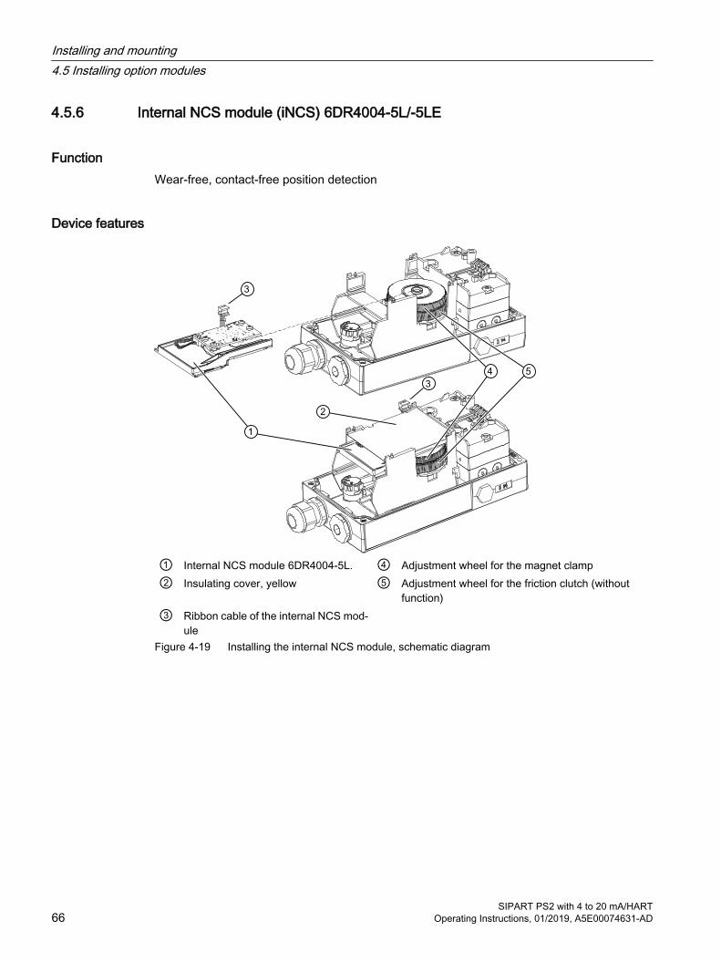
4.5.6 Internal NCS module (iNCS) 6DR4004-5L/-5LE
FunctionWear-free, contact-free position detection
Device features
① Internal NCS module 6DR4004-5L. ④ Adjustment wheel for the magnet clamp② Insulating cover, yellow ⑤ Adjustment wheel for the friction clutch (without
function)③ Ribbon cable of the internal NCS mod‐
ule
Figure 4-19 Installing the internal NCS module, schematic diagram
Installing and mounting4.5 Installing option modules
SIPART PS2 with 4 to 20 mA/HART66 Operating Instructions, 01/2019, A5E00074631-AD

Requirement● You are familiar with the general procedure described in the section "General information on
installing option modules (Page 50)".
● The slot required for the internal NCS (iNCS) module in the rack is free. The following option modules use the same slot in the rack:
– Alarm module
– SIA module
– Mechanical limit switch module
– Internal NCS module
● The positioner is mounted, or is to be mounted, directly on the valve using the positioner shaft.
Procedure 1. Open the positioner as in the description depending on the device version:
– Opening the standard and and intrinsically safe version (Page 50)
– Opening the device version with "flameproof enclosure" (Page 53)
2. Remove the ribbon cable from the basic electronics.
3. Tighten the two fixing screws of the basic electronics.
4. Remove the basic electronics.
5. Insert the connector of the ribbon cable (A) into the slot as shown below. Note: There is no space for the ribbon cable (A) in earlier versions of the positioner. Here you fasten the ribbon cable to the container using a cable tie.
6. Screw the special screw ⑥ into the shaft of the positioner.
Installing and mounting4.5 Installing option modules
SIPART PS2 with 4 to 20 mA/HARTOperating Instructions, 01/2019, A5E00074631-AD 67
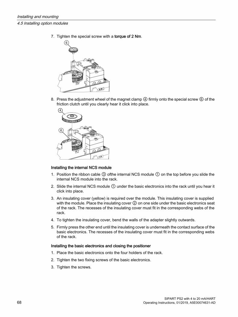
7. Tighten the special screw with a torque of 2 Nm.
8. Press the adjustment wheel of the magnet clamp ④ firmly onto the special screw ⑥ of the friction clutch until you clearly hear it click into place.
Installing the internal NCS module1. Position the ribbon cable ③ ofthe internal NCS module ① on the top before you slide the
internal NCS module into the rack.
2. Slide the internal NCS module ① under the basic electronics into the rack until you hear it click into place.
3. An insulating cover (yellow) is required over the module. This insulating cover is supplied with the module. Place the insulating cover ② on one side under the basic electronics seat of the rack. The recesses of the insulating cover must fit in the corresponding webs of the rack.
4. To tighten the insulating cover, bend the walls of the adapter slightly outwards.
5. Firmly press the other end until the insulating cover is underneath the contact surface of the basic electronics. The recesses of the insulating cover must fit in the corresponding webs of the rack.
Installing the basic electronics and closing the positioner1. Place the basic electronics onto the four holders of the rack.
2. Tighten the two fixing screws of the basic electronics.
3. Tighten the screws.
Installing and mounting4.5 Installing option modules
SIPART PS2 with 4 to 20 mA/HART68 Operating Instructions, 01/2019, A5E00074631-AD

4. Insert the ribbon cable connector of the internal NCS module ① onto the positioner basic electronics. Note for installed position feedback module: Reestablish all electrical connections between the basic electronics and the position feedback module.
5. Put on the supplied module cover. Make sure that the ribbon cable is not trapped.
NoteModule cover
Do not use the standard module cover. The provided module cover has a larger recess.
6. Close the positioner as in the description depending on the device version:
– Closing the standard and and intrinsically safe version (Page 52)
– Closing the device version with "flameproof enclosure" (Page 56)
ResultThe module is installed and connected to the basic electronics of the positioner. Now configure the module with the parameter "1.YFCT (Page 145)".
See alsoOverview of initialization parameters 1 to 5 (Page 137)
4.5.7 EMC filter module 6DR4004-6F/-8F
FunctionYou will require the EMC filter module if you use an external position sensor on the positioner, e.g. a potentiometer or a non-contacting sensor. The EMC filter module forms the interface between external position sensors and the basic electronics of the positioner. This module protects the positioner from electromagnetic effects.
Device features
① Switch block 1② Switch block 2
Figure 4-20 EMC filter module, schematic diagram
Installing and mounting4.5 Installing option modules
SIPART PS2 with 4 to 20 mA/HARTOperating Instructions, 01/2019, A5E00074631-AD 69
● EMC protection
● Connection to basic electronics
● Connection terminals for:
– External potentiometers with 3 kΩ, 5 kΩ or 10 kΩ
– Signals 0 to 20 mA
– Signals 0 to 10 V
Requirement● You are familiar with the general procedure described in the section "General information on
installing option modules (Page 50)".
● You have at least one of the following modules:
– 6DR4004-8F EMC filter module / Analog Input Module (AIM) - nEx
– 6DR4004-6F EMC filter module / Analog Input Module (AIM) - Ex
● Any already installed optional module has been removed.
● You have one of the following external position detection systems / Position Transmitters:
– 6DR4004-.N* NCS sensor
– C73451-A430-D78 Polycarbonate enclosure with potentiometer
– 6DR4004-1ES Aluminum enclosure with potentiometer
– 6DR4004-2ES Aluminum enclosure with NCS
– 6DR4004-3ES Aluminum enclosure with NCS and SIA module / Inductive Limit Switch (ILS)
– 6DR4004-4ES Aluminum enclosure with NCS and Mechanic Limit Switch (MLS)
Installing and mounting4.5 Installing option modules
SIPART PS2 with 4 to 20 mA/HART70 Operating Instructions, 01/2019, A5E00074631-AD

Procedure for installing the EMC filter module
① EMC filter module terminals ⑤ Basic electronics② Yellow wheel for locking the position detection ⑥ Screw③ Positioner ⑦ EMC filter module 6DR4004-6F/-8F④ Ribbon cable connector of fitted potentiometer,
or ribbon cable connector of EMC filter module
Figure 4-21 Installation EMC filter module
1. Open the positioner as described in section "Opening the standard and and intrinsically safe version (Page 50)".
2. Remove the ribbon cable from the basic electronics.
3. Loosen the two fixing screws of the basic electronics ⑤.
4. Remove the basic electronics.
5. Loosen the screw ⑥ in the connection area of the positioner.
6. Insert the connector of the ribbon cable (A) into the slot as shown below.Note: There is no space for the ribbon cable (A) in earlier versions of the positioner. Here you fasten the ribbon cable with the supplied cable tie at the container.
7. Secure the EMC filter module using the screw ⑥.
8. Place the basic electronics ⑤ onto the four holders of the rack.
9. Screw in the two fixing screws of the basic electronics ⑤.
10.Tighten the screws.
Installing and mounting4.5 Installing option modules
SIPART PS2 with 4 to 20 mA/HARTOperating Instructions, 01/2019, A5E00074631-AD 71

11.Insert the ribbon cable connector ④ of the EMC filter module onto the positioner basic electronics.
12.Establish all electrical connections between the basic electronics and the option modules.
13.Close the positioner as described in section "Closing the standard and and intrinsically safe version (Page 52)".
Installing and mounting4.5 Installing option modules
SIPART PS2 with 4 to 20 mA/HART72 Operating Instructions, 01/2019, A5E00074631-AD
Connection 55.1 Basic safety instructions
WARNING
Lever for position detection
Danger of crushing and shearing with mounting kits which use a lever for position detection. During commissioning and ongoing operation, severing or squeezing of limbs could occur as a result of the lever. Risk of injury when working on control valves due to the high operating force of the pneumatic actuator.● Do not reach into the range of motion of the lever following mounting of the positioner and
mounting kit.
WARNING
With intrinsically device version (Ex i)
Risk of explosion in hazardous areas.
For intrinsically safe device versions only the certified circuits may be connected as auxiliary power supply, control and signal circuits.● Make sure that the power source of the used circuits is marked as intrinsically safe.
WARNING
Unsuitable cables, cable glands and/or plugs
Risk of explosion in hazardous areas.● Use only cable glands/plugs that comply with the requirements for the relevant type of
protection.● Tighten the cable glands in accordance with the torques specified in Technical data
(Page 237).● Close unused cable inlets for the electrical connections.● When replacing cable glands, only use cable glands of the same type.● After installation, check that the cables are seated firmly.
SIPART PS2 with 4 to 20 mA/HARTOperating Instructions, 01/2019, A5E00074631-AD 73
NOTICE
Condensation in the device
Damage to device through formation of condensation if the temperature difference between transportation or storage and the mounting location exceeds 20 °C (36 °F).● Before taking the device into operation, let the device adapt for several hours in the new
environment.
NOTICE
Ambient temperature too high
Damage to cable sheath.● At an ambient temperature ≥ 60 °C (140 °F), use heat-resistant cables suitable for an
ambient temperature at least 20 °C (36 °F) higher.
WARNING
Improper power supply
Risk of explosion in hazardous areas as result of incorrect power supply.● Connect the device in accordance with the specified power supply and signal circuits. The
relevant specifications can be found in the certificates, in Technical data (Page 237) or on the nameplate.
WARNING
Lack of equipotential bonding
Risk of explosion through compensating currents or ignition currents through lack of equipotential bonding.● Ensure that the device is potentially equalized.
Exception: It may be permissible to omit connection of the equipotential bonding for devices with type of protection "Intrinsic safety Ex i".
WARNING
Unprotected cable ends
Risk of explosion through unprotected cable ends in hazardous areas.● Protect unused cable ends in accordance with IEC/EN 60079-14.
Connection5.1 Basic safety instructions
SIPART PS2 with 4 to 20 mA/HART74 Operating Instructions, 01/2019, A5E00074631-AD

WARNING
Improper laying of shielded cables
Risk of explosion through compensating currents between hazardous area and the non‑hazardous area.● Shielded cables that cross into hazardous areas should be grounded only at one end.● If grounding is required at both ends, use an equipotential bonding conductor.
WARNING
Connecting device in energized state
Risk of explosion in hazardous areas.● Connect devices in hazardous areas only in a de-energized state.
Exceptions:● Devices having the type of protection "Intrinsic safety Ex i" may also be connected in
energized state in hazardous areas.● Exceptions for type of protection "Increased safety ec" (Zone 2) are regulated in the
relevant certificate.
WARNING
Incorrect selection of type of protection
Risk of explosion in areas subject to explosion hazard.
This device is approved for several types of protection. 1. Decide in favor of one type of protection.2. Connect the device in accordance with the selected type of protection.3. In order to avoid incorrect use at a later point, make the types of protection that are not used
permanently unrecognizable on the nameplate.
NOTICE
Standard cable gland/torque
Device damage.● Owing the reasons pertaining to tightness (IP enclosure rating) and the required tensile
strength, only use the cables having a diameter ≥ 8 mm for standard M20x1.5 cable gland, or use a suitable seal insert in case of smaller diameters.
● In the NPT version, the positioner is delivered with a coupling. When inserting a counter piece in the coupling, ensure that the maximum permissible torque of 10 Nm is not exceeded.
Connection5.1 Basic safety instructions
SIPART PS2 with 4 to 20 mA/HARTOperating Instructions, 01/2019, A5E00074631-AD 75

CAUTION
Maximum AC/DC switching voltage with UL approval E344532
The mechanical limit switch module 6DR4004-6K is approved for use for positioners with UL approval. The maximum supply voltage in this case is 30 V AC/DC.
The mechanical limit switch module 6DR4004-8K is not approved for use for positioners with UL approval.
If this information is ignored, the UL approval for the mechanical limit switch module for the positioner becomes invalid.
Two-wire mode
NOTICE
Connection of voltage source to current input
Device damage if a voltage source is connected to the current input Iw (terminals 6 and 7).● Never connect the current input Iw to a low-resistance voltage source, otherwise the
positioner may be destroyed. ● Always use a high-impedance power source. ● Observe the static destruction limit specified in the "Electrical data (Page 244)".
NoteImprovement of interference immunity● Lay signal cables separate from cables with voltages > 60 V.● Use cables with twisted wires.● Keep device and cables at a distance from strong electromagnetic fields.● Take account of the conditions for communication specified in the Electrical data
(Page 244).● Use shielded cables to guarantee the full specification according to HART/PA/FF/Modbus/
EIA-485/Profibus DP.
Electromagnetic compatibilityThe polycarbonate enclosure is metalized from inside to increase the electromagnetic compatibility (EMC) with respect to high-frequency radiation. The shield is connected to the threaded bush shown in the following picture such that it is electrically conductive.
Note that this protection is effective only if you connect at least one of these bushes to the earthed control valves through electrically conductive (bare) attachments.
Connection5.1 Basic safety instructions
SIPART PS2 with 4 to 20 mA/HART76 Operating Instructions, 01/2019, A5E00074631-AD
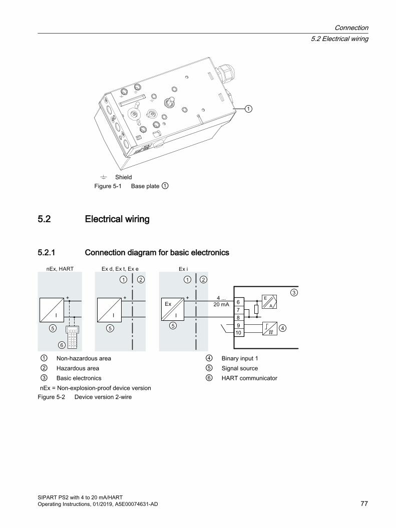
ShieldFigure 5-1 Base plate ①
5.2 Electrical wiring
5.2.1 Connection diagram for basic electronics
① Non-hazardous area ④ Binary input 1② Hazardous area ⑤ Signal source③ Basic electronics ⑥ HART communicatornEx = Non-explosion-proof device version
Figure 5-2 Device version 2-wire
Connection5.2 Electrical wiring
SIPART PS2 with 4 to 20 mA/HARTOperating Instructions, 01/2019, A5E00074631-AD 77
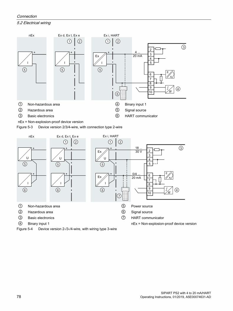
① Non-hazardous area ④ Binary input 1② Hazardous area ⑤ Signal source③ Basic electronics ⑥ HART communicatornEx = Non-explosion-proof device version
Figure 5-3 Device version 2/3/4-wire, with connection type 2-wire
① Non-hazardous area ⑤ Power source② Hazardous area ⑥ Signal source③ Basic electronics ⑦ HART communicator④ Binary input 1 nEx = Non-explosion-proof device version
Figure 5-4 Device version 2-/3-/4-wire, with wiring type 3-wire
Connection5.2 Electrical wiring
SIPART PS2 with 4 to 20 mA/HART78 Operating Instructions, 01/2019, A5E00074631-AD
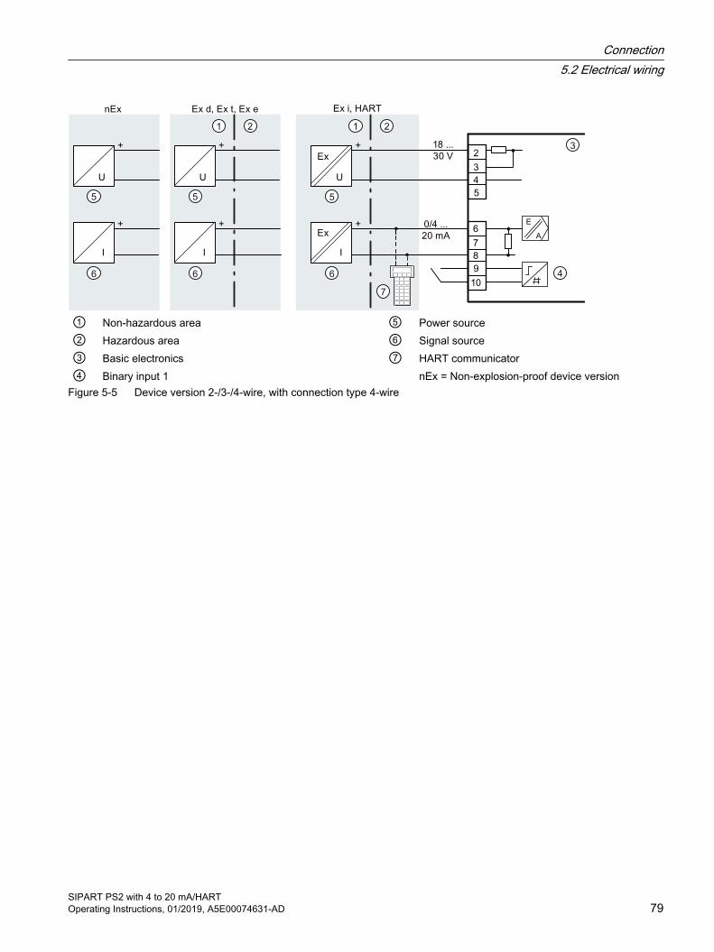
① Non-hazardous area ⑤ Power source② Hazardous area ⑥ Signal source③ Basic electronics ⑦ HART communicator④ Binary input 1 nEx = Non-explosion-proof device version
Figure 5-5 Device version 2-/3-/4-wire, with connection type 4-wire
Connection5.2 Electrical wiring
SIPART PS2 with 4 to 20 mA/HARTOperating Instructions, 01/2019, A5E00074631-AD 79
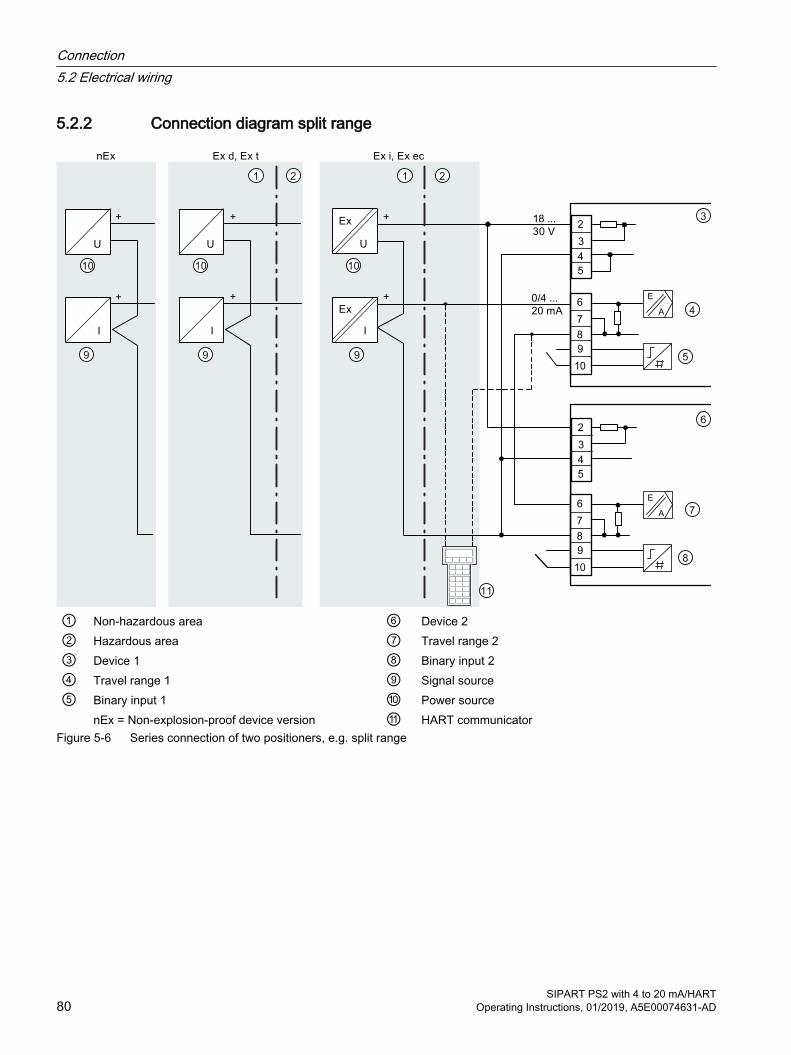
5.2.2 Connection diagram split range
① Non-hazardous area ⑥ Device 2② Hazardous area ⑦ Travel range 2③ Device 1 ⑧ Binary input 2④ Travel range 1 ⑨ Signal source⑤ Binary input 1 ⑩ Power source nEx = Non-explosion-proof device version ⑪ HART communicator
Figure 5-6 Series connection of two positioners, e.g. split range
Connection5.2 Electrical wiring
SIPART PS2 with 4 to 20 mA/HART80 Operating Instructions, 01/2019, A5E00074631-AD
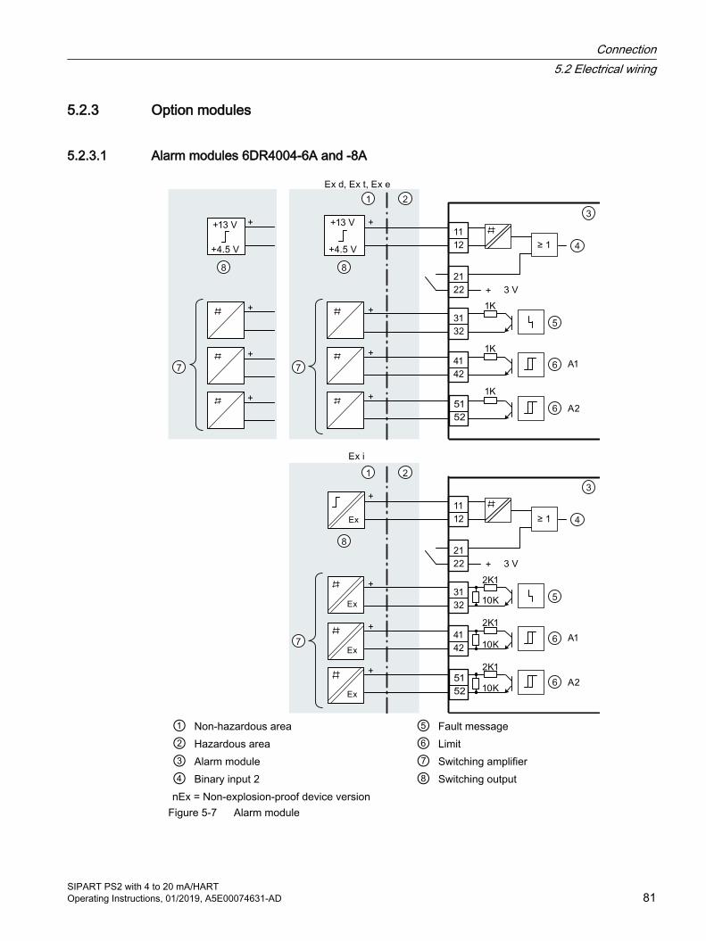
5.2.3 Option modules
5.2.3.1 Alarm modules 6DR4004-6A and -8A
① Non-hazardous area ⑤ Fault message② Hazardous area ⑥ Limit③ Alarm module ⑦ Switching amplifier④ Binary input 2 ⑧ Switching outputnEx = Non-explosion-proof device version
Figure 5-7 Alarm module
Connection5.2 Electrical wiring
SIPART PS2 with 4 to 20 mA/HARTOperating Instructions, 01/2019, A5E00074631-AD 81
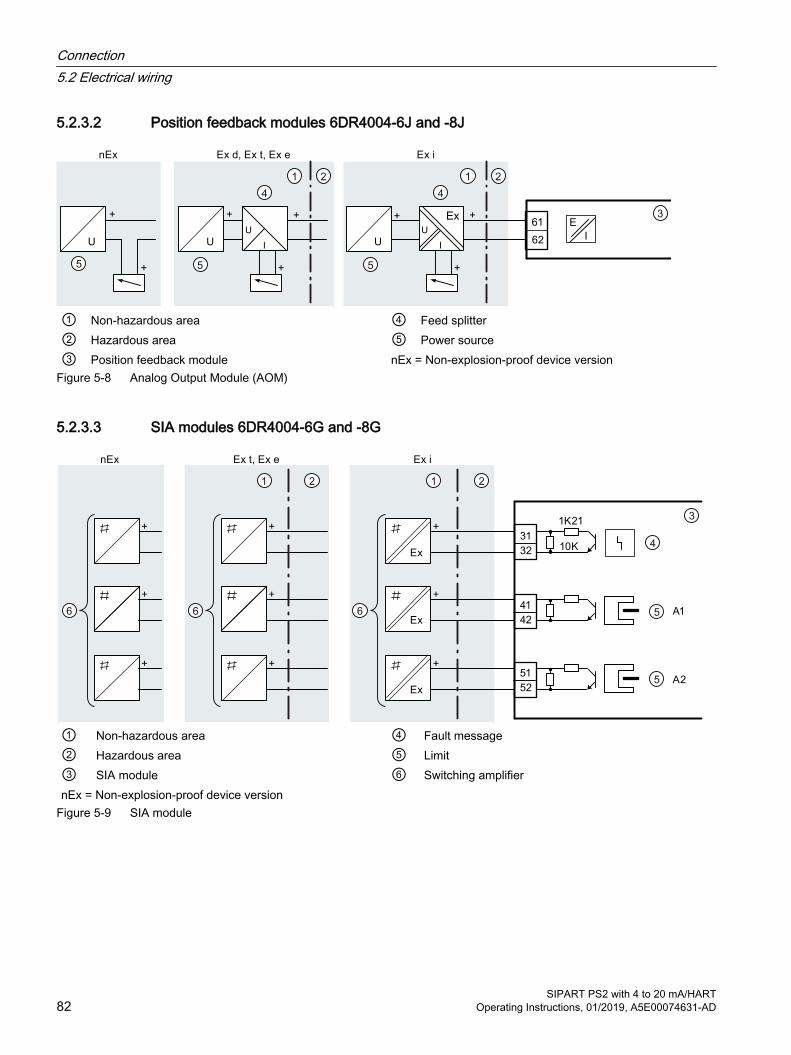
5.2.3.2 Position feedback modules 6DR4004-6J and -8J
E
I
61
62
① Non-hazardous area ④ Feed splitter② Hazardous area ⑤ Power source③ Position feedback module nEx = Non-explosion-proof device version
Figure 5-8 Analog Output Module (AOM)
5.2.3.3 SIA modules 6DR4004-6G and -8G
① Non-hazardous area ④ Fault message② Hazardous area ⑤ Limit③ SIA module ⑥ Switching amplifiernEx = Non-explosion-proof device version
Figure 5-9 SIA module
Connection5.2 Electrical wiring
SIPART PS2 with 4 to 20 mA/HART82 Operating Instructions, 01/2019, A5E00074631-AD
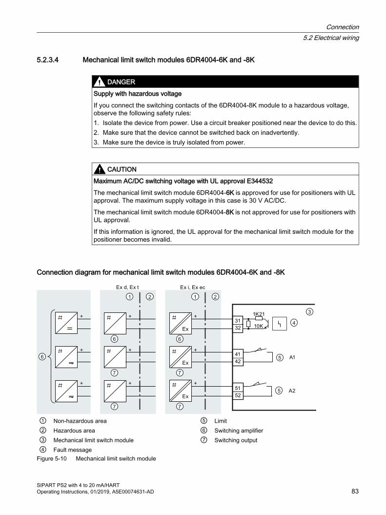
5.2.3.4 Mechanical limit switch modules 6DR4004-6K and -8K
DANGER
Supply with hazardous voltage
If you connect the switching contacts of the 6DR4004-8K module to a hazardous voltage, observe the following safety rules:1. Isolate the device from power. Use a circuit breaker positioned near the device to do this.2. Make sure that the device cannot be switched back on inadvertently.3. Make sure the device is truly isolated from power.
CAUTION
Maximum AC/DC switching voltage with UL approval E344532
The mechanical limit switch module 6DR4004-6K is approved for use for positioners with UL approval. The maximum supply voltage in this case is 30 V AC/DC.
The mechanical limit switch module 6DR4004-8K is not approved for use for positioners with UL approval.
If this information is ignored, the UL approval for the mechanical limit switch module for the positioner becomes invalid.
Connection diagram for mechanical limit switch modules 6DR4004-6K and -8K
① Non-hazardous area ⑤ Limit② Hazardous area ⑥ Switching amplifier③ Mechanical limit switch module ⑦ Switching output④ Fault message
Figure 5-10 Mechanical limit switch module
Connection5.2 Electrical wiring
SIPART PS2 with 4 to 20 mA/HARTOperating Instructions, 01/2019, A5E00074631-AD 83
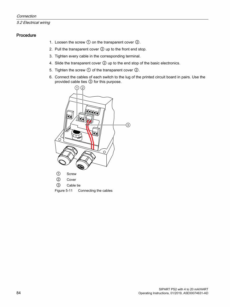
Procedure1. Loosen the screw ① on the transparent cover ②.
2. Pull the transparent cover ② up to the front end stop.
3. Tighten every cable in the corresponding terminal.
4. Slide the transparent cover ② up to the end stop of the basic electronics.
5. Tighten the screw ① of the transparent cover ②.
6. Connect the cables of each switch to the lug of the printed circuit board in pairs. Use the provided cable ties ③ for this purpose.
① Screw② Cover③ Cable tie
Figure 5-11 Connecting the cables
Connection5.2 Electrical wiring
SIPART PS2 with 4 to 20 mA/HART84 Operating Instructions, 01/2019, A5E00074631-AD
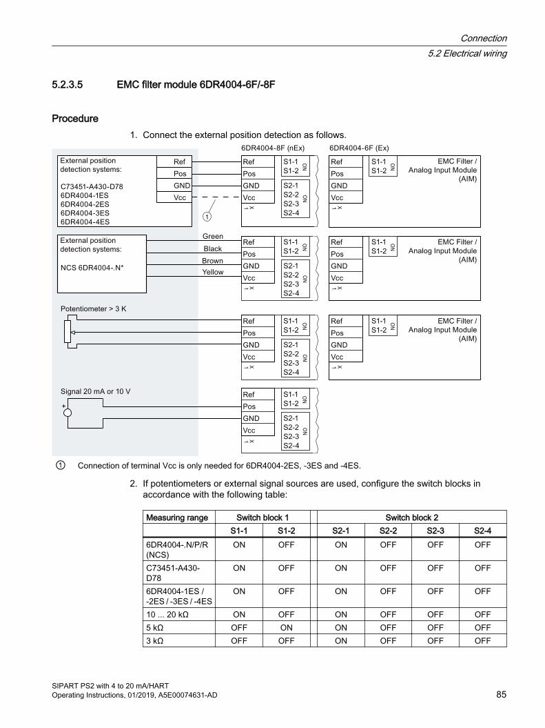
5.2.3.5 EMC filter module 6DR4004-6F/-8F
Procedure1. Connect the external position detection as follows.
1
① Connection of terminal Vcc is only needed for 6DR4004-2ES, -3ES and -4ES.
2. If potentiometers or external signal sources are used, configure the switch blocks in accordance with the following table:
Measuring range Switch block 1 Switch block 2 S1-1 S1-2 S2-1 S2-2 S2-3 S2-46DR4004-.N/P/R (NCS)
ON OFF ON OFF OFF OFF
C73451-A430-D78
ON OFF ON OFF OFF OFF
6DR4004-1ES / -2ES / -3ES / -4ES
ON OFF ON OFF OFF OFF
10 ... 20 kΩ ON OFF ON OFF OFF OFF5 kΩ OFF ON ON OFF OFF OFF3 kΩ OFF OFF ON OFF OFF OFF
Connection5.2 Electrical wiring
SIPART PS2 with 4 to 20 mA/HARTOperating Instructions, 01/2019, A5E00074631-AD 85
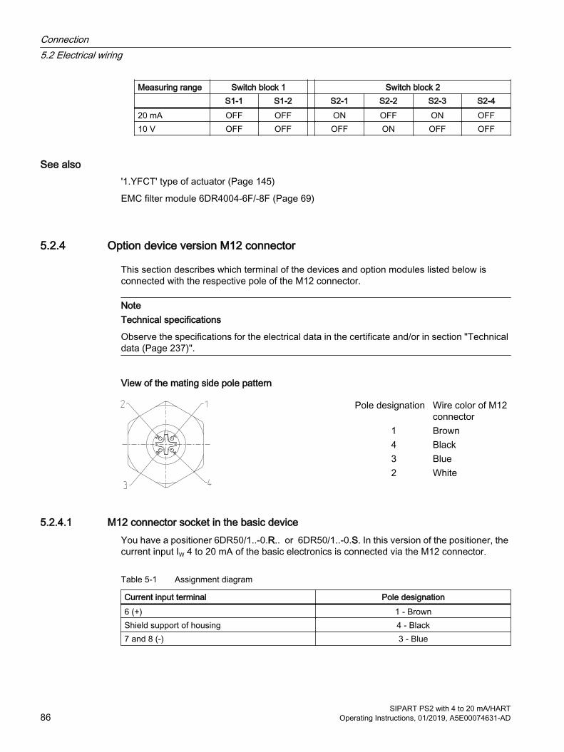
Measuring range Switch block 1 Switch block 2 S1-1 S1-2 S2-1 S2-2 S2-3 S2-420 mA OFF OFF ON OFF ON OFF10 V OFF OFF OFF ON OFF OFF
See also'1.YFCT' type of actuator (Page 145)
EMC filter module 6DR4004-6F/-8F (Page 69)
5.2.4 Option device version M12 connector
This section describes which terminal of the devices and option modules listed below is connected with the respective pole of the M12 connector.
NoteTechnical specifications
Observe the specifications for the electrical data in the certificate and/or in section "Technical data (Page 237)".
View of the mating side pole pattern
Pole designation Wire color of M12 connector
1 Brown4 Black3 Blue2 White
5.2.4.1 M12 connector socket in the basic deviceYou have a positioner 6DR50/1..-0.R.. or 6DR50/1..-0.S. In this version of the positioner, the current input IW 4 to 20 mA of the basic electronics is connected via the M12 connector.
Table 5-1 Assignment diagram
Current input terminal Pole designation6 (+) 1 - BrownShield support of housing 4 - Black7 and 8 (-) 3 - Blue
Connection5.2 Electrical wiring
SIPART PS2 with 4 to 20 mA/HART86 Operating Instructions, 01/2019, A5E00074631-AD
5.2.4.2 M12 connector for connecting the position feedback module 6DR4004-6J / 8J (-Z D53)You have a positioner with order suffix -Z order code D53. In this version of the positioner, the M12 connector is used to electrically connect the current output of the position feedback module.
Table 5-2 Assignment diagram
Current output terminal Pole designation61 (+) 1 - BrownShield support of housing 4 - Black62 (-) 3 - Blue
5.2.4.3 M12 connector for connecting the external position detection system (-Z D54)You have a positioner with order suffix -Z order code D54. In this version of the positioner, the M12 connector is used to electrically connect the fitted EMC filter module (6DR4004-6F). Connect the external position detection system using the M12 connector.
Table 5-3 Assignment diagram
Terminal Pole designationPOS (X1/2) 3 - BlueVCC (X1/4) 1 - BrownGND (X1/1) 4 - BlackVREF (X1/3) 2 - White
5.2.4.4 M12 connector for connecting the alarm module 6DR4004-6A / -8A (-Z D55)You have a positioner with order suffix -Z order code D55. In this version of the positioner, the M12 connector is used to electrically connect the current output of the position feedback module.
Table 5-4 Assignment diagram
Alarm output terminal Pole designation41 (+) 1 - Brown52 (-) 4 - Black42 (-) 3 - Blue51 (+) 2 - White
Connection5.2 Electrical wiring
SIPART PS2 with 4 to 20 mA/HARTOperating Instructions, 01/2019, A5E00074631-AD 87
5.2.4.5 M12 connector for connecting the SIA module 6DR4004-6G /-8G (-Z D56)You have a positioner with order suffix -Z order code D56. In this version of the positioner, the M12 connector is used to electrically connect the outputs of the SIA module.
Table 5-5 Assignment diagram
Alarm output terminal Pole designation41 (+) 1 - Brown52 (-) 4 - Black42 (-) 3 - Blue51 (+) 2 - White
5.2.4.6 M12 connector for connecting the mechanical limit switch module 6DR4004-6K (-Z D57)You have a positioner with order suffix -Z order code D57. In this version of the positioner, the M12 connector is used to electrically connect the outputs of the mechanical limit switch module.
Table 5-6 Assignment diagram
Alarm output terminal Pole designation41 (+) 1 - Brown52 (-) 4 - Black42 (-) 3 - Blue51 (+) 2 - White
5.3 Pneumatic connection
5.3.1 Basic safety instructions for the pneumatic connection
WARNING
Pneumatic auxiliary power
For safety reasons, the pneumatic auxiliary power supply can be fed after installation only if the positioner is switched to "P-Manual mode" when an electrical signal is present. This operating mode is preset in the delivery state.
NoteSpecifications regarding air quality
Observe the specifications regarding the air quality, see section "Technical specifications > Pneumatic data (Page 237)".
Connection5.3 Pneumatic connection
SIPART PS2 with 4 to 20 mA/HART88 Operating Instructions, 01/2019, A5E00074631-AD

NoteLeakage
Besides continuous air consumption, a leakage can cause the positioner to try to compensate the position deviation. This will result in premature wear in the entire control device.● Check offline using the diagnostic parameter "11.LEAK" whether leakage is present.● If there is leakage, check the pneumatic connections for leaks.
See alsoReaction to failure of auxiliary powers (Page 91)
Changing the operating mode (Page 96)
Diagnostic value '11.LEAK - Leakage test' (Page 203)
5.3.2 Pneumatic connection for 6DR5..0/1/2/3
5.3.2.1 Structure of pneumatic connection
① Output: Actuating pressure Y2 *)② Input: Supply air PZ③ Output: Actuating pressure Y1 ④ Exhaust air outlet with sound absorber, thread G¼*) for double-acting actuators
Figure 5-12 Pneumatic connection, example
5.3.2.2 Integrated pneumatic connectionThe following pneumatic connections are provided at the rear side of the basic device for the integrated attachment for single-acting linear actuators:
● Actuating pressure Y1
● Exhaust air outlet
Connection5.3 Pneumatic connection
SIPART PS2 with 4 to 20 mA/HARTOperating Instructions, 01/2019, A5E00074631-AD 89
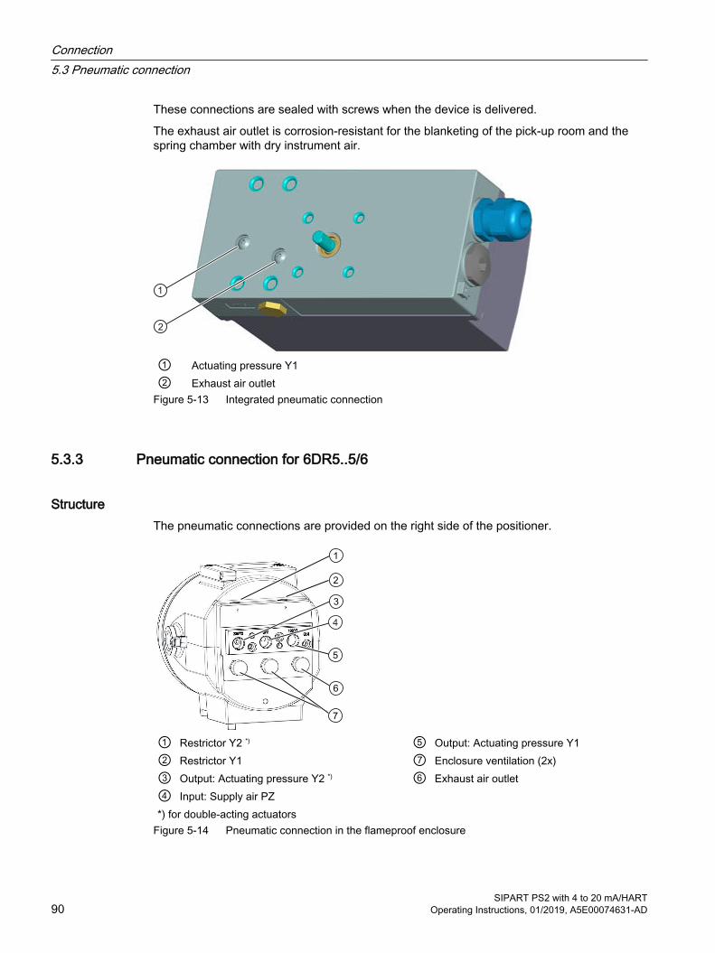
These connections are sealed with screws when the device is delivered.
The exhaust air outlet is corrosion-resistant for the blanketing of the pick-up room and the spring chamber with dry instrument air.
① Actuating pressure Y1 ② Exhaust air outlet
Figure 5-13 Integrated pneumatic connection
5.3.3 Pneumatic connection for 6DR5..5/6
StructureThe pneumatic connections are provided on the right side of the positioner.
① Restrictor Y2 *) ⑤ Output: Actuating pressure Y1② Restrictor Y1 ⑦ Enclosure ventilation (2x)③ Output: Actuating pressure Y2 *) ⑥ Exhaust air outlet④ Input: Supply air PZ *) for double-acting actuators
Figure 5-14 Pneumatic connection in the flameproof enclosure
Connection5.3 Pneumatic connection
SIPART PS2 with 4 to 20 mA/HART90 Operating Instructions, 01/2019, A5E00074631-AD
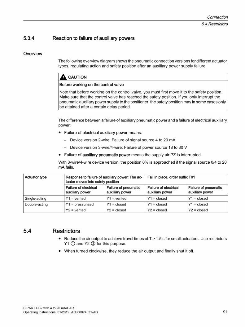
5.3.4 Reaction to failure of auxiliary powers
OverviewThe following overview diagram shows the pneumatic connection versions for different actuator types, regulating action and safety position after an auxiliary power supply failure.
CAUTION
Before working on the control valve
Note that before working on the control valve, you must first move it to the safety position. Make sure that the control valve has reached the safety position. If you only interrupt the pneumatic auxiliary power supply to the positioner, the safety position may in some cases only be attained after a certain delay period.
The difference between a failure of auxiliary pneumatic power and a failure of electrical auxiliary power:
● Failure of electrical auxiliary power means:
– Device version 2-wire: Failure of signal source 4 to 20 mA
– Device version 3-wire/4-wire: Failure of power source 18 to 30 V
● Failure of auxiliary pneumatic power means the supply air PZ is interrupted.
With 3-wire/4-wire device version, the position 0% is approached if the signal source 0/4 to 20 mA fails.
Actuator type Response to failure of auxiliary power: The ac‐tuator moves into safety position
Fail in place, order suffix F01
Failure of electrical auxiliary power
Failure of pneumatic auxiliary power
Failure of electrical auxiliary power
Failure of pneumatic auxiliary power
Single-acting Y1 = vented Y1 = vented Y1 = closed Y1 = closedDouble-acting Y1 = pressurized
Y2 = ventedY1 = closedY2 = closed
Y1 = closedY2 = closed
Y1 = closedY2 = closed
5.4 Restrictors● Reduce the air output to achieve travel times of T > 1.5 s for small actuators. Use restrictors
Y1 ① and Y2 ② for this purpose.
● When turned clockwise, they reduce the air output and finally shut it off.
Connection5.4 Restrictors
SIPART PS2 with 4 to 20 mA/HARTOperating Instructions, 01/2019, A5E00074631-AD 91
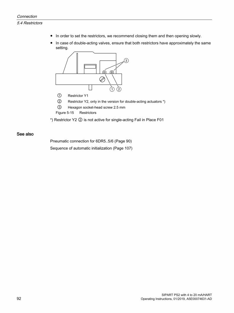
● In order to set the restrictors, we recommend closing them and then opening slowly.
● In case of double-acting valves, ensure that both restrictors have approximately the same setting.
① Restrictor Y1② Restrictor Y2, only in the version for double-acting actuators *)③ Hexagon socket-head screw 2.5 mm
Figure 5-15 Restrictors
*) Restrictor Y2 ② is not active for single-acting Fail in Place F01
See alsoPneumatic connection for 6DR5..5/6 (Page 90)
Sequence of automatic initialization (Page 107)
Connection5.4 Restrictors
SIPART PS2 with 4 to 20 mA/HART92 Operating Instructions, 01/2019, A5E00074631-AD
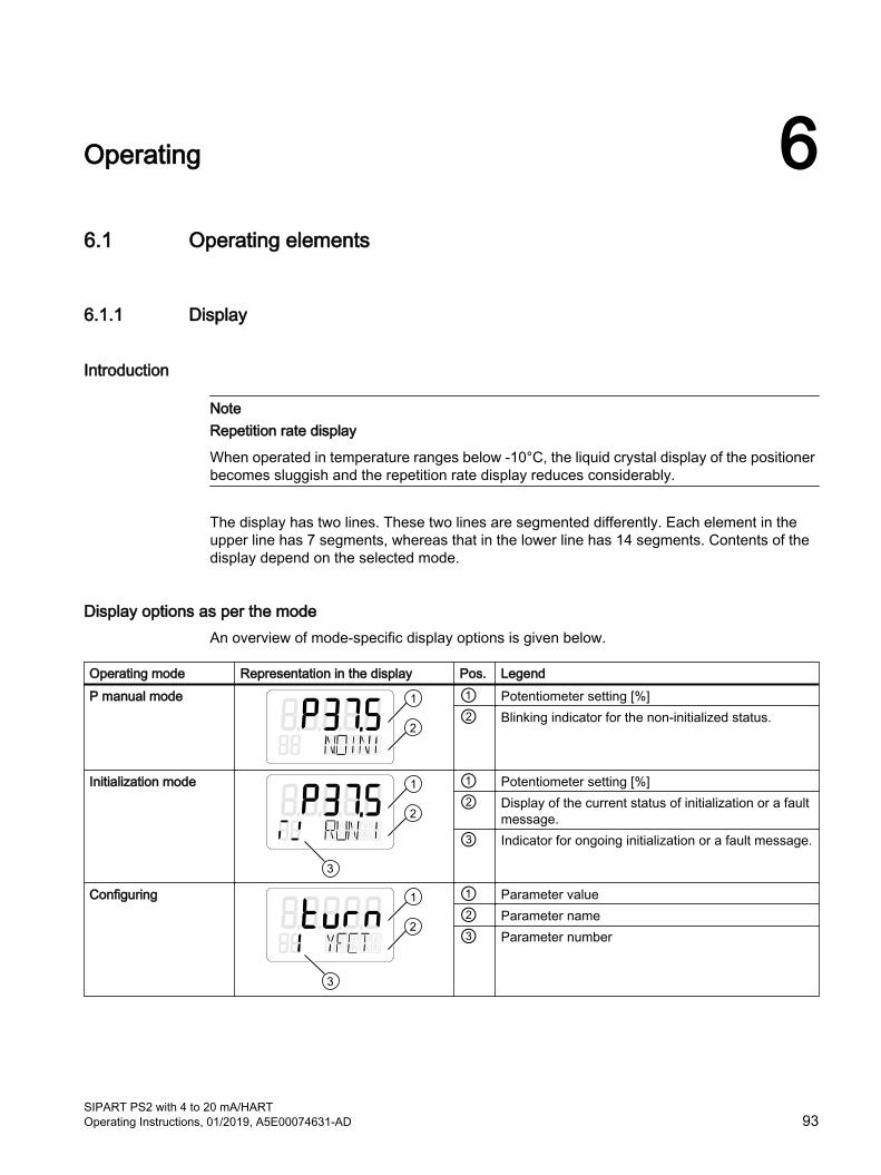
Operating 66.1 Operating elements
6.1.1 Display
Introduction
NoteRepetition rate display
When operated in temperature ranges below -10°C, the liquid crystal display of the positioner becomes sluggish and the repetition rate display reduces considerably.
The display has two lines. These two lines are segmented differently. Each element in the upper line has 7 segments, whereas that in the lower line has 14 segments. Contents of the display depend on the selected mode.
Display options as per the modeAn overview of mode-specific display options is given below.
Operating mode Representation in the display Pos. LegendP manual mode ① Potentiometer setting [%]
② Blinking indicator for the non-initialized status.
Initialization mode ① Potentiometer setting [%]② Display of the current status of initialization or a fault
message.③ Indicator for ongoing initialization or a fault message.
Configuring ① Parameter value② Parameter name③ Parameter number
SIPART PS2 with 4 to 20 mA/HARTOperating Instructions, 01/2019, A5E00074631-AD 93
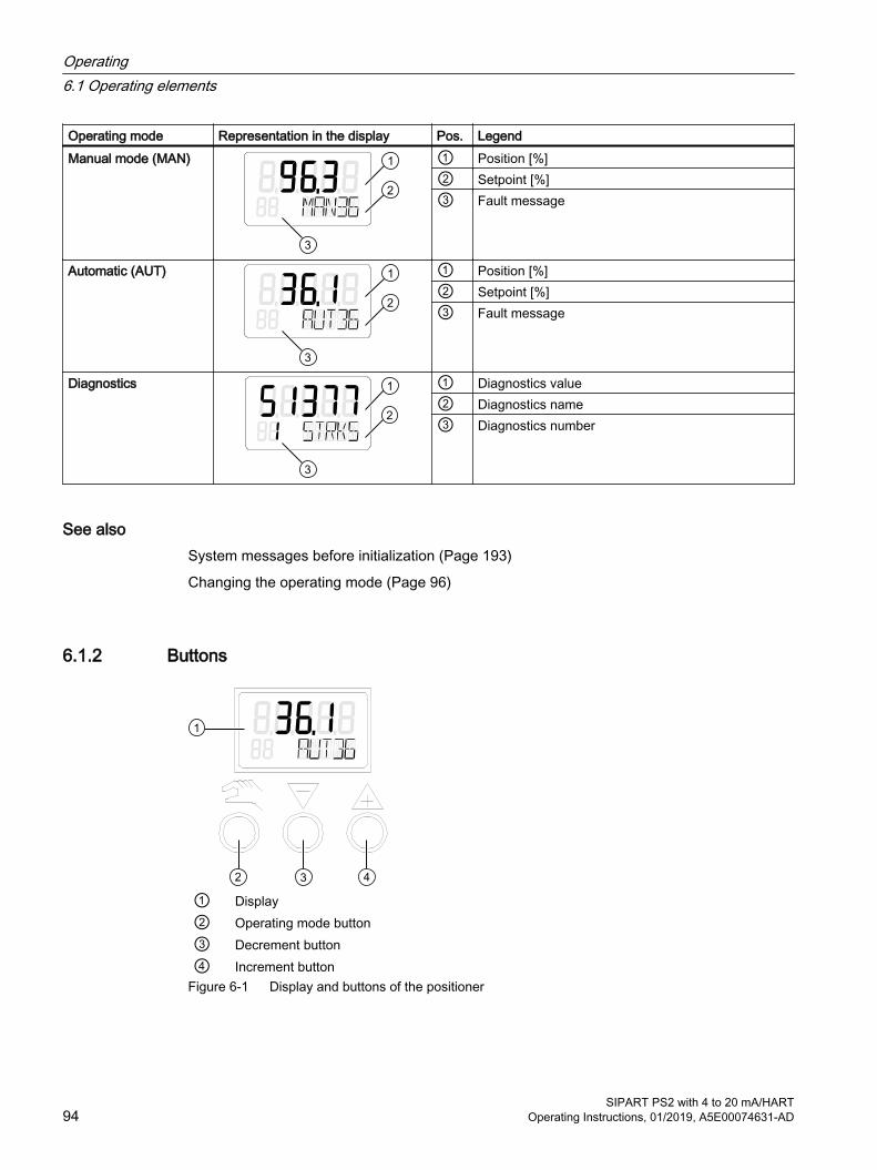
Operating mode Representation in the display Pos. LegendManual mode (MAN) ① Position [%]
② Setpoint [%]③ Fault message
Automatic (AUT) ① Position [%]② Setpoint [%]③ Fault message
Diagnostics ① Diagnostics value② Diagnostics name③ Diagnostics number
See alsoSystem messages before initialization (Page 193)
Changing the operating mode (Page 96)
6.1.2 Buttons
① Display② Operating mode button③ Decrement button④ Increment button
Figure 6-1 Display and buttons of the positioner
Operating6.1 Operating elements
SIPART PS2 with 4 to 20 mA/HART94 Operating Instructions, 01/2019, A5E00074631-AD

● You can use three buttons to operate the positioner.
● The function of the buttons depends on the mode selected.
● In a positioner with a flameproof enclosure, the buttons are protected by a cover. The button cover can be opened after unlatching the locking screw.
NoteButton cover
In positioners with flameproof enclosures, the button cover prevents liquids from seeping through. The IP66 / type 4X degree of protection is not ensured when the enclosure or the button cover is open.
You have to remove the enclosure cover to operate the buttons of the basic device or the "intrinsically safe" version.
NoteDegree of protection
The IP66 / type 4X degree of protection is not ensured as long as the positioner is open.
Function of buttons:
● The button is used to select the modes and to forward the parameters.
● The button is used to select parameter values in "Configuration" mode. You can use this button to move the actuator in "Manual" mode.
● The button is also used to select parameter values in "Configuration" mode. You can use this button to move the actuator in "Manual" mode.
NoteOrder
Parameters are activated in the reverse order when the and buttons are pressed simultaneously.
6.1.3 Firmware version The current firmware version is displayed when you exit the operating mode "Configuration".
Figure 6-2 Firmware version, example
Operating6.1 Operating elements
SIPART PS2 with 4 to 20 mA/HARTOperating Instructions, 01/2019, A5E00074631-AD 95
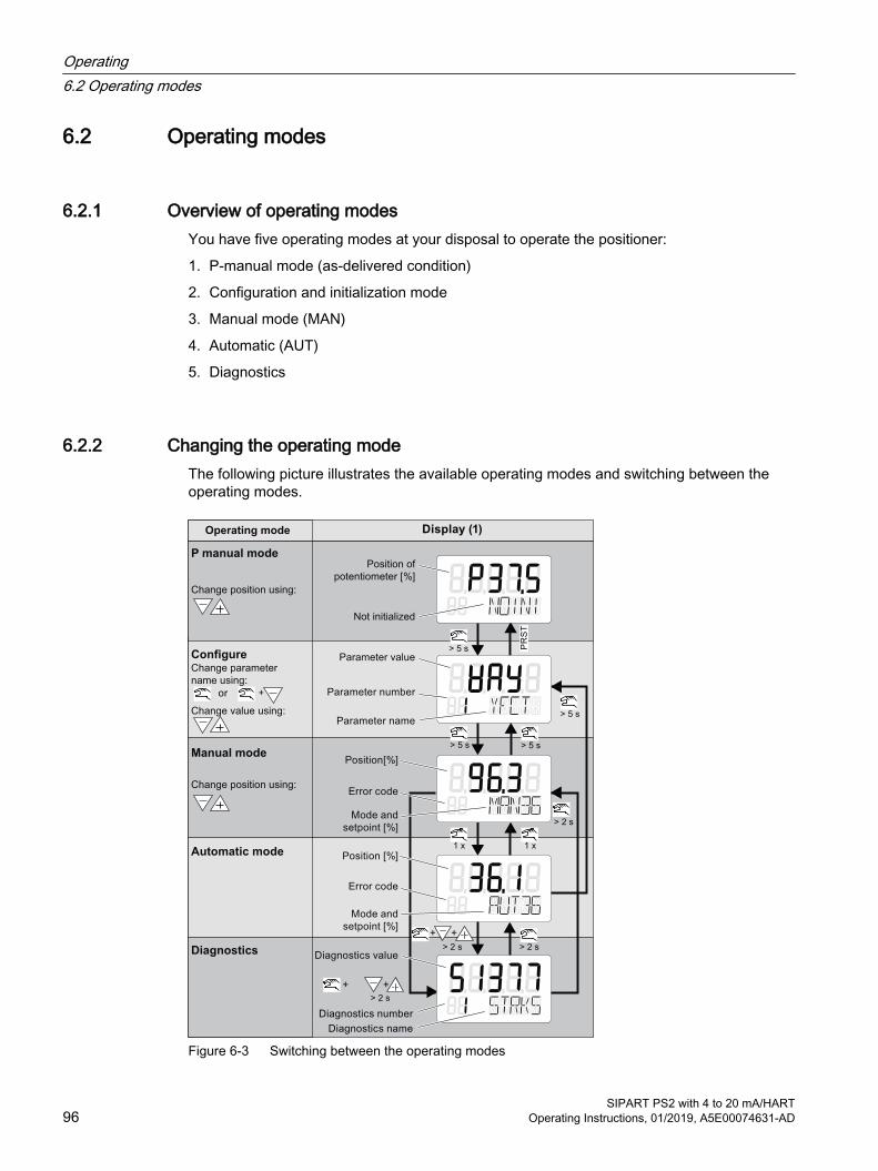
6.2 Operating modes
6.2.1 Overview of operating modesYou have five operating modes at your disposal to operate the positioner:
1. P-manual mode (as-delivered condition)
2. Configuration and initialization mode
3. Manual mode (MAN)
4. Automatic (AUT)
5. Diagnostics
6.2.2 Changing the operating modeThe following picture illustrates the available operating modes and switching between the operating modes.
+ +
+ +
> 5 s
> 5 s
> 5 s
> 5 s
> 2 s
> 2 s > 2 s
> 2 s
1 x 1 x
PR
ST
+
Operating mode Display (1)
P manual mode
Change position using:
Change position using:
ConfigureChange parameter
name using:
or
Change value using:
Position of
potentiometer [%]
Not initialized
Parameter value
Parameter number
Parameter name
Manual mode
Automatic mode
Diagnostics
Position[%]
Error code
Mode and
setpoint [%]
Position [%]
Error code
Mode and
setpoint [%]
Diagnostics value
Diagnostics number
Diagnostics name
Figure 6-3 Switching between the operating modes
Operating6.2 Operating modes
SIPART PS2 with 4 to 20 mA/HART96 Operating Instructions, 01/2019, A5E00074631-AD

See alsoDisplay (Page 93)
6.2.3 Overview of configurationThe following picture illustrates the handling of operating modes such as "Configuration" and "Initialization mode":
Figure 6-4 Overview of the "Configuration" operating mode
6.2.4 Description of operating modes
P manual mode
NoteDelivery state
The "P manual mode" is preset for the positioner in the delivery state.
The display of the positioner shows the current potentiometer position in the upper line. "NOINI" blinks in the second line of the display.
Move to the actuator with the or buttons.
Switch to "Configuration" mode to adapt the actuator to the positioner.
Alarms or position feedbacks can be triggered after initializing the positioner completely.
Operating6.2 Operating modes
SIPART PS2 with 4 to 20 mA/HARTOperating Instructions, 01/2019, A5E00074631-AD 97

Configuration and initializationTo get to the "Configuration" mode, press the button for at least 5 seconds.
You can use the "Configuration" mode to adjust the positioner individually as per your actuator and start commissioning or initialization.
The positioner reports the "Configuration" mode with a configurable fault message. A position feedback or display of limits A1 and A2 is not possible.
NoteFailure of electrical auxiliary power
If electrical auxiliary power supply fails when configuring, the positioner responds as follows when the power supply is reestablished:● The positioner switches to the first parameter.● Settings of the values already configured are retained.
In order to save the changed parameter values, exit the "Configuration" mode or switch to another parameter. When "Configuration" mode is restarted, the output in the display switches to the last activated parameter.
Manual mode (MAN)In this mode, you move the actuator with or . The setting selected here is retained irrespective of the setpoint current and leakages, if any.
NoteAccelerating the actuator movement
Proceed as follows if you wish to accelerate the actuator movement:1. Keep one of the two direction buttons pressed.2. Press the remaining direction button simultaneously.
NoteFailure of power supply
When the power supply is reestablished after a failure, the positioner switches to the "Automatic" mode.
Automatic (AUT)Automatic is the standard mode. In this mode, the positioner compares the setpoint position with the actual position. The positioner moves the actuator until the control deviation reaches the configurable deadband. An error message is displayed if the deadband cannot be reached.
DiagnosticsProceed as follows to call the "Diagnostics" mode from the "Automatic" or "Manual" modes:
Operating6.2 Operating modes
SIPART PS2 with 4 to 20 mA/HART98 Operating Instructions, 01/2019, A5E00074631-AD
Press the three buttons of the positioner at the same time for at least 2 seconds.
Current operating data can be called and displayed in this mode, e.g.:
● Number of total strokes
● Number of changes in direction
● Number of fault messages
NoteSetting the mode
The "Automatic" and "Manual" modes remain set when switching to the "Diagnostics" mode. The positioner responds as per the configured mode:● The predefined setpoint is used as the control variable in "Automatic" mode.● The last reached position is retained in "Manual" mode.
See alsoOverview (Page 105)
Overview of advanced diagnostic parameters A to U (Page 141)
Overview of diagnostics values (Page 199)
6.2.5 Optimization of controller data
NoteInitializing
Initialize the positioner automatically before changing the parameter settings as per your specific requirements.
The positioner determines the data for control quality automatically during the initialization process.
The data determined is optimized for a short transient time in the case of minor overshoots.
The adjustment can be accelerated or the attenuation can be intensified by optimizing the data.
The following special cases are suitable for targeted data optimization:
● Small actuators with travel times < 1 s.
● Operation with boosters, described in section "Booster commissioning (Page 305)"
Procedure1. Switch to "Diagnostics" mode.
2. Select the diagnostics parameters.
Operating6.2 Operating modes
SIPART PS2 with 4 to 20 mA/HARTOperating Instructions, 01/2019, A5E00074631-AD 99

3. Press the three buttons of the positioner at the same time for at least 2 seconds.
4. Activate the setting function. Press the or button for at least 5 seconds.
The modified diagnostics values are effective immediately. The effects on the controller results can then be tested.
In order to optimize the controller data, change the values of the diagnostics parameters listed below.
Diagnostics parameters '23.IMPUP' Impulse length UP / '24.IMPDN' Impulse length DOWNYou can use these diagnostics parameters to determine the smallest impulse lengths for each actuating direction. The actuator is then moved with these lengths. The optimum value depends in particular on the volume of the actuator. Small values lead to small controller increments and frequent activation of the actuator. Large values are advantageous for large actuator volumes.
NoteController increments● There is no movement if the values are too small.● Large controller increments also lead to large movements with small actuators.
Diagnostics parameters '28.SSUP' Slow step zone UP / '29.SSDN' Slow step zone DOWNThe slow step zone is the area of mean control deviation. For more information on the slow step zone, refer to the section "Mode of operation (Page 28)".
Select small values to achieve high speeds of shifting even with small control deviations. Select large values to reduce overshoots particularly in case of large changes in the setpoint.
NOTICE
Overshoots or too low speeds of shifting
Too small values can result in overshoots. ● Enter a higher value.
Too large values result in too slow speeds of shifting near the adjusted status.● Enter a smaller value.
Operating6.2 Operating modes
SIPART PS2 with 4 to 20 mA/HART100 Operating Instructions, 01/2019, A5E00074631-AD
Diagnostics parameters '47.PRUP' Prediction UP / '48.PRDN' Prediction DOWNThese diagnostics parameters act as attenuation factors and are used to set the control dynamics. Changes in the diagnostics values have the following results:
● Small values result in quick adjustments with overshoots.
● Large values result in slow adjustments without overshoots.
NoteReference variable
It is advantageous to use a fixed reference variable to optimize the control data. Therefore, change the deadband of the controller in the '34.DEBA' parameter from "Auto" to a fixed value.
Operating6.2 Operating modes
SIPART PS2 with 4 to 20 mA/HARTOperating Instructions, 01/2019, A5E00074631-AD 101

Operating6.2 Operating modes
SIPART PS2 with 4 to 20 mA/HART102 Operating Instructions, 01/2019, A5E00074631-AD
Commissioning 77.1 Basic safety instructions
WARNING
Lever for position detection
Danger of crushing and shearing with mounting kits which use a lever for position detection. During commissioning and ongoing operation, severing or squeezing of limbs could occur as a result of the lever. Risk of injury when working on control valves due to the high operating force of the pneumatic actuator.● Do not reach into the range of motion of the lever following mounting of the positioner and
mounting kit.
WARNING
Improper commissioning in hazardous areas
Device failure or risk of explosion in hazardous areas.● Do not commission the device until it has been mounted completely and connected in
accordance with the information in Technical data (Page 237).● Before commissioning take the effect on other devices in the system into account.
WARNING
Loss of explosion protection
Risk of explosion in hazardous areas if the device is open or not properly closed.● Close the device as described in Installing and mounting (Page 35).
WARNING
Opening device in energized state
Risk of explosion in hazardous areas● Only open the device in a de-energized state.● Check prior to commissioning that the cover, cover locks, and cable inlets are assembled
in accordance with the directives.
Exception: Devices having the type of protection "Intrinsic safety Ex i" may also be opened in energized state in hazardous areas.
SIPART PS2 with 4 to 20 mA/HARTOperating Instructions, 01/2019, A5E00074631-AD 103
WARNING
Water in compressed air line
Device damage and possibly loss of type of protection. The factory setting for the purging air selector is "IN". In the "IN" position, water from the compressed air line may enter the device from the pneumatics during initial commissioning.● Before commissioning, make sure that no water is present in the compressed air line.
If you cannot be sure that there is no water in the compressed air line:● Set the purging air selector to "OUT". In this way, you prevent water from the compressed
air line from penetrating the device.● Only set the purging air selector to "IN" again when all water has been discharged from the
compressed air line.
CAUTION
Loss of type of protection
Damage to device if the enclosure is open or not properly closed. The type of protection specified on the nameplate or in Technical data (Page 237) is no longer guaranteed.● Make sure that the device is securely closed.
WARNING
Commissioning and operation with pending error
If an error message appears, correct operation in the process is no longer guaranteed.● Check the gravity of the error.● Correct the error.● If the error still exists:
– Take the device out of operation.– Prevent renewed commissioning.
CAUTION
Increased sound pressure level
Changes to the sound absorber of the positioner or the mounting of pneumatic components or pneumatic options on the positioner can cause a sound pressure with a level of 80 dBA to be exceeded.● Wear suitable hearing protection to protect yourself against hearing damage.
Commissioning7.1 Basic safety instructions
SIPART PS2 with 4 to 20 mA/HART104 Operating Instructions, 01/2019, A5E00074631-AD
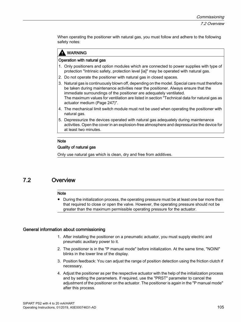
When operating the positioner with natural gas, you must follow and adhere to the following safety notes:
WARNING
Operation with natural gas 1. Only positioners and option modules which are connected to power supplies with type of
protection "Intrinsic safety, protection level [ia]" may be operated with natural gas.2. Do not operate the positioner with natural gas in closed spaces.3. Natural gas is continuously blown off, depending on the model. Special care must therefore
be taken during maintenance activities near the positioner. Always ensure that the immediate surroundings of the positioner are adequately ventilated.The maximum values for ventilation are listed in section "Technical data for natural gas as actuator medium (Page 247)".
4. The mechanical limit switch module must not be used when operating the positioner with natural gas.
5. Depressurize the devices operated with natural gas adequately during maintenance activities. Open the cover in an explosion-free atmosphere and depressurize the device for at least two minutes.
NoteQuality of natural gas
Only use natural gas which is clean, dry and free from additives.
7.2 Overview
Note● During the initialization process, the operating pressure must be at least one bar more than
that required to close or open the valve. However, the operating pressure should not be greater than the maximum permissible operating pressure for the actuator.
General information about commissioning1. After installing the positioner on a pneumatic actuator, you must supply electric and
pneumatic auxiliary power to it.
2. The positioner is in the "P manual mode" before initialization. At the same time, "NOINI" blinks in the lower line of the display.
3. Position feedback: You can adjust the range of position detection using the friction clutch if necessary.
4. Adjust the positioner as per the respective actuator with the help of the initialization process and by setting the parameters. If required, use the "PRST" parameter to cancel the adjustment of the positioner on the actuator. The positioner is again in the "P manual mode" after this process.
Commissioning7.2 Overview
SIPART PS2 with 4 to 20 mA/HARTOperating Instructions, 01/2019, A5E00074631-AD 105

Types of initializationYou can initialize the positioner as follows:
● Automatic initialization:during automatic initialization, the positioner determines the following one after the other:
– The direction of action
– The actuator travel and angle of rotation
– The travel time of the actuator
The positioner also adjusts the control parameters as per the dynamic response of the actuator.
● Manual initialization:the actuator travel and the angle of rotation of the actuator are set manually. The remaining parameters are automatically determined. This function is useful for valves which are lined, for example, with PTFE.
● Copying the initialization data when replacing a positioner:the initialization data of a positioner can be read and copied into another positioner. A defective device can thus be replaced without interrupting an ongoing process through initialization.
You have to define a few parameters for the positioner before initialization. Owing to the preset values, you cannot adjust further parameters for initialization.
You can use a suitably configured and activated binary input to protect the configured settings against accidental adjustment.
See alsoOverview of operating modes (Page 96)
Commissioning7.2 Overview
SIPART PS2 with 4 to 20 mA/HART106 Operating Instructions, 01/2019, A5E00074631-AD

7.3 Sequence of automatic initialization
OverviewThe automatic initialization takes place in the following phases:
Automatic initialization phase DescriptionStart -RUN 1 Establishing the direction of action.RUN 2 Checking the actuator travel and trimming the lower and
upper endstops.RUN 3 Establishing and displaying the travel time (leakage test)RUN 4 Minimization of controller incrementsRUN 5 Optimization of the transient responseEnd -
The following structured charts describe the sequence of initialization. The "Up/Down" names indicate the direction of action of actuators.
Linear actuator Part-turn actuator
Open Closed Closed Open
Commissioning7.3 Sequence of automatic initialization
SIPART PS2 with 4 to 20 mA/HARTOperating Instructions, 01/2019, A5E00074631-AD 107
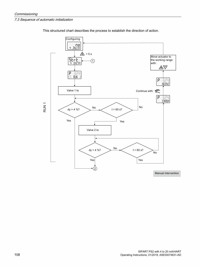
This structured chart describes the process to establish the direction of action.
RU
N 1
Commissioning7.3 Sequence of automatic initialization
SIPART PS2 with 4 to 20 mA/HART108 Operating Instructions, 01/2019, A5E00074631-AD

This structured chart describes the process to determine the actuator travel checks. It also contains information about the sequence for trimming the lower and upper endstops.
Commissioning7.3 Sequence of automatic initialization
SIPART PS2 with 4 to 20 mA/HARTOperating Instructions, 01/2019, A5E00074631-AD 109
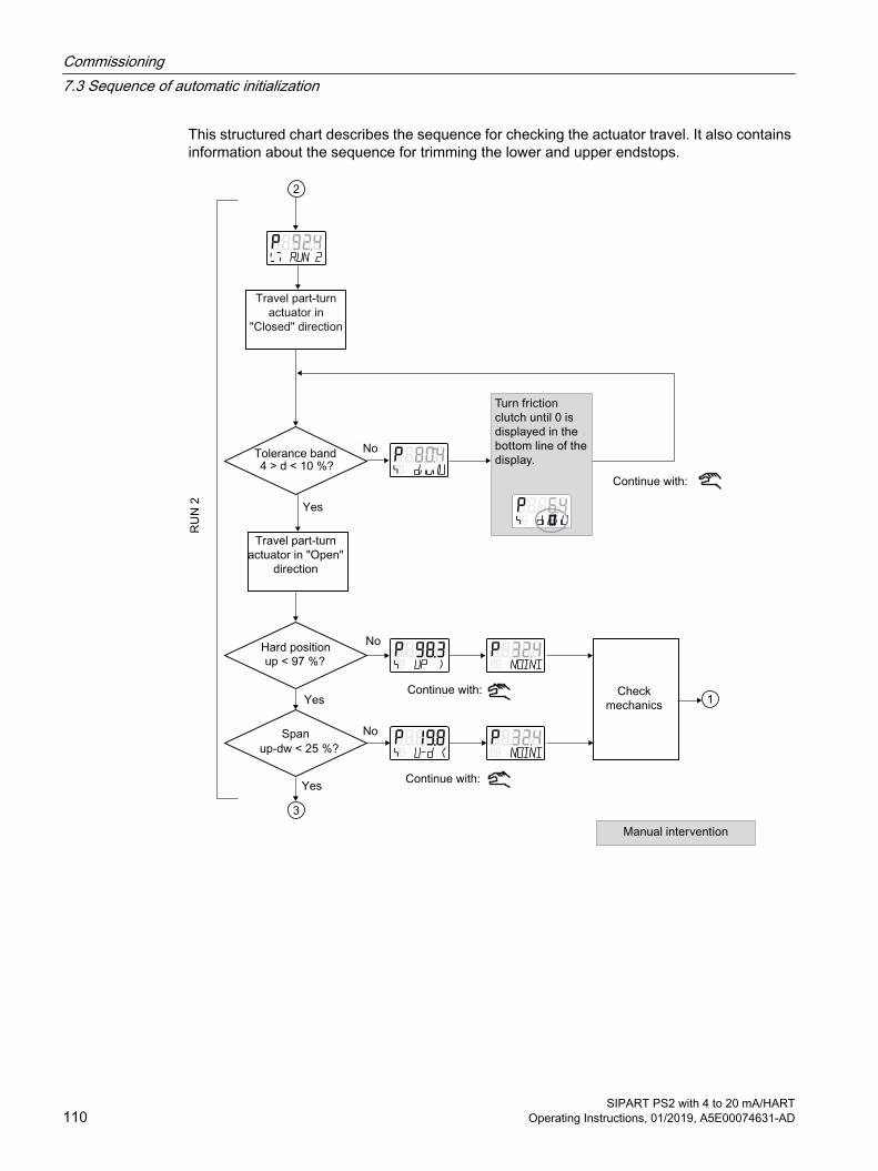
This structured chart describes the sequence for checking the actuator travel. It also contains information about the sequence for trimming the lower and upper endstops.
Commissioning7.3 Sequence of automatic initialization
SIPART PS2 with 4 to 20 mA/HART110 Operating Instructions, 01/2019, A5E00074631-AD
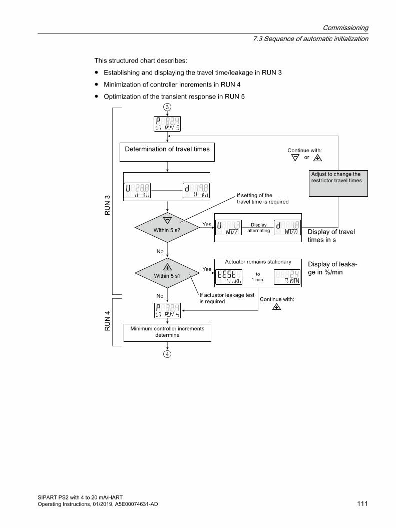
This structured chart describes:
● Establishing and displaying the travel time/leakage in RUN 3
● Minimization of controller increments in RUN 4
● Optimization of the transient response in RUN 5
Commissioning7.3 Sequence of automatic initialization
SIPART PS2 with 4 to 20 mA/HARTOperating Instructions, 01/2019, A5E00074631-AD 111
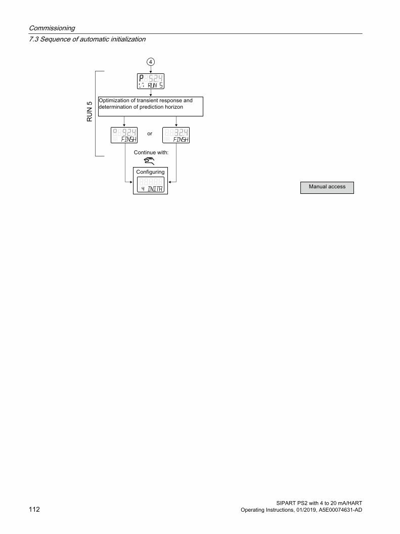
Commissioning7.3 Sequence of automatic initialization
SIPART PS2 with 4 to 20 mA/HART112 Operating Instructions, 01/2019, A5E00074631-AD

7.4 Setting the friction clutch
IntroductionIt has a friction clutch and a switchable gear (Page 47) so that the positioner can be used with different mechanical part-turn and linear actuators. Use the friction clutch to adjust the position detection area. For positioners in non-flameproof enclosures, you also have the option of locking the friction clutch.
Requirement● The positioner is mounted.
Procedure
In non-flameproof enclosure In flameproof enclosure Ex d
1. Adjust the working area to your application by turning the adjustment wheel of the friction clutch ①.
2. Fasten the friction clutch. Insert a standard approx. 4 mm wide screwdriver in the friction clutch gear latch ②.
3. Use the screwdriver to turn the friction clutch gear latch ② counterclockwise ③ until it engages. The friction clutch ① is locked.
1. With the positioner in the flameproof enclosure, the friction clutch is on the outside of the device. Attach a pin to the friction clutch ①.
2. Adjust the working area to your application by turning the adjustment wheel of the friction clutch ①.
Note:● It is not possible to lock the friction clutch.● Do not open the screws on the friction clutch.
Commissioning7.4 Setting the friction clutch
SIPART PS2 with 4 to 20 mA/HARTOperating Instructions, 01/2019, A5E00074631-AD 113

7.5 Purge air switchingWhen the enclosure is open, the purge air switch above the pneumatic terminal strip on the pneumatic block can be accessed.
● In the IN position, the enclosure is flushed from inside with a small volume of clean and dry instrument air.
● In the OUT position, the purge air is directly directed towards outside.
① Purging air selector② Pneumatic connections Y1, PZ and Y2
Figure 7-1 Purge air switch on the pneumatic block; view of the positioner on the pneumatic connection side when the cover is open
The factory setting is the "IN" position.
7.6 Commissioning linear actuators
7.6.1 Preparing linear actuators for commissioning
RequirementsYou have already installed the positioner using the suitable mounting kit.
Setting the transmission ratio selector
NoteCommissioning
The setting of the transmission ratio selector is extremely important to commission the positioner.
Stroke [mm] Position of the transmission ratio selector5 ... 20 33°25 ... 35 90°40 ... 130 90°
Commissioning7.6 Commissioning linear actuators
SIPART PS2 with 4 to 20 mA/HART114 Operating Instructions, 01/2019, A5E00074631-AD

Connecting the positioner1. Connect a suitable current or voltage source. The positioner is now in "P manual mode". The
current potentiometer voltage (P) in percent is shown in the upper line of the display, e.g.: 'P37.5', and 'NOINI' flashes in the bottom line:
2. Connect the actuator and the positioner to the pneumatic lines.
3. Supply the pneumatic auxiliary power to the positioner.
Setting the actuator1. Check whether the mechanical unit can be moved freely in the entire travel range. Move the
actuator to the respective end position for this purpose using the or button.
NoteEnd position
By simultaneously pressing the and buttons, you reach the end position faster.
2. Now move the actuator to the horizontal position of the lever.
3. A value between 'P48.0' and 'P52.0' is shown on the display.
4. If a value beyond this value range is shown on the display, you must move the friction clutch. Move the friction clutch until a value between 'P48.0' and 'P52.0' is reached. The closer this value is to 'P50.0', the more accurately the positioner determines the stroke travel.
NoteFor device versions with flameproof enclosure
The inner friction clutch is fixed. Therefore, only move the outer friction clutch. This also applies when using an internal NCS module.The following applies to device versions without flameproof enclosure with internal NCS module 6DR4004-5L.:
The inner friction clutch has no function. This means you should only adjust the adjustment wheel of the magnet clamp; see section "Internal NCS module (iNCS) 6DR4004-5L/-5LE (Page 66)". Requirement: The '1.YFCT' type of actuator (Page 145) parameter is set.
See alsoMounting to linear actuator (Page 39)
Opening the device version with "flameproof enclosure" (Page 53)
Commissioning7.6 Commissioning linear actuators
SIPART PS2 with 4 to 20 mA/HARTOperating Instructions, 01/2019, A5E00074631-AD 115

7.6.2 Automatic initialization of linear actuators
RequirementsThe following conditions must be fulfilled before activating the automatic initialization:
1. The actuator spindle can be moved completely.
2. The actuator spindle is at a central position after moving.
Initializing the linear actuator automatically
NoteInterrupting initialization
An ongoing initialization can be interrupted at any time. To do this, press . The settings configured until then are retained.
All parameters are reset to factory settings only if you have explicitly activated the preset settings in the "PRST" parameter.
1. Switch to the "Configuration" mode. To do this, keep the button pressed for at least 5 seconds. The display shows the following:
2. Call the "2.YAGL" parameter. To do this, press . The following is shown on the display depending on the setting:
3. Check whether the value displayed in the "2.YAGL" parameter matches the setting of the transmission ratio selector. If required, change the setting of the transmission ratio selector to 33° or 90°.
Commissioning7.6 Commissioning linear actuators
SIPART PS2 with 4 to 20 mA/HART116 Operating Instructions, 01/2019, A5E00074631-AD

4. Set the "3.YWAY" parameter to determine the total stroke in mm. The setting of parameter 3 is optional. The display shows the determined total stroke only at the end of the initialization phase.
– Press the button if you do not require any information about the total stroke in mm. You are then directed to parameter 4.
– Call the "3.YWAY" parameter. To do this, press . The display shows the following:
NoteSet the "3.YWAY" parameter
Proceed as follows to set parameter 3:1. On the scale of the lever, read the value marked by the carrier pin.2. Set the parameter with the buttons and to the read value.
5. Call the "4.INITA" parameter. To do this, briefly press the button. The display shows the following:
6. Start the initialization process. To do this, keep the button pressed for at least 5 seconds until the display shows the following:
The positioner runs through five initialization steps during the automatic initialization process. Displays for the initialization steps from "RUN 1" to "RUN 5" are shown in the lower line on the display. The initialization process depends on the actuator used, and takes up to 15 minutes.
7. The following display indicates that the automatic initialization is complete:
See alsoSequence of automatic initialization (Page 107)
Commissioning7.6 Commissioning linear actuators
SIPART PS2 with 4 to 20 mA/HARTOperating Instructions, 01/2019, A5E00074631-AD 117
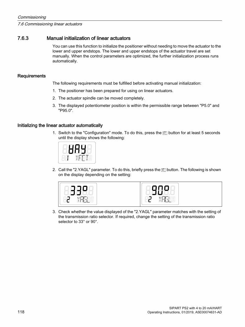
7.6.3 Manual initialization of linear actuatorsYou can use this function to initialize the positioner without needing to move the actuator to the lower and upper endstops. The lower and upper endstops of the actuator travel are set manually. When the control parameters are optimized, the further initialization process runs automatically.
RequirementsThe following requirements must be fulfilled before activating manual initialization:
1. The positioner has been prepared for using on linear actuators.
2. The actuator spindle can be moved completely.
3. The displayed potentiometer position is within the permissible range between "P5.0" and "P95.0".
Initializing the linear actuator automatically1. Switch to the "Configuration" mode. To do this, press the button for at least 5 seconds
until the display shows the following:
2. Call the "2.YAGL" parameter. To do this, briefly press the button. The following is shown on the display depending on the setting:
3. Check whether the value displayed of the "2.YAGL" parameter matches with the setting of the transmission ratio selector. If required, change the setting of the transmission ratio selector to 33° or 90°.
Commissioning7.6 Commissioning linear actuators
SIPART PS2 with 4 to 20 mA/HART118 Operating Instructions, 01/2019, A5E00074631-AD

4. Set the "3.YWAY" parameter to determine the total stroke in mm. The setting of the "3.YWAY" parameter is optional. The display shows the determined total stroke only at the end of the initialization phase.
– Briefly press the button if you do not require any information about the total stroke in mm. You are then directed to parameter 4.
– Call the "3.YWAY" parameter. To do this, briefly press the button. The display shows the following:
NoteSet the "3.YWAY" parameter
To set the "3.YWAY" parameter proceed as follows:1. On the scale of the lever, read the value marked by the carrier pin.2. Set the parameter to the read value with the or button.
5. Call the "5.INITM" parameter. To do this, press the button twice. The display shows the following:
6. Start the initialization process. To do this, press the button for at least 5 seconds until the display shows the following:
The current potentiometer position is output on the display after 5 seconds. Examples of the displayed potentiometer positions are given below:
7. Determine the lower endstop of the actuator spindle.
8. Move the actuator to the desired position using the or button.
Commissioning7.6 Commissioning linear actuators
SIPART PS2 with 4 to 20 mA/HARTOperating Instructions, 01/2019, A5E00074631-AD 119
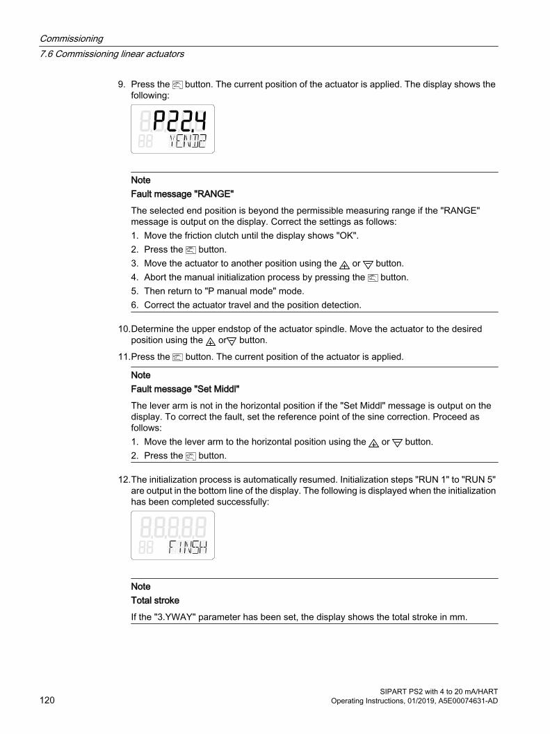
9. Press the button. The current position of the actuator is applied. The display shows the following:
NoteFault message "RANGE"
The selected end position is beyond the permissible measuring range if the "RANGE" message is output on the display. Correct the settings as follows:1. Move the friction clutch until the display shows "OK".2. Press the button.3. Move the actuator to another position using the or button.4. Abort the manual initialization process by pressing the button.5. Then return to "P manual mode" mode.6. Correct the actuator travel and the position detection.
10.Determine the upper endstop of the actuator spindle. Move the actuator to the desired position using the or button.
11.Press the button. The current position of the actuator is applied.
NoteFault message "Set Middl"
The lever arm is not in the horizontal position if the "Set Middl" message is output on the display. To correct the fault, set the reference point of the sine correction. Proceed as follows:1. Move the lever arm to the horizontal position using the or button.2. Press the button.
12.The initialization process is automatically resumed. Initialization steps "RUN 1" to "RUN 5" are output in the bottom line of the display. The following is displayed when the initialization has been completed successfully:
NoteTotal stroke
If the "3.YWAY" parameter has been set, the display shows the total stroke in mm.
Commissioning7.6 Commissioning linear actuators
SIPART PS2 with 4 to 20 mA/HART120 Operating Instructions, 01/2019, A5E00074631-AD

7.7 Commissioning part-turn actuators
7.7.1 Preparing part-turn actuators for commissioning
NoteSetting of the adjustment angle
The usual adjustment angle for part-turn actuators is 90°.● Set the transmission ratio selector in the positioner to 90°.
RequirementsThe following conditions must be fulfilled before activating the initialization:
1. You have installed the positioner for the part-turn actuators using the suitable mounting kit.
2. You have connected the actuator and the positioner to the pneumatic lines.
3. Pneumatic auxiliary power is supplied to the positioner.
4. The positioner has been connected to a suitable power supply.
Setting the actuator1. The positioner is in the "P manual mode". The current potentiometer voltage P in percent is
shown on the upper line in the display. "NOINI" blinks in the lower line of the display. Examples of corresponding displays are given below:
2. Check whether the mechanical unit can be moved freely in the entire travel range. Move the drive to the respective end position for this purpose using the or button.
NoteEnd position
By simultaneously pressing the and buttons, you reach the end position faster.
3. After checking, move the actuator to a central position. This accelerates the initialization process.
Commissioning7.7 Commissioning part-turn actuators
SIPART PS2 with 4 to 20 mA/HARTOperating Instructions, 01/2019, A5E00074631-AD 121
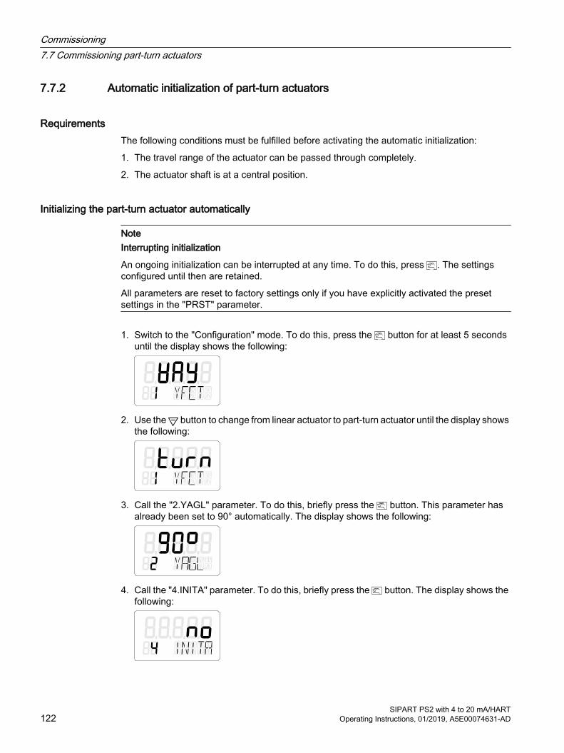
7.7.2 Automatic initialization of part-turn actuators
RequirementsThe following conditions must be fulfilled before activating the automatic initialization:
1. The travel range of the actuator can be passed through completely.
2. The actuator shaft is at a central position.
Initializing the part-turn actuator automatically
NoteInterrupting initialization
An ongoing initialization can be interrupted at any time. To do this, press . The settings configured until then are retained.
All parameters are reset to factory settings only if you have explicitly activated the preset settings in the "PRST" parameter.
1. Switch to the "Configuration" mode. To do this, press the button for at least 5 seconds until the display shows the following:
2. Use the button to change from linear actuator to part-turn actuator until the display shows the following:
3. Call the "2.YAGL" parameter. To do this, briefly press the button. This parameter has already been set to 90° automatically. The display shows the following:
4. Call the "4.INITA" parameter. To do this, briefly press the button. The display shows the following:
Commissioning7.7 Commissioning part-turn actuators
SIPART PS2 with 4 to 20 mA/HART122 Operating Instructions, 01/2019, A5E00074631-AD

5. Start the initialization process. To do this, press the button for at least 5 seconds until the display shows the following:
The positioner runs through five initialization steps during the automatic initialization process. Displays for the initialization steps from "RUN 1" to "RUN 5" are shown in the lower line on the display. The initialization process depends on the actuator used, and takes up to 15 minutes.
6. The following display indicates that the automatic initialization is complete. The total angle of rotation of the actuator is shown on the upper line on the display:
See alsoSequence of automatic initialization (Page 107)
7.7.3 Manual initialization of part-turn actuatorsYou can use this function to initialize the positioner without needing to move the actuator to the lower and upper endstops. The lower and upper endstops of the actuator travel are set manually. When the control parameters are optimized, the further initialization process runs automatically.
RequirementsThe following requirements must be fulfilled before activating manual initialization:
1. The positioner has been prepared for using on part-turn actuators.
2. The actuator can be moved completely.
3. The displayed potentiometer position is within the permissible range between "P5.0" and "P95.0".
NoteSetting of the adjustment angle
The usual adjustment angle for part-turn actuators is 90°. Accordingly set the transmission ratio selector in the positioner to 90°.
Commissioning7.7 Commissioning part-turn actuators
SIPART PS2 with 4 to 20 mA/HARTOperating Instructions, 01/2019, A5E00074631-AD 123

Initializing the positioner manually1. Switch to the "Configuration" mode. To do this, press the button for at least 5 seconds
until the display shows the following:
2. Set the "YFCT" parameter to "turn". To do this, press . The display shows the following:
3. Call the second parameter "YAGL". To do this, press . The display shows the following:
4. Call the "INITM" parameter. To do this, press the button twice. The display shows the following:
5. Start the initialization process. Press the button for at least 5 seconds until the display shows the following:
6. The current potentiometer position is output on the display after 5 seconds:
7. Determine the lower endstop of the actuator.
8. Move the actuator to the desired position using the or button.
Commissioning7.7 Commissioning part-turn actuators
SIPART PS2 with 4 to 20 mA/HART124 Operating Instructions, 01/2019, A5E00074631-AD

9. Press the button. The current position of the actuator is applied. The display shows the following:
NoteFault message "RANGE"
The selected end position is beyond the permissible measuring range if the "RANGE" message is output on the display. Correct the settings as follows: 1. Move the friction clutch until the display shows "OK".2. Press the button.3. Move the actuator to another position using the or button.4. Abort the manual initialization process by pressing the button.5. Then return to "P manual mode".6. Correct the actuator travel and the position detection.
10.Determine the upper endstop of the actuator. Move the actuator to the desired position using the or button.
11.Press the button. The current position of the actuator is applied.
12.The initialization process is automatically resumed. Initialization steps "RUN 1" to "RUN 5" are output in the bottom line of the display. The following display indicates that the initialization has been completed successfully:
7.8 Canceling initialization1. Press the button.
– Canceling automatic initialization: the display shows "INITA".
– Canceling manual initialization: the display shows "INITM".
The positioner is in the "Configuration" mode.
2. Exit the "Configuration" mode. To do this, press the button for at least 5 seconds.The software version is displayed.After releasing the button, the positioner is in "P manual mode". The positioner is not initialized.
Commissioning7.8 Canceling initialization
SIPART PS2 with 4 to 20 mA/HARTOperating Instructions, 01/2019, A5E00074631-AD 125
7.9 Device replacement
Introduction
NoteInitialization
The positioner can be replaced without having to interrupt ongoing processes. However, copying and transferring of the initialization parameters only allows an approximate adjustment of the positioner to your actuator. Following initialization, the positioner initially works with the manually defined parameters.● For this reason, an automatic or manual initialization should be carried out as soon as
possible.
NoteDeferred initialization
Initialize the new positioner as soon as possible. The following properties can be ensured only after initializing:● Optimum adjustment of the positioner as per the mechanical and dynamic properties of the
actuator.● Non-deviating position of end stops● Correctness of the maintenance data
There are two ways of replacing a positioner when the equipment is in operation, without having to interrupt the process. The two options depend on whether your positioner has communication.
First possibility - with communication1. Read the initialization parameters from the previous positioner. Use the parameter
assignment tools suitable for this purpose.
2. Transfer the initialization parameters read in the parameterization software under Point 1 into the new positioner.
3. Fix the actuator at its current position mechanically or pneumatically. Use the locking function of your mounting kit, if available.
4. Determine the actual position value. To do this, read the actual position value from the display of the previous positioner. Note down the read value.
5. Dismount the previous positioner from the actuator.
6. Attach the lever arm of the previous positioner to the new positioner.
7. Mount the new positioner on the actuator.
8. Set the transmission ratio selector of the new positioner to the same position as that of the previous positioner.
9. If the displayed actual position value differs from the noted value, correct the deviation by moving the friction clutch.
Commissioning7.9 Device replacement
SIPART PS2 with 4 to 20 mA/HART126 Operating Instructions, 01/2019, A5E00074631-AD

10.The new positioner is ready for operation when the displayed and noted values match.
11.Release the fixing of the actuator.
Second possibility - without communication1. Fix the actuator at its current position mechanically or pneumatically. Use the locking
function of your mounting kit, if available.
2. Determine the actual position value. To do this, read the actual position value on the display of the previous positioner. Note down the read value.
NoteElectronics defect
If the positioner's electronics is defective, measure the actual position value with a ruler or protractor at the actuator or valve. Convert the read value into %. Note down the converted value.
3. Dismount the previous positioner from the actuator.
4. Attach the lever arm of the previous positioner to the new positioner.
5. To prevent interference with the ongoing process, initialize the new positioner on an actuator with a similar stroke or swivel range. Attach the new positioner to this actuator. Initialize the new positioner.
6. Then dismount the new, initialized positioner from this actuator.
7. Mount the new, initialized positioner on the fixed actuator.
8. If the displayed actual position value differs from the noted value, correct the deviation by moving the friction clutch.
9. Use the buttons on the positioner to enter the parameters which deviate from the factory setting, such as type of actuator or tight closing.
10.Change to the measured value view using the button, see section "Description of operating modes (Page 97)".
11.Release the fixing of the actuator.
See alsoSequence of automatic initialization (Page 107)
Automatic initialization of linear actuators (Page 116)
Automatic initialization of part-turn actuators (Page 122)
Manual initialization of linear actuators (Page 118)
Manual initialization of part-turn actuators (Page 123)
Commissioning7.9 Device replacement
SIPART PS2 with 4 to 20 mA/HARTOperating Instructions, 01/2019, A5E00074631-AD 127

Commissioning7.9 Device replacement
SIPART PS2 with 4 to 20 mA/HART128 Operating Instructions, 01/2019, A5E00074631-AD

Functional safety 88.1 Range of applications for functional safety
The positioner is suitable for use on valves that satisfy the special requirements in terms of functional safety up to SIL 2 in accordance with IEC 61508 or IEC 61511. The 6DR5.1.-0....-....-Z C20 versions are available for this.
These are single-acting positioners for mounting on pneumatic actuators with spring return.
The positioner automatically depressurizes the valve actuator on demand or in case of faults, which thus switches the valve to the specified safety position.
This positioner meets the following requirement:
● Functional safety up to SIL 2 in accordance with IEC 61508 or IEC 61511 for safe venting
See alsoFunctional safety in process instrumentation (http://www.siemens.com/SIL)
8.2 Safety functionDepressurizing of the connected actuator is the safety function for the SIPART PS2 positioner. The built-in spring brings the valve to the required safety position. Depending on the direction of action of this spring, the valve is completely opened or closed.
The positioner starts the depressurizing process of the connected pneumatic actuator at the latest 100 ms after the request. The progress of the depressurizing process depends on the connections and properties of the pneumatic actuator.
This safety function can be triggered by:
● With 2-wire connection: a signal source with 0 mA.
● With 3/4-wire connection: a power supply source with 0 V.
The safety function is not affected by other device functions, particularly the microcontroller, software and communication interface. With respect to this safety function, the positioner must therefore be considered as a type A subsystem in accordance with EN 61508-2.
SIPART PS2 with 4 to 20 mA/HARTOperating Instructions, 01/2019, A5E00074631-AD 129
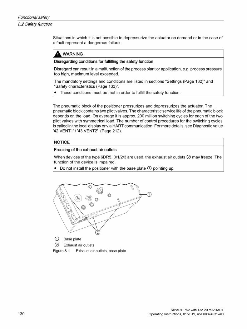
Situations in which it is not possible to depressurize the actuator on demand or in the case of a fault represent a dangerous failure.
WARNING
Disregarding conditions for fulfilling the safety function
Disregard can result in a malfunction of the process plant or application, e.g. process pressure too high, maximum level exceeded.
The mandatory settings and conditions are listed in sections "Settings (Page 132)" and "Safety characteristics (Page 133)".● These conditions must be met in order to fulfill the safety function.
The pneumatic block of the positioner pressurizes and depressurizes the actuator. The pneumatic block contains two pilot valves. The characteristic service life of the pneumatic block depends on the load. On average it is approx. 200 million switching cycles for each of the two pilot valves with symmetrical load. The number of control procedures for the switching cycles is called in the local display or via HART communication. For more details, see Diagnostic value '42.VENT1' / '43.VENT2' (Page 212).
NOTICE
Freezing of the exhaust air outlets
When devices of the type 6DR5..0/1/2/3 are used, the exhaust air outlets ② may freeze. The function of the device is impaired.● Do not install the positioner with the base plate ① pointing up.
① Base plate② Exhaust air outlets
Figure 8-1 Exhaust air outlets, base plate
Functional safety8.2 Safety function
SIPART PS2 with 4 to 20 mA/HART130 Operating Instructions, 01/2019, A5E00074631-AD
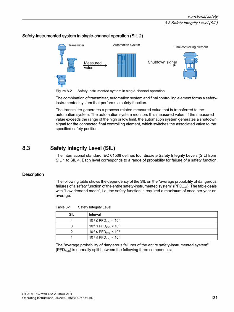
Safety-instrumented system in single-channel operation (SIL 2)
Automation systemTransmitterFinal controlling element
Figure 8-2 Safety-instrumented system in single-channel operation
The combination of transmitter, automation system and final controlling element forms a safety-instrumented system that performs a safety function.
The transmitter generates a process-related measured value that is transferred to the automation system. The automation system monitors this measured value. If the measured value exceeds the range of the high or low limit, the automation system generates a shutdown signal for the connected final controlling element, which switches the associated valve to the specified safety position.
8.3 Safety Integrity Level (SIL)The international standard IEC 61508 defines four discrete Safety Integrity Levels (SIL) from SIL 1 to SIL 4. Each level corresponds to a range of probability for failure of a safety function.
DescriptionThe following table shows the dependency of the SIL on the "average probability of dangerous failures of a safety function of the entire safety-instrumented system" (PFDAVG). The table deals with "Low demand mode", i.e. the safety function is required a maximum of once per year on average.
Table 8-1 Safety Integrity Level
SIL Interval4 10-5 ≤ PFDAVG < 10-4
3 10-4 ≤ PFDAVG < 10-3
2 10-3 ≤ PFDAVG < 10-2
1 10-2 ≤ PFDAVG < 10-1
The "average probability of dangerous failures of the entire safety-instrumented system" (PFDAVG) is normally split between the following three components:
Functional safety8.3 Safety Integrity Level (SIL)
SIPART PS2 with 4 to 20 mA/HARTOperating Instructions, 01/2019, A5E00074631-AD 131

Figure 8-3 PFD distribution
The following table shows the achievable Safety Integrity Level (SIL) for the entire safety-instrumented system for type A devices depending on the safe failure fraction (SFF) and the hardware fault tolerance (HFT).
● Type A devices include analog transmitters and shut-off valves without complex components, e.g. microprocessors (see also IEC 61508, Section 2).
● The specific values for your device are listed in the manufacturer's declaration (SIL Declaration of Conformity, Functional Safety according to IEC 61508 and IEC 61511): Certificates (http://www.siemens.com/processinstrumentation/certificates).
SFF HFT for type A devices 0 1 2< 60% SIL 1 SIL 2 SIL 360 to 90 % SIL 2 SIL 3 SIL 490 to 99 % SIL 3 SIL 4 SIL 4> 99% SIL 3 SIL 4 SIL 4
8.4 SettingsNo special parameter settings are required for the safety function.
Protection against configuration changesYou should attach the housing cover so that the device is protected against unwanted and unauthorized changes/operation.
Checking the safety function
Prerequisite for checking the safety function● Positioner is in operation.
● The actuator belonging to the positioner is not in the safety position.
Procedure● On the positioner, switch the signal source to 0 mA or the power supply source to 0 V.
● Reduce the inlet pressure (PZ) to a third of the maximum supply pressure.
● Always carry out the validation of the safety function with positioner and valve under operating conditions.
Functional safety8.4 Settings
SIPART PS2 with 4 to 20 mA/HART132 Operating Instructions, 01/2019, A5E00074631-AD

ResultThe actuator brings the valve to the specified safety position.
See alsoSafety function (Page 129)
8.5 Safety characteristicsThe safety characteristics necessary for use of the system are listed in the SIL declaration of conformity. These values apply under the following conditions:
● The positioner is only used in applications with low demand rate for the "Low demand mode".
● The positioner is blocked against unwanted and unauthorized changes/operation.
● The signal source with 0 mA or the power supply source with 0 V for the SIPART PS2 positioner is generated by a safe system that fulfills SIL 2 for single-channel operation.
● The connected single-acting type actuator returns the valve to the safe end position by spring force in the following scenarios:
– With a chamber pressure (Y1 connection) up to a third of the maximum available supply air pressure (PZ connection)
● The air outlet does not contain any additional cross-sectional contractions leading to an increased dynamic pressure. In particular, a silencer is only allowed if icing or other contamination is ruled out.
● The restrictor in the Y1 circuit may not be completely closed during operation.
● The auxiliary pneumatic power is free of oil, water and dirt in line with:DIN/ISO 8573-1, maximum class 3
● The average temperature viewed over a long period is 40 °C.
● Fault rates are calculated on the basis of a mean time to repair (MTTR) of 8 hours.
● In case of a fault, the pneumatic outlet of the positioner is depressurized. A spring in the pneumatic actuator must move the valve to the pre-defined, safe end position.
● A dangerous failure of the positioner is a failure whereby the pressure outlet is not depressurized or the safety position is not reached when the signal source is 0 mA or the power supply source is 0 V.
See alsoSettings (Page 132)
Functional safety8.5 Safety characteristics
SIPART PS2 with 4 to 20 mA/HARTOperating Instructions, 01/2019, A5E00074631-AD 133

8.6 Maintenance/check
IntervalWe recommend that the functioning of the positioner is checked at regular intervals of one year.
Checking the safety functionCheck the safety function as detailed in chapter "Settings (Page 132)"
Checking safetyVerify the safety function of the entire safety circuit on a regular basis in accordance with IEC 61508/61511. The test intervals are determined in the course of calculations for each safety circuit of a system (PFDAVG).
Functional safety8.6 Maintenance/check
SIPART PS2 with 4 to 20 mA/HART134 Operating Instructions, 01/2019, A5E00074631-AD
Parameter assignment 99.1 Introduction to parameter assignment section
A positioner is responsible for controlling a valve and for monitoring the status of a valve. The parameters described in this section are used to optimally adapt the positioner to the valve and its application.
The parameters are divided into initialization parameters, application parameters, and the extended diagnostics parameters.
● Initialization parameters 1 to 5 (Page 145): Describes die parameters which are relevant for initial commissioning of the positioner on the valve. For example, you can start the automatic initialization here.
● Application parameters 6 to 52 (Page 149): Describes die parameters with which the positioner is adapted to the valve application, for example tight closing at the end stops.
● Advanced diagnostic parameters A to U (Page 166): Describes the diagnostics functions which are provided by the positioner. These include monitoring of leakages as well as the partial stroke test. Following activation of these functions, the positioner continuously monitors the status of the valve. If you enter thresholds in the parameters of the diagnostics functions, the positioner actively signals high or low violation of these thresholds. The current monitoring state for these thresholds is displayed as a diagnostic value. For additional details on diagnostics and diagnostic values, refer to the section Diagnostics (Page 198).
The following configuration schematic shows the principle of operation of the parameters. This is followed by a tabular overview of the parameters. Finally, the individual parameters and their functionality are described.
Furthermore, the positioners with HART, PA and FF communication interface in combination with a host system, e.g. SIMATIC PDM or HART communicator etc., offer the following advantages:
● Offline tests such as full stroke test, step response test, multi-step response test and valve performance test.
● Diagnostics cockpit which provides an overview of the state of positioner and valve.
● Logbook with time stamp for documentation of all events such as the violation of thresholds.
● Wizards which provide prompting through the relevant parameters during commissioning, the partial stroke test as well as the offline test.
SIPART PS2 with 4 to 20 mA/HARTOperating Instructions, 01/2019, A5E00074631-AD 135
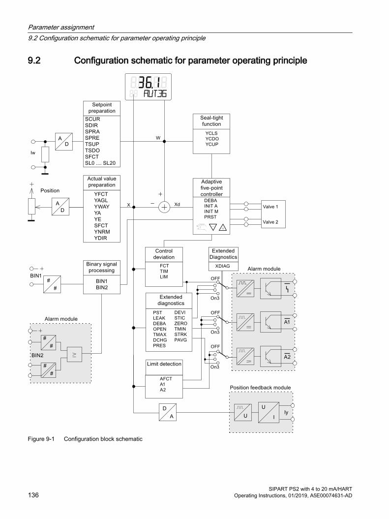
9.2 Configuration schematic for parameter operating principle
Figure 9-1 Configuration block schematic
Parameter assignment9.2 Configuration schematic for parameter operating principle
SIPART PS2 with 4 to 20 mA/HART136 Operating Instructions, 01/2019, A5E00074631-AD
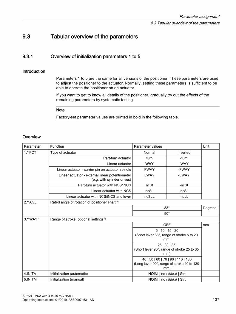
9.3 Tabular overview of the parameters
9.3.1 Overview of initialization parameters 1 to 5
IntroductionParameters 1 to 5 are the same for all versions of the positioner. These parameters are used to adjust the positioner to the actuator. Normally, setting these parameters is sufficient to be able to operate the positioner on an actuator.
If you want to get to know all details of the positioner, gradually try out the effects of the remaining parameters by systematic testing.
Note
Factory-set parameter values are printed in bold in the following table.
Overview
Parameter Function Parameter values Unit1.YFCT Type of actuator Normal Inverted
Part-turn actuator turn -turnLinear actuator WAY -WAY
Linear actuator - carrier pin on actuator spindle FWAY -FWAYLinear actuator - external linear potentiometer
(e.g. with cylinder drives)LWAY -LWAY
Part-turn actuator with NCS/iNCS ncSt -ncStLinear actuator with NCS ncSL -ncSL
Linear actuator with NCS/iNCS and lever ncSLL -ncLL2.YAGL Rated angle of rotation of positioner shaft 1)
33° Degrees90°
3.YWAY2) Range of stroke (optional setting) 3)
OFF mm5 | 10 | 15 | 20
(Short lever 33°, range of stroke 5 to 20 mm)
25 | 30 | 35 (Short lever 90°, range of stroke 25 to 35
mm)40 | 50 | 60 | 70 | 90 | 110 | 130
(Long lever 90°, range of stroke 40 to 130 mm)
4.INITA Initialization (automatic) NOINI | no / ###.# | Strt 5.INITM Initialization (manual) NOINI | no / ###.# | Strt
Parameter assignment9.3 Tabular overview of the parameters
SIPART PS2 with 4 to 20 mA/HARTOperating Instructions, 01/2019, A5E00074631-AD 137
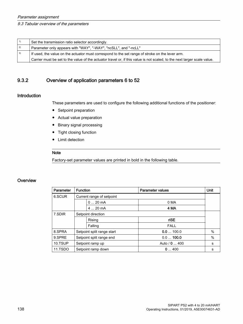
1) Set the transmission ratio selector accordingly.2) Parameter only appears with "WAY", "-WAY", "ncSLL", and "-ncLL" 3) If used, the value on the actuator must correspond to the set range of stroke on the lever arm.
Carrier must be set to the value of the actuator travel or, if this value is not scaled, to the next larger scale value.
9.3.2 Overview of application parameters 6 to 52
IntroductionThese parameters are used to configure the following additional functions of the positioner:
● Setpoint preparation
● Actual value preparation
● Binary signal processing
● Tight closing function
● Limit detection
Note
Factory-set parameter values are printed in bold in the following table.
Overview
Parameter Function Parameter values Unit6.SCUR Current range of setpoint
0 ... 20 mA 0 MA4 ... 20 mA 4 MA
7.SDIR Setpoint direction Rising riSE
Falling FALL8.SPRA Setpoint split range start 0.0 ... 100.0 %9.SPRE Setpoint split range end 0.0 ... 100.0 %10.TSUP Setpoint ramp up Auto / 0 ... 400 s11.TSDO Setpoint ramp down 0 ... 400 s
Parameter assignment9.3 Tabular overview of the parameters
SIPART PS2 with 4 to 20 mA/HART138 Operating Instructions, 01/2019, A5E00074631-AD
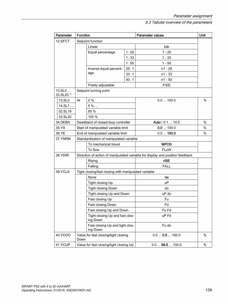
Parameter Function Parameter values Unit12.SFCT Setpoint function
Linear LinEqual percentage 1 : 25 1 - 25
1 : 33 1 - 331 : 50 1 - 50
Inverse equal percent‐age
25 : 1 n1 - 2533 : 1 n1 - 3350 : 1 n1 - 50
Freely adjustable FrEE13.SL0 ... 33.SL20 1)
Setpoint turning point
13.SL0 At 0 % 0.0 ... 100.0 %14.SL1 .... 5 % ...32.SL19 95 %33.SL20 100 %
34.DEBA Deadband of closed-loop controller Auto / 0.1 ... 10.0 %35.YA Start of manipulated variable limit 0.0 ... 100.0 %36.YE End of manipulated variable limit 0.0 ... 100.0 %37.YNRM Standardization of manipulated variable
To mechanical travel MPOS To flow FLoW
38.YDIR Direction of action of manipulated variable for display and position feedback Rising riSE
Falling FALL39.YCLS Tight closing/fast closing with manipulated variable
None noTight closing Up uPTight closing Down doTight closing Up and Down uP doFast closing Up FuFast closing Down FdFast closing Up and Down Fu FdTight closing Up and fast clos‐ing Down
uP Fd
Fast closing Up and tight clos‐ing Down
Fu do
40.YCDO Value for fast closing/tight closing Down
0.0 ... 0.5 ... 100.0 %
41.YCUP Value for fast closing/tight closing Up 0.0 ... 99.5 ... 100.0 %
Parameter assignment9.3 Tabular overview of the parameters
SIPART PS2 with 4 to 20 mA/HARTOperating Instructions, 01/2019, A5E00074631-AD 139
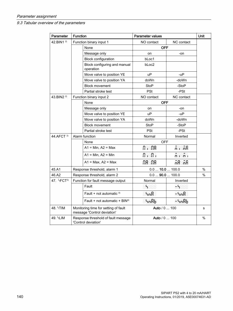
Parameter Function Parameter values Unit42.BIN1 2) Function binary input 1 NO contact NC contact
None OFFMessage only on -onBlock configuration bLoc1 Block configuring and manual operation
bLoc2
Move valve to position YE uP -uPMove valve to position YA doWn -doWnBlock movement StoP -StoPPartial stroke test PSt -PSt
43.BIN2 2) Function binary input 2 NO contact NC contact None OFF
Message only on -onMove valve to position YE uP -uPMove valve to position YA doWn -doWnBlock movement StoP -StoPPartial stroke test PSt -PSt
44.AFCT 3) Alarm function Normal Inverted None OFF
A1 = Min, A2 = Max
A1 = Min, A2 = Min
A1 = Max, A2 = Max
45.A1 Response threshold, alarm 1 0.0 ... 10.0 ... 100.0 %46.A2 Response threshold, alarm 2 0.0 ... 90.0 ... 100.0 %47. FCT3) Function for fault message output Normal Inverted
Fault
Fault + not automatic 4)
Fault + not automatic + BIN4)
48. TIM Monitoring time for setting of fault message 'Control deviation'
Auto / 0 ... 100 s
49. LIM Response threshold of fault message 'Control deviation'
Auto / 0 ... 100 %
Parameter assignment9.3 Tabular overview of the parameters
SIPART PS2 with 4 to 20 mA/HART140 Operating Instructions, 01/2019, A5E00074631-AD

Parameter Function Parameter values Unit50.PRST Preset
Reset all parameters which can be reset by 'Init', 'PArA' and 'diAg'.
ALL
Reset initialization parame‐ters '1.YFCT' to '5.INITM'.
Init
Reset parameters '6.SCUR' to '49. LIM'.
PArA
Reset parameters A to P of the extended diagnostics func‐tion as well as parameter '52.XDIAG'.
diAg
51.PNEUM Pneumatics type Standard pneumatic block Std
Fail in place pneumatic block FIPOperation with boosters booSt
52.XDIAG Activation of extended diagnostics Off OFF
Single stage message On1Two stage message On2Three stage message On3
1) Setpoint turning points only appear when '12.SFCT = FrEE' is selected.2) 'Normally closed' means: Operation when a switch is open or Low level
'Normally open' means: Action on switch closed or High level3) 'Normal' means: High level, no fault message
'Inverted' means: Low level, no fault message4) '+' means: Logical OR combination
9.3.3 Overview of advanced diagnostic parameters A to U
IntroductionThese parameters are used to set the extended diagnostics functions of the positioner.
NoteFactory setting
Factory-set parameter values are printed in bold in the following table.
Parameter assignment9.3 Tabular overview of the parameters
SIPART PS2 with 4 to 20 mA/HARTOperating Instructions, 01/2019, A5E00074631-AD 141
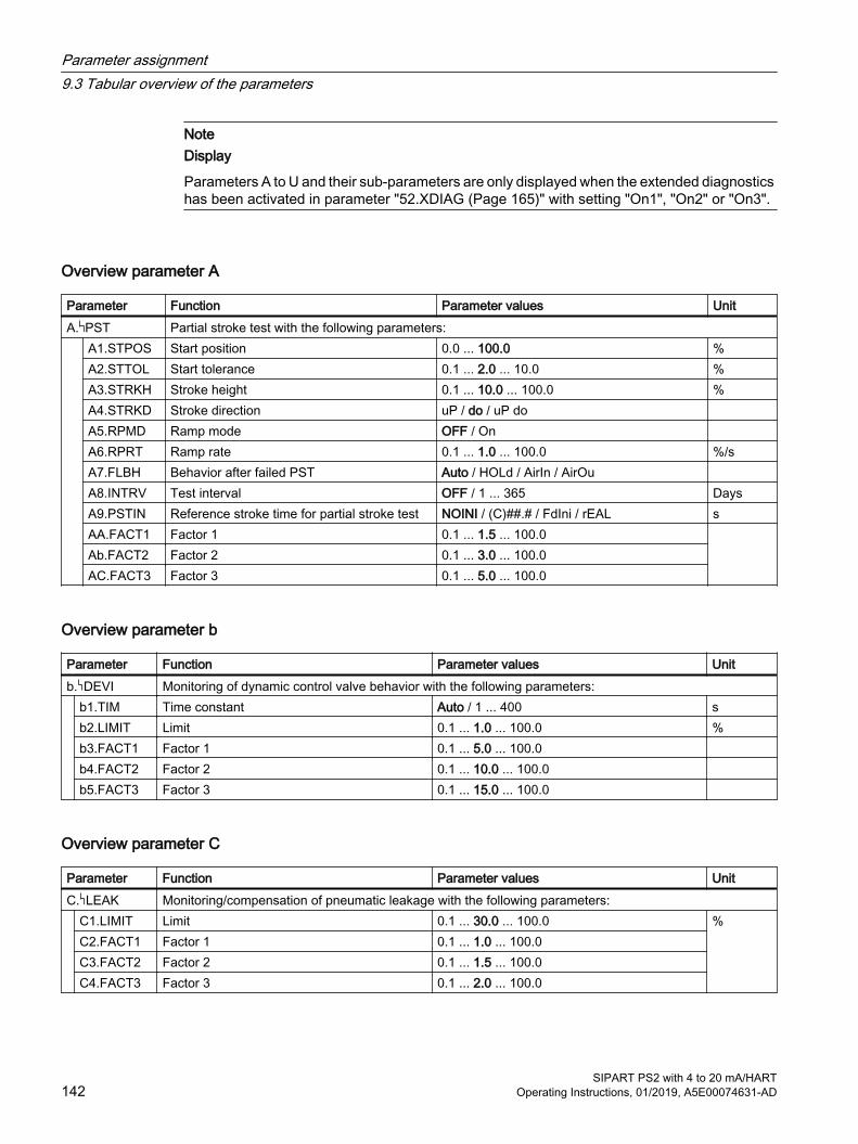
NoteDisplay
Parameters A to U and their sub-parameters are only displayed when the extended diagnostics has been activated in parameter "52.XDIAG (Page 165)" with setting "On1", "On2" or "On3".
Overview parameter A
Parameter Function Parameter values UnitA. PST Partial stroke test with the following parameters:
A1.STPOS Start position 0.0 ... 100.0 %A2.STTOL Start tolerance 0.1 ... 2.0 ... 10.0 %A3.STRKH Stroke height 0.1 ... 10.0 ... 100.0 %A4.STRKD Stroke direction uP / do / uP do A5.RPMD Ramp mode OFF / On A6.RPRT Ramp rate 0.1 ... 1.0 ... 100.0 %/sA7.FLBH Behavior after failed PST Auto / HOLd / AirIn / AirOu A8.INTRV Test interval OFF / 1 ... 365 DaysA9.PSTIN Reference stroke time for partial stroke test NOINI / (C)##.# / FdIni / rEAL sAA.FACT1 Factor 1 0.1 ... 1.5 ... 100.0 Ab.FACT2 Factor 2 0.1 ... 3.0 ... 100.0AC.FACT3 Factor 3 0.1 ... 5.0 ... 100.0
Overview parameter b
Parameter Function Parameter values Unitb. DEVI Monitoring of dynamic control valve behavior with the following parameters:
b1.TIM Time constant Auto / 1 ... 400 sb2.LIMIT Limit 0.1 ... 1.0 ... 100.0 %b3.FACT1 Factor 1 0.1 ... 5.0 ... 100.0 b4.FACT2 Factor 2 0.1 ... 10.0 ... 100.0 b5.FACT3 Factor 3 0.1 ... 15.0 ... 100.0
Overview parameter C
Parameter Function Parameter values UnitC. LEAK Monitoring/compensation of pneumatic leakage with the following parameters:
C1.LIMIT Limit 0.1 ... 30.0 ... 100.0 %C2.FACT1 Factor 1 0.1 ... 1.0 ... 100.0C3.FACT2 Factor 2 0.1 ... 1.5 ... 100.0C4.FACT3 Factor 3 0.1 ... 2.0 ... 100.0
Parameter assignment9.3 Tabular overview of the parameters
SIPART PS2 with 4 to 20 mA/HART142 Operating Instructions, 01/2019, A5E00074631-AD
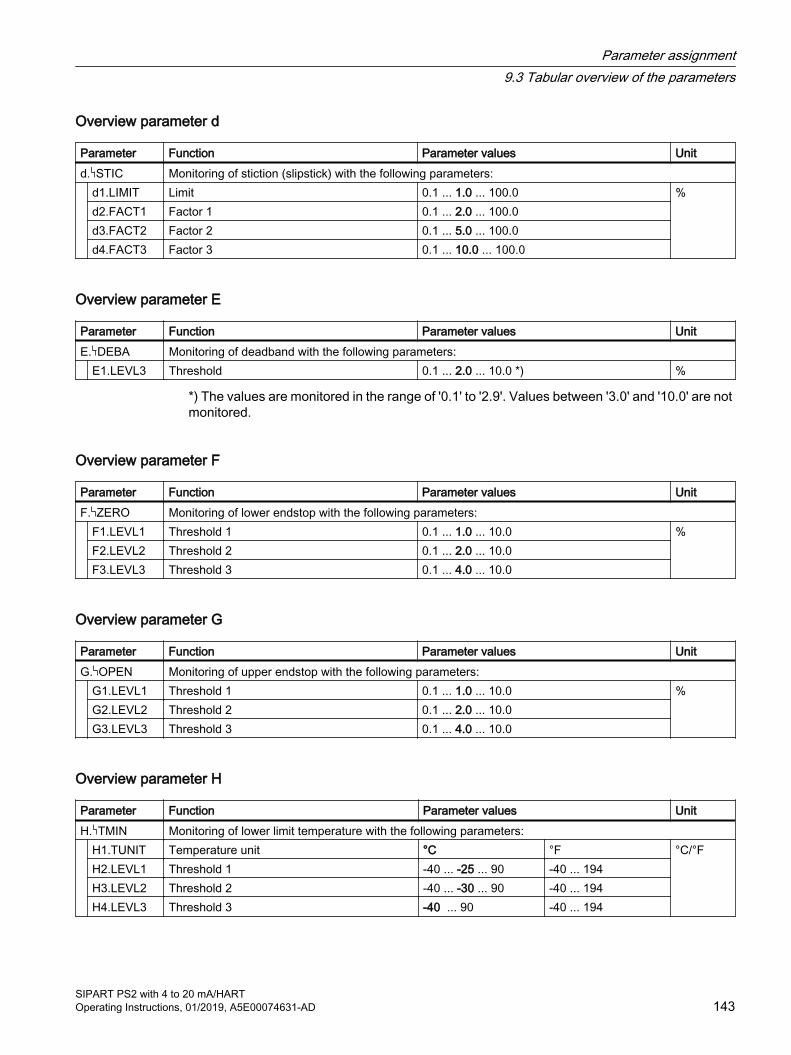
Overview parameter d
Parameter Function Parameter values Unitd. STIC Monitoring of stiction (slipstick) with the following parameters:
d1.LIMIT Limit 0.1 ... 1.0 ... 100.0 %d2.FACT1 Factor 1 0.1 ... 2.0 ... 100.0d3.FACT2 Factor 2 0.1 ... 5.0 ... 100.0d4.FACT3 Factor 3 0.1 ... 10.0 ... 100.0
Overview parameter E
Parameter Function Parameter values UnitE. DEBA Monitoring of deadband with the following parameters: E1.LEVL3 Threshold 0.1 ... 2.0 ... 10.0 *) %
*) The values are monitored in the range of '0.1' to '2.9'. Values between '3.0' and '10.0' are not monitored.
Overview parameter F
Parameter Function Parameter values UnitF. ZERO Monitoring of lower endstop with the following parameters:
F1.LEVL1 Threshold 1 0.1 ... 1.0 ... 10.0 %F2.LEVL2 Threshold 2 0.1 ... 2.0 ... 10.0F3.LEVL3 Threshold 3 0.1 ... 4.0 ... 10.0
Overview parameter G
Parameter Function Parameter values UnitG. OPEN Monitoring of upper endstop with the following parameters:
G1.LEVL1 Threshold 1 0.1 ... 1.0 ... 10.0 %G2.LEVL2 Threshold 2 0.1 ... 2.0 ... 10.0G3.LEVL3 Threshold 3 0.1 ... 4.0 ... 10.0
Overview parameter H
Parameter Function Parameter values UnitH. TMIN Monitoring of lower limit temperature with the following parameters:
H1.TUNIT Temperature unit °C °F °C/°FH2.LEVL1 Threshold 1 -40 ... -25 ... 90 -40 ... 194H3.LEVL2 Threshold 2 -40 ... -30 ... 90 -40 ... 194H4.LEVL3 Threshold 3 -40 ... 90 -40 ... 194
Parameter assignment9.3 Tabular overview of the parameters
SIPART PS2 with 4 to 20 mA/HARTOperating Instructions, 01/2019, A5E00074631-AD 143

Overview parameter J
Parameter Function Parameter values UnitJ. TMAX Monitoring of upper limit temperature with the following parameters:
J1.TUNIT Temperature unit °C °F °C/°FJ2.LEVL1 Threshold 1 -40 ... 75 ... 90 -40 ... 194J3.LEVL2 Threshold 2 -40 ... 80 ... 90 -40 ... 194J4.LEVL3 Threshold 3 -40 ... 90 -40 ... 194
Overview parameter L
Parameter Function Parameter values UnitL. STRK Monitoring of number of total strokes with the following parameters:
L1. LIMIT Limit 1 ... 1E6 ... 1E8 L2.FACT1 Factor 1 0.1 ... 1.0 ... 40.0L3.FACT2 Factor 2 0.1 ... 2.0 ... 40.0L4.FACT3 Factor 3 0.1 ... 5.0 ... 40.0
Overview parameter O
Parameter Function Parameter values UnitO. DCHG Monitoring of number of changes in direction with the following parameters:
O1.LIMIT Limit 1 ... 1E6 ... 1E8 O2.FACT1 Factor 1 0.1 ... 1.0 ... 40.0O3.FACT2 Factor 2 0.1 ... 2.0 ... 40.0O4.FACT3 Factor 3 0.1 ... 5.0 ... 40.0
Overview parameter P
Parameter Function Parameter values UnitP. PAVG Monitoring of position average value with the following parameters:
P1.TBASE Time basis of average value generation 0.5h / 8h / 5d / 60d / 2.5y P2.STATE Status of monitoring of position average value IdLE / rEF / ###.# / Strt P3.LEVL1 Threshold 1 0.1 ... 2.0 ... 100.0 %P4.LEVL2 Threshold 2 0.1 ... 5.0 ... 100.0 %P5.LEVL3 Threshold 3 0.1 ... 10.0 ... 100.0 %
Parameter assignment9.3 Tabular overview of the parameters
SIPART PS2 with 4 to 20 mA/HART144 Operating Instructions, 01/2019, A5E00074631-AD

Overview parameter U
Parameter Function Parameter values UnitU. PRES Activate pressure monitoring
U1.PUNIT Pressure unit bar / psi / MPa U2.PZLIM Low limit of the supply pressure (PZLIM) 1.4 ...7.0 bar
20.30 ... 101.52 psi0.140 ... 0.700 MPa
U3.PZHYS Hysteresis of the low limit of the supply pres‐sure
0.2 ... 1.0 bar2.90 ... 14.50 psi0.020 ... 0.100 MPa
U4.PZ_FR Error response on undershoot of the supply pressure
cont / HOLd
9.4 Description of parameters
9.4.1 Initialization parameters 1 to 5
9.4.1.1 '1.YFCT' type of actuator
Requirement: Type of actuator as well as mounting type and direction of action are known.
Possible settings:
Actuator with normal direction of action
Actuator with inverted direction of action
● turn● WAY● FWAY● LWAY● ncSt● ncSL● ncSLL
● -turn● -WAY● -FWAY● -LWAY● -ncSt● -ncSL● -ncLL
Purpose: Use this parameter to adjust the positioner to the respective actua‐tor. ● turn/-turn: Use this setting for a part-turn actuator with a directly
mounted positioner. ● WAY/-WAY: Use this setting.
– For a linear actuator with a carrier pin mounted on the lever.– In conjunction with devices which use an internal
potentiometer.
Parameter assignment9.4 Description of parameters
SIPART PS2 with 4 to 20 mA/HARTOperating Instructions, 01/2019, A5E00074631-AD 145

● FWAY/-FWAY: Use this setting.– For a linear actuator with a carrier pin mounted on the actuator
spindle.– In conjunction with devices which use an internal
potentiometer. ● LWAY/-LWAY: Use this setting for an external linear
potentiometer on a linear actuator (e.g. with cylinder drives). ● ncSt/-ncSt: Use this setting for a part-turn actuator for:
– An NCS sensor 6DR4004-. N.10 and -.N.40– A positioner 6DR5...-0..9.-....- L1A with internal NCS module– A positioner 6DR59* with accessory NCS module
6DR4004-5L/-5LE– External position detection systems 6DR4004-2ES, -3ES and
-4ES– Internal NCS module
● ncSL/-ncSL: Use this setting for an NCS sensor 6DR4004-.N.20 on a linear actuator for strokes < 14 mm (0.55 inch).
● ncSLL/-ncLL: Use this setting for a linear actuator for:– An NCS sensor 6DR4004-.N.30 for strokes > 14 mm
(0.55 inch).– A positioner 6DR5...-0..9.-....- L1A with internal NCS module– A positioner 6DR59* with accessory NCS module
6DR4004-5L/-5LE– External position detection systems 6DR4004-2ES, -3ES and
-4ES– An internal NCS module. No limitations apply to the internal
NCS module. In the case of actuators with inverted direction of action, use the
settings with the minus sign, e.g. -turn.Description: Meaning of actuator with normal direction of action:
● Part-turn actuator closes when the drive shaft, positioner shaft or magnet of the NCS sensor rotates in the clockwise direction.
● Linear actuator closes when the actuator spindle moves downwards and the positioner shaft or magnet of the NCS sensor rotates in the anti-clockwise direction.
Meaning for actuator with inverted direction of action:● Part-turn actuator closes when the drive shaft, positioner shaft or
magnet of the NCS sensor rotates in the anti-clockwise direction.● Linear actuator closes when the actuator spindle moves
downwards and the positioner shaft or magnet of the NCS sensor rotates in the anti-clockwise direction.
Parameter assignment9.4 Description of parameters
SIPART PS2 with 4 to 20 mA/HART146 Operating Instructions, 01/2019, A5E00074631-AD

Additional information:● The '3.YWAY' Range of stroke (Page 148) parameter is
displayed only for 'WAY', '-WAY', 'ncSLL' or '-ncLL'.● turn/-turn: The '2.YAGL' Rated angle of rotation of feedback
(Page 147) parameter is automatically set to 90° and cannot be changed.
● WAY/-WAY: The positioner compensates the non-linearity. The non-linearity is caused by the transformation of the linear movement of the linear actuator into the rotary movement of the positioner shaft. For correct compensation see section "Preparing linear actuators for commissioning (Page 114)".
Factory setting: WAY
9.4.1.2 '2.YAGL' Rated angle of rotation of feedback
Requirement: Transmission ratio selector and the value set in the '2.YAGL' pa‐rameter match. Only then does the value shown on the display match the actual position.
Possible settings: ● 33°● 90°
Purpose: Use this parameter for a linear actuator. For a linear actuator, set an angle of 33° or 90° depending on the range of stroke. The current setting of the actuator is then measured more accurately. The fol‐lowing is applicable:● 33°: Strokes ≤ 20 mm● 90°: Strokes 25 ... 35 mm● 90°: Strokes > 40 ... 130 mm
Use the mounting kit:● 6DR4004-8V for strokes up to 35 mm● 6DR4004-8L for strokes greater than 35 up to 130 mm
'2.YAGL' can only be adjusted if '1.YFCT' is set to 'WAY'/'-WAY' or 'FWAY'/'-FWAY'. With all other settings of '1.YFCT', an angle of 90° is automatically set for '2.YAGL'.
Factory setting: 33°
See alsoSequence of automatic initialization (Page 107)
Parameter assignment9.4 Description of parameters
SIPART PS2 with 4 to 20 mA/HARTOperating Instructions, 01/2019, A5E00074631-AD 147

9.4.1.3 '3.YWAY' Range of stroke
Requirement: ● Positioner is mounted.● Carrier pin is mounted on the lever in accordance with the
actuator's range of stroke as described in section Mounting to linear actuator (Page 39).
Possible settings: ● OFF● 5.0 | 10.0 | 15.0 | 20.0 | 25.0 |30.0 | 35.0 | 40.0 |
50.0 | 60.0 | 70.0 | 90.0 | 110.0 | 130.0Purpose: Use this parameter to display the determined stroke value in mm
when initialization of a linear actuator has been completed.If you select the 'OFF' setting, the real stroke is not displayed after initialization.From the possible settings shown above, select the value which corresponds to the range of stroke of your actuator in mm.If the range of stroke of the actuator does not correspond to a pos‐sible setting, use the next higher value. Use the value specified on the nameplate of the actuator for this purpose.'3.YWAY' is only displayed if '1.YFCT' is set to 'WAY'/'-WAY' or 'ncSLL'/'-ncLL'.
Factory setting: OFF
See also'1.YFCT' type of actuator (Page 145)
9.4.1.4 '4.INITA' Initialization (automatically)
Possible settings: ● NOINI● no / ###.#● Strt
Purpose: Use this parameter to start the automatic initialization process. 1. Select the "Strt" setting. 2. Then press the button for at least 5 seconds. The sequence of the initialization process from "RUN 1" to "RUN 5" is output in the bottom line of the display.
Factory setting: NOINI
Parameter assignment9.4 Description of parameters
SIPART PS2 with 4 to 20 mA/HART148 Operating Instructions, 01/2019, A5E00074631-AD
9.4.1.5 '5.INITM' Initialization (manual)
Possible settings: ● NOINI● no / ###.#● Strt
Purpose: Use this parameter to start the manual initialization process.1. Select the "Strt" setting. 2. Then press the button for at least 5 seconds.
Description: If the positioner has already been initialized and if the "4.INITA" and "5.INITM" values are set, it is possible to reset the positioner to the non-initialized status. To do this, press the button for at least 5 seconds.
Factory setting: NOINI
9.4.2 Application parameters 6 to 52
9.4.2.1 '6.SCUR' Current range of setpoint
Requirement: ● You have a SIPART PS2 in version "2-, 3-, 4-wire".● Positioner is connected in accordance with the connection
graphics for 2/3/4-wire systems shown in section "Electrical wiring (Page 77)".
Possible settings: ● 0 MA● 4 MA
Purpose: This parameter is used to set the current range of the setpoint. The selection of the current range depends on the type of connection. The "0 MA" setting (0 to 20 mA) is only possible for three-wire and four-wire connections.
Factory setting: 4 MA
Parameter assignment9.4 Description of parameters
SIPART PS2 with 4 to 20 mA/HARTOperating Instructions, 01/2019, A5E00074631-AD 149
9.4.2.2 '7.SDIR' Setpoint direction
Possible settings: ● riSE● FALL
Purpose: This parameter is used to set the setpoint direction. The setpoint direction is used to reverse the direction of action of the setpoint.● Rising (riSE): A higher value at the setpoint input results in
opening of the valve.● Falling (FALL): A higher value at the setpoint input results in
closing of the valve.The setpoint direction is primarily used for the split-range mode and for single-acting actuators with the safety setting 'uP'.
Factory setting: riSE
9.4.2.3 '8.SPRA' Setpoint split range start / '9.SPRE' Setpoint split range start end
Adjustment range: 0.0 ... 100.0Purpose: With these two parameters in combination with parameter "'7.SDIR'
Setpoint direction (Page 150)", you can limit the effective setpoint. This allows split range tasks with the following characteristic curves to be solved:● rising/falling● falling/rising● falling/falling● rising/rising
Factory setting: With "SPRA": 0.0 With "SPRE": 100.0
Parameter assignment9.4 Description of parameters
SIPART PS2 with 4 to 20 mA/HART150 Operating Instructions, 01/2019, A5E00074631-AD
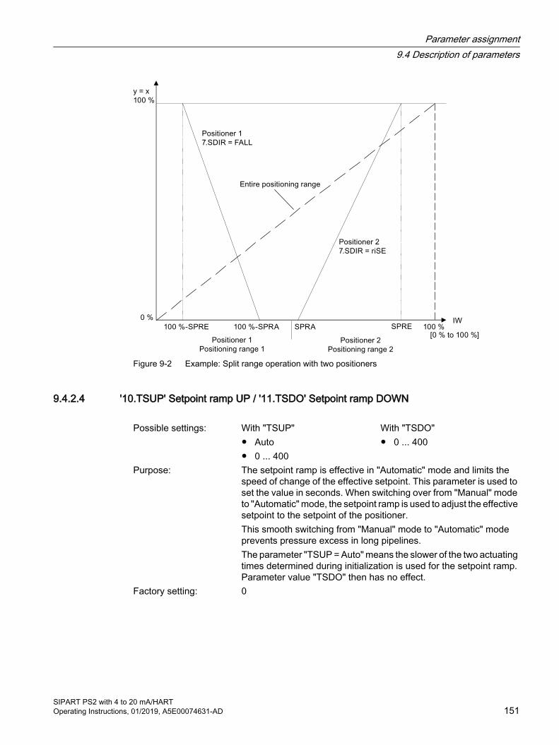
Figure 9-2 Example: Split range operation with two positioners
9.4.2.4 '10.TSUP' Setpoint ramp UP / '11.TSDO' Setpoint ramp DOWN
Possible settings: With "TSUP"● Auto● 0 ... 400
With "TSDO"● 0 ... 400
Purpose: The setpoint ramp is effective in "Automatic" mode and limits the speed of change of the effective setpoint. This parameter is used to set the value in seconds. When switching over from "Manual" mode to "Automatic" mode, the setpoint ramp is used to adjust the effective setpoint to the setpoint of the positioner.This smooth switching from "Manual" mode to "Automatic" mode prevents pressure excess in long pipelines.The parameter "TSUP = Auto" means the slower of the two actuating times determined during initialization is used for the setpoint ramp. Parameter value "TSDO" then has no effect.
Factory setting: 0
Parameter assignment9.4 Description of parameters
SIPART PS2 with 4 to 20 mA/HARTOperating Instructions, 01/2019, A5E00074631-AD 151
9.4.2.5 '12.SFCT' Setpoint function
Possible settings: ● Lin● 1 - 25● 1 - 33● 1 - 50● n1 - 25● n1 - 33● n1 - 50● FrEE
Purpose: This parameter is used to linearize nonlinear valve characteristics. Optional flow characteristics as shown in the figure in the description of the '13.SL0' ... '33.SL20' Setpoint turning point (Page 152) pa‐rameter are simulated for linear valve characteristics.
Factory setting: Lin
Seven valve characteristics are stored in the positioner and are selected using the 'SFCT' parameter:
Valve characteristics Set with parameter valueLinear LinEqual percentage 1:25 1-25Equal percentage 1:33 1-33Equal percentage 1:50 1-50Inverse equal percentage 25:1 n1-25Inverse equal percentage 33:1 n1-33Inverse equal percentage 50:1 n1-50Freely adjustable FrEE
9.4.2.6 '13.SL0' ... '33.SL20' Setpoint turning point
Adjustment range: 0.0 ... 100.0Purpose: These parameters are used to assign a flow coefficient in units of 5%
to each setpoint turning point. The setpoint turning points form a polyline with 20 linear segments which models the valve character‐istic; see figure below.
Factory setting: "0", "5" ... "95", "100"
Parameter assignment9.4 Description of parameters
SIPART PS2 with 4 to 20 mA/HART152 Operating Instructions, 01/2019, A5E00074631-AD

Setpoint characteristic curves, standardization of manipulated variables, and tight closing function
Input of the setpoint turning points is only possible if the "'12.SFCT' Setpoint function (Page 152)" parameter is set to "FrEE". You can only enter one monotone rising characteristic curve and two consecutive interpolation points must differ by at least 0.2%.
9.4.2.7 '34.DEBA' Deadband of closed-loop controller
Possible settings: ● Auto● 0.1 ... 10.0
Purpose: This parameter is used with the "Auto" setting to adjust the dead‐band in automatic mode continually and adaptively to the require‐ments of the control loop. If a regulator oscillation is detected, then the deadband is incrementally enlarged. The reverse adaptation takes place using a time criterion.The deadband is set using the values 0.1 to 10.0. The value is given in percent. Control oscillations can then be suppressed. The smaller the deadband, the better the control accuracy.
Factory setting: Auto
Parameter assignment9.4 Description of parameters
SIPART PS2 with 4 to 20 mA/HARTOperating Instructions, 01/2019, A5E00074631-AD 153

9.4.2.8 '35.YA' Start of manipulated variable limit / '36.YE' End of manipulated variable limit
Adjustment range: 0.0 ... 100.0Purpose: These parameters are used to limit the mechanical actuator travel
from stop to stop to the configured values. The value is given in percent. This allows the mechanical travel range of the actuator to be limited to the effective flow, preventing integral saturation of the controlling closed-loop controller.See the figure in the description of the '37.YNRM' Standardization of manipulated variable (Page 154) parameter.'Dead angle' functionThe dead angle is the angle range in which the process valve allows no flow. The dead angle range starts at the lower endstop of the valve, for example, and ends at the angle at which the medium be‐gins to flow. Use this function if you want to use the entire signal range for valve control (for example, 4 to 20 mA). To now use the entire signal range for valve control (for example, of ball and segment valves), set the low limit of the manipulated varia‐ble (YA) to the percentage at which the medium begins to flow. To display the new start value as 0%, set '37.YNRM' Standardization of manipulated variable (Page 154) to 'FloW'.
Factory setting: When 'YA': 0.0 When 'YE': 100.0
Note
'YE' must always be set larger than 'YA'.
9.4.2.9 '37.YNRM' Standardization of manipulated variable
Possible settings: ● MPOS● FLoW
Purpose: Use the '35.YA' Start of manipulated variable limit / '36.YE' End of manipulated variable limit (Page 154) parameters to limit the ma‐nipulated variable. This limitation causes two different scaling types 'MPOS' and 'FLoW' for the display and for the position feedback through the current output.The MPOS scale shows the mechanical positions from 0 to 100% between the upper and lower endstops of the initialization. The po‐sition is not influenced by the '35.YA' Start of manipulated variable limit / '36.YE' End of manipulated variable limit (Page 154) parame‐ters. The 'YA' and 'YE' parameters are shown in the MPOS scale.
Parameter assignment9.4 Description of parameters
SIPART PS2 with 4 to 20 mA/HART154 Operating Instructions, 01/2019, A5E00074631-AD

The FLoW scale is the standardization from 0 to 100% in the range between the 'YA' and 'YE' parameters. Over this range, the setpoint w is also always 0 to 100%. This results in a more or less flow-pro‐portional display and position feedback. The flow-proportional dis‐play and position feedback also results from the use of valve char‐acteristics.
In order to calculate the control deviation, the setpoint in the display is also shown in the corresponding scale.The following uses the example of an 80-mm linear actuator to illus‐trate the dependence of the stroke on the scaling as well as on the 'YA' and 'YE' parameters; see the following figure.
Factory setting: MPOS
Figure 9-3 YNRM = MPOS or YNRM = FLoW; default: YA = 0 % and YE = 100 %
Figure 9-4 Example: YNRM = MPOS with YA = 10 % and YE = 80 %
Figure 9-5 Example: YNRM = FLoW with YA = 10 % and YE = 80 %
Parameter assignment9.4 Description of parameters
SIPART PS2 with 4 to 20 mA/HARTOperating Instructions, 01/2019, A5E00074631-AD 155
See also'39.YCLS' Tight closing/fast closing with manipulated variable (Page 156)
9.4.2.10 '38.YDIR' Direction of manipulated variable for display and position feedback
Possible settings: ● riSE● FALL
Purpose: This parameter is used to set the direction of action of the display and the position feedback. The direction can be rising or falling.
Factory setting: riSE
9.4.2.11 '39.YCLS' Tight closing/fast closing with manipulated variable
Possible settings: no None uP Tight closing Up do Tight closing Down uP do Tight closing Up and Down Fu Fast closing Up Fd Fast closing Down Fu Fd Fast closing Up and Down uP Fd Tight closing Up and fast closing Down Fu do Fast closing Up and tight closing DownPurpose: This parameter is used to drive the control valve to the mechanical
end stops. If the parameter is not activated, the control valve controls to the end positions which were determined during the initialization.With tight closing, the control valve requires longer to leave the end stops. With fast closing, the end stops of the control valve are left immediately. The tight closing and fast closing functions are activated on one side or for both end positions. Parameter '39.YCLS' becomes effective if the effective setpoint:● Is at or below the value set in the '40.YCDO' parameter.● Is at or above the value set in the '41.YCUP' Value for tight
closing/fast closing Up (Page 157) parameter.Factory setting: no
Parameter assignment9.4 Description of parameters
SIPART PS2 with 4 to 20 mA/HART156 Operating Instructions, 01/2019, A5E00074631-AD

See the figure in the description of the '37.YNRM' Standardization of manipulated variable (Page 154) parameter and the figure in the description of the '13.SL0' ... '33.SL20' Setpoint turning point (Page 152) parameters.
NoteActivated tight closing/fast closing function
If the function is activated, then the monitoring of control deviation is turned off in the respective overflow direction for the '49. LIM' parameter. The following applies: 'YCDO: < 0 %' and 'YCUP: > 100 %'. This functionality is especially advantageous for valves with lining. For long-term monitoring of the end positions, we recommend that you activate the 'F. ZERO' and 'G.OPEN' parameters.
9.4.2.12 '40.YCDO' Value for tight closing/fast closing Down
Requirement: '39.YCLS' Tight closing/fast closing with manipulated variable (Page 156) Parameter is set to 'do', 'uP do', 'Fd', 'Fu Fd', 'uP Fd' or 'Fu do'
Adjustment range: 0.0 ... 100.0Purpose: Use the 'YCDO' parameter to set the value as of which the "Tight
closing/fast closing Down" function is activated. If the effective set‐point is at or below the value set here, the actuator moves in tight closing Down or fast closing Down.
Factory setting: 0.5
Note
The value in the 'YCDO' parameter is always smaller than that in 'YCUP'. The tight closing/fast closing function has a fixed hysteresis of 1%. The 'YCDO' parameter is relative to the mechanical stops. The 'YCDO' is independent of the values set in the '7.SDIR' Setpoint direction (Page 150) and '38.YDIR' Direction of manipulated variable for display and position feedback (Page 156) parameters.
9.4.2.13 '41.YCUP' Value for tight closing/fast closing Up
Requirement: '39.YCLS' Tight closing/fast closing with manipulated variable (Page 156) Parameter is set to 'do', 'uP do', 'Fd', 'Fu Fd', 'uP Fd' or 'Fu do'
Adjustment range: 0.0 ... 100.0Purpose: Use the 'YCUP' parameter to set the value as of which the tight
closing Up or fast closing Up is activated. If the effective setpoint is at or above the value set here, the actuator moves in tight closing Up or fast closing Up.
Factory setting: 99.5
Parameter assignment9.4 Description of parameters
SIPART PS2 with 4 to 20 mA/HARTOperating Instructions, 01/2019, A5E00074631-AD 157

Note
The value in the 'YCDO' parameter is always smaller than that in 'YCUP'. The tight closing/fast closing function has a fixed hysteresis of 1%. The 'YCUP' parameter is relative to the mechanical stops. The 'YCUP' is independent of the values set in the '7.SDIR' Setpoint direction (Page 150) and '38.YDIR' Direction of manipulated variable for display and position feedback (Page 156) parameters.
9.4.2.14 '42.BIN1' / '43.BIN2' Function binary input
Setting option ● Binary input 1 Normally open
OFFonbloc1bloc2uPdoWnStoPPST
Normally closedOFF-on-uP-doWn-StoP-PST
● Binary input 2 Normally open
OFFonuPdoWnStoPPST
Normally closedOFF-on-uP-doWn-StoP-PST
Purpose: These parameters determine the function of the binary inputs. The possible functions are described below. The direction of action can be adapted to a normally closed or normally open mode.
● BIN1 or BIN2 = On or -OnBinary messages from peripherals, e.g. from pressure or temperature switches, are read over the communication interface or fed through a logical OR combination with other messages to trigger the error message output.
● BIN1 = bLoc1Use this parameter value to interlock the "Configuration" mode against adjustment. The lock is performed e.g. with a jumper between terminals 9 and 10.
● BIN1 = bLoc2If binary input 1 has been activated, the "Manual" as well as "Configuration" modes are blocked.
Parameter assignment9.4 Description of parameters
SIPART PS2 with 4 to 20 mA/HART158 Operating Instructions, 01/2019, A5E00074631-AD

● BIN1 or BIN2 = contact uP or doWn closes, or contact -uP or -doWn opensIf the binary input is activated, the actuator uses the value defined by the "'35.YA' Start of manipulated variable limit / '36.YE' End of manipulated variable limit (Page 154)" parameter for controlling in "Automatic" mode.
● BIN1 or BIN2 contact closes = StoP or -StoP contact opensIn "Automatic" mode, the piezo valves are blocked when the binary input is activated. The actuator remains at the last position. Leakage measurements can be performed in this way without using the initialization function.
● BIN1 or BIN2 = PSt or -PStUsing binary inputs 1 or 2, a partial-stroke test can be triggered by actuation of your choice of a normally closed or normally open switch.
● BIN1 or BIN2 = OFFNo functionSpecial function of binary input 1: If binary input 1 is activated in "P-manual mode" by means of a jumper between terminals 9 and 10, the firmware version is displayed when the button is pressed.
If one of the above functions is activated simultaneously with the "BIN1" and "BIN2" parameters, then: "Blocking" has priority over "uP". "uP" has priority over "doWn". "doWn" has priority over "PST".
Factory setting: OFF
9.4.2.15 '44.AFCT' Alarm function
Possible settings: See representation belowPurpose: This parameter can be used to determine the value at which going
above or below a given offset or angle will result in a message. The triggering of alarms (limits) is relative to the MPOS scale. Alarms are signaled through the alarm module. In addition, alarms can also be read via the communication interface.The direction of action of the binary outputs can be adjusted from "High active" to "Low active" for the next system.
Factory setting: OFF
Parameter assignment9.4 Description of parameters
SIPART PS2 with 4 to 20 mA/HARTOperating Instructions, 01/2019, A5E00074631-AD 159

Direction of action and hysteresis Alarm moduleExamples A1 A2A1 = 48
AFCT = MIN / MAXA2 = 52Way =45 Active Way =50 Way =55 Active A1 = 48
AFCT = -MIN / -MAXA2 = 52Way =45 ActiveWay =50 Active ActiveWay =55 Active A1 = 52
AFCT = MIN / MAXA2 = 48Way =45 Active Way =50 Active ActiveWay =55 Active A1 = 52
AFCT = -MIN / -MAXA2 = 48Way =45 ActiveWay =50 Way =55 Active
Note
If the extended diagnostic is activated using parameter "'52.XDIAG' Activating for extended diagnostics (Page 165)" with setting "On3", then the alarms are not output through the alarm module. Alarm A1 is output with setting "On2". However, notification via the communication interface is possible at any time.
Parameter assignment9.4 Description of parameters
SIPART PS2 with 4 to 20 mA/HART160 Operating Instructions, 01/2019, A5E00074631-AD

9.4.2.16 '45.A1' / '46.A2' Response threshold of alarm
Adjustment range: 0.0 ... 100.0Purpose: These parameters are used to specify when an alarm should be
displayed. The response thresholds of the alarms (in percent) refer to the MPOS scale in the '37.YNRM' Standardization of manipulated variable (Page 154) parameter. The MPOS scale corresponds to the mechanical travel.Depending on the setting of the alarm function in the '44.AFCT' Alarm function (Page 159) parameter, the alarm is triggered upon an upward violation (Max) or downward violation (Min) of this response threshold.
Factory setting: With 'A1': 10.0 With 'A2': 90.0
9.4.2.17 '47.\\FCT' Function for fault message output
Requirement: At least one of the following modules is fitted● Alarm module● Slot initiator alarm module (SIA module)● Mechanical limit switch module
Possible settings: Normal direction of action Inverted direction of action●● nA● nAb
● -● - nA● - nAb
Purpose: The fault message in the form of monitoring of control deviation over time can also be triggered due to the following events:● Power failure● Processor fault● Actuator fault● Valve fault● Compressed air failure● Threshold 3 message of extended diagnostics.
See parameter '52.XDIAG' Activating for extended diagnostics (Page 165).
The fault message cannot be switched off, but it can be suppressed (factory setting) when you exit 'Automatic' mode. Set the ' FCT' pa‐rameter to ' nA' to also generate a fault message here.
You also have an option to "or" the fault message with the status of the binary inputs. To do this, first set the '42.BIN1' / '43.BIN2' Func‐tion binary input (Page 158) parameter to 'on' or '-on'. Subsequently set the ' FCT' parameter to ' nAb'.Select the '- ' setting if you want the fault message to be output with inverted direction of action.
Factory setting:
Parameter assignment9.4 Description of parameters
SIPART PS2 with 4 to 20 mA/HARTOperating Instructions, 01/2019, A5E00074631-AD 161

9.4.2.18 '48.\\TIM' Monitoring time for setting of fault message 'Control deviation'
Possible settings: ● Auto● 0 ... 100
Purpose: The '48. TIM' parameter is used to set the time in seconds within which the positioner must have reached the regulated condition. The corresponding response threshold is specified in the '49. LIM' pa‐rameter.When the configured time is exceeded, the fault message output is set.
Factory setting: Auto
NoteActivated tight closing/fast closing function
If the function is activated, then the monitoring of control deviation is turned off in the respective overflow direction for the '49. LIM' parameter. The following applies: 'YCDO: < 0 %' and 'YCUP: > 100 %'. This functionality is especially advantageous for valves with lining. For long-term monitoring of the end positions, we recommend that you activate the 'F. ZERO' and 'G.OPEN' parameters.
9.4.2.19 '49.\\LIM' Response threshold of fault message 'Control deviation'
Possible settings: ● Auto● 0 ... 100
Purpose: This parameter is used to set a value for the permissible size of the control deviation to trigger a fault message. The value is given in percent.If the '48. TIM' and '49. LIM' parameters are set to 'Auto', then the fault message is set if the slow step zone is not reached within a certain period of time. Within 5 to 95% of the actuator travel, this time is twice the initialization travel time, and ten times the initialization travel time outside of 10 to 90%.
Factory setting: Auto
NoteActivated tight closing/fast closing function
If the function is activated, then the monitoring of control deviation is turned off in the respective overflow direction for the '49. LIM' parameter. The following applies: 'YCDO: < 0 %' and 'YCUP: > 100 %'. This functionality is especially advantageous for valves with lining. For long-term monitoring of the end positions, we recommend that you activate the 'F. ZERO' and 'G.OPEN' parameters.
Parameter assignment9.4 Description of parameters
SIPART PS2 with 4 to 20 mA/HART162 Operating Instructions, 01/2019, A5E00074631-AD
9.4.2.20 '50.PRST' Preset
Possible settings: ● ALL● Init● PArA● diAg
Purpose: Use this parameter to restore the factory settings for most parame‐ters. The following parameter groups are available:● ALL: Reset all parameters together which can be reset by 'Init',
'PArA' and 'diAg'.● Init: Reset initialization parameters '1.YFCT' to '5.INITM'.● PArA: Reset application parameters '6.SCUR' Current range of
setpoint (Page 149) to '49.\\LIM' Response threshold of fault message 'Control deviation' (Page 162).
● diAg: Reset parameters A to P of the extended diagnostics as well as parameter '52.XDIAG' Activating for extended diagnostics (Page 165).
An overview of the parameters and factory settings can be found in section Tabular overview of the parameters (Page 137).
In order to select one of the parameter groups listed above, repeat‐edly press the button until the desired setting is output in the dis‐play. Start the function by keeping the button pressed until 'oCAY' is output in the display. The values of the parameter group are now the factory settings.
Description: If you wish to use a previously initialized positioner on a different control valve, set the parameters to the factory settings prior to a new initialization. To do this, use the 'ALL' or 'Init' setting.Restore the factory settings if you have changed several parameters at once without being able to predict their effect and the undesired reactions which may occur as a result. To do this, use the 'ALL' set‐ting.
Factory setting: ALL
See alsoDisplay of diagnostics values (Page 198)
9.4.2.21 '51.PNEUM' Pneumatics type
Requirements: FIP You have a positioner with the "Fail in place" function with order suffix -Z, order code F01.
booSt You operate the positioner with a booster.Possible settings: Std Standard pneumatic block FIP Fail in place pneumatic block booSt Operation with boosters
Parameter assignment9.4 Description of parameters
SIPART PS2 with 4 to 20 mA/HARTOperating Instructions, 01/2019, A5E00074631-AD 163

Purpose: Start the function by pressing the button for at least 5 seconds. The display shows 'WAit' during these 5 seconds. Set the desired function after 5 seconds.
Std Setting for a standard pneumatic block FIP If you order a positioner for Fail in Place applications, it is
then equipped with a special pneumatic block. The "PNEUM" parameter is preset to "FIP". The parameter must be set to "FIP" again when the basic electronics are replaced.
booSt Use this function if you operate the positioner with a boos‐ter. This function then shows the actuator overshoot. You can find a description of how to operate the booster un‐der Booster (Page 295).
Parameter assignment9.4 Description of parameters
SIPART PS2 with 4 to 20 mA/HART164 Operating Instructions, 01/2019, A5E00074631-AD
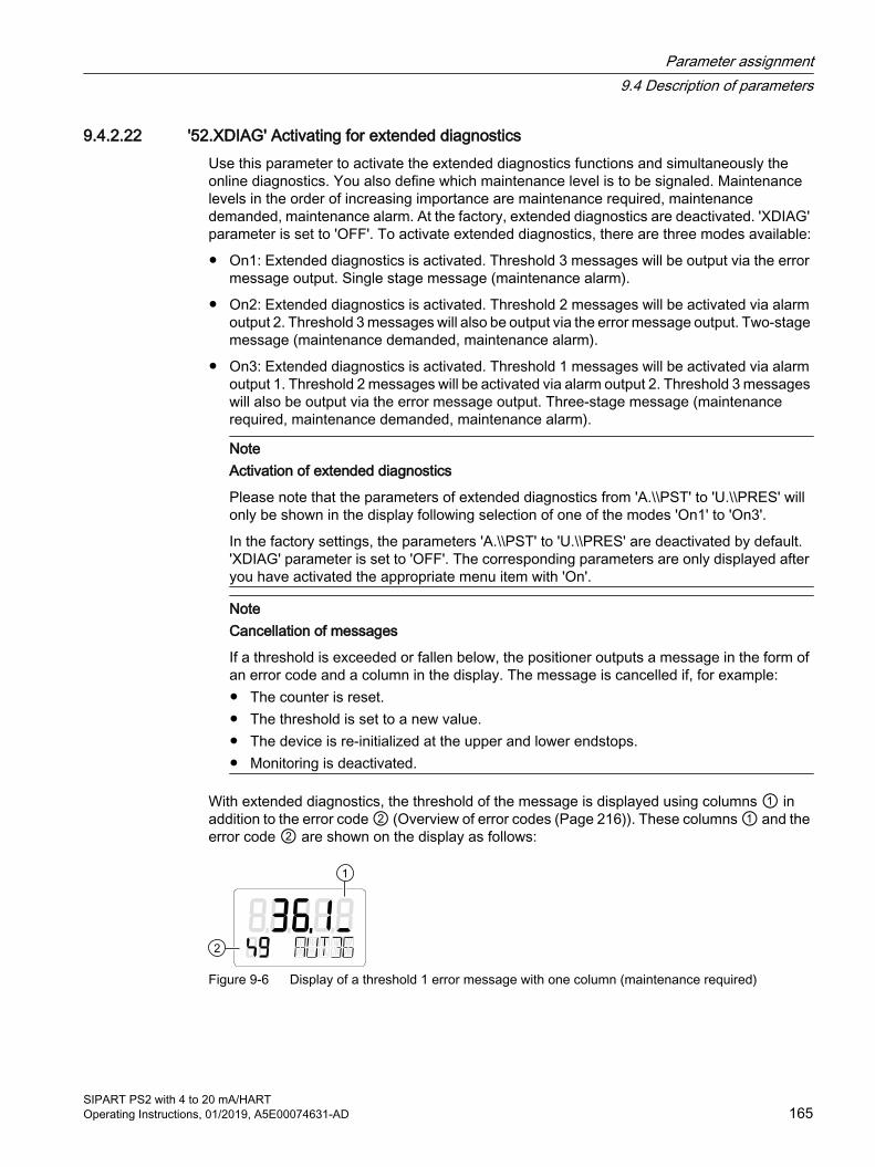
9.4.2.22 '52.XDIAG' Activating for extended diagnosticsUse this parameter to activate the extended diagnostics functions and simultaneously the online diagnostics. You also define which maintenance level is to be signaled. Maintenance levels in the order of increasing importance are maintenance required, maintenance demanded, maintenance alarm. At the factory, extended diagnostics are deactivated. 'XDIAG' parameter is set to 'OFF'. To activate extended diagnostics, there are three modes available:
● On1: Extended diagnostics is activated. Threshold 3 messages will be output via the error message output. Single stage message (maintenance alarm).
● On2: Extended diagnostics is activated. Threshold 2 messages will be activated via alarm output 2. Threshold 3 messages will also be output via the error message output. Two-stage message (maintenance demanded, maintenance alarm).
● On3: Extended diagnostics is activated. Threshold 1 messages will be activated via alarm output 1. Threshold 2 messages will be activated via alarm output 2. Threshold 3 messages will also be output via the error message output. Three-stage message (maintenance required, maintenance demanded, maintenance alarm).
NoteActivation of extended diagnostics
Please note that the parameters of extended diagnostics from 'A.\\PST' to 'U.\\PRES' will only be shown in the display following selection of one of the modes 'On1' to 'On3'.
In the factory settings, the parameters 'A.\\PST' to 'U.\\PRES' are deactivated by default. 'XDIAG' parameter is set to 'OFF'. The corresponding parameters are only displayed after you have activated the appropriate menu item with 'On'.
NoteCancellation of messages
If a threshold is exceeded or fallen below, the positioner outputs a message in the form of an error code and a column in the display. The message is cancelled if, for example: ● The counter is reset. ● The threshold is set to a new value.● The device is re-initialized at the upper and lower endstops. ● Monitoring is deactivated.
With extended diagnostics, the threshold of the message is displayed using columns ① in addition to the error code ② (Overview of error codes (Page 216)). These columns ① and the error code ② are shown on the display as follows:
Figure 9-6 Display of a threshold 1 error message with one column (maintenance required)
Parameter assignment9.4 Description of parameters
SIPART PS2 with 4 to 20 mA/HARTOperating Instructions, 01/2019, A5E00074631-AD 165

Figure 9-7 Display of a threshold 2 error message with two columns (maintenance demanded)
Figure 9-8 Display of a threshold 3 error message with three columns (maintenance alarm)
The factory setting is 'OFF'.
9.4.3 Advanced diagnostic parameters A to U
9.4.3.1 Partial stroke test 'A.\\PST'
A. PST - Partial Stroke Test
Requirement: The parameter "52.XDIAG (Page 165)" is set to "On1", "On2" or "On3".
Possible settings: ● OFF● On
Purpose: Use this parameter to activate and deactivate the partial stroke test. To activate monitoring, assign the parameter value "On". Sub-pa‐rameters are displayed.Trigger the partial stroke test using:● Buttons on the device● A binary input● Communication● A cyclic test intervalThe current status of the partial stroke test is displayed in the diag‐nostic value "12.PST (Page 204)". Diagnostic value "13.PRPST (Page 206)" and "14.NXPST (Page 206)" provide additional information on the partial stroke test.
Factory setting: OFF
Parameter assignment9.4 Description of parameters
SIPART PS2 with 4 to 20 mA/HART166 Operating Instructions, 01/2019, A5E00074631-AD
A1.STPOS - Start position
Adjustment range: 0.0 ... 100.0Purpose: Use this sub-parameter to define the start position of the partial
stroke test in percent. Set the start position in a range from "0.0" to "100.0". The triggering of alarms (limits) is relative to the MPOS scale.The actuator moves during the partial stroke test from the start po‐sition to the target position. The target position is determined from the interaction between start position (A1.STPOS), stroke height (A3.STRKH) and stroke direction (A4.STRKD).
Factory setting: 100.0
A2.STTOL - Start tolerance
Adjustment range: 0.1 ... 10.0Purpose: Use this sub-parameter to assign the start tolerance of the partial
stroke test in percent. Set the start tolerance relative to the start position in a range from "0.1" to "10.0".
Example: You have set "50.0" as start position and "2.0" as start tolerance. In this case, a partial stroke test is initiated during operation only be‐tween a position of 48 and 52%.
Factory setting: 2.0
A3.STRKH - Stroke height
Adjustment range: 0.1 ... 100.0Purpose: Use this sub-parameter to assign the stroke height of the partial
stroke test in percent. Set the stroke height in a range from "0.1" to "100.0".
Factory setting: 10.0
A4.STRKD - Stroke direction
Possible settings: ● uP● do● uP do
Purpose: Use this sub-parameter to assign the stroke direction of the partial stroke test.
uP: Actuator only moves upward● The actuator moves from its start position to the upper target
position.● After reaching the upper target position, the actuator moves back
to the start position.
Parameter assignment9.4 Description of parameters
SIPART PS2 with 4 to 20 mA/HARTOperating Instructions, 01/2019, A5E00074631-AD 167

Formula (uP): Upper target position = Start position (A1.STPOS) ± Start tolerance (A2.STTOL) + Stroke height (A3.STRKH)
do: Actuator only moves downward● The actuator moves from its start position to the lower target
position.● After reaching the lower target position, the actuator moves back
to the start position.Formula (do): Low target position = Start position (A1.STPOS) ± Start tolerance
(A2.STTOL) - Stroke height (A3.STRKH) uP do: Actuator moves up and down
● The actuator first moves from its start position to the upper target position.
● It then moves from the upper target position to the lower target position.
● After reaching the lower target position, the actuator moves back to the start position.
Formula (uP do) Target position = Start position (A1.STPOS) ± Start tolerance (A2.STTOL) ± Stroke height (A3.STRKH)
Factory setting: do
A5.RPMD - Ramp mode
Setting options: ● OFF● On
Purpose: Enable or disable ramp mode. ● OFF: The partial stroke test is executed in an uncontrolled
manner.● On: The partial stroke test is executed in a controlled manner.
Control is at the ramp rate set in the "A6.RPRT" parameter. Use ramp mode to shorten or extend the time of the partial stroke test. Extend the partial stroke test to give the higher-level control loop a chance to react to the partial stroke test.
Factory setting: OFF
A6.RPRT - Ramp rate
Adjustment range: 0.1 ... 100.0Purpose: Change the ramp rate to shorten or extend the duration of the partial
stroke test. The ramp rate refers to the total stroke of the control valve and is set in % stroke per second (%/s). Smaller values extend the duration, larger values shorten the duration of the partial stroke test. Example: Setting "10.0" means that the partial stroke test is run with 10% stroke per second.
Factory setting: 1.0
Parameter assignment9.4 Description of parameters
SIPART PS2 with 4 to 20 mA/HART168 Operating Instructions, 01/2019, A5E00074631-AD

A7.FLBH - Behavior after failed PST
Setting options: ● Auto● HOLd● AirIn● AirOu
Purpose: Assign how the positioner is to respond if a partial stroke test fails. Note: A partial stroke test fails if the limit threshold assigned in "Fac‐tor 3 (AC.FACT3)" is exceeded.● Auto: Switch to "Automatic" mode. "AUT" is displayed on the
device.● HOLd: Hold current position.● AirIn: Pressurize actuator with supply air PZ.● AirOu: Depressurize actuator.
Factory setting: Auto
A8.INTRV - Test interval
Adjustment range: OFF, 1 ... 365Purpose: Use this sub-parameter to enter the interval time for the cyclic partial
stroke test in days. Set the test interval in a range from 1 to 365.Factory setting: OFF
A9.PSTIN - Reference stroke time for partial stroke test
Indication on the display: ● NOINI● (C)##.#● FdIni● rEAL
Purpose: Status for reference stroke time in secondsDescription: Use this sub-parameter to measure the reference stroke time for the
partial stroke test.The reference stroke time corresponds to the controlled movement from the start position to the target position.If the positioner has already been initialized, the calculated average travel time of the control valve is displayed as a reference value.
● NOINI: Positioner has not yet been initialized. ● (C)##.#: An average travel time of 1.2 seconds, for example, is
shown in the display as "C 1.2", whereby "C" stands for 'calculated'. The average travel time can be used as a reference stroke time. However, it merely represents a rough guideline value.
● FdIni: If the starting position cannot be approached or the stroke target cannot be achieved, "FdIni" is displayed. "FdIni" stands for "failed PST initialization".
Parameter assignment9.4 Description of parameters
SIPART PS2 with 4 to 20 mA/HARTOperating Instructions, 01/2019, A5E00074631-AD 169
● rEAL: Set the sub-parameters "A1.STPOS" to "A5.RPMD" according to your requirements. Then start measuring the reference stroke time by pressing the button for at least 5 seconds. The display shows "rEAL" during these 5 seconds.The device then moves to the configured start position automatically and executes the desired stroke. The current position in percent is continuously shown on the display. "inPST" for "initialize partial stroke test" appears in the lower line of the display.
Factory setting: NOINI
AA.FACT1 - Factor 1
Adjustment range: 0.1 ... 100.0Purpose: Use this sub-parameter to assign the factor to form threshold 1.
Set the factor in a range from "0.1" to "100.0". The threshold is the product of the reference stroke time and "AA.FACT1". The process to determine the reference stroke time is described under "A9.PSTIN".The threshold 1 message is displayed when threshold 1 is excee‐ded. This message is only output if threshold 2 or 3 is not exceeded at the same time. The process to activate and display this message is described in the "XDIAG" parameter.
Factory setting: 1.5
Ab.FACT2 - Factor 2
Adjustment range: 0.1 ... 100.0Purpose: Use this sub-parameter to assign the factor to form threshold 2.
Set the factor in a range from "0.1" to "100.0". The threshold is the product of the reference stroke time and "Ab.FACT2". The process to determine the reference stroke time is described under "A9.PSTIN".The threshold 2 message is displayed when threshold 2 is excee‐ded. This message is only output if threshold 3 is not exceeded at the same time. The process to activate and display this message is described in the "XDIAG" parameter.
Factory setting: 3.0
Parameter assignment9.4 Description of parameters
SIPART PS2 with 4 to 20 mA/HART170 Operating Instructions, 01/2019, A5E00074631-AD
AC.FACT3 - Factor 3
Adjustment range: 0.1 ... 100.0Purpose: Use this sub-parameter to assign the factor to form threshold 3.
Set the factor in a range from "0.1" to "100.0". The threshold is the product of the reference stroke time and "AC.FACT3". The process to determine the reference stroke time is described under "A9.PSTIN".The threshold 3 message is displayed when threshold 3 is excee‐ded. The process to activate and display this message is described in the "XDIAG" parameter.The positioner responds in accordance with the option set in the sub-parameter "A7.FLBH".
Factory setting: 5.0
9.4.3.2 Monitoring of dynamic control valve behavior 'b.\\DEVI'
b. DEVI - Monitoring of dynamic control valve behavior
Requirement: The '52.XDIAG' Activating for extended diagnostics (Page 165) pa‐rameter is set to 'On1', 'On2' or 'On3'.
Possible settings: ● OFF● On
Purpose: This parameter allows you to monitor the dynamic control valve be‐havior. The actual position course is compared with the expected position course for this purpose. This comparison helps in drawing a conclusion about the correct operational response of the control valve. Monitoring is performed in three steps. To activate monitoring, set the parameter to 'On'. Sub-parameters are displayed. Appropri‐ately set the sub-parameters.
The current value is displayed in Diagnostics value '15.DEVI - Dy‐namic control valve behavior' (Page 207). The positioner triggers a message if the current value exceeds one of the three thresholds.
Factory setting: OFF
b1.TIM - Time constant
Possible settings: ● Auto● 1 ... 400
Purpose: Use this sub-parameter to define the attenuation effect of the low-pass filter. The unit is seconds. The time constant 'b1.TIM' is calcu‐lated from the travel times 'uP' and 'doWn' determined during the initialization. This time constant becomes effective when the 'b1.TIM' parameter is set to 'Auto'.
Parameter assignment9.4 Description of parameters
SIPART PS2 with 4 to 20 mA/HARTOperating Instructions, 01/2019, A5E00074631-AD 171
If the time constant is inadequate, the setting of 'b1.TIM' can be changed manually. Set the time constant in a range from '1' to '400'. In this case:● Setting '1' indicates a very weak attenuation. ● Setting '400' indicates a strong attenuation. The currently determined deviation is displayed in Diagnostics value '15.DEVI - Dynamic control valve behavior' (Page 207). The posi‐tioner triggers a message if the current value exceeds one of the three parameterizable thresholds.
Factory setting: Auto
b2.LIMIT - Limit
Adjustment range: 0.1 ... 100.0Purpose: Use this sub-parameter to set a base limit in percent. The base limit
defines the magnitude of the permissible deviation from the expec‐ted position course. The limit serves as a reference variable for the fault message factors.Set the base limit in a range from '0.1' to '100.0'.
Factory setting: 1.0
b3.FACT1 - Factor 1
Adjustment range: 0.1 ... 100.0Purpose: Use this sub-parameter to set the factor for formation of threshold 1.
Set the factor in a range from '0.1' to '100.0'. The threshold is the product of 'b2.LIMIT' and 'b3.FACT1'.The threshold 1 message is displayed when threshold 1 is excee‐ded. This message is only output if threshold 2 or 3 is not exceeded at the same time. The process to activate and display this message is described in the 'XDIAG' parameter.
Factory setting: 5.0
b4.FACT2 - Factor 2
Adjustment range: 0.1 ... 100.0Purpose: Use this sub-parameter to set the factor for formation of threshold 1.
Set the factor in a range from '0.1' to '100.0'. The threshold is the product of 'b2.LIMIT' and 'b4.FACT2'.The threshold 2 message is displayed when threshold 2 is excee‐ded. This message is only output if threshold 3 is not exceeded at the same time. The process to activate and display this message is described in the 'XDIAG' parameter.
Factory setting: 10.0
Parameter assignment9.4 Description of parameters
SIPART PS2 with 4 to 20 mA/HART172 Operating Instructions, 01/2019, A5E00074631-AD

b5.FACT3 - Factor 3
Adjustment range: 0.1 ... 100.0Purpose: Use this sub-parameter to set the factor for formation of threshold 1.
Set the factor in a range from '0.1' to '100.0'. The threshold is the product of 'b2.LIMIT' and 'b5.FACT3'.The threshold 3 message is displayed when threshold 3 is excee‐ded. The process to activate and display this message is described in the 'XDIAG' parameter.
Factory setting: 15.0
9.4.3.3 Monitoring/compensation of pneumatic leakage 'C.\\LEAK'
C. LEAK - Monitoring/compensation of pneumatic leakage
NoteAccuracy of results
Please note that this monitoring only delivers results in the case of single-acting, spring-loaded actuators and a setpoint from 5 to 95%.
NoteActivated tight closing/fast closing function
Please note that monitoring with an activated '39.YCLS' Tight closing/fast closing with manipulated variable (Page 156) function only delivers results in the case of a setpoint with the following values:● Value for tight closing/fast closing Down (YCDO) +5% to ● value for tight closing/fast closing Up (YCUP) -5%
'40.YCDO' Value for tight closing/fast closing Down (Page 157)
and '41.YCUP' Value for tight closing/fast closing Up (Page 157)
NoteUpdate of the message
When the leakage has been rectified, the new status is displayed as message after some time.● To determine the current leakage, start the online leakage test with Diagnostic value
'11.LEAK - Leakage test' (Page 203).
Parameter assignment9.4 Description of parameters
SIPART PS2 with 4 to 20 mA/HARTOperating Instructions, 01/2019, A5E00074631-AD 173

Requirement: The '52.XDIAG' Activating for extended diagnostics (Page 165) pa‐rameter is set to 'On1', 'On2' or 'On3'.Operating mode 'Automatic' (AUT) is set for the leakage compen‐sation.
Possible settings: ● OFF● On
Purpose: This parameter is used to activate leak monitoring and leakage compensation. Leakages mainly occur in the actuator or in the pipe installation. To activate monitoring or compensation, set the param‐eter to 'On'. Sub-parameters are displayed. Appropriately set the sub-parameters.
The leakage compensation compensates the leakage in control phases with constant setpoint. The control quality is increased by reducing or preventing the typical, periodic oscillations of leaky valves. The leakage compensation compensates leakages up to 2% of the positioner's air performance.The two following diagnostics values indicate the length and period of the current leakage compensation pulse:Diagnostic value '57.LKPUL - Length of the leakage compensation pulse' (Page 214), Diagnostic value '58.LKPER - Period of the leak‐age compensation pulse' (Page 214)
The leak monitoring is carried out in three stages for all control pha‐ses (dynamic and static setpoints). The current value of the monitoring is displayed in Diagnostic value '16.ONLK - Pneumatic leakage' (Page 207).
Factory setting: OFF
C1.LIMIT - Limit
Adjustment range: 0.1 ... 100.0Purpose: Use this sub-parameter to set the limit of the leakage indicator in
percent. Set the limit in a range from '0.1' to '100.0'. If no leakage exists, monitoring of the pneumatic leakage is automatically calibra‐ted in such a way during the initialization (section Commissioning (Page 103)) that the leakage indicator remains below the value 30. A value above 30 means that a leakage exists. '30.0' is therefore an advisable setting for the parameter. After a certain time this limit can be varied slightly depending on the application.
Parameter assignment9.4 Description of parameters
SIPART PS2 with 4 to 20 mA/HART174 Operating Instructions, 01/2019, A5E00074631-AD
To optimize the sensitivity of the monitoring of the pneumatic leak‐age to your specific application, follow these steps:1. After initializing the positioner automatically, use a calibration
device to initiate a ramp movement.2. Conditions for the ramp movement:
– The ramp covers the normal operating range of the valve.– The steepness of the ramp matches the dynamic
requirements of the corresponding application.– The characteristic of the ramp corresponds to the
characteristic of the setpoint that actually occurs.3. During the ramp movement, the Diagnostic value '16.ONLK -
Pneumatic leakage' (Page 207) provides information about the actual values. Define the limit of the leakage indicator accordingly.
The positioner triggers a message if the current value exceeds one of the three thresholds. How to set the three thresholds is described below.
Factory setting: 30.0
C2.FACT1 - Factor 1
Adjustment range: 0.1 ... 100.0Purpose: Use this sub-parameter to set the factor for formation of threshold 1.
Set the factor in a range from '0.1' to '100.0'. The threshold is the product of 'C1.LIMIT' and 'C2.FACT1'.A leakage was detected when threshold 1 is exceeded. The control quality is not affected. The threshold 1 message is shown. This message is only output if threshold 2 or 3 is not exceeded at the same time.The process to activate and display this message is described in the 'XDIAG' parameter.
Factory setting: 1.0
C3.FACT2 - Factor 2
Adjustment range: 0.1 ... 100.0Purpose: Use this sub-parameter to set the factor for formation of threshold 2.
Set the factor in a range from '0.1' to '100.0'. The threshold is the product of 'C1.LIMIT' and 'C3.FACT2'.A leakage was detected when threshold 2 is exceeded. The control quality is affected. Maintenance is recommended. The threshold 2 message is shown. This message is only output if threshold 3 is not exceeded at the same time.The process to activate and display this message is described in the 'XDIAG' parameter.
Factory setting: 1.5
Parameter assignment9.4 Description of parameters
SIPART PS2 with 4 to 20 mA/HARTOperating Instructions, 01/2019, A5E00074631-AD 175

C4.FACT3 - Factor 3
Adjustment range: 0.1 ... 100.0Purpose: Use this sub-parameter to set the factor for formation of threshold 3.
Set the factor in a range from '0.1' to '100.0'. The threshold is the product of 'C1.LIMIT' and 'C4.FACT3'.A leakage was detected when threshold 3 is exceeded. The control quality is strongly affected. Maintenance is necessary. The thresh‐old 3 message is shown.The process to activate and display this message is described in the 'XDIAG' parameter.
Factory setting: 2.0
See also11 Monitoring/compensation of pneumatic leakage (Page 221)
9.4.3.4 Monitoring of stiction (slipstick) 'd.\\STIC'
d. STIC - Monitoring of stiction (slipstick)
Requirement: The '52.XDIAG' Activating for extended diagnostics (Page 165) pa‐rameter is set to 'On1', 'On2' or 'On3'.
Possible settings: ● OFF● On
Purpose: Use this parameter to continuously monitor the current stiction (slip‐stick) of the control valve. If the parameter is activated, the positioner detects the slipstick that may occur. Sudden changes in the valve position, so-called slip jumps, indicate excessive stiction. Where slip jumps are detected, the filtered step height is stored as a slipstick value. If slip jumps no longer exist, the stiction (slipstick) is reduced slowly. Monitoring is performed in three steps. To activate monitor‐ing, set the parameter to 'On'. Sub-parameters are displayed. Ap‐propriately set the sub-parameters. The current value is displayed in Diagnostic value '17.STIC - Stiction (slipstick)' (Page 207). The positioner triggers a message if the cur‐rent value exceeds one of the thresholds.
Factory setting: OFF
NoteIncorrect interpretation in case of travel times below one second
If the travel times are less than one second, the positioner does not accurately differentiate between a normal movement of the actuator and a sudden change. Therefore, increase the travel time if required.
Parameter assignment9.4 Description of parameters
SIPART PS2 with 4 to 20 mA/HART176 Operating Instructions, 01/2019, A5E00074631-AD
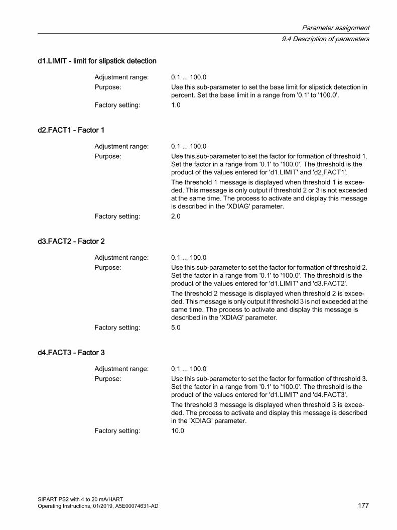
d1.LIMIT - limit for slipstick detection
Adjustment range: 0.1 ... 100.0Purpose: Use this sub-parameter to set the base limit for slipstick detection in
percent. Set the base limit in a range from '0.1' to '100.0'.Factory setting: 1.0
d2.FACT1 - Factor 1
Adjustment range: 0.1 ... 100.0Purpose: Use this sub-parameter to set the factor for formation of threshold 1.
Set the factor in a range from '0.1' to '100.0'. The threshold is the product of the values entered for 'd1.LIMIT' and 'd2.FACT1'.The threshold 1 message is displayed when threshold 1 is excee‐ded. This message is only output if threshold 2 or 3 is not exceeded at the same time. The process to activate and display this message is described in the 'XDIAG' parameter.
Factory setting: 2.0
d3.FACT2 - Factor 2
Adjustment range: 0.1 ... 100.0Purpose: Use this sub-parameter to set the factor for formation of threshold 2.
Set the factor in a range from '0.1' to '100.0'. The threshold is the product of the values entered for 'd1.LIMIT' and 'd3.FACT2'.The threshold 2 message is displayed when threshold 2 is excee‐ded. This message is only output if threshold 3 is not exceeded at the same time. The process to activate and display this message is described in the 'XDIAG' parameter.
Factory setting: 5.0
d4.FACT3 - Factor 3
Adjustment range: 0.1 ... 100.0Purpose: Use this sub-parameter to set the factor for formation of threshold 3.
Set the factor in a range from '0.1' to '100.0'. The threshold is the product of the values entered for 'd1.LIMIT' and 'd4.FACT3'.The threshold 3 message is displayed when threshold 3 is excee‐ded. The process to activate and display this message is described in the 'XDIAG' parameter.
Factory setting: 10.0
Parameter assignment9.4 Description of parameters
SIPART PS2 with 4 to 20 mA/HARTOperating Instructions, 01/2019, A5E00074631-AD 177
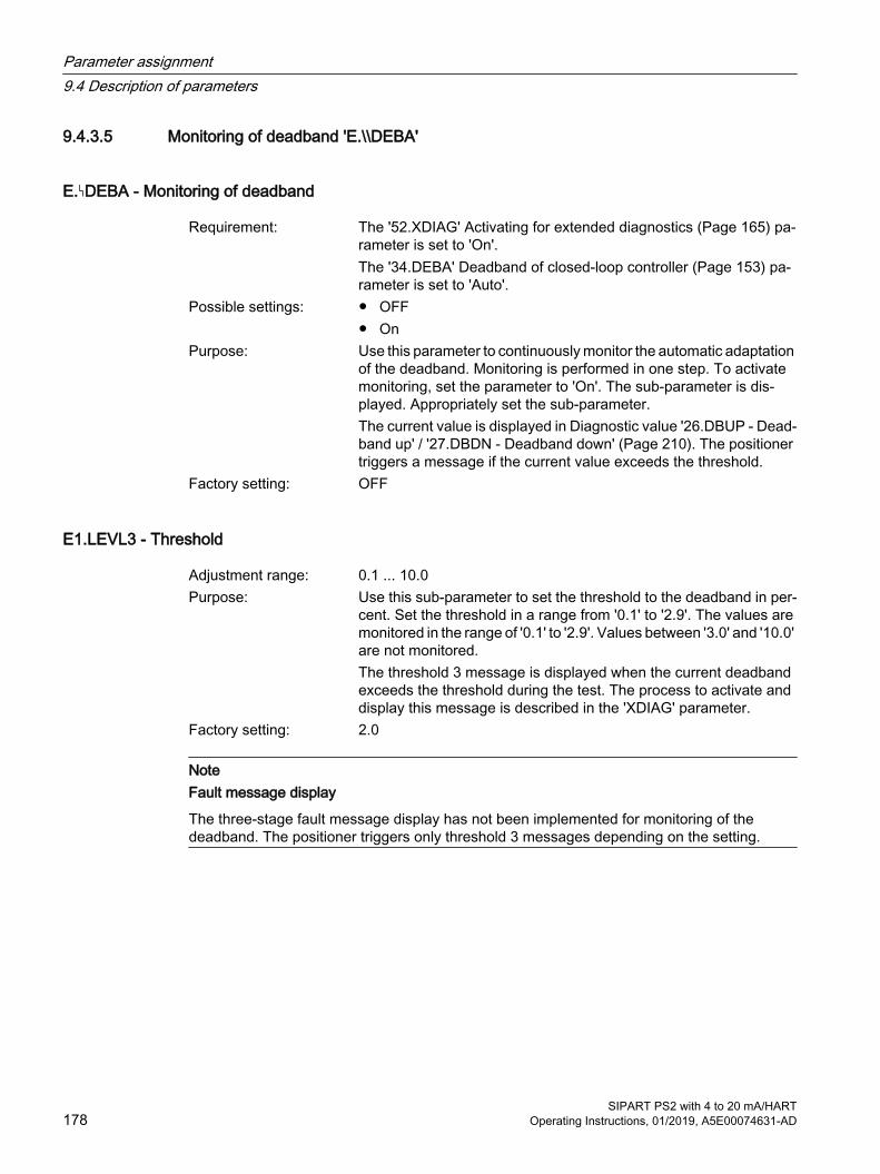
9.4.3.5 Monitoring of deadband 'E.\\DEBA'
E. DEBA - Monitoring of deadband
Requirement: The '52.XDIAG' Activating for extended diagnostics (Page 165) pa‐rameter is set to 'On'.The '34.DEBA' Deadband of closed-loop controller (Page 153) pa‐rameter is set to 'Auto'.
Possible settings: ● OFF● On
Purpose: Use this parameter to continuously monitor the automatic adaptation of the deadband. Monitoring is performed in one step. To activate monitoring, set the parameter to 'On'. The sub-parameter is dis‐played. Appropriately set the sub-parameter.
The current value is displayed in Diagnostic value '26.DBUP - Dead‐band up' / '27.DBDN - Deadband down' (Page 210). The positioner triggers a message if the current value exceeds the threshold.
Factory setting: OFF
E1.LEVL3 - Threshold
Adjustment range: 0.1 ... 10.0Purpose: Use this sub-parameter to set the threshold to the deadband in per‐
cent. Set the threshold in a range from '0.1' to '2.9'. The values are monitored in the range of '0.1' to '2.9'. Values between '3.0' and '10.0' are not monitored.
The threshold 3 message is displayed when the current deadband exceeds the threshold during the test. The process to activate and display this message is described in the 'XDIAG' parameter.
Factory setting: 2.0
NoteFault message display
The three-stage fault message display has not been implemented for monitoring of the deadband. The positioner triggers only threshold 3 messages depending on the setting.
Parameter assignment9.4 Description of parameters
SIPART PS2 with 4 to 20 mA/HART178 Operating Instructions, 01/2019, A5E00074631-AD
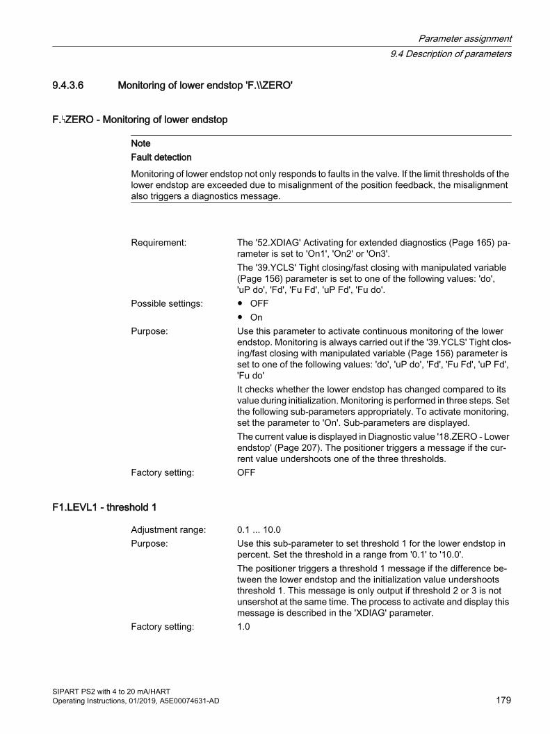
9.4.3.6 Monitoring of lower endstop 'F.\\ZERO'
F. ZERO - Monitoring of lower endstop
NoteFault detection
Monitoring of lower endstop not only responds to faults in the valve. If the limit thresholds of the lower endstop are exceeded due to misalignment of the position feedback, the misalignment also triggers a diagnostics message.
Requirement: The '52.XDIAG' Activating for extended diagnostics (Page 165) pa‐rameter is set to 'On1', 'On2' or 'On3'.The '39.YCLS' Tight closing/fast closing with manipulated variable (Page 156) parameter is set to one of the following values: 'do', 'uP do', 'Fd', 'Fu Fd', 'uP Fd', 'Fu do'.
Possible settings: ● OFF● On
Purpose: Use this parameter to activate continuous monitoring of the lower endstop. Monitoring is always carried out if the '39.YCLS' Tight clos‐ing/fast closing with manipulated variable (Page 156) parameter is set to one of the following values: 'do', 'uP do', 'Fd', 'Fu Fd', 'uP Fd', 'Fu do'It checks whether the lower endstop has changed compared to its value during initialization. Monitoring is performed in three steps. Set the following sub-parameters appropriately. To activate monitoring, set the parameter to 'On'. Sub-parameters are displayed. The current value is displayed in Diagnostic value '18.ZERO - Lower endstop' (Page 207). The positioner triggers a message if the cur‐rent value undershoots one of the three thresholds.
Factory setting: OFF
F1.LEVL1 - threshold 1
Adjustment range: 0.1 ... 10.0Purpose: Use this sub-parameter to set threshold 1 for the lower endstop in
percent. Set the threshold in a range from '0.1' to '10.0'.The positioner triggers a threshold 1 message if the difference be‐tween the lower endstop and the initialization value undershoots threshold 1. This message is only output if threshold 2 or 3 is not unsershot at the same time. The process to activate and display this message is described in the 'XDIAG' parameter.
Factory setting: 1.0
Parameter assignment9.4 Description of parameters
SIPART PS2 with 4 to 20 mA/HARTOperating Instructions, 01/2019, A5E00074631-AD 179

F2.LEVL2 - threshold 2
Adjustment range: 0.1 ... 10.0Purpose: Use this sub-parameter to set threshold 2 for the lower endstop in
percent. Set the threshold in a range from '0.1' to '10.0'.The positioner triggers a threshold 2 message if the difference be‐tween the lower endstop and the initialization value undershoots threshold 2. This message is only output if threshold 3 is not under‐shot at the same time. The process to activate and display this mes‐sage is described in the 'XDIAG' parameter.
Factory setting: 2.0
F3.LEVL3 - threshold 3
Adjustment range: 0.1 ... 10.0Purpose: Use this sub-parameter to set threshold 3 for the lower endstop in
percent. Set the threshold in a range from '0.1' to '10.0'.The positioner triggers a threshold 3 message if the difference be‐tween the lower endstop and the initialization value undershoots threshold 3. The process to activate and display this message is described in the 'XDIAG' parameter.
Factory setting: 4.0
9.4.3.7 Monitoring the upper endstop 'G.\\OPEN'
G. OPEN - Monitoring of upper endstop
NoteFault detection
Monitoring of upper endstop not only responds to faults in the valve. If the limit thresholds of the upper endstop are exceeded due to misalignment of the position feedback, the misalignment also triggers a message.
Requirement: The '52.XDIAG' Activating for extended diagnostics (Page 165) pa‐rameter is set to 'On1', 'On2' or 'On3'.The '39.YCLS' Tight closing/fast closing with manipulated variable (Page 156) parameter is set to one of the following values: 'uP', 'uP do', 'Fu', 'Fu Fd', 'uP Fd', 'Fu do'
Possible settings: ● OFF● On
Parameter assignment9.4 Description of parameters
SIPART PS2 with 4 to 20 mA/HART180 Operating Instructions, 01/2019, A5E00074631-AD

Purpose: Use this parameter to activate continuous monitoring of the upper endstop. Monitoring is always carried out if the '39.YCLS' Tight clos‐ing/fast closing with manipulated variable (Page 156) parameter is set to one of the following values: 'uP', 'uP do', 'Fu', 'Fu Fd', 'uP Fd', 'Fu do'It checks whether the upper endstop has changed compared to its value during initialization. Monitoring is performed in three steps. Set the following sub-parameters appropriately. To activate monitoring, set the parameter to 'On'. Sub-parameters are displayed. The value is displayed in Diagnostic value '19.OPEN - Upper end‐stop' (Page 208). The positioner triggers a message if the current value exceeds one of the three thresholds.
Factory setting: OFF
G1.LEVL1 - threshold 1
Adjustment range: 0.1 ... 10.0Purpose: Use this sub-parameter to set threshold 1 for the upper endstop in
percent. Set the threshold in a range from '0.1' to '10.0'.The positioner triggers a threshold 1 message if the difference be‐tween the upper endstop and the initialization value exceeds thresh‐old 1. This message is only output if threshold 2 or 3 is not exceeded at the same time. The process to activate and display this message is described in the 'XDIAG' parameter.
Factory setting: 1.0
G2.LEVL2 - threshold 2
Adjustment range: 0.1 ... 10.0Purpose: Use this sub-parameter to set threshold 2 for the upper endstop in
percent. Set the threshold in a range from '0.1' to '10.0'.The positioner triggers a threshold 2 message if the difference be‐tween the upper endstop and the initialization value exceeds thresh‐old 2. This message is only output if threshold 3 is not exceeded at the same time. The process to activate and display this message is described in the 'XDIAG' parameter.
Factory setting: 2.0
Parameter assignment9.4 Description of parameters
SIPART PS2 with 4 to 20 mA/HARTOperating Instructions, 01/2019, A5E00074631-AD 181
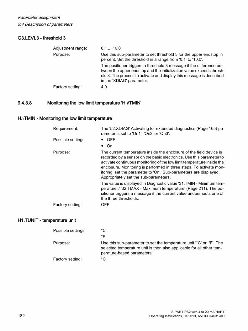
G3.LEVL3 - threshold 3
Adjustment range: 0.1 ... 10.0Purpose: Use this sub-parameter to set threshold 3 for the upper endstop in
percent. Set the threshold in a range from '0.1' to '10.0'.The positioner triggers a threshold 3 message if the difference be‐tween the upper endstop and the initialization value exceeds thresh‐old 3. The process to activate and display this message is described in the 'XDIAG' parameter.
Factory setting: 4.0
9.4.3.8 Monitoring the low limit temperature 'H.\\TMIN'
H. TMIN - Monitoring the low limit temperature
Requirement: The '52.XDIAG' Activating for extended diagnostics (Page 165) pa‐rameter is set to 'On1', 'On2' or 'On3'.
Possible settings: ● OFF● On
Purpose: The current temperature inside the enclosure of the field device is recorded by a sensor on the basic electronics. Use this parameter to activate continuous monitoring of the low limit temperature inside the enclosure. Monitoring is performed in three steps. To activate mon‐itoring, set the parameter to 'On'. Sub-parameters are displayed. Appropriately set the sub-parameters.The value is displayed in Diagnostic value '31.TMIN - Minimum tem‐perature' / '32.TMAX - Maximum temperature' (Page 211). The po‐sitioner triggers a message if the current value undershoots one of the three thresholds.
Factory setting: OFF
H1.TUNIT - temperature unit
Possible settings: °C°F
Purpose: Use this sub-parameter to set the temperature unit '°C' or '°F'. The selected temperature unit is then also applicable for all other tem‐perature-based parameters.
Factory setting: °C
Parameter assignment9.4 Description of parameters
SIPART PS2 with 4 to 20 mA/HART182 Operating Instructions, 01/2019, A5E00074631-AD

H2.LEVL1 - threshold 1
Adjustment range: -40.0C ... 90.0C-40.0F ... 194.0F
Purpose: Use this sub-parameter to set the temperature for threshold 1.The positioner triggers a threshold 1 message if the current temper‐ature inside the enclosure undershoots threshold 1. This message is only output if threshold 2 or 3 is not exceeded at the same time. The process to activate and display this message is described in the 'XDIAG' parameter.
Factory setting: -25.0C
H3.LEVL2 - threshold 2
Adjustment range: -40.0C ... 90.0C-40.0F ... 194.0F
Purpose: Use this sub-parameter to set the temperature for threshold 2.The positioner triggers a threshold 2 message if the current temper‐ature inside the enclosure undershoots threshold 2. This message is only output if threshold 3 is not exceeded at the same time. The process to activate and display this message is described in the 'XDIAG' parameter.
Factory setting: -30.0C
H4.LEVL3 - threshold 3
Adjustment range: -40.0C ... 90.0C-40.0F ... 194.0F
Purpose: Use this sub-parameter to set the temperature for threshold 3.The positioner triggers a threshold 3 message if the current temper‐ature inside the enclosure undershoots threshold 3. The process to activate and display this message is described in the 'XDIAG' pa‐rameter.
Factory setting: -40.0C
See also'39.YCLS' Tight closing/fast closing with manipulated variable (Page 156)
Parameter assignment9.4 Description of parameters
SIPART PS2 with 4 to 20 mA/HARTOperating Instructions, 01/2019, A5E00074631-AD 183
9.4.3.9 Monitoring the high limit temperature 'J.\\TMAX'
J. TMAX - Monitoring the upper limit temperature
Requirement: The '52.XDIAG' Activating for extended diagnostics (Page 165) pa‐rameter is set to 'On1', 'On2' or 'On3'.
Possible settings: ● OFF● On
Purpose: The current temperature inside the enclosure of the field device is recorded by a sensor on the basic electronics. Use this parameter to activate continuous monitoring of the high limit temperature inside the enclosure. Monitoring is performed in three steps. To activate monitoring, set the parameter to 'On'. Sub-parameters are dis‐played. Appropriately set the sub-parameters. The value is displayed in Diagnostic value '31.TMIN - Minimum tem‐perature' / '32.TMAX - Maximum temperature' (Page 211). The po‐sitioner triggers a message if the current value exceeds one of the three thresholds.
Factory setting: OFF
J1.TUNIT - temperature unit
Possible settings: °C°F
Purpose: Use this sub-parameter to set the temperature unit '°C' or '°F'. The selected temperature unit is then also applicable for all other tem‐perature-based parameters.
Factory setting: °C
J2.LEVL1 - threshold 1
Adjustment range: -40.0C ... 90.0C-40.0F ... 194.0F
Purpose: Use this sub-parameter to set the temperature for threshold 1.The positioner triggers a threshold 1 message if the current temper‐ature inside the enclosure exceeds threshold 1. This message is only output if threshold 2 or 3 is not exceeded at the same time. The process to activate and display this message is described in the 'XDIAG' parameter.
Factory setting: 75.0C
Parameter assignment9.4 Description of parameters
SIPART PS2 with 4 to 20 mA/HART184 Operating Instructions, 01/2019, A5E00074631-AD
J3.LEVL2 - threshold 2
Adjustment range: -40.0C ... 90.0C-40.0F ... 194.0F
Purpose: Use this sub-parameter to set the temperature for threshold 2.The positioner triggers a threshold 2 message if the current temper‐ature inside the enclosure exceeds threshold 2. This message is only output if threshold 3 is not exceeded at the same time. The process to activate and display this message is described in the 'XDIAG' parameter.
Factory setting: 80.0C
J4.LEVL3 - threshold 3
Adjustment range: -40.0C ... 90.0C-40.0F ... 194.0F
Purpose: Use this sub-parameter to set the temperature for threshold 3.The positioner triggers a threshold 3 message if the current temper‐ature inside the enclosure exceeds threshold 3. The process to ac‐tivate and display this message is described in the 'XDIAG' param‐eter.
Factory setting: 90.0C
9.4.3.10 Monitoring of number of total strokes 'L.\\STRK'
L. STRK - Monitoring of number of total strokes
Requirement: The '52.XDIAG' Activating for extended diagnostics (Page 165) pa‐rameter is set to 'On1', 'On2' or 'On3'.
Possible settings: ● OFF● On
Purpose: Use this parameter to continuously monitor the total strokes covered by the actuator. A total stroke corresponds to the path from the lower endstop of the actuator to the upper endstop and back again, in other words twice the travel. During operation, partial strokes of the ac‐tuator are added together into total strokes. Monitoring is performed in three steps. To activate monitoring, set the parameter to 'On'. Sub-parameters are displayed. Appropriately set the sub-parameters.The current value is displayed in Diagnostic value '1.STRKS - Num‐ber of total strokes' (Page 201). The positioner triggers a message if the current value exceeds one of the three thresholds. This message is only output if threshold 2 or 3 is not exceeded at the same time.
Factory setting: OFF
Parameter assignment9.4 Description of parameters
SIPART PS2 with 4 to 20 mA/HARTOperating Instructions, 01/2019, A5E00074631-AD 185
L1.LIMIT - Limit
Adjustment range: 1 ... 1.00E8Purpose: Use this sub-parameter to set the base limit for the number of total
strokes. Set the base limit in a range from '1' to '1.00E8'.Factory setting: 1.00E6
L2.FACT1 - Factor 1
Adjustment range: 0.1 ... 40.0Purpose: Use this sub-parameter to set the factor for formation of threshold 1.
Set the factor in a range from '0.1' to '40.0'. The threshold is the product of 'L1.LIMIT' and 'L2.FACT1'.The threshold 1 message is displayed when threshold 1 is excee‐ded. This message is only output if threshold 2 or 3 is not exceeded at the same time. The process to activate and display this message is described in the 'XDIAG' parameter.
Factory setting: 1.0
L3.FACT2 - Factor 2
Adjustment range: 0.1 ... 40.0Purpose: Use this sub-parameter to set the factor for formation of threshold 2.
Set the factor in a range from '0.1' to '40.0'. The threshold is the product of 'L1.LIMIT' and 'L3.FACT2'.The threshold 2 message is displayed when threshold 2 is excee‐ded. This message is only output if threshold 3 is not exceeded at the same time. The process to activate and display this message is described in the 'XDIAG' parameter.
Factory setting: 2.0
L4.FACT3 - Factor 3
Adjustment range: 0.1 ... 40.0Purpose: Use this sub-parameter to set the factor for formation of threshold 3.
Set the factor in a range from '0.1' to '40.0'. The threshold is the product of 'L1.LIMIT' and 'L4.FACT3'.The threshold 3 message is displayed when threshold 3 is excee‐ded. The process to activate and display this message is described in the 'XDIAG' parameter.
Factory setting: 5.0
See alsoDisplay of diagnostics values (Page 198)
Parameter assignment9.4 Description of parameters
SIPART PS2 with 4 to 20 mA/HART186 Operating Instructions, 01/2019, A5E00074631-AD

9.4.3.11 Monitoring of number of changes in direction 'O.\\DCHG'
O. DCHG - Monitoring of number of changes in direction
Requirement: The '52.XDIAG' Activating for extended diagnostics (Page 165) pa‐rameter is set to 'On1', 'On2' or 'On3'.
Possible settings: ● OFF● On
Purpose: Use this parameter to continuously monitor the number of changes in direction of the actuator beyond the deadband. Monitoring is per‐formed in three steps. Set the following sub-parameters appropri‐ately. To activate monitoring, set the parameter to 'On'. Sub-param‐eters are displayed.The current value is displayed in Diagnostic value '2.CHDIR - Num‐ber of changes in direction' (Page 201). The positioner triggers a message if the current value exceeds one of the three thresholds.
Factory setting: OFF
O1.LIMIT - Limit
Adjustment range: 1 ... 1.00E8Purpose: Use this sub-parameter to set the base limit for the changes of di‐
rection of the actuator. Set the base limit in a range from '1' to '1.00E8'.
Factory setting: 1.00E6
O2.FACT1 - Factor 1
Adjustment range: 0.1 ... 40.0Purpose: Use this sub-parameter to set the factor for formation of threshold 1.
Set the factor in a range from '0.1' to '40.0'. The threshold is the product of 'O1.LIMIT' and 'O2.FACT1'.The threshold 1 message is displayed when threshold 1 is excee‐ded. This message is only output if threshold 2 or 3 is not exceeded at the same time. The process to activate and display this message is described in the 'XDIAG' parameter.
Factory setting: 1.0
Parameter assignment9.4 Description of parameters
SIPART PS2 with 4 to 20 mA/HARTOperating Instructions, 01/2019, A5E00074631-AD 187
O3.FACT2 - Factor 2
Adjustment range: 0.1 ... 40.0Purpose: Use this sub-parameter to set the factor for formation of threshold 2.
Set the factor in a range from '0.1' to '40.0'. The threshold is the product of 'O1.LIMIT' and 'O3.FACT2'.The threshold 2 message is displayed when threshold 2 is excee‐ded. This message is only output if threshold 3 is not exceeded at the same time. The process to activate and display this message is described in the 'XDIAG' parameter.
Factory setting: 2.0
O4.FACT3 - Factor 3
Adjustment range: 0.1 ... 40.0Purpose: Use this sub-parameter to set the factor for formation of threshold 3.
Set the factor in a range from '0.1' to '40.0'. The threshold is the product of 'O1.LIMIT' and 'O4.FACT3'.The threshold 3 message is displayed when threshold 3 is excee‐ded. The process to activate and display this message is described in the 'XDIAG' parameter.
Factory setting: 5.0
See alsoDisplay of diagnostics values (Page 198)
9.4.3.12 Monitoring the position average value 'P.\\PAVG'
P. PAVG - Monitoring the position average value
Requirement: The '52.XDIAG' Activating for extended diagnostics (Page 165) pa‐rameter is set to 'On1', 'On2' or 'On3'.
Possible settings: ● OFF● On
Purpose: Use this parameter to activate the test to calculate and monitor the average value of position. During the test, the average values of position and reference are always compared at the end of a time interval.The current value is displayed in Diagnostic value '20.PAVG - Aver‐age value of position' (Page 208). The positioner triggers a message if the current average value of position undershoots one of the three thresholds.
Factory setting: OFF
Parameter assignment9.4 Description of parameters
SIPART PS2 with 4 to 20 mA/HART188 Operating Instructions, 01/2019, A5E00074631-AD
P1.TBASE - Time basis of average value generation
Possible settings: 0.5h / 8h / 5d / 60d / 2.5yPurpose: Use this sub-parameter to set the time interval to calculate the aver‐
age value of position. The following values are available to define the time intervals:● 30 minutes● 8 hours● 5 days● 60 days● 2.5 yearsAfter starting the calculation for average value of reference and ex‐piry of the time interval, a position average over the interval period is determined and compared with the average value of reference. The test is then restarted.
Factory setting: 0.5h
P2.STATE - Status of monitoring position average value
Possible settings: IdLE / rEF / ###.# / StrtPurpose: Use this sub-parameter to start the calculation for average value of
position. If an average value of reference has never been deter‐mined, the parameter value is 'IdLE'.Then start the calculation by pressing the button for 5 seconds. The value in the display changes from 'IdLE' to 'rEF'. The average value of reference is calculated.When the time interval expires, the calculated average value of ref‐erence is shown on the display.
Factory setting: IdLE
NoteCurrent average value of position
The respective current average value of position is displayed in the Diagnostic value '20.PAVG - Average value of position' (Page 208). If no average value of position has been calculated, 'COMP' is displayed as the diagnostic value.
Parameter assignment9.4 Description of parameters
SIPART PS2 with 4 to 20 mA/HARTOperating Instructions, 01/2019, A5E00074631-AD 189
P3.LEVL1 - threshold 1
Possible settings: 0.1 ... 100.0Purpose: Use this sub-parameter to set threshold 1 for the maximum deviation
of the current average value of position from the average value of reference. The value is given in percent. Set the threshold in a range from '0.1' to '100.0'.The positioner triggers the threshold 1 message if the difference between the average value of position and the average value of reference exceeds threshold 1. This message is only output if threshold 2 or 3 is not exceeded at the same time. The process to activate and display this message is described in the 'XDIAG' pa‐rameter.
Factory setting: 2.0
P4.LEVL2 - threshold 2
Possible settings: 0.1 ... 100.0Purpose: Use this sub-parameter to set threshold 2 for the maximum deviation
of the current average value of position from the average value of reference. The value is given in percent. Set the threshold in a range from '0.1' to '100.0'.The positioner triggers the threshold 2 message if the difference between the average value of position and the average value of reference exceeds threshold 2. This message is only output if threshold 3 is not exceeded at the same time. The process to acti‐vate and display this message is described in the 'XDIAG' parameter.
Factory setting: 5.0
P5.LEVL3 - threshold 3
Possible settings: 0.1 ... 100.0Purpose: Use this sub-parameter to set threshold 3 for the maximum deviation
of the current average value of position from the average value of reference. The value is given in percent. Set the threshold in a range from '0.1' to '100.0'.The positioner triggers the threshold 3 message if the difference between the average value of position and the average value of reference exceeds threshold 3. The process to activate and display this message is described in the 'XDIAG' parameter.
Factory setting: 10.0
Parameter assignment9.4 Description of parameters
SIPART PS2 with 4 to 20 mA/HART190 Operating Instructions, 01/2019, A5E00074631-AD
9.4.3.13 Pressure monitoring 'U.\\PRES'
U. PRES - Activate pressure monitoring
Requirement: The parameter "XDIAG (Page 165)" is set to "On1", "On2" or "On3".Possible settings: ● OFF
● OnPurpose: Activates or deactivates all pressure-based diagnostics.Factory setting: On
U1.PUNIT - Pressure unit
Possible settings: bar / psi / MPaPurpose: Defines the pressure unit for all pressure-based diagnostic param‐
eters.Factory setting: bar
U2.PZLIM - Low limit of the supply pressure (PZLIM)
Possible settings: 1.4 to 7.0 (bar)20.30 … 101.52 psi0.140 ... 0.700 MPa
Purpose: Defines the minimum required supply pressure. When the value is undershot, the message "18 (Page 221)" appears on the display in "Automatic" and "Manual" modes.
Factory setting: 1.4
U3.PZHYS - Hysteresis of the low limit of the supply pressure
Possible settings: 0.2 to 1.0 (bar)2.90 … 14.50 psi0.020 ... 0.100 MPa
Purpose: Defines the hysteresis of the low limit of the supply pressure (U2.PZLIM). The error message 18 (Page 221) in the "Automatic" and "Manual" modes is deleted when the value of the supply pressure PZ is "PZHYS" larger than the value assigned in "U2.PZLIM". The control becomes active again if the configured fault reaction was "HOLd".
Factory setting: 0.2
Parameter assignment9.4 Description of parameters
SIPART PS2 with 4 to 20 mA/HARTOperating Instructions, 01/2019, A5E00074631-AD 191
U4.PZ_FR - Error response on undershoot of the supply pressure
Possible settings: cont / HOLdPurpose: Defines the behavior of the device when the limit value of the supply
pressure (U2.PZLIM) is undershot.Cont = Chamber pressure is controlled via supply air PZ HOLd = Chamber pressure is maintained, corresponds to the re‐sponse for Fail in Place
Factory setting: cont
Parameter assignment9.4 Description of parameters
SIPART PS2 with 4 to 20 mA/HART192 Operating Instructions, 01/2019, A5E00074631-AD
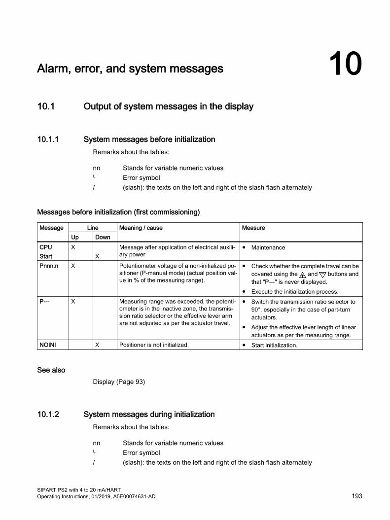
Alarm, error, and system messages 1010.1 Output of system messages in the display
10.1.1 System messages before initializationRemarks about the tables:
nn Stands for variable numeric valuesError symbol
/ (slash): the texts on the left and right of the slash flash alternately
Messages before initialization (first commissioning)
Message Line Meaning / cause MeasureUp Down
CPUStart
X X
Message after application of electrical auxili‐ary power
● Maintenance
Pnnn.n X Potentiometer voltage of a non-initialized po‐sitioner (P-manual mode) (actual position val‐ue in % of the measuring range).
● Check whether the complete travel can be covered using the and buttons and that "P---" is never displayed.
● Execute the initialization process.P--- X Measuring range was exceeded, the potenti‐
ometer is in the inactive zone, the transmis‐sion ratio selector or the effective lever arm are not adjusted as per the actuator travel.
● Switch the transmission ratio selector to 90°, especially in the case of part-turn actuators.
● Adjust the effective lever length of linear actuators as per the measuring range.
NOINI X Positioner is not initialized. ● Start initialization.
See alsoDisplay (Page 93)
10.1.2 System messages during initializationRemarks about the tables:
nn Stands for variable numeric valuesError symbol
/ (slash): the texts on the left and right of the slash flash alternately
SIPART PS2 with 4 to 20 mA/HARTOperating Instructions, 01/2019, A5E00074631-AD 193

Messages during initialization
Message Line Meaning/cause MeasureUp Down
P--- X Measuring range was exceeded, the potenti‐ometer is in the inactive zone, the transmis‐sion ratio selectors or the effective lever arm are not adjusted as per the actuator travel
● Switch the transmission ratio selector to 90°, especially in the case of part-turn actuators.
● Adjust the effective lever length of linear actuators as per the measuring range.
RUN 1 X Initialization was started, part 1 is active (the direction of action is determined)
● Wait.
RUN 2 X Initialization part 2 is active (actuator travel check and determination of end stops)
● Wait.
RUN 3 X Initialization part 3 is active (determination and display of travel times)
● Wait.
RUN 4 X Initialization part 4 is active (determination of the minimum controller increment length)
● Wait.
RUN 5 X Initialization part 5 is active (optimization of the transient response)
● Wait until "FINSH" is displayed. Initialization was completed successfully.
YEND1 X The first end position can be approached only in case of a manual initialization
1. Approach first end position using or button.
2. Acknowledge using button.YEND2 X The second end position can be approached
only in case of a manual initialization1. Approach second end position using
or button.2. Acknowledge using button.
RANGE X The end position or the measuring span is be‐yond the permissible measuring range only in case of a manual initialization
● Approach a different end position using or button and acknowledge using button.
● Move the friction clutch until "ok" is displayed, and then acknowledge with the button.
● Terminate the initialization process using the button, switch to the P-manual mode, and correct the actuator travel and the position displacement sensor.
ok x The permissible measuring range of end po‐sitions is achieved only in case of a manual initialization
● Use the button to acknowledge; the remaining steps ("RUN 1" to "FINSH") run automatically.
RUN 1 / ERROR
X Error in "RUN 1", no movement e.g. due to the lack of compressed air
Possible causes:● Insufficient supply of compressed air.● Restrictor(s) blocked.● Actuator does not move freely.Measures:1. Eliminate possible causes.2. Restart initialization.
Alarm, error, and system messages10.1 Output of system messages in the display
SIPART PS2 with 4 to 20 mA/HART194 Operating Instructions, 01/2019, A5E00074631-AD

Message Line Meaning/cause MeasureUp Down
d___U X Bar graph display of the zero point is outside the tolerance range
1. Set between "P 4.0" and "P 9.9" ( >0< ) using friction clutch.
2. Continue using or button.SEt X Friction clutch was moved; "P 50.0" not dis‐
played when the lever is horizontal1. In the case of linear actuators, use the
or button to bring the lever perpendicular to the spindle.
2. Briefly acknowledge using button (initialization is continued).
MIDDL X
UP > X "UP" tolerance range was exceeded or the in‐active zone of the potentiometer was covered.
1. Increase the effective lever length of the linear actuators or switch the transmission ratio selector to 90°.
2. Briefly acknowledge using button.3. Restart initialization.
90_95 X Possible only in case of part-turn actuators: actuator travel is not in the range between 90 and 95%
1. Use the or button to move it in the range between 90 and 95%.
2. Briefly acknowledge using button.U-d> X "Up-Down" measuring span was undershot 1. Decrease the effective lever length of the
linear actuators or switch the transmission ratio selector to 33°.
2. Briefly acknowledge using button.3. Restart initialization.
U nn.n X Display of the "Up" travel time ● Wait until initialization continues in RUN 4.● To change the travel time, interrupt the
initialization process using the button.● Activate the leakage test using the
button.
D->U X
D nn.n X Display of the "Down" travel time ● Wait until initialization continues in RUN 4.● To change the travel time, interrupt the
initialization process using the button.● Activate the leakage test using the
button.
U->d X
NOZZL X Actuator stops (the initialization process was interrupted using the "-" button when the ac‐tuation speed display was active)
1. The travel time can be changed by adjusting the restrictor(s).
2. Redetermine the positioning speed using the button.
3. Continue using button.TESt X Leakage test active (the "+" button was press‐
ed when the actuation speed display was ac‐tive)
● Wait for one minute.LEAKG X
nn.n X Value and unit of the result after the leakage test
● Rectify the leakage if the value is too large.● Continue using button.%/MIN X
Alarm, error, and system messages10.1 Output of system messages in the display
SIPART PS2 with 4 to 20 mA/HARTOperating Instructions, 01/2019, A5E00074631-AD 195
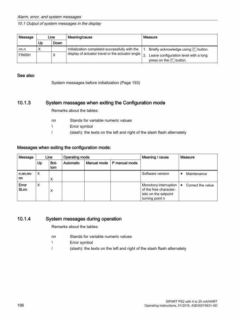
Message Line Meaning/cause MeasureUp Down
nn.n X Initialization completed successfully with the display of actuator travel or the actuator angle
1. Briefly acknowledge using button.2. Leave configuration level with a long
press on the button.FINISH X
See alsoSystem messages before initialization (Page 193)
10.1.3 System messages when exiting the Configuration modeRemarks about the tables:
nn Stands for variable numeric valuesError symbol
/ (slash): the texts on the left and right of the slash flash alternately
Messages when exiting the configuration mode:
Message Line Operating mode Meaning / cause MeasureUp Bot‐
tomAutomatic Manual mode P manual mode
n.nn.nn-nn
X X
Software version ● Maintenance
Error SLnn
X X
Monotony interruption of the free character‐istic on the setpoint turning point n
● Correct the value
10.1.4 System messages during operationRemarks about the tables:
nn Stands for variable numeric valuesError symbol
/ (slash): the texts on the left and right of the slash flash alternately
Alarm, error, and system messages10.1 Output of system messages in the display
SIPART PS2 with 4 to 20 mA/HART196 Operating Instructions, 01/2019, A5E00074631-AD
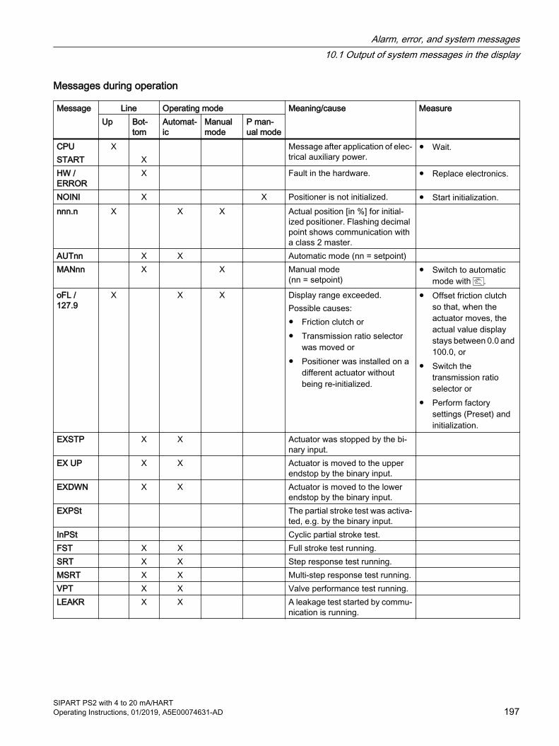
Messages during operation
Message Line Operating mode Meaning/cause MeasureUp Bot‐
tomAutomat‐ic
Manual mode
P man‐ual mode
CPUSTART
X X
Message after application of elec‐trical auxiliary power.
● Wait.
HW / ERROR
X Fault in the hardware. ● Replace electronics.
NOINI X X Positioner is not initialized. ● Start initialization.nnn.n X X X Actual position [in %] for initial‐
ized positioner. Flashing decimal point shows communication with a class 2 master.
AUTnn X X Automatic mode (nn = setpoint) MANnn X X Manual mode
(nn = setpoint)● Switch to automatic
mode with .oFL / 127.9
X X X Display range exceeded.Possible causes:● Friction clutch or● Transmission ratio selector
was moved or● Positioner was installed on a
different actuator without being re-initialized.
● Offset friction clutch so that, when the actuator moves, the actual value display stays between 0.0 and 100.0, or
● Switch the transmission ratio selector or
● Perform factory settings (Preset) and initialization.
EXSTP X X Actuator was stopped by the bi‐nary input.
EX UP X X Actuator is moved to the upper endstop by the binary input.
EXDWN X X Actuator is moved to the lower endstop by the binary input.
EXPSt The partial stroke test was activa‐ted, e.g. by the binary input.
InPSt Cyclic partial stroke test. FST X X Full stroke test running. SRT X X Step response test running. MSRT X X Multi-step response test running. VPT X X Valve performance test running. LEAKR X X A leakage test started by commu‐
nication is running.
Alarm, error, and system messages10.1 Output of system messages in the display
SIPART PS2 with 4 to 20 mA/HARTOperating Instructions, 01/2019, A5E00074631-AD 197

10.2 Diagnostics
10.2.1 Display of diagnostics values
Structure of the diagnostics display The display in "Diagnostics" mode has a structure similar to that in "Configuration" mode:
● The upper line shows the value of the diagnostics variable.
● The lower line shows the number and the abbreviation of the displayed variable.
Some diagnostics value can be greater than 99999. In such a case, the display switches over to the exponential view. Example: The value "1234567" is shown as "1.23E6".
General procedure1. Press all three buttons at the same time for at least 2 seconds. You are now in the
diagnostics display.
2. Use the button to select the next diagnostics value.
3. Press the button for at least 2 seconds in order to exit the diagnostics display.
How to show the diagnostics values in reverse orderPress the and buttons simultaneously.
How to set values to zeroSpecific values can be set to zero by pressing the button for at least 5 seconds. The diagnostics values which can be reset are listed in the table in section "Overview of diagnostics values (Page 199)".
10.2.2 Saving the diagnostics valuesThe diagnostic values are written into a non-volatile memory every 15 minutes so that, in the event of a power failure, only the diagnostic values of the previous 15 minutes are lost. The values in the resettable parameters can be set to zero.
To do this, press the button for at least 5 seconds.
The diagnostic values which can be reset can be found in the table in section Overview of diagnostics values (Page 199).
Alarm, error, and system messages10.2 Diagnostics
SIPART PS2 with 4 to 20 mA/HART198 Operating Instructions, 01/2019, A5E00074631-AD
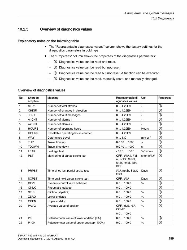
10.2.3 Overview of diagnostics values
Explanatory notes on the following table● The "Representable diagnostics values" column shows the factory settings for the
diagnostics parameters in bold type.
● The "Properties" column shows the properties of the diagnostics parameters:
– ① Diagnostics value can be read and reset.
– ② Diagnostics value can be read but not reset.
– ③ Diagnostics value can be read but not reset. A function can be executed.
– ④ Diagnostics value can be read, manually reset, and manually changed.
Overview of diagnostics values
No. Short de‐scription
Meaning Representable di‐agnostics values
Unit Properties
1 STRKS Number of total strokes 0 ... 4.29E9 - ①2 CHDIR Number of changes in direction 0 ... 4.29E9 - ①3 CNT Number of fault messages 0 ... 4.29E9 - ①4 A1CNT Number of alarms 1 0 ... 4.29E9 - ①5 A2CNT Number of alarms 2 0 ... 4.29E9 - ①6 HOURS Number of operating hours 0 ... 4.29E9 Hours ②7 HOURR Resettable operating hours counter 0 ... 4.29E9 ①8 WAY Determined travel 0 ... 130 mm or ° ②9 TUP Travel time up 0.0 / 0 ... 1000 s ②10 TDOWN Travel time down 0.0 / 0 ... 1000 s ②11 LEAK Leakage test - / 0.0 ... 100.0 %/minute ③12 PST Monitoring of partial stroke test OFF / ###.#, FdI‐
ni, notSt, SdtSt, fdtSt, notoL, Strt, StoP
s for ###.# ③
13 PRPST Time since last partial stroke test ###, notSt, Sdtst, fdtSt
Days ②
14 NXPST Time until next partial stroke test OFF / ### Days ②15 DEVI Dynamic control valve behavior 0.0 ... 100.0 % ②16 ONLK Pneumatic leakage 0.0 ... 100.0 - ②17 STIC Stiction (slipstick) 0.0 ... 100.0 % ②18 ZERO Lower endstop 0.0 ... 100.0 % ②19 OPEN Upper endstop 0.0 ... 100.0 % ②20 PAVG Average value of position OFF, IdLE, rEF,
COMP0.0 ... 100.0
% ②
21 P0 Potentiometer value of lower endstop (0%) 0.0 ... 100.0 % ③22 P100 Potentiometer value of upper endstop (100%) 0.0 ... 100.0 % ③
Alarm, error, and system messages10.2 Diagnostics
SIPART PS2 with 4 to 20 mA/HARTOperating Instructions, 01/2019, A5E00074631-AD 199
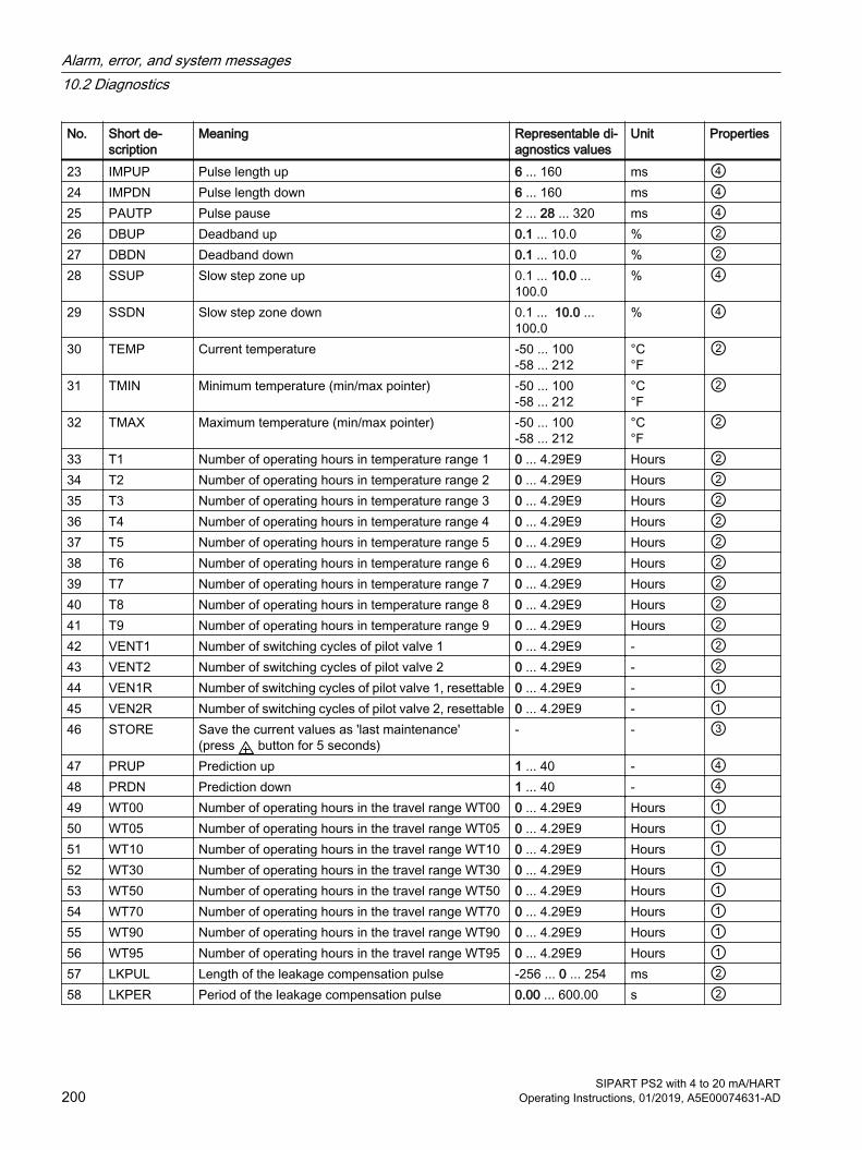
No. Short de‐scription
Meaning Representable di‐agnostics values
Unit Properties
23 IMPUP Pulse length up 6 ... 160 ms ④24 IMPDN Pulse length down 6 ... 160 ms ④25 PAUTP Pulse pause 2 ... 28 ... 320 ms ④26 DBUP Deadband up 0.1 ... 10.0 % ②27 DBDN Deadband down 0.1 ... 10.0 % ②28 SSUP Slow step zone up 0.1 ... 10.0 ...
100.0% ④
29 SSDN Slow step zone down 0.1 ... 10.0 ... 100.0
% ④
30 TEMP Current temperature -50 ... 100 -58 ... 212
°C°F
②
31 TMIN Minimum temperature (min/max pointer) -50 ... 100-58 ... 212
°C°F
②
32 TMAX Maximum temperature (min/max pointer) -50 ... 100-58 ... 212
°C°F
②
33 T1 Number of operating hours in temperature range 1 0 ... 4.29E9 Hours ②34 T2 Number of operating hours in temperature range 2 0 ... 4.29E9 Hours ②35 T3 Number of operating hours in temperature range 3 0 ... 4.29E9 Hours ②36 T4 Number of operating hours in temperature range 4 0 ... 4.29E9 Hours ②37 T5 Number of operating hours in temperature range 5 0 ... 4.29E9 Hours ②38 T6 Number of operating hours in temperature range 6 0 ... 4.29E9 Hours ②39 T7 Number of operating hours in temperature range 7 0 ... 4.29E9 Hours ②40 T8 Number of operating hours in temperature range 8 0 ... 4.29E9 Hours ②41 T9 Number of operating hours in temperature range 9 0 ... 4.29E9 Hours ②42 VENT1 Number of switching cycles of pilot valve 1 0 ... 4.29E9 - ②43 VENT2 Number of switching cycles of pilot valve 2 0 ... 4.29E9 - ②44 VEN1R Number of switching cycles of pilot valve 1, resettable 0 ... 4.29E9 - ①45 VEN2R Number of switching cycles of pilot valve 2, resettable 0 ... 4.29E9 - ①46 STORE Save the current values as 'last maintenance'
(press button for 5 seconds)- - ③
47 PRUP Prediction up 1 ... 40 - ④48 PRDN Prediction down 1 ... 40 - ④49 WT00 Number of operating hours in the travel range WT00 0 ... 4.29E9 Hours ①50 WT05 Number of operating hours in the travel range WT05 0 ... 4.29E9 Hours ①51 WT10 Number of operating hours in the travel range WT10 0 ... 4.29E9 Hours ①52 WT30 Number of operating hours in the travel range WT30 0 ... 4.29E9 Hours ①53 WT50 Number of operating hours in the travel range WT50 0 ... 4.29E9 Hours ①54 WT70 Number of operating hours in the travel range WT70 0 ... 4.29E9 Hours ①55 WT90 Number of operating hours in the travel range WT90 0 ... 4.29E9 Hours ①56 WT95 Number of operating hours in the travel range WT95 0 ... 4.29E9 Hours ①57 LKPUL Length of the leakage compensation pulse -256 ... 0 ... 254 ms ②58 LKPER Period of the leakage compensation pulse 0.00 ... 600.00 s ②
Alarm, error, and system messages10.2 Diagnostics
SIPART PS2 with 4 to 20 mA/HART200 Operating Instructions, 01/2019, A5E00074631-AD
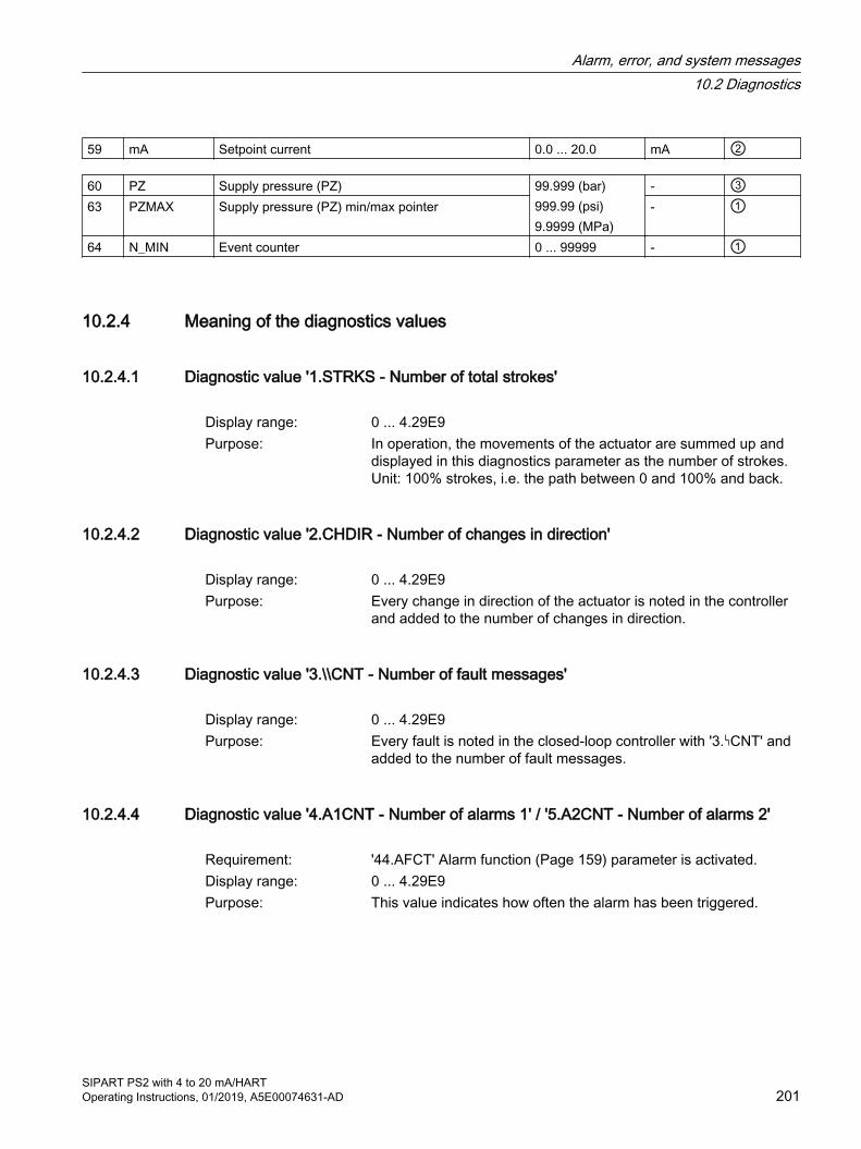
59 mA Setpoint current 0.0 ... 20.0 mA ②
60 PZ Supply pressure (PZ) 99.999 (bar)999.99 (psi)9.9999 (MPa)
- ③63 PZMAX Supply pressure (PZ) min/max pointer - ①
64 N_MIN Event counter 0 ... 99999 - ①
10.2.4 Meaning of the diagnostics values
10.2.4.1 Diagnostic value '1.STRKS - Number of total strokes'
Display range: 0 ... 4.29E9Purpose: In operation, the movements of the actuator are summed up and
displayed in this diagnostics parameter as the number of strokes. Unit: 100% strokes, i.e. the path between 0 and 100% and back.
10.2.4.2 Diagnostic value '2.CHDIR - Number of changes in direction'
Display range: 0 ... 4.29E9Purpose: Every change in direction of the actuator is noted in the controller
and added to the number of changes in direction.
10.2.4.3 Diagnostic value '3.\\CNT - Number of fault messages'
Display range: 0 ... 4.29E9Purpose: Every fault is noted in the closed-loop controller with '3. CNT' and
added to the number of fault messages.
10.2.4.4 Diagnostic value '4.A1CNT - Number of alarms 1' / '5.A2CNT - Number of alarms 2'
Requirement: '44.AFCT' Alarm function (Page 159) parameter is activated.Display range: 0 ... 4.29E9Purpose: This value indicates how often the alarm has been triggered.
Alarm, error, and system messages10.2 Diagnostics
SIPART PS2 with 4 to 20 mA/HARTOperating Instructions, 01/2019, A5E00074631-AD 201

10.2.4.5 Diagnostic value '6.HOURS - Number of operating hours'
Display range: 0 ... 4.29E9Purpose: The runtime meter is incremented every hour as soon as electric
auxiliary power is supplied to the positioner.
10.2.4.6 Diagnostic value '7.HOURR - Resettable operating hours counter'
Display range: 0 ... 4.29E9Purpose: The runtime meter is incremented every hour as soon as electric
auxiliary power is supplied to the positioner. In contrast to Diagnostic value '6.HOURS - Number of operating hours' (Page 202), this value can be reset.
Description: In order to minimize the control valve wear resulting from a poor control quality, it makes sense to optimize the positioner's parame‐ters. You can recognize optimum parameter settings when the val‐ues of the Diagnostic value '44.VEN1R' / '45.VEN2R' (Page 213) are low. Low values mean that the switching frequency of the positioner pneumatics is also low. In order to carry out a comparison with var‐ious parameter settings, determine the number of switching cycles per hour. To do this, use the values of the Diagnostic value '44.VEN1R' / '45.VEN2R' (Page 213) and '7.HOURR'. These three parameters can be reset to enable simpler determination of the val‐ues.
10.2.4.7 Diagnostic value '8.WAY - Determined travel'
Requirement for linear actuator:
The travel is set in the '3.YWAY' Range of stroke (Page 148) pa‐rameter.
Display range: 0 ... 130Purpose: This value in mm or ° specifies the travel determined during the
initialization.
10.2.4.8 Diagnostic value '9.TUP - Travel time up' / '10.TDOWN - Travel time down'
Display range: 0 ... 1000Purpose: This value indicates the current UP or DOWN travel time in seconds
determined during the initialization.
Alarm, error, and system messages10.2 Diagnostics
SIPART PS2 with 4 to 20 mA/HART202 Operating Instructions, 01/2019, A5E00074631-AD
10.2.4.9 Diagnostic value '11.LEAK - Leakage test'
Requirement The positioner is initialized and in manual mode (MAN).Display range: ● -
● 0.0 ... 100.0Purpose: You can use this diagnostics parameter to read the last test result or
start an offline leakage test with which you can detect leakages in the actuator or in the pipe installation. Display is percent stroke per mi‐nute referred to the total stroke. A test result originates from one of the following options:● Function '11.LEAK' has already been carried out.● Leakage test was already carried out during initialization, see
procedure of RUN 3 in section Sequence of automatic initialization (Page 107).
● 'Offline leakage test' function was already executed by a HOST system.
"-" in the display can have the following causes:● A leakage test has not yet been carried out.● Resetting to the factory settings was carried out using
the '50.PRST' Preset (Page 163) > ALL parameter.● Positioner is not initialized.How to start the test1. Move the actuator to the position at which you wish to start the
test.2. In 'Diagnostics' mode, go to the '11.LEAK' diagnostic value as
described in section Display of diagnostics values (Page 198).3. Start the function by pressing the button for at least 5 seconds.
Description: 'Strt' is output in the display. The function is started after 5 seconds. 'tESt' and the current position of the actuator (actual value) are then displayed alternately for one minute. After one minute, the display shows the difference in the actuator position before and after the test. This means: the actuator position has changed by the displayed value in one minute.
Alarm, error, and system messages10.2 Diagnostics
SIPART PS2 with 4 to 20 mA/HARTOperating Instructions, 01/2019, A5E00074631-AD 203
10.2.4.10 Diagnostic value '12.PST - Monitoring of partial stroke test'
Indication on the display: ● OFF● C-ERR● FdIni● notSt● ###.#● SdtSt● FdtSt
Purpose: This diagnostics parameter indicates the stroke time measured dur‐ing the last partial stroke test. A partial stroke test can be initiated manually or a current partial stroke test can be interrupted by pressing the button.
Description of indications on the display:
● OFF: The partial stroke test function is deactivated.● C-ERR: Configuration error. Partial stroke test cannot be started.
Settings in the 'A1.STPOS start position', 'A3.STRKH stroke height' and 'A4.STRKD stroke direction' are not plausible.
● FdIni - Failed PST Initialization: The reference stroke time measurement of the partial stroke test has failed.
● notSt - No Test: A partial stroke test has not yet been executed.● ###.#: Corresponds to the measured stroke time in seconds. The
last partial stroke test was successfully executed.● SdtSt - Stopped Test: The last partial stroke test was interrupted.● FdtSt - Failed Test: The last partial stroke test has failed.
Status messages: The following status messages appear when you hold the button pressed:● notoL - No Tolerance: The control valve is beyond the tolerance
range to start the partial stroke test. A manual partial stroke test is not started.
● Strt - Start: A manual partial stroke test is started five seconds after pressing the button.
● StoP - Stop: The current partial stroke test is interrupted. 'WAIT' is output in the display.
Factory setting: OFF
Alarm, error, and system messages10.2 Diagnostics
SIPART PS2 with 4 to 20 mA/HART204 Operating Instructions, 01/2019, A5E00074631-AD

10.2.4.11 Diagnostic value '12.PST - Monitoring of partial stroke test' (version with pressure sensors)
The monitoring of the partial stroke test for positioners with pressure sensors is described below.
Indication on the display: ● OFF● C-ERR● FdIni● notSt● noREF● oCAY● SdtSt● FdtSt
Purpose: This diagnostics parameter indicates the status of the partial stroke test.A partial stroke test can be initiated manually or a current partial stroke test can be interrupted by pressing the button.
Description of indications on the display:
● OFF: The function of the partial stroke test is disabled.● C-ERR: Configuration error. Partial stroke test cannot be started.
Settings in the "A1.STPOS start position" and "Ad.ENPOSend position" parameters are not plausible.
● FdIni - Failed PST Initialization: A reference abort pressure is determined with the parameter "AF.PSTRF". This test failed.
● notSt - No Test: A partial stroke test has not yet been executed.● noREF: A reference partial stroke test has not yet been executed.● oCAY: The last partial stroke test was successfully executed.● SdtSt - Stopped Test: The last partial stroke test was interrupted.● FdtSt - Failed Test: The last partial stroke test has failed.
Status messages: The following status messages appear when you hold the button pressed:● notoL - No Tolerance: The control valve is beyond the tolerance
range to start the partial stroke test. A manual partial stroke test is not started.
● Strt - Start: A manual partial stroke test is started five seconds after pressing the button. 'WAIT' is output in the display.
● StoP - Stop: The current partial stroke test was interrupted.Factory setting: OFF
Alarm, error, and system messages10.2 Diagnostics
SIPART PS2 with 4 to 20 mA/HARTOperating Instructions, 01/2019, A5E00074631-AD 205

10.2.4.12 Diagnostic value '13.PRPST - Time since last partial stroke test' (version without pressure sensors)
Indication on the display: ● ###● notSt● Sdtst● FdtSt
Purpose: This diagnostics parameter shows the elapsed time in days since the last partial stroke test.
Status messages: ● notSt - No Test: A manual partial stroke test has not yet been executed.
● SdtSt - Stopped Test: The last partial stroke test was interrupted.● FdtSt - Failed Test: The last partial stroke test has failed.
10.2.4.13 Diagnostic value '13.PRPST' - Time since last partial stroke test' (version with pressure sensors)
Indication on the display: ● ###● notSt● noREF● Sdtst● FdtSt
Purpose: This diagnostics parameter shows the elapsed time in days since the last partial stroke test.
Status messages: ● notSt - No Test: A manual partial stroke test has not yet been executed.
● noREF: A reference partial stroke test has not yet been executed.● SdtSt - Stopped Test: The last partial stroke test was interrupted.● FdtSt - Failed Test: The last partial stroke test has failed.
10.2.4.14 Diagnostic value '14.NXPST - Time until next partial stroke test'
Requirement: ● The partial stroke test is activated in 'Configuration' mode.● The test interval is set in the 'A8.INTRV' parameter.
Indication on the display: ● OFF● ###
Purpose: This diagnostics parameter shows the time in days until the next partial stroke test. If one of the above-mentioned conditions is not met, 'OFF' is shown on the display.
Alarm, error, and system messages10.2 Diagnostics
SIPART PS2 with 4 to 20 mA/HART206 Operating Instructions, 01/2019, A5E00074631-AD
10.2.4.15 Diagnostics value '15.DEVI - Dynamic control valve behavior'
Requirement: Monitoring of dynamic control valve behavior 'b.\\DEVI' (Page 171) parameter is activated.
Display range: 0.0 ... 100.0Purpose: This value in percent provides information about the current dynam‐
ically determined deviation from the model response.
10.2.4.16 Diagnostic value '16.ONLK - Pneumatic leakage'
Requirement: Monitoring/compensation of pneumatic leakage 'C.\\LEAK' (Page 173) parameter is activated.
Display range: 0 ... 100Purpose: This diagnostics parameter shows the current leakage indicator.
10.2.4.17 Diagnostic value '17.STIC - Stiction (slipstick)'
Requirement: Monitoring of stiction (slipstick) 'd.\\STIC' (Page 176) parameter is activated.
Display range: 0.0 ... 100.0Purpose: This diagnostics parameter shows the filtered value of the slip jumps
in percent resulting from the stiction.
10.2.4.18 Diagnostic value '18.ZERO - Lower endstop'
Requirement: Monitoring of lower endstop 'F.\\ZERO' (Page 179) parameter is ac‐tivated.'39.YCLS' Tight closing/fast closing with manipulated variable (Page 156) Parameter is set to one of the following values: 'do', 'uP do', 'Fd', 'Fu Fd', 'uP Fd', 'Fu do'
Display range: 0.0 ... 100.0Purpose: Indication of how many percent the lower endstop has changed
compared to its value during initialization.
Alarm, error, and system messages10.2 Diagnostics
SIPART PS2 with 4 to 20 mA/HARTOperating Instructions, 01/2019, A5E00074631-AD 207
10.2.4.19 Diagnostic value '19.OPEN - Upper endstop'
Requirement: Monitoring the upper endstop 'G.\\OPEN' (Page 180) parameter is activated.'39.YCLS' Tight closing/fast closing with manipulated variable (Page 156) parameter is set to one of the following values: 'uP', 'uP do', 'Fu', 'Fu Fd', 'uP Fd', 'Fu do'
Display range: 0.0 ... 100.0Purpose: An indication of the current shift of the upper endstop compared to its
initialization value.
10.2.4.20 Diagnostic value '20.PAVG - Average value of position'
Indication on the display: ● OFF● IdLE● rEF● COMP
Purpose: This value shows the last calculated comparison average. Meaning of the displays:● OFF: The underlying function is deactivated in the configuration
menu.● IdLE : Inactive. The function has not been started yet.● rEF: The reference average is calculated. The function was
started, and the reference interval is in progress at the moment.● COMP: The comparison average is calculated. The function was
started, and the comparison interval is in progress at the moment.
10.2.4.21 Diagnostic value '21.P0 - Potentiometer value of lower endstop (0%)' / '22.P100 - Potentiometer value of upper endstop (100%)'
Display range: ● NO● 0.0 ... 100.0
'NO': Changing the low or upper endstop is not possible in the current state of the control valve. Initialize the positioner again.
Requirement 1 - read values
The positioner is initialized.
Purpose 1 Read valuesYou can use the P0 and P100 parameters to read the values for the lower endstop (0%) and the upper endstop (100%) of the position measurement as determined during the automatic initialization. The values of manually approached end positions are applicable for man‐ual initialization.
Alarm, error, and system messages10.2 Diagnostics
SIPART PS2 with 4 to 20 mA/HART208 Operating Instructions, 01/2019, A5E00074631-AD

Requirement 2 - change values
● The positioner is initialized and in manual mode (MAN) or automatic mode (AUT).
● The current position of the actuator is within the range -10 to +10% of the lower endstop (P0).
● The current position of the actuator is within the range 90 to 110% of the upper endstop (P100).
Purpose 2:
Change valuesYou can use these two parameters to change the lower endstop (P0) and the upper endstop (P100).Since initialization is not usually carried out under process condi‐tions, the values for the lower endstop (P0) and the upper endstop (P100) may change when the process is started. These changes may result from temperature changes with the associated thermal expan‐sion of the material. If the Monitoring of lower endstop 'F.\\ZERO' (Page 179) and Monitoring the upper endstop 'G.\\OPEN' (Page 180) parameters are active, the thresholds set in these two parameters can be exceeded as a result of thermal expansion. An error message is output in the display.The process-dependent thermal expansion may represent the nor‐mal state in your application. You do not wish to receive an error message as a result of this thermal expansion. Therefore reset the 'P0' and/or 'P100' parameters after the process-dependent thermal expansion has had its complete effect on the control valve. The pro‐cedure is described in the following.
Description: Procedure for manual mode (MAN)1. Move the actuator to the desired position of the lower endstop
(upper endstop) using the and buttons.2. Switch to diagnostics mode.3. Go to diagnostic value 21.P0 (22.P100).4. Apply the setting by pressing the button for at least 5 seconds.
After 5 seconds, '0.0' (with 22.P100: '100.0') is displayed. Result: The lower endstop (upper endstop) now corresponds to the current position of the actuator.
5. Switch to manual mode (MAN). Result: Values for the upper endstop (lower endstop) have changed.
Procedure for automatic mode (AUT)1. Check in the display whether the current position of the actuator
is at the desired position of the lower endstop (upper endstop).2. Switch to diagnostics mode.3. Go to diagnostic value 21.P0 (22.P100).4. Apply the setting by pressing the button for at least 5 seconds.
After 5 seconds, '0.0' (with 22.P100: '100.0') is displayed. Result: The lower endstop (upper endstop) now corresponds to the current position of the actuator.
5. Switch to automatic mode (AUT).
Alarm, error, and system messages10.2 Diagnostics
SIPART PS2 with 4 to 20 mA/HARTOperating Instructions, 01/2019, A5E00074631-AD 209
See alsoChanging the operating mode (Page 96)
10.2.4.22 Diagnostic value '23.IMPUP - Pulse length up' / '24.IMPDN - Pulse length down'
Display range: 6 ... 160Purpose: The smallest impulse lengths that can be used to move the actuator
are determined during the initialization process. They are separately determined for the 'Up' and 'Down' directions and displayed here. Display in ms.In the case of special applications you can additionally set the small‐est impulse lengths in these two parameters.
Factory setting: 6
See alsoMode of operation (Page 28)
Optimization of controller data (Page 99)
10.2.4.23 Diagnostic value '25.PAUTP - Pulse interval'
Display range: 2 ... 320Purpose: This value is not changed during an initialization process. Display in
ms.For applications with high stiction (slipstick), adjusting this parame‐ter improves the control quality.This parameter can be set for special applications.
Factory setting: 28
See alsoMode of operation (Page 28)
10.2.4.24 Diagnostic value '26.DBUP - Deadband up' / '27.DBDN - Deadband down'
Display range: 0.1 ... 10.0Purpose: In this parameter, you can read the deadbands of the controller in the
'Up' and 'Down' directions. Display in percent. The values correspond either to the manually configured value of the '34.DEBA' Deadband of closed-loop controller (Page 153) parameter or to the value auto‐matically adapted by the device if 'DEBA' was set to 'Auto'.
Alarm, error, and system messages10.2 Diagnostics
SIPART PS2 with 4 to 20 mA/HART210 Operating Instructions, 01/2019, A5E00074631-AD
10.2.4.25 Diagnostic value '28.SSUP - Slow step zone up' / '29.SSDN - Slow step zone down'
Display range: 0.1 ... 100.0Purpose: The slow step zone is the zone of the closed-loop controller in which
control signals are issued in a pulsed manner. Display is in percent. The impulse length is thus proportional to the control deviation. If the control deviation is beyond the slow step zone, the valves are con‐trolled using permanent contact.This parameter can be set for special applications.
Factory setting: 10.0
See alsoMode of operation (Page 28)
Optimization of controller data (Page 99)
10.2.4.26 Diagnostic value '30.TEMP - Current temperature'
Display range: °C: -50 ... 100°F: -58 ... 212
Purpose: Current temperature in the positioner enclosure. The sensor is present on the basic electronics. In order to switch over the temper‐ature display between °C and °F, press the button.
10.2.4.27 Diagnostic value '31.TMIN - Minimum temperature' / '32.TMAX - Maximum temperature'
Display range: °C: -50 ... 100°F: -58 ... 212
Purpose: The minimum and maximum temperatures within the enclosure are constantly determined and saved as with a min/max pointer. This value can only be reset in the factory. In order to switch over the temperature display between °C and °F, press the button.
Alarm, error, and system messages10.2 Diagnostics
SIPART PS2 with 4 to 20 mA/HARTOperating Instructions, 01/2019, A5E00074631-AD 211

10.2.4.28 Diagnostic value '33.T1' ... '41.T9' - Number of operating hours in the temperature range 1 to 9
Display range: 0 ... 4.29E9Purpose: Statistics about the duration of operation in different temperature
ranges is maintained in the device. An average of the measured temperature is taken every hour and the counter assigned to the corresponding temperature range is incremented. This helps in drawing conclusions about the past operating conditions of the de‐vice and the entire control valve.The temperature ranges are classified as follows:
T1 T2 T3 T4 T5 T6 T7 T8 T9Temperature range [°C] - ≥ -30 ≥ -15 ≥ 0 ≥ 15 ≥ 30 ≥ 45 ≥ 60 ≥ 75 ≤ -30 < -15 < 0 < 15 < 30 < 45 < 60 < 75 -
Operating hours in temperature ranges T1 to T2
10.2.4.29 Diagnostic value '42.VENT1' / '43.VENT2'
'42.VENT1' Number of switching cycles of pilot valve 1'43.VENT2' Number of switching cycles of pilot valve 2Display range: 0 ... 4.29E9Purpose: Control procedures of the pilot valves in the pneumatic block of the
positioner are counted and displayed in this parameter.Description: The pneumatic block of the positioner pressurizes and depressurizes
the actuator. The pneumatic block contains two pilot valves. The char‐acteristic service life of the pneumatic block depends on the load. This amounts on average to approx. 200 million switching cycles for each of the two pilot valves with symmetrical load. The number of control pro‐cedures for the switching cycles serves to assess the switching fre‐quency of the pneumatic block.Counting procedure for single-acting actuators:● Pressurize => 42.VENT1● Depressurize => 43.VENT2Counting procedure for double-acting actuators:● Pressurize (Y2) / Depressurize (Y1) => 42.VENT1● Depressurize (Y1) / Pressurize (Y2) => 43.VENT2The value is written hourly into a nonvolatile memory.
Alarm, error, and system messages10.2 Diagnostics
SIPART PS2 with 4 to 20 mA/HART212 Operating Instructions, 01/2019, A5E00074631-AD

10.2.4.30 Diagnostic value '44.VEN1R' / '45.VEN2R'
'44.VEN1R' Number of switching cycles of pilot valve 1, resettable'45.VEN2R' Number of switching cycles of pilot valve 2, resettableDisplay range: 0 ... 4.29E9Purpose: Control procedures of the pilot valves in the pneumatic block of the
positioner are counted since the last time this parameter was reset, and displayed here.
Description: Corresponds to the description for Diagnostic value '42.VENT1' / '43.VENT2' (Page 212) referred to the diagnostics parameters 'VEN1R' and 'VEN2R' described here.
10.2.4.31 Diagnostic value '46.STORE - Save maintenance data'
Purpose: The minimum and maximum temperatures within the enclosure are constantly determined and saved as with a min/max pointer. This value can only be reset in the factory. In order to switch over the temperature display between °C and °F, press the button for at least 5 seconds in order to initiate a save function. The values of the diagnostics parameters Diagnostic value '8.WAY - Determined trav‐el' (Page 202) to Diagnostic value '11.LEAK - Leakage test' (Page 203) and Diagnostic value '21.P0 - Potentiometer value of lower endstop (0%)' / '22.P100 - Potentiometer value of upper end‐stop (100%)' (Page 208) to Diagnostic value '28.SSUP - Slow step zone up' / '29.SSDN - Slow step zone down' (Page 211) are saved in the non-volatile memory as 'data of last maintenance'. This diag‐nostics data contains selected values whose changes can give in‐formation about mechanical wear and tear of the valve.This function is normally operated through the PDM, menu com‐mand 'Diagnostics-> Save maintenance information'. The data of the last maintenance operation can be compared with the current data using SIMATIC PDM.
10.2.4.32 Diagnostic value '47.PRUP - Prediction up' / '48.PRDN - Prediction down'
Display range: 1 ... 40Purpose: This value specifies the prediction of the controller for the up (PRUP)
and down (PRDN) movements. For more information, refer also to the section Optimization of con‐troller data (Page 99).
Factory setting: 1
Alarm, error, and system messages10.2 Diagnostics
SIPART PS2 with 4 to 20 mA/HARTOperating Instructions, 01/2019, A5E00074631-AD 213
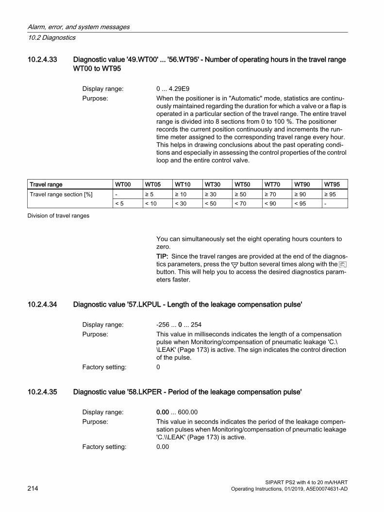
10.2.4.33 Diagnostic value '49.WT00' ... '56.WT95' - Number of operating hours in the travel range WT00 to WT95
Display range: 0 ... 4.29E9Purpose: When the positioner is in "Automatic" mode, statistics are continu‐
ously maintained regarding the duration for which a valve or a flap is operated in a particular section of the travel range. The entire travel range is divided into 8 sections from 0 to 100 %. The positioner records the current position continuously and increments the run‐time meter assigned to the corresponding travel range every hour. This helps in drawing conclusions about the past operating condi‐tions and especially in assessing the control properties of the control loop and the entire control valve.
Travel range WT00 WT05 WT10 WT30 WT50 WT70 WT90 WT95Travel range section [%] - ≥ 5 ≥ 10 ≥ 30 ≥ 50 ≥ 70 ≥ 90 ≥ 95
< 5 < 10 < 30 < 50 < 70 < 90 < 95 -
Division of travel ranges
You can simultaneously set the eight operating hours counters to zero.TIP: Since the travel ranges are provided at the end of the diagnos‐tics parameters, press the button several times along with the button. This will help you to access the desired diagnostics param‐eters faster.
10.2.4.34 Diagnostic value '57.LKPUL - Length of the leakage compensation pulse'
Display range: -256 ... 0 ... 254Purpose: This value in milliseconds indicates the length of a compensation
pulse when Monitoring/compensation of pneumatic leakage 'C.\\LEAK' (Page 173) is active. The sign indicates the control direction of the pulse.
Factory setting: 0
10.2.4.35 Diagnostic value '58.LKPER - Period of the leakage compensation pulse'
Display range: 0.00 ... 600.00Purpose: This value in seconds indicates the period of the leakage compen‐
sation pulses when Monitoring/compensation of pneumatic leakage 'C.\\LEAK' (Page 173) is active.
Factory setting: 0.00
Alarm, error, and system messages10.2 Diagnostics
SIPART PS2 with 4 to 20 mA/HART214 Operating Instructions, 01/2019, A5E00074631-AD
10.2.4.36 Diagnostic value '59.mA - Setpoint current'Here you can display the current setpoint in mA.
10.2.4.37 Diagnostic value '60.PZ Supply air pressure (PZ)'
Indication on the display: ##.### (bar)###.## (psi)#.#### (MPa)
Purpose: Shows the current supply pressure (PZ). The value refers to the pressure unit assigned in "U1.PUNIT (Page 191)". The value is only displayed if "U.\\PRES" is activated and at least one pressure sensor is connected.If the supply air PZ is switched off, the pressure value shown in the display is 0. Depending on the height at which you use the position‐er, the displayed pressure value is ≠0. Press the button for at least 5 seconds to set the value to 0. As long as you press the button, "reset" is shown in the display. This calibration is only possible if the displayed pressure value is in the range -0.5 to +0.5 bar.
10.2.4.38 Diagnostic value '63.PZMAX Supply pressure (PZ) min/max pointer
Indication on the display: ##.### (bar)###.## (psi)#.#### (MPa)
Purpose: The supply pressure (PZ) is continuously monitored and the maxi‐mum value (min/max pointer) is displayed.The min/max pointer can be reset via HART communication.
10.2.4.39 Diagnostic value '64.N_MIN Event counter'
Display range: 0 ... 99999Purpose: Each new measured value of the pressure monitoring is compared
with the value set in "U.PZLIM (Page 191)". The counter increases when the supply pressure is lower than the configured limit value.The counter can be reset via HART communication.
Alarm, error, and system messages10.2 Diagnostics
SIPART PS2 with 4 to 20 mA/HARTOperating Instructions, 01/2019, A5E00074631-AD 215
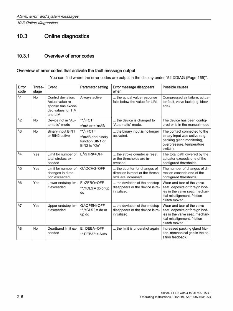
10.3 Online diagnostics
10.3.1 Overview of error codes
Overview of error codes that activate the fault message outputYou can find where the error codes are output in the display under "52.XDIAG (Page 165)".
Error code
Three-stage
Event Parameter setting Error message disappears when
Possible causes
1 No Control deviation: Actual value re‐sponse has excee‐ded values for TIM and LIM
Always active ... the actual value response falls below the value for LIM
Compressed air failure, actua‐tor fault, valve fault (e.g. block‐ade).
2 No Device not in "Au‐tomatic" mode
**. FCT1)
= nA or = nAB... the device is changed to "Automatic" mode.
The device has been config‐ured or is in the manual mode
3 No Binary input BIN1 or BIN2 active
**. FCT1)
= nAB and binary function BIN1 or BIN2 to "On"
... the binary input is no longer activated.
The contact connected to the binary input was active (e.g. packing gland monitoring, overpressure, temperature switch).
4 Yes Limit for number of total strokes ex‐ceeded
L. STRK≠OFF ... the stroke counter is reset or the thresholds are in‐creased
The total path covered by the actuator exceeds one of the configured thresholds.
5 Yes Limit for number of changes in direc‐tion exceeded
O. DCHG≠OFF ... the counter for changes of direction is reset or the thresh‐olds are increased.
The number of changes of di‐rection exceeds one of the configured thresholds.
6 Yes Lower endstop lim‐it exceeded
F. ZERO≠OFF **.YCLS = do or up do
... the deviation of the endstop disappears or the device is re-initialized.
Wear and tear of the valve seat, deposits or foreign bod‐ies in the valve seat, mechan‐ical misalignment, friction clutch moved.
7 Yes Upper endstop lim‐it exceeded
G. OPEN≠OFF **.YCLS1) = do or up do
... the deviation of the endstop disappears or the device is re-initialized.
Wear and tear of the valve seat, deposits or foreign bod‐ies in the valve seat, mechan‐ical misalignment, friction clutch moved.
8 No Deadband limit ex‐ceeded
E. DEBA≠OFF**.DEBA1) = Auto
... the limit is undershot again Increased packing gland fric‐tion, mechanical gap in the po‐sition feedback.
Alarm, error, and system messages10.3 Online diagnostics
SIPART PS2 with 4 to 20 mA/HART216 Operating Instructions, 01/2019, A5E00074631-AD
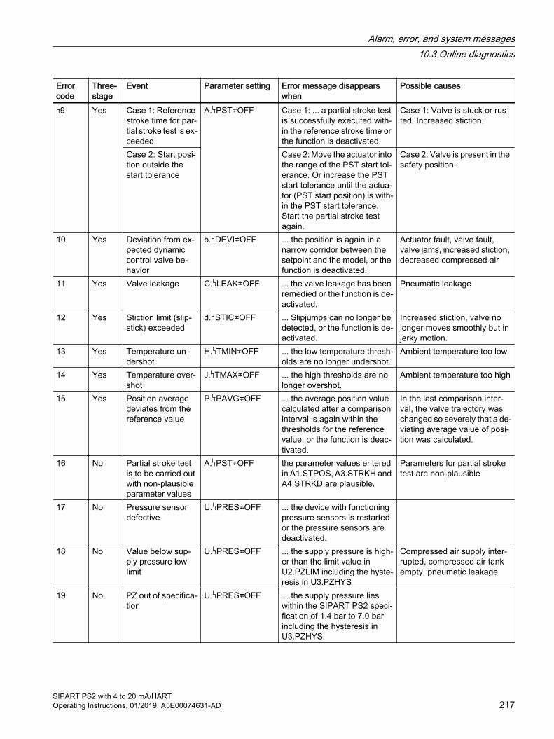
Error code
Three-stage
Event Parameter setting Error message disappears when
Possible causes
9 Yes Case 1: Reference stroke time for par‐tial stroke test is ex‐ceeded.
A. PST≠OFF Case 1: ... a partial stroke test is successfully executed with‐in the reference stroke time or the function is deactivated.
Case 1: Valve is stuck or rus‐ted. Increased stiction.
Case 2: Start posi‐tion outside the start tolerance
Case 2: Move the actuator into the range of the PST start tol‐erance. Or increase the PST start tolerance until the actua‐tor (PST start position) is with‐in the PST start tolerance. Start the partial stroke test again.
Case 2: Valve is present in the safety position.
10 Yes Deviation from ex‐pected dynamic control valve be‐havior
b. DEVI≠OFF ... the position is again in a narrow corridor between the setpoint and the model, or the function is deactivated.
Actuator fault, valve fault, valve jams, increased stiction, decreased compressed air
11 Yes Valve leakage C. LEAK≠OFF ... the valve leakage has been remedied or the function is de‐activated.
Pneumatic leakage
12 Yes Stiction limit (slip‐stick) exceeded
d. STIC≠OFF ... Slipjumps can no longer be detected, or the function is de‐activated.
Increased stiction, valve no longer moves smoothly but in jerky motion.
13 Yes Temperature un‐dershot
H. TMIN≠OFF ... the low temperature thresh‐olds are no longer undershot.
Ambient temperature too low
14 Yes Temperature over‐shot
J. TMAX≠OFF ... the high thresholds are no longer overshot.
Ambient temperature too high
15 Yes Position average deviates from the reference value
P. PAVG≠OFF ... the average position value calculated after a comparison interval is again within the thresholds for the reference value, or the function is deac‐tivated.
In the last comparison inter‐val, the valve trajectory was changed so severely that a de‐viating average value of posi‐tion was calculated.
16 No Partial stroke test is to be carried out with non-plausible parameter values
A. PST≠OFF the parameter values entered in A1.STPOS, A3.STRKH and A4.STRKD are plausible.
Parameters for partial stroke test are non-plausible
17 No Pressure sensor defective
U. PRES≠OFF ... the device with functioning pressure sensors is restarted or the pressure sensors are deactivated.
18 No Value below sup‐ply pressure low limit
U. PRES≠OFF ... the supply pressure is high‐er than the limit value in U2.PZLIM including the hyste‐resis in U3.PZHYS
Compressed air supply inter‐rupted, compressed air tank empty, pneumatic leakage
19 No PZ out of specifica‐tion
U. PRES≠OFF ... the supply pressure lies within the SIPART PS2 speci‐fication of 1.4 bar to 7.0 bar including the hysteresis in U3.PZHYS.
Alarm, error, and system messages10.3 Online diagnostics
SIPART PS2 with 4 to 20 mA/HARTOperating Instructions, 01/2019, A5E00074631-AD 217

1) Refer to the corresponding parameter descriptions for additional information about parameters
10.3.2 Overview of online diagnosticsOnline diagnostics means diagnostics during ongoing operation. During operation of the positioner, a few important values and parameters are continually monitored. In configuration mode, you can configure that monitoring so that the fault message output will be activated if, for instance, a limit is exceeded.
Information about what events can activate the fault message output can be found in the table in section "Overview of error codes (Page 216)".
This section contains particular information about the following situations:
● Possible causes of the fault message.
● Events which activate the fault message output or alarm outputs.
● Settings of parameters needed for event monitoring.
● Cancelling an error message
When the fault message output is triggered in "Automatic" or "Manual" mode, the display shows which fault triggered the message. The two digits on the lower left show the corresponding error code. If multiple triggers occur at the same time, they are displayed one after the other cyclically. The device status, including all fault messages, can be called up using command "#48" over HART.
See also'52.XDIAG' Activating for extended diagnostics (Page 165)
Advanced diagnostic parameters A to U (Page 166)
10.3.3 XDIAG parameter You can use the extended diagnostics parameters to display error messages in one, two or three stages. In addition to the fault message output, alarm outputs 1 and 2 are then used. For this purpose, set the "XDIAG" parameter as described in the following table:
Settings of XDIAG Message due toOFF Extended diagnostics not activatedOn1 Fault message output for threshold 3 error message (maintenance alarm, single-stage)On2 Fault message output for threshold 3 error messages and alarm output 2 for threshold 2
error messages (maintenance demanded, two-stage)On3 Fault message output for threshold 3 error messages and alarm output 2 for threshold 2
error messages and alarm output 1 for threshold 1 error messages (maintenance required, three-stage)
Possible settings of the 'XDIAG' parameter
Alarm, error, and system messages10.3 Online diagnostics
SIPART PS2 with 4 to 20 mA/HART218 Operating Instructions, 01/2019, A5E00074631-AD
10.3.4 Meaning of error codes
10.3.4.1 1 Remaining control deviationThe deviation between the setpoint and the actual value is continuously monitored in "Automatic" mode. The fault message for a remaining control deviation is activated depending on the setting of the application parameters " TIM" - monitoring time for setting the fault messages - and " LIM" - response threshold for the fault message. The fault message is cancelled as soon as the control deviation drops below the response threshold. This monitoring function is always active.
10.3.4.2 2 Device not in "Automatic" modeWhen the device is not in automatic mode, an error message is generated if the ' FCT' parameter (function of fault message output) is set correctly. A warning is then sent to the control system if the device was switched to manual or configuration mode on-site.
10.3.4.3 3 Binary input BIN1 or BIN2 activeIf the binary input is activated, an error message is generated when the " FCT" parameter (function of fault message output) and the "BIN1" parameter (function of binary input 1) are set correctly. For example, it can be a switch to monitor the packing glands, a temperature switch or a limit switch (e.g. for pressure).
Binary input 2 (in the optional alarm module) can be configured in a similar manner.
10.3.4.4 4 Monitoring the number of total strokesThe diagnostics value "1 STRKS" is constantly compared with the thresholds that are determined from the "L1.LIMIT" to "L4.FACT3" parameters. If the thresholds are exceeded, the fault message output or the alarm outputs respond depending on the mode of the extended diagnostics. These two functions can be deactivated using the parameter setting "OFF" for "L. STRK".
10.3.4.5 5 Monitoring the number of changes in directionThe diagnostics value "2 CHDIR" is constantly compared with the thresholds that are determined from the "O1.LIMIT" to "O4.FACT3" parameters. If the thresholds are exceeded, the fault message output or the alarm outputs respond depending on the mode of the extended diagnostics. These two functions can be deactivated using the parameter setting "OFF" for "O. DCHG".
Alarm, error, and system messages10.3 Online diagnostics
SIPART PS2 with 4 to 20 mA/HARTOperating Instructions, 01/2019, A5E00074631-AD 219
10.3.4.6 6 Monitoring the lower endstop / 7 Monitoring the upper endstopIf the parameter "F. ZERO" is set to "ON", monitoring of the lower endstop is activated. This function can be used to detect the errors in the valve seat. An overshot limit indicates the possibility of deposits or foreign bodies in the valve seat. An undershot limit indicates probable wear and tear of the valve seat or flow restrictor. Even a mechanical misalignment of the position feedback can trigger this fault message.
Monitoring is always carried out whenever the valve is in the "tight closing/fast closing Down" position. The current position is compared with the position that was determined as the lower endstop at the time of initialization. Requirement: '39.YCLS' Tight closing/fast closing with manipulated variable (Page 156) Parameter is set to one of the following values: 'do', 'uP do', 'Fd', 'Fu Fd'.
Example: A value of 3% is set. The position is normally adopted for "tight closing/fast closing Down". A fault is reported if a value > 3% or < -3% is determined instead.
The fault message remains activated until either a subsequent monitoring remains within the tolerance or a re-initialization process is executed. Even the deactivation of monitoring ("F.ZERO"=OFF) may trigger an error message.
This monitoring function does not deliver any utilizable results if the end stops were not determined automatically at the time of initialization, but the limits were set manually (manual initialization, "5.INITM").
Similar diagnostics is carried out for the upper endstop. The "G. OPEN" parameter is used to set the limit for this. Requirement: '39.YCLS' Tight closing/fast closing with manipulated variable (Page 156) Parameter is set to one of the following values: 'uP', 'uP do', 'Fu', 'Fu Fd', 'uP Fd', 'Fu do
10.3.4.7 8 Monitoring deadbandIf the deadband increases disproportionately when adjusting it automatically ("DEBA"=Auto parameter), it indicates an error in the system (e.g. severely increased packing gland friction, play in the position displacement sensor, leakage). A limit can therefore be entered for this value ("E1.LEVL3", threshold for deadband monitoring). An error message output is activated when this value is exceeded.
10.3.4.8 9 Partial stroke testOn the one hand, this fault message appears when a manual or cyclic partial stroke test is initiated and the test cannot be started since the valve is not within the starting tolerance. On the other hand, the fault message appears when one of the three thresholds of the partial stroke test that are determined from the 'A9.PSTIN' reference stroke time multiplied by factors 'AA.FACT1', 'Ab.FACT2' and 'AC.FACT3' is violated. The severity of the fault message is shown by the number of bars on the display. The severity of the fault message is simultaneously displayed using the fault message output or alarm outputs depending on the mode of the advanced diagnostics.
Alarm, error, and system messages10.3 Online diagnostics
SIPART PS2 with 4 to 20 mA/HART220 Operating Instructions, 01/2019, A5E00074631-AD
10.3.4.9 10 Monitoring of dynamic control valve behaviorThe monitoring of the operational behavior responds when the actual valve position shifts from a narrow corridor between the setpoint and the expected position course. In this case, the deviation between the expected and actual position course is filtered, displayed and compared with the configured thresholds that are determined from the "b2.LIMIT" limit multiplied by the factors "b3.FACT1" to "b5.FACT3".
10.3.4.10 11 Monitoring/compensation of pneumatic leakage This fault message appears if a leakage is present. For additional information, see Monitoring/compensation of pneumatic leakage 'C.\\LEAK' (Page 173).
10.3.4.11 12 Monitoring of stiction (slipstick)If the stiction of the control valve increases during operation or if an increasing number of Slipjumps is detected, "d1.LIMIT" could be exceeded and result in this fault message.
10.3.4.12 13 Monitoring the lower limit temperatureThis fault message appears when the lower limit temperature thresholds are undershot.
10.3.4.13 14 Monitoring the upper limit temperatureThis fault message appears when the upper limit temperature thresholds are overshot.
10.3.4.14 15 Monitoring the position average valueThis fault message appears when a position value calculated after the expiry of a comparison interval deviates from the reference value by more than the configured thresholds.
10.3.4.15 16 Monitoring the plausibility of values for the partial stroke testThis error message is triggered if, when starting a partial stroke test, the plausibility check of the "A1.STPOS", "A3.STRKH" and "A4.STRKD" parameters was not successful.
10.3.4.16 17 Monitoring the pressure sensorsIf the pressure sensor module is activated and at least one connected pressure sensor is defective, this fault message is displayed.
10.3.4.17 18 Monitoring low limit of supply pressure (PZLIM)If the supply pressure is below the configured low limit (PZLIM), this alarm message is displayed.
Alarm, error, and system messages10.3 Online diagnostics
SIPART PS2 with 4 to 20 mA/HARTOperating Instructions, 01/2019, A5E00074631-AD 221
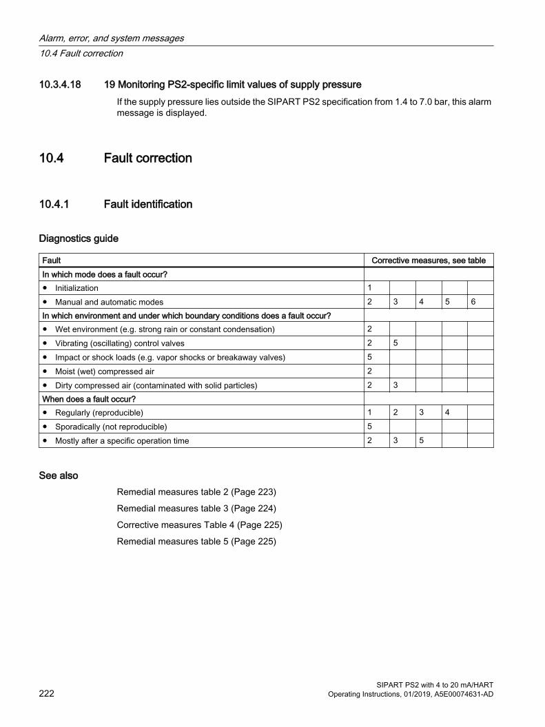
10.3.4.18 19 Monitoring PS2-specific limit values of supply pressureIf the supply pressure lies outside the SIPART PS2 specification from 1.4 to 7.0 bar, this alarm message is displayed.
10.4 Fault correction
10.4.1 Fault identification
Diagnostics guide
Fault Corrective measures, see tableIn which mode does a fault occur? ● Initialization 1 ● Manual and automatic modes 2 3 4 5 6In which environment and under which boundary conditions does a fault occur? ● Wet environment (e.g. strong rain or constant condensation) 2 ● Vibrating (oscillating) control valves 2 5 ● Impact or shock loads (e.g. vapor shocks or breakaway valves) 5 ● Moist (wet) compressed air 2 ● Dirty compressed air (contaminated with solid particles) 2 3 When does a fault occur? ● Regularly (reproducible) 1 2 3 4 ● Sporadically (not reproducible) 5 ● Mostly after a specific operation time 2 3 5
See alsoRemedial measures table 2 (Page 223)
Remedial measures table 3 (Page 224)
Corrective measures Table 4 (Page 225)
Remedial measures table 5 (Page 225)
Alarm, error, and system messages10.4 Fault correction
SIPART PS2 with 4 to 20 mA/HART222 Operating Instructions, 01/2019, A5E00074631-AD
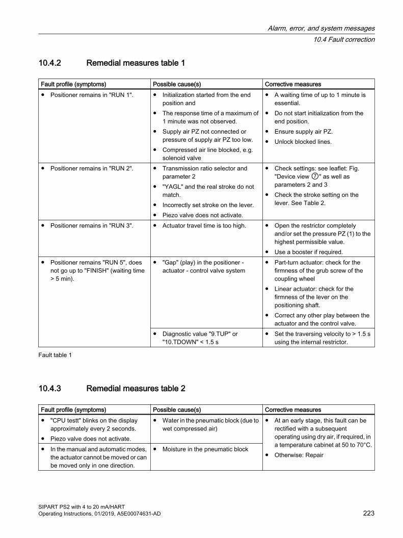
10.4.2 Remedial measures table 1
Fault profile (symptoms) Possible cause(s) Corrective measures● Positioner remains in "RUN 1". ● Initialization started from the end
position and● The response time of a maximum of
1 minute was not observed.● Supply air PZ not connected or
pressure of supply air PZ too low. ● Compressed air line blocked, e.g.
solenoid valve
● A waiting time of up to 1 minute is essential.
● Do not start initialization from the end position.
● Ensure supply air PZ.● Unlock blocked lines.
● Positioner remains in "RUN 2". ● Transmission ratio selector and parameter 2
● "YAGL" and the real stroke do not match.
● Incorrectly set stroke on the lever.● Piezo valve does not activate.
● Check settings: see leaflet: Fig. "Device view ⑦" as well as parameters 2 and 3
● Check the stroke setting on the lever. See Table 2.
● Positioner remains in "RUN 3". ● Actuator travel time is too high. ● Open the restrictor completely and/or set the pressure PZ (1) to the highest permissible value.
● Use a booster if required.● Positioner remains "RUN 5", does
not go up to "FINISH" (waiting time > 5 min).
● "Gap" (play) in the positioner - actuator - control valve system
● Part-turn actuator: check for the firmness of the grub screw of the coupling wheel
● Linear actuator: check for the firmness of the lever on the positioning shaft.
● Correct any other play between the actuator and the control valve.
● Diagnostic value "9.TUP" or "10.TDOWN" < 1.5 s
● Set the traversing velocity to > 1.5 s using the internal restrictor.
Fault table 1
10.4.3 Remedial measures table 2
Fault profile (symptoms) Possible cause(s) Corrective measures● "CPU testt" blinks on the display
approximately every 2 seconds.● Piezo valve does not activate.
● Water in the pneumatic block (due to wet compressed air)
● At an early stage, this fault can be rectified with a subsequent operating using dry air, if required, in a temperature cabinet at 50 to 70°C.
● Otherwise: Repair● In the manual and automatic modes,
the actuator cannot be moved or can be moved only in one direction.
● Moisture in the pneumatic block
Alarm, error, and system messages10.4 Fault correction
SIPART PS2 with 4 to 20 mA/HARTOperating Instructions, 01/2019, A5E00074631-AD 223

Fault profile (symptoms) Possible cause(s) Corrective measures● Piezo valve does not activate (a
gentle click sound is not audible when the "+" or "-" buttons are pressed in the manual mode.)
● The screw between the shrouding cover and the pneumatic block has not been tightened firmly or the cover got stuck.
● Tighten the screw firmly; if required, rectify the deadlock.
● Dirt (swarf, particles) in the pneumatic block
● Repair or a new device; clean and/or replace the built-in fine screens.
● Deposits on the contacts between the electronic printed circuit board and the pneumatic block may develop due to abrasion owing to continuous loads resulting from strong vibrations.
● Clean all contact surfaces with spirit; if required, bend the pneumatic block contact springs.
Fault table 2
See alsoRepair/Upgrading (Page 230)
10.4.4 Remedial measures table 3
Fault profile (symptoms) Possible cause Corrective measures● Actuator does not move. ● Compressed air < 1.4 bar ● Set pressure of supply air PZ to
> 1.4 bar.● Piezo valve does not switch
(however, a gentle clicking sound can be heard when the or button is pressed in "Manual" mode.)
● Restrictor valve turned off (screw at the right end stop)
● Open the restrictor screw by turning it anticlockwise, see leaflet, Fig. "Device view ⑥".
● Dirt in the pneumatic block ● Repair or a new device; clean and/or replace the built-in fine screens.
● A piezo valve is switched constantly in stationary automatic mode (constant setpoint) and in "Manual" mode.
● Pneumatic leakage in the positioner - actuator system; start the leakage test in "RUN 3" (initialization).
● Rectify leakage in the actuator and/or feed line.
● In case of an intact actuator and tight feed line: Repair or new device
● Dirt in the pneumatic block ● See above
Fault table 3
See alsoRepair/Upgrading (Page 230)
Alarm, error, and system messages10.4 Fault correction
SIPART PS2 with 4 to 20 mA/HART224 Operating Instructions, 01/2019, A5E00074631-AD
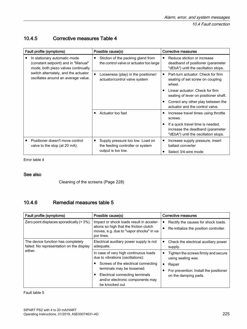
10.4.5 Corrective measures Table 4
Fault profile (symptoms) Possible cause(s) Corrective measures● In stationary automatic mode
(constant setpoint) and in "Manual" mode, both piezo valves continually switch alternately, and the actuator oscillates around an average value.
● Stiction of the packing gland from the control valve or actuator too large
● Reduce stiction or increase deadband of positioner (parameter "dEbA") until the oscillation stops.
● Looseness (play) in the positioner/actuator/control valve system
● Part-turn actuator: Check for firm seating of set screw on coupling wheel.
● Linear actuator: Check for firm seating of lever on positioner shaft.
● Correct any other play between the actuator and the control valve.
● Actuator too fast ● Increase travel times using throttle screws.
● If a quick travel time is needed, increase the deadband (parameter "dEbA") until the oscillation stops.
● Positioner doesn't move control valve to the stop (at 20 mA).
● Supply pressure too low. Load on the feeding controller or system output is too low.
● Increase supply pressure, insert ballast converter
● Select 3/4-wire mode
Error table 4
See alsoCleaning of the screens (Page 228)
10.4.6 Remedial measures table 5
Fault profile (symptoms) Possible cause(s) Corrective measuresZero point displaces sporadically (> 3%). Impact or shock loads result in acceler‐
ations so high that the friction clutch moves, e.g. due to "vapor shocks" in va‐por lines.
● Rectify the causes for shock loads.● Re-initialize the position controller.
The device function has completely failed: No representation on the display either.
Electrical auxiliary power supply is not adequate.
● Check the electrical auxiliary power supply.
In case of very high continuous loads due to vibrations (oscillations):● Screws of the electrical connecting
terminals may be loosened.● Electrical connecting terminals
and/or electronic components may be knocked out.
● Tighten the screws firmly and secure using sealing wax.
● Repair● For prevention: Install the positioner
on the damping pads.
Fault table 5
Alarm, error, and system messages10.4 Fault correction
SIPART PS2 with 4 to 20 mA/HARTOperating Instructions, 01/2019, A5E00074631-AD 225

See alsoRepair/Upgrading (Page 230)
10.4.7 Corrective measures table 6
Fault profile (symptoms) Possible cause(s) Corrective measures● With diagnostic value "60.PZ"
(Page 215), display shows "99999".● Display shows alarm message "17
(Page 221)".
● Pressure sensor defective Replace the pressure sensor module (Page 233)
● Display shows alarm message "18 (Page 221)".
● Display shows "HOLd".
● Supply pressure undershoots the low limit (U2.PZLIM (Page 191)).
● Device is set to "Hold position", when (U4.PZ_FR) "HOLd" is assigned as error response.
Increase the supply pressure until the limit (U2.PZLIM) incl. hysteresis (U3.PZHYS) is exceeded.
● Display shows alarm message "19 (Page 222)".
● Supply pressure outside the specification
Increase the supply pressure until the limit (U2.PZLIM) incl. hysteresis (U3.PZHYS) is exceeded.Lower the supply pressure until the limit (U2.PZLIM) incl. hysteresis (U3.PZHYS) is undershot.
Error table 6 Pressure sensor module
Alarm, error, and system messages10.4 Fault correction
SIPART PS2 with 4 to 20 mA/HART226 Operating Instructions, 01/2019, A5E00074631-AD

Service and maintenance 1111.1 Basic safety instructions
WARNING
Impermissible repair of the device● Repair must be carried out by Siemens authorized personnel only.
WARNING
Dust layers above 5 mm
Risk of explosion in hazardous areas. Device may overheat due to dust build up.● Remove dust layers in excess of 5 mm.
NOTICE
Penetration of moisture into the device
Device damage.● Make sure when carrying out cleaning and maintenance work that no moisture penetrates
the inside of the device.
CAUTION
Releasing button lock
Improper modification of parameters could influence process safety.● Make sure that only authorized personnel may cancel the button locking of devices for
safety-related applications.
Cleaning the enclosure● Clean the outside of the enclosure with the inscriptions and the display window using a cloth
moistened with water or a mild detergent.
● Do not use any aggressive cleansing agents or solvents, e.g. acetone. Plastic parts or the painted surface could be damaged. The inscriptions could become unreadable.
SIPART PS2 with 4 to 20 mA/HARTOperating Instructions, 01/2019, A5E00074631-AD 227
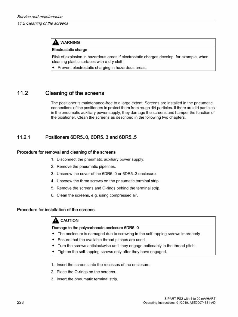
WARNING
Electrostatic charge
Risk of explosion in hazardous areas if electrostatic charges develop, for example, when cleaning plastic surfaces with a dry cloth.● Prevent electrostatic charging in hazardous areas.
11.2 Cleaning of the screensThe positioner is maintenance-free to a large extent. Screens are installed in the pneumatic connections of the positioners to protect them from rough dirt particles. If there are dirt particles in the pneumatic auxiliary power supply, they damage the screens and hamper the function of the positioner. Clean the screens as described in the following two chapters.
11.2.1 Positioners 6DR5..0, 6DR5..3 and 6DR5..5
Procedure for removal and cleaning of the screens1. Disconnect the pneumatic auxiliary power supply.
2. Remove the pneumatic pipelines.
3. Unscrew the cover of the 6DR5..0 or 6DR5..3 enclosure.
4. Unscrew the three screws on the pneumatic terminal strip.
5. Remove the screens and O-rings behind the terminal strip.
6. Clean the screens, e.g. using compressed air.
Procedure for installation of the screens
CAUTION
Damage to the polycarbonate enclosure 6DR5..0● The enclosure is damaged due to screwing in the self-tapping screws improperly.● Ensure that the available thread pitches are used.● Turn the screws anticlockwise until they engage noticeably in the thread pitch.● Tighten the self-tapping screws only after they have engaged.
1. Insert the screens into the recesses of the enclosure.
2. Place the O-rings on the screens.
3. Insert the pneumatic terminal strip.
Service and maintenance11.2 Cleaning of the screens
SIPART PS2 with 4 to 20 mA/HART228 Operating Instructions, 01/2019, A5E00074631-AD
4. Tighten the three screws. Note: With the polycarbonate enclosure, the screws are self-tapping.
5. Place the cover and tighten it.
6. Connect the pneumatic pipelines again.
11.2.2 Positioners 6DR5..1, 6DR5..2 and 6DR5..6
Removal, cleaning and installation of the screens1. Disconnect the pneumatic auxiliary power supply.
2. Remove the pneumatic connecting cables.
3. Remove the metal screen from the bores carefully.
4. Clean the metal screens, e.g. using compressed air.
5. Insert the screens.
6. Connect the pneumatic pipelines again.
11.3 Maintenance and repair work
WARNING
Maintenance during continued operation in a hazardous area
There is a risk of explosion when carrying out repairs and maintenance on the device in a hazardous area.● Isolate the device from power.
- or -● Ensure that the atmosphere is explosion-free (hot work permit).
WARNING
Impermissible accessories and spare parts
Risk of explosion in areas subject to explosion hazard.● Only use original accessories or original spare parts.● Observe all relevant installation and safety instructions described in the instructions for the
device or enclosed with the accessory or spare part.
Service and maintenance11.3 Maintenance and repair work
SIPART PS2 with 4 to 20 mA/HARTOperating Instructions, 01/2019, A5E00074631-AD 229
WARNING
Improper connection after maintenance
Risk of explosion in areas subject to explosion hazard.● Connect the device correctly after maintenance.● Close the device after maintenance work.
Refer to Electrical data (Page 244).
11.3.1 Repair/UpgradingSend defective devices to the repairs department, together with information on the malfunction and the cause of the malfunction. When ordering replacement devices, please provide the serial number of the original device. You can find the serial number on the nameplate.
11.4 Replace basic electronics
Requirement● You are familiar with the general procedure described in the section "General information on
installing option modules (Page 50)".
Procedure
NotePossible movement of the actuator
While replacing the basic electronics, the actuator can unintentionally vent itself. ● Observe the procedure described below.
Removing1. Switch off the supply air PZ and depressurize the actuator.
2. Open the positioner as in the description depending on the device version:
– Opening the standard and and intrinsically safe version (Page 50)
– Opening the device version with "flameproof enclosure" (Page 53)
3. Remove the ribbon cable from the basic electronics.
4. Tighten the two fixing screws of the basic electronics.
5. Remove the basic electronics.
6. Place the new basic electronics onto the four holders of the rack.
Service and maintenance11.4 Replace basic electronics
SIPART PS2 with 4 to 20 mA/HART230 Operating Instructions, 01/2019, A5E00074631-AD
Installation1. Tighten the two fixing screws of the basic electronics.
2. Tighten the screws.
3. Close the positioner as in the description depending on the device version:
– Closing the standard and and intrinsically safe version (Page 52)
– Closing the device version with "flameproof enclosure" (Page 56)
4. For a positioner with order option -Z F01 "Fail in Place", adjust the parameter "51.PNEUM (Page 163)" from "Std" to "FIP".
5. Switch on the supply air PZ again.
6. Initialize the positioner as described in section "Commissioning (Page 103)".
Service and maintenance11.4 Replace basic electronics
SIPART PS2 with 4 to 20 mA/HARTOperating Instructions, 01/2019, A5E00074631-AD 231
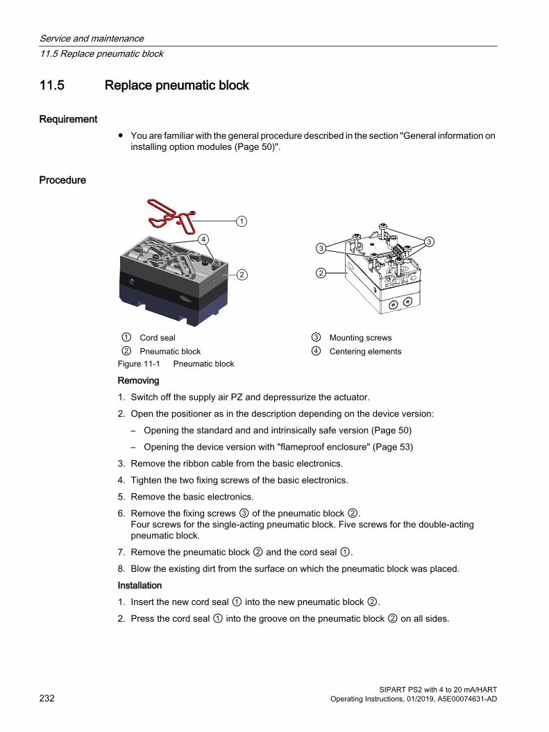
11.5 Replace pneumatic block
Requirement● You are familiar with the general procedure described in the section "General information on
installing option modules (Page 50)".
Procedure
① Cord seal ③ Mounting screws② Pneumatic block ④ Centering elements
Figure 11-1 Pneumatic block
Removing
1. Switch off the supply air PZ and depressurize the actuator.
2. Open the positioner as in the description depending on the device version:
– Opening the standard and and intrinsically safe version (Page 50)
– Opening the device version with "flameproof enclosure" (Page 53)
3. Remove the ribbon cable from the basic electronics.
4. Tighten the two fixing screws of the basic electronics.
5. Remove the basic electronics.
6. Remove the fixing screws ③ of the pneumatic block ②. Four screws for the single-acting pneumatic block. Five screws for the double-acting pneumatic block.
7. Remove the pneumatic block ② and the cord seal ①.
8. Blow the existing dirt from the surface on which the pneumatic block was placed.
Installation
1. Insert the new cord seal ① into the new pneumatic block ②.
2. Press the cord seal ① into the groove on the pneumatic block ② on all sides.
Service and maintenance11.5 Replace pneumatic block
SIPART PS2 with 4 to 20 mA/HART232 Operating Instructions, 01/2019, A5E00074631-AD

3. Place the new pneumatic block on the base plate. Make sure that the pneumatic block engages with the centering elements ④ on the baseplate.
4. Screw the supplied fixing screws ③ into the pneumatic block.
5. Tighten the fixing screws with a torque of 1.1 Nm.
6. Place the new basic electronics onto the four holders of the rack.
7. Tighten the two fixing screws of the basic electronics.
8. Tighten the fixing screws.
9. Close the positioner as in the description depending on the device version:
– Closing the standard and and intrinsically safe version (Page 52)
– Closing the device version with "flameproof enclosure" (Page 56)
10.For a positioner with order option -Z F01 "Fail in Place", adjust the parameter "51.PNEUM (Page 163)" from "Std" to "FIP".
11.Switch on the supply air PZ again.
12.Initialize the positioner as described in section "Commissioning (Page 103)".
11.6 Replace the pressure sensor module
Requirement● You have a positioner with a built-in pressure sensor module, order suffix -Z P01.
● It is helpful if you are familiar with the procedure described in the section "Replace pneumatic block (Page 232)".
Service and maintenance11.6 Replace the pressure sensor module
SIPART PS2 with 4 to 20 mA/HARTOperating Instructions, 01/2019, A5E00074631-AD 233
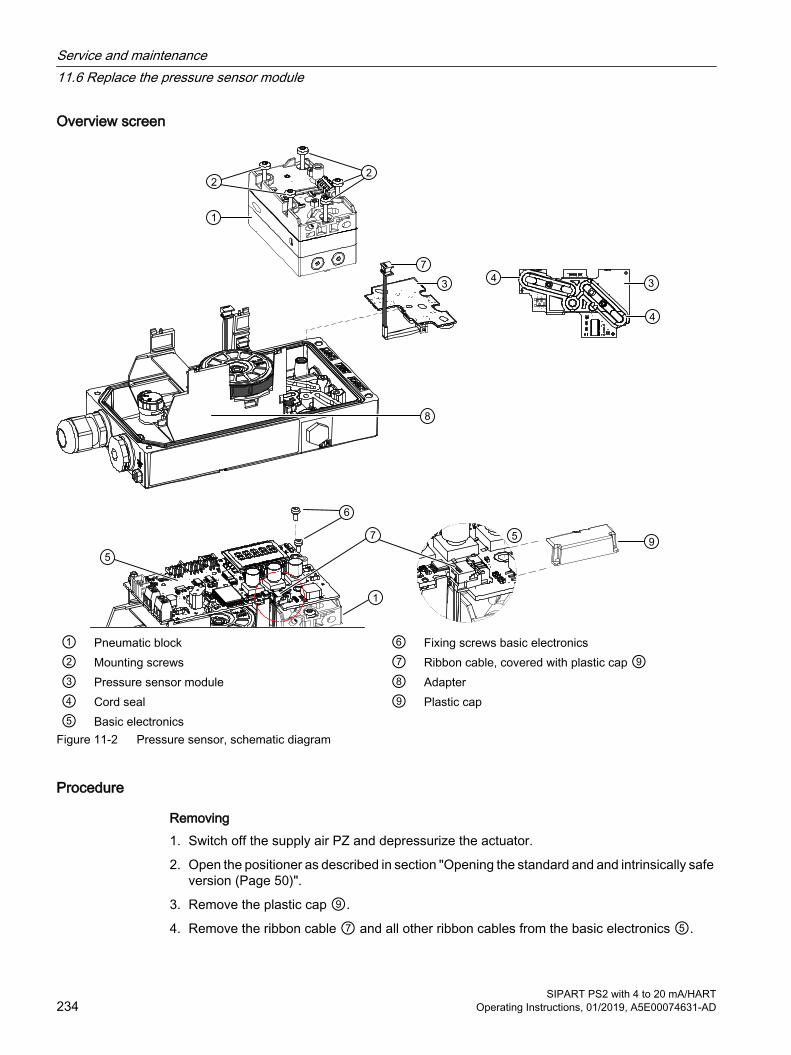
Overview screen
① Pneumatic block ⑥ Fixing screws basic electronics② Mounting screws ⑦ Ribbon cable, covered with plastic cap ⑨③ Pressure sensor module ⑧ Adapter④ Cord seal ⑨ Plastic cap⑤ Basic electronics
Figure 11-2 Pressure sensor, schematic diagram
Procedure
Removing1. Switch off the supply air PZ and depressurize the actuator.
2. Open the positioner as described in section "Opening the standard and and intrinsically safe version (Page 50)".
3. Remove the plastic cap ⑨.
4. Remove the ribbon cable ⑦ and all other ribbon cables from the basic electronics ⑤.
Service and maintenance11.6 Replace the pressure sensor module
SIPART PS2 with 4 to 20 mA/HART234 Operating Instructions, 01/2019, A5E00074631-AD

5. Loosen the two fixing screws ⑥ of the basic electronics.
6. Remove the basic electronics ⑤.
7. Remove the fixing screws ② of the pneumatic block ①.Four screws for the single-acting pneumatic block. Five screws for the double-acting pneumatic block.
8. Remove the pneumatic block ①.Make sure that the cord seal ④ of the pneumatic block is in the pneumatic block.
9. Blow the existing dirt from the surface on which the pneumatic block was placed.
10.Remove the pressure sensor module ③ and the cord seal ④ of the pressure sensor module.
Installation1. Insert the new cord seal ④ into the new pressure sensor module ③.
2. Press the cord seal ④ into the groove on the pressure sensor module ③ on all sides.
3. Place the pressure sensor module ③ on the baseplate.
4. Place the pneumatic block ① on the pressure sensor module ③.
– Make sure that the cord seal ④ of the pneumatic block is in the pneumatic block.
– Make sure that the pneumatic block engages with the centering elements ④ on the baseplate.
5. Screw the fixing screws ② into the pneumatic block ①.
6. Tighten the fixing screws ② with a torque of 1.1 Nm.
7. Place the basic electronics ⑤ onto the four holders of the rack ⑧.
8. Screw in the two fixing screws ⑥ of the basic electronics.
9. Tighten the fixing screws ⑥.
10.Insert the ribbon cable ⑦ and all other ribbon cables onto the basic electronics ⑤.
11.Place the plastic cap ⑨.
12.Close the positioner as described in section "Closing the standard and and intrinsically safe version (Page 52)".
13.For a positioner with order option -Z F01 "Fail in Place", adjust the parameter "'51.PNEUM' Pneumatics type (Page 163)" from "Std" to "FIP".
14.Switch on the supply air PZ.
15.Initialize the positioner as described in section "Commissioning (Page 103)".
ResultThe pressure sensor module is ready to use again.
Service and maintenance11.6 Replace the pressure sensor module
SIPART PS2 with 4 to 20 mA/HARTOperating Instructions, 01/2019, A5E00074631-AD 235
See alsoClosing the device version with "flameproof enclosure" (Page 56)
Parameter assignment (Page 135)
General information on installing option modules (Page 50)
11.7 Return procedureEnclose the bill of lading, return document and decontamination certificate in a clear plastic pouch and attach it firmly to the outside of the packaging.
Required forms● Delivery note
● Return document (http://www.siemens.com/processinstrumentation/returngoodsnote)with the following information:
– Product (item description)
– Number of returned devices/replacement parts
– Reason for returning the item(s)
● Decontamination declaration (http://www.siemens.com/sc/declarationofdecontamination)With this declaration you warrant "that the device/replacement part has been carefully cleaned and is free of residues. The device/replacement part does not pose a hazard for humans and the environment."If the returned device/replacement part has come into contact with poisonous, corrosive, flammable or water-contaminating substances, you must thoroughly clean and decontaminate the device/replacement part before returning it in order to ensure that all hollow areas are free from hazardous substances. Check the item after it has been cleaned.Any devices/replacement parts returned without a decontamination declaration will be cleaned at your expense before further processing.
11.8 Disposal
Devices described in this manual should be recycled. They may not be disposed of in the municipal waste disposal services according to the Di‐rective 2012/19/EC on waste electronic and electrical equipment (WEEE).Devices can be returned to the supplier within the EC, or to a locally ap‐proved disposal service for eco-friendly recycling. Observe the specific reg‐ulations valid in your country.Further information about devices containing batteries can be found at: In‐formation on battery/product return (WEEE) (https://support.industry.siemens.com/cs/document/109479891/)
Service and maintenance11.8 Disposal
SIPART PS2 with 4 to 20 mA/HART236 Operating Instructions, 01/2019, A5E00074631-AD

Technical data 1212.1 Rated conditions
Rated conditions Ambient conditions For use indoors and outdoors.Ambient temperature In hazardous areas, observe the maximum permissible am‐
bient temperature corresponding to the temperature class.● Permissible ambient temperature for operation 2)3) -30 ... +80 °C (-22 ... +176 °F)
● Height 2000 m above sea level. At altitudes greater than 2000 m above sea level, use a suitable power supply.
● Relative humidity 0 ... 100%Degree of pollution 2Overvoltage category IIDegree of protection 1) IP66 / type 4XMounting position Any; pneumatic connections and exhaust air outlet not fac‐
ing up in wet environment, Proper mounting (Page 38)Vibration resistance ● Harmonic oscillations (sine) according
to EN 60068-2-6/10.20083.5 mm (0.14"), 2 ... 27 Hz, 3 cycles/axis98.1 m/s² (321.84 ft/s²), 27 ... 300 Hz, 3 cycles/axis
● Bumping (half-sine) according to EN 60068-2-27/02.2010 150 m/s² (492 ft/s²), 6 ms, 1000 shocks/axis
● Noise (digitally controlled) according to EN 60068-2-64/04.2009
10 ... 200 Hz; 1 (m/s²)²/Hz (3.28 (ft/s²)²/Hz)200 ... 500 Hz; 0.3 (m/s²)²/Hz (0.98 (ft/s²)²/Hz)4 hours/axis
● Recommended range of continuous operation of the entire control valve
≤ 30 m/s² (98.4 ft/s²) without resonance peak
Climate class According to IEC/EN 60721-3● Storage 1K5, but -40 ... +80°C (1K5, but -40 ... +176°F)
● Transport 2K4, but -40 ... +80°C (2K4, but -40 ... +176°F)
1) Max. impact energy 1 Joule for enclosure with inspection window 6DR5..0 and 6DR5..1 or max. 2 Joule for 6DR5..32) At ≤ -10 °C (≤ 14 °F) the display refresh rate of the indicator is limited.3) The following applies to order suffix (order code) -Z M40: -40 ... +80 °C (-40 ... +176°F)
12.2 Pneumatic data
Pneumatic data Auxiliary power (air supply) Compressed air, carbon dioxide (CO2), nitrogen (N), noble
gases or cleaned natural gas● Pressure 1) 1.4 ... 7 bar (20.3 ... 101.5 psi)
SIPART PS2 with 4 to 20 mA/HARTOperating Instructions, 01/2019, A5E00074631-AD 237

Pneumatic data Air quality to ISO 8573-1 ● Solid particulate size and density Class 3
● Pressure dew point Class 3 (min. 20 K (36 °F) below ambient temperature)
● Oil content Class 3Unrestricted flow (DIN 1945) ● Inlet air valve (ventilate actuator) 2) 2 bar; 0.1 KV (29 psi; 0.116 CV) 4.1 Nm³/h (18.1 USgpm)
4 bar; 0.1 KV (58 psi; 0.116 CV) 7.1 Nm³/h (31.3 USgpm)6 bar; 0.1 KV (87 psi; 0.116 CV) 9.8 Nm³/h (43.1 USgpm)
● Exhaust valve (deaerate actuator for all versions except fail in place) 2)
2 bar; 0.2 KV (29 psi; 0.232 CV) 8.2 Nm³/h (36.1 USgpm) 4 bar; 0.2 KV (58 psi; 0.232 CV) 13.7 Nm³/h (60.3 USgpm)
6 bar; 0.2 KV (87 psi; 0.232 CV) 19.2 Nm³/h (84.5 USgpm)● Exhaust valve (deaerate actuator for fail in place version) 2 bar; 0.1 KV (29 psi; 0.116 CV) 4.3 Nm³/h (19.0 USgpm) 4 bar; 0.1 KV (58 psi; 0.116 CV) 7.3 Nm³/h (32.2 USgpm) 6 bar; 0.1 KV (87 psi; 0.116 CV) 9.8 Nm³/h (43.3 USgpm)Valve leakage < 6⋅10-4 Nm³/h (0.0026 USgpm)Throttle ratio Adjustable up to ∞: 1Auxiliary power consumption in the controlled state < 3.6⋅10-2 Nm³/h (0.158 USgpm)Sound pressure level LA eq < 75 dB
LA max < 80 dBSound pressure with installed booster 3) LAeq < 95.2 dB
LA max < 98.5 dB1) The following applies to fail in place double acting: 3 ... 7 bar (43.5 ... 101.5 psi)2) When using device versions Ex d (6DR5..5-... and 6DR5..6-...), values are reduced by approximately 20%.3) Read the warning notice "Increased sound pressure level (Page 103)".
See alsoBasic safety instructions (Page 103)
12.3 Construction
Construction How does it work? ● Range of stroke (linear actuator) 3 ... 130 mm (0.12 ... 5.12") (angle of rotation of the posi‐
tioner shaft 16 ... 90°)● Angle of rotation (part-turn actuator) 30 to 100°
Technical data12.3 Construction
SIPART PS2 with 4 to 20 mA/HART238 Operating Instructions, 01/2019, A5E00074631-AD

Construction Mounting method ● On the linear actuator Using mounting kit 6DR4004-8V and, where necessary, an
additional lever arm 6DR4004-8L on actuators according to IEC 60534-6-1 (NAMUR) with a fin, columns, or a plane surface.
● On the part-turn actuator Using mounting kit 6DR4004-8D or TGX:16300-1556 on actuators with mounting plane according to VDI/VDE 3845 and IEC 60534-6-2: The required mount must be provided on the actuator-side.
Weight, positioner without option modules or accessories ● 6DR5..0 Glass-fiber reinforced polycarbonate enclosure Approx. 0.9 kg (1.98 lb)
● 6DR5.11 aluminum enclosure, only single-acting Approx. 1.3 kg (2.86 lb)
● 6DR5..2 stainless steel enclosure Approx. 3.9 kg (8.6 lb)
● 6DR5..3 aluminum enclosure Approx. 1.6 kg (3.53 lb)
● 6DR5..5 aluminum enclosure, flameproof, rugged Approx. 5.2 kg (11.46 lb)
● 6DR5..6 stainless steel enclosure, flameproof, rugged Approx. 8.4 kg (18.5 lb)Material ● Enclosure 6DR5..0 polycarbonate Glass-fiber reinforced polycarbonate (PC)
6DR5.11 aluminum, only single-acting GD AISi126DR5..2 stainless steel Austenitic stainless steel 316Cb, mat. No. 1.45816DR5..3 aluminum GD AlSi126DR5..5 aluminum, flameproof, rugged GK AISi12
6DR5..6 stainless steel enclosure, flameproof, rugged Austenitic stainless steel 316L, mat. No. 1.4409● Pressure gauge block Aluminum AIMgSi, anodized or stainless steel 316Versions ● In the polycarbonate enclosure 6DR5..0 Single-acting and double-acting
● In aluminum enclosure 6DR5.11 Single-acting
● In aluminum enclosures 6DR5..3 and 6DR5..5 Single-acting and double-acting
● In stainless steel enclosures 6DR5..2 and 6DR5..6 Single-acting and double-actingTorques ● Part-turn actuator fixing screws DIN 933 M6x12-A2 5 Nm (3.7 ft lb)
● Linear actuator fixing screws DIN 933 M8x16-A2 12 Nm (8.9 ft lb)
● Gland pneumatic G¼ 15 Nm (11.1 ft lb)
● Pneumatic gland 1/4-18 NPT Without sealant 12 Nm (8.9 ft lb) With sealant 6 Nm (4.4 ft lb)● Cable glands Screw-in torque for plastic gland in all enclosures 4 Nm (3 ft lb) Screw-in torque for cable gland made of metal/stainless
steel in polycarbonate enclosure6 Nm (4.4 ft lb)
Technical data12.3 Construction
SIPART PS2 with 4 to 20 mA/HARTOperating Instructions, 01/2019, A5E00074631-AD 239

Construction Screw-in torque for metal/stainless steel glands in alumi‐
num/stainless steel enclosure6 Nm (4.4 ft lb)
Screw-in torque for NPT adapter made of metal/stainless steel in polycarbonate enclosure
8 Nm (5.9 ft lb)
Screw-in torque for NPT adapter made of metal/stainless steel in aluminum/stainless steel enclosure
15 Nm (11.1 ft lb)
Screw-in torque for NPT gland in the NPT adapterNOTE: To avoid damage to the device, the NPT adapter must be held in place while the NPT gland is screwed into the NPT adapter.
68 Nm (50 ft lb)
Tightening torque for union nut made of plastic 2.5 Nm (1.8 ft lb) Tightening torque for union nut made of metal/stainless
steel4 Nm (3 ft lb)
● Pressure gauge block fixing screws 6 Nm (4.4 ft lb)Manometer ● Degree of protection Manometer made of plastic IP31
Manometer, steel IP44Manometer made of stainless steel 316 IP54
● Vibration resistance In accordance with DIN EN 837-1Connections, electrical ● Screw terminals 2.5 mm2 AWG30-14
● Cable gland Without Ex protection as well as with Ex i M20 x 1.5 or 1/2-14 NPT With explosion protection Ex d Ex d-certified M20 x 1.5; 1/2-14 NPT or M25 x 1.5Connections, pneumatic Female thread G¼ or ¼-18 NPT
12.4 Controller
Controller Control unit ● Five-point controller Adaptive
● Dead zone dEbA = auto Adaptive
dEbA = 0.1 ... 10 % Can be set as fixed valueAnalog-to-digital converter ● Scanning time 10 ms
● Resolution ≤ 0,05 %
● Transmission error ≤ 0,2 %
● Temperature influence ≤ 0.1 %/10 K (≤ 0.1 %/18 °F)
Technical data12.4 Controller
SIPART PS2 with 4 to 20 mA/HART240 Operating Instructions, 01/2019, A5E00074631-AD

12.5 Explosion protection
12.5.1 Breakdown of the article numbersEach device has a nameplate (Page 24). This nameplate shows a specific article number for the device. Lower-case letters are used and explained in the tables below for the variable digits in the article number. Each variable that is used stands for a different order version. You will find the order data in the FI 01 catalog on the Internet.
Table 12-1 Article number
Table 12-2 Enclosure and the relevant variables
Enclosure polycarbonate 6DR5 (b = 0)
Enclosure aluminum single-act‐ing 6DR5 (b = 1)
Enclosure stainless steel 6DR5 (b = 2)
Enclosure aluminum single/double-acting 6DR5 (b = 3)
Enclosure aluminum flameproof 6DR5 (b = 5) Enclosure stainless steel flameproof 6DR5 (b = 6)
6DR5ayb- 0cdef- g..h- Z jjja (version) =0, 2, 5, 6
c (Ex protection) = E, D, F, G, K
g =0, 2, 6, 7, 8
jjj (-Z order code) == A20, A40, C20, D53, D54, D55, D56, D57, F01, K**, L1A, M40,R**, S**, Y** * = any character
y (actuator) =1, 2
d (thread) =G, N, M, P, R, S
h (manometer block) =0, 1, 2, 3, 4, 9
b (enclosure) =0, 1, 2, 3
e (limit monitor) =0, 1, 2, 3, 9
f (option module) =0, 1, 2, 3
Technical data12.5 Explosion protection
SIPART PS2 with 4 to 20 mA/HARTOperating Instructions, 01/2019, A5E00074631-AD 241
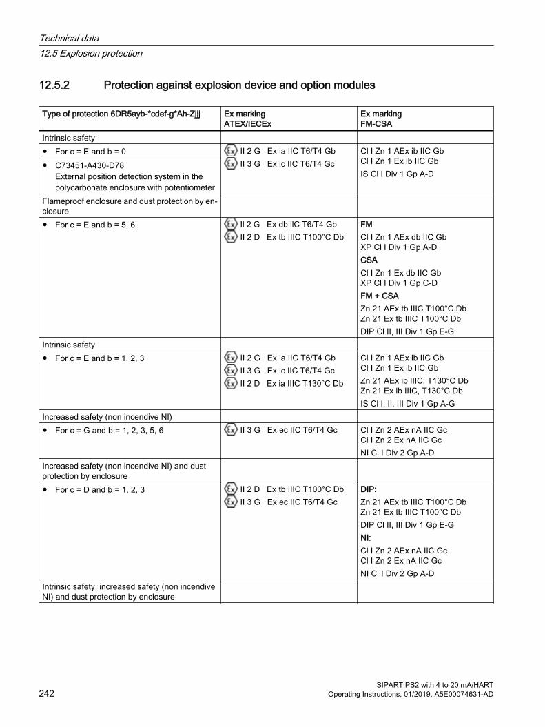
12.5.2 Protection against explosion device and option modules
Type of protection 6DR5ayb-*cdef-g*Ah-Zjjj Ex marking ATEX/IECEx
Ex marking FM-CSA
Intrinsic safety ● For c = E and b = 0 II 2 G Ex ia IIC T6/T4 Gb
II 3 G Ex ic IIC T6/T4 GcCl I Zn 1 AEx ib IIC Gb Cl I Zn 1 Ex ib IIC GbIS Cl I Div 1 Gp A-D
● C73451-A430-D78External position detection system in the polycarbonate enclosure with potentiometer
Flameproof enclosure and dust protection by en‐closure
● For c = E and b = 5, 6 Il 2 G Ex db llC T6/T4 Gb II 2 D Ex tb IIIC T100°C Db
FMCl I Zn 1 AEx db IIC Gb XP Cl I Div 1 Gp A-DCSACl I Zn 1 Ex db IIC Gb XP Cl I Div 1 Gp C-DFM + CSAZn 21 AEx tb IIIC T100°C Db Zn 21 Ex tb IIIC T100°C DbDIP Cl II, III Div 1 Gp E-G
Intrinsic safety ● For c = E and b = 1, 2, 3 II 2 G Ex ia IIC T6/T4 Gb
II 3 G Ex ic IIC T6/T4 Gc II 2 D Ex ia IIIC T130°C Db
Cl I Zn 1 AEx ib IIC Gb Cl I Zn 1 Ex ib IIC GbZn 21 AEx ib IIIC, T130°C Db Zn 21 Ex ib IIIC, T130°C DbIS Cl I, II, III Div 1 Gp A-G
Increased safety (non incendive NI) ● For c = G and b = 1, 2, 3, 5, 6 II 3 G Ex ec IIC T6/T4 Gc Cl I Zn 2 AEx nA IIC Gc
Cl I Zn 2 Ex nA IIC GcNI Cl I Div 2 Gp A-D
Increased safety (non incendive NI) and dust protection by enclosure
● For c = D and b = 1, 2, 3 II 2 D Ex tb IIIC T100°C Db II 3 G Ex ec IIC T6/T4 Gc
DIP:Zn 21 AEx tb IIIC T100°C Db Zn 21 Ex tb IIIC T100°C DbDIP Cl II, III Div 1 Gp E-GNI:Cl I Zn 2 AEx nA IIC Gc Cl I Zn 2 Ex nA IIC GcNI Cl I Div 2 Gp A-D
Intrinsic safety, increased safety (non incendive NI) and dust protection by enclosure
Technical data12.5 Explosion protection
SIPART PS2 with 4 to 20 mA/HART242 Operating Instructions, 01/2019, A5E00074631-AD
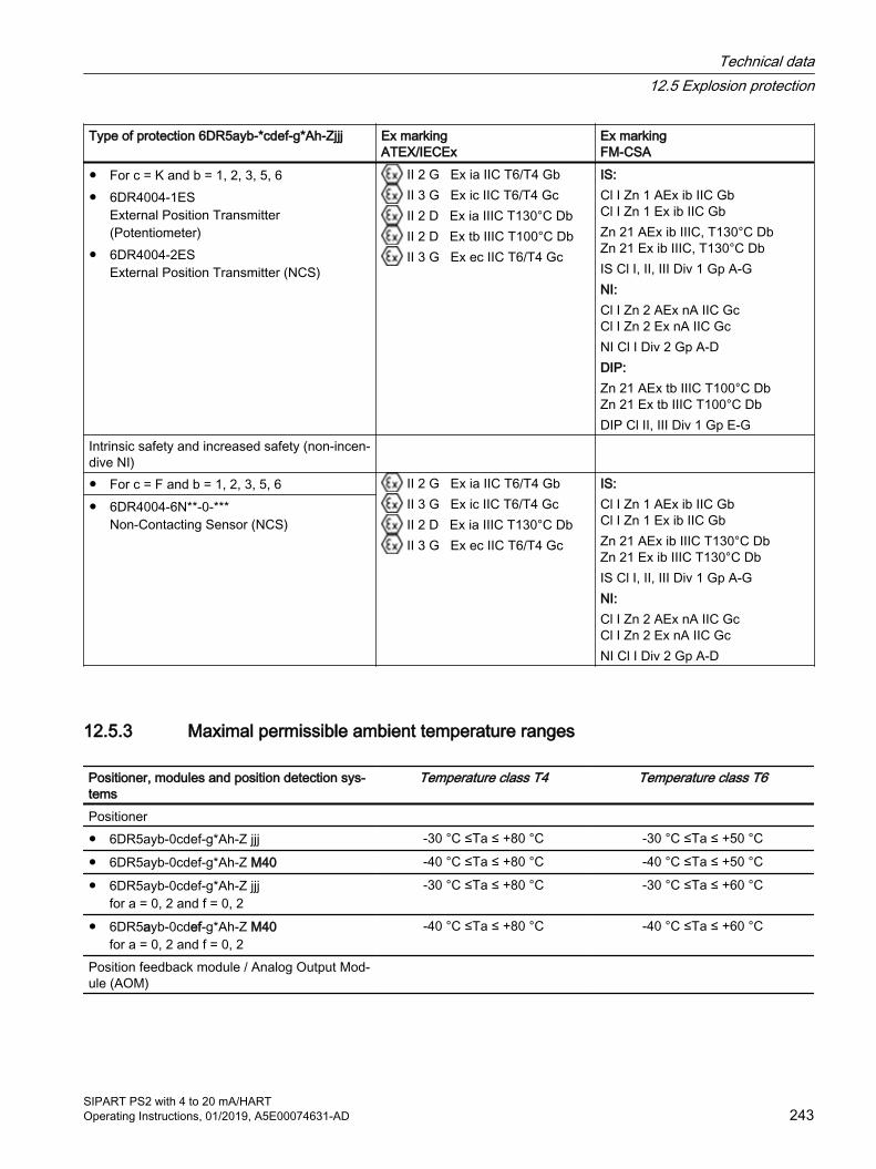
Type of protection 6DR5ayb-*cdef-g*Ah-Zjjj Ex marking ATEX/IECEx
Ex marking FM-CSA
● For c = K and b = 1, 2, 3, 5, 6● 6DR4004-1ES
External Position Transmitter (Potentiometer)
● 6DR4004-2ESExternal Position Transmitter (NCS)
II 2 G Ex ia IIC T6/T4 Gb II 3 G Ex ic IIC T6/T4 Gc II 2 D Ex ia IIIC T130°C Db II 2 D Ex tb IIIC T100°C Db II 3 G Ex ec IIC T6/T4 Gc
IS:Cl I Zn 1 AEx ib IIC Gb Cl I Zn 1 Ex ib IIC GbZn 21 AEx ib IIIC, T130°C Db Zn 21 Ex ib IIIC, T130°C DbIS Cl I, II, III Div 1 Gp A-GNI:Cl I Zn 2 AEx nA IIC Gc Cl I Zn 2 Ex nA IIC GcNI Cl I Div 2 Gp A-DDIP:Zn 21 AEx tb IIIC T100°C Db Zn 21 Ex tb IIIC T100°C DbDIP Cl II, III Div 1 Gp E-G
Intrinsic safety and increased safety (non-incen‐dive NI)
● For c = F and b = 1, 2, 3, 5, 6 II 2 G Ex ia IIC T6/T4 Gb II 3 G Ex ic IIC T6/T4 Gc II 2 D Ex ia IIIC T130°C Db II 3 G Ex ec IIC T6/T4 Gc
IS:Cl I Zn 1 AEx ib IIC Gb Cl I Zn 1 Ex ib IIC Gb Zn 21 AEx ib IIIC T130°C Db Zn 21 Ex ib IIIC T130°C DbIS Cl I, II, III Div 1 Gp A-GNI:Cl I Zn 2 AEx nA IIC Gc Cl I Zn 2 Ex nA IIC GcNI Cl I Div 2 Gp A-D
● 6DR4004-6N**-0-***Non-Contacting Sensor (NCS)
12.5.3 Maximal permissible ambient temperature ranges
Positioner, modules and position detection sys‐tems
Temperature class T4 Temperature class T6
Positioner ● 6DR5ayb-0cdef-g*Ah-Z jjj -30 °C ≤Ta ≤ +80 °C -30 °C ≤Ta ≤ +50 °C
● 6DR5ayb-0cdef-g*Ah-Z M40 -40 °C ≤Ta ≤ +80 °C -40 °C ≤Ta ≤ +50 °C
● 6DR5ayb-0cdef-g*Ah-Z jjjfor a = 0, 2 and f = 0, 2
-30 °C ≤Ta ≤ +80 °C -30 °C ≤Ta ≤ +60 °C
● 6DR5ayb-0cdef-g*Ah-Z M40 for a = 0, 2 and f = 0, 2
-40 °C ≤Ta ≤ +80 °C -40 °C ≤Ta ≤ +60 °C
Position feedback module / Analog Output Mod‐ule (AOM)
Technical data12.5 Explosion protection
SIPART PS2 with 4 to 20 mA/HARTOperating Instructions, 01/2019, A5E00074631-AD 243

Positioner, modules and position detection sys‐tems
Temperature class T4 Temperature class T6
● Already fitted:6DR5ayb-0cdef-g.Ah-Z ... for f = 1, 3
● Can be retrofitted 6DR4004-6J
-30 °C ≤Ta ≤ +80 °C -
● Already fitted and can be retrofitted:6DR5ayb-0cdef-g*Ah-Z M40 for f = 1, 3
-40 °C ≤Ta ≤ +80 °C -
Position detection systems ● Non-Contacting Sensor (NCS)
6DR4004-6N**-0-***-40 °C ≤Ta ≤ +90 °C -40 °C ≤Ta ≤ +70 °C
● External position detection system in the polycarbonate enclosure with potentiometer C73451-A430-D78
-40 °C ≤Ta ≤ +90 °C -40 °C ≤Ta ≤ +60 °C
● External Position Transmitter (Potentiometer)6DR4004-1ES
-40 °C ≤Ta ≤ +90 °C -40 °C ≤Ta ≤ +60 °C
● External Position Transmitter (NCS)6DR4004-2ES
-40 °C ≤Ta ≤ +90 °C -40 °C ≤Ta ≤ +50 °C
12.6 Certificates and approvals
Certificates and approvals Classification according to pressure equip‐ment directive (PED 2014/68/EU)
For fluid group 1 gases; fulfills requirements according to article 4, paragraph 3 (good engineering practice SEP)
CE conformity The applicable directives and applied standards with their revision levels can be found in the EU declaration of conformity on the Internet.
UL conformity You can find the appropriate "Standard(s) for Safety", including the relevant versions, in the UL-CERTIFICATE OF COMPLIANCE on the Internet.
See alsoCertificates (http://www.siemens.com/processinstrumentation/certificates)
12.7 Electrical data
Basic electronics without explosion protection
Basic electronics with explosion pro‐tection Ex "db"
Basic electronics with explosion pro‐tection Ex "ia"
Basic electronics with explosion pro‐tection Ex "ic", "ec", "tb"
Current input IW ● Rated signal range 0/4 ... 20 mA
Technical data12.7 Electrical data
SIPART PS2 with 4 to 20 mA/HART244 Operating Instructions, 01/2019, A5E00074631-AD
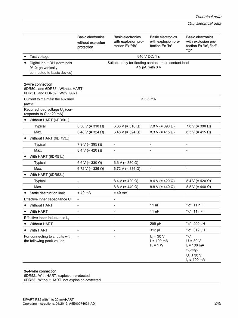
Basic electronics without explosion protection
Basic electronics with explosion pro‐tection Ex "db"
Basic electronics with explosion pro‐tection Ex "ia"
Basic electronics with explosion pro‐tection Ex "ic", "ec", "tb"
● Test voltage 840 V DC, 1 s
● Digital input DI1 (terminals 9/10; galvanically connected to basic device)
Suitable only for floating contact; max. contact load < 5 μA with 3 V
2-wire connection 6DR50.. and 6DR53.. Without HART 6DR51.. and 6DR52.. With HARTCurrent to maintain the auxiliary power
≥ 3.6 mA
Required load voltage UB (cor‐responds to Ω at 20 mA)
● Without HART (6DR50..) Typical 6.36 V (= 318 Ω) 6.36 V (= 318 Ω) 7.8 V (= 390 Ω) 7.8 V (= 390 Ω) Max. 6.48 V (= 324 Ω) 6.48 V (= 324 Ω) 8.3 V (= 415 Ω) 8.3 V (= 415 Ω)● Without HART (6DR53..) Typical 7.9 V (= 395 Ω) - - - Max. 8.4 V (= 420 Ω) - - -● With HART (6DR51..) Typical 6.6 V (= 330 Ω) 6.6 V (= 330 Ω) - - Max. 6.72 V (= 336 Ω) 6.72 V (= 336 Ω) - -● With HART (6DR52..) Typical - 8.4 V (= 420 Ω) 8.4 V (= 420 Ω) 8.4 V (= 420 Ω) Max. - 8.8 V (= 440 Ω) 8.8 V (= 440 Ω) 8.8 V (= 440 Ω)● Static destruction limit ± 40 mA ± 40 mA - -Effective inner capacitance Ci - - ● Without HART - - 11 nF "ic": 11 nF
● With HART - - 11 nF "ic": 11 nFEffective inner inductance Li - - ● Without HART - - 209 µH "ic": 209 µH
● With HART - - 312 µH "ic": 312 µHFor connecting to circuits with the following peak values
- - Ui = 30 V Ii = 100 mA Pi = 1 W
"ic": Ui = 30 V Ii = 100 mA"ec"/"t": Un ≤ 30 V In ≤ 100 mA
3-/4-wire connection 6DR52.. With HART, explosion-protected 6DR53.. Without HART, not explosion-protected
Technical data12.7 Electrical data
SIPART PS2 with 4 to 20 mA/HARTOperating Instructions, 01/2019, A5E00074631-AD 245

Basic electronics without explosion protection
Basic electronics with explosion pro‐tection Ex "db"
Basic electronics with explosion pro‐tection Ex "ia"
Basic electronics with explosion pro‐tection Ex "ic", "ec", "tb"
Load voltage at 20 mA ≤ 0.2 V (= 10 Ω) ≤ 0.2 V (= 10 Ω) ≤ 1 V (= 50 Ω) ≤ 1 V (= 50 Ω)Auxiliary power UAux 18 ... 35 V DC 18 ... 35 V DC 18 ... 30 V DC 18 ... 30 V DC● Current consumption IAux (UAux - 7.5 V)/2.4 kΩ [mA]For connecting to circuits with the following peak values
- - Ui = 30 V Ii = 100 mA Pi = 1 W
"ic": Ui = 30 V Ii = 100 mA"ec"/"t": Un ≤ 30 V In ≤ 100 mA
Effective inner capacitance Ci - - 22 nF 22 nFEffective inner inductance Li - - 0.12 mH 0.12 mHGalvanic isolation Between UAux and IW Between UAux and IW Between UAux and IW
(2 intrinsically safe circuits)
Between UAux and IW
12.8 Electrical data for pressure sensors
Basic electronics without explosion protection
Basic electronics for pressure sensors 6DR51.. -Z P01 HART, non-ExCurrent input IW ● Rated signal range 0/4 ... 20 mA
● Test voltage 840 V DC, 1 s
● Digital input DI1 (terminals 9/10; galvanically connected to basic device)
Suitable only for floating contact; max. contact load < 5 μA with 3 V
Current to maintain the auxiliary power ≥ 3.6 mARequired load voltage UB (corresponds to Ω at 20 mA) 9.4 V (= 470 Ω)Static destruction limit ± 30 VEffective inner capacitance Ci -Effective inner inductance Li -For connecting to circuits with the following peak values -
Technical data12.8 Electrical data for pressure sensors
SIPART PS2 with 4 to 20 mA/HART246 Operating Instructions, 01/2019, A5E00074631-AD

12.9 Communication (HART)
HART communication HART version 7PC parameter assignment soft‐ware
SIMATIC PDM; supports all device objects. The software is not included in the scope of delivery.
12.10 Technical data for natural gas as actuator medium
IntroductionNote when using an actuator with natural gas that this can escape at the exhaust air outlets.
① Base plate ③ Exhaust air outlet sound absorber ② Exhaust air outlet enclosure ventilation ④ Exhaust air outlet near the pneumatic con‐
nections
NoteExhaust air outlet with sound absorber ③The positioner is supplied as standard with a sound absorber. To provide an outlet for the exhaust air, replace the sound absorber by a G¼ pipe coupling.Enclosure ventilation ② and control air outlet ④Enclosure ventilation and control air outlet cannot be collected and channeled off.
Please refer to the following table for the maximum ventilation values.
Technical data12.10 Technical data for natural gas as actuator medium
SIPART PS2 with 4 to 20 mA/HARTOperating Instructions, 01/2019, A5E00074631-AD 247
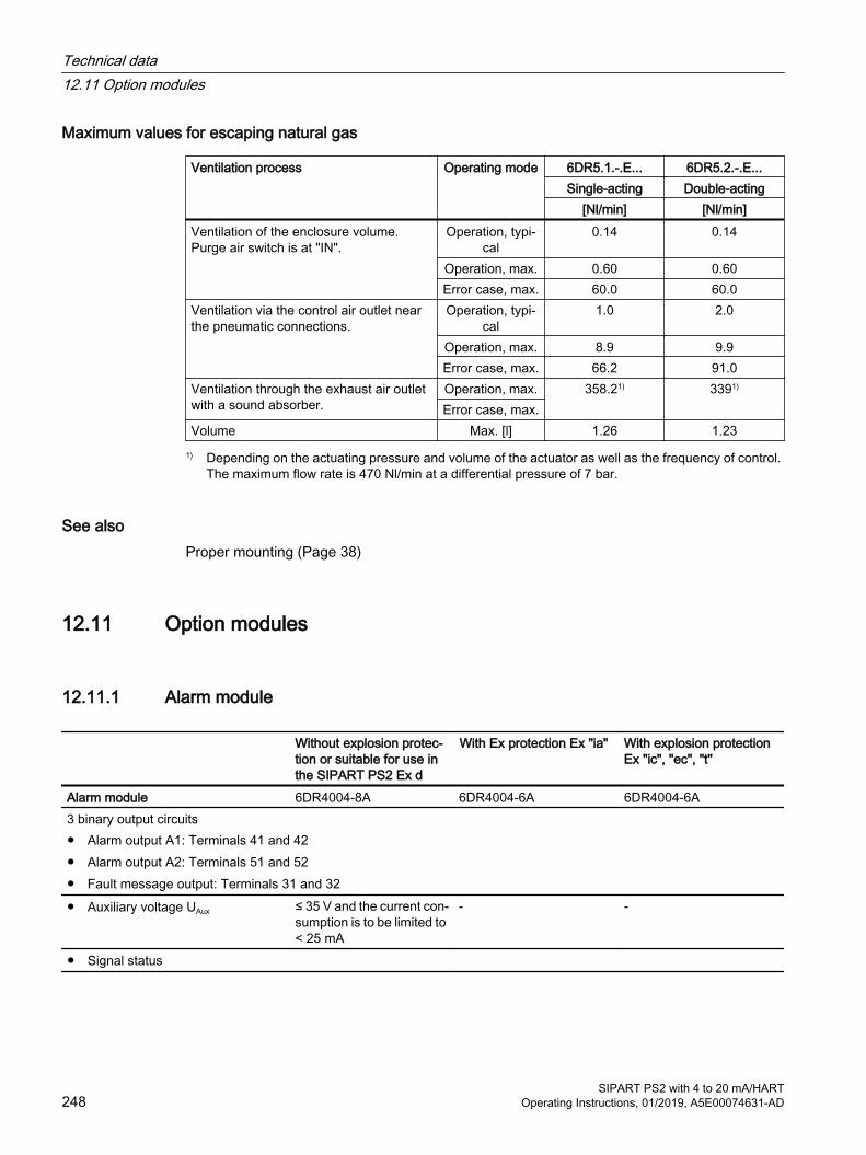
Maximum values for escaping natural gas
Ventilation process Operating mode 6DR5.1.-.E... 6DR5.2.-.E...Single-acting Double-acting
[Nl/min] [Nl/min]Ventilation of the enclosure volume. Purge air switch is at "IN".
Operation, typi‐cal
0.14 0.14
Operation, max. 0.60 0.60Error case, max. 60.0 60.0
Ventilation via the control air outlet near the pneumatic connections.
Operation, typi‐cal
1.0 2.0
Operation, max. 8.9 9.9Error case, max. 66.2 91.0
Ventilation through the exhaust air outlet with a sound absorber.
Operation, max. 358.21) 3391)
Error case, max.Volume Max. [l] 1.26 1.23
1) Depending on the actuating pressure and volume of the actuator as well as the frequency of control. The maximum flow rate is 470 Nl/min at a differential pressure of 7 bar.
See alsoProper mounting (Page 38)
12.11 Option modules
12.11.1 Alarm module
Without explosion protec‐tion or suitable for use in the SIPART PS2 Ex d
With Ex protection Ex "ia" With explosion protection Ex "ic", "ec", "t"
Alarm module 6DR4004-8A 6DR4004-6A 6DR4004-6A3 binary output circuits● Alarm output A1: Terminals 41 and 42● Alarm output A2: Terminals 51 and 52● Fault message output: Terminals 31 and 32● Auxiliary voltage UAux ≤ 35 V and the current con‐
sumption is to be limited to < 25 mA
- -
● Signal status
Technical data12.11 Option modules
SIPART PS2 with 4 to 20 mA/HART248 Operating Instructions, 01/2019, A5E00074631-AD
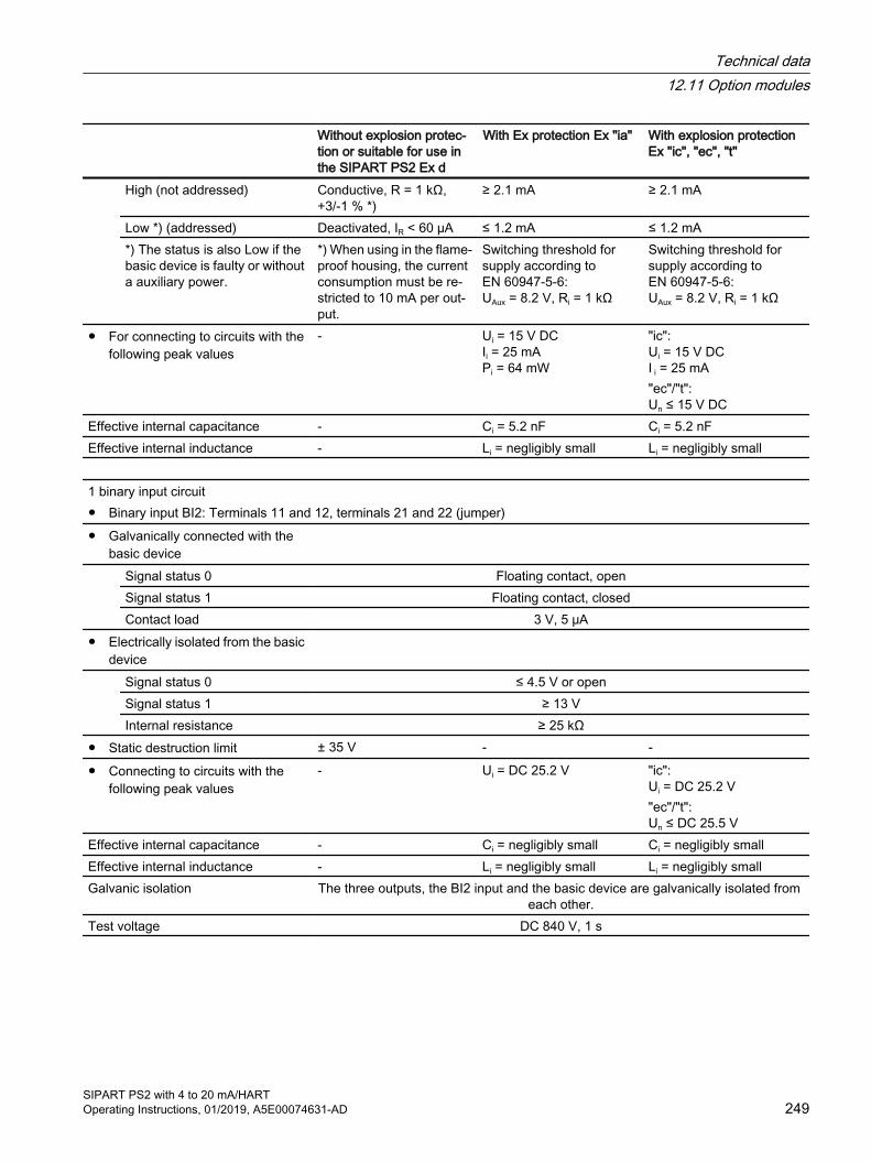
Without explosion protec‐tion or suitable for use in the SIPART PS2 Ex d
With Ex protection Ex "ia" With explosion protection Ex "ic", "ec", "t"
High (not addressed) Conductive, R = 1 kΩ, +3/-1 % *)
≥ 2.1 mA ≥ 2.1 mA
Low *) (addressed) Deactivated, IR < 60 µA ≤ 1.2 mA ≤ 1.2 mA*) The status is also Low if the basic device is faulty or without a auxiliary power.
*) When using in the flame‐proof housing, the current consumption must be re‐stricted to 10 mA per out‐put.
Switching threshold for supply according to EN 60947-5-6: UAux = 8.2 V, Ri = 1 kΩ
Switching threshold for supply according to EN 60947-5-6: UAux = 8.2 V, Ri = 1 kΩ
● For connecting to circuits with the following peak values
- Ui = 15 V DC Ii = 25 mA Pi = 64 mW
"ic": Ui = 15 V DC I i = 25 mA"ec"/"t": Un ≤ 15 V DC
Effective internal capacitance - Ci = 5.2 nF Ci = 5.2 nFEffective internal inductance - Li = negligibly small Li = negligibly small 1 binary input circuit● Binary input BI2: Terminals 11 and 12, terminals 21 and 22 (jumper)● Galvanically connected with the
basic device
Signal status 0 Floating contact, openSignal status 1 Floating contact, closedContact load 3 V, 5 μA
● Electrically isolated from the basic device
Signal status 0 ≤ 4.5 V or openSignal status 1 ≥ 13 VInternal resistance ≥ 25 kΩ
● Static destruction limit ± 35 V - -
● Connecting to circuits with the following peak values
- Ui = DC 25.2 V "ic": Ui = DC 25.2 V"ec"/"t": Un ≤ DC 25.5 V
Effective internal capacitance - Ci = negligibly small Ci = negligibly smallEffective internal inductance - Li = negligibly small Li = negligibly smallGalvanic isolation The three outputs, the BI2 input and the basic device are galvanically isolated from
each other.Test voltage DC 840 V, 1 s
Technical data12.11 Option modules
SIPART PS2 with 4 to 20 mA/HARTOperating Instructions, 01/2019, A5E00074631-AD 249
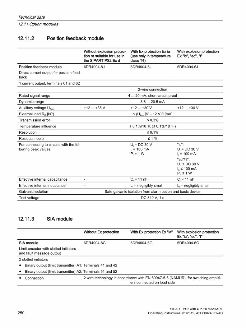
12.11.2 Position feedback module
Without explosion protec‐tion or suitable for use in the SIPART PS2 Ex d
With Ex protection Ex ia (use only in temperature class T4)
With explosion protection Ex "ic", "ec", "t"
Position feedback moduleDirect current output for position feed‐back
6DR4004-8J 6DR4004-6J 6DR4004-6J
1 current output, terminals 61 and 62 2-wire connectionRated signal range 4 ... 20 mA, short-circuit proofDynamic range 3.6 ... 20.5 mAAuxiliary voltage UAux +12 ... +35 V +12 ... +30 V +12 ... +30 VExternal load RB [kΩ] ≤ (UAux [V] - 12 V)/I [mA]Transmission error ≤ 0.3%Temperature influence ≤ 0.1%/10 K (≤ 0.1%/18 °F)Resolution ≤ 0.1%Residual ripple ≤ 1 %For connecting to circuits with the fol‐lowing peak values
Ui = DC 30 V Ii = 100 mA Pi = 1 W
"ic": Ui = DC 30 V Ii = 100 mA"ec"/"t": Un ≤ DC 30 V In ≤ 100 mAPn ≤ 1 W
Effective internal capacitance - Ci = 11 nF Ci = 11 nFEffective internal inductance - Li = negligibly small Li = negligibly smallGalvanic isolation Safe galvanic isolation from alarm option and basic deviceTest voltage DC 840 V, 1 s
12.11.3 SIA module
Without Ex protection With Ex protection Ex "ia" With explosion protection Ex "ic", "ec", "t"
SIA moduleLimit encoder with slotted initiators and fault message output
6DR4004-8G 6DR4004-6G 6DR4004-6G
2 slotted initiators● Binary output (limit transmitter) A1: Terminals 41 and 42● Binary output (limit transmitter) A2: Terminals 51 and 52● Connection 2 wire technology in accordance with EN 60947-5-6 (NAMUR), for switching amplifi‐
ers connected on load side
Technical data12.11 Option modules
SIPART PS2 with 4 to 20 mA/HART250 Operating Instructions, 01/2019, A5E00074631-AD
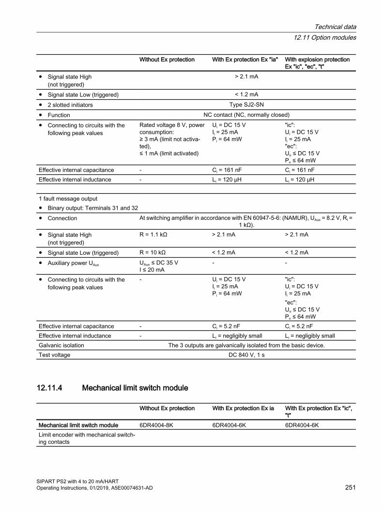
Without Ex protection With Ex protection Ex "ia" With explosion protection Ex "ic", "ec", "t"
● Signal state High (not triggered)
> 2.1 mA
● Signal state Low (triggered) < 1.2 mA
● 2 slotted initiators Type SJ2-SN
● Function NC contact (NC, normally closed)
● Connecting to circuits with the following peak values
Rated voltage 8 V, power consumption: ≥ 3 mA (limit not activa‐ted), ≤ 1 mA (limit activated)
Ui = DC 15 V Ii = 25 mA Pi = 64 mW
"ic": Ui = DC 15 V Ii = 25 mA "ec": Un ≤ DC 15 V Pn ≤ 64 mW
Effective internal capacitance - Ci = 161 nF Ci = 161 nFEffective internal inductance - Li = 120 μH Li = 120 μH 1 fault message output● Binary output: Terminals 31 and 32● Connection At switching amplifier in accordance with EN 60947-5-6: (NAMUR), UAux = 8.2 V, Ri =
1 kΩ).● Signal state High
(not triggered)R = 1.1 kΩ > 2.1 mA > 2.1 mA
● Signal state Low (triggered) R = 10 kΩ < 1.2 mA < 1.2 mA
● Auxiliary power UAux UAux ≤ DC 35 V I ≤ 20 mA
- -
● Connecting to circuits with the following peak values
- Ui = DC 15 V Ii = 25 mA Pi = 64 mW
"ic": Ui = DC 15 V Ii = 25 mA"ec": Un ≤ DC 15 V Pn ≤ 64 mW
Effective internal capacitance - Ci = 5.2 nF Ci = 5.2 nFEffective internal inductance - Li = negligibly small Li = negligibly smallGalvanic isolation The 3 outputs are galvanically isolated from the basic device.Test voltage DC 840 V, 1 s
12.11.4 Mechanical limit switch module
Without Ex protection With Ex protection Ex ia With Ex protection Ex "ic", "t"
Mechanical limit switch module 6DR4004-8K 6DR4004-6K 6DR4004-6KLimit encoder with mechanical switch‐ing contacts
Technical data12.11 Option modules
SIPART PS2 with 4 to 20 mA/HARTOperating Instructions, 01/2019, A5E00074631-AD 251

Without Ex protection With Ex protection Ex ia With Ex protection Ex "ic", "t"
2 limit contacts● Binary output 1: Terminals 41 and
42● Binary output 2: Terminals 51 and
52
● Max. switching current AC/DC 4 A - -
● For connecting to circuits with the following peak values
- Ui = 30 V Ii = 100 mA Pi = 750 mW
"ic": Ui = 30 V Ii = 100 mA "t":Un = 30 V In = 100 mA
Effective internal capacitance - Ci = negligibly small Ci = negligibly smallEffective internal inductance - Li = negligibly small Li = negligibly small● Max. switching voltage AC/DC 250 V/24 V DC 30 V DC 30 V1 fault message output● Binary output: Terminals 31 and 32
● Connection On switching amplifier according to EN 60947-5-6: (NAMUR), UAux = 8.2 V, Ri = 1 kΩ).
● Signal state High (not triggered)
R = 1.1 kΩ > 2.1 mA > 2.1 mA
● Signal state Low (triggered) R = 10 kΩ < 1.2 mA < 1.2 mA
● Auxiliary power UAux ≤ DC 35 V I ≤ 20 mA
- -
● Connecting to circuits with the following peak values
- Ui = 15 V Ii = 25 mA Pi = 64 mW
"ic" : Ui = 15 V Ii = 25 mA "t":Un = 15 V In = 25 mA
Effective internal capacitance - Ci = 5.2 nF Ci = 5.2 nFEffective internal inductance - Li = negligibly small Li = negligibly smallGalvanic isolation The 3 outputs are galvanically isolated from the basic deviceTest voltage DC 3150 V, 2 sRated condition height Max. 2 000 m mean sea
level Use a suitable power supply at an altitude of more than 2 000 m above sea level.
- -
Technical data12.11 Option modules
SIPART PS2 with 4 to 20 mA/HART252 Operating Instructions, 01/2019, A5E00074631-AD

12.11.5 EMC filter module
Without Ex protection With Ex protection Ex "ia", "ic"
With explosion protection Ex "ec", "t"
6DR4004-8F 6DR4004-6F 6DR4004-6FThe EMC filter module type 6DR4004-6F and -8F is required to connect contactless, external
position detection, e.g. NCS module or an external position detection system with potentiometer type C73451-A430-D78 or 6DR4004-1ES to -4ES or with internal NCS module 6DR4004-2ES to -4ES.
For devices with explosion protection, other types of potentiometers with a resistance value of 3 kΩ, 5 kΩ or 10 kΩ can be connected.
For devices without explosion protection, signals between 0 and 20 mA or 0 and 10 V can additionally be processed.R-potentiometer ● Maximum values with supply by other
basic devices (6DR50/1/2/3/9)Umax = 5 V Uo = 5 V
Io = 100 mA Po = 33 mW Co = 1 μF Lo = 1 mH
Umax = 5 V
● Maximum values when powered by the base unit with PA (6DR55) or FF communication (6DR56)
Umax = 5 V Uo = 5 V Io = 75 mA static Io = 160 mA transient Po = 120 mWCo = 1 μF Lo = 1 mH
Umax = 5 V
Signal 20 mA ● Nominal signal range 0 ... 20 mA -
● Internal load RB 200 Ω -
● Static destruction limit 40 mA -Signal 10 V ● Nominal signal range 0 ... 10 V -
● Internal resistance Ri 25 kΩ -
● Static destruction limit 20 V -Supply and signal power circuits Galvanically connected with the basic device
12.11.6 Internal NCS modules 6DR4004-5L and 6DR4004-5LE
Additional modules Without Ex protection With Ex protection Ex "ia"
With explosion protection Ex "ic", "ec", "t"
Internal NCS module 6DR4004-5L 6DR4004-5LE 6DR4004-5LELinearity (after corrections made by positioner)
± 1 % ± 1 % ± 1 %
Hysteresis ± 0.2 % ± 0.2 % ± 0.2 %
Technical data12.11 Option modules
SIPART PS2 with 4 to 20 mA/HARTOperating Instructions, 01/2019, A5E00074631-AD 253

12.11.7 Other technical specificationsTechnical specifications for additional option modules and accessories is available at:
● Technical specifications NCS (Page 281)
● Technical specifications of the external position detection system (Page 287)
● Sealing plug / thread adapter (Page 291)
● Positioner with remote control electronics (Page 311)
Technical data12.11 Option modules
SIPART PS2 with 4 to 20 mA/HART254 Operating Instructions, 01/2019, A5E00074631-AD
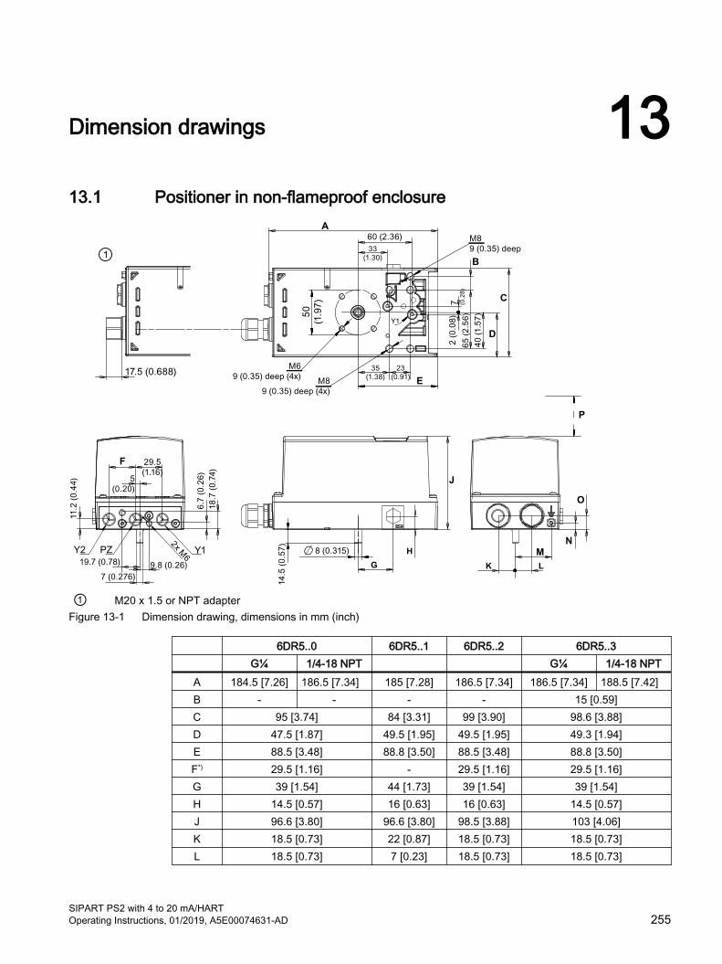
Dimension drawings 1313.1 Positioner in non-flameproof enclosure
F
G
B
D
H
C
J
K L
N
O
E
M
A
P
① M20 x 1.5 or NPT adapterFigure 13-1 Dimension drawing, dimensions in mm (inch)
6DR5..0 6DR5..1 6DR5..2 6DR5..3 G¼ 1/4-18 NPT G¼ 1/4-18 NPT
A 184.5 [7.26] 186.5 [7.34] 185 [7.28] 186.5 [7.34] 186.5 [7.34] 188.5 [7.42]B - - - - 15 [0.59]C 95 [3.74] 84 [3.31] 99 [3.90] 98.6 [3.88]D 47.5 [1.87] 49.5 [1.95] 49.5 [1.95] 49.3 [1.94]E 88.5 [3.48] 88.8 [3.50] 88.5 [3.48] 88.8 [3.50]F*) 29.5 [1.16] - 29.5 [1.16] 29.5 [1.16]G 39 [1.54] 44 [1.73] 39 [1.54] 39 [1.54]H 14.5 [0.57] 16 [0.63] 16 [0.63] 14.5 [0.57]J 96.6 [3.80] 96.6 [3.80] 98.5 [3.88] 103 [4.06]K 18.5 [0.73] 22 [0.87] 18.5 [0.73] 18.5 [0.73]L 18.5 [0.73] 7 [0.23] 18.5 [0.73] 18.5 [0.73]
SIPART PS2 with 4 to 20 mA/HARTOperating Instructions, 01/2019, A5E00074631-AD 255
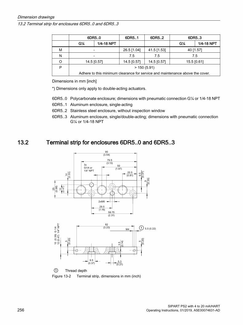
6DR5..0 6DR5..1 6DR5..2 6DR5..3 G¼ 1/4-18 NPT G¼ 1/4-18 NPT
M - 26.5 [1.04] 41.5 [1.53] 40 [1.57]N - 7.5 7.5 7.5O 14.5 [0.57] 14.5 [0.57] 14.5 [0.57] 15.5 [0.61]P > 150 (5.91)
Adhere to this minimum clearance for service and maintenance above the cover.
Dimensions in mm [inch]
*) Dimensions only apply to double-acting actuators.
6DR5..0 Polycarbonate enclosure; dimensions with pneumatic connection G¼ or 1/4-18 NPT6DR5..1 Aluminum enclosure, single-acting6DR5..2 Stainless steel enclosure, without inspection window6DR5..3 Aluminum enclosure, single/double-acting; dimensions with pneumatic connection
G¼ or 1/4-18 NPT
13.2 Terminal strip for enclosures 6DR5..0 and 6DR5..3
① Thread depthFigure 13-2 Terminal strip, dimensions in mm (inch)
Dimension drawings13.2 Terminal strip for enclosures 6DR5..0 and 6DR5..3
SIPART PS2 with 4 to 20 mA/HART256 Operating Instructions, 01/2019, A5E00074631-AD

13.3 Positioner in flameproof enclosure
B
A
C
G
F
D
E
① All air connections G¼ or ¼-18 NPT② Air connection Y2, only with double-acting version
Figure 13-3 Dimensions of positioner in flameproof enclosure
6DR5..5 6DR5..6A 5 [0.2] -B 60 (2.36) -C 25.7 (1.01) 21.7 (0.85)D 33.5 (1.32) 25 [0.99]E 33.5 (1.32) -F 158.5 [6.24] 160 [6.3]G 235.3 [9.26] 227.6 [8.96]
Dimensions in mm [inch]
6DR5..5 Aluminum enclosure, flameproof; dimensions with pneumatic connection G¼ or 1/4-18 NPT
6DR5..6 Stainless steel enclosure, flameproof
Dimension drawings13.3 Positioner in flameproof enclosure
SIPART PS2 with 4 to 20 mA/HARTOperating Instructions, 01/2019, A5E00074631-AD 257

Dimension drawings13.3 Positioner in flameproof enclosure
SIPART PS2 with 4 to 20 mA/HART258 Operating Instructions, 01/2019, A5E00074631-AD

Spare parts / accessories / scope of delivery 1414.1 Overview
WARNING
Assembling the components
When assembling components, ensure that only those positioners and option modules are combined with each other that are approved for the corresponding operating range.
These conditions particularly apply to safe operation of the positioner in hazardous areas. Observe the applicable certificates and approvals or the "Technical data (Page 237)".
Basic versionThe positioner can be delivered for:
● Double-acting actuators
● Single-acting actuators
The positioner and its option modules are delivered as separate units and with different versions for the operation in:
● Hazardous environments and atmospheres
● Non-hazardous environments and atmospheres
Enclosure The electronic unit with display, the position feedback, and the pneumatic block are integrated in the enclosure.
The enclosure is available in the following versions:
● Polycarbonate enclosure for single-acting and double-acting actuators
● Aluminum enclosure for single-acting or double-acting actuators
● Stainless steel enclosure for single and double-acting actuators
● Flameproof enclosure for single and double-acting actuators
Options The positioner can be equipped with different option modules. The following modules are normally available:
● Position feedback module: two-wire current output 4 to 20 mA for position feedback
● Alarm module: 3 binary outputs and 1 binary input
SIPART PS2 with 4 to 20 mA/HARTOperating Instructions, 01/2019, A5E00074631-AD 259

● SIA module: one binary output for fault messages, two binary outputs for limit monitors
● Mechanical limit switch module with two switches and one alarm output
● Internal NCS module 6DR4004-5L/-5LE
The SIA module and the mechanical limit switch module cannot be used in device versions with flameproof enclosure. For more limitations, please refer to section "Technical data (Page 237)".
Accessories ● Pressure gauge block: 2 or 3 pressure gauges for single and double-acting positioners
● Mounting flange (NAMUR) for safety pneumatic block
● Mounting kits for linear and part-turn actuators
For separate mounting of positioner and position sensor
● External position detection system
● NCS sensor for contactless position detection
Note
The version is identified using a special nameplate.
Spare parts / accessories / scope of delivery14.1 Overview
SIPART PS2 with 4 to 20 mA/HART260 Operating Instructions, 01/2019, A5E00074631-AD

14.2 Spare parts
Description Article number For versionBasic electronics
2-wire, not Ex, without HART A5E00082459 6DR50..-.N
2-wire, Ex, without HART A5E00082457 6DR50..-.D/E/F/G/K
2-wire, not Ex, with HART A5E00082458 6DR51..-.N
2-wire, not Ex, with HART, extended diagnostics sup‐ported by pressure sensors
A5E45152693 6DR51..-.N* -Z P01
2/3/4-wire, Ex, with HART A5E00082456 6DR52..-.D/E/F/G/K
2/3/4-wire, not Ex, without HART A5E00102018 6DR53..-.N
PROFIBUS PA, not Ex A5E00141523 6DR55..-.N
PROFIBUS PA, Ex A5E00141550 6DR55..-.D/E/F/G/K
FOUNDATION Fieldbus, not Ex A5E00215467 6DR56..-.N
FOUNDATION Fieldbus, Ex A5E00215466 6DR56..-.D/E/F/G/K
Interface module for positioner without basic electronics A5E00151572 6DR5910-*
Interface module for 19-inch slide-in module 4 ... 20 mA A5E00151571 A5E00151560
Spare parts / accessories / scope of delivery14.2 Spare parts
SIPART PS2 with 4 to 20 mA/HARTOperating Instructions, 01/2019, A5E00074631-AD 261
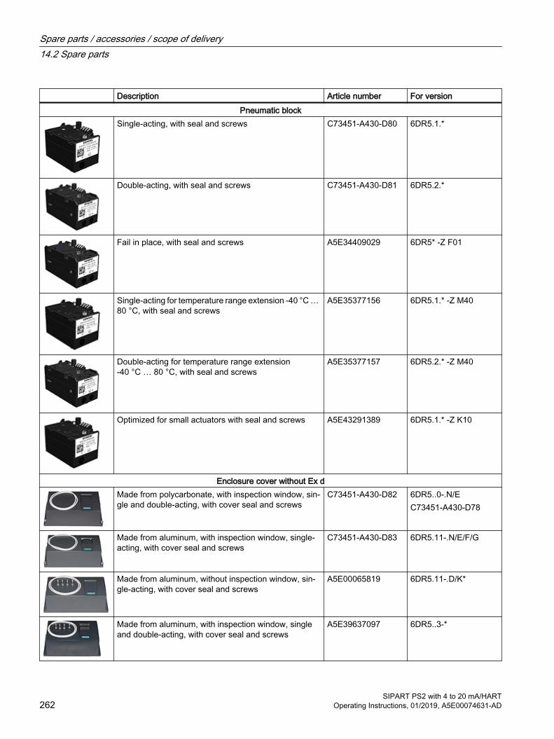
Description Article number For versionPneumatic block
Single-acting, with seal and screws C73451-A430-D80 6DR5.1.*
Double-acting, with seal and screws C73451-A430-D81 6DR5.2.*
Fail in place, with seal and screws A5E34409029 6DR5* -Z F01
Single-acting for temperature range extension -40 °C … 80 °C, with seal and screws
A5E35377156 6DR5.1.* -Z M40
Double-acting for temperature range extension -40 °C … 80 °C, with seal and screws
A5E35377157 6DR5.2.* -Z M40
Optimized for small actuators with seal and screws A5E43291389 6DR5.1.* -Z K10
Enclosure cover without Ex dMade from polycarbonate, with inspection window, sin‐gle and double-acting, with cover seal and screws
C73451-A430-D82 6DR5..0-.N/EC73451-A430-D78
Made from aluminum, with inspection window, single-acting, with cover seal and screws
C73451-A430-D83 6DR5.11-.N/E/F/G
Made from aluminum, without inspection window, sin‐gle-acting, with cover seal and screws
A5E00065819 6DR5.11-.D/K*
Made from aluminum, with inspection window, single and double-acting, with cover seal and screws
A5E39637097 6DR5..3-*
Spare parts / accessories / scope of delivery14.2 Spare parts
SIPART PS2 with 4 to 20 mA/HART262 Operating Instructions, 01/2019, A5E00074631-AD
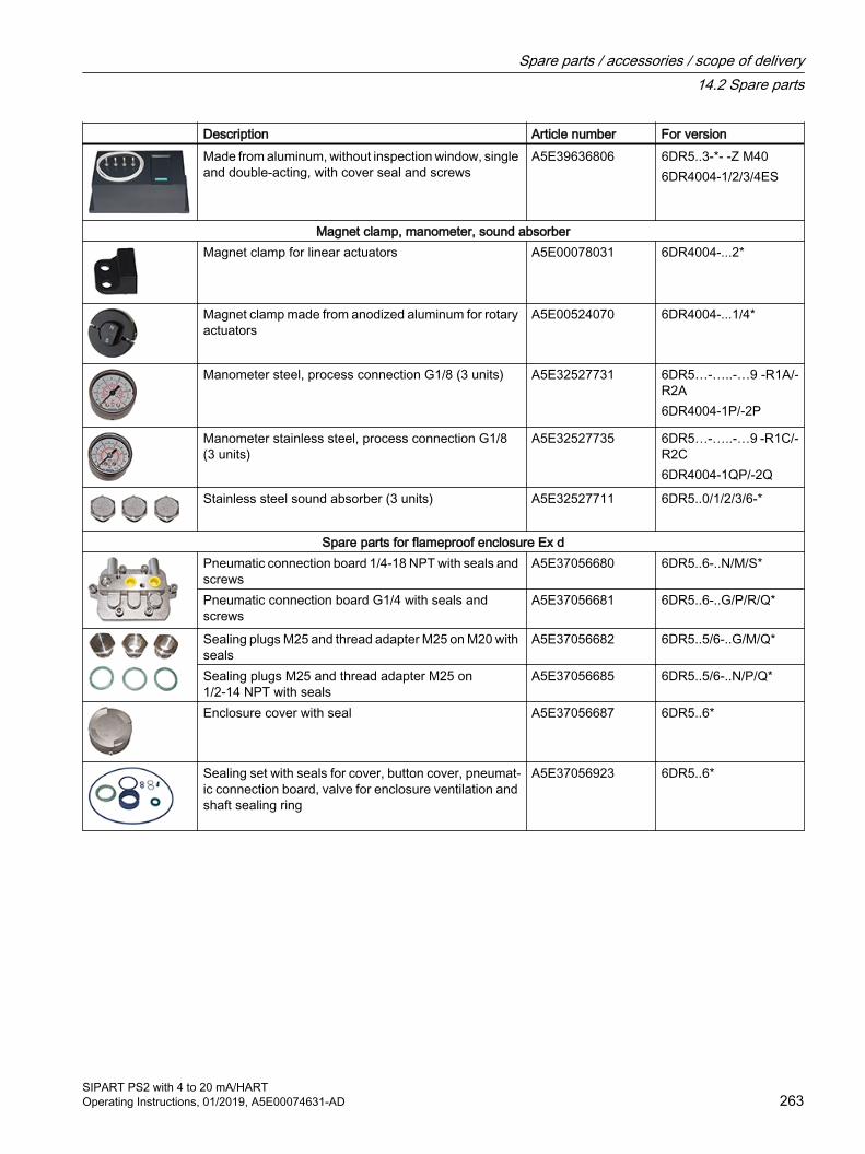
Description Article number For versionMade from aluminum, without inspection window, single and double-acting, with cover seal and screws
A5E39636806 6DR5..3-*- -Z M406DR4004-1/2/3/4ES
Magnet clamp, manometer, sound absorberMagnet clamp for linear actuators A5E00078031 6DR4004-...2*
Magnet clamp made from anodized aluminum for rotary actuators
A5E00524070 6DR4004-...1/4*
Manometer steel, process connection G1/8 (3 units) A5E32527731 6DR5…-…..-…9 -R1A/-R2A6DR4004-1P/-2P
Manometer stainless steel, process connection G1/8 (3 units)
A5E32527735 6DR5…-…..-…9 -R1C/-R2C6DR4004-1QP/-2Q
Stainless steel sound absorber (3 units) A5E32527711 6DR5..0/1/2/3/6-*
Spare parts for flameproof enclosure Ex dPneumatic connection board 1/4-18 NPT with seals and screws
A5E37056680 6DR5..6-..N/M/S*
Pneumatic connection board G1/4 with seals and screws
A5E37056681 6DR5..6-..G/P/R/Q*
Sealing plugs M25 and thread adapter M25 on M20 with seals
A5E37056682 6DR5..5/6-..G/M/Q*
Sealing plugs M25 and thread adapter M25 on 1/2-14 NPT with seals
A5E37056685 6DR5..5/6-..N/P/Q*
Enclosure cover with seal A5E37056687 6DR5..6*
Sealing set with seals for cover, button cover, pneumat‐ic connection board, valve for enclosure ventilation and shaft sealing ring
A5E37056923 6DR5..6*
Spare parts / accessories / scope of delivery14.2 Spare parts
SIPART PS2 with 4 to 20 mA/HARTOperating Instructions, 01/2019, A5E00074631-AD 263
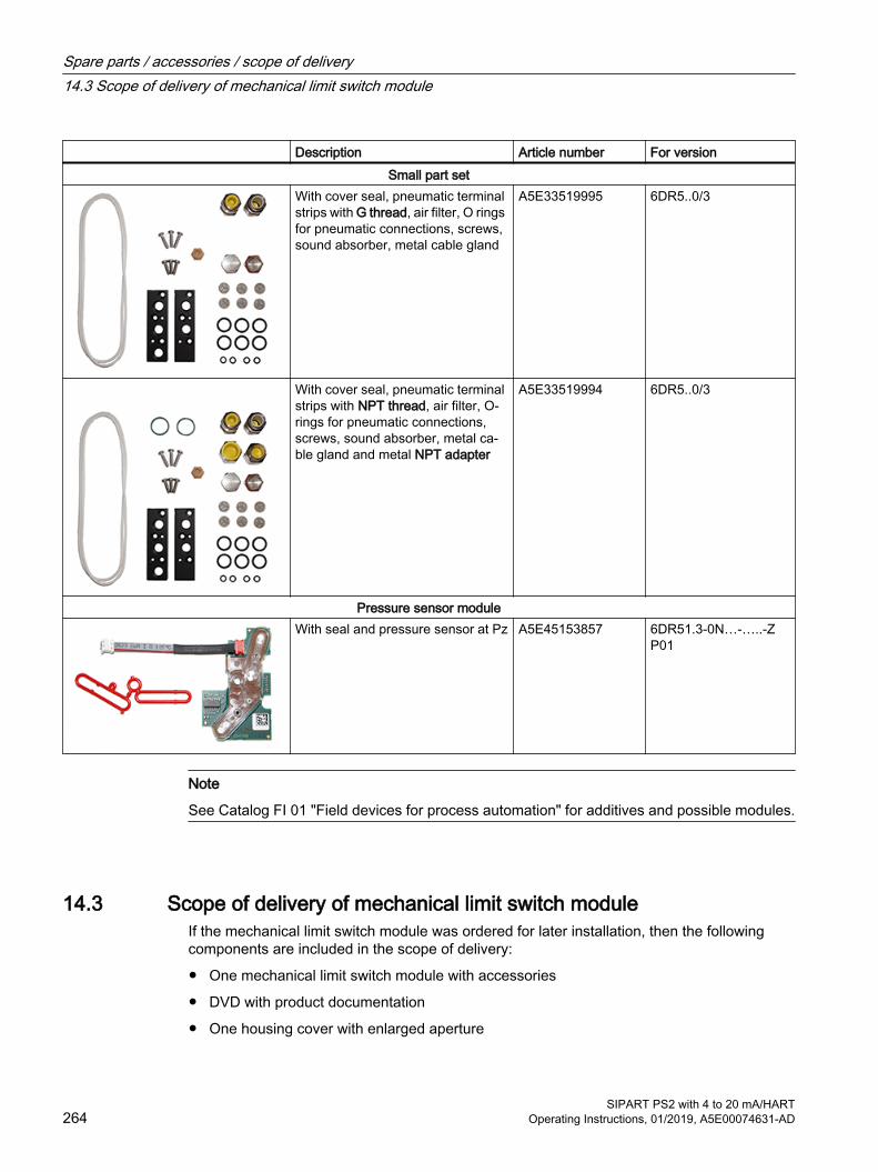
Description Article number For versionSmall part set
With cover seal, pneumatic terminal strips with G thread, air filter, O rings for pneumatic connections, screws, sound absorber, metal cable gland
A5E33519995 6DR5..0/3
With cover seal, pneumatic terminal strips with NPT thread, air filter, O-rings for pneumatic connections, screws, sound absorber, metal ca‐ble gland and metal NPT adapter
A5E33519994 6DR5..0/3
Pressure sensor moduleWith seal and pressure sensor at Pz A5E45153857 6DR51.3-0N…-…..-Z
P01
Note
See Catalog FI 01 "Field devices for process automation" for additives and possible modules.
14.3 Scope of delivery of mechanical limit switch moduleIf the mechanical limit switch module was ordered for later installation, then the following components are included in the scope of delivery:
● One mechanical limit switch module with accessories
● DVD with product documentation
● One housing cover with enlarged aperture
Spare parts / accessories / scope of delivery14.3 Scope of delivery of mechanical limit switch module
SIPART PS2 with 4 to 20 mA/HART264 Operating Instructions, 01/2019, A5E00074631-AD
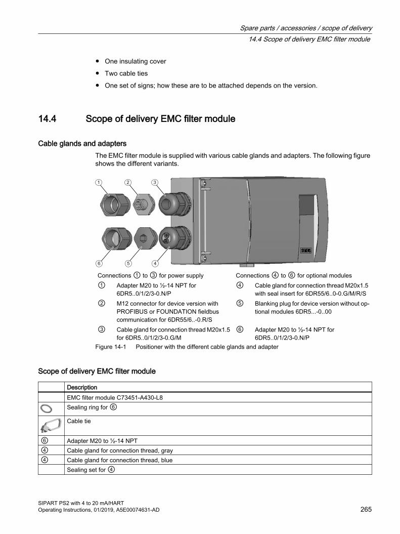
● One insulating cover
● Two cable ties
● One set of signs; how these are to be attached depends on the version.
14.4 Scope of delivery EMC filter module
Cable glands and adaptersThe EMC filter module is supplied with various cable glands and adapters. The following figure shows the different variants.
1 2 3
6 5 4
Connections ① to ③ for power supply Connections ④ to ⑥ for optional modules① Adapter M20 to ½-14 NPT for
6DR5..0/1/2/3-0.N/P④ Cable gland for connection thread M20x1.5
with seal insert for 6DR55/6..0-0.G/M/R/S② M12 connector for device version with
PROFIBUS or FOUNDATION fieldbus communication for 6DR55/6..-0.R/S
⑤ Blanking plug for device version without op‐tional modules 6DR5...-0..00
③ Cable gland for connection thread M20x1.5 for 6DR5..0/1/2/3-0.G/M
⑥ Adapter M20 to ½-14 NPT for 6DR5..0/1/2/3-0.N/P
Figure 14-1 Positioner with the different cable glands and adapter
Scope of delivery EMC filter module
Description EMC filter module C73451-A430-L8
Sealing ring for ⑥Cable tie
⑥ Adapter M20 to ½-14 NPT④ Cable gland for connection thread, gray④ Cable gland for connection thread, blue Sealing set for ④
Spare parts / accessories / scope of delivery14.4 Scope of delivery EMC filter module
SIPART PS2 with 4 to 20 mA/HARTOperating Instructions, 01/2019, A5E00074631-AD 265

Description Sealing set plug for ④ Screw for plastic Oval head screw M3x6
14.5 AccessoriesFor accessories, refer to Catalog FI 01 "Field devices for process automation", for example:
● Option modules
● NCS sensor for contactless position detection
● Mounting kits
● Operating software
14.6 Order dataIn order to ensure that the ordering data you are using is not outdated, the latest ordering data is always available on the Internet:
Process instrumentation catalog (http://www.siemens.com/processinstrumentation/catalogs)
Spare parts / accessories / scope of delivery14.6 Order data
SIPART PS2 with 4 to 20 mA/HART266 Operating Instructions, 01/2019, A5E00074631-AD

Appendix AA.1 Technical support
Technical SupportIf this documentation does not provide complete answers to any technical questions you may have, contact Technical Support at:
● Support request (http://www.siemens.com/automation/support-request)
● More information about our Technical Support is available at Technical support (http://www.siemens.com/automation/csi/service)
Internet Service & SupportIn addition to our documentation, Siemens provides a comprehensive support solution at:
● Service&Support (http://www.siemens.com/automation/service&support)
Personal contactIf you have additional questions about the device, please contact your Siemens personal contact at:
● Partner (http://www.automation.siemens.com/partner)
To find the personal contact for your product, go to "All Products and Branches" and select "Products & Services > Industrial Automation > Process Instrumentation".
DocumentationYou can find documentation on various products and systems at:
● Instructions and manuals (http://www.siemens.com/processinstrumentation/documentation)
See alsoSIPART PS2 product information (http://www.siemens.com/sipartps2)
E-mail (mailto:[email protected])
Process instrumentation catalog (http://www.siemens.com/processinstrumentation/catalogs)
SITRANS T product information (http://www.siemens.com/sitranst)
Product information on SITRANS P in the Internet (http://www.siemens.com/sitransp)
SIPART PS2 with 4 to 20 mA/HARTOperating Instructions, 01/2019, A5E00074631-AD 267
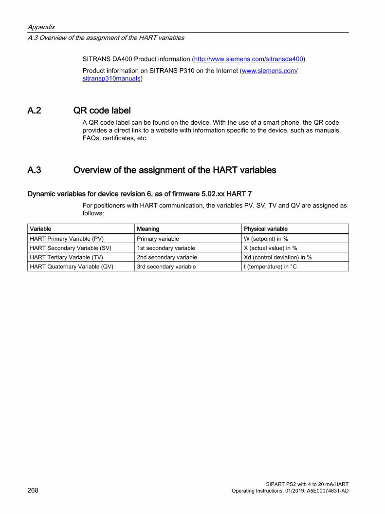
SITRANS DA400 Product information (http://www.siemens.com/sitransda400)
Product information on SITRANS P310 on the Internet (www.siemens.com/sitransp310manuals)
A.2 QR code labelA QR code label can be found on the device. With the use of a smart phone, the QR code provides a direct link to a website with information specific to the device, such as manuals, FAQs, certificates, etc.
A.3 Overview of the assignment of the HART variables
Dynamic variables for device revision 6, as of firmware 5.02.xx HART 7For positioners with HART communication, the variables PV, SV, TV and QV are assigned as follows:
Variable Meaning Physical variableHART Primary Variable (PV) Primary variable W (setpoint) in %HART Secondary Variable (SV) 1st secondary variable X (actual value) in %HART Tertiary Variable (TV) 2nd secondary variable Xd (control deviation) in %HART Quaternary Variable (QV) 3rd secondary variable t (temperature) in °C
AppendixA.3 Overview of the assignment of the HART variables
SIPART PS2 with 4 to 20 mA/HART268 Operating Instructions, 01/2019, A5E00074631-AD

External position detection BB.1 Introduction
WARNING
External position detection system
Versions with flameproof enclosures may not be operated with an external position detection system with the same type of protection.
In some cases it makes sense to mount the position detection and the controller unit separately. A separate mounting the case, for example, with continuous and strong vibrations, high or too low ambient temperatures and nuclear radiation. A universal component is available for this purpose. It is suitable for part-turn and linear actuators. You will require the following:
One of the following external position detection systems● Article number C73451-A430-D78 made of polycarbonate or with article number
6DR4004-1ES made of aluminum consisting of:
– Positioner enclosure
– Integrated friction clutch
– Integrated potentiometer
– Various blanking plugs and seals
● An external position detection system with article number 6DR4004-2ES, 3ES or 4ES comprising:
– Positioner enclosure
– Internal NCS module
– Various blanking plugs and seals
– Integrated SIA module (6DR4004-3ES) or GWK module (6DR4004-4ES)
● NCS sensor for contactless position detection 6DR4004-6N.../-8N.
● Potentiometers with 3 kΩ, 5 kΩ or 10 kΩ
● Position sensor with a signal range from 0 to 20 mA
● Position sensor with a signal range from 0 to 10 V
And a positioner● Positioner in combination with EMC filter module 6DR5..0/1/2/3-0...2/3 or retrofitted as
accessory 6DR4004-6F/-8F.
– An EMC filter module as an accessory is provided in a set along with cable clamps and M20 cable glands.
SIPART PS2 with 4 to 20 mA/HARTOperating Instructions, 01/2019, A5E00074631-AD 269
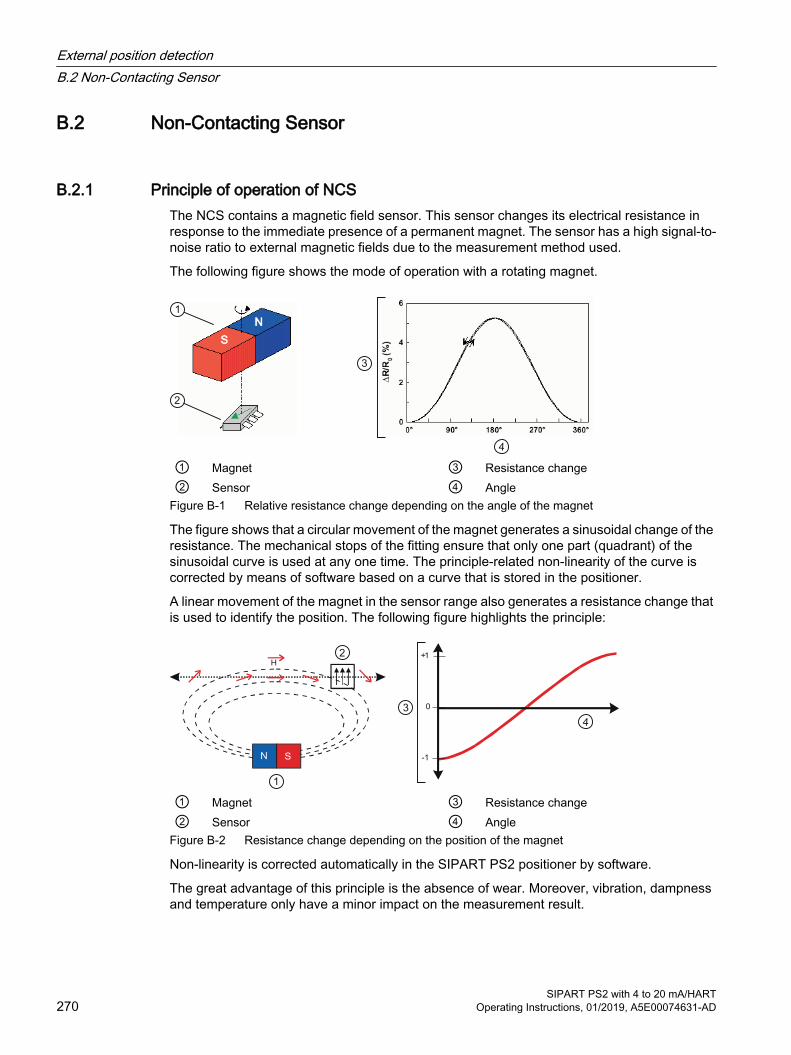
B.2 Non-Contacting Sensor
B.2.1 Principle of operation of NCSThe NCS contains a magnetic field sensor. This sensor changes its electrical resistance in response to the immediate presence of a permanent magnet. The sensor has a high signal-to-noise ratio to external magnetic fields due to the measurement method used.
The following figure shows the mode of operation with a rotating magnet.
① Magnet ③ Resistance change② Sensor ④ Angle
Figure B-1 Relative resistance change depending on the angle of the magnet
The figure shows that a circular movement of the magnet generates a sinusoidal change of the resistance. The mechanical stops of the fitting ensure that only one part (quadrant) of the sinusoidal curve is used at any one time. The principle-related non-linearity of the curve is corrected by means of software based on a curve that is stored in the positioner.
A linear movement of the magnet in the sensor range also generates a resistance change that is used to identify the position. The following figure highlights the principle:
① Magnet ③ Resistance change② Sensor ④ Angle
Figure B-2 Resistance change depending on the position of the magnet
Non-linearity is corrected automatically in the SIPART PS2 positioner by software.
The great advantage of this principle is the absence of wear. Moreover, vibration, dampness and temperature only have a minor impact on the measurement result.
External position detectionB.2 Non-Contacting Sensor
SIPART PS2 with 4 to 20 mA/HART270 Operating Instructions, 01/2019, A5E00074631-AD
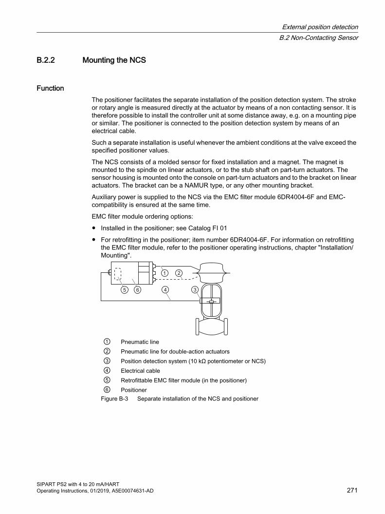
B.2.2 Mounting the NCS
FunctionThe positioner facilitates the separate installation of the position detection system. The stroke or rotary angle is measured directly at the actuator by means of a non contacting sensor. It is therefore possible to install the controller unit at some distance away, e.g. on a mounting pipe or similar. The positioner is connected to the position detection system by means of an electrical cable.
Such a separate installation is useful whenever the ambient conditions at the valve exceed the specified positioner values.
The NCS consists of a molded sensor for fixed installation and a magnet. The magnet is mounted to the spindle on linear actuators, or to the stub shaft on part-turn actuators. The sensor housing is mounted onto the console on part-turn actuators and to the bracket on linear actuators. The bracket can be a NAMUR type, or any other mounting bracket.
Auxiliary power is supplied to the NCS via the EMC filter module 6DR4004-6F and EMC-compatibility is ensured at the same time.
EMC filter module ordering options:
● Installed in the positioner; see Catalog FI 01
● For retrofitting in the positioner; item number 6DR4004-6F. For information on retrofitting the EMC filter module, refer to the positioner operating instructions, chapter "Installation/Mounting".
① Pneumatic line② Pneumatic line for double-action actuators③ Position detection system (10 kΩ potentiometer or NCS)④ Electrical cable⑤ Retrofittable EMC filter module (in the positioner)⑥ Positioner
Figure B-3 Separate installation of the NCS and positioner
External position detectionB.2 Non-Contacting Sensor
SIPART PS2 with 4 to 20 mA/HARTOperating Instructions, 01/2019, A5E00074631-AD 271
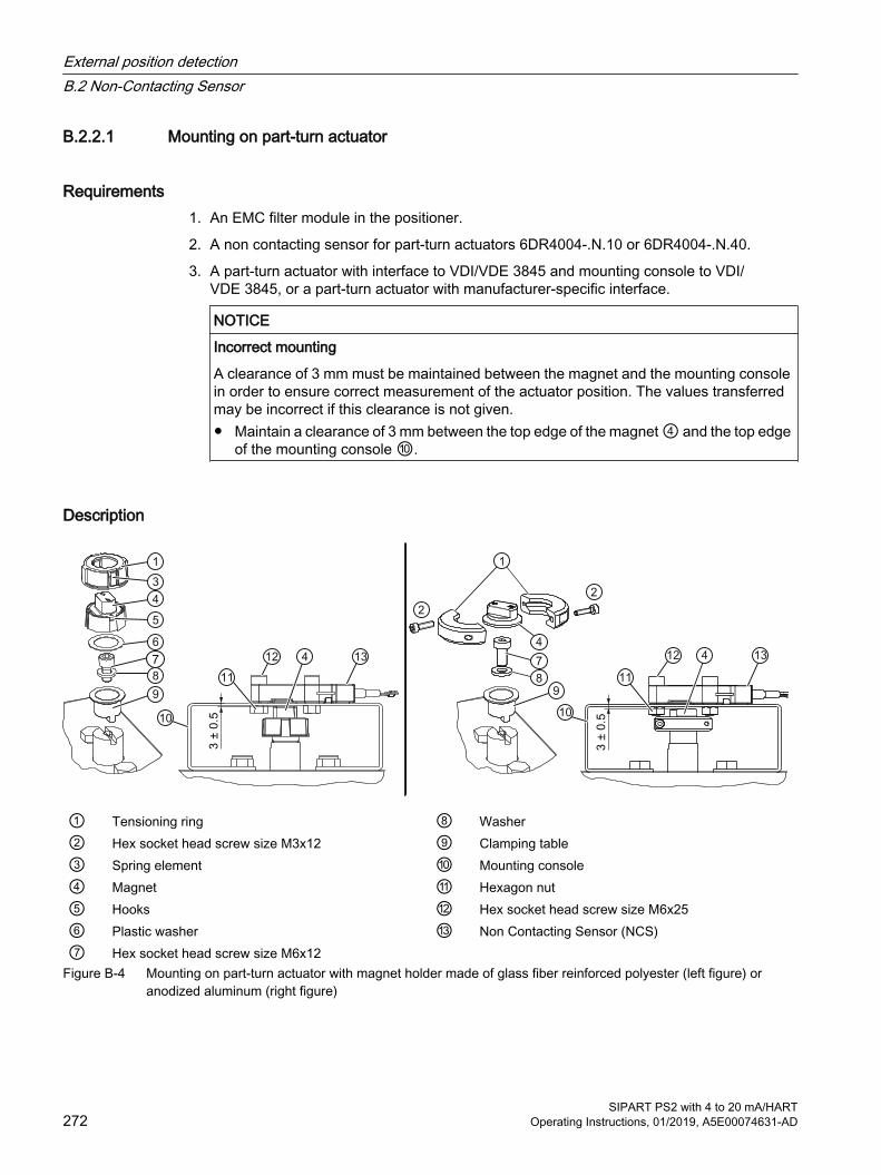
B.2.2.1 Mounting on part-turn actuator
Requirements1. An EMC filter module in the positioner.
2. A non contacting sensor for part-turn actuators 6DR4004-.N.10 or 6DR4004-.N.40.
3. A part-turn actuator with interface to VDI/VDE 3845 and mounting console to VDI/VDE 3845, or a part-turn actuator with manufacturer-specific interface.
NOTICE
Incorrect mounting
A clearance of 3 mm must be maintained between the magnet and the mounting console in order to ensure correct measurement of the actuator position. The values transferred may be incorrect if this clearance is not given.● Maintain a clearance of 3 mm between the top edge of the magnet ④ and the top edge
of the mounting console ⑩.
Description
① Tensioning ring ⑧ Washer② Hex socket head screw size M3x12 ⑨ Clamping table③ Spring element ⑩ Mounting console④ Magnet ⑪ Hexagon nut⑤ Hooks ⑫ Hex socket head screw size M6x25⑥ Plastic washer ⑬ Non Contacting Sensor (NCS)⑦ Hex socket head screw size M6x12
Figure B-4 Mounting on part-turn actuator with magnet holder made of glass fiber reinforced polyester (left figure) or anodized aluminum (right figure)
External position detectionB.2 Non-Contacting Sensor
SIPART PS2 with 4 to 20 mA/HART272 Operating Instructions, 01/2019, A5E00074631-AD

Procedure for the part-turn actuator to VDI/VDE 38451. Slide the clamping table ⑨ onto the stub shaft of the part-turn actuator.
2. Mount the clamping table ⑨ to the stub shaft using a hex socket head screw ⑦ and washer ⑧.
3. Depending on the material of the magnet holder, proceed as follows:
Magnet holder made of glass fiber reinforced polyester
Magnet holder made of anodized aluminum
1. Insert the plastic washer ⑥ into the magnet ④.
2. Fix the magnet ④ onto the clamping table ⑨. The magnet ④ can now be rotated easily on the clamping table ⑨.
3. Slide the tensioning ring ① over the magnet ④. Make sure that the spring elements ③ and the hook ⑤ on the magnet ④ are lined up above one another and that they engage. You will now have more resistance when turning the tensioning ring ① and magnet ④.
1. Place the magnet ④ onto the clamping table ⑨.
2. Secure the magnet ④ to the clamping table⑨ by connecting the two parts of the tensioning ring ① to the two hex socket head screws ②. The magnet ④ can now be rotated easily on the clamping table ⑨.
3. Then tighten the two hex socket head screws ②. The magnet ④ can then no longer be rotated on the clamping table ⑨.
4. Screw the NCS ⑬ onto the mounting console ⑩ using the hexagon socket-head screw ⑫, hex nut ⑪ and the washer ⑧.
5. Once the NCS ⑬ is mounted, the clearance of 3 mm between the top edge of the magnet ④ and the top edge of the mounting console ⑩ is set automatically.
Procedure for part-turn actuators with manufacturer-specific interface1. Steps 1 to 4 as above.
2. Set a clearance of 3 mm between the top edge of the magnet ④ and the top edge of the mounting console ⑩. Extend the stub shaft accordingly, or insert washers underneath the NCS housing ⑬.
ReferenceFor information on the scope of delivery, refer to chapter "Scope of delivery of NCS for part-turn actuators (Page 283)".
External position detectionB.2 Non-Contacting Sensor
SIPART PS2 with 4 to 20 mA/HARTOperating Instructions, 01/2019, A5E00074631-AD 273
B.2.2.2 Mounting on linear actuator up to 14 mm (0.55 inch)
Requirement1. An EMC filter module in the positioner.
2. An NCS for linear actuators up to 14 mm (0.55 inch) 6DR4004-.N.20.
3. A linear actuator with interface to NAMUR. This installation must be carried out individually. Only a NAMUR mounting bracket can be used as mounting base. The following figure shows the assembly with NAMUR mounting bracket. Or: A linear actuator without interface to NAMUR and individual mounting solution.
You can find the dimensions of the NCS as well as the NCS magnet under Dimensional drawing of non-contacting sensor (Page 283).
External position detectionB.2 Non-Contacting Sensor
SIPART PS2 with 4 to 20 mA/HART274 Operating Instructions, 01/2019, A5E00074631-AD
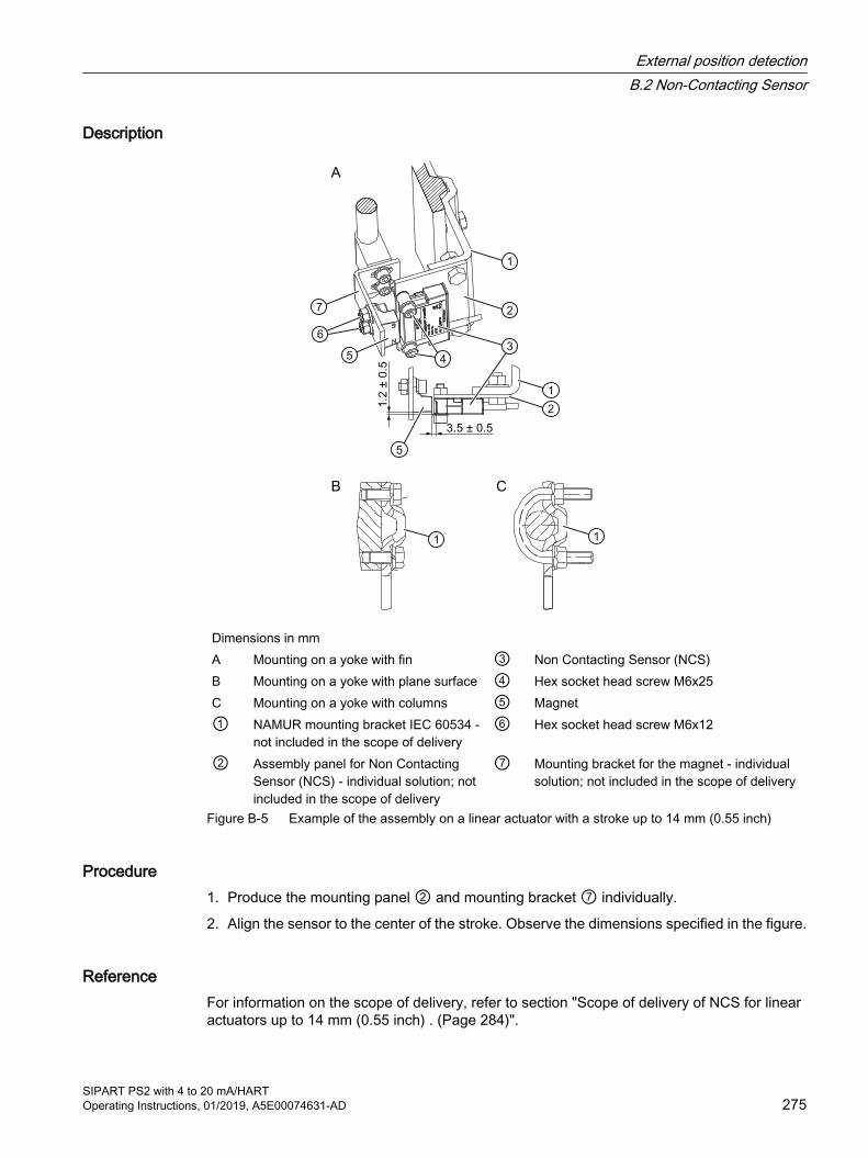
Description
Dimensions in mmA Mounting on a yoke with fin ③ Non Contacting Sensor (NCS)B Mounting on a yoke with plane surface ④ Hex socket head screw M6x25C Mounting on a yoke with columns ⑤ Magnet① NAMUR mounting bracket IEC 60534 -
not included in the scope of delivery⑥ Hex socket head screw M6x12
② Assembly panel for Non Contacting Sensor (NCS) - individual solution; not included in the scope of delivery
⑦ Mounting bracket for the magnet - individual solution; not included in the scope of delivery
Figure B-5 Example of the assembly on a linear actuator with a stroke up to 14 mm (0.55 inch)
Procedure1. Produce the mounting panel ② and mounting bracket ⑦ individually.
2. Align the sensor to the center of the stroke. Observe the dimensions specified in the figure.
ReferenceFor information on the scope of delivery, refer to section "Scope of delivery of NCS for linear actuators up to 14 mm (0.55 inch) . (Page 284)".
External position detectionB.2 Non-Contacting Sensor
SIPART PS2 with 4 to 20 mA/HARTOperating Instructions, 01/2019, A5E00074631-AD 275
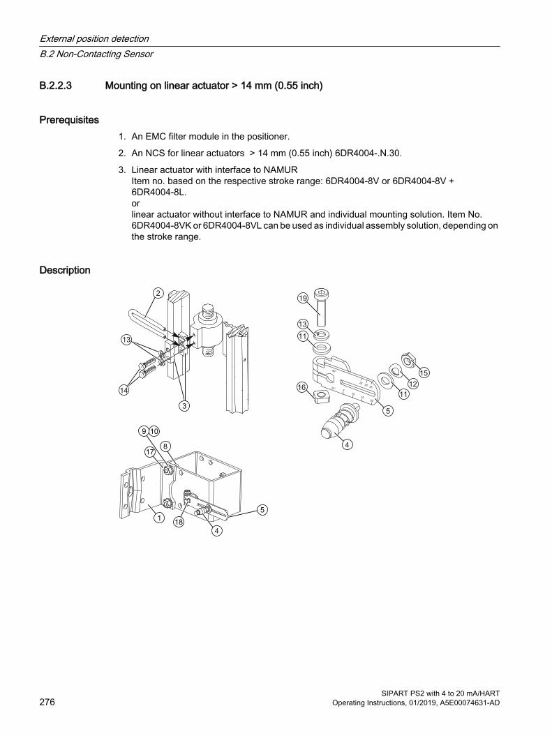
B.2.2.3 Mounting on linear actuator > 14 mm (0.55 inch)
Prerequisites1. An EMC filter module in the positioner.
2. An NCS for linear actuators > 14 mm (0.55 inch) 6DR4004-.N.30.
3. Linear actuator with interface to NAMURItem no. based on the respective stroke range: 6DR4004-8V or 6DR4004-8V + 6DR4004-8L.orlinear actuator without interface to NAMUR and individual mounting solution. Item No. 6DR4004-8VK or 6DR4004-8VL can be used as individual assembly solution, depending on the stroke range.
Description
External position detectionB.2 Non-Contacting Sensor
SIPART PS2 with 4 to 20 mA/HART276 Operating Instructions, 01/2019, A5E00074631-AD

A Mounting on a yoke with fin ⑨ Spring washer A8B Mounting on a yoke with plane surface ⑩ Washer B 8.4C Mounting on a yoke with columns ⑪ Washer B 6.4① NAMUR mounting bracket IEC 60534 ⑫ Spring lock washer② Pick-up bracket ⑬ Spring washer A6③ Clamping piece ⑭ Hexagonal screw size M6x25④ Dog pin ⑮ Hexagonal nut M6⑤ Lever ⑯ Square-head nut M6⑥ U bracket ⑰ Hexagonal nut M8⑦ Hexagonal screw size M8x20 ⑱ Shaft⑧ Hexagonal screw size M8x16 ⑲ Hex socket head screw size M6x25
Figure B-6 Mounting instructions for linear actuators with a stroke > 14 mm (0.55 inch)
Procedure1. Mount the clamping pieces ③ to the actuator spindle using the hexagonal screw ⑭ and
spring washers ⑬.
2. Slide the pick-up bracket ② into the milled recesses of the clamping pieces.
3. Set the necessary length.
4. Tighten the screws so that you can still shift the pick-up bracket ②.
5. Set the center of the pin ④ to the stroke range value specified on the actuator, or to the next higher scaling value of the lever ⑤. The actuating distance in mm will be displayed on successful initialization if you set the same value at parameter "3.YWAY" when commissioning the system.
6. Slide the lever ⑤ onto the shaft ⑱ up to the mechanical stop.
7. Secure the lever ⑤ using the hex socket head screw ⑲.
External position detectionB.2 Non-Contacting Sensor
SIPART PS2 with 4 to 20 mA/HARTOperating Instructions, 01/2019, A5E00074631-AD 277

8. Mount the bracket ① to the NCS mounting kit using:
– Two hexagonal screws ⑧– Spring washer ⑨– Washer ⑩– Hexagonal nut ⑰The selection of the row of holes depends on the yoke width of the actuator. Make sure that the dog pin ④ engages in the pick-up bracket ② as close as possible to the spindle over the complete stroke range. The dog pin must not touch the clamping pieces.
9. Place the NCS assembly kit with the mounting bracket ① onto the actuator. Ensure that the dog pin ④ is guided inside the pick-up bracket ②.
10.Tighten the pick-up bracket ② .
11.Prepare the assembly parts for the relevant actuator type for installation:
– For mounting on yoke with fin: hexagonal screw ⑦, washer ⑩ and spring washer ⑨.
– For mounting on a yoke with plane surface: Four hexagonal screw ⑦ with washer ⑩ and spring washer ⑨.
– For actuator with columns: Two U brackets ⑥, four hexagonal screw ⑰ with washer ⑩ and spring washer ⑨.
12.Mount the NCS assembly kit to the yoke using the assembly parts that you prepared.
NoteObserve the height
Adjust the height of the NCS assembly kit so that the lever position is in line horizontally with the stroke center. Use the lever scale on the actuator for orientation. If a symmetrical assembly is not possible, you must always ensure that the lever is in horizontal position within the range of the stroke.
ReferenceFor information on the scope of delivery, refer to section "Scope of delivery of NCS for linear actuators > 14 mm (0.55 inch) . (Page 285)"
External position detectionB.2 Non-Contacting Sensor
SIPART PS2 with 4 to 20 mA/HART278 Operating Instructions, 01/2019, A5E00074631-AD
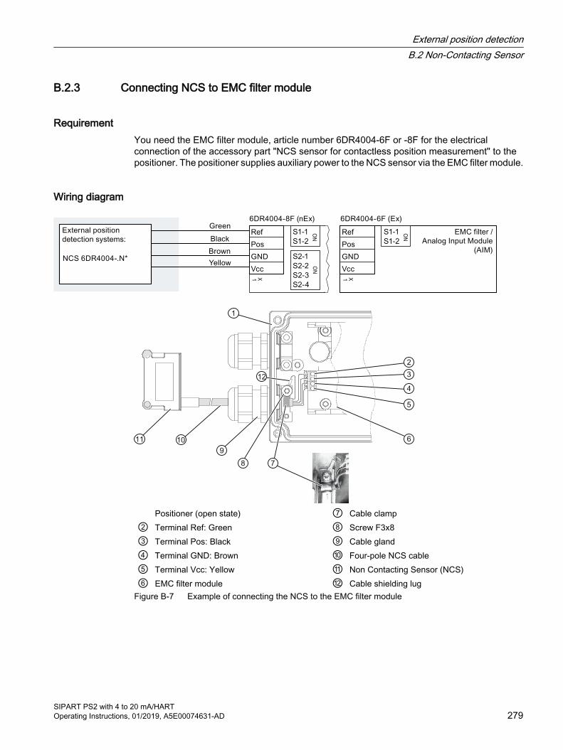
B.2.3 Connecting NCS to EMC filter module
RequirementYou need the EMC filter module, article number 6DR4004-6F or -8F for the electrical connection of the accessory part "NCS sensor for contactless position measurement" to the positioner. The positioner supplies auxiliary power to the NCS sensor via the EMC filter module.
Wiring diagram
Positioner (open state) ⑦ Cable clamp② Terminal Ref: Green ⑧ Screw F3x8③ Terminal Pos: Black ⑨ Cable gland④ Terminal GND: Brown ⑩ Four-pole NCS cable⑤ Terminal Vcc: Yellow ⑪ Non Contacting Sensor (NCS)⑥ EMC filter module ⑫ Cable shielding lug
Figure B-7 Example of connecting the NCS to the EMC filter module
External position detectionB.2 Non-Contacting Sensor
SIPART PS2 with 4 to 20 mA/HARTOperating Instructions, 01/2019, A5E00074631-AD 279
ProcedureThe NCS sensor is equipped with a shielded four-pole cable. Wire this cable to the positioner as follows:
1. Feed the four-pole NCS cable ⑩ through the union nut and the cable gland. Note: The type of cable gland depends on the positioner version.
2. Tighten the cable gland ⑨.
3. Terminate the four-pole NCS cable ⑩ in the EMC module of the positioner in accordance with the wiring diagram.
4. Place the cable clamp ⑦ onto the outer insulation of the four-pole NCS cable ⑩.
5. Use the screw ⑧ to bond the cable shielding lug ⑫ and the cable clamp ⑦ to the ground terminal of the positioner.
6. Grounding:The rear steel panel of the NCS sensor is inevitably bonded to the ground potential of the system when mounting on the console. This ground connection is only functional if there is a low-impedance connection to ground potential of the system. Ensure this state by measuring the ground resistance. If necessary, ensure proper grounding by means of an additional cable from the NCS sensor to ground potential.
B.2.4 Commissioning of NCS
B.2.4.1 Prerequisites / default settings1. Supply electrical and pneumatic auxiliary power to the SIPART PS2 positioner. The top row
of the display shows the current sensor voltage (0 to 100%), while the "NOINI" info flashes in the bottom row. The pneumatic actuator does not move.
2. If the SIPART PS2 positioner has already been initialized, carry out a reset. Carry out the reset of parameter group "Init" in the '50.PRST' Preset (Page 163) parameter.
3. Preset for part-turn actuators:While the valve or flaps are closed, align the North pole of the magnet with the cable; "N" in position ⑦ in "Figure B-4 Mounting on part-turn actuator with magnet holder made of glass fiber reinforced polyester (left figure) or anodized aluminum (right figure) (Page 272)".
4. Monitor the display of the positioner while adjusting the actuator to its mechanical stops by means of and at the positioner. Verify that the displayed values never exceed the range from P2.0 to P98.0.
Note
This condition cannot be met with slipping flaps or linear actuators that exceed the mechanical actuation limits.
External position detectionB.2 Non-Contacting Sensor
SIPART PS2 with 4 to 20 mA/HART280 Operating Instructions, 01/2019, A5E00074631-AD
B.2.4.2 Initialization of part-turn actuators
Procedure1. For part-turn actuators operating in standard control direction, set parameter "1.YFCT" to
"ncSt", or to "-ncSt" in case of inverse control direction.
2. Launch initialization as usual with "INITA".
B.2.4.3 Initializing linear actuators with a stroke range up to 14 mm (0.55 inch)
Requirements1. Set the "1.YFCT" parameter of the positioner to "ncSL" or - with inverse control direction -
to "-ncSL".
2. Launch initialization as usual with "INITA".
B.2.4.4 Initializing linear actuators with a stroke range > 14 mm (0.55 inch)
Note
Parameter values "ncSLL" and "-ncLL" are only available for devices of the 6DR5... series and only with the firmware version > C4. Set the value to 90° on devices of the 6DR5... series with firmware version < C5 (YAGL). This setting is also necessary for devices of the 6DR4... series. Resultant non-linearity can be corrected by means of the programmable characteristic by setting the parameter value from "SFCT" to "FrEE" and adapting the interpolation points.
Requirements1. Set the "1.YFCT" parameter of the positioner to "ncSLL" or - with inverse control direction
- to "-ncLL".
2. Launch initialization as usual with "INITA".
B.2.5 Technical specifications NCS
Additional modules Without Ex protection With Ex protection Ex "ia"
With explosion protection Ex "ic", "ec"
Travel range ● Linear actuator 6DR4004-6/8N.20 3 to 14 mm (0.12 to 0.55")
● Linear actuator 6DR4004-6/8N.30 10 to 130 mm (0.39 to 5.12"); up to 200 mm (7.87") on request
● Part-turn actuator 30 to 100°
External position detectionB.2 Non-Contacting Sensor
SIPART PS2 with 4 to 20 mA/HARTOperating Instructions, 01/2019, A5E00074631-AD 281
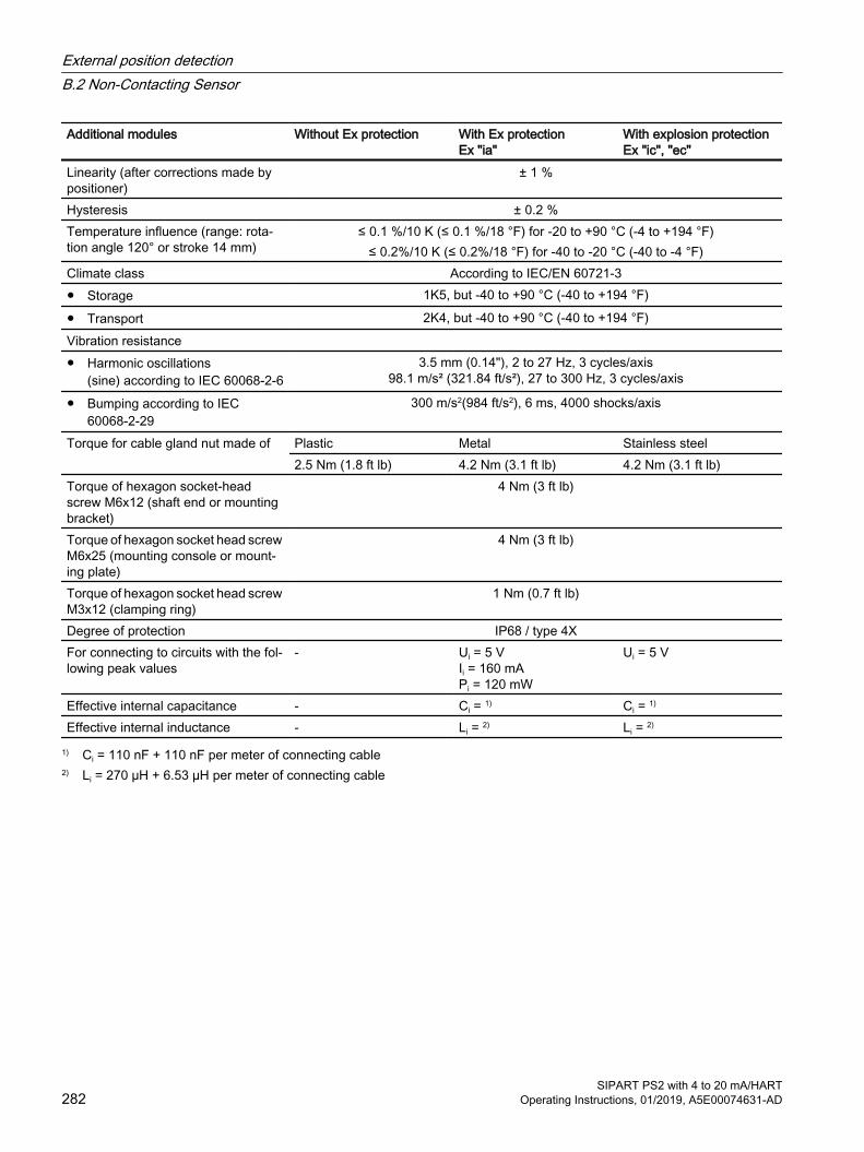
Additional modules Without Ex protection With Ex protection Ex "ia"
With explosion protection Ex "ic", "ec"
Linearity (after corrections made by positioner)
± 1 %
Hysteresis ± 0.2 %Temperature influence (range: rota‐tion angle 120° or stroke 14 mm)
≤ 0.1 %/10 K (≤ 0.1 %/18 °F) for -20 to +90 °C (-4 to +194 °F)≤ 0.2%/10 K (≤ 0.2%/18 °F) for -40 to -20 °C (-40 to -4 °F)
Climate class According to IEC/EN 60721-3● Storage 1K5, but -40 to +90 °C (-40 to +194 °F)
● Transport 2K4, but -40 to +90 °C (-40 to +194 °F)Vibration resistance ● Harmonic oscillations
(sine) according to IEC 60068-2-63.5 mm (0.14"), 2 to 27 Hz, 3 cycles/axis
98.1 m/s² (321.84 ft/s²), 27 to 300 Hz, 3 cycles/axis
● Bumping according to IEC 60068-2-29
300 m/s2(984 ft/s2), 6 ms, 4000 shocks/axis
Torque for cable gland nut made of Plastic Metal Stainless steel2.5 Nm (1.8 ft lb) 4.2 Nm (3.1 ft lb) 4.2 Nm (3.1 ft lb)
Torque of hexagon socket-head screw M6x12 (shaft end or mounting bracket)
4 Nm (3 ft lb)
Torque of hexagon socket head screw M6x25 (mounting console or mount‐ing plate)
4 Nm (3 ft lb)
Torque of hexagon socket head screw M3x12 (clamping ring)
1 Nm (0.7 ft lb)
Degree of protection IP68 / type 4XFor connecting to circuits with the fol‐lowing peak values
- Ui = 5 V Ii = 160 mA Pi = 120 mW
Ui = 5 V
Effective internal capacitance - Ci = 1) Ci = 1)
Effective internal inductance - Li = 2) Li = 2)
1) Ci = 110 nF + 110 nF per meter of connecting cable2) Li = 270 µH + 6.53 µH per meter of connecting cable
External position detectionB.2 Non-Contacting Sensor
SIPART PS2 with 4 to 20 mA/HART282 Operating Instructions, 01/2019, A5E00074631-AD

B.2.6 Dimensional drawing of non-contacting sensor
A NCS B MagnetFigure B-8 Dimensional drawing of the NCS and magnet
B.2.7 NCS sensor scope of delivery
B.2.7.1 Scope of delivery of NCS for part-turn actuators
Part-turn ac‐tuator
6DR4004-.N.10
Part-turn ac‐tuator
6DR4004-.N.40
Quantity Quantity Name Note1 1 Magnet clamp 5 5 Washer 62 2 Hex socket head screw M6x12
External position detectionB.2 Non-Contacting Sensor
SIPART PS2 with 4 to 20 mA/HARTOperating Instructions, 01/2019, A5E00074631-AD 283
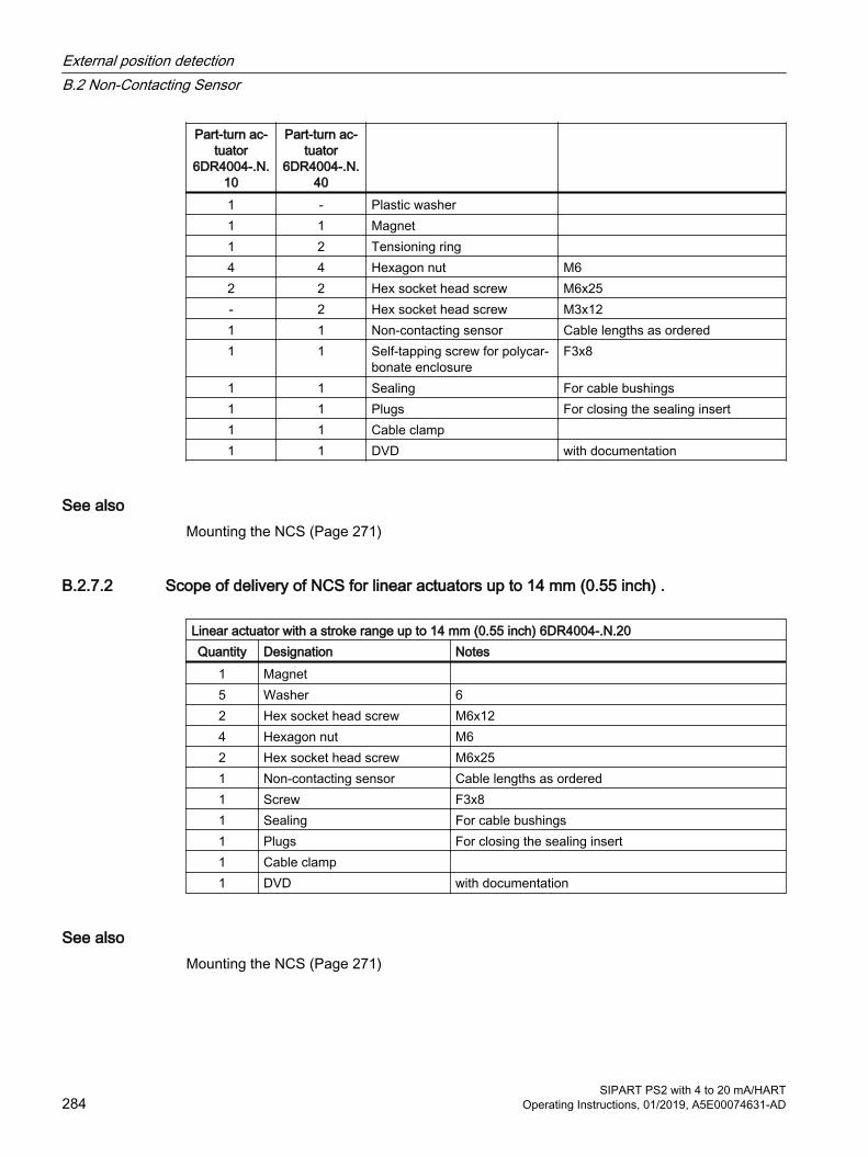
Part-turn ac‐tuator
6DR4004-.N.10
Part-turn ac‐tuator
6DR4004-.N.40
1 - Plastic washer 1 1 Magnet 1 2 Tensioning ring 4 4 Hexagon nut M62 2 Hex socket head screw M6x25- 2 Hex socket head screw M3x121 1 Non-contacting sensor Cable lengths as ordered1 1 Self-tapping screw for polycar‐
bonate enclosureF3x8
1 1 Sealing For cable bushings1 1 Plugs For closing the sealing insert1 1 Cable clamp 1 1 DVD with documentation
See alsoMounting the NCS (Page 271)
B.2.7.2 Scope of delivery of NCS for linear actuators up to 14 mm (0.55 inch) .
Linear actuator with a stroke range up to 14 mm (0.55 inch) 6DR4004-.N.20Quantity Designation Notes
1 Magnet 5 Washer 62 Hex socket head screw M6x124 Hexagon nut M62 Hex socket head screw M6x251 Non-contacting sensor Cable lengths as ordered1 Screw F3x81 Sealing For cable bushings1 Plugs For closing the sealing insert1 Cable clamp 1 DVD with documentation
See alsoMounting the NCS (Page 271)
External position detectionB.2 Non-Contacting Sensor
SIPART PS2 with 4 to 20 mA/HART284 Operating Instructions, 01/2019, A5E00074631-AD
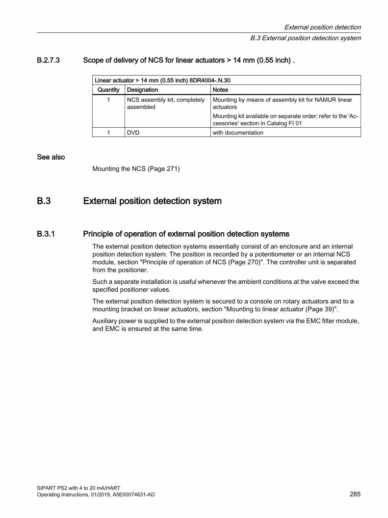
B.2.7.3 Scope of delivery of NCS for linear actuators > 14 mm (0.55 inch) .
Linear actuator > 14 mm (0.55 inch) 6DR4004-.N.30Quantity Designation Notes
1 NCS assembly kit, completely assembled
Mounting by means of assembly kit for NAMUR linear actuatorsMounting kit available on separate order; refer to the 'Ac‐cessories' section in Catalog FI 01
1 DVD with documentation
See alsoMounting the NCS (Page 271)
B.3 External position detection system
B.3.1 Principle of operation of external position detection systemsThe external position detection systems essentially consist of an enclosure and an internal position detection system. The position is recorded by a potentiometer or an internal NCS module, section "Principle of operation of NCS (Page 270)". The controller unit is separated from the positioner.
Such a separate installation is useful whenever the ambient conditions at the valve exceed the specified positioner values.
The external position detection system is secured to a console on rotary actuators and to a mounting bracket on linear actuators, section "Mounting to linear actuator (Page 39)".
Auxiliary power is supplied to the external position detection system via the EMC filter module, and EMC is ensured at the same time.
External position detectionB.3 External position detection system
SIPART PS2 with 4 to 20 mA/HARTOperating Instructions, 01/2019, A5E00074631-AD 285
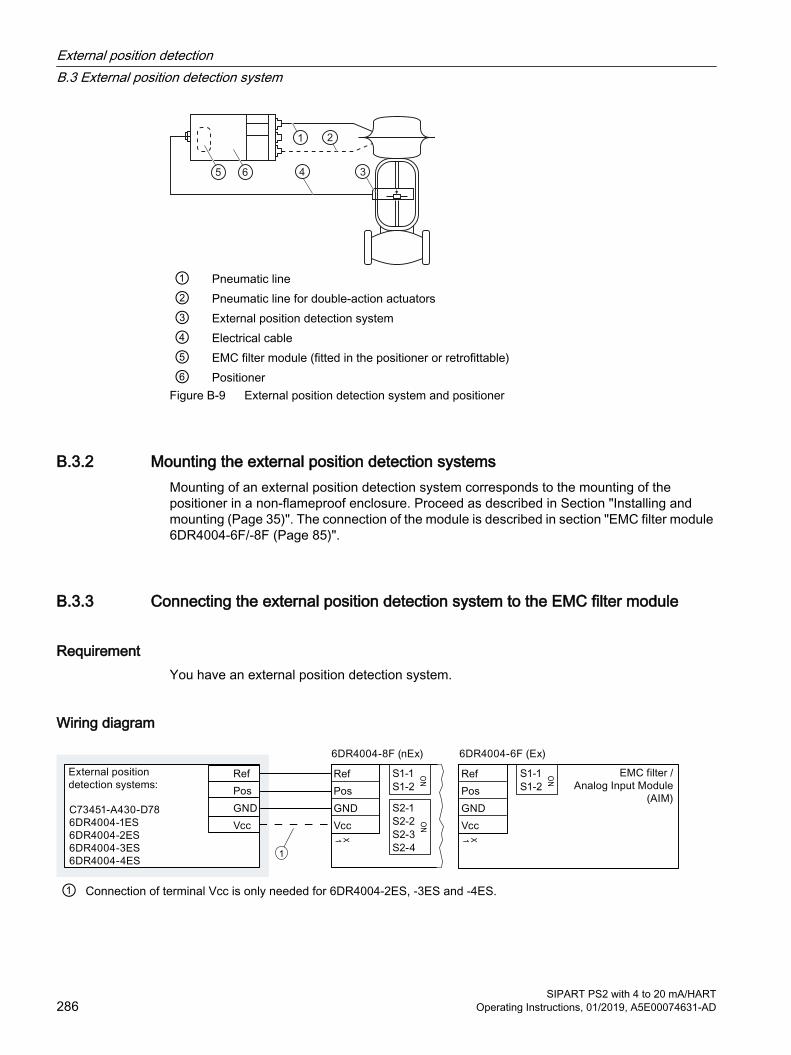
① Pneumatic line② Pneumatic line for double-action actuators③ External position detection system④ Electrical cable⑤ EMC filter module (fitted in the positioner or retrofittable)⑥ Positioner
Figure B-9 External position detection system and positioner
B.3.2 Mounting the external position detection systemsMounting of an external position detection system corresponds to the mounting of the positioner in a non-flameproof enclosure. Proceed as described in Section "Installing and mounting (Page 35)". The connection of the module is described in section "EMC filter module 6DR4004-6F/-8F (Page 85)".
B.3.3 Connecting the external position detection system to the EMC filter module
RequirementYou have an external position detection system.
Wiring diagram
1
① Connection of terminal Vcc is only needed for 6DR4004-2ES, -3ES and -4ES.
External position detectionB.3 External position detection system
SIPART PS2 with 4 to 20 mA/HART286 Operating Instructions, 01/2019, A5E00074631-AD

B.3.4 Technical specifications of the external position detection system
Rated conditions Ambient temperature In hazardous areas, observe the maximum permissible ambient
temperature corresponding to the temperature class.● Permissible ambient temperature for operation -40 ... +90 °C (-40 ... +194 °F)Degree of protection 1) IP66 / type 4XClimate class According to IEC/EN 60721-3● Storage 1K5, but -40 ... +90 °C (1K5, but -40 ... +194 °F)
● Transport 2K4, but -40 ... +90 °C (2K4, but -40 ... +194 °F)
● Operation 4K3, but -40 ... +90 °C (4K3, but -40 ... +194 °F)
1 ) Impact energy max. 1 joule.
See alsoConstruction (Page 238)
Construction Material body ● C73451-A430-D78 Glass-fiber reinforced polycarbonate (PC)
● 6DR4004-1ES AluminumWeight ● Enclosure C73451-A430-D78 Approx. 0.9 kg (1.98 lb)
● Enclosure 6DR4004-1ES Approx. 1.6 kg (3.53 lb)Torque for cable gland nut made of plastic See Construction (Page 238)
External position detectionB.3 External position detection system
SIPART PS2 with 4 to 20 mA/HARTOperating Instructions, 01/2019, A5E00074631-AD 287

External position detectionB.3 External position detection system
SIPART PS2 with 4 to 20 mA/HART288 Operating Instructions, 01/2019, A5E00074631-AD

Pressure gauge block CPressure gauge block
Pressure gauge blocks that are available as accessories are illustrated below. The gauges display measured values for the actuating pressure and supply air. The image to the left shows the pressure gauge block for single-acting actuators. The image to the right shows the pressure gauge block for double-acting actuators.
Y1 Actuating pressurePZ Supply airY2 Actuating pressure
Fixing the pressure gauge blockThe pressure gauge block is fixed onto the lateral pneumatic connection of the positioner using the screws provided. Use the provided O-rings as sealing elements.
SIPART PS2 with 4 to 20 mA/HARTOperating Instructions, 01/2019, A5E00074631-AD 289

Pressure gauge block
SIPART PS2 with 4 to 20 mA/HART290 Operating Instructions, 01/2019, A5E00074631-AD

Sealing plug / thread adapter DD.1 Intended use of accessory part
The sealing plug and the thread adapter (components) can be used for installation in electrical equipment of flameproof" "Ex d" type of protection of groups IIA, IIB, IIC as well as dust protection by enclosure "Ex t" type of protection.
D.2 Safety instructions for accessory part
WARNING
Incorrect assembly● The component can be damaged or destroyed or its functionality impaired through
incorrect assembly.– Mount the component using a suitable tool. Refer to the information in Chapter
"Technical specifications of accessory part (Page 292)", for example, torques for installation.
● For "Explosion-proof Ex d" type of protection: To ensure an engagement depth of 8 mm, the enclosure must have a wall thickness of at least 10 mm.
Improper modifications
Danger to personnel, system and environment can result from modifications and repairs of the component, particularly in hazardous areas.● Any modification which deviates from the delivery state is not permitted.Loss of enclosure type of protection
IP protection is not guaranteed without sealant.● Use a suitable thread sealant.● If you are using the component in type of protection dust protection by enclosure "Ex t", use
the supplied sealing ring (①, figure in Chapter "Dimensional drawings for accessory part (Page 293)").
Unsuitable fluids in the environment
Danger of injury or damage to device.
Aggressive media in the environment can damage the sealing ring. Type of protection and device protection may no longer be guaranteed.● Make sure that the sealing material is suitable for the area of use.
SIPART PS2 with 4 to 20 mA/HARTOperating Instructions, 01/2019, A5E00074631-AD 291

NoteLoss of type of protection
Changes in the ambient conditions can loosen the component.● As part of the recommended maintenance intervals: Check the compression fitting for tight
fit and tighten, if necessary.
D.3 Technical specifications of accessory part
Technical specifications sealing plug and thread adapterSealing plug suitable for types of protection Explosion-proof enclosure "d" of groups IIA, IIB, IIC
Dust protection by enclosure "t"Standard compliance The components meet Directive 94/9. They meet the requirements of
standards IEC/EN 60079-0; IEC/EN 60079-1; IEC/EN 60079-31.Explosion protection ● Gas explosion protection II2G Ex d IIC
● Dust explosion protection II1D Ex t IIICCertificates IECEx TUN 13.0022 U
TÜV 13 ATEX 121710 UMaterial for sealing plug / thread adapter Stainless steelMaterial for seal Vulcanized fiber or Victor Reinz AFM 30Ambient temperature range -40 ... +100 °C (-40 ... +212 °F)For "Ex d" type of protection: Required wall thickness for tappings
10 mm
Torque ● For thread size M20 x 1.5 65 Nm
● For thread size M25 x 1.5 95 Nm
● For thread size ½-14 NPT 65 NmWidth A/F for thread size M20 x 1.5 27Width A/F for thread size M25 x 1.5 30Key size for thread size ½-14 NPT 10
Sealing plug / thread adapterD.3 Technical specifications of accessory part
SIPART PS2 with 4 to 20 mA/HART292 Operating Instructions, 01/2019, A5E00074631-AD

D.4 Dimensional drawings for accessory part
Sealing plug Ex d, M20 x 1.5, dimensions in mm Sealing plug Ex d, M25 x 1.5, dimensions in mm
Sealing plug / thread adapterD.4 Dimensional drawings for accessory part
SIPART PS2 with 4 to 20 mA/HARTOperating Instructions, 01/2019, A5E00074631-AD 293

Thread adapter Ex d, M25 x 1.5 on M20 x 1.5 and M25 x 1.5 on ½-14 NPT, dimensions in mm
① Sealing ring: Use for dust protection "Ex t" type of protection.
Sealing plug Ex d ½ -14 NPT
Sealing plug / thread adapterD.4 Dimensional drawings for accessory part
SIPART PS2 with 4 to 20 mA/HART294 Operating Instructions, 01/2019, A5E00074631-AD
Booster ECAUTION
Increased sound pressure level
Changes to the sound absorber of the positioner or the mounting of pneumatic components or pneumatic options on the positioner can cause a sound pressure with a level of 80 dBA to be exceeded.● Wear suitable hearing protection to protect yourself against hearing damage.
E.1 Booster introductionIn order to shorten the travel times, use a booster between the positioner and actuator. The booster increases the air performance.
With single-acting positioners, use of the boosters 6DR4004-1RJ, -1RK, -1RP or -1RQ, you connect to the air output Y1.
With double-acting positioners, use two of the boosters 6DR4004-2RJ, -2RK, -2RP or -2RQ which you connect to the air outputs Y1 and Y2.
NoteSIPART PS2 double-acting
The booster changes the double-acting SIPART PS2-operation in the event of the loss of supply air. The Integral Volume Booster or external Volume Booster is used to depressurize the output pressure; the valve position cannot be determined in the event of loss of supply air. The Integral Volume Booster does not have any effect on the operation of the positioner in the event of the failure of the control signal or power supply. You can find more detailed information on this in the SIPART PS2 manual.
SIPART PS2 with 4 to 20 mA/HARTOperating Instructions, 01/2019, A5E00074631-AD 295

E.2 Operating principle of boosterThe input pressure from the positioner which acts on the effective surface of the upper diaphragm, produces a force which counteracts the force of the outlet pressure acting on the lower diaphragm at a ratio of 1:1. A change of the inlet pressure results in a difference so that balance has to be restored by a pilot valve. This increase presses the diaphragm module down, opens the pilot valve and releases supply air to the outlet until balance is restored. A decrease, on the other hand, ensures that the diaphragm module is raised, which opens the outlet air seat and lowers the outlet pressure such that it corresponds to the inlet pressure. These devices have a stabilizing bypass needle valve, so that the inlet pressure can directly go to the output in the event of small or gradual changes at the input. As the booster has a bypass, there is no loss of accuracy and if the needle valve is set properly, the persistence stability can be retained. The suitable setting of the needle valve depends on the size of the actuator. The larger the actuator, the more the needle valve can be closed and its stability retained.
① Input ⑤ Supply pressure② Exhaust air outlet ⑥ Output③ Outlet air seat ⑦ Diaphragm④ Supply air seat ⑧ Bypass valve
BoosterE.2 Operating principle of booster
SIPART PS2 with 4 to 20 mA/HART296 Operating Instructions, 01/2019, A5E00074631-AD
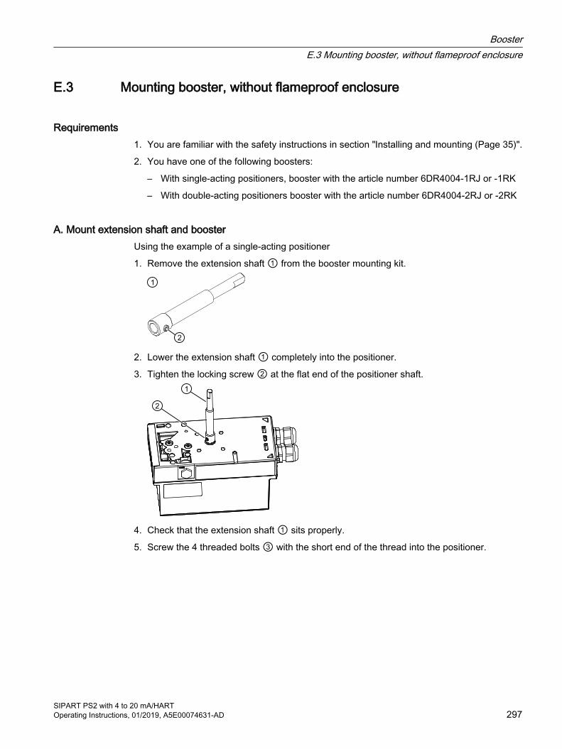
E.3 Mounting booster, without flameproof enclosure
Requirements1. You are familiar with the safety instructions in section "Installing and mounting (Page 35)".
2. You have one of the following boosters:
– With single-acting positioners, booster with the article number 6DR4004-1RJ or -1RK
– With double-acting positioners booster with the article number 6DR4004-2RJ or -2RK
A. Mount extension shaft and boosterUsing the example of a single-acting positioner
1. Remove the extension shaft ① from the booster mounting kit.
2. Lower the extension shaft ① completely into the positioner.
3. Tighten the locking screw ② at the flat end of the positioner shaft.
4. Check that the extension shaft ① sits properly.
5. Screw the 4 threaded bolts ③ with the short end of the thread into the positioner.
BoosterE.3 Mounting booster, without flameproof enclosure
SIPART PS2 with 4 to 20 mA/HARTOperating Instructions, 01/2019, A5E00074631-AD 297
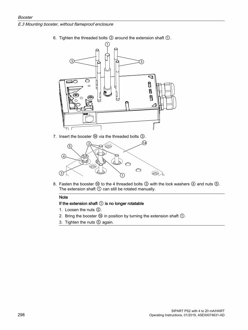
6. Tighten the threaded bolts ③ around the extension shaft ①.
7. Insert the booster ⑭ via the threaded bolts ③.
8. Fasten the booster ⑭ to the 4 threaded bolts ③ with the lock washers ④ and nuts ⑤.The extension shaft ① can still be rotated manually.
NoteIf the extension shaft ① is no longer rotatable1. Loosen the nuts ⑤. 2. Bring the booster ⑭ in position by turning the extension shaft ①.3. Tighten the nuts ⑤ again.
BoosterE.3 Mounting booster, without flameproof enclosure
SIPART PS2 with 4 to 20 mA/HART298 Operating Instructions, 01/2019, A5E00074631-AD

B. Mounting the manometer and connection blockUsing the example of a single-acting positioner
1. Fasten the manometer block ⑥ to the positioner with two screws ⑦ and lock washers ⑧.
2. Check whether the O-rings are in the manometer block. There are two O-rings in the single-acting version. There are three O rings with the double-acting version.
3. Apply light pressure to the lock washers ⑧. The screws are tightened later.
4. Fasten the connection block ⑨ to the booster with 2 screws ⑫ and 2 lock washers ⑬.
5. Fasten the connection block ⑨ to the manometer block ⑥ with 2 screws ⑩ and 2 lock washers ⑪.
BoosterE.3 Mounting booster, without flameproof enclosure
SIPART PS2 with 4 to 20 mA/HARTOperating Instructions, 01/2019, A5E00074631-AD 299
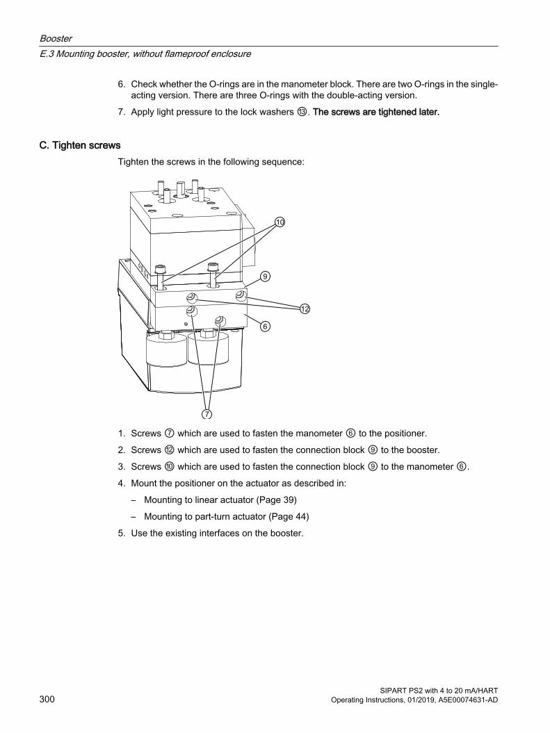
6. Check whether the O-rings are in the manometer block. There are two O-rings in the single-acting version. There are three O-rings with the double-acting version.
7. Apply light pressure to the lock washers ⑬. The screws are tightened later.
C. Tighten screwsTighten the screws in the following sequence:
1. Screws ⑦ which are used to fasten the manometer ⑥ to the positioner.
2. Screws ⑫ which are used to fasten the connection block ⑨ to the booster.
3. Screws ⑩ which are used to fasten the connection block ⑨ to the manometer ⑥.
4. Mount the positioner on the actuator as described in:
– Mounting to linear actuator (Page 39)
– Mounting to part-turn actuator (Page 44)
5. Use the existing interfaces on the booster.
BoosterE.3 Mounting booster, without flameproof enclosure
SIPART PS2 with 4 to 20 mA/HART300 Operating Instructions, 01/2019, A5E00074631-AD
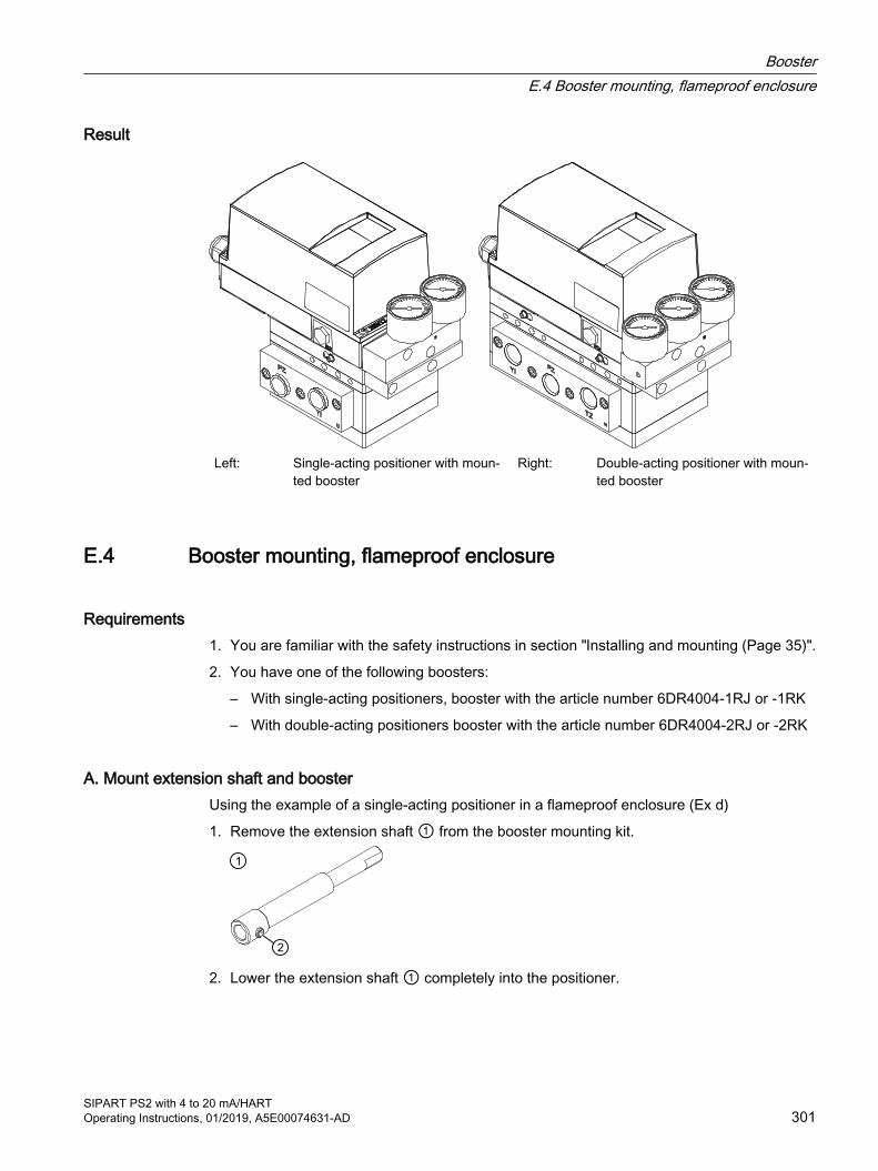
Result
Left: Single-acting positioner with moun‐ted booster
Right: Double-acting positioner with moun‐ted booster
E.4 Booster mounting, flameproof enclosure
Requirements1. You are familiar with the safety instructions in section "Installing and mounting (Page 35)".
2. You have one of the following boosters:
– With single-acting positioners, booster with the article number 6DR4004-1RJ or -1RK
– With double-acting positioners booster with the article number 6DR4004-2RJ or -2RK
A. Mount extension shaft and boosterUsing the example of a single-acting positioner in a flameproof enclosure (Ex d)
1. Remove the extension shaft ① from the booster mounting kit.
2. Lower the extension shaft ① completely into the positioner.
BoosterE.4 Booster mounting, flameproof enclosure
SIPART PS2 with 4 to 20 mA/HARTOperating Instructions, 01/2019, A5E00074631-AD 301
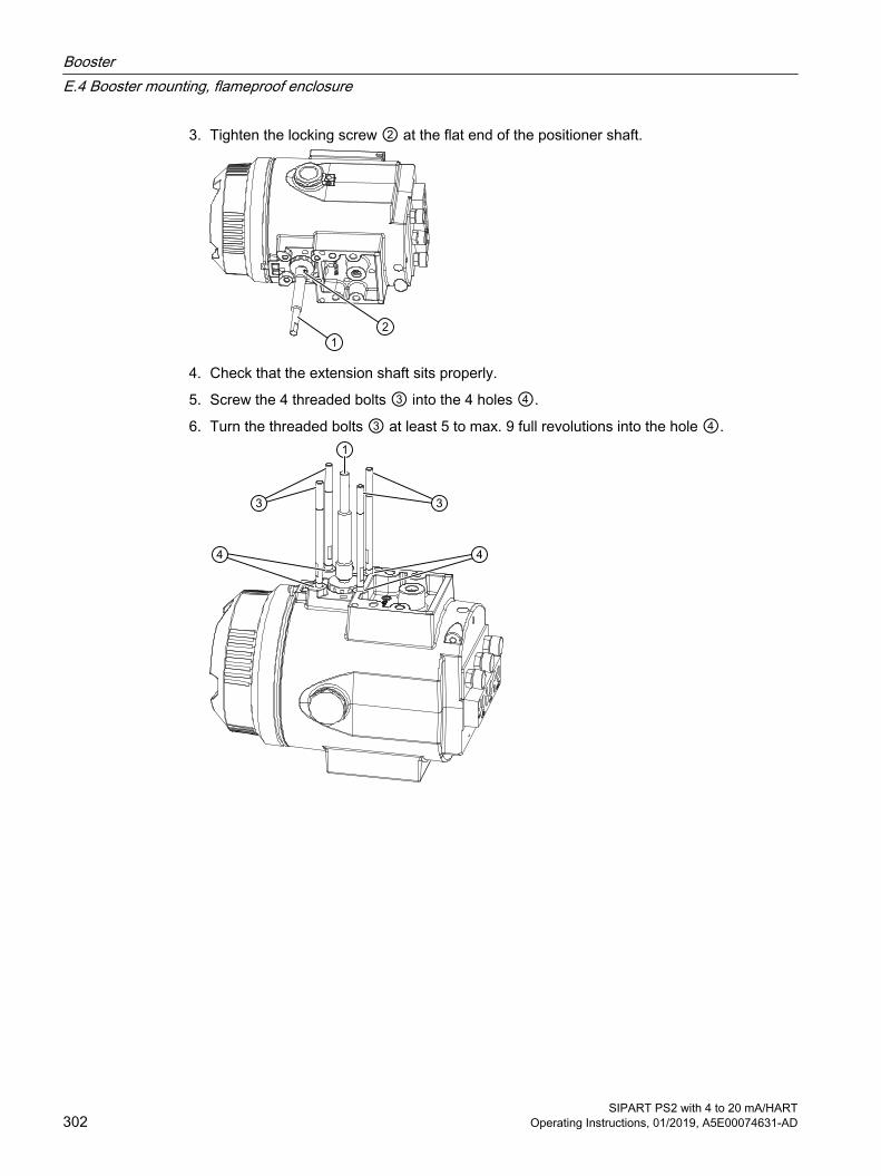
3. Tighten the locking screw ② at the flat end of the positioner shaft.
4. Check that the extension shaft sits properly.
5. Screw the 4 threaded bolts ③ into the 4 holes ④.
6. Turn the threaded bolts ③ at least 5 to max. 9 full revolutions into the hole ④.
BoosterE.4 Booster mounting, flameproof enclosure
SIPART PS2 with 4 to 20 mA/HART302 Operating Instructions, 01/2019, A5E00074631-AD

7. Insert the booster ⑭ via the threaded bolts ③.
8. Fasten the booster ⑭ to the 4 threaded bolts ③ with the lock washers ④ and nuts ⑤.The extension shaft ① can still be rotated manually.
NoteIf the extension shaft ① is no longer rotatable1. Loosen the nuts ⑤. 2. Bring the booster ⑭ in position by turning the extension shaft ①.3. Tighten the nuts ⑤ again.
B. Mounting the manometer and connection blockUsing the example of a single-acting positioner in a flameproof enclosure (Ex d)
1. Fasten the manometer block ⑥ to the positioner with two screws ⑦ and lock washers ⑧.
2. Check whether the O-rings are in the manometer block. There are two O-rings in the single-acting version. There are three O rings with the double-acting version.
BoosterE.4 Booster mounting, flameproof enclosure
SIPART PS2 with 4 to 20 mA/HARTOperating Instructions, 01/2019, A5E00074631-AD 303
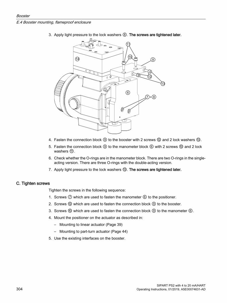
3. Apply light pressure to the lock washers ⑧. The screws are tightened later.
4. Fasten the connection block ⑨ to the booster with 2 screws ⑫ and 2 lock washers ⑬.
5. Fasten the connection block ⑨ to the manometer block ⑥ with 2 screws ⑩ and 2 lock washers ⑪.
6. Check whether the O-rings are in the manometer block. There are two O-rings in the single-acting version. There are three O-rings with the double-acting version.
7. Apply light pressure to the lock washers ⑬. The screws are tightened later.
C. Tighten screwsTighten the screws in the following sequence:
1. Screws ⑦ which are used to fasten the manometer ⑥ to the positioner.
2. Screws ⑫ which are used to fasten the connection block ⑨ to the booster.
3. Screws ⑩ which are used to fasten the connection block ⑨ to the manometer ⑥.
4. Mount the positioner on the actuator as described in:
– Mounting to linear actuator (Page 39)
– Mounting to part-turn actuator (Page 44)
5. Use the existing interfaces on the booster.
BoosterE.4 Booster mounting, flameproof enclosure
SIPART PS2 with 4 to 20 mA/HART304 Operating Instructions, 01/2019, A5E00074631-AD
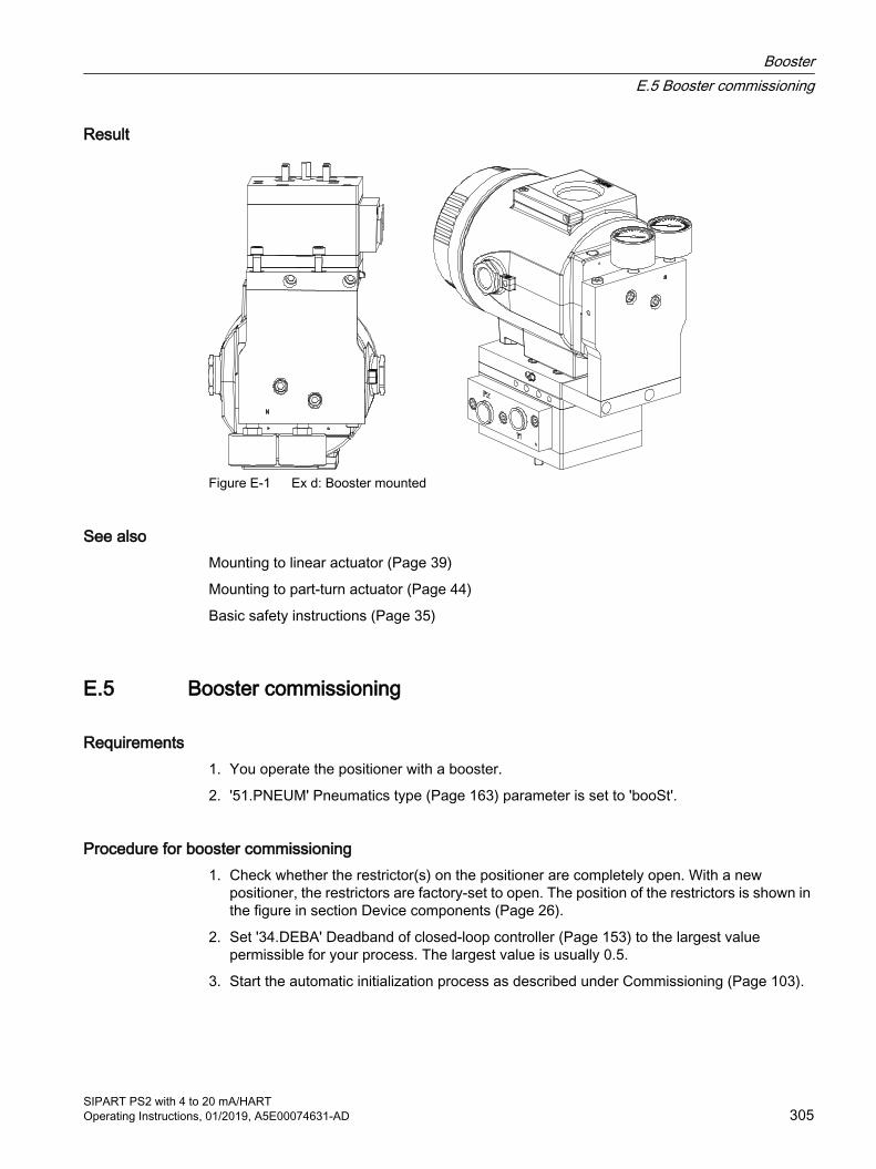
Result
Figure E-1 Ex d: Booster mounted
See alsoMounting to linear actuator (Page 39)
Mounting to part-turn actuator (Page 44)
Basic safety instructions (Page 35)
E.5 Booster commissioning
Requirements1. You operate the positioner with a booster.
2. '51.PNEUM' Pneumatics type (Page 163) parameter is set to 'booSt'.
Procedure for booster commissioning1. Check whether the restrictor(s) on the positioner are completely open. With a new
positioner, the restrictors are factory-set to open. The position of the restrictors is shown in the figure in section Device components (Page 26).
2. Set '34.DEBA' Deadband of closed-loop controller (Page 153) to the largest value permissible for your process. The largest value is usually 0.5.
3. Start the automatic initialization process as described under Commissioning (Page 103).
BoosterE.5 Booster commissioning
SIPART PS2 with 4 to 20 mA/HARTOperating Instructions, 01/2019, A5E00074631-AD 305
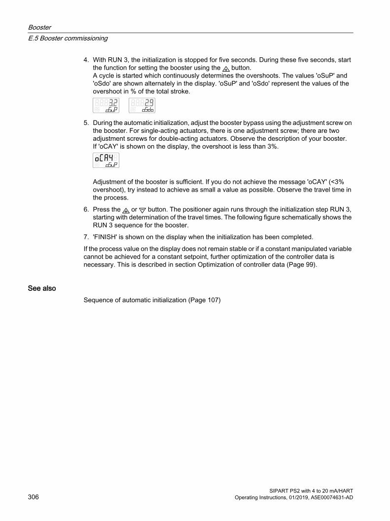
4. With RUN 3, the initialization is stopped for five seconds. During these five seconds, start the function for setting the booster using the button.A cycle is started which continuously determines the overshoots. The values 'oSuP' and 'oSdo' are shown alternately in the display. 'oSuP' and 'oSdo' represent the values of the overshoot in % of the total stroke.
5. During the automatic initialization, adjust the booster bypass using the adjustment screw on the booster. For single-acting actuators, there is one adjustment screw; there are two adjustment screws for double-acting actuators. Observe the description of your booster.If 'oCAY' is shown on the display, the overshoot is less than 3%.
Adjustment of the booster is sufficient. If you do not achieve the message 'oCAY' (<3% overshoot), try instead to achieve as small a value as possible. Observe the travel time in the process.
6. Press the or button. The positioner again runs through the initialization step RUN 3, starting with determination of the travel times. The following figure schematically shows the RUN 3 sequence for the booster.
7. 'FINISH' is shown on the display when the initialization has been completed.
If the process value on the display does not remain stable or if a constant manipulated variable cannot be achieved for a constant setpoint, further optimization of the controller data is necessary. This is described in section Optimization of controller data (Page 99).
See alsoSequence of automatic initialization (Page 107)
BoosterE.5 Booster commissioning
SIPART PS2 with 4 to 20 mA/HART306 Operating Instructions, 01/2019, A5E00074631-AD

Figure E-2 RUN 3 and 4 (booster)
See alsoCommissioning (Page 103)
BoosterE.5 Booster commissioning
SIPART PS2 with 4 to 20 mA/HARTOperating Instructions, 01/2019, A5E00074631-AD 307

E.6 Booster dimension drawings
E.6.1 For positioners in non-flameproof enclosure
SA Single-actingDA Double-acting
Figure E-3 Dimension drawings booster mounted on positioner, dimensions in mm (inch)
BoosterE.6 Booster dimension drawings
SIPART PS2 with 4 to 20 mA/HART308 Operating Instructions, 01/2019, A5E00074631-AD

E.6.2 For positioners in flameproof enclosure
SA Single-actingDA Double-acting
Figure E-4 Dimension drawings booster mounted on positioner in a flameproof enclosure, dimensions in mm (inch)
E.7 Technical specifications of booster
Booster Vibration resistance ● Harmonic oscillations According to ISA-S75.13
● Bumping (half-sine) according to EN 60068-2-27/02.2010 150 m/s² (492 ft/s²), 6 ms, 1000 shocks/axisClimate class According to IEC/EN 60721-3
BoosterE.7 Technical specifications of booster
SIPART PS2 with 4 to 20 mA/HARTOperating Instructions, 01/2019, A5E00074631-AD 309

Booster ● Storage 1K5, but -40 ... +80°C (1K5, but -40 ... +176°F)
● Transport 2K4, but -40 ... +80°C (2K4, but -40 ... +176°F)Weight booster, single-acting ● Booster, single-acting, polycarbonate, with positioner 4.0 kg (8.8 lb)
● Booster, single-acting, polycarbonate, installation kit only 2.9 kg (6.5 lb)
● Booster, single-acting with flameproof enclosure, with positioner
7.9 kg (17.4 lb)
● Booster, single-acting with flameproof enclosure, installation kit only
3.3 kg (7.3 lb)
Weight booster, double-acting ● Polycarbonate enclosure, with positioner 5.3 kg (11.7 lb)
● Polycarbonate enclosure, installation kit only 4.3 kg (9.4 lb)
● Enclosure with flameproof enclosure, with positioner 9.3 kg (20.5 lb)
● Enclosure with flameproof enclosure, installation kit only 4.7 kg (10.4 lb)Connections ● Pneumatic 1/2-14 NPT or G½
● Manometer 1/4-18 NPT or G½Auxiliary power (air supply) Compressed air, carbon dioxide (CO2), nitrogen (N), noble
gases or cleaned natural gas● Pressure 1.4 ... 7 bar (20.3 ... 101.5 psi)
● Supply air According to ISO 8573-1
● Air consumption 1.2 x 10⁻² Nm3/h (0.007SCFM)Manometer Thread 1/4-18 NPT or G½ with stainless steel enclosure
MPa, bar, psiDegree of protection IP66
Flow capacity Cv 2.0
BoosterE.7 Technical specifications of booster
SIPART PS2 with 4 to 20 mA/HART310 Operating Instructions, 01/2019, A5E00074631-AD
Positioner with remote control electronics FF.1 Introduction to remote control electronics
In some cases it is advisable to use the positioner separately from the control electronics. The option of separating the control electronics of the positioner is available for this purpose. The positioner is in a different location than the control electronics. This remote control electronics of the positioner allows the valves to be controlled in radiation contaminated environment, as all highly integrated electronic components are located in the area that is protected from radiation. Highly integrated electronic components are, for example, memory blocks and microprocessor blocks.
For the above described deployment you required the two following components:
● Component 1 consisting of the control electronics in the form of a 19" slide-in module. The 19" slide-in module is installed in the control cabinet and is available in the following two versions:
– Slide-in module as 4 to 20 mA with 2-wire connection, article number A5E00151560
● Component 2 consisting of the positioner without control electronics. The positioner with control electronics is mounted on the valve.
– Positioner without control electronics with position detection system and pneumatic unit, mounted on the valve, article number 6DR5910-0NG00-0AA0.Positioner without basic electronics 6DR5910 (Page 318)
Components 1 and 2 are connected electrically to each other. The components are described below.
F.2 19" slide-in module
F.2.1 Description of 19" slide-in module 4 to 20 mA
DescriptionThis component is a control electronics in the 19" slide-in module in 4 to 20 mA version. Commissioning is only possible in conjunction with a positioner component 6DR5910. The 19" slide-in module has three channels and controls up to three valves.
The control electronics supplies the current position of the valve in the form of a current of 4 to 20 mA, which corresponds to the position feedback.
SIPART PS2 with 4 to 20 mA/HARTOperating Instructions, 01/2019, A5E00074631-AD 311
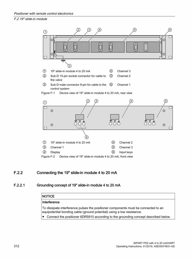
① 19" slide-in module 4 to 20 mA ④ Channel 3② Sub-D 15-pin socket connector for cable to
the valve⑤ Channel 2
③ Sub-D male connector 9-pin for cable to the control system
⑥ Channel 1
Figure F-1 Device view of 19" slide-in module 4 to 20 mA, rear view
① 19" slide-in module 4 to 20 mA ④ Channel 2③ Channel 1 ⑤ Channel 3② Display ⑥ Input keys
Figure F-2 Device view of 19" slide-in module 4 to 20 mA, front view
F.2.2 Connecting the 19" slide-in module 4 to 20 mA
F.2.2.1 Grounding concept of 19" slide-in module 4 to 20 mA
NOTICE
Interference
To dissipate interference pulses the positioner components must be connected to an equipotential bonding cable (ground potential) using a low resistance.● Connect the positioner 6DR5910 according to the grounding concept described below.
Positioner with remote control electronicsF.2 19" slide-in module
SIPART PS2 with 4 to 20 mA/HART312 Operating Instructions, 01/2019, A5E00074631-AD
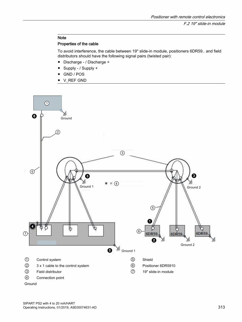
NoteProperties of the cable
To avoid interference, the cable between 19" slide-in module, positioners 6DR59.. and field distributors should have the following signal pairs (twisted pair):● Discharge - / Discharge + ● Supply - / Supply + ● GND / POS ● V_REF GND
① Control system ⑤ Shield② 3 x 1 cable to the control system ⑥ Positioner 6DR5910③ Field distributor ⑦ 19" slide-in module④ Connection point Ground
Positioner with remote control electronicsF.2 19" slide-in module
SIPART PS2 with 4 to 20 mA/HARTOperating Instructions, 01/2019, A5E00074631-AD 313

Figure F-3 Grounding concept of 19" slide-in module 4 to 20 mA version
Notes on the individual connection points:
The cable shield is not connected to the positioner 6DR5910.
The positioner 6DR5910 is connected via the mechanical assembly to Ground 2 , see Installing and mounting (Page 35). Section Basic safety instructions (Page 73) describes how to ground the enclosure.Each field distributor is grounded. The cable shields in the field distributor are not grounded. The cable shields are interconnected.The cable shields on the 19" slide-in module are connected to the field distributor.
The 19" slide-in module is connected to Ground 1.
The cable shields on the control system are not connected to ground.
F.2.2.2 Electrical connection of 19" slide-in module 4 to 20 mA
RequirementYou have read sections Connection (Page 73) and Grounding concept of 19" slide-in module 4 to 20 mA (Page 312).
Positioner with remote control electronicsF.2 19" slide-in module
SIPART PS2 with 4 to 20 mA/HART314 Operating Instructions, 01/2019, A5E00074631-AD

Connecting
① D-SUB male connector 15-pin ⑧ Cable to control system② Cable to the positioner 6DR5910 ⑨ Signal source③ Positioner 6DR59.. ⑩ Control system④ Connecting terminals, positioner ⑪ Power source⑤ Signal cables for potentiometer ⑫ Earth potential⑥ Signal cables for pneumatic block ⑬ Control electronics in the 19" slide-in module
4 to 20 mA⑦ D-SUB female connector 9-pin ⑭ Channel 1 of 3
Figure F-4 Connecting basic electronics to power supply
ProcedureObserve the safety instructions for connection in section Basic safety instructions (Page 73).
1. Strip 5 mm of the cable shield on the cable ②.
2. Open the positioner 6DR5910. Unscrew the four fixing screws of the enclosure cover.
3. Insert the prepared cable ② through the cable entry of the positioner.
4. Tighten the cable entry.
Positioner with remote control electronicsF.2 19" slide-in module
SIPART PS2 with 4 to 20 mA/HARTOperating Instructions, 01/2019, A5E00074631-AD 315

5. Connect the wires of the cable ② to the connecting terminals ④ and to the SUB-D male connector ⑦ according to the following table:
Connecting terminals ④ / ⑤
Assignment Assignment, male connector ①
Connecting terminals ④ / ⑥
Assignment Assignment, male connector ①
2345
GNDVrefVccVpos
76-5
678910
Not assignedDischarge +Discharge -Supply +Supply -
-211514
6. Connect the positioner 6DR5910 ③ with the 19" slide-in module ⑬ using the SUB-D female connector ⑦.
7. Connect the wires of the cable ⑧ to the signal source ⑨ and the power source ⑪ as well as the SUB-D female connector ⑦ according to the following table:
Assignment of female connector ⑦ for ⑪ Assignment of female connector ⑦ for ⑪12345
Signal source +Signal source ----
6789
--Signal source +Signal source -
8. Connect the 19" slide-in module ⑬ with the control system ⑩ using the SUB-D female connector ⑦.
F.2.3 Technical specifications of 19" slide-in module 4 to 20 mAYou can find the valid technical specifications for the positioner Technical data (Page 237). The technical specifications valid for the 19" slide-in module 4 to 20 mA are set out below.
Rated conditions Degree of protection ● Front IP40 acc. to DIN EN 60529
● Back page IP20 acc. to DIN EN 60529Mounting position AnyVibration resistance ● Harmonic oscillations (sine wave) according to
DIN EN 60082-2-6/05.963.5 mm (0.14"), 5 ... 8.4 Hz, 4 cycles/axle10 m/s² (33 ft/s²), 8.4 ... 500 Hz, 4 cycles/axle
● Oscillations (sinusoidal) according to DIN EN 60068-2-6/04.96
KWU DD 7080.9/93KTA 3503 from 11.86
● Shock (half-sine) according to DIN EN 60068-2-27/02.2010 150 m/s² (492 ft/s²), 11 ms, 6 shocks/axle
Positioner with remote control electronicsF.2 19" slide-in module
SIPART PS2 with 4 to 20 mA/HART316 Operating Instructions, 01/2019, A5E00074631-AD

Construction Weight Approx. 1.8 kgMaterial body 19" slide-in module, 2HM, aluminumNumber of channels, basic electronics: 3Climate class According to IEC/EN 60721-3● Storage -25°C to 80°C, 75% at 25°C, without condensation
● Transport -25°C to 80°C, 75% at 25°C, without condensation
● Operation 0°C to 50°C, 75% at 25°C, without condensation
Electrical data Electrical connection 9-pin Sub-D plug
15-pin Sub-D female connectorCurrent input IW ● Rated signal range 4 to 20 mA
● Current to maintain the auxiliary power ≥ 3.6 mA2-wire connection ● Current to maintain the auxiliary power ≥ 3.6 mA
● Required load voltage UB (corresponds to Ω at 20 mA) 6.4 V (= 320 Ω)
● Static destruction limit ± 40 mA
Technical specifications for the controller unit is available at Controller (Page 240). Technical specifications for the position feedback module is available at Position feedback module (Page 250).
Cable data (minimum requirements) Cable length ≤ 130 mCapacity wire / wire ≤ 150 nF/kmCapacity wire / shield ≤ 200 nF/kmInductance ≤ 1 mH/kmCopper resistance ≤ 100 Ω/kmInsulation conductance ≥ 0.5 x 10⁷ S/kmAmbient temperature -30 ... +80 °CNumber of poles ● Cable to the control system (min/max) 4 or 9
● Cable to the positioner 6DR5910 8 or 15Connection ● Cable to the control system (min/max) 9-pin Sub-D female connector
● Cable to the positioner 6DR5910 15-pin Sub-D male connector
Positioner with remote control electronicsF.2 19" slide-in module
SIPART PS2 with 4 to 20 mA/HARTOperating Instructions, 01/2019, A5E00074631-AD 317

F.2.4 Dimensional drawing of 19" slide-in module 4 to 20 mA
① Rear view ② Side viewFigure F-5 19" slide-in module 4 to 20 mA, dimensions in mm
The dimensions of the positioner without basic electronics 6DR5910 correspond to the dimensions 6DR5..0. You can find these dimensions in the Positioner in non-flameproof enclosure (Page 255) section.
F.2.5 Scope of delivery of remote control electronics
Description Article number19" slide-in module as 4 to 20 mA version, aluminum, 3 channels, non-Ex A5E00151560SIPART PS2 without basic electronics, single-acting, polycarbonate enclosure, non-Ex
6DR5910-...
See alsoSpare parts (Page 261)
F.3 Positioner without basic electronics 6DR5910This component is a positioner without basic electronics (6DR5910). Commissioning is only possible in conjunction with a basic electronics component in the form of a 19" slide-in module. The positioner without basic electronics is available in the device version in polycarbonate enclosure, single-acting.
The following section describes how you mount, connect and commission the positioner without basic electronics.
Positioner with remote control electronicsF.3 Positioner without basic electronics 6DR5910
SIPART PS2 with 4 to 20 mA/HART318 Operating Instructions, 01/2019, A5E00074631-AD
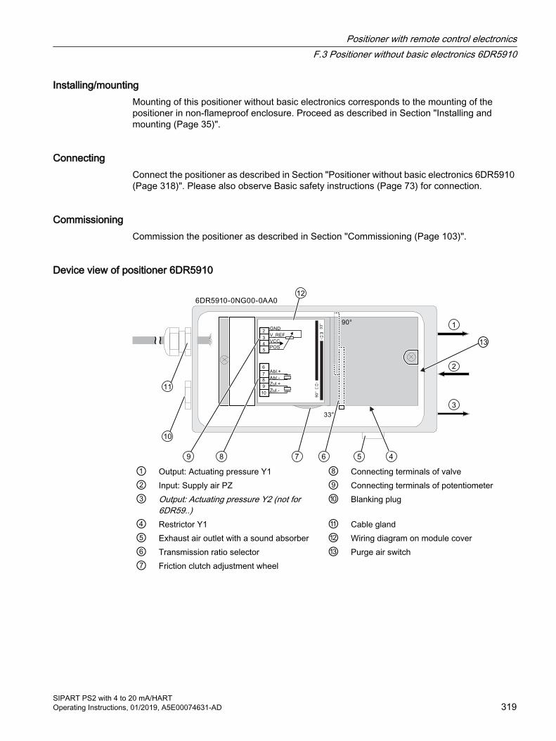
Installing/mountingMounting of this positioner without basic electronics corresponds to the mounting of the positioner in non-flameproof enclosure. Proceed as described in Section "Installing and mounting (Page 35)".
ConnectingConnect the positioner as described in Section "Positioner without basic electronics 6DR5910 (Page 318)". Please also observe Basic safety instructions (Page 73) for connection.
CommissioningCommission the positioner as described in Section "Commissioning (Page 103)".
Device view of positioner 6DR5910
① Output: Actuating pressure Y1 ⑧ Connecting terminals of valve② Input: Supply air PZ ⑨ Connecting terminals of potentiometer③ Output: Actuating pressure Y2 (not for
6DR59..)⑩ Blanking plug
④ Restrictor Y1 ⑪ Cable gland⑤ Exhaust air outlet with a sound absorber ⑫ Wiring diagram on module cover⑥ Transmission ratio selector ⑬ Purge air switch⑦ Friction clutch adjustment wheel
Positioner with remote control electronicsF.3 Positioner without basic electronics 6DR5910
SIPART PS2 with 4 to 20 mA/HARTOperating Instructions, 01/2019, A5E00074631-AD 319

Positioner with remote control electronicsF.3 Positioner without basic electronics 6DR5910
SIPART PS2 with 4 to 20 mA/HART320 Operating Instructions, 01/2019, A5E00074631-AD
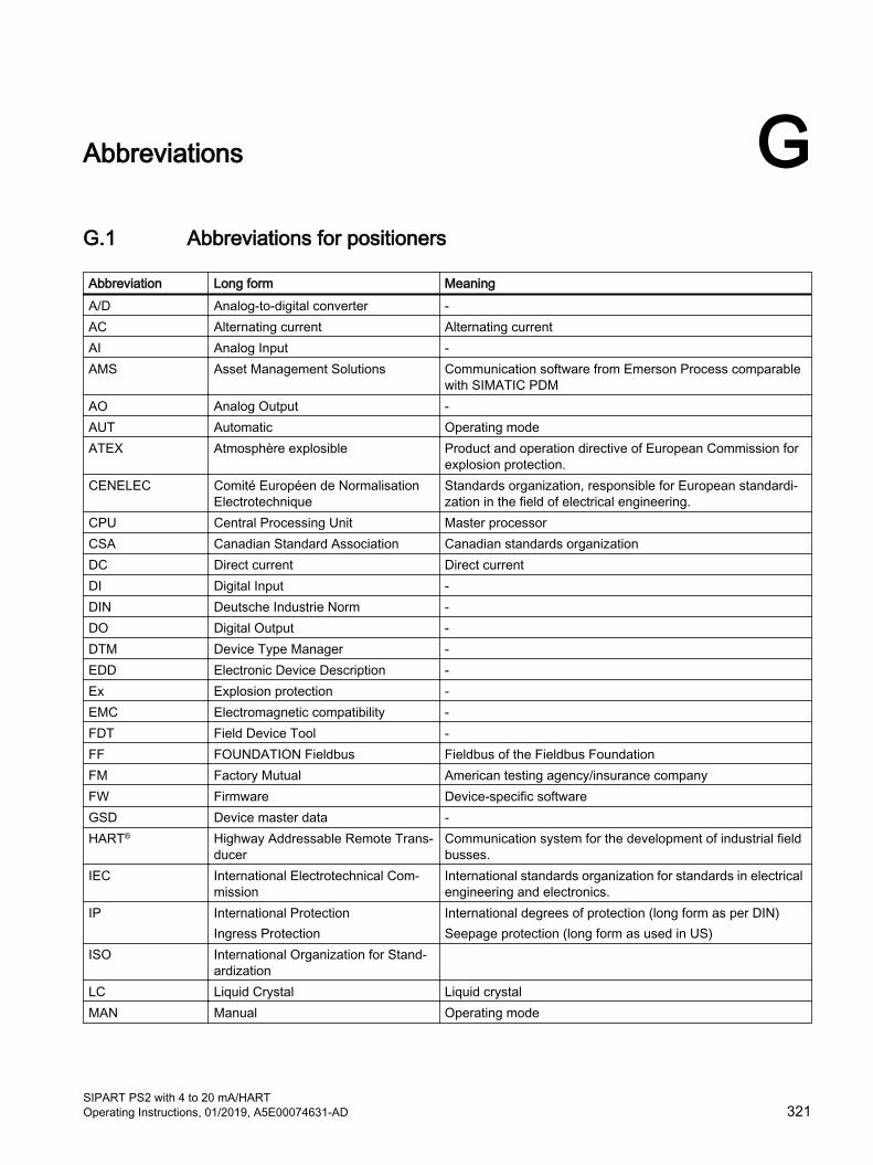
Abbreviations GG.1 Abbreviations for positioners
Abbreviation Long form MeaningA/D Analog-to-digital converter -AC Alternating current Alternating currentAI Analog Input -AMS Asset Management Solutions Communication software from Emerson Process comparable
with SIMATIC PDMAO Analog Output -AUT Automatic Operating modeATEX Atmosphère explosible Product and operation directive of European Commission for
explosion protection.CENELEC Comité Européen de Normalisation
ElectrotechniqueStandards organization, responsible for European standardi‐zation in the field of electrical engineering.
CPU Central Processing Unit Master processorCSA Canadian Standard Association Canadian standards organizationDC Direct current Direct currentDI Digital Input -DIN Deutsche Industrie Norm -DO Digital Output -DTM Device Type Manager -EDD Electronic Device Description -Ex Explosion protection -EMC Electromagnetic compatibility -FDT Field Device Tool -FF FOUNDATION Fieldbus Fieldbus of the Fieldbus FoundationFM Factory Mutual American testing agency/insurance companyFW Firmware Device-specific softwareGSD Device master data -HART® Highway Addressable Remote Trans‐
ducerCommunication system for the development of industrial field busses.
IEC International Electrotechnical Com‐mission
International standards organization for standards in electrical engineering and electronics.
IP International ProtectionIngress Protection
International degrees of protection (long form as per DIN)Seepage protection (long form as used in US)
ISO International Organization for Stand‐ardization
LC Liquid Crystal Liquid crystalMAN Manual Operating mode
SIPART PS2 with 4 to 20 mA/HARTOperating Instructions, 01/2019, A5E00074631-AD 321

Abbreviation Long form MeaningNAMUR Standards working group for meas‐
urement and control technology in the chemicals industry
Association of users in process conductor technology
µC Microcontroller One-Chip computer systemNCS Non-Contacting Sensor Sensor for contactless position detectionNEMA National Electrical Manufacturers As‐
sociationUS standards institutionNational Electrical Manufacturers Association
NPT National Pipe Thread Taper Pipe threading for self-sealing threads as per ANSI B.1.20.1OPOS interface® Open Positioner Interface Standard interface for the connection between a positioner and
a pneumatic linear or part-turn actuatorPA Process Automation Process automationPDM Process Device Manager Siemens communication software / Engineering toolPROFIBUS Process Field Bus FieldbusRSS feed Rich Site Summary Feed Shows changes in regular intervals to web sites you are sub‐
scribed to.SIA Slit initiator alarm module Option module of the positionerVDE Verband der Elektrotechnik, Elektro‐
nik und Informationstechnik e. V.Industrial and professional association
VDI Verein Deutscher Ingenieure e. V. Technical/scientific association
G.2 Abbreviations for functional safety
Abbreviation Full term in English MeaningFIT Failure in Time Frequency of failure
Number of faults within 109 hoursHFT Hardware Fault Tolerance Hardware fault tolerance:
Capability of a function unit to continue executing a required function in the presence of faults or deviations.
MooN "M out of N" voting Classification and description of the safety-instrumented system in terms of redundancy and the selection procedures used.A safety-instrumented system or part that consists of "N" inde‐pendent channels. The channels are connected to each other in such a way that "M" channels are in each case sufficient for the device to perform the safety instrumented function.Example:Pressure measurement: 1oo2 architecture. A safety-instrumen‐ted system decides that a specified pressure limit has been ex‐ceeded if one out of two pressure sensors reaches this limit. In a 1oo1 architecture, there is only one pressure sensor.
MTBF Mean Time Between Failures Average period between two failuresMTTR Mean Time To Restoration Average period between the occurrence of a fault in a device or
system and restoration of functionalityPFD Probability of Dangerous Failure on
DemandProbability of dangerous failures of a safety function on demand
AbbreviationsG.2 Abbreviations for functional safety
SIPART PS2 with 4 to 20 mA/HART322 Operating Instructions, 01/2019, A5E00074631-AD

Abbreviation Full term in English MeaningPFDAVG Average Probability of Dangerous Fail‐
ure on DemandAverage probability of dangerous failures of a safety function on demand
SFF Safe Failure Fraction Proportion of safe failures: Proportion of failures without the potential to bring the safety-in‐strumented system into a dangerous or non-permissible func‐tional status.
SIL Safety Integrity Level The international standard IEC 61508 defines four discrete Safe‐ty Integrity Levels (SIL 1 to SIL 4). Each level corresponds to a range of probability for failure of a safety function. The higher the Safety Integrity Level of the safety-instrumented system, the low‐er the probability that it will not execute the required safety func‐tions.
SIS Safety Instrumented System A safety-instrumented system (SIS) executes the safety func‐tions that are required to achieve or maintain a safe status in a system. It consists of sensors, logic unit/control system and final controlling elements.
AbbreviationsG.2 Abbreviations for functional safety
SIPART PS2 with 4 to 20 mA/HARTOperating Instructions, 01/2019, A5E00074631-AD 323

AbbreviationsG.2 Abbreviations for functional safety
SIPART PS2 with 4 to 20 mA/HART324 Operating Instructions, 01/2019, A5E00074631-AD

Glossary
ActuatorConverter that converts electric signals into mechanical or other non-electric variables.
Actuator chamberFor pneumatic actuators which consist of two pressure chambers in double-acting versions and of a pressure chamber and a spring chamber in single-acting versions.
AnalogA signal type which represents data using continuously varying, measurable and physical quantities, e.g. current or voltage. Opposite to digital. The range between 4 and 20 mA is often used to transfer analog signals.
Analog-to-digital converterAn analog-to-digital converter is an interface between the analog environment and the digitally working computers. Only then can the computers be used for measurement and control tasks.
Analog-to-digital converters convert analog input signals to digital signals. Analog measurement data is thus converted into digital information. On the other hand, a digital-to-analog converter coverts digital information into analog signals.
Asset Management Solution (AMS)Software package by Emerson Process. The AMS Device Manager, which is somewhat similar to the PDM, is the most significant part of the package.
ATEXATEX is the abbreviation of the French term "Atmosphère explosible". ATEX stands for the two directives of the European Community in the field of explosion protection: the ATEX product directive 2014/34/EU and the ATEX operation directive 1999/92/EC.
Auxiliary voltageAuxiliary voltage is an electric supply or reference voltage that is required by some electric circuits in addition to the standard supply. The auxiliary voltage can, for example, be specially stabilized, have a particular level or polarity and/or other properties which are important for the correct functioning of switch components. Auxiliary voltage is used, for example, with four-wire systems.
SIPART PS2 with 4 to 20 mA/HARTOperating Instructions, 01/2019, A5E00074631-AD 325
ChamberA largely or completely enclosed cavity in a machine or apparatus.
Conduit piping systemA piping system for the American market, wherein the electric and pneumatic lines are protected by a casing.
ConfiguringSee parameter assignment.
Control fittingA valve consisting of an actuator + control valve + positioner.
CornerstoneManagement software for process instrumentation.
DecrementFrom the Latin word decrementare, decrease. Decrement is the defined amount of change when decreasing a variable gradually. IT term that refers to a step-by-step decrease in a numeric value.→Increment.
Degree of protectionThe degree of protection of a device indicates the extent of protection. The extent of protection includes the safety of persons against coming in contact with live or rotating parts, and the protection of electric resources against the penetration of water, foreign bodies and dust. The degrees of protection of electric machines are indicated by an abbreviation comprising two letters and two numbers (e.g. IP55). The degree of protection is coded using the IP code. The degrees of protection are standardized in DIN EN 60529.
Device category 1Category 1 devices must be procured such that they ensure an extremely high degree of safety. Devices in this category must ensure an extremely high degree of safety even for faults that occur rarely. Even if two faults occur in the device, it should not lead to ignition. Devices in this category are suitable for use in zone 0 or 20.
Device category 2Category 2 devices must be procured such that they ensure a high degree of safety. Devices in this category must ensure the required degree of safety in case of frequent faults or ones that can be normally expected, e.g. defects in the device, and avoid ignition sources. Devices in this category are suitable for use in zone 1 or 21.
Glossary
SIPART PS2 with 4 to 20 mA/HART326 Operating Instructions, 01/2019, A5E00074631-AD

Device category 3Category 3 devices must be procured such that they ensure a normal degree of safety. Devices in this category must ensure the required degree of safety in case of frequent faults or ones that can be normally expected, e.g. defects in the device, and avoid ignition sources. Devices in this category are suitable for use in zone 2 or 22.
DigitalRepresentation of a variable in the form of characters or numbers. The functional course of an originally changeable analog variable is simulated in predefined stages. Predefined values are assigned to these stages. Opposite to "analog".
EEPROMEEPROM (Electrically Erasable Programmable Read-Only Memory; literally: elektrisch löschbarer, programmierbarer Nur-Lese-Speicher in German) is a non-volatile electronic memory. EEPROMs are often used when individual data bytes change over long time periods and need to be saved in a manner protected against power failure, e.g. configuration data or operating hours counters.
Electromagnetic compatibilityDefinition as per the EMC law: EMC is the capability of a device to operate satisfactorily in an electromagnetic environment without itself emitting electromagnetic signals which interfere with other devices in that environment.
Ex d"Flameproof enclosure" type of protection. When the potentially explosive mixtures enter the enclosure of a resource and an ignition source exists in the enclosure. The transfer of the explosion inside the enclosure to the surrounding space must be ruled out.
● d: flameproof enclosure
Ex ia / Ex ib / Ex icIf potentially explosive mixtures enter the enclosure of a resource, it should not lead to ignition. Demarcation of energy and increased temperatures.
Ex nEquipment containing energy-limiting, non-sparking contacts as well as circuits whose contacts are supplied with limited energy.
Ex tDust ignition protection with "t" enclosure. Dust ignition protection where the electric equipment has an enclosure providing protection against dust ingress and a measure for limiting the surface temperature.
Glossary
SIPART PS2 with 4 to 20 mA/HARTOperating Instructions, 01/2019, A5E00074631-AD 327
Factory MutualIndustrial property insurer and certification agency in the USA. FM Global is one of the largest industrial insurers in the world who are specialized in the field of technically-supported property insurance. It offers services like product research, testing and certification.
Failure that causes a dangerous situationFailure with the potential to switch a safety-instrumented system to a hazardous or non-functioning safety status.
FirmwareFirmware (FW) is software that is embedded on a chip in electronic devices – in contrast to software which is saved on hard disks, CD-ROMs or other media. These days, firmware is mostly stored in a flash memory or an EEPROM. Firmware is software in the hardware, and is thus an intermediate between software and hardware. Firmware is normally model-specific. This means that it does not function on other device models and is delivered by the manufacturing company. The corresponding devices cannot function without the firmware. The firmware mostly contains elementary functions to control the device, as well as input and output routines.
Frequency shift keyingENGLISH: Frequency shift keying (FSK)
Frequency shift keying is a simple modulation format in which digital values 0 and 1 are represented by two different frequencies.
GSD fileThe file that describes the properties of a PROFIBUS DP slave or a PROFINET IO device.
The GSD file is a database file for PROFIBUS devices. The device manufacturer provides the corresponding GSD file containing the description of device properties. The information in the file can be read using Engineering Tools.
HARTHART (Highway Addressable Remote Transducer) is a standardized and widely used communication system for configuring industrial fieldbuses. This communication system enables digital communication of multiple participants (field devices) using a common data bus. HART implements the widely used 4/20 mA standard to transfer analog sensor signals. Existing cables of the old system can be used directly and both systems can be operated simultaneously. HART specifies several protocol levels in the OSI model. HART enables transfer of process and diagnostics information and control signals between field devices and the higher-level control system. Standardized parameter sets can be used for manufacturer-independent operation of all HART devices.
Glossary
SIPART PS2 with 4 to 20 mA/HART328 Operating Instructions, 01/2019, A5E00074631-AD
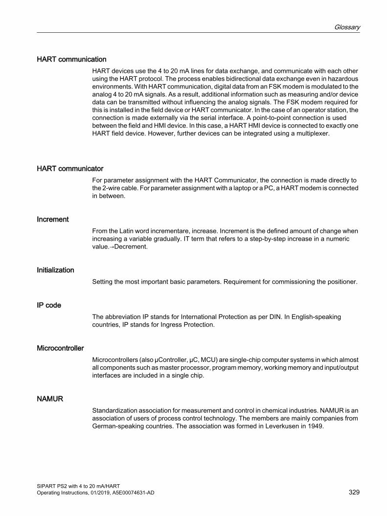
HART communicationHART devices use the 4 to 20 mA lines for data exchange, and communicate with each other using the HART protocol. The process enables bidirectional data exchange even in hazardous environments. With HART communication, digital data from an FSK modem is modulated to the analog 4 to 20 mA signals. As a result, additional information such as measuring and/or device data can be transmitted without influencing the analog signals. The FSK modem required for this is installed in the field device or HART communicator. In the case of an operator station, the connection is made externally via the serial interface. A point-to-point connection is used between the field and HMI device. In this case, a HART HMI device is connected to exactly one HART field device. However, further devices can be integrated using a multiplexer.
HART communicatorFor parameter assignment with the HART Communicator, the connection is made directly to the 2-wire cable. For parameter assignment with a laptop or a PC, a HART modem is connected in between.
IncrementFrom the Latin word incrementare, increase. Increment is the defined amount of change when increasing a variable gradually. IT term that refers to a step-by-step increase in a numeric value.→Decrement.
InitializationSetting the most important basic parameters. Requirement for commissioning the positioner.
IP codeThe abbreviation IP stands for International Protection as per DIN. In English-speaking countries, IP stands for Ingress Protection.
MicrocontrollerMicrocontrollers (also µController, µC, MCU) are single-chip computer systems in which almost all components such as master processor, program memory, working memory and input/output interfaces are included in a single chip.
NAMURStandardization association for measurement and control in chemical industries. NAMUR is an association of users of process control technology. The members are mainly companies from German-speaking countries. The association was formed in Leverkusen in 1949.
Glossary
SIPART PS2 with 4 to 20 mA/HARTOperating Instructions, 01/2019, A5E00074631-AD 329

NEMANational Electrical Manufacturers Association. NEMA is a standardization institute in the USA. NEMA was formed in 1926 with the merge of Associated Manufacturers of Electrical Supplies and the Electric Power Club.
Parameter assignmentIndividual parameter settings are specifically changed to adjust the positioner as per the actuator or other requirements. Parameter assignment is carried out after the complete commissioning of the positioner.
Piezoelectric effectName of a physical phenomenon. Due to mechanical compression loads on a crystal, an electric potential develops on specific crystal surfaces. In a reverse case, applying an electric field to specific crystal surfaces leads to crystal deformation.
Potentially explosive atmosphereMixture of air, combustible gases, fluff, fibers or dusts.
Pressure chamberThe pneumatic actuators are available in single and double-acting versions. In a single-acting version, only one pressure chamber is pressurized and depressurized. The pressure developed works against a spring. In a double-acting version, two pressure chambers work against each other. Pressurizing the volume of one chamber simultaneously depressurizes the volume of the other.
Process Device ManagerPDM is a Siemens software package for configuration, parameter assignment, commissioning and maintenance of network configurations and field devices. Part of SIMATIC STEP 7. Used for configuration and diagnostics.
Protection level● ia: Protection level. Electric equipment operating fault-free, and with existence of two
countable errors.
● ib: Protection level. Electric equipment operating fault-free, and with existence of one countable error.
● ic: Protection level. Electrical equipment is not able to cause an ignition when operating fault-free.
Glossary
SIPART PS2 with 4 to 20 mA/HART330 Operating Instructions, 01/2019, A5E00074631-AD
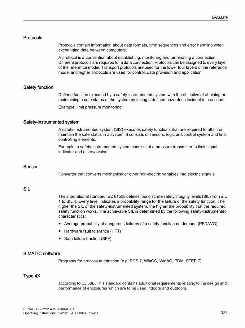
ProtocolsProtocols contain information about data formats, time sequences and error handling when exchanging data between computers.
A protocol is a convention about establishing, monitoring and terminating a connection. Different protocols are required for a data connection. Protocols can be assigned to every layer of the reference model. Transport protocols are used for the lower four layers of the reference model and higher protocols are used for control, data provision and application.
Safety functionDefined function executed by a safety-instrumented system with the objective of attaining or maintaining a safe status of the system by taking a defined hazardous incident into account.
Example: limit pressure monitoring
Safety-instrumented systemA safety-instrumented system (SIS) executes safety functions that are required to attain or maintain the safe status in a system. It consists of sensors, logic unit/control system and final controlling elements.
Example: a safety-instrumented system consists of a pressure transmitter, a limit signal indicator and a servo valve.
SensorConverter that converts mechanical or other non-electric variables into electric signals.
SILThe international standard IEC 61508 defines four discrete safety integrity levels (SIL) from SIL 1 to SIL 4. Every level indicates a probability range for the failure of the safety function. The higher the SIL of the safety-instrumented system, the higher the probability that the required safety function works. The achievable SIL is determined by the following safety-instrumented characteristics:
● Average probability of dangerous failures of a safety function on demand (PFDAVG)
● Hardware fault tolerance (HFT)
● Safe failure fraction (SFF)
SIMATIC softwarePrograms for process automation (e.g. PCS 7, WinCC, WinAC, PDM, STEP 7).
Type 4Xaccording to UL 50E. This standard contains additional requirements relating to the design and performance of enclosures which are to be used indoors and outdoors.
Glossary
SIPART PS2 with 4 to 20 mA/HARTOperating Instructions, 01/2019, A5E00074631-AD 331
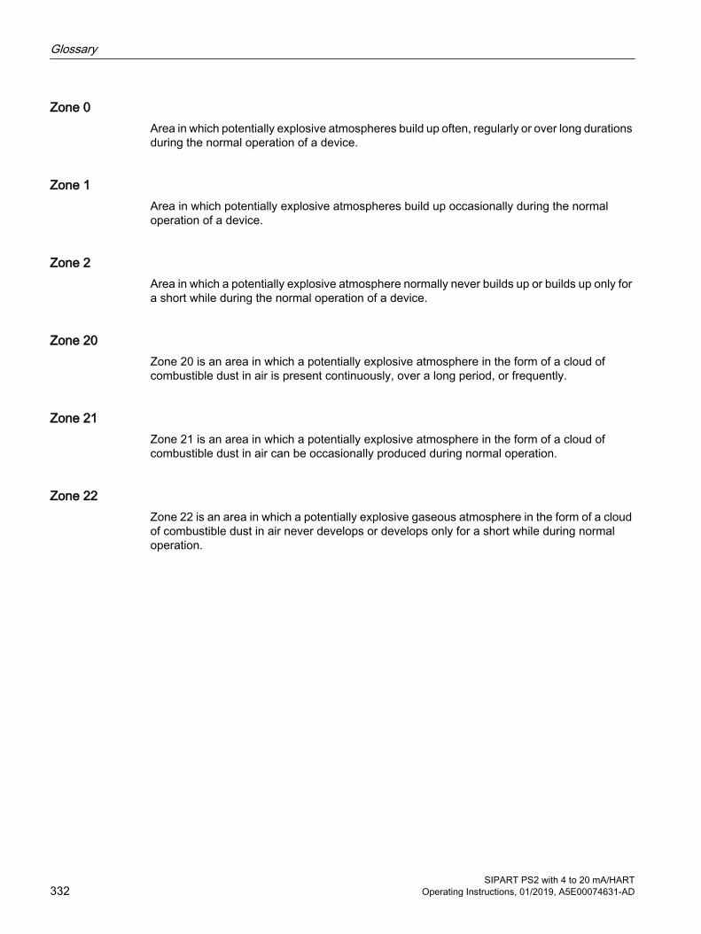
Zone 0Area in which potentially explosive atmospheres build up often, regularly or over long durations during the normal operation of a device.
Zone 1Area in which potentially explosive atmospheres build up occasionally during the normal operation of a device.
Zone 2Area in which a potentially explosive atmosphere normally never builds up or builds up only for a short while during the normal operation of a device.
Zone 20Zone 20 is an area in which a potentially explosive atmosphere in the form of a cloud of combustible dust in air is present continuously, over a long period, or frequently.
Zone 21Zone 21 is an area in which a potentially explosive atmosphere in the form of a cloud of combustible dust in air can be occasionally produced during normal operation.
Zone 22Zone 22 is an area in which a potentially explosive gaseous atmosphere in the form of a cloud of combustible dust in air never develops or develops only for a short while during normal operation.
Glossary
SIPART PS2 with 4 to 20 mA/HART332 Operating Instructions, 01/2019, A5E00074631-AD
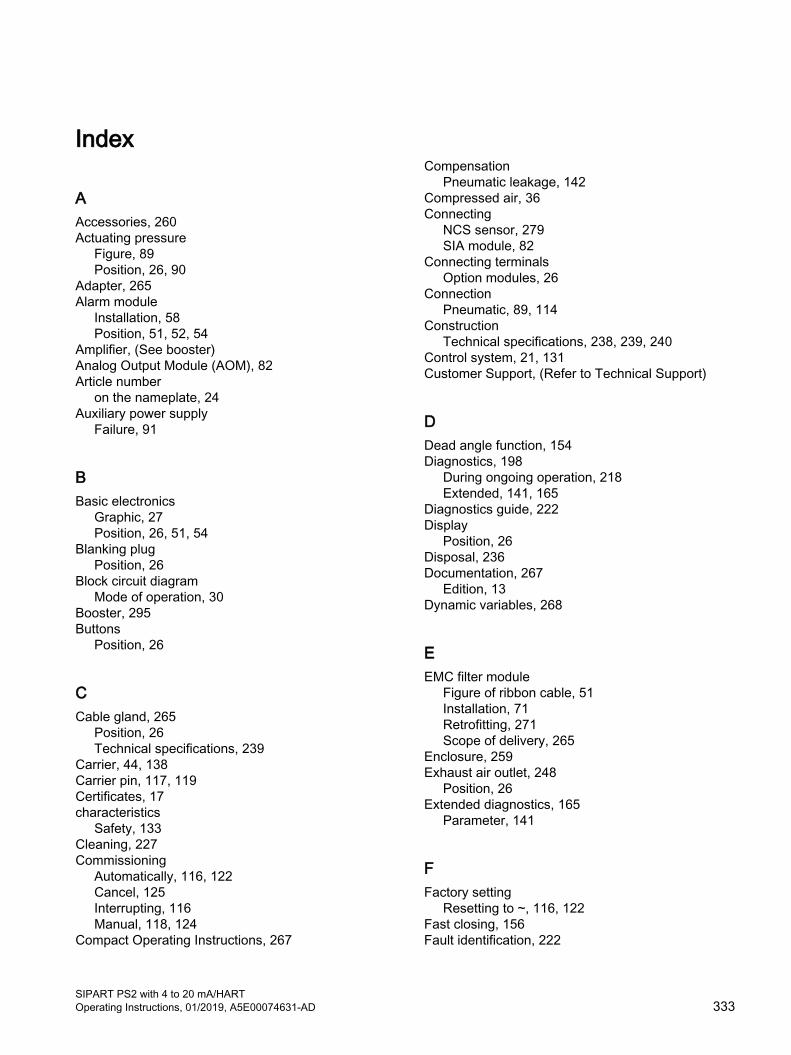
Index
AAccessories, 260Actuating pressure
Figure, 89Position, 26, 90
Adapter, 265Alarm module
Installation, 58Position, 51, 52, 54
Amplifier, (See booster)Analog Output Module (AOM), 82Article number
on the nameplate, 24Auxiliary power supply
Failure, 91
BBasic electronics
Graphic, 27Position, 26, 51, 54
Blanking plugPosition, 26
Block circuit diagramMode of operation, 30
Booster, 295Buttons
Position, 26
CCable gland, 265
Position, 26Technical specifications, 239
Carrier, 44, 138Carrier pin, 117, 119Certificates, 17characteristics
Safety, 133Cleaning, 227Commissioning
Automatically, 116, 122Cancel, 125Interrupting, 116Manual, 118, 124
Compact Operating Instructions, 267
CompensationPneumatic leakage, 142
Compressed air, 36Connecting
NCS sensor, 279SIA module, 82
Connecting terminalsOption modules, 26
ConnectionPneumatic, 89, 114
ConstructionTechnical specifications, 238, 239, 240
Control system, 21, 131Customer Support, (Refer to Technical Support)
DDead angle function, 154Diagnostics, 198
During ongoing operation, 218Extended, 141, 165
Diagnostics guide, 222Display
Position, 26Disposal, 236Documentation, 267
Edition, 13Dynamic variables, 268
EEMC filter module
Figure of ribbon cable, 51Installation, 71Retrofitting, 271Scope of delivery, 265
Enclosure, 259Exhaust air outlet, 248
Position, 26Extended diagnostics, 165
Parameter, 141
FFactory setting
Resetting to ~, 116, 122Fast closing, 156Fault identification, 222
SIPART PS2 with 4 to 20 mA/HARTOperating Instructions, 01/2019, A5E00074631-AD 333
Final controlling element, 131Five-point controller, 21, 29Flow rate, 248Freezing
Exhaust air outlet, 38, 130Friction clutch, 21
Position, 26, 52Set, 113
GGear
switchable, 21Gear latch, 49
HHART
Modem, 32HART module, 31HART variables, 268Hazardous area
Laws and directives, 17Qualified personnel, 19
History, 13Hotlline, (Refer to Support request)
II/Os
Technical specifications, 240iNCS
Installation, 66Initialization
Automatically, 107Cancel, 125Interrupting, 122
InstallationAlarm module, 58Mechanical limit switch module, 64Position feedback module, 57
Instuctions and manuals, 267Insulating cover, 51, 66Internal NCS module
Commissioning, 115Installation, 48, 66Technical specifications, 253
Iy module, (See position feedback module)
LLaws and directives
Disassembly, 17Personell, 17
LeakagePneumatic, 142
Leakage testOffline, 203
Linear actuatorAdd-on extensions, 21Automatic commissioning, 116Automatic commissioning (flowchart), 107Manual commissioning, 118Pneumatic connection, integrated, 89Single-acting, 22
MManometer
Mounting, 289Technical specifications, 240
Manuals, 267Material
Technical specifications, 239Mechanical limit switch module, 63, 105
Installation, 64Position, 51, 54
Mode of operation, 28Modifications
correct usage, 18improper, 18
Module coverPosition, 51, 54
Motherboard, (See basic electronics)Mount
Dimensions, 47Mounting kit
Linear actuator, 39
NNameplate
Position, 52, 55Natural gas
Maximum values for ventilation, 247Operation, 105
NCS, 69Installation, 48
Index
SIPART PS2 with 4 to 20 mA/HART334 Operating Instructions, 01/2019, A5E00074631-AD
NCS moduleInternal, 48
NCS sensorConnecting to EMC filter module, 279
OOffline leakage test, 203Online diagnostics, 218Operating Instructions, 267Operation
Natural gas, 105Option modules, 259
Installation, 52Order code, 24Ordering supplement, 24
PParameters 1 to 5
Overview, 137Parameters 6 to 51
Overview, 138Parameters A to P
Overview, 142Part-turn actuator
Automatic commissioning, 122Automatic commissioning (flowchart), 107Double-acting, 22Manual commissioning, 124Mounting, 44
Pneumatic actuator, 28Pneumatic block, (See pneumatic block)
Position, 51, 54Purging air selector, 114
Pneumatic connections, 114Position feedback module
Installation, 57Position, 52, 55see Analog Output Module (AOM), 82
PositionerReplacing, 126
Potentiometer, 69Position, 51, 54
Pressure gauge block, 22Torque, 240
Printed circuit board, (See basic electronics)Product name, 24Purge air switch, 248
Position, 26Purging air selector, 114
QQR code label, 268Qualified personnel, 19
RReading initialization parameters, 126Restrictor
Position, 26Return procedure, 236Ribbon cable
Figure, 51Graphic, 54
SSafety position, 91Scope of delivery, 14
EMC filter module, 265Screen
Cleaning of~, 228Sealing plug
Technical specifications, 292Service, 267Service & Support, 267
Internet, 267servo valve
Integrated, 21Settings, 132SIA module
Connecting, 82Installation, 60, 61Position, 51, 54
SIL 2, 131Single-channel operation, 131Slot initiator, (See SIA module)Sound absorber
Position, 26Special screw
Position, 51Supply air
Position, 26Supply air PZ, 133Support, 267Support request, 267System pressure, (see Supply air)
Index
SIPART PS2 with 4 to 20 mA/HARTOperating Instructions, 01/2019, A5E00074631-AD 335

TTechnical Support, 267
Partner, Personal contact, 267
Terminal strip, 114Test certificates, 17Threaded adapter
Technical specifications, 292Tight closing, 156Tightening torque
Technical specifications, (Torque)Torque, 239, 292Transmission ratio selector, 49
Position, 26, 51, 55Transmitter, 131
VVersion
Technical specifications, 239
WWarning label
Position, 51, 54Warranty, 15Weight
Technical specifications, 239Wiring diagram
Position, 26Wiring diagram on module cover, 52
YY1, 133
Index
SIPART PS2 with 4 to 20 mA/HART336 Operating Instructions, 01/2019, A5E00074631-AD
Related Documents