Siemens FI 01 · 2014 US Edition 5 5/2 Product Overview SIPART PS2 5/3 Technical description Technical specifications 5/8 - all versions 5/10 - SIPART PS2 with and without HART 5/12 - SIPART PS2 with PROFIBUS PA/ with FOUNDATION Fieldbus 5/14 - Option modules Selection and Ordering data 5/18 - SIPART PS2 5/21 - Accessories/Spare parts 5/23 Dimensional drawings 5/25 Schematics 5/26 Mounting kit Software Sec. 8 SIMATIC PDM, for parametrize HART and PROFIBUS PA devices You can download all instructions, catalogs and certificates for positioners free of charge at the following Internet address: www.siemens.com/positioners Positioners © Siemens AG 2014

Welcome message from author
This document is posted to help you gain knowledge. Please leave a comment to let me know what you think about it! Share it to your friends and learn new things together.
Transcript
Siemens FI 01 · 2014 US Edition
55/2 Product Overview
SIPART PS25/3 Technical description
Technical specifications5/8 - all versions5/10 - SIPART PS2 with and without HART5/12 - SIPART PS2 with PROFIBUS PA/
with FOUNDATION Fieldbus5/14 - Option modules
Selection and Ordering data5/18 - SIPART PS25/21 - Accessories/Spare parts5/23 Dimensional drawings5/25 Schematics5/26 Mounting kit
SoftwareSec. 8 SIMATIC PDM, for parametrize
HART and PROFIBUS PA devices
You can download all instructions,catalogs and certificates for positioners free of charge at the followingInternet address:www.siemens.com/positioners
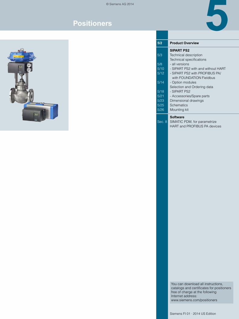
Positioners
FI01_2014_us_Kap05.book Seite 1 Mittwoch, 16. April 2014 11:12 11
© Siemens AG 2014

PositionersProduct Overview
5/2 Siemens FI 01 · 2014 US Edition
5
Overview
Application Description Catalog page Software forparameteriza-tion
Positioners
Position control of pneumatic linear or part-turn actuators, also for intrinsically safe operation
SIPART PS2Universal device for positioning pneumatic actuators• Connection: 4 to 20 mA• HART; PROFIBUS PA or
FOUNDATION Fieldbus• Local manual operation• Binary inputs and outputs• Diagnostic function• Blocking function• Automatic startup• Partial Stroke Testing
5/3 SIMATIC PDM
As above, but in flameproof enclo-sure for explosion-proof, Class I, Division 1 applications
SIPART PS2As above, but in flameproof aluminum enclosure
5/3 SIMATIC PDM
FI01_2014_us_Kap05.book Seite 2 Mittwoch, 16. April 2014 11:12 11
© Siemens AG 2014

PositionersSIPART PS2
Technical description
5/3Siemens FI 01 · 2014 US Edition
5
Overview
Electropneumatic positioner SIPART PS2 in the Makrolon enclosure
SIPART PS2 electropneumatic positioner in flameproof aluminium enclo-sure
SIPART PS2 in stainless steel enclosure
The SIPART PS2 electropneumatic positioner is used to control the final control element of pneumatic linear or part-turn actua-tors. The electropneumatic positioner moves the actuator to a valve position corresponding to the setpoint. Additional function inputs can be used to block the valve or to set a safety position. A binary input is present as standard in the basic device for this purpose.
Benefits
SIPART PS2 positioners offer decisive advantages:• Simple installation and automatic commissioning
(self-adjustment of zero and span)• Simple operation with
- Local operation (manual operation) and configuration of the device using three buttons and a user-friendly two-linedisplay
- Parameterization via SIMATIC PDM• Very high-quality control thanks to an online adaptation
procedure• Negligible air consumption in stationary operation• "Tight closing" function (ensures maximum positioning
pressure on the valve seat)• Numerous functions can be activated by simple configuring
(e. g. characteristic curves and limits) • Extensive diagnostic functions for valve and actuator• Only one device version for linear and part-turn actuators• Few moving parts, hence insensitive to vibrations• External non contacting sensor as option for extreme ambient
conditions• "Intelligent solenoid valve": Partial Stroke Test and solenoid
valve function in one device• Partial Stroke Test e. g. for safety valves• Can also be operated with purified natural gas,
carbon dioxide, nitrogen or noble gases• SIL (Safety Integrity Level) 2
Application
The SIPART PS2 positioner is used, for example, in the following industries:• Chemical/petrochemical/refinering• Power stations• Paper and glass• Water, waste water• Food and pharmaceuticals• Offshore plants
The SIPART PS2 positioner is available:• For single-acting actuators: In Makrolon, stainless steel or alu-
minum enclosure, as well as flameproof aluminum enclosure• For double-acting actuators: In Makrolon enclosure, stainless
steel enclosure and flameproof aluminum enclosure• For non-hazardous applications• For hazardous applications in the versions
- Intrinsic safety type of protection- Flameproof enclosure type of protection- Non-sparking type of protection- Dust protection by enclosure type of protection
and in the versions:• With 0/4 ... 20 mA control with/without communication through
HART signal• With PROFIBUS PA communication interface• With FOUNDATION Fieldbus (FF) communications interface.
FI01_2014_us_Kap05.book Seite 3 Mittwoch, 16. April 2014 11:12 11
© Siemens AG 2014

PositionersSIPART PS2
Technical description
5/4 Siemens FI 01 · 2014 US Edition
5
Explosion-proof versions• Device with protection type "intrinsic safety" for use in Zone 1,
2, 21 or Class I, Division 1, Groups ABCD• Device with protection type "dust protection with enclosure" for
use in Zone 22• Device with protection type "non-sparking" for use in Zone 2 or
Class I, Division 2, Groups ABCD• Device with protection type "flameproof enclosure" for use in
Zone 1 or Class I, Division 1, Groups ABCD
Stainless steel enclosure for extreme ambient conditionsThe SIPART PS2 is available in a stainless steel enclosure (with no window in the cover) for use in particularly aggressive envi-ronments (e.g. offshore operation, chlorine plants etc.). The de-vice functions are the same as for the basic version.
Design
The SIPART PS2 positioner is a digital field device with a highly-integrated microcontroller.
The positioner consists of the following components:• Enclosure and cover• PCB with corresponding electronics with or without communi-
cation through HARTor with electronics for communication in accordance with - PROFIBUS PA specification, IEC 61158-2; bus-supplied
device, or- FOUNDATION Fieldbus (FF) specification, IEC 61158-2,
bus-supplied device• Position detection system• Terminal housing with screw terminals• Pneumatic valve manifold with piezoelectric valve precontrol.
The valve manifold is located in the housing, the pneumatic con-nections for the inlet air and the positioning pressure on the right-hand side. A pressure gauge block and/or a safety solenoid valve can be connected there as options. The SIPART PS2 posi-tioner is fitted to the linear or part-turn actuator using an appro-priate mounting kit. The enclosure provides slots for separately ordered option boards with the following functions:
Iy module • Position feedback as a two-wire signal 4 to 20 mA
Alarm unit (3 outputs, 1 input) • Signaling of two limits of the travel or angle by binary signals.
The two limits can be set independently as maximum or mini-mum values.
• Output of an alarm if the setpoint position of the final control element is not reached in automatic mode or if a device fault occurs.
• Second binary input for alarm signals of for triggering safety reactions, e. g. blocking function or safety position.
Limit signaling through slot-type initiators (SIA module) Two limits can be signaled redundantly as NAMUR signals (EN 60947-5-6) by slot-type initiators. An alarm output is also in-tegrated in the module (see "Alarm Module").
Mechanical limit switch module(limit value contact module) Two limits can be signaled redundantly by switching contacts. An alarm output is also integrated in the module (see "Alarm Module").
Valid for all modules described above:
All signals are electrically isolated from one another and from the basic unit. The outputs indicate self-signaling faults. The modules are easily installed.
Separate mounting of position detection system andcontroller unit The position detection system and controller unit can be con-nected separately for all casing versions of the SIPART PS2 (ex-cept flameproof design). Measurement of the travel or angle is carried out directly on the actuator. The controller unit can then be mounted a certain distance away, e. g. on a mounting pipe or similar, and is connected to the position detection system by an electric cable and to the actuator by one or two pneumatic lines. The remote mounted design is used when the conditions at the actuator exceed the specified values for the positioner (e. g. strong vibrations, temperature, etc.).
The following can be used for measuring the travel or angle:• NCS sensor• External position detection system C73451-A430-D78• A commercially available potentiometer (10 k resistance
maximum), e. g. for higher application temperatures or cus-tomer-specific applications
The use of potentiometers is recommended for very small linear actuators with a short valve travel since, on the one hand, the space required by the potentiometer is very small and, on the other, the transmission characteristic is optimum for a small travel.
Separate mounting of position detection system and controller unit
Non contacting sensor (NCS)
NCS for part-turn actuator (6DR4004-xNx10) mounted with mounting console (left) and NCS for linear actuator 14 mm (0.55 inch) (6DR4004-xNx20) mounted with actuator-specific mounting solution (right)
3
1 2
465
1 Pneumatic connection2 Pneumatic connection for double-acting
actuators3 Position detection system
(10 kΩ potentiometer or NCS)4 Electric cable5 Retrofitted EMC filter module (in device)6 SIPART PS2
FI01_2014_us_Kap05.book Seite 4 Mittwoch, 16. April 2014 11:12 11
© Siemens AG 2014

PositionersSIPART PS2
Technical description
5/5Siemens FI 01 · 2014 US Edition
5
NCS (6DR4004-xNx30) for travels > 14 mm (0.55 inch) mounted using mounting kit for NAMUR linear actuator
The NCS sensor consists of a non-contacting position sensor. All coupling elements are omitted such as coupling wheel and driver pin with part-turn actuators or lever and pick-up bracket with linear actuators for up to 14 mm travel.
This results in:• Even greater resistance to vibration and shock• No wear of sensor• Problem-free mounting on very small actuators• Negligible hysteresis with very small travels.
The sensor does not require an additional power supply, i. e. SIPART PS2 (not for Ex d version) can be operated in a 2-wire system. The NCS (Non Contacting Sensor) consists of a potted sensor housing which must be mounted permanently and a magnet which is mounted on the shaft of linear actuators or on the shaft end of part-turn actuators. For the version for travels >14 mm (0.55 inch), the magnet and the NCS are premounted on a stainless steel frame and offer the same interface mechan-ically as the positioner itself, i. e. they can be mounted using the standard mounting kits 6DR4004-8V, -8VK and -8VL.
The installation of a EMC filter module in the positioner (controller unit) is necessary in order to ensure a connection level with EMC according to EC Declaration of Conformity when using external sensors (see "Selection and Ordering Data", "EMC Filter Mod-ule").
Function
The SIPART PS2 positioner works in a completely different way to normal positioners.
Mode of operationComparison of the setpoint and the actual value takes place electronically in a microcontroller. If the microcontroller detects a deviation, it uses a 5-way switch procedure to control the piezo-electric valves, which regulates the flow of air into and from the chambers of the pneumatic actuator or blows it in the opposite direction.
The microcontroller then outputs an electric control command to the piezoelectric valve in accordance with the size and direction of the deviation (deviation between setpoint and actual values). The piezoelectric valve converts the command into a pneumatic positional increment.
The positioner outputs a continuous signal in the area where there is a large system deviation (high-speed zone); in areas of moderate system deviation (slow-speed zone) it outputs a se-quence of pulses. No positioning signals are output in the case of a small system deviation (adaptive or variable deadband).
The linear or rotary motion of the actuator is detected by the mounting kit and transferred to a high-quality potentiometer over a shaft and a non-floating gear transmission.
The angular error of the pick-up in cases where the assembly is mounted on a linear actuator is corrected automatically.
When connected in a 2-wire system, the SIPART PS2 draws its power exclusively from the 4 to 20 mA setpoint signal.The electric power is also connected through the 2-wire bus sig-nal with PROFIBUS operation (SIPART PS2 PA).The same applies for the FOUNDATION Fieldbus version.
Pneumatic valve manifold with piezoelectric valveprecontrolThe piezoelectric valve can release very short control pulses. This helps achieve a high positioning accuracy. The pilot ele-ment is a piezoelectric bending converter which switches the pneumatic main controller unit. The valve manifold is character-ized by an extremely long service life.
Local operationLocal operation is performed using the built-in display and the three buttons. Switching between the operating levels Auto-matic, Manual, Configuring and Diagnosis is possible at the press of a button.
In manual mode the drive can be adjusted over the entire range without interrupting the circuit.
Operation and monitoring with the SIMATIC PDMconfiguration softwareThe configuration software SIMATIC PDM permits simple opera-tion, monitoring, configuration and parameterization of the de-vice. The diagnostic information available can be read via SIMATIC PDM from the device. Communication is carried out via the HART protocol or PROFIBUS PA. For the HART protocol, the device can be accessed both via a HART modem and via a HART-compatible input/output module (remote IO). The corre-sponding device description files, such as GSD and (Enhanced) EDD are available for both types of communication.
In addition, the SITRANS DTM provides software based on tried and tested EDD technology that can be used to parameterize field devices via a DTM (Device Type Manager) using an FDT frame application (e. g. PACTware). SITRANS DTM and the nec-essary device-specific enhanced EDD are available for down-load free of charge. The software provides the relevant commu-nication interfaces for HART and PROFIBUS.
Automatic commissioningWith a simple configuration menu the SIPART PS2 can be quickly adapted to the fitting and adjusted by means of an automatic startup function.
During initialization, the microcontroller determines the zero point, full-scale value, the direction of action and the positioning speed of the fitting. From this data it establishes the minimum pulse time and the deadband, thus optimizing the control.
Low air consumptionA hallmark of the SIPART PS2 is its extremely low consumption of air. Normal air losses on conventional positioners are costly. Thanks to the use of modern piezoelectric technology, the SI-PART PS2 consumes air only when it is needed, which means economic operation and payback for the user.
FI01_2014_us_Kap05.book Seite 5 Mittwoch, 16. April 2014 11:12 11
© Siemens AG 2014

PositionersSIPART PS2
Technical description
5/6 Siemens FI 01 · 2014 US Edition
5
Comprehensive monitoring functionsThe SIPART PS2 has various monitoring functions with which changes within the actuator and valve can be detected and sig-naled if applicable when a selectable limit has been exceeded. This information is important for diagnosis of the actuator or valve. The measuring data to be determined and monitored, some of whose limits can be adjusted, include:• Travel integral• Number of changes in direction• Alarm counter• Self-adjusting deadband• Valve end limit position (e. g. for detection of valve seat wear
or deposits)• Operating hours (also according to temperature and travel
ranges) as well as min./max. temperature• Operating cycles of piezoelectric valves• Valve positioning time• Actuator leakages• Partial stroke testing
Status monitoring with 3-stage alarm conceptThe intelligent electropneumatic SIPART PS2 positioner is equipped with additional monitoring functions. The status indi-cations derived from these monitoring functions signal active faults of the unit. The severity of these faults are graded using "traffic light signaling", symbolized by a wrench in the colors green, yellow and red (in SIMATIC PDM and Maintenance Sta-tion):• Need for maintenance (green wrench)• Urgent need for maintenance (yellow wrench)• Imminent danger of unit failure or general failure (red wrench)
This allows users to put early measures into action before a se-rious valve or actuator fault occurs which could result in a system shutdown. The fact that a fault indication is signaled, such as the onset of a diaphragm break in the actuator or the progressive sluggishness of a unit, enables the user to ensure system reli-ability at any time by means of suitable maintenance strategies.
This three-stage alarm hierarchy also allows early detection and signaling of other faults, such as the static friction of a packing box, the wearing of a valve plug/seating, or precipitations or in-crustations on the fittings.
These fault indications can be output either line-conducted over the alarm outputs (see above) of the positioner (max. 3), or via communication over the HART or field bus interfaces. In this case, the HART, PROFIBUS and FF versions of SIPART PS2 per-mit a differentiation of the various fault indications, as well as a trend representation and histogram function of all key process variables with regard to the fittings.
The device display also displays the graded maintenancerequirements, complete with identification of the source of the fault.
Functional safety acc. to SIL2The positioner is suitable for use on valves that satisfy the spe-cial requirements in terms of functional safety up to SIL 2 in ac-cordance with IEC 61508 or IEC 61511. The variants 6DR5.1.-0....-....-Z C20 are available for this.
These are single-acting positioners for mounting on pneumatic actuators with spring return.
The positioner vents the valve actuator on demand/in the event of a fault and puts the valve in the preset safety position.
This positioner meets the following requirement: • "Functional safety up to SIL 2 in accordance with IEC 61508 or
IEC 61511 for safe venting.
SIPART PS 2 as "intelligent solenoid valve“Open/Close valves, safety fittings in particular, are generally pneumatically controlled over a solenoid valve. If you use SIPART PS2 instead of this type of solenoid valve, the positioner performs two tasks in a single device (without extra wiring)• Firstly, it switches the valve off on demand by venting the ac-
tuator (functional safety acc. to SIL 2 (see above)• Secondly, it can perform a Partial Stroke Test at regular inter-
vals (1 - 365 days), which prevents the blocking of the valve, e. g. due to corrosion.
As in this case SIPART PS2 is constantly working in normaloperation (e. g. 99 % position), it also acts as a permanent test function for the pneumatic output circuit, which is not usually possible when using a solenoid valve.
Solenoid valves on control valves can also not normally be tested during operation. They are therefore not necessary when using SIPART PS 2 with a 4-wire connection system as the vent-ing is carried out on demand by SIPART PS2. This means that on control valves, both the control function and the shut-off function can be carried out by a single device.
ConfiguringIn configuring mode, the SIPART PS2 positioner can be config-ured to requirements and include the following settings:• Input current range 4 to 20 mA (configurable to 0 to 20 mA)• Rising or falling characteristic curve at the setpoint input• Positioning speed limit (setpoint ramp)• Splitrange operation; adjustable start-of-scale and full-scale
values• Response threshold (deadband); self-adjusting or fixed• Direction of action; rising or falling output pressure with rising
setpoint• Limits (start-of-scale and full-scale values) of positioning
range• Limits (alarms) of the final control element position; minimum
and maximum values• Automatic "tight closing" (with adjustable response threshold)• The travel can be corrected in accordance with the valve char-
acteristic curve.• Function of binary inputs• Function of alarm output etc.
Configuration of the various SIPART PS2 versions is largelyidentical.
FI01_2014_us_Kap05.book Seite 6 Mittwoch, 16. April 2014 11:12 11
© Siemens AG 2014

PositionersSIPART PS2
Technical description
5/7Siemens FI 01 · 2014 US Edition
5
SIPART PS2, electropneumatic positioner, function diagram
8 9
3
4
56
7
12
9
345
67
12
8
Motherboard with microcontroller and input circuitControl panel with display and pushbuttonsPiezoelectric valve unit, always presentValve unit, present as accessory in double-acting positionerIy module for SIPART PS2 controller
Alarm module for 3 alarm outputs and one binay inputSIA module (slot initiator alarm module, fig.) or mechanicallimit switch moduleSpring loaded pneumatic actuator (single-acting)Springless pneumatic actuator (double-acting)
Note:Alarm module (6) and SIA module (7) can only be inserted as alternatives.
Ex-haust
Exhaust
Inlet air
Micro-controller
Trav
el
Trav
el
AD
AD
BE1
IW+
W
+
W
x
BE2 A1 A2
+5 V+24 V
–∆y
+∆y
UU
I
pZ
+–
A1 A2
I
HART
IW–
y0
–
x0
p1
p1
p2
p2
p1
p2
p1
I
FI01_2014_us_Kap05.book Seite 7 Mittwoch, 16. April 2014 11:12 11
© Siemens AG 2014

PositionersSIPART PS2
Technical specifications
5/8 Siemens FI 01 · 2014 US Edition
5
Technical specifications
SIPART PS2 (all versions)
Rated conditionsPermissible ambient temperature for operation
See "Technical Specifications" on page 5/9
Degree of protection1) IP66 according to EN 60529/NEMA 4X
Mounting position Any; pneumatic connections and exhaust opening not facing up in wet environment
Vibration resistance
• Harmonic oscillations (sine-wave) according toEN 60068-2-6/10.2008
3.5 mm (0.14"), 2 ... 27 Hz,3 cycles/axis98.1 m/s² (321.84 ft/s²),27 ... 300 Hz, 3 cycles/axis
• Bumping (half-sine) according to EN 60068-2-27/02.2010
150 m/s² (492 ft/s²), 6 ms,1000 shocks/axis
• Noise (digitally controlled) accord-ing to EN 60068-2-64/04.2009
10 ... 200 Hz; 1 (m/s²)²/Hz(3.28 (ft/s²)²/Hz)200 ... 500 Hz; 0.3 (m/s²)²/Hz (0.98 (ft/s²)²/Hz)4 hours/axis
• Recommended continuous duty range of the complete fitting
30 m/s² (98.4 ft/s²) without reso-nance sharpness
Climatic class According to EN 60721-3-4
• Storage 1K5, but -40 ... +80 °C(1K5, but -40 ... +176 °F)
• Transport 2K4, but -40 ... +80 °C(2K4, but -40 ... +176 °F)
• Operation2) 4K3, but -30 ... +80 °C(4K3, but -22 ... +176 °F)3)
Pneumatic data
Auxiliary power (air supply) Compressed air, carbon dioxide (CO2), nitrogen (N), noble gases or cleaned natural gas
• Pressure 1.4 ... 7 bar (20.3 ... 101.5 psi)
Air quality to ISO 8573-1
• Solid particulate size and density Class 2
• Pressure dew point Class 2 (min. 20 K (36 °F) below ambient temperature)
• Oil content Class 2
Unrestricted flow (DIN 1945)
• Inlet air valve (ventilate actuator)4)
- 29 psig (2 bar) 2.4 SCFM (4.15 Nm3/hr )
- 58 psig (4 bar) 4.2 SCFM (7.1 Nm3/hr)
- 87 psig (6 bar) 5.7 SCFM (9.8 Nm3/hr)
• Outlet air valve (vent actuator)4)
- 29 psig (2 bar) 4.8 SCFM (8.2 Nm3/hr)
- 58 psig (4 bar) 8.1 SCFM (13.7 Nm3/hr)
- 87 psig (6 bar) 11.1 SCFM (19.2 Nm3/hr)
Bleed Rate (Controlled State) 0.0035 SCFM (6 . 10-4 Nm3/hr)
Restrictor ratio Adjustable up to : 1
Auxiliary power consumption in the controlled state
< 3.6 10-2 Nm³/h (0.158 USgpm)
Design
Mode of operation
• Range of stroke (linear actuators) 3 ... 130 mm (0.12 ... 5.12 inch) (angle of positioner shaft 16 ... 90°)
• Angle of rotation range(part-turn actuators)
30 ... 100°
Mounting type
• On linear actuators Using mounting kit 6DR4004-8V and where necessary with an additional lever arm 6DR4004-8L on actuators according to IEC 60534-6-1 (NAMUR) with ribs, bars or flat face.
• On part-turn actuators Using mounting kit 6DR4004-8D on actuators with mounting plane according to VDI/VDE 3845 and IEC 60534-6-2: The necessary mounting console is fitted on the actuator side.
Weight, basic device
• Glass-fiber reinforced enclosure made from polycarbonate
Approx. 0.9 kg (1.98 lb)
• Aluminum enclosure Approx. 1.3 kg (2.86 lb)
• Stainless steel enclosure Approx. 3.9 kg (8.6 lb)
• Pressure-proof aluminum enclo-sure
Approx. 5.2 kg (11.46 lb)
Material
• Enclosure
- 6DR5..0-... (Makrolon) Glass-fiber reinforced polycar-bonate (PC)
- 6DR5..1-... (aluminum) GD AISi12
- 6DR5..2-... (stainless steel) Austenitic stainless steel mat. No. 1.4581
- 6DR5.5-... (aluminum, flame-proof)
GK AISi12
• Pressure gauge block Aluminium AIMgSi, anodized
Dimensions See "Dimensional Drawings" on page 5/23
Device versions
• In Makrolon enclosure Single-acting and double-acting
• In aluminum enclosure Single-acting
• Im flameproof aluminiumenclosure
Single-acting and double-acting
• In stainless steel enclosure Single-acting and double-acting
Gauge
• Degree of protection
- Gauge made of plastic IP31
- Gauge made of steel IP44
- Gauge made ofstainless steel 316
IP54
• Vibration resistance According to EN 837-1
FI01_2014_us_Kap05.book Seite 8 Mittwoch, 16. April 2014 11:12 11
© Siemens AG 2014

PositionersSIPART PS2
Technical specifications
5/9Siemens FI 01 · 2014 US Edition
5
1) Max. impact energy 1 Joule for enclosure with inspection window6DR5..0 and 6DR5..1.
2) At -10 °C ( 14 °F) the display refresh rate of the indicator is limited. For basic devices with Ex protection the following applies: Only T4 permissible when using with Iy module.
3) -20 ... +80 °C (-4 ... + 176 °F) for 6DR55..-0G..., 6DR56..-0G...,6DR55..-0D... and 6DR56..-0D...
4) With Ex d version (6DR5..5-…) values reduced by approx. 20 %.
Controller
Controller unit
• Five-point switch Self-adjusting
• Deadband
- dEbA = Auto Self-adjusting
- dEbA = 0.1 … 10 % Can be set as fixed value
Analog-to-digital converter
• Scan time 10 ms
• Resolution 0,05 %
• Transmission error 0,2 %
• Temperature influence effect 0.1 %/10 K ( 0.1 %/18 °F)
Cycle time
• 20 mA/HART device 20 ms
• PA device 60 ms
• FF device 60 ms (min. loop time)
Certificates and approvalsClassification according to pressure equipment directive (PED 97/23/EC)
For gases of fluid group 1, com-plies with requirements of article 3, paragraph 3 (sound engineering practice SEP)
CE conformity You can find the appropriate directives and standards, includ-ing the relevant versions, in the EC Declaration of Conformity on the Internet.
Explosion protectionExplosion protection according to ATEX/IECEx
• Flameproof enclosure "d" II 2 G Ex d IIC T6/T4 Gb
• Intrinsic safety "ia" II 2 G Ex ia IIC T6/T4 GbII 2 D Ex ia IIIC 110°C Db
• Intrinsic safety "ic" II 3 G Ex ic IIC T6/T4 Gc
• Non-sparking "nA" II 3 G Ex nA IIC T6/T4 Gc
• Dust, protection with "t" enclosure II 3 D Ex tb IIIC T100°C Dc IP66
Explosion protection according to FM/CSA
• Explosion-proof "d"
- FM XP, Class I, Division 1, ABCDXP, Class I, Zone 1, AEx d, IIC,T6/T4
- CSA Class I, Division 1, Groups CDClass II/III Div 1, Groups EFG
• Intrinsic safety "ia"
- FM IS, Class I, Division 1, ABCD Class I; Zone 1, AEx ib, IIC, T6/T4
- CSA Class I, Division 1, ABCD Class I; Zone 1, Ex ib, IIC
• Non-sparking "nA"
- FM NI, Class I, Division 2, ABCD NI, Class I, Zone 2, IIC,T6/T4
- CSA Class I, Division 2, ABCD Class I, Zone 2, IIC
Dust, protection with "t" enclosure
- CSA Class II, Divison 1
Permissible ambienttemperatureFor operation with and without HART2)
Zone 1, 2 and 22T4: -30 ... +80 °C (-22 ... +176 °F)T6: -30 ... +50 °C (-22 ... +122 °F)
For operation with PROFIBUS PA or with FOUNDATION Fieldbus2)
Zone 1T4: -30 ... +80 °C (-22 ... +176 °F)T6: -30 ... +50 °C (-22 ... +122 °F)Zone 2 and 22T4: -20 ... +75 °C (-4 ... +103 °F)T6: -20 ... +50 °C (-4 ... +122 °F)
Natural gas as driving medium For technical specifications using natural gas as driving medium, see operating instructions.
FI01_2014_us_Kap05.book Seite 9 Mittwoch, 16. April 2014 11:12 11
© Siemens AG 2014

PositionersSIPART PS2
Technical specifications
5/10 Siemens FI 01 · 2014 US Edition
5
SIPART PS2 with and without HART
Basic device without Ex protection
Basic device with Ex d explosionprotection
Basic device with "ia"explosionprotection
Basic device with explosion protection "ic", "nA", "t"
Electrical specificationsCurrent input IW• Rated signal range 0/4 ... 20 mA• Test voltage 840 V DC, 1 s• Binary input BE1 (terminals 9/10;
electrically connected to the basic device)
Suitable only for floating contact; max. contact load < 5 A at 3 V
2-wire connection (terminals 6/8) 6DR50.. and 6DR53.. without HART6DR51.. and 6DR52.. with HARTCurrent to maintain the auxiliary power supply
3.6 mA
Required load voltage UB(corresponds to at 20mA)• Without HART (6DR50..)
- Typical 6.36 V (= 318 ) 6.36 V (= 318 ) 7.8 V (= 390 ) 7.8 V (= 390 )- max. 6.48 V (= 324 ) 6.48 V (= 324 ) 8.3 V (= 415 ) 8.3 V (= 415 )
• Without HART (6DR53..)- Typical 7.9 V (= 395 ) - - -- max. 8.4 V (= 420 ) - - -
• With HART (6DR51..)- Typical 6.6 V (= 330 ) 6.6 V (= 330 ) - -- max. 6.72 V (= 336 ) 6.72 V (= 336 ) - -
• With HART (6DR52..)- Typical - 8.4 V (= 420 ) 8.4 V (= 420 ) 8.4 V (= 420 )- max. - 8.8 V (= 440 ) 8.8 V (= 440 ) 8.8 V (= 440 )
• Static destruction limit 40 mA 40 mA - -Effective internal capacitance Ci• Without HART - - 22 nF "ic": 22 nF• With HART - - 7 nF "ic": 7 nFEffective internal inductance Li• Without HART - - 0,12 mH "ic": 0,12 mH• With HART - - 0,24 mH "ic": 0,24 mH For connecting to circuits with thefollowing peak values
- - Un = 30 VIi = 100 mAPi = 1 W
"ic":Ui = 30 VIi = 100 mA"nA"/"t":Un 30 VIn 100 mA
3-/4-wire connection(terminals 2/4 and 6/8) 6DR52.. with HART,explosion-protected6DR53.. without HART,not explosion-protected)Load voltage at 20 mA 0.2 V (= 10 ) 0.2 V (= 10 ) 1 V (= 50 ) 1 V (= 50 )Power supply UH 18 ... 35 V DC 18 ... 35 V DC 18 ... 30 V DC 18 ... 30 V DCCurrent consumption IH (UH -7.5 V)/2.4 k [mA]Effective internal capacitance Ci - - 22 nF "ic": 22 nFEffective internal inductance Li - - 0.12 mH "ic": 0,12 mHFor connecting to circuits with the fol-lowing peak values
- - Un = 30 V DCIi = 100 mAPi = 1 W
"ic":Ui = 30 VIi = 100 mA"nA/"t":Un 30 VIn 100 mA
Electrical isolation between UH and IW between UH and IW between UH and IW(2 intrinsically safe cir-cuits)
between UH and IW
FI01_2014_us_Kap05.book Seite 10 Mittwoch, 16. April 2014 11:12 11
© Siemens AG 2014
PositionersSIPART PS2
Technical specifications
5/11Siemens FI 01 · 2014 US Edition
5
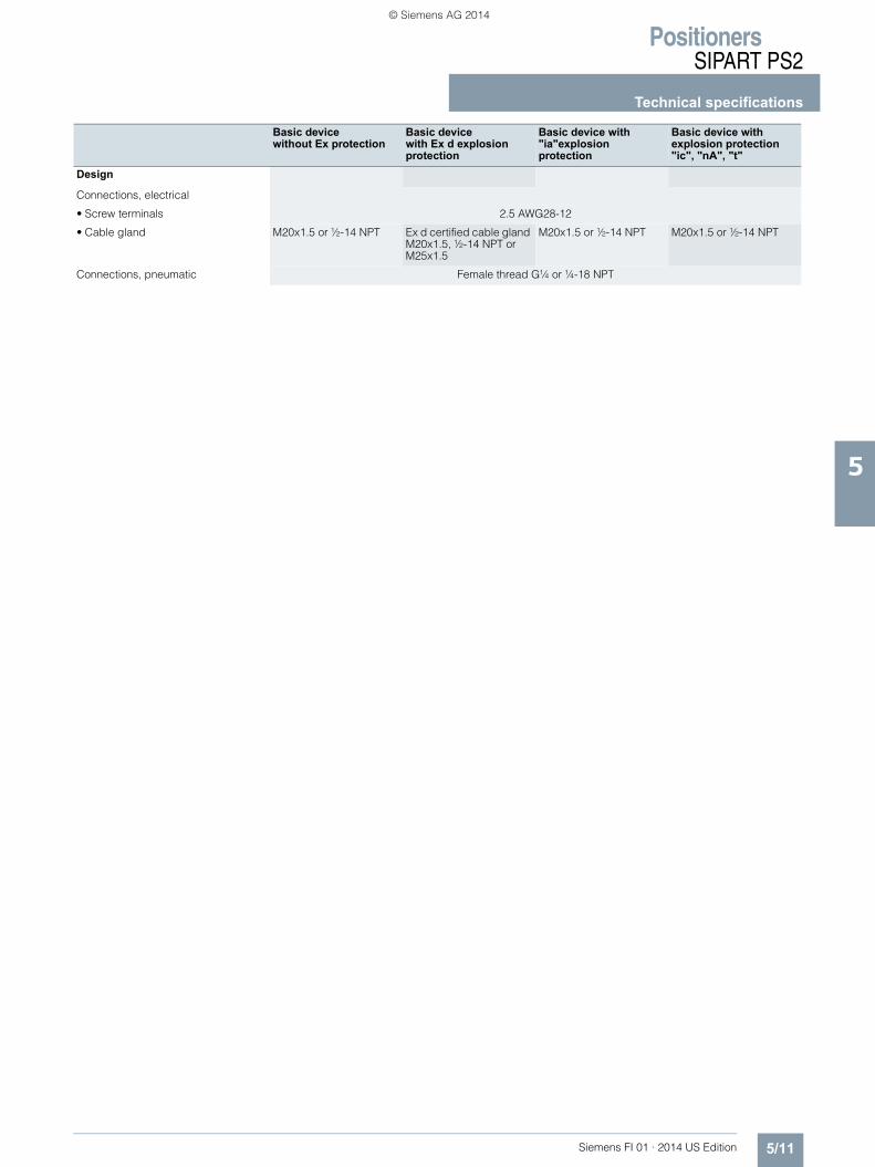
Design
Connections, electrical
• Screw terminals 2.5 AWG28-12
• Cable gland M20x1.5 or ½-14 NPT Ex d certified cable gland M20x1.5, ½-14 NPT or M25x1.5
M20x1.5 or ½-14 NPT M20x1.5 or ½-14 NPT
Connections, pneumatic Female thread G¼ or ¼-18 NPT
Basic device without Ex protection
Basic device with Ex d explosionprotection
Basic device with "ia"explosionprotection
Basic device with explosion protection "ic", "nA", "t"
FI01_2014_us_Kap05.book Seite 11 Mittwoch, 16. April 2014 11:12 11
© Siemens AG 2014

PositionersSIPART PS2
Technical specifications
5/12 Siemens FI 01 · 2014 US Edition
5
SIPART PS2 with PROFIBUS PA/with FOUNDATION Fieldbus
Basic device without Ex protection
Basic device with Ex d explosionprotection
Basic device with "ia"explosionprotection
Basic device with explo-sion protection"ic", "nA", "t"
Electrical specificationsPower supply, bus circuit(terminals 6/7)
Bus-supplied
Bus voltage 9 ... 32 V 9 ... 32 V 9 ... 24 V 9 ... 32 V
For connecting to circuits with thefollowing peak values
• Bus connection with FISCOsupply unit
Ui = 17.5 VIi = 380 mAPi = 5.32 W
"ic":Ui = 17.5 VIi = 570 mA"nA"/"t": Un 32 V
• Bus connection with barrier Ui = 24 VIi = 250 mAPi = 1.2 W
"ic": Ui = 32 V"nA"/"t": Un 32 V
Effective internal capacitance - - Ci = negligible Ci = negligible
Effective internal inductance - - Li = 8 µH "ic": Li = 8 µH
Current consumption 11.5 mA 10 %
Additional error signal 0 mA
Safety shutdown can be activated with coding bridge (terminals 81/82)
electrically isolated from bus circuit and binary input
• Input resistance > 20 k
• Signal state "0" (shutdown active) 0 ... 4.5 V or unconnected
• Signal state "1" (shutdown not active) 13 ... 30 V
For connecting to power supply with the following peak values
Ui = 30 VIi = 100 mAPi = 1 W
"nA":Un 30 VIn 100 mA"ic":Ui = 30 VIi = 100 mA
• Effective Internal capacitance - - Ci = negligibly small Ci = negligibly small
Binary input BE1 for PROFIBUS (termi-nals 9/10); electrically connected to the bus circuit)
Bridged or connection to switching contact. Suitable only for floating contact; max. contact load < 5 µA at 3 V
Electrical isolation
• For basic device without Ex protec-tion and for basic device with Ex d
Electrical isolation between basic device and the input for safety shutdown, as well as the outputs of the option modules
• For basic device Ex "ia" The basic device and the input to the safety shutdown, as well as the outputs of the option modules,are separate, intrinsically safe circuits.
• For basic device Ex "ic", "nA", "t" Electrical isolation between basic device and the input for safety shutdown,as well as the outputs of the option modules
Test voltage 840 V DC, 1 s
DesignConnections, electrical
• Screw terminals 2.5 AWG28-12
• Cable gland M20x1.5 or ½-14 NPT Ex d certified cable gland M20x1.5; ½-14 NPT or M25x1.5
M20x1.5 or ½-14 NPT M20x1.5 or ½-14 NPT
Connections, pneumatic Female thread G¼ or ¼-18 NPT
PROFIBUS PA communicationCommunication Layers 1 and +2 according to PROFIBUS PA, transmission technology according to IEC 61158-2;
slave function; layer 7 (protocol layer) according to PROFIBUS DP,EN 50170 standard with the extended PROFIBUS functions
(all data acyclic, manipulated variable, feedbacks and status also cyclic)
C2 connections Four connections to master class 2 are supported; automatic connection setup 60 s after break in commu-nication
Device profile PROFIBUS PA profile B, version 3.0, more than 150 objects
Response time to master message Typically 10 ms
Device address 126 (when delivered)
PC parameterizing software SIMATIC PDM; supports all device objects. The software is not included in the scope of delivery.
FI01_2014_us_Kap05.book Seite 12 Mittwoch, 16. April 2014 11:12 11
© Siemens AG 2014
PositionersSIPART PS2
Technical specifications
5/13Siemens FI 01 · 2014 US Edition
5
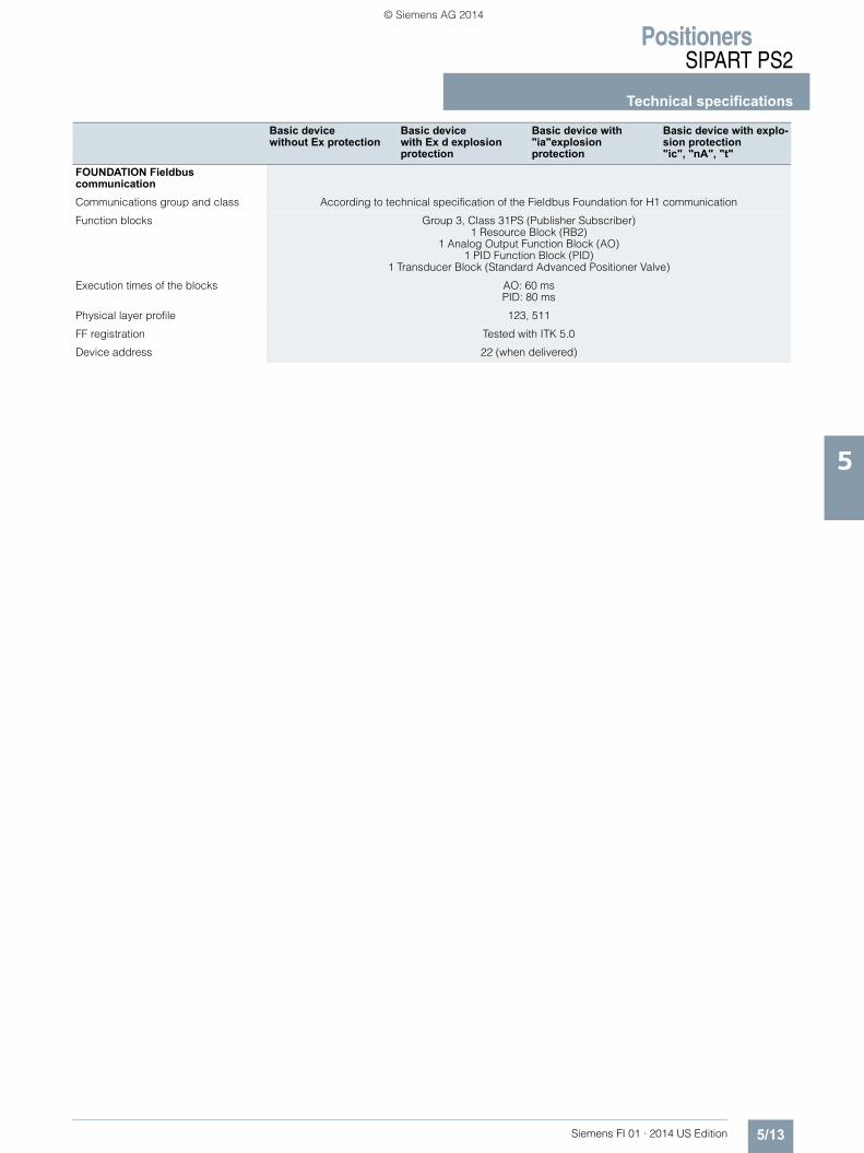
FOUNDATION FieldbuscommunicationCommunications group and class According to technical specification of the Fieldbus Foundation for H1 communication
Function blocks Group 3, Class 31PS (Publisher Subscriber) 1 Resource Block (RB2)
1 Analog Output Function Block (AO) 1 PID Function Block (PID)
1 Transducer Block (Standard Advanced Positioner Valve)
Execution times of the blocks AO: 60 ms PID: 80 ms
Physical layer profile 123, 511
FF registration Tested with ITK 5.0
Device address 22 (when delivered)
Basic device without Ex protection
Basic device with Ex d explosionprotection
Basic device with "ia"explosionprotection
Basic device with explo-sion protection"ic", "nA", "t"
FI01_2014_us_Kap05.book Seite 13 Mittwoch, 16. April 2014 11:12 11
© Siemens AG 2014

PositionersSIPART PS2
Technical specifications
5/14 Siemens FI 01 · 2014 US Edition
5
Option modules
Without Ex protection/with Ex protection Ex d
With explosion protection "ia" With explosion protection "ic", "nA", "t"
Alarm unit 6DR4004-8A 6DR4004-6A 6DR4004-6A3 binary output circuits • Alarm output A1: Terminals 41 and 42
• Alarm output A2: Terminals 51 and 52• Alarm output: Terminals 31 and 32
• Power supply UH 35 V - -
• Signal state
- High (not activated) Conductive, R = 1 k, +3/-1 % *) 2.1 mA 2.1 mA
- Low *) (activated) Blocked, IR < 60 µA 1.2 mA 1.2 mA
*) Low is also the status when the basic device is faulty or is without additional electrical power supply.
*) When used in the flameproof enclo-sure the current consumption must be limited to 10 mA per output.
Switching threshold with supply to EN 60947-5-6:UH = 8.2 V, Ri = 1 k
Switching threshold with supply to EN 60947-5-6: UH = 8.2 V, Ri = 1 k
• For connecting to circuits with the following peak values
- Ui = 15 VIi = 25 mAPi = 64 mW
"ic":Ui = 15 VIi = 25 mA"nA"/"t": Un 15 V
Effective internal capacitance - Ci = 5.2 nF Ci = 5.2 nF
Effective internal inductance - Li = negligibly small Li = negligibly small
1 binary output circuit Binary input BE2: Terminals 11 and 12, terminals 21 and 22 (bridge)
• Electrically connected to the basic device
- Signal state 0 Floating contact, open
- Signal state 1 Floating contact, closed
- Contact load 3 V, 5 A
• Electrically isolated from the basic device
- Signal state 0 4.5 V or open
- Signal state 1 13 V
- Natural resistance 25 k• Static destruction limit 35 V - -
• For connecting to circuits with the following peak values
- Ui = 25.2 V "ic": Ui = 25.2 V"nA"/"t": Un 25.5 V
Effective internal capacitance - Ci = negligibly small Ci = negligibly small
Effective internal inductance - Li = negligibly small Li = negligibly small
Electrical isolation The 3 outputs, the input BE2 and the basic device are electrically isolated from each other
Test voltage 840 V DC, 1 s
Iy module 6DR4004-8J 6DR4004-6J 6DR4004-6JDC output for position feedback
1 current output: Terminals 61 and 62 2-wire connection
Rated signal range 4 ... 20 mA, short-circuit proof
Total operating range 3.6 … 20.5 mA
Power supply UH +12 … +35 V +12 … +30 V +12 … +30 V
External loads RB [k] (UH [V] – 12 V)/I [mA]
Transmission error 0,3 %
Temperature influence effect 0.1 %/10 K ( 0.1 %/18 °F)
Resolution 0,1 %
Residual ripple 1 %
• For connecting to circuits with the following peak values
- Ui = 30 VIi = 100 mAPi = 1 W
"ic":Ui = 30 V, Ii = 100 mA"nA"/"t":Un 30 V, In 100 mAPn 1 W
Effective internal capacitance - Ci = 11 nF Ci = 11 nF
Effective internal inductance - Li = negligibly small Li = negligibly small
Electrical isolation Electrically isolated from the alarm option and safely isolated from the basic device
Test voltage 840 V DC, 1 s
FI01_2014_us_Kap05.book Seite 14 Mittwoch, 16. April 2014 11:12 11
© Siemens AG 2014

PositionersSIPART PS2
Technical specifications
5/15Siemens FI 01 · 2014 US Edition
5
Without Ex protection With explosion protection "ia" With explosion protection "ic", "nA", "t"
SIA moduleLimit transmitter with slot-typeinitiators and alarm output
6DR4004-8G 6DR4004-6G 6DR4004-6G
2 slot-type initiators • Binary output (limit transmitter) A1: Terminals 41 and 42• Binary output (limit transmitter) A2: Terminals 51 and 52
• Connection 2-wire system to EN 60947-5-6 (NAMUR), for switching amplifier to be connected on load side
• Signal state Low (activated) < 1.2 mA
• 2 slot-type initiators Type SJ2-SN
• Function NC (normally closed)
• Connecting to circuits with thefollowing peak values
Rated voltage 8 V currentconsumption: 3 mA (limit value not responded), 1 mA (limit value responded)
Ui = 15 VIi = 25 mAPi = 64 mW
"ic":Ui = 15 VIi = 25 mA"nA":Un 15 VPn 64 mW
Effective internal capacitance - Ci = 41 nF Ci = 41 nF
Effective internal inductance - Li = 100 µH Li = 100 µH
1 alarm output Binary output: Terminals 31 and 32
• Connection On switching amplifier according to EN 60947-5-6: (NAMUR), UH = 8.2 V, Ri = 1 k).
• Signal state High (not activated)
R = 1.1 k > 2.1 mA > 2.1 mA
• Signal state Low (activated) R = 10 k < 1.2 mA < 1.2 mA
• Power supply UH UH 35 V DCI 20 mA
- -
• Connecting to circuits with thefollowing peak values
- Ui = 15 VIi = 25 mAPi = 64 mW
"ic":Ui = 15 VIi = 25 mA"nA":Un 15 VPn 64 mW
Effective internal capacitance - Ci = 5.2 nF Ci = 5.2 nF
Effective internal inductance - Li = negligibly small Li = negligibly small
Electrical isolation The 3 outputs are electrically isolated from the basic device.
Test voltage 840 V DC, 1 s
FI01_2014_us_Kap05.book Seite 15 Mittwoch, 16. April 2014 11:12 11
© Siemens AG 2014

PositionersSIPART PS2
Technical specifications
5/16 Siemens FI 01 · 2014 US Edition
5
Mechanical limit switch module 6DR4004-8K 6DR4004-6K 6DR4004-6K
Limit transmitter with mechanical switching contacts
2 limit value contacts • Binary output A1: Terminals 41 and 42• Binary output A2: Terminals 51 and 52
• Max. switching current AC/DC 4 A - -
• Connecting to circuits with thefollowing peak values
- Ui = 30 VIi = 100 mAPi = 750 mW
"ic":Ui = 30 VIi = 100 mA"nA":Un 15 V
Effective internal capacitance - Ci = negligibly small Ci = negligibly small
Effective internal inductance - Li = negligibly small Li = negligibly small
• Max. switching voltage AC/DC 250 V/24 V 30 V DC 30 V DC
1 alarm output • Binary output: Terminals 31 and 32
• Connection On switching amplifier according to EN 60947-5-6: (NAMUR),UH = 8.2 V, Ri = 1 k).
-
• Signal state High (not activated)
R = 1.1 k > 2.1 mA > 2.1 mA
• Signal state Low (activated) R = 10 k < 1.2 mA < 1.2 mA
• Auxiliary power UH 35 V DCI 20 mA
- -
• Connecting to circuits with thefollowing peak values
- Ui = 15 VIi = 25 mAPi = 64 mW
"ic":Ui = 15 VIi = 25 mA
Effective internal capacitance - Ci = 5.2 nF Ci = 5.2 nF
Effective internal inductance - Li = negligibly small Li = negligibly small
Electrical isolation The 3 outputs are electrically isolated from the basic device
Test voltage 3 150 V DC, 2 s
Rated conditions altitude Max. 2 000 m NNAt altitudes over 2 000 m NN,use a suitable power supply
- -
EMC filter module EMC filter module type C73451-A430-L8 is required for NCS sensor or an external potentiometer. External position sensor (potentiometer or NCS; as option) with the following peak values
Resistance of externalpotentiometer
10 k
Peak values when suppled via the PROFIBUS basic device
- Uo = 5 VIo = 75 mA statischIo = 160 mA kurzfristigPo = 120 mW
Uo = 5 VIo = 75 mA-Po = 120 mW
Peak values when suppled via other basic devices
- Uo = 5 VIo = 100 mAPo = 33 mWCo = 1 FLo = 1 mH
Uo = 5 VIo = 75 mAPo = 120 mWCo = 1 FLo = 1 mH
Electrical isolation Electrically connected to the basic device
Test voltage 840 V DC, 1 s
Without Ex protection With explosion protection "ia" With explosion protection "ic", "nA", "t"
FI01_2014_us_Kap05.book Seite 16 Mittwoch, 16. April 2014 11:12 11
© Siemens AG 2014

PositionersSIPART PS2
Technical specifications
5/17Siemens FI 01 · 2014 US Edition
5
NCS sensorPosition range
• Linear actuator 6DR4004-.N.20 3 ... 14 mm (0.12 ... 0.55")
• Linear actuator 6DR4004-.N.30 10 ... 130 mm (0.39 ... 5.12"); up to 200 mm (7.87") on request
• Part-turn actuator 30° ... 100°
Linearity (after correction bypositioner)
• Linear actuator 1 %
• Part-turn actuator 1 %
Hysteresis 0,2 %
Continuous working temperature -40 °C ... +90 °C (-40 °F ... +194 °F)
- -
Climatic class Nach DIN EN 60721-3-4
• Lagerung 1K5, but -40 ... +90 °C (1K5, but -40 ... +176 °F)
• Transport 2K4, but -40 ... +90 °C (2K4, but -40 ... +176 °F)
Vibration resistance
• Harmonic oscillations (sine-wave) according to EN 60068-2-6/05.96
7 mm (0.28"), 5 ... 54 Hz; 500 m/s² (1640 ft/s²), 80 ... 200 Hz
Degree of protection of enclosure IP68 according ot IEC EN 60529; NEMA 4X / Encl. Type 4X
• Connecting to circuits with thefollowing peak values
- Ui = 5 VIi = 160 mAPi = 120 mW
"ic"/"nA": Ui = 5 V
Effective internal capacitance - Ci = 180 nF Ci = 180 nF
Effective internal inductance - Li = 922 µH Li = 922 µH
Explosion protection according to ATEX/IECEx
- Intrinsic safety "ia":II 2 G Ex ia IIC T6/T4 Gb
Intrinsic safety "ic":II 3 G Ex ic IIC T6/T4 GcNon-sparking "nA":II 3 G Ex nA IIC T6/T4 Gc
Explosion protection according to FM
- Intrinsic safety "ia":IS, Class I, Divison 1, ABCDIS, Class I, Zone 1, AEx ib, IIC
Non-sparking, "nA":NI, Class I, Divison 2, ABCDNI, Class I, Zone 2, AEx nA, IIC
Permissible ambient temperature
• ATEX/IECEx - T4: -40 ... +90 °C (-40 ... +194 °F)T6: -40 ... +70 °C (-40 ... +158 °F)
• FM - T4: -40 ... +85 °C (-40 ... +185 °F)T6: -40 ... +70 °C (-40 ... +158 °F)
Without Ex protection With explosion protection "ia" With explosion protection "ic", "nA", "t"
FI01_2014_us_Kap05.book Seite 17 Mittwoch, 16. April 2014 11:12 11
© Siemens AG 2014

PositionersSIPART PS2Selection and Ordering dataSIPART PS2
5/18 Siemens FI 01 · 2014 US Edition
5
Selection and ordering data Article No. Order code
SIPART PS2 electropneumatic positioner in enclosure made of Makrolon, aluminum and stain-less steel
6 D R 5
777 - 0 7777 - 77A7 777
Version2-wire (4 to 20 mA)• Without HART 0• With HART, not explosion-
protected1
2-, 3-, 4-wire (0/4 to 20 mA)• With HART, explosion-protected 2• Without HART, not explosion
-protected3
PROFIBUS PA connection 5FOUNDATION Fieldbus connection 6
For actuatorSingle-acting 1Double-acting 2
EnclosureMakrolon 0Aluminum; only single-acting 1 1Stainless steel (without window) 2
Explosion protectionWithout N
In type of protection (ATEX/IECEx/FM/CSA)• intrinsic safety
E
With protection type (ATEX/IECEx)1)
• Non-sparking• Dust protection via enclosure
D
With protection type (ATEX/IECEx/FM)2)
• Intrinsic safety• Non-sparking
F
With protection type (ATEX/IECEx/FM)2)
• Non-sparking
G
With protection type (ATEX/IECEx)1)
• Intrinsic safety• Non-sparking• Dust protection via enclosure
K
Connection threadelectrical/pneumaticWith cable gland M20x1.5/G¼ GWith cable gland ½-14 NPT / ¼-18 NPT
N
With cable gland M20x1.5/¼-18 NPT
M
With cable gland ½-14 NPT / G¼
P
With plug M12 / G¼3) RWith plug M12 / ¼-18 NPT3) S
We can offer shorter delivery times for configurations identified as part of the Quick Ship Program. For details see page 9/5 in the appendix.
Limit monitorInstalled, incl. 2nd cable glandWithout 0Alarm module; electronic (6DR4004-.A) 1SIA module; slot-type initiators(6DR4004-.G)
2
Mechanical limit switch module (mechanical switching contacts (6DR4004-.K))
3
Option modulesInstalled, incl. 2nd cable glandWithout 0Iy module for position feedback sig-nal (4 ... 20 mA) (6DR4004-.J)
1
EMC filter module for external posi-tion sensor in the SIPART PS2 enclo-sure (C73451-A430-D23), NCS sensor 6DR4004-.N..0 and external position sensing with non-Siemens potentiometer
2
Iy module and EMC filter module for external position sensor
3
Customer-specific designWithout 0
Brief instructionsGerman/English AFrench/Spanish/Italian B
Mounted pressure gauge blockWithout 0
Gauge made of plastic caseBlock made of aluminum, single-acting G¼, scaled in MPa and bar
1
Block made of aluminum, double-acting G¼, scaled in MPa and bar
2
Block made of aluminum, single-acting ¼-18 NPT, scaled in MPa and psi
3
Block made of aluminum, single-acting ¼-18 NPT, scaled in MPa and psi
4
Gauge made of ss caseblock made of aluminium, single-acting G¼, scaled in MPa, bar, psi
9 R 1 A
Block made of aluminium, double-acting G¼, scaled in MPa, bar, psi
9 R 2 A
Block made of aluminium, single-acting ¼-18 NPT, scaled in MPa, bar, psi
9 R 1 B
Block made of aluminium, double-acting ¼-18 NPT, scaled in MPa, bar, psi
9 R 2 B
Gauge made of stainless steel 316Block made of stainless steel 316, single-acting G¼, scaled in MPa, bar, psi
9 R 1 C
Block made of stainless steel 316, double-acting G¼, scaled in MPa, bar, psi
9 R 2 C
Block made of stainless steel 316, single-acting ¼-18 NPT, scaled in MPa, bar, psi
9 R 1 D
Block made of stainless steel 316, double-acting ¼-18 NPT, scaled in MPa, bar, psi
9 R 2 D
We can offer shorter delivery times for configurations identified as part of the Quick Ship Program. For details see page 9/5 in the appendix.
Selection and ordering data Article No. Order code
SIPART PS2 electropneumatic positioner in enclosure made of Makrolon, aluminum and stain-less steel
6 D R 5
777 - 0 7777 - 77A7 777
FI01_2014_us_Kap05.book Seite 18 Mittwoch, 16. April 2014 11:12 11
© Siemens AG 2014

PositionersSIPART PS2
Selection and Ordering dataSIPART PS2
5/19Siemens FI 01 · 2014 US Edition
5
1) Enclosure: aluminum or stainless steel, each without inspection window in the cover
2) Enclosure: aluminum or Makrolon, each with inspection window in the cover Max. impact energy 1 Joule for enclosure with inspection window 6DR5..0 und 6DR5..1.
3) Only with version PROFIBUS PA 6DR55.. and FOUNDATION Fieldbus 6DR56..Only with type of protection dust protection by enclosure, 6DR5...-0D... and 6DR5...-0K..
Further designs Order code
Add "-Z" to Article No. and specify Order Code.
Pneumatic terminal block made of stainless steel 316For device versions in Makrolon enclosure
K18
Version with stainless steel sound absorbersStandard with stainless steel enclo-sure
A40
TAG plate made of stainless steel, 3-lineText line 1: Plain text from Y17Text line 2: Plain text from Y15Text line 3: Plain text from Y16
A20
Text line 1 (Max. 16 characters) Y17Text line 2 (Max. 24 characters) Y15Text line 3 (Max. 8 characters) Y16Preset bus addressSpecify in plain text: Y25: ........(only for 6DR55.. and 6DR56..)
Y25
Functional safety (SIL 2) only for 6DR5.1. (single-acting position-ers)Device suitable for use according to IEC 61508 and IEC 61511
C20
OPOS adapter with interface VDI/VDE 3847blanketing, not for flameproof alumi-num enclosure
K20
Customer-specific diagnosticsSpecify in plain text: Y30: ........
Y30
Selection and ordering data Article No. Order code
SIPART PS2 electropneumatic positioner in enclosure made of Makrolon, aluminum and stain-less steel
6 D R 5
777 - 0 7777 - 77A7 777
FI01_2014_us_Kap05.book Seite 19 Mittwoch, 16. April 2014 11:12 11
© Siemens AG 2014

PositionersSIPART PS2Selection and Ordering dataSIPART PS2
5/20 Siemens FI 01 · 2014 US Edition
5
Selection and ordering data Article No. Order code
SIPART PS2 electropneumatic positioner, in flameproof alumi-num enclosure, without cable gland
6 D R 5
77 5 - 0 E777 - 77A7 777
Version2-wire (4 to 20 mA)• Without HART 0• With HART 12-, 3-, 4-wire (0/4 to 20 mA)• With HART 2• Without HART 3PROFIBUS PA connection 5FOUNDATION Fieldbus connection 6
For actuatorSingle-acting 1Double-acting 2
Connection threadelectrical/pneumaticM20 x 1.5 / G¼ G½-14 NPT / ¼-18 NPT NM20 x 1.5 / ¼-18 NPT M½-14 NPT / G¼ PM25x1.5 / G¼ Q
Limit monitorBuilt-inWithout 0Alarm module; electronic(6DR4004-8A)
1
Option modulesBuilt-inWithout 0Iy module for position feedback signal (4 ... 20 mA) (6DR4004-8J)
1
EMC filter module for external position sensor
2
Iy module and EMC filter module for external position sensor
3
Customer-specific designWithout 0
Brief instructionsGerman/English AFrench/Spanish/Italian B
Mounted pressure gauge blockWithout 0
Gauge made of plastic caseBlock made of aluminium, single-acting G¼, scaled in MPa and bar
1
Block made of aluminium, double-acting G¼, scaled in MPa and bar
2
Block made of aluminium, single-acting, ¼-18 NPT, scaled in MPa and psi
3
Block made of aluminium, double-acting, ¼-18 NPT, scaled in MPa and psi
4
Gauge made of ss caseblock made of aluminium, single-acting G¼, scaled in MPa, bar, psi
9 R 1 A
Block made of aluminium, double-acting G¼, scaled in MPa, bar, psi
9 R 2 A
Block made of aluminium, single-acting ¼-18 NPT, scaled in MPa, bar, psi
9 R 1 B
Block made of aluminium, double-acting ¼-18 NPT, scaled in MPa, bar, psi
9 R 2 B
Gauge made of stainless steel 316Block made of stainless steel 316, single-acting G¼, scaled in MPa, bar, psi
9 R 1 C
Block made of stainless steel 316, double-acting G¼, scaled in MPa, bar, psi
9 R 2 C
Block made of stainless steel 316, single-acting ¼-18 NPT, scaled in MPa, bar, psi
9 R 1 D
Block made of stainless steel 316, double-acting ¼-18 NPT, scaled in MPa, bar, psi
9 R 2 D
Further designs Order code
Add "-Z" to Article No. and specify Order Code.
TAG plate made of stainless steel, 3-lineText line 1: Plain text from Y17Text line 2: Plain text from Y15Text line 3: Plain text from Y16
A20
Text line 1 (Max. 16 characters) Y17Text line 2 (Max. 24 characters) Y15Text line 3 (Max. 8 characters) Y16Preset bus addressSpecify in plain text: Y25: ........only for 6DR55.. and 6DR56..)
Y25
Functional safety (SIL 2) only for 6DR5.1. (single-action position-ers)Device suitable for use according to IEC 61508 and IEC 61511
C20
Selection and ordering data Article No. Order code
SIPART PS2 electropneumatic positioner, in flameproof alumi-num enclosure, without cable gland
6 D R 5
77 5 - 0 E777 - 77A7 777
FI01_2014_us_Kap05.book Seite 20 Mittwoch, 16. April 2014 11:12 11
© Siemens AG 2014

PositionersSIPART PS2
Selection and Ordering dataAccessories/Spare parts
5/21Siemens FI 01 · 2014 US Edition
5
Selection and ordering data Article No.
Selection and ordering data Article No.
Accessoriesly module for position feedback signal(4 ... 20 mA)
• Without explosion protection 6DR4004-8J• With explosion protection ATEX/IECEx 6DR4004-6J• With explosion protection FM/CSA 6DR4004-7JAlarm unit for 3 alarm outputs and 1 binary input (functionality: 2 limit monitors, 1 fault alarm, 1 binary input)
• Without explosion protection 6DR4004-8A• With explosion protection ATEX/IECEx 6DR4004-6A• With explosion protection FM/CSA 6DR4004-7ASIA module (slot-type initiator alarm unit, not for Ex d version)
• Without explosion protection 6DR4004-8G• With ATEX/IECEx and FM/CSA explosion pro-
tection6DR4004-6G
Mechanical limit switch module (with mechanical ground contacts, not for Ex d version)
• Without explosion protection 6DR4004-8K• With explosion protection 6DR4004-6KEMC filter module for connection of external position sensor (10 k) or NCS sensor
C73451-A430-D23
Selection and ordering data Article No.
Accessories
NCS sensorfor non-contacting detection of position (not for Ex d version)
6 D R 4 0 0 4 - 7N77 0
Explosion protectionNot explosion-proof 8With protection type (ATEX/IECEx/FM)• Intrinsic safety• Non-sparking
6
Cable length6 m (19.68 ft) N20 m (65.67 ft) P40 m (131,23 ft) R
Actuator typeFor part-turn actuators, glass fiber-rein-forced polyester magnet holders1)
1) Fitted with mounting console, available for order separately as accessory.
1
For linear actuators up to 14 mm (0.55 inch)2)
2) Mounted without NAMUR interface, individual mounting solution. Or mounted with NAMUR interface. Only a NAMUR mounting bracket can be used as mounting base (order separately as accessory).
2
For linear actuators > 14 ... 130 mm (0.55 ... 5.12 inch)3)
3) Mounted with NAMUR interface. Article No. either 6DR4004-8V or 6DR4004-8V + 6DR4004-8L depending on stroke range. Or mounted without NAMUR interface, individual mounting solution. Article No. 6DR4004-8VK or 6DR4004-8VL can be used as individual mounting solution depending on the stroke range.
3
For part-turn actuators, anodized aluminum magnet holders
4
External position detection system (with explosion protection to ATEX/IECEx) for separate mounting of position sensor and con-troller unit (not for Ex d version), comprising SIPART PS2 Makrolon enclosure with integral potentiometer and sliding clutch (without elec-tronics and valve block)The EMC filter module is additionally required for the controller unit. (separate ordering item, see above).
C73451-A430-D78
Gauge block with2 gauges made of plastic, block made of aluminium, single-acting G¼, scaled in MPa and bar
6DR4004-1M
3 gauges made of plastic, block made of aluminium, double-acting G¼, scaled in MPa and bar
6DR4004-2M
2 gauges made of plastic, block made of aluminium, single-acting ¼-18 NPT, scaled in MPa and psi
6DR4004-1MN
3 gauges made of plastic, block made of aluminium, double-acting ¼-18 NPT, scaled in MPa and psi
6DR4004-2MN
2 gauges made of ss caseBlock made of aluminum, single-acting G¼, scaled in MPa, bar, psi
6DR4004-1P
3 gauges made of ss caseBlock made of aluminum, double-acting G¼, scaled in Mpa, bar, psi
6DR4004-2P
2 gauges made of ss caseBlock made of aluminum, single-acting ¼-18 NPT, scaled in MPa, bar, psi
6DR4004-1PN
3 gauges made of ss caseBlock made of aluminum, double-acting ¼-18 NPT, scaled in MPa, bar, psi
6DR4004-2PN
2 gauges made of stainless steel 316Block made of stainless steel 316, single-acting G¼, scaled in MPa, bar, psi
6DR4004-1Q
3 gauges made of stainless steel 316Block made of stainless steel 316, double-acting G¼, scaled in MPa, bar, psi
6DR4004-2Q
2 gauges made of stainless steel 316Block made of stainless steel 316, single-acting ¼-18 NPT, scaled in MPa, bar, psi
6DR4004-1QN
3 gauges made of stainless steel 316Block made of stainless steel 316, double-acting ¼-18 NPT, scaled in MP, bar, psi
6DR4004-2QN
Pneumatic terminal block made ofstainless steel 316 to replace the pneumatic terminal block made of aluminium for SIPART PS2 with Makrolon enclosure
Single-acting with G¼ 6DR4004-1RDouble-acting with G¼ 6DR4004-2RSingle-acting with ¼-18 NPT 6DR4004-1RNDouble-acting with ¼-18 NPT 6DR4004-2RNMounting kit for NAMUR part-turn actuators(VDI/VDE 3845, with plastic coupling wheel, without mounting console)
6DR4004-8D
(VDI/VDE 3845, with stainless steel coupling, without mounting console)
TGX:16300-1556
The following mounting consoles can be used with the NAMUR part-turn actuator mounting kit 6DR4004-8D.Size W x L x H (H = height of shaft butt)
• 30 x 80 x 20 mm TGX:16152-105• 30 x 80 x 30 mm TGX:16300-147• 30 x 130 x 30 mm TGX:16300-149• 30 x 130 x 50 mm TGX:16300-151
FI01_2014_us_Kap05.book Seite 21 Mittwoch, 16. April 2014 11:12 11
© Siemens AG 2014

PositionersSIPART PS2Selection and Ordering dataAccessories/Spare parts
5/22 Siemens FI 01 · 2014 US Edition
5
1) Only together with 6DR4004-8S and 6DR4004-1M.
Note:
All the above-mentioned manuals are included on DVD and can be downloaded from www.siemens.de/sipartps2.
Scope of delivery for positioner• 1 SIPART PS2 positioner as ordered• 1 DVD with the complete documentation for all versions and
accessories• Short manual "SIPART PS2 - Configuration At a Glance"
Selection and ordering data Article No.
Mounting kit for other part-turn actuatorsThe following mounting consoles can be used together with the NAMUR part-turn actuator mounting kit 6DR4004-8D.
• SPX (DEZURIK) Power Rac, sizes R1, R1A, R2 and R2A
TGX:16152-328
• Masoneilan Camflex II TGX:16152-350• Fisher 1051/1052/1061, sizes 30, 40, 60 to 70 TGX:16152-364• Fisher 1051/1052, size 33 TGX:16152-348Note:See the Siemens or the interactive price book for a complete listing of over 200 rotary and linear attachment kits.
Mounting kit for NAMUR linear actuators• NAMUR linear actuator mounting kit with short
lever 2 ... 35 mm (0.08 ... 1.38 inch)6DR4004-8V
• Long lever for travels from 35 ... 130 mm (1.38 ... 5.12 inch)
6DR4004-8L
• Reduced mounting kit (like 6DR4004-8V but without fixing angle and U-bracket), with short lever with up to 35 mm travel (1.38 inch)
6DR4004-8VK
• Reduced mounting kit (like 6DR4004-8V but without fixing angle and U-bracket), with long lever with > 35 mm travel (1.38 inch)
6DR4004-8VL
• Roll and disk made of stainless steel 316 for replacement of the Teflon roll and aluminum disk in the 6DR4004-8, -8VK and -8VL mounting kits for NAMUR linear actuators
6DR4004-3N
• Two terminal blocks made of stainless steel 316 for replacement of the aluminum terminal blocks in the 6DR4004-8V, -8VK and -8VL mounting kits for NAMUR linear actuators
6DR4004-3M
Note:See the Siemens or the interactive price book for a complete listing of over 200 rotary and linear attachment kits.
Mounting kit for other linear actuators • Retrofitting kit for Moore series 72 and 750 valve
positionersTGX:16152-117
• Masoneilan type 87/88 TGX:16152-620• Fisher type 657/667, size 30 to 80 TGX:16152-110• Samson actuator type 3277
(yoke dimension (H5) = 101 mm2
(integrated connection without tube), not for Ex d
6DR4004-8S
Note:See the Siemens or the interactive price book for a complete listing of over 200 rotary and linear attachment kits.
OPOS Interface according to VDI/VDE 3847• OPOS adapter with interface VDI/VDE 3847,
blanketing, not for flameproof aluminum enclo-sure
6DR4004-5PA
• OPOS/NAMUR mounting kit with short lever (complete), base plate, rail, mounting parts
6DR4004-5PL
Connection block, for safety solenoid valve with extended mounting flange to NAMUR
• For mounting to IEC 534-6 6DR4004-1B• For SAMSON actuator (integrated mounting)
see above6DR4004-1C1)
Pipe mountingMounting bracket for pipe mounting of the SIPART PS2 positioner (e. g. when using the NCS sensor)
TGX:16152-336
Additional actuator components can be found at the following Internet address: www.siemens.de/sipartps2Customer-specific mounting kits available on request.
Documentation (see notes below)Operating Instructions
• SIPART PS2 HART German A5E00074630• SIPART PS2 HART English A5E00074631• SIPART PS2 PROFIBUS PA German A5E00127924• SIPART PS2 PROFIBUS PA English A5E00127926• SIPART PS2 FOUNDATION Fieldbus German A5E00214568• SIPART PS2 FOUNDATION Fieldbus English A5E00214569SIPART PS2 Compact Instruction Manual
• English, French, German, Spanish, Italian, Dutch
A5E03436620
• English, Estonian, Latvian, Lithuanian, Polish, Romanian
A5E03436655
• English, Bulgarian, Czech, Finnish, Slovakian, Slovenian
A5E03436664
• English, Danish, Greek, Portuguese, Swedish, Hungarian
A5E03436683
Operating Instructions for NCS Sensor
• German/English/French/Spanish/Italian A5E00097485SIPART PS2 device documentation
• DVD with complete documentation for all device versions
A5E00214567
SITRANS I200 output isolator HART (see SITRANS I supply units and isolation ampli-fiers") with
• 24 V DC power supply 7NG4131-0AA00HART modem for connecting to PC or laptop
• with RS232 interface 7MF4997-1DA• with USB interface 7MF4997-1DB
NCS-Sensor spare parts
Magnet holder made of fiberglass-reinforced polyester including magnet for non-contacting position detection for part-turn actuators
A5E00078030
Magnet holder made of anodized aluminum including magnet for non-contacting position detection for part-turn actuators
A5E00524070
FI01_2014_us_Kap05.book Seite 22 Mittwoch, 16. April 2014 11:12 11
© Siemens AG 2014

PositionersSIPART PS2
Dimensional drawings
5/23Siemens FI 01 · 2014 US Edition
5
Dimensional drawings
Makrolon and stainless steel enclosure (top), aluminum enclosure (center), Makrolon, stainless steel and aluminum enclosure (bottom), dimensions in mm (inch)
48(1
.89)
Stainless steel version, values:1) 74 (2.91)2) 99 (3.89)3) 98 (3.86)4) Dimension at electrical connection ½-14 NPT (with adapter) 203 mm (8")
M8, 9 (0.35) deep9 (0.35) deep
M8, 9 (0.35) deep
96.6
(3.8
0)3)
M12 x 1.5
65(2
.56)
60(2.36)
2(0
.08)
23(0.91)
58(2.28)
1824)
(7.17)
7(0
.28)
29 (1.1
4)
95 (3
.74)
1)
72 (2
.84)
2)(1.1
6)(1
.16)
(0.44)
Y1
Y1
Y2
PZ 29.5
29.5
11,2
50 (1.97), 4 x M6
Y1
50 (1.97), 4 x M69 (0.35)
Y1
PZ
6.5(0.26)
29.5
(1.1
6)
11.2(0.44)
14(0
.55)7
(0.2
8)34
.5(1
.36)
27.5
(1.0
8)
29.5
(1.1
6)
2(0
.08)
58(2.28)
182(7.17)
29 (1.1
4) 84(3
.31)
12(0.47)
59(2
.32)65(2
.56)
E
37(1
.46)33
23(0.91)
(1.30)
G¼"
FI01_2014_us_Kap05.book Seite 23 Mittwoch, 16. April 2014 11:12 11
© Siemens AG 2014

PositionersSIPART PS2
Dimensional drawings
5/24 Siemens FI 01 · 2014 US Edition
5
Flameproof enclosure left, dimensions in mm (inch)
Mounting onto part-turn actuators; mounting consoles (scope of delivery of actuator manufacturer), extract from VDI/VDE 3845, dimensions in mm (inch)
1) Connection 238/Y2 only for double-acting version
7.75
(0.3
1)
33.5
(1.3
2)33
.5(1
.32)
25.7(1.00)
87.2(3.43)
14.3(0.56)
4.5
(0.1
8)19
.25
(0.7
6)10
.25
(0.4
0)
7.5(0.30)
3.5(0.14)
233.3(9.19)128.5
(5.06)
158.
5(6
.24)
82.5
(3.2
5)
Ø13
6.5
(5.3
7)
235.3(9.26)
all air connectionsG1/4 or 1/4-NPT
1)60
(2.36) Ø50
(1.97)
65(2
.56)
23(0.91)
43(1
.69)
5 (0.2)
34(1
.34)
25(0
.98) 12
(0.47)
7(0
.28)
Ø8 (0.31) h9
Mounting level of positioner
Part-turn actuator
Mounting plate
F05-Lkr.-Ø50 (1.97)
6.5
(0.2
6)
4+0.1 (0.16+0.04)
25 (0
.98)
> 4 (0.16)
a = 4 (0.16)b = 12 (0.47)
Ø35 (1.38)
a
b
M6
FI01_2014_us_Kap05.book Seite 24 Mittwoch, 16. April 2014 11:12 11
© Siemens AG 2014

PositionersSIPART PS2
Schematics
5/25Siemens FI 01 · 2014 US Edition
5
SchematicsElectric connection of 2-wire devices (6DR50.. and 6DR51..)Devices of types 6DR50.. and 6DR51.. are operated in a 2-wire system.
SIPART PS2 electropneumatic positioner, input circuit for 6DR50.. and 6DR51..
Electric connection of PROFIBUS PA device (6DR55..) and FOUNDATION Fieldbus device (6DR56..)
SIPART PS2 PA and SIPART PS2 FF electropneumatic positioner, input circuit for 6DR55.. and 6DR56..
Electric connection of 2-, 3- and 4-wire device(6DR52.. and 6DR53..)Devices of types 6DR52.. and 6DR53.. can be operated in a 2-, 3- and 4-wire system.
SIPART PS2 electropneumatic positioner, example of connection for com-munication through HART for 6DR52..
SIPART PS2 electropneumatic positioner, input circuits for 6DR52.. and 6DR53..
Two-wire system 4 ... 20 mA
BE1
78910
+
–J
6
PROFIBUS PA and FOUNDATION Fieldbus connection
Input for safety shutdown (activated using coding jumper)1)
≤ 30 V
≤ 24 V
+–
BE1
7
910
+
–
6
1)8182
HART modem
Only required with current sources not conforming to HART
PC/Laptop
R ≥ 250 Ω if req. 1)
1)
2345
+–
Ily = 4 ... 20 mA
678
lW-
lH+
1) Jumper between 5 and 7 only for three-wire system
Two-wire system
Three-/Four-wire system
2345
+
–
J
678910
4 ... 20 mA
0/4 ... 20 mA
2345
+
–
678910
18 ... 30 V
J
+
–
BE1
BE1
1)
FI01_2014_us_Kap05.book Seite 25 Mittwoch, 16. April 2014 11:12 11
© Siemens AG 2014

PositionersSIPART PS2
Mounting kit
5/26 Siemens FI 01 · 2014 US Edition
5
Mounting kit for NAMUR linear actuators• 1 mounting bracket• 2 mounting prisms• 1 U-bracket• 1 lever arm with adjustable pick-up roll• 2 U-bolts• Various screws and lock washers
Mounting of SIPART PS2 on linear actuators Mounting of SIPART PS2 in flameproof aluminium enclosure on linear ac-tuators
FI01_2014_us_Kap05.book Seite 26 Mittwoch, 16. April 2014 11:12 11
© Siemens AG 2014

PositionersSIPART PS2
Mounting kit
5/27Siemens FI 01 · 2014 US Edition
5
Mounting kit for NAMUR part-turn actuators• 1 coupling wheel• 1 driver pin• 8 scales• 1 pointer• Various screws and lock washers
Caution: The mounting consoles and the screws for mounting onto the part-turn actuator are not included in the scope of delivery and must be provided by the customer (see "Technical specifications")
Mounting of SIPART PS2 on part-turn actuators Mounting of SIPART PS2 in flameproof aluminium enclosure on part-turn actuators
More information
Special versionsOn request
FI01_2014_us_Kap05.book Seite 27 Mittwoch, 16. April 2014 11:12 11
© Siemens AG 2014

Positioners
Notes
5/28 Siemens FI 01 · 2014 US Edition
5
FI01_2014_us_Kap05.book Seite 28 Mittwoch, 16. April 2014 11:12 11
© Siemens AG 2014
Related Documents