COVER SHEET This is the author version of article published as: Wang, Charles and Walker, Rodney A. and Enderle, Werner (2002) Single Antenna Attitude Determination for FedSat. In Proceedings Institute of Navigation GPS-02. Copyright 2002 (please consult author) Accessed from http://eprints.qut.edu.au

Welcome message from author
This document is posted to help you gain knowledge. Please leave a comment to let me know what you think about it! Share it to your friends and learn new things together.
Transcript

COVER SHEET
This is the author version of article published as: Wang, Charles and Walker, Rodney A. and Enderle, Werner (2002) Single Antenna Attitude Determination for FedSat. In Proceedings Institute of Navigation GPS-02. Copyright 2002 (please consult author) Accessed from http://eprints.qut.edu.au

Single Antenna Attitude Determination for FedSat
Mr Charles Wang, Cooperative Research Centre for Satellite Systems, Brisbane, Australia
Dr Rodney A. Walker, Cooperative Research Centre for Satellite Systems, Brisbane, Australia Associate Professor Werner Enderle, Cooperative Research Centre for Satellite Systems, Brisbane,
Australia Biography Mr Charles Wang completed his undergraduate study at Queensland University of Technology with Bachelor of Aerospace Avionic Engineering in Oct 2000. During year 2001, Charles Wang has undertaken further study in Master of Engineering Science (Communication and Computing) at QUT and graduated with first class honours. From Aug 2002, Charles Wang started the Masters of Engineering by research at the Cooperative Research Centre for Satellite Systems (CRCSS) in the Faculty of Built Environment and Engineering at QUT. He is working in the area of “Global Positioning System Attitude Determination Using Signal to Noise Ratio from Single Antenna” under the supervision of Dr. Rodney Walker and Associate Professor Werner Enderle. Dr Rodney Walker is currently an avionics lecturer at the Queensland University of Technology. He is also the FedSat GPS payload manager in the CRC for Satellite systems FedSat mission working closely with NASA’s GPS Development Team at JPL. He has 10 years experience in the field of Satellite and Land Based Navigation systems, conducting his PhD research in the field of multipath propagation modelling and effects on the GPS system. The bulk of his research into this area was conducted at the Rutherford Appleton Laboratory in the UK. He is also a private pilot and for the last 2 years has been working on the development of unmanned and fully autonomous robotic aircraft. He has degrees in Electrical Engineering and in Computer Science. Dr Werner Enderle received his Ph.D. in 1998 from the Technical University of Berlin. He worked for DLR/GSOC since 1994 in the flight dynamics division, where he is specialized in attitude determination using GPS and also space borne GPS applications. Between 2000 and 2001 he was joining the Galileo Support Team (GAST), which is supporting the European Commission in the context of the design studies for the European Global Navigation Satellite System (Galileo). Since 2001 he is an Associate Professor for Aerospace Avionics at the Queensland University of Technology in Brisbane Australia and also involved in the
Australian Cooperative Research Centre for Satellite Systems. He was a co-investigator of the EQUATOR-S GPS experiment that first proved the possibility of main and side-lobe tracking of GPS satellites from geosynchronous altitudes and above. Abstract FedSat is the first satellite to be launched by Australia for 30 years. It is will be a scientific spacecraft with a number of experimental payloads. These payloads comprise of a single antenna GPS receiver, a 3-axis magnetometer, a Ka Band transponder and a re-configurable computing payload. It will be launched by Nasda on a H2A rocket as a piggyback payload with ADEOS-2. The GPS receiver is a NASA JPL designed "BlackJack" receiver, which was provided to the CRCSS by NASA. The high-level objectives, for the GPS receiver on the FedSat mission, are to provide an orbit determination capability and an attitude determination capability, whilst operating within strict power budget requirements. The current baseline is a total of 20 minutes of operation per 100 minute orbit. This paper presents the history of the attitude determination capability for FedSat, an outline of the antenna gain pattern tests performed for FedSat, a summary of results obtained to date, and recommendations for new approached to improve the performance of single antenna attitude determination systems. Introduction The FedSat program began approximately 5 years ago. One of the original requirements of FedSat was that a GPS receiver function be implemented, and that an attitude solution be a realisable output from this GPS receiver. Over the next year a market survey was conducted, as to the availability of a space-qualified GPS receiver, and the result of this was a generous offer from NASA to use one of the “new” BlackJack GPS receivers currently under development by SpectrumAstro and JPL. An
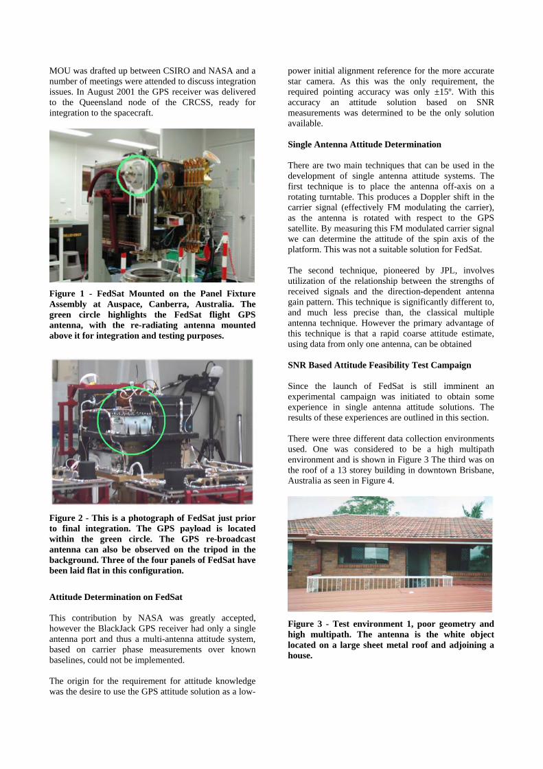
MOU was drafted up between CSIRO and NASA and a number of meetings were attended to discuss integration issues. In August 2001 the GPS receiver was delivered to the Queensland node of the CRCSS, ready for integration to the spacecraft.
Figure 1 - FedSat Mounted on the Panel Fixture Assembly at Auspace, Canberra, Australia. The green circle highlights the FedSat flight GPS antenna, with the re-radiating antenna mounted above it for integration and testing purposes.
Figure 2 - This is a photograph of FedSat just prior to final integration. The GPS payload is located within the green circle. The GPS re-broadcast antenna can also be observed on the tripod in the background. Three of the four panels of FedSat have been laid flat in this configuration.
Attitude Determination on FedSat This contribution by NASA was greatly accepted, however the BlackJack GPS receiver had only a single antenna port and thus a multi-antenna attitude system, based on carrier phase measurements over known baselines, could not be implemented. The origin for the requirement for attitude knowledge was the desire to use the GPS attitude solution as a low-
power initial alignment reference for the more accurate star camera. As this was the only requirement, the required pointing accuracy was only ±15º. With this accuracy an attitude solution based on SNR measurements was determined to be the only solution available. Single Antenna Attitude Determination There are two main techniques that can be used in the development of single antenna attitude systems. The first technique is to place the antenna off-axis on a rotating turntable. This produces a Doppler shift in the carrier signal (effectively FM modulating the carrier), as the antenna is rotated with respect to the GPS satellite. By measuring this FM modulated carrier signal we can determine the attitude of the spin axis of the platform. This was not a suitable solution for FedSat. The second technique, pioneered by JPL, involves utilization of the relationship between the strengths of received signals and the direction-dependent antenna gain pattern. This technique is significantly different to, and much less precise than, the classical multiple antenna technique. However the primary advantage of this technique is that a rapid coarse attitude estimate, using data from only one antenna, can be obtained SNR Based Attitude Feasibility Test Campaign Since the launch of FedSat is still imminent an experimental campaign was initiated to obtain some experience in single antenna attitude solutions. The results of these experiences are outlined in this section. There were three different data collection environments used. One was considered to be a high multipath environment and is shown in Figure 3 The third was on the roof of a 13 storey building in downtown Brisbane, Australia as seen in Figure 4.
Figure 3 - Test environment 1, poor geometry and high multipath. The antenna is the white object located on a large sheet metal roof and adjoining a house.
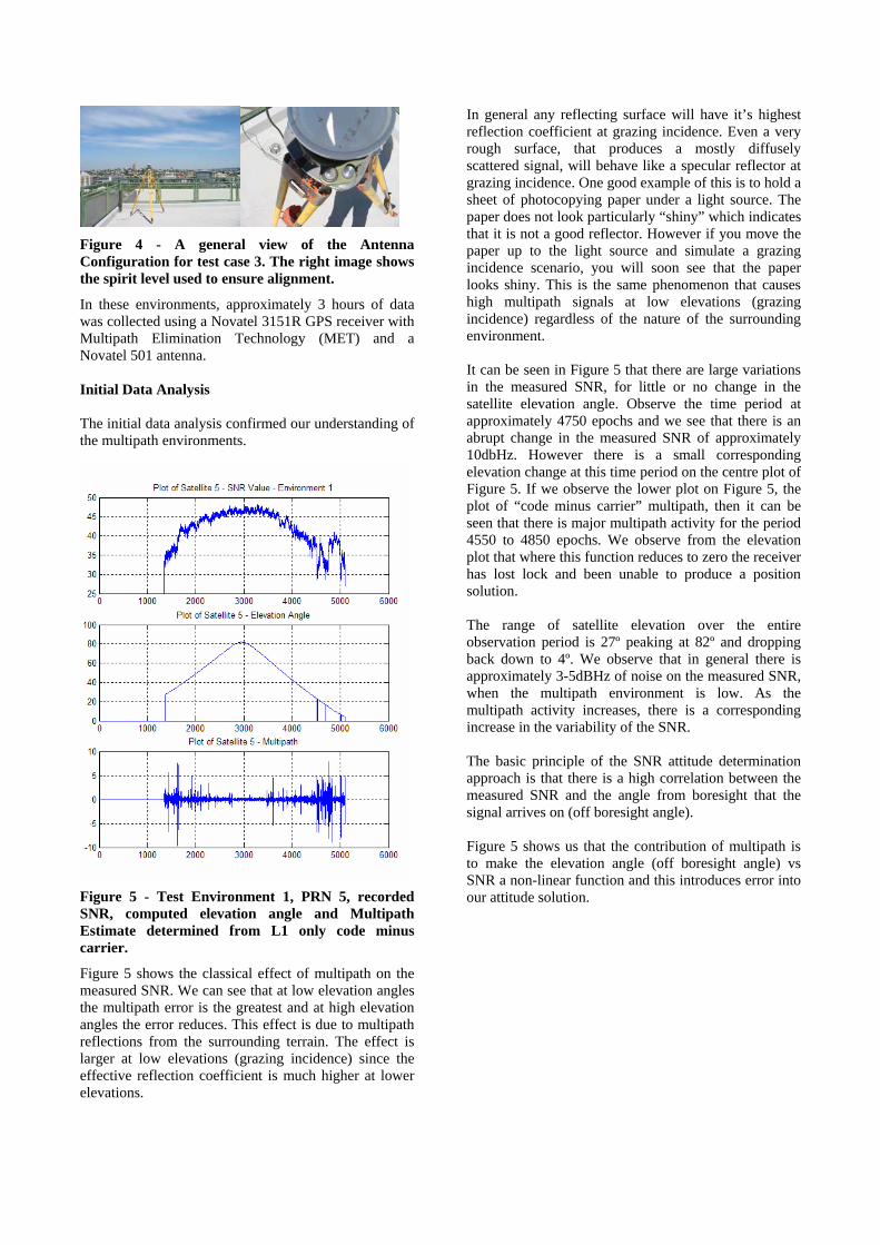
Figure 4 - A general view of the Antenna Configuration for test case 3. The right image shows the spirit level used to ensure alignment.
In these environments, approximately 3 hours of data was collected using a Novatel 3151R GPS receiver with Multipath Elimination Technology (MET) and a Novatel 501 antenna. Initial Data Analysis The initial data analysis confirmed our understanding of the multipath environments.
Figure 5 - Test Environment 1, PRN 5, recorded SNR, computed elevation angle and Multipath Estimate determined from L1 only code minus carrier.
Figure 5 shows the classical effect of multipath on the measured SNR. We can see that at low elevation angles the multipath error is the greatest and at high elevation angles the error reduces. This effect is due to multipath reflections from the surrounding terrain. The effect is larger at low elevations (grazing incidence) since the effective reflection coefficient is much higher at lower elevations.
In general any reflecting surface will have it’s highest reflection coefficient at grazing incidence. Even a very rough surface, that produces a mostly diffusely scattered signal, will behave like a specular reflector at grazing incidence. One good example of this is to hold a sheet of photocopying paper under a light source. The paper does not look particularly “shiny” which indicates that it is not a good reflector. However if you move the paper up to the light source and simulate a grazing incidence scenario, you will soon see that the paper looks shiny. This is the same phenomenon that causes high multipath signals at low elevations (grazing incidence) regardless of the nature of the surrounding environment. It can be seen in Figure 5 that there are large variations in the measured SNR, for little or no change in the satellite elevation angle. Observe the time period at approximately 4750 epochs and we see that there is an abrupt change in the measured SNR of approximately 10dbHz. However there is a small corresponding elevation change at this time period on the centre plot of Figure 5. If we observe the lower plot on Figure 5, the plot of “code minus carrier” multipath, then it can be seen that there is major multipath activity for the period 4550 to 4850 epochs. We observe from the elevation plot that where this function reduces to zero the receiver has lost lock and been unable to produce a position solution. The range of satellite elevation over the entire observation period is 27º peaking at 82º and dropping back down to 4º. We observe that in general there is approximately 3-5dBHz of noise on the measured SNR, when the multipath environment is low. As the multipath activity increases, there is a corresponding increase in the variability of the SNR. The basic principle of the SNR attitude determination approach is that there is a high correlation between the measured SNR and the angle from boresight that the signal arrives on (off boresight angle). Figure 5 shows us that the contribution of multipath is to make the elevation angle (off boresight angle) vs SNR a non-linear function and this introduces error into our attitude solution.

Figure 6 - Test Environment 3, PRN 30, recorded SNR, computed elevation angle and Multipath Estimate determined from L1 only code minus carrier.
Figure 6 shows a much-improved multipath environment. The range of satellite elevation over this period is 36º peaking at 66º and dropping back down to 17º. We see the typical 3-5 dBHz noise on the SNR measurement and we see a low multipath environment (in the lower graph). We can then observe some degree of correlation between the middle graph (elevation angle vs time) and the upper graph (measured SNR vs time). Attitude Solution using Weighted Line-of-Sight Vectors Now that we have obtained the data for cases where the antenna boresight vector is on the minus gravity vector, we can attempt to produce an two-axis attitude solution. The correct attitude solution will be 90º roll and 90º pitch. Any variations from 90º in these computed values are errors in the system. The process can be summarized into four simple steps [2]:
1. Calculate the line-of-sight vector to each tracked satellite.
2. Normalize the line-of-sight vectors to a unit vector.
3. Multiply the unit vectors by the measured SNR for all observed satellites.
4. Add SNR weighted vectors to obtain a vector sum.
Once the vector sum is obtained in the ECEF XYZ reference frame, we convert to a local tangent plane (LTP) in order to be able to calculate the roll and pitch angles. The LTP uses the orientation of North, East and Down, which is consistent with the geodetic coordinates. To transform the vector sum, use cosine matrix (North, East, Down) and solving for each component results in the following equations: Vnorth= -Vx sinϕ cosλ - Vy sinϕ sinλ + Vz cosϕ Veast= -Vx sinλ + Vy cosλ Vdown = -Vx cosϕ cosλ - Vy cosϕ sinλ - Vz sinϕ
Figure 7 - Definition of Pitch and Roll Angles for this analysis
Figure 8 - Line of Sight Vectors for Environment 3, Data Sample 1000. Signal Strengths are indicated by the length of the vectors. PRN numbers are indicated. These have been converted to LTP.
Figure 8 shows the computed line-of-sight vectors converted to local tangent plane coordinates. Figure 7 shows the definitions of pitch and roll angle used for this analysis.
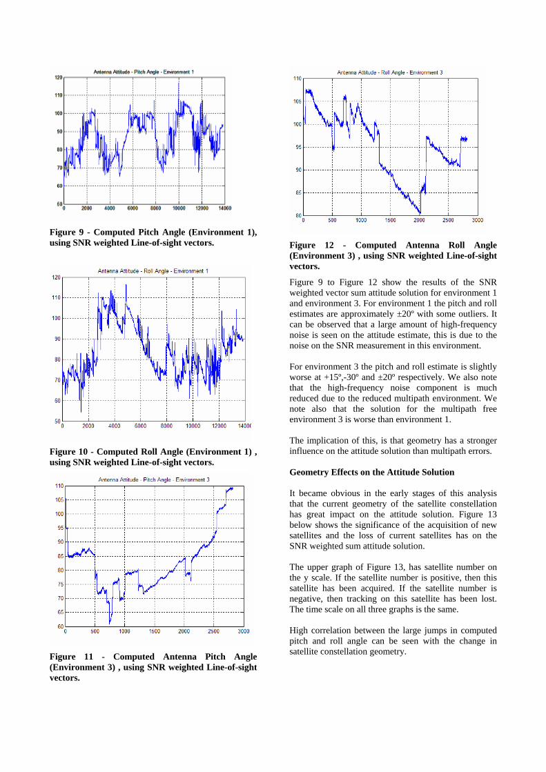
Figure 9 - Computed Pitch Angle (Environment 1), using SNR weighted Line-of-sight vectors.
Figure 10 - Computed Roll Angle (Environment 1) , using SNR weighted Line-of-sight vectors.
Figure 11 - Computed Antenna Pitch Angle (Environment 3) , using SNR weighted Line-of-sight vectors.
Figure 12 - Computed Antenna Roll Angle (Environment 3) , using SNR weighted Line-of-sight vectors.
Figure 9 to Figure 12 show the results of the SNR weighted vector sum attitude solution for environment 1 and environment 3. For environment 1 the pitch and roll estimates are approximately ±20º with some outliers. It can be observed that a large amount of high-frequency noise is seen on the attitude estimate, this is due to the noise on the SNR measurement in this environment. For environment 3 the pitch and roll estimate is slightly worse at +15º,-30º and ±20º respectively. We also note that the high-frequency noise component is much reduced due to the reduced multipath environment. We note also that the solution for the multipath free environment 3 is worse than environment 1. The implication of this, is that geometry has a stronger influence on the attitude solution than multipath errors. Geometry Effects on the Attitude Solution It became obvious in the early stages of this analysis that the current geometry of the satellite constellation has great impact on the attitude solution. Figure 13 below shows the significance of the acquisition of new satellites and the loss of current satellites has on the SNR weighted sum attitude solution. The upper graph of Figure 13, has satellite number on the y scale. If the satellite number is positive, then this satellite has been acquired. If the satellite number is negative, then tracking on this satellite has been lost. The time scale on all three graphs is the same. High correlation between the large jumps in computed pitch and roll angle can be seen with the change in satellite constellation geometry.

Figure 13 - Impact of Geometry Changes in Computed Attitude, using SNR weighted Line-of-sight vectors.
It was also observed that if grouping of satellites occurred, then this would bias the attitude solution towards that grouping of satellites since a weighted vector average was being made. For example, in Figure 8, we observe that the line-of-sight vectors for PRN 23 and PRN 5 are geometrically highly correlated. This adds weight to an attitude solution in that direction. Geometry Optimising Selection Algorithm Since it had been observed that the satellite geometry is the major contributor to the accuracy of this system. It was decided to investigate if a selection algorithm, based on geometry optimisation could be implemented that would improve the performance of the attitude solution. A simple selection algorithm was chosen to ensure that there was even satellite angular spacing in the north and down planes (pitch angle) and also in the down and east planes (roll angle). This process ensured that there was no grouping of satellite line-of-sight vectors, which would favour a particular attitude solution. Figure 14 and Figure 15 show the results of implementing a geometry optimisation algorithm.
Figure 14 - Geometry Optimised Pitch Angle, Test Environment 3
Figure 15 - Geometry Optimised Roll Angle, Test Environment 3
We note that there has not been a significant improvement in terms of the maximum and minimum values (by comparison with Figure 11 and Figure 12) but there is less systematic error and better general agreement. This still does not represent the type of performance required for FedSat. Simplified Attitude Solution A simpler approach suggested by Serrano[1] is based on only using the geometric vector measurements of the GPS constellation to determine the attitude of a vehicle. By observing which satellites are visible and tracked on the antenna and knowing the position of the receiver and each tracked satellite, it is possible to determine the orientation of the pointed antenna. This strategy is solely relying on the geometry available, eliminating systematic errors introduced by any variation of SNR

measurement due to multipath. Results for such approach are shown below in Figure 16 and Figure 17.
Figure 16 - Computed Pitch Angle using the Simplified Attitude Solution, Environment 3
Figure 17 - Computed Roll Angle using the Simplified Attitude Solution, Environment 3
This process produces very similar results to the SNR weighted solution, but lacks the noise from the SNR weighting. Simplified JPL Algorithm with Geometry Modification This approach combines both methods for completeness. Again no substantial improvement is made. Refer to Figure 18 and Figure 19 for a presentation of these results.
Figure 18 - Computed Pitch Solution using Simplified Approach and Geometry Optimisation
Figure 19 - Computed Roll Solution using Simplified Approach and Geometry Optimisation
Antenna Gain Pattern Modelling Another approach that was investigated was to develop a model to convert measured SNR to off boresight angle based on calibration tests. A large amount of elevation and SNR data was collected in the three environments and the results of this is shown in Figure 20 and Figure 21.

Figure 20 - Original SNR vs Elevation Model for Environment 1
Figure 20 shows an analysis of the variation in observed SNR for satellite elevation angle (off boresight angle) for all measurements made, at all azimuths, in environment 1. It can be observed that if one uses SNR as an index to determine elevation angle there is up to ±30º uncertainty for higher SNR’s. Consider an SNR of 45dBHz.
Figure 21 - Calibrated SNR Vs Elevation Model For Environment 2 (Data080102.txt)
By examination of Figure 21, for any given SNR value, the maximum and minimum elevation derived from it will be around 20 degrees in difference. For example, for the line labeled as 1, the predicted mean, maximum and minimum elevation at SNR of 42dBHz is 30º, 38º and 21º respectively (+8º, -9º). For 2, the mean, maximum and minimum elevation at SNR 44dBHz is 43º, 55º and 37º respectively (+12º,-6º). Therefore by using this SNR model, the antenna attitude can be estimated to be within ±10º. The antenna gain pattern of the Novatel 501 antenna, makes estimating the highest elevation spacecraft difficult since the gain of the 501 is not the highest on the boresight vector.
The FedSat Antenna Configuration FedSat’s antenna is mounted on the negative velocity vector face of the spacecraft. It is also mounted in one corner of the spacecraft as shown in Figure 22 and Figure 24. An analysis was conducted to determine the impact of this location on the gain pattern profile of the antenna.
Figure 22 - FedSat GPS Antenna Mounting Configuration with magnetometer boom stored.
1
2
Figure 23 - FedSat GPS Antenna Location (Second View)
Figure 24 - FedSat GPS Antenna Mounting Configuration with magnetometer boom deployed.

The antenna is the Sensor Systems S67-1575-14. Which has a published antenna gain pattern that is shown in Figure 25.
Figure 25 - Published Antenna Gain Pattern for Sensor Systems S67-1575-14
A mock-up model of FedSat was constructed (called TinSat) to which the flight antenna was mounted. TinSat was then placed on a calibrated antenna test range at CSIRO in Sydney, Australia. The range control computer recorded the gain, phase and azimuth angle measurements to a series of files at 0.5 degree intervals. The scans were automated, and began at an azimuth of 310 degrees, and rotated around to 50 degrees as shown in Figure 26. By this convention the antenna boresight vector is at 180° azimuth for the range turntable. Each scan took approximately 3 minutes. The basic layout within the range is shown in Figure 27.
Y
X
Height
Tx
Rx
+
-
-
+
Y
X
Height
Tx
Rx
Y
X
Height
Tx
Rx
+
-
-
+
Figure 26 - Basic Layout of Antenna Range Test Configuration for "TinSat"
Figure 27 - Photograph of TinSat with the GPS Flight Antenna on the range.
Four planes were cut through the TinSat model and these are defined in Figure 28. The second black circle in this figure, beside the GPS antenna corresponds to the piece of white tape seen in Figure 27. The results of these antenna gain measurements are seen in Figure 29 through to Figure 32.
Figure 28 – Definition of TinSat Antenna Plane Slices

Figure 29 - L1, Left to Right, 270° to 90° Slice (as per Figure 28) 180° on this figure is the antenna boresight vector.
Figure 30 - L1, Left to Right, 225° to 45° Slice (as per Figure 28) 180° on this figure is the antenna boresight vector.
Figure 31 - L1, Left to Right, 180° to 0° Slice (as per Figure 28) 180° on this figure is the antenna boresight vector.
Figure 32 - L1, Left to Right, 135° to 315° Slice (as per Figure 28) 180° on this figure is the antenna boresight vector.
Discussion of SNR-based Attitude Determination for the FedSat Antenna It has been sent that the basic assumption for the use of an SNR weighted attitude solution, or for the development of an SNR vs. off bore-sight angle model, is that the gain pattern of the antenna reduces monatonically as a function of off bore-sight angle

(elevation angle if the antenna is mounted on the local tangent plane). If consideration is made of Figure 29 to Figure 32 we observe that this assumption is not true for the measured FedSat flight antenna. Consider Figure 30, which is the plane 225° to 45° (Left to Right) as depicted in Figure 28. The antenna test range azimuth angle of 180º, corresponds to the antenna boresight vector. At an elevation angle of 30º (240º range azimuth), for this slice (azimuth 225º) we can see that there is more gain here than at the boresight vector of the antenna (90º elevation, 180º range azimuth). It is observed that due to the offset location of the antenna, on the negative velocity plane of FedSat, there has been a great modification to the published antenna gain pattern of the Sensor Systems S67-1575-14 as seen in Figure 25. Figure 33 shows a 3-dimensional representation of the distortion of the antenna gain pattern at low elevation angles for signals propagating across the negative velocity vector face of FedSat (azimuths 180º to 270º from Figure 28).
Figure 33 - 3D Representation of FedSat Antenna Gain Pattern
Conclusions This analysis was initiated to determine an approach for single antenna attitude determination for FedSat. During this analysis it has been observed that the Accuracy of the solution depends on the geometry of the GPS satellites. The accuracy of SNR weighted or SNR vs Elevation Angle model approaches and the geometry, depends upon the nature of the antenna gain pattern. That is a decrease in antenna gain for a decrease in elevation angle. FedSat does not have a suitable antenna gain pattern for these approaches, as the gain does not decrease for decreasing elevation angle (off boresight angle).
In general the SNR-based algorithms work best when used in a wide-open area with as many satellites in view as possible. It has also been observed that this technique does not work well in environments where multipath is a significant factor. Recommendations Given the poor accuracy that is likely to be achieved by using traditional SNR-based approaches for the FedSat mission another approach is required. One concept that will be explored for implementation will be to develop a spherical model of the antenna gain pattern. An algorithm will be developed that iterates the orientation of the antenna gain model through a range of possible attitude solutions. This algorithm then attempts to adjust the orientation of the antenna spherical model via a least squares type adjustment to minimise the difference between the weighted line-of-sight vectors, with the spherical model of the antenna gain pattern. With this type of approach, yaw angle information could potentially be obtained, due to the variation in the antenna gain pattern not only in elevation, but also in azimuth. Acknowledgements The authors would like to acknowledge the assistance of NASA and JPL in the development of the FedSat GPS payload. We take the opportunity the thank Mr Troy Spencer for allowing us to use his “Code minus Carrier” algorithm for this paper. We also would like to thank Mr William Kellar who participated in the Antenna Tests in Sydney. References [1] J. Serrano, J. Potti, P. Bernedo, P. Silvestrin, "A New Spacecraft Attitude Determination Scheme Based on the Use of GPS Line-Of-Sight Vectors", Proceedings of the ION GPS, Palm Springs, CA, 1995, pp. 1797-1806 [2] C.B. Duncan, C.E. Dunn, “Estimating Attitude from GPS Measurements on One Antenna”, Technical Support Package, Nasa Tech Brief Vol. 22, No. 6, Item #107.
Related Documents


