Simultaneous amplitude-contrast and quantitative phase-contrast microscopy by numerical reconstruction of Fresnel off-axis holograms Etienne Cuche, Pierre Marquet, and Christian Depeursinge We present a digital method for holographic microscopy involving a CCD camera as a recording device. Off-axis holograms recorded with a magnified image of microscopic objects are numerically reconstructed in amplitude and phase by calculation of scalar diffraction in the Fresnel approximation. For phase- contrast imaging the reconstruction method involves the computation of a digital replica of the reference wave. A digital method for the correction of the phase aberrations is presented. We present a detailed description of the reconstruction procedure and show that the transverse resolution is equal to the diffraction limit of the imaging system. © 1999 Optical Society of America OCIS codes: 090.0090, 110.0180, 040.1520, 350.5030, 090.1000. 1. Introduction The idea of reconstructing a hologram with a com- puter was proposed for the first time more than 30 years ago by Goodman and Laurence 1 and by Kro- nrod et al. 2 At that time the main drawbacks of this numerical approach of holography were the insuffi- cient performance of computers and the lack of ade- quate devices for digital image acquisition. Today these handicaps have been suppressed, and digital holography can be performed efficiently and inexpen- sively with a charged-coupled device ~CCD! camera for hologram recording and a personal computer for the reconstruction. In the past ten years digital holography has been applied in various configurations. Haddad et al. 3 and Boyer et al. 4 reported an application in Fourier- transform holography for biomedical microscopy. A numerical method for the reconstruction of Fresnel holograms recorded with a CCD camera was reported for the first time by Schnars and Ju ¨ ptner, 5 and sim- ilar techniques have been applied in various domains such as position measurement, 6 endoscopy, 7 light-in- flight observation, 8 and optical coherence tomogra- phy. 9,10 A method that uses phase-shifting interferometry has also been proposed for in-line ho- lography. 11,12 All the above-mentioned studies con- cern amplitude-contrast imaging for which only the intensity of the reconstructed optical field is consid- ered. An application of digital holography to holo- gram interferometry 13,14 has demonstrated the ability of the technique to measure a phase difference between two different states of the object. However, as presented in Refs. 13 and 14, the method cannot be used for the reconstruction of a phase-contrast image on the basis of a single hologram. In a previous study 15 Cuche et al.. demonstrated that phase reconstruction is possible by multiplica- tion of the hologram with a computed replica of the reference wave. It was also demonstrated that the obtained phase contrast is quantitative and can be used directly for applications in optical metrology such as surface profilometry in which a resolution approaching 10 nm has been obtained for step height measurement. Attractive features of this new imag- ing technique are the high acquisition rate ~video frequency! and the high reconstruction rate ~;1 Hz!, the ability to reconstruct simultaneously an amplitude-contrast and a phase-contrast image, and the ability to provide precise quantitative informa- tion about the three-dimensional structure of the specimen by computational means with a single ho- logram acquisition. In Ref. 15 holograms were recorded with a Michel- E. Cuche ~etienne.cuche@epfl.ch! and C. Depeursinge are with the Institute of Applied Optics, Swiss Federal Institute of Tech- nology, CH-1015 Lausanne, Switzerland. P. Marquet is with the Institute of Physiology, Laboratory of Neurological Research, De- partment of Neurology, University of Lausanne, CH-1005 Lau- sanne, Switzerland. Received 14 April 1999; revised manuscript received 3 August 1999. 0003-6935y99y346994-08$15.00y0 © 1999 Optical Society of America 6994 APPLIED OPTICS y Vol. 38, No. 34 y 1 December 1999

Welcome message from author
This document is posted to help you gain knowledge. Please leave a comment to let me know what you think about it! Share it to your friends and learn new things together.
Transcript
tnhf
Simultaneous amplitude-contrast and quantitativephase-contrast microscopy by numericalreconstruction of Fresnel off-axis holograms
Etienne Cuche, Pierre Marquet, and Christian Depeursinge
We present a digital method for holographic microscopy involving a CCD camera as a recording device.Off-axis holograms recorded with a magnified image of microscopic objects are numerically reconstructedin amplitude and phase by calculation of scalar diffraction in the Fresnel approximation. For phase-contrast imaging the reconstruction method involves the computation of a digital replica of the referencewave. A digital method for the correction of the phase aberrations is presented. We present a detaileddescription of the reconstruction procedure and show that the transverse resolution is equal to thediffraction limit of the imaging system. © 1999 Optical Society of America
OCIS codes: 090.0090, 110.0180, 040.1520, 350.5030, 090.1000.
6 7
ftattsl
1. Introduction
The idea of reconstructing a hologram with a com-puter was proposed for the first time more than 30years ago by Goodman and Laurence1 and by Kro-nrod et al.2 At that time the main drawbacks of thisnumerical approach of holography were the insuffi-cient performance of computers and the lack of ade-quate devices for digital image acquisition. Todaythese handicaps have been suppressed, and digitalholography can be performed efficiently and inexpen-sively with a charged-coupled device ~CCD! camerafor hologram recording and a personal computer forthe reconstruction.
In the past ten years digital holography has beenapplied in various configurations. Haddad et al.3and Boyer et al.4 reported an application in Fourier-ransform holography for biomedical microscopy. Aumerical method for the reconstruction of Fresnelolograms recorded with a CCD camera was reportedor the first time by Schnars and Juptner,5 and sim-
ilar techniques have been applied in various domains
E. Cuche [email protected]! and C. Depeursinge are withthe Institute of Applied Optics, Swiss Federal Institute of Tech-nology, CH-1015 Lausanne, Switzerland. P. Marquet is with theInstitute of Physiology, Laboratory of Neurological Research, De-partment of Neurology, University of Lausanne, CH-1005 Lau-sanne, Switzerland.
Received 14 April 1999; revised manuscript received 3 August1999.
0003-6935y99y346994-08$15.00y0© 1999 Optical Society of America
6994 APPLIED OPTICS y Vol. 38, No. 34 y 1 December 1999
such as position measurement, endoscopy, light-in-flight observation,8 and optical coherence tomogra-phy.9,10 A method that uses phase-shiftinginterferometry has also been proposed for in-line ho-lography.11,12 All the above-mentioned studies con-cern amplitude-contrast imaging for which only theintensity of the reconstructed optical field is consid-ered. An application of digital holography to holo-gram interferometry13,14 has demonstrated theability of the technique to measure a phase differencebetween two different states of the object. However,as presented in Refs. 13 and 14, the method cannot beused for the reconstruction of a phase-contrast imageon the basis of a single hologram.
In a previous study15 Cuche et al.. demonstratedthat phase reconstruction is possible by multiplica-tion of the hologram with a computed replica of thereference wave. It was also demonstrated that theobtained phase contrast is quantitative and can beused directly for applications in optical metrologysuch as surface profilometry in which a resolutionapproaching 10 nm has been obtained for step heightmeasurement. Attractive features of this new imag-ing technique are the high acquisition rate ~videorequency! and the high reconstruction rate ~;1 Hz!,he ability to reconstruct simultaneously anmplitude-contrast and a phase-contrast image, andhe ability to provide precise quantitative informa-ion about the three-dimensional structure of thepecimen by computational means with a single ho-ogram acquisition.
In Ref. 15 holograms were recorded with a Michel-
cwobsmoepc
mbflttlbpaarotct
ilcabctipmIfu
bc
wtAFwrud
aMf
son interferometer with an object wave directly re-flected by the specimen. In this configuration thetransverse resolution was limited to approximately30 mm. Here we present a new, to our knowledge,onfiguration designed for microscopic investigationsith the same transverse resolution as with classical
ptical microscopy. The presented instrument coulde called a digital holographic microscope and con-ists of a microscope objective ~MO! that produces aagnified image of the sample that is used as an
bject for the hologram creation. Since a phase ab-rration is associated with the use of a MO, we alsoresent a digital method that has been developed toorrect this aberration.
2. Microscope Designs
Two kinds of digital holographic microscope are pre-sented. The first one ~Fig. 1! is designed for trans-
ission imaging with transparent samples ~e.g.,iological cells! and the second one ~Fig. 2! for re-ection imaging. In both cases the basic architec-ure is that of a Mach–Zender interferometer. Forhe present experiments a linearly polarized He–Neaser ~10 mW! is used as a light source. The com-ination of a neutral density filter, a half-wavelate, and a polarizing beam splitter is used for thedjustment of the intensities in the reference armnd the object arm of the interferometer. In theeference arm a half-wave plate is introduced tobtain parallel polarizations at the exit of the in-erferometer. In each arm, beam expanders, in-luding pinholes for spatial filtering, are introducedo produce plane waves.
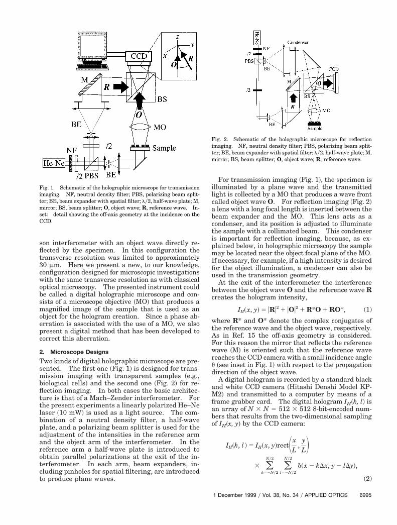
Fig. 1. Schematic of the holographic microscope for transmissionimaging. NF, neutral density filter; PBS, polarizing beam split-ter; BE, beam expander with spatial filter; ly2, half-wave plate; M,mirror; BS, beam splitter; O, object wave; R, reference wave. In-set: detail showing the off-axis geometry at the incidence on theCCD.
For transmission imaging ~Fig. 1!, the specimen islluminated by a plane wave and the transmittedight is collected by a MO that produces a wave frontalled object wave O. For reflection imaging ~Fig. 2!lens with a long focal length is inserted between theeam expander and the MO. This lens acts as aondenser, and its position is adjusted to illuminatehe sample with a collimated beam. This condensers important for reflection imaging, because, as ex-lained below, in holographic microscopy the sampleay be located near the object focal plane of the MO.
f necessary, for example, if a high intensity is desiredor the object illumination, a condenser can also besed in the transmission geometry.At the exit of the interferometer the interference
etween the object wave O and the reference wave Rreates the hologram intensity,
IH~x, y! 5 uRu2 1 uOu2 1 R*O 1 RO*, (1)
here R* and O* denote the complex conjugates ofhe reference wave and the object wave, respectively.s in Ref. 15 the off-axis geometry is considered.or this reason the mirror that reflects the referenceave ~M! is oriented such that the reference wave
eaches the CCD camera with a small incidence angle~see inset in Fig. 1! with respect to the propagationirection of the object wave.A digital hologram is recorded by a standard black
nd white CCD camera ~Hitashi Denshi Model KP-2! and transmitted to a computer by means of a
rame grabber card. The digital hologram IH~k, l! isan array of N 3 N 5 512 3 512 8-bit-encoded num-bers that results from the two-dimensional samplingof IH~x, y! by the CCD camera:
IH~k, l ! 5 IH~x, y!rectSxL
,yLD
3 (k52Ny2
Ny2
(l52Ny2
Ny2
d~x 2 kDx, y 2 lDy!,
(2)
Fig. 2. Schematic of the holographic microscope for reflectionimaging. NF, neutral density filter; PBS, polarizing beam split-ter; BE, beam expander with spatial filter; ly2, half-wave plate; M,mirror; BS, beam splitter; O, object wave; R, reference wave.
1 December 1999 y Vol. 38, No. 34 y APPLIED OPTICS 6995
ltodltftwefit
alCehtoc
tsdopoiiit3
rwi
dtocpatitsrsr
p
6
where k, l are integers, L 3 L 5 4.85 mm 3 4.85 mmis the area of the sensitive chip, and Dx, Dy definesthe sampling intervals in the hologram plane ~pixelsize! Dx 5 Dy 5 LyN.
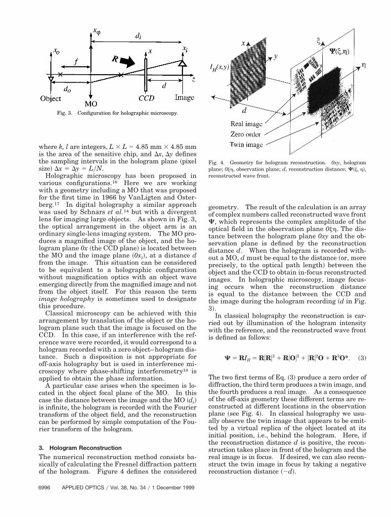
Holographic microscopy has been proposed invarious configurations.16 Here we are workingwith a geometry including a MO that was proposedfor the first time in 1966 by VanLigten and Oster-berg.17 In digital holography a similar approachwas used by Schnars et al.14 but with a divergentens for imaging large objects. As shown in Fig. 3,he optical arrangement in the object arm is anrdinary single-lens imaging system. The MO pro-uces a magnified image of the object, and the ho-ogram plane 0x ~the CCD plane! is located betweenhe MO and the image plane ~0xi!, at a distance drom the image. This situation can be consideredo be equivalent to a holographic configurationithout magnification optics with an object wavemerging directly from the magnified image and notrom the object itself. For this reason the termmage holography is sometimes used to designatehis procedure.
Classical microscopy can be achieved with thisrrangement by translation of the object or the ho-ogram plane such that the image is focused on theCD. In this case, if an interference with the ref-rence wave were recorded, it would correspond to aologram recorded with a zero object–hologram dis-ance. Such a disposition is not appropriate forff-axis holography but is used in interference mi-roscopy where phase-shifting interferometry18 is
applied to obtain the phase information.A particular case arises when the specimen is lo-
cated in the object focal plane of the MO. In thiscase the distance between the image and the MO ~di!is infinite, the hologram is recorded with the Fouriertransform of the object field, and the reconstructioncan be performed by simple computation of the Fou-rier transform of the hologram.
3. Hologram Reconstruction
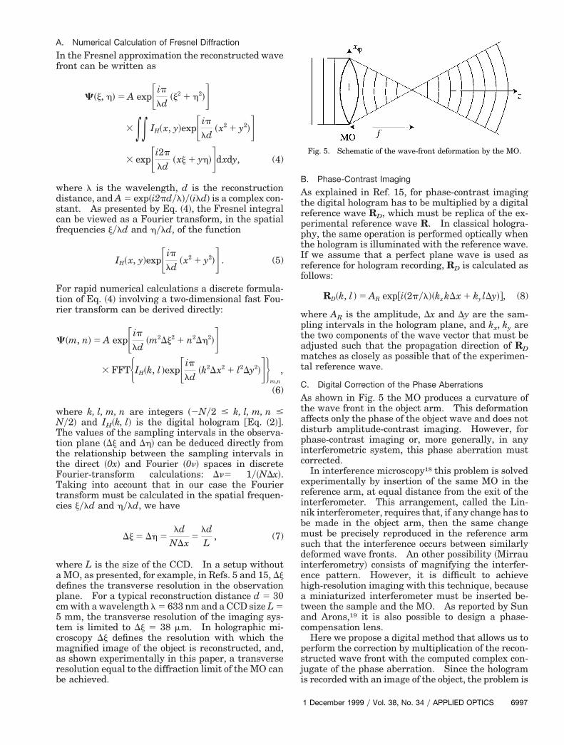
The numerical reconstruction method consists ba-sically of calculating the Fresnel diffraction patternof the hologram. Figure 4 defines the considered
Fig. 3. Configuration for holographic microscopy.
996 APPLIED OPTICS y Vol. 38, No. 34 y 1 December 1999
geometry. The result of the calculation is an arrayof complex numbers called reconstructed wave frontC, which represents the complex amplitude of theoptical field in the observation plane 0jh. The dis-ance between the hologram plane 0xy and the ob-ervation plane is defined by the reconstructionistance d. When the hologram is recorded with-ut a MO, d must be equal to the distance ~or, morerecisely, to the optical path length! between thebject and the CCD to obtain in-focus reconstructedmages. In holographic microscopy, image focus-ng occurs when the reconstruction distances equal to the distance between the CCD andhe image during the hologram recording ~d in Fig.!.In classical holography the reconstruction is car-
ied out by illumination of the hologram intensityith the reference, and the reconstructed wave front
s defined as follows:
C 5 RIH 5 RuRu2 1 RuOu2 1 uRu2O 1 R2O*. (3)
The two first terms of Eq. ~3! produce a zero order ofiffraction, the third term produces a twin image, andhe fourth produces a real image. As a consequencef the off-axis geometry these different terms are re-onstructed at different locations in the observationlane ~see Fig. 4!. In classical holography we usu-lly observe the twin image that appears to be emit-ed by a virtual replica of the object located at itsnitial position, i.e., behind the hologram. Here, ifhe reconstruction distance d is positive, the recon-truction takes place in front of the hologram and theeal image is in focus. If desired, we can also recon-truct the twin image in focus by taking a negativeeconstruction distance ~2d!.
Fig. 4. Geometry for hologram reconstruction. 0xy, hologramlane; 0jh, observation plane; d, reconstruction distance; C~j, h!,
reconstructed wave front.
TtttFTtc
c5tcmarb
p
A. Numerical Calculation of Fresnel Diffraction
In the Fresnel approximation the reconstructed wavefront can be written as
C~j, h! 5 A expFipld
~j2 1 h2!G3 ** IH~x, y!expFip
ld~x2 1 y2!G
3 expFi2p
ld~xj 1 yh!Gdxdy, (4)
where l is the wavelength, d is the reconstructiondistance, and A 5 exp~i2pdyl!y~ild! is a complex con-stant. As presented by Eq. ~4!, the Fresnel integralcan be viewed as a Fourier transform, in the spatialfrequencies jyld and hyld, of the function
IH~x, y!expFipld
~x2 1 y2!G . (5)
For rapid numerical calculations a discrete formula-tion of Eq. ~4! involving a two-dimensional fast Fou-rier transform can be derived directly:
C~m, n! 5 A expFipld
~m2Dj2 1 n2Dh2!G3 FFTHIH~k, l !expFip
ld~k2Dx2 1 l2Dy2!GJ
m,n
,
(6)
where k, l, m, n are integers ~2Ny2 # k, l, m, n #Ny2! and IH~k, l! is the digital hologram @Eq. ~2!#.
he values of the sampling intervals in the observa-ion plane ~Dj and Dh! can be deduced directly fromhe relationship between the sampling intervals inhe direct ~0x! and Fourier ~0n! spaces in discreteourier-transform calculations: Dn5 1y~NDx!.aking into account that in our case the Fourier
ransform must be calculated in the spatial frequen-ies jyld and hyld, we have
Dj 5 Dh 5ld
NDx5
ldL
, (7)
where L is the size of the CCD. In a setup withouta MO, as presented, for example, in Refs. 5 and 15, Djdefines the transverse resolution in the observationplane. For a typical reconstruction distance d 5 30m with a wavelength l 5 633 nm and a CCD size L 5mm, the transverse resolution of the imaging sys-
em is limited to Dj 5 38 mm. In holographic mi-roscopy Dj defines the resolution with which theagnified image of the object is reconstructed, and,
s shown experimentally in this paper, a transverseesolution equal to the diffraction limit of the MO cane achieved.
B. Phase-Contrast Imaging
As explained in Ref. 15, for phase-contrast imagingthe digital hologram has to be multiplied by a digitalreference wave RD, which must be replica of the ex-perimental reference wave R. In classical hologra-phy, the same operation is performed optically whenthe hologram is illuminated with the reference wave.If we assume that a perfect plane wave is used asreference for hologram recording, RD is calculated asfollows:
RD~k, l ! 5 AR exp@i~2pyl!~kx kDx 1 ky lDy!#, (8)
where AR is the amplitude, Dx and Dy are the sam-ling intervals in the hologram plane, and kx, ky are
the two components of the wave vector that must beadjusted such that the propagation direction of RDmatches as closely as possible that of the experimen-tal reference wave.
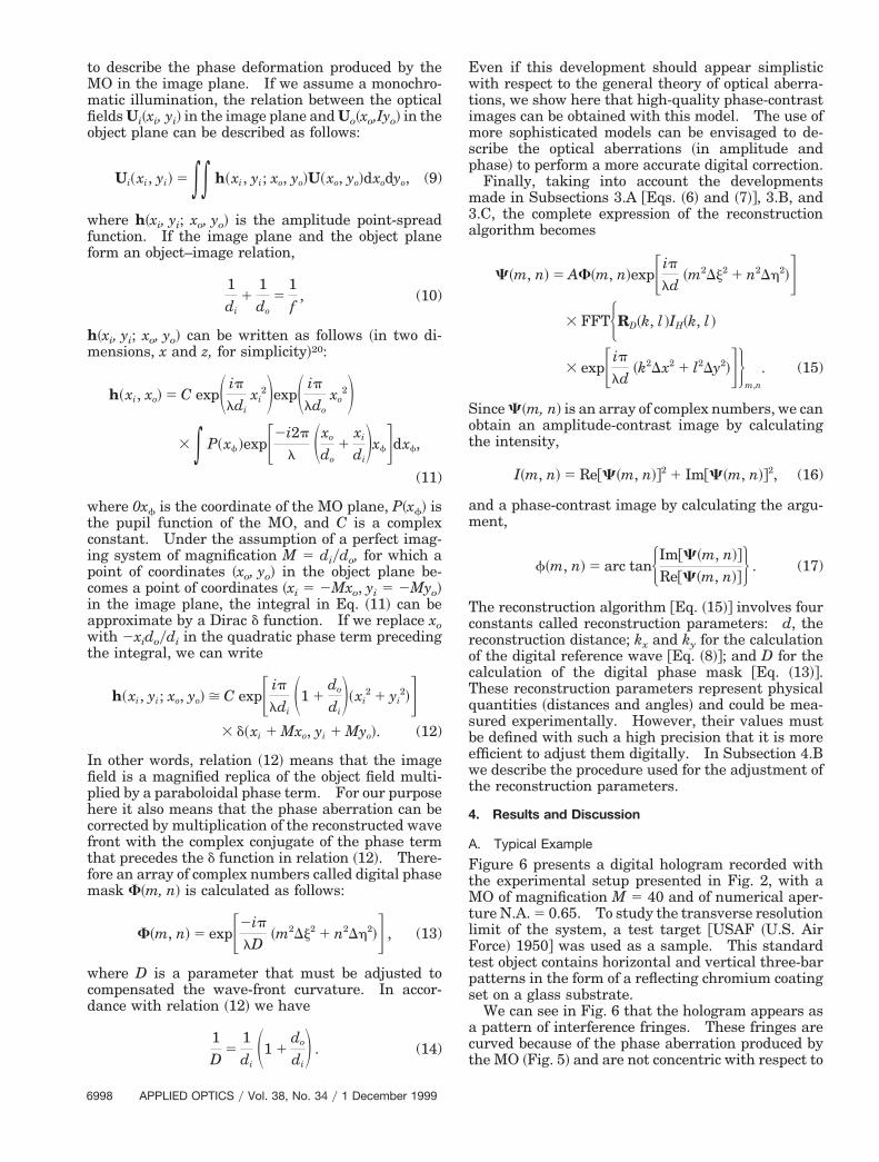
C. Digital Correction of the Phase Aberrations
As shown in Fig. 5 the MO produces a curvature ofthe wave front in the object arm. This deformationaffects only the phase of the object wave and does notdisturb amplitude-contrast imaging. However, forphase-contrast imaging or, more generally, in anyinterferometric system, this phase aberration mustcorrected.
In interference microscopy18 this problem is solvedexperimentally by insertion of the same MO in thereference arm, at equal distance from the exit of theinterferometer. This arrangement, called the Lin-nik interferometer, requires that, if any change has tobe made in the object arm, then the same changemust be precisely reproduced in the reference armsuch that the interference occurs between similarlydeformed wave fronts. An other possibility ~Mirrauinterferometry! consists of magnifying the interfer-ence pattern. However, it is difficult to achievehigh-resolution imaging with this technique, becausea miniaturized interferometer must be inserted be-tween the sample and the MO. As reported by Sunand Arons,19 it is also possible to design a phase-compensation lens.
Here we propose a digital method that allows us toperform the correction by multiplication of the recon-structed wave front with the computed complex con-jugate of the phase aberration. Since the hologramis recorded with an image of the object, the problem is
Fig. 5. Schematic of the wave-front deformation by the MO.
1 December 1999 y Vol. 38, No. 34 y APPLIED OPTICS 6997
o
ff
ci
a
t
Ifiphcftfm
p
m3a
am
cr
cTqsbewt
tlF
6
to describe the phase deformation produced by theMO in the image plane. If we assume a monochro-matic illumination, the relation between the opticalfields Ui~xi, yi! in the image plane and Uo~xo,Iyo! in thebject plane can be described as follows:
Ui~xi, yi! 5 ** h~xi, yi; xo, yo!U~xo, yo!dxodyo, (9)
where h~xi, yi; xo, yo! is the amplitude point-spreadunction. If the image plane and the object planeorm an object–image relation,
1di
11do
51f
, (10)
h~xi, yi; xo, yo! can be written as follows ~in two di-mensions, x and z, for simplicity!20:
h~xi, xo! 5 C expS ipldi
xi2DexpS ip
ldoxo
2D3 * P~xf!expF2i2p
l Sxo
do1
xi
diDxfGdxf,
(11)
where 0xf is the coordinate of the MO plane, P~xf! isthe pupil function of the MO, and C is a complexonstant. Under the assumption of a perfect imag-ng system of magnification M 5 diydo, for which a
point of coordinates ~xo, yo! in the object plane be-comes a point of coordinates ~xi 5 2Mxo, yi 5 2Myo!in the image plane, the integral in Eq. ~11! can bepproximate by a Dirac d function. If we replace xo
with 2xidoydi in the quadratic phase term precedinghe integral, we can write
h~xi, yi; xo, yo! > C expF ipldi
S1 1do
diD~xi
2 1 yi2!G
3 d~xi 1 Mxo, yi 1 Myo!. (12)
n other words, relation ~12! means that the imageeld is a magnified replica of the object field multi-lied by a paraboloidal phase term. For our purposeere it also means that the phase aberration can beorrected by multiplication of the reconstructed waveront with the complex conjugate of the phase termhat precedes the d function in relation ~12!. There-ore an array of complex numbers called digital phase
ask F~m, n! is calculated as follows:
F~m, n! 5 expF2iplD
~m2Dj2 1 n2Dh2!G , (13)
where D is a parameter that must be adjusted tocompensated the wave-front curvature. In accor-dance with relation ~12! we have
1D
51diS1 1
do
diD . (14)
998 APPLIED OPTICS y Vol. 38, No. 34 y 1 December 1999
Even if this development should appear simplisticwith respect to the general theory of optical aberra-tions, we show here that high-quality phase-contrastimages can be obtained with this model. The use ofmore sophisticated models can be envisaged to de-scribe the optical aberrations ~in amplitude and
hase! to perform a more accurate digital correction.Finally, taking into account the developmentsade in Subsections 3.A @Eqs. ~6! and ~7!#, 3.B, and
.C, the complete expression of the reconstructionlgorithm becomes
C~m, n! 5 AF~m, n!expFipld
~m2Dj2 1 n2Dh2!G3 FFTHRD~k, l !IH~k, l !
3 expFipld
~k2Dx2 1 l2Dy2!GJm,n
. (15)
Since C~m, n! is an array of complex numbers, we canobtain an amplitude-contrast image by calculatingthe intensity,
I~m, n! 5 Re@C~m, n!#2 1 Im@C~m, n!#2, (16)
nd a phase-contrast image by calculating the argu-ent,
f~m, n! 5 arc tanHIm@C~m, n!#
Re@C~m, n!#J . (17)
The reconstruction algorithm @Eq. ~15!# involves fouronstants called reconstruction parameters: d, theeconstruction distance; kx and ky for the calculation
of the digital reference wave @Eq. ~8!#; and D for thealculation of the digital phase mask @Eq. ~13!#.hese reconstruction parameters represent physicaluantities ~distances and angles! and could be mea-ured experimentally. However, their values muste defined with such a high precision that it is morefficient to adjust them digitally. In Subsection 4.Be describe the procedure used for the adjustment of
he reconstruction parameters.
4. Results and Discussion
A. Typical Example
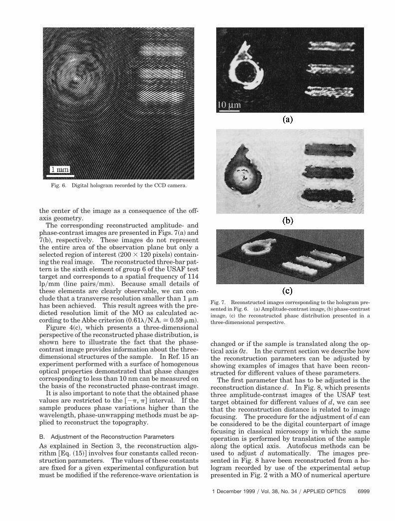
Figure 6 presents a digital hologram recorded withthe experimental setup presented in Fig. 2, with aMO of magnification M 5 40 and of numerical aper-ure N.A. 5 0.65. To study the transverse resolutionimit of the system, a test target @USAF ~U.S. Airorce! 1950# was used as a sample. This standard
test object contains horizontal and vertical three-barpatterns in the form of a reflecting chromium coatingset on a glass substrate.
We can see in Fig. 6 that the hologram appears asa pattern of interference fringes. These fringes arecurved because of the phase aberration produced bythe MO ~Fig. 5! and are not concentric with respect to
ittltchdc
pscdeoct
vswp
the center of the image as a consequence of the off-axis geometry.
The corresponding reconstructed amplitude- andphase-contrast images are presented in Figs. 7~a! and7~b!, respectively. These images do not representthe entire area of the observation plane but only aselected region of interest ~200 3 120 pixels! contain-ng the real image. The reconstructed three-bar pat-ern is the sixth element of group 6 of the USAF testarget and corresponds to a spatial frequency of 114pymm ~line pairsymm!. Because small details ofhese elements are clearly observable, we can con-lude that a transverse resolution smaller than 1 mmas been achieved. This result agrees with the pre-icted resolution limit of the MO as calculated ac-ording to the Abbe criterion ~0.61lyN.A. > 0.59 mm!.
Figure 4~c!, which presents a three-dimensionalerspective of the reconstructed phase distribution, ishown here to illustrate the fact that the phase-ontrast image provides information about the three-imensional structures of the sample. In Ref. 15 anxperiment performed with a surface of homogenousptical properties demonstrated that phase changesorresponding to less than 10 nm can be measured onhe basis of the reconstructed phase-contrast image.
It is also important to note that the obtained phasealues are restricted to the @2p, p# interval. If theample produces phase variations higher than theavelength, phase-unwrapping methods must be ap-lied to reconstruct the topography.
B. Adjustment of the Reconstruction Parameters
As explained in Section 3, the reconstruction algo-rithm @Eq. ~15!# involves four constants called recon-struction parameters. The values of these constantsare fixed for a given experimental configuration butmust be modified if the reference-wave orientation is
Fig. 6. Digital hologram recorded by the CCD camera.
changed or if the sample is translated along the op-tical axis 0z. In the current section we describe howthe reconstruction parameters can be adjusted byshowing examples of images that have been recon-structed for different values of these parameters.
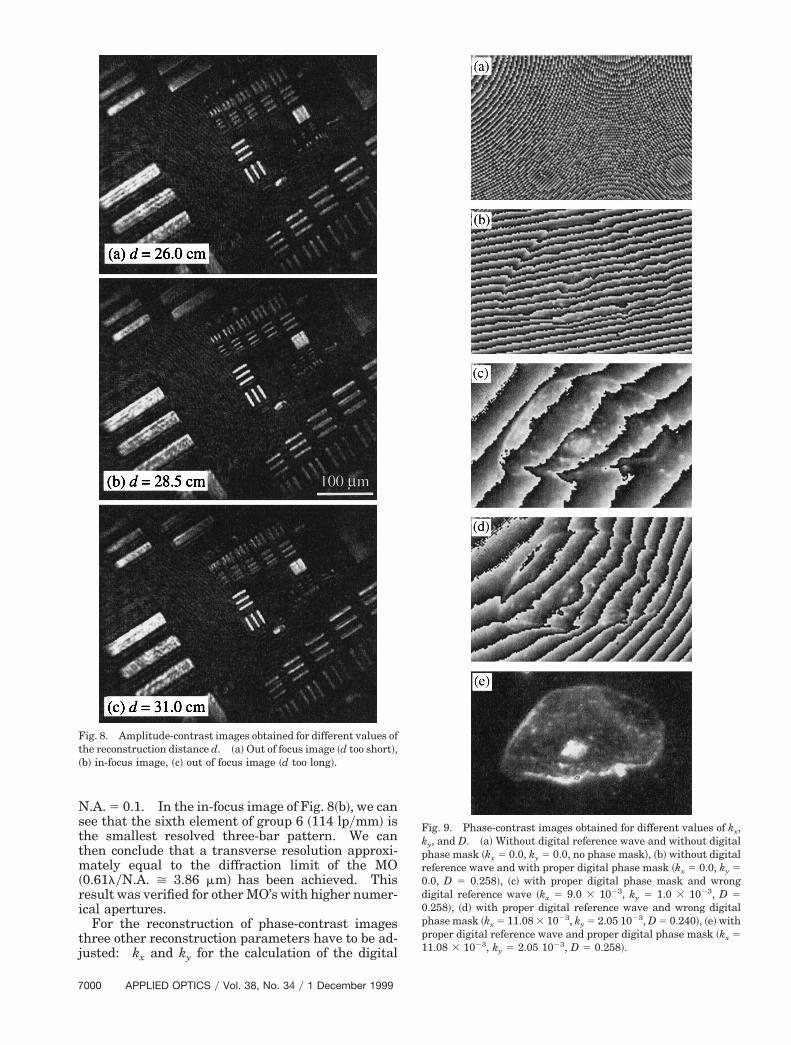
The first parameter that has to be adjusted is thereconstruction distance d. In Fig. 8, which presentsthree amplitude-contrast images of the USAF testtarget obtained for different values of d, we can seethat the reconstruction distance is related to imagefocusing. The procedure for the adjustment of d canbe considered to be the digital counterpart of imagefocusing in classical microscopy in which the sameoperation is performed by translation of the samplealong the optical axis. Autofocus methods can beused to adjust d automatically. The images pre-sented in Fig. 8 have been reconstructed from a ho-logram recorded by use of the experimental setuppresented in Fig. 2 with a MO of numerical aperture
Fig. 7. Reconstructed images corresponding to the hologram pre-sented in Fig. 6. ~a! Amplitude-contrast image, ~b! phase-contrastimage, ~c! the reconstructed phase distribution presented in athree-dimensional perspective.
1 December 1999 y Vol. 38, No. 34 y APPLIED OPTICS 6999
s
0
7
N.A. 5 0.1. In the in-focus image of Fig. 8~b!, we canee that the sixth element of group 6 ~114 lpymm! is
the smallest resolved three-bar pattern. We canthen conclude that a transverse resolution approxi-mately equal to the diffraction limit of the MO~0.61lyN.A. > 3.86 mm! has been achieved. Thisresult was verified for other MO’s with higher numer-ical apertures.
For the reconstruction of phase-contrast imagesthree other reconstruction parameters have to be ad-justed: kx and ky for the calculation of the digital
Fig. 8. Amplitude-contrast images obtained for different values ofthe reconstruction distance d. ~a! Out of focus image ~d too short!,~b! in-focus image, ~c! out of focus image ~d too long!.
000 APPLIED OPTICS y Vol. 38, No. 34 y 1 December 1999
Fig. 9. Phase-contrast images obtained for different values of kx,ky, and D. ~a! Without digital reference wave and without digitalphase mask ~kx 5 0.0, ky 5 0.0, no phase mask!, ~b! without digitalreference wave and with proper digital phase mask ~kx 5 0.0, ky 50.0, D 5 0.258!, ~c! with proper digital phase mask and wrongdigital reference wave ~kx 5 9.0 3 1023, ky 5 1.0 3 1023, D 5.258!, ~d! with proper digital reference wave and wrong digital
phase mask ~kx 5 11.08 3 1023, ky 5 2.05 1023, D 5 0.240!, ~e! withproper digital reference wave and proper digital phase mask ~kx 511.08 3 1023, ky 5 2.05 1023, D 5 0.258!.
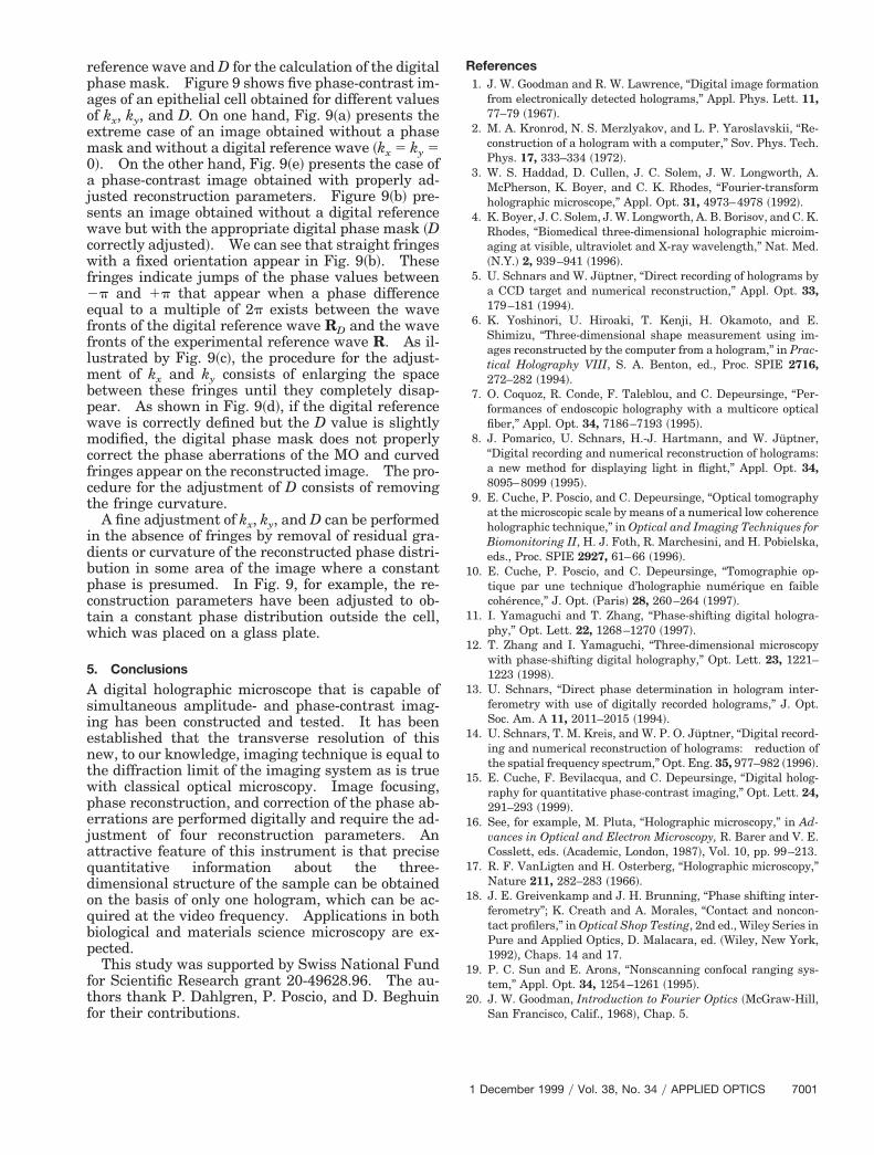
reference wave and D for the calculation of the digitalphase mask. Figure 9 shows five phase-contrast im-ages of an epithelial cell obtained for different valuesof kx, ky, and D. On one hand, Fig. 9~a! presents theextreme case of an image obtained without a phasemask and without a digital reference wave ~kx 5 ky 50!. On the other hand, Fig. 9~e! presents the case ofa phase-contrast image obtained with properly ad-justed reconstruction parameters. Figure 9~b! pre-sents an image obtained without a digital referencewave but with the appropriate digital phase mask ~Dcorrectly adjusted!. We can see that straight fringeswith a fixed orientation appear in Fig. 9~b!. Thesefringes indicate jumps of the phase values between2p and 1p that appear when a phase differenceequal to a multiple of 2p exists between the wavefronts of the digital reference wave RD and the wavefronts of the experimental reference wave R. As il-lustrated by Fig. 9~c!, the procedure for the adjust-ment of kx and ky consists of enlarging the spacebetween these fringes until they completely disap-pear. As shown in Fig. 9~d!, if the digital referencewave is correctly defined but the D value is slightlymodified, the digital phase mask does not properlycorrect the phase aberrations of the MO and curvedfringes appear on the reconstructed image. The pro-cedure for the adjustment of D consists of removingthe fringe curvature.
A fine adjustment of kx, ky, and D can be performedin the absence of fringes by removal of residual gra-dients or curvature of the reconstructed phase distri-bution in some area of the image where a constantphase is presumed. In Fig. 9, for example, the re-construction parameters have been adjusted to ob-tain a constant phase distribution outside the cell,which was placed on a glass plate.
5. Conclusions
A digital holographic microscope that is capable ofsimultaneous amplitude- and phase-contrast imag-ing has been constructed and tested. It has beenestablished that the transverse resolution of thisnew, to our knowledge, imaging technique is equal tothe diffraction limit of the imaging system as is truewith classical optical microscopy. Image focusing,phase reconstruction, and correction of the phase ab-errations are performed digitally and require the ad-justment of four reconstruction parameters. Anattractive feature of this instrument is that precisequantitative information about the three-dimensional structure of the sample can be obtainedon the basis of only one hologram, which can be ac-quired at the video frequency. Applications in bothbiological and materials science microscopy are ex-pected.
This study was supported by Swiss National Fundfor Scientific Research grant 20-49628.96. The au-thors thank P. Dahlgren, P. Poscio, and D. Beghuinfor their contributions.
References1. J. W. Goodman and R. W. Lawrence, “Digital image formation
from electronically detected holograms,” Appl. Phys. Lett. 11,77–79 ~1967!.
2. M. A. Kronrod, N. S. Merzlyakov, and L. P. Yaroslavskii, “Re-construction of a hologram with a computer,” Sov. Phys. Tech.Phys. 17, 333–334 ~1972!.
3. W. S. Haddad, D. Cullen, J. C. Solem, J. W. Longworth, A.McPherson, K. Boyer, and C. K. Rhodes, “Fourier-transformholographic microscope,” Appl. Opt. 31, 4973–4978 ~1992!.
4. K. Boyer, J. C. Solem, J. W. Longworth, A. B. Borisov, and C. K.Rhodes, “Biomedical three-dimensional holographic microim-aging at visible, ultraviolet and X-ray wavelength,” Nat. Med.~N.Y.! 2, 939–941 ~1996!.
5. U. Schnars and W. Juptner, “Direct recording of holograms bya CCD target and numerical reconstruction,” Appl. Opt. 33,179–181 ~1994!.
6. K. Yoshinori, U. Hiroaki, T. Kenji, H. Okamoto, and E.Shimizu, “Three-dimensional shape measurement using im-ages reconstructed by the computer from a hologram,” in Prac-tical Holography VIII, S. A. Benton, ed., Proc. SPIE 2716,272–282 ~1994!.
7. O. Coquoz, R. Conde, F. Taleblou, and C. Depeursinge, “Per-formances of endoscopic holography with a multicore opticalfiber,” Appl. Opt. 34, 7186–7193 ~1995!.
8. J. Pomarico, U. Schnars, H.-J. Hartmann, and W. Juptner,“Digital recording and numerical reconstruction of holograms:a new method for displaying light in flight,” Appl. Opt. 34,8095–8099 ~1995!.
9. E. Cuche, P. Poscio, and C. Depeursinge, “Optical tomographyat the microscopic scale by means of a numerical low coherenceholographic technique,” in Optical and Imaging Techniques forBiomonitoring II, H. J. Foth, R. Marchesini, and H. Pobielska,eds., Proc. SPIE 2927, 61–66 ~1996!.
10. E. Cuche, P. Poscio, and C. Depeursinge, “Tomographie op-tique par une technique d’holographie numerique en faiblecoherence,” J. Opt. ~Paris! 28, 260–264 ~1997!.
11. I. Yamaguchi and T. Zhang, “Phase-shifting digital hologra-phy,” Opt. Lett. 22, 1268–1270 ~1997!.
12. T. Zhang and I. Yamaguchi, “Three-dimensional microscopywith phase-shifting digital holography,” Opt. Lett. 23, 1221–1223 ~1998!.
13. U. Schnars, “Direct phase determination in hologram inter-ferometry with use of digitally recorded holograms,” J. Opt.Soc. Am. A 11, 2011–2015 ~1994!.
14. U. Schnars, T. M. Kreis, and W. P. O. Juptner, “Digital record-ing and numerical reconstruction of holograms: reduction ofthe spatial frequency spectrum,” Opt. Eng. 35, 977–982 ~1996!.
15. E. Cuche, F. Bevilacqua, and C. Depeursinge, “Digital holog-raphy for quantitative phase-contrast imaging,” Opt. Lett. 24,291–293 ~1999!.
16. See, for example, M. Pluta, “Holographic microscopy,” in Ad-vances in Optical and Electron Microscopy, R. Barer and V. E.Cosslett, eds. ~Academic, London, 1987!, Vol. 10, pp. 99–213.
17. R. F. VanLigten and H. Osterberg, “Holographic microscopy,”Nature 211, 282–283 ~1966!.
18. J. E. Greivenkamp and J. H. Brunning, “Phase shifting inter-ferometry”; K. Creath and A. Morales, “Contact and noncon-tact profilers,” in Optical Shop Testing, 2nd ed., Wiley Series inPure and Applied Optics, D. Malacara, ed. ~Wiley, New York,1992!, Chaps. 14 and 17.
19. P. C. Sun and E. Arons, “Nonscanning confocal ranging sys-tem,” Appl. Opt. 34, 1254–1261 ~1995!.
20. J. W. Goodman, Introduction to Fourier Optics ~McGraw-Hill,San Francisco, Calif., 1968!, Chap. 5.
1 December 1999 y Vol. 38, No. 34 y APPLIED OPTICS 7001
Related Documents