ISSN (ONLINE): 2395-695X ISSN (PRINT): 2395-695X International Journal of Advanced Research in Basic Engineering Sciences and Technology (IJARBEST) Vol. 2, Issue 10, October 2016 K. Deepak et al ©IJARBEST PUBLICATIONS Simulation and Implementation of Electric Bicycle employing BLDC Drive K.Deepak 1 , R.Gowtham 2 , T.Hariharan 3 , S.Manimaran 4 & Dr.R.Seyezhai 5 1,2,3,4 UG Scholars, Department of EEE, SSN College of Engineering, Chennai. 5 Associate Professor, Renewable Energy Conversion Laboratory, Department of EEE, SSN College of Engineering, Chennai. Abstract - Electric Bicycles have been gaining attention as an efficient and clean means of transportation. This paper focuses on the design and implementation of a hybrid powered electric bicycle employing a dc-dc power converter. Two DC sources are used: battery and super capacitor. The super capacitor is connected in parallel to the battery and a dc-dc converter is designed in closed loop which arbitrates power between the battery and super capacitor. The purpose of employing super capacitor is to drive the vehicle during the peak power required by the load. The main components of the proposed electric bicycle are: battery, super capacitors, dc-dc converter, controller and BLDC motor. These components are modeled in MATLAB. Three topologies of dc-dc converter are investigated for the electric bicycle and they are compared in terms of ripple at the input and the output and from the results it is found that the modified boost converter results in reduced ripple. The lead acid battery and super capacitor are modeled in SIMULINK to obtain the voltage and current waveform. A prototype of the proposed dc-dc converter is built alongwith controller and it is tested. A real-time working model of electric bicycle is built and the performance of the sources and the power converter are analyzed and the results are verified. Index Terms- Electric bicycle, ripple, duty cycle, state of charge I. INTRODUCTION In the present era, there is an increasing demand for transportation and this has led to the vast development in the area of electric vehicles. Bicycle is a mode of transportation which is safe and cheaper and it reduces the air the pollution. Therefore, the use of electric bicycles has increased. Conventionally, dc motors are employed but it suffers from commutation problem and requires frequent maintenance. The deployment of Brushless DC motor (BLDC) for e-cycle overcomes the above problem.The BLDC motor is electrically commutated by power switches instead of brushes and is highly reliable since it does not have any brushes to wear out and replace. 16

Simulation and Implementation of Electric Bicycle employing BLDC Drive
Feb 15, 2017
Welcome message from author
This document is posted to help you gain knowledge. Please leave a comment to let me know what you think about it! Share it to your friends and learn new things together.
Transcript
ISSN (ONLINE): 2395-695X
ISSN (PRINT): 2395-695X
International Journal of Advanced Research in Basic Engineering Sciences and Technology (IJARBEST) Vol. 2, Issue 10, October 2016
K. Deepak et al ©IJARBEST PUBLICATIONS
Simulation and Implementation of Electric
Bicycle employing BLDC Drive
K.Deepak1, R.Gowtham2, T.Hariharan3, S.Manimaran4 & Dr.R.Seyezhai5
1,2,3,4 UG Scholars, Department of EEE, SSN College of Engineering, Chennai.
5Associate Professor, Renewable Energy Conversion Laboratory,
Department of EEE, SSN College of Engineering, Chennai.
Abstract - Electric Bicycles have been gaining attention as an efficient and clean means of
transportation. This paper focuses on the design and implementation of a hybrid powered
electric bicycle employing a dc-dc power converter. Two DC sources are used: battery and
super capacitor. The super capacitor is connected in parallel to the battery and a dc-dc
converter is designed in closed loop which arbitrates power between the battery and super
capacitor. The purpose of employing super capacitor is to drive the vehicle during the peak
power required by the load. The main components of the proposed electric bicycle are:
battery, super capacitors, dc-dc converter, controller and BLDC motor. These components
are modeled in MATLAB. Three topologies of dc-dc converter are investigated for the
electric bicycle and they are compared in terms of ripple at the input and the output and
from the results it is found that the modified boost converter results in reduced ripple. The
lead acid battery and super capacitor are modeled in SIMULINK to obtain the voltage and
current waveform. A prototype of the proposed dc-dc converter is built alongwith
controller and it is tested. A real-time working model of electric bicycle is built and the
performance of the sources and the power converter are analyzed and the results are
verified.
Index Terms- Electric bicycle, ripple, duty cycle, state of charge
I. INTRODUCTION
In the present era, there is an increasing demand for transportation and this has led to the
vast development in the area of electric vehicles. Bicycle is a mode of transportation which is
safe and cheaper and it reduces the air the pollution. Therefore, the use of electric bicycles has
increased. Conventionally, dc motors are employed but it suffers from commutation problem and
requires frequent maintenance. The deployment of Brushless DC motor (BLDC) for e-cycle
overcomes the above problem.The BLDC motor is electrically commutated by power switches
instead of brushes and is highly reliable since it does not have any brushes to wear out and
replace.
16
ISSN (ONLINE): 2395-695X
ISSN (PRINT): 2395-695X
International Journal of Advanced Research in Basic Engineering Sciences and Technology (IJARBEST) Vol. 2, Issue 10, October 2016
K. Deepak et al ©IJARBEST PUBLICATIONS
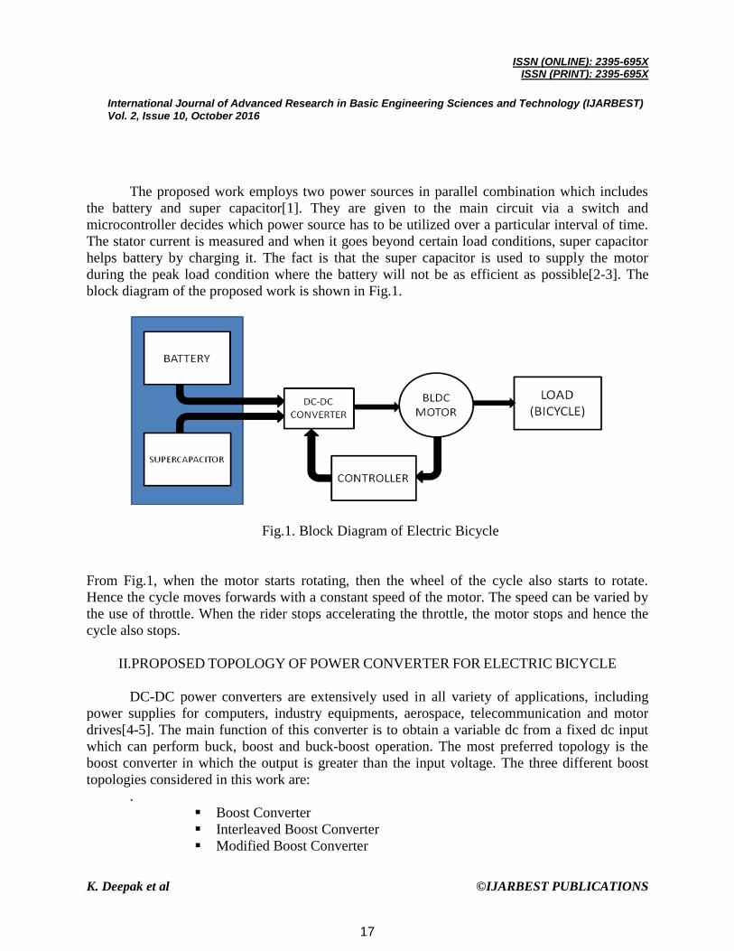
The proposed work employs two power sources in parallel combination which includes
the battery and super capacitor[1]. They are given to the main circuit via a switch and
microcontroller decides which power source has to be utilized over a particular interval of time.
The stator current is measured and when it goes beyond certain load conditions, super capacitor
helps battery by charging it. The fact is that the super capacitor is used to supply the motor
during the peak load condition where the battery will not be as efficient as possible[2-3]. The
block diagram of the proposed work is shown in Fig.1.
Fig.1. Block Diagram of Electric Bicycle
From Fig.1, when the motor starts rotating, then the wheel of the cycle also starts to rotate.
Hence the cycle moves forwards with a constant speed of the motor. The speed can be varied by
the use of throttle. When the rider stops accelerating the throttle, the motor stops and hence the
cycle also stops.
II.PROPOSED TOPOLOGY OF POWER CONVERTER FOR ELECTRIC BICYCLE
DC-DC power converters are extensively used in all variety of applications, including
power supplies for computers, industry equipments, aerospace, telecommunication and motor
drives[4-5]. The main function of this converter is to obtain a variable dc from a fixed dc input
which can perform buck, boost and buck-boost operation. The most preferred topology is the
boost converter in which the output is greater than the input voltage. The three different boost
topologies considered in this work are:
.
Boost Converter
Interleaved Boost Converter
Modified Boost Converter
17

ISSN (ONLINE): 2395-695X
ISSN (PRINT): 2395-695X
International Journal of Advanced Research in Basic Engineering Sciences and Technology (IJARBEST) Vol. 2, Issue 10, October 2016
K. Deepak et al ©IJARBEST PUBLICATIONS
(A) Boost Converter or Step-Up Converter
A boost converter is a switch mode DC to DC converter in which the output voltage is
greater than the input voltage and the circuit is shown in Fig.2. It is also called as step up
converter. The name step up converter comes from the fact that analogous to step up transformer
the input voltage is stepped up to a level greater than the input voltage. By law of conservation of
energy the input power has to be equal to output power (assuming no losses in the circuit).
Input power (Pin) = output power (Pout)
Since Vin < Vout in a boost converter, it follows then that the output current is less than
the input current. Therefore in a boost converter
Vin < Vout and Iin >Iout
Fig.2. Boost converter circuit
The main working principle of boost converter is that the inductor in the input circuit
resists sudden variations in input current. When the main switch is turned on, the inductor
current rises to the maximum value and energy is stored in the inductor. When the switch is
turned off, the polarity of the emf induced in the inductor reverses as it cannot the change the
direction of current instantaneously and hence the freewheeling diode is forward biased. As a
result, the inductor discharges and the energy stored in it are transferred to the load and the
inductor current decays. Therefore, the voltage across the load will be equal to the sum of the
supply voltage and voltage across the inductor. Hence, this converter produces an output greater
than the input voltage, thus performing boosting action. The large time constant compared to
switching period ensures a constant output voltage.
18
ISSN (ONLINE): 2395-695X
ISSN (PRINT): 2395-695X
International Journal of Advanced Research in Basic Engineering Sciences and Technology (IJARBEST) Vol. 2, Issue 10, October 2016
K. Deepak et al ©IJARBEST PUBLICATIONS
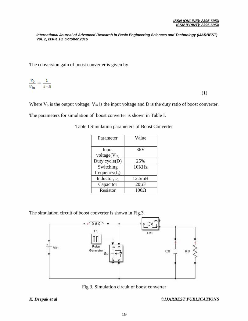
The conversion gain of boost converter is given by
(1)
Where Vo is the output voltage, Vin is the input voltage and D is the duty ratio of boost converter.
The parameters for simulation of boost converter is shown in Table I.
Table I Simulation parameters of Boost Converter
Parameter Value
Input
voltage(Vin)
36V
Duty cycle(D) 25%
Switching
frequency(fs)
10KHz
Inductor,L1 12.5mH
Capacitor 20µF
Resistor 100Ω
The simulation circuit of boost converter is shown in Fig.3.
Fig.3. Simulation circuit of boost converter
19

ISSN (ONLINE): 2395-695X
ISSN (PRINT): 2395-695X
International Journal of Advanced Research in Basic Engineering Sciences and Technology (IJARBEST) Vol. 2, Issue 10, October 2016
K. Deepak et al ©IJARBEST PUBLICATIONS
Fig. 4. Output voltage waveform
Fig.5. Output voltage ripple waveform
Fig.6. Input current waveform
20
ISSN (ONLINE): 2395-695X
ISSN (PRINT): 2395-695X
International Journal of Advanced Research in Basic Engineering Sciences and Technology (IJARBEST) Vol. 2, Issue 10, October 2016
K. Deepak et al ©IJARBEST PUBLICATIONS
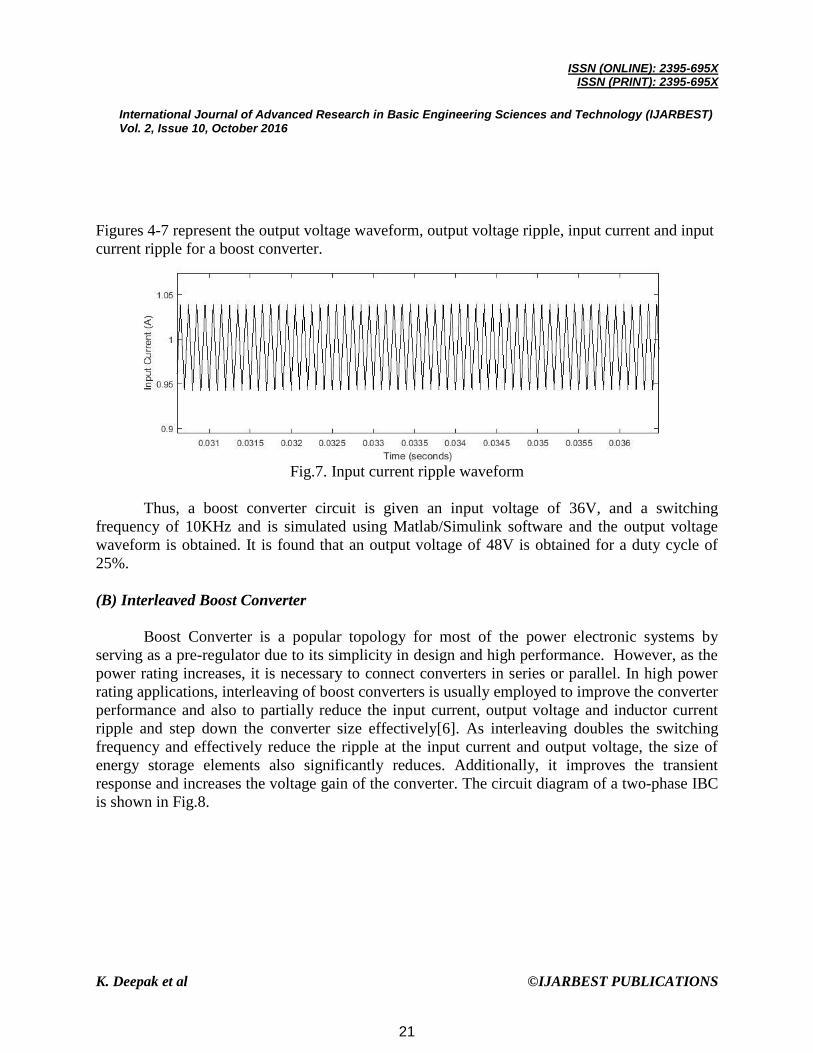
Figures 4-7 represent the output voltage waveform, output voltage ripple, input current and input
current ripple for a boost converter.
Fig.7. Input current ripple waveform
Thus, a boost converter circuit is given an input voltage of 36V, and a switching
frequency of 10KHz and is simulated using Matlab/Simulink software and the output voltage
waveform is obtained. It is found that an output voltage of 48V is obtained for a duty cycle of
25%.
(B) Interleaved Boost Converter
Boost Converter is a popular topology for most of the power electronic systems by
serving as a pre-regulator due to its simplicity in design and high performance. However, as the
power rating increases, it is necessary to connect converters in series or parallel. In high power
rating applications, interleaving of boost converters is usually employed to improve the converter
performance and also to partially reduce the input current, output voltage and inductor current
ripple and step down the converter size effectively[6]. As interleaving doubles the switching
frequency and effectively reduce the ripple at the input current and output voltage, the size of
energy storage elements also significantly reduces. Additionally, it improves the transient
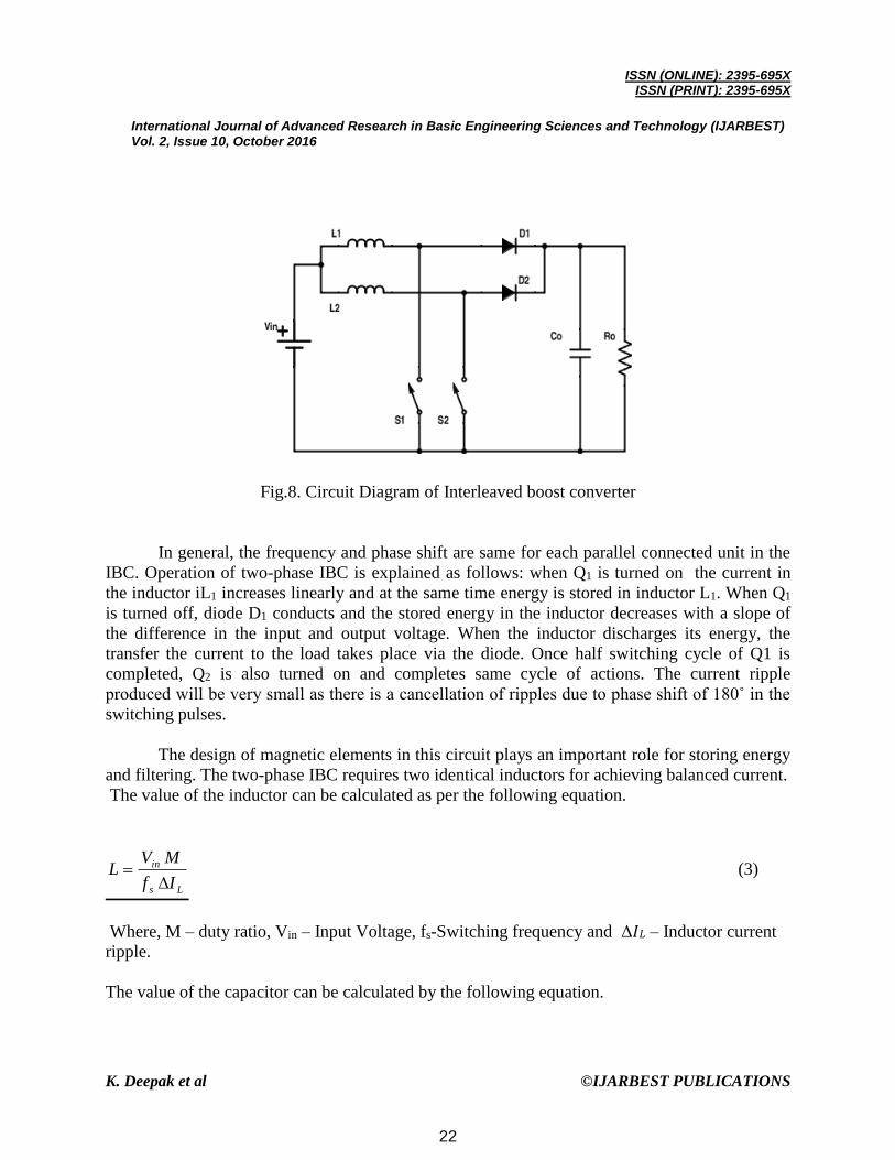
response and increases the voltage gain of the converter. The circuit diagram of a two-phase IBC
is shown in Fig.8.
21
ISSN (ONLINE): 2395-695X
ISSN (PRINT): 2395-695X
International Journal of Advanced Research in Basic Engineering Sciences and Technology (IJARBEST) Vol. 2, Issue 10, October 2016
K. Deepak et al ©IJARBEST PUBLICATIONS
Fig.8. Circuit Diagram of Interleaved boost converter
In general, the frequency and phase shift are same for each parallel connected unit in the
IBC. Operation of two-phase IBC is explained as follows: when Q1 is turned on the current in
the inductor iL1 increases linearly and at the same time energy is stored in inductor L1. When Q1
is turned off, diode D1 conducts and the stored energy in the inductor decreases with a slope of
the difference in the input and output voltage. When the inductor discharges its energy, the
transfer the current to the load takes place via the diode. Once half switching cycle of Q1 is
completed, Q2 is also turned on and completes same cycle of actions. The current ripple
produced will be very small as there is a cancellation of ripples due to phase shift of 180˚ in the
switching pulses.
The design of magnetic elements in this circuit plays an important role for storing energy
and filtering. The two-phase IBC requires two identical inductors for achieving balanced current.
The value of the inductor can be calculated as per the following equation.
Ls
in
If
MVL
(3)
Where, M – duty ratio, Vin – Input Voltage, fs-Switching frequency and Δ𝐼𝐿 – Inductor current
ripple.
The value of the capacitor can be calculated by the following equation.
22
ISSN (ONLINE): 2395-695X
ISSN (PRINT): 2395-695X
International Journal of Advanced Research in Basic Engineering Sciences and Technology (IJARBEST) Vol. 2, Issue 10, October 2016
K. Deepak et al ©IJARBEST PUBLICATIONS
(4)
Where, M – duty cycle, fs-Switching frequency, Δ𝑉𝐶 – Change in output voltage, Io –Output
current.
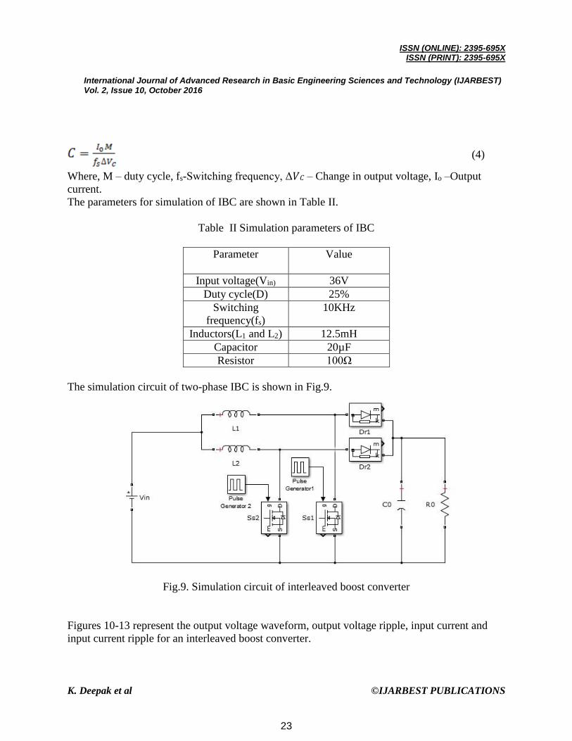
The parameters for simulation of IBC are shown in Table II.
Table II Simulation parameters of IBC
Parameter Value
Input voltage(Vin) 36V
Duty cycle(D) 25%
Switching
frequency(fs)
10KHz
Inductors(L1 and L2) 12.5mH
Capacitor 20µF
Resistor 100Ω
The simulation circuit of two-phase IBC is shown in Fig.9.
Fig.9. Simulation circuit of interleaved boost converter
Figures 10-13 represent the output voltage waveform, output voltage ripple, input current and
input current ripple for an interleaved boost converter.
23

ISSN (ONLINE): 2395-695X
ISSN (PRINT): 2395-695X
International Journal of Advanced Research in Basic Engineering Sciences and Technology (IJARBEST) Vol. 2, Issue 10, October 2016
K. Deepak et al ©IJARBEST PUBLICATIONS
Fig.10. Output voltage waveform
Fig.11. Output voltage ripple waveform
Fig.12. Input current waveform
24

ISSN (ONLINE): 2395-695X
ISSN (PRINT): 2395-695X
International Journal of Advanced Research in Basic Engineering Sciences and Technology (IJARBEST) Vol. 2, Issue 10, October 2016
K. Deepak et al ©IJARBEST PUBLICATIONS
Fig.13. Input current ripple waveform
Thus, an interleaved boost converter circuit is given an input voltage of 36V, and a
switching frequency of 10KHz and is simulated using Matlab/Simulink software and the output
voltage waveform is obtained. It is found that an output voltage of 48V is obtained for a duty
cycle of 25%.
(C) Modified Boost Converter
The circuit diagram shown in Fig.14 represents the two energy storage systems: the super
capacitor and the battery. According to the load level, the power semiconductor S1 is on during
the time tON. The main challenge of the work is to use in the same circuit super capacitors and
batteries and to manage the energy in each one, without changing the DC-DC power converter
topology. To get this objective, the Fig.14 circuit was implemented together with a specific
control strategy. The control strategy should, first of all, control the states of the switches S2 and
S3 in order to prolong the autonomy of the electrical vehicle and improve the efficiency of the
circuit. On the other hand, it should avoid simultaneous operation of the battery and the super
capacitors. In this case, a fast discharge of both energy storage systems would be observed.
25
ISSN (ONLINE): 2395-695X
ISSN (PRINT): 2395-695X
International Journal of Advanced Research in Basic Engineering Sciences and Technology (IJARBEST) Vol. 2, Issue 10, October 2016
K. Deepak et al ©IJARBEST PUBLICATIONS
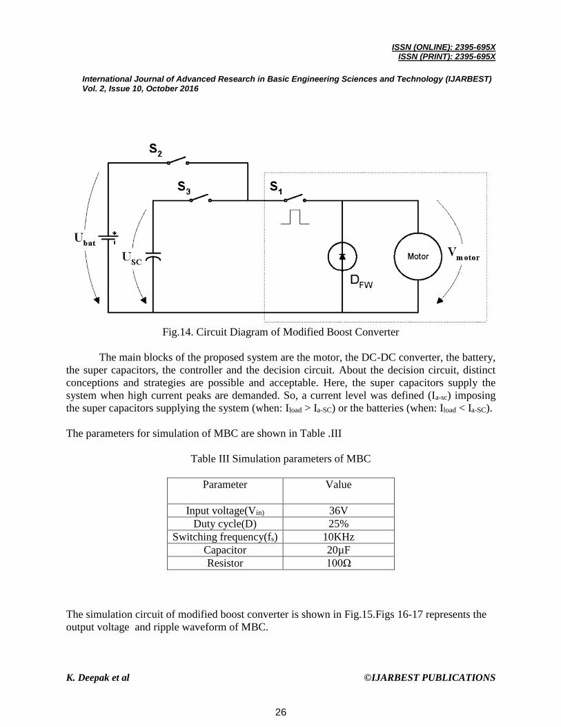
Fig.14. Circuit Diagram of Modified Boost Converter
The main blocks of the proposed system are the motor, the DC-DC converter, the battery,
the super capacitors, the controller and the decision circuit. About the decision circuit, distinct
conceptions and strategies are possible and acceptable. Here, the super capacitors supply the
system when high current peaks are demanded. So, a current level was defined (Ia-sc) imposing
the super capacitors supplying the system (when: Iload > Ia-SC) or the batteries (when: Iload < Ia-SC).
The parameters for simulation of MBC are shown in Table .III
Table III Simulation parameters of MBC
Parameter Value
Input voltage(Vin) 36V
Duty cycle(D) 25%
Switching frequency(fs) 10KHz
Capacitor 20µF
Resistor 100Ω
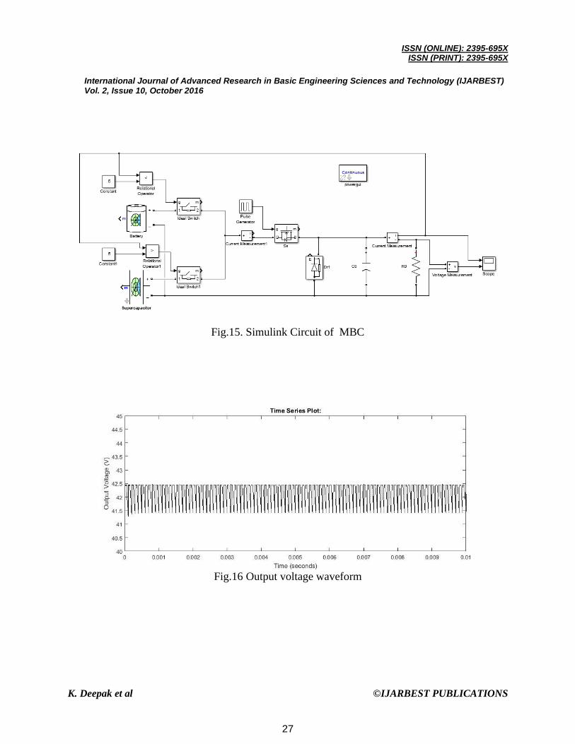
The simulation circuit of modified boost converter is shown in Fig.15.Figs 16-17 represents the
output voltage and ripple waveform of MBC.
26
ISSN (ONLINE): 2395-695X
ISSN (PRINT): 2395-695X
International Journal of Advanced Research in Basic Engineering Sciences and Technology (IJARBEST) Vol. 2, Issue 10, October 2016
K. Deepak et al ©IJARBEST PUBLICATIONS
Fig.15. Simulink Circuit of MBC
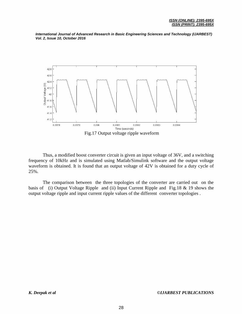
Fig.16 Output voltage waveform
27
ISSN (ONLINE): 2395-695X
ISSN (PRINT): 2395-695X
International Journal of Advanced Research in Basic Engineering Sciences and Technology (IJARBEST) Vol. 2, Issue 10, October 2016
K. Deepak et al ©IJARBEST PUBLICATIONS
Fig.17 Output voltage ripple waveform
Thus, a modified boost converter circuit is given an input voltage of 36V, and a switching
frequency of 10kHz and is simulated using Matlab/Simulink software and the output voltage
waveform is obtained. It is found that an output voltage of 42V is obtained for a duty cycle of
25%.
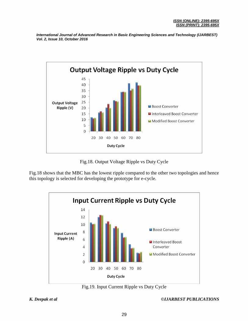
The comparison between the three topologies of the converter are carried out on the
basis of (i) Output Voltage Ripple and (ii) Input Current Ripple and Fig.18 & 19 shows the
output voltage ripple and input current ripple values of the different converter topologies .
28
ISSN (ONLINE): 2395-695X
ISSN (PRINT): 2395-695X
International Journal of Advanced Research in Basic Engineering Sciences and Technology (IJARBEST) Vol. 2, Issue 10, October 2016
K. Deepak et al ©IJARBEST PUBLICATIONS
Fig.18. Output Voltage Ripple vs Duty Cycle
Fig.18 shows that the MBC has the lowest ripple compared to the other two topologies and hence
this topology is selected for developing the prototype for e-cycle.
Fig.19. Input Current Ripple vs Duty Cycle
29
ISSN (ONLINE): 2395-695X
ISSN (PRINT): 2395-695X
International Journal of Advanced Research in Basic Engineering Sciences and Technology (IJARBEST) Vol. 2, Issue 10, October 2016
K. Deepak et al ©IJARBEST PUBLICATIONS
On comparing all the topologies, it has been found that the best topology that suits for the work
is modified boost converter. On comparing with other two topologies, MBC has less ripple
voltage and ripple current at the output and input side respectively. Also the efficiency is high in
MBC when compared to other two topologies.
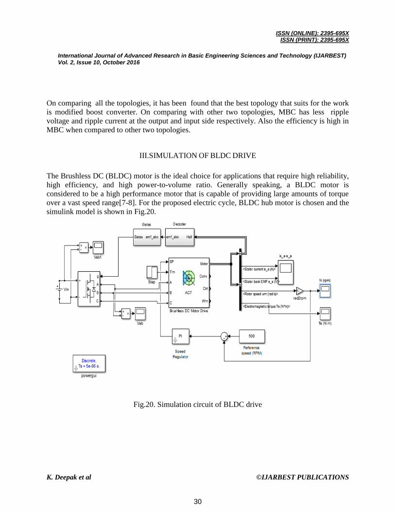
III.SIMULATION OF BLDC DRIVE
The Brushless DC (BLDC) motor is the ideal choice for applications that require high reliability,
high efficiency, and high power-to-volume ratio. Generally speaking, a BLDC motor is
considered to be a high performance motor that is capable of providing large amounts of torque
over a vast speed range[7-8]. For the proposed electric cycle, BLDC hub motor is chosen and the
simulink model is shown in Fig.20.
Fig.20. Simulation circuit of BLDC drive
30

ISSN (ONLINE): 2395-695X
ISSN (PRINT): 2395-695X
International Journal of Advanced Research in Basic Engineering Sciences and Technology (IJARBEST) Vol. 2, Issue 10, October 2016
K. Deepak et al ©IJARBEST PUBLICATIONS
Fig.21 Stator Back EMF Waveform
Fig.22 Stator Current Waveform
Fig.23 Rotor Speed Waveform
31
ISSN (ONLINE): 2395-695X
ISSN (PRINT): 2395-695X
International Journal of Advanced Research in Basic Engineering Sciences and Technology (IJARBEST) Vol. 2, Issue 10, October 2016
K. Deepak et al ©IJARBEST PUBLICATIONS
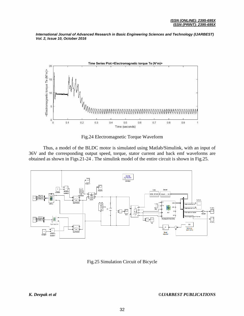
Fig.24 Electromagnetic Torque Waveform
Thus, a model of the BLDC motor is simulated using Matlab/Simulink, with an input of
36V and the corresponding output speed, torque, stator current and back emf waveforms are
obtained as shown in Figs.21-24 . The simulink model of the entire circuit is shown in Fig.25.
Fig.25 Simulation Circuit of Bicycle
32
ISSN (ONLINE): 2395-695X
ISSN (PRINT): 2395-695X
International Journal of Advanced Research in Basic Engineering Sciences and Technology (IJARBEST) Vol. 2, Issue 10, October 2016
K. Deepak et al ©IJARBEST PUBLICATIONS
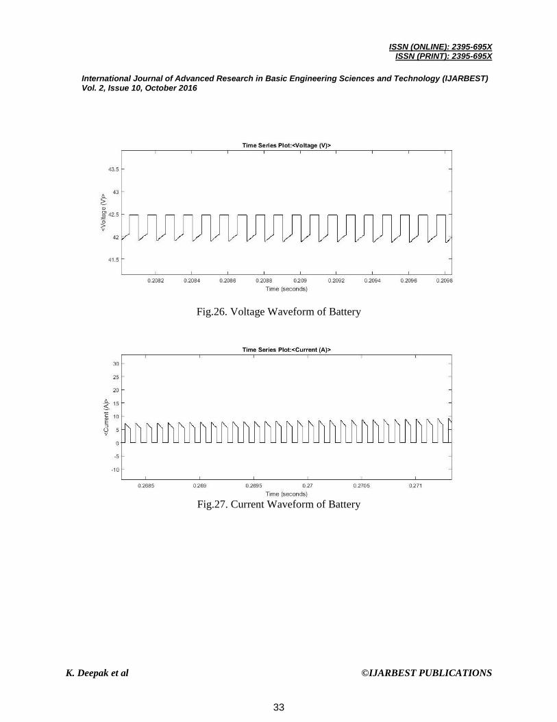
Fig.26. Voltage Waveform of Battery
Fig.27. Current Waveform of Battery
33

ISSN (ONLINE): 2395-695X
ISSN (PRINT): 2395-695X
International Journal of Advanced Research in Basic Engineering Sciences and Technology (IJARBEST) Vol. 2, Issue 10, October 2016
K. Deepak et al ©IJARBEST PUBLICATIONS
Fig.28. SOC Characteristics of Battery
Fig.29. Voltage Waveform of Supercapacitor
34
ISSN (ONLINE): 2395-695X
ISSN (PRINT): 2395-695X
International Journal of Advanced Research in Basic Engineering Sciences and Technology (IJARBEST) Vol. 2, Issue 10, October 2016
K. Deepak et al ©IJARBEST PUBLICATIONS
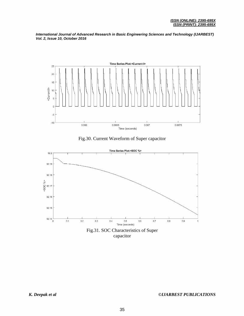
Fig.30. Current Waveform of Super capacitor
Fig.31. SOC Characteristics of Super
capacitor
35
ISSN (ONLINE): 2395-695X
ISSN (PRINT): 2395-695X
International Journal of Advanced Research in Basic Engineering Sciences and Technology (IJARBEST) Vol. 2, Issue 10, October 2016
K. Deepak et al ©IJARBEST PUBLICATIONS
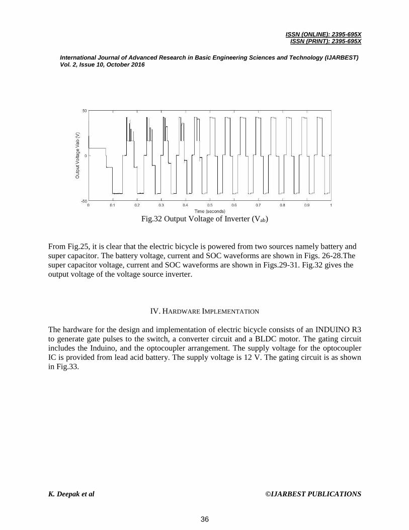
Fig.32 Output Voltage of Inverter (Vab)
From Fig.25, it is clear that the electric bicycle is powered from two sources namely battery and
super capacitor. The battery voltage, current and SOC waveforms are shown in Figs. 26-28.The
super capacitor voltage, current and SOC waveforms are shown in Figs.29-31. Fig.32 gives the
output voltage of the voltage source inverter.
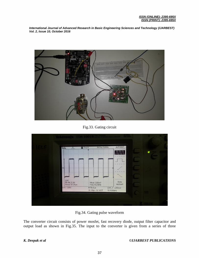
IV. HARDWARE IMPLEMENTATION
The hardware for the design and implementation of electric bicycle consists of an INDUINO R3
to generate gate pulses to the switch, a converter circuit and a BLDC motor. The gating circuit
includes the Induino, and the optocoupler arrangement. The supply voltage for the optocoupler
IC is provided from lead acid battery. The supply voltage is 12 V. The gating circuit is as shown
in Fig.33.
36
ISSN (ONLINE): 2395-695X
ISSN (PRINT): 2395-695X
International Journal of Advanced Research in Basic Engineering Sciences and Technology (IJARBEST) Vol. 2, Issue 10, October 2016
K. Deepak et al ©IJARBEST PUBLICATIONS
Fig.33. Gating circuit
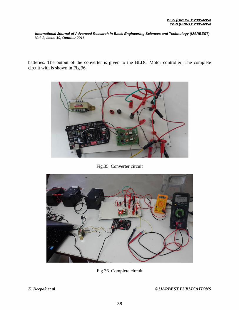
Fig.34. Gating pulse waveform
The converter circuit consists of power mosfet, fast recovery diode, output filter capacitor and
output load as shown in Fig.35. The input to the converter is given from a series of three
37
ISSN (ONLINE): 2395-695X
ISSN (PRINT): 2395-695X
International Journal of Advanced Research in Basic Engineering Sciences and Technology (IJARBEST) Vol. 2, Issue 10, October 2016
K. Deepak et al ©IJARBEST PUBLICATIONS
batteries. The output of the converter is given to the BLDC Motor controller. The complete
circuit with is shown in Fig.36.
Fig.35. Converter circuit
Fig.36. Complete circuit
38
ISSN (ONLINE): 2395-695X
ISSN (PRINT): 2395-695X
International Journal of Advanced Research in Basic Engineering Sciences and Technology (IJARBEST) Vol. 2, Issue 10, October 2016
K. Deepak et al ©IJARBEST PUBLICATIONS
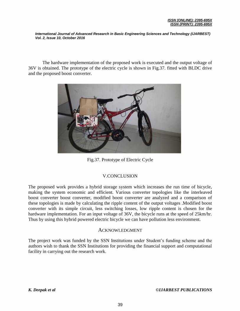
The hardware implementation of the proposed work is executed and the output voltage of
36V is obtained. The prototype of the electric cycle is shown in Fig.37. fitted with BLDC drive
and the proposed boost converter.
Fig.37. Prototype of Electric Cycle
V.CONCLUSION
The proposed work provides a hybrid storage system which increases the run time of bicycle,
making the system economic and efficient. Various converter topologies like the interleaved
boost converter boost converter, modified boost converter are analyzed and a comparison of
these topologies is made by calculating the ripple content of the output voltages .Modified boost
converter with its simple circuit, less switching losses, low ripple content is chosen for the
hardware implementation. For an input voltage of 36V, the bicycle runs at the speed of 25km/hr.
Thus by using this hybrid powered electric bicycle we can have pollution less environment.
ACKNOWLEDGMENT
The project work was funded by the SSN Institutions under Student’s funding scheme and the
authors wish to thank the SSN Institutions for providing the financial support and computational
facility in carrying out the research work.
39

ISSN (ONLINE): 2395-695X
ISSN (PRINT): 2395-695X
International Journal of Advanced Research in Basic Engineering Sciences and Technology (IJARBEST) Vol. 2, Issue 10, October 2016
K. Deepak et al ©IJARBEST PUBLICATIONS
REFERENCES
1) Burke, A.F. ,‘Batteries and super capacitors for electric, hybrid, and fuel cell vehicles’, Proc. IEEE, vol. 95,
no. 4, pp. 806-820, 2007.
2) Nikhil Hatwar ; Anurag Bisen ; Haren Dodke ; Akshay Junghare and Milind Khanapurkar, ‘Design
Approach for Electric Bikes Using Battery and Super Capacitor For Performance Improvement’, 16th
International IEEE Annual Conference on Intelligent Transportation Systems , The Hague, The
Netherlands, 2013.
3) Pay, S.; Baghzouz, Y. , ‘Effectiveness of battery-super capacitor combination in electric vehicles’, Power
Tech Conference Proceedings, IEEE Bologna , vol.3, no., pp. 6 pp. Vol.3, 23-26, 2003.
4) Khaligh, A. and Zhihao, L., ‘Battery, super capacitor, fuel cell, and hybrid energy storage systems for
electric, hybrid electric, fuel cell, and plug-in hybrid electric vehicles: State-of-the –art’, IEEE Trans. Veh.
Technol, vol. 59, no. 6, pp. 2806-2814, 2010.
5) Solero, L.; Lidozzi, A.; Pomilo, J.A. (2005) ‘Design of multiple-input power converter for hybrid vehicles’,
IEEE Trans. Power Electron., vol. 20, no. 5, pp. 1007–1016, 2005.
6) Mounica Ganta , Pallam reddy Nirupa, Thimmadi Akshitha, Dr.R.Seyezhai , “ Simple And Efficient
Implementation Of Two-Phase Interleaved Boost Converter For Renewable Energy Source
“,International Journal of Emerging Technology and Advanced Engineering, Volume 2, Issue 4, April
2012.
7) Ji Zhi-cheng; Shen Yan-xia and Jiang Jian-guo, ‘A Novel Method for Modeling and Simulation BLDC
System based on Matlab’, Journal of System Simulation, Vol.15 No.12, 2003.
8) Yin Yun-hua; Zheng Bin; Zheng Hao-xin, ‘A Method for Modeling and Simulation of Brushless DC
Motor Control System based on Matlab’, National Key Laboratory for Electronic Measurement
Technology, North University of China. Journal of System Simulation, Vol.20 No.2, 2008.
9) Kroeze, R.C. and Krein, P.T. , ‘ Electrical Battery Model for Use in Dynamic Electric Vehicle
Simulations’, University of Illinois at Urbana-Champaign Department of Electrical and Computer
Engineering, 2008.
10) Camara, M.B.; Gualous, H.; Gustin, F. and Berthon, A. , ‘Control strategy of hybrid sources for transport
applications using super capacitors and battery’, in Proc. IEEE, IPEMC, Shanghai, China, vol. 1, pp. 1–5,
2006.
11) Thounthong, P.; Rafel, S.; Davat, B. , ‘Energy management of fuel cell/battery super capacitor hybrid
power source for vehicle applications’, J. Power Sources, vol. 193, pp. 376-385,2009.
40
Related Documents