WinCC/IndustrialDataBridge Documentation ___________________ ___________________ ___________________ ___________________ ___________________ ___________________ SIMATIC HMI WinCC V7.2 WinCC/IndustrialDataBridge Documentation System Manual Printout of the Online Help 02/2013 A5E32364152-AA Introduction 1 Configuration 2 Modules 3 Runtime Environment 4 Advanced Features 5 FAQs 6

Welcome message from author
This document is posted to help you gain knowledge. Please leave a comment to let me know what you think about it! Share it to your friends and learn new things together.
Transcript

WinCC/IndustrialDataBridge
Documentation
___________________
___________________
___________________
___________________
___________________
___________________
SIMATIC HMI
WinCC V7.2WinCC/IndustrialDataBridgeDocumentation
System Manual
Printout of the Online Help
02/2013 A5E32364152-AA
Introduction 1
Configuration 2
Modules 3
Runtime Environment 4
Advanced Features 5
FAQs 6

Siemens AG Industry Sector Postfach 48 48 90026 NÜRNBERG GERMANY
Order number: A5E32364152-AA Ⓟ 02/2013 Technical data subject to change
Copyright © Siemens AG 2013. All rights reserved
Legal information Warning notice system
This manual contains notices you have to observe in order to ensure your personal safety, as well as to prevent damage to property. The notices referring to your personal safety are highlighted in the manual by a safety alert symbol, notices referring only to property damage have no safety alert symbol. These notices shown below are graded according to the degree of danger.
DANGER indicates that death or severe personal injury will result if proper precautions are not taken.
WARNING indicates that death or severe personal injury may result if proper precautions are not taken.
CAUTION indicates that minor personal injury can result if proper precautions are not taken.
NOTICE indicates that property damage can result if proper precautions are not taken.
If more than one degree of danger is present, the warning notice representing the highest degree of danger will be used. A notice warning of injury to persons with a safety alert symbol may also include a warning relating to property damage.
Qualified Personnel The product/system described in this documentation may be operated only by personnel qualified for the specific task in accordance with the relevant documentation, in particular its warning notices and safety instructions. Qualified personnel are those who, based on their training and experience, are capable of identifying risks and avoiding potential hazards when working with these products/systems.
Proper use of Siemens products Note the following:
WARNING Siemens products may only be used for the applications described in the catalog and in the relevant technical documentation. If products and components from other manufacturers are used, these must be recommended or approved by Siemens. Proper transport, storage, installation, assembly, commissioning, operation and maintenance are required to ensure that the products operate safely and without any problems. The permissible ambient conditions must be complied with. The information in the relevant documentation must be observed.
Trademarks All names identified by ® are registered trademarks of Siemens AG. The remaining trademarks in this publication may be trademarks whose use by third parties for their own purposes could violate the rights of the owner.
Disclaimer of Liability We have reviewed the contents of this publication to ensure consistency with the hardware and software described. Since variance cannot be precluded entirely, we cannot guarantee full consistency. However, the information in this publication is reviewed regularly and any necessary corrections are included in subsequent editions.

WinCC/IndustrialDataBridge Documentation System Manual, 02/2013, Printout of the Online Help, A5E32364152-AA 3
Table of contents
1 Introduction. ................................................................................................................................................ 7
1.1 Information in this manual.............................................................................................................7
1.2 IndustrialDataBridge Overview .....................................................................................................9
2 Configuration . ........................................................................................................................................... 15
2.1 IDB Configuration. ......................................................................................................................15
2.2 Software User Interface ..............................................................................................................17
2.3 User Interface Layout..................................................................................................................33
2.4 Project Basics . ...........................................................................................................................37
2.5 Import / Generate Runtime Configuration...................................................................................49
2.6 Interface Structuring....................................................................................................................51
3 Modules. ................................................................................................................................................... 55
3.1 Modules. .....................................................................................................................................55
3.2 OPC Data Access . .....................................................................................................................57 3.2.1 Overview . ...................................................................................................................................57 3.2.2 Configuring the OPC Data Access Interface as a Provider . .......................................................59 3.2.3 Connecting Tags from the OPC Data Access Interface . ............................................................66 3.2.4 Configuring the OPC Data Access Interface as a Consumer. ....................................................70 3.2.5 Connecting Tags to the OPC Data Access Interface. .................................................................79
3.3 IDB OPC Server. ........................................................................................................................82 3.3.1 Overview . ...................................................................................................................................82 3.3.2 IDB OPC Server Address Space ................................................................................................84 3.3.3 Configuring the IDB OPC Server Interface as a Consumer . ......................................................86 3.3.4 Connecting Tags to the IDB OPC Server ...................................................................................93
3.4 OPC XML. ..................................................................................................................................96 3.4.1 Overview . ...................................................................................................................................96 3.4.2 Requirements. ............................................................................................................................98 3.4.3 Configuring the OPC XML as Provider .....................................................................................100 3.4.4 Connecting Tags from the OPC XML Interface . .......................................................................105 3.4.5 Configuring the OPC XML as Consumer..................................................................................112 3.4.6 Connecting Tags to the OPC XML Interface ............................................................................120
3.5 WinCC OLE DB . ......................................................................................................................123 3.5.1 Overview . .................................................................................................................................123 3.5.2 Requirements. ..........................................................................................................................125 3.5.3 Configuring the WinCC OLE DB Interface as a Provider . ........................................................127 3.5.4 Configuration of the Transfer Behavior.....................................................................................135 3.5.5 Configuring a Trigger ................................................................................................................144 3.5.6 Connecting Tags from the WinCC OLE DB Interface. ..............................................................150
3.6 Database. .................................................................................................................................153

Table of contents
WinCC/IndustrialDataBridge Documentation 4 System Manual, 02/2013, Printout of the Online Help, A5E32364152-AA
3.6.1 Overview . ................................................................................................................................ 153 3.6.2 Supported data types ............................................................................................................... 156 3.6.3 Configuring a Database Interface as Provider . ........................................................................ 159 3.6.4 Data Link Properties................................................................................................................. 166 3.6.5 Connecting Tags from a Database Interface . .......................................................................... 169 3.6.6 Configuring a Database Interface as Consumer. ..................................................................... 172 3.6.7 Consumer Types. .................................................................................................................... 181 3.6.8 Connecting Tags to a Database Interface . .............................................................................. 187
3.7 Dynamic Database................................................................................................................... 193 3.7.1 Overview . ................................................................................................................................ 193 3.7.2 Configuring an Interface to a Dynamic Database as a Provider. ............................................. 197 3.7.3 Configuring a Trigger ............................................................................................................... 204 3.7.4 Connecting Tags from the Interface of a Dynamic Database. ................................................. 210 3.7.5 Connecting OPC Tags from the Interface of a Dynamic Database . ........................................ 216 3.7.6 Configuring an Interface to a Dynamic Database as a Consumer. .......................................... 219 3.7.7 Connecting Tags to a Dynamic Database Interface . ............................................................... 226
3.8 CSV and TXT Files .................................................................................................................. 231 3.8.1 Overview . ................................................................................................................................ 231 3.8.2 Configuring an Interface to CSV- and TXT-Files as a Consumer. ........................................... 232 3.8.3 Connecting Tags to an Interface to CSV- and TXT-Files . ....................................................... 237
3.9 Excel. ....................................................................................................................................... 245 3.9.1 Overview . ................................................................................................................................ 245 3.9.2 Requirements. ......................................................................................................................... 247 3.9.3 Configuring an Excel Interface as Consumer . ......................................................................... 248 3.9.4 Connecting Tags to the Excel Interface ................................................................................... 255
3.10 Send/Receive. ......................................................................................................................... 258 3.10.1 Overview . ................................................................................................................................ 258 3.10.2 Requirements. ......................................................................................................................... 261 3.10.3 Configuring the Send/Receive Interface as a Provider. ........................................................... 262 3.10.4 Configuring the Different Types of Connections . ..................................................................... 268 3.10.5 Connecting Tags from a Send/Receive Interface . ................................................................... 272 3.10.6 Configuring the Send/Receive Interface as a Consumer. ........................................................ 275 3.10.7 Connecting Tags to a Send/Receive Interface . ....................................................................... 280
3.11 WinCC User Archive ................................................................................................................ 283 3.11.1 Overview . ................................................................................................................................ 283 3.11.2 Configuring the Interface to WinCC User Archives as a Provider . .......................................... 284 3.11.3 Configuring a Trigger ............................................................................................................... 291 3.11.4 Connecting Tags from the WinCC User Archives Interface. .................................................... 297 3.11.5 Connecting OPC Tags from the WinCC User Archives Interface. ........................................... 304 3.11.6 Configuring the Interface to WinCC User Archives as a Consumer . ....................................... 307 3.11.7 Connecting Tags to the WinCC User Archives Interface. ........................................................ 313 3.11.8 Configuring the Deleting of Tags from the WinCC User Archive . ............................................ 317
4 Runtime Environment . ............................................................................................................................ 319
4.1 IDB Runtime. ........................................................................................................................... 319
4.2 Menu commands and buttons.................................................................................................. 320
4.3 Views. ...................................................................................................................................... 322
4.4 Options . ................................................................................................................................... 325

Table of contents
WinCC/IndustrialDataBridge Documentation System Manual, 02/2013, Printout of the Online Help, A5E32364152-AA 5
4.4.1 Overview . .................................................................................................................................325 4.4.2 Start Settings. ...........................................................................................................................327 4.4.3 Diagnostic Settings ...................................................................................................................329 4.4.4 Change password .....................................................................................................................333 4.4.5 Checking License Data .............................................................................................................334 4.4.6 Starting service . .......................................................................................................................335
4.5 Working with Connections ........................................................................................................337
5 Advanced Features. ................................................................................................................................ 345
5.1 Viewing Alarm Messages..........................................................................................................345
5.2 Using IDB Controls in Web Navigator.......................................................................................346
5.3 Accessing IDB Runtime using WinCC Controls. .......................................................................349
5.4 Asian Language Support ..........................................................................................................354
6 FAQs . ..................................................................................................................................................... 357
Glossary . ................................................................................................................................................ 363
Index. ...................................................................................................................................................... 367

Table of contents
WinCC/IndustrialDataBridge Documentation 6 System Manual, 02/2013, Printout of the Online Help, A5E32364152-AA

WinCC/IndustrialDataBridge Documentation System Manual, 02/2013, Printout of the Online Help, A5E32364152-AA 7
Introduction 11.1 Information in this manual
Content of the manual The IDB Documentation manual provides you the following information that helps you to work with IndustrialDataBridge Configuration System application and IndustrialDataBridge Runtime application.
● IndustrialDataBridge Overview:
This chapter provides an overview of IndustrialDataBridge and its usage. The different provider or consumer modules supported including the priniciple of operation of IndustrialDataBridge Configuration System and IndustrialDataBridge Runtime System is explained here.
● IndustrialDataBridge Configuration
This chapter deals with the information regarding the steps for starting and exiting IDB CS.
● Software User Interface
This chapter includes information specific to the details of the software user interface, its usage within IDB CS and a detailed explanation of each of the software user controls provided within the appication.
● User Interface Layout
This chapter includes information about the user interface layout and ways of managing and storing the window layout.
● Project Basics
The basic concept of project, links and connections is explained here. The related steps for creating project, saving project and managing project(s) within project tree are provided in this chapter. This chapter also includes information about links, their usage within project tree and ways through which links can be managed.

Introduction 1.1 Information in this manual
WinCC/IndustrialDataBridge Documentation 8 System Manual, 02/2013, Printout of the Online Help, A5E32364152-AA
● Import / Generate Runtime Configuration
This chapter includes information about the steps for importing or generating runtime configuration.
● Modules
This chapter includes the list of supported provider and consumer types. Each of these module(s) are covered in detail within the individual chapter names. Each module includes information about creating project, link, configuring provider/consumer configuration, configuring transfer settings for provider and performing connection mapping between provider and consumer types.
● Runtime
The Runtime chapter deals with working of IndustrialDataBridge Runtime application and provides information about the various options available within Runtime appliation. This chapter also includes information for activating connection and enabling or starting data tranfer.
● Advanced Features
A list of advanced features supported in IDB are provided here. This chapter includes information about Asian language support, using IDB Runtime using WinCC controls and information about Web Navigator support in IDB Runtime.
Introduction 1.2 IndustrialDataBridge Overview
WinCC/IndustrialDataBridge Documentation System Manual, 02/2013, Printout of the Online Help, A5E32364152-AA 9
1.2 IndustrialDataBridge Overview
Introduction The WinCC/IndustrialDataBridge V7.2 is a WinCC option. It enables the data exchange between various systems by using variety of standard interfaces with simple configuration. These are organized into modules within IndustrialDataBridge that includes various systems or data interfaces. You can expand the data exchange to other data interfaces at any time with this modular construction. The software design also allows the simple integration of new interfaces into the application. The IndustrialDataBridge is used for exchanging data between automation systems from different vendors (via OPC XML or Send/Receive for example) or with other applications storing process data in Office formats such as Excel or Access. For archiving larger data volumes, you can also integrate databases (SQL Server, Oracle).
The IndustrialDataBridge holds the Configuration system "IndustrialDataBridge CS" and the Runtime system "IndustrialDataBridge RT".
Configuration files are created in XML format using the IndustrialDataBridge CS application. The IDB CS includes a well equipped user interface that provides options for configuring IDB links. There are options for commissioning, status monitoring and troubleshooting available in the runtime environment. The IndustrialDataBridge RT allows access to the process data and links the data as defined in the loaded configuration file.
Note
Please note that throughout this manual in some of the chapters you may find that, "IndustrialDataBridge CS" is referred to as "IDB CS" and "IndustrialDataBridge RT" as "IDB RT".
Usage IndustrialDataBridge V7.2 can be used along with WinCC and can also run as an independent software. The following 3 scenarios shown below helps to make you understand the usage of IDB application.
● As Independent software: The IndustrialDataBridge application can run as an independent software application by installing IDB V7.2.
● As centralized WinCC Station: IDB can be installed on single station or Multiclient station or WinCC Server ie., on top of WinCC systems wherein IDB can act as a centralized point of access to all other systems.
● Using Web Navigator: If the IDB control is embedded in a WinCC screen, it can be used on a Web Navigator client / server. Hence, it is possible to control IDB CS via Internet. For example, to start, stop or load new configuration.

Introduction 1.2 IndustrialDataBridge Overview
WinCC/IndustrialDataBridge Documentation 10 System Manual, 02/2013, Printout of the Online Help, A5E32364152-AA
Overview An exchange between different automation systems and IT systems is made possible with the IndustrialDataBridge. The following image shows an overview of the various applications and formats that are supported by the IDB Configuration application.
The various data interfaces are linked via software modules. These modules are divided into "Provider" and "Consumer".
● Provider
● Consumer
The provider establishes the connection to data provider, from which the data is delivered. The consumer connects with the data consumer, into which the data is written.
You can connect different providers and consumers with one-another. Note that not all providers exist as consumers and vice versa. One provider must always be connected with one consumer.
The IndustrialDataBridge is connection-oriented. Therefore, a connection always functions in one direction only. For bidirectional communication, you must configure two connections. A total of up to 32 connections are available.
Examples can be found in "Getting Started" manual.

Introduction 1.2 IndustrialDataBridge Overview
WinCC/IndustrialDataBridge Documentation System Manual, 02/2013, Printout of the Online Help, A5E32364152-AA 11
Principle of Operation The IndustrialDataBridge V7.2 is divided into two parts:
● Configuration system
● Runtime system
You create and manage provider/consumer configuration, settings and connection(s) in the configuration system. You only require four steps to completely configure a connection:
1. Create project and create the required link(s). Next, select the desired provider and consumer types.
2. Define provider and consumer configuration properties.
3. Perform link settings - configure the Transfer options for provider.
4. Create connection by performing mapping between provider to consumer tags.
5. Generate Runtime Configuration by exporting the XML file.
Performing data transfer can be done in the runtime system:
1. Loading the configuration file (XML)
2. Connect the links (provider and consumer types)
3. Start the data transfer
Introduction 1.2 IndustrialDataBridge Overview
WinCC/IndustrialDataBridge Documentation 12 System Manual, 02/2013, Printout of the Online Help, A5E32364152-AA
Start the Runtime Environment
An XML configuration file that is exported from IDB CS is loaded in the IDB runtime system. After the connection(s) have been activated (data provider and data consumer are connected successfully), the runtime environment monitors the life-span of the provider and consumer components and establishes the connection again automatically, if necessary. Only if you have clicked on "Start", the actual data exchange will be started.
More detailed explanation about the runtime environment is provided in "Runtime Environment" chapter.
With Configuration System in IDB CS available separately, the configuration of various data interfaces are handled in the IDB Configuration System. The Runtime System enables loading the configuration files and performing the data transfer. Hence, this allows you to create a configuration on one computer in the development department for instance. You can then transfer the file into the runtime environment on a computer in production. Using configuration on computers in different production locations or keeping different configuration files for different projects is also possible with IndustrialDataBridge application.
Supported Languages The following interface languages are available in the IndustrialDataBridge V7.2:
● German
● English
● French
● Italian
● Spanish
● Simplified Chinese
● Japanese
Screen Resolution used The IndustrialDataBridge application has been designed with a well-built user interface to support resolution of 1280x1024 pixels. It is strongly recommended to use this resolution format.
Introduction 1.2 IndustrialDataBridge Overview
WinCC/IndustrialDataBridge Documentation System Manual, 02/2013, Printout of the Online Help, A5E32364152-AA 13
See also Overview (Page 57)
Overview (Page 96)
Overview (Page 258)
Overview (Page 153)
Overview (Page 193)
Overview (Page 123)
Overview (Page 283)
Configuring the OPC Data Access Interface as a Consumer (Page 70)
Configuring the OPC XML as Consumer (Page 112)
Configuring the Send/Receive Interface as a Consumer (Page 275)
Configuring a Database Interface as Consumer (Page 172)
Overview (Page 245)
Overview (Page 82)
Configuring an Interface to a Dynamic Database as a Consumer (Page 219)
Overview (Page 231)
Configuring the Interface to WinCC User Archives as a Consumer (Page 307)

Introduction 1.2 IndustrialDataBridge Overview
WinCC/IndustrialDataBridge Documentation 14 System Manual, 02/2013, Printout of the Online Help, A5E32364152-AA
WinCC/IndustrialDataBridge Documentation System Manual, 02/2013, Printout of the Online Help, A5E32364152-AA 15
Configuration 22.1 IDB Configuration
Introduction IndustrialDataBridge (IDB) configuration application is used for configuring and managing connections between provider and consumer. Connection can be established between various provider and consumer types.
This chapter provides information about starting and exiting IDB application. It also includes information pertaining to the basic structure of an IDB configuration.
Starting IDB configuration system To start IDB configuration from windows environment, select "Start" > "All Programs" > "Siemens Automation" > "IndustrialDataBridge" > "IndustrialDataBridge CS". This will open the IDB V7.2 application window.
To open IDB application using WinCC, follow these steps:
1. Select "Start" > "All Programs" > "SIMATIC" > "WinCC" > "WinCC Explorer".
This will invoke the WinCC Explorer window.
2. In WinCC Explorer, select "IndustrialDataBridge" > "Configuration" from the left hand tree structure to open IDB V7.2 application.
The IDB configuration window includes options for creating a project. Once a project has been created, it provides option to create links between various provider(s), consumer(s) and help to manage their connections. Options are also provided to save the new configuration, export as an XML file or import an existing configuration.
Exiting IDB configuration system Follow the steps given below to exit IDB configuration:
1. Select "Project" menu and click "Exit" option.
2. If the project contains any changes that have not been saved, you will be asked if you wish to save them.
Configuration 2.1 IDB Configuration
WinCC/IndustrialDataBridge Documentation 16 System Manual, 02/2013, Printout of the Online Help, A5E32364152-AA
● Select "Yes" to save the changes in the current project and exit IDB configuration
● Select "No" to close the IDB configuration without saving the most recent changes in the project
● Select "Cancel" to cancel the exit dialog window. However, the IDB configuration application will still be open.
Structure The basic structure within the IDB Configuration system (CS) is built with the concept of a Project. A project refers to a single IDB configuration that can be loaded at any point of time. The project is an entry point for performing a configuration wherein each project consists of link(s) and connection(s).
● Project: A project helps to create and manage provider/consumer configuration properties, settings and includes options to perform connection mapping.
● Link: A link is part of a project and allows to configure the provider, consumer and transfer behavior settings for provider.
● Connection: A connection represents a mapping between provider and consumer types.
See also Software User Interface (Page 17)

Configuration 2.2 Software User Interface
WinCC/IndustrialDataBridge Documentation System Manual, 02/2013, Printout of the Online Help, A5E32364152-AA 17
2.2 Software User Interface
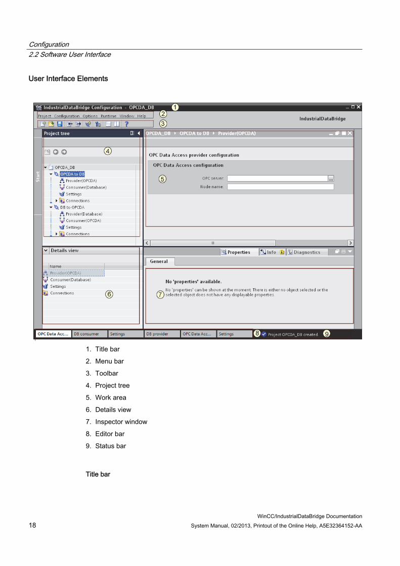
Introduction This chapter provides a complete overview of IDB CS Software user interface elements and explains each of these controls in detail.
User Interface The structure of IndustrialDataBridge Configuration application includes an easy to use user interface that provides options for creating & modifying projects/links/nodes, performing provider/consumer configuration and saving the configuration files. The information about these user controls have been grouped into the related areas within the user interface.
Configuration 2.2 Software User Interface
WinCC/IndustrialDataBridge Documentation 18 System Manual, 02/2013, Printout of the Online Help, A5E32364152-AA
User Interface Elements
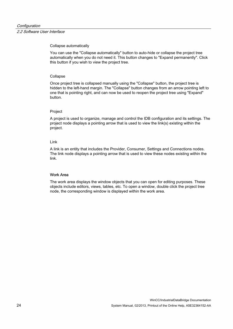
1. Title bar
2. Menu bar
3. Toolbar
4. Project tree
5. Work area
6. Details view
7. Inspector window
8. Editor bar
9. Status bar
Title bar

Configuration 2.2 Software User Interface
WinCC/IndustrialDataBridge Documentation System Manual, 02/2013, Printout of the Online Help, A5E32364152-AA 19
The Title bar exists at the top position of IDB Configuration application. It displays the project name once the project has been opened. If no projects are open, then the title bar will not display the project name in the title bar. The title bar provides 3 window controls that is used to minimize, maximize or close the IDB CS application window. These controls exist towards the right hand position of the title bar.
a. Minimize: Minimizes the IDB Configuration application to the windows task bar.
b. Maximize: Maximizes the IDB Configuration application and displays the complete application view.
c. Close: Closes the IDB Configuration application.
Note
Selecting the "Close" icon exits the IDB Configuration application without saving changes to the currently opened project. However, a dialog window is displayed that prompts whether you wish to save the changes to the current project. Select "Yes" to save the changes to the project.
Menu bar
The Menu bar includes all related menu items that are required for working with the IndustrialDataBridge application. The list of menu items and their description is provided below:
Table 2- 1 "Project" menu
Item Description New project Creates a new project Open project Opens a new project Close project Closes an opened project without saving Save Saves the project along with the configuration Save as Saves the project with a new name Delete project Provides option to select the project that needs to
be deleted and to perform Delete operation Generate Runtime Configuration Exports the XML file to desired folder location Import Runtime Configuration Imports the XML file into IDB CS and opens as a
new project Exit Exits the IDB CS application

Configuration 2.2 Software User Interface
WinCC/IndustrialDataBridge Documentation 20 System Manual, 02/2013, Printout of the Online Help, A5E32364152-AA
Table 2- 2 "Configuration" menu
Item Description Add new link1 Allows for adding a new link Delete all links 2 Deletes all links created within the project Connect 3 Connects the provider tag with selected
consumer tag Delete connection 4 Deletes the selected connection after user
confirmation
Note 1 The menu option "Add new link" is displayed in the "Configuration" menu only if a
project is open. This option is shown even if the project does not contain any link(s). 2 The menu option "Delete all links" is in enable state in the "Configuration" menu only
when a project is open that contains atleast one link. 3 4 The menu options "Connect" & "Delete connection" are in enable state in the
"Configuration" menu only while navigating within the connection mapping tab and when the basic conditions for connection establishment are satisfied.
Table 2- 3 "Options" menu
Item Description Settings Includes IDB CS General settings and keyboard
shortcuts information
Table 2- 4 "Runtime" menu
Item Description Runtime configuration Opens Runtime Configuration
Table 2- 5 "Window" menu
Item Description Close all editors Closes all open editors including the editor
window in the editor bar Minimize all editors Minimizes all open editors and displays this
window in the editor bar Next editor Navigates to next available editor window Previous editor Navigates to the previous editor window
Configuration 2.2 Software User Interface
WinCC/IndustrialDataBridge Documentation System Manual, 02/2013, Printout of the Online Help, A5E32364152-AA 21
Item Description Split editors vertically Splits editors vertically within the work area Split editors horizontally Splits editors horizontally within the work area Unsplit Reverts back the split windows to normal state Store current layout Saves the current screen layout Manage layouts Pops up a window that helps to manage different
window layouts Restore active layout Restores the active layout Default window layout Provides a radio button option that helps to toggle
between modes More layout Provides layout in expanded view
Table 2- 6 "Help" menu
Item Description Show Help Displays the Online Help window Installed Software Provides information about the installed software About Displays product and version information
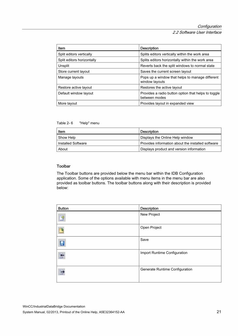
Toolbar
The Toolbar buttons are provided below the menu bar within the IDB Configuration application. Some of the options available with menu items in the menu bar are also provided as toolbar buttons. The toolbar buttons along with their description is provided below:
Button DescriptionNew Project
Open Project
Save
Import Runtime Configuration
Generate Runtime Configuration
Configuration 2.2 Software User Interface
WinCC/IndustrialDataBridge Documentation 22 System Manual, 02/2013, Printout of the Online Help, A5E32364152-AA
Button Description
Add New Link
Runtime Configuration
Split editors horizontally
Split editors vertically
Show Help
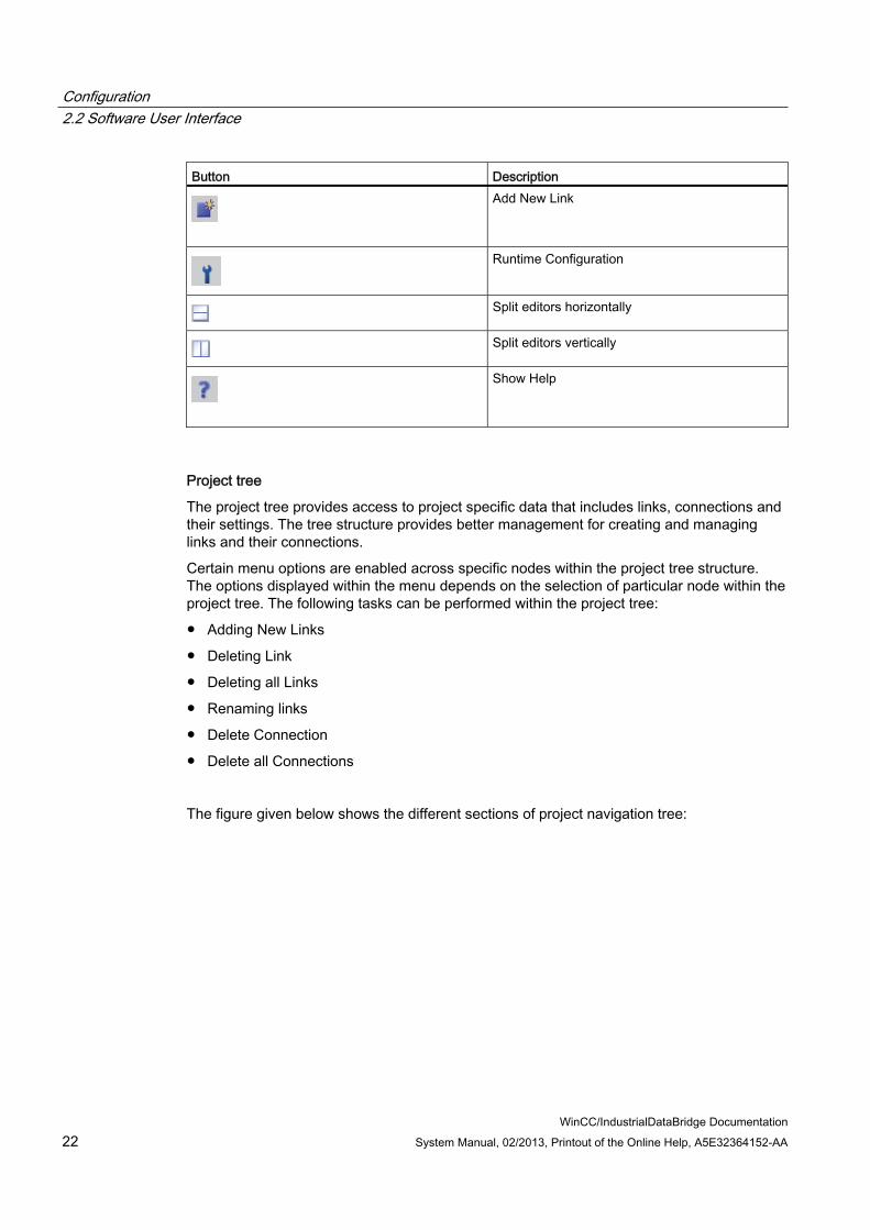
Project tree
The project tree provides access to project specific data that includes links, connections and their settings. The tree structure provides better management for creating and managing links and their connections.
Certain menu options are enabled across specific nodes within the project tree structure. The options displayed within the menu depends on the selection of particular node within the project tree. The following tasks can be performed within the project tree:
● Adding New Links
● Deleting Link
● Deleting all Links
● Renaming links
● Delete Connection
● Delete all Connections
The figure given below shows the different sections of project navigation tree:

Configuration 2.2 Software User Interface
WinCC/IndustrialDataBridge Documentation System Manual, 02/2013, Printout of the Online Help, A5E32364152-AA 23
1. Side stripe
2. Title bar
3. Collapse automatically
4. Collapse
5. Project
6. Link
Side stripe
The Side stripe bar is used to collapse/expand the project tree.
Title bar
The name of the project is displayed in the title bar.
Configuration 2.2 Software User Interface
WinCC/IndustrialDataBridge Documentation 24 System Manual, 02/2013, Printout of the Online Help, A5E32364152-AA
Collapse automatically
You can use the "Collapse automatically" button to auto-hide or collapse the project tree automatically when you do not need it. This button changes to "Expand permanently". Click this button if you wish to view the project tree.
Collapse
Once project tree is collapsed manually using the "Collapse" button, the project tree is hidden to the left-hand margin. The "Collapse" button changes from an arrow pointing left to one that is pointing right, and can now be used to reopen the project tree using "Expand" button.
Project
A project is used to organize, manage and control the IDB configuration and its settings. The project node displays a pointing arrow that is used to view the link(s) existing within the project.
Link
A link is an entity that includes the Provider, Consumer, Settings and Connections nodes. The link node displays a pointing arrow that is used to view these nodes existing within the link.
Work Area
The work area displays the window objects that you can open for editing purposes. These objects include editors, views, tables, etc. To open a window, double click the project tree node, the corresponding window is displayed within the work area.
Configuration 2.2 Software User Interface
WinCC/IndustrialDataBridge Documentation System Manual, 02/2013, Printout of the Online Help, A5E32364152-AA 25
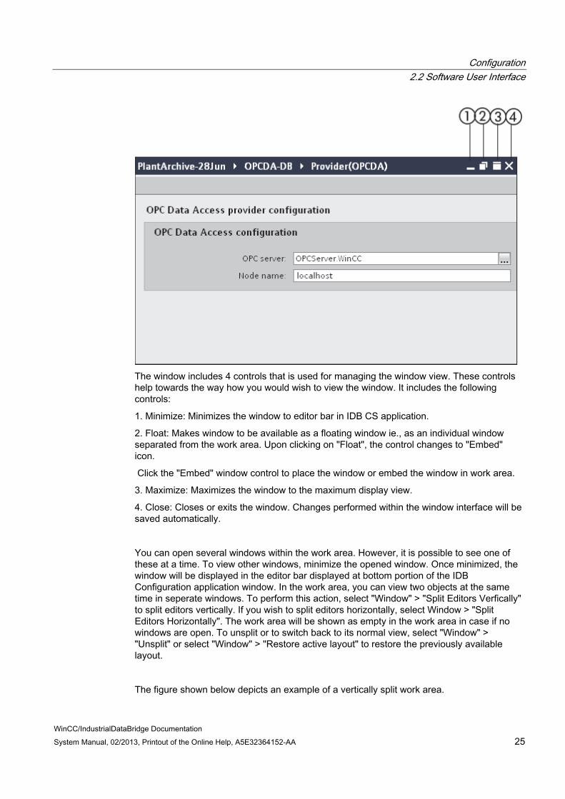
The window includes 4 controls that is used for managing the window view. These controls help towards the way how you would wish to view the window. It includes the following controls:
1. Minimize: Minimizes the window to editor bar in IDB CS application.
2. Float: Makes window to be available as a floating window ie., as an individual window separated from the work area. Upon clicking on "Float", the control changes to "Embed" icon.
Click the "Embed" window control to place the window or embed the window in work area.
3. Maximize: Maximizes the window to the maximum display view.
4. Close: Closes or exits the window. Changes performed within the window interface will be saved automatically.
You can open several windows within the work area. However, it is possible to see one of these at a time. To view other windows, minimize the opened window. Once minimized, the window will be displayed in the editor bar displayed at bottom portion of the IDB Configuration application window. In the work area, you can view two objects at the same time in seperate windows. To perform this action, select "Window" > "Split Editors Verfically" to split editors vertically. If you wish to split editors horizontally, select Window > "Split Editors Horizontally". The work area will be shown as empty in the work area in case if no windows are open. To unsplit or to switch back to its normal view, select "Window" > "Unsplit" or select "Window" > "Restore active layout" to restore the previously available layout.
The figure shown below depicts an example of a vertically split work area.
Configuration 2.2 Software User Interface
WinCC/IndustrialDataBridge Documentation 26 System Manual, 02/2013, Printout of the Online Help, A5E32364152-AA
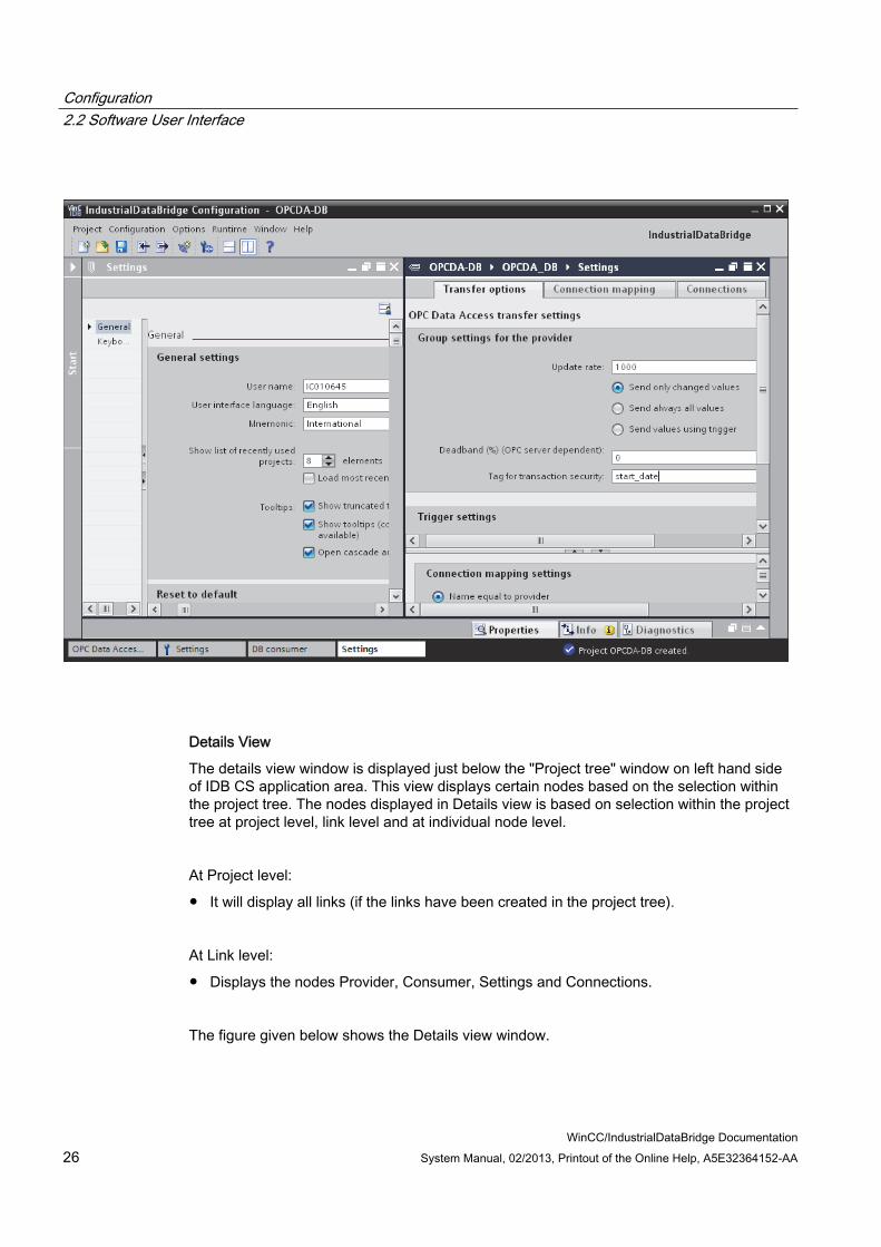
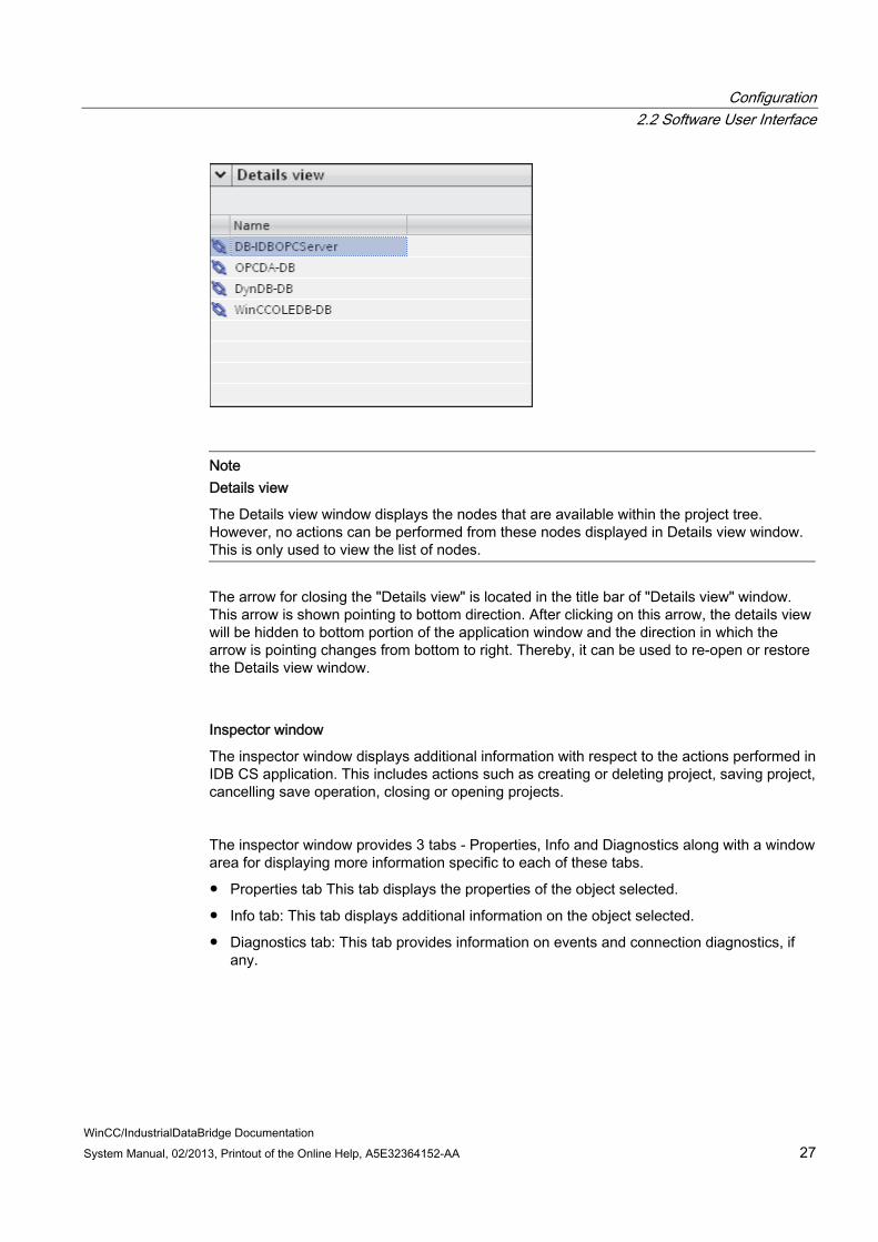
Details View
The details view window is displayed just below the "Project tree" window on left hand side of IDB CS application area. This view displays certain nodes based on the selection within the project tree. The nodes displayed in Details view is based on selection within the project tree at project level, link level and at individual node level.
At Project level:
● It will display all links (if the links have been created in the project tree).
At Link level:
● Displays the nodes Provider, Consumer, Settings and Connections.
The figure given below shows the Details view window.
Configuration 2.2 Software User Interface
WinCC/IndustrialDataBridge Documentation System Manual, 02/2013, Printout of the Online Help, A5E32364152-AA 27
Note Details view
The Details view window displays the nodes that are available within the project tree. However, no actions can be performed from these nodes displayed in Details view window. This is only used to view the list of nodes.
The arrow for closing the "Details view" is located in the title bar of "Details view" window. This arrow is shown pointing to bottom direction. After clicking on this arrow, the details view will be hidden to bottom portion of the application window and the direction in which the arrow is pointing changes from bottom to right. Thereby, it can be used to re-open or restore the Details view window.
Inspector window
The inspector window displays additional information with respect to the actions performed in IDB CS application. This includes actions such as creating or deleting project, saving project, cancelling save operation, closing or opening projects.
The inspector window provides 3 tabs - Properties, Info and Diagnostics along with a window area for displaying more information specific to each of these tabs.
● Properties tab This tab displays the properties of the object selected.
● Info tab: This tab displays additional information on the object selected.
● Diagnostics tab: This tab provides information on events and connection diagnostics, if any.

Configuration 2.2 Software User Interface
WinCC/IndustrialDataBridge Documentation 28 System Manual, 02/2013, Printout of the Online Help, A5E32364152-AA
Note Inspector Window usage
In IDB Configuration application, inspector window can be used mainly to view the status of actions performed in the application that are displayed as messages. These messages are displayed within the "General" tab. The "General" tab exists within the 'Info' tab of Inspector window.
The inspector window can be hidden within the IDB Configuration application screen whenever it is not required. This window provides the following 3 controls displayed at right hand portion on the title bar of this window.
1. Float: The "Float" option makes window to be available as a floating window ie., as an individual window separated from the work area.
Upon clicking on "Float", the control changes to "Embed" icon. Click on the "Embed" window control to place the window or embed the window in work area.
2. Collapse: Once the inspector window is collapsed manually using the "Collapse" control, the project tree is hidden to the bottom margin. The "Collapse" button changes from an arrow pointing left to one that is pointing right, and can now be used to reopen the inspector window using "Expand" button.
3. Minimize: Minimizes the inspector window to bottom portion of the work area.
Editor bar
Configuration 2.2 Software User Interface
WinCC/IndustrialDataBridge Documentation System Manual, 02/2013, Printout of the Online Help, A5E32364152-AA 29
In IDB CS application, the configuration window or settings window or any of the editor windows when minimized will appear in the editor bar. If you have opened mulitple windows, these windows are shown as grouped together one after the other. To switch quickly between different editor windows, you can use the editor bar. This editor bar is placed at the bottom portion of IDB CS application window screen.
Usually, It will be difficult and tedious to switch between editors in the work area by minimizing or maximizing editor windows. Editor bar will be useful in such instances as it allows easier switching between different windows.
Note Editors / Windows
In IDB Configuration application, windows that provide configuration or settings information are also known as 'editors' or 'editor' windows. The name "editor" is used as it allows to edit text within the text box or user controls in these windows.
Status bar
The status bar is placed adjacent to the editor bar within the IDB Configuration application. The status bar displays the status information based on the actions performed at project level. Some examples include opening project, closing the project, saving the project.
IDB CS General Settings The IDB CS "Settings" window can be accessed from IDB CS menu by clicking on "Options" > "Settings". The Settings window displayed within the work area includes a left hand side pane that provides 2 links:
● General: The "General" link displays IDB CS General Settings
● Keyboard shortcuts: The Keyboard shortcuts page displays the list of supported keyboard shortcuts used within IDB CS application.

Configuration 2.2 Software User Interface
WinCC/IndustrialDataBridge Documentation 30 System Manual, 02/2013, Printout of the Online Help, A5E32364152-AA

Configuration 2.2 Software User Interface
WinCC/IndustrialDataBridge Documentation System Manual, 02/2013, Printout of the Online Help, A5E32364152-AA 31
General Settings
The General Settings section includes the following list of fields that provides the basic user information as well as includes general options required to work in IDB CS application.
● User name: Lists the user name based on the information provided in Windows login credentials.
● User interface language: Provides a list box that allows you to select or change the user interface language required to work with IDB CS appication.
● Mnemonic: Provides the mnemonic information as a list box. 2 options are listed here - International, German. By default, the option "International" is selected.
● Show list of recently used projects: Displays a control that lists the number of projects that is allowed to be shown in "Browse" window while opening IDB project.
It accepts a value in the range 1 - 12. By default, a value of 8 is selected.
● Load most recent project during startup: Loads the recently opened project while starting IDB CS the next time.
● Tooltips: The tooltip setting displays 3 options available as check boxes.
– Show truncated texts completely: Displays truncated text in all tooltips displayed in the application.
– Show tooltips (context-sensitive help is available): Displays tooltips that have context-sensitive help defined.
– Open cascade automatically in tooltips: Displays cascaded tooltips.
Reset to default
This section lists the window types that can have all their properties reset to default.
● All application settings: The "Reset to deafult" button is provided that allows to reset the settings to default options.
● Editor layouts: The "Reset to deafult" button allows to reset all the editor layouts.
● Show all message windows: The "Reset to deafult" button resets this property to default.
Storage settings
This section displays the settings related to storage location for projects.
● Recently used storage location: This button can be selected if you wish to use recently used storage location to be displayed while browsing projects.
● Specify default setting for storage location: Upon selection of this radio button, the application allows to select a default storage location to be used while browsing projects.
The following options are enabled upon selection of the option "Specify default setting for storage location":

Configuration 2.2 Software User Interface
WinCC/IndustrialDataBridge Documentation 32 System Manual, 02/2013, Printout of the Online Help, A5E32364152-AA
● Storage location for projects: A browse button is provided to help you in browsing the default folder location to be used for storing the projects.
● Storage location for libraries: A browse button is provided to help you in browsing the default folder location to be used for storing the libraries.
Keyboard shortcuts A list of available shortcut keys in IDB CS are provided in the following table:
Shortcut key Description Alt+Enter Displays the project properties in a dialog
window. Alt+F4 Exits the IDB CS application. Alt+Shift+F12 Unsplits or restores the splitted window to its
normal state. Ctrl+Del Delete all links Ctrl+E Provides option to select the project that needs to
be deleted and to perform Delete operation Ctrl+F12 Split editors horizontally. Ctrl+F6 Change to next open editor. Ctrl+L Add new link. Ctrl+N Creates a new project. Ctrl+O Invokes "Open project" window that allows to
open a project. Ctrl+R Opens Runtime Configuration window. Ctrl+S Save changes to the project. Ctrl+Shift+C Connect provider and consumer types. Ctrl+Shift+Del Deletes an already existing connection. Ctrl+Shift+E Generate runtime configuration. Ctrl+Shift+F4 Close all open editors. Ctrl+Shift+F6 Change or switch to previous editor. Ctrl+Shift+O Import runtime configuration. Ctrl+Shift+S Save as
Note Split / Unsplit editors
To unsplit or to switch back to its normal view, select "Window" > "Unsplit" or select "Window" > "Restore active layout" to restore the previously available layout.
Configuration 2.3 User Interface Layout
WinCC/IndustrialDataBridge Documentation System Manual, 02/2013, Printout of the Online Help, A5E32364152-AA 33
2.3 User Interface Layout
Introduction IDB Configuration provides support for saving the user interface layout. Any changes to the user interface layout within the application can be saved. When you make any changes to the user interface layout, these changes are retained even after restarting the IDB application.
Apart from saving the user interface layout, the application provides support for saving certain window layout and also the layout within Editors.
Window layout IDB Configuration allows working with multiple windows and editors. A change to the window layout includes resizing a window or closing and opening an editor window. Each window layout can be manually saved and can be restored whenever required.
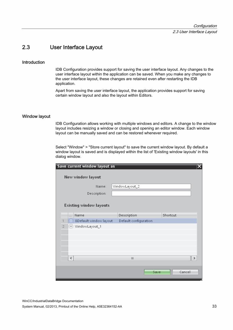
Select "Window" > "Store current layout" to save the current window layout. By default a window layout is saved and is displayed within the list of 'Existing window layouts' in this dialog window.
Configuration 2.3 User Interface Layout
WinCC/IndustrialDataBridge Documentation 34 System Manual, 02/2013, Printout of the Online Help, A5E32364152-AA
Follow the steps given below to save a window layout:
1. Adjust the window size using the resize handle and customize the layout as required.
2. In Window menu, select "Store Current Layout" option. This invokes the "Save current window layout as" dialog box.
3. Enter a name for the window layout in the "Name" field.
4. The "Description" field is optional. If you wish to add a description of the layout, enter a unique description in the "Description" field.
5. Click "Save" button to save the changes performed.
If a window layout has been saved by following the steps given above, you can load the window layout anytime depending on your requirement. The first five window layouts that are saved can be loaded by selecting the layout name from "Window" menu in the menu bar. Additionally, the "Manage layouts" option in "Window" menu helps you to load additional window layouts that are not among the five window layouts.
If you have loaded a window layout and made necessary changes to the layout, you can restore the originally saved window layout by selecting the "Restore active layout" option from "Window" menu. At any point of time, if you want to close all editors or minimize all editors, select the "Close all editors" or "Minimize all editors" options from "Window" menu.
To manage the editor windows effectively, IDB CS also provides support for splitting the editors. The editors within the work area can be split either horizontally or vertically using the "Split Editors Vertically" or "Split Editors Horizontally" options from Window menu. If you have multiple editors and if you want to switch between the editors, the Window menu includes the options "Next Editor" and "Previous Editor" that allows to switch back and forth between the open editors. The "Unsplit" option allows to unsplit an already split work area.
Managing Window layouts The "Manage layouts" dialog box provides support for changing the order of window layouts, selecting a window layout or deleting window layout.

Configuration 2.3 User Interface Layout
WinCC/IndustrialDataBridge Documentation System Manual, 02/2013, Printout of the Online Help, A5E32364152-AA 35
Follow the steps given below to manage window layouts:
1. In "Window" menu, select "Manage layouts" option. The "Manage all window layouts" dialog box will be opened.
2. Select the desired window layout that you wish to modify by selecting the radio button.
3. To change the order of displayed window layouts, select the Up or Down symbol.
4. Select Delete symbol to delete the selected window layout.
5. Click OK after performing the required changes.
6. The selected window layout will be thus activated.
Resetting user interface layout Every change performed to the user interface layout is saved. These changes are available even after a restart of IDB CS application. For example, if you change the width of General Settings window or collapse the inspector window, these layout changes are retained. It is not required to customize the layout every time.
In some cases where it is required to restore the original layout settings or factory settings, the user interface layout can be resetted.
Follow the steps given below to reset the user interface settings to the factory settings:

Configuration 2.3 User Interface Layout
WinCC/IndustrialDataBridge Documentation 36 System Manual, 02/2013, Printout of the Online Help, A5E32364152-AA
1. In IDB CS menu bar, select "Options" > "Settings".
The "Settings" window is displayed in the work area.
2. Select the "General" label in area navigation.
3. Click the "Reset to default" button across the applicable field.
The default settings for the user interface are restored.

Configuration 2.4 Project Basics
WinCC/IndustrialDataBridge Documentation System Manual, 02/2013, Printout of the Online Help, A5E32364152-AA 37
2.4 Project Basics
Introduction IndustrialDataBridge Configuration System (CS) is an application that enables the data transfer between a provider and consumer. A provider can also be configured as data provider and consumer as data consumer. The communication happens between the provider and consumer wherein the parameter definitions for provider and consumer are completely different. Due to these differences, this chapter provides a general description that includes project basics and steps for creating / managing projects, links.
The first and foremost task while starting to work with the IDB Configuration application is to create a new project. The project acts as a container for other node elements that is required for creating a single IDB configuration. Within the project, these node elements are arranged as a tree structure in the project tree. A project is used to organize data pertaining to the provider, consumer, link settings and the corresponding connections. The node elements that make up a project include the following:
● Link properties
● Provider/Consumer data and configuration information
● Connection Transfer options
● Connection mapping settings
● Connections
● Common data
● Documentation settings
● Languages & resources
Tasks The IDB CS application provides support for creating configuration that consist of connection between the provider(s) and consumer(s). The most important tasks that can be performed using IDB V7.2 are provided below:
● Creating a project
● Creating / Managing links & Connections
● Configuring Provider / Consumer types
● Configuring Settings & perform connection mapping
● Saving the Project
● Import / Generate Runtime Configuration

Configuration 2.4 Project Basics
WinCC/IndustrialDataBridge Documentation 38 System Manual, 02/2013, Printout of the Online Help, A5E32364152-AA
Note
Information about IDB Configuration application user interface and its components are provided in "Software User Interface (Page 17)" chapter.
Creating a New Project
Follow these steps to create a new project:
1. In IndustrialDataBridge application, select "Project" > "New project" to create a new project.
2. In the dialog box, the default entries are created for "Project name", "Path" and "Author" fields.
The project name and author name can be modified with custom information.
3. Specify a project name, click [...] button and select the folder location wherever project needs to be saved.
Note
The subsequent text boxes in this dialog include optional items for entering the Author name and additional information about the project. The "Author" and "Comments" fields are optional. The "Comment" field provides a text area for entering additional information. For better identification purposes, if required, you can enter the author name, and comments specific to the created project. Note that the information written within the "Comments" field will not be translated.
4. After entering the required information, select "Create" button.
5. The project name will be listed within the "Project tree" located on left hand side of the IDB configuration screen.

Configuration 2.4 Project Basics
WinCC/IndustrialDataBridge Documentation System Manual, 02/2013, Printout of the Online Help, A5E32364152-AA 39
Note Project node
After creating a project, the following nodes are created and displayed within the project node in Project tree - Common data, Documentation settt ings, Languages & resources.
Note Project name
Using "\" is not allowed within project name. It is suggested to ensure to not use "\" (backslash) character in project names.
● Project: A project is used to plan, organize, manage and control IDB CS configuration and other settings. A single project can include any number of links within a specific project. All tasks performed within IDB CS are managed within these projects. A project forms a basic structure for creating and managing configuration. Once a project has been configured and the connection(s) are created, IDB Configuration application includes options to generate the Runtime Configuration (XML) as an XML file.
● Link: In IDB CS, a link represents an entity that can contain several connections. A Link is always a part of the project and is displayed in project tree after creating the link. The created links are always shown below the project name in the tree structure. Once a link is created, the following sub-nodes are created automatically in tree structure below the link name - Provider, Consumer, Settings & Connections.
● Connection: A connection represents a unique mapping between the provider and consumer types. The connection node is displayed within the link node. It exists exactly below the "Settings" node in project tree. The connections created are displayed within the "Connections" node.
● Common data: This node is created within the project in project tree and contains 2 sub-nodes "Alarm classes" and "Text lists" that is used for displaying the list of alarm classes and text lists.
● Documentation settings: This node is created within the project in project tree and is available below the Common data node. It includes 3 sub-nodes "Document information", "Frames" and "Cover pages" and generally provide information regarding the document print settings.
● Languages & resources: This node is created created within the project in project tree and is available below the Documentation settings node. It includes 2 sub-nodes "Project languages" and "Project texts" and provides options to select the languages and define or manage project texts.

Configuration 2.4 Project Basics
WinCC/IndustrialDataBridge Documentation 40 System Manual, 02/2013, Printout of the Online Help, A5E32364152-AA
Note Viewing project properties
To view project properties, right click on the project name in project tree and select "Properties" option. Alternatively, you can select the project icon in project tree and press the key combination "Alt+Enter" to open the project properties window.
Managing Projects Once a project has been created, the project will be listed in the Project tree. At any point of time, you can open an already saved project, close project, save changes to the project or delete an existing project. The links and connections that are created will be displayed within the project node. The project tree allows for easier and effective management of links, their properties, connection mapping settings and connections.

Configuration 2.4 Project Basics
WinCC/IndustrialDataBridge Documentation System Manual, 02/2013, Printout of the Online Help, A5E32364152-AA 41
1. Slider control
2. Title bar
3. Collapse automatically
4. Collapse
5. Project
6. Link
The Project tree includes icons or controls that help to manage viewing the project tree nodes and controlling navigation. The nodes listed below the project name includes several sub-nodes. Perform a single click on the pointing arrow across project or link node to expand or view the contents of the specific node in project tree. Double click the sub-node(s) within the link node to open the respective editor window in work area.
Opening a Project
Follow these steps to open an existing project:
1. In Project menu, select "Project" > "Open project" to open an existing project.
The "Open project" dialog opens that includes the most recently used projects.
2. Select a project from the list and click "Open" button.
3. The project will now be listed in the project tree.

Configuration 2.4 Project Basics
WinCC/IndustrialDataBridge Documentation 42 System Manual, 02/2013, Printout of the Online Help, A5E32364152-AA
Select the "Browse" button to open a specific project that is not listed in the "Recently used" list within the Open project window. You can further select the project by browsing the respective folders.
Note Browse Projects
If you are unable to locate the project from the list, then browse to the respective folder by clicking the "Browse" button. The default storage location for IDB CS V7.2 projects is: "\My Documents\Automation". Navigate to the folder that contains the project and open the project file. Projects of IDB Configuration application have an extension ".ip72".
Note Opening projects
If you try to create a new project or open a project while another project is open, IDB CS application prompts a dialog window if you wish to save the changes to the already opened project and then creates a new project or opens the project.
Note Opening configuration file from a previous IDB version
To open an IDB configuration that was created using IDB V7.0.3, you need to import the old configuration file into IDB CS V7.2 by using the "Import Runtime Configuration" icon provided in IDB CS toolbar. This configuration file will be converted automatically to the current file format and saved as a new project with the project file extension ".ip72".
Note Loading configuration file in IDB V7.0.3 Runtime
If you wish to use the configuration XML file that was exported from IDB CS V7.2 in V7.0.3 Runtime application, you can perform the operation of activating the connection(s) and starting data transfer. However, if you have used OPC XML as a provider/consumer, data transfer does not happen.
Viewing Project properties
Once a project has been created, at any point of time you can view the project properties. The information entered in the text fields while creating the project including the comments specified can be viewed in the project properties window. Right click on project icon in project tree and click "Properties" option to view the project properties window.
Saving & Closing projects

Configuration 2.4 Project Basics
WinCC/IndustrialDataBridge Documentation System Manual, 02/2013, Printout of the Online Help, A5E32364152-AA 43
Once you have performed some changes to the project, the changes can be saved either with the same project name or using a different project name. Follow the steps mentioned below to save a project:
1. Select "Project" > "Save" option to save the project. All the changes to the project are saved under the current project name.
2. The project can be saved also with the help of "Save" icon provided in IDB toolbar.
Note Saving XML file
Saving a project will save the changes made to the current project. However, this will not save the XML file created within the project. The IndustrialDataBridge Runtime application enables loading the XML configuration file and allows to perform the data transfer. In order to save the XML file, you need to generate the file. Select "Generate Runtime Configuration" icon provided in the IDB toolbar to save the XML file to desired folder location.
Note Saving Changes to editor window
A save operation is not required every time whenever changes are performed within the editor window in the work area. The changes made to these settings are automatically saved.
To save a project with a different name, follow these steps:
1. Select "Save as" option in the "Project" menu.
2. In the "Save current project as" dialog box, navigate to the specific project folder within "Save in" box.
3. Enter the project name in the "File name" box.
4. Once you are done with the changes, select the "Save" button.
The project will be saved with the new name.
All open projects that are opened in the IDB V7.2 application can be closed with the help of the menu option. Follow the steps mentioned below to close a project:
1. To close a project that is opened, select "Project" > "Close" option.

Configuration 2.4 Project Basics
WinCC/IndustrialDataBridge Documentation 44 System Manual, 02/2013, Printout of the Online Help, A5E32364152-AA
2. A message is displayed if you have made any changes to the project since the last time you saved it.
3. Confirm by clicking the "Yes" or "No" button whether or not you wish to save the changes.
Deleting projects
Follow the below mentioned steps to delete project:
1. In project tree, highlight the project name that is required to be deleted.
Ensure that there are no properties window in open state within work area.
2. Select "Project" > "Delete project" option to delete the project.

Configuration 2.4 Project Basics
WinCC/IndustrialDataBridge Documentation System Manual, 02/2013, Printout of the Online Help, A5E32364152-AA 45
3. A confirmation dialog window is displayed with a message. Click Yes to continue the delete operation.
4. The entire project including the file with extension .ip72 will be deleted from the stored location.
Note Open project
In IDB Configuration interface, it is not possible to delete any project that is in open state.
Creating & Modifying Links After creating a project, the next step is to create a link between the provider and consumer types. A link is an entity that allows to connect the provider and consumer types. A link always establishes a connection between the provider and consumer. There can be any number of connections created within a single link.
The creation of link involves selection of provider and consumer types along with defining their respective connection properties required for establishing the link. A link is defined within a project and is part of each project. There can be any number of links created for a project.
Prerequisites:
● The IDB Configuration application is opened
● A new project is created and is listed within the project tree
Follow the steps given below to create a new link:
1. In project tree, right click on the project name and select "Add new Link" option.

Configuration 2.4 Project Basics
WinCC/IndustrialDataBridge Documentation 46 System Manual, 02/2013, Printout of the Online Help, A5E32364152-AA
A link can also be created using the "Add new link" graphic icon provided in the toolbar.
2. In the "Add new link" dialog that is opened, enter a unique link name.
3. Select the provider type, consumer type and click OK button.
4. The created link will be displayed below the current project name in project tree.
Note New Link
The corresponding node entries - "Provider", "Consumer", "Settings" and "Connections" are created below the new link in Project tree. The Provider type and Consumer type that you had selected while creating the link will be shown next to the Provider and Consumer node (within brackets) in the Project tree.
Note
After you have created the link, the "Connections" node will not contain any connections, hence the "Connections" node will be empty. The list of connections will be displayed in the "Connections" node only if the respective connections have been created from the Settings window.
● Provider: The provider node is listed below the link node in project tree. To open the provider node properties window, double click the provider node in project tree. The provider properties window will be always displayed in the work area. At any point of time, you can modify the settings within the provider node properties window.
● Consumer: The consumer node is listed below the provider ncode in project tree. Double click the consumer node in project tree to open the consumer properties window. The consumer properties window will be always displayed in the work area.
● Settings: The settings window is used to configure the link settings. This window includes 3 tabs:
– Transfer options: This tab provides the options for configuring the transfer settings for provider.
– Connection mapping: This tab provides you the required fields to map provider and consumer and configure the connection.
– Connections: The list of connections created are displayed in this tab.

Configuration 2.4 Project Basics
WinCC/IndustrialDataBridge Documentation System Manual, 02/2013, Printout of the Online Help, A5E32364152-AA 47
Note IDB Configuration
A complete configuration exists after the required links containing connections between provider(s) and consumer(s) are created. Creating a connection inolves configuring the Provider, Consumer, Transfer options and performing required mapping between provider and consumer types.
Modifying links
To modify an already created link, firstly select the link that needs to be modified. Perform a single click on the link name, the link name will be converted into an editable area wherein it allows you to edit the link name. Type in the desired link name and click the area outside the link name, the modified link name will be now displayed below the project node in project tree.
Links can also be modified by selecting the link name in project tree and pressing the F2 key. The link name will be available for you to edit the link name.
Deleting links
A link that is created within the project can be deleted at any point of time. Follow the steps mentioned below to delete a link:
1. Highlight the link that needs to be deleted.
2. Right click on the link name and select "Delete link" option.
3. A confirmation message is displayed if you are sure to delete the link.
4. Confirm by clicking the "Yes" or "No" button whether or not you wish to delete the link.

Configuration 2.4 Project Basics
WinCC/IndustrialDataBridge Documentation 48 System Manual, 02/2013, Printout of the Online Help, A5E32364152-AA
Note Delete all links
The IDB V7.2 application includes options to delete all links. This option is provided in the "Configuration" menu. To perform this operation, select the project name within project tree and select "Configuration" > "Delete all links". The list of all links created within the currently open project will thus be deleted.
Right click on the project node and select "Delete all links" option to delete all the links within the project.

Configuration 2.5 Import / Generate Runtime Configuration
WinCC/IndustrialDataBridge Documentation System Manual, 02/2013, Printout of the Online Help, A5E32364152-AA 49
2.5 Import / Generate Runtime Configuration
Introduction While working with IndustrialDataBridge CS application, the resulting output from the project is a complete IDB configuration file. This configuration file is an XML file that is used in the IDB Runtime environment. The IDB Runtime application loads the configuration file, activates the connection between provider and consumer components and performs the data transfer by monitoring the life-span of these components.
The XML file can be generated in IDB CS using the "Generate Runtime Configuration" option. Similarly, an IDB configuration available as an XML file can be loaded into IDB CS application using the "Import Runtime Configuration" option. Loading an IDB configuration includes loading the respective XML file which will load all the respective links and their connections within the project tree.
This chapter describes the importance of generating / importing runtime configuration and the steps for performing them.
Importing an XML file A project that has been already created in IDB CS application can be opened using the menu option "Project" > "Open". Alternatively, you can open an existing project by importing the XML file belonging to that specific project. However, it is important to note that you should have exported or generated the XML file using the "Generate Runtime Configuration" icon in IDB toolbar. The "Generate Runtime Configuration" option is also provided within the "Project" menu.
After importing the XML file, the entire project contents are opened and can be accessed from the project tree. Further, any changes that you make to the opened project, should be saved using the "Project" > "Save" option.
Note Default Storage Location
The default storage location for IDB CS V7.2 projects is: "\My Documents\Automation". This storage location is used as the default location while importing project files. Project files in IDB CS have an extension ".ip72". Any project that has been created can also be opened in IDB CS with the help of ".ip72" project file.
Follow the steps given below to import the project file:
1. Select the "Import Runtime Configuration" icon in IDB CS toolbar.

Configuration 2.5 Import / Generate Runtime Configuration
WinCC/IndustrialDataBridge Documentation 50 System Manual, 02/2013, Printout of the Online Help, A5E32364152-AA
2. In the "Open" dialog window, browse the respective folder structure and select the XML file name. Then click "OK" button.
3. The entire project contents will now be imported into the Project tree and is displayed within the tree structure.
Exporting an XML file An IDB project includes all the components necessary for creating an complete IDB configuration. In order to load the configuration in IDB runtime environment, it is required to use the XML file that contains complete configuration information specific to the project. This XML file belonging to the project can be generated using the "Generate Runtime Configuration" icon provided in IDB CS toolbar. The "Generate Runtime Configuration" option is also provided within the "Project" menu.
Note Default Storage Location
After performing the export operation, the XML files are exported to the location: "\My Documents\Automation".
Note XML file
If the XML file in Runtime application is not updated, changes made within the project will not take effect. Hence, it is recommended to generate the runtime configuration once again that includes the updated changes and use the updated XML file in Runtime.
Follow the steps given below to export an XML file:
1. Perform the required configuration and save the changes to the project.
2. Select the "Generate Runtime Configuration" icon in IDB CS toolbar.
3. In the "Save As" dialog window, navigate to the appropriate folder, enter the file name and select "Save" button.
Ensure that you have selected the "Save as type" to be XML file.
4. The XML file will be saved in the selected location and can be used in the IDB Runtime application.

Configuration 2.6 Interface Structuring
WinCC/IndustrialDataBridge Documentation System Manual, 02/2013, Printout of the Online Help, A5E32364152-AA 51
2.6 Interface Structuring
Introduction The IDB V7.2 configuration interface and its corresponding windows provide various settings and options depending on the loaded modules. These settings are described in the "Modules (Page 55)" chapter.
This chapter includes information about different sections of the configuration interface depending on corresponding selection within IDB configuration application. The IDB Configuration mainly consists of the "configuration interface area".
Configuration Interface area The left-hand portion of the configuration interface includes the project tree structure that displays the tree nodes. Upon opening the IDB configuration interface, firstly you can observe that the project tree will be empty and does not contain any nodes within the tree structure.
Once a new project is created, the project node with the specified project name is shown in the project tree.
After a link is created, the link will be displayed within the project. The link consists of the following nodes listed within each link node in project tree:
● Provider
● Consumer
● Settings
● Connections
Note Details view
The "Details view" window is displayed on left hand side of IDB CS window and is listed below the project tree. This window displays only the details of Project and Links. Hence, the content within this Details view is shown only when you click on Project node or Link node within the project tree. The relevant nodes belonging to the project or link are displayed in the "Details view" window.
The view on the right-hand portion of IDB CS application window displays the work area. The work area displays information based on the selected node in the Project tree:
Project level

Configuration 2.6 Interface Structuring
WinCC/IndustrialDataBridge Documentation 52 System Manual, 02/2013, Printout of the Online Help, A5E32364152-AA
Upon selection of Project name within the Project tree, it does not display any information in the work area. If there are no links created for the specific project, the project node will be shown as empty. If the links are already created within the project, select the project name and click the arrow icon to expand or view the list of links within the project.
Performing a right click on the project name (if there are already created link(s)), will display the following options:
1. Add new link: This option is used to create a new link.
2. Delete all links: This option ca be used to delete all links.
3. Properties: This option lists the project properties in a separate window.
Link level
The links that have been created are displayed in Project tree within the project node. Initially, these links will not display the expanded view consisting of the sub-nodes. To view the sub-nodes available within the link node, expand the arrow icon next to the link name. The provider or consumer type selected as part of creation of link will be shown next to each sub-node (within link node). Hence, there can be any number of links that can be created within a single project in IDB Configuration System application.
After the creation of a link, the "Provider", "Consumer", "Settings" and "Connections" nodes are created automatically and displayed within the link node.
● At provider or consumer node level, after double clicking the node, the corresponding provider/consumer configuration window is displayed in work area. Thereby, you can configure the Provider / Consumer in the respective window.
● The delete link option is enabled for all created links within the project tree. Right clicking on the link node provides an option to delete a link.
Settings level
The Settings node exists within the Project tree that provides options to configure the link settings. The Settings window can be accessed by double clicking the Settings node in Project tree. The Settings window provides 3 tabs - Transfer options, Connection mapping and Connections. These tabs are displayed within the Settings window in work area. The Settings node helps you to configure provider transfer options, perform connection mapping and create/view connections within these tabs.
The "Connection mapping settings" area is displayed as a split window within the Transfer options tab. This window is active only within the Transfer options tab and is helpful to choose a connection name even before you perform a connection mapping in Connection Mapping tab. This display is common across all modules while configuring the provider transfer options in "Transfer options" tab.

Configuration 2.6 Interface Structuring
WinCC/IndustrialDataBridge Documentation System Manual, 02/2013, Printout of the Online Help, A5E32364152-AA 53
The "Connection mapping" tab displays the provider and consumer area one below the other on left hand portion of this tab. The "Connection mapping settings" area is displayed to right hand side of the window. The following icons are provided within the "Connection mapping settings" area that enables you to create connection, modify connection, delete connection and delete all connections. The icons and their description are provided in the table shown below:
Icon Description
Connect
Modify connection
Delete connection
Delete all connections
Connections level
After performing a connection mapping between provider and consumer type, the connections are created and displayed within the Connections tab of Settings window. These connections are also displayed within the Connections node in Project tree. The existing connections can be deleted by using the icons within Connection mapping tab or by performing a right click on any existing connection within "Connections" node in Project tree.
Performing a right click on the "Connections" node in project tree provides the option to "Delete all connections".
Connection mapping prerequisites In order to perform connection mapping, a set of prerequisites are determined by IDB CS application during connection mapping phase that controls displaying the menu options, toolbar icons or icons in connection mapping tab. These options are in enable state and can be used only when the required standards are met for establishing a connection between provider and consumer, otherwise these options will be in disable state.
The following points are valid and these standards need to be followed in order to ensure the required options (menu options / toolbar icons) are available for creating a connection:
● Ensure that the appropriate schema is selected in Schema field, if applicable for the selected table.
● The table you have selected should contain at least one single row with a valid data type. For a list of data types supported in IDB CS, please refer chapter "Supported data types (Page 156)".
● The table should not contain any null values. This has to be verified during creation of the table.

Configuration 2.6 Interface Structuring
WinCC/IndustrialDataBridge Documentation 54 System Manual, 02/2013, Printout of the Online Help, A5E32364152-AA
● Ensure that the required column is selected in both provider and consumer.
● The provider or consumer section within the connection mapping tab should not contain fields that are empty provided if there is a field enabled for user selection.
Modifying Connection properties At any point of time, the IDB Configuration interface allows you to perform changes to the provider or consumer configuration, transfer behavior settings, connection mapping or link settings belonging to a particular project.
WinCC/IndustrialDataBridge Documentation System Manual, 02/2013, Printout of the Online Help, A5E32364152-AA 55
Modules 33.1 Modules
IDB CS supports a variety of provider and consumer types. Each module contains the steps for configuring a connection from provider to consumer and viceversa. When creating or modifying a link, perform the provider/consumer configuration in the work area for which the displayed fields depend on the selected module, example: "OPC Data Access" module. For each module, the chapter deals with an Overview section. The individual steps are described in the chapters that includes information about the module when used as a provider and also as a consumer along with steps for mapping a connection. Some modules act only as a consumer. In such chapters, the usage of the module as a consumer is explained.
Besides the Overview chapter, more information is available for different modules in subsequent chapters. The following list of provider and consumer types are dealt in more detail:
Provider:
● OPC Data Access
● OPC XML
● WinCC OLEDB
● Database
● Dynamic database
● Send/Receive
● WinCC User Archive
Consumer:
● OPC Data Access
● IDB OPC Server
● OPC XML
● Database
● Dynamic database
● CSV/TXT
● Excel
● Send/Receive
● WinCC User Archive

Modules 3.1 Modules
WinCC/IndustrialDataBridge Documentation 56 System Manual, 02/2013, Printout of the Online Help, A5E32364152-AA

Modules 3.2 OPC Data Access
WinCC/IndustrialDataBridge Documentation System Manual, 02/2013, Printout of the Online Help, A5E32364152-AA 57
3.2 OPC Data Access
3.2.1 Overview
Introduction The OPC standard software interface allows devices and applications from various manufacturers to be combined into one another in a uniform manner. The Data Access interface addresses the internal OPC Client of the IndustrialDataBridge or using any OPC Server, which can then connect to external modules. The connection is either established locally or remotely. This module supports the OPC DataAccess 2.x interface or higher with synchronous and asynchronous access.
An OPC Server provides a manufacturer as a "Service Provider" for accessing data. Different manufacturers offer different OPC servers with specific properties for different application ranges. An OPC server can offer the data that can be accessed via PROFIBUS for instance, another can provide access to a programmable controller.
An OPC client as a user of the services is not limited to a single server but can use any amount of OPC servers within the scope of system performance capacity. Since the type of data access is the same for all OPC servers, you can exchange one OPC server for a product of another manufacturer with comparably less effort.
For the OPC server, unique names are defined by the supplier for identifying the object. OPC clients must use this name to specify the OPC server. These names are designated as ProgIDs within the scope of the 'COM' standard.
An OPC server can be addressed by multiple OPC clients. This makes various OPC-conforming applications available for a data provider.
Note DCOM settings
To work in the configuration and runtime environment of OPC Data Access (as provider and as a consumer), you must configure the DCOM settings correctly in Windows. Incorrect DCOM settings can lead to problems in IDB configuration and in the IDB runtime applications. Information on DCOM settings can be found in "Microsoft Windows Help".
Note Accessing tags
The OPCServer.WinCC tags are only available when WinCC project is activated and the OPC Server is selected in the OPC Server browser window.
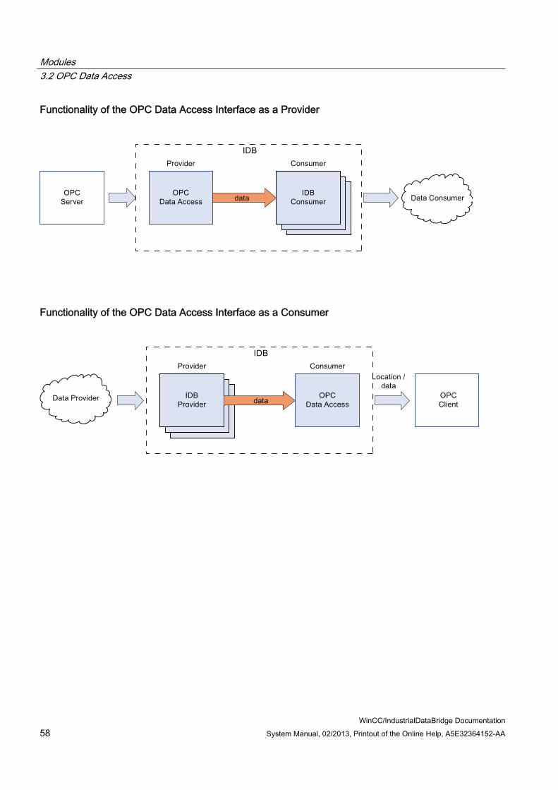
Modules 3.2 OPC Data Access
WinCC/IndustrialDataBridge Documentation 58 System Manual, 02/2013, Printout of the Online Help, A5E32364152-AA
Functionality of the OPC Data Access Interface as a Provider
Functionality of the OPC Data Access Interface as a Consumer

Modules 3.2 OPC Data Access
WinCC/IndustrialDataBridge Documentation System Manual, 02/2013, Printout of the Online Help, A5E32364152-AA 59
3.2.2 Configuring the OPC Data Access Interface as a Provider
Objective To create a project with corresponding link having OPC Data Access as provider and configure the respective provider/consumer connection properties along with transfer behaviour settings
Creating a link 1. Open IDB Configuration and create a project by following the steps mentioned below:
– In IDB Configuration menu bar, select "Project" > "Create" to create a new project.
– In the "Create new project" dialog box, specify a project name, click [...] button and select the folder location wherever the project needs to be saved.
– After entering the required information, select "Create" button. This creates a new project.
2. The project name will be listed within the "Project tree". The next step is to create a link. Follow the steps mentioned below to create a link between provider and consumer:
– Right click on project name node in the tree structure and select "Add new link" option.
– In the "Add new link" dialog that is displayed, enter a unique link name.
– Select the provider type as OPC Data Access, consumer type as Database and click OK button.
– The created link will be displayed below the project name in project tree.
– The corresponding entries - Provider, Consumer, Settings and Connections are created as nodes that exist below the new link in the tree structure.
3. In project tree, double click the Provider node to open the provider configuration window.

Modules 3.2 OPC Data Access
WinCC/IndustrialDataBridge Documentation 60 System Manual, 02/2013, Printout of the Online Help, A5E32364152-AA
In OPC Data Access provider configuration window, perform the following settings:
– Browse for OPC Server by clicking the [...] button and select OPC Server from the list. Next, click the button representing "tick mark" to accept the changes.
The selection of the server is supported by an OPC tag browser. The browser shows the local OPC Servers. You can search for OPC Servers in the network as well.
– The node name is simultaneously displayed in "Node name" text box after selection of the OPC Server.
Note Node name
For local OPC Server, the node name will display as "local host". In case of remote OPC Server, the remote computer name will be displayed after selection of OPC Server on the remote computer. This "Node name" is required for searching the OPC Server from the remote computer.
The OPC tag browser does not display any content if node name is invalid.
Note
The "OPC Server" and "Node name" fields are provided as editable fields.
If the information about OPC Server name and node name is known, you can directly enter the information in the "OPC Server" and "Node name" fields. If the node name / OPC Server name is invalid, there will be no content displayed within the OPC tag browser.
4. Next, double click the Consumer node in project tree. In Consumer configuration window, perform the following settings:

Modules 3.2 OPC Data Access
WinCC/IndustrialDataBridge Documentation System Manual, 02/2013, Printout of the Online Help, A5E32364152-AA 61
"Database consumer configuration" section
– Select the type of database by choosing the appropriate radio button.
– If the database exists on a server location, enter the server name in "Server" field.
If you wish to enable windows authentication automatically, select the check box "Use automatic windows authentication".
– In "Database" field, click on [...] button and select the database from the list or from the folder structure.

Modules 3.2 OPC Data Access
WinCC/IndustrialDataBridge Documentation 62 System Manual, 02/2013, Printout of the Online Help, A5E32364152-AA
Note Server name
The "Server" field for entering the Server name, the "Use automatic windows authentication" check box and the fields for entering the logon information are enabled only if you have selected a database other than Microsoft Access.
– If a user name and password has been set for the database, enter the user name and password in the "User name" and "Password" fields respectively.
If you wish to set a blank password, enable the check box "Blank password". To save the entered password, enable the check box "Allow saving password".
– Click Test button to test the connection. The application tests the database connection string and verifies the selected database.
"Consumer type configuration" section
– Select the "Consumer type" by selecting from the list. In this case, we consider the consumer type as "One data record per call - record set. More information about the consumer types are provided in detail in Chapter 3.6.7, "Consumer Types" (Page 181).
Note Transaction type
The Stored procedure or Prepared insert statement transaction type options are in enable state only when the consumer type "One data record per call - command set" is selected and if you have selected a database other than Microsoft access. By default, the Prepared insert statement option is automatically selected. Only the "Table" field is enabled if Microsoft access is selected as the database type
and consumer type is selected as "One data record per call - command set". Select the table name by clicking on the drop down list box.
If you have selected a database type other than Microsoft access and the consumer type is selected as "One data record per call - command set", then all the fields within the Transaction type will be in enable state.
Performing link settings 1. In project tree, double click the Settings node to open Settings window in the work area.
The Settings window consists of 3 tabs - Transfer options, Connection Mapping & Connections.

Modules 3.2 OPC Data Access
WinCC/IndustrialDataBridge Documentation System Manual, 02/2013, Printout of the Online Help, A5E32364152-AA 63
2. Within the Transfer options tab, you can configure the transfer behavior settings for provider.
3. Enter a time period in the "Update rate" field after which the system checks for when the data has to be transferred.
It checks each and every tag for all connections.
NoteUpdate rate
For better performance, it is recommended to use an update rate of 1000 ms or 1 sec.

Modules 3.2 OPC Data Access
WinCC/IndustrialDataBridge Documentation 64 System Manual, 02/2013, Printout of the Online Help, A5E32364152-AA
4. Next, select the type of data transfer:
– Send only changed values Data is transferred whenever the configured tag value changes. If a threshold value is configured in the "Deadband" field and if the selected OPC Server supports deadband, then data transfer happens only upon data change exceeding the dead band value specified. Dead band value should be within 0 - 100.
– Send always all values After every update cycle, the data of all tags of the provider, which you have connected with the consumer, will be transferred.
– Send values using trigger After every update cycle, a selected tag of the OPC Server is checked to see if it has reached a trigger value. In this case, all values are transferred. For configuring trigger settings, please refer step "No.7".
Note "Send only changed values" data transfer
If the deadband value is configured and the selected OPC Server does not support deadband, a value of 0% is set and any change in the value will be considered for data transfer. Data transfer of this type is independent of "Update rate".
Note Optional fields
The "Deadband" and "Item for Transaction Security" fields are optional.
Note Deadband
All OPC Servers do not support deadband. This is dependent on the OPC Server being used. The "Deadband value (%)" text box is enabled only with the data transfer type - "Send only changed values". This text box is disabled while you select transfer types - "Send always all values" and "Send values using trigger".
5. Enter the deadband value (in percent) to contain a value within the range 0 - 100.
6. In "Tag for Transaction Security" field, click [...] button and select a OPC Server tag from the OPC tag browser. You can define an OPC tag on an OPC server, in which the success-/failure-status of the data transfer will be stored in the "Tag for transaction security" field.
This value should have 1 byte signed char (e.g. VT_I1). '-1' indicates the success state and '0' indicates failure.

Modules 3.2 OPC Data Access
WinCC/IndustrialDataBridge Documentation System Manual, 02/2013, Printout of the Online Help, A5E32364152-AA 65
7. If you have selected the option "Send values using trigger", you can configure the trigger that provides options to set the trigger options.
The Trigger section is enabled only with the data transfer type "Send values using trigger".
Perform the following settings in the "Trigger settings" section:
– In "Trigger tag" field, select the tag that should trigger a data transfer. Click on [...] to select the tag from OPC tag browser.
– Select a valid data type by selecting from the drop down list.
– Enter a threshold at which a data transfer should be triggered, in the "Trigger value" field.
– In "Confirmation value" field, enter a value that the trigger tag should take on after triggering. The confirmation value does not give any information on whether a transaction has been completed successfully.
Note Trigger behavior
The trigger tag selected in "Trigger tag" field triggers the data transfer. IDB CS sets the confirmation value in the provider tag specified in "Confirmation value" field.
Example: If Trigger value is 100, the data transfer will happen after a known duration that is mentioned in "Update rate" field. Once the value of tag reaches the value 100, a confirmation value is written to the provider tag.
8. The transfer behavior settings for OPC Data Access as provider will be saved automatically.
Note Saving Changes
A save operation is not required every time whenever changes are performed within the editor window in the work area. The changes made to these settings are automatically saved. However, once the project is created, at any point of time, you can save the project by selecting the "Project" > "Save" menu option.
Results You have created a connection between the OPC Data Access interface and a consumer. These elements are displayed in the tree structure of the configuration interface. In order to transfer data, connect the provider and consumer tags, as described in chapter "Connecting Tags from the OPC Data Access Interface".
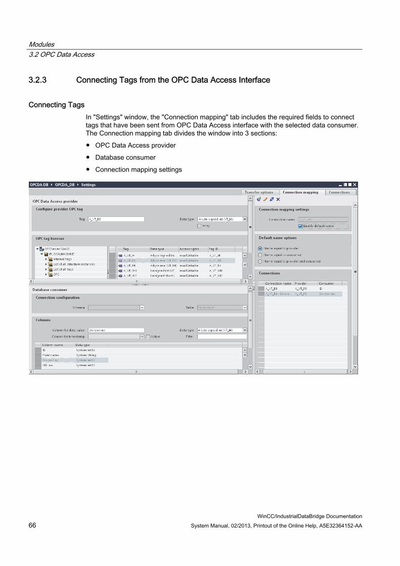
Modules 3.2 OPC Data Access
WinCC/IndustrialDataBridge Documentation 66 System Manual, 02/2013, Printout of the Online Help, A5E32364152-AA
3.2.3 Connecting Tags from the OPC Data Access Interface
Connecting Tags In "Settings" window, the "Connection mapping" tab includes the required fields to connect tags that have been sent from OPC Data Access interface with the selected data consumer. The Connection mapping tab divides the window into 3 sections:
● OPC Data Access provider
● Database consumer
● Connection mapping settings

Modules 3.2 OPC Data Access
WinCC/IndustrialDataBridge Documentation System Manual, 02/2013, Printout of the Online Help, A5E32364152-AA 67
The "OPC Data Access provider" section is displayed at top left portion of "Connection mapping" tab. This section provides you with required options to choose the tag name from the "OPC tag browser". The "Database consumer" section is displayed at bottom left portion of "Connection mapping" tab. This section lists the selected Table, Schema and column names that can be mapped with the tags existing within "OPC DataaAccess provider". The information within "Database consumer" section explained below is specific to having the consumer type as "One data record per call - recordset".
Note Consumer types
The fields displayed within "Database consumer" section depends on the "Consumer type" that you have selected in Consumer configuration window. In this case, the consumer type "One data record per call - recordset" is used.
The separator between the provider and consumer section provides a resize handle that helps you to resize the height of the section in order to view the fields within the section clearly.
The "Connection mapping settings" section is displayed at right side of "Connection mapping" tab. This section helps you to provide a name for connection along with options for choosing default name for connection. The "Connect", "Modify connection", "Delete connection" and "Delete all connections" icons are provided at the top portion of this section.
1. In "OPC Data Access provider" section, select the tag name from the list that is displayed within the "OPC tag browser". Upon selection of the tag within OPC tag browser, the tag name is displayed in "Tag ID" field. The data type is selected automatically based on selection of this tag.
2. If the selected tag has Array data type, then the "Array" check box is automatically enabled. This check box is provided below the "Data type" field.
3. Next, configure the column in the "Database consumer" section by following these steps:
– Select the Schema, if applicable from "Schema" field. The selected table is shown in the "Table" field.
– The column names are displayed within "Columns" area. If the table has columns with Date/time data type, the time stamp can also be written to the column within the table. In this case, select the respective "Active" check box and select the column within "Column for timestamp" field.

Modules 3.2 OPC Data Access
WinCC/IndustrialDataBridge Documentation 68 System Manual, 02/2013, Printout of the Online Help, A5E32364152-AA
4. In "Columns" area, select the Column name that you wish to connect with OPC Data Access tag. The data type of selected column will be automatically displayed in the "Datatype" field.
The selected column is displayed in "Column for data value" field.
Note Data type conversion
If the provider tag data type does not match with consumer column, IDB CS converts the provider data type to match with data type of consumer. A status window is displayed to indicate this change.
5. Check the name of the connection in the "Connection mapping settings" area to the right. Enter a unique name for the connection in the "Connection name" field or use the options within "Default name options" area. Click "Connect" button to confirm your entries.
6. Repeat steps 1 to 5 for all tags of the "OPC Data Access" interface that you wish to transfer.
7. The connection name including the provider and consumer data values will be displayed within the "Connection mapping settings" section.The list of connections will be also displayed within the Connections tab as well as in the project tree within the "Connections" node belonging to the specific link.
Note Schema
Microsoft Access does not support schema functionality. Hence, you can observe that the Schema field in Database consumer is in disable state.
While using any other database as consumer, the Schema field will be in enable state.
Note Array
If the OPC Data Access provider tag has a data type of type "Array" and if the database consumer column has data type selected other than array data type, after clicking on the "Connect" button, the "Array" check box in the "OPC Data Access provider" is automatically unchecked.
Note
In Connection mapping tab, if you are using OPC Data Access as provider that has a tag of data type other than Array data type and any other consumer that supports "Array" data type, after clicking on the "Connect" button, the "Array" check box in provider is automatically checked.

Modules 3.2 OPC Data Access
WinCC/IndustrialDataBridge Documentation System Manual, 02/2013, Printout of the Online Help, A5E32364152-AA 69
Note Modifying Consumer type
Once the connection(s) have been created in Connection mapping window and if you wish to modify the Consumer type in Database consumer configuration, the IDB CS application will not allow to change the Consumer type. To change the Consumer type, you need to delete the connection(s) that have been already created. Close the consumer configuration window and re-open the window from the project tree to modify the consumer type.
Results The connections that you have created are shown in the "Connections" tab of IDB CS Settings window as well as within the "Connections" node in project tree.

Modules 3.2 OPC Data Access
WinCC/IndustrialDataBridge Documentation 70 System Manual, 02/2013, Printout of the Online Help, A5E32364152-AA
3.2.4 Configuring the OPC Data Access Interface as a Consumer
Objective To create a project with corresponding link having OPC Data Access as consumer and configure the respective provider/consumer connection properties along with transfer behaviour settings
Creating a link 1. Open IDB Configuration and create a project by following the steps mentioned below:

Modules 3.2 OPC Data Access
WinCC/IndustrialDataBridge Documentation System Manual, 02/2013, Printout of the Online Help, A5E32364152-AA 71
– In IDB Configuration menu, select "Project" > "Create" to create a new project.
– In the "Create new project" dialog box, specify a project name, click [...] button and select the folder location wherever the project needs to be saved.
– After entering the required information, select "Create" button. This creates a new project.
2. The project name will be listed within the "Project tree". The next step is to create a link. Follow the steps mentioned below to create a link between provider and consumer:
– Right click on project name node in the tree structure and select "Add new link" option.
– In the "Add new link" dialog that is displayed, enter a unique link name.
– Select the provider type as Database, consumer type as OPC Data Access and click OK button.
– The created link will be displayed below the project name in project tree.
– The corresponding entries - Provider, Consumer, Settings and Connections are created as nodes that exist below the new link in the tree structure.
3. In project tree, double click the Provider node to open the provider configuration window:

Modules 3.2 OPC Data Access
WinCC/IndustrialDataBridge Documentation 72 System Manual, 02/2013, Printout of the Online Help, A5E32364152-AA
In Database provider configuration window, perform the following settings:
– Select the type of database by choosing the appropriate radio button.
– If the database exists on a server location, enter the server name in "Server" field.
If you wish to enable windows authentication automatically, select the check box "Use automatic windows authentication".
– In "Database" field, click on [...] button and select the database from the list or from the folder structure.
Note Server name
The "Server" field for entering the Server name, "Use automatic windows authentication" check box and the fields for entering the logon information are enabled only if you have selected a database other than Microsoft Access.
– If a user name and password has been set for the database, enter the user name and password in the "User name" and "Password" fields respectively.
If you wish to set a blank password, enable the check box "Blank password". To save the entered password, enable the check box "Allow saving password".
– Click Test button to test the connection. The application tests the database connection string and verifies the selected database.
4. Next, double click the Consumer node in project tree. In Consumer configuration window, perform the following settings:

Modules 3.2 OPC Data Access
WinCC/IndustrialDataBridge Documentation System Manual, 02/2013, Printout of the Online Help, A5E32364152-AA 73
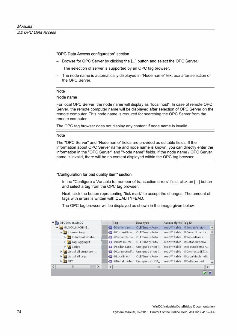
Modules 3.2 OPC Data Access
WinCC/IndustrialDataBridge Documentation 74 System Manual, 02/2013, Printout of the Online Help, A5E32364152-AA
"OPC Data Access configuration" section
– Browse for OPC Server by clicking the [...] button and select the OPC Server.
The selection of server is supported by an OPC tag browser.
– The node name is automatically displayed in "Node name" text box after selection of the OPC Server.
Note Node name
For local OPC Server, the node name will display as "local host". In case of remote OPC Server, the remote computer name will be displayed after selection of OPC Server on the remote computer. This node name is required for searching the OPC Server from the remote computer.
The OPC tag browser does not display any content if node name is invalid.
Note
The "OPC Server" and "Node name" fields are provided as editable fields. If the information about OPC Server name and node name is known, you can directly enter the information in the "OPC Server" and "Node name" fields. If the node name / OPC Server name is invalid, there will be no content displayed within the OPC tag browser.
"Configuration for bad quality item" section
– In the "Configure a Variable for number of transaction errors" field, click on [...] button and select a tag from the OPC tag browser.
Next, click the button representing "tick mark" to accept the changes. The amount of tags with errors is written with QUALITY=BAD.
The OPC tag browser will be displayed as shown in the image given below:

Modules 3.2 OPC Data Access
WinCC/IndustrialDataBridge Documentation System Manual, 02/2013, Printout of the Online Help, A5E32364152-AA 75
– Choose the specific data type by selecting from the drop down list box.
Note OPC tags
Selection of the tag in OPC tag browser displays the corresponding data type in "Data type" field. However, if you remember the name of tag, enter the tag name and data type in the respective fields within "Configuration for bad quality item" section.
"Asynchronous transfer configuration" section
– Enable the check box option "Write asynchronous" for asynchronous writing.
– Enter the permitted number of maximum outstanding write transactions in the text box.
Note Asynchronous transfer
If the "Write asynchronous" check box is enabled, a default value of 10 is set and will be displayed within the "Maximum number of outstanding write transaction" text box. When this check box is disabled, the value will be reset to 0. You can type a value in this text box ranging from 1 - 40.
If the value entered in this text box is not within the range, then an error message is displayed.
Note Asynchronous writing
The Asynchronous transfer configuration is useful to ensure the correctness of the actual data transfer that is happening.
Example: If you have configured the "Maximum number of outstanding write transaction" as 15 and if the data transfer is not happening correctly, after the failure of 15th transaction, a warning message will be displayed in the IDB Runtime Trace view.
Performing link settings 1. In project tree, double click the Settings node to open Settings window in the work area.
The Settings window consists of 3 tabs - Transfer options, Connection Mapping & Connections.

Modules 3.2 OPC Data Access
WinCC/IndustrialDataBridge Documentation 76 System Manual, 02/2013, Printout of the Online Help, A5E32364152-AA
2. Within the Transfer options tab, you can configure the transfer behavior settings for provider.

Modules 3.2 OPC Data Access
WinCC/IndustrialDataBridge Documentation System Manual, 02/2013, Printout of the Online Help, A5E32364152-AA 77
3. Select the "Schema" if applicable and the "Table" name by selecting from the drop down list.
Enter a time period in the "Update rate" field after which the system checks for when the data is to be transferred.
Note Schema
Microsoft Access does not support schema functionality. Hence, you can observe that the Schema field will be in disable state if you have chosen Microsoft Access as the database type.
Note Table name
If you are unable to view Table name in the "Table" field, check if the Schema is selected in "Schema" field. Without selecting the "Schema", the table name will not be displayed. However, if you are using Microsoft Access as the database, this condition will not be valid. If you are still unable to view the Table, please verify with the provider configuration.
Note Update rate
For better performance, it is recommended to use an update rate of 1000 ms or 1 sec.
4. Next, select the type of data transfer:
– Send only changed values
After every update cycle, the value existing within the Update rate is checked. If there is a change in the value, the value will be transferred, else it will be ignored.
– Send always all values
After every update cycle, all the connected column values are transferred from provider to the consumer.
– Send values using trigger
After every update cycle, the trigger condition is verified. If the trigger condition is met, then the data is transferred.

Modules 3.2 OPC Data Access
WinCC/IndustrialDataBridge Documentation 78 System Manual, 02/2013, Printout of the Online Help, A5E32364152-AA
5. If you have selected the option "Send values using trigger", you can configure the trigger. The Trigger section is enabled only if the data transfer type "Send values using trigger" is selected.
Perform the following settings in the "Configure trigger" section:
– In the "Schema" field, choose a valid schema by selecting the drop down list.
– Choose a "Table" name by selecting from the drop down list.
– Select the specific column that needs to be used for the trigger condition.
– Choose a valid data type by selecting from the drop down list.
– Enter a threshold at which a data transfer should be triggered, in the "Trigger value" field.
– In "Confirmation value" field, enter a value that the trigger tag should take on after triggering.
The Confirmation value does not give any information whether a transaction has been completed successfully.
Note Trigger behavior
The column name selected will be used for the trigger condition that triggers the data transfer. IDB CS sets the confirmation value in the provider tag specified in "Confirmation value" field.
6. The transfer behavior settings for provider will be saved automatically.
Note Saving Changes
A save operation is not required every time whenever changes are performed within the editor window in the work area. The changes made to these settings are automatically saved. However, once the project is created, at any point of time, you can save the project by selecting the "Project" > "Save" menu option.
Results You have created a connection between a provider and the OPC Data Access interface. These elements are displayed in the tree structure of the configuration interface. In order to transfer data, connect the provider and consumer tags, as described in chapter "Connecting Tags to the OPC Data Access Interface".

Modules 3.2 OPC Data Access
WinCC/IndustrialDataBridge Documentation System Manual, 02/2013, Printout of the Online Help, A5E32364152-AA 79
3.2.5 Connecting Tags to the OPC Data Access Interface
Connecting Tags In "Settings" window, the "Connection mapping" tab includes the required fields to connect tags that have been sent from selected provider to OPC Data Access interface. The Connection mapping tab divides the window into 3 sections:
● Database provider
● OPC Data Access consumer
● Connection mapping settings
The "Database provider" section is displayed at top left portion of "Connection mapping" tab. This section lists the column values that can be mapped with the tags existing within OPC Data Access interface. The "OPC Data Access consumer" section is displayed at bottom left portion of "Connection mapping" tab. This section provides you with required options to choose the tag name from the list of OPC tags in the OPC tag browser.
The separator between the provider and consumer section provides a resize handle that helps you to resize the height of the section in order to view the fields within the section clearly.

Modules 3.2 OPC Data Access
WinCC/IndustrialDataBridge Documentation 80 System Manual, 02/2013, Printout of the Online Help, A5E32364152-AA
The "Connection mapping settings" section is displayed at right side of "Connection mapping" tab. This section helps you to provide a name for connection along with options for choosing default name for connection. The "Connect", "Modify connection", "Delete connection" and "Delete all connections" icons are provided at the top portion of this section.
1. In "Database provider" section, the selected archive is shown in the "Table" field. Select the "Schema" for database if applicable by selecting from drop down list.
2. The Column names and their corresponding data type are displayed within "Columns" area.
Select a Column name from the list, the selected column is displayed in "Column for data value" field. The data type is shown in the "Data type" field.
3. The "Filter" field provides you the option to filter the Column names based on single character or first few characters of column name.
For example, if you wish to view the column names starting with "S", type this character in "Filter" text box. All column names starting with "S" are displayed.
4. Next, configure the tag in the "OPC Data Access consumer" section by following these steps:
– Select the tag name from the list that is displayed within "OPC tag browser". Upon selection of the tag within OPC tag browser, the tag name is displayed in "Tag ID" field. The data type is displayed in "Data type" field based on selection of the tag.
Note Data type conversion
If the provider tag data type does not match with consumer column, IDB CS converts the provider data type to match with data type of consumer. A status window is displayed to indicate this change.
5. Check the name of the connection in the "Connection mapping settings" area to the right. Enter a unique name for the connection in the "Connection name" field or use the options within "Default name options" area. Click "Connect" button to confirm your entries.
6. Repeat steps 1 to 5 for all elements of the "Database Provider" that you wish to transfer.
7. The connection name including the provider and consumer data values will be displayed within the "Connection mapping settings" section.The list of connections will be also displayed within the Connections tab as well as in the project tree within the "Connections" node belonging to the specific link.
Note Schema
Microsoft Access does not support schema functionality. Hence, you can observe that the Schema field in Database consumer is in disable state.
While using any other database as consumer, the Schema field will be in enable state.

Modules 3.2 OPC Data Access
WinCC/IndustrialDataBridge Documentation System Manual, 02/2013, Printout of the Online Help, A5E32364152-AA 81
NoteArray
If the database provider column has a data type selected other than array data type and if the OPC Data Access consumer tag has "Array" data type, then after clicking the "Connect" button, an error message "Error while setting data type of provider" is displayed. This will not allow to perform a connection mapping as "Array" data type might not be supported by the selected provider.
Note OPC Data Access as consumer
In Connection mapping tab, if you are using any other provider that supports "Array" data type and consumer is OPC Data Access that has a tag of data type other than "Array" data type, after clicking on the "Connect" button, the "Array" check box in provider is automatically checked.
Results The connections that you have created are shown in the "Connections" tab of IDB "Settings" window as well as within the "Connections node" in project tree.

Modules 3.3 IDB OPC Server
WinCC/IndustrialDataBridge Documentation 82 System Manual, 02/2013, Printout of the Online Help, A5E32364152-AA
3.3 IDB OPC Server
3.3.1 Overview
Introduction The internal OPC Server of the IndustrialDataBridge is addressed through the OPC Data Access 2.x (or higher) interface and functions internally as a consumer, i.e. you can only read tags (items). In this case, the ProgID of the OPC Server is "OPC.IndustrialDataBridge".
Networking OPC uses DCOM technology for networking. In this way, the data sources (OPC Server) are available on the local computer including all servers being available on the network as remote data sources.
Applications The IDB OPC Server of the IndustrialDataBridge is a consumer module. You can acquire the data via all available provider modules (Database, Dynamic database, OPC Data Access, OPC XML, Send/Receive, WinCC OLE DB, WinCC User Archive).
The following data types are supported and are released for the IDB OPC Server module.
● VT_UI1 ( 1 byte unsigned )
● VT_I1 ( 1 byte signed )
● VT_UI2 ( 2 byte unsigned )
● VT_I2 ( 2 byte signed )
● VT_UI4 ( 4 byte unsigned )
● VT_I4 ( 4 byte signed )
● VT_R4 ( 4 byte real )
● VT_R8 ( 8 byte real )
● VT_BSTR ( binary string )
● VT_BOOL ( boolean )

Modules 3.3 IDB OPC Server
WinCC/IndustrialDataBridge Documentation System Manual, 02/2013, Printout of the Online Help, A5E32364152-AA 83
● VT_CY ( currency )
● VT_DATE ( date )
Note Important Notes
The internal OPC Client of the IndustrialDataBridge "OPC.IndustrialDataBridge" can be used as a OPC Server and works only when this internal OPC Server is used as a provider. However, you will not be able to configure some of the fields existing within transfer options while this internal OPC Server is used as a provider.
If you are using "OPC.IndustrialDataBridge" as the OPC Server in consumer configuration, it is important to note that you will not be able to perform configuration for bad quality item in consumer configuration.
Also, while using "OPC.IndustrialDataBridge" as the OPC Server (In consumer configuration) in Connection mapping tab, the access rights for the tags will be available as "Readable", hence you will not be able to write to these tags. A dialog box will be displayed with a warning message "The access rights do not allow writing" upon selecting the tag within the tag browser of Consumer section area in the Connection mapping window.
Modules 3.3 IDB OPC Server
WinCC/IndustrialDataBridge Documentation 84 System Manual, 02/2013, Printout of the Online Help, A5E32364152-AA
3.3.2 IDB OPC Server Address Space
Configuring Address Space The module of the IDB that is used internally as a data target (Consumer), is viewed as an OPC Server by an external OPC application. The address space of this OPC server is created by the configuration of the connected tags. This requires that target tags are defined first and connected with respective provider tags.
The following data types are available for selection:
● Unsigned char (VT_UI1)
● Unsigned short (VT_UI2
● Unsigned int (VT_UI4)
● signed char (VT_I1)
● 2-byte signed int (VT_I2)
● 4-byte signed int (VT_I4)
● 4-byte real (VT_R4)
● 8-byte real (VT_R8)
● Binary string (VT_BSTR)
● Boolean; True=-1, False = 0 (VT_BOOL)
● Date (VT_DATE)
Upon performing the required changes, the created configuration in the project can be saved and exported to configuration (XML file). The configuration (XML file) is then opened and started in the IDB Runtime environment.
Viewing Address Space If an OPC Client, for instance an OPC Scout by SimaticNet, is now connected to the OPC Server (OPC.IndustrialDataBridge.1), it can be searched and the tags can be displayed according to the configuration.
You can then view the configured address space and the structure of the ItemIDs in the Itembrowser (the OPC Navigator as a component of the OPC Scout for example):

Modules 3.3 IDB OPC Server
WinCC/IndustrialDataBridge Documentation System Manual, 02/2013, Printout of the Online Help, A5E32364152-AA 85
① This part of the addressing area has been assigned ② The connection name is used here ③ The tags are read-only! ④ The name of the ItemID is formed as follows: Output.ConnectionName.TagName. In this instance, the name
component "Output" is a fixed definition and the components "ConnectionName" and "TagName" are variable.
When tags are added, by means of defining the connections between provider and consumer, the address space is defined on the OPC Data Access Server. The tags that are read by the defined provider have access right "Readable". Writing to these tags is not possible.
Note Starting a New Configuration in the Runtime Environment
If a new or changed configuration (XML file) is opened and started in the runtime environment while an OPC Client (external) is connected with the OPC Server (IDB), the address space of the server could possibly change. The items that the connected client uses can be made invalid this way!
Note Quality of the Tags
If the runtime program is stopped with a loaded configuration, all tags have the quality "Bad".

Modules 3.3 IDB OPC Server
WinCC/IndustrialDataBridge Documentation 86 System Manual, 02/2013, Printout of the Online Help, A5E32364152-AA
3.3.3 Configuring the IDB OPC Server Interface as a Consumer
Objective To create a project with corresponding link having IDB OPC Server as consumer and configure the respective provider/consumer connection properties along with transfer behavior settings
Creating a link 1. Open IDB Configuration and create a project by following the steps mentioned below:
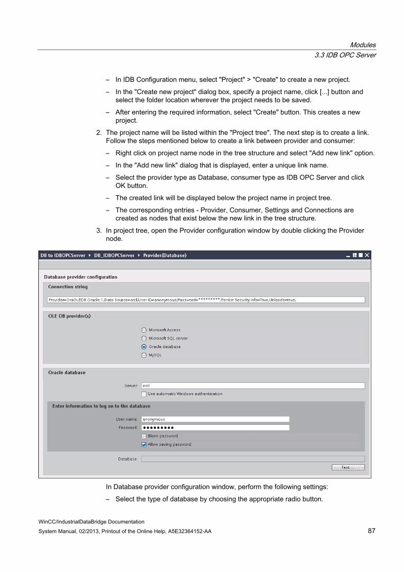
Modules 3.3 IDB OPC Server
WinCC/IndustrialDataBridge Documentation System Manual, 02/2013, Printout of the Online Help, A5E32364152-AA 87
– In IDB Configuration menu, select "Project" > "Create" to create a new project.
– In the "Create new project" dialog box, specify a project name, click [...] button and select the folder location wherever the project needs to be saved.
– After entering the required information, select "Create" button. This creates a new project.
2. The project name will be listed within the "Project tree". The next step is to create a link. Follow the steps mentioned below to create a link between provider and consumer:
– Right click on project name node in the tree structure and select "Add new link" option.
– In the "Add new link" dialog that is displayed, enter a unique link name.
– Select the provider type as Database, consumer type as IDB OPC Server and click OK button.
– The created link will be displayed below the project name in project tree.
– The corresponding entries - Provider, Consumer, Settings and Connections are created as nodes that exist below the new link in the tree structure.
3. In project tree, open the Provider configuration window by double clicking the Provider node.
In Database provider configuration window, perform the following settings:
– Select the type of database by choosing the appropriate radio button.

Modules 3.3 IDB OPC Server
WinCC/IndustrialDataBridge Documentation 88 System Manual, 02/2013, Printout of the Online Help, A5E32364152-AA
– If the database exists on a server location, enter the server name in "Server" field.
If you wish to enable windows authentication automatically, select the check box "Use automatic windows authentication".
– In "Database" field, click on [...] button and select the database from the list or from the folder structure.
Note Server name
The "Server" field for entering the Server name, "Use automatic windows authentication" check box and the fields for entering the logon information are enabled only if you have selected a database other than Microsoft Access.
– If a user name and password has been set for the database, enter the user name and password in the "User name" and "Password" fields respectively.
If you wish to set a blank password, enable the check box "Blank password". To save the entered password, enable the check box "Allow saving password".
– Click Test button to test the connection. The application tests the database connection string and verifies the selected database.
Note Oracle database
While using "Oracle" as the database type, please note that the "Database" field in 'Database provider configuration' window is shown in disable state and does not allow any user selection for this field. The selection of table belonging to Oracle database can be performed within the 'Transfer options' tab.
4. Next, double click the Consumer node in project tree.

Modules 3.3 IDB OPC Server
WinCC/IndustrialDataBridge Documentation System Manual, 02/2013, Printout of the Online Help, A5E32364152-AA 89
In Consumer configuration window, configure the server connection by providing a connection name in the "Connection name" text box.
Note Name of the Server Connection
When configuring the IDB OPC Server as a consumer, the connection name should be unique throughout the entire IDB OPC Server configuration.
Performing link settings 1. In project tree, double click the Settings node to open Settings window in the work area.
The Settings window consists of 3 tabs - Transfer options, Connection Mapping & Connections.

Modules 3.3 IDB OPC Server
WinCC/IndustrialDataBridge Documentation 90 System Manual, 02/2013, Printout of the Online Help, A5E32364152-AA
2. Within the Transfer options tab, you can configure the transfer behavior settings for provider.

Modules 3.3 IDB OPC Server
WinCC/IndustrialDataBridge Documentation System Manual, 02/2013, Printout of the Online Help, A5E32364152-AA 91
"Provider settings" section
– Select the Schema firstly and then choose the Table name by selecting from the drop down list.
– Enter a time period in the "Update rate" field after which the system checks for whether data is to be transferred.
Note Schema
Microsoft Access does not support schema functionality. Hence, you can observe that the Schema field will be in disable state if you have chosen Microsoft Access as the database type.
Note Table name
If you are unable to view Table name in the "Table" field, check if the Schema is selected in "Schema" field. Without selecting the "Schema", the table name will not be displayed. However, if you are using Microsoft Access as the database, this condition will not be valid. If you are still unable to view the Table, please verify with the provider configuration.
Note Update rate
For better performance, it is recommended to use an update rate of 1000 ms or 1 sec.
3. Next, select the type of data transfer:
– Send only changed values
After every update cycle, the value existing within the Update rate is checked. If there is a change in the value, the value will be transferred, else it will be ignored.
– Send always all values
After every update cycle, all the connected column values are transferred from provider to the consumer.
– Send values using trigger
After every update cycle, the trigger condition is verified. If the trigger condition is met, then the data is transferred.
Modules 3.3 IDB OPC Server
WinCC/IndustrialDataBridge Documentation 92 System Manual, 02/2013, Printout of the Online Help, A5E32364152-AA
4. If you have selected the option "Send values using trigger", you can configure the trigger. The Trigger section is enabled only if the data transfer type "Send values using trigger" is selected.
Perform the following settings in the "Configure trigger" section:
– In the Schema field, choose a valid schema by selecting the drop down list.
– Choose a table name by selecting from the drop down list.
– Select the specific column that needs to be used for the trigger condition.
– Choose a valid data type by selecting from the drop down list.
– Enter a threshold at which a data transfer should be triggered, in the "Trigger value" field.
– In "Confirmation value" field, enter a value that the trigger tag should take on after triggering.
The Confirmation value does not give any information whether a transaction has been completed successfully.
5. The transfer behaviour settings for provider will be saved automatically.
Note Saving Changes
A save operation is not required every time whenever changes are performed within the editor window in the work area. The changes made to these settings are automatically saved. However, once the project is created, at any point of time, you can save the project by selecting the "Project" > "Save" menu option.
Results You have created a connection between a provider and the IDB OPC Server interface. These elements are displayed in the tree structure of the configuration interface. In order to transfer data, connect the provider and consumer tags, as described in chapter "Connecting Tags to the IDB OPC Server".
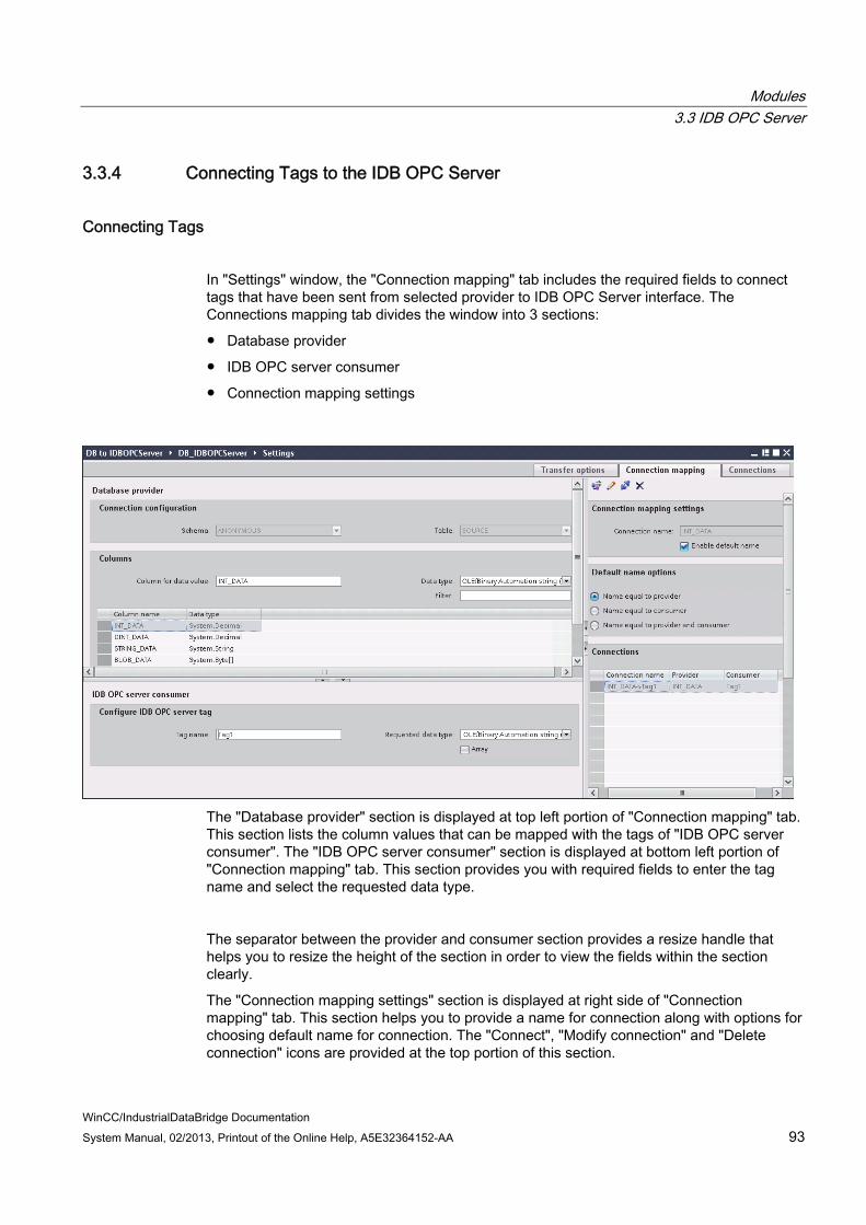
Modules 3.3 IDB OPC Server
WinCC/IndustrialDataBridge Documentation System Manual, 02/2013, Printout of the Online Help, A5E32364152-AA 93
3.3.4 Connecting Tags to the IDB OPC Server
Connecting Tags
In "Settings" window, the "Connection mapping" tab includes the required fields to connect tags that have been sent from selected provider to IDB OPC Server interface. The Connections mapping tab divides the window into 3 sections:
● Database provider
● IDB OPC server consumer
● Connection mapping settings
The "Database provider" section is displayed at top left portion of "Connection mapping" tab. This section lists the column values that can be mapped with the tags of "IDB OPC server consumer". The "IDB OPC server consumer" section is displayed at bottom left portion of "Connection mapping" tab. This section provides you with required fields to enter the tag name and select the requested data type.
The separator between the provider and consumer section provides a resize handle that helps you to resize the height of the section in order to view the fields within the section clearly.
The "Connection mapping settings" section is displayed at right side of "Connection mapping" tab. This section helps you to provide a name for connection along with options for choosing default name for connection. The "Connect", "Modify connection" and "Delete connection" icons are provided at the top portion of this section.

Modules 3.3 IDB OPC Server
WinCC/IndustrialDataBridge Documentation 94 System Manual, 02/2013, Printout of the Online Help, A5E32364152-AA
1. In "Database provider" section, the selected archive is shown in the "Table" field. Select the Schema for database if applicable by selecting from drop down list.
2. The Column names are displayed within "Columns" area. Select a Column name from the list.
The selected column is displayed in "Column for data value" field. The data type is shown automatically.
3. The "Filter" field provides you the option to filter the Column names based on single character or first few characters of column name.
For example, if you wish to view the column names starting with "S", type this character in "Filter" text box. All column names starting with "S" are displayed.
4. In "IDB OPC server consumer" section, configure the IDB OPC server tag. In "Tag name" field, enter the tag name for which the values should be transferred.
5. Within "Requested data type" field, select the data type from the list.
6. Check the name of the connection in the "Connection mapping settings" area (right). Enter a unique name for the connection in the "Connection name" field or use the options within "Default name options". Click "Connect" button to confirm your entries.
Note Data type conversion
If the provider tag data type does not match with consumer column, IDB CS converts the provider data type to match with data type of consumer. A status window is displayed to indicate this change.
7. Repeat steps 1 to 6 for all elements of the "Database Provider" that you wish to transfer.
8. The connection name including the provider and consumer data values will be displayed within the "Connection mapping settings" section.The list of connections will be also displayed within the Connections tab as well as in the project tree within the "Connections" node belonging to the specific link.
Note Schema
Microsoft Access does not support schema functionality. Hence, you can observe that the Schema field in Database consumer is in disable state.
While using any other database as consumer, the Schema field will be in enable state.

Modules 3.3 IDB OPC Server
WinCC/IndustrialDataBridge Documentation System Manual, 02/2013, Printout of the Online Help, A5E32364152-AA 95
Note Array
If the Database provider column has a data type selected other than array data type and if the consumer tag (IDB OPC Server tag) has array data type wherein the "Array" check box has been marked for selection, then after clicking the "Connect" button, an error message "Error while setting data type of provider" is displayed. This will not allow to perform a connection mapping as "Array" data type might not be supported by selected provider.
In Connection mapping tab, if you are using any other provider that does not support "Array" data type and consumer is IDB OPC Server that has a tag of data type "Array", after clicking on the "Connect" button, the "Array" check box in provider is automatically checked.
Note Quality of tags
If data type of consumer does not match with the provider data type, then the tag will have Quality = BAD.
Results The connections that you have created are shown in the "Connections" tab of IDB "Settings" window as well as within the "Connections" node of project tree.
Modules 3.4 OPC XML
WinCC/IndustrialDataBridge Documentation 96 System Manual, 02/2013, Printout of the Online Help, A5E32364152-AA
3.4 OPC XML
3.4.1 Overview
Introduction OPC XML provides a standard interface for accessing data. It can serve both as a server providing data and as a client receiving data from other data providers. With XML, the extensible markup language, it provides another means to describe and exchange information between collaboration applications. The OPC XML based interface will simplify sharing and data exchange of OPC data amongst various levels of plant hierarchy and across various platforms.
OPC XML module is based on data exchange via XML with the platform-independent protocol that is used to enable applications to communicate with each other. The module supports the OPC Data Access 2.0x / 3.0 interface type data.
An OPC XML server can be addressed by multiple OPC clients. Similarly, any OPC client can be used to connect to the OPC XML server or data provider. As OPC XML is platform independent, it allows applications to easily communicate. This makes various OPC-confirming applications available for a data provider across multiple platforms.
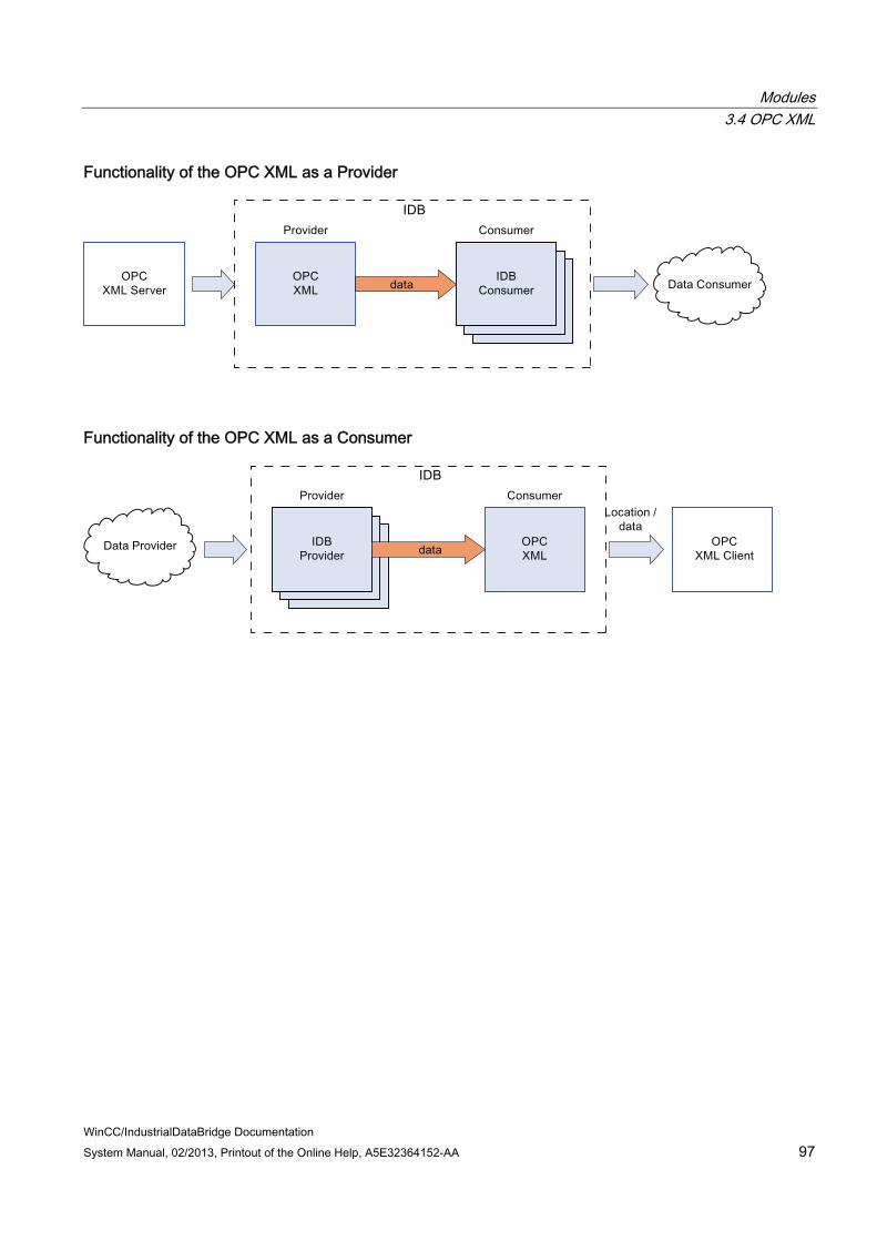
Modules 3.4 OPC XML
WinCC/IndustrialDataBridge Documentation System Manual, 02/2013, Printout of the Online Help, A5E32364152-AA 97
Functionality of the OPC XML as a Provider
Functionality of the OPC XML as a Consumer

Modules 3.4 OPC XML
WinCC/IndustrialDataBridge Documentation 98 System Manual, 02/2013, Printout of the Online Help, A5E32364152-AA
3.4.2 Requirements
Introduction OPC XML enables exchange of data amongst various levels of plant hierarchy and across multiple platforms. In order to use OPC XML, a number of additional software components must be installed.
Using WinCC OPC XML Server The prerequisites to be installed while using WinCC OPC XML Server are listed below:
● WinCC OPC XML Server (using WinCC Setup)
● WinCC Connectivity Pack (License is required)
● Internet Information Server (IIS)
● Microsoft .NET Framework V2.0
● Microsoft ASP.NET
Using any other OPC XML Server While using any other OPC XML Server, the prerequisites to be installed are listed below:
● Internet Information Server (IIS)
● Microsoft .NET Framework V2.0
● Microsoft ASP.NET
Note Web Navigator support
While working simultaneously with OPC XML Server and Web Navigator in Windows XP Professional operating system, running multiple websites are not supported. Running multiple websites using IIS is not supported by Windows XP operating system. To run multiple websites, it is strongly recommended to use an operating system that includes Server edition such as Windows Server 2003 operating system.
Note Installing IIS
IIS needs to be installed firstly before performing the installation of .NET Framework V2.0.

Modules 3.4 OPC XML
WinCC/IndustrialDataBridge Documentation System Manual, 02/2013, Printout of the Online Help, A5E32364152-AA 99
Working with Windows 2003 R2 Server While working with Windows 2003 R2 Server, it is important to follow the steps given below before starting to use OPC XML:
1. Select "Start" > "Run" and type the program name "inetmgr". The Internet Information Services (IIS) window will be opened.
2. In IIS window on the left pane, click the computer name (local computer) and select "Web Service Extensions".
3. In right pane, perform the following settings:
– Select "Active Server Pages" and click the "Allow" button.
– Select "ASP.NET v2.0.50727" and click "Allow" button.
– If "ASP.NET v4.0.30319" or other version is selected, then click "Prohibhit" button.
4. Restart the IIS (enter "iisreset" in command prompt).

Modules 3.4 OPC XML
WinCC/IndustrialDataBridge Documentation 100 System Manual, 02/2013, Printout of the Online Help, A5E32364152-AA
3.4.3 Configuring the OPC XML as Provider
Objective To create a project with corresponding link having OPC XML as provider and configure the respective provider/consumer configuration along with transfer behavior settings.
Creating a link 1. Open IDB Configuration and create a project by following the steps mentioned below:
– In IDB Configuration menu bar, select "Project" > "Create" to create a new project.
– In the "Create new project" dialog box, specify a project name, click [...] button and select the folder location wherever the project needs to be saved.
– After entering the required information, select "Create" button. This creates a new project.
2. The project name will be listed within the "Project tree". The next step is to create a link. Follow the steps mentioned below to create a link between provider and consumer:
– Right click on project name node in the tree structure and select "Add new link" option.
– In the "Add new link" dialog that is displayed, enter a unique link name.
– Select the provider type as OPC XML, consumer type as CSV/TXT and click OK button.
– The created link will be displayed below the project name in project tree.
– The corresponding entries - Provider, Consumer, Settt ings and Connections are created as nodes that exist below the new link in the tree structure.
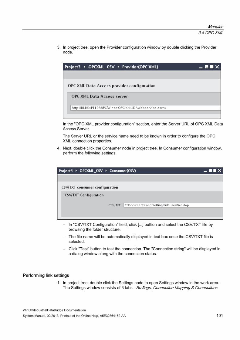
Modules 3.4 OPC XML
WinCC/IndustrialDataBridge Documentation System Manual, 02/2013, Printout of the Online Help, A5E32364152-AA 101
3. In project tree, open the Provider configuration window by double clicking the Provider node.
In the "OPC XML provider configuration" section, enter the Server URL of OPC XML Data Access Server.
The Server URL or the service name need to be known in order to configure the OPC XML connection properties.
4. Next, double click the Consumer node in project tree. In Consumer configuration window, perform the following settings:
– In "CSV/TXT Configuration" field, click [...] buttion and select the CSV/TXT file by browsing the folder structure.
– The file name will be automatically displayed in text box once the CSV/TXT file is selected.
– Click "Test" button to test the connection. The "Connection string" will be displayed in a dialog window along with the connection status.
Performing link settings 1. In project tree, double click the Settings node to open Settings window in the work area.
The Settings window consists of 3 tabs - Se tttings, Connection Mapping & Connections.

Modules 3.4 OPC XML
WinCC/IndustrialDataBridge Documentation 102 System Manual, 02/2013, Printout of the Online Help, A5E32364152-AA
2. Within the Transfer options tab, you can configure the transfer behavior settings for provider.
3. Enter a time period in the "Update rate" field after which the system checks for whether data is to be transferred.
Note Update rate
For better performance, it is recommended to use an update rate of 1000 ms or 1 sec.
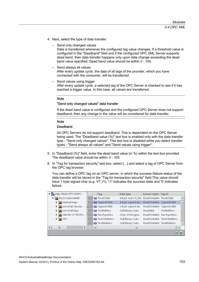
Modules 3.4 OPC XML
WinCC/IndustrialDataBridge Documentation System Manual, 02/2013, Printout of the Online Help, A5E32364152-AA 103
4. Next, select the type of data transfer:
– Send only changed values Data is transferred whenever the configured tag value changes. If a threshold value is configured in the "Deadband" field and if the configured OPC XML Server supports dead band, then data transfer happens only upon data change exceeding the dead band value specified. Dead band value should be within 0 - 100.
– Send always all values After every update cycle, the data of all tags of the provider, which you have connected with the consumer, will be transferred.
– Send values using trigger After every update cycle, a selected tag of the OPC Server is checked to see if it has reached a trigger value. In this case, all values are transferred.
Note "Send only changed values" data transfer
If the dead band value is configured and the configured OPC Server does not support deadband, then any change in the value will be considered for data transfer.
Note Deadband
All OPC Servers do not support deadband. This is dependent on the OPC Server being used. The "Deadband value (%)" text box is enabled only with the data transfer type - "Send only changed values". This text box is disabled while you select transfer types - "Send always all values" and "Send values using trigger".
5. In "Deadband (%)" field, enter the dead band value (in %) within the text box provided. The deadband value should be within 0 - 100.
6. In "Tag for transaction security" text box, select […] and select a tag of OPC Server from the OPC tag browser.
You can define a OPC tag on an OPC server, in which the success-/failure-status of the data transfer will be stored in the "Tag for transaction security" field.This value should have 1 byte signed char (e.g. VT_I1). '-1' indicates the success state and '0' indicates failure.

Modules 3.4 OPC XML
WinCC/IndustrialDataBridge Documentation 104 System Manual, 02/2013, Printout of the Online Help, A5E32364152-AA
7. If you have selected the option "Send values using trigger", you can configure the trigger that provides options to choose trigger tag and set trigger values. Perform the following settings in the "Trigger settings" section:
– In "Trigger tag" text box, select [...] button to open OPC tag browser and select a tag that should trigger a data transfer.
– Select a valid data type by selecting from the drop down list.
– Enter a threshold at which a data transfer should be triggered, in the "Trigger value" field.
– You can enter a value that the trigger tag should take on after triggering, in the "Confirmation value" field. The confirmation value does not give any information on whether a transaction has been completed successfully.
8. The transfer behavior settings for OPC XML as provider will be saved automatically.
Note Saving Changes
A save operation is not required every time whenever changes are performed within the editor window in the work area. The changes made to these settings are automatically saved. However, once the project is created, at any point of time, you can save the project by selecting the "Project" > "Save" menu option.
Results You have created a connection between the OPC XML and a consumer. These elements are displayed in the tree structure of the configuration interface. In order to transfer data, connect the provider and consumer tags, as described in chapter "Connecting Tags from the OPC XML Interface (Page 105)".
See also Connecting Tags from the OPC XML

Modules 3.4 OPC XML
WinCC/IndustrialDataBridge Documentation System Manual, 02/2013, Printout of the Online Help, A5E32364152-AA 105
3.4.4 Connecting Tags from the OPC XML Interface
Connecting Tags In "Settings" window, the "Connection mapping" tab includes the required fields to connect tags that have been sent from the OPC XML Data Access provider to selected consumer. The Connection mapping tab divides the window into 3 sections. The Connection Settings are performed by configuring the settings within the Connection mapping tab.
The Connection mapping tab divides the window into 3 sections.
● OPC XML Data Access provider
● CSV/TXT consumer
● Connection mapping properties
This tab displays the "OPC XML Data Access provider" and "CSV/TXT consumer" on left hand side whereas the right hand side of window contains Connection mapping properties and connection options. The separator between the provider and consumer section provides a resize handle that helps you to resize the height of the section in order to view the fields within the section clearly.
The "Connection mapping settings" section is displayed at right side of "Connection mapping" tab. This section helps you to provide a name for connection along with options for choosing default name for connection. The "Connect", "Modify connection", "Delete connection" and "Delete all connections" icons are provided at the top portion of this section.
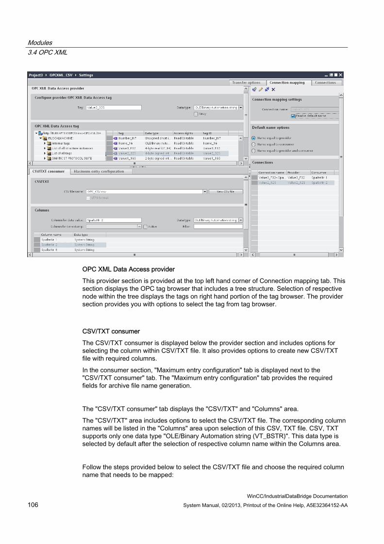
Modules 3.4 OPC XML
WinCC/IndustrialDataBridge Documentation 106 System Manual, 02/2013, Printout of the Online Help, A5E32364152-AA
OPC XML Data Access provider
This provider section is provided at the top left hand corner of Connection mapping tab. This section displays the OPC tag browser that includes a tree structure. Selection of respective node within the tree displays the tags on right hand portion of the tag browser. The provider section provides you with options to select the tag from tag browser.
CSV/TXT consumer
The CSV/TXT consumer is displayed below the provider section and includes options for selecting the column within CSV/TXT file. It also provides options to create new CSV/TXT file with required columns.
In the consumer section, "Maximum entry configuration" tab is displayed next to the "CSV/TXT consumer" tab. The "Maximum entry configuration" tab provides the required fields for archive file name generation.
The "CSV/TXT consumer" tab displays the "CSV/TXT" and "Columns" area.
The "CSV/TXT" area includes options to select the CSV/TXT file. The corresponding column names will be listed in the "Columns" area upon selection of this CSV, TXT file. CSV, TXT supports only one data type "OLE/Binary Automation string (VT_BSTR)". This data type is selected by default after the selection of respective column name within the Columns area.
Follow the steps provided below to select the CSV/TXT file and choose the required column name that needs to be mapped:

Modules 3.4 OPC XML
WinCC/IndustrialDataBridge Documentation System Manual, 02/2013, Printout of the Online Help, A5E32364152-AA 107
1. Within "CSV/TXT" area, the "CSV filename" list box is provided that displays a list of CSV or TXT files.
Click the drop down arrow of "CSV filename" field and select the appropriate CSV file.
2. If the CSV/TXT file does not exist in the list, select "New CSV file" button. The "CSV Creator" dialog box opens thus providing options to create a new CSV file.
In the "CSV creator" dialog window, select "Add" button to create a column entry with default name. To define a custom name for the column, enter the column name in "Column name" field provided at top portion of this window. The created columns are displayed within the "Columns" text area. The "UP" and "DOWN" buttons allows in changing the column sequence.
Note
The keyword "ID" written in capital letters should not be used for creating the first column name of CSV file. If "ID" is given as column name for the first column, then a warning message is displayed upon double clicking the CSV file. CSV files do not support this behavior.
3. Enter a file name in the "Filename" text box followed by file extension and select "Create" button to create the CSV file. The new CSV file will be now available in the file list.
If the file that is selected within the list is of type UTF-8 format, the check box "UTF-8" will be automatically enabled. If the file is of ANSI format, the check box remains unchecked.
4. In "CSV/TXT consumer" tab, select the CSV file that is displayed in the "CSV filename" field list box. The "Columns" area displays the "column name" along with its associated "Data type".

Modules 3.4 OPC XML
WinCC/IndustrialDataBridge Documentation 108 System Manual, 02/2013, Printout of the Online Help, A5E32364152-AA
5. In "Columns" area, select the column name from the list. The selected column name is displayed in "Column for data value" field and the corresponding data type is selected and displayed in "Data type" field.
6. The time stamp can be written to the specific column. In this case, select the respective "Active" check box and select the column in "Column for timestamp" field list box as the CSV/TXT supports only one data type "OLE/Binary Automation string (VT_BSTR).
7. The "Filter" field provides you the option to filter the Column names based on single character or first few characters of column name.
For example, if you wish to view the column names starting with "S", type this character in "Filter" text box. All column names starting with "S" are displayed.
Maximum entry configuration
The "Maximum Entry Configuration" tab provides options to archive the data. Continuous archiving can be handled or else options to archive once the maximum entries are reached are also supported. This also provides support for archive file name generation wherein several options are provided for selection that is used for generating the archive file name. The "Archive path" field allows for selecting the desired archive path.
Follow the steps given below to perform these archive settings:
1. Select the check box "Archive File at Maximum Entry" and specify a value in "Max. entries" text box.

Modules 3.4 OPC XML
WinCC/IndustrialDataBridge Documentation System Manual, 02/2013, Printout of the Online Help, A5E32364152-AA 109
Note
If this check box "Archive File at Maximum Entry" is unchecked, the Archive File Name Generation and other file name selection options within this tab will be in disable state.
Note By default, the "Max. entries" field displays the value as 0. However, this value can be
modified. It is important to ensure that "Max. entries" field should not be left blank. If "Max. entries" is set to a value less than zero or negative value entered or if the field
is blank, an error message "Value should be greater than or equal to zero" is displayed.
The maximum value for Max. entries in CSV/TXT is 2147483647. Any value entered above this range will not be accepted and displays an error message as "Type conversion failed".
2. In "Archive File Name Generation" area, options are provided for file name generation with respect to the archive file. Select any one of the following options by selecting the radio button.
– Use current date and time
– Use current date and serial number
– Use serial number
3. Next, specify the Archive path in the text box provided. You can either enter the complete folder path in the text box or select the path using "[...]" button. If you provide the path in "Archive path" text box, archived CSV files are generated at this path. By default, this text box has the same path where the base CSV file is present.
4. The "Use Dedicated file name" check box allows to specify a dedicated file name in combination with a serial number & date or date & time or serial number. If this checkbox is unchecked, then the base CSV filename will be used for archiving.
5. The "Select filename type" field provides options to select custom file name.
– To use custom file name, select filename type as "Use custom filename" and enter the custom file name in "Custom file name" text box.
Modules 3.4 OPC XML
WinCC/IndustrialDataBridge Documentation 110 System Manual, 02/2013, Printout of the Online Help, A5E32364152-AA
Connection Mapping
To establish connection between the provider and consumer, column mapping is required to be performed between the provider and consumer types. The Connection window displays "Default connection name" options in order to specify a name for default connection. "Connect", "Modify connection", "Delete connection" and "Delete all connections" icons are provided below the "Default connection name" section area. These buttons help in order to work with the connections.
Note Modify connection
To modify an existing connection, perform the required changes and then select "Modify connection" button. The changes can be observed within the Connection window only after selecting the "Modify" button.
Follow these steps to perform column mapping between provider and consumer:
1. In "OPC XML Data Access provider", select a tag name from the list that is displayed within the "OPC XML Data Access tag browser". Upon selection of the tag within tag browser, the tag name is displayed in "Tag" field. The data type is selected automatically based on selection of this tag.
2. If the selected tag has Array data type, then the "Array" check box is automatically enabled. This check box is provided below the "Data type" field.
3. Next, choose the column name from "CSV/TXT consumer" column that needs to be mapped and click "Connect" button.
Note Data type conversion
If the provider tag data type does not match with consumer column, IDB CS converts the provider data type to match with data type of consumer. A status window is displayed to indicate this change.
4. Repeat steps 1 - 3 for all elements of the data provider that you wish to transfer. A connection is created for each of the column values existing between provider and consumer.
5. The connection name including the provider and consumer data values will be displayed within the "Connection mapping settings" section.
6. The list of connections will be also displayed within the Connections tab as well as in the project tree within the "Connections" node belonging to the specific link.

Modules 3.4 OPC XML
WinCC/IndustrialDataBridge Documentation System Manual, 02/2013, Printout of the Online Help, A5E32364152-AA 111
NoteArray
If the OPC XML Data Access provider tag has a data type of type "Array" and if the CSV/TXT consumer column has data type other than array data type, after clicking on the Connect buton, the "Array" check box in the "OPC XML Data Access provider" is automatically unchecked.
Results The connections that you have created are shown in the "Connections" tab of IDB "Settings" window as well as within the project tree node.

Modules 3.4 OPC XML
WinCC/IndustrialDataBridge Documentation 112 System Manual, 02/2013, Printout of the Online Help, A5E32364152-AA
3.4.5 Configuring the OPC XML as Consumer
Objective To create a project with corresponding link having OPC XML as consumer and configure the respective provider/consumer configuration along with transfer behavior settings.
Creating a link 1. Open IDB Configuration and create a project by following the steps mentioned below:
– In IDB Configuration menu bar, select "Project" > "Create" to create a new project.
– In the "Create new project" dialog box, specify a project name, click [...] button and select the folder location wherever the project needs to be saved.
– After entering the required information, select "Create" button. This creates a new project.
2. The project name will be listed within the "Project tree". The next step is to create a link. Follow the steps mentioned below to create a link between provider and consumer:
– Right click on project name node in the tree structure and select "Add new link" option.
– In the "Add new link" dialog that is displayed, enter a unique link name.
– Select the provider type as OPC Data Access, consumer type as OPC XML and click OK button.
– The created link will be displayed below the project name in project tree.
– The corresponding entries - Provider, Consumer, Settt ings and Connections are created as nodes that exist below the new link in the tree structure.
3. In project tree, open the Provider configuration window by double clicking the Provider node.
In Provider configuration window, perform the following settings:

Modules 3.4 OPC XML
WinCC/IndustrialDataBridge Documentation System Manual, 02/2013, Printout of the Online Help, A5E32364152-AA 113
– Browse for OPC Server by clicking the [...] button and select OPC Server from the list.
The selection of the server is supported by an OPC Server browser. The browser displays the local OPC Servers as well as OPC Servers in the network.
– The node name is simultaneously displayed in "Node name" text box after selection of the OPC Server.
Note Node name
For local OPC Server, the node name will display as "local host". In case of remote OPC Server, the remote computer name will be displayed after selection of OPC Server on the remote computer. This node name is required for searching the OPC Server from the remote computer.
The OPC Server browser does not display any content if you enter an invalid node name in the "Node name" text box.
Note
The "OPC Server" and "Node name" fields are provided as editable fields. If the information about OPC Server name and node name is known, you can directly enter the information in the "OPC Server" and "Node name" fields. If the node name / OPC Server name is invalid, there will be no content displayed within the OPC tag browser.
4. Next, double click the Consumer node in project tree. In Consumer configuration window, perform the following settings:

Modules 3.4 OPC XML
WinCC/IndustrialDataBridge Documentation 114 System Manual, 02/2013, Printout of the Online Help, A5E32364152-AA
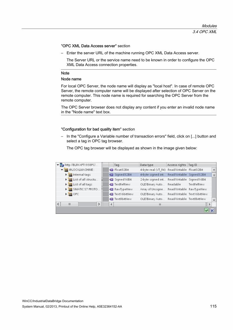
Modules 3.4 OPC XML
WinCC/IndustrialDataBridge Documentation System Manual, 02/2013, Printout of the Online Help, A5E32364152-AA 115
"OPC XML Data Access server" section
– Enter the server URL of the machine running OPC XML Data Access server.
The Server URL or the service name need to be known in order to configure the OPC XML Data Access connection properties.
Note Node name
For local OPC Server, the node name will display as "local host". In case of remote OPC Server, the remote computer name will be displayed after selection of OPC Server on the remote computer. This node name is required for searching the OPC Server from the remote computer.
The OPC Server browser does not display any content if you enter an invalid node name in the "Node name" text box.
"Configuration for bad quality item" section
– In the "Configure a Variable number of transaction errors" field, click on [...] button and select a tag in OPC tag browser.
The OPC tag browser will be displayed as shown in the image given below:

Modules 3.4 OPC XML
WinCC/IndustrialDataBridge Documentation 116 System Manual, 02/2013, Printout of the Online Help, A5E32364152-AA
– Choose the specific data type by selecting from the drop down list box.
Note OPC tags
Selection of the tag in OPC tag browser displays the corresponding data type in "Data type" field. However, if you know the tag name, enter the tag name in "Configure a Variable for number of transaction errors" field and select the data type in "Data type" field by selecting from the list.
"Asynchronous transfer configuration" section
– Enable the check box option "Write asynchronous" for asynchronous writing.
– Enter the permitted number of maximum outstanding write transactions in the text box.
Note Asynchronous transfer
If the "Write asynchronous" check box is enabled, a default value of 10 is set and will be displayed within the "Maximum number of outstanding write transaction" text box. When this check box is disabled, the value will be reset to 0. You can type a value in this text box ranging from 1 - 40. If the value entered in this text box is not within the range, then an error message is displayed.
Note Asynchronous writing
The Asynchronous transfer configuration is useful to ensure the correctness of the actual data transfer that is happening.
Example: If you have configured the "Maximum number of outstanding write transaction" as 15 and if the data transfer is not happening correctly, after the failure of 15th transaction, a warning message will be displayed in the IDB Runtime Trace view.
Performing link settings 1. In project tree, double click the Settings node to open Settings window in the work area.
The Settings window consists of 3 tabs - Se tttings, Connection Mapping & Connections.

Modules 3.4 OPC XML
WinCC/IndustrialDataBridge Documentation System Manual, 02/2013, Printout of the Online Help, A5E32364152-AA 117
2. Within the Transfer options tab, you can configure the transfer behavior settings for provider.
3. Enter a time period in the "Update rate" field after which the system checks for whether data is to be transferred.
NoteUpdate rate
For better performance, it is recommended to use an update rate of 1000 ms or 1 sec.
Modules 3.4 OPC XML
WinCC/IndustrialDataBridge Documentation 118 System Manual, 02/2013, Printout of the Online Help, A5E32364152-AA
4. Next, select the type of data transfer:
– Send only changed values
Data is transferred whenever the configured tag value changes. If a threshold value is configured in the "Deadband" field and if the selected OPC Server supports deadband, then data transfer happens only upon data change exceeding the dead band value specified. Dead band value should be within 0 - 100.
– Send always all values
After every update cycle, the data of all tags of the provider, which you have connected with the consumer, will be transferred.
– Send values using trigger
After every update cycle, a selected tag of the OPC Server is checked to see if it has reached a trigger value. In this case, all values are transferred.
Note "Send only changed values" data transfer
If the deadband value is configured and the selected OPC Server does not support deadband, a value of 0% is set and any change in the value will be considered for data transfer. Data transfer of this type is independent of "Update rate".
Note Deadband
All OPC Servers do not support deadband. This is dependent on the OPC Server being used. The "Deadband value (%)" text box is enabled only with the data transfer types - "Send only changed values" and "Send always all values". This text box is disabled while you select the transfer type "Send values using trigger".
5. Enter the deadband value (in percent) to contain a value within the range 0 - 100.
6. In "Tag for Transaction Security" field, click [...] button and select a tag of OPC Server from the OPC tag browser.
You can define an OPC item on an OPC server, in which the success-/failure-status of the data transfer will be stored in the "Tag for transaction security" field. This value should have 1 byte signed char (e.g. VT_I1). "-1" indicates the success state and "0" indicates failure.

Modules 3.4 OPC XML
WinCC/IndustrialDataBridge Documentation System Manual, 02/2013, Printout of the Online Help, A5E32364152-AA 119
7. If you have selected the option "Send values using trigger", you can configure the trigger that provides options to set the trigger options. The Trigger section is enabled only with the data transfer type "Send values using trigger".
Perform the following settings in the "Configure Trigger" section:
– In "Trigger tag" text box, select the tag that should trigger a data transfer. Click on [...] to select the tag from OPC tag browser.
– Select a valid data type by selecting from the drop down list.
– Enter a threshold at which a data transfer should be triggered, in the "Trigger value" field.
– In "Confirmation value" field, enter a value that the trigger tag should take on after triggering.
The confirmation value does not give any information on whether a transaction has been completed successfully.
8. The transfer behavior settings for OPC Data Access as provider will be saved automatically.
Note Saving changes
A save operation is not required every time whenever changes are performed within the editor window in the work area. The changes made to these settings are automatically saved. However, once the project is created, at any point of time, you can save the project by selecting the "Project" > "Save" menu option.
Results You have created a connection between the provider and OPC XML as a consumer. These elements are displayed in the tree structure of the IDB configuration interface. In order to transfer data, connect the provider and consumer tags, as described in chapter "Connecting Tags to the OPC XML Interface (Page 120)".

Modules 3.4 OPC XML
WinCC/IndustrialDataBridge Documentation 120 System Manual, 02/2013, Printout of the Online Help, A5E32364152-AA
3.4.6 Connecting Tags to the OPC XML Interface
Connecting tags In "Settings" window, the "Connection mapping" tab includes the required fields to connect tags that have been sent from selected provider to OPC XML Data Access consumer. The Connection Settings are performed by configuring the settings within the Connection mapping tab. The Connection mapping tab divides the window into 3 sections.
● OPC Data Access provider
● OPC XML Data Access consumer
● Connection mapping properties
The "OPC Data Access provider" section is displayed at top left portion of "Connection mapping" tab. This section lists the tags that can be mapped with the tags existing within "OPC XML Data Access consumer". The "OPC XML Data Access consumer" section is displayed at bottom left portion of "Connection mapping" tab. This section provides you with required options to choose the tag name from the list of OPC tags to be mapped.
The separator between the provider and consumer section provides a resize handle that helps you to resize the height of the section in order to view the fields within the section clearly.

Modules 3.4 OPC XML
WinCC/IndustrialDataBridge Documentation System Manual, 02/2013, Printout of the Online Help, A5E32364152-AA 121
The "Connection mapping settings" section is displayed at right side of "Connection mapping" tab. This section helps you to provide a name for connection along with options for choosing default name for connection. The "Connect", "Modify connection" and "Delete connection" icons are provided at the top portion of this section.
1. In "OPC Data Access provider" section, select the tag name from the list that is displayed within "OPC tag browser".
Upon selection of the tag within OPC tag browser, the tag name is displayed in "Tag" field. The data type is selected automatically based on selection of the tag.
2. If the selected tag has Array data type, then the "Array" check box is automatically enabled. This check box is provided below the "Data type" field.
3. Next, configure the tag in the "OPC XML Data Access consumer" section by following these steps:
– Select the tag name from the list that is displayed within "OPC tag browser". Upon selection of the tag within OPC tag browser, the tag name is displayed in "Tag" field. The data type is selected automatically based on selection of this tag.
– If the selected tag has Array data type, then the "Array" check box is automatically enabled. This check box is provided below the "Data type" field.
4. Check the name of the connection in the "Connection mapping settings" area to the right. Enter a unique name for the connection in the "Connection name" field or use the options within "Default name options". Click "Connect" button to confirm your entries.
The connection name including the provider and consumer data values will be displayed within the "Connection mapping settings" section.The list of connections will be also displayed within the Connections tab as well as in the project tree within the "Connections" node belonging to the specific link.
Note Data type conversion
If the provider tag data type does not match with consumer column, IDB CS converts the provider data type to match with data type of consumer. A status window is displayed to indicate this change.
5. Repeat steps 1 to 4 for all elements of the "OPC Data Access provider" interface that you wish to transfer.
6. The connection name including the provider and consumer data values will be displayed within the "Connection mapping settings" section.The list of connections will be also displayed within the Connections tab as well as in the project tree within the "Connections" node belonging to the specific link.

Modules 3.4 OPC XML
WinCC/IndustrialDataBridge Documentation 122 System Manual, 02/2013, Printout of the Online Help, A5E32364152-AA
Note Array
If the OPC Data Access provider column has a data type other than array data type and if the OPC XML Data Access consumer tag has data type of type "Array", after clicking on the Connect buton, the "Array" check box in the "OPC XML Data Access consumer" is automatically checked.
Results The connections that you have created are shown in the "Connections" tab of IDB "Settings" window as well as within the project tree node.

Modules 3.5 WinCC OLE DB
WinCC/IndustrialDataBridge Documentation System Manual, 02/2013, Printout of the Online Help, A5E32364152-AA 123
3.5 WinCC OLE DB
3.5.1 Overview
Introduction The WinCC OLEDB Provider enables access to the archive data from WinCC. You can select message archives or process value archives with this archive data.
In this case, there are 3 different transfer modes:
● Cyclic and continuous(*)
● Triggered and continuous(*)
● Triggered time period
For the "Cyclic and continuous" transfer, the transfer time is set with a timer. This enables an hours transfer to be started for instance. The time period is defined using the last two timer times.
In mode "Triggered and continuous", the transfer time is defined using a trigger condition with OPC tags. The time period is defined using the last two trigger times. The IDB marks the last transfer time and reads the interval between two trigger times.
With transfer method "Triggered time period", the transfer time is defined using a trigger condition with OPC tags. The time period, which is read from the WinCC archive, is defined using two other OPC tags.
(*) The continuous data transfer can be continued on with a stop of the IndustrialDataBridge. The IDB saves the time of the last transfer so that even after a restart, a continuous transfer can be completed without doubled or missing data. This functionality is only supported if the configuration file is not changed or another file is loaded. The start-up behavior for the initial start of a configuration must be defined.

Modules 3.5 WinCC OLE DB
WinCC/IndustrialDataBridge Documentation 124 System Manual, 02/2013, Printout of the Online Help, A5E32364152-AA
Transparent Access to Process Value Archives from a Connectivity Station If the IndustrialDataBridge is configured for using on a Connectivity Station, a transparent access can be set on the process value archive. This requires that you enter the server prefix instead of a computer name. This allows you to access archives on redundant servers or on a central archive server without any other efforts.
Note Adjustment between Summer and Winter Time For all data that is to be transferred, a check is performed to determine whether Winter
time or Summer time is concerned and is considered accordingly in the conversion. For time definitions that are defined precisely in the hour of the adjustment, doubled data
records can occur in the data consumer. No data records will be lost.
In order to maintain the correct behavior of the IDB as of version V7.2, set the time zone to UTC. GMT is only to be set the same as UTC time in Winter. During summer time, there is a difference of 1 hour.
Modules 3.5 WinCC OLE DB
WinCC/IndustrialDataBridge Documentation System Manual, 02/2013, Printout of the Online Help, A5E32364152-AA 125
3.5.2 Requirements
Prerequisites in WinCC ● In order for the WinCC OLEDB Provider of the IndustrialDataBridge to access WinCC, the
ConnectivityPack client (WinCC OLE DB driver) has to be installed. Without this client, the database interface is not available.
● For configuring WinCC OLEDB provider configuration, the WinCC project XML file exported from the current WinCC configuration must be available. If WinCC runs on another computer, you will have to install IDB separately so that the project XML export will be available. The "Project XML Export" command is located in the pop-up menu of the IndustrialDataBridge of the WinCC Explorer.
● If the WinCC Runtime is not in RUN status, the browse interface of the OPC server (OPC tag browser) is not available. Switch the WinCC into RUN status.
Note Time:
If the clock on the IndustrialDataBridge computer is advanced, the interval will not be completely covered. This circumstance may result in an incomplete transfer of data. Synchronize the computer clocks.
Note Access to WinCC OLE DB from another PC in a Workgroup:
The client and server computers require users with the same access rights, since otherwise a WinCC OLE DB access is not possible.
Prerequisites for Single Point of System Access to Process Data Archives from a connectivity station In order for you to set up "Single Point of System Access" (connectivity station), you require the Connectivity station name and symbolic computer name (server prefix) of the computer that is acting as connectivity station. Simatic PCS7 and WinCC needs to be installed to use the computer as connectivity station.
Note PCS7
The "OpenPCS7" software option needs to be selected while installing PCS7. For more information about installing PCS7 or creating projects, please refer "PCS7 manual".

Modules 3.5 WinCC OLE DB
WinCC/IndustrialDataBridge Documentation 126 System Manual, 02/2013, Printout of the Online Help, A5E32364152-AA
Note WinCC Project XML file
The WinCC Project XML file has to be exported from the connectivity station. To use Single Point of System Access (connectivity station), the XML file that supports "Single Point of System Access" has to be used. The corresponding connectivity station name is automatically displayed in WinCC OLEDB provider configuration if you are using a valid XML file that supports "Single Point of System Access". If the XML file used is not a valid one, then the connectivity station name will not be listed.
If the WinCC project has been changed, you must execute the "Project XML Export" command on the Engineering Station. In WinCC OLEDB provider configuration, you need to select the modified XML file again. Transfer the data onto the connectivity station again.
Prerequisites for having Process Data Archives from a WinCC station To use process data archives from a WinCC station, you require the WinCC station name and project name of the computer that is acting as WinCC station. WinCC needs to be installed to use the computer as connectivity station.
Note WinCC Project XML file
The WinCC Project XML file has to be exported from the WinCC station (the computer that has WinCC installed). A valid XML file that is exported from the WinCC station needs to be used in WinCC OLEDB provider configuration. If you are using a valid XML file, then the corresponding WinCC station name is displayed.
Exporting a WinCC Archive Configuration If you want to access data in a WinCC Archive, you must make this data available for the WinCC OLE DB.
Proceed as follows in this case:
1. Open the IndustrialDataBridge pop-up menu in the WinCC Explorer.
2. Select command "Project XML Export".
3. WinCC creates an XML file. This process can take several minutes depending on the workload and computer power.
4. The WinCC then indicates the export path. Confirm this message by clicking "OK".
You can now access the WinCC archive via the WinCC OLE DB interface.

Modules 3.5 WinCC OLE DB
WinCC/IndustrialDataBridge Documentation System Manual, 02/2013, Printout of the Online Help, A5E32364152-AA 127
Note Changed WinCC Project Configuration
If the WinCC project has been changed, you must execute the "Project XML Export" command again and check the IDB configuration and modify it if necessary.
3.5.3 Configuring the WinCC OLE DB Interface as a Provider
Objective To create a project with corresponding link having WinCC OLE DB as provider and configure the respective provider/consumer properties along with transfer behaviour settings
Creating a link 1. Open IDB Configuration and create a project by following the steps mentioned below:
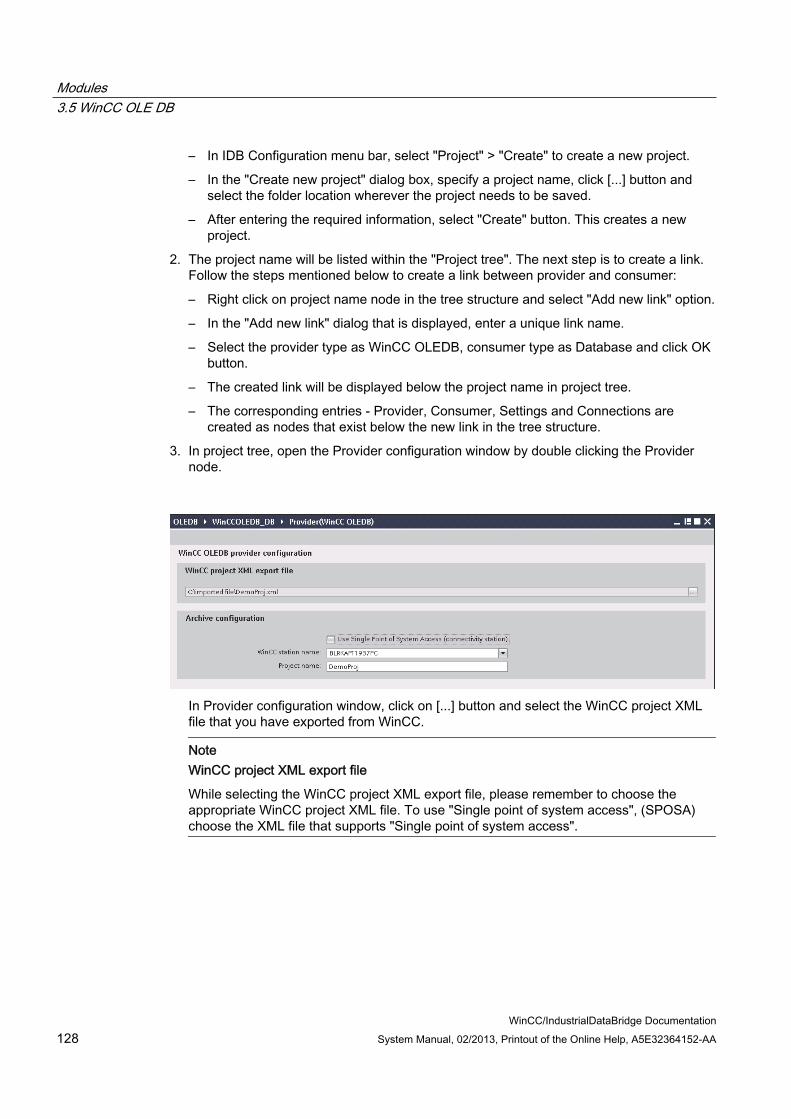
Modules 3.5 WinCC OLE DB
WinCC/IndustrialDataBridge Documentation 128 System Manual, 02/2013, Printout of the Online Help, A5E32364152-AA
– In IDB Configuration menu bar, select "Project" > "Create" to create a new project.
– In the "Create new project" dialog box, specify a project name, click [...] button and select the folder location wherever the project needs to be saved.
– After entering the required information, select "Create" button. This creates a new project.
2. The project name will be listed within the "Project tree". The next step is to create a link. Follow the steps mentioned below to create a link between provider and consumer:
– Right click on project name node in the tree structure and select "Add new link" option.
– In the "Add new link" dialog that is displayed, enter a unique link name.
– Select the provider type as WinCC OLEDB, consumer type as Database and click OK button.
– The created link will be displayed below the project name in project tree.
– The corresponding entries - Provider, Consumer, Settings and Connections are created as nodes that exist below the new link in the tree structure.
3. In project tree, open the Provider configuration window by double clicking the Provider node.
In Provider configuration window, click on [...] button and select the WinCC project XML file that you have exported from WinCC.
Note WinCC project XML export file
While selecting the WinCC project XML export file, please remember to choose the appropriate WinCC project XML file. To use "Single point of system access", (SPOSA) choose the XML file that supports "Single point of system access".

Modules 3.5 WinCC OLE DB
WinCC/IndustrialDataBridge Documentation System Manual, 02/2013, Printout of the Online Help, A5E32364152-AA 129
4. For IDB CS to be used on a WinCC station, ensure that you do not mark the "Use Single point of system access" for selection.
– In "Archive configuration" section, select the WinCC station name of the selected provider.
Note WinCC station The WinCC station name is listed in the drop down list box of "WinCC station name"
field that displays the station name wherever the WinCC XML file exists. Choose the WinCC station name by selecting from list.
The project name is automatically displayed based on the WinCC project XML file that is selected in "WinCC project XML file" text box.
5. If IDB CS is required to be used on a Connectivity station, you can set up "Single point of system access" to these process value archives.
– To use transparent access, enable the "Use Single point of system access" check box.
– Enter the server prefix (symbolic computer name) of connectivity station that has WinCC installed.
Note Connectivity Station
Select the check box "Use Single point of system access" only if IDB CS is set as a connectivity station. The transparent access from a connectivity station can occur to process value archives. Once this check box is selected, you can observe that the label "WinCC station name" is changed to "Connectivity station name". The connectivity station is listed in the drop down list box of "Connectivity station
name" field that displays the name of connectivity station wherever the WinCC XML file exists. Choose the connectivity station name by selecting from list.
The project name is automatically displayed based on the WinCC project XML file that is selected in "WinCC project XML file" text box.

Modules 3.5 WinCC OLE DB
WinCC/IndustrialDataBridge Documentation 130 System Manual, 02/2013, Printout of the Online Help, A5E32364152-AA
6. Next, double click the Consumer node in project tree to open the consumer configuration window.
7. In Consumer connection configuration window, perform the following settings:
"Database consumer configuration" section
– Select the type of database by choosing the appropriate radio button.

Modules 3.5 WinCC OLE DB
WinCC/IndustrialDataBridge Documentation System Manual, 02/2013, Printout of the Online Help, A5E32364152-AA 131
– If the database exists on a server location, enter the server name in "Server" field.
If you wish to enable windows authentication automatically, select the check box "Use automatic windows authentication".
– In "Database" field, click on [...] button and select the database from the list or from the folder structure.
Note Server name
The "Server" field for entering the Server name, "Use automatic windows authentication" check box and the fields for entering the logon information are enabled only if you have selected a database other than Microsoft Access.
– If a user name and password has been set for the database, enter the user name and password in the "User name" and "Password" fields respectively.
If you wish to set a blank password, enable the check box "Blank password". To save the entered password, enable the check box "Allow saving password".
– Click Test button to test the connection. The application tests the database connection string and verifies the selected database.
"Consumer type configuration" section
– Select the "Consumer type" by selecting from the list. More information about the consumer types are provided in chapter "Consumer Types".
– Choose the "Transaction type" - Stored procedure or Prepared insert statement and select Table name and Schema.
Note Transaction type
The Stored procedure or Prepared insert statement transaction type options are in enable state only when the consumer type "One data record per call - command set" is selected and if you have selected a database type other than Microsoft Access. By default, the Prepared insert statement option is automatically selected. Only the "Table" field is enabled if Microsoft Access is selected as database type
and consumer type is selected as "One data record per call - command set". Select the table name by clicking the drop down list box.
If you have selected a database type other than Microsoft Access and consumer type is selected as "One data record per call - command set", then all the fields within the Transaction type will be in enable state.

Modules 3.5 WinCC OLE DB
WinCC/IndustrialDataBridge Documentation 132 System Manual, 02/2013, Printout of the Online Help, A5E32364152-AA
Performing link settings
1. In project tree, double click the Settings node to open Settings window in the work area. The Settings window consists of 3 tabs - Transfer options, Connection Mapping & Connections.
2. Within the Transfer Options tab, you can configure the archive settings and transfer behavior settings for provider.
3. In "Archive settings" section, choose the Archive type. In "Archive" field, select whether data is to be transferred from 'Process value archive' or from 'Alarm message archive'. Depending on the archive type selected, the "Process value" button and "Events" button will be shown in disable or enable state.
4. Click on "Process value" button open the "Variable Filter" window. The "Events filter" window can be opened by clicking on the "Events" button.
More information about configuring these filter settings is provided in "Configuration of the transfer behavior".

Modules 3.5 WinCC OLE DB
WinCC/IndustrialDataBridge Documentation System Manual, 02/2013, Printout of the Online Help, A5E32364152-AA 133
5. Select the appropriate time zone in the "Time zone for consumer" field.
Note Time zone
If the project is created in Windows XP operating system and if you import the configuration XML file in Windows 7 or Windows 2008 Server operating system or viceversa, it is strongly recommended to set the time zone accordingly.
6. In "Time settings" section, enter the cycle time and choose metric (milli seconds / seconds / minutes / hours) by selecting the drop down list box.
7. Next, select the type of data transfer:
– Cyclic & Continuously
Here, transfer time is set with a timer. This enables an hours transfer to be started for instance.
The time period is defined using the last two timer times.
– Triggered & Continuously
In the type, the transfer time is defined using a trigger condition with OPC tags. The time period is defined using the last two trigger times. The IDB marks the last transfer time and reads the interval between two trigger times.
– Triggered time span
In this type, the transfer time is defined using a trigger condition with OPC tags. The time period, which is read from the WinCC archive, is defined using two other OPC tags.
Note Transfer type
Based on transfer type, the buttons "Time span", "Start-up behavior" and "Trigger" will be in enable or disable state. If option "Cyclic & Continuously" or "Triggered & Continuously" is selected, both the
"Start-up behavior" and "Trigger" buttons can be used. With option "Triggered time span", only the Timespan and Trigger buttons can be
used.
Note OPC tag browser
The OPC tag browser is displayed within the "Time span", "Start-up behavior" and "Trigger" windows. The OPC tags will only be displayed if you have already selected the name of OPC Server in "Trigger Provider" window.
Modules 3.5 WinCC OLE DB
WinCC/IndustrialDataBridge Documentation 134 System Manual, 02/2013, Printout of the Online Help, A5E32364152-AA
8. Configure the "Trigger" and "Time span" or the "Start-up behavior" in the dialog window that you open by clicking the respective button.
More information about the transfer setting capabilities and their options are provided in chapter "Configuration of the transfer behavior".
9. The transfer behavior settings for WinCC OLEDB as provider will be saved automatically.
Note Saving Changes
A save operation is not required every time whenever changes are performed within the editor window in the work area. The changes made to these settings are automatically saved. However, once the project is created, at any point of time, you can save the project by selecting the "Project" > "Save" menu option.
Results You have configured the WinCC OLEDB interface and a consumer. These elements are displayed in the tree structure of the configuration interface. In order to transfer data, connect the provider and consumer tags, as described in chapter "Connecting Tags from the WinCC OLE DB Interface".
Modules 3.5 WinCC OLE DB
WinCC/IndustrialDataBridge Documentation System Manual, 02/2013, Printout of the Online Help, A5E32364152-AA 135
3.5.4 Configuration of the Transfer Behavior
Configuration options The Settings window provides user interface controls in form of drop down list box or buttons or radio buttons that are used to perform "Archive type settings" and "Transfer type settings". The configuration settings and their options existing within these dialog windows are explained below.
Archive type Settings There are two archive types that are supported in WinCC OLEDB as a provider. The "Process value" button or "Events" button is activated depending on selection of the archive type ("Process value archive", "Alarm message archive")
● Process value archive tags
● Alarm message archive tags
Process value archive tags
Click on "Process value" button to open "Variable filter" window that provides options to configure or limit the selection of process value archive tags whose value will be transferred.

Modules 3.5 WinCC OLE DB
WinCC/IndustrialDataBridge Documentation 136 System Manual, 02/2013, Printout of the Online Help, A5E32364152-AA
1. In "Archive" field, select the archive for which you wish to transfer the data by choosing from the drop down list.
2. The "Archive variable" section displays a list of archive variables. Select one or more tags from the list that is displayed at left hand side of the window.
3. Transfer these tags to the selection field on right side with ">" or use ">>" to transfer all tags in the list.
Use "<" or "<<" to delete the selected or all tags from the selection field on right side.
4. Confirm this selection by clicking the "OK" button.
Alarm message archive tags
Click on "Events" button to open "Events filter" window that provides options to configure the Alarm message numbers that trigger the events. The values of individual message numbers or a message number range for which you want to transfer can be selected in the "Events filter" dialog window.

Modules 3.5 WinCC OLE DB
WinCC/IndustrialDataBridge Documentation System Manual, 02/2013, Printout of the Online Help, A5E32364152-AA 137
1. Enter a message number in the "Single Event" field text box and click "Include" button. This will be added to the "Chosen events" list.
2. To specify a message number range, enter the start range and end range in "From" and "To" text box. Then, click "Include" button to add this event range.
3. To exclude any event from the list, select the event within the list and click "Exclude" button. To clear all the events displayed within the "Chosen events" field, click "Delete list" button.
4. You can select the archive language by choosing the "Archive language" field drop down list box. This will display the archive messages in the selected language.
5. Once you have performed the changes, confirm this selection by clicking the "OK" button.
Transfer type settings WinCC OLEDB supports three transfer type settings that can be selected by choosing the appropriate radio button. The "Time span" or "Start-up behavior" or "Trigger" buttons are activated depending on the radio button option you have selected within "Time settings" section area. Clicking on the respective button will open the dialog window. The information about the configuration options available within each of these dialog windows are explained below.
● Time span
● Start-up behavior
● Trigger

Modules 3.5 WinCC OLE DB
WinCC/IndustrialDataBridge Documentation 138 System Manual, 02/2013, Printout of the Online Help, A5E32364152-AA
Time span The "Time span" button is activated only if you have selected the radio button option "Triggered time span". Click "Time span" button to open the "Time span" dialog window. The transfer time period for selected tags is defined in this "Time span" window. The selection is controlled through tags of the OPC Server provided within the OPC tag browser.
Note OPC tag browser
The OPC tags within the "Time span" window will only be displayed if you have already selected the name of OPC Server in "Trigger Provider" window.
In "Time span" window, "Define update cycle" section area, the time period can be be defined using two different ways:
● With a Start time and an End time (using "From" and "To" selection)
● With a Start time and Time period (using "+/-" selection)
Procedure
To define the transfer time period, follow these steps:

Modules 3.5 WinCC OLE DB
WinCC/IndustrialDataBridge Documentation System Manual, 02/2013, Printout of the Online Help, A5E32364152-AA 139
1. Select the tags that define the Start time by performing selection within the OPC tag browser.
2. Confirm the selection by clicking the "Apply" button in the "From" line. The selected tag is added within the "From" text box.
3. Define whether you want to define an End time or a period of time by selecting the appropriate radio button.
4. Select the tags that define End time or the time span in the OPC tag browser. The tag selection will be added to the text box below "From" field.
5. Confirm the selection by clicking the "Apply" button in the "To" line or "+/-".
6. Click OK button after performing the required changes.
Note Tag type
The tags that define a time span must be of the type "VT_I4 or be present as string that can be converted into the type "VT_I4" by the OPC server. With the time span, the preceding sign determines whether the period of time is before (-) or after (+) the start time (From).
Note No Time Period Defined
If no transfer time period is selected within the "From" and "To" or "+/-" fields, all available data is transferred.
Different number format in provider and consumer file
If the date format of the operating system deviates from the date format of the string to be converted, you will have to adapt the XML configuration file. Otherwise, you may experience conversion errors.
Example: German operating system / 'Date' as string saved in English format.
In this case, you will have to amend the entry <Link UID="Ref-1" Name="Linkname"> to <Link UID="Ref-1" Name="Linkname" LCID="1033"> in the XML configuration file.
The attribute LCID (LocalID) indicates the format in which the string content will be saved. During conversion, it will be converted into the format of the operating system. The language name and its LCID attribute value are mentioned below:
● English; LCID="1033"
● German; LCID="1031"
● French; LCID="1036"
● Italian; LCID="1040"
● Spanish; LCID="1034"
● Chinese; LCID="2052"
● Japanese; LCID="1041"
Modules 3.5 WinCC OLE DB
WinCC/IndustrialDataBridge Documentation 140 System Manual, 02/2013, Printout of the Online Help, A5E32364152-AA
Additional values for LCID are available under http://www.microsoft.com (http://www.microsoft.com) when you enter the search term "LCID".
Time Zone for Data of the OPC Tags
Define a time zone for the data of the selected OPC tags by selecting the time zone from drop down list box. This field "Time zone for data of OPC variables" is provided below the OPC tag browser and includes a drop down list box that allows you to select the time zone. The default setting for the time zone is the local time on the computer, on which the configuration was performed. If the OPC server is in another time zone, select the respective time zone. After performing the required changes, select OK button.
Start-up behavior The "Start-up behavior" button is activated if any one of the transfer types "Cyclic & continuously" or "Triggered & continuously" is selected. To open the "Start-up behavior" dialog window, select "Start-up behavior" button. The settings mentioned here will be used during start of the IndustrialDataBridge Runtime.
Note OPC tag browser
The OPC tags in "Start-up behavior" window will only be displayed if you have already selected the name of OPC Server in "Trigger Provider" window.

Modules 3.5 WinCC OLE DB
WinCC/IndustrialDataBridge Documentation System Manual, 02/2013, Printout of the Online Help, A5E32364152-AA 141
Procedure
To configure the behavior of first transfer, follow these steps:
1. Choose one of the listed options provided within the "Behavior of first transfer" section area.
2. If you have selected "Point in time defined by OPC tag", mark the respective tag in OPC tag browser and click "Apply" button.
3. The selected tag is added within the "Point in time defined by OPC tag" text box.
4. Select the time zone for data transfer of OPC tags in "Time zone for data of OPC tags" drop down list field.
Note Time zone
If the project is created in Windows XP operating system and if you import the configuration XML file in Windows 7 or Windows 2008 Server operating system or viceversa, it is strongly recommended to set the time zone accordingly.
5. Click "Ok" button after performing the required changes.

Modules 3.5 WinCC OLE DB
WinCC/IndustrialDataBridge Documentation 142 System Manual, 02/2013, Printout of the Online Help, A5E32364152-AA
Note Tag type
The tags that define a point in time must be of the type "VT_DATE" or be present as a string that can be converted into the type VT_DATE by the OPC Server.
Note Transfer behavior If the "Transfer cu rrrent archive values" option is selected, it transfers the current values
(either process values or alarm messages) from the time the data transfer has started. With option "Point in time defined by OPC tag" selected, the data transfer will happen
from the date defined by OPC tag (existing in text box) till current date.
Maximum time for interrupted connection
The continuity of data transfer is guaranteed throughout IDB CS application and is also supported even while IDB is stopped. The IDB CS application saves the time duration of last transfer so that even after a restart, a continous transfer can be completed without missing the data. This function can be limited with the entry "Maximum time for interrupted connection" specified in minutes.
This value limits the time period, from which the data will be transferred after the start or a connection interruption. If the value is too small, it can restrict the continuity of the data transfer. Enter the maximum time for interrupted connection in minutes and select OK button.
Note New or Changed Configuration File
The functionality is only supported if no new or a changed configuration file is loaded in the IDB runtime environment.
Time zone for data of the OPC Tags
You must define a time zone for the data of selected OPC tags. Define a time zone for the data of the selected OPC tags by selecting the time zone from drop down list box. This field "Time zone for data of OPC variables" is provided below the OPC tag browser and includes a drop down list box that allows you to select the time zone. The default setting for the time zone is the local time on the computer, on which the configuration was performed. If the OPC server is in another time zone, select the respective time zone.

Modules 3.5 WinCC OLE DB
WinCC/IndustrialDataBridge Documentation System Manual, 02/2013, Printout of the Online Help, A5E32364152-AA 143
Note UTC time format
Since the data will be stored in UTC time format within the database, it is strongly recommended to follow or set the time zone to UTC time format.
Trigger Configure the condition that triggers a data transfer for this link in the "Config. Trigger Provider" dialog. The description for this dialog is provided in the chapter "Configuring a Trigger".

Modules 3.5 WinCC OLE DB
WinCC/IndustrialDataBridge Documentation 144 System Manual, 02/2013, Printout of the Online Help, A5E32364152-AA
3.5.5 Configuring a Trigger
Introduction The "Trigger Provider" dialog window provides the OPC settings, Trigger configuration options and required fields that help you to configure the condition that triggers a data transfer. This dialog window is opened after clicking the "Trigger" button in Transfer optionswindow.
Note OPC tag browser
The OPC tags within "Trigger configuration" section will only be displayed if you have already selected the name of the OPC Server.
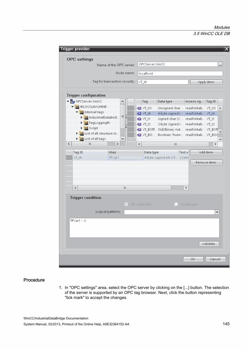
Modules 3.5 WinCC OLE DB
WinCC/IndustrialDataBridge Documentation System Manual, 02/2013, Printout of the Online Help, A5E32364152-AA 145
Procedure 1. In "OPC settings" area, select the OPC server by clicking on the [...] button. The selection
of the server is supported by an OPC tag browser. Next, click the button representing "tick mark" to accept the changes.

Modules 3.5 WinCC OLE DB
WinCC/IndustrialDataBridge Documentation 146 System Manual, 02/2013, Printout of the Online Help, A5E32364152-AA
2. The "Node name" is automatically displayed in "Node name" text box after selection of the OPC Server.
Note Node name
For local OPC Server, the node name will display as "local host". In case of remote OPC Server, the remote computer name will be displayed after selection of OPC Server on the remote computer. This "Node name" is required for searching the OPC Server from the remote computer.
The OPC tag browser does not display any content if node name is invalid.
Note
The "OPC Server" and "Node name" fields are provided as editable fields.
If the information about OPC Server name and node name is known, you can directly enter the information in the "OPC Server" and "Node name" fields. If the node name / OPC Server name is invalid, there will be no content displayed within the OPC tag browser.
3. You can define an OPC tag on the trigger provider, in which the success-/failure-status of the data transfer will be stored in the "Tag for transaction security" field. This value should have 1 byte signed char (e.g. VT_I1). -1 indicates the success state and 0 indicates failure. Select the tag of the OPC server, in which this information is to be saved in the tag browser and click on the "Apply item" button.
4. The tree structure of OPC server is displayed within "Trigger Configuration" area.
5. In "Trigger Configuration" area, select the desired tags individually and accept them by clicking on "Add item" each time.
The selected tags are shown in the table below the tag browser that displays the tag list.

Modules 3.5 WinCC OLE DB
WinCC/IndustrialDataBridge Documentation System Manual, 02/2013, Printout of the Online Help, A5E32364152-AA 147
6. Use the "Remove item" button to remove the marked item. If no item is marked for deletion, the last item from the list is deleted if you click the "Remove item" button. Details about the columns in the Tag list are located in section "Tag declaration".
Note OPC Server
After selection of the tags and adding them to tag list, if you switch to another OPC Server in OPC Settings area, a dialog window is displayed that prompts the message whether you wish to discard previous settings.
7. In "Trigger condition" area, you can select the type of syntax with selection button "VB Style" or JScript Style". If a trigger condition is already created, this setting can no longer be changed. If the language is to be changed, the text in the "Configure Trigger Condition" field must be deleted.
Details on the programming languages are located in section "Programming Languages".
8. Create the trigger condition in the selected language. Use the Alias designations in the tag list for these tags. Within the text box displayed, enter the operator symbols using the keyboard or select them from the "Logical patterns" list box.
9. Test the created condition by clicking on "Validate". The trigger condition is calculated with the values that are entered in the "Test value" column. The result "TRUE" or "FALSE" is shown in a message box.
10. If the trigger condition provides the correct result and after confirming the changes, close the dialog by clicking on "OK" button.
Additional Information
Tag declaration
The columns for the tag declaration contain the following:
● Data type: Data type of the tag. If the data type defined here does not match that on the server, an attempt to convert the data type is made.
● TagID: The TagID of the tag on the OPC server
● Alias: The alias is used for creating the trigger condition. This name must be unique and it must correspond with the naming conventions of the allocated programming languages. For more detailed information about the naming conventions, see paragraph "Valid alias names".
● Confirmation value: The confirmation value is the value that the variable takes on after fulfilling the trigger condition and the values have been delivered to the consumer. The default value is "<Empty>", i.e., no confirmation value is written.
● Test value: This value is only for testing the trigger condition and has no influence on the later data exchange. The test values are to be selected and changed so that they test whether the trigger condition delivers the expected result in all operating conditions.

Modules 3.5 WinCC OLE DB
WinCC/IndustrialDataBridge Documentation 148 System Manual, 02/2013, Printout of the Online Help, A5E32364152-AA
NoteConfirmation value
The confirmation value does not give any information on whether a transaction has been completed successfully.
Note Necessity of Alias Names
The OPC TagID is not used because it may possibly not correspond with the tag validity criteria, for instance, a "Point" in the tag name is not allowed.
Valid Alias Names:
A valid alias must correspond with the following rules:
● Letters (no umlaut characters or ß), numbers and underscore character (_) are allowed.
● The first character must be a letter or underscore.
● An alias can be as long as you require.
● Key words from VB script or J script are not allowed. Note the respective language description for this.
● Case sensitive (upper and lower case letters). ("tag" is not the same as "Tag").
Programming languages
You can use VBScript or JScript for the trigger condition.
The following table shows the operator type and their symbols in both languages:
Type VBScript JScript Logical NOT NOT ! Logical AND AND && Logical OR OR || multiplication * * division / / addition + + subtraction - - Not equal to <> != Less than < < Greater than > >

Modules 3.5 WinCC OLE DB
WinCC/IndustrialDataBridge Documentation System Manual, 02/2013, Printout of the Online Help, A5E32364152-AA 149
Type VBScript JScript Comparison = == Assignment <not possible> = True true or True true Incorrect false or False false string <Quotation Marks> <Quotation Marks>
It is recommended to use these operators only. Other operators can be found in the language descriptions for the respective language.
Note Loss of Trigger Events
The triggering depends on the update speed of the OPC server. In this case, note that data changes that occur within an update cycle are not considered by the trigger. That means that a faster change of a tag from 1 - 0 - 1 is not necessarily indicated to the trigger provider by the OPC server, since the 1 exists at the end again and no value change exists at the check time. This means that a potentially true condition is not recognized as being true and therefore will not lead to a data transfer.
Configurations, with which the confirmation value is to set a "true" trigger condition to "false" again, are not secure because of the statement above. When data changes occur too quickly, the "true value" may stay the same or values can be left out.

Modules 3.5 WinCC OLE DB
WinCC/IndustrialDataBridge Documentation 150 System Manual, 02/2013, Printout of the Online Help, A5E32364152-AA
3.5.6 Connecting Tags from the WinCC OLE DB Interface
Connecting Tags In "Settings" window, the "Connection mapping" tab includes the required fields to connect tags that have been sent from WinCC OLEDB interface with the selected data consumer. The Connection mapping tab divides the window into 3 sections.
● WinCC OLEDB provider
● Database consumer
● Connection mapping settings

Modules 3.5 WinCC OLE DB
WinCC/IndustrialDataBridge Documentation System Manual, 02/2013, Printout of the Online Help, A5E32364152-AA 151
The "WinCC OLEDB provider" section is displayed at top left portion of "Connection mapping" tab. This section provides you with required options to choose column name from the list of columns displayed in "Columns" section area. The "Database consumer" section exists below the provider section and lists the selected table, schema and column names that can be mapped with the columns existing within WinCC OLEDB interface.
Note Consumer types
The fields displayed within "Database consumer" section depends on the "Consumer type" that you have selected in Consumer configuration window.
In this case, the consumer type "One data record per call - recordset" is used.
The separator between the provider and consumer section provides a resize handle that helps you to resize the height of the section in order to view the fields within the section clearly.
The "Connection mapping settings" section is displayed at right side of "Connection mapping" tab. This section provides you the options to enter the connection name along with options for choosing default name for connection. The "Connect", "Modify connection", "Delete connection" and "Delete all connections" icons are provided at the top portion of this section.
1. In "WinCC OLEDB provider" section, select the column name from the list that is displayed within "Columns" section area.
2. Upon selection, the column name is displayed in "Column for data value" field. The data type is selected automatically based on selection of column name.
3. The "Filter" field provides you the option to filter the Column names based on single character or first few characters of column name.
For example, if you wish to view the column names starting with "S", type this character in "Filter" text box. All column names starting with "S" are displayed.
4. Next, configure the consumer column in the "Database consumer" section by following these steps:
– The selected table is shown in the "Table" field. Select the Schema for database if applicable by selecting from drop down list.
– The column names are displayed within "Columns" area. If the table has columns with Date/time data type, the time stamp can also be written to the column within the table. In this case, select the respective "Active" check box and select the column within "Column for timestamp" field.
5. Select the Column name in consumer that you wish to connect with "WinCC OLEDB" column name. The data type of selected column will be automatically displayed in the "Datatype" field.
The selected column is displayed in "Column for data value" field.

Modules 3.5 WinCC OLE DB
WinCC/IndustrialDataBridge Documentation 152 System Manual, 02/2013, Printout of the Online Help, A5E32364152-AA
6. Check the name of the connection in the "Connection mapping settings" area to the right. Enter a unique name for the connection in the "Connection name" field or use the options within "Default name options". Click "Connect" button to confirm your entries.
Note Data type conversion
If the provider tag data type does not match with consumer column, IDB CS converts the provider data type to match with data type of consumer. A status window is displayed to indicate this change.
7. Repeat steps 1 to 5 for all elements of the "WinCC OLEDB" that you wish to transfer.
8. The connection name including the provider and consumer data values will be displayed within the "Connection mapping settings" section.The list of connections will be also displayed within the Connections tab as well as in the project tree within the "Connections" node belonging to the specific link.
Note Schema
Microsoft Access does not support schema functionality. Hence, you can observe that the Schema field in Database consumer is in disable state.
While using any other database as consumer, the Schema field will be in enable state.
Note Modifying Consumer type
Once the connection(s) have been created in Connection mapping window and if you wish to modify the Consumer type in Database consumer configuration, the IDB CS application will not allow to change the Consumer type. To change the Consumer type, you need to delete the connection(s) that have been already created. Close the consumer configuration window and re-open the window from the project tree to modify the consumer type.
Results The connections that you have created are shown in the "Connections" tab of IDB CS Settings window as well as within the project tree node.

Modules 3.6 Database
WinCC/IndustrialDataBridge Documentation System Manual, 02/2013, Printout of the Online Help, A5E32364152-AA 153
3.6 Database
3.6.1 Overview
Overview The Database module provides read access (database as provider) and write access (database as consumer) to a database. The following list of databases are supported:
● MS Access 2000 / 2003 via driver "MS JET OLE DB Provider"
● MS Access 2007 / 2010 via "MS ACE 12.0 OLE DB Provider"
● MS SQL Server 2005 or 2008 via driver "MS OLE DB Provider for SQL"
● ORACLE 10g / 11g via driver "Oracle provider for OLE DB"
● MySQL 5.5 via driver "MySQL ODBC"
Using other databases is basically possible but has not been tested and is therefore not approved. Fault-free functionality is therefore not guaranteed. A respective test is possible upon request.
For more information on using different databases, please read carefully the instructions provided in the note at the end of this chapter.

Modules 3.6 Database
WinCC/IndustrialDataBridge Documentation 154 System Manual, 02/2013, Printout of the Online Help, A5E32364152-AA
Database Provider Read access is provided to the first line of a database with the database provider. Here you can choose the type of access:
● Send always all values (read every 1000 ms by default)
● Send values using trigger (data read only upon occurrence of the trigger value)
● Send only changed values (data transferred if a field changes in the first line)
Database Consumer A write access is provided wherein you can write data in the database consumer.
The following connection types are supported:
database Networking MS Access Local MS SQL Server Local and remote MySQL Local and remote Oracle Local and remote

Modules 3.6 Database
WinCC/IndustrialDataBridge Documentation System Manual, 02/2013, Printout of the Online Help, A5E32364152-AA 155
Note Important Notes for Configuring the Different Databases In 64-bit operating system, IDB application requires 32-bit ODBC connector for MySQL
database. The version information specific to MySQL ODBC driver can be edited directly in the
"Connection string" field within provider or consumer configuration window. For access to an MS SQL Server and MS Access, the Microsoft Data Access
Components 2.8 (MDAC 2.8) must be installed. For the MS JET 4.0 OLE DB Provider with MS Access, default setting "Share Deny None"
is to be used under the extended settings for access authorizations. The selection of more than one access authorization causes an error in the configuration environment of the IndustrialDataBridge.
Using data type VT_I8 as a trigger tag (values transferred upon event) in the database provider is not approved.
The remote access of the IndustrialDataBridge on a PC with an MS Access Database (via MS JET 4.0 OLE DB Provider) is not approved because of reconnect problems.
The character "?" (VT_BSTR) cannot be written in a field with field data type "char" or "varchar" with the SQL server (in the Runtime interface, a respective error message is output).
Since a StoredProcedure or a PreparedInsertStatement always requires all values, faults can occur in the "Only upon change" transfer mode. In this case, this mode should not be used in combination with StoredProcedure or PreparedInsertStatement.
The time stamp must be assigned before connecting the first tags. Afterwards, adding or changing is only possible if all items are deleted, the dialog is closed and reopened again. The time stamp is generated from the local time, if new data is transferred from the provider.
A table name is not to contain any spaces, otherwise problems can occur in the transfer.

Modules 3.6 Database
WinCC/IndustrialDataBridge Documentation 156 System Manual, 02/2013, Printout of the Online Help, A5E32364152-AA
3.6.2 Supported data types
MS Access The following data types/field data types are supported with Microsoft Access by the IDB:
VARIANT Data type Field data type VT_BOOL Yes/No VT_BSTR Memo VT_BSTR Text VT_CY Currency VT_DATE Date/time VT_I4 AutoValue VT_I2 Number, Integer VT_I4 Number, LongInteger VT_R4 Number, Single VT_R8 Number, Double VT_UI1 Number, Byte
The following data types/field data types are not supported with Microsoft Access by the IDB:
VARIANT Data type Field data typedecimal
VT_CLSID ReplicationID
MS SQL and WinCC User Archive The following data types/field data types are supported with Microsoft SQL Server and the WinCC UserArchives by the IDB:
VARIANT Data type Field data type VT_BOOL bit VT_BSTR char VT_BSTR varchar VT_BSTR text VT_BSTR nchar VT_BSTR nvarchar VT_BSTR ntext VT_CY money VT_CY smallmoney VT_DATE datetime VT_I2 smallint

Modules 3.6 Database
WinCC/IndustrialDataBridge Documentation System Manual, 02/2013, Printout of the Online Help, A5E32364152-AA 157
VARIANT Data type Field data type VT_I4 int VT_DECIMAL bigint VT_R4 real VT_R8 float VT_UI1 tinyint
The following data types/field data types are not supported with SQL Server as data target by the IDB:
VARIANT Data type Field data type binary decimal numeric timestamp varbinary
VARIANT FAR sql-variant
Oracle The following data types/field data types are supported with Oracle by the IDB:
VARIANT data type data type array VT_BSTR CHAR VT_BSTR VARCHAR2 VT_BSTR NCHAR2 VT_BSTR NVARCHAR2 VT_DECIMAL NUMBER VT_DATE DATE VT_BSTR LONG VT_R8 FLOAT
MySQL The following data types/field data types are supported with MySQL by the IDB:
VARIANT Data type Field data type VT_BOOL bit VT_BSTR char VT_BSTR varchar VT_BSTR text VT_DATE datetime

Modules 3.6 Database
WinCC/IndustrialDataBridge Documentation 158 System Manual, 02/2013, Printout of the Online Help, A5E32364152-AA
VARIANT Data type Field data type VT_I2 smallint VT_I4 int VT_DECIMAL bigint VT_R4 float VT_R8 real VT_UI1 tinyint
Modules 3.6 Database
WinCC/IndustrialDataBridge Documentation System Manual, 02/2013, Printout of the Online Help, A5E32364152-AA 159
3.6.3 Configuring a Database Interface as Provider
Objective To create a project with corresponding link having Database as provider and configure the respective provider/consumer configuration along with transfer behavior settings.
Creating a link 1. Open IDB Configuration and create a project by following the steps mentioned below:
– In IDB Configuration menu, select "Project" > "Create" to create a new project.
– In the "Create new project" dialog box, specify a project name, click [...] button and select the folder location wherever the project needs to be saved.
– After entering the required information, select "Create" button. This creates a new project.
2. The project name will be listed within the "Project tree". The next step is to create a link. Follow the steps mentioned below to create a link between provider and consumer:
– Right click on project name node in the tree structure and select "Add new link" option.
– In the "Add new link" dialog that is displayed, enter a unique link name.
– Select the provider type as Database, consumer type as Database and click OK button.
– The created link will be displayed below the project name in project tree.
– The corresponding entries - Provider, Consumer, Settt ings and Connections are created as nodes that exist below the new link in the tree structure.

Modules 3.6 Database
WinCC/IndustrialDataBridge Documentation 160 System Manual, 02/2013, Printout of the Online Help, A5E32364152-AA
3. In project tree, open the Provider configuration window by double clicking the Provider node.
In Provider configuration window, perform the following settings:
– Select the type of database by choosing the appropriate radio button.
– If the database exists on a server location, enter the server name in "Server" field.
If you wish to enable windows authentication automatically, select the check box "Use automatic windows authentication".
– In "Database" field, click on [...] button and select the database from the list or from the folder structure.
Note Server name
The "Server" field for entering the Server name, "Use automatic windows authentication" check box and the fields for entering the logon information are enabled only if you have selected a database other than Microsoft Access.

Modules 3.6 Database
WinCC/IndustrialDataBridge Documentation System Manual, 02/2013, Printout of the Online Help, A5E32364152-AA 161
– If a user name and password has been set for the database, enter the user name and password in the "User name" and "Password" fields respectively.
If you wish to set a blank password, enable the check box "Blank password". To save the entered password, enable the check box "Allow saving password".
– Click Test button to test the connection. The application tests the database connection string and verifies the selected database.
4. Next, double click the Consumer node in project tree.
"Database consumer configuration" section
– Select the type of database by choosing the appropriate radio button.
Modules 3.6 Database
WinCC/IndustrialDataBridge Documentation 162 System Manual, 02/2013, Printout of the Online Help, A5E32364152-AA
– If the database exists on a server location, enter the server name in "Server" field.
If you wish to enable windows authentication automatically, select the check box "Use automatic windows authentication".
– In "Database" field, click on [...] button and select the database from the list or from the folder structure.
Note Server name
The "Server" field for entering the Server name, "Use automatic windows authentication" check box and the fields for entering the logon information are enabled only if you have selected a database other than Microsoft Access.
– If a user name and password has been set for the database, enter the user name and password in the "User name" and "Password" fields respectively.
If you wish to set a blank password, enable the check box "Blank password". To save the entered password, enable the check box "Allow saving password".
– Click Test button to test the connection. The application tests the database connection string and verifies the selected database.
"Consumer type configuration" section
– Select the "Consumer type" by selecting from the list. More information about the consumer types are provided in chapter "Consumer Types".
– Choose the "Transaction type" - Stored procedure or Prepared insert statement and select table name and schema.
Note Transaction type
The Stored procedure or Prepared insert statement transaction type options are in enable state only when the consumer type "One data record per call - command set" is selected and if you have selected a database type other than Microsoft Access. By default, the Prepared insert statement option is automatically selected. Only the "Table" field is enabled if Microsoft Access is selected as database type
and consumer type is selected as "One data record per call - command set". Select the table name by clicking the drop down list box.
If you have selected a database type other than Microsoft Access and consumer type is selected as "One data record per call - command set", then all the fields within the Transaction type will be in enable state.
Performing link settings 1. In project tree, double click the Settings node to open Settings window in the work area.

Modules 3.6 Database
WinCC/IndustrialDataBridge Documentation System Manual, 02/2013, Printout of the Online Help, A5E32364152-AA 163
The Settings window consists of 3 tabs - Transfer options, Connection Mapping & Connections.

Modules 3.6 Database
WinCC/IndustrialDataBridge Documentation 164 System Manual, 02/2013, Printout of the Online Help, A5E32364152-AA
2. Within the Transfer options tab, you can configure the transfer behavior settings for provider.
"Provider settings" section
– Select the Schema, if applicable and choose the Table name by selecting from the drop down list.
– Enter a time period in the "Update rate" field after which the system checks for whether data is to be transferred.
Note Schema
Microsoft Access does not support schema functionality. Hence, you can observe that the Schema field will be in disable state if you have chosen Microsoft Access as the database type.
Note Table name
If you are unable to view Table name in the "Table" field, check if the Schema is selected in "Schema" field. Without selecting the "Schema", the table name will not be displayed. However, if you are using Microsoft Access as the database, this condition will not be valid. If you are still unable to view the Table, please verify with the provider configuration.
Note Update rate
For better performance, it is recommended to use an update rate of 1000 ms or 1 sec.
3. Next, select the type of data transfer:
– Send only changed values
After every update cycle, the value existing within the Update rate is checked. If there is a change in the value, the value will be transferred, else it will be ignored.
– Send always all values
After every update cycle, all the connected column values are transferred from provider to the consumer.
– Send values using trigger
After every update cycle, the trigger condition is verified. If the trigger condition is met, then the data is transferred.
Modules 3.6 Database
WinCC/IndustrialDataBridge Documentation System Manual, 02/2013, Printout of the Online Help, A5E32364152-AA 165
4. If you have selected the option "Send values using trigger", you can configure the trigger. The Trigger section is enabled only if the data transfer type "Send values using trigger" is selected.
Perform the following settings in the "Configure trigger" section:
– In the Schema field, choose a valid schema (if applicable) by selecting the drop down list.
– Choose a table name by selecting from the drop down list.
– In Column field, select the specific column that needs to be used for the trigger condition.
– Choose a valid data type by selecting from the drop down list.
– Enter a threshold at which a data transfer should be triggered, in the "Trigger value" field.
– In "Confirmation value" field, enter a value that the trigger tag should take on after triggering.
The Confirmation value does not give any information whether a transaction has been completed successfully.
5. The transfer behavior settings for provider will be saved automatically.
Note Saving changes
A save operation is not required every time whenever changes are performed within the editor window in the work area. The changes made to these settings are automatically saved. However, once the project is created, at any point of time, you can save the project by selecting the "Project" > "Save" menu option.
Results You have created a connection between the database interface and a consumer. These elements are displayed in the tree structure of the IDB configuration interface. In order to transfer data, connect the provider and consumer tags, as described in chapter "Connecting Tags from a Database Interface".

Modules 3.6 Database
WinCC/IndustrialDataBridge Documentation 166 System Manual, 02/2013, Printout of the Online Help, A5E32364152-AA
3.6.4 Data Link Properties
Overview The "Database provider configuration" and "Database consumer configuration" windows are displayed within the work area of IDB Configuration System. The information provided within the provider and consumer windows are identical except for the section in Database consumer configuration that allows for selecting the consumer type and transaction type behavior. The provider and consumer configuration windows can be accessed by double clicking the provider node and consumer node from project tree. The Settings window consists of "Transfer options", "Connection mapping" and "Connections" tabs. These individual tabs includes the fields and options required for configuring provider transfer options, creating connection(s) and managing or viewing already created connections.
Different number format in provider and consumer type If the number format of the operating system deviates from the number format of the connected file, you will have to adapt the XML configuration file. Otherwise, you may experience conversion errors.
Example:
German operating system / Floating-point numbers are to be saved in English format ("." instead ",").
In this case you will have to amend the entry <Link UID="Ref-1" Name="OPC-DB2"> to <Link UID="Ref-1" Name="OPC-DB2" LCID="1033"> in the XML configuration file.
The attribute LCID (LocalID) indicates in which number format the values will be saved. During conversion it will be converted into the format of the operating system. For English, the value of attribute LCID="1033", for German LCID="1031", for French it is LCID="1036", for Italian it is LCID="1040", for Spanish it is LCID="1034", for Chinese it is LCID="2052" and for Japanese it is LCID="1041". Additional values for LCID are available under http://www.microsoft.com (http://www.microsoft.com) when you enter the search term "LCID".
Selecting the database The OLE DB provider(s) / OLE DB consumer(s) section area provides options to select the required database type. The list of database types provided for selection are same on both the provider configuration window and consumer configuration window.
The IndustrialDataBridge supports the following database types:
● Microsoft Access
● Microsoft SQL server
● Oracle database
● MySQL
Modules 3.6 Database
WinCC/IndustrialDataBridge Documentation System Manual, 02/2013, Printout of the Online Help, A5E32364152-AA 167
Database connection In provider/consumer configuration window, depending on the selected database type, the corresponding information is displayed in the subsequent fields. The fields that do not require any entry are shown in disable state. You may observe that the selected database type and connection string parameters are displayed in the "Connection string" field.
Microsoft Access
● Select the type of database by choosing the appropriate radio button.
● If the database exists on a server location, enter the server name in "Server" field.
If you wish to enable windows authentication automatically, select the check box "Use automatic windows authentication".
● In "Database" field, click on [...] button and select the database from the list.
● If a user name and password has been set for the database, enter the user name and password in the "User name" and "Password" fields respectively.
If you wish to set a blank password, enable the check box "Blank password". To save the entered password, enable the check box "Allow saving password".
● Click Test button to test the connection. The application tests the database connection string and verifies the selected database.
Microsoft SQL Server / MySQL
In "Server" field, enter the SQL server location that stores the database. You can also use the IP number of the server instead of the server name. The computer name does not have to be resolved and no connection has to be established with the DNS server.
If you use TCP/IP (standard) as a network library, a port number to the SQL server is also accepted in this position, separated by a comma. The standard port is 1433. When using a Firewall and also via router connections through NAT, it may be necessary to use another port. In this case, you must configure the SQL server for the other port.
● Select the type of database by choosing the appropriate radio button.
● In "Database" field, click on [...] button and select the database from the list.
● If you wish to enable windows authentication automatically, select the check box "Use automatic windows authentication".
● If a user name and password has been set for the database, enter the user name and password in the "User name" and "Password" fields respectively.
● If you wish to set a blank password, enable the check box "Blank password". To save the entered password, enable the check box "Allow saving password".
The MySQL ODBC interface does not support this Windows authentication.
As an alternative, you can use the log-on via SQL security. Create a user profile in the SQL server and use the user name and password in the configuration to log-on here.
● The "Test" button can be used to check for whether access is granted to the database.

Modules 3.6 Database
WinCC/IndustrialDataBridge Documentation 168 System Manual, 02/2013, Printout of the Online Help, A5E32364152-AA
Oracle database
Enter the service name that is to be used for the connection in the "Server" field. The service name refers specifically to a configuration and can be created in the "tnsnames.ora" file. You will find information on the host, protocol and database in this file.
Example:
If you use the service name "testdatabase" for the connection configuration, you will find the following entry in the "tnsnames.ora" file:
#testdatabase
testdatabase.domain.testhost.com =
(DESCRIPTION=
(ADDRESS=
(PROTOCOL=tcp)
(HOST=domain.testhost.com)
(PORT=1531)
)
(CONNECT_DATA=
(SID=testdatabase)
)
)
In the section "Enter information to log on to the database", enter the user name and password that you have entered in the Oracle Database user profile window.
The "Test" button can be used to check for whether access is granted to the database.
Note Saving changes
A save operation is not required every time whenever changes are performed within the editor window in the work area. The changes made to these settings are automatically saved. However, once the project is created, at any point of time, you can save the project by selecting the "Project" > "Save" menu option.

Modules 3.6 Database
WinCC/IndustrialDataBridge Documentation System Manual, 02/2013, Printout of the Online Help, A5E32364152-AA 169
3.6.5 Connecting Tags from a Database Interface
Connecting Tags In "Settings" window, the "Connection mapping" tab includes the required fields to connect tags that have been sent from the Database interface with selected consumer type. The Connection Settings are performed by configuring the settings within the Connection mapping tab. The Connection mapping tab divides the window into 3 sections.
● Database Provider
● Database Consumer
● Connection mapping settings
The "Database Provider" section is displayed at top left portion of "Connection mapping" tab. This section lists the column values that can be mapped with the columns existing within Database Consumer. The "Database Consumer" section is displayed to bottom left portion of "Connection mapping" tab. This section provides you with required options to choose schema, table name and column names to be mapped. The separator between the provider and consumer section provides a resize handle that helps you to resize the height of the section in order to view the fields within the section clearly.
The "Connection mapping settings" section is displayed at right side of "Connection mapping" tab. This section helps you to provide a name for connection along with options for choosing default name for connection. The "Connect", "Modify connection" and "Delete connection" icons are provided at the top portion of this section.

Modules 3.6 Database
WinCC/IndustrialDataBridge Documentation 170 System Manual, 02/2013, Printout of the Online Help, A5E32364152-AA
Note Consumer types
The fields displayed within "Database consumer" section depends on the "Consumer type" that you have selected in Consumer configuration window.
In this case, the consumer type "One data record per call - recordset" is used.
1. In "Database Provider", the selected table is shown in "Table" field. Select the Schema for database if applicable by selecting from the drop down list in "Schema" field.
2. The Column names are displayed within "Columns" area. Select a Column name from the list.
The selected column is displayed in "Column for data value" field. The data type is shown automatically.
3. The "Filter" field provides you the option to filter the Column names based on single character or first few characters of column name.
For example, if you wish to view the column names starting with "S", type this character in "Filter" text box. All column names starting with "S" are displayed.
4. Configure the consumer tag in the "Database Consumer" section by following these steps:
– The selected table is shown in the "Table" field. The schema (if selected at consumer configuration) is displayed in the "Schema" field. Microsoft Access does not support the Schema functionality.
– The column names are displayed within "Columns" area. If the table has columns with respective data types, the time stamp can also be written to the table. In this case, select the respective "Active" check box and select the column within "Column for timestamp" field.
5. Select the Column name that you wish to connect with "Database Provider". The selected column is displayed in "Column for data value" field.
Note Data type conversion
If the provider tag data type does not match with consumer column, IDB CS converts the data type to match with data type of provider tag. A status window is displayed to indicate this change.
6. Check the name of the connection in the "Connection mapping settings" area to the right. Enter a unique name for the connection in the "Connection name" field or use the options within "Default name options". Click "Connect" button to confirm your entries.

Modules 3.6 Database
WinCC/IndustrialDataBridge Documentation System Manual, 02/2013, Printout of the Online Help, A5E32364152-AA 171
7. Repeat steps 1 to 5 for all elements of the "Database Provider" that you wish to transfer.
8. The connection name including the provider and consumer data values will be displayed within the "Connection mapping settings" section.The list of connections will be also displayed within the Connections tab as well as in the project tree within the "Connections" node belonging to the specific link.
Note BLOB as new data type
The BLOB data type is applicable when you are using Send/Receive as provider or consumer and is applicable for database other than Microsoft Access. The BLOB data type will be listed in the connecting mapping tab within the consumer section area for MySQL or Oracle or SQL Server. You can select the BLOB data type in provider/consumer section area within the Data type field. However, the size of data needs to be mentioned in Number field. It can be mapped with Character array or string field of PLC data. The size of data depends on supported size provided by Step7 project.
Maximum 1000 bytes of character with unicode support can be transferred for a BLOB field in Oracle.
Note Schema
Microsoft Access does not support schema functionality. Hence, you can observe that the Schema field in Database consumer is in disable state.
While using any other database as consumer, the Schema field will be in enable state.
Note Modifying Consumer type
Once the connection(s) have been created in Connection mapping window and if you wish to modify the Consumer type in Database consumer configuration, the IDB CS application will not allow to change the Consumer type. To change the Consumer type, you need to delete the connection(s) that have been already created. Close the consumer configuration window and re-open the window from the project tree to modify the consumer type.
Results The connections that you have created are shown in the "Connections" tab of IDB CS Settings window as well as within the project tree node.

Modules 3.6 Database
WinCC/IndustrialDataBridge Documentation 172 System Manual, 02/2013, Printout of the Online Help, A5E32364152-AA
3.6.6 Configuring a Database Interface as Consumer
Objective To create a project with corresponding link having Database as consumer and configure the respective provider/consumer configuration along with transfer behaviour settings.
Creating a link 1. Open IDB Configuration and create a project by following the steps mentioned below:
– In IDB Configuration menu, select "Project" > "Create" to create a new project.
– In the "Create new project" dialog box, specify a project name, click [...] button and select the folder location wherever the project needs to be saved.
– After entering the required information, select "Create" button. This creates a new project.
2. The project name will be listed within the "Project tree". The next step is to create a link. Follow the steps mentioned below to create a link between provider and consumer:
– Right click on project name node in the tree structure and select "Add new link" option.
– In the "Add new link" dialog that is displayed, enter a unique link name.
– Select the provider type as Database, consumer type as Database and click OK button.
– The created link will be displayed below the project name in project tree.
– The corresponding entries - Provider, Consumer, Settt ings and Connections are created as nodes that exist below the new link in the tree structure.

Modules 3.6 Database
WinCC/IndustrialDataBridge Documentation System Manual, 02/2013, Printout of the Online Help, A5E32364152-AA 173
3. In project tree, open the Provider configuration window by double clicking the Provider node.
In Database provider configuration window, perform the following settings:
– Select the type of database by choosing the appropriate radio button.
– If the database exists on a server location, enter the server name in "Server" field.
If you wish to enable windows authentication automatically, select the check box "Use automatic windows authentication".
– In "Database" field, click on [...] button and select the database from the list or from the folder structure.
–
–
–
–
–

Modules 3.6 Database
WinCC/IndustrialDataBridge Documentation 174 System Manual, 02/2013, Printout of the Online Help, A5E32364152-AA
–
Note Server name
The "Server" field for entering the Server name, "Use automatic windows authentication" check box and the fields for entering the logon information are enabled only if you have selected a database other than Microsoft Access.
– If a user name and password has been set for the database, enter the user name and password in the "User name" and "Password" fields respectively.
If you wish to set a blank password, enable the check box "Blank password". To save the entered password, enable the check box "Allow saving password".
– Click Test button to test the connection. The application tests the database connection string and verifies the selected database.
4. Next, double click the Consumer node in project tree.
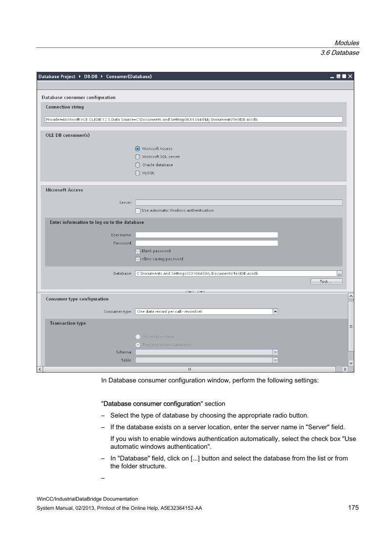
Modules 3.6 Database
WinCC/IndustrialDataBridge Documentation System Manual, 02/2013, Printout of the Online Help, A5E32364152-AA 175
In Database consumer configuration window, perform the following settings:
"Database consumer configuration" section
– Select the type of database by choosing the appropriate radio button.
– If the database exists on a server location, enter the server name in "Server" field.
If you wish to enable windows authentication automatically, select the check box "Use automatic windows authentication".
– In "Database" field, click on [...] button and select the database from the list or from the folder structure.
–

Modules 3.6 Database
WinCC/IndustrialDataBridge Documentation 176 System Manual, 02/2013, Printout of the Online Help, A5E32364152-AA
–
Note Server name
The "Server" field for entering the Server name, "Use automatic windows authentication" check box and the fields for entering the logon information are enabled only if you have selected a database other than Microsoft Access.
– If a user name and password has been set for the database, enter the user name and password in the "User name" and "Password" fields respectively.
If you wish to set a blank password, enable the check box "Blank password". To save the entered password, enable the check box "Allow saving password".
– Click Test button to test the connection. The application tests the database connection string and verifies the selected database.
"Consumer type configuration" section
– Select the "Consumer type" by selecting from the list. More information about the consumer types are provided in chapter "Consumer Types".
– Choose the "Transaction type" - Stored procedure or Prepared insert statement and select table name and schema.
Note Transaction type
The Stored procedure or Prepared insert statement transaction type options are in enable state only when the consumer type "One data record per call - command set" is selected and if you have selected a database type other than Microsoft Access. By default, the Prepared insert statement option is automatically selected.
Only the "Table" field is enabled if Microsoft Access is selected as database type and consumer type is selected as "One data record per call - command set". Select the table name by clicking the drop down list box.
If you have selected a database type other than Microsoft Access and consumer type is selected as "One data record per call - command set", then all the fields within the Transaction type will be in enable state.
Performing link settings 1. In project tree, double click the Settings node to open Settings window in the work area.
The Settings window consists of 3 tabs - Transfer options, Connection Mapping & Connections.

Modules 3.6 Database
WinCC/IndustrialDataBridge Documentation System Manual, 02/2013, Printout of the Online Help, A5E32364152-AA 177

Modules 3.6 Database
WinCC/IndustrialDataBridge Documentation 178 System Manual, 02/2013, Printout of the Online Help, A5E32364152-AA
2. Within the Transfer options tab, you can configure the transfer behavior settings for provider.
"Provider settings" section
– Select the Schema, if applicable and choose the Table name by selecting from the drop down list.
– Enter a time period in the "Update rate" field after which the system checks for whether data is to be transferred.
Note Schema
Microsoft Access does not support schema functionality. Hence, you can observe that the Schema field will be in disable state if you have chosen Microsoft Access as the database type.
Note Table name
If you are unable to view Table name in the "Table" field, check if the Schema is selected in "Schema" field. Without selecting the "Schema", the table name will not be displayed. However, if you are using Microsoft Access as the database, this condition will not be valid. If you are still unable to view the Table, please verify with the provider configuration.
Note Update rate
For better performance, it is recommended to use an update rate of 1000 ms or 1 sec.

Modules 3.6 Database
WinCC/IndustrialDataBridge Documentation System Manual, 02/2013, Printout of the Online Help, A5E32364152-AA 179
3. Next, select the type of data transfer:
– Send only changed values
After every update cycle, the value existing within the Update rate is checked. If there is a change in the value, the value will be transferred, else it will be ignored.
– Send always all values
After every update cycle, all the connected column values are transferred from provider to the consumer.
– Send values using trigger
After every update cycle, the trigger condition is verified. If the trigger condition is met, then the data is transferred.
4. If you have selected the option "Send values using trigger", you can configure the trigger. The Trigger section is enabled only if the data transfer type "Send values using trigger" is selected.
Perform the following settings in the "Configure trigger" section:
– In the Schema field, choose a valid schema (if applicable) by selecting the drop down list.
– Choose a table name by selecting from the drop down list.
– In Column field, select the specific column that needs to be used for the trigger condition.
– Choose a valid data type by selecting from the drop down list.
– Enter a threshold at which a data transfer should be triggered, in the "Trigger value" field.
– In "Confirmation value" field, enter a value that the trigger tag should take on after triggering.
The Confirmation value does not give any information whether a transaction has been completed successfully.The transfer behaviour settings for provider will be saved automatically.
Note Saving changes
A save operation is not required every time whenever changes are performed within the editor window in the work area. The changes made to these settings are automatically saved. However, once the project is created, at any point of time, you can save the project by selecting the "Project" > "Save" menu option.

Modules 3.6 Database
WinCC/IndustrialDataBridge Documentation 180 System Manual, 02/2013, Printout of the Online Help, A5E32364152-AA
Results You have created a connection between the database interface and a provider. These elements are displayed in the tree structure of the IDB configuration interface. In order to transfer data, connect the provider and consumer tags, as described in chapter "Connecting Tags to a Database Interface".

Modules 3.6 Database
WinCC/IndustrialDataBridge Documentation System Manual, 02/2013, Printout of the Online Help, A5E32364152-AA 181
3.6.7 Consumer Types
Overview If you have selected database as a data consumer, define the type of write access in the "Consumer type" field. The following types are available:
● One data record per tag
● One data record per call - recordset
● One data record per call - command set
Example: "One data record per tag" With a hierarchically organized database, it is possible to assign entered values with different status using so-called index columns. These multi-dimensional connections allow management with the "One data record per tag" consumer type.
In this example, there are three index tables created, the name of which exists in the data tables:
Modules 3.6 Database
WinCC/IndustrialDataBridge Documentation 182 System Manual, 02/2013, Printout of the Online Help, A5E32364152-AA
● TablePlant (contains the building designations)
● TableMachine (contains the machine list)
● TableSensor (contains a list of sensors)
If a data record is entered in one of the data tables (TableBYTE, TableFLOAT, TableINT), the data can be assigned in the index tables by linking the respective entries. If for example, the following data record is written in table TableINT, the indexing connects every index entry with a value of the corresponding index table:
IndexPlant: 1
IndexMachine: 3
IndexSensor: 5
Value: 34
In this example, the index entries stand for the following values:
IndexPlant: 1 corresponds with Hall A
IndexMachine: 3 corresponds with the steel press
IndexSensor: 5 corresponds with the sensor for outside temperature
Value: 34
This means that the value 34 was measured on sensor "Outside temperature" on the steel press in Hall A.
More detailed information on index-based database programming is located in the Microsoft Help for Access
One data record per tag The fields displayed within the consumer area in connection mapping tab includes options to choose table/schema name, index columns and data values. When the database consumer is configured with consumer type "One data record per tag", the corresponding fields within "Database consumer" area of Connection mapping tab will be displayed as shown below:

Modules 3.6 Database
WinCC/IndustrialDataBridge Documentation System Manual, 02/2013, Printout of the Online Help, A5E32364152-AA 183
The Database consumer will consist of the following sections:
● Connection configuration
● Index values
● Data values
The "Connection configuration" section displays the 'Schema' and 'Table' fields. If the selected database supports schema functionality, then the "Schema" field will be enabled that allows you to select the schema name from the drop down list. The "Table" field provides the option to select the table name by clicking the drop down list arrow.
The "Index values" section lists 3 rows containing "Index column" and "Index" fields. Initially, these fields will be in disable state. Enable the "Active" check box and select the desired column that has a foreign key relationship to a column (primary key) of another table. Select the desired index value in "Index" field. Please note that the Index column selected should not be defined as a primary key. To realise this scenario, let us understand with the help of an example.
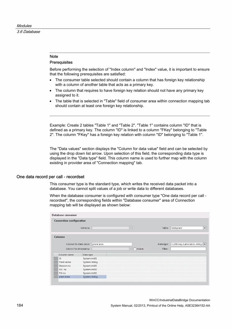
Modules 3.6 Database
WinCC/IndustrialDataBridge Documentation 184 System Manual, 02/2013, Printout of the Online Help, A5E32364152-AA
Note Prerequisites
Before performing the selection of "Index column" and "Index" value, it is important to ensure that the following prerequisites are satisfied: The consumer table selected should contain a column that has foreign key relationship
with a column of another table that acts as a primary key. The column that requires to have foreign key relation should not have any primary key
assigned to it. The table that is selected in "Table" field of consumer area within connection mapping tab
should contain at least one foreign key relationship.
Example: Create 2 tables "Table 1" and "Table 2". "Table 1" contains column "ID" that is defined as a primary key. The column "ID" is linked to a column "FKey" belonging to "Table 2". The column "FKey" has a foreign key relation with column "ID" belonging to "Table 1".
The "Data values" section displays the "Column for data value" field and can be selected by using the drop down list arrow. Upon selection of this field, the corresponding data type is displayed in the "Data type" field. This column name is used to further map with the column existing in provider area of "Connection mapping" tab.
One data record per call - recordset This consumer type is the standard type, which writes the received data packet into a database. You cannot split values of a job or write data to different databases.
When the database consumer is configured with consumer type "One data record per call - recordset", the corresponding fields within "Database consumer" area of Connection mapping tab will be displayed as shown below:

Modules 3.6 Database
WinCC/IndustrialDataBridge Documentation System Manual, 02/2013, Printout of the Online Help, A5E32364152-AA 185
One data record per call - command set This consumer type is designed especially for SQL databases. This type processes data records with the help of SQL instructions. This makes it possible to handle data differently within a job.
Note Transaction type
With the selection of consumer type "One data record per call - command set", the fields within the "Transaction type" section area (in database consumer configuration) are enabled. The options for selecting "Stored procedure" or "Prepared insert statement" and the "Table" / "Schema" fields are enabled only if you have choosen a database type other than Microsoft Access.
Note Stored Procedure / Prepared insert statement
Depending on the selected database type, you can select "Stored procedure" or "Prepared insert statement" in the "Transaction type" field within Database consumer configuration. Enter the name of Stored Procedure or select the Table containing the Prepared insert statement in the "Table" field. Define a filter that limits the number of displayed tables in the "Schema" field.
Please note that Microsoft Access does not support the Schema functionality.
When the database consumer is configured with consumer type "One data record per call - commandset", the corresponding fields within "Database consumer" area of Connection mapping tab will be displayed as shown below:

Modules 3.6 Database
WinCC/IndustrialDataBridge Documentation 186 System Manual, 02/2013, Printout of the Online Help, A5E32364152-AA
The Database consumer will consist of the following sections:
● Data values
● Column selection
The "Data values" section lists the table name and schema (if applicable). The list of column names are displayed in "Column selection" section. Selection of any of the column names from the list within "Column selection" section will display the corresponding column name and data type in "Data values" section within "Column for data value" and "Data type" fields respectively.
● The "Character maximum length" displays the length of character variable.
The Character maximum length for String data type should contain a value that is greater than 0.
● The "Parameter number" field lists a unique number for the specific parameter.
● The "Numeric precision" field displays the maximum number of digits in a number.
● The "Numeric scale" field displays the number of digits to the right of decimal point in a number.
For example, 123.45 has a precision of 5 and a scale of 2.
Transaction Type With SQL databases, data is entered in the database with SQL instructions. Quite often, these instructions are integrated right in the program, often because of lacking awareness concerning the advantages of Stored Procedures or Prepared Statements.
Stored Procedures
The use of Stored Procedures utilizes the advantage of compiled SQL codes and increases the performance of the operating programs:
With direct SQL Statement processing, these must be decompressed, compiled and executed by the SQL server. This routine is repeated each time the statement is called upon.
By using a Stored Procedure, the statement is handed over in compiled format and is temporarily stored in the so-called Procedure Cache. This prevents the continuous recompilation and greatly increases the performance of the process.
Modules 3.6 Database
WinCC/IndustrialDataBridge Documentation System Manual, 02/2013, Printout of the Online Help, A5E32364152-AA 187
Note Permissions
For working with stored procedure, "execute" permission is required.
Prepared (Insert) Statements
When frequently switching between online and offline mode, it makes sense to utilize the advantages of the Stored Procedures. A permanent integration of an SQL statement in the Procedure Cache should be avoided however. This is possible by using so-called Prepared Statements. The DataBridge is a Prepared Insert Statement.
Prepared Statements parse and compile the statement one time when connecting with the database and delete the statement from memory when disconnecting. This makes the initial call of the statement slower but the following calls are faster because the statement is retained until data processing is complete.
With long data transfers use "Stored Procedures". To have frequent connection switching, use "Prepared Insert Statements".
3.6.8 Connecting Tags to a Database Interface
Connecting Tags In "Settings" window, the "Connection mapping" tab includes the required fields to connect tags that have been sent from the provider type with database interface. The Connection Settings are performed by configuring the settings within the Connection mapping tab. The Connection mapping tab divides the window into 3 sections.
● Database Provider
● Database Consumer
● Connection mapping settings
Modules 3.6 Database
WinCC/IndustrialDataBridge Documentation 188 System Manual, 02/2013, Printout of the Online Help, A5E32364152-AA
Note Consumer types
The fields displayed within "Database consumer" section depends on the "Consumer type" that you have selected in Consumer configuration window.
In this case, the consumer type "One data record per call - recordset" is used.
1. In "Database Provider", the selected table is shown in "Table" field. Select the Schema for database if applicable by selecting from the drop down list in "Schema" field.
2. The Column names are displayed within "Columns" area. Select a Column name from the list.
The selected column is displayed in "Column for data value" field. The data type is shown automatically.
3. The "Filter" field provides you the option to filter the Column names based on single character or first few characters of column name.
For example, if you wish to view the column names starting with "S", type this character in "Filter" text box. All column names starting with "S" are displayed.
Modules 3.6 Database
WinCC/IndustrialDataBridge Documentation System Manual, 02/2013, Printout of the Online Help, A5E32364152-AA 189
4. Configure the consumer tag in the "Database Consumer" section by following these steps:
– The selected table is shown in the "Table" field. The schema (if selected at consumer configuration) is displayed in the "Schema" field. Microsoft Access does not support the Schema functionality.
– The column names are displayed within "Columns" area. If the table has columns with respective data types, the time stamp can also be written to the table. In this case, select the respective "Active" check box and select the column within "Column for timestamp" field.
5. Select the Column name that you wish to connect with "Database Provider". The selected column is displayed in "Column for data value" field.
Note Data type conversion
If the provider tag data type does not match with consumer column, IDB CS converts the data type to match with data type of provider tag. A status window is displayed to indicate this change.
6. Check the name of the connection in the "Connection mapping settings" area to the right. Enter a unique name for the connection in the "Connection name" field or use the options within "Default name options". Click "Connect" button to confirm your entries.
7. Repeat steps 1 to 5 for all elements of the "Database Provider" that you wish to transfer.
8. The connection name including the provider and consumer data values will be displayed within the "Connection mapping settings" section.The list of connections will be also displayed within the Connections tab as well as in the project tree within the "Connections" node belonging to the specific link.
Note BLOB as new data type
The BLOB data type is applicable when you are using Send/Receive as provider or consumer and is applicable for database other than Microsoft Access. The BLOB data type will be listed in the connecting mapping tab within the provider section area for MySQL or Oracle or SQL Server. You can select the BLOB data type in provider/consumer section area within the Data type field. However, the size of data needs to be mentioned in Number field. It can be mapped with Character array or string field of PLC data. The size of data depends on supported size provided by Step7 project.
Maximum 1000 bytes of character with unicode support can be transferred for a BLOB field in Oracle.

Modules 3.6 Database
WinCC/IndustrialDataBridge Documentation 190 System Manual, 02/2013, Printout of the Online Help, A5E32364152-AA
Note Modifying Consumer type
Once the connection(s) have been created in Connection mapping window and if you wish to modify the Consumer type in Database consumer configuration, the IDB CS application will not allow to change the Consumer type. To change the Consumer type, you need to delete the connection(s) that have been already created. Close the consumer configuration window and re-open the window from the project tree to modify the consumer type.
The display changes depending on the selected consumer type in Transfer options tab:
● One data record per tag
● One data record per call - recordset
● One data record per call - command set
Note Additional information about consumer types
The description of each of the sections contained within these consumer types (including the images) are explained in Chapter 3.6.7 "Consumer Types" (Page 181).
The steps to be followed while using specific consumer type is described in more detail below:
One data record per tag In "Database consumer" section, select the data consumer and define the write behavior by following these steps:
1. Choose the table name to which the data should be transferred by selecting the table in "Table" field. Select the schema if applicable by choosing from the drop down list. Microsoft Access does not support the Schema functionality.
2. In the "Index values" area, you can assign different status based on on the values inserted in the index columns.
– Select the "Active" selection box. In the activated line, select the index column for which a value is to be assigned.
– Enter a number / value in the "Index" field or select an existing value by clicking the [...] button.

Modules 3.6 Database
WinCC/IndustrialDataBridge Documentation System Manual, 02/2013, Printout of the Online Help, A5E32364152-AA 191
3. In the "Data values" area, "Column for data value" field, select the column that you would like to connect with the provider. The data type is selected automatically.
– If the table has columns with the respective data types, the item quality or a time stamp can also be written to the table.
– In this case, select the respective "Active" check box and select the column in which the value should be entered.
4. Check the name of the connection in the "Connecting mapping properties" section displayed at right portion of Connection mapping tab. Enter a unique name for the connection in the "Connection name" field or use the Default name options. Click "Connect" button to confirm your entries.
5. Repeat steps 1 to 4 for all elements of the provider that you wish to transfer.
One data record per job - recordset In the "Database consumer" section, select the data consumer and define the write behavior:
1. Choose the table name to which the data should be transfrrred by selecting the table in "Table" field. Select the schema if applicable by choosing from the drop down list. Microsoft Access does not support the Schema functionality.
2. In the "Columns" area, select the column that you want to connect with the data provider. The selected column is displayed in "Column for data value" field. The data type is selected automatically.
If the table has a column with the Date/Time data type, a time stamp can also be written to the table. In this case, select the "Active" check box and select the column listed within "Column for time stamp".
3. The "Filter" field provides you the option to filter the Column names based on single character or first few characters of column name.
For example, if you wish to view the column names starting with "S", type this character in "Filter" text box. All column names starting with "S" are displayed.
4. Check the name of the connection in the "Connecting mapping settings" section displayed at right portion of Connection mapping tab. Enter a unique name for the connection in the "Connection name" field or use the Default name options. Click "Connect" button to confirm your entries.
5. Repeat steps 1 to 3 for all elements of the provider that you wish to transfer.
One data record per job - command set The consumer type "command set" is made exclusively for SQL databases. SQL-specific database connections can be defined with the predefined settings.
1. In "Database consumer" section, "Column selection" area, select the column that you would like to connect with the Database provider. The selected column is displayed in "Column for data value" field. The data type will be selected automatically. The fields "Character maximum length", "Numeric precision", "Parameter number" and "Numeric scale" describe the consumer data type in the database.

Modules 3.6 Database
WinCC/IndustrialDataBridge Documentation 192 System Manual, 02/2013, Printout of the Online Help, A5E32364152-AA
2. Check the name of the connection in the "Connecting mapping settings" section displayed at right portion of "Connection mapping" tab. Enter a unique name for the connection in the "Connection name" field or use the Default name option. Click "Connect" button to confirm your entries.
3. Repeat steps 1 to 3 for all elements of the provider that you wish to transfer.
With Stored procedure transaction type, you can select the stored procedure table in the "Table" field.

Modules 3.7 Dynamic Database
WinCC/IndustrialDataBridge Documentation System Manual, 02/2013, Printout of the Online Help, A5E32364152-AA 193
3.7 Dynamic Database
3.7.1 Overview
Overview The dynamic database module provides the possibility to have read and write access to a database. You can access MS Access, MS SQL Server, MySQL and Oracle 10g databases. Unlike the database module, a data record selection can be made at the time of the transfer.
For the special request for different databases, note the information at the end of this chapter.
Dynamic Database Provider
Introduction
The dynamic database provider has a trigger and control capabilities from OPC unlike the normal database provider. This way, the selection of the time and the data records can be made from the OPC. In addition, you also have the ability to transfer a combination of database and OPC tags. If the trigger condition has been met, data can be sent to the consumer from the OPC and the database together and can be processed there together.
The configuration of the dynamic database provider has two other configuration steps. The trigger and a list of "Where" conditions should be configured.
Example:
The OPC Trigger checks two OPC tags for whether they meet the configured condition. If the condition has been met, the remaining values are read by the OPC server. In this case, these are values that are used for the Where condition and the values that are sent directly to the consumer.
The SQL statement is made up of the values for the "Where" condition. A database query is made afterwards. The resulting data records are sent to the consumer together with the OPC values. After the Consumer has sent the data to data target, the configured confirmation values of the trigger item are written.
Process (see example):

Modules 3.7 Dynamic Database
WinCC/IndustrialDataBridge Documentation 194 System Manual, 02/2013, Printout of the Online Help, A5E32364152-AA
Dynamic Database Consumer
Introduction
Unlike the normal database consumer, the dynamic database consumer can update a table record. One of the values that are supplied by the provider is used for selecting a record in the target database. This value is used for the "Where" condition in SQL statement, created internally in the IndustrialDataBridge. Only one value (tag) can be compared with a column.
If a record does not exist within the table, you can add a new record. The general behaviour is defined while configuring.
Modules 3.7 Dynamic Database
WinCC/IndustrialDataBridge Documentation System Manual, 02/2013, Printout of the Online Help, A5E32364152-AA 195
Example:
The image shows an exemplary process. The data from the provider is entered in the SQL statement, which affects the "update record". Since the value of the ID is "1" in "Where" condition, writing is done to the first record in this example.
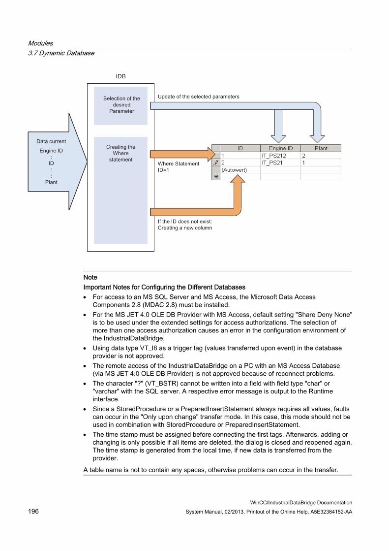
Modules 3.7 Dynamic Database
WinCC/IndustrialDataBridge Documentation 196 System Manual, 02/2013, Printout of the Online Help, A5E32364152-AA
Note Important Notes for Configuring the Different Databases For access to an MS SQL Server and MS Access, the Microsoft Data Access
Components 2.8 (MDAC 2.8) must be installed. For the MS JET 4.0 OLE DB Provider with MS Access, default setting "Share Deny None"
is to be used under the extended settings for access authorizations. The selection of more than one access authorization causes an error in the configuration environment of the IndustrialDataBridge.
Using data type VT_I8 as a trigger tag (values transferred upon event) in the database provider is not approved.
The remote access of the IndustrialDataBridge on a PC with an MS Access Database (via MS JET 4.0 OLE DB Provider) is not approved because of reconnect problems.
The character "?" (VT_BSTR) cannot be written into a field with field type "char" or "varchar" with the SQL server. A respective error message is output to the Runtime interface.
Since a StoredProcedure or a PreparedInsertStatement always requires all values, faults can occur in the "Only upon change" transfer mode. In this case, this mode should not be used in combination with StoredProcedure or PreparedInsertStatement.
The time stamp must be assigned before connecting the first tags. Afterwards, adding or changing is only possible if all items are deleted, the dialog is closed and reopened again. The time stamp is generated from the local time, if new data is transferred from the provider.
A table name is not to contain any spaces, otherwise problems can occur in the transfer.

Modules 3.7 Dynamic Database
WinCC/IndustrialDataBridge Documentation System Manual, 02/2013, Printout of the Online Help, A5E32364152-AA 197
3.7.2 Configuring an Interface to a Dynamic Database as a Provider
Objective To create a project with corresponding link having Dynamic Database as provider and configure the respective provider/consumer configuration along with transfer behavior settings for provider.
Creating a link 1. Open IDB Configuration and create a project by following the steps mentioned below:
– In IDB Configuration menu, select "Project" > "Create" to create a new project.
– In the "Create new project" dialog box, specify a project name, click [...] button and select the folder location wherever the project needs to be saved.
– After entering the required information, select "Create" button. This creates a new project.
2. The project name will be listed within the "Project tree". The next step is to create a link. Follow the steps mentioned below to create a link between provider and consumer:
– Right click on project name node in the tree structure and select "Add new link" option.
– In the "Add new link" dialog that is displayed, enter a unique link name.
– Select the provider type as Dynamic Database, consumer type as Database and click OK button.
– The created link will be displayed below the project name in project tree.
– The corresponding entries - Provider, Consumer, Settt ings and Connections are created as nodes that exist below the new link in the tree structure.

Modules 3.7 Dynamic Database
WinCC/IndustrialDataBridge Documentation 198 System Manual, 02/2013, Printout of the Online Help, A5E32364152-AA
3. In project tree, open the Provider configuration window by double clicking the Provider node.
In Dynamic database provider configuration window, perform the following settings:
– Select the type of database by choosing the appropriate radio button.
– If the database exists on a server location, enter the server name in "Server" field.
If you wish to enable windows authentication automatically, select the check box "Use automatic windows authentication".
– In "Database" field, click on [...] button and select the database from the list or from the folder structure.
Note Server name
The "Server" field for entering the Server name, "Use automatic windows authentication" check box and the fields for entering the logon information are enabled only if you have selected a database other than Microsoft Access.

Modules 3.7 Dynamic Database
WinCC/IndustrialDataBridge Documentation System Manual, 02/2013, Printout of the Online Help, A5E32364152-AA 199
– If a user name and password has been set for the database, enter the user name and password in the "User name" and "Password" fields respectively.
If you wish to set a blank password, enable the check box "Blank password". To save the entered password, enable the check box "Allow saving password".
– Click Test button to test the connection. The application tests the database connection string and verifies the selected database.
4. In project tree, open the Consumer configuration window by double clicking the Consumer node.
In Database consumer configuration window, perform the following settings:

Modules 3.7 Dynamic Database
WinCC/IndustrialDataBridge Documentation 200 System Manual, 02/2013, Printout of the Online Help, A5E32364152-AA
"Database consumer configuration" section
– Select the type of database by choosing the appropriate radio button.
– If the database exists on a server location, enter the server name in "Server" field.
If you wish to enable windows authentication automatically, select the check box "Use automatic windows authentication".
– In "Database" field, click on [...] button and select the database from the list or from the folder structure.

Modules 3.7 Dynamic Database
WinCC/IndustrialDataBridge Documentation System Manual, 02/2013, Printout of the Online Help, A5E32364152-AA 201
Note Server name
The "Server" field for entering the Server name, "Use automatic windows authentication" check box and the fields for entering the logon information are enabled only if you have selected a database other than Microsoft Access.
– If a user name and password has been set for the database, enter the user name and password in the "User name" and "Password" fields respectively.
If you wish to set a blank password, enable the check box "Blank password". To save the entered password, enable the check box "Allow saving password".
– Click Test button to test the connection. The application tests the database connection string and verifies the selected database.
"Consumer type configuration" section
– Select the "Consumer type" by selecting from the list. More information about the consumer types are provided in chapter "Consumer Types".
– Choose the "Transaction type" - Stored procedure or Prepared insert statement and select table name and schema.
Note Transaction type
The Stored procedure or Prepared insert statement transaction type options are in enable state only when the consumer type "One data record per call - command set" is selected and if you have selected a database type other than Microsoft Access. By default, the Prepared insert statement option is automatically selected.
Only the "Table" field is enabled if Microsoft Access is selected as database type and consumer type is selected as "One data record per call - command set". Select the table name by clicking the drop down list box.
If you have selected a database type other than Microsoft Access and consumer type is selected as "One data record per call - command set", then all the fields within the Transaction type will be in enable state.
Performing link settings
1. In project tree, double click the Settings node to open Settings window in the work area.

Modules 3.7 Dynamic Database
WinCC/IndustrialDataBridge Documentation 202 System Manual, 02/2013, Printout of the Online Help, A5E32364152-AA
2. The Settings window consists of 3 tabs - Transfer options, Connection Mapping & Connections.
3. Within the Transfer options tab, you can configure the transfer behavior settings for provider.
Note Selecting Schema If you are using a database other than Microsoft Access, selection of Schema is
mandatory before choosing the Table name. While using Microsoft Access as database, the "Schema" field is displayed in disable
state and does not allow any selection of Schema.
– Select the Schema firstly by choosing from the drop down list box.
– Next, choose the Table name in "Table" field.
– Click "Event" button to configure the trigger provider settings. The "Trigger provider" window will be opened.
The description of the "Trigger provider" is provided in chapter "Configuring a Trigger"
4. The transfer behavior settings for provider will be saved automatically.

Modules 3.7 Dynamic Database
WinCC/IndustrialDataBridge Documentation System Manual, 02/2013, Printout of the Online Help, A5E32364152-AA 203
Note Saving changes
A save operation is not required every time whenever changes are performed within the editor window in the work area. The changes made to these settings are automatically saved. However, once the project is created, at any point of time, you can save the project by selecting the "Project" > "Save" menu option.
Results You have configured the Dynamic Database interface and a consumer. These elements are displayed in the tree structure of the configuration interface. In order to transfer data, connect the provider and consumer tags, as described in chapter "Connecting Tags from the Interface of a Dynamic Database".

Modules 3.7 Dynamic Database
WinCC/IndustrialDataBridge Documentation 204 System Manual, 02/2013, Printout of the Online Help, A5E32364152-AA
3.7.3 Configuring a Trigger
Introduction The "Trigger Provider" dialog window provides the OPC settings, Trigger configuration options and required fields that help you to configure the condition that triggers a data transfer. This dialog window is opened after clicking the "Trigger" button in Transfer options window.
Note OPC tag browser
The OPC tags within "Trigger configuration" section will only be displayed if you have already selected the name of the OPC Server.

Modules 3.7 Dynamic Database
WinCC/IndustrialDataBridge Documentation System Manual, 02/2013, Printout of the Online Help, A5E32364152-AA 205
Procedure 1. In "OPC settings" area, select the OPC server by clicking on the [...] button. The selection
of the server is supported by an OPC tag browser. Next, click the button representing "tick mark" to accept the changes.

Modules 3.7 Dynamic Database
WinCC/IndustrialDataBridge Documentation 206 System Manual, 02/2013, Printout of the Online Help, A5E32364152-AA
2. The "Node name" is automatically displayed in "Node name" text box after selection of the OPC Server.
Note Node name
For local OPC Server, the node name will display as "local host". In case of remote OPC Server, the remote computer name will be displayed after selection of OPC Server on the remote computer. This "Node name" is required for searching the OPC Server from the remote computer.
The OPC tag browser does not display any content if node name is invalid.
Note
The "OPC Server" and "Node name" fields are provided as editable fields.
If the information about OPC Server name and node name is known, you can directly enter the information in the "OPC Server" and "Node name" fields. If the node name / OPC Server name is invalid, there will be no content displayed within the OPC tag browser.
3. You can define an OPC tag on the trigger provider, in which the success-/failure-status of the data transfer will be stored in the "Tag for transaction security" field. This value should have 1 byte signed char (e.g. VT_I1). -1 indicates the success state and 0 indicates failure. Select the tag of the OPC server, in which this information is to be saved in the tag browser and click on the "Apply item" button.
4. The tree structure of OPC server is displayed within "Trigger Configuration" area.
5. In "Trigger Configuration" area, select the desired tags individually and accept them by clicking on "Add item" each time.
The selected tags are shown in the table below the tag browser that displays the tag list.

Modules 3.7 Dynamic Database
WinCC/IndustrialDataBridge Documentation System Manual, 02/2013, Printout of the Online Help, A5E32364152-AA 207
6. Use the "Remove item" button to remove the marked item. If no item is marked for deletion, the last item from the list is deleted if you click the "Remove item" button. Details about the columns in the Tag list are located in section "Tag declaration".
Note OPC Server
After selection of the tags and adding them to tag list, if you switch to another OPC Server in OPC Settings area, a dialog window is displayed that prompts the message whether you wish to discard previous settings.
7. In "Trigger condition" area, you can select the type of syntax with selection button "VB Style" or JScript Style". If a trigger condition is already created, this setting can no longer be changed. If the language is to be changed, the text in the "Configure Trigger Condition" field must be deleted.
Details on the programming languages are located in section "Programming Languages".
8. Create the trigger condition in the selected language. Use the Alias designations in the tag list for these tags. Within the text box displayed, enter the operator symbols using the keyboard or select them from the "Logical patterns" list box.
9. Test the created condition by clicking on "Validate". The trigger condition is calculated with the values that are entered in the "Test value" column. The result "TRUE" or "FALSE" is shown in a message box.
10. If the trigger condition provides the correct result and after confirming the changes, close the dialog by clicking on "OK" button.
Additional Information
Tag declaration
The columns for the tag declaration contain the following:
● Data type: Data type of the tag. If the data type defined here does not match that on the server, an attempt to convert the data type is made.
● TagID: The TagID of the tag on the OPC server
● Alias: The alias is used for creating the trigger condition. This name must be unique and it must correspond with the naming conventions of the allocated programming languages. For more detailed information about the naming conventions, see paragraph "Valid alias names".
● Confirmation value: The confirmation value is the value that the variable takes on after fulfilling the trigger condition and the values have been delivered to the consumer. The default value is "<Empty>", i.e., no confirmation value is written.
● Test value: This value is only for testing the trigger condition and has no influence on the later data exchange. The test values are to be selected and changed so that they test whether the trigger condition delivers the expected result in all operating conditions.

Modules 3.7 Dynamic Database
WinCC/IndustrialDataBridge Documentation 208 System Manual, 02/2013, Printout of the Online Help, A5E32364152-AA
Note Confirmation value
The confirmation value does not give any information on whether a transaction has been completed successfully.
Note Necessity of Alias Names
The OPC TagID is not used because it may possibly not correspond with the tag validity criteria, for instance, a "Point" in the tag name is not allowed.
Valid Alias Names:
A valid alias must correspond with the following rules:
● Letters (no umlaut characters or ß), numbers and underscore character (_) are allowed.
● The first character must be a letter or underscore.
● An alias can be as long as you require.
● Key words from VB script or J script are not allowed. Note the respective language description for this.
● Case sensitive (upper and lower case letters). ("tag" is not the same as "Tag").
Programming languages
You can use VBScript or JScript for the trigger condition.
The following table shows the operator type and their symbols in both languages:
Type VBScript JScript Logical NOT NOT ! Logical AND AND && Logical OR OR || multiplication * * division / / addition + + subtraction - - Not equal to <> != Less than < < Greater than > >

Modules 3.7 Dynamic Database
WinCC/IndustrialDataBridge Documentation System Manual, 02/2013, Printout of the Online Help, A5E32364152-AA 209
Type VBScript JScript Comparison = == Assignment <not possible> = True true or True true Incorrect false or False false string <Quotation Marks> <Quotation Marks>
It is recommended to use these operators only. Other operators can be found in the language descriptions for the respective language.
Note Loss of Trigger Events
The triggering depends on the update speed of the OPC server. In this case, note that data changes that occur within an update cycle are not considered by the trigger. That means that a faster change of a tag from 1 - 0 - 1 is not necessarily indicated to the trigger provider by the OPC server, since the 1 exists at the end again and no value change exists at the check time. This means that a potentially true condition is not recognized as being true and therefore will not lead to a data transfer.
Configurations, with which the confirmation value is to set a "true" trigger condition to "false" again, are not secure because of the statement above. When data changes occur too quickly, the "true value" may stay the same or values can be left out.
Modules 3.7 Dynamic Database
WinCC/IndustrialDataBridge Documentation 210 System Manual, 02/2013, Printout of the Online Help, A5E32364152-AA
3.7.4 Connecting Tags from the Interface of a Dynamic Database
Connecting Tags In "Settings" window, the "Connection mapping" tab includes the required fields to connect tags that have been sent from the Dynamic Database interface with the selected data consumer. The Connection mapping tab divides the window into 3 sections
● Dynamic database provider
● Database consumer
● Connection mapping settings
The "Dynamic database provider" section is displayed at top left portion of "Connection mapping" tab. This section provides you with required options to choose schema, table name and column names to be mapped. The "Database consumer" section exists below the provider section and lists the column values that can be mapped with the columns existing within Dynamic Database.
The separator between the provider and consumer section provides a resize handle that helps you to resize the height of the section in order to view the fields within the section clearly.
The "Connection mapping settings" section is displayed at right side of "Connection mapping" tab. This section helps you to provide a name for connection along with options for choosing default name for connection. The "Connect", "Modify connection" and "Delete connection" icons are provided at the top portion of this section.
Note Select OPC server
In order to configure the settings in the "Where Statement" tab, you must have selected an OPC server in the link settings in dialog "Trigger Provider". This dialog window is accessed by clicking on the "Event" button in "Transfer options" tab.
This chapter covers the aspects related to "Dynamic Database provider" and "Where Statement" tabs. Also, the steps to be performed to have a connection mapping between provider and consumer are provided within this chapter.
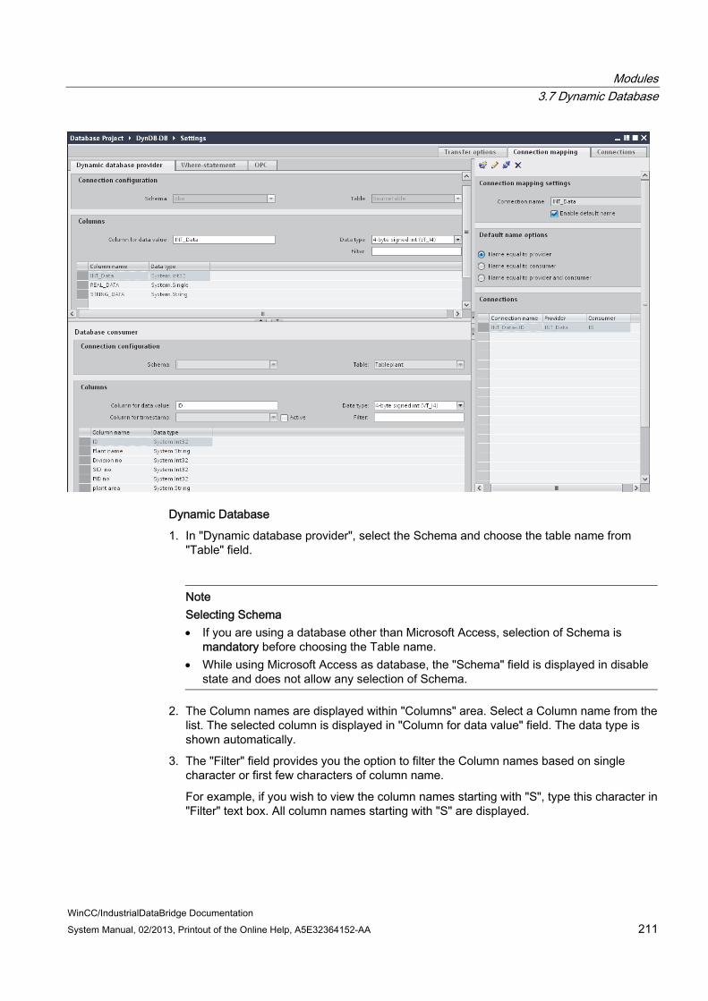
Modules 3.7 Dynamic Database
WinCC/IndustrialDataBridge Documentation System Manual, 02/2013, Printout of the Online Help, A5E32364152-AA 211
Dynamic Database
1. In "Dynamic database provider", select the Schema and choose the table name from "Table" field.
Note Selecting Schema If you are using a database other than Microsoft Access, selection of Schema is
mandatory before choosing the Table name. While using Microsoft Access as database, the "Schema" field is displayed in disable
state and does not allow any selection of Schema.
2. The Column names are displayed within "Columns" area. Select a Column name from the list. The selected column is displayed in "Column for data value" field. The data type is shown automatically.
3. The "Filter" field provides you the option to filter the Column names based on single character or first few characters of column name.
For example, if you wish to view the column names starting with "S", type this character in "Filter" text box. All column names starting with "S" are displayed.

Modules 3.7 Dynamic Database
WinCC/IndustrialDataBridge Documentation 212 System Manual, 02/2013, Printout of the Online Help, A5E32364152-AA
4. Next, configure the consumer tag in the "Database consumer" section by following these steps:
– The selected table is shown in the "Table" field. Select the Schema if applicable by selecting from the drop down list in "Schema" text box.
– The column names are displayed within "Columns" area. If the table has columns with respective data types, the time stamp can also be written to the table. In this case, select the respective "Active" check box and select the column within "Column for timestamp" field.
5. Select the Column name that you wish to connect with "Dynamic Database" column.
The selected column is displayed in "Column for data value" field.
6. Check the name of the connection in the "Connection mapping settings" area to the right. Enter a unique name for the connection in the "Connection name" field or use the options within "Default name options". Click "Connect" button to confirm your entries.
Note Data type conversion
If the provider tag data type does not match with consumer column, IDB CS converts the data type to match with data type of provider tag. A status window is displayed to indicate this change.
7. Repeat steps 1 to 6 for all elements of the "Dynamic database provider" that you wish to transfer.
8. The connection name including the provider and consumer data values will be displayed within the "Connection mapping settings" section.The list of connections will be also displayed within the Connections tab as well as in the project tree within the "Connections" node belonging to the specific link.
Where-statement

Modules 3.7 Dynamic Database
WinCC/IndustrialDataBridge Documentation System Manual, 02/2013, Printout of the Online Help, A5E32364152-AA 213
The SQL String that describes the access location for reading the data is shown on this tab. The "Where-statement" tab mainly includes the "WHERE" section and text area for displaying the "Resulting SQL-String". Follow the steps provided below to configure the Where statement.
1. Within Where statement tab, click "Add" button to open the dialog that provides you with options to select the column in order to compare the content.
2. Select the Fieldname you wish to check for a certain value. The selected field name is displayed in "Fieldname" field. The data type for this field name is automatically selected in the "Datatype" field.
3. This "Fieldname" is shown in the "WHERE" text box. Choose the operator symbol from the drop down list that is used for comparision.
4. In "OPC-variable" section, select the OPC tag, the value of which is compared with the previously selected column entry. Then, click OK button.
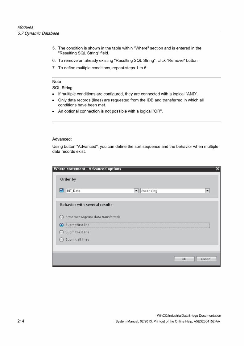
Modules 3.7 Dynamic Database
WinCC/IndustrialDataBridge Documentation 214 System Manual, 02/2013, Printout of the Online Help, A5E32364152-AA
5. The condition is shown in the table within "Where" section and is entered in the "Resulting SQL String" field.
6. To remove an already existing "Resulting SQL String", click "Remove" button.
7. To define multiple conditions, repeat steps 1 to 5.
Note SQL String If multiple conditions are configured, they are connected with a logical "AND". Only data records (lines) are requested from the IDB and transferred in which all
conditions have been met. An optional connection is not possible with a logical "OR".
Advanced:
Using button "Advanced", you can define the sort sequence and the behavior when multiple data records exist.

Modules 3.7 Dynamic Database
WinCC/IndustrialDataBridge Documentation System Manual, 02/2013, Printout of the Online Help, A5E32364152-AA 215
● Order By Select the selection field. You can then define the column name and the sort direction.
● Behaviour with several results: Select one of the following option fields and click OK button. Based on selected radio button, you can decide the action to be performed:
– Error message (no data transferred): When this option is selected, no data will be transferred.
– Submit first line: Submits only the first row in the table.
– Submit last line: Submits the last record or last row contained within the table.
– Submit all lines: Considers transfer of all records or rows within the table.
Note Modifying Consumer type
Once the connection(s) have been created in Connection mapping window and if you wish to modify the Consumer type in Database consumer configuration, the IDB CS application will not allow to change the Consumer type. To change the Consumer type, you need to delete the connection(s) that have been already created. Close the consumer configuration window and re-open the window from the project tree to modify the consumer type.
Results The connections that you have created are shown in the "Connections" tab of IDB Settings window as well as within the project tree node.

Modules 3.7 Dynamic Database
WinCC/IndustrialDataBridge Documentation 216 System Manual, 02/2013, Printout of the Online Help, A5E32364152-AA
3.7.5 Connecting OPC Tags from the Interface of a Dynamic Database
Connecting OPC Tags In "Connection mapping" tab, the "OPC" tab includes options to connect OPC tags that have been sent from the Dynamic Database interface with the selected data consumer.
The "Connection mapping" tab consists of 3 tabs:
● Dynamic Database
● Where Statement
● OPC
This chapter covers the aspects related to OPC tab.
Note Select OPC server
In order to configure the settings on the "OPC" tab, you must have selected an OPC server in the link settings in dialog "Config. Trigger Provider". This dialog window is accessed by clicking on the "Event" button in "Transfer options" tab.

Modules 3.7 Dynamic Database
WinCC/IndustrialDataBridge Documentation System Manual, 02/2013, Printout of the Online Help, A5E32364152-AA 217
1. In the "Dynamic Database provider" area, navigate to OPC tab. The OPC tab mainly includes the OPC tag browser and "Configure provider OPC tag" area.
2. In OPC tag browser, select the tag for which the values should be transferred. The selected tag is shown in the "TagID" field. The data type is chosen according to the selection.
3. If the selected tag has Array data type, then the "Array" check box is automatically enabled. This check box is provided below the "Datatype" field.
4. Next, configure the consumer tag in the "Database consumer" section by following these steps:
– The selected table is shown in the "Table" field. The schema (if selected at provider side) is displayed in the "Schema" field.
– The column names are displayed within "Columns" area. If the table has columns with respective data types, the time stamp can also be written to the table. In this case, select the respective "Active" check box and select the column within "Column for timestamp" field.
5. Select the Column name that you wish to connect with the OPC tag. The selected column is displayed in "Column for data value" field of Database consumer.

Modules 3.7 Dynamic Database
WinCC/IndustrialDataBridge Documentation 218 System Manual, 02/2013, Printout of the Online Help, A5E32364152-AA
6. Check the name of the connection in the "Connection mapping settings" area to the right. Enter a unique name for the connection in the "Connection name" field or use the options within "Default name options". Click "Connect" button to confirm your entries.
7. Repeat steps 1 to 5 for all elements of the "Dynamic Database" that you wish to transfer.
Note Array
If the OPC provider tag has a data type of array data type and if the database consumer column has data type other than array data type, after clicking on the Connect buton, the "Array" check box in the "OPC tab" is automatically unchecked.
Results The connections that you have created are shown in the "Connections" tab of IDB CS Settings window as well as within the project tree node.

Modules 3.7 Dynamic Database
WinCC/IndustrialDataBridge Documentation System Manual, 02/2013, Printout of the Online Help, A5E32364152-AA 219
3.7.6 Configuring an Interface to a Dynamic Database as a Consumer
Objective To create a project with corresponding link having Dynamic Database as consumer and configure the respective provider/consumer connection properties along with transfer behaviour settings.
Creating a link 1. Open IDB Configuration and create a project by following the steps mentioned below:
– In IDB Configuration menu, select "Project" > "Create" to create a new project.
– In the "Create new project" dialog box, specify a project name, click [...] button and select the folder location wherever the project needs to be saved.
– After entering the required information, select "Create" button. This creates a new project.
2. The project name will be listed within the "Project tree". The next step is to create a link. Follow the steps mentioned below to create a link between provider and consumer:
– Right click on project name node in the tree structure and select "Add new link" option.
– In the "Add new link" dialog that is displayed, enter a unique link name.
– Select the provider type as Database, consumer type as Dynamic Database and click OK button.
– The created link will be displayed below the project name in project tree.
– The corresponding entries - Provider, Consumer, Settt ings and Connections are created as nodes that exist below the new link in the tree structure.

Modules 3.7 Dynamic Database
WinCC/IndustrialDataBridge Documentation 220 System Manual, 02/2013, Printout of the Online Help, A5E32364152-AA
3. In project tree, open the Provider configuration window by double clicking the Provider node.
In Database provider configuration window, perform the following settings:
– Select the type of database by choosing the appropriate radio button.
– If the database exists on a server location, enter the server name in "Server" field.
If you wish to enable windows authentication automatically, select the check box "Use automatic windows authentication".
– In "Database" field, click on [...] button and select the database from the list or from the folder structure.
Note Server name
The "Server" field for entering the Server name, "Use automatic windows authentication" check box and the fields for entering the logon information are enabled only if you have selected a database other than Microsoft Access.

Modules 3.7 Dynamic Database
WinCC/IndustrialDataBridge Documentation System Manual, 02/2013, Printout of the Online Help, A5E32364152-AA 221
– If a user name and password has been set for the database, enter the user name and password in the "User name" and "Password" fields respectively.
If you wish to set a blank password, enable the check box "Blank password". To save the entered password, enable the check box "Allow saving password".
– Click Test button to test the connection. The application tests the database connection string and verifies the selected database.
4. In project tree, open the Consumer configuration window by double clicking the Consumer node.
In Danamic database consumer configuration window, perform the following settings:
– Select the type of database by choosing the appropriate radio button.
– If the database exists on a server location, enter the server name in "Server" field.
If you wish to enable windows authentication automatically, select the check box "Use automatic windows authentication".

Modules 3.7 Dynamic Database
WinCC/IndustrialDataBridge Documentation 222 System Manual, 02/2013, Printout of the Online Help, A5E32364152-AA
– In "Database" field, click on [...] button and select the database from the list or from the folder structure.
Note Server name
The "Server" field for entering the Server name, "Use automatic windows authentication" check box and the fields for entering the logon information are enabled only if you have selected a database other than Microsoft Access.
– If a user name and password has been set for the database, enter the user name and password in the "User name" and "Password" fields respectively.
If you wish to set a blank password, enable the check box "Blank password". To save the entered password, enable the check box "Allow saving password".
– Click Test button to test the connection. The application tests the database connection string and verifies the selected database.
Performing link settings 1. In project tree, double click the Settings node to open Settings window in the work area.
The Settings window consists of 3 tabs - Transfer options, Connection Mapping & Connections.

Modules 3.7 Dynamic Database
WinCC/IndustrialDataBridge Documentation System Manual, 02/2013, Printout of the Online Help, A5E32364152-AA 223
2. Within the Transfer options tab, you can configure the transfer behavior settings for provider.
"Provider settings" section
– Select the Schema, if applicable and choose the Table name by selecting from the drop down list.
Modules 3.7 Dynamic Database
WinCC/IndustrialDataBridge Documentation 224 System Manual, 02/2013, Printout of the Online Help, A5E32364152-AA
– Enter a time period in the "Update rate" field after which the system checks for whether data is to be transferred.
Note Selecting Schema If you are using a database other than Microsoft Access, selection of Schema is
mandatory before choosing the Table name. While using Microsoft Access as database, the "Schema" field is displayed in
disable state and does not allow any selection of Schema.
Note Update rate
For better performance, it is recommended to use an update rate of 1000 ms or 1 sec.
3. Next, select the type of data transfer:
– Send only changed values
After every update cycle, the value existing within the Update rate is checked. If there is a change in the value, the value will be transferred, else it will be ignored.
– Send always all values
After every update cycle, all the connected column values are transferred from provider to the consumer.
– Send values using trigger
After every update cycle, the trigger condition is verified. If the trigger condition is met, then the data is transferred.
4. If you have selected the option "Send values using trigger", you can configure the trigger. The Trigger section is enabled only if the data transfer type "Send values using trigger" is selected.
Perform the following settings in the "Configure trigger" section:
– In the Schema field, choose a valid schema by selecting the drop down list.
– Choose a table name by selecting from the drop down list.
– In Column field, select the specific column that needs to be used for the trigger condition.
– Choose a valid data type by selecting from the drop down list.
– Enter a threshold at which a data transfer should be triggered, in the "Trigger value" field.
– In "Confirmation value" field, enter a value that the trigger tag should take on after triggering.
The Confirmation value does not give any information whether a transaction has been completed successfully.
5. The transfer behavior settings for provider will be saved automatically.

Modules 3.7 Dynamic Database
WinCC/IndustrialDataBridge Documentation System Manual, 02/2013, Printout of the Online Help, A5E32364152-AA 225
Note Saving changes
A save operation is not required every time whenever changes are performed within the editor window in the work area. The changes made to these settings are automatically saved. However, once the project is created, at any point of time, you can save the project by selecting the "Project" > "Save" menu option.
Results You have created a connection between the dynamic database interface and a provider. These elements are displayed in the tree structure of the IDB configuration interface. In order to transfer data, connect the provider and consumer tags, as described in chapter "Connecting Tags to a Dynamic Database Interface".

Modules 3.7 Dynamic Database
WinCC/IndustrialDataBridge Documentation 226 System Manual, 02/2013, Printout of the Online Help, A5E32364152-AA
3.7.7 Connecting Tags to a Dynamic Database Interface
Connecting Tags In "Settings" window, the "Connection mapping" tab includes the required fields to connect tags that have been sent from the selected data provider to Dynamic Database interface. The Connection mapping tab divides the window into 3 sections:
● Database provider
● Dynamic database consumer
● Connection mapping settings
The "Database provider" section is displayed at top left portion of "Connection mapping" tab. This section lists the column values that can be mapped with the columns existing with Dynamic Database consumer. The "Dynamic database consumer" section is displayed to bottom left portion of "Connection mapping" tab. This section provides you with required options to choose schema, table name and column names to be mapped.
Modules 3.7 Dynamic Database
WinCC/IndustrialDataBridge Documentation System Manual, 02/2013, Printout of the Online Help, A5E32364152-AA 227
Note Connection mapping
A specific connection can be created between the Database provider column and the column (belonging to Dynamic database consumer) selected in the Where statement tab. You can create a new connection or else modify an existing connection to apply Where statement on the selected column.
The separator between the provider and consumer section provides a resize handle that helps you to resize the height of the section in order to view the fields within the section clearly.
The "Connection mapping settings" section is displayed at right side of "Connection mapping" tab. This section helps you to provide a name for connection along with options for choosing default name for connection. The "Connect", "Modify connection" and "Delete connection" icons are provided at the top portion of this section.
1. In "Database provider" section, the selected archive is shown in the "Table" field. Select the Schema if applicable by selecting from the drop down list in "Schema" text box.
2. The Column names are displayed within "Columns" area. Select a Column name from the list. The selected column is displayed in "Column for data value" field. The data type is shown automatically.
3. The "Filter" field provides you the option to filter the Column names based on single character or first few characters of column name.
For example, if you wish to view the column names starting with "S", type this character in "Filter" text box. All column names starting with "S" are displayed.
Note Dynamic database consumer
The "Dynamic database consumer" section area consists of 2 tabs - 'Dynamic Database consumer' and 'Where- Statement'.
This chapter covers the aspects related to "Dynamic database consumer" and "Where-Statement" tabs.

Modules 3.7 Dynamic Database
WinCC/IndustrialDataBridge Documentation 228 System Manual, 02/2013, Printout of the Online Help, A5E32364152-AA
4. Next, configure the consumer tag in the "Dynamic database consumer" tab by following these steps:
Note Selecting Schema If you are using a database other than Microsoft Access, selection of Schema is
mandatory before choosing the Table name. While using Microsoft Access as database, the "Schema" field is displayed in disable
state and does not allow any selection of Schema.
– In "Dynamic database provider", select the Schema and choose the table name from "Table" field.
– The column names are displayed within "Columns" area. The column names are displayed within "Columns" area. If the table has columns with respective data types, the time stamp can also be written to the table. In this case, select the respective "Active" check box and select the column within "Column for timestamp" field.
5. Select the Column name that you wish to connect with "Database provider". The selected column is displayed in "Column for data value" field.
The data type for the selected column is automatically selected in the "Data type" field.
6. The "Filter" field provides you the option to filter the column names based on single character or first few characters of column name.
For example, if you wish to view the column names starting with "S", type this character in "Filter" text box. All column names starting with "S" are displayed.
7. Check the name of the connection in the "Connection mapping settings" area to the right. Enter a unique name for the connection in the "Connection name" field or use the options within "Default name options". Click "Connect" button to confirm your entries.
Note Data type conversion
If the provider tag data type does not match with consumer column, IDB CS converts the data type to match with data type of provider tag. A status window is displayed to indicate this change.
8. Repeat steps 1 to 7 for all elements of the "Database Provider" that you wish to transfer.
9. The connection name including the provider and consumer data values will be displayed within the "Connection mapping settings" section.The list of connections will be also displayed within the Connections tab as well as in the project tree within the "Connections" node belonging to the specific link.
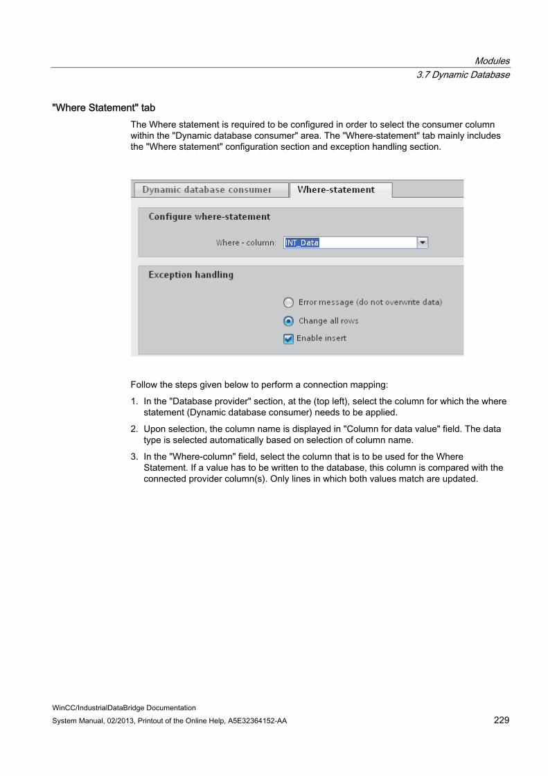
Modules 3.7 Dynamic Database
WinCC/IndustrialDataBridge Documentation System Manual, 02/2013, Printout of the Online Help, A5E32364152-AA 229
"Where Statement" tab The Where statement is required to be configured in order to select the consumer column within the "Dynamic database consumer" area. The "Where-statement" tab mainly includes the "Where statement" configuration section and exception handling section.
Follow the steps given below to perform a connection mapping:
1. In the "Database provider" section, at the (top left), select the column for which the where statement (Dynamic database consumer) needs to be applied.
2. Upon selection, the column name is displayed in "Column for data value" field. The data type is selected automatically based on selection of column name.
3. In the "Where-column" field, select the column that is to be used for the Where Statement. If a value has to be written to the database, this column is compared with the connected provider column(s). Only lines in which both values match are updated.

Modules 3.7 Dynamic Database
WinCC/IndustrialDataBridge Documentation 230 System Manual, 02/2013, Printout of the Online Help, A5E32364152-AA
4. The behavior is defined in the "Exception handling" field if the selection of the consumer row is not unique:
– Error Message: No target lines are overwritten and an error message is given as an output in the trace view of IDB Runtime.
– Change all rows: All selected consumer rows are overwritten.
– Using the "Enable Insert" check box, you define the behavior if a line with the key (primary key) does not exist. If the option is selected, a new line with the respective key is created.
Note Simultaneous Utilization as Key and Target Column
In order to have more setting ability with the configuration, a column can be used as a key column and as a consumer column simultaneously. Take note that this causes the data in the database to be inconsistent and/or future access to the dynamic database consumer may result in errors.
5. Check the name of the connection in the "Connection mapping settings" area (right). Enter a unique name for the connection in the "Connection name" field or use the options within "Default name options". Click "Connect" button to confirm your entries.
Results The connections that you have created are shown in the "Connections" tab of IDB "Settings" window as well as within the project tree node.

Modules 3.8 CSV and TXT Files
WinCC/IndustrialDataBridge Documentation System Manual, 02/2013, Printout of the Online Help, A5E32364152-AA 231
3.8 CSV and TXT Files
3.8.1 Overview
Overview The IDB application provides support for writing data to an ASCII file, UTF-8 format file using module CSV, TXT. This module can be used only as a consumer and works with all provider types.
CSV, TXT as a consumer type is to be given priority because of the much higher access speed in comparison with the "Excel file" data type. You can open and process files of this type with Microsoft Excel or with another table calculation program.
To establish connection to CSV/TXT files, let us consider OPC Data Access (OPC DA) as the provider in this case.
Note Important Notes for Configuring OPC Data Access To work in configuration and runtime environment of the module OPC Data Access, you
must configure the DCOM settings correctly in Windows. Information on DCOM settings can be found in Microsoft Help.
The tag browser information or the tags are displayed only if OPC Server is selected in provider configuration window and is available.

Modules 3.8 CSV and TXT Files
WinCC/IndustrialDataBridge Documentation 232 System Manual, 02/2013, Printout of the Online Help, A5E32364152-AA
3.8.2 Configuring an Interface to CSV- and TXT-Files as a Consumer
Objective To create a project with corresponding link having CSV, TXT as consumer and configure the respective provider/consumer configuration along with transfer behavior settings
Creating a link 1. Open IDB Configuration and create a project by following the steps mentioned below:
– In IDB Configuration menu, select "Project" > "Create" to create a new project.
– In the "Create new project" dialog box, specify a project name, click [...] button and select the folder location wherever the project needs to be saved.
– After entering the required information, select "Create" button. This creates a new project.
2. The project name will be listed within the "Project tree". The next step is to create a link. Follow the steps mentioned below to create a link between provider and consumer:
– Right click on project name node in the tree structure and select "Add new link" option.
– In the "Add new link" dialog that is displayed, enter a unique link name.
– Select the provider type as OPC Data Access, consumer type as CSV/TXT and click OK button.
– The created link will be displayed below the project name in project tree.
– The corresponding entries - Provider, Consumer, Settt ings and Connections are created as nodes that exist below the new link in the tree structure.
3. In project tree, open the Provider configuration window by double clicking the Provider node.
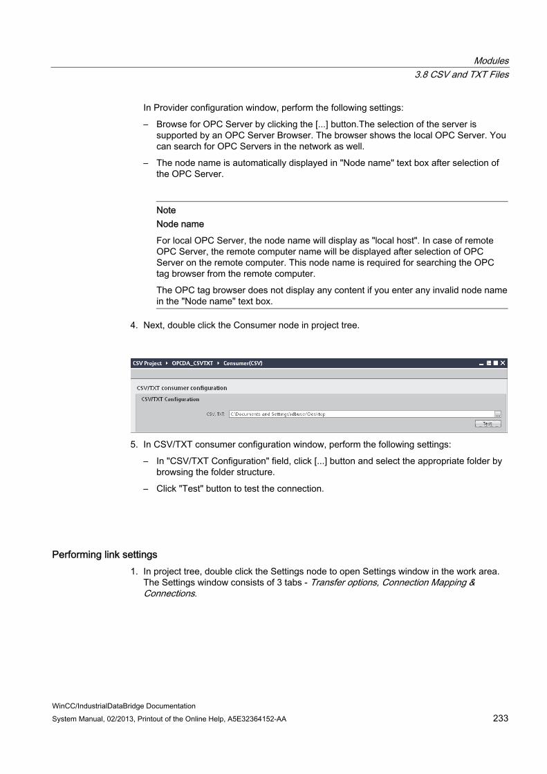
Modules 3.8 CSV and TXT Files
WinCC/IndustrialDataBridge Documentation System Manual, 02/2013, Printout of the Online Help, A5E32364152-AA 233
In Provider configuration window, perform the following settings:
– Browse for OPC Server by clicking the [...] button.The selection of the server is supported by an OPC Server Browser. The browser shows the local OPC Server. You can search for OPC Servers in the network as well.
– The node name is automatically displayed in "Node name" text box after selection of the OPC Server.
Note Node name
For local OPC Server, the node name will display as "local host". In case of remote OPC Server, the remote computer name will be displayed after selection of OPC Server on the remote computer. This node name is required for searching the OPC tag browser from the remote computer.
The OPC tag browser does not display any content if you enter any invalid node name in the "Node name" text box.
4. Next, double click the Consumer node in project tree.
5. In CSV/TXT consumer configuration window, perform the following settings:
– In "CSV/TXT Configuration" field, click [...] button and select the appropriate folder by browsing the folder structure.
– Click "Test" button to test the connection.
Performing link settings 1. In project tree, double click the Settings node to open Settings window in the work area.
The Settings window consists of 3 tabs - Transfer options, Connection Mapping & Connections.

Modules 3.8 CSV and TXT Files
WinCC/IndustrialDataBridge Documentation 234 System Manual, 02/2013, Printout of the Online Help, A5E32364152-AA
2. Within the Transfer options tab, you can configure the transfer behavior settings for provider.
3. Enter a time period in the "Update rate" field after which the system checks for whether data is to be transferred.
Note Update rate
For better performance, it is recommended to use an update rate of 1000 ms or 1 sec.

Modules 3.8 CSV and TXT Files
WinCC/IndustrialDataBridge Documentation System Manual, 02/2013, Printout of the Online Help, A5E32364152-AA 235
4. Next, select the type of data transfer:
– Send only changed values
Data is transferred whenever the configured tag value changes. If a threshold value is configured in the "Deadband" field and if the selected OPC Server supports deadband, then data transfer happens only upon data change exceeding the dead band value specified. Dead band value should be within 0 - 100.
– Send always all values
After every update cycle, the data of all tags of the provider, which you have connected with the target, will be transferred.
– Send values using trigger
After every update cycle, a selected tag of the OPC Server is checked to see if it has reached a trigger value. In this case, all values are transferred.
Note "Send only changed values" data transfer
If the deadband value is configured and the selected OPC Server does not support deadband, a value of 0% is set and any change in the value will be considered for data transfer. Data transfer of this type is independent of "Update rate"
5. Enter the deadband value (in percent) to contain a value within the range 0 - 100.
6. In "Tag for transaction security" field, click [...] button and select a tag of OPC Server from the OPC tag browser.
You can define a OPC tag on an OPC server, in which the success-/failure-status of the data transfer will be stored in the "Tag for transaction security" field.This value should have 1 byte signed char (e.g. VT_I1). '-1' indicates the success state and '0' indicates failure.
7. If you have selected the option "Send values using trigger", you can configure the trigger that provides options to set the trigger options. The Trigger section is enabled only with the data transfer type "Send values using trigger".
Perform the following settings in the "Trigger settings" section:
– In "Trigger tag" field, select the tag that should trigger a data transfer. Click on [...] to select the tag from OPC tag browser.
– Select a valid data type by selecting from the drop down list.
– Enter a threshold at which a data transfer should be triggered, in the "Trigger value" field.
– In "Confirmation value" field, enter a value that the trigger tag should take on after triggering.
The confirmation value does not give any information on whether a transaction has been completed successfully.
8. The transfer behavior settings for provider will be saved automatically.

Modules 3.8 CSV and TXT Files
WinCC/IndustrialDataBridge Documentation 236 System Manual, 02/2013, Printout of the Online Help, A5E32364152-AA
Note Saving changes
A save operation is not required every time whenever changes are performed within the editor window in the work area. The changes made within the editor windows are automatically saved. However, once the project is created, at any point of time, you can save the project by selecting the "Project" > "Save" menu option.
Results You have configured the OPC Data Access as provider and the interface to CSV/TXT file including provider transfer options. These elements are displayed in the tree structure of the configuration interface. In order to transfer data, connect the provider and consumer tags, as described in chapter "Connecting Tags to an Interface to CSV- and TXT-Files".

Modules 3.8 CSV and TXT Files
WinCC/IndustrialDataBridge Documentation System Manual, 02/2013, Printout of the Online Help, A5E32364152-AA 237
3.8.3 Connecting Tags to an Interface to CSV- and TXT-Files
Connecting Tags In "Settings" window, the "Connection mapping" tab includes the required fields to connect tags that have been sent from the selected provider to CSV/TXT consumer. The Connection Settings are performed by configuring the settings within the Connection mapping tab.
The Connection mapping tab divides the window into 3 sections.
● OPC Data Access provider
● CSV/TXT consumer
● Connection mapping properties
This tab displays the "OPC Data Access provider" and "CSV/TXT consumer" on left hand side whereas the right hand side of window contains Connection mapping properties and connection options. The separator between the provider and consumer section provides a resize handle that helps you to resize the height of the section in order to view the fields within the section clearly.
The "Connection mapping settings" section is displayed at right side of "Connection mapping" tab. This section helps you to provide a name for connection along with options for choosing default name for connection. The "Connect", "Modify connection", "Delete connection" and "Delete all connections" icons are provided at the top portion of this section.
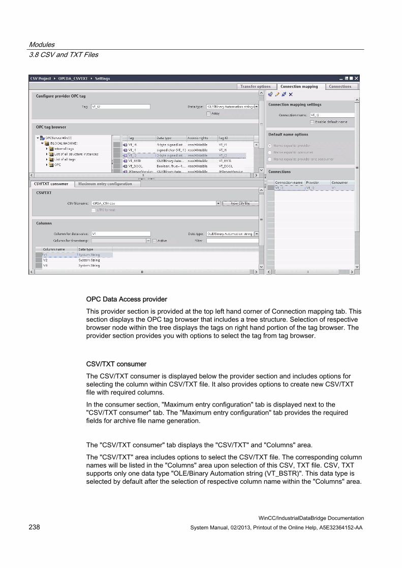
Modules 3.8 CSV and TXT Files
WinCC/IndustrialDataBridge Documentation 238 System Manual, 02/2013, Printout of the Online Help, A5E32364152-AA
OPC Data Access provider
This provider section is provided at the top left hand corner of Connection mapping tab. This section displays the OPC tag browser that includes a tree structure. Selection of respective browser node within the tree displays the tags on right hand portion of the tag browser. The provider section provides you with options to select the tag from tag browser.
CSV/TXT consumer
The CSV/TXT consumer is displayed below the provider section and includes options for selecting the column within CSV/TXT file. It also provides options to create new CSV/TXT file with required columns.
In the consumer section, "Maximum entry configuration" tab is displayed next to the "CSV/TXT consumer" tab. The "Maximum entry configuration" tab provides the required fields for archive file name generation.
The "CSV/TXT consumer" tab displays the "CSV/TXT" and "Columns" area.
The "CSV/TXT" area includes options to select the CSV/TXT file. The corresponding column names will be listed in the "Columns" area upon selection of this CSV, TXT file. CSV, TXT supports only one data type "OLE/Binary Automation string (VT_BSTR)". This data type is selected by default after the selection of respective column name within the "Columns" area.
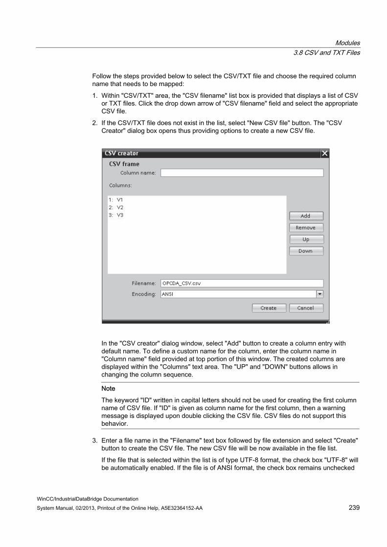
Modules 3.8 CSV and TXT Files
WinCC/IndustrialDataBridge Documentation System Manual, 02/2013, Printout of the Online Help, A5E32364152-AA 239
Follow the steps provided below to select the CSV/TXT file and choose the required column name that needs to be mapped:
1. Within "CSV/TXT" area, the "CSV filename" list box is provided that displays a list of CSV or TXT files. Click the drop down arrow of "CSV filename" field and select the appropriate CSV file.
2. If the CSV/TXT file does not exist in the list, select "New CSV file" button. The "CSV Creator" dialog box opens thus providing options to create a new CSV file.
In the "CSV creator" dialog window, select "Add" button to create a column entry with default name. To define a custom name for the column, enter the column name in "Column name" field provided at top portion of this window. The created columns are displayed within the "Columns" text area. The "UP" and "DOWN" buttons allows in changing the column sequence.
Note
The keyword "ID" written in capital letters should not be used for creating the first column name of CSV file. If "ID" is given as column name for the first column, then a warning message is displayed upon double clicking the CSV file. CSV files do not support this behavior.
3. Enter a file name in the "Filename" text box followed by file extension and select "Create" button to create the CSV file. The new CSV file will be now available in the file list.
If the file that is selected within the list is of type UTF-8 format, the check box "UTF-8" will be automatically enabled. If the file is of ANSI format, the check box remains unchecked

Modules 3.8 CSV and TXT Files
WinCC/IndustrialDataBridge Documentation 240 System Manual, 02/2013, Printout of the Online Help, A5E32364152-AA
4. In "CSV/TXT consumer" tab, select the CSV file that is displayed in the "CSV filename" field list box. The "Columns" area displays the "column name" along with its associated "Data type".
5. In "Columns" area, select the column name from the list. The selected column name is displayed in "Column for data value" field and the corresponding data type is selected and displayed in "Data type" field.
6. If the column name has "Date/time" data type, the time stamp can be written to the specific column. In this case, select the respective "Active" check box and select the column in "Column for timestamp" field list box.
7. The "Filter" field provides you the option to filter the Column names based on single character or first few characters of column name.
For example, if you wish to view the column names starting with "S", type this character in "Filter" text box. All column names starting with "S" are displayed.
Maximum Entry Configuration:
The "Maximum Entry Configuration" tab provides options to archive the data. Continuous archiving can be handled or else options to archive once the maximum entries are reached are also supported. This also provides support for archive file name generation wherein several options are provided for selection that is used for generating the archive file name. The "Archive path" field allows for selecting the desired archive path.

Modules 3.8 CSV and TXT Files
WinCC/IndustrialDataBridge Documentation System Manual, 02/2013, Printout of the Online Help, A5E32364152-AA 241
Follow the steps given below to perform these archive settings:
1. Select the check box "Archive File at Maximum Entry" and specify a value in "Max. entries" text box. If this value is set to zero, you can write any number of lines into the file.
Note
If this check box "Archive File at Maximum Entry" is unchecked, the Archive File Name Generation and other file name selection options within this tab will be in disable state.
Note By default, the "Max. entries" field displays the value as 0. However, this value can be
modified. It is important to ensure that "Max. entries" field should not be left blank. If "Max. entries" is set to a value less than zero or negative value entered or if the field
is blank, an error message "Value should be greater than or equal to zero" is displayed.
The maximum value for Max. entries in CSV/TXT is 2147483647. Any value entered above this range will not be accepted and displays an error message as "Type conversion failed".
2. In "Archive File Name Generation" area, options are provided for file name generation with respect to the archive file. Select any one of the following options by selecting the radio button.
– Use current date and time
– Use current date and serial number
– Use serial number
3. Next, specify the Archive path in the text box provided. You can either enter the full path name in the text box or select the path using "..." button. If you provide the path in archive path text box, archived CSV files are generated at this path. By default, this text box has the same path where the base CSV file is present.

Modules 3.8 CSV and TXT Files
WinCC/IndustrialDataBridge Documentation 242 System Manual, 02/2013, Printout of the Online Help, A5E32364152-AA
4. The "Use Dedicated File Name" check box allows for options to specify a dedicated file name in combination with a serial number and date or date and time or serial number. If this checkbox is unchecked, then the base CSV filename will be used for archiving.
5. The "Select filename type" field provides options to select custom file name or to use file name from WinCC tag.
– To use custom file name, select filename type as "Use custom filename" and enter the custom file name in "Custom file name" text box.
– To use file name from WinCC tag, select filename type as "Use filename from WinCC tag". An OPC tag that uses the FileName Tag will be created. The FileNameTag is displayed only after performing a connection mapping.
This feature provides option to configure an OPC Tag as FileName for the CSV file. All Archive File Name Generation settings are applied along with OPC tag value to construct a file name. Data from the provider is written into this file until either the maximum entry configured is reached or the OPC Tag configured for the CSV file name changes.
Note
Upon selection of "Use Dedicated File Name" check box, the 'Select Filename Type' provides an option "Use Filename from WinCC Tag" within the drop down combo box. This option is provided only with providers that supports Tags.
Note
The OPC Tag as FileName feature can be used even if Max. entries is 0. If you have used this setting, then the new file is created only when the OPC Tag changes. Until then, all records are written to the CSV file that was created during creation of previous OPC Tag. The maximum entry condition does not hold as the maximum entry is 0 and all the data is written into a single file until the OPC Tag value configured for file name changes.
Note
If the OPC Tag value is NULL, then the base file or template file is taken into consideration for forming the file name.
Connection Mapping
To establish connection between the provider and consumer, a data column mapping is required to be performed. Defining a connection name is the first step towards the setup of a connection. The Connection window displays "Default connection name" options in order to specify a name for default connection. Connect, delete and modify buttons are provided below the "Default connection name" section. These buttons help in order to work with the connections.
Modules 3.8 CSV and TXT Files
WinCC/IndustrialDataBridge Documentation System Manual, 02/2013, Printout of the Online Help, A5E32364152-AA 243
Note Modify connection
To modify an existing connection, perform the required changes and then select "Modify" button. The changes can be observed within the Connection window only after selecting the "Modify" button.
Follow these steps to perform column mapping between provider and consumer:
1. Select a tag name from "OPC Data Access provider" and choose the column name from CSV/TXT consumer" column that needs to be mapped. Click "Connect" button.
2. If there is a data mismatch between the provider and consumer columns, IDB CS will modify the data type to VT_BSTR data type and displays the message "The provider data type was changed to fit the consumer type". Next, click OK.
3. Repeat steps 1 & 2 for all elements of the provider that you wish to transfer. A connection is created for each of the column values in provider and consumer.
4. To use file name from WinCC tag, select the OPC Tag from tag browser. Specify a connection name for this connection from the options provided within the "Default Connection name" area and click "Connect" button.
5. The connection name including the provider and consumer data values will be displayed below the Connect button.
6. The list of connections will be displayed in the Connections tab.
Note Array
If the OPC Data Access provider tag has a data type of array data type and if the CSV/TXT consumer column has data type other than array data type, after clicking on the Connect buton, the "Array" check box in the "OPC Data Access provider" is automatically unchecked.
Note Column for time stamp
The time stamp must be assigned before connecting the first tags. Afterwards, adding or changing is only possible if all items are deleted, the dialog is closed and reopened again. The time stamp is generated from the local time, if new data is transferred from the provider.
Results The connections that you have created are shown in the "Connections" tab of IDB CS "Settings" window as well as within the project tree node.

Modules 3.8 CSV and TXT Files
WinCC/IndustrialDataBridge Documentation 244 System Manual, 02/2013, Printout of the Online Help, A5E32364152-AA
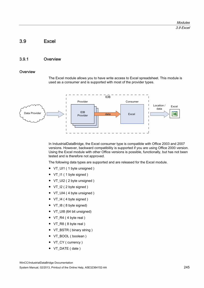
Modules 3.9 Excel
WinCC/IndustrialDataBridge Documentation System Manual, 02/2013, Printout of the Online Help, A5E32364152-AA 245
3.9 Excel
3.9.1 Overview
Overview The Excel module allows you to have write access to Excel spreadsheet. This module is used as a consumer and is supported with most of the provider types.
In IndustrialDataBridge, the Excel consumer type is compatible with Office 2003 and 2007 versions. However, backward compatibility is supported if you are using Office 2000 version. Using the Excel module with other Office versions is possible, functionally, but has not been tested and is therefore not approved.
The following data types are supported and are released for the Excel module.
● VT_UI1 ( 1 byte unsigned )
● VT_I1 ( 1 byte signed )
● VT_UI2 ( 2 byte unsigned )
● VT_I2 ( 2 byte signed )
● VT_UI4 ( 4 byte unsigned )
● VT_I4 ( 4 byte signed )
● VT_I8 ( 8 byte signed)
● VT_UI8 (64 bit unsigned)
● VT_R4 ( 4 byte real )
● VT_R8 ( 8 byte real )
● VT_BSTR ( binary string )
● VT_BOOL ( boolean )
● VT_CY ( currency )
● VT_DATE ( date )

Modules 3.9 Excel
WinCC/IndustrialDataBridge Documentation 246 System Manual, 02/2013, Printout of the Online Help, A5E32364152-AA
Note Writing Larger Volumes of Data
Frequent use or transferring larger volumes of data can lead to performance loss of close to 100%. The utilization of a CSV file is recommended for this application.
Note Closing Excel
When opening an Excel table, a new window is opened. If all Excel windows are closed, Excel is also closed. The instance to which the IndustrialDataBridge is therefore also deleted in this case. The connection is only re-established after a Reconnect (10 seconds). During this time, all incoming data is lost.
Note Setting "Save after a certain duration"
With the configuration "Save after a certain duration" and setting the time at less than 30 seconds, problems can occur when separating the data target Excel in the Runtime program.

Modules 3.9 Excel
WinCC/IndustrialDataBridge Documentation System Manual, 02/2013, Printout of the Online Help, A5E32364152-AA 247
3.9.2 Requirements
Prerequisites In order to use a connection to Microsoft Excel as a consumer, you need the Microsoft Excelprogram. This program is not provided with the WinCC IndustrialDataBridge. Microsoft Excel is part of the Microsoft Office package.
If you are not sure whether the software is installed, contact your system administrator.
File Extension Office 2003 includes Excel program and has the file extension ".xls" whereas Excel provided in Office 2007 / Office 2010 has the file extension as ".xlsx".

Modules 3.9 Excel
WinCC/IndustrialDataBridge Documentation 248 System Manual, 02/2013, Printout of the Online Help, A5E32364152-AA
3.9.3 Configuring an Excel Interface as Consumer
Objective To create a project with corresponding link having Excel as consumer and configure the respective provider/consumer connection configuration along with their transfer behaviour settings
Creating a link 1. Open IDB Configuration and create a project by following the steps mentioned below:
– In IDB Configuration menu, select "Project" > "Create" to create a new project.
– In the "Create new project" dialog box, specify a project name, click [...] button and select the folder location wherever the project needs to be saved.
– After entering the required information, select "Create" button. This creates a new project.
2. The project name will be listed within the "Project tree". The next step is to create a link. Follow the steps mentioned below to create a link between provider and consumer:
– Right click on project name node in the tree structure and select "Add new link" option.
– In the "Add new link" dialog that is displayed, enter a unique link name.
– Select the provider type as Database, consumer type as Excel and click OK button.
– The created link will be displayed below the project name in project tree.
– The corresponding entries - Provider, Consumer, Settt ings and Connections are created as nodes that exist below the new link in the tree structure.
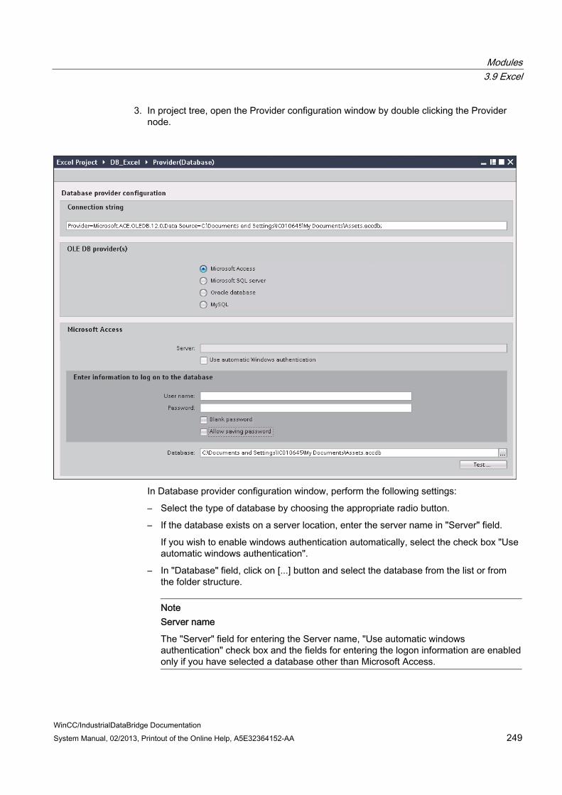
Modules 3.9 Excel
WinCC/IndustrialDataBridge Documentation System Manual, 02/2013, Printout of the Online Help, A5E32364152-AA 249
3. In project tree, open the Provider configuration window by double clicking the Provider node.
In Database provider configuration window, perform the following settings:
– Select the type of database by choosing the appropriate radio button.
– If the database exists on a server location, enter the server name in "Server" field.
If you wish to enable windows authentication automatically, select the check box "Use automatic windows authentication".
– In "Database" field, click on [...] button and select the database from the list or from the folder structure.
Note Server name
The "Server" field for entering the Server name, "Use automatic windows authentication" check box and the fields for entering the logon information are enabled only if you have selected a database other than Microsoft Access.

Modules 3.9 Excel
WinCC/IndustrialDataBridge Documentation 250 System Manual, 02/2013, Printout of the Online Help, A5E32364152-AA
– If a user name and password has been set for the database, enter the user name and password in the "User name" and "Password" fields respectively.
If you wish to set a blank password, enable the check box "Blank password". To save the entered password, enable the check box "Allow saving password".
– Click Test button to test the connection. The application tests the database connection string and verifies the selected database.
4. Next, double click the Consumer node in project tree to open the consumer configuration window.
5. The Consumer configuration window consists of 2 tabs - Excel save option and Advance options tabs.

Modules 3.9 Excel
WinCC/IndustrialDataBridge Documentation System Manual, 02/2013, Printout of the Online Help, A5E32364152-AA 251
6. In "Excel save option" tab, perform the following settings:
– In "File path" field, click [...] button and select the excel file by browsing the folder structure.
– The file name will be automatically displayed in "Filename" text box once the excel file is selected.
7. In "Advance options" tab, the "Sheet Configuration" section provides options to define the sheet name and number of sheets per workbook.
The "Auto save" option allows to specify a time interval after which the file will be saved. The "Suffix of filename" section provides options to define the method of numbering for the excel files. Perform the following settings to configure the advance options:
– Select the radio button "Keep default sheet name" to use default name for the sheet.
– Select the radio button "Set Sheet name as" to set unique names for each sheet and enter the sheet name in text box provided.
– You can specify the number of sheets required for the workbook by selecting the radio button with label "1" or "2" or "3".
Based on this selection, the text box for entering the sheet name will be enabled or disabled.
– In "Auto save option" section, enable the check box "Save after a certain time" and set the hours, minutes and seconds in the control text box.
– In "Suffix of filename" section, select the radio button "Successive version number" or "Date / Time" option.
The successive version number defines the method of numbering for files.
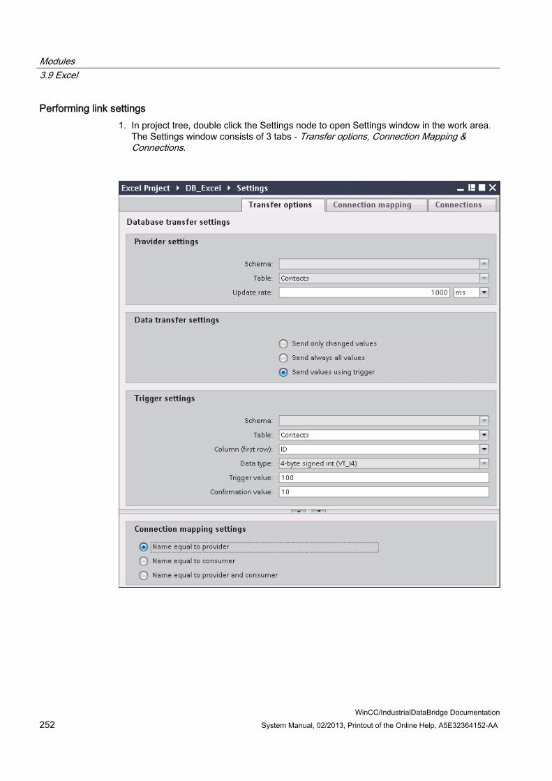
Modules 3.9 Excel
WinCC/IndustrialDataBridge Documentation 252 System Manual, 02/2013, Printout of the Online Help, A5E32364152-AA
Performing link settings 1. In project tree, double click the Settings node to open Settings window in the work area.
The Settings window consists of 3 tabs - Transfer options, Connection Mapping & Connections.

Modules 3.9 Excel
WinCC/IndustrialDataBridge Documentation System Manual, 02/2013, Printout of the Online Help, A5E32364152-AA 253
2. Within the Transfer options tab, you can configure the transfer behavior settings for provider.
"Provider settings" section
– Select the Schema, if applicable and choose the Table name by selecting from the drop down list.
– Enter a time period in the "Update rate" field after which the system checks for whether data is to be transferred.
Note Selecting Schema If you are using a database other than Microsoft Access, selection of Schema is
mandatory before choosing the Table name. While using Microsoft Access as database, the "Schema" field is displayed in
disable state and does not allow any selection of Schema.
Note Update rate
For better performance, it is recommended to use an update rate of 1000 ms or 1 sec.
3. Next, select the type of data transfer:
– Send only changed values
After every update cycle, the value existing within the Update rate is checked. If there is a change in the value, the value will be transferred, else it will be ignored.
– Send always all values
After every update cycle, all the connected column values are transferred from provider to the consumer.
– Send values using trigger
After every update cycle, the trigger condition is verified. If the trigger condition is met, then the data is transferred.
Modules 3.9 Excel
WinCC/IndustrialDataBridge Documentation 254 System Manual, 02/2013, Printout of the Online Help, A5E32364152-AA
4. If you have selected the option "Send values using trigger", you can configure the trigger. The Trigger section is enabled only if the data transfer type "Send values using trigger" is selected.
Perform the following settings in the "Trigger settings" section:
– In the Schema field, choose a valid schema by selecting the drop down list.
– Choose a table name by selecting from the drop down list.
– In Column field, select the specific column that needs to be used for the trigger condition.
– Choose a valid data type by selecting from the drop down list.
– Enter a threshold at which a data transfer should be triggered, in the "Trigger value" field.
– In "Confirmation value" field, enter a value that the trigger tag should take on after triggering.
The Confirmation value does not give any information whether a transaction has been completed successfully.
5. The transfer behaviour settings for provider will be saved automatically.
Note Saving Changes
A save operation is not required every time whenever changes are performed within the editor window in the work area. The changes made to these settings are automatically saved. However, once the project is created, at any point of time, you can save the project by selecting the "Project" > "Save" menu option.
Results You have created a connection between the Excel interface and a provider. These elements are displayed in the tree structure of the configuration interface. In order to transfer data, connect the provider and consumer tags, as described in chapter "Connecting Tags to an Excel Interface".

Modules 3.9 Excel
WinCC/IndustrialDataBridge Documentation System Manual, 02/2013, Printout of the Online Help, A5E32364152-AA 255
3.9.4 Connecting Tags to the Excel Interface
Connecting Tags In "Settings" window, the "Connection mapping" tab includes the required fields to connect tags that have been sent from the selected data target with Excel. The Connection mapping tab divides the window into 3 sections
● Database provider
● Excel consumer
● Connection mapping settings
The "Database provider" section is displayed at top left portion of "Connection mapping" tab. This section displays the selected schema, table name within "Schema" and "Table" fields along with the column names. These columns can be mapped with the columns existing within Excel interface. The "Excel consumer" section is displayed to bottom left portion of "Connection mapping" tab.
The separator between the provider and consumer section provides a resize handle that helps you to resize the height of the section in order to view the fields within the section clearly.
The "Connection mapping settings" section is displayed at right side of "Connection mapping" tab. This section helps you to provide a name for connection along with options for choosing default name for connection. The "Connect", "Modify connection", "Delete connection" and "Delete all connections" icons are provided at the top portion of this section.
Modules 3.9 Excel
WinCC/IndustrialDataBridge Documentation 256 System Manual, 02/2013, Printout of the Online Help, A5E32364152-AA
1. In "Database provider" section, the selected archive is shown in the "Table" field. The Column names are displayed within "Columns" area.
Select a Column name from the list. The selected column is displayed in "Column for data value" field. The data type is showan automatically.
2. The "Filter" field provides you the option to filter the Column names based on single character or first few characters of column name.
For example, if you wish to view the column names starting with "S", type this character in "Filter" text box. All column names starting with "S" are displayed.
3. In the "Excel consumer" area, enter the column name in "Column name" field. The "Binary String (VT_BTR)" is selected by default in the "Datatype" field.
To change the data type, click the drop down arrow in "Datatype" list box and select the appropriate data type.
4. Within "Excel consumer", mark the field in which the column should be saved in first row. The column name is entered in this field.
Note Data type conversion
If the provider tag data type does not match with consumer column, IDB CS converts the data type to match with data type of provider tag. A status window is displayed to indicate this change.
5. Check the name of the connection in the "Connection mapping settings" area to the right. Enter a unique name for the connection in the "Connection name" field or use the options within "Default name options". Click "Connect" button to confirm your entries.
Once the connection is created, you can observe that the mapped column in "Config excel consumer" area is displayed in yellow color. This represents the connected column in "Config excel consumer"
6. Repeat steps 1 to 5 for all elements of "Database Provider" that you wish to transfer.
Note Number of Excel columns
In Excel consumer, a maximum of 256 columns are supported wherein you can create connections with 256 columns. After the 256th column, if you try establishing a connection mapping, a warning message will be displayed. However, you will still be able to create connections after 256 columns. In Runtime, connections upto a maximum of 256 can be enabled.

Modules 3.9 Excel
WinCC/IndustrialDataBridge Documentation System Manual, 02/2013, Printout of the Online Help, A5E32364152-AA 257
Note Opening Excel file during data transfer
During data transfer process between the provider and excel as consumer, IDB Runtime writes the data in the Excel file. If the excel file is opened in parallel during the transfer process, then runtime application stops working. A trace message "Inserting a value failed" will be displayed in the "Trace view" once you try opening this excel file.
Please note that the Runtime application stops working and you will not be able to stop or disconnect the data transfer process. In this scenario, you need to restart the IDB service. However, you will not be able to save any data during the last data transfer.
Results The connections that you have created are shown in the "Connections" tab of IDB "Settings" window as well as within the project tree node.
Modules 3.10 Send/Receive
WinCC/IndustrialDataBridge Documentation 258 System Manual, 02/2013, Printout of the Online Help, A5E32364152-AA
3.10 Send/Receive
3.10.1 Overview
Overview The Send/Receive module in IDB is used for sending and receiving data to or from Siemens PLC. A secure communication is created over TCP protocol and enables reading or writing data to or from the PLC memory. This module acts both as a provider and as a consumer.
The concept behind using the Send/Receive module is defined in such a way that it will be able to read data from the PLC and will be able to write (Send) data to a consumer type (for example, Database). In the other way, it will be possible to read (Receive) data from a database and able to write data to a PLC.
The Send/Receive module supports the following connection types:
● ISOonTCP (RFC 1006) active / passive connection establishment
● TCPnative active / passive connection establishment
● UDP
In this case, the following data types are approved for the Send/Receive data source module:
● VT_UI1 ( 1 byte unsigned )
● VT_I1 ( 1 byte signed )
● VT_UI2 ( 2 byte unsigned )
● VT_I2 ( 2 byte signed )
● VT_UI4 ( 4 byte unsigned )
● VT_I4 ( 4 byte signed )
● VT_R4 ( 4 byte real )
● VT_BSTR ( binary string ) -> Interpretation as S7- or null-terminating string
Note Data Type VT_BOOL
The utilization of VT_BOOL is not approved, since this data type is interpreted as a byte and can overwrite values this way.

Modules 3.10 Send/Receive
WinCC/IndustrialDataBridge Documentation System Manual, 02/2013, Printout of the Online Help, A5E32364152-AA 259
Structure of the Send/Receive Provider:
Structure of the Send/Receive Consumer:
Please note the following information:
● If the IndustrialDataBridge and SimaticNET Softnet are installed and run on the same computer, problems will occur with a passive connection establishment of ISOonTCP. Configure the connection with active connection establishment in this case or use a CP1613 and Hardnet.
● With the "TCPnative" connection type, the following information is valid:
– If IndustrialDataBridge port = 0 and "Active establishing of connection" check box enabled, then a free IndustrialDataBridge port will be used.
– If PLC port = 0 and "Active establishing of connection" check box in disable state, the PLC port will not be verified.

Modules 3.10 Send/Receive
WinCC/IndustrialDataBridge Documentation 260 System Manual, 02/2013, Printout of the Online Help, A5E32364152-AA
Note Send/Receive
Using Send/Receive as provider or consumer type with other supported provider / consumer types can be configured in IDB CS application. However, after loading the configuration in Runtime environment and connecting the provider/consumer types, you may observe that the IDB connection status will still be shown in red colour and the status of connection is in "Disconnected" state.
The "Connected" state can be achieved only if you are using Send/Receive to send or receive data to or from a PLC.
Modules 3.10 Send/Receive
WinCC/IndustrialDataBridge Documentation System Manual, 02/2013, Printout of the Online Help, A5E32364152-AA 261
3.10.2 Requirements
Prerequisites To be able to send or receive data to or from the PLC, it is required to prepare the environment accordingly. "STEP7 Professional" software is required to be installed to prepare the environment and configure STEP7 program. Preparing STEP7 software environment is required to be made initially before configuring this module in IDB if you wish to perform data transfer between to and from the PLC.
Note Using STEP7 and preparing for the environment
For more information on using STEP7 and creating data blocks, please refer "STEP7 Professional V12 Information System ".
One of the main prerequisite is to create same memory allocation for different variables in IDB consumer as it has been done in STEP7 project (for PLC). The data types used in both provider and consumer need to match in order to ensure a successful data transfer.
If the data type used in Send/Receive configuration has String data type, then the size of this String data type should be the same or greater than the size of String data type defined in STEP7 project.
Hardware and Software requirements A minimal set of software and hardware requirements need to be met for installation for SIMATIC STEP7 Professional software package. For more information about these hardware and software requirements required for working with STEP7 Professional software, please refer "System Requirements STEP7 Professional".

Modules 3.10 Send/Receive
WinCC/IndustrialDataBridge Documentation 262 System Manual, 02/2013, Printout of the Online Help, A5E32364152-AA
3.10.3 Configuring the Send/Receive Interface as a Provider
Objective To create a project with corresponding link having Send/Receive as provider and configure the respective provider/consumer connection properties along with transfer behaviour settings.
Creating a link 1. Open IDB Configuration and create a project by following the steps mentioned below:
– In IDB Configuration menu, select "Project" > "Create" to create a new project.
– In the "Create new project" dialog box, specify a project name, click [...] button and select the folder location wherever the project needs to be saved.
– After entering the required information, select "Create" button. This creates a new project.
2. The project name will be listed within the "Project tree". The next step is to create a link. Follow the steps mentioned below to create a link between provider and consumer:
– Right click on project name node in the tree structure and select "Add new link" option.
– In the "Add new link" dialog that is displayed, enter a unique link name.
– Select the provider type as Send/Receive, consumer type as OPC Data Access and click OK button.
– The created link will be displayed below the project name in project tree.
– The corresponding entries - Provider, Consumer, Settings and Connections are created as nodes that exist below the new link in the tree structure.
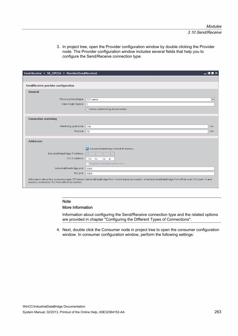
Modules 3.10 Send/Receive
WinCC/IndustrialDataBridge Documentation System Manual, 02/2013, Printout of the Online Help, A5E32364152-AA 263
3. In project tree, open the Provider configuration window by double clicking the Provider node. The Provider configuration window includes several fields that help you to configure the Send/Receive connection type.
Note More Information
Information about configuring the Send/Receive connection type and the related options are provided in chapter "Configuring the Different Types of Connections".
4. Next, double click the Consumer node in project tree to open the consumer configuration window. In consumer configuration window, perform the following settings:

Modules 3.10 Send/Receive
WinCC/IndustrialDataBridge Documentation 264 System Manual, 02/2013, Printout of the Online Help, A5E32364152-AA
"OPC Data Access configuration" section
– Browse for OPC Server by clicking the [...] button and select the OPC Server.
The selection of server is supported by an OPC tag browser.
– The node name is automatically displayed in "Node name" text box after selection of the OPC Server.
Note Node name
For local OPC Server, the node name will display as "local host". In case of remote OPC Server, the remote computer name will be displayed after selection of OPC Server on the remote computer. This node name is required for searching the OPC Server from the remote computer.
The OPC tag browser does not display any content if node name is invalid.
Modules 3.10 Send/Receive
WinCC/IndustrialDataBridge Documentation System Manual, 02/2013, Printout of the Online Help, A5E32364152-AA 265
Note
The "OPC Server" and "Node name" fields are provided as editable fields. If the information about OPC Server name and node name is known, you can directly enter the information in the "OPC Server" and "Node name" fields. If the node name / OPC Server name is invalid, there will be no content displayed within the OPC tag browser
"Configuration for bad quality item" section
– In the "Configure a Variable for number of transaction errors" field, click on [...] button and select a tag from the OPC tag browser.
Next, click the button representing "tick mark" to accept the changes. The amount of tags with errors is written with QUALITY=BAD.
– Choose the specific data type by selecting from the drop down list box.
Note OPC tags
Selection of the tag in OPC tag browser displays the corresponding data type in "Data type" field. However, if you remember the name of tag, enter the tag name and data type in the respective fields within "Configuration for bad quality item" section.
"Asynchronous transfer configuration" section
– Enable the check box option "Write asynchronous" for asynchronous writing.
– Enter the permitted number of maximum outstanding write transactions in the text box.
Note Asynchronous transfer
If the "Write asynchronous" check box is enabled, a default value of 10 is set and will be displayed within the "Maximum number of outstanding write transaction" text box. When this check box is disabled, the value will be reset to 0. You can type a value in this text box ranging from 1 - 40.
If the value entered in this text box is not within the range, then an error message is displayed.
Note Asynchronous writing
The Asynchronous transfer configuration is useful to ensure the correctness of the actual data transfer that is happening.
Example: If you have configured the "Maximum number of outstanding write transaction" as 15 and if the data transfer is not happening correctly, after the failure of 15th transaction, a warning message will be displayed in the IDB Runtime Trace view.

Modules 3.10 Send/Receive
WinCC/IndustrialDataBridge Documentation 266 System Manual, 02/2013, Printout of the Online Help, A5E32364152-AA
Performing link settings 1. In project tree, double click the Settings node to open Settings window in the work area.
The Settings window consists of 3 tabs - Transfer options, Connection Mapping & Connections.
2. Within the Transfer options tab, you can configure the transfer behavior settings for Send/Receive as provider.
Enter a time period in the "Update rate" field after which the system checks for whether data is to be transferred.
Note Update rate
For better performance, it is recommended to use an update rate of 1000 ms or 1 sec.

Modules 3.10 Send/Receive
WinCC/IndustrialDataBridge Documentation System Manual, 02/2013, Printout of the Online Help, A5E32364152-AA 267
3. Next, select the type of data transfer:
– Send only changed values
After every update cycle, the value existing within the Update rate is checked. If there is a change in the value, the value will be transferred, else it will be ignored.
– Send always all values
After every update cycle, all the connected column values are transferred from provider to the consumer.
4. The transfer behavior settings for provider will be saved automatically.
Note Saving Changes
A save operation is not required every time whenever changes are performed within the editor window in the work area. The changes made to these settings are automatically saved. However, once the project is created, at any point of time, you can save the project by selecting the "Project" > "Save" menu option.
Results You have created a connection between the Send/Receive interface and OPC Data Access as a consumer. These elements are displayed in the tree structure of the IDB configuration interface. In order to transfer data, connect the provider and consumer tags, as described in chapter "Connecting Tags from a Send/Receive Interface".
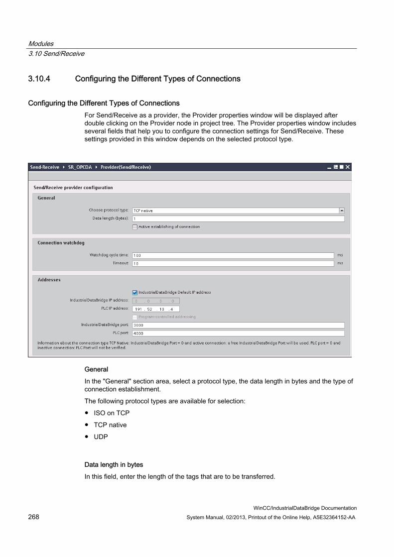
Modules 3.10 Send/Receive
WinCC/IndustrialDataBridge Documentation 268 System Manual, 02/2013, Printout of the Online Help, A5E32364152-AA
3.10.4 Configuring the Different Types of Connections
Configuring the Different Types of Connections For Send/Receive as a provider, the Provider properties window will be displayed after double clicking on the Provider node in project tree. The Provider properties window includes several fields that help you to configure the connection settings for Send/Receive. These settings provided in this window depends on the selected protocol type.
General
In the "General" section area, select a protocol type, the data length in bytes and the type of connection establishment.
The following protocol types are available for selection:
● ISO on TCP
● TCP native
● UDP
Data length in bytes
In this field, enter the length of the tags that are to be transferred.
Modules 3.10 Send/Receive
WinCC/IndustrialDataBridge Documentation System Manual, 02/2013, Printout of the Online Help, A5E32364152-AA 269
Active connection setup
This "Active establishing of connection" check box is used for defining whether IDB actively enables the connection establishment.
Connection watchdog
In the "Connection watchdog" section, define the following parameters in the fields:
● Watchdog cycle time: This refers to the time after which a ping will be set to check for whether the connection to the partner station still exists. Depending on the network load, you should select the monitoring cycle larger (with higher network load) or smaller. This unit needs to be specified in ms.
● Timeout: Maximum response time for a ping before an error is indicated. This unit need to be specified in ms.
Addresses
In the "Addresses" section, enter the connection data for the partner station in the "Addresses" field:
● IndustrialDataBridge IP address: Enter the IP address of the partner station.
The "IndustrialDataBridge IP address" must be configured if the computer has multiple network cards or IP addresses. Otherwise, select the "IndustrialDataBridge Default IP address" selection box.
● PLC IP address: Enter the IP address of PLC device.
Depending on the set protocol, further settings are required:

Modules 3.10 Send/Receive
WinCC/IndustrialDataBridge Documentation 270 System Manual, 02/2013, Printout of the Online Help, A5E32364152-AA
● ISO on TCP TSAP IndustrialDataBridge: Enter the TSAP (Transfer Service Access Point) in ASC format for IDB. Configure the TSAP with a length from 1 to 16 bytes.
TSAP PLC: Enter the TSAP in ASC format for the PLC device. You can configure the TSAP with a length of from 1 to 16 bytes.
● TCP native IndustrialDataBridge Port: Enter the IDB port number. You should set the value for port in the range 2000 to 65534.
PLC Port: Enter the PLC port number. You should set the value for port in the range 2000 to 65534.
● UDP IndustrialDataBridge Port: Enter the IDB port number. You should set the value for the port in a range between 2000 to 65534. PLC Port: Enter the PLC port number. You should set the value for port in the range 2000 to 65534.
If you select the selection box "Program-controlll ed addressing" you can create a free UDP connection. IP address and port for partner station no longer have to be configured but are read from the connection data area. This way, you can change dynamically during runtime. Free UDP connections require a job header in the data area of the connection.
The following graphic shows the structure of the data area and the meaning and positioning of the parameters in the job header.
The picture shows a good example based on the following IP address: 192.168.1.100
For port address 2000, for example, the following must be entered: For the high byte: 7Hex (= 7Dec); for the low byte: D0Hex (= 208Dec)

Modules 3.10 Send/Receive
WinCC/IndustrialDataBridge Documentation System Manual, 02/2013, Printout of the Online Help, A5E32364152-AA 271
Note Occupied Port
With the "TCP native" connection type, the port that should be used might possibly be occupied on the active side. In this case, set the IndustrialDataBridge port to "0" with an active connection.

Modules 3.10 Send/Receive
WinCC/IndustrialDataBridge Documentation 272 System Manual, 02/2013, Printout of the Online Help, A5E32364152-AA
3.10.5 Connecting Tags from a Send/Receive Interface
Connecting Tags In "Settings" window, click on "Connection mapping" tab to connect tags that have been sent from Send/Receive interface with the selected data consumer. The Connection mapping tab divides the window into the following 3 sections:
● Send/Receive provider
● OPC Data Access consumer
● Connection mapping settings
The "Send/Receive provider" section is displayed at top left portion of the "Connection mapping" tab. This section provides you with required options to choose
The "OPC Data Access consumer" is displayed to the left bottom portion of this tab.
Follow the steps given below to connect tags from a Send/Receive interface to OPC Data Access.
1. In "Send/Receive" provider section, enter the start point of the tag in the "First byte" field. You have already entered the data length of the tags in "Send/Receive provider configuration" window.

Modules 3.10 Send/Receive
WinCC/IndustrialDataBridge Documentation System Manual, 02/2013, Printout of the Online Help, A5E32364152-AA 273
The information regarding the fields contained within Send/Receive provider configuration is described in Chapter 3.10.4 "Configuring the Different Types of Connections".
2. Select the respective data type in the "Requested data type" field.
Note Interpret data
The "Interpret as" field will allow selection only if one of the data types Binary String (VT_BSTR) or Date (VT_Date) is selected in "Requested data type field.
3. If you have selected one of the data types Binary String (VT_BSTR) or Date (VT_Date), specify how the incoming data should be interpreted as well:
– Data that is transferred from the data provider as an S7 string or as a byte string is converted to data type VT_BSTR.
– Data that is transferred from the data provider as an S7_Date_and_Time string is converted to data type VT_DATE.
4. If you have selected "OLE/Binary Automation string" as data type in "Requested data type" field, the "Number" field is available for entering a valid number.
Enter a valid number in "Number" field. The permitted range that can be entered within the "Number" text box is any value between 1 to 8192.
5. Configure the consumer tag in the "OPC Data Access consumer" section (bottom left) by following these steps:
– Select a consumer tag from the OPC tag browser in the "OPC Data Access consumer" section.
– The Tag ID and Data type is automatically shown based on selection of OPC tag within the tag browser.
6. Check the name of the connection in the "Connection mapping settings" area (right). Enter a unique name for the connection in the "Connection name" field or use the options within "Default name options". Click "Connect" button to confirm your entries.
7. Repeat steps 2 to 6 for all elements of the data provider that you wish to transfer.
Note BLOB as new data type
If database of type Oracle or MySQL or SQL Server is used as consumer with Send/Receive as provider, in connecting mapping tab, you can select the BLOB data type within the consumer section area. The size of BLOB need to be mentioned in Number field.
As PLC do not support BLOB data type, during Step7 project creation, it is required to select string or character array as data type. In IDB configuration, this can data can be mapped with BLOB type field in Database consumer section area.The size of data depends on supported size of data types provided in Step7 project.

Modules 3.10 Send/Receive
WinCC/IndustrialDataBridge Documentation 274 System Manual, 02/2013, Printout of the Online Help, A5E32364152-AA
Note Array If the provider tag has a data type of array data type and if the consumer column has data
type other than array data type, after clicking on the Connect buton, the "Array" check boxin the "OPC Data Access consumer" is automatically unchecked.
If the Send/Receive provider column has a data type other than array data type and if the OPC Data Access consumer tag has array data type, after clicking on the Connect buton, the "Array" check box in the "OPC Data Access consumer" is automatically checked.
Results The connections that you have created are shown in the "Connections" tab of IDB CS "Settings" window as well as within the project tree node.

Modules 3.10 Send/Receive
WinCC/IndustrialDataBridge Documentation System Manual, 02/2013, Printout of the Online Help, A5E32364152-AA 275
3.10.6 Configuring the Send/Receive Interface as a Consumer
Objective To create a project with corresponding link having Send/Receive as consumer and configure the respective provider/consumer configuration along with transfer behaviour settings.
Creating a link 1. Open IDB Configuration and create a project by following the steps mentioned below:
– In IDB Configuration menu bar, select "Project" > "Create" to create a new project.
– In the "Create new project" dialog box, specify a project name, click [...] button and select the folder location wherever the project needs to be saved.
– After entering the required information, select "Create" button. This creates a new project.
2. The project name will be listed within the "Project tree". The next step is to create a link. Follow the steps mentioned below to create a link between provider and consumer:
– Right click on project name node in the tree structure and select "Add new link" option.
– In the "Add new link" dialog that is displayed, enter a unique link name.
– Select the provider type as OPC Data Access, consumer type as Send/Receive and click OK button.
– The created link will be displayed below the project name in project tree.
– The corresponding entries - Provider, Consumer, Settings and Connections are created as nodes that exist below the new link in the tree structure.
3. In project tree, open the Provider configuration window by double clicking the Provider node.

Modules 3.10 Send/Receive
WinCC/IndustrialDataBridge Documentation 276 System Manual, 02/2013, Printout of the Online Help, A5E32364152-AA
In Provider configuration window, perform the following settings:
– Browse for OPC Server
– Select the node name
4. In project tree, open the Consumer configuration window by double clicking the Consumer node. The Consumer configuration window includes several fields that helps you to configure the Send/Receive connection type.
Note More Information
Information about configuring the Send/Receive connection type and the related options are provided in Chapter 3.10.4 "Configuring the Different Types of Connections".
Performing link settings 1. In project tree, double click the Settings node to open Settings window in the work area.
The Settings window consists of 3 tabs - Transfer options, Connection Mapping & Connections.

Modules 3.10 Send/Receive
WinCC/IndustrialDataBridge Documentation System Manual, 02/2013, Printout of the Online Help, A5E32364152-AA 277
2. Within the Transfer options tab, you can configure the transfer behavior settings for provider.
Enter a time period in the "Update rate" field after which the system checks for whether data is to be transferred.
NoteUpdate rate
For better performance, it is recommended to use an update rate of 1000 ms or 1 sec.

Modules 3.10 Send/Receive
WinCC/IndustrialDataBridge Documentation 278 System Manual, 02/2013, Printout of the Online Help, A5E32364152-AA
3. Next, select the type of data transfer:
– Send only changed values
Data is transferred whenever the configured tag value changes. If a threshold value is configured in the "Deadband" field and if the selected OPC Server supports deadband, then data transfer happens only upon data change exceeding the dead band value specified. Dead band value should be within 0 - 100.
– Send always all values
After every update cycle, the data of all tags of the provider, which you have connected with the consumer, will be transferred.
– Send values using trigger
After every update cycle, a selected tag of the OPC Server is checked to see if it has reached a trigger value. In this case, all values are transferred.
Note "Send only changed values" data transfer
If the deadband value is configured and the selected OPC Server does not support deadband, a value of 0% is set and any change in the value will be considered for data transfer. Data transfer of this type is independent of "Update rate".
Note Deadband
All OPC Servers do not support deadband. This is dependent on the OPC Server being used. The "Deadband value (%)" text box is enabled only with the data transfer types - "Send only changed values" and "Send always all values". This text box is disabled while you select the transfer type "Send values using trigger".
4. Enter the deadband value (in percent) to contain a value within the range 0 - 100.
5. In "Item for Transaction Security" field, click [...] button and select a tag of OPC Server from the OPC tag browser.
You can define an OPC tag on an OPC server, in which the success-/failure-status of the data transfer will be stored in the "Item for transaction security" field.This value should have 1 byte signed char (e.g. VT_I1). -1 indicates the success state and 0 indicates failure.
Modules 3.10 Send/Receive
WinCC/IndustrialDataBridge Documentation System Manual, 02/2013, Printout of the Online Help, A5E32364152-AA 279
6. If you have selected the option "Send values using trigger", you can configure the trigger that provides options to set the trigger options. The "Trigger settings" section is enabled only with the data transfer type "Send values using trigger".
Perform the following settings in the "Trigger settings" section:
– In "Trigger tag" field, select the tag that should trigger a data transfer. Click on [...] button to select the tag from OPC tag browser.
– Select a valid data type by selecting from the drop down list.
– Enter a threshold at which a data transfer should be triggered, in the "Trigger value" field.
– In "Confirmation value" field, enter a value that the trigger tag should take on after triggering.
The confirmation value does not give any information on whether a transaction has been completed successfully.
7. The transfer behavior settings for OPC DataAccess as provider will be saved automatically.
Note Saving Changes
A save operation is not required every time whenever changes are performed within the editor window in the work area. The changes made to these settings are automatically saved. However, once the project is created, at any point of time, you can save the project by selecting the "Project" > "Save" menu option.
Results You have created a connection between the OPC Data Access interface and Send/Receive as a consumer. These elements are displayed in the tree structure of the IDB configuration interface. In order to transfer data, connect the provider and consumer tags, as described in chapter "Connecting Tags to a Send/Receive".

Modules 3.10 Send/Receive
WinCC/IndustrialDataBridge Documentation 280 System Manual, 02/2013, Printout of the Online Help, A5E32364152-AA
3.10.7 Connecting Tags to a Send/Receive Interface
Connecting Tags In "Settings" window, click on "Connection Mapping" tab to connect tags that have been sent from selected data provider with the Send/Receive interface. The Connection mapping tab divides the window into the following 3 sections:
● OPC Data Access provider
● Send/Receive consumer
● Connection mapping settings
The "OPC Data Access provider" is displayed to the top left portion of this tab. The "Send/Receive consumer" section is displayed at bottom left portion of the "Connection mapping" tab.
Follow the steps given below to connect tags from OPC Data Access to Send/Receive interface.
1. In "OPC Data Access provider" area, navigate to OPC tag browser and select an OPC tag.
2. The Tag ID and data type is automatically shown based on selection of OPC tag.
Modules 3.10 Send/Receive
WinCC/IndustrialDataBridge Documentation System Manual, 02/2013, Printout of the Online Help, A5E32364152-AA 281
3. In "Send/Receive consumer" area (bottom left), enter the start point of the tag in the "First byte" field.
4. Select the respective data type in the "Requested data type" field.
Note Interpret data
The "Interpret as" field will allow selection only if one of the data types Binary String (VT_BSTR) or Date (VT_Date) is selected in "Requested data type field.
5. If you have selected one of the data types Binary String (VT_BSTR) or Date (VT_Date), specify how the incoming data should be interpreted as well:
– Data that is transferred from the data provider as an S7 string or as a byte string is converted to data type VT_BSTR.
– Data that is transferred from the data provider as an S7_Date_and_Time string is converted to data type VT_DATE.
6. If you have selected "OLE/Binary Automation string" as data type in "Requested data type" field, the "Number" field is available for entering a valid number.
Enter a valid number in "Number" field. The permitted range that can be entered within the "Number" text box is any value between 1 to 8192.
7. Check the name of the connection in the "Connection mapping settings" area (right). Enter a unique name for the connection in the "Connection name" field or use the options within "Default name options". Click "Connect" button to confirm your entries.
8. Repeat steps 1 to 7 for all elements of the data source that you wish to transfer.
Note BLOB as new data type
If database of type Oracle or MySQL or SQL Server is used as provider with Send/Receive as consumer, in connecting mapping tab, you can select the BLOB data type within the provider section area. The size of BLOB need to be mentioned in Number field.
As PLC do not support BLOB data type, during Step7 project creation, it is required to select string or character array as data type. In IDB configuration, this can data can be mapped with BLOB type field in Database provider section area.The size of data depends on supported size of data types provided in Step7 project.
Note Array If the provider tag has a data type of array data type and if the consumer column has data
type other than array data type, after clicking on the Connect buton, the "Array" check box in the "OPC Data Access provider" is automatically unchecked.
If the OPC Data Access provider column has a data type other than array data type and if the Send/Receive consumer tag has array data type, after clicking on the Connect buton, the "Array" check box in the "Send/Receive consumer" is automatically checked.

Modules 3.10 Send/Receive
WinCC/IndustrialDataBridge Documentation 282 System Manual, 02/2013, Printout of the Online Help, A5E32364152-AA
Results The connections that you have created are shown in the "Connections" tab of IDB CS "Settings" window as well as within the project tree node.
Modules 3.11 WinCC User Archive
WinCC/IndustrialDataBridge Documentation System Manual, 02/2013, Printout of the Online Help, A5E32364152-AA 283
3.11 WinCC User Archive
3.11.1 Overview
Introduction The "WinCC User Archive" module enables read and write access to the archive database of the WinCC project. The functionality is similar to the module for dynamic databases. As a consumer, there is also the possibility of deleting data in a WinCC User Archive.
Note Important Notes for Configuring the Different Databases For access to an MS SQL Server and MS Access, the Microsoft Data Access
Components 2.8 (MDAC 2.8) must be installed (http://www.microsoft.com/data/). Using data type VT_I8 as a trigger tag (values transferred upon event) in the database
provider is not approved. The character "?" (VT_BSTR) cannot be written in a field with field data type "char" or
"varchar" with the SQL server (in the Runtime interface, a respective error message is output).
The time stamp must be assigned before connecting the first tags. Afterwards, adding or changing the time stamp is only possible if all items are deleted, the dialog is closed and reopened again. The time stamp is generated from the local time, if new data is transferred from the provider.
A table name is not to contain any spaces, otherwise problems can occur in the transfer.

Modules 3.11 WinCC User Archive
WinCC/IndustrialDataBridge Documentation 284 System Manual, 02/2013, Printout of the Online Help, A5E32364152-AA
3.11.2 Configuring the Interface to WinCC User Archives as a Provider
Objective To create a project with corresponding link having WinCC User Archive as provider and configure the respective provider/consumer connection configuration along with transfer behavior settings.
Creating a link 1. Open IDB Configuration and create a project by following the steps mentioned below:
– In IDB Configuration menu, select "Project" > "Create" to create a new project.
– In the "Create new project" dialog box, specify a project name, click [...] button and select the folder location wherever the project needs to be saved.
– After entering the required information, select "Create" button. This creates a new project.
2. The project name will be listed within the "Project tree". The next step is to create a link. Follow the steps mentioned below to create a link between provider and consumer:
– Right click on project name node in the tree structure and select "Add new link" option.
– In the "Add new link" dialog that is displayed, enter a unique link name.
– Select the provider type as WinCC User Archive, consumer type as Database and click OK button.
– The created link will be displayed below the project name in project tree.
– The corresponding entries - Provider, Consumer, Settt ings and Connections are created as nodes that exist below the new link in the tree structure.
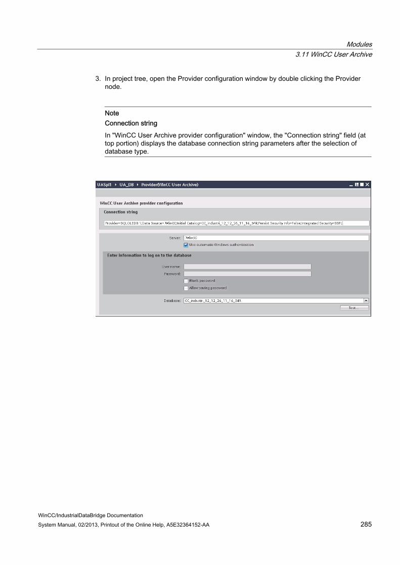
Modules 3.11 WinCC User Archive
WinCC/IndustrialDataBridge Documentation System Manual, 02/2013, Printout of the Online Help, A5E32364152-AA 285
3. In project tree, open the Provider configuration window by double clicking the Provider node.
NoteConnection string
In "WinCC User Archive provider configuration" window, the "Connection string" field (at top portion) displays the database connection string parameters after the selection of database type.

Modules 3.11 WinCC User Archive
WinCC/IndustrialDataBridge Documentation 286 System Manual, 02/2013, Printout of the Online Help, A5E32364152-AA
In WinCC User Archive provider configuration window, perform the following settings:
– Enter the server name and/or complete path of WinCC User Archive database.
– Select the database name from the list that is displayed in the "Database" field. Click on the drop down list box to view this list.
– If you wish to enable windows authentication automatically, select the check box "Use automatic Windows authentication".
– Within the section area that provides options to logon to the database, enter the user name and password.
This information is required to logon to the WinCC User Archive database.
– Click Test button to test the connection.
Note User Archive
Ensure that you enter the complete path of the computer wherever WinCC has been installed. If the path name is not valid, then the "Database" field will not display any tables. Also, it is important to verify that the user archive table contains one or more rows of data.
4. Next, double click the Consumer node in project tree. In Consumer configuration window, perform the following settings:

Modules 3.11 WinCC User Archive
WinCC/IndustrialDataBridge Documentation System Manual, 02/2013, Printout of the Online Help, A5E32364152-AA 287
"Database consumer configuration" section
– Select the type of database by choosing the appropriate radio button.
– If the database exists on a server location, enter the server name in "Server" field.
If you wish to enable windows authentication automatically, select the check box "Use automatic windows authentication".
– In "Database" field, click on [...] button and select the database from the list or from the folder structure.

Modules 3.11 WinCC User Archive
WinCC/IndustrialDataBridge Documentation 288 System Manual, 02/2013, Printout of the Online Help, A5E32364152-AA
Note Server name
The "Server" field for entering the Server name, "Use automatic windows authentication" check box and the fields for entering the logon information are enabled only if you have selected a database other than Microsoft Access.
– If a user name and password has been set for the database, enter the user name and password in the "User name" and "Password" fields respectively.
If you wish to set a blank password, enable the check box "Blank password". To save the entered password, enable the check box "Allow saving password".
– Click Test button to test the connection. The application tests the database connection string and verifies the selected database.
"Consumer type configuration" section
– Select the "Consumer type" by selecting from the list. More information about the consumer types are provided in detail in chapter 3.6.7, "Consumer Types".
– Choose the "Transaction type" - Stored procedure or Prepared insert statement and select table name and schema.
Note Transaction type
The Stored procedure or Prepared insert statement transaction type options are in enable state only when the consumer type "One data record per call - command set" is selected and if you have selected a database other than Microsoft access. By default, the Prepared insert statement option is automatically selected. Only the "Table" field is enabled if Microsoft access is selected as the database type
and consumer type is selected as "One data record per call - command set". Select the table name by clicking on the drop down list box.
If you have selected a database type other than Microsoft access and the consumer type is selected as "One data record per call - command set", then all the fields within the Transaction type will be in enable state.
Performing link settings 1. In project tree, double click the Settings node to open Settings window in the work area.
The Settings window consists of 3 tabs - Transfer options, Connection Mapping & Connections.
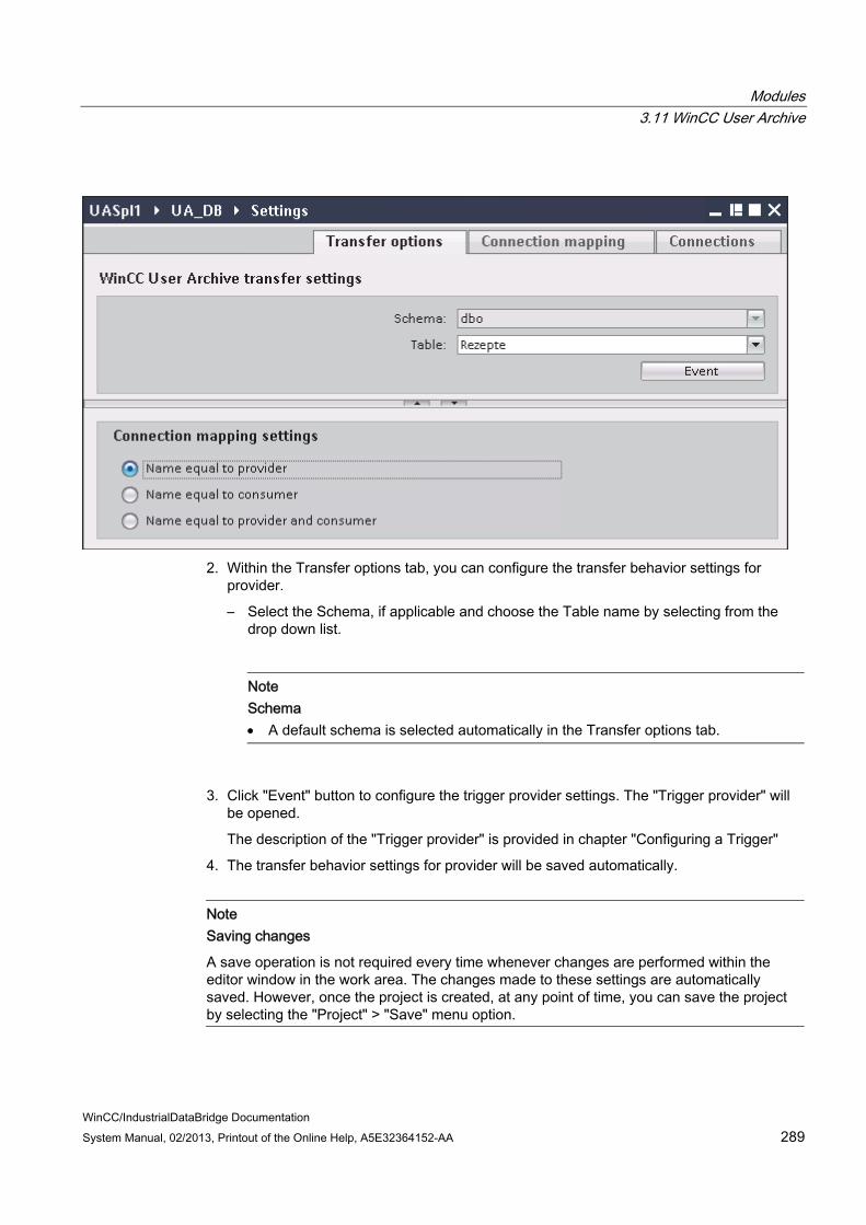
Modules 3.11 WinCC User Archive
WinCC/IndustrialDataBridge Documentation System Manual, 02/2013, Printout of the Online Help, A5E32364152-AA 289
2. Within the Transfer options tab, you can configure the transfer behavior settings for provider.
– Select the Schema, if applicable and choose the Table name by selecting from the drop down list.
Note Schema A default schema is selected automatically in the Transfer options tab.
3. Click "Event" button to configure the trigger provider settings. The "Trigger provider" will be opened.
The description of the "Trigger provider" is provided in chapter "Configuring a Trigger"
4. The transfer behavior settings for provider will be saved automatically.
Note Saving changes
A save operation is not required every time whenever changes are performed within the editor window in the work area. The changes made to these settings are automatically saved. However, once the project is created, at any point of time, you can save the project by selecting the "Project" > "Save" menu option.

Modules 3.11 WinCC User Archive
WinCC/IndustrialDataBridge Documentation 290 System Manual, 02/2013, Printout of the Online Help, A5E32364152-AA
Results You have configured the WinCC User Archive interface and a consumer including the provider transfer options. These elements are displayed in the tree structure of the IDB configuration interface. In order to transfer data, connect the provider and consumer tags, as described in chapter "Connecting Tags from the WinCC User Archives Interface".

Modules 3.11 WinCC User Archive
WinCC/IndustrialDataBridge Documentation System Manual, 02/2013, Printout of the Online Help, A5E32364152-AA 291
3.11.3 Configuring a Trigger
Introduction The "Trigger Provider" dialog window provides the OPC settings, Trigger configuration options and required fields that help you to configure the condition that triggers a data transfer. This dialog window is opened after clicking the "Trigger" button in Transfer optionswindow.
Note OPC tag browser
The OPC tags within "Trigger configuration" section will only be displayed if you have already selected the name of the OPC Server.

Modules 3.11 WinCC User Archive
WinCC/IndustrialDataBridge Documentation 292 System Manual, 02/2013, Printout of the Online Help, A5E32364152-AA
Procedure 1. In "OPC settings" area, select the OPC server by clicking on the [...] button. The selection
of the server is supported by an OPC tag browser. Next, click the button representing "tick mark" to accept the changes.

Modules 3.11 WinCC User Archive
WinCC/IndustrialDataBridge Documentation System Manual, 02/2013, Printout of the Online Help, A5E32364152-AA 293
2. The "Node name" is automatically displayed in "Node name" text box after selection of the OPC Server.
Note Node name
For local OPC Server, the node name will display as "local host". In case of remote OPC Server, the remote computer name will be displayed after selection of OPC Server on the remote computer. This "Node name" is required for searching the OPC Server from the remote computer.
The OPC tag browser does not display any content if node name is invalid.
Note
The "OPC Server" and "Node name" fields are provided as editable fields.
If the information about OPC Server name and node name is known, you can directly enter the information in the "OPC Server" and "Node name" fields. If the node name / OPC Server name is invalid, there will be no content displayed within the OPC tag browser.
3. You can define an OPC tag on the trigger provider, in which the success-/failure-status of the data transfer will be stored in the "Tag for transaction security" field. This value should have 1 byte signed char (e.g. VT_I1). -1 indicates the success state and 0 indicates failure. Select the tag of the OPC server, in which this information is to be saved in the tag browser and click on the "Apply item" button.
4. The tree structure of OPC server is displayed within "Trigger Configuration" area.
5. In "Trigger Configuration" area, select the desired tags individually and accept them by clicking on "Add item" each time.
The selected tags are shown in the table below the tag browser that displays the tag list.

Modules 3.11 WinCC User Archive
WinCC/IndustrialDataBridge Documentation 294 System Manual, 02/2013, Printout of the Online Help, A5E32364152-AA
6. Use the "Remove item" button to remove the marked item. If no item is marked for deletion, the last item from the list is deleted if you click the "Remove item" button. Details about the columns in the Tag list are located in section "Tag declaration".
Note OPC Server
After selection of the tags and adding them to tag list, if you switch to another OPC Server in OPC Settings area, a dialog window is displayed that prompts the message whether you wish to discard previous settings.
7. In "Trigger condition" area, you can select the type of syntax with selection button "VB Style" or JScript Style". If a trigger condition is already created, this setting can no longer be changed. If the language is to be changed, the text in the "Configure Trigger Condition" field must be deleted.
Details on the programming languages are located in section "Programming Languages".
8. Create the trigger condition in the selected language. Use the Alias designations in the tag list for these tags. Within the text box displayed, enter the operator symbols using the keyboard or select them from the "Logical patterns" list box.
9. Test the created condition by clicking on "Validate". The trigger condition is calculated with the values that are entered in the "Test value" column. The result "TRUE" or "FALSE" is shown in a message box.
10. If the trigger condition provides the correct result and after confirming the changes, close the dialog by clicking on "OK" button.
Additional Information
Tag declaration
The columns for the tag declaration contain the following:
● Data type: Data type of the tag. If the data type defined here does not match that on the server, an attempt to convert the data type is made.
● TagID: The TagID of the tag on the OPC server
● Alias: The alias is used for creating the trigger condition. This name must be unique and it must correspond with the naming conventions of the allocated programming languages. For more detailed information about the naming conventions, see paragraph "Valid alias names".
● Confirmation value: The confirmation value is the value that the variable takes on after fulfilling the trigger condition and the values have been delivered to the consumer. The default value is "<Empty>", i.e., no confirmation value is written.
● Test value: This value is only for testing the trigger condition and has no influence on the later data exchange. The test values are to be selected and changed so that they test whether the trigger condition delivers the expected result in all operating conditions.
Modules 3.11 WinCC User Archive
WinCC/IndustrialDataBridge Documentation System Manual, 02/2013, Printout of the Online Help, A5E32364152-AA 295
NoteConfirmation value
The confirmation value does not give any information on whether a transaction has been completed successfully.
Note Necessity of Alias Names
The OPC TagID is not used because it may possibly not correspond with the tag validity criteria, for instance, a "Point" in the tag name is not allowed.
Valid Alias Names:
A valid alias must correspond with the following rules:
● Letters (no umlaut characters or ß), numbers and underscore character (_) are allowed.
● The first character must be a letter or underscore.
● An alias can be as long as you require.
● Key words from VB script or J script are not allowed. Note the respective language description for this.
● Case sensitive (upper and lower case letters). ("tag" is not the same as "Tag").
Programming languages
You can use VBScript or JScript for the trigger condition.
The following table shows the operator type and their symbols in both languages:
Type VBScript JScript Logical NOT NOT ! Logical AND AND && Logical OR OR || multiplication * * division / / addition + + subtraction - - Not equal to <> != Less than < < Greater than > >

Modules 3.11 WinCC User Archive
WinCC/IndustrialDataBridge Documentation 296 System Manual, 02/2013, Printout of the Online Help, A5E32364152-AA
Type VBScript JScript Comparison = == Assignment <not possible> = True true or True true Incorrect false or False false string <Quotation Marks> <Quotation Marks>
It is recommended to use these operators only. Other operators can be found in the language descriptions for the respective language.
Note Loss of Trigger Events
The triggering depends on the update speed of the OPC server. In this case, note that data changes that occur within an update cycle are not considered by the trigger. That means that a faster change of a tag from 1 - 0 - 1 is not necessarily indicated to the trigger provider by the OPC server, since the 1 exists at the end again and no value change exists at the check time. This means that a potentially true condition is not recognized as being true and therefore will not lead to a data transfer.
Configurations, with which the confirmation value is to set a "true" trigger condition to "false" again, are not secure because of the statement above. When data changes occur too quickly, the "true value" may stay the same or values can be left out.

Modules 3.11 WinCC User Archive
WinCC/IndustrialDataBridge Documentation System Manual, 02/2013, Printout of the Online Help, A5E32364152-AA 297
3.11.4 Connecting Tags from the WinCC User Archives Interface
Connecting Tags In "Settings" window, the "Connection mapping" tab includes the required fields to connect tags that have been sent from the WinCC User Archives interface with the selected consumer. The Connection mapping tab divides the window into 3 sections
● WinCC User Archive Provider
● Database consumer
● Connection mapping settings
The "WinCC User Archive provider" section is displayed at top left portion of "Connection mapping" tab. This section provides you with required options to choose schema, table name and column names to be mapped. The "Database consumer" section exists below the provider section and lists the column values that can be mapped with the columns existing within WinCC User Archive database.
Note Consumer types
The fields displayed within "Database consumer" section depends on the "Consumer type" that you have selected in Consumer configuration window. In this case, the consumer type "One data record per call - recordset" is used.

Modules 3.11 WinCC User Archive
WinCC/IndustrialDataBridge Documentation 298 System Manual, 02/2013, Printout of the Online Help, A5E32364152-AA
The separator between the provider and consumer section provides a resize handle that helps you to resize the height of the section in order to view the fields within the section clearly.
The "Connection mapping settings" section is displayed at right side of "Connection mapping" tab. This section helps you to provide a name for connection along with options for choosing default name for connection. The "Connect", "Modify connection", "Delete connection" and "Delete all connections" icons are provided at the top portion of this section.
Note Connection Mapping tab
To get a clear view of all fields in the sections within the "Connection mapping" tab, it is suggested to use the "Collapse" option within the Inspector window and Project tree. Once you click on "Collapse" icon, the window minimizes and provides with "Expand" option. At any point of time, to bring back the window, click on "Expand" icon.
The "WinCC User Archive provider" section consists of 3 tabs:
● WinCC User Archive
● Where-Statement
● OPC
This chapter covers the aspects related to "WinCC User Archive" and "Where-Statement" tabs. Also, the steps to be performed to have a connection mapping between provider and consumer are provided within this chapter.
Note Select OPC server
In order to configure the settings on the "Where Statement" tab, you must have selected an OPC server in the dialog "Config Trigger Provider". This dialog window is accessed by clicking on the "Event" button in "Transfer options" tab.
WinCC User Archive
1. In "WinCC User Archive provider", the selected archive is shown in the "Table" field. Select the Schema for database if applicable by selecting from the drop down list in "Schema" field.
2. The Column names are displayed within "Columns" area. Select a Column name from the list. The selected column is displayed in "Column for data value" field. The data type is shown automatically.

Modules 3.11 WinCC User Archive
WinCC/IndustrialDataBridge Documentation System Manual, 02/2013, Printout of the Online Help, A5E32364152-AA 299
3. The "Filter" field provides you the option to filter the Column names based on single character or first few characters of column name.
For example, if you wish to view the column names starting with "S", type this character in "Filter" text box. All column names starting with "S" are displayed.
4. Next, configure the consumer column in the "Config database consumer" section by following these steps:
– The selected table is shown in the "Table" field. Select the Schema for database if applicable by selecting from the drop down list in "Schema" field.
– The column names are displayed within "Columns" area. If the table has columns with respective data types, the time stamp can also be written to the table. In this case, select the respective "Active" check box and select the column within "Column for timestamp" field.
5. Select the Column name in "Database consumer" that you wish to connect with "WinCC User Archive Provider" column name. The data type of selected column will be automatically displayed in the "Datatype" field.
The selected column is displayed in "Column for data value" field.
Note Data type conversion
If the provider tag data type does not match with consumer column, IDB CS converts the data type to match with data type of provider tag. A status window is displayed to indicate this change.
6. Check the name of the connection in the "Connection mapping settings" area to the right. Enter a unique name for the connection in the "Connection name" field or use the options within "Default name options". Click "Connect" button to confirm your entries.
7. Repeat steps 1 to 5 for all elements of the "WinCC User Archive Provider" that you wish to transfer.
8. The connection name including the provider and consumer data values will be displayed within the "Connection mapping settings" section.The list of connections will be also displayed within the Connections tab as well as in the project tree within the "Connections" node belonging to the specific link.
Note Modifying Consumer type
Once the connection(s) have been created in Connection mapping window and if you wish to modify the Consumer type in Database consumer configuration, the IDB CS application will not allow to change the Consumer type. To change the Consumer type, you need to delete the connection(s) that have been already created. Close the consumer configuration window and re-open the window from the project tree to modify the consumer type.

Modules 3.11 WinCC User Archive
WinCC/IndustrialDataBridge Documentation 300 System Manual, 02/2013, Printout of the Online Help, A5E32364152-AA
Where Statement
The SQL String that describes the access location for reading the data is shown on this tab. The "Where-statement" tab mainly includes the "WHERE" section and text area for displaying the "Resulting SQL-String".
Follow the steps given below to configure the Where statement:
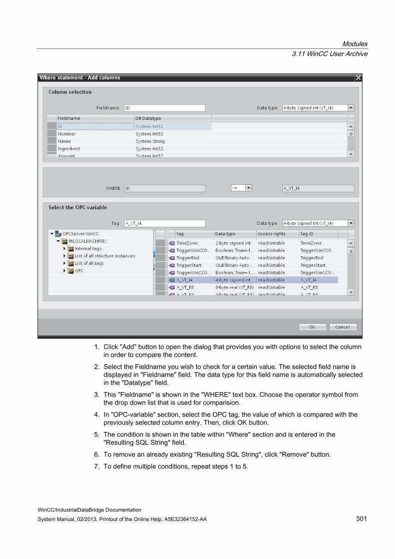
Modules 3.11 WinCC User Archive
WinCC/IndustrialDataBridge Documentation System Manual, 02/2013, Printout of the Online Help, A5E32364152-AA 301
1. Click "Add" button to open the dialog that provides you with options to select the column in order to compare the content.
2. Select the Fieldname you wish to check for a certain value. The selected field name is displayed in "Fieldname" field. The data type for this field name is automatically selected in the "Datatype" field.
3. This "Fieldname" is shown in the "WHERE" text box. Choose the operator symbol from the drop down list that is used for comparision.
4. In "OPC-variable" section, select the OPC tag, the value of which is compared with the previously selected column entry. Then, click OK button.
5. The condition is shown in the table within "Where" section and is entered in the "Resulting SQL String" field.
6. To remove an already existing "Resulting SQL String", click "Remove" button.
7. To define multiple conditions, repeat steps 1 to 5.
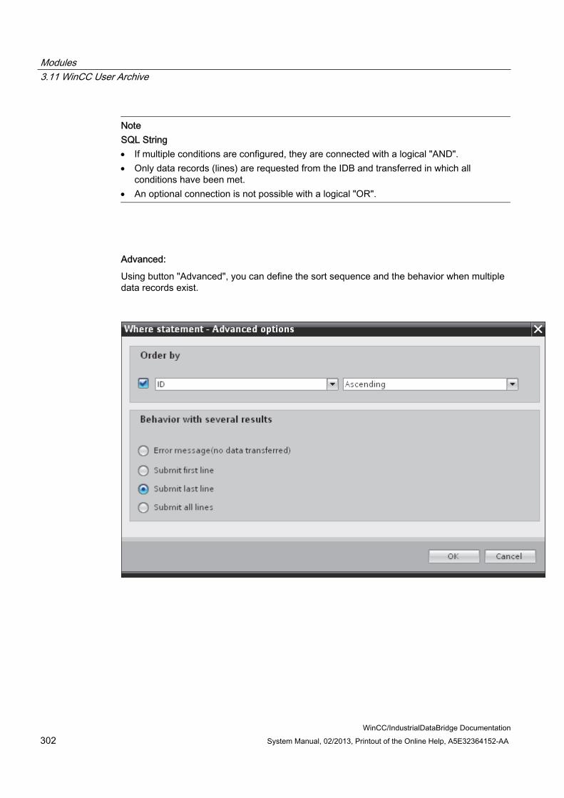
Modules 3.11 WinCC User Archive
WinCC/IndustrialDataBridge Documentation 302 System Manual, 02/2013, Printout of the Online Help, A5E32364152-AA
Note SQL String If multiple conditions are configured, they are connected with a logical "AND". Only data records (lines) are requested from the IDB and transferred in which all
conditions have been met. An optional connection is not possible with a logical "OR".
Advanced:
Using button "Advanced", you can define the sort sequence and the behavior when multiple data records exist.

Modules 3.11 WinCC User Archive
WinCC/IndustrialDataBridge Documentation System Manual, 02/2013, Printout of the Online Help, A5E32364152-AA 303
● Order By Select the selection field. You can then define the column name and the sort direction.
● Behavior with several results: Select one of the following option fields and click OK button. Based on selected radio button, you can decide the action to be performed:
– Error message (no data transferred)
– Submit first line
– Submit last line
– Submit all lines
Standard settings for these options are:
● No sorting
● Error message (no data transferred)
Results The connections that you have created are shown in the "Connections" tab of IDB CS "Settings" window as well as within the project tree node.

Modules 3.11 WinCC User Archive
WinCC/IndustrialDataBridge Documentation 304 System Manual, 02/2013, Printout of the Online Help, A5E32364152-AA
3.11.5 Connecting OPC Tags from the WinCC User Archives Interface
Connecting Tags In "Connection mapping" tab, "WinCC User Archive Provider" section (displayed at top left portion) includes the following 3 tabs:
● WinCC User Archive provider
● Where Statement
● OPC
This chapter covers the aspects related to OPC tab.
The "OPC" tab includes options to connect OPC tags that have been sent from the WinCC User Archives interface with the selected data consumer.
Note Select OPC server
In order to configure the settings on the "OPC" tab, you must have selected an OPC server in "Trigger provider" window." This dialog window is accessed by clicking on the "Event" button in "Transfer options" tab.

Modules 3.11 WinCC User Archive
WinCC/IndustrialDataBridge Documentation System Manual, 02/2013, Printout of the Online Help, A5E32364152-AA 305
1. In the "WinCC User Archive Provider" area, within the OPC tab, the OPC tag browser is displayed. In tag browser, select the tag for which the values should be transferred. The selected tag is shown in the "Tag ID" field. The data type is chosen according to the selection.
2. If the selected tag has Array data type, then the "Array" check box is automatically enabled. This check box is provided below the "Datatype" field.
3. Next, configure the consumer column in the "Database consumer" section by following these steps:
– The selected table is shown in the "Table" field. Select the Schema if applicable by selecting from the drop down list in "Schema" text box.
– The column names are displayed within "Columns" area. If the table has columns with respective data types, the time stamp can also be written to the table. In this case, select the respective "Active" check box and select the column within "Column for timestamp" field.
4. Select the Column name that you wish to connect with the OPC tag. The selected column is displayed in "Column for data value" field.
5. Check the name of the connection in the "Connection mapping settings" area to the right. Enter a unique name for the connection in the "Connection name" field or use the options within "Default name options". Click "Connect" button to confirm your entries.

Modules 3.11 WinCC User Archive
WinCC/IndustrialDataBridge Documentation 306 System Manual, 02/2013, Printout of the Online Help, A5E32364152-AA
6. Repeat steps 1 to 5 for all elements of the "WinCC User Archive Provider" that you wish to transfer.
7. The connection name including the provider and consumer data values will be displayed within the "Connection mapping settings" section.The list of connections will be also displayed within the Connections tab as well as in the project tree within the "Connections" node belonging to the specific link.
Note Array
If the provider tag has a data type of array data type and if the database consumer column has data type other than array data type, after clicking on the Connect buton, the "Array" check box in the "OPC tab" is automatically unchecked.
Results The connections that you have created are shown in the "Connections" tab of IDB CS "Settings" window as well as within the project tree node.

Modules 3.11 WinCC User Archive
WinCC/IndustrialDataBridge Documentation System Manual, 02/2013, Printout of the Online Help, A5E32364152-AA 307
3.11.6 Configuring the Interface to WinCC User Archives as a Consumer
Objective To create a project with corresponding link having WinCC User Archive as consumer and configure the respective provider/consumer configuration along with transfer behaviour settings.
Creating a link 1. Open IDB Configuration and create a project by following the steps mentioned below:
– In IDB Configuration menu, select "Project" > "Create" to create a new project.
– In the "Create new project" dialog box, specify a project name, click [...] button and select the folder location wherever the project needs to be saved.
– After entering the required information, select "Create" button. This creates a new project.
2. The project name will be listed within the "Project tree". The next step is to create a link. Follow the steps mentioned below to create a link between provider and consumer:
– Right click on project name node in the tree structure and select "Add new link" option.
– In the "Add new link" dialog that is displayed, enter a unique link name.
– Select the provider type as Database, consumer type as WinCC User Archive and click OK button.
– The created link will be displayed below the project name in project tree.
– The corresponding entries - Provider, Consumer, Settt ings and Connections are created as nodes that exist below the new link in the tree structure.
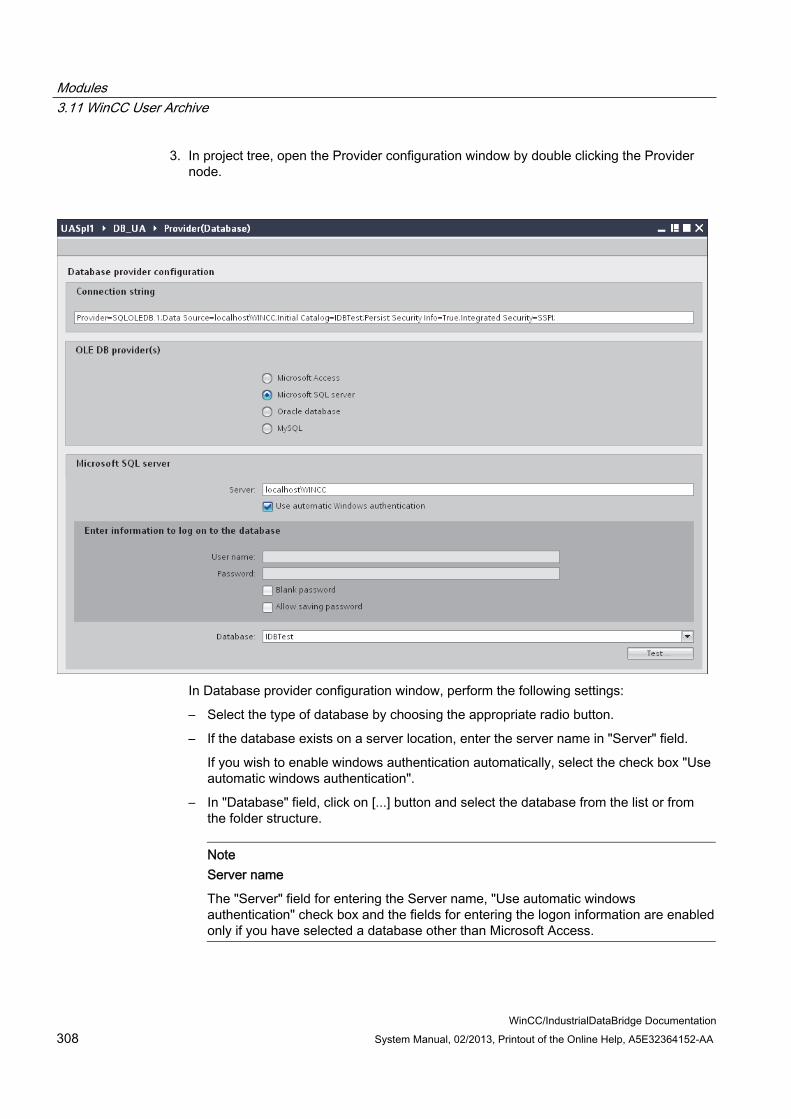
Modules 3.11 WinCC User Archive
WinCC/IndustrialDataBridge Documentation 308 System Manual, 02/2013, Printout of the Online Help, A5E32364152-AA
3. In project tree, open the Provider configuration window by double clicking the Provider node.
In Database provider configuration window, perform the following settings:
– Select the type of database by choosing the appropriate radio button.
– If the database exists on a server location, enter the server name in "Server" field.
If you wish to enable windows authentication automatically, select the check box "Use automatic windows authentication".
– In "Database" field, click on [...] button and select the database from the list or from the folder structure.
Note Server name
The "Server" field for entering the Server name, "Use automatic windows authentication" check box and the fields for entering the logon information are enabled only if you have selected a database other than Microsoft Access.
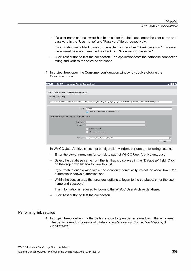
Modules 3.11 WinCC User Archive
WinCC/IndustrialDataBridge Documentation System Manual, 02/2013, Printout of the Online Help, A5E32364152-AA 309
– If a user name and password has been set for the database, enter the user name and password in the "User name" and "Password" fields respectively.
If you wish to set a blank password, enable the check box "Blank password". To save the entered password, enable the check box "Allow saving password".
– Click Test button to test the connection. The application tests the database connection string and verifies the selected database.
4. In project tree, open the Consumer configuration window by double clicking the Consumer node.
In WinCC User Archive consumer configuration window, perform the following settings:
– Enter the server name and/or complete path of WinCC User Archive database.
– Select the database name from the list that is displayed in the "Database" field. Click on the drop down list box to view this list.
– If you wish to enable windows authentication automatically, select the check box "Use automatic windows authentication".
– Within the section area that provides options to logon to the database, enter the user name and password.
This information is required to logon to the WinCC User Archive database.
– Click Test button to test the connection.
Performing link settings 1. In project tree, double click the Settings node to open Settings window in the work area.
The Settings window consists of 3 tabs - Transfer options, Connection Mapping & Connections.

Modules 3.11 WinCC User Archive
WinCC/IndustrialDataBridge Documentation 310 System Manual, 02/2013, Printout of the Online Help, A5E32364152-AA

Modules 3.11 WinCC User Archive
WinCC/IndustrialDataBridge Documentation System Manual, 02/2013, Printout of the Online Help, A5E32364152-AA 311
2. Within the Transfer options tab, you can configure the transfer behavior settings for provider.
"Provider settings" section
– Select the Schema, if applicable and choose the Table name by selecting from the drop down list.
– Enter a time period in the "Update rate" field after which the system checks for whether data is to be transferred.
Note Selecting Schema If you are using a database other than Microsoft Access, selection of Schema is
mandatory before choosing the Table name. While using Microsoft Access as database, the "Schema" field is displayed in
disable state and does not allow any selection of Schema.
Note Update rate
For better performance, it is recommended to use an update rate of 1000 ms or 1 sec.
3. Next, select the type of data transfer:
– Send only changed values
After every update cycle, the value existing within the Update rate is checked. If there is a change in the value, the value will be transferred, else it will be ignored.
– Send always all values
After every update cycle, all the connected column values are transferred from provider to the consumer.
– Send values using trigger
After every update cycle, the trigger condition is verified. If the trigger condition is met, then the data is transferred.

Modules 3.11 WinCC User Archive
WinCC/IndustrialDataBridge Documentation 312 System Manual, 02/2013, Printout of the Online Help, A5E32364152-AA
4. If you have selected the option "Send values using trigger", you can configure the trigger. The "Trigger settings" section is enabled only if the data transfer type "Send values using trigger" is selected.
Perform the following settings in the "Trigger settings" section:
– In the Schema field, choose a valid schema by selecting the drop down list.
– Choose a table name by selecting from the drop down list.
– In Column field, select the specific column that needs to be used for the trigger condition.
– Choose a valid data type by selecting from the drop down list.
– Enter a threshold at which a data transfer should be triggered, in the "Trigger value" field.
– In "Confirmation value" field, enter a value that the trigger tag should take on after triggering.
The Confirmation value does not give any information whether a transaction has been completed successfully.
5. The transfer behavior settings for provider will be saved automatically.
Note Saving changes
A save operation is not required every time whenever changes are performed within the editor window in the work area. The changes made to these settings are automatically saved. However, once the project is created, at any point of time, you can save the project by selecting the "Project" > "Save" menu option.
Results You have created a connection between the WinCC User Archives interface and a provider. These elements are displayed in the tree structure of the IDB configuration interface. In order to transfer data, connect the provider and consumer tags, as described in chapter "Connecting Tags to a WinCC User Archives Interface".

Modules 3.11 WinCC User Archive
WinCC/IndustrialDataBridge Documentation System Manual, 02/2013, Printout of the Online Help, A5E32364152-AA 313
3.11.7 Connecting Tags to the WinCC User Archives Interface
Connecting Tags In "Settings" window, the "Connection mapping" tab includes the required fields to connect tags that have been sent from the selected data provider to WinCC User Archives interface. The Connection mapping tab divides the window into 3 sections:
● Database provider
● WinCC User Archive Consumer
● Connection mapping settings
The "Database provider" section is displayed at top left portion of "Connection mapping" tab. This section lists the column values that can be mapped with the columns existing within WinCC User Archive database. The "WinCC User Archive Consumer" section is displayed to bottom left portion of "Connection mapping" tab. This section provides you with required options to choose schema, table name and column names to be mapped.
A specific connection can be created between the Database provider column and the column (belonging to WinCC User Archive consumer) selected in the Where statement tab. You can create a new connection or else modify an existing connection to apply Where statement on the selected column.

Modules 3.11 WinCC User Archive
WinCC/IndustrialDataBridge Documentation 314 System Manual, 02/2013, Printout of the Online Help, A5E32364152-AA
The separator between the provider and consumer section provides a resize handle that helps you to resize the height of the section in order to view the fields within the section clearly.
The "Connection mapping settings" section is displayed at right side of "Connection mapping" tab. This section helps you to provide a name for connection along with options for choosing default name for connection. The "Connect", "Modify connection", "Delete connection" and "Delete all connections" icons are provided at the top position of this section.
Note Connection Mapping tab
To get a clear view of all fields in the sections within the "Connection mapping" tab, it is suggested to use the "Collapse" option within the Inspector window and Project tree. Once you click on "Collapse" icon, the window minimizes and provides with "Expand" option. At any point of time, to bring back the window, click on "Expand" icon.
1. In "Database provider" section, the selected archive is shown in the "Table" field. Select the Schema for database if applicable by selecting from the drop down list in "Schema" field.
2. The Column names are displayed within "Columns" area. Select a Column name from the list. The selected column is displayed in "Column for data value" field. The data type is shown automatically.
3. The "Filter" field provides you the option to filter the Column names based on single character or first few characters of column name.
For example, if you wish to view the column names starting with "S", type this character in "Filter" text box. All column names starting with "S" are displayed.
Note WinCC User Archive consumer
The WinCC User Archive consumer consists of 3 tabs - WinCC User Archive consumer, Where-Statement and Delete Settings.
This chapter covers the aspects related to "WinCC User Archive consumer" and "Where-Statement" tabs.
4. Next, configure the column in the "WinCC User Archive consumer" tab by following these steps:
– The selected table is shown in the "Table" field. Select the Schema for database if applicable by selecting from the drop down list in "Schema" field.
– The column names are displayed within "Columns" area. If the table has columns with respective data types, the time stamp can also be written to the table. In this case, select the respective "Active" check box and select the column within "Column for timestamp" field.

Modules 3.11 WinCC User Archive
WinCC/IndustrialDataBridge Documentation System Manual, 02/2013, Printout of the Online Help, A5E32364152-AA 315
5. Select the Column name that you wish to connect with "Database provider". The selected column is displayed in "Column for data value" field.
Note Data type conversion
If the provider tag data type does not match with consumer column, IDB CS converts the data type to match with data type of provider tag. A status window is displayed to indicate this change.
6. Check the name of the connection in the "Connection mapping settings" area to the right. Enter a unique name for the connection in the "Connection name" field or use the options within "Default name options". Click "Connect" button to confirm your entries.
7. Repeat steps 1 to 6 for all elements of the "Database provider" that you wish to transfer.
8. The connection name including the provider and consumer data values will be displayed within the "Connection mapping settings" section.The list of connections will be also displayed within the Connections tab as well as in the project tree within the "Connections" node belonging to the specific link.
"Where Statement" tab The Where statement is required to be configured in order to select the column within the WinCC User Archive Consumer. The "Where-statement" tab mainly includes the "Where statement" configuration section and exception handling section.
Follow the steps given below to perform a connection mapping:

Modules 3.11 WinCC User Archive
WinCC/IndustrialDataBridge Documentation 316 System Manual, 02/2013, Printout of the Online Help, A5E32364152-AA
1. In the "Database provider" section, at the (top left), select the column for which the where statement (WinCC User Archive consumer) needs to be applied.
2. Upon selection, the column name is displayed in "Column for data value" field. The data type is selected automatically based on selection of column name.
3. In the "Where-column" field, select the column that is to be used for the Where Statement. If a value needs to be written to the database, this column is compared with the connected provider column(s). Only lines in which both values match are updated.
4. The behavior is defined in the "Exceptional handling" section if the selection of the consumer row is not unique:
– Error Message: No consumer rows lines are overwritten and an error message is given as an output in the trace view of IDB Runtime.
– Change all rows: All selected consumer rows are overwritten.
– Using the "Enable Insert" check box, you define the behavior if a line with the key (primary key) does not exist. If the option is selected, a new line with the respective key is created.
Note Simultaneous Utilization as Key and Consumer Column
In order to have more setting ability with the configuration, you can use a column as a key column and as a consumer column simultaneously. Take note that this causes the data in the database to be inconsistent and/or future access to the WinCC User Archive consumer may result in errors.
5. Check the name of the connection in the "Connection mapping settings" area (right). Enter a unique name for the connection in the "Connection name" field or use the options within "Default name options". Click "Connect" button to confirm your entries.
Results The connections that you have created are shown in the "Connections" tab of IDB CS "Settings" window as well as within the project tree node.

Modules 3.11 WinCC User Archive
WinCC/IndustrialDataBridge Documentation System Manual, 02/2013, Printout of the Online Help, A5E32364152-AA 317
3.11.8 Configuring the Deleting of Tags from the WinCC User Archive
Connecting Tags In Connection mapping tab, the "WinCC User Archive consumer" section includes the following 3 tabs:
● WinCC User Archive consumer
● Where-Statement
● Delete settings
This chapter deals with the "Delete settings" tab.
With "WinCC User Archive consumer", you are able to delete data records from the User Archive. This requires connecting a provider column with a consumer column. If the delete condition has been met, the data record of the consumer column is deleted from the user archive. Delete has priority over "Insert" and "Update" actions.
Follow the steps given below to perform a connection mapping:
1. In the "Database provider" area, at the (top left), select the column for which the values should be compared.
2. Upon selection, the column name is displayed in "Column for data value" field. The data type is selected automatically based on selection of column name.

Modules 3.11 WinCC User Archive
WinCC/IndustrialDataBridge Documentation 318 System Manual, 02/2013, Printout of the Online Help, A5E32364152-AA
3. In "Delete settings" tab, enable the "Delete possible" check box and enter a value for the delete column in the "Value for delete variable" field.
If the connecting provider column takes on this value, the respective data record that contains this value is deleted from the User Archive based on the Where statement.
4. Check the name of the connection in the connection area (right). Enter a unique name for the connection in the Connection field or use the Default name convention.
5. Click "Connect" button to confirm your entries.
Results The connections that you have created are shown in the "Connections" tab of IDB CS "Settings" window as well as within the project tree node.

WinCC/IndustrialDataBridge Documentation System Manual, 02/2013, Printout of the Online Help, A5E32364152-AA 319
Runtime Environment 44.1 IDB Runtime
Introduction The IDB Runtime (RT) interface is a component of the IndustrialDataBridge. A created configuration file can be loaded in the runtime interface. The runtime environment includes the actual provider and consumer components. The Runtime system allows access to data within the configuration and establishes the linkage with data as defined in loaded configuration file.
Starting IDB Runtime To start IDB Runtime from windows environment, select "Start" > "All Programs" > "Siemens Automation" > "IndustrialDataBridge" > "IndustrialDataBridge RT". This will open the IDB V7.2 Runtime application window.
Note
You can make changes within the Runtime interface only if IDB Service has been started. To start the service, you need to have sufficient administrator privileges.
A created configuration file (XML) can be loaded in the runtime interface using the "Startup option" tab. This tab is provided within the "Runtime configuration" window. This window can be accessed by selecting "Options" > "Startup option" or by clicking the "Options" button in application toolbar.
Once data provider and data consumer are connected successfully, the link(s) will be activated. Thereby, the runtime interface monitors the life-span of the provider and consumer components and establishes the connection automatically, if necessary. The runtime interface thus starts the runtime components and enables data transfer beween the provider and consumer types.

Runtime Environment 4.2 Menu commands and buttt ons
WinCC/IndustrialDataBridge Documentation 320 System Manual, 02/2013, Printout of the Online Help, A5E32364152-AA
4.2 Menu commands and buttons
Overview This chapter provides information about the menu options and toolbar icons provided with IDB Runtime system. Few options that are provided within the menus are also available as toolbar buttons. These buttons are shown in enable state only if the IDB Service has been started. Starting the IDB Service is a prerequisite before making any changes within the Runtime interface.
Menu commands The following menu options are provided in the Runtime interface of the IndustrialDataBridge:
Table 4- 1 "File" menu
Menu Option Button Function Open Opens a saved IDB configuration
Close - Closes an open configuration without saving. The Runtime interface stays open.
Save Saves an open configuration
Exit - Exits the IDB Runtime interface
Table 4- 2 "Options" menu
Menu Option Button Function Start option - Opens the window for setting the start parameters. Trace - Opens the window for setting the logging function. Password - Opens the window for changing the password. License - Opens the window for checking the license. NT Service - Opens the window for starting the IDB Service. Language - Selection of user interface language. Password check - Activates/deactivates the password check. Trace logging - Activates/deactivates the logging function.

Runtime Environment 4.2 Menu commands and buttt ons
WinCC/IndustrialDataBridge Documentation System Manual, 02/2013, Printout of the Online Help, A5E32364152-AA 321
The "Options" button opens the "Runtime configuration" window and consists of the following tabs - "Startup option", "Trace", "Password", "License" and "NT Service".
Table 4- 3 "Operate" menu
Menu option Button Function Connect Connects provider(s) with consumer(s).
Disconnect Closes connection between provider(s) and consumer(s).
Start Starts the data transfer.
Stop Stops the data transfer.
Table 4- 4 "Help" menu
Command Button Function Contents - Opens the IDB V7.2 information system. Index - Opens the index template of the information system. Search - Opens the search template of the information system. About - Displays the license information and the IDB version
information.
The "Help" button is provided in the toolbar. This button can be used to access the IDB information system.
Buttons The function of some of the toolbar buttons displayed in the IDB Runtime toolbar corresponds with the functions of the menu commands.

Runtime Environment 4.3 Views
WinCC/IndustrialDataBridge Documentation 322 System Manual, 02/2013, Printout of the Online Help, A5E32364152-AA
4.3 Views
Introduction The IDB Runtime interface includes support for viewing the status messages and status of connection(s) and their data transfer. This information is managed within the views. The IndustrialDataBridge Runtime interface includes 2 views:
● Trace view
● Status view
Trace view In the trace view, you can view the current messages with respect to each of the actions performed in runtime including the data transfer status of the provider and consumer types. These messages contain status messages as well as error messages and output parameters of the individual components. The data is displayed in the form of a continuous list and shown in ascending order.
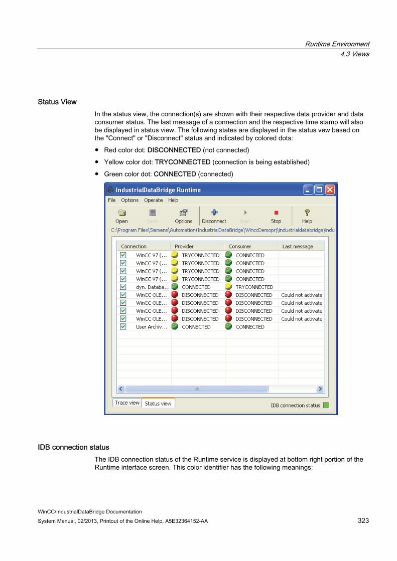
Runtime Environment 4.3 Views
WinCC/IndustrialDataBridge Documentation System Manual, 02/2013, Printout of the Online Help, A5E32364152-AA 323
Status View In the status view, the connection(s) are shown with their respective data provider and data consumer status. The last message of a connection and the respective time stamp will also be displayed in status view. The following states are displayed in the status vew based on the "Connect" or "Disconnect" status and indicated by colored dots:
● Red color dot: DISCONNECTED (not connected)
● Yellow color dot: TRYCONNECTED (connection is being established)
● Green color dot: CONNECTED (connected)
IDB connection status The IDB connection status of the Runtime service is displayed at bottom right portion of the Runtime interface screen. This color identifier has the following meanings:
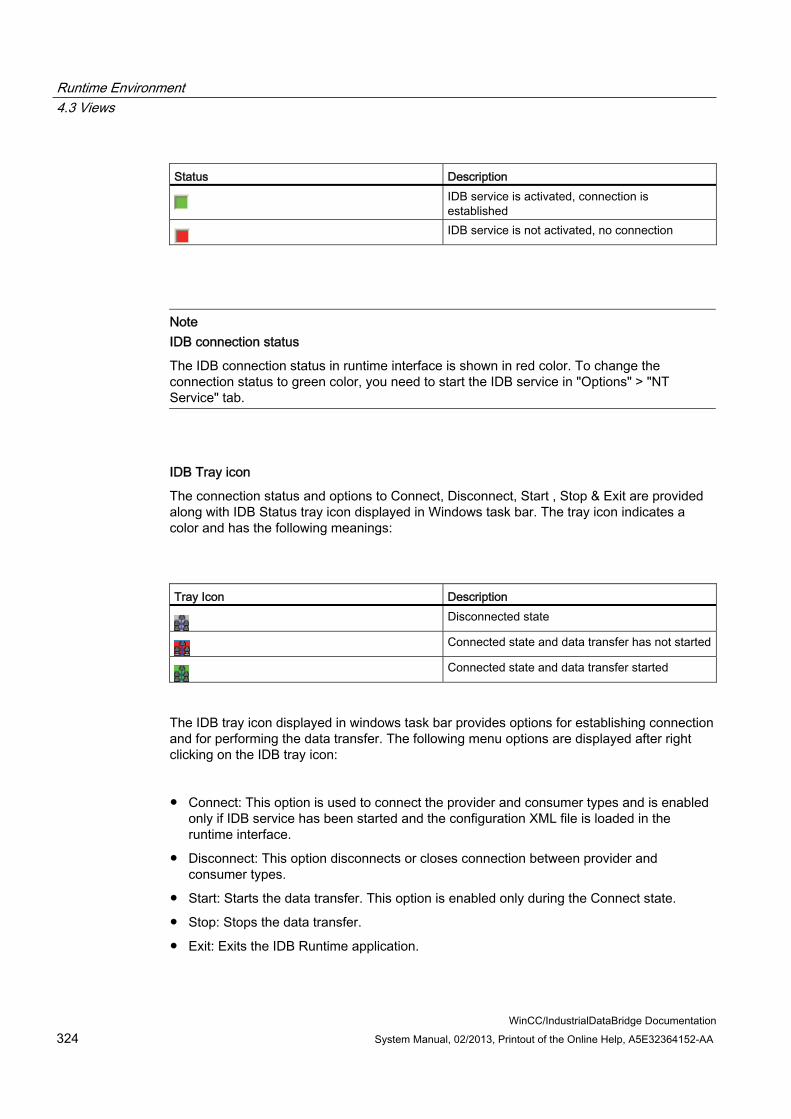
Runtime Environment 4.3 Views
WinCC/IndustrialDataBridge Documentation 324 System Manual, 02/2013, Printout of the Online Help, A5E32364152-AA
Status Description
IDB service is activated, connection is established
IDB service is not activated, no connection
Note IDB connection status
The IDB connection status in runtime interface is shown in red color. To change the connection status to green color, you need to start the IDB service in "Options" > "NT Service" tab.
IDB Tray icon
The connection status and options to Connect, Disconnect, Start , Stop & Exit are provided along with IDB Status tray icon displayed in Windows task bar. The tray icon indicates a color and has the following meanings:
Tray Icon Description
Disconnected state
Connected state and data transfer has not started
Connected state and data transfer started
The IDB tray icon displayed in windows task bar provides options for establishing connection and for performing the data transfer. The following menu options are displayed after right clicking on the IDB tray icon:
● Connect: This option is used to connect the provider and consumer types and is enabled only if IDB service has been started and the configuration XML file is loaded in the runtime interface.
● Disconnect: This option disconnects or closes connection between provider and consumer types.
● Start: Starts the data transfer. This option is enabled only during the Connect state.
● Stop: Stops the data transfer.
● Exit: Exits the IDB Runtime application.

Runtime Environment 4.4 Options
WinCC/IndustrialDataBridge Documentation System Manual, 02/2013, Printout of the Online Help, A5E32364152-AA 325
4.4 Options
4.4.1 Overview
Overview The following commands or items are displayed in the "Options" menu:
● Start option
● Trace (available only if the service has been started and a configuration file is open)
● Password
● License
● NT Service
● Language
● Password check
● Trace logging
The first five items can be accessed from the tabs existing within the "Runtime configuration" window. This window can be accessed by clicking the "Options" button in the toolbar. Within each of these tabs existing within "Runtime configuration" window, the changes performed are active only if you close the window by clicking the "OK" button.
The other three items "Language", "Password check" and "Trace logging" are activated or deactivated directly by the selection in menu interface. The current status is shown with a check mark. However, the "Language" menu item includes a sub-menu that displays the list of languages. Upon selecting the particular language, all the menu interface items including the runtime user interface text will be displayed based on the selected language.
Note
You can only make changes in the Runtime interface if the IDB Service has been started.
Functions The functions of each of these options are provided below:
Start option
Option to determine the Start settings of the IDB Service.
Trace

Runtime Environment 4.4 Options
WinCC/IndustrialDataBridge Documentation 326 System Manual, 02/2013, Printout of the Online Help, A5E32364152-AA
Trace is a logging function, which enables external logging of error messages, calls and data transfers in case of an error. Trace is available only if the IDB Service has been started and a configuration file is open.
Password
Option to determine the password for password protection.
License
This option is for displaying the license parameter.
Language
Selection of the IDB user interface language. English is the default language. The language can only be changed if the IDB service has been started.
Password check
Activates or deactivates the password check.
Trace recording
Activates or deactivates the logging function for error analysis.

Runtime Environment 4.4 Options
WinCC/IndustrialDataBridge Documentation System Manual, 02/2013, Printout of the Online Help, A5E32364152-AA 327
4.4.2 Start Settings
Overview There are various possibilities for starting the IndustrialDataBridge. These possibilities are listed below:
● Manually in the WinCC Explorer
● In the start settings of the computer properties in WinCC
● As an application in the Windows Autostart folder
● As a service in the computer administration
Note More Information
More information about the steps to be followed within each of these options to start IDB is provided in Chapter 4.5 "Working with Connections" (Page 337).
Start settings in the "Start option" tab Once IDB Service has been started, you can set the start behavior of IDB runtime in the "Startup option" tab.
To define the start behavior of IDB runtime application, select the tab entry "Startup option" in the "Options" menu or click "Options" button and choose "Startup option" tab.

Runtime Environment 4.4 Options
WinCC/IndustrialDataBridge Documentation 328 System Manual, 02/2013, Printout of the Online Help, A5E32364152-AA
You can adapt the following settings:
● Automatically connect and activate link(s): If this check box is enabled, you can configure the IndustrialDataBridge Runtime so that when invoked, all link(s) defined in the selected XML configuration file are automatically connected and activated.
If this option is activated, more setting possibilities are available:
● wait before connect (seconds): You can define a waiting time between 0 to 1000 seconds before the IDB Service connects with the data provider and data consumer. This setting makes it possible to start other applications before the IDB Service connection.
● Automatically activate trace: Trace logging can be activated automatically, even if no user is logged in. Note the information in the chapter "Diagnostic Settings" in this case.
● Select a configuration XML file: This file is used once IDB runtime application is started. You can search for a saved configuration file or select the active file.
Note
After performing any changes to the Startup settings, you need to restart the computer in order for the changes to be effective.

Runtime Environment 4.4 Options
WinCC/IndustrialDataBridge Documentation System Manual, 02/2013, Printout of the Online Help, A5E32364152-AA 329
4.4.3 Diagnostic Settings
Introduction With the "Trace" logging function, you write the trace messages of IndustrialDataBridge Runtime into a file. This way, you can check the behavior of certain connections offline.
However, this does not influence the display in the Trace view.
Note Trace tab
The trace tab is displayed in "Runtime configuration" window only if the IDB Service is started and if you have loaded a valid configuration XML file.
Note Memory requirement and performance loss
Activation of Trace results in a greater memory requirement and performance loss. We recommend that this function is only activated for troubleshooting.
Trace settings Trace settings can only be processed if the IDB Service has been started and a valid configuration XML file has been loaded in runtime.
To edit the trace settings, select "Trace" within "Options" menu or click "Options" button in application toolbar and select the "Trace" tab.

Runtime Environment 4.4 Options
WinCC/IndustrialDataBridge Documentation 330 System Manual, 02/2013, Printout of the Online Help, A5E32364152-AA
The trace settings are performed separately for the provider and the consumer of each connection:
● Select the connection that you wish to monitor.
● Select a memory location and a file name for each log
● Define the scope of the logging in the "Trace level" area:
Trace level Description Off Logging is switched off. Exception Errors Saves only the error messages of a certain category. Errors Saves all error messages. Function calls Saves only the calls of a certain category. All function calls Saves all calls. Data All information is saved.
We recommend coordinating the selection of the trace level with the hotline employee that works on the solution to the problem.
● In the "Buffer size" field, define how many entries are to collect in the buffer before the data is written. This setting is used for accelerating the recording.
● With "All Providers" or "All Consumers", the log data of all connections in the selected trace level are saved in separate provider and consumer files.
● Close the window by clicking "OK" button.
Note Trace file path
In Windows 7 and Windows 2008 (64-bit) operating system, it is strongly recommended to configure trace file path settings in any drive other than 'C:' drive.
Starting Trace logging You start the trace logging with menu command "Options" > "Trace logging". If the menu command is selected, then trace recording will be active.
If you wish to start trace recording with the IDB Service, you will have to select the "Automatically activate trace" option in the "Startup option" tab.
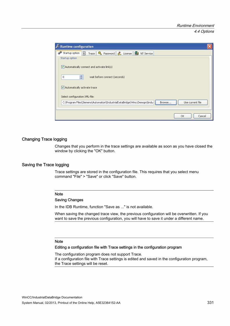
Runtime Environment 4.4 Options
WinCC/IndustrialDataBridge Documentation System Manual, 02/2013, Printout of the Online Help, A5E32364152-AA 331
Changing Trace logging Changes that you perform in the trace settings are available as soon as you have closed the window by clicking the "OK" button.
Saving the Trace logging Trace settings are stored in the configuration file. This requires that you select menu command "File" > "Save" or click "Save" button.
Note Saving Changes
In the IDB Runtime, function "Save as ..." is not available.
When saving the changed trace view, the previous configuration will be overwritten. If you want to save the previous configuration, you will have to save it under a different name.
Note Editing a configuration file with Trace settings in the configuration program
The configuration program does not support Trace. If a configuration file with Trace settings is edited and saved in the configuration program, the Trace settings will be reset.

Runtime Environment 4.4 Options
WinCC/IndustrialDataBridge Documentation 332 System Manual, 02/2013, Printout of the Online Help, A5E32364152-AA
Viewing Alarm messages Once tracing is enabled in runtime, the error messages or status messages displayed in Trace view can logged into in a log file. However, IDB Runtime does not raise error messages for any system specific errors or initialization failure or data transfer failure. In order to support this behavior, these error messages that require attention can be shown as system messages using Alarm logging control in WinCC.
For more information about viewing Alarm messages in WinCC Alarm logging, please refer Chapter 5.1 "Viewing Alarm messages".
See also Viewing Alarm Messages (Page 345)

Runtime Environment 4.4 Options
WinCC/IndustrialDataBridge Documentation System Manual, 02/2013, Printout of the Online Help, A5E32364152-AA 333
4.4.4 Change password
Introduction The IndustrialDataBridge provides password protection functionality.
If password checking is active, the password is queried when starting, connecting and disconnecting in Runtime.
Activating the Password Protection Select "Options" > "Password Checking" in IDB Runtime. If the menu command is selected, then the function will be active.
The password check is switched off as default.
Changing the Password
Note
The password can only be changed if the "Password check" option is enabled in the "Options" menu.
In order to change the password, select menu "Options" > "Password" or click "Options" button and select the "Password" tab.
Enter the old and the new password and repeat the new password to exclude the possibility of input errors. The entries are displayed in masked form for safety reasons.
Click "Apply" button to confirm your input, then close the window by clicking on "OK".

Runtime Environment 4.4 Options
WinCC/IndustrialDataBridge Documentation 334 System Manual, 02/2013, Printout of the Online Help, A5E32364152-AA
4.4.5 Checking License Data
License Information In order to display the license, select menu "Options" > "License" or click "Options" button and select the "License" tab.
The following information is displayed:
● The number of connections in the current configuration file.
● The maximum number of connections allowed with the actual license.
● The License ID of the active license.
Changes cannot be performed to any of the fields displayed in "License" tab.

Runtime Environment 4.4 Options
WinCC/IndustrialDataBridge Documentation System Manual, 02/2013, Printout of the Online Help, A5E32364152-AA 335
4.4.6 Starting service
Introduction Before you can use the IndustrialDataBridge for data transmission, you will have to start the IDB Service. This can be performed by following any of the methods mentioned below:
● Manually in the "NT Service" tab of Runtime configuration window.
● Manually or automatically as service in the computer administration.
The following paragraph is a description of a manual start in the window "NT Service" and automatic startup in computer administration as well as stopping the service.
Note
In Windows Server 2003 operating system, local policies do not permit entering an arbitrary user for a service. This means you cannot configure a new user using the Runtime interface of the IDB.
You have two options for entering a new user for a service: Changing the local policy via the Local Security Settings console "Secpol.msc". Enter the user via the Service console "Services.msc". The policy will be automatically
adjusted for this user.
The default setting is the user "System account".
Manual start of the IDB Service in the window "NT Service". To start the IDB service, select the "NT Service" entry in the "Options" menu or click "Options" buttons and select the "NT Service" tab.
Runtime Environment 4.4 Options
WinCC/IndustrialDataBridge Documentation 336 System Manual, 02/2013, Printout of the Online Help, A5E32364152-AA
● Enter the Service Port you wish to use. The default setting is port 11111. Communication between Runtime interface and the IDB Service with the TCP/IP protocol will take place via this port.
● If you want to start the IDB Service for the current user, select the "System account" and click " Start Service".
● If you want to start the service for another user, deactivate the System account check box and enter the User name and Password in "User name" and "Password" fields respectively. Click "Apply" button to start the IDB Service.
● Close the window by clicking "OK" button.
Automatic start of the IDB Runtime Service To perform this option, you need to have administrator privileges. For doing an automatic start of IDB Runtime service, click on "Options" toolbar button to open the Runtime configuration window. In this window, select "NT Service" tab and enable the "Automatic mode" check box. This check box needs to be enabled only after the service has been started for first time. You can observe that once this automatic mode is set, the "IndustrialDataBridge" service in "Services.msc" will be changed from 'Manual' to 'Automatic'. This service will be automatically started when the computer starts up and 'IDB Connection status' is displayed in green colour.
Note Automatic mode The check box "Automatic mode" needs to be enabled only after the runtime service has
been started. If you modify the setting in Services.msc from 'Manual' to 'Automatic', the "Automatic
mode" check box will not be enabled in NT Service tab. To have the "Automatic mode" enabled in NT Service tab, stop the runtime service and restart service for the changes to take effect.
Follow these steps to set up automatic start from "Services.msc":
● Open the "Services" window in "System Control" > "Administration".
● Double-click the service "IndustrialDataBridge Runtime".
The "Properties" dialog box opens.
● Select the Start type "Automatic" and close the window with "OK".
Stopping the service To stop the IDB service, select the "NT Service tab" in "Options" menu or click "Options" button and select the "NT Service" tab. Click "Stop service".

Runtime Environment 4.5 Working with Connections
WinCC/IndustrialDataBridge Documentation System Manual, 02/2013, Printout of the Online Help, A5E32364152-AA 337
4.5 Working with Connections
Introduction This chapter provides complete information specific to working with connections and the steps required to activate connection(s) and perform data transfer using IDB RT application. It also describes several ways for accessing IDB RT application.
Different formats If the number or date format of the operating system deviates from the corresponding format of the connected file, you will have to adapt the XML configuration file. Otherwise, you may experience conversion errors.
Examples
Case 1: German operating system / Floating-point numbers are to be saved in English format ("." instead ",").
Case 2: German operating system / Date as string saved in English format.
In this case you will have to amend the entry <Link UID="Ref-1" Name="OPC-DB2"> to <Link UID="Ref-1" Name="OPC-DB2" LCID="1033"> in the XML configuration file.
The attribute LCID (LocalID) indicates in which format the values will be saved. During conversion they will be converted into the format of the operating system. The attribute LCID has the following values for the interface language of the IDB:
Language LCID attribute English 1033 German 1031 French 1036 Italian 1040 Spanish 1034 Chinese 2052 Japanese 1041
Additional values for LCID are available under http://www.microsoft.com (http://www.microsoft.com) when you enter the search term "LCID".
Accessing IDB Runtime There are several ways for accessing the IndustrialDataBridge Runtime application.
Runtime Environment 4.5 Working with Connections
WinCC/IndustrialDataBridge Documentation 338 System Manual, 02/2013, Printout of the Online Help, A5E32364152-AA
● Using Auto start:
You can start IDB Runtime automatically when the computer starts up. However, it is also possible to start the service automatically with XML configuration file being loaded. This can be achieved by performing the steps provided below:
– Add IDB Runtime application to Windows Start menu:
In Windows, Select Start > Programs > Startup. Right click on Startup listing and click Open option. Startup folder will open containing the programs to launch at Windows Startup. Add shortcut to the folder containing IDB Runtime file ("C:\Program Files\Siemens\Automation\IndustrialDataBridge\Bin\idb_v7_rt.exe"). When computer starts up, the IDB Runtime application will be opened and displayed on the screen.
– Enable Automatic start-up option:
To perform this option, you need to have administrator privileges. To perform this operation, click on "Options" toolbar button to open the "Runtime configuration" window. Select "NT Service" tab and enable the "Automatic mode" check box. This check box needs to be enabled only after the service has been started. You can observe that once this automatic mode is set, the "IndustrialDataBridge" service in "Services.msc" will be changed from 'Manual' to 'Automatic'. This service will be automatically started when the computer starts up and 'IDB Connection status' displayed in green colour.
Note Services console
The automatic start-up option can also be enabled from windows Services ('services.msc'). To open services, click Start > Run, type services.msc and click OK. From the Services window that is displayed, navigate to IndustrialDataBridge Runtime entry and select "Properties" option. In the "Properties" window, General tab, select Startup type to 'Automatic' from the drop down list. This service will be automatically started when the computer starts up and "IDB Connection status" displayed in green colour.
– Enable automatic data transfer:
The XML configuration file can be automatically loaded during Windows start up. To perform this operation, click on "Options" toolbar button to open the Runtime configuration window. Select "Startup option" tab and select the XML configuration file. Hence, when the computer starts up, the IDB Runtime application will be opened with service being started automatically and all IDB links connected and started.
● Using WinCC Explorer:

Runtime Environment 4.5 Working with Connections
WinCC/IndustrialDataBridge Documentation System Manual, 02/2013, Printout of the Online Help, A5E32364152-AA 339
Open WinCC Explorer and select "Computer" element listed within the navigation window. The corresponding name of computer will be displayed in data window. Access the "Computer Properties" and select Startup tab. In this tab, add an additional task to the folder containing IDB Runtime file (C:\Program Files\Siemens\IndustrialDataBridge\bin\idb_v7_rt.exe). Click OK once you have made the changes. Select Activate button in WinCC Explorer toolbar to start IDB Runtime application.
To start IDB connection or links automatically upon activating the project, you need to enable the Automatic Startup type in Windows Services. Enable automatic data transfer by selecting start option in IDB Runtime options and select XML configuration file. Upon activating the project from WinCC Explorer will now enable IDB Runtime environment to be automatically opened and all IDB links are connected and started.
● Using WinCC controls:
Start WinCC Graphics Designer from WinCC Explorer and add the ActiveX control "IDB Runtime Control". Save the project and select "Runtime" button in toolbar to activate the control. WinCC Runtime will be opened in a new window that displays IDB Runtime application window.
To start IDB connection or links automatically upon starting the project, you need to enable the Automatic Startup type in Windows Services. Enable automatic data transfer by selecting start option in IDB Runtime options and select XML configuration file. Upon clicking Runtime button from Graphics Designer toolbar will now enable IDB Runtime environment to be automatically opened and all IDB links are connected and started.
To start IDB Runtime application manually, perform the following steps:
● In the Windows start menu, select "Siemens Automation" > "IndustrialDataBridge" > "IndustrialDataBridge RT".
Performing data transfer The IndustrialDataBridge Runtime application provides the required options to connect provider and consumer types, activate the links and perform data transfer. Before performing the data transfer, it is required to have the following prerequisites ready.
Prerequisites:
● You have configured at least one connection in the IDB CS application and is available as a configuration XML file.
● The Runtime service has been started and is running. Enable the "Automatic mode" check box if you wish to have the service startup type as automatic.
● The path or location for saving the trace file is set in the "Trace" tab.
● The configuration XML file that has been exported for IDB CS is opened in IDB RT application.

Runtime Environment 4.5 Working with Connections
WinCC/IndustrialDataBridge Documentation 340 System Manual, 02/2013, Printout of the Online Help, A5E32364152-AA
Follow the steps given below to start one or more connections manually:
1. In the Windows start menu, select "Siemens Automation" > "IndustrialDataBridge" > "IndustrialDataBridge RT". To start IDB runtime from WinCC Explorer, select "IndustrialDataBridge", right click and choose "Runtime" from the pop-up menu.
2. To load a configuration file, select "Open" in the "File" menu or click "Open" button.
3. Select the Status view. A list of connections applicable for the specific configuration will be thus displayed. A check mark appears next to the connection name.
This allows for performing actions on individual connection(s).
4. To connect, select the entry "Connect" in the "Operate" menu or click "Connect" button.
5. As soon as the status is displayed with a green colored dot in provider and consumer columns, the connection is complete.
6. To activate the connections, select the entry "Start" under "Operate" menu or click "Start" button.
Data can now be transferred via the connection.
7. In Status view, select a connection and right click on the connection. A context menu is displayed with a list of options. This allows for working with individual connections. However, the displayed options are dependent on connect / disconnect state.
When IDB is in connected state:
– Right click on an already connected connection will show "Disconnect" option
– Right click on a disconnected connection will show "Connect" option
– If connection fails due to consumer/provider not being initialized, then on performing right click "Disconnect" option will be displayed
When IDB is in started state:
– Right click on a disconnected connection will show "Start" option
– Right click on a connected connection will show "Disconnect" option

Runtime Environment 4.5 Working with Connections
WinCC/IndustrialDataBridge Documentation System Manual, 02/2013, Printout of the Online Help, A5E32364152-AA 341
Note Security settings for Windows 7 and Windows 2008 Server operating system
By default, the User Account Control (UAC) is set as "high" and hence denies write access to the "Program Files" directory.
In Windows 7 and Windows 2008 Server operating system, it is suggested to save the files (that is selected as a consumer) into a folder location within the drive on your computer other than boot or operating system drive.

Runtime Environment 4.5 Working with Connections
WinCC/IndustrialDataBridge Documentation 342 System Manual, 02/2013, Printout of the Online Help, A5E32364152-AA
Note Opening Excel file during data transfer
During data transfer process between the provider and excel as consumer, IDB Runtime writes the data in the Excel file. If the excel file is opened in parallel during the transfer process, then runtime application stops working. A trace message "Inserting a value failed" will be displayed in the "Trace view" once you try opening this excel file.
Please note that the Runtime application stops working and you will not be able to stop or disconnect the data transfer process. In this scenario, you need to restart the IDB service. However, you will not be able to save any data during the last data transfer.
Note Send/Receive
Using Send/Receive as provider or consumer type with other supported provider / consumer types can be configured in IDB CS application. However, after loading the configuration in Runtime environment and connecting the provider/consumer types, you may observe that the IDB connection status will still be shown in red colour and the status of connection is in "Disconnected" state.
The "Connected" state can be achieved only if you are using Send/Receive to send or receive data to or from a PLC.
Managing status of individual connections In IDB Runtime window within the "Status view", the interface allows to change the status of individual connection(s). This can be done by using the "Connection" check box displayed in first column of the grid within runtime window. The list of connection(s) to be connected or disconnected can be selected using the "Connection" check box.
Upon marking the respective "Connection" check box for selection, you can disconnect the selected connection(s) (in connected state) using the "Disconnect" button. It is important to note that after disconnecting the connection(s), the connection will be disconnected and Disconnect button in toolbar is changed to "Connect" button. This is irrespective of the status of other connection(s).
To change the status of other connection(s), right click on the "provider" or "consumer" column and select the desired option.
Runtime Environment 4.5 Working with Connections
WinCC/IndustrialDataBridge Documentation System Manual, 02/2013, Printout of the Online Help, A5E32364152-AA 343
Stopping data transfer To end the data transfer, proceed as follows:
1. Select the required connections and use the menu "Operate" > "Stop" or click "Stop" button.
2. Data transmission is stopped but the connection stays intact and can be restarted.
3. Disconnect the connections by selecting the option "Disconnect" from "Operate" menu or click "Disconnect" button.
4. The connections will be disconnected but the configuration will stay loaded. Click File menu and select "Close" option from the list to close the configuration.
5. To exit IDB Runtime application, select "File" > "Exit" option.
Note Maximum Number of Links
For all provider/consumer types of the IndustrialDataBridge, the number of links is recommended to a maximum of 32 links in Runtime operation. The functionality in runtime operation is not guaranteed with a higher number of links.
Note Stopping or disconnecting takes a long time
Stopping or disconnecting a WinCC OLE DB connection can take a long time in certain cases. The reason may be that all job bundles will have to be processed completely.
See also http://www.microsoft.com (http://www.microsoft.com)

Runtime Environment 4.5 Working with Connections
WinCC/IndustrialDataBridge Documentation 344 System Manual, 02/2013, Printout of the Online Help, A5E32364152-AA

WinCC/IndustrialDataBridge Documentation System Manual, 02/2013, Printout of the Online Help, A5E32364152-AA 345
Advanced Features 55.1 Viewing Alarm Messages
Introduction In IDB Runtime interface, the status messages and error messages are shown in the trace view. These error messages can also be logged in a log file if tracing is enabled in the runtime environment. However, while using IndustrialDataBridge in combination with WinCC, IDB Runtime does not raise error messages for any system specific errors or initialization failure or data transfer failure. Hence, these error messages that require attention can be shown as system messages using Alarm logging control in WinCC. This chapter provides more information about viewing alarm messages in Alarm logging application.
Alarm Messages To view alarm messages in WinCC Alarm logging, follow the steps given below:
1. In Tools menu, select "WinCC System Messages".
2. In "WinCC System Messages" window, within the "Create system messages" section, select the desired option and click Create button.
3. A list of system messages will be created. Once the progress bar is full, click Close button to close the window.
4. The table window displayed at bottom portion of the Alarm Logging application displays the complete list of alarm messages.
The alarm message displays the message text in following format:
<provider name>, <error message>, <connection name>
Advanced Features 5.2 Using IDB Controls in Web Navigator
WinCC/IndustrialDataBridge Documentation 346 System Manual, 02/2013, Printout of the Online Help, A5E32364152-AA
5.2 Using IDB Controls in Web Navigator
Introduction The IDB runtime control on Web Navigator client screen allows an operator from a client computer to browse configuration files that are located on a server, load configuration file and start or stop the data transfer. Multiple clients can connect to a single server.
The IndustrialDataBridge consists of a server component that is installed on the computer acting as a server. The configured client computer can control and monitor the runtime environment from an open Internet Explorer browser without the need of complete IDB installation on the client computer. However, it is not possible to Start/Stop IDB service, change service login settings and port settings from the client computer. All other operations or controls provided within IDB runtime environment can be handled from the browser screen interface on the client computer.
Prerequisites ● Microsoft Internet Information Server (IIS) 6.0
● Web Navigator Server Component
● Web Navigator Client Component
● IDB Server Component
For more information regarding installing IIS, refer Microsoft website.
Benefits ● IDB installation
Complete installation of IndustrialDataBridge V7.2 is not required on client machines.
Necessary components required on the client machine are identified and prompted for installation while launching the Web client.
● IDB can be operated remotely as a client
● Enables easier browsing of IDB configuration files (during runtime) from remote computer running as a client
● Supports operation on clients with authorization support
Usage Using the Internet explorer browser, the IDB runtime environment can be accessed from any client computer without the need for having a complete IDB installation. However, all the required prerequisites need to be installed before accessing the runtime application from the client computer using a browser.

Advanced Features 5.2 Using IDB Controls in Web Navigator
WinCC/IndustrialDataBridge Documentation System Manual, 02/2013, Printout of the Online Help, A5E32364152-AA 347
1. In client machine, firstly enter the local host address or IP address of the server machine.
2. If the client does not have necessary components installed, a message is displayed in Startup screen as "IDB Control plugin not installl ed".
Install this component using the link given on the same Startup screen. If component is installed, this message will not be displayed and this step can be skipped.
3. The browser displays the runtime application and lists all the controls available within the IDB runtime application.
4. Open the configuration file list by clicking the "Open" button. A customized "File Open" dialog window is displayed. The server files are displayed in this folder structure that can be loaded by the clients.
5. Click the "Refresh" button to refresh the latest configuration files list.
6. Select a file and click the "Open" button. The selected file is loaded in IDB runtime control and the data transfer can be started from the client computer.
Note Open dialog box
A customized File Open dialog window is displayed upon clicking the Open button in runtime application. The list of files that can be opened remotely by clients are displayed in the file list. All the XML configuration files located in server directory specified by "ConfigurationFilesPath" key under key "HKEY_LOCAL_MACHINE\SOFTWARE\Siemens\IT4Industry\IndustrialDataBridge" in the registry on the server will be displayed in the file list within the customized File Open dialog window while loading files.
It is not possible to browse or select any other files existing on the Web Navigator server computer. You will not be able to load any configuration file that is not present in the directory specified by registry entry. Any existing file that is already loaded on the server will be displayed on client even if the file is not present in the above mentioned directory. This restriction applies only to the files that can be loaded by the client.
Configuration & Trace files The IDB control existing on the client identifies the server machine automatically and lists all the configuration and trace files present in a particular directory on the server. In Options > Runtime Configuration > Trace tab, the trace file can be selected or new files will be created only in the directory specified by the registry key "TraceFilesPath" under key "HKEY_LOCAL_MACHINE\SOFTWARE\Siemens\IT4Industry\IndustrialDataBridge" on the server. This directory that displays the configuration or trace file list can be accessed from the client computer.

Advanced Features 5.2 Using IDB Controls in Web Navigator
WinCC/IndustrialDataBridge Documentation 348 System Manual, 02/2013, Printout of the Online Help, A5E32364152-AA
The file loaded on client is displayed in the Group box header. Since the file physically do not exist on the client computer, the complete file path is not displayed. Only the file name of specific file is displayed in the header. A file loaded by client on server will reflect on all the clients connected to the same server. On the server, if you wish to restrict the client to load configuration file or Start/Stop data transfer, then the server should enable the Password check option.
Note
You will not be able to load any configuration file that is not present in the directory specified by registry entry. Any existing file that is already loaded on the server will be displayed on client even if the file is not present in the above mentioned directory. This restriction applies only to the configuration or trace files that can be loaded by the client.

Advanced Features 5.3 Accessing IDB Runtime using WinCC Controls
WinCC/IndustrialDataBridge Documentation System Manual, 02/2013, Printout of the Online Help, A5E32364152-AA 349
5.3 Accessing IDB Runtime using WinCC Controls
Overview WinCC IDB Runtime application can be accessed using WinCC controls. This is possible by adding WinCC ActiveX control "IDB Runtime Control" as an OCX in Graphics Designer. This will help WinCC users to start IDB Runtime within their environment.
The look and feel of IDB Runtime as an OCX is almost similar to the IDB Runtime as an executable. However, there are few additional changes to IDB Runtime as an OCX and these changes are covered in the subsequent sections.
Accessing IDB Runtime To access IDB Runtime control as ActiveX control in WinCC, follow the steps given below:
1. Start WinCC Explorer.
2. In WinCC Explorer, double click "Graphics Designer" element from navigation window to open Graphics Designer.
3. In Graphics Designer, Select File > New to create a new PDL file.
4. Navigate to Object Palette and select controls tab. Highlight "ActiveX controls" from the list.
5. Expand the ActiveX controls tree to view a list of available controls.
Note
If you are unable to view the controls after expanding the list, right click on ActiveX controls and select "Add/Remove" option. The "Select OCX Controls" window is displayed that provides a list of available controls. Select "IDB Runtime control" and click OK.
6. IDB Runtime control should be available as an OCX within the controls list.
7. Drag and drop this OCX control to the container area within the PDL file window.
8. Once this control is added to the container, save the PDL file and click Runtime control in Standard toolbar to activate Runtime mode.
9. The IDB Runtime control is displayed / opened on the WinCC Runtime screen.
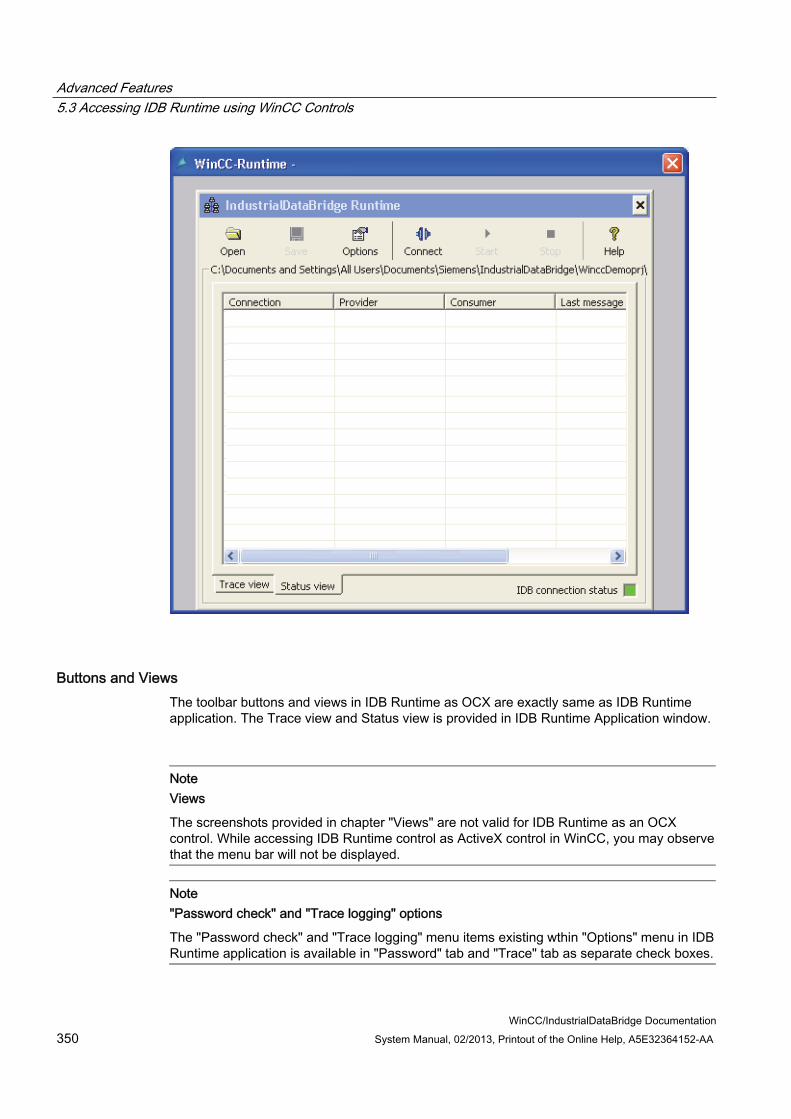
Advanced Features 5.3 Accessing IDB Runtime using WinCC Controls
WinCC/IndustrialDataBridge Documentation 350 System Manual, 02/2013, Printout of the Online Help, A5E32364152-AA
Buttons and Views The toolbar buttons and views in IDB Runtime as OCX are exactly same as IDB Runtime application. The Trace view and Status view is provided in IDB Runtime Application window.
Note Views
The screenshots provided in chapter "Views" are not valid for IDB Runtime as an OCX control. While accessing IDB Runtime control as ActiveX control in WinCC, you may observe that the menu bar will not be displayed.
Note "Password check" and "Trace logging" options
The "Password check" and "Trace logging" menu items existing wthin "Options" menu in IDB Runtime application is available in "Password" tab and "Trace" tab as separate check boxes.

Advanced Features 5.3 Accessing IDB Runtime using WinCC Controls
WinCC/IndustrialDataBridge Documentation System Manual, 02/2013, Printout of the Online Help, A5E32364152-AA 351
Options Select "Options" toolbar button from IDB Runtime application to access Runtime Configuration. The "Runtime Configuration" provides the following tabs:
● Startup Option
● Trace
● Password
● License
● NT Service
Note
Changes to the Runtime interface can be performed only if the IDB Service has been started.
The options provided within each of these tabs are same as the options in IDB Runtime application. However, there are some additional features that are provided with IDB Runtime as WinCC control. These features are highlighted below:
IDB Runtime Application Menus:
The IDB Runtime Application window does not include menu based navigation. The required operations can be performed using the GUI buttons existing on the application toolbar.
Language Option:
The IDB Runtime application provides language support. It supports 7 languages - English, Spanish, German, Italian, Chinese, Japanese and French. While accessing IDB Runtime as OCX control on WinCC Runtime screen, the language changes when the language of WinCC Runtime has been changed.
The language option of IDB runtime control is not linked to IDB Runtime application or any other IDB runtime control. This means that language change in IDB runtime control does not change the language of other controls or IDB Runtime application and viceversa.
Trace Logging:
The Trace tab is provided next to Startup option tab. This tab is displayed only after you have loaded the configuration file in IDB Runtime window.

Advanced Features 5.3 Accessing IDB Runtime using WinCC Controls
WinCC/IndustrialDataBridge Documentation 352 System Manual, 02/2013, Printout of the Online Help, A5E32364152-AA
The "Trace Logging" check box is available within the "Trace" tab of Runtime Configuration window. Upon enabling this check box, it allows to save the trace messages generated both from provider and consumer side. Within the Trace tab, the "Provider log file" and "Consumer log file" sections provide options to specify the file name for logging the trace messages. At a later point of time, the trace log files can be used to view these trace messages.
Password Check:
The "Password Check" check box is provided within "Password" tab of Runtime Configuration window. Once this check box is enabled, it generates a dialog box asking you to enter the password each time an operation is performed within each of the tabs in Runtime Configuration.

Advanced Features 5.3 Accessing IDB Runtime using WinCC Controls
WinCC/IndustrialDataBridge Documentation System Manual, 02/2013, Printout of the Online Help, A5E32364152-AA 353
Open dialog box:
The Open button and Startup Option tab provides options to select configuration XML file in order to activate the connection during runtime. Select "Browse" button to invoke the "Open" dialog window.
In IDB Runtime as OCX, the following points are valid with respect to the actions performed within Open dialog box.
● Open dialog box is opened only in Read mode. You will be able to open only an XML file.
● Option to delete a file or folder is not provided within this dialog box.
● Options to cut/paste a file or folder and creation of new file/folder are not available.
● Menu pop-up on right mouse-click within the window area cannot be performed.
● Drag and drop of file or folder within the dialog box cannot be done.
● Options to rename file or folder using F2 key cannot be performed.

Advanced Features 5.4 Asian Language Support
WinCC/IndustrialDataBridge Documentation 354 System Manual, 02/2013, Printout of the Online Help, A5E32364152-AA
5.4 Asian Language Support
Multilingual Configuration IndustrialDataBridge V7.2 enables you to configure your projects and perform data transfer in multiple languages. IDB V7.2 supports multilingual configuration of all items containing text that is visible in Configuration and Runtime interface.
Supported Languages In IndustrialDataBridge V7.2 Configuration interface and Runtime interface, the following interface languages are supported:
● German
● English
● French
● Italian
● Spanish
● Simplified Chinese
● Japanese
GUI language The language that is selected during installation of IDB V7.2 will be set as the language in which the IDB CS or IDB RT menus, dialog boxes and help are displayed. However, you can switch to any respective language within IDB application (CS and RT). If you have changed the GUI language in IDB, the next time when you start IDB, the interface is displayed in the GUI language that you had set up previously.
The technical terms especially the provider and consumer names will be displayed in English language irrespective of the selected language in IDB.
Note Asian languages
For using Chinese and Japanese languages on Windows XP and Windows Server 2003 operating systems, you need to install MUI pack.

Advanced Features 5.4 Asian Language Support
WinCC/IndustrialDataBridge Documentation System Manual, 02/2013, Printout of the Online Help, A5E32364152-AA 355
Note
If you work with Chinese (simplified) operating system, for example, and you want to view IDB V7.2 user interface in english language, you need to set the English language options in operating system settings: For Windows XP, select "Start > Settings > Control Panel > Region and Language
Options" in the "Languages" tab. In Windows 7, "Start > Control Panel > Region and Language" > "Keyboard and
languages" tab, "Display language". This field is available only if the required language packs are installed on your computer.

Advanced Features 5.4 Asian Language Support
WinCC/IndustrialDataBridge Documentation 356 System Manual, 02/2013, Printout of the Online Help, A5E32364152-AA

WinCC/IndustrialDataBridge Documentation System Manual, 02/2013, Printout of the Online Help, A5E32364152-AA 357
FAQs 6Frequently Asked Questions
● Can I use an XML configuration file created using previous version of IDB?
Yes, XML configuration file created using previous version of IDB can be directly loaded into Runtime. However, for using/modifying this XML configuration file in Configuration module, user needs to Import this configuration file, this would create a project in IDB CS.
● Is a project file compulsory for working with IDB CS V7.2?
Yes
● How can I change the Default Project storage location for IDB CS Projects?
An option has been given on the editor under Option->Settings menu for the same in IDB TIA. On the editor open, go to “Storage settings” group box and modify the “Storage location for projects”.
● How to load a configuration created in IDB CS in IDB Runtime?
Once a configuration is ready in IDB CS, user can generate the Runtime configuration data using an option (Generate runtime configuration) given in IDB CS. This option generates the XML Configuration file required to operate in Runtime.
● How can I reset the settings performed within the IDB CS application?
In IDB CS menu, select "Options" > "Settings" to open the "Settings" window in work area. On left pane of "Settings" window, click "General" to view the "General" settings in right pane. The "Reset to default" section area provides the required settings to reset the settings to default.
● Where can I find the definitions for all the available keyboard shortcuts?
There is an option given in the Settings editor under Option->Settings menu for the same. Go to “Keyboard Shortcuts” on the options displayed on the left side of the opened editor window.

FAQs
WinCC/IndustrialDataBridge Documentation 358 System Manual, 02/2013, Printout of the Online Help, A5E32364152-AA
● The provider/consumer configuration window or any other editor window do not provide options to Save.
In IDB CS, the data entered within the configuration window/editors will be automatically saved.
● Is it required to have a complete installation of IDB on WebNavigator Client machine for using IDB Runtime control remotely via WebNavigator?
No, complete installation of IDB is not required on the WebNavigator client. Only IDB client installation is required which is done by the WebNavigator setup.
● Can I make IDB Runtime service Manual/Automatic from a remote Web client?
Yes.
● Is there a limitation on number of clients that can connect to a single IDB Runtime Service? No, there is no limitation.
● Can the user on WebNavigator client start and stop IDB Runtime Service remotely with the option provided on the IDB Runtime control?
No, User cannot perform this operation remotely. These operations along with change of User account and port number is disabled for the user to change/modify.
● I modified the ConfigurationFilespath and TraceFilesPath in the registry under Siemens/IT4Industry/IndustrialDataBridge. Do, I need to restart the system for changes to take effect?
No, system restart is not required. However, IDB service need to be restarted.
● Is WinCC required to be in running state in order to configure the User Archive?
Yes, WinCC is required to be started to be able to access the User Archive and configure User Archive as provider and consumer in IDB CS application.
● Can a user start data transfer to or from OPC XML on a machine WebNavigator is configured and running?
Some Operating system (For Ex: WinXP) doesn’t allow simultaneously running of more than one websites. On these Operating system, it is not possible to run OPC XML along with WebNavigator.
On Operating systems where these are allowed, both OPC XML and WebNavigator can run simultaneously.
FAQs
WinCC/IndustrialDataBridge Documentation System Manual, 02/2013, Printout of the Online Help, A5E32364152-AA 359
● Is Connectivity Pack License required for browsing OPC XML tag in WinCC?
Yes
● Is it possible to get the count of the bad quality connection in OPC XML Provider/Consumer?
Yes, it is possible to get the count of the bad quality connection. For this, in OPC XML Data Access Consumer Configuration, user needs to associate a tag in “Configuration for bad quality item”. During runtime, the count of the bad quality item will be written into the configured tag.
● Not able to browse the OPC XML Tags. What are the possible reasons?
Check the following scenarios, a. Check whether the OPC XML Web service is running or not in Internet Information Services (IIS). If not run the OPC XML web service in IIS. b. Ensure whether the IIS is installed before installing .NET Framework. c. Refer the WinCC documentation for configuring OPC XML Web service in IIS.
● When I open the CSV file, the following error message is displayed: "Excel has detected that ‘<file>’ is a SYLK file, but cannot load it. Either the file has errr ors or is not a SYLK file format. Click OK to try to open this file in a difff erent format." This error occurs when the first column name is “ID” both I and D capital. To avoid this error, one can rename this column to small case or any prefix or suffix to ID.
● I have created a CSV file manually (not by IDB CS) with the intention of transferring Unicode data, but data is not showing correctly. Required language packs are installed on my machine.
File should be created in UTF-8 character encoding format for this. Open the file as a txt file and while saving, select the encoding as UTF-8.
● Unable to change the consumer type option on the Database consumer type configuration, so as the schema and table?
These options will be in disable state, if there is any connection exists. So ensure that there are no connections exist to change the consumer type option.
● How to transfer data when the table has a foreign key relation?
Use the Per-Tag Database consumer type for the data transfer.

FAQs
WinCC/IndustrialDataBridge Documentation 360 System Manual, 02/2013, Printout of the Online Help, A5E32364152-AA
● I have created a table in Oracle database, however I am not able to transfer Unicode data in the table.
For transferring Unicode data in Oracle, ensure that the database is created with UTF 8 character encoding support.
● Can I edit the connection string on the configuration screen?
Yes, you can edit the connection string in Configuration window. The connection string and the fields are updated accordingly.
● OPC tag browser is not listing any OPC DA Server. However, there are OPC servers installed on the machine. What could be the problem?
To browse OPC DA servers, opcenum.exe should be running as a service on the server machine. To check whether this service is running , Go to start -> Run. Type services.msc and press enter. If “opcenum” is not started, make it automatic mode and start it. If not able to browse OPC servers on remote machine, ensure that the above step is done on the remote machine.
● Not able to browse the items of an OPC DA Server.
Check if the OPC server is running. If it is not running, start the OPC Server.
● Not able to browse the OPC Items on remote computer.
Check if the DMAT settings are proper. If DMAT settings are proper, then check the login user account on both the Server and client machine.
Note
If user is trying to access the tags of WinCC, then in both the PCs ensure that the login user account are under SIMATIC HMI from ‘Local users and Groups”
More detailed information is provided in Chapter 3.2 OPC DataAccess in the IDB Documentation manual
● I have only IDB installed, how can I use Send/Receive as Provider or Consumer. Is there any option in IDB to configure the Step7 Project? To use Send/Receive as Provider or Consumer, a Step7 Project is also required. There is no option in IDB to configure this project. A Step7 project is created and the program is downloaded in PLC. Without this, Send/Receive would not work in IDB runtime.

FAQs
WinCC/IndustrialDataBridge Documentation System Manual, 02/2013, Printout of the Online Help, A5E32364152-AA 361
● In IDB CS, Send/Receive connection mapping screen, is it required to set the number fields same for both provider and consumer?
No
● Is it possible to have same names for two links or connections?
No it is not possible.
● Can we rename an already created link or connection?
Yes, an existing link or connection name can be renamed. In Project tree, perform a single click on the link or connection. The link name will be changed to an editable area allowing you to modify the link name.
● I see some consumer data as “??” or square boxes.
Data transferred is Chinese or Japanese and system doesn’t have language pack installed for these languages. Installing correct MUI language pack would fix this issue.
● A notification to be given to the operator when IDB is not able to transfer data. Is it possible?
Yes, this can be achieved if the user has installed WinCC. IDB sends Alarm messages when an error occurs during the data transfer. This is inbuilt in IDB and no additional settings are required for this.
● I want to see a detailed report if there are any failures during data transfer.
For detailed report on reason for data failure, user needs to configure trace log settings and enable the trace logging. This setting can also be done remotely on a WebClient.
● I installed IDB then I installed MUI package for Chinese and Japanese. I don’t find an option to switch to Chinese and Japanese in IDB CS.
IDB Configuration module would need a repair/modify for the new languages to be shown. However, IDB Runtime would take the effect without IDB setup Repair/modify/reinstallation.

FAQs
WinCC/IndustrialDataBridge Documentation 362 System Manual, 02/2013, Printout of the Online Help, A5E32364152-AA
● On uninstallation of IDB, what files/folders are removed and what files/folders are retained.
– All IDB related binaries are removed except OPC related binaries if used by other products like WinCC.
– However, Configuration files and folders, Trace files and folders etc are not removed.
– Editors layout settings are also not retained.
– License files are not removed.
● OPC XML DA does not work after performing the installation of .NET Framework V2.0 and IIS
It is important to ensure that you need to firstly install IIS. After installing IIS, install the .NET Framework. If the order of installation is changed, ASP.NET will not be registered in IIS. To resolve this issue, execute the following command in command prompt:
C:\Windows\Microsoft.Net\Framework\v2.0.50727\aspnet_regiis.exe –i
If the System path is not set to "C:\Windows", modify the path.
After executing the above mentioned command, reset IIS by entering the command "iisreset" in command prompt.
● OPC XML DA does not work in Windows 2003 R2 Server
Follow the steps provided below to resolve this issue:
– Select "Start" > "Run" and type the program name "inetmgr". The Internet Information Services (IIS) window will be opened.
– In IIS window on the left pane, click the computer name (local computer) and select "Web Service Extensions".
– In right pane, select "Active Server Pages" and click the "Allow" button. Select "ASP.NET v2.0.50727" and click "Allow" button.
– If "ASP.NET v4.0.30319" or other version is selected, then click "Prohibhit" button.
– Restart the IIS (enter "iisreset" in command prompt).
● What is the use of "Asynchronous transfer configuration" option in OPC XML DataAccess consumer configuration?
It is useful for the user to ensure whether the data transfer is happening correctly or not.
For example, if you have configured the "Maximum number of outstanding write transaction" as 15 (Default is 10 and maximum value is 40).
If data transfer does not happen correctly, after the failure of 15th transaction, a warning message will be displayed in IDB Runtime Trace view.
WinCC/IndustrialDataBridge Documentation System Manual, 02/2013, Printout of the Online Help, A5E32364152-AA 363
Glossary
Address space Physical database/tag management of a consumer or provider component
ADO ADO is short for ActiveX Data Objects. ADO is an interface based on ActiveX for data access to databases and table-like data sources such as e.g. Excel worksheets and CSV files.
API API is short for Application Programming Interface.
Bridge The upper-most element in the hierarchy of the IndustrialDataBridge. The element contains (maximum 32) links.
Configuration Interface A component of the IndustrialDataBridge. The data connections are created and edited in the configuration interface. Three steps are necessary for the complete configuration of a connection: 1. Create project, link and configure data provider and consumer properties. 2. Perform the link settings and configure transfer settings. 3. Map connections between provier and consumer tags.
Connection Connection in this case means a tag connection between a provider and a consumer tag.
CSV file A CSV file is a text file for saving or exchanging simply structured data. CSV stands for Character Separated Values, Comma Separated Values or Colon Separated Values because the individual values are separated with a special separating character such as a comma or a semicolon. A general standard for the file format does not exist.

Glossary
WinCC/IndustrialDataBridge Documentation 364 System Manual, 02/2013, Printout of the Online Help, A5E32364152-AA
Data consumer Target location for data sending. The part of a data terminal equipment to which data is delivered or data should be delivered to. The data consumer is normally equipped with a standardized transfer interface. With the IndustrialDataBridge, the data consumer can be the OPC, databases (Oracle, SQL, Access, MySQL), SendReceive, Microsoft Excel, IDB OPC Server, Send /Receive, CSV file, Dynamic database at present.
Data provider Original location of the data sender. The data provider is part of data terminal equipment that is used for supplying data to a data link. The data provider is normally equipped with a standardized transfer interface. With the IndustrialDataBridge Configuration interface, the data provider can be OPC Data Access, OPC XML, database (Oracle / SQL / Access) Send/Receive, WinCC OLE DB, Dynamic database.
DB Database; an electronic archive with quick access and space-saving storage for large volumes of data for many users or programs. Data or messages can be organized or called up according to a variable organization scheme, individually or linked, for the dialog operation as well as for stack processing. A database can be used by many applications programs. Depending on the structuring and application of the database, the differences are categorized as distributed databases, relational databases, public and object-oriented databases.
IDB IndustrialDataBridge; the IndustrialDataBridge enables data exchange between different systems via standards. This does not require any further programming. An exchange between automation systems of different manufacturers is made possible with the IndustrialDataBridge. The various data interfaces are linked via software modules. These software modules are divided into providers and consumers. The providers made the connection to the data source, from which the data is delivered. The consumer connects with the data target, into which the data is written. The IndustrialDataBridge is divided into the configuration interface and the runtime environment with runtime interface/components:·
Link A link makes the connection between a provider and a consumer component.

Glossary
WinCC/IndustrialDataBridge Documentation System Manual, 02/2013, Printout of the Online Help, A5E32364152-AA 365
OLE Object Linking and Embedding is an object system and protocol developed by Microsoft, which is to enable the collaboration of different (OLE-capable) applications and therefore the creation of heterogenic compound documents. A picture that was created with a drawing program can be bound into a text document for example. Noteworthy in this case is that double clicking on this embedded picture allows it to be edited directly from the text program using the original drawing program. This runs – recognizable in the changed menu structure – as a plug-in program within the document application. OLE objects can either be linked (object linking) or embedded. With linking, only a reference to the connected object is created and saved in the document, while with embedding, a copy of the object is saved in the document. This linking or embedding can be done with Drag & Drop or Copy & Paste among others. The advantage of embedding is that the connecting document is independent of the source files for the connected objects. However, embedding requires more memory for the connected documents than with object linking.
OPC OPC is short for OLE for Process Control. OPC specifies various services for accessing information in the production process such as tags, alarms and archive data.
Provider A provider is the COM components that make establishing a connection to a data source possible in the runtime environment. The provider is initialized, controlled and destroyed by the consumer. It refers to data from the data source and writes this data into the connected consumer based on the configuration.
Runtime Components Consumer- and provider components
Runtime Environment The runtime environment includes the actual consumer and provider components.
Runtime Interface A component of the IndustrialDataBridge. A created configuration file can be loaded in the runtime interface. After the link has been activated (I.e. data source and data target are connected successfully), the runtime interface monitors the life-span of the source and target components and establishes the connection again automatically if necessary. The runtime interface starts the runtime components.
Server Computer that provides its information, content, services, computing power or applications to the clients.

Glossary
WinCC/IndustrialDataBridge Documentation 366 System Manual, 02/2013, Printout of the Online Help, A5E32364152-AA
SQL Structured Query Language. SQL is a structure query language, which considers the lines, columns, field and key of the database as objects. It contains a number of commands for creating, modifying and accessing the files organized in tables.
Tag A tag corresponds to an entity that contains a unique value.
User Interface Method of entering commands and data into the computer or via the computer to the network. The development of standardized graphic user interfaces simplifies the work with computers for even inexperienced users.
XML XML is short for Extensible Markup Language XML is a markup language for the display of hierarchical structured data in the form of text files. XML is preferred for the exchange of data between different IT systems.

WinCC/IndustrialDataBridge Documentation System Manual, 02/2013, Printout of the Online Help, A5E32364152-AA 367
Index
B
Buttons Runtime, 319
C
Configuration interface, 51 Configuring a Trigger, 142, 201, 288 Connecting OPC Tags from a Provider
WinCC User Archive, 301 Connecting Tags from a Provider
database, 167 Dynamic Database, 207 Dynamic Database - OPC Tags, 213 OPC data access, 66 Send/Receive, 269 WinCC OLE DB, 148 WinCC User Archive, 294
Connecting Tags to the Consumer database, 185 Dynamic Database, 223 Excel, 252 IDB OPC Server, 91 OPC data access, 78 Send/Receive, 277 WinCC User Archive, 310
Consumer Type, 178 Creating a Connection to the Consumer
CSV and TXT Files, 228 database, 170 Dynamic Database, 216 Send/Receive, 272 WinCC User Archive, 304
Creating a Connection to the Provider Dynamic Database, 194
Creating Connections from the Provider database, 157 WinCC OLE DB, 126 WinCC User Archive, 281
CSV and TXT Files Creating a Connection to the Consumer, 228 Overview, 228
D
database Connecting Tags from a Provider, 167 Connecting Tags to the Consumer, 185 Creating a Connection to the Consumer, 170 Creating Connections from the Provider, 157 Overview, 151
Delete variables WinCC User Archive, 313
Diagnostic Settings, 327 Dynamic Database
Connecting Tags from a Provider, 207 Connecting Tags to the Consumer, 223 Creating a Connection to the Consumer, 216 Creating a Connection to the Provider, 194 Overview, 190 Where Statement, 209
Dynamic Database - OPC Tags Connecting Tags from a Provider, 213
E
Excel Connecting Tags to the Consumer, 252 Overview, 242 Requirements, 244
Exporting a WinCC Archive Configuration, 124
I IDB OPC Server
Address space, 82 Connecting Tags to the Consumer, 91 Overview, 81
IDB OPC Server Address Space, 82 IDB Service, 333
J
JScript, 146, 205, 292
L
License Data, 332

Index
WinCC/IndustrialDataBridge Documentation 368 System Manual, 02/2013, Printout of the Online Help, A5E32364152-AA
Logging Function, 327
M
Menu commands Runtime, 318
N
NT Service, 325, 333
O
OPC data access Connecting Tags from a Provider, 66 Connecting Tags to the Consumer, 78 Overview, 57
Overview, 10 CSV and TXT Files, 228 database, 151 Dynamic Database, 190 Excel, 242 IDB OPC Server, 81 OPC data access, 57 Runtime Options, 323 Send/Receive, 255 WinCC OLE DB, 121 WinCC User Archive, 280
P
Password, 331 change, 331 Enable, 331
Principle of Operation, 11 Programming languages, 146, 205, 292
R
Requirements Excel, 244
S
Send/Receive Configuring Connection Types, 265 Connecting Tags from a Provider, 269 Connecting Tags to the Consumer, 277 Creating a Connection to the Consumer, 272
Overview, 255 Start settings, 325 Status View, 321
T
Trace, 327 Trace recording
change, 329 Save, 329 Start, 328
Trace View, 320 Transaction Type, 184
V
VBScript, 146, 205, 292 Views
Status View, 321 Trace View, 320
W
Where Statement Dynamic Database, 209 WinCC User Archive, 297, 312
WinCC OLE DB Connecting Tags from a Provider, 148 Creating Connections from the Provider, 126 Overview, 121 Prerequisites in WinCC, 123
WinCC User Archive Connecting OPC Tags from a Provider, 301 Connecting Tags from a Provider, 294 Connecting Tags to the Consumer, 310 Creating a Connection to the Consumer, 304 Creating Connections from the Provider, 281 Delete variables, 313 Overview, 280 Where Statement, 297, 312
Related Documents


![Don’t gamble with physical properties – Kein Glücksspiel ... · AspenTech, CHEMCAD ... x HCl [mol/mol] VLE HCl-H2O, Aspen V7.2 Aspen V7.2 Aspen V7.2 Othmer,D.F, Ind. Eng. Chem.](https://static.cupdf.com/doc/110x72/5b58ae057f8b9a4e1b8c50a7/dont-gamble-with-physical-properties-kein-gluecksspiel-aspentech.jpg)


