FACULDADE DE E NGENHARIA DA UNIVERSIDADE DO P O RTO Silicone breast implants: Experimental analysis of failure mechanisms Nilza Alexandra Gomes Ramião A thesis submitted in conformity with the requirements for the Doctoral Degree in Biomedical Engineering Supervisor: Doutor Pedro Alexandre Lopes de Sousa Martins Co-supervisor: Professor Doutor António Augusto Fernandes July of 2017

Welcome message from author
This document is posted to help you gain knowledge. Please leave a comment to let me know what you think about it! Share it to your friends and learn new things together.
Transcript
FACULDADE DE ENGENHARIA DA UNIVERSIDADE DO PORTO
Silicone breast implants: Experimentalanalysis of failure mechanisms
Nilza Alexandra Gomes Ramião
A thesis submitted in conformity with the requirements for theDoctoral Degree in Biomedical Engineering
Supervisor: Doutor Pedro Alexandre Lopes de Sousa MartinsCo-supervisor: Professor Doutor António Augusto Fernandes
July of 2017

© Nilza Ramião, 2017

Laughter is timeless, imagination has no age, and dreams are forever.
Walt Disney (1901-1966)

v
Agradecimentos/Acknowledgements
Na reta final de mais uma etapa, não podia deixar de agradecer a todas as pessoas
que, indiretamente ou diretamente, me ajudaram nestes, longos, quatro anos, na realização
e finalização com sucesso deste trabalho. Manterei no meu coração um pedacinho de cada
um.
Começo por expressar o meu agradecimento ao Professor Doutor Pedro Martins e
ao Professor Doutor António Augusto Fernandes, meus orientadores, por todo o apoio,
interesse, incentivo, disponibilidade constante, que gentilmente me dispensaram em todo
o processo de investigação no âmbito do doutoramento. O meu muito Obrigada!
Não posso deixar de agradecer à Dra. Maria da Luz Barroso e à Dra. Diana Costa
Santos médicas-cirurgiãs, do Centro Hospitalar de Vila Nova de Gaia, pela
disponibilidade constante. Sem a vossa ajuda este trabalho não seria possível. Obrigada
pelo carinho durante estes anos.
Agradeço ao Professor Renato Natal, ao Marco Parente, ao Jorge Belinha e à
Fernanda pelas partilhas de conhecimentos, amizade e carinho, ao longo destes anos.
Agradeço o apoio financeiro proporcionado pela Fundação para a Ciência e a
Tecnologia, através da Bolsa de Doutoramento SFRH / BD / 85090 / 2012. Ao SciTech
(Science and Technology for Competitive and Sustainable Industries) NORTE-01-0145-
vi
FEDER-000022. Bem como ao IDMEC/FEUP, e ao INEGI principalmente ao
departamento UCVE.
Aos meus amigos do piso seis, por todos estes anos de amizade e companheirismo,
por serem a minha “família” do dia-a-dia. Obrigada. À Julinha por ser a amiga e uma
“mãe” todos os dias, obrigada pelo teu carinho e pelas palavras de conforto nos momentos
mais difíceis; à Carlinha por mostrar sempre o lado positivo do mundo; ao Marcelo
obrigada por estares sempre disponível para ajudar (foste muito importante neste últimos
três anos), obrigada pela tua paciência, amizade e claro pelo companheirismo nas
corridas; à Betinha por estar presente nestes últimos seis anos. Começámos e acabámos
juntas duas etapas importantes da nossa vida, obrigada pelo apoio; à Sofia obrigada pela
companhia no trabalho até as tantas da noite e pela tua amizade, obrigada; à Ana por
partilhar comigo o gosto pela costura e pelos bons momentos que já passámos juntas; à
Dulce por me transmitir sempre o seu lado calmo, e pela tua amizade, obrigada; ao Paulo
meu companheiro do lado, obrigada por todos os momentos; à Thuane obrigada por
fazeres parte da minha vida, e por estares sempre aqui comigo quando preciso, e, mesmo
separadas por um oceano, sinto todos os dias que estás perto; à Luana a minha
companheira que separa a realidade do mundo imaginário, obrigada pela amizade; à Rita
tenho que agradecer pelas boas conversas, e partilhas de ideias/conhecimento; e à Joana,
a única pessoa do piso seis, que compreende a magia do mundo da Disney, obrigada pelos
bons e recentes momentos.
Não posso deixar de gradecer à Paula e ao Daniel pela amizade incondicional nestes
anos. Obrigada por me darem a melhor afilhada de sempre, a Isabel, e por me
proporcionarem todos os dias momentos de felicidade. Daniel obrigada pela tua amizade
e por me ouvires. A tua forma calma de lidar com as situações ajudaram-me e fizeram-
vii
me crescer nestes últimos quatro anos, e claro obrigado pela paciência, sei que as vezes
sou chata e teimosa. Obrigada!
Ao Pena, à Xana e à Pipoquinha por fazerem parte da minha vida, por partilharem
comigo tão bons momentos, sei que sempre que precisar vocês estão aqui para me ajudar.
Obrigada pelo vosso carinho. Ao Dantas e à Helena, obrigada pelas palavras sinceras.
Obrigada por partilharem comigo os gostos pelo desporto, e claro obrigada Lenita por
todo o teu apoio nesta etapa final.
Ao Ricardo, meu irmão gémeo, pela amizade incondicional nestes dez anos.
Obrigada por estares sempre pronto a ouvires, pelo incentivo, compreensão e por teres
sempre uma palavra sincera e amiga em todas as ocasiões, tu sabes o quanto me ajudaste
e quanto és importante.
Às minhas mikinhas, Cátia e Diana, pela vossa amizade. Obrigada por fazerem
parte da minha vida, por me darem o mais bonito que uma amizade pode ter, o vosso
sorriso e apoio incondicional.
À minha nova família, os meus sogrinhos, Diogo e avós emprestados, obrigada por
me receberem tão bem, pelo vosso carinho, amor, miminhos e ajuda em todos os
momentos. E claro que não podia deixar de agradecer pela companhia e boa disposição
todas as manhãs para a FEUP, sem dúvida que fazem a diferença para que o dia comece
bem.
À avó Isilda, tios, tias e primas, obrigada por todo amor, mimos, sorrisos, e dos
bons momentos que passamos em família. Principalmente à avó Isilda, por ser a melhor
avó do mundo (eu sei que ainda sou a neta favorita).
Deixo para o fim, mas sem dúvida que são os primeiros em tudo, a minha mamã, a
minha pequenina Du (os meus amores perfeitos), o António, a Minus e o Eduardo. São
sem dúvida as pessoas mais importantes da minha vida, e sem vocês nada disto teria sido
viii
possível. Obrigada mamizinha por me ensinares a ser a tua borboleta colorida, por seres
a melhor mãe e Mulher do mundo, e por me incutires a confiança de lutar sempre pelos
meus sonhos. À minha pequenina por seres a melhor amiga e irmã do mundo. Obrigada
por seres sempre a minha confidente. Obrigada às duas por todo o vosso amor, miminhos,
sorrisos, apoio, compreensão e por estarem sempre presentes em todas as etapas da minha
vida. Ao meu irmão António porque, mesmo longe, és sem dúvida o melhor irmão do
mundo, e à tua maneira sempre me fizeste acreditar que tudo seria possível.
Ao Eduardo (meu morzinho e Homem da minha vida) pelo teu amor incondicional.
Sem dúvida que só consegui alcançar esta etapa porque tu estiveste, e estás, sempre
comigo. Obrigada por seres o melhor Homem, namorado e amigo do mundo. Obrigada
pela paciência, miminhos e amor a todos os momentos. Sem dúvida que esta tese é
dedicada a Ti!
ix
Abstract
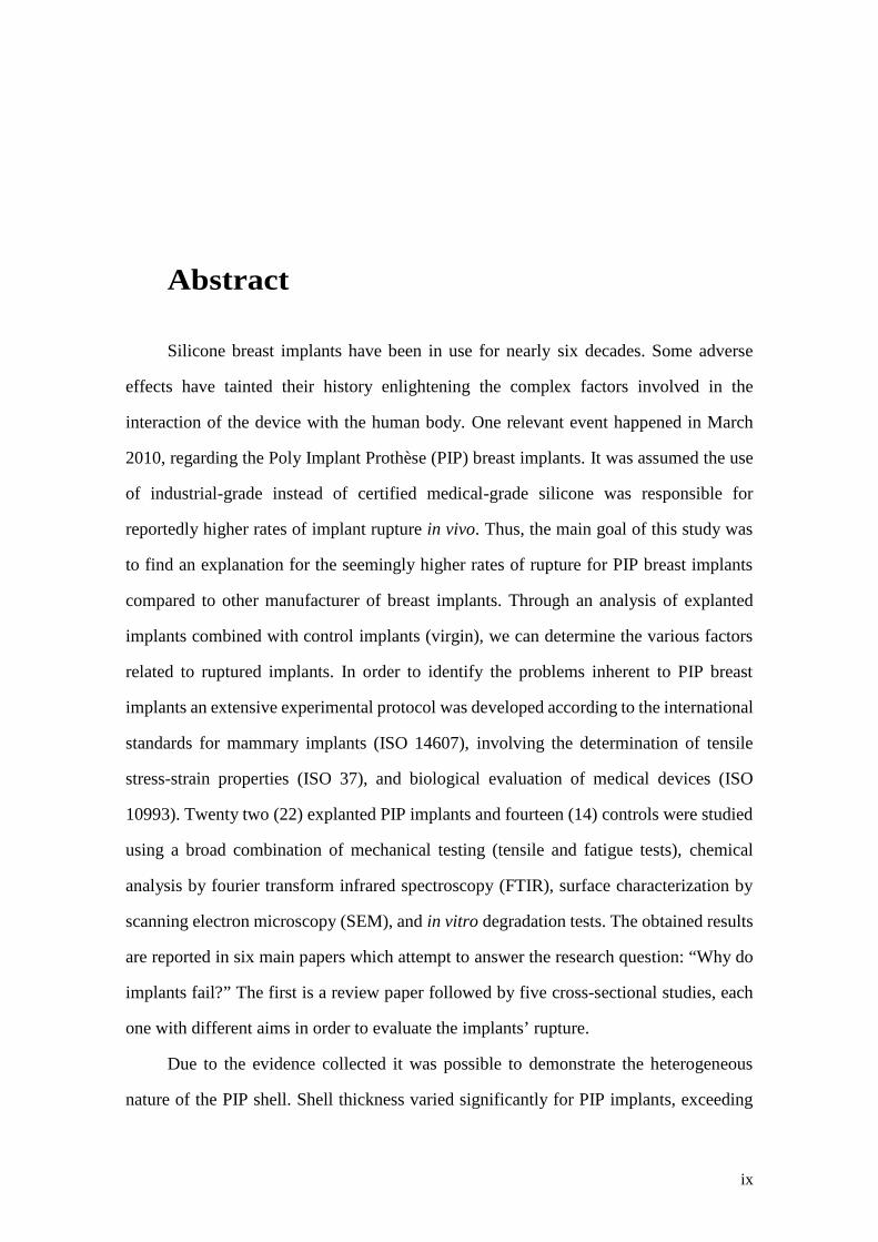
Silicone breast implants have been in use for nearly six decades. Some adverse
effects have tainted their history enlightening the complex factors involved in the
interaction of the device with the human body. One relevant event happened in March
2010, regarding the Poly Implant Prothèse (PIP) breast implants. It was assumed the use
of industrial-grade instead of certified medical-grade silicone was responsible for
reportedly higher rates of implant rupture in vivo. Thus, the main goal of this study was
to find an explanation for the seemingly higher rates of rupture for PIP breast implants
compared to other manufacturer of breast implants. Through an analysis of explanted
implants combined with control implants (virgin), we can determine the various factors
related to ruptured implants. In order to identify the problems inherent to PIP breast
implants an extensive experimental protocol was developed according to the international
standards for mammary implants (ISO 14607), involving the determination of tensile
stress-strain properties (ISO 37), and biological evaluation of medical devices (ISO
10993). Twenty two (22) explanted PIP implants and fourteen (14) controls were studied
using a broad combination of mechanical testing (tensile and fatigue tests), chemical
analysis by fourier transform infrared spectroscopy (FTIR), surface characterization by
scanning electron microscopy (SEM), and in vitro degradation tests. The obtained results
are reported in six main papers which attempt to answer the research question: “Why do
implants fail?” The first is a review paper followed by five cross-sectional studies, each
one with different aims in order to evaluate the implants’ rupture.
Due to the evidence collected it was possible to demonstrate the heterogeneous
nature of the PIP shell. Shell thickness varied significantly for PIP implants, exceeding
x
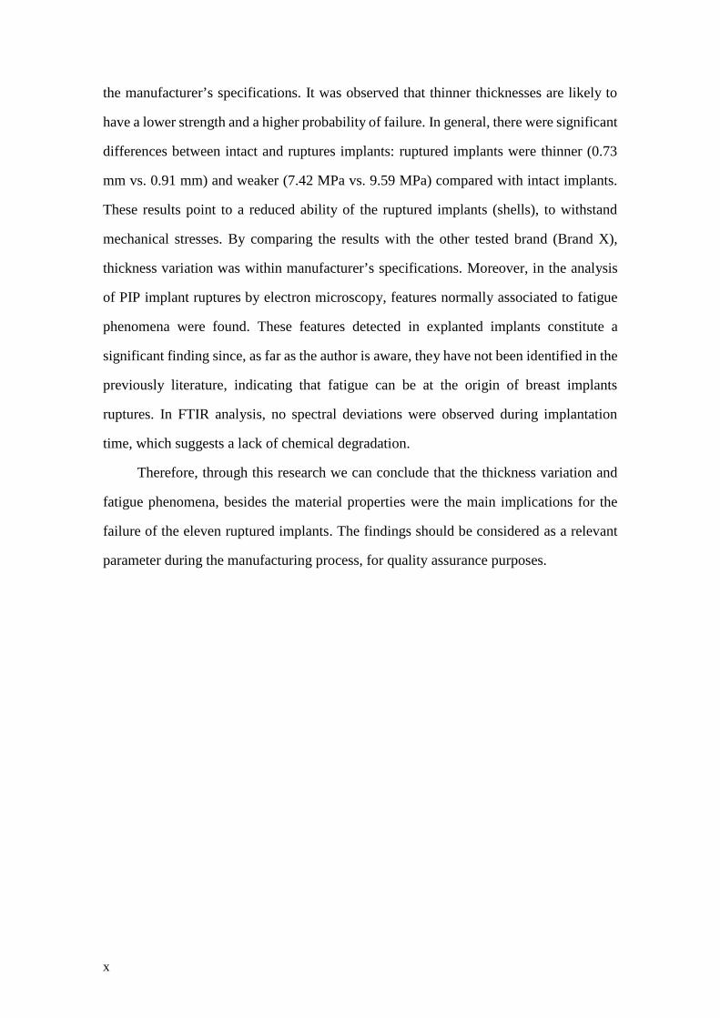
the manufacturer’s specifications. It was observed that thinner thicknesses are likely to
have a lower strength and a higher probability of failure. In general, there were significant
differences between intact and ruptures implants: ruptured implants were thinner (0.73
mm vs. 0.91 mm) and weaker (7.42 MPa vs. 9.59 MPa) compared with intact implants.
These results point to a reduced ability of the ruptured implants (shells), to withstand
mechanical stresses. By comparing the results with the other tested brand (Brand X),
thickness variation was within manufacturer’s specifications. Moreover, in the analysis
of PIP implant ruptures by electron microscopy, features normally associated to fatigue
phenomena were found. These features detected in explanted implants constitute a
significant finding since, as far as the author is aware, they have not been identified in the
previously literature, indicating that fatigue can be at the origin of breast implants
ruptures. In FTIR analysis, no spectral deviations were observed during implantation
time, which suggests a lack of chemical degradation.
Therefore, through this research we can conclude that the thickness variation and
fatigue phenomena, besides the material properties were the main implications for the
failure of the eleven ruptured implants. The findings should be considered as a relevant
parameter during the manufacturing process, for quality assurance purposes.
xi
Resumo
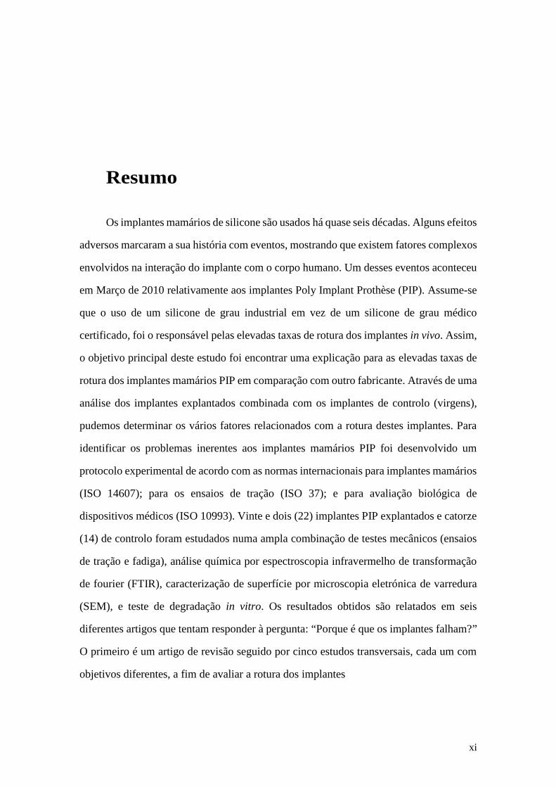
Os implantes mamários de silicone são usados há quase seis décadas. Alguns efeitos
adversos marcaram a sua história com eventos, mostrando que existem fatores complexos
envolvidos na interação do implante com o corpo humano. Um desses eventos aconteceu
em Março de 2010 relativamente aos implantes Poly Implant Prothèse (PIP). Assume-se
que o uso de um silicone de grau industrial em vez de um silicone de grau médico
certificado, foi o responsável pelas elevadas taxas de rotura dos implantes in vivo. Assim,
o objetivo principal deste estudo foi encontrar uma explicação para as elevadas taxas de
rotura dos implantes mamários PIP em comparação com outro fabricante. Através de uma
análise dos implantes explantados combinada com os implantes de controlo (virgens),
pudemos determinar os vários fatores relacionados com a rotura destes implantes. Para
identificar os problemas inerentes aos implantes mamários PIP foi desenvolvido um
protocolo experimental de acordo com as normas internacionais para implantes mamários
(ISO 14607); para os ensaios de tração (ISO 37); e para avaliação biológica de
dispositivos médicos (ISO 10993). Vinte e dois (22) implantes PIP explantados e catorze
(14) de controlo foram estudados numa ampla combinação de testes mecânicos (ensaios
de tração e fadiga), análise química por espectroscopia infravermelho de transformação
de fourier (FTIR), caracterização de superfície por microscopia eletrónica de varredura
(SEM), e teste de degradação in vitro. Os resultados obtidos são relatados em seis
diferentes artigos que tentam responder à pergunta: “Porque é que os implantes falham?”
O primeiro é um artigo de revisão seguido por cinco estudos transversais, cada um com
objetivos diferentes, a fim de avaliar a rotura dos implantes
xii
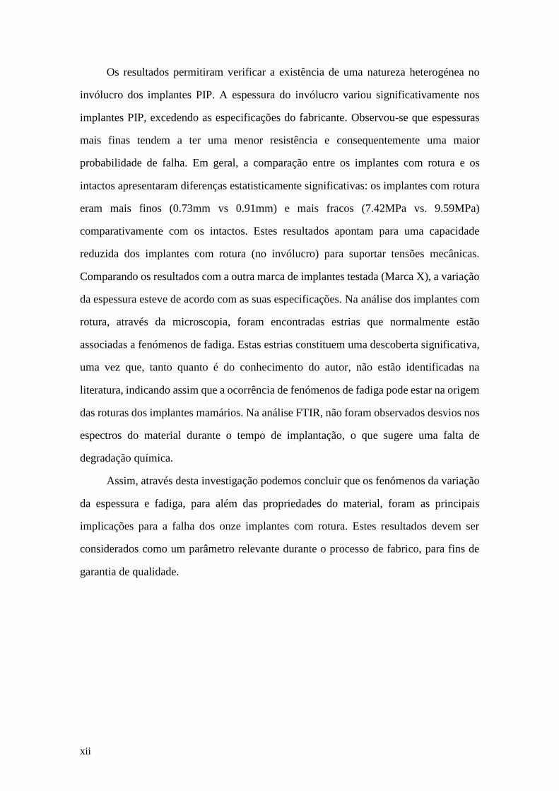
Os resultados permitiram verificar a existência de uma natureza heterogénea no
invólucro dos implantes PIP. A espessura do invólucro variou significativamente nos
implantes PIP, excedendo as especificações do fabricante. Observou-se que espessuras
mais finas tendem a ter uma menor resistência e consequentemente uma maior
probabilidade de falha. Em geral, a comparação entre os implantes com rotura e os
intactos apresentaram diferenças estatisticamente significativas: os implantes com rotura
eram mais finos (0.73mm vs 0.91mm) e mais fracos (7.42MPa vs. 9.59MPa)
comparativamente com os intactos. Estes resultados apontam para uma capacidade
reduzida dos implantes com rotura (no invólucro) para suportar tensões mecânicas.
Comparando os resultados com a outra marca de implantes testada (Marca X), a variação
da espessura esteve de acordo com as suas especificações. Na análise dos implantes com
rotura, através da microscopia, foram encontradas estrias que normalmente estão
associadas a fenómenos de fadiga. Estas estrias constituem uma descoberta significativa,
uma vez que, tanto quanto é do conhecimento do autor, não estão identificadas na
literatura, indicando assim que a ocorrência de fenómenos de fadiga pode estar na origem
das roturas dos implantes mamários. Na análise FTIR, não foram observados desvios nos
espectros do material durante o tempo de implantação, o que sugere uma falta de
degradação química.
Assim, através desta investigação podemos concluir que os fenómenos da variação
da espessura e fadiga, para além das propriedades do material, foram as principais
implicações para a falha dos onze implantes com rotura. Estes resultados devem ser
considerados como um parâmetro relevante durante o processo de fabrico, para fins de
garantia de qualidade.
xiii
Contents
Abstract .......................................................................................................................... ix
Resumo........................................................................................................................... xi
Contents ....................................................................................................................... xiii
List of Figures ............................................................................................................. xix
List of Tables............................................................................................................ xxvii
List of Abbreviations ............................................................................................... xxix
List of Symbols........................................................................................................ xxvii
Chapter I
Introduction .................................................................................................................... 3
1. Motivation ................................................................................................................. 3
2. Objectives.................................................................................................................. 5
3. Thesis Outline ........................................................................................................... 6
References ................................................................................................................... 10
Chapter II
Background Literature Review ................................................................................... 11
1. Evolution of Breast Implants................................................................................... 13
2. Mechanical Interaction between Tissue and Implants ............................................ 16
3. Mechanisms of Implant Failure............................................................................... 20
References ................................................................................................................... 26
Chapter III
Research Methodology ................................................................................................. 33
References ................................................................................................................... 42
xiv
Chapter IV
Review Article ............................................................................................................... 45
Biomechanical Properties of Breast Tissue, a State-of-the-art Review
Article 1 ...................................................................................................................... 47
Abstract .................................................................................................................... 49
1. Introduction.......................................................................................................... 51
2. Characterization of Soft Tissues – Basic Concepts ............................................. 56
3. Experimental Techniques to Characterize Breast Tissue..................................... 62
3.1 In vivo Techniques............................................................................................. 62
3.2. Ex vivo Techniques ........................................................................................... 65
4. Mechanical Properties of Breast Tissue............................................................... 67
5. Discussion and Conclusions ................................................................................ 78
References................................................................................................................ 86
Chapter V
Original Articles ........................................................................................................... 97
Mechanical Performance of Poly Implant Prosthesis (PIP) Breast Implants a
Comparative Study
Article 2 ...................................................................................................................... 99
Abstract .................................................................................................................. 101
1. Introduction........................................................................................................ 103
2. Material and Methods ........................................................................................ 104
2.1.Breast Implants Collection............................................................................... 104
2.2.Mechanical Testing Protocol ........................................................................... 104
2.2.1. Samples Preparation .................................................................................... 105
2.2.2. Testing Procedure ........................................................................................ 108
2.3 Statistical Analysis........................................................................................... 109
3. Results................................................................................................................ 109
3.1. Appearance of Explanted Implants ................................................................. 110
3.2. Mechanical Testing......................................................................................... 112
3.2.1 Breast Implants Shell Strength – Global Overview...................................... 112
3.2.2 Thickness Variation ...................................................................................... 120
xv
4. Discussion.......................................................................................................... 123
5. Conclusions........................................................................................................ 127
References.............................................................................................................. 129
Breast Implants Rupture Induced by Fatigue Phenomena
Article 3 (Letter Communication) ......................................................................... 133
References.............................................................................................................. 137
A Morphologic Analysis of Rupture of Poly Implant Prosthesis (PIP) Breast
Implants
Article 4 .................................................................................................................... 139
Abstract .................................................................................................................. 141
1. Introduction........................................................................................................ 143
2. Material and Methods ........................................................................................ 144
2.1 Materials .......................................................................................................... 144
2.2. Scanning Electron Microscopy (SEM) Analysis ............................................ 144
2.3 Fatigue Test...................................................................................................... 145
3. Results................................................................................................................ 146
3.1. Visual Inspection of Implants ......................................................................... 146
3.2. SEM Analysis of Shells and Failure Regions ................................................. 147
3.3 Fatigue Tests Results ....................................................................................... 151
4. Discussion.......................................................................................................... 153
5. Conclusions........................................................................................................ 157
References.............................................................................................................. 158
Intact vs Ruptured Breast Implants. A Woman-centric Paired Analysis
Article 5 .................................................................................................................... 163
Abstract .................................................................................................................. 165
1. Introduction........................................................................................................ 167
2. Material and Methods ........................................................................................ 168
2.1 Clinical Data .................................................................................................... 168
2.2 Testing Protocol ............................................................................................... 171
2.3 Fourier Transform Infrared Spectroscopy (FTIR) Characterization................ 171
2.4 Statistical Analysis........................................................................................... 172
xvi
3. Results................................................................................................................ 172
3.1. Shell Properties of Intact vs Ruptured Breast Implants .................................. 175
3.2. Chemical Characterization of Silicone Shells and Gels ................................. 180
4. Discussion.......................................................................................................... 181
5. Conclusions........................................................................................................ 184
References.............................................................................................................. 186
In vitro Degradation of Polydimethylsiloxanes for Breast Implant Applications
Phenomena
Article 6 .................................................................................................................... 191
Abstract .................................................................................................................. 193
1. Introduction........................................................................................................ 195
2. Material and Methods ........................................................................................ 196
2.1 Degradation test ............................................................................................ 197
2.2 Mechanical Test ............................................................................................. 197
2.3 Morphological Characterization ...................................................................... 198
2.4 Surface Characterization by Fourier Transform Infrared Spectroscopy (FTIR)
............................................................................................................................... 198
2.5 Statistical Analysis........................................................................................... 198
3. Results................................................................................................................ 199
3.1. Mass Loss During In Vitro Aging................................................................... 199
3.2 Mechanical Properties Analysis....................................................................... 200
3.3. SEM Analysis ................................................................................................. 202
3.4. ATR – FTIR Analysis..................................................................................... 204
4. Discussion.......................................................................................................... 206
5. Conclusions........................................................................................................ 207
References.............................................................................................................. 209
Chapter VI
Integrated Discussion ................................................................................................. 213
Chapter VII
Conclusions ................................................................................................................. 227

xvii
Chapter VIII
Limitations and Recommendations for Future Works ........................................... 233

xix
List of Figures
Chapter I – Introduction
Figure 1. Exploratory steps to evaluate the ruptures causes............................................ 6
Chapter II – Background Literature Review
Figure 1. Breast Implants Evolution. a) First Generation, b) Second Generation, and c)
Third Generation. Adapted from [7, 8]................................................................... 15
Figure 2. Modern Generation with round shape a) The textured surface and b) cohesive
gel is visible (the arrow points to the cohesive gel) ............................................... 16
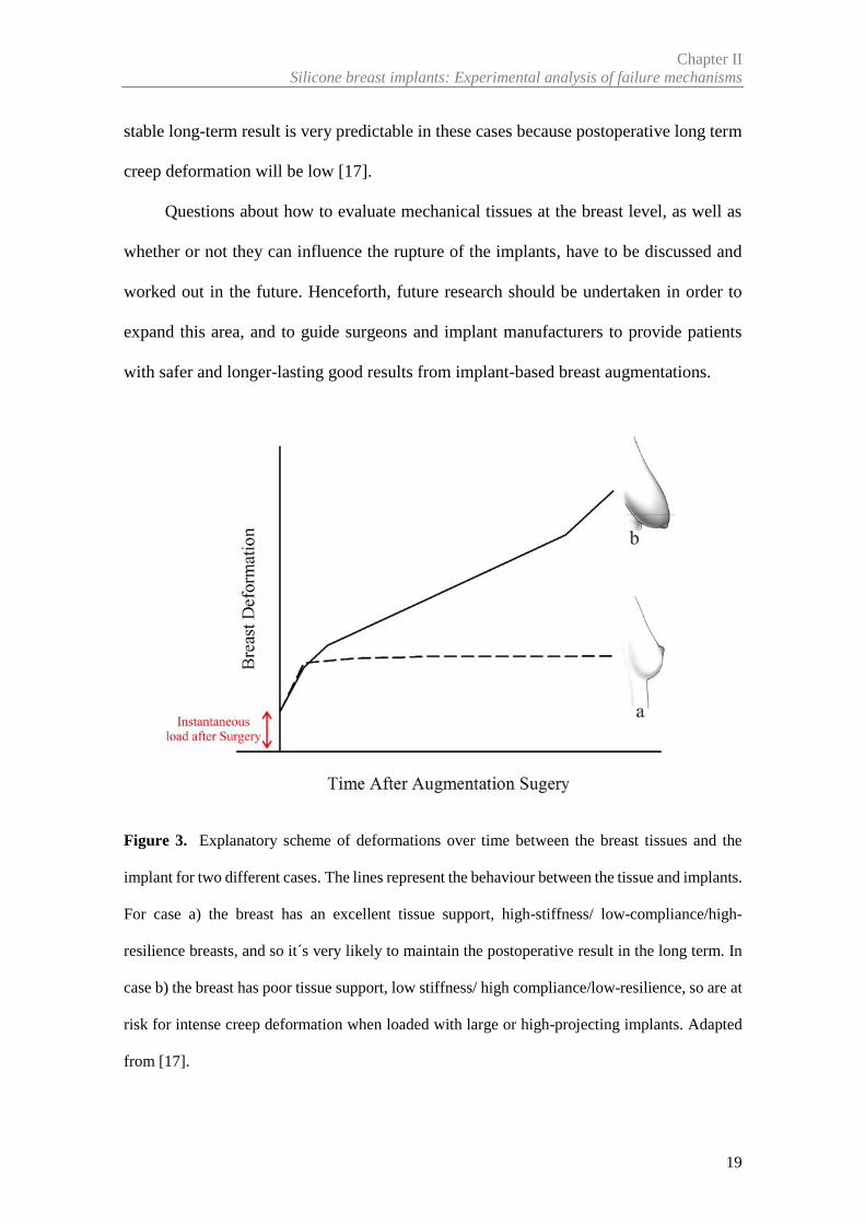
Figure 3. Explanatory scheme of deformations over time between the breast tissues and
the implant for two different cases. The lines represent the behaviour between the
tissue and implants. For case a) the breast has an excellent tissue support, high-
stiffness/ low-compliance/high-resilience breasts, and so it´s very likely to maintain
the postoperative result in the long term. In case b) the breast has poor tissue support,
low stiffness/ high compliance/low-resilience, so are at risk for intense creep
deformation when loaded with large or high-projecting implants. Adapted from [17].
................................................................................................................................ 19
Chapter III – Research Methodology
Figure 1. Exploratory steps to evaluate the ruptures causes, with description of the
methodology used…………………………………………………………………35
xx
Figure 2. Schematics of the experimental procedure: (a,b,c) implant segmentation into 12
segments, (d) example of sample preparation for tensile tests of a segment……….35
Figure 3. Scheme divided by articles about the number of implants and samples were
analysed .................................................................................................................. 41
Chapter IV – Review Article
Article 1- Biomechanical Properties of Breast Tissue, a State-of-the-art Review
Figure 1. Anatomy of Breast .......................................................................................... 52
Figure 2. Stiffness in different soft tissue. Adapted from [30]....................................... 56
Figure 3. Mechanical behaviour of linear elastic and hyperelastic materials................. 58
Figure 4 The dashed is a hyteresis loop and shows the amount of energy lost (as heat) in
a loading and unloading cycle. Adapted from [31]. ............................................... 59
Figure 5. (a) Unconfined compression, (b) Confined compression and (c) Indentation test
................................................................................................................................ 61
Figure 6.An overview of elasticity imaging methods. Adapted from [32,
66]…………………………………………………………………………………65
Figure 7. Behaviour of breast tissue at different levels of pre-load compression. Adapted
from [32, 34,85]...................................................................................................... 76
Chapter V – Original Articles
Article 2- Mechanical Performance of Poly Implant Prosthesis (PIP) Breast
Implants a Comparative Study
Figure 1. Classification of the Shell damage. a) Hole shaped damage; b) V- shaped split;
c) Split and d) Gross damage, in this case the shell and the cohesive gel were totally
separated.. ............................................................................................................. 106
Figure 2. Schematics of the experimental procedure. a) Regions of the implant; b) Implant
segmentation into 12 segments. To ensure traceability of each segment over the
xxi
implant, each segment was labelled with a number (1 to 12); c) example of sample
preparation for tensile tests; d) Tensile testing equipment ................................... 107
Figure 3. Scheme of the sample thickness measurement. Yellow-edges of the samples;
red-control area..................................................................................................... 108
Figure 4 This figure is a direct comparison between implants with a large and small
rupture. a Example of the aspect of the shell and gel in an explanted implant with
split rupture (posterior location and implanted for 40 months); b V-shape split that
shows a yellowish coloration and calcifications in gel and shell (anterior and
equatorial location and implanted for 46 months). ............................................... 111
Figure 5. Material behaviour of the control implants (stress at 266% of strain). Average
values of measures are expressed as mean (M) ± standard deviation (SD). A total of
24 samples in anterior region and 12 samples in posterior region are represented in
contour plot for ControlPip02. For ControlBrand X02, 23 samples are shown in
anterior and 20 in posterior
regions……………................................................................................................113
Figure 6. The box plot shows the stress (MPa) at 266% of strain between Controls (PIP
and brand X). Values are presented as median (horizontal line within box), 25-75th
percentile (box) and T-bars (range to the minimum or maximum values)........... 114
Figure 7. Stress (MPa) of two explanted implants with different characteristics - type of
rupture, implant colour and duration of implantation. PIP01 was implanted for 46
months, and had a V-shaped rupture and yellowish appearance (56 samples). PIP08
was implanted for 64 months, and had a hole rupture and clear appearance (57
samples). ............................................................................................................... 114
Figure 8. The box plot compare the stress (MPa) between three regions of implant
(Anterior, equatorial, and posterior) for three groups of implants ....................... 115
xxii
Figure 9. The box plot compares the stress (MPa) at different levels of strain between PIP
implants (explanted and control). Values are presented as median (horizontal line
within box), 25-75th percentile (box) and T-bars (range to the minimum or
maximum values)………………………………...………………………….…...117
Figure 10. a) Correlation between stress (MPa) at 266% of strain and duration of
implantation of ruptured PIP implants (r = 0.56; n=11; P = 0.0053); b) Correlation
between stress and year of implantation (r=-0.681; n=11;
P=0.0208)…………………………………………………………………….......118
Figure 11. Pearson correlation between stress (MPa) at 266% of strain and thickness (mm)
of controlPip01 breast implants (coefficients in Table 4). R2 is the coefficient of
determination. Total of 60 samples, from which 24 were in the anterior, 24 were in
the equatorial and 12 in the posterior
regions…………………………………………………………………..………..121
Figure 12. Example of Pearson correlation between stress (MPa) with 266% of strain and
thickness (mm) of explanted implant PIP04 (Coefficients are reported in Table 4).
R2 is the coefficient of determination. A total of 58 samples, from which 22 were in
the anterior region, 24 were in the equatorial and 12 in the posterior regions... .. 122
Figure 13. Example of Pearson correlation between stress (MPa) with 266% of strain and
thickness (mm) of ControlBrand X01 implant (Coefficients are reported in Table 4).
A total of 60 samples (24 in anterior; 12 in equatorial and 24 in posterior
regions)................................................................................................................. 122
Article 3- Breast Implants Rupture Induced by Fatigue Phenomena
Figure 1. Fatigue fracture surface a) schematic representation [4], b) micrograph (75x) of
implant samples from the hole rupture site, and c) micrograph (200x) of implant
xxiii
samples from the split rupture site;the arrow points to the fatigue crack
origin……………………………………………………………………….…….136
Article 4- A Morphologic Analysis of Rupture of Poly Implant Prosthesis (PIP)
Breast Implants
Figure 1. Samples Geometries. a) uniaxial sample and b) biaxial sample……………...146
Figure 2. Two implants with different ruptures. a) Gross Damage with 140mm of rupture
size; b) V-shape split with 80mm ........................................................................ 147
Figure 3.SEM micrographs (75x), view of v-shape split rupture in four
implants……………………………………………………………………..……148
Figure 4. SEM micrographs (75x), view of gross damage of the implant
shell…………………………………………………………………...………….149
Figure 5.Small ruptures. a) Hole rupture and b) Split rupture ..................................... 150
Figure 6. SEM micrographs of small ruptures - a,c) 75x; b,d) 200x. The same type of
striations appears in all implants. a,b) Split rupture and c,d) Hole rupture. The arrows
point in the direction of crack initiation point.. .................................................... 150
Figure 7. SEM micrographs (a) 75x and b) 200x) in biaxiais samples, the striations are
visible. The dashed lines are to emphasize part of striations................................ 152
Figure 8. a) schematic representation of radial tearing lines or ridges, and propagation of
a fatigue crack in parallel planes (see de arrow); b) micrograph of biaxial samples,
the radial tearing lines and the fatigue crack in parallel planes (see arrow) are visble.
.............................................................................................................................. 152
Figure 9. SEM micrographs of the a) inner surface (500x) and b) outer surface (75x) of
the sample IMGHC-TX-S-265 with damage........................................................ 153
xxiv
Article 5- Intact vs Ruptured Breast Implants. A Woman-centric Paired Analysis
Figure 1. Shell Aspect: a) Control implant; clear aspect. b) Intact implant; clear aspect
and no macroscopic changes. c) Ruptured shell; yellowed
shell........................................................................................................................174
Figure 2. Different gel conditions: a) Clear gel, non-cohesive (oily). b) Yellow gel, non-
cohesive. c) Clear gel, cohesive single mass ........................................................ 175
Figure 3. Comparison of Tensile Strength (MPa) for implant shells grouped according
with gel conditions. Values are presented as median (horizontal line within box), 25-
75th percentile (box) and T-bars (range to the minimum or maximum
values)………………………………………………………………………..…..176
Figure 4 Tensile strength (MPa) of explants and controls (3 groups) as a function of
implantation time (months). ................................................................................. 178
Figure 5.Comparison between intact and ruptured implants, per patient. The colour
variation represents the tensile strength along the shell. I= Intact implant; R=
Ruptured Implant; IT= Implantation Time and RT= Rupture type ...................... 180
Figure 6. FTIR spectra of gel and shell extracted from intact, ruptured and control
implants ................................................................................................................ 181
Article 6- In vitro Degradation of Polydimethylsiloxanes for Breast Implant
Applications Phenomena
Figure 1. Experimental results of weight loss for Brand 1 during the degradation period
under buffer solutions……………………………………………………….……199
Figure 2. Experimental results of weight loss for Brand 2 during the degradation period
under buffer solutions ........................................................................................... 200
xxv
Figure 3. Example of tensile test results during the degradation in two buffer solutions:
a) and b) for Brand 1 and lot 1.2; c) and d) for Brand 2. Blue and red lines are used
to represent the stiffening of the shell .................................................................. 202
Figure 4. SEM micrographs of the outer surface of a) Brand 1 implants (x75 to lot 1.1 and
x200 to lot 1.2), and b) Brand 2 implants (x75 and x200) over two time points (0 and
12 Weeks) under pH 7.4 and a pH 4.0 solutions .................................................. 203
Figure 5. FTIR spectra of Brand 1 (a) and Brand 2 (b) soaked in different solutions and
different degradations stages ................................................................................ 205

xxvii
List of Tables
Chapter IV – Review Article
Article 1- Biomechanical Properties of Breast Tissue, a State-of-the-art Review
Table 1. Mechanical tests for the breast tissue reported in literature, grouped according
with vital state of the subject (in vivo / ex vivo) and testing
technique……………………………………………………………………….….69
Table 2. A Summary of the results from mechanical testing of ex vivo breast
tissue………………………………………………………………………………74
Table 3. A summary of results from in vivo magnetic resonance elastography for breast
tissue………………………………………………………………………………78
Chapter V – Original Articles
Article 2- Mechanical Performance of Poly Implant Prosthesis (PIP) Breast
Implants a Comparative Study
Table 1. Clinical characteristics and implant rupture status ......................................... 110
Table 2. Multi-factor ANOVA analysis results. Homogeneous Groups regarding regions
(stress values at 266% strain) for all implants. The table is organized into subgroups,
and within each column, the levels contain a group of means within which there are
no statistically significant differences. ................................................................. 116
Table 3. Multi-factor ANOVA analysis results. Homogeneous Groups regarding stress
(at 266% strain) for PIP implants (explanted vs control). The table is organized into
xxviii
subgroups, and within each column, the levels contain a group of means within
which there are no statistically significant differences......................................... 119
Table 4. Correlation analysis using Pearson Correlation for all implants. ................... 123
Article 4- A Morphologic Analysis of Rupture of Poly Implant Prosthesis (PIP)
Breast Implants
Table 1. Information about the control PIP breast implants………………………..…..151
Article 5- Intact vs Ruptured Breast Implants. A Woman-centric Paired Analysis
Table 1. Clinical and demographic information……………………………………….170
Table 2. Classification of gel and shell condition………………………………….......174
Table 3.Multi-factor ANOVA results regarding gel condition for explanted
implants…………………………………………………………………………..176
Table 4. Multi-factor ANOVA analysis results regarding all implants, and shell
thickness…………………………………………………………………………177
Table 5. Tensile strength and thickness comparison between intact and ruptured explanted
implants per patient (data expressed as mean±standard
deviation)……………………………………………………………….……….179
Article 6- In vitro Degradation of Polydimethylsiloxanes for Breast Implant
Applications Phenomena
Table 1. Statistical analysis of mechanical properties for breast implant samples in
different stages of degradation (0 and 12 weeks). Bold type indicates significant
differences (p<0.05).............................................................................................. 201
xxix
List of Abbreviations
ATR Attenuated Total Reflectance
BMI Body Mass Index
CEMUP Materials Centre of the University of Porto
CETRIB Tribology, Vibrations and Industrial Maintenance
CT Computed Tomography
DCIS Ductal Carcinoma in Situ
IDC Invasive Ductal Carcinoma
D4 Octamethylcyclotetrasiloxane
FDA Food and Drug Administration (USA)
FEM Finite Element Method
FTIR Fourier Transform Infrared Spectroscopy
INFARMED National Authority of Medicines and Health Products
INEGI Institute of Science and Innovation in Mechanical and Industrial
Engineering
MRI Magnetic Resonance Imaging
MRE Magnetic Resonance Elastography
OCT Optical Coherence Elastography
PET Positron Emission Tomography
PIP Poly Implant Prothèse
TGA Therapeutic Good Administration (Australia)

xxx
SEM Scanning Electron Microscopy
SN Serial Number
SPECT Single Photon Emission Computed Tomography
PDMS Polydimethylsiloxanes
US Ultrasound
Th Thickness
xxvii
List of Symbols
σ Stress
ε Strain
E Young´s Modulus
ν Poisson’s ratio
q Load density
a Radius of loaded area (piston)
w Maximum displacement in the load direction
K Conversion factor that depends on the indenter’s geometry
ɛa Strain in loading direction (axial)
ɛd Strain in lateral direction
pi Initial weight of the sample
pf Weight after different degradation stages


Chapter I
_________________________________________________________________________________
Introduction

3
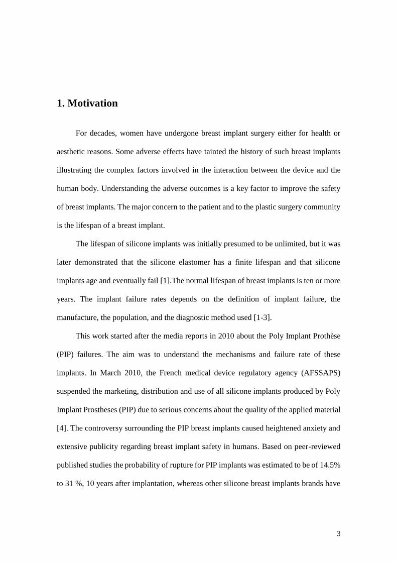
1. Motivation
For decades, women have undergone breast implant surgery either for health or
aesthetic reasons. Some adverse effects have tainted the history of such breast implants
illustrating the complex factors involved in the interaction between the device and the
human body. Understanding the adverse outcomes is a key factor to improve the safety
of breast implants. The major concern to the patient and to the plastic surgery community
is the lifespan of a breast implant.
The lifespan of silicone implants was initially presumed to be unlimited, but it was
later demonstrated that the silicone elastomer has a finite lifespan and that silicone
implants age and eventually fail [1].The normal lifespan of breast implants is ten or more
years. The implant failure rates depends on the definition of implant failure, the
manufacture, the population, and the diagnostic method used [1-3].
This work started after the media reports in 2010 about the Poly Implant Prothèse
(PIP) failures. The aim was to understand the mechanisms and failure rate of these
implants. In March 2010, the French medical device regulatory agency (AFSSAPS)
suspended the marketing, distribution and use of all silicone implants produced by Poly
Implant Prostheses (PIP) due to serious concerns about the quality of the applied material
[4]. The controversy surrounding the PIP breast implants caused heightened anxiety and
extensive publicity regarding breast implant safety in humans. Based on peer-reviewed
published studies the probability of rupture for PIP implants was estimated to be of 14.5%
to 31 %, 10 years after implantation, whereas other silicone breast implants brands have
Chapter IIntroduction
4
been reported with a rupture rate of 1.1 to 11.6%, considering the same follow-up period
[5-11].
In order to identify the problems inherent to breast implants, it is necessary to
analyse the explanted implants. Thus, an extensive experimental protocol was developed
to analyse PIP explanted and control implants (PIP and other brand), in order to identify
the causes of implant failures, rupture mechanism, and the interaction between the
implants and breast tissue. The effects of implantation time on the durability of implant
shells should be analysed by studying the implants according to type, so that explants can
be compared with the controls. This is necessary because the strength of implant shells
can vary considerably as a function of manufacturer, implant type, and lot-to-lot
variability for the given type. For this reason data for the control implant, PIP and other
brand (Brand X) are also presented with the explant data in order to understand main
reason for the rupture causes.
This research was carried out with the collaboration of Dra. Maria da Luz Barroso
and Dra. Diana Costa Santos of Department of Plastic Surgery of the Hospital Center of
Gaia, Portugal. The collaboration involved the supply of all explanted breast implants,
demographic information about patients, clinical information and the necessary contacts
for the acquisition of the control implants (virgin) - PIP and another brand (Brand X). PIP
sealed controls were supplied by the National Authority of Medicines and Health
Products (INFARMED, Portugal). Brand X was supplied by manufacturers’
representatives in Portugal.
Chapter ISilicone breast implants: Experimental analysis of failure mechanisms
5
2. Objectives
The main goal of this study was to find an explanation for the seemingly higher
rates of rupture for PIP breast implants compared to other breast implants brands.
To understand and contextualize this problem, the following specific objectives
were defined:
- Review the mechanical properties of breast tissue.
- Characterize the ruptured breast implants as a function of patient´s
demographic and clinical data.
- Analyse and describe the rupture characteristics of explanted implants.
- Develop a protocol to analyse the shell integrity of explanted implants.
- Provide details of the ruptured shell region and its relation with breast
implant failure.
- Characterize the shells and gels (intact and ruptured implants) by chemical
surface analysis.
- In vitro evaluation of the effect of material properties during implantation
time, under physical/chemical conditions of the human body (temperature and pH).
- Validate the experimental results for explanted implants by comparison
with available control implants.
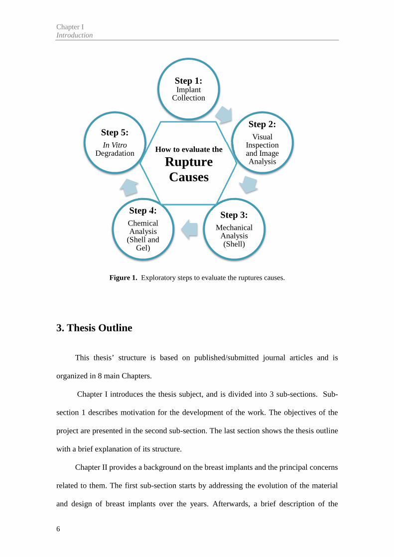
Figure 1 illustrates schematically the sequence of activities carried out to collect the
experimental data.
Chapter IIntroduction
6
Figure 1. Exploratory steps to evaluate the ruptures causes.
3. Thesis Outline
This thesis’ structure is based on published/submitted journal articles and is
organized in 8 main Chapters.
Chapter I introduces the thesis subject, and is divided into 3 sub-sections. Sub-
section 1 describes motivation for the development of the work. The objectives of the
project are presented in the second sub-section. The last section shows the thesis outline
with a brief explanation of its structure.
Chapter II provides a background on the breast implants and the principal concerns
related to them. The first sub-section starts by addressing the evolution of the material
and design of breast implants over the years. Afterwards, a brief description of the
Step 1:Implant
Collection
Step 2:Visual
Inspectionand ImageAnalysis
Step 3:Mechanical
Analysis(Shell)
Step 4:ChemicalAnalysis
(Shell andGel)
Step 5:In Vitro
Degradation How to evaluate the
RuptureCauses
Chapter ISilicone breast implants: Experimental analysis of failure mechanisms
7
relationship between tissues and breast implants is presented, as well as possible
complications associated with this interaction (sub-section 2). Sub-section 3 reviews the
main causes/implications of breast implants’ rupture.
Chapter III describes the experimental methodology adopted for this thesis.
Chapters IV (Review Article) and V (Original Articles) are composed of the articles
written during the project, depicting in greater detail the obtained results. These chapters
were designed to achieve the main purpose of this thesis, comprised of one review article
and five original studies, each one with different aims. The sequence of articles is
organized as follows:
Chapter IV - Article 1:
Title: Biomechanical Properties of Breast tissue, a State-of-the-art
Review.
Authors: Nilza Ramião, Pedro Martins, Rita Rynkevic, António A.
Fernandes, Maria da Luz Barroso, Diana C. Santos
Published in: Biomechanics and Modeling in Mechanobiology, 2016:15(5);
1307-23 doi: 10.1007/s10237-016-0763-8.
Chapter V- Article 2:
Title: Mechanical Performance of Poly Implant Prosthesis (PIP) Breast
Implants a Comparative Study
Authors: Nilza Ramião, Pedro Martins, Maria da Luz Barroso, Diana C.
Santos, Francisco Pereira, António A. Fernandes
Published in: Aesthetic Plastic Surgery, 2017, doi: 10.1007/s00266-017-0776-4
Chapter IIntroduction
8
Chapter V - Article 3:
Title: Breast Implants Rupture Induced by Fatigue Phenomena
Authors: Nilza Ramião, Pedro Martins, Maria da Luz Barroso, Diana C.
Santos, António A. Fernandes
Published in: Journal of Plastic, Reconstructive & Aesthetic Surgery, 2017, doi:
10.1016/j.bjps.2017.01.002
Chapter V - Article 4:
Title: An Experimental Analysis of Shell Failure in Breast Implants
Authors: Nilza Ramião, Pedro Martins, Maria da Luz Barroso, Diana C.
Santos, António A. Fernandes
Published in: Journal of the Mechanical Behavior of Biomedical Materials, 2017,
doi: 10.1016/j.jmbbm.2017.04.005
Chapter V - Article 5:
Title: Intact vs Ruptured Poly Implant Prothèse (PIP) Breast Implants. A
Woman-centric Paired Analysis
Authors: Nilza Ramião, Pedro Martins, Maria da Luz Barroso, Diana C.
Santos, António A. Fernandes
Submitted to an International Journal: Journal of Plastic, Reconstructive &
Aesthetic Surgery
Chapter ISilicone breast implants: Experimental analysis of failure mechanisms
9
Chapter V - Article 6:
Title: In vitro Degradation of Polydimethylsiloxanes for Breast Implant
Applications
Authors: Nilza Ramião, Pedro Martins, Maria da Luz Barroso, Diana C.
Santos, António A. Fernandes
Published in: Journal of Applied Biomaterials & Functional Materials, 2017, doi:
10.5301/jabfm.5000354
Chapter VI presents an integrated discussion of the obtained results and the thesis’
main contributions.
Chapter VII and VIII summarizes the main conclusions and possible pathways for
future research.
Chapter IIntroduction
10
References
[1] Rohrich RJ, Adams WP, Beran SJ et al (1998) An analysis of silicone gel-filled breast
implants: diagnosis and failure rates. Plast Reconstr Surg 1998;102:2304–2308 discussion 2309
[2] Cunningham B. The mentor core study on silicone memory gel breast implants. Plast
Reconstr Surg 2007; 120:19S–29S
[3] Spear SL, Murphy DK, Slicton A, et al. Inamed silicone breast implant core study
results at 6 years. Plast Reconstr Surg 2007; 120:8S–16S
[4] Scientific Committee on Emerging and Newly Identified Health Risks. The safety of
PIP silicone breast implants Available at:
http://ec.europa.eu/health/scientific_committees/emerging/docs/scenihr_o_043.pdf. [Accessed
March 10, 2013]
[5] Wazir U., Kasem A, Mokbel K. The Clinical Implications of Poly Implant Prothèse
Breast Implants: An Overview. Arch Plast Surg 2015; 42:4-10
[6] Maijers MC, Niessen FB. Prevalence of rupture in Poly Implant Prothèse silicone breast
implants, recalled from the European market in 2010. Plast Reconstr Surg 2012; 129:1372–1378.
[7] Berry MG, Stanek JJ (2013) PIP implant biodurability: a post-publicity update. J Plast
Reconstr Aesthet Surg. 66:1174-81
[8] Quaba O, Quaba A. PIP silicone breast implants: rupture rates based on the explantation
of 676 implants in a single surgeon series. J Plast Reconstr Aesthet Surg 2013;66(9):1182–1187.
[9] Oulharj S, Pauchot J, Tropet Y. PIP breast implant removal: a study of 828 cases. J
Plast Reconstr Aesthet Surg 2014;67:302-7
[10] Khan UD. Poly Implant Prothèse (PIP) Incidence of device failure and capsular
contracture: a retrospective study. Aesthetic Plast Surg 2013;37(5):906–913
[11] Spear SL, Murphy DK. Allergan Silicone Breast Implant U.S. Core Clinical Study
Group. Natrelle round silicone breast implants: core study results at 10 years. Plast Reconstr Surg
2014;133:1354-61

Chapter II
_________________________________________________________________________________
Background Literature Review

13
1. Evolution of Breast Implants
Breast augmentation is the third most performed aesthetical surgical procedure in
the world, with 1.348.197 surgeries having been performed in 2015 [1]. Breast implants
have been an essential tool in the global plastic surgeon’s cosmetic and reconstructive set
of skills since their invention by Cronin and Gerow in the early 1960’s [2]. Since then,
the development of new materials, manufacturing, design and surgical technical
improvement have continued to evolve. Five main generations of silicone breast implants
have been introduced to the market over the last 60 years [3]. The Breast implant material
is polydimethylsiloxane (PDMS), and over the years gels with different amounts of cross-
linking – and thus different properties – have been used. PDMS is the basis for both the
breast implant silicone gel and shell. PDMS “is an oily, sticky liquid with a viscosity that
increases as the average chain length (molecular weight) is increased” [4]. The breast
implants are created from liquid components during the formation of the shell, to which
are added a selected amount of “nano-particles” of amorphous “fumed” silica (SiO2) filler
[5]. Adding the “nano-particles” results in a silicone rubber with improved strength, and
increased elongation before failure as tensile loading is increased [4].
The gels are consisted of polymeric networks of swollen cross-linked PDMS. The
extent of cross linking and amount of fluid added to the gel accounts for the wide variety
of viscosities and cohesivities of various generation silicone gel implants [6]. In contrast,
the shell has “much greater crosslinking, very little fluid and the addition of amorphous
silica for strength” [6].
Chapter IIBackground Literature Review
14
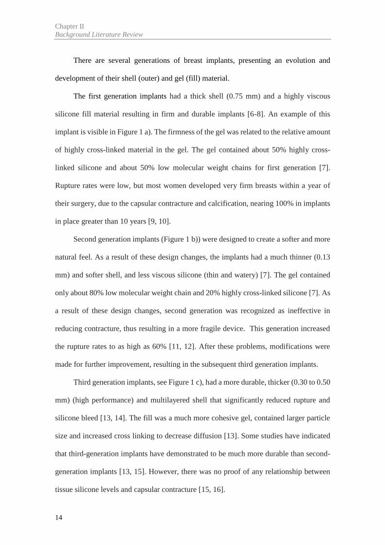
There are several generations of breast implants, presenting an evolution and
development of their shell (outer) and gel (fill) material.
The first generation implants had a thick shell (0.75 mm) and a highly viscous
silicone fill material resulting in firm and durable implants [6-8]. An example of this
implant is visible in Figure 1 a). The firmness of the gel was related to the relative amount
of highly cross-linked material in the gel. The gel contained about 50% highly cross-
linked silicone and about 50% low molecular weight chains for first generation [7].
Rupture rates were low, but most women developed very firm breasts within a year of
their surgery, due to the capsular contracture and calcification, nearing 100% in implants
in place greater than 10 years [9, 10].
Second generation implants (Figure 1 b)) were designed to create a softer and more
natural feel. As a result of these design changes, the implants had a much thinner (0.13
mm) and softer shell, and less viscous silicone (thin and watery) [7]. The gel contained
only about 80% low molecular weight chain and 20% highly cross-linked silicone [7]. As
a result of these design changes, second generation was recognized as ineffective in
reducing contracture, thus resulting in a more fragile device. This generation increased
the rupture rates to as high as 60% [11, 12]. After these problems, modifications were
made for further improvement, resulting in the subsequent third generation implants.
Third generation implants, see Figure 1 c), had a more durable, thicker (0.30 to 0.50
mm) (high performance) and multilayered shell that significantly reduced rupture and
silicone bleed [13, 14]. The fill was a much more cohesive gel, contained larger particle
size and increased cross linking to decrease diffusion [13]. Some studies have indicated
that third-generation implants have demonstrated to be much more durable than second-
generation implants [13, 15]. However, there was no proof of any relationship between
tissue silicone levels and capsular contracture [15, 16].
Chapter IISilicone breast implants: Experimental analysis of failure mechanisms
15
More recently, fourth and fifth generation implants have been developed [8]. These
implants have a more cohesive gel filler combined with thicker shells, and different
surfaces (both textured and smooth) [3, 8]. In order to minimize the amount of free low
molecular weight molecules available to pass into the surrounding tissues through the
silicone shell, the gels of the latest generation of implants are highly cross-linked [4].
The textured shell was developed with the aim to reduce capsular contracture, since
the tissues adhere better to rough surfaces. Also, the post-surgical mechanical behaviour
of implants filled with silicone gel is more similar to natural breast tissue.
Figure 1. Breast Implants Evolution. a) First Generation, b) Second Generation, and c) Third
Generation. Adapted from [7, 8].
Modern generation breast implants can be divided into different categories, such as
surface (textured, micro-textured and smooth), shape (round or anatomical), fill (cohesive
gel or saline), and implant dimensions (height/width, projection and volume). These
implant characteristics allow individualization for each patient depending on the patient’s
tissue quality/quantity and tissue-based bio-dimensional assessment. The choice of breast
implant is dependent on the specific surgical indication along with patient and surgeon
preferences [6].
Chapter IIBackground Literature Review
16
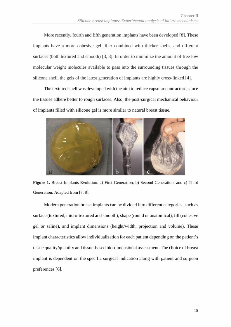
Based on the review about the breast implant evolution, the implants used in the
various studies throughout this thesis were: modern generation, textured shell, round
shape and with cohesive gel (Figure 2). All of them had different volumes.
Figure 2. Modern Generation with round shape a) The textured surface and b) cohesive gel is
visible (the arrow points to the cohesive gel).
2. Mechanical Interaction between Tissue and Implants
After augmentation or reconstruction, there is a need to increase the existing
knowledge of the breast to improve existing protocols of clinical examination, like
sensibility in the decision process, diagnostic and surgical planning. For these reasons, a
comprehensive knowledge of the mechanical properties of the breast tissues is important
for studying the effect of plastic and oncoplastic surgery techniques for breast
reconstruction as well as for design of cosmetic breast implants.
Breast augmentation may cause complications in the long-term. For instance,
postoperative tissue stretch deformities may appear. These complications are responsible
for many potential risks, such as breakdown of the inframammary fold, permanent tissue
atrophy, visible implant edges, and sensory loss [17].
Chapter IISilicone breast implants: Experimental analysis of failure mechanisms
17
In augmentation mammoplasty one of the complications is the malposition or
displacement of the prosthesis. This phenomenon can be seen when the patient’s breast
and skin are very soft and easily stretchable [18,19]. The displacement of the prosthesis
was not noted in patients with firm or normal breasts. Therefore, it is important to evaluate
the elasticity of the skin and other breast tissue (glandular and fat tissue) before designing
the placement of the breast implants. These factors highlight the importance of measuring
the elasticity of breast skin for surgery [18]. A survey performed among aesthetic plastic
surgeons [20] found that skin elasticity ranked first among the vital preoperative
considerations in breast augmentation.
In fact, the relationship between breast tissues and the mammary implant is a
reciprocal stress and strain [17]. A detailed understanding of breast tissue dynamics is
important for a long lasting and rewarding breast augmentation. Hence, a literature review
of the investigations that have been made on mechanical behaviour of different breast
tissues was done in by Ramião et al. [21].
Many of the factors affecting the results of the final implant shape are not well
understood by breast implant manufacturers, nor by the plastic surgery community. Some
of these factors are the effect that the implant shape (round vs anatomic) has on the final
breast shape, how the implant distributes its volume in the tissues and how the implant
and breast tissue change over time [22].
Ramião et al. [21] showed that the mechanical behaviour is different among the
tissues, and is highly dependent on the tissue preload compression level. For instance,
when the woman is subject to a breast augmentation, the breast is loaded with an implant
which undergoes instant deformation [17]. On the other hand, the stretched breast exerts
a load on the implant [17]. This deformation and load will not remain constant over time
because, among other factors, the augmented breast and the implant will undergo a
Chapter IIBackground Literature Review
18
variable amount of creep deformation. This can be associated to the distribution of various
tissues during women’s life cycle, which undergoes periodical changes that depend on
factors such as age, menstrual cycle, pregnancy/lactation, weight, body mass index,
hormone therapy and menopause. Such alterations are expected to have an effect on the
biomechanical properties of breast tissue. Summarily, the creep deformation of the
augmented breast is dependent on three factors, the implant size (volume), the ever-
changing supporting structure of the breast (coopers ligament) and aging (time).
Several authors showed that implant soft tissue dynamics affect the short and long-
term results of augmentation in both primary and reoperation cases [17, 22-26]. For the
best performance of breast augmentation, two concepts should be considered:
compliance/stiffness and resilience/creep.
For instance, women who need an augmentation mastopexy, because they suffer
from empty hypoplastic breasts after pregnancy/nursing, may have poor tissue support,
low-stiffness/ high compliance/ low-resilience breasts. These women are also at risk for
intense creep deformation when loaded with large or high-projecting implants [17]
(Figure 3). This type of breast, with poor tissue support, accepts large/high-projecting
implants. However, due its low resilience, it might easily undergo to a substantial amount
of creep deformation over time (Figure 3) [17]. Therefore, the choice of an implant with
a medium volume and projection is fundamental to avoid creep deformation. This
reasoning also applies to women with small breasts, excellent tissue support, and high-
stiffness/low-compliance/high-resilience breasts. This type of breast is not easily
stretched to the point of accepting a large/high-projecting implant due to its excellent
tissue support and, for the same reason, will not easily soften with time after the
augmentation [17]. Therefore, in these cases a ‘‘tight’’ breast augmentation will remain
tight for a long time because of its low compliance and high resilience. Furthermore, a
Chapter IISilicone breast implants: Experimental analysis of failure mechanisms
19
stable long-term result is very predictable in these cases because postoperative long term
creep deformation will be low [17].
Questions about how to evaluate mechanical tissues at the breast level, as well as
whether or not they can influence the rupture of the implants, have to be discussed and
worked out in the future. Henceforth, future research should be undertaken in order to
expand this area, and to guide surgeons and implant manufacturers to provide patients
with safer and longer-lasting good results from implant-based breast augmentations.
Figure 3. Explanatory scheme of deformations over time between the breast tissues and the
implant for two different cases. The lines represent the behaviour between the tissue and implants.
For case a) the breast has an excellent tissue support, high-stiffness/ low-compliance/high-
resilience breasts, and so it´s very likely to maintain the postoperative result in the long term. In
case b) the breast has poor tissue support, low stiffness/ high compliance/low-resilience, so are at
risk for intense creep deformation when loaded with large or high-projecting implants. Adapted
from [17].
Chapter IIBackground Literature Review
20
3. Mechanisms of Implant Failure
A considerable amount of literature is available in the area of chemical and physical
characterisation of breast implants in general, as well as PIP implants. Considerable
research has been conducted on the mechanical properties of implant shells in an effort
to find an explanation for the rates of rupture. Current section reports the results of breast
implant physicochemical characterisation studies that have been conducted [27].
Proposed causes for implant rupture include:
- damage from surgical instruments;
- shell swelling;
- fold flaw;
- trauma to the implant such as a force to the chest or closed capsulotomy;
- physical and chemical features of the initial implant;
- the implantation procedure and site;
- time since the implantation and associated material degradation;
- personal-specific factors such as lifestyle, and sportive activities or accidental
mechanical overexposure.
For a long time, some published studies have indicated that implant failure can be
explained on the basis of in vivo degradation of the shell’s mechanical properties when
exposed to a biological environment [28-31]. A negative correlation between implant
duration and mechanical resistance was found, suggesting a shell degradation.
The other cause for implant failure that was explored in the literature was focused
on the time-dependent phenomenon of the silicone shell’s swelling. The swell
phenomenon is described as a decrease in shell strength due to migration of silicone fluid
from the gel into the shell.
Chapter IISilicone breast implants: Experimental analysis of failure mechanisms
21
Various papers by Brandon and colleagues [32-36] report the mechanical properties
of various generations of implants manufactured by Dow Corning. The authors
confirmed the degradation in mechanical properties due to swelling but showed that the
crosslink density remained constant. In 2006 [37], they postulate failure at the site of
implants folds as an etiology of implant rupture, and reported that implant folding is
thought to be more common in the presence of capsular contracture of long duration.
More recently, Necchi et al. [38] studied the failure of 100 implants of a recent
generation, comparing intact (n=67) and ruptured (n=33) implants that were implanted
during 6 to 13 years. The gel was carefully removed from the shell, and the shell gently
wiped using isopropyl alcohol-moistened Kimwipes (Kimberly–Clark Corp., USA) from
explanted and control implants. Then, three samples for the tensile test (Die C half-scale,
see ASTM D 412-06ae2 Standard, 2006) were cut. The tests were carried out in
displacement control at a cross-head velocity of 250 mm/min. A preload of 0.2N was
imposed to uniform the specimens’ initial stress state. After tests, the authors found a
significant decrease in shell strength of ruptured versus non-ruptured implants, and
compared this change to shell swell based on increased fraction of extraction in the
ruptured implants.
Handel et al. [39] reported that the most common cause of implant rupture is
damage caused by surgical instruments during placement. In this article, Mentor and
Allergan data shows that 50−64% of ruptured implants were reported to be damaged by
surgical instruments. In addition, the authors suggest there is a critical need to implement
uniform statistical methodology using follow-up data only through the patient's last
magnetic resonance imaging scan, as rupture rates can vary greatly depending on the
statistical methodology selected. Brando et al. [40] confirmed the results of Handel et al.
Chapter IIBackground Literature Review
22
[39] through micrograph images. These authors showed micrographs that clearly
demonstrate that the shell striations present patterns similar to a scalpel cut.
Since March 2010 until the time of writing, most studies about implant ruptures
have focused on the French brand PIP. Several studies have attempted to delineate
specific flaws in the implants, and extrapolate the points at which quality control may
have failed. However, there were few physical and chemical studies on PIP implants, but
there is a large number of retrospective studies.
There are still some questions in the published literature regarding the specific flaw
in the PIP implants that lead to their failure. This is in part due to a lack of readily
accessible information regarding the specific processes used in the manufacture of the
PIP implants [41]. A major challenge in analysing data concerning PIP implants is that
there appears to have been variations in the quality of the implants between different
batches [27] that were released to the market.
There was no indication from the available data that the demographic profile of
patients (women) who have had PIP breast implants differ from women with implants
from other manufacturers [27].
Based on peer-reviewed published studies, the probability of rupture for PIP
implants is estimated to be around 14.5% to 31% after 5 to 10 years of implantation, while
other silicone breast implants have been reported with a rupture rate of 1.1 to 11.6% after
10 years of implantation [42-47].
Therapeutic Goods Administration (TGA) [48] analysed explanted and control
(new) PIP implants. For control PIP implants, the TGA presented that the mechanical
properties of shells meet the requirements of applicable international standards. However,
explanted PIP implants exhibited a decrease of the tensile strength of the shell
comparatively with control implants.
Chapter IISilicone breast implants: Experimental analysis of failure mechanisms
23
Yildirimer et al. [49] compared 18 explanted PIP implants (15 intact and 3 ruptured
implants) with four medical-grade silicone control implants. These implants were
subjected to mechanical tests and Fourier transform infrared spectra (FTIR). Mechanical
properties were assessed according to the standard ISO 37:2005. For tensile testing, dog
bone-shaped pieces type 3 (shaft length 20 mm, width 4mm, six pieces per implant) were
obtained from the shell. Uniaxial tension was applied to either end of the specimen at an
extension rate of 100mm/min until failure. FTIR spectra were obtained on a Jasco FT/IR
4200 spectrometer (Jasco, Great Dunmow, UK) equipped with a diamond attenuated total
reflectance (ATR). A total of six pieces per shell or gel were analysed. Spectra were
produced from an average of 20 scans at 4cm-1 resolution over a range of 600-4000cm-1
wave numbers. The authors showed that PIP silicone shells have significantly weaker
mechanical strength, when compared to medical grade controls. However, it must be
taken into account that the control implants were from another brand, as it is desirable to
compare the properties of the explants with those of lot-matched controls from the same
brand. FTIR analysis demonstrated changes that suggest degradation of the Si-O-Si cross-
links of the silicone in the PIP shells to Si-OH; such change correlated to the implantation
time. The explanted implants gels showed a variable consistency, ranging from highly
cohesive to soft, non-adhesive and prone to breakdown on manual handling compared
with gels taken from intact PIP and control implants. The probable reason for this is that
in vivo exposure of the silicone gel leads to degradation and cross-link scission.
Swart et al. [50] compared 19 explanted ruptured PIP implants with two control PIP
implants. Specimen preparation and investigations followed the protocol for “analysis of
breast implants” published by Brandon et al. [32-36] with the exception being that
mechanical properties were assessed according to the international standard for mammary
implants (ISO 14607:2007). Five dog-bone shaped specimens were cut from each implant
Chapter IIBackground Literature Review
24
shell using a die described in ISO 37:2005. The authors observed that key properties, such
as shell thickness displayed significant variation within sample and between samples of
PIP implants. They found areas on the surfaces of nearly all the explanted devices where
the absolute minimum thickness of the shell was below 0.57 mm, which was the minimum
specified by the manufacturer. This higher variability could partly explain the higher early
rupture rates of PIP implants.
Schubert et al. [51] compared 23 explanted PIP implants (13 textured and 10 micro-
textured) with 2 different brands. The mechanical properties of the shell were analysed
according to DIN 53504. Small dog-bone shaped specimens (shape S3) were chosen to
allow an investigation of the homogeneity of the mechanical properties. Each specimen
was stretched to failure at a constant crosshead speed yielding of 20 mm/min. One new
implant from each of the two brands was analysed together with five explants. The authors
reported that the tensile strength properties differ significantly between textured and
micro-textured PIP implants, and in particular, a micro-textured shell seems to be more
resilient.
Amoresano et al. [52] analysed 16 explanted implants from different manufacturers.
The implant shells have been examined following the standard procedure reported in ISO
104302:2012. Three to five samples for each implant has been cut into a dog-bone shaped,
50mm long, from the implant shells, and measurements between 0 and 4MPa were
performed using a tensile tester. The study revealed that the PIP implants had the greatest
weakening compared to all other samples. PIP implants showed breaking points at the
lowest strain value with respect to all others, which again was further indication of poor
mechanical properties. However, it is necessary to note that the experimental protocol
was different from other studies, and analysed only two PIP implants out of 16.
Chapter IISilicone breast implants: Experimental analysis of failure mechanisms
25
Beretta and Malacco [53] compared the filler materials of a ruptured explanted PIP
with a control McGhan implant and a sample of technical-grade silicone. The authors
analysed these samples using rheological techniques, attenuated total reflectance infrared
spectroscopy, nuclear magnetic resonance, gas chromatography coupled to mass
spectrometry and flow injection electrospray mass spectrometry. They found significant
amounts of cholesterol and a lack of cross-linkages from gel of PIP implants, which
corresponded with the lack of cohesiveness compared to medical-grade silicone.
In conclusion, given the lack of standardized screening and reporting, as well as the
multiple implant generations and manufacturers available, it is difficult to reach
comparable rupture rates across implant types and manufacturers. Thus, the significant
differences in methodologies, experimental protocols, variations in patient evaluation, as
well as variable length of implantation duration reported in rupture data, make it difficult
to directly compare rupture rates across manufacturers and implant types (surface, shape,
volume, etc.).
Chapter IIBackground Literature Review
26
References
[1] ISAPS International Survey on Aesthetic. Global Statistic 2014. Available at:
http://www.isaps.org/news/isaps-global-statistics. [Accessed February 11, 2016]
[2] Cronin TD, Gerow FJ. Augmentation mammoplasty: A new ‘natural feel’ prosthesis.
Transections of the Third International Congress of Plastic Surgery, Amsterdam. Excerpta
Medical 1964:41–9
[3] Maxwell GP, Gabriel A. The evolution of breast implants. Plast Reconstr Surg
2014;134:12S-7S
[4] Daniels AU. Silicone breast implant materials. Swiss Med 2012; Wkly 142:w13614
[5] Colas A, Curtis J. Ch. 2.3 Silicone biomaterials: history and chemistry. In: Ratner B,
Hoffman A, Schoen F, Lemons J (editors). Biomaterials Science: An Introduction to Materials in
Medicine. 2nd Edition. New York: Elsevier; 2004. p. 80–6.
[6] Shaughnessy KO. Evolution and update on current devices for prosthetic breast
reconstruction. Gland Surgery 2015; 4(2):97-110
[7] Peters W. The evolution of breast implants. Can J Plast Surg 2002;10(5):223-236;
[8] Hillard C, Fowler JD, Barta R, Cunningham B. Silicone breast implant rupture: a
review. Gland Surg 2016. doi: 10.21037/gs.2016.09.12
[9] Cronin TD, Greenberg RL. Our experiences with the silastic gel breast prosthesis. Plast
Reconstr Surg 1970;46:1-7.
[10] Peters W, Pritzker K, Smith D, et al. Capsular calcification associated with silicone
breast implants: incidence, determinants, and characterization. Ann Plast Surg 1998;41:348-60
[11] Collis N, Sharpe DT. Silicone gel-filed breast implant integrity: a retrospective review
of 478 consecutively explanted implants. Plast Reconstr Surg 2000;105:1979- 85
[12] Brown SL, Middleton MS, Berg WA, et al. Prevalence of rupture of silicone gel breast
implants revealed on MR imaging in a population of women in Birmingham, Alabama. AJR Am
J Roentgenol 2000;175:1057-64
Chapter IISilicone breast implants: Experimental analysis of failure mechanisms
27
[13] Peters W, Lugowski S. Survival properties of third-generation silicone gel breast
implants. Can J Plast Surg 2002; 10:109-12
[14] Bondurant S, Enester V, Herdman R, eds. Safety of Silicone Breast Implants. Institute
of Medicine. Washington: National Academy Press, 1999
[15] Peters WJ, Pritzker KP, Smith DC, et al. Capsular calcification associated with silicone
breast implants: incidence, determinants, and characterization. Ann Plast Surg 1998;41:348-60.
[16] Yu LT, Latorre G, Marotta J, et al. In vitro measurement of silicone bleed from breast
implants. Plast Reconstr Surg 1996;97:756-64
[17] Vegas MR, del Yerro JLM. Stiffness, Compliance, Resilience, and Creep
Deformation: Understanding Implant-Soft Tissue Dynamics in the Augmented Breast:
Fundamentals Based on Materials Science. Aesth Plast Surg; 2013:37:922–930 DOI
10.1007/s00266-013-0197-y
[18] Ramião N, Martins P, Fernandes AA. Biomechanical Properties of Breast Tissue.
Bioengineering (ENBENG), 2013 IEEE 3rd Portuguese Meeting.
DOI: 10.1109/ENBENG.2013.6518432
[19] Takayanagi S, Nakagawa C, Sugimoto YS. Augmentation Mammaplasty: Where
Should the Implant Be Placed? Aesthetic Plastic Surgery, Springer – Verlag New York, LLC,
28:83–88, 2004, DOI: 10.1007/s00266-004-3118
[20] Choudry U, Kim N. Preoperative assessment preferences and reported reoperation
rates for size change in primary breast augmentation: a survey of ASPS members. Plast Reconstr
Surg; 2012:130:1352–1359
[21] Ramião, N., et al. Biomechanical properties of breast tissue, a state-of-the-art review.
Biomech Model Mechanobiol 2016:15(5); 1307-23 doi: 10.1007/s10237-016-0763-8.
[22] Abu-Hijleh MF, Roshier AL, Al-Shboul Q, Dharap AS, Harris PF. The membranous
layer of superficial fascia: Evidence for its widespread distribution in the body. Surg Radiol Anat;
2006:28:606–619
Chapter IIBackground Literature Review
28
[23] Tebbetts JB. A system for breast implant selection based« on patient tissue
characteristics and implant-soft tissue dynamics. Plast Reconstr Surg 2002;109:1396–1409
discussion 410–415
[24] Tebbetts JB, Adams WP. Five critical decisions in breast augmentation using five
measurements in 5 minutes: the high-five decision support process. Plast Reconstr Surg
2006;118:35S–45S
[25] Tebbetts JB, Teitelbaum S. High- and extra-high-projection breast implants: potential
consequences for patients. Plast Reconstr Surg 2010;126:2150–2159
[26] Handel N. Secondary mastopexy in the augmented patient: a recipe for disaster. Plast
Reconstr Surg; 2006:118:152S–163S discussion 64S–65S, 66S–67S
[27] Scientific Committee on Emerging and Newly Identified Health Risks. The safety of
PIP silicone breast implants Available at:
http://ec.europa.eu/health/scientific_committees/emerging/docs/scenihr_o_043.pdf. [Accessed
March 10, 2013]
[28] Wolf CJ, Brandon HJ, Young VL, Jerin KL, Srivastava AP. Chemical, Physical and
Mechanical Analysis of Explanted Breast Implants. In: Potter M, Rose NR, eds. Immunology of
Silicones. Springer, Berlin 1996;25-37
[29] Greenwald DP, Randolph M, May JW. Mechanical analysis of explanted silicone
breast implants. Plast Reconstr Surg. 1996;98(2):269-72
[30] Phillips J, de Camera DL, Lockwood MD. Grebner WC Strength of silicone breast
implants. Plast Reconstr Surg. 1996;97(6):1215-25
[31] Marotta JS, Amery DP, Widenhouse CW, Martin PJ, Goldberg EP. Degradation of
physical properties of silicone gel breast implants and high rates of implant failures. In
Proceedings of the 24th Annual Meeting of the Society of Biomaterials. 1998; 374:1999
[32] Brandon HJ, Jerina KL, Wolf CJ, Young VL. Ultimate strength properties of control
and explanted Silastic 0 and Silastic I silicone g el- filled breast implant shells. Aesthet. Surg J.;
1999 5, 381–387
Chapter IISilicone breast implants: Experimental analysis of failure mechanisms
29
[33] Brandon HJ, Jerina KL, Wolf CJ, Young VL. Ultimate strength properties of explanted
and control Silastic II silicone gel- filled breast implant shells. Aesthet. Surg. J; 2000: 2, 122–132
[34] Brandon HJ, Jerina KL, Wolf CJ, Young VL. In vivo aging characteristics of silicone
gel breast implants compared to lot matched controls. Plast. Reconstr. Surg; 2002:109 (6), 1927–
1933
[35] Brandon HJ, Young VL, Watson ME, Wolf CJ, Jerina KL. Protocol for retrieval and
analysis of breast implants. J. Long-Term. Eff. Med. Implants; 2003:13 (1), 49–61
[36] Wolf CJ, Brandon HJ, Young VL, Jerina KL. Effect of surgical insertion on the local
shell properties of SILASTIC II silicone gel breast implants. J. Biomater. Sci. Polym.; 2000: Ed.
11 (10), 1007–1021
[37] Brandon HJ, Taylor ML, Powell TE, Walker PS. Morphology of breast implant fold
flaw failure. J Long Term Eff Med Implants; 2006; 16:441-50
[38] Necchi S, Molina D, Turri S, Rossetto F, Rietjens M. Failure of silicone gel breast
implants: is the mechanical weakening due to shell swelling a significant cause of prostheses
rupture? J Mech Behav Biomed Mater; 2011: 4:2002–2008
[39] Handel N, Garcia ME, Wixtrom R. Breast implant rupture: causes, incidence, clinical
impact, and management. Plast Reconstr Surg 2013; 132:1128-37
[40] Brandon HJ, Taylor ML, Powell TE, Walker PS. Microscopy analysis of breast
implant failure due to surgical instrument damage, Aesth Surg J 2007; 27: 239–256.
[41] Wazir U., Kasem A, Mokbel K. The Clinical Implications of Poly Implant Prothèse
Breast Implants: An Overview. Arch Plast Surg 2015; 42:4-10
[42] Maijers MC, Niessen FB. Prevalence of rupture in Poly Implant Prothèse silicone
breast implants, recalled from the European market in 2010. Plast Reconstr Surg 2012; 129:1372–
1378
[43] Berry MG, Stanek JJ (2013) PIP implant biodurability: a post-publicity update. J Plast
Reconstr Aesthet Surg. 66:1174-81
Chapter IIBackground Literature Review
30
[44] Quaba O, Quaba A. PIP silicone breast implants: rupture rates based on the
explantation of 676 implants in a single surgeon series. J Plast Reconstr Aesthet Surg
2013;66(9):1182–1187
[45] Oulharj S, Pauchot J, Tropet Y. PIP breast implant removal: a study of 828 cases. J
Plast Reconstr Aesthet Surg 2014;67:302-7
[46] Khan UD. Poly Implant Prothèse (PIP) Incidence of device failure and capsular
contracture: a retrospective study. Aesthetic Plast Surg 2013;37(5):906–913.
[47] Spear SL, Murphy DK. Allergan Silicone Breast Implant U.S. Core Clinical Study
Group. Natrelle round silicone breast implants: core study results at 10 years. Plast Reconstr Surg
2014;133:1354-61
[48] Australian Government Department of Health and Ageing Therapeutic Goods
Administration (TGA) (2013) PIP breast implants: Update on TGA testing of PIP breast implants.
http://www.tga.gov.au/alert/pip-breast-implants-update-tga-testing-pip-breast-implants.
[Accessed 10 March 2013]
[49] Yildirimer L, Seifalian AM, Butler PE. Surface and mechanical analysis of explanted
Poly Implant Prothèse silicone breast implants. Br J Surg 2013;100(6):761-7
[50] Swarts E, Kop A, Nilasaroya A; Keogh CV, Cooper T. Rupture of Poly Implant
Prothèse Silicone Breast Implants: An Implant Retrieval Study. Plast Reconstr Surg;
2013:131(4):480e-489e
[51] Schubert DW, Kaschta J, Horch RE, Waltera BL. On the failure of silicone breast
implants: new insights by mapping the mechanical properties of implant shells. Society of
Chemical Industry 2013; 63: 172–178
[52] Amoresano A, De Stefano L, Rea I, Pane F, Birolo L, Schonauer F. Chemical and
Structural Characterization of Several Mid-Term Explanted Breast Prostheses. Materials
2016;9:678
Chapter IISilicone breast implants: Experimental analysis of failure mechanisms
31
[53] Beretta G, Malacco M. Chemical and physicochemical properties of the high cohesive
silicone gel from Poly Implant Prothese (PIP) breast prostheses after explantation: a preliminary,
comparative analytical investigation. J Pharm Biomed Anal 2013; 78-79:75-82


Chapter III
_________________________________________________________________________________
Research Methodology

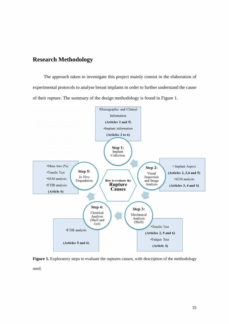
35
Research Methodology
The approach taken to investigate this project mainly consist in the elaboration of
experimental protocols to analyse breast implants in order to further understand the cause
of their rupture. The summary of the design methodology is found in Figure 1.
Figure 1. Exploratory steps to evaluate the ruptures causes, with description of the methodology
used.
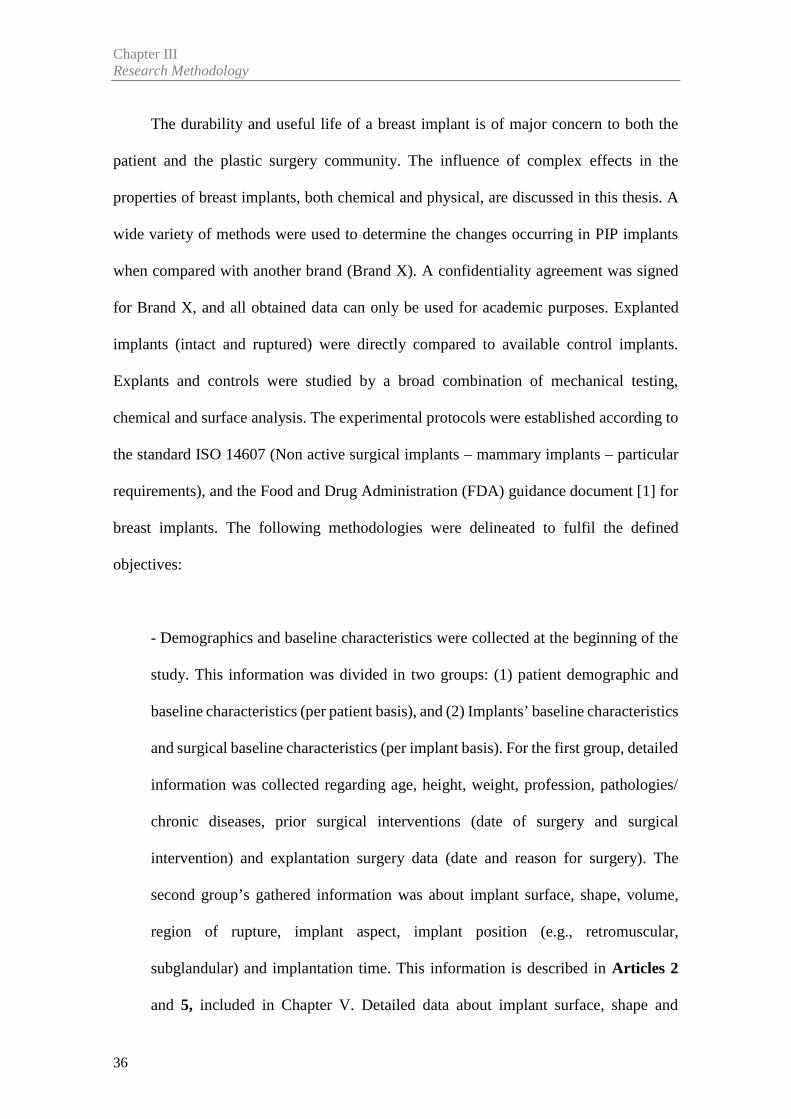
Chapter IIIResearch Methodology
36
The durability and useful life of a breast implant is of major concern to both the
patient and the plastic surgery community. The influence of complex effects in the
properties of breast implants, both chemical and physical, are discussed in this thesis. A
wide variety of methods were used to determine the changes occurring in PIP implants
when compared with another brand (Brand X). A confidentiality agreement was signed
for Brand X, and all obtained data can only be used for academic purposes. Explanted
implants (intact and ruptured) were directly compared to available control implants.
Explants and controls were studied by a broad combination of mechanical testing,
chemical and surface analysis. The experimental protocols were established according to
the standard ISO 14607 (Non active surgical implants – mammary implants – particular
requirements), and the Food and Drug Administration (FDA) guidance document [1] for
breast implants. The following methodologies were delineated to fulfil the defined
objectives:
- Demographics and baseline characteristics were collected at the beginning of the
study. This information was divided in two groups: (1) patient demographic and
baseline characteristics (per patient basis), and (2) Implants’ baseline characteristics
and surgical baseline characteristics (per implant basis). For the first group, detailed
information was collected regarding age, height, weight, profession, pathologies/
chronic diseases, prior surgical interventions (date of surgery and surgical
intervention) and explantation surgery data (date and reason for surgery). The
second group’s gathered information was about implant surface, shape, volume,
region of rupture, implant aspect, implant position (e.g., retromuscular,
subglandular) and implantation time. This information is described in Articles 2
and 5, included in Chapter V. Detailed data about implant surface, shape and
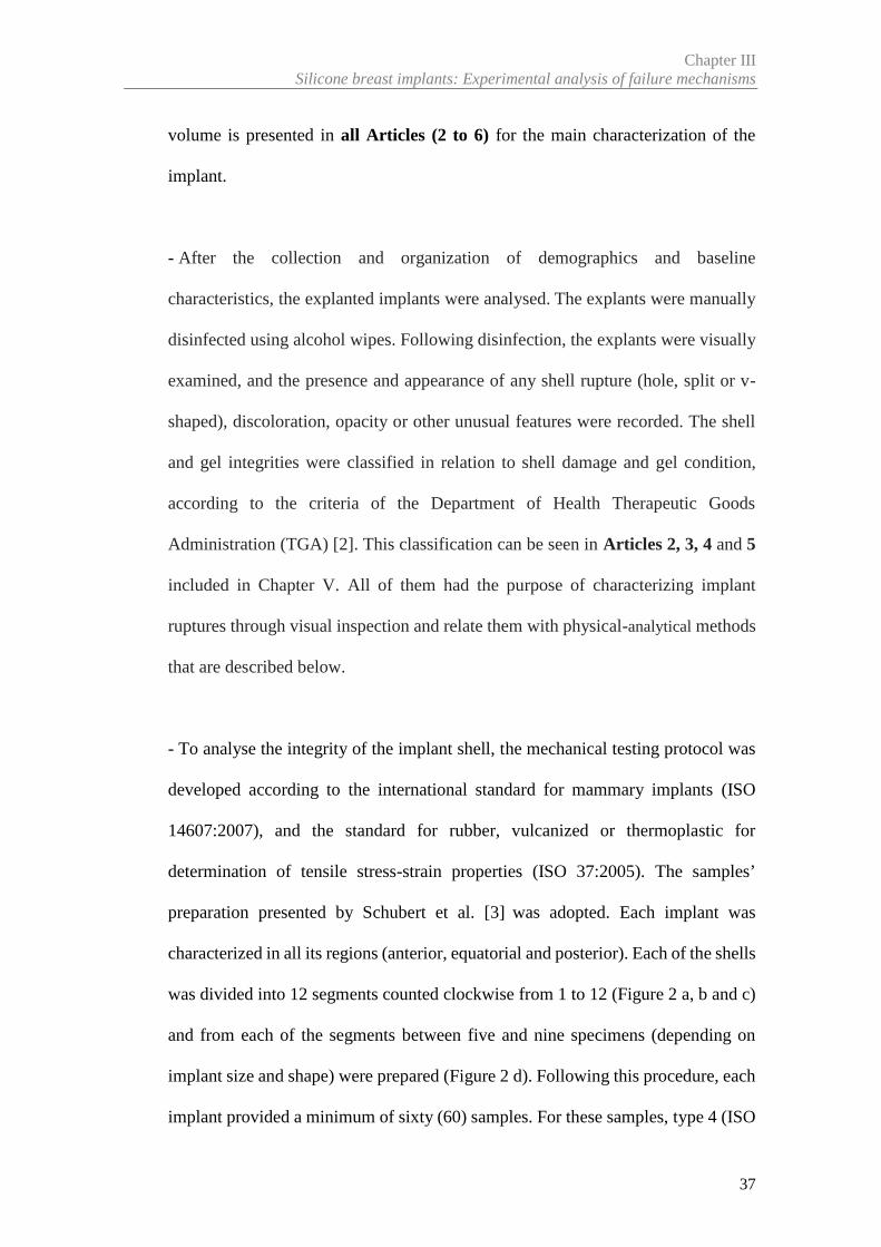
Chapter IIISilicone breast implants: Experimental analysis of failure mechanisms
37
volume is presented in all Articles (2 to 6) for the main characterization of the
implant.
- After the collection and organization of demographics and baseline
characteristics, the explanted implants were analysed. The explants were manually
disinfected using alcohol wipes. Following disinfection, the explants were visually
examined, and the presence and appearance of any shell rupture (hole, split or v-
shaped), discoloration, opacity or other unusual features were recorded. The shell
and gel integrities were classified in relation to shell damage and gel condition,
according to the criteria of the Department of Health Therapeutic Goods
Administration (TGA) [2]. This classification can be seen in Articles 2, 3, 4 and 5
included in Chapter V. All of them had the purpose of characterizing implant
ruptures through visual inspection and relate them with physical-analytical methods
that are described below.
- To analyse the integrity of the implant shell, the mechanical testing protocol was
developed according to the international standard for mammary implants (ISO
14607:2007), and the standard for rubber, vulcanized or thermoplastic for
determination of tensile stress-strain properties (ISO 37:2005). The samples’
preparation presented by Schubert et al. [3] was adopted. Each implant was
characterized in all its regions (anterior, equatorial and posterior). Each of the shells
was divided into 12 segments counted clockwise from 1 to 12 (Figure 2 a, b and c)
and from each of the segments between five and nine specimens (depending on
implant size and shape) were prepared (Figure 2 d). Following this procedure, each
implant provided a minimum of sixty (60) samples. For these samples, type 4 (ISO
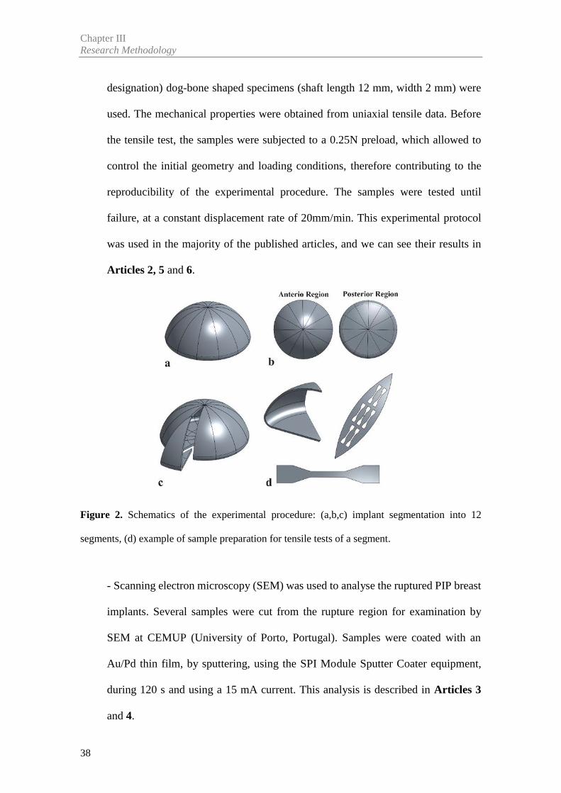
Chapter IIIResearch Methodology
38
designation) dog-bone shaped specimens (shaft length 12 mm, width 2 mm) were
used. The mechanical properties were obtained from uniaxial tensile data. Before
the tensile test, the samples were subjected to a 0.25N preload, which allowed to
control the initial geometry and loading conditions, therefore contributing to the
reproducibility of the experimental procedure. The samples were tested until
failure, at a constant displacement rate of 20mm/min. This experimental protocol
was used in the majority of the published articles, and we can see their results in
Articles 2, 5 and 6.
Figure 2. Schematics of the experimental procedure: (a,b,c) implant segmentation into 12
segments, (d) example of sample preparation for tensile tests of a segment.
- Scanning electron microscopy (SEM) was used to analyse the ruptured PIP breast
implants. Several samples were cut from the rupture region for examination by
SEM at CEMUP (University of Porto, Portugal). Samples were coated with an
Au/Pd thin film, by sputtering, using the SPI Module Sputter Coater equipment,
during 120 s and using a 15 mA current. This analysis is described in Articles 3
and 4.
Chapter IIISilicone breast implants: Experimental analysis of failure mechanisms
39
- The research made to determine the causes and mechanisms of rupture of PIP
explanted breast implants led to evidence that fatigue phenomena may be associated
with the initiation of implant rupture. In order to verify this phenomena, a fatigue
test protocol was carried out to simulate a mechanism of fatigue crack growth. Two
parameters were used in the fatigue test: displacement and frequency. The
displacement amplitude was 15mm, equivalent to ~20% strain in the narrow region
of the specimen. This displacement was calculated by the tensile tests carried out
in control implants in Article 2 and 5. The samples were tested at 1 Hz because it
is similar to that of walking or a beating heart [4]. This approach is described in the
Article 4 included in Chapter V.
- The characteristics of the degradation of the material are directly linked to the
breakage of crosslinks, and can be seen by Fourier Transform Infrared
Spectroscopy (FTIR). Thus, the chemical composition of the gel and shell of
explanted implants (intact and ruptured) were analysed by FTIR equipped with a
diamond attenuated total reflectance (ATR) accessory. Spectra were acquired over
20 scans with wavelengths ranging from 600 to 4000cm-1, with a resolution of 4
cm-1. This analysis is described in Article 5 included in Chapter V.
Several studies [5-12] pointed, as primary factor for in vivo implant shell failure,
the material degradation/change of properties during implantation time. This degradation
involves multiple physical and/or chemical processes. Although biodegradation effects
had been identified through the explanted implants, in vitro biodurability testing of PDMS
breast implants is not well documented in the open literature. The purpose of this study
was to characterize the degradation of the breast implant under physical/chemical
Chapter IIIResearch Methodology
40
conditions of the human body (temperature and pH): a ‘normal’ physiology (pH = 7.4)
and an inflammatory process (pH = 4.0), in order to understand whether the material was
degraded or not with the conditions imposed. This approach is described in Article 6
included in Chapter V, which comprises the following stages:
- In vitro degradation process was conducted in accordance with ISO 10993
"Biological evaluation of medical devices". To study in vitro degradation processes
of the implant shell, Phosphate Buffer Solution pH 7.4 (PBS) and Potassium
hydrogen phthalate buffered (HP) with pH 4.0 were used as a model of biological
fluid (normal and inflammation). Samples were kept in the buffered solutions at
37°C during twelve (12) weeks. After the degradation process began, a batch of
samples was removed periodically from the thermal bath for their weight to be
measured.
- Analysis of the mechanical performance of the shell after degradation (stage 0 and
12 week) followed the mechanical protocol described above.
- Analysis of the surface, via SEM, followed the protocol described above. In this
case, the shell surfaces were analysed to verify if there has been any changes due
to degradation.
- Analysis of the chemical composition FTIR, followed the protocol described
above.
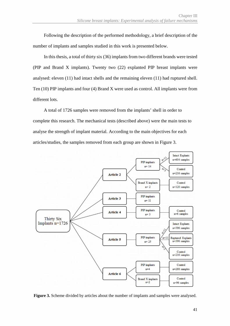
Chapter IIISilicone breast implants: Experimental analysis of failure mechanisms
41
Following the description of the performed methodology, a brief description of the
number of implants and samples studied in this work is presented below.
In this thesis, a total of thirty six (36) implants from two different brands were tested
(PIP and Brand X implants). Twenty two (22) explanted PIP breast implants were
analysed: eleven (11) had intact shells and the remaining eleven (11) had ruptured shell.
Ten (10) PIP implants and four (4) Brand X were used as control. All implants were from
different lots.
A total of 1726 samples were removed from the implants’ shell in order to
complete this research. The mechanical tests (described above) were the main tests to
analyse the strength of implant material. According to the main objectives for each
articles/studies, the samples removed from each group are shown in Figure 3.
Figure 3. Scheme divided by articles about the number of implants and samples were analysed.
Chapter IIIResearch Methodology
42
References
[1] USA Food and Drug Administration (FDA). Draft Guidance for Industry and FDA
Staff: Saline, Silicone Gel and Alternative Breast Implants. (November 2006)
http://www.fda.gov/downloads/medicaldevices/deviceregulationandguidance/guidancedocumen
ts/ucm071233.pdf. [Accessed 3 February 2012]
[2] Australian Government Department of Health and Ageing Therapeutic Goods
Administration (TGA) (2013) PIP breast implants: Update on TGA testing of PIP breast implants.
http://www.tga.gov.au/alert/pip-breast-implants-update-tga-testing-pip-breast-implants.
[Accessed 10 March 2013]
[3] Schubert DW, Kaschta J, Horch RE, Waltera BL. On the failure of silicone breast
implants: new insights by mapping the mechanical properties of implant shells. Society of
Chemical Industry 2013; 63: 172–178
[4] Roeder RK. Mechanical Characterization of Biomaterials. Elsevier Inc. 2013.
http://dx.doi.org/10.1016/B978-0-12-415800-9.00003-6. Chapter 3.4.4 pag 78-80. [Accessed 21
February 2016]
[5] Wolf CJ, Brandon HJ, Young VL, Jerin KL, Srivastava AP. Chemical, Physical and
Mechanical Analysis of Explanted Breast Implants. In: Potter M, Rose NR, eds. Immunology of
Silicones. Springer, Berlin 1996;25-37
[6] Greenwald DP, Randolph M, May JW. Mechanical analysis of explanted silicone breast
implants. Plast Reconstr Surg. 1996;98(2):269-72
[7] Phillips J, de Camera DL, Lockwood MD. Grebner WC Strength of silicone breast
implants. Plast Reconstr Surg. 1996;97(6):1215-25
[8] Marotta JS, Amery DP, Widenhouse CW, Martin PJ, Goldberg EP. Degradation of
physical properties of silicone gel breast implants and high rates of implant failures. In
Proceedings of the 24th Annual Meeting of the Society of Biomaterials. 1998; 374:1999
Chapter IIISilicone breast implants: Experimental analysis of failure mechanisms
43
[9] Yildirimer L, Seifalian AM, Butler PE. Surface and mechanical analysis of explanted
Poly Implant Prothèse silicone breast implants. Br J Surg 2013;100(6):761-7
[10] Birkefeld AB, Bertermann R, Eckert H, Pfleiderer V. Liquid- and solid-state high-
resolution NMR methods for the investigation of aging processes of silicone breast implants.
Biomaterials 2003;24:35-46
[11] Marotta JS, Goldberg EP, Habal MB, et al. Silicone Gel Breast Implant Failure:
Evaluation of Properties of Shell and Gels for Explanted Prostheses of Shells and Gels for
Explanted Prostheses and Meta-analysis of Literature Rupture Data. Ann Plast Surg. 2002;
49:227–247
[12] Pfleiderer B, Xu P, Ackermann JL, Garrido L. Aging of biomaterials based on silicone
rubber. J Biomed Mater Res 1995; 29:1129–40


Chapter IV
_________________________________________________________________________________
Review Article

Article 1
________________________________________________________
Biomechanical Properties of Breast Tissue, a State-of-the-artReview
Nilza Ramião a, Pedro Martins a, Rita Rynkevic a,b, António A. Fernandesa,c,
Maria da Luz Barrosod , Diana C. Santosd
a INEGI, Faculty of Engineering, University of Porto, Porto, Portugal
b Department of Development and Regeneration, Faculty of Medicine, University
Hospitals Leuven, Belgium
c Department of Mechanical Engineering, Faculty of Engineering, University of Porto,
Porto, Portugal
d Department of Plastic Surgery of Gaia Hospital Center, Vila Nova de Gaia, Portugal
Published in: Biomechanics and Modeling in Mechanobiology, 2016:15(5); 1307-23
doi: 10.1007/s10237-016-0763-8

49
Abstract
This paper reviews the existing literature on the tests used to determine the
mechanical properties of women breast tissues (fat, glandular and tumoral tissue) as well
as the different values of these properties. The knowledge of the mechanical properties
of breast tissue is important for cancer detection, study and planning of surgical
procedures such as surgical breast reconstruction using pre-surgical methods and improve
the interpretation of clinical tests.
Based on the data collected from the analysed studies some important conclusions
were achieved: (1) the Young’s modulus of breast tissues is highly dependent on the level
of tissue pre-load compression (2) the results of these studies clearly indicate a wide
variation in moduli not only among different types of tissue but also within each tissue
type. These differences were most evident in normal fat and fibroglandular tissues.
Keywords: Breast tissue, Mechanical properties, Compression loading,
Elasticity modulus.

51
1. Introduction
The breast is an important organ in women´s body, since it contains glandular tissue
essential for the production and secretion of milk. The breast is a heterogeneous structure
containing different tissue layers (Figure 1), however, the predominant types of tissue
within the breast are fat and glandular tissue. Each breast contains 15–25 lobes of
compound glands that are embedded in fibrous and adipose tissues. These lobes, each
containing an excretory duct that drains into the lactiferous sinus, radiate from a central
nipple-areolar complex.
The breast is firmly attached to the skin and underlying structures by fibrous bands
referred to as suspensory ligaments (Cooper’s ligaments), which provide the functions of
support, hold the breasts in place and contribute to determine the shape and contour of
the breast.
The distribution of various tissues during women’s life cycle undergoes cyclic
changes that depend on factors like age, menstrual cycle, pregnancy / lactation, hormone
therapy, menopause, among others. Some of these changes have profound effects in
tissue’s structure and morphology.
Such alterations are expected to have an effect on the biomechanical properties of
breast tissue. For instance, a stretching of Cooper’s ligaments and a weakening of the
coupling between the breast and the surrounding tissues are observed with increasing age.
An important property of soft tissues is their intrinsic elasticity, which may change under
the influence of pathophysiologic processes, such as tumor development [1]. Breast
cancer is the most common female disease worldwide, currently affecting approximately
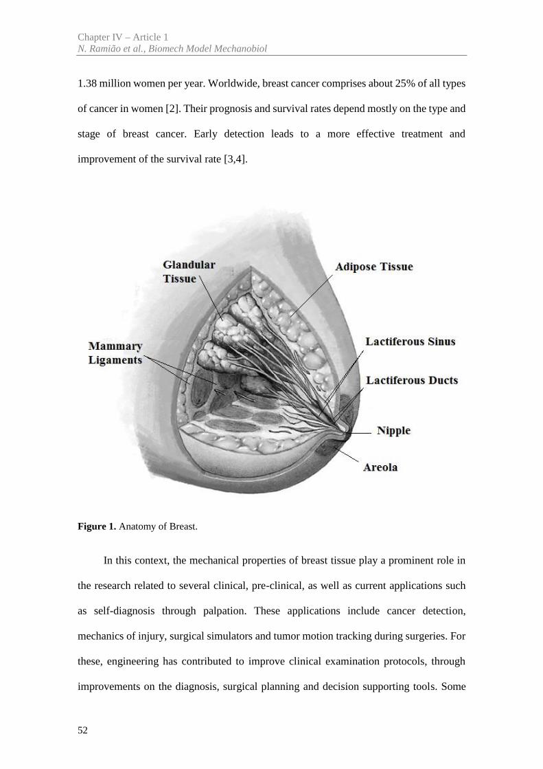
Chapter IV – Article 1N. Ramião et al., Biomech Model Mechanobiol
52
1.38 million women per year. Worldwide, breast cancer comprises about 25% of all types
of cancer in women [2]. Their prognosis and survival rates depend mostly on the type and
stage of breast cancer. Early detection leads to a more effective treatment and
improvement of the survival rate [3,4].
Figure 1. Anatomy of Breast.
In this context, the mechanical properties of breast tissue play a prominent role in
the research related to several clinical, pre-clinical, as well as current applications such
as self-diagnosis through palpation. These applications include cancer detection,
mechanics of injury, surgical simulators and tumor motion tracking during surgeries. For
these, engineering has contributed to improve clinical examination protocols, through
improvements on the diagnosis, surgical planning and decision supporting tools. Some
Chapter IV – Article 1Biomechanical Properties of Breast Tissue, a State-of-the-art Review
53
studies are based on biomechanics’ concepts using finite element modeling (FEM). These
numerical models are differentiated, primarily, by how the breast geometry is discretized,
application of boundary conditions, and/or knowledge of the breast tissue material
properties. In most studies, large deformations were considered, and information on
patient-specific breast morphology and on elastic-tissue properties was required. To
improve the outcome of breast needle biopsy, Azar et al. [5] developed a model of the
breast to predict tissue deformation during the procedure, and Carter et al. [6] presented
a model that can potentially be applied for image guided surgery.
Roose et al. [7] presented a computational model capable of simulating the
postoperative shape of the breast with up to 1cm accuracy after a subglandular breast
implantation.
Unlu et al. [8] developed and tested a new computerized finite element method
(FEM) based on a 3D non rigid registration of PET and MR breast images. This simple
method was proposed to facilitate the nonrigid registration of MRI or CT images of any
type of soft-tissue to their molecular counterparts such as those obtained using PET and
SPECT.
There are several challenges associated with localization of suspect lesions in the
breast in an MRI exam. These difficulties include patient positioning, visibility of the
lesion that may fade after contrast injection, menstrual cycles, and lesion deformation.
Stewart et al. [9], Azar et al. [5], Samani et al. [10], Carter et al. [6], Unlu et al. [8] and
Pathmanathan et al. [11] are examples of some authors that developed patient-specific
finite element (FE) breast models obtained from diagnostic MR images, with potential
for patient-specific therapeutics.
The ideal approach to achieve high quality patient-specific simulations should
include the in vivo, and ideally non-destructive estimation of the mechanical properties.
Chapter IV – Article 1N. Ramião et al., Biomech Model Mechanobiol
54
Han et al. [12] performed in vivo material parameter estimation by ultrasonic indentation
tests on breast tissues. Another in vivo experimental technique was used by Buijs et al.
[13], consisting of a model to predict target displacements using a combination of
ultrasound elastography and finite element (FE) modeling. This technique can help pre-
operative planning of minimally invasive surgical interventions.
While significant research has been conducted to develop techniques to measure
the elastic modulus of breast tissues, little research has been focused on their hyperelastic
mechanical behaviour.
Following, the ability of FE models to predict in vivo behaviour strongly depends
on the accuracy of the mechanical properties of tissue components. An accurate breast
model has proved to be very difficult to implement, due to several difficulties associated
to breast tissues:(1) the complex morphology; (2) the patient-specific variability, (3) the
highly nonlinear (hyperelastic) mechanical behaviour and (4) the difficulty of measuring
elastic properties of different types of tissues in the breast [10,14-18].
However, in order to make the biomechanical models predict more realistically in
vivo behaviour and help improving clinical and pre-clinical applications (for example,
cancer detection), several authors studied the mechanical properties of the different breast
tissues. Thus, throughout this article we provide a review about the techniques to measure
the mechanical properties in and ex vivo. These measurement types are subdivided in two
categories in vivo and ex vivo. Regarding ex vivo techniques, it is given a comprehensive
review of the test protocols (compressive tests) used in various studies as well as the
obtained biomechanical results [10,14,19-22]. Considering in vivo testing the approach is
elastography, a noninvasive by nature and based on an imaging technique [23-27].
All these studies have the purpose of simulating and assisting the diagnostic
methods used in clinical breast examination. In most breast examination methods,
Chapter IV – Article 1Biomechanical Properties of Breast Tissue, a State-of-the-art Review
55
compression is applied to help detecting lesions, and sometimes it becomes necessary to
apply higher compression loads to investigate stiffer regions. This situation creates the
need to know more about the mechanical properties of breast tissue under compression.
Despite the importance of compressive loading and its contribution to the characterization
of tissue in applications of cancer detection, there are few studies that have focused on
the mechanical behaviour of breast tissue in response to compression.
Widespread adoption of such techniques (in vivo and ex vivo) associated with
biomechanical modeling and imaging techniques of the breast have the potential to
significantly reduce the numbers of misdiagnosed breast cancers and enhance surgical
planning for patient treatment.
The main objective of this review is gathering the mechanical properties of breast
tissues (adipose, glandular, and tumor), available to date in the literature, through
different in vivo and ex vivo tests, enabling as well the identification of the relationship
between tissue properties and pathological mechanics.
An accurate knowledge of the breast tissues' mechanical properties allows realistic
simulations by finite element modeling and improvement in clinical exams for breast
cancer (screening, diagnosis and monitoring tests), thus it opens possibilities for medical
applications such as surgery planning and surgery outcome simulation.
This paper is organized in five sections that evolve from the simplest concepts of
breast tissue characterization to the state of the art testing techniques used. Section 2
details the characterization of breast tissues, and addresses the main experimental
challenges involved. Section 3 analyses the differences and specificities of in vivo and ex
vivo mechanical techniques. Section 4 summarizes the mechanical experimental results
of each breast tissue, and Section 5 includes a discussion and reached the conclusions.
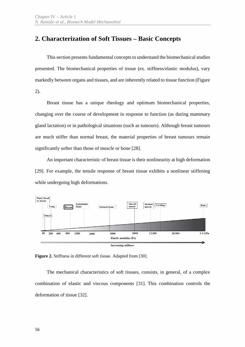
Chapter IV – Article 1N. Ramião et al., Biomech Model Mechanobiol
56
2. Characterization of Soft Tissues – Basic Concepts
This section presents fundamental concepts to understand the biomechanical studies
presented. The biomechanical properties of tissue (ex. stiffness/elastic modulus), vary
markedly between organs and tissues, and are inherently related to tissue function (Figure
2).
Breast tissue has a unique rheology and optimum biomechanical properties,
changing over the course of development in response to function (as during mammary
gland lactation) or in pathological situations (such as tumours). Although breast tumours
are much stiffer than normal breast, the material properties of breast tumours remain
significantly softer than those of muscle or bone [28].
An important characteristic of breast tissue is their nonlinearity at high deformation
[29]. For example, the tensile response of breast tissue exhibits a nonlinear stiffening
while undergoing high deformations.
Figure 2. Stiffness in different soft tissue. Adapted from [30].
The mechanical characteristics of soft tissues, consists, in general, of a complex
combination of elastic and viscous components [31]. This combination controls the
deformation of tissue [32].
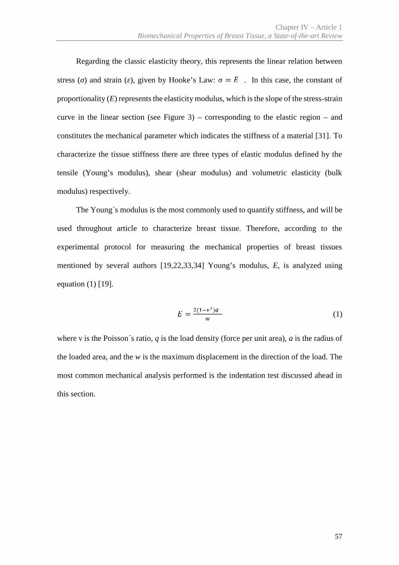
Chapter IV – Article 1Biomechanical Properties of Breast Tissue, a State-of-the-art Review
57
Regarding the classic elasticity theory, this represents the linear relation between
stress (σ) and strain (ε), given by Hooke’s Law: = . In this case, the constant of
proportionality (E) represents the elasticity modulus, which is the slope of the stress-strain
curve in the linear section (see Figure 3) – corresponding to the elastic region – and
constitutes the mechanical parameter which indicates the stiffness of a material [31]. To
characterize the tissue stiffness there are three types of elastic modulus defined by the
tensile (Young’s modulus), shear (shear modulus) and volumetric elasticity (bulk
modulus) respectively.
The Young´s modulus is the most commonly used to quantify stiffness, and will be
used throughout article to characterize breast tissue. Therefore, according to the
experimental protocol for measuring the mechanical properties of breast tissues
mentioned by several authors [19,22,33,34] Young’s modulus, E, is analyzed using
equation (1) [19].
= ( )(1)
where ν is the Poisson´s ratio, q is the load density (force per unit area), a is the radius of
the loaded area, and the w is the maximum displacement in the direction of the load. The
most common mechanical analysis performed is the indentation test discussed ahead in
this section.
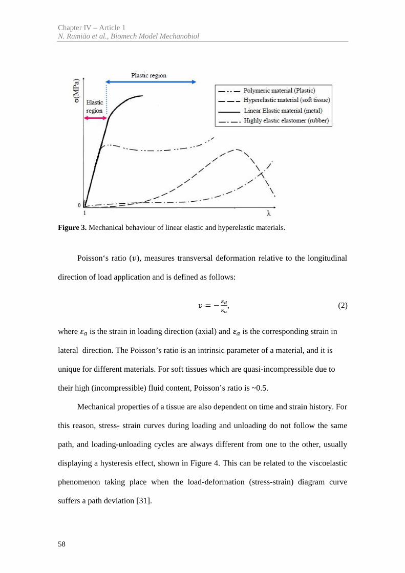
Chapter IV – Article 1N. Ramião et al., Biomech Model Mechanobiol
58
Figure 3. Mechanical behaviour of linear elastic and hyperelastic materials.
Poisson‘s ratio ( ), measures transversal deformation relative to the longitudinal
direction of load application and is defined as follows:
= − , (2)
where is the strain in loading direction (axial) and is the corresponding strain in
lateral direction. The Poisson’s ratio is an intrinsic parameter of a material, and it is
unique for different materials. For soft tissues which are quasi-incompressible due to
their high (incompressible) fluid content, Poisson’s ratio is ~0.5.
Mechanical properties of a tissue are also dependent on time and strain history. For
this reason, stress- strain curves during loading and unloading do not follow the same
path, and loading-unloading cycles are always different from one to the other, usually
displaying a hysteresis effect, shown in Figure 4. This can be related to the viscoelastic
phenomenon taking place when the load-deformation (stress-strain) diagram curve
suffers a path deviation [31].
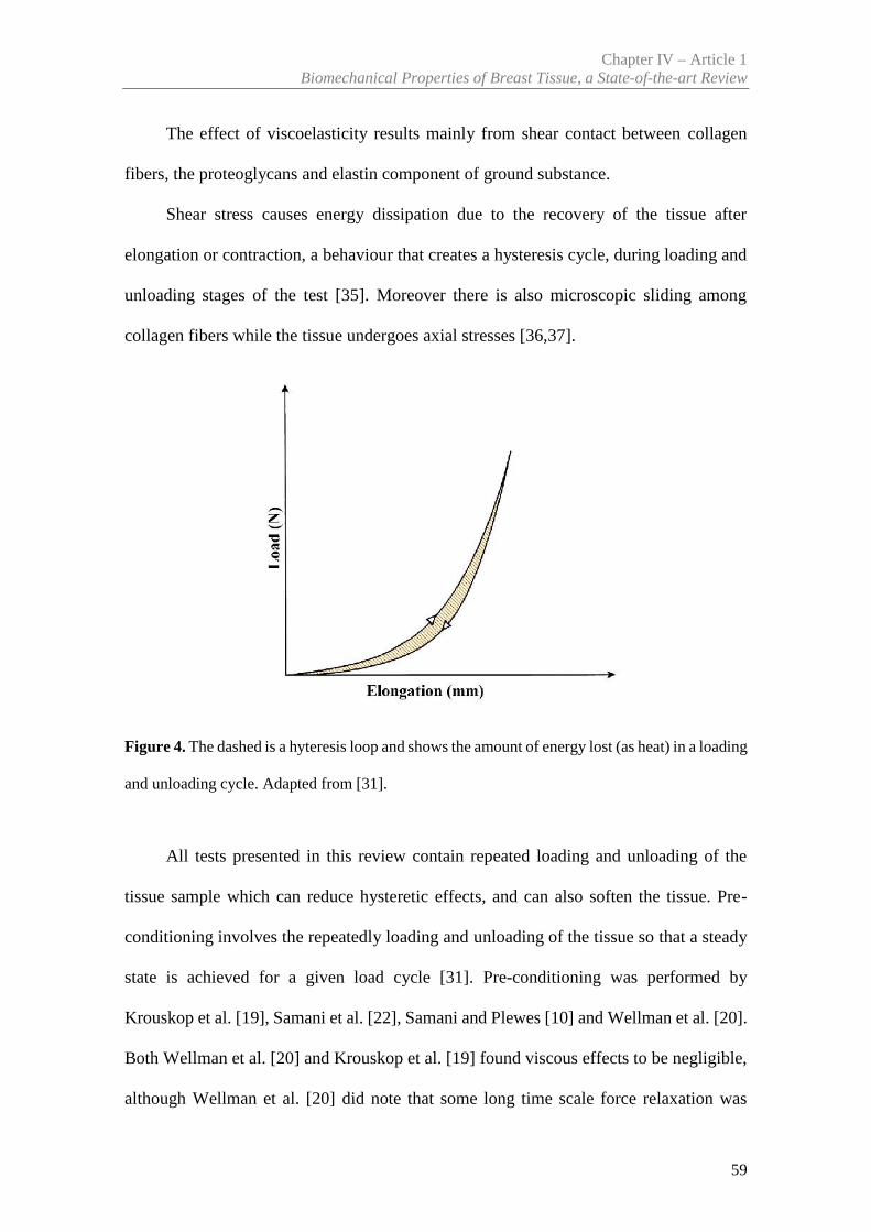
Chapter IV – Article 1Biomechanical Properties of Breast Tissue, a State-of-the-art Review
59
The effect of viscoelasticity results mainly from shear contact between collagen
fibers, the proteoglycans and elastin component of ground substance.
Shear stress causes energy dissipation due to the recovery of the tissue after
elongation or contraction, a behaviour that creates a hysteresis cycle, during loading and
unloading stages of the test [35]. Moreover there is also microscopic sliding among
collagen fibers while the tissue undergoes axial stresses [36,37].
Figure 4. The dashed is a hyteresis loop and shows the amount of energy lost (as heat) in a loading
and unloading cycle. Adapted from [31].
All tests presented in this review contain repeated loading and unloading of the
tissue sample which can reduce hysteretic effects, and can also soften the tissue. Pre-
conditioning involves the repeatedly loading and unloading of the tissue so that a steady
state is achieved for a given load cycle [31]. Pre-conditioning was performed by
Krouskop et al. [19], Samani et al. [22], Samani and Plewes [10] and Wellman et al. [20].
Both Wellman et al. [20] and Krouskop et al. [19] found viscous effects to be negligible,
although Wellman et al. [20] did note that some long time scale force relaxation was
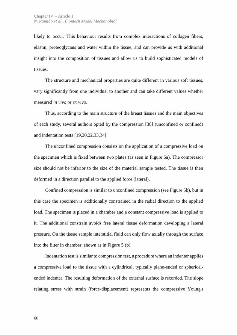
Chapter IV – Article 1N. Ramião et al., Biomech Model Mechanobiol
60
likely to occur. This behaviour results from complex interactions of collagen fibers,
elastin, proteoglycans and water within the tissue, and can provide us with additional
insight into the composition of tissues and allow us to build sophisticated models of
tissues.
The structure and mechanical properties are quite different in various soft tissues,
vary significantly from one individual to another and can take different values whether
measured in vivo or ex vivo.
Thus, according to the main structure of the breast tissues and the main objectives
of each study, several authors opted by the compression [38] (unconfined or confined)
and indentation tests [19,20,22,33,34].
The unconfined compression consists on the application of a compressive load on
the specimen which is fixed between two plates (as seen in Figure 5a). The compressor
size should not be inferior to the size of the material sample tested. The tissue is then
deformed in a direction parallel to the applied force (lateral).
Confined compression is similar to unconfined compression (see Figure 5b), but in
this case the specimen is additionally constrained in the radial direction to the applied
load. The specimen is placed in a chamber and a constant compressive load is applied to
it. The additional constrain avoids free lateral tissue deformation developing a lateral
pressure. On the tissue sample interstitial fluid can only flow axially through the surface
into the filter in chamber, shown as in Figure 5 (b).
Indentation test is similar to compression test, a procedure where an indenter applies
a compressive load to the tissue with a cylindrical, typically plane-ended or spherical-
ended indenter. The resulting deformation of the external surface is recorded. The slope
relating stress with strain (force-displacement) represents the compressive Young's
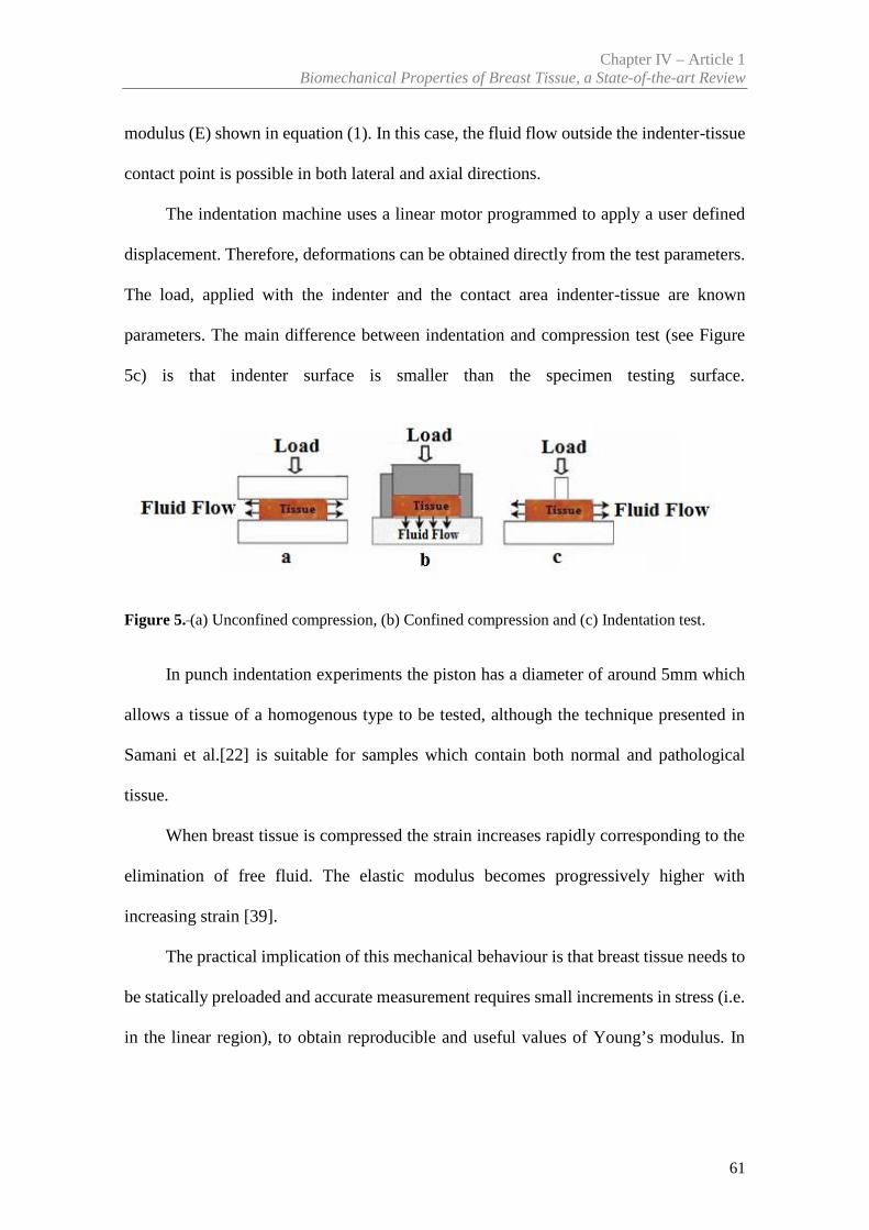
Chapter IV – Article 1Biomechanical Properties of Breast Tissue, a State-of-the-art Review
61
modulus (E) shown in equation (1). In this case, the fluid flow outside the indenter-tissue
contact point is possible in both lateral and axial directions.
The indentation machine uses a linear motor programmed to apply a user defined
displacement. Therefore, deformations can be obtained directly from the test parameters.
The load, applied with the indenter and the contact area indenter-tissue are known
parameters. The main difference between indentation and compression test (see Figure
5c) is that indenter surface is smaller than the specimen testing surface.
Figure 5. (a) Unconfined compression, (b) Confined compression and (c) Indentation test.
In punch indentation experiments the piston has a diameter of around 5mm which
allows a tissue of a homogenous type to be tested, although the technique presented in
Samani et al.[22] is suitable for samples which contain both normal and pathological
tissue.
When breast tissue is compressed the strain increases rapidly corresponding to the
elimination of free fluid. The elastic modulus becomes progressively higher with
increasing strain [39].
The practical implication of this mechanical behaviour is that breast tissue needs to
be statically preloaded and accurate measurement requires small increments in stress (i.e.
in the linear region), to obtain reproducible and useful values of Young’s modulus. In
Chapter IV – Article 1N. Ramião et al., Biomech Model Mechanobiol
62
addition, the testing conditions as well as tissue characteristics must be specified (for
example: age of the tissue, its temperature, type of test…).
3. Experimental Techniques to Characterize Breast Tissue
This section reviews the available literature on the stiffness of the breast tissues
obtained experimentally. The discussion is divided in two parts: (3.1) in vivo techniques
and (3.2) ex vivo techniques. With in vivo techniques tissues are tested with small strains
or loads and all the changes induced are reversible. In contrast, ex vivo protocol involves
larger strains or loads inducing non-reversible changes to the tissues. The relationships
between the strain (a measure of deformation) and the stress (internal pressure) are
reviewed for each breast tissue type [10,14,19-22,34,40-48]. Several authors have
reported that mammary tissue has a nonlinear mechanical response [8,14,10,19,21,22,41-
47,49-56]: the in vivo (elastography) and ex vivo (compression and punch indentation
tests) testing methods found in literature are summarized in Table 1. The mechanical
properties of the breast constituents have been characterized considering linear elastic
Young’s moduli to quantify the stiffness.
3.1 In vivo Techniques
Palpation is an effective method for breast cancer diagnosis. It’s a technique based
on a qualitative assessment of the low-frequency stiffness of tissue, which is primarily
useful to detect relatively large and superficial tumors.
However, this technique is not sufficiently sensitive with cases where the tumor is
too small and/or its location deep in the body, precludes its detection and evaluation by
palpation. In some cases, the examiner may be inexperienced or the signs are not clear,
Chapter IV – Article 1Biomechanical Properties of Breast Tissue, a State-of-the-art Review
63
so the result of palpation becomes doubtful. Therefore, other qualitative methods are
required to detect the presence of abnormalities.
To help detect relatively large and superficial tumors, an imaging technique, called
elastography, has been developed from the late 1980s to the early 1990s [51,57-59]. This
technique provides quantitative information on tissue stiffness and is characterized by
estimations of the elastic modulus [21,40,44,46,60].
Elastography helps estimating or assessing the non-invasively changes in the
mechanical properties of the tissues under compression at a microscopic level [45]. This
technology can be understood as imaging-based counterpart to palpation, commonly used
by physicians to diagnose and characterize diseases.
Elastography is characterized by having a higher degree of specificity and
sensitivity. It has the ability to detect the type of abnormality (tumor benign or malignant)
and separate it from healthy tissues, for example separating the tumor from the adipose
and fibroglandular tissue [49].
This technique provides insight into the elastic properties of biological tissues
(when applying a small axial uniform compression) and of the strains resulting on site
[51, 52, 60]. The goal of this technique is to create an image of the distribution of physical
parameters related to the mechanical properties of the tissue by measuring the response
or strain of the tissue resulting from the applied stress. The elasticity imaging methods
consist in applying some form of stress or mechanical excitation to the tissue, and
measuring the tissue response to this stimulus, and from this response calculating
parameters that reflect the mechanical properties (see Figure 6) [50].
There are different approaches to elastography, either quasi-static or dynamic
(transient and harmonic). The following references provide a comprehensive overview of
these techniques [51, 61-65].
Chapter IV – Article 1N. Ramião et al., Biomech Model Mechanobiol
64
There are different methods of elastography depending on the tissue response
measurement, namely ultrasonography/compression, MR and optical (Figure 6).
After the measurement of tissue responses to applied stress, using the elasticity
imaging processes and the acquired data, it's possible to estimate the mechanical
properties of the tissue. Typically, soft tissue is assumed to be isotropic, linear elastic,
and Hookean when elasticity imaging techniques are employed.
Some studies intend to characterize the type of abnormality and increase the
specificity of elastography, in an attempt to avoid unnecessary biopsies [55].
Changes in the stiffness of soft tissues are generally associated with the presence of
pathology; malignant or benign breast tumors are usually stiffer than normal breast
tissues, and malignant breast tumors are significantly stiffer when compared to benign
tumors. Thus, the mechanical properties of breast tissues, measured by elastography, can
help to detect the presence of abnormality in the breast (sensitivity), and also to classify
the type of the detected abnormality (specificity) [55].
Depending on the particular elastography technique used, there is a range of false-
negatives [33]. These errors could be reduced or minimized with a better understanding
of the testing conditions; such investigations can be carried out using ex vivo techniques.
As pre-compression, required to initiate elastography, influences the test results, an
improved knowledge of its influence is critical. A modern and more accurate definition
of pre-compression was provided by Umemoto et al. [34], “pre-load compression”.
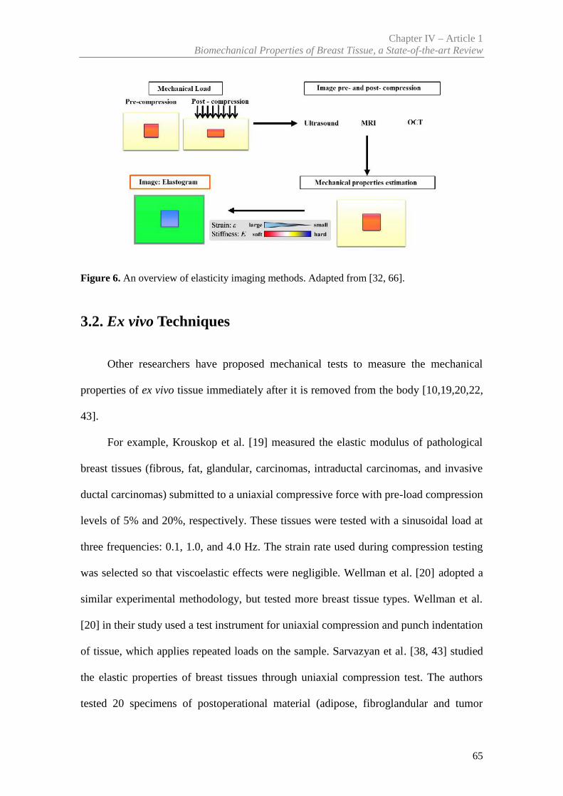
Chapter IV – Article 1Biomechanical Properties of Breast Tissue, a State-of-the-art Review
65
Figure 6. An overview of elasticity imaging methods. Adapted from [32, 66].
3.2. Ex vivo Techniques
Other researchers have proposed mechanical tests to measure the mechanical
properties of ex vivo tissue immediately after it is removed from the body [10,19,20,22,
43].
For example, Krouskop et al. [19] measured the elastic modulus of pathological
breast tissues (fibrous, fat, glandular, carcinomas, intraductal carcinomas, and invasive
ductal carcinomas) submitted to a uniaxial compressive force with pre-load compression
levels of 5% and 20%, respectively. These tissues were tested with a sinusoidal load at
three frequencies: 0.1, 1.0, and 4.0 Hz. The strain rate used during compression testing
was selected so that viscoelastic effects were negligible. Wellman et al. [20] adopted a
similar experimental methodology, but tested more breast tissue types. Wellman et al.
[20] in their study used a test instrument for uniaxial compression and punch indentation
of tissue, which applies repeated loads on the sample. Sarvazyan et al. [38, 43] studied
the elastic properties of breast tissues through uniaxial compression test. The authors
tested 20 specimens of postoperational material (adipose, fibroglandular and tumor
Chapter IV – Article 1N. Ramião et al., Biomech Model Mechanobiol
66
tissue) under compression between two plates. The intent of these studies was to
characterize the viscoelastic behaviour and to confirm whether or not the tissue could be
modeled as an elastic material within the frequency range of interest.
Samani et al. [10, 22] developed a complex system to measure the elastic modulus
of normal breast and tumorous tissue (without the need to remove the tumors) from slices
obtained after surgery. For normal tissue Samani et al. [67] developed a technique where
small block shape specimens were indented and the resulting force–displacement slope
was converted to the Young’s modulus using an FE model. For tumours, Samani and
Plewes [68] (used a technique where tumours remained within tissue slices. The tumour
is surrounded by normal tissues. The sample is indented and the resulting force
displacement slope converted to the Young’s modulus iteratively using the tissue slice
FE model. One major improvement of this technique is that tumorous tissue may be tested
imbedded on normal tissue. The comparison between experimental (experimental
phantom) and FE simulation (numerical phantom) data has associated errors. As the
authors recognize, an ideal solution would include 3D MRI or CT scan, so that the
naturally occurring variations in tumour shape and density can be reflected on the FE
simulation (detailed FE mesh). This may be the reason why the authors state that they
obtained a smaller error while analyzing larger tumours. A relevant thumb rule pointed
by the authors is the 1(thickness):4(slice diameter) ratio of tissue slice dimensions. This
is the minimal thickness: diameter ratio that allows a comparison between experimental
results and the FEM simulation of a semi-infinite body. For practical purposes, if the
tumours are small (less than a few centimeters) the errors due to the deformation of the
surrounding (normal) tissues will be significant.
Matsumura et al. [33] and Umemoto et al. [34], measured the elastic property,
young’s moduli, from surgically-resected breast tissue by material testing machine
Chapter IV – Article 1Biomechanical Properties of Breast Tissue, a State-of-the-art Review
67
(Instron) with 3mm cylindrical indenter. The breast tissues samples (glandular, adipose
and tumour tissue) were cut and soaked in saline and heated for 5 minutes in the
thermostatic chamber maintaining 45Cº temperature. Then the samples were removed
from the saline and placed on the testing stage which is kept under 37Cº temperature (the
surface of the sample is kept moist with saline). The authors used different compression
protocols, with compression starting from zero-compression (zero-stress – 0kPa) up to a
compression strain of 30% (50% in the case of fat or gland) with compression speed of
1mm/min.
In several studies of breast tissue, samples were properly preserved according to
standard preservation procedures. Often the time gap between collection and testing did
not exceed the period of two hours. There were no measurable changes in the data
obtained after allowing the specimens to sit for periods up to two hours [19, 22].
The experimental techniques used to estimate the biomechanical properties of
breast tissues during the last decades are summarized in Table 1.
4. Mechanical Properties of Breast Tissue
Over the past decades, several research works were performed to characterize the
biomechanical properties of soft tissues, which are subject to some degree of mechanical
activity [31]. However, very limited quantitative information is available on the
biomechanical properties of soft tissues, which do not have an active mechanical function
such as the breast [22].
Several studies [8,19,20,22,30,69] have quantified the mechanical properties of the
breast constituents using Young’s moduli to relate the stiffness to the type of tissue. These
studies have shown that tumors are much stiffer than normal breast tissues. This occurs
Chapter IV – Article 1N. Ramião et al., Biomech Model Mechanobiol
68
because the tumoral tissues undergo collagen remodeling which leads to stiffening.
According to Lopez et al. [70] “the oriented, thickened collagen fibers along whose
mammary gland tumor cells have been seen to migrate are indeed a source of the ECM
stiffening”. In order to develop tractable mathematical models, from which material
properties can be extracted, several researches [5,19,20,47,70-73] assumed that the
different types of tissue (fat, glandular and fibrous tissue) can be modeled as
homogeneous, and that their behaviour under compression is approximately isotropic and
nearly incompressible [31]. Since soft biological tissue is predominately composed of
water - an incompressible fluid - it is considered incompressible [31]. With these
assumptions, it is possible to model the behaviour of the tissue using a single elastic or
shear modulus. Several authors [5, 19,20, 22, 69, 74] considered that the incompressibility
condition imply that the Poisson ration is 0.5, which means if compressive load is applied
in axial direction the material expands in other two directions with a ratio of 0.5 with
respect to the compression axis [75].
Under these assumptions, Sarvazyan et al. [38] presented results in which they
measured the elastic modulus of 168 ex vivo specimens of normal, fibroadenomatous and
cancerous breast tissues. Reported Young’s modulus values ranged from 2.0 kPa for
normal tissue and 15.0 kPa for invasive ductal carcinomas. However, these authors did
not describe in detail their measurement system, so it is hard to identify the source of the
observed differences.
Sarvazyan et al. [43] reported a study of 150 specimens of normal,
fibroadenomatous and cancerous tissues. They showed that fibroadenomas are typically
4 times as stiff as normal tissue, while tumors can be as much as 7 times stiffer.
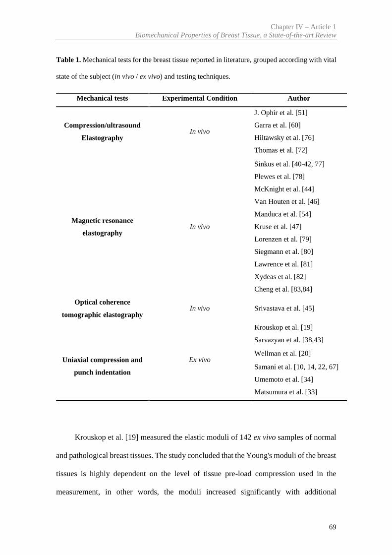
Chapter IV – Article 1Biomechanical Properties of Breast Tissue, a State-of-the-art Review
69
Table 1. Mechanical tests for the breast tissue reported in literature, grouped according with vital
state of the subject (in vivo / ex vivo) and testing techniques.
Mechanical tests Experimental Condition Author
Compression/ultrasound
ElastographyIn vivo
J. Ophir et al. [51]
Garra et al. [60]
Hiltawsky et al. [76]
Thomas et al. [72]
Magnetic resonance
elastographyIn vivo
Sinkus et al. [40-42, 77]
Plewes et al. [78]
McKnight et al. [44]
Van Houten et al. [46]
Manduca et al. [54]
Kruse et al. [47]
Lorenzen et al. [79]
Siegmann et al. [80]
Lawrence et al. [81]
Xydeas et al. [82]
Cheng et al. [83,84]
Optical coherence
tomographic elastographyIn vivo Srivastava et al. [45]
Uniaxial compression and
punch indentation
Ex vivo
Krouskop et al. [19]
Sarvazyan et al. [38,43]
Wellman et al. [20]
Samani et al. [10, 14, 22, 67]
Umemoto et al. [34]
Matsumura et al. [33]
Krouskop et al. [19] measured the elastic moduli of 142 ex vivo samples of normal
and pathological breast tissues. The study concluded that the Young's moduli of the breast
tissues is highly dependent on the level of tissue pre-load compression used in the
measurement, in other words, the moduli increased significantly with additional
Chapter IV – Article 1N. Ramião et al., Biomech Model Mechanobiol
70
compression. For example, at 5% pre-load compression strain he found that the ratio of
the elastic modulus of cancerous tissue to that of fat was 5:1, while at 20% pre-load
compression strain the ratio grew to 25:1. The same authors observed that the modulus of
adipose breast tissue is relatively constant over the range of loadings studied. For the
ductal carcinoma the modulus is low at low strain; it is indistinguishable from fat at the
low strain range but at the high strain range, the modulus is larger than any of the normal
tissues. The invasive ductal carcinomas are very stiff and the modulus of this tissue is
higher than the other tissues at both strain ranges tested. In conclusion, the modulus
dependency on pre-load compression confirms that the nonlinear elastic behaviour is
often observed in biological tissues [19,20]. Krouskop et al. [19] found that cancerous
tissue is not only much stiffer than adipose and normal glandular tissue, but displays a
higher non-linear increase in stiffness. Recent studies by Barr and Zhang [85] contradict
the results of Krouskop et al. [19]. This evidence demonstrated that different levels of
pre-load compression applied to adipose tissue lead to different mechanical behaviour.
The results obtained by Krouskop et al. [19] most likely occurred because the samples
were not confined to a limited volume, as seen in normal breast tissue. Wellman et al.
[20] studied the stiffness of 26 samples of adipose tissue, 7 of fibroglandular tissue, 1 of
ductal carcinoma in situ (DCIS) and 25 of invasive ductal carcinoma (DCI). The authors
reported a wide scatter in the mechanical behaviour of the various tissue samples tested.
For example, at 1% pre-load compression strain, it was found that the stiffness ratio of
cancerous tissue to that of the other normal tissues was 10:1, while at 15% pre-load
compression strain the ratio increased to approximately 50:1. Comparing the stiffness of
the cancerous tissue with adipose and normal glandular tissue the study concludes that
cancerous tissue is 10 times as stiff as normal fat at 1% strain, and more than 70 times as
Chapter IV – Article 1Biomechanical Properties of Breast Tissue, a State-of-the-art Review
71
stiff at 15% strain, while the stiffness in the cancerous tissue to glandular is more than 2.5
times as stiff at 1% strain and approximately 5 times as stiff at 15% strain.
Samani et al. [22] developed two different methods to measure tissue elasticity. The
authors tested 169 ex vivo breast tissue samples, including fat, fibroglandular tissue as
well as benign and malignant breast tumor types. They reported that fat and fibroglandular
tissues exhibit identical mechanical properties, with a Young’s modulus of 3.25 kPa under
small strains. Tumor tissues data obtained by Samani et al. [22] show a substantially
higher Young’s modulus than fibroglandular tissue, compared to the data of Sarvazyan et
al. [43]. Moreover, the authors observed a general increase in the elastic modulus with
more invasive cancers, when compared with other type of tumours. Thus, for high-grade
invasive ductal carcinomas were the stiffest tumours exhibiting a Young’s modulus
approximately 13 fold larger than either fat or fibroglandular tissue, with other tumours
types demonstrating a 3–6-fold increase in tissue stiffness. In Table 2, it is noted that the
values the standard deviation is high in some cases, e.g. high-grade IDC (12.47). This can
be attributed to a number of factors including having a small statistical sample (for
example in high-grade IDC has only 9), systematic errors associated with the
measurement techniques and used FE models, tissue heterogeneity and finally to the
variability of tissue stiffness during menstrual phase and for different age groups.
Although there is a similarity with the results of Sarvazyan et al. [43], there is no
correlation with data from Baki [74] and Krouskop et al. [19]. In general, the authors
obtained smaller Young’s modulus values compared to the values obtained by Krouskop
et al. [19], which makes clear the Young’s modulus variation observed between the
studies. These disagreements may arise due to the method of pre-load compression
chosen and preparation of samples by these two studies. Examples of these differences
Chapter IV – Article 1N. Ramião et al., Biomech Model Mechanobiol
72
can be: using substantially larger compression forces for preloading; and ignoring tissue
specimen heterogeneity.
Matsumura et al. [33], measured the elastic moduli, with different pre strain, of 60
ex vivo samples of normal and 27 pathological breast tissues. The authors verified non-
linearity in tissue elasticity and difference of Young’s modulus in all tissues depending
on compression level. For example, DCIS revealed larger stiffness than normal fat or
gland under a slight stress, but the relation between them changed when stress increased.
The IDC and mucinous carcinoma exhibited significantly larger Young's moduli than
normal tissues (fat or gland) and the DCIS. The authors also verified that the elasticity of
IDC varies over a wide range of compression.
More recently Umemoto et al. [34] measured the elastic moduli of the 87 surgical
tissues, including 33 lesions and normal tissues (fat: 29 locations, mammary gland: 24
locations). As seen in Table 2, the Young’s moduli of breast tissues differed under
conditions of light stress (<1 kPa), and, in ascending order of their elasticity, the tissues
were fat, normal gland and ductal carcinoma in situ (DCIS) and invasive ductal carcinoma
(IDC). The rates of increase in elasticity of normal breast tissues with respect to a stress
axis from 0.0 to 1.2 kPa are significantly larger than those of malignant tissues, especially
in IDC; the Young’s moduli of normal breast tissues increase to the point where they
come close to or exceed those of malignant tissues. The authors also verified significant
difference in non-linearity between DCIS and IDC, especially in the stress-elastic
modulus relationships under the minimal stress conditions. The authors concluded that
the Young’s modulus relationship between normal breast tissues and malignant tumors
dramatically changes as stress is applied because of the non-linear properties (see Figure
7).Table 2 summarizes the results of mechanical properties of the ex vivo breast tissue
obtained by different authors.
Chapter IV – Article 1Biomechanical Properties of Breast Tissue, a State-of-the-art Review
73
As can be seen in Sec. 3.1, breast tissue’s elastic modulus can be measured in vivo
using magnetic resonance elastography. Lawrence et al. [81], were among the first to
study in vivo breast MRE. A total of nine healthy female volunteers have been evaluated,
and demonstrated that MRE is feasible and can adequately illuminate the breast tissues
with shear waves and can characterize biomechanical properties of glandular tissue (2.45
± 0.2 kPa) and fat tissue (0.43 ± 0.07 kPa).
Kruse et al. [47] presented preliminary results from an in vivo MRE exam of a
patient with a biopsy-proven carcinoma. Showed that a localized area roughly two to
three times stiffer than the surrounding fibrous tissues corresponds to a biopsy proven
cancerous tumor.
Similarly, Sinkus et al. [40] reported that carcinoma exhibits an anisotropic
elasticity distribution while the surrounding benign tissue appears isotropic. The results
obtained in vivo revealed increases in stiffness of roughly two to three times between
background tissue and lesions. Van Houten et al. [46] separated the properties of the
adipose and fibroglandular tissue within the breast by manual segmentation. The authors
concluded that the adipose tissue has lower Young’s moduli compared to other tissues.
Srivastava et al. [45] measured the mechanical properties for a normal, malignant and
benign breast tissue. These authors reported that Young´s modulus for malignant breast
tissue samples are approximately four times higher than that of the normal tissues, while
for benign tissue samples it is about two times higher than that of the normal samples.
The data reported is, consistent with previous studies, like Krouskop et al. [19], Wellman
et al. [20] and Samani et al. [22].
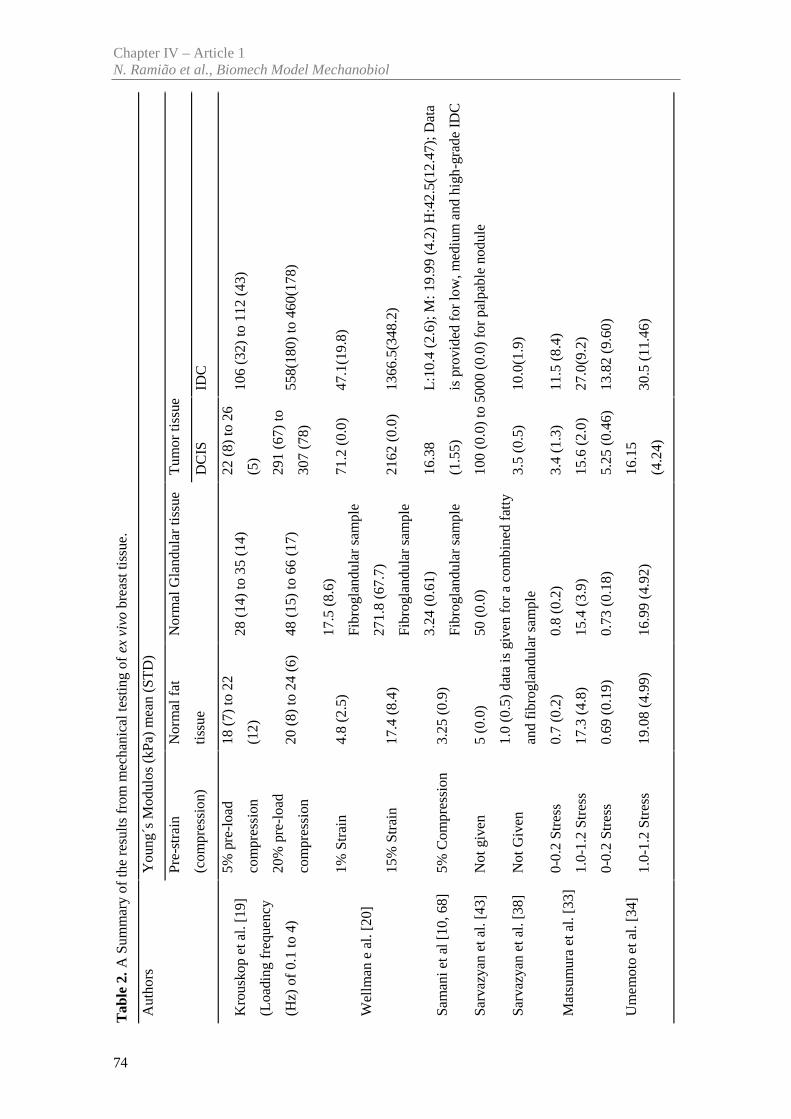
Tab
le2.
A S
umm
ary
of th
e re
sults
fro
m m
echa
nica
l tes
ting
ofex
viv
obr
east
tiss
ue.
Aut
hors
You
ng´s
Mod
ulos
(kP
a) m
ean
(ST
D)
Pre-
stra
in
(com
pres
sion
)
Nor
mal
fat
tiss
ue
Nor
mal
Gla
ndul
ar ti
ssue
Tum
or ti
ssue
DC
ISID
C
Kro
usko
p et
al.
[19]
(Loa
ding
freq
uenc
y
(Hz)
of
0.1
to 4
)
5% p
re-l
oad
com
pres
sion
18 (
7) to
22
(12)
28 (
14)
to 3
5 (1
4)22
(8)
to 2
6
(5)
106
(32)
to 1
12 (
43)
20%
pre
-loa
d
com
pres
sion
20 (
8) to
24
(6)
48 (
15)
to 6
6 (1
7)29
1 (6
7) to
307
(78)
558(
180)
to 4
60(1
78)
Wel
lman
e a
l. [2
0]
1%St
rain
4.8
(2.5
)17
.5 (
8.6)
Fibr
ogla
ndul
ar s
ampl
e71
.2 (
0.0)
47.1
(19.
8)
15%
Str
ain
17.4
(8.
4)27
1.8
(67.
7)
Fibr
ogla
ndul
ar s
ampl
e21
62 (
0.0)
1366
.5(3
48.2
)
Sam
ani e
t al [
10, 6
8]5%
Com
pres
sion
3.25
(0.
9)3.
24 (
0.61
)
Fibr
ogla
ndul
ar s
ampl
e
16.3
8
(1.5
5)
L:1
0.4
(2.6
); M
: 19.
99 (
4.2)
H:4
2.5(
12.4
7); D
ata
is p
rovi
ded
for
low
, med
ium
and
hig
h-gr
ade
IDC
Sarv
azya
n et
al.
[43]
Not
giv
en5
(0.0
)50
(0.
0)10
0 (0
.0)
to 5
000
(0.0
) fo
r pa
lpab
le n
odul
e
Sarv
azya
n et
al.
[38]
Not
Giv
en1.
0 (0
.5)
data
is g
iven
for
aco
mbi
ned
fatt
y
and
fibr
ogla
ndul
ar s
ampl
e3.
5 (0
.5)
10.0
(1.9
)
Mat
sum
ura
et a
l. [3
3]0-
0.2
Stre
ss0.
7 (0
.2)
0.8
(0.2
)3.
4 (1
.3)
11.5
(8.
4)
1.0-
1.2
Stre
ss17
.3 (
4.8)
15.4
(3.
9)15
.6 (
2.0)
27.0
(9.2
)
Um
emot
o et
al.
[34]
0-0.
2 St
ress
0.69
(0.
19)
0.73
(0.
18)
5.25
(0.
46)
13.8
2 (9
.60)
1.0-
1.2
Stre
ss19
.08
(4.9
9)16
.99
(4.9
2)16
.15
(4.2
4)30
.5 (
11.4
6)
Chapter IV – Article 1N. Ramião et al., Biomech Model Mechanobiol
74
Chapter IV – Article 1Biomechanical Properties of Breast Tissue, a State-of-the-art Review
75
McKnight et al. [44] studied six healthy volunteers and six patients with biopsy-
proven palpable breast malignancies, and concluded that the average shear stiffness of
the tumors was 33 kPa (range = 18–94 kPa), which was about four times greater than that
of adipose tissue (mean = 8 kPa, range = 4–16 kPa) in breast cancer patients. In the healthy
volunteers, the mean value for adipose tissue was 3.3 ± 1.9 kPa, which is less than their
fibroglandular tissue (7.5 ± 3.6 kPa).
Xydeas et al. [82] studied viscosity and elasticity of breast tissues in five patients
with six malignant lesions, eleven patients with benign lesions, and four patients with no
lesions using MRE. The aim of the study was to investigate the potential value of MRE
to improve the differentiation between benign and malignant tumors. The mean elasticity
parameters were: breast cancer (3.1 ± 0.7 kPa), fibroadenoma (1.4 ± 0.5 kPa), fibrocystic
changes (1.7 ± 0.8 kPa) and surrounding tissue (1.2 ± 0.2 kPa). According to the study,
malignant tumors documented higher values of elasticity than benign corresponding to
signal intensity and morphologic data. Table 3 summarizes some results from in vivo
MRE elastography.
Sayed et al. [26] used multi-compression 3D ultrasound elastography and
demonstrated the ability of the technique to better diagnose stiff masses inside breast
tissue. The results obtained in vivo revealed the target mass was approximately 6.3 times
stiffer than the background soft tissue. These results were compared with biopsy
diagnosis, and showed a good agreement with biopsy outcomes.
It should be noted that normally the stress distribution is not uniform within the
body and the tissue elasticity is nonlinear. According with tissue nonlinearity, the
Young’s modulus tends to increase when the compression is intensified as shown in
Figure 7.
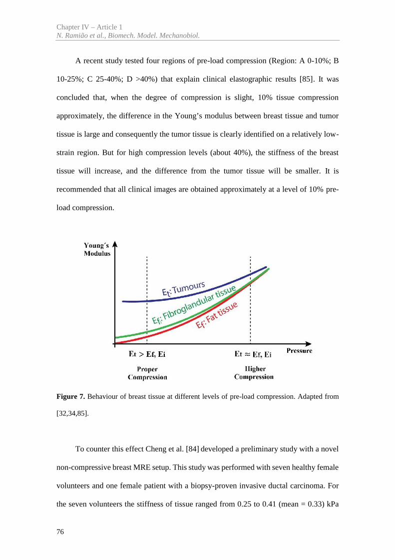
Chapter IV – Article 1N. Ramião et al., Biomech. Model. Mechanobiol.
76
A recent study tested four regions of pre-load compression (Region: A 0-10%; B
10-25%; C 25-40%; D >40%) that explain clinical elastographic results [85]. It was
concluded that, when the degree of compression is slight, 10% tissue compression
approximately, the difference in the Young’s modulus between breast tissue and tumor
tissue is large and consequently the tumor tissue is clearly identified on a relatively low-
strain region. But for high compression levels (about 40%), the stiffness of the breast
tissue will increase, and the difference from the tumor tissue will be smaller. It is
recommended that all clinical images are obtained approximately at a level of 10% pre-
load compression.
Figure 7. Behaviour of breast tissue at different levels of pre-load compression. Adapted from
[32,34,85].
To counter this effect Cheng et al. [84] developed a preliminary study with a novel
non-compressive breast MRE setup. This study was performed with seven healthy female
volunteers and one female patient with a biopsy-proven invasive ductal carcinoma. For
the seven volunteers the stiffness of tissue ranged from 0.25 to 0.41 (mean = 0.33) kPa
Chapter IV – Article 1Biomechanical Properties of Breast Tissue, a State-of-the-art Review
77
for adipose tissue, and from 0.46 to 0.9 (mean = 0.64) kPa for glandular tissue. For the
other patient the stiffness of adipose tissue was 0.41 ± 0.10 kPa and of glandular tissue
was 0.90 ± 0.18 kPa. The invasive ductal carcinoma was stiffer, 1.42 ± 0.17 kPa, as show
in table 3. The invasive ductal carcinoma is about 3 times stiffer than the adipose tissue
and 1.5 times stiffer than the glandular tissue.
Based on the data collected from the analyzed studies, the following conclusions
were achieved:
-The stress–strain curves of the breast tissues, describing the mechanical behaviour
of the tissue under different stress levels, follow an exponential behaviour, with
malignant masses showing a steeper curve than the benign tissues.
-The moduli of elasticity of the fibrous, glandular and cancerous tissue are
significantly higher than the adipose tissue, and are not constant along the studied
strain variations. The fat tissue behaviour is closer to linear than all other tissues
measured.
-There was [19,20] a dependency of the mechanical properties with the technique
used: if an image of the elastic modulus distribution throughout the breast, was
obtained at one strain level and then the strain level was doubled, the whole of the
tissue compressed would suffer an increase in stiffness. Thus, the Young’s modulus
of breast tissues is highly dependent on the level of tissue pre-load compression,
and the relative stiffness is a good predictor of histological diagnosis.
The results of these studies clearly indicate a wide variation in moduli not only
among different types of tissue but also within each tissue type. These differences were
most evident in normal fat and fibroglandular tissues.
The research works reviewed, used different techniques for estimating the tissue
stiffness distribution within a breast. However there is surprisingly little available
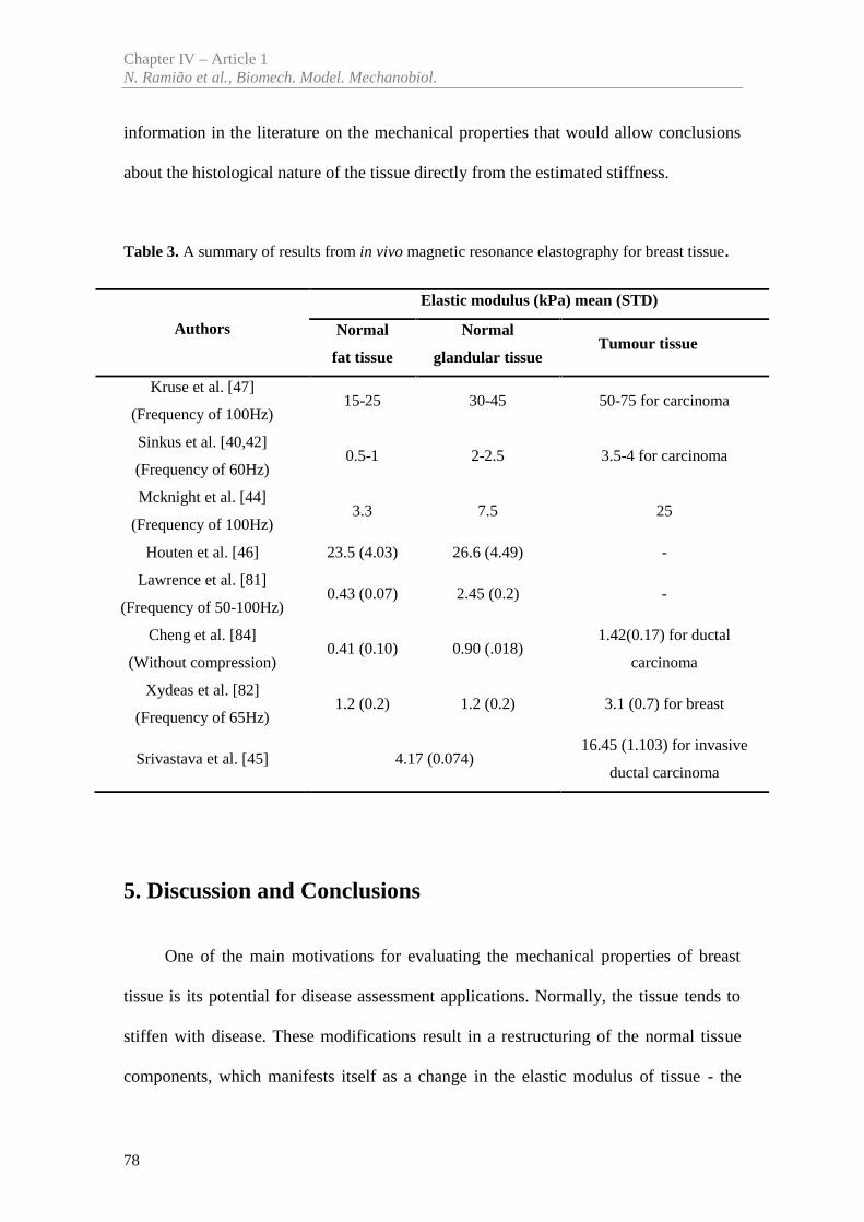
Chapter IV – Article 1N. Ramião et al., Biomech. Model. Mechanobiol.
78
information in the literature on the mechanical properties that would allow conclusions
about the histological nature of the tissue directly from the estimated stiffness.
Table 3. A summary of results from in vivo magnetic resonance elastography for breast tissue.
Authors
Elastic modulus (kPa) mean (STD)
Normal
fat tissue
Normal
glandular tissueTumour tissue
Kruse et al. [47]
(Frequency of 100Hz)15-25 30-45 50-75 for carcinoma
Sinkus et al. [40,42]
(Frequency of 60Hz)0.5-1 2-2.5 3.5-4 for carcinoma
Mcknight et al. [44]
(Frequency of 100Hz)3.3 7.5 25
Houten et al. [46] 23.5 (4.03) 26.6 (4.49) -
Lawrence et al. [81]
(Frequency of 50-100Hz)0.43 (0.07) 2.45 (0.2) -
Cheng et al. [84]
(Without compression)0.41 (0.10) 0.90 (.018)
1.42(0.17) for ductal
carcinoma
Xydeas et al. [82]
(Frequency of 65Hz)1.2 (0.2) 1.2 (0.2) 3.1 (0.7) for breast
Srivastava et al. [45] 4.17 (0.074)16.45 (1.103) for invasive
ductal carcinoma
5. Discussion and Conclusions
One of the main motivations for evaluating the mechanical properties of breast
tissue is its potential for disease assessment applications. Normally, the tissue tends to
stiffen with disease. These modifications result in a restructuring of the normal tissue
components, which manifests itself as a change in the elastic modulus of tissue - the
Chapter IV – Article 1Biomechanical Properties of Breast Tissue, a State-of-the-art Review
79
common mechanical property used for evaluation [86]. Thus, the studies performed have
been focused on the measurement of breast tissue stiffness through the elasticity moduli.
On the other hand, a comprehensive knowledge of the mechanical properties for glandular
and adipose tissue is not yet available in the literature, which explains the lack of recent
articles in this review. Although all these studies were made to visualize the distribution
of stiffness within the breast, there are few studies on the mechanical properties aimed at
understanding the histological nature of the tissue directly from the estimated stiffness.
Table 2 and 3 show the mechanical properties range reported by different authors.
As can be seen in the tables, there is a significant variability which makes it difficult to
use statistical data to model the individual properties of the breast. This variability is
highly dependent on several types of pre-load compression. In summary, Young’s moduli
of normal breast tissue increased dramatically with increasing compression. As for the
DCIS (ductal carcinoma in situ) specimens, their elastic moduli becomes close to those
of normal breast tissues, as the stress applied increases under higher compression.
Moreover, these studies showed a general increase in the elastic modulus associated with
more invasive carcinoma. As a consequence, Young’s moduli measured for invasive
carcinoma specimens exhibited greater variation than those for normal tissues. Variation
must have its roots on the complex pathologic structure of the tissue i.e., the
heterogeneous mixture of cellular and fibro stromal components. Thus, the elasticity
measurements clearly indicate that each tissue in the breast exhibits different non-linear
characteristics in stress versus elastic modulus relationships under light compression
conditions. Characterization of the mechanical behaviour of the breast requires a
combination of experimental techniques, specialized software particularly regarding the
compression levels used. This approach is of capital importance to predict deformations
accurately using biomechanical simulation models such as FEM models.
Chapter IV – Article 1N. Ramião et al., Biomech. Model. Mechanobiol.
80
By analyzing Table 2, the results Krouskop et al. [19] were clear relatively to:
Young’s moduli variation between different tissues of the breast, and Young’s moduli
increase with the initial condition of strain applied (i.e., percentage of pre-load
compression). In comparison, the Young’s moduli measured for adipose, normal gland,
DCIS and IDC in several authors, such as, Samani et al. [22], Matsumura et al. [33] and
Umemoto et al. [34] tended to be smaller than those reported by Krouskop et al. [19]. The
observed disagreements in this case are attributed to the fact that, in their measurement,
Krouskop et al. [19] applied substantial pre-load compression of 5% and 20%, and
consequently the authors did not describe their initial stress conditions fully. However, it
can be speculated that the differences in Young’s moduli were originated from the
different stresses applied to the specimen. It was also presumed that the stress used in
studies described by Matsumura et al. [33] and Umemoto et al. [34] was lower than the
stress used by Krouskop et al. [19].
Similar results to Krouskop et al. [19] have been shown by Wellman et al. [20].
Both studies obtained higher Young's when compared with the other studies. Matsumura
et al. [33] and Umemoto et al. [34] used a similar protocol testing (same stress), which
found very similar results for the different breast and tumor tissues. They concluded that
the results revealed a reduction or inversion in the difference of Young’s moduli between
normal and tumour tissues with increasing stress.
By comparing the results by Samani et al. [22] with those reported by Sarvazyan et
al. [38], it was verified that some of the results were in accordance while others show
Young’s modulus generally smaller. For example, Samani et al. [22] reported Young’s
modulus values of approximately 3.25 kPa and 19.99 kPa for normal tissues and IDC,
respectively, which are fairly well compared with the 2.0 kPa and 15.0 kPa that obtained
by Sarvazyan et al. [38]. However, the results described by the other authors in Table 2
Chapter IV – Article 1Biomechanical Properties of Breast Tissue, a State-of-the-art Review
81
are different when comparing with Sarvazyan et al. [38] and Sarvazyan et al. [43]. So, it
is important to refer that Sarvazyan et al. [38] and Sarvazyan et al. [43] did not reported
details of their measurement system, thus it is hard to speculate the source of the observed
disagreements.
The data reported in Table 3 is, consistent with previous studies, like Krouskop et
al. [19], Wellman et al. [20], Samani et al. [22], Matsumura et al. [33] and Umemoto et
al. [34]. The results of these studies indicate a wide variation in elastic moduli not only
among different types of tissue but also within each tissue type.
Although the studies from Kruse et al. [47] and McKnight et al. [44] used a similar
elasticity imaging technique (frequency at 100Hz), the results for the various tissues were
different. For example, Kruse et al. [47] reported values of approximately 15 kPa and 50
kPa for fat tissues and tumor, respectively, which are different compared with the 3.0 kPa
and 25.0 kPa obtained by McKnight et al. [44]. Xydeas et al. [82], Sinkus et al. [40] and
Lawrence et al. [81] shown a similar results for normal tissue (fat and glandular tissues).
It is important to note that the variability of the results reported by MRE elastography
may be associated with the variability in the test procedure (such as the different shear
wave frequencies applied).
Until now researchers have used different approaches to estimate the mechanical
properties of soft biological tissue. The differences in stiffness between normal and
abnormal breast tissue have been recognized for a long time [51]. To analyze large
deformations (ex. pre-strains up to 20%) the ex vivo tests are the most suitable. However,
in vivo data is only collected under small pre-strain conditions and often the pre-strain
used is not recorded. Considering this limitation, in vivo data is of limited usefulness for
modelling large deformations of the breast. Often, the force information is discarded
during the test to estimate the mechanical properties of the tissue because it is applied as
Chapter IV – Article 1N. Ramião et al., Biomech. Model. Mechanobiol.
82
an adjunct to existing imaging modalities. Thus, it is necessary to establish a method to
measure large deformations of tumor tissue and its nonlinear elastic behaviour with
accuracy. Typically these techniques make images of the tissue at two different applied
loads and compute a displacement field from them. This displacement field is then used
to infer the stiffness of the tissue, from assumptions made about the stress field. Basically
the pre-load compression has a considerable effect on the quality and results of
elastography. For example, the breast elastography is very susceptible to pre-load
compression because the chest wall acts as a hard posterior surface, allowing for
substantial pre-load compression when scanning. The effects of pre-load compression are
significant in the breast and can easily affect test outcomes (benign versus malignant). A
clear example is referred by Matsumura et al. [33], which showed that DCIS cannot be
sometimes easily detected (i.e. false negatives) at excessive breast compression in clinical
exam on elastography. This limitation highlights the need to quantify the preload for
compression magnitude (strain or stress) in various breast and tumor tissues. Umemoto
et al. [34] understood this need and measured the compression magnitude through loaded
stress on the tissue sample in compression test. Thereby showing quantitatively the
relationship between the magnitude of compression and tissue elasticity (Young's
modulus) in the target lesion.
Therefore, the importance of nonlinear responses of soft tissue to compressive loads
in clinical breast examination highlights the need for launching a comprehensive study
on the hyperelastic characterization of ex vivo and in vivo soft tissues, to enhance clinical
approaches including the detection of breast cancer.
Despite all available results from compression experiments, until now there is no
data available about the material properties of the breast under uniaxial or biaxial tensile
loading conditions (because of its fragile constitution). Recently, Sommer et al. [87]

Chapter IV – Article 1Biomechanical Properties of Breast Tissue, a State-of-the-art Review
83
performed tests in human abdominal adipose tissue by biaxial tensile and triaxial shear
tests. This experimental attempt to understand the anisotropy in the properties of the
adipose tissue produced promising results. Adipose tissue was characterized as a
nonlinear, anisotropic and viscoelastic soft biological material. These tests are a new
approach to study the breast adipose tissue. None of the experiments reported takes into
account the pre-strain caused by gravity, hydration and tissue fibers. It is a limitation of
ex vivo tests, contrary to in vivo tests where the measurements are performed in the natural
state, i.e., the blood supply and interstitial fluids are present. When compared to the ex
vivo tests, in vivo tests are used as a diagnostic tool that help assessing the changes in the
mechanical properties of the tissues under compression in a simple and non-invasive way.
As they can separate tumors from adjacent healthy tissues and distinguish if the tumor is
malignant or benign according to their stiffness, these tests are valuable for characterizing
the mechanical properties of the different breast tissues due to their high degree of
specificity and sensitivity [40,44-47,50,53,54].
The high Young´s modulus variability reported by several studies is directly
correlated with the use of different mechanical tests, experimental conditions (in vivo or
ex vivo), different pre-load compression, tissue heterogeneity and systematic errors
associated with the measurement techniques. Some of these errors may be introduced due
to the blood supply and interstitial fluids absence during the tests, although these are
efforts to keep the samples hydrated. The other source of error could be associated to the
location where the tissue samples were removed. In addition, it is expected to see different
measures of firmness in the same tissue.
Regarding the different pre-load compressions, the Young’s modulus between
breast tissue and tumor tissue is large when the degree of compression is slight. However,
when the compression is too strong, the stiffness of the breast tissue will increase, and the
Chapter IV – Article 1N. Ramião et al., Biomech. Model. Mechanobiol.
84
difference from the tumor tissue will be smaller [32,85]. This compression effects partly
explains the inconsistencies in the reported stiffness values of breast tissues from different
methods in the literature [32,44,67,85,88,89].
Another feature is that the mechanical properties of breast tissues differ between
individuals and over time due to the variability in breast morphology, hormonal status,
age, and physiological condition [45]. Despite of in the majority of the studies the authors
refer a range of age of the samples, there was a lack of information regarding some
important factors such as pre or post menopause, menstrual cycle and so on, which could
have influence in the experimental results. For example, Lorenzen et al. [90] found that
fibroglandular tissue roughly doubled in stiffness during the menstrual cycle. Therefore,
future studies should include these factors in order to understand the variations of breast
tissue in the several stages of the women’s life.
Glandular, adipose and fibrous tissues are the main tissues of the breast that have
been studied to estimate their mechanical properties. There are no studies to date of the
suspensory cooper's ligaments (they provide support and hold the breasts in place). So, it
is necessary to develop techniques to test the suspensory cooper´s ligaments. This effort
can contribute to establish a methodology based on the finite element method to simulate
a realistic 3D model of the breast. Thus, all knowledge on the mechanical properties of
the breast tissue is important for studying the effect of plastic and oncoplastic surgery
techniques in breast reconstruction, as well as for design of cosmetic breast implants.
In conclusion, it was possible to verify that the difference in mechanical behaviour
between tissues, provides useful information with potential impact on clinical diagnosis.
The development in experimental protocols led to an improvement of clinical diagnosis.
In order words, better experimental protocols led to a refinement of the compression
Chapter IV – Article 1Biomechanical Properties of Breast Tissue, a State-of-the-art Review
85
magnitude to apply in clinical examination. This procedure is fundamental to avoid false-
negatives.
The mechanical tests of soft biological tissues require a test system suitable to the
specificity of these materials. The determination of mechanical properties can be used to:
correlate the mechanical behaviour with pathology (e.g. cancer) or with population
characteristics (age, menopause, lactation, etc...) and to simulate the biomechanics of the
breast tissue. Further research is therefore needed to: (1) integrate the etiological factors
influencing the biomechanical proprieties of breast tissues, such as age, body mass index
or hormonal status (menopause); (2) characterize all tissues, including the suspensory
cooper's ligaments; (3) build experimental set-ups that includes in vivo and ex vivo testing
in order to validate the results; (4) standardizing the experimental protocol, in order to
analyse samples from the same breast location; (5) controlling the amount of pre-load
compression (for instance, test two levels of pre strain, a proper and a higher level used
in clinical breast examination). Because the pre-load compression is a substantial factor
in obtaining accurate results.
Acknowledgments
The authors gratefully acknowledge funding from Ministério da Ciência, Inovação
e do Ensino Superior, FCT, Portugal, under grants SFRH / BD / 85090 / 2012, and project
LAETA - UID/EMS/50022/2013, from Fundação da Ciência e Tecnologia, Portugal, and
the project Biomechanics: contributions to the healthcare, reference NORTE-07-0124-
FEDER-000035 co-financed by Programa Operacional Regional do Norte (ON.2 - O
Novo Norte), through the Fundo Europeu de Desenvolvimento Regional (FEDER).
Chapter IV – Article 1N. Ramião et al., Biomech. Model. Mechanobiol.
86
Conflict of interest statement
None declared.
References
[1] Bogonoletz W. Elastosis in breast cancer. Pathol Annu, 1986;21(2)m: 347–366. doi:
10.1002/1097-0142(197401)33:1<174::AID-CNCR2820330126>3.0.CO;2-X
[2] Stewart BW. Wild CP. World Cancer Report, International Agency for Research on
Cancer (IARC), 2014, ISBN 978-92-832-0429-9
[3] Society AC (2013) Cancer Facts & Figures 2013. Atlanta: American Cancer Society.
[4] World Health Organization (WHO).World Report on Disability. Malta: 2011 ISBN 978
92 4 068521 5
[5] Azar FS, Metaxas DN, Schnall MD. A Deformable Finite Element Model of the Breast
for Predicting Mechanical Deformations under. Acad Radiol.2001;10:965–975.
doi:10.1016/S1076-6332(03)80640-2
[6] Carter T, Sermesant M, Cash D, Barratt D, Tanner C, Hawkes D. Application of soft
tissue modeling to image-guided surgery. Med. Eng. Phys. 2005; 27:893–909.
doi:10.1016/j.medengphy.2005.10.005
[7] Roose L, De Maerteleire W, Mollemans W, Suetens P. Validation of different soft tissue
simulation methods for breast augmentation. Int. Congr. Ser. 2005;1281:485–490.
doi:10.1016/j.ics.2005.03.126
[8] Unlu MZ, Krol A, Magri A, et al. Computerized method for nonrigid MR-to-PET
breast-image registration. Comput. Biol. Med 210;40:37–53.
doi:10.1016/j.compbiomed.2009.10.010
[9] Stewart ML, Smith LM, Hall N. A numerical investigation of breast compression: a
computer-aided design approach for prescribing boundary conditions. IEEE Trans. Biomed. Eng
Chapter IV – Article 1Biomechanical Properties of Breast Tissue, a State-of-the-art Review
87
2011; 58:2876–84. doi:10.1109/TBME.2011.2162063
[10] Samani A, Bishop J, Plewes D. Biomechanical 3-D finite element modeling of the
human breast using MRI data. IEEE Trans. Med. Imaging 2001a:20 (4):271 - 279.
doi:10.1109/42.921476
[11] Pathmanathan P, Gavaghan D, Whiteley J, et al. Predicting tumour location by
simulating large deformations of the breast using a 3D finite element model and nonlinear
elasticity. Lect Notes Comput Sci 2004;3217:217–224
[12] Han L, Noble JA, Burcher M (2003) A novel ultrasound indentation system for
measuring biomechanical properties of in vivo soft tissue. Ultrasound Med. Biol 29:813–823.
doi:10.1016/S0301-5629(02)00776-7
[13] Buijs J, Hansen H, Lopata R, Corte C, Misra S. Predicting Target Displacements using
Ultrasound Elastography and Finite Element Modeling. IEEE Transactions on biomedical
engineering 2011;58(11):3143-3155. doi:10.1109/TBME.2011.2164917
[14] Samani A, Plewes D. A method to measure the hyperelastic parameters of ex vivo
breast tissue samples, Phys. Med. Biol. 2004;49: 4395–405. doi:10.1088/0031-9155/49/18/014
[15] O’Hagan JJ, Samani A. Measurement of the hyperelastic properties of tissue slices
with tumour inclusion. Phys. Med. Biol. 2009; 54:2557–2569. doi:10.1088/0031-9155/54/8/020
[16] Ruiter N, Stotzka R, Muller T,Gemmeke H, Reichenbach J, Kaiser W. Model-based
registration of X-ray mammograms and MR images of the female breast. IEEE Transactions on
Nuclear Science 2006; 53(1):204–211. doi:10.1109/TNS.2005.862983
[17] Pathmanathan P, Gavaghan D, Whiteley J, Chapman S, Brady J. Predicting tumor
location by modeling the deformation of the breast. IEEE Transactions on Biomedical
Engineering 2008;55:2471–2480.doi: 10.1109/TBME.2008.925714
[18] Rajagopal V, Lee A, Chung JH, et al. Creating individual-specific biomechanical
models of the breast for medical image analysis. Acad. Radiol.2008; 15:1425–36.
doi:10.1016/j.acra.2008.07.017
[19] Krouskop T, Wheeler T, Kallel F, Garra B. Hall, Elastic moduli of breast and prostate
Chapter IV – Article 1N. Ramião et al., Biomech. Model. Mechanobiol.
88
tissues under compression, Ultrason Imaging 1998;20:260–274. doi:
10.1177/016173469802000403
[20] Wellman PS, Howe RD, Dalton E, Kern KA. Breast Tissue Stiffness in Compression
is Correlated to Histological Diagnosis 1999;1–15
[21] Samani A, Bishop J, Plewes D. A constrained modulus reconstruction technique for
breast cancer assessment. IEEE Trans. Med. Imaging 2001b; 20:877–85. doi:10.1109/42.952726´
[22] Samani A, Zubovits J, Plewes D. Elastic moduli of normal and pathological human
breast tissues: an inversion-technique-based investigation of 169 samples. Phys. Med. Biol 2007;
52:1565–76. doi:10.1088/0031-9155/52/6/002
[23] Harrigan TP, Konofagou EE. Estimation of material elastic moduli in elastography: A
local method, and an investigation of Poisson’s ratio sensitivity. J. Biomech 2004; 37:1215–1221.
doi:10.1016/j.jbiomech.2003.12.027
[24] Doyley MM, Bamber JC, Fuechsel F, Bush NL. A freehand elastographic imaging
approach for clinical breast imaging: system development and performance evaluation.
Ultrasound Med. Biol 2001; 27:1347–1357. doi:10.1016/S0301-5629(01)00429-X
[25] Housden R, Gee AH, Treece GM, Prager RW. 3-D ultrasonic strain imaging using
freehand scanning and a mechanically-swept probe. IEEE Trans. Ultrason. Ferroelectr. Freq.
Control 2010; 57:501–506. doi:10.1109/TUFFC.2010.1431
[26] Sayed A, Layne G, Abraham J, Mukdadi O. Nonlinear characterization of breast
cancer using multi-compression 3D ultrasound elastography in vivo. Ultrasonics 2013; 53:979–
91. doi:10.1016/j.ultras.2013.01.005
[27] Burnside E, Hall T, Sommer A, Hesley G, et al. Differentiating benign from malignant
solid breast masses with US strain imaging, Radiology 2007;245:401–410.
doi:http://dx.doi.org/10.1148/radiol.2452061805
[28] Butcher DT, Alliston T, Weaver VM. A tense situation: forcing tumour progression.
Nat Rev Cancer 2009;9(2):108–122. doi:10.1038/ nrc2544
[29] Price BD, Gibson AP, Tan LT, Royle GJ. An elastically compressible phantom
Chapter IV – Article 1Biomechanical Properties of Breast Tissue, a State-of-the-art Review
89
material with mechanical and x-ray attenuation properties equivalent to breast tissue. Phys. Med.
Biol. 2010; 55:1177–88. doi:10.1088/0031-9155/55/4/018
[30] Cox TR, Erler JT. Remodeling and homeostasis of the extracellular matrix:
implications for fibrotic diseases and cancer. Dis. Model. Mech 2011;4:165–178.
doi:10.1242/dmm.004077
[31] Fung YC (1993) Biomechanics: Mechanical Properties of Living Tissues. New York:
Springer. ISBN 0-387-97947-6
[32] Shiina T (2013) JSUM ultrasound elastography practice guidelines: Basics and
terminology. J. Med. Ultrason 40:309–323. doi:10.1007/s10396-013-0490-z
[33] Matsumura T, Umemoto T, Fujihara Y, Ueno E, Yamakawa M, Shiina T, Mitake T
(2009) Measurement of elastic property of breast tissue for elasticity imaging. Proc. - IEEE
Ultrason. Symp. 1451–1454. doi:10.1109/ULTSYM.2009.5442044
[34] Umemoto T, Ueno E, Matsumura T, et al. Ex vivo and in vivo assessment of the non-
linearity of elasticity properties of breast tissues for quantitative strain elastography. Ultrasound
Med. Biol 2014;40:1755–1768. doi:10.1016/j.ultrasmedbio.2014.02.005´
[35] Lemaitre J (2001) Handbook of materials behavior models: Nonlinear models and
properties. Academic Press. ISBN: 978-0-12-443341-0
[36] Silver FH, Freeman J, Seehra GP. Collagen self-assembly and development of matrix
mechanical properties. J. Biomech. 2003;36:1529–1553. doi:10.1016/S0021-9290(03)00135-0
[37] Silver FH and Landis WJ. Viscoelasticity, Energy Storage and Transmission and
Dissipation by Extracellular Matrices in Vertebrates. In: Fratzl P, Collagen: structure and
mechanics. Spinger, New York, pp 133-154, 2008, ISBN: 9780387739052
[38] Sarvazyan A, Goukassian D, Maevsky E, Oranskaja G. Elasticity imaging as a new
modality of medical imaging for cancer detection. Proc. Int. Workshop on Interaction of
Ultrasound with Biological Media, 1994:69–81
[39] Wells PNT, Liang H-D. Medical ultrasound: imaging of soft tissue strain and
elasticity. J. R. Soc. Interface 2011;8: 1521–1549. doi:10.1098 /rsif.2011.0054
Chapter IV – Article 1N. Ramião et al., Biomech. Model. Mechanobiol.
90
[40] Sinkus R, Lorenzen J, Schrader D, Lorenzen M, Dargatz M, Holz D. In Vivo Tensor
MR-Elastography - Anisotropy of Mamma-Carcinoma. Ismrm 2000; 26:493
[41] Sinkus R, Tanter M, Catheline S et al. Imaging anisotropic and viscous properties of
breast tissue by magnetic resonance-elastography. Magn. Reson. Med 2005a; 53:372–87.
doi:10.1002/mrm.20355
[42] Sinkus R, Tanter M, Xydeas T, Catheline S, Bercoff J, Fink M. Viscoelastic shear
properties of in vivo breast lesions measured by MR elastography. Magn. Reson. Imaging 2005b;
23:159–165. doi:10.1016/j.mri.2004.11.060
[43] Sarvazyan A, Skovoroda A, Emelianov S, et al. Biophysical Bases of Elasticity
Imaging. Acoustical Imaging 1995; 21:223-240
[44] McKnight AL, Kugel JL, Rossman PJ, Manduca A, Hartmann LC, Ehman RL. MR
elastography of breast cancer: preliminary results. AJR. Am. J. Roentgenol 2002; 178:1411–1417.
doi:10.2214/ajr.178.6.1781411
[45] Srivastava A, Verma Y, Rao KD, Gupta PK. Determination of Elastic Properties of
Resected Human Breast Tissue Samples Using Optical Coherence Tomographic Elastography.
Strain 2011; 47:75–87. doi:10.1111/j.1475-1305.2009.00627.x
[46] Van Houten EEW, Doyley MM, Kennedy FE, Weaver JB, Paulsen KD. Initial in vivo
experience with steady-state subzone-based MR elastography of the human breast. J. Magn.
Reson. Imaging 2003; 17:72–85. doi:10.1002/jmri.10232
[47] Kruse S, Smith J, Lawrence A, Dresner M et al. Tissue characterization usi02ng
magnetic resonance elastography: preliminary results. Phys Med Biol 2000; 45:1579–1590.
doi:10.1088/0031-9155/45/6/313
[48] Scaperrotta G, Ferranti C, Costa C, et al. Role of sonoelastography in non-palpable
breast lesions. Eur. Radiol 2008;18:2381–2389. doi:10.1007/s00330-008-1032-8
[49] Wilson L, Robinson D, Dadd M. Elastography - The movement begins. Phys Med
Biol 2000; 45:1409-1421. doi:10.1088/0031-9155/45/6/301
[50] Mariappan YK, Glaser KJ, Ehman RL. Magnetic resonance elastography: a review.
Chapter IV – Article 1Biomechanical Properties of Breast Tissue, a State-of-the-art Review
91
Clin. Anat 2010; 23:497–511. doi:10.1002/ca.21006
[51] Ophir J, Céspedes I, Ponnekanti H, Yazdi Y, Li X (1991) Elastography: a quantitative
method for imaging the elasticity of biological tissues. Ultrason Imaging 1991; 13:111-134.
doi:10.1016/0161-7346(91)90079-W
[52] Cespedes I, Ophir J, Ponnekanti H , Maklad N. Elastography: Elasticity imaging using
ultrasound with application to muscle and breast in vivo. Ultrason Imaging 1993; 15:73–88. doi:
10.1177/016173469301500201
[53] Korte C, Van der Steen A. Intravascular ultrasound elastography: an overview.
Ultrasonics 2002; 40:859–865. doi:10.1016/S0041-624X(02)00227-5
[54] Manduca A, Smith J, Muthupillai R, Rossman P, Greenleaf J, Ehman R. Image
analysis techniques for magnetic resonance elastography, Engineering in Medicine and Biology
Society, In: Proceedings of the 5th Annual Meeting of ISMRM, 1997; 2:756-757.doi:
10.1109/IEMBS.1996.651961
[55] Mehrabian H, Campbell G, Samani A. A constrained reconstruction technique of
hyperelasticity parameters for breast cancer assessment. Phys. Med. Biol 2010; 55:7489–7508.
doi:10.1088/0031-9155/55/24/007
[56] Muthupillai R, Lomas D, Rossman P, Greenleaf J, Manduca A, Ehman R. Magnetic
Resonance Elastography by Direct Visualization of Propagating Acoustic Strain Waves. Science
1995; 69:1854-1857. doi:10.1126/science.7569924
[57] Lerner RM., Parker KJ. Sono-elasticity images, ultrasonic tissue charactertization and
echographic imaging. In: Thijssen, J (ed). 7th Eoropean Communities Workshop. The
Netherlands: Nijmegen, 1987
[58] Lerner RM, Parker KJ, Holen J, Gramiak R, Waag RC. Sono-elasticity: medical
elasticity images derived from ultrasound signals in mechanically vibrated targets. In: Kessler
LW (ed) Acoustical Imaging. Sonoscan Inc.16, 1988:317-27, ISBN 978-1-4613-0725-9
[59] O’Donnell M, Skovoroda AR, Shapo BM, Emelianov SY. Internal Displacement and
Strain Imaging Using Ultrasonic Speckle Tracking. IEEE Trans. Ultrason. Ferroelec. Freq .Contr
Chapter IV – Article 1N. Ramião et al., Biomech. Model. Mechanobiol.
92
1994; 41(3):314–25. doi:10.1109/58.285465
[60] Garra B, Cespedes E, Ophir J, et al. Elastography of breast lesions: Initial clinical
results, Radiology 1997;202:79–86. doi: http://dx.doi.org/10.1148/radiology.202.1.8988195
[61] Bamber JC, Barbone PE, Bush NL et al. Progress in freehand elastography of the
breast. IEICE Trans. Inf. Syst 2002; 85(1):5-14
[62] Greenleaf JF, Fatemi M, Insana M. Selected methods for imaging elastic properties of
biological tissues. Annual Review of Biomedical Engineering 2003;5:57–78. doi:
5.040202.121623
[63] Manduca A, Dutt V, Borup DT, Muthupillai R, Greenleaf JF, Ehman RL. An inverse
approach to the calculation of elasticity maps for magnetic resonance elastography. Proceedings
of SPIE - The International Society for Optical Engineering 1998; 3338:426–36
[64] Parker KJ, Doyley MM, Rubens DJ. Imaging the elastic properties of tissue: the 20
year perspective. Phys. Med. Biol 2011; 56:R1–R29. doi:10.1088/0031-9155/56/1/R01
[65] Doyley MM. Model-based elastography: a survey of approaches to the inverse
elasticity problem. Phys Med Biol. 2013;57(3):R35–R73. doi:10.1088/0031-9155/57/3/R35
[66] Sudhakar K, Venkatesh R, Ehman L. Magnetic Resonance Elastography .Springer
New York Heidelberg Dordrecht London. Book. 2014, ISBN 978-1-4939-1574-3
[67] Samani A, Bishop J, Luginbuhl C, Plewes DB. Measuring the elastic modulus of ex
vivo small tissue samples Phys. Med. Biol. 2003;48 2183–98. PII: S0031-9155(03)60749-9
[68] Samani A and Plewes DB. An inverse problem solution for measuring the elastic
modulus of intact ex vivo breast tissue tumours Phys. Med. Biol. 2007; 52:1247–60.
doi:10.1088/0031-9155/52/5/003
[69] Jurvelin J, Buschmann M, Hunziker E. Optical and mechanical determination of
Poisson's ratio of adult bovine humeral articular cartilage. J Biomech 1997;30:235-241.
doi:10.1016/S0021-9290(96)00133-9
[70] Lopez JI, Kang I, You W-K, McDonald DM, Weaver VM. In situ force mapping of
mammary gland transformation. Integr. Biol. 2011;3:910–921. doi: 10.1039/c1ib00043h
Chapter IV – Article 1Biomechanical Properties of Breast Tissue, a State-of-the-art Review
93
[71] Azar FS, Metaxas DN, Schnall MD. Methods for modeling and predicting mechanical
deformations of the breast under external perturbations. Medical Image Analysis 2002; 6:1–27.
doi:10.1016/S1361-8415(01)00053-6
[72] Thomas A, Fischer T, Frey H, et al. Real-time elastography-an advanced method of
ultrasound: First results in 108 patients with breast lesions. Ultrasound Obstet. Gynecol 2006;28:
335–40. doi:10.1002/uog.2823
[73] Zhang M, Zheng YP, Mak AFT. Estimating the effective Young ’ s modulus of soft
tissues from indentation tests — nonlinear finite element analysis of effects of friction and large
deformation. Med Eng Phys 1997;19(6):512–517. doi:10.1016/S1350-4533(97)00017-9
[74] Bakic P. Breast Tissue Description and Modeling in Mammography. Dissertation,
Leigh University, PA, USA, 2000
[75] Gefen A, Dilmoney B. Mechanics of the normal woman’s breast. Technol Health Care
2007;15(4):259–271
[76] Hiltawsky K, Kruger M, Starke C, Heuser L, Ermert H, Jensen A. Freehand ultrasound
elastography of breast lesions: clinical results, Ultrasound Med. Biol 2001;27(11):1461–1469.
doi: 10.1016/S0301-5629(01)00434-3
[77] Sinkus R, Lorenzen J, Schrader D, Lorenzen M, Dargatz M, Holz D. High-resolution
tensor MR elastography for breast tumor detection. Phys Med Biol 2000a;45:1649–1664.
doi:10.1088/0031-9155/45/6/317
[78] Plewes D, Bishop J, Samani A, Sciarretta J. Visualization and quantification of breast
cancer biomechanical properties with magnetic resonance elastography, Phys. Med. Biol
200;45(6): 1591-1610. doi:10.1088/0031-9155/45/6/314
[79] Lorenzen J, Sinkus R, Schrader D, et al. Imaging of breast tumors using MR
elastography. Rofo 2001;173 (1):12–7. doi: 10.1055/s-2001-10233
[80] Siegmann KC, Xydeas T, Sinkus R, Kraemer B, Vogel U, Claussen CD. Diagnostic
value of MR elastography in addition to contrast-enhanced MR imaging of the breast-initial
clinical results. Eur. Radiol 2010;20:318–25. doi:10.1007/s00330-009-1566-4
Chapter IV – Article 1N. Ramião et al., Biomech. Model. Mechanobiol.
94
[81] Lawrence A, Muthupillai R, Rossman P, Smith J, Manduca A, Ehman R. Magnetic
resonance elastography of the breast: preliminary experience. In Proceedings of the international
society for magnetic resonance in medicine. Sydney, Australia: International Society for
Magnetic Resonance in Medicine, 1998
[82] Xydeas T, Siegmann K, Sinkus R, et al. Magnetic Resonance Elastography of the
Breast. Invest. Radiol 2005;40:412–420. doi:10.1097/01.rli.0000166940.72971.4ª
[83] Cheng HD, Shan J, Ju W, Guo Y, Zhang L. Automated breast cancer detection and
classification using ultrasound images: A survey. Pattern Recognit 2010; 43:299–317.
doi:10.1016/j.patcog.2009.05.012
[84] Cheng J, Brandt KR, Ghosh K, et al. Non compressive MR elastography of breasts.
Proceedings of the international society for magnetic resonance in medicine. Salt Lake City, USA:
International Society for Magnetic Resonance in Medicine, 2013
[85] Barr RG, Zhang Z. Effects of precompression on elasticity imaging of the breast:
development of a clinically useful semiquantitative method of precompression assessment. J.
Ultrasound Med 2012; 31:895–902.
[86] Buckley A, Hill K, Davidson J. Collagen metabolism. Methods in Enzymology
1988;163:674-694
[87] Sommer G, Eder M, Kovacs L, et al. Multiaxial mechanical properties and constitutive
modeling of human adipose tissue: A basis for preoperative simulations in plastic and
reconstructive surgery. Acta Biomater 2013;9:9036–9048. doi:10.1016/j.actbio.2013.06.011
[88] Abdullah N, El-khoury M, Kao E. Breast Imaging Reporting and Data System Lexicon
for US : Interobserver Agreement for assessment of breast masses. Radiology 2009;252: 665–
672. doi: 10.1148/radiol.2523080670
[89] Sadigh G, Carlos RC, Neal CH, Dwamena BA. Accuracy of quantitative ultrasound
elastography for differentiation of malignant and benign breast abnormalities : a meta-analysis.
Breast Cancer Res Treat 2012;134(3):923–931. doi:10.1007/s10549-012-2020-x
[90] Lorenzen J, Sinkus R, Biesterfeldt M, Adam G. Menstrual-Cycle Dependence of

Chapter IV – Article 1Biomechanical Properties of Breast Tissue, a State-of-the-art Review
95
Breast Parenchyma Elasticity : Estimation With Magnetic Resonance Elastography of Breast
Tissue During the Menstrual Cycle. Invest Radiol 2003; 38(4):236–240


Chapter V
________________________________________________________________________________-
Original Articles

Article 2
________________________________________________________
Mechanical Performance of Poly Implant Prosthesis (PIP) BreastImplants a Comparative Study
Nilza Ramião a, Pedro Martins a, Maria da Luz Barrosob, Diana C. Santosb,
Francisco Pereiraa, António A. Fernandesa
a INEGI, Faculty of Engineering, University of Porto, Porto, Portugalb Department of Plastic Surgery of Gaia Hospital Center, Vila Nova de Gaia, Portugal
Published in: Aesthetic Plastic Surgery, 2017, doi: 10.1007/s00266-017-0776-4

101
Abstract
Background: There is societal concern regarding potential health problems
associated with breast implants. Much of this distrust climate was a reaction to the Poly
Implant Prosthesis (PIP) scandal. Studying the mechanisms of implant rupture is an
important step for their improvement. The mechanical behaviour of breast implant shells
were studied on explanted and virgin implants. Implants from both PIP and another brand
(brand X), currently in the market, were considered.
Methods: To study the mechanical behaviour of the shell, a total of 940 samples,
from 11 explants and 5 control implants were analysed. The experimental protocol
follows the ISO standards for shell integrity and determination of tensile stress-strain
properties. Pearson correlation analyses and the multi-factor ANOVA statistical tests
were performed using mechanical test data.
Results: Both PIP control and explants had significant variations of stress
(P=0.0001) and shell thickness (P=0.000) throughout the implant. The stress was found
directly related to shell thickness. Shell thickness varied significantly for PIP implants,
exceeding the manufacturer’s specifications. Regarding the other brand, thickness
variation was within manufacturer’s specifications.
Conclusions: The heterogeneous nature of PIP implants was confirmed. The
implant shell thickness should be considered as a relevant parameter during the
manufacturing process, for quality control purposes. These results may contribute to
dispel mistrust and doubt surrounding breast implants, among the medical community
and patients.

102
Keywords: Breast implant, Poly Implant Prosthesis (PIP), Mechanical behaviour;
Implant thickness.
103
1. Introduction
Overall safety, durability, long-term stability, and aesthetic value of the breast
implants has been a matter of interest and concern for a long time [1-6]. However, events
surrounding PIP breast implants in 2010, have renewed the debate among the medical
community and PIP breast implant users about the safety of breast silicone implants, and
its effect in patients’ health.
In Portugal, the health regulator entity (INFARMED) banned the use of PIP
implants in 2010. The removal rate of this type of implants (revision surgery) started to
increase from 2011 onwards, due to a wider media coverage, increasing 60% in 2012 [7].
Several studies on biodurability of breast implant shells, concluded that it is
influenced by different factors, such as damage during surgery, material ageing following
implantation, open and closed capsulotomy, trauma injuries (shocks from car accidents),
manufacturing defects, fatigue, shell wrinkling, needle biopsy or hematoma aspiration,
and patch detachment [8]. In particular, for PIP breast implants, problems included:
ageing of implant materials following implantation (degradation of material), variability
in the design and manufacturing process, the quality of surgical procedure for
implantation, and the quality of raw materials [9-11]. Following these studies, it was
suggested that PIP implants have not been manufactured according to medical device
standards [10-12]. These led regulatory authorities [9] and public opinion to associate the
brand with a higher risk of several types of ruptures.
The available literature on PIP implant rupture is supported by limited experimental
data. In particular, the mechanical characterization, when available, is based on a small
Chapter V- Article 2N. Ramião et al., Aesthet. Plast. Surg.
104
number of tests per implant, typically between 1 and 20 [4, 11, 13-15]. To fill this gaps in
the available mechanical characterization, a protocol to characterize all regions of the
implant (anterior, equatorial and posterior) is proposed. The experimental protocol
included a detailed analysis of the different implant regions. Moreover, PIP implants were
compared with another commercially available brand.
There is a wide variation of tensile behaviours of implant shells over different
brands. Inter-brand variations may be linked to different curing processes during
manufacture [11, 16, 17]. Even for different batches of the same brand there are noticeable
variations of mechanical behaviour over the same deformation range, as found by this
investigation and by other researchers [8]. To compare implants from different brands,
the experimental protocol adopted for this work consisted on tensile analysis over fixed
strain points of the test sample – 33%, 66%, 133% and 266% length increase. These strain
points were common to all tested implants, thus providing a robust comparison basis.
2. Material and Methods
2.1. Breast Implants Collection
Eleven explanted PIP breast implants were collected from February 2012 to July
2013. The implants were implanted between 2004 and 2010. Three PIP virgin implants
were obtained from the Portuguese health regulator entity, and were used as controls.
Two implants from another brand (brand X) commonly used in Portugal, were also used
as controls.
2.2. Mechanical Testing Protocol
The mechanical testing protocol was designed according to the international
standard for mammary implants (ISO 14607:2007), and the standard for rubber,
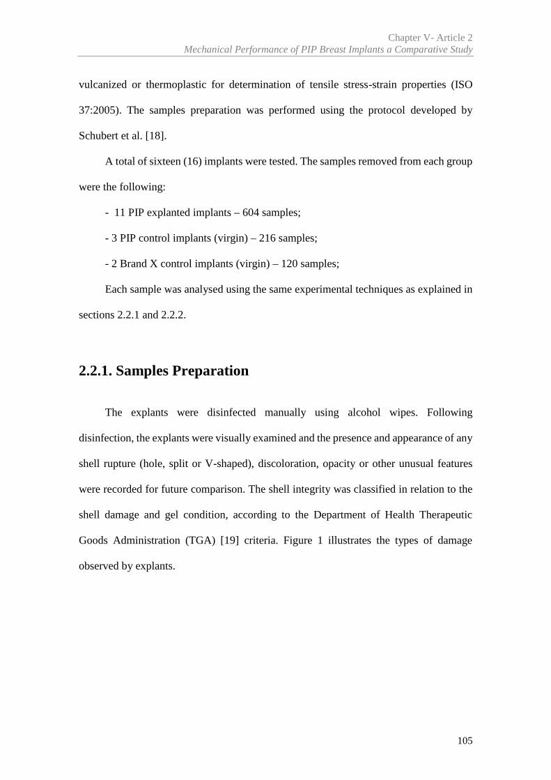
Chapter V- Article 2Mechanical Performance of PIP Breast Implants a Comparative Study
105
vulcanized or thermoplastic for determination of tensile stress-strain properties (ISO
37:2005). The samples preparation was performed using the protocol developed by
Schubert et al. [18].
A total of sixteen (16) implants were tested. The samples removed from each group
were the following:
- 11 PIP explanted implants – 604 samples;
- 3 PIP control implants (virgin) – 216 samples;
- 2 Brand X control implants (virgin) – 120 samples;
Each sample was analysed using the same experimental techniques as explained in
sections 2.2.1 and 2.2.2.
2.2.1. Samples Preparation
The explants were disinfected manually using alcohol wipes. Following
disinfection, the explants were visually examined and the presence and appearance of any
shell rupture (hole, split or V-shaped), discoloration, opacity or other unusual features
were recorded for future comparison. The shell integrity was classified in relation to the
shell damage and gel condition, according to the Department of Health Therapeutic
Goods Administration (TGA) [19] criteria. Figure 1 illustrates the types of damage
observed by explants.
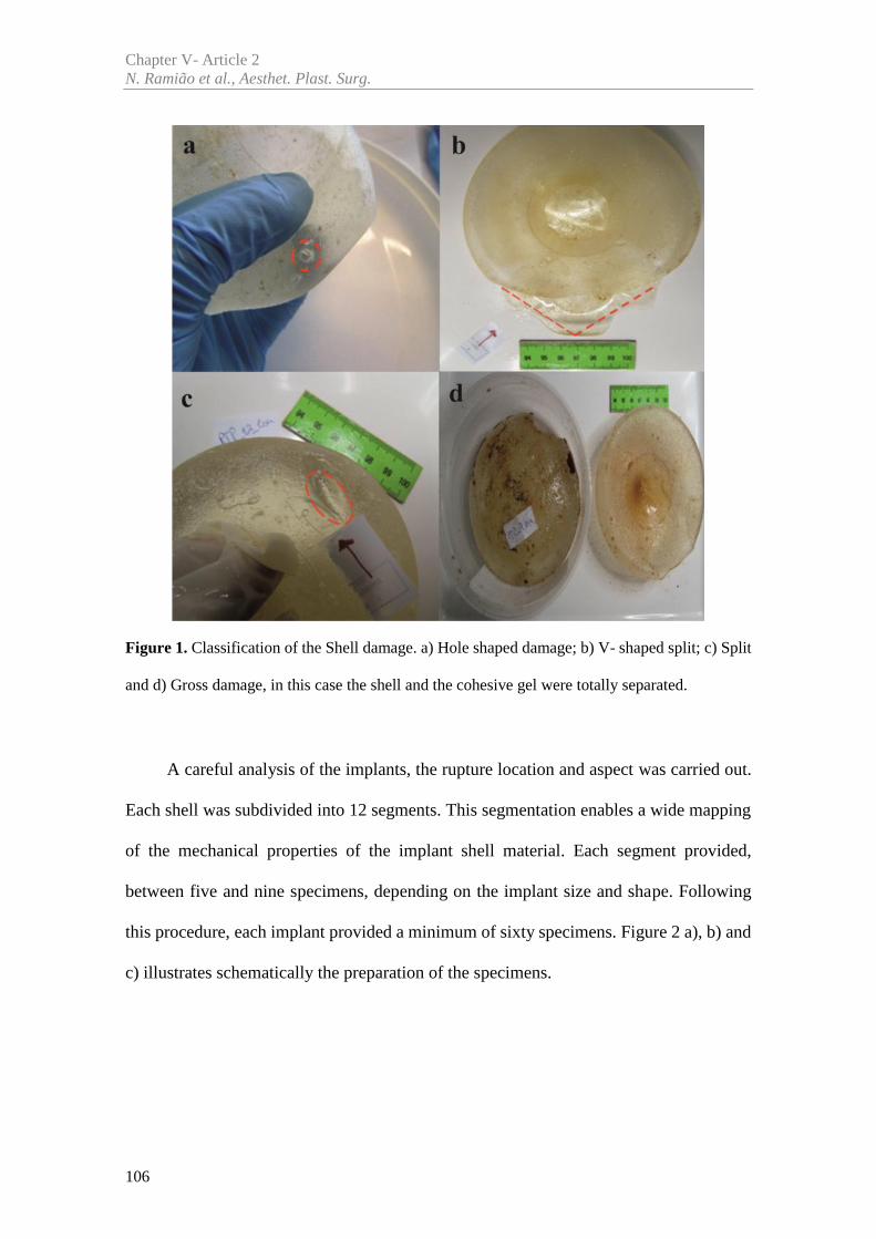
Chapter V- Article 2N. Ramião et al., Aesthet. Plast. Surg.
106
Figure 1. Classification of the Shell damage. a) Hole shaped damage; b) V- shaped split; c) Split
and d) Gross damage, in this case the shell and the cohesive gel were totally separated.
A careful analysis of the implants, the rupture location and aspect was carried out.
Each shell was subdivided into 12 segments. This segmentation enables a wide mapping
of the mechanical properties of the implant shell material. Each segment provided,
between five and nine specimens, depending on the implant size and shape. Following
this procedure, each implant provided a minimum of sixty specimens. Figure 2 a), b) and
c) illustrates schematically the preparation of the specimens.
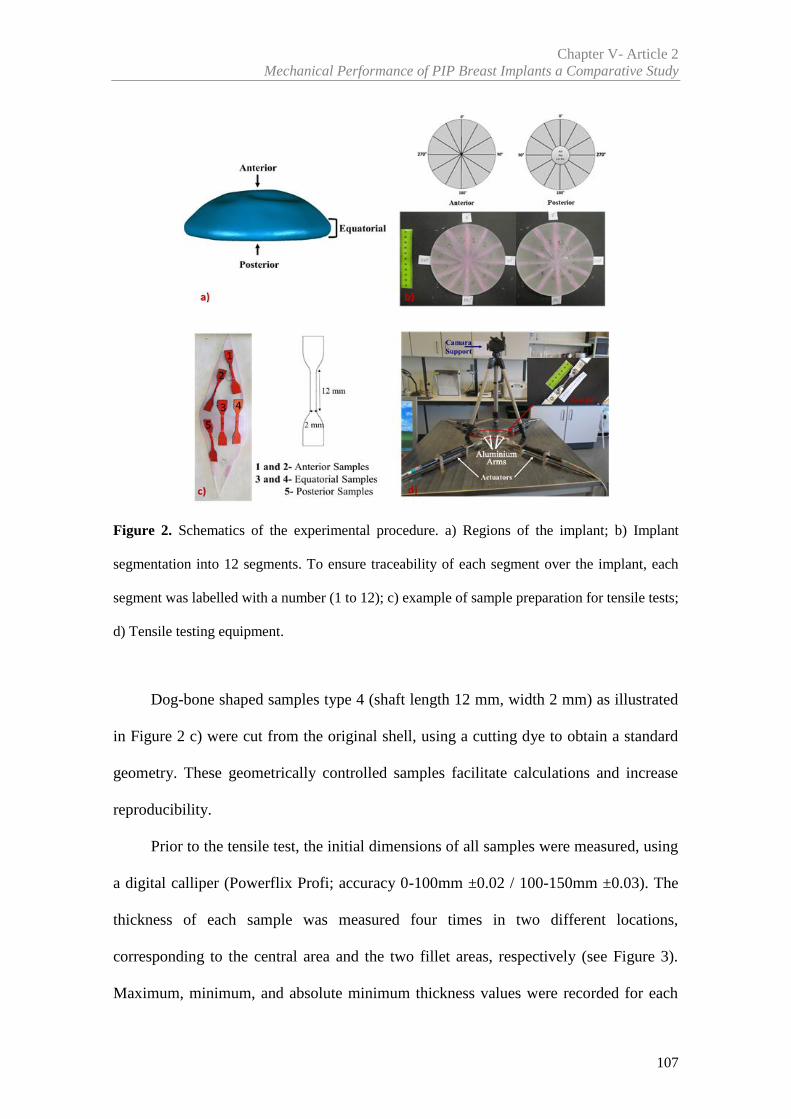
Chapter V- Article 2Mechanical Performance of PIP Breast Implants a Comparative Study
107
Figure 2. Schematics of the experimental procedure. a) Regions of the implant; b) Implant
segmentation into 12 segments. To ensure traceability of each segment over the implant, each
segment was labelled with a number (1 to 12); c) example of sample preparation for tensile tests;
d) Tensile testing equipment.
Dog-bone shaped samples type 4 (shaft length 12 mm, width 2 mm) as illustrated
in Figure 2 c) were cut from the original shell, using a cutting dye to obtain a standard
geometry. These geometrically controlled samples facilitate calculations and increase
reproducibility.
Prior to the tensile test, the initial dimensions of all samples were measured, using
a digital calliper (Powerflix Profi; accuracy 0-100mm ±0.02 / 100-150mm ±0.03). The
thickness of each sample was measured four times in two different locations,
corresponding to the central area and the two fillet areas, respectively (see Figure 3).
Maximum, minimum, and absolute minimum thickness values were recorded for each
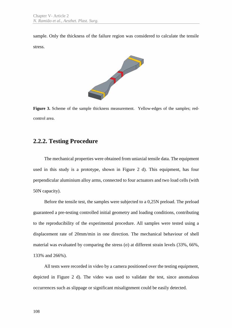
Chapter V- Article 2N. Ramião et al., Aesthet. Plast. Surg.
108
sample. Only the thickness of the failure region was considered to calculate the tensile
stress.
Figure 3. Scheme of the sample thickness measurement. Yellow-edges of the samples; red-
control area.
2.2.2. Testing Procedure
The mechanical properties were obtained from uniaxial tensile data. The equipment
used in this study is a prototype, shown in Figure 2 d). This equipment, has four
perpendicular aluminium alloy arms, connected to four actuators and two load cells (with
50N capacity).
Before the tensile test, the samples were subjected to a 0,25N preload. The preload
guaranteed a pre-testing controlled initial geometry and loading conditions, contributing
to the reproducibility of the experimental procedure. All samples were tested using a
displacement rate of 20mm/min in one direction. The mechanical behaviour of shell
material was evaluated by comparing the stress (σ) at different strain levels (33%, 66%,
133% and 266%).
All tests were recorded in video by a camera positioned over the testing equipment,
depicted in Figure 2 d). The video was used to validate the test, since anomalous
occurrences such as slippage or significant misalignment could be easily detected.
Chapter V- Article 2Mechanical Performance of PIP Breast Implants a Comparative Study
109
2.3 Statistical Analysis
The data was analysed using SPSS version 20 (SPSS, Inc, Chicago, Illinois). One-
Way ANOVA was used to compare the different groups considered. The multi-factor
ANOVA was used to analyse the stress variance (MPa) over different factors. Different
implants and different regions were considered. This analysis helped to determine which
factors had a statistically significant effect on the stress at different levels of strain.
Pearson correlation [20] was used to study the influence of shell thickness variation on
the mechanical properties. The same statistical test was used to evaluate the influence of
the duration of implantation on the stress. Average values of the measured or calculated
data were expressed as mean (M) ± standard deviation (SD). Generally, a statistical
significance was defined as P < 0.050.
3. Results
Regarding the explanted implants, the most frequent reason for an implant removal
was the patient’s fear of future complications and possible implant rupture. The 11
explanted implants analysed were ruptured in the shell. All had textured shell, round
shape and volumes ranging between 210 and 310 cc (see Table 1). The duration of
implantation varied from 36 to 95 months, with average of 57.36±19.96 months. The
rupture of these implants happened in a period lower than 10 years (120 months) of
implantation and were removed in 2012.Five virgin implants, being three PIP and two
from brand X, with round shape, textured shell surface and volumes ranged between 170
and 415 cc were used as controls. All control implants belong to different lots.
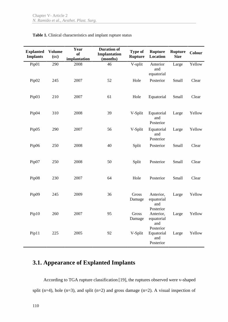
Chapter V- Article 2N. Ramião et al., Aesthet. Plast. Surg.
110
Table 1. Clinical characteristics and implant rupture status
3.1. Appearance of Explanted Implants
According to TGA rupture classification [19], the ruptures observed were v-shaped
split (n=4), hole (n=3), and split (n=2) and gross damage (n=2). A visual inspection of
ExplantedImplants
Volume(cc)
Yearof
implantation
Duration ofImplantation
(months)
Type ofRupture
RuptureLocation
RuptureSize
Colour
Pip01 290 2008 46 V-split Anteriorand
equatorial
Large Yellow
Pip02 245 2007 52 Hole Posterior Small Clear
Pip03 210 2007 61 Hole Equatorial Small Clear
Pip04 310 2008 39 V-Split Equatorialand
Posterior
Large Yellow
Pip05 290 2007 56 V-Split Equatorialand
Posterior
Large Yellow
Pip06 250 2008 40 Split Posterior Small Clear
Pip07 250 2008 50 Split Posterior Small Clear
Pip08 230 2007 64 Hole Posterior Small Clear
Pip09 245 2009 36 GrossDamage
Anterior,equatorial
andPosterior
Large Yellow
Pip10 260 2007 95 GrossDamage
Anterior,equatorial
andPosterior
Large Yellow
Pip11 225 2005 92 V-Split Equatorialand
Posterior
Large Yellow
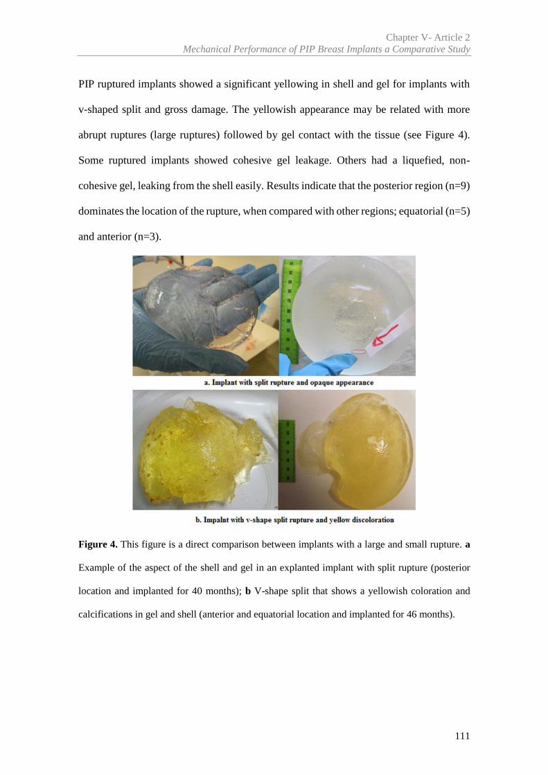
Chapter V- Article 2Mechanical Performance of PIP Breast Implants a Comparative Study
111
PIP ruptured implants showed a significant yellowing in shell and gel for implants with
v-shaped split and gross damage. The yellowish appearance may be related with more
abrupt ruptures (large ruptures) followed by gel contact with the tissue (see Figure 4).
Some ruptured implants showed cohesive gel leakage. Others had a liquefied, non-
cohesive gel, leaking from the shell easily. Results indicate that the posterior region (n=9)
dominates the location of the rupture, when compared with other regions; equatorial (n=5)
and anterior (n=3).
Figure 4. This figure is a direct comparison between implants with a large and small rupture. a
Example of the aspect of the shell and gel in an explanted implant with split rupture (posterior
location and implanted for 40 months); b V-shape split that shows a yellowish coloration and
calcifications in gel and shell (anterior and equatorial location and implanted for 46 months).
Chapter V- Article 2N. Ramião et al., Aesthet. Plast. Surg.
112
3.2. Mechanical Testing
A total of 940 individual samples were tested. The explanted PIP implants provided
a total of 604 samples, from which 255 samples were in the anterior region, 230 were in
the equatorial region and 119 in the posterior region. The number of samples removed
from the posterior region was lower since it was the most affected by ruptures.
From PIP control implants 216 samples were prepared; 88 anterior samples, 78
equatorial samples and 50 posterior samples. 120 samples were prepared from brand X
implants; 48 anterior samples, 24 equatorial samples and 48 from the posterior region.
The study aimed to analyse the stress difference among regions, depending on
different levels of strain, and identify the weaker regions in each implant.
3.2.1 Breast Implants Shell Strength – Global Overview
To obtain an implant-wide stress variation mapping, a custom contour plot was
developed and coded in MatLab. Regarding the control implants, Figure 5 represents the
stress along the shell at a 266% strain in three regions of both PIP control and brand X
implants. Sample’s location and stress level (MPa) are shown by blue dots and colour
variation, respectively. It can be observed that the brand X implant, shows a uniform
stress variation among the regions (anterior and posterior), in contrast with the PIP control
implant. In fact, the brand X shows a 9.51MPa (±0.97) stress average for the anterior
region and 8.99MPa (±0.96) for the posterior region, compared to 9.52MPa (±1.31) and
8.9MPa (±1.21) respectively for PIP implants, which has a higher standard deviation than
brand X. Figure 6 gives a statistical overview of the control groups results variation for
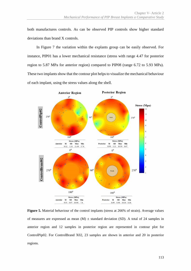
Chapter V- Article 2Mechanical Performance of PIP Breast Implants a Comparative Study
113
both manufactures controls. As can be observed PIP controls show higher standard
deviations than brand X controls.
In Figure 7 the variation within the explants group can be easily observed. For
instance, PIP01 has a lower mechanical resistance (stress with range 4.47 for posterior
region to 5.87 MPa for anterior region) compared to PIP08 (range 6.72 to 5.93 MPa).
These two implants show that the contour plot helps to visualize the mechanical behaviour
of each implant, using the stress values along the shell.
Figure 5. Material behaviour of the control implants (stress at 266% of strain). Average values
of measures are expressed as mean (M) ± standard deviation (SD). A total of 24 samples in
anterior region and 12 samples in posterior region are represented in contour plot for
ControlPip02. For ControlBrand X02, 23 samples are shown in anterior and 20 in posterior
regions.
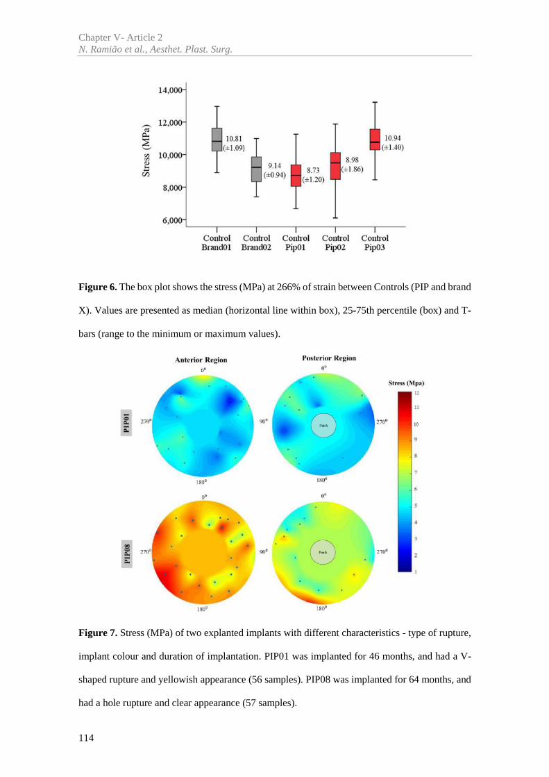
Chapter V- Article 2N. Ramião et al., Aesthet. Plast. Surg.
114
Figure 6. The box plot shows the stress (MPa) at 266% of strain between Controls (PIP and brand
X). Values are presented as median (horizontal line within box), 25-75th percentile (box) and T-
bars (range to the minimum or maximum values).
Figure 7. Stress (MPa) of two explanted implants with different characteristics - type of rupture,
implant colour and duration of implantation. PIP01 was implanted for 46 months, and had a V-
shaped rupture and yellowish appearance (56 samples). PIP08 was implanted for 64 months, and
had a hole rupture and clear appearance (57 samples).
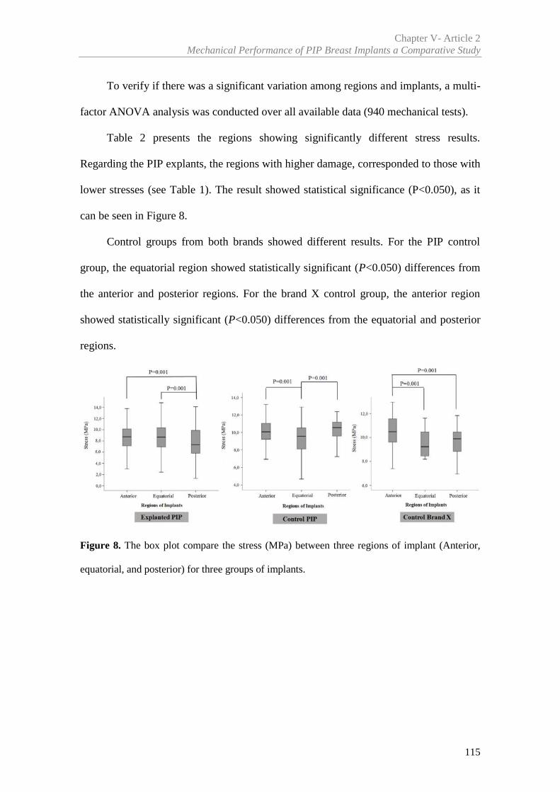
Chapter V- Article 2Mechanical Performance of PIP Breast Implants a Comparative Study
115
To verify if there was a significant variation among regions and implants, a multi-
factor ANOVA analysis was conducted over all available data (940 mechanical tests).
Table 2 presents the regions showing significantly different stress results.
Regarding the PIP explants, the regions with higher damage, corresponded to those with
lower stresses (see Table 1). The result showed statistical significance (P<0.050), as it
can be seen in Figure 8.
Control groups from both brands showed different results. For the PIP control
group, the equatorial region showed statistically significant (P<0.050) differences from
the anterior and posterior regions. For the brand X control group, the anterior region
showed statistically significant (P<0.050) differences from the equatorial and posterior
regions.
Figure 8. The box plot compare the stress (MPa) between three regions of implant (Anterior,
equatorial, and posterior) for three groups of implants.
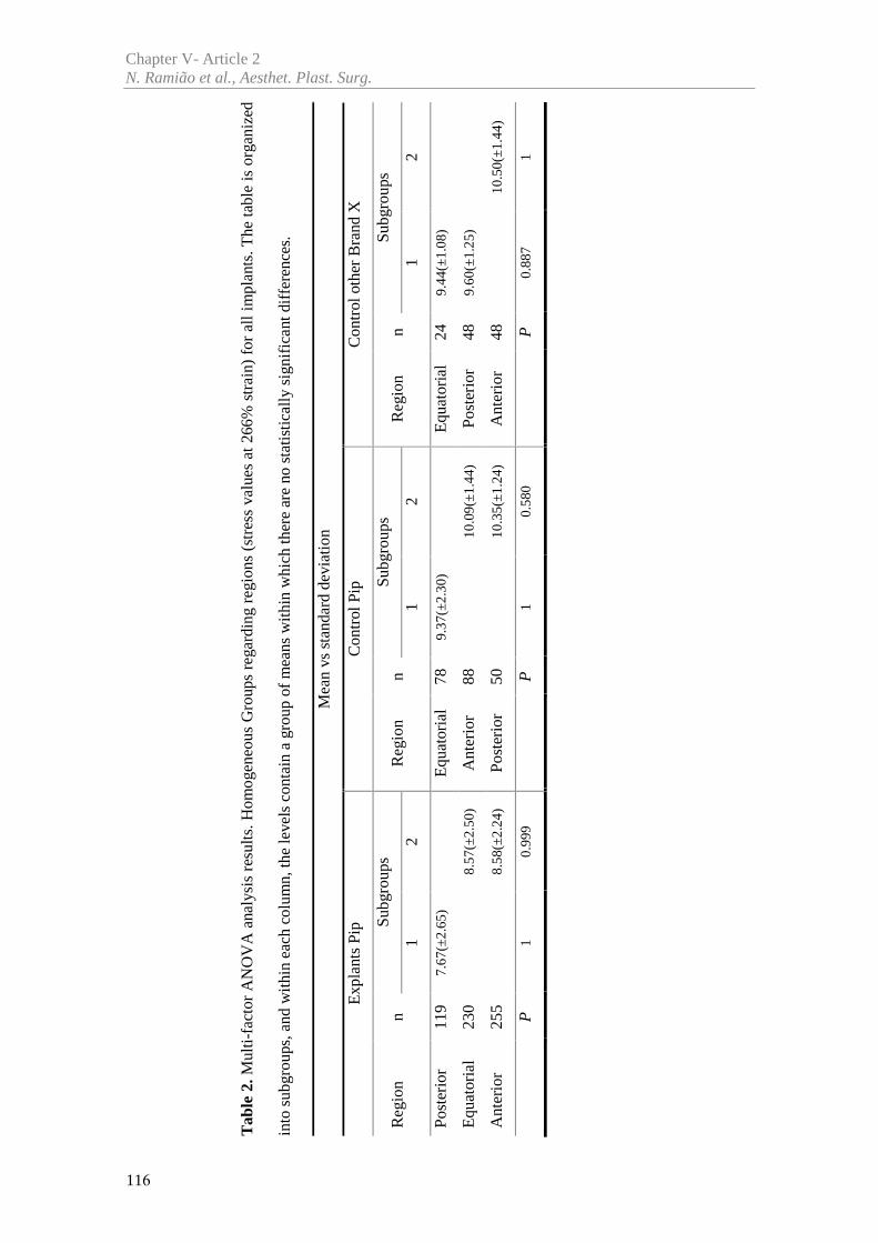
Tab
le 2
.Mul
ti-fa
ctor
AN
OV
A a
naly
sis
resu
lts.H
omog
eneo
us G
roup
s re
gard
ing
regi
ons
(str
ess
valu
es a
t 266
% s
trai
n) f
or a
ll im
plan
ts. T
he ta
ble
is o
rgan
ized
into
sub
grou
ps, a
nd w
ithi
n ea
ch c
olum
n, th
e le
vels
con
tain
a g
roup
of
mea
ns w
ithin
whi
ch th
ere
are
no s
tatis
tical
ly s
igni
fica
nt d
iffe
renc
es.
Mea
n vs
stan
dard
dev
iatio
n
Exp
lant
s Pi
pC
ontr
ol P
ipC
ontr
ol o
ther
Bra
nd X
Reg
ion
nSu
bgro
ups
Reg
ion
nSu
bgro
ups
Reg
ion
nSu
bgro
ups
12
12
12
Post
erio
r11
97.
67(±
2.65
)E
quat
oria
l78
9.37
(±2.
30)
Equ
ator
ial
249.
44(±
1.08
)
Equ
ator
ial
230
8.57
(±2.
50)
Ant
erio
r88
10.0
9(±1
.44)
Post
erio
r48
9.60
(±1.
25)
Ant
erio
r25
58.
58(±
2.24
)Po
ster
ior
5010
.35(
±1.2
4)A
nter
ior
4810
.50(
±1.4
4)
P1
0.99
9P
10.
580
P0.
887
1
Chapter V- Article 2N. Ramião et al., Aesthet. Plast. Surg.
116
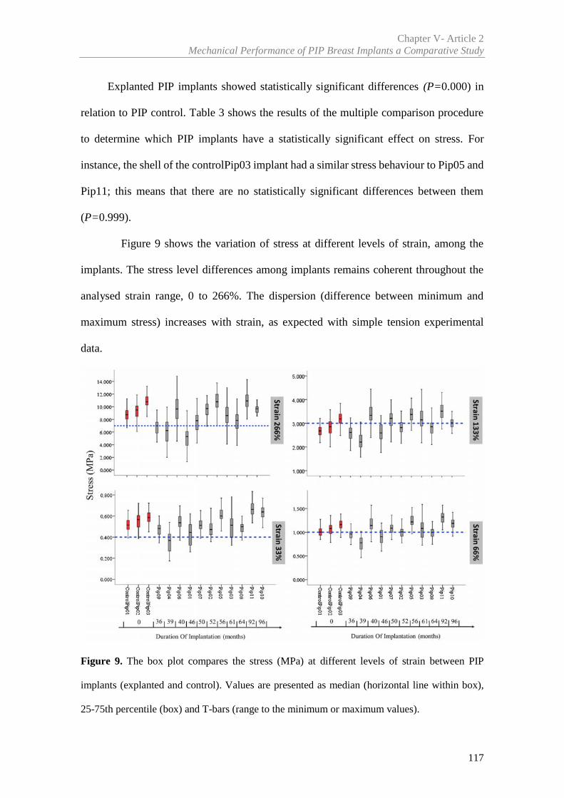
Chapter V- Article 2Mechanical Performance of PIP Breast Implants a Comparative Study
117
Explanted PIP implants showed statistically significant differences (P=0.000) in
relation to PIP control. Table 3 shows the results of the multiple comparison procedure
to determine which PIP implants have a statistically significant effect on stress. For
instance, the shell of the controlPip03 implant had a similar stress behaviour to Pip05 and
Pip11; this means that there are no statistically significant differences between them
(P=0.999).
Figure 9 shows the variation of stress at different levels of strain, among the
implants. The stress level differences among implants remains coherent throughout the
analysed strain range, 0 to 266%. The dispersion (difference between minimum and
maximum stress) increases with strain, as expected with simple tension experimental
data.
Figure 9. The box plot compares the stress (MPa) at different levels of strain between PIP
implants (explanted and control). Values are presented as median (horizontal line within box),
25-75th percentile (box) and T-bars (range to the minimum or maximum values).
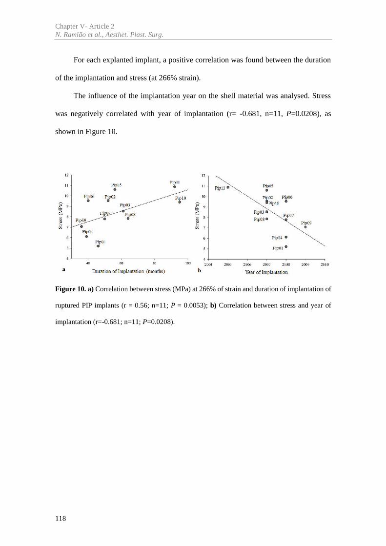
Chapter V- Article 2N. Ramião et al., Aesthet. Plast. Surg.
118
For each explanted implant, a positive correlation was found between the duration
of the implantation and stress (at 266% strain).
The influence of the implantation year on the shell material was analysed. Stress
was negatively correlated with year of implantation (r= -0.681, n=11, P=0.0208), as
shown in Figure 10.
Figure 10. a) Correlation between stress (MPa) at 266% of strain and duration of implantation of
ruptured PIP implants (r = 0.56; n=11; P = 0.0053); b) Correlation between stress and year of
implantation (r=-0.681; n=11; P=0.0208).
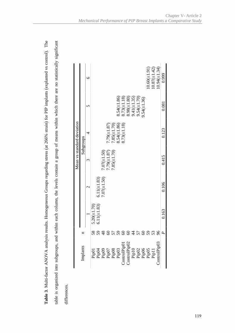
Tab
le 3
. Mul
ti-fa
ctor
AN
OV
A a
naly
sis
resu
lts.
Hom
ogen
eous
Gro
ups
rega
rdin
g st
ress
(at
266
% s
trai
n) f
or P
IP i
mpl
ants
(ex
plan
ted
vs c
ontr
ol).
The
tabl
e is
org
aniz
ed i
nto
subg
roup
s, a
nd w
ithin
eac
h co
lum
n, t
he l
evel
s co
ntai
n a
grou
p of
mea
ns w
ithin
whi
ch t
here
are
no
stat
istic
ally
sig
nifi
cant
diff
eren
ces.
Impl
ants
nM
ean
vsst
anda
rd d
evia
tion
Subg
roup
s1
23
45
6Pi
p01
585.
20(±
1.70
)Pi
p04
596.
11(±
1.83
)6.
11(±
1.83
)Pi
p09
487.
07(±
1.50
)7.
07(±
1.50
)Pi
p07
607.
79(±
1.87
)7.
79(±
1.87
)Pi
p08
577.
85(±
1.70
)7.
85(±
1.70
)Pi
p03
598.
54(±
1.86
)8.
54(±
1.86
)C
ontr
olPi
p01
608.
73(±
1.18
)8.
73(±
1.18
)C
ontr
olPi
p02
608.
98(±
1.80
)Pi
p10
449.
41(±
1.35
)Pi
p02
579.
54(±
1.70
)Pi
p06
609.
54(±
1.36
)Pi
p05
5910
.60(
±1.9
1)Pi
p11
5310
.87(
±1.4
2)C
ontr
olPi
p03
9610
.94(
±1.3
4)P
0.16
30.
106
0.41
50.
123
0.08
10.
999
Chapter V- Article 2Mechanical Performance of PIP Breast Implants a Comparative Study
119
Chapter V- Article 2N. Ramião et al., Aesthet. Plast. Surg.
120
3.2.2 Thickness Variation
During sample preparation, it was noticed that shell thickness displayed significant
variation within and among the samples, especially regarding PIP implants.
The average shell thickness of the PIP explanted breast implants ranged between
0.62 and 1.07 mm. The maximum and minimum thickness values recorded were 1.30 mm
and 0.44 mm, respectively. Variation was also observed in the PIP control implants, with
a 0.59mm minimum thickness and 1.15mm maximum. The brand X implants showed
smaller thickness variation between the regions, with minimum thickness of 0.55mm and
maximum of 0.98mm.
The thickness variation (%) was calculated with equation, ℎ% = ( ) ×100 , where is the mean thickness per implant, while and are the
minimum and maximum thickness per implant.
The thickness variation for PIP explanted implants reached values between 30.93%
and 65.22%. For the PIP control group, thickness variation increases, ranging from
31.71% to 85.26%. Regarding the brand X, thickness variation reached inferior values,
between 30.97% and 41.49%.
To study a possible influence of the sample thickness on stress, the stresses at 33%,
66%, 133% and 266% strain were analysed for all tested samples. A noticeable influence
of thickness over stress was found only for 266% strain.
For PIP control implants, a strong correlation was observed between thickness and
stress, using the Pearson coefficient (Table 4). Taking as example controlPip01 implant
(Figure 11) the results per region were: anterior [r=0.89, n=24, P<0.05], equatorial
[r=0.84, n=24, P<0.05] and posterior [r=0.98, n=12, P<0.001].
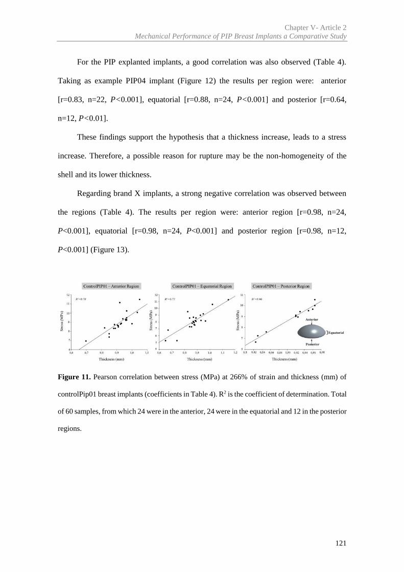
Chapter V- Article 2Mechanical Performance of PIP Breast Implants a Comparative Study
121
For the PIP explanted implants, a good correlation was also observed (Table 4).
Taking as example PIP04 implant (Figure 12) the results per region were: anterior
[r=0.83, n=22, P<0.001], equatorial [r=0.88, n=24, P<0.001] and posterior [r=0.64,
n=12, P<0.01].
These findings support the hypothesis that a thickness increase, leads to a stress
increase. Therefore, a possible reason for rupture may be the non-homogeneity of the
shell and its lower thickness.
Regarding brand X implants, a strong negative correlation was observed between
the regions (Table 4). The results per region were: anterior region [r=0.98, n=24,
P<0.001], equatorial [r=0.98, n=24, P<0.001] and posterior region [r=0.98, n=12,
P<0.001] (Figure 13).
Figure 11. Pearson correlation between stress (MPa) at 266% of strain and thickness (mm) of
controlPip01 breast implants (coefficients in Table 4). R2 is the coefficient of determination. Total
of 60 samples, from which 24 were in the anterior, 24 were in the equatorial and 12 in the posterior
regions.
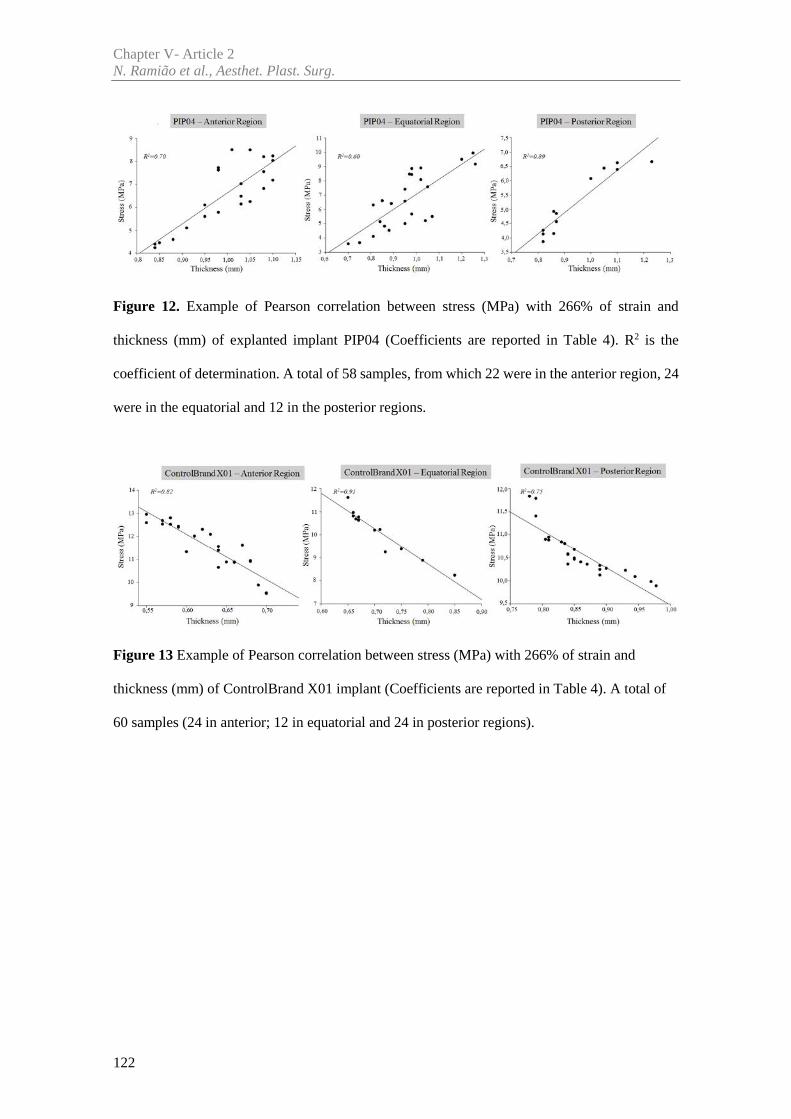
Chapter V- Article 2N. Ramião et al., Aesthet. Plast. Surg.
122
Figure 12. Example of Pearson correlation between stress (MPa) with 266% of strain and
thickness (mm) of explanted implant PIP04 (Coefficients are reported in Table 4). R2 is the
coefficient of determination. A total of 58 samples, from which 22 were in the anterior region, 24
were in the equatorial and 12 in the posterior regions.
Figure 13 Example of Pearson correlation between stress (MPa) with 266% of strain and
thickness (mm) of ControlBrand X01 implant (Coefficients are reported in Table 4). A total of
60 samples (24 in anterior; 12 in equatorial and 24 in posterior regions).
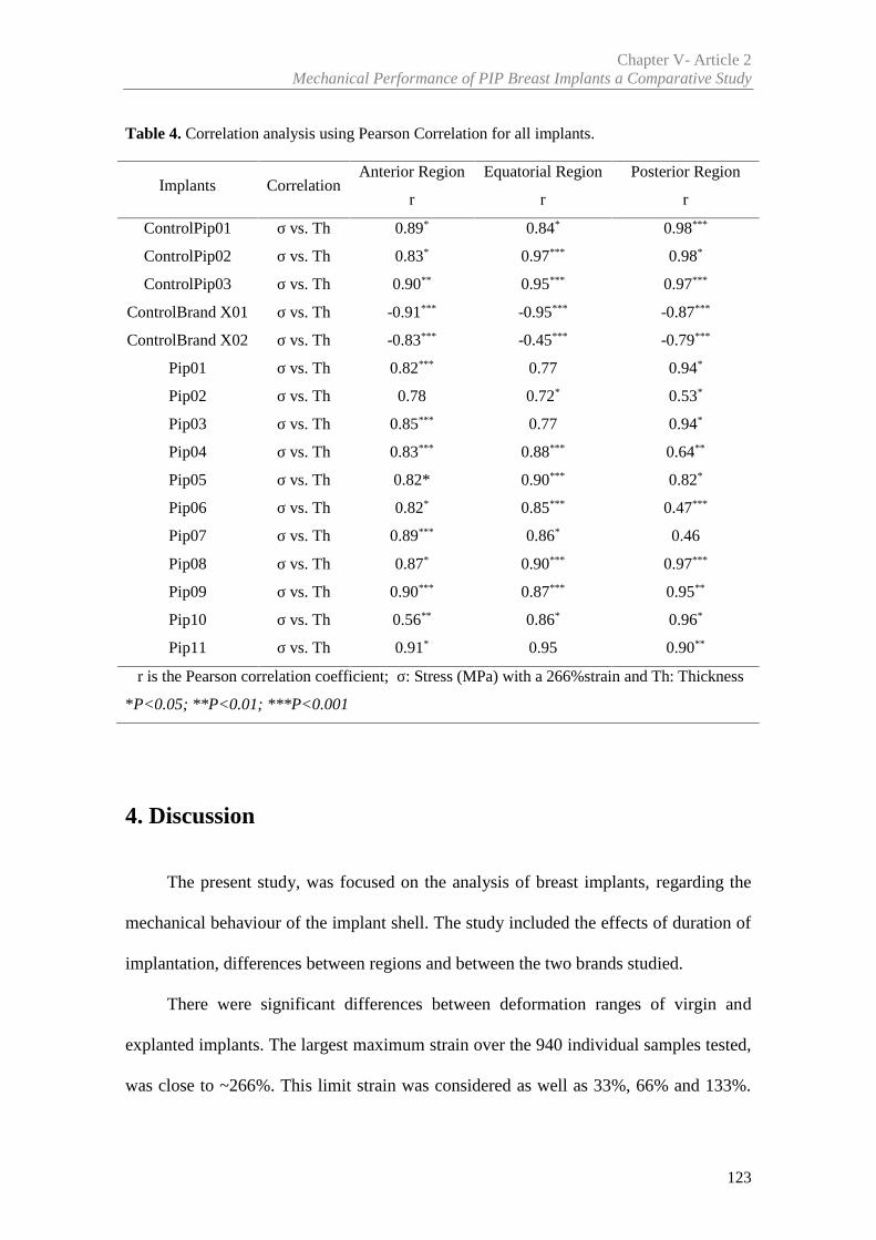
Chapter V- Article 2Mechanical Performance of PIP Breast Implants a Comparative Study
123
Table 4. Correlation analysis using Pearson Correlation for all implants.
Implants CorrelationAnterior Region Equatorial Region Posterior Region
r r r
ControlPip01 σ vs. Th 0.89* 0.84* 0.98***
ControlPip02 σ vs. Th 0.83* 0.97*** 0.98*
ControlPip03 σ vs. Th 0.90** 0.95*** 0.97***
ControlBrand X01 σ vs. Th -0.91*** -0.95*** -0.87***
ControlBrand X02 σ vs. Th -0.83*** -0.45*** -0.79***
Pip01 σ vs. Th 0.82*** 0.77 0.94*
Pip02 σ vs. Th 0.78 0.72* 0.53*
Pip03 σ vs. Th 0.85*** 0.77 0.94*
Pip04 σ vs. Th 0.83*** 0.88*** 0.64**
Pip05 σ vs. Th 0.82* 0.90*** 0.82*
Pip06 σ vs. Th 0.82* 0.85*** 0.47***
Pip07 σ vs. Th 0.89*** 0.86* 0.46
Pip08 σ vs. Th 0.87* 0.90*** 0.97***
Pip09 σ vs. Th 0.90*** 0.87*** 0.95**
Pip10 σ vs. Th 0.56** 0.86* 0.96*
Pip11 σ vs. Th 0.91* 0.95 0.90**
r is the Pearson correlation coefficient; σ: Stress (MPa) with a 266%strain and Th: Thickness
*P<0.05; **P<0.01; ***P<0.001
4. Discussion
The present study, was focused on the analysis of breast implants, regarding the
mechanical behaviour of the implant shell. The study included the effects of duration of
implantation, differences between regions and between the two brands studied.
There were significant differences between deformation ranges of virgin and
explanted implants. The largest maximum strain over the 940 individual samples tested,
was close to ~266%. This limit strain was considered as well as 33%, 66% and 133%.
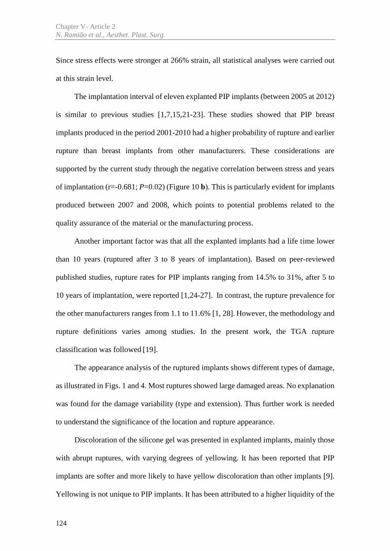
Chapter V- Article 2N. Ramião et al., Aesthet. Plast. Surg.
124
Since stress effects were stronger at 266% strain, all statistical analyses were carried out
at this strain level.
The implantation interval of eleven explanted PIP implants (between 2005 at 2012)
is similar to previous studies [1,7,15,21-23]. These studies showed that PIP breast
implants produced in the period 2001-2010 had a higher probability of rupture and earlier
rupture than breast implants from other manufacturers. These considerations are
supported by the current study through the negative correlation between stress and years
of implantation (r=-0.681; P=0.02) (Figure 10 b). This is particularly evident for implants
produced between 2007 and 2008, which points to potential problems related to the
quality assurance of the material or the manufacturing process.
Another important factor was that all the explanted implants had a life time lower
than 10 years (ruptured after 3 to 8 years of implantation). Based on peer-reviewed
published studies, rupture rates for PIP implants ranging from 14.5% to 31%, after 5 to
10 years of implantation, were reported [1,24-27]. In contrast, the rupture prevalence for
the other manufacturers ranges from 1.1 to 11.6% [1, 28]. However, the methodology and
rupture definitions varies among studies. In the present work, the TGA rupture
classification was followed [19].
The appearance analysis of the ruptured implants shows different types of damage,
as illustrated in Figs. 1 and 4. Most ruptures showed large damaged areas. No explanation
was found for the damage variability (type and extension). Thus further work is needed
to understand the significance of the location and rupture appearance.
Discoloration of the silicone gel was presented in explanted implants, mainly those
with abrupt ruptures, with varying degrees of yellowing. It has been reported that PIP
implants are softer and more likely to have yellow discoloration than other implants [9].
Yellowing is not unique to PIP implants. It has been attributed to a higher liquidity of the
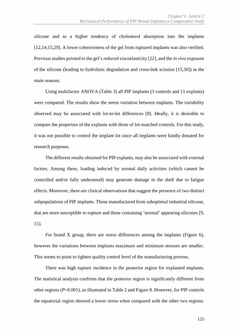
Chapter V- Article 2Mechanical Performance of PIP Breast Implants a Comparative Study
125
silicone and to a higher tendency of cholesterol absorption into the implants
[12,14,15,29]. A lower cohesiveness of the gel from ruptured implants was also verified.
Previous studies pointed to the gel’s reduced viscoelasticity [22], and the in vivo exposure
of the silicone (leading to hydrolytic degradation and cross-link scission [15,30]) as the
main reasons.
Using multifactor ANOVA (Table 3) all PIP implants (3 controls and 11 explants)
were compared. The results show the stress variation between implants. The variability
observed may be associated with lot-to-lot differences [8]. Ideally, it is desirable to
compare the properties of the explants with those of lot-matched controls. For this study,
it was not possible to control the implant lot since all implants were kindly donated for
research purposes.
The different results obtained for PIP explants, may also be associated with external
factors. Among these, loading induced by normal daily activities (which cannot be
controlled and/or fully understood) may generate damage in the shell due to fatigue
effects. Moreover, there are clinical observations that suggest the presence of two distinct
subpopulations of PIP implants. Those manufactured from suboptimal industrial silicone,
that are more susceptible to rupture and those containing ‘normal’ appearing silicones [9,
15].
For brand X group, there are stress differences among the implants (Figure 6),
however the variations between implants maximum and minimum stresses are smaller.
This seems to point to tighten quality control level of the manufacturing process.
There was high rupture incidence in the posterior region for explanted implants.
The statistical analysis confirms that the posterior region is significantly different from
other regions (P=0.001), as illustrated in Table 2 and Figure 8. However, for PIP controls
the equatorial region showed a lower stress when compared with the other two regions.
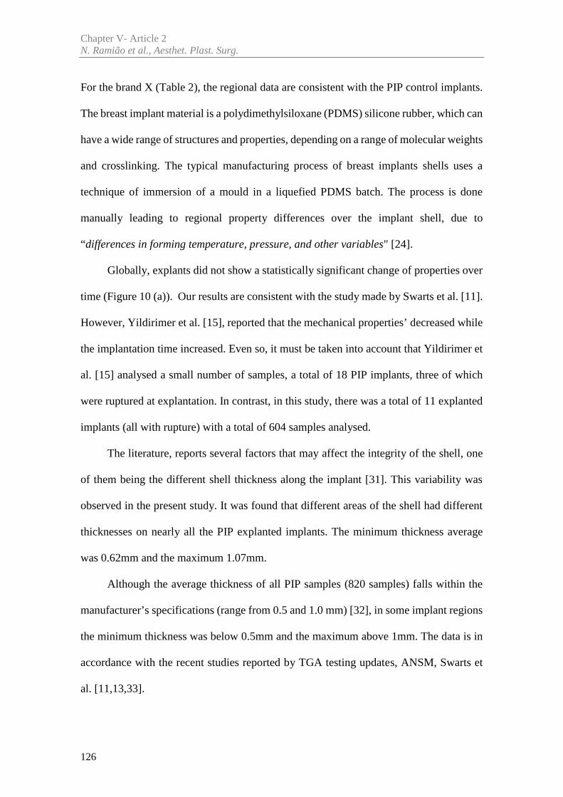
Chapter V- Article 2N. Ramião et al., Aesthet. Plast. Surg.
126
For the brand X (Table 2), the regional data are consistent with the PIP control implants.
The breast implant material is a polydimethylsiloxane (PDMS) silicone rubber, which can
have a wide range of structures and properties, depending on a range of molecular weights
and crosslinking. The typical manufacturing process of breast implants shells uses a
technique of immersion of a mould in a liquefied PDMS batch. The process is done
manually leading to regional property differences over the implant shell, due to
“differences in forming temperature, pressure, and other variables" [24].
Globally, explants did not show a statistically significant change of properties over
time (Figure 10 (a)). Our results are consistent with the study made by Swarts et al. [11].
However, Yildirimer et al. [15], reported that the mechanical properties’ decreased while
the implantation time increased. Even so, it must be taken into account that Yildirimer et
al. [15] analysed a small number of samples, a total of 18 PIP implants, three of which
were ruptured at explantation. In contrast, in this study, there was a total of 11 explanted
implants (all with rupture) with a total of 604 samples analysed.
The literature, reports several factors that may affect the integrity of the shell, one
of them being the different shell thickness along the implant [31]. This variability was
observed in the present study. It was found that different areas of the shell had different
thicknesses on nearly all the PIP explanted implants. The minimum thickness average
was 0.62mm and the maximum 1.07mm.
Although the average thickness of all PIP samples (820 samples) falls within the
manufacturer’s specifications (range from 0.5 and 1.0 mm) [32], in some implant regions
the minimum thickness was below 0.5mm and the maximum above 1mm. The data is in
accordance with the recent studies reported by TGA testing updates, ANSM, Swarts et
al. [11,13,33].
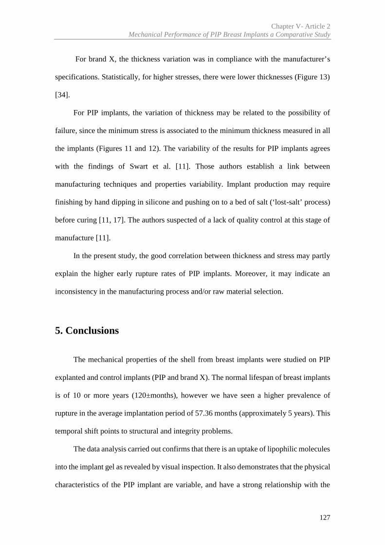
Chapter V- Article 2Mechanical Performance of PIP Breast Implants a Comparative Study
127
For brand X, the thickness variation was in compliance with the manufacturer’s
specifications. Statistically, for higher stresses, there were lower thicknesses (Figure 13)
[34].
For PIP implants, the variation of thickness may be related to the possibility of
failure, since the minimum stress is associated to the minimum thickness measured in all
the implants (Figures 11 and 12). The variability of the results for PIP implants agrees
with the findings of Swart et al. [11]. Those authors establish a link between
manufacturing techniques and properties variability. Implant production may require
finishing by hand dipping in silicone and pushing on to a bed of salt (‘lost-salt’ process)
before curing [11, 17]. The authors suspected of a lack of quality control at this stage of
manufacture [11].
In the present study, the good correlation between thickness and stress may partly
explain the higher early rupture rates of PIP implants. Moreover, it may indicate an
inconsistency in the manufacturing process and/or raw material selection.
5. Conclusions
The mechanical properties of the shell from breast implants were studied on PIP
explanted and control implants (PIP and brand X). The normal lifespan of breast implants
is of 10 or more years (120±months), however we have seen a higher prevalence of
rupture in the average implantation period of 57.36 months (approximately 5 years). This
temporal shift points to structural and integrity problems.
The data analysis carried out confirms that there is an uptake of lipophilic molecules
into the implant gel as revealed by visual inspection. It also demonstrates that the physical
characteristics of the PIP implant are variable, and have a strong relationship with the
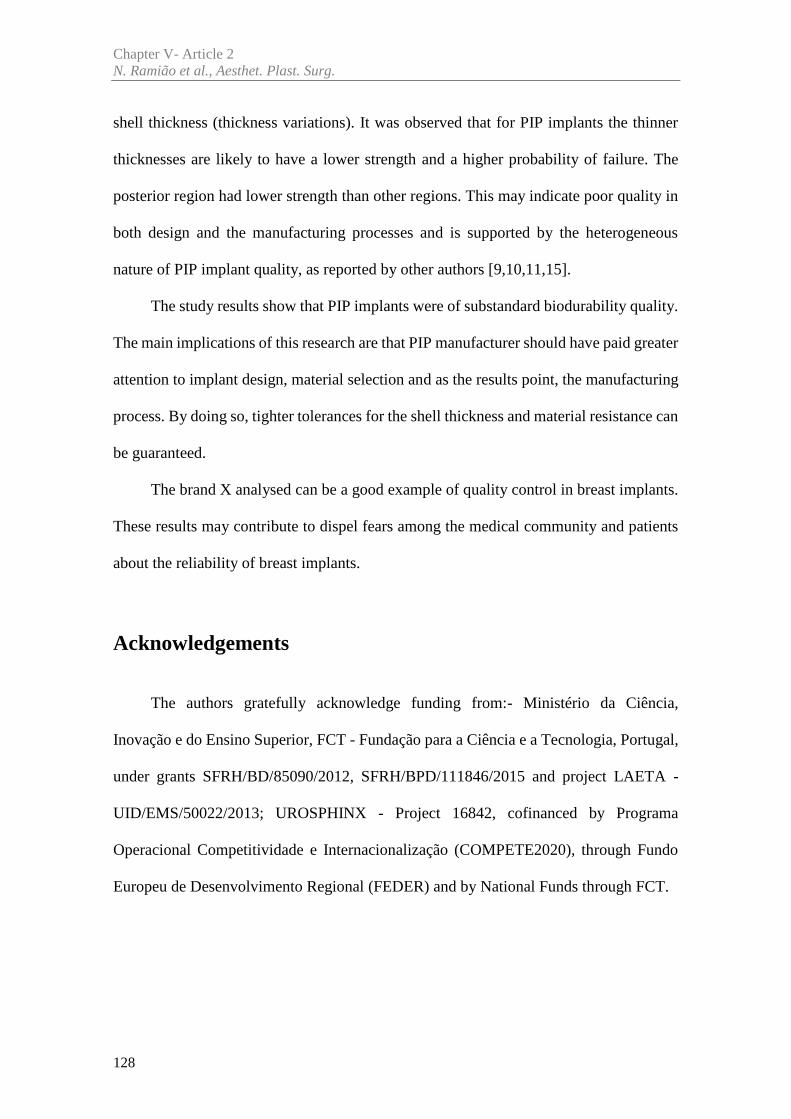
Chapter V- Article 2N. Ramião et al., Aesthet. Plast. Surg.
128
shell thickness (thickness variations). It was observed that for PIP implants the thinner
thicknesses are likely to have a lower strength and a higher probability of failure. The
posterior region had lower strength than other regions. This may indicate poor quality in
both design and the manufacturing processes and is supported by the heterogeneous
nature of PIP implant quality, as reported by other authors [9,10,11,15].
The study results show that PIP implants were of substandard biodurability quality.
The main implications of this research are that PIP manufacturer should have paid greater
attention to implant design, material selection and as the results point, the manufacturing
process. By doing so, tighter tolerances for the shell thickness and material resistance can
be guaranteed.
The brand X analysed can be a good example of quality control in breast implants.
These results may contribute to dispel fears among the medical community and patients
about the reliability of breast implants.
Acknowledgements
The authors gratefully acknowledge funding from:- Ministério da Ciência,
Inovação e do Ensino Superior, FCT - Fundação para a Ciência e a Tecnologia, Portugal,
under grants SFRH/BD/85090/2012, SFRH/BPD/111846/2015 and project LAETA -
UID/EMS/50022/2013; UROSPHINX - Project 16842, cofinanced by Programa
Operacional Competitividade e Internacionalização (COMPETE2020), through Fundo
Europeu de Desenvolvimento Regional (FEDER) and by National Funds through FCT.
Chapter V- Article 2Mechanical Performance of PIP Breast Implants a Comparative Study
129
Declaration of Conflicting Interests
None declared.
References
[1] Maijers MC, Niessen FB. Prevalence of rupture in Poly Implant Prothèse silicone breast
implants, recalled from the European market in 2010. Plast Reconstr Surg 2012; 129:1372–1378
[2] Lockwood MD. Strength, strain, energy, and toughness of silicone
breast implant shells. In Proceedings of the 1996 Fifteenth Southern, Biomedical Engineering
Conference, Dayton, OH March 29-31
[3] Phillips JW, de Camara DL, Lockwood, MD, Grebner CC. Strength of silicone breast
implants. Plast Reconstr Surg 1996; 97:1215-1225
[4] Greenwald DP, Randolph M, May JW. Mechanical analysis of explanted silicone breast
implants. Plast Reconstr Surg 1996;98:269-272
[5] Marotta JS, Amery DP, Widenhouse CW, Martin PJ, Goldberg EP. Degradation of
physical properties of silicone gel breast implants and high rates of implant failures. In
Proceedings of the 24th Annual Meeting of the Society of Biomaterials, 1 January, 374, 1998
[6] Brandon HJ, Young VL, Jerina KL, Wolf CJ. Variability in the properties of silicone
gel breast implants. In Proceedings of the 24th Annual Meeting of the Society of Biomaterials, 1
January, 400, 1998
[7] Santos DC, Barroso ML, Gomes N, et al. PIP breast implant rupture—A retrospective
study from Portugal. Eur J Plast Surg 2015;38:301-308
[8] Brandon HJ, Jerina KL, Wolf CJ, Young VL. Retrieval and analysis of breast implants
emphasizing strength, durability, and failure mechanisms. In: Peter W, Brandon HJ, Jerina KL,
Wolf W, Young VL (eds) Biomaterials in Plastic Surgery, Woodhead Publishing Limited, 154-
217, 2012
Chapter V- Article 2N. Ramião et al., Aesthet. Plast. Surg.
130
[9] Scientific Committee on Emerging and Newly Identified Health Risks. The safety of
PIP silicone breast implants (February 2012). Available at:
http://ec.europa.eu/health/scientific_committees/emerging/docs/scenihr_o_043.pdf. [Accessed
10 March 2012]
[10] Wazir U, Kasem A, Mokbel K. The Clinical Implications of Poly Implant Prothèse
Breast Implants: An Overview. Arch Plast Surg 215;42:4-10
[11] Swarts E, Kop A, Nilasaroya A; Keogh CV, Cooper T. Rupture of Poly Implant
Prothèse Silicone Breast Implants: An Implant Retrieval Study. Plast Reconstr Surg 2013;
131(4):480e-489e
[12] Beretta G, Malacco M. Chemical and physicochemical properties of the high cohesive
silicone gel from Poly Implant Prothese (PIP) breast prostheses after explantation: a preliminary,
comparative analytical investigation. J Pharm Biomed Anal 2013; 78-79:75-82
[13] Brandon HJ, Young VL, Jerina KL, Wolf CJ. Effect of Implantation Surgery on the
Strength Properties of Silastic® II Silicone Gel Breast Implants. Aesthet Surg J. 1999; 19:197–
204
[14] Necchi S, Molina D, Turri S, Rossetto F, Rietjens M. Failure of silicone gel breast
implants: is the mechanical weakening due to shell swelling a significant cause of prostheses
rupture? J Mech Behav Biomed Mater 2011; 4:2002–2008
[15] Yildirimer L, Seifalian AM, Butler PE. Surface and mechanical analysis of explanted
Poly Implant Prothèse silicone breast implants. Br J Surg 100(6):761-7
[16] Daniels AU (2012) Silicone breast implant materials. Swiss Med 2013; Wkly
142:w13614
[17] Mathieu DP, Jaime ME, Manufacturing Process: Silicone breast implants (2014)
https://prezi.com/bgyd4zxce52m/manufacturing-process-silicone-breast-
implants/?utm_campaign=share&utm_medium=copy. [Accessed 9 September 2016]
Chapter V- Article 2Mechanical Performance of PIP Breast Implants a Comparative Study
131
[18] Schubert DW, Kaschta J, Horch RE, Waltera BL. On the failure of silicone breast
implants: new insights by mapping the mechanical properties of implant shells. Society of
Chemical Industry 2013; 63: 172–178
[19] TGA (2013) PIP breast implants: Update on TGA testing of PIP breast implants
Available at: http://www.tga.gov.au/alert/pip-breast-implants-update-tga-testing-pip-breast-
implants. [Accessed 10 March 2013]
[20] Pallant, J (2005) SPSS survival manual: A step by step guide to data analysis using
SPSS for Windows third edition. Ligare Book Printer, Sydney, 2005
[21] Aktouf A, Auquit-Auckbur I, Coquerel-Beghin D, Delpierre V, Milliez PY. Breast
augmentation by Poly Implant Prothèses silicone implants: retrospective study about 99 patients.
Rupture analysis and management. Ann Chir Plast Esthet. 2012; 57(6):558-66
[22] Carillon MA, Giard S, Emmanuelli V, Houpeau JL, Ceugnart L, Chauvet MP. Breast
implants and health alert PIP: experience of the regional cancer center of Lille. Bull Cancer 2012;
1;99(2):147-53
[23] Reyal F, Feron JG, Leman Detour S, et al.The impact of poly implant prothèse fraud
on breast cancer patients: a report by the Institut Curie. Plast Reconstr Surg 2013; 131 (4):690-5
[24] Berry MG, Stanek JJ. PIP implant biodurability: a post-publicity update. J Plast
Reconstr Aesthet Surg. 2013; 66:1174-81
[25] Quaba O, Quaba A. PIP silicone breast implants: rupture rates based on the
explantation of 676 implants in a single surgeon series. J Plast Reconstr Aesthet Surg 2013;
66(9):1182–1187
[26] Oulharj S, Pauchot J, Tropet Y. PIP breast implant removal: a study of 828 cases. J
Plast Reconstr Aesthet Surg 2014; 67:302-7
[27] Khan UD. Poly Implant Prothèse (PIP) Incidence of device failure and capsular
contracture: a retrospective study. Aesthetic Plast Surg 2013; 37(5):906–913
Chapter V- Article 2N. Ramião et al., Aesthet. Plast. Surg.
132
[28] Spear SL, Murphy DK. Allergan Silicone Breast Implant U.S. Core Clinical Study
Group. Natrelle round silicone breast implants: core study results at 10 years. Plast Reconstr Surg
2014; 133:1354-61
[29] Berry RB. Rupture of PIP breast implants. J Plast Reconstr
Aesthet Surg 2007; 60:967e8
[30] Tan J, Chao YJ, Li X, Van Zee JW. Degradation of silicone rubber under compression
in a simulated PEM fuel cell environment. J Power Sources 2007; 172: 782–789
[31] Bondurant S, Ernster V, Herdman R. Safety of Silicone Breast Implants. National
Academies Press: Washington, D.C, 1999, ISBN: 0-309-51931-4, 560
[32] Chief Medical Offier (CMO). Poly Implant Prothèse (PIP) Breast Implants: Report of
Chief Medical officer. 2012, ISBN: 978-1-74241-733-2
[33] Agence nationale de sécurité du médicament et des produits de santé (ANSM). PIP
Breast Implants. Available at:
http://www.ansm.sante.fr/var/ansm_site/storage/original/application/ea94f5f3532f4f831d6a923e
f553a77e.pdf . [Accessed 16 June 2013]
[34] Zheng L., Pereira PNR, Nakajima M, Sano H, Tagami J. Relationship Between
Adhesive Thickness and Microtensile Bond Strength. Operative Dentistry 2001; 26:99-1
Article 3(Letter Communication)
________________________________________________________
Breast Implants Rupture Induced by Fatigue Phenomena
Nilza Ramião a, Pedro Martins a, Maria da Luz Barrosob,
Diana C. Santosb, António A. Fernandesa
a INEGI, Faculty of Engineering, University of Porto, Porto, Portugalb Department of Plastic Surgery of Gaia Hospital Center, Vila Nova de Gaia, Portugal
Published in: Journal of Plastic, Reconstructive & Aesthetic Surgery, 2017, doi:
10.1016/j.bjps.2017.01.002

135
The research to study the causes and mechanisms of rupture of explanted breast
implants (Poly Implant Prosthesis – PIP), led to evidence that fatigue phenomena may be
associated to the initiation of implant ruptures. This finding has not been reported in the
literature as far as the authors are aware.
Eleven ruptured implants, explanted in the Department of Plastic Surgery of the
Hospital Center of Gaia, Portugal, were analysed. The shell samples, cut from the
ruptured region were examined by SEM (Scanning electron microscopy) at CEMUP
(University of Porto, Portugal).
The implants were classified in four groups, according to the type of shell rupture
(hole, split, v-shaped and gross damage), following the methodology introduced by the
Department of Health Therapeutic Goods Administration (Australia) [1]. Four explants
had a v-shape split, three had a hole, two a split and the remaining two presented gross
damage. The cause of large ruptures (v-shape split and gross damage) could not be
identified. Implants with small ruptures (hole or split) showed fractographic features
commonly found in fatigue processes, as illustrated in Figure 1.
This suggests that implants, subjected to cyclic loads, can initiate fatigue cracks
from pre-existing defects (microstructural inhomogeneities such as inclusions, pores and
among others [2,3]). As can be observed in Figure 1, a fractographic analysis reveals
crack initiation and microscopic crack growth, as illustrated by the “beachmarks” present
in the rupture surface. The “beachmarks” have a concave shape, typically associated to
the crack initiation origin (see red arrow in Figure 1). They are due to nonuniform crack
propagation induced by variation of the externally applied loads (e.g running, walking
and other) [4]. The “beachmarks” represent one of the most well known morphologic
feature of fatigue crack surfaces. The final unstable fracture (rupture) occurs when the
crack length exceeds a critical depth.
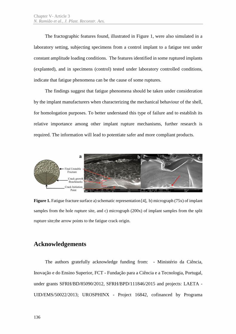
Chapter V- Article 3N. Ramião et al., J. Plast. Reconstr. Aes.
136
The fractographic features found, illustrated in Figure 1, were also simulated in a
laboratory setting, subjecting specimens from a control implant to a fatigue test under
constant amplitude loading conditions. The features identified in some ruptured implants
(explanted), and in specimens (control) tested under laboratory controlled conditions,
indicate that fatigue phenomena can be the cause of some ruptures.
The findings suggest that fatigue phenomena should be taken under consideration
by the implant manufacturers when characterizing the mechanical behaviour of the shell,
for homologation purposes. To better understand this type of failure and to establish its
relative importance among other implant rupture mechanisms, further research is
required. The information will lead to potentiate safer and more compliant products.
Figure 1. Fatigue fracture surface a) schematic representation [4], b) micrograph (75x) of implant
samples from the hole rupture site, and c) micrograph (200x) of implant samples from the split
rupture site;the arrow points to the fatigue crack origin.
Acknowledgements
The authors gratefully acknowledge funding from: - Ministério da Ciência,
Inovação e do Ensino Superior, FCT - Fundação para a Ciência e a Tecnologia, Portugal,
under grants SFRH/BD/85090/2012, SFRH/BPD/111846/2015 and projects: LAETA -
UID/EMS/50022/2013; UROSPHINX - Project 16842, cofinanced by Programa
Chapter V- Article 3Breast Implants Rupture Induced by Fatigue Phenomena.
137
Operacional Competitividade e Internacionalização (COMPETE2020), through Fundo
Europeu de Desenvolvimento Regional (FEDER) and by National Funds through FCT;
NORTE-01-0145-FEDER-000022 – SciTech – Science and Technology for Competitive
and Sustainable Industries (NORTE2020).
References
[1] Australian Government Department of Health and Ageing Therapeutic Goods
Administration (TGA) (2013) PIP breast implants: Update on TGA testing of PIP breast implants.
http://www.tga.gov.au/alert/pip-breast-implants-update-tga-testing-pip-breast-implants.
[Accessed 10 March 2013].
[2] Roeder RK. Mechanical Characterization of Biomaterials. Elsevier Inc. 2013.
http://dx.doi.org/10.1016/B978-0-12-415800-9.00003-6. Chapter 3.4.4 pag 78-80. [Accessed 21
February 2016].
[3] Hosford W F. Mechanical Behavior of Materials. 1ª ed, Cambridge University Press.
New York. 2005. Chapter Fatigue pag 281-282. ISBN-13 978-0-511-11575-2
[4] Fernandes AA. Fatigue performances of fillet welded joints of Al-Zn-Mg alloys
containing root defects. Phd theses, Cranfield University, 1978

Article 4
________________________________________________________
An Experimental Analysis of Shell Failure in Breast Implants
Nilza Ramião a, Pedro Martins a, Maria da Luz Barrosob,
Diana C. Santosb, António A. Fernandesa
a INEGI, Faculty of Engineering, University of Porto, Porto, Portugal
b Department of Plastic Surgery of Gaia Hospital Center, Vila Nova de Gaia, Portugal
Published in: Journal of the Mechanical Behavior of Biomedical Materials, 2017, doi:
10.1016/j.jmbbm.2017.04.005

141
Abstract
Breast implant durability and the mechanisms of rupture are important topics in the
medical community, for patients, manufactures and regulatory medical agencies. After
concerns about the Poly Implant Prosthesis (PIP) implants, the need for understanding
the adverse outcomes and the failure mode to improve the breast implants increased. The
objective of this research is to analyze and describe the rupture characteristics of failed
explanted PIP implants to study the modes and causes of rupture.
Eleven explanted PIP implants were analysed by visual inspection and scanning
electron microscopy (SEM). To simulate hipothetical ruptures caused by cyclic
mechanical stress (fatigue) in the implant shell, two control implants were submitted to
fatigue tests, and analysed with SEM.
None of the samples from the explants showed any damage that could be associated
to surgical instruments. However, for small ruptures (either Hole or split) striations were
found, which normally appear due to fatigue phenomena.
In the context of this work, the striations found in explants constitute a significant
finding as they point to the occurrence of fatigue phenomena associated with mammary
implants rupture. This research, also demonstrates that rupture surface analysis of
explanted breast implants has the potential to become a useful indicator for assessing
implant rupture mechanisms.
Keywords: Poly Implant Prosthesis (PIP), Failure mechanism, Scanning electron
microscopy (SEM), Fatigue.

143
1. Introduction
Breast implant rupture has been an important topic for the plastic surgery
community, regulatory agencies and particularly for patients [1-3]. Concerns about the
safety of silicone implants were intensified since the 2010 scandal involving Poly Implant
Prothèse (PIP) manufacturer. Recent studies concluded that the probability of early
rupture (life time lower than 10 years [4-5]) is higher for PIP implants. Based on
published studies, rupture rates for PIP implants ranged from 14.5 to 31 % after 5 to 10
years of implantation [4,6-9], while other implants showed a rupture rate from 1 to 11.6%
[4-5].
The failure of breast implants is influenced by different factors: material ageing
following implantation; surgical procedure quality (e.g., inadvertent damage);
manufacturing defects; shell wrinkling; patch detachment, among others [10]. Another
factor that possibly explains implant failure is the loading frequency imposed to the breast
due to daily activities such as running and walking. This mechanism is called mechanical
fatigue. Trauma injuries, such as shocks from car accidents [11] may play a role in the
damage mechanism that causes implant failures.
Current literature states that a large percentage of PIP implants ruptures are possibly
related to the shell quality over a large number of batches [1, 12]. This may point to a
considerable variability in the manufacturing process.
Even though the literature indicates the manufacturing process as a principal factor
leading to PIP implants failure, few studies have been conducted to characterize the type
of failure (e.g. damage due to surgical instruments, cyclic loading/fatigue). Therefore, the
Chapter V- Article 4N. Ramião et al., J. Mech. Behav. Biomed.
144
objective of this study is to determine the causes of rupture by analyzing failed explanted
breast implants.
2. Material and Methods
2.1 Materials
To understand how and why PIP implants show significant rates of premature
failure, eleven ruptured implants, explanted in the Department of Plastic Surgery of the
Hospital Center of Gaia, Portugal, were analysed. Sealed controls were supplied by the
National Authority of Medicines and Health Products (INFARMED, Portugal).
The explants underwent a disinfection procedure, following the health regulatory
authority’s standard procedure [1-2].
The diagnostic techniques for explants were: Stage 1 - visual inspection; Stage 2 -
scanning electron microscopy (SEM)); Stage 3 - Mechanical testing.
The last two stages will be described in sub-chapters: 2.2 Scanning electron
microscopy analysis and 2.3 Fatigue test.
During Stage 1, failure regions, shell rupture (hole, split or v-shaped), discoloration,
opacity and other features were recorded. In this work, the methodology reported by the
Department of Health Therapeutic Goods Administration (Australia) [3] was followed.
2.2. Scanning Electron Microscopy (SEM) Analysis
After inspection and disinfection of explants, several samples were cut from the
rupture region for examination by SEM at CEMUP (University of Porto, Portugal).
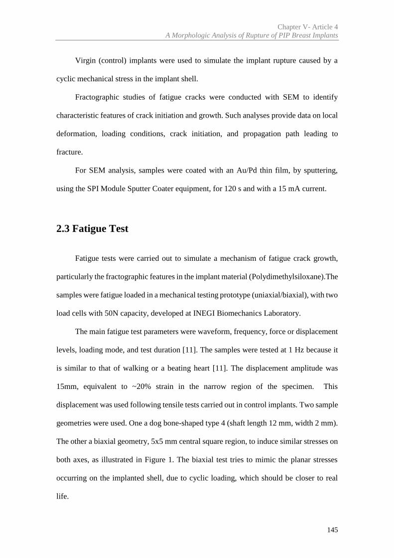
Chapter V- Article 4A Morphologic Analysis of Rupture of PIP Breast Implants
145
Virgin (control) implants were used to simulate the implant rupture caused by a
cyclic mechanical stress in the implant shell.
Fractographic studies of fatigue cracks were conducted with SEM to identify
characteristic features of crack initiation and growth. Such analyses provide data on local
deformation, loading conditions, crack initiation, and propagation path leading to
fracture.
For SEM analysis, samples were coated with an Au/Pd thin film, by sputtering,
using the SPI Module Sputter Coater equipment, for 120 s and with a 15 mA current.
2.3 Fatigue Test
Fatigue tests were carried out to simulate a mechanism of fatigue crack growth,
particularly the fractographic features in the implant material (Polydimethylsiloxane).The
samples were fatigue loaded in a mechanical testing prototype (uniaxial/biaxial), with two
load cells with 50N capacity, developed at INEGI Biomechanics Laboratory.
The main fatigue test parameters were waveform, frequency, force or displacement
levels, loading mode, and test duration [11]. The samples were tested at 1 Hz because it
is similar to that of walking or a beating heart [11]. The displacement amplitude was
15mm, equivalent to ~20% strain in the narrow region of the specimen. This
displacement was used following tensile tests carried out in control implants. Two sample
geometries were used. One a dog bone-shaped type 4 (shaft length 12 mm, width 2 mm).
The other a biaxial geometry, 5x5 mm central square region, to induce similar stresses on
both axes, as illustrated in Figure 1. The biaxial test tries to mimic the planar stresses
occurring on the implanted shell, due to cyclic loading, which should be closer to real
life.
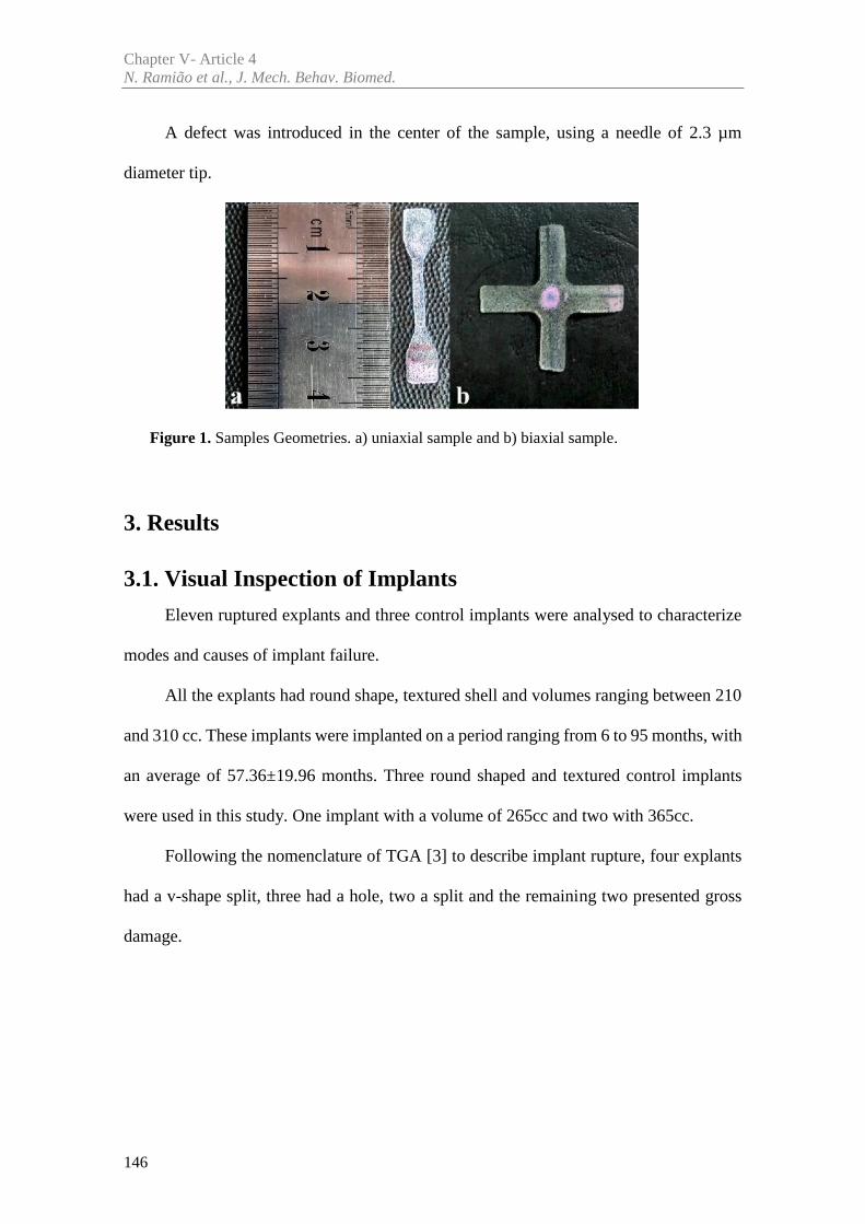
Chapter V- Article 4N. Ramião et al., J. Mech. Behav. Biomed.
146
A defect was introduced in the center of the sample, using a needle of 2.3 µm
diameter tip.
Figure 1. Samples Geometries. a) uniaxial sample and b) biaxial sample.
3. Results
3.1. Visual Inspection of Implants
Eleven ruptured explants and three control implants were analysed to characterize
modes and causes of implant failure.
All the explants had round shape, textured shell and volumes ranging between 210
and 310 cc. These implants were implanted on a period ranging from 6 to 95 months, with
an average of 57.36±19.96 months. Three round shaped and textured control implants
were used in this study. One implant with a volume of 265cc and two with 365cc.
Following the nomenclature of TGA [3] to describe implant rupture, four explants
had a v-shape split, three had a hole, two a split and the remaining two presented gross
damage.
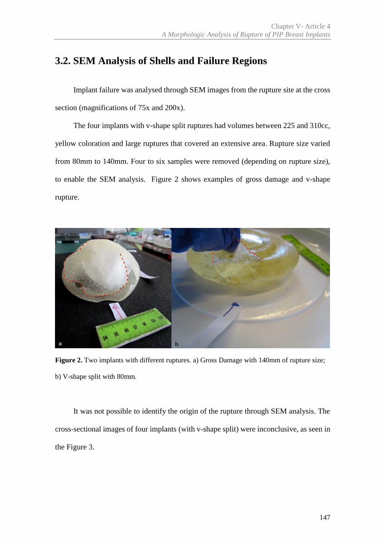
Chapter V- Article 4A Morphologic Analysis of Rupture of PIP Breast Implants
147
3.2. SEM Analysis of Shells and Failure Regions
Implant failure was analysed through SEM images from the rupture site at the cross
section (magnifications of 75x and 200x).
The four implants with v-shape split ruptures had volumes between 225 and 310cc,
yellow coloration and large ruptures that covered an extensive area. Rupture size varied
from 80mm to 140mm. Four to six samples were removed (depending on rupture size),
to enable the SEM analysis. Figure 2 shows examples of gross damage and v-shape
rupture.
Figure 2. Two implants with different ruptures. a) Gross Damage with 140mm of rupture size;
b) V-shape split with 80mm.
It was not possible to identify the origin of the rupture through SEM analysis. The
cross-sectional images of four implants (with v-shape split) were inconclusive, as seen in
the Figure 3.
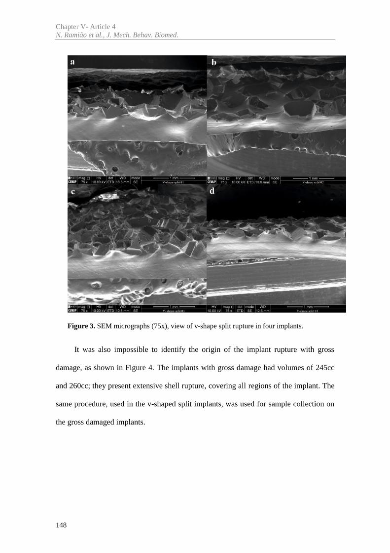
Chapter V- Article 4N. Ramião et al., J. Mech. Behav. Biomed.
148
Figure 3. SEM micrographs (75x), view of v-shape split rupture in four implants.
It was also impossible to identify the origin of the implant rupture with gross
damage, as shown in Figure 4. The implants with gross damage had volumes of 245cc
and 260cc; they present extensive shell rupture, covering all regions of the implant. The
same procedure, used in the v-shaped split implants, was used for sample collection on
the gross damaged implants.
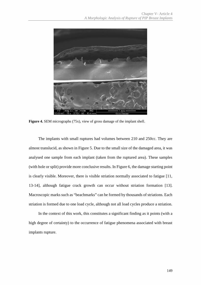
Chapter V- Article 4A Morphologic Analysis of Rupture of PIP Breast Implants
149
Figure 4. SEM micrographs (75x), view of gross damage of the implant shell.
The implants with small ruptures had volumes between 210 and 250cc. They are
almost translucid, as shown in Figure 5. Due to the small size of the damaged area, it was
analysed one sample from each implant (taken from the ruptured area). These samples
(with hole or split) provide more conclusive results. In Figure 6, the damage starting point
is clearly visible. Moreover, there is visible striation normally associated to fatigue [11,
13-14], although fatigue crack growth can occur without striation formation [13].
Macroscopic marks such as “beachmarks” can be formed by thousands of striations. Each
striation is formed due to one load cycle, although not all load cycles produce a striation.
In the context of this work, this constitutes a significant finding as it points (with a
high degree of certainty) to the occurrence of fatigue phenomena associated with breast
implants rupture.
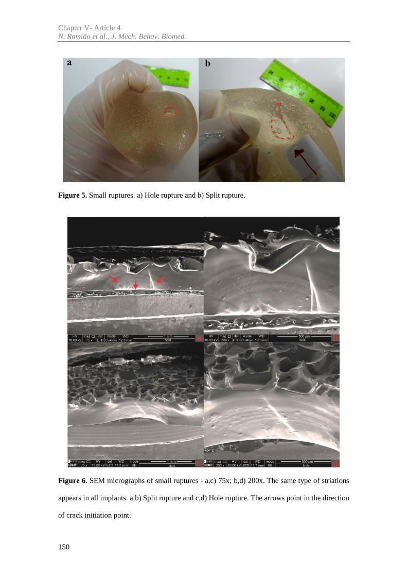
Chapter V- Article 4N. Ramião et al., J. Mech. Behav. Biomed.
150
Figure 5. Small ruptures. a) Hole rupture and b) Split rupture.
Figure 6. SEM micrographs of small ruptures - a,c) 75x; b,d) 200x. The same type of striations
appears in all implants. a,b) Split rupture and c,d) Hole rupture. The arrows point in the direction
of crack initiation point.
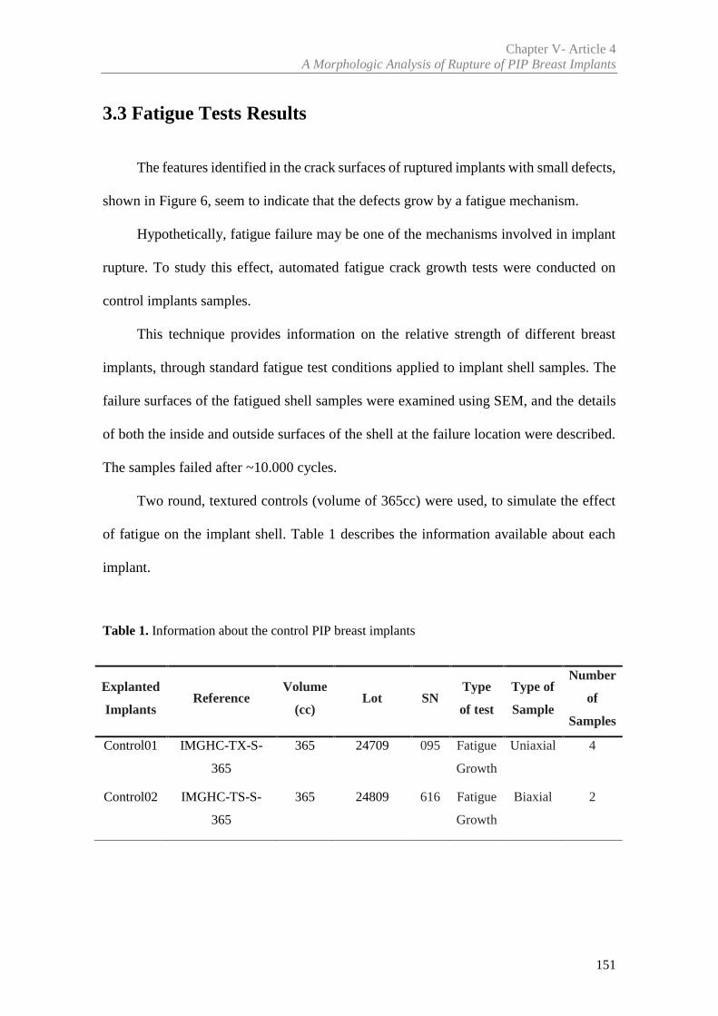
Chapter V- Article 4A Morphologic Analysis of Rupture of PIP Breast Implants
151
3.3 Fatigue Tests Results
The features identified in the crack surfaces of ruptured implants with small defects,
shown in Figure 6, seem to indicate that the defects grow by a fatigue mechanism.
Hypothetically, fatigue failure may be one of the mechanisms involved in implant
rupture. To study this effect, automated fatigue crack growth tests were conducted on
control implants samples.
This technique provides information on the relative strength of different breast
implants, through standard fatigue test conditions applied to implant shell samples. The
failure surfaces of the fatigued shell samples were examined using SEM, and the details
of both the inside and outside surfaces of the shell at the failure location were described.
The samples failed after ~10.000 cycles.
Two round, textured controls (volume of 365cc) were used, to simulate the effect
of fatigue on the implant shell. Table 1 describes the information available about each
implant.
Table 1. Information about the control PIP breast implants
Explanted
ImplantsReference
Volume
(cc)Lot SN
Type
of test
Type of
Sample
Number
of
Samples
Control01 IMGHC-TX-S-
365
365 24709 095 Fatigue
Growth
Uniaxial 4
Control02 IMGHC-TS-S-
365
365 24809 616 Fatigue
Growth
Biaxial 2
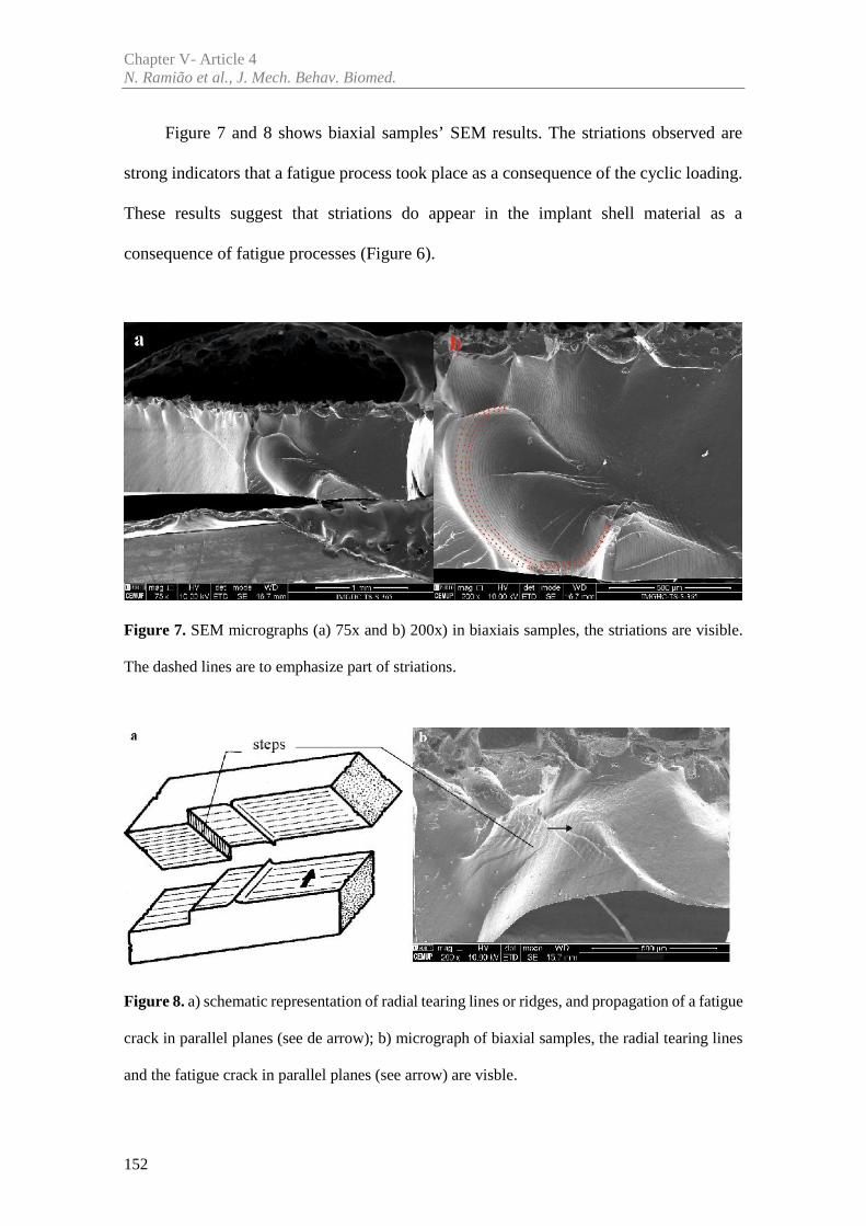
Chapter V- Article 4N. Ramião et al., J. Mech. Behav. Biomed.
152
Figure 7 and 8 shows biaxial samples’ SEM results. The striations observed are
strong indicators that a fatigue process took place as a consequence of the cyclic loading.
These results suggest that striations do appear in the implant shell material as a
consequence of fatigue processes (Figure 6).
Figure 7. SEM micrographs (a) 75x and b) 200x) in biaxiais samples, the striations are visible.
The dashed lines are to emphasize part of striations.
Figure 8. a) schematic representation of radial tearing lines or ridges, and propagation of a fatigue
crack in parallel planes (see de arrow); b) micrograph of biaxial samples, the radial tearing lines
and the fatigue crack in parallel planes (see arrow) are visble.
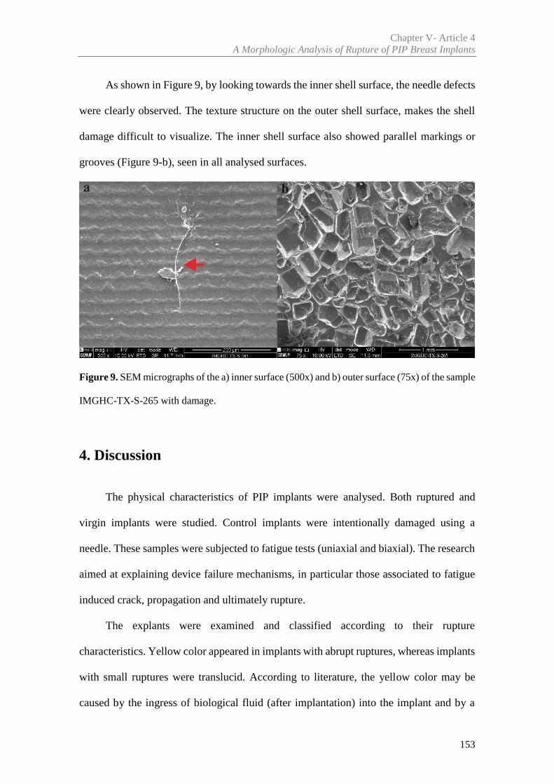
Chapter V- Article 4A Morphologic Analysis of Rupture of PIP Breast Implants
153
As shown in Figure 9, by looking towards the inner shell surface, the needle defects
were clearly observed. The texture structure on the outer shell surface, makes the shell
damage difficult to visualize. The inner shell surface also showed parallel markings or
grooves (Figure 9-b), seen in all analysed surfaces.
Figure 9. SEM micrographs of the a) inner surface (500x) and b) outer surface (75x) of the sample
IMGHC-TX-S-265 with damage.
4. Discussion
The physical characteristics of PIP implants were analysed. Both ruptured and
virgin implants were studied. Control implants were intentionally damaged using a
needle. These samples were subjected to fatigue tests (uniaxial and biaxial). The research
aimed at explaining device failure mechanisms, in particular those associated to fatigue
induced crack, propagation and ultimately rupture.
The explants were examined and classified according to their rupture
characteristics. Yellow color appeared in implants with abrupt ruptures, whereas implants
with small ruptures were translucid. According to literature, the yellow color may be
caused by the ingress of biological fluid (after implantation) into the implant and by a
Chapter V- Article 4N. Ramião et al., J. Mech. Behav. Biomed.
154
strong tendency for cholesterol absorption into the implants [12, 15-18]. Each of the
explants, had an appearance in agreement with known types of damage namely, hole, v-
shape split and gross damage. This variability was verified by other authors [3, 19].
Figure 6 showed one type of striation commonly found in fatigue processes [20]. It
suggests that implants can be subjected to cyclic loading that may lead to rupture. A
typical metal fatigue crack surface shows the three phases of a fatigue process, as shown
in Figures 6: crack initiation, crack growth and final unstable fracture.
The crack initiation is composed by nucleation and microscopic growth of the
crack. When this occurs inside a material, it is normally associated to the presence of
defects and microstructural inhomogeneities (for example, inclusions and pores) [11, 14].
“Beachmarks”, are a characteristic feature of fatigue crack surfaces. These marks
appear during crack propagation and show the crack front position and its propagation
direction history throughout fatigue. “Beachmarks” are associated to crack growth rate
variations, stops/ accelerations due to load variations induced by internal or external
causes [13]. For instance, changes in load or the degradation process over a certain period
of time [11, 13-14] are sources of “beachmarks”.
The final unstable fracture occurs when the crack length exceeds a critical depth.
Critical depths depend on the toughness and resistance of the material and on the loading
conditions [13-14, 21].
The striation of explanted implants differs from the laboratory simulated ones. In
laboratory conditions, the striations are equidistant, as load cycles were imposed at a
constant frequency. In contrast, there were significant variations of the distances between
explanted implants striations. A possible explanation is the random (potentially aperiodic)
nature of the cyclic mechanical loadings due to repetitive voluntary activities of the
woman.
Chapter V- Article 4A Morphologic Analysis of Rupture of PIP Breast Implants
155
The striations are common in a large number of metallic materials [22], where it is
possible to identify fatigue marks. Fatigue striations are also visible in different [23-28]
(other than metallic) materials. Regarding implant shell materials, the authors could not
find studies that correlate the striations with the fatigue process. Therefore, it was
necessary to determine whether these materials generated similar fatigue markings on
fracture surfaces produced under cyclic loading conditions.
In Figure 6, the crack initiation started from the inside (smooth) to the outside
(textured) of the shell. This may indicate that the rupture happened due to the quality of
the material (e.g, inclusions and pores), or due to significant body motion (physical
activities, trauma, among others). As large cyclic stresses weaken the implant, as fatigue
damage accumulates, the corresponding crack propagation may result in failure. If
implant shell rupture does occur due to a fatigue process, the following possibilities
should be considered: the cyclic loading that ultimately led to crack propagation and
implant rupture, must have occurred after implantation; there was a shell defect, either
prior to implantation or inflicted (accidentally) during implantation that acted as the
nucleation agent for the fatigue process. Since the whole implant history is unknown and
a detailed (microstructural) analysis of the implant is not available, there is no definitive
evidence on the two possibilities stated. To confirm fatigue as a source of the striations
(Figures 6), laboratory fatigue tests were carried out on virgin implant shell samples.The
fatigue test results shown in Figure 7 shows the fatigue striations in a regular pattern.
Figure 8 shows “step” striations. They correspond to different point of crack
propagation, at different planes that can connect to each other [13].
The authors could not find any other studies in the available literature, showing the
existence of fatigue striation in explanted breast implants.
Chapter V- Article 4N. Ramião et al., J. Mech. Behav. Biomed.
156
Other researchers have studied how fatigue affects breast implants using a
laboratory apparatus in which flat plates cyclically compressed the implants [29-32].
Marotta et al. [30] concluded ‘that a primary mechanism for rupture must be the
progressive cyclic mechanical stress induced creation and enlargement of tears in
weakened silicone fluid swollen silicone elastomeric shells’. Brandon et al. [29],
described the morphological features of the fatigue failure surfaces of smooth and
textured saline-filled breast implants. These studies showed that some fatigue processes
can induce the shell rupture in breast implants.
Two different modes of failure were observed depending on the magnitude of the
cyclic load, corresponding to a different number of fatigue cycles at failure. The rupture
modes found in Brandon et al. [29] were similar to those found on samples of the
explanted implants in the current study. Both ruptures were small, one was a tear and
other a pinhole. More recently, Haws et al. [33], analysed the surgical techniques to better
understand the etiology of implant rupture, suggesting the occurrence of flex fatigue.
The parallel marking lines observed in inner shell surfaces (Figure 9) were also
verified by Swarts et al. [15] and on PIP- Technical Report [34]. Swart et al. [15]
suggested that the marks can be caused by the manufacturing forms used to shape the
shell. As shown in Figure 9, this type of material makes difficult to determine the origin
of rupture, even when the outer shell surface has visible rupture. Therefore, if there are
some instrument damage during surgery or if the material is already damaged, it will be
difficult for the surgeon to identify the rupture.
In summary, further research is important to analyse breast implants failure, and
understand the mechanisms that generate the shell damage, with potential to improve the
manufacture process.
Chapter V- Article 4A Morphologic Analysis of Rupture of PIP Breast Implants
157
5. Conclusions
The SEM analysis used in this research allow the classification of the failure mode,
and may be an important tool in the diagnosis of implant failure mechanisms.
In summary, the implant failure may be related to implant handling before the
surgical procedure, the implantation procedure, in vivo processes (e.g., abrasion or breast
biopsy), the explantation procedure, and in vivo cyclic loading that may induce fatigue
damage in the implant.
This study suggests that the fatigue damage can be potential cause of in vivo failure.
The implant accumulation of in vivo cyclic loading over the years is unavoidable. To
better understand this type of failure and to establish its relative importance among other
implant rupture mechanisms, further research is required.
This manuscript emphasizes the need to analyze the explanted implants after
rupture. Data collection at the time of explantation by a surgeon or appropriate healthcare
provider at the explant site is recommended. Thus, information such as - reason(s) for the
device explantation; the presence of any shell defects; type of rupture; extent of implant
rupture (intracapsular, extracapsular, or migrated gel); any discoloration, opacity of the
shell and in the filler; and whether the rupture occurred before or during explantation (if
applicable) - would be (potentially) helpful for the product’s improvement.
The existence of information about the breast implant after rupture, may potentiate
the development and improvement of safer and more compliant products, being at the
same time a significant tool for future scientific research and product monitoring.
Chapter V- Article 4N. Ramião et al., J. Mech. Behav. Biomed.
158
Acknowledgements
The authors gratefully acknowledge funding from: - Ministério da Ciência,
Inovação e do Ensino Superior, FCT - Fundação para a Ciência e a Tecnologia, Portugal,
under grants SFRH/BD/85090/2012, SFRH/BPD/111846/2015 and projects: LAETA -
UID/EMS/50022/2013; UROSPHINX - Project 16842, cofinanced by Programa
Operacional Competitividade e Internacionalização (COMPETE2020), through Fundo
Europeu de Desenvolvimento Regional (FEDER) and by National Funds through FCT;
NORTE-01-0145-FEDER-000022 – SciTech – Science and Technology for Competitive
and Sustainable Industries (NORTE2020).
References
[1] Scientific Committee on Emerging and Newly Identified Health Risks. The safety of
PIP silicone breast implants. SCENIHR: Brussels, 2012.
http://ec.europa.eu/health/scientific_committees/emerging/docs/scenihr_o_043.pdf [Accessed
12 May 2014]
[2] USA Food and Drug Administration (FDA). Draft Guidance for Industry and FDA
Staff: Saline, Silicone Gel and Alternative Breast Implants. (November 2006)
http://www.fda.gov/downloads/medicaldevices/deviceregulationandguidance/guidancedocumen
ts/ucm071233.pdf. [Accessed 3 February 2012]
[3] Australian Government Department of Health and Ageing Therapeutic Goods
Administration (TGA) (2013) PIP breast implants: Update on TGA testing of PIP breast implants.
http://www.tga.gov.au/alert/pip-breast-implants-update-tga-testing-pip-breast-implants.
[Accessed 10 March 2013]
Chapter V- Article 4A Morphologic Analysis of Rupture of PIP Breast Implants
159
[4] Maijers MC, Niessen FB. Prevalence of rupture in Poly Implant Prothèse silicone breast
implants, recalled from the European market in 2010. Plast Reconstr Surg. 2012; 129:1372–1378.
[5] Spear SL, Murphy DK. Allergan Silicone Breast Implant U.S. Core Clinical Study
Group. Natrelle round silicone breast implants: core study results at 10 years. Plast Reconstr Surg
2014; 133:1354-61
[6] Berry MG, Stanek JJ. PIP implant biodurability: a post-publicity update. J Plast
Reconstr Aesthet Surg 2013;66:1174-81
[7] Oulharj S, Pauchot J, Tropet Y. PIP breast implant removal: a study of 828 cases. J
Plast Reconstr Aesthet Surg 2014; 67:302-7
[8] Quaba O, Quaba A. PIP silicone breast implants: rupture rates based on the explantation
of 676 implants in a single surgeon series. J Plast Reconstr Aesthet Surg 2013; 66(9):1182–1187
[9] Khan UD. Poly Implant Prothèse (PIP) Incidence of device failure and capsular
contracture: a retrospective study. Aesthetic Plast Surg 2013; 37(5):906–913
[10] Brandon HJ, Jerina KL, Wolf CJ. and Young V.L. Retrieval and analysis of breast
implants emphasizing strength, durability, and failure mechanisms. Woodhead Publishing
Limited, 2012
[11] Roeder RK. Mechanical Characterization of Biomaterials. Elsevier Inc. 2013.
http://dx.doi.org/10.1016/B978-0-12-415800-9.00003-6. Chapter 3.4.4 pag 78-80. [Accessed 21
February 2016]
[12] Yildirimer L, Seifalian AM, Butler PE. Surface and mechanical analysis of explanted
Poly Implant Prothèse silicone breast implants. Br J Surg. 2013; 100(6):761-7
[13] Branco CM, Fernandes AA, Castro PMST. Fadiga de estruturas soldadas. Fundação
Calouste Gulbenkian. 2º edição, 1999; p. 177-190
[14] Hosford W F. Mechanical Behavior of Materials. 1ª ed, Cambridge University Press.
New York. 2005. Chapter Fatigue pag 281-282. ISBN-13 978-0-511-11575-2
Chapter V- Article 4N. Ramião et al., J. Mech. Behav. Biomed.
160
[15] Swarts E, Kop A, Nilasaroya A, Keogh CV, Cooper T. Rupture of Poly Implant
Prothèse Silicone Breast Implants: An Implant Retrieval Study. Plast Reconstr Surg. 2013;
131(4):480e-489e
[16] Beretta G, Malacco M. Chemical and physicochemical properties of the high cohesive
silicone gel from Poly Implant Prothese (PIP) breast prostheses after explantation: a preliminary,
comparative analytical investigation. J Pharm Biomed Anal. 2013; 78-79:75-82
[17] Necchi S, Molina D, Turri S, Rossetto F, Rietjens M. Failure of silicone gel breast
implants: is the mechanical weakening due to shell swelling a significant cause of prostheses
rupture? J Mech Behav Biomed Mater. 2011; 4:2002–2008
[18] Berry RB. Rupture of PIP breast implants. J Plast Reconstr Aesthet Surg. 2007;
60:967e8
[19] Schubert DW, Kaschta J, Horch RE, Waltera BL. On the failure of silicone breast
implants: new insights by mapping the mechanical properties of implant shells. Society of
Chemical Industry. 2013; 63: 172–178
[20] Ramião N, Martins P, Barroso ML, Santos D.C., Fernandes AA. Breast Implants
Rupture Induced by Fatigue Phenomena, J Plast Reconstr Aesthet Surg., 2017
[21] Meyers, M. & Chawla, K. Mechanical Behavior of Materials. 2ª ed, 2009. Cambridge
University Press. New York
[22] Metals Handbook, Vol. 9, eighth ed., ASM, 1974
[23] Mars WV, Fatemi A. Rubber Chem. Technol. 2004, 77, (3), 391–412. 2
[24] Asare S, Busfield JJC. Plast. Rubber Compos.: Macromol. Eng. 2011; 40(4), 194–200.
[25] Mirza S, Hansen P, Harris J. Plast. Rubber Compos.: Macromol. Eng. 2011; 40(4),
185–193
[26] Wang YP, Chen X, Yu W. Plast. Rubber Compos.: Macromol. Eng. 2011; 40 (10),
491–496
[27] Persson BNJ, Albohr O, Heinrich G. and Ueba H. J. Phys. Condens. Matter 2005: 17,
R1071
Chapter V- Article 4A Morphologic Analysis of Rupture of PIP Breast Implants
161
[28] Munoz L, Vanel L, Sanseau O, et al. Fatigue crack growth dynamics in filled natural
rubber. Plastics, Rubber and Composites 2012; 41:7, 273-276
[29] Brandon HJ, Jerina KL, Savoy TL, and Wolf CJ. Scanning electron microscope
fractography of induced fatigue-damaged saline breast implants, Journal of Long-Term Effects
of Medical Implants 2006;16, 71–82
[30] Marotta JS, Goldberg EP, Habal MB, et al. Silicone gel breast implant failure:
Evaluation of properties of shells and gels for explanted prostheses and meta-analysis of literature
rupture data, Ann Plast Surg,2002; 49, 227–24l
[31] Inamed Corporation. PMA P020056 Silicone-Filled Breast Implants Briefi ng
Document. 2006, pp. 13–14. Listed on FDA www.fda.gov. [Accessed 20 February 2016]
[32] Mcmeeking RM, Allen GM, Yang P. Parallel Plate Cyclic Fatigue Analysis of Gel-
Filled Mammary Implants. PO30053, Attachment 11, Report M 028listed on FDA. 2004.
www.fda.gov. [Accessed 20 February 2016]
[33] Haws MJ, Alizadeh K, Kaufman DL. Sientra Primary and Revision Augmentation
Rupture Trending and Analysis with Magnetic Resonance Imaging. Aesthetic Surgery Journal,
2015; 35(S1 ) S33– S42
[34] PIP – Technical Report. Part I: Analysis of 17 breast implant samples by Fourier-
Transform Infrared Spectroscopy (FTIR) and Field Emission Scanning Electron Microscopy
(FESEM); Part II: Analysis of the morphology of 7 breast implant samples by Field Emission
Scanning Electron Microscopy (FE-SEM). Royal Institute of Technology. 2013.
https://lakemedelsverket.se/upload/nyheter/2013/PIP/Technical-report_KTH_PIP_2013-05-
28.pdf . [Accessed 20 February 2016]

Article 5
________________________________________________________
Intact vs Ruptured Poly Implant Prothèse (PIP) Breast Implants.A Woman-centric Paired Analysis
Nilza Ramião a, Pedro Martins a, Maria da Luz Barrosob,
Diana C. Santosb, António A. Fernandesa
a INEGI, Faculty of Engineering, University of Porto, Porto, Portugal
b Department of Plastic Surgery of Gaia Hospital Center, Vila Nova de Gaia, Portugal
Submitted to an International Journal: Journal of Plastic, Reconstructive & Aesthetic
Surgery

165
Abstract
Background: Despite many studies that evaluated breast implants rupture, there is
no consensus over causes and incidence. Most studies lack a multifactor analysis of risk
causes associated with breast implant rupture. To fill this gap, an experimental protocol
was developed to compare ruptured and intact Poly Implant Prothèse (PIP) breast
implants from the same woman. These conditions guarantee that physical/biological
variables are the same for each woman.
Methods: Twenty-two PIP explants (eleven intact and eleven ruptured) and three
control PIP implants were analysed. The mechanical properties of ruptured and intact
implants were compared in terms of brand, lot, implantation time, and demographic
conditions.
Results: In general, there were statically significant differences between intact and
ruptures PIP implants. Ruptured implants were thinner (0.73mm Vs 0.91mm) and weaker
(7.42MPa Vs 9.59MPa) than intact implants. The same was observed for each woman,
using a paired analysis of the intact Vs ruptured implants.
Conclusions: Intact and ruptured implants have distinct mechanical behaviours,
and thickness variations. According with authors' understanding of the problem, these
differences may be associated with the typical manufacturing process of breast implant
shells. The results stress the importance of a thorough control of the shell thickness. Given
its relevance, shell thickness should be used as a control quality measure for
homologation purposes.

Keywords: Breast Implants, Explanted Implants, Ruptured Implants, Mechanical
Properties.
167
1. Introduction
Breast implant rupture is one of the principal complications and concerns
surrounding mammary prosthesis implantation. It represents the main cause of implant
removal. Usually, the rupture of silicone breast implants from recent generations, does
not produce a change in volume. Consequently, the patient does not know that a rupture
has occurred. Therefore, one of the principal concerns about breast implants is to
understand the cause of rupture and how to avoid it. Several papers have studied breast
implant failure [1-8]. Their fundamental contributions were: failure reasons; shell-gel
interaction; and change of material properties during implantation.
Several studies [2-3,6,9-11] pointed as primary factor for in vivo implant shell
failure, the change of mechanical properties over time. These results showed that shell
strength, toughness and elasticity decrease with implantation time for all implant
generations (first, second or third generation). However, other studies pointed the shell
swelling, by the inner gel, as the main factor responsible for the shell decay [4-5,9,12-
15]. Recently, the concerns about the Poly Implant Prothèse breast implants renewed the
discussion about implant failure causes. According to some authors [8,16,17] shell
rupture may be related to deficiencies in manufacturing techniques, associated with shell
thickness variation.
However, besides the problems listed above, breast implants can fail for other
reasons: shell damage caused by surgical instruments; open or closed capsulotomy; shell
wrinkling; mechanical pressure during mammography; needle biopsy or hematoma
aspiration; and cyclic fatigue or friction between tissues and implant [15,18].
Chapter V- Article 5N. Ramião et al., Aesthet. Surg. J.
168
Despite many studies that evaluated breast implants rupture, there is no consensus
over causes and incidence. Most studies lack a multifactor analysis of risk causes
associated with breast implant rupture. The rupture causes may depend on multifactors
such as the patient, the implant, biological and environmental factors. Due to literature
shortcomings an experimental protocol to study the rupture causes was developed. Paired
analysis of the mechanical properties of ruptured and intact PIP explanted implants per
patient was conducted. The mechanical properties were then discussed on the light of the
demographic conditions (same patient, age, BMI, physical activity, surgery, implantation
time, implant position, among others). The intact and ruptured implants were analysed
and compared by manufacturer and lot.
2. Material and Methods
Patient and implant data are summarized in Table 1. Details regarding samples
preparation, the mechanical testing protocol and chemical analysis (FTIR) are presented
in the following sections.
2.1 Clinical Data
This study includes clinical information about 11 women undergoing a removal and
replacement of breast implants (2 per woman) between February 2012 to July 2013, at
the Department of Plastic Surgery of the Hospital Centre of Gaia, Portugal. The 22
implants removed were analysed and linked to their clinical information (Table 1). The
clinical information was obtained through computerised and paper clinical files. In some
Chapter V- Article 5Intact vs Ruptured Breast Implants. A Woman-centric Paired Analysis
169
cases, patients were called to obtain missing data. The available clinical data is
summarized in Table 1.
The information collected included the following parameters:
- Patient sociodemographic data (age, body mass index (BMI), profession,
pathologies/ chronic diseases);
- prior surgical interventions (date of surgery, surgical intervention);
- explantation surgery data (date, reason for surgery);
- explanted implant characterization (shape, surface, volume, region of rupture,
aspect of implant, position of the implants and implantation time).
BMI was evaluated according to the classification of the WHO (World Health
Organization) [19] for: underweight (BMI<18); normal (BMI>18<25) and overweight
(BMI>25<30). The physical activity of each patient was assessed according to working
activity: Manual labor/significant physical effort or work without significant physical
activity. Three virgin implants (same brand), obtained from the National Authority of
Medicine and Health Products (INFARMED), were used as controls. Code Pa#
correspond to intact and ruptured implant per patient.
Before the mechanical tests the explants were classified in relation to the shell
damage and gel condition, according to the Department of Health Therapeutic Goods
Administration criteria [20].
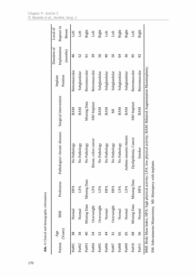
Chapter V- Article 5N. Ramião et al., Aesthet. Surg. J.
170
Tab
le. 1
Clin
ical
and
dem
ogra
phic
info
rmat
ion
Pa#0
1N
orm
alH
PAN
o Pa
thol
ogy
BA
MR
etro
mus
cula
rL
eft
3846
Pa#0
2N
orm
alL
PAN
o Pa
thol
ogy
BA
MSu
bgla
ndul
arL
eft
3452
Pa#0
3M
issi
ng D
ata
Mis
sing
Dat
aN
o Pa
thol
ogy
Mis
sing
Dat
aR
etro
mus
cula
rR
ight
4061
Pa#0
4O
verw
eigh
tL
PAB
reas
t,co
lon
canc
erSM
+Im
plan
tR
etro
mus
cula
rL
eft
5439
Pa#0
5O
verw
eigh
tL
PAN
o Pa
thol
ogy
BA
MSu
bgla
ndul
arR
ight
5256
Pa#0
6N
orm
alH
PAN
o Pa
thol
ogy
BA
MSu
bgla
ndul
arL
eft
4440
Pa#0
7O
verw
eigh
tH
PAN
o Pa
thol
ogy
MI
Subg
land
ular
Lef
t31
50
Pa#0
8N
orm
alL
PAN
o Pa
thol
ogy
BA
MSu
bgla
ndul
arR
ight
6564
Pa#0
9N
orm
alL
PAA
sthm
a si
nusi
tis r
hini
tisB
AM
Subg
land
ular
Rig
ht65
36
Pa#1
0M
issi
ng D
ata
Mis
sing
Dat
aD
ysli
pide
mia
, Can
cer
SM+
Impl
ant
Ret
rom
uscu
lar
Lef
t68
95
Pa#1
1N
orm
alH
PASm
oker
BA
MR
etro
mus
cula
rR
ight
5692
BM
I: B
ody
Mas
s In
dex;
HPA
: hig
h ph
ysic
al a
ctiv
ity;
LPA
:low
phy
sica
l act
ivit
y; B
AM
: Bila
tera
l Aug
men
tati
on M
amm
opla
sty;
SM: S
ubcu
tane
ous
Mas
tect
omy;
MI:
Mas
tope
xy w
ith
impl
ants
BM
IPr
ofes
sion
Path
olog
ies/
chr
onic
dis
ease
sSu
rgic
al in
terv
enti
on(Y
ears
)
Age
Patie
ntIm
plan
t
Posi
tion
Dur
atio
n of
Impl
anta
tion
(mon
ths)
Loc
al o
f
Rup
ture
in
Bre
ast
Chapter V- Article 5Intact vs Ruptured Breast Implants. A Woman-centric Paired Analysis
171
2.2 Testing Protocol
The experimental protocol, was developed according with the ISO standards for the
analysis of breast implant materials: ISO 14607:2007 and ISO 37:2005. The 22 explants
(eleven intact and eleven ruptured) and 3 control implants were prepared for testing by
removing the gel from shell. The sample preparation and testing followed the protocol
previously developed by the authors [21].
The samples were tested until failure with a displacement rate of 20mm/min, in one
direction. It was used a mechanical testing machine prototype (with biaxial capabilities),
developed at INEGI Biomechanics Laboratory (Porto, PT). To guarantee a controlled
initial geometry and loading conditions, the samples were subjected to a 0.25N preload.
The main mechanical property considered in this study was the tensile strength (stress at
break) (σmax).
2.3 Fourier Transform Infrared Spectroscopy (FTIR)
Characterization
The chemical composition of the surfaces and gels of twenty two implants were
analysed using a Cary 630 FTIR Spectrometer (Agilent Technologies, USA) equipped
with a diamond attenuated total reflectance (ATR) accessory. The tests were carried out
at INEGI’s tribology laboratory (CETRIB): spectra were acquired over 20 scans with
wavelengths ranging from 600 to 4000cm-1, with a resolution of 4 cm-1. A background
scan was performed before each sample measurement.
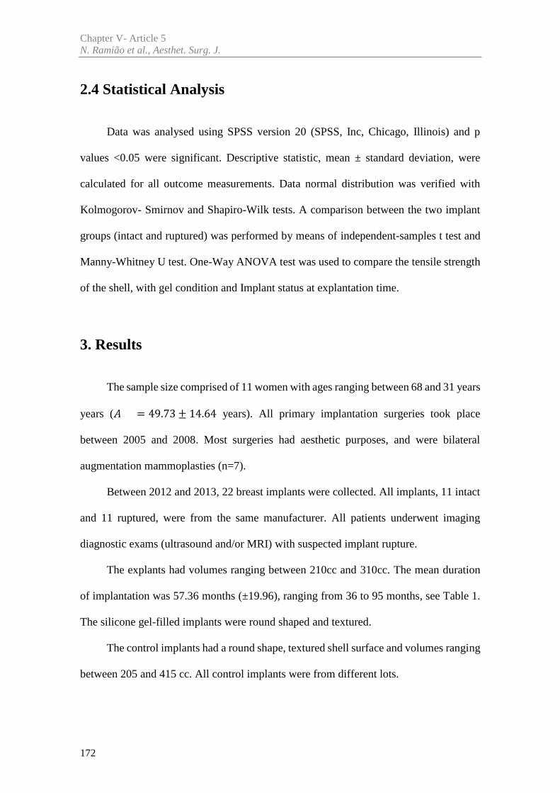
Chapter V- Article 5N. Ramião et al., Aesthet. Surg. J.
172
2.4 Statistical Analysis
Data was analysed using SPSS version 20 (SPSS, Inc, Chicago, Illinois) and p
values <0.05 were significant. Descriptive statistic, mean ± standard deviation, were
calculated for all outcome measurements. Data normal distribution was verified with
Kolmogorov- Smirnov and Shapiro-Wilk tests. A comparison between the two implant
groups (intact and ruptured) was performed by means of independent-samples t test and
Manny-Whitney U test. One-Way ANOVA test was used to compare the tensile strength
of the shell, with gel condition and Implant status at explantation time.
3. Results
The sample size comprised of 11 women with ages ranging between 68 and 31 years
years ( = 49.73 ± 14.64 years). All primary implantation surgeries took place
between 2005 and 2008. Most surgeries had aesthetic purposes, and were bilateral
augmentation mammoplasties (n=7).
Between 2012 and 2013, 22 breast implants were collected. All implants, 11 intact
and 11 ruptured, were from the same manufacturer. All patients underwent imaging
diagnostic exams (ultrasound and/or MRI) with suspected implant rupture.
The explants had volumes ranging between 210cc and 310cc. The mean duration
of implantation was 57.36 months (±19.96), ranging from 36 to 95 months, see Table 1.
The silicone gel-filled implants were round shaped and textured.
The control implants had a round shape, textured shell surface and volumes ranging
between 205 and 415 cc. All control implants were from different lots.
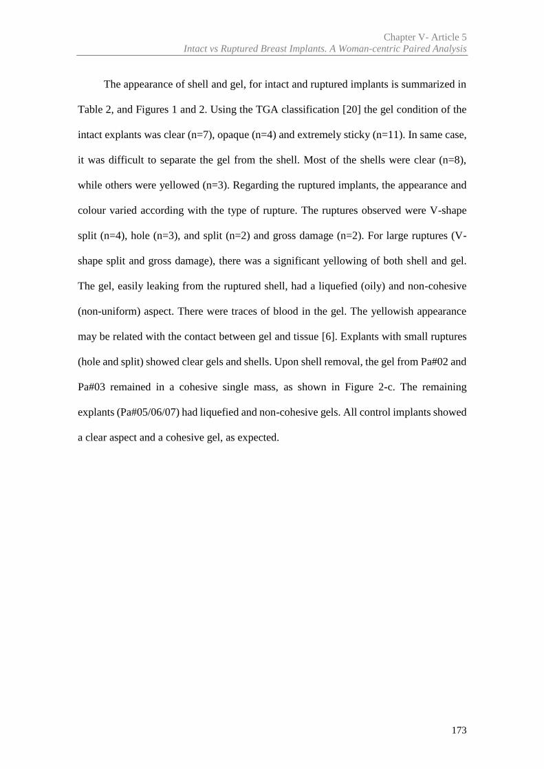
Chapter V- Article 5Intact vs Ruptured Breast Implants. A Woman-centric Paired Analysis
173
The appearance of shell and gel, for intact and ruptured implants is summarized in
Table 2, and Figures 1 and 2. Using the TGA classification [20] the gel condition of the
intact explants was clear (n=7), opaque (n=4) and extremely sticky (n=11). In same case,
it was difficult to separate the gel from the shell. Most of the shells were clear (n=8),
while others were yellowed (n=3). Regarding the ruptured implants, the appearance and
colour varied according with the type of rupture. The ruptures observed were V-shape
split (n=4), hole (n=3), and split (n=2) and gross damage (n=2). For large ruptures (V-
shape split and gross damage), there was a significant yellowing of both shell and gel.
The gel, easily leaking from the ruptured shell, had a liquefied (oily) and non-cohesive
(non-uniform) aspect. There were traces of blood in the gel. The yellowish appearance
may be related with the contact between gel and tissue [6]. Explants with small ruptures
(hole and split) showed clear gels and shells. Upon shell removal, the gel from Pa#02 and
Pa#03 remained in a cohesive single mass, as shown in Figure 2-c. The remaining
explants (Pa#05/06/07) had liquefied and non-cohesive gels. All control implants showed
a clear aspect and a cohesive gel, as expected.
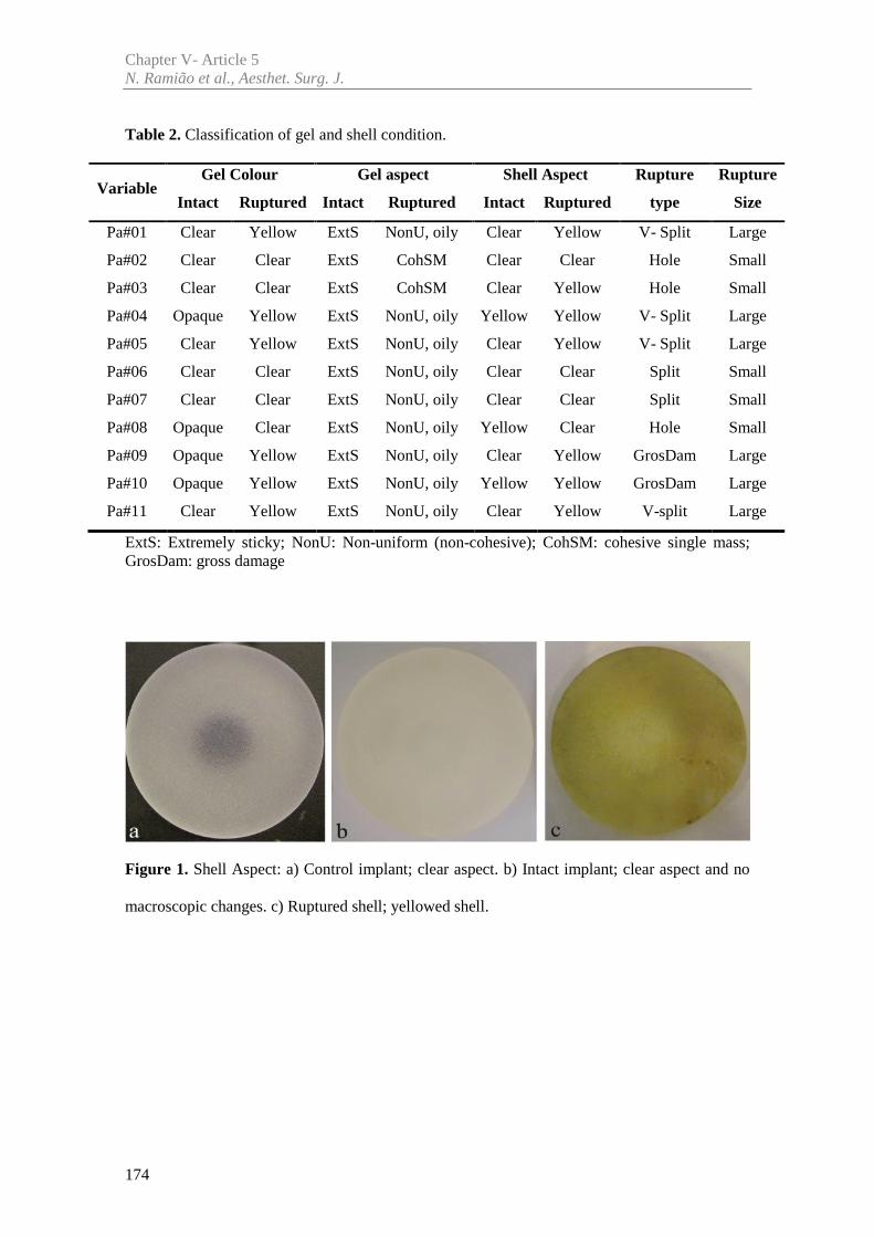
Chapter V- Article 5N. Ramião et al., Aesthet. Surg. J.
174
Table 2. Classification of gel and shell condition.
ExtS: Extremely sticky; NonU: Non-uniform (non-cohesive); CohSM: cohesive single mass;GrosDam: gross damage
Figure 1. Shell Aspect: a) Control implant; clear aspect. b) Intact implant; clear aspect and no
macroscopic changes. c) Ruptured shell; yellowed shell.
VariableGel Colour Gel aspect Shell Aspect Rupture
type
Rupture
SizeIntact Ruptured Intact Ruptured Intact Ruptured
Pa#01 Clear Yellow ExtS NonU, oily Clear Yellow V- Split Large
Pa#02 Clear Clear ExtS CohSM Clear Clear Hole Small
Pa#03 Clear Clear ExtS CohSM Clear Yellow Hole Small
Pa#04 Opaque Yellow ExtS NonU, oily Yellow Yellow V- Split Large
Pa#05 Clear Yellow ExtS NonU, oily Clear Yellow V- Split Large
Pa#06 Clear Clear ExtS NonU, oily Clear Clear Split Small
Pa#07 Clear Clear ExtS NonU, oily Clear Clear Split Small
Pa#08 Opaque Clear ExtS NonU, oily Yellow Clear Hole Small
Pa#09 Opaque Yellow ExtS NonU, oily Clear Yellow GrosDam Large
Pa#10 Opaque Yellow ExtS NonU, oily Yellow Yellow GrosDam Large
Pa#11 Clear Yellow ExtS NonU, oily Clear Yellow V-split Large
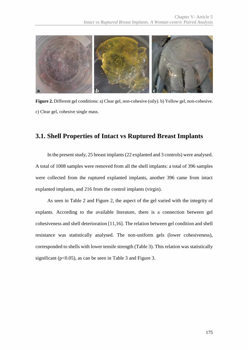
Chapter V- Article 5Intact vs Ruptured Breast Implants. A Woman-centric Paired Analysis
175
Figure 2. Different gel conditions: a) Clear gel, non-cohesive (oily). b) Yellow gel, non-cohesive.
c) Clear gel, cohesive single mass.
3.1. Shell Properties of Intact vs Ruptured Breast Implants
In the present study, 25 breast implants (22 explanted and 3 controls) were analysed.
A total of 1008 samples were removed from all the shell implants: a total of 396 samples
were collected from the ruptured explanted implants, another 396 came from intact
explanted implants, and 216 from the control implants (virgin).
As seen in Table 2 and Figure 2, the aspect of the gel varied with the integrity of
explants. According to the available literature, there is a connection between gel
cohesiveness and shell deterioration [11,16]. The relation between gel condition and shell
resistance was statistically analysed. The non-uniform gels (lower cohesiveness),
corresponded to shells with lower tensile strength (Table 3). This relation was statistically
significant (p<0.05), as can be seen in Table 3 and Figure 3.
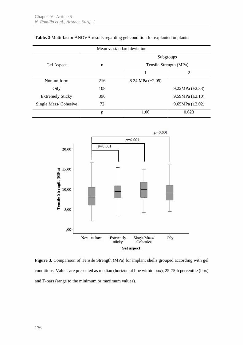
Chapter V- Article 5N. Ramião et al., Aesthet. Surg. J.
176
Table. 3 Multi-factor ANOVA results regarding gel condition for explanted implants.
Mean vs standard deviation
Gel Aspect n
Subgroups
Tensile Strength (MPa)
1 2
Non-uniform 216 8.24 MPa (±2.05)
Oily 108 9.22MPa (±2.33)
Extremely Sticky 396 9.59MPa (±2.10)
Single Mass/ Cohesive 72 9.65MPa (±2.02)
p 1.00 0.623
Figure 3. Comparison of Tensile Strength (MPa) for implant shells grouped according with gel
conditions. Values are presented as median (horizontal line within box), 25-75th percentile (box)
and T-bars (range to the minimum or maximum values).
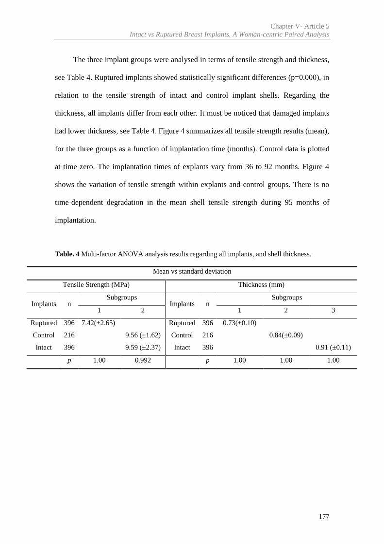
Chapter V- Article 5Intact vs Ruptured Breast Implants. A Woman-centric Paired Analysis
177
The three implant groups were analysed in terms of tensile strength and thickness,
see Table 4. Ruptured implants showed statistically significant differences (p=0.000), in
relation to the tensile strength of intact and control implant shells. Regarding the
thickness, all implants differ from each other. It must be noticed that damaged implants
had lower thickness, see Table 4. Figure 4 summarizes all tensile strength results (mean),
for the three groups as a function of implantation time (months). Control data is plotted
at time zero. The implantation times of explants vary from 36 to 92 months. Figure 4
shows the variation of tensile strength within explants and control groups. There is no
time-dependent degradation in the mean shell tensile strength during 95 months of
implantation.
Table. 4 Multi-factor ANOVA analysis results regarding all implants, and shell thickness.
Mean vs standard deviation
Tensile Strength (MPa) Thickness (mm)
Implants nSubgroups
Implants nSubgroups
1 2 1 2 3
Ruptured 396 7.42(±2.65) Ruptured 396 0.73(±0.10)
Control 216 9.56 (±1.62) Control 216 0.84(±0.09)
Intact 396 9.59 (±2.37) Intact 396 0.91 (±0.11)
p 1.00 0.992 p 1.00 1.00 1.00
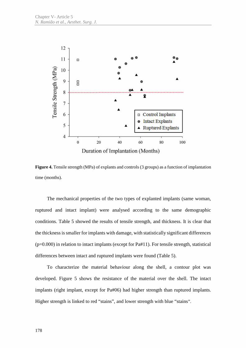
Chapter V- Article 5N. Ramião et al., Aesthet. Surg. J.
178
Figure 4. Tensile strength (MPa) of explants and controls (3 groups) as a function of implantation
time (months).
The mechanical properties of the two types of explanted implants (same woman,
ruptured and intact implant) were analysed according to the same demographic
conditions. Table 5 showed the results of tensile strength, and thickness. It is clear that
the thickness is smaller for implants with damage, with statistically significant differences
(p=0.000) in relation to intact implants (except for Pa#11). For tensile strength, statistical
differences between intact and ruptured implants were found (Table 5).
To characterize the material behaviour along the shell, a contour plot was
developed. Figure 5 shows the resistance of the material over the shell. The intact
implants (right implant, except for Pa#06) had higher strength than ruptured implants.
Higher strength is linked to red “stains”, and lower strength with blue “stains”.
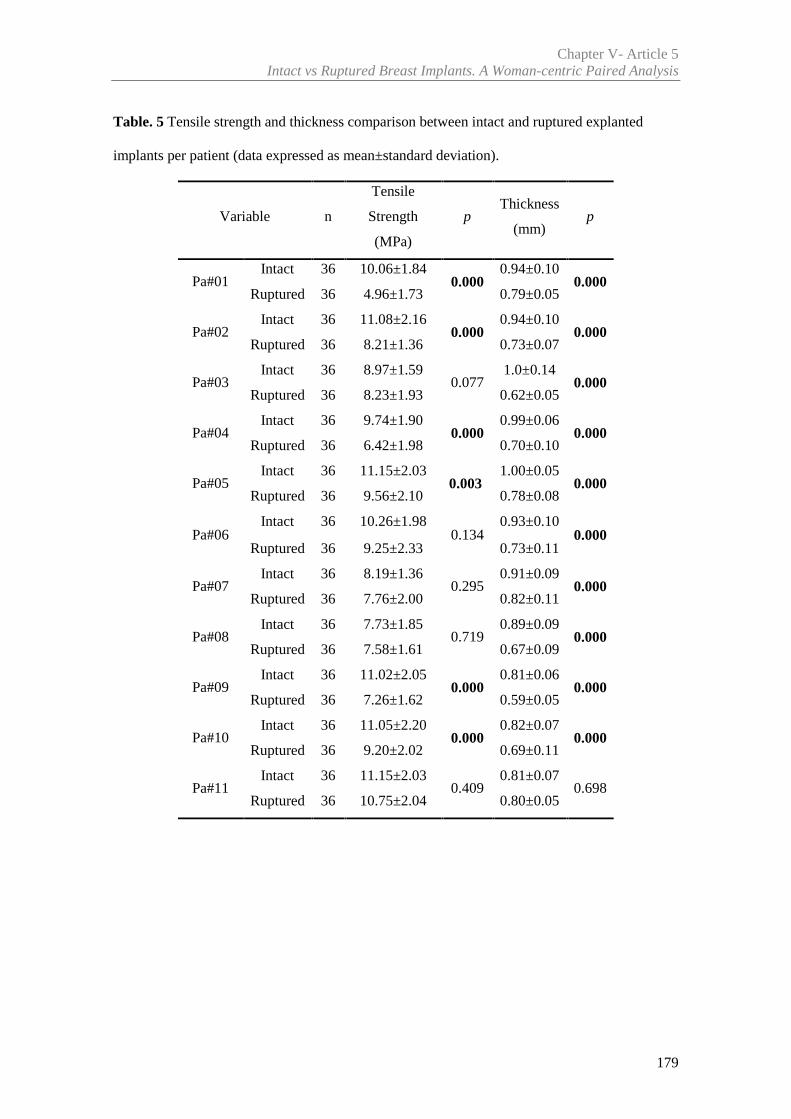
Chapter V- Article 5Intact vs Ruptured Breast Implants. A Woman-centric Paired Analysis
179
Table. 5 Tensile strength and thickness comparison between intact and ruptured explanted
implants per patient (data expressed as mean±standard deviation).
Variable n
Tensile
Strength
(MPa)
pThickness
(mm)p
Pa#01Intact 36 10.06±1.84
0.0000.94±0.10
0.000Ruptured 36 4.96±1.73 0.79±0.05
Pa#02Intact 36 11.08±2.16
0.0000.94±0.10
0.000Ruptured 36 8.21±1.36 0.73±0.07
Pa#03Intact 36 8.97±1.59
0.0771.0±0.14
0.000Ruptured 36 8.23±1.93 0.62±0.05
Pa#04Intact 36 9.74±1.90
0.0000.99±0.06
0.000Ruptured 36 6.42±1.98 0.70±0.10
Pa#05Intact 36 11.15±2.03
0.0031.00±0.05
0.000Ruptured 36 9.56±2.10 0.78±0.08
Pa#06Intact 36 10.26±1.98
0.1340.93±0.10
0.000Ruptured 36 9.25±2.33 0.73±0.11
Pa#07Intact 36 8.19±1.36
0.2950.91±0.09
0.000Ruptured 36 7.76±2.00 0.82±0.11
Pa#08Intact 36 7.73±1.85
0.7190.89±0.09
0.000Ruptured 36 7.58±1.61 0.67±0.09
Pa#09Intact 36 11.02±2.05
0.0000.81±0.06
0.000Ruptured 36 7.26±1.62 0.59±0.05
Pa#10Intact 36 11.05±2.20
0.0000.82±0.07
0.000Ruptured 36 9.20±2.02 0.69±0.11
Pa#11Intact 36 11.15±2.03
0.4090.81±0.07
0.698Ruptured 36 10.75±2.04 0.80±0.05
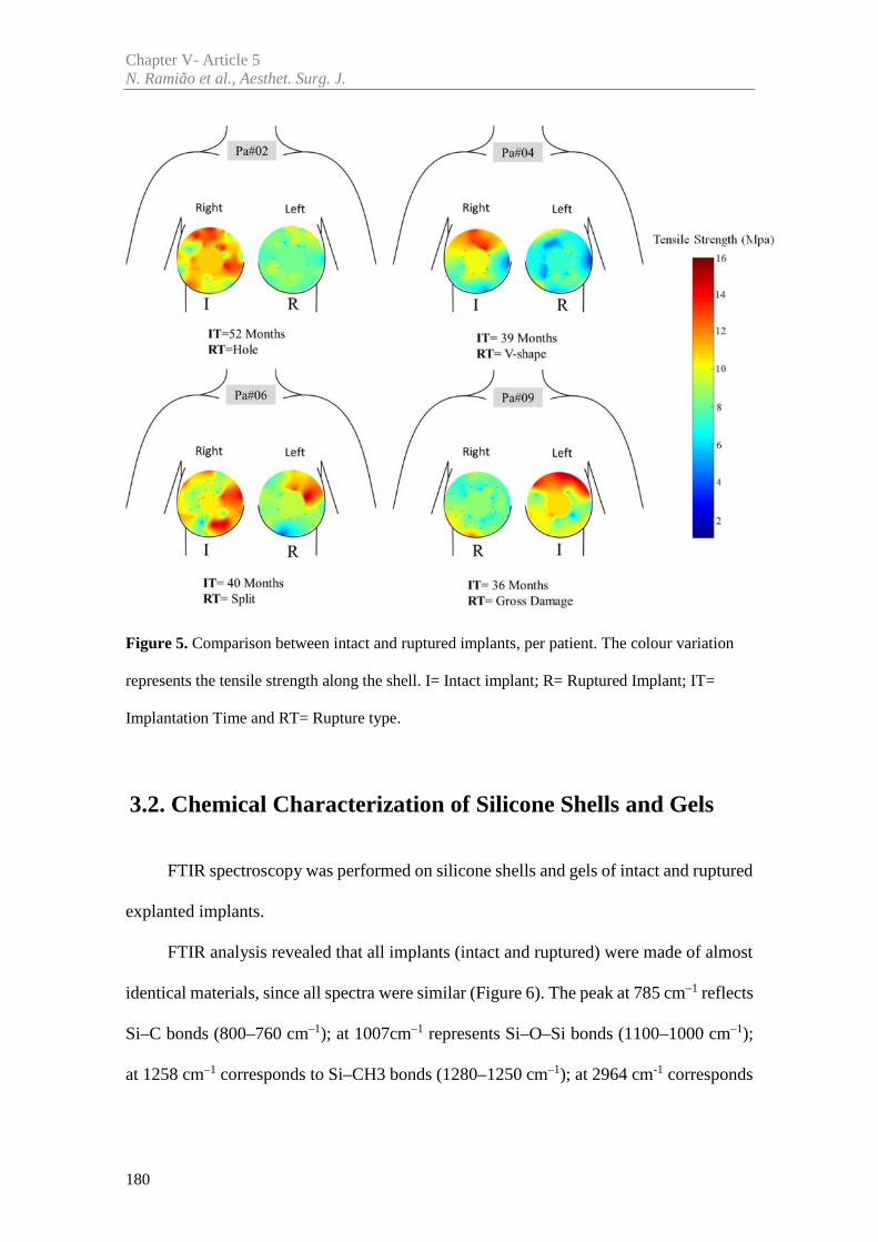
Chapter V- Article 5N. Ramião et al., Aesthet. Surg. J.
180
Figure 5. Comparison between intact and ruptured implants, per patient. The colour variation
represents the tensile strength along the shell. I= Intact implant; R= Ruptured Implant; IT=
Implantation Time and RT= Rupture type.
3.2. Chemical Characterization of Silicone Shells and Gels
FTIR spectroscopy was performed on silicone shells and gels of intact and ruptured
explanted implants.
FTIR analysis revealed that all implants (intact and ruptured) were made of almost
identical materials, since all spectra were similar (Figure 6). The peak at 785 cm–1 reflects
Si–C bonds (800–760 cm–1); at 1007cm–1 represents Si–O–Si bonds (1100–1000 cm–1);
at 1258 cm–1 corresponds to Si–CH3 bonds (1280–1250 cm–1); at 2964 cm-1 corresponds
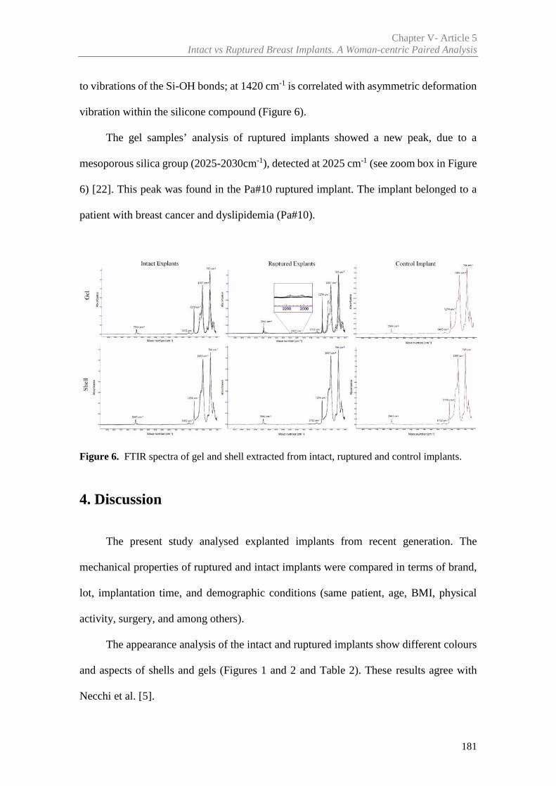
Chapter V- Article 5Intact vs Ruptured Breast Implants. A Woman-centric Paired Analysis
181
to vibrations of the Si-OH bonds; at 1420 cm-1 is correlated with asymmetric deformation
vibration within the silicone compound (Figure 6).
The gel samples’ analysis of ruptured implants showed a new peak, due to a
mesoporous silica group (2025-2030cm-1), detected at 2025 cm-1 (see zoom box in Figure
6) [22]. This peak was found in the Pa#10 ruptured implant. The implant belonged to a
patient with breast cancer and dyslipidemia (Pa#10).
Figure 6. FTIR spectra of gel and shell extracted from intact, ruptured and control implants.
4. Discussion
The present study analysed explanted implants from recent generation. The
mechanical properties of ruptured and intact implants were compared in terms of brand,
lot, implantation time, and demographic conditions (same patient, age, BMI, physical
activity, surgery, and among others).
The appearance analysis of the intact and ruptured implants show different colours
and aspects of shells and gels (Figures 1 and 2 and Table 2). These results agree with
Necchi et al. [5].
Chapter V- Article 5N. Ramião et al., Aesthet. Surg. J.
182
The color of shell and gel for ruptured implants varied according to the type of
rupture. Implants with abrupt ruptures, showed yellowing of shell and gel. Conversely,
the gels and shells from the small ruptures were clear. The available literature agrees that
PIP implants had a higher tendency for cholesterol absorption, which made them softer
and more likely to present yellow discoloration than other implants [6, 20, 21, 23, 24].
Lower gel cohesiveness (broken and oily) was seen in ruptured implants. Previous studies
suggested as a cause, the gel’s reduced viscoelasticity [25], and the in vivo exposure of
the silicone (leading to hydrolytic degradation and cross-link scission [6,26,27]
According to Brandon et al. [16] and Bodin et al. [11] the broken gel and lower
cohesiveness of the ruptured implants may increase the level of non-cross-linked silicone.
This process may induce the shell progressive deterioration.
The present research found statistically significant differences of the tensile
strength, between non-uniform and uniform gels of explanted implants (Table 3 and
Figure 3). These findings along with other parameters must be taken in account to explain
early shell ruptures. Regarding the explants, no direct correlation could be established
between the gel and shell integrity and implantation time. This result is in contradiction
with other publications [18], which reported a change of gel properties with implantation
time.
The thickness of intact implants was (on average) higher compared to ruptured
implants (Table 4 and 5). In the literature, shell thickness variations have already been
identified as one of several factors that may affect the integrity of the shell [8,21]. In a
previous work the authors have concluded that shell thickness may play a role in the
process of implant failure, with thinner implants displaying lower tensile strengths [21].
Chapter V- Article 5Intact vs Ruptured Breast Implants. A Woman-centric Paired Analysis
183
For the analysis of intact and ruptured implants, the mechanical properties of shell
samples were compared. There were significant differences in material resistance (tensile
strength) (Tables 4 and 5).
These results point to a reduced ability of the ruptured implants (shells), to
withstand mechanical stresses. This may be one of the possible causes of the failure
observed. These results are consistent with the study made by Necchi et al. [5], and
contradict the results reported by Brandon et al. [4,13,28]. Given the size and specificity
of the analysed implant sample (brand, lot, shape, surface, etc.), it cannot be established
a definite connection between the mechanical properties and rupture probability.
However, implants with small damages (Tables 2 and 5) did not show significant
differences of the tensile strength when compared with intact implant. These results may
be related to fatigue phenomena, occasionally identified as the mechanism of implant
rupture, reported by the authors on a previous study [29].
FTIR analysis revealed that all implants (explants and controls) were made of
similar materials. All tested samples’ spectra were very similar, and their spectroscopic
profiles were found almost superimposable [30,31]. These findings suggest lack of
chemical degradation during the implantation time. The peak (2025 cm-1) found in patient
Pa#10 spectra, shows that the gel did absorb mesoporous silica compounds. These
compounds are widely used as catalysts for drug delivery reagents and imaging [32,33].
This evidence agrees with the known clinical history of Pa#10, which includes oncologic
pathologies (Table 1). Despite this evidence being found in a single implant, it highlights
the possibility of bioaccumulation and tissue contamination of the implant materials (shell
and gel). Further studies are needed to study chemical impact the mechanical properties,
due to bioaccumulation [27,34].
Chapter V- Article 5N. Ramião et al., Aesthet. Surg. J.
184
5. Conclusions
Three groups of implants were tested and compared to investigate the causes of
breast implant failure. This study has unique characteristics, as it compares for the first
time (as far as the authors’ knowledge goes) rupture and intact implants from the same
woman. These conditions guarantee that physical/biological variables are the same for
each patient (pair of intact and ruptured implants). The results show that the gel cohesion
must be involved in the long-term durability of implants, as well as the thickness of the
shell material. Intact and ruptured implants have distinct mechanical behaviors, as
significant differences in the tensile strength were observed. Despite each implant pair
have endured the same environment (the patient body), for the same time, there were
significant differences between them (intact vs ruptured). These differences (in integrity
and mechanical behavior) may be linked with several factors. According with authors'
understanding of the problem [21,29], these differences may be associated with the
typical manufacturing process of breast implant shells. The manufacturing of implant
shells uses a technique based on immersion of a positive mould in a liquefied
Polydimethylsiloxane (PDMS) batch. The process is done manually leading to regional
property differences over the implant shell. Regarding the eleven ruptured implants,
resistance appears to be associated with implant thickness. The results stress the
importance of a thorough control of the shell thickness. Given its relevance, shell
thickness should be used as a control quality measure for homologation purposes.
Chapter V- Article 5Intact vs Ruptured Breast Implants. A Woman-centric Paired Analysis
185
Acknowledgements
The authors gratefully acknowledge funding from: - Ministério da Ciência, Inovação e do
Ensino Superior, FCT - Fundação para a Ciência e a Tecnologia, Portugal, under grants
SFRH/BD/85090/2012, SFRH/BPD/111846/2015 and projects: LAETA -
UID/EMS/50022/2013; UROSPHINX - Project 16842, cofinanced by Programa Operacional
Competitividade e Internacionalização (COMPETE2020), through Fundo Europeu de
Desenvolvimento Regional (FEDER) and by National Funds through FCT; NORTE-01-0145-
FEDER-000022 – SciTech – Science and Technology for Competitive and Sustainable Industries
(NORTE2020).
Declaration of Conflicting Interests
None declared.
Chapter V- Article 5N. Ramião et al., Aesthet. Surg. J.
186
References
[1] de Camara DL, Sheridan JM, Kammer BA. Rupture and aging of silicone gel breast
implants. Plast Reconstr Surg 1993; 91:828-34, whoo_2014
[2] Phillips JW, de Camara DL, Lockwood, MD, Grebner CC. Strength of silicone breast
implants. Plast Reconstr Surg.1996; 97:1215-1225
[3] Greenwald DP, Randolph M, May JW. Mechanical analysis of explanted
silicone breast implants. Plast Reconstr Surg 1996;98:269-272
[4] Brandon HJ, Young VL, Jerina KL, Wolf CJ. Effect of Implantation Surgery on the
Strength Properties of Silastic® II Silicone Gel Breast Implants. Aesthet Surg J. 1999; 19:197–
204
[5] Necchi S, Molina D, Turri S, Rossetto F, Rietjens M. Failure of silicone gel breast
implants: is the mechanical weakening due to shell swelling a significant cause of prostheses
rupture? J Mech Behav Biomed Mater. 2011; 4:2002–2008
[6] Yildirimer L, Seifalian AM, Butler PE. Surface and mechanical analysis of explanted
Poly Implant Prothèse silicone breast implants. Br J Surg. 2013; 100(6):761-7
[7] Schubert DW, Kaschta J, Horch RE, Waltera BL. On the failure of silicone breast
implants: new insights by mapping the mechanical properties of implant shells. Society of
Chemical Industry. 2013; 63: 172–178
[8] Swarts E, Kop A, Nilasaroya A; Keogh CV, Cooper T. Rupture of Poly Implant
Prothèse Silicone Breast Implants: An Implant Retrieval Study. Plast Reconstr Surg. 2013;
131(4):480e-489e
[9] Wolf, C.J., Brandon, H.J., Young, V.L., Jerina, K.L., Srivastava, A.P.,1996. Chemical,
physical and mechanical analysis of explanted breast implants. Curr. Top. Microbiol. Immunol.
210, 25–37
[10] Holmich LR, Friis S, Fryzek JP, et al. Incidence of silicone breast implant rupture.
Arch Surg 2003;138:801-6
Chapter V- Article 5Intact vs Ruptured Breast Implants. A Woman-centric Paired Analysis
187
[11] Bodin F,Jung C, Dieval F, et al. Aging of retrieved gel breast implants: A comparison
between two product generations. J. Mech Behav Biomed 2015; 4 6 : 1 1 – 2 2
[12] Marotta, J.S., Widenhouse, C.W., Habal, M.B., Goldberg, E.P., 1999. Silicone g el
breast implant failure and frequency of additional surgeries: analysis of 35 studies reporting
examination of more than 8000 explants. J. Biomed. Mater. Res. 48 (3), 354–364
[13] Brandon, H.J., Jerina, K.L., Wolf, C.J., Young, V.L., 2000. Ultimate strength
properties of explanted and control Silastic II silicone gel- f lled breast implant shells. Aesthet.
Surg. J. 2, 122–132
[14] Wolf, C.J., Jerina, K.L., Brandon, H.J., Young, V.L., 2002. The effect of cyclic
swelling (octamethylcyclotetrasiloxane) on the physical properties of silicone breast implant
shells. J. Biomater. Sci. Polym. Ed. 13 (1), 27–41
[15] Brandon, H.J., Jerina, K.L., Wolf, C.J., Young, V.L., 2002. In vivo aging
characteristics of silicone gel breast implants compared to lotmatched controls. Plast. Reconstr.
Surg. 109 (6), 1927–1933
[16] Brandon, H., Jerina, K., Wolf, C., Young, V. Biodurability of retrieved silicone gel
breast implants. Plast. Reconstr. Surg 2003;111 (7): 2295–2306
[17] Bondurant S, Ernster V, Herdman R (1999) Safety of Silicone Breast Implants.
National Academies Press: Washington, D.C. ISBN: 0-309-51931-4, 560
[18] Feng LJ, Amini SB. Analysis of risk factors associated with rupture of silicone gel
breast implants. Plast Reconstr Surg 1999;104:955-63
[19] World Health Organization. Available at: http://www.who.int/en/ . [Accessed 6
December 2016]
[20] TGA (2013) PIP breast implants: Update on TGA testing of PIP breast implants
Available at: http://www.tga.gov.au/alert/pip-breast-implants-update-tga-testing-pip-breast-
implants. [Accessed 10 March 2013]
Chapter V- Article 5N. Ramião et al., Aesthet. Surg. J.
188
[21] Ramião N, Martins P, Barroso M L, Santos DC, Pereira F., Fernandes AA, Mechanical
Performance of Poly Implant Prosthesis (PIP) Breast Implants a Comparative Study. Accepted
for publication in Aesthet. Plas. Surg. 2017
[22] Lee I, Zhang Q, Ge J, Yin Y, Zaera F. Encapsulation of Supported Pt Nanoparticles
with Mesoporous Silica for Increased Catalyst Stability. Nano Res. 2011;4(1):115-123
[23] Berry RB. Rupture of PIP breast implants. J Plast Reconstr Aesthet Surg
2007;60:967e8-8
[24] Beretta G, Malacco M. Chemical and physicochemical properties of the high cohesive
silicone gel from Poly Implant Prothese (PIP) breast prostheses after explantation: a preliminary,
comparative analytical investigation. J Pharm Biomed Anal 2013; 78-79:75-82
[25] Carillon MA, Giard S, Emmanuelli V, Houpeau JL, Ceugnart L, Chauvet MP. Breast
implants and health alert PIP: experience of the regional cancer center of Lille. Bull Cancer 2012;
1;99(2):147-53.
[26] Tan J, Chao YJ, Li X, Van Zee JW. Degradation of silicone rubber under compression
in a simulated PEM fuel cell environment. J Power Sources 2007;172: 782–789
[27] Beretta G, Panseri S, Manzo A, Hamid R, Malacco M. Analytical investigations on
elastomeric shells of new Poly Implant Prothèse (PIP) breast and from sixteen cases of surgical
explantation J Pharm Biomed Anal 2014;98: 144–152.
[28] Brandon HJ, Jerina KL, Wolf CJ, Young V.L. (2012) Retrieval and analysis of breast
implants emphasizing strength, durability, and failure mechanisms. In: Peter W, Brandon HJ,
Jerina KL, Wolf W, Young VL (eds) Biomaterials in Plastic Surgery, Woodhead Publishing
Limited, 154-217
[29] Ramião N, Martins P; Barroso ML, Santos DC, Fernandes AA.. Breast Implants
Rupture Induced by Fatigue Phenomena. J. Plast. Reconstr. Aes., 2017, Doi:
10.1016/j.bjps.2017.01.002
[30] Kaali P, Momcilovic D, Markstrom A, Aune T, Czel G, Karlsson S (2010).
Degradation of Biomedical Polydimethylsiloxanes During Exposure to In Vivo Biofilm
Chapter V- Article 5Intact vs Ruptured Breast Implants. A Woman-centric Paired Analysis
189
Environment Monitored by FE-SEM, ATR-FTIR, and MALDI-TOF MS. Journal of Applied
Polymer Science. 115: 802–810
[31] Kidder LH, Kalasinsky VF, Luke JL, Levin IW, Lewis EN. Visualization of silicone
gel in human breast tissue using new infrared imaging spectroscopy. Nature 1997;3 (2): 235-237
[32] Bharti C, Nagaich U, Pal AK, Gulati N. Mesoporous silica nanoparticles in target drug
delivery system: A review. Int J Pharm Investig. 2015 ;5(3): 1 24–1 33
[33] Giraldo LF, López BL, Pérez L. Mesoporous Silica Applications. Macromol. Symp.
2007:258, 129–141
[34] Amoresano A, De Stefano L, Rea I, Pane F, Birolo L, Schonauer F (2016). Chemical
and Structural Characterization of Several Mid-Term Explanted Breast Prostheses. Materials
9:678; doi:10.3390/ma9080678

Article 6
________________________________________________________
In vitro Degradation of Polydimethylsiloxanes for Breast ImplantApplications Phenomena
Nilza Ramião a, Pedro Martins a, Maria da Luz Barrosob,
Diana C. Santosb, António A. Fernandesa
a INEGI, Faculty of Engineering, University of Porto, Porto, Portugal
b Department of Plastic Surgery of Gaia Hospital Center, Vila Nova de Gaia, Portugal
Published in: Journal of Applied Biomaterials & Functional Materials, 2017; doi:
10.5301/jabfm.5000354

193
Abstract
The durability of breast implant material is associated to the failure probability,
increasing with time since implantation. The current study avoids the bias introduced by
biological factors, to systematically investigate the degradation over-time of shell
materials. The fundamental physical/chemical conditions were maintained (temperature
and pH), to decouple biological aspects from the degradation process.
Six virgin implants of two brands were submitted to: in vitro degradation process;
mechanical testing of shell materials; surface change analysis (via Scanning electron
microscopy - SEM); and chemical composition analysis by Fourier Transform Infrared
Spectroscopy (FTIR).
FTIR results show that, the principal chemical bonds of the material remained intact
after 12 weeks of degradation. Apparently implants shell´s structure remained unchanged.
Despite this observation, there were statistically significant differences between strain at
failure at different time points for the shell of both brands, translated into a stiffening of
the material overtime.
Material stiffening is reported as an indicator of material degradation. This altered
mechanical behaviour added to the mechanical friction from tissue-tissue/tissue-implant
and to the external mechanical loading (physical activity) may alter the material
performance in women's body. Ultimately these changes may affect the implant
durability. Further works are needed to understand the biological aspects of the
degradation process and their impact on implants durability.
Keywords: Breast Implants, Degradation Process, Polydimethylsiloxanes (PDMS).

195
1. Introduction
The Polydimethylsiloxanes (PDMS) is the basis of both gel and shell of breast
implants. The shell is produced from liquid components, and an amorphous “fumed”
silica (SiO2) filler. SiO2 is added to make high-performance silicone rubber for many
purposes, including for the enhancement of mechanical properties [1-5]. The gel is a
weakly crosslinked material which forms a three-dimensional polymer network.
Crosslink occurs due to the reaction of vinyl groups present in the copolymer chains
(dimethyl- and methylvinyl-siloxane) [3-5]. Increasing PDMS crosslinking degree, can
lead to stronger and stiffer shell and gel materials [4]. The aging of implant material,
usually associated among other factors to slow degradation, involves multiple physical
and/or chemical processes.
A main risk of breast implant failure, is the material degradation during
implantation time [1-3,6-9]. Several causes for degradation of the breast implant, were
identified in the literature:
- additional crosslinking to embrittle the silicone [2];
- degradation or weakening of the Si-O-Si cross-links in the shells to Si-OH
[9,10,11];
- degradation leading to the production of dimethyl siloxanes (e.g
octamethylcyclotetrasiloxane (D4)) [2];
- swelling of the silicone elastomer shell by silicone fluid from the gel
[2,7,12];
Chapter V- Article 6N. Ramião et al., J. Appl Biomater Funct Mater
196
- silicone degradation produced by prolonged contact with lipids
[3,8,13,14];
- degradation of the base polymer to a lower average molecular weight
material [2].
Although biodegradation effects had been identified, in vitro biodurability testing
of PDMS breast implants are not well documented in the open literature. Most of the work
done by breast implant producers for implant development, is confidential.
The purpose of this research was to characterize the breast implant degradation,
under physical/chemical conditions of the human body (temperature and pH): a ‘normal’
physiology (pH = 7.4) and an inflammatory process (pH = 4.0). This study comprises the
following stages: (I) in vitro degradation process; (II) analysis of the mechanical
performance of the shell; (III) analysis of the surface (via Scanning electron microscopy
- SEM); (IV) analysis of the chemical composition by Fourier Transform infrared
spectroscopy (FTIR).
2. Material and Methods
Six virgin implants of two different brands were tested. All implants were round
shaped, with textured surface and low profile. The degradation study was carried out
taking into account,
- inter-brand comparison. Different brands compared at the same time point.
- intra-brand comparison. For each brand, the same implant lot was used for
all time points.
Chapter V- Article 6In vitro Degradation of PDMS for Breast Implant Applications Phenomena
197
2.1 Degradation test
Degradation process was conducted according with ISO 10993 "Biological
evaluation of medical devices". To study in vitro degradation processes of the materials
two buffer solutions were used: phosphate buffered saline with pH 7.4 (Ref. P4417
Sigma-Aldrich®), and Potassium hydrogen phthalate buffered (Ref. 82560 Sigma-
Aldrich®) with pH 4.0. The degradation process was carried out during twelve weeks at
controlled temperature, of 37ºC. Every week a batch of samples was removed from the
thermal bath, and samples weight were measured. Weight loss (%) was calculated using
equation (1), % = ∗ 100 (1)
where pi is the initial samples’ weight and pf their weight after different degradation
stages (0-12 weeks).
2.2 Mechanical Test
The mechanical properties were evaluated at the end of each stage of degradation.
These properties were obtained from uniaxial tensile testing data, through a prototype
developed at INEGI Biomechanics Laboratory (Porto, PT). The experimental protocol
follows the ISO standards for shell integrity (ISO 14607:2007) and determination of
tensile stress-strain properties (ISO 37:2005). The equipment used, has alloy aluminium
arms, connected to actuators and two load cells with 50N capacity. Before the tensile test,
samples were subjected to a 0.25 preload, to guarantee a pre-testing controlled initial
geometry. The samples were tested until failure, at a constant displacement rate of
20mm/min.
Chapter V- Article 6N. Ramião et al., J. Appl Biomater Funct Mater
198
2.3 Morphological Characterization
SEM analyses were carried out in a JEOL JSM 6301F/ Oxford INCA Energy
350/Gatan Alto 2500 microscope (Tokyo, Japan) at CEMUP (University of Porto,
Portugal). This technique was used to analyse the morphology evolution due to
degradation. Samples were analysed at four time points - 0, 4, 8 and 12 weeks.
Samples were coated with an Au/Pd thin film, by sputtering, using the SPI Module
Sputter Coater equipment, for 120 s and with a 15 mA current.
2.4 Surface Characterization by Fourier Transform Infrared
Spectroscopy (FTIR)
The chemical composition of the surfaces were analysed using a Cary 630 FTIR
Spectrometer (Agilent Technologies, USA) equipped with a diamond attenuated total
reflectance (ATR) accessory. The tests were carried out at INEGI’s tribology laboratory
(CETRIB). Each spectrum was acquired over 20 scans with wavelengths ranging from
600 to 4000cm-1, with a resolution of 4 cm-1. A background scan was performed before
each sample measurement.
2.5 Statistical Analysis
The statistical analysis was performed using IBM SPSS Statistics software version
20.0, with the significance level set at p<0.05. Data normal distribution was verified with
Kolmogorov- Smirnov and Shapiro-Wilk tests. The statistical differences in the
mechanical properties among groups were assessed using independent-samples t test and
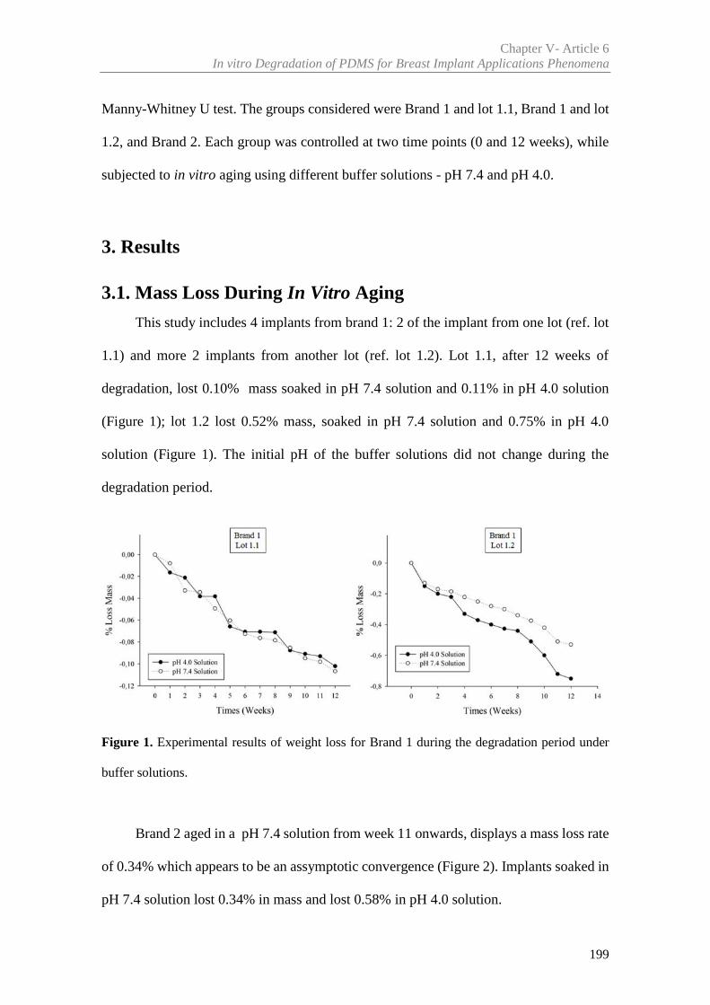
Chapter V- Article 6In vitro Degradation of PDMS for Breast Implant Applications Phenomena
199
Manny-Whitney U test. The groups considered were Brand 1 and lot 1.1, Brand 1 and lot
1.2, and Brand 2. Each group was controlled at two time points (0 and 12 weeks), while
subjected to in vitro aging using different buffer solutions - pH 7.4 and pH 4.0.
3. Results
3.1. Mass Loss During In Vitro Aging
This study includes 4 implants from brand 1: 2 of the implant from one lot (ref. lot
1.1) and more 2 implants from another lot (ref. lot 1.2). Lot 1.1, after 12 weeks of
degradation, lost 0.10% mass soaked in pH 7.4 solution and 0.11% in pH 4.0 solution
(Figure 1); lot 1.2 lost 0.52% mass, soaked in pH 7.4 solution and 0.75% in pH 4.0
solution (Figure 1). The initial pH of the buffer solutions did not change during the
degradation period.
Figure 1. Experimental results of weight loss for Brand 1 during the degradation period under
buffer solutions.
Brand 2 aged in a pH 7.4 solution from week 11 onwards, displays a mass loss rate
of 0.34% which appears to be an assymptotic convergence (Figure 2). Implants soaked in
pH 7.4 solution lost 0.34% in mass and lost 0.58% in pH 4.0 solution.
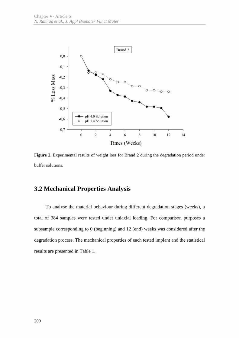
Chapter V- Article 6N. Ramião et al., J. Appl Biomater Funct Mater
200
Figure 2. Experimental results of weight loss for Brand 2 during the degradation period under
buffer solutions.
3.2 Mechanical Properties Analysis
To analyse the material behaviour during different degradation stages (weeks), a
total of 384 samples were tested under uniaxial loading. For comparison purposes a
subsample corresponding to 0 (beginning) and 12 (end) weeks was considered after the
degradation process. The mechanical properties of each tested implant and the statistical
results are presented in Table 1.
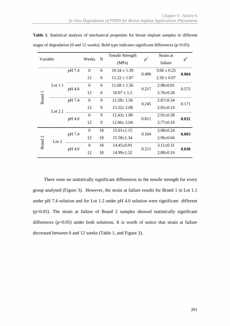
Chapter V- Article 6In vitro Degradation of PDMS for Breast Implant Applications Phenomena
201
Table 1. Statistical analysis of mechanical properties for breast implant samples in different
stages of degradation (0 and 12 weeks). Bold type indicates significant differences (p<0.05).
There were no statistically significant differences in the tensile strength for every
group analysed (Figure 3). However, the strain at failure results for Brand 1 in Lot 1.1
under pH 7.4 solution and for Lot 1.2 under pH 4.0 solution were significant different
(p<0.05). The strain at failure of Brand 2 samples showed statistically significant
differences (p<0.05) under both solutions. It is worth of notice that strain at failure
decreased between 0 and 12 weeks (Table 1, and Figure 3).
Variable Weeks NTensile Strength
(MPa)p1
Strain at
failurep2
Bra
nd 1
Lot 1.1
pH 7.4 0 6 10.34 ± 1.390.496
3.06 ± 0.250.004
12 6 11.22 ± 1.87 2.50 ± 0.07
pH 4.00 6 11.68 ± 1.56
0.2172.98±0.01
0.57512 6 10.07 ± 1.5 2.76±0.26
Lot 2.1
pH 7.4 0 9 12.28± 1.560.245
2.87±0.340.171
12 9 13.32± 2.08 2.85±0.14
pH 4.00 9 12.43± 1.89
0.8112.91±0.38
0.03112 9 12.66± 2.04 2.77±0.10
Bra
nd 2
Lot 2
pH 7.40 18 15.01±1.15
0.1643.08±0.24
0.00312 18 15.58±1.34 2.96±0.04
pH 4.00 18 14.45±0.91
0.2113.11±0.31
0.03012 18 14.99±1.52 2.88±0.10
Chapter V- Article 6N. Ramião et al., J. Appl Biomater Funct Mater
202
Figure 3. Example of tensile test results during the degradation in two buffer solutions: a) and b)
for Brand 1 and lot 1.2; c) and d) for Brand 2. Blue and red lines are used to represent the stiffening
of the shell.
3.3. SEM Analysis
The SEM was used to analyse the material surface. Before degradation (0 weeks),
implants from the same lot showed similar surface morphology.
Brand 1 and Brand 2 showed similar surface morphology over different degradation
stages for pH 7.4 and pH 4.0 buffer solutions (Figure 4). The textured outer surface of
Brand 1 showed a morphology different than Brand 2 (Figure 4). Brand 1 reveals larger
surface structures extending over several hundred micrometres, whereas Brand 2
structures are squarer and with larger gaps between each other.
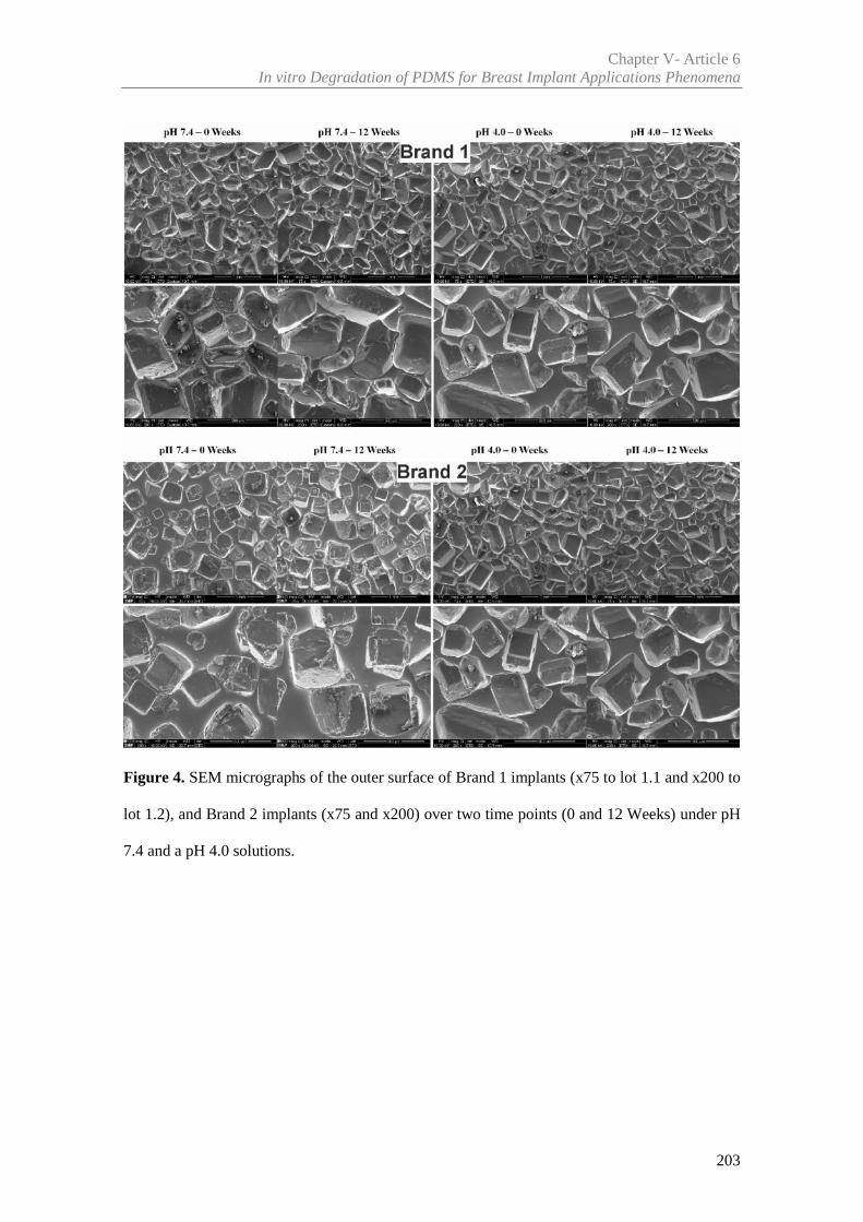
Chapter V- Article 6In vitro Degradation of PDMS for Breast Implant Applications Phenomena
203
Figure 4. SEM micrographs of the outer surface of Brand 1 implants (x75 to lot 1.1 and x200 to
lot 1.2), and Brand 2 implants (x75 and x200) over two time points (0 and 12 Weeks) under pH
7.4 and a pH 4.0 solutions.
Chapter V- Article 6N. Ramião et al., J. Appl Biomater Funct Mater
204
3.4. ATR – FTIR Analysis
Figure 5, show the FTIR spectra for all implants over different stages and solutions
degradation of pH 7.4 and pH 4.0. All FTIR spectra showed that samples were of the
same type of material similar to a PDMS spectrum as found in the literature [8]. There
was no evidence of significant chemical structure modifications.
The wave numbers (cm-1) showed significant peaks (for material identification) at
786cm–1, corresponding to Si–C bond vibrations (800–760 cm–1). The peaks at 1005cm–
1 and 1004cm–1 correspond to the stretching vibrations of Si–O–Si bonds, with a broad
band in the region 1100-1000 cm-1 (polymer backbone). The peak at 1258 cm–1 is
associated with Si–CH3 bonds (1280–1250 cm–1), and the weak band at 1412 cm-1 is
correlated with asymmetric deformation vibration. A peak at 2964 cm– 1 corresponds to
vibrations of the Si–OH bonds. The variation in the absorbance seen in Figure 5 is likely
due to the differences in elasticity and thickness of samples.
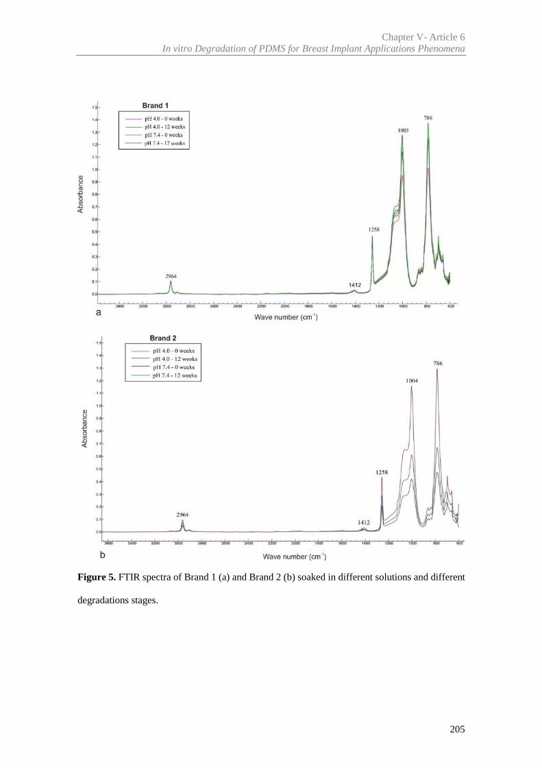
Chapter V- Article 6In vitro Degradation of PDMS for Breast Implant Applications Phenomena
205
Figure 5. FTIR spectra of Brand 1 (a) and Brand 2 (b) soaked in different solutions and different
degradations stages.
Chapter V- Article 6N. Ramião et al., J. Appl Biomater Funct Mater
206
4. Discussion
The durability and useful life of a breast implant continues to be a subject of intense
interest and debate to both the patients and the plastic surgery community. To evaluate
the potential impact of in vivo degradation on the mechanical properties of implant shells,
an experimental protocol including uniaxial tension testing and in vitro degradation was
carried from two implants brands. The observation that implants shells are sensitive to
degradation in the body has been demonstrated for a long time on several studies
[2,6,9,12,15-17]. Several authors showed a negative correlation between implant duration
and mechanical resistance [1,2,6,7,9,16,17]. Furthermore, Yildirimer et al. [9] using
FTIR, found evidence of degradation of the Si-O-Si cross-links to Si-OH on silicone
shells, which may be related to inflammation.
However, Brandon et al. [12,18,19] ,Wolf et al. [20], and Swart et al. [21], showed
that there was no time-dependent degradation in the shell tensile strength over years of
implantation. These authors considered that implant failure is highly correlated with the
implantation/explantation procedures, trauma of the breast, or manufacturing defects.
This assessment of the problem does not have into consideration the baseline of
implant shell properties, since all previous sudies were conducted on explanted implants
(in vivo) [1,2,6,7,9,12,15-17,18-21]. The current study avoids the bias introduced by
biological factors, to systematically investigate the degradation over-time of shell
materials. The fundamental physical/chemical conditions were maintained (temperature
and pH), in an effort to decouple biological aspects from the whole degradation process.
The overall material degradation differs from a person to person, from tissue to tissue and
over time for the same person [22]. In the present study found evidence of mass loss over
Chapter V- Article 6In vitro Degradation of PDMS for Breast Implant Applications Phenomena
207
the degradation period (Figures 1 and 2); however the tensile strength of the shell material
was not signicantly affected as observed in Table 1, and Figure 3.
There was a statistically significant strain at failure reduction for the shell of both
brands after a degradation period of 12 weeks (Table 1). This is due translated into a
stiffening of the shell, as illustrated by the blue and red lines in Figure 3d. Material
stiffening is reported as an indicative factor of material degradation [23]. Considering
Brand 2 (Figure 3d) for a 2.5 of strain, the stress after 12 weeks of degradation is higher
than initial stress.
SEM results revealed that the surface morphology did not show any differences
after 12 weeks of degradation. Apparently implants shell´s structure remained unchanged.
FTIR results (Figure 5) indicated the presence of the same type of PDMS for
implant material in all samples, which agrees with literature [8,9,24-26]. No spectral
deviations were observed during the degradation period, which suggests a lack of
chemical degradation.
5. Conclusions
In this study the authors attempted to decouple the biological aspects from the
whole degradation process, by maintaining the human body physical/chemical conditions
i.e., temperature and pH.
FTIR results show that, the principal chemical bonds of the material remained intact
after 12 weeks of degradation. Despite this observation, there were statistically significant
differences between the strain at different times points, which translated into a stiffening
of the material overtime. This change may alter the mechanical friction tissue-tissue
and/or tissue-implant, affections significantly the performance of the implant material in
Chapter V- Article 6N. Ramião et al., J. Appl Biomater Funct Mater
208
the women's body when subjects to external mechanical loading such as physical activity
and other. Ultimately these changes may affect the implant durability.
Further work is needed to understand the biological aspects of the degradation
process especially under longer testing periods. In particular aspects such as oxidation
(due to oxidants produced by tissues) and enzymatic degradation should be analysed.
Larger degradation periods may also shed some light on fundamental degradation
mechanisms such as weight loss, which was not fully understood with the current study.
Acknowledgements
The authors gratefully acknowledge funding from: - Ministério da Ciência,
Inovação e do Ensino Superior, FCT - Fundação para a Ciência e a Tecnologia, Portugal,
under grants SFRH/BD/85090/2012, SFRH/BPD/111846/2015 and projects: LAETA -
UID/EMS/50022/2013; UROSPHINX - Project 16842, cofinanced by Programa
Operacional Competitividade e Internacionalização (COMPETE2020), through Fundo
Europeu de Desenvolvimento Regional (FEDER) and by National Funds through FCT;
NORTE-01-0145-FEDER-000022 – SciTech – Science and Technology for Competitive
and Sustainable Industries (NORTE2020).
Declaration of Conflicting Interests
None declare.
Chapter V- Article 6In vitro Degradation of PDMS for Breast Implant Applications Phenomena
209
References
[1] Greenwald DP, Randolph M, May JW. Mechanical Analysis of Explanted Silicone
Breast Implants. In: Shiffman MA, ed. Breast Augmentation. Principles and Practice, Springer,
Berlin 2009;193-196
[2] Wolf CJ, Brandon HJ, Young VL, Jerin KL, Srivastava AP. Chemical, Physical and
Mechanical Analysis of Explanted Breast Implants. In: Potter M, Rose NR, eds. Immunology of
Silicones. Springer, Berlin 1996;25-37
[3] Birkefeld AB, Bertermann R, Eckert H, Pfleiderer V. Liquid- and solid-state high-
resolution NMR methods for the investigation of aging processes of silicone breast implants.
Biomaterials. 2003;24:35-46
[4] Daniels AU, Silicone breast implant materials. Swiss Med Wkly. 2012;142:w13614.
[5] Picha GJ, Goldstein JA.. Analysis of the soft-tissue response to components used in the
manufacture of breast implants: rat animal model. Plast Reconstr Surg. 1991;87:490
[6] Marotta JS, Goldberg EP, Habal MB, et al. Silicone Gel Breast Implant Failure:
Evaluation of Properties of Shell and Gels for Explanted Prostheses of Shells and Gels for
Explanted Prostheses and Meta-analysis of Literature Rupture Data. Ann Plast Surg.
2002;49:227–247
[7] Marotta JS, Amery DP, Widenhouse CW, Martin PJ, Goldberg EP. Degradation of
physical properties of silicone gel breast implants and high rates of implant failures. In
Proceedings of the 24th Annual Meeting of the Society of Biomaterials. 1998;374:1999
[8] Beretta G, Malacco M. Chemical and physicochemical properties of the high cohesive
silicone gel from Poly Implant Prothese (PIP) breast prostheses after explantation: a preliminary,
comparative analytical investigation. J Pharm Biomed Anal. 2013;84:159-167
[9] Yildirimer L, Seifalian AM, Butler PE. Surface and mechanical analysis of explanted
Poly Implant Prothèse silicone breast implants. Br J Surg. 2013;100(6):761-7
Chapter V- Article 6N. Ramião et al., J. Appl Biomater Funct Mater
210
[10] Taylor RB, Eldred DE, Kim G, Curtis JM, Brandon HJ, Klykken PC. Assessment of
silicone gel breast implant biodurability by NMR and EDS techniques. J Biomedical Materials
Res. 2008;85A:684–91
[11] Pfleiderer B, Xu P, Ackermann JL, Garrido L. Aging of biomaterials based on silicone
rubber. J Biomed Mater Res. 1995;29:1129–40
[12] Brandon HJ, Jerina KL, Wolf CJ, Young VL. Retrieval and analysis of breast implants
emphasizing strength, durability, and failure mechanisms. In: Peter W, Brandon HJ, Jerina KL,
Wolf W, Young VL, eds. Biomaterials in Plastic Surgery. Woodhead Publishing Limited.
2012;154-217
[13] Williams DF. On the mechanism s of biocompatibility. Biomaterials. 2008;29:2941–
2953
[14] Kirkpatrick WN, Jones BM. The history of Trilucent implants, and a chemical analysis
of the triglyceride filler in 51 consecutively removed Trilucent breast prostheses. Br J Plast Surg.
2002;55(6):479–89
[15] Lockwood MD. Strength, strain, energy, and toughness of silicone breast implant
shells. Dissertation, University of Illinois, Chicago, IL, 1995
[16] Phillips J, de Camera DL, Lockwood MD. Grebner WC Strength of silicone breast
implants. Plast Reconstr Surg. 1996;97(6):1215-25
[17] Greenwald DP, Randolph M, May JW. Mechanical analysis of explanted silicone
breast implants. Plast Reconstr Surg. 1996;98(2):269-72
[18] Brandon HJ, Jerina KL, Wolf CJ, Young VL. In vivo aging characteristics of silicone
gel breast implants compared to lot-matched controls. Plast
Reconstr Surg. 2002;109:1927–1933
[19] Brandon HJ, Jerina KL, Wolf CJ, Young VL. Biodurability of retrieved
silicone gel breast implants. Plast Reconstr Surg. 2003;111:2295–2306
Chapter V- Article 6In vitro Degradation of PDMS for Breast Implant Applications Phenomena
211
[20] Wolf CJ, Young VL, Jerina KL, Brandon HJ. Effect of surgical insertion on the local
shell properties of Silastic II silicone gel breast implants. J. Biomater. Sci. Polymer Edn. 2000;
11(10):1007–1021
[21] Swarts E, Kop A, Nilasaroya A; Keogh CV, Cooper T. Rupture of Poly Implant
Prothèse Silicone Breast Implants: An Implant Retrieval Study. Plast Reconstr Surg.
2013;131(4):480e-489e
[22] Lyu S, Untereker D. Degradability of Polymers for Implantable Biomedical Devices.
Int. J. Mol. Sci. 2009;10:4033-4065
[23] Gunatillake PA, Martin DJ, Meijs GF, McCarthy SJ, Adhikari R. Designing Biostable
Polyurethane Elastomers for Biomedical Implants. Aust. J. Chem. 2003;56:545-557
[24] Amoresano A, De Stefano L, Rea I, Pane F, Birolo L, Schonauer F. Chemical and
Structural Characterization of Several Mid-Term Explanted Breast Prostheses. Materials.
2016;9:678
[25] Kaali P, Momcilovic D, Markstrom A, Aune T, Czel G, Karlsson S. Degradation of
Biomedical Polydimethylsiloxanes During Exposure to In Vivo Biofilm Environment Monitored
by FE-SEM, ATR-FTIR, and MALDI-TOF MS. J. Appl. Polym. Sci. 2010;115:802–810.
[26] Yang J, Webb AR, Ameer GA. Novel citric Acid-based biodegradable elastomers for
tissue engineering. Adv. Mater. 2004;16(6):511–516


Chapter VI
________________________________________________________________________________-
Integrated Discussion

215
Integrated Discussion
In the last few decades, breast augmentation and reconstruction have evolved
significantly due to the development of new materials and surgery technical
improvement. Despite the improvements in implant design and manufacturing
technologies throughout the years, the long-term reliability of implants and the
phenomena involved in their failure are not completely clarified yet [1,2]. The same
applies to plastic and oncoplastic surgical techniques for breast reconstruction. For
instance, the stress-strain correlation between the implants and tissue, the implications
the properties may have on final implant shape and the influence they may have on the
implant rupture are not well understood by the plastic surgery community nor by breast
implant manufacturers [3]. Therefore, researching the mechanical behaviour of both
breast tissues and implant material is “vital” to understand the long-term results of the
breast augmentation procedure.
A recent Poly Implant Prosthèse (PIP) breast implants scandal revived concerns
about the mechanical stability of implanted silicones. As such, the main goal of this study
focuses on explaining the seemingly higher rates of rupture for PIP breast implants
compared to other breast implants brands, by presenting original studies to corroborate
the importance of analysing explanted implants. The studies show that experimental
evaluation and testing may contribute to characterize the causes, the physical process and
the biomechanical process of implant failure. Hence, based on the main objectives and
methodologies adopted, the most relevant findings of this research are discussed below.
Chapter VIIntegrated Discussion
216
Focusing on currently available data, there is no indication that the demographic
profile of women who have had PIP breast implants differs from those with implants from
other manufacturers [4]. In this sense, the silicone breast implants may fail, regardless of
the manufacturer. Based on peer-reviewed published studies, the probability of rupture
for PIP implants is estimated to be around 14.5% to 31 % after 5 to 10 years of
implantation [5-10], while other silicone breast implants have been reported with a
rupture rate of 1.1 to 11.6% after 10 years of implantation [5,11]. Data suggests that PIP
implant rupture after 10 years is higher than that of modern generation implants, but
comparable to that of older generation implants [12]. These studies showed that PIP breast
implants produced during 2001-2010 presented a higher probability of rupture and earlier
rupture than implants from other manufacturers [5,6,10,13-17]. Our findings are in the
line with these conclusions, since the twenty-two studied explants had been implanted
between 2005 and 2012. Furthermore, the explanted implants, especially the eleven
considered with rupture, had a lifetime lower than 10 years (ruptured after 3 to 8 years of
implantation). This temporal shift can be associated with structural integrity problems.
The visual appearance, related to cohesiveness and other qualitative parameters
such as clarity and oiliness, is highly variable in PIP implants (intact, ruptured and
controls) (Articles 2, 4 and 5). Thus, for PIP and Brand X controls most gels appeared to
be firm (cohesive). However, for explanted implants, gels appeared relatively less firm
(non-cohesive) and oily, regardless of the time of implantation. Additionally, lower gel
cohesiveness (broken and oily) was seen in ruptured implants. The main reason for a
lower cohesiveness of the gel is that in vivo exposure of silicone leads to hydrolytic
degradation and cross-link scission [13,18]. Furthermore, according to TGA the "milk
fluid" aspect witnessed in explanted PIP breast implants with ruptures was found to be
predominantly an emulsion of water and silicone [19].
Chapter VISilicone breast implants: Experimental analysis of failure mechanisms
217
Another finding, discussed in Articles 2, 4 and 5, was the colour of both shell and
gel for ruptured implants varied according to the type of rupture. There is unanimous
agreement in the literature that the data evaluated for PIP implants contained a higher
tendency for cholesterol absorption, which made it softer and more likely to present
yellow discoloration than other implants [4,13,17,20,21]. However, in this study (Article
2) the analysis of explanted implants for Brand X to verify if they presented the same
variation of cohesiveness and colour was not undertaken since no ruptured implants were
available. In this context, and according to the literature, implants from other
manufacturers can be clear, yellow, opaque or oily, but not non-cohesive [22], which may
be considered as additional evidence of the variability between PIP implants.
The results of Article 5 show that gel cohesion may be involved in the long-term
durability of implants shells. According to Brandon et al [1] and Bodin et al. [23] the
broken gel and lower cohesiveness of the ruptured implants may increase the level of non-
cross-linked silicone that accentuates the mechanism of theorized shell diffusion and
accentuate the process of shell progressive deterioration. More systematic and
independent analyses should be performed on a larger sample of implants, to confirm the
results obtained, for example through cohesivity testing.
To explore the ruptures in breast implants, we developed an experimental protocol
for characterizing the entire implant shell. One of the key assumptions of all studies on
the mechanical properties of silicone breast shells is that silicone properties are the same
along the specimen under investigation, which may limit the conclusions. For instance,
in Articles 2 and 5 through the schematic representation of a colour map (Figures 5 and
7 in Article 2, and Figure 5 in Article 5) shows the variation of tensile strength over the
shell. It is evident that the shell is inhomogeneous for each implant, and the mechanical
properties vary from anterior, equatorial and posterior region. This variability is
Chapter VIIntegrated Discussion
218
associated with the typical manufacturing process of breast implant shells. The
manufacturing process of implant shells uses a technique based on immersion of a mould
in a liquefied PDMS batch. The process is done manually leading to regional property
differences over the implant shell, due to differences in forming temperature, pressure,
and other variables [24]. The available literature on implant rupture is supported by
limited experimental data. The mechanical characterization, when available, is based on
a small number of tests per implant, typically between 1 and 20 [13,19,21,25-28]. In our
opinion, it is a small sampling to characterize the implant material behaviour along the
shell. The approach shown in Articles 2, 5 and 6 includes a far superior number of
samples, as up to now a minimum of sixty samples per implant have been tested. This
method enables a wide mapping of the mechanical properties of the implant shell
material, as the location of each individual sample was known and, therefore, mapping of
the mechanical properties per sample location was possible, as seen in Articles 2, 5 and
6.
Tensile testing provides a measure of the compliance of a particular sample with
specified quality criteria, and the quality of the sample is considered to be reflective of
the batch from which it is drawn. The mechanical tests performed along the different
articles of this thesis present a variation in the tensile strength between explanted and
controls implants. One of this variation is presented in Article 5, where a comparison
between intact and ruptured implants showed a shell tensile strength of 7.42MPa for
ruptured implants, compared with 9.59MPa for intact implants. These results point to a
reduced ability of the ruptured implants (shells) to withstand mechanical stresses. It can
be suggested that the resistance of the implants associated with other factors may be one
of the possible causes of the failure observed.
Chapter VISilicone breast implants: Experimental analysis of failure mechanisms
219
Both this work and the literature presented shell thickness variations, which is one
of several factors that may affect the integrity of the shell, as well as the variation in
quality parameters from PIP implants [4,19,27]. Although the average thickness of all PIP
samples (a total of 1216 samples – 396 from intact implants, 604 from ruptured implants
and 216 from control implants) falls within the manufacturer’s specifications (range from
0.5 and 1.0 mm), in some implant regions the minimum thickness was below 0.5mm and
the maximum above 1mm. It was found that different regions of the shell had different
thicknesses on nearly all the PIP implants. Brand X exhibited a smaller thickness
variations among the regions, and this variation was in compliance with the
manufacturer’s specifications. In Article 2 evidence that a thinner shell thickness for PIP
implants was more likely to have a lower strength and a higher probability of failure is
reported. Article 5 showed that intact implants were thicker (0.91mm) when compared
to ruptured ones (0.73mm), which suggest that thickness can be related to the possibility
of failure. Furthermore, this suggests inconsistencies in the manufacturing process that
could explain higher rates of rupture.
Microscopy techniques provided details of the ruptured shell region and could be
used to determine the cause of breast implant failure, as seen in Articles 3 and 4. Results
suggest that fatigue damage can be a potential cause of in vivo failure. All implant with
small ruptures (hole and split) presented features commonly found in fatigue processes.
Likewise, in Article 6, implants with small damages did not show significant differences
of the tensile strength when compared with intact implant, which may be related to the
fatigue phenomena found in Article 3 and 4. Shell failure may not be directly related to
a decrease in mechanical strength but to fatigue effects. Implant failure may be associated
with loading induced by normal daily activities, in addition to the presence of implant
defects and microstructural inhomogeneities (e.g., inclusions and pores) that may
Chapter VIIntegrated Discussion
220
generate damage in the shell due to fatigue mechanisms. The features detected in explants
were verified by fatigue testing performed in laboratory conditions, and should be viewed
as a starting point for further work on fatigue test crack growth. The microscopy features
suggest that fatigue phenomena should be taken into consideration by manufacturers
when characterizing the mechanical behaviour of the shell, for homologation purposes.
Literature states that silicone exposure (from both shell and gel) to a strongly acidic
environment and to bacterial contamination during the implantation procedure, results in
hydrolytic degradation of cross-links and chain scission of the polymeric backbone
[14,17,21,29-31]. Kaali et al. [30] showed that inflammation processes (i.e capsular
contracture) coupled with bacterial contamination during implantation further accelerates
silicone degradation. Scala et al. [31] demonstrated a temporal association between
exposure to bodily fluids with or without inflammatory surroundings and silicone
degradation. Yildirimer et al. [13] reported spectroscopic changes between 3200 cm−1 and
3600 cm−1, and between 1525 cm−1 and 1760 cm−1, attributed to Si-OH bonds from
silicone degradation and to protein-like bands, respectively. A co-existing ‘protein-like’
spike in the spectroscopy suggests that this degradation may be due to the presence of a
bio-film, which may be related to inflammation [13]. Furthermore, absorption bands seem
to be associated with water and proteins from breast late periprosthetic fluid (LPF)
infiltrated inside the implants [13,17,32]. Recently, Amoresano et al. [21] showed signs
of carboxylic acid that can be ascribed to lipid infiltration.
In Article 5 the shell and gel chemistry analysis for explanted implants by FTIR
indicated the presence of the same type of PDMS for implant material in all samples. No
spectral deviations were observed during implantation time, and we did not find
significant differences between the intact and ruptured implant. These findings suggest a
lack of chemical degradation during the implantation time. However, the new found peak
Chapter VISilicone breast implants: Experimental analysis of failure mechanisms
221
(2025cm-1, see Figure 6 in Article 5) shows that the gel is able to absorb mesoporous
silica compounds, which may related with medication taken by the patient at the time of
implant rupture. This was confirmed with the collected clinical information, since the
implant was explanted from a 68 year woman with breast cancer and dyslipidemia. Even
if this peak was found in a single implant, it highlights the possibility of bioaccumulation
and tissue contamination in the implant material (shell and gel). This opens the door to
further studies, namely those focusing on the chemical impact to the mechanical
properties, due to bioaccumulation.
Material aging may due to the contact with biological tissues may be associated to
implant failures as reported by some authors [13,25,33-35]. In this context, it was decided
to carried out an in vitro degradation analysis as detailed in Article 6. .In vitro degradation
tests concluded that chemical bonds of the material remained intact after 12 weeks of
degradation, and the implants’ shell structure (studied with SEM analysis) apparently
remained unchanged. However, there was a stiffening of the material along that period
for both PIP implant (described as Brand 1 in Article 6) and Brand X (described as Brand
2 in Article 6). Material stiffening is reported as an indicator of degradation: this
mechanical behaviour change combined with mechanical friction from tissue-
tissue/tissue-implant and with external mechanical loading (physical activity), may alter
the material performance in women's bodies, and in consequence affect implant
durability. Further work is needed to understand the biological aspects of the degradation
process, especially under longer testing periods, as well as to emphasize the relevance of
studies between the interaction of the tissue and the implant.
Chapter VIIntegrated Discussion
222
References
[1] Brandon, H., Jerina, K., Wolf, C., Young, V. Biodurability of retrieved silicone gel
breast implants. Plast. Reconstr. Surg 2003;111 (7): 2295–2306
[2] Necchi S, Molina D, Turri S, Rossetto F, Rietjens M. Failure of silicone gel breast
implants: is the mechanical weakening due to shell swelling a significant cause of prostheses
rupture? J Mech Behav Biomed Mater; 2011: 4:2002–2008
[3] Vegas MR, del Yerro JLM. Stiffness, Compliance, Resilience, and Creep Deformation:
Understanding Implant-Soft Tissue Dynamics in the Augmented Breast: Fundamentals Based on
Materials Science. Aesth Plast Surg; 2013:37:922–930 DOI 10.1007/s00266-013-0197-y
[4] Scientific Committee on Emerging and Newly Identified Health Risks. The safety of
PIP silicone breast implants Available at:
http://ec.europa.eu/health/scientific_committees/emerging/docs/scenihr_o_043.pdf. [Accessed
March 10, 2013]
[5] Maijers MC, Niessen FB. Prevalence of rupture in Poly Implant Prothèse silicone breast
implants, recalled from the European market in 2010. Plast Reconstr Surg 2012; 129:1372–1378.
[6] Berry MG, Stanek JJ. PIP implant biodurability: a post-publicity update. J Plast
Reconstr Aesthet Surg. 2013; 66:1174-81
[7] Quaba O, Quaba A. PIP silicone breast implants: rupture rates based on the explantation
of 676 implants in a single surgeon series. J Plast Reconstr Aesthet Surg 2013; 66(9):1182–1187.
[8] Oulharj S, Pauchot J, Tropet Y. PIP breast implant removal: a study of 828 cases. J
Plast Reconstr Aesthet Surg 2014; 67:302-7
[9] Khan UD. Poly Implant Prothèse (PIP) Incidence of device failure and capsular
contracture: a retrospective study. Aesthetic Plast Surg 2013; 37(5):906–913
[10] Santos DC, Barroso ML, Gomes N, et al. PIP breast implant rupture—A retrospective
study from Portugal. Eur J Plast Surg 2015;38:301-308
Chapter VISilicone breast implants: Experimental analysis of failure mechanisms
223
[11] Spear SL, Murphy DK. Allergan Silicone Breast Implant U.S. Core Clinical Study
Group. Natrelle round silicone breast implants: core study results at 10 years. Plast Reconstr Surg
2014; 133:1354-61.
[12] Wazir U, Kasem A, Mokbel K. The Clinical Implications of Poly Implant Prothèse
Breast Implants: An Overview. Arch Plast Surg 215;42:4-10
[13] Yildirimer L, Seifalian AM, Butler PE. Surface and mechanical analysis of explanted
Poly Implant Prothèse silicone breast implants. Br J Surg 100(6):761-7
[14] Aktouf A, Auquit-Auckbur I, Coquerel-Beghin D, Delpierre V, Milliez PY. Breast
augmentation by Poly Implant Prothèses silicone implants: retrospective study about 99 patients.
Rupture analysis and management. Ann Chir Plast Esthet. 2012; 57(6):558-66
[15] Carillon MA, Giard S, Emmanuelli V, Houpeau JL, Ceugnart L, Chauvet MP. Breast
implants and health alert PIP: experience of the regional cancer center of Lille. Bull Cancer 2012;
1;99(2):147-53
[16] Reyal F, Feron JG, Leman Detour S, et al.The impact of poly implant prothèse fraud
on breast cancer patients: a report by the Institut Curie. Plast Reconstr Surg 2013; 131 (4):690-5
[17] Beretta G, Malacco M. Chemical and physicochemical properties of the high cohesive
silicone gel from Poly Implant Prothese (PIP) breast prostheses after explantation: a preliminary,
comparative analytical investigation. J Pharm Biomed Anal 2013; 78-79:75-82
[18] Carillon MA, Giard S, Emmanuelli V, Houpeau JL, Ceugnart L, Chauvet MP. Breast
implants and health alert PIP: experience of the regional cancer center of Lille. Bull Cancer 2012;
1;99(2):147-53
[19] Australian Government Department of Health and Ageing Therapeutic Goods
Administration (TGA) (2013) PIP breast implants: Update on TGA testing of PIP breast implants.
http://www.tga.gov.au/alert/pip-breast-implants-update-tga-testing-pip-breast-implants.
[Accessed 10 March 2013]
[20] Berry RB. Rupture of PIP breast implants. J Plast Reconstr Aesthet Surg
2007;60:967e8-8
Chapter VIIntegrated Discussion
224
[21] Amoresano A, De Stefano L, Rea I, Pane F, Birolo L, Schonauer F. Chemical and
Structural Characterization of Several Mid-Term Explanted Breast Prostheses. Materials
2016;9:678
[22] Hölmich LR, Breiting VB, Fryzek JP, Brandt B, Wolthers MS, Kjøller K, McLaughlin
JK, Friis S.(2007) Long-term cosmetic outcome after breast implantation, Annals of Plastic
Surgery, 597-604
[23] Bodin F,Jung C, Dieval F, et al. Aging of retrieved gel breast implants: A comparison
between two product generations. J. Mech Behav Biomed 2015; 4 6 : 1 1. –
[24] Daniels AU. Silicone breast implant materials. Swiss Med 2012; Wkly 142:w13614
[25] Wolf CJ, Brandon HJ, Young VL, Jerin KL, Srivastava AP. Chemical, Physical and
Mechanical Analysis of Explanted Breast Implants. In: Potter M, Rose NR, eds. Immunology of
Silicones. Springer, Berlin 1996;25-37
[26] Phillips J, de Camera DL, Lockwood MD. Grebner WC Strength of silicone breast
implants. Plast Reconstr Surg. 1996;97(6):1215-25
[27] Swarts E, Kop A, Nilasaroya A; Keogh CV, Cooper T. Rupture of Poly Implant
Prothèse Silicone Breast Implants: An Implant Retrieval Study. Plast Reconstr Surg;
2013:131(4):480e-489e
[28] Brandon HJ, Young VL, Jerina KL, Wolf CJ. Effect of Implantation Surgery on the
Strength Properties of Silastic® II Silicone Gel Breast Implants. Aesthet Surg J 1999; 19:197–
204
[29] Tan J, Chao YJ, Li X, Van Zee JW. Degradation of silicone rubber under compression
in a simulated PEM fuel cell environment. J Power Sources 2007;172: 782–789
[30] Kaali P, Momcilovic D, Markstrom A, Aune T, Czel G, Karlsson S (2010).
Degradation of Biomedical Polydimethylsiloxanes During Exposure to In Vivo Biofilm
Environment Monitored by FE-SEM, ATR-FTIR, and MALDI-TOF MS. Journal of Applied
Polymer Science. 115: 802–810
Chapter VISilicone breast implants: Experimental analysis of failure mechanisms
225
[31] Scala L, Hickman W. Thermal and oxidative degradation of silicones. Ind Eng Chem
1958; 50: 1583–1584
[32] Beretta G, Panseri S, Manzo A, Hamid R, Malacco M. Analytical investigations on
elastomeric shells of new Poly Implant Prothèse (PIP) breast and from sixteen cases of surgical
explantation J Pharm Biomed Anal 2014;98: 144–152
[33] Greenwald DP, Randolph M, May JW. Mechanical Analysis of Explanted Silicone
Breast Implants. In: Shiffman MA, ed. Breast Augmentation. Principles and Practice, Springer,
Berlin 2009;193-196
[34] Birkefeld AB, Bertermann R, Eckert H, Pfleiderer V. Liquid- and solid-state high-
resolution NMR methods for the investigation of aging processes of silicone breast implants.
Biomaterials. 2003;24:35-46
[35] Marotta JS, Goldberg EP, Habal MB, et al. Silicone Gel Breast Implant Failure:
Evaluation of Properties of Shell and Gels for Explanted Prostheses of Shells and Gels for
Explanted Prostheses and Meta-analysis of Literature Rupture Data. Ann Plast Surg.
2002;49:227–247


Chapter VII
________________________________________________________________________________-
Conclusions

229
Conclusions
The main purpose of this thesis was to contribute for the explanation of the
seemingly higher rates of rupture for PIP breast implants compared to other breast
implants. To achieve meaningful contributions on this domain, a multidisciplinary effort
between engineers and medical doctors was required. After the thesis’ conclusion, it can
be assumed that the experimental methodology adopted proved to be an useful tool for
the analysis of explanted implants. The physical and chemical processes in the
methodology are able to reveal why breast implants fail. The most relevant conclusions
of this research are summarized below:
The heterogeneous nature of PIP implants was confirmed in Article 2. This study
demonstrated that the physical characteristics of the PIP implant are variable, and have a
strong relationship with the shell thickness (thickness variations). By comparison, the
Brand X can be a good example of quality control in breast implants, by not showing
these variations. This may contribute to dispel fears among the medical community and
patients about the reliability of breast implants.
Articles 3 and 4 demonstrated that, with the proper background and experience in
analysing ruptured breast implant shells, the features at the failure site can be correctly
interpreted and the corresponding failure mechanisms can be diagnosed. Breast implant
failure may be related to several factors, such as: implant handling before the surgical
procedure, the implantation procedure, in vivo processes (e.g., abrasion or breast biopsy),
Chapter VIIConclusions
230
the explantation procedure, and in vivo cyclic loading that may induce fatigue damage in
the implant. Analysing the microscopy images of the eleven ruptured implants, the study
concluded that fatigue damage can be a potential cause of in vivo failure.
Article 5 has unique characteristics because, to the author’s best knowledge, it
compares rupture and intact explanted implants from the same woman for the first time.
These conditions guarantee that physical/biological variables are the same for each
patient (pair of intact and ruptured implants). Although all implant pairs endured the same
environment (the patient body), the results showed that there were statistically relevant
differences between intact and ruptures implants. Ruptured implants were thinner (0.73
mm vs 0.91 mm) and weaker (7.42 MPa vs 9.59 MPa) than intact implants. The most
important observation based on the present study is that the mechanical weakness of the
shell has to be considered one of the main mechanisms of breast implant failure.
Finally, in Article 6 the authors attempted to simulate the in vivo degradation, by
decoupling the biological aspects from the whole degradation process. This was achieved
by maintaining the human body physical/chemical conditions i.e., temperature and pH.
The data analysis showed that the material stiffening may be an indicator of material
degradation. However, despite this observation the results showed the need to improve
the developed degradation process. Improving this process should allow for better
understanding of the biological aspects of the degradation process (especially under
longer testing periods) and their impact on implants’ durability.
In conclusion, the thesis results point to several possible causes of rupture for the
explanted implants, these may explain the high rupture rates of the PIP implants compared
Chapter VIISilicone breast implants: Experimental analysis of failure mechanisms
231
to other brands. Regarding the eleven implants with rupture it can be concluded that the
implants’ resistance is associated with several factors, but the thickness variation and
fatigue phenomena, were identified as the main reasons leading to failure. The findings
suggest that fatigue phenomena and thickness should be taken into account by
manufacturers when characterizing the mechanical behaviour of the shell, for
homologation purposes. To better understand this type of failure and its relevance among
other implant rupture mechanisms further research is required. This is the kind of
information that will potentiate safer and longer lasting products.
In conclusion, this thesis should not be viewed as a finalized work, but rather as the
beginning of several research avenues.


Chapter VIII
________________________________________________________________________________-
Limitations and Recommendations for FutureWorks

235
Limitations and Recommendations for Future Works
During the design of the study, we tried to obtain an equal number of implants for
each of the considered groups, which was not achieved. The main reason for the lack of
implant parity in the PIP and Brand X control groups was virgin implant availability.
From all the partners in the study, only Brand X gave the proper consent to study their
implants, both in small numbers and with anonymity. PIP implants were obtained through
Portuguese regulatory authorities (INFARMED), and we accepted the number and type
of implants gently provided. Due to these constrains, to properly complete the work it
would be necessary to have larger samples of Brand X or other brands currently used.
Another important point was the lack of explanted Brand X implants, which was
due to the fact that no explants from Brand X were available during the implant collection
period (over a year). The relative abundance of PIP explants over the collection period is
mainly explained by the concerns expressed over the potential health issues linked with
PIP implants, which is not the case for Brand X. Thus, inter-brand explant comparison is
impossible at this stage, and will be a topic for future studies. Additionally, to strengthen
the present work, the acquisition of a larger number of explanted implants (e.g. PIP)
related with demographic information and surgical procedures would be needed to
improve the understanding of failure mechanisms. Likewise, the description of implant
position in the chest cavity and the rupture spot in the implant by surgeons would be
important to compare with the data in Articles 2, 3, 4 and 6. This approach could be used
to verify if the position and contact with the breast tissue influences rupture, and if the
Chapter VIIILimitations and Recommendations for Future Works
236
mechanical behaviour of tissues and internal forces during static postures and dynamic
activities have any direct effects on the rupture.
Due to differences in cohesiveness between explanted implants and controls,
cohesivity testing (ISO 14607- Annex D) shall be performed to measure both the
rheological properties and the integrity of the gel.
In Articles 3 and 4, the features identified in some ruptured explanted implants and
in specimens (control) tested under laboratory controlled conditions indicate that fatigue
phenomena can be the cause of some ruptures. Since these finding have not been reported
in the literature, to the best of the author’s knowledge, this is a matter for future studies.
More fatigue crack growth tests performed in laboratory are required to better understand
this type of failure.
According to the in vitro degradation study performed (Article 5), further work is
needed to understand the biological aspects of the degradation process, especially for
longer testing periods. In particular, aspects such as oxidation (due to oxidants produced
by tissues) and enzymatic degradation should be analysed. Larger degradation periods
may also shed some light on fundamental degradation mechanisms such as weight loss
and material stiffening, which was not fully understood in Article 5.
Considering our experience in the material behaviour of PIP breast implants, allied
with the sensitivity of the group to study soft tissues, a study of the soft tissue pocket as
well as the implant could be performed to better understand the relation between both
mechanical behaviours, as there certainly is an interdependence/interaction (mechanical,
chemical, etc.) between implant and capsule. Phenomena such as capsule contracture
would be better understood if both structures were studied.
Likewise, it would be important to study the different breast tissues. Despite many
studies that characterize the mechanical behaviour of breast tissue, most studies lack a
Chapter VIIISilicone breast implants: Experimental analysis of failure mechanisms
237
multivariate analysis. Because of the shortcomings referenced in the review Article 1
further research is needed to:
(1) integrate the etiological factors influencing the biomechanical proprieties of
breast tissues, such as age, body mass index or hormonal status (menopause);
(2) characterize all tissues, including the suspensory cooper's ligaments;
(3) build experimental set-ups that includes in vivo and ex vivo testing in order to
validate the results;
(4) standardize the experimental protocol, in order to analyse samples from the
same breast location;
(5) control the amount of pre-load compression (for instance, test two levels of pre
strain, a proper and a higher level used in clinical breast examination).
After this approach, it is important to relate the mechanical interaction between
implants and breast tissue, as for instance, a mechanical knowledge of the factors
affecting breast deformation and shape along time (e.g., the properties of skin) is
necessary.
.


Related Documents