1 CHAPTER TWO SHEET PILE WALLS 1. Introduction Connected or semi connected sheet piles are often used to build continuous walls for waterfront structures that range from small waterfront pleasure boats launching facilities to large dock facilities. In contrast to the construction of other types of retaining walls, the building of sheet pile walls does not usually require dewatering of site. Sheet piles are also used for some temporary structures, such as braced cuts. Fig.1. Example of water Front Sheet Pile Several types of sheet piles are commonly used in construction: (a) wooden sheet piles, (b) precast concrete sheet piles, and (c) steel sheet piles. Aluminum sheet piles are also marketed. Wooden sheet piles are used only for temporary, light structures that are above the water table. The most common types are ordinary wooden planks, which are about 50mm x 300mm in cross section and are driven edge to edge. Precast concrete sheet piles are heavy and are designed with reinforcement to with stand the permanent stresses to which the structure will be subjected after construction and also to handle the stresses produced during construction. In cross section, these piles are about 500-800mm wide and 150-250mm thick.

Welcome message from author
This document is posted to help you gain knowledge. Please leave a comment to let me know what you think about it! Share it to your friends and learn new things together.
Transcript
1
CHAPTER TWO
SHEET PILE WALLS
1. Introduction
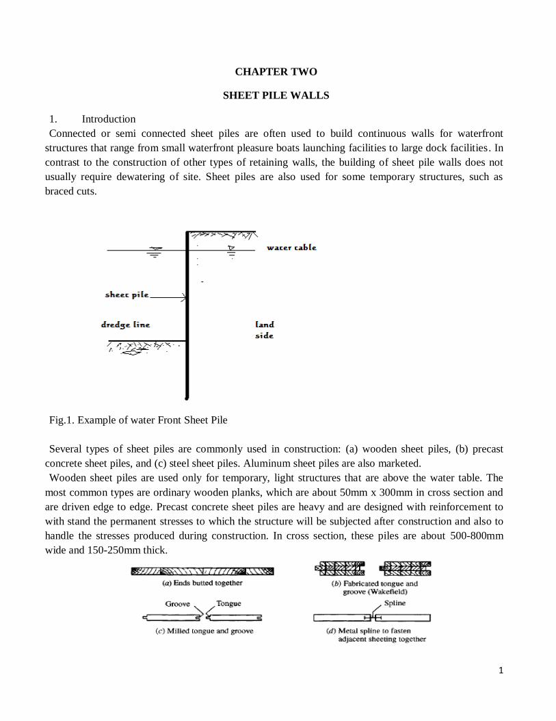
Connected or semi connected sheet piles are often used to build continuous walls for waterfront
structures that range from small waterfront pleasure boats launching facilities to large dock facilities. In
contrast to the construction of other types of retaining walls, the building of sheet pile walls does not
usually require dewatering of site. Sheet piles are also used for some temporary structures, such as
braced cuts.
Fig.1. Example of water Front Sheet Pile
Several types of sheet piles are commonly used in construction: (a) wooden sheet piles, (b) precast
concrete sheet piles, and (c) steel sheet piles. Aluminum sheet piles are also marketed.
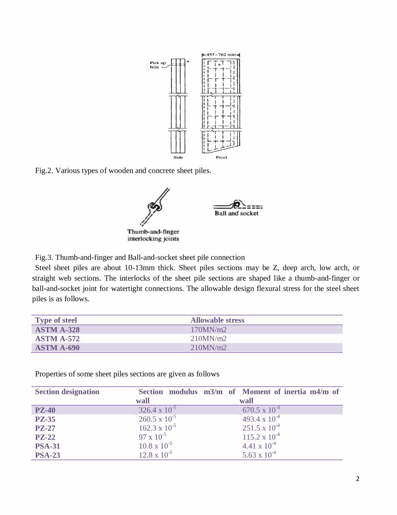
Wooden sheet piles are used only for temporary, light structures that are above the water table. The
most common types are ordinary wooden planks, which are about 50mm x 300mm in cross section and
are driven edge to edge. Precast concrete sheet piles are heavy and are designed with reinforcement to
with stand the permanent stresses to which the structure will be subjected after construction and also to
handle the stresses produced during construction. In cross section, these piles are about 500-800mm
wide and 150-250mm thick.
2
Fig.2. Various types of wooden and concrete sheet piles.
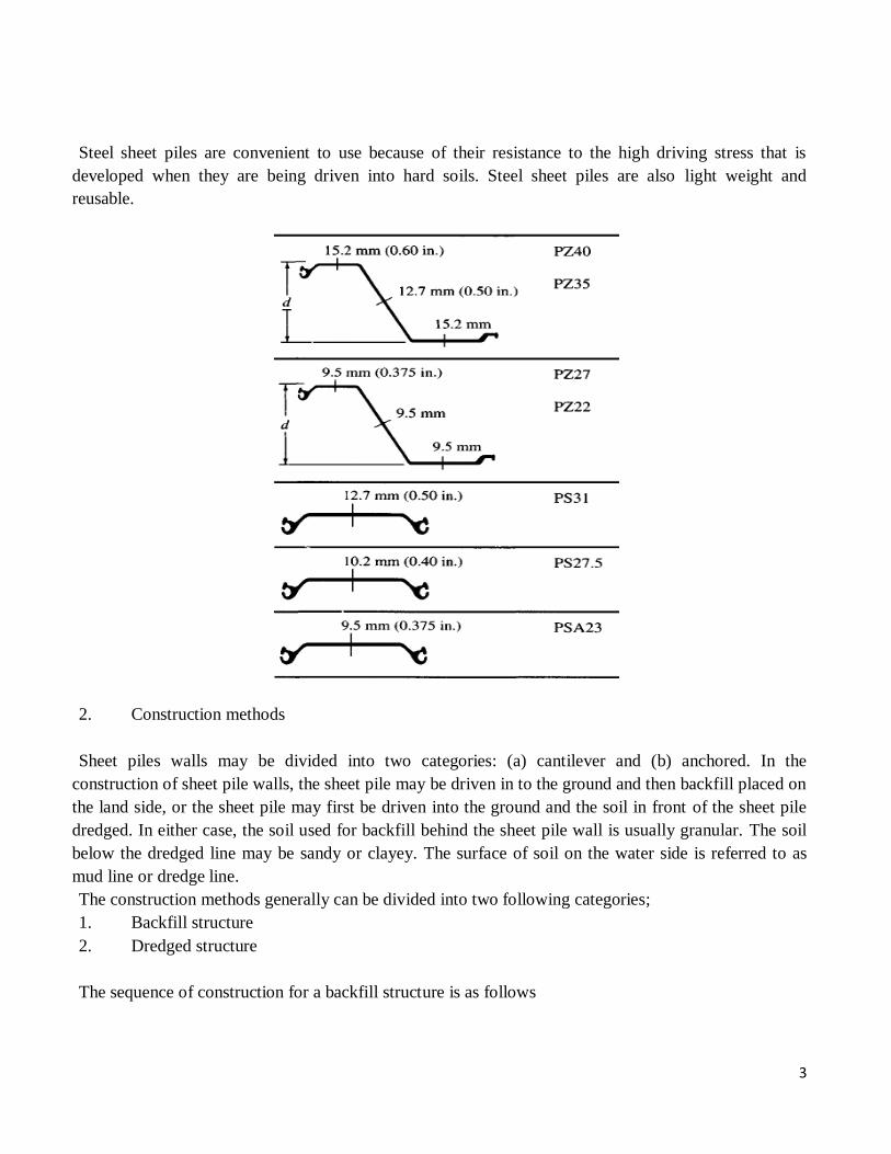
Fig.3. Thumb-and-finger and Ball-and-socket sheet pile connection
Steel sheet piles are about 10-13mm thick. Sheet piles sections may be Z, deep arch, low arch, or
straight web sections. The interlocks of the sheet pile sections are shaped like a thumb-and-finger or
ball-and-socket joint for watertight connections. The allowable design flexural stress for the steel sheet
piles is as follows.
Type of steel Allowable stress
ASTM A-328 170MN/m2
ASTM A-572 210MN/m2
ASTM A-690 210MN/m2
Properties of some sheet piles sections are given as follows
Section designation Section modulus m3/m of
wall
Moment of inertia m4/m of
wall
PZ-40 326.4 x 10⁻⁵
670.5 x 10⁻⁴
PZ-35
PZ-27
PZ-22
PSA-31
PSA-23
260.5 x 10⁻⁵
162.3 x 10⁻⁵
97 x 10-5
10.8 x 10⁻⁵
12.8 x 10⁻⁵
493.4 x 10⁻⁴
251.5 x 10⁻⁴
115.2 x 10⁻⁴
4.41 x 10⁻⁴
5.63 x 10⁻⁴
3
Steel sheet piles are convenient to use because of their resistance to the high driving stress that is
developed when they are being driven into hard soils. Steel sheet piles are also light weight and
reusable.
2. Construction methods
Sheet piles walls may be divided into two categories: (a) cantilever and (b) anchored. In the
construction of sheet pile walls, the sheet pile may be driven in to the ground and then backfill placed on
the land side, or the sheet pile may first be driven into the ground and the soil in front of the sheet pile
dredged. In either case, the soil used for backfill behind the sheet pile wall is usually granular. The soil
below the dredged line may be sandy or clayey. The surface of soil on the water side is referred to as
mud line or dredge line.
The construction methods generally can be divided into two following categories;
1. Backfill structure
2. Dredged structure
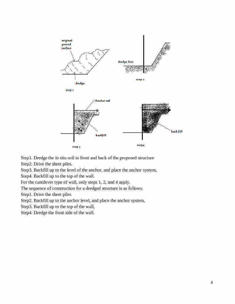
The sequence of construction for a backfill structure is as follows
4
Step1. Dredge the in situ soil in front and back of the proposed structure
Step2. Drive the sheet piles.
Step3. Backfill up to the level of the anchor, and place the anchor system,
Step4. Backfill up to the top of the wall.
For the cantilever type of wall, only steps 1, 2, and 4 apply.
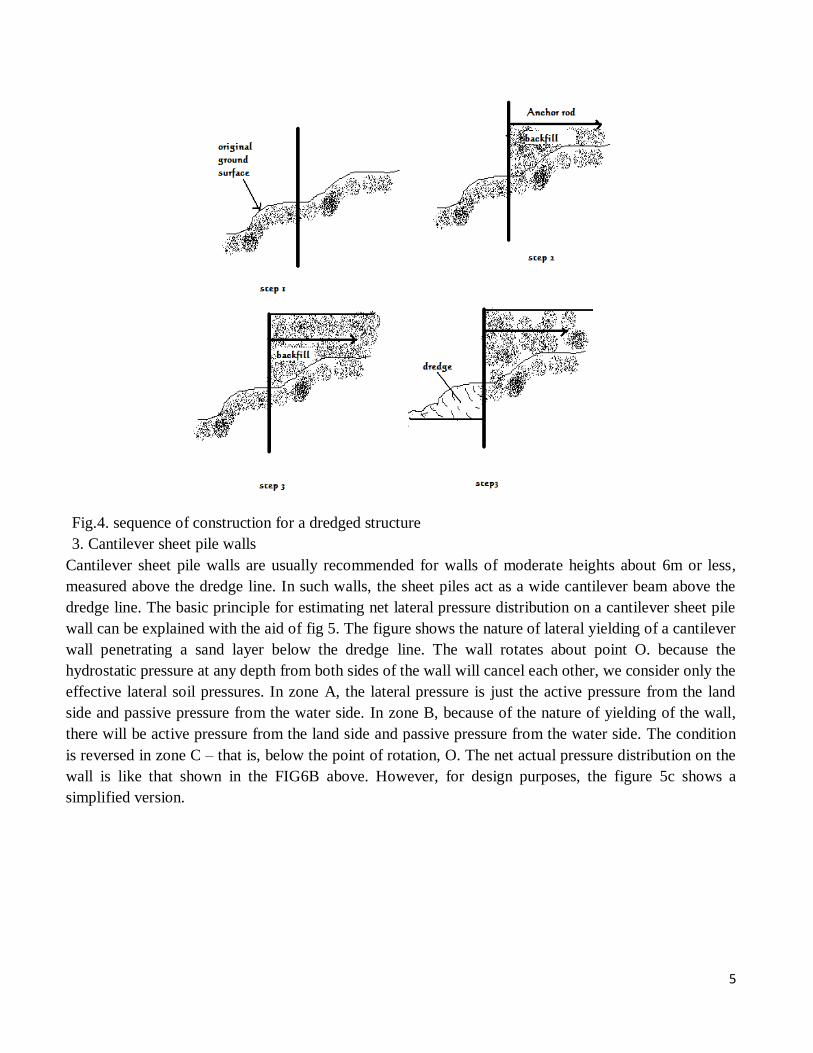
The sequence of construction for a dredged structure is as follows.
Step1. Drive the sheet piles
Step2. Backfill up to the anchor level, and place the anchor system,
Step3. Backfill up to the top of the wall,
Step4. Dredge the front side of the wall.
5
Fig.4. sequence of construction for a dredged structure
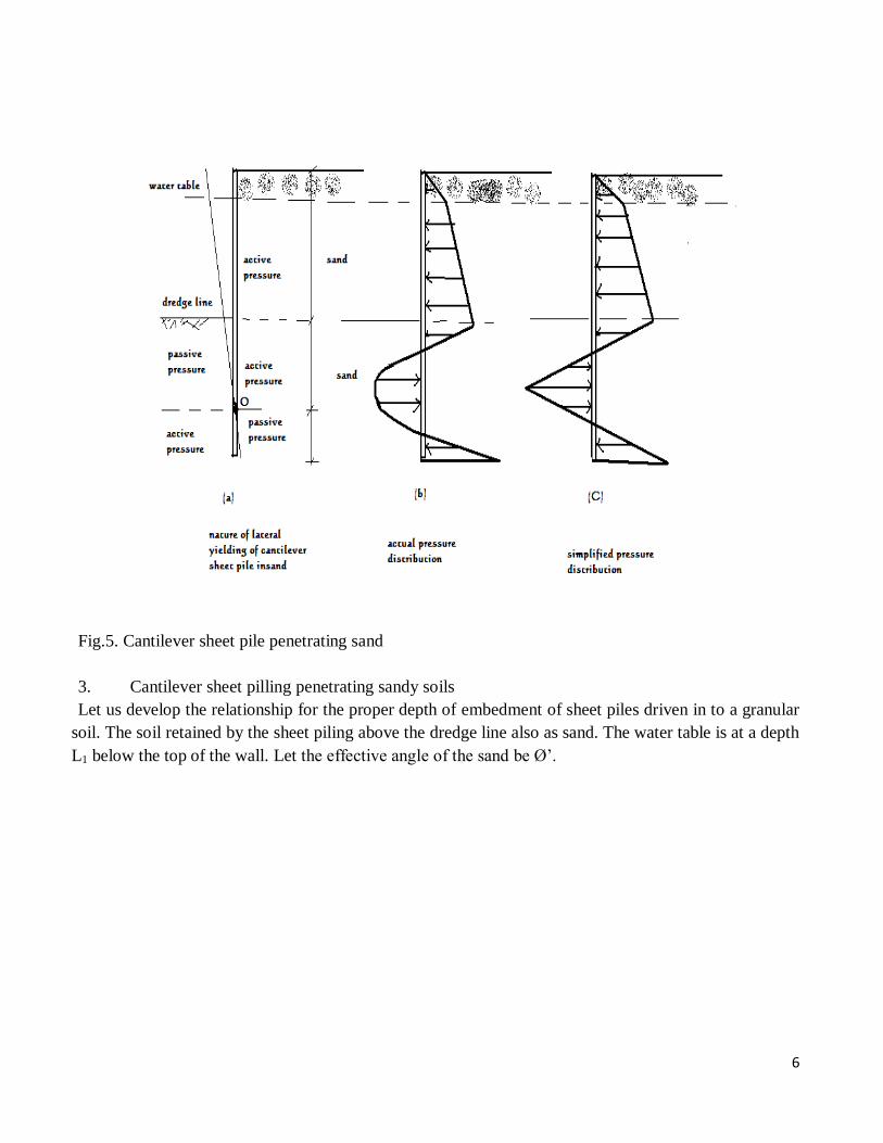
3. Cantilever sheet pile walls
Cantilever sheet pile walls are usually recommended for walls of moderate heights about 6m or less,
measured above the dredge line. In such walls, the sheet piles act as a wide cantilever beam above the
dredge line. The basic principle for estimating net lateral pressure distribution on a cantilever sheet pile
wall can be explained with the aid of fig 5. The figure shows the nature of lateral yielding of a cantilever
wall penetrating a sand layer below the dredge line. The wall rotates about point O. because the
hydrostatic pressure at any depth from both sides of the wall will cancel each other, we consider only the
effective lateral soil pressures. In zone A, the lateral pressure is just the active pressure from the land
side and passive pressure from the water side. In zone B, because of the nature of yielding of the wall,
there will be active pressure from the land side and passive pressure from the water side. The condition
is reversed in zone C – that is, below the point of rotation, O. The net actual pressure distribution on the
wall is like that shown in the FIG6B above. However, for design purposes, the figure 5c shows a
simplified version.
6
Fig.5. Cantilever sheet pile penetrating sand
3. Cantilever sheet pilling penetrating sandy soils
Let us develop the relationship for the proper depth of embedment of sheet piles driven in to a granular
soil. The soil retained by the sheet piling above the dredge line also as sand. The water table is at a depth
L1 below the top of the wall. Let the effective angle of the sand be Ø’.
7
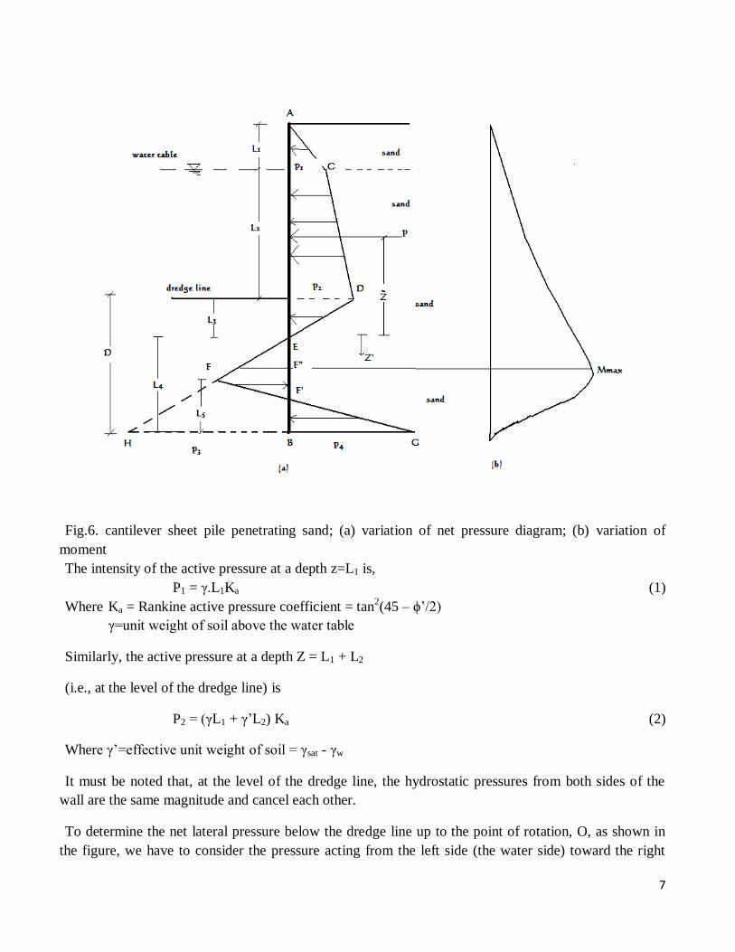
Fig.6. cantilever sheet pile penetrating sand; (a) variation of net pressure diagram; (b) variation of
moment
The intensity of the active pressure at a depth z=L1 is,
P1 = γ.L1Ka (1)
Where Ka = Rankine active pressure coefficient = tan2(45 – ϕ’/2)
γ=unit weight of soil above the water table
Similarly, the active pressure at a depth Z = L1 + L2
(i.e., at the level of the dredge line) is
P2 = (γL1 + γ’L2) Ka (2)
Where γ’=effective unit weight of soil = γsat - γw
It must be noted that, at the level of the dredge line, the hydrostatic pressures from both sides of the
wall are the same magnitude and cancel each other.
To determine the net lateral pressure below the dredge line up to the point of rotation, O, as shown in
the figure, we have to consider the pressure acting from the left side (the water side) toward the right
8
side (the land side) of the wall and also the active pressure acting from the right side toward the left side
of the wall, for such cases, ignoring the hydrostatic pressure from both sides of the wall, the active
pressure at depth Z is,
Pa = (γL1 + γ’L2 + γ’(Z - L1 - L2)) Ka (3)
Also, the passive pressure at depth Z is
Pp = γ’(Z - L1 - L2) Kp (4)
Where Kp = Rankine passive pressure coefficient = tan2(45 + ϕ’/2)
Combining eqs 3 and 4 yields the net lateral earth pressure, namely,
P = Pa – Pp = (γL1 + γ’L2)Ka - γ’(Z - L1 - L2)(KP - Ka) (5)
= P2 - γ’(Z - L)(KP - Ka) where L = L1 + L2
The net pressure, P equals zero at a depth L3 below the dredge line, so
P2 - γ’(Z - L)(KP - Ka) = 0
Or
(Z - L) = L3 = P2/ γ’(KP - Ka) (6)
Equation 6 indicates that the slope of the net pressure distribution line DEF is 1 vertical to γ’(KP - Ka)
horizontal, so, in the pressure diagram,
HB = P3 = L4 γ’(KP - Ka) (7)
At the bottom of the sheet pile, passive pressure, Pp, acts from the right toward the left side, and active
pressure acts from the left toward the right of the sheet pile, so at Z = L + D
Pp = (γL1 + γ’L2 + γ’D) Kp (8)
At the same depth,
Pa = γ’D Ka (9)
Hence, the net lateral pressure at the bottom of the sheet pile is,
Pp – Pa =P4 = (γL1 + γ’L2)Kp + γ’D(KP - Ka)
= (γL1 + γ’L2)KP + γ’L3(KP - Ka) + γ’L4(KP - Ka)
=P5 + γ’L4(KP - Ka) (10)
Where
9
P5 = (γL1 + γ’L2)KP + γ’L3(KP - Ka) (11)
D = L3 + L4 (12)
For the stability of the wall, the principles of statics can now be applied;
∑FH = 0 ∑MB = 0
For the summation of horizontal forces, we have
Area of the pressure diagram ACDE – area of EFHB + area of FHBG = 0
Or, P-P3L4/2 +L5(P3 + P4)/2 = 0 (13)
Where P = area of pressure diagram ACDE
Summing the moment of all the forces about point B yields
P(L4 + Ž) – (L4.P3/2)(L4/3) + L5/2 (P3 + P4)(L5/3) = 0 (14)
From eq. 13
L5 = (P3L4 – 2P)/ (P3 + P4) (15)
Combining eqs. 7, 10, 14, and 15 and simplifying them further, we obtain the following fourth – degree
equation in terms of L4
L4 (16)
In this equation,
A1 = (17)
A2 = (18)
A3 = (19)
A4 = (20)
Step by step procedure for obtaining the pressure diagram
Based on the preceding theory, a step-by-step procedure for obtaining the pressure diagram for a
cantilever sheet pile wall penetrating a granular soil is as follows
1. Calculate Ka and Kp
10
2. Calculate P1 and P2 (Note that L1 and L2 are given)
3. Calculate L3
4. Calculate P.
5. Calculate Ž (i.e., center of pressure for the area ACDE) by taking the moment about E
6. Calculate P5.
7. Calculate A1,A2,A3,and A4
8. Solve eq. 16 by trial and error to determine L4
9. Calculate P4
10. Calculate P3
11. Obtain L5
12. Draw a pressure distribution diagram.
13. Obtain the theoretical depth of penetration as L3 + L4 .The actual depth of penetration is
increased by about 20 – 30%
It may be noted that some designers prefer to use a factor of safety on the passive earth pressure earth
pressure coefficient at the beginning. In that case, in step1,
Kp(design) =
Where F.S = factor of safety (usually between 1.5 and 2)
For this type of analysis, follow steps 1-12 with the values of Ka = tan2(45 – ϕ’/2) and KP(design). The
actual depth of penetration can be determined by adding L3, obtain from step 3, and L4, obtained from
step8.
Calculation of Maximum Bending Moment:
The nature of the variation of the moment diagram for a cantilever sheet pile wall is shown in the figure
given above. The maximum moment will occur between point E and F’. Obtaining the maximum
moment (Mmax) per unit length of the wall requires determining the point of zero shear. For a new axis
z’(with origin at point E) for zero shear,
P =
Or
Z’ = (21)
Once the point of zero shear force is determined (point F’’ in the fig), the magnitude of the maximum
moment can be obtained as
Mmax = P(Ž + Z’) – (22)
11
The necessary profile of the sheet piling is then according to the allowable stress of the sheet pile
material, or
S = (23)
Where S = section modulus of the sheet pile required per unit length of the structure
σallow = allowable flexural stress of the sheet pile.
Example 1
A cantilever sheet pile wall penetrating a granular soil. Here, L1 = 2m, L2 = 3m, γsat = 19.33KN/ m3, γ
= 15.9KN/m3, and ϕ’ = 32
0
a. What is the theoretical depth of embedment, D?
b. For a 30% increase in D, what should be the total length of the sheet piles?
c. What should be the minimum section modulus of the sheet piles? Use σallow = 172MN/m2
4. Cantilever sheet piling penetrating clay
At times, cantilever sheet pile must be driven into a clay layer possessing an undrained cohesion C (ϕ’
= 0). The net pressure diagram will be somewhat different from that discussed for sheet pile for sand.
Figure below shows a cantilever sheet pile wall driven into clay with a backfill of granular soil above the
level of the wall. The diagram for net pressure distribution below the dredge line can now be determined
as follows.
12
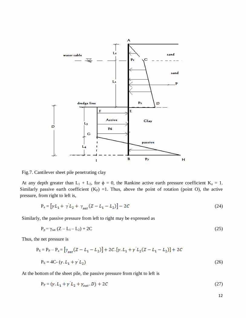
Fig.7. Cantilever sheet pile penetrating clay
At any depth greater than L1 + L2, for ϕ = 0, the Rankine active earth pressure coefficient Ka = 1.
Similarly passive earth coefficient (KP) =1. Thus, above the point of rotation (point O), the active
pressure, from right to left is,
Pa = (24)
Similarly, the passive pressure from left to right may be expressed as
Pp = γsat (Z – L1 – L2) + 2C (25)
Thus, the net pressure is
P6 = PP – Pa =
P6 = 4C- ( (26)
At the bottom of the sheet pile, the passive pressure from right to left is
PP = ( (27)
13
Similarly, the active pressure from left to right is
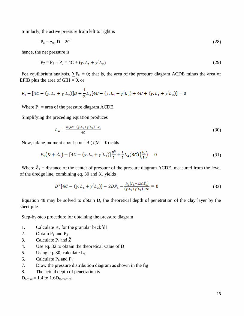
Pa = γsat.D – 2C (28)
hence, the net pressure is
P7 = PP – Pa = 4C + ( (29)
For equilibrium analysis, ∑FH = 0; that is, the area of the pressure diagram ACDE minus the area of
EFIB plus the area of GIH = 0, or
Where P1 = area of the pressure diagram ACDE.
Simplifying the preceding equation produces
(30)
Now, taking moment about point B (∑M = 0) ields
(31)
Where Ž1 = distance of the center of pressure of the pressure diagram ACDE, measured from the level
of the dredge line, combining eq. 30 and 31 yields
(32)
Equation 48 may be solved to obtain D, the theoretical depth of penetration of the clay layer by the
sheet pile.
Step-by-step procedure for obtaining the pressure diagram
1. Calculate Ka for the granular backfill
2. Obtain P1 and P2
3. Calculate P1 and Ž
4. Use eq. 32 to obtain the theoretical value of D
5. Using eq. 30, calculate L4
6. Calculate P6 and P7
7. Draw the pressure distribution diagram as shown in the fig
8. The actual depth of penetration is
Dactual = 1.4 to 1.6Dtheoretical
14
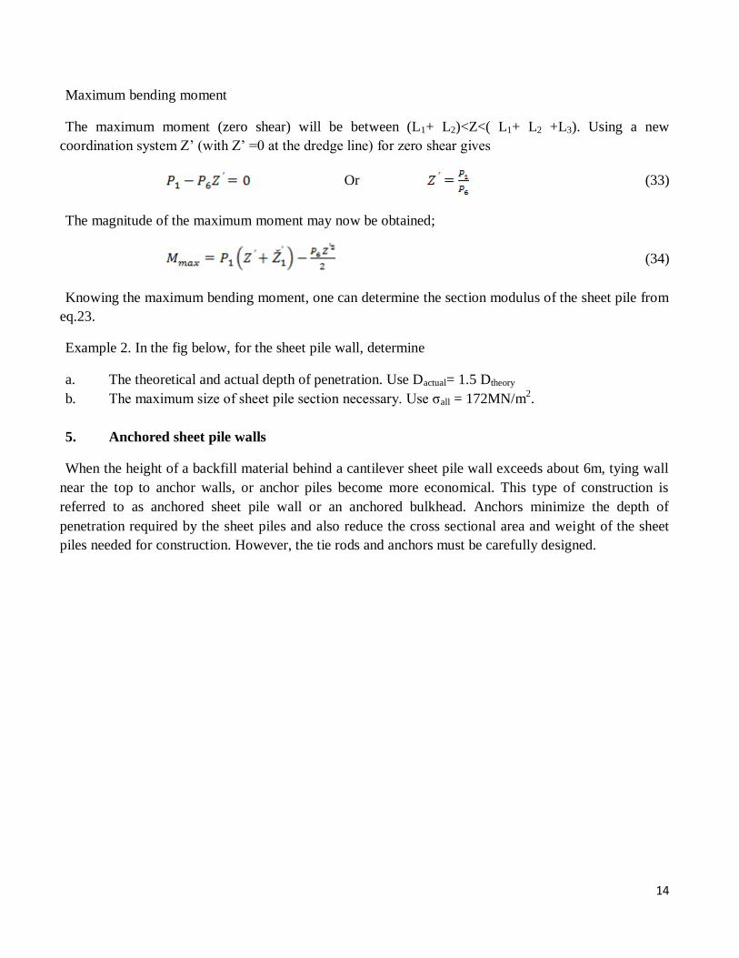
Maximum bending moment
The maximum moment (zero shear) will be between (L1+ L2)<Z<( L1+ L2 +L3). Using a new
coordination system Z’ (with Z’ =0 at the dredge line) for zero shear gives
Or (33)
The magnitude of the maximum moment may now be obtained;
(34)
Knowing the maximum bending moment, one can determine the section modulus of the sheet pile from
eq.23.
Example 2. In the fig below, for the sheet pile wall, determine
a. The theoretical and actual depth of penetration. Use Dactual= 1.5 Dtheory
b. The maximum size of sheet pile section necessary. Use σall = 172MN/m2.
5. Anchored sheet pile walls
When the height of a backfill material behind a cantilever sheet pile wall exceeds about 6m, tying wall
near the top to anchor walls, or anchor piles become more economical. This type of construction is
referred to as anchored sheet pile wall or an anchored bulkhead. Anchors minimize the depth of
penetration required by the sheet piles and also reduce the cross sectional area and weight of the sheet
piles needed for construction. However, the tie rods and anchors must be carefully designed.
15
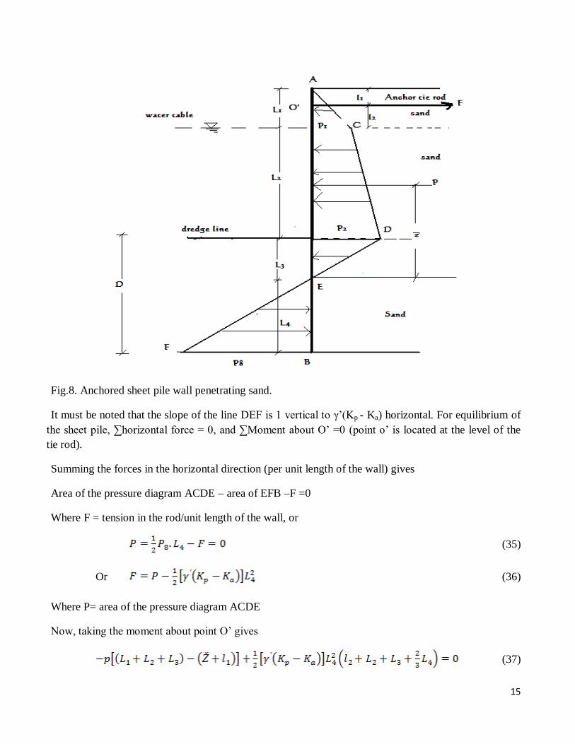
Fig.8. Anchored sheet pile wall penetrating sand.
It must be noted that the slope of the line DEF is 1 vertical to γ’(Kp - Ka) horizontal. For equilibrium of
the sheet pile, ∑horizontal force = 0, and ∑Moment about O’ =0 (point o’ is located at the level of the
tie rod).
Summing the forces in the horizontal direction (per unit length of the wall) gives
Area of the pressure diagram ACDE – area of EFB –F =0
Where F = tension in the rod/unit length of the wall, or
(35)
Or (36)
Where P= area of the pressure diagram ACDE
Now, taking the moment about point O’ gives
(37)
16
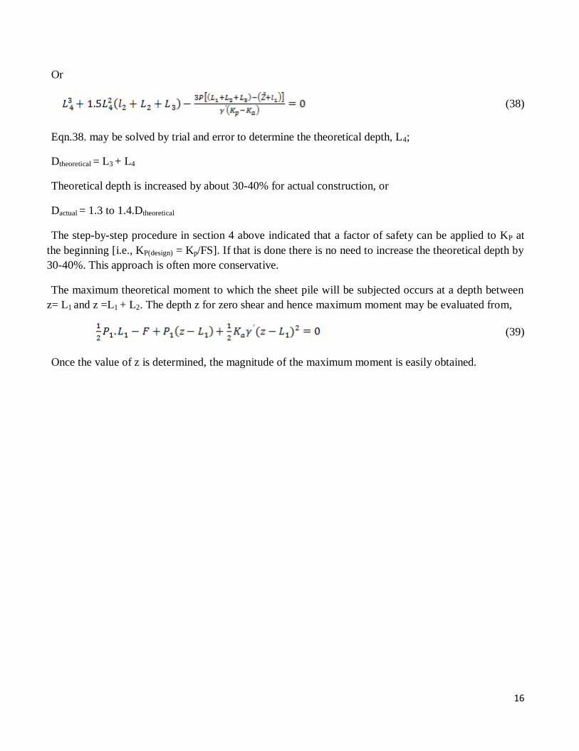
Or
(38)
Eqn.38. may be solved by trial and error to determine the theoretical depth, L4;
Dtheoretical = L3 + L4
Theoretical depth is increased by about 30-40% for actual construction, or
Dactual = 1.3 to 1.4.Dtheoretical
The step-by-step procedure in section 4 above indicated that a factor of safety can be applied to KP at
the beginning [i.e., KP(design) = Kp/FS]. If that is done there is no need to increase the theoretical depth by
30-40%. This approach is often more conservative.
The maximum theoretical moment to which the sheet pile will be subjected occurs at a depth between
z= L1 and z =L1 + L2. The depth z for zero shear and hence maximum moment may be evaluated from,
(39)
Once the value of z is determined, the magnitude of the maximum moment is easily obtained.
Related Documents