Aalborg Universitet Vertical Equilibrium of Sheet Pile Walls with Emphasis on Toe Capacity and Plugging Iversen, Kirsten Malte; Augustesen, Anders Hust; Nielsen, Benjaminn Nordahl Publication date: 2010 Document Version Publisher's PDF, also known as Version of record Link to publication from Aalborg University Citation for published version (APA): Iversen, K. M., Augustesen, A. H., & Nielsen, B. N. (2010). Vertical Equilibrium of Sheet Pile Walls with Emphasis on Toe Capacity and Plugging. Aalborg: Department of Civil Engineering, Aalborg University. DCE Technical Reports, No. 94 General rights Copyright and moral rights for the publications made accessible in the public portal are retained by the authors and/or other copyright owners and it is a condition of accessing publications that users recognise and abide by the legal requirements associated with these rights. ? Users may download and print one copy of any publication from the public portal for the purpose of private study or research. ? You may not further distribute the material or use it for any profit-making activity or commercial gain ? You may freely distribute the URL identifying the publication in the public portal ? Take down policy If you believe that this document breaches copyright please contact us at [email protected] providing details, and we will remove access to the work immediately and investigate your claim. Downloaded from vbn.aau.dk on: juni 15, 2018

Welcome message from author
This document is posted to help you gain knowledge. Please leave a comment to let me know what you think about it! Share it to your friends and learn new things together.
Transcript
Aalborg Universitet
Vertical Equilibrium of Sheet Pile Walls with Emphasis on Toe Capacity and Plugging
Iversen, Kirsten Malte; Augustesen, Anders Hust; Nielsen, Benjaminn Nordahl
Publication date:2010
Document VersionPublisher's PDF, also known as Version of record
Link to publication from Aalborg University
Citation for published version (APA):Iversen, K. M., Augustesen, A. H., & Nielsen, B. N. (2010). Vertical Equilibrium of Sheet Pile Walls withEmphasis on Toe Capacity and Plugging. Aalborg: Department of Civil Engineering, Aalborg University. DCETechnical Reports, No. 94
General rightsCopyright and moral rights for the publications made accessible in the public portal are retained by the authors and/or other copyright ownersand it is a condition of accessing publications that users recognise and abide by the legal requirements associated with these rights.
? Users may download and print one copy of any publication from the public portal for the purpose of private study or research. ? You may not further distribute the material or use it for any profit-making activity or commercial gain ? You may freely distribute the URL identifying the publication in the public portal ?
Take down policyIf you believe that this document breaches copyright please contact us at [email protected] providing details, and we will remove access tothe work immediately and investigate your claim.
Downloaded from vbn.aau.dk on: juni 15, 2018
ISSN 1901-726X DCE Technical Report No. 94
Vertical Equilibrium of Sheet PileWalls with Emphasis on Toe
Capacity and PluggingK. M. Iversen
A. H. AugustesenB. N. Nielsen
Department of Civil Engineering

DCE Technical Report No. 94
Vertical Equilibrium of Sheet Pile Walls with Emphasis on Toe Capacity and Plugging
by
K. M. Iversen A. H. Augustesen
B. N. Nielsen
June 2010
© Aalborg University
Aalborg UniversityDepartment of Civil Engineering
Division of Water and Soil
Scientific Publications at the Department of Civil Engineering
Technical Reports are published for timely dissemination of research results and scientific workcarried out at the Department of Civil Engineering (DCE) at Aalborg University. This mediumallows publication of more detailed explanations and results than typically allowed in scientificjournals.
Technical Memoranda are produced to enable the preliminary dissemination of scientific work bythe personnel of the DCE where such release is deemed to be appropriate. Documents of this kindmay be incomplete or temporary versions of papers—or part of continuing work. This should bekept in mind when references are given to publications of this kind.
Contract Reports are produced to report scientific work carried out under contract. Publications ofthis kind contain confidential matter and are reserved for the sponsors and the DCE. Therefore,Contract Reports are generally not available for public circulation.
Lecture Notes contain material produced by the lecturers at the DCE for educational purposes. Thismay be scientific notes, lecture books, example problems or manuals for laboratory work, orcomputer programs developed at the DCE.
Theses are monograms or collections of papers published to report the scientific work carried out atthe DCE to obtain a degree as either PhD or Doctor of Technology. The thesis is publicly availableafter the defence of the degree.
Latest News is published to enable rapid communication of information about scientific workcarried out at the DCE. This includes the status of research projects, developments in thelaboratories, information about collaborative work and recent research results.
Published 2010 by Aalborg University Department of Civil Engineering Sohngaardsholmsvej 57, DK-9000 Aalborg, Denmark
Printed in Aalborg at Aalborg University
ISSN 1901-726X DCE Technical Report No. 94

Vertical Equilibrium of Sheet Pile Walls with Emphasison Toe Capacity and Plugging
K. M. Iversen1, A. H. Augustesen2, B. N. Nielsen3
Aalborg University, June 2010
Abstract
Constructions including retaining walls are normally established in areas where it is im-
possible to conduct an excavation with inclined sides. Due to large excavation depths and
due to restrictions on the deformations of the wall, it is often necessary to anchor the wall.
The limited space makes it impossible to design the anchorage with anchor plates, and
the anchorage is therefore often designed as bored and injected soil anchors. Reasons for
design and establishment make it is necessary to construct these anchors with an inclination.
Inclining anchors imply that larger forces need to be transferred at the pile toe to fulfil vertical
equilibrium. The paper describes a case study of sheet pile walls in Aalborg Clay, and the
amount of loads transferred as point loads at the pile toe for free and anchored walls is
estimated. A parametric study is made for the free wall with regards to the height and the
roughness of the wall. Due to limitations of the calculation method, the study of the anchored
wall only includes variation of the roughness. For the case study, it is found that the vertical
equilibrium is fulfilled for the considered free wall. An anchored wall needs a plug forming at
the pile toe to fulfil the criterion of vertical equilibrium. However, the suggested theoretical
model shows that the extent of the plug is much smaller than needed.
1 Introduction
Retaining walls are typically established in ar-
eas where limited space, stability or ground
water conditions make it impossible to con-
duct the excavation with inclined sides. This
is often the case in the cities. Due to require-
ments on the deformations of constructions
nearby, it is often necessary to anchor these
walls. 1 2 3
The limited space condition frequently im-
plies that it is impossible to design the an-
chorage with anchor plates; there is simply no
available area to establish anchor plates in the
1Graduate Student, Dept. of Civil Engineering, Aal-
borg University, Denmark.2Specialist in Geotechnical Engineering, Ph.D.,
M.Sc., COWI A/S. Part-time lecturer, Dept. of Civil
Engineering, Aalborg University3Assistant Professor, M.Sc., Dept. of Civil Engi-
neering, Aalborg University, Denmark.
required distance from sheet pile wall. It is
therefore necessary to design the anchorage
as an injected soil anchor.
To achieve the necessary roughness of the
interface between soil and anchor, these are
injected with concrete after installation. Fur-
ther, they are often injected again one day af-
ter the first injection, inducing a more rough
interface between the soil and the anchor.
The grouting and the design of these an-
chorages normally make it necessary to in-
stall them with an inclination. This induces a
larger overburden pressure at the fixed length
of the anchor which increases the bearing ca-
pacity. Further, the inclination makes it easier
to place the anchors deep below existing con-
structions minimising the risk of damage of
neighbouring constructions.
If the anchors were established in a hor-
1
K. M. Iversen, A. H. Augustesen and B. N. Nielsen
izontal plane, this would complicate the in-
stallation of the anchor, as the concrete used
for injection would drift from the fixed zone
of the anchor into zone of the apparent free
length and even back into the excavation pit.
The total stability of the wall would not be en-
sured if the failure mechanism 7of the anchor
coincides with the likewise from the wall.
Designing sheet pile walls with inclined
anchors implies that larger vertical force is in-
troduced as a point load in the pile toe to fulfil
vertical equilibrium. The load, which can be
transferred through the cross section area of
pile toe, is small compared to the load needed
to be transferred to the soil. It is therefore in-
teresting to investigate whether the effective
area of a sheet pile toe can be assumed larger
than the cross section area of the steel. This is
the case if a plug forms inside the cross sec-
tion of the sheet pile wall.
Nowadays, vertical equilibrium of sheet
pile walls is often neglected or restricted to
investigations on whether the tip resistance is
negative, i.e. an upwards directed force is to
be transferred at the pile toe. An upward di-
rected force implies that a tension force be-
tween pile toe and the underlying soil oc-
curs, which the soil does not handle well and
the force cannot be transferred. However, a
downward directed force implies a compres-
sion force, which the soil is able to transfer.
According to Ovesen et al. (2007) and Har-
remoës et al. (2003) the vertical projection
is of minor importance when designing sheet
pile walls.
In Denmark sheet pile walls are mainly de-
signed using Brinch Hansen’s earth pressure
theory (Brinch Hansen, 1953). This theory
provides a formula to calculate the tangential
earth pressure acting on the wall and this for-
mula is generally applied. It is accepted that
upwards directed forces cannot be transferred
at the pile toe. However, there is not yet estab-
lished a practice for estimation of the transfer-
ral of a downwards directed force to the soil
if the steel area of the sheet pile wall cannot
provide sufficient bearing capacity.
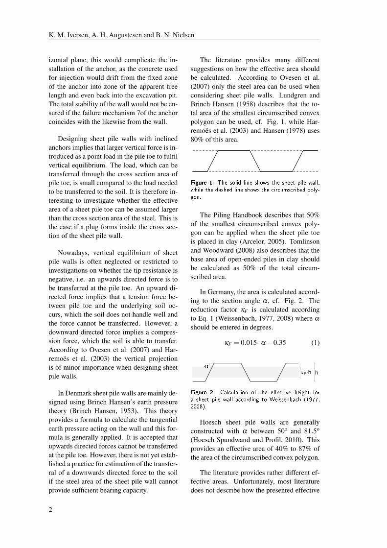
The literature provides many different
suggestions on how the effective area should
be calculated. According to Ovesen et al.
(2007) only the steel area can be used when
considering sheet pile walls. Lundgren and
Brinch Hansen (1958) describes that the to-
tal area of the smallest circumscribed convex
polygon can be used, cf. Fig. 1, while Har-
remoës et al. (2003) and Hansen (1978) uses
80% of this area.
������ �� ��� ����� ��� ���� ��� ����� ���� ������� ��� � ���� ��� ���� ��� ������������� ��������
The Piling Handbook describes that 50%
of the smallest circumscribed convex poly-
gon can be applied when the sheet pile toe
is placed in clay (Arcelor, 2005). Tomlinson
and Woodward (2008) also describes that the
base area of open-ended piles in clay should
be calculated as 50% of the total circum-
scribed area.
In Germany, the area is calculated accord-
ing to the section angle α , cf. Fig. 2. The
reduction factor κF is calculated according
to Eq. 1 (Weissenbach, 1977, 2008) where αshould be entered in degrees.
κF = 0.015 ·α−0.35 (1)
F·
������ � � ���� ��� �� ��� �������� ������ ��� ����� ���� �� ������� �� ������� �� ��� �!""#$�
Hoesch sheet pile walls are generally
constructed with α between 50o and 81.5o
(Hoesch Spundwand und Profil, 2010). This
provides an effective area of 40% to 87% of
the area of the circumscribed convex polygon.
The literature provides rather different ef-
fective areas. Unfortunately, most literature
does not describe how the presented effective
2

Vertical Equilibrium of Sheet Pile Walls with Emphasis on Toe Capacity and Plugging
����� �� ���� ���� ����� ��� ����� ����� �� �����
Author/editor Plug size of sheet pile wall Originates from Theory for
Ovesen et al. (2007) 0 % for steel sections Unknown Sheet pile walls
Lundgren and Brinch Hansen (1958) 100 % Unknown Sections of cast iron
Harremoës et al. (2003) 80 % Unknown Sheet pile walls
Hansen (1978) 80 % Unknown Sheet pile walls
Arcelor (2005) 50 % Unknown Piles
Tomlinson and Woodward (2008) 50 % Unknown Piles
Weissenbach (2008) 40 - 87.3 % Empicical data Sheet pile walls
Weissenbach (1997) 40 - 87.3 % Empicical data Sheet pile walls
areas are found, i.e. theoretical, numerical, or
based on empirical values, cf. Tab. 1. There-
fore, this paper theoretically investigates the
plugging effect based on theory described for
open-ended circular pipe piles.
Before the theoretical evaluation of plug-
ging, the magnitude of the forces at the pile
toe is investigated for both anchored and free
sheet pile walls. According to EN1997-
1, a sheet pile wall has no roughness in
the soil-to-steel interface which implies that
the tangential earth pressure is equal to zero
in the undrained state (European Committee
for Standardization, 2007). However, in the
drained state the roughness is normally ad-
justed so the criterion of vertical equilibrium
is fulfilled. Plugging is therefore investigated
in the drained state.
Aalborg Clay is used as a medium for
the investigations in this paper. The strength
of Aalborg Clay is defined by Iversen et al.
(2010), and summarised in Tab. 2.
2 Magnitude of Point Load atPile Toe
Before investigating the plugging effect, the
necessity of plugs formed in the toe of sheet
pile walls is documented in the studied case
in Aalborg Clay.
The excavation depth h2 is 5m and 12mfor the free and the anchored sheet pile wall,
respectively, cf. Fig. 3. The water level is
placed at excavation level on the front side,
����� �� �������� ������ ���� �������� �������� �� ��� ����� �
Characteristic value Design value
ϕ ′ [o] 28.1 24.0
c′ [kPa] 13.0 10.8
cu [kPa] 0.446 ·σ ′v( σ ′pc
σ ′v
)0.72NA
cu,average [kPa] 100.8 56
and at surface level on the back side, marked
by the dashed line in the figure. The design
value of the surface load is 20kN/m2 and it
is placed on the back side. In the anchored
model the anchor is placed 2m below exca-
vation level and the anchor is inclined 20o to
horizontal.
Point loads in the wall at the pile toe acting
upwards are considered negative.
h2
2 m
h
qd = 20 kN/m2
20°
Aalborg Claysat = 20 kN/m3
�� � �� �!���� ��� ��"���� ���� ���� �����#������ ��� �������� �$��������" ����� ��� ������
The tangential earth pressure F is calcu-
lated according to Eq. 2, which theoretically
connects the earth pressure to the movements
3
K. M. Iversen, A. H. Augustesen and B. N. Nielsen
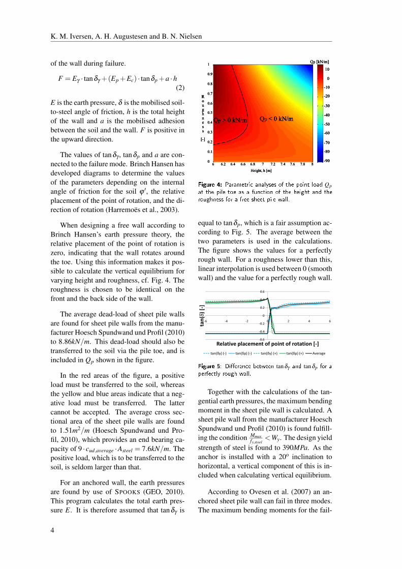
of the wall during failure.
F = Eγ · tanδγ +(Ep +Ec) · tanδp +a ·h(2)
E is the earth pressure, δ is the mobilised soil-
to-steel angle of friction, h is the total height
of the wall and a is the mobilised adhesion
between the soil and the wall. F is positive in
the upward direction.
The values of tanδγ , tanδp and a are con-
nected to the failure mode. Brinch Hansen has
developed diagrams to determine the values
of the parameters depending on the internal
angle of friction for the soil ϕ ′, the relative
placement of the point of rotation, and the di-
rection of rotation (Harremoës et al., 2003).
When designing a free wall according to
Brinch Hansen’s earth pressure theory, the
relative placement of the point of rotation is
zero, indicating that the wall rotates around
the toe. Using this information makes it pos-
sible to calculate the vertical equilibrium for
varying height and roughness, cf. Fig. 4. The
roughness is chosen to be identical on the
front and the back side of the wall.
The average dead-load of sheet pile walls
are found for sheet pile walls from the manu-
facturer Hoesch Spundwand und Profil (2010)
to 8.86kN/m. This dead-load should also be
transferred to the soil via the pile toe, and is
included in Qp shown in the figure.
In the red areas of the figure, a positive
load must be transferred to the soil, whereas
the yellow and blue areas indicate that a neg-
ative load must be transferred. The latter
cannot be accepted. The average cross sec-
tional area of the sheet pile walls are found
to 1.51m2/m (Hoesch Spundwand und Pro-
fil, 2010), which provides an end bearing ca-
pacity of 9 ·cud,average ·Asteel = 7.6kN/m. The
positive load, which is to be transferred to the
soil, is seldom larger than that.
For an anchored wall, the earth pressures
are found by use of SPOOKS (GEO, 2010).
This program calculates the total earth pres-
sure E. It is therefore assumed that tanδγ is
������ �� ���������� ������ � ��� � �� �� Qp�� ��� ��� � � �� � ����� � ��� ������ �� ���
� ������ � � � ���� ����� ��� ���
equal to tanδp, which is a fair assumption ac-
cording to Fig. 5. The average between the
two parameters is used in the calculations.
The figure shows the values for a perfectly
rough wall. For a roughness lower than this,
linear interpolation is used between 0 (smooth
wall) and the value for a perfectly rough wall.
�0.2
0
0.2
0.4
0.6
�6 �4 �2 0 2 4 6
tan(��)�[�]
�0.6
�0.4
�0.2
0
0.2
0.4
0.6
�6 �4 �2 0 2 4 6
tan(�)�[�]
Relative�placement�of�point�of�rotation�[�]
tan(��)�(�) tan(�p)�(�) tan(��)�(+) tan(�p)�(+) Average
������ �� ��������� ����� tanδγ ��� tanδp �� �
��� ���� ����� ����
Together with the calculations of the tan-
gential earth pressures, the maximum bending
moment in the sheet pile wall is calculated. A
sheet pile wall from the manufacturer Hoesch
Spundwand und Profil (2010) is found fulfill-
ing the condition Mmaxfy,steel
<Wy. The design yield
strength of steel is found to 390MPa. As the
anchor is installed with a 20o inclination to
horizontal, a vertical component of this is in-
cluded when calculating vertical equilibrium.
According to Ovesen et al. (2007) an an-
chored sheet pile wall can fail in three modes.
The maximum bending moments for the fail-
4

Vertical Equilibrium of Sheet Pile Walls with Emphasis on Toe Capacity and Plugging
200
�100
0
100
200
300
0 0.1 0.2 0.3 0.4 0.5 0.6 0.7 0.8 0.9 1
Force�[kN/m
]
�300
�200
�100
0
100
200
300
0 0.1 0.2 0.3 0.4 0.5 0.6 0.7 0.8 0.9 1
Force�[kN/m
]
Roughness�[�]
Qp�(1FC) Rb�(1FC) Rb�incl�plug�(1FC) Qp�(2FC) Rb�(2FC) Rb�incl�plug�(2FC)
������ �� ���������� ������ ��� � ������ � ��� ��� ����� ��� ��� Qp �� ��� � ��� ����� � ��
���������� � ��� � � � ��� ������� ����������� Rb �� Rb ��� ��� �� ��� ���� ��������� � ��� ���� ��
��� ������ ����� ������������
��� � ��������� ����� � ��� � ��� ��� ������� ���������� ������ � � ��� ���� ����� � ��� �� ����
Roughness 0.2 0.3 0.4 0.5 0.6 0.7 0.8 0.9 1.0
Section height, hwall (1FC) [mm] 485 485 485 485 440 440 440
Plug size (1FC) [mm] 485.0 436.5 402.6 368.6 330.0 294.8 250.8
Relative plug size (1FC) 100% 90 % 83 % 76 % 75 % 67 % 57 %
Section height, hwall (2FC) [mm] 485 485 440 350
Plug size (2FC) [mm] 417.1 286.2 171.6 31.5
Relative plug size (2FC) 86 % 59 % 39 % 9 %
ure mode without any yield hinges (0FC) are
very high, and it has not been possible to
find sheet pile walls with sufficient moment
of resistance. For the failure modes with one
(1FC) and two (2FC) yield hinges the rough-
ness of the wall must be larger than 0.4 and
0.2, respectively, to find sheet pile walls with
sufficient moments of resistance. A para-
metric analysis of the roughness of anchored
sheet pile walls can be seen in Fig. 6.
The bearing capacity calculated over the
steel area is never enough to ensure verti-
cal equilibrium for the 1FC failure mode, cf.
Fig. 6. To fulfil the vertical equilibrium it is
necessary to assume that a plug forms in the
pile toe. The size of the plug needed to fulfil
equilibrium in per cent and millimetre is seen
in Tab. 3. Further, the section height of the
chosen profile is noted.
For the 2FC failure mode Qp becomes
negative when the roughness is 0.6 and larger.
This load cannot be transferred to the soil. To
fulfil the criterion of vertical equilibrium it is
necessary to assume that the roughness is be-
low 0.5. The size of the plug needed to fulfil
vertical equilibrium can be seen in Tab. 3.
In the present case, plugging is of great
importance to be able to fulfil the vertical
equilibrium equation. Especially when the
1FC failure mode is used, large forces need
to be transferred through the sheet pile toe. In
the following section, a theoretical approach
to the plugging phenomenon is taken.
3 Theoretical Expression forPlugging
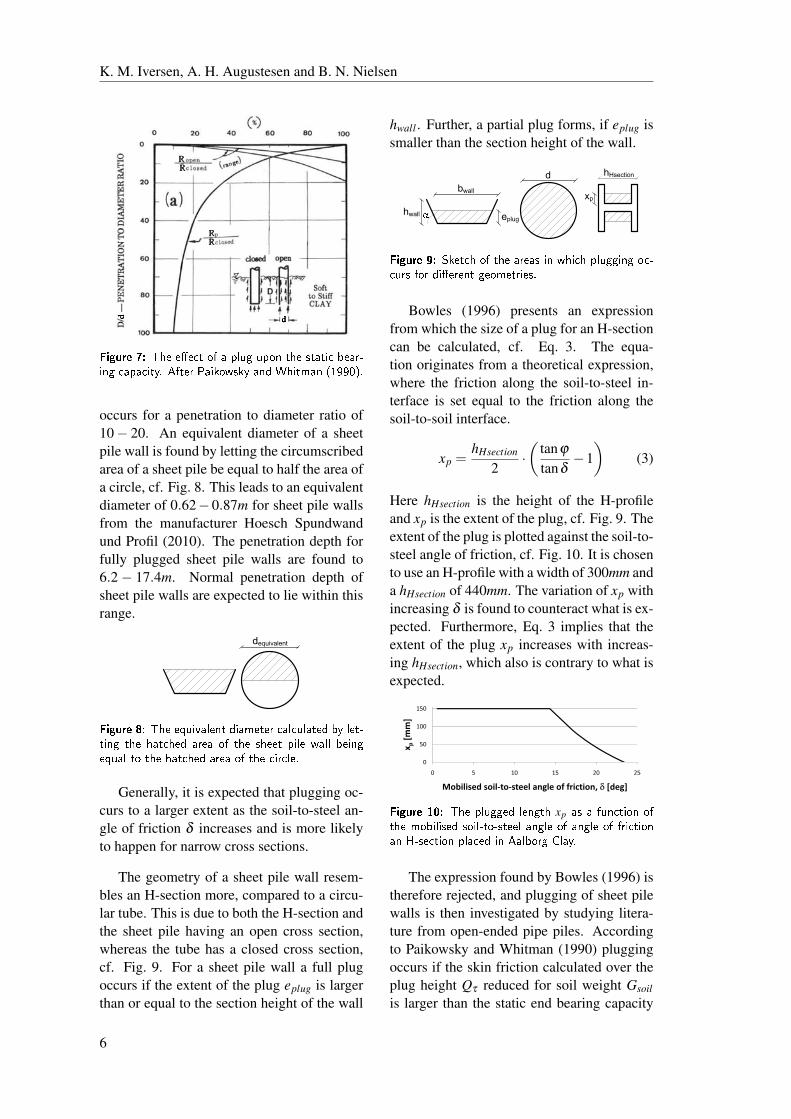
The plugging phenomenon is investigated by
Paikowsky and Whitman (1990) for open-
ended pipe piles. They have plotted the ra-
tio of the static end bearing capacity Rp to the
total bearing capacity of a closed-ended pipe
pile against the penetration depth D to the di-
ameter d ratio, cf. Fig. 7. This curve indicates
that for high ratios of the penetration to diam-
eter ratio the end bearing capacity is of minor
importance of the total bearing capacity.
Further, they have plotted the ratio of the
static bearing capacity of an open-ended pipe
Ropen to the bearing capacity of a closed-
ended pipe Rclosed . It is found that a full plug
5
K. M. Iversen, A. H. Augustesen and B. N. Nielsen
������ �� ��� ����� �� �� ��� ��� ����� ������ ������ ����� �������� �� ������ ���� !�
occurs for a penetration to diameter ratio of
10− 20. An equivalent diameter of a sheet
pile wall is found by letting the circumscribed
area of a sheet pile be equal to half the area of
a circle, cf. Fig. 8. This leads to an equivalent
diameter of 0.62−0.87m for sheet pile walls
from the manufacturer Hoesch Spundwand
und Profil (2010). The penetration depth for
fully plugged sheet pile walls are found to
6.2− 17.4m. Normal penetration depth of
sheet pile walls are expected to lie within this
range.
equivalent
������ � ��� �"��#���� ������� �������� �� ������� ��� ������ �� �� ��� ����� ��� ��� ���� �"�� �� ��� ������ �� �� ��� �������
Generally, it is expected that plugging oc-
curs to a larger extent as the soil-to-steel an-
gle of friction δ increases and is more likely
to happen for narrow cross sections.
The geometry of a sheet pile wall resem-
bles an H-section more, compared to a circu-
lar tube. This is due to both the H-section and
the sheet pile having an open cross section,
whereas the tube has a closed cross section,
cf. Fig. 9. For a sheet pile wall a full plug
occurs if the extent of the plug eplug is larger
than or equal to the section height of the wall
hwall . Further, a partial plug forms, if eplug is
smaller than the section height of the wall.
Hsection
wall
wall
p
plug
������ � $����� �� ��� ��� �� ����� �� �� ������� ��� �������� ����������
Bowles (1996) presents an expression
from which the size of a plug for an H-section
can be calculated, cf. Eq. 3. The equa-
tion originates from a theoretical expression,
where the friction along the soil-to-steel in-
terface is set equal to the friction along the
soil-to-soil interface.
xp =hHsection
2·(tanϕtanδ
−1
)(3)
Here hHsection is the height of the H-profile
and xp is the extent of the plug, cf. Fig. 9. The
extent of the plug is plotted against the soil-to-
steel angle of friction, cf. Fig. 10. It is chosen
to use an H-profile with a width of 300mm and
a hHsection of 440mm. The variation of xp with
increasing δ is found to counteract what is ex-
pected. Furthermore, Eq. 3 implies that the
extent of the plug xp increases with increas-
ing hHsection, which also is contrary to what is
expected.
150
100
150
mm]
0
50
100
150
x p[m
m]
0
50
100
150
0 5 10 15 20 25
x p[m
m]
M bili d il t t l l f f i ti �� [d ]
0
50
100
150
0 5 10 15 20 25
x p[m
m]
Mobilised�soil�to�steel�angle�of�friction,��� [deg]
0
50
100
150
0 5 10 15 20 25
x p[m
m]
Mobilised�soil�to�steel�angle�of�friction,�� [deg]
0
50
100
150
0 5 10 15 20 25
x p[m
m]
Mobilised�soil�to�steel�angle�of�friction,�� [deg]
������ ��� ��� �� �� ��� �� xp � �������� ����� ��������� ������������� � �� �� � �� �� ��������� %�������� ���� �� ����� &���
The expression found by Bowles (1996) is
therefore rejected, and plugging of sheet pile
walls is then investigated by studying litera-
ture from open-ended pipe piles. According
to Paikowsky and Whitman (1990) plugging
occurs if the skin friction calculated over the
plug height Qτ reduced for soil weight Gsoilis larger than the static end bearing capacity
6

Vertical Equilibrium of Sheet Pile Walls with Emphasis on Toe Capacity and Plugging
����� �� ��������� � �� ��� ���� � ��� �� ��������� �� ���� ���� ��������
Expression Variables Reference
τCoulomb = K0σ ′v · tan(δ ) K0, δ and σ ′v (Ovesen et al., 2007)
τRandolph et al. = βσ ′v δ , ϕ ′ and σ ′v (Randolph et al., 1991)
τAPI = αAPI · cu cu and σ ′v (API, 2002)
τMeyerhof = 1.5 ·K0 ·σ ′v · tan(ϕ ′) K0, ϕ and σ ′v (Meyerhof, 1976; Randolph and Murphy, 1985)
beneath the plugged zone Rb, cf. Eq. 4.
Qτ −Gsoil > Rb (4)
The point bearing capacity is calculated as for
piles in clay, cf. Eq. 5 (Ovesen et al., 2007;
Harremoës et al., 2003; API, 2002; Arcelor,
2005; Pelletier et al., 1993).
Rb = 9 · cu ·Ab (5)
Here, cu is the undrained shear strength and
Ab is the end bearing area including the
plugged area. The end bearing capacity is cal-
culated in the undrained state, as no expres-
sion is found for calculating Rb in the drained
state in clay. According to Hansen (1978)
the undrained state is critical when calculat-
ing Rb, i.e. a minimum value. However, in the
investigations on the plugging effect, the crit-
ical situation occurs where Rb is at its maxi-
mum. A higher Rb counteracts plugging. As
no maximum expression exists, Rb is calcu-
lated in the undrained state.
The dead load of the soil Gsoil is calculated
as the submerged unit weight of the soil in
the plug and the volume vertically above, cf.
Eq. 6.
Gsoil = D ·Ab · γ ′ (6)
The skin friction is calculated as the unit skin
friction τ times the area of the plug-to-wall
interface. This area is calculated by means
of the vertical height of the plug hplug. The
unit skin friction can be calculated in various
ways. Four expressions for the unit skin fric-
tion is used here, cf. Eq. 7 to 10 (Ovesen et al.,
2007; API, 2002; Randolph et al., 1991; Mey-
erhof, 1976).
τCoulomb = K0 ·σ ′v · tan(δ ) (7)
τAPI = αAPI · cu (8)
τRandolph et al. = β ·σ ′v (9)
τMeyerhof = 1.5 ·K0 ·σ ′v · tan(ϕ ′
)(10)
Here, K0 is the earth pressure coefficient at
rest, σ ′v is the effective insitu vertical stress
and δ is the soil-to-steel angle of friction. The
API-method calculates the unit skin friction
empirically by the factor αAPI , cf. Eq. 11,
which depends on the ratio ψ calculated as
the ratio of the undrained shear strength to the
effective insitu vertical stress.
αAPI = 0.5ψ−0.5 if ψ ≤ 1.0αAPI = 0.5ψ−0.25 if ψ > 1.0
(11)
The method proposed by Randolph et al.
(1991) uses the β factor. This factor depends
on the ratio of the horizontal to the vertical ef-
fective stress inside the plug after installation.
This can be hard to determine, and for design
purpose a minimum value of β can be used,
cf. Eq. 12.
β =sinϕ · sin(Δ−δ )
1+ sinϕ · cos(Δ−δ )(12)
Δ = arcsin
(sinδsinϕ
)
The expression established by Meyerhof
(1976) resembles Coulomb’s failure criterion,
Eq. 7. Coulomb’s failure criterion is a theo-
retically established equation. Randolph and
Murphy (1985) refers to τmeyerhof in the shown
form, and describes that the factor 1.5 allows
for the increase in horizontal effective stress
due to pile installation. It has afterwards been
indicated that the internal angle of friction
should be replaced by the angle of friction
measured by simple shear, which tends to be
somewhat lower than the deduced from triax-
ial testing (Randolph and Murphy, 1985).
The four proposed expressions are sum-
marised in Tab. 4, where the incorporated
variables in the expressions are noted. Ac-
cording to EN1997-1 the amount of shear
stress which can be mobilised between a wall
7

K. M. Iversen, A. H. Augustesen and B. N. Nielsen
and the soil should be dependent on the soil-
to-steel angle of friction δ (European Com-
mittee for Standardization, 2007). According
to Tab. 4 this is only the case for the first and
second expression. The third and fourth ex-
pression is therefore eliminated at this stage.
Bea and Doyle (1975) investigated the
soil-to-steel angle of friction for different
types of soil by both a triaxial rod shear test
and a direct shear test. Their general observa-
tion is that the interface strength increases as
the plasticity index IP decreases. They tested
two types of clay and a dense sand, and the
results can be seen in Tab. 5.
����� �� ������� ����� ��� ����� ���� ����� ������ ��� �� �������� �� ���� �� � ������ ��������� ���� ����� ���� ��� ����� � !"�
IP [%] δT RST [o] δDS [o]Gulf of Mexico Clay 40−70 6 14
Silty Clays 20−30 10 20
Dense Sand NA 20 30
According to Iversen et al. (2010) the av-
erage plasticity index for Aalborg Clay is IP =22.5%. Comparing this value to those found
in Tab. 5 indicates that the failure value of the
soil-to-steel angle of friction is between 10o
and 20o.
EN1997-1 prescribes that the mobilised
soil-to-steel angle of friction for at sheet pile
wall may not exceed δ = 0.67 · ϕ ′ (Euro-pean Committee for Standardization, 2007).
Using the maximum allowed value of δ ac-
cording to EN1997-1 implies that the failure
value of the soil-to-steel angle of friction for
Aalborg Clay should be 0.67 · 24.0o = 16.0o.This value is the interval indicated by Bea and
Doyle (1975) for a plasticity index of 22.5%.
In the following δ f ailure is set to 16.0o.
4 Verification of TheoreticalExpression
The previous section describes the theory be-
hind the plugging phenomenon. The theory
is applied for a given cross section of a sheet
pile placed in Aalborg Clay, and the extent of
the plug is estimated based on the two sug-
gested methods for calculating the unit skin
friction. A sheet pile wall with the dimensions
in Tab. 6 is used.
����� �� ��#�� �� ���� $��� %��� �������� ����� �
hwall 440mmbwall 675mmα 56o
The strength of Aalborg Clay is defined
by Iversen et al. (2010) and summarised in
Tab. 2. The coefficient of earth pressure at rest
is calculated as K0 = 1−sin ϕ ′d = 0.593. Theundrained shear strength is applied as stress
dependent according to the SHANSEP for-
mula (Ladd et al., 1977). Iversen et al. (2010)
defines the regression coefficients for Aalborg
Clay to A = 0.446 and Λ = 0.72, and the ap-
plied shear strength is seen in Eq. 13.
cuk = 0.446 ·σ ′v ·(σ ′pc
σ ′v
)0.72
(13)
Previous triaxial tests conducted on Aalborg
Clay show an OCR of approximately two and
a unit weight of 20kN/m3 (Ibsen, 2007; Luke,
1994; Geoteknisk Insititut, 1985; Geoteknisk
Institut, 1963). The preconsolidation stress is
estimated as σ ′pc = σ ′v ·OCR = 200kPa.
Partial coefficients according to EN1997-1
DK NA:2008 are introduced on the strength,
i.e. 1.2 on the drained strength and 1.8 on the
undrained strength (European Committee for
Standardization, 2008). It is assumed that the
driving depth of the sheet pile wall is D = 10mand the height of the soil plug is 1m.
The soil-to-steel angle of friction is used
as a measure of the plugging effect. The plug-
ging effect is increased if the soil-to-steel an-
gle of friction necessary to form a plug de-
creases and vice versa. The verification in-
cludes that Eq. 4 shall fulfil the following:
1. The plugging effect increases when the
8
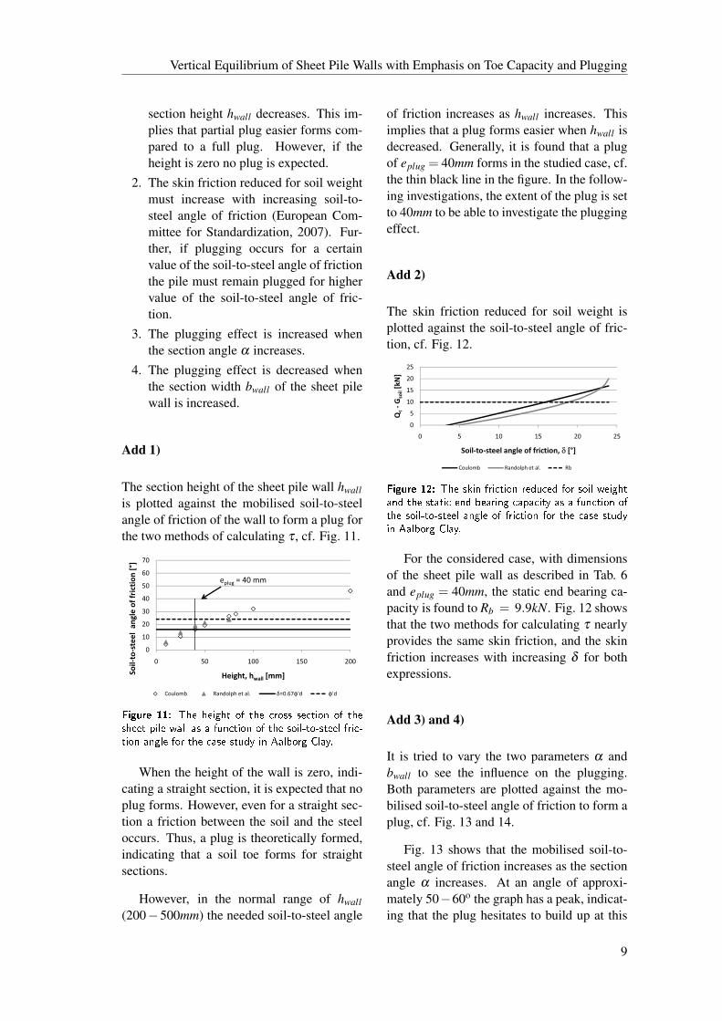
Vertical Equilibrium of Sheet Pile Walls with Emphasis on Toe Capacity and Plugging
section height hwall decreases. This im-
plies that partial plug easier forms com-
pared to a full plug. However, if the
height is zero no plug is expected.
2. The skin friction reduced for soil weight
must increase with increasing soil-to-
steel angle of friction (European Com-
mittee for Standardization, 2007). Fur-
ther, if plugging occurs for a certain
value of the soil-to-steel angle of friction
the pile must remain plugged for higher
value of the soil-to-steel angle of fric-
tion.
3. The plugging effect is increased when
the section angle α increases.
4. The plugging effect is decreased when
the section width bwall of the sheet pile
wall is increased.
Add 1)
The section height of the sheet pile wall hwallis plotted against the mobilised soil-to-steel
angle of friction of the wall to form a plug for
the two methods of calculating τ , cf. Fig. 11.
60
70
[°]
40
50
60
70
friction
�[°]
eplug =�40�mm
30
40
50
60
70
le�of�friction�[°]
eplug =�40�mm
10
20
30
40
50
60
70
el��angle�of�friction�[°]
eplug =�40�mm
0
10
20
30
40
50
60
70
0 50 100 150 200�to�steel��an
gle�of�friction
�[°]
eplug =�40�mm
0
10
20
30
40
50
60
70
0 50 100 150 200
Soil�to�steel��angle�of�friction�[°]
Height,�hwall [mm]
eplug =�40�mm
0
10
20
30
40
50
60
70
0 50 100 150 200
Soil�to�steel��angle�of�friction�[°]
Height,�hwall [mm]
Coulomb Randolph�et�al. �=0.67�'d �'d
eplug =�40�mm
0
10
20
30
40
50
60
70
0 50 100 150 200
Soil�to�steel��angle�of�friction�[°]
Height,�hwall [mm]
Coulomb Randolph�et�al. �=0.67�'d �'d
eplug =�40�mm
������ ��� ��� ������ �� ��� ��� ������ �� ���
����� ��� ���� �� � ������� �� ��� ������������� ���
���� ����� �� ��� ��� ����� �� ������ �����
When the height of the wall is zero, indi-
cating a straight section, it is expected that no
plug forms. However, even for a straight sec-
tion a friction between the soil and the steel
occurs. Thus, a plug is theoretically formed,
indicating that a soil toe forms for straight
sections.
However, in the normal range of hwall(200−500mm) the needed soil-to-steel angle
of friction increases as hwall increases. This
implies that a plug forms easier when hwall is
decreased. Generally, it is found that a plug
of eplug = 40mm forms in the studied case, cf.
the thin black line in the figure. In the follow-
ing investigations, the extent of the plug is set
to 40mm to be able to investigate the plugging
effect.
Add 2)
The skin friction reduced for soil weight is
plotted against the soil-to-steel angle of fric-
tion, cf. Fig. 12.
0
5
10
15
20
25
Q���G
soil[kN]
0
5
10
15
20
25
0 5 10 15 20 25
Q��G
soil[kN]
Soil�to�steel�angle�of�friction,�� [°]
Coulomb Randolph�et�al. Rb
������ �� ��� ���� ������ ����� �� ���� ������
��� ��� ����� ��� ������ � ���� �� � ������� ��
��� ������������� ����� �� ������ �� ��� ��� �����
�� ������ �����
For the considered case, with dimensions
of the sheet pile wall as described in Tab. 6
and eplug = 40mm, the static end bearing ca-
pacity is found to Rb = 9.9kN. Fig. 12 shows
that the two methods for calculating τ nearly
provides the same skin friction, and the skin
friction increases with increasing δ for both
expressions.
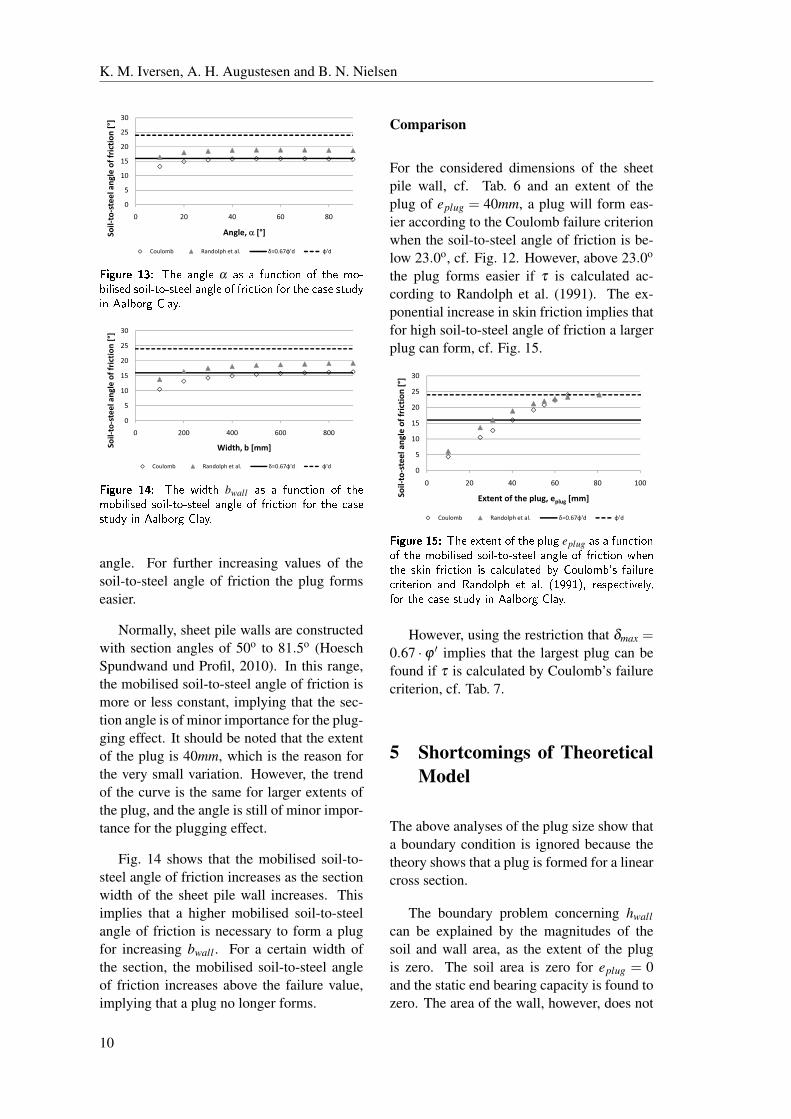
Add 3) and 4)
It is tried to vary the two parameters α and
bwall to see the influence on the plugging.
Both parameters are plotted against the mo-
bilised soil-to-steel angle of friction to form a
plug, cf. Fig. 13 and 14.
Fig. 13 shows that the mobilised soil-to-
steel angle of friction increases as the section
angle α increases. At an angle of approxi-
mately 50−60o the graph has a peak, indicat-
ing that the plug hesitates to build up at this
9
K. M. Iversen, A. H. Augustesen and B. N. Nielsen
5
10
15
20
25
30l�ang
le�of�friction�[°]
0
5
10
15
20
25
30
0 20 40 60 80
Soil�to�steel�ang
le�of�friction�[°]
Angle,��� [°]
Coulomb Randolph�et�al. �=0.67�'d �'d
������ �� ��� ����� α �� � ��� �� � ��� ���
� � ��� �� ���������� ����� � � �� �� �� ��� ���� ����
� ������� �����
5
10
15
20
25
30
el�ang
le�of�friction�[°]
0
5
10
15
20
25
30
0 200 400 600 800
Soil�to�steel�ang
le�of�friction�[°]
Width,�b�[mm]
Coulomb Randolph�et�al. �=0.67�'d �'d
������ �� ��� ����� bwall � � �� ���� � ����������� ����������� ����� � �� ���� �� ��� ������ �� ������� �����
angle. For further increasing values of the
soil-to-steel angle of friction the plug forms
easier.
Normally, sheet pile walls are constructed
with section angles of 50o to 81.5o (Hoesch
Spundwand und Profil, 2010). In this range,
the mobilised soil-to-steel angle of friction is
more or less constant, implying that the sec-
tion angle is of minor importance for the plug-
ging effect. It should be noted that the extent
of the plug is 40mm, which is the reason for
the very small variation. However, the trend
of the curve is the same for larger extents of
the plug, and the angle is still of minor impor-
tance for the plugging effect.
Fig. 14 shows that the mobilised soil-to-
steel angle of friction increases as the section
width of the sheet pile wall increases. This
implies that a higher mobilised soil-to-steel
angle of friction is necessary to form a plug
for increasing bwall . For a certain width of
the section, the mobilised soil-to-steel angle
of friction increases above the failure value,
implying that a plug no longer forms.
Comparison
For the considered dimensions of the sheet
pile wall, cf. Tab. 6 and an extent of the
plug of eplug = 40mm, a plug will form eas-
ier according to the Coulomb failure criterion
when the soil-to-steel angle of friction is be-
low 23.0o, cf. Fig. 12. However, above 23.0o
the plug forms easier if τ is calculated ac-
cording to Randolph et al. (1991). The ex-
ponential increase in skin friction implies that
for high soil-to-steel angle of friction a larger
plug can form, cf. Fig. 15.
30
[°]
20
25
30
riction�[°]
15
20
25
30
e�of�friction
�[°]
5
10
15
20
25
30
eel�angle�of�friction�[°]
0
5
10
15
20
25
30
0 20 40 60 80 100l�to�steel�angle�of�friction�[°]
0
5
10
15
20
25
30
0 20 40 60 80 100
Soil�to�steel�angle�of�friction�[°]
Extent�of�the�plug,�eplug [mm]
0
5
10
15
20
25
30
0 20 40 60 80 100
Soil�to�steel�angle�of�friction�[°]
Extent�of�the�plug,�eplug [mm]
Coulomb Randolph�et�al. �=0.67�'d �'d
0
5
10
15
20
25
30
0 20 40 60 80 100
Soil�to�steel�angle�of�friction�[°]
Extent�of�the�plug,�eplug [mm]
Coulomb Randolph�et�al. �=0.67�'d �'d
������ � ��� ������ � ��� ���� eplug � � �� ����� ��� �������� ����������� ����� � �� ���� ������� ��� �� ���� � �� ������ �� �������� ������ �������� ��� �������� �� ��� �� �!" ���� ��#���"�� ��� �� ���� �� ������� �����
However, using the restriction that δmax =0.67 ·ϕ ′ implies that the largest plug can be
found if τ is calculated by Coulomb’s failure
criterion, cf. Tab. 7.
5 Shortcomings of TheoreticalModel
The above analyses of the plug size show that
a boundary condition is ignored because the
theory shows that a plug is formed for a linear
cross section.
The boundary problem concerning hwallcan be explained by the magnitudes of the
soil and wall area, as the extent of the plug
is zero. The soil area is zero for eplug = 0
and the static end bearing capacity is found to
zero. The area of the wall, however, does not
10
Vertical Equilibrium of Sheet Pile Walls with Emphasis on Toe Capacity and Plugging
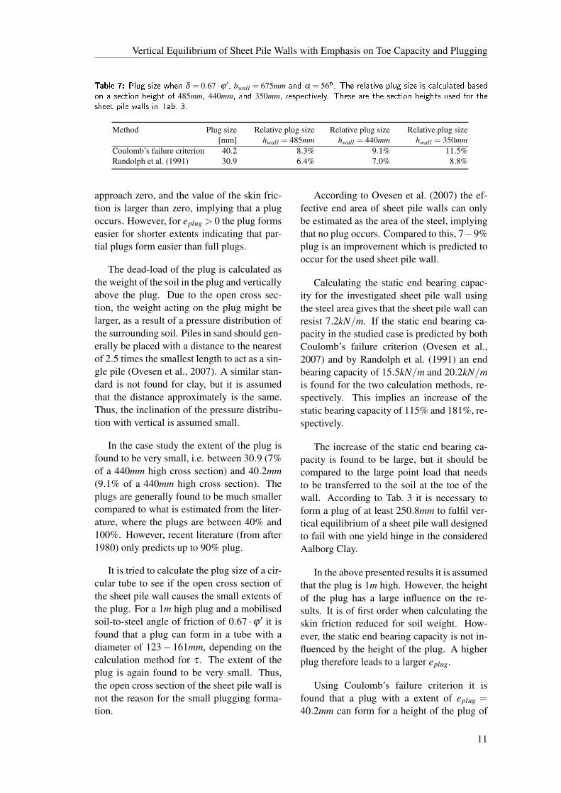
����� �� ���� ���� �� δ = 0.67 ·ϕ ′� bwall = 675mm �� α = 56�� �� ��� ���� ���� ���� �� � ���� ��� � ���
�� ������� ���� �� 485mm� 440mm� �� 350mm� ������������� ���� �� �� ������� ����� ���� ��� ��
���� ���� ��� �� � �� ��
Method Plug size Relative plug size Relative plug size Relative plug size
[mm] hwall = 485mm hwall = 440mm hwall = 350mmCoulomb’s failure criterion 40.2 8.3% 9.1% 11.5%Randolph et al. (1991) 30.9 6.4% 7.0% 8.8%
approach zero, and the value of the skin fric-
tion is larger than zero, implying that a plug
occurs. However, for eplug > 0 the plug forms
easier for shorter extents indicating that par-
tial plugs form easier than full plugs.
The dead-load of the plug is calculated as
the weight of the soil in the plug and vertically
above the plug. Due to the open cross sec-
tion, the weight acting on the plug might be
larger, as a result of a pressure distribution of
the surrounding soil. Piles in sand should gen-
erally be placed with a distance to the nearest
of 2.5 times the smallest length to act as a sin-
gle pile (Ovesen et al., 2007). A similar stan-
dard is not found for clay, but it is assumed
that the distance approximately is the same.
Thus, the inclination of the pressure distribu-
tion with vertical is assumed small.
In the case study the extent of the plug is
found to be very small, i.e. between 30.9 (7%
of a 440mm high cross section) and 40.2mm(9.1% of a 440mm high cross section). The
plugs are generally found to be much smaller
compared to what is estimated from the liter-
ature, where the plugs are between 40% and
100%. However, recent literature (from after
1980) only predicts up to 90% plug.
It is tried to calculate the plug size of a cir-
cular tube to see if the open cross section of
the sheet pile wall causes the small extents of
the plug. For a 1m high plug and a mobilised
soil-to-steel angle of friction of 0.67 ·ϕ ′ it isfound that a plug can form in a tube with a
diameter of 123− 161mm, depending on the
calculation method for τ . The extent of the
plug is again found to be very small. Thus,
the open cross section of the sheet pile wall is
not the reason for the small plugging forma-
tion.
According to Ovesen et al. (2007) the ef-
fective end area of sheet pile walls can only
be estimated as the area of the steel, implying
that no plug occurs. Compared to this, 7−9%
plug is an improvement which is predicted to
occur for the used sheet pile wall.
Calculating the static end bearing capac-
ity for the investigated sheet pile wall using
the steel area gives that the sheet pile wall can
resist 7.2kN/m. If the static end bearing ca-
pacity in the studied case is predicted by both
Coulomb’s failure criterion (Ovesen et al.,
2007) and by Randolph et al. (1991) an end
bearing capacity of 15.5kN/m and 20.2kN/mis found for the two calculation methods, re-
spectively. This implies an increase of the
static bearing capacity of 115% and 181%, re-
spectively.
The increase of the static end bearing ca-
pacity is found to be large, but it should be
compared to the large point load that needs
to be transferred to the soil at the toe of the
wall. According to Tab. 3 it is necessary to
form a plug of at least 250.8mm to fulfil ver-
tical equilibrium of a sheet pile wall designed
to fail with one yield hinge in the considered
Aalborg Clay.
In the above presented results it is assumed
that the plug is 1m high. However, the height
of the plug has a large influence on the re-
sults. It is of first order when calculating the
skin friction reduced for soil weight. How-
ever, the static end bearing capacity is not in-
fluenced by the height of the plug. A higher
plug therefore leads to a larger eplug.
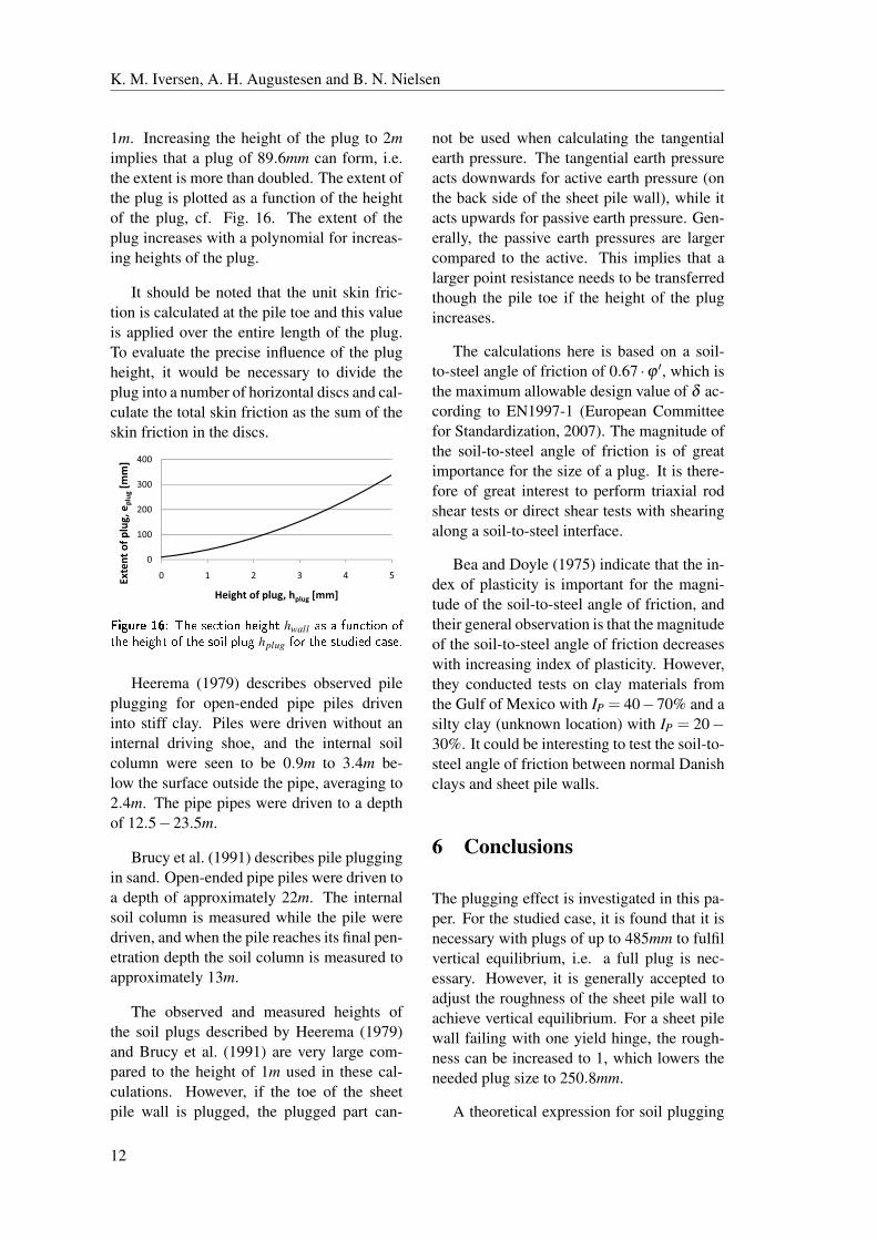
Using Coulomb’s failure criterion it is
found that a plug with a extent of eplug =40.2mm can form for a height of the plug of
11
K. M. Iversen, A. H. Augustesen and B. N. Nielsen
1m. Increasing the height of the plug to 2mimplies that a plug of 89.6mm can form, i.e.
the extent is more than doubled. The extent of
the plug is plotted as a function of the height
of the plug, cf. Fig. 16. The extent of the
plug increases with a polynomial for increas-
ing heights of the plug.
It should be noted that the unit skin fric-
tion is calculated at the pile toe and this value
is applied over the entire length of the plug.
To evaluate the precise influence of the plug
height, it would be necessary to divide the
plug into a number of horizontal discs and cal-
culate the total skin friction as the sum of the
skin friction in the discs.
400]
300
400
g[m
m]
200
300
400
,�eplug[m
m]
100
200
300
400
f�plug,�e
plug[m
m]
0
100
200
300
400
0 1 2 3 4 5tent�of�p
lug,�e
plug[m
m]
0
100
200
300
400
0 1 2 3 4 5Extent�of�p
lug,�e
plug[m
m]
Height of plug h [mm]
0
100
200
300
400
0 1 2 3 4 5Extent�of�p
lug,�e
plug[m
m]
Height�of�plug,�hplug [mm]
0
100
200
300
400
0 1 2 3 4 5Extent�of�p
lug,�e
plug[m
m]
Height�of�plug,�hplug [mm]
������ �� ��� ������ ����� hwall �� � � ���� ��
��� ����� �� ��� ���� �� hplug ��� ��� �� ���� �����
Heerema (1979) describes observed pile
plugging for open-ended pipe piles driven
into stiff clay. Piles were driven without an
internal driving shoe, and the internal soil
column were seen to be 0.9m to 3.4m be-
low the surface outside the pipe, averaging to
2.4m. The pipe pipes were driven to a depth
of 12.5−23.5m.
Brucy et al. (1991) describes pile plugging
in sand. Open-ended pipe piles were driven to
a depth of approximately 22m. The internal
soil column is measured while the pile were
driven, and when the pile reaches its final pen-
etration depth the soil column is measured to
approximately 13m.
The observed and measured heights of
the soil plugs described by Heerema (1979)
and Brucy et al. (1991) are very large com-
pared to the height of 1m used in these cal-
culations. However, if the toe of the sheet
pile wall is plugged, the plugged part can-
not be used when calculating the tangential
earth pressure. The tangential earth pressure
acts downwards for active earth pressure (on
the back side of the sheet pile wall), while it
acts upwards for passive earth pressure. Gen-
erally, the passive earth pressures are larger
compared to the active. This implies that a
larger point resistance needs to be transferred
though the pile toe if the height of the plug
increases.
The calculations here is based on a soil-
to-steel angle of friction of 0.67 ·ϕ ′, which is
the maximum allowable design value of δ ac-
cording to EN1997-1 (European Committee
for Standardization, 2007). The magnitude of
the soil-to-steel angle of friction is of great
importance for the size of a plug. It is there-
fore of great interest to perform triaxial rod
shear tests or direct shear tests with shearing
along a soil-to-steel interface.
Bea and Doyle (1975) indicate that the in-
dex of plasticity is important for the magni-
tude of the soil-to-steel angle of friction, and
their general observation is that the magnitude
of the soil-to-steel angle of friction decreases
with increasing index of plasticity. However,
they conducted tests on clay materials from
the Gulf of Mexico with IP = 40−70% and a
silty clay (unknown location) with IP = 20−30%. It could be interesting to test the soil-to-
steel angle of friction between normal Danish
clays and sheet pile walls.
6 Conclusions
The plugging effect is investigated in this pa-
per. For the studied case, it is found that it is
necessary with plugs of up to 485mm to fulfil
vertical equilibrium, i.e. a full plug is nec-
essary. However, it is generally accepted to
adjust the roughness of the sheet pile wall to
achieve vertical equilibrium. For a sheet pile
wall failing with one yield hinge, the rough-
ness can be increased to 1, which lowers the
needed plug size to 250.8mm.
A theoretical expression for soil plugging
12
Vertical Equilibrium of Sheet Pile Walls with Emphasis on Toe Capacity and Plugging
is suggested, where equilibrium of the soil
plug must be fulfilled. The equilibrium pre-
scribes that a plug occurs if the skin friction
mobilised between the soil and the wall in the
plugged area is larger than the static end bear-
ing capacity acting under the plugged zone.
The skin friction is reduced for the weight of
the soil in the plug and vertically above the
plug.
Four expressions for calculating the skin
friction in the soil-to-steel interface are as-
sessed. Two expressions fail to fulfil the re-
quirement from EN1997-1, which prescribes
that the mobilised skin friction should be de-
termined from the soil-to-steel angle of fric-
tion δ .
The remaining two expressions are com-
pared with Aalborg Clay as the case material.
The two expressions provide results close to
one another. However, a larger plug forms if
the skin friction is calculated by Coulomb’s
failure criterion. Using the limitation from
EN1997-1 that δ may not exceed 0.67 · ϕ ′provides that a plug of 30.9mm and 40.2mmcan form for the two calculation methods for
the described dimensions of the sheet pile.
The theoretical model fails to fulfil one
boundary condition; when the height of the
cross section is chosen to zero, the model
predicts a plug. This is not expected as a
section height of zero implies a straight sec-
tion. However, in the normal range of used
section heights for sheet pile walls, a higher
mobilised soil-to-steel angle of frictions is
needed to form a plug for increasing heights.
This fact corresponds to what is expected.
The theoretical model provides very short
plugs compared to what is needed to fulfil
vertical equilibrium. The extent of the mo-
bilised plug is very dependent on the height
of the plug, and the mobilised plug is found
to increase with a polynomial for increasing
height of the plug.
It has not been possible to investigate the
height of plugs forming in sheet pile walls.
A high plug provides a large extents of the
plug but the plugged zone cannot be used to
transfer tangential earth pressures. This im-
plies that the point load at the pile toe might
increase and larger plugs are needed. These
effects are not investigated further.
Bibliography
API (2002). Recommended Practice forPlanning, Designing and ConstructingFixed Offshore Platforms - Woking StressDesign. American Petroleum Institute.
Arcelor (2005). Piling Handbook (8 ed.).
Arcelor RPS.
Bea, R. G. and E. H. Doyle (1975).
Parameters Affecting Axial Capacity of
Piles in Clays. Annual OffshoreTechnology Conference 2, 611–623.
Bowles, J. E. (1996). Foundation Analysisand Design (5 ed.). McGraw-Hill.
Brinch Hansen, J. (1953). Earth PressureCalculations (2 ed.). Danish Technical
Press.
Brucy, F., J. Meunier, and J.-F. Nauroy
(1991). Behavior of pile plug in sandy
soils during and after driving. AnnualOffshore Technology Conference 1,145–154.
European Committee for Standardization
(2007). Eurocode 7: Geotechnical design- Part 1: General rules. Dansk Standard.
European Committee for Standardization
(2008). National Annex to Eurocode 7:Geotechnical design - Part 1: Generalrules. Dansk Standard.
GEO (2010, May). Beskrivelse af SPOOKS.
On the WWW. URL
http://www.geo.dk/forside/ydelser/
geoteknik/designafspunsvægge-
spooks/beskrivelseafspooks.aspx.
Geoteknisk Insititut (1985). Aalborg.Havnen. Kajudretning mv. Bundforhold.Styrkeparametre mv. Geoteknisk Institut.
13
K. M. Iversen, A. H. Augustesen and B. N. Nielsen
Geoteknisk Institut (1963). Styrkeparametrefor Yoldialer. Geoteknisk Institut.
Hansen, B. (1978). Geoteknik og Fundering,del 1. Den private Ingeniørfond ved
Danmarks Tekniske Højskole.
Harremoës, Krebs Ovesen, and Moust
Jacobsen (2003). Lærebog i Geoteknik 2(4 ed.). Polyteknisk forlag.
Heerema, E. P. (1979). Pile driving and static
load tests on piles in stiff clay. AnnualOffshore Technology Conference 2,1135–1145.
Hoesch Spundwand und Profil (2010, May).
Product Range | Hoesch Sections. On the
WWW. URL
http://www.spundwand.de/e/.
Ibsen, L. B. (2007). Triaxialforsøg på
Aalborg ler. Internal report.
Iversen, K. M., B. N. Nielsen, and A. H.
Augustesen (2010). Strength properties of
Aalborg Clay. Unpublished.
Ladd, C. C., R. Foott, K. Ishihara,
F. Schlosser, and H. G. Poulos (1977).
Stress-deformation and strength
characteristics. Proc. 9th Int. Conf. on SoilMechanics and Foundation Engineering,421–494.
Luke, K. (1994). The use of CPT in DanishSoils with special emphasis on measuringthe undrained shear strength. Ph. D.
thesis, Aalborg University.
Lundgren, H. and J. Brinch Hansen (1958).
Geoteknik. Teknisk Forlag.
Meyerhof, G. G. (1976). Bearing capacity
and settlement of pile foundations.
Journal of Geotechnical EngineeringDivision 102(3), 197–228.
Ovesen, N. K., L. Fuglsang, and G. Bagge
(2007). Lærebog i Geoteknik (1 ed.).
Polyteknisk Forlag.
Paikowsky, S. G. and R. V. Whitman (1990).
The effects of plugging on pile
performance and design. CanadianGeotechnical Journal 27(4), 429–440.
Pelletier, J. H., J. D. Murff, and A. C. Young
(1993). Historical development and
assessment of the current API design
methods for axially loaded pipes. AnnualOffshore Technology Conference 2,253–282.
Randolph, M. F., E. C. Leong, and G. T.
Houlsby (1991). One-dimensional
analysis of soil plugs in pipe piles.
Geotechnique 41(4), 587–598.
Randolph, M. F. and B. S. Murphy (1985).
Shaft capacity of driven piles in clay.
Annual Offshore Technology Conference 1,371–378.
Tomlinson, M. and J. Woodward (2008). PileDesign and Donstruction Practice (5 ed.).
Taylor & Francis.
Weissenbach, A. (Ed.) (1977). Baugruben,Teil III, Berechnungsverfahren. Verlag von
Wilhelm Ernest & Sohn.
Weissenbach, A. (Ed.) (2008).
Recommendations on Excavations: EBA(2 ed.). Ernst & Sohn. Translation of the
4th German Edition.
14

Recent publications in the DCE Technical Report Series
Iversen, K. M., Nielsen, B. N., & Augustesen, A. H. (2010). Investigation on the Effect of Drained Strength when Designing Sheet Pile Walls. DCE Technical Report , 93.
Iversen, K. M., Nielsen, B. N., & Augustesen, A. H. (2010). Strength Properties of Aalborg Clay. DCE Technical Report , 92.

ISSN 1901-726X DCE Technical Report No. 94
Related Documents