Shear Wave Speed Measurement Using an Unfocused Ultrasound Beam Heng Zhao, Pengfei Song, Matthew W. Urban, James F. Greenleaf, and Shigao Chen Department of Physiology and Biomedical Engineering, Mayo Clinic College of Medicine, Rochester, MN Abstract Tissue elasticity is related to pathology and therefore has important medical applications. Radiation force from a focused ultrasound beam has been used to produce shear waves in tissues for shear wave speed and tissue elasticity measurements. The feasibility of shear wave speed measurement using radiation force for an unfocused ultrasound beam is demonstrated in this study with a linear and a curved array transducer. Consistent measurement of shear wave speed was achieved over a relatively long axial extent (z = 10-40 mm for the linear array, and z = 15-60 mm for the curved array) in 3 calibrated phantoms with different shear moduli. In vivo measurements on the biceps of a healthy volunteer show consistent increase of shear wave speed for the biceps under 0, 1, 2, and 3 kg loading. Advantages and limitations of unfocused push are discussed. Keywords Elasticity; Shear wave; Ultrasound radiation force; Unfocused INTRODUCTION Mechanical properties of tissues such as shear modulus (elasticity) are related to the state of tissue health (Sarvazyan et al. 1998). Assuming isotropy, incompressibility, and linearity, the shear modulus μ of an elastic tissue is related to its shear wave propagation speed c s by (1) where ρ is density which can be assumed to be 1000 kg/m 3 for all soft tissues (Yamakoshi et al. 1990). Eq. (1) neglects tissue viscosity and frequency effects, but generally is considered valid when the frequency of the shear wave is low and narrowband. Therefore, measurements of shear wave propagation speed can be used to estimate tissue elasticity. Acoustic radiation force from a focused ultrasound beam can be used to generate shear waves within tissues (Sarvazyan et al. 1998; Bercoff et al. 2004; Palmeri et al. 2008; Chen et al. 2009). It is commonly assumed that the shear waves generated by the ultrasound radiation force at the focal region propagate within the transducer imaging plane in a direction perpendicular to the ultrasound beam axis (Parker et al. 2011). Therefore, tissue Corresponding Author: Shigao Chen Address: 200 First Street, S.W., Rochester, MN 55905 U.S.A. Phone: 507-284-8252 Fax: 507-266-0361 [email protected]. Publisher's Disclaimer: This is a PDF file of an unedited manuscript that has been accepted for publication. As a service to our customers we are providing this early version of the manuscript. The manuscript will undergo copyediting, typesetting, and review of the resulting proof before it is published in its final citable form. Please note that during the production process errors may be discovered which could affect the content, and all legal disclaimers that apply to the journal pertain. NIH Public Access Author Manuscript Ultrasound Med Biol. Author manuscript; available in PMC 2013 September 01. Published in final edited form as: Ultrasound Med Biol. 2012 September ; 38(9): 1646–1655. doi:10.1016/j.ultrasmedbio.2012.05.015. NIH-PA Author Manuscript NIH-PA Author Manuscript NIH-PA Author Manuscript

Welcome message from author
This document is posted to help you gain knowledge. Please leave a comment to let me know what you think about it! Share it to your friends and learn new things together.
Transcript
Shear Wave Speed Measurement Using an UnfocusedUltrasound Beam
Heng Zhao, Pengfei Song, Matthew W. Urban, James F. Greenleaf, and Shigao ChenDepartment of Physiology and Biomedical Engineering, Mayo Clinic College of Medicine,Rochester, MN
AbstractTissue elasticity is related to pathology and therefore has important medical applications.Radiation force from a focused ultrasound beam has been used to produce shear waves in tissuesfor shear wave speed and tissue elasticity measurements. The feasibility of shear wave speedmeasurement using radiation force for an unfocused ultrasound beam is demonstrated in this studywith a linear and a curved array transducer. Consistent measurement of shear wave speed wasachieved over a relatively long axial extent (z = 10-40 mm for the linear array, and z = 15-60 mmfor the curved array) in 3 calibrated phantoms with different shear moduli. In vivo measurementson the biceps of a healthy volunteer show consistent increase of shear wave speed for the bicepsunder 0, 1, 2, and 3 kg loading. Advantages and limitations of unfocused push are discussed.
KeywordsElasticity; Shear wave; Ultrasound radiation force; Unfocused
INTRODUCTIONMechanical properties of tissues such as shear modulus (elasticity) are related to the state oftissue health (Sarvazyan et al. 1998). Assuming isotropy, incompressibility, and linearity,the shear modulus μ of an elastic tissue is related to its shear wave propagation speed cs by
(1)
where ρ is density which can be assumed to be 1000 kg/m3 for all soft tissues (Yamakoshi etal. 1990). Eq. (1) neglects tissue viscosity and frequency effects, but generally is consideredvalid when the frequency of the shear wave is low and narrowband. Therefore,measurements of shear wave propagation speed can be used to estimate tissue elasticity.
Acoustic radiation force from a focused ultrasound beam can be used to generate shearwaves within tissues (Sarvazyan et al. 1998; Bercoff et al. 2004; Palmeri et al. 2008; Chen etal. 2009). It is commonly assumed that the shear waves generated by the ultrasoundradiation force at the focal region propagate within the transducer imaging plane in adirection perpendicular to the ultrasound beam axis (Parker et al. 2011). Therefore, tissue
Corresponding Author: Shigao Chen Address: 200 First Street, S.W., Rochester, MN 55905 U.S.A. Phone: 507-284-8252 Fax:507-266-0361 [email protected].
Publisher's Disclaimer: This is a PDF file of an unedited manuscript that has been accepted for publication. As a service to ourcustomers we are providing this early version of the manuscript. The manuscript will undergo copyediting, typesetting, and review ofthe resulting proof before it is published in its final citable form. Please note that during the production process errors may bediscovered which could affect the content, and all legal disclaimers that apply to the journal pertain.
NIH Public AccessAuthor ManuscriptUltrasound Med Biol. Author manuscript; available in PMC 2013 September 01.
Published in final edited form as:Ultrasound Med Biol. 2012 September ; 38(9): 1646–1655. doi:10.1016/j.ultrasmedbio.2012.05.015.
NIH
-PA Author Manuscript
NIH
-PA Author Manuscript
NIH
-PA Author Manuscript
motion at several lateral positions along the shear wave propagation path at the push beamfocal depth can be measured using pulse-echo ultrasound to calculate shear wavepropagation speed based on the time-of-flight principle. However, a previous study showsshear wave speed measurements based on such a method suffer from bias that may beassociated with the focused push beam shape (Zhao et al. 2011).
Some alternative push methods using ultrasound radiation force have been proposed.Bercoff, et al., proposed Supersonic Shear Imaging (SSI) which generates quasi-plane shearwave by marching multiple focused push beams at a supersonic speed (Bercoff et al. 2004).Hoyt, et al., reported an elasticity imaging method using shear waves generated by axiconfocal beams (Hoyt et al. 2012). McAleavey, et al., introduced a spatially-modulated impulseacoustic radiation force (SMURF) imaging method which uses apodization function orintersecting push beams to generate shear waves with known spatial distribution(McAleavey et al. 2007).
In this study, we evaluate the feasibility of shear wave production in tissue with unfocusedultrasound for shear wave speed measurements based on the time-of-flight principle. Theperformance of the shear wave speed measurements is validated using both phantom and invivo experiments. The advantages and limitations of the unfocused push are also discussed.
METHODShear wave measurement technique
A Verasonics ultrasound system (Verasonics Inc., Redmond, WA) was used in this study tomake shear wave speed measurements with a linear array transducer L7-4 or a curvilineartransducer C4-2 (Philips Healthcare, Andover, MA). A continuous segment of elements (8,12, or 16 elements) at the center of each transducer was used to transmit the unfocused pushbeam at ±90 volts. There were no focusing delays applied between the transmittingtransducer elements. A total of 2976 cycles of ultrasound were used in the push beam. Thisprovided a 595 μs push duration for the L7-4 with a center frequency of 5 MHz, and 992 μspush duration for the C4-2 with a center frequency of 3 MHz. Propagation of shear waveswas monitored for 15 ms at a pulse repetition frequency (PRF) of 4 kHz for the L7-4 using“flash” imaging. In flash imaging mode, the Verasonics ultrasound system transmits anunfocused ultrasound pulse (a “plane wave” compared to a traditional focused ultrasound“beam”) into the imaged medium and uses parallel channel processing to generate onecomplete two-dimensional (2D) ultrasound image from each transmission (Bercoff et al.2004). To improve the signal-to-noise ratio (SNR) of detection for the C4-2, two steeredflash imaging frames were used for angle compounding with an effective PRF of 4.85 kHz(Montaldo et al. 2009). The center frequencies used for imaging pulses were 3 MHz for theC4-2 and 5 MHz for the L7-4. Therefore, shear wave motion can be detected within a 2Dregion (with a pixel resolution of one ultrasound wavelength which was 0.51 mm for theC4-2 and 0.31 mm for the L7-4) at high PRF. The axial range of flash imaging was 3-72 mmfor C4-2 and 2-46 mm for L7-4, which were much smaller than the maximum detectablerange (150 mm for 4.85 kHz assuming c = 1540 m/s). Tissue velocity due to shear wavemotion was calculated from in-phase/quadrature (IQ) data using one-dimensional (1D)autocorrelation method (Kasai et al. 1985) and averaged over 10 wavelengths(corresponding to an axial range of 5 mm for C4-2 and 3 mm for the L7-4) along the depthdirection to improve SNR. Shear wave speed (group velocity) was then estimated from thearrival time (using time-to-peak) of the shear wave at different lateral distances from thepush beam center through linear regression (Palmeri et al. 2008). The lateral range used forlinear regression of shear wave speed was 3-18 mm for L7-4 and 4-18 mm for C4-2.
Zhao et al. Page 2
Ultrasound Med Biol. Author manuscript; available in PMC 2013 September 01.
NIH
-PA Author Manuscript
NIH
-PA Author Manuscript
NIH
-PA Author Manuscript

Intensity Field Simulation Using Field IIThe simulation program Field II (Jensen and Svendsen 1992) was used to simulate intensityfields of the unfocused and focused beams generated by the L7-4 and C4-2.
For the L7-4, the simulated transducer has 128 elements with element size of 7 mm × 0.283mm (height × width) and kerf width of 0.025 mm. The elevation focus is fixed at 25 mmdepth. The center frequency of the transducer is 5 MHz. The spatial resolution is set to 0.5mm. The excitation signal is 100 cycles of sinusoids (20 μs) oscillating at 5 MHz, theduration of which is long enough to be treated as continuous wave.
For the C4-2, the simulated curved array transducer has 128 elements with element size of13 mm × 0.359 mm (height × width) and kerf width of 0.05 mm. The elevation focus isfixed at 70 mm depth. The convex radius is 41 mm. The center frequency of the transduceris 3 MHz. The spatial resolution is also 0.5 mm. The excitation signal is 100 cycles ofsinusoids (33.3 μs) oscillating at 3 MHz.
The simulation sampling rate is set to be 100 MHz for both transducers. The pressure fieldsof the unfocused push (12 elements aperture for both L7-4 and C4-2) and focused push (64elements aperture, focused at 25 mm for L7-4 and 40 mm for C4-2) were simulated, and theintensity field I is derived by
(2)
where p is the pressure and ρ and c are the density and sound speed of the medium,respectively.
Phantom experimentsThree homogeneous elasticity phantoms (custom made by CIRS, Inc. Norfolk, VA) withdifferent elasticity values were used in this study. Each phantom had a dimension of 10 × 10× 8 cm3 (width × depth × height) and frequency dependent ultrasound attenuation of 0.43dB/MHz/cm. The shear wave speed in each phantom was calibrated by Magnetic ResonanceElastography (MRE) and 1D Transient Elastography (TE) in a previous study (Zhao et al.2011). The mean and standard deviations of shear wave speed measured at 100 Hz by MREare 1.24 ± 0.01 m/s, 1.47 ± 0.02 m/s, and 1.80 ± 0.02 m/s for phantoms 1, 2, and 3,respectively. Results obtained from 1D TE (using one cycle of 100 Hz vibration) are close tothose of the MRE tests: 1.23 ± 0.02 m/s, 1.48 ± 0.03 m/s, and 1.89 ± 0.07 m/s for phantom1, 2, and 3, respectively.
Shear wave speed measurements using the unfocused push were made in each phantomusing both L7-4 and C4-2. For each transducer, the aperture size used for unfocused pushbeam transmission was 8, 12, or 16 elements. For each of the setup combinations mentionedabove, 3 repeated measurements were made by positioning the transducer at 3 differentlocations on the phantom surface. The locations were selected randomly near the center ofeach phantom to avoid potential influence of the boundaries for measurements. For eachacquisition, shear wave speed was estimated for one region at the left side and one region atthe right side of the push beam. Therefore, we have a total of 108 unfocused shear wavemeasurements in this phantom study (3 phantoms by 2 transducers by 3 aperture sizes by 3repetitions by 2 sides). Shear wave measurements with focused push beams were alsoperformed in all 3 phantoms to facilitate comparison with unfocused push. For the L7-4transducer, the push beam had a center frequency of 5 MHz, duration of 198 μs, a 64-element aperture, and focal depth of 25 mm. For the C4-2 transducer, the push beam had a
Zhao et al. Page 3
Ultrasound Med Biol. Author manuscript; available in PMC 2013 September 01.
NIH
-PA Author Manuscript
NIH
-PA Author Manuscript
NIH
-PA Author Manuscript
center frequency of 3 MHz, duration of 331 μs, a 64-element aperture, and focal depth of 40mm.
Acoustic Output MeasurementsThe acoustic output of the L7-4 and C4-2 transducers (both focused and unfocused beams)in the phantom experiments was measured using a calibrated hydrophone (HGL-0200, OndaCorporation, Sunnyvale, CA) according to a procedure recommended by the AmericanInstitute of Ultrasound in Medicine (AIUM) (AIUM/NEMA 2009). The mechanical index(MI) and spatial peak pulse-average intensity (ISPPA), and spatial peak time-averageintensity (ISPTA) were derated at 0.3 dB/cm/MHz based on the equations in (AIUM/NEMA2009). The PRF for the push pulse to calculate ISPTA was set to be 1 Hz. The maximumtemperature increase was calculated based on the following equation (Palmeri andNightingale 2004):
(3)
where α is the ultrasound attenuation which was set to be 0.5 dB/cm/MHz, cv is the heatcapacity per unit volume (4.2 J/cm3/°C), and t is the duration of the push pulse. Equation (3)neglects cooling due to heat conduction and blood perfusion, and therefore provides aconservative estimation of heating in tissue.
In vivo testsElasticity of biceps brachii muscle under different loading was studied in a healthyvolunteer. The study was approved by Mayo Institutional Review Board (IRB) and writtenconsent was obtained. As illustrated in Fig. 1, the volunteer was seated upright with upperarm and forearm elevated to chest height and rested on a table. The L7-4 transducer wasplaced on the mid-section of the biceps and aligned with the muscle fiber direction through acustom made probe holder. The elbow angle was kept at 90° during the experiment. Muscleelasticity measurements were made at rest and then during isometric contractions at differentloading levels (1, 2, and 3 kg) using the reading from a force scale as visual feedback. Anunfocused push beam transmitted by 16 elements of the transducer with duration of 0.2 mswas used to generate shear waves. Propagation of shear waves was then detected using thesame transducer for 15 ms at a PRF of 22.22 kHz with the axial range of 2-18 mm. Threeangle compounding was used to improve the SNR of detection, leading to an effective framerate of 7.41 kHz for detection. A high effective PRF for detection was necessary to capturethe shear wave in muscle which propagated at a relatively high speed. Measurements wererepeated 5 times for each loading level (with a resting time of about 1 minute betweenmeasurements).
Statistical analysisOne-way ANOVA was used to test statistically significant differences among groups ofshear wave speed results using unfocused, focused, and independent measurements. Studentt-test (two-tailed) was used to test difference between two groups when ANOVA result wassignificant. Tests with a p value less than 0.05 was considered statistically significantlydifferent.
RESULTSFig. 2 shows the simulated intensity of the center axis of the focused and unfocused beamsgenerated by the L7-4 (a) and C4-2 (b) transducers under attenuation levels of 0.3, 0.5, and0.7 dB/cm/MHz. The intensity curves were normalized by the one with the highest
Zhao et al. Page 4
Ultrasound Med Biol. Author manuscript; available in PMC 2013 September 01.
NIH
-PA Author Manuscript
NIH
-PA Author Manuscript
NIH
-PA Author Manuscript
magnitude for each transducer. According to the figure, focused beams generate higherintensity at the focal depths than unfocused beams. However, the unfocused beams havemore consistent intensity over depth than focused beams.
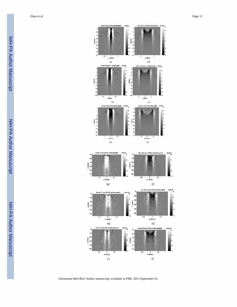
Fig. 3(a)-(c) and (d)-(f) show representative motion (particle velocity in axial direction)distributions in phantom 1, 2, and 3 generated by the L7-4 using a 12-element aperture at 1ms and 5 ms after the push. Fig. 3(g)-(i) and (j)-(l) show motion distributions in 3 phantomsgenerated by the C4-2 using a 12-element aperture at 1 ms and 5 ms after the push. It can beobserved that the shear wave fronts generated by L7-4 and C4-2 remain fairly vertical evenwhen propagating to certain lateral distance, indicating consistent shear wave speedmeasurement can be achieved over a relatively large axial range. For comparison, Fig. 3(m)and (n) show motion in phantom 2 generated by L7-4 and C4-2 using a 64-element focusedpush at 25 mm and 40 mm depths, respectively. Except the small region near focal zone, theshapes of the wave fronts generated by focused push are more complicated, suggesting thatshear wave speed measurement may not be consistent using data at depths out of the focalzone.
Representative results obtained with the L7-4 using a 16-element unfocused push beam inphantom 2 are shown in Fig. 4. Fig. 4(a) shows the displacement time curves at differentlateral positions obtained at the depth of z = 15 mm from the transducer surface. The linearregression of the time-to-peak vs. lateral position at z = 15 mm is shown in Fig. 4(b). Fig.4(c) shows the maximum displacements of the shear wave versus lateral positions measuredat different depths. Error bars are standard deviations obtained from 6 independentmeasurements (3 random locations within the same phantom, each location with two sides:left and right). This figure reveals the magnitude of the displacement signal available forshear wave speed measurement. Fig. 4(d) shows the shear wave speed measured byprocessing echoes from different depths of the same acquisition. Error bars are standarddeviations from 6 independent acquisitions. Each acquisition was processed to estimateshear wave speeds for all depths shown in Fig. 4(d).
Shear wave speeds measured in all 3 phantoms are shown in Fig. 5. Fig. 5(a)-(c) are resultsobtained with the L7-4 using 16, 12, and 8 elements for unfocused push, respectively. Fig.5(e)-(g) are results obtained with the C4-2 using 16, 12, and 8 elements for unfocused push,respectively. For comparison, Fig. 5(d) shows results obtained with the L7-4 using a 64-element focused push at 25 mm depth, and Fig. 5(h) shows results obtained with the C4-2using a 64-element focused push at 40 mm depth. Compared to focused push, unfocusedpush produces more consistent results in the axial depth range shown in Fig. 5.
Shear wave speeds measured with unfocused push in all three phantoms are shown in Fig. 6for comparison with focused push, MRE and 1D TE. Fig. 6(a) shows results for the L7-4using 16, 12, and 8 elements for unfocused push and 64 elements for focused push at 25 mmdepth. Error bars for the unfocused push measurements are standard deviations of meanshear wave speeds at different depths shown in Fig. 5. The mean and standard deviationvalues for focused push in each phantom are from 5 measurements at 5 random locationsusing data from the focal region. Fig. 6(b) shows results for the C4-2 using 16, 12, and 8elements for unfocused push and 64 elements for focused push at 40 mm depth. Nosignificant difference is found between unfocused and independent measurements (MREand 1D TE) using the L7-4 in each phantom (p > 0.21). The results using focused push aresignificantly higher than unfocused and independent measurements (p < 0.047). For theC4-2, unfocused results are significantly higher (p < 0.014) than independent measurements.Results from the focused push are significantly higher than unfocused and independentmeasurements (p < 0.001). However, no significant difference is found among unfocusedresults using different push apertures (p > 0.22).
Zhao et al. Page 5
Ultrasound Med Biol. Author manuscript; available in PMC 2013 September 01.
NIH
-PA Author Manuscript
NIH
-PA Author Manuscript
NIH
-PA Author Manuscript
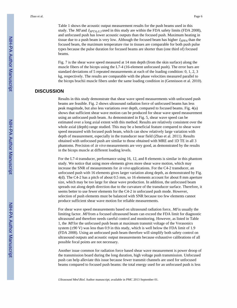
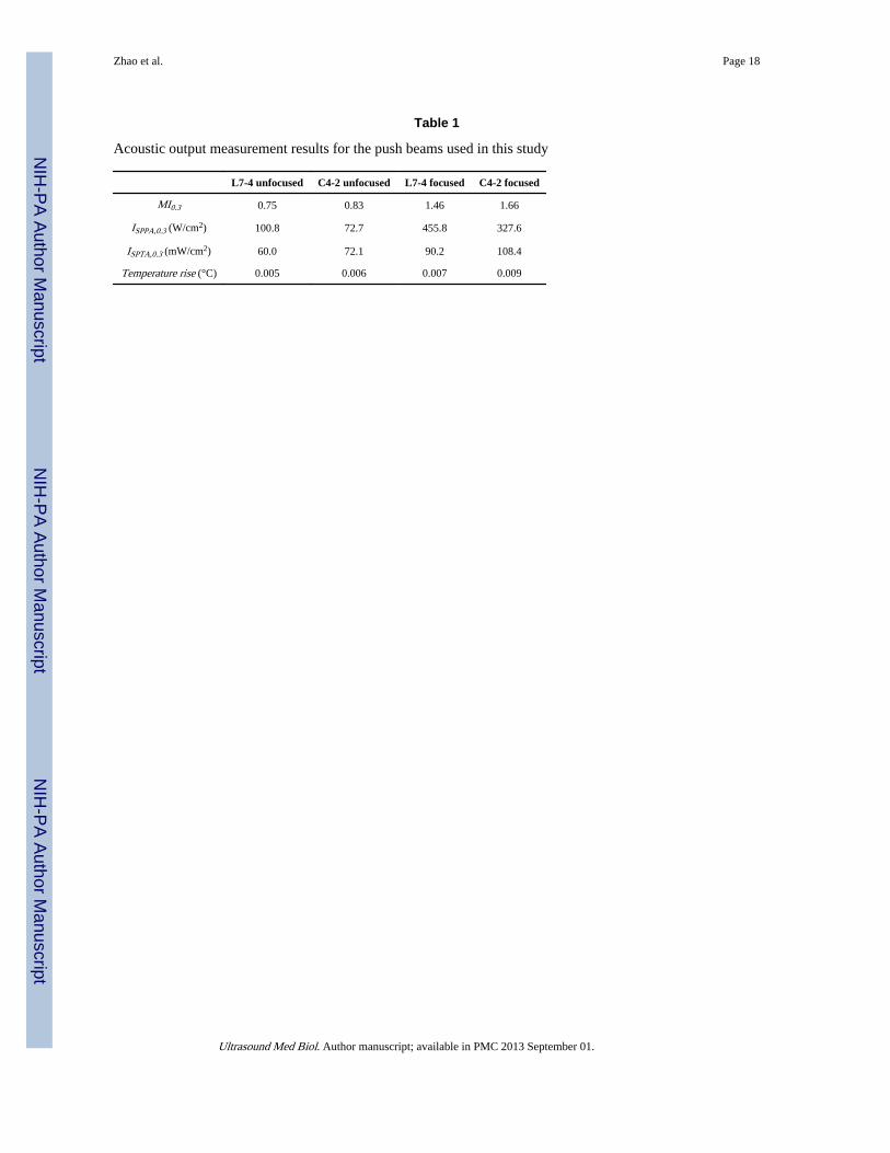
Table 1 shows the acoustic output measurement results for the push beams used in thisstudy. The MI and ISPTA,0.3 used in this study are within the FDA safety limits (FDA 2008),and unfocused push has lower acoustic outputs than the focused push. Maximum heating intissue due to a push beam is very low. Although the focused beam has higher ISPPA than thefocused beam, the maximum temperature rise in tissues are comparable for both push pulsetypes because the pulse duration for focused beams are shorter than (one third of) focusedbeams.
Fig. 7 is the shear wave speed measured at 14 mm depth (from the skin surface) along themuscle fibers of the biceps using the L7-4 (16-element unfocused push). The error bars arestandard deviations of 5 repeated measurements at each of the loading condition: 0, 1, 2, 3kg, respectively. The results are comparable with the phase velocities measured parallel tothe biceps brachii muscle fibers under the same loading condition in (Gennisson et al. 2010).
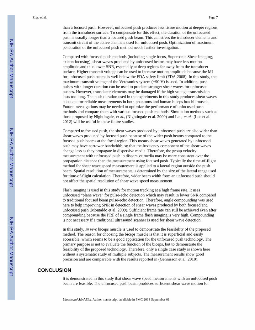
DISCUSSIONResults in this study demonstrate that shear wave speed measurements with unfocused pushbeams are feasible. Fig. 2 shows ultrasound radiation force of unfocused beams has lesspeak magnitude, but also less variations over depth, compared to focused beams. Fig. 4(a)shows that sufficient shear wave motion can be produced for shear wave speed measurementusing an unfocused push beam. As demonstrated in Fig. 5, shear wave speed can beestimated over a long axial extent with this method. Results are relatively consistent over thewhole axial (depth) range studied. This may be a beneficial feature compared to shear wavespeed measured with focused push beam, which can show relatively large variation withdepth of measurement, especially in the transducer near field (Zhao et al. 2011). Resultsobtained with unfocused push are similar to those obtained with MRE and 1D TE in all 3phantoms. Precision of in vivo measurements are very good, as demonstrated by the resultsin the biceps muscle at different loading levels.
For the L7-4 transducer, performance using 16, 12, and 8 elements is similar in this phantomstudy. We notice that using more elements gives more shear wave motion, which mayincrease the SNR of measurements for in vivo applications. For the C4-2 transducer, anunfocused push with 16 elements gives larger variation along depth, as demonstrated by Fig.4(d). The C4-2 has a pitch of about 0.5 mm, so 16 elements account for about 8 mm aperturesize, which may be too large for shear wave production. In addition, the unfocused beamspreads out along depth direction due to the curvature of the transducer surface. Therefore, itseems better to use fewer elements for the C4-2 in unfocused push mode. However,selection of push elements must be balanced with SNR because too few elements cannotproduce sufficient shear wave motion for reliable measurements.
For shear wave speed measurements based on ultrasound radiation force, MI is usually thelimiting factor. MI from a focused ultrasound beam can exceed the FDA limit for diagnosticultrasound and therefore needs careful control and monitoring. However, as listed in Table1, the MI for the unfocused push beam at maximum transmit voltage of the Verasonicssystem (±90 V) was less than 0.9 in this study, which is well below the FDA limit of 1.9(FDA 2008). Using an unfocused push beam therefore will simplify both safety control onultrasound outputs and acoustic output measurements because exhaustive calibrations of allpossible focal points are not necessary.
Another issue common for radiation force based shear wave measurement is power droop ofthe transmission board during the long duration, high voltage push transmission. Unfocusedpush can help alleviate this issue because fewer transmit channels are used for unfocusedbeams compared to focused push beams: the total energy used for an unfocused push is less
Zhao et al. Page 6
Ultrasound Med Biol. Author manuscript; available in PMC 2013 September 01.
NIH
-PA Author Manuscript
NIH
-PA Author Manuscript
NIH
-PA Author Manuscript
than a focused push. However, unfocused push produces less tissue motion at deeper regionsfrom the transducer surface. To compensate for this effect, the duration of the unfocusedpush is usually longer than a focused push beam. This can stress the transducer elements andtransmit circuit of the active channels used for unfocused push. Optimization of maximumpenetration of the unfocused push method needs further investigation.
Compared with focused push methods (including single focus, Supersonic Shear Imaging,axicon focusing), shear waves produced by unfocused beams may have less motionamplitude and thus lower SNR, especially at deep regions far away from the transducersurface. Higher transmit voltage can be used to increase motion amplitude because the MIfor unfocused push beams is well below the FDA safety limit (FDA 2008). In this study, themaximum transmit voltage of the Verasonics system (±90 V) is used. In addition, pushpulses with longer duration can be used to produce stronger shear waves for unfocusedpushes. However, transducer elements may be damaged if the high voltage transmissionlasts too long. The push duration used in the experiments in this study produces shear wavesadequate for reliable measurements in both phantoms and human biceps brachii muscle.Future investigations may be needed to optimize the performance of unfocused pushmethods and compare them with various focused push methods. Simulation methods such asthose proposed by Nightingale, et al., (Nightingale et al. 2000) and Lee, et al., (Lee et al.2012) will be useful in these future studies.
Compared to focused push, the shear waves produced by unfocused push are also wider thanshear waves produced by focused push because of the wider push beams compared to thefocused push beams at the focal region. This means shear waves generated by unfocusedpush may have narrower bandwidth, so that the frequency component of the shear waveschange less as they propagate in dispersive media. Therefore, the group velocitymeasurement with unfocused push in dispersive media may be more consistent over thepropagation distance than the measurement using focused push. Typically the time-of-flightmethod for shear wave speed measurement is applied to a lateral region outside the pushbeam. Spatial resolution of measurements is determined by the size of the lateral range usedfor time-of-flight calculation. Therefore, wider beam width from an unfocused push shouldnot affect the spatial resolution of shear wave speed measurement.
Flash imaging is used in this study for motion tracking at a high frame rate. It usesunfocused “plane wave” for pulse-echo detection which may result in lower SNR comparedto traditional focused beam pulse-echo detection. Therefore, angle compounding was usedhere to help improving SNR in detection of shear waves produced by both focused andunfocused push (Montaldo et al. 2009). Sufficient frame rate can still be achieved even aftercompounding because the PRF of a single frame flash imaging is very high. Compoundingis not necessary if a traditional ultrasound scanner is used for shear wave detection.
In this study, in vivo biceps muscle is used to demonstrate the feasibility of the proposedmethod. The reason for choosing the biceps muscle is that it is superficial and easilyaccessible, which seems to be a good application for the unfocused push technology. Theprimary purpose is not to evaluate the function of the biceps, but to demonstrate thefeasibility of the proposed technology. Therefore, only a single case study is shown herewithout a systematic study of multiple subjects. The measurement results show goodprecision and are comparable with the results reported in (Gennisson et al. 2010).
CONCLUSIONIt is demonstrated in this study that shear wave speed measurements with an unfocused pushbeam are feasible. The unfocused push beam produces sufficient shear wave motion for
Zhao et al. Page 7
Ultrasound Med Biol. Author manuscript; available in PMC 2013 September 01.
NIH
-PA Author Manuscript
NIH
-PA Author Manuscript
NIH
-PA Author Manuscript
reliable measurements. Shear wave speed can be measured over an axial extent of 10-40 mmusing a linear array and over an axial extent of 15-60 mm using a curved array. Resultsobtained with this method in 3 elasticity phantoms are validated by MRE and 1D TEmeasurements. Precision of the method is also good, as demonstrated by in vivomeasurements along the muscle fibers of the biceps under different loading conditions.
AcknowledgmentsThis work was supported by NIH grants EB002167 and DK082408. The content is solely the responsibility of theauthors and does not necessarily represent the official views of NIH. Mayo and some of the authors have financialinterest in the technology described here.
REFERENCESAIUM/NEMA. Acoustic output measurement standard for diagnostic ultrasound equipment. Revision
3. American Institute of Ultrasound in Medicine; National Electrical Manufacturers Assoc.; Laurel,MD: Rosslyn, VA: 2009.
Bercoff J, Tanter M, Fink M. Supersonic shear imaging: A new technique for soft tissue elasticitymapping. IEEE Transactions on Ultrasonics Ferroelectrics and Frequency Control. 2004; 51:396–409.
Chen S, Urban MW, Pislaru C, Kinnick R, Zheng Y, Yao AP, Greenleaf JF. Shearwave DispersionUltrasound Vibrometry (SDUV) for Measuring Tissue Elasticity and Viscosity. IEEE Transactionson Ultrasonics Ferroelectrics and Frequency Control. 2009; 56:55–62.
FDA. Information for manufacturers seeking marketing clearance of diagnostic ultrasound systems andtransducers. Food and Drug Administration, Center for Devices and Radiological Health; SilverSpring, MD: 2008.
Gennisson JL, Deffieux T, Mace E, Montaldo G, Fink M, Tanter M. Viscoelastic and anisotropicmechanical properties of in vivo muscle tissue assessed by supersonic shear imaging. Ultrasound inmedicine & biology. 2010; 36:789–801. [PubMed: 20420970]
Hoyt K, Hah Z, Hazard C, Parker KJ. Experimental validation of acoustic radiation force inducedshear wave interference patterns. Physics in Medicine and Biology. 2012; 57:21–30. [PubMed:22127377]
Jensen JA, Svendsen NB. Calculation of pressure fields from arbitrarily shaped, apodized, and excitedultrasound transducers. IEEE transactions on ultrasonics, ferroelectrics, and frequency control.1992; 39:262–7.
Kasai C, Namekawa K, Koyano A, Omoto R. Real-time two-dimensional blood flow imaging using anautocorrelation technique. IEEE Transactions on Sonics and Ultrasonics. 1985; Su-32:458–64.
Lee KH, Szajewski BA, Hah Z, Parker KJ, Maniatty AM. Modeling shear waves through a viscoelasticmedium induced by acoustic radiation force. Int. J. Numer. Meth. Biomed. Engng. 2012
McAleavey SA, Menon M, Orszulak J. Shear-modulus estimation by application ofSpatiallyModulated impulsive acoustic radiation force. Ultrasonic Imaging. 2007; 29:87–104.[PubMed: 17679324]
Montaldo G, Tanter M, Bercoff J, Benech N, Fink M. Coherent plane-wave compounding for veryhigh frame rate ultrasonography and transient elastography. IEEE Trans Ultrason Ferroelectr FreqControl. 2009; 56:489–506. [PubMed: 19411209]
Nightingale KR, Nightingale RW, Palmeri ML, Trahey GE. A finite element model of remotepalpation of breast lesions using radiation force: factors affecting tissue displacement. UltrasonicImaging. 2000; 22:35–54. [PubMed: 10823496]
Palmeri ML, Nightingale KR. On the thermal effects associated with radiation force imaging of softtissue. IEEE transactions on ultrasonics, ferroelectrics, and frequency control. 2004; 51:551–65.
Palmeri ML, Wang MH, Dahl JJ, Frinkley KD, Nightingale KR. Quantifying hepatic shear modulus invivo using acoustic radiation force. Ultrasound in Medicine and Biology. 2008; 34:546–58.[PubMed: 18222031]
Zhao et al. Page 8
Ultrasound Med Biol. Author manuscript; available in PMC 2013 September 01.
NIH
-PA Author Manuscript
NIH
-PA Author Manuscript
NIH
-PA Author Manuscript
Parker KJ, Doyley MM, Rubens DJ. Imaging the elastic properties of tissue: the 20 year perspective.Physics in Medicine and Biology. 2011; 56:R1–R29. [PubMed: 21119234]
Sarvazyan AP, Rudenko OV, Swanson SD, Fowlkes JB, Emelianov SY. Shear wave elasticityimaging: A new ultrasonic technology of medical diagnostics. Ultrasound in Medicine andBiology. 1998; 24:1419–35. [PubMed: 10385964]
Yamakoshi Y, Sato J, Sato T. Ultrasonic imaging of internal vibration of soft tissue under forcedvibration. IEEE Trans Ultrason Ferroelectr Freq Control. 1990; 37:45–53. [PubMed: 18285015]
Zhao H, Song P, Urban MW, Kinnick RR, Yin M, Greenleaf JF, Chen S. Bias Observed in Time-of-Flight Shear Wave Speed Measurements Using Radiation Force of a Focused Ultrasound Beam.Ultrasound Med Biol. 2011; 37:1884–92. [PubMed: 21924817]
Zhao et al. Page 9
Ultrasound Med Biol. Author manuscript; available in PMC 2013 September 01.
NIH
-PA Author Manuscript
NIH
-PA Author Manuscript
NIH
-PA Author Manuscript
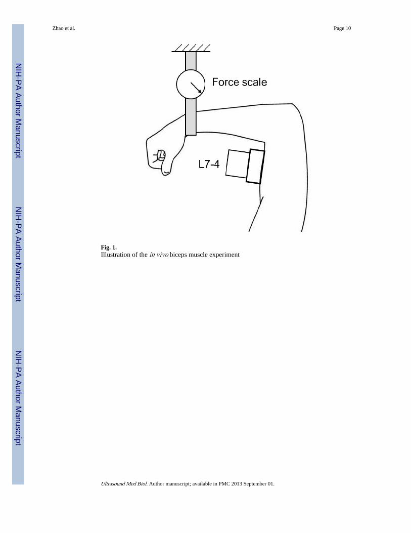
Fig. 1.Illustration of the in vivo biceps muscle experiment
Zhao et al. Page 10
Ultrasound Med Biol. Author manuscript; available in PMC 2013 September 01.
NIH
-PA Author Manuscript
NIH
-PA Author Manuscript
NIH
-PA Author Manuscript
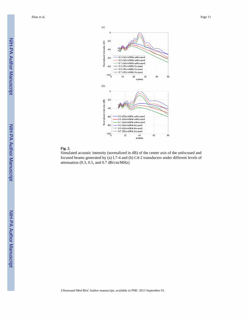
Fig. 2.Simulated acoustic intensity (normalized in dB) of the center axis of the unfocused andfocused beams generated by (a) L7-4 and (b) C4-2 transducers under different levels ofattenuation (0.3, 0.5, and 0.7 dB/cm/MHz)
Zhao et al. Page 11
Ultrasound Med Biol. Author manuscript; available in PMC 2013 September 01.
NIH
-PA Author Manuscript
NIH
-PA Author Manuscript
NIH
-PA Author Manuscript
Zhao et al. Page 12
Ultrasound Med Biol. Author manuscript; available in PMC 2013 September 01.
NIH
-PA Author Manuscript
NIH
-PA Author Manuscript
NIH
-PA Author Manuscript
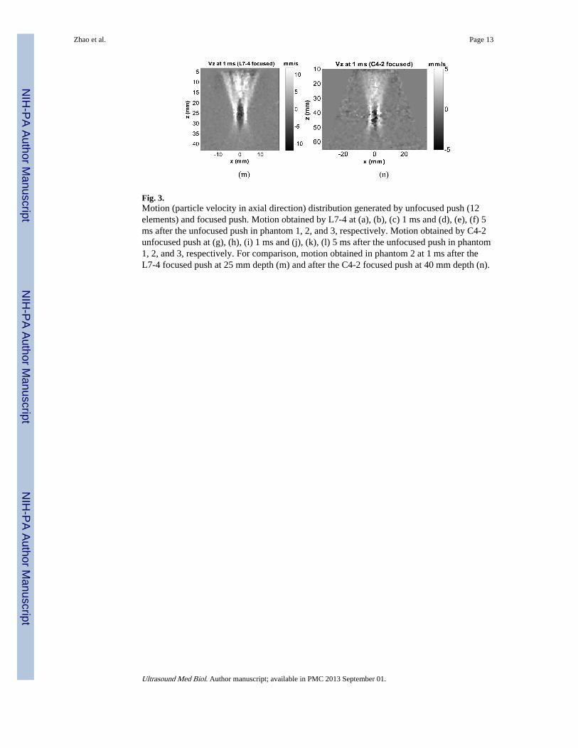
Fig. 3.Motion (particle velocity in axial direction) distribution generated by unfocused push (12elements) and focused push. Motion obtained by L7-4 at (a), (b), (c) 1 ms and (d), (e), (f) 5ms after the unfocused push in phantom 1, 2, and 3, respectively. Motion obtained by C4-2unfocused push at (g), (h), (i) 1 ms and (j), (k), (l) 5 ms after the unfocused push in phantom1, 2, and 3, respectively. For comparison, motion obtained in phantom 2 at 1 ms after theL7-4 focused push at 25 mm depth (m) and after the C4-2 focused push at 40 mm depth (n).
Zhao et al. Page 13
Ultrasound Med Biol. Author manuscript; available in PMC 2013 September 01.
NIH
-PA Author Manuscript
NIH
-PA Author Manuscript
NIH
-PA Author Manuscript
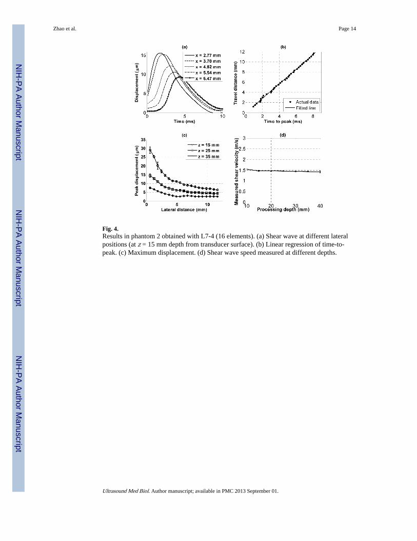
Fig. 4.Results in phantom 2 obtained with L7-4 (16 elements). (a) Shear wave at different lateralpositions (at z = 15 mm depth from transducer surface). (b) Linear regression of time-to-peak. (c) Maximum displacement. (d) Shear wave speed measured at different depths.
Zhao et al. Page 14
Ultrasound Med Biol. Author manuscript; available in PMC 2013 September 01.
NIH
-PA Author Manuscript
NIH
-PA Author Manuscript
NIH
-PA Author Manuscript
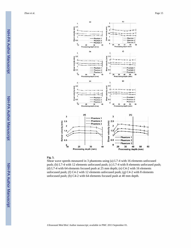
Fig. 5.Shear wave speeds measured in 3 phantoms using (a) L7-4 with 16 elements unfocusedpush; (b) L7-4 with 12 elements unfocused push; (c) L7-4 with 8 elements unfocused push;(d) L7-4 with 64 elements focused push at 25 mm depth; (e) C4-2 with 16 elementsunfocused push; (f) C4-2 with 12 elements unfocused push; (g) C4-2 with 8 elementsunfocused push; (h) C4-2 with 64 elements focused push at 40 mm depth.
Zhao et al. Page 15
Ultrasound Med Biol. Author manuscript; available in PMC 2013 September 01.
NIH
-PA Author Manuscript
NIH
-PA Author Manuscript
NIH
-PA Author Manuscript
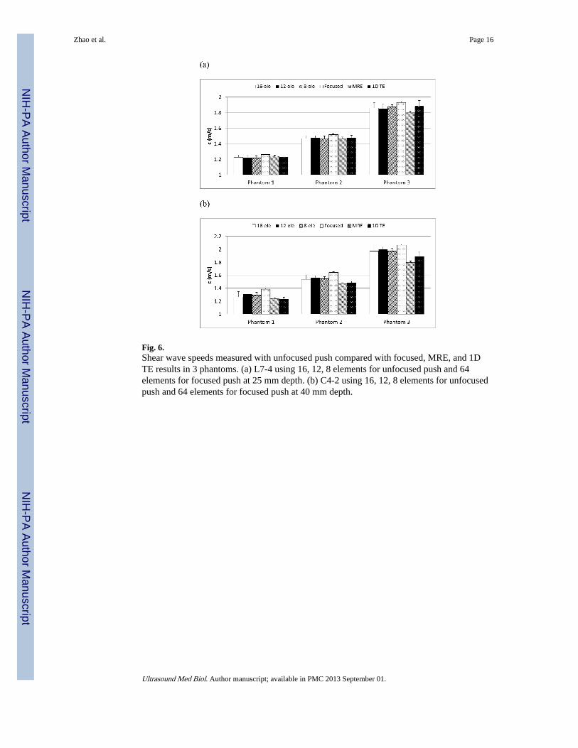
Fig. 6.Shear wave speeds measured with unfocused push compared with focused, MRE, and 1DTE results in 3 phantoms. (a) L7-4 using 16, 12, 8 elements for unfocused push and 64elements for focused push at 25 mm depth. (b) C4-2 using 16, 12, 8 elements for unfocusedpush and 64 elements for focused push at 40 mm depth.
Zhao et al. Page 16
Ultrasound Med Biol. Author manuscript; available in PMC 2013 September 01.
NIH
-PA Author Manuscript
NIH
-PA Author Manuscript
NIH
-PA Author Manuscript
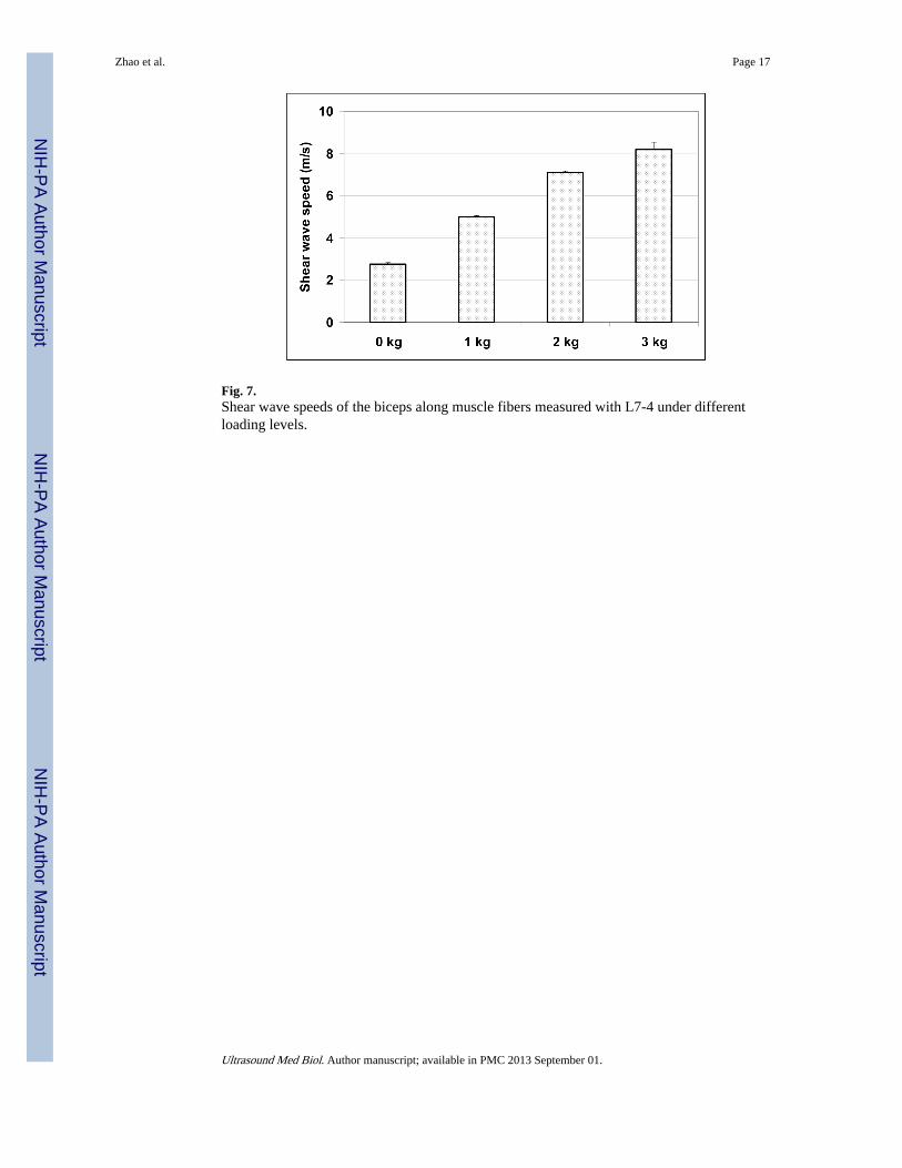
Fig. 7.Shear wave speeds of the biceps along muscle fibers measured with L7-4 under differentloading levels.
Zhao et al. Page 17
Ultrasound Med Biol. Author manuscript; available in PMC 2013 September 01.
NIH
-PA Author Manuscript
NIH
-PA Author Manuscript
NIH
-PA Author Manuscript
NIH
-PA Author Manuscript
NIH
-PA Author Manuscript
NIH
-PA Author Manuscript
Zhao et al. Page 18
Table 1
Acoustic output measurement results for the push beams used in this study
L7-4 unfocused C4-2 unfocused L7-4 focused C4-2 focused
MI0.3 0.75 0.83 1.46 1.66
ISPPA,0.3 (W/cm2) 100.8 72.7 455.8 327.6
ISPTA,0.3 (mW/cm2) 60.0 72.1 90.2 108.4
Temperature rise (°C) 0.005 0.006 0.007 0.009
Ultrasound Med Biol. Author manuscript; available in PMC 2013 September 01.
Related Documents


![Ultrasound velocimetry in a shear-thickening wormlike ...threadlike or wormlike micelles [1]. Aqueous solutions of these wormlike micelles are viscoelastic and their rheological behavior](https://static.cupdf.com/doc/110x72/60fa2b18789eb30fed0fef56/ultrasound-velocimetry-in-a-shear-thickening-wormlike-threadlike-or-wormlike.jpg)


