Shear Strengthening of Reinforced Concrete Beams with External Steel Bars and with CRFP C. R. LLopiz IMERIS, Facultad de Ingeniería, UNCuyo, Mendoza F. J. Crisafulli IMERIS, Facultad de Ingeniería, UNCuyo, Mendoza E. J. Vega IMERIS, Facultad de Ingeniería, UNCuyo, Mendoza SUMMARY The seismic retrofitting of existing buildings presents significant problems all around the world. Their study and assessment indicate that many different problems can be detected. Structural engineers need to apply several strategies to fulfil retrofitting process objectives. Achieving appropriate solutions is difficult task, particularly in developing countries: economical reasons or lack of technology reduce the available alternatives. This paper describes main results and conclusions obtained from an experimental research program conducted to evaluate response of two different shear strengthening schemes for applying to a high rise building. Objectives of proposed solutions are to (i) increase the shear strength of beam allowing the development of ductile plastic hinge at their ends and (ii) provide lateral support to longitudinal beam bars, to control their buckling. The paper also intends to verify soundness of some simplified models recently proposed to assess yield and ultimate curvature, rotation and displacement, comparing with experimental results here reported. Keywords: Shear Strengthening, Reinforded Concrete beam, Threaded Bars, CFRP. 1. SEISMIC RISK AND BUILDING CODE REGULATIONS The Poder Judicial Building, PJB, to be retrofitted is located in Mendoza, 1100 Km west of Buenos Aires, Argentina. The city was destroyed on March 1861 by a very strong shaking. It is within the highest seismic region of the country. Since that devastating event, just minor tremors have occurred nearby and therefore all building stock constructed in the last 150 years have not been tested by the current ultimate state design earthquake. The PJB was designed and constructed during the 70´s, just before the first official seismic code was to be enforced (CCA, Mza, 1970). As in any part of the world, at that time, the capacity design principles were not known and, even for relatively high buildings, the shear reinforcement resulted from the fictitious code forces rather than from the flexural capacity. Furthermore, in those days the 4.2mm diameter steel bars were allowed to be used as transverse reinforcement in Argentina. Lateral seismic coefficient adopted was 10 %g, and reinforced concrete members were proportioned and detailed according to German DIN 1045 regulations. The proposed retrofitting was based upon the new argentine seismic code (IC-103, part I, 2005) which follows the New Zealand earthquake resistant design philosophy (Paulay and Priestley, 1992). 2. DESCRIPTION OF THE BUILDING STRUCTURE Strengthening of PJB girders are main objective of this paper, is a ten story public office construction, with one basement, 9500 m 2 covered area and almost 40 m total height. Figure 1 shows the PJB structural plans and the front façade. It is a complete in situ cast reinforced concrete structure. The original design attempted to consider spatial frames as the only main lateral resistance system for both directions. However, as can be appreciated in Figure 1, some squat reinforced concrete walls are present in the lower stories in the longitudinal direction, and from the foundation to the top two channel-shaped walls enclose the area of elevators and stairs. As was the practice of those days in Mendoza, all

Welcome message from author
This document is posted to help you gain knowledge. Please leave a comment to let me know what you think about it! Share it to your friends and learn new things together.
Transcript
Shear Strengthening of Reinforced Concrete Beams with
External Steel Bars and with CRFP
C. R. LLopiz IMERIS, Facultad de Ingeniería, UNCuyo, Mendoza
F. J. Crisafulli IMERIS, Facultad de Ingeniería, UNCuyo, Mendoza
E. J. Vega IMERIS, Facultad de Ingeniería, UNCuyo, Mendoza
SUMMARY
The seismic retrofitting of existing buildings presents significant problems all around the world. Their study and
assessment indicate that many different problems can be detected. Structural engineers need to apply several
strategies to fulfil retrofitting process objectives. Achieving appropriate solutions is difficult task, particularly in
developing countries: economical reasons or lack of technology reduce the available alternatives. This paper
describes main results and conclusions obtained from an experimental research program conducted to evaluate
response of two different shear strengthening schemes for applying to a high rise building. Objectives of proposed
solutions are to (i) increase the shear strength of beam allowing the development of ductile plastic hinge at their
ends and (ii) provide lateral support to longitudinal beam bars, to control their buckling. The paper also intends to
verify soundness of some simplified models recently proposed to assess yield and ultimate curvature, rotation and
displacement, comparing with experimental results here reported.
Keywords: Shear Strengthening, Reinforded Concrete beam, Threaded Bars, CFRP.
1. SEISMIC RISK AND BUILDING CODE REGULATIONS
The Poder Judicial Building, PJB, to be retrofitted is located in Mendoza, 1100 Km west of Buenos
Aires, Argentina. The city was destroyed on March 1861 by a very strong shaking. It is within the
highest seismic region of the country. Since that devastating event, just minor tremors have occurred
nearby and therefore all building stock constructed in the last 150 years have not been tested by the
current ultimate state design earthquake.
The PJB was designed and constructed during the 70´s, just before the first official seismic code was to
be enforced (CCA, Mza, 1970). As in any part of the world, at that time, the capacity design principles
were not known and, even for relatively high buildings, the shear reinforcement resulted from the
fictitious code forces rather than from the flexural capacity. Furthermore, in those days the 4.2mm
diameter steel bars were allowed to be used as transverse reinforcement in Argentina. Lateral seismic
coefficient adopted was 10 %g, and reinforced concrete members were proportioned and detailed
according to German DIN 1045 regulations. The proposed retrofitting was based upon the new
argentine seismic code (IC-103, part I, 2005) which follows the New Zealand earthquake resistant
design philosophy (Paulay and Priestley, 1992).
2. DESCRIPTION OF THE BUILDING STRUCTURE
Strengthening of PJB girders are main objective of this paper, is a ten story public office construction,
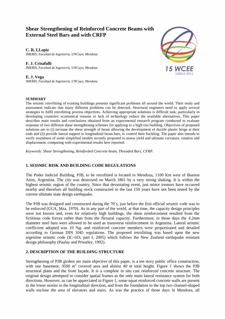
with one basement, 9500 m2 covered area and almost 40 m total height. Figure 1 shows the PJB
structural plans and the front façade. It is a complete in situ cast reinforced concrete structure. The
original design attempted to consider spatial frames as the only main lateral resistance system for both
directions. However, as can be appreciated in Figure 1, some squat reinforced concrete walls are present
in the lower stories in the longitudinal direction, and from the foundation to the top two channel-shaped
walls enclose the area of elevators and stairs. As was the practice of those days in Mendoza, all
reinforced concrete walls were ignored in the design and the whole seismic demand was allocated to the
frames. Under such circumstances, should an intense quake hit the building, brittle shear failures can be
anticipated since, once again, transverse reinforcement was assigned just to cover minimum steel
requirements, typically 6mm bars spacing 150 mm, many times in a single mesh at the middle of the
wall thickness. Strengthening of the walls is outside the scope of this paper.
At a glance, the structure was reasonably symmetric, particularly in the longitudinal direction and, for
both directions, in the emerging eight stories high portion tower. The vertical circulation core is almost
centered. In lower stories, the centre of mass migrates some distance to the front facade but the mass
induced eccentricity is not dramatic and it is not an issue.
Figure 1. Structural Plans of the building and front facade. In read ellipse (d) tested girders.
Most of columns were either rectangular 400mm or 360mm wide by 1000mm or 1200 mm high, or
cross-shaped section with similar dimensions. It was fortunate that the column design to flexure was
very conservative and therefore, in almost all cases columns are stronger than girders. Furthermore, for
the transverse steel in columns, 8mm bar diameter were used.
Slabs are supported in one direction with 100mm or 120 mm thickness. Once again, 4.2mm bars are
used in the weak direction. No damage for acting gravity loads were observed to this time and the same
applies to foundations and the supporting soil.
Structural walls were ignored for the seismic lateral resistance. However, exterior squat walls have
enough longitudinal steel for supporting lateral soil pressure. Even though squat shear mechanisms
(Paulay and Priestley, 1992) were not enough to withstand elastic demands, during the retrofitting
design process, the assigned force were tuned according to what is needed for the rest of the structure.
The U-shaped interior walls, due to high reinforcement in the flange borders, lack of transverse
reinforcement and will need also to be shear strengthened. Typical interior girders are 300mm-600mm,
width-total height. In the outside frames proportions change to 250mm-1100mm respectively. For all
girders, transverse reinforcement consist of two legs of 4.2mm diameter spacing from 100mm to
250mm. Figure 2 shows typical reinforcement details for interior girders at roof level. Regarding
flexural reinforcement, it was a positive fact that for gravity loads the original criteria was to consider
girders almost simple supported on columns and therefore when superimposed to seismic actions the
demands for positive and negative moments were almost identical. As a consequence, and can be seen
(a) Basement (b) Ground Floor
(c) First Floor (d) Second to
Seventh Floor x
y
(f) Front Facade
(e) Column Shapes

in the figure, girders resulted with almost the same reinforcement for both positive and negative support
moments (6-20mm bars on the left, 5-20mm on the right). However immediately, and just by inspection,
several simultaneous problems become apparent: (i) diameter of the stirrups, 4.2mm, are very small and
too spaced to preclude premature buckling of the longitudinal bars; (ii) for the same reason, there is not
enough stirrups to resist shear when flexural resistance along with large ductility demands; (iii) large
discontinuity in flexural and shear strength since only 2-10mm bars as basic top beam reinforcement
and all bend-up (normally 3-20mm bars) located at the same position. The overcoming of these
drawbacks regarding the potential poor response of the building against seismic attack is presented next.
Figure 2. Typical reinforcement for an interior girder at roof level.
PJB did not presented at time of inspection any visible damage. However, regarding seismic events, it
was never compromised since its construction. There exists minor cracking as observed in any normal
reinforced concrete construction. Quality of concrete, evaluated through cylindrical 3 inches (75mm)
diameter samples, was good, average 21MPa for slabs and girders and 17MPa for walls and columns.
The steel available at the time of construction was cold twisted, fy=420MPa. After tested in the lab,
4.2mm and 6mm diameters resulted with average fy=600 MPa and fmax=650 MPa, while 12mm and
16mm diameters resulted fy=500 MPa and fmax=550 MPa. No defined yield region, low strain hardening
and low ultimate strain were observed. Beam-column joints, in general, satisfied the code condition (IC-
103-2005) that the maximum nominal shear stress should not exceed 0.16f´c.
3. CODE REGULATIONS FOR DUCTILE BEHAVIOUR
A summary of current code regulations (IC-105-2005) are revised and contrasted against the design of
the girders under study, in particular with respect to transverse reinforcement.
(i) Minimum diameter bar 6mm: not satisfied (used 4.2mm)
(ii) Maximum spacing in plastic hinge regions 6db=120mm (for 20mm longitudinal bar) and
d/4=137mm, normally not satisfied (150 mm was the usual spacing)
(iii) Minimum area of stirrup with respect to area of supported longitudinal bar against buckling:
Ate=(∑Ab/16)(s/6db), not satisfied, since for one 4.2mm leg spacing 150mm, the maximum area allowed
to support is 177mm2, i.e., not even one 20mm (area 314mm
2) bar is code protected.
(iv) Minimum steel reinforcement for shear in plastic hinge, where vc=0. For the case of Figure 2,
seismic action from the left, positive nominal moment of the left is about 420KNm and negative
nominal on the right is close to 360KNm. Overstrength moments are 588KNm and 504KNm
respectively, and when shear due to gravity, about 100KN, is incorporated, the maximum shear demand
results Vu=[(588+504)/5.60+100]KN=295KN. The resulting shear stress is vu=1.80MPa. The required
transverse reinforcement would be then Av=(1.80x300x120/420)mm2, and therefore, three 8mm bar legs,

spacing 120mm is required. Only two 4.2mm spacing 150mm are supplied, i.e., almost seven times less
than code requirements. Minimum shear steel reinforcement given by
Amin=(0.333/fy)bws=(0.333/420)x30x120mm2=29mm
2 would be almost satisfied if the spacing for the
4.2mm stirrups would have been 120mm, not 150mm as it was.
4. PRELIMINARY 1:2 SCALE TESTS
Final objective of this research was to investigate 1:1 scale models to implement strengthening of
girders at column supports. Dimensions of the column-beam-slab subassemblages are considerable as it
is the associated cost for construction, handling and testing, among other aspects. Therefore, it was
decided to build the minimum necessary amount of 1:1 scale models but to perform previously a series
of tests on 1:2 scale models, Figure 3, which served to tune up the final proposals at real scale.
Figure 3. Half scale models strengthened for shear and to delay buckling of longitudinal bars:
(a) Steel plates with welded threaded bolts and top plate;(b) CFRP full wrap and (c) Threaded bars with top
plate and bottom angle
Dimensions of scaled models are 150mm width and 300mm total height. Three strengthening strategies,
as shown in Figure 3, were implemented: (a) see Figure 3(a), U-shaped steel plates whose flanges are
15cm
30cm
15cm
30cm

welded to crossing-slab threaded bars (to simulate the real construction) which in turn are adjusted
through a crossing transverse plate; (b) Figure 3(b), strips of Carbon Fiber Reinforced Polymers) CRFP,
making a full wrapped member, and (c) Figure 3(c) threaded bars each side of the web, adjusted by
bolting to plates at top and angles at bottom of girder faces. Two additional half scale models were
tested, one practically without stirrups (just one in the middle of the length to keep longitudinal bars in
position), and the other with transverse reinforcement designed according to capacity design. Both
served as reference since the first showed the behavior controlled by shear failure and the other gave the
response to be imitated to. Main conclusions from these tests are:
(i) The element without stirrups had a sudden and very brittle failure.
(ii) The girder designed for capacity against shear reached the maximum flexural strength as
predicted, and was able to develop a displacement ductility exceeding 5 (five) without loss
of strength. The test was interrupted before total collapse occurred.
(iii) The 3 (three) girders strengthened to shear behaved with similar response to the previous
well designed. However, the element with CFRP did not showed good response when only
one FRP wrapped the section. It is recommended, (ACI 440-F, 2010, and ACI- 440.2R-08,
2008), that a minimum of two plies be used for proper confinement response in plastic
hinge regions. The response with FRP improved substantially when this recommendation
was implemented in the tested girder.
(iv) The authors of tests reported here felt more confidence with use of the U steel shape, case
(a), but its implementation is more expensive and difficult to build in the field than the
simplest solution which resulted to be case (c). This is also the cheapest among all.
(v) The use of FRP requires good knowledge of the fiber to apply as well as experienced
workmanship to follow all necessary previous preparation of the surface.
5. FULL SCALE MODELS
Typical interior frame girders are T shaped, 6600mm span at column axes, 300 mm web width, 600mm
total height supporting slabs of 100mm thickness. Therefore, the full scale models are subassemblages
of same dimensions, with flange of the 1650mm as effective width since it responds to the ratio l/4 and
close to the (bw+16hs) permitted for the code. The girder longitudinal steel was almost symmetric for
positive and negative moments at supports. For negative moments there exists some small additional
contribution coming from the basic steel adopted as top bars, 2-10mm diameter bars, and from the
secondary steel of the slab, namely 4.2mm spacing 150mm.
Three models with identical steel arrangement were constructed, as shown in Figure 4, except for the
first subassemblage with transverse girder reinforcement designed applying principles of capacity
design. In all cases, free end of the girders were heavily reinforced with stirrups to avoid any failure at
point loading. In the PJB girders, longitudinal steel changed from 4 to 8 bars-20mm diameter. Web steel
ratio then changes from 0.77 % to 1.55 %, top and bottom. Figure 4(d) indicates 1256mm2 for bottom
reinforcement and 1417mm2 for the top negative, corresponding almost 0.8% longitudinal steel ratio.
Figure 5 shows test scheme, both top and bottom of columns hinged to simulate zero moment at middle
column. Static reversible load applied to girder end, with length simulating half span of the girders. On
the right appears the hydraulic jack 50ton capacity, with 400mm maximum stroke.
The end girder vertical displacements were measured by two LVDTs, and vertical and horizontal
movements of the supporting blocks were also monitored for corrections. Rotations and curvatures are
measured at three girder sections (three for each section, one on top and two at the bottom), close to the
column face. Relative displacements are detected through linear potentiometers spanning between
pieces of steel bars 4.2mm diameter which are fixed to girder longitudinal bars. A total of fourteen
sensors were installed. At the centre, Figure 5(b) scheme of instrumentation installed.

Figure 4. Full scale model: (a) Above left, longitudinal view section of the tested girder, showing also the
transverse beam framing also to joint; (b) Above right, cross section of column; (c) Left below, girder cross
section 3-3 and (d) Right below, girder cross section 2-2. The transverse reinforcement under (8mm diameter)
applies to the girder designed for capacity.
Figure 5. Full Scale Model: (a) testing scheme; (b) instrumentation and (c) full scale model fixed to 800mm
thickness L-Slab-Wall reacting system at the IMERIS structural laboratory.
5.1 Shear Capacity Design Model
5.1.1 Local and Global Response.
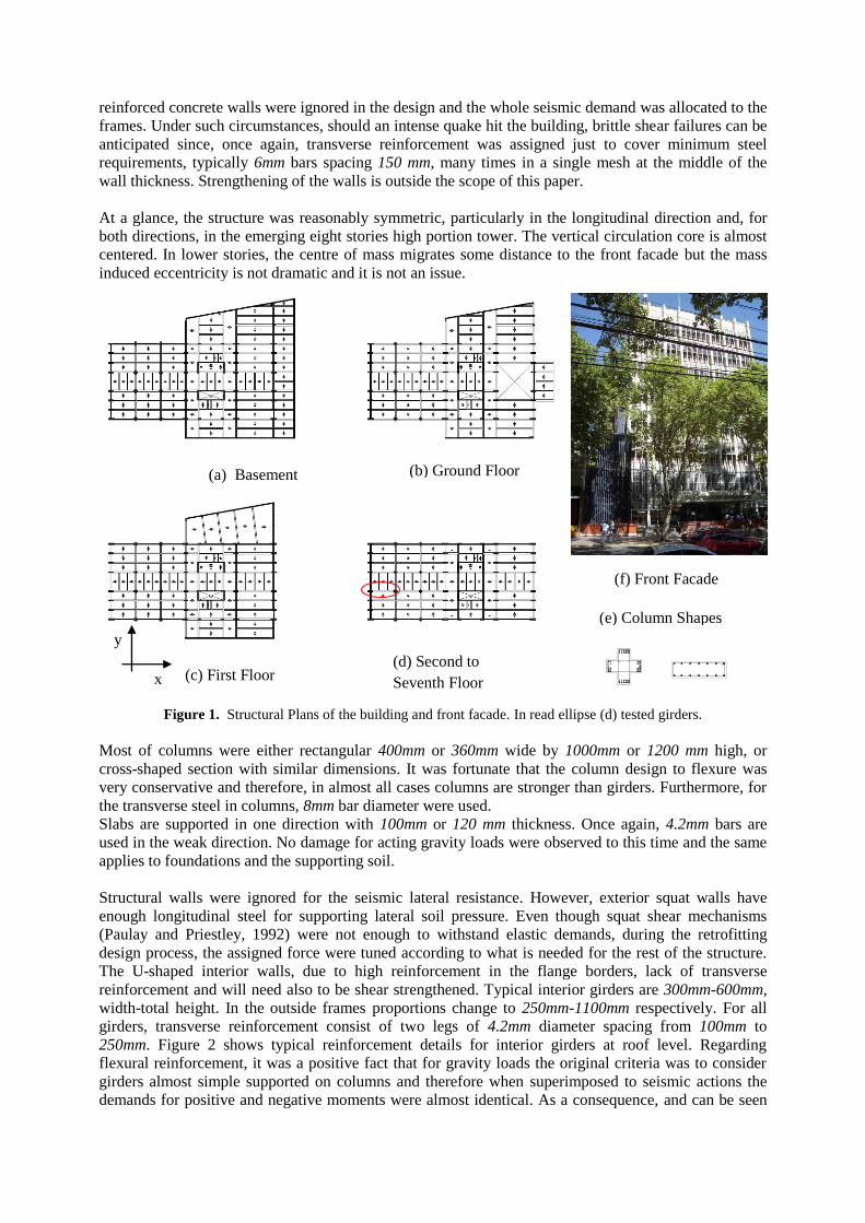
The first model tested, shown in Figure 6, intended to satisfy all current argentine requirements (IC-
103-2005) regarding transverse reinforcement. Figure 7 shows the complete local response in terms of
Moment vs. Curvature. The result for the testing the ADN-420, designation for the type of steel,
fy=420MPa, used as longitudinal reinforcement in the girders, 20mm diameter bar is included.
LVDT 03
LVDT 01
LVDT 04
PD01
PS01 PS02 PS03
PII01 PII02 PII03PID01 PID02 PID03
d1 d2 d3
2.65m
S1 S2 S3
External Joint Subassemblage
Hydraulic jack
Column Longitudinal Steel 14 25mm
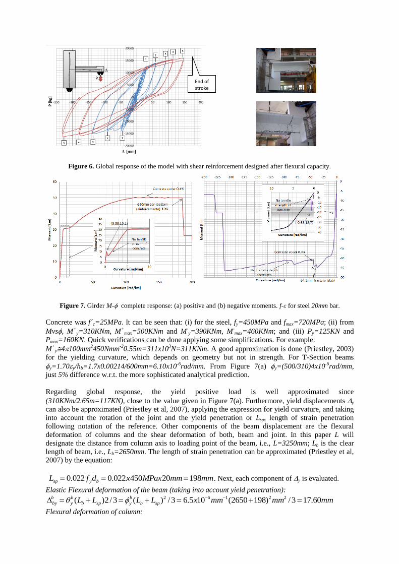
Figure 6. Global response of the model with shear reinforcement designed after flexural capacity.
Figure 7. Girder M- complete response: (a) positive and (b) negative moments. f-ε for steel 20mm bar.
Concrete was f´c=25MPa. It can be seen that: (i) for the steel, fy=450MPa and fmax=720MPa; (ii) from
Mvs, M+
y=310KNm, M+
max=500KNm and M-y=390KNm, M
-max=460KNm; and (iii) Py=125KN and
Pmax=160KN. Quick verifications can be done applying some simplifications. For example:
M+
y4100mm2450Nmm
-20.55m=311x10
3N=311KNm. A good approximation is done (Priestley, 2003)
for the yielding curvature, which depends on geometry but not in strength. For T-Section beams
y=1.70y/hb=1.7x0.00214/600mm=6.10x10-6
rad/mm. From Figure 7(a) y=(500/310)4x10-6
rad/mm,
just 5% difference w.r.t. the more sophisticated analytical prediction.
Regarding global response, the yield positive load is well approximated since
(310KNm/2.65m=117KN), close to the value given in Figure 7(a). Furthermore, yield displacements y
can also be approximated (Priestley et al, 2007), applying the expression for yield curvature, and taking
into account the rotation of the joint and the yield penetration or Lsp, length of strain penetration
following notation of the reference. Other components of the beam displacement are the flexural
deformation of columns and the shear deformation of both, beam and joint. In this paper L will
designate the distance from column axis to loading point of the beam, i.e., L=3250mm; Lb is the clear
length of beam, i.e., Lb=2650mm. The length of strain penetration can be approximated (Priestley et al,
2007) by the equation:
mmmmMPaxxdfL bysp 19820450022.0022.0 . Next, each component of y is evaluated.
Elastic Flexural deformation of the beam (taking into account yield penetration):
mmmmmmxLLLL spb
b
yspb
b
y
b
by 60.173/)1982650(105.63/)(3/2)( 22162
Flexural deformation of column:
End of stroke
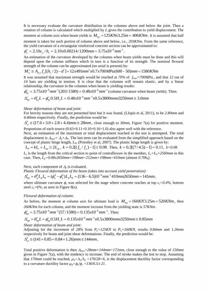
It is necessary evaluate the curvature distribution in the columns above and below the joint. Then a
rotation of column is calculated which multiplied by L gives the contribution to yield displacement. The
moment at column axis when beam yields is KNmmKNxMby 40625.3125 . It is assumed that half
moment is taken for each portion of column above and below, i.e., 203KNm. From the same reference,
the yield curvature of a rectangular reinforced concrete section can be approximated to: 161075.31200/00214.010.2/10.2 mmxmmxhcy
c
y .
An estimation of the curvature developed by the columns when beam yields must be done and this will
depend upon the column stiffness which in turn is a function of its strength. The nominal flexural
strength of the column can be approximated (no axial is present) by:
KNmmmMPaxxmmxdhfAM cytst
c
n 1580)50600(7007.049112´])2/[( 2
,
It was assumed that maximum strength would be reached at 70% of fmax=700MPa., and that 12 out of
14 bars are yielding in tension. It is clear that the columns will remain elastic, and by a linear
relationship, the curvature in the columns when beam is yielding results: 1616 1048.0)1580/203(1075.3 mmxmmxc
by (column curvature when beam yields). Then:
mmmmmmxxxmmxLHL c
c
by
c
by
c
by 0.3325038005.01048.05.0 16
Shear deformation of beam and joint:
For brevity reasons they are not presented here but it was found, (Llopiz et al, 2011), to be 2.80mm and
4.40mm respectively. Finally, the prediction would be:
mmmmb
y 28)4.48.20.36.17( , close enough to 30mm, Figure 7(a) for positive moment.
Proportions of each source (0.63+0.11+0.10+0.16=1.0) also agree well with the reference.
Next, an estimation of the maximum or total displacement reached in the test is attempted. The total
displacement is max= y+P. The last term can be evaluated from the simplified approach based on the
concept of plastic hinge length, LP, (Priestley et al, 2007). The plastic hinge length is given by:
spspcP LLkLL 2 , 08.0]1)/[(2.0 yu ffk . Then, 11.0]1)5.4/7[(2.0 k , k=0.08.
Lc is the length from the critical section to point of contraflexure in the member, Lc=Lb=2560mm in this
case. Then, Lp=0.08x2650mm+198mm=212mm+198mm=410mm (almost 0.70hb).
Next, each component of p is evaluated.
Plastic Flexural deformation of the beam (takes into account yield penetration):
mmmmmmmmLLLL bp
b
y
b
ubp
b
p
b
bp 141265041010)5.6136()( 16 ,
where ultimate curvature u was selected for the stage where concrete reaches at top εc=0.4%, bottom
steel εs=6%, as seen in Figure 8(a).
Flexural deformation of column:
As before, the moment at column axis for ultimate load is KNmmKNMbu 52025.3160 , then
260KNm for each column, and the moment increase from the yielding state is 57KNm. 1616 10135.0)1580/57(1075.3 mmxmmxc
bp . Then:
mmmmmmxxxmmxLHL c
c
bp
c
bp
c
bp 85.0325038005.010135.05.0 16
Shear deformation of beam and joint:
Adjusting for the increment of 28% from Py=125KN to Pu=160KN, results 0.84mm and 1.26mm
respectively for beam and joint shear deformations. Finally, the prediction would be:
mmmmb
p 144)26.184.085.0141( ,
Total positive deformation is then max=28mm+144mm=172mm, close enough to the value of 150mm
given in Figure 7(a), with the tendency to increase. The end of stroke makes the test to stop. Assuming
that 170mm could be reached, ∆=∆u/∆y =170/28=6, is the displacement ductility factor corresponding
to a curvature ductility factor =u/y =136/6.5 21.
By inspecting Figure 6(a), it can be seen that the maximum negative displacement was close to 230mm,
and since yield displacement is almost 40mm, the ductility on reverse load was quite similar.
5.1.2 Design of Plastic Hinge for Ductile Behaviour.
From analytical predictions, Mmax=500KNm for positive and Mmax=460Knm for negative case,
considering real fs-εs relationship for the steel. Code nominal moment with specified fy=420MPa was
Mn=300KNm. Applying the code material overstrength factor o=1.40, code overstrength moment is
Mo=420KNm. The tested beam will be subjected, should an earthquake occur, to an additional 37KN/m
due to gravity loads and therefore, the ultimate shear demand is:
KNKNKNmmxKNmKNmVu 28010018065.2/37]30.5/)460500[(
Maximum stirrup spacing is s=6x20mm=120mm, or s=d/4=560mm/4=140mm.
It was adopted three 8mm legs spaced 120mm, as shown in Figure 5(c). The nominal shear strength is:
KNKNmmKNxmmmmxmmxVn 280294/420.0)120/560(503 22
This shear resistance was taken as reference for designing the strengthening of the other two models.
5.1.3 Analysis of observed experimental response.
Stable elastic response resulted after many reversal cycles. Very ductile behaviour was achieved up to
displacement ductility ∆=6. Typical flexure-shear cracks appeared along the test, and at large ductility
demands longitudinal steel starts buckling. Minor cracks observed in the joints and columns.
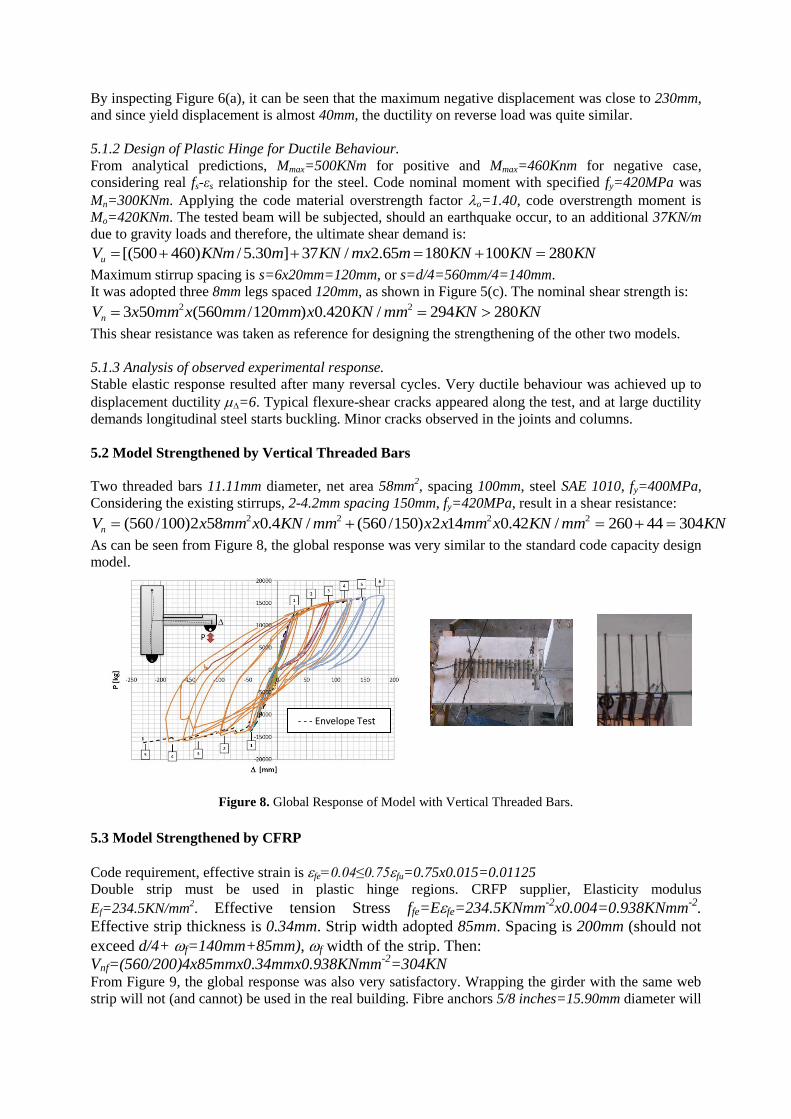
5.2 Model Strengthened by Vertical Threaded Bars
Two threaded bars 11.11mm diameter, net area 58mm2, spacing 100mm, steel SAE 1010, fy=400MPa,
Considering the existing stirrups, 2-4.2mm spacing 150mm, fy=420MPa, result in a shear resistance:
KNmmKNxmmxxmmKNxmmxVn 30444260/42.0142)150/560(/4.0582)100/560( 2222
As can be seen from Figure 8, the global response was very similar to the standard code capacity design
model.
Figure 8. Global Response of Model with Vertical Threaded Bars.
5.3 Model Strengthened by CFRP
Code requirement, effective strain is fe=0.04≤0.75fu=0.75x0.015=0.01125
Double strip must be used in plastic hinge regions. CRFP supplier, Elasticity modulus
Ef=234.5KN/mm2. Effective tension Stress ffe=Efe=234.5KNmm
-2x0.004=0.938KNmm
-2.
Effective strip thickness is 0.34mm. Strip width adopted 85mm. Spacing is 200mm (should not
exceed d/4+ f=140mm+85mm), f width of the strip. Then:
Vnf=(560/200)4x85mmx0.34mmx0.938KNmm-2
=304KN From Figure 9, the global response was also very satisfactory. Wrapping the girder with the same web
strip will not (and cannot) be used in the real building. Fibre anchors 5/8 inches=15.90mm diameter will
- - - Envelope Test
1
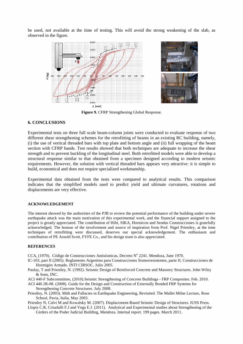
be used, not available at the time of testing. This will avoid the strong weakening of the slab, as
observed in the figure.
Figure 9. CFRP Strengthening Global Response.
6. CONCLUSIONS
Experimental tests on three full scale beam-column joints were conducted to evaluate response of two
different shear strengthening schemes for the retrofitting of beams in an existing RC building, namely,
(i) the use of vertical threaded bars with top plate and bottom angle and (ii) full wrapping of the beam
section with CFRP bands. Test results showed that both techniques are adequate to increase the shear
strength and to prevent buckling of the longitudinal steel. Both retrofitted models were able to develop a
structural response similar to that obtained from a specimen designed according to modern seismic
requirements. However, the solution with vertical threaded bars appears very attractive: it is simple to
build, economical and does not require specialized workmanship.
Experimental data obtained from the tests were compared to analytical results. This comparison
indicates that the simplified models used to predict yield and ultimate curvatures, rotations and
displacements are very effective.
ACKNOWLEDGEMENT
The interest showed by the authorities of the PJB to review the potential performance of the building under severe
earthquake attack was the main motivation of this experimental work, and the financial support assigned to the
project is greatly appreciated. The contribution of Hilti, SIKA, Hormicon and Sendas Construcciones is gratefully
acknowledged. The honour of the involvement and source of inspiration from Prof. Nigel Priestley, at the time
techniques of retrofitting were discussed, deserves our special acknowledgement. The enthusiasm and
contribution of PE Arnold Scott, FYFE Co., and his design team is also appreciated.
REFERENCES
CCA, (1970). Código de Construcciones Antisísmicas, Decreto No 2241. Mendoza, June 1970.
IC-103, part II (2005). Reglamento Argentino para Construcciones Sismorresistentes, parte II, Construcciones de
Hormigón Armado. INTI CIRSOC. Julio 2005.
Paulay, T and Priestley, N. (1992). Seismic Design of Reinforced Concrete and Masonry Structures. John Wiley
& Sons, INC.
ACI 440-F Subcommittee, (2010).Seismic Strengthening of Concrete Buildings - FRP Composites. Feb. 2010.
ACI 440.2R-08. (2008). Guide for the Design and Construction of Externally Bonded FRP Systems for
Strengthening Concrete Structures. July 2008.
Priestley, N. (2003). Mith and Fallacies in Earthquake Engineering, Revisited. The Mallet Milne Lecture, Rose
School, Pavia, Italia, May 2003.
Priestley N, Calvi M and Kowalsky M. (2007). Displacement-Based Seismic Design of Structures. IUSS Press.
Llopiz C.R, Crisafulli F.J and Vega E.J. (2011). Analytical and Experimental studies about Strengthening of the
Girders of the Poder Judicial Building, Mendoza. Internal report. 199 pages. March 2011.
- - - Envelope Test 1
____FRP Mod
Related Documents