Learning Objectives To understand the students about important parts of shaping machine, application of machine mechanism, various types of operations performed in the machine. CONTENTS 3.1 Introduction 3.2 Process of machining 3.3 Main parts of the shaping machine 3.4 Types of shaping machine 3.5 Quick return mechanism 3.6 e size of a shaper 3.7 Adjusting the length of stroke 3.8 Method of table movement 3.9 Pawl and Ratchet mechanism 3.10 Swivel tool head 3.11 Work-Holding devices 3.12 Types of shaper tools 3.13 Setting of shaper table, vice and Tool head 3.14 Types of shaping operations 3.15 Special operations 3.16 Cutting speed, depth of cut and feed 3.17 Coolant 3.18 Safety precautions Shaping Machine 57 Uruvu kandu ellaamai vaendum urul Perundhaerkku achchaani annar udaiththu. – Kural 667 Despite not men of modest bearing, look not at form, but what men are, for some there live, high functions sharing, like linch- pin of the mighty car. 03 C H A P T E R XII BME_English version CHAPTER 03.indd 57 1/8/2020 1:43:56 PM

Welcome message from author
This document is posted to help you gain knowledge. Please leave a comment to let me know what you think about it! Share it to your friends and learn new things together.
Transcript
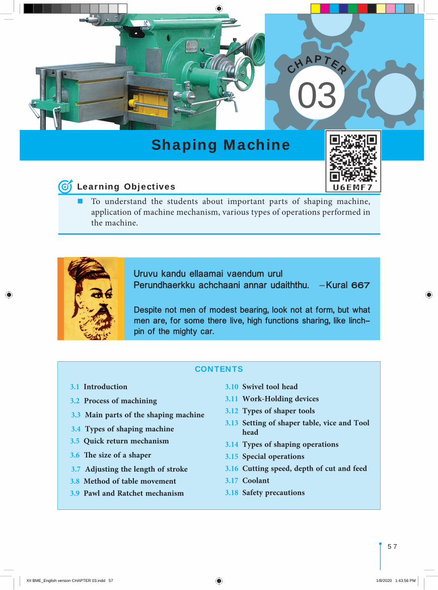
Learning Objectives�To understand the students about important parts of shaping machine,
application of machine mechanism, various types of operations performed in the machine.
CONTENTS
3.1 Introduction
3.2 Process of machining
3.3 Main parts of the shaping machine
3.4 Types of shaping machine 3.5 Quick return mechanism
3.6 The size of a shaper
3.7 Adjusting the length of stroke 3.8 Method of table movement 3.9 Pawl and Ratchet mechanism
3.10 Swivel tool head3.11 Work-Holding devices3.12 Types of shaper tools3.13 Setting of shaper table, vice and Tool
head3.14 Types of shaping operations3.15 Special operations3.16 Cutting speed, depth of cut and feed3.17 Coolant3.18 Safety precautions
Shaping Machine
5 7
Uruvu kandu ellaamai vaendum urulPerundhaerkku achchaani annar udaiththu. – Kural 667
Despite not men of modest bearing, look not at form, but what men are, for some there live, high functions sharing, like linch-pin of the mighty car.
03
CHAPTER
XII BME_English version CHAPTER 03.indd 57 1/8/2020 1:43:56 PM
5 8 CHAPTER 03 SHAPING MACHINE
Shaping machine was designed by James Nasmith, an Englishman in the year 1936. He designed it to produce flat surface. After it was designed by him to produce various surfaces like horizontal, vertical, inclined, concave and convex surfaces.
James Nasmith
3.1 IntroductionShaping is a process of machining a flat surface which may be horizontal, vertical, inclined, concave or convex using a reciprocating single point tool. A shaping machine is a reciprocating type of machine tool. James Nasmith, an Englishman designed a shaping machine to produce flat surfaces in the year 1836.
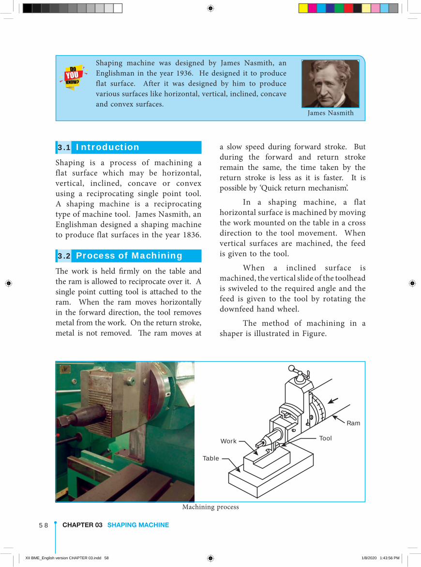
3.2 Process of MachiningThe work is held firmly on the table and the ram is allowed to reciprocate over it. A single point cutting tool is attached to the ram. When the ram moves horizontally in the forward direction, the tool removes metal from the work. On the return stroke, metal is not removed. The ram moves at
a slow speed during forward stroke. But during the forward and return stroke remain the same, the time taken by the return stroke is less as it is faster. It is possible by ‘Quick return mechanism’.
In a shaping machine, a flat horizontal surface is machined by moving the work mounted on the table in a cross direction to the tool movement. When vertical surfaces are machined, the feed is given to the tool.
When a inclined surface is machined, the vertical slide of the toolhead is swiveled to the required angle and the feed is given to the tool by rotating the downfeed hand wheel.
The method of machining in a shaper is illustrated in Figure.
Table
Work Tool
Ram
Machining process
XII BME_English version CHAPTER 03.indd 58 1/8/2020 1:43:56 PM
5 9CHAPTER 03 SHAPING MACHINE
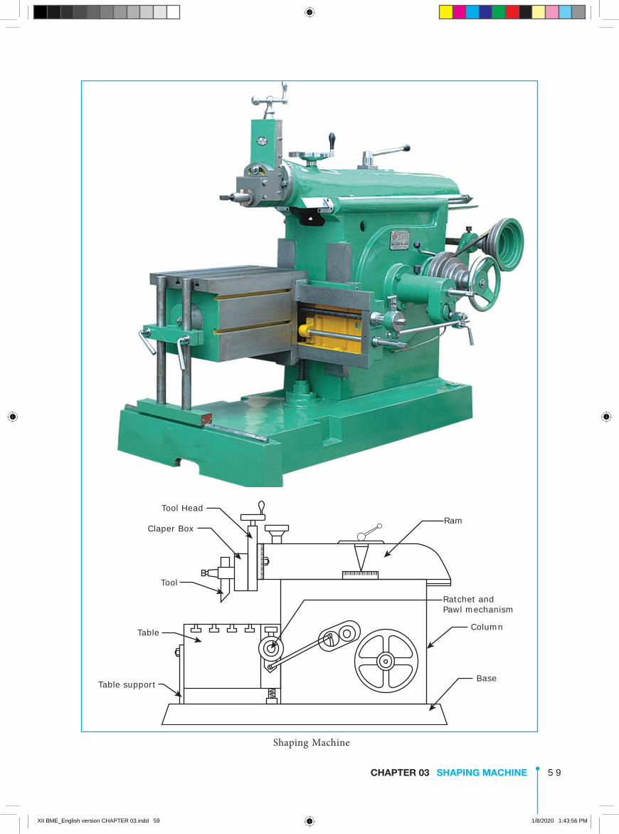
Table support
Table
Tool
Tool Head
Claper BoxRam
Ratchet and Pawl mechanism
Column
Base
Shaping Machine
XII BME_English version CHAPTER 03.indd 59 1/8/2020 1:43:56 PM
6 0 CHAPTER 03 SHAPING MACHINE
TableIt is an important part useful in holding the work firmly on it. It is mounted on the saddle which is located above the crossrail. The top and sides of the table are accurately machined and have T-slots. Workpieces are held on the table with the help of shaper vise, clamps and straps.
RamRam supports the toolhead on its front. It reciprocates on the accurately machined guideways on the top of the column. It is connected to the reciprocating mechanism placed inside the column. The position of ram reciprocation may be adjusted according to the location of the work on the table.
ToolheadThe toolhead is fitted on the face of the ram and hold the tool rigidly. It provides vertical and angular feed movement of the tool. The swivel toolhead can be positioned at any required angle and the vertical slide can be moved vertically or at any desired angle to machine vertical or inclined surfaces.
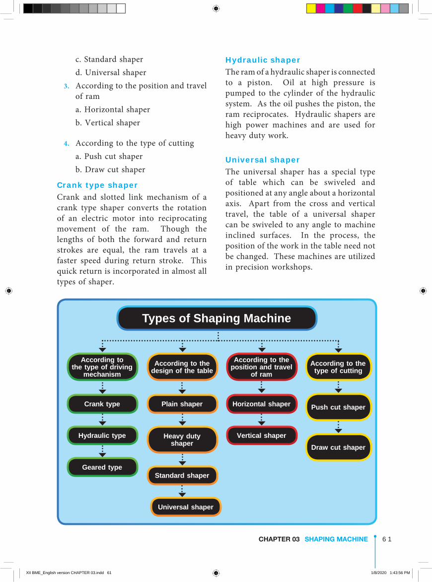
3.4 Types of shaping machine
The shaping machines are classified as follows
1. According to the type of driving mechanism
a. Crank type b. Hydraulic type c. Geared type 2. According to the design of the table a. Plain shaper b. Heavy duty shaper
3.3 Main parts of shaping machine
BaseThe base is hollow and is made of cast iron. It provides the necessary support for all the other parts of the machine. It is rigidly bolted to the floor of the workshop.
ColumnIt is a box like casting mounted vertically on top of the base. Two accurate guideways are machined on the top of the column. The ram reciprocates on these guideways. The front face of the column is provided with two vertical guideways. They act as guideways for the crossrail. Crossrail moves vertically along these guideways. The column encloses the ram reciprocating mechanism and the mechanism for strokelength adjustment.
Cross rail It is mounted on the front vertical guideways of the coloumn. The table may be raised or lowered by adjusting the cross rail vertically. A horizontal cross feedscrew is fitted within the crossrail.
The construction of a shaping machine is shown
Saddle The saddle is mounted on the cross rail. It holds the table rigidity on its top. The saddle can be moved in crosswise direction, by holding the crossfeed screw by hand or power.
XII BME_English version CHAPTER 03.indd 60 1/8/2020 1:43:56 PM
6 1CHAPTER 03 SHAPING MACHINE
Hydraulic shaperThe ram of a hydraulic shaper is connected to a piston. Oil at high pressure is pumped to the cylinder of the hydraulic system. As the oil pushes the piston, the ram reciprocates. Hydraulic shapers are high power machines and are used for heavy duty work.
Universal shaperThe universal shaper has a special type of table which can be swiveled and positioned at any angle about a horizontal axis. Apart from the cross and vertical travel, the table of a universal shaper can be swiveled to any angle to machine inclined surfaces. In the process, the position of the work in the table need not be changed. These machines are utilized in precision workshops.
c. Standard shaper d. Universal shaper 3. According to the position and travel
of ram a. Horizontal shaper b. Vertical shaper
4. According to the type of cutting a. Push cut shaper b. Draw cut shaper
Crank type shaperCrank and slotted link mechanism of a crank type shaper converts the rotation of an electric motor into reciprocating movement of the ram. Though the lengths of both the forward and return strokes are equal, the ram travels at a faster speed during return stroke. This quick return is incorporated in almost all types of shaper.
According to the type of driving
mechanism
Crank type
Hydraulic type
Geared type
According to the position and travel
of ramAccording to the
type of cutting
Push cut shaperHorizontal shaper
Vertical shaper
According to the design of the table
Plain shaper
Heavy duty shaper
Standard shaper
Universal shaper
Draw cut shaper
Types of Shaping Machine
XII BME_English version CHAPTER 03.indd 61 1/8/2020 1:43:56 PM

6 2 CHAPTER 03 SHAPING MACHINE
and the rate of production increases. The following mechanisms are used for quick return of the ram.
1. Crank and slotted link mechanism 2. Hydraulic mechanism 3. Whitworth mechanism
Crank and slotted link mechanismAn electrical motor runs the driving pinion(S) at a uniform speed. This pinion makes the bull gear (M) to rotate at a uniform speed. Bull gear is a large gear fitted inside the column. The point ‘O’ is the centre of the bull gear. A slotted link having a long slot along its length is pivoted about the point ‘K’. A sliding block ‘N’ is fitted inside the slot and slides along the length of the slotted link. ‘P’ is the crank pin and ‘OP’ can be considered as a crank.
Figure shows the crank & slotted link mechanism.
When the bull gear rotates, the sliding block also rotates in the crank pin circle. This arrangement provides a rocking movement to the rocker arm. As
Universal shaper
3.5 Quick return mechanismThe ram moves at a comparatively slower speed during the forward cutting stroke. During the return stroke, the mechanism is so designed to make the tool move at a faster rate to reduce the idle return time. This mechanism is known as quick return mechanism.
At the ram moves at a faster rate during stroke, the time taken becomes less. The total machining time decreases
Slotted link
Crank pin (P)
Crank
Ram
Clamping lever Handwheel for position of stroke adjustment
BAR
C L
O
C1
K
Sliding block (N)
Bull gear (M)
Drivingpinion (S)
Bevel gear
Bevel gear
Crank and Slotted link Mechanism
XII BME_English version CHAPTER 03.indd 62 1/8/2020 1:43:57 PM
6 3CHAPTER 03 SHAPING MACHINE
The strokelength of a ram is the distance the ram moves forward or backward. It depends upon the distance between the centre of the bull gear and the centre of the sliding block. It is adjusted according to the length of the work.
3.6 The size of a shaperThe size of a shaper is determined by the maximum length of stroke it can make. Shapers with maximum strokelength of 175 mm to 900 mm are available. Machines with maximum strokelength of 300 mm 450 mm and 600 mm are used widely.
To specify the machine further, the following points are to be provided.
1. The type of drive a. Individual motor b. Belt driven 2. The method of obtaining different
speeds a. Gear box b. Step cone pulley 3. Horse power of the motor 4. Cutting to return stroke ratio 5. Number and range of speed
arrangement 6. The type of the table.
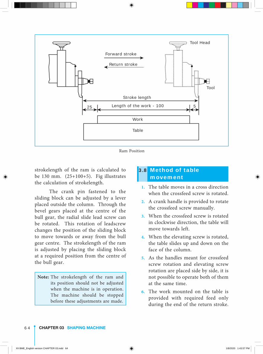
3.7 Adjusting the length of stroke
The length of the stroke is calculated to be nearly 30 mm longer than the work. The position of stroke is so adjusted that the tool starts to move from a distance of 25 mm before the beginning of the cut and continues to move 5 mm after the end of the cut. For example as shown in Figure, the length of the work is 100 mm. The
the top of the slotted link is connected to the ram, the ram reciprocates horizontally. So, bull gear rotation is converted into the reciprocating movement of the ram.
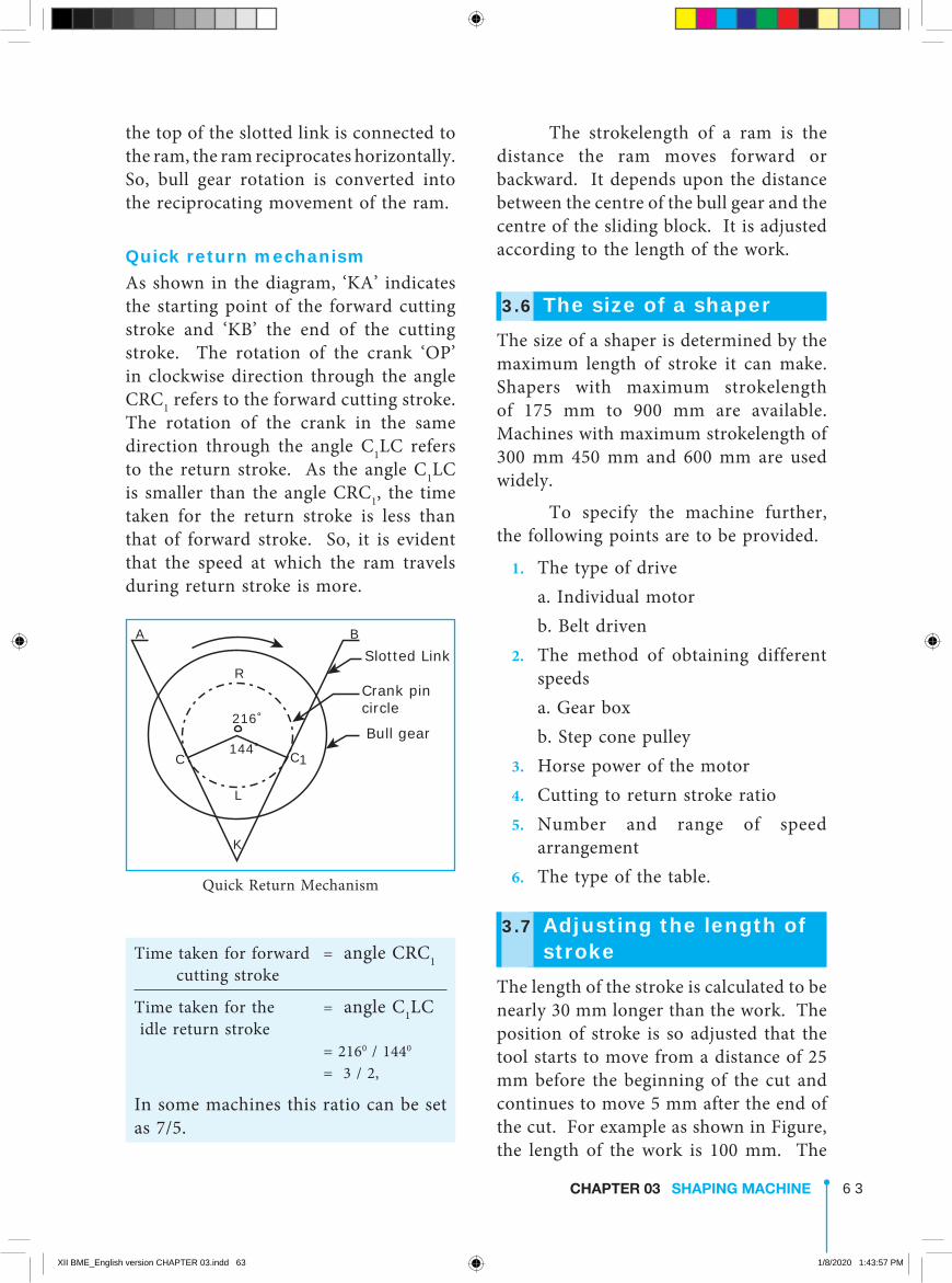
Quick return mechanismAs shown in the diagram, ‘KA’ indicates the starting point of the forward cutting stroke and ‘KB’ the end of the cutting stroke. The rotation of the crank ‘OP’ in clockwise direction through the angle CRC1 refers to the forward cutting stroke. The rotation of the crank in the same direction through the angle C1LC refers to the return stroke. As the angle C1LC is smaller than the angle CRC1, the time taken for the return stroke is less than that of forward stroke. So, it is evident that the speed at which the ram travels during return stroke is more.
Bull gear
Crank pincircle
Slotted LinkBA
R
L
K
C144˚
216˚
C1
Quick Return Mechanism
Time taken for forward = angle CRC1 cutting stroke
Time taken for the = angle C1LC idle return stroke = 2160 / 1440
= 3 / 2,
In some machines this ratio can be set as 7/5.
XII BME_English version CHAPTER 03.indd 63 1/8/2020 1:43:57 PM
6 4 CHAPTER 03 SHAPING MACHINE
3.8 Method of table movement
1. The table moves in a cross direction when the crossfeed screw is rotated.
2. A crank handle is provided to rotate the crossfeed screw manually.
3. When the crossfeed screw is rotated in clockwise direction, the table will move towards left.
4. When the elevating screw is rotated, the table slides up and down on the face of the column.
5. As the handles meant for crossfeed screw rotation and elevating screw rotation are placed side by side, it is not possible to operate both of them at the same time.
6. The work mounted on the table is provided with required feed only during the end of the return stroke.
strokelength of the ram is calculated to be 130 mm. (25+100+5). Fig illustrates the calculation of strokelength.
The crank pin fastened to the sliding block can be adjusted by a lever placed outside the column. Through the bevel gears placed at the centre of the bull gear, the radial slide lead screw can be rotated. This rotation of leadscrew changes the position of the sliding block to move towards or away from the bull gear centre. The strokelength of the ram is adjusted by placing the sliding block at a required position from the centre of the bull gear.
Note: The strokelength of the ram and its position should not be adjusted when the machine is in operation. The machine should be stopped before these adjustments are made.
Table
Work
Length of the work - 100
Stroke length
Tool
Tool Head
Forward stroke
Return stroke
25 5
Ram Position
XII BME_English version CHAPTER 03.indd 64 1/8/2020 1:43:57 PM
6 5CHAPTER 03 SHAPING MACHINE
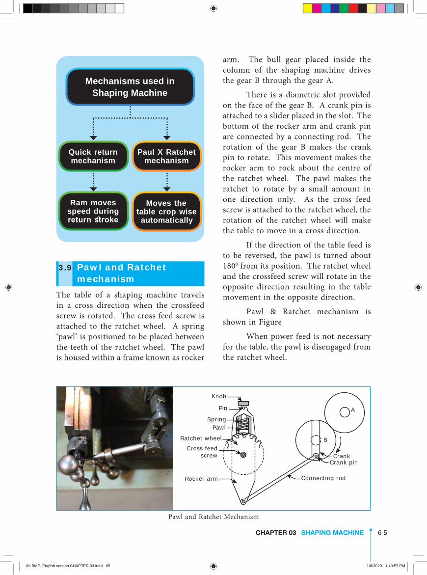
arm. The bull gear placed inside the column of the shaping machine drives the gear B through the gear A.
There is a diametric slot provided on the face of the gear B. A crank pin is attached to a slider placed in the slot. The bottom of the rocker arm and crank pin are connected by a connecting rod. The rotation of the gear B makes the crank pin to rotate. This movement makes the rocker arm to rock about the centre of the ratchet wheel. The pawl makes the ratchet to rotate by a small amount in one direction only. As the cross feed screw is attached to the ratchet wheel, the rotation of the ratchet wheel will make the table to move in a cross direction.
If the direction of the table feed is to be reversed, the pawl is turned about 1800 from its position. The ratchet wheel and the crossfeed screw will rotate in the opposite direction resulting in the table movement in the opposite direction.
Pawl & Ratchet mechanism is shown in Figure
When power feed is not necessary for the table, the pawl is disengaged from the ratchet wheel.
3.9 Pawl and Ratchet mechanism
The table of a shaping machine travels in a cross direction when the crossfeed screw is rotated. The cross feed screw is attached to the ratchet wheel. A spring ‘pawl’ is positioned to be placed between the teeth of the ratchet wheel. The pawl is housed within a frame known as rocker
Ram moves speed during return stroke
Moves the table crop wise
automatically
Mechanisms used in Shaping Machine
Quick return mechanism
Paul X Ratchet mechanism
Connecting rod
Crank pinCrank
B
A
Rocker arm
Cross feedscrew
Ratchet wheel
PawlSpring
Pin
Knob
Pawl and Ratchet Mechanism
XII BME_English version CHAPTER 03.indd 65 1/8/2020 1:43:57 PM
6 6 CHAPTER 03 SHAPING MACHINE
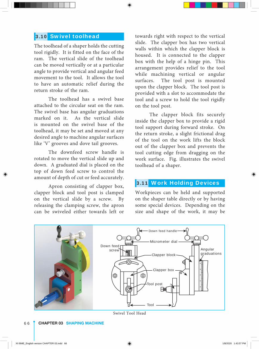
towards right with respect to the vertical slide. The clapper box has two vertical walls within which the clapper block is housed. It is connected to the clapper box with the help of a hinge pin. This arrangement provides relief to the tool while machining vertical or angular surfaces. The tool post is mounted upon the clapper block. The tool post is provided with a slot to accommodate the tool and a screw to hold the tool rigidly on the tool post.
The clapper block fits securely inside the clapper box to provide a rigid tool support during forward stroke. On the return stroke, a slight frictional drag of the tool on the work lifts the block out of the clapper box and prevents the tool cutting edge from dragging on the work surface. Fig. illustrates the swivel toolhead of a shaper.
3.11 Work Holding DevicesWorkpieces can be held and supported on the shaper table directly or by having some special devices. Depending on the size and shape of the work, it may be
3.10 Swivel toolheadThe toolhead of a shaper holds the cutting tool rigidly. It is fitted on the face of the ram. The vertical slide of the toolhead can be moved vertically or at a particular angle to provide vertical and angular feed movement to the tool. It allows the tool to have an automatic relief during the return stroke of the ram.
The toolhead has a swivel base attached to the circular seat on the ram. The swivel base has angular graduations marked on it. As the vertical slide is mounted on the swivel base of the toolhead, it may be set and moved at any desired angle to machine angular surfaces like ‘V’ grooves and dove tail grooves.
The downfeed screw handle is rotated to move the vertical slide up and down. A graduated dial is placed on the top of down feed screw to control the amount of depth of cut or feed accurately.
Apron consisting of clapper box, clapper block and tool post is clamped on the vertical slide by a screw. By releasing the clamping screw, the apron can be swiveled either towards left or
Clapper box
Down feedscrew Angular
graduations
Tool
Tool post
Clapper block
Micrometer dial
Down feed handle
Swivel Tool Head
XII BME_English version CHAPTER 03.indd 66 1/8/2020 1:43:57 PM

6 7CHAPTER 03 SHAPING MACHINE
strip at one end and by a stop pin at the other side. The screw is tightened to secure the work properly on the machine table. The use of stop pin is shown in Figure.
ClampStop pin
Bolt
TableWork
Clamp and Stop pin
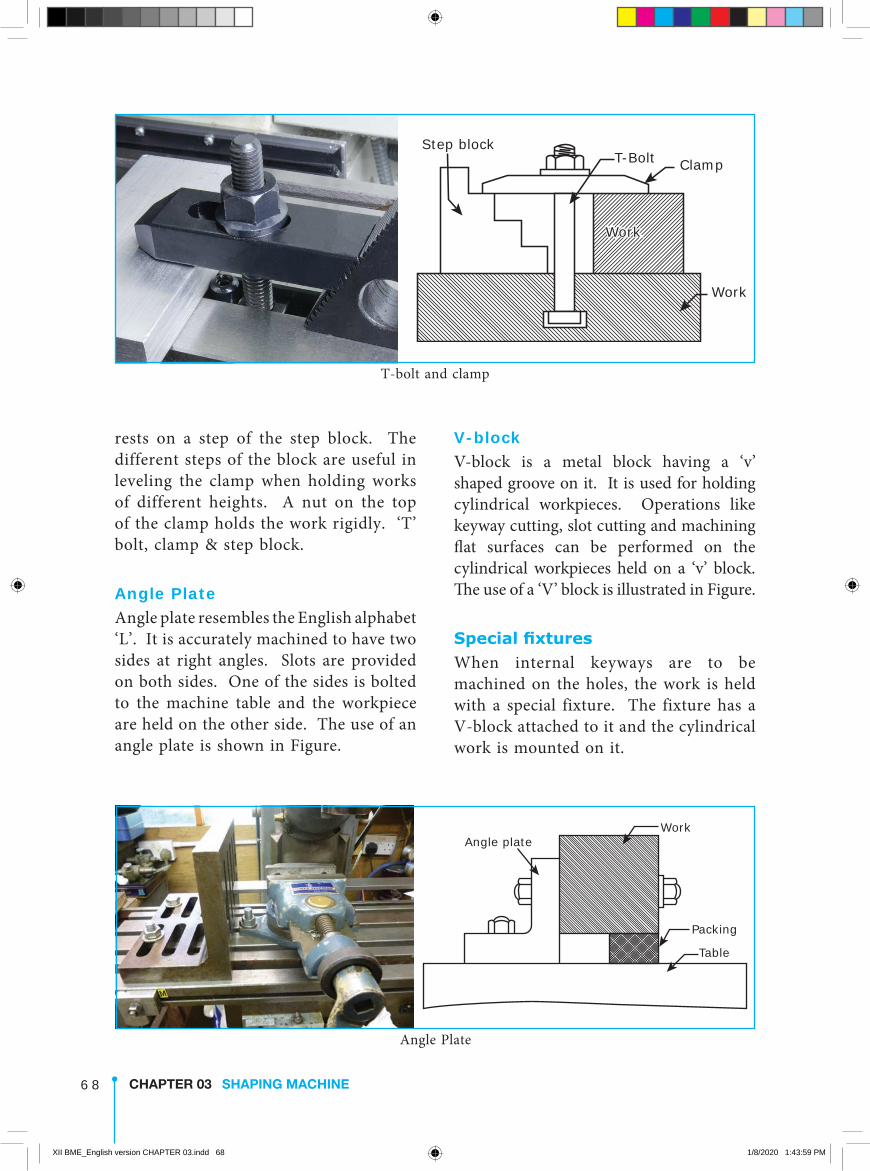
T-bolts and step blocksThe step blocks are used in combination with T-bolts and clamps to hold the work directly on the machine table. The t-bolts are fitted in the T-slots of the machine table. One side of the clamp holds the work and the other side
supported on the table by any one of the following methods.
1. Shaper vise 2. Clamps and stop pins 3. T-bolts and step blocks 4. Angle Plate 5. V-Block 6. Special fixtures
ViseVise is the most common and simple work holding device used in a shaper. Different types of vises are used in a shaping machine according to the need and they are: 1. Plain Vise, 2. Swivel Vise, 3. Universal Vise
Clamps and stop pinsT-bolts are fitted into the T-slots of the table. The work is placed on the table. The work is supported by a rectangular
Work Holding Devices
Shaper Vise
Clamps and S top Pins
T-bolts and S tep Blocks
Angle Plate
V-Block
Special fixtures
Work
Movable JawFixed jaw
Swivelbase
Screw
Vise
XII BME_English version CHAPTER 03.indd 67 1/8/2020 1:43:58 PM
6 8 CHAPTER 03 SHAPING MACHINE
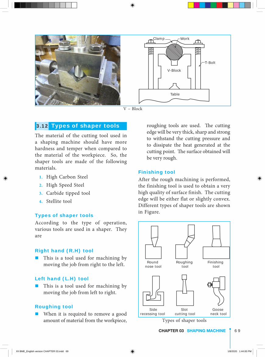
V-blockV-block is a metal block having a ‘v’ shaped groove on it. It is used for holding cylindrical workpieces. Operations like keyway cutting, slot cutting and machining flat surfaces can be performed on the cylindrical workpieces held on a ‘v’ block. The use of a ‘V’ block is illustrated in Figure.
Special fixturesWhen internal keyways are to be machined on the holes, the work is held with a special fixture. The fixture has a V-block attached to it and the cylindrical work is mounted on it.
rests on a step of the step block. The different steps of the block are useful in leveling the clamp when holding works of different heights. A nut on the top of the clamp holds the work rigidly. ‘T’ bolt, clamp & step block.
Angle PlateAngle plate resembles the English alphabet ‘L’. It is accurately machined to have two sides at right angles. Slots are provided on both sides. One of the sides is bolted to the machine table and the workpiece are held on the other side. The use of an angle plate is shown in Figure.
Step blockT-Bolt Clamp
Work
Work
T-bolt and clamp
Work
Table
Angle plate
Packing
Angle Plate
XII BME_English version CHAPTER 03.indd 68 1/8/2020 1:43:59 PM
6 9CHAPTER 03 SHAPING MACHINE
roughing tools are used. The cutting edge will be very thick, sharp and strong to withstand the cutting pressure and to dissipate the heat generated at the cutting point. The surface obtained will be very rough.
Finishing toolAfter the rough machining is performed, the finishing tool is used to obtain a very high quality of surface finish. The cutting edge will be either flat or slightly convex. Different types of shaper tools are shown in Figure.
3.12 Types of shaper toolsThe material of the cutting tool used in a shaping machine should have more hardness and temper when compared to the material of the workpiece. So, the shaper tools are made of the following materials.
1. High Carbon Steel 2. High Speed Steel 3. Carbide tipped tool 4. Stellite tool
Types of shaper toolsAccording to the type of operation, various tools are used in a shaper. They are
Right hand (R.H) tool�This is a tool used for machining by
moving the job from right to the left.
Left hand (L.H) tool�This is a tool used for machining by
moving the job from left to right.
Roughing tool�When it is required to remove a good
amount of material from the workpiece,
Work
T-Bolt
V-Block
Clamp
Table
V – Block
Types of shaper tools
Round nose tool
Siderecessing tool
Slot cutting tool
Goose neck tool
Roughing tool
Finishing tool
XII BME_English version CHAPTER 03.indd 69 1/8/2020 1:44:00 PM
7 0 CHAPTER 03 SHAPING MACHINE
work and the tool are done with the help of test bars and feeler gauges.
3.14 Types of shaping operations
Different types of operations are performed in a shaping machine. They are broadly classified as
1. Regular operations 2. Special operations
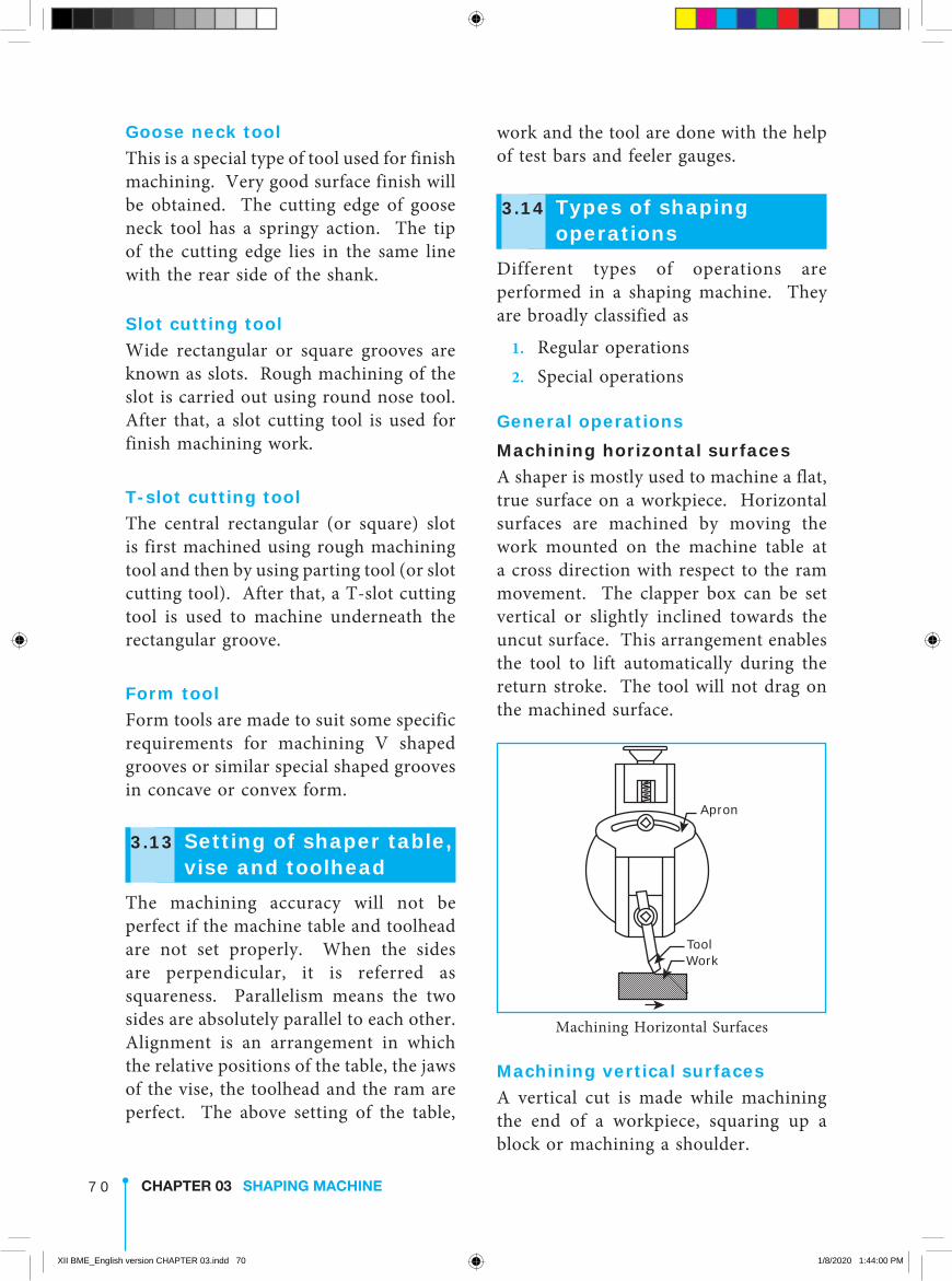
General operationsMachining horizontal surfacesA shaper is mostly used to machine a flat, true surface on a workpiece. Horizontal surfaces are machined by moving the work mounted on the machine table at a cross direction with respect to the ram movement. The clapper box can be set vertical or slightly inclined towards the uncut surface. This arrangement enables the tool to lift automatically during the return stroke. The tool will not drag on the machined surface.
WorkTool
Apron
Machining Horizontal Surfaces
Machining vertical surfacesA vertical cut is made while machining the end of a workpiece, squaring up a block or machining a shoulder.
Goose neck toolThis is a special type of tool used for finish machining. Very good surface finish will be obtained. The cutting edge of goose neck tool has a springy action. The tip of the cutting edge lies in the same line with the rear side of the shank.
Slot cutting toolWide rectangular or square grooves are known as slots. Rough machining of the slot is carried out using round nose tool. After that, a slot cutting tool is used for finish machining work.
T-slot cutting toolThe central rectangular (or square) slot is first machined using rough machining tool and then by using parting tool (or slot cutting tool). After that, a T-slot cutting tool is used to machine underneath the rectangular groove.
Form toolForm tools are made to suit some specific requirements for machining V shaped grooves or similar special shaped grooves in concave or convex form.
3.13 Setting of shaper table, vise and toolhead
The machining accuracy will not be perfect if the machine table and toolhead are not set properly. When the sides are perpendicular, it is referred as squareness. Parallelism means the two sides are absolutely parallel to each other. Alignment is an arrangement in which the relative positions of the table, the jaws of the vise, the toolhead and the ram are perfect. The above setting of the table,
XII BME_English version CHAPTER 03.indd 70 1/8/2020 1:44:00 PM
7 1CHAPTER 03 SHAPING MACHINE
Machining Inclined surfacesIf the surface to be machined is neither horizontal nor perpendicular, the surface is called inclined surface. Machining ‘V’ grooves and dovetail grooves are some examples for angular machining.
Machining the inclined (angular) surfaces can be done in several ways.
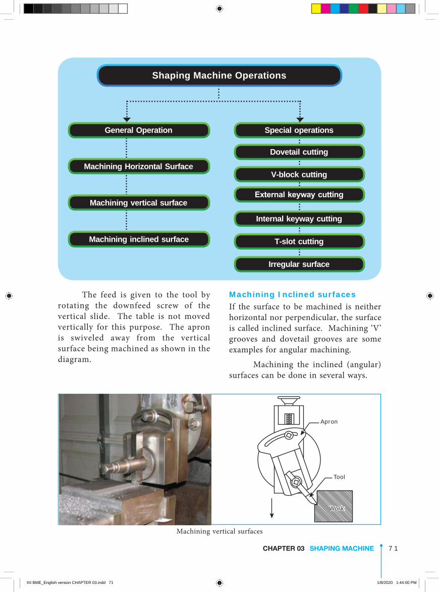
The feed is given to the tool by rotating the downfeed screw of the vertical slide. The table is not moved vertically for this purpose. The apron is swiveled away from the vertical surface being machined as shown in the diagram.
Shaping Machine Operations
General Operation
Machining Horizontal Surface
Machining vertical surface
Machining inclined surface
Special operations
Dovetail cutting
V-block cutting
External keyway cutting
Internal keyway cutting
T-slot cutting
Irregular surface
Work
Tool
Apron
Machining vertical surfaces
XII BME_English version CHAPTER 03.indd 71 1/8/2020 1:44:00 PM
7 2 CHAPTER 03 SHAPING MACHINE
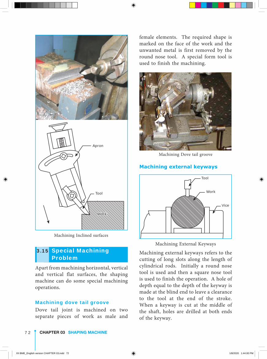
female elements. The required shape is marked on the face of the work and the unwanted metal is first removed by the round nose tool. A special form tool is used to finish the machining.
Machining Dove tail groove
Machining external keyways
Vice
Work
Tool
Machining External Keyways
Machining external keyways refers to the cutting of long slots along the length of cylindrical rods. Initially a round nose tool is used and then a square nose tool is used to finish the operation. A hole of depth equal to the depth of the keyway is made at the blind end to leave a clearance to the tool at the end of the stroke. When a keyway is cut at the middle of the shaft, holes are drilled at both ends of the keyway.
Work
Tool
Apron
Machining Inclined surfaces
3.15 Special Machining Problem
Apart from machining horizontal, vertical and vertical flat surfaces, the shaping machine can do some special machining operations.
Machining dove tail grooveDove tail joint is machined on two separate pieces of work as male and
XII BME_English version CHAPTER 03.indd 72 1/8/2020 1:44:00 PM
7 3CHAPTER 03 SHAPING MACHINE
Then, the groove is further machined with a form tool confirming the shape of the teeth.
Machining Rackgear
3.16 Cutting speed, depth of cut and Feed
Cutting speedThe distance an object travels in a particular period of time is known as speed. In a shaper, the cutting speed is the speed at which the metal is removed by the cutting tool in a period of one minute. In a shaper, the cutting speed is considered only during the forward cutting stroke. This is expressed in metre per minute.
The cutting speed differs to suit different machining conditions like work material, the finish required, and the type of the tool and the rigidity of the machine.
Depth of cutDepth of cut is the thickness of metal that is removed during machining. It is the perpendicular distance measured between the machined surface and the uncut surface of the workpiece. It is expressed in mm or in inches.
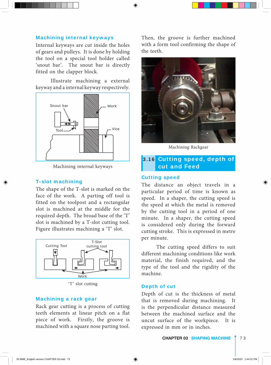
Machining internal keywaysInternal keyways are cut inside the holes of gears and pulleys. It is done by holding the tool on a special tool holder called ‘snout bar’. The snout bar is directly fitted on the clapper block.
Illustrate machining a external keyway and a internal keyway respectively.
Snout bar
Vice
Work
Tool
Machining internal keyways
T-slot machiningThe shape of the T-slot is marked on the face of the work. A parting off tool is fitted on the toolpost and a rectangular slot is machined at the middle for the required depth. The broad base of the ‘T’ slot is machined by a T-slot cutting tool. Figure illustrates machining a ‘T’ slot.
T-Slotcutting toolCutting Tool
Work
‘T’ slot cutting
Machining a rack gearRack gear cutting is a process of cutting teeth elements at linear pitch on a flat piece of work. Firstly, the groove is machined with a square nose parting tool.
XII BME_English version CHAPTER 03.indd 73 1/8/2020 1:44:01 PM
7 4 CHAPTER 03 SHAPING MACHINE
4. The sharp edges of the work should be handled with care.
5. The measuring of the work should be done only after the machine is switched off.
6. The operator should not seek the assistance of others for starting and stopping the machine.
7. Machining of precision parts and internal surfaces of the workpiece are to be carried out with great care and attention.
8. The operator should stay away from direction of the ram movement.
Safety hints regarding the shaping machine 1. The workpiece is to be positioned
in such a way that ram will not hit the workpiece while performing the forward stroke.
2. Strokelength of the ram and the position of stroke are to be set correctly before performing the operation.
3. Proper holding of the work should be ensured. Work holding devices like clamps and vise jaws should not come in the way of the reciprocating tool.
4. We have to ensure that the tool or the tool post or the ram will not hit the job or the job holding clamps or the vise jaws.
5. The machine should be stopped before making any adjustment to the strokelength, position of stroke, apron and tool position.
FeedFeed is the relative movement of the work or tool in a direction perpendicular to the axis of reciprocation of the ram per double stroke. It is expressed in mm per stroke.
3.17 CoolantDue to the friction between the tool and the work surface during machining, heat is generated. The tool loses its cutting capacity and the machined surface is hardened. Coolant is used on the surfaces to avoid damage to the cutting edge of the tool as well as to the machined surface.
Soluble oil is mixed with water to be used as a suitable coolant. One part of the oil is mixed with fifteen parts of water to be used as coolant. Usage of water as coolant may result in rust formation on the metal parts. Lubricants cannot be used as coolants.
3.18 Safety precautionsThe following safety precautions should be observed while working on a shaping machine.
Safety precautions regarding operators 1. No alteration or adjustment should
be done on the machine parts while the machine is functioning.
2. Clamps holding the work should not be adjusted while the machine is in operation.
3. The machine is to be stopped before cleaning the metal chips.
XII BME_English version CHAPTER 03.indd 74 1/8/2020 1:44:01 PM
7 5CHAPTER 03 SHAPING MACHINE
5. The ratio of forward stroke time to return stroke time is
a. 3:2 b. 5:3 c. 1:3 d. 1:2 6. The part used to lift the tool while
the ram moves the returning stroke a. Tool-head b. Work-table c. Clapper-block d. Cross-slide
Part II.Answer the following questions in one or two sentences 3 Marks 7. Define “Shaping”. 8. List any four parts of shaper. 9. What is the use of crank & slotted
link mechanism? 10. Define “cutting speed” of shaping
machine. 11. Define “feed” of a shaping machine. 12. Mention the “depth of cut” of
shaping machine. 13. What is the use of a clapper box? 14. What is the use of swivel tool head
of a shaping machine?
Part I.Choose the correct option 1 Mark 1. The shaping machine was designed
by a. Henry Maudslay b. Eli Whitney c. Michael Faraday d. James Nasmith 2. The operation mainly done on a
shaping machine is a. Turning b. Drilling c. Machining a flat surface d. Thread cutting 3. The mechanism used to move the
shaper table automatically is a. Back gear mechanism b. Crank & slotted link mechanism c. Tumbler gear mechanism d. Pawl & Ratchet mechanism 4. The part involved in reciprocation
by quick return is a. Table b. Ram c. Column d. Crossrail
ACTIVITIES 1. Visiting the nearby workshop or polytechnic or engineering college for knowing
what type of operations done in shaping machine. 2. To make different models shapes of cubic square, cubic rectangle and prism by
using wood (or) thermocol sheet.
QUESTIONS
XII BME_English version CHAPTER 03.indd 75 1/8/2020 1:44:01 PM

7 6 CHAPTER 03 SHAPING MACHINE
Part III.Answer the following questions in about a page 5 Marks 15. List out the types of shaping machines. 16. Write short notes on a. changing the stroke length of the ram b. Position of the ram
Part IV.Answer the following Questions in detail. 10 Marks 17. Draw a neat diagram of a shaping machine and explain its important parts. 18. Explain the crank & slotted link mechanism of quick return of the ram with a
diagram. 19. Explain the ratchet & pawl mechanism with a diagram. 20. Explain any four work holding devices used in a shaping machine with diagrams. 21. Explain any four operations performed in a shaping machine with diagrams.
XII BME_English version CHAPTER 03.indd 76 1/8/2020 1:44:01 PM
Related Documents