High-speed DC circuit-breakers for Rolling Stock Type UR6, UR10 & UR15 COMPONENTS

SG104136BEN_B07_Brochure_UR6-10-15 T_0415
Aug 21, 2015
Welcome message from author
This document is posted to help you gain knowledge. Please leave a comment to let me know what you think about it! Share it to your friends and learn new things together.
Transcript

High-speed DC circuit-breakersfor Rolling StockType UR6, UR10 & UR15
C O M P O N E N T S
2
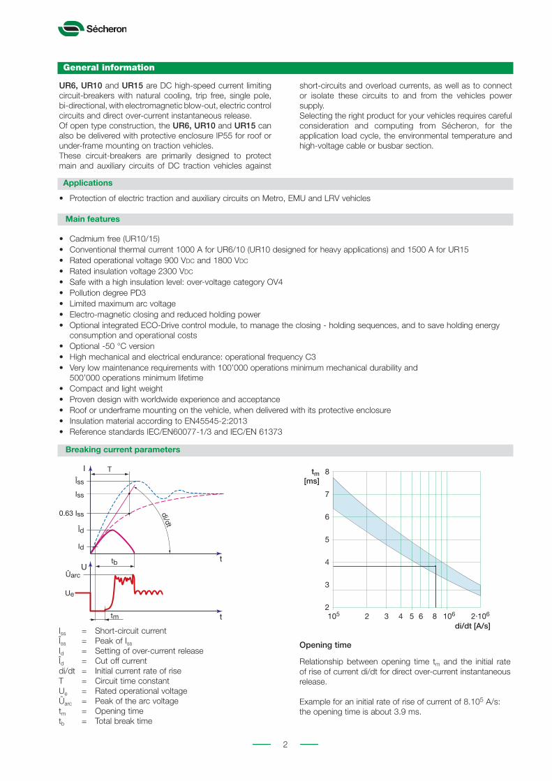
Relationship between opening time tm and the initial rate of rise of current di/dt for direct over-current instantaneous release.
Example for an initial rate of rise of current of 8.105 A/s: the opening time is about 3.9 ms.
Opening time
105 106 2.1062 3 4 5di/dt [A/s]
6 82
3
4
5
6
7
8tm[ms]
short-circuits and overload currents, as well as to connect or isolate these circuits to and from the vehicles power supply. Selecting the right product for your vehicles requires careful consideration and computing from Sécheron, for the application load cycle, the environmental temperature and high-voltage cable or busbar section.
• Cadmium free (UR10/15)• Conventional thermal current 1000 A for UR6/10 (UR10 designed for heavy applications) and 1500 A for UR15• Rated operational voltage 900 Vdc and 1800 Vdc
• Rated insulation voltage 2300 Vdc
• Safe with a high insulation level: over-voltage category OV4• Pollution degree PD3• Limited maximum arc voltage• Electro-magnetic closing and reduced holding power• Optional integrated ECO-Drive control module, to manage the closing - holding sequences, and to save holding energy
consumption and operational costs• Optional -50 °C version • High mechanical and electrical endurance: operational frequency C3• Very low maintenance requirements with 100’000 operations minimum mechanical durability and
500’000 operations minimum lifetime• Compact and light weight• Proven design with worldwide experience and acceptance• Roof or underframe mounting on the vehicle, when delivered with its protective enclosure• Insulation material according to EN45545-2:2013• Reference standards IEC/EN60077-1/3 and IEC/EN 61373
UR6, UR10 and UR15 are DC high-speed current limiting circuit-breakers with natural cooling, trip free, single pole, bi-directional, with electromagnetic blow-out, electric control circuits and direct over-current instantaneous release.Of open type construction, the UR6, UR10 and UR15 can also be delivered with protective enclosure IP55 for roof or under-frame mounting on traction vehicles. These circuit-breakers are primarily designed to protect main and auxiliary circuits of DC traction vehicles against
• Protection of electric traction and auxiliary circuits on Metro, EMU and LRV vehicles
IEC-60077
Id
Îd
Iss
0.63 Iss
Ut
ttm
I
tb
Îss
di/dt
T
Ûarc
Ue
Iss = Short-circuit currentÎss = Peak of Iss
Id = Setting of over-current releaseÎd = Cut off currentdi/dt = Initial current rate of riseT = Circuit time constantUe = Rated operational voltageÛarc = Peak of the arc voltagetm = Opening timetb = Total break time
General information
Applications
Main features
Breaking current parameters
3
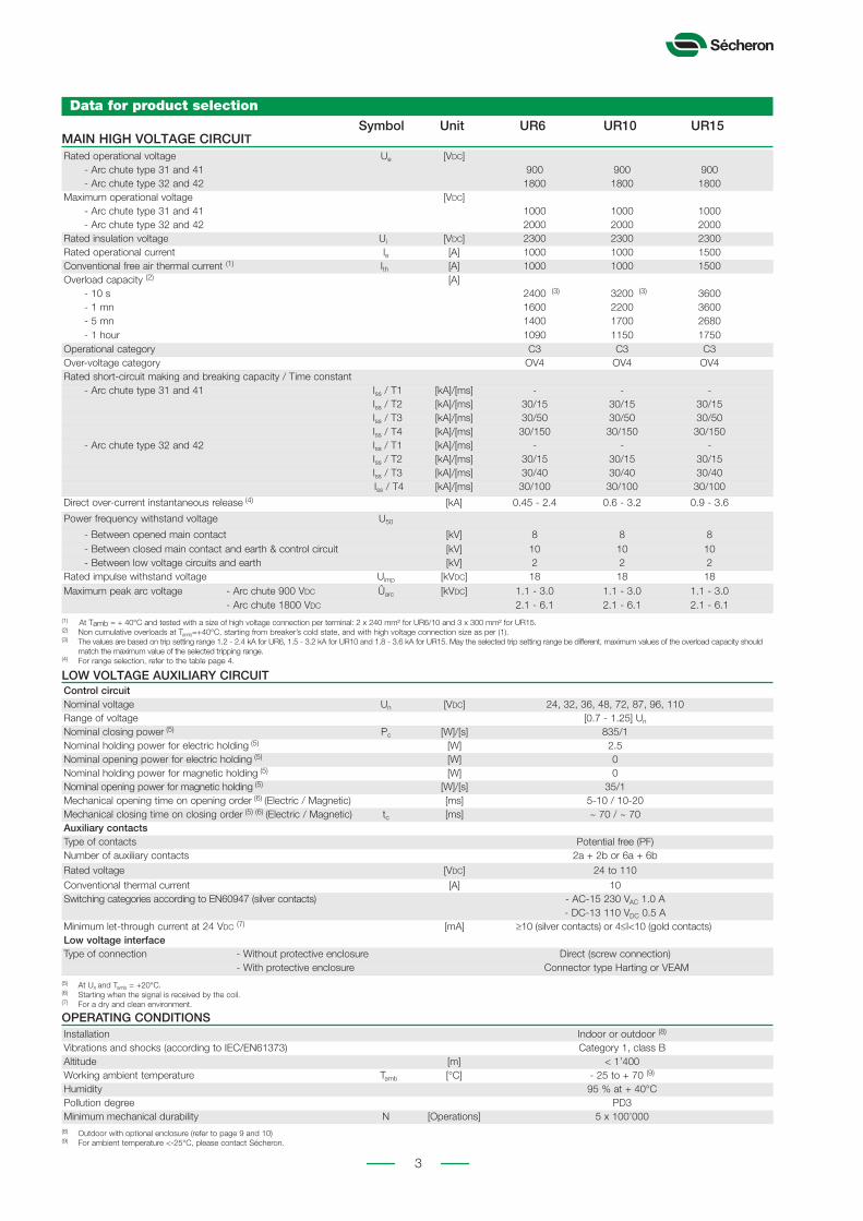
Data for product selection
Rated operational voltage Ue [Vdc] - Arc chute type 31 and 41 900 900 900 - Arc chute type 32 and 42 1800 1800 1800Maximum operational voltage [Vdc] - Arc chute type 31 and 41 1000 1000 1000 - Arc chute type 32 and 42 2000 2000 2000Rated insulation voltage Ui [Vdc] 2300 2300 2300Rated operational current Ie [A] 1000 1000 1500Conventional free air thermal current (1) Ith [A] 1000 1000 1500Overload capacity (2) [A] - 10 s 2400 (3) 3200 (3) 3600 - 1 mn 1600 2200 3600 - 5 mn 1400 1700 2680 - 1 hour 1090 1150 1750Operational category C3 C3 C3Over-voltage category OV4 OV4 OV4Rated short-circuit making and breaking capacity / Time constant - Arc chute type 31 and 41 Iss / T1 [kA]/[ms] - - - Iss / T2 [kA]/[ms] 30/15 30/15 30/15 Iss / T3 [kA]/[ms] 30/50 30/50 30/50 Iss / T4 [kA]/[ms] 30/150 30/150 30/150 - Arc chute type 32 and 42 Iss / T1 [kA]/[ms] - - - Iss / T2 [kA]/[ms] 30/15 30/15 30/15 Iss / T3 [kA]/[ms] 30/40 30/40 30/40 Iss / T4 [kA]/[ms] 30/100 30/100 30/100
Direct over-current instantaneous release (4) [kA] 0.45 - 2.4 0.6 - 3.2 0.9 - 3.6
Power frequency withstand voltage U50
- Between opened main contact [kV] 8 8 8 - Between closed main contact and earth & control circuit [kV] 10 10 10 - Between low voltage circuits and earth [kV] 2 2 2Rated impulse withstand voltage Uimp [kVdc] 18 18 18Maximum peak arc voltage - Arc chute 900 Vdc Ûarc [kVdc] 1.1 - 3.0 1.1 - 3.0 1.1 - 3.0 - Arc chute 1800 Vdc 2.1 - 6.1 2.1 - 6.1 2.1 - 6.1
(1) At Tamb = + 40°C and tested with a size of high voltage connection per terminal: 2 x 240 mm² for UR6/10 and 3 x 300 mm² for UR15.(2) Non cumulative overloads at Tamb=+40°C, starting from breaker’s cold state, and with high voltage connection size as per (1).(3) The values are based on trip setting range 1.2 - 2.4 kA for UR6, 1.5 - 3.2 kA for UR10 and 1.8 - 3.6 kA for UR15. May the selected trip setting range be different, maximum values of the overload capacity should
match the maximum value of the selected tripping range.(4) For range selection, refer to the table page 4.
Control circuitNominal voltage Un [Vdc] 24, 32, 36, 48, 72, 87, 96, 110Range of voltage [0.7 - 1.25] Un
Nominal closing power (5) Pc [W]/[s] 835/1Nominal holding power for electric holding (5) [W] 2.5Nominal opening power for electric holding (5) [W] 0Nominal holding power for magnetic holding (5) [W] 0Nominal opening power for magnetic holding (5) [W]/[s] 35/1Mechanical opening time on opening order (6) (Electric / Magnetic) [ms] 5-10 / 10-20 Mechanical closing time on closing order (5) (6) (Electric / Magnetic) tc [ms] ~ 70 / ~ 70Auxiliary contactsType of contacts Potential free (PF)Number of auxiliary contacts 2a + 2b or 6a + 6bRated voltage [Vdc] 24 to 110Conventional thermal current [A] 10Switching categories according to EN60947 (silver contacts) - AC-15 230 VAC 1.0 A - DC-13 110 VDC 0.5 A Minimum let-through current at 24 Vdc (7) [mA] ≥10 (silver contacts) or 4≤I<10 (gold contacts)Low voltage interfaceType of connection - Without protective enclosure Direct (screw connection) - With protective enclosure Connector type Harting or VEAM
(5) At Un and Tamb = +20°C.(6) Starting when the signal is received by the coil.(7) For a dry and clean environment.
Installation Indoor or outdoor (8)
Vibrations and shocks (according to IEC/EN61373) Category 1, class BAltitude [m] < 1’400Working ambient temperature Tamb [°C] - 25 to + 70 (9)
Humidity 95 % at + 40°CPollution degree PD3Minimum mechanical durability N [Operations] 5 x 100’000
(8) Outdoor with optional enclosure (refer to page 9 and 10)(9) For ambient temperature <-25°C, please contact Sécheron.
MAIN HIGH VOLTAGE CIRCUIT
LOW VOLTAGE AUXILIARY CIRCUIT
OPERATING CONDITIONS
Symbol Unit UR6 UR10 UR15

4
Required informations for breaker selection
In order to select the appropriate breaker suited to your application, the following informations must be provided to Sécheron. Once these data computed, and in function of the maximum allowed temperature rise of the critical parts of the different breakers UR6/10/15, Sécheron will recommend the breaker type that matches your application.The following data and informations must be sent to Sécheron for computing.
1 - Application load cycle
An excel table with the load cycles the breaker will have to withstand in the application, shall be sent to Sécheron for comput-ing, and shall include as a minimum the following informations:• The peak value Ip3 and the i² x t of the most energetical load of the vehicule’s trip• The highest peak value Ip1 of the vehicule’s trip and its duration• The Irms current (Root Means Square) of the vehicule’s trip
2 - Maximum working ambient temperature of the circuit-breaker in the application ......... °C
3 - High voltage connection type and number of connection per high voltage terminal
- Cable: :1 :2 :3
- Busbar: :1 :2 :3
4 - Individual high voltage connection size - Cable: ........ mm² - Busbar: ........ mm x ......... mm
Note: It is recommended that the current density of the high voltage connections wired to the DC circuit-breaker and related to the rms current of the application shall not exceed 1.7 ~ 2.0 A/mm². For current density that exceeds the recommended value, the breaker thermal current may have to be derated in function of the application.
Direct over-current instantaneous release
UR6 UR10 UR15Designation code
Standard Option
0.45 - 0.9 - - F
0.6 - 1.2 0.6 - 1.2 - A
0.9 - 1.8 0.9 - 1.8 0.9 - 1.8 B
1.2 - 2.4 1.2 - 2.4 1.2 - 2.4 C
- 1.5 - 3.2 - D
- - 1.8 - 3.6 E
Available setting ranges (in kA) with their corresponding designation code for selection page 12.
[A]
[s]
i² x t
Ip2
Ip3
Ip1
I rms
t1
rms current Real current Braking current
Load cycle Load cycle
Vehicule’s trip
x loadcycles
y loadcyclesLoad cycle
5
10
165
145
40
20
40
20 135
Ø14
Ø9 Ø9
M16
(2)
165
145 10
10 10
420
115 115
190
30 UR6/UR10: 40 UR15: 65
0 4 5 . 7 6
0 2
0 8 1 0 6
) 1 ( 5 6 1 :
V
0 0 9 5 0 3 :
V
0 0 8 1
5 . 2 4
30 130
A A 165 B B 420
0 9
C
UR6/10 UR15
Ø14
11
LV HV
10
165
145
40
20
40
20 135
Ø14
Ø9 Ø9
M16
(2)
165
145 10
10 10
420
115 115
190
30 UR6/UR10: 40 UR15: 65
0 4 5 . 7 6
0 2
0 8 1 0 6
) 1 ( 5 6 1 :
V
0 0 9 5 0 3 :
V
0 0 8 1
5 . 2 4
30 130
A A 165 B B 420
0 9
C
UR6/10 UR15
Ø14
11
LV HV
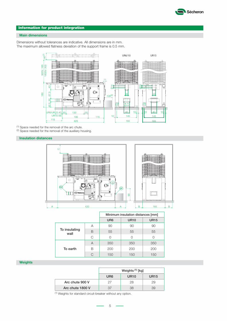
(1) Space needed for the removal of the arc chute.(2) Space needed for the removal of the auxiliary housing.
Main dimensions
Weights
Insulation distances
Information for product integration
Dimensions without tolerances are indicative. All dimensions are in mm. The maximum allowed flatness deviation of the support frame is 0.5 mm.
(1) Weights for standard circuit-breaker without any option.
Minimum insulation distances [mm]
UR6 UR10 UR15
To insulating wall
A 90 90 90
B 55 55 55
C 0 0 0
To earth
A 350 350 350
B 200 200 200
C 150 150 150
Weights (1) [kg]
UR6 UR10 UR15
Arc chute 900 V 27 28 29
Arc chute 1800 V 37 38 39

6
Low voltage control diagram
Ie
~ 20%
100%
0
0
0,5 1 tc tc+1tc+0.5
t [s]
D
FE
BA
C
–
SV=+
Rp
Rs
–
+
~ 5%
100%
0 0,5 1
t [s]
SV=
R1
E
F
G
B CA
DIe
E
B
C
A
D
FE
–
SV=+
Rs
Maintien magnétique pour UR60/80(maintien électrique idem que UR26-36-40-46)
UR26/36/40/46
UR60/80
Ie
~ 20%
100%
0
0
0,5 1 tc tc+1tc+0.5
t [s]
D
FE
BA
C
–
SV=+
Rp
Rs
–
+
~ 5%
100%
0 0,5 1
t [s]
SV=
R1
E
F
G
B CA
DIe
E
B
C
A
D
FE
–
SV=+
Rs
Maintien magnétique pour UR60/80(maintien électrique idem que UR26-36-40-46)
UR26/36/40/46
UR60/80
Electric holding: E type Magnetic holding: M type
Ie
~ 20%
100%
0
0
0,5 1 tc tc+1tc+0.5
t [s]
D
FE
BA
C
–
SV=+
Rp
Rs
–
+
~ 5%
100%
0 0,5 1
t [s]
SV=
R1
E
F
G
B CA
DIe
E
B
C
A
D
FE
–
SV=+
Rs
Maintien magnétique pour UR60/80(maintien électrique idem que UR26-36-40-46)
UR26/36/40/46
UR60/80
Customer’s scope
Ie
~ 20%
100%
0
0
0,5 1 tc tc+1tc+0.5
t [s]
D
FE
BA
C
–
SV=+
Rp
Rs
–
+
~ 5%
100%
0 0,5 1
t [s]
SV=
R1
E
F
G
B CA
DIe
E
B
C
A
D
FE
–
SV=+
Rs
Maintien magnétique pour UR60/80(maintien électrique idem que UR26-36-40-46)
UR26/36/40/46
UR60/80
Sécheron’s scope
Ie
~ 20%
100%
0
0
0,5 1 tc tc+1tc+0.5
t [s]
D
FE
BA
C
–
SV=+
Rp
Rs
–
+
~ 5%
100%
0 0,5 1
t [s]
SV=
R1
E
F
G
B CA
DIe
E
B
C
A
D
FE
–
SV=+
Rs
Maintien magnétique pour UR60/80(maintien électrique idem que UR26-36-40-46)
UR26/36/40/46
UR60/80
Ie
~ 20%
100%
0
0
0,5 1 tc tc+1tc+0.5
t [s]
D
FE
BA
C
–
SV=+
Rp
Rs
–
+
~ 5%
100%
0 0,5 1
t [s]
SV=
R1
E
F
G
B CA
DIe
E
B
C
A
D
FE
–
SV=+
Rs
Maintien magnétique pour UR60/80(maintien électrique idem que UR26-36-40-46)
UR26/36/40/46
UR60/80
Start of the closing pulse: the contacts F + G close.Closing pulse: 0.5 to 1 s.Start of the holding current: the contact G opens.Holding: a R1 resistance limits the holding current to 5% of the closing current.Opening: the contact F opens to provoke the interruption of the holding current.
Start of the closing pulse: the contacts E close.Closing pulse: 0.5 to 1 s, then the contacts E open.Holding: achieved by the permanent magnet.Opening: the contacts F close to provoke a current pulse of the opposite polarity to the closing current. The duration of this pulse is 0.5-1 s, then the contact F opens. The opening current is 20 % of the closing current.
Ie
~ 20%
100%
0
0
0,5 1 tc tc+1tc+0.5
t [s]
D
FE
BA
C
–
SV=+
Rp
Rs
–
+
~ 5%
100%
0 0,5 1
t [s]
SV=
R1
E
F
G
B CA
DIe
E
B
C
A
D
FE
–
SV=+
Rs
Maintien magnétique pour UR60/80(maintien électrique idem que UR26-36-40-46)
UR26/36/40/46
UR60/80
Ie
~ 20%
100%
0
0
0,5 1 tc tc+1tc+0.5
t [s]
D
FE
BA
C
–
SV=+
Rp
Rs
–
+
~ 5%
100%
0 0,5 1
t [s]
SV=
R1
E
F
G
B CA
DIe
E
B
C
A
D
FE
–
SV=+
Rs
Maintien magnétique pour UR60/80(maintien électrique idem que UR26-36-40-46)
UR26/36/40/46
UR60/80
Ie
~ 20%
100%
0
0
0,5 1 tc tc+1tc+0.5
t [s]
D
FE
BA
C
–
SV=+
Rp
Rs
–
+
~ 5%
100%
0 0,5 1
t [s]
SV=
R1
E
F
G
B CA
DIe
E
B
C
A
D
FE
–
SV=+
Rs
Maintien magnétique pour UR60/80(maintien électrique idem que UR26-36-40-46)
UR26/36/40/46
UR60/80
Ie
~ 20%
100%
0
0
0,5 1 tc tc+1tc+0.5
t [s]
D
FE
BA
C
–
SV=+
Rp
Rs
–
+
~ 5%
100%
0 0,5 1
t [s]
SV=
R1
E
F
G
B CA
DIe
E
B
C
A
D
FE
–
SV=+
Rs
Maintien magnétique pour UR60/80(maintien électrique idem que UR26-36-40-46)
UR26/36/40/46
UR60/80
Ie
~ 20%
100%
0
0
0,5 1 tc tc+1tc+0.5
t [s]
D
FE
BA
C
–
SV=+
Rp
Rs
–
+
~ 5%
100%
0 0,5 1
t [s]
SV=
R1
E
F
G
B CA
DIe
E
B
C
A
D
FE
–
SV=+
Rs
Maintien magnétique pour UR60/80(maintien électrique idem que UR26-36-40-46)
UR26/36/40/46
UR60/80
Ie
~ 20%
100%
0
0
0,5 1 tc tc+1tc+0.5
t [s]
D
FE
BA
C
–
SV=+
Rp
Rs
–
+
~ 5%
100%
0 0,5 1
t [s]
SV=
R1
E
F
G
B CA
DIe
E
B
C
A
D
FE
–
SV=+
Rs
Maintien magnétique pour UR60/80(maintien électrique idem que UR26-36-40-46)
UR26/36/40/46
UR60/80
Ie
~ 20%
100%
0
0
0,5 1 tc tc+1tc+0.5
t [s]
D
FE
BA
C
–
SV=+
Rp
Rs
–
+
~ 5%
100%
0 0,5 1
t [s]
SV=
R1
E
F
G
B CA
DIe
E
B
C
A
D
FE
–
SV=+
Rs
Maintien magnétique pour UR60/80(maintien électrique idem que UR26-36-40-46)
UR26/36/40/46
UR60/80
Ie
~ 20%
100%
0
0
0,5 1 tc tc+1tc+0.5
t [s]
D
FE
BA
C
–
SV=+
Rp
Rs
–
+
~ 5%
100%
0 0,5 1
t [s]
SV=
R1
E
F
G
B CA
DIe
E
B
C
A
D
FE
–
SV=+
Rs
Maintien magnétique pour UR60/80(maintien électrique idem que UR26-36-40-46)
UR26/36/40/46
UR60/80
Ie
~ 20%
100%
0
0
0,5 1 tc tc+1tc+0.5
t [s]
D
FE
BA
C
–
SV=+
Rp
Rs
–
+
~ 5%
100%
0 0,5 1
t [s]
SV=
R1
E
F
G
B CA
DIe
E
B
C
A
D
FE
–
SV=+
Rs
Maintien magnétique pour UR60/80(maintien électrique idem que UR26-36-40-46)
UR26/36/40/46
UR60/80
Coil characteristics
ClosingPulse 0.5 to 1s E type holding M type opening
Pulse 0.5 to 1s
Unom Inom Imin E Imin M Imax R1 Inom Imin Imax Rs Rp Inom Imin Imax
[V] [A] [A] [A] [A] [Ω] [A] [A] [A] [Ω] [Ω] [A] [A] [A]
24 34.5 18.7 20.7 58.6 12.3 1.85 1.27 2.34 1.29 0.66 7.18 4.25 10.71
36 24.2 13.0 14.5 41.0 26.6 1.28 0.88 1.62 3.00 1.50 4.82 2.87 7.15
48 19.4 10.5 11.6 32.9 45.9 0.99 0.68 1.26 5.15 2.45 3.74 2.22 5.55
72 12.1 6.5 7.2 20.5 106.5 0.64 0.44 0.81 12.00 6.00 2.41 1.43 3.57
110 7.6 4.1 4.6 12.9 253.0 0.41 0.28 0.52 28.50 14.60 1.55 0.92 2.30
220 3.8 2.0 2.3 6.4 1014 0.21 0.14 0.26 114 59.00 0.77 0.46 1.15
E, F, G: Control relay’s contact.R1: Resistor to be inserted in the holding circuit of the E type; the power to be considered for the resistor choice is 280 W (4x70 W).Rs: Resistor to be inserted in series with the coil in the opening circuit of the M type; the power to be considered for the resistor choice is 70 W (277 W / 4).Rp: Resistor to be inserted in parallel with the closing coil in the opening circuit of the M type.S: Automatic circuit-breaker.
Typical value for closing coils for UR6/10/15

7
Low voltage interface
Without protective enclosure
With protective enclosure
Harting type HAN® M 18(2a + 2b auxiliary switches)
Harting type HAN® M 28(6a + 6b auxiliary switches)
Harting type HAN® M connector (standard for protective enclosure):
Configuration with 2 or 6 auxiliary switches
Direct connection on auxiliary switches and closing coil.
Low voltage cables go through PG 11 glands of the auxiliary contacts housing.
Note: Low voltage connectors are delivered with all pins mounted.
VEAM type 13 pins(2a + 2b auxiliary switches)
VEAM type 30 pins(6a + 6b auxiliary switches
or 6a + 4b in 24 Vdc)
VEAM type connector (option for protective enclosure):
Low voltage wiring diagrams
HARTING
Légende
11 9
12 8
7 5 3 1
4
15
16
1319
20 10 6 21418
17
11 9
12 8
7 5 3 1
4
15
16
13
10 6 214
11 9
12 8
7 5 3 1
4
15
16
13
10 6 214
11 9
12 8
7 5 3 1
4
15
16
13
10 6 21418
17
11 9
12 8
7 5 3 1
4
13
10 6 214
11 9
12 8
7 5 3 1
4
13
10 6 214
21
22
19
18
1721
22
(WI)19
18
17 21
22
(I>)
21
22
Standard: xxxx
9 8 5
7 4
6 23
1
12
10
1115
13
1421
22
Standard: xxxxx
11 9
12 8
7 5 3 1
4
15
16
1319
20 10 6 21418
1721
22
1920 I
18
16
17 21
22
1920 I(WI) (I>)
18
16
1721
22
1920 I
2324 I 23
24 I
2324 I 23
24 I
I
BrochureA
NSI
Brochure EN(I>)
31
3230
29
I>(WI) (I>) (WI)
I>
I> I>
I>
I> I>
I> I>
27
2826
25 31
3230
29 27
2826
25
(WI) (I>) (WI)
Standard: xxxx
Type : PF Type : CO
9 8 5
7 4
6 23
1
12
10
1115
13
1421
22
Standard: xxxxx
11 9
12 8
7 5 3 1
4
15
16
1319
20 10 6 21418
1721
22
I> I>
a b a b
Standard: HSHR430397P0001
Schéma SG100312P1 Schéma SG100312P1 Type : 4O-4S - Config D
Schéma SG100318P1 Type : 5O-4S - Indirect
Schéma SG10317P1Type : 4O-3S - Indirect + config C Schéma SG10317P1 Type : 4O-3S - Indirect + config D
Type : 4O-4S - Config C
Circuit-breaker main contact( ) (I>) (WI)
Type : PFVEAM
Direct
HARTING
Légende
II>
Standard HAN: 28 polesStandard HAN: 18 poles
a b a b
3
4
13
4 22
13
4
13
4 22
1 3
4
13
4 22
1 3
4
13
4 22
1
B A B C D E FE
V
U
(1)
(1)
V
U
(1)
(1)
7
9
81
3 104
2136
1112
B E
PS
R O
C A(*)
D L
K I V TZ
a
X
B(*)
d b(*)
Y
G
H
E
F WJ U e c(*)
A B C D E F
C2C4
C3C1
A5 A6
A7 A11
A9 A10 A13 A14
A15
A1
A3
A2
A8 A12 A16
A17 A18
A19 A20A4
C5
C7
C6
C8
9
11
105
7 128
624
3 1
C2C4
C3C1
A5 A6
A7 A11
A9 A10 A13 A14
A15
A1
A3
A2
A8 A12 A16
A17 A18
A19 A20A4
C5
C7
C6
C8
9
11
105
7 128
624
3 1
A B C D E FB E
A B C D E FB E
WI
Standard HPR: 28 polesStandard HPR: 18 poles
(1)
(1)
(1)
(1)
(1)
(1)
(1)
(1)
(1)
(1)
(1)
(1)
Varistor on coil
HARTING
Légende
11 9
12 8
7 5 3 1
4
15
16
1319
20 10 6 21418
17
11 9
12 8
7 5 3 1
4
15
16
13
10 6 214
11 9
12 8
7 5 3 1
4
15
16
13
10 6 214
11 9
12 8
7 5 3 1
4
15
16
13
10 6 21418
17
11 9
12 8
7 5 3 1
4
13
10 6 214
11 9
12 8
7 5 3 1
4
13
10 6 214
21
22
19
18
1721
22
(WI)19
18
17 21
22
(I>)
21
22
Standard: xxxx
9 8 5
7 4
6 23
1
12
10
1115
13
1421
22
Standard: xxxxx
11 9
12 8
7 5 3 1
4
15
16
1319
20 10 6 21418
1721
22
1920 I
18
16
17 21
22
1920 I(WI) (I>)
18
16
1721
22
1920 I
2324 I 23
24 I
2324 I 23
24 I
I
BrochureA
NSI
Brochure EN(I>)
31
3230
29
I>(WI) (I>) (WI)
I>
I> I>
I>
I> I>
I> I>
27
2826
25 31
3230
29 27
2826
25
(WI) (I>) (WI)
Standard: xxxx
Type : PF Type : CO
9 8 5
7 4
6 23
1
12
10
1115
13
1421
22
Standard: xxxxx
11 9
12 8
7 5 3 1
4
15
16
1319
20 10 6 21418
1721
22
I> I>
a b a b
Standard: HSHR430397P0001
Schéma SG100312P1 Schéma SG100312P1 Type : 4O-4S - Config D
Schéma SG100318P1 Type : 5O-4S - Indirect
Schéma SG10317P1Type : 4O-3S - Indirect + config C Schéma SG10317P1 Type : 4O-3S - Indirect + config D
Type : 4O-4S - Config C
Circuit-breaker closing coil
HARTING
Légende
11 9
12 8
7 5 3 1
4
15
16
1319
20 10 6 21418
17
11 9
12 8
7 5 3 1
4
15
16
13
10 6 214
11 9
12 8
7 5 3 1
4
15
16
13
10 6 214
11 9
12 8
7 5 3 1
4
15
16
13
10 6 21418
17
11 9
12 8
7 5 3 1
4
13
10 6 214
11 9
12 8
7 5 3 1
4
13
10 6 214
21
22
19
18
1721
22
(WI)19
18
17 21
22
(I>)
21
22
Standard: xxxx
9 8 5
7 4
6 23
1
12
10
1115
13
1421
22
Standard: xxxxx
11 9
12 8
7 5 3 1
4
15
16
1319
20 10 6 21418
1721
22
1920 I
18
16
17 21
22
1920 I(WI) (I>)
18
16
1721
22
1920 I
2324 I 23
24 I
2324 I 23
24 I
I
BrochureA
NSI
Brochure EN(I>)
31
3230
29
I>(WI) (I>) (WI)
I>
I> I>
I>
I> I>
I> I>
27
2826
25 31
3230
29 27
2826
25
(WI) (I>) (WI)
Standard: xxxx
Type : PF Type : CO
9 8 5
7 4
6 23
1
12
10
1115
13
1421
22
Standard: xxxxx
11 9
12 8
7 5 3 1
4
15
16
1319
20 10 6 21418
1721
22
I> I>
a b a b
Standard: HSHR430397P0001
Schéma SG100312P1 Schéma SG100312P1 Type : 4O-4S - Config D
Schéma SG100318P1 Type : 5O-4S - Indirect
Schéma SG10317P1Type : 4O-3S - Indirect + config C Schéma SG10317P1 Type : 4O-3S - Indirect + config D
Type : 4O-4S - Config C
1a+1b - Switch PF
HARTING
Légende
11 9
12 8
7 5 3 1
4
15
16
1319
20 10 6 21418
17
11 9
12 8
7 5 3 1
4
15
16
13
10 6 214
11 9
12 8
7 5 3 1
4
15
16
13
10 6 214
11 9
12 8
7 5 3 1
4
15
16
13
10 6 21418
17
11 9
12 8
7 5 3 1
4
13
10 6 214
11 9
12 8
7 5 3 1
4
13
10 6 214
21
22
19
18
1721
22
(WI)19
18
17 21
22
(I>)
21
22
Standard: xxxx
9 8 5
7 4
6 23
1
12
10
1115
13
1421
22
Standard: xxxxx
11 9
12 8
7 5 3 1
4
15
16
1319
20 10 6 21418
1721
22
1920 I
18
16
17 21
22
1920 I(WI) (I>)
18
16
1721
22
1920 I
2324 I 23
24 I
2324 I 23
24 I
I
BrochureA
NSI
Brochure EN(I>)
31
3230
29
I>(WI) (I>) (WI)
I>
I> I>
I>
I> I>
I> I>
27
2826
25 31
3230
29 27
2826
25
(WI) (I>) (WI)
Standard: xxxx
Type : PF Type : CO
9 8 5
7 4
6 23
1
12
10
1115
13
1421
22
Standard: xxxxx
11 9
12 8
7 5 3 1
4
15
16
1319
20 10 6 21418
1721
22
I> I>
a b a b
Standard: HSHR430397P0001
Schéma SG100312P1 Schéma SG100312P1 Type : 4O-4S - Config D
Schéma SG100318P1 Type : 5O-4S - Indirect
Schéma SG10317P1Type : 4O-3S - Indirect + config C Schéma SG10317P1 Type : 4O-3S - Indirect + config D
Type : 4O-4S - Config C
Connector male contact
( ) (I>) (WI)
Type : PFVEAM
Direct
HARTING
Légende
II>
Standard HAN: 28 polesStandard HAN: 18 poles
a b a b
3
4
13
4 22
13
4
13
4 22
1 3
4
13
4 22
1 3
4
13
4 22
1
B A B C D E FE
V
U
(1)
(1)
V
U
(1)
(1)
7
9
81
3 104
2136
1112
B E
PS
R O
C A(*)
D L
K I V TZ
a
X
B(*)
d b(*)
Y
G
H
E
F WJ U e c(*)
A B C D E F
C2C4
C3C1
A5 A6
A7 A11
A9 A10 A13 A14
A15
A1
A3
A2
A8 A12 A16
A17 A18
A19 A20A4
C5
C7
C6
C8
9
11
105
7 128
624
3 1
C2C4
C3C1
A5 A6
A7 A11
A9 A10 A13 A14
A15
A1
A3
A2
A8 A12 A16
A17 A18
A19 A20A4
C5
C7
C6
C8
9
11
105
7 128
624
3 1
A B C D E FB E
A B C D E FB E
WI
Standard HPR: 28 polesStandard HPR: 18 poles
(1)
(1)
(1)
(1)
(1)
(1)
(1)
(1)
(1)
(1)
(1)
(1)
Direct connection (Configuration without protective enclosure)
Auxiliary contacts - 2a + 2b configuration Auxiliary contacts - 6a + 6b configuration
(1) Double cable only for 24Vdc control voltage.
( ) (I>) (WI)
Type : PFVEAM
Direct
HARTING
Légende
II>
Standard HAN: 28 polesStandard HAN: 18 poles
a b a b
3
4
13
4 22
13
4
13
4 22
1 3
4
13
4 22
1 3
4
13
4 22
1
B A B C D E FE
V
U
(1)
(1)
V
U
(1)
(1)
7
9
81
3 104
2136
1112
B E
PS
R O
C A(*)
D L
K I V TZ
a
X
B(*)
d b(*)
Y
G
H
E
F WJ U e c(*)
A B C D E F
C2C4
C3C1
A5 A6
A7 A11
A9 A10 A13 A14
A15
A1
A3
A2
A8 A12 A16
A17 A18
A19 A20A4
C5
C7
C6
C8
9
11
105
7 128
624
3 1
C2C4
C3C1
A5 A6
A7 A11
A9 A10 A13 A14
A15
A1
A3
A2
A8 A12 A16
A17 A18
A19 A20A4
C5
C7
C6
C8
9
11
105
7 128
624
3 1
A B C D E FB E
A B C D E FB E
WI
Standard HPR: 28 polesStandard HPR: 18 poles
(1)
(1)
(1)
(1)
(1)
(1)
(1)
(1)
(1)
(1)
(1)
(1)
Legend
8
( ) (I>) (WI)
Type : PFVEAM
Direct
HARTING
Légende
II>
Standard HAN: 28 polesStandard HAN: 18 poles
a b a b
3
4
13
4 22
13
4
13
4 22
1 3
4
13
4 22
1 3
4
13
4 22
1
B A B C D E FE
V
U
(1)
(1)
V
U
(1)
(1)
7
9
81
3 104
2136
1112
B E
PS
R O
C A(*)
D L
K I V TZ
a
X
B(*)
d b(*)
Y
G
H
E
F WJ U e c(*)
A B C D E F
C2C4
C3C1
A5 A6
A7 A11
A9 A10 A13 A14
A15
A1
A3
A2
A8 A12 A16
A17 A18
A19 A20A4
C5
C7
C6
C8
9
11
105
7 128
624
3 1
C2C4
C3C1
A5 A6
A7 A11
A9 A10 A13 A14
A15
A1
A3
A2
A8 A12 A16
A17 A18
A19 A20A4
C5
C7
C6
C8
9
11
105
7 128
624
3 1
A B C D E FB E
A B C D E FB E
WI
Standard HPR: 28 polesStandard HPR: 18 poles
(1)
(1)
(1)
(1)
(1)
(1)
(1)
(1)
(1)
(1)
(1)
(1)
Only the pins related to your selected configuration page 12 will be wired according to the below’s pin assignment. The connector will be delivered with all pins mounted even if not all wired.
Harting type HAN connector (Standard for protective enclosure)
Auxiliary contacts - 2a + 2b configurationHarting Type HAN® M 18
Auxiliary contacts - 6a + 6b configurationHarting Type HAN® M 28
(1) Double cable only for 24Vdc control voltage.
( ) (I>) (WI)
Type : PFVEAM
Direct
HARTING
Légende
II>
Standard HAN: 28 polesStandard HAN: 18 poles
a b a b
3
4
13
4 22
13
4
13
4 22
1 3
4
13
4 22
1 3
4
13
4 22
1
B A B C D E FE
V
U
(1)
(1)
V
U
(1)
(1)
7
9
81
3 104
2136
1112
B E
PS
R O
C A(*)
D L
K I V TZ
a
X
B(*)
d b(*)
Y
G
H
E
F WJ U e c(*)
A B C D E F
C2C4
C3C1
A5 A6
A7 A11
A9 A10 A13 A14
A15
A1
A3
A2
A8 A12 A16
A17 A18
A19 A20A4
C5
C7
C6
C8
9
11
105
7 128
624
3 1
C2C4
C3C1
A5 A6
A7 A11
A9 A10 A13 A14
A15
A1
A3
A2
A8 A12 A16
A17 A18
A19 A20A4
C5
C7
C6
C8
9
11
105
7 128
624
3 1
A B C D E FB E
A B C D E FB E
WI
Standard HPR: 28 polesStandard HPR: 18 poles
(1)
(1)
(1)
(1)
(1)
(1)
(1)
(1)
(1)
(1)
(1)
(1)
Only the pins related to your selected configuration page 12 will be wired according to the below’s pin assignment. The connector will be delivered with all pins mounted even if not all wired.
VEAM type connector (Option for protective enclosure)
Auxiliary contacts - 2a + 2b configurationVEAM Type 13 poles
Auxiliary contacts - 6a + 6b configurationVEAM Type 30 pins
Note: For 24Vdc configuration, pins with (*) are not wired (6a + 4b configuration).
(1) Double cable only for 24Vdc control voltage.
Options (subject to additional costs)
ECO-Drive integrated control module
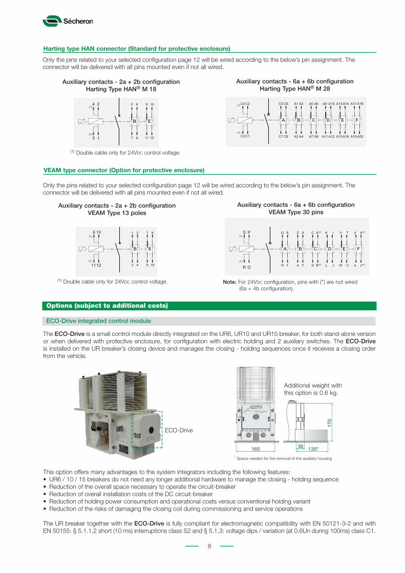
The ECO-Drive is a small control module directly integrated on the UR6, UR10 and UR15 breaker, for both stand-alone version or when delivered with protective enclosure, for configuration with electric holding and 2 auxiliary switches. The ECO-Drive is installed on the UR breaker’s closing device and manages the closing - holding sequences once it receives a closing order from the vehicle.
This option offers many advantages to the system integrators including the following features:• UR6 / 10 / 15 breakers do not need any longer additional hardware to manage the closing - holding sequence• Reduction of the overall space necessary to operate the circuit-breaker• Reduction of overall installation costs of the DC circuit-breaker• Reduction of holding power consumption and operational costs versus conventional holding variant• Reduction of the risks of damaging the closing coil during commissioning and service operations
The UR breaker together with the ECO-Drive is fully compliant for electromagnetic compatibility with EN 50121-3-2 and with EN 50155: § 5.1.1.2 short (10 ms) interruptions class S2 and § 5.1.3: voltage dips / variation (at 0.6Un during 100ms) class C1.
36
170
135*165 * Space needed for the removal of the auxiliary housing
Additional weight with this option is 0.6 kg.
ECO-Drive
( ) (I>) (WI)
Type : PFVEAM
Direct
HARTING
Légende
II>
Standard HAN: 28 polesStandard HAN: 18 poles
a b a b
3
4
13
4 22
13
4
13
4 22
1 3
4
13
4 22
1 3
4
13
4 22
1
B A B C D E FE
V
U
(1)
(1)
V
U
(1)
(1)
7
9
81
3 104
2136
1112
B E
PS
R O
C A(*)
D L
K I V TZ
a
X
B(*)
d b(*)
Y
G
H
E
F WJ U e c(*)
A B C D E F
C2C4
C3C1
A5 A6
A7 A11
A9 A10 A13 A14
A15
A1
A3
A2
A8 A12 A16
A17 A18
A19 A20A4
C5
C7
C6
C8
9
11
105
7 128
624
3 1
C2C4
C3C1
A5 A6
A7 A11
A9 A10 A13 A14
A15
A1
A3
A2
A8 A12 A16
A17 A18
A19 A20A4
C5
C7
C6
C8
9
11
105
7 128
624
3 1
A B C D E FB E
A B C D E FB E
WI
Standard HPR: 28 polesStandard HPR: 18 poles
(1)
(1)
(1)
(1)
(1)
(1)
(1)
(1)
(1)
(1)
(1)
(1)
9
511373
355
373
355
695
368±5
368±5
695
LV
HV
LV
HV
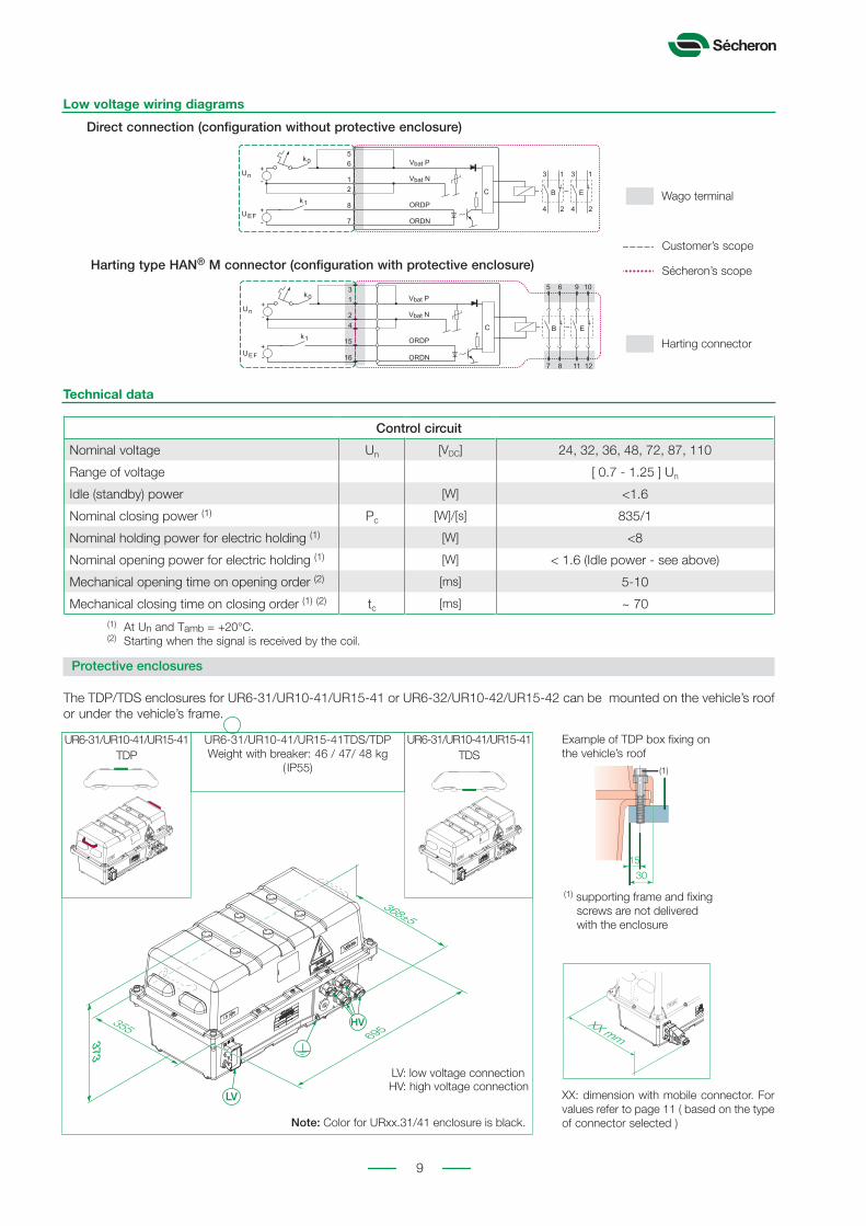
Low voltage wiring diagrams
B
65
11
24
3 1
24
3
2
8
7
E
Vbat P
Vbat N
ORDP
ORDN
k0
Un
UEF
k1
+
+
-
-
C
B
7 8 11 12
5 6
13
24
15
16
9 10
E
Vbat P
Vbat N
ORDP
ORDN
k0
Un
UEF
k1
+
+
-
-
C
Control circuit
Nominal voltage Un [VDC] 24, 32, 36, 48, 72, 87, 110
Range of voltage [ 0.7 - 1.25 ] Un
Idle (standby) power [W] <1.6
Nominal closing power (1) Pc [W]/[s] 835/1
Nominal holding power for electric holding (1) [W] <8
Nominal opening power for electric holding (1) [W] < 1.6 (Idle power - see above)
Mechanical opening time on opening order (2) [ms] 5-10
Mechanical closing time on closing order (1) (2) tc [ms] ~ 70
Technical data
(1) At Un and Tamb = +20°C.(2) Starting when the signal is received by the coil.
Direct connection (configuration without protective enclosure)
Harting type HAN® M connector (configuration with protective enclosure)
Customer’s scope
Sécheron’s scope
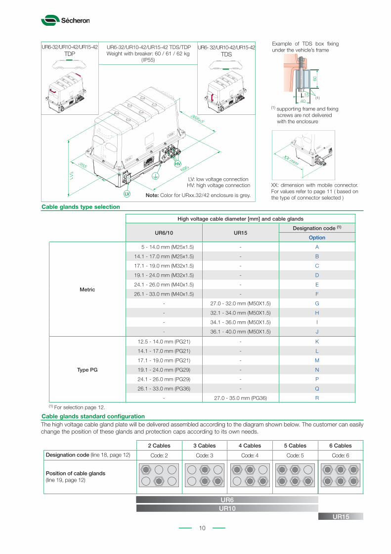
UR6-31/UR10-41/UR15-41TDS/TDP Weight with breaker: 46 / 47/ 48 kg
( IP55)
Protective enclosures
The TDP/TDS enclosures for UR6-31/UR10-41/UR15-41 or UR6-32/UR10-42/UR15-42 can be mounted on the vehicle’s roof or under the vehicle’s frame.
60
40
1530
15
(1)
(1)
UR6-31/UR10-41/UR15-41TDP
UR6-31/UR10-41/UR15-41TDS
Example of TDP box fixing on the vehicle’s roof
XX: dimension with mobile connector. For values refer to page 11 ( based on the type of connector selected )Note: Color for URxx.31/41 enclosure is black.
Harting connector
Wago terminalB
65
11
24
3 1
24
3
2
8
7
E
Vbat P
Vbat N
ORDP
ORDN
k0
Un
UEF
k1
+
+
-
-
C
XX mm
(1) supporting frame and fixing screws are not delivered with the enclosure
LV: low voltage connectionHV: high voltage connection
10
The high voltage cable gland plate will be delivered assembled according to the diagram shown below. The customer can easily change the position of these glands and protection caps according to its own needs.
Cable glands standard configuration
2 Cables 3 Cables 4 Cables 5 Cables 6 Cables
Designation code (line 18, page 12) Code: 2 Code: 3 Code: 4 Code: 5 Code: 6
Position of cable glands(line 19, page 12)
UR6UR10
UR15
Cable glands type selection
High voltage cable diameter [mm] and cable glands
UR6/10 UR15Designation code (1)
Option
Metric
5 - 14.0 mm (M25x1.5) - A
14.1 - 17.0 mm (M25x1.5) - B
17.1 - 19.0 mm (M32x1.5) - C
19.1 - 24.0 mm (M32x1.5) - D
24.1 - 26.0 mm (M40x1.5) - E
26.1 - 33.0 mm (M40x1.5) - F
- 27.0 - 32.0 mm (M50X1.5) G
- 32.1 - 34.0 mm (M50X1.5) H
- 34.1 - 36.0 mm (M50X1.5) I
- 36.1 - 40.0 mm (M50X1.5) J
Type PG
12.5 - 14.0 mm (PG21) - K
14.1 - 17.0 mm (PG21) - L
17.1 - 19.0 mm (PG21) - M
19.1 - 24.0 mm (PG29) - N
24.1 - 26.0 mm (PG29) - P
26.1 - 33.0 mm (PG36) - Q
- 27.0 - 35.0 mm (PG36) R(1) For selection page 12.
511373
355 373
355
695
368±5
368±5
695
LV
HV
LV
HV
UR6-32/UR10-42/UR15-42 TDS/TDP Weight with breaker: 60 / 61 / 62 kg
( IP55)
60
40
1530
15
(1)
(1)
Example of TDS box fixing under the vehicle’s frame
XX: dimension with mobile connector. For values refer to page 11 ( based on the type of connector selected )Note: Color for URxx.32/42 enclosure is grey.
UR6-32/UR10-42/UR15-42TDP
UR6- 32/UR10-42/UR15-42TDS
XX mm
(1) supporting frame and fixing screws are not delivered with the enclosure
LV: low voltage connectionHV: high voltage connection
11
Designation code for separately ordered mobile connector (for optional protective enclosure)
Auxiliary switches Fixedconnector
type
Mobile connectorOverall
width: XX [mm] (1)
Number of pinCablegland
Sécheron’snumber
ConnectorDevice Number Type
Size2.5 mm²
Size1.5 mm²
Size 2 mm2
UR6UR10UR15
2a+2b PFHarting
HAN® M 184 14 - M32
SG102955R00001 460 ± 5
SG102955R00003 431 ± 5
6a+6b PFHarting
HAN® M 284 24 - M32
SG102955R00002 460 ± 5
SG102955R00004 431 ± 5
UR6UR10UR15
2a+2b PFVEAM
type 13 pins
4 8 -
PG29
SG100025R00007(for 24Vdc)
430 ± 5
- - 10SG100025R00008
(for 36-110Vdc)430 ± 5
6a+6b PFVEAM
type 30 pins6 24 - PG29
SG100025R2(for 24-110Vdc)
430 ± 5
(1) Overall dimension of the enclosure with the selected mobile connector (Harting or VEAM). See drawing below.
Designation code for ordering
Designation code information
• Be sure to establish the designation code from our latest version of the brochure by downloading it from our website “www.secheron.com”.
• Be careful to write down the complete alphanumerical designation code with 20 characters when placing your order.• The customer shall write down the setting value Ids in its order form.• For technical reasons some variants and options indicated in the designation code might not be combined.• The bold part of this designation code defines the device type, and the complete designation defines the identification
number of the product, as displayed on the identification plate attached to the product.
Example of customer’s choice: UR .6 31 T D ø Z Z Z Z Z A 1 E C N 1Line: 10 11 12 13 14 15 16 17 18 19 20 21 22 23 24 25 26
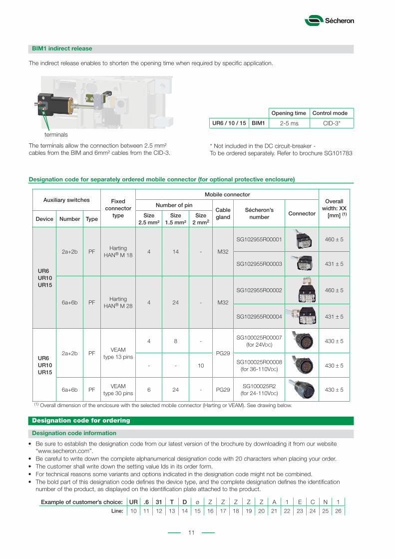
BIM1 indirect release
The indirect release enables to shorten the opening time when required by specific application.
* Not included in the DC circuit-breaker - To be ordered separately. Refer to brochure SG101783
Opening time Control mode
UR6 / 10 / 15 BIM1 2-5 ms CID-3*
The terminals allow the connection between 2.5 mm² cables from the BIM and 6mm² cables from the CID-3.
terminals

Copyright© 2015Sécheron SA
This document is not contractual and contains information corresponding to the level of technology at the date of printing. Sécheron reserves the right to modify and/or improve the product, whose characteristics are described in these documents, as required by new technology at any time. It is the purchaser’s responsibility to inform himself, no matter what the circumstances, of the product’s maintenance conditions and requirements. Sécheron reserves all rights, especially those arising from our “General Delivery Conditions”. S
G1
04
13
6B
EN
_B0
7-0
41
5
Sécheron SA Rue du Pré-Bouvier 251217 Meyrin - GenevaCH-Switzerland
Tel: +41 22 739 41 11Fax: +41 22 739 48 [email protected]
Designation code (options are subject to additional costs) - Order form
The low voltage connector must be ordered separately:Harting HAN® M 18: SG102955R00001 Harting HAN® M 28: SG102955R00002 Other type: SG.................Value of the setting of the direct over-current release: .......................[A]
Line Description Designation Standard Options Customer’s choice
10 Breaker type UR UR UR11 Conventional thermal current (1) - 1000 A (UR6) .6 - 1000 A (UR10) 10 - 1500 A (UR15) 15 12 Rated operational voltage - UR6 900 V 31 1800 V 32 - UR10/15 900 V 41 1800 V 4213 Application Traction (according to IEC60077-3) T T14 Mounting position Vertical D15 Protective enclosure No Ø For roof mounting P For underframe mounting S16 Type of low voltage connector (2)(3) NA Z Harting type HAN® M 2 VEAM 317 Type of high voltage cable gland plate (2) NA Z Metal - grounded M 18 Number of glands (2)(4) NA Z - UR6/10 4 4 Other selection according to table page 10 .... - UR15 only 6 6 19 Position of cable glands on plate (2)(4) NA Z Standard S20 External diamater of the HV cables (2)(5) NA Z Metric glands - UR6 19.1 - 24.0 mm (M32x1.5) D - UR10 26.1 - 33.0 mm (M40x1.5) F - UR15 36.1 - 40.0 mm (M50x1.5) J Cable glands type PG (specific execution) - UR6 19.1 - 24.0 mm (PG29) N - UR10 26.1 - 33.0 mm (PG36) Q - UR15 27.0 - 35.0 mm (PG36) R Other selection according to table page 10 ....21 Nominal control voltage 24 VDC A 36 VDC B 48 VDC C 72 VDC D 110 VDC E 32 VDC F 87 VDC G 96 VDC
(6) H22 Varistor on coil Yes (7) 1 No (7) N23 Control type Electric holding - without ECO-Drive E Magnetic holding - without ECO-Drive M Electric holding - with ECO-Drive (7) 424 Range of the direct over-current instaneous release - UR6/10/15 1.2 - 2.4 kA C - UR10 1.5 - 3.2 kA D - UR15 1.8 - 3.6 kA E Other selection according to table page 4 ....25 Indirect release No N N BIM1 126 Auxiliary contacts 2a + 2b - (switch PF) - Silver type 1 6a + 6b (8) - (switch PF) - Silver type 2 2a + 2b - (switch PF) - Gold type 3 6a + 6b (8) - (switch PF) - Gold type 4
(1) According to Sécheron’s recommendation (refer to page 4).(2) Options valid with a protectecive enclosure(3) When ordering a breaker with a protective enclosure, the low voltage mobile connector
must be ordered separately according to the description page 11.(4) Refer to cable glands configuration scheme page 10.(5) The customer will have to adapt the inner diameter of the gland seals by removing the
unnecessary rubber rings.
(6) Only possible with holding type electric E.(7) In case control type “Electric holding - with ECO-Drive” is selected (line 23), select “No”
for line 22. Option not compatible for breaker’s version with protective enclosure and 6a+6b auxiliary switches, nor for version with VEAM connector.
(8) 6a + 4b configuration for 24 VDC control voltage for VEAM connector.
Place and date: Name: Signature:
Related Documents


