S.E.V Solar Extended Vehicle EEL 4914 Senior Design II Group #4 Hamed Alostath Daniel Grainger Frank Niles Sergio Roig

Welcome message from author
This document is posted to help you gain knowledge. Please leave a comment to let me know what you think about it! Share it to your friends and learn new things together.
Transcript

S.E.V Solar Extended Vehicle
EEL 4914 Senior Design II
Group #4
Hamed Alostath Daniel Grainger
Frank Niles Sergio Roig

Motivation • The majority of electric motor RC planes tend
to have a low flight time • Solar panels are not typically used in small
UAVs • There is a high demand for autonomous
drones in military applications

Goals • Build an aerial vehicle that uses solar power to
extend the overall flight time of a RC plane • To have the plane fly autonomously in a slow,
descending circular path • To further reduce power consumption by
allowing the plane to periodically glide with the motor turned off, then throttle up and climb to max alt
Overall Block Diagram
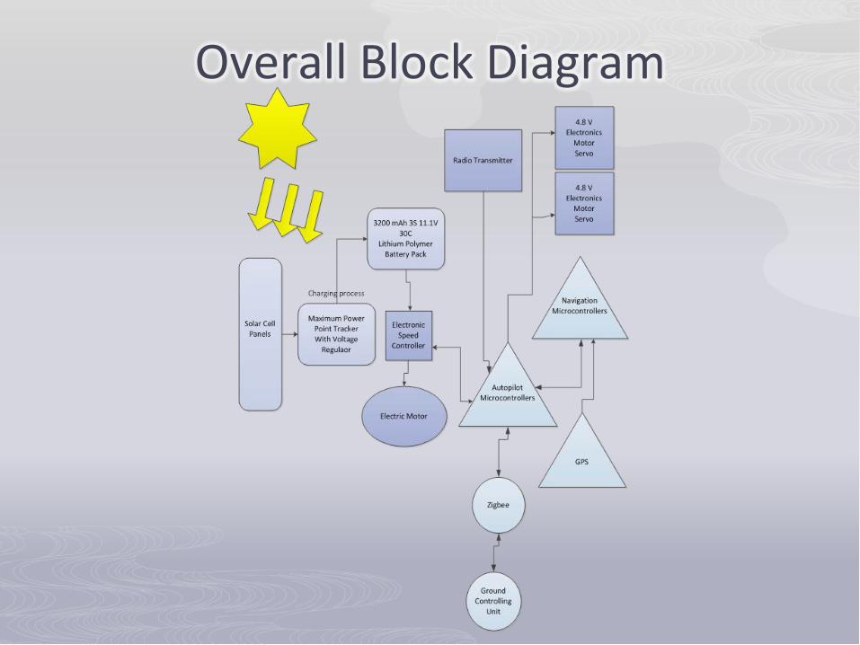
Airframe: Specifications • Wing Area: 465 in2 (30 dm2) • Wing Span: 51.18 in (1300 mm) • Length: 65.35 in (1660 mm) • Total Weight: 2.2 lb (1.0 kg) • Wing Loading: 2.1935 g/in2 (34 g/dm2)

Functionality: Physical Features • Overhead wing (gliding) • No ailerons on the main
wing • Push propeller rather
than pull propeller • Hand-launched take-off
method • Deep-stall landing
method

Typical Interaction of Motor, Servos, and ESC
Electronic Speed Controller
Receiver
Remote Controller
Motor
Servo2
Servo1

Motor Selection Features
• Lightweight • Large KV output (RPM/Volt) • Outrunner motor
Specifications • KV Rating: 1100 rpm/volt • Input Voltage: 7.2-12V • Continuous Current: 30A • Max Burst Current: 42A

ESC Selection Requirements
• Current rating must be greater than or equal to the motor.
Specifications • Cont. Current: 60A • Burst Current: 75A • Operating Voltage: 4.8-6.0V • Weight: 66g (2.33 oz)

Servo Selection Operation
• Vertical tailfin rudder • Horizontal tailfin elevator • Metal gear
Specifications • Torque: 2.0 kg/cm • Operating Speed:
0.11 sec/60 degrees • Operating Voltage: 4.8-6.0V • Weight: 9g (0.32oz)

Airframe: Testing • The E-Flite Apprentice
15E served as our initial prototype
• Allowed for testing our electronic connections
• Practice our RC flying skills

Hardware Design Solar Extended Vehicle µController GPS 3-axis Gyroscope 3-axis Accelerometer Solar panels Charging Circuit Battery
µController

• 8-Bit AVR RISC Architecture • Arduino Development Environment • TQFP package • 8 ADC • Two Wire Interface/USART
ATmega328 by Atmel •Yaw/Pitch/Roll stabilizes the SEV • Inertial forces

ATmega328 LY530ALH Z-axis LPR530AL X/Y axis ADXL335 X/Y/Z axes MT3329 GPS
ATmega328 LY530ALH LPR530AL ADXL335 MT3329 Sample $9.95 $7.95 $9.95 $63.51 1.8 – 5.5 V 3 V 3 V 3V 4.5 – 6.5 V 8-channel 10-bit ADC
Analog Output
Analog Output
Analog Output
Rx/Tx
Navigation Unit

Autopilot Unit
ATmega328 ATtiny45 Xbee-Pro 900MHz 2.4G 6-channel Receiver Throttle/Rudder/Elevator Ground Station Laptop Xbee-Pro 900MHz 2.4G DX5e 5-channel Transmitter
ATtiny45 Xbee-Pro (RF) RC Rx (RF) Sample $95.37 $9.00 1.8 – 5.5 V 3 – 3.6 V 4.5 – 6.5 V - 900 MHz 2.4 GHz
UART UART
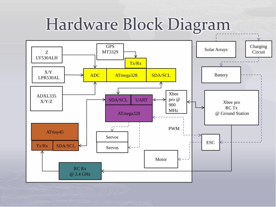
ATmega328
GPS MT3329
X/Y LPR530AL
ADXL335 X/Y/Z
Motor
Servos
Battery
Xbee pro RC Tx
@ Ground Station ATmega328
Z LY530ALH
Solar Arrays
RC Rx @ 2.4 GHz
ADC SDA/SCL
SDA/SCL
ATtiny45
Xbee pro @ 900 MHz
UART
Tx/Rx
ESC Tx/Rx
Charging Circuit
Servos SDA/SCL
Hardware Block Diagram
PWM

Printed Circuit Boards
Charging Circuit Board LT3652 MPPT Charging Controller Connectors: Solar Cells, Battery, ESC

Autopilot Circuit Board
Autopilot Circuit Board Single and dual axis Gyroscopes Accelerometer Center of Gravity Connectors: Charging-Circuit Circuit-Board, GPS, Xbee-Pro, and Servos

Power System The power system will consist of the following items: • Solar Panels • Lithium Polymer Battery Pack • Maximum Power Point Tracking Circuit

Solar Cells The solar cells that we were integrating into our S.E.V project
had to meet three very important design criteria. • High Total Maximum Output • Lightweight • Easy System Integration
PowerFilm RC7.2-75

Comparison of Solar Cells
Panel
SolMaxx Flex 7.2V 100mA
SolMaxx Flex 7.2V 200mA
PowerFilm RC7.2-75
Dimensions: 10.6” x 3.9” 10.6” x 6.9” 10.6” x 3.5”
Weight: 1.1 oz 1.9 oz 0.2 oz
Total Weight: 8.8 oz 7.6 oz 1.6 oz
Thickness: NA NA 0.2 mm
Voltage: 7.2V 7.2V 7.2V
Total Output: 291 mA @ 19.8V 291mA 19.8V 291mA 19.8V
Price: $20.95 ea. $37.75 ea. $27.45 ea.

Solar Array Configuration Series/ Parallel
19.8V @ 291 mA

LiPo Battery Pack E-flite EFLB1040
Type: LiPo Capacity: 3200mAh Voltage: 11.1V Connector Wire Gauge: 12 AWG Weight: 9.9 oz (251g) Configuration: 3S Length: 5.20 in (132mm) Width: 1.70 in (43.2mm) Height: 0.90 in (22.9mm) Maximum Continuous Discharge : 15C Maximum Continuous Current : 48A
What is Maximum Power Point Tracker
MPPT or Maximum Power Point Tracking is an algorithm that included in charge controllers used for extracting maximum available power from PV module under certain conditions. The voltage at which PV module can produce maximum power is called ‘maximum power point’ (or peak power voltage). Maximum power varies with: • Solar Radiation • Ambient Temperature • Solar Cell Temperature.

LT3652 - Power Tracking 2A Battery Charger for Solar Power
• Wide Input Voltage Range: 4.95V to 32V (40V Abs Max) • Programmable Charge Rate Up to 2A • User Selectable Termination: C/10 or On-Board Termination Timer • Resistor Programmable Float Voltage Up to 14.4V Accommodates
Li-Ion/Polymer, LiFePO4, SLA, NiMH/NiCd Chemistries • No VIN Blocking Diode Required for Battery Voltages ≤ 4.2V • 1MHz Fixed Frequency • 0.5% Float Voltage Reference Accuracy • 5% Charge Current Accuracy • 2.5% C/10 Detection Accuracy • Binary-Coded Open-Collector Status Pins • 3mm × 3mm MSOP-12 Package

LT3652 Maximum Power Point Tracking Circuit

Voltage Monitor Programming • The LT3652 also contains a voltage monitor pin that enables it to
monitor the minimum amount of voltage coming into the MPPT. The input supply voltage regulation is controlled via the voltage divider resistor RIN1 and RIN2. An operating supply voltage can be programmed by monitoring the supply through the resistor divider network. This is done by having a ratio of RIN1/RIN2 for a desired minimum voltage. In order to achieve the 11.1V needed:
RIN1/RIN2 = (VIN(MIN)/2.7) - 1 RIN1/RIN2= 12.185

Float Voltage Monitor Programming • Using a resistor divider is needed to program the desired
float voltage, VBAT(FLT), for the battery system. In particular, resistors RFB1 and RFB2 will have to have the correct values to set the 12.6-volt float charge needed in the lithium polymer battery pack.
RFB1= (VBAT(FLT) * 2.5 * 105)/3.3
RFB1= 943.18 KΩ
RFB2 = (R1*(2.5*105))/(R1*(2.5*105))
RFB2= 340.16 KΩ

Charge Current Programming • Charge current programming is set by choosing an
inductor sense resistor. For our particular circuit that we are designing the total expected max current that we would see from the circuit is 463mA. The expected value for RSense would be a resistor with an approximate value of 0.2161Ω.
RSENSE = 0.1/ICHG(MAX)
RSENSE= 0.2161 Ω

Software Design
•Arduino IDE •ArduPilot: Open source autopilot platform •AHRS •Ground Control Station •Simulator: XPlane

ArduPilot • Manual- Full manual control • Circle- Fly in a stabilized circle, this is used when there is no
GPS present • Stabilize- This mode will have the plane maintain level flight • Fly-by-wire A- Autopilot style control via user input, manual
throttle • Fly-by-wire B- Autopilot style control via user input, airspeed
controlled throttle Power • Auto- All control of the UAV are through the ArduPilot • RTL- The UAV will return to its launch location and circle until
manually controlled • Loiter- The UAV will circle in the current location • The Fly-By-Wire B mode is where we have chosen to place
our power saving code. This allows us to use the control switch to enter and exit the power saving mode.

ArduPilot Cont. •The code consist of one main loop. •Within the main loop there are three Functions. •The fast loop checks to see if the radio controller is sending a signal, it will calculate the altitude and bearing error and last will update current flight mode. •The medium loop is comprised of 5 different cases that will be executed one at a time. These cases range from navigation to timers. And most importantly checks to see if the control switch has been changed.

Power Saving Code servo_out[CH_THROTTLE] = temp_thro; if(current_loc.alt < 3000) temp_thro = THROTTLE_MAX; servo_out[CH_THROTTLE] = THROTTLE_MAX; nav_roll = 0 ; nav_pitch = 1500; if(current_loc.alt > 6000) temp_thro = THROTTLE_MIN; servo_out[CH_THROTTLE] = THROTTLE_MIN; nav_roll = HEAD_MAX / 3; nav_pitch = 500;

Altitude Heading Reference System • The code will be used to maintain a model of the
UAV’s orientation in space. • This code is based on Bill Premerlani’s Direction
Cosine Matrix (DCM) algorithm. • The DCM is a 3 by 3 matrix array; the gyro data is
used in a time step integration to update the matrix. With this data from the sensors and GPS can be used to correct for errors.
• With this data we can determine pitch, roll and yaw; but for this project we will only be using the pitch and yaw. With this code we are now able to fly, without the control of a user, our UVA to waypoints.
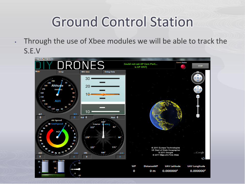
Ground Control Station • Through the use of Xbee modules we will be able to track the
S.E.V

Software Testing
• Before we flew the plane we tested the software.
• This was done in a simulated environment, we chose to do this to avoid destroying our airframes
• We used the XPlane software to simulate the software code.
• Testing was done by using development boards purchased from SparkFun

Description Quantity Price Each Total Price Plane 1 $89.95 $119.80
Motor 1 $54.99 $58.56
Prototype plane incl. servo & ESC 2 Incl $300.00
Electronic Speed Controller 1 Incl Incl
Microcontroller ATmega 328 & ATtiny45 1 Sample Free
Triple-Axis Accelerometer- ADXL335 1 $5.00 $5.00
Barometric Pressure Sensor – BMP085 1 Sample Free
Gyroscope LY530ALH & LPR530AL 2 Sample Free
GPS Mediatech MT3329 1 $63.51 $63.51
Transmitter/ Receiver 1 $32.78 $32.78
Zigbee Pro 2 $47.69 $95.37
Solar Panel PowerFilm RC7.2-75 8 $31.34 $250.69
Lithium-Ion Polymer Battery Pack 2 $53.24 $106.48
LT3652 Charging Circuit 2 $27.98 $48.88
Sub-Total $1,023.00
S.E.V Actual Budget

Difficulties • Weather Conditions • Landing Protocol • Less solar radiance during winter
months • The motor was over powered for this
airframe • High maintenance testing • Software communications difficulties
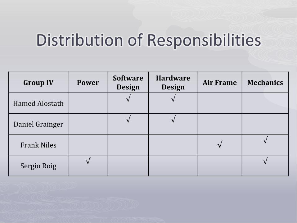
Distribution of Responsibilities
Group IV Power Software Design
Hardware Design Air Frame Mechanics
Hamed Alostath √
√
Daniel Grainger √
√
Frank Niles √ √
Sergio Roig √
√

Questions?
Related Documents