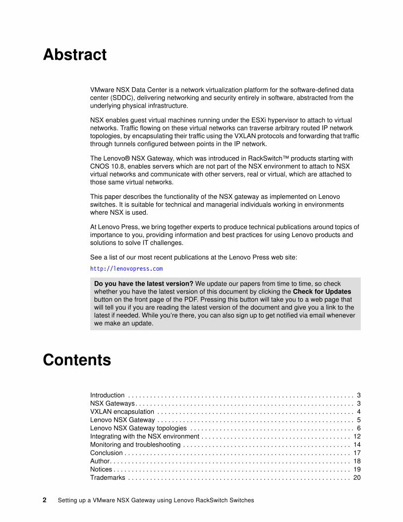
Front cover Setting up a VMware NSX Gateway using Lenovo RackSwitch Switches Introduces the NSX Gateway and VXLAN encapsulation Describes the function available in CNOS 10.8 or later Includes step-by-step instructions to set up the Gateway Provides the commands to verify and troubleshoot Scott Lorditch

Welcome message from author
This document is posted to help you gain knowledge. Please leave a comment to let me know what you think about it! Share it to your friends and learn new things together.
Transcript
Front cover
Setting up a VMware NSX Gateway using Lenovo RackSwitch Switches
Introduces the NSX Gateway and VXLAN encapsulation
Describes the function available in CNOS 10.8 or later
Includes step-by-step instructions to set up the Gateway
Provides the commands to verify and troubleshoot
Scott Lorditch
2 Setting up a VMware NSX Gateway using Lenovo RackSwitch Switches
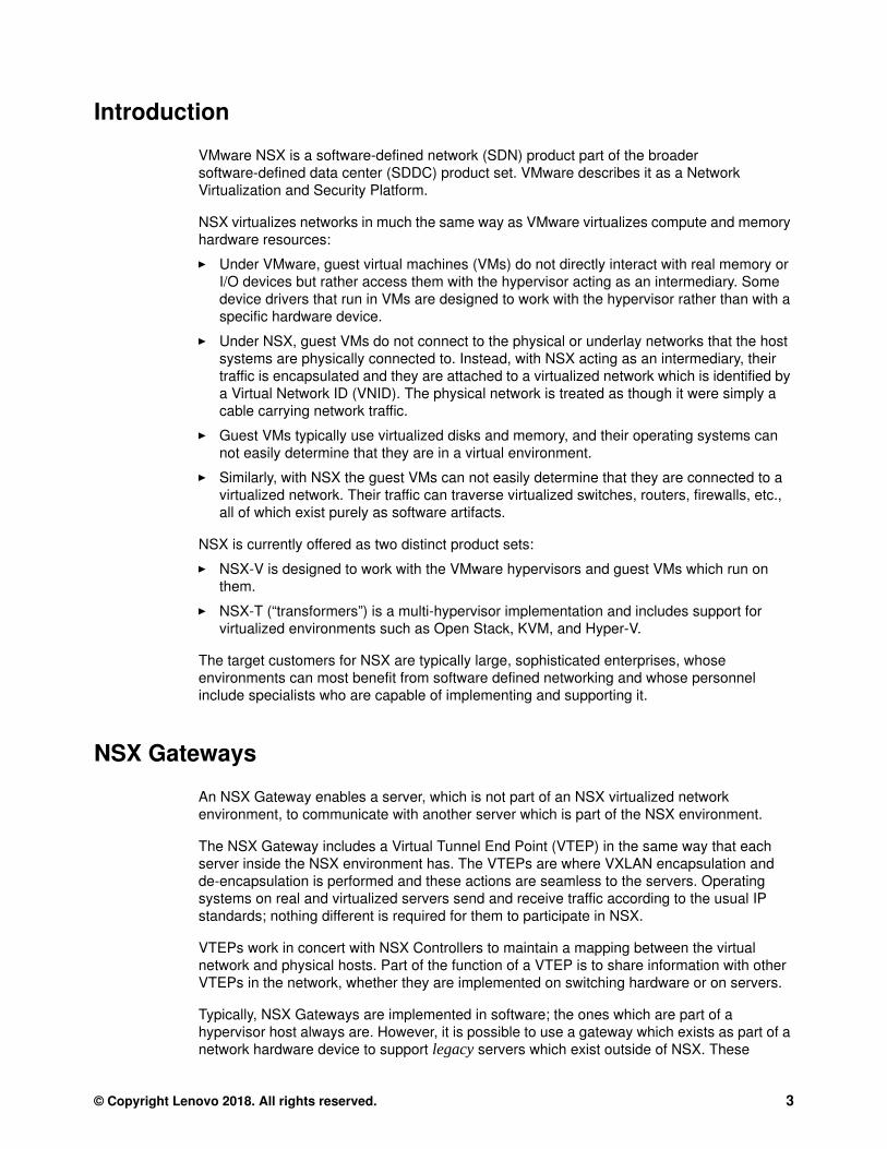
Abstract
VMware NSX Data Center is a network virtualization platform for the software-defined data center (SDDC), delivering networking and security entirely in software, abstracted from the underlying physical infrastructure.
NSX enables guest virtual machines running under the ESXi hypervisor to attach to virtual networks. Traffic flowing on these virtual networks can traverse arbitrary routed IP network topologies, by encapsulating their traffic using the VXLAN protocols and forwarding that traffic through tunnels configured between points in the IP network.
The Lenovo® NSX Gateway, which was introduced in RackSwitch™ products starting with CNOS 10.8, enables servers which are not part of the NSX environment to attach to NSX virtual networks and communicate with other servers, real or virtual, which are attached to those same virtual networks.
This paper describes the functionality of the NSX gateway as implemented on Lenovo switches. It is suitable for technical and managerial individuals working in environments where NSX is used.
At Lenovo Press, we bring together experts to produce technical publications around topics of importance to you, providing information and best practices for using Lenovo products and solutions to solve IT challenges.
See a list of our most recent publications at the Lenovo Press web site:
http://lenovopress.com
Contents
Introduction . . . . . . . . . . . . . . . . . . . . . . . . . . . . . . . . . . . . . . . . . . . . . . . . . . . . . . . . . . . . . . 3NSX Gateways. . . . . . . . . . . . . . . . . . . . . . . . . . . . . . . . . . . . . . . . . . . . . . . . . . . . . . . . . . . . 3VXLAN encapsulation . . . . . . . . . . . . . . . . . . . . . . . . . . . . . . . . . . . . . . . . . . . . . . . . . . . . . . 4Lenovo NSX Gateway . . . . . . . . . . . . . . . . . . . . . . . . . . . . . . . . . . . . . . . . . . . . . . . . . . . . . . 5Lenovo NSX Gateway topologies . . . . . . . . . . . . . . . . . . . . . . . . . . . . . . . . . . . . . . . . . . . . . 6Integrating with the NSX environment . . . . . . . . . . . . . . . . . . . . . . . . . . . . . . . . . . . . . . . . . 12Monitoring and troubleshooting . . . . . . . . . . . . . . . . . . . . . . . . . . . . . . . . . . . . . . . . . . . . . . 14Conclusion . . . . . . . . . . . . . . . . . . . . . . . . . . . . . . . . . . . . . . . . . . . . . . . . . . . . . . . . . . . . . . 17Author. . . . . . . . . . . . . . . . . . . . . . . . . . . . . . . . . . . . . . . . . . . . . . . . . . . . . . . . . . . . . . . . . . 18Notices . . . . . . . . . . . . . . . . . . . . . . . . . . . . . . . . . . . . . . . . . . . . . . . . . . . . . . . . . . . . . . . . . 19Trademarks . . . . . . . . . . . . . . . . . . . . . . . . . . . . . . . . . . . . . . . . . . . . . . . . . . . . . . . . . . . . . 20
Do you have the latest version? We update our papers from time to time, so check whether you have the latest version of this document by clicking the Check for Updates button on the front page of the PDF. Pressing this button will take you to a web page that will tell you if you are reading the latest version of the document and give you a link to the latest if needed. While you’re there, you can also sign up to get notified via email whenever we make an update.
Introduction
VMware NSX is a software-defined network (SDN) product part of the broader software-defined data center (SDDC) product set. VMware describes it as a Network Virtualization and Security Platform.
NSX virtualizes networks in much the same way as VMware virtualizes compute and memory hardware resources:
� Under VMware, guest virtual machines (VMs) do not directly interact with real memory or I/O devices but rather access them with the hypervisor acting as an intermediary. Some device drivers that run in VMs are designed to work with the hypervisor rather than with a specific hardware device.
� Under NSX, guest VMs do not connect to the physical or underlay networks that the host systems are physically connected to. Instead, with NSX acting as an intermediary, their traffic is encapsulated and they are attached to a virtualized network which is identified by a Virtual Network ID (VNID). The physical network is treated as though it were simply a cable carrying network traffic.
� Guest VMs typically use virtualized disks and memory, and their operating systems can not easily determine that they are in a virtual environment.
� Similarly, with NSX the guest VMs can not easily determine that they are connected to a virtualized network. Their traffic can traverse virtualized switches, routers, firewalls, etc., all of which exist purely as software artifacts.
NSX is currently offered as two distinct product sets:
� NSX-V is designed to work with the VMware hypervisors and guest VMs which run on them.
� NSX-T (“transformers”) is a multi-hypervisor implementation and includes support for virtualized environments such as Open Stack, KVM, and Hyper-V.
The target customers for NSX are typically large, sophisticated enterprises, whose environments can most benefit from software defined networking and whose personnel include specialists who are capable of implementing and supporting it.
NSX Gateways
An NSX Gateway enables a server, which is not part of an NSX virtualized network environment, to communicate with another server which is part of the NSX environment.
The NSX Gateway includes a Virtual Tunnel End Point (VTEP) in the same way that each server inside the NSX environment has. The VTEPs are where VXLAN encapsulation and de-encapsulation is performed and these actions are seamless to the servers. Operating systems on real and virtualized servers send and receive traffic according to the usual IP standards; nothing different is required for them to participate in NSX.
VTEPs work in concert with NSX Controllers to maintain a mapping between the virtual network and physical hosts. Part of the function of a VTEP is to share information with other VTEPs in the network, whether they are implemented on switching hardware or on servers.
Typically, NSX Gateways are implemented in software; the ones which are part of a hypervisor host always are. However, it is possible to use a gateway which exists as part of a network hardware device to support legacy servers which exist outside of NSX. These
© Copyright Lenovo 2018. All rights reserved. 3
gateways typically perform their function largely as part of a switching ASIC. They therefore take the load off of the processors which drive the hypervisor servers, and can typically support higher traffic volumes. The Lenovo CNOS gateway function is such a gateway and uses the capabilities of the switching ASICs to enhance performance.
VXLAN encapsulation
NSX traffic is carried across the physical underlay network by being encapsulated according to the standard specified in RFC 7348. The official definition of the RFC 7348 standard can be found at https://tools.ietf.org/html/rfc7348.
The original purpose of VXLAN was to extend VLANs used by VMware hypervisors so that vMotion of guest machines could cross an arbitrary routed network topology. The use of VXLAN tunnels was found to be useful in more generalized roles. The primary benefit of NSX and VXLAN could be argued to be that, by virtualizing the network, it facilitates and expedites changes to the network which would take more time and effort if done with real physical devices. This is similar to the benefit obtained from using a hypervisor and virtual machines.
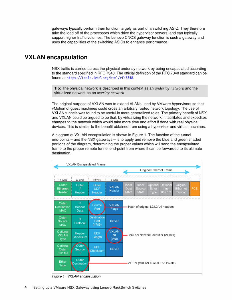
A diagram of VXLAN encapsulation is shown in Figure 1. The function of the tunnel end-points – and the NSX gateways – is to apply and remove the blue and green shaded portions of the diagram, determining the proper values which will send the encapsulated frame to the proper remote tunnel end-point from where it can be forwarded to its ultimate destination.
Figure 1 VXLAN encapsulation
Tip: The physical network is described in this context as an underlay network and the virtualized network as an overlay network.
VXLANFlags
SourcePort
IPHeader
Data
OuterDestination
MAC
OriginalEthernetPayload
OptionalInner
802.1Q
OptionalEtherType
InnerSourceMAC
InnerDestMAC
OuterUDP
Header
VXLANHeader
OuterIP
Header
OuterDestination
IP
EtherType
OuterEthernetHeader
FCS
DestinationPort
(4789)
IPProtocol
OuterSourceMAC
RSVD
UDPLength
HeaderChecksum
OptionalVXLAN
Type
VXLANNI
(VNI)
UDPChecksum
VXLAN Network Identifier (24 bits)
OuterSource
IP
OptionalOuter
802.1QRSVD
Hash of original L2/L3/L4 headers
8 bytes8 bytes20 bytes14 bytes
VTEPs (VXLAN Tunnel End Points)
Original Ethernet Frame
VXLAN Encapsulated Frame
4 Setting up a VMware NSX Gateway using Lenovo RackSwitch Switches
One key function of the encapsulation process is to determine the proper network for the traffic, referred to as the Virtual Network ID (VNID). There are mappings between VLAN tags used on Ethernet and VNID’s, which are configured or learned by the gateways. The VNID is part of the VXLAN header shown in deep blue on Figure 1.
Lenovo NSX Gateway
Lenovo’s NSX Gateway is a function of the CNOS firmware of Lenovo RackSwitch switches. It is certified by VMware on all of the Lenovo switches which can run CNOS starting with release 10.8. This includes the following products:
� Lenovo RackSwitch G8272� Lenovo RackSwitch G8296� Lenovo RackSwitch G8332� Lenovo ThinkSystem™ NE1032 RackSwitch� Lenovo ThinkSystem NE1032T RackSwitch� Lenovo ThinkSystem NE1072T RackSwitch� Lenovo ThinkSystem NE2572 RackSwitch� Lenovo ThinkSystem NE10032 RackSwitch
The gateway allows servers (including virtualized servers) which are not participating in the NSX environment to communicate with servers that are participating, by performing VXLAN encapsulation. In Lenovo RackSwitch switches, the VXLAN encapsulation is performed in hardware as a function of the Broadcom switching ASICs. Traffic on specified VLANs and specified ports is forwarded as encapsulated traffic on a determined VNID network.
The current implementation of the gateway is as a layer-2 gateway, which means that the traffic will originate/terminate on the same subnet as that used by the corresponding VNID network; IP routing is not supported in this release of the gateway. IP routing is a planned enhancement for a future release.
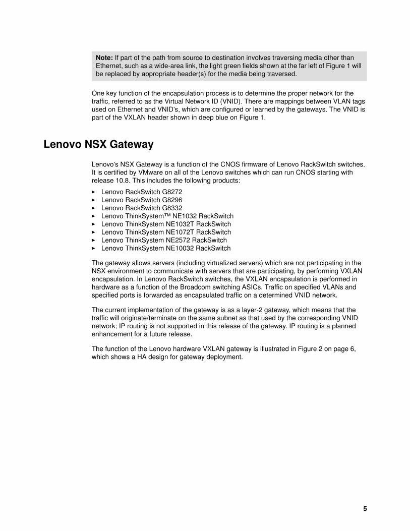
The function of the Lenovo hardware VXLAN gateway is illustrated in Figure 2 on page 6, which shows a HA design for gateway deployment.
Note: If part of the path from source to destination involves traversing media other than Ethernet, such as a wide-area link, the light green fields shown at the far left of Figure 1 will be replaced by appropriate header(s) for the media being traversed.
5
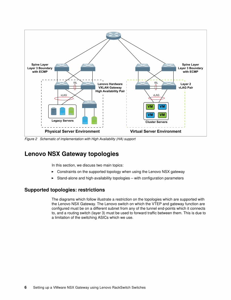
Figure 2 Schematic of implementation with High Availability (HA) support
Lenovo NSX Gateway topologies
In this section, we discuss two main topics:
� Constraints on the supported topology when using the Lenovo NSX gateway
� Stand-alone and high-availability topologies – with configuration parameters
Supported topologies: restrictions
The diagrams which follow illustrate a restriction on the topologies which are supported with the Lenovo NSX Gateway. The Lenovo switch on which the VTEP and gateway function are configured must be on a different subnet from any of the tunnel end-points which it connects to, and a routing switch (layer 3) must be used to forward traffic between them. This is due to a limitation of the switching ASICs which we use.
VM
VMVM
VM
Physical Server Environment Virtual Server Environment
Legacy Servers
Spine LayerLayer 3 Boundary
with ECMP
Lenovo HardwareVXLAN Gateway
High Availability Pair
Cluster Servers
Layer 2vLAG Pair
Spine LayerLayer 3 Boundary
with ECMP
ISL ISL
vLAG vLAG
6 Setting up a VMware NSX Gateway using Lenovo RackSwitch Switches
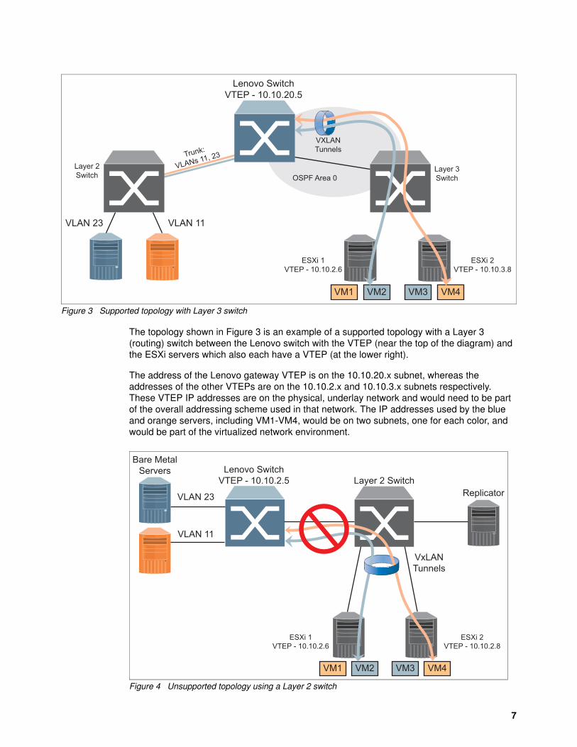
Figure 3 Supported topology with Layer 3 switch
The topology shown in Figure 3 is an example of a supported topology with a Layer 3 (routing) switch between the Lenovo switch with the VTEP (near the top of the diagram) and the ESXi servers which also each have a VTEP (at the lower right).
The address of the Lenovo gateway VTEP is on the 10.10.20.x subnet, whereas the addresses of the other VTEPs are on the 10.10.2.x and 10.10.3.x subnets respectively. These VTEP IP addresses are on the physical, underlay network and would need to be part of the overall addressing scheme used in that network. The IP addresses used by the blue and orange servers, including VM1-VM4, would be on two subnets, one for each color, and would be part of the virtualized network environment.
Figure 4 Unsupported topology using a Layer 2 switch
Lenovo SwitchVTEP - 10.10.20.5
Layer 3Switch
Layer 2Switch
VXLANTunnels
VLAN 23 VLAN 11
Trunk:
VLANs 11, 23
VM1 VM2 VM3 VM4
ESXi 1VTEP - 10.10.2.6
OSPF Area 0
ESXi 2VTEP - 10.10.3.8
Lenovo SwitchVTEP - 10.10.2.5
Replicator
Bare MetalServers
Layer 2 Switch
VxLANTunnels
VLAN 23
VLAN 11
VM1 VM2 VM3 VM4
ESXi 1VTEP - 10.10.2.6
ESXi 2VTEP - 10.10.2.8
7
In Figure 4, an unsupported topology is shown. The problem is that the Lenovo switch where the NSX gateway and VTEP reside can not connect to the two other tunnel end-points, both of which are on the same subnet with the Lenovo switch VTEP (10.10.2.x) and also with each other.
Stand-alone topology and configuration
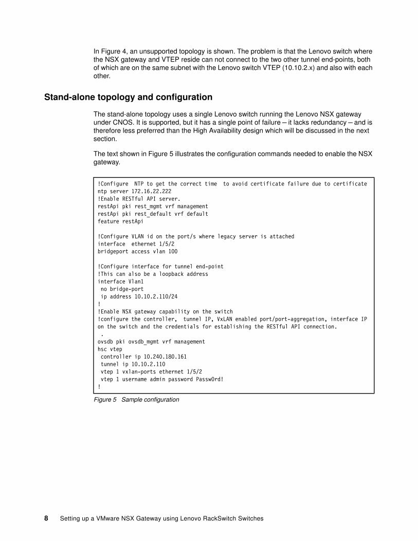
The stand-alone topology uses a single Lenovo switch running the Lenovo NSX gateway under CNOS. It is supported, but it has a single point of failure – it lacks redundancy – and is therefore less preferred than the High Availability design which will be discussed in the next section.
The text shown in Figure 5 illustrates the configuration commands needed to enable the NSX gateway.
Figure 5 Sample configuration
!Configure NTP to get the correct time to avoid certificate failure due to certificate ntp server 172.16.22.222!Enable RESTful API server.restApi pki rest_mgmt vrf management restApi pki rest_default vrf defaultfeature restApi
!Configure VLAN id on the port/s where legacy server is attached interface ethernet 1/5/2bridgeport access vlan 100
!Configure interface for tunnel end-point!This can also be a loopback addressinterface Vlan1 no bridge-port ip address 10.10.2.110/24!!Enable NSX gateway capability on the switch!configure the controller, tunnel IP, VxLAN enabled port/port-aggregation, interface IP on the switch and the credentials for establishing the RESTful API connection. .ovsdb pki ovsdb_mgmt vrf management hsc vtep controller ip 10.240.180.161 tunnel ip 10.10.2.110 vtep 1 vxlan-ports ethernet 1/5/2 vtep 1 username admin password Passw0rd!!
8 Setting up a VMware NSX Gateway using Lenovo RackSwitch Switches
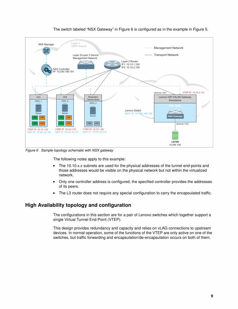
The switch labeled “NSX Gateway” in Figure 6 is configured as in the example in Figure 5.
Figure 6 Sample topology schematic with NSX gateway
The following notes apply to this example:
� The 10.10.x.x subnets are used for the physical addresses of the tunnel end-points and those addresses would be visible on the physical network but not within the virtualized network.
� Only one controller address is configured; the specified controller provides the addresses of its peers.
� The L3 router does not require any special configuration to carry the encapsulated traffic.
High Availability topology and configuration
The configurations in this section are for a pair of Lenovo switches which together support a single Virtual Tunnel End-Point (VTEP).
This design provides redundancy and capacity and relies on vLAG connections to upstream devices. In normal operation, some of the functions of the VTEP are only active on one of the switches, but traffic forwarding and encapsulation/de-encapsulation occurs on both of them.
NSX ControllerIP: 10.240.180.161
NSX Manager
Lenovo HW VXLAN GatewayStandalone
Lenovo SwitchMGT IP: 10.140.180.145
LS100VLAN 100
ethernet 1/5/2
ethernet 1/6/3
VDS
ESXi_1
Server
VM VM
VM VM
VTEP IP: 10.10.1.52MGT IP: 10.241.42.196
VTEP IP: 10.10.2.110
Layer 3OSPF Area 0
VDS
ESXi_2
Server
VM VM
VM VM
VTEP IP: 10.10.1.70MGT IP: 10.241.42.197
ReplicationService Node
Server
VM VM
VTEP IP: 10.10.1.55MGT IP: 10.241.42.219
Layer 3 RouterIF1: 10.10.1.100IF2: 10.10.2.100
Layer 2/Layer 3 DeviceManagement Network
VNI 1000
Management Network
Transport Network
NSX Gateway
ESXi_3
9
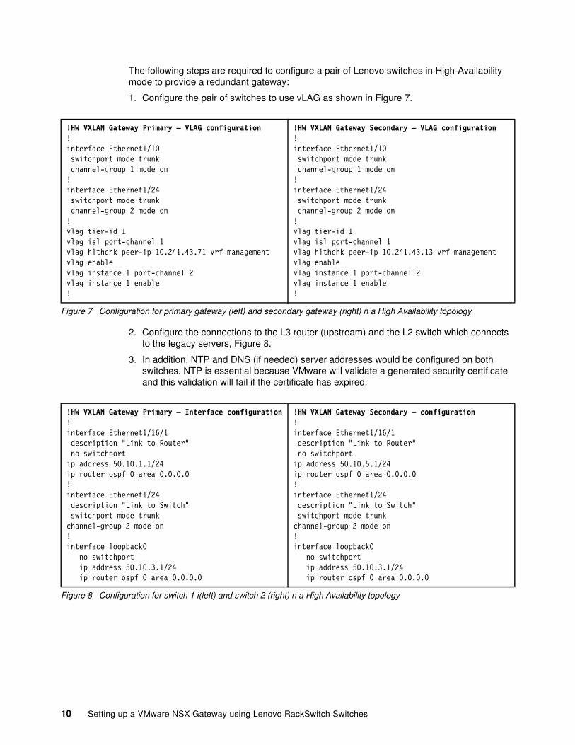
The following steps are required to configure a pair of Lenovo switches in High-Availability mode to provide a redundant gateway:
1. Configure the pair of switches to use vLAG as shown in Figure 7.
Figure 7 Configuration for primary gateway (left) and secondary gateway (right) n a High Availability topology
2. Configure the connections to the L3 router (upstream) and the L2 switch which connects to the legacy servers, Figure 8.
3. In addition, NTP and DNS (if needed) server addresses would be configured on both switches. NTP is essential because VMware will validate a generated security certificate and this validation will fail if the certificate has expired.
Figure 8 Configuration for switch 1 i(left) and switch 2 (right) n a High Availability topology
!HW VXLAN Gateway Primary – VLAG configuration!interface Ethernet1/10 switchport mode trunk channel-group 1 mode on!interface Ethernet1/24 switchport mode trunk channel-group 2 mode on!vlag tier-id 1vlag isl port-channel 1vlag hlthchk peer-ip 10.241.43.71 vrf managementvlag enablevlag instance 1 port-channel 2vlag instance 1 enable!
!HW VXLAN Gateway Secondary – VLAG configuration!interface Ethernet1/10 switchport mode trunk channel-group 1 mode on!interface Ethernet1/24 switchport mode trunk channel-group 2 mode on!vlag tier-id 1vlag isl port-channel 1vlag hlthchk peer-ip 10.241.43.13 vrf managementvlag enablevlag instance 1 port-channel 2vlag instance 1 enable!
!HW VXLAN Gateway Primary – Interface configuration!interface Ethernet1/16/1 description "Link to Router" no switchportip address 50.10.1.1/24ip router ospf 0 area 0.0.0.0 !interface Ethernet1/24 description "Link to Switch" switchport mode trunkchannel-group 2 mode on!interface loopback0 no switchport ip address 50.10.3.1/24 ip router ospf 0 area 0.0.0.0
!HW VXLAN Gateway Secondary – configuration!interface Ethernet1/16/1 description "Link to Router" no switchportip address 50.10.5.1/24ip router ospf 0 area 0.0.0.0 !interface Ethernet1/24 description "Link to Switch" switchport mode trunkchannel-group 2 mode on!interface loopback0 no switchport ip address 50.10.3.1/24 ip router ospf 0 area 0.0.0.0
10 Setting up a VMware NSX Gateway using Lenovo RackSwitch Switches
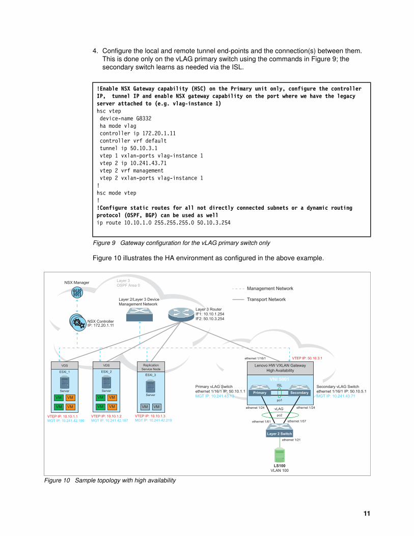
4. Configure the local and remote tunnel end-points and the connection(s) between them. This is done only on the vLAG primary switch using the commands in Figure 9; the secondary switch learns as needed via the ISL.
Figure 9 Gateway configuration for the vLAG primary switch only
Figure 10 illustrates the HA environment as configured in the above example.
Figure 10 Sample topology with high availability
!Enable NSX Gateway capability (HSC) on the Primary unit only, configure the controller IP, tunnel IP and enable NSX gateway capability on the port where we have the legacy server attached to (e.g. vlag-instance 1)hsc vtep device-name G8332 ha mode vlag controller ip 172.20.1.11 controller vrf default tunnel ip 50.10.3.1 vtep 1 vxlan-ports vlag-instance 1 vtep 2 ip 10.241.43.71 vtep 2 vrf management vtep 2 vxlan-ports vlag-instance 1!hsc mode vtep !!Configure static routes for all not directly connected subnets or a dynamic routing protocol (OSPF, BGP) can be used as wellip route 10.10.1.0 255.255.255.0 50.10.3.254
NSX ControllerIP: 172.20.1.11
NSX Manager
Lenovo HW VXLAN GatewayHigh Availability
Secondary vLAG Switchethernet 1/16/1 IP: 50.10.5.1MGT IP: 10.241.43.71
Primary vLAG Switchethernet 1/16/1 IP: 50.10.1.1MGT IP: 10.241.43.13
ISL
Primary Secondary
po1
Layer 2 Switch
LS100VLAN 100
po2
vLAGethernet 1/24 ethernet 1/24
ethernet 1/16/1
VDS
ESXi_1
Server
VM VM
VM VM
VTEP IP: 10.10.1.1MGT IP: 10.241.42.196
VTEP IP: 50.10.3.1
Layer 3OSPF Area 0
ethernet 1/61
ethernet 1/21
ethernet 1/57
VDS
ESXi_2
Server
VM VM
VM VM
VTEP IP: 10.10.1.2MGT IP: 10.241.42.197
ReplicationService Node
Server
VM VM
ESXi_3
VTEP IP: 10.10.1.3MGT IP: 10.241.42.219
Layer 3 RouterIF1: 10.10.1.254IF2: 50.10.3.254
Layer 2/Layer 3 DeviceManagement Network
VNI 5001
Management Network
Transport Network
11
Integrating with the NSX environment
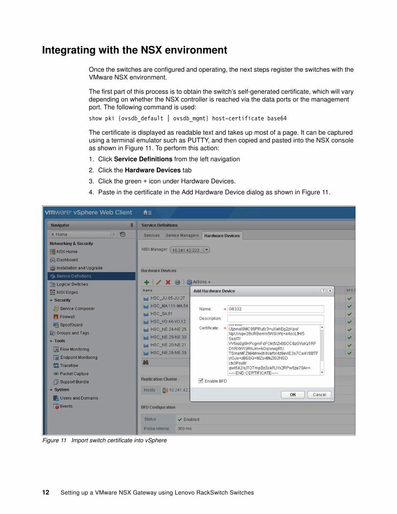
Once the switches are configured and operating, the next steps register the switches with the VMware NSX environment.
The first part of this process is to obtain the switch’s self-generated certificate, which will vary depending on whether the NSX controller is reached via the data ports or the management port. The following command is used:
show pki {ovsdb_default | ovsdb_mgmt} host-certificate base64
The certificate is displayed as readable text and takes up most of a page. It can be captured using a terminal emulator such as PUTTY, and then copied and pasted into the NSX console as shown in Figure 11. To perform this action:
1. Click Service Definitions from the left navigation
2. Click the Hardware Devices tab
3. Click the green + icon under Hardware Devices.
4. Paste in the certificate in the Add Hardware Device dialog as shown in Figure 11.
Figure 11 Import switch certificate into vSphere
12 Setting up a VMware NSX Gateway using Lenovo RackSwitch Switches
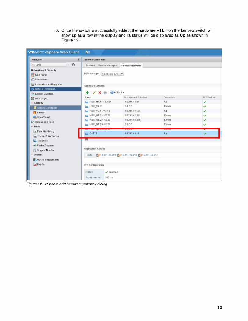
5. Once the switch is successfully added, the hardware VTEP on the Lenovo switch will show up as a row in the display and its status will be displayed as Up as shown in Figure 12.
Figure 12 vSphere add hardware gateway dialog
13
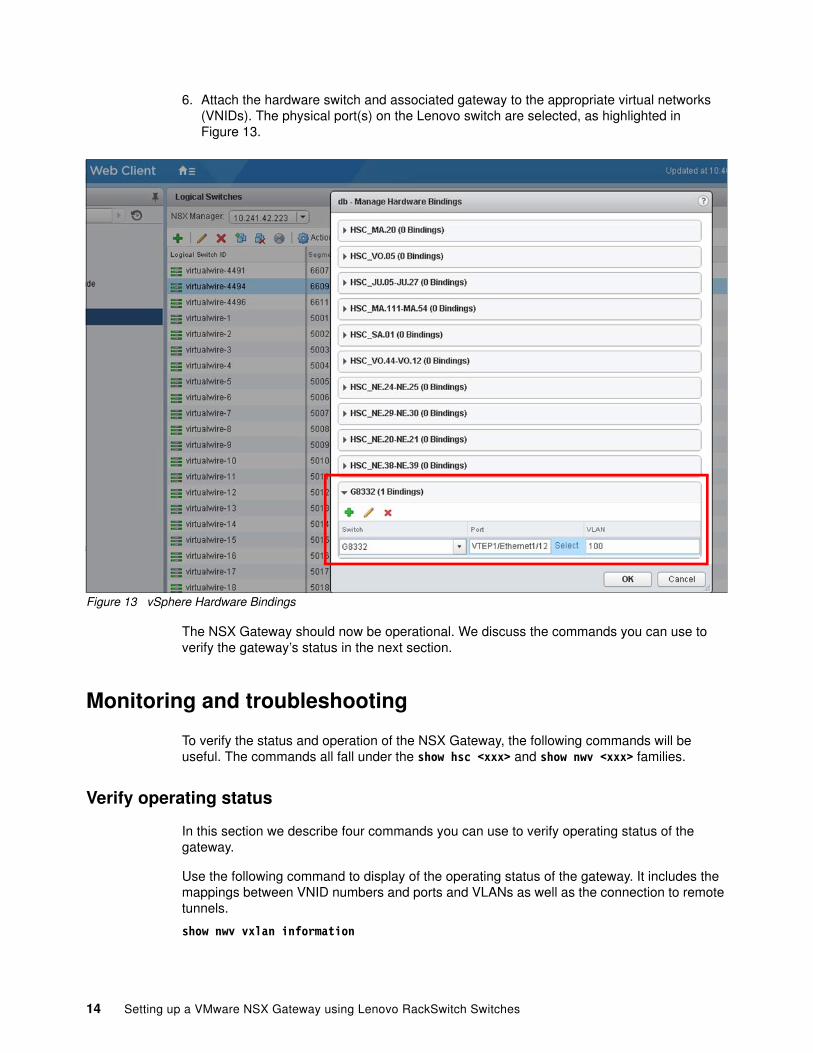
6. Attach the hardware switch and associated gateway to the appropriate virtual networks (VNIDs). The physical port(s) on the Lenovo switch are selected, as highlighted in Figure 13.
Figure 13 vSphere Hardware Bindings
The NSX Gateway should now be operational. We discuss the commands you can use to verify the gateway’s status in the next section.
Monitoring and troubleshooting
To verify the status and operation of the NSX Gateway, the following commands will be useful. The commands all fall under the show hsc <xxx> and show nwv <xxx> families.
Verify operating status
In this section we describe four commands you can use to verify operating status of the gateway.
Use the following command to display of the operating status of the gateway. It includes the mappings between VNID numbers and ports and VLANs as well as the connection to remote tunnels.
show nwv vxlan information
14 Setting up a VMware NSX Gateway using Lenovo RackSwitch Switches
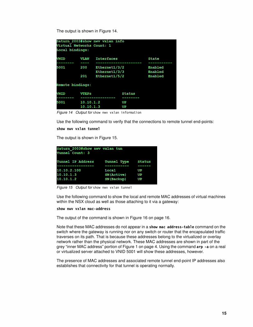
The output is shown in Figure 14.
Figure 14 Output for show nwv vxlan information
Use the following command to verify that the connections to remote tunnel end-points:
show nwv vxlan tunnel
The output is shown in Figure 15.
Figure 15 Output for show nwv vxlan tunnel
Use the following command to show the local and remote MAC addresses of virtual machines within the NSX cloud as well as those attaching to it via a gateway:
show nwv vxlan mac-address
The output of the command is shown in Figure 16 on page 16.
Note that these MAC addresses do not appear in a show mac address-table command on the switch where the gateway is running nor on any switch or router that the encapsulated traffic traverses on its path. That is because these addresses belong to the virtualized or overlay network rather than the physical network. These MAC addresses are shown in part of the grey “inner MAC address” portion of Figure 1 on page 4. Using the command arp -a on a real or virtualized server attached to VNID 5001 will show these addresses, however.
The presence of MAC addresses and associated remote tunnel end-point IP addresses also establishes that connectivity for that tunnel is operating normally.
15
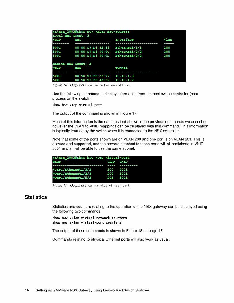
Figure 16 Output of show nwv vxlan mac-address
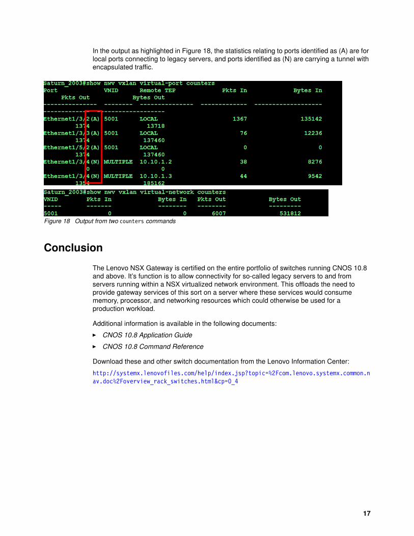
Use the following command to display information from the host switch controller (hsc) process on the switch:
show hsc vtep virtual-port
The output of the command is shown in Figure 17.
Much of this information is the same as that shown in the previous commands we describe, however the VLAN to VNID mappings can be displayed with this command. This information is typically learned by the switch when it is connected to the NSX controller.
Note that some of the ports shown are on VLAN 200 and one port is on VLAN 201. This is allowed and supported, and the servers attached to those ports will all participate in VNID 5001 and all will be able to use the same subnet.
Figure 17 Output of show hsc vtep virtual-port
Statistics
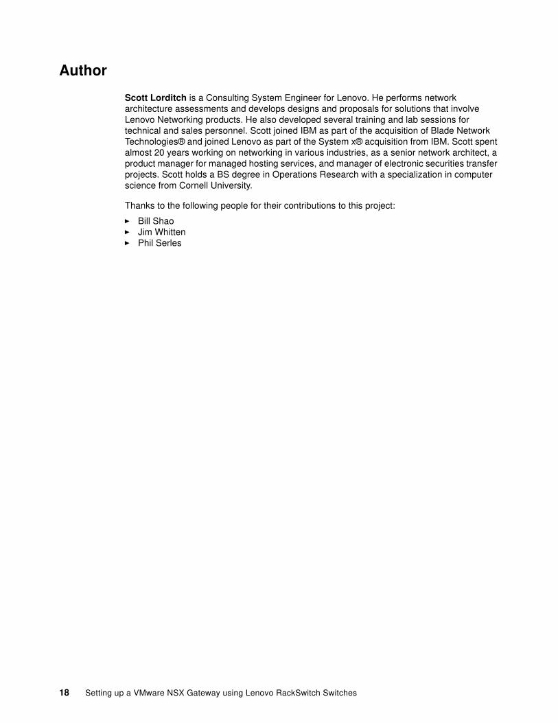
Statistics and counters relating to the operation of the NSX gateway can be displayed using the following two commands:
show nwv vxlan virtual-network countersshow nwv vxlan virtual-port counters
The output of these commands is shown in Figure 18 on page 17.
Commands relating to physical Ethernet ports will also work as usual.
16 Setting up a VMware NSX Gateway using Lenovo RackSwitch Switches
In the output as highlighted in Figure 18, the statistics relating to ports identified as (A) are for local ports connecting to legacy servers, and ports identified as (N) are carrying a tunnel with encapsulated traffic.
Figure 18 Output from two counters commands
Conclusion
The Lenovo NSX Gateway is certified on the entire portfolio of switches running CNOS 10.8 and above. It’s function is to allow connectivity for so-called legacy servers to and from servers running within a NSX virtualized network environment. This offloads the need to provide gateway services of this sort on a server where these services would consume memory, processor, and networking resources which could otherwise be used for a production workload.
Additional information is available in the following documents:
� CNOS 10.8 Application Guide
� CNOS 10.8 Command Reference
Download these and other switch documentation from the Lenovo Information Center:
http://systemx.lenovofiles.com/help/index.jsp?topic=%2Fcom.lenovo.systemx.common.nav.doc%2Foverview_rack_switches.html&cp=0_4
17
Author
Scott Lorditch is a Consulting System Engineer for Lenovo. He performs network architecture assessments and develops designs and proposals for solutions that involve Lenovo Networking products. He also developed several training and lab sessions for technical and sales personnel. Scott joined IBM as part of the acquisition of Blade Network Technologies® and joined Lenovo as part of the System x® acquisition from IBM. Scott spent almost 20 years working on networking in various industries, as a senior network architect, a product manager for managed hosting services, and manager of electronic securities transfer projects. Scott holds a BS degree in Operations Research with a specialization in computer science from Cornell University.
Thanks to the following people for their contributions to this project:
� Bill Shao� Jim Whitten � Phil Serles
18 Setting up a VMware NSX Gateway using Lenovo RackSwitch Switches
Notices
Lenovo may not offer the products, services, or features discussed in this document in all countries. Consult your local Lenovo representative for information on the products and services currently available in your area. Any reference to a Lenovo product, program, or service is not intended to state or imply that only that Lenovo product, program, or service may be used. Any functionally equivalent product, program, or service that does not infringe any Lenovo intellectual property right may be used instead. However, it is the user's responsibility to evaluate and verify the operation of any other product, program, or service.
Lenovo may have patents or pending patent applications covering subject matter described in this document. The furnishing of this document does not give you any license to these patents. You can send license inquiries, in writing, to:
Lenovo (United States), Inc.1009 Think Place - Building OneMorrisville, NC 27560U.S.A.Attention: Lenovo Director of Licensing
LENOVO PROVIDES THIS PUBLICATION “AS IS” WITHOUT WARRANTY OF ANY KIND, EITHER EXPRESS OR IMPLIED, INCLUDING, BUT NOT LIMITED TO, THE IMPLIED WARRANTIES OF NON-INFRINGEMENT, MERCHANTABILITY OR FITNESS FOR A PARTICULAR PURPOSE. Some jurisdictions do not allow disclaimer of express or implied warranties in certain transactions, therefore, this statement may not apply to you.
This information could include technical inaccuracies or typographical errors. Changes are periodically made to the information herein; these changes will be incorporated in new editions of the publication. Lenovo may make improvements and/or changes in the product(s) and/or the program(s) described in this publication at any time without notice.
The products described in this document are not intended for use in implantation or other life support applications where malfunction may result in injury or death to persons. The information contained in this document does not affect or change Lenovo product specifications or warranties. Nothing in this document shall operate as an express or implied license or indemnity under the intellectual property rights of Lenovo or third parties. All information contained in this document was obtained in specific environments and is presented as an illustration. The result obtained in other operating environments may vary.
Lenovo may use or distribute any of the information you supply in any way it believes appropriate without incurring any obligation to you.
Any references in this publication to non-Lenovo Web sites are provided for convenience only and do not in any manner serve as an endorsement of those Web sites. The materials at those Web sites are not part of the materials for this Lenovo product, and use of those Web sites is at your own risk.
Any performance data contained herein was determined in a controlled environment. Therefore, the result obtained in other operating environments may vary significantly. Some measurements may have been made on development-level systems and there is no guarantee that these measurements will be the same on generally available systems. Furthermore, some measurements may have been estimated through extrapolation. Actual results may vary. Users of this document should verify the applicable data for their specific environment.
© Copyright Lenovo 2018. All rights reserved.Note to U.S. Government Users Restricted Rights -- Use, duplication or disclosure restricted by Global Services Administration (GSA) ADP Schedule Contract 19
This document was created or updated on August 30, 2018.
Send us your comments via the Rate & Provide Feedback form found athttp://lenovopress.com/lp0946
Trademarks
Lenovo, the Lenovo logo, and For Those Who Do are trademarks or registered trademarks of Lenovo in the United States, other countries, or both. These and other Lenovo trademarked terms are marked on their first occurrence in this information with the appropriate symbol (® or ™), indicating US registered or common law trademarks owned by Lenovo at the time this information was published. Such trademarks may also be registered or common law trademarks in other countries. A current list of Lenovo trademarks is available on the Web at http://www.lenovo.com/legal/copytrade.html.
The following terms are trademarks of Lenovo in the United States, other countries, or both:
Blade Network Technologies®Lenovo®
RackSwitch™Lenovo(logo)®
System x®ThinkSystem™
The following terms are trademarks of other companies:
Hyper-V, and the Windows logo are trademarks of Microsoft Corporation in the United States, other countries, or both.
Other company, product, or service names may be trademarks or service marks of others.
20 Setting up a VMware NSX Gateway using Lenovo RackSwitch Switches
Related Documents