2350 Mission College Blvd. Suite 600 Santa Clara, CA 95054 www.bladenetwork.net RackSwitch ™ G8000 Application Guide Version 6.0 Part Number: BMD00126, August 2009

Welcome message from author
This document is posted to help you gain knowledge. Please leave a comment to let me know what you think about it! Share it to your friends and learn new things together.
Transcript
2350 Mission College Blvd.Suite 600
Santa Clara, CA 95054www.bladenetwork.net
RackSwitch™ G8000
Application GuideVersion 6.0
Part Number: BMD00126, August 2009

RackSwitch G8000 Application Guide
2 BMD00126, August 2009
Copyright © 2009 Blade Network Technologies, Inc., 2350 Mission College Blvd., Suite 600, Santa Clara, California, 95054, USA. All rights reserved. Part Number: BMD00126.
This document is protected by copyright and distributed under licenses restricting its use, copying, distribution, and decompilation. No part of this document may be reproduced in any form by any means without prior written authorization of Blade Network Technologies, Inc. Documentation is provided “as is” without warranty of any kind, either express or implied, including any kind of implied or express warranty of non-infringement or the implied warranties of merchantability or fitness for a particular purpose.
U.S. Government End Users: This document is provided with a “commercial item” as defined by FAR 2.101 (Oct. 1995) and contains “commercial technical data” and “commercial software documentation” as those terms are used in FAR 12.211-12.212 (Oct. 1995). Government End Users are authorized to use this documentation only in accordance with those rights and restrictions set forth herein, consistent with FAR 12.211- 12.212 (Oct. 1995), DFARS 227.7202 (JUN 1995) and DFARS 252.227-7015 (Nov. 1995).
Blade Network Technologies, Inc. reserves the right to change any products described herein at any time, and without notice. Blade Network Technologies, Inc. assumes no responsibility or liability arising from the use of products described herein, except as expressly agreed to in writing by Blade Network Technologies, Inc. The use and purchase of this product does not convey a license under any patent rights, trademark rights, or any other intellectual property rights of Blade Network Technologies, Inc.
Originated in the USA.
RackSwitch is a trademark of Blade Network Technologies, Inc. in the United States and certain other countries. Cisco® and EtherChannel® are registered trademarks of Cisco Systems, Inc. in the United States and certain other countries. Any other trademarks appearing in this manual are owned by their respective companies.
BMD00126, August 2009 3
Contents
Preface 11Who Should Use This Guide 11What You’ll Find in This Guide 11Typographic Conventions 13How to Get Help 14
Chapter 1: Introduction 15Stacking 15Other New Features 16Restrictions 16Upgrading the Switch Software 17
Software Update Requirements 17Loading New Software to Your Switch 18
Chapter 2: Accessing the Switch 21Locating the Master Switch IP Interface 21Using Telnet 23Using the Browser-Based Interface 24
Configuring BBI Access via HTTP 24Configuring BBI Access via HTTPS 24
Using SNMP 26SNMP v1, v2 26SNMP v3.0 26Configuring SNMP Trap Hosts 29
Securing Access to the Switch 31RADIUS Authentication and Authorization 31TACACS+ Authentication 35Secure Shell 39End User Access Control 41
RackSwitch G8000 Application Guide
4 � Contents BMD00126, August 2009
Chapter 3: Stacking 43Stacking Overview 43Stacking Requirements 44Stack Membership 44
The Master Switch 45Backup Switch Selection 46
Stack Member Numbers 48Best Configuration Practices 48Configuring Each Switch in a Stack 49Additional Master Configuration 51
Master Configuration via the ISCLI 51Master Configuration via BBI 54
Managing a Stack 57Upgrading Software in an Existing Stack 59Replacing or Removing Stacked Switches 61ISCLI Stacking Commands 64
Chapter 4: Port-Based Network Access Control 67Extensible Authentication Protocol over LAN 68802.1X Authentication Process 69802.1X Port States 71RADIUS VLAN Assignment 71Guest VLAN 72Supported RADIUS Attributes 73Configuration Guidelines 74
Chapter 5: VLANs 75VLAN Overview 76VLANs and Port VLAN ID Numbers 76
VLAN Numbers 76PVID Numbers 77
VLAN Tagging 78VLAN Topologies and Design Considerations 82
VLAN Configuration Rules 82Multiple VLANs with Tagging Adapters 82VLAN Configuration Example 84
RackSwitch G8000 Application Guide
BMD00126, August 2009 Contents � 5
Chapter 6: Ports and Trunking 85Trunking Overview 85
Statistical Load Distribution 86Built-In Fault Tolerance 86Before Configuring Static Trunks 86Static Trunk Group Configuration Rules 87
Port Trunking Example 88Configurable Trunk Hash Algorithm 90Link Aggregation Control Protocol 91
LACP Configuration Guidelines 92Configuring LACP 93
Chapter 7: Quality of Service 95QoS Overview 95Access Control Lists 97
Packet Classifiers 97ACL Actions 99ACL Order of Precedence 99ACL Groups 100Assigning ACLs to a Port 102ACL Metering and Re-Marking 103Viewing ACL Statistics 104
ACL Configuration Examples 104Using DSCP Values to Provide QoS 108
Differentiated Services Concepts 108Per-Hop Behavior 109QoS Levels 110DSCP Re-Marking and Mapping 111
Using 802.1p Priority to Provide QoS 112Queuing and Scheduling 113
Chapter 8: IGMP 115IGMP Snooping 116
FastLeave 117IGMP Snooping configuration example 118
Static Multicast Router 119
RackSwitch G8000 Application Guide
6 � Contents BMD00126, August 2009
Chapter 9: High Availability 121Trunking for Link Redundancy 121Stacking for High Availability Topologies 122Layer 2 Failover 123
VLAN Monitor 124Setting the Failover Limit 124L2 Failover with LACP 124Configuration Guidelines 124L2 Failover Configurations 125Configuring Layer 2 Failover 126
Chapter 10: Port Mirroring 127Port Mirroring behavior 128Configuring Port Mirroring 128
Index 129

BMD00126, August 2009 7
Figures
Figure 3-1: Example of Stacking Connections 50Figure 3-2: Attached Switch Information Window 54Figure 3-3: Stack Switch Configuration Window 55Figure 3-4: Binding the Switch to the Stack 55Figure 3-5: Stack IP Interfaces Configuration Window 56Figure 4-1: Authenticating a Port Using EAPoL 69Figure 5-1: Default VLAN settings 79Figure 5-2: Port-based VLAN assignment 80Figure 5-3: 802.1Q tagging (after port-based VLAN assignment) 80Figure 5-4: 802.1Q tag assignment 81Figure 5-5: 802.1Q tagging (after 802.1Q tag assignment) 81Figure 5-6: Example 1: Multiple VLANs with VLAN-Tagged Gigabit Adapters 82Figure 6-1: Port Trunk Group Configuration Example 88Figure 7-1: QoS Model 96Figure 7-2: Layer 3 IPv4 Packet 108Figure 7-3: Layer 2 802.1q/802.1p VLAN tagged packet 112Figure 9-1: Trunking Ports for Link Redundancy 121Figure 9-2: High Availability Topology Using Stacking 122Figure 9-3: Basic Layer 2 Failover 125Figure 10-1: Monitoring Ports 127

RackSwitch G8000 Application Guide
8 � Figures BMD00126, August 2009

BMD00126, August 2009 9
Tables
Table 2-1: User Access Levels 34Table 2-2: Blade OS-proprietary Attributes for RADIUS 34Table 2-3: Default TACACS+ Authorization Levels 36Table 2-4: Alternate TACACS+ Authorization Levels 36Table 3-1: Stacking Boot Management buttons 58Table 6-1: Actor vs. Partner LACP configuration 91Table 7-1: Well-Known Protocol Types 97Table 7-2: Well-known application ports 98Table 7-3: Well-Known TCP flag values 98Table 7-4: Default QoS Service Levels 110

RackSwitch G8000 Application Guide
10 � Tables BMD00126, August 2009
BMD00126, August 2009 11
Preface
The RackSwitch G8000 Application Guide describes how to configure and use the BLADE OS 6.0 software on the BLADE RackSwitch G8000 1/10Gb Ethernet Switch.
For documentation about installing the switch physically, see the Installation Guide for your switch.
Who Should Use This Guide
This Application Guide is intended for network installers and system administrators engaged in configuring and maintaining a network. The administrator should be familiar with Ethernet concepts, IP addressing, and SNMP configuration parameters.
What You’ll Find in This Guide
This guide will help you plan, implement, and administer G8000 software. Where possible, each section provides feature overviews, usage examples, and configuration instructions.
� Chapter 1, “Introduction,” describes the features and restrictions for using BLADE OS 6.0 with stacking, and provides detailed instructions for converting from BLADE OS 1.x.
� Chapter 2, “Accessing the Switch,” describes how to access the switch to perform admin-istration tasks. This chapter also discusses different methods to manage the switch for remote administrators using specific IP addresses, authentication, and Secure Shell (SSH).
RackSwitch G8000 Application Guide
12 � Preface BMD00126, August 2009
� Chapter 3, “Stacking,” describes how combine multiple G8000 switches into a single, aggregate switch entity.
� Chapter 4, “Port-Based Network Access Control,” describes how to authenticate devices attached to a LAN port that has point-to-point connection characteristics. Preventing access to ports that fail authentication and authorization provides security for switch ports.
� Chapter 5, “VLANs,” describes how to configure Virtual Local Area Networks (VLANs) for creating separate network segments, including how to use VLAN tagging for devices that use multiple VLANs.
� Chapter 6, “Ports and Trunking,” describes how to group multiple physical ports together to aggregate the bandwidth between large-scale network devices.
� Chapter 7, “Quality of Service,” discusses Quality of Service features, including IP filter-ing using Access Control Lists, Differentiated Services, and IEEE 802.1p priority values.
� Chapter 8, “IGMP,” describes how to use Internet Group Management Protocol (IGMP) to allow IP Multicast routers to discover host group members.
� Chapter 9, “High Availability,” describes how trunking and stacking contribute to redun-dant network topoloties, and explains how to use the Layer 2 Failover feature to ensure that network resources remain available if one switch is removed for service.
� Chapter 10, “Port Mirroring,” discusses the main tool for troubleshooting your switch—monitoring ports.
RackSwitch G8000 Application Guide
BMD00126, August 2009 Preface � 13
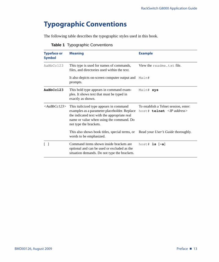
Typographic Conventions
The following table describes the typographic styles used in this book.
Table 1 Typographic Conventions
Typeface or Symbol
Meaning Example
AaBbCc123 This type is used for names of commands, files, and directories used within the text.
View the readme.txt file.
It also depicts on-screen computer output and prompts.
Main#
AaBbCc123 This bold type appears in command exam-ples. It shows text that must be typed in exactly as shown.
Main# sys
<AaBbCc123> This italicized type appears in command examples as a parameter placeholder. Replace the indicated text with the appropriate real name or value when using the command. Do not type the brackets.
To establish a Telnet session, enter:host# telnet <IP address>
This also shows book titles, special terms, or words to be emphasized.
Read your User’s Guide thoroughly.
[ ] Command items shown inside brackets are optional and can be used or excluded as the situation demands. Do not type the brackets.
host# ls [-a]
RackSwitch G8000 Application Guide
14 � Preface BMD00126, August 2009
How to Get Help
If you need help, service, or technical assistance, call Blade Network Technologies Technical Support:
US toll free calls: 1-800-414-5268
International calls: 1-408-834-7871
You also can visit our website at the following address:
http://www.bladenetwork.net
Click the Support tab.
The warranty card received with your product provides details for contacting a customer support representative. If you are unable to locate this information, please contact your reseller. Before you call, prepare the following information:
� Serial number of the switch unit
� Software release version number
� Brief description of the problem and the steps you have already taken
� Technical support dump information (# show tech-support)

BMD00126, August 2009 15
CHAPTER 1
Introduction
This chapter describe the basic features and requirements for using the BLADE RackSwitch G8000 1/10Gb Ethernet Switch with BLADE OS 6.0 for stacking.
Stacking
BLADE OS 6.0 is specifically engineered for use in stacking RackSwitch G8000 switches. A stack is a group of up to six G8000 switches that work together as a unified system. The net-work views the stack of switches as a single entity, identified by a single network IP address. The ports in a stack are pooled together. Ports from multiple stack members can even be trunked together, providing both switch expansion and redundancy benefits.

RackSwitch G8000 Application Guide
16 � Chapter 1: Introduction BMD00126, August 2009
Other New Features
BLADE OS 6.0 now supports the following:
� FTP for software and configuration downloads.
� BLADE OS command line interface with hierarchical menus, in addition to the standard ISCLI.
� HTTPS certificate generation (see “Configuring BBI Access via HTTPS” on page 24).
� 802.1X VLAN assignment (see “RADIUS VLAN Assignment” on page 71)
� Guest VLANs (see “Guest VLAN” on page 72)
� Enhanced ACLs with ACL Groups and multiple precedence levels (see “Access Control Lists” on page 97)
� Layer 2 Failover
Restrictions
Some features found in stand-alone versions of BLADE OS for the G8000 do not apply. The following stand-alone features are not present in BLADE OS 6.0 for stacking:
� Private VLANs
� Spanning Tree Protocol (including STP, RSTP, MSTP, and PVRST+)
� Storm Control Filters
� RMON
� Static IP Routing
� IGMPv3
� UFD (Replaced by expanded Layer 2 Failover capabilities)
� SSL certificate import

RackSwitch G8000 Application Guide
BMD00126, August 2009 Chapter 1: Introduction � 17
Upgrading the Switch Software
The switch software image is the executable code running on the G8000. A version of the image ships with the switch, and comes pre-installed on the device. The features described in this document require BLADE OS version 6.0 software.
Software Update Requirements
If you are using a prior version of BLADE OS, you may update the software. Use the following ISCLI command to determine the current software version installed on your switch:
To find the latest version of software available for your G8000, go to:
http://www.bladenetwork.net/support_services_rackswitch.html
Click on software updates and obtain the appropriate software. To install BLADE OS 6.0 on your G8000, you will need the following:
� The image software file and boot software file loaded on an TFTP server on your network
� The hostname or IP address of the TFTP server
� The name of the new software image and boot files.
NOTE – The DNS parameters must be configured if specifying hostnames. Also, if updating from BLADE OS 6.0 or higher, FTP download is supported in addition to TFTP.
When the update requirements are met, use the following procedure to install the BLADE OS 6.0 software image and boot image on your switch.
RS G8000# show boot
RackSwitch G8000 Application Guide
18 � Chapter 1: Introduction BMD00126, August 2009
Loading New Software to Your Switch
When the upgrade requirements are met, use the following procedure to install BLADE OS 6.0 on your switch. The procedure you will use depends on whether the switch is isolated or part of an existing stack configuration:
� When updating an isolated switch (one that is not yet part of a stack), use the normal switch update procedure, as found on below.
� When updating a currently stacked switch, the software must be updated simultaneously for all switches in the stack. See “Upgrading Software in an Existing Stack” on page 59.
Unless noted otherwise in this document or in the instructions for a specific version of BLADE OS, installing updates on an isolated (non-stacked) switch may use the regular update procedure, described below.
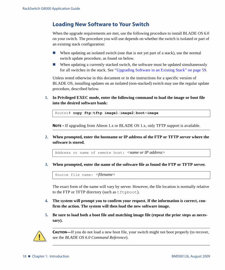
1. In Privileged EXEC mode, enter the following command to load the image or boot file into the desired software bank:
NOTE – If upgrading from Alteon 1.x or BLADE OS 1.x, only TFTP support is available.
2. When prompted, enter the hostname or IP address of the FTP or TFTP server where the software is stored.
3. When prompted, enter the name of the software file as found the FTP or TFTP server.
The exact form of the name will vary by server. However, the file location is normally relative to the FTP or TFTP directory (such as tftpboot).
4. The system will prompt you to confirm your request. If the information is correct, con-firm the action. The system will then load the new software image.
5. Be sure to load both a boot file and matching image file (repeat the prior steps as neces-sary).
Router# copy ftp|tftp image1|image2|boot-image
Address or name of remote host: <name or IP address>
Source file name: <filename>
!CAUTION—If you do not load a new boot file, your switch might not boot properly (to recover, see the BLADE OS 6.0 Command Reference).
RackSwitch G8000 Application Guide
BMD00126, August 2009 Chapter 1: Introduction � 19
6. Specify the location of the new image file (image1 or image2). In Global Configuration mode, enter:
7. Reset the switch to run the new software. In Global Configuration mode, enter the fol-lowing command:
8. The system will prompt you to confirm your request. If the information is correct, con-firm the action.
The system will then reboot using the new software with factory default configuration.
NOTE – BLADE OS 1.x configuration files are not compatible with BLADE OS 6.0.
Router(config)# boot image image1|image2
Router(config)# reload

RackSwitch G8000 Application Guide
20 � Chapter 1: Introduction BMD00126, August 2009
BMD00126, August 2009 21
CHAPTER 2
Accessing the Switch
The Blade OS software provides means for accessing, configuring, and viewing information and statistics about the RackSwitch G8000. This chapter discusses different methods of accessing the switch and ways to secure the switch for remote administrators:
� “Locating the Master Switch IP Interface” on page 21
� “Using Telnet” on page 23
� “Using the Browser-Based Interface” on page 24
� “Using SNMP” on page 26
� “Securing Access to the Switch” on page 31
� “RADIUS Authentication and Authorization” on page 31
� “TACACS+ Authentication” on page 35
� “End User Access Control” on page 41
Locating the Master Switch IP Interface
Managing the switch through Telnet, SNMP, or a Web browser is performed using the active Master interface.
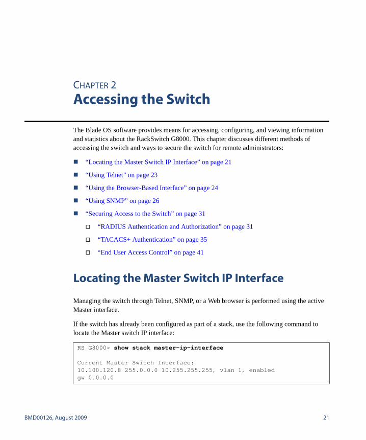
If the switch has already been configured as part of a stack, use the following command to locate the Master switch IP interface:
RS G8000> show stack master-ip-interface
Current Master Switch Interface:10.100.120.8 255.0.0.0 10.255.255.255, vlan 1, enabledgw 0.0.0.0
RackSwitch G8000 Application Guide
22 � Chapter 2: Accessing the Switch BMD00126, August 2009
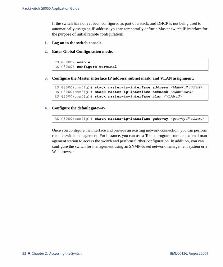
If the switch has not yet been configured as part of a stack, and DHCP is not being used to automatically assign an IP address, you can temporarily define a Master switch IP interface for the purpose of initial remote configuration:
1. Log on to the switch console.
2. Enter Global Configuration mode.
3. Configure the Master interface IP address, subnet mask, and VLAN assignment:
4. Configure the default gateway:
Once you configure the interface and provide an existing network connection, you can perform remote switch management. For instance, you can use a Telnet program from an external man-agement station to access the switch and perform further configuration. In addition, you can configure the switch for management using an SNMP-based network management system or a Web browser.
RS G8000> enableRS G8000# configure terminal
RS G8000(config)# stack master-ip-interface address <Master IP address>RS G8000(config)# stack master-ip-interface netmask <subnet mask>RS G8000(config)# stack master-ip-interface vlan <VLAN ID>
RS G8000(config)# stack master-ip-interface gateway <gateway IP address>

RackSwitch G8000 Application Guide
BMD00126, August 2009 Chapter 2: Accessing the Switch � 23
Using Telnet
A Telnet connection offers the convenience of accessing the switch from any workstation con-nected to the network. Telnet access provides the same options for user access and administra-tor access as those available through the console port.
To configure the switch for Telnet access, the switch must have an IP address. The switch can get its IP address in one of two ways:
� Dynamically, from a DHCP server on your network� Manually, when you configure the switch IP address
Once you have configured the switch with an IP address and gateway, you can access the switch from any workstation connected to the management network. Telnet access provides the same options for user and administrator access as those available through the console port.
By default, Telnet access is enabled. Use the following command to disable/enable Telnet access:
To establish a Telnet connection to the switch, you can run the Telnet program on your work-station and issue the Telnet command, followed by the switch IP address:
RS G8000(config)# [no] access telnet enable
telnet <switch IP address>
RackSwitch G8000 Application Guide
24 � Chapter 2: Accessing the Switch BMD00126, August 2009
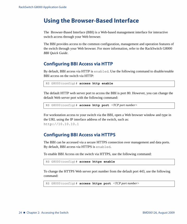
Using the Browser-Based Interface
The Browser-Based Interface (BBI) is a Web-based management interface for interactive switch access through your Web browser.
The BBI provides access to the common configuration, management and operation features of the switch through your Web browser. For more information, refer to the RackSwitch G8000 BBI Quick Guide.
Configuring BBI Access via HTTP
By default, BBI access via HTTP is enabled. Use the following command to disable/enable BBI access on the switch via HTTP:
The default HTTP web server port to access the BBI is port 80. However, you can change the default Web server port with the following command:
For workstation access to your switch via the BBI, open a Web browser window and type in the URL using the IP interface address of the switch, such as: http://10.10.10.1
Configuring BBI Access via HTTPS
The BBI can be accessed via a secure HTTPS connection over management and data ports. By default, BBI access via HTTPS is enabled.
To enable BBI Access on the switch via HTTPS, use the following command:
To change the HTTPS Web server port number from the default port 443, use the following command:
RS G8000(config)# access http enable
RS G8000(config)# access http port <TCP port number>
RS G8000(config)# access https enable
RS G8000(config)# access https port <TCP port number>
RackSwitch G8000 Application Guide
BMD00126, August 2009 Chapter 2: Accessing the Switch � 25
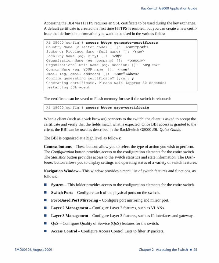
Accessing the BBI via HTTPS requires an SSL certificate to be used during the key exchange. A default certificate is created the first time HTTPS is enabled, but you can create a new certif-icate that defines the information you want to be used in the various fields:
The certificate can be saved to Flash memory for use if the switch is rebooted:
When a client (such as a web browser) connects to the switch, the client is asked to accept the certificate and verify that the fields match what is expected. Once BBI access is granted to the client, the BBI can be used as described in the RackSwitch G8000 BBI Quick Guide.
The BBI is organized at a high level as follows:
Context buttons – These buttons allow you to select the type of action you wish to perform. The Configuration button provides access to the configuration elements for the entire switch. The Statistics button provides access to the switch statistics and state information. The Dash-board button allows you to display settings and operating status of a variety of switch features.
Navigation Window – This window provides a menu list of switch features and functions, as follows:
� System – This folder provides access to the configuration elements for the entire switch.
� Switch Ports – Configure each of the physical ports on the switch.
� Port-Based Port Mirroring – Configure port mirroring and mirror port.
� Layer 2 Management – Configure Layer 2 features, such as VLANs
� Layer 3 Management – Configure Layer 3 features, such as IP interfaces and gateway.
� QoS – Configure Quality of Service (QoS) features for the switch.
� Access Control – Configure Access Control Lists to filter IP packets.
RS G8000(config)# access https generate-certificateCountry Name (2 letter code) [ ]: <country code>State or Province Name (full name) []: <state>Locality Name (eg, city) []: <city>Organization Name (eg, company) []: <company>Organizational Unit Name (eg, section) []: <org. unit>Common Name (eg, YOUR name) []: <name>Email (eg, email address) []: <email address>Confirm generating certificate? [y/n]: yGenerating certificate. Please wait (approx 30 seconds)restarting SSL agent
RS G8000(config)# access https save-certificate
RackSwitch G8000 Application Guide
26 � Chapter 2: Accessing the Switch BMD00126, August 2009
Using SNMP
Blade OS supports SNMP v1.0, v2.0 and v3.0 for access through any network management software, such as IBM Director or HP-OpenView.
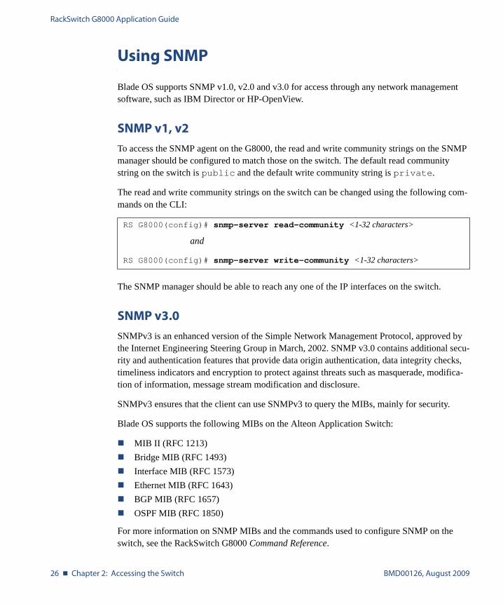
SNMP v1, v2
To access the SNMP agent on the G8000, the read and write community strings on the SNMP manager should be configured to match those on the switch. The default read community string on the switch is public and the default write community string is private.
The read and write community strings on the switch can be changed using the following com-mands on the CLI:
The SNMP manager should be able to reach any one of the IP interfaces on the switch.
SNMP v3.0
SNMPv3 is an enhanced version of the Simple Network Management Protocol, approved by the Internet Engineering Steering Group in March, 2002. SNMP v3.0 contains additional secu-rity and authentication features that provide data origin authentication, data integrity checks, timeliness indicators and encryption to protect against threats such as masquerade, modifica-tion of information, message stream modification and disclosure.
SNMPv3 ensures that the client can use SNMPv3 to query the MIBs, mainly for security.
Blade OS supports the following MIBs on the Alteon Application Switch:
� MIB II (RFC 1213)� Bridge MIB (RFC 1493)� Interface MIB (RFC 1573)� Ethernet MIB (RFC 1643)� BGP MIB (RFC 1657)� OSPF MIB (RFC 1850)
For more information on SNMP MIBs and the commands used to configure SNMP on the switch, see the RackSwitch G8000 Command Reference.
RS G8000(config)# snmp-server read-community <1-32 characters>
and
RS G8000(config)# snmp-server write-community <1-32 characters>
RackSwitch G8000 Application Guide
BMD00126, August 2009 Chapter 2: Accessing the Switch � 27
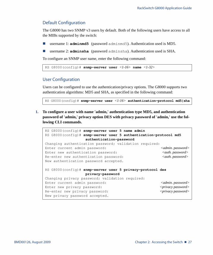
Default Configuration
The G8000 has two SNMP v3 users by default. Both of the following users have access to all the MIBs supported by the switch:
� username 1: adminmd5 (password adminmd5). Authentication used is MD5.
� username 2: adminsha (password adminsha). Authentication used is SHA.
To configure an SNMP user name, enter the following command:
User Configuration
Users can be configured to use the authentication/privacy options. The G8000 supports two authentication algorithms: MD5 and SHA, as specified in the following command:
1. To configure a user with name 'admin,' authentication type MD5, and authentication password of 'admin,' privacy option DES with privacy password of 'admin,' use the fol-lowing CLI commands.
RS G8000(config)# snmp-server user <1-16> name <1-32>
RS G8000(config)# snmp-server user <1-16> authentication-protocol md5|sha
RS G8000(config)# snmp-server user 5 name adminRS G8000(config)# snmp-server user 5 authentication-protocol md5
authentication-passwordChanging authentication password; validation required:Enter current admin password: <admin. password>Enter new authentication password: <auth. password>Re-enter new authentication password: <auth. password>New authentication password accepted.
RS G8000(config)# snmp-server user 5 privacy-protocol desprivacy-password
Changing privacy password; validation required:Enter current admin password: <admin. password>Enter new privacy password: <privacy password>Re-enter new privacy password: <privacy password>New privacy password accepted.
RackSwitch G8000 Application Guide
28 � Chapter 2: Accessing the Switch BMD00126, August 2009
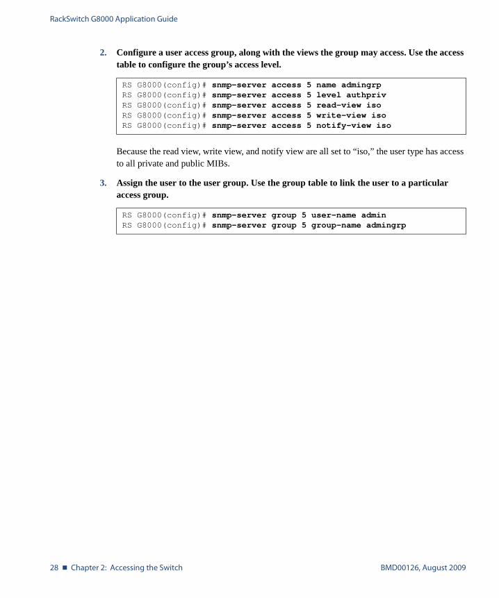
2. Configure a user access group, along with the views the group may access. Use the access table to configure the group’s access level.
Because the read view, write view, and notify view are all set to “iso,” the user type has access to all private and public MIBs.
3. Assign the user to the user group. Use the group table to link the user to a particular access group.
RS G8000(config)# snmp-server access 5 name admingrpRS G8000(config)# snmp-server access 5 level authprivRS G8000(config)# snmp-server access 5 read-view isoRS G8000(config)# snmp-server access 5 write-view isoRS G8000(config)# snmp-server access 5 notify-view iso
RS G8000(config)# snmp-server group 5 user-name adminRS G8000(config)# snmp-server group 5 group-name admingrp
RackSwitch G8000 Application Guide
BMD00126, August 2009 Chapter 2: Accessing the Switch � 29
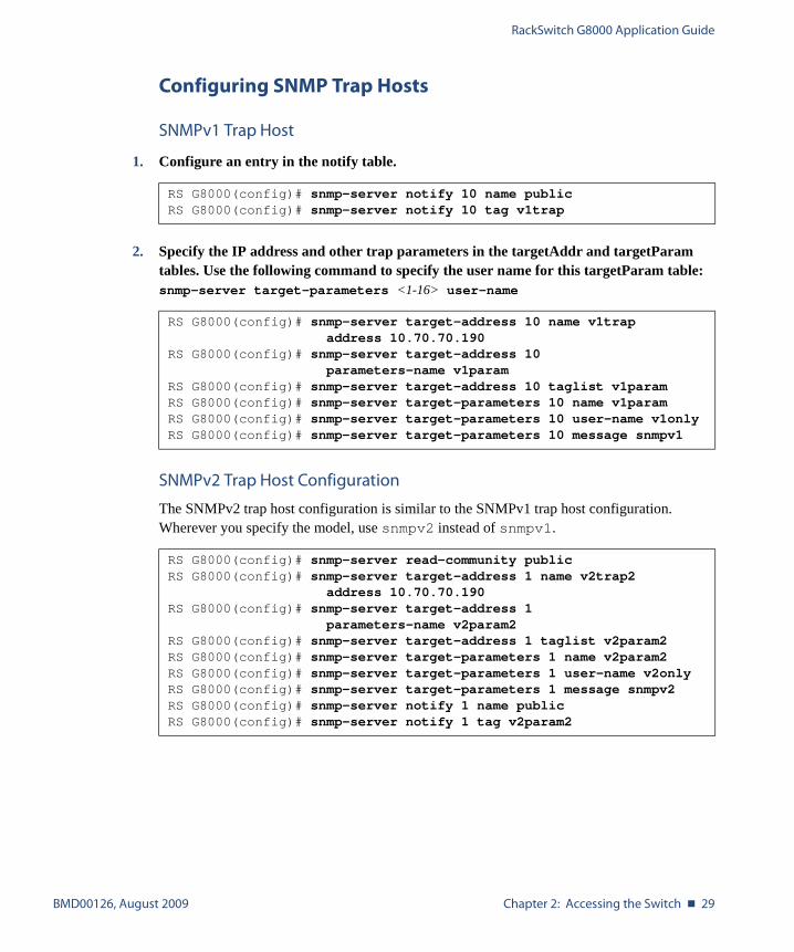
Configuring SNMP Trap Hosts
SNMPv1 Trap Host
1. Configure an entry in the notify table.
2. Specify the IP address and other trap parameters in the targetAddr and targetParam tables. Use the following command to specify the user name for this targetParam table: snmp-server target-parameters <1-16> user-name
SNMPv2 Trap Host Configuration
The SNMPv2 trap host configuration is similar to the SNMPv1 trap host configuration. Wherever you specify the model, use snmpv2 instead of snmpv1.
RS G8000(config)# snmp-server notify 10 name publicRS G8000(config)# snmp-server notify 10 tag v1trap
RS G8000(config)# snmp-server target-address 10 name v1trapaddress 10.70.70.190
RS G8000(config)# snmp-server target-address 10parameters-name v1param
RS G8000(config)# snmp-server target-address 10 taglist v1paramRS G8000(config)# snmp-server target-parameters 10 name v1paramRS G8000(config)# snmp-server target-parameters 10 user-name v1onlyRS G8000(config)# snmp-server target-parameters 10 message snmpv1
RS G8000(config)# snmp-server read-community publicRS G8000(config)# snmp-server target-address 1 name v2trap2
address 10.70.70.190RS G8000(config)# snmp-server target-address 1
parameters-name v2param2RS G8000(config)# snmp-server target-address 1 taglist v2param2RS G8000(config)# snmp-server target-parameters 1 name v2param2RS G8000(config)# snmp-server target-parameters 1 user-name v2onlyRS G8000(config)# snmp-server target-parameters 1 message snmpv2RS G8000(config)# snmp-server notify 1 name publicRS G8000(config)# snmp-server notify 1 tag v2param2
RackSwitch G8000 Application Guide
30 � Chapter 2: Accessing the Switch BMD00126, August 2009
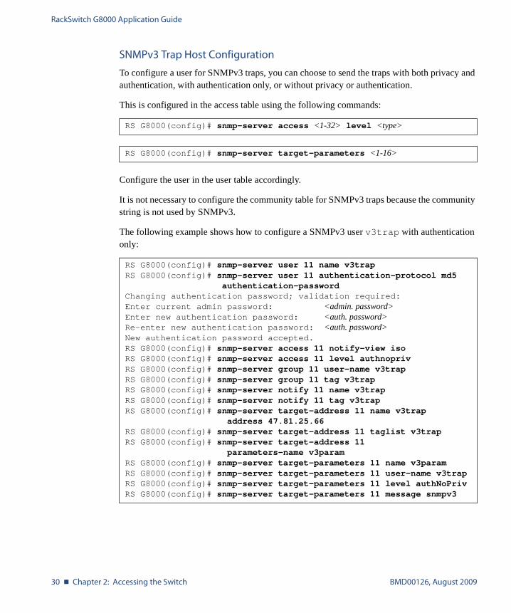
SNMPv3 Trap Host Configuration
To configure a user for SNMPv3 traps, you can choose to send the traps with both privacy and authentication, with authentication only, or without privacy or authentication.
This is configured in the access table using the following commands:
Configure the user in the user table accordingly.
It is not necessary to configure the community table for SNMPv3 traps because the community string is not used by SNMPv3.
The following example shows how to configure a SNMPv3 user v3trap with authentication only:
RS G8000(config)# snmp-server access <1-32> level <type>
RS G8000(config)# snmp-server target-parameters <1-16>
RS G8000(config)# snmp-server user 11 name v3trapRS G8000(config)# snmp-server user 11 authentication-protocol md5
authentication-passwordChanging authentication password; validation required:Enter current admin password: <admin. password>Enter new authentication password: <auth. password>Re-enter new authentication password: <auth. password>New authentication password accepted.RS G8000(config)# snmp-server access 11 notify-view isoRS G8000(config)# snmp-server access 11 level authnoprivRS G8000(config)# snmp-server group 11 user-name v3trapRS G8000(config)# snmp-server group 11 tag v3trapRS G8000(config)# snmp-server notify 11 name v3trapRS G8000(config)# snmp-server notify 11 tag v3trapRS G8000(config)# snmp-server target-address 11 name v3trap
address 47.81.25.66RS G8000(config)# snmp-server target-address 11 taglist v3trapRS G8000(config)# snmp-server target-address 11
parameters-name v3paramRS G8000(config)# snmp-server target-parameters 11 name v3paramRS G8000(config)# snmp-server target-parameters 11 user-name v3trapRS G8000(config)# snmp-server target-parameters 11 level authNoPrivRS G8000(config)# snmp-server target-parameters 11 message snmpv3
RackSwitch G8000 Application Guide
BMD00126, August 2009 Chapter 2: Accessing the Switch � 31
Securing Access to the Switch
Secure switch management is needed for environments that perform significant management functions across the Internet.
The following features are addressed in this section:
� “RADIUS Authentication and Authorization” on page 31
� “TACACS+ Authentication” on page 35
� “End User Access Control” on page 41
RADIUS Authentication and Authorization
Blade OS supports the RADIUS (Remote Authentication Dial-in User Service) method to authenticate and authorize remote administrators for managing the switch. This method is based on a client/server model. The Remote Access Server (RAS)—the switch—is a client to the back-end database server. A remote user (the remote administrator) interacts only with the RAS, not the back-end server and database.
RADIUS authentication consists of the following components:
� A protocol with a frame format that utilizes UDP over IP (based on RFC 2138 and 2866)
� A centralized server that stores all the user authorization information
� A client, in this case, the switch
The G8000—acting as the RADIUS client—communicates to the RADIUS server to authenti-cate and authorize a remote administrator using the protocol definitions specified in RFC 2138 and 2866. Transactions between the client and the RADIUS server are authenticated using a shared key that is not sent over the network. In addition, the remote administrator passwords are sent encrypted between the RADIUS client (the switch) and the back-end RADIUS server.
How RADIUS Authentication Works
1. Remote administrator connects to the switch and provides user name and password.
2. Using Authentication/Authorization protocol, the switch sends request to authentication server.
3. Authentication server checks the request against the user ID database.
4. Using RADIUS protocol, the authentication server instructs the switch to grant or deny administrative access.
RackSwitch G8000 Application Guide
32 � Chapter 2: Accessing the Switch BMD00126, August 2009
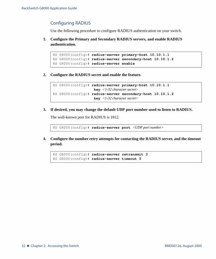
Configuring RADIUS
Use the following procedure to configure RADIUS authentication on your switch.
1. Configure the Primary and Secondary RADIUS servers, and enable RADIUS authentication.
2. Configure the RADIUS secret and enable the feature.
3. If desired, you may change the default UDP port number used to listen to RADIUS.
The well-known port for RADIUS is 1812.
4. Configure the number retry attempts for contacting the RADIUS server, and the timeout period.
RS G8000(config)# radius-server primary-host 10.10.1.1RS G8000(config)# radius-server secondary-host 10.10.1.2RS G8000(config)# radius-server enable
RS G8000(config)# radius-server primary-host 10.10.1.1key <1-32 character secret>
RS G8000(config)# radius-server secondary-host 10.10.1.2key <1-32 character secret>
RS G8000(config)# radius-server port <UDP port number>
RS G8000(config)# radius-server retransmit 3RS G8000(config)# radius-server timeout 5

RackSwitch G8000 Application Guide
BMD00126, August 2009 Chapter 2: Accessing the Switch � 33
RADIUS Authentication Features in Blade OS
Blade OS supports the following RADIUS authentication features:
� Supports RADIUS client on the switch, based on the protocol definitions in RFC 2138 and RFC 2866.
� Allows RADIUS secret password up to 32 bytes and less than 16 octets.
� Supports secondary authentication server so that when the primary authentication server is unreachable, the switch can send client authentication requests to the secondary authen-tication server. Use the following command to show the currently active RADIUS authen-tication server:
� Supports user-configurable RADIUS server retry and time-out values:
� Time-out value = 1-10 seconds
� Retries = 1-3
The switch will time out if it does not receive a response from the RADIUS server in 1-3 retries. The switch will also automatically retry connecting to the RADIUS server before it declares the server down.
� Supports user-configurable RADIUS application port.The default is 1812/UDP-based on RFC 2138. Port 1645 is also supported.
� Allows network administrator to define privileges for one or more specific users to access the switch at the RADIUS user database.
RS G8000(config)# show radius-server

RackSwitch G8000 Application Guide
34 � Chapter 2: Accessing the Switch BMD00126, August 2009
Switch User Accounts
The user accounts listed in Table 2-1 can be defined in the RADIUS server dictionary file.
RADIUS Attributes for G8000 User Privileges
When the user logs in, the switch authenticates his/her level of access by sending the RADIUS access request, that is, the client authentication request, to the RADIUS authentication server.
If the remote user is successfully authenticated by the authentication server, the switch will verify the privileges of the remote user and authorize the appropriate access. The administrator has an option to allow secure backdoor access via Telnet/SSH/BBI. Secure backdoor provides switch access when the RADIUS servers cannot be reached. You always can access the switch via the console port, by using noradius and the administrator password, whether secure backdoor is enabled or not.
NOTE – To obtain the RADIUS backdoor password for your G8000, contact Technical Support.
All user privileges, other than those assigned to the Administrator, have to be defined in the RADIUS dictionary. RADIUS attribute 6 which is built into all RADIUS servers defines the administrator. The file name of the dictionary is RADIUS vendor-dependent. The following RADIUS attributes are defined for G8000 user privileges levels:
Table 2-1 User Access Levels
User Account Description and Tasks Performed Password
User The User has no direct responsibility for switch management. He/she can view all switch status information and statistics but cannot make any configuration changes to the switch.
user
Operator The Operator manages all functions of the switch. The Operator can reset ports.
oper
Administrator The super-user Administrator has complete access to all commands, information, and configuration commands on the switch, including the ability to change both the user and operator passwords.
admin
Table 2-2 Blade OS-proprietary Attributes for RADIUS
User Name/Access User-Service-Type Value
User Vendor-supplied 255
Operator Vendor-supplied 252
Admin Vendor-supplied 6
RackSwitch G8000 Application Guide
BMD00126, August 2009 Chapter 2: Accessing the Switch � 35
TACACS+ Authentication
Blade OS supports authentication and authorization with networks using the Cisco Systems TACACS+ protocol. The G8000 functions as the Network Access Server (NAS) by interacting with the remote client and initiating authentication and authorization sessions with the TACACS+ access server. The remote user is defined as someone requiring management access to the G8000 through a data port.
TACACS+ offers the following advantages over RADIUS:
� TACACS+ uses TCP-based connection-oriented transport; whereas RADIUS is UDP-based. TCP offers a connection-oriented transport, while UDP offers best-effort delivery. RADIUS requires additional programmable variables such as re-transmit attempts and time-outs to compensate for best-effort transport, but it lacks the level of built-in support that a TCP transport offers.
� TACACS+ offers full packet encryption whereas RADIUS offers password-only encryp-tion in authentication requests.
� TACACS+ separates authentication, authorization and accounting.
How TACACS+ Authentication Works
TACACS+ works much in the same way as RADIUS authentication as described on page 31.
1. Remote administrator connects to the switch and provides user name and password.
2. Using Authentication/Authorization protocol, the switch sends request to authentication server.
3. Authentication server checks the request against the user ID database.
4. Using TACACS+ protocol, the authentication server instructs the switch to grant or deny administrative access.
During a session, if additional authorization checking is needed, the switch checks with a TACACS+ server to determine if the user is granted permission to use a particular command.
RackSwitch G8000 Application Guide
36 � Chapter 2: Accessing the Switch BMD00126, August 2009
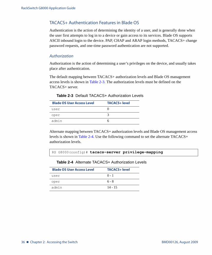
TACACS+ Authentication Features in Blade OS
Authentication is the action of determining the identity of a user, and is generally done when the user first attempts to log in to a device or gain access to its services. Blade OS supports ASCII inbound login to the device. PAP, CHAP and ARAP login methods, TACACS+ change password requests, and one-time password authentication are not supported.
Authorization
Authorization is the action of determining a user’s privileges on the device, and usually takes place after authentication.
The default mapping between TACACS+ authorization levels and Blade OS management access levels is shown in Table 2-3. The authorization levels must be defined on the TACACS+ server.
Alternate mapping between TACACS+ authorization levels and Blade OS management access levels is shown in Table 2-4. Use the following command to set the alternate TACACS+ authorization levels.
Table 2-3 Default TACACS+ Authorization Levels
Blade OS User Access Level TACACS+ level
user 0
oper 3
admin 6
RS G8000(config)# tacacs-server privilege-mapping
Table 2-4 Alternate TACACS+ Authorization Levels
Blade OS User Access Level TACACS+ level
user 0 - 1
oper 6 - 8
admin 14 - 15

RackSwitch G8000 Application Guide
BMD00126, August 2009 Chapter 2: Accessing the Switch � 37
If the remote user is successfully authenticated by the authentication server, the switch verifies the privileges of the remote user and authorizes the appropriate access. The adminis-trator has an option to allow secure backdoor access via Telnet/SSH. Secure backdoor pro-vides switch access when the TACACS+ servers cannot be reached. You always can access the switch via the console port, by using notacacs and the administrator password, whether secure backdoor is enabled or not.
NOTE – To obtain the TACACS+ backdoor password for your G8000, contact Technical Support.
Accounting
Accounting is the action of recording a user's activities on the device for the purposes of billing and/or security. It follows the authentication and authorization actions. If the authentication and authorization is not performed via TACACS+, there are no TACACS+ accounting mes-sages sent out.
You can use TACACS+ to record and track software logins, configuration changes, and inter-active commands.
The G8000 supports the following TACACS+ accounting attributes:
� protocol (console/Telnet/SSH/HTTP/HTTPS)
� start_time
� stop_time
� elapsed_time
� disc_cause
NOTE – When using the Browser-Based Interface, the TACACS+ Accounting Stop records are sent only if the Logout button on the browser is clicked.

RackSwitch G8000 Application Guide
38 � Chapter 2: Accessing the Switch BMD00126, August 2009
Command Authorization and Logging
When TACACS+ Command Authorization is enabled, Blade OS configuration commands are sent to the TACACS+ server for authorization. Use the following command to enable TACACS+ Command Authorization:
When TACACS+ Command Logging is enabled, Blade OS configuration commands are logged on the TACACS+ server. Use the following command to enable TACACS+ Command Logging:
The following examples illustrate the format of Blade OS commands sent to the TACACS+ server:
Configuring TACACS+ Authentication
1. Configure Primary and Secondary TACACS+ servers, and enable authentication.
2. Configure the TACACS+ secret and second secret.
3. If desired, you may change the default TCP port number used to listen to TACACS+.
The well-known port for TACACS+ is 49.
4. Configure the number of retry attempts, and the timeout period.
RS G8000(config)# tacacs-server command-authorization
RS G8000(config)# tacacs-server command-logging
authorization request, cmd=shell, cmd-arg=interface ipaccounting request, cmd=shell, cmd-arg=interface ipauthorization request, cmd=shell, cmd-arg=enableaccounting request, cmd=shell, cmd-arg=enable
RS G8000(config)# tacacs-server primary-host 10.10.1.1RS G8000(config)# tacacs-server secondary-host 10.10.1.2RS G8000(config)# tacacs-server enable
RS G8000(config)# tacacs-server primary-host 10.10.1.1key <1-32 character secret>
RS G8000(config)# tacacs-server secondary-host 10.10.1.2key <1-32 character secret>
RS G8000(config)# tacacs-server port <TCP port number>
RS G8000(config)# tacacs-server retransmit 3RS G8000(config)# tacacs-server timeout 5
RackSwitch G8000 Application Guide
BMD00126, August 2009 Chapter 2: Accessing the Switch � 39
Secure Shell
Secure Shell (SSH) use secure tunnels to encrypt and secure messages between a remote administrator and the switch. Telnet does not provide this level of security. The Telnet method of managing a G8000 does not provide a secure connection.
SSH is a protocol that enables remote administrators to log securely into the G8000 over a net-work to execute management commands.
The benefits of using SSH are listed below:
� Authentication of remote administrators� Identifying the administrator using Name/Password� Authorization of remote administrators� Determining the permitted actions and customizing service for individual administrators� Encryption of management messages � Encrypting messages between the remote administrator and switch
The Blade OS implementation of SSH supports both versions 1.0 and 2.0 and supports SSH client versions 1.5 - 2.x.
Configuring SSH features on the Switch
Before you can use SSH commands, use the following commands to turn on SSH. SSH is disabled by default.
Use the following command to enable SSH:
SSH Encryption of Management Messages
The following encryption and authentication methods are supported for SSH:
Server Host Authentication: Client RSA authenticates the switch at the beginning of every connection
Key Exchange: RSA
Encryption: 3DES-CBC, DES
User Authentication: Local password authentication
RS G8000(config)# ssh enable
RackSwitch G8000 Application Guide
40 � Chapter 2: Accessing the Switch BMD00126, August 2009
Generating RSA Host and Server Keys for SSH Access
To support the SSH server feature, two sets of RSA keys (host and server keys) are required. The host key is 1024 bits and is used to identify the G8000. The server key is 768 bits and is used to make it impossible to decipher a captured session by breaking into the G8000 at a later time.
When the SSH server is first enabled and applied, the switch automatically generates the RSA host and server keys and is stored in the Flash memory. To configure RSA host and server keys, enter the following commands to generate them manually.
When the switch reboots, it will retrieve the host and server keys from the Flash memory. If these two keys are not available in the flash and if the SSH server feature is enabled, the switch automatically generates them during the system reboot. This process may take several minutes to complete.
The switch can automatically regenerate the RSA server key. To set the interval of RSA server key autogeneration, use the following command:
A value of 0 (zero) denotes that RSA server key autogeneration is disabled. When greater than 0, the switch will autogenerate the RSA server key every specified interval; however, RSA server key generation is skipped if the switch is busy doing other key or cipher generation when the timer expires.
NOTE – The switch will perform only one session of key/cipher generation at a time. Thus, an SSH client will not be able to log in if the switch is performing key generation at that time, or if another client has logged in immediately prior. Also, key generation will fail if an SSH client is logging in at that time.
SSH Integration with RADIUS/TACACS+ Authentication
SSH is integrated with RADIUS authentication. After the RADIUS server is enabled on the switch, all subsequent SSH authentication requests will be redirected to the specified RADIUS servers for authentication. The redirection is transparent to the SSH clients.
SSH is integrated with TACACS+ authentication. After the TACACS+ server is enabled on the switch, all subsequent SSH authentication requests will be redirected to the specified TACACS+ servers for authentication. The redirection is transparent to the SSH clients.
RS G8000(config)# ssh generate-host-keyRS G8000(config)# ssh generate-server-key
RS G8000(config)# ssh interval <number of hours (0-24)>
RackSwitch G8000 Application Guide
BMD00126, August 2009 Chapter 2: Accessing the Switch � 41
End User Access Control
Blade OS allows an administrator to define end user accounts that permit end users to perform operation tasks via the switch CLI commands. Once end user accounts are configured and enabled, the switch requires username/password authentication.
For example, an administrator can assign a user, who can then log into the switch and perform operational commands (effective only until the next switch reboot).
Considerations for Configuring End User Accounts
� A maximum of 10 user IDs are supported on the switch.
� Blade OS supports end user support for console, Telnet, BBI, and SSHv1/v2 access to the switch.
� If RADIUS authentication is used, the user password on the Radius server will override the user password on the G8000. Also note that the password change command on the switch only modifies the use switch password and has no effect on the user password on the Radius server. Radius authentication and user password cannot be used concurrently to access the switch.
� Passwords for end users can be up to 128 characters in length.
User Access Control
The end user access control commands allow you to configure end user accounts.
Setting Up User IDs
Up to 10 user IDs can be configured. Use the following commands to define user names and passwords:
RS G8000(config)# access user 1 name <1-8 characters>RS G8000(config)# access user 1 password
Changing user1 password; validation required:Enter current admin password: <current administrator password>Enter new user1 password: <new user password>Re-enter new user1 password: <new user password>New user1 password accepted.
RackSwitch G8000 Application Guide
42 � Chapter 2: Accessing the Switch BMD00126, August 2009
Defining a User’s Access Level
The end user is by default assigned to the user access level (also known as class of service, or COS). COS for all user accounts have global access to all resources except for User COS, which has access to view only resources that the user owns. For more information, see Table 2-1 “User Access Levels” on page 34.
To change the user’s level, select one of the following options:
Enabling or Disabling a User
An end user account must be enabled before the switch recognizes and permits login under the account. Once enabled, the switch requires any user to enter both username and password.
Listing Current Users
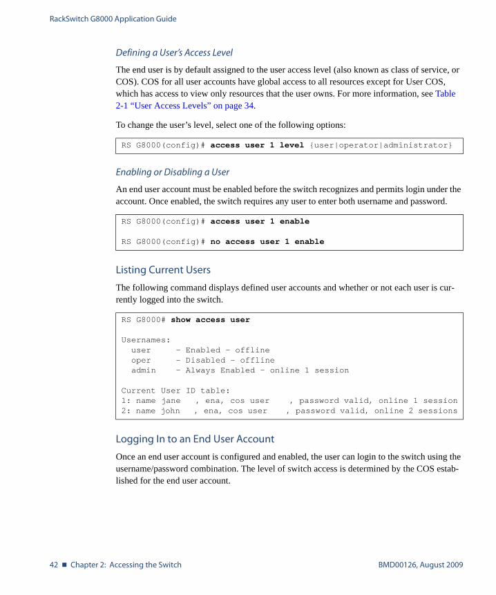
The following command displays defined user accounts and whether or not each user is cur-rently logged into the switch.
Logging In to an End User Account
Once an end user account is configured and enabled, the user can login to the switch using the username/password combination. The level of switch access is determined by the COS estab-lished for the end user account.
RS G8000(config)# access user 1 level {user|operator|administrator}
RS G8000(config)# access user 1 enable
RS G8000(config)# no access user 1 enable
RS G8000# show access user
Usernames:user - Enabled - offlineoper - Disabled - offlineadmin - Always Enabled - online 1 session
Current User ID table:1: name jane , ena, cos user , password valid, online 1 session2: name john , ena, cos user , password valid, online 2 sessions

BMD00126, August 2009 43
CHAPTER 3
Stacking
This chapter describe how to implement the stacking feature in the BLADE RackSwitch G8000 1/10Gb Ethernet Switch.
Stacking Overview
A stack is a group of up to six RackSwitch G8000 switches with BLADE OS software that work together as a unified system. A stack has the following properties, regardless of the num-ber of switches included:
� The network views the stack as a single entity, and the stack is identified by a single net-work IP address.
� The number of ports in a stack equals the total number of ports of all the switches that are part of the stack.
� The number of available IP interfaces, VLANs, Trunks, Trunk Links, and other switch attributes are not aggregated among the switches in a stack. The totals for the stack as a whole are the same as for any single switch configured in stand-alone mode.
RackSwitch G8000 Application Guide
44 � Chapter 3: Stacking BMD00126, August 2009
Stacking Requirements
Before switches can form a stack, they must meet the following requirements:
� All switches must be the same model (RackSwitch G8000).
� Each switch must be installed with BLADE OS software, version 6.0 or later. The same release version is not required, as the Master switch will push a firmware image to each differing switch which is part of the stack.
� 10Gb Ethernet port 51 and port 52 (via optional 10GbE modules installed at the back of the switch) must be available for stacking on each switch. The cables used for connecting the switches in a stack carry low-level, inter-switch communications critical to shared switching functions. Always maintain the stability of stack links in order to avoid internal stack reconfiguration.
Stack Membership
A stack contains up to six switches, interconnected by a stack trunk in a local ring topology (see Figure 3-1 on page 50). With this topology, only a single stack link failure will be allowed.
An operational stack must contain one Master and one or more Members, as follows:
� Master
One switch controls the operation of the stack and is called the Master. The Master pro-vides a single point to manage the stack. A stack must have one and only one Master. The firmware image, configuration information, and run-time data are maintained by the Mas-ter and pushed to each switch in the stack as necessary.
� Member
Member switches provide additional port capacity to the stack. Members receive configu-ration changes, run-time information, and software updates from the Master.
� Backup
One member switch can be designated as a Backup to the Master. The Backup takes over control of the stack if the Master fails. Configuration information and run-time data are synchronized with the Master.

RackSwitch G8000 Application Guide
BMD00126, August 2009 Chapter 3: Stacking � 45
The Master Switch
An operational stack can have only one active Master at any given time. In a normal stack con-figuration, one switch is configured as a Master and all others are configured as Members.
When adding new switches to an existing stack, the administrator should explicitly configure each new switch for its intended role as a Master (only when replacing a previous Master) or as a Member. All stack configuration procedures in this chapter depict proper role specification.
However, although uncommon, there are scenarios in which a stack may temporarily have more than one Master switch. Should this occur, one Master switch will automatically be cho-sen as the active Master for the entire stack. The selection process is designed to promote sta-ble, predictable stack operation and minimize stack reboots and other disruptions.
Splitting and Merging One Stack
If stack links or Member switches fail, any Members which cannot access either the Master or Backup are considered isolated and will not process network traffic (see “No Backup” on page 47). Members which have access to a Master or Backup (or both), despite link or Member failures, will continue to operate as part of their active stack.
If multiple stack links or stack Member switches fail, thereby separating the Master and Backup into separate sub-stacks, the Backup automatically becomes an active Master for the partial stack in which is resides. Later, if the topology failures are corrected, the partial stacks will merge, and the two active Masters will come into contact.
In this scenario, if both the (original) Master and the Backup (acting as Master) are in opera-tion when the merger occurs, the original Master will reassert its role as active Master for the entire stack. The Backup will reboot and return to its role as Backup.
However, if the original Master switch is disrupted (powered down or in the process of reboot-ing) when it is reconnected with the active stack, the Backup (acting as Master) will retain its acting Master status in order to avoid disruption to the functioning stack. The deferring Master will temporarily assume a role as Backup.
If both the Master and Backup are rebooted, the switches will assume their originally configured roles.
If, while the stack is still split, the Backup (acting as Master) is explicitly reconfigured to become a regular Master, then when the split stacks are finally merged, the Master with the lowest MAC address will become the new active Master for the entire stack.
RackSwitch G8000 Application Guide
46 � Chapter 3: Stacking BMD00126, August 2009
Merging Independent Stacks
If switches from different stacks are linked together in a stack topology without first reconfig-uring their roles as recommended, it is possible that more than one switch in the stack might be configured as a Master.
Although all switches which are configured for stacking and joined by stacking links are rec-ognized as potential stack participants by any operational Master switches, they are not brought into operation within the stack until explicitly assigned (or “bound”) to a specific Mas-ter switch.
Consider two independent stacks, Stack A and Stack B, which are merged into one stacking topology. The stacks will behave independently until the switches in Stack B are bound to Master A (or vice versa). In this example, once the Stack B switches are bound to Master A, Master A will automatically reconfigure them to operate as Stack A Members, regardless of their original status within Stack B.
However, for purposes of future Backup selection, reconfigured Masters retain their identity as configured Masters, even though they otherwise act as Members and lose all settings pertain-ing to their original stacks.
Backup Switch Selection
An operational stack can have one optional Backup at any given time. Only the Backup speci-fied in the active Master’s configuration is eligible to take over current stack control when the Master is rebooted or fails. The Master automatically synchronizes configuration settings with the specified Backup to facilitate the transfer of control functions.
The Backup retains its status until one of the following occurs:
� The Backup setting is deleted or changed using the following command from the active Master:
� A new Master assumes operation as active Master in the stack, and uses it’s own config-ured Backup settings.
� The active Master is rebooted with the boot configuration set to factory defaults (clearing the Backup setting).
RS G8000(config)# no stack backup
-or-
RS G8000(config)# stack backup <csum 1-6>
RackSwitch G8000 Application Guide
BMD00126, August 2009 Chapter 3: Stacking � 47
Master Failover
When the Master switch is present, it controls the operation of the stack and pushes configura-tion information to the other switches in the stack. If the active Master fails, then the desig-nated Backup (if one is defined in the Master’s configuration) becomes the new acting Master and the stack continues to operate normally.
Secondary Backup
When a Backup takes over stack control operations, if any other configured Masters (acting as Member switches) are available within the stack, the Backup will select one as a secondary Backup. The primary Backup automatically reconfigures the secondary Backup, and specifies itself (the primary Backup) as the new Backup in case the secondary fails. This prevents the chain of stack control from migrating too far from the original Master and Backup configura-tion intended by the administrator.
Master Recovery
If the prior Master recovers in a functioning stack where the Backup has assumed stack con-trol, the prior Master does not reassert itself as the stack Master. Instead, the prior Master will assume a role as a secondary Backup to avoid further stack disruption.
Upon stack reboot, the Master and Backup will resume their regular roles.
No Backup
If a Backup is not configured on the active Master, or the specified Backup is not operating, then if the active Master fails, the stack will reboot without an active Master.
When a group of stacked switches are rebooted without an active Master present, the switches are considered to be isolated. All isolated switches in the stack are placed in a WAITING state until a Master appears. During this WAITING period, all the external ports and internal server ports of these Member switches are placed into operator-disabled state. Without the Master, a stack cannot respond correctly to networking events.

RackSwitch G8000 Application Guide
48 � Chapter 3: Stacking BMD00126, August 2009
Stack Member Numbers
Each switch in the stack has two numeric identifiers, as follows:
� Attached Switch Number (asnum)
An asnum is automatically assigned by the Master switch, based on each Member switch’s physical connection in relation to the Master. The asnum is mainly used as an internal ID by the Master switch and is not user-configurable.
� Configured Switch Number (csnum):
The csnum is the logical switch ID assigned by the stack administrator. The csnum is used in most stacking-related configuration commands and switch information output. It is also used as a port prefix to distinguish the relationship between the ports on different switches in the stack.
It is recommended that asnum 1 and csnum 1 be used for identifying the Master switch. By default, csnum 1 is assigned to the Master. If csnum 1 is not available, the lowest available csnum is assigned to the Master.
Best Configuration Practices
The following are guidelines for building an effective switch stack:
� Always connect the stack switches in a complete ring topology.
� Optimal stack performance occurs in a stack of three switches, as each switch is then directly connected to all others in the stack.
� For stacks with more than three switches, the Backup switch should be adjacent to the Master in the stacking topology.
� Avoid disrupting the stack connections unnecessarily while the stack is in operation.
� For best redundancy, create trunks that include ports from two or more stack members.
� Avoid altering the stack asnum and csnum definitions unnecessarily while the stack is in operation.
� Stacking uses one of the QoS priority queues for management and control traffic. There-fore, only seven priority queues will be available for regular QoS use.
� Configure only as many QoS levels as necessary. This allows the best use of packet buffers.
RackSwitch G8000 Application Guide
BMD00126, August 2009 Chapter 3: Stacking � 49
Configuring Each Switch in a Stack
This section provides procedures for creating a stack of switches. The high-level procedure is as follows:
� Configure stacking on each switch.
� Designate one switch as the Master.
� Reboot all stack switches.
� Connect the stack trunk as shown in Figure 3-1.
� Configure the Master interface.
� Configure additional stacking parameters on the Master.
To pre-configure each Member switch for stacking, use the ISCLI to perform the following steps.
1. Configure the stacking VLAN, or use the default setting.
Although any VLAN (except VLAN 1) may be defined for stack traffic, it is highly recom-mended that the default, VLAN 4090, be reserved for stacking (shown below).
2. Set the stacking mode.
By default, each switch is set to Member mode. However, one switch must be set to Master mode. Use the following command on only the designated Master switch:
NOTE – If any Member switches are incorrectly set to Master mode, use the mode member option to set them back to Member mode.
3. Reboot all of the stack switches.
RS G8000(config)# boot stack vlan 4090
RS G8000(config)# boot stack mode master
RackSwitch G8000 Application Guide
50 � Chapter 3: Stacking BMD00126, August 2009
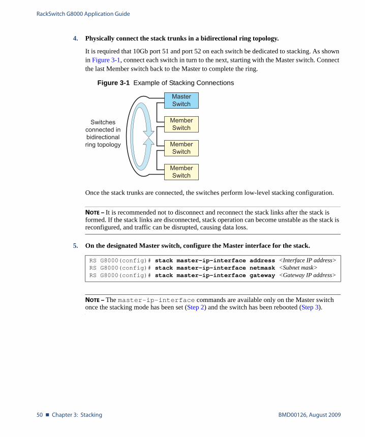
4. Physically connect the stack trunks in a bidirectional ring topology.
It is required that 10Gb port 51 and port 52 on each switch be dedicated to stacking. As shown in Figure 3-1, connect each switch in turn to the next, starting with the Master switch. Connect the last Member switch back to the Master to complete the ring.
Figure 3-1 Example of Stacking Connections
Once the stack trunks are connected, the switches perform low-level stacking configuration.
NOTE – It is recommended not to disconnect and reconnect the stack links after the stack is formed. If the stack links are disconnected, stack operation can become unstable as the stack is reconfigured, and traffic can be disrupted, causing data loss.
5. On the designated Master switch, configure the Master interface for the stack.
NOTE – The master-ip-interface commands are available only on the Master switch once the stacking mode has been set (Step 2) and the switch has been rebooted (Step 3).
RS G8000(config)# stack master-ip-interface address <Interface IP address>RS G8000(config)# stack master-ip-interface netmask <Subnet mask>RS G8000(config)# stack master-ip-interface gateway <Gateway IP address>
Switchesconnected inbidirectionalring topology
MemberSwitch
MemberSwitch
MemberSwitch
MasterSwitch
RackSwitch G8000 Application Guide
BMD00126, August 2009 Chapter 3: Stacking � 51
Additional Master Configuration
Once the Master switch interface has been defined, access the internal management IP inter-face of the Master switch, and complete the configuration. This can be done using either the switch ISCLI or the Browser-Based Interface (BBI).
Master Configuration via the ISCLI
Use the following procedures to complete the stack configuration using the ISCLI. To use the BBI instead, see “Master Configuration via BBI” on page 54.
Locating the Master Switch IP Interface via ISCLI
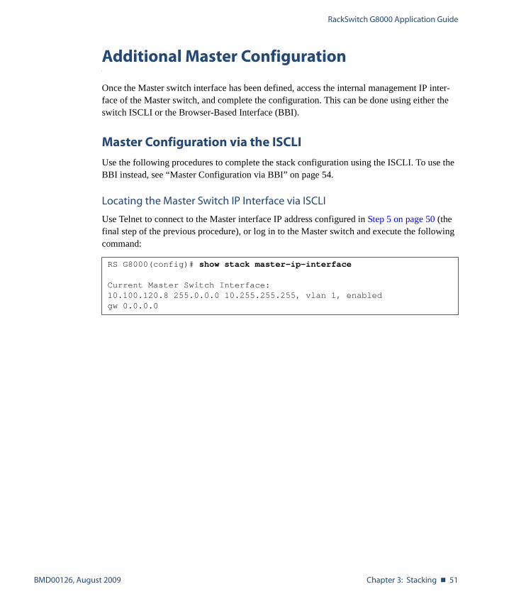
Use Telnet to connect to the Master interface IP address configured in Step 5 on page 50 (the final step of the previous procedure), or log in to the Master switch and execute the following command:
RS G8000(config)# show stack master-ip-interface
Current Master Switch Interface:10.100.120.8 255.0.0.0 10.255.255.255, vlan 1, enabledgw 0.0.0.0

RackSwitch G8000 Application Guide
52 � Chapter 3: Stacking BMD00126, August 2009
Viewing Stack Connections via ISCLI
To view information about the switches in a stack, execute the following command:
RS G8000(config)# show stack switch
Stack name:Local switch is the master.
Local switch:csnum - 1MAC - 00:00:00:00:01:00Switch Type - 9Chassis Type - 99Switch Mode (cfg) - MasterPriority - 225Stack MAC - 00:00:00:00:01:1f
Master switch:csnum - 1MAC - 00:00:00:00:01:00
Backup switch:csnum - 2MAC - 00:22:00:ad:43:00
Configured Switches:--------------------------------csnum MAC asnum--------------------------------
C1 00:00:00:00:01:00 A1C2 00:22:00:ad:43:00 A3C3 00:11:00:af:ce:00 A2
Attached Switches in Stack:-------------------------------------asnum MAC csnum State-------------------------------------
A1 00:00:00:00:01:00 C1 IN_STACKA2 00:11:00:af:ce:00 C3 IN_STACKA3 00:22:00:ad:43:00 C2 IN_STACK
RackSwitch G8000 Application Guide
BMD00126, August 2009 Chapter 3: Stacking � 53
Binding Members to the Stack via ISCLI
You can bind Member switches to a stack csnum using either their MAC address or asnum:
To remove a Member switch, execute the following command:
Assigning a Stack Backup Switch via ISCLI
To define a Member switch as a Backup (optional) which will assume the Master role if the Master switch should fail, execute the following command:
Configuring an External IP Address for the Stack via ISCLI
Configure the following information for the Master switch interface:
� Master interface IP address and subnet mask
� Default gateway IP address
� VLAN number used for external access to the stack (rather than the internal VLAN 4090 used for inter-stack traffic)
Use the following commands:
When the Master switch interface is defined, configuration is complete.
RS G8000(config)# stack switch-number <csnum> mac <MAC address>
or
RS G8000(config)# stack switch-number <csnum> bind <asnum>
RS G8000(config)# no stack switch-number <csnum>
RS G8000(config)# stack backup <csnum>
RS G8000(config)# stack master-ip-interface address <master IP address>RS G8000(config)# stack master-ip-interface netmask <subnet mask>RS G8000(config)# stack master-ip-interface gateway <gateway IP address>RS G8000(config)# stack master-ip-interface vlan 12
RackSwitch G8000 Application Guide
54 � Chapter 3: Stacking BMD00126, August 2009
Master Configuration via BBI
As an alternative to the ISCLI (“Master Configuration via the ISCLI” on page 51), you may complete the Master switch configuration using the BBI as shown in the following procedures.
Locating the Master Switch Internal Management IP Interface via BBI
To launch the BBI for the Master switch, use a Web browser to access the Master interface IP address configured in Step 5 on page 50.
Viewing Stack Connections via BBI
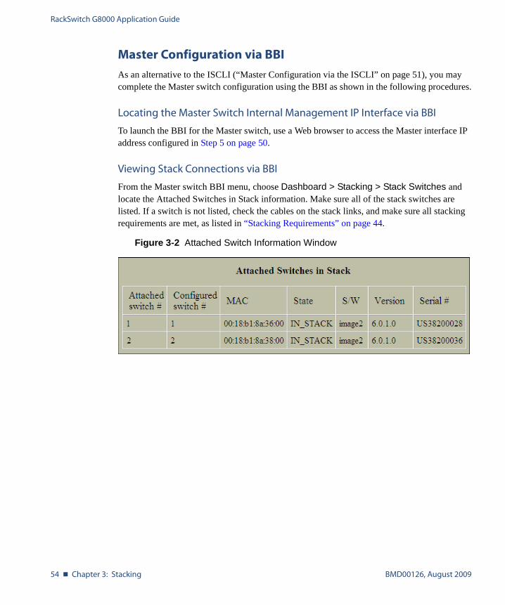
From the Master switch BBI menu, choose Dashboard > Stacking > Stack Switches and locate the Attached Switches in Stack information. Make sure all of the stack switches are listed. If a switch is not listed, check the cables on the stack links, and make sure all stacking requirements are met, as listed in “Stacking Requirements” on page 44.
Figure 3-2 Attached Switch Information Window
RackSwitch G8000 Application Guide
BMD00126, August 2009 Chapter 3: Stacking � 55
Binding Members to the Stack via BBI
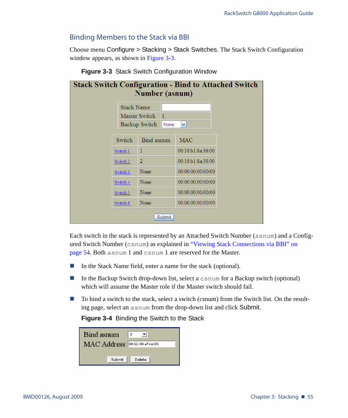
Choose menu Configure > Stacking > Stack Switches. The Stack Switch Configuration window appears, as shown in Figure 3-3.
Figure 3-3 Stack Switch Configuration Window
Each switch in the stack is represented by an Attached Switch Number (asnum) and a Config-ured Switch Number (csnum) as explained in “Viewing Stack Connections via BBI” on page 54. Both asnum 1 and csnum 1 are reserved for the Master.
� In the Stack Name field, enter a name for the stack (optional).
� In the Backup Switch drop-down list, select a csnum for a Backup switch (optional) which will assume the Master role if the Master switch should fail.
� To bind a switch to the stack, select a switch (csnum) from the Switch list. On the result-ing page, select an asnum from the drop-down list and click Submit.
Figure 3-4 Binding the Switch to the Stack

RackSwitch G8000 Application Guide
56 � Chapter 3: Stacking BMD00126, August 2009
Click Submit to register the changes, Apply to make the changes active, and Save to retain changes beyond reboot cycles.
Configuring an External IP Address for the Stack via BBI
Choose menu Configure > Stacking > Master & Backup Interfaces. Use the Interfaces window to configure a single IP interface for the stack. This interface is known at the Master interface and is shared by all switches in the stack.
Figure 3-5 Stack IP Interfaces Configuration Window
Enter the following information for the Master Switch Interface:
� Master interface IP address and subnet mask
� VLAN number used for external access to the stack (rather than the internal VLAN 4090 used for inter-stack traffic)
� Default gateway IP address
Click Apply to make the changes active, and Save to retain changes beyond reboot cycles.
RackSwitch G8000 Application Guide
BMD00126, August 2009 Chapter 3: Stacking � 57
Managing a Stack
The stack is managed through the Master switch. The Master switch then pushes configuration changes and run-time information to the Member switches.
Use Telnet or the Browser-Based Interface (BBI) to access the Master, as follows:
� On any switch in the stack, connect to any port that is not part of an active trunk, and use the IP address of the Master to access the Master switch.
� Use the management IP address assigned to the Master by the management system.
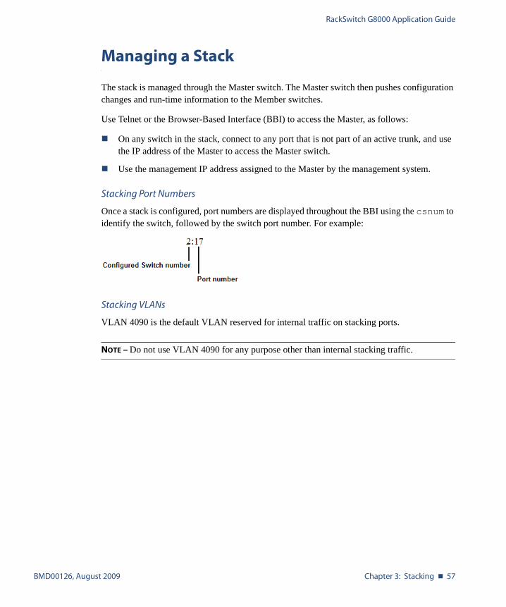
Stacking Port Numbers
Once a stack is configured, port numbers are displayed throughout the BBI using the csnum to identify the switch, followed by the switch port number. For example:
Stacking VLANs
VLAN 4090 is the default VLAN reserved for internal traffic on stacking ports.
NOTE – Do not use VLAN 4090 for any purpose other than internal stacking traffic.

RackSwitch G8000 Application Guide
58 � Chapter 3: Stacking BMD00126, August 2009
Rebooting Stacked Switches
The Configure > System > Config/Image Control window allow the administrator to perform a reboot of individual switches in the stack, or the entire stack. The following table describes the stacking Reboot buttons.
The Update Image/Cfg section of the window applies to the Master. When a new software image or configuration file is loaded, the file first loads onto the Master, and the Master pushes the file to all other switches in the stack, placing it in the same software or configuration bank as that on the Master. For example, if the new image is loaded into image 1 on the Master switch, the Master will push the same firmware to image 1 on each Member switch.
Table 3-1 Stacking Boot Management buttons
Field Description
Reboot Stack Performs a software reboot/reset of all switches in the stack. The software image specified in the Image To Boot drop-down list becomes the active image.
Reboot Master Performs a software reboot/reset of the Master switch. The software image spec-ified in the Image To Boot drop-down list becomes the active image.
Reboot Switches Performs a reboot/reset on selected switches in the stack. Select one or more switches in the drop-down list, and click Reboot Switches. The software image specified in the Image To Boot drop-down list becomes the active image.
RackSwitch G8000 Application Guide
BMD00126, August 2009 Chapter 3: Stacking � 59
Upgrading Software in an Existing Stack
Upgrade all stacked switches at the same time. The Master controls the upgrade process. Use the following procedure to perform a software upgrade for a stacked system.
1. Load new software on the Master (see “Upgrading the Switch Software” on page 17).
The Master pushes the new software image to all Members in the stack, as follows:
� If the new software is loaded into image 1, the Master pushes the software into image 1 on all Members.
� If loaded into image 2, the Master pushes the software into image 2 on all Members.
The software push can take several minutes to complete.
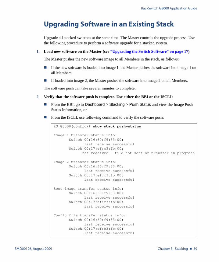
2. Verify that the software push is complete. Use either the BBI or the ISCLI:
� From the BBI, go to Dashboard > Stacking > Push Status and view the Image Push Status Information, or
� From the ISCLI, use following command to verify the software push:
RS G8000(config)# show stack push-status
Image 1 transfer status info:Switch 00:16:60:f9:33:00:
last receive successfulSwitch 00:17:ef:c3:fb:00:
not received - file not sent or transfer in progress
Image 2 transfer status info:Switch 00:16:60:f9:33:00:
last receive successfulSwitch 00:17:ef:c3:fb:00:
last receive successful
Boot image transfer status info:Switch 00:16:60:f9:33:00:
last receive successfulSwitch 00:17:ef:c3:fb:00:
last receive successful
Config file transfer status info:Switch 00:16:60:f9:33:00:
last receive successfulSwitch 00:17:ef:c3:fb:00:
last receive successful
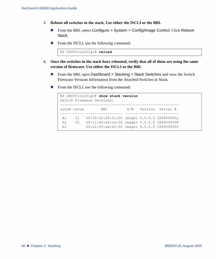
RackSwitch G8000 Application Guide
60 � Chapter 3: Stacking BMD00126, August 2009
3. Reboot all switches in the stack. Use either the ISCLI or the BBI.
� From the BBI, select Configure > System > Config/Image Control. Click Reboot Stack.
� From the ISCLI, use the following command:
4. Once the switches in the stack have rebooted, verify that all of them are using the same version of firmware. Use either the ISCLI or the BBI.
� From the BBI, open Dashboard > Stacking > Stack Switches and view the Switch Firmware Versions Information from the Attached Switches in Stack.
� From the ISCLI, use the following command:
RS G8000(config)# reload
RS G8000(config)# show stack versionSwitch Firmware Versions:-------------------------------------------------------asnum csnum MAC S/W Version Serial #----- ----- ----------------- ------ ------- ----------A1 C1 00:00:00:00:01:00 image1 0.0.0.0 CH4909005LA2 C2 00:11:00:af:ce:00 image1 0.0.0.0 CH4909005FA3 00:22:00:ad:43:00 image1 0.0.0.0 CH4909005T

RackSwitch G8000 Application Guide
BMD00126, August 2009 Chapter 3: Stacking � 61
Replacing or Removing Stacked Switches
Stack switches may be replaced or removed while the stack is in operation. However, the fol-lowing conditions must be met in order to avoid unnecessary disruption:
� If removing an active Master switch, make sure that a valid Backup exists in the stack.
� It is best to replace only one switch at a time.
� If replacing or removing multiple switches, when one switch has been properly discon-nected (see the procedures that follow), any adjacent switch can also be removed.
� Removing any two, non-adjacent switches will divide the ring and disrupt the stack.
Use the following procedures to replace a stack switch.
Preparing the New Switch
If replacing a switch in an existing stack, use the following procedure to prepare the new replacement switch for joining the stack:
1. Make sure the new switch meets the stacking requirements on page 44.
2. Configure the stacking VLAN, of use the default setting.
Although any VLAN may be defined for stack traffic, it is highly recommended that the default, VLAN 4090, be reserved for stacking (shown below).
3. Set the stacking mode.
By default, each switch is set to Member mode. However, if the incoming switch has been used in another stacking configuration, it may be necessary to ensure the proper mode is set.
� If replacing a Member or Backup switch:
� If replacing a Master switch:
4. Apply and save your configuration changes.
5. Turn the new switch off.
RS G8000(config)# boot stack vlan 4090
RS G8000(config)# boot stack mode member
RS G8000(config)# boot stack mode master
RackSwitch G8000 Application Guide
62 � Chapter 3: Stacking BMD00126, August 2009
Removing a Switch from the Stack
1. Make sure the stack is configured in a ring topology.
NOTE – When an open-ended daisy-chain topology is in effect (either by design or as the result of any failure of one of the stacking links), removing a stack switch from the interior of the chain can divide the chain and cause serious disruption to the stack operation.
2. If removing a Master switch, make sure that a Backup switch exists in the stack and then turn the Master switch off. This will force the Backup switch to assume Master opera-tions for the stack.
3. Remove the stack link cables from the old switch only.
4. Disconnect all network cables from the old switch only.
5. Turn off only the old switch (if not already off), and remove it.
Installing the New Switch or Healing the Topology
1. If installing a new switch, place it in its determined place according to the RackSwitch G8000 Installation Guide.
2. Attach the required stack link cables to port 51 and port 52 between the stacked switches.
3. Attach the desired network cables to the new switch, if installed.
4. Turn the new switch on, if installed.
When the new switch boots, it will join the existing stack. Wait for this process to complete.

RackSwitch G8000 Application Guide
BMD00126, August 2009 Chapter 3: Stacking � 63
Joining the New Switch to the Stack
1. Log in to the Master switch interface.
NOTE – If replacing the Master switch, be sure to log in to the Master switch interface (hosted temporarily on the Backup switch) rather than logging in directly to the newly installed Master.
2. From the Master switch interface, assign the csnum for the new switch.
You can join the switch to a stack by binding a stack csnum to the new switch’s MAC address or asnum:
3. Apply and save your configuration changes.
NOTE – If replacing the Master switch, the Master will not assume control from the Backup unless the Backup is rebooted or fails.
RS G8000(config)# stack switch-number <csnum> mac <MAC address>or
RS G8000(config)# stack switch-number <csnum> bind <asnum>
RackSwitch G8000 Application Guide
64 � Chapter 3: Stacking BMD00126, August 2009
ISCLI Stacking Commands
Stacking-related ISCLI commands are listed below. For details on specific commands, see the RackSwitch G8000 ISCLI Reference.
� boot stack mode master|member
� boot stack push-image boot-image|image1|image2 <asnum 1-12>� boot stack vlan <VLAN 2-4094> <asnum 1-12>|master|backup|all� default boot stack <asnum 1-12>|master|backup|all� [no] logging log stacking
� no stack backup
� no stack backup-ip-interface
� no stack master-ip-interface
� no stack name
� no stack switch-number <csnum 1-6>� show boot stack <asnum 1-12>|master|backup|all� show stack attached-switches
� show stack backup
� show stack backup-ip-interface
� show stack dynamic
� show stack link
� show stack master-ip-interface
� show stack path-map [<csnum 1-6>]� show stack push-status
� show stack name
� show stack switch
� show stack switch-number [<csnum 1-6>]� show stack version
� stack backup <csnum 1-6>� stack backup-ip-interface address <IP address>
[<subnet mask> [<gateway IP address> [<VLAN 1-4094>]]]� stack backup-ip-interface gateway <IP address>� stack backup-ip-interface netmask <subnet mask>� stack backup-ip-interface vlan <VLAN 1-4094>� stack master-ip-interface address <IP address>
[<subnet mask> [<gateway IP address> [<VLAN 1-4094>]]]
RackSwitch G8000 Application Guide
BMD00126, August 2009 Chapter 3: Stacking � 65
� stack master-ip-interface gateway <IP address>� stack master-ip-interface netmask <subnet mask>� stack master-ip-interface vlan <VLAN 1-4094>� stack name <word>� stack switch-number <csnum 1-6> bind <asnum 1-12>� stack switch-number <csnum 1-6> mac <MAC address>

RackSwitch G8000 Application Guide
66 � Chapter 3: Stacking BMD00126, August 2009
BMD00126, August 2009 67
CHAPTER 4
Port-Based Network Access Control
Port-Based Network Access control provides a means of authenticating and authorizing devices attached to a LAN port that has point-to-point connection characteristics. It prevents access to ports that fail authentication and authorization. This feature provides security to ports of the G8000 that connect to servers.
The following topics are discussed in this section:
� “Extensible Authentication Protocol over LAN” on page 68� “802.1X Authentication Process” on page 69� “802.1X Port States” on page 71� “Supported RADIUS Attributes” on page 73� “Configuration Guidelines” on page 74

RackSwitch G8000 Application Guide
68 � Chapter 4: Port-Based Network Access Control BMD00126, August 2009
Extensible Authentication Protocol over LAN
The G8000 can provide user-level security for its ports using the IEEE 802.1X protocol, which is a more secure alternative to other methods of port-based network access control. Any device attached to an 802.1X-enabled port that fails authentication is prevented access to the network and denied services offered through that port.
The 802.1X standard describes port-based network access control using Extensible Authenti-cation Protocol over LAN (EAPoL). EAPoL provides a means of authenticating and authoriz-ing devices attached to a LAN port that has point-to-point connection characteristics and of preventing access to that port in cases of authentication and authorization failures.
EAPoL is a client-server protocol that has the following components:
� Supplicant or Client The Supplicant is a device that requests network access and provides the required creden-tials (user name and password) to the Authenticator and the Authenticator Server.
� Authenticator The Authenticator enforces authentication and controls access to the network. The Authenticator grants network access based on the information provided by the Supplicant and the response from the Authentication Server. The Authenticator acts as an intermedi-ary between the Supplicant and the Authentication Server: requesting identity information from the client, forwarding that information to the Authentication Server for validation, relaying the server’s responses to the client, and authorizing network access based on the results of the authentication exchange. The G8000 acts as an Authenticator.
� Authentication ServerThe Authentication Server validates the credentials provided by the Supplicant to deter-mine if the Authenticator should grant access to the network. The Authentication Server may be co-located with the Authenticator. The G8000 relies on external RADIUS servers for authentication.
Upon a successful authentication of the client by the server, the 802.1X-controlled port transi-tions from unauthorized to authorized state, and the client is allowed full access to services through the port. When the client sends an EAP-Logoff message to the authenticator, the port will transition from authorized to unauthorized state.

RackSwitch G8000 Application Guide
BMD00126, August 2009 Chapter 4: Port-Based Network Access Control � 69
802.1X Authentication Process
The clients and authenticators communicate using Extensible Authentication Protocol (EAP), which was originally designed to run over PPP, and for which the IEEE 802.1X Standard has defined an encapsulation method over Ethernet frames, called EAP over LAN (EAPOL). Figure 4-1 shows a typical message exchange initiated by the client.
Figure 4-1 Authenticating a Port Using EAPoL
802.1X ClientRADIUSServer
Radius-Access-Request
Radius-Access-Challenge
Radius-Access-Request
Radius-Access-Accept
EAP-Request (Credentials)
EAP-Response (Credentials)
EAP-Success
EAP-Request (Identity)
EAP-Response (Identity)
EAPOL-Start
Port Authorized
Port Unauthorized
G8000(Authenticator)
(RADIUS Client)
EAPOL
Ethernet
RADIUS-EAP
UDP/IP
RackSwitch G8000 Application Guide
70 � Chapter 4: Port-Based Network Access Control BMD00126, August 2009
During authentication, EAPOL messages are exchanged between the client and the G8000 authenticator, while RADIUS-EAP messages are exchanged between the G8000 authenticator and the RADIUS server.
Authentication is initiated by one of the following methods:
� The G8000 authenticator sends an EAP-Request/Identity packet to the client
� Client sends an EAPOL-Start frame to the G8000 authenticator, which responds with an EAP-Request/Identity frame.
The client confirms its identity by sending an EAP-Response/Identity frame to the G8000 authenticator, which forwards the frame encapsulated in a RADIUS packet to the server.
The RADIUS authentication server chooses an EAP-supported authentication algorithm to verify the client’s identity, and sends an EAP-Request packet to the client via the G8000 authenticator. The client then replies to the RADIUS server with an EAP-Response containing its credentials.
Upon a successful authentication of the client by the server, the 802.1X-controlled port transi-tions from unauthorized to authorized state, and the client is allowed full access to services through the controlled port. When the client later sends an EAPOL-Logoff message to the G8000 authenticator, the port transitions from authorized to unauthorized state.
If a client that does not support 802.1X connects to an 802.1X-controlled port, the G8000 authenticator requests the client's identity when it detects a change in the operational state of the port. The client does not respond to the request, and the port remains in the unauthorized state.
NOTE – When an 802.1X-enabled client connects to a port that is not 802.1X-controlled, the client initiates the authentication process by sending an EAPOL-Start frame. When no response is received, the client retransmits the request for a fixed number of times. If no response is received, the client assumes the port is in authorized state, and begins sending frames, even if the port is unauthorized.
RackSwitch G8000 Application Guide
BMD00126, August 2009 Chapter 4: Port-Based Network Access Control � 71
802.1X Port States
The state of the port determines whether the client is granted access to the network, as follows:
� UnauthorizedWhile in this state the port discards all ingress and egress traffic except EAP packets.
� AuthorizedWhen the client is successfully authenticated, the port transitions to the authorized state allowing all traffic to and from the client to flow normally.
� Force UnauthorizedYou can configure this state that denies all access to the port.
� Force AuthorizedYou can configure this state that allows full access to the port.
Use the 802.1X global configuration commands (dot1x) to configure 802.1X authentication for all ports in the switch. Use the 802.1X port commands to configure a single port.
RADIUS VLAN Assignment
BLADE OS 6.0 allows switch ports to be assigned a particular VLAN based on the result of the RADIUS authentication. The following commands are used in Global Configuration mode to turn the feature on or off for the switch:
By default, the VLAN assignment feature is turned off for each port. To enable or disable the feature on individual ports, use the following commands in Interface Configuration mode:
For VLAN assignment, the following tunnel attributes are required on the RADIUS server:
� Tunnel-Type = VLAN� Tunnel-Medium-Type = 802� Tunnel-Private-Group-ID = <VLAN ID>
VLAN assignment with RADIUS has the following characteristics:
RS G8000(config)# dot1x vlan-assign (Turn VLAN assignment on)RS G8000(config)# no dot1x vlan-assign (Turn VLAN assignment off)
RS G8000(config-if)# dot1x vlan-assign (Turn VLAN assignment on)RS G8000(config-if)# no dot1x vlan-assign (Turn VLAN assignment off)
RackSwitch G8000 Application Guide
72 � Chapter 4: Port-Based Network Access Control BMD00126, August 2009
� If 802.1X authentication is enabled and all information from the RADIUS server is valid, the authorized device is placed in the RADIUS specified VLAN after authentication.
� If no VLAN is supplied by the RADIUS server, or if 802.1X authentication is disabled, the port retains its regular VLAN after successful authentication.
� If 802.1X authentication is enabled, but the RADIUS VLAN information is not valid, the authorization will fail and the port will retain its regular VLAN. This prevents ports from appearing unexpectedly in inappropriate VLANs due to configuration errors.
� If no VLAN is specified by the RADIUS server, or if the specified VLAN is disabled on the switch, the port retains its regular VLAN.
� If 802.1X authentication is disabled on the port, the port retains its regular VLAN.
� If an 802.1X port is authenticated and is assigned a VLAN by the RADIUS server, any changes made to the VLAN configuration on the switch will not take effect.
� When the port is in a force authorized, force unauthorized, unauthorized, or shutdown state, the port will be returned to its regularly configured VLAN.
� When a port is using an 802.1X assigned VLAN, if a non-existent or disabled VLAN is specified by the RADIUS server during re-authentication, the previously assigned VLAN will remain in effect and a syslog message will be generated.
Guest VLAN
The guest VLAN provides limited access for unauthenticated ports. Use the following com-mand to configure a guest VLAN:
Client ports that have not received an EAPOL response are placed into the Guest VLAN, if one is configured on the switch. Once the port is authenticated, the port is moved from the Guest VLAN to its configured VLAN.
When Guest VLAN is enabled, the following considerations apply while a port is in the unau-thenticated state:
� The port is placed in the guest VLAN.
� The Port VLAN ID (PVID) is changed to the Guest VLAN ID.
� Port tagging is disabled on the port.
RS G8000(config)# dot1x guest-vlan vlan <VLAN ID>(Define Guest VLAN)RS G8000(config)# dot1x guest-vlan enable (Enable Guest VLAN)
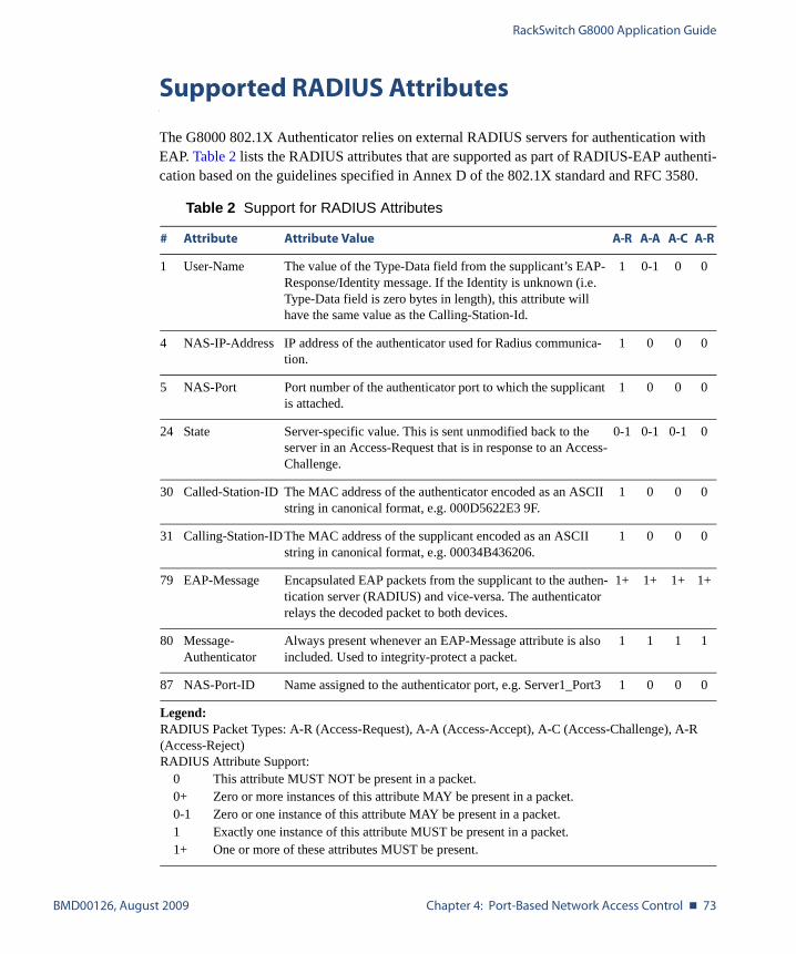
RackSwitch G8000 Application Guide
BMD00126, August 2009 Chapter 4: Port-Based Network Access Control � 73
Supported RADIUS Attributes
The G8000 802.1X Authenticator relies on external RADIUS servers for authentication with EAP. Table 2 lists the RADIUS attributes that are supported as part of RADIUS-EAP authenti-cation based on the guidelines specified in Annex D of the 802.1X standard and RFC 3580.
Table 2 Support for RADIUS Attributes
# Attribute Attribute Value A-R A-A A-C A-R
1 User-Name The value of the Type-Data field from the supplicant’s EAP-Response/Identity message. If the Identity is unknown (i.e. Type-Data field is zero bytes in length), this attribute will have the same value as the Calling-Station-Id.
1 0-1 0 0
4 NAS-IP-Address IP address of the authenticator used for Radius communica-tion.
1 0 0 0
5 NAS-Port Port number of the authenticator port to which the supplicant is attached.
1 0 0 0
24 State Server-specific value. This is sent unmodified back to the server in an Access-Request that is in response to an Access-Challenge.
0-1 0-1 0-1 0
30 Called-Station-ID The MAC address of the authenticator encoded as an ASCII string in canonical format, e.g. 000D5622E3 9F.
1 0 0 0
31 Calling-Station-IDThe MAC address of the supplicant encoded as an ASCII string in canonical format, e.g. 00034B436206.
1 0 0 0
79 EAP-Message Encapsulated EAP packets from the supplicant to the authen-tication server (RADIUS) and vice-versa. The authenticator relays the decoded packet to both devices.
1+ 1+ 1+ 1+
80 Message-Authenticator
Always present whenever an EAP-Message attribute is also included. Used to integrity-protect a packet.
1 1 1 1
87 NAS-Port-ID Name assigned to the authenticator port, e.g. Server1_Port3 1 0 0 0
Legend:RADIUS Packet Types: A-R (Access-Request), A-A (Access-Accept), A-C (Access-Challenge), A-R (Access-Reject)RADIUS Attribute Support:
0 This attribute MUST NOT be present in a packet.0+ Zero or more instances of this attribute MAY be present in a packet.0-1 Zero or one instance of this attribute MAY be present in a packet.1 Exactly one instance of this attribute MUST be present in a packet.1+ One or more of these attributes MUST be present.
RackSwitch G8000 Application Guide
74 � Chapter 4: Port-Based Network Access Control BMD00126, August 2009
Configuration Guidelines
When configuring EAPoL, consider the following guidelines:
� The 802.1X port-based authentication is currently supported only in point-to-point config-urations, that is, with a single supplicant connected to an 802.1X-enabled switch port.
� When 802.1X is enabled, a port has to be in the authorized state before any other Layer 2 feature can be operationally enabled.
� The 802.1X supplicant capability is not supported. Therefore, none of its ports can suc-cessfully connect to an 802.1X-enabled port of another device, such as another switch, that acts as an authenticator, unless access control on the remote port is disabled or is con-figured in forced-authorized mode. For example, if a G8000 is connected to another G8000, and if 802.1X is enabled on both switches, the two connected ports must be con-figured in force-authorized mode.
� The following 802.1X provisions are not supported and might affect 802.1X operations: Service-Type, Session-Timeout, and Termination-Action.
� RADIUS accounting service for 802.1X-authenticated devices or users is not supported.
� Configuration changes performed using SNMP and the standard 802.1X MIB will take effect immediately.
BMD00126, August 2009 75
CHAPTER 5
VLANs
This chapter describes network design and topology considerations for using Virtual Local Area Networks (VLANs). VLANs commonly are used to split up groups of network users into man-ageable broadcast domains, to create logical segmentation of workgroups, and to enforce security policies among logical segments. The following topics are discussed in this chapter:
� “VLANs and Port VLAN ID Numbers” on page 76
� “VLAN Tagging” on page 78
� “VLAN Topologies and Design Considerations” on page 82This section discusses how you can connect users and segments to a host that supports many logical segments or subnets by using the flexibility of the multiple VLAN system.
NOTE – VLANs can be configured from the Command Line Interface (see “VLAN Configura-tion” as well as “Port Configuration” in the Command Reference).
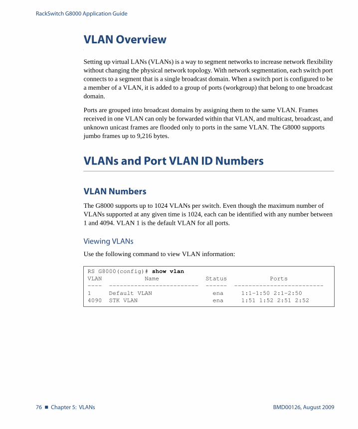
RackSwitch G8000 Application Guide
76 � Chapter 5: VLANs BMD00126, August 2009
VLAN Overview
Setting up virtual LANs (VLANs) is a way to segment networks to increase network flexibility without changing the physical network topology. With network segmentation, each switch port connects to a segment that is a single broadcast domain. When a switch port is configured to be a member of a VLAN, it is added to a group of ports (workgroup) that belong to one broadcast domain.
Ports are grouped into broadcast domains by assigning them to the same VLAN. Frames received in one VLAN can only be forwarded within that VLAN, and multicast, broadcast, and unknown unicast frames are flooded only to ports in the same VLAN. The G8000 supports jumbo frames up to 9,216 bytes.
VLANs and Port VLAN ID Numbers
VLAN Numbers
The G8000 supports up to 1024 VLANs per switch. Even though the maximum number of VLANs supported at any given time is 1024, each can be identified with any number between 1 and 4094. VLAN 1 is the default VLAN for all ports.
Viewing VLANs
Use the following command to view VLAN information:
RS G8000(config)# show vlanVLAN Name Status Ports---- ------------------------- ------ -------------------------1 Default VLAN ena 1:1-1:50 2:1-2:504090 STK VLAN ena 1:51 1:52 2:51 2:52
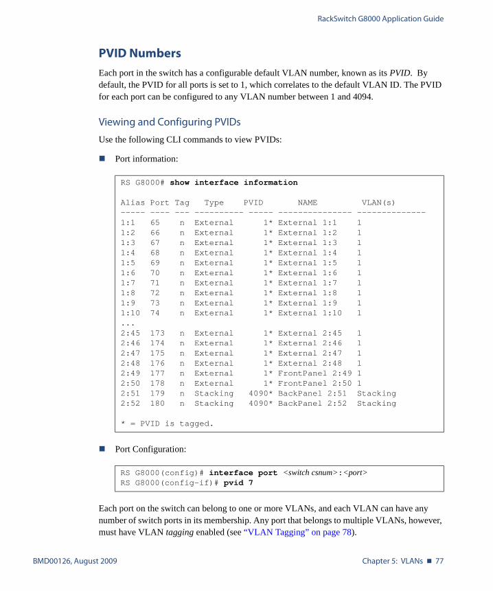
RackSwitch G8000 Application Guide
BMD00126, August 2009 Chapter 5: VLANs � 77
PVID Numbers
Each port in the switch has a configurable default VLAN number, known as its PVID. By default, the PVID for all ports is set to 1, which correlates to the default VLAN ID. The PVID for each port can be configured to any VLAN number between 1 and 4094.
Viewing and Configuring PVIDs
Use the following CLI commands to view PVIDs:
� Port information:
� Port Configuration:
Each port on the switch can belong to one or more VLANs, and each VLAN can have any number of switch ports in its membership. Any port that belongs to multiple VLANs, however, must have VLAN tagging enabled (see “VLAN Tagging” on page 78).
RS G8000# show interface information
Alias Port Tag Type PVID NAME VLAN(s)----- ---- --- ---------- ----- --------------- --------------1:1 65 n External 1* External 1:1 11:2 66 n External 1* External 1:2 11:3 67 n External 1* External 1:3 11:4 68 n External 1* External 1:4 11:5 69 n External 1* External 1:5 11:6 70 n External 1* External 1:6 11:7 71 n External 1* External 1:7 11:8 72 n External 1* External 1:8 11:9 73 n External 1* External 1:9 11:10 74 n External 1* External 1:10 1...2:45 173 n External 1* External 2:45 12:46 174 n External 1* External 2:46 12:47 175 n External 1* External 2:47 12:48 176 n External 1* External 2:48 12:49 177 n External 1* FrontPanel 2:49 12:50 178 n External 1* FrontPanel 2:50 12:51 179 n Stacking 4090* BackPanel 2:51 Stacking2:52 180 n Stacking 4090* BackPanel 2:52 Stacking
* = PVID is tagged.
RS G8000(config)# interface port <switch csnum>:<port>RS G8000(config-if)# pvid 7
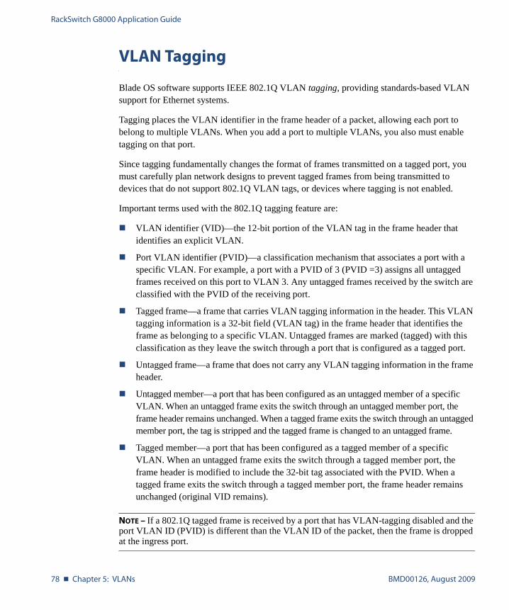
RackSwitch G8000 Application Guide
78 � Chapter 5: VLANs BMD00126, August 2009
VLAN Tagging
Blade OS software supports IEEE 802.1Q VLAN tagging, providing standards-based VLAN support for Ethernet systems.
Tagging places the VLAN identifier in the frame header of a packet, allowing each port to belong to multiple VLANs. When you add a port to multiple VLANs, you also must enable tagging on that port.
Since tagging fundamentally changes the format of frames transmitted on a tagged port, you must carefully plan network designs to prevent tagged frames from being transmitted to devices that do not support 802.1Q VLAN tags, or devices where tagging is not enabled.
Important terms used with the 802.1Q tagging feature are:
� VLAN identifier (VID)—the 12-bit portion of the VLAN tag in the frame header that identifies an explicit VLAN.
� Port VLAN identifier (PVID)—a classification mechanism that associates a port with a specific VLAN. For example, a port with a PVID of 3 (PVID =3) assigns all untagged frames received on this port to VLAN 3. Any untagged frames received by the switch are classified with the PVID of the receiving port.
� Tagged frame—a frame that carries VLAN tagging information in the header. This VLAN tagging information is a 32-bit field (VLAN tag) in the frame header that identifies the frame as belonging to a specific VLAN. Untagged frames are marked (tagged) with this classification as they leave the switch through a port that is configured as a tagged port.
� Untagged frame—a frame that does not carry any VLAN tagging information in the frame header.
� Untagged member—a port that has been configured as an untagged member of a specific VLAN. When an untagged frame exits the switch through an untagged member port, the frame header remains unchanged. When a tagged frame exits the switch through an untagged member port, the tag is stripped and the tagged frame is changed to an untagged frame.
� Tagged member—a port that has been configured as a tagged member of a specific VLAN. When an untagged frame exits the switch through a tagged member port, the frame header is modified to include the 32-bit tag associated with the PVID. When a tagged frame exits the switch through a tagged member port, the frame header remains unchanged (original VID remains).
NOTE – If a 802.1Q tagged frame is received by a port that has VLAN-tagging disabled and the port VLAN ID (PVID) is different than the VLAN ID of the packet, then the frame is dropped at the ingress port.

RackSwitch G8000 Application Guide
BMD00126, August 2009 Chapter 5: VLANs � 79
Figure 5-1 Default VLAN settings
NOTE – The port numbers specified in these illustrations may not directly correspond to the physical port configuration of your switch model.
When a VLAN is configured, ports are added as members of the VLAN, and the ports are defined as either tagged or untagged (see Figure 5-2 through Figure 5-5).
The default configuration settings for the G8000 has all ports set as untagged members of VLAN 1 with all ports configured as PVID = 1. In the default configuration example shown in Figure 5-1, all incoming packets are assigned to VLAN 1 by the default port VLAN identifier (PVID =1).
Figure 5-2 through Figure 5-5 illustrate generic examples of VLAN tagging. In Figure 5-2, untagged incoming packets are assigned directly to VLAN 2 (PVID = 2). Port 5 is configured as a tagged member of VLAN 2, and port 7 is configured as an untagged member of VLAN 2.
Port 1
DA
SA
Data
CRC
Incominguntagged
packet
BS45010A
Port 2 Port 3 Port 4 Port 5
VLAN 1
802.1Q Switch
By default:
Key
All ports are assigned PVID = 1All ports are untagged members of VLAN 1
PVID = 1
Port 6 ...
DA
SA
Data
CRC
Outgoinguntagged packet
(unchanged)
Port 7
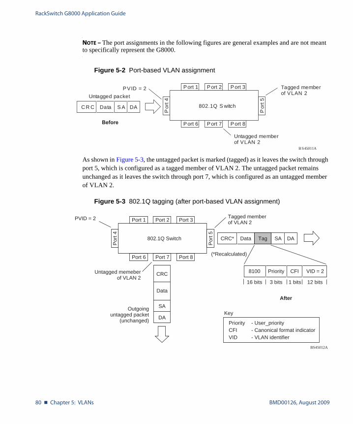
RackSwitch G8000 Application Guide
80 � Chapter 5: VLANs BMD00126, August 2009
NOTE – The port assignments in the following figures are general examples and are not meant to specifically represent the G8000.
Figure 5-2 Port-based VLAN assignment
As shown in Figure 5-3, the untagged packet is marked (tagged) as it leaves the switch through port 5, which is configured as a tagged member of VLAN 2. The untagged packet remains unchanged as it leaves the switch through port 7, which is configured as an untagged member of VLAN 2.
Figure 5-3 802.1Q tagging (after port-based VLAN assignment)
Port 6
DAS ADataC R C
BS45011A
Port 7 Port 8
Port 1
Por
t 4
Por
t 5
P ort 2 Port 3
802.1Q S witch
PVID = 2
Untagged packet
Untagged memberof VLAN 2
Tagged memberof VLAN 2
Before
BS45012A
Port 6 Port 7 Port 8
Port 1
Por
t 4
Por
t 5
Port 2 Port 3
802.1Q Switch
Key
PriorityCFI VID
- User_priority- Canonical format indicator- VLAN identifier
PVID = 2 Tagged memberof VLAN 2
Untagged memeberof VLAN 2
After
DA
SA
Data
CRC
(*Recalculated)
Outgoinguntagged packet
(unchanged)
DASADataCRC* Tag
VID = 2Priority
16 bits 3 bits 1 bits 12 bits
8100 CFI
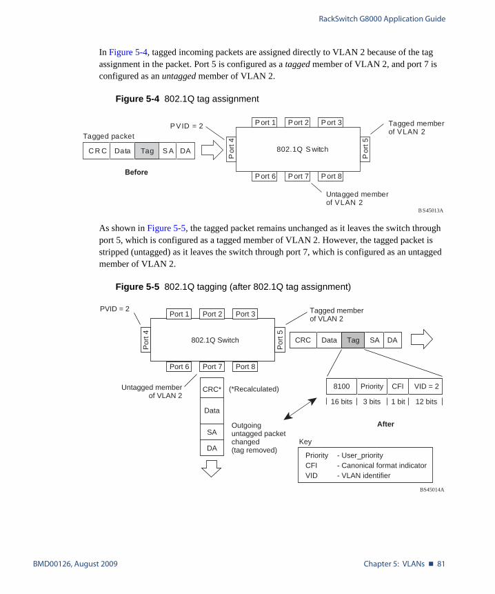
RackSwitch G8000 Application Guide
BMD00126, August 2009 Chapter 5: VLANs � 81
In Figure 5-4, tagged incoming packets are assigned directly to VLAN 2 because of the tag assignment in the packet. Port 5 is configured as a tagged member of VLAN 2, and port 7 is configured as an untagged member of VLAN 2.
Figure 5-4 802.1Q tag assignment
As shown in Figure 5-5, the tagged packet remains unchanged as it leaves the switch through port 5, which is configured as a tagged member of VLAN 2. However, the tagged packet is stripped (untagged) as it leaves the switch through port 7, which is configured as an untagged member of VLAN 2.
Figure 5-5 802.1Q tagging (after 802.1Q tag assignment)
Port 6
DAS ATagDataC R C
Tagged packet
BS45013A
Port 7 Port 8
Port 1
Por
t 4
Por
t 5
P ort 2 Port 3
802.1Q S witch
PVID = 2
Untagged memberof VLAN 2
Tagged memberof VLAN 2
Before
BS45014A
Port 6 Port 7 Port 8
Port 1
Por
t 4
Por
t 5
Port 2 Port 3
802.1Q Switch
Key
PriorityCFI VID
- User_priority- Canonical format indicator- VLAN identifier
PVID = 2 Tagged memberof VLAN 2
Untagged memberof VLAN 2
After
DA
SA
Data
CRC* (*Recalculated)
Outgoinguntagged packetchanged(tag removed)
DASADataCRC Tag
VID = 2Priority
16 bits 3 bits 1 bit 12 bits
8100 CFI

RackSwitch G8000 Application Guide
82 � Chapter 5: VLANs BMD00126, August 2009
VLAN Topologies and Design Considerations
� By default, the G8000 software is configured so that tagging is disabled on all ports.
� By default, the G8000 software is configured so that all ports are members of VLAN 1.
VLAN Configuration Rules
VLANs operate according to specific configuration rules. When creating VLANs, consider the following rules that determine how the configured VLAN reacts in any network topology:
� All ports involved in trunking and port mirroring must have the same VLAN configura-tion. If a port is on a trunk with a mirroring port, the VLAN configuration cannot be changed. For more information trunk groups, see “Port Trunking Example” on page 88.
� All ports that are involved in port mirroring must have memberships in the same VLANs. If a port is configured for port mirroring, the port’s VLAN membership cannot be changed. For more information on configuring port mirroring, see “Port Mirroring” on page 127.
Multiple VLANs with Tagging Adapters
Figure 5-6 Example 1: Multiple VLANs with VLAN-Tagged Gigabit Adapters
Server 1VLAN 1
Server 2VLAN 1
Server 3VLAN 2
Server 4VLAN 3
Server 5VLAN 1, 2
EnterpriseRouting Switch
EnterpriseRouting Switch
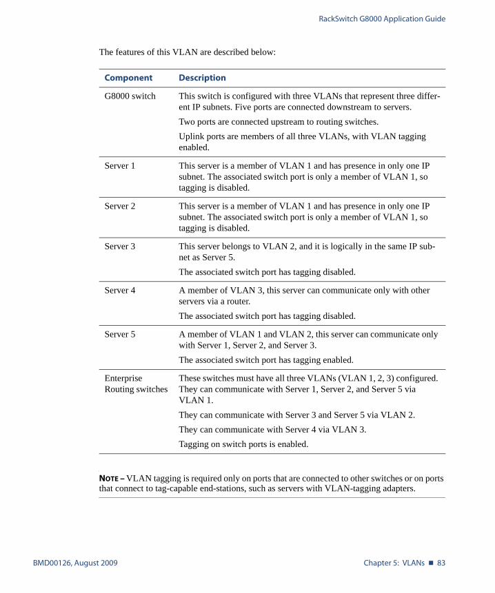
RackSwitch G8000 Application Guide
BMD00126, August 2009 Chapter 5: VLANs � 83
The features of this VLAN are described below:
NOTE – VLAN tagging is required only on ports that are connected to other switches or on ports that connect to tag-capable end-stations, such as servers with VLAN-tagging adapters.
Component Description
G8000 switch This switch is configured with three VLANs that represent three differ-ent IP subnets. Five ports are connected downstream to servers.Two ports are connected upstream to routing switches. Uplink ports are members of all three VLANs, with VLAN tagging enabled.
Server 1 This server is a member of VLAN 1 and has presence in only one IP subnet. The associated switch port is only a member of VLAN 1, so tagging is disabled.
Server 2 This server is a member of VLAN 1 and has presence in only one IP subnet. The associated switch port is only a member of VLAN 1, so tagging is disabled.
Server 3 This server belongs to VLAN 2, and it is logically in the same IP sub-net as Server 5. The associated switch port has tagging disabled.
Server 4 A member of VLAN 3, this server can communicate only with other servers via a router. The associated switch port has tagging disabled.
Server 5 A member of VLAN 1 and VLAN 2, this server can communicate only with Server 1, Server 2, and Server 3. The associated switch port has tagging enabled.
Enterprise Routing switches
These switches must have all three VLANs (VLAN 1, 2, 3) configured. They can communicate with Server 1, Server 2, and Server 5 via VLAN 1.They can communicate with Server 3 and Server 5 via VLAN 2.They can communicate with Server 4 via VLAN 3. Tagging on switch ports is enabled.

RackSwitch G8000 Application Guide
84 � Chapter 5: VLANs BMD00126, August 2009
VLAN Configuration Example
Use the following procedure to configure the example network shown in Figure 5-6.
1. Enable VLAN tagging on server ports that support multiple VLANs.
2. Enable tagging on uplink ports that support multiple VLANs.
3. Configure the VLANs and their member ports.
By default, all ports are members of VLAN 1, so configure only those ports that belong to other VLANs.
RS G8000(config)# interface port 1:5RS G8000(config-if)# taggingRS G8000(config-if)# exit
RS G8000(config)# interface port 1:47RS G8000(config-if)# taggingRS G8000(config-if)# exitRS G8000(config)# interface port 1:48RS G8000(config-if)# taggingRS G8000(config-if)# exit
RS G8000(config)# vlan 2RS G8000(config-vlan)# enableRS G8000(config-vlan)# member 1:3RS G8000(config-vlan)# member 1:5RS G8000(config-vlan)# member 1:47RS G8000(config-vlan)# member 1:48RS G8000(config-vlan)# exitRS G8000(config)# vlan 3RS G8000(config-vlan)# enableRS G8000(config-vlan)# member 1:4,1:47,1:48RS G8000(config-vlan)# exit
BMD00126, August 2009 85
CHAPTER 6
Ports and Trunking
Trunk groups can provide super-bandwidth, multi-link connections between switches or other trunk-capable devices. A trunk group is a group of ports that act together, combining their bandwidth to create a single, larger virtual link. This chapter provides configuration back-ground and examples for trunking multiple ports together:
� “Trunking Overview” on page 85
� “Port Trunking Example” on page 88
� “Configurable Trunk Hash Algorithm” on page 90
� “Link Aggregation Control Protocol” on page 91
Trunking Overview
When using port trunk groups between two switches, as shown in Figure 6-1 on page 88, you can create a virtual link between the switches, operating up to 40 Gb per second, depending on how many physical ports are combined. Each G8000 supports up to 64 static trunk groups (portchannels) and up to 64 LACP trunk groups, consisting of 1-8 ports in each group.
Trunk groups are also useful for connecting a G8000 to third-party devices that support link aggregation, such as Cisco routers and switches with EtherChannel technology (not ISL trunk-ing technology) and Sun's Quad Fast Ethernet Adapter. Trunk Group technology is compatible with these devices when they are configured manually.

RackSwitch G8000 Application Guide
86 � Chapter 6: Ports and Trunking BMD00126, August 2009
Statistical Load Distribution
Network traffic is distributed statistically between the ports in a trunk group. The switch can use a combination of Layer 2 MAC and Layer 3 IP address information, present in each trans-mitted frame, to determine load distribution.
Each packet’s particular MAC or IP address information results in selecting one line in the trunk group for data transmission. The more data streams feeding the trunk lines, the more evenly traffic distribution becomes.
Built-In Fault Tolerance
Since each trunk group is comprised of multiple physical links, the trunk group is inherently fault tolerant. As long as one connection between the switches is available, the trunk remains active.
Statistical load balancing is maintained whenever a port in a trunk group is lost or returned to service.
Before Configuring Static Trunks
When you create and enable a static trunk, the trunk members (switch ports) take on certain settings necessary for correct operation of the trunking feature.
Before you configure your trunk, you must consider these settings, along with specific config-uration rules, as follows:
1. Read the configuration rules provided in the section, “Static Trunk Group Configuration Rules” on page 87.
2. Determine which switch ports (up to eight) are to become trunk members (the specific ports making up the trunk).
Ensure that the chosen switch ports are set to enabled. Trunk member ports must have the same VLAN configuration.
3. Consider how existing VLANs will be affected by the addition of a trunk.
RackSwitch G8000 Application Guide
BMD00126, August 2009 Chapter 6: Ports and Trunking � 87
Static Trunk Group Configuration Rules
The trunking (portchannel) feature operates according to specific configuration rules. When creating trunks, consider the following rules that determine how a trunk group reacts in any network topology:
� All trunks must originate from one network entity (a single device or multiple devices in a stack), and lead to one destination entity.
� Ports from different member switches in the same stack may be aggregated together in one trunk.
� Any physical switch port can belong to only one trunk group.
� Trunking from third-party devices must comply with Cisco® EtherChannel® technology.
� When ports become members of a trunk, configuration parameters (except ACLs and QoS) are applied per trunk. When a trunk group is formed, these parameters are config-ured for the trunk ID, which overrides the port-level parameters.
� All trunk member ports must be assigned to the same VLAN configuration before the trunk can be enabled.
� You cannot change the VLAN membership for a trunk group’s member port. You can change the VLAN membership of the trunk group.
� When an active port is configured in a trunk, the port becomes a trunk member when you enable the trunk.
� You cannot configure a trunk member as a monitor port in a port-mirroring configuration.
� Trunks cannot be monitored by a monitor port; however, trunk members can be moni-tored.
� A trunk member cannot be configured as a monitor port.
� All ports in static trunks must be have the same link configuration (speed, duplex, flow control).
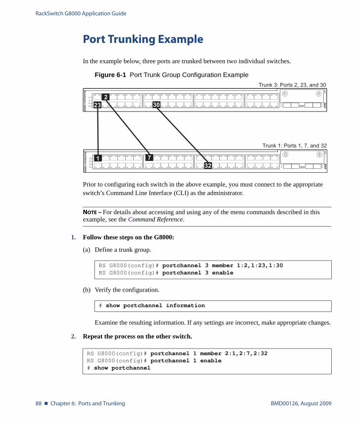
RackSwitch G8000 Application Guide
88 � Chapter 6: Ports and Trunking BMD00126, August 2009
Port Trunking Example
In the example below, three ports are trunked between two individual switches.
Figure 6-1 Port Trunk Group Configuration Example
Prior to configuring each switch in the above example, you must connect to the appropriate switch’s Command Line Interface (CLI) as the administrator.
NOTE – For details about accessing and using any of the menu commands described in this example, see the Command Reference.
1. Follow these steps on the G8000:
(a) Define a trunk group.
(b) Verify the configuration.
Examine the resulting information. If any settings are incorrect, make appropriate changes.
2. Repeat the process on the other switch.
RS G8000(config)# portchannel 3 member 1:2,1:23,1:30RS G8000(config)# portchannel 3 enable
# show portchannel information
RS G8000(config)# portchannel 1 member 2:1,2:7,2:32RS G8000(config)# portchannel 1 enable# show portchannel
Trunk 3: Ports 2, 23, and 30
Trunk 1: Ports 1, 7, and 32
30232
1 732
RackSwitch G8000 Application Guide
BMD00126, August 2009 Chapter 6: Ports and Trunking � 89
3. Connect the switch ports that will be members in the trunk group.
Trunk group 3 (on the G8000) is now connected to trunk group 1 (on the other switch).
NOTE – In this example, two G8000 switches are used. If a third-party device supporting link aggregation is used (such as Cisco routers and switches with EtherChannel technology or Sun's Quad Fast Ethernet Adapter), trunk groups on the third-party device should be configured manually. Connection problems could arise when using automatic trunk group negotiation on the third-party device.
4. Examine the trunking information on each switch.
Information about each port in each configured trunk group is displayed. Make sure that trunk groups consist of the expected ports and that each port is in the expected state.
The following restrictions apply:
� Any physical switch port can belong to only one trunk group.
� Up to eight ports can belong to the same trunk group.
� All ports in static trunks must be have the same link configuration (speed, duplex, flow control).
� Trunking from third-party devices must comply with Cisco® EtherChannel® technology.
# show portchannel informationPortChannel 3: Enabledport state:1:2: STG 1 forwarding1:23: STG 1 forwarding1:30: STG 1 forwarding
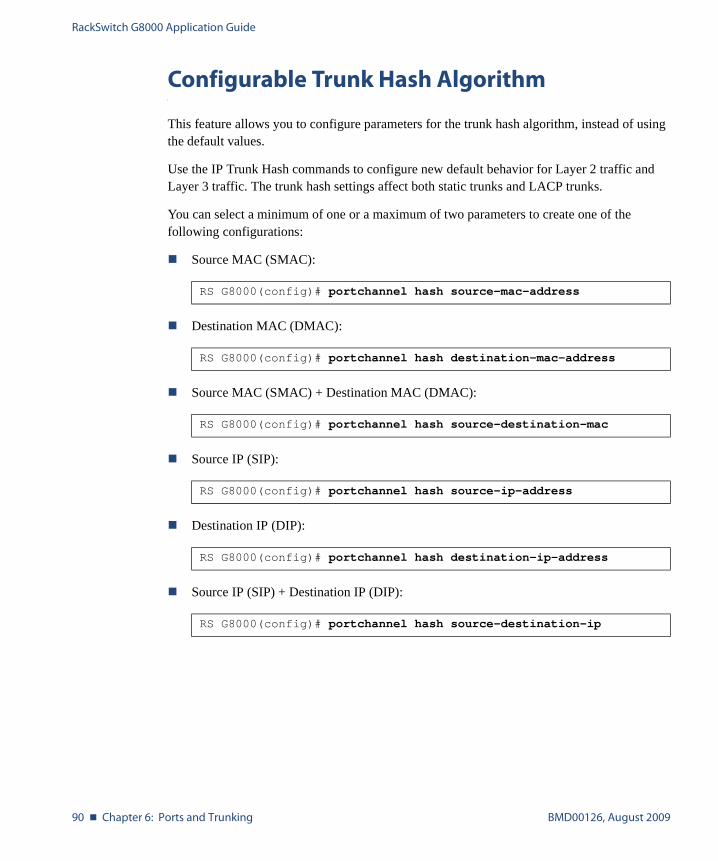
RackSwitch G8000 Application Guide
90 � Chapter 6: Ports and Trunking BMD00126, August 2009
Configurable Trunk Hash Algorithm
This feature allows you to configure parameters for the trunk hash algorithm, instead of using the default values.
Use the IP Trunk Hash commands to configure new default behavior for Layer 2 traffic and Layer 3 traffic. The trunk hash settings affect both static trunks and LACP trunks.
You can select a minimum of one or a maximum of two parameters to create one of the following configurations:
� Source MAC (SMAC):
� Destination MAC (DMAC):
� Source MAC (SMAC) + Destination MAC (DMAC):
� Source IP (SIP):
� Destination IP (DIP):
� Source IP (SIP) + Destination IP (DIP):
RS G8000(config)# portchannel hash source-mac-address
RS G8000(config)# portchannel hash destination-mac-address
RS G8000(config)# portchannel hash source-destination-mac
RS G8000(config)# portchannel hash source-ip-address
RS G8000(config)# portchannel hash destination-ip-address
RS G8000(config)# portchannel hash source-destination-ip
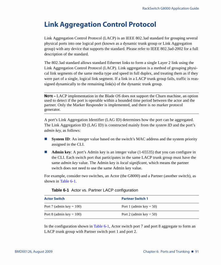
RackSwitch G8000 Application Guide
BMD00126, August 2009 Chapter 6: Ports and Trunking � 91
Link Aggregation Control Protocol
Link Aggregation Control Protocol (LACP) is an IEEE 802.3ad standard for grouping several physical ports into one logical port (known as a dynamic trunk group or Link Aggregation group) with any device that supports the standard. Please refer to IEEE 802.3ad-2002 for a full description of the standard.
The 802.3ad standard allows standard Ethernet links to form a single Layer 2 link using the Link Aggregation Control Protocol (LACP). Link aggregation is a method of grouping physi-cal link segments of the same media type and speed in full duplex, and treating them as if they were part of a single, logical link segment. If a link in a LACP trunk group fails, traffic is reas-signed dynamically to the remaining link(s) of the dynamic trunk group.
NOTE – LACP implementation in the Blade OS does not support the Churn machine, an option used to detect if the port is operable within a bounded time period between the actor and the partner. Only the Marker Responder is implemented, and there is no marker protocol generator.
A port’s Link Aggregation Identifier (LAG ID) determines how the port can be aggregated. The Link Aggregation ID (LAG ID) is constructed mainly from the system ID and the port’s admin key, as follows:
� System ID: An integer value based on the switch’s MAC address and the system priority assigned in the CLI.
� Admin key: A port’s Admin key is an integer value (1-65535) that you can configure in the CLI. Each switch port that participates in the same LACP trunk group must have the same admin key value. The Admin key is local significant, which means the partner switch does not need to use the same Admin key value.
For example, consider two switches, an Actor (the G8000) and a Partner (another switch), as shown in Table 6-1.
In the configuration shown in Table 6-1, Actor switch port 7 and port 8 aggregate to form an LACP trunk group with Partner switch port 1 and port 2.
Table 6-1 Actor vs. Partner LACP configuration
Actor Switch Partner Switch 1
Port 7 (admin key = 100) Port 1 (admin key = 50)
Port 8 (admin key = 100) Port 2 (admin key = 50)
RackSwitch G8000 Application Guide
92 � Chapter 6: Ports and Trunking BMD00126, August 2009
LACP automatically determines which member links can be aggregated and then aggregates them. It provides for the controlled addition and removal of physical links for the aggregation.
Each port on the switch can have one of the following LACP modes.
� off (default)The user can configure this port in to a regular static trunk group.
� activeThe port is capable of forming an LACP trunk. This port sends LACPDU packets to part-ner system ports.
� passiveThe port is capable of forming an LACP trunk. This port only responds to the LACPDU packets sent from an LACP active port.
Each active LACP port transmits LACP data units (LACPDUs), while each passive LACP port listens for LACPDUs. During LACP negotiation, the admin key is exchanged. The LACP trunk group is enabled as long as the information matches at both ends of the link. If the admin key value changes for a port at either end of the link, that port’s association with the LACP trunk group is lost.
When the system is initialized, all ports by default are in LACP off mode and are assigned unique admin keys. To make a group of ports aggregatable, you assign them all the same admin key. You must set the port’s LACP mode to active to activate LACP negotiation. You can set other port’s LACP mode to passive, to reduce the amount of LACPDU traffic at the ini-tial trunk-forming stage.
Use the following command to check whether the ports are trunked:
LACP Configuration Guidelines
Consider the following guidelines when you configure LACP trunks:
� When ports become members of a trunk, configuration parameters (except ACLs and QoS) are applied per trunk. When a trunk group is formed, these parameters are config-ured for the trunk ID, which overrides the port-level parameters.
� The range of potential LACP trunk IDs is 1-65535.
� Each port that is configured to participate in LACP must be set to full duplex.
� Ports configured for 802.1X network access control cannot be configured for LACP.
� LACP can be enabled on up to 256 ports in a stack.
RS G8000# show lacp information
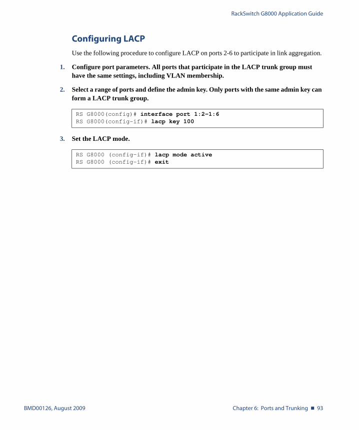
RackSwitch G8000 Application Guide
BMD00126, August 2009 Chapter 6: Ports and Trunking � 93
Configuring LACP
Use the following procedure to configure LACP on ports 2-6 to participate in link aggregation.
1. Configure port parameters. All ports that participate in the LACP trunk group must have the same settings, including VLAN membership.
2. Select a range of ports and define the admin key. Only ports with the same admin key can form a LACP trunk group.
3. Set the LACP mode.
RS G8000(config)# interface port 1:2-1:6RS G8000(config-if)# lacp key 100
RS G8000 (config-if)# lacp mode activeRS G8000 (config-if)# exit

RackSwitch G8000 Application Guide
94 � Chapter 6: Ports and Trunking BMD00126, August 2009

BMD00126, August 2009 95
CHAPTER 7
Quality of Service
Quality of Service features allow you to allocate network resources to mission-critical applica-tions at the expense of applications that are less sensitive to such factors as time delays or net-work congestion. You can configure your network to prioritize specific types of traffic, ensuring that each type receives the appropriate Quality of Service (QoS) level.
The following topics are discussed in this section:
� “QoS Overview” on page 95� “Access Control Lists” on page 97� “Using DSCP Values to Provide QoS” on page 108� “Using 802.1p Priority to Provide QoS” on page 112� “Queuing and Scheduling” on page 113
QoS Overview
QoS helps you allocate guaranteed bandwidth to the critical applications, and limit bandwidth for less critical applications. Applications such as video and voice must have a certain amount of bandwidth to work correctly; using QoS, you can provide that bandwidth when necessary. Also, you can put a high priority on applications that are sensitive to timing out or that cannot tolerate delay, by assigning their traffic to a high-priority queue.
By assigning QoS levels to traffic flows on your network, you can ensure that network resources are allocated where they are needed most. QoS features allow you to prioritize net-work traffic, thereby providing better service for selected applications.
Figure 7-1 shows the basic QoS model used by the switch.

RackSwitch G8000 Application Guide
96 � Chapter 7: Quality of Service BMD00126, August 2009
Figure 7-1 QoS Model
The switch uses the Differentiated Services (DiffServ) architecture to provide QoS functions. DiffServ is described in IETF RFCs 2474 and 2475.
With DiffServ, you can establish policies to direct traffic. A policy is a traffic-controlling mech-anism that monitors the characteristics of the traffic (such as its source, destination, and proto-col) and performs a controlling action on the traffic when certain characteristics are matched.
The switch can classify traffic by reading the DiffServ Code Point (DSCP) or IEEE 802.1p pri-ority value, or by using filters to match specific criteria. When network traffic attributes match those specified in a traffic pattern, the policy instructs the switch to perform specified actions on each packet that passes through it. The packets are assigned to different Class of Service (COS) queues and scheduled for transmission.
The basic QoS model works as follows:
� Classify traffic:
� Read DSCP
� Read 802.1p Priority
� Match ACL filter parameters
� Meter traffic:
� Define bandwidth and burst parameters
� Select actions to perform on in-profile and out-of-profile traffic
� Perform actions:
� Drop packets
� Pass packets
� Mark DSCP or 802.1p Priority
� Set COS queue (with or without re-marking)
� Queue and schedule traffic:
� Place packets in one of two COS queues
� Schedule transmission based on the COS queue weight
Ports
ACLFilter
ACLMeter
Drop/Pass/Re-Mark
ClassifyPackets
PerformActions
EgressIngress
COSQueue
MeterTraffic
Queue andSchedule
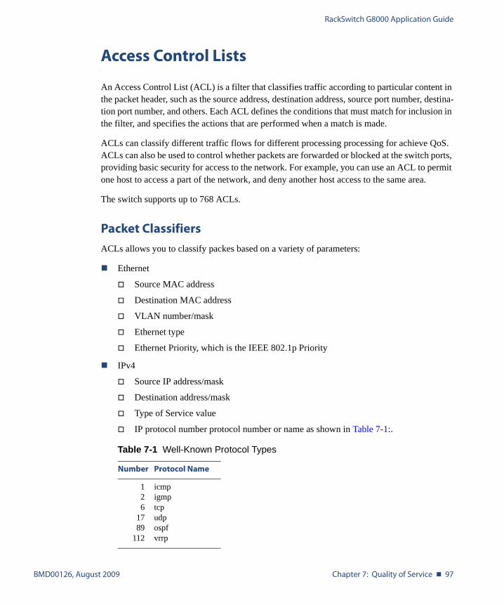
RackSwitch G8000 Application Guide
BMD00126, August 2009 Chapter 7: Quality of Service � 97
Access Control Lists
An Access Control List (ACL) is a filter that classifies traffic according to particular content in the packet header, such as the source address, destination address, source port number, destina-tion port number, and others. Each ACL defines the conditions that must match for inclusion in the filter, and specifies the actions that are performed when a match is made.
ACLs can classify different traffic flows for different processing processing for achieve QoS. ACLs can also be used to control whether packets are forwarded or blocked at the switch ports, providing basic security for access to the network. For example, you can use an ACL to permit one host to access a part of the network, and deny another host access to the same area.
The switch supports up to 768 ACLs.
Packet Classifiers
ACLs allows you to classify packes based on a variety of parameters:
� Ethernet
� Source MAC address
� Destination MAC address
� VLAN number/mask
� Ethernet type
� Ethernet Priority, which is the IEEE 802.1p Priority
� IPv4
� Source IP address/mask
� Destination address/mask
� Type of Service value
� IP protocol number protocol number or name as shown in Table 7-1:.
Table 7-1 Well-Known Protocol Types
Number Protocol Name
126
1789
112
icmp igmptcpudpospfvrrp
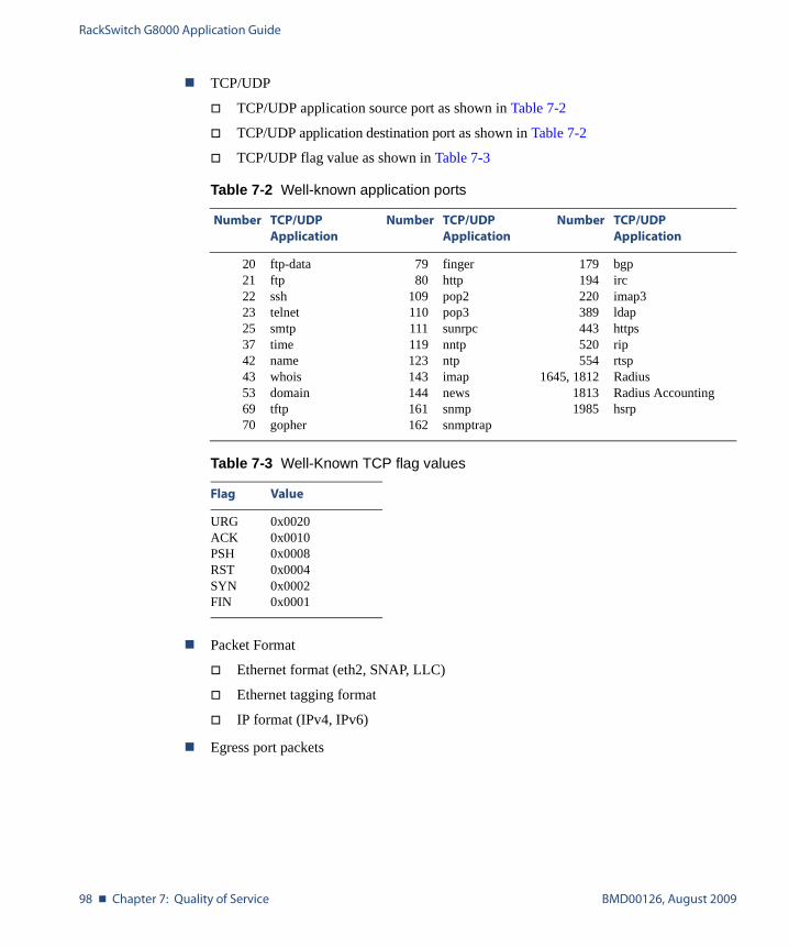
RackSwitch G8000 Application Guide
98 � Chapter 7: Quality of Service BMD00126, August 2009
� TCP/UDP
� TCP/UDP application source port as shown in Table 7-2
� TCP/UDP application destination port as shown in Table 7-2
� TCP/UDP flag value as shown in Table 7-3
� Packet Format
� Ethernet format (eth2, SNAP, LLC)
� Ethernet tagging format
� IP format (IPv4, IPv6)
� Egress port packets
Table 7-2 Well-known application ports
Number TCP/UDPApplication
Number TCP/UDPApplication
Number TCP/UDPApplication
2021222325374243536970
ftp-dataftpsshtelnetsmtptimenamewhoisdomaintftpgopher
7980
109110111119123143144161162
fingerhttppop2pop3sunrpcnntpntpimapnewssnmpsnmptrap
179194220389443520554
1645, 181218131985
bgpircimap3ldaphttpsriprtspRadiusRadius Accountinghsrp
Table 7-3 Well-Known TCP flag values
Flag Value
URGACKPSHRSTSYNFIN
0x00200x00100x00080x00040x00020x0001
RackSwitch G8000 Application Guide
BMD00126, August 2009 Chapter 7: Quality of Service � 99
ACL Actions
Actions determine how identified traffic flows are treated. The switch QoS actions include the fol-lowing:
� Pass or Drop
� Re-mark a new DiffServ Code Point (DSCP)
� Re-mark the 802.1p field
� Set the COS queue
ACL Order of Precedence
When multiple ACLs are assigned to a port, the order in which the ACLs are applied to port traffic (or whether they are applied at all) depends on the following factors:
� The precedence group in which the ACL resides;
� The ACL number;
� Whether a prior ACL in the precedence group is also matched;
� And whether the ACL action is compatible with preceding ACLs.
ACLs are automatically divided into six precedence groups:
Precedence Group 1 includes ACL 1–128.Precedence Group 2 includes ACL 129–256.Precedence Group 3 includes ACL 257–384.Precedence Group 4 includes ACL 385–512.Precedence Group 5 includes ACL 513–640.Precedence Group 6 includes ACL 641–768.
The switch processes each precedence group in numeric sequence; Precedence group 1 is eval-uated first, followed by precedence group 2, and so on.
Within each precedence group, ACLs that are assigned to the port are processed in numeric sequence, based on ACL number. Lower-numbered ACLs take precedence over higher-num-bered ACLs. For example, ACL 1 (if assigned to the port) is evaluated first and has top priority within precedence group 1.
For each precedence group, only the first assigned ACL that matches the port traffic is consid-ered. If multiple ACLs in the precedence group match the traffic, only the one with the lowest ACL number is considered. The others in the precedence group are ignored.

RackSwitch G8000 Application Guide
100 � Chapter 7: Quality of Service BMD00126, August 2009
One ACL match from each precedence group is permitted, meaning that up to six ACL matches may be considered for action: one from precedence group 1, one from precedence group 2, and so on.
Of the matching ACLs that are permitted, each configured ACL action is applied in sequence, based on ACL number, with the lowest-numbered ACL’s action applied first. If any ACL action contradicts the action of a preceding ACL (one with a lower ACL number), the action of the higher-numbered ACL is ignored.
If no assigned ACL matches the port traffic, no ACL action is applied.
ACL Groups
ACLs allow you to classify packets according to a particular content in the packet header, such as the source address, destination address, source port number, destination port number, and others. Once classified, packet flows can be identified for more processing.
To assist in organizing multiple ACLs and assigning them to ports, you can place ACLs into ACL Groups, thereby defining complex traffic profiles. ACLs and ACL Groups can then be assigned on a per-port basis. Any specific ACL can be assigned to multiple ACL Groups, and any ACL or ACL Group can be assigned to multiple ports. If, as part of multiple ACL Groups, a specific ACL is assigned to a port multiple times, only one instance is used. The redundant entries are ignored.
� Individual ACLs
The G8000 supports up to 768 ACLs. Each ACL defines one filter rule for matching traf-fic criteria. Each filter rule can also include an action (permit or deny the packet). For example:
ACL 1:VLAN = 1SIP = 10.10.10.1 (255.255.255.0)Action = permit

RackSwitch G8000 Application Guide
BMD00126, August 2009 Chapter 7: Quality of Service � 101
� Access Control List Groups
An Access Control List Group (ACL Group) is a collection of ACLs. For example:
ACL Groups organize ACLs into traffic profiles that can be more easily assigned to ports. The G8000 supports up to 768 ACL Groups.
NOTE – ACL Groups are used for convenience in assigning multiple ACLs to ports. ACL Groups have no effect on the ACL order of precedence. All ACLs assigned to the port (whether individually assigned or part of an ACL Group) are considered as individual ACLs for the purposes of determining their order of precedence.
ACL Group 1
ACL 1:VLAN = 1SIP = 10.10.10.1 (255.255.255.0)Action = permit
ACL 2:VLAN = 2SIP = 10.10.10.2 (255.255.255.0)Action = deny
ACL 3:Priority = 7DIP = 10.10.10.3 (255.255.255.0)Action = permit

RackSwitch G8000 Application Guide
102 � Chapter 7: Quality of Service BMD00126, August 2009
Assigning ACLs to a Port
Once you configure an ACL, you must assign the ACL to a port. Each port can accept multiple ACLs. Note that higher-priority ACLs are considered first, and their action takes precedence over lower-priority ACLs.
When you assign an ACL to a port, the ACL acts only upon ingress traffic, not egress traffic.
To assign an ACL or ACL Group to a port, use the following commands:
To remove an assigned ACL or ACL Group from a port:
RS G8000(config)# interface port <csnum>:<port>(Select stack port)RS G8000(config-if)# access-control list <ACL number>(Add ACL)RS G8000(config-if)# access-control group <ACL Group>(Add ACL Group)RS G8000(config-if)# exit
RS G8000(config)# interface port <csnum>:<port>RS G8000(config-if)# no access-control list <ACL number>RS G8000(config-if)# no access-control group <ACL Group>RS G8000(config-if)# exit
RackSwitch G8000 Application Guide
BMD00126, August 2009 Chapter 7: Quality of Service � 103
ACL Metering and Re-Marking
You can define a profile for the aggregate traffic flowing through the G8000 by configuring a QoS meter (if desired) and assigning ACL Groups to ports. When you add ACL Groups to a port, make sure they are ordered correctly in terms of precedence.
Actions taken by an ACL are called In-Profile actions. You can configure additional In-Profile and Out-of-Profile actions on a port. Data traffic can be metered, and re-marked to ensure that the traffic flow provides certain levels of service in terms of bandwidth for different types of network traffic.
Metering
QoS metering provides different levels of service to data streams through user-configurable parameters. A meter is used to measure the traffic stream against a traffic profile, which you create. Thus, creating meters yields In-Profile and Out-of-Profile traffic for each ACL, as fol-lows:
� In-Profile–If there is no meter configured or if the packet conforms to the meter, the packet is classified as In-Profile.
� Out-of-Profile–If a meter is configured and the packet does not conform to the meter (exceeds the committed rate or maximum burst rate of the meter), the packet is classified as Out-of-Profile.
Using meters, you set a Committed Rate in Kbps (1000 bits per second in each Kbps). All traf-fic within this Committed Rate is In-Profile. Additionally, you set a Maximum Burst Size that specifies an allowed data burst larger than the Committed Rate for a brief period. These param-eters define the In-Profile traffic.
Meters keep the sorted packets within certain parameters. You can configure a meter on an ACL, and perform actions on metered traffic, such as packet re-marking.
Re-Marking
Re-marking allows for the treatment of packets to be reset based on new network specifica-tions or desired levels of service. You can configure the ACL to re-mark a packet as follows:
� Change the DSCP value of a packet, used to specify the service level traffic should receive.
� Change the 802.1p priority of a packet.

RackSwitch G8000 Application Guide
104 � Chapter 7: Quality of Service BMD00126, August 2009
Viewing ACL Statistics
ACL statistics display how many packets hit (matched) each ACL. Use ACL statistics to check filter performance, and debug the ACL filters.
You must enable statistics for each ACL that you want to monitor. Use the following com-mand to enable statistics for the ACL:
Use the following command to view ACL statistics:
ACL Configuration Examples
Deny Source
Use this configuration to block traffic to a specific host. All traffic that ingresses port 1:1 is denied if it is destined for the host at IP address 100.10.1.1
1. Configure an Access Control List.
2. Assign the ACL to port 1:1.
RS G8000(config)# access-control list <ACL number> statistics
RS G8000(config)# show access-control counters
RS G8000(config)# access-control list 1 ipv4 destination-ip-address100.10.1.1
RS G8000(config)# access-control list 1 action deny
RS G8000(config)# interface port 1:1RS G8000(config-if)# access-control list 1RS G8000(config-if)# exit
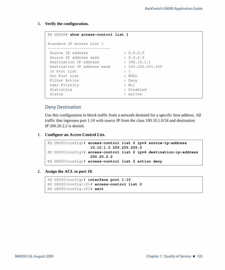
RackSwitch G8000 Application Guide
BMD00126, August 2009 Chapter 7: Quality of Service � 105
3. Verify the configuration.
Deny Destination
Use this configuration to block traffic from a network destined for a specific host address. All traffic that ingresses port 1:10 with source IP from the class 100.10.1.0/24 and destination IP 200.20.2.2 is denied.
1. Configure an Access Control List.
2. Assign the ACL to port 10.
RS G8000# show access-control list 1
Standard IP Access List 1----------------------------Source IP address : 0.0.0.0Source IP address mask : 0.0.0.0Destination IP address : 100.10.1.1Destination IP address mask : 255.255.255.255In Port List : 1Out Port List : NULLFilter Action : DenyUser Priority : NilStatistics : DisabledStatus : Active
RS G8000(config)# access-control list 2 ipv4 source-ip-address10.10.1.0 255.255.255.0
RS G8000(config)# access-control list 2 ipv4 destination-ip-address200.20.2.2
RS G8000(config)# access-control list 2 action deny
RS G8000(config)# interface port 1:10RS G8000(config-if)# access-control list 2RS G8000(config-if)# exit
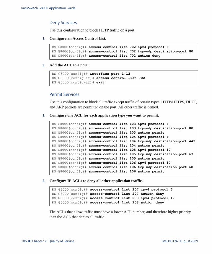
RackSwitch G8000 Application Guide
106 � Chapter 7: Quality of Service BMD00126, August 2009
Deny Services
Use this configuration to block HTTP traffic on a port.
1. Configure an Access Control List.
2. Add the ACL to a port.
Permit Services
Use this configuration to block all traffic except traffic of certain types. HTTP/HTTPS, DHCP, and ARP packets are permitted on the port. All other traffic is denied.
1. Configure one ACL for each application type you want to permit.
2. Configure IP ACLs to deny all other application traffic.
The ACLs that allow traffic must have a lower ACL number, and therefore higher priority, than the ACL that denies all traffic.
RS G8000(config)# access-control list 702 ipv4 protocol 6RS G8000(config)# access-control list 702 tcp-udp destination-port 80RS G8000(config)# access-control list 702 action deny
RS G8000(config)# interface port 1:12RS G8000(config-if)# access-control list 702RS G8000(config-if)# exit
RS G8000(config)# access-control list 103 ipv4 protocol 6RS G8000(config)# access-control list 103 tcp-udp destination-port 80RS G8000(config)# access-control list 103 action permitRS G8000(config)# access-control list 104 ipv4 protocol 6RS G8000(config)# access-control list 104 tcp-udp destination-port 443RS G8000(config)# access-control list 104 action permitRS G8000(config)# access-control list 105 ipv4 protocol 17RS G8000(config)# access-control list 105 tcp-udp destination-port 67RS G8000(config)# access-control list 105 action permitRS G8000(config)# access-control list 106 ipv4 protocol 17RS G8000(config)# access-control list 106 tcp-udp destination-port 68RS G8000(config)# access-control list 106 action permit
RS G8000(config)# access-control list 207 ipv4 protocol 6RS G8000(config)# access-control list 207 action denyRS G8000(config)# access-control list 208 ipv4 protocol 17RS G8000(config)# access-control list 208 action deny

RackSwitch G8000 Application Guide
BMD00126, August 2009 Chapter 7: Quality of Service � 107
3. Configure one ACL to permit ARP traffic.
4. Configure an ACL to deny all other traffic.
5. Assign the ACLs to a port.
RS G8000(config)# access-control list 600 ethernet ethernet-type arpRS G8000(config)# access-control list 600 action permit
RS G8000(config)# access-control list 700 action deny
RS G8000(config)# interface port 1:7RS G8000(config-if)# access-control list 103,104,105,106,207,208,
600,700RS G8000(config-if)# exit

RackSwitch G8000 Application Guide
108 � Chapter 7: Quality of Service BMD00126, August 2009
Using DSCP Values to Provide QoS
The six most significant bits in the TOS byte of the IP header are defined as DiffServ Code Points (DSCP). Packets are marked with a certain value depending on the type of treatment the packet must receive in the network device. DSCP is a measure of the Quality of Service (QoS) level of the packet.
Differentiated Services Concepts
To differentiate between traffic flows, packets can be classified by their DSCP value. The Dif-ferentiated Services (DS) field in the IP header is an octet, and the first six bits, called the DS Code Point (DSCP), can provide QoS functions. Each packet carries its own QoS state in the DSCP. There are 64 possible DSCP values (0-63).
Figure 7-2 Layer 3 IPv4 Packet
The G8000 can perform the following actions to the DSCP:
� Read the DSCP value of ingress packets
� Re-mark the DSCP value to a new value
� Map the DSCP value to an 802.1p priority
Once the DSCP value is marked, the G8000 can use it to direct traffic prioritization.
7 6 5 4 3 2 1 0
Differentiated Services Code Point (DSCP) unused
VersionLength
ToS Length ID Offset TTL Proto FCS DIPSIP Data
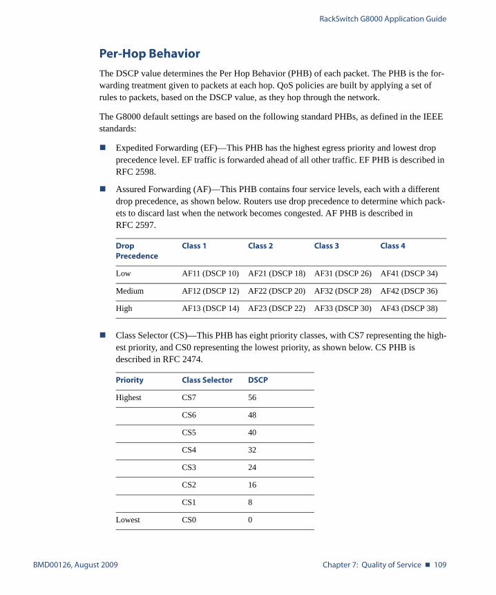
RackSwitch G8000 Application Guide
BMD00126, August 2009 Chapter 7: Quality of Service � 109
Per-Hop Behavior
The DSCP value determines the Per Hop Behavior (PHB) of each packet. The PHB is the for-warding treatment given to packets at each hop. QoS policies are built by applying a set of rules to packets, based on the DSCP value, as they hop through the network.
The G8000 default settings are based on the following standard PHBs, as defined in the IEEE standards:
� Expedited Forwarding (EF)—This PHB has the highest egress priority and lowest drop precedence level. EF traffic is forwarded ahead of all other traffic. EF PHB is described in RFC 2598.
� Assured Forwarding (AF)—This PHB contains four service levels, each with a different drop precedence, as shown below. Routers use drop precedence to determine which pack-ets to discard last when the network becomes congested. AF PHB is described in RFC 2597.
� Class Selector (CS)—This PHB has eight priority classes, with CS7 representing the high-est priority, and CS0 representing the lowest priority, as shown below. CS PHB is described in RFC 2474.
DropPrecedence
Class 1 Class 2 Class 3 Class 4
Low AF11 (DSCP 10) AF21 (DSCP 18) AF31 (DSCP 26) AF41 (DSCP 34)
Medium AF12 (DSCP 12) AF22 (DSCP 20) AF32 (DSCP 28) AF42 (DSCP 36)
High AF13 (DSCP 14) AF23 (DSCP 22) AF33 (DSCP 30) AF43 (DSCP 38)
Priority Class Selector DSCP
Highest CS7 56
CS6 48
CS5 40
CS4 32
CS3 24
CS2 16
CS1 8
Lowest CS0 0
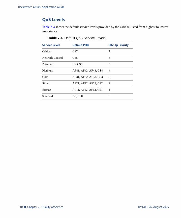
RackSwitch G8000 Application Guide
110 � Chapter 7: Quality of Service BMD00126, August 2009
QoS Levels
Table 7-4 shows the default service levels provided by the G8000, listed from highest to lowest importance:
Table 7-4 Default QoS Service Levels
Service Level Default PHB 802.1p Priority
Critical CS7 7
Network Control CS6 6
Premium EF, CS5 5
Platinum AF41, AF42, AF43, CS4 4
Gold AF31, AF32, AF33, CS3 3
Silver AF21, AF22, AF23, CS2 2
Bronze AF11, AF12, AF13, CS1 1
Standard DF, CS0 0
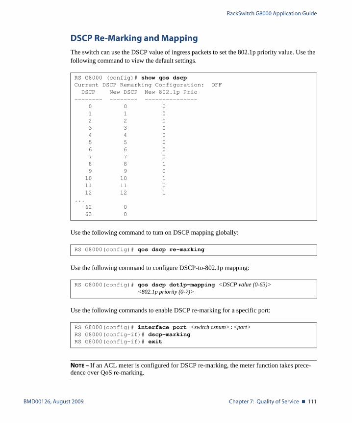
RackSwitch G8000 Application Guide
BMD00126, August 2009 Chapter 7: Quality of Service � 111
DSCP Re-Marking and Mapping
The switch can use the DSCP value of ingress packets to set the 802.1p priority value. Use the following command to view the default settings.
Use the following command to turn on DSCP mapping globally:
Use the following command to configure DSCP-to-802.1p mapping:
Use the following commands to enable DSCP re-marking for a specific port:
NOTE – If an ACL meter is configured for DSCP re-marking, the meter function takes prece-dence over QoS re-marking.
RS G8000 (config)# show qos dscpCurrent DSCP Remarking Configuration: OFF
DSCP New DSCP New 802.1p Prio-------- -------- ---------------
0 0 01 1 02 2 03 3 04 4 05 5 06 6 07 7 08 8 19 9 010 10 111 11 012 12 1
...62 063 0
RS G8000(config)# qos dscp re-marking
RS G8000(config)# qos dscp dot1p-mapping <DSCP value (0-63)><802.1p priority (0-7)>
RS G8000(config)# interface port <switch csnum>:<port>RS G8000(config-if)# dscp-markingRS G8000(config-if)# exit
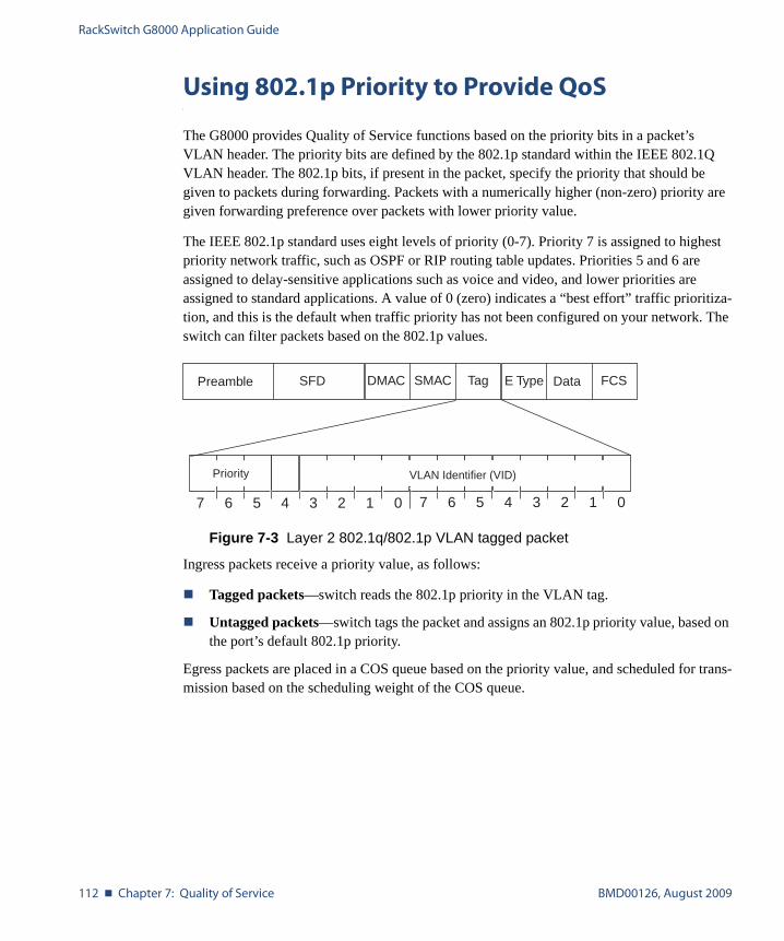
RackSwitch G8000 Application Guide
112 � Chapter 7: Quality of Service BMD00126, August 2009
Using 802.1p Priority to Provide QoS
The G8000 provides Quality of Service functions based on the priority bits in a packet’s VLAN header. The priority bits are defined by the 802.1p standard within the IEEE 802.1Q VLAN header. The 802.1p bits, if present in the packet, specify the priority that should be given to packets during forwarding. Packets with a numerically higher (non-zero) priority are given forwarding preference over packets with lower priority value.
The IEEE 802.1p standard uses eight levels of priority (0-7). Priority 7 is assigned to highest priority network traffic, such as OSPF or RIP routing table updates. Priorities 5 and 6 are assigned to delay-sensitive applications such as voice and video, and lower priorities are assigned to standard applications. A value of 0 (zero) indicates a “best effort” traffic prioritiza-tion, and this is the default when traffic priority has not been configured on your network. The switch can filter packets based on the 802.1p values.
Figure 7-3 Layer 2 802.1q/802.1p VLAN tagged packet
Ingress packets receive a priority value, as follows:
� Tagged packets—switch reads the 802.1p priority in the VLAN tag.
� Untagged packets—switch tags the packet and assigns an 802.1p priority value, based on the port’s default 802.1p priority.
Egress packets are placed in a COS queue based on the priority value, and scheduled for trans-mission based on the scheduling weight of the COS queue.
7 6 5 4 3 2 1 0
Priority
7 6 5 4 3 2 1 0
VLAN Identifier (VID)
SFD DMAC SMAC Tag E Type Data FCSPreamble
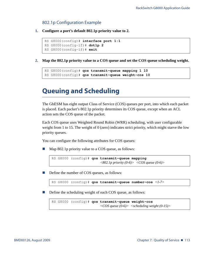
RackSwitch G8000 Application Guide
BMD00126, August 2009 Chapter 7: Quality of Service � 113
802.1p Configuration Example
1. Configure a port’s default 802.1p priority value to 2.
2. Map the 802.1p priority value to a COS queue and set the COS queue scheduling weight.
Queuing and Scheduling
The GbESM has eight output Class of Service (COS) queues per port, into which each packet is placed. Each packet’s 802.1p priority determines its COS queue, except when an ACL action sets the COS queue of the packet.
Each COS queue uses Weighted Round Robin (WRR) scheduling, with user configurable weight from 1 to 15. The weight of 0 (zero) indicates strict priority, which might starve the low priority queues.
You can configure the following attributes for COS queues:
� Map 802.1p priority value to a COS queue, as follows:
� Define the number of COS queues, as follows:
� Define the scheduling weight of each COS queue, as follows:
RS G8000(config)# interface port 1:1RS G8000(config-if)# dot1p 2RS G8000(config-if)# exit
RS G8000(config)# qos transmit-queue mapping 1 10RS G8000(config)# qos transmit-queue weight-cos 10
RS G8000 (config)# qos transmit-queue mapping<802.1p priority (0-6)> <COS queue (0-6)>
RS G8000 (config)# qos transmit-queue number-cos <1-7>
RS G8000 (config)# qos transmit-queue weight-cos <COS queue (0-6)> <scheduling weight (0-15)>

RackSwitch G8000 Application Guide
114 � Chapter 7: Quality of Service BMD00126, August 2009

BMD00126, August 2009 115
CHAPTER 8
IGMP
Internet Group Management Protocol (IGMP) is used by IP Multicast routers to learn about the existence of host group members on their directly attached subnet (see RFC 2236). The IP Multicast routers get this information by broadcasting IGMP Membership Queries and listen-ing for IP hosts reporting their host group memberships. This process is used to set up a client/server relationship between an IP Multicast source that provides the data streams and the cli-ents that want to receive the data.
The G8000 can perform IGMP Snooping, and connect to static multicast routers (Mrouters).
The following topics are discussed in this chapter:
� “IGMP Snooping” on page 116
� “Static Multicast Router” on page 119
RackSwitch G8000 Application Guide
116 � Chapter 8: IGMP BMD00126, August 2009
IGMP Snooping
IGMP Snooping allows the switch to forward multicast traffic only to those ports that request it. IGMP Snooping prevents multicast traffic from being flooded to all ports. The switch learns which server hosts are interested in receiving multicast traffic, and forwards it only to ports connected to those servers.
IGMP Snooping conserves bandwidth. With IGMP Snooping, the switch learns which ports are interested in receiving multicast data, and forwards multicast data only to those ports. In this way, other ports are not burdened with unwanted multicast traffic.
The switch can sense IGMP Membership Reports from attached clients and act as a proxy to set up a dedicated path between the requesting host and a local IP Multicast router. After the pathway is established, the switch blocks the IP Multicast stream from flowing through any port that does not connect to a host member, thus conserving bandwidth.
The client-server path is set up as follows:
� An IP Multicast Router (Mrouter) sends Membership Queries to the switch, which for-wards them to all ports in a given VLAN.
� Hosts that want to receive the multicast data stream send Membership Reports to the switch, which sends a proxy Membership Report to the Mrouter.
� The switch sets up a path between the Mrouter and the host, and blocks all other ports from receiving the multicast.
� Periodically, the Mrouter sends Membership Queries to ensure that the host wants to con-tinue receiving the multicast. If a host fails to respond with a Membership Report, the Mrouter stops sending the multicast to that path.
� The host can send a Leave Report to the switch, which sends a proxy Leave Report to the Mrouter. The multicast path is terminated immediately.
The G8000 supports the following IGMP capacities:
� IGMP version 1 and 2
� 1024 VLANs
� 128 Mrouters
� 512 multicast groups
NOTE – Unknown multicast traffic is sent to all ports if the flood option is disabled. To enable or disable IGMP flood, use the following command: RS G8000(config)# [no] ip igmp flood
RackSwitch G8000 Application Guide
BMD00126, August 2009 Chapter 8: IGMP � 117
FastLeave
In normal IGMP operation, when the switch receives an IGMPv2 Leave message, it sends a Group-Specific Query to determine if any other devices in the same group (and on the same port) are still interested in the specified multicast group traffic. The switch removes the affili-ated port from that particular group, if the following conditions apply:
� If the switch does not receive an IGMP Membership Report within the query-response-interval.
� If no multicast routers have been learned on that port.
With FastLeave enabled on the VLAN, a port can be removed immediately from the port list of the group entry when the IGMP Leave message is received, unless a multicast router was learned on the port.
Enable FastLeave only on VLANs that have only one host connected to each physical port. To enable FastLeave, use the following command:
RS G8000(config)# ip igmp fastleave <VLAN number (1-4094)>
RackSwitch G8000 Application Guide
118 � Chapter 8: IGMP BMD00126, August 2009
IGMP Snooping configuration example
This section provides steps to configure IGMP Snooping on the switch.
Configure IGMP Snooping
1. Configure port and VLAN membership on the switch.
2. Enable IGMP Snooping.
3. Add VLANs to IGMP Snooping.
4. View dynamic IGMP information.
These commands display information about IGMP Groups and Mrouters learned by the switch.
RS G8000(config)# ip igmp snoop enable
RS G8000 (config)# ip igmp snoop vlan 1
RS G8000# show ip igmp groups
Note: Local groups (224.0.0.x) are not snooped/relayed and will not appear.Source Group VLAN Port Version Mode Expires Fwd
-------------- --------------- ------- ------ -------- ----- ------- ---10.1.1.1 232.1.1.1 2 4 V2 INC 4:16 Yes10.1.1.5 232.1.1.1 2 4 V2 INC 4:16 Yes
* 232.1.1.1 2 4 V2 INC - No10.10.10.43 235.0.0.1 9 1 V2 INC 2:26 Yes
* 236.0.0.1 9 1 V2 EXC - Yes
RS G8000# show ip igmp mrouter
VLAN Port Version Expires Max Query Resp. Time QRV QQIC------ ------- -------- -------- -------------------- --- ----
1 4 V2 static - - -2 3 V2 4:09 128 2 125

RackSwitch G8000 Application Guide
BMD00126, August 2009 Chapter 8: IGMP � 119
Static Multicast Router
A static multicast router (Mrouter) can be configured for a particular port on a particular VLAN. A static Mrouter does not have to be learned through IGMP Snooping. Any data port can accept a static Mrouter.
When you configure a static Mrouter on a VLAN, it replaces any dynamic Mrouters learned through IGMP Snooping.
Configure a Static Multicast Router
1. For each MRouter, configure a port or trunk group (1-52, po1-po104), VLAN (1-4094) and version (1-3).
The IGMP version is set for each VLAN, and cannot be configured separately for each Mrouter.
2. Verify the configuration.
RS G8000(config)# ip igmp mrouter 5 1 2
RS G8000# show ip igmp mrouter

RackSwitch G8000 Application Guide
120 � Chapter 8: IGMP BMD00126, August 2009
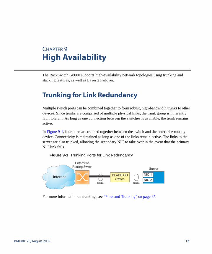
BMD00126, August 2009 121
CHAPTER 9
High Availability
The RackSwitch G8000 supports high-availability network topologies using trunking and stacking features, as well as Layer 2 Failover.
Trunking for Link Redundancy
Multiple switch ports can be combined together to form robust, high-bandwidth trunks to other devices. Since trunks are comprised of multiple physical links, the trunk group is inherently fault tolerant. As long as one connection between the switches is available, the trunk remains active.
In Figure 9-1, four ports are trunked together between the switch and the enterprise routing device. Connectivity is maintained as long as one of the links remain active. The links to the server are also trunked, allowing the secondary NIC to take over in the event that the primary NIC link fails.
Figure 9-1 Trunking Ports for Link Redundancy
For more information on trunking, see “Ports and Trunking” on page 85.
Trunk Trunk
Server
NIC 1
NIC 2Internet
EnterpriseRouting Switch
BLADE OSSwitch
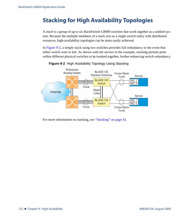
RackSwitch G8000 Application Guide
122 � Chapter 9: High Availability BMD00126, August 2009
Stacking for High Availability Topologies
A stack is a group of up to six RackSwitch G8000 switches that work together as a unified sys-tem. Because the multiple members of a stack acts as a single switch entity with distributed resources, high-availability topologies can be more easily achieved.
In Figure 9-2, a simple stack using two switches provides full redundancy in the event that either switch were to fail. As shown with the servers in the example, stacking permits ports within different physical switches to be trunked together, further enhancing switch redundancy.
Figure 9-2 High Availability Topology Using Stacking
For more information on stacking, see “Stacking” on page 43.
Trunk
Cross-StackTrunk Server
NIC 1NIC 2
Trunk Cross-StackTrunk
Server
NIC 1NIC 2
StackLinksInternet
EnterpriseRouting Switch
BLADE OSSwitch
BLADE OSStacked Switches
BLADE OSSwitch

RackSwitch G8000 Application Guide
BMD00126, August 2009 Chapter 9: High Availability � 123
Layer 2 Failover
The primary application for Layer 2 Failover is to support Network Adapter Teaming. With Network Adapter Teaming, all the NICs on any given server share the same IP address, and are configured into a team. One NIC is the primary link, and the other is a standby link.
Layer 2 Failover allows you to configure a set of ports and/or trunks to monitor for link failures (a monitor list), and another set of ports and/or trunks to disable when the trigger limit is reached (a control list). When the switch detects a link failure on the monitor list (such as for uplink ports), it automatically disables the items in control list (such as server ports). When tar-get server ports are disabled, the corresponding server’s network adapter can detect the dis-abled link, and trigger a network-adapter failover to another port or trunk on the switch, or to another switch in the network.
The switch automatically enables the control list items when the monitor list items return to service.
Monitor Port State
A monitor port is considered operation as long as the following conditions are true:
� The port must be in the Link Up state.
� If the port is part of an LACP trunk, the port must be in the Aggregated state.
If any of the above conditions is false, the monitor port is considered to have failed.
Control Port State
A control port is considered Operational if the monitor trigger is up. As long as the trigger is up, the port is considered operational from a teaming perspective, even if the port itself is actu-ally in the Down state or Not Aggregated state (if part of an LACP trunk).
A control port is considered to have failed if the monitor trigger is in the Down state.
To view the state of any port, use one of the following commands:
>> # /info/link (View port link status)>> # /info/l2/lacp/dump (View port LACP status)
RackSwitch G8000 Application Guide
124 � Chapter 9: High Availability BMD00126, August 2009
Setting the Failover Limit
The failover limit lets you specify the minimum number of operational links required within each trigger before the trigger initiates a failover event. For example, if the limit is two (/cfg/l2/failovr/trigger <x>/limit 2), a failover event occurs when the num-ber of operational links in the trigger is two or fewer. When you set the limit to zero, the switch triggers a failover event only when no links in the trigger are operational.
L2 Failover with LACP
L2 Failover works together with Link Aggregation Control Protocol (LACP) which allows the switch to form dynamic trunks. You can use the admin key to add up to two LACP trunks to a failover trigger. When you add an admin key to a trigger (/cfg/l2/failovr/trigger <x>/mmon/monitor/addkey <admin key>), any LACP trunk with that admin key becomes a member of the trigger.
Configuration Guidelines
This section provides important information about configuring L2 Failover:
� A failover trigger can monitor multiple static trunks or a single LACP key, but not both.
� With VLAN Monitor on, the following additional guidelines apply:
� All external ports in all trunks that are added to a single failover trigger must have the same VLAN membership and have the same PVID.
� Each failover trigger must operate on a different VLAN membership.
� Multiple failover triggers cannot operate on the same internal port.

RackSwitch G8000 Application Guide
BMD00126, August 2009 Chapter 9: High Availability � 125
L2 Failover Configurations
Figure 9-3 is a simple example of Layer 2 Failover. One switch is the primary, and the other is used as a backup. In this example, all the network uplink ports on the primary switch belong to a single trunk group with Layer 2 Failover enabled and Failover Limit set to 2. The backup switch is configured in a similar fashion.
Figure 9-3 Basic Layer 2 Failover
If links in trigger 1 are disrupted such that two or fewer links remain active on the primary switch, the switch temporarily disables ports connected to the servers. This action causes the servers to failover to the NIC connected to the backup switch.
Trigger 1
Trigger 1
Primary
Backup
Server 1
Server 2
NIC 1
NIC 2
NIC 1
NIC 2
Internet
EnterpriseRouting Switches BLADE OS
Switches

RackSwitch G8000 Application Guide
126 � Chapter 9: High Availability BMD00126, August 2009
Configuring Layer 2 Failover
Use the following procedure to configure a Layer 2 Failover Manual Monitor.
1. Configure Network Adapter Teaming on the servers.
2. Configure general Layer 2 Failover parameters.
3. Specify the links to monitor.
4. Specify the links to disable when the failover limit is reached.
5. Apply and verify the configuration.
6. Save the configuration.
>> # /cfg/l2/failovr/on (Turn Failover on)>> Failover# trigger 1 (Select trigger 1)>> Trigger 1# ena (Enable trigger 1)>> Trigger 1# limit 2 (Set Failover limit to 2 links)
>> Trigger 1# mmon/monitor (Select Manual Monitor, Monitor menu)>> Monitor# addport 4 (Add port 4)>> Monitor# addport 5 (Add port 5)>> Monitor# addport 6 (Add port 6)>> Monitor# addport 7 (Add port 7)>> Monitor# ..
>> Manual Monitor# control (Select Manual Monitor - Control menu)>> Control# addport 13 (Add port 13)>> Control# addport 14 (Add port 14)
>> Control# apply (Make your changes active)>> # /cfg/l2/failovr/cur (View current Failover configuration)
>> Failover# save (Save for restore after reboot)
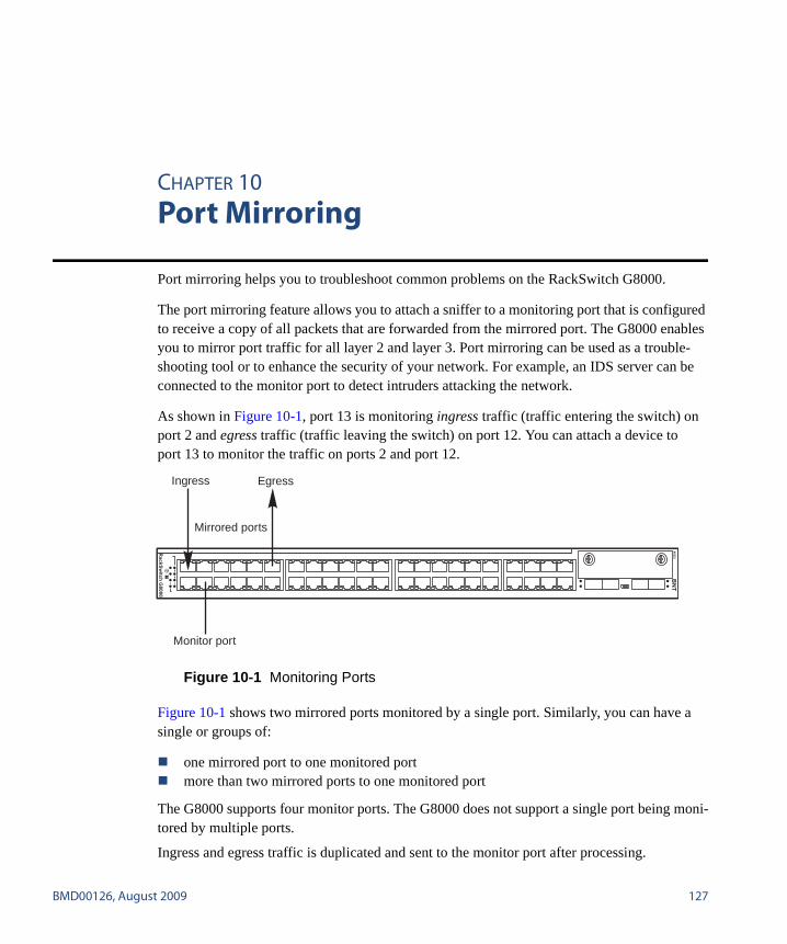
BMD00126, August 2009 127
CHAPTER 10
Port Mirroring
Port mirroring helps you to troubleshoot common problems on the RackSwitch G8000.
The port mirroring feature allows you to attach a sniffer to a monitoring port that is configured to receive a copy of all packets that are forwarded from the mirrored port. The G8000 enables you to mirror port traffic for all layer 2 and layer 3. Port mirroring can be used as a trouble-shooting tool or to enhance the security of your network. For example, an IDS server can be connected to the monitor port to detect intruders attacking the network.
As shown in Figure 10-1, port 13 is monitoring ingress traffic (traffic entering the switch) on port 2 and egress traffic (traffic leaving the switch) on port 12. You can attach a device to port 13 to monitor the traffic on ports 2 and port 12.
Figure 10-1 Monitoring Ports
Figure 10-1 shows two mirrored ports monitored by a single port. Similarly, you can have a single or groups of:
� one mirrored port to one monitored port� more than two mirrored ports to one monitored port
The G8000 supports four monitor ports. The G8000 does not support a single port being moni-tored by multiple ports.
Ingress and egress traffic is duplicated and sent to the monitor port after processing.
Monitor port
Mirrored ports
Ingress Egress
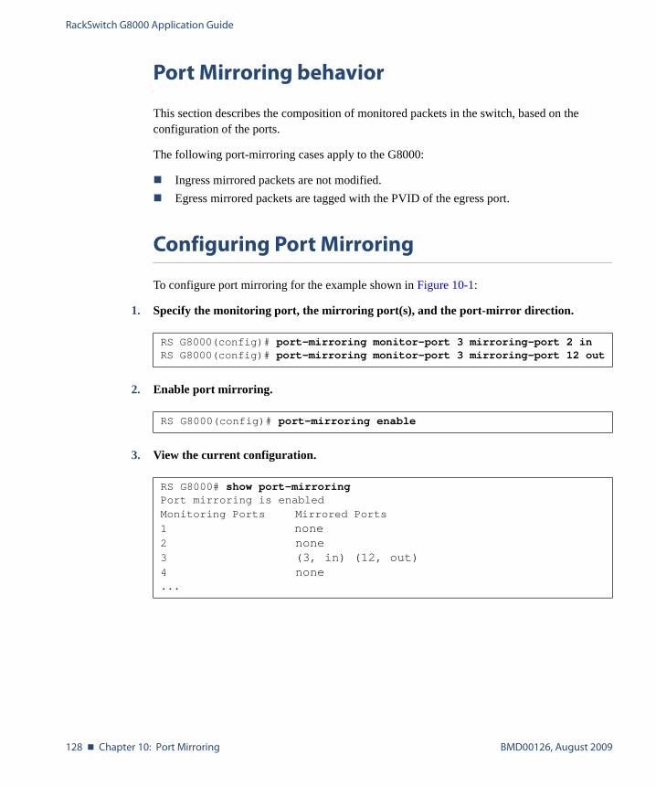
RackSwitch G8000 Application Guide
128 � Chapter 10: Port Mirroring BMD00126, August 2009
Port Mirroring behavior
This section describes the composition of monitored packets in the switch, based on the configuration of the ports.
The following port-mirroring cases apply to the G8000:
� Ingress mirrored packets are not modified.� Egress mirrored packets are tagged with the PVID of the egress port.
Configuring Port Mirroring
To configure port mirroring for the example shown in Figure 10-1:
1. Specify the monitoring port, the mirroring port(s), and the port-mirror direction.
2. Enable port mirroring.
3. View the current configuration.
RS G8000(config)# port-mirroring monitor-port 3 mirroring-port 2 inRS G8000(config)# port-mirroring monitor-port 3 mirroring-port 12 out
RS G8000(config)# port-mirroring enable
RS G8000# show port-mirroringPort mirroring is enabledMonitoring Ports Mirrored Ports
1 none2 none3 (3, in) (12, out)4 none...

BMD00126, August 2009 129
Index
Symbols[ ]....................................................................... 13
Numerics802.1p .............................................................. 112802.1Q VLAN tagging......................................... 78
AAccess Control List (ACL)................................... 97accessing the switch
RADIUS authentication................................. 31security........................................................ 31TACACS+ authentication .............................. 35using the Browser-based Interface................... 24
administrator account........................................... 34application ports.................................................. 98
Bbroadcast domains ............................................... 75
CCisco EtherChannel ....................................... 87, 89Class of Service queue ....................................... 113command conventions ......................................... 13configuration rules
port mirroring............................................... 87spanning tree................................................ 87Trunking...................................................... 87VLANs ....................................................... 87
configuring port trunking ..................................... 89
Ddefault password.................................................. 34Differentiated Services Code Point (DSCP).......... 108
EEAPoL ............................................................... 68End user access control, configuring...................... 41EtherChannel ...................................................... 85
as used with port trunking ........................ 87, 89Extensible Authentication Protocol over LAN ........ 68
FFailover ............................................................ 123fault tolerance with port trunking .......................... 86frame tagging. See VLANs tagging.
Hhigh-availability ................................................ 121HP-OpenView..................................................... 26
IIBM Director....................................................... 26ICMP ................................................................. 97IEEE standards
802.1p ....................................................... 112802.1Q......................................................... 78802.1X......................................................... 68
IGMP ......................................................... 97, 115IGMP Snooping................................................. 116Internet Group Management Protocol (IGMP) ......115IP address for Telnet ............................................ 23IP subnets with VLANs........................................ 75ISL Trunking....................................................... 85
RackSwitch G8000 Application Guide
130 � Index BMD00126, August 2009
LLACP .................................................................91Link Aggregation Control Protocol ........................91logical segment. See IP subnets.
Mmanual style conventions ......................................13meter ................................................................103MIBs, SNMP.......................................................26mirroring ports...................................................127monitoring ports.................................................127multi-links between switches using port trunking ....85
Nnetwork management............................................26
OOSPF filtering criteria...........................................97
Ppassword
administrator account .....................................34default..........................................................34user account..................................................34
Per Hop Behavior (PHB) ....................................109port mirroring ....................................................127
configuration rules .........................................87port trunking........................................................86
configuration example....................................88description....................................................89EtherChannel ................................................85fault tolerance ...............................................86
portsfor services ...................................................98monitoring..................................................127physical. See switch ports.
priority value (802.1p) ........................................112protocol types ......................................................97PVID (port VLAN ID)..........................................77
RRADIUS
authentication ............................................... 31port 1812 and 1645 ....................................... 98port 1813 ..................................................... 98SSH ............................................................ 40
re-mark............................................................. 103routers and port trunking ...................................... 85RSA keys............................................................ 40
Ssecurity
port mirroring............................................. 127RADIUS authentication ................................. 31TACACS+ authentication .............................. 35VLANs........................................................ 75
segmentation. See IP subnets.segments. See IP subnets.service ports........................................................ 98SNMP ................................................................ 26
HP-OpenView.............................................. 26MIBS .......................................................... 26
spanning tree configuration rules........................... 87SSH
configuring .................................................. 39RSA host and server keys............................... 40
stacking ...................................................... 43, 122statistical load distribution.................................... 86switch ports VLANs membership.......................... 77
TTACACS+.......................................................... 35
authentication ............................................... 35tagging. See VLANs tagging.TCP ................................................................... 97technical terms
port VLAN identifier (PVID) ......................... 78tagged frame ................................................ 78tagged member ............................................. 78untagged frame............................................. 78untagged member ......................................... 78VLAN identifier (VID).................................. 78
text conventions .................................................. 13Trunk Hash algorithm .......................................... 90Trunking configuration rules ................................ 87typographic conventions....................................... 13
RackSwitch G8000 Application Guide
BMD00126, August 2009 Index � 131
UUDP................................................................... 97user account........................................................ 34
VVirtual Local Area Networks. See VLANs.VLANs
broadcast domains ........................................ 75configuration rules ........................................ 87default PVID................................................ 77example showing multiple VLANs ................. 82ID numbers .................................................. 76multiple VLANs........................................... 78port members ............................................... 77PVID .......................................................... 77security........................................................ 75tagging ............................................... 77 to 83topologies .................................................... 82

RackSwitch G8000 Application Guide
132 � Index BMD00126, August 2009
Related Documents