Servo Valve, Flapper Nozzle Series: VSS10H 0-280 Bar (0-4000 PSI) 0-80lpm (21gpm) at 70 bar (1015psi) drop Features High Static precision and dynamic response up to 35hz For high dynamic or high position accuracy applications. Standard NG10/D05 mounting pattern Reliable long life operation Manual override operation Mechanical null adjustment Flapper Nozzle design Easy to replace protection filter. Fifth supply port available to provide independent pressure to pilot stage. Maximum rated pressure to 280 bar (4000psi) Nominal flow rating of 10, 20, 40, 60 and 80lpm Ordering Details Construction FluidHaus 1 VSS10H V Valve S Subplate Mount S Valve Type: Servo 10H- Mounting Size: 10H = NG10 (D05) 2-stage C- Spool Configuration: 40- Spool Flow (at 210bar pressure drop) 100 Command Signal: 100 = +/-100mA 4P- Electrical Connector = 4P = 4-Pin round connector according to 654-MS3106F14S-2S 1 Series A B P T Code/Flow (lpm) 10 20 40 60 80 C = Example Part Number: VSS10H-C-40-1004P-1 ) ( ) ( ) ( ) ( A B P T ) ( ) ( ) ( ) ( A P B T X left and right Coils armature assembly Internal filter Β88> 75 (35μm absolute 88μm) null adjustment lower pole piece pilot supply orifice (2) spool spool sleeve Removable cover for filter access Remove plug from X port for external 5th port piltot and insert in pressure port. null adjustment access

Welcome message from author
This document is posted to help you gain knowledge. Please leave a comment to let me know what you think about it! Share it to your friends and learn new things together.
Transcript
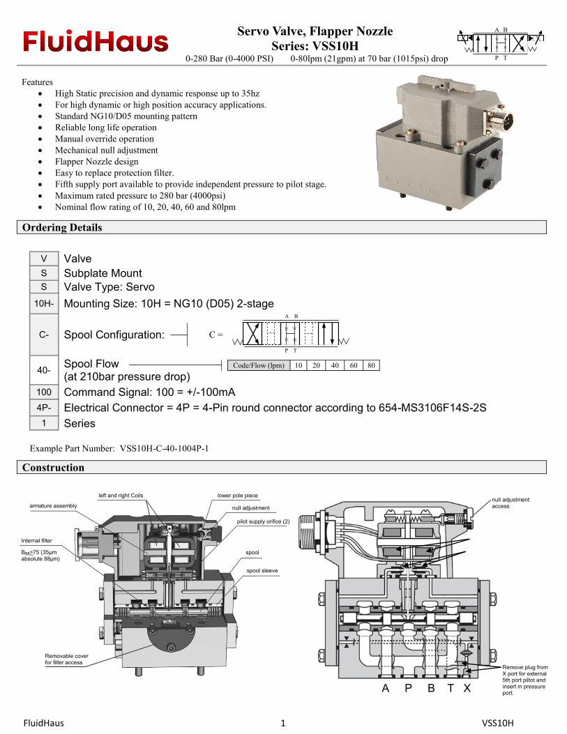
Servo Valve, Flapper Nozzle
Series: VSS10H
0-280 Bar (0-4000 PSI) 0-80lpm (21gpm) at 70 bar (1015psi) drop
Features
High Static precision and dynamic response up to 35hz
For high dynamic or high position accuracy applications.
Standard NG10/D05 mounting pattern
Reliable long life operation
Manual override operation
Mechanical null adjustment
Flapper Nozzle design
Easy to replace protection filter.
Fifth supply port available to provide independent pressure to pilot stage.
Maximum rated pressure to 280 bar (4000psi)
Nominal flow rating of 10, 20, 40, 60 and 80lpm
Ordering Details
Construction
FluidHaus 1 VSS10H
V Valve
S Subplate Mount S Valve Type: Servo
10H- Mounting Size: 10H = NG10 (D05) 2-stage
C- Spool Configuration:
40- Spool Flow (at 210bar pressure drop)
100 Command Signal: 100 = +/-100mA
4P- Electrical Connector = 4P = 4-Pin round connector according to 654-MS3106F14S-2S
1 Series
A B
P T
Code/Flow (lpm) 10 20 40 60 80
C =
Example Part Number: VSS10H-C-40-1004P-1
) ( ) (
) ( ) (
A B
P T
) ( ) (
) ( ) (
A P B T X
left and right Coils
armature assembly
Internal filter
Β88>75 (35μm
absolute 88μm)
null adjustment
lower pole piece
pilot supply orifice (2)
spool
spool sleeve
Removable cover for filter access
Remove plug from X port for external 5th port piltot and insert in pressure port.
null adjustment access
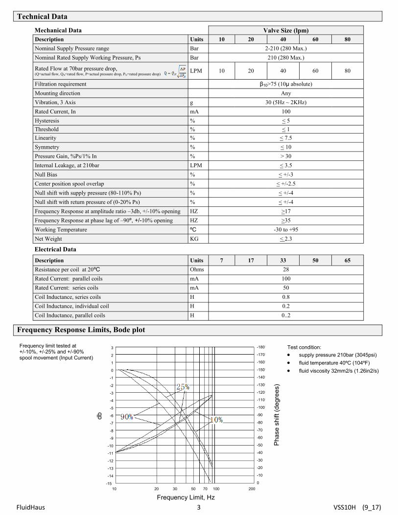
Technical Data
Frequency Response Limits, Bode plot
FluidHaus 3 VSS10H (9_17)
Mechanical Data Valve Size (lpm)
Description Units 10 20 40 60 80
Nominal Supply Pressure range Bar 2-210 (280 Max.)
Nominal Rated Supply Working Pressure, Ps Bar 210 (280 Max.)
Rated Flow at 70bar pressure drop, (Q=actual flow, QN=rated flow, P=actual pressure drop, PN=rated pressure drop)
LPM 10 20 40 60 80
Filtration requirement β10>75 (10μ absolute)
Mounting direction Any
Vibration, 3 Axis g 30 (5Hz ~ 2KHz)
Rated Current, In mA 100
Hysteresis % < 5
Threshold % < 1
Linearity % < 7.5
Symmetry % < 10
Pressure Gain, %Ps/1% In % > 30
Internal Leakage, at 210bar LPM < 3.5
Null Bias % < +/-3
Center position spool overlap % < +/-2.5
Null shift with supply pressure (80-110% Ps) % < +/-4
Null shift with return pressure of (0-20% Ps) % < +/-4
Frequency Response at amplitude ratio –3db, +/-10% opening HZ >17
Frequency Response at phase lag of –90º, +/-10% opening HZ >35
Working Temperature ºC -30 to +95
Net Weight KG < 2.3
Electrical Data
Description Units 7 17 33 50 65
Resistance per coil at 20ºC Ohms 28
Rated Current: parallel coils mA 100
Rated Current: series coils mA 50
Coil Inductance, series coils H 0.8
Coil Inductance, individual coil H 0.2
Coil Inductance, parallel coils H 0..2
Frequency Limit, Hz
db
Phase s
hift (d
egre
es)
3
2
1
0
-1
-2
-3
-4
-5
-6
-7
-8
-9
-10
-11
-12
-13
-14
-15
10 20 30 50 70 100 200
-180
-170
-160
-150
-140
-130
-120
-110
-100
-90
-80
-70
-60
-50
-40
-30
-20
-10
0
Test condition:
supply pressure 210bar (3045psi)
fluid temperature 40ºC (104ºF)
fluid viscosity 32mm2/s (1.26in2/s)
Frequency limit tested at +/-10%, +/-25% and +/-90% spool movement (Input Current)

Dimensional Data
Electrical Connection
FluidHaus 3 VSS10H
4-Pin round connector 654-MS3106F14S-2S Mating Connector MS3106-14S-2S
119
74
97.5
126
134.9
121.7 4 x M6 -A-
12
66
106.6
70
35
12.5
80.9
118
A B
P X
T
47.6
36
23.8
46
39.5
24.5
13.5
1.5
-A-
54
27 5 x Ø15.8
2 x Ø10
20.6
10.3
Ø11.8 2 x Ø9
Mounting Pattern NG10/D05
B
C
D
A
Parallel
P to A, B to T - +
P to B, A to T + -
B
C
D
A
Series
P to A, B to T - +
P to B, A to T + -
B
C
D
A
Single
P to A, B to T - + + -
P to B, A to T + - - +
X T A P B
O-rings - NBR, 75 Shore: P,T, A and B ports: 12xØ2
(4) Mounting Bolts, M6 x70 (Iso 4762-10.9) Included in supply
Related Documents