Sentinel-1 Ref: S1-RS-MDA-52-7441 MPC Nom: DI-MPC-PB MPC Ref: MPC-0240 Issue/Revision: 3/7 Date: 27/02/2020 ESA Unclassified For Official Use Sentinel-1 Product Specification Prepared By: Pauline Vincent, M. Bourbigot Harald Johnsen, Riccardo Piantanida Checked By: Guillaume Hajduch Quality Assurance: Julie Poullaouec Project Manager: Guillaume Hajduch (signature / date) Document Number: S1-RS-MDA-52-7441 S-1 MPC Nomenclature: DI-MPC-PB S-1 MPC Reference: MPC-0240

Welcome message from author
This document is posted to help you gain knowledge. Please leave a comment to let me know what you think about it! Share it to your friends and learn new things together.
Transcript

Sentinel-1
Ref: S1-RS-MDA-52-7441 MPC Nom: DI-MPC-PB MPC Ref: MPC-0240 Issue/Revision: 3/7 Date: 27/02/2020
ESA Unclassified For Official Use
Sentinel-1 Product Specification
Prepared By: Pauline Vincent, M. Bourbigot
Harald Johnsen, Riccardo Piantanida
Checked By: Guillaume Hajduch
Quality Assurance: Julie Poullaouec
Project Manager: Guillaume Hajduch
(signature / date)
Document Number: S1-RS-MDA-52-7441 S-1 MPC Nomenclature: DI-MPC-PB
S-1 MPC Reference: MPC-0240

Sentinel-1
Ref: S1-RS-MDA-52-7441 MPC Nom: DI-MPC-PB MPC Ref: MPC-0240 Issue/Revision: 3/7 Date: 27/02/2020
ESA Unclassified – For Official Use
(ii)
CHANGE RECORD
From issue 1.0 to 2.9, the Sentinel-1 Product Specification was maintained by a consortium led by
MDA under the reference S1-RS-MDA-52-7441.
The S-1 IPF and associated documentation is then maintained by the S-1 Mission Performance
Centre. From the issue 3.0 the Sentinel-1 Product Specification is maintained by The S-1 Mission
Performance Center which is a consortium led by CLS.
ISSUE DATE PAGE(S) DESCRIPTION
1/0 June 26, 2009 All First Issue
2/0 July 30, 2010 All Second Issue
Added Level 2 Product Specification for PDR L2.
Updated based on content of CCN N.2
Addressed PDR L1 RIDs (High):
RID 2: Re-organized the layout of Appendix A.
RID 10(1): Clarified the text introducing the
ADSR Summary table.
RID 10(3): Added a column with references to
applicable appendix for ADSR summary table.
RID 11: Relocated and updated naming template.
RID 15: Updated naming convention and inclusion
criteria for Quick-look MDS.
RID 16: Added more detailed descriptions of the
manifest file to the Product Format Overview and
Product Data Sets sections.
RID 18: Updated definition of ModelTiePointTag
to include all tie points in an image.
RID 19: The azimuthSteeringRate has been placed
in the productInformation record.
Addressed PDR L1 RIDs (Med/Low):
RID 1, RID 3, RID 4, RID 6, RID 7, RID 8, RID
9, RID 12, RID 13, RID 14, RID 17, RID 20, RID
21, RID 22, RID 24, RID 25, RID 26, RID 27,
RID 28
Sentinel-1
Ref: S1-RS-MDA-52-7441 MPC Nom: DI-MPC-PB MPC Ref: MPC-0240 Issue/Revision: 3/7 Date: 27/02/2020
ESA Unclassified – For Official Use
(iii)
ISSUE DATE PAGE(S) DESCRIPTION
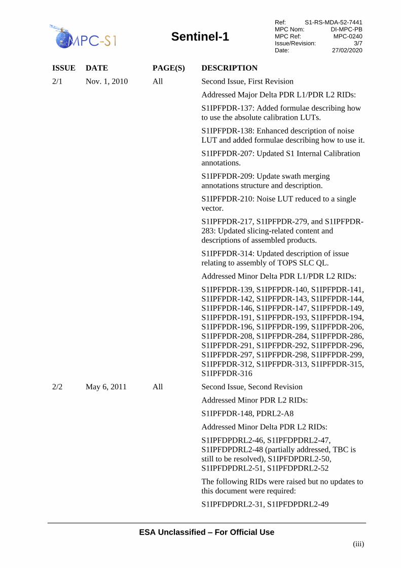
2/1 Nov. 1, 2010 All Second Issue, First Revision
Addressed Major Delta PDR L1/PDR L2 RIDs:
S1IPFPDR-137: Added formulae describing how
to use the absolute calibration LUTs.
S1IPFPDR-138: Enhanced description of noise
LUT and added formulae describing how to use it.
S1IPFPDR-207: Updated S1 Internal Calibration
annotations.
S1IPFPDR-209: Update swath merging
annotations structure and description.
S1IPFPDR-210: Noise LUT reduced to a single
vector.
S1IPFPDR-217, S1IPFPDR-279, and S1IPFPDR-
283: Updated slicing-related content and
descriptions of assembled products.
S1IPFPDR-314: Updated description of issue
relating to assembly of TOPS SLC QL.
Addressed Minor Delta PDR L1/PDR L2 RIDs:
S1IPFPDR-139, S1IPFPDR-140, S1IPFPDR-141,
S1IPFPDR-142, S1IPFPDR-143, S1IPFPDR-144,
S1IPFPDR-146, S1IPFPDR-147, S1IPFPDR-149,
S1IPFPDR-191, S1IPFPDR-193, S1IPFPDR-194,
S1IPFPDR-196, S1IPFPDR-199, S1IPFPDR-206,
S1IPFPDR-208, S1IPFPDR-284, S1IPFPDR-286,
S1IPFPDR-291, S1IPFPDR-292, S1IPFPDR-296,
S1IPFPDR-297, S1IPFPDR-298, S1IPFPDR-299,
S1IPFPDR-312, S1IPFPDR-313, S1IPFPDR-315,
S1IPFPDR-316
2/2 May 6, 2011 All Second Issue, Second Revision
Addressed Minor PDR L2 RIDs:
S1IPFPDR-148, PDRL2-A8
Addressed Minor Delta PDR L2 RIDs:
S1IPFDPDRL2-46, S1IPFDPDRL2-47,
S1IPFDPDRL2-48 (partially addressed, TBC is
still to be resolved), S1IPFDPDRL2-50,
S1IPFDPDRL2-51, S1IPFDPDRL2-52
The following RIDs were raised but no updates to
this document were required:
S1IPFDPDRL2-31, S1IPFDPDRL2-49

Sentinel-1
Ref: S1-RS-MDA-52-7441 MPC Nom: DI-MPC-PB MPC Ref: MPC-0240 Issue/Revision: 3/7 Date: 27/02/2020
ESA Unclassified – For Official Use
(iv)
ISSUE DATE PAGE(S) DESCRIPTION
2/3 Sept. 22, 2011 Second Issue, Third Revision
Addressed Major CDR L1&L2 RIDs:
Section 6.3 IPFCDR-123: The description for the
downlinkInformationType was updated to describe
the fact that the record contains records for
multiple swaths in the IW/EW GRD case. Other
similar field descriptions also updated.
Section
6.1.2
IPFCDR-133: An optional leapSecondInformation
section has been added to the manifest metadata,
matching the definition in the L0 specification.
Section 6.1 IPFCDR-132 and IPFCDR-134: Added Table 6-2
to describe data types used within the manifest,
and updated Table 6-6 to align with Table 6-2 and
improve wrapped metadata descriptions.
Section
6.3.5
IPFCDR-137: Updated the product preview
example to use a preview from a product
generated by the IPF.
Addressed Minor CDR L1&L2 RIDs:
All IPFCDR-20, IPFCDR-96, IPFCDR-97,
IPFCDR-114, IPFCDR-115, IPFCDR-116,
IPFCDR-117, IPFCDR-119, IPFCDR-120,
IPFCDR-124, IPFCDR-129, IPFCDR-130,
IPFCDR-131, IPFCDR-135, IPFCDR-136
2/4 May 01, 2012 Second Issue, Fourth Revision
Section 3.4 Updated slicing section for changes in annotations.
Table 3-19 Added sensorModeType, floatCoefficientArray
and doubleCoefficientArray types, and modified
supported ranges for primitive data types
Table 3-20 Added mode to adsHeaderType.
Table 6-7 Updates to manifest field descriptions.
Section
6.2.3
Updated field names for L2 OCN to distinguish
between the three different components, and
removed contactInformation field.

Sentinel-1
Ref: S1-RS-MDA-52-7441 MPC Nom: DI-MPC-PB MPC Ref: MPC-0240 Issue/Revision: 3/7 Date: 27/02/2020
ESA Unclassified – For Official Use
(v)
ISSUE DATE PAGE(S) DESCRIPTION
Section
6.3.1.1
CDR-A14: Updated missing line/gap fields to
distinguish between downlink and instrument
missing lines.
Updated replica/PG quality fields.
Updated DC quality fields to change SNR to RMS
error.
Updated description of productQualityIndex:
Reserved for future use as agreed at the FAT.
Section
6.3.1.2
Minor updates to general annotation DSR field
descriptions, added timeDelay and gain fields to
replica.
Section
6.3.1.3
Updated slice parameters.
Renamed numberOfRangeSamples to
numberOfSamples and numberOfAzimuthLines to
numberOfLines.
Added pgSource.
Added correctBistaticDelayFlag.
Added processorScalingFactor.
Section
6.3.1.4
Modified DCE fields to use RMS error instead of
SNR.
Section
6.3.1.6
Added sensingTime to swath timing structure.
Section
6.3.2
Updated the calibration vector description and
conversion formulae. Removed
processorScalingFactor and offset fields.
Section
6.3.3
Updated the noise vector formulae.
2/5 Aug. 27, 2012 Second Issue, Fifth Revision
Section
6.2.3
Updated L2 structures.
Table 6-67 Renamed correctBistaticDelayFlag to
bistaticDelayCorrectionApplied
Table 3-8,
6-11
Removed Copyright field from GeoTIFF
metadata.
Table 6-7 Updated platform->instrument wrapped metatdata:
added swath field and corrected the description of
the swathNumber field.

Sentinel-1
Ref: S1-RS-MDA-52-7441 MPC Nom: DI-MPC-PB MPC Ref: MPC-0240 Issue/Revision: 3/7 Date: 27/02/2020
ESA Unclassified – For Official Use
(vi)
ISSUE DATE PAGE(S) DESCRIPTION
2/6 Feb. 18, 2013 Second Issue, Sixth Revision
Updates for CCN#4:
Section 3.1 Added descriptions of notch modes.
Section 3.4 Updated assembly strategies for affected fields.
Sections
3.5.1, 3.5.3
Added support for notch modes
Section
3.6.1
Corrected description of the byte order of L1
measurement data.
Section
3.6.3
Added support for notch modes.
Added coordinate system reference frame type.
Added type for TOPS filter origin.
Sections 4.1,
4.2
Added support for notch modes.
Section 6.1 Updated manifest description
Section
6.2.3.3
Updated descriptions of owiInversionQuality and
owiWindQuality fields.
Table 6-23 Added missing line counters and flags for SSB
Error Flag.
Table 6-28 Updated the description of orbit and attitude lists.
Table 6-31 Added prf field to downlinkInformationType
Table 6-32 Added counter for SSB Error Flag.
Table 6-43 Added frame field to orbitType.
Table 6-47 Added frame field to attitudeType.
Table 6-55 Removed values array from replicaType
Table 6-63 Added azimuthFrequency to
imageInformationType
Table 6-67 Added rxVariationCorrectionApplied and
topsFilterOrigin to processingInformationType.
Figure 6-16 Update L1 Image ADSR figure.
2/7 Jan. 30, 2014 Second Issue, Seventh Revision
All Removed copyright, use and disclosure notice.
Section 2.1 Removed obsolete document references.
Section
3.3.5
Clarified that the L0 resources are included in the
manifest file.
Section
3.6.1
Updated SAFE namespaces.
Sentinel-1
Ref: S1-RS-MDA-52-7441 MPC Nom: DI-MPC-PB MPC Ref: MPC-0240 Issue/Revision: 3/7 Date: 27/02/2020
ESA Unclassified – For Official Use
(vii)
ISSUE DATE PAGE(S) DESCRIPTION
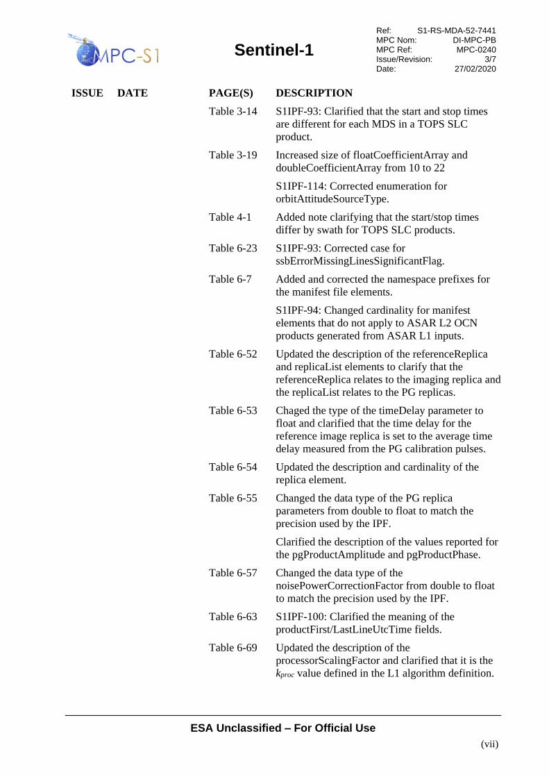
Table 3-14 S1IPF-93: Clarified that the start and stop times
are different for each MDS in a TOPS SLC
product.
Table 3-19 Increased size of floatCoefficientArray and
doubleCoefficientArray from 10 to 22
S1IPF-114: Corrected enumeration for
orbitAttitudeSourceType.
Table 4-1 Added note clarifying that the start/stop times
differ by swath for TOPS SLC products.
Table 6-23 S1IPF-93: Corrected case for
ssbErrorMissingLinesSignificantFlag.
Table 6-7 Added and corrected the namespace prefixes for
the manifest file elements.
S1IPF-94: Changed cardinality for manifest
elements that do not apply to ASAR L2 OCN
products generated from ASAR L1 inputs.
Table 6-52 Updated the description of the referenceReplica
and replicaList elements to clarify that the
referenceReplica relates to the imaging replica and
the replicaList relates to the PG replicas.
Table 6-53 Chaged the type of the timeDelay parameter to
float and clarified that the time delay for the
reference image replica is set to the average time
delay measured from the PG calibration pulses.
Table 6-54 Updated the description and cardinality of the
replica element.
Table 6-55 Changed the data type of the PG replica
parameters from double to float to match the
precision used by the IPF.
Clarified the description of the values reported for
the pgProductAmplitude and pgProductPhase.
Table 6-57 Changed the data type of the
noisePowerCorrectionFactor from double to float
to match the precision used by the IPF.
Table 6-63 S1IPF-100: Clarified the meaning of the
productFirst/LastLineUtcTime fields.
Table 6-69 Updated the description of the
processorScalingFactor and clarified that it is the
kproc value defined in the L1 algorithm definition.

Sentinel-1
Ref: S1-RS-MDA-52-7441 MPC Nom: DI-MPC-PB MPC Ref: MPC-0240 Issue/Revision: 3/7 Date: 27/02/2020
ESA Unclassified – For Official Use
(viii)
ISSUE DATE PAGE(S) DESCRIPTION
2/8 May 30, 2014 Second Issue, Eighth Revision
Table 3-19 Corrected typo in range of imageNumberType.
Corrected range of absOrbitNumberType.
Changed range of missionDataTakeIdType from
hexadecimal to integer to match the software.
Table 6-53 Clarified the description of the timeDelay
parameter.
Table 6-55 Clarified the description of the
reconstructedReplicaValidFlag.
Changed the equations for the values of
pgProductAmplitude and pgProductPhase to
include the sqrt() function.
Clarified the description of the internalTimeDelay
parameter.
2/9 Nov. 21, 2014 Second Issue, Ninth Revision
Section
3.4.1.3
Clarified the concatenation strategy for imagery to
account for image width variation.
Described the possibility of duplicate list entries
among consecutive slices.
Table 3-6 Clarified the assembly strategy for items in the
manifest file.
Table 3-7 Clarified the concatenation strategy for quick-look
imagery to account for image width variation.
Table 3-8 Added the assembly strategy for the file format
and changed the assembly strategy for the image
width field from Include to Merge.
Chaged the assembly strategy from Merge to
Include for geo-key and geo-params tags.
Table 3-9 Clarified the assembly of the line number in
calibration and noise annotations.
Table 3-10 Clarified the assembly of the byte offset in the
swath timing annotations.
Table 3-12 Clarified the concatenation strategy for the number
of samples field to account for image width
variation.
Table 6-9 Corrected definition of dataObjectType
Table 6-10 Corrected definition of byteStreamType
Table 6-11 Added definition of referenceType

Sentinel-1
Ref: S1-RS-MDA-52-7441 MPC Nom: DI-MPC-PB MPC Ref: MPC-0240 Issue/Revision: 3/7 Date: 27/02/2020
ESA Unclassified – For Official Use
(ix)
ISSUE DATE PAGE(S) DESCRIPTION
Table 6-12 Added definition of checksumInformationType
Table 6-12 Corrected the order of the data in the Model Tie
Point Tag.
Figure 6-8
Table 6-16
Updated L2 OCN global attributes
Figure 6-10
Table 6-18
Updated L2 OSW variables
Figure 6-12
Table 6-20
Updated L2 RVL variables
Table 6-58 Corrected the number of possible noise elements
in the noise list to account for the assembled
products.
Table 6-63 Changed azimuth FM rate annotation to an array.
Figure 6-18 Updated EAP figure
Table 6-82 Changed EAP to complex and added roll field.
Table 6-103 Changed type of line field from unsigned to
signed.
3/0 February 12, 2015 Third issue
Table 6-15 Added L2 OCN Dimension: length (cf. IPF-4)
Table 6-16 Added L2 OSW component variables:
oswEcmwfWindSpeed, oswEcmwfWindDirection
(cf. IPF-4)
June 16, 2015 Table 6-16 Changed decription of the windSpeed and
windDirection variables. (cf. IPF-4)
June 18, 2015 Section
6.3.3
Changed noise and value formulas (cf. IPF-78,
MPCS-845)
Table 6-60 Changed formula for azimuthFmRate (cf. IPF-78,
MPCS-833)
July 21, 2015 Figure 6-9,
Figure 6-10,
Figure 6-11,
Figure 6-12,
Figure 6-13
Changed L2 OCN netcdf figures in order to take
into account attributes, dimensions and variables.
July 23, 2015 Table 6-91 Changed srgrCoefficients and grsrCoefficients
formulation to a generic formulation (cf. IPF-97)
Sentinel-1
Ref: S1-RS-MDA-52-7441 MPC Nom: DI-MPC-PB MPC Ref: MPC-0240 Issue/Revision: 3/7 Date: 27/02/2020
ESA Unclassified – For Official Use
(x)
ISSUE DATE PAGE(S) DESCRIPTION
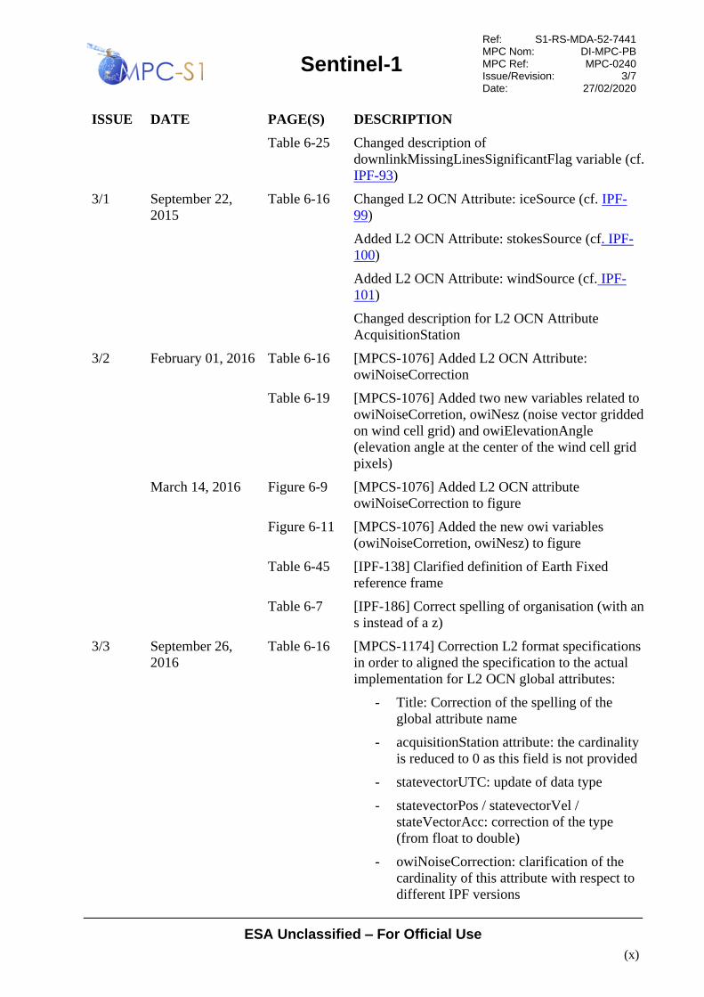
Table 6-25 Changed description of
downlinkMissingLinesSignificantFlag variable (cf.
IPF-93)
3/1 September 22,
2015
Table 6-16 Changed L2 OCN Attribute: iceSource (cf. IPF-
99)
Added L2 OCN Attribute: stokesSource (cf. IPF-
100)
Added L2 OCN Attribute: windSource (cf. IPF-
101)
Changed description for L2 OCN Attribute
AcquisitionStation
3/2 February 01, 2016 Table 6-16 [MPCS-1076] Added L2 OCN Attribute:
owiNoiseCorrection
Table 6-19 [MPCS-1076] Added two new variables related to
owiNoiseCorretion, owiNesz (noise vector gridded
on wind cell grid) and owiElevationAngle
(elevation angle at the center of the wind cell grid
pixels)
March 14, 2016 Figure 6-9 [MPCS-1076] Added L2 OCN attribute
owiNoiseCorrection to figure
Figure 6-11 [MPCS-1076] Added the new owi variables
(owiNoiseCorretion, owiNesz) to figure
Table 6-45 [IPF-138] Clarified definition of Earth Fixed
reference frame
Table 6-7 [IPF-186] Correct spelling of organisation (with an
s instead of a z)
3/3 September 26,
2016
Table 6-16 [MPCS-1174] Correction L2 format specifications
in order to aligned the specification to the actual
implementation for L2 OCN global attributes:
- Title: Correction of the spelling of the
global attribute name
- acquisitionStation attribute: the cardinality
is reduced to 0 as this field is not provided
- statevectorUTC: update of data type
- statevectorPos / statevectorVel /
stateVectorAcc: correction of the type
(from float to double)
- owiNoiseCorrection: clarification of the
cardinality of this attribute with respect to
different IPF versions

Sentinel-1
Ref: S1-RS-MDA-52-7441 MPC Nom: DI-MPC-PB MPC Ref: MPC-0240 Issue/Revision: 3/7 Date: 27/02/2020
ESA Unclassified – For Official Use
(xi)
ISSUE DATE PAGE(S) DESCRIPTION
Table 6-17 [MPCS-1174] Correction L2 format specifications
in order to aligned the specification to the actual
implementation for L2 OCN dimensions:
- clarification of rvlSwath cardinality of SM
and WV products
Table 6-18 [MPCS-1174] Correction L2 format specifications
in order to aligned the specification to the actual
implementation for L2 OSW components
variables:
- oswPartitions: Clarification of the number
of partitions and their meaning and of their
data types
- oswPhi / oswLon / oswLat / oswDirmet /
oswWindDirection /
oswEcmwfWindDirection /
oswIncidenceAngle, oswHeading :
correction of the unit of direction provided
as variable attribute
- oswHs / oswWl / oswSnr / oswIconf:
correction of the number of partitions used
in order to compute the significant wave
height
- oswAmbiFac / oswIconf / oswInten,
oswNv / oswKurt / oswWaveAge /
oswLandFlag: correction of unit
(adimentional)
Table 6-19 [MPCS-1174] Correction L2 format specifications
in order to aligned the specification to the actual
implementation for L2 OWI components variables
:
- owiLon / owLat / owiIncidenceAngle /
owiHeading / owiCalConstInci /
owiWindDirection /
owiEcmwfWindDirection /
owiElevationAngle: clarification of the
units
- owiHs / owiWl / owDirmet /
owiWindSeaHs: clarification of specific
cases were a fillvalue is used
- owiNesz: clarification of the cardinality of
this attribute with respect to different IPF
versions:

Sentinel-1
Ref: S1-RS-MDA-52-7441 MPC Nom: DI-MPC-PB MPC Ref: MPC-0240 Issue/Revision: 3/7 Date: 27/02/2020
ESA Unclassified – For Official Use
(xii)
ISSUE DATE PAGE(S) DESCRIPTION
Table 6-20 [MPCS-1174] Correction L2 format specifications
in order to aligned the specification to the actual
implementation for L2 RVL components
variables:
- for all variables: clarification of the
dimensions for the various acquisition
modes
3/4 March 10, 2017 Sec. 6.3.3 Noise annotations updated in order to introduce
denoising vectors along azimuth direction (cf. IPF-
310)
3/4 March 30, 2017 Table 6-17 Introduction of 3 new dimension oswKxBinSize,
oswKyBinSize, oswLag to accommodate the
Cartesian cross spectra output variable.
Add dimension owiPolarisation
Table 6-18 Introduction of several new variables:
oswCartSpec, oswKx, oswKy,
oswQualityFlagPartition, oswQualityFlag,
oswTotalHs
Introduction of variables of peak direction from
group analysis: oswGroupDir,
oswEllipsLength,oswEllipsLengthStdDev,
oswEllipsWidth, oswEllipsWidthStdDev
Table 6-19 Change of cardinality owiNrcs, owiNesz in the
case of dual polarization acquisition (adding the
cross-polarisation information)
Remove of owiLandFlag replaced by owiMask
allowing the annotation of
landmask/iceMask/noDataAvailable.
Introduction of owiNrcsNeszCorr (noise corrected
NRCS averaged on the wind grid).
Table 6-15 Adding of IPF version in L2 OCN Netcdf global
attribute
28/08/2017 Table 6-17,
Table 6-18,
Table 6-19
Change ubyte to byte variables on L2 OCN Netcdf
in order to maintain the NetCDF 3.4 format
compliancy
06/11/2017 Table 6-17 Precision on the variable oswKx and oswKy
(frequency vectors of the cartesian cross spectra),
which have been resp. normalized by variables
oswGroundRgSize, oswAziSize
06/11/2017 Table 6-17,
Table 6-19
Review of the L2 variables units to be compliant
with the udunit norm

Sentinel-1
Ref: S1-RS-MDA-52-7441 MPC Nom: DI-MPC-PB MPC Ref: MPC-0240 Issue/Revision: 3/7 Date: 27/02/2020
ESA Unclassified – For Official Use
(xiii)
ISSUE DATE PAGE(S) DESCRIPTION
11/12/2017 Table 3-14 The datatake id in the Level 2 measurement file
can be either in upper or lower case.
3/5 April 19, 2018 Table 3-9 Updated the assembly methods for
noiseRangeVector and noiseAzimuthVector type.
Table 6-102
Table 6-103
Updated the table title with the correct name of the
types.
Table 6-18 Change range to azimuth on oswCartSpecRe and
oswCartSpecIm
3/6 January 7, 2019 Table 6-18 Update of OSW specification due to new low filter
June, 2019 Table 6-18 Add two new OSW variables oswJx oswJy relative
to the Jacobian vector of the image cartesian cross
spectra transformation oswCartSpecRe and
oswCartSpecIm (non-linear resampling, only used
to export the variable)
3/7 September 16,
2019
Table 6-18 Clarification content oswQualityFlagPartition.
Addition of variables oswPolSpecNV and
oswHsNV (IPF 3.30)

Sentinel-1
Ref: S1-RS-MDA-52-7441 MPC Nom: DI-MPC-PB MPC Ref: MPC-0240 Issue/Revision: 3/7 Date: 27/02/2020
ESA Unclassified – For Official Use
(xiv)
TABLE OF CONTENTS
1 INTRODUCTION.......................................................................................................... 1-1
1.1 Purpose ................................................................................................................. 1-1
1.2 Scope .................................................................................................................... 1-1
1.3 Document Structure ............................................................................................. 1-1
2 DOCUMENTS................................................................................................................ 2-1
2.1 Applicable Documents ......................................................................................... 2-1
2.2 Reference Documents .......................................................................................... 2-1
3 PRODUCT FORMAT OVERVIEW ........................................................................... 3-1
3.1 Products Overview ............................................................................................... 3-2
3.1.1 Level 1 Products Overview .................................................................. 3-3
3.1.2 Level 2 Products Overview .................................................................. 3-5
3.2 High Level Product Structure .............................................................................. 3-6
3.3 Product Components ............................................................................................ 3-8
3.3.1 Manifest File ........................................................................................ 3-8
3.3.2 Measurement Data Sets ........................................................................ 3-9
3.3.3 Annotation Data Sets .......................................................................... 3-10
3.3.4 Representation Data Sets .................................................................... 3-11
3.3.5 Resources ........................................................................................... 3-12
3.4 Slice Products ..................................................................................................... 3-12
3.4.1 Overview ............................................................................................ 3-13
3.4.2 Manifest File ...................................................................................... 3-21
3.4.3 Measurement Data Sets ...................................................................... 3-23
3.4.4 Annotation Data Sets .......................................................................... 3-27
3.5 Product Naming ................................................................................................. 3-33
3.5.1 Product ............................................................................................... 3-33
3.5.2 Manifest File ...................................................................................... 3-36
3.5.3 Data Sets ............................................................................................. 3-36
3.6 Product Conventions .......................................................................................... 3-39
3.6.1 Decisions ............................................................................................ 3-39
3.6.2 Content Table Conventions ................................................................ 3-39
3.6.3 Primitive Data Types .......................................................................... 3-40
4 LEVEL 1 PRODUCT SPECIFICATION ................................................................... 4-1
4.1 Level 1 SLC Products .......................................................................................... 4-1
4.2 Level 1 GRD Products ......................................................................................... 4-3
5 LEVEL 2 PRODUCT SPECIFICATION ................................................................... 5-1
5.1 Level 2 OCN Products ......................................................................................... 5-1
6 PRODUCT DATA SETS ............................................................................................... 6-1
6.1 Manifest File ........................................................................................................ 6-1
6.1.1 Information Package Map .................................................................... 6-3
6.1.2 Metadata Section .................................................................................. 6-4
6.1.3 Data Object Section ............................................................................ 6-12
Sentinel-1
Ref: S1-RS-MDA-52-7441 MPC Nom: DI-MPC-PB MPC Ref: MPC-0240 Issue/Revision: 3/7 Date: 27/02/2020
ESA Unclassified – For Official Use
(xv)
6.2 Measurement Data Sets ...................................................................................... 6-13
6.2.1 Level 1 Image ..................................................................................... 6-13
6.2.2 Quick-look Image ............................................................................... 6-16
6.2.3 Level 2 OCN Measurement Data ....................................................... 6-18
6.3 Annotation Data Sets ......................................................................................... 6-43
6.3.1 L1 Product Annotation Data Set ........................................................ 6-43
6.3.2 L1 Calibration Annotation Data Set ................................................. 6-102
6.3.3 L1 Noise Annotation Data Set ......................................................... 6-106
6.3.4 Map Overlay Annotation Data Set ................................................... 6-111
6.3.5 Product Preview Annotation Data Set .............................................. 6-113

Sentinel-1
Ref: S1-RS-MDA-52-7441 MPC Nom: DI-MPC-PB MPC Ref: MPC-0240 Issue/Revision: 3/7 Date: 27/02/2020
ESA Unclassified – For Official Use
(xvi)
LIST OF FIGURES
Figure 1-1 Document Structure and Section Relationships ....................................................... 1-3
Figure 3-1 Sentinel-1 Product Family Tree ............................................................................... 3-3
Figure 3-2 Sentinel-1 Product Composition Overview ............................................................. 3-7
Figure 3-3 Example of Include Assembly Strategy ................................................................. 3-15
Figure 3-4 Example of Merge Assembly Strategy .................................................................. 3-17
Figure 3-5 Example of Concatenate Assembly Strategy ......................................................... 3-20
Figure 3-6 Assembly of a L1 Image MDS............................................................................... 3-26
Figure 3-7 Sentinel-1 Product Naming Convention ................................................................ 3-34
Figure 6-1 Sentinel-1 Manifest File Structure ........................................................................... 6-1
Figure 6-2 Information Package Map Structure ........................................................................ 6-3
Figure 6-3 Metadata Section Structure and Content .................................................................. 6-5
Figure 6-4 Data Object Section Structure and Content ........................................................... 6-12
Figure 6-5 Grey-scale Single Polarisation Quick-look Images: Left VV Co-polarisation
and Right VH Cross-polarisation ....................................................................... 6-17
Figure 6-6 3 Channel (RGB) Composite Dual Polarisation VV/VH Quick-look Image ........ 6-18
Figure 6-7 L2 OCN Product Top-level Format ....................................................................... 6-19
Figure 6-8 L2 OCN Global Attributes ..................................................................................... 6-21
Figure 6-9 L2 OCN Dimensions .............................................................................................. 6-24
Figure 6-11 L2 OWI Component Variables ............................................................................ 6-35
Figure 6-12 L2 RVL Component Variables ............................................................................ 6-40
Figure 6-13 L1 Product Annotation Data Set .......................................................................... 6-44
Figure 6-14 L1 Quality Information ADSR ............................................................................. 6-47
Figure 6-15 L1 General ADSR ................................................................................................ 6-54
Figure 6-16 L1 Image ADSR ................................................................................................... 6-73
Figure 6-17 L1 Doppler Centroid ADSR................................................................................. 6-81
Figure 6-18 L1 Antenna Elevation Pattern ADSR .................................................................. 6-85
Figure 6-19 L1 Swath Timing ADSR ...................................................................................... 6-88
Figure 6-20 L1 Geo-location Grid ADSR ............................................................................... 6-91
Figure 6-21 L1 Coordinate Conversion ADSR ....................................................................... 6-94
Figure 6-22 L1 Swath Merging ADSR .................................................................................... 6-97
Figure 6-23 Swath Merging ................................................................................................... 6-101
Figure 6-24 L1 Calibration Data Set ...................................................................................... 6-103
Figure 6-25 L1 Noise LUT Data Set...................................................................................... 6-107
Figure 6-26 Sentinel-1 Map Overlay Displayed in Google Earth ......................................... 6-111
Figure 6-27 Map Overlay Annotation Data Set ..................................................................... 6-112
Figure 6-28 Example Product Preview ADS ......................................................................... 6-114

Sentinel-1
Ref: S1-RS-MDA-52-7441 MPC Nom: DI-MPC-PB MPC Ref: MPC-0240 Issue/Revision: 3/7 Date: 27/02/2020
ESA Unclassified – For Official Use
(xvii)
LIST OF TABLES
Table 3-1 ADSR Summary for Sentinel-1 Manifest File .......................................................... 3-9
Table 3-2 Summary of Measurement Data Sets used by Sentinel-1 ......................................... 3-9
Table 3-3 Summary of the Annotation Data Sets used by Sentinel-1 ..................................... 3-10
Table 3-4 ADSR Summary for Level 1 Product Annotation ADS .......................................... 3-10
Table 3-5 Data Set Representation Details .............................................................................. 3-11
Table 3-6 Assembly of the Sentinel-1 Manifest File ............................................................... 3-21
Table 3-7 Assembly of the L1 Measurement Data Sets .......................................................... 3-23
Table 3-8 Assembly of L1 Image MDS TIFF/GeoTIFF Information ..................................... 3-24
Table 3-9 Assembly of the L1 Annotation Data Sets .............................................................. 3-27
Table 3-10 Assembly of the Level 1 Product Annotation ADS .............................................. 3-28
Table 3-11 Assembly of the L1 General Annotation ADSR ................................................... 3-30
Table 3-12 Assembly of the L1 Image Annotation ADSR ...................................................... 3-31
Table 3-13 Sentinel-1 Product Naming Elements ................................................................... 3-35
Table 3-14 Sentinel-1 Data Set Naming Elements .................................................................. 3-37
Table 3-15 Measurement Data Set Naming Convention for Sentinel-1 .................................. 3-38
Table 3-16 Annotation Data Set Naming Convention for Sentinel-1 ...................................... 3-38
Table 3-17 Representation Data Set Naming Convention for Sentinel-1 ................................ 3-38
Table 3-18 Product Data Content Table Column Descriptions ............................................... 3-40
Table 3-19 Primitive Data Types for Sentinel-1 Product Format ............................................ 3-40
Table 3-20 Data Type - adsHeaderType .................................................................................. 3-43
Table 4-1 Sentinel-1 Level 1 SLC Product Composition .......................................................... 4-2
Table 4-2 Level 1 Product Annotation DSR Applicable to Level 1 SLC Products ................... 4-3
Table 4-3 Sentinel-1 Level 1 GRD Product Composition ......................................................... 4-4
Table 4-4 Level 1 Product Annotation DSR Applicable to Level 1 GRD Products .................. 4-5
Table 5-1 Sentinel-1 Level 2 OCN Product Composition ......................................................... 5-1
Table 6-1 Element - XFDU ........................................................................................................ 6-2
Table 6-2 Primitive Data Types for Sentinel-1 Manifest Format .............................................. 6-2
Table 6-3 Data Type - informationPackageMapType ............................................................... 6-3
Table 6-4 Data Type - contentUnitType .................................................................................... 6-4
Table 6-5 Data Type - metadataSectionType ............................................................................ 6-5
Table 6-6 Data Type - metadataObjectType .............................................................................. 6-5
Table 6-7 Mandatory Wrapped Metadata Elements for Sentinel-1 Products ............................ 6-7
Table 6-8 Data Type - dataObjectSectionType ....................................................................... 6-12
Table 6-9 Data Type - dataObjectType ................................................................................... 6-12
Table 6-10 Data Type - byteStreamType ................................................................................. 6-12
Table 6-11 Data Type - referenceType .................................................................................... 6-13
Table 6-12 Data Type - checksumInformationType ................................................................ 6-13
Table 6-13 Summary of TIFF Tags used in Sentinel-1 Products ............................................ 6-14
Table 6-14 Summary of GeoTIFF Tags/Keys Used in Sentinel-1 Products ........................... 6-15
Sentinel-1
Ref: S1-RS-MDA-52-7441 MPC Nom: DI-MPC-PB MPC Ref: MPC-0240 Issue/Revision: 3/7 Date: 27/02/2020
ESA Unclassified – For Official Use
(xviii)
Table 6-15 L2 OCN Product .................................................................................................... 6-19
Table 6-16 L2 OCN Global Attributes .................................................................................... 6-22
Table 6-17 L2 OCN Dimensions ............................................................................................. 6-24
Table 6-18 L2 OSW Component Variables ............................................................................. 6-28
Table 6-19 L2 OWI Component Variables .............................................................................. 6-36
Table 6-20 L2 RVL Component Variables .............................................................................. 6-41
Table 6-21 Element - product .................................................................................................. 6-45
Table 6-22 Data Type - l1QualityInformationType ................................................................. 6-48
Table 6-23 Data Type - qualityDataListType .......................................................................... 6-48
Table 6-24 Data Type - qualityDataType ................................................................................ 6-48
Table 6-25 Data Type - downlinkQualityType ........................................................................ 6-49
Table 6-26 Data Type - rawDataAnalysisQualityType ........................................................... 6-52
Table 6-27 Data Type - dopplerCentroidQualityType ............................................................. 6-52
Table 6-28 Data Type - imageQualityType ............................................................................. 6-53
Table 6-29 Data Type - imageStatisticsType ........................................................................... 6-53
Table 6-30 Data Type - l1GeneralAnnotationType ................................................................. 6-54
Table 6-31 Data Type - productInformationType ................................................................... 6-55
Table 6-32 Data Type - downlinkInformationListType .......................................................... 6-56
Table 6-33 Data Type - downlinkInformationType ................................................................. 6-56
Table 6-34 Data Type - bitErrorCountType ............................................................................ 6-57
Table 6-35 Data Type - downlinkValuesType ......................................................................... 6-59
Table 6-36 Data Type - dataFormatType ................................................................................. 6-60
Table 6-37 Data Type - rangeDecimationType ....................................................................... 6-60
Table 6-38 Data Type - swlListType ....................................................................................... 6-60
Table 6-39 Data Type - swlType ............................................................................................. 6-61
Table 6-40 Data Type - swstListType ..................................................................................... 6-61
Table 6-41 Data Type - swstType ............................................................................................ 6-61
Table 6-42 Data Type - pointingStatusListType ..................................................................... 6-61
Table 6-43 Data Type - pointingStatusType ............................................................................ 6-62
Table 6-44 Data Type - orbitListType ..................................................................................... 6-62
Table 6-45 Data Type - orbitType ........................................................................................... 6-63
Table 6-46 Data Type - positionType ...................................................................................... 6-63
Table 6-47 Data Type - velocityType ...................................................................................... 6-63
Table 6-48 Data Type - attitudeListType ................................................................................. 6-64
Table 6-49 Data Type - attitudeType ....................................................................................... 6-64
Table 6-50 Data Type - rawDataAnalysisListType ................................................................. 6-65
Table 6-51 Data Type - rawDataAnalysisType ....................................................................... 6-65
Table 6-52 Data Type - rawDataAnalysisSupportType ........................................................... 6-66
Table 6-53 Data Type - replicaInformationListType ............................................................... 6-67
Table 6-54 Data Type - replicaInformationType ..................................................................... 6-67
Table 6-55 Data Type – referenceReplicaType ....................................................................... 6-67
Table 6-56 Data Type - replicaListType .................................................................................. 6-68
Table 6-57 Data Type - replicaType ........................................................................................ 6-68

Sentinel-1
Ref: S1-RS-MDA-52-7441 MPC Nom: DI-MPC-PB MPC Ref: MPC-0240 Issue/Revision: 3/7 Date: 27/02/2020
ESA Unclassified – For Official Use
(xix)
Table 6-58 Data Type - noiseListType .................................................................................... 6-71
Table 6-59 Data Type - noiseType .......................................................................................... 6-71
Table 6-60 Data Type - terrainHeightListType ....................................................................... 6-71
Table 6-61 Data Type - terrainHeightType ............................................................................. 6-72
Table 6-62 Data Type - azimuthFmRateListType ................................................................... 6-72
Table 6-63 Data Type - azimuthFmRateType ......................................................................... 6-72
Table 6-64 Data Type - l1ImageAnnotationType .................................................................... 6-74
Table 6-65 Data Type - imageInformationType ..................................................................... 6-74
Table 6-66 Data Type – sliceListType ..................................................................................... 6-75
Table 6-67 Data Type - sliceType ........................................................................................... 6-76
Table 6-68 Data Type - imageStatisticsType ........................................................................... 6-76
Table 6-69 Data Type - processingInformationType ............................................................... 6-76
Table 6-70 Data Type - swathProcParamsListType ................................................................ 6-78
Table 6-71 Data Type - swathProcParamsType ...................................................................... 6-79
Table 6-72 Data Type - processingParametersType ................................................................ 6-79
Table 6-73 Data Type - inputDimensionsListType ................................................................. 6-80
Table 6-74 Data Type - inputDimensionsType ....................................................................... 6-80
Table 6-75 Data Type - l1DopplerCentroidType ..................................................................... 6-82
Table 6-76 Data Type - dceBlockListType ............................................................................. 6-82
Table 6-77 Data Type - dcEstimateType ................................................................................. 6-82
Table 6-78 Data Type - fineDceListType ................................................................................ 6-83
Table 6-79 Data Type - fineDceType ...................................................................................... 6-84
Table 6-80 Data Type - l1AntennaPatternType ....................................................................... 6-85
Table 6-81 Data Type - antennaPatternListType ..................................................................... 6-85
Table 6-82 Data Type - antennaPatternType ........................................................................... 6-86
Table 6-83 Data Type - l1SwathType ...................................................................................... 6-89
Table 6-84 Data Type - burstListType ..................................................................................... 6-89
Table 6-85 Data Type - burstType ........................................................................................... 6-89
Table 6-86 Data Type - l1GeolocationGridType ..................................................................... 6-92
Table 6-87 Data Type - geolocationGridPointListType .......................................................... 6-92
Table 6-88 Data Type - geolocationGridPointType ................................................................ 6-92
Table 6-89 Data Type - l1CoordinateConversionType ........................................................... 6-94
Table 6-90 Data Type - coordinateConversionListType ......................................................... 6-95
Table 6-91 Data Type - coordinateConversionType ............................................................... 6-95
Table 6-92 Data Type - l1SwathMergeType ........................................................................... 6-98
Table 6-93 Data Type - swathMergeListType ......................................................................... 6-98
Table 6-94 Data Type - swathMergeType ............................................................................... 6-98
Table 6-95 Data Type - swathBoundsListType ....................................................................... 6-99
Table 6-96 Data Type - swathBoundsType ............................................................................. 6-99
Table 6-97 Element - calibration ........................................................................................... 6-104
Table 6-98 Data Type - calibrationInformationType ............................................................. 6-104
Table 6-99 Data Type - calibrationVectorListType ............................................................... 6-104
Table 6-100 Data Type - calibrationVectorType ................................................................... 6-105

Sentinel-1
Ref: S1-RS-MDA-52-7441 MPC Nom: DI-MPC-PB MPC Ref: MPC-0240 Issue/Revision: 3/7 Date: 27/02/2020
ESA Unclassified – For Official Use
(xx)
Table 6-101 Element - noise .................................................................................................. 6-108
Table 6-102 Data Type - noiseRangeVectorListType ........................................................... 6-108
Table 6-103 Data Type - noiseRangeVectorType ................................................................. 6-108
Table 6-104105 Data Type - noiseAzimuthVectorListType ................................................. 6-109
Table 6-106 Data Type - noiseAzimuthVectorType .............................................................. 6-109
Table 6-107 Root element - kml ............................................................................................ 6-112
Table 6-108 Data Type – kml:DocumentType ...................................................................... 6-112
Table 6-109 Data Type – kml:FolderType ............................................................................ 6-112
Table 6-110 Data Type - kml:GroundOverlayType .............................................................. 6-113
Table 6-111 Data Type - kml:LinkType ................................................................................ 6-113
Table 6-112 Data Type - gx:LatLonQuadType ..................................................................... 6-113
Table 6-113 Contents of the Product Preview ADS .............................................................. 6-114

Sentinel-1
Ref: S1-RS-MDA-52-7441 MPC Nom: DI-MPC-PB MPC Ref: MPC-0240 Issue/Revision: 3/7 Date: 27/02/2020
ESA Unclassified – For Official Use
(xxi)
ACRONYMS AND ABBREVIATIONS
ADS Annotation Data Set
ADSR Annotation Data Set Record
AEP Antenna Elevation Pattern
AN Azimuth Notch
ANX Ascending Node Crossing
ASAR Advanced SAR
ASCII American Standard Code for Information Interchange
BAQ Block Adaptive Quantisation
BigTIFF Big Tag Image File Format
CCN Contract Change Notice
CCSDS Consultative Committee for Space Data Systems
CDR Critical Design Review
CDRL Contract Data Requirements List
COTS Commercial off the Shelf
CRC Cyclic Redundancy Check
dB DeciBel
DC Doppler Centroid
DCE Doppler Centroid Estimation/Estimate
DN Digital Number
DS Data Set
DSR Data Set Record
ECC Event Control Code
ECMWF European Centre for Medium-Range Weather Forecasts
EN Elevation Notch
ESA European Space Agency
ESRIN European Space Research Institute
EW Extra Wide Swath
FDBAQ Flexible Dynamic Block Adaptive Quantisation
FM Frequency Modulation
FR Full Resolution
GB Giga Byte
GEBCO General Bathymetric Chart of Oceans
Sentinel-1
Ref: S1-RS-MDA-52-7441 MPC Nom: DI-MPC-PB MPC Ref: MPC-0240 Issue/Revision: 3/7 Date: 27/02/2020
ESA Unclassified – For Official Use
(xxii)
GeoTIFF Geo-reference Tag Image File Format
GMES Global Monitoring for Environment and Security
GMF Geophysical Model Function
GRD Ground Range, Multi-look, Detected
HH Horizontal polarisation (Tx & Rx)
HR High Resolution
HTML HyperText Markup Language
HV Horizontal Vertical polarisation
Hz Hertz
I/Q In-phase/Quadrature
ICD Interface Control Document
ID Identifier
IPF Instrument Processing Facility
ISLR Integrated Slide Lobe Ratio
ISP Instrument Source Packet
IW Interferometric Wide Swath
Km Kilometre
KML Keyhole Markup Language
L0 Level Zero
L1 Level One
L2 Level Two
LUT Look-up Table
m metre
MDS Measurement Data Set
MHz Megahertz
MR Medium Resolution
N/A Not Applicable
NetCDF Network Common Data Form
NRCS Normalised Radar Cross Section
OCN L2 Ocean Product
OSW Ocean Swell Spectra
OWI Ocean Wind Field
PDR Preliminary Design Review
PG Product Generation

Sentinel-1
Ref: S1-RS-MDA-52-7441 MPC Nom: DI-MPC-PB MPC Ref: MPC-0240 Issue/Revision: 3/7 Date: 27/02/2020
ESA Unclassified – For Official Use
(xxiii)
PNG Portable Network Graphics
pol. Polarisation
PRF Pulse Repetition Frequency
PRI Pulse Repetition Interval
RDA Raw Data Analysis
RDS Representation Data Set
RGB Red Green Blue
RID Review Item Disposition
RMS root mean squared
RVL Radial Surface Velocity
S-1 Sentinel-1
SAR Synthetic Aperture Radar
SAS SAR Antenna Sub-system
SES SAR Electronic Sub-system
SI International System of Units
SLC Single Look Complex
SM Stripmap
SOW Statement of Work
SPPDU Space Packet Protocol Data Unit
SWL Sampling Window Length
SWST Sampling Window Start Time
TBC To Be Confirmed
TBD To Be Determined
TIFF Tag Image File Format
TOPSAR Terrain Observation with Progressive Scanning SAR
Tx Transmit
URL Uniform Resource Locator
UTC Universal Time Coordinated
VH Vertical Horizontal polarisation
VV Vertical polarisation
W3C World Wide Web Consortium
WGS 84 World Geodetic System (1984)
WV Wave
XFDU XML Formatted Data Unit

Sentinel-1
Ref: S1-RS-MDA-52-7441 MPC Nom: DI-MPC-PB MPC Ref: MPC-0240 Issue/Revision: 3/7 Date: 27/02/2020
ESA Unclassified – For Official Use
(xxiv)
XML eXtensible Markup Language
ZDT Zero Doppler Time

Sentinel-1
Ref: S1-RS-MDA-52-7441 MPC Nom: DI-MPC-PB MPC Ref: MPC-0240 Issue/Revision: 3/7 Date: 27/02/2020
ESA Unclassified – For Official Use
(1-1)
1 INTRODUCTION
This section introduces the purpose, scope and structure of the document.
1.1 Purpose
This document defines the detailed product format for all Sentinel-1 Level 1 (L1)
and Level 2 (L2) products. It specifies the content and format of the products
generated by the Sentinel-1 Instrument Processing Facility (IPF).
1.2 Scope
This product specification satisfies the Sentinel-1 detailed L1 product format
(deliverable PFL1-4) and the Sentinel-1 detailed L2 product format (deliverable
PFL2-3) from the ESA Statement of Work (SOW) [A-1] with the modifications
described in the Sentinel-1 IPF Contract Change Notice N. 2, Changes in ESRIN
Contract No. 21722/08/I-LG [A-4].
This document specifies the content and format of Sentinel-1 L1 and L2 products for
the four Sentinel-1 Synthetic Aperture Radar (SAR) acquisition modes: Stripmap
(SM); Interferometric Wide Swath (IW); Extra Wide Swath (EW); and Wave (WV).
The performance and characteristics for each of the products in the Sentinel-1
product family are detailed in the Sentinel-1 Product Definition [A-3]. The
definition of Level 0 (L0) products is contained in the Sentinel-1 L0 Product Format
Specification [R-8] and is not part of this document.
The Sentinel-1 product schema files form the definitive source for the content and
format of Sentinel-1 products. The schema files are included in Appendix A and are
distributed with every Sentinel-1 L1 and L2 product.
1.3 Document Structure
This document is structured as follows:
• Section 1 introduces the purpose, scope and structure of the document;
• Section 2 lists the applicable and reference documents;
• Section 3 introduces the objectives and key concepts of the specification and
presents an overview of the product format;
• Section 4 defines the collections of data sets (DS) from Section 6 that make up
each Sentinel-1 L1 product;

Sentinel-1
Ref: S1-RS-MDA-52-7441 MPC Nom: DI-MPC-PB MPC Ref: MPC-0240 Issue/Revision: 3/7 Date: 27/02/2020
ESA Unclassified – For Official Use
(1-2)
• Section 5 defines the collections of data sets from Section 6 that make up each
Sentinel-1 L2 product;
• Section 6 describes the contents and format of each Sentinel-1 L1 and L2 data
set. This section presents an abstract view of the details of each data set
contained in the schemas defined in Appendix A and is intended for users of
all levels;
• Appendix A contains the eXtensible Markup Language (XML) schema files
that define the content and format of all Sentinel-1 L1 data sets. The XML
schema files are the definitive source for the Sentinel-1 L1 product format.
This section is intended for an audience with an understanding of XML
Schema.
Within this document, Sections 1 and 2 are independent and stand-alone in the
respect that they do not rely on other sections within the document for context;
however, Sections 3 through 6 and Appendix A deserve special attention because
inter-dependencies do exist between these sections of the document. Figure 1-1
presents a graphical view of the structure of the sections described in the list above
and the relationships between each.

Sentinel-1
Ref: S1-RS-MDA-52-7441 MPC Nom: DI-MPC-PB MPC Ref: MPC-0240 Issue/Revision: 3/7 Date: 27/02/2020
ESA Unclassified – For Official Use
(1-3)
Figure 1-1 Document Structure and Section Relationships
Section 1
INTRODUCTION
Section 2
DOCUMENTS
Section 3
PRODUCT FORMAT OVERVIEW
Section 4
LEVEL 1 PRODUCT SPECIFICATION
Section 5
LEVEL 2 PRODUCT SPECIFICATION
Section 6
PRODUCT DATA SETS
Appendix A
PRODUCT SCHEMAS
Describe
Is composed of
Describe
Is composed of
Define Abstract view of
Introduces Introduces

Sentinel-1
Ref: S1-RS-MDA-52-7441 MPC Nom: DI-MPC-PB MPC Ref: MPC-0240 Issue/Revision: 3/7 Date: 27/02/2020
ESA Unclassified – For Official Use
(2-1)
2 DOCUMENTS
2.1 Applicable Documents
The following documents of the date/revision indicated form part of this document
to the extent referenced herein.
A-1 GMES-DFPR-EOPG-SW-07-00006 Sentinel-1 Product Definitions &
Instrument Processing Facility
Development Statement of Work,
Issue/Revision 4/1, 23-05-2008.
ESA.
A-2 S1-RS-MDA-52-7452 Sentinel-1 IPF System Requirements
Specification. Issue/Revision 2/3.
Feb. 18, 2013. MDA.
A-3 S1-RS-MDA-52-7440 Sentinel-1 Product Definition,
Issue/Revision 2/4, Aug. 23, 2012.
MDA.
A-4 CCN No. 2 Contract Change Notice N. 2,
Changes in ESRIN Contract No.
21722/08/I-LG, June 21, 2010. MDA
A-5 01-7416A MDA Proposal to ESA for Sentinel-1
IPF Contract Change Request #04,
Nov. 13, 2012.
A-6 GMES-GSEG-EOPG-SW-12-0037 Sentinel-1 IPF Development Change
Request No. 4, Issue/Revision 1/2,
Oct. 25, 2012. ESA.
2.2 Reference Documents
The following documents provide useful reference information associated with this
document. These documents are to be used for information only and changes to the
date/revision number (if provided) shall not make this document out of date.
R-1 XML Formatted Data Unit Structure
and Construction Rules. September
15, 2004. CCSDS.
Sentinel-1
Ref: S1-RS-MDA-52-7441 MPC Nom: DI-MPC-PB MPC Ref: MPC-0240 Issue/Revision: 3/7 Date: 27/02/2020
ESA Unclassified – For Official Use
(2-2)
R-2 XML 1.1 Second Edition, W3C
Recommendation, 16 August 2006,
Bray et al.
R-3 XML Schema Part 1: Structures
Second Edition, W3C
Recommendation, 28 October 2004,
Thompson et al.
R-4 XML Schema Part 2: Datatypes
Second Edition, W3C
Recommendation, 28 October 2004,
Biron et al.
R-5 TIFF Revision 6.0, June 3, 1992.
Adobe Systems Incorporated.
R-6 GeoTIFF Format Specification,
GeoTIFF Revision 1.0, Version
1.8.2, 28 December 2000, Ritter and
Ruth.
R-7 BigTIFF File Format Proposal,
AWare Systems.
R-8 S1PD.SP.00110.ASTR Sentinel-1 L0 Product Format
Specifications, Issue/Revision 1/7,
Dec 20, 2012. ACS.
R-9 GMES-S1GS-EOPG-TN-10-0001 Sentinel-1 Products Naming
Standard Convention, Issue 1/1, July
01, 2010, ESA.
R-10 OGC 07-147r2 KML, Version 2.2, April 14, 2008,
Open Geospatial Consortium Inc.
R-11 Portable Network Graphics
Specification Second Edition, W3C
Recommendation, 10 November
2003.
R-12 Network Common Data Form
(NetCDF) Users Guide, NetCDF
Version 4.0.1, March 2009, Unidata.
R-13 Google extensions to KML 2.2:
http://code.google.com/apis/kml/sche
ma/kml22gx.xsd. 2009 Google Inc.

Sentinel-1
Ref: S1-RS-MDA-52-7441 MPC Nom: DI-MPC-PB MPC Ref: MPC-0240 Issue/Revision: 3/7 Date: 27/02/2020
ESA Unclassified – For Official Use
(2-3)
R-14 S1-TN-MDA-52-7445 Sentinel-1 Level 1 Detailed
Algorithm Definition, Issue 1/4, Sep.
27, 2012, MDA.

Sentinel-1
Ref: S1-RS-MDA-52-7441 MPC Nom: DI-MPC-PB MPC Ref: MPC-0240 Issue/Revision: 3/7 Date: 27/02/2020
ESA Unclassified – For Official Use
(3-1)
3 PRODUCT FORMAT OVERVIEW
The objectives of this specification are to define a Sentinel-1 product format for the
L1 and L2 products defined in the Sentinel-1 Product Definition [A-3] that:
• applies to Sentinel-1 L1 and L2 products;
• contains the complete set of parameters and annotations required for
calibration, analysis, quality assessment and post-processing of the product;
• supports the harmonisation of product formats across a multitude of Global
Monitoring for Environment and Security (GMES) missions;
• supports a computer-based approach for validation of the consistency and
content of the product; and,
• uses technologies that are current and widely supported to ensure ease of use
for end users.
In order to meet these objectives the Sentinel-1 product format leverages the
following key concepts:
• the product format is based on SAFE, an XML-based format that has the
following advantages:
• XML is an ASCII based language that is both human and machine
readable;
• XML is widely supported by Commercial off the Shelf (COTS) tools
including image processors, databases, browsers and translators;
• XML supports a computer based approach to format and content
validation through the use of XML schema files;
• SAFE uses a data wrapping technique that provides the flexibility to
support any binary data format (making the format scalable enough to
represent all levels of Sentinel-1 products);
• SAFE is endorsed as the recommended product format for the
harmonisation of products across GMES missions by the GMES Product
Harmonisation Study;
• the product annotations are based on ENVISAT ASAR heritage, have been
augmented to include the specialisations required to fully support Sentinel-1
and have been enhanced by the experience from other SAR missions like
RADARSAT-2 and TerraSAR-X; and
• the data formats selected to represent images and measurement data
(GeoTIFF, PNG, NetCDF) within the products are based on industry standard
formats.

Sentinel-1
Ref: S1-RS-MDA-52-7441 MPC Nom: DI-MPC-PB MPC Ref: MPC-0240 Issue/Revision: 3/7 Date: 27/02/2020
ESA Unclassified – For Official Use
(3-2)
3.1 Products Overview
The Sentinel-1 IPF supports the generation of L1 and L2 products for the following
four SAR acquisition modes:
• Stripmap (SM) – A standard SAR stripmap imaging mode where the ground
swath is illuminated with a continuous sequence of pulses while the antenna
beam is pointing to a fixed azimuth and elevation angle. Refer to Section
3.3.1 of [A-3] for a detailed description of SM.
• Interferometric Wide Swath (IW) – Data is acquired in 3 swaths using the
Terrain Observation with Progressive Scanning SAR (TOPSAR) imaging
technique. In IW mode bursts are synchronised from pass to pass to ensure
the alignment of interferometric pairs. Refer to Section 3.3.2 of [A-3] for a
detailed description of IW.
• Extra Wide Swath (EW) – Data is acquired in 5 swaths using the TOPSAR
imaging technique. EW mode provides very large swath coverage at the
expense of spatial resolution. Refer to Section 3.3.3 of [A-3] for a detailed
description of EW.
• Wave (WV) – Data is acquired in small stripmap scenes called “vignettes”,
situated at regular intervals of 100 km along track. The vignettes are acquired
in ‘leap frog’ mode; i.e., one vignette is acquired at a near range incidence
angle while the next vignette is acquired at a far range incidence angle. Refer
to Section 3.3.4 of [A-3] for a detailed description of WV.
• Elevation Notch (EN) and Azimuth Notch (AN) – The notch acquisition
modes are instrument calibration modes used for the determination of
elevation pointing. They are fully based on SM acquisition parameters with
the main difference being the excitation coefficients used during the
acquisition of measurement data.
The Sentinel-1 IPF is capable of generating a family of Level 1 and Level 2 products
from the four SAR measurement modes and the tree illustrating the Sentinel-1
family of products is presented in Figure 3-1.

Sentinel-1
Ref: S1-RS-MDA-52-7441 MPC Nom: DI-MPC-PB MPC Ref: MPC-0240 Issue/Revision: 3/7 Date: 27/02/2020
ESA Unclassified – For Official Use
(3-3)
Figure 3-1 Sentinel-1 Product Family Tree
3.1.1 Level 1 Products Overview
The following types of L1 products are generated by the Sentinel-1 IPF:
• Slant Range, Single-Look Complex (SLC); and
Acquisition Mode
SM/EN/AN
L1 Product Type
Resolution Class
L2 Product
Type
SLC
FR
HR
MR
OCN
IW
SLC
HR
OCN
WV
SLC
MR
OCN
EW
SLC
HR
MR
OCN
GRD
GRD
GRD
MR
GRD
Sentinel-1
Ref: S1-RS-MDA-52-7441 MPC Nom: DI-MPC-PB MPC Ref: MPC-0240 Issue/Revision: 3/7 Date: 27/02/2020
ESA Unclassified – For Official Use
(3-4)
• Ground Range, Multi-Look, Detected (GRD).
SLC products are images in the slant range by azimuth imaging plane, in the image
plane of satellite data acquisition. Each image pixel is represented by a complex (I
and Q) magnitude value and therefore contains both amplitude and phase
information. The processing for all SLC products results in a single look in each
dimension using the full available signal bandwidth. The imagery is geo-referenced
using orbit and attitude data from the satellite.
GRD products lie in the ground range by azimuth surface, with image coordinates
oriented along ground range and flight direction. To convert from imaging slant
range coordinates to ground range coordinates, a slant to ground projection is
performed onto an ellipsoid (typically the WGS84 ellipsoid) corrected using terrain
height, which varies in azimuth and is constant in range. The standard GRD products
are detected, multi-look products, with approximately square resolution cells and
square pixel spacing. Multi-looking is a processing property that results in images
with reduced speckle, but also with reduced resolution: the more looks the less
speckle noise and the lower the resolution.
The resolution of SLC products is determined by the acquisition mode; however, the
GRD products can be further classified into a resolution class characterised by the
acquisition mode employed as well as by the level of multi-looking performed
during processing:
• Full Resolution (FR) products;
• High Resolution (HR) products; and
• Medium Resolution (MR) products.
For detailed descriptions of the properties and characteristics of each product type
for the various modes, refer to [A-3].
3.1.1.1 Annotation Products
The IPF is also capable of generating Annotation products for the L1 SLC and GRD
product types. Annotation products are generated for internal PDGS purposes and
are not distributed externally to users.
L1 Annotation products are generated using the same processing as the “nominal”
products and so are identical to the nominal products except that they contain only
the product annotations and exclude the image MDS; this results in a product
containing all the metadata but with a significantly reduced data volume. For SM,
IW and EW modes annotation products may contain a Quick-look image for a visual
reference of the product scene coverage. For detailed descriptions of the properties
and characteristics of each product type for the various modes, refer to [A-3].
For L2 products, the metadata in the annotation product is based on the internal L1
SLC product that was used as input to the L2 Processor.

Sentinel-1
Ref: S1-RS-MDA-52-7441 MPC Nom: DI-MPC-PB MPC Ref: MPC-0240 Issue/Revision: 3/7 Date: 27/02/2020
ESA Unclassified – For Official Use
(3-5)
3.1.2 Level 2 Products Overview
The Sentinel-1 IPF is capable of generating an L2 Ocean (OCN) product from input
L1 products (note that these input SLC and GRD products are produced using
different parameters than standard L1 products, specifically for the purpose of L2
processing). The L2 OCN product is composed of three components: an Ocean
Swell Spectra (OSW) component; an Ocean Wind Field (OWI) component; and, a
Radial Velocity (RVL) component. Each of the three components is described in
the subsequent sections (respectively).
3.1.2.1 Level 2 Ocean Swell Spectra Component
The OSW component of the OCN product is a two-dimensional ocean surface swell
spectra estimated from a Level 1 SLC image. The OSW component also contains
one estimate of the wind speed and direction per ocean swell spectrum, as well as
parameters derived from the ocean swell spectra (integrated wave parameters) and
from the vignette (image statistics).
The OSW component is generated from SM and WV data. It cannot be generated
from TOPSAR data, since individual looks with sufficient time separation are
required. The obtained inter look time separation within one burst is too short due to
the progressive scanning (i.e. short dwell time). For WV data, there is one OSW
spectra derived per vignette. For SM data, multiple spectras are derived from the
image on a ground-range grid.
Refer to Section 6.2.1.1 of [A-3] for the detailed description and definition of the L2
OSW component.
3.1.2.2 Level 2 Ocean Wind Field Component
The OWI component of the OCN product is a ground-range gridded estimate of the
surface wind speed and direction at a height of 10 m above the ocean surface,
derived from an input L1 GRD image from SM, IW or EW mode. Refer to Section
6.2.1.2 of [A-3] for the detailed description and definition of the L2 OWI
component.
3.1.2.3 Level 2 Radial Surface Velocity Component
The RVL component of the OCN product is calculated based on the difference
between the measured L2 Doppler grid and the geometrical Doppler calculated by
the L1 processor. The measured L2 Doppler grid accounts for the antenna
mispointing Doppler by including the antenna error matrix in the antenna model
synthesis. The RVL estimates are produced on a ground-range grid, although the
input product is SLC.
Refer to Section 6.2.1.3 of [A-3] for the detailed description and definition of the L2
RVL component.
Sentinel-1
Ref: S1-RS-MDA-52-7441 MPC Nom: DI-MPC-PB MPC Ref: MPC-0240 Issue/Revision: 3/7 Date: 27/02/2020
ESA Unclassified – For Official Use
(3-6)
3.2 High Level Product Structure
This section describes the high-level format and structure that is applicable to all
Sentinel-1 L1 and L2 products. The term “product” simply refers to a directory
folder that contains a collection of information. Sentinel-1 products contain related
information grouped together into files referred to as data sets, and data sets are
collected and grouped together to form a complete product.
The Sentinel-1 product format is a specialisation of the SAFE format and thus
inherits its information, logical, and physical models from the SAFE standard. One
of the key advantages of the SAFE format is its ability to capture how the
information in a product is logically interconnected and validated; however, the
focus of this product specification document is to present the physical structure and
composition of Sentinel-1 products.
The detailed implementation of the SAFE format for Sentinel-1 products is managed
in the XML schema files contained in Appendix A. The purpose of this document is
to clearly and concisely convey the Sentinel-1 product format in a manner that
allows the user to gain understanding without knowledge of the details at the XML
schema level; that is:
• this document deals with what information is contained in a product and where
it is located; and
• the schema files in Appendix A define the detailed product format as a SAFE
specialisation.
Figure 3-2 presents a conceptual overview of the composition of Sentinel-1
products.

Sentinel-1
Ref: S1-RS-MDA-52-7441 MPC Nom: DI-MPC-PB MPC Ref: MPC-0240 Issue/Revision: 3/7 Date: 27/02/2020
ESA Unclassified – For Official Use
(3-7)
Figure 3-2 Sentinel-1 Product Composition Overview
Every Sentinel-1 product contains a manifest file, which can be thought of as the top
level of each product as it describes the content and the structure of the product.
The product data and metadata are contained in data set records (DSR). Data set
records are composed of nested structures that contain fields of information logically
related and grouped together within the DSR. Data set records are logically grouped
together to form files called data sets (DS). The structure and content of one type of
DSR is always the same; however, a dataset may contain multiple different types of
DSRs. For example, the L1 Product Annotation Data Set (ADS) describes the
properties of the product. The information fields in this data set are grouped into the
DSRs to which they apply; for example, the fields describing the general properties
of the product are found in the generalAnnotation DSR while the Doppler
information is found in the dopplerCentroid DSR. The generalAnnotation and
dopplerCentroid DSRs differ in structure and content because of the information that
each contains; however, all generalAnnotation DSRs are identical to each other in
structure and content and all dopplerCentroid DSRs are identical to each other in
structure and content. These rules apply to all DSRs within Sentinel-1 products.
Manifest
File
Measurement data Annotation data data
Measurement Data
Sets
Annotation data Annotation Data
Sets
Representation
Data Sets
1.. ∞ 1..∞ 1.. ∞
1..1
Describe Define
Define (optionally)
Data Set Record
…………
Data Set Record
Data Set Record
…………
Data Set Record
Data Set Record
…………
Data Set Record

Sentinel-1
Ref: S1-RS-MDA-52-7441 MPC Nom: DI-MPC-PB MPC Ref: MPC-0240 Issue/Revision: 3/7 Date: 27/02/2020
ESA Unclassified – For Official Use
(3-8)
This concept differs from the ENVISAT product format in which the structure of all
DSRs within a data set is the same.
There are three categories of data sets for Sentinel-1 products:
• Measurement data sets (MDS) contain images derived from instrument data
(L1) or binary information products derived from the instrument data or
images (L1 and L2). A more detailed description of the measurement data sets
follows in Section 3.3.2 and the definitions are specified in Section 6.2;
• Annotation data sets (ADS) contain metadata that describes the properties
and characteristics of the measurement data or how the measurement data was
generated. A more detailed description of the annotation data sets follows in
Section 3.3.3 and the definitions are specified in Section 6.3; and
• Representation data sets (RDS) contain information about the format or
syntax of the measurement and annotation data sets and can be used to
validate and exploit these data. A more detailed description of the
representation data sets follows in Section 3.3.4.
In addition to physical data sets, Sentinel-1 products also contain information called
resources. Resources are any data that have a direct influence over how the product
was created, such as input files and auxiliary or external data files. Resources are
not physically included in the product but are identified by special fields in the
manifest file. Resources are described in more detail in Section 3.3.5.
3.3 Product Components
This section introduces the components and data sets that may be included in a
Sentinel-1 product.
3.3.1 Manifest File
The manifest file is an XML file that forms the core of every Sentinel-1 product.
The manifest file serves two important purposes within the product:
1. It contains information about the collection of data sets that comprise the
product, the nature of each data set and how the data sets relate to one another;
and
2. It contains general information about the product that is useful for cataloguing
and identification purposes.
The manifest file can be thought of as the map of each product and there is one
manifest file present in every product.
Table 3-1 introduces the Annotation Data Set Records (ADSR) contained in the
manifest file for Sentinel-1 products and a more detailed description of the structure
of, and the information contained in the manifest file is presented in Section 6.1.

Sentinel-1
Ref: S1-RS-MDA-52-7441 MPC Nom: DI-MPC-PB MPC Ref: MPC-0240 Issue/Revision: 3/7 Date: 27/02/2020
ESA Unclassified – For Official Use
(3-9)
Table 3-1 ADSR Summary for Sentinel-1 Manifest File
Data Set Record Description Reference
Information
Package Map
The information package map contains a high-level textual description of
the product and references to all of the MDS and ADS contained within
the product.
6.1.1
Metadata Section The metadata section contains a minimal set of wrapped product metadata
that can be used for product identification and cataloguing and it also
contains references to each of the ADS contained within the product.
6.1.2
Data Object Section The data object section contains references to the physical location of each
MDS and ADS file comprising the product with a description of the file
format, file location and checksum of each file.
6.1.3
3.3.2 Measurement Data Sets
Measurement data sets are binary encoded files that contain:
1. images derived from instrument data (L1); or
2. binary information products derived from the instrument data or images (L1
and L2).
The content and format of the measurement data sets is described in detail in Section
6.2; however, in order to provide context for the following sections, Table 3-2
introduces the measurement data sets and provides a general description of the
content and format of each.
Table 3-2 Summary of Measurement Data Sets used by Sentinel-1
Data Set Name Description Format Reference
L1 Image Image data sets contain SAR data that has been processed
into an image.
GeoTIFF 6.2.1
Quick look Image Quick look image data sets are an averaged, decimated
version of the image data set that results in a smaller image
file that is suitable for previewing products.
PNG 6.2.2
L2 Ocean The L2 Ocean data set contains an Ocean Swell Wave
Spectra (OSW), an Ocean Wind Field (OWI) and a Radial
Surface Velocity vector (RVL) estimated from input L1
SAR images (note that these input L1 SLC and GRD
products are produced using different parameters than
standard L1 products, specifically for the purpose of L2
processing).
NetCDF 6.2.3

Sentinel-1
Ref: S1-RS-MDA-52-7441 MPC Nom: DI-MPC-PB MPC Ref: MPC-0240 Issue/Revision: 3/7 Date: 27/02/2020
ESA Unclassified – For Official Use
(3-10)
3.3.3 Annotation Data Sets
Annotation data sets are files that contain metadata – data that describes other data –
that describe characteristics of the product.
The general structure and content of the annotation data is described in detail in
Section 6; however, Table 3-3 introduces the different types of annotation data sets
and provides a general description of the information contained in each. Table 3-4
introduces all of the Annotation DSRs (ADSR) that may be included in the Level 1
Product Annotation DS and within Section 4 the exact ADSR included with each
specific product is detailed.
Table 3-3 Summary of the Annotation Data Sets used by Sentinel-1
Data Set Name Description References
Level 1 Product Annotation The Level 1 product annotation data set contains the metadata
that describes the main characteristics of the product such as:
state of the platform during acquisition, image properties,
Doppler information, geographic location, etc. A summary of
annotation data set records included in the product annotation
data set is presented in Table 3-4.
6.3.1
A2
Level 1 Calibration The calibration data set contains calibration information and the
beta nought, sigma nought, gamma and digital number (DN)
Look-up Tables (LUT) that can be used for absolute product
calibration.
6.3.2
A3
Level 1 Noise The noise data set contains the estimated thermal noise LUT. 6.3.3
A4
Map Overlay The map overlay data set includes information about the
geographic coverage of the product.
6.3.4
Product Preview The product preview data set presents a graphical overview of
the product using the Quick-look image MDS and provides
access to the data sets contained within the product through
hyperlinks.
6.3.5
Table 3-4 ADSR Summary for Level 1 Product Annotation ADS
Data Set Record Description Reference
Quality Information The quality information data set represents a summary of quality
flags and values for information extracted from other data set
records.
6.3.1.1
General Annotation The general annotation data set record contains a summary of
information extracted from the downlink echo, calibration and noise
packets used to generate all Level 1 products.
6.3.1.2
Image Annotation The image annotation data set record contains properties and
parameters for all Level 1 slant range and ground rage images.
0
Sentinel-1
Ref: S1-RS-MDA-52-7441 MPC Nom: DI-MPC-PB MPC Ref: MPC-0240 Issue/Revision: 3/7 Date: 27/02/2020
ESA Unclassified – For Official Use
(3-11)
Data Set Record Description Reference
Doppler Centroid The Doppler centroid (DC) data set record contains the Doppler
centroid estimate (DCE) list, which contains the Doppler estimates
calculated from orbit geometry and data analysis. These estimates
are used by the IPF during image processing and focusing.
6.3.1.4
Antenna Pattern The antenna pattern data set record contains a list of vectors of the
antenna elevation pattern values that have been updated along track
and used to correct the radiometry during image processing.
6.3.1.5
Swath Timing The swath timing data set record contains information for each burst
within a swath for TOPSAR products and is specific to IW and EW
SLC products. The purpose of the information included in this file is
to allow users of IW and EW products to extract bursts from the
image files included with the product.
6.3.1.6
Geolocation Grid The geolocation grid data set record contains a matrix of points
defining the slant range time, incidence angle, and geodetic latitude
and longitude positions at various range and azimuth positions within
the image.
6.3.1.7
Coordinate Conversion The coordinate conversion data set record contains information
required to perform the conversions between the slant-range and
ground-range coordinate systems. This DSR is present only if slant
range to ground range conversion was performed during processing.
6.3.1.8
Swath Merging The swath merging data set record contains information about how
multiple swaths were stitched together to form one large contiguous
swath. This data set record only applies to IW and EW GRD
products.
6.3.1.9
3.3.4 Representation Data Sets
The representation data sets define the detailed format and content of the datasets
within the Sentinel-1 products using XML Schema [R-3] and [R-4] and implement
the Sentinel-1 specialisations of the SAFE specification. Each representation data
set is an XML formatted schema file with ASCII encoding and an “.xsd” file
extension.
Representation data sets are included with every Sentinel-1 product and may be used
by image processors to interpret and manipulate measurement and annotation data
sets and can be used by XML validation tools to validate the format and content of
the annotation data sets. Table 3-5 below describes the Sentinel-1 L1 and L2
datasets and indicates whether or not each has an associated RDS.
Table 3-5 Data Set Representation Details
Data Set Name Data Set Type RDS Definition
Level 1 Product Annotation Annotation Data Set Yes A2
Level 1 Calibration Annotation Data Set Yes A3
Level 1 Noise Annotation Data Set Yes A4
Map Overlay Annotation Data Set Yes [R-10]

Sentinel-1
Ref: S1-RS-MDA-52-7441 MPC Nom: DI-MPC-PB MPC Ref: MPC-0240 Issue/Revision: 3/7 Date: 27/02/2020
ESA Unclassified – For Official Use
(3-12)
Data Set Name Data Set Type RDS Definition
Product Preview Annotation Data Set No N/A
Level 1 Image Measurement Data Set No N/A
Level 1 Quick-look Measurement Data Set No N/A
Level 2 OCN Measurement Data Set No N/A
The Sentinel-1 representation data sets are defined in Appendix A.
3.3.5 Resources
Resources are data that are not physically included in the product but are
fundamentally applicable to the generation of the product, such as:
• the L0 input product and all of its applicable resources;
• the software name and version used to process the product; and
• the auxiliary data used to generate the product.
As mentioned above, resources are not included with the product but are referenced
by file name, with an entry in the manifest file. The content and format of each
resource is governed by its applicable documentation and is beyond the scope of this
specification.
All Sentinel-1 L1 and L2 products shall contain – as a minimum – the following
resources:
1. This document at the applicable Issue/Revision number;
2. [A-3] at the applicable Issue/Revision number;
3. The identification of the software used to create the product;
4. The name of the input product; and
5. Each auxiliary data file used to generate the product.
3.4 Slice Products
Section 3.4.1 introduces the concept of slice products and describes the methods for
combining a set of slice products into an assembled product. Sections 3.4.2, 3.4.3,
and 3.4.4 describe specifically how information is combined into an assembled
product for the manifest file, the measurement data sets and the annotation data sets
(respectively).
Note that representation data sets do not require any assembly because they define
the structure and content of the data sets and do not themselves include any
measurement data or metadata.
Sentinel-1
Ref: S1-RS-MDA-52-7441 MPC Nom: DI-MPC-PB MPC Ref: MPC-0240 Issue/Revision: 3/7 Date: 27/02/2020
ESA Unclassified – For Official Use
(3-13)
3.4.1 Overview
L1 output products may be in the form of one of the following:
• An L1 individual scene product that covers a complete L0 segment of data; or
• A set of L1 slice products that collectively cover the same L0 segment of data.
In both cases the output products are fully formatted Sentinel-1 L1 products
compliant with the format defined in this specification and the properties of L1 slice
products within a set are such that:
• All slices are generated using the same set of processing parameters;
• The image data is continuous in terms of geometry, radiometry and phase; and
• The annotations are coherent in terms of update rate and grid spacing.
These properties allow slice products to be combined to form an assembled L1
product with the same product characteristics that covers the complete L0 segment.
The Sentinel-1 product format has been designed to support individual scene
products, slice products and the scenario where a set of slice products is combined
into an assembled product.
The following list introduces the three strategies for combining sliced products into
an assembled product. These are used throughout the remainder of the document:
• Include – the value of the information is identical for all slices and a single
occurrence of the value is copied into the assembled product;
• Merge – the value of the information may differ between slices and a single
value must be amalgamated into the assembled product using the values from
all slices (the exact method for how this is done is described in the following
sections on a field-by-field basis; e.g., averaging, majority polling, summing,
etc.); and
• Concatenate – the information is stored in list format and the values from each
slice are appended to the appropriate list in the assembled product in Zero
Doppler Time (ZDT) ordered sequence and the list count attribute is updated
to contain the number of items in the concatenated list.
The following sub-sections provide an example of each assembly strategy.

Sentinel-1
Ref: S1-RS-MDA-52-7441 MPC Nom: DI-MPC-PB MPC Ref: MPC-0240 Issue/Revision: 3/7 Date: 27/02/2020
ESA Unclassified – For Official Use
(3-14)
3.4.1.1 Include
The include strategy is used when the value of the field is identical for all slices.
This means that without loss of generality the value for the field can be taken from
any slice. A practical approach is to always take the value from the first slice. In the
example illustrated in Figure 3-3 below, the four fields: missionId, productType,
polarisation, and swath from the adsHeader DSR are shown for a set of slice
products containing N slices numbered 1 .. N. The example shows that the values for
each field are identical for all slices and are taken from the first slice and included in
the assembled product.

Sentinel-1
Ref: S1-RS-MDA-52-7441 MPC Nom: DI-MPC-PB MPC Ref: MPC-0240 Issue/Revision: 3/7 Date: 27/02/2020
ESA Unclassified – For Official Use
(3-15)
Figure 3-3 Example of Include Assembly Strategy
product
adsHeader
missionId = “S1A”
productType = “SLC”
polarisation = “HH”
swath = “S3”
<product>
<adsHeader>
<missionId>S1A</missionId>
<productType>SLC</productType>
<polarisation>HH</poplarisation>
<swath>S3</swath>
. . .
</adsHeader>
. . .
</product>
Slice1
product
adsHeader
missionId = “S1A”
productType = “SLC”
polarisation = “HH”
swath = “S3”
<product>
<adsHeader>
<missionId>S1A</missionId>
<productType>SLC</productType>
<polarisation>HH</poplarisation>
<swath>S3</swath>
. . .
</adsHeader>
. . .
</product>
SliceN
INCLUDE
product
adsHeader
missionId = “S1A”
productType = “SLC”
polarisation = “HH”
swath = “S3”
<product>
<adsHeader>
<missionId>S1A</missionId>
<productType>SLC</productType>
<polarisation>HH</poplarisation>
<swath>S3</swath>
. . .
</adsHeader>
. . .
</product>
Assembled Product

Sentinel-1
Ref: S1-RS-MDA-52-7441 MPC Nom: DI-MPC-PB MPC Ref: MPC-0240 Issue/Revision: 3/7 Date: 27/02/2020
ESA Unclassified – For Official Use
(3-16)
3.4.1.2 Merge
The merge strategy is used when the field is unique within the product (i.e. there is
only one occurrence of the field within the product) and the value of the field differs
between slices. Depending on the nature of the value of the field within the slices,
different approaches apply when merging the values for fields. These approaches are
explained in the sections below on a field-by-field basis.
In the example illustrated in Figure 3-4, the two fields: startTime and stopTime from
the adsHeader DSR are shown for a set of slice products containing N slices
numbered 1 .. N. These fields are unique within each product and the example shows
that the values for each field differ between slices. To merge the startTime field, the
value is taken from the first slice (Slice1) and to merge the stopTime field, the value
is taken from the last slice (SliceN) as shown in the figure.
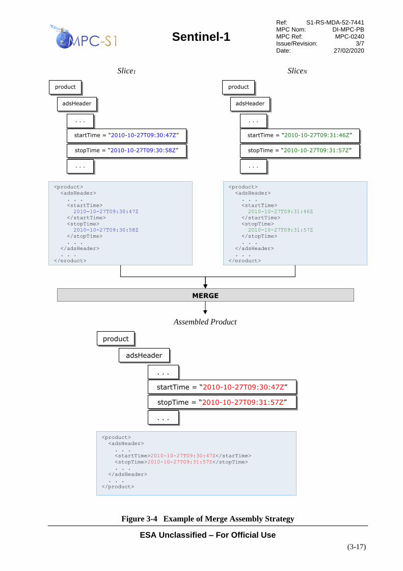
Sentinel-1
Ref: S1-RS-MDA-52-7441 MPC Nom: DI-MPC-PB MPC Ref: MPC-0240 Issue/Revision: 3/7 Date: 27/02/2020
ESA Unclassified – For Official Use
(3-17)
Figure 3-4 Example of Merge Assembly Strategy
product
adsHeader
. . .
startTime = “2010-10-27T09:30:47Z”
stopTime = “2010-10-27T09:30:58Z”
. . .
<product>
<adsHeader>
. . .
<startTime>
2010-10-27T09:30:47Z
</startTime>
<stopTime>
2010-10-27T09:30:58Z
</stopTime>
. . .
</adsHeader>
. . .
</product>
Slice1
<product>
<adsHeader>
. . .
<startTime>
2010-10-27T09:31:46Z
</startTime>
<stopTime>
2010-10-27T09:31:57Z
</stopTime>
. . .
</adsHeader>
. . .
</product>
SliceN
MERGE
product
adsHeader
. . .
startTime = “2010-10-27T09:30:47Z”
stopTime = “2010-10-27T09:31:57Z”
. . .
<product>
<adsHeader>
. . .
<startTime>2010-10-27T09:30:47Z</starTime>
<stopTime>2010-10-27T09:31:57Z</stopTime>
. . .
</adsHeader>
. . .
</product>
Assembled Product
product
adsHeader
. . .
startTime = “2010-10-27T09:31:46Z”
stopTime = “2010-10-27T09:31:57Z”
. . .

Sentinel-1
Ref: S1-RS-MDA-52-7441 MPC Nom: DI-MPC-PB MPC Ref: MPC-0240 Issue/Revision: 3/7 Date: 27/02/2020
ESA Unclassified – For Official Use
(3-18)
3.4.1.3 Concatenate
The concatenate strategy is used when the field or record is contained within a list.
This applies to both binary image data as well as XML annotation data.
For imagery data, the binary data from each slice is appended in order and any
applicable length (azimuth) dimension is updated to reflect the length of the
assembled image. The image width can vary from azimuth line to azimuth line and
this must be considered when assembling the final output image. The pixels should
be assembled in range time order and padding – zero-fill, for example – should be
applied for missing range pixels. A conceptual example of assembling imagery data
is illustrated in Figure 3-6.
For XML annotations, lists within a data set are always suffixed with the word
“List” and always contain an integer attribute named “count” that identifies the
number of items within the list. In general, concatenation is simply appending
records to the list in time ordered sequence and updating (merging in a sense) the
count attribute to identify the total number of items in the concatenated list.
Concatenation of any list within a data set is done at the highest level at which a list
exists. For example, if aList contains a record named aRecord and aRecord contains
a list named bList, concatenation is always performed on aList. To ensure data
completeness within each slice it is possible that list entries may be duplicated near
the time boundaries of consecutive slices. Duplicate list entries will always have the
exact same azimuthTime value and can be identified in this way. In terms of
handling duplicate entries in the assembled output product, they could be trimmed to
one entry in the assembled output product, or they could simply be left as duplicates
in the assembled output product. This specification makes no recommendation on
the approach for the handling of duplicates; the decision on how to handle duplicate
list entries is left to the discretion of the assembler.
In the example illustrated in Figure 3-5 below, the Doppler annotations for the slices
are concatenated. For sake of example the data segment is 60 seconds long and
divided into 6 slices of 10 seconds each, numbered 1 .. 6. The Doppler centroid
estimates are done every 5 seconds creating 2 estimates per slice and a total of 12
estimates over all the slices. For compactness, only the information for the first slice
and last slice are shown in the graph. The figure shows the dcEstimateList from the
first and last slice with two dcEstimate records under each. In both cases the value of
the count attribute is 2. For the assembled product, the figure shows how the
dcEstimateList has grown because the dcEstimate records from each slice have been
added and the value of the count attribute is set to 12.

Sentinel-1
Ref: S1-RS-MDA-52-7441 MPC Nom: DI-MPC-PB MPC Ref: MPC-0240 Issue/Revision: 3/7 Date: 27/02/2020
ESA Unclassified – For Official Use
(3-19)
product
dopplerCentroid
dcEstimateList
<product>
. . .
<dopplerCentroid>
<dcEstimateList count=”2”>
<dcEstimate>
<azimuthTime>
2010-10-27T09:30:47Z
</azimuthTime>
<t0>7.265845301551916e+06</t0>
. . .
</dcEstimate>
<dcEstimate>
<azimuthTime>
2010-10-27T09:30:52Z
</azimuthTime>
<t0>7.265845301551916e+06</t0>
. . .
</dcEstimate>
</dcEstimateList>
</dopplerCentroid>
. . .
</product>
Slice1
<product>
. . .
<dopplerCentroid>
<dcEstimateList count=”2”>
<dcEstimate>
<azimuthTime>
2010-10-27T09:31:46Z
</azimuthTime>
<t0>7.265845301551916e+06</t0>
. . .
</dcEstimate>
<dcBlock>
<azimuthTime>
2010-10-27T09:31:51Z
</azimuthTime>
<t0>7.265845301551916e+06</t0>
. . .
</dcEstimate>
</dcEstimateList>
</dopplerCentroid>
. . .
</product>
Slice6
CONCATENATE
@count = “2”
dcEstimate
azimuthTime = “2010-10-27T09:30:47Z”
t0 = 7.265845301551916e+06
. . .
dcEstimate
azimuthTime = “2010-10-27T09:30:52Z”
t0 = 7.265845301551916e+06
. . .
product
dopplerCentroid
dcEstimateList
@count = “2”
dcEstimate
azimuthTime = “2010-10-27T09:31:46Z”
t0 = 7.265845301551916e+06
. . .
dcEstimate
azimuthTime = “2010-10-27T09:31:51Z”
t0 = 7.265845301551916e+06
. . .
...
...

Sentinel-1
Ref: S1-RS-MDA-52-7441 MPC Nom: DI-MPC-PB MPC Ref: MPC-0240 Issue/Revision: 3/7 Date: 27/02/2020
ESA Unclassified – For Official Use
(3-20)
Figure 3-5 Example of Concatenate Assembly Strategy
product
dopplerCentroid
dcEstimateLis
t
<product>
. . .
<dopplerCentroid>
<dcEstimateList length=”12”>
<dcEstimate>
<azimuthTime>
2010-10-27T09:30:47Z
</azimuthTime>
<t0>7.265845301551916e+06</t0>
. . .
</dcEstimate>
<dcEstimate>
<azimuthTime>
2010-10-27T09:30:52Z
</azimuthTime>
<t0>7.265845301551916e+06</t0>
. . .
</dcEstimate>
<!-- 2 dcEstimate records for Slice2 -->
<!-- 2 dcEstimate records for Slice3 -->
<!-- 2 dcEstimate records for Slice4 -->
<!-- 2 dcEstimate records for Slice5 -->
<dcEstimate>
<azimuthTime>
2010-10-27T09:31:46Z
</azimuthTime>
<t0>7.265845301551916e+06</t0>
. . .
</dcEstimate>
<dcEstimate>
<azimuthTime>
2010-10-27T09:31:51Z
</azimuthTime>
<t0>7.265845301551916e+06</t0>
. . .
</dcEstimate>
</dcEstimateList>
</dopplerCentroid>
. . .
</product>
Assembled Product
@count = “12”
dcEstimate
azimuthTime = “2010-10-27T09:30:47Z”
t0 = 7.265845301551916e+06
. . .
dcEstimate
azimuthTime = “2010-10-27T09:30:52Z”
t0 = 7.265845301551916e+06
. . .
<!-- 2 dcEstimate records for Slice2 -->
<!-- 2 dcEstimate records for Slice3 -->
<!-- 2 dcEstimate records for Slice4 -->
<!-- 2 dcBlock records for Slice5 -->
dcEstimate
azimuthTime = “2010-10-27T09:31:46Z”
t0 = 7.265845301551916e+06
. . .
dcEstimate
azimuthTime = “2010-10-27T09:31:51Z”
t0 = 7.265845301551916e+06
. . .
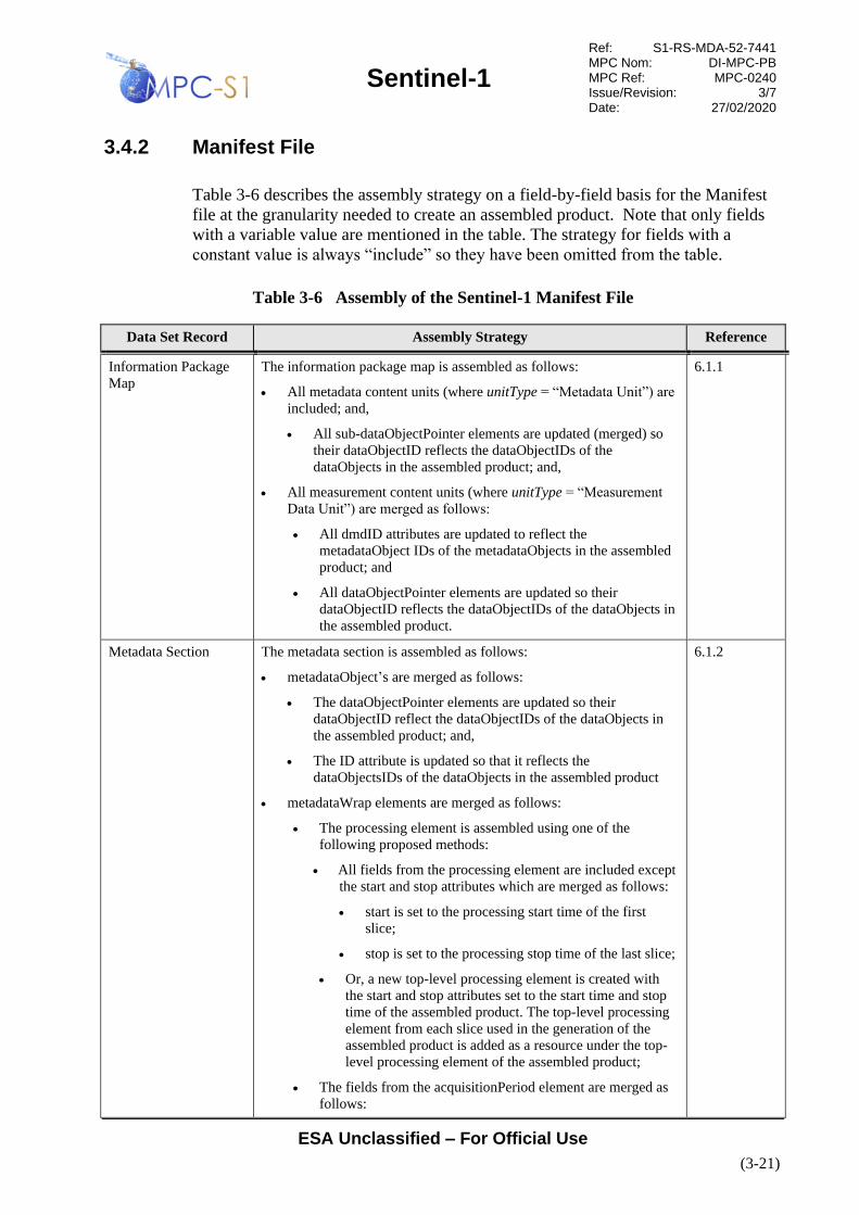
Sentinel-1
Ref: S1-RS-MDA-52-7441 MPC Nom: DI-MPC-PB MPC Ref: MPC-0240 Issue/Revision: 3/7 Date: 27/02/2020
ESA Unclassified – For Official Use
(3-21)
3.4.2 Manifest File
Table 3-6 describes the assembly strategy on a field-by-field basis for the Manifest
file at the granularity needed to create an assembled product. Note that only fields
with a variable value are mentioned in the table. The strategy for fields with a
constant value is always “include” so they have been omitted from the table.
Table 3-6 Assembly of the Sentinel-1 Manifest File
Data Set Record Assembly Strategy Reference
Information Package
Map
The information package map is assembled as follows:
• All metadata content units (where unitType = “Metadata Unit”) are
included; and,
• All sub-dataObjectPointer elements are updated (merged) so
their dataObjectID reflects the dataObjectIDs of the
dataObjects in the assembled product; and,
• All measurement content units (where unitType = “Measurement
Data Unit”) are merged as follows:
• All dmdID attributes are updated to reflect the
metadataObject IDs of the metadataObjects in the assembled
product; and
• All dataObjectPointer elements are updated so their
dataObjectID reflects the dataObjectIDs of the dataObjects in
the assembled product.
6.1.1
Metadata Section The metadata section is assembled as follows:
• metadataObject’s are merged as follows:
• The dataObjectPointer elements are updated so their
dataObjectID reflect the dataObjectIDs of the dataObjects in
the assembled product; and,
• The ID attribute is updated so that it reflects the
dataObjectsIDs of the dataObjects in the assembled product
• metadataWrap elements are merged as follows:
• The processing element is assembled using one of the
following proposed methods:
• All fields from the processing element are included except
the start and stop attributes which are merged as follows:
• start is set to the processing start time of the first
slice;
• stop is set to the processing stop time of the last slice;
• Or, a new top-level processing element is created with
the start and stop attributes set to the start time and stop
time of the assembled product. The top-level processing
element from each slice used in the generation of the
assembled product is added as a resource under the top-
level processing element of the assembled product;
• The fields from the acquisitionPeriod element are merged as
follows:
6.1.2

Sentinel-1
Ref: S1-RS-MDA-52-7441 MPC Nom: DI-MPC-PB MPC Ref: MPC-0240 Issue/Revision: 3/7 Date: 27/02/2020
ESA Unclassified – For Official Use
(3-22)
Data Set Record Assembly Strategy Reference
• The startTime and startTimeANX attributes are set to
their respective times from the first slice;
• The stopTime and stopTimeANX attributes are set to
their respective times from the last slice;
• All fields from the platform element are included;
• The fields from the measurementOrbitReference element are
merged as follows:
• For the orbitNumber element the start attribute is set to
the value from the first slice and the stop attribute is set
to the value from the last slice;
• For the relativeOrbitNumber element the start attribute
is set to the value from the first slice and the stop
attribute is set to the value from the last slice;
• The value of the cycleNumber element is set to the value
from the last slice;
• The value of the phaseIdentifier element is set to the
value from the last slice;
• The value of the pass element is set to the value from the
first slice;
• The value of the ascendingNodeTime is set to the value
from the first slice;
• The measurementFrameSet element is merged by updating
the coordinates element so that the values represent the
coordinates of the assembled image.
• All the fields in the generalProductInformation element are
included except for the productComposition and
sliceProductFlag. The productComposition is set to
“Assembled” and the sliceProductFlag is updated so that it is
set to false and the following elements are then omitted:
• segmentStartTime;
• sliceNumber;
• totalSlices; and
• metadataReference elements (RDS) are included.
Data Object Section The data object section is assembled by merging each dataObject as
follows:
• The ID attribute may be merged by updating its value based on
filename of the object within the assembled product;
• The href attribute of the byteStream element is merged by updating
its value so that it points to the filename of the object within the
assembled product;
• The checksum element of the byteStream element is merged by re-
calculating the checksum on the object file within the assembled
product;
• The size attribute of the byteStream element is merged by setting
its value to the size of the object file within the assembled product.
6.1.3

Sentinel-1
Ref: S1-RS-MDA-52-7441 MPC Nom: DI-MPC-PB MPC Ref: MPC-0240 Issue/Revision: 3/7 Date: 27/02/2020
ESA Unclassified – For Official Use
(3-23)
3.4.3 Measurement Data Sets
Table 3-7 describes the assembly strategy on a field-by-field basis for the L1 image
MDS at the granularity needed to create an assembled product. Note that only fields
with a variable value are mentioned in the table. The strategy for fields with a
constant value is always “include” so they have been omitted from the table. The
reference column in the table indicates the section where the field is described.
Figure 3-6 illustrates the process of assembling the information in an L1 image
MDS.
Table 3-7 Assembly of the L1 Measurement Data Sets
Data Set Name Assembly Strategy Reference
L1 Image TIFF/GeoTIFF header tags are included and merged. Details are provided
in Table 3-8.
Measurement (image) data is concatenated.
6.2.1
Quick look Image The PNG header is merged by setting the Width field to the maximum
range extent across all the slices and summing the Height field for all
slices. All other header fields are included.
Measurement (image) data is concatenated.
Note: For IW and EW SLC images, the Quick-Look image for a slice will
contain black fill at the start and end of the image that varies for each
swath. This is due to the fact that the SLCs consist of staggered bursts
from multiple swaths, so that the edges of the Quick-Look image of a
slice must be padded out so that all swaths start and end at the same line.
As a result, the concatenated Quick-Look images from IW and EW SLC
slices will also contain extra padding at slice boundaries, and the resulting
Quick-Look image will be longer than the concatenated full resolution
Quick-Look image. In addition, if a KML bounding box is used to
overlay the IW/EW Quick-Look on a map, due to the mismatch in image
dimensions and the physical geolocation, the image will appear
"squished" in the overlay.
This only applies to IW and EW SLC Quick-Look images, it does not
apply to other modes or to other IW and EW products.
6.2.2
L2 Ocean Not Applicable. The L2 OCN product is generated only from an
individual scene or slice input L1 product and assembled products are not
relevant to the generation of L2 products. The combination of data sets
within L2 products is beyond the scope of this specification.
6.2.3
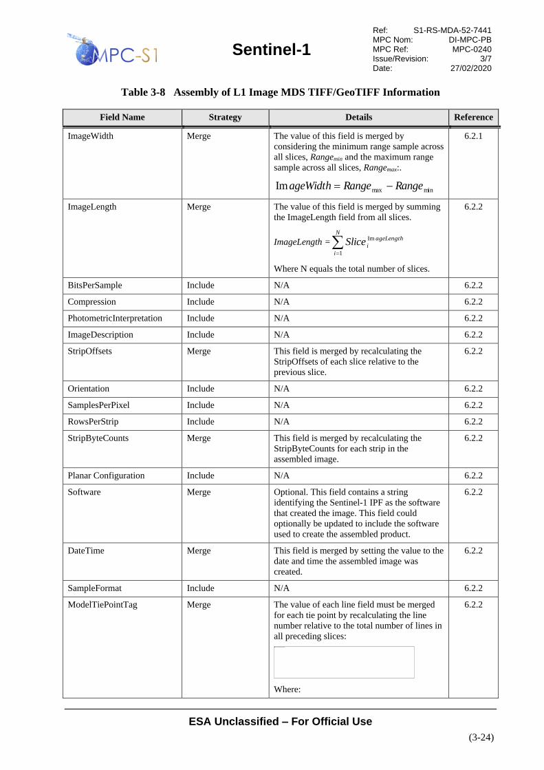
Sentinel-1
Ref: S1-RS-MDA-52-7441 MPC Nom: DI-MPC-PB MPC Ref: MPC-0240 Issue/Revision: 3/7 Date: 27/02/2020
ESA Unclassified – For Official Use
(3-24)
Table 3-8 Assembly of L1 Image MDS TIFF/GeoTIFF Information
Field Name Strategy Details Reference
ImageWidth Merge The value of this field is merged by
considering the minimum range sample across
all slices, Rangemin and the maximum range
sample across all slices, Rangemax:.
minmaxIm RangeRangeageWidth −=
6.2.1
ImageLength Merge The value of this field is merged by summing
the ImageLength field from all slices.
ImageLength ==
N
i
ageLength
iSlice1
Im
Where N equals the total number of slices.
6.2.2
BitsPerSample Include N/A 6.2.2
Compression Include N/A 6.2.2
PhotometricInterpretation Include N/A 6.2.2
ImageDescription Include N/A 6.2.2
StripOffsets Merge This field is merged by recalculating the
StripOffsets of each slice relative to the
previous slice.
6.2.2
Orientation Include N/A 6.2.2
SamplesPerPixel Include N/A 6.2.2
RowsPerStrip Include N/A 6.2.2
StripByteCounts Merge This field is merged by recalculating the
StripByteCounts for each strip in the
assembled image.
6.2.2
Planar Configuration Include N/A 6.2.2
Software Merge Optional. This field contains a string
identifying the Sentinel-1 IPF as the software
that created the image. This field could
optionally be updated to include the software
used to create the assembled product.
6.2.2
DateTime Merge This field is merged by setting the value to the
date and time the assembled image was
created.
6.2.2
SampleFormat Include N/A 6.2.2
ModelTiePointTag Merge The value of each line field must be merged
for each tie point by recalculating the line
number relative to the total number of lines in
all preceding slices:
Where:
6.2.2
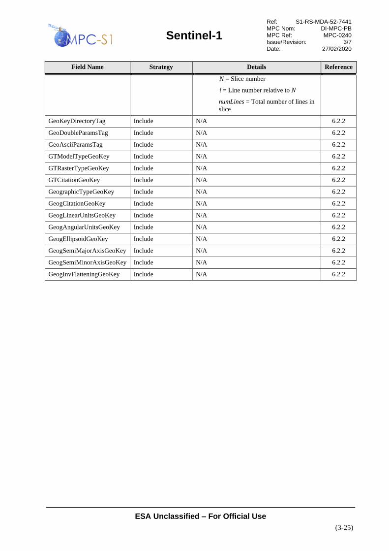
Sentinel-1
Ref: S1-RS-MDA-52-7441 MPC Nom: DI-MPC-PB MPC Ref: MPC-0240 Issue/Revision: 3/7 Date: 27/02/2020
ESA Unclassified – For Official Use
(3-25)
Field Name Strategy Details Reference
N = Slice number
i = Line number relative to N
numLines = Total number of lines in
slice
GeoKeyDirectoryTag Include N/A 6.2.2
GeoDoubleParamsTag Include N/A 6.2.2
GeoAsciiParamsTag Include N/A 6.2.2
GTModelTypeGeoKey Include N/A 6.2.2
GTRasterTypeGeoKey Include N/A 6.2.2
GTCitationGeoKey Include N/A 6.2.2
GeographicTypeGeoKey Include N/A 6.2.2
GeogCitationGeoKey Include N/A 6.2.2
GeogLinearUnitsGeoKey Include N/A 6.2.2
GeogAngularUnitsGeoKey Include N/A 6.2.2
GeogEllipsoidGeoKey Include N/A 6.2.2
GeogSemiMajorAxisGeoKey Include N/A 6.2.2
GeogSemiMinorAxisGeoKey Include N/A 6.2.2
GeogInvFlatteningGeoKey Include N/A 6.2.2
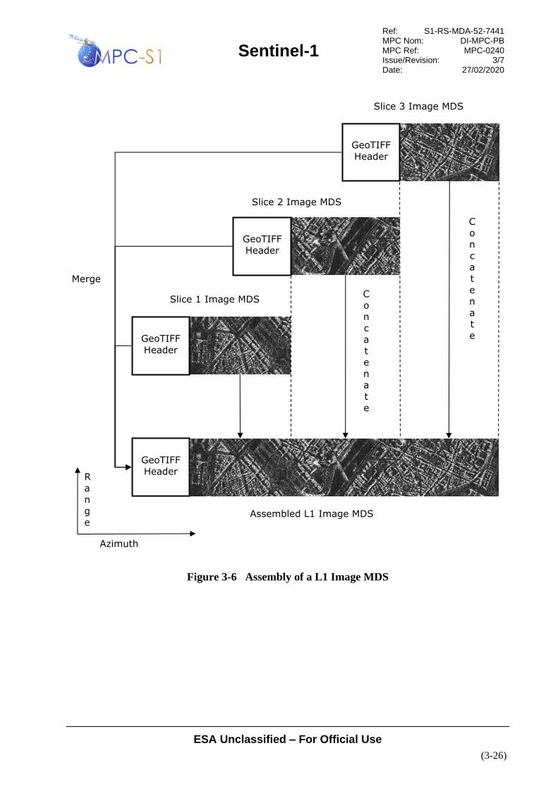
Sentinel-1
Ref: S1-RS-MDA-52-7441 MPC Nom: DI-MPC-PB MPC Ref: MPC-0240 Issue/Revision: 3/7 Date: 27/02/2020
ESA Unclassified – For Official Use
(3-26)
Figure 3-6 Assembly of a L1 Image MDS
GeoTIFF
Header
GeoTIFF
Header
GeoTIFF
Header
GeoTIFF
Header
C
on
ca
te
na
t
e
Merge
Azimuth
R
an
g
e
C
on
ca
t
en
at
e
Slice 1 Image MDS
Slice 2 Image MDS
Slice 3 Image MDS
Assembled L1 Image MDS
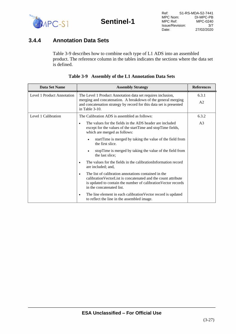
Sentinel-1
Ref: S1-RS-MDA-52-7441 MPC Nom: DI-MPC-PB MPC Ref: MPC-0240 Issue/Revision: 3/7 Date: 27/02/2020
ESA Unclassified – For Official Use
(3-27)
3.4.4 Annotation Data Sets
Table 3-9 describes how to combine each type of L1 ADS into an assembled
product. The reference column in the tables indicates the sections where the data set
is defined.
Table 3-9 Assembly of the L1 Annotation Data Sets
Data Set Name Assembly Strategy References
Level 1 Product Annotation The Level 1 Product Annotation data set requires inclusion,
merging and concatenation. A breakdown of the general merging
and concatenation strategy by record for this data set is presented
in Table 3-10.
6.3.1
A2
Level 1 Calibration The Calibration ADS is assembled as follows:
• The values for the fields in the ADS header are included
except for the values of the startTime and stopTime fields,
which are merged as follows:
• startTime is merged by taking the value of the field from
the first slice.
• stopTime is merged by taking the value of the field from
the last slice;
• The values for the fields in the calibrationInformation record
are included; and,
• The list of calibration annotations contained in the
calibrationVectorList is concatenated and the count attribute
is updated to contain the number of calibrationVector records
in the concatenated list.
• The line element in each calibrationVector record is updated
to reflect the line in the assembled image.
6.3.2
A3

Sentinel-1
Ref: S1-RS-MDA-52-7441 MPC Nom: DI-MPC-PB MPC Ref: MPC-0240 Issue/Revision: 3/7 Date: 27/02/2020
ESA Unclassified – For Official Use
(3-28)
Data Set Name Assembly Strategy References
Level 1 Noise The Noise ADS is assembled as follows:
• The values for the fields in the ADS header are included
except for the values of the startTime and stopTime fields,
which are merged as follows:
• startTime is merged by taking the value of the field from
the first slice.
• stopTime is merged by taking the value of the field from
the last slice; and,
• The list of range thermal annotations contained in the
noiseRangeVectorList is concatenated and the count attribute
is updated to contain the number of noiseRangeVector records
in the concatenated list.
• The line element in each noiseRangeVector record is updated
to reflect the line in the assembled image.
• The list of azimuth thermal annotations contained in the
noiseAzimuthVectorList is concatenated and the count
attribute is updated to contain the number of
noiseAzimuthVector records in the concatenated list.
• The firstAzimuthLine, lastAzimuthLine and line elements in
each noiseAzimuthVector are updated to reflect the line in the
assembled image.
6.3.3
A4
Map Overlay The values for all fields in the Map Overlay data set are included
except for the coordinates elements of the gx:LatLonQuad
element; these are merged by updating their values so that they
represent the coordinates of the assembled image.
6.3.4
Product Preview The values for all fields in the Product Preview data set are
merged by setting the product name and data set file names to the
corresponding names in the assembled product.
6.3.5
Table 3-10 Assembly of the Level 1 Product Annotation ADS
Data Set Record Assembly Strategy Reference
ADS Header The values for the fields in the ADS header are included except for the
values of the startTime and stopTime fields, which are merged as
follows:
• startTime is merged by taking the value of the field from the first
slice.
• stopTime is merged by taking the value of the field from the last
slice.
Table 3-20
Quality Information The list of quality annotations contained in the qualityDataList
element is concatenated and the count attribute is updated to contain
the number of qualityData records in the concatenated list.
6.3.1.1
General Annotation The productInformation sub-record contains single value fields that
are merged and included. All other sub-records contain lists which are
concatenated. Details are presented in Table 3-11.
6.3.1.2

Sentinel-1
Ref: S1-RS-MDA-52-7441 MPC Nom: DI-MPC-PB MPC Ref: MPC-0240 Issue/Revision: 3/7 Date: 27/02/2020
ESA Unclassified – For Official Use
(3-29)
Data Set Record Assembly Strategy Reference
Image Annotation This DSR contains two records which contain only single value fields.
The fields in the imageInformation record are included and merged
and all the fields for the processingInformation record are included;
except for the inputDimensionsList record, which is concatenated.
Details are presented in Table 3-12.
0
Doppler Centroid The list of Doppler centroid annotations contained in the dcBlockList
element is concatenated and the count attribute is updated to contain
the number of dcBlock records in the concatenated list.
6.3.1.4
Antenna Pattern The list of antenna pattern annotations contained in the
antennaPatternList element is concatenated and the count attribute is
updated to contain the number of antennaPattern records in the
concatenated list.
6.3.1.5
Swath Timing The list of swath timing annotations contained in the burstList element
is concatenated and the count attribute is updated to contain the
number of burst records in the concatenated list.
In addition to concatenation, each byteOffset field must be merged to
contain the correct byte offset by recalculating each byteOffset
relative to all preceding bursts within the assembled image:
N
i
N
fsetlastByteOf
N
i SliceSlicebyteOffset += −1
Where:
N = Slice number
i = Byte offset relative to N
lastByteOffset = Largest (last) byte offset from the previous
slice
6.3.1.6
Geolocation Grid The list of geolocation grid points contained in the
geolocationGridPointList element is concatenated and the count
attribute is updated to contain the number of geolocationGridPoint
records in the concatenated list.
In addition to the concatenation, the value of the line field must be
merged for each grid point by recalculating the line number relative to
the total number of lines in all preceding slices:
Where:
N = Slice number
i = Line number relative to N
numLines = Total number of lines in slice
6.3.1.7
Coordinate Conversion The list of coordinate conversion annotations contained in the
coordinateConversionList is concatenated and the count attribute is
updated to contain the number of coordinateConversion records in the
concatenated list.
6.3.1.8

Sentinel-1
Ref: S1-RS-MDA-52-7441 MPC Nom: DI-MPC-PB MPC Ref: MPC-0240 Issue/Revision: 3/7 Date: 27/02/2020
ESA Unclassified – For Official Use
(3-30)
Data Set Record Assembly Strategy Reference
Swath Merging The lists of swath merging annotations are concatenated. There is a
swathBoundsList for each swath. The list of swath merging
annotations contained in each swathBoundsList is concatenated and
the count attribute for each is updated to contain the number of
swathBounds records in the concatenated list.
6.3.1.9
Table 3-11 Assembly of the L1 General Annotation ADSR
Field Path
Strategy Details
/product/generalAnnotation/productInformation/pass
Merge Use the pass field from the first slice in the product.
/product/generalAnnotation/productInformation/timelinessCategory
Include N/A
/product/generalAnnotation/productInformation/platformHeading
Merge The platformHeading field is merged recalculating the platform heading mid-
acquisition (azimuth direction) for the assembled product.
/product/generalAnnotation/productInformation/projection
Include N/A
/product/generalAnnotation/productInformation/rangeSamplingRate
Include N/A
/product/generalAnnotation/productInformation/radarFrequency
Include N/A
/product/generalAnnotation/productInformation/azimuthSteeringRate
Include N/A
/product/generalAnnotation/downlinkInformationList
Concatenate The list of downlink information annotations contained in the
downlinkInformationList element is concatenated and the count attribute is updated
to contain the number of downlinkInformation records in the concatenated list.
/product/generalAnnotation/orbitList
Concatenate The list of orbit annotations contained in the orbitList element is concatenated and
the count attribute is updated to contain the number of orbit records in the
concatenated list.
/product/generalAnnotation/attitudeList
Concatenate The list of downlink information annotations contained in the attitudeList element is
concatenated and the count attribute is updated to contain the number of attitude
records in the concatenated list.
/product/generalAnnotation/replicaInformation/replicaInformationList
Concatenate The list of replicaInformation annotations contained in the replicaInformationList
element is concatenated and the count attribute is updated to contain the number of
replicaInformation records in the concatenated list.

Sentinel-1
Ref: S1-RS-MDA-52-7441 MPC Nom: DI-MPC-PB MPC Ref: MPC-0240 Issue/Revision: 3/7 Date: 27/02/2020
ESA Unclassified – For Official Use
(3-31)
Field Path
Strategy Details
/product/generalAnnotation/noiseList
Concatenate The list of noise measurement annotations contained in the noiseList element is
concatenated and the count attribute is updated to contain the number of noise
records in the concatenated list.
/product/generalAnnotation/terrainHeightList
Concatenate The list of terrain height annotations contained in the terrainHeigthList element is
concatenated and the count attribute is updated to contain the number of
terrainHeight records in the concatenated list.
/product/generalAnnotation/azimuthFmRateList
Concatenate The list of azimuth FM rate annotations contained in the azimuthFmRateList
element is concatenated and the count attribute is updated to contain the number of
azimuthFmRate records in the concatenated list.
Table 3-12 Assembly of the L1 Image Annotation ADSR
Field Path
Strategy Details
/product/imageAnnotation/imageInformation/productFirstLineUtcTime
Merge The productFirstLineUtcTime field is merged by using the value of this field from
the first slice.
/product/imageAnnotation/imageInformation/productLastLineUtcTime
Merge The productLastLineUtcTime field is merged by using the value of this field from
the last slice.
/product/imageAnnotation/imageInformation/ascendingNodeTime
Merge The ascendingNodeTime field is merged by using the value of this field from the
first slice.
/product/generalAnnotation/imageInformation/anchorTime
Include The anchorTime value will be the same in every slice
/product/generalAnnotation/imageInformation/productComposition
Merge The productComposition field is set to “Assembled” for the final product (the input
slice productComposition fields should be set to “Slice”).
/product/generalAnnotation/imageInformation/sliceNumber
Merge The sliceNumber field is set to 0.
/product/generalAnnotation/imageInformation/sliceList
Include N/A
/product/generalAnnotation/imageInformation/slantRangeTime
Include The slantRangeTime value will be the same in every slice
/product/imageAnnotation/imageInformation/pixelValue
Include N/A
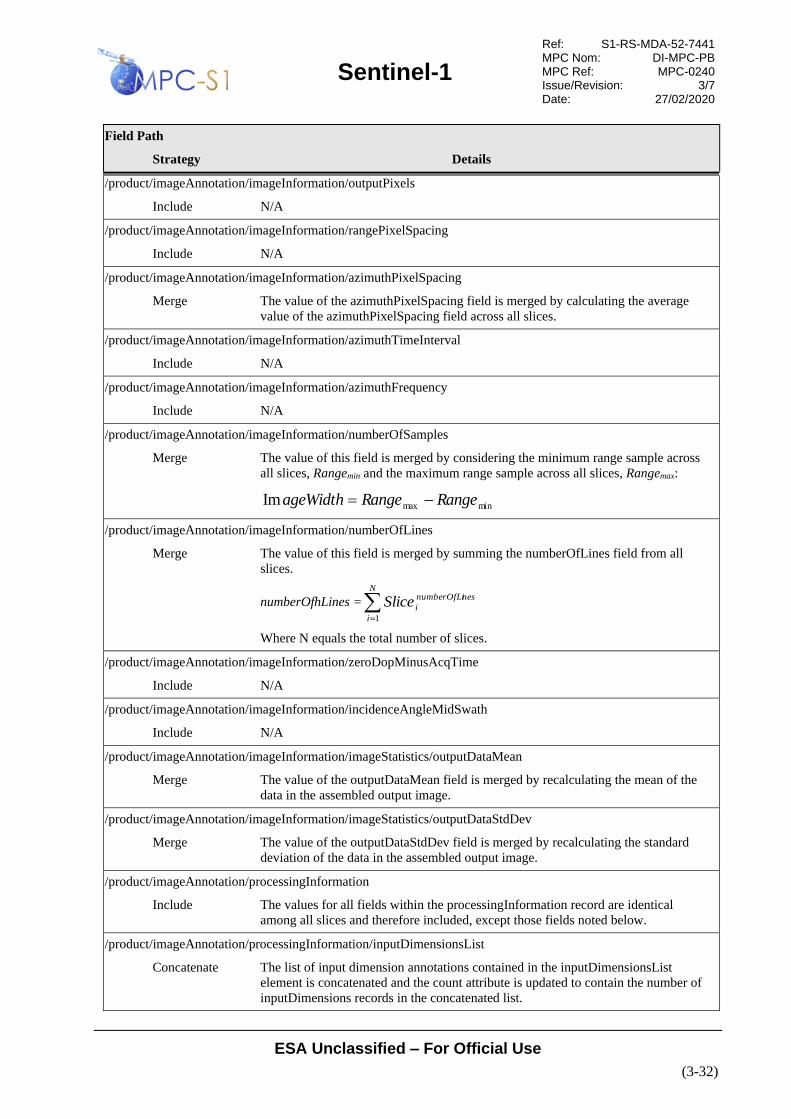
Sentinel-1
Ref: S1-RS-MDA-52-7441 MPC Nom: DI-MPC-PB MPC Ref: MPC-0240 Issue/Revision: 3/7 Date: 27/02/2020
ESA Unclassified – For Official Use
(3-32)
Field Path
Strategy Details
/product/imageAnnotation/imageInformation/outputPixels
Include N/A
/product/imageAnnotation/imageInformation/rangePixelSpacing
Include N/A
/product/imageAnnotation/imageInformation/azimuthPixelSpacing
Merge The value of the azimuthPixelSpacing field is merged by calculating the average
value of the azimuthPixelSpacing field across all slices.
/product/imageAnnotation/imageInformation/azimuthTimeInterval
Include N/A
/product/imageAnnotation/imageInformation/azimuthFrequency
Include N/A
/product/imageAnnotation/imageInformation/numberOfSamples
Merge The value of this field is merged by considering the minimum range sample across
all slices, Rangemin and the maximum range sample across all slices, Rangemax:
minmaxIm RangeRangeageWidth −=
/product/imageAnnotation/imageInformation/numberOfLines
Merge The value of this field is merged by summing the numberOfLines field from all
slices.
numberOfhLines ==
N
i
nesnumberOfLi
iSlice1
Where N equals the total number of slices.
/product/imageAnnotation/imageInformation/zeroDopMinusAcqTime
Include N/A
/product/imageAnnotation/imageInformation/incidenceAngleMidSwath
Include N/A
/product/imageAnnotation/imageInformation/imageStatistics/outputDataMean
Merge The value of the outputDataMean field is merged by recalculating the mean of the
data in the assembled output image.
/product/imageAnnotation/imageInformation/imageStatistics/outputDataStdDev
Merge The value of the outputDataStdDev field is merged by recalculating the standard
deviation of the data in the assembled output image.
/product/imageAnnotation/processingInformation
Include The values for all fields within the processingInformation record are identical
among all slices and therefore included, except those fields noted below.
/product/imageAnnotation/processingInformation/inputDimensionsList
Concatenate The list of input dimension annotations contained in the inputDimensionsList
element is concatenated and the count attribute is updated to contain the number of
inputDimensions records in the concatenated list.

Sentinel-1
Ref: S1-RS-MDA-52-7441 MPC Nom: DI-MPC-PB MPC Ref: MPC-0240 Issue/Revision: 3/7 Date: 27/02/2020
ESA Unclassified – For Official Use
(3-33)
3.5 Product Naming
This section defines the naming convention for Sentinel-1 products. Consideration
has been made with respect to the ESA Sentinel-1 Products Naming Convention
described in [R-9]. This document has been created specifically to meet the product
naming needs of the Sentinel-1 mission.
3.5.1 Product
This section defines the naming standard for the top-level Sentinel-1 product folder.
The top-level Sentinel-1 product folder name is composed of upper-case
alphanumeric characters separated by an underscore “_”. Figure 3-7 defines the
naming standard for Sentinel-1 products. Table 3-13 defines the naming elements
and their range and is used throughout the remainder of this document as the
standard for naming Sentinel-1 product folders.
For assembled products, the product name is updated as follows:
• The value of each naming element is included, except for:
• Start date/time which is merged by using the value from the first slice;
• Stop date/time which is merged by using the value from the last slice;
and,
• Product unique identifier which is merged by recalculating the CRC-16
checksum on the assembled manifest file.
Note that ASAR options are only valid for ASAR offline test products and will not
be available operationally.

Sentinel-1
Ref: S1-RS-MDA-52-7441 MPC Nom: DI-MPC-PB MPC Ref: MPC-0240 Issue/Revision: 3/7 Date: 27/02/2020
ESA Unclassified – For Official Use
(3-34)
Figure 3-7 Sentinel-1 Product Naming Convention
MMM_BB_TTTR_LFPP_YYYYMMDDTHHMMSS_YYYYMMDDTHHMMSS_OOOOOO_DDDDDD_CCCC.EEEE
Stop Date and Time
Product Type:
“SLC” / “GRD” /
“OCN”
Mode/Beam Identifier
“S1”/”S2”/”S3”/S4”/”S5/”S6”
“IW”
“EW”
“WV”
“IM”
“EN”/”N1”/”N2”/”N3”/N4”/”N5/”N6”
Mission Identifier:
“S1A”
“S1B”
“ASA”
Processing Level:
“1” / “2”
Product Class:
“S” (SAR Standard)
“A” (Annotation)
Polarisation:
“SH” (Single HH)
“SV” (Single VV)
“DH” (Dual HH/HV)
“DV” (Dual VV/VH)
“HH” (Partial Dual, HH only)
“HV” (Partial Dual, HV only)
“VV” (Partial Dual, VV only)
“VH” (Partial Dual, VH only)
Product Unique Identifier
Start Date and Time
Product Format Extension:
“SAFE”
Absolute Orbit Number
Mission Data Take Id
Resolution Class:
“F” (Full resolution)
“H” (High resolution)
“M” (Medium resolution)

Sentinel-1
Ref: S1-RS-MDA-52-7441 MPC Nom: DI-MPC-PB MPC Ref: MPC-0240 Issue/Revision: 3/7 Date: 27/02/2020
ESA Unclassified – For Official Use
(3-35)
Table 3-13 Sentinel-1 Product Naming Elements
Name Element Pattern Name Element Description Name Element Range
MMM Mission identifier. The S1A option
is used for products produced for
the Sentinel-1A instrument and the
S1B is used for products produced
for the Sentinel-1B instrument.
The ASA option is used for
products produced from the
ENVISAT ASAR instrument.
S1A, S1B, ASA
BB Mode/beam identifier. The S1-S6
beams apply to SM products, and
IW, EW and WV identifiers apply
to products from the respective
modes. The EN and N1-N6 beams
apply to the notch acquisition
modes. The IM and WV modes
apply to ASAR IM and WV
products respectively.
S1, S2, S3, S4, S5, S6, IW, EW, WV, EN, N1,
N2, N3, N4, N5, N6, IM
TTT Product type. SLC, GRD, OCN
R Resolution class. F (Full resolution), H (High resolution), M
(Medium resolution), _ (underscore: Not
applicable to the current product type. Used for
SLC and OCN.)
L Processing level. 1, 2
F Product class. S (SAR Standard), A (Annotation product).
PP Polarisation. SH (Single HH polarisation),
SV (Single VV polarisation),
DH (Dual HH/HV polarisation),
DV (Dual VV/VH polarisation),
HH (Partial Dual polarisation, HH only),
HV (Partial Dual polarisation, HV only),
VV (Partial Dual polarisation, VV only),
VH (Partial Dual polarisation, VH only)
YYYYMMDDTHHMMSS Product start or stop date and time. Fourteen digits representing the start date and
time separated by the character T.
OOOOOO Absolute orbit number at product
start time.
000001-999999
DDDDDD Mission data take identifier. 000001-FFFFFF (000000 for ASAR)
CCCC Product unique identifier. A
hexadecimal string generated by
computing CRC-16 on the
manifest file. The CRC-16
algorithm used to compute the
unique identifier is CRC-CCITT
(0xFFFF).
0000-FFFF
EEEE Product format extension. SAFE

Sentinel-1
Ref: S1-RS-MDA-52-7441 MPC Nom: DI-MPC-PB MPC Ref: MPC-0240 Issue/Revision: 3/7 Date: 27/02/2020
ESA Unclassified – For Official Use
(3-36)
3.5.2 Manifest File
The name of the manifest file included in all products is:
manifest.safe
3.5.3 Data Sets
This section defines the naming standard for all data set files within a Sentinel-1
product. Sentinel-1 product data sets are composed of lower-case alphanumeric
characters separated by a hyphen “-”. Table 3-14 defines the naming elements and
their range and is used throughout the remainder of this document as the standard for
naming Sentinel-1 product data sets.
In the case of assembled products, the data set names are updated as follows:
• The value of each naming element is included, except for:
• Sensing start date/time which is merged by using the value from the first
slice; and
• Sensing stop date/time which is merged by using the value from the last
slice.
Note that ASAR options are only valid for ASAR offline test products and will not
be available operationally.

Sentinel-1
Ref: S1-RS-MDA-52-7441 MPC Nom: DI-MPC-PB MPC Ref: MPC-0240 Issue/Revision: 3/7 Date: 27/02/2020
ESA Unclassified – For Official Use
(3-37)
Table 3-14 Sentinel-1 Data Set Naming Elements
Name Element
Pattern
Name Element Description Name Element Range
mmm Mission identifier. The s1a option is used for
products produced for the Sentinel-1A
instrument and the s1b is used for products
produced for the Sentinel-1B instrument. The
asa option is used for products produced from
the ENVISAT ASAR instrument.
s1a, s1b, asa
sss Swath identifier (up to 3 lower case
alphanumeric characters). The s1-s6 swaths
apply to SM products, the iw and iw1-3 swaths
apply to IW products (iw is used for detected IW
products where the 3 swaths are merged into one
image), the ew and ew1-5 swaths apply to EW
products (ew is used for detected EW products
where the 5 swaths are merged into one image),
and the wv1-2 swaths apply to WV products.
The en and n1-n6 swaths apply to the notch
acquisition modes. The is1-is7 swaths apply to
ASAR IM and WV products.
s1, s2, s3, s4, s5, s6, iw, iw1, iw2,
iw3, ew, ew1, ew2, ew3, ew4, ew5,
wv1, wv2, en, n1, n2, n3, n4, n5, n6,
is1, is2, is3, is4, is5, is6, is7
ttt Product type slc, grd, ocn
pp Polarisation hh (Single HH polarisation),
hv (Single HV polarisation),
vv(Single VV polarisation),
vh (Single VH polarisation)
nnn Image number. For WV products the image
number is used to distinguish between vignettes.
For SM, IW and EW modes the image number is
still used but refers instead to each swath and
polarisation combination (known as the
“channel”) of the data.
001-999
See notes 1234 below.
yyyymmddthhmmss Product start or stop date and time. Fourteen digits representing the date
and time separated by the character t5.
oooooo Absolute orbit number at product start time. 000001-999999
dddddd Mission data take id.
For Level 2 measurement data, this field can be
either in lower or upper case
000001-ffffff or 000001-FFFFFF
1 WV mode has an image number for each vignette. For a WV product with 105 vignettes, 105
images exist numbered in time ascending order from 001 through 105.
2 SM single polarisation products have one channel numbered 001. SM dual polarisation products
have two channels numbered 001 and 002 in the order they are processed by the IPF.
3 IW single polarisation products have three channels numbered 001 – 003. IW dual polarisation
products have six channels numbered 001 – 006 in the order they are processed by the IPF.
4 EW single polarisation products have five channels numbered 001 – 005. EW dual polarisation
products have ten channels numbered 001 – 010 in the order they are processed by the IPF.
5 For IW and EW SLC products the start and stop times are different for each MDS.

Sentinel-1
Ref: S1-RS-MDA-52-7441 MPC Nom: DI-MPC-PB MPC Ref: MPC-0240 Issue/Revision: 3/7 Date: 27/02/2020
ESA Unclassified – For Official Use
(3-38)
Name Element
Pattern
Name Element Description Name Element Range
eeee File extension html, kml, tiff, xml, xsd, nc, png
3.5.3.1 Measurement Data Sets
Table 3-15 defines the naming convention for all measurement data sets used within
Sentinel-1 products.
Table 3-15 Measurement Data Set Naming Convention for Sentinel-1
MDS Type Naming Convention
L1 Image and
L2 Measurement
mmm-sss-ttt-pp-yyyymmddthhmmss-yyyymmddthhmmss-oooooo-dddddd-nnn.eeee
Quick look quick-look.png
3.5.3.2 Annotation Data Sets
Table 3-16 defines the naming convention for all annotation data sets used within
Sentinel-1 products.
Table 3-16 Annotation Data Set Naming Convention for Sentinel-1
ADS Type Naming Convention
Level 1 Product
Annotation
mmm-sss-ttt-pp-yyyymmddthhmmss-yyyymmddthhmmss-oooooo-dddddd-nnn.xml
Level 1
Calibration
calibration-mmm-sss-ttt-pp-yyyymmddthhmmss-yyyymmddthhmmss-oooooo-dddddd-
nnn.xml
Level 1 Noise noise-mmm-sss-ttt-pp-yyyymmddthhmmss-yyyymmddthhmmss-oooooo-dddddd-nnn.xml
Map Overlay map-overlay.kml
Product Preview product-preview.html
3.5.3.3 Representation Data Sets
Table 3-17 defines the names of all representation data sets used within Sentinel-1
products.
Table 3-17 Representation Data Set Naming Convention for Sentinel-1
RDS Type Naming Convention
Sentinel 1 Object Types s1-object-types.xsd
Level 1 Product s1-level-1-product.xsd

Sentinel-1
Ref: S1-RS-MDA-52-7441 MPC Nom: DI-MPC-PB MPC Ref: MPC-0240 Issue/Revision: 3/7 Date: 27/02/2020
ESA Unclassified – For Official Use
(3-39)
RDS Type Naming Convention
Level 1 Calibration s1-level-1-calibration.xsd
Level 1 Noise s1-level-1-noise.xsd
3.6 Product Conventions
This section describes applicable product conventions.
3.6.1 Decisions
• GeoTIFF imagery will be stored in native byte endian format, nominally little
endian (byte order is specified in the TIFF format).
• Product annotations will use standard SI units whenever possible.
• Attributes should be defined using only the following types from the XML
Schema namespace [http://www.w3.org/2001/XMLSchema]:
• long
• int
• short
• byte
• unsignedLong
• unsignedInt
• unsignedShort
• unsignedByte
• string
• Where ever possible elements should be defined using the primitive data types
described in Section 3.6.3 for the Sentinel-1 namespaces:
• s1sar: http://www.esa.int/safe/sentinel-1.0/sentinel-1/sar
• s1sarl1: http://www.esa.int/safe/sentinel-1.0/sentinel-1/sar/level-1
• s1sarl2: http://www.esa.int/safe/sentinel-1.0/sentinel-1/sar/level-2
3.6.2 Content Table Conventions
This specification presents the contents of S1 product structures as using tables
detailing the content. In order to help understand the information contained in these
tables the columns present in each table and their meaning are presented in
Table 3-18.

Sentinel-1
Ref: S1-RS-MDA-52-7441 MPC Nom: DI-MPC-PB MPC Ref: MPC-0240 Issue/Revision: 3/7 Date: 27/02/2020
ESA Unclassified – For Official Use
(3-40)
Table 3-18 Product Data Content Table Column Descriptions
Column Name Description
Name Defines the name of the element or attribute.
Elements are displayed in normal font.
Attributes are displayed in italics.
Description Describes the purpose of the element or attribute including the units (if applicable). The
absence of a unit designation for string data types implies a string literal and for
numerical data types (integers, floats, etc…) the absence of a unit designation implies an
absolute number.
Elements are displayed in normal font.
Attributes are displayed in italics.
Data Type Defines the data type of the element or attribute.
Elements are displayed in normal font.
Attributes are displayed in italics.
Cardinality Elements are displayed in normal font and this column defines the number of occurrences
of the element in the form:
[minOccurs ..] maxOccurs
Attributes are displayed in italics and this column describes the use of the attribute
where, “optional” means the attribute may or may not be present and “required” means
the presence of the attribute is mandatory.
3.6.3 Primitive Data Types
Table 3-19 describes the primitive data types defined in the Sentinel-1 namespace.
For data types which express floating point or integer numbers, these are expressed
as ASCII strings in XML files with enough digits to express the full precision of the
data type.
Note that ASAR options are only valid for ASAR offline test products and will not
be available operationally.
Table 3-19 Primitive Data Types for Sentinel-1 Product Format
Type Name Description Range
chirpSourceType Enumeration of the available chirp schemes. Extracted, Nominal
pgSourceType Enumeration of the available PG schemes. Extracted, Model
rrfSpectrumType The type of range matched filter to use during
processing. "Unextended": range reference
function is unextended in frequency domain;
"Extended Flat": range reference function is
extended and flat in frequency domain; and,
"Extended Tapered": range reference function is
extended and tapered in frequency domain.
Unextended, Extended Flat, Extended
Tapered

Sentinel-1
Ref: S1-RS-MDA-52-7441 MPC Nom: DI-MPC-PB MPC Ref: MPC-0240 Issue/Revision: 3/7 Date: 27/02/2020
ESA Unclassified – For Official Use
(3-41)
Type Name Description Range
dcMethodType Enumeration of Doppler centroid
calculation/estimation methods.
Data Analysis, Orbit and Attitude,
Pre-defined
dcInputDataType Enumeration of input data types for Doppler
centroid estimation.
Raw, Range Compressed
timeType Time with respect to the specified reference
time system. All times are with respect to UTC,
and can provide up to 1 microsecond resolution.
imageNumberType Image number type. For WV products the
image number is used to distinguish between
vignettes. For SM, IW and EW modes the
image number is still used but refers instead to
each swath and polarisation combination
(known as the “channel”) of the data. This value
ranges from 001 to 999.
00[1-9]|0[1-9][0-9]|[1-9][0-9][0-9]
swathType Enumeration of all valid swath identifiers for
the Sentinel-1 SAR instrument. The S1-S6
swaths apply to SM products, the IW and IW1-
3 swaths apply to IW products (IW is used for
detected IW products where the 3 swaths are
merged into one image), the EW and EW1-5
swaths apply to EW products (EW is used for
detected EW products where the 5 swaths are
merged into one image), and the WV1-2 swaths
apply to WV products. The EN, N1-N6 swaths
apply to the Sentinel-1 notch modes used for
instrument calibration. The RF swath applies to
the Sentinel-1 RFC mode which is not
processed by the IPF. The IS1-IS7 swaths
apply to ASAR IM and WV products.
S1, S2, S3, S4, S5, S6, IW, IW1,
IW2, IW3, EW, EW1, EW2, EW3,
EW4, EW5, WV, WV1, WV2, EN,
N1, N2, N3, N4, N5, N6,RF, IS1, IS2,
IS3, IS4, IS5, IS6, IS7
swathNumberType Swath number from SPPDU. 0 .. 127
weightingWindowType Enumeration of weighting window names. Hamming, None
polarisationType Enumeration of valid polarisations for the
Sentinel-1 SAR instrument.
HH, HV, VH, VV
sensorModeType Enumeration of the SAR instrument imaging
modes.
S1, S2, S3, S4, S5, S6, IW, EW, WV,
EN, N1, N2, N3, N4, N5, N6, RF, IM
passDirectionType Enumeration of the orbit pass direction values. Ascending, Descending
projectionType Enumeration of the image projection. Slant Range, Ground Range
pixelValueType Enumeration of output pixel value interpretation
types.
Complex, Detected
outputPixelsType Enumeration of output pixel data types. 32 bit Float, 16 bit Signed Integer, 16
bit Unsigned Integer, 8 bit Unsigned
Integer
dataFormatModeType Enumeration of compression method names.
This enumeration is a consolidated list from the
Sentinel-1 SPPDU document and the ENVISAT
Product Specification.
FDBAQ, BAQ 3 Bit, BAQ 4 Bit,
BAQ 5 Bit, Decimation, Bypass, Full
8 Bit, SM, FBAQ 2 Bit, FBAQ 3 Bit,
FBAQ 4 Bit, None
productCompositionType Enumeration of product composition indicators.
The valid values are: "Individual", to indicate a
full non-sliced product; "Slice", to indicate that
this is a single slice of a larger product; and
"Assembled", to indicate that this is a product
that has been created by combining multiple
slices.
Individual, Slice, Assembled

Sentinel-1
Ref: S1-RS-MDA-52-7441 MPC Nom: DI-MPC-PB MPC Ref: MPC-0240 Issue/Revision: 3/7 Date: 27/02/2020
ESA Unclassified – For Official Use
(3-42)
Type Name Description Range
aocsOpModeType Enumeration of the available AOCS operational
mode from the pointing status in the downlink.
No Mode, Normal Pointing Mode,
Orbit Control Mode
missionIdType Sentinel-1 mission identifier. The S1A option is
used for products produced for the Sentinel-1A
instrument and the S1B is used for products
produced for the Sentinel-1B instrument. The
ASA option is used for products produced from
the ENVISAT ASAR instrument.
S1A, S1B, ASA
productType Output product type. SLC, GRD, OCN
absOrbitNumberType Absolute orbit number. 1-999999
missionDataTakeIdType Mission data take identifier. 1-999999
referenceFrameType Enumeration of coordinate system reference
frames supported by the EO CFI.
Undefined, Galactic, BM1950,
BM2000, HM2000, GM2000, Mean
Of Date, True Of Date, Pseudo Earth
Fixed, Earth Fixed, Topocentric,
Satellite Orbital, Satellite Nominal,
Satellite Attitude, Instrument Attitude
topsFilterOriginType Enumeration of valid origins for defining the
TOPS ramping/de-ramping filter.
All Lines, Only Echo Lines
orbitAttitudeSourceType Enumeration for the sources of orbit and
attitude data.
Downlink, Auxiliary
bool Boolean (true or false). true, false
string Character string. 1 .. 512 UTF-8 characters.
unsignedLong 64 bit unsigned integer. 0 .. 18446744073709551616
unsignedInt 32 bit unsigned integer. 0 .. 4294967295
unsignedShort 16 bit unsigned integer. 0 .. 65535
unsignedByte 8 bit unsigned integer. 0 .. 255
int64 64 bit signed integer. -9223372036854775808 ..
9223372036854775807
uint64 64 bit unsigned integer. 0 .. 18446744073709551616
int32 32 bit signed integer. -2147483648 .. 2147483647
uint32 32 bit unsigned integer. 0 .. 4294967295
int16 16 bit signed integer. -32768 .. 32767
uint16 16 bit unsigned integer. 0 .. 65535
byte 8 bit signed byte. -128 .. 127
ubyte 8 bit unsigned byte. 0 .. 255
float 32 bit (7 decimal digits) single precision
floating point number with an optional "units"
attribute.
Machine dependent
double 64 bit (16 decimal digits) double precision
floating point number with an optional "units"
attribute.
Machine dependent
complex 64 bit complex number consisting of a 32 bit
single precision floating point real part and a 32
bit single precision floating point imaginary
part.
Machine dependent
floatArray String containing an array of float values
separated by spaces. The mandatory count
attribute defines the number of elements in the
array.
0 .. 25100 float values

Sentinel-1
Ref: S1-RS-MDA-52-7441 MPC Nom: DI-MPC-PB MPC Ref: MPC-0240 Issue/Revision: 3/7 Date: 27/02/2020
ESA Unclassified – For Official Use
(3-43)
Type Name Description Range
doubleArray String containing an array of double values
separated by spaces. The mandatory count
attribute defines the number of elements in the
array.
0 .. 25100 double values
complexArray String containing an array of complex values
separated by spaces. The mandatory count
attribute defines the number of complex
elements in the array.
0 .. 25100 complex values
intArray String containing an array of int values
separated by spaces. The mandatory count
attribute defines the number of elements in the
array.
0 .. 25100 integer values
floatCoefficientArray String containing an array of float values
separated by spaces. The mandatory count
attribute defines the number of elements in the
array.
0 .. 22 float values
doubleCoefficientArray String containing an array of double values
separated by spaces. The mandatory count
attribute defines the number of elements in the
array.
0 .. 22 double values
adsHeaderType Common header for all Annotation Data Sets.
This record contains the information necessary
to identify Annotation Data Sets and link them
to the appropriate Measurement Data Set. See
Table 3-20 below.
Not Applicable
Table 3-20 Data Type - adsHeaderType
Name Description Data Type Cardinality
missionId Mission identifier for this data set.
missionIdType 1
productType Product type for this data set.
productType 1
polarisation Polarisation for this data set.
polarisationType 1
mode Sensor mode for this data set.
sensorModeType 1
swath Swath identifier for this data set. This element
identifies the swath that applies to all data
contained within this data set. The swath identifier
"EW" is used for products in which the 5 EW
swaths have been merged. Likewise, "IW" is used
for products in which the 3 IW swaths have been
merged.
swathType 1
startTime Zero Doppler start time of the output image
[UTC].
timeType 1
stopTime Zero Doppler stop time of the output image
[UTC].
timeType 1
absoluteOrbitNumber Absolute orbit number at data set start time.
absOrbitNumberType 1

Sentinel-1
Ref: S1-RS-MDA-52-7441 MPC Nom: DI-MPC-PB MPC Ref: MPC-0240 Issue/Revision: 3/7 Date: 27/02/2020
ESA Unclassified – For Official Use
(3-44)
Name Description Data Type Cardinality
missionDataTakeId Mission data take identifier.
missionDataTakeIdTyp
e
1
imageNumber Image number. For WV products the image number
is used to distinguish between vignettes. For SM,
IW and EW modes the image number is still used
but refers instead to each swath and polarisation
combination (known as the 'channel') of the data.
imageNumberType 1

Sentinel-1
Ref: S1-RS-MDA-52-7441 MPC Nom: DI-MPC-PB MPC Ref: MPC-0240 Issue/Revision: 3/7 Date: 27/02/2020
ESA Unclassified – For Official Use
(4-1)
4 LEVEL 1 PRODUCT SPECIFICATION
This section defines the composition of all Level 1 products; that is, the collection of
data sets included in each Sentinel-1 Level-1 product type. It defines how the
measurement, annotation and representation data sets presented in Section 6 are put
together to form a complete Sentinel-1 Level 1 product.
4.1 Level 1 SLC Products
This section defines the composition of Sentinel-1 Level-1 SLC products. The
collection of data sets that comprise Level-1 SLC products is presented in Table 4-1.
Table 4-2 lists the data set records from the Level 1 product annotation data set that
are included in the Level 1 SLC products.

Sentinel-1
Ref: S1-RS-MDA-52-7441 MPC Nom: DI-MPC-PB MPC Ref: MPC-0240 Issue/Revision: 3/7 Date: 27/02/2020
ESA Unclassified – For Official Use
(4-2)
Table 4-1 Sentinel-1 Level 1 SLC Product Composition
File/Folder Name SM/EN/AN IW EW WV
MMM_BB_TTTR_LFPP_YYYYMMDDTHHMMSS_YYYYMMDDTHHMMSS_OOOOOO_DDDDDD_CCCC.SAFE
manifest.safe 1 1 1 1
annotation/ 1 1 1 1
mmm-sss-ttt-pp-yyyymmddthhmmss-yyyymmddthhmmss-
oooooo- dddddd-nnn.xml 1 per pol.
1 per pol.
per swath1
1 per pol.
per swath1
1 per
vignette
calibration/ 1 1 1 1
calibration-mmm-sss-ttt-pp-yyyymmddthhmmss-
yyyymmddthhmmss-oooooo-dddddd-nnn.xml 1 per pol.
1 per pol.
per swath1
1 per pol.
per swath1
1 per
vignette
noise-mmm-sss-ttt-pp-yyyymmddthhmmss--
yyyymmddthhmmss-oooooo-dddddd-nnn.xml 1 per pol.
1 per pol.
per swath1
1 per pol.
per swath1
1 per
vignette
measurement/1 1 1 1 1
mmm-sss-ttt-pp-yyyymmddthhmmss-yyyymmddthhmmss-
oooooo- dddddd-nnn.tiff1 1 per pol.
1 per pol.
per swath1
1 per pol.
per swath1
1 per
vignette
preview/ 1 1 1 1
map-overlay.kml 1 1 1 1
product-preview.html 1 1 1 1
quick-look.png 0 or 1 0 or 1 0 or 1 0
icons/ 1 1 1 1
Image files required to support the product-preview.html file As required As required As required As required
support/ 1 1 1 1
s1-level-1-calibration.xsd 1 1 1 1
s1-level-1-measurement.xsd 11 11 11 11
s1-level-1-noise.xsd 1 1 1 1
s1-level-1-product.xsd 1 1 1 1
s1-level-1-quicklook.xsd 1 1 1 0
s1-map-overlay.xsd 1 1 1 1
s1-object-types.xsd 1 1 1 1
s1-product-preview.xsd 1 1 1 1
Notes:
1 – The start and stop times for TOPS SLC products are different for each swath.

Sentinel-1
Ref: S1-RS-MDA-52-7441 MPC Nom: DI-MPC-PB MPC Ref: MPC-0240 Issue/Revision: 3/7 Date: 27/02/2020
ESA Unclassified – For Official Use
(4-3)
2 – Excluded from Annotation Products.
Table 4-2 Level 1 Product Annotation DSR Applicable to Level 1 SLC Products
Data Set Record Name SM/EN/AN IW EW WV
Quality Information ✓ ✓ ✓ ✓
General Annotation ✓ ✓ ✓ ✓
Image Annotation ✓ ✓ ✓ ✓
Doppler Centroid ✓ ✓ ✓ ✓
Antenna Pattern ✓ ✓ ✓ ✓
Swath Timing ✓ ✓
Geolocation Grid ✓ ✓ ✓ ✓
Coordinate Conversion
Swath Merging
4.2 Level 1 GRD Products
This section defines the composition of Sentinel-1 Level-1 GRD products. The
collection of data sets that comprise Level-1 GRD products is presented in Table
4-3. Table 4-4 lists the data set records from the Level 1 product annotation data set
that are included in the Level 1 GRD products.

Sentinel-1
Ref: S1-RS-MDA-52-7441 MPC Nom: DI-MPC-PB MPC Ref: MPC-0240 Issue/Revision: 3/7 Date: 27/02/2020
ESA Unclassified – For Official Use
(4-4)
Table 4-3 Sentinel-1 Level 1 GRD Product Composition
File/Folder Name SM/EN/AN IW EW WV
MMM_BB_TTTR_LFPP_YYYYMMDDTHHMMSS_YYYYMMDDTHHMMSS_OOOOOO_DDDDDD_CCCC.SAFE
manifest.safe 1 1 1 1
annotation/ 1 1 1 1
mmm-sss-ttt-pp-yyyymmddthhmmss-yyyymmddthhmmss-
oooooo- dddddd-nnn.xml 1 per pol. 1 per pol. 1 per pol.
1 per
vignette
calibration/ 1 1 1 1
calibration-mmm-sss-ttt-pp-yyyymmddthhmmss-
yyyymmddthhmmss-oooooo-dddddd-nnn.xml 1 per pol. 1 per pol. 1 per pol.
1 per
vignette
noise-mmm-sss-ttt-pp-yyyymmddthhmmss-
yyyymmddthhmmss- oooooo-dddddd-
nnn.xml
1 per pol. 1 per pol. 1 per pol. 1 per
vignette
measurement/1 1 1 1 1
mmm-sss-ttt-pp-yyyymmddthhmmss-yyyymmddthhmmss-
oooooo- dddddd-nnn.tiff1 1 per pol. 1 per pol. 1 per pol.
1 per
vignette
preview/ 1 1 1 1
map-overlay.kml 1 1 1 1
product-preview.html 1 1 1 1
quick-look.png 0 or 1 0 or 1 0 or 1 0
icons/ 1 1 1 1
Image files required to support the product-preview.html file As required As required As required As required
support/
s1-level-1-calibration.xsd 1 1 1 1
s1-level-1-measurement.xsd 11 11 11 11
s1-level-1-noise.xsd 1 1 1 1
s1-level-1-product.xsd 1 1 1 1
s1-level-1-quicklook.xsd 1 1 1 0
s1-map-overlay.xsd 1 1 1 1
s1-object-types.xsd 1 1 1 1
s1-product-preview.xsd 1 1 1 1
Notes:

Sentinel-1
Ref: S1-RS-MDA-52-7441 MPC Nom: DI-MPC-PB MPC Ref: MPC-0240 Issue/Revision: 3/7 Date: 27/02/2020
ESA Unclassified – For Official Use
(4-5)
1 – Excluded from Annotation Products.
Table 4-4 Level 1 Product Annotation DSR Applicable to Level 1 GRD Products
Data Set Record Name SM/EN/AN IW EW WV
Quality Information ✓ ✓ ✓ ✓
General Annotation ✓ ✓ ✓ ✓
Image Annotation ✓ ✓ ✓ ✓
Doppler Centroid ✓ ✓ ✓ ✓
Antenna Pattern ✓ ✓ ✓ ✓
Swath Timing
Geolocation Grid ✓ ✓ ✓ ✓
Coordinate Conversion ✓ ✓ ✓ ✓
Swath Merging ✓ ✓
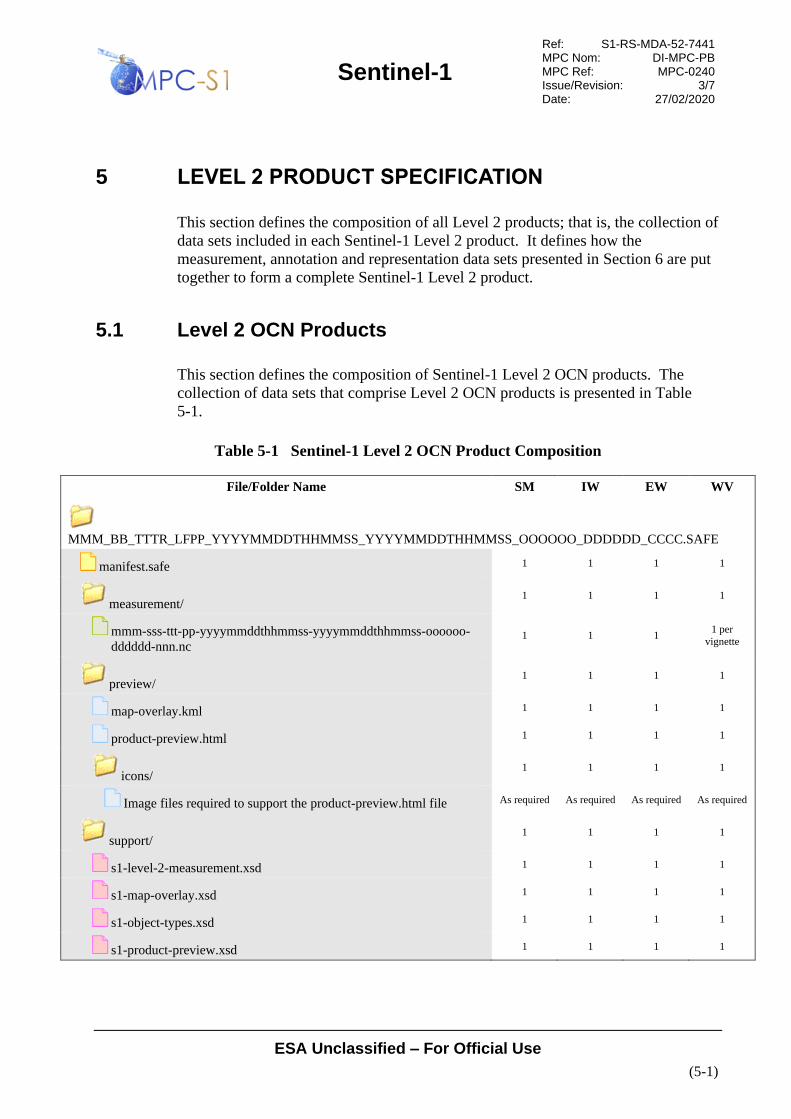
Sentinel-1
Ref: S1-RS-MDA-52-7441 MPC Nom: DI-MPC-PB MPC Ref: MPC-0240 Issue/Revision: 3/7 Date: 27/02/2020
ESA Unclassified – For Official Use
(5-1)
5 LEVEL 2 PRODUCT SPECIFICATION
This section defines the composition of all Level 2 products; that is, the collection of
data sets included in each Sentinel-1 Level 2 product. It defines how the
measurement, annotation and representation data sets presented in Section 6 are put
together to form a complete Sentinel-1 Level 2 product.
5.1 Level 2 OCN Products
This section defines the composition of Sentinel-1 Level 2 OCN products. The
collection of data sets that comprise Level 2 OCN products is presented in Table
5-1.
Table 5-1 Sentinel-1 Level 2 OCN Product Composition
File/Folder Name SM IW EW WV
MMM_BB_TTTR_LFPP_YYYYMMDDTHHMMSS_YYYYMMDDTHHMMSS_OOOOOO_DDDDDD_CCCC.SAFE
manifest.safe 1 1 1 1
measurement/ 1 1 1 1
mmm-sss-ttt-pp-yyyymmddthhmmss-yyyymmddthhmmss-oooooo-
dddddd-nnn.nc 1 1 1
1 per
vignette
preview/ 1 1 1 1
map-overlay.kml 1 1 1 1
product-preview.html 1 1 1 1
icons/ 1 1 1 1
Image files required to support the product-preview.html file As required As required As required As required
support/ 1 1 1 1
s1-level-2-measurement.xsd 1 1 1 1
s1-map-overlay.xsd 1 1 1 1
s1-object-types.xsd 1 1 1 1
s1-product-preview.xsd 1 1 1 1

Sentinel-1
Ref: S1-RS-MDA-52-7441 MPC Nom: DI-MPC-PB MPC Ref: MPC-0240 Issue/Revision: 3/7 Date: 27/02/2020
ESA Unclassified – For Official Use
(5-2)
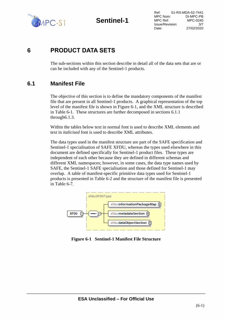
Sentinel-1
Ref: S1-RS-MDA-52-7441 MPC Nom: DI-MPC-PB MPC Ref: MPC-0240 Issue/Revision: 3/7 Date: 27/02/2020
ESA Unclassified – For Official Use
(6-1)
6 PRODUCT DATA SETS
The sub-sections within this section describe in detail all of the data sets that are or
can be included with any of the Sentinel-1 products.
6.1 Manifest File
The objective of this section is to define the mandatory components of the manifest
file that are present in all Sentinel-1 products. A graphical representation of the top
level of the manifest file is shown in Figure 6-1, and the XML structure is described
in Table 6-1. These structures are further decomposed in sections 6.1.1
through6.1.3.
Within the tables below text in normal font is used to describe XML elements and
text in italicised font is used to describe XML attributes.
The data types used in the manifest structure are part of the SAFE specification and
Sentinel-1 specialisation of SAFE XFDU, whereas the types used elsewhere in this
document are defined specifically for Sentinel-1 product files. These types are
independent of each other because they are defined in different schemas and
different XML namespaces; however, in some cases, the data type names used by
SAFE, the Sentinel-1 SAFE specialisation and those defined for Sentinel-1 may
overlap. A table of manifest-specific primitive data types used for Sentinel-1
products is presented in Table 6-2 and the structure of the manifest file is presented
in Table 6-7.
Figure 6-1 Sentinel-1 Manifest File Structure
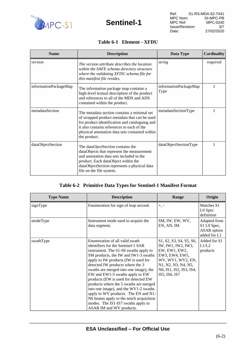
Sentinel-1
Ref: S1-RS-MDA-52-7441 MPC Nom: DI-MPC-PB MPC Ref: MPC-0240 Issue/Revision: 3/7 Date: 27/02/2020
ESA Unclassified – For Official Use
(6-2)
Table 6-1 Element - XFDU
Name Description Data Type Cardinality
version The version attribute describes the location
within the SAFE schema directory structure
where the validating XFDU schema file for
this manifest file resides.
string required
informationPackageMap The information package map contains a
high-level textual description of the product
and references to all of the MDS and ADS
contained within the product.
informationPackageMap
Type
1
metadataSection The metadata section contains a minimal set
of wrapped product metadata that can be used
for product identification and cataloguing and
it also contains references to each of the
physical annotation data sets contained within
the product.
metadataSectionType 1
dataObjectSection The dataOjectSection contains the
dataObjects that represent the measurement
and annotation data sets included in the
product. Each dataObject within the
dataObjectSection represents a physical data
file on the file system.
dataObjectSectionType 1
Table 6-2 Primitive Data Types for Sentinel-1 Manifest Format
Type Name Description Range Origin
signType Enumeration for sign of leap second. +, - Matches S1
L0 Spec
definition
modeType Instrument mode used to acquire the
data segment.
SM, IW, EW, WV,
EN, AN, IM
Adapted from
S1 L0 Spec,
ASAR option
added for L1
swathType Enumeration of all valid swath
identifiers for the Sentinel-1 SAR
instrument. The S1-S6 swaths apply to
SM products, the IW and IW1-3 swaths
apply to IW products (IW is used for
detected IW products where the 3
swaths are merged into one image), the
EW and EW1-5 swaths apply to EW
products (EW is used for detected EW
products where the 5 swaths are merged
into one image), and the WV1-2 swaths
apply to WV products. The EN and N1-
N6 beams apply to the notch acquisition
modes. The IS1-IS7 swaths apply to
ASAR IM and WV products.
S1, S2, S3, S4, S5, S6,
IW, IW1, IW2, IW3,
EW, EW1, EW2,
EW3, EW4, EW5,
WV, WV1, WV2, EN,
N1, N2, N3, N4, N5,
N6, IS1, IS2, IS3, IS4,
IS5, IS6, IS7
Added for S1
L1/L2
products

Sentinel-1
Ref: S1-RS-MDA-52-7441 MPC Nom: DI-MPC-PB MPC Ref: MPC-0240 Issue/Revision: 3/7 Date: 27/02/2020
ESA Unclassified – For Official Use
(6-3)
Type Name Description Range Origin
passType Direction of the orbit (ascending,
descending) for the oldest ISP in the
product.
ASCENDING,
DESCENDING
Similar to S1
L0 Spec
definition
productTypeType Product type of product. SLC, GRD, OCN Added for S1
L1/L2
products
transmitterReceiverPolarisation
Type
Polarization of the data segment
contained in a Data Object.
HH,VV,HV,VH Matches S1
L0 Spec
definition
productTimelinessCategoryTyp
e
Describes the required timeliness of the
processing.
NRT-10m, NRT-1h,
NRT-3h, Fast-24h,
Off-line, Reprocessing
Added for S1
L1/L2
products
productClassType Enumeration of the product classes. A, S Matches S1
L0 Spec
definition
productClassDescriptionType Textual descriptions of product classes. SAR Standard L1
Product, SAR
Annotation L1
Product, SAR Standard
L2 Product, SAR
Annotation L2 Product
Added for S1
L1/L2
products
productCompositionType Enumeration of the product composition
types.
Individual, Slice,
Assembled
Added for S1
L1/L2
products
6.1.1 Information Package Map
The manifest file contains exactly one information package map with one content
unit as a child element. Beneath the first content unit is a list of content units that
define the metadata and data objects within the product; that is, the data sets that
make up the product.
Figure 6-2 Information Package Map Structure
Table 6-3 Data Type - informationPackageMapType
Name Description Data Type Cardinality
contentUnit The informationPackageMap contains exactly 1
contentUnit and this contentUnit catalogues the
physical data components included in the product.
contentUnitType 1
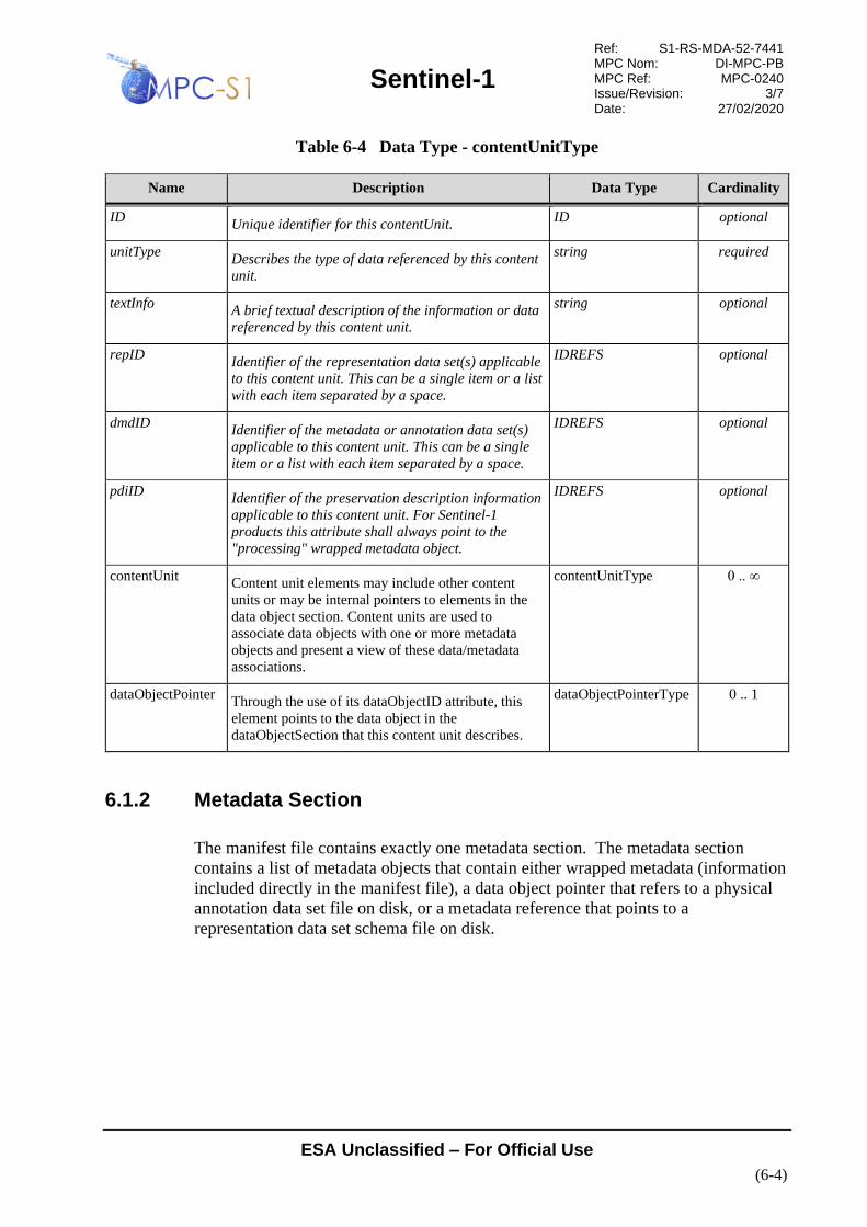
Sentinel-1
Ref: S1-RS-MDA-52-7441 MPC Nom: DI-MPC-PB MPC Ref: MPC-0240 Issue/Revision: 3/7 Date: 27/02/2020
ESA Unclassified – For Official Use
(6-4)
Table 6-4 Data Type - contentUnitType
Name Description Data Type Cardinality
ID Unique identifier for this contentUnit.
ID optional
unitType Describes the type of data referenced by this content
unit.
string required
textInfo A brief textual description of the information or data
referenced by this content unit.
string optional
repID Identifier of the representation data set(s) applicable
to this content unit. This can be a single item or a list
with each item separated by a space.
IDREFS optional
dmdID Identifier of the metadata or annotation data set(s)
applicable to this content unit. This can be a single
item or a list with each item separated by a space.
IDREFS optional
pdiID Identifier of the preservation description information
applicable to this content unit. For Sentinel-1
products this attribute shall always point to the
"processing" wrapped metadata object.
IDREFS optional
contentUnit Content unit elements may include other content
units or may be internal pointers to elements in the
data object section. Content units are used to
associate data objects with one or more metadata
objects and present a view of these data/metadata
associations.
contentUnitType 0 .. ∞
dataObjectPointer Through the use of its dataObjectID attribute, this
element points to the data object in the
dataObjectSection that this content unit describes.
dataObjectPointerType 0 .. 1
6.1.2 Metadata Section
The manifest file contains exactly one metadata section. The metadata section
contains a list of metadata objects that contain either wrapped metadata (information
included directly in the manifest file), a data object pointer that refers to a physical
annotation data set file on disk, or a metadata reference that points to a
representation data set schema file on disk.

Sentinel-1
Ref: S1-RS-MDA-52-7441 MPC Nom: DI-MPC-PB MPC Ref: MPC-0240 Issue/Revision: 3/7 Date: 27/02/2020
ESA Unclassified – For Official Use
(6-5)
Figure 6-3 Metadata Section Structure and Content
Table 6-5 Data Type - metadataSectionType
Name Description Data Type Cardinality
metadataObject Metadata objects can take one of three forms: the first is
"wrapped metadata" in which valid XML data is
embedded directly in the manifest file itself using an
metadataWrap element; the second is a reference to an
annotation data set in the dataObjectSection through a
dataObjectPointer element; and, the third is a physical
reference to a representation data set on the filesystem
through the use of a metadataReference element.
For Sentinel-1 products a minimum of 6
metadataObjects shall be present dedicated to:
processing, acquisitionPeriod, platform,
measurementOrbitReference, measurementFrameSet and
generalProductInformation metadataWrap objects.
metadataObjectType 6 .. ∞
Table 6-6 Data Type - metadataObjectType
Name Description Data Type Cardinality
ID Unique identifier of this meta data object.
ID required
category Defines the category of this meta data. The category is
used to specify the nature of the metadata, whether it is
preservation information (PDI), description information
(DMD) or representation information (REP)
string required
classification A textual description of the classification of this meta
data. The classification is linked to the category and
provides a more verbose description of the nature of the
metadata, whether it is preservation information
(PROVENANCE), description information
(DESCRIPTION) or representation information
(REPRESENTATION)
string required
dataObjectPointer The dataObjectPointer element is used when the
metadata object is an annotation data set. The
dataObjectPointer element is used to point to the
applicable annotation data set in the dataObject section
through its dataObjectID attribute.
dataObjectPointerTyp
e
0 .. 1

Sentinel-1
Ref: S1-RS-MDA-52-7441 MPC Nom: DI-MPC-PB MPC Ref: MPC-0240 Issue/Revision: 3/7 Date: 27/02/2020
ESA Unclassified – For Official Use
(6-6)
Name Description Data Type Cardinality
metadataWrap The metadataWrap element is used to embed XML
metadata directly in the manifest file itself. This element
is used to express information that can be used for
product identification and cataloguing.
metadataWrapType 0 .. 1
metadataReference The metadataReference element is used when the
metadata object is a representation data set. The
metadataReference element is used to specify the
physical file location of the applicable representation
data set.
metadataReferenceTy
pe
0 .. 1
The mandatory wrapped metadata elements included in all Sentinel-1 products are
described in Table 6-7.

Sentinel-1
Ref: S1-RS-MDA-52-7441 MPC Nom: DI-MPC-PB MPC Ref: MPC-0240 Issue/Revision: 3/7 Date: 27/02/2020
ESA Unclassified – For Official Use
(6-7)
Table 6-7 Mandatory Wrapped Metadata Elements for Sentinel-1 Products
Name Description Data Type Cardinality
safe:processing Metadata describing the processing steps performed on the
auxiliary data.
processingType 1
name Name of the processing step used to create the product. string required
start Processing start time. dateTime required
stop Processing stop time. dateTime required
safe:facility Identifies an organisation authority of the processing step. facilityType 1
country Name of the country where the facility is located. This
element is configurable within the IPF.
string required
name Name of the facility where the processing step was
performed. This element is configurable within the IPF.
string required
organisation Name of the organisation responsible for the facility. This
element is configurable within the IPF.
string required
site Geographical location of the facility. This element is
configurable within the IPF.
string required
safe:software Reference to the software used for the processing step. softwareType 0 .. ∞
name Name of the software. string required
version Software version identification. string optional
safe:resource Reference to resources involved in the processing. This
includes references to orbit and attitude files used to
process the product. See Section 3.3.5 for a description of
the resources included with each product.
resourceType 0 .. ∞
name Name of the resource. string required
role Role the resource played in processing. string required
href URL of the resource. anyURI optional

Sentinel-1
Ref: S1-RS-MDA-52-7441 MPC Nom: DI-MPC-PB MPC Ref: MPC-0240 Issue/Revision: 3/7 Date: 27/02/2020
ESA Unclassified – For Official Use
(6-8)
Name Description Data Type Cardinality
processing Metadata describing the processing steps performed on the
auxiliary data by the resource. A resource can have its
own processing metadata entry that may contain resources
with their own processing entries. Each additional
resource and processing entry is nested within the previous
entry. For the IPF, the entries can be “SLC Processing”,
“Post Processing” or “L2 Processing”.
processingType 0 .. ∞
xmlns For all sub-processing elements the xmlns attribute shall
be included and set to the safe namespace URI
http://www.esa.int/safe/sentinel-1.0
anyURI required
safe:acquisitionPeriod Time extent of the Sentinel-1 L1 product. acquisitionPeriodType 1
safe:startTime Sensing start time of the input data used to produce the
output image.
dateTime 1
safe:stopTime Sensing stop time of the input data used to produce the
output image.
dateTime 1
safe:extension extensionType 1
s1:timeANX s1:timeANXType 1
s1:startTimeANX Sensing start time of the input data relative to the
ascending node crossing. This is a count of the time
elapsed since the orbit ascending node crossing [ms].
double 1
s1: stopTimeANX Sensing stop time of the input data relative to the
ascending node crossing. This is a count of the time
elapsed since the orbit ascending node crossing [ms].
double 1
safe:platform Metadata describing the mission platform to which
acquired the data.
platformType 1
safe:nssdcIdentifier Univocally identifies the mission according to standard
defined by the World Data Center for Satellite Information
(WDC-SI), available at
http://nssdc.gsfc.nasa.gov/nmc/scquery.html
string 1
safe:familyName The full mission name. E.g. “SENTINEL-1” string 1
safe:number The alphanumeric identifier of the platform within the
mission.
string 1
safe:instrument Information related to the instrument on the platform to
which acquired the data.
instrumentType 1
safe:familyName Instrument name. string 1

Sentinel-1
Ref: S1-RS-MDA-52-7441 MPC Nom: DI-MPC-PB MPC Ref: MPC-0240 Issue/Revision: 3/7 Date: 27/02/2020
ESA Unclassified – For Official Use
(6-9)
Name Description Data Type Cardinality
abbreviation Abbreviated instrument name. string required
safe:extension extensionType 1
s1sar:instrumentMode s1sar:instrumentModeType 1
s1sar:mod
e
Instrument mode. s1sar:modeType 1
s1sar:swa
th
List of the swaths contained within a product. Most
products will contain only one swath, except for TOPS
SLC products which include 3 or 5 swaths.
s1sar:swathType 1 .. 5
safe:extension This element is only present if it was present in the input
L0 product, and if so the leapSeconInformation
information in the L0 product is copied into the L1/L2
product.
extensionType 0 .. 1
s1:leapSecondInformation Information on the leap second applied to the product UTC
timing. This element is only present if it was present in the
input L0 product, and if so the leapSeconInformation
information in the L0 product is copied into the L1/L2
product.
s1:leapSecondInformationType 0 .. 1
s1:
utcTimeOfOccurrence
UTC time of occurrence of leap second (if leap second
occurred in the product time window); it represents the
time after the leap second occurrence (i.e. midnight of day
after the leap second)
dateTime 1
s1:sign Sign of leap second (+ or -). s1:signType 1
safe:orbitReference Contains information describing the orbit or the orbit range
of the image data.
orbitReferenceType 1
safe:orbitNumber Absolute orbit number. orbitNumberType 1
start Absolute orbit number of the oldest line within the image
data.
unsignedInt required
stop Absolute orbit number of the most recent line within the
image data.
unsignedInt required
safe:relativeOrbitNumber Relative orbit number. relativeOrbitNumberType 1
start Relative orbit number of the oldest line within the image
data.
unsignedInt required
stop Relative orbit number of the most recent line within the
image data.
unsignedInt required

Sentinel-1
Ref: S1-RS-MDA-52-7441 MPC Nom: DI-MPC-PB MPC Ref: MPC-0240 Issue/Revision: 3/7 Date: 27/02/2020
ESA Unclassified – For Official Use
(6-10)
Name Description Data Type Cardinality
safe:cycleNumber Absolute sequence number of the mission cycle to which
the oldest image data applies.
unsignedInt 1
safe:phaseIdentifier Id of the mission phase to which the oldest image data
applies.
unsignedInt 1
safe:extension extensionType 1
s1:orbitProperties s1:orbitPropertiesType
s1: pass Direction of the orbit (ascending, descending) for the
oldest image data in the product (the start of the product).
s1:passType 1
s1:ascendingNodeTime UTC time of the ascending node of the orbit. This element
is present for all products except ASAR L2 OCN products
which are generated from an ASAR L1 input.
dateTime 0 .. 1
safe:frameSet Geographical and time location of the instrument footprint,
considered as a single frame. This element is present for all
products except ASAR L2 OCN products which are
generated from an ASAR L1 input.
frameSetType 0 .. 1
safe:frame The instrument footprint frame. There is one frame per
product for SM, IW and EW modes, and one frame per
vignette for WV mode products.
frameType 1 .. 200
safe:number Number of the WV vignette which this frame describes. unsignedInt 0 .. 1
safe:footprint Coordinates of instrument footprint in GML notation
(gml:coordinates type as defined in
http://www.opengis.net/gml , namely string with 4 pairs of
coordinates (lon,lat of near and far range at start and stop
time of the image) separated by a space.
gml:LinearRingType 1
s1sarl1:standAloneProductIn
formation
Metadata describing the product. s1sar:standAloneProductInformationType 1
s1sarl1:instrumentConfigura
tionID
The instrument configuration ID (Radar database ID) for
this data.
unsignedInt 1
s1sarl1:missionDataTakeID Unique ID of the datatake within the mission. unsignedInt 1
s1sarl1:transmitterReceiver
Polarisation
Transmit/Receive polarisation for the data. There is one
element for each Tx/Rx combination.
transmitterReceiverPolarisationType 1 .. 2
s1sarl1:productClass Output product class “A” for Annotation or “S” for
Standard.
productClassType 1

Sentinel-1
Ref: S1-RS-MDA-52-7441 MPC Nom: DI-MPC-PB MPC Ref: MPC-0240 Issue/Revision: 3/7 Date: 27/02/2020
ESA Unclassified – For Official Use
(6-11)
Name Description Data Type Cardinality
s1sarl1:productClassDescrip
tion
Textual description of the output product class. productClassDescriptionType 1
s1sarl1:productComposition The composition type of this product: “Individual”, “Slice”
or “Assembled”.
productCompositionType 1
s1sarl1:productType The product type (correction level) of this product. productTypeType 1
s1sarl1:productTimelinessC
ategory
Describes the required timeliness of the processing. One
of:
• NRT-10m
• NRT-1h
• NRT-3h
• Fast-24h
• Off-line
• Reprocessing
productTimelinessCategoryType 1
s1sarl1:sliceProductFlag True if this is a slice from a larger product or false if this is
a complete product.
bool 1
s1sarl1:segmentStartTime Sensing start time of the segment to which this slice
belongs. This field is only present if sliceProductFlag =
true.
dateTime 0 .. 1
s1sarl1:sliceNumber Absolute slice number of this slice starting at 1. This field
is only present if sliceProductFlag = true.
unsignedInt 0 .. 1
s1sarl1:totalSlices Total number of slices in the complete data take. This field
is only present if sliceProductFlag = true.
unsignedInt 0 .. 1
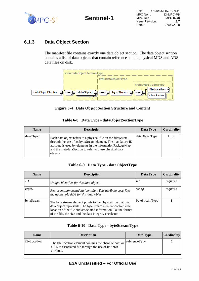
Sentinel-1
Ref: S1-RS-MDA-52-7441 MPC Nom: DI-MPC-PB MPC Ref: MPC-0240 Issue/Revision: 3/7 Date: 27/02/2020
ESA Unclassified – For Official Use
(6-12)
6.1.3 Data Object Section
The manifest file contains exactly one data object section. The data object section
contains a list of data objects that contain references to the physical MDS and ADS
data files on disk.
Figure 6-4 Data Object Section Structure and Content
Table 6-8 Data Type - dataObjectSectionType
Name Description Data Type Cardinality
dataObject Each data object refers to a physical file on the filesystem
through the use of its byteStream element. The mandatory ID
attribute is used by elements in the informationPackageMap
and the metadataSection to refer to these physical data
objects.
dataObjectType 1 .. ∞
Table 6-9 Data Type - dataObjectType
Name Description Data Type Cardinality
ID Unique identifier for this data object
ID required
repID Representation metadata identifier. This attribute describes
the applicable RDS for this data object.
string required
byteStream The byte stream element points to the physical file that this
data object represents. The byteStream element contains the
location of the file and associated information like the format
of the file, the size and the data integrity checksum.
byteStreamType 1
Table 6-10 Data Type - byteStreamType
Name Description Data Type Cardinality
fileLocation The fileLocation element contains the absolute path or
URL to associated file through the use of its “href”
attribute.
referenceType 1

Sentinel-1
Ref: S1-RS-MDA-52-7441 MPC Nom: DI-MPC-PB MPC Ref: MPC-0240 Issue/Revision: 3/7 Date: 27/02/2020
ESA Unclassified – For Official Use
(6-13)
Name Description Data Type Cardinality
checksum Provides the integrity checksum for the file referred to
by this byteStream element.
checksumInformationTyp
e
1
Table 6-11 Data Type - referenceType
Name Description Data Type Cardinality
locatorType Defines the location type.
locatorTypeType required
href Specifies the format of the file referred to by this
byteStream element.
string required
Table 6-12 Data Type - checksumInformationType
Name Description Data Type Cardinality
checksumName The name of the algorithm used to generate the
checksum value.
checksumNameType required
6.2 Measurement Data Sets
This section describes the content and format of the measurement data sets used in
Sentinel-1 products.
6.2.1 Level 1 Image
This section describes the image measurement data sets that can be included in a
Sentinel-1 Level 1 product.
Image measurement data sets within Sentinel-1 L1 products are stored in GeoTIFF
format [R-6] which is built upon the TIFF format [R-5]. Every GeoTIFF file is
therefore a TIFF file. Some image files in Sentinel-1 products will be larger than
4 GB in size. The maximum size for a standard TIFF image is 4 GB, so in order to
accommodate files larger than 4 GB is size, the BigTIFF format [R-7] is used.
BigTIFF is also built upon the TIFF format, extending it to support files of an
arbitrarily large size.
L1 SLC images are generated in 32-bit signed integer format with each pixel
represented by two interleaved I&Q 16-bit signed integer samples in the order:
IQIQIQ… L1 GRD images are generated in 16-bit unsigned integer format with
each pixel representing a single 16-bit magnitude sample. In terms of TIFF output
and metadata tags, this equates to:
For SLC images: BitsPerSample = 32

Sentinel-1
Ref: S1-RS-MDA-52-7441 MPC Nom: DI-MPC-PB MPC Ref: MPC-0240 Issue/Revision: 3/7 Date: 27/02/2020
ESA Unclassified – For Official Use
(6-14)
SamplesPerPixel = 1
SampleFormat = 5 (complex integer, ‘int16’)
For GRD images: BitsPerSample = 16
SamplesPerPixel = 1
SampleFormat = 1 (unsigned integer, ‘uint16’)
Note that for all L1 images the IPF supports only pixel interleaving (band
interleaving is not supported) and so PlanarConfiguration is always set to 1,
meaning contiguous (or pixel interleaved).
The TIFF tags used to annotate Sentinel-1 image files are presented in Table 6-13
and the GeoTIFF tags and keys used to annotate Sentinel-1 image files are presented
in Table 6-14.
Table 6-13 Summary of TIFF Tags used in Sentinel-1 Products
TIFF Tag Name TIFF Tag
Code
TIFF Tag
Type Value Description
ImageWidth 256 LONG Variable Number of pixels per line.
ImageLength 257 LONG Variable Number of lines in image.
BitsPerSample 258 SHORT 32 or 16 Number of bits per sample. Set to 32 bits for
SLC (16 bits I and 16 bits Q) and 16 bits for
GRD.
Compression 259 SHORT 1 Compression scheme used. Always set to 1 (no
compression).
PhotometricInterpretation 262 SHORT 1 Colour space of the image. Always set to 1
(minimum value is black).
ImageDescription 270 ASCII Variable A string that describes the image. Examples:
“Sentinel-1A SM SLC L1” and “Sentinel-1A
IW GRD MR L1”.
StripOffsets 273 Array of
LONG
Variable Array of byte offsets for each strip within the
image. For S1, each “strip” represents a range
line, and the offset to the start of the image is
the first value in the StripOffsets array.
Orientation 274 SHORT 1 The orientation of the image with respect to
rows and columns. Always set to 1
(TOPLEFT) to indicate that the first sample is
ithe upper left corner.
SamplesPerPixel 277 SHORT 1 Number of samples per pixel. Always set to 1.
RowsPerStrip 278 LONG Variable Number of rows per strip. Always set to 1.
StripByteCounts 279 Array of
LONG
Variable Array of the number of bytes in each strip. For
S1, the number of bytes in each “strip” will be
the same, as all image lines contain the same
number and type of samples.

Sentinel-1
Ref: S1-RS-MDA-52-7441 MPC Nom: DI-MPC-PB MPC Ref: MPC-0240 Issue/Revision: 3/7 Date: 27/02/2020
ESA Unclassified – For Official Use
(6-15)
TIFF Tag Name TIFF Tag
Code
TIFF Tag
Type Value Description
PlanarConfiguration 284 SHORT 1 Configuration in which the components
(samples) of each pixel are stored. Always set
to 1 (contiguous).
Software 305 ASCII Variable Software name and version that created the
image.
DateTime 306 ASCII Variable Date and time of image creation in the format:
YYYY:MM:DD HH:MM:SS
SampleFormat 339 SHORT 5 or 1 Interpretation of pixel format. Set to 5
(complex signed integer, ‘int16’) for SLC
products, set to 1 (unsigned integer, ‘uint16’)
for all others.
Table 6-14 Summary of GeoTIFF Tags/Keys Used in Sentinel-1 Products
GeoTIFF Tag/Key Name GeoTIFF
Tag/
Key Code
Type Value Description
ModelTiePointTag 33922 Array of
DOUBLE
N * (pixel,line,,0,
lat, lng,0)
Maps image pixels to
geographic coordinates, where
N is the number of tie points in
the scene.
GeoKeyDirectoryTag 34735 Array of
SHORT
Variable Contains the value of all
GeoTIFF keys of type SHORT
and the location of the values
for GeoTIFF keys of other
types.
GeoDoubleParamsTag 34736 Array of
DOUBLE
Variable Contains the value of all
GeoTIFF keys of type
DOUBLE.
GeoAsciiParamsTag 34737 Array of
ASCII
Variable Contains the value of all
GeoTIFF keys of type ASCII.
GTModelTypeGeoKey 1024 SHORT 2 Model coordinate system.
Always set to 2 (Geographic –
latitude and longitude –
coordinates).
GTRasterTypeGeoKey 1025 SHORT 1 Raster space coordinate
system. Always set to 1 (Pixels
represent an area in the image).
GTCitationGeoKey 1026 ASCII “Geo-referenced
SAR image”
Description of the
configuration of the GeoTIFF.
Always set to “Geo-referenced
SAR image”.
GeographicTypeGeoKey 2048 SHORT Variable Type of geographic coordinate
system. Nominally this is set to
4326 for the WGS-84 ellipsoid.
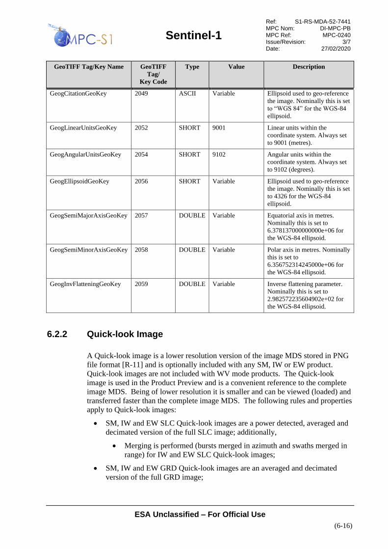
Sentinel-1
Ref: S1-RS-MDA-52-7441 MPC Nom: DI-MPC-PB MPC Ref: MPC-0240 Issue/Revision: 3/7 Date: 27/02/2020
ESA Unclassified – For Official Use
(6-16)
GeoTIFF Tag/Key Name GeoTIFF
Tag/
Key Code
Type Value Description
GeogCitationGeoKey 2049 ASCII Variable Ellipsoid used to geo-reference
the image. Nominally this is set
to “WGS 84” for the WGS-84
ellipsoid.
GeogLinearUnitsGeoKey 2052 SHORT 9001 Linear units within the
coordinate system. Always set
to 9001 (metres).
GeogAngularUnitsGeoKey 2054 SHORT 9102 Angular units within the
coordinate system. Always set
to 9102 (degrees).
GeogEllipsoidGeoKey 2056 SHORT Variable Ellipsoid used to geo-reference
the image. Nominally this is set
to 4326 for the WGS-84
ellipsoid.
GeogSemiMajorAxisGeoKey 2057 DOUBLE Variable Equatorial axis in metres.
Nominally this is set to
6.378137000000000e+06 for
the WGS-84 ellipsoid.
GeogSemiMinorAxisGeoKey 2058 DOUBLE Variable Polar axis in metres. Nominally
this is set to
6.356752314245000e+06 for
the WGS-84 ellipsoid.
GeogInvFlatteningGeoKey 2059 DOUBLE Variable Inverse flattening parameter.
Nominally this is set to
2.982572235604902e+02 for
the WGS-84 ellipsoid.
6.2.2 Quick-look Image
A Quick-look image is a lower resolution version of the image MDS stored in PNG
file format [R-11] and is optionally included with any SM, IW or EW product.
Quick-look images are not included with WV mode products. The Quick-look
image is used in the Product Preview and is a convenient reference to the complete
image MDS. Being of lower resolution it is smaller and can be viewed (loaded) and
transferred faster than the complete image MDS. The following rules and properties
apply to Quick-look images:
• SM, IW and EW SLC Quick-look images are a power detected, averaged and
decimated version of the full SLC image; additionally,
• Merging is performed (bursts merged in azimuth and swaths merged in
range) for IW and EW SLC Quick-look images;
• SM, IW and EW GRD Quick-look images are an averaged and decimated
version of the full GRD image;

Sentinel-1
Ref: S1-RS-MDA-52-7441 MPC Nom: DI-MPC-PB MPC Ref: MPC-0240 Issue/Revision: 3/7 Date: 27/02/2020
ESA Unclassified – For Official Use
(6-17)
• Dual polarisation SLC and GRD products contain only one Quick-look image
(adhering to the rules above) which is a combination of the imagery from both
polarisation channels.
The Quick-look images for single polarisation products are output as greyscale PNG
images similar to the ones shown in Figure 6-5.
Figure 6-5 Grey-scale Single Polarisation Quick-look Images: Left VV Co-polarisation
and Right VH Cross-polarisation
For dual polarisation products a single composite image of both polarisations is
created using a three channel Red Green Blue (RGB) PNG image similar to the one

Sentinel-1
Ref: S1-RS-MDA-52-7441 MPC Nom: DI-MPC-PB MPC Ref: MPC-0240 Issue/Revision: 3/7 Date: 27/02/2020
ESA Unclassified – For Official Use
(6-18)
shown in Figure 6-6. In composite Quick-look images, the values of the red, green
and blue channels are calculated as per Section 7.3.3 of [R-14].
Figure 6-6 3 Channel (RGB) Composite Dual Polarisation VV/VH Quick-look Image
6.2.3 Level 2 OCN Measurement Data
The Level 2 OCN MDS contains an Ocean Swell Wave spectra component (OSW),
an Ocean Wind field component (OWI) and a Radial Surface Velocity component

Sentinel-1
Ref: S1-RS-MDA-52-7441 MPC Nom: DI-MPC-PB MPC Ref: MPC-0240 Issue/Revision: 3/7 Date: 27/02/2020
ESA Unclassified – For Official Use
(6-19)
(RVL) estimated from an input L1 SAR image. The format of this data set is a
NetCDF file [R-12]. The information in the NetCDF file is broken into three groups
– attributes, dimensions and variables – as depicted in Figure 6-7 and described in
Table 6-15. The NetCDF format supports the inclusion of both the processed
measurement data and the associated metadata within the same file, so the L2 MDS
is a self-contained, self-describing file that requires no additional annotations or
supporting files.
Note: NetCDF is a binary format and because of its self-describing nature, differs
somewhat in format from the other data sets described so far; however, within this
section the use of XML diagrams is still employed to present a conceptual view of
the structure and content of the Level 2 ocean swell wave spectra and wind field data
set. The graphical and tabular views presented below are only conceptual and do not
reflect the physical layout of the NetCDF L2 MDS.
Figure 6-7 L2 OCN Product Top-level Format
Table 6-15 L2 OCN Product
Name Description Data Type Cardinality
attributes Global attributes annotate variables or files with small
notes or supplementary metadata. Attributes are always
scalar values or 1D arrays which can be associated with
either a variable or the product as a whole.
NetCDF
Construct
1
dimensions Dimensions describe the axes of the data arrays
(variables). A dimension has a name and a length.
NetCDF
Construct
1
variables Variables are used to store both the processed L2
measurement data and the associated product
annotations. A variable represents an array of values of
the same type. A scalar value is treated as a 0-
dimensional array. A variable has a name, a data type,
and a shape described by its list of dimensions specified
when the variable is created.
NetCDF
Construct
1
6.2.3.1 Global Attributes
Global attributes annotate variables or products with small notes or supplementary
metadata. Attributes are always scalar values or 1D arrays which can be associated
with either a variable or the product as a whole. The attributes within the L2 MDS
annotate basic information about the input and output data.

Sentinel-1
Ref: S1-RS-MDA-52-7441 MPC Nom: DI-MPC-PB MPC Ref: MPC-0240 Issue/Revision: 3/7 Date: 27/02/2020
ESA Unclassified – For Official Use
(6-20)
Figure 6-8 and Table 6-16 present a graphical and tabular view, respectively, of the
L2 OCN attributes.
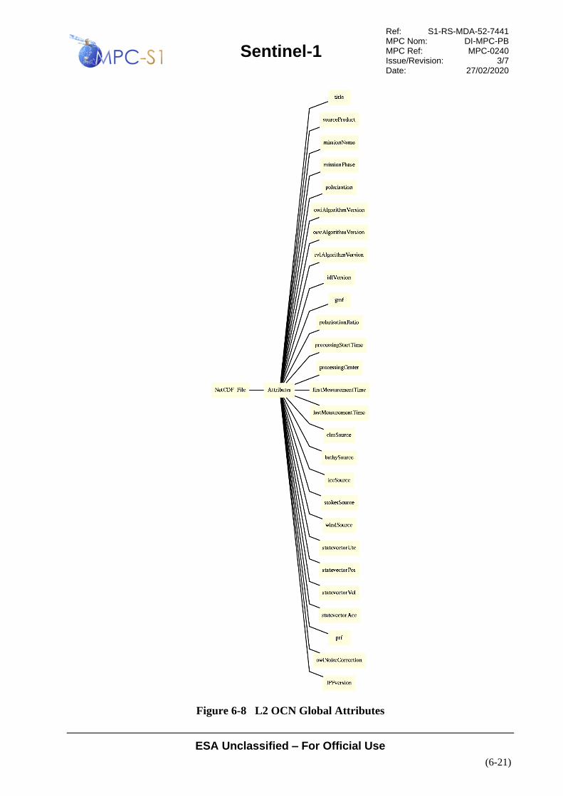
Sentinel-1
Ref: S1-RS-MDA-52-7441 MPC Nom: DI-MPC-PB MPC Ref: MPC-0240 Issue/Revision: 3/7 Date: 27/02/2020
ESA Unclassified – For Official Use
(6-21)
Figure 6-8 L2 OCN Global Attributes

Sentinel-1
Ref: S1-RS-MDA-52-7441 MPC Nom: DI-MPC-PB MPC Ref: MPC-0240 Issue/Revision: 3/7 Date: 27/02/2020
ESA Unclassified – For Official Use
(6-22)
Table 6-16 L2 OCN Global Attributes
Name Description Data Type Cardinality
title Title/description of the L2 OCN product.
string 1
sourceProduct Identifier (file name) of the input L1 product.
string 1
missionName Identifier of the platform that acquired the SAR data that
the L2 OCN product was generated from.
string 1
missionPhase Phase of the mission (Calibration, Validation,
Operational).
string 1
polarisation Polarisation (“HH”, “VV”, “VV/VH”, “HH/HV”).
string 1
acquisitionStation Name of the facility that acquired the SAR data (empty
string in most situations as the L2 OCN product can be
generated from L0 product received at different acquisition
stations)
string 0
oswAlgorithmVersion Version identifier of the OSW algorithm.
string 1
owiAlgorithmVersion Version identifier of the OWI algorithm.
string 1
rvlAlgorithmVersion Version identifier of the RVL algorithm.
string 1
idlVersion Version identifier of the IDL software used to generate the
L2 OCN product.
string 1
gmf Geophysical Model Function (GMF) used for OWI
processing.
string 1
polarisationRatio Name and parameters of polarisation ratio used for
transforming HH NRCS to VV NRCS before inversion.
string 1
processingStartTime Start time of L2 processing [UTC].
timeType 1
processingCenter Name of the processing center where the L2 OCN product
was generated.
string 1
firstMeasurementTime Zero Doppler start time of the source data acquisition
[UTC].
timeType 1
lastMeasurementTime Zero Doppler stop time of the source data acquisition
[UTC].
timeType 1
clmSource Coastline and land masking auxiliary data source.
string 1
bathySource Bathymetry auxiliary data source.
string 1
iceSource Ice coverage auxiliary data source. This attribute is set to
“None” if the ice auxiliary file is not available.
string 1
stokesSource Stokes drift auxiliary data source. This attribute is set to
“None” if the stokes drif auxiliary file is not available.
string 1

Sentinel-1
Ref: S1-RS-MDA-52-7441 MPC Nom: DI-MPC-PB MPC Ref: MPC-0240 Issue/Revision: 3/7 Date: 27/02/2020
ESA Unclassified – For Official Use
(6-23)
Name Description Data Type Cardinality
windSource Wind auxiliary data source. This attribute is set to “None”
if the wind auxiliary file is not available.
string 1
statevectorUtc State vector time [UTC].
RFC 5322
timeType
1
statevectorPos State vector position [m].
double 3
statevectorVel State vector velocity [m/s].
double 3
statevectorAcc State vector acceleration [m/s2].
double 3
prf Pulse repetition frequency [Hz].
float 1 .. 5
owiNoiseCorrection Set to ‘True’ when the noise correction has been activated,
otherwise ‘False’
owiNoiseCorrection set as True means that the wind
inversion process has taken (owiNrcs-owiNesz)>0 as input,
otherwise owiNoiseCorrection is False and the OWI
inversion process has runned directly from owiNrcs.
This parameter is present from IPF2.70 and later (please
note that it is not present in WV products processed by
IPF2.7x)
bool 1
IPFversion Version of IPF
string 1
6.2.3.2 Dimensions
Dimensions describe the axes of the data arrays (variables). Each dimension has a
name and a length. Within the L2 OCN product, the dimensions are used to define
the sizes of the ocean swell wave spectra and wind field grids. Figure 6-9 and
Table 6-17 present a graphical and tabular view, respectively, of the L2 OCN
dimensions.

Sentinel-1
Ref: S1-RS-MDA-52-7441 MPC Nom: DI-MPC-PB MPC Ref: MPC-0240 Issue/Revision: 3/7 Date: 27/02/2020
ESA Unclassified – For Official Use
(6-24)
Figure 6-9 L2 OCN Dimensions
Table 6-17 L2 OCN Dimensions
Name Description Data Type Cardinali
ty
oswRaSize Number of range swell wave spectra cells. For WV mode
this dimension is set to 1 as there is 1 swell wave spectra
per WV vignette. For SM this dimension is set to the
number of cells in the range direction, nominally 4. This
parameter does not apply to IW nor EW mode.
unsignedInt 1

Sentinel-1
Ref: S1-RS-MDA-52-7441 MPC Nom: DI-MPC-PB MPC Ref: MPC-0240 Issue/Revision: 3/7 Date: 27/02/2020
ESA Unclassified – For Official Use
(6-25)
Name Description Data Type Cardinali
ty
oswAzSize Number of azimuth swell wave spectra cells. For WV
mode this dimension is set to 1 as there is 1 swell wave
spectra per WV vignette. For SM this dimension is set to
the number of cells in the azimuth direction, nominally
4; although, this will vary with the length of the input
image strip. This parameter does not apply to IW nor
EW mode.
unsignedInt 1
owiRaSize Number of range wind cells. For WV mode this
dimension is set to 1 as there is 1 wind cell per WV
vignette. For SM this dimension is set to the number of
cells in the range direction.
unsignedInt 1
owiAzSize Number of azimuth wind cells. For WV mode this
dimension is set to 1 as there is 1 wind cell per WV
vignette. For SM this dimension is set to the number of
cells in the azimuth direction, this will vary with the
length of the input image strip.
unsignedInt 1
owiIncSize Number of incidence angle vectors. unsignedInt 1
rvlRaSize Number of range radial velocity cells. For WV mode this
dimension is set to 1 as there is 1 radial velocity cells per
WV vignette. For SM this dimension is set to the number
of cells in the range direction.
unsignedInt 1
rvlAzSize Number of azimuth radial velocity cells. For WV mode
this dimension is set to 1 as there is 1 radial velocity cells
per WV vignette. For SM this dimension is set to the
number of cells in the azimuth direction, , this will vary
with the length of the input image strip.
unsignedInt 1
oswWavenumberBinSize Number of wavenumber bins in the swell wave polar
spectrum.
unsignedInt 1
oswAngularBinSize Number of angular bins in the swell wave polar
spectrum.
unsignedInt 1
oswPartitions Number of partitions per swell wave spectra cell. unsignedInt 1
length Max length of string variable to store (UTC time) unisgnedInt 1
rvlSwath Number of swath for EW, IW (not used in SM and WV) unsignedInt 0..1
owiPolarisation Number of polarisation in the product unsignedInt 1
oswKxBinSize Number of bins in range direction for the cartesian wave
spectrum
unsignedInt 1
oswKyBinSize Number of bins in azimuth direction for the cartesian
wave spectrum
unsignedInt 1
oswLag Number of combined cross spectrum unsignedInt 1

Sentinel-1
Ref: S1-RS-MDA-52-7441 MPC Nom: DI-MPC-PB MPC Ref: MPC-0240 Issue/Revision: 3/7 Date: 27/02/2020
ESA Unclassified – For Official Use
(6-26)
6.2.3.3 Variables
Variables are used to store both the processed L2 measurement data and the
associated product annotations. A variable represents an array of values of the same
type. A scalar value is treated as an array with one element. A variable has a name, a
data type, and a shape described by its list of dimensions specified when the variable
is created. A graphical view of the L2 OCN variables is presented in Figure 6-10
and:
• Table 6-18 presents the variables in the OSW component grid;
• Table 6-19 presents the variables in the OWI component grid; and
• Table 6-20 presents the variables in the RVL component grid.

Sentinel-1
Ref: S1-RS-MDA-52-7441 MPC Nom: DI-MPC-PB MPC Ref: MPC-0240 Issue/Revision: 3/7 Date: 27/02/2020
ESA Unclassified – For Official Use
(6-27)
Figure 6-10 L2 OSW Component Variables
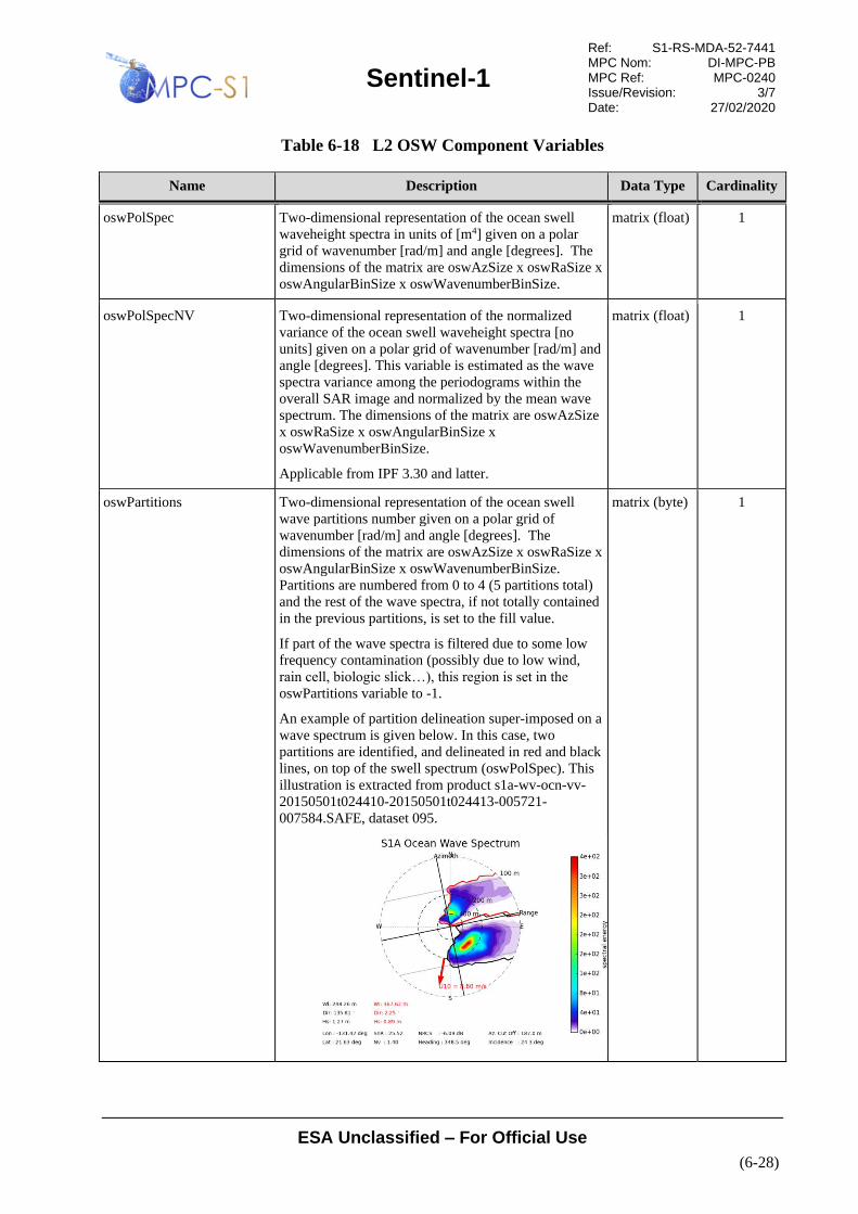
Sentinel-1
Ref: S1-RS-MDA-52-7441 MPC Nom: DI-MPC-PB MPC Ref: MPC-0240 Issue/Revision: 3/7 Date: 27/02/2020
ESA Unclassified – For Official Use
(6-28)
Table 6-18 L2 OSW Component Variables
Name Description Data Type Cardinality
oswPolSpec Two-dimensional representation of the ocean swell
waveheight spectra in units of [m4] given on a polar
grid of wavenumber [rad/m] and angle [degrees]. The
dimensions of the matrix are oswAzSize x oswRaSize x
oswAngularBinSize x oswWavenumberBinSize.
matrix (float) 1
oswPolSpecNV Two-dimensional representation of the normalized
variance of the ocean swell waveheight spectra [no
units] given on a polar grid of wavenumber [rad/m] and
angle [degrees]. This variable is estimated as the wave
spectra variance among the periodograms within the
overall SAR image and normalized by the mean wave
spectrum. The dimensions of the matrix are oswAzSize
x oswRaSize x oswAngularBinSize x
oswWavenumberBinSize.
Applicable from IPF 3.30 and latter.
matrix (float) 1
oswPartitions Two-dimensional representation of the ocean swell
wave partitions number given on a polar grid of
wavenumber [rad/m] and angle [degrees]. The
dimensions of the matrix are oswAzSize x oswRaSize x
oswAngularBinSize x oswWavenumberBinSize.
Partitions are numbered from 0 to 4 (5 partitions total)
and the rest of the wave spectra, if not totally contained
in the previous partitions, is set to the fill value.
If part of the wave spectra is filtered due to some low
frequency contamination (possibly due to low wind,
rain cell, biologic slick…), this region is set in the
oswPartitions variable to -1.
An example of partition delineation super-imposed on a
wave spectrum is given below. In this case, two
partitions are identified, and delineated in red and black
lines, on top of the swell spectrum (oswPolSpec). This
illustration is extracted from product s1a-wv-ocn-vv-
20150501t024410-20150501t024413-005721-
007584.SAFE, dataset 095.
matrix (byte) 1

Sentinel-1
Ref: S1-RS-MDA-52-7441 MPC Nom: DI-MPC-PB MPC Ref: MPC-0240 Issue/Revision: 3/7 Date: 27/02/2020
ESA Unclassified – For Official Use
(6-29)
Name Description Data Type Cardinality
oswQualityCrossSpectraRe Two-dimensional representation of the real part of the
quality image cross-spectra parameter [m2/rad2] given
on a polar grid of wavenumber [rad/m] and angle
[degrees]. The dimensions of the matrix are oswAzSize
x oswRaSize x oswAngularBinSize x
oswWavenumberBinSize.
matrix (float) 1
oswQualityCrossSpectraIm Two-dimensional representation of the imaginary part
of the quality image cross-spectra parameter [m2/rad2]
given on a polar grid of wavenumber [rad/m] and angle
[degrees]. The dimensions of the matrix are oswAzSize
x oswRaSize x oswAngularBinSize x
oswWavenumberBinSize.
matrix (float) 1
oswK Array of logarithmically spaced wavenumber bins for
the ocean swell wave spectra [rad/m]. The dimension
of the array is oswWavenumberBinSize.
array (float) 1
oswPhi Array of equidistantly spaced directional bins for the
ocean swell wave spectra [degrees]. The dimension of
the array is oswAngularBinSize.
array (float) 1
oswAzCutoff The azimuth cut-off wavelength is the shortest
wavelength in the azimuth direction that is resolved in
the swell wave spectra. The cut-off wavelength in the
azimuth direction [m] is computed from the SAR
imagette cross-spectra. The Spectral Resolution
(specRes) is derived from this parameter. The
dimensions of the matrix are oswAzSize x oswRaSize.
matrix (float) 1
oswRaCutoff The range cut-off wavelength [m] is the shortest
wavelength in range direction that can be resolved in
the swell wave spectra. The cut-off wavelength is
computed from the slant range resolution (or range
bandwidth, fsf ) and the local incidence angle as:
λrange(θ)=c/fsfsinθ
The dimensions of the matrix are oswAzSize x
oswRaSize
matrix (float) 1
oswSpecRes The spectral resolution gives the shortest ocean
wavelength [m] that can be detected. This depends on
the sea state and the wave direction relative to azimuth.
This parameter is a vector of wave lengths equal to the
number of directional bins. In range, the theoretical
limit is given by the range bandwidth, and does not
depend on the sea state.
λ(φ)=(λc·cos(φ+φtrack))>λmin
where λmin=2π/kmax ≈ 30m is the shortest wavelength in
the spectra. Here λc is the azimuth cut-off wavelength
estimated from the SAR image spectra, and φtrack is the
satellite track heading counter clockwise relative to
North. The dimensions of the matrix are oswAzSize x
oswRaSize x oswAngularBinSize.
matrix (float) 1
oswLon Geodetic longitude at wave cell center [degrees_east].
The dimensions of the matrix are oswAzSize x
oswRaSize.
matrix (float) 1
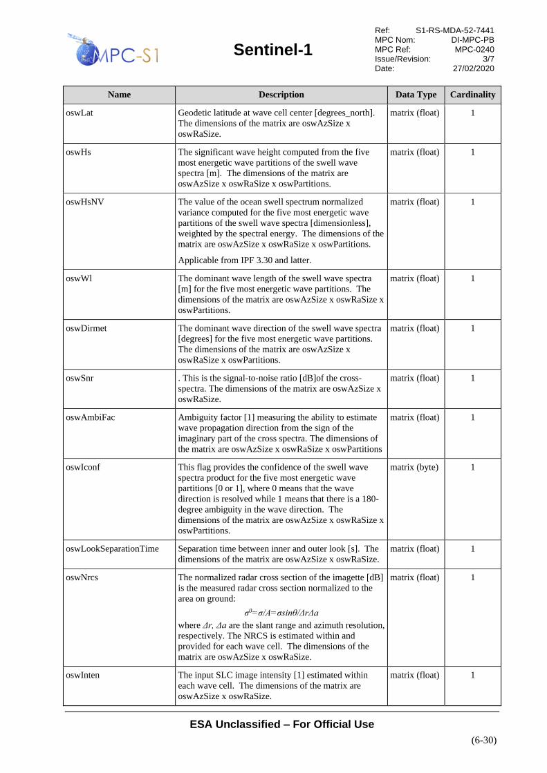
Sentinel-1
Ref: S1-RS-MDA-52-7441 MPC Nom: DI-MPC-PB MPC Ref: MPC-0240 Issue/Revision: 3/7 Date: 27/02/2020
ESA Unclassified – For Official Use
(6-30)
Name Description Data Type Cardinality
oswLat Geodetic latitude at wave cell center [degrees_north].
The dimensions of the matrix are oswAzSize x
oswRaSize.
matrix (float) 1
oswHs The significant wave height computed from the five
most energetic wave partitions of the swell wave
spectra [m]. The dimensions of the matrix are
oswAzSize x oswRaSize x oswPartitions.
matrix (float) 1
oswHsNV The value of the ocean swell spectrum normalized
variance computed for the five most energetic wave
partitions of the swell wave spectra [dimensionless],
weighted by the spectral energy. The dimensions of the
matrix are oswAzSize x oswRaSize x oswPartitions.
Applicable from IPF 3.30 and latter.
matrix (float) 1
oswWl The dominant wave length of the swell wave spectra
[m] for the five most energetic wave partitions. The
dimensions of the matrix are oswAzSize x oswRaSize x
oswPartitions.
matrix (float) 1
oswDirmet The dominant wave direction of the swell wave spectra
[degrees] for the five most energetic wave partitions.
The dimensions of the matrix are oswAzSize x
oswRaSize x oswPartitions.
matrix (float) 1
oswSnr . This is the signal-to-noise ratio [dB]of the cross-
spectra. The dimensions of the matrix are oswAzSize x
oswRaSize.
matrix (float) 1
oswAmbiFac Ambiguity factor [1] measuring the ability to estimate
wave propagation direction from the sign of the
imaginary part of the cross spectra. The dimensions of
the matrix are oswAzSize x oswRaSize x oswPartitions
matrix (float) 1
oswIconf This flag provides the confidence of the swell wave
spectra product for the five most energetic wave
partitions [0 or 1], where 0 means that the wave
direction is resolved while 1 means that there is a 180-
degree ambiguity in the wave direction. The
dimensions of the matrix are oswAzSize x oswRaSize x
oswPartitions.
matrix (byte) 1
oswLookSeparationTime Separation time between inner and outer look [s]. The
dimensions of the matrix are oswAzSize x oswRaSize.
matrix (float) 1
oswNrcs The normalized radar cross section of the imagette [dB]
is the measured radar cross section normalized to the
area on ground:
σ0=σ/A=σsinθ/ΔrΔa
where Δr, Δa are the slant range and azimuth resolution,
respectively. The NRCS is estimated within and
provided for each wave cell. The dimensions of the
matrix are oswAzSize x oswRaSize.
matrix (float) 1
oswInten The input SLC image intensity [1] estimated within
each wave cell. The dimensions of the matrix are
oswAzSize x oswRaSize.
matrix (float) 1

Sentinel-1
Ref: S1-RS-MDA-52-7441 MPC Nom: DI-MPC-PB MPC Ref: MPC-0240 Issue/Revision: 3/7 Date: 27/02/2020
ESA Unclassified – For Official Use
(6-31)
Name Description Data Type Cardinality
oswNv The variance of the input SLC image normalized by the
square of the mean intensity [1] estimated within each
wave cell. The dimensions of the matrix are
oswAzSize x oswRaSize.
matrix (float) 1
oswSkew The skewness of the input SLC image [1] estimated
within each wave cell. The dimensions of the matrix
are oswAzSize x oswRaSize.
matrix (float) 1
oswKurt The kurtosis of the input SLC image [a1] estimated
within each wave cell. The dimensions of the matrix
are oswAzSize x oswRaSize.
matrix (float) 1
oswWindSpeed Wind speed [m/s] used for wave spectral retrieval. This
value is derived from the NRCS using the default wind
direction (45 degRa) or the value from the European
Centre for Medium-Range Weather Forecasts
(ECMWF) atmospheric model derived from the L2
auxiliary file. The dimensions of the matrix are
oswAzSize x oswRaSize.
matrix (float) 1
oswWindDirection Wind direction [degrees] used for wave spectral
retrieval. This value is derived from the ECMWF
atmospheric model derived from the L2 auxiliary file or
set to 45deg. The dimensions of the matrix are
oswAzSize x oswRaSize.
matrix (float) 1
oswWindSeaHs The significant wave height for the wind sea part of the
total wave height spectrum [m]. Computed from the
wind speed and the inverse wave age. The dimensions
of the matrix are oswAzSize x oswRaSize.
matrix (float) 1
oswWaveAge The parameter [1] derived from the SAR data that
describes the state of development of the wind sea
component of the wave spectra. The dimensions of the
matrix are oswAzSize x oswRaSize.
matrix (float) 1
oswEcmwfWindSpeed Wind speed [m/s] from ECMWF atmoshperic model
extracted from S1__AUX_WND files. Dimension is
oswAzSize x oswRaSize
matrix (float) 1
oswEcmwfWindDirection Wind direction [degrees_north] from ECMWF
atmoshperic mode extracted from S1__AUX_WND
files. Dimension is oswAzSize x oswRaSize
matrix (float) 1
oswNlWidth Non-linear inverse spectral width [m] describing non-
linear spectral cut-off computed from the cross-spectra.
The parameter can be used for calibration and gain
monitoring. The dimensions of the matrix are
oswAzSize x oswRaSize.
matrix (float) 1
oswDepth Sea depth [m] from General Bathymetric Chart of
Oceans (GEBCO) data set. This parameter is resampled
into the wave cell grid. The dimensions of the matrix
are oswAzSize x oswRaSize.
matrix (float) 1
oswLandCoverage Percentage [%] of land coverage within the estimation
area. The dimensions of the matrix are oswAzSize x
oswRaSize.
matrix (float) 1

Sentinel-1
Ref: S1-RS-MDA-52-7441 MPC Nom: DI-MPC-PB MPC Ref: MPC-0240 Issue/Revision: 3/7 Date: 27/02/2020
ESA Unclassified – For Official Use
(6-32)
Name Description Data Type Cardinality
oswLandFlag Land mask flag. This flag is set to 1 if the
land_coverage > 10%; otherwise, it is set to 0. The
dimensions of the matrix are oswAzSize x oswRaSize.
, matrix
(byte)
1
oswIncidenceAngle Radar incidence angle [degrees] to the center of the
wave cells. This parameter is provided at each azimuth
line in the wave cell grid. The dimensions of the matrix
are oswAzSize x oswRaSize.
matrix (float) 1
oswHeading Local Northing angle [degrees]. The dimensions of the
matrix are oswAzSize x oswRaSize.
matrix (float) 1
oswGroundRngSize Ground range size of the estimation area [m]. The
dimensions of the matrix are oswAzSize x oswRaSize.
matrix (float) 1
oswAziSize Azimuth size of the estimation area [m]. The
dimensions of the matrix are oswAzSize x oswRaSize.
matrix (float) 1
oswCartSpecRe Real part of the Cathesian cross spectra [m^4]. Half of
the full Cartesian cross spectras are stored (full
frequencies in azimuth direction and only positive
frequencies in range direction) to be symetrized. The
dimensions of the matrix are oswAzSize x oswRaSize x
oswKyBinSize x oswKxBinSize x oswLag.
- Zeros time lag= co-spectra: average cross
spectra of subviews 0-0, 1-1 and 2-2.
- First time lag= average cross spectra of
subviews 0-1 and 1-2
- Second time lag= cross spectra of subviews 0-
2
Matrix (float) 1
oswCartSpecIm Imaginary part of the Cathesian cross spectra [m^4].
Half of the full Cartesian cross spectras are stored (full
frequencies in azimuth direction and only positive
frequencies in range direction) to be symetrized. The
dimensions of the matrix are oswAzSize x oswRaSize x
oswKyBinSize x oswKxBinSize x oswLag.
- Zeros time lag= co-spectra: average cross
spectra of subviews 0-0, 1-1 and 2-2.
- First time lag= average cross spectra of
subviews 0-1 and 1-2
- Second time lag= cross spectra of subviews 0-
2
Matrix (float) 1
oswKx Normalized Array of spacial frequency bins in range
direction for the carthesian cross spectra [m/m], half the
array is presented corresponding to positive
frequencies. The dimension of the array is
oswKxBinSize
The oswKx array has been normalized by
oswGroundRngSize variable and has to be divided by
this later in order to get the actual spacial frequency
vector for the given imaget.
Array (float) 1
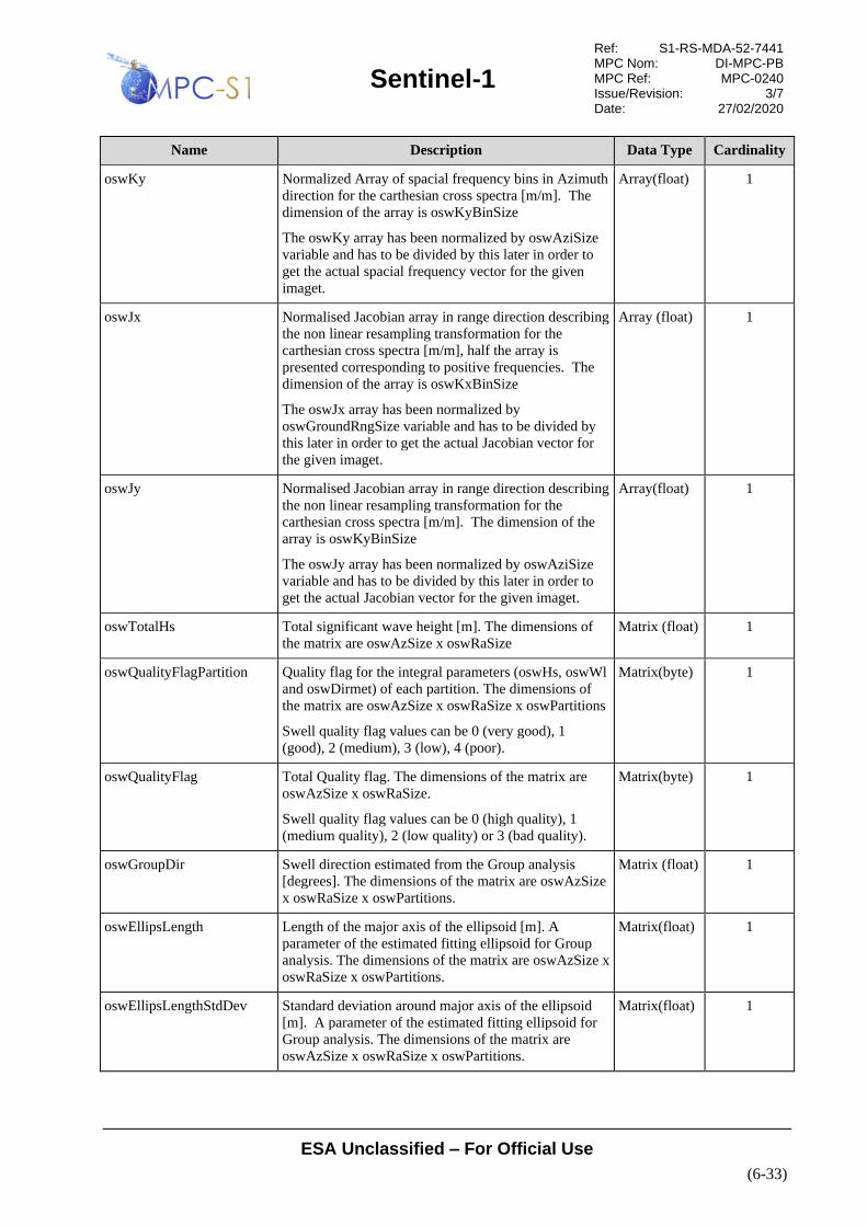
Sentinel-1
Ref: S1-RS-MDA-52-7441 MPC Nom: DI-MPC-PB MPC Ref: MPC-0240 Issue/Revision: 3/7 Date: 27/02/2020
ESA Unclassified – For Official Use
(6-33)
Name Description Data Type Cardinality
oswKy Normalized Array of spacial frequency bins in Azimuth
direction for the carthesian cross spectra [m/m]. The
dimension of the array is oswKyBinSize
The oswKy array has been normalized by oswAziSize
variable and has to be divided by this later in order to
get the actual spacial frequency vector for the given
imaget.
Array(float) 1
oswJx Normalised Jacobian array in range direction describing
the non linear resampling transformation for the
carthesian cross spectra [m/m], half the array is
presented corresponding to positive frequencies. The
dimension of the array is oswKxBinSize
The oswJx array has been normalized by
oswGroundRngSize variable and has to be divided by
this later in order to get the actual Jacobian vector for
the given imaget.
Array (float) 1
oswJy Normalised Jacobian array in range direction describing
the non linear resampling transformation for the
carthesian cross spectra [m/m]. The dimension of the
array is oswKyBinSize
The oswJy array has been normalized by oswAziSize
variable and has to be divided by this later in order to
get the actual Jacobian vector for the given imaget.
Array(float) 1
oswTotalHs Total significant wave height [m]. The dimensions of
the matrix are oswAzSize x oswRaSize
Matrix (float) 1
oswQualityFlagPartition Quality flag for the integral parameters (oswHs, oswWl
and oswDirmet) of each partition. The dimensions of
the matrix are oswAzSize x oswRaSize x oswPartitions
Swell quality flag values can be 0 (very good), 1
(good), 2 (medium), 3 (low), 4 (poor).
Matrix(byte) 1
oswQualityFlag Total Quality flag. The dimensions of the matrix are
oswAzSize x oswRaSize.
Swell quality flag values can be 0 (high quality), 1
(medium quality), 2 (low quality) or 3 (bad quality).
Matrix(byte) 1
oswGroupDir Swell direction estimated from the Group analysis
[degrees]. The dimensions of the matrix are oswAzSize
x oswRaSize x oswPartitions.
Matrix (float) 1
oswEllipsLength Length of the major axis of the ellipsoid [m]. A
parameter of the estimated fitting ellipsoid for Group
analysis. The dimensions of the matrix are oswAzSize x
oswRaSize x oswPartitions.
Matrix(float) 1
oswEllipsLengthStdDev Standard deviation around major axis of the ellipsoid
[m]. A parameter of the estimated fitting ellipsoid for
Group analysis. The dimensions of the matrix are
oswAzSize x oswRaSize x oswPartitions.
Matrix(float) 1

Sentinel-1
Ref: S1-RS-MDA-52-7441 MPC Nom: DI-MPC-PB MPC Ref: MPC-0240 Issue/Revision: 3/7 Date: 27/02/2020
ESA Unclassified – For Official Use
(6-34)
Name Description Data Type Cardinality
oswEllipsWidth Length of the minor axis of the ellipsoid [m]. A
parameter of the estimated fitting ellipsoid for Group
analysis. The dimensions of the matrix are oswAzSize x
oswRaSize x oswPartitions.
Matrix (float) 1
oswEllipsWidthStdDev Standard deviation around major axis of the ellipsoid
[m]. parameters of the estimated ellipsoid for Group
analysis. The dimensions of the matrix are oswAzSize x
oswRaSize x oswPartitions.
Matrix(float) 1
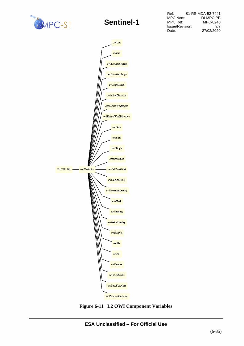
Sentinel-1
Ref: S1-RS-MDA-52-7441 MPC Nom: DI-MPC-PB MPC Ref: MPC-0240 Issue/Revision: 3/7 Date: 27/02/2020
ESA Unclassified – For Official Use
(6-35)
Figure 6-11 L2 OWI Component Variables

Sentinel-1
Ref: S1-RS-MDA-52-7441 MPC Nom: DI-MPC-PB MPC Ref: MPC-0240 Issue/Revision: 3/7 Date: 27/02/2020
ESA Unclassified – For Official Use
(6-36)
Table 6-19 L2 OWI Component Variables
Name Description Data Type Cardinality
owiLon Geodetic longitude at wind cell center [degrees_east].
The dimensions of the matrix are owiAzSize x
owiRaSize.
matrix (float) 1
owiLat Geodetic latitude at wind cell center [degrees_north]. The
dimensions of the matrix are owiAzSize x owiRaSize.
matrix (float) 1
owiLandFlag Land mask flag. This flag is set to 1 if the land_coverage
> 10%; otherwise, it is set to 0. The dimensions of the
matrix are owiAzSize x owiRaSize.
Please note that this flag is not present for product of IPF
2.90 and latr
matrix (byte) 0,1
owiMask Owi mask. The dimensions of the matrix are owiAzSize x
owiRaSize . Byte value:
0: usefull data
1:land mask: set to 1 if the land_coverage > 10%
2: ice mask: Extended IceMask (10km dilated ice edge
area)
4: missing data
Matrix (byte) 1
owiIncidenceAngle Radar incidence angle [degrees] to the center of the wind
cells. This parameter is provided at each azimuth line in
the wind cell grid. The dimensions of the matrix are
owiAzSize x owiRaSize.
matrix (float) 1
owiHeading Local Northing angle [degrees]. The dimensions of the
matrix are owiAzSize x owiRaSize.
matrix (float) 1
owiNrcs The normalized radar cross section of the imagette
[m²/m²] is the measured radar cross section normalized to
the area on ground:
σ0=σ/A=σsinθ/ΔrΔa
where Δr, Δa are the slant range and azimuth resolution,
respectively. The NRCS is estimated within and provided
for each wind cell. The dimensions of the matrix are
owiAzSize x owiRaSizex owiPolarisation.
matrix (float) 1
owiNrcsNeszCorr The noise corrected NRCS [m²/m²] averaged within and
provided for each wind cell. The dimensions of the
matrix are owiAzSize x owiRaSizex owiPolarisation.
matrix (float) 1
owiPBright Percentage of bright targets pixels detected in each SAR
wind cell and removed for the computation of the mean
NRCS [%]. The dimensions of the matrix are owiAzSize
x owiRaSize.
matrix (float) 1
owiNrcsCmod Predicted NRCS from CMOD and ECMWF a priori 10m
wind for each SAR wind cell [m²/m²]. The dimensions of
the matrix are owiAzSize x owiRaSize.
matrix (float) 1

Sentinel-1
Ref: S1-RS-MDA-52-7441 MPC Nom: DI-MPC-PB MPC Ref: MPC-0240 Issue/Revision: 3/7 Date: 27/02/2020
ESA Unclassified – For Official Use
(6-37)
Name Description Data Type Cardinality
owiCalConstObsi Geophysical calibration constant estimated for each L2
OCN product from ECMWF ancillary wind field and
CMOD GMF used for wind retrieval. The dimension of
the vector is owiIncSize.
vector (float) 1
owiCalConstInci Incidence angles [degrees] vector corresponding to the
Geophysical calibration constant vector. The dimension
of the vector is owiIncSize.
vector (float) 1
owiWindSpeed SAR wind speed for each wind cell [m/s]. The
dimensions of the matrix are owiAzSize x owiRaSize.
matrix (float) 1
owiWindDirection SAR wind direction for each wind cell [degrees]. The
dimensions of the matrix are owiAzSize x owiRaSize.
matrix (float) 1
owiInversionQuality Inversion quality indicator for each wind cell. The
dimensions of the matrix are owiAzSize x owiRaSize.
owiInversionQuality flag is related to the wind inversion
step relying on the NRCS, the incidence angle, azimuth
look angle and ancillary wind speed and direction. If the
NRCS, the incidence and azimuth look angles are correct,
then it is expected that the SAR wind will be consistent
with the ancillary wind. The owiInversionQuality flag is
an indication of this consistency between SAR and
ancillary winds. The values are as followed:
Inversion quality flag values can be 0 (high quality), 1
(medium quality) or 2 (low quality)
,
,
.
Where is a configurable auxiliary input parameter with
a default value of 1.5.
matrix (byte) 1
owiWindQuality SAR wind quality flag for each wind cell. The
dimensions of the matrix are owiAzSize x owiRaSize.
The owiWindQuality flag Qw is more general than the
owiInversionQuality. This flag includes the inversion
quality but also the geophysical quality flag found for the
whole product and the quality of the NRCS estimated for
each wind vector cell. This quality depends on the
percentage of bright targets found among the pixels
included in each wind vector cell.
Wind quality flag values can be 0 (high quality), 1
(medium quality), 2 (low quality) or 3 (bad quality).
The quality of the of the NRCS is evaluated as followed:
matrix (byte) 1
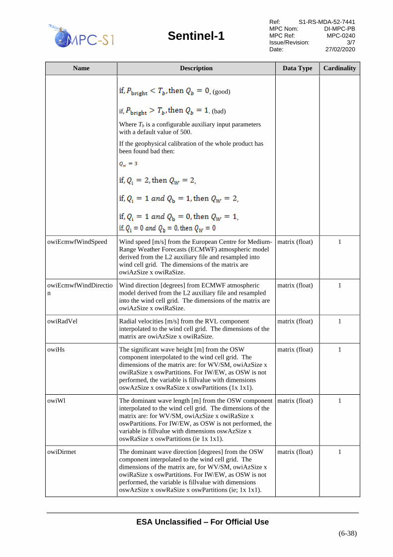
Sentinel-1
Ref: S1-RS-MDA-52-7441 MPC Nom: DI-MPC-PB MPC Ref: MPC-0240 Issue/Revision: 3/7 Date: 27/02/2020
ESA Unclassified – For Official Use
(6-38)
Name Description Data Type Cardinality
, (good)
if, . (bad)
Where Tb is a configurable auxiliary input parameters
with a default value of 500.
If the geophysical calibration of the whole product has
been found bad then:
,
,
,
owiEcmwfWindSpeed Wind speed [m/s] from the European Centre for Medium-
Range Weather Forecasts (ECMWF) atmospheric model
derived from the L2 auxiliary file and resampled into
wind cell grid. The dimensions of the matrix are
owiAzSize x owiRaSize.
matrix (float) 1
owiEcmwfWindDirectio
n
Wind direction [degrees] from ECMWF atmospheric
model derived from the L2 auxiliary file and resampled
into the wind cell grid. The dimensions of the matrix are
owiAzSize x owiRaSize.
matrix (float) 1
owiRadVel Radial velocities [m/s] from the RVL component
interpolated to the wind cell grid. The dimensions of the
matrix are owiAzSize x owiRaSize.
matrix (float) 1
owiHs The significant wave height [m] from the OSW
component interpolated to the wind cell grid. The
dimensions of the matrix are: for WV/SM, owiAzSize x
owiRaSize x oswPartitions. For IW/EW, as OSW is not
performed, the variable is fillvalue with dimensions
oswAzSize x oswRaSize x oswPartitions (1x 1x1).
matrix (float) 1
owiWl The dominant wave length [m] from the OSW component
interpolated to the wind cell grid. The dimensions of the
matrix are: for WV/SM, owiAzSize x owiRaSize x
oswPartitions. For IW/EW, as OSW is not performed, the
variable is fillvalue with dimensions oswAzSize x
oswRaSize x oswPartitions (ie 1x 1x1).
matrix (float) 1
owiDirmet The dominant wave direction [degrees] from the OSW
component interpolated to the wind cell grid. The
dimensions of the matrix are, for WV/SM, owiAzSize x
owiRaSize x oswPartitions. For IW/EW, as OSW is not
performed, the variable is fillvalue with dimensions
oswAzSize x oswRaSize x oswPartitions (ie; 1x 1x1).
matrix (float) 1

Sentinel-1
Ref: S1-RS-MDA-52-7441 MPC Nom: DI-MPC-PB MPC Ref: MPC-0240 Issue/Revision: 3/7 Date: 27/02/2020
ESA Unclassified – For Official Use
(6-39)
Name Description Data Type Cardinality
owiWindSeaHs The significant wave height for the wind sea part of the
total wave height spectrum [m] from the OSW component
interpolated to the wind cell grid. The dimensions of the
matrix are: for WV/SM owiAzSize x owiRaSize. For
IW/EW, as OSW is not performed, the variable is
fillvalue with dimensions, oswAzSize x oswRaSize (1x 1
and fillvalue).
matrix (float) 1
owiElevationAngle Radar elevation angle [degrees] to the center of the wind
cells. This parameter is provided at each azimuth line in
the wind cell grid.
The dimensions of the matrix are owiAzSize x
owiRaSize.
matrix (float) 1
owiNesz The noise equivalent sigmaNaught, dimension is
equivalent to measured radar cross section normalized to
the area on ground [m²/m²]. The owiNesz is a copy of the
calibrated Noise LUT annotated in the Level1
interpolated on the wind cell grid.
The dimensions of the matrix are owiAzSize x owiRaSize
x owiPolarisation.
matrix (float) 1
owiPolarisationName The name of the receiving polarization in order to
discriminate the co and cross polarisation. The dimension
is owiPolarisation
Array(byte) 1
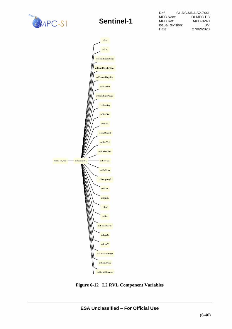
Sentinel-1
Ref: S1-RS-MDA-52-7441 MPC Nom: DI-MPC-PB MPC Ref: MPC-0240 Issue/Revision: 3/7 Date: 27/02/2020
ESA Unclassified – For Official Use
(6-40)
Figure 6-12 L2 RVL Component Variables

Sentinel-1
Ref: S1-RS-MDA-52-7441 MPC Nom: DI-MPC-PB MPC Ref: MPC-0240 Issue/Revision: 3/7 Date: 27/02/2020
ESA Unclassified – For Official Use
(6-41)
Table 6-20 L2 RVL Component Variables
Name Description Data Type Cardinality
rvlLon Geodetic longitude at RVL cell center [degrees_east].
The dimensions of the matrix are: for SM/WV, rvlAziSize
x rvlRaSize; for EW/IW, rvlAziSize x rvlRaSize x
rvlSwath;.
matrix (float) 1
rvlLat Geodetic latitude at RVL cell center [degrees_north]. The
dimensions of the matrix are; for SM/WV, rvlAziSize x
rvlRaSize; for EW/IW, rvlAziSize x rvlRaSize x
rvlSwath;.
matrix (float) 1
rvlLandCoverage Percentage [%] of land coverage within the estimation
area. The dimensions of the matrix are ; for SM/WV,
rvlAziSize x rvlRaSize; for EW/IW, rvlAziSize x
rvlRaSize x rvlSwath.
matrix (float) 1
rvlLandFlag Land mask flag This flag is set to 1 if the land_coverage >
10%; otherwise, it is set to 0. The dimensions of the
matrix are : for SM/WV, rvlAziSize x rvlRaSize; for
EW/IW, rvlAziSize x rvlRaSize x rvlSwath..
matrix (byte) 1
rvlIncidenceAngle Radar incidence angle [degrees] to the center of the RVL
cells. This parameter is provided at each azimuth line in
the radial velocity cell grid. The dimensions of the matrix
are : for SM/WV, rvlAziSize x rvlRaSize; for EW/IW,
rvlAziSize x rvlRaSize x rvlSwath.
matrix (float) 1
rvlHeading Local Northing angle [degrees]. The dimensions of the
matrix are : for SM/WV, rvlAziSize x rvlRaSize; for
EW/IW, rvlAziSize x rvlRaSize x rvlSwath.
matrix (float) 1
rvlNrcs Normalized radar cross-section [m^2/m^2], side-band
corrected signal intensity.The intensity is estimated within
and provided for each radial velocity cell. The
dimensions of the matrix are: for SM/WV, rvlAziSize x
rvlRaSize; for EW/IW, rvlAziSize x rvlRaSize x
rvlSwath.
matrix (float) 1
rvlDcObs Estimated Doppler centroid frequency [Hz]. The
dimensions of the matrix are : for SM/WV, rvlAziSize x
rvlRaSize; for EW/IW, rvlAziSize x rvlRaSize x
rvlSwath;.
array (float) 1
rvlDcObsStd Estimated Doppler frequency standard deviation [Hz].
The dimensions of the matrix are: for SM/WV, rvlAziSize
x rvlRaSize; for EW/IW, rvlAziSize x rvlRaSize x
rvlSwath;.
array (float) 1
rvlConfDcObs Confidence in the Doppler centroid frequency estimates.
The dimensions of the matrix are : for SM/WV,
rvlAziSize x rvlRaSize; for EW/IW, rvlAziSize x
rvlRaSize x rvlSwath.
matrix (byte) 1
rvlRadVel Radial velocities [m/s]. The dimensions of the matrix are:
for SM/WV, rvlAziSize x rvlRaSize; for EW/IW,
rvlAziSize x rvlRaSize x rvlSwath.
matrix (float) 1

Sentinel-1
Ref: S1-RS-MDA-52-7441 MPC Nom: DI-MPC-PB MPC Ref: MPC-0240 Issue/Revision: 3/7 Date: 27/02/2020
ESA Unclassified – For Official Use
(6-42)
Name Description Data Type Cardinality
rvlRadVelStd Standard deviation of radial velocities [m/s]. The
dimensions of the matrix are : for SM/WV, rvlAziSize x
rvlRaSize; for EW/IW, rvlAziSize x rvlRaSize x
rvlSwath;.
matrix (float) 1
rvlDcGeo Doppler centroid frequency from geometry [Hz]. This
parameter is interpolated from the L1 product. The
dimensions of the matrix are : for SM/WV, rvlAziSize x
rvlRaSize; for EW/IW, rvlAziSize x rvlRaSize x
rvlSwath;.
matrix (float) 1
rvlDcMiss Doppler centroid frequency from antenna miss-pointing
[Hz]. The dimensions of the matrix are : for SM/WV,
rvlAziSize x rvlRaSize; for EW/IW, rvlAziSize x
rvlRaSize x rvlSwath;
matrix (float) 1
rvlYaw Yaw [degrees] of satellite platform versus zero Doppler
time. The dimensions of the matrix are: for SM/WV,
rvlAziSize x rvlRaSize; for EW/IW, rvlAziSize x
rvlRaSize x rvlSwath;.
matrix (float) 1
rvlPitch Pitch [degrees] of satellite platform versus zero Doppler
time. The dimensions of the matrix are : for SM/WV,
rvlAziSize x rvlRaSize; for EW/IW, rvlAziSize x
rvlRaSize x rvlSwath.
matrix (float) 1
rvlRoll Roll [degrees] of satellite platform versus zero Doppler
time. The dimensions of the matrix are : for SM/WV,
rvlAziSize x rvlRaSize; for EW/IW, rvlAziSize x
rvlRaSize x rvlSwath.
matrix (float) 1
rvlSnr Signal to noise ratio estimated from Doppler spectra
(side-band corrected intensity/additive noise) [1]. The
dimensions of the matrix are : for SM/WV, rvlAziSize x
rvlRaSize; for EW/IW, rvlAziSize x rvlRaSize x
rvlSwath.
matrix (float) 1
rvlUssX Longitudinal component of surface stokes drift [m/s] from
WAVEWATCH III model. The dimensions of the matrix
are : for SM/WV, rvlAziSize x rvlRaSize; for EW/IW,
rvlAziSize x rvlRaSize x rvlSwath.
matrix (float) 1
rvlUssY Meridianal component of surface stokes drift [m/s] from
WAVEWATCH III model. The dimensions of the matrix
are : for SM/WV, rvlAziSize x rvlRaSize; for EW/IW,
rvlAziSize x rvlRaSize x rvlSwath..
matrix (float) 1
rvlSweepAngle Sweep angle of the TOPS mode [degrees]. The
dimensions of the matrix are : for SM/WV, rvlAziSize x
rvlRaSize; for EW/IW, rvlAziSize x rvlRaSize x
rvlSwath.
matrix (float) 1
rvlSlantRangeTime Slant range time [s]. The dimensions of the matrix are: for
SM/WV, rvlAziSize x rvlRaSize; for EW/IW, rvlAziSize
x rvlRaSize x rvlSwath.
matrix (float) 1
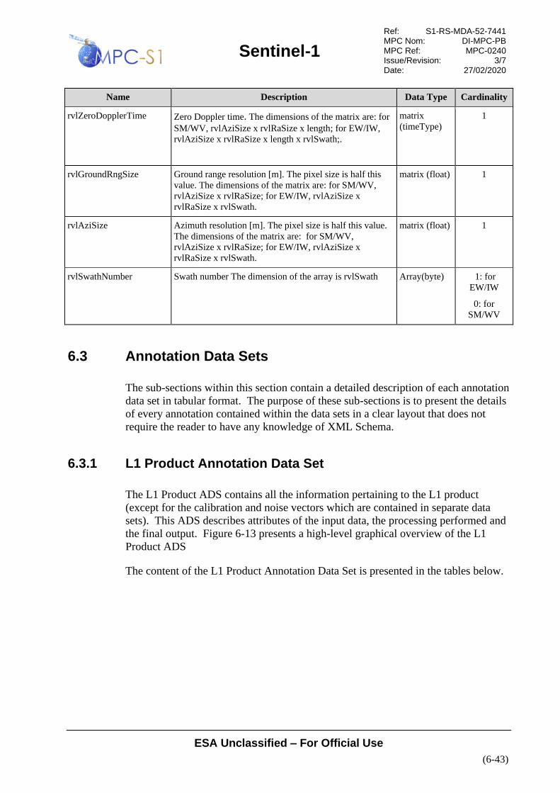
Sentinel-1
Ref: S1-RS-MDA-52-7441 MPC Nom: DI-MPC-PB MPC Ref: MPC-0240 Issue/Revision: 3/7 Date: 27/02/2020
ESA Unclassified – For Official Use
(6-43)
Name Description Data Type Cardinality
rvlZeroDopplerTime Zero Doppler time. The dimensions of the matrix are: for
SM/WV, rvlAziSize x rvlRaSize x length; for EW/IW,
rvlAziSize x rvlRaSize x length x rvlSwath;.
matrix
(timeType)
1
rvlGroundRngSize Ground range resolution [m]. The pixel size is half this
value. The dimensions of the matrix are: for SM/WV,
rvlAziSize x rvlRaSize; for EW/IW, rvlAziSize x
rvlRaSize x rvlSwath.
matrix (float) 1
rvlAziSize Azimuth resolution [m]. The pixel size is half this value.
The dimensions of the matrix are: for SM/WV,
rvlAziSize x rvlRaSize; for EW/IW, rvlAziSize x
rvlRaSize x rvlSwath.
matrix (float) 1
rvlSwathNumber Swath number The dimension of the array is rvlSwath Array(byte) 1: for
EW/IW
0: for
SM/WV
6.3 Annotation Data Sets
The sub-sections within this section contain a detailed description of each annotation
data set in tabular format. The purpose of these sub-sections is to present the details
of every annotation contained within the data sets in a clear layout that does not
require the reader to have any knowledge of XML Schema.
6.3.1 L1 Product Annotation Data Set
The L1 Product ADS contains all the information pertaining to the L1 product
(except for the calibration and noise vectors which are contained in separate data
sets). This ADS describes attributes of the input data, the processing performed and
the final output. Figure 6-13 presents a high-level graphical overview of the L1
Product ADS
The content of the L1 Product Annotation Data Set is presented in the tables below.

Sentinel-1
Ref: S1-RS-MDA-52-7441 MPC Nom: DI-MPC-PB MPC Ref: MPC-0240 Issue/Revision: 3/7 Date: 27/02/2020
ESA Unclassified – For Official Use
(6-44)
Figure 6-13 L1 Product Annotation Data Set

Sentinel-1
Ref: S1-RS-MDA-52-7441 MPC Nom: DI-MPC-PB MPC Ref: MPC-0240 Issue/Revision: 3/7 Date: 27/02/2020
ESA Unclassified – For Official Use
(6-45)
Table 6-21 Element - product
Name Description Data Type Cardinality
adsHeader ADS header data set record. This DSR contains information that applies to the entire data set.
adsHeaderType 1
qualityInformation Quality information data set record. This DSR contains the quality flags and the values used to set them during
image processing as well as the overall quality index.
l1QualityInformationType 1
generalAnnotation General annotation data set record. This DSR contains information describing some key characteristics that apply
to the entire L1 product. This includes annotations such as the sensing start and stop times, polarisation and swath.
It also contains annotations derived from the input processing step including information extracted/calculated
from the downlink data and raw data analysis (RDA) statistics.
l1GeneralAnnotationType 1
imageAnnotation Image annotation data set record. This DSR contains information describing the properties of the image MDS
(such as data type and image dimensions) and the key parameters/options used during the processing of the
image.
l1ImageAnnotationType 1
dopplerCentroid Doppler centroid data set record. This DSR contains information about the Doppler centroid values estimated and
used during image processing.
l1DopplerCentroidType 1
antennaPattern Antenna pattern data set record. This DSR contains information describing the elevation antenna pattern and how
it was applied by the IPF during image processing.
l1AntennaPatternType 1
swathTiming Swath timing data set record. This DSR contains the information about the bursts within the image MDS
including the burst dimensions, burst timing and burst location. This DSR is specific to IW and EW SLC
products.
l1SwathType 1
geolocationGrid Geolocation grid data set record. This DSR describes the geodetitic position of line/pixel combinations within the
image MDS.
l1GeolocationGridType 1
coordinateConversion Coordinate conversion data set record. This DSR contains the annotations required to convert between the slant
range and ground range coordinate systems.
l1CoordinateConversionType 1
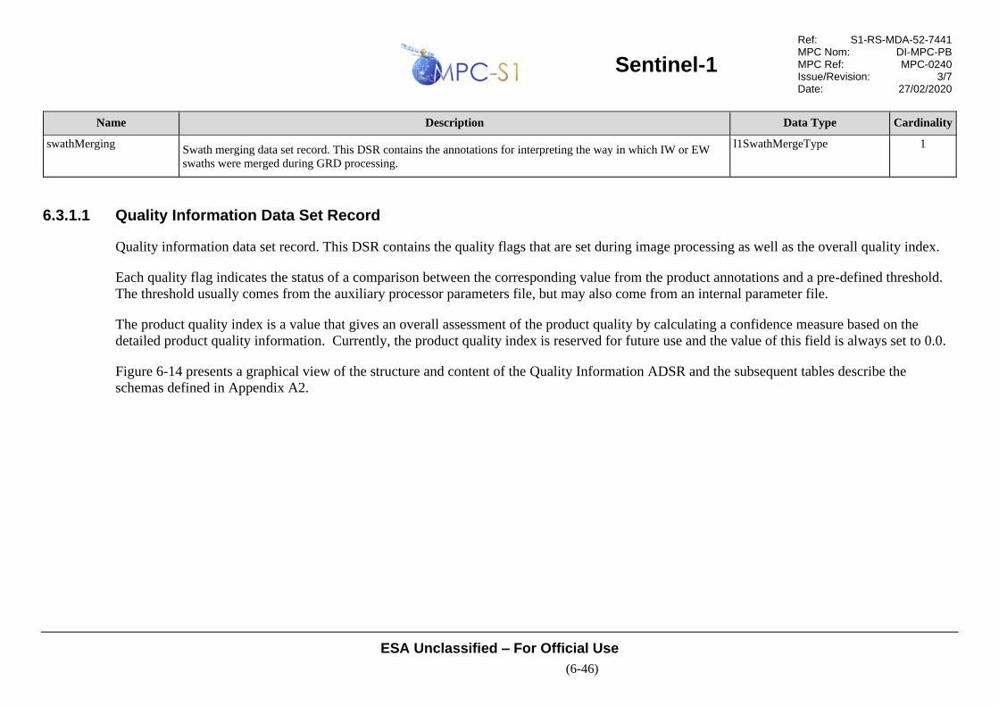
Sentinel-1
Ref: S1-RS-MDA-52-7441 MPC Nom: DI-MPC-PB MPC Ref: MPC-0240 Issue/Revision: 3/7 Date: 27/02/2020
ESA Unclassified – For Official Use
(6-46)
Name Description Data Type Cardinality
swathMerging Swath merging data set record. This DSR contains the annotations for interpreting the way in which IW or EW
swaths were merged during GRD processing.
l1SwathMergeType 1
6.3.1.1 Quality Information Data Set Record
Quality information data set record. This DSR contains the quality flags that are set during image processing as well as the overall quality index.
Each quality flag indicates the status of a comparison between the corresponding value from the product annotations and a pre-defined threshold.
The threshold usually comes from the auxiliary processor parameters file, but may also come from an internal parameter file.
The product quality index is a value that gives an overall assessment of the product quality by calculating a confidence measure based on the
detailed product quality information. Currently, the product quality index is reserved for future use and the value of this field is always set to 0.0.
Figure 6-14 presents a graphical view of the structure and content of the Quality Information ADSR and the subsequent tables describe the
schemas defined in Appendix A2.

Sentinel-1
Ref: S1-RS-MDA-52-7441 MPC Nom: DI-MPC-PB MPC Ref: MPC-0240 Issue/Revision: 3/7 Date: 27/02/2020
ESA Unclassified – For Official Use
(6-47)
Figure 6-14 L1 Quality Information ADSR

Sentinel-1
Ref: S1-RS-MDA-52-7441 MPC Nom: DI-MPC-PB MPC Ref: MPC-0240 Issue/Revision: 3/7 Date: 27/02/2020
ESA Unclassified – For Official Use
(6-48)
Table 6-22 Data Type - l1QualityInformationType
Name Description Data Type Cardinality
productQualityIndex Overall product quality index. This annotation is calculated based on specific quality parameters and gives an
overall quality value to the product. This parameter is reserved for future use and its value is set to 0.0.
double 1
qualityDataList Quality data list. This element contains a list of qualityData records which contain the quality values and flags
calculated and set during image processing. For individual scene and slice products there is one qualityData
record in the list. For assembled products the list contains one qualityData record for each slice included in the
assembled product.
qualityDataListType 1
Table 6-23 Data Type - qualityDataListType
Name Description Data Type Cardinality
count Number of qualityData records within the list. unsignedInt required
qualityData Quality data. This record contains the quality values and flags that are set during image processing. Each flag
indicates the status of a comparison between the corresponding value(s) and a pre-defined threshold. For
individual scene and slice products there is one qualityData record. For assembled products the list contains all
the qualityData records for each slice included in the assembled product. For a minimum output slice length of
10s and a maximum segment length of 25 minutes, the maximum number of records in the list is 150.
qualityDataType 1 .. 150
Table 6-24 Data Type - qualityDataType
Name Description Data Type Cardinality
azimuthTime Zero Doppler azimuth time at which this set of quality annotations applies [UTC]. timeType 1
downlinkQuality Downlink quality. This record contains the quality indicators - values and flags - related to the downlink
information.
downlinkQualityType 1
rawDataAnalysisQuality Raw data analysis quality. This record contains the quality indicators - values and flags - related to the raw data
analysis information.
rawDataAnalysisQualityType 1

Sentinel-1
Ref: S1-RS-MDA-52-7441 MPC Nom: DI-MPC-PB MPC Ref: MPC-0240 Issue/Revision: 3/7 Date: 27/02/2020
ESA Unclassified – For Official Use
(6-49)
Name Description Data Type Cardinality
dopplerCentroidQuality Doppler centroid quality. This record contains the quality indicators - values and flags - related to the Doppler
centroid estimation.
dopplerCentroidQualityType 1
imageQuality Image quality. This record contains the quality indicators - values and flags - related to properties of the output
image.
imageQualityType 1
Table 6-25 Data Type - downlinkQualityType
Name Description Data Type Cardinality
iInputDataMean Calculated mean of the input data for the I channel. double 1
qInputDataMean Calculated mean of the input data for the Q channel. double 1
inputDataMeanOutsideNominalRangeFlag Input data mean outside nominal range flag. False if the mean of I and Q input values are both
within specified range from expected mean. For expected mean of x, the measured mean must fall
between x-threshold to x+threshold. True otherwise.
bool 1
iInputDataStdDev Calculated standard deviation of the input data for the I channel. double 1
qInputDataStdDev Calculated standard deviation of the input data for the Q channel. double 1
inputDataStDevOutsideNominalRangeFlag Input data standard deviation outside nominal range flag. False if the standard deviation values of
I and Q input values are both within specified range of expected standard deviation. For expected
std. dev. x, the measured std. dev. must fall between x-threshold to x+threshold. True otherwise.
bool 1
numDownlinkInputDataGaps Number of downlink gaps detected in the input data. uint32
downlinkGapsInInputDataSignificantFlag Significant downlink gaps in the input data flag. A downlink input data gap is defined as a
contiguous block of N downlink missing lines (the value of N is predefined for each product).
False if the number of downlink input gaps is less than or equal to the threshold value, true if
number of downlink input data gaps is greater than the threshold value.
bool
numDownlinkInputMissingLines Number of downlink missing lines detected in the input data, excluding data gaps. A downlink
missing line is defined as any echo line physically absent from the input data file due to a
downlink error.
uint32

Sentinel-1
Ref: S1-RS-MDA-52-7441 MPC Nom: DI-MPC-PB MPC Ref: MPC-0240 Issue/Revision: 3/7 Date: 27/02/2020
ESA Unclassified – For Official Use
(6-50)
Name Description Data Type Cardinality
downlinkMissingLinesSignificantFlag Downlink missing lines significant flag. False if the percentage of downlink missing lines is less
than or equal to the threshold value, true if the percentage of downlink missing lines is greater
than the threshold value. The number of downlink missing lines is
numDownlinkInputMissingLines.
bool
numInstrumentInputDataGaps Number of instrument gaps detected in the input data. uint32 1
instrumentGapsInInputDataSignificantFlag Significant instrument gaps in the input data flag. An instrument input data gap is defined as a
contiguous block of N instrument missing lines (the value of N is predefined for each product).
False if the number of instrument input gaps is less than or equal to the threshold value, true if
number of instrument input data gaps is greater than the threshold value.
bool 1
numInstrumentInputMissingLines Number of instrument missing lines detected in the input data, excluding data gaps. An instrument
missing line is defined as any echo line physically absent from the input data file due to a failure
by the instrument to produce the expected echo line.
uint32 1
instrumentMissingLinesSignificantFlag Instrument missing lines significant flag. False if the percentage of instrument missing lines is less
than or equal to the threshold value, true if the percentage of instrument missing lines is greater
than the threshold value. The number of instrument missing lines is
numInstrumentInputMissingLines.
bool 1
numSsbErrorInputDataGaps Number of gaps detected in the input data due to the SSB Error flag being set. uint32 1
ssbErrorGapsInInputDataSignificantFlag Significant SSB Error gaps in the input data flag. An SSB Error input data gap is defined as a
contiguous block of N lines in which the SSB Error Flag is set to true (the value of N is predefined
for each product). False if the number of SSB Error input gaps is less than or equal to the
threshold value, true if number of SSB Error input data gaps is greater than the threshold value.
bool 1
numSsbErrorInputMissingLines Number of SSB Error missing lines detected in the input data, excluding data gaps. An SSB Error
missing line is defined as any echo line in which the SSB Error Flag is the ISP secondary header is
set to true.
uint32 1
ssbErrorMissingLinesSignificantFlag SSB Error missing lines significant flag. False if the percentage of SSB Error missing lines is less
than or equal to the threshold value, true if the percentage of SSB Error missing lines is greater
than the threshold value. The number of SSB Error missing lines is
numSsbErrorInputMissingLines.
bool 1

Sentinel-1
Ref: S1-RS-MDA-52-7441 MPC Nom: DI-MPC-PB MPC Ref: MPC-0240 Issue/Revision: 3/7 Date: 27/02/2020
ESA Unclassified – For Official Use
(6-51)
Name Description Data Type Cardinality
chirpSourceUsed Chirp source used during processing (Nominal or Extracted). This value is a copy of the value
from the processingOptions record.
chirpSourceType 1
pgSourceUsed PG source used during processing (Model or Extracted). This value is a copy of the value from the
referenceReplica record.
pgSourceType 1
rrfSpectrumUsed Type of range replica function used (Unextended, Extended Flat, Extended Tapered). This value is
a copy of the value from the processingOptions record.
rrfSpectrumType 1
replicaReconstructionFailedFlag Chirp replica reconstruction failed or is of low quality flag. False if able to reconstruct at least one
valid extracted replica during processing. True if unable to reconstruct any valid extracted replicas
during processing. A replica is valid if it was successfully reconstructed and all quality measures
were acceptable. If this flag is true then the processor uses the nominal range pulse for processing
and a nominal elevation beam scaling factor.
bool 1
meanPgProductAmplitude Mean of all PG product amplitude values from the replicas extracted from the calibration pulses. double 1
stdDevPgProductAmplitude Standard deviation of all PG product amplitude values from the replicas extracted from the
calibration pulses.
double 1
meanPgProductPhase Mean value of all PG product phase values from the replicas extracted from the calibration pulses
[radians].
double 1
stdDevPgProductPhase Standard deviation of all PG product phase values from the replicas extracted from the calibration
pulses [radians].
double 1
pgProductDerivationFailedFlag PG product derivation failed flag. False if the percentage of invalid relative and absolute PG
products is below the configured threshold; or, true otherwise. If this flag is set to true then the
values from the PG product model will be used in place of the derived PG product values.
bool 1
invalidDownlinkParamsFlag Invalid downlink parameters flag. False if all parameters read from the downlinked data were
valid, true if any downlink parameter is out of range and therefore a default value has been used
during processing.
bool 1
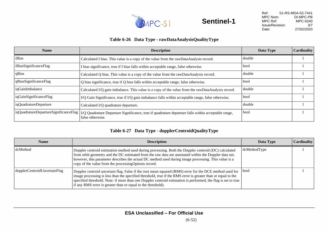
Sentinel-1
Ref: S1-RS-MDA-52-7441 MPC Nom: DI-MPC-PB MPC Ref: MPC-0240 Issue/Revision: 3/7 Date: 27/02/2020
ESA Unclassified – For Official Use
(6-52)
Table 6-26 Data Type - rawDataAnalysisQualityType
Name Description Data Type Cardinality
iBias Calculated I bias. This value is a copy of the value from the rawDataAnalysis record. double 1
iBiasSignificanceFlag I bias significance, true if I bias falls within acceptable range, false otherwise. bool 1
qBias Calculated Q bias. This value is a copy of the value from the rawDataAnalysis record. double 1
qBiasSignificanceFlag Q bias significance, true if Q bias falls within acceptable range, false otherwise. bool 1
iqGainImbalance Calculated I/Q gain imbalance. This value is a copy of the value from the rawDataAnalysis record. double 1
iqGainSignificanceFlag I/Q Gain Significance, true if I/Q gain imbalance falls within acceptable range, false otherwise. bool 1
iqQuadratureDeparture Calculated I/Q quadrature departure. double 1
iqQuadratureDepartureSignificanceFlag I/Q Quadrature Departure Significance, true if quadrature departure falls within acceptable range,
false otherwise.
bool 1
Table 6-27 Data Type - dopplerCentroidQualityType
Name Description Data Type Cardinality
dcMethod Doppler centroid estimation method used during processing. Both the Doppler centroid (DC) calculated
from orbit geometry and the DC estimated from the raw data are annotated within the Doppler data set;
however, this parameter describes the actual DC method used during image processing. This value is a
copy of the value from the processingOptions record.
dcMethodType 1
dopplerCentroidUncertainFlag Doppler centroid uncertain flag. False if the root mean squared (RMS) error for the DCE method used for
image processing is less than the specified threshold, true if the RMS error is greater than or equal to the
specified threshold. Note: if more than one Doppler centroid estimation is performed, the flag is set to true
if any RMS error is greater than or equal to the threshold).
bool 1

Sentinel-1
Ref: S1-RS-MDA-52-7441 MPC Nom: DI-MPC-PB MPC Ref: MPC-0240 Issue/Revision: 3/7 Date: 27/02/2020
ESA Unclassified – For Official Use
(6-53)
Table 6-28 Data Type - imageQualityType
Name Description Data Type Cardinality
imageStatistics Mean and standard deviation statistics for the image. This record is a copy of the record from the
imageInformation record.
imageStatisticsType 1
outputDataMeanOutsideNominalRangeFlag Output data mean outside nominal range flag. False if the mean of I and Q output values for SLC
image or mean of detected pixels for a detected product, are both within specified range from
expected mean. For expected mean of x, the measured mean must fall between x-threshold to
x+threshold. True otherwise.
bool 1
outputDataStDevOutsideNominalRangeFlag Output data standard deviation outside nominal range flag. False if the std. dev. of I and Q output
values for SLC image or std. dev. of detected pixels for a detected product, are both within
specified range from expected std. dev. For expected std. dev. of x, the measured std. dev. must
fall between x-threshold to x+threshold. True otherwise.
bool 1
Table 6-29 Data Type - imageStatisticsType
Name Description Data Type Cardinality
outputDataMean Mean value of output data. complex 1
outputDataStdDev Standard deviation of output data. complex 1
6.3.1.2 General Annotation Data Set Record
General annotation data set record. This DSR contains information describing some key characteristics that apply to the entire L1 product. This
includes annotations such as the sensing start and stop times, polarisation and swath. It also contains annotations derived from the input processing
step including information extracted/calculated from the downlink data and raw data analysis statistics.

Sentinel-1
Ref: S1-RS-MDA-52-7441 MPC Nom: DI-MPC-PB MPC Ref: MPC-0240 Issue/Revision: 3/7 Date: 27/02/2020
ESA Unclassified – For Official Use
(6-54)
Figure 6-15 presents a graphical view of the structure and content of the General ADSR and the subsequent tables describe the schemas defined in
Appendix A2.
Figure 6-15 L1 General ADSR
Table 6-30 Data Type - l1GeneralAnnotationType
Name Description Data Type Cardinality
productInformation General product information. This record describes some key characteristics of the product, the input data
and the acquisition platform.
productInformationType 1
downlinkInformationList Downlink information list. This element contains a list of downlinkInformation records which contain
information extracted and calculated from the input data.
downlinkInformationListType 1
orbitList List of orbit information used by the IPF during processing. This list contains sets of orbit state vectors that
are updated along azimuth. The values represent the interpolated values used by the IPF and are derived
from the sub-commutated ancillary data from the ISPs or from an input auxiliary orbit file.
orbitListType 1
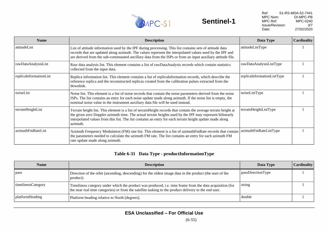
Sentinel-1
Ref: S1-RS-MDA-52-7441 MPC Nom: DI-MPC-PB MPC Ref: MPC-0240 Issue/Revision: 3/7 Date: 27/02/2020
ESA Unclassified – For Official Use
(6-55)
Name Description Data Type Cardinality
attitudeList List of attitude information used by the IPF during processing. This list contains sets of attitude data
records that are updated along azimuth. The values represent the interpolated values used by the IPF and
are derived from the sub-commutated ancillary data from the ISPs or from an input auxiliary attitude file.
attitudeListType 1
rawDataAnalysisList Raw data analysis list. This element contains a list of rawDataAnalysis records which contain statistics
collected from the input data.
rawDataAnalysisListType 1
replicaInformationList Replica information list. This element contains a list of replicaInformation records, which describe the
reference replica and the reconstructed replicas created from the calibration pulses extracted from the
downlink.
replicaInformationListType 1
noiseList Noise list. This element is a list of noise records that contain the noise parameters derived from the noise
ISPs. The list contains an entry for each noise update made along azimuth. If the noise list is empty, the
nominal noise value in the instrument auxiliary data file will be used instead.
noiseListType 1
terrainHeightList Terrain height list. This element is a list of terrainHeight records that contain the average terrain height at
the given zero Doppler azimuth time. The actual terrain heights used by the IPF may represent bilinearly
interpolated values from this list. The list contains an entry for each terrain height update made along
azimuth.
terrainHeightListType 1
azimuthFmRateList Azimuth Frequency Modulation (FM) rate list. This element is a list of azimuthFmRate records that contain
the parameters needed to calculate the azimuth FM rate. The list contains an entry for each azimuth FM
rate update made along azimuth.
azimuthFmRateListType 1
Table 6-31 Data Type - productInformationType
Name Description Data Type Cardinality
pass Direction of the orbit (ascending, descending) for the oldest image data in the product (the start of the
product).
passDirectionType 1
timelinessCategory Timeliness category under which the product was produced, i.e. time frame from the data acquisition (for
the near real time categories) or from the satellite tasking to the product delivery to the end user.
string 1
platformHeading Platform heading relative to North [degrees]. double 1

Sentinel-1
Ref: S1-RS-MDA-52-7441 MPC Nom: DI-MPC-PB MPC Ref: MPC-0240 Issue/Revision: 3/7 Date: 27/02/2020
ESA Unclassified – For Official Use
(6-56)
Name Description Data Type Cardinality
projection Projection of the image, either slant range or ground range. projectionType 1
rangeSamplingRate Range sample rate [Hz]. double 1
radarFrequency Radar frequency [Hz]. double 1
azimuthSteeringRate Azimuth steering rate for IW and EW modes [degrees/s]. double 1
Table 6-32 Data Type - downlinkInformationListType
Name Description Data Type Cardinality
count Number of downlink information records within the list. unsignedInt required
downlinkInformation Downlink information. This record contains information about the data extracted/calculated from the input
data, including values extracted from the ISP and data error counters. For individual scene and slice
products there is one downlinkInformation record, except in the case of IW/EW GRD products, where
there will be one record per swath. For assembled products the list contains all the downlinkInformation
records for each slice included in the assembled product. For a minimum output slice length of 10s, a
maximum segment length of 25 minutes and a maximum 5 swaths, the maximum number of records in the
list is 750.
downlinkInformationType 1 .. 750
Table 6-33 Data Type - downlinkInformationType
Name Description Data Type Cardinality
swath Swath from which this downlink information data was extracted. swathType 1
azimuthTime Zero Doppler azimuth time at which this set of downlink information applies [UTC]. timeType 1
firstLineSensingTime Sensing time of first line of input data [UTC]. timeType 1
lastLineSensingTime Sensing time of last line of input data [UTC]. timeType 1

Sentinel-1
Ref: S1-RS-MDA-52-7441 MPC Nom: DI-MPC-PB MPC Ref: MPC-0240 Issue/Revision: 3/7 Date: 27/02/2020
ESA Unclassified – For Official Use
(6-57)
Name Description Data Type Cardinality
prf Pulse repetition frequency (PRF) of the input raw data [Hz]. This is the inverse of the PRI extracted from
the downlink for this swath.
double 1
bitErrorCount Error counters. This record contains the error counter for each field that is validated as the input source
packets are analyzed.
bitErrorCountType 1
downlinkValues Downlink values. This record contains values extracted directly from the Instrument Source Packets. downlinkValuesType 1
Table 6-34 Data Type - bitErrorCountType
Name Description Data Type Cardinality
numErrSyncMarker Number of errors detected in the sync marker field. uint32 1
numErrDataTakeId Number of errors detected in the data take identifier field. uint32 1
numErrEccNumber Number of errors detected in the Event Control Code (ECC) number field. uint32 1
numErrTestMode Number of errors detected in the test mode field. uint32 1
numErrRxChannelId Number of errors detected in the Rx channel identifier field. uint32 1
numErrInstrumentConfigId Number of errors detected in the instrument configuration identifier field. uint32 1
numErrPacketCount Number of errors detected in the space packet count field. uint32 1
numErrPriCount Number of errors detected in the Pulse Repetition Interval (PRI) count field. uint32 1
numErrSsbErrorFlag Number of packets in which the SSB Error Flag is set to true. uint32 1
numErrBaqMode Number of errors detected in the Block Adaptive Quantisation (BAQ) mode field. uint32 1
numErrBaqBlockLength Number of errors detected in the BAQ block length field. uint32 1
numErrRangeDecimation Number of errors detected in the range decimation field. uint32 1
numErrRxGain Number of errors detected in the Rx gain field. uint32 1

Sentinel-1
Ref: S1-RS-MDA-52-7441 MPC Nom: DI-MPC-PB MPC Ref: MPC-0240 Issue/Revision: 3/7 Date: 27/02/2020
ESA Unclassified – For Official Use
(6-58)
Name Description Data Type Cardinality
numErrTxRampRate Number of errors detected in the Tx ramp rate field. uint32 1
numErrTxPulseStartFrequency Number of errors detected in the Tx pulse start frequency field. uint32 1
numErrRank Number of errors detected in the rank field. uint32 1
numErrPri Number of errors detected in the PRI code field uint32 1
numErrSwst Number of errors detected in the sampling window start time (SWST) field. uint32 1
numErrSwl Number of errors detected in the sampling window length (SWL) field. uint32 1
numErrPolarisation Number of errors detected in the polarisation field. uint32 1
numErrTempComp Number of errors detected in the temperature compensation field. uint32 1
numErrElevationBeamAddress Number of errors detected in the elevation beam address field. uint32 1
numErrAzimuthBeamAddress Number of errors detected in the azimuth beam address field. uint32 1
numErrSasTestMode Number of errors detected in the SAR Antenna Sub-system (SAS) test mode field. uint32 1
numErrCalType Number of errors detected in the calibration operation type field. uint32 1
numErrCalibrationBeamAddress Number of errors detected in the calibration beam address field. uint32 1
numErrCalMode Number of errors detected in the calibration mode field. uint32 1
numErrTxPulseNumber Number of errors detected in the Tx pulse number field. uint32 1
numErrSignalType Number of errors detected in the signal type field. uint32 1
numErrSwapFlag Number of errors detected in the swap flag field. uint32 1
numErrSwathNumber Number of errors detected in the swath number field. uint32 1
numErrNumberOfQuads Number of errors detected in the number of quads field. uint32 1
numIspHeaderErrors Total number of errors detected in ISP headers. uint32 1
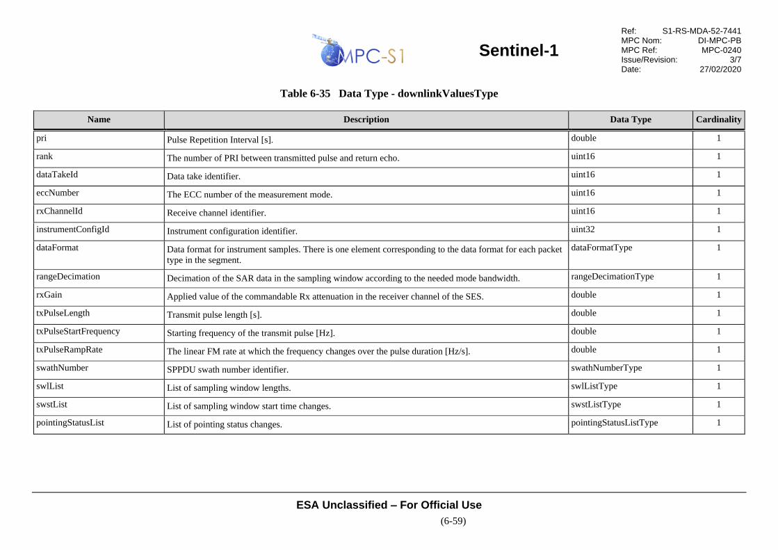
Sentinel-1
Ref: S1-RS-MDA-52-7441 MPC Nom: DI-MPC-PB MPC Ref: MPC-0240 Issue/Revision: 3/7 Date: 27/02/2020
ESA Unclassified – For Official Use
(6-59)
Table 6-35 Data Type - downlinkValuesType
Name Description Data Type Cardinality
pri Pulse Repetition Interval [s]. double 1
rank The number of PRI between transmitted pulse and return echo. uint16 1
dataTakeId Data take identifier. uint16 1
eccNumber The ECC number of the measurement mode. uint16 1
rxChannelId Receive channel identifier. uint16 1
instrumentConfigId Instrument configuration identifier. uint32 1
dataFormat Data format for instrument samples. There is one element corresponding to the data format for each packet
type in the segment.
dataFormatType 1
rangeDecimation Decimation of the SAR data in the sampling window according to the needed mode bandwidth. rangeDecimationType 1
rxGain Applied value of the commandable Rx attenuation in the receiver channel of the SES. double 1
txPulseLength Transmit pulse length [s]. double 1
txPulseStartFrequency Starting frequency of the transmit pulse [Hz]. double 1
txPulseRampRate The linear FM rate at which the frequency changes over the pulse duration [Hz/s]. double 1
swathNumber SPPDU swath number identifier. swathNumberType 1
swlList List of sampling window lengths. swlListType 1
swstList List of sampling window start time changes. swstListType 1
pointingStatusList List of pointing status changes. pointingStatusListType 1
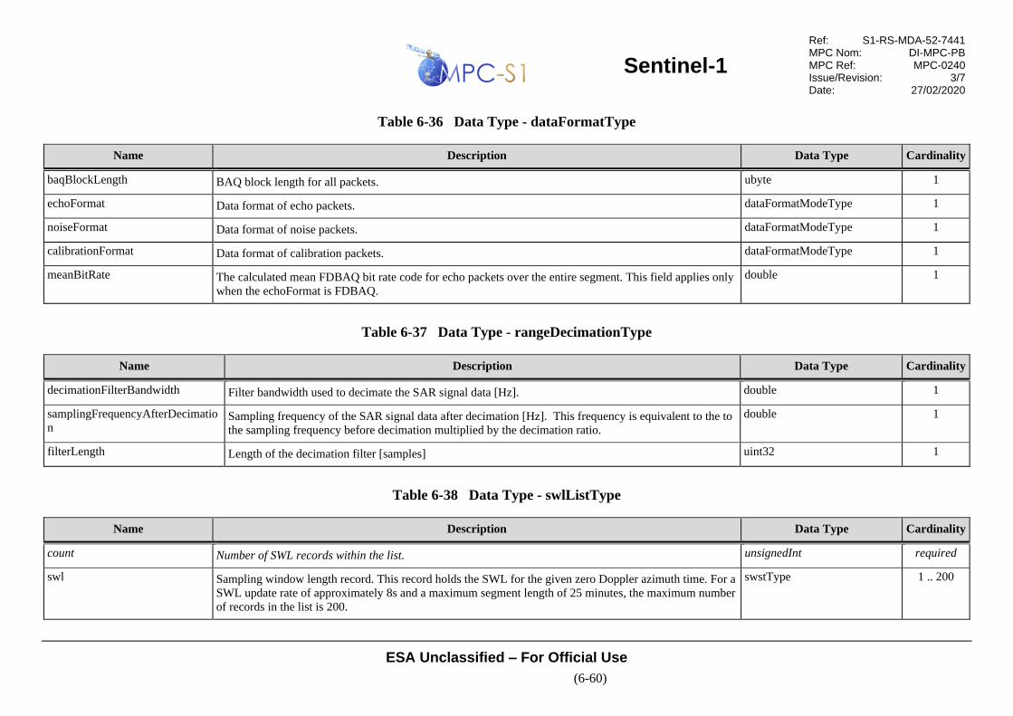
Sentinel-1
Ref: S1-RS-MDA-52-7441 MPC Nom: DI-MPC-PB MPC Ref: MPC-0240 Issue/Revision: 3/7 Date: 27/02/2020
ESA Unclassified – For Official Use
(6-60)
Table 6-36 Data Type - dataFormatType
Name Description Data Type Cardinality
baqBlockLength BAQ block length for all packets. ubyte 1
echoFormat Data format of echo packets. dataFormatModeType 1
noiseFormat Data format of noise packets. dataFormatModeType 1
calibrationFormat Data format of calibration packets. dataFormatModeType 1
meanBitRate The calculated mean FDBAQ bit rate code for echo packets over the entire segment. This field applies only
when the echoFormat is FDBAQ.
double 1
Table 6-37 Data Type - rangeDecimationType
Name Description Data Type Cardinality
decimationFilterBandwidth Filter bandwidth used to decimate the SAR signal data [Hz]. double 1
samplingFrequencyAfterDecimatio
n Sampling frequency of the SAR signal data after decimation [Hz]. This frequency is equivalent to the to
the sampling frequency before decimation multiplied by the decimation ratio.
double 1
filterLength Length of the decimation filter [samples] uint32 1
Table 6-38 Data Type - swlListType
Name Description Data Type Cardinality
count Number of SWL records within the list. unsignedInt required
swl Sampling window length record. This record holds the SWL for the given zero Doppler azimuth time. For a
SWL update rate of approximately 8s and a maximum segment length of 25 minutes, the maximum number
of records in the list is 200.
swstType 1 .. 200

Sentinel-1
Ref: S1-RS-MDA-52-7441 MPC Nom: DI-MPC-PB MPC Ref: MPC-0240 Issue/Revision: 3/7 Date: 27/02/2020
ESA Unclassified – For Official Use
(6-61)
Table 6-39 Data Type - swlType
Name Description Data Type Cardinality
azimuthTime Zero Doppler azimuth time of sampling window length change [UTC]. timeType 1
value Sampling Window Length [s]. double 1
Table 6-40 Data Type - swstListType
Name Description Data Type Cardinality
count Number of swst records within the list. unsignedInt required
swst SWST record. This record holds the SWST for the given zero Doppler azimuth time. For a SWST update
rate of approximately 8s and a maximum segment length of 25 minutes, the maximum number of records in
the list is 200.
swstType 1 .. 200
Table 6-41 Data Type - swstType
Name Description Data Type Cardinality
azimuthTime Zero Doppler azimuth time of sampling window start change [UTC]. timeType 1
value Sampling window start time for first range sample [s]. double 1
Table 6-42 Data Type - pointingStatusListType
Name Description Data Type Cardinality
count Number of pointing status records within the list. unsignedInt required
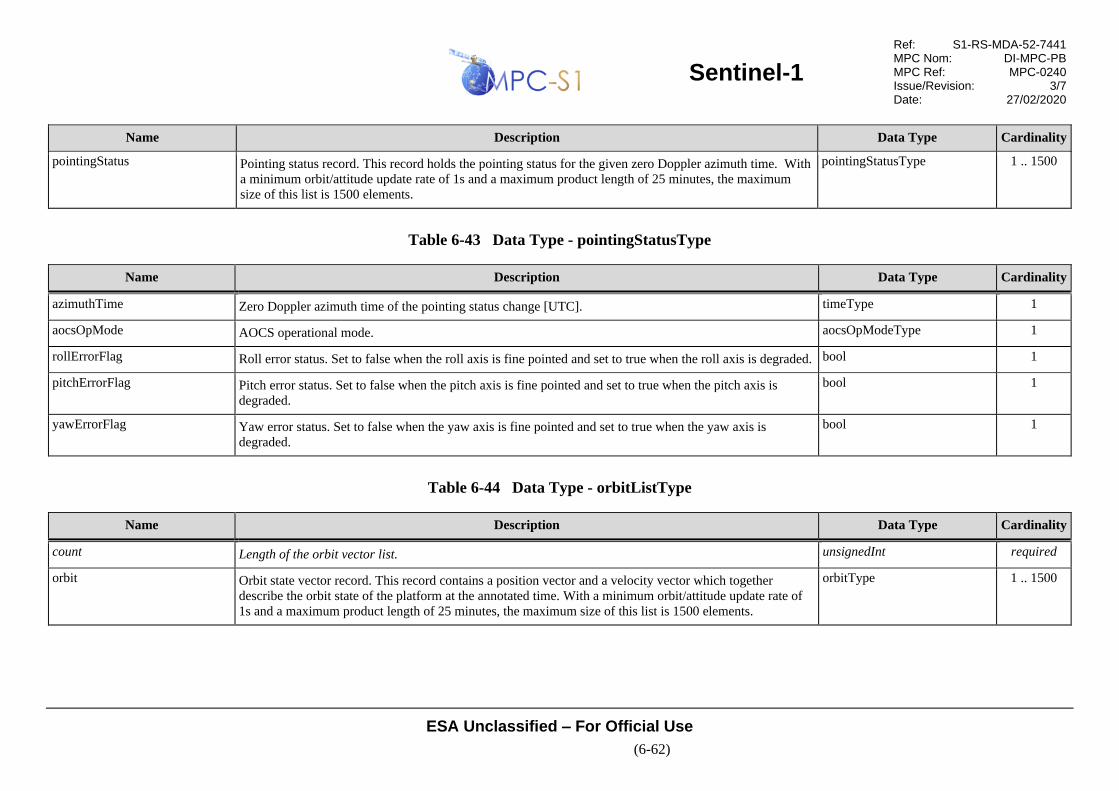
Sentinel-1
Ref: S1-RS-MDA-52-7441 MPC Nom: DI-MPC-PB MPC Ref: MPC-0240 Issue/Revision: 3/7 Date: 27/02/2020
ESA Unclassified – For Official Use
(6-62)
Name Description Data Type Cardinality
pointingStatus Pointing status record. This record holds the pointing status for the given zero Doppler azimuth time. With
a minimum orbit/attitude update rate of 1s and a maximum product length of 25 minutes, the maximum
size of this list is 1500 elements.
pointingStatusType 1 .. 1500
Table 6-43 Data Type - pointingStatusType
Name Description Data Type Cardinality
azimuthTime Zero Doppler azimuth time of the pointing status change [UTC]. timeType 1
aocsOpMode AOCS operational mode. aocsOpModeType 1
rollErrorFlag Roll error status. Set to false when the roll axis is fine pointed and set to true when the roll axis is degraded. bool 1
pitchErrorFlag Pitch error status. Set to false when the pitch axis is fine pointed and set to true when the pitch axis is
degraded.
bool 1
yawErrorFlag Yaw error status. Set to false when the yaw axis is fine pointed and set to true when the yaw axis is
degraded.
bool 1
Table 6-44 Data Type - orbitListType
Name Description Data Type Cardinality
count Length of the orbit vector list. unsignedInt required
orbit Orbit state vector record. This record contains a position vector and a velocity vector which together
describe the orbit state of the platform at the annotated time. With a minimum orbit/attitude update rate of
1s and a maximum product length of 25 minutes, the maximum size of this list is 1500 elements.
orbitType 1 .. 1500
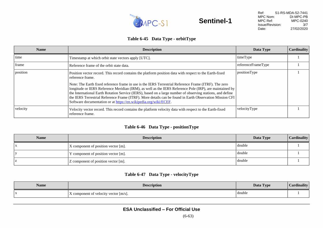
Sentinel-1
Ref: S1-RS-MDA-52-7441 MPC Nom: DI-MPC-PB MPC Ref: MPC-0240 Issue/Revision: 3/7 Date: 27/02/2020
ESA Unclassified – For Official Use
(6-63)
Table 6-45 Data Type - orbitType
Name Description Data Type Cardinality
time Timestamp at which orbit state vectors apply [UTC]. timeType 1
frame Reference frame of the orbit state data. referenceFrameType 1
position Position vector record. This record contains the platform position data with respect to the Earth-fixed
reference frame.
Note: The Earth fixed reference frame in use is the IERS Terrestrial Reference Frame (ITRF). The zero
longitude or IERS Reference Meridian (IRM), as well as the IERS Reference Pole (IRP), are maintained by
the International Earth Rotation Service (IERS), based on a large number of observing stations, and define
the IERS Terrestrial Reference Frame (ITRF). More details can be found in Earth Observation Mission CFI
Software documentation or at https://en.wikipedia.org/wiki/ECEF.
positionType 1
velocity Velocity vector record. This record contains the platform velocity data with respect to the Earth-fixed
reference frame.
velocityType 1
Table 6-46 Data Type - positionType
Name Description Data Type Cardinality
x X component of position vector [m]. double 1
y Y component of position vector [m]. double 1
z Z component of position vector [m]. double 1
Table 6-47 Data Type - velocityType
Name Description Data Type Cardinality
x X component of velocity vector [m/s]. double 1

Sentinel-1
Ref: S1-RS-MDA-52-7441 MPC Nom: DI-MPC-PB MPC Ref: MPC-0240 Issue/Revision: 3/7 Date: 27/02/2020
ESA Unclassified – For Official Use
(6-64)
Name Description Data Type Cardinality
y Y component of velocity vector [m/s]. double 1
z Z component of velocity vector [m/s]. double 1
Table 6-48 Data Type - attitudeListType
Name Description Data Type Cardinality
count Length of the attitude list. unsignedInt required
attitude Attitude data record. This record contains the attitude quaternions and an angular velocity vector which
together describe the attitude state of the platform at the annotated time. With a minimum orbit/attitude
update rate of 1s and a maximum product length of 25 minutes, the maximum size of this list is 1500
elements.
attitudeType 1 .. 1500
Table 6-49 Data Type - attitudeType
Name Description Data Type Cardinality
time Timestamp to which attitude data applies [UTC]. timeType 1
frame Reference frame of the attitude data. referenceFrameType 1
q0 Q0 attitude quaternion as extracted from ancillary attitude data. float 1
q1 Q1 attitude quaternion as extracted from ancillary attitude data. float 1
q2 Q2 attitude quaternion as extracted from ancillary attitude data. float 1
q3 Q3 attitude quaternion as extracted from ancillary attitude data. float 1
wx X component of angular velocity vector as extracted from ancillary attitude data [degrees/s]. double 1
wy Y component of angular velocity vector as extracted from ancillary attitude data [degrees/s]. double 1

Sentinel-1
Ref: S1-RS-MDA-52-7441 MPC Nom: DI-MPC-PB MPC Ref: MPC-0240 Issue/Revision: 3/7 Date: 27/02/2020
ESA Unclassified – For Official Use
(6-65)
Name Description Data Type Cardinality
wz Z component of angular velocity vector as extracted from ancillary attitude data [degrees/s]. double 1
roll Platform roll calculated from ancillary attitude data [degrees]. double 1
pitch Platform pitch calculated from ancillary attitude data [degrees]. double 1
yaw Platform yaw calculated from ancillary attitude data [degrees]. double 1
Table 6-50 Data Type - rawDataAnalysisListType
Name Description Data Type Cardinality
count Number of rawDataAnalysis records within the list. unsignedInt required
rawDataAnalysis Raw data analysis information. This record contains data statistics collected from sampling a subset of the
raw input data. It contains the values calculated for both the I and Q channels. For individual scene and
slice products there is one rawDataAnalysis record except in the case of IW/EW GRD products, where
there will be one record per swath. For assembled products the list contains all the downlinkInformation
records for each slice included in the assembled product. For a minimum output slice length of 10s, a
maximum segment length of 25 minutes and a maximum 5 swaths, the maximum number of records in the
list is 750.
rawDataAnalysisType 1 .. 750
Table 6-51 Data Type - rawDataAnalysisType
Name Description Data Type Cardinality
azimuthTime Zero Doppler azimuth time at which this set of raw data analysis values apply [UTC]. timeType 1
iBias Calculated I bias. double 1
qBias Calculated Q bias. double 1
iqQuadratureDeparture Calculated I/Q quadrature departure. double 1

Sentinel-1
Ref: S1-RS-MDA-52-7441 MPC Nom: DI-MPC-PB MPC Ref: MPC-0240 Issue/Revision: 3/7 Date: 27/02/2020
ESA Unclassified – For Official Use
(6-66)
Name Description Data Type Cardinality
iqGainImbalance Calculated I/Q gain imbalance. double 1
support Supporting Raw Data Analysis (RDA) values. rawDataAnalysisSupportType 1
Table 6-52 Data Type - rawDataAnalysisSupportType
Name Description Data Type Cardinality
iBiasUpperBound I bias upper bound. double 1
iBiasLowerBound I bias lower bound. double 1
qBiasUpperBound Q bias upper bound. double 1
qBiasLowerBound Q bias lower bound. double 1
iqGainUpperBound I/Q gain upper bound. double 1
iqGainLowerBound I/Q gain lower bound. double 1
iqQuadratureDepartureUpperBound I/Q quadrature departure upper bound. double 1
iqQuadratureDepartureLowerBound I/Q quadrature departure lower bound. double 1
iBiasUsedForCorrection I channel bias used for correction (may be different from the calculated bias). double 1
qBiasUsedForCorrection Q channel bias used for correction (may be different from the calculated bias). double 1
iqGainImbalanceUsedForCorrection I/Q gain imbalance used for correction (may be different from the calculated gain). double 1
iqQuadratureDepartureUsedForCorre
ction I/Q quadrature departure used for correction (may be different from the calculated quadrature
departure).
double 1

Sentinel-1
Ref: S1-RS-MDA-52-7441 MPC Nom: DI-MPC-PB MPC Ref: MPC-0240 Issue/Revision: 3/7 Date: 27/02/2020
ESA Unclassified – For Official Use
(6-67)
Table 6-53 Data Type - replicaInformationListType
Name Description Data Type Cardinality
count Number of replicaInformation records within the list. unsignedInt required
replicaInformation Replica information. This record contains information about the reference and reconstructed replicas.
There will be one replica information record per ADS, except for IW/EW GRD products which will contain
one per swath.
replicaInformationType 1 .. 5
Table 6-54 Data Type - replicaInformationType
Name Description Data Type Cardinality
swath Swath to which this replica information applies. swathType 1
referenceReplica Reference replica record. This record contains information about the reference imaging replica that was
used by the IPF during processing. When the extracted replica is used for processing the information in this
record comes from the calibration pulses at the nominal imaging bandwidth. When the nominal replica is
used for processing the information in this record comes directly from the AUX_INS data.
referenceReplicaType 1
replicaList Replica list. This element contains a list of the reconstructed replicas created from the PG calibration pulses
at 100 MHz bandwidth extracted from the downlink. The list contains an entry for each complete
calibration sequence.
replicaListType 1
Table 6-55 Data Type – referenceReplicaType
Name Description Data Type Cardinality
azimuthTime Zero Doppler azimuth time of the middle of the calibration sequence that the reference replica was created
from [UTC].
timeType 1
chirpSource Source of the reference replica: Nominal or Extracted. chirpSourceType 1
pgSource Source of the PG values used in processing: Model or Extracted. pgSourceType 1

Sentinel-1
Ref: S1-RS-MDA-52-7441 MPC Nom: DI-MPC-PB MPC Ref: MPC-0240 Issue/Revision: 3/7 Date: 27/02/2020
ESA Unclassified – For Official Use
(6-68)
Name Description Data Type Cardinality
amplitudeCoefficients Reference replica amplitude coefficients. This element contains the count attribute number of single
precision floating point values separated by spaces.
floatCoefficientArray 1
phaseCoefficients Reference replica phase coefficients. This element contains the count attribute number of single precision
floating point values separated by spaces.
floatCoefficientArray 1
timeDelay Internal time delay [s] representing the average deviation of the replica location from the location of the
transmitted pulse. If the pgSource is Model, then this value is filled with the timeDelay parameter from the
AUX_INS file. If the pgSource is Extracted, then this value is filled with the average internal time delay
calculated across all valid extracted PG replicas reconstructed from the calibration pulses at 100 MHz
bandwidth.
float 1
gain Complex gain to be applied to the range match filter to compensate for the amplitude and phase differences
between the two channels in dual polarisation data.
complex 1
Table 6-56 Data Type - replicaListType
Name Description Data Type Cardinality
count Number of replica records within the list. unsignedInt required
replica PG chirp replica parameters derived from the calibration pulses at 100 MHz bandwidth, With an average
calibration cycle interval of 5s and a maximum product length of 25 minutes, the maximum size of this list
is 300 elements.
replicaType 0 .. 300
Table 6-57 Data Type - replicaType
Name Description Data Type Cardinality
azimuthTime Zero Doppler azimuth time in azimuth at which replica applies [UTC]. timeType 1
crossCorrelationBandwidth 3-dB pulse width of cross-correlation function between the reconstructed replica and the nominal replica
[samples].
float 1

Sentinel-1
Ref: S1-RS-MDA-52-7441 MPC Nom: DI-MPC-PB MPC Ref: MPC-0240 Issue/Revision: 3/7 Date: 27/02/2020
ESA Unclassified – For Official Use
(6-69)
Name Description Data Type Cardinality
crossCorrelationPslr Peak side lobe level (PSLR) of cross-correlation function between the reconstructed replica and the nominal
replica [dB].
float 1
crossCorrelationIslr Integrated Side Lobe Ratio (ISLR) of cross-correlation function between the reconstructed replica and the
nominal replica [dB].
float 1
crossCorrelationPeakLocation Peak location of cross-correlation function between the reconstructed replica and the nominal replica
[samples].
float 1
reconstructedReplicaValidFlag Indicates if the cross-correlation between the nominal PG replica and this extracted PG replica resulted in a
valid peak location. Set to true if a valid peak location was found; or, false otherwise.
bool 1
pgProductAmplitude Amplitude of the PG product derived from this replica. The amplitude value annotated for the PG product
is:
abs(1/PG ∙ sqrt(meanRxCalPow(swath1)/meanRxCalPow(swathn)))
Where:
• abs() is the absolute value function for a complex number;
• sqrt() is the square root function;
• meanRxCalPow(swath1) is the mean RX calibration power of swath 1 calculated according to [R-14];
• meanRxCalPow(swathn) is the mean RX calibration power of the current swath calculated according to
[R-14].
PG product values can only be calculated for products that have at least one valid extracted reconstructed
replica. If no valid extracted reconstructed replica exists within the product then this value will be set to the
default value of 1.0 for every replica record.
float 1
pgProductPhase Phase of the PG product derived from this replica [radians]. The phase value annotated for the PG product
is:
arg(1/PG ∙ sqrt(meanRxCalPow(swath1)/meanRxCalPow(swathn)))
Where:
• arg() is the phase value function for a complex number;
float 1

Sentinel-1
Ref: S1-RS-MDA-52-7441 MPC Nom: DI-MPC-PB MPC Ref: MPC-0240 Issue/Revision: 3/7 Date: 27/02/2020
ESA Unclassified – For Official Use
(6-70)
Name Description Data Type Cardinality
• sqrt() is the square root function;
• meanRxCalPow(swath1) is the mean RX calibration power of swath 1 calculated according to [R-14];
• meanRxCalPow(swathn) is the mean RX calibration power of the current swath calculated according to
[R-14].
PG product values can only be calculated for products that have at least one valid extracted reconstructed
replica. If no valid extracted reconstructed replica exists within the product then this value will be set to the
default value of 0.0 for every replica record.
modelPgProductAmplitude PG product amplitude value from the input PG product model. float 1
modelPgProductPhase PG product phase value from the input PG product model [radians]. float 1
relativePgProductValidFlag Indicates if the amplitude and phase of the PG product passed relative validation. Set to true if
|pgProductAmplitude – meanPgProductAmplitude| < pgAmpStdFractionThreshold *
stdDevPgProductAmplitude and |pgProductPhase – meanPgProductPhase| < pgPhaseStdFractionThreshold
* stdDevPgProductPhase; or, false otherwise.
Where pgAmpStdFractionThreshold and pgPhaseStdFractionThreshold are configured threshold values.
PG product values can only be calculated and validated for products that have at least one valid extracted
reconstructed replica. If no valid extracted reconstructed replica exists within the product then this flag will
be set to false for every replica record.
bool 1
absolutePgProductValidFlag Indicates if the amplitude and phase of the PG product passed the absolute validation. Set to true if
|pgProductAmplitude – modelPgProductAmplitude| < maxPgAmpErrorThreshold and |pgProductPhase –
modelPgProductPhase| < maxPgPhaseErrorThreshold; or, false otherwise.
Where maxPgAmpErrorThreshold and maxPgPhaseErrorThreshold are configured threshold values and
modelPgProductPhase are values obtained from the PG product model.
PG product values can only be calculated and validated for products that have at least one valid extracted
reconstructed replica. If no valid extracted reconstructed replica exists within the product then this flag will
be set to false for every replica record.
bool 1
internalTimeDelay Internal time delay [s] representing the calculated deviation of the location of this PG replica from the
location of the transmitted pulse; i.e., the nominal PG replica.
float 1

Sentinel-1
Ref: S1-RS-MDA-52-7441 MPC Nom: DI-MPC-PB MPC Ref: MPC-0240 Issue/Revision: 3/7 Date: 27/02/2020
ESA Unclassified – For Official Use
(6-71)
Table 6-58 Data Type - noiseListType
Name Description Data Type Cardinality
count Number of noise records within the list. unsignedInt required
noise Noise parameters derived from noise packets. There are a maximum of two sets of noise parameters per
swath.
noiseType 0 .. 1500
Table 6-59 Data Type - noiseType
Name Description Data Type Cardinality
swath Swath to which the noise information applies. swathType 1
azimuthTime Zero Doppler azimuth time of the noise measurement [UTC]. timeType 1
noisePowerCorrectionFactor Noise power correction factor. float 1
numberOfNoiseLines Number of noise lines used to calculate noise correction factor. uint32 1
Table 6-60 Data Type - terrainHeightListType
Name Description Data Type Cardinality
count Number of terrain height records within the list. unsignedInt Required
terrainHeight Terrain height record containing the average terrain height (in metres above the ocean surface) for the
given zero Doppler azimuth time. With a minimum terrain height spacing of 1s and a maximum product
length of 25 minutes, the maximum size of this list is 1500 elements.
terrainHeightType 1 .. 1500

Sentinel-1
Ref: S1-RS-MDA-52-7441 MPC Nom: DI-MPC-PB MPC Ref: MPC-0240 Issue/Revision: 3/7 Date: 27/02/2020
ESA Unclassified – For Official Use
(6-72)
Table 6-61 Data Type - terrainHeightType
Name Description Data Type Cardinality
azimuthTime Zero Doppler azimuth time of terrain height measurement [UTC]. timeType 1
value Average terrain height above ocean surface [m]. The value is the average height in the range direction for
the given zero Doppler azimuth time.
double 1
Table 6-62 Data Type - azimuthFmRateListType
Name Description Data Type Cardinality
count Number of azimuthFmRate records within the list. unsignedInt required
azimuthFmRate Azimuth FM rate = c0 + c1(tSR - t0) + c2(tSR - t0)^2. Where tSR = two way slant range time. With a
minimum azimuth processing block length of approximately 2s and a maximum product length of 25
minutes, the maximum size of this list is 750 elements.
azimuthFmRateType 1 .. 750
Table 6-63 Data Type - azimuthFmRateType
Name Description Data Type Cardinality
azimuthTime Zero Doppler azimuth time to which azimuth FM rate parameters apply [UTC]. timeType 1
t0 Two way slant range time origin used for azimuth FM rate calculation [s]. double 1
azimuthFmRatePolynomial Azimuth FM rate coefficients array in order of c0 [Hz/s] c1 [Hz/s^2] c2 [Hz/s^3]. doubleCoefficientArray 1

Sentinel-1
Ref: S1-RS-MDA-52-7441 MPC Nom: DI-MPC-PB MPC Ref: MPC-0240 Issue/Revision: 3/7 Date: 27/02/2020
ESA Unclassified – For Official Use
(6-73)
6.3.1.3 Image Annotation Data Set Record
Image annotation data set record. This DSR contains information describing the properties
of the image MDS (such as data type and image dimensions) and the key
parameters/options used during the processing of the image.
Figure 6-16 presents a graphical view of the structure and content of the image ADSR and
the subsequent tables describe the schemas defined in Appendix A2.
Figure 6-16 L1 Image ADSR
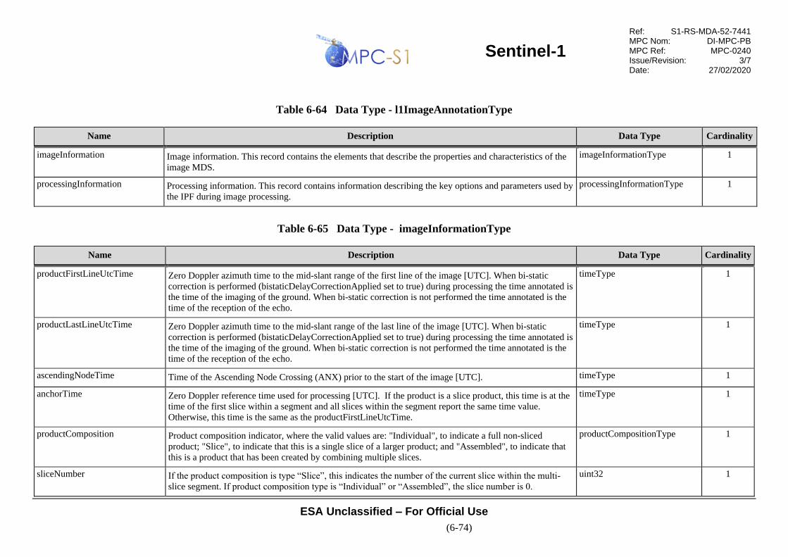
Sentinel-1
Ref: S1-RS-MDA-52-7441 MPC Nom: DI-MPC-PB MPC Ref: MPC-0240 Issue/Revision: 3/7 Date: 27/02/2020
ESA Unclassified – For Official Use
(6-74)
Table 6-64 Data Type - l1ImageAnnotationType
Name Description Data Type Cardinality
imageInformation Image information. This record contains the elements that describe the properties and characteristics of the
image MDS.
imageInformationType 1
processingInformation Processing information. This record contains information describing the key options and parameters used by
the IPF during image processing.
processingInformationType 1
Table 6-65 Data Type - imageInformationType
Name Description Data Type Cardinality
productFirstLineUtcTime Zero Doppler azimuth time to the mid-slant range of the first line of the image [UTC]. When bi-static
correction is performed (bistaticDelayCorrectionApplied set to true) during processing the time annotated is
the time of the imaging of the ground. When bi-static correction is not performed the time annotated is the
time of the reception of the echo.
timeType 1
productLastLineUtcTime Zero Doppler azimuth time to the mid-slant range of the last line of the image [UTC]. When bi-static
correction is performed (bistaticDelayCorrectionApplied set to true) during processing the time annotated is
the time of the imaging of the ground. When bi-static correction is not performed the time annotated is the
time of the reception of the echo.
timeType 1
ascendingNodeTime Time of the Ascending Node Crossing (ANX) prior to the start of the image [UTC]. timeType 1
anchorTime Zero Doppler reference time used for processing [UTC]. If the product is a slice product, this time is at the
time of the first slice within a segment and all slices within the segment report the same time value.
Otherwise, this time is the same as the productFirstLineUtcTime.
timeType 1
productComposition Product composition indicator, where the valid values are: "Individual", to indicate a full non-sliced
product; "Slice", to indicate that this is a single slice of a larger product; and "Assembled", to indicate that
this is a product that has been created by combining multiple slices.
productCompositionType 1
sliceNumber If the product composition is type “Slice”, this indicates the number of the current slice within the multi-
slice segment. If product composition type is “Individual” or “Assembled”, the slice number is 0.
uint32 1

Sentinel-1
Ref: S1-RS-MDA-52-7441 MPC Nom: DI-MPC-PB MPC Ref: MPC-0240 Issue/Revision: 3/7 Date: 27/02/2020
ESA Unclassified – For Official Use
(6-75)
Name Description Data Type Cardinality
sliceList List of annotations for all slices in segment. The total size of the list represents the number of slices in the
segment; that is, there is one slice record for each slice within the segment. If product composition type is
“Individual” or “Assembled”, the total size of this list is 0.
sliceListType 1
slantRangeTime Two-way slant range time to first sample [s]. double 1
pixelValue Interpretation of the image pixels within the image MDS [Detected or Complex]. pixelValueType 1
outputPixels Data type of output pixels within the image MDS. outputPixelsType 1
rangePixelSpacing Pixel spacing between range samples [m]. float 1
azimuthPixelSpacing Nominal pixel spacing between range lines [m]. float 1
azimuthTimeInterval Time spacing between azimuth lines of the output image [s]. double 1
azimuthFrequency Azimuth line frequency of the output image [Hz]. This is the inverse of the azimuthTimeInterval. double 1
numberOfSamples Total number of samples in the output image (image width). uint32 1
numberOfLines Total number of lines in the output image (image length). uint32 1
zeroDopMinusAcqTime Time difference between zero Doppler time and acquisition time of output image lines [s]. double 1
incidenceAngleMidSwath Incidence angle at mid swath [degrees]. double 1
imageStatistics Mean and standard deviation statistics for the image. If the pixelValue field is set to Complex, both the real
and imaginary parts of the statistics are reported. If the pixelValue field is set to Detected, only the real
parts of the statistics are reported
imageStatisticsType 1
Table 6-66 Data Type – sliceListType
Name Description Data Type Cardinality
count Number of slice records within the list. unsignedInt required
slice Slice record describing a single slice within a multi-slice segment. sliceType 0 .. 150

Sentinel-1
Ref: S1-RS-MDA-52-7441 MPC Nom: DI-MPC-PB MPC Ref: MPC-0240 Issue/Revision: 3/7 Date: 27/02/2020
ESA Unclassified – For Official Use
(6-76)
Table 6-67 Data Type - sliceType
Name Description Data Type Cardinality
sliceNumber Slice number of the slice to which the information in this record applies. uint32 1
sensingStartTime Sensing start time of this slice [UTC]. timeType 1
sensingStopTime Sensing stop time of this slice [UTC]. timeType 1
Table 6-68 Data Type - imageStatisticsType
Name Description Data Type Cardinality
outputDataMean Mean value of output data. complex 1
outputDataStdDev Standard deviation of output data. complex 1
Table 6-69 Data Type - processingInformationType
Name Description Data Type Cardinality
rawDataAnalysisUsed False if correction was done using default parameters, true if correction was done using raw data
analysis.
bool 1
orbitDataFileUsed True if the orbit data used for processing came from an external file, false if the orbit data used for
processing came from the downlink.
bool 1
attitudeDataFileUsed True if the attitude data used for processing came from an external file, false if the attitude data used for
processing came from the downlink.
bool 1
rxVariationCorrectionApplied False if the receive variation correction was not applied, true if the receive variation correction was
applied.
bool 1
antennaElevationPatternApplied False if antenna elevation pattern correction was not applied, true if antenna elevation pattern correction
was applied.
bool 1
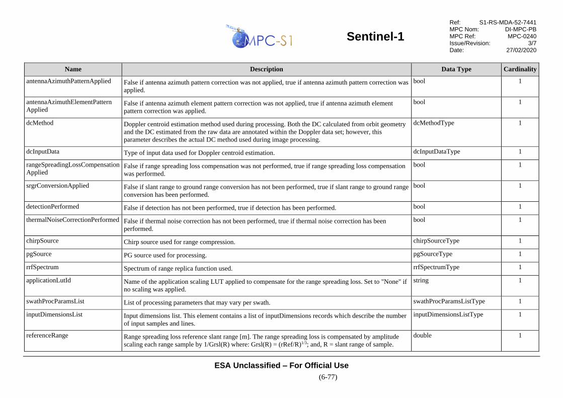
Sentinel-1
Ref: S1-RS-MDA-52-7441 MPC Nom: DI-MPC-PB MPC Ref: MPC-0240 Issue/Revision: 3/7 Date: 27/02/2020
ESA Unclassified – For Official Use
(6-77)
Name Description Data Type Cardinality
antennaAzimuthPatternApplied False if antenna azimuth pattern correction was not applied, true if antenna azimuth pattern correction was
applied.
bool 1
antennaAzimuthElementPattern
Applied False if antenna azimuth element pattern correction was not applied, true if antenna azimuth element
pattern correction was applied.
bool 1
dcMethod Doppler centroid estimation method used during processing. Both the DC calculated from orbit geometry
and the DC estimated from the raw data are annotated within the Doppler data set; however, this
parameter describes the actual DC method used during image processing.
dcMethodType 1
dcInputData Type of input data used for Doppler centroid estimation. dcInputDataType 1
rangeSpreadingLossCompensation
Applied False if range spreading loss compensation was not performed, true if range spreading loss compensation
was performed.
bool 1
srgrConversionApplied False if slant range to ground range conversion has not been performed, true if slant range to ground range
conversion has been performed.
bool 1
detectionPerformed False if detection has not been performed, true if detection has been performed. bool 1
thermalNoiseCorrectionPerformed False if thermal noise correction has not been performed, true if thermal noise correction has been
performed.
bool 1
chirpSource Chirp source used for range compression. chirpSourceType 1
pgSource PG source used for processing. pgSourceType 1
rrfSpectrum Spectrum of range replica function used. rrfSpectrumType 1
applicationLutId Name of the application scaling LUT applied to compensate for the range spreading loss. Set to "None" if
no scaling was applied.
string 1
swathProcParamsList List of processing parameters that may vary per swath. swathProcParamsListType 1
inputDimensionsList Input dimensions list. This element contains a list of inputDimensions records which describe the number
of input samples and lines.
inputDimensionsListType 1
referenceRange Range spreading loss reference slant range [m]. The range spreading loss is compensated by amplitude
scaling each range sample by 1/Grsl(R) where: Grsl(R) = (rRef/R)1/3; and, R = slant range of sample.
double 1

Sentinel-1
Ref: S1-RS-MDA-52-7441 MPC Nom: DI-MPC-PB MPC Ref: MPC-0240 Issue/Revision: 3/7 Date: 27/02/2020
ESA Unclassified – For Official Use
(6-78)
Name Description Data Type Cardinality
ellipsoidName Name of the reference ellipsoid used when processing this product. string 1
ellipsoidSemiMajorAxis Semi-major axis of ellipsoid [m]. double 1
ellipsoidSemiMinorAxis Semi-minor axis of ellipsoid [m]. double 1
bistaticDelayCorrectionApplied False if bi-static delay correction was not applied, true if bi-static delay correction was applied. bool 1
topsFilterConvention Name of the TOPS filter convention used during processing. This field describes how the TOPS
ramping/de-ramping filters are defined. If set to "Only Echo Lines" then the filter is defined using only the
echo lines in a burst; otherwise, if set to "All Lines" then the filter is defined using all the lines in a burst.
topsFilterConventionType 1
orbitSource Source of the orbit data used during processing. Set to “Extracted” if the orbit information extracted from
the sub-commutated acillary data in the source packet headers is used during processing. Set to
“Auxiliary” if the orbit information from an input auxiliary file is used during processing.
orbitAttitudeSourceType 1
attitudeSource Source of the attitude data used during processing. Set to “Extracted” if the attitude information extracted
from the sub-commutated acillary data in the source packet headers is used during processing. Set to
“Auxiliary” if the attitude information from an input auxiliary file is used during processing.
orbitAttitudeSourceType 1
Table 6-70 Data Type - swathProcParamsListType
Name Description Data Type Cardinality
count Number of processingParameters records within the list. unsignedInt required
swathProcParams Processing parameters. This record contains the range and azimuth processing parameters used to process
each input swath in the image. There will be one record per ADS, except for IW/EW GRD products which
will contain one per swath.
swathProcParamsType 1 .. 5

Sentinel-1
Ref: S1-RS-MDA-52-7441 MPC Nom: DI-MPC-PB MPC Ref: MPC-0240 Issue/Revision: 3/7 Date: 27/02/2020
ESA Unclassified – For Official Use
(6-79)
Table 6-71 Data Type - swathProcParamsType
Name Description Data Type Cardinality
swath Input swath to which the processing parameters were applied. swathType 1
rangeProcessing Range processing information. This record describes the parameters used by the IPF during range
processing.
processingParametersType 1
azimuthProcessing Azimuth processing information. This record describes the parameters used by the IPF during azimuth
processing.
processingParametersType 1
processorScalingFactor Processor scaling factor. This value includes the input scaling factor and the range and azimuth
oversampling factors from the auxiliary input and is applied multiplicatively to the image data during
processing. This is the value referred to as kproc in [R-14]
float 1
Table 6-72 Data Type - processingParametersType
Name Description Data Type Cardinality
windowType Name of the weighting window type used during processing. weightingWindowType 1
windowCoefficient Value of the weighting window coefficient used during processing. double 1
totalBandwidth Total available bandwidth [Hz]. double 1
processingBandwidth Bandwidth used during processing [Hz]. double 1
lookBandwidth Bandwidth for each look used during processing [Hz]. double 1
numberOfLooks Number of looks. uint32 1
lookOverlap Overlap between looks [Hz]. double 1
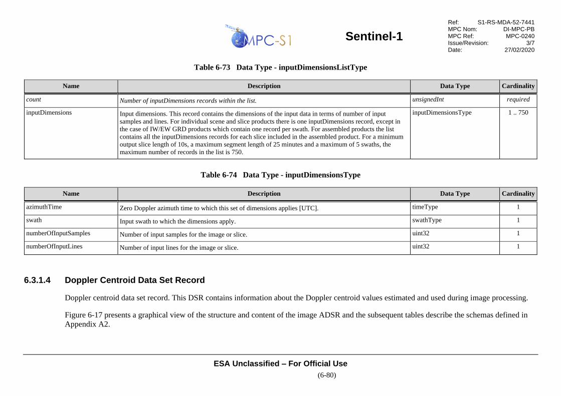
Sentinel-1
Ref: S1-RS-MDA-52-7441 MPC Nom: DI-MPC-PB MPC Ref: MPC-0240 Issue/Revision: 3/7 Date: 27/02/2020
ESA Unclassified – For Official Use
(6-80)
Table 6-73 Data Type - inputDimensionsListType
Name Description Data Type Cardinality
count Number of inputDimensions records within the list. unsignedInt required
inputDimensions Input dimensions. This record contains the dimensions of the input data in terms of number of input
samples and lines. For individual scene and slice products there is one inputDimensions record, except in
the case of IW/EW GRD products which contain one record per swath. For assembled products the list
contains all the inputDimensions records for each slice included in the assembled product. For a minimum
output slice length of 10s, a maximum segment length of 25 minutes and a maximum of 5 swaths, the
maximum number of records in the list is 750.
inputDimensionsType 1 .. 750
Table 6-74 Data Type - inputDimensionsType
Name Description Data Type Cardinality
azimuthTime Zero Doppler azimuth time to which this set of dimensions applies [UTC]. timeType 1
swath Input swath to which the dimensions apply. swathType 1
numberOfInputSamples Number of input samples for the image or slice. uint32 1
numberOfInputLines Number of input lines for the image or slice. uint32 1
6.3.1.4 Doppler Centroid Data Set Record
Doppler centroid data set record. This DSR contains information about the Doppler centroid values estimated and used during image processing.
Figure 6-17 presents a graphical view of the structure and content of the image ADSR and the subsequent tables describe the schemas defined in
Appendix A2.

Sentinel-1
Ref: S1-RS-MDA-52-7441 MPC Nom: DI-MPC-PB MPC Ref: MPC-0240 Issue/Revision: 3/7 Date: 27/02/2020
ESA Unclassified – For Official Use
(6-81)
Figure 6-17 L1 Doppler Centroid ADSR

Sentinel-1
Ref: S1-RS-MDA-52-7441 MPC Nom: DI-MPC-PB MPC Ref: MPC-0240 Issue/Revision: 3/7 Date: 27/02/2020
ESA Unclassified – For Official Use
(6-82)
Table 6-75 Data Type - l1DopplerCentroidType
Name Description Data Type Cardinality
dcEstimateList List of Doppler centroid estimates that have been calculated by the IPF during image processing. The list
contains an entry for each Doppler centroid estimate made along azimuth.
dcEstimateListType 1
Table 6-76 Data Type - dceBlockListType
Name Description Data Type Cardinality
Count Number of dcEstimate records within the list. unsignedInt required
dcEstimate Doppler centroid estimate record which contains the Doppler centroid calculated from geometry and
estimated from the data, associated signal-to-noise ratio values and indicates which DCE method was used
by the IPF during image processing. With a minimum Doppler centroid update rate of 1s (for IW and EW
where the Doppler is recalculated for every burst cycle) and a maximum product length of 25 minutes, the
maximum size of this list is 1500 elements.
dcEstimateType 1 .. 1500
Table 6-77 Data Type - dcEstimateType
Name Description Data Type Cardinality
azimuthTime Zero Doppler azimuth time of this Doppler centroid estimate [UTC]. This time represents the centre of
the block used to calculate the fune DC estimates used to derive the data DC polynomial.
timeType 1
t0 Two-way slant range time origin for Doppler centroid estimate [s]. double 1
geometryDcPolynomial Doppler centroid estimated from orbit, expressed as the following polynomial (assuming 5 coefficients):
)( )( )( )( 4
04
3
03
2
02010 ttdttdttdttddtroidDopplerCen SRSRSRSR −+−+−+−+=
where tSR = 2 way slant range time.
floatCoefficientArray 1

Sentinel-1
Ref: S1-RS-MDA-52-7441 MPC Nom: DI-MPC-PB MPC Ref: MPC-0240 Issue/Revision: 3/7 Date: 27/02/2020
ESA Unclassified – For Official Use
(6-83)
Name Description Data Type Cardinality
dataDcPolynomial Doppler centroid estimated from data, expressed as the following polynomial (assuming 5 coefficients):
)( )( )( )( 4
04
3
03
2
02010 ttdttdttdttddtroidDopplerCen SRSRSRSR −+−+−+−+=
where tSR = 2 way slant range time.
floatCoefficientArray 1
dataDcRmsError The RMS error of the Doppler centroid estimate. It is calculated as the average of the individual RMS
residual errors between input fine Doppler centroid estimates and the fitted polynomial. If the Doppler
centroid was not estimated from data, this is set to 0.
double 1
dataDcRmsErrorAboveThreshold False if the RMS error is below the acceptable threshold for the Doppler centroid estimated from the data.
True if the RMS error is greater than or equal to the acceptable threshold.
bool 1
fineDceAzimuthStartTime First zero Doppler azimuth time of the block of signal data used for the fine DC estimates [UTC]. timeType 1
fineDceAzimuthStopTime Last zero Doppler azimuth time of the block of signal data used for the fine DC estimates [UTC]. timeType 1
fineDceList List of the fine Doppler centroid estimates for this block. This element is a list of fineDce records which
contain the fine Doppler centroid frequencies that were used for fitting the data polynomial for this
block.
fineDceListType 1
Table 6-78 Data Type - fineDceListType
Name Description Data Type Cardinality
count Number of Doppler centroid estimates in the list. unsignedInt required
fineDce Fine Doppler centroid estimate. Each estimate represents the Doppler frequency at the given slant range
time within the current block. Approximately 20 estimates are performed per swath so for 5 swaths, the
maximum number of estimates in this list is 100.
fineDceType 0 .. 100
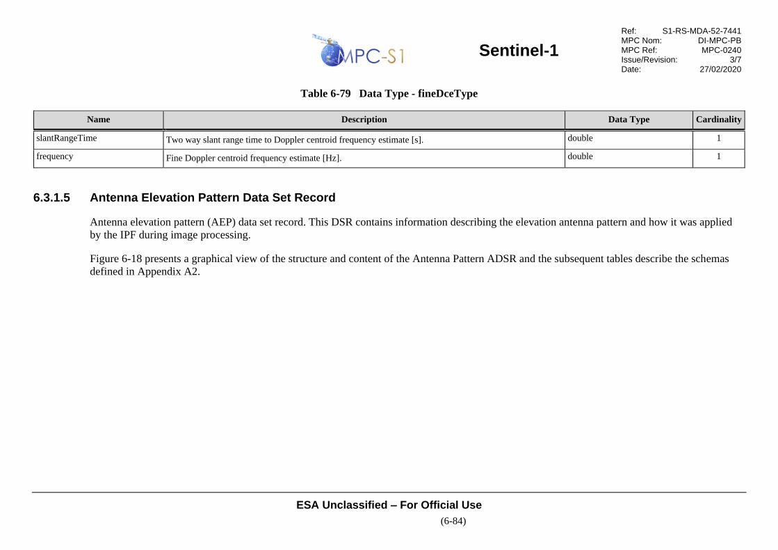
Sentinel-1
Ref: S1-RS-MDA-52-7441 MPC Nom: DI-MPC-PB MPC Ref: MPC-0240 Issue/Revision: 3/7 Date: 27/02/2020
ESA Unclassified – For Official Use
(6-84)
Table 6-79 Data Type - fineDceType
Name Description Data Type Cardinality
slantRangeTime Two way slant range time to Doppler centroid frequency estimate [s]. double 1
frequency Fine Doppler centroid frequency estimate [Hz]. double 1
6.3.1.5 Antenna Elevation Pattern Data Set Record
Antenna elevation pattern (AEP) data set record. This DSR contains information describing the elevation antenna pattern and how it was applied
by the IPF during image processing.
Figure 6-18 presents a graphical view of the structure and content of the Antenna Pattern ADSR and the subsequent tables describe the schemas
defined in Appendix A2.

Sentinel-1
Ref: S1-RS-MDA-52-7441 MPC Nom: DI-MPC-PB MPC Ref: MPC-0240 Issue/Revision: 3/7 Date: 27/02/2020
ESA Unclassified – For Official Use
(6-85)
Figure 6-18 L1 Antenna Elevation Pattern ADSR
Table 6-80 Data Type - l1AntennaPatternType
Name Description Data Type Cardinality
antennaPatternList Antenna pattern list. This element is a list of antennaPattern records that describe the antenna elevation
pattern as it is updated in azimuth. The list contains an entry for each AEP update made along azimuth.
antennaPatternListType 1
Table 6-81 Data Type - antennaPatternListType
Name Description Data Type Cardinality
count Number of antenna pattern records within the list. unsignedInt required

Sentinel-1
Ref: S1-RS-MDA-52-7441 MPC Nom: DI-MPC-PB MPC Ref: MPC-0240 Issue/Revision: 3/7 Date: 27/02/2020
ESA Unclassified – For Official Use
(6-86)
Name Description Data Type Cardinality
antennaPattern The antenna pattern record describes the antenna elevation pattern at the given zero Doppler azimuth time
for a given swath. For a minimum azimuth antenna pattern spacing of 10s, a maximum segment length of
25 minutes and a maximum 5 swaths, the maximum number of records in the list is 750.
antennaPatternType 1 .. 750
Table 6-82 Data Type - antennaPatternType
Name Description Data Type Cardinality
swath Swath to which the elevation antenna pattern applies. swathType 1
azimuthTime Zero Doppler azimuth time at which antenna pattern applies [UTC]. timeType 1
slantRangeTime Two-way slant range time array for this antenna pattern [s]. This array contains the count attribute
number of double floating point values (i.e. one value per point in the antenna pattern), separated by
spaces.
doubleArray 1
elevationAngle Corresponding elevation angle for this antenna pattern [degrees]. This array contains the count attribute
number of floating point values (i.e. one value per point in the antenna pattern), separated by spaces. This
array contains the same number of values as the slantRangeTime array.
floatArray 1
elevationPattern Corresponding two-way antenna elevation pattern value for this point. This array contains the count
attribute number of complex floating point values (i.e. one value per point in the antenna pattern),
separated by spaces in the order I Q I Q I Q ... This array contains the same number of values as the
slantRangeTime array.
complexArray 1
incidenceAngle Corresponding incidence angle value for this point. This array contains the count attribute number of
floating point values (i.e. one value per point in the antenna pattern), separated by spaces [degrees]. This
array contains the same number of values as the slantRangeTime array.
floatArray 1
terrainHeight Average terrain height in range for this antenna pattern [m]. double 1
roll Estimated roll angle for this antenna pattern [degrees]. double 1
Sentinel-1
Ref: S1-RS-MDA-52-7441 MPC Nom: DI-MPC-PB MPC Ref: MPC-0240 Issue/Revision: 3/7 Date: 27/02/2020
ESA Unclassified – For Official Use
(6-87)
6.3.1.6 Swath Timing Data Set Record
Swath timing data set record. This DSR contains the information about the bursts within the image MDS including the burst dimensions, burst
timing and burst location. This DSR is specific to IW and EW SLC products.
Figure 6-19 presents a graphical view of the structure and content of the Swath Timing ADSR and the subsequent tables describe the schemas
defined in Appendix A2.
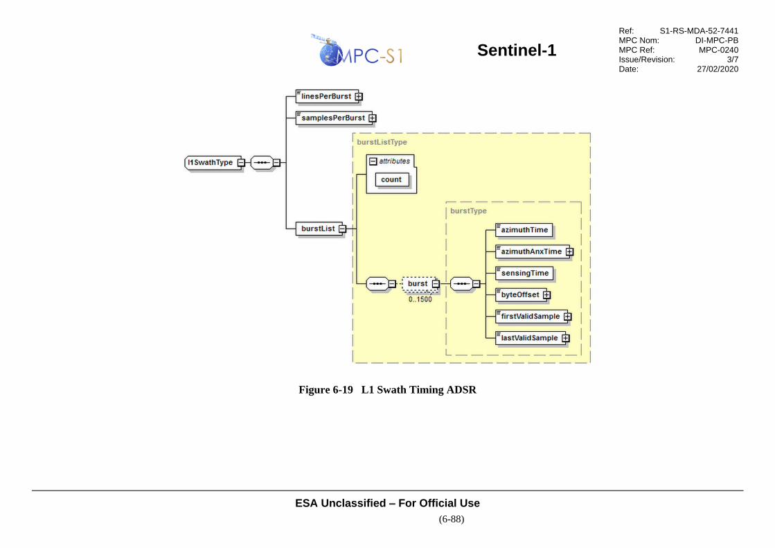
Sentinel-1
Ref: S1-RS-MDA-52-7441 MPC Nom: DI-MPC-PB MPC Ref: MPC-0240 Issue/Revision: 3/7 Date: 27/02/2020
ESA Unclassified – For Official Use
(6-88)
Figure 6-19 L1 Swath Timing ADSR
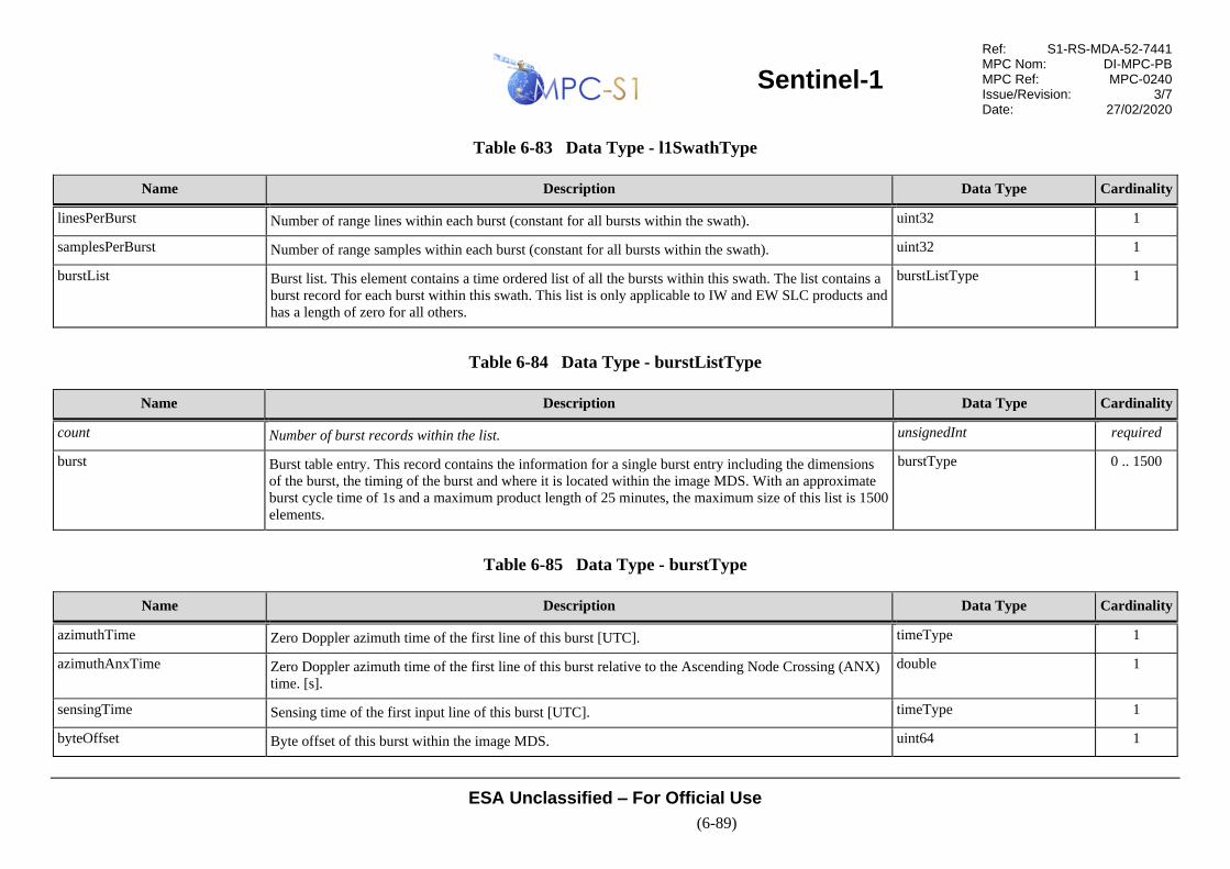
Sentinel-1
Ref: S1-RS-MDA-52-7441 MPC Nom: DI-MPC-PB MPC Ref: MPC-0240 Issue/Revision: 3/7 Date: 27/02/2020
ESA Unclassified – For Official Use
(6-89)
Table 6-83 Data Type - l1SwathType
Name Description Data Type Cardinality
linesPerBurst Number of range lines within each burst (constant for all bursts within the swath). uint32 1
samplesPerBurst Number of range samples within each burst (constant for all bursts within the swath). uint32 1
burstList Burst list. This element contains a time ordered list of all the bursts within this swath. The list contains a
burst record for each burst within this swath. This list is only applicable to IW and EW SLC products and
has a length of zero for all others.
burstListType 1
Table 6-84 Data Type - burstListType
Name Description Data Type Cardinality
count Number of burst records within the list. unsignedInt required
burst Burst table entry. This record contains the information for a single burst entry including the dimensions
of the burst, the timing of the burst and where it is located within the image MDS. With an approximate
burst cycle time of 1s and a maximum product length of 25 minutes, the maximum size of this list is 1500
elements.
burstType 0 .. 1500
Table 6-85 Data Type - burstType
Name Description Data Type Cardinality
azimuthTime Zero Doppler azimuth time of the first line of this burst [UTC]. timeType 1
azimuthAnxTime Zero Doppler azimuth time of the first line of this burst relative to the Ascending Node Crossing (ANX)
time. [s].
double 1
sensingTime Sensing time of the first input line of this burst [UTC]. timeType 1
byteOffset Byte offset of this burst within the image MDS. uint64 1

Sentinel-1
Ref: S1-RS-MDA-52-7441 MPC Nom: DI-MPC-PB MPC Ref: MPC-0240 Issue/Revision: 3/7 Date: 27/02/2020
ESA Unclassified – For Official Use
(6-90)
Name Description Data Type Cardinality
firstValidSample An array of integers indicating the offset of the first valid image sample within each range line. This
array contains count attribute integers, equal to the linesPerBurst field (i.e. one value per range line
within the burst), separated by spaces. If a range line does not contain any valid image samples, the
integer is set to -1.
intArray 1
lastValidSample An array of integers indicating the offset of the last valid image sample within each range line. This array
contains count attribute integers, equal to the linesPerBurst (i.e. one value per range line within the
burst), separated by spaces. If a range line does not contain any valid image samples, the integer is set to
-1.
intArray 1
6.3.1.7 Geo-location Grid Data Set Record
Geo-location grid data set record. This DSR describes the geodetic position (latitude and longitude) of line/pixel combinations within the image
MDS.
Figure 6-20 presents a graphical view of the structure and content of the Geo-location Grid ADSR and the subsequent tables describe the schemas
defined in Appendix A2.

Sentinel-1
Ref: S1-RS-MDA-52-7441 MPC Nom: DI-MPC-PB MPC Ref: MPC-0240 Issue/Revision: 3/7 Date: 27/02/2020
ESA Unclassified – For Official Use
(6-91)
Figure 6-20 L1 Geo-location Grid ADSR
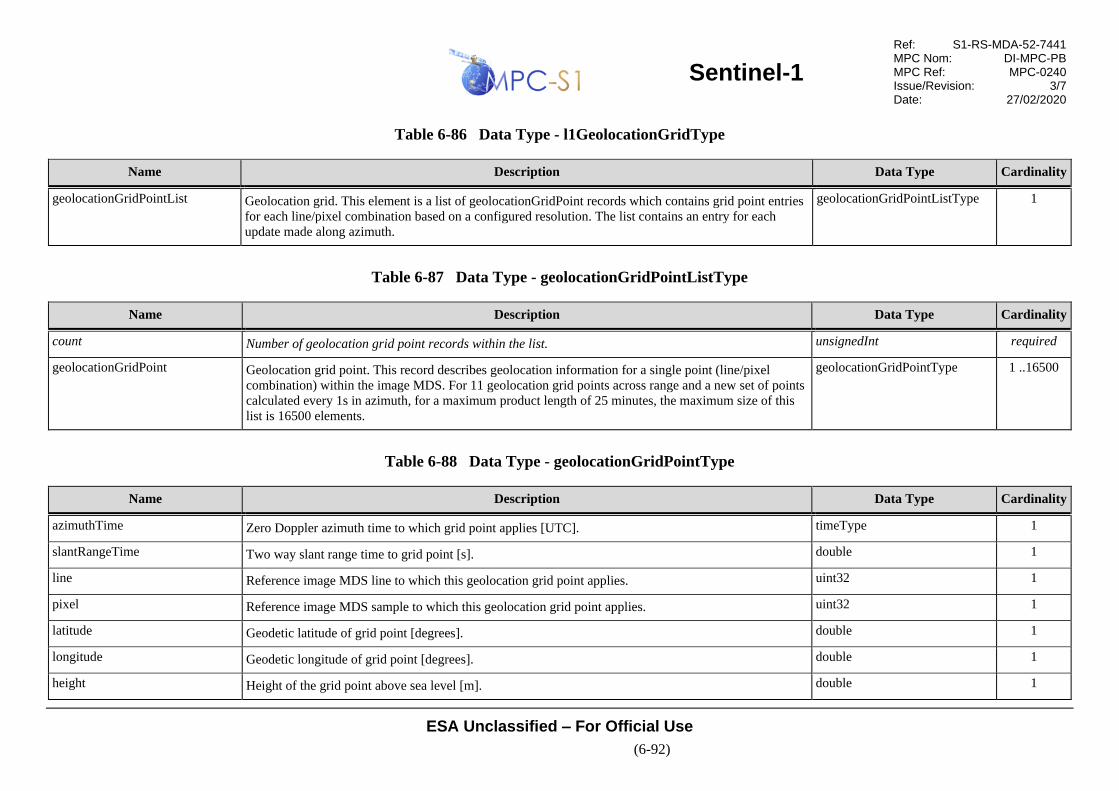
Sentinel-1
Ref: S1-RS-MDA-52-7441 MPC Nom: DI-MPC-PB MPC Ref: MPC-0240 Issue/Revision: 3/7 Date: 27/02/2020
ESA Unclassified – For Official Use
(6-92)
Table 6-86 Data Type - l1GeolocationGridType
Name Description Data Type Cardinality
geolocationGridPointList Geolocation grid. This element is a list of geolocationGridPoint records which contains grid point entries
for each line/pixel combination based on a configured resolution. The list contains an entry for each
update made along azimuth.
geolocationGridPointListType 1
Table 6-87 Data Type - geolocationGridPointListType
Name Description Data Type Cardinality
count Number of geolocation grid point records within the list. unsignedInt required
geolocationGridPoint Geolocation grid point. This record describes geolocation information for a single point (line/pixel
combination) within the image MDS. For 11 geolocation grid points across range and a new set of points
calculated every 1s in azimuth, for a maximum product length of 25 minutes, the maximum size of this
list is 16500 elements.
geolocationGridPointType 1 ..16500
Table 6-88 Data Type - geolocationGridPointType
Name Description Data Type Cardinality
azimuthTime Zero Doppler azimuth time to which grid point applies [UTC]. timeType 1
slantRangeTime Two way slant range time to grid point [s]. double 1
line Reference image MDS line to which this geolocation grid point applies. uint32 1
pixel Reference image MDS sample to which this geolocation grid point applies. uint32 1
latitude Geodetic latitude of grid point [degrees]. double 1
longitude Geodetic longitude of grid point [degrees]. double 1
height Height of the grid point above sea level [m]. double 1

Sentinel-1
Ref: S1-RS-MDA-52-7441 MPC Nom: DI-MPC-PB MPC Ref: MPC-0240 Issue/Revision: 3/7 Date: 27/02/2020
ESA Unclassified – For Official Use
(6-93)
Name Description Data Type Cardinality
incidenceAngle Incidence angle to grid point [degrees]. double 1
elevationAngle Elevation angle to grid point [degrees]. double 1
6.3.1.8 Coordinate Conversion Data Set Record
Coordinate conversion data set record. This DSR contains the annotations required to convert pixels within the image MDS between the slant
range and ground range coordinate systems.
Figure 6-21 presents a graphical view of the structure and content of the Coordinate Conversion ADSR and the subsequent tables describe the
schemas defined in Appendix A2.

Sentinel-1
Ref: S1-RS-MDA-52-7441 MPC Nom: DI-MPC-PB MPC Ref: MPC-0240 Issue/Revision: 3/7 Date: 27/02/2020
ESA Unclassified – For Official Use
(6-94)
Figure 6-21 L1 Coordinate Conversion ADSR
Table 6-89 Data Type - l1CoordinateConversionType
Name Description Data Type Cardinality
coordinateConversionList Coordinate conversion list. This element is a list of coordinateConversion records that describe
conversion between the slant range and ground range coordinate systems. The list contains an entry for
each update made along azimuth. This list applies to and is filled in only for GRD products and therefore
has a length of zero for SLC products.
coordinateConversionListType 1
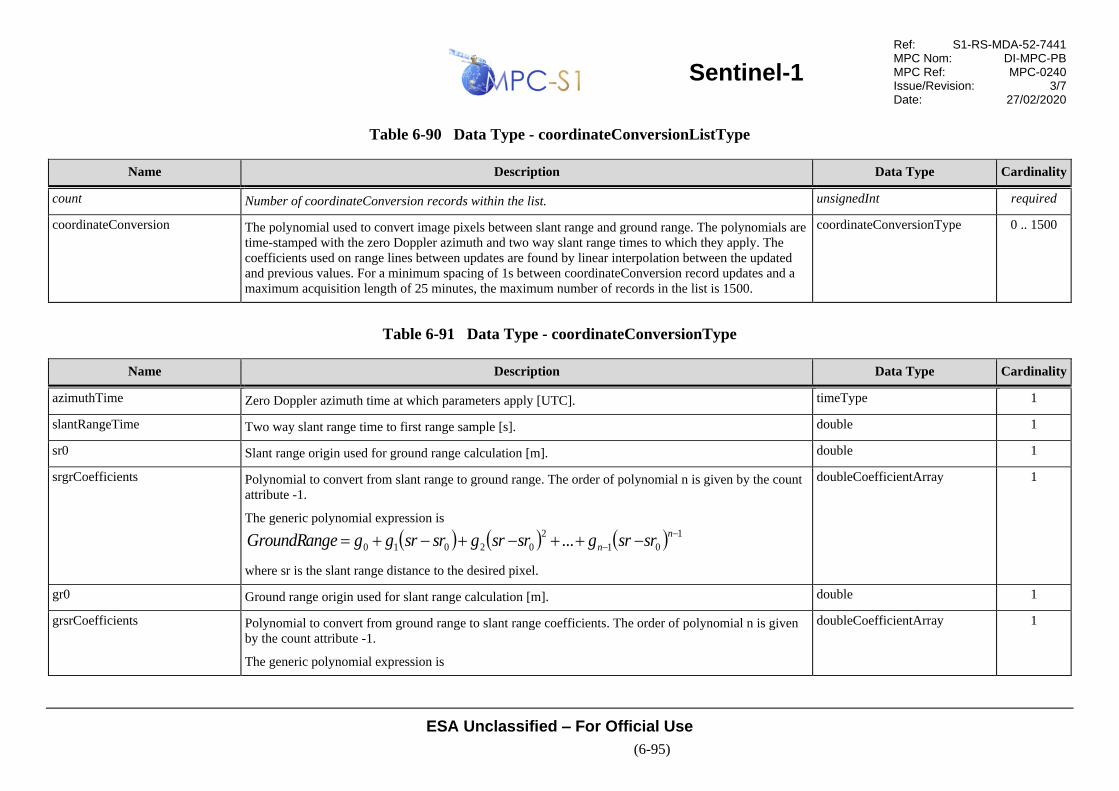
Sentinel-1
Ref: S1-RS-MDA-52-7441 MPC Nom: DI-MPC-PB MPC Ref: MPC-0240 Issue/Revision: 3/7 Date: 27/02/2020
ESA Unclassified – For Official Use
(6-95)
Table 6-90 Data Type - coordinateConversionListType
Name Description Data Type Cardinality
count Number of coordinateConversion records within the list. unsignedInt required
coordinateConversion The polynomial used to convert image pixels between slant range and ground range. The polynomials are
time-stamped with the zero Doppler azimuth and two way slant range times to which they apply. The
coefficients used on range lines between updates are found by linear interpolation between the updated
and previous values. For a minimum spacing of 1s between coordinateConversion record updates and a
maximum acquisition length of 25 minutes, the maximum number of records in the list is 1500.
coordinateConversionType 0 .. 1500
Table 6-91 Data Type - coordinateConversionType
Name Description Data Type Cardinality
azimuthTime Zero Doppler azimuth time at which parameters apply [UTC]. timeType 1
slantRangeTime Two way slant range time to first range sample [s]. double 1
sr0 Slant range origin used for ground range calculation [m]. double 1
srgrCoefficients Polynomial to convert from slant range to ground range. The order of polynomial n is given by the count
attribute -1.
The generic polynomial expression is
( ) ( ) ( ) 1
01
2
02010 ...−
− −++−+−+=n
n srsrgsrsrgsrsrggeGroundRang
where sr is the slant range distance to the desired pixel.
doubleCoefficientArray 1
gr0 Ground range origin used for slant range calculation [m]. double 1
grsrCoefficients Polynomial to convert from ground range to slant range coefficients. The order of polynomial n is given
by the count attribute -1.
The generic polynomial expression is
doubleCoefficientArray 1
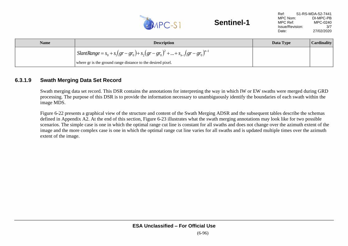
Sentinel-1
Ref: S1-RS-MDA-52-7441 MPC Nom: DI-MPC-PB MPC Ref: MPC-0240 Issue/Revision: 3/7 Date: 27/02/2020
ESA Unclassified – For Official Use
(6-96)
Name Description Data Type Cardinality
)( )( )( 1
01
2
02010 ...−
− −++−+−+=n
n grgrsgrgrsgrgrssSlantRange
where gr is the ground range distance to the desired pixel.
6.3.1.9 Swath Merging Data Set Record
Swath merging data set record. This DSR contains the annotations for interpreting the way in which IW or EW swaths were merged during GRD
processing. The purpose of this DSR is to provide the information necessary to unambiguously identify the boundaries of each swath within the
image MDS.
Figure 6-22 presents a graphical view of the structure and content of the Swath Merging ADSR and the subsequent tables describe the schemas
defined in Appendix A2. At the end of this section, Figure 6-23 illustrates what the swath merging annotations may look like for two possible
scenarios. The simple case is one in which the optimal range cut line is constant for all swaths and does not change over the azimuth extent of the
image and the more complex case is one in which the optimal range cut line varies for all swaths and is updated multiple times over the azimuth
extent of the image.

Sentinel-1
Ref: S1-RS-MDA-52-7441 MPC Nom: DI-MPC-PB MPC Ref: MPC-0240 Issue/Revision: 3/7 Date: 27/02/2020
ESA Unclassified – For Official Use
(6-97)
Figure 6-22 L1 Swath Merging ADSR

Sentinel-1
Ref: S1-RS-MDA-52-7441 MPC Nom: DI-MPC-PB MPC Ref: MPC-0240 Issue/Revision: 3/7 Date: 27/02/2020
ESA Unclassified – For Official Use
(6-98)
Table 6-92 Data Type - l1SwathMergeType
Name Description Data Type Cardinality
swathMergeList Merge information for IW and EW GRD products. This list contains one record per swath. swathMergeListType 1
Table 6-93 Data Type - swathMergeListType
Name Description Data Type Cardinality
count Number of swathMerge records within the list. unsignedInt required
swathMerge This record contains the information needed to identify where each burst of the given swath was merged
within the image MDS.
swathMergeType 0 .. 5
Table 6-94 Data Type - swathMergeType
Name Description Data Type Cardinality
swath Swath to which swath merging information applies. swathType 1
swathBoundsList This list contains the information needed to identify where the current swath has been merged into the
image MDS. Each swathBounds record represents a rectangular area that may include several burst
merged in azimuth. These records do not describe where individual bursts were merged in azimuth,
within a swath.
swathBoundsListType 1

Sentinel-1
Ref: S1-RS-MDA-52-7441 MPC Nom: DI-MPC-PB MPC Ref: MPC-0240 Issue/Revision: 3/7 Date: 27/02/2020
ESA Unclassified – For Official Use
(6-99)
Table 6-95 Data Type - swathBoundsListType
Name Description Data Type Cardinality
count Number of swath bounds records within the list. unsignedInt required
swathBounds Swath boundary record. This record contains the information needed to identify the position of the swath
within the image. The swath boundary is identified by a rectangular area defined by the points
(firstRangeSample,firstAzimuthLine) and (lastRangeSample,lastAzimuthLine). The optimal range cut
line can vary in azimuth and so a new record is included for each swath boundary update in azimuth. It is
important to note that the information on the azimuth cut line is lost and not represented by these
annotations. Although a line in azimuth is implicitly created by each bounding box, this does not
necessarily represent the azimuth cut line used during swath merging. For an average spacing of 1s
between swath bound updates and a maximum acquisition length of 25 minutes, the maximum number of
records in the list is 1500.
swathBoundsType 1 .. 1500
Table 6-96 Data Type - swathBoundsType
Name Description Data Type Cardinality
azimuthTime Zero Doppler azimuth time of firstAzimuthLine [UTC]. timeType 1
firstAzimuthLine First azimuth line of the swath boundary [lines]. This point represents the azimuth origin of the swath
boundary.
uint32 1
firstRangeSample First range sample of the swath boundary [samples]. This point represents the range origin of the swath
boundary.
uint32 1
lastAzimuthLine Last azimuth line of the swath boundary [lines]. Relative to the firstAzimuthLine, this point represents
the azimuth extent of the swath boundary.
uint32 1
lastRangeSample Last range sample of the swath boundary [samples]. Relative to the firstRangeSample, this point
represents the range extent of the swath boundary.
uint32 1

Sentinel-1
Ref: S1-RS-MDA-52-7441 MPC Nom: DI-MPC-PB MPC Ref: MPC-0240 Issue/Revision: 3/7 Date: 27/02/2020
ESA Unclassified – For Official Use
(6-100)
The annotations for the simple case in the graph below contain a single swathBoundsType entry for each swath that represents a bounding box
covering the entire azimuth extent of the image. The annotations in the complex case contain multiple swathBoundsType entries for each swath –
4, 6 and 3 for IW1, IW2 and IW3 respectively – that collectively describe the location of the swaths within the image. To identify the applicable
set of annotations for each bounding box the notation x
yniwM )( is used where M is the swath number – 1, 2 or 3, n is the index of the
swathBoundsType annotation increasing as the optimal range cut line changes in azimuth and the superscript/subscript pair x/y describes a point in
the image defined by (firstRangeSample,firstAzimuthLine) or (lastRangeSample,lastAzimuthLine).

Sentinel-1
Ref: S1-RS-MDA-52-7441 MPC Nom: DI-MPC-PB MPC Ref: MPC-0240 Issue/Revision: 3/7 Date: 27/02/2020
ESA Unclassified – For Official Use
(6-101)
Figure 6-23 Swath Merging
IW1 IW2 IW3
Rng
A
z
i
Simple Case: Constant Optimal Range Cut Line
Complex Case: Varying Optimal Range Cut Line

Sentinel-1
Ref: S1-RS-MDA-52-7441 MPC Nom: DI-MPC-PB MPC Ref: MPC-0240 Issue/Revision: 3/7 Date: 27/02/2020
ESA Unclassified – For Official Use
(6-102)
6.3.2 L1 Calibration Annotation Data Set
The L1 Calibration ADS provides four calibration LUTs with every product. Applying any of these tables undoes the application output scaling
introduced by the processor and scales the image to achieve the desired type of absolute calibration, notably:
Three of these LUTs allow one to convert the digital numbers in the image MDS into , or radiometrically calibrated imagery – depending
on which LUT is used – by applying a range dependent gain (and a constant offset in the GRD case) to the image data. Note that in order to
achieve the desired calibration the absolute calibration constant Kabs (absoluteCalibrationConstant), has also been built into these tables. The fourth
LUT, the dn LUT allows one to recover the original DN value that the image had before the scaling by the application LUT (therefore the dn LUT
does not include the external calibration factor Kabs).
In order to convert the DN of a given range pixel i in a Sentinel-1 SAR image to a calibrated value or the original DN, the user has to apply one of
the following formulae:
2
2
)(i
i
A
DNivalue =
where, depending on the selected LUT:
)(ivalue = one of , or or ioriginalDN .
= one of , , )(igamma or
For any pixel i that falls between points in the LUT the value is found by bilinear interpolation.
Figure 6-24 presents a graphical view of the structure and content of the L1 Calibration LUT Data Set and the subsequent tables describe the
schemas defined in Appendix A3.
00
i0 i
0i
iA )(ibetaNought )(itsigmaNough )(idn
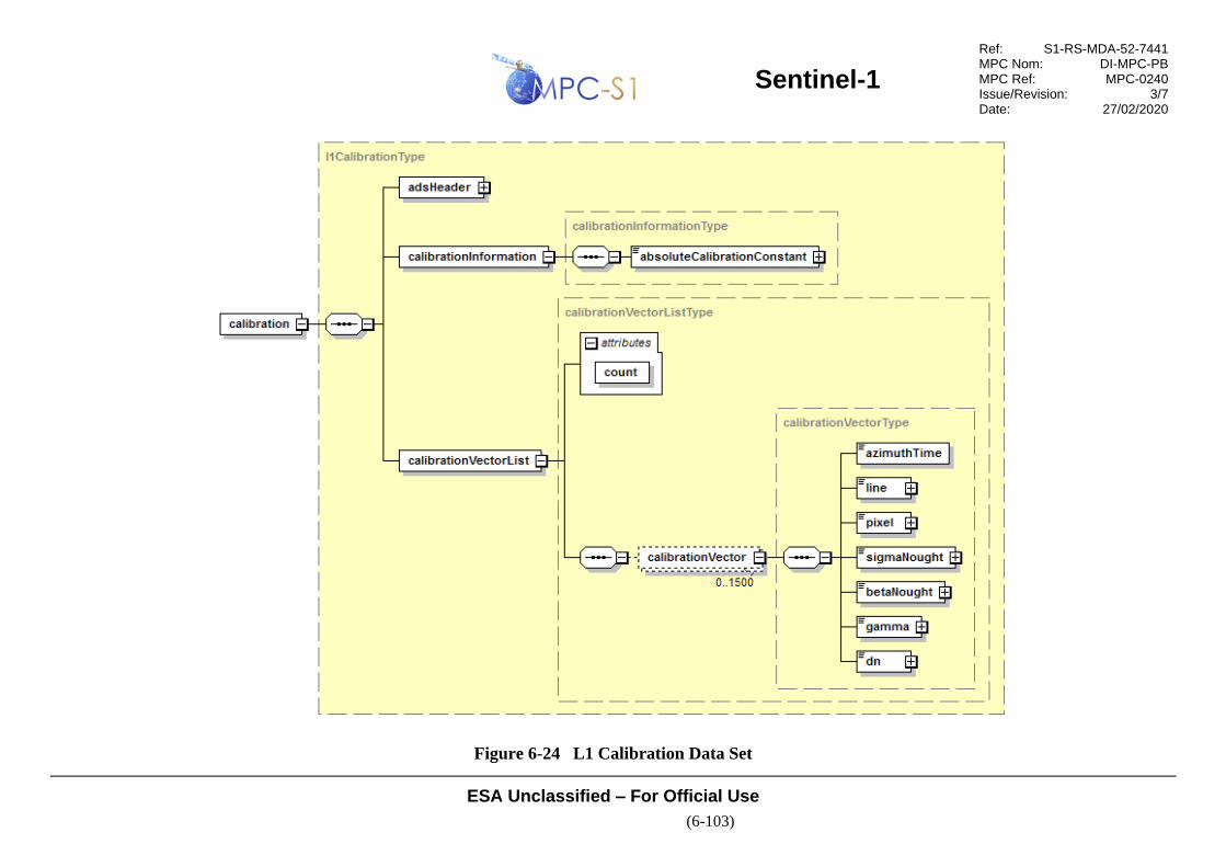
Sentinel-1
Ref: S1-RS-MDA-52-7441 MPC Nom: DI-MPC-PB MPC Ref: MPC-0240 Issue/Revision: 3/7 Date: 27/02/2020
ESA Unclassified – For Official Use
(6-103)
Figure 6-24 L1 Calibration Data Set
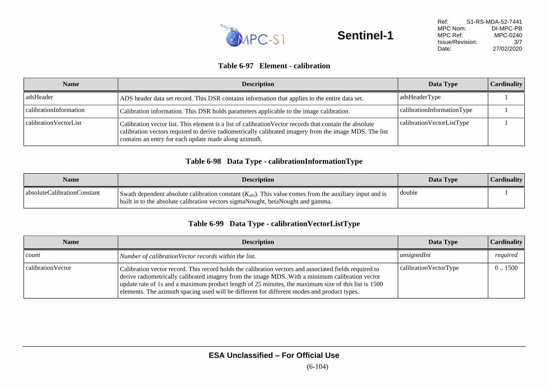
Sentinel-1
Ref: S1-RS-MDA-52-7441 MPC Nom: DI-MPC-PB MPC Ref: MPC-0240 Issue/Revision: 3/7 Date: 27/02/2020
ESA Unclassified – For Official Use
(6-104)
Table 6-97 Element - calibration
Name Description Data Type Cardinality
adsHeader ADS header data set record. This DSR contains information that applies to the entire data set. adsHeaderType 1
calibrationInformation Calibration information. This DSR holds parameters applicable to the image calibration. calibrationInformationType 1
calibrationVectorList Calibration vector list. This element is a list of calibrationVector records that contain the absolute
calibration vectors required to derive radiometrically calibrated imagery from the image MDS. The list
contains an entry for each update made along azimuth.
calibrationVectorListType 1
Table 6-98 Data Type - calibrationInformationType
Name Description Data Type Cardinality
absoluteCalibrationConstant Swath dependent absolute calibration constant (Kabs). This value comes from the auxiliary input and is
built in to the absolute calibration vectors sigmaNought, betaNought and gamma.
double 1
Table 6-99 Data Type - calibrationVectorListType
Name Description Data Type Cardinality
count Number of calibrationVector records within the list. unsignedInt required
calibrationVector Calibration vector record. This record holds the calibration vectors and associated fields required to
derive radiometrically calibrated imagery from the image MDS. With a minimum calibration vector
update rate of 1s and a maximum product length of 25 minutes, the maximum size of this list is 1500
elements. The azimuth spacing used will be different for different modes and product types.
calibrationVectorType 0 .. 1500

Sentinel-1
Ref: S1-RS-MDA-52-7441 MPC Nom: DI-MPC-PB MPC Ref: MPC-0240 Issue/Revision: 3/7 Date: 27/02/2020
ESA Unclassified – For Official Use
(6-105)
Table 6-100 Data Type - calibrationVectorType
Name Description Data Type Cardinality
azimuthTime Zero Doppler azimuth time at which calibration vector applies. timeType 1
line Image line at which the calibration vector applies. int32 1
pixel Image pixel at which the calibration vector applies. This array contains the count attribute number of
integer values (i.e. one value per point in the calibration vectors), separated by spaces. The maximum
length of this array will be one value for every pixel in an image line, however in general the vectors will
be subsampled.
intArray 1
sigmaNought Sigma nought calibration vector. This array contains the count attribute number of floating point values
separated by spaces. The values in this vector are aligned with the pixel vector.
floatArray 1
betaNought Beta nought calibration vector. This array contains the count attribute number of floating point values
separated by spaces. The values in this vector are aligned with the pixel vector.
floatArray 1
gamma Gamma calibration vector. This array contains the count attribute number of floating point values
separated by spaces. The values in this vector are aligned with the pixel vector.
floatArray 1
dn Digital number calibration vector. This array contains the count attribute number of floating point values
separated by spaces. The values in this vector are aligned with the pixel vector.
floatArray 1

Sentinel-1
Ref: S1-RS-MDA-52-7441 MPC Nom: DI-MPC-PB MPC Ref: MPC-0240 Issue/Revision: 3/7 Date: 27/02/2020
ESA Unclassified – For Official Use
(6-106)
6.3.3 L1 Noise Annotation Data Set
The L1 Noise ADS provides a LUT – with values provided in linear power – that can be used to derive calibrated noise profiles which match the
calibrated GRD data.
More specifically, in order to convert the values provided in the noise LUT to , or calibrated noise or to the noise estimated by the IPF
during SLC processing, the noise LUT must be scaled by the corresponding calibration LUT ( , or or dn , respectively):
²)(
i
i
Ainoise
=
where, depending on the LUT selected to calibrate the image data:
)(inoise = calibrated noise profile for one of , or or ioriginalDN
i = )(inoiseLut
= one of , , )(igamma ,
Once the calibrated noise profile has been obtained as above, the noise can be removed from the GRD data by subtraction.
It is also possible to obtain calibrated data and remove the estimated noise in one step by considering the subtraction of the noise in the formula
described in 6.3.2 as follows:
2
2)(
)(i
ii
A
DNivalue
−=
For any pixel i that falls between points in the LUT the value is found by bilinear interpolation.
Figure 6-25 presents a graphical view of the structure and content of the L1 Noise LUT Data Set and the subsequent tables describe the schemas
defined in Appendix A4.
00
00
i0 i
0i
iA )(ibetaNought )(itsigmaNough )(idn

Sentinel-1
Ref: S1-RS-MDA-52-7441 MPC Nom: DI-MPC-PB MPC Ref: MPC-0240 Issue/Revision: 3/7 Date: 27/02/2020
ESA Unclassified – For Official Use
(6-107)
Figure 6-25 L1 Noise LUT Data Set

Sentinel-1
Ref: S1-RS-MDA-52-7441 MPC Nom: DI-MPC-PB MPC Ref: MPC-0240 Issue/Revision: 3/7 Date: 27/02/2020
ESA Unclassified – For Official Use
(6-108)
Table 6-101 Element - noise
Name Description Data Type Cardinality
adsHeader ADS header data set record. This DSR contains information that applies to the entire data set. adsHeaderType 1
noiseRangeVectorList Range noise vector list. This element is a list of noiseRangeVector records that contain the range thermal
noise estimation for the image MDS. The list contains an entry for each update made along azimuth.
noiseRangeVectorListType 1
noiseAzimuthVectorList Azimuth noise vector list. This annotation divides the image in blocks providing a list of azimuth noise
vector records that contain the thermal noise estimation for the block. The block belongs to a (sub-)swath
(i.e. it can't cross by design two swaths) and it is delimited by firstAzimuthLine, lastAzimuthLine,
firstRangeSample, lastRangeSample.
noiseAzimuthVectorListType
Table 6-102 Data Type - noiseRangeVectorListType
Name Description Data Type Cardinality
count Number of noiseRangeVector records within the list. unsignedInt required
noiseRangeVector Noise range vector. This record contains the thermal noise estimation annotations which can be used to
remove thermal noise from the image. With a minimum noise vector update rate of 1s and a maximum
product length of 25 minutes, the maximum size of this list is 1500 elements. The azimuth spacing used
will be different for different modes and product types.
Note: the noise removal can create negative values that requires to be clipped. The clipping is made such
that it is not possible to recover the original pixel values if one want to re-instate the noise vector.
noiseRangeVectorType 0 .. 1500
Table 6-103 Data Type - noiseRangeVectorType
Name Description Data Type Cardinality
azimuthTime Zero Doppler azimuth time at which noise vector applies. timeType 1
line Image line at which the noise vector applies. int32 1
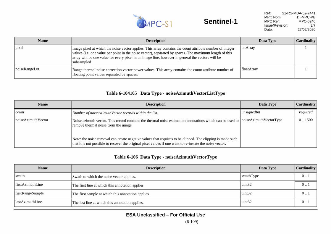
Sentinel-1
Ref: S1-RS-MDA-52-7441 MPC Nom: DI-MPC-PB MPC Ref: MPC-0240 Issue/Revision: 3/7 Date: 27/02/2020
ESA Unclassified – For Official Use
(6-109)
Name Description Data Type Cardinality
pixel Image pixel at which the noise vector applies. This array contains the count attribute number of integer
values (i.e. one value per point in the noise vector), separated by spaces. The maximum length of this
array will be one value for every pixel in an image line, however in general the vectors will be
subsampled.
intArray 1
noiseRangeLut Range thermal noise correction vector power values. This array contains the count attribute number of
floating point values separated by spaces.
floatArray 1
Table 6-104105 Data Type - noiseAzimuthVectorListType
Name Description Data Type Cardinality
count Number of noiseAzimuthVector records within the list. unsignedInt required
noiseAzimuthVector Noise azimuth vector. This record contains the thermal noise estimation annotations which can be used to
remove thermal noise from the image.
Note: the noise removal can create negative values that requires to be clipped. The clipping is made such
that it is not possible to recover the original pixel values if one want to re-instate the noise vector.
noiseAzimuthVectorType 0 .. 1500
Table 6-106 Data Type - noiseAzimuthVectorType
Name Description Data Type Cardinality
swath Swath to which the noise vector applies. swathType 0 .. 1
firstAzimuthLine The first line at which this annotation applies. uint32 0 .. 1
firstRangeSample The first sample at which this annotation applies. uint32 0 .. 1
lastAzimuthLine The last line at which this annotation applies. uint32 0 .. 1

Sentinel-1
Ref: S1-RS-MDA-52-7441 MPC Nom: DI-MPC-PB MPC Ref: MPC-0240 Issue/Revision: 3/7 Date: 27/02/2020
ESA Unclassified – For Official Use
(6-110)
Name Description Data Type Cardinality
lastRangeSample The last sample at which this annotation applies. uint32 0 .. 1
line Image line at which the noise vector applies. This array contains the count attribute number of integer
values (i.e. one value per point in the noise vector), separated by spaces. The maximum length of this
array will be one value for every line in an image pixel, however in general the vectors will be
subsampled.
intArray 1
noiseAzimuthLut Azimuth thermal noise correction vector power values. This array contains the count attribute number of
floating point values separated by spaces.
floatArray 1

Sentinel-1
Ref: S1-RS-MDA-52-7441 MPC Nom: DI-MPC-PB MPC Ref: MPC-0240 Issue/Revision: 3/7 Date: 27/02/2020
ESA Unclassified – For Official Use
(6-111)
6.3.4 Map Overlay Annotation Data Set
The map overlay data set is a Keyhole Markup Language (KML) file [R-10] that
describes the product coverage area and is suitable for viewing in any application
that supports KML. Figure 6-26 shows a graphical example of the map overlay in
which the composite Quick-look image from Section 6.2.2 is geo-referenced and
displayed as an overlay in Google Earth.
The map overlay data set contains the KML elements required to select the product’s
Quick-look image, position it on the map and display it. Figure 6-27 presents a
graphical view of the XML structure of the map overlay data set and the content and
structure are presented in the subsequent tables. Note that data types in the
following tables that are prefixed with “kml:” are part of the KML specification [R-
10] and types prefixed with “gx:” are part of the Google extensions to KML [R-13].
Figure 6-26 Sentinel-1 Map Overlay Displayed in Google Earth
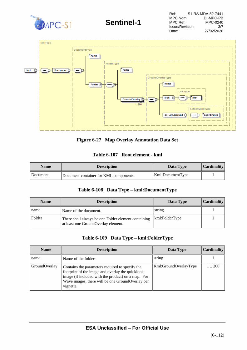
Sentinel-1
Ref: S1-RS-MDA-52-7441 MPC Nom: DI-MPC-PB MPC Ref: MPC-0240 Issue/Revision: 3/7 Date: 27/02/2020
ESA Unclassified – For Official Use
(6-112)
Figure 6-27 Map Overlay Annotation Data Set
Table 6-107 Root element - kml
Name Description Data Type Cardinality
Document Document container for KML components. Kml:DocumentType 1
Table 6-108 Data Type – kml:DocumentType
Name Description Data Type Cardinality
name Name of the document. string 1
Folder There shall always be one Folder element containing
at least one GroundOverlay element.
kml:FolderType 1
Table 6-109 Data Type – kml:FolderType
Name Description Data Type Cardinality
name Name of the folder. string 1
GroundOverlay Contains the parameters required to specify the
footprint of the image and overlay the quicklook
image (if included with the product) on a map. For
Wave images, there will be one GroundOverlay per
vignette.
Kml:GroundOverlayType 1 .. 200
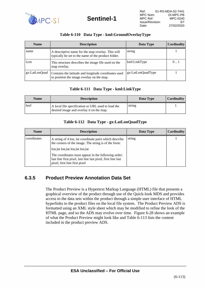
Sentinel-1
Ref: S1-RS-MDA-52-7441 MPC Nom: DI-MPC-PB MPC Ref: MPC-0240 Issue/Revision: 3/7 Date: 27/02/2020
ESA Unclassified – For Official Use
(6-113)
Table 6-110 Data Type - kml:GroundOverlayType
Name Description Data Type Cardinality
name A descriptive name for the map overlay. This will
typically be set to the name of the product folder.
string 1
icon This structure describes the image file used on the
map overlay.
kml:LinkType 0 .. 1
gx:LatLonQuad Contains the latitude and longitude coordinates used
to position the image overlay on the map.
gx:LatLonQuadType 1
Table 6-111 Data Type - kml:LinkType
Name Description Data Type Cardinality
href A local file specification or URL used to load the
desired image and overlay it on the map.
string 1
Table 6-112 Data Type - gx:LatLonQuadType
Name Description Data Type Cardinality
coordinates A string of 4 lon, lat coordinate pairs which describe
the corners of the image. The string is of the form:
lon,lat lon,lat lon,lat lon,lat
The coordinates must appear in the following order:
last line first pixel, last line last pixel, first line last
pixel, first line first pixel
string 1
6.3.5 Product Preview Annotation Data Set
The Product Preview is a Hypertext Markup Language (HTML) file that presents a
graphical overview of the product through use of the Quick-look MDS and provides
access to the data sets within the product through a simple user interface of HTML
hyperlinks to the product files on the local file system. The Product Preview ADS is
formatted using an XML style sheet which may be modified to refine the look of the
HTML page, and so the ADS may evolve over time. Figure 6-28 shows an example
of what the Product Preview might look like and Table 6-113 lists the content
included in the product preview ADS.
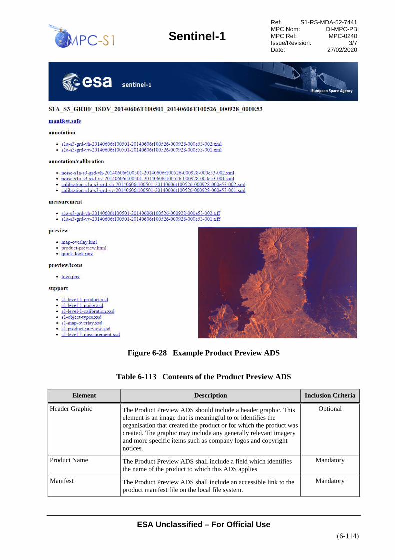
Sentinel-1
Ref: S1-RS-MDA-52-7441 MPC Nom: DI-MPC-PB MPC Ref: MPC-0240 Issue/Revision: 3/7 Date: 27/02/2020
ESA Unclassified – For Official Use
(6-114)
Figure 6-28 Example Product Preview ADS
Table 6-113 Contents of the Product Preview ADS
Element Description Inclusion Criteria
Header Graphic The Product Preview ADS should include a header graphic. This
element is an image that is meaningful to or identifies the
organisation that created the product or for which the product was
created. The graphic may include any generally relevant imagery
and more specific items such as company logos and copyright
notices.
Optional
Product Name The Product Preview ADS shall include a field which identifies
the name of the product to which this ADS applies
Mandatory
Manifest The Product Preview ADS shall include an accessible link to the
product manifest file on the local file system.
Mandatory
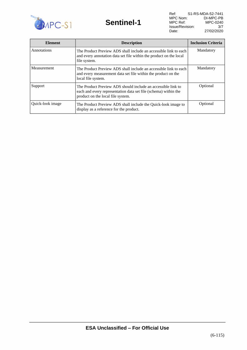
Sentinel-1
Ref: S1-RS-MDA-52-7441 MPC Nom: DI-MPC-PB MPC Ref: MPC-0240 Issue/Revision: 3/7 Date: 27/02/2020
ESA Unclassified – For Official Use
(6-115)
Element Description Inclusion Criteria
Annotations The Product Preview ADS shall include an accessible link to each
and every annotation data set file within the product on the local
file system.
Mandatory
Measurement The Product Preview ADS shall include an accessible link to each
and every measurement data set file within the product on the
local file system.
Mandatory
Support The Product Preview ADS should include an accessible link to
each and every representation data set file (schema) within the
product on the local file system.
Optional
Quick-look image The Product Preview ADS shall include the Quick-look image to
display as a reference for the product.
Optional

Sentinel-1
Ref: S1-RS-MDA-52-7441 MPC Nom: DI-MPC-PB MPC Ref: MPC-0240 Issue/Revision: 3/7 Date: 27/02/2020
ESA Unclassified – For Official Use
(A-1)
A XML SCHEMAS
A1 SENTINEL-1 OBJECT TYPES SCHEMA
Defines the primitive data types used by the Sentinel-1 product schemas
See attached file “s1-object-types.xsd”
A2 SENTINEL-1 L1 PRODUCT ANNOTATION SCHEMA
Defines the Sentinel-1 L1 Product Annotation Data Set
See attached file “s1-level-1-product.xsd”
A3 SENTINEL-1 L1 CALIBRATION SCHEMA
Defines the Sentinel-1 L1 Calibration Data Set
See attached file “s1-level-1-calibration.xsd”
A4 SENTINEL-1 L1 NOISE SCHEMA
Defines the Sentinel-1 L1 Noise Data Set
See attached file “s1-level-1-noise.xsd”
A5 SENTINEL-1 SAFE SPECIALISATION SCHEMAS
See attached schema files in the “xsd/” folder
Related Documents